
Evaluation of Ethane as a Power Conversion System Working ...
54
Evaluation of Ethane as a Power Conversion System Working Fluid for Fast Reactors by Jeffrey A. Perez Submitted to the Department of Nuclear Science and Engineering in Partial Fulfillment of the Requirements for the Degree of Bachelor of Science in Nuclear Science and Engineering at the Massachusetts Institute of Technology June 2008 C Jeffrey Perez. All rights reserved. The author hereby grants to MIT permission to reproduce and to distribute publicly paper and electronic of this thesis document in whole or in part. Signature of Author (I'f - -, epartmet f Nuclear Jeffrey A. Perez Science and Engineering May 8, 2008 Certified by:.......... ... ................. ... .................... J- -Dr. Michael Driscoll Professor Emeritus of Nuclear Science and Engineering Thesis Supervisor Certified by:............ Dr. Pavel Hejzlar Principal Research Scientist Thesis Reader Dr. David Cory Accepted by: ....................... Professor of Nuclei Science and Engineering Chairman, NSE Committee for Undergraduate Students 1 AACHNh" OF TECHNOLOGY JUL 2 4 2008 LIBRARIES
-
Upload
khangminh22 -
Category
Documents
-
view
2 -
download
0
Transcript of Evaluation of Ethane as a Power Conversion System Working ...

Evaluation of Ethane as a Power Conversion SystemWorking Fluid for Fast Reactors
by
Jeffrey A. Perez
Submitted to the Department of Nuclear Science and Engineering in PartialFulfillment of the Requirements for the Degree of
Bachelor of Science in Nuclear Science and Engineeringat the
Massachusetts Institute of Technology
June 2008
C Jeffrey Perez. All rights reserved.
The author hereby grants to MIT permission to reproduce and to distribute publicly paper andelectronic of this thesis document in whole or in part.
Signature of Author(I'f - -,
epartmet f NuclearJeffrey A. Perez
Science and EngineeringMay 8, 2008
Certified by:.......... ... ................. ... ....................J- -Dr. Michael Driscoll
Professor Emeritus of Nuclear Science and EngineeringThesis Supervisor
Certified by:............Dr. Pavel Hejzlar
Principal Research ScientistThesis Reader
Dr. David CoryAccepted by: .......................
Professor of Nuclei Science and EngineeringChairman, NSE Committee for Undergraduate Students
1
AACHNh"
OF TECHNOLOGY
JUL 2 4 2008
LIBRARIES

Evaluation of Ethane as a Power Conversion SystemWorking Fluid for Fast Reactors
by
Jeffrey A. Perez
Submitted to the Department of Nuclear Science and Engineering on May 9, 2008in partial fulfillment of the requirements for the Degree ofBachelor of Science in Nuclear Science and Engineering.
ABSTRACT
A supercritical ethane working fluid Brayton power conversion system isevaluated as an alternative to carbon dioxide. The HSC® chemical kinetics code wasused to study thermal dissociation and chemical interactions for ethane and other coolantsunder a variety of conditions. The NIST database was used for reaction rates. Overallresults were not conclusive. The supercritical behavior of ethane at high pressures is notwell documented, and the recombination rates of its dissociation reactions could provevery important. Ethane is known to crack into ethylene, but computer simulations showthat it can, at equilibrium, also form significant amounts of hydrogen and methane.These reactions cracked more than 25% of the ethane above 3000 C, even though high (20MPa) pressure significantly reduced dissociation compared to results at 0.1 MPa. At highpressure it appears that ethane might recombine much faster than it dissociates, whichwould be highly advantageous. Further research and experimentation is encouraged.Simple experiments should be sufficient to identify the behavior of ethane at hightemperatures and pressures.
Ethane was calculated to have better heat transfer properties than carbon dioxide.In particular, heat exchanger sizes could be reduced by as much as a factor of three. Onthe other hand, more turbomachinery stages are needed.
A simple experiment is proposed to determine whether recombination undercompressor inlet conditions is sufficiently fast and complete to make the use of ethane apractical proposition.
The chemical reaction of ethane with sodium, while it generates hydrogen, isendothermic, which may quench the reaction in the event of small heat exchangerleakage.
Thesis Supervisor: Professor Michael DriscollTitle: Professor Emeritus of Nuclear Science and Engineering

Acknowledgements
I would first and foremost like to thank my parents without whose love and support Iwould not be where I am today. I want them both to know how much I love them andappreciate all that they have done and sacrificed for me.I would also like to sincerely thank Professor Michael Driscoll for all of the help that hehas given me in this process. In every step along the way, his insights and feedback havebeen crucial to my success. He has been patient, understanding and supportive, and forthat I am incredibly grateful. I would also like to thank Dr. Pavel Hejzlar who has alsoprovided feedback and suggestions throughout the thesis writing process.
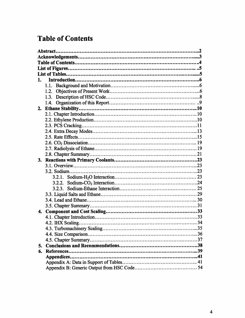
Table of Contents
Abstract......................................................................................2..Acknowledgements....... .................................................................. 3Table of Contents ............................................................................. 4List of Figures.................................................................................5List of Tables ...................................................... .................. .........51. Introduction............................................................................6
1.1. Background and Motivation........................................................6..1.2. Objectives of Present Work ..................................................... 61.3. Description of HSC Code ............................................................ 81.4. Organization of this Report .................................................... ..9
2. Ethane Stability........................................................................ 102.1. Chapter Introduction ....................................................... ... 102.2. Ethylene Production .................................................................102.3. PCS Cracking .............................. ................................ 112.4. Extra Decay Modes ................................................................... 132.5. Rate Effects.....................................................152.6. CO 2 Dissociation .................................................................. 192.7. Radiolysis of Ethane .............................................................. 192.8. Chapter Summary ................................................................. 21
3. Reactions with Primary Coolants..................................................233.1. Overview ............................................................... ..... 233.2. Sodium ............................................................................ . 23
3.2.1. Sodium-H20 Interaction................................................... 233.2.2. Sodium-CO 2 Interaction .................................................. 243.2.3. Sodium-Ethane Interaction............................................... 25
3.3. Liquid Salts and Ethane ........................................................... 293.4. Lead and Ethane ................................................................... 303.5. Chapter Summary ................................................................. 31
4. Component and Cost Scaling............................................334.1. Chapter Introduction .............................................................. 334.2. IHX Scaling......................................................................... 344.3. Turbomachinery Scaling ........................................................... 354.4. Size Comparison ..................................................................... 364.5. Chapter Summary ................................................................. 37
5. Conclusions and Recommendations.................................... 386. References............................................................................... 39
Appendices ........................................... 41Appendix A: Data in Support of Tables ............................................. 41Appendix B: Generic Output from HSC Code ...................................... 54

List of Figures
Figure 2.1: Fraction of Ethane Cracking vs. 1/Temperature at 20 MPaFigure 2.2: Fraction of Ethane Cracking vs. Pressure at 5500CFigure 2.3: Decomposition of 1 mol of EthaneFigure 2.4: Time Constants for Ethane Cracking into CH3Figure 2.5: Experimental and Theoretical Time Constants for the Recombination of
EthaneFigure 2.6: Experimentally-Derived Rate Constants for Ethylene ProductionFigure 3.1: Reaction of Various Working Fluids and Sodium: Gibbs Free Energy Change
per Mole of NaFigure 3.2: Reaction of Various Working Fluids and Sodium: Enthalpy Change per Mole
of NaFigure 3.3 Energy/Enthalpy Change for Na Reaction (at 0.1 MPa)Figure 3.4: Equilibrium Products of Ethane-NaF ReactionFigure 3.5: Equilibrium Products of Ethane-Pb Reaction
List of Tables
Table 1.1 - Comparison of Material PropertiesTable 4.1: Thermodynamic Properties of CO2 and EthaneTable 4.2: Heat Exchanger ScalingTable 4.3: Turbomachinery Scaling
1. Introduction
1.1 Background and Motivation
The liquid metal cooled fast breeder reactor (LMFBR) features prominently in future
nuclear power growth scenarios. It is the central focus of the US-led Global Nuclear
Energy Partnership (GNEP) [1] and of a recently awarded NERI project at MIT [2]. A
power conversion system (PCS) consisting of a steam cycle, as is used in most current
reactors, is unappealing for LMFBRs because they are typically cooled by liquid sodium,
and any leak between the two systems could have catastrophic consequences. So a less
reactive secondary coolant is desired.
Currently supercritical CO2 is the predominant choice of working fluid for use in
closed Brayton cycle power conversion systems. Extensive research has been done on
the CO 2 cycle [1], and it provides significant advantages over helium, its main
competitor. Namely, it offers comparable performance at lower temperatures. Other
materials might have the potential, however, to offer even better material or
thermodynamic properties.
Since balance of plant can constitute a significant portion of the cost of a plant,
increases in efficiency can mean smaller components and an overall reduction in cost.
1.2 Objectives of Present Work
Ethane (C2H6) is evaluated as a potential replacement for CO2 as a PCS working
fluid for use with a LMFBR. In order for ethane to be considered, it must offer
performance comparable to that of carbon dioxide. CO2 is less reactive with sodium than

water, and it is able to operate at high power cycle efficiency and much lower
temperatures than helium [1], meaning that it is applicable in a wider variety of
situations. Ethane, therefore, should be comparable in these regards.
Ethane is considered for several reasons: its critical temperature is very close to
that of CO2 and there has been extensive research done on it. In order to be a viable
competitor, another material must have a critical temperature near that of CO2. If that is
the case, then the law of corresponding states, which roughly correlates properties
according to critical temperatures and pressures, suggests that, at least to first order, the
two materials are highly substitutable. A critical temperature near ambient is desirable
because the work consumed by Brayton cycle compressors is significantly reduced
compared to ideal gas working fluids [1]. A summary of critical properties of carbon
dioxide and ethane is shown in Table 1.1. Ethane is well researched because it has
several industrial uses. At low temperatures it is used as a refrigerant, and at high
temperatures it is cracked to produce ethylene. So there should be sufficient data already
available to make a preliminary analysis possible.
Table 1.1 - Comparison of Material Properties
CO 2 C2H6 Ratio C2H/ CO2
Molecular Weight 44.01 30.07 0.683
Critical Pressure 7.377 4.89 0.663
(MPa)
Critical Temp. (C) 31 32.2 1.04
Critical Density 467.6 203 0.434
(kg/m3)
Its two most serious drawbacks are its flammability and potential for thermal
decomposition. Ethane is one of the principle constituents of natural gas, and therefore is
highly flammable. Savings from efficiency would therefore have to be sufficient to
outweigh the potential costs of working with a more hazardous material.
If for no other reason, an investigation of ethane should be instructive in that it
will elucidate the reasons for carbon dioxide's predominance as the choice of coolant.
1.3 Description of HSC Code
HSC Chemistry® 6.0 is a code designed for chemical reaction and equilibria
calculations. It has several independent modules, and the one primarily used in this
report is the Equilibrium Module. This tells the end products of a reaction, given the
initial reactants, at equilibrium. It takes input in the form of all chemical compounds to
be considered in a reaction (reactant and product) and operating parameters such as
ambient pressure and temperature. The program makes clear that careful definition of the
chemical reaction and potential products is crucial: "The most demanding step is the
selection of the species and phases, ie. the definition of the chemical system."[3]
It then uses a Gibbs energy minimizing algorithm to find the most stable combination
of all the given compounds and elements. It gives the amount of each selected compound
at equilibrium as well as the change in free energy and entropy associated with the
reaction. All data in this report examines a fixed amount of reactants at varying pressures
and temperatures, though it is possible to simulate addition of material at fixed
conditions. A sample of an HSC output is shown in Appendix B.
HSC does not take into account rate effects or non-ideal conditions, and for this
reason its results should be understood to be idealized representations of solutions.
1.4 Organization of This Report
Chapter 2 first examines the thermal dissociation of ethane. Since high temperature
and pressure performance are necessary, this is of paramount importance. HSC is used to
evaluate ethane in a variety of temperature and pressure conditions, and various
dissociation schemes are analyzed. Then reaction rate effects are considered, and finally,
material damage by radiation in the form of radiolysis is studied.
Chapter 3 looks at how reactive ethane is relative to other secondary coolants. First
the reactions between sodium and various secondary coolants are compared. Then
reactions are evaluated between ethane and sodium and liquid salts, both of which are
also currently under consideration as primary coolants.
Chapter 4 gives a preliminary examination of scaling for various components
including heat exchanger and turbomachinery.
Chapter 5 provides a summary of important results and conclusions, and
recommends future work.
Data for all figures and calculations throughout can be found in Appendix A.
2. Ethane Stability
2.1 Chapter Introduction
Using ethane as a PCS secondary coolant requires that it maintain chemical
stability at the pressures and temperatures of operation. In order for it to be a viable
competitor with the other options already available, it must be shown that it does not
break down, as doing so would significantly alter its useful chemical properties. This
chapter will look at the thermal dissociation of ethane at several levels of complexity, the
time rates associated with these reactions, and finally at radiolysis, another potential loss
mechanism for coolant.
2.2 Ethylene Production
One of the most common current uses for ethane is in the production of ethylene.
Worldwide, ethane is the second most common material used to produce ethylene, and its
use is increasing. The process of converting heavier hydrocarbons to ethylene is known
as hydrolysis or steam cracking. In this process the ethane, along with water to lower
partial pressure, is heated to 500-6500C, and then repeatedly and briefly increased to
temperatures as high as 850 0C, where bonds are broken and smaller molecules formed.
"Ethylene is the largest-volume petrochemical produced worldwide [4]," and as such there
has been much research done on its production and, more specifically, the ethane reaction
used to produce it [4].
The formation of ethylene depends on three factors: high temperature, low
pressure, and short residence time. High temperatures are needed to promote the

endothermic reactions that govern cracking. Low pressure and residence times are
necessary because of the nature of ethylene. If it is allowed to stay at high pressures or
high temperatures for too long, it will tend to react to produce other, secondary, products,
which are not desired.
2.3 PCS Cracking
The present object of investigation, however, is the use of ethane as a supercritical
power conversion system (PCS) working fluid. In this case cracking is not desirable; it
would effectively reduce the amount of working fluid in the system and change its
properties, particularly near the critical point. The PCS system operates at moderately
high temperatures (550-6500C) but, unlike the cracking reactor, at high pressures. The
high temperature acts to promote cracking, but the high pressure acts to suppress it. It is
not immediately obvious which of these effects is dominant, so it is important to verify
whether, at the intended operating conditions, there is a significant amount of
dissociation.
The chemical thermodynamics code, HSC [3], was used to do this evaluation.
The HSC code analyzes a set of given chemical compounds at given temperature and
pressures and uses a Gibbs energy minimization method to identify the most stable
combination [3]. Preliminary analysis verified that at conditions found in ethane
cracking reactors full dissociation of ethane occurs. The supporting data for this reaction
is found in appendix A.2.0.
Since ethane (C2H6) is known to dissociate into ethylene (C2H4), HSC was first
used to check for dissociation according to equation (1).
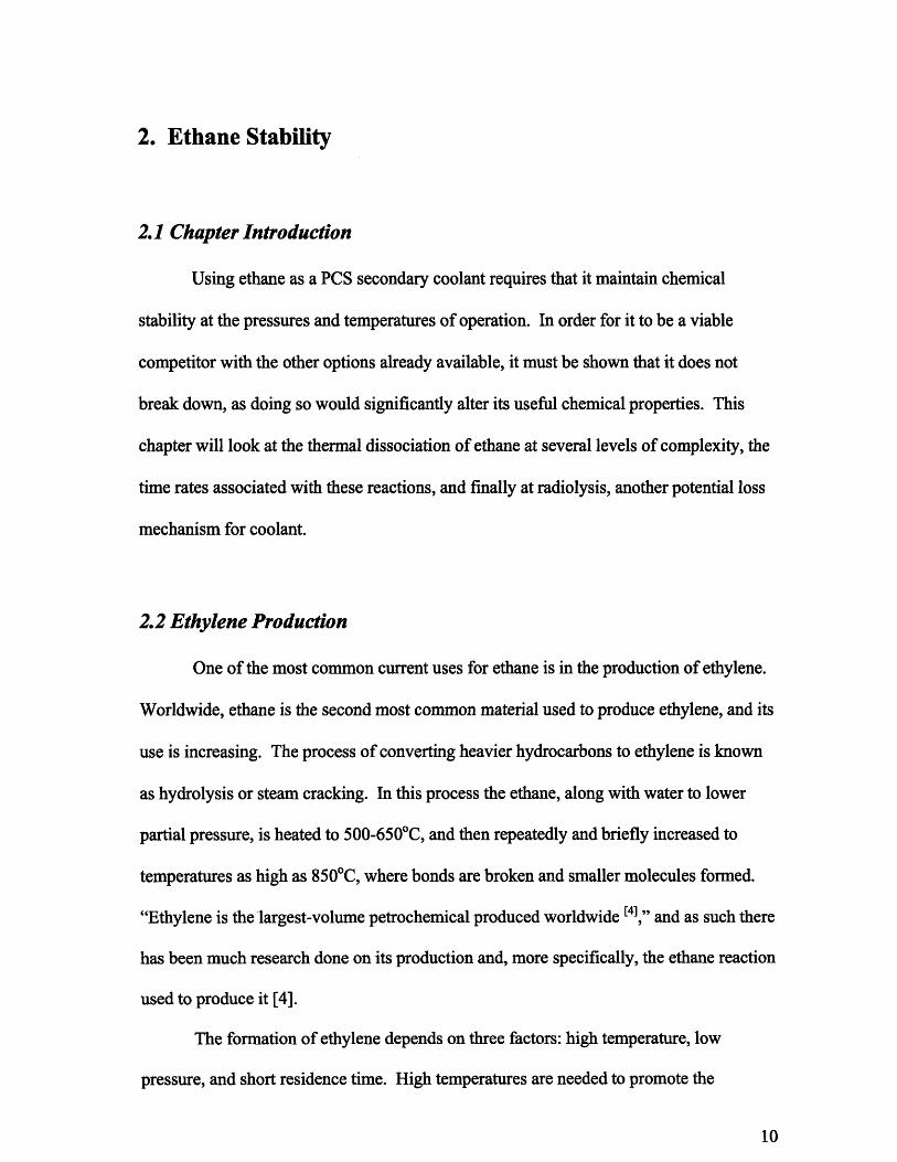
C2H6 <- - C2H4 + H2 (2.1)
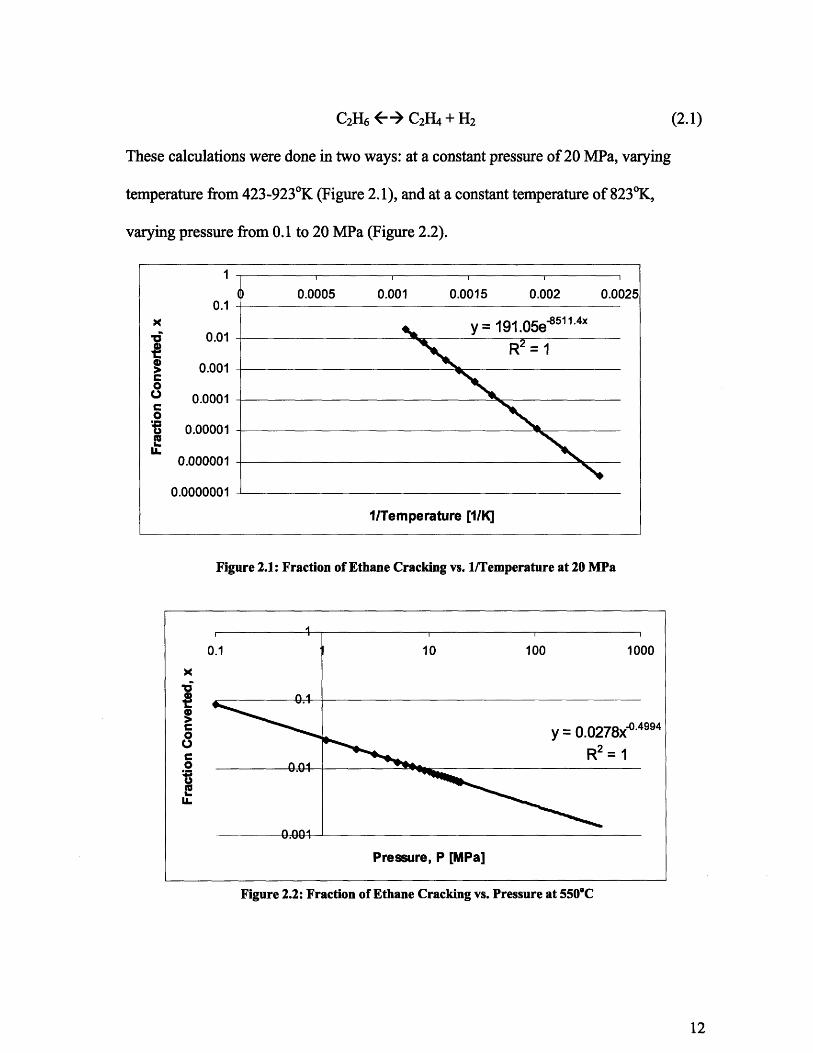
These calculations were done in two ways: at a constant pressure of 20 MPa, varying
temperature from 423-9230K (Figure 2.1), and at a constant temperature of 8230K,
varying pressure from 0.1 to 20 MPa (Figure 2.2).
Figure 2.1: Fraction of Ethane Cracking vs. 1/Temperature at 20 MPa
1
0.0005 0.001 0.0015 0.002 0.00250.1
0.01 = 191.05e-85114x
I 0.01 2
S0.001C0S 0.0001
C0S 0.00001
0.000001
0.0000001
1/Temperature [1/K]
994
Pressure, P [MPa]
Figure 2.2: Fraction of Ethane Cracking vs. Pressure at 5500 C
30

These plots show that the amount of ethane cracking at the point of interest (550 0C and
20 MPa) is -0.6%. This is well below a tolerable value for power cycle applications.
Curve fits to this data give the dissociation fraction, x, as functions of T and P:
x=191*e s8511rr (2.2)
x=0.0876/Po.5 (2.3)
These functions fit what is theoretically expected for a dissociation reaction, and
therefore, also serve as another check on the validity of the program. In Reference [5],
figure 2.3 shows that empirically, these are the relationships that ought to hold.
2.4 Extra Decay Modes
While at the conditions at which commercial ethylene production takes place,
equation (2.1) is dominant, it is worth demonstrating that other possible byproducts are
not produced. Ethane cracking is a known and reliable method for creating ethylene, but
it does not necessarily follow that at the significantly different pressures and time scales
under review different chemical reactions might become more prevalent.
Equation (2.1) is a simplified representation of the ethane to ethylene reaction, and
this simplification creates uncertainty about potential byproducts. The free radical
mechanism predicts production of CH4, C2H6, C3H8, C4Ho1 , and others in the cracking of
ethane [4]. This method describes the entire chain of reactions involved in the production
of ethylene. Equation (2.1) is replaced by the series of reactions described in equations
2.4 - 2.11 [11]. It is unclear, however, if these three equations represent the only
pathway, or merely one of several. It is noted that "the mechanisms proposed generally

include the following reactions." This, at least, gives the appearance that the full
mechanism is not understood or agreed upon, but these reactions are fairly standard.
C2H6 - CH3* + CH 3* (2.4)
CH3 *+ C 2H 6 - CH4 + C2H5s (2.5)
C2H5* " C2H4 + H* (2.6)
H + C2H6 - C2H5 + H2 (2.7)
C2H5 + C2H5 - C4Ho1 (2.8)
C2H5 + C2H5 - C2H4 + C2H6 (2.9)
H + C2H5 4 C2H6 (2.10)
C2H5 + CH 3- C3H8 (2.11)
Section 3 of the same report [ 11] makes it explicitly clear that Equations 2.6 and 2.7
have associated reverse reactions, but does not elaborate about others.
In a run that checks for all but the heavier hydrocarbon chains, there are some
surprising results. Figure 2.3 shows the amount of each compound considered that
results from thermal dissociation of ethane at various temperatures; all results are at 20
MPa. The ethane experiences significant degradation, though not into ethylene as was
expected. It breaks down predominantly into methane, but it also produces ethylene to a
greater extent than when considering equation (1) alone. This result follows from
equations 2-4, which shows that every molecule of ethylene produced should also
produce one of methane. The Ullman reference does not, however, clarify whether this
free radical representation is the only one, or if there are alternate paths to ethylene

production. Other free radical pathways might explain why it is possible to commercially
crack ethane without producing methane.
1.2
E 1
S0.8
u 0.6
0 0.4
E 0.2z
00 100 200 300 400 500 600 700 800 90
Temperature (K)
Figure 2.3: Decomposition of 1 mol of Ethane
This is seriously detrimental to the prospects of an ethane PCS. The critical
temperature of methane is -820C, compared with 320C for ethane [6]. As was mentioned
in the introduction, critical temperatures must be close in order for the law of
corresponding states to apply. If some small portion of the ethane had cracked it would
not have been sufficient to significantly alter the material properties, but if more than half
of it is breaking down (which is the case at -700 0 K) then it appears that the ethane would
not be a workable option. These results, however, stand in opposition to other research
and industrial practices. It is possible that there is some other process or effects at work.
2.5 Rate Effects
The reason for the disparity between these calculations and the known reality of
cracking ethane to produce ethylene is likely the relative reaction rates. Ethane cracking
plants usually only heat up the gas to the peak temperatures for very short times (on the

order of seconds). Since the HSC code that was used only looks at free energy
minimization, and all results are given at equilibrium, it is likely that the ethane to
ethylene reaction occurs much quicker than the ethane to methane one. In this way, it is
possible to produce ethylene without simultaneously producing methane if it is done
quickly, before the mixture is allowed to come to equilibrium. If this is the case, then an
ethane PCS would require more research and likely experimentation.
The actual situation may not be as serious as Figure 2.3 might suggest.
Depending on how rapidly equilibrium is achieved, it may well be that dissociation is not
a serious limitation. The key condition for cycle performance is at the compressor inlet,
which is about 350C (308 K), where dissociation is negligible. However if cycle average
temperature dominates dissociation could be too severe. To settle this issue dynamic
molecular simulation and loop tests will be required.
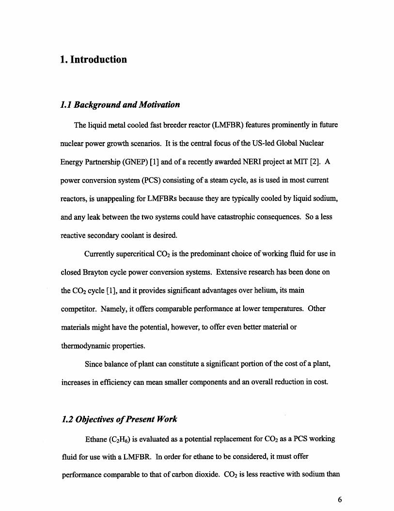
The NIST database
provides limited reaction
data for the various cracking
modes of ethane. Figures
2.4 and 2.5 show NIST data
for the ethane to CH 3
reaction (equation 2.4),
which was available over
the widest range of
L~11p~ILwc.F 1Lt
Figure 2.4: Time Constants for Ethane Cracking into CH3
et mperatures.
Figure
2.4 shows first and second order time constants for the reaction. The first order constants
have units of sec1 and correspond to the forward reaction; the second order ones have
units of cm3/mol/sec and correspond to the reverse reaction. Of particular interest in this
figure are the second order values appearing both above and below the first order.
This belies a profound lack of understanding for the process. Both of these data sets
come from the NIST database (more information is found in appendix A.2.4), and both
are based on literature review. Unfortunately second order experimental data are rare and
often cover only a small specific temperature range.
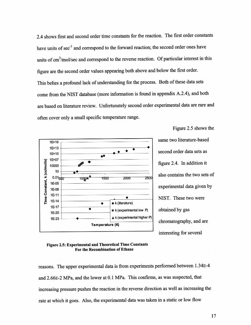
Figure 2.5 shows the
same two literature-based
second order data sets as
figure 2.4. In addition it
also contains the two sets of
experimental data given by
NIST. These two were
obtained by gas
chromatography, and are
interesting for several
Figure 2.5: Experimental and Theoretical Time ConstantsFor the Recombination of Ethane
reasons. The upper experimental data is from experiments performed between 1.34E-4
and 2.66E-2 MPa, and the lower at 0.1 MPa. This confirms, as was suspected, that
increasing pressure pushes the reaction in the reverse direction as well as increasing the
rate at which it goes. Also, the experimental data was taken in a static or low flow
situation, which is not the condition which would be under investigation ideally. It
should be kept in mind that all this data applies to equation 2.4, which is the first step in
the chain of reactions to create ethylene. These are important because they give an
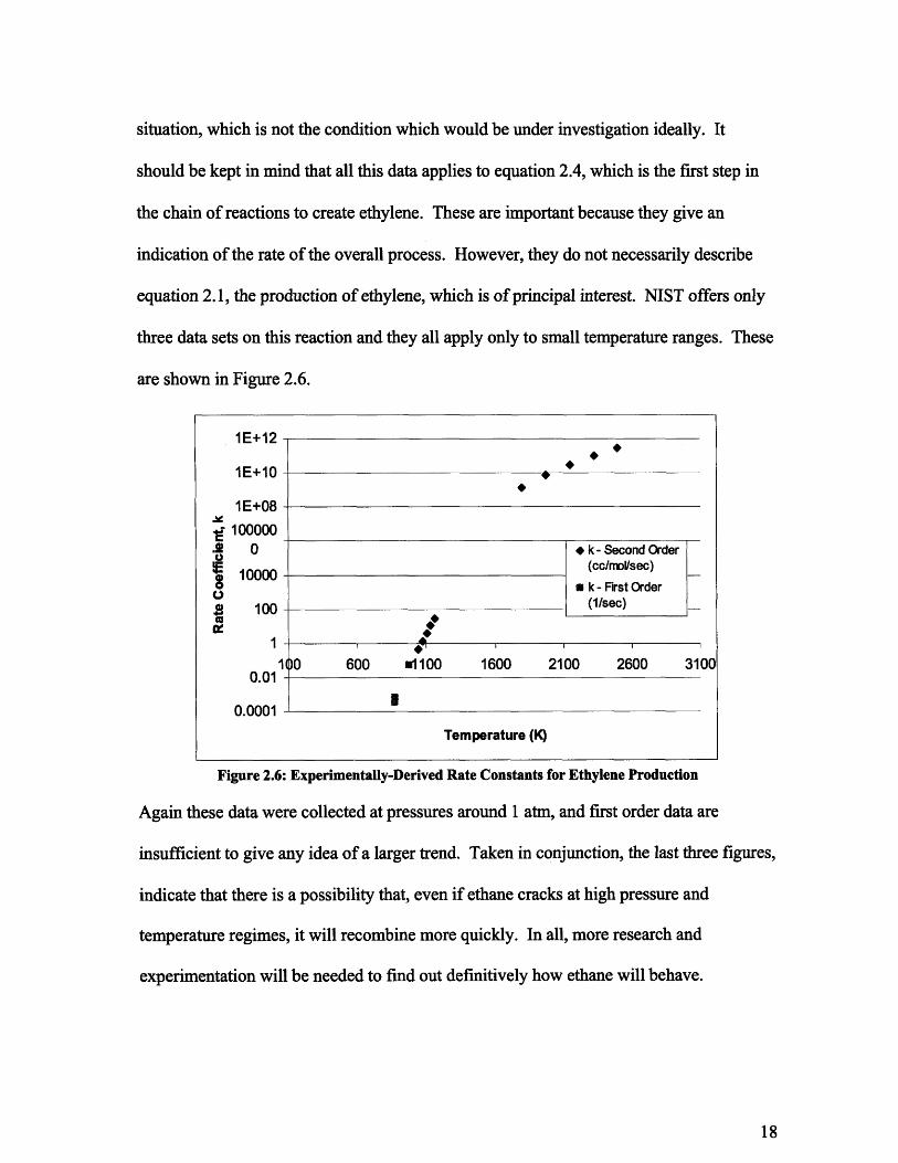
indication of the rate of the overall process. However, they do not necessarily describe
equation 2.1, the production of ethylene, which is of principal interest. NIST offers only
three data sets on this reaction and they all apply only to small temperature ranges. These
are shown in Figure 2.6.
Figure 2.6: Experimentally-Derived Rate Constants for Ethylene Production
Again these data were collected at pressures around 1 atm, and first order data are
insufficient to give any idea of a larger trend. Taken in conjunction, the last three figures,
indicate that there is a possibility that, even if ethane cracks at high pressure and
temperature regimes, it will recombine more quickly. In all, more research and
experimentation will be needed to find out definitively how ethane will behave.
1E+12
1E+10 -
1E+084 100000.2 0 * k- Second Order
10000 (cc/rnol/Vsec)a k - First Order
£( 100 (1/sec)
100 600 1o100 1600 2100 2600 31000.01
0.0001Temperature (K)
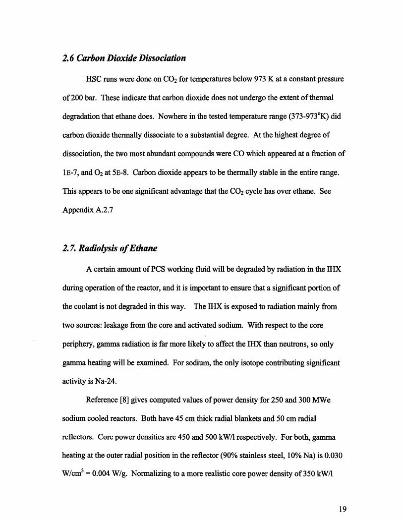
2.6 Carbon Dioxide Dissociation
HSC runs were done on CO 2 for temperatures below 973 K at a constant pressure
of 200 bar. These indicate that carbon dioxide does not undergo the extent of thermal
degradation that ethane does. Nowhere in the tested temperature range (373-9730K) did
carbon dioxide thermally dissociate to a substantial degree. At the highest degree of
dissociation, the two most abundant compounds were CO which appeared at a fraction of
1E-7, and 02 at 5E-8. Carbon dioxide appears to be thermally stable in the entire range.
This appears to be one significant advantage that the CO 2 cycle has over ethane. See
Appendix A.2.7
2.7. Radiolysis of Ethane
A certain amount of PCS working fluid will be degraded by radiation in the IHX
during operation of the reactor, and it is important to ensure that a significant portion of
the coolant is not degraded in this way. The IHX is exposed to radiation mainly from
two sources: leakage from the core and activated sodium. With respect to the core
periphery, gamma radiation is far more likely to affect the IHX than neutrons, so only
gamma heating will be examined. For sodium, the only isotope contributing significant
activity is Na-24.
Reference [8] gives computed values of power density for 250 and 300 MWe
sodium cooled reactors. Both have 45 cm thick radial blankets and 50 cm radial
reflectors. Core power densities are 450 and 500 kW/1 respectively. For both, gamma
heating at the outer radial position in the reflector (90% stainless steel, 10% Na) is 0.030
W/cm3 = 0.004 W/g. Normalizing to a more realistic core power density of 350 kW/1
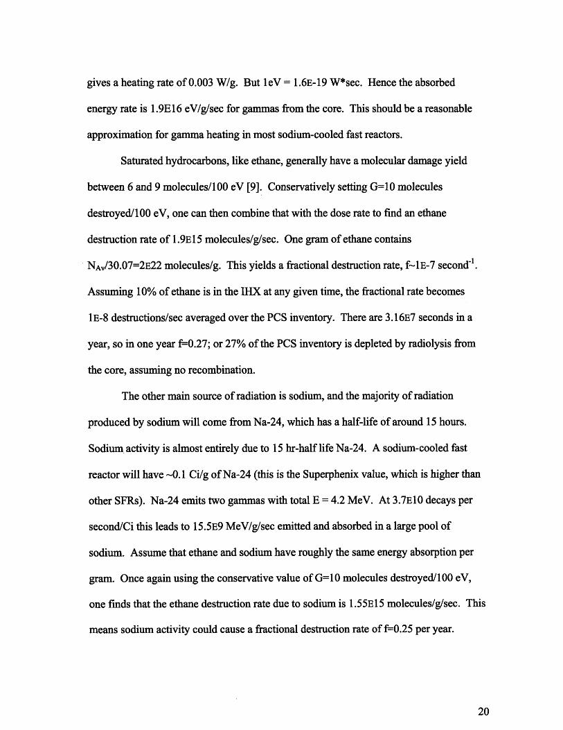
gives a heating rate of 0.003 W/g. But leV = 1.6E-19 W*sec. Hence the absorbed
energy rate is 1.9E16 eV/g/sec for gammas from the core. This should be a reasonable
approximation for gamma heating in most sodium-cooled fast reactors.
Saturated hydrocarbons, like ethane, generally have a molecular damage yield
between 6 and 9 molecules/100 eV [9]. Conservatively setting G=10 molecules
destroyed/100 eV, one can then combine that with the dose rate to find an ethane
destruction rate of 1.9E15 molecules/g/sec. One gram of ethane contains
NAv/30.07=2E22 molecules/g. This yields a fractional destruction rate, f-1E-7 second1 .
Assuming 10% of ethane is in the IHX at any given time, the fractional rate becomes
1E-8 destructions/sec averaged over the PCS inventory. There are 3.16E7 seconds in a
year, so in one year f=-0.27; or 27% of the PCS inventory is depleted by radiolysis from
the core, assuming no recombination.
The other main source of radiation is sodium, and the majority of radiation
produced by sodium will come from Na-24, which has a half-life of around 15 hours.
Sodium activity is almost entirely due to 15 hr-half life Na-24. A sodium-cooled fast
reactor will have -0.1 Ci/g of Na-24 (this is the Superphenix value, which is higher than
other SFRs). Na-24 emits two gammas with total E = 4.2 MeV. At 3.7E10 decays per
second/Ci this leads to 15.5E9 MeV/g/sec emitted and absorbed in a large pool of
sodium. Assume that ethane and sodium have roughly the same energy absorption per
gram. Once again using the conservative value of G=10 molecules destroyed/100 eV,
one finds that the ethane destruction rate due to sodium is 1.55E15 molecules/g/sec. This
means sodium activity could cause a fractional destruction rate of f=0.25 per year.

This is slightly misleading, however. A more realistic estimate can be gained by
assuming that C2H6 has the same radiation absorption per gram of the IHX instead of per
gram sodium. Roughly the fractions of each material in the IHX are:
Volume Fraction Component Density (g/cm3)
0.25 C2H6 0.2
0.25 Na 1.0
0.5 steel 8.0
This yields an average IHX density of 4.3 g/cm3 . Therefore, per gram of IHX, the dose
rate is about 1/4h as large as in pure sodium. And because the gamma absorption, (p/p)a,
varies slowly from element to element, the dose rate for C2H6 is roughly the same as that
for the IHX as a whole [6]. The fractional destruction rate from Na-24 is therefore
around 6% per year. When combined with the 27% per year from core radiation one gets
a total of around 33%, which is tolerable, but suggests attention be paid to this issue, by
addition of shielding and/or raising the IHX higher above the core.
2.8 Chapter Summary
Results were mixed about the thermal dissociation of ethane. Theoretical models
predict that ethane should break down into methane and hydrogen, but current industrial
practices show that ethane is effectively cracked into ethylene on a large-scale basis with
only minor methane production. Also there is uncertainty surrounding rate constants.
NIST does not have sufficient data to make judgments about rates of reactions, so the
explanation might lie with the rates of reactions. Experimentation will be required to
know definitively how ethane behaves in the high temperature/high pressure regime.

Radiolysis does not appear to be a significant issue, and the bulk of it can be
reduced by simply moving heat exchangers farther from the core or adding additional
shielding.
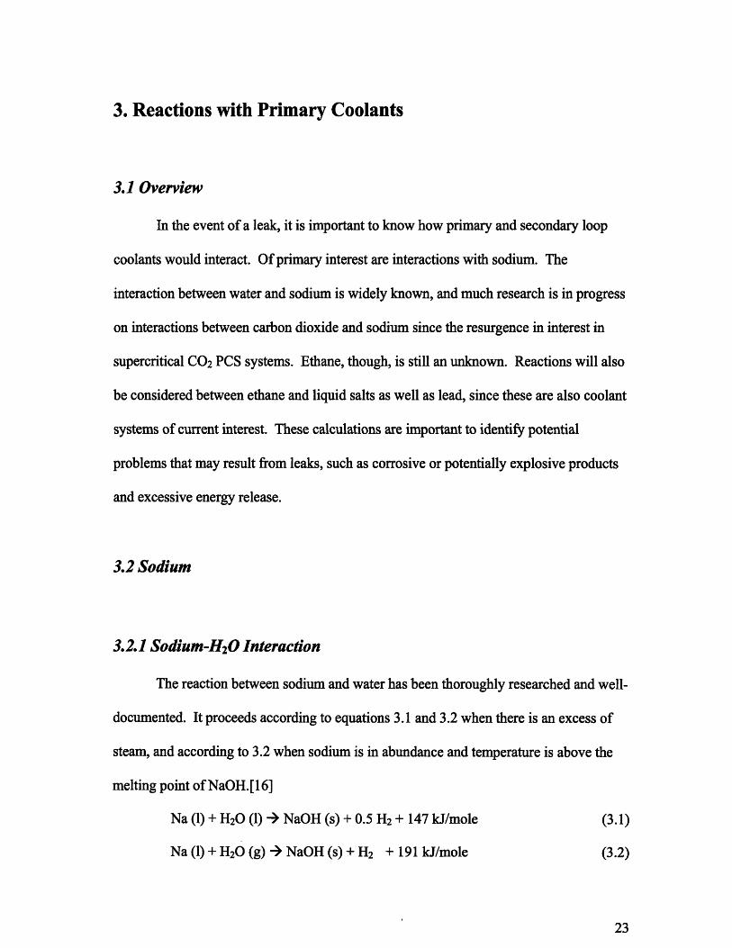
3. Reactions with Primary Coolants
3.1 Overview
In the event of a leak, it is important to know how primary and secondary loop
coolants would interact. Of primary interest are interactions with sodium. The
interaction between water and sodium is widely known, and much research is in progress
on interactions between carbon dioxide and sodium since the resurgence in interest in
supercritical CO2 PCS systems. Ethane, though, is still an unknown. Reactions will also
be considered between ethane and liquid salts as well as lead, since these are also coolant
systems of current interest. These calculations are important to identify potential
problems that may result from leaks, such as corrosive or potentially explosive products
and excessive energy release.
3.2 Sodium
3.2.1 Sodium-H 20 Interaction
The reaction between sodium and water has been thoroughly researched and well-
documented. It proceeds according to equations 3.1 and 3.2 when there is an excess of
steam, and according to 3.2 when sodium is in abundance and temperature is above the
melting point of NaOH.[16]
Na (1) + H20 (1) - NaOH (s) + 0.5 H2 + 147 kJ/mole (3.1)
Na (1) + H20 (g) - NaOH (s) + H2 + 191 kJ/mole (3.2)

Na (1) + NaOH (1) - Na20 (s) + 0.5 H2 + 6.7 kJ/mole (3.3)
Solid alkalis, such as sodium, react with water violently, and with liquid alkalis
the reaction is even more violent. This creates engineering problems for operating the
two systems in conjunction. Heat exchangers must be designed either with extra barriers,
such as intermediate fluids, in place or that are able to withstand pressure and
temperature spikes that could arise from a leak. Detectors must also be in place in order
to identify small leaks. All of these steps sacrifice efficiency and safety. This reaction is
especially dangerous because, in addition to being highly exothermic, it also produces
large amounts of explosive hydrogen gas.
3.2.2 Sodium-CO2 Interaction
The sodium-carbon dioxide reaction is also well researched. As early as the
1960s, experiments were being done to test the reactivity of carbon dioxide and liquid
sodium [12]. Independent experiments and theoretical models have verified that equation
3.2 is the equation governing this reaction.
Na + 0.75 CO2 - 0.5 Na2CO3 + 0.25 C + 271 kJ/mole (3.4)
This reaction has been determined to be the result of equations 3.3 and 3.4.
Na + 0.25 CO 2 - 0.5 Na20 + 0.25 C (3.5)
0.5 Na20 + 0.5 CO 2 - 0.5 Na2CO3 (3.6)
Equation 3.5 represents the situation likely to be encountered in a heat exchanger leak;
the high pressure CO 2 would be pushed into the primary system where there is an excess
of sodium. Equation 3.5 is the rate limiting equation. Recent experiments have verified
that liquid sodium and CO 2 react to give a significant amount of Na2CO3 and smaller
amounts of solid carbon [13]. This study showed that the reaction proceeds readily at
temperatures above 3000C and was very fast above 6000C. Conflicting studies place the
temperature at which "rapid" reaction begins to occur between 4500 C [12] and 600 0C
[14], but it is certain that at the temperatures involved in a LMFBR there would be a
reaction.
HSC runs verified that theory matches experimental outcomes: the energy release
is around 270 kJ/mol (fig 3.2), and if there is an excess of Na, there is less Na2CO3
produced and increasing amounts of carbon, as predicted by equation 3.7. Na2CO3 may,
however, interact with sodium. Different reports give different theoretical answers [12],
and there does not appear to be physical data, but it is possible that Na2CO 3 reacts with
sodium according to equation 3.7, to produce more carbon. Carbon in sodium can lead to
carbonization of steel.
4 Na + Na2CO 3- 3 Na20 + C (3.7)
While carbon dioxide does produce more energy than water when reacting with sodium,
it has the advantage of not producing hydrogen. It also seems to proceed more slowly
even though it releases more energy [12].
3.2.3 Sodium-Ethane Interaction
The sodium-ethane interaction was based upon equation 3.8. Similar to Eq. 3.5, it
expresses the situation in which sodium is in abundance.
Na +0.5 C2H6 " 0.5 Na2C2 + 1.5 H2 (3.8)
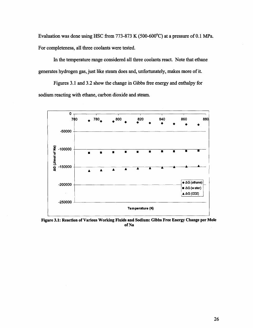
Evaluation was done using HSC from 773-873 K (500-6000C) at a pressure of 0.1 MPa.
For completeness, all three coolants were tested.
In the temperature range considered all three coolants react. Note that ethane
generates hydrogen gas, just like steam does and, unfortunately, makes more of it.
Figures 3.1 and 3.2 show the change in Gibbs free energy and enthalpy for
sodium reacting with ethane, carbon dioxide and steam.
71
-50000
z -100000o4-0
E
S-150000
-200000
-9_3rnnnn
*0 780 800 820 840 860 880
A A A A A A A A A A
* AG (ethane)SAG (water)
* AG (CO2)
Temperature (IQ)
Figure 3.1: Reaction of Various Working Fluids and Sodium: Gibbs Free Energy Change per Moleof Na
II· · · · ·
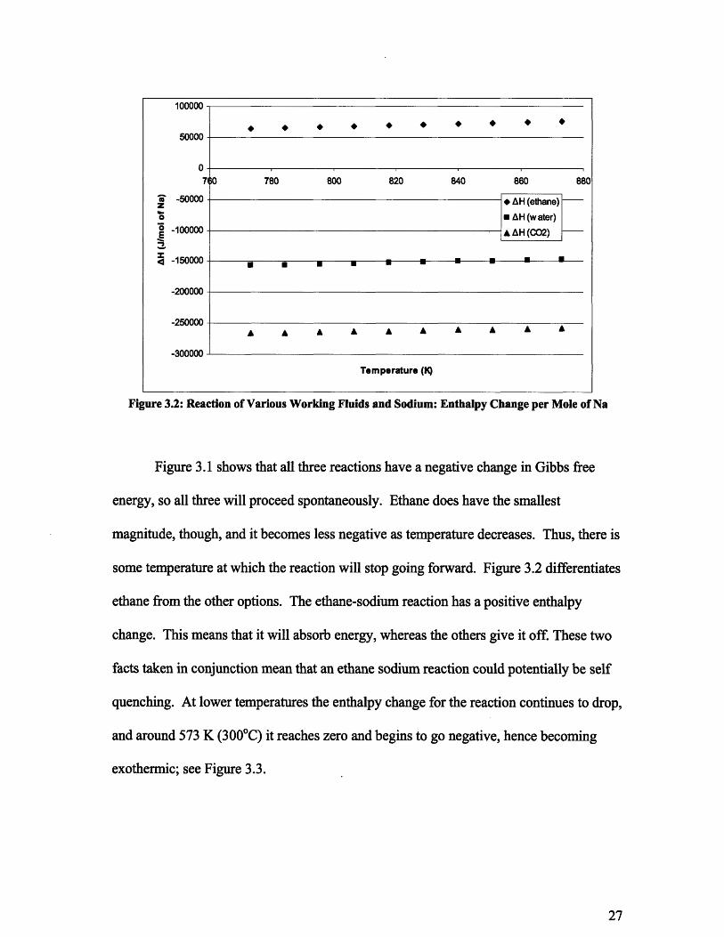
Figure 3.2: Reaction of Various Working Fluids and Sodium: Enthalpy Change per Mole of Na
Figure 3.1 shows that all three reactions have a negative change in Gibbs free
energy, so all three will proceed spontaneously. Ethane does have the smallest
magnitude, though, and it becomes less negative as temperature decreases. Thus, there is
some temperature at which the reaction will stop going forward. Figure 3.2 differentiates
ethane from the other options. The ethane-sodium reaction has a positive enthalpy
change. This means that it will absorb energy, whereas the others give it off. These two
facts taken in conjunction mean that an ethane sodium reaction could potentially be self
quenching. At lower temperatures the enthalpy change for the reaction continues to drop,
and around 573 K (3000C) it reaches zero and begins to go negative, hence becoming
exothermic; see Figure 3.3.
100000
50000
0710 780 800 820 840 860 880
S-50000 - AH (ethane) -
SAH H(water)0 -100000 A AH (CO2)
4-150000 t 5 -
-200000
-250000
-300000
Temperature (1)

Figure 3.3 Energy/Enthalpy Change for Na Reaction (at 0.1 MPa)
The change in enthalpy for the sodium-ethane reaction (equation 3.6), is 75
kJ/mol-Na in the range of 500-6000C (773-873 K), and it steadily decreases at lower
temperatures until it goes negative at 3000C (573 K). In order to look at the potential for
a quenching reaction, consider a leak of 1 kg (33.3 moles) of ethane into the primary
system. 33.3 moles of C2H6 react with 66.6 moles of Na.
66.6 mol* (75 kJ/mol) = 5000kJ absorbed
Cp,Na= 32.7 J/mol(oC) [15]
5000kJ/ C, = 1.53E5 mol (oC) associated with 1 kg of C2H6
If it were leaked slowly so that the energy absorption was spread evenly
throughout the entire inventory of sodium (assuming 3000 tons of Na, which was the
value for Superphenix), then 3E6 kg of sodium would be heated 0.0010C. If, however,

the leak was faster and only 30 kg of sodium was cooled, by the same energy absorption,
then it would experience a 100 degree drop. This though is an over-estimate because at
4500C the energy change is only 45 kJ/mol. This means that even in the case of an
uncontained leak, sodium temperature would slowly drop and approach 300 0C (which is
well above sodium's melting point of 97.70 C). An ethane leak would also lead to
production of hydrogen, but since temperature is in control, this should be an acceptable
risk.
Another important factor is the speed of this reaction. Both steam and carbon
dioxide are known to react quickly with sodium, and the quickness of this reaction can be
part of the problem. Unfortunately NIST does not have information on the ethane-
sodium interaction. Therefore, further experimentation will be necessary to identify how
quickly the reaction proceeds.
Yevick claims that sodium will not react with hydrocarbons until they have been
thermally decomposed. He says that sodium only reacts with the decomposition
products, though he does not give any specific examples. If this is true then reaction rate
would be dependant on rate of thermal dissociation. This serves only to reinforce the
importance of thermal cracking experiments. [16]
3.3 Liquid Salts and Ethane
Ethane does not appear to react with liquid salts in the temperature range of
interest. It was tested for reactions using NaCl, MgCl and NaF, which are all materials
under current investigation. For all three salts tested, results were identical. As is shown
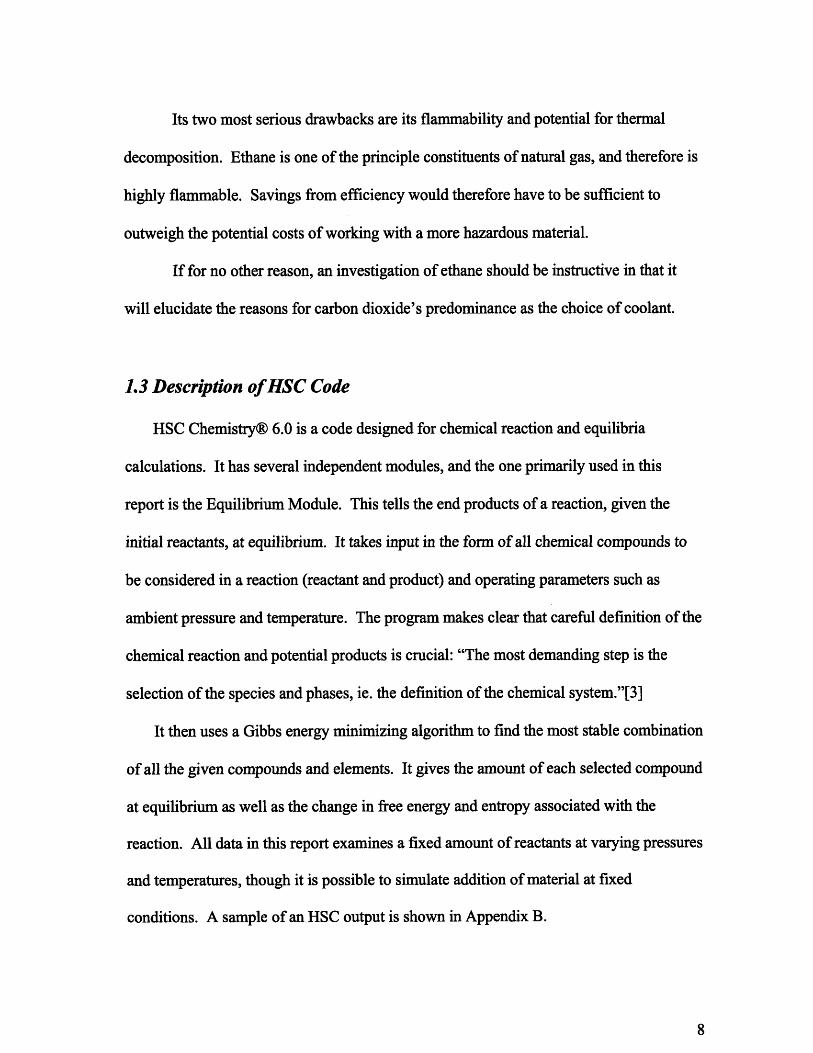
in figure 3.4, large amounts of hydrogen gas and carbon are produced, and to a lesser
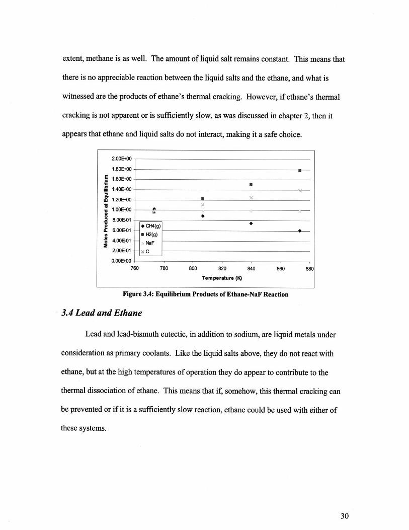
extent, methane is as well. The amount of liquid salt remains constant. This means that
there is no appreciable reaction between the liquid salts and the ethane, and what is
witnessed are the products of ethane's thermal cracking. However, if ethane's thermal
cracking is not apparent or is sufficiently slow, as was discussed in chapter 2, then it
appears that ethane and liquid salts do not interact, making it a safe choice.
Figure 3.4: Equilibrium Products of Ethane-NaF Reaction
3.4 Lead and Ethane
Lead and lead-bismuth eutectic, in addition to sodium, are liquid metals under
consideration as primary coolants. Like the liquid salts above, they do not react with
ethane, but at the high temperatures of operation they do appear to contribute to the
thermal dissociation of ethane. This means that if, somehow, this thermal cracking can
be prevented or if it is a sufficiently slow reaction, ethane could be used with either of
these systems.
L.UUVVtUU
1.80E+O0
E 1.60E+00
. 1.40E+00
w 1.20E+00
1.00E+008
8.00E-01
. 6.00E-01
S4.00E-01
2.00E-01
0.OOE+00760 780 800 820 840 860 880
Temperature (K)
n nnr. nn

E2 2.
W 1.5
oI
* CH4(g)
* H2(g)
SC
x Pb(I)
* H2(g)
C U
U~ i
760 780 800 820 840 860 880
Temperature (K)
Figure 3.5: Equilibrium Products of Ethane-Pb Reaction
3.5 Chapter Summary
When compared with carbon dioxide or steam, ethane appears to be a worthwhile
alternative. The ethane-sodium reaction is the only one of the three that is endothermic,
which means that it has the potential to quench itself. Unfortunately, reaction rate data is
unavailable, and this means that experimentation involving liquid sodium and gaseous
ethane, similar to what has been done with CO2 would be useful. Experimental data
would verify energy absorption of the reaction as well as give valuable rate information.
Tests should also be done to verify the claim that sodium only reacts with decomposition
products of hydrocarbons. It should be relatively simple to test whether ethane alone
reacts differently with sodium than ethane that has undergone a certain amount of thermal
cracking.
-I

Ethane, if it is thermally stable, appears to be inert in contact with liquid salts and
lead. This reinforces the need for experimental verification of its behavior at high
temperature and pressure, as discussed in chapter 2.
4. Component and Cost Scaling
4.1 Chapter Introduction
Aside from all considerations of thermal viability, there is another issue which is
of paramount importance: efficiency. If ethane does not have the potential to provide an
equivalent or higher efficiency cycle compared to CO2, then further inquiry and
experimentation would be wasted. Therefore it is important to provide a basis for belief
in competitive efficiency.
Table 4.1 compares various chemical and thermodynamic properties of ethane
and carbon dioxide. The similarity of critical temperatures is an indication that ethane
can perform comparably to carbon dioxide because of the law of corresponding states.
Also of interest are the heat capacity, thermal conductivity, and critical pressure. Higher
heat capacity and thermal conductivity imply improved performance. Lower critical
pressure means that an optimized ethane system should be easier to build, as walls may
not have to be as thick. Lower critical density means higher compressor work per unit
mass flow rate, but it also means a higher tolerable mass flow that should offset this
constraint.
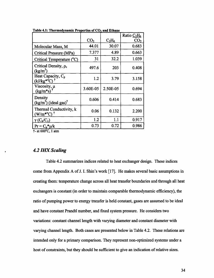
Table 4.1: Thermodynamic Pro perties of COz and EthaneRatio 2
CO2 C 2H6 CO 2
Molecular Mass, M 44.01 30.07 0.683
Critical Pressure (MPa) 7.377 4.89 0.663
Critical Temperature (oC) 31 32.2 1.039
Critical Density, p, 497.6 203 0.408(kg/m3)Heat Capacity, CP 1.2 3.79 3.158(kJ/kg*OC) IViscosity, C1*Viscosity, 3.60E-05 2.50E-05 0.694(kg/m*s) _
Density 0.606 0.414 0.683(kg/m3) (ideal gas)t
Thermal Conductivity, k 0.06 0.132 2.200(W/m*OC) ty (CP/Cv) 1.2 1.1 0.917Pr = C*p/k1 0.73 0.72 0.986
ft- at 6000C, 1 atm
4.2 IHX Scaling
Table 4.2 summarizes indices related to heat exchanger design. These indices
come from Appendix A of J. I. Shin's work [17]. He makes several basic assumptions in
creating them: temperature change across all heat transfer boundaries and through all heat
exchangers is constant (in order to maintain comparable thermodynamic efficiency), the
ratio of pumping power to energy transfer is held constant, gases are assumed to be ideal
and have constant Prandtl number, and fixed system pressure. He considers two
variations: constant channel length with varying diameter and constant diameter with
varying channel length. Both cases are presented below in Table 4.2. These relations are
intended only for a primary comparison. They represent non-optimized systems under a
host of constraints, but they should be sufficient to give an indication of relative sizes.
Table 4.2 shows that there are some striking attributes of ethane. Its higher
Reynold's number and heat transfer coefficient translate into much smaller heat
exchangers - by up to a factor of three. Since these ratios do not include any kind of
optimization, this means a more efficient and less expensive ethane system is possible
and more research is therefore encouraged.
Table 4.2: Heat Exchanger Scaling
Fixed Length, Varying Diameter Fixed Diameter, Varying LengthRelation Ratio C2H6 Ratio C2H6Relation Relation
CO2 CO 2Channel 1/2 1/2Velocity C/2 1.78 C1/2 1.78
Number of M-2/3Cp-4/3 1/3 0.31 M-'Cp 3/2 0.261ChannelsChannel Surface M-5/6Cp-17/12 9-1/6 0.29 M-4/5C P-7/5 -1/5 0.292Area (total) 02 0Channel /6Cp -1/12 -1/6 1.03Diameter
M-'Cp-3/2 0.26 ----- -----
Channel Length ----- -/5"' 1/10 11/5 1.04Duct Diameter M-5/12C 7/12 1/24 0.59 M-5/12 -7/12 1/24 0.59
4.3 Turbomachinery Scaling
Turbomachinery scaling ratios come from the same source [17], and are important
because often the same working fluid properties will have opposite effects on the two
systems. Again there are some basic assumptions that go into them. Table 4.3 compares
design parameters for turbomachinery scaling. Ethane's low gas bending stress is
advantageous, but the number of stages is a severe drawback. If ethane requires 3-5
times as many stages as carbon dioxide, then its turbomachinery could be more
expensive. Even helium and steam only require around twice as many stages.

Table 4.3: Turbomachinery ScalingRatio C2H6
Dependence CO2
Diameter (1/MCp)1/3 0.774Mass Flow Rate (kg/s) 1/Cp 0.317Volumetric Flow Rate (m3/s) 1/(MCp) 0.463Number of Stages (MCp)2/3*Cp 5.27
Co 3.16Flow Velocity (m/s) 1/MCp) 3 0.774Speed of Sound, m M-1/2 1.21Mach Number M1/2 0.827Gas Bending Stress, ksi 1/(CP2*(MCV)) 0.046Reynolds Number 1/(i*(MCp) 2/3) 0.862
m / Pc 0.74
4.4 Size Comparison
Another important factor in the comparison between ethane and carbon dioxide
PCSs is their relative cost. According to Freas' thesis, 87,000 kg of C02 must be kept on
site to accommodate a 300 MWe plant. 58,000 kg are needed for the PCS inventory
itself, and an additional 50% is needed in case of leaks. This would provide leakage
make-up for 100 days assuming a 0.5% per day leak rate. [18]
This means that in order to maintain the same number of moles of gas:
(30/44) * 87,000 = 59;320 kg of C2H6
-60,000 kg of C2H6 are needed. This is roughly 200 kg/MWe.
4.5 Chapter Summary
All of the results in this chapter are subject to optimization, and it is not
immediately clear which effects are strongest. The IHX is predicted to be more efficient
with ethane, but the turbomachinery appears to require more stages. Reduced flow rate
also means that it should have smaller diameter, and reduced size might help to offset an
increase in stages. Numerous further analyses are needed for a more complete
understanding of the system, including a better understanding of how ethane behaves at
higher temperature and pressure. The prospects appear attractive and thus, more
examination is recommended.
5. Conclusions and Recommendations
An ethane-based Brayton power conversion system deserves further research.
Computer simulations give mixed results, but ethylene industry experience suggests that
use in a power conversion system may still be possible. Limited rate data also suggests
that recombination should be much faster than dissociation, which could reconstitute pure
ethylene at compression inlet conditions (350C, 8 MPa). The next step should be to run
experiments to verify ethane's behavior at high temperature and pressure and verify
whether it will dissociate excessively. Even if it does, the rate and extent of
recombination at lower temperatures should be evaluated. If stability up to about 3000C
can be confirmed, then ethane can be employed for geothermal applications even if
higher temperature service proves impracticable. [19]
A simple experiment in which ethane is heated in a fixed volume flask and
pressure is measured as a function of temperature and time is proposed. If dissociation
occurs then the pressure will increase. Using the ideal gas law: PV=nRT one can
establish a molecular dissociation ratio, r, comparing results to standard conditions:
r = (n/no) = (P/Po) * (To/T)
If this ratio rises then dissociation is occurring, but if it drops back to 1.0 the products are
recombining. If this test is successful, then more elaborate loop experiments can be
designed.
If ethane is determined to be sufficiently thermally stable, then experiments
should be run to test its reactivity with liquid sodium. Also cycle performance
calculations should be carried out under optimized conditions to compare the efficiency
of ethane and CO 2 cycles.

References:
[1] V. Dostal, M.J. Driscoll, P. Hejzlar. "High Performance Supercritical CarbonDioxide Cycle for Next Generation Nuclear Reactors," Nuclear Technology, Vol.154, No. 3, June 2006.
[2] G.E. Apostolakis et al. "Risk-Informed Balancing of Safety, Non-Proliferation, andEconomics for the Sodium Cooled Fast Reactor (SFR), NERI Project No. 08-020.
[3] A. Roine. Outokumpu HSC Chemistry for Windows: Chemical Reaction andEquilibrium Software with Extensive Thermodynamical Database, Version 5.1.,User's Guide. 02103-ORC-T, Outokumpu Research Oy, Finland, 2002.
[4] H. Zimmermann, R. Walzi. Ullman's Encyclopedia of Industrial Chemistry. Wiley-VCH Verlag GmbH & Co., 2007.http://www.mrw.interscience.wiley.com/emrw/9783527306732/ueic/article/a10 045/current/html?hd=All%2Cethylene
[5] S. Raseev. Thermal and Catalytic Processes in Petroleum Refining. MarcelDekker, 2003.
[6] Etherington, Harold. Nuclear Engineering Handbook. McGraw-Hill, 1958.
[7] Handbook of Compressed Gas 3 rd Edition, Compressed Gas Association, 1990.
[8] M.S. Kalra and M. J. Driscoll "Gamma Heating in LMFBR Media" MITNE-179,Feb. 1976, pp. 105, 108, 175.
[9] Robert Bolt, James Carroll, "Radiation Effects on Organic Materials" AcademicPress, 1963. pp. 55, 71, 117.
[10] A. Trenwith. "Re-examination of the Thermal Dissociation of Ethane." Thesis,Dept. of Inorganic Chemistry, School of Chemistry, The University, Newcastleupon Tyne, 1978.
[11] M. C. Lin and M. H. Black. "The Thermal Decomposition of Ethane." Dept. ofChemistry Thesis, University of Ottawa, 1996.
[12] C. Latge, G. Rodriguez, N. Simon, "Supercritical C02 Brayton Cycle for SFR: Na-C02 interaction and consequences on design and operation." Global, 2005.
[13] J.H. Choi, S.D. Suk, D. Choi, J.M. Kim, D. Hahn, J. H. Cahalan, "Capsule Test forInvestigating the Sodium-Carbon Dioxide Interaction." ICAPP '06, Paper 6369.

[14] H. Ishikawa, S. Miyahara, Y. Yoshizawa, "Experimental Study of Sodium -Carbon Dioxide Reaction." Paper 5688, ICAPP '05.
[15] V.E. Zinovev. "Handbook of Thermophysical Properties of Metals at HighTemperatures" Nova Science Publications, 1996.
[16] J. Yevick, A. Amorosi. "Fast Reactor Technology: Plant Design" The MIT Press,1966.
[17] Shin, J. I. "Conceptual Design of an HTGR System for a Total EnergyApplication," Appendix A. Nuclear Engineering Thesis, MIT, 1975.
[18] Freas, R. "Analysis of Required Supporting Systems for the Supercritical CO 2Power Conversion System," Nuclear Engineering Thesis, MIT, 2003.
[19] "The Future of Geothermal Energy" Interdisciplinary Report, MIT, 2006.
http://wwwl.eere.energy.gov/geothermal/egx_technology.html

Appendix A: Data in Support of Figures
This appendix provides the numerical data for all plots derived from the HSC®
code. A full description of this code can be found in section 1.4 of this report. Because
temperature parameters for runs are entered in Celsius and output is in Kelvin, most input
temperatures are cited as round numbers in Celsius and not Kelvin.
A.2.0 - Comparison of Ethane Cracking at High and Low Pressures
This data comes from an HSC run analyzing Equation 2.1. It is similar to figures
2.1 and 2.3 except it also includes a data set at the low pressure at which industrial ethane
cracking occurs. It is present to verify the stipulated assumption that at high temperature
and low pressure ethane fully dissociates into ethylene. It also effectively illustrates the
difference that pressure makes on the reaction.
0.0
0.7
0. - -x (1 bar)9 -.--- x (200 bar)
C
S0.4
a-0.3
0.2
0.1
400 500 600 80700 0 00 1000 1100 120
Temperature, K
T (K) Dissociation DissociationFraction Fraction(1 bar) (200 bar)
423.15 5.12E-06 3.62E-07462.624 2.78E-05 1.97E-06502.097 1.16E-04 8.24E-06541.571 3.98E-04 2.81E-05581.045 1.15E-03 8.15E-05620.518 2.93E-03 2.07E-04659.992 6.67E-03 4.72E-04699.466 1.39E-02 9.81E-04738.939 2.67E-02 1.89E-03778.413 4.81E-02 3.41E-03817.887 8.19E-02 5.81E-03857.361 1.32E-01 9.44E-03896.834 2.04E-01 1.47E-02936.308 2.98E-01 2.21E-02975.782 4.13E-01 3.21E-021015.255 5.39E-01 4.52E-021054.729 6.61E-01 6.22E-021094.203 7.64E-01 8.35E-021133.676 8.42E-01 1.10E-011173.15 8.96E-01 1.41E-01
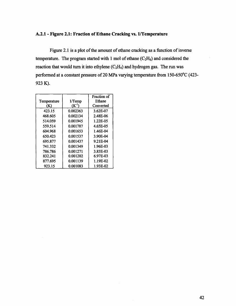
A.2.1 - Figure 2.1: Fraction of Ethane Cracking vs. 1/Temperature
Figure 2.1 is a plot of the amount of ethane cracking as a function of inverse
temperature. The program started with 1 mol of ethane (C2H6) and considered the
reaction that would turn it into ethylene (C2H4) and hydrogen gas. The run was
performed at a constant pressure of 20 MPa varying temperature from 150-650 0C (423-
923 K).
Fraction ofTemperature 1/Temp Ethane
(K) (Ki.) Converted423.15 0.002363 3.62E-07468.605 0.002134 2.48E-06514.059 0.001945 1.22E-05559.514 0.001787 4.65E-05604.968 0.001653 1.46E-04650.423 0.001537 3.90E-04695.877 0.001437 9.21E-04741.332 0.001349 1.96E-03786.786 0.001271 3.83E-03832.241 0.001202 6.97E-03877.695 0.001139 1.19E-02923.15 0.001083 1.93E-02
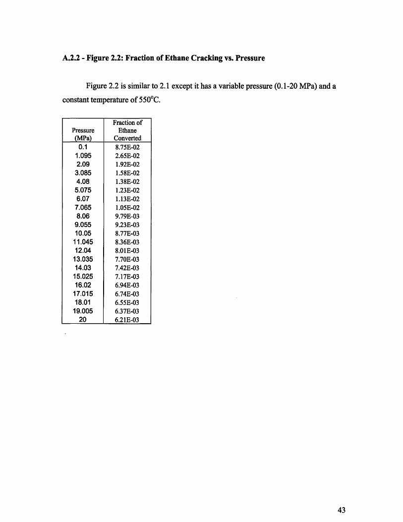
A.2.2 - Figure 2.2: Fraction of Ethane Cracking vs. Pressure
Figure 2.2 is similar to 2.1 except it has a variable pressure (0.1-20 MPa) and a
constant temperature of 5500C.
Fraction ofPressure Ethane
(MPa) Converted0.1 8.75E-02
1.095 2.65E-022.09 1.92E-02
3.085 1.58E-024.08 1.38E-025.075 1.23E-026.07 1.13E-02
7.065 1.05E-028.06 9.79E-03
9.055 9.23E-0310.05 8.77E-03
11.045 8.36E-0312.04 8.01E-0313.035 7.70E-0314.03 7.42E-0315.025 7.17E-0316.02 6.94E-0317.015 6.74E-0318.01 6.55E-03
19.005 6.37E-0320 6.21E-03
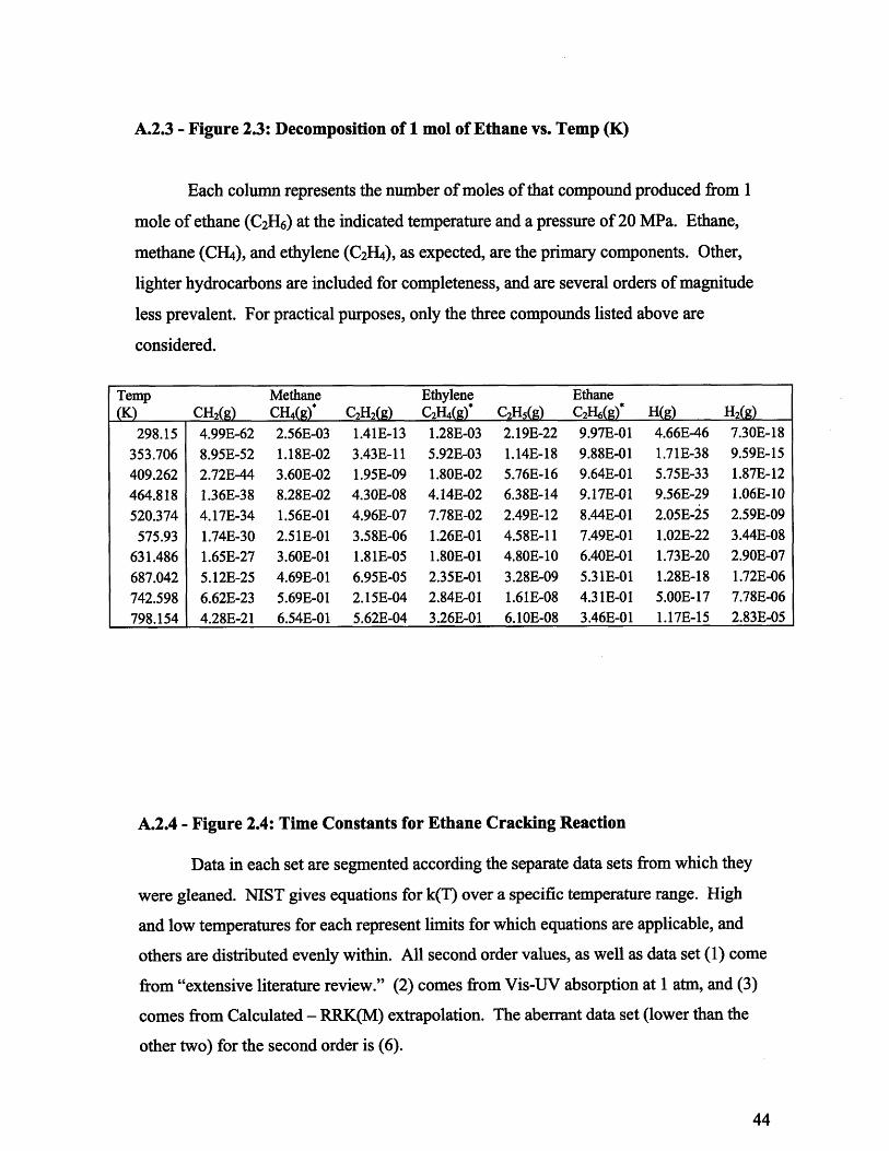
A.2.3 - Figure 2.3: Decomposition of 1 mol of Ethane vs. Temp (K)
Each column represents the number of moles of that compound produced from 1
mole of ethane (C2H6) at the indicated temperature and a pressure of 20 MPa. Ethane,
methane (CH 4), and ethylene (C2H4), as expected, are the primary components. Other,
lighter hydrocarbons are included for completeness, and are several orders of magnitude
less prevalent. For practical purposes, only the three compounds listed above are
considered.
Temp Methane Ethylene Ethane(K) CH2(g) CH4(g) C2H C2H4(g)* C2Hs(g) C2H6(g) H(g) H2(g)
298.15 4.99E-62 2.56E-03 1.41E-13 1.28E-03 2.19E-22 9.97E-01 4.66E-46 7.30E-18353.706 8.95E-52 1.18E-02 3.43E-11 5.92E-03 1.14E-18 9.88E-01 1.71E-38 9.59E-15409.262 2.72E-44 3.60E-02 1.95E-09 1.80E-02 5.76E-16 9.64E-01 5.75E-33 1.87E-12464.818 1.36E-38 8.28E-02 4.30E-08 4.14E-02 6.38E-14 9.17E-01 9.56E-29 1.06E-10520.374 4.17E-34 1.56E-01 4.96E-07 7.78E-02 2.49E-12 8.44E-01 2.05E-25 2.59E-09
575.93 1.74E-30 2.51E-01 3.58E-06 1.26E-01 4.58E-11 7.49E-01 1.02E-22 3.44E-08631.486 1.65E-27 3.60E-01 1.81E-05 1.80E-01 4.80E-10 6.40E-01 1.73E-20 2.90E-07687.042 5.12E-25 4.69E-01 6.95E-05 2.35E-01 3.28E-09 5.31E-01 1.28E-18 1.72E-06742.598 6.62E-23 5.69E-01 2.15E-04 2.84E-01 1.61E-08 4.31E-01 5.00E-17 7.78E-06798.154 4.28E-21 6.54E-01 5.62E-04 3.26E-01 6.10E-08 3.46E-01 1.17E-15 2.83E-05
A.2.4 - Figure 2.4: Time Constants for Ethane Cracking Reaction
Data in each set are segmented according the separate data sets from which they
were gleaned. NIST gives equations for k(T) over a specific temperature range. High
and low temperatures for each represent limits for which equations are applicable, and
others are distributed evenly within. All second order values, as well as data set (1) come
from "extensive literature review." (2) comes from Vis-UV absorption at 1 atm, and (3)
comes from Calculated - RRK(M) extrapolation. The aberrant data set (lower than the
other two) for the second order is (6).
First Order
T (K) k (sec-')300 1.06E-48
512.5 1.48E-21725 2.15E-10
937.5 0.0002511150 1.59147
1362.5 634.12791575 48920.11
1787.5 13164452000 173237851350 47.454081540 1008.2491730 8619.5041920 39784.622110 119151.7843 4.25E-07
1079.714 0.0409821316.429 59.366831553.143 8903.3951789.857 342190.32026.571 54541872263.286 47659065
2500 2.71E+08
Second Orderk
T (K) (cc/mol/sec)300 2.79E-64
583.3333 1.53E-33866.6667 1.7E-23
1150 1.08E-181433.333 5.78E-161716.667 2.97E-14
2000 4.11E-13300 1.74E-40
583.3333 9.38E-10866.6667 10.39887
1150 658484.91433.333 3.51E+081716.667 1.8E+10
2000 2.49E+11800 2.4635831140 873877.71480 8.74E+081820 6.61E+102160 1.28E+122500 1.11E+13
Specific equations used to generate data and reference sources are below:
(1) 94BAU/COB - Baulch,D.L.; Cobos,C.J.; Cox,R.A.; Frank,P.; Hayman,G.; Just,Th.;Kerr,J.A.; Murrells,T.; Pilling,M.J.; Troe,J.; Walker,R.W.; Warnatz,J.Evaluated kinetic data for combusion modeling. Supplement I
k(T)=1.54e18*(T/298)^(-1.24)*(EXP(-45700/T))(2) 93DAV/DIR - Davidson,D.F.; DiRosa,M.D.; Hanson,R.K.; Bowman,C.T.A study of ethane decomposition in a shock tube using laser absorption of CH3
k(T)=1.38E+32*(T/298)A(-17.6)*EXP(-58800/T)(3) 89TSA - Tsang,W. Rate constants for the decomposition and formation of simplealkanes over extended temperature and pressure ranges
k(T)=1.12E18*(T/298)A (-1.79)*EXP(-45834/T)(4) 94BAU/COB - Baulch,D.L.; Cobos,C.J.; Cox,R.A.; Frank,P.; Hayman,G.; Just,Th.;Kerr,J.A.; Murrells,T.; Pilling,M.J.; Troe,J.; Walker,R.W.; Warnatz,J.Evaluated kinetic data for combusion modelling. Supplement I
k(T)=45100*(T/298)A (-8.24)*EXP( - 47100/T)(5) 94BAU/COB - Baulch,D.L.; Cobos,C.J.; Cox,R.A.; Frank,P.; Hayman,G.; Just,Th.;Kerr,J.A.; Murrells,T.; Pilling,M.J.; Troe,J.; Walker,R.W.; Warnatz,J.Evaluated kinetic data for combusion modelling. Supplement I
k(T)=2.72E28*(T/298)A (- 8.24)*EXP(-47090/T)(6) 84WAR - Warnatz, J. Rate coefficients in the C/H/O system
k(T)=le19*EXP(-34278/T)
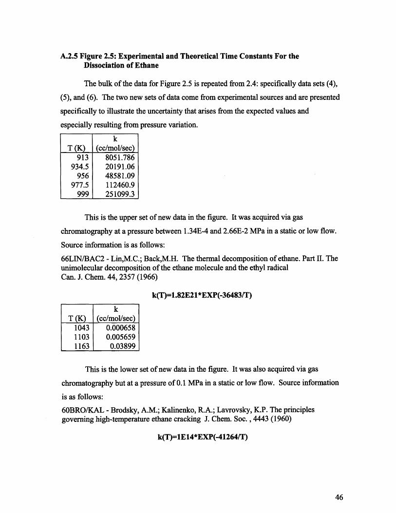
A.2.5 Figure 2.5: Experimental and Theoretical Time Constants For theDissociation of Ethane
The bulk of the data for Figure 2.5 is repeated from 2.4: specifically data sets (4),
(5), and (6). The two new sets of data come from experimental sources and are presented
specifically to illustrate the uncertainty that arises from the expected values and
especially resulting from pressure variation.
kT (K) (cc/mol/sec)
913 8051.786934.5 20191.06
956 48581.09977.5 112460.9
999 251099.3
This is the upper set of new data in the figure. It was acquired via gas
chromatography at a pressure between 1.34E-4 and 2.66E-2 MPa in a static or low flow.
Source information is as follows:
66LIN/BAC2 - Lin,M.C.; Back,M.H. The thermal decomposition of ethane. Part II. Theunimolecular decomposition of the ethane molecule and the ethyl radicalCan. J. Chem. 44, 2357 (1966)
k(T)=1.82E21*EXP(-36483/T)
kT (K) (cc/mol/sec)
1043 0.0006581103 0.0056591163 0.03899
This is the lower set of new data in the figure. It was also acquired via gas
chromatography but at a pressure of 0.1 MPa in a static or low flow. Source information
is as follows:
60BRO/KAL - Brodsky, A.M.; Kalinenko, R.A.; Lavrovsky, K.P. The principlesgoverning high-temperature ethane cracking J. Chem. Soc., 4443 (1960)
k(T)=1E14*EXP(-41264/T)
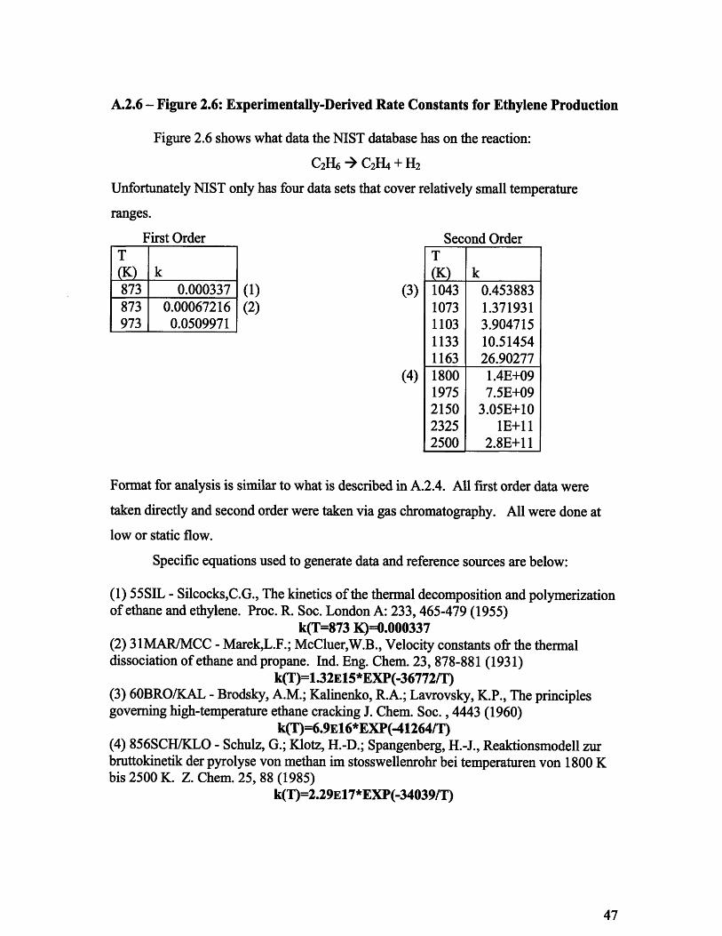
A.2.6 - Figure 2.6: Experimentally-Derived Rate Constants for Ethylene Production
Figure 2.6 shows what data the NIST database has on the reaction:
C2H6 4 C2H4 + H2
Unfortunately NIST only has four data sets that cover relatively small temperature
ranges.
First Order
k0.000337
0.000672160.0509971
(1)(2)
(3)
(4)
Second OrderT(K)1043107311031133116318001975215023252500
k0.4538831.3719313.90471510.5145426.902771.4E+097.5E+09
3.05E+101E+11
2.8E+11
Format for analysis is similar to what is described in A.2.4. All first order data were
taken directly and second order were taken via gas chromatography. All were done at
low or static flow.
Specific equations used to generate data and reference sources are below:
(1) 55SIL - Silcocks,C.G., The kinetics of the thermal decomposition and polymerizationof ethane and ethylene. Proc. R. Soc. London A: 233, 465-479 (1955)
k(T=873 K)=0.000337(2) 31MAR/MCC - Marek,L.F.; McCluer,W.B., Velocity constants ofr the thermaldissociation of ethane and propane. Ind. Eng. Chem. 23, 878-881 (1931)
k(T)=1.32E15*EXP(-36772/T)(3) 60BRO/KAL - Brodsky, A.M.; Kalinenko, R.A.; Lavrovsky, K.P., The principlesgoverning high-temperature ethane cracking J. Chem. Soc., 4443 (1960)
k(T)=6.9E16*EXP(-41264/T)(4) 856SCH/KLO - Schulz, G.; Klotz, H.-D.; Spangenberg, H.-J., Reaktionsmodell zurbruttokinetik der pyrolyse von methan im stosswellenrohr bei temperaturen von 1800 Kbis 2500 K. Z. Chem. 25, 88 (1985)
k(T)=2.29E17*EXP(-34039/T)
T
873873
973
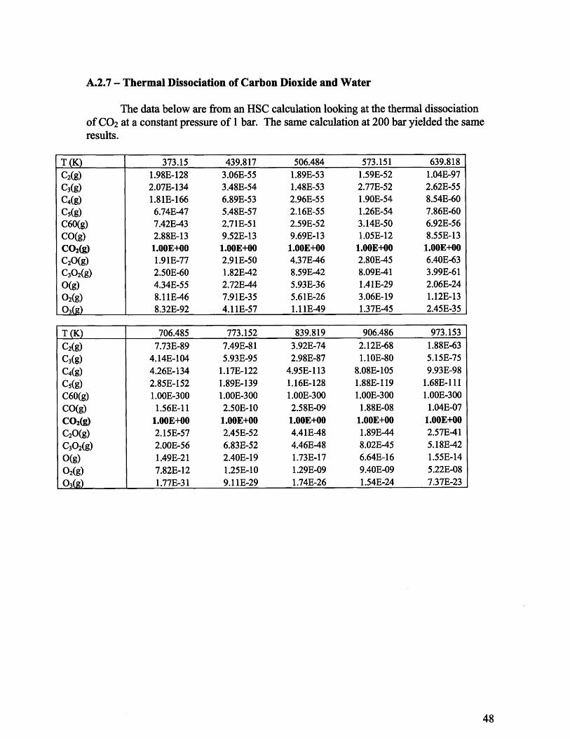
A.2.7 - Thermal Dissociation of Carbon Dioxide and Water
The data below are from an HSC calculation looking at the thermal dissociationof CO 2 at a constant pressure of 1 bar. The same calculation at 200 bar yielded the sameresults.
T(K) 373.15 439.817 506.484 573.151 639.818
C2(g) 1.98E-128 3.06E-55 1.89E-53 1.59E-52 1.04E-97C3(g) 2.07E-134 3.48E-54 1.48E-53 2.77E-52 2.62E-55C4(g) 1.81E-166 6.89E-53 2.96E-55 1.90E-54 8.54E-60C5(g) 6.74E-47 5.48E-57 2.16E-55 1.26E-54 7.86E-60C60(g) 7.42E-43 2.71E-51 2.59E-52 3.14E-50 6.92E-56CO(g) 2.88E-13 9.52E-13 9.69E-13 1.05E-12 8.55E-13CO2(g) 1.00E+00 1.00E+00 1.00E+00 1.00E+00 1.00E+00C20(g) 1.91E-77 2.91E-50 4.37E-46 2.80E-45 6.40E-63C30 2(g) 2.50E-60 1.82E-42 8.59E-42 8.09E-41 3.99E-61
0(g) 4.34E-55 2.72E-44 5.93E-36 1.41E-29 2.06E-24
0 2(g) 8.11E-46 7.91E-35 5.61E-26 3.06E-19 1.12E-13
03(g) 8.32E-92 4.11E-57 1.11E-49 1.37E-45 2.45E-35
T(K) 706.485 773.152 839.819 906.486 973.153
C2(g) 7.73E-89 7.49E-81 3.92E-74 2.12E-68 1.88E-63C3(g) 4.14E-104 5.93E-95 2.98E-87 1.10E-80 5.15E-75C 4(g) 4.26E-134 1.17E-122 4.95E-113 8.08E-105 9.93E-98
C5(g) 2.85E-152 1.89E-139 1.16E-128 1.88E-119 1.68E-111C60(g) 1.00E-300 1.00E-300 1.00E-300 1.00E-300 1.00E-300
CO(g) 1.56E-11 2.50E-10 2.58E-09 1.88E-08 1.04E-07
CO2(g) 1.00E+00 1.00E+00 1.00E+00 1.00E+00 1.00E+00C20(g) 2.15E-57 2.45E-52 4.41E-48 1.89E-44 2.57E-41
C30 2(g) 2.00E-56 6.83E-52 4.46E-48 8.02E-45 5.18E-42
0(g) 1.49E-21 2.40E-19 1.73E-17 6.64E-16 1.55E-14
02(g) 7.82E-12 1.25E-10 1.29E-09 9.40E-09 5.22E-0803(g) 1.77E-31 9.11E-29 1.74E-26 1.54E-24 7.37E-23

The data below are results showing that water does not thermally dissociate at highertemperatures. It was run at pressure of 1 bar.
T (K) 473.15 573.15 673.15 773.15 873.15 973.15 1073.15
H(g) 4.32E-31 1.59E-24 2.29E-20 2.50E-17 5.56E-15 4.13E-13 1.39E-11
H2(g) 1.53E-18 7.31E-14 1.67E-11 7.37E-10 1.38E-08 1.42E-07 9.58E-07
H02(g) 4.30E-25 1.05E-22 1.29E-19 3.73E-17 2.96E-15 9.62E-14 1.64E-12
H20(g) 1.00E+00 1.00E+00 1.00E+00 1.00E+00 1.00E+00 1.00E+00 1.00E+00
H202(g) 6.31E-22 7.04E-20 1.70E-17 1.29E-15 3.67E-14 5.28E-13 4.65E-12
O(g) 1.16E-31 8.15E-27 1.85E-22 4.10E-19 1.58E-16 1.80E-14 8.52E-1302(g) 9.41E-14 1.02E-13 8.33E-12 3.66E-10 6.82E-09 6.99E-08 4.66E-07
03(g) 1.60E-39 9.66E-37 5.88E-32 4.56E-28 4.62E-25 1.14E-22 1.02E-20
OH(g) 1.16E-19 1.51E-16 7.02E-14 7.64E-12 2.85E-10 5.09E-09 5.31E-08
H20 0.00E+00 0.OOE+00 0.00E+00 0.00E+00 0.00E+00 0.00E+00 0.00E+00
H20(1) 0.00E+00 0.00E+00 0.00E+00 0.00E+00 0.00E+00 0.00E+00 0.00E+00
H202(1) 0.00E+00 0.00E+00 0.00E+00 0.00E+00 0.00E+00 0.00E+00 0.00E+00
A.3.1 - Figure 3.1: Reaction of Various Coolants and Sodium: Gibbs Free EnergyChange per Mole of Na
Reactions were computed at 0.1 MPa according to equations 3.1, 3.2 and 3.5.
Temperature AG C2H6 AG H20 AG CO2(K) (kJ/mol-Na) (kJ/mol-Na) (kJ/mol-Na)
773.15 -19.2002 -109.824 -160.456784.261 -20.4334 -109.174 -158.897795.372 -21.7244 -108.531 -157.363806.483 -22.9826 -107.903 -155.935817.594 -24.2145 -107.298 -154.351828.706 -25.5628 -106.698 -152.891839.817 -26.8725 -106.12 -151.456850.928 -28.2055 -105.554 -149.945862.039 -29.4957 -105 -148.645873.15 -30.9043 -104.366 -147.185

A.3.2 - Figure 3.2: Reaction of Various Coolants and Sodium: Enthalpy Change perMole of Na
Both enthalpy and entropy results are given because entropy (as well as Gibbs
energy) is explicitly given in the HSC code, and enthalpy is derived from these values.
Data for lower temperatures is available more fully below.
Temperature AH C2H6 AH H20 AH CO2(K) (kJ/mol-Na) (kJ/mol-Na) (kJ/mol-Na)
773.15 64.3 -156.6 -266.3784.261 65.6 -155.5 -265.4795.372 66.88 -154.4 -264.5806.483 68.15 -153.3 -263.6817.594 69.4 -152.2 -262.6828.706 70.65 -151.1 -261.7839.817 71.89 -150 -260.8850.928 73.14 -148.9 -259.8862.039 74.38 -147.8 -258.9873.15 75.62 -146.6 -257.9
Temperature AS C2H6 AS H20 AS CO2(K) (J/K mol-Na) (J/K mol-Na) (J/K mol-Na)
773.15 108 -60.5 -136.9784.261 109.7 -59.07 -135.8795.372 111.4 -57.67 -134.7806.483 113 -56.29 -133.5817.594 114.5 -54.92 -132.4828.706 116.1 -53.58 -131.3839.817 117.6 -52.25 -130.2850.928 119.1 -50.94 -129.1862.039 120.5 -49.65 -127.9873.15 122 -48.37 -126.8
A.3.3 - Figure 3.3 Energy/Enthalpy Change for Na-C2H6Reaction (at 0.1 MPa)
Temperature AH AG(K) (kJ/mol-Na) (kJ/mol-Na)
423.15 -25.06 -6.98726439.82 -23.51 -6.18121456.48 -21.77 -5.40048473.15 -19.78 -4.6439489.82 -17.48 -3.93653506.49 -14.77 -3.27279523.15 -11.54 -2.67781539.82 -7.65 -2.17724556.49 -2.36 -1.82961573.15 3.64 -1.70595.37 13.31 -2.01617.59 24.28 -3.04639.82 34.96 -4.79662.04 43.76 -7.01684.26 50.23 -9.42706.48 54.92 -11.86728.70 58.53 -14.30750.93 61.56 -16.76773.15 64.30 -19.20
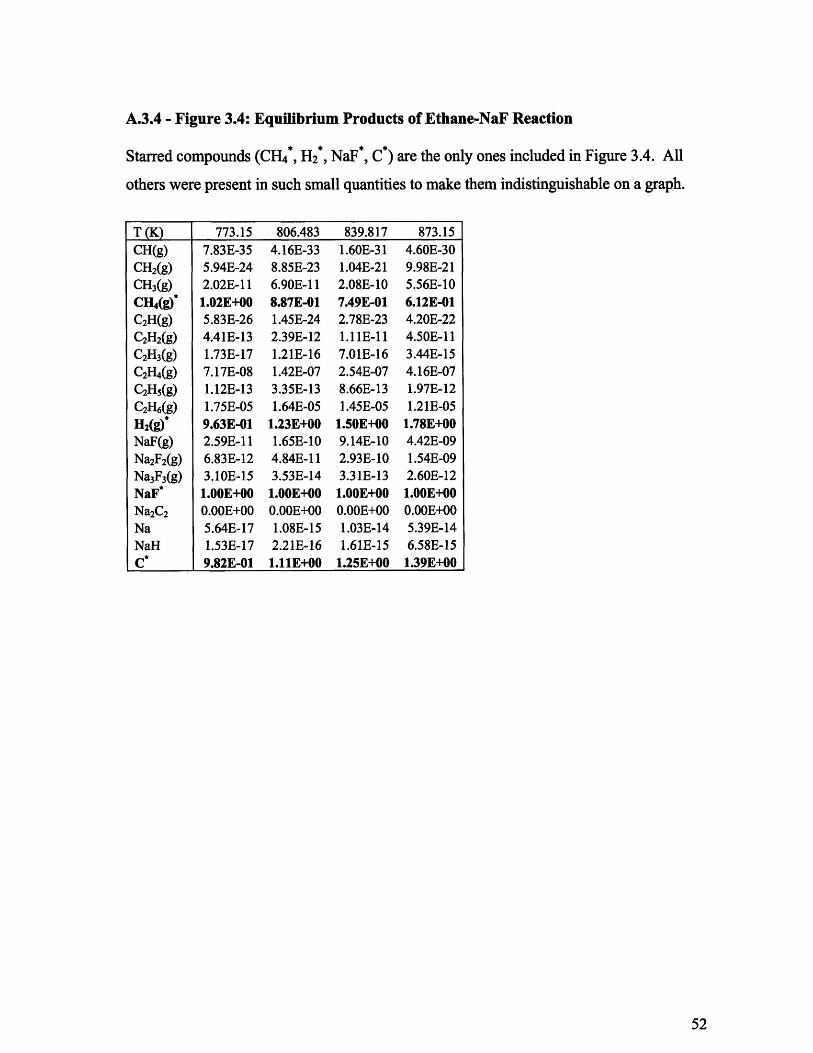
A.3.4 - Figure 3.4: Equilibrium Products of Ethane-NaF Reaction
Starred compounds (CH4*, H2 *, NaF*, C*) are the only ones included in Figure 3.4. All
others were present in such small quantities to make them indistinguishable on a graph.
T (K) 773.15 806.483 839.817 873.15CH(g) 7.83E-35 4.16E-33 1.60E-31 4.60E-30CH2(g) 5.94E-24 8.85E-23 1.04E-21 9.98E-21CH3(g) 2.02E-11 6.90E-11 2.08E-10 5.56E-10CH4(g)* 1.02E+00 8.87E-01 7.49E-01 6.12E-01
C2H(g) 5.83E-26 1.45E-24 2.78E-23 4.20E-22C2H2(g) 4.41E-13 2.39E-12 1.11E-11 4.50E-11C2H3 (g) 1.73E-17 1.21E-16 7.01E-16 3.44E-15
C2H4(g) 7.17E-08 1.42E-07 2.54E-07 4.16E-07
C2Hs(g) 1.12E-13 3.35E-13 8.66E-13 1.97E-12C2H6(g) 1.75E-05 1.64E-05 1.45E-05 1.21E-05H2(g)* 9.63E-01 1.23E+00 1.50E+00 1.78E+00NaF(g) 2.59E-11 1.65E-10 9.14E-10 4.42E-09Na2F2(g) 6.83E-12 4.84E-11 2.93E-10 1.54E-09Na3F3(g) 3.10E-15 3.53E-14 3.31E-13 2.60E-12NaF* 1.00E+00 1.00E+00 1.00E+00 1.00E+00Na2C2 0.00E+00 0.00 0.OOE+00 0.0.00E+00Na 5.64E-17 1.08E-15 1.03E-14 5.39E-14NaH 1.53E-17 2.21E-16 1.61E-15 6.58E-15C* 9.82E-01 1.11E+00 1.25E+00 1.39E+00

A.3.5 - Figure 3.5: Equilibrium Products of Ethane-Pb Reaction
T (K)C(g)C2(g)C3(g)C4(g)C5(g)C60(g)CH(g)CH2(g)CH3(g)CH4(g)C2H(g)C2H2(g)C2H3(g)C2H4(g)C2H5(g)C2H6(g)H(g)H2(g)Pb2(g)Pb(CH3)4(g)Pb(C2H5)4(g)PbH(g)Pb(H3)(Tg)CPb(I)
773.15 798.15 823.15 848.15 873.155.50E-41 2.00E-39 5.83E-38 1.39E-36 2.74E-351.95E-47 1.34E-45 7.10E-44 2.95E-42 9.84E-415.40E-45 3.47E-43 1.72E-41 6.68E-40 2.08E-383.74E-56 5.27E-54 5.46E-52 4.24E-50 2.53E-482.10E-56 3.26E-54 3.69E-52 3.11E-50 2.00E-48
2.96E-182 9.29E-176 1.01E-169 4.06E-164 6.36E-1594.94E-35 1.03E-33 1.76E-32 2.53E-31 3.09E-304.14E-24 3.24E-23 2.20E-22 1.32E-21 7.00E-211.55E-11 3.92E-11 9.17E-11 2.00E-10 4.08E-108.67E-01 7.64E-01 6.62E-01 5.62E-01 4.70E-011.96E-26 2.38E-25 2.47E-24 2.20E-23 1.70E-221.63E-13 6.17E-13 2.12E-12 6.63E-12 1.91E-117.07E-18 3.19E-17 1.28E-16 4.65E-16 1.53E-153.24E-08 5.53E-08 8.88E-08 1.35E-07 1.93E-075.61E-14 1.29E-13 2.71E-13 5.28E-13 9.57E-139.64E-06 9.08E-06 8.25E-06 7.23E-06 6.14E-061.51 E-12 4.90E-12 1.47E-11 4.12E-11 1.08E-10
1.27E+00 1.47E+00 1.68E+00 1.88E+00 2.06E+004.15E-16 1.82E-15 7.30E-15 2.69E-14 9.19E-142.60E-37 9.36E-37 2.87E-36 7.62E-36 1.78E-355.22E-54 2.03E-53 6.34E-53 1.61 E-52 3.44E-522.24E-12 7.08E-12 2.08E-11 5.67E-11 1.46E-109.11E-21 3.28E-20 1.07E-19 3.20E-19 8.79E-191.13E+00 1.24E+00 1.34E+00 1.44E+00 1.53E+001.00E+00 1.00E+00 1.00E+00 1.00E+00 1.00E+00
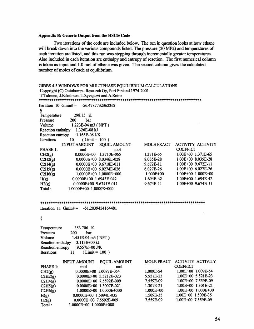
Appendix B: Generic Output from the HSC® Code
Two iterations of the code are included below. The run in question looks at how ethanewill break down into the various compounds listed. The pressure (20 MPa) and temperatures ofeach iteration are listed, and this run was stepping through incrementally greater temperatures.Also included in each iteration are enthalpy and entropy of reaction. The first numerical columnis taken as input and 1.0 mol of ethane was given. The second column gives the calculatednumber of moles of each at equilibrium.
GIBBS 4.5 WINDOWS FOR MULTIPHASE EQUILIBRIUM CALCULATIONSCopyright (C) Outokumpu Research Oy, Pori Finland 1974-2001T.Talonen, J.Eskelinen, T.Syvajarvi and A.Roine
Iteration 10 Gmin# = -56.4787732362362
Temperature 298.15 KPressure 200 barVolume 1.223E-04 m3 ( NPT)Reaction enthalpy 1.326E-08 kJReaction entrovpy 1.165E-08 J/K
10 (Limit = 100 )INPUT AMOUNT EQUIL AMOUNT
mol mol0.0000E+00 1.3710E-0650.0000E+00 8.0346E-0280.0000E+00 9.6718E-0110.0000E+00 6.0274E-0261.0000E+00 1.0000E+000
0.0000E+00 1.6943E-0420.0000E+00 9.6741E-011 I
1.0000E+00 1.0000E+000
MOLE FRACT
1.371E-658.035E-289.672E-116.027E-261.000E+001.694E-429.674E-11
ACTIVITY ACTIVITYCOEFFICI1.00E+00 1.371E-651.00E+00 8.035E-281.00E+00 9.672E-111.00E+00 6.027E-261.00E+00 1.000E+001.00E+00 1.694E-421.00E+00 9.674E-11
Iteration 11 Gmin#= -51.2039454164481
Temperature 353.706 KPressure 200 barVolume 1.451E-04 m3 ( NPT)Reaction enthalpy 3.113E+00 kJReaction entropy 9.557E+00 J/KIterations 11 (Limit = 100 )
INPUT AMOUNT EQUIL AMOUNTmol mol
0.0000E+00 1.0087E-0540.0000E+00 5.5212E-0230.0000E+00 7.5592E-0090.0000E+00 1.3007E-0211.0000E+00 1.0000E+000
0.0000E+00 1.5094E-0350.0000E+00 7.5592E-009
1.0000E+00 1.0000E+000
MOLE FRACT
1.009E-545.521E-237.559E-091.301E-211.000E+001.509E-357.559E-09
ACTIVITY ACTIVITYCOEFFICI
1.00E+00 1.009E-541.00E+00 5.521E-231.00E+00 7.559E-091.00E+00 1.301E-211.00E+00 1.000E+001.00E+00 1.509E-351.00E+00 7.559E-09
Iterations
PHASE 1:CH2(g)C2H2(g)C2H4(g)C2H5(g)C2H6(g)H(g)H2(g)Total:
PHASE 1:CH2(g)C2H2(g)C2H4(g)C2H5(g)C2H6(g)H(g)H2(g)Total :


![Reactions of bis[1,2-bis(dialkylphosphino)ethane]-(dihydrogen)hydridoiron(1+) with alkynes](https://static.fdokumen.com/doc/165x107/63146d10c32ab5e46f0ce1ad/reactions-of-bis12-bisdialkylphosphinoethane-dihydrogenhydridoiron1-with.jpg)

