Architectural Working Drawings
52
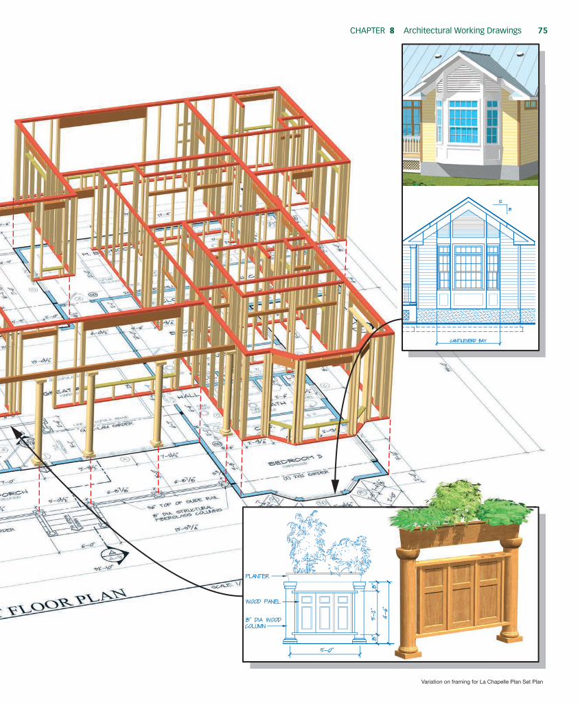
Figure 8.1 The La Chapelle floor plan represents real framing to carpenters who read, visualize, and build from a set of plans. Architectural Working Drawings 8 CHAPTER
-
Upload
khangminh22 -
Category
Documents
-
view
2 -
download
0
Transcript of Architectural Working Drawings

Variation on framing for La Chapelle Plan Set Plan
Figure 8.1 The La Chapelle floor plan represents real framing to carpenters who read, visualize, and build from a set of plans.
Architectural Working Drawings8ChApter
M08_POWE4171_01_SE_C08_074-093.indd 74 12/4/14 4:03 PM
ChapTer 8 architectural Working Drawings 75
Variation on framing for La Chapelle Plan Set Plan
M08_POWE4171_01_SE_C08_074-093.indd 75 12/4/14 4:03 PM

76 seCTion Three project planning and architectural plans
O b j e c t i v e s
ArchitecturAl PlAns And PlAn sheets
Contract-related documents include the final building contract, detailed specification sheet(s), and working drawings for con-struction. This set of paperwork becomes part of the legal founda-tion for the project. Each document is vital to the building process. The various plan sheets listed below make up the working draw -ings that builders and subcontractors typically use to develop their estimates. Carpenters will use the same drawings to interpret the design and build the structure.
Many people refer to a set of working drawings as plans or blueprints. In fact, working drawings are part of the complete set of architectural plans. Architectural plans include working drawings, schedules, and other sheets shown in the list below. Many architectural plan sheets are horizontal (section) views of the building. The most common plan sheets include floor plans, foundation plans, and roof plans. The order of plan sheets gen -erally follows the order of the building process. Elevation views are usually before building plans to give builders, homeowners, and trade workers a sense of how the entire project will look on completion. Not all architectural plan sets will include each sheet listed below.
1. Title and Legend Sheet(s) 2. Plot Plan (site plan) 3. Elevations 4. Foundation Plan 5. Floor Framing Plans 6. Floor Plans 7. Ceiling Framing Plans 8. Roof Framing Plans 9. Window and Door Schedules 10. Details and Section Views 11. Interior Elevations 12. Trade Plans (Mechanical, Electrical, Plumbing) 13. Specifications
The sophistication and detail in a set of construction plans may vary based on building design, owner’s need, and the ar -chitect. In any case, enough detail is required to help minimize mistakes and facilitate coordination within the various trades, subcontractors, and materials suppliers. In drawing construction plans, architects, drafters, or builders will illustrate many details in only one place to eliminate confusion and redundant informa-tion. For instance, specifying the same stud spacing on every wall section is not required for most plans.
title sheetsThe title sheet (Figure 8.2) is the cover for a set of architec -tural plans. On new construction, the title sheet typically has a front elevation view of the home. The title sheet normally includes all pertinent information about the primary parties involved with the project. The title sheet will list the architect (designer), owner, builder, and major subcontractors, and it may include a green home certification program’s seal and the green verifier’s information. Other sheets in the plan set will use a title block. The title block organizes some of the same information from the title page for quick reference on each page. Page numbers will be part of a title block to help keep drawings organized.
Plan VisualizationVisualizing the finished home or addition by reviewing a set of working drawings is a learned skill developed by builders, car -penters, and other craftspeople. It takes practice to develop the spatial skills necessary to visualize a three-dimensional building represented on a two-dimensional sheet of paper. Experienced carpenters can take a virtual tour in their minds of the finished building as they read and interpret information in a set of ar -chitectural plans. As this chapter covers each plan sheet, draw a mental picture to visualize the information and begin developing spatial skills. Figure 8.1 illustrates how the 2-D drawing becomes a real 3-D structure.
Orthographic ProjectionDrafters, engineers, architects, and builders use a system known as orthographic projection to create drawings of three-dimensional buildings on two-dimensional paper. Ortho means “straight line” and this projection provides a graphical representation on a two-dimensional plane. The projection represents objects drawn with a common relationship ; that is, they are in scale with each other. Common perspectives and drawing techniques are shown in Figure 8.3.
A common drawing perspective providing a three-dimensional view (3D) is the isometric view. Isometric views place all horizontal lines at 30° angles relative to the horizon with vertical lines perpen-dicular to the horizon. With this method, all lines are to scale and remain in proportion. An example is shown in Figure 8.3.
n Define and explain the various sheets that make up a set of architectural plans.
n identify the sheets in a set of working drawings and ex-plain the information available from each working drawing.
n Define the most common scales used on architectural plans. explain why scales are important and what informa-tion they make possible on a single plan sheet.
n Give examples of electronic plan scaling aids and software available to estimators and builders. explain how these tools help estimators work faster and more accurately.
n explain why section views and details are important plan sheets. how do carpenters and other trade workers use these views?
n explain how Building information Modeling software helps build energy-efficient homes.
M08_POWE4171_01_SE_C08_074-093.indd 76 12/4/14 4:03 PM

ChapTer 8 architectural Working Drawings 77
LICENSED LAND SURVEYOR
CODE ENFORCEMENT PLAN REVIEW APPROVAL
ON
E ST
ORY
RA
NC
H
W/ D
ETA
CH
ED G
AR
AG
E
CO
VE
R S
HE
ET
&
SIT
E P
LA
NW
. KEI
TH P
OW
ELL
N 0
2°00
'00"
E
105
.97'
S 0
5°00
'00"
W
158
.12'
N 70°00'00" W
111.09'
S 20°00'00" W
114.52'
12'-0" WIDE ASPHALT TRAVEL LANE
(60' PUBLIC RIGHT-OF-WAY)
4'-0" WIDE BIKE LANE
2' WIDE GRAVEL SHOULDER
8' WIDE UTILITY
EASEMENT
33.14'
47.28'
17.70'
25' FRONT BUILDING SETBACK LINE
15' S
IDE
BU
ILD
ING
SE
TB
AC
K L
INE
15' S
IDE
BU
ILD
ING
SE
TB
AC
K L
INE
25' REAR BUILDING SETBACK LINE
2' WIDE GRAVEL SHOLDER
SAN
SAN
SAN
G
WS
SL
SL
GS
GS
SL
WS
WS
G
G
G
G
E
E
E
E
E
W
W
W
4'-0" PUBLIC SIDEWALK
S 05°00'00" W 156.29'PROPERTY BOUNDARY LINE
10'
88.5
'
10'
MIN.
BENCHMARK“X” ON TOP OF CONCRETEHIGHWAY MONUMENTELEV. = 100.00
0 20 40
SCALE IN FEET
1” = 120’
SITE PLAN
SITE LOCATION MAP
SHEET INDEXSAWYER LANE
SAWYER LANE
McM
UR
RY
WA
Y
1 STORYWOOD FRAME HOUSE
1,987 S.F.SUB-FLOOR ELEV. = 106.32
10’ WIDE DRIVEWAY W/ TURN-AROUNDSEE NOTE 3 FOR OPTIONAL SURFACES
DR
IVE
WAYDRIVEWAY MAY ALSO BE USED
AS CONSTRUCTION STAGINGUNTIL CONCRETE IS PLACEDAND FINISHED
LOT AREA = 26,548 S.F. / 0.61 ACRES
PROPERTY BOUNDARY
C1
A1
A2
A3
A4
A5
A6
A7
S-1
D-1
D-2
D-3
COVER SHEET, SITE PLAN
SOUTH & EAST ELEVATIONS
NORTH & WEST ELEVATIONS
FOUNDATION PLAN
FIRST FLOOR FRAMING PLAN
FIRST FLOOR PLAN
CEILING FRAMING PLAN
ROOF FRAMING PLAN
CROSS SECTIONS & INTERIOR ELEVATIONS
DETAILS
DETAILS
DETAILS
WINDOW SCHEDULE
A
B
C
D
E
F
G
H
I
J
K
L
M
N
O
P
Q
R
MODELMARK
(3) 3056DH/TR
3060DH/TR
2630DH
(2) 2030DH/TR
(3) 4050DH/TR
(2) 2056DH/TR
6010TR
(3) 3050DH/TR
2040GL/TR
4010TR
2050DH/TR
(2) 3050DH/TR
2630DH/TR
4050DH/TR
28110AW
2650DH
CUSTOM SK
CUSTOM SK
42.75
14.25
5.62
13.5
17.25
10.5
4.20
40.5
8.25
3.00
9.75
27.0
7.87
17.12
3.73
9.37
8.00
16.00
19.44
6.04
3.50
8.43
8.10
4.55
-
18.22
3.24
-
4.05
12.15
3.5
7.11
3.49
6.75
2.00
NA
9'-0 1/2" × 6'-6 1/2"3'-0 1/2" × 7'-0 1/2"
2'-6 1/2" × 3'-0 1/2"
4'-0 1/2" × 4'-0 1/2"
4'-0 1/2" × 6'-0 1/2"
2'-0 1/2" × 6'-6 1/2"
6'-0 1/2" × 1'-0 1/2"
9'-0 1/2" × 6'-0 1/2" 32 1/2" × 27" (6.04) M. BDR.
32 1/2" × 27" (6.04) BDR. 2
41 7/8" × 28" (7.63) BDR. 3
2'-0 1/2" × 5'-0 1/2"
4'-0 1/2" × 1'-0 1/2"
6'-0 1/2" × 6'-0 1/2"
6'-0 1/2" × 6'-0 1/2"
2'-6 1/2" × 4'-0 1/2"
4'-0 1/2" × 6'-0 1/2"
2'-8 1/2" × 1'-10 1/2"
2'-6 1/2" × 5'-0 1/2"
2'-0" × 4'-0" Per P.E.
4'-0" × 4'-0" Per P.E.
DH = DOUBLE HUNG, TR = TRANSOM, CS = CASEMENT, GL = GLIDER, AW = AWNING, SK = SKYLIGHT
SYMBOL
COMMERCIAL(RETAIL, RESTAURANTS,COMMUNITY SERVICES)
DELLA’S PLACECOMMUNITY
PARK
SITEINFILL LOT
A
ROUGH OPENINGWIDTH × HEIGHT
LIGHTS.F.
VENT.S.F.
EGRESSW. × H. (S.F.)
LEGEND
LAND CONSERVATION AREASEE NOTE 1
DECK
RAIN GUTTERDOWNSPOUTLOCATION (3 TYP.)
ROOF OVERHANG
ROOFOVERHANG
X
XX
X X
XXX
X
14'-6"
22'-0"
22'-0"
26'-0"
26'-0"
32'-10"
15'-0"
2' CANTILEVER
STEPS
STEPS
SIDEWALK
8'-91/8"
STEPS
10'-8"
30'-0"
18'-0
"
17'-0
"
8'-0
"
32'-0
"
33'-0
"
10'-0
"
PORCH
CONSTRUCTIONSTAGING AREA
SEE NOTE 2
LAWN AREASEE NOTE 4
PATIO
LIMITS OFCLEARING
LIMITS OFCLEARING
CONSTRUCTION /SILT FENCE
LAWN AREASEEN NOTE 4
WOODEDAREA
WOODEDAREA
WOODEDAREA
CURB
STOP
WOODEDAREA
LAWN AREASEEN NOTE 4
2 CARGARAGE
SITE PLAN NOTES:
1) AREA RESERVED FOR LAND CONSERVATION: A) THE GENERAL CONTRACTOR SHALL INSTALL AND MAINTAIN A CONSTRUCTION (SILT) FENCE AS SHOWN. FINAL PLACEMENT BY EPA CERTIFIED ENGINEER, POSSIBLE SITE RETENTION POND PER LOCAL REQUIREMENTS. B) SILT FENCES AND/OR HAY BALE DYKES SHALL BE INSTALLED AS PER CIVIL ENGINEER’S INSTRUCTIONS TO PROVIDE SOIL AND SEDIMENT CONTROL.
2) THE CONTRACTOR SHALL CONTAIN STAGING, STOCKPILE, AND DISPOSAL ONLY WITHIN THE DESIGNATED AREA. 3) OPTIONAL SURFACES FOR DRIVEWAY AND SIDEWALKS:PERVIOUS CONCRETE, RECYCLED ASPHALT/RUBBER; GRAVEL; CRUSHED STONE, BRICK, SEA SHELL, OR OTHER REGIONALLY AVAILABLE RE-PURPOSED MATERIALS. PROTECT EXISTING PUBLIC SIDEWALK DURING CONSTRUCTION.
4) ALL LAWN AREAS SHALL RECEIVE FINAL GRADING AND SEEDING AS SOON AS POSSIBLE AFTER CONSTRUCTION IS COMPLETE. LAWN OPTIONS; PLANNED NATURAL AREAS AND XERISCAPING WITH GRASSES AND WILD FLOWERS ACCUSTOMED TO LOCAL CONDITIONS AND YEARLY RAINFALL TO MINIMIZE WATER USE FOR IRRIGATION.
SITE STATISTICS:
LOT AREA: 26,548 S.F. / 0.61 ACRES
DEDICATED GREEN SPACE: 6,674 S.F. / 25%
BUILDING SIZE: 1,987 S.F.GARAGE SIZE: 272 S.F.
TOTAL IMPERVIOUS AREA: 2,259 S.F. / 9%PERVIOUS CONCRETE AREA: 1,053 S.F. / 4%
BUILDING SETBACK LINES
UTILITY EASEMENT
LAND CONSERVATION BOUNDARY
ROOF GUTTER & DOWNSPOUT
CONSTRUCTION FENCE
GAS MAIN
GAS SERVICE
G
U.G. ELECTRIC E
GS
W
WS
99
SAN
SL
SANITARY SEWER
SANITARY LATERAL
WATER MAIN
WATER SERVICE
ES ELECTRIC SERVICE
GROUND ELEVATION CONTOUR
LIMITS OF CLEARING
ES
ES
RESIDENTIAL SUBDIVISION
INFILL LOTS EARN GREEN CERTIFICATION POINTS
1210
8
23
25
2119
GR
EE
NW
AY
AR
EA
, O
LD
RA
ILR
OA
D R
EM
OV
ED
R310.1.1 MINIMUM OPENING AREA. ALL EMERGENCY ESCAPE AND RESCUE OPENINGS SHALL HAVE AMINIMUM NET CLEAR OPENING OF 5.7 SQUARE FEET. (EXCEPTION: GRADE FLOOR OPENINGS SHALL HAVE A MINIMUM NET CLEAR OPENING OF 5 SQUARE FEET).
R310.1.2 MINIMUM OPENING HEIGHT. THE MINIMUM NET CLEAR OPENING HEIGHT SHALL BE 24 INCHES.
R310.1.3 MINIMUM OPENING WIDTH. THE MINIMUM NET CLEAR OPENING WIDTH SHALL BE 20 INCHES.
R310.1.4 OPERATIONAL CONSTRAINTS. EMERGENCY ESCAPE AND RESCUE OPENINGS SHALL BE OPERATIONAL FROM THE INSIDE OF THE ROOM WITHOUT THE USE OF KEYS, TOOLS OR SPECIAL KNOWLEDGE.
ENERY SPECIFICATIONS
Design U-Factor = 0.35Design SHGC = 0.40U-VALUE AND SOLAR HEAT GAIN COEFFICIENT (SHGC) MINIMUMS PER CLIMATE ZONE 3A
EMERGENCY EGRESS
SIZE
2-2×4
2-2×6
2-2×8
2-2×10
2-2×12
3-2×8
3-2×10
3-2×12
4-2×8
4-2×10
4-2×12
GROUND SNOW LOAD (PSF) = 30BUILDING WIDTH = 36'
SOURCE: 2015 IRC TABLE 602.7(1)
SPAN
2'-10"
4'-2"
5'-4"
6'-6"
7'-6"
6'-8"
8'-2"
9'-5"
7'-8"
9'-5"
10'-11"
NO. JACK STUDS
1
1
2
2
2
1
2
2
1
2
2
FOOTNOTE D, TABLE 602.7(1); “WHERE THE NUMBER OF REQUIRED JACK STUDS EQUALS ONE, THE HEADER IS PERMITTED TO BE SUPPORTED BY AN APPROVED FRAMING ANCHOR . . .”
SL. = SLIDER, BF = BI-FOLD
DOOR SCHEDULE
1
2
3
4
5
6
7
8
9
10
SIZEMARK
3 1 "
"
"
"
"
"
"
"
"
0 68 34 STL. INS.
STL. INS.
F.G. INS.
H.C. WD.
H.C. WD.
H.C. WD.
H.C. WD.
H.C. WD.
PC.
SL.
HG.
HG.
HG.
HG.
HG.
HG.
HG.
B.F.
H.C. WD.
EXT.
EXT.
EXT.
INT.
INT.
INT.
INT.
INT.
INT.
× ×
134×
134×
138×
138×
138×
138×
138×
138×
28 70×
60 70×
"134×30 70×
28 70×
20 70×
28 70×
16 70×
40 70×
30 70×
STL = STEEL, INS = INSULATED, S.G. = SAFETY GLASS, FG = FIBERGLASS,
HC = HOLLOW CORE, WD = WOOD, HG. = HINGED, PC = POCKET,
SYMBOL1
MAT’L.
1" INS. ENTRY
ENTRY
ENTRY
PRIVACY
PRIVACY
1" INS.
STL. INS.EXT. ENTRY1" INS.
1" INS. S.G.
GLASS LOCKSET TYPEINTERIOR
EXTERIOR
NOTE: HOME DESIGN IS TYPICAL FOR INTERNATIONAL ENERGY CONSERVATION CODE AND INTERNATIONAL RESIDENTIAL CODE CLIMATE ZONE 3A.
GIRDER & HEADER SPANS FOR EXTERIOR WALLS
(supporting Roof and Ceiling)
Figure 8.2 Check the title sheet for contact information and other details.
Figure 8.3 a full set of building plans will use many drawing types to relate information using 2D and 3D techniques.
Front30°30°
Right side
ORTHOGRAPHIC PROJECTION
Vanishingpoint
Horizon line
Vanishingpoint
PERSPECTIVE
ISOMETRIC
M08_POWE4171_01_SE_C08_074-093.indd 77 12/4/14 4:03 PM

78 seCTion Three project planning and architectural plans
Figure 8.4 Manual and electronic aids help estimate plans quickly estimator work quickly and accurately.Sources: (a, b, c) alvin & Company, inc.; (d) scalex Corporation
(a) Architect’s flat scale (c) rolling ruler
(d) scalex PlanWheel (b) Architect’s triangular scale
how to Apply the Architect’s scale Learning to use the architect’s scale is important to reading and interpreting working drawings. Follow the steps shown below and refer to Figure 8.7 to practice with an architect’s scale and develop accuracy and confi-dence in reading working drawings. The figure in this example is part of plan sheet A-5 the detached garage from the La Chapelle Plan But the technique can be used throughout any scaled set of plans using an architectural ruler.
1. Find the appropriate fraction mark at the end of the scale that corresponds to the scale of plan sheet A-5. In this example shown in Figure 8.7, 1>4″ = 1′ is used.
2. Using the 1/4 ″ scale, set the architectural ruler on the zero mark and one corner of the garage front.
3. Read across the scale to the other end of the garage and note 22′. 4. On a 1>4″ = 1′ scale, 5½″ is equal to twenty-two 1>4″ seg-
ments; i.e., 22′ as shown on plan sheet A-5. Take a basic ruler and you will see the garage’s actual measurement on the plan sheet is 5½″.
5. The area to the right of the zero mark on the architect’s scale is for measuring inches. For example, you can meas -ure 9″ on the scale right of the zero mark by counting nine hash marks.
Civil engineer’s ScaleOn a building lot or larger land area, surveyors use measuring equipment that divides parts of a foot into a decimal number car-ried to thousandths of a foot for accuracy; for example, 255.469′ may be the length of a property line. Because of the larger scales, decimal formatting, and accuracy, surveyors use this standard to create the property lines on most plot plans. A civil engineer’s
dimensioning Aids for Working with Architectural PlansReading a set of construction plans requires practice, experi -ence, and spatial skills. To quickly read rough dimensions or for estimating; a wide range of computer controlled, electronic, and manual dimensioning aids are available. Even though these tools usually provide enough accuracy for estimating and general draw-ings, always refer to the architectural plans for exact dimensions and details. Various scaling tools are available to increase accuracy and speed when estimating; see Figure 8.4.
Architect’s ScaleThere are several versions of the architect’s scale; the most com-monly used is triangular with 11 different scales, one being a full-size ruler. Common plan scales are shown in Figure 8.5. The end of each scale has a fraction that designates the par-ticular scale. In residential construction, 1>4″ = 1′ is the most common scale used on working drawings, as shown in Figure 8 .6. However, some plan sheets, depending on paper size, build -ing size, and objects represented, may use 1>8″ = 1′ or other scales. Be sure to check each sheet for the appropriate scale be-fore taking measurements.
P r o F e s s i o n A l t i P
Written plan dimensions always take precedence over scaled and measured dimensions. Variations in printing and paper can decrease the accuracy of measuring and scaling dimen-sions from a physical plan set.
M08_POWE4171_01_SE_C08_074-093.indd 78 12/4/14 4:04 PM

ChapTer 8 architectural Working Drawings 79
3" = 1'
0 1 2 3 4 5 6 7 8 9 10 11 12 3
16
12" = 1' full scale; (also use 1/16" = 1')
Yellow mark = one scaled foot
0 1 2 3
11/2" = 1'
921 6 3 0 21
1
1" = 1'
0369 1 2
3/4" = 1'
43 0 31 2
21
1/2" = 1'
024
3/8" = 1'
0246 83
323
1/8" = 1'
81
3/32" = 1'
3/16" = 1'
0 4 8 12 16 20 24 28 32
02468101416 163
41
0 4 8 12 16 20 24
1/4" = 1'
0246810
Figure 8.5 eleven scales are available on a triangular architect’s ruler. The most common used in residential construction is 1/4″ = 1′.
scale can be used to read these large-scale drawings easily. The civil engineer’s scale divides into six scales; each scale further mul-tiplies by a factor of 10 for increasingly larger scale drawings. See the engineer’s scale chart and example for reading a civil engineer-ing scale in Figure 8.8.
electronic Scaling ToolsElectronic tools are available for scaling plans when estimating. Two popular types, the ScaleMaster II and the Scalex PlanWheel (shown in Figure 8.4), can perform linear, area, and volume measurements for easy and accurate estimating. Some electronic measuring aids are wireless and interface with spreadsheets and estimating software. Some versions have a small calculator built in to help with adding and subtracting measurements. All dimen-sioning aids help with calculations required for estimating. In ad-dition, electronic aids increase accuracy to a higher level and can decrease overall estimating time.
Working drAWings
Depending on building complexity, roof design, and other vari-ables, a set of working drawings for a residential home may be 5 to 10 sheets. For basic designs, a simple floor plan, a few speci -fications, and possibly a roof plan is all many carpenters need once the building corners are determined with a site plan. The point is that working drawings may be very simple or very com-plex depending on the project and the experience level of the builder and crew members. Using the International Residential Code, experienced carpenters can easily adjust to a particular set of working drawings. The complexity of the drawing is a factor in determining the plan sheet size; standard sizes are shown in Figure 8.9.
The working drawings provided to contractors for bidding serve many purposes in the overall construction process. Below are some applications of working drawings other than physical construction.
1. Estimating and Take-offs. The builder and subcontractors use working drawings to calculate all of their materials, labor, and other expenses.
2. Permitting. In residential construction, the requirement for plans in the permitting process varies by jurisdiction. Some architects create a set of plans specifically for permitting; they may have a slightly different look than actual working draw-ings.
3. Permanent Record. A set of working drawings constitutes a permanent record of construction and design, along with all details and specifications. Provide a set to the homeowner for future repairs, additions, or remodeling projects.
4. Legal Record. The working drawings become part of the le -gal record for the building. If legal issues arise during or after construction, courts may use working drawings as a basis for determining important facts.
M08_POWE4171_01_SE_C08_074-093.indd 79 12/4/14 4:04 PM

80 seCTion Three project planning and architectural plans
Using the common 1" = 1" scale, the master bedroom’s physical measurement is 45/8". Using the 1/4" plan scale converts it to the actual size of 18'-5".
La Chapelle House PlanFigure 8.6 scaled drawings help to illustrate an entire building on a single plan sheet.
3 1
2 5
4
Figure 8.7 Using the scales on an architectural ruler, a carpenter, builder, or designer can draw large-scale areas on plan sheets.
M08_POWE4171_01_SE_C08_074-093.indd 80 12/4/14 4:04 PM

ChapTer 8 architectural Working Drawings 81
PresentAtion And eleVAtion VieWing style
Presentation ViewPlan books, internet sites, architects, or builders may provide a presentation view (Figure 8.10). This is essentially a tool for selling the plans or home and provides little related to actual construc -tion detail. Presentation views, in pencil or color, typically show fully developed landscaping, distinctive features, and even people to present the finished home in a favorable light. Unless the owner specifically requests the added perspective provided by a presenta-tion drawing, it is not included in most construction plans.
Whole house elevation ViewsElevation views provide a visual and scaled view of the home’s exte -rior or interior. Most plan sets include views with each side shown and detailed. Elevations include references to many specifications for framing and exterior finishes. Roof slopes, ceiling heights, finished floor heights, and roofing and siding materials are usually identified on elevation sheets, as shown in Figure 8.11 and detailed as follows:
Roof slope: Roof slopes may not be the same for all covered sections of the home. For example, dormers, shed roofs, and garages may have different slopes.
Ceiling heights: Ceiling heights are provided on most elevation sheets and may be included on specifications or detail sheets.
Exterior finishes: Exterior finishes are usually illustrated and noted on elevations. In some cases, the street side of a home will be brick and the other three sides are covered with siding or other materi-als to meet restrictions of the neighborhood or community.
Topography: The actual lot grade (topography) helps estimators calculate foundation materials and grading work. Elevations also illustrate the home’s finished look in relation to grade.
interior elevationsInterior finish work such as cabinets, trim work, and built-in bookcases may have a plan sheet (see Figure 8.12) with interior elevations so carpenters know where to set these items. Interior elevations dimension universal design features like lowered counters or fixtures so carpenters can install the features ac -cording to requirements. Universal design heights and details for doors, cabinets, and other features are discussed in other ar-eas of the text.
lAyout And FrAming PlAn VieWs
For plan views, a cutting plane is a horizontal line “cutting” the object for a better view. For example, with typical floor plans, the horizontal cutting plane is typically at a height that cuts through doors and windows on exterior walls so they are in the final view. Removing the area above the cutting plane creates a bird’s-eye view looking down into the structure like the example in Figure 8.13.
Plot or site PlanA site plan (Figure 8.14) contains information verified by a sur -veyor, engineer, and others. It illustrates important features such as utility easements, topography, property lines, setbacks, and el -evations. Site plans usually include the building footprint, drive -ways, auxiliary buildings, and other constructed features on site as references. A plot plan, very similar to a site plan, is specifically for recording a piece of land and shows much of the information on the site plan without a house on the lot. Some of the important aspects include the following:
Easements: Any property easements must be specifically located and identified. It is advisable to check with code officials and utility companies for restrictions and setbacks related to prop-erty easements.
Setbacks: All property setbacks shown on site plans should be verified with local zoning officials before construction begins. A quick phone call can help eliminate serious code problems related to building within a setback area.
Benchmark: The benchmark sets the elevation of many con-struction features, including finished floor levels and founda-tion heights.
Site plans contain very important information about el -evation. Each site plan has an elevation called the benchmark. The benchmark represents a starting elevation that may be an actual elevation above sea level or, for ease of use, an arbi -trary number like 100.00 ′. In either case, all points of eleva -tion throughout the site plan reference against the benchmark elevation. Carpenters and masons will use these elevations as starting points to calculate foundations and finished floor heights. Masonry workers will use these elevations to build and check all foundation walls, piers, and other structural compo -nents of the foundation system.
Site or plot plans have become more significant in today’s environment of green building. The orientation of the building is important to operating efficiency. Windows and doors can be oriented and sized to maximize any solar advantages based on the home’s location. The site plan can be used to manipulate the scaled building footprint into the best orientation for solar ef -ficiency based on location, building size, and limitations of the building lot. These plan sheets also show protected areas like tree drip zones and natural areas, as well as areas designated for mate-rials storage and heavy equipment.
P r o F e s s i o n A l t i P
The oldest known plan or drawing dates back to around 2100 BC and is credited to the Chaldean prince of Lagash, a city-state in ancient Mesopotamia. in his time, the prince was known as an engineer and a builder.
M08_POWE4171_01_SE_C08_074-093.indd 81 12/4/14 4:04 PM

82 seCTion Three project planning and architectural plans
Foundation PlanThe information on a foundation plan provides critical dimen -sions for structural support features. The height of the cutting plane should be set to “cut through” any windows, doors, or other openings in basement walls so the builder can define locations,
Figure 8.8 Civil engineering scales are designed for working with very large distances.
30
1" = 30'
0 20
10 / 1 to 1
20 / 1 to 2
30 / 1 to 3
40 / 1 to 4
50 / 1 to 5
60 / 1 to 6
1" = 1'
1" = 2'
1" = 3'
1" = 4'
1" = 5'
1" = 6'
1" = 10'
1" = 20'
1" = 30'
1" = 40'
1" = 50'
1" = 60'
1" = 100'
1" = 200'
1" = 300'
1" = 400'
1" = 500'
1" = 600'
ScaleDivision/Ratio
Multiply Scale by Factor of 10for Larger Scale
Civil Engineer’s Scale(also commonly used by surveyors)
40 60
8.5" × 11"A
B
C
D
E
11" × 17"
17" × 22"
22" × 34"
34" × 44"
Figure 8.9 The american national standards institute (ansi) de-veloped a standard for working drawings using a letter designation corresponding to each sheet size. Large size e prints provide the most detail and are easier to read.
Figure 8.10 presentation drawings are used to present the finished home in the best light possible for selling sets of plans or the proposed new home.
1,,,1,1,1,1,111111,1,111111111111111111111111,1,111111,1111,111,11,111,111,1111111,1,11111111111111,1111111,11111111111111111,111111111111111111,11111,,1111,1111,1111111111,,989898777 SqSqSqq.. FFtFt. Rancncnch h h ononn 00 6.6.6.61111 AcAcAcrereresss3333333333 3 333 3 3333333333333333333333333333333333333333333333333333333333333333333333333333333333333 333333333333333333333 3333333333333333333333 333333333333333333333333333333333333333333333333333 333333 333333333 BeBBeBeBeBeBeBeBeBeBeBeBBBeBeBeeBeBeBBeBeeeBeBeBeBeBeBeBeeBeBeBeBBeBeBeBeeBeBeBeBeBBBBeBBeBBBBBeeBeeeBBeBBBBeeeeBBeBBeeeBBeeeeBBBBeeBeBeeeeBeBeBBBBBBeeeeeeeBeBBeeeeBeeeeBBBeeeBeeeBeeeBBBBeeeeeeBBeeBeeeBeeeeBBBBBBeBeeeBeeeBBeBeBBeeeBeBBeBBBBeeeBBBBeeeBBBeBBeeeeeeeeeBBeeeeeeBBeeBeeeeeBBBeeeeBBBBeeeBBBBeeeeeddddrddddddddddddddddddddddddddddddddddddddddddddddddddddddddddddddddddddddddddddddddddddddddddddddddddddddddddddddddddddddddddddddddddddddd ooooommms222 2 2 222222222 222222222 222222222222222222222222222222222222 BaBBaBaBaBBaBaBBaBaBBBaBBaBBaBaBBBaBaBBaBaBaBaBaBaBBaBaBBBBBBBBBaBaBaBBBaBaBaBaBBBBBBBaBaBaBaBaBaBBBBBBBaBBaBBBBBBBBaBBaBaBaBBBBaaBaaBaBaBaBaBBaBaBBBBBaaBaBBBaBaaaBaaBBBaBaaaaaaBaaBBBBBaaaBaaBBBBBaaBaBaaaBaBBBBaaaBaaaaaaaBaaaaBBaBBBaaaaaaBBaBaBaBaBaBaBaBBBaaBaBaBBBBaBaaaBBBaBaBaBBaBaaaaBBBBBBaBBBaaaaBaBaaaBaaBaBBaBBaaaaaBaBBBBBaththththtthththththtttttttththtttthtthththththththtthttttttttttttttthtttttthtttttthhhhhhhhthhthhhthhhhhhtttthhthhhhhhhhhtttthhhhhhhhthhtttthtthtthhhhhhthttttthhhhhhhtththhhhtttttttt ssssssssssssssssssssssssssssssssssss2 2 22 22222222 22 222222222 222222222 CCCaaaCaCCaCaCaCaCaCaaCCaCCaCCaCCaCaCCaaCaCaCCaCCCaCaCaCaCaCCCCCCaCaCCaCaaCaCaCCCCaaCaCaCCaaCaCCaCCaCaCaCaCaCaaCaCaCaCCaaaaCaCaaaaaaaCCCaaaaCCCaCCCCaCCCCaCCCaaaaaaaaaaCaaaaaaCCCCCCCaCCCCC r rr rr r rrrrrrrr rrrr rrrrrrrrrr rrrrrrrrrrrrrrrrrrrrrrrrrrrr GaGGGaGaGaGaGaGGGaGaGaGaGaGGaGGaGGaGGaGaGGaGGGaGaGaGGGGaGaGaGGGGGaGaGaGaGaGaGaGGGaGGGaGGGaGaGaGaGaGGGGGGGGaGGGGaaGaGGGGGaGGGGaGaGaGGaGaGGGaaaGGGaGGGGGGGGaGGGaGaGGGGGGaGGGaGGGGGGaGGaGGGaGGGGaGGGGGGGaGGGaGaaaaGaGGGGaGGGGaaaaaaGGGGGGaGGaaaaaaaaaGGGGGGaaaaaaaaaaaaaaGGGGGGGaaaaaaaaaGaaGaGaaaaGaaaGaGGGGGGGGGGGGGaGGGGGGGGGGaGGGGGaGGGGaaGGGGaGGGaaGGGararrrrrrrrrrrarrrrrrarrrrrrrrrrrrrrrrrrrrrrrrrrrrrrrrrrrrrarrrrarrrr gegegegegeggSoSoSoSooSSoSoSoSoSoSoSoSoSoSSSoSoSoSSoSSSSoSoSSoSoSoSoSoSSSoSooSSoSSSSSSSSoSoSSoSoooSSooooSooSoooooSoSooooSSSooSSSSSooSoooooooooooooolalalalalalalalallalaalaalalalalalaalalaaalaalalallallaaaaaaaaaarrrr rr rrrrrrrrrrrr rrrrrrrrrrrrr rrrrrrrrrrrrrrrrrr rrrrrrrrrrr rrrrrrrrrrrrrrrrrrrrrrrrrrrrrrrrrrrrrrrrrrrrrrrrrr rrrrrrrrr r HHoHoHoHoHHoHHoHoHoHoHoHoHoHoHoHoHoHoHooHoooHooHHHoHoHHoHooHoHoHHHoHHoHooHHHHHHHoooHoHoHoHHHHHoHoHHHHHHHoHoHoHoHoooHHHHHHoHoHoHoHHoooHooHHHHoHoHHHHoHoooooooHHHooHoHoooHooHooooHooHooHoooHoHHoHoHooHoHooHoHHoHoHoHoHHooHooHHooooHoHHHoHHooHoHoHooHoHHoHHHoHoHoHoHHHoHoHoHHooHoHoHHoHHHHHooHHoooooooooooHHooooooootttttttttttttttttttttttttttttttttttttttttttttttttttttttttttttttttttttttttttttttttttttttttt tttt tttttttttttttttttttttttttttttttttttttttttt tt WaWaWWWWWWWWWWWWWWWWWWWWW teteteteterrrrrPhPhPhPhPhPhPhPhPhPhPhPhhPhhPhPhhPhPhPhhhPhhhhhhPPhhhPhhhhhhhhhhhhhhhhhhhPhPhhhhhPhhPhPhhPP otototototttttttotototttttttotootottttottototoottttotooottotootoototootottottttttttootoootovovovovovovovooovovovovovovovovooovovovovovovovoovovoooovoovovoovooovoooooooooovovovoooooooooooo ooloolololollolololloollooollolllolllolllooolooolooloooololoooooooooooolooolloloooooooloooloooooolololololooooolololoolooolllololloolooooooooooooooooloooooooolooooooloollloooolllooooolooooo tttttattttatattttattttattattttttatatattaatatatatatatataaaaattatatataaataatatataaaaatataatataaaaattttattattttaaataatttttttataaaattttatttaaattaaaaataataaaaaaaaaaaaaicicicici SS S SSSSSSupuppppppppppppuppuppupupupupupupupupuuuuuuuuuupupuupupuppppupupupuppuppppupuuuppuuuuuuuppppppppppppppppppppppppppppppplplplllplplplpllllplplplppllllplplplllplpllpplplllllpllllllplpllllplplplplppplppppplpppllpplpppplpplpplllpllllpppppplppplpppplppllplplppppppppplplpppplplplpppplpplplpppppplplppplppplppplpppplplppppplpppplppplppllppllplpplpplplplppplllplppplpllplpllppllpplpppplllppppplllppppppppppppppppppppppppppppppppppp eememememememememmememememememememememeememmmeemeemmmeeeeemeeemmmmeeeeemmeeeeemeeeeemmememeeeeeeemeemeeeeemeeemeeeeeeemeeemmeeeemeeemmemmmmmmmmemmmeeeeeeeeeeeeeeeee eneneeneneneneneneneneenenenenenenenenenennenenenenenneneeeennenneneennneneeeeeneeeeneeeeeneeneneenenneennenennnnenennnenneeeennnnnneeeneneennennnennne tatatatatatataaaatataatatataatatatattaaaaatttataattttatttatatatatttttttatattaaaaatatatataaaaaaaaaaaaatatataataaaaaaaaatataataaatataaataatataaaataaaataataaaataaataattaaaaaaataaaaaaaaataaaaaaaaaaaaaaaaaaaaaaaaaaaaaaataaaaaaataaaatatttaaaatallll lllllllllllllllllllllllllllll llllll llllllllllll llllll lllllllll lllllllllllllllll l EEEEEEEElEEEEEEEEEEEEEEEEEEEEEEEEEEEEEEEEEEEEEEEEEEEEEEEEEEEEEEEEEEEEEEEEEEEEEEEEEEEEEEEEEEEElElEEEEEElEEEEEEEEEEEEEElEEEE ecececectrtrtriicicic
1,987 Sq. Ft. Ranch on 0.61 Acres3 Bedrooms2 Baths2 Car GarageSolar Hot WaterPhotovoltaic Supplemental Electric
M08_POWE4171_01_SE_C08_074-093.indd 82 12/4/14 4:04 PM

ChapTer 8 architectural Working Drawings 83
m A t h t i P
The footing projection is the width of the footing beyond the foundation wall, pier, or column. irC r403.1.1 Minimum size states, “Footing projections, P, shall be not less than 2 inches and shall not exceed the thickness of the footing.” (2015 irC, p. 80) For the example in Figure 8.15, what is the total foot-ing width based on the footing projection and basement wall specifications?
Answer: Foundation wall is 108″ concrete with an exterior footing projection of 34″ and an interior footing projection of 34″ = 16″ total footing width.
type, and other specifics. Take a look at the information below and noted in Figure 8.15 of important specifications provided by foundation plans.
Foundation wall type and width: The foundation width as determined by code or design may not be the same for all areas of the building.
Window openings: Window type, size, and location may not be the same at all locations.
Dimension lines: Carefully note dimension lines and their refer-ence points. They may represent the outside edge, the center-line, or the inside edge of the object referenced.
Footings and piers: Dashed lines represent the footing width for foundation walls, piers, and columns. The footing width beyond the foundation wall, column, or pier on either side is the footing projection (see Figure 8.15).
Concrete: Some concrete specifications may be listed on foun-dation plans, but refer to specifications sheets for all pertinent details.
Local frost lines: The depth of footings below grade must be defined by local code jurisdictions based on local soil and weather conditions. In the International Residential Code, Table R301.2(1), footnote b states, “The jurisdiction shall fill in the frost line depth . . . with the minimum depth of footing below finished grade.” (2015 IRC, p. 29)
The floor plan provides the information needed to estimate many materials like studs, drywall, doors, windows, and floor framing. Many plan sets include framing sheets for floors, walls, and ceilings as shown in the following sections. Although not re-quired, framing sheets help estimators work more accurately and help carpenters reduce material waste.
Room size and layout: As with any dimension, be sure of the reference point so the actual work will match the floor plan. In rooms with appliances, bathroom fixtures, or other equipment, the point of reference for dimensions is critical to design. For example, the kitchen cabinets are often preordered based on floor plan dimensions. A mistake in reference point here during rough framing means the cabi-nets may not fit in the finished wall space. See Figure 8.17 and the examples of minimum spacing requirements from the International Residential Code Figure R307.1, Mini-mum Fixture Clearances. Always confirm that dimensions meet any local changes to the model code.
Piers and columns: The surface contact area of support for framing materials over bearing supports (piers and columns) is regulated by IRC section R502.6.1. It requires floor joists ends over bearing support to lap a minimum of 3″ and requires the boards to be nailed with three 10d face nails.
Plumbing fixtures: IRC Section R307, Toilet, Bath and Shower Spaces, specifies minimum spacing requirements for these fixtures. Reading the floor plans correctly while laying out the walls is critical to assure code-compliant spacing in all areas.
Electrical and HVAC: Floor plans are used by trades work-ers to position outlets, switches, home integration systems, HVAC supply and return registers, and many other compo-nents of the home design.
Exterior features: Floor plans dimensionalize the place-ment of decks, porches, garages, and other attached, exte-rior features. Depending on design, exterior features like decks may have details specified and illustrated on other plan sheets.
Floor PlanFloor plans like the example in Figure 8.16 are usually the most information-packed of all plan sheets. Like the foundation plan, the floor plan cutting plane should be at a height that includes all window and door openings. This sheet defines the size and layout of all rooms and may include electrical, HVAC, and plumbing information. If the home design is more complex, however, elec-trical, HVAC, and plumbing may be on separate sheets to simplify the view and help eliminate mistakes and oversights during esti -mating and construction.
m A t h t i P
a floor plan measures from edge to edge on the exterior. one exterior kitchen wall shows an outside dimension of 12′-8″. according to the specifications, all exterior walls are framed with 2 × 6 studs, 1>2″ gypsum board on the interior, and 1>2″osB sheathing on the exterior. Wall-to-wall, what is the maxi-mum width of the cabinet assembly?
Given dimension is 12′-8″. subtract the 2 × 6 wall thick-ness from both sides (5½″+5½″ = 11″). subtract the gypsum board and osB from both sides (1>2″+1>2″ = 1″ × 2 sides= 2″). Final answer: 12′-8″-11″-2″ = 11′-7″ maximum cab-
inet assembly width.
M08_POWE4171_01_SE_C08_074-093.indd 83 12/4/14 4:04 PM

84 seCTion Three project planning and architectural plans
La Chapelle House Plan
Figure 8.11 elevation drawings may identify important framing and finish design requirements, such as roof slope.
Framing Plans for ceilings and roofsCeiling or roof framing plans provide details for all structural components and the layout spacing and arrangement of the sys -tem. For example, in Figure 8.18, spacing and framing details for all ceiling joists are noted on the ceiling framing plan (sheet A-6). In addition, the size and type of all materials is defined in the framing plan.
A ceiling or roof framing plan (Figure 8.18) will show details of framing for green features such as I-joists, raised-heel trusses, engineered lumber, or recycled steel. These green and sustainable design options must be detailed for carpenters to follow the de -sign specifics. Estimators also need this information for bidding. Some of the green features on framing plans may be included on the specifications sheets.
Without a framing plan, carpenters will design a ceiling or roof system based on the IRC code requirements to provide a code-minimum system that meets all standards for safety. However, using the green features noted above will improve on the mini -mum design requirements of the International Residential Code and may reduce materials consumption.
detail and section ViewsThe detail and section views provide very specific information about a particular construction or design feature. These views provide en-larged drawings to show specific details. To assure compliance with design and efficiency standards for the home, carpenters need de -tail sheets to define materials, techniques, and special applications.
Detail and section views are often combined several to a sheet. When a particular area of a plan sheet has a corresponding al -phabetical or numerical indicator, refer to the detail sheets. This indicator directs the carpenter to a particular enlarged view on the detail sheet. For example, note the window flashing details from plan sheet D-1 in Figure 8.19.
One of the most common detail views is a wall section. See Figure 8.20 for the wall detail from plan sheet D-1. Common prac-tice is to include one typical wall section and any details unique to the home’s design or special features. A wall section may include green features and framing requirements above code minimums as shown in Figure 8.20. Study detail sheets carefully before con -struction begins to assure compliance with structural, materials, and energy-efficiency requirements.
M08_POWE4171_01_SE_C08_074-093.indd 84 12/4/14 4:04 PM

ChapTer 8 architectural Working Drawings 85
La Chapelle House Plan
schedules and specificationsWith a set of architectural drawings, the most common sched -ule or specification sheet is for windows and doors. Throughout a plan set, windows, doors, and other components have a numeric al or alphabetical designator corresponding to an entry on the schedule sheet. Information on the schedule sheet will provide specifications, model numbers, material type, size, rough open -ings, manufacturer, and may include a notation of the product’s efficiency. See the window schedule from plan sheet C-1 in Figure 8.21. Chapter 43, Windows, Skylights, and Tubular Day-Lighting Devices, covers the efficiency standards noted on the C-1 plan sheet.
cAd ProgrAms For design And energy eFFiciency
CAD (Computer-Aided Design) software has been available for building design and estimating for years. Options range from simple to very sophisticated software and hardware packages for residential and commercial construction. The most advanced
programs provide materials lists and 3D real-world walkthroughs and at the same time calculate the impact of materials and con -struction techniques on building operating efficiency. Stand-alone estimating and accounting programs are available as part of fully integrated modeling software called Building Information Modeling (BIM). BIM is sophisticated software that models many aspects of a building, including air quality, energy consumption, and operational efficiency.
P r o F e s s i o n A l t i P
CaD (Computer-aided Design) or CaDD (Computer-aided Design and Drafting) are very similar. Both are available as freestanding programs or as part of a total BiM package.
Figure 8.11 (Continued)
3d design and estimating softwareToday’s estimating and 3D modeling software programs (resi-dential and commercial) range from entry-level programs to highly sophisticated custom programs. A basic example of what
M08_POWE4171_01_SE_C08_074-093.indd 85 12/4/14 4:04 PM

86 seCTion Three project planning and architectural plans
La Chapelle House Plan
Figure 8.12 elevations for interior work help carpenters meet layout and installation requirements.
FLOOR PLAN3D MODEL SHOWING CUTTING PLANE
Cutting plane
Figure 8.13 Floor plans are horizontal section views and become part of a set of working drawings.
M08_POWE4171_01_SE_C08_074-093.indd 86 12/4/14 4:04 PM

ChapTer 8 architectural Working Drawings 87
La Chapelle House Plan
N 0
2°00
'00"
E
105
.97'
S 0
5°00
'00"
W
158
.12'
N 70°00'00" W
111.09'
S 20°00'00" W
114.52'
12'-0" WIDE ASPHALT TRAVEL LANE
(60' PUBLIC RIGHT-OF-WAY)
4'-0" WIDE BIKE LANE
2' WIDE GRAVEL SHOULDER
8' WIDE UTILITY
EASEMENT
33.14'
47.28'
17.70'
25' FRONT BUILDING SETBACK LINE
15' S
IDE
BU
ILD
ING
SE
TB
AC
K L
INE
15' S
IDE
BU
ILD
ING
SE
TB
AC
K L
INE
25' REAR BUILDING SETBACK LINE
2' WIDE GRAVEL SHOLDER
SAN
SAN
SAN
G
WS
SL
SL
GS
GS
SL
WS
WS
G
G
G
G
E
E
E
E
E
W
W
W
4'-0" PUBLIC SIDEWALK
S 05°00'00" W 156.29'PROPERTY BOUNDARY LINE
10'
88.5
'
10'
MIN.
BENCHMARK“X” ON TOP OF CONCRETEHIGHWAY MONUMENTELEV. = 100.00
0 20 40
SCALE IN FEET
SITE PLAN
SAWYER LANE
1 STORYWOOD FRAME HOUSE
1,987 S.F.SUB-FLOOR ELEV. = 106.32
10’ WIDE DRIVEWAY W/ TURN-AROUNDSEE NOTE 3 FOR OPTIONAL SURFACES
DR
IVE
WAYDRIVEWAY MAY ALSO BE USED
AS CONSTRUCTION STAGINGUNTIL CONCRETE IS PLACEDAND FINISHED
LOT AREA = 26,548 S.F. / 0.61 ACRES
LAND CONSERVATION AREASEE NOTE 1
DECK
RAIN GUTTERDOWNSPOUTLOCATION (3 TYP.)
ROOF OVERHANG
ROOFOVERHANG
X
XXX
XX
X
14'-6"
22'-0"
22'-0"
26'-0"
26'-0"
32'-10"
15'-0"
2' CANTILEVER
STEPS
STEPS
SIDEWALK
8'-91/8"
STEPS
10'-8"
30'-0"
18'-0
"
17'-0
"
8'-0
"
32'-0
"
33'-0
"
10'-0
"
PORCH
CONSTRUCTIONSTAGING AREA
SEE NOTE 2
LAWN AREASEE NOTE 4
PATIO
LIMITS OFCLEARING
LIMITS OFCLEARING
CONSTRUCTION /SILT FENCE
LAWN AREASEEN NOTE 4
WOODEDAREA
WOODEDAREA
WOODEDAREA
CURB
STOP
WOODEDAREA
LAWN AREASEEN NOTE 4
2 CARGARAGE
SITE STATISTICS:
LOT AREA: 26,548 S.F. / 0.61 ACRES
DEDICATED GREEN SPACE: 6,674 S.F. / 25%
BUILDING SIZE: 1,987 S.F.GARAGE SIZE: 272 S.F.
TOTAL IMPERVIOUS AREA: 2,259 S.F. / 9%PERVIOUS CONCRETE AREA: 1,053 S.F. / 4%
ES
ES
Figure 8.14 a site plan contains important information for positioning the home on the building lot. When builders have the option, solar orienta-tion of the home can significantly improve a home’s energy efficiency.
M08_POWE4171_01_SE_C08_074-093.indd 87 12/4/14 4:04 PM

88 seCTion Three project planning and architectural plans
La Chapelle House Plan
Figure 8.15 Foundation plans detail all footings, piers, foundation walls, and basement walls.
these programs can do is shown in Figure 8.22. Most can produce a complete set of working drawings for any residential design. Some engineers, architects, and builders in residential construc -tion use AutoCAD®. However, AutoCAD requires training and is primarily a commercial design product. Programs tailored for residential construction are easy to use and provide many levels of detail. Some 3D design programs can integrate with account -ing programs for detailed cost reports and estimating functions.
Modern builders and subcontractors take advantage of tech-nological advances in communications and software that inte-grate design, accounting, and scheduling software. These modern tools save time, reduce errors, and help builders become more effi-cient and profitable. Learning to work with these programs is a pre-requisite to management positions in the construction industry.
Building information modeling (Bim)An example of BIM software is the REM/ Rate™ software used by Energy Star HERS raters. This software package provides energy modeling based on criteria input by the rater, such as
blower door and duct blaster testing, insulation quantity and quality of installation, energy-efficient lighting, appliances, and heating and cooling equipment. Using BIM software, a rater can provide a detailed analysis to the builder or home -owner of the operating costs and operating efficiencies of the building.
One of the many functions of BIM software is to compare products for efficiency and cost. For example, windows of dif-ferent efficiency levels can be compared to calculate the an -nual energy cost differences. BIM programs make calculations based on building orientation and latitude to determine solar heat gain for windows and doors. The software will calculate these numbers as part of operating efficiency and energy costs on an annual basis. Green remodelers and builders use the reports generated by BIM software programs to help custom -ers see the advantages of green and efficient components and materials.
M08_POWE4171_01_SE_C08_074-093.indd 88 12/4/14 4:04 PM

ChapTer 8 architectural Working Drawings 89
Figure 8.16 Floor plans contain abundant information for carpenters and other workers. sometimes hVaC, plumbing, and electrical crafts have their own floor plan sheets to help increase detail and readability.
15 in. Wall
Wall
21 in.clearance
Wall
21 in.clearance
Water closetor bidet
15 in. Wall
21"clearance
21 in.clearance
30 in.
Shower
30 in
.
24 in. clearancein front of opening
Tub
Tub
Figure 8.17 reading floor plans to lay out walls is critical to assure code compliance in areas like bathrooms. Many jurisdictions will adapt (change) the model code to meet local requirements and concerns.
M08_POWE4171_01_SE_C08_074-093.indd 89 12/4/14 4:04 PM

90 seCTion Three project planning and architectural plans
Figure 8.19 plan detail sheets help assure the building envelope construction meets design standards.
La Chapelle House Plan
Figure 8.18 a framing plan helps eliminate errors in design and makes carpentry more efficient and cost effective.
M08_POWE4171_01_SE_C08_074-093.indd 90 12/4/14 4:04 PM

ChapTer 8 architectural Working Drawings 91
La Chapelle House PlanHOUSE SECTION VIEW, TYPICAL MATERIALS
1
Figure 8.20 Wall sections provide information about all materials needed to construct the system in a way that meets design and efficiency requirements.
M08_POWE4171_01_SE_C08_074-093.indd 91 12/4/14 4:04 PM

92 seCTion Three project planning and architectural plans
Figure 8.21 The schedule sheet provides details on specific components to assure compliance with certification programs like the iCC 700 national Green Building standard, energy star, or LeeD for homes.
La Chapelle House Plan
WINDOW SCHEDULE
A
B
C
D
E
F
G
H
I
J
K
L
M
N
O
P
Q
R
MODELMARK
(3) 3056DH/TR
3060DH/TR
2630DH
(2) 2030DH/TR
(3) 4050DH/TR
(2) 2056DH/TR
6010TR
(3) 3050DH/TR
2040GL/TR
4010TR
2050DH/TR
(2) 3050DH/TR
2630DH/TR
4050DH/TR
28110AW
2650DH
CUSTOM SK
CUSTOM SK
42.75
14.25
5.62
13.5
17.25
10.5
4.20
40.5
8.25
3.00
9.75
27.0
7.87
17.12
3.73
9.37
8.00
16.00
19.44
6.04
3.50
8.43
8.10
4.55
-
18.22
3.24
-
4.05
12.15
3.5
7.11
3.49
6.75
2.00
NA
9'-0 1/2" × 6'-6 1/2"3'-0 1/2" × 7'-0 1/2"
2'-6 1/2" × 3'-0 1/2"
4'-0 1/2" × 4'-0 1/2"
4'-0 1/2" × 6'-0 1/2"
2'-0 1/2" × 6'-6 1/2"
6'-0 1/2" × 1'-0 1/2"
9'-0 1/2" × 6'-0 1/2" 32 1/2" × 27" (6.04) M. BDR.
32 1/2" × 27" (6.04) BDR. 2
41 7/8" × 28" (7.63) BDR. 3
2'-0 1/2" × 5'-0 1/2"
4'-0 1/2" × 1'-0 1/2"
6'-0 1/2" × 6'-0 1/2"
6'-0 1/2" × 6'-0 1/2"
2'-6 1/2" × 4'-0 1/2"
4'-0 1/2" × 6'-0 1/2"
2'-8 1/2" × 1'-10 1/2"
2'-6 1/2" × 5'-0 1/2"
2'-0" × 4'-0" Per P.E.
4'-0" × 4'-0" Per P.E.
DH = DOUBLE HUNG, TR = TRANSOM, CS = CASEMENT, GL = GLIDER, AW = AWNING, SK = SKYLIGHT
SYMBOLA
ROUGH OPENINGWIDTH × HEIGHT
LIGHTS.F.
VENT.S.F.
EGRESSW. × H. (S.F.)
R310.1.1 MINIMUM OPENING AREA. ALL EMERGENCY ESCAPE AND RESCUE OPENINGS SHALL HAVE AMINIMUM NET CLEAR OPENING OF 5.7 SQUARE FEET. (EXCEPTION: GRADE FLOOR OPENINGS SHALL HAVE A MINIMUM NET CLEAR OPENING OF 5 SQUARE FEET).
R310.1.2 MINIMUM OPENING HEIGHT. THE MINIMUM NET CLEAR OPENING HEIGHT SHALL BE 24 INCHES.
R310.1.3 MINIMUM OPENING WIDTH. THE MINIMUM NET CLEAR OPENING WIDTH SHALL BE 20 INCHES.
R310.1.4 OPERATIONAL CONSTRAINTS. EMERGENCY ESCAPE AND RESCUE OPENINGS SHALL BE OPERATIONAL FROM THE INSIDE OF THE ROOM WITHOUT THE USE OF KEYS, TOOLS OR SPECIAL KNOWLEDGE.
ENERY SPECIFICATIONS
Design U-Factor = 0.35Design SHGC = 0.40U-VALUE AND SOLAR HEAT GAIN COEFFICIENT (SHGC) MINIMUMS PER CLIMATE ZONE 3A
EMERGENCY EGRESS
La Chapelle House Plan
Figure 8.22 CaDD-type programs can generate a wide range of detailed drawings and perspectives.
M08_POWE4171_01_SE_C08_074-093.indd 92 12/4/14 4:04 PM

ChapTer 8 architectural Working Drawings 93
1. Describe how BIM software is important to building and verifying energy-efficient home construction.
2. What is the purpose of the benchmark on site plans? What important elements of construction reference the benchmark as a starting point?
3. How many scales does a triangular architectural ruler have? What is the most common scale used for residential plan sets? What are the advantages of a scaled drawing?
4. What accessory materials are available for scaling and estimat -ing? What advantages do these accessories offer estimators and builders?
5. Describe and explain at least three advantages available when using design, estimating, and drawing software.
6. Which plan sheet usually has the most building informa -tion? What types of information are available from this plan sheet?
7. What plan sheets provide information about required types of windows and doors and their correct placement?
8. When locating the building on the site, which working draw-ing would verify information on setbacks, easements, orien -tation, and other factors?
9. What is the purpose of section and detail views? 10. Where in the plan set would you find information about the
parties involved in the construction process?
revieWQuestiOns
architectural plans
title sheet
orthographic projection
isometric view
architect’s scale
presentation view
elevation view
cutting plane
bird’s-eye view
site plan
plot plan
benchmark
foundation plan
floor plan
ceiling or roof framing plans
detail and section views
schedule sheet
Building information Modeling (BiM)
Keyterms
M08_POWE4171_01_SE_C08_074-093.indd 93 12/4/14 4:04 PM

582
Chapter
n Explain the layout techniques for common, hip, and valley rafters.
n Explain rafter/truss overhangs and projections.n Demonstrate the use of a framing square to lay out rafters.n Demonstrate the use of a rafter square to lay out rafters.n Explain how to use a framing square table for rafter
calculations.n Demonstrate measuring and layout techniques for
common, hip, and valley rafter end cuts.n Explain why valley rafters have long and short versions.n Lay out and explain typical rafter types required to build
common residential roof designs.
O b j e c t i v e s
Common, hip, and Valley rafters36
The Common RafTeR
The common rafter is the primary roof rafter used for gable roofs, combination gables in T or L shape designs, the saltbox roof, and gambrel roofs. There is even a common rafter in the center of a hip roof in many cases. Measuring, marking, and cutting common raft-ers for each of these roof styles follows exactly the same procedure. Therefore, learning and understanding the common rafter is the most important step toward building many types of roof systems.
Laying out and cutting dimensional lumber rafters is a sys -tematic process. Carefully follow the descriptions in this chapter to understand plumb cuts, level cuts, bird’s mouths, line lengths, and other features of common rafters.
Calculating the Line LengthCommon rafter line length can be determined using a conventional framing square, or a Speed Square and associated rafter tables. Accomplished carpenters have their personal preferences for par -ticular tools and layout methods; however, knowing how to use dif-ferent framing tools and methods makes a more versatile carpenter.
The line length calculation method (Figure 36.1) uses the Pythagorean Theorem and a right triangle to determine a rafter’s line length, which is the hypotenuse (C) of a right triangle. Using the unit run and unit rise will give you the theoretical line length of one unit length; if you know the total run of the rafter, you can calcu-late the line length. The total run and total rise will give you the total unit length, which is the theoretical length of the rafter. Remember the rafter is based on single units combined to complete the total rafter. See the illustrations and math examples in Figure 36.1.
Framing Square Step-Off MethodStepping off a rafter is the oldest method still used to create raft -ers of all types. The process uses only a framing square or Speed
Square and the information provided on plans. With the tradi -tional framing square, use square gauges to improve accuracy and assure each step-off is the same as the last one. See the example of how to use square gauges and a framing square for increased ac-curacy in Figure 36.2.
Framing Square TablesThe blade portion of a professional framing square displays rafter tables for common, hip, and valley rafters. The same information can also be seen in Table 36.1. The tables give the unit length of a rafter based on the design roof slope. Most framing squares show common unit lengths for slopes from 2
12 up to 1812 . Table 36.1
shows the unit length information found on the side of a tradi -tional framing square. Rafter tables are also readily available on the internet. The following examples show that one simple method for calculating the length of a rafter works for common, hip, and valley rafters.
P R o f e s s i o n a L T i P
The Swanson Speed Square, the Empire Rafter Square, and other small triangular framing squares use rafter tables in a booklet provided with the square. Keep these books handy to reference the rafter span tables.
Working with the information in Table 36.1, calculate the to-tal length for a common rafter and a valley rafter using typical roof slopes such as 4
12 , 812 , or 10
12 . The following example shows the simple steps using the 4
12 roof slope. Work with other slopes as practice and confirm your answers with Table 36.1.
1. Using Table 36.1, note the common rafter unit length for a 4
12 sloped roof is 12.65″. 2. Again using Table 36.1, note the valley rafter unit length for
a 412 sloped roof is 17.44″. Remember, a professional fram-
ing square has all the solutions found in Table 36.1 and more right on the blade! (See the section of the framing square blade shown in Figure 36.1.)
3. Calculate the total rafter length for the common rafter. As -sume the roof span is 28 feet, so total run (half the total span) is 14 feet. 14 units of run × 12.65″ per unit = 177.1″.
Convert 177 to feet and inches: 177>12 = 14.75′ or 14′@9″. Now convert the decimal: .1 × 16 = 1.6. Round to 2>16,
which reduces to 1>8. Final common rafter length is 14′@9 1>8″. 4. Repeat the process in step 3 with the valley rafter. The total
run is 14′ as shown in step 3. 5. Calculate valley rafter length:
M36_POWE4171_01_SE_C36_582-613.indd 582 18/12/14 5:23 PM

ChapTER 36 Common, hip, and Valley Rafters 583
figure 36.1 Calculation method for determining total rafter length.
C2 = Total rise2 + Total run2
C2 =9.252 + 142
C2 = (86.56 +196)C2 = 281.56C = 281.56C (theoretical line length) = 16.78
C2 = unit rise2 × unit run2
C2 = 82 + 122
C2 = (64 + 144)C2 = 208C = 208C (line length) = 14.42" as the unit length of the common rafter.
8
8"
12
12" 9'-3
" to
tal r
ise
28' total span
14' total run
Theoretical Line Length = Unit length x 14
1
4 x 14.42" = 16.82'
Theoretical line length: 16'-8 5/8"
812
9'-3
" to
tal r
ise
28' total span
14' total run
The theoretical line length does not account for half the thickness of the ridge board which is subtracted from the theoretical line length:Actual LL = 16.78' (theoretical LL) – ¾"16 feet plus .78 × 12 = 9.36Keep the 9" with the 16′ and convert the .36.36 × 16 = 5.76, rounded to 6/16, reduced to ⅜"Now we have the final total of 16'-9⅜″ as the theoretical rafter length. Subtract ¾ , which is half the actual thickness of a 2× ridge board, from 16'-9⅜" for the final and actual length to cut the common rafter:16'-9⅜" − ¾" = 16'-8⅝"
14.42"
14 units of run × 17.44″ unit length = 244.16″. Convert 244 to feet and inches: 244>12 = 20.33′ or 20′@4″. Now convert the decimal .16 to sixteenths of an inch:
.16 × 16 = 2.56. Round to 3>16. Therefore, final valley rafter length is 20′@4 3>16″.
Keep in mind the framing square tables are simple represen-tations of the right triangle. Using the Pythagorean Theorem you can easily calculate any unit run for any rise. See the examples in Figure 36.3. You can also find the answer on the framing square. One example is for a common rafter with a 12″ unit run; the other is for hip and valley rafters that have a 16.97″ unit run.
M36_POWE4171_01_SE_C36_582-613.indd 583 18/12/14 5:23 PM

584 SECTion ElEvEn Roof Components, Framing, and assembly
figure 36.2 The step-off method is more accurate with square gauges.
112
33334
556
788
88777
655
4443
22211
141415
1617
1819
2021
222323
13133131
1099
8777
66655
4443
22211
14141515151
16617
1819
2021
2223
2424
11111010110
999999
910
1112
1314
1222
33344
556
78
91010
1112
1314
1516
121211 1313
122
11122
1112
1311212
112
3344
55666
733
88888882222
8877
665
4433
22211
141415
1617
1819
2021
222323
131313131112
1110
9
877
6665
4443
22211
14141515
16617
1819
2021
2223
2424
131312
11111010101
99999
910
1112
1314
122
333444
5566
77888
121
99111
101010111
1213
1415
16
12
34
56
78
87
65
43
21
1415
1617
1819
2021
2223
1312
1110
9
87
65
43
21
1415
1617
1819
2021
2223
24
1312
1110
9
910
1112
1314
12
34
56
78
910
1112
1314
1516
#4 Move the framing square down the rafter and realign with the mark made in step three.#5 Mark the next intersection of the 12" unit run with the rafter like step #3 above.#6 Repeat steps 3-5 as required for the total run of the rafter. In this example 14 times are required to get a total run of 14 feet.
#7 Mark the final plumb line along the rafter to complete the process.
14 unit runs (14.42") × 14' (total run) = 201.88" / 12" = 16.82' rafter length.
#2 Draw a line down the tongue edge to create the first plumb cut.#3 Mark the 12" intersection (blade side) with the rafter by using a crow’s foot. A crow’s foot creates an exact point to work from and is more accurate than a single line or mark.
#1 Set the framing square and align 8" on the tongue and 12" on the blade with the top edge of the rafter. Lock the framing gauges at this position when available.
8"
12"
Framing gauge
12
34
56
78
87
65
43
21
1415
1617
1819
2021
2223
1312
1110
9
87
65
43
21
1415
1617
1819
2021
2223
24
1312
1110
9
910
1112
1314
12
34
56
78
910
1112
1314
1516
#2 Plumb cut
#3 Crow’s foot on edge of board
#4
#6#5
12
34
56
78
87
65
43
21
1415
1617
1819
2021
2223
1312
1110
9
87
65
43
21
1415
1617
1819
2021
2223
24
1312
1110
9
910
1112
1314
12
34
56
78
910
1112
1314
1516
8
12
Rafter
One unit run is 12"; therefore 14 feet total run is 14 units of run
Final plumb cut
The actual plumb line to be cut is ¾" (half the ridge thickness) from the theoreti-cal plumb line marked in step one
CL ¾"
table 36.1 Rafter table for Unit length of common, Hip, and valley Rafters
Roof slope Common Rafter Unit Length hip and Valley Rafter Unit Length
212 12.17 17.09
312 12.37 17.23
412 12.65 17.44
512 13 17.69
612 13.42 18
712 13.89 18.36
812 14.42 18.76
912 15 19.21
1012 15.62 19.70
1112 16.28 20.22
1212 16.97 20.78
M36_POWE4171_01_SE_C36_582-613.indd 584 18/12/14 5:23 PM

ChapTER 36 Common, hip, and Valley Rafters 585
seat Cut (Bird’s mouth)The seat cut creates a level surface so the rafter will sit securely on the wall plate and tight against the outside edge of the wall top plate. The seat cut, commonly known as a bird’s mouth, consists of a plumb line and a level line. Remember all plumb lines and level lines are marked the same way; the only thing that changes is the location of the mark. When using a framing square or a Speed Square, just repeat the process at each location.
The plumb line of the seat cut is the lower mark of the rafter line length. Use a square and mark a plumb line in this location. The level line of the seat cut does not have an exact procedure or standard. Many carpenters have their own methods; regardless of the method used, the important points to remember are these: the seat cut level line should never be wider than the wall plate and you should never remove more than one-third of the rafter depth . The level line length will decrease as the slope of the roof increases. See Figure 36.5.
Rafter Length adjustments to account for Ridge BoardsThe line lengths calculated in the preceding examples are the theo-retical line lengths; in other words, the actual mathematical calcu-lated length from the outer plane of the wall to the center point of the ridge. To account for the thickness of the ridge board you must remove half the thickness of the actual ridge board from the rafter theoretical length. See Figure 36.4.
figure 36.3 The unit length of common, hip, or valley rafters is easy to calculate with the pythagorean Theorem.
14.42"
12"
COMMON RAFTER TRIANGLE
HIP OR VALLEY RAFTER TRIANGLE
8"
C2 = A2 + B2 C2 = 122 + 82 C2 = 144 + 64 C = 208 C = 14.42
C2 = A2 + B2 C2 = 16.972 + 82 C2 = 287.98 + 64 C = 351.98 C = 18.76
18.76"
16.97"
8"
P R o f e s s i o n a L T i P
Calculators designed for construction are available to save time and increase accuracy. Framers may use them to double-check their calculations and estimators use them for speed and accuracy.
P R o f e s s i o n a L T i P
all rafters must be properly fastened on both ends to meet code minimums. however, areas subjected to high winds or the possibility of seismic activity often go beyond code in their fastening requirements. Some jurisdictions require structural strapping continuously from the rafters or trusses in the roof all the way down to the foundation. Check with local code officials for requirements at the building site. a wide range of ties and straps are available.
P R o f e s s i o n a L T i P
Usually rafters are cut with circular saws. When cutting the bird’s mouth, be careful not to cut past the plumb line. Fin-ish the cut with a hand saw or reciprocating saw to maintain rafter integrity and strength.
Seat Cut Adjustment for SidingSometimes the seat cut is adjusted to allow exterior siding under-neath the rafter. This technique helps protect the upper edge of the siding material and is more common with wood siding materials. In this case, the plumb line is moved down the thickness of the sid-ing material and the level line is simply extended. See Figure 36.6.
Beyond The WaLL PLane: RafTeR TaiLs
After the rafter length and all plumb and level lines have been marked, determine the length needed for the rafter tail; that is, the outward end of the common rafter. The rafter tail is designed to support fascia and soffit material used to close in the roof system. Properly sized rafter tails and the completed eaves protect win -dows, doors, and sidewalls from snow, rain, and solar heat gain. Protecting a home’s interior from solar heat gain in the summer months can significantly reduce cooling expenses. In Chapter 11, Green Aspects of Building Sites, refer to the section about seasonal angles of the sun for more information about the effects of soffit depth on solar heat gain.
protecting the windows and doors from solar heat gain with extended soffits and other methods can reduce the run time for cooling equipment, increasing building operating efficiency and reducing monthly utility costs for the life of the building.
GrEEnTip
M36_POWE4171_01_SE_C36_582-613.indd 585 18/12/14 5:23 PM

586 SECTion ElEvEn Roof Components, Framing, and assembly
figure 36.4 When using ridge boards, be sure to account for the thickness of the ridge board when marking common rafter line lengths.
#1 12
34
56
78
87
65
43
21
1415
1617
1819
2021
2223
1312
1110
9
87
65
43
21
1415
1617
1819
2021
2223
24
1312
1110
9
910
1112
1314
12
34
56
78
910
1112
1314
1516
#1 Use the framing square or triangular square to draw the plumb line at the ridge end.
#2
12
34
56
78
87
65
43
21
1415
1617
1819
2021
2223
1312
1110
9
87
65
43
21
1415
1617
1819
2021
2223
24
1312
1110
9
910
1112
1314
12
34
56
78
910
1112
1314
1516
Theoretical line length
CL
½ the ridge board width must be subtracted from the calculated line length
Ridge board
Theoretical
line length
Theoretical
line length
Outside edge oftop plate
Top plate
#2 Make a mark perpendicular to the plumb line half the thickness of the ridge board, usually ¾". This line is not drawn down the edge of the ridge board.
#3
#3 Draw another plumb line on the mark created in step 2. This is the actual line to cut when making the rafter.
overhang and Projection of Rafter TailsOverhang is the extended length of the rafter beyond the exterior edge of the wall system. Plans may provide the overhang length; however, in many cases the projection of the rafter tail is given. The projection is a horizontal measurement of the distance the rafter travels beyond the outer wall edge (plane). With either number, carpenters can complete the rafter design and mark the final plumb cut.
Figure 36.7 illustrates both the projection and overhang for a rafter tail. When plans provide the projection only, divide the projection by 12 ″ to get the unit runs of a common rafter. This
new number is the total run of the rafter tail because the tail is essentially a short rafter. Now measure along the top edge of the rafter from the seat cut plumb line to mark this line length for the rafter tail plumb line.
P R o f e s s i o n a L T i P
Cutting plumb lines and level lines on rafter tails after the raft-ers are in place is tricky and can be dangerous. With carefully designed and cut rafters, these cuts are easily made before the rafters are installed, eliminating the hazards and difficulty of cutting from a ladder.
M36_POWE4171_01_SE_C36_582-613.indd 586 18/12/14 5:23 PM

ChapTER 36 Common, hip, and Valley Rafters 587
figure 36.5 a seat cut is a plumb line and a level line combination.
Top plate Seat cut
Line length
Seat cutplumb line
1/3
2/3
The level line should never be wider than the wall plate or remove more than one-third of the rafter
Do not cut more than 1/3 of the rafter depth making a bird's mouth
Finish cut with a handsaw
Seat cut Seat cut
figure 36.6 The seat cut can be adjusted to allow siding under the rafter.
Seat cut6"
Top plate
Siding
Extendlevel line 3/4"
figure 36.7 The rafter tail is essentially a short rafter with the line length calculated exactly like a common rafter.
30" projection
Final plumb line
36 1/16 " overhang
Projection = 30", so 30" / 12" = 2.5. 2.5 × 14.42 (unit length for 8/12 slope common rafter) = 36.05" or 36 1/16"
8
12
M36_POWE4171_01_SE_C36_582-613.indd 587 18/12/14 5:23 PM

588 SECTion ElEvEn Roof Components, Framing, and assembly
Rake oVeRhangs
The area of a gable roof that extends beyond the plane of the end wall is called the rake end. A rafter known as a rake rafter is used to frame this area. Other common names for a rake rafter include a fly rafter or a barge rafter. Several methods are used, but each pro-vides the same structural support for the rake end. Keep in mind the depth of the rake has a direct bearing on shading windows and protecting the end wall from rain, wind, and stormwater. Green, highly efficient design accounts for this principle and may require a design well beyond the very short rakes (0 to 6″) of some homes.
Rake supports and LookoutsLookouts are short sections of framing lumber the same dimen -sional size as the rafter material. They provide the structural support for the rake rafter; finish fascia, and soffit material. Lookouts are in-stalled and secured before the roof sheathing is applied. Later, when sheathing is applied, it adds support to the rake end by stopping any deflection in the rake. See the installation methods in Figure 36.10.
Rafter Tail VariationsThe end cuts on a common rafter will vary depending on the design requirements. Many variations are common in residen -tial construction. When the roof’s edge design calls for a closed soffit, only a plumb cut is needed on the rafter’s tail. A closed soffit essentially “seals” the soffit area and rafter tails with a ba -sic box technique. Hence, some carpenters call a closed soffit a boxed soffit.
When the roof edge design calls for an open soffit, a plumb cut and a level line cut are required. The open soffit design fin -ishes the end of the rafter tail with fascia board and leaves the underside exposed. The roof system is “sealed” from the outside with a frieze board or similar method. Figure 36.8 illustrates the two basic methods. Details and fully illustrated construction techniques for both designs are found in Chapter 39, Cornice Construction.
When building a closed soffit, some carpenters will allow the rafters to run wild, meaning the rafter ends are not yet uniform in length. The final plumb cut, which sets the final length of all rafters, is not marked until all the rafters are secured in their final position. Carpenters then mark the plumb line on a rafter tail on both ends of the roof system and use a chalk line to snap a straight line down all rafter edges. Finally, a sliding T-bevel or level is used to plumb the chalk mark along the rafter sides and each is cut indi-vidually. See the Step by Step Procedure: Making a Plumb Cut on Common Rafter Tails for cutting a plumb and level line on rafter tails after they are installed.
Cutting the Rafter Tail Level LineA level line is commonly used on the rafter tail to provide a level nailing surface for soffit material. Like marking the level line for a bird’s mouth, no exact process is common in all areas. Whatever process is used, make sure the level line does not cut away too much of the plumb cut that is used to attach the fascia board. Use a framing square set to the roof slope to make this final cut on the rafter tail. See Figure 36.9.
figure 36.8 The cornice design determines the cuts needed on the end of a common rafter.
CLOSED SOFFIT DESIGN OPEN SOFFIT DESIGN
figure 36.9 When setting the level line, be sure enough of the plumb line remains to fasten the fascia boards.
Plumb line
M36_POWE4171_01_SE_C36_582-613.indd 588 18/12/14 5:23 PM

ChapTER 36 Common, hip, and Valley Rafters 589
figure 36.10 The rake end of a gable roof is supported with various methods depending on design and preference.
Fascia
Rafter
Notch in first rafter for lookout
Rake board
Rake board
Lookouts supportedby gable wall
Gable wall studs
Gable wall top plate
Rake rafter
Ridge board
Rafter ties
Short blocks can be added on 24" centers to add additional support and a nailing surface for soffit material
With very short rakes (6" or less), an extended fascia board and ridge board extension provide structural support
Lookout can be spaced from 16" o.c. up to 32" o.c. depending on the depth of the rake and the structural support required
Two 10d nails required in the notched joint and the butt end
M36_POWE4171_01_SE_C36_582-613.indd 589 18/12/14 5:23 PM

590 SECTion ElEvEn Roof Components, Framing, and assembly
with the formula shown in the following example, which uses a roof with a slope of 8
12 .
1. Convert the on-center spacing to units of run. With 16 ″ o.c. spacing you have 16>12 = 1.33 units of run. With 24 ″ o.c. spacing you have 24>12 = 2 units of run.
2. Multiply the unit rise (slope) by the unit runs calculated in step 1. With studs spaced 16″ o.c. you have 8 × 1.33 = 10.64″. Now convert the fraction: .64 × 16 = 10.24>16. Reduce to 10>16,then 5>8″ for a common difference of 10 5>8″. With studs spaced 24″ o.c. you have 8 × 2 = 16″ common difference.
The gable stud directly under the ridge board must be square on both ends, then plumbed and toenailed to the top plate and un-derneath the ridge board with two 10d nails at each end. After the center stud is plumb and secure, mark the wall plate with the de -sired o.c. spacing, and then cut each stud to the appropriate length using the common difference method shown in Figure 36.11.
notching gable end studsA framing square or Speed Square can set the angle to mark the top end of gable studs for notching. Keep in mind the gable stud overall length is the common difference length illustrated in Figure 36.11. Make this mark so the top edge of the gable stud will be flush with (or slightly less than) the top of the rafter. The other mark for the gable stud determines the notch location that will support the rafter.
gable stud Cut-and-fit methodDepending on carpenter preference, gable studs can be eas -ily set on the wall plate on-center marks and plumbed with a level, and then marked against the rafter directly. Mark the stud at the underside of the rafter and at the top of the rafter. Then cut the notch the same depth as the rafter stock thickness. This method is simple and does not require a framing square; however, each stud must be marked individually to ensure ac -curacy. See Figure 36.12.
gaBLe end sTUds
The gable end rafter is the rafter directly above the end wall of the house. Gable end studs provide the support for the gable end rafter. They are square on the end that sits on the wall top plate, then notched and angled on the upper end that directly supports the rafter above. The notched and angled end of gable studs are all the same, but the length changes at each on-center point by a common difference. Calculate the common difference for any roof slope
Using 24″ on-center spacing is preferred where accept-able to reduce materials. When making gable end studs use the shortest available material to again reduce waste and improve framing efficiency.
GrEEnTip
figure 36.11 Determining the common difference (CD) of gable end studs.
8
12
Ridge board
16" CDRafter
Top plate
24" o.c.typical
CD (common difference) 1. Convert on-center spacing (24") to units of run 24 / 12 = 2 units of run. 2. Multiply units of run x unit rise. 2 × 8 = 16" common difference.
Set stud beneath ridge board to plumb and toenail both ends with two 10d nails
figure 36.12 Using the plumb method and o.c. spacing to mark gable studs.
CUT-AND-FIT METHOD
Notch mark
Top of stud markMark
Gable stud
Top plate
Rafter
Level
24" o.c. mark
M36_POWE4171_01_SE_C36_582-613.indd 590 18/12/14 5:24 PM

ChapTER 36 Common, hip, and Valley Rafters 591
and total length of the roof’s common rafters. See the example in Figure 36.14 and follow these simple steps using a common rafter that is 12′ long and a total run of 9′.
1. Use the 12″ mark on the blade as the total length of the com-mon rafter.
2. Use the 9″ mark on the tongue as the total run for the com-mon rafter.
3. Measure across the outside edges between the 12 ″ and 9 ″ marks, which in this case is about 15″.
This technique shows how powerful the right triangle and a framing square can be with simple framing or estimating tasks. For the rough length, good for estimating and ordering materials, the framing square measurement of 15″ represents 15′, so the es-timator or carpenter knows 16′stock will be required. Remember this important aspect: this method is for rough estimating and does not account for overhangs . The length of the overhang must be added to the estimated length before ordering.
The Pythagorean Theorem will calculate the length of hip rafters using the same technique as common rafters. Since we al -ready know all 45° hip rafters have the same slope (unit rise) as common rafters, we can calculate the unit length. The unit run of a common rafter is 12 ″ because it travels straight to the wall top plate from the ridge board. The unit run of a hip rafter is 16.97 ″ because it travels at a 45° angle between the ridge board and the wall top plates.
A hip rafter forms a 45° angle with the corner of the building and the ridge board. A common rafter forms a 90° angle with the ridge board. In both cases the right triangle can be used to calcu-late framing lengths and number of pieces required for estimating.
hiP RafTeRs
Hip rafters travel from the ridge board to the wall top plate just like a common rafter but at a 45° angle. Since hip rafters are at an angle they have slightly different cuts on each end, and importantly, hip rafters are longer than common rafters because they travel at an angle to get to the wall plate. The hip rafter essentially creates a connection between two roof types, the gable and the hip. This ef-fect, or change in roof plane, eliminates the gable end and makes the roof design very good at resisting high winds. Figure 36.13 illustrates basic hip roof framing components.
A professional framing square has hip and hip jack rafter tables that provide the unit lengths for hip rafters. Again, because hips form an intersection of two roof planes and run at 45° angles to the ridge board, they are longer than common rafters. The slope of a hip roof section is the same as the slope of the common rafters in the gable sec-tion. The rafter that connects between the hip rafter and the end wall plate of the building is the hip jack rafter. Hip jacks increase structural support and create on-center nailing surfaces for roof sheathing.
hip Rafter Unit LengthFor estimating purposes, the rough length of a hip rafter can be measured using a framing square once you know the total run
P R o f e s s i o n a L T i P
The notched section of a gable end stud should be no deeper than the thickness of the rafter.
figure 36.13 Basic hip roof components.
Main ridge board
Common rafter
Collar tie
Ceiling joist
Fasciaboard Hip rafter
Hip rafter
Top of wall(top plate)
Rafter tail
Hip jack rafters
Hipsection
Gablesection
Common rafter atend of ridge board
No common rafter at end of ridge board
M36_POWE4171_01_SE_C36_582-613.indd 591 18/12/14 5:24 PM

592 SECTion ElEvEn Roof Components, Framing, and assembly
figure 36.14 Using a framing square to estimate hip rafter lengths for ordering or estimating.
Blade
Tongue1
23
45
67
8
87654321 14 15 16 17 18 19 20 21 22 23131211109
87654321 14 15 16 17 18 19 20 21 22 23 24131211109
910
1112
1314
12
34
56
78
910
1112
1314
1516
Horizontal run of roofor unit run
12" 1
or u
nit
rise
Vert
ical
ris
e of
roo
f
9"
9"
212"
3Diagonal: 15"
figure 36.15 hip rafters use a longer unit run (16.97″) for calculating the rafter’s unit length.
Total run = 11'
Roof span (building width) = 22'
C2 = A2 + B2 C2 = 16.972 + 82 C2 = 287.98 + 64C2 = 351.98 C = 351.98 C = 18.76 hip unit length. This can be found on the framing square under the 8" mark and the hip rafter line.
Now calculate the total hip length based on the hip unit length calculation. Hip rafter total length is:18.76 x 10 unit runs = 206.36 inches or 17'-2 1/4".
45°
90°
Square
Framing squaretable
Ridge board
Ridge board
Commonrafter
Hip rafter
Top plate
Hip rafter
Common rafter
Hip jack rafter
Step offmethod
45°
C = hip rafter lengthB =
unit
rise
A = unit run
Total run
Totalrise
8
12Slope triangle
Follow the basic equations in Figure 36.15 to calculate a hip rafter length. Notice how the equation comes up with the same result found on framing squares. A good framing square or calculator is always valuable to carpenters.
m a T h T i P
Calculate the total line length for a hip rafter with a total run of 14 feet and a slope of 5
12 . See Figure 36.16 and the following steps using a framing square and basic con-struction math.
Calculating dimensions of hip and other rafters is a basic pro-cess. Use these steps to calculate a hip rafter theoretical line length:
1. Looking at a framing square table, find the line for hip raft -ers, move down to the 5 ″ mark and find 17.69. This means 17.69″ per foot of run for the hip rafter.
M36_POWE4171_01_SE_C36_582-613.indd 592 18/12/14 5:24 PM

ChapTER 36 Common, hip, and Valley Rafters 593
is longer than the common rafter which runs perpendicular (90° angle) to the ridge board. Therefore, the unit run of the hip rafter is 16.97″ instead of 12 ″. Remember the unit lengths for hip raft -ers and common rafters is based on the roof slope and given on framing square tables.
The rafter tables and calculations provide the theoretical line length as shown in Figure 36.18. In the end, any necessary rafter rail length (check the plan design) is added to the theoretical line length. Using the basic steps that follow and Figure 36.18, calculate the the-oretical line length of a hip rafter, answering this question: What is the theoretical line length for a standard 45° hip rafter on a roof with a common rafter total run of 12′ and a slope triangle of 8
12 ?
1. Use the framing square table under the 8 ″ column. The sec-ond line gives the unit length per foot of run for a hip rafter, which in this case is 18.76″.
2. Multiply the total run (same as the common rafter) by the unit length from the rafter table on the framing square: 12 × 18.76 = 225.12″.
3. Convert to feet and inches. a. Divide by 12 to convert to feet: 225.12>12 = 18.76′. b. Set the 18 ′ aside for now and multiply the .76 by 12 to
convert to inches: .76 × 12 = 9.12. c. Set the 9 ″ aside and convert the remaining decimal to
a fractional inch (sixteenths): .12 × 16 = 1.92 or 2>16, which reduces to 1>8.
d. Now combine: 18′@9 1>8″ is the final hip rafter theoretical line length.
shortening the hip Rafter at the Ridge BoardAs with common rafters, the theoretical length of a hip rafter is shortened at the ridgeline to account for the ridge board thickness. However, the shortening distance is based on a 45° measurement
2. Multiply 17.69 × 14 (unit runs) = 247.66″. 3. Convert 247.66″ to feet by dividing by 12: 247.66>12 = 20.63′ Now convert this back to a workable fraction. 4. Set the 20′ aside and solve the decimal portion. a. Multiply the decimal 3 12 to get inches: .63 × 12 = 7.56″ Set aside the 7″ and solve for the remaining decimal. b. Multiply the decimal by 16 to get sixteenths: .56 × 16 = 8.96, rounded to 9>16″. Combine everything
for the total. 5. Combine: 20′ + 7″ + 9>16″ = 20′@7 9>16″ theoretical line
length for the hip rafter.
Layout Components for a hip RafterA hip rafter layout consists of the same plumb and level lines used for common rafters. Because the hip connects at a 45° angle, a few extra steps are required to lay out the unique cuts at each end. On the ridge board end, the hip requires a cheek cut, sometimes called a side cut. The lower end forms the corner of the eaves and has a cut layout unique to hips that allows for attaching fascia boards.
Figure 36.17 illustrates the various cuts required with hip raft-ers. These include the plumb and level lines with additional plumb lines needed to create the beveled ends and shorten the hip at the ridgeline. At the ridge, a hip rafter may use a single cheek cut or a double cheek cut.
hip Rafter Line LengthThe line length for a hip rafter is calculated with the same for -mula (Pythagorean Theorem) used to calculate common rafter length. Remember, hip and common rafters have the same slope. However, because the hip runs at a 45° angle to the ridge board it
figure 36.16 Using a framing square table and construction math to calculate a hip rafter length.
12
34
56
78
8 7 6 5 4 3 2 19
8 7 6 5 4 3 2 11 41 51 61 71 81 92 02 12 22 3 1 3 1 2 1 1 1 0
1 41 51 61 71 81 92 02 12 2 1 3 1 2 1 1 1 0
9
910
1112
1314
12
34
56
78
910
1112
1314
1516
1
M36_POWE4171_01_SE_C36_582-613.indd 593 18/12/14 5:24 PM

594 SECTion ElEvEn Roof Components, Framing, and assembly
Cheek Cut Layout ProceduresOnce the hip rafter is marked to shorten the length as Figure 36.19 shows, a single or double cheek cut must be marked so the rafter will fit against the ridge board at the required 45° angle. The easi -est method uses the framing square to make the required angle for a single cheek cut. See the example in Figure 36.20. A detailed method for measuring and marking both single and double cheek cuts is shown in the Step-by-Step Procedures section of the chapter.
marking the Bird’s mouth and dropping the hipThe bird’s mouth layout for a hip rafter is the same process used for common rafters with a couple of exceptions. The hip rafter bird’s mouth level line is always a little longer than a common rafter level line because the hip rafter sits at an angle across the corner of the building and requires the same full bearing for structural strength as common rafters. After the theoretical line length of the hip rafter has been marked on the lower end, use the framing square to mark the plumb line and level lines required for the bird’s mouth. See Figure 36.21 for the basic process of creating a bird’s mouth based on the simple steps that follow. Always start from the theoretical line length, which should be calculated and marked on the rafter at this point.
1. Align the framing square along the edge of the rafter at the mark for the roof rise on the tongue (8 ″) and the hip rafter unit run (16.97″) on the blade.
2. Shift the framing square to align the plumb line with the the-oretical line length mark. Confirm the 16.97 ″ on the blade is still aligned along the edge of the rafter and mark the plumb line on the side of the rafter by tracing along the tongue of the framing square as shown in Figure 36.21.
3. Measure down the plumb line made in step two the same dis-tance as the common rafters. Now set the level line to com -plete the basic bird’s mouth or seat cut.
A hip rafter will also require dropping the hip. Dropping the hip is required because the top corners of a hip rafter will sit slightly higher than the plane of the roof and might interfere with sheathing.
figure 36.17 hip rafters require additional steps to create the spe-cial 45° angled cuts known as bevel cuts.
1
3
4
5
610
7
8
9
Double bevel cut
Hip rafter
UPPER END
LOWER END
Single cheek or double cheek cut (based on framing plan and carpenter preference)
5. Seat cut plumb line
6. Seat cut level line
7. Raised seat cut line
8. Fascia cut line
9. Soffit cut line
10. Tail end bevel cut
1. Theoretical ridge plumb cut
2. Adjustment of 1 1/6" to second plumb line to shorten hip
3. Actual cut plumb line to shorten the hip
4. Bevel cut line at ridge
2
figure 36.18 Calculating theoretical line length for a hip rafter. a framing square can be used to determine the total theoretical length of any rafter using the basic step-off method.
of the ridge and not the 90° square measurement used for com -mon rafters. Because the ridge board is measured at a 45° angle, half this distance is slightly over 1″, or 1 1>16″ to be exact. See the layout example in Figure 36.19.
1
P R o f e s s i o n a L T i P
instead of dropping the hip rafter, another method called backing the hip can be used. This process requires cutting a bevel line along the length of the hip rafter. Because this method takes more time and is tricky to cut, most carpenters drop the hip as shown in Figure 36.21.
M36_POWE4171_01_SE_C36_582-613.indd 594 18/12/14 5:24 PM

ChapTER 36 Common, hip, and Valley Rafters 595
figure 36.19 hip rafters are shortened the same amount with a single or double cheek cut.
Com
mon
rafte
r
DOUBLE CHEEK CUT SINGLE CHEEK CUT
Hip rafte
r
Hip rafte
r
Common rafter
Com
mon
rafte
rRi
dge
boar
d
Ridg
e bo
ard
Shorten the hip by 1/2 the45° thickness of the hiprafter (11/16" for standarddimensional lumber)
figure 36.20 The framing square can be used to mark the proper angle of the cheek cut based on the roof slope and the framing square tables.
Square gauge
Blade
Tongue
Rafter
10 7
/ 8"
12" 12
34
56
78
87654321 14 15 16 17 18 19 20 21 22 23131211109
87654321 14 15 16 17 18 19 20 21 22 23 24131211109
910
1112
1314
12
34
56
78
910
1112
1314
1516
Step 1) Look under the 8" mark on the framing square and the last line of the rafter table for hip side cuts shows 10 7/8".
Step 2) Set the framing square on the top the hip rafter with the tongue at the 10 7/8" mark and the blade on the 12" mark.
Step 3) Mark the angle of the cheek cut along the blade of the framing square.
2
12
34
56
78
87
65
43
21
1415
1617
1819
2021
2223
1312
1110
9
87
65
43
21
1415
1617
1819
2021
2223
24
1312
1110
9
910
1112
1314
12
34
56
78
910
1112
1314
1516
3
Dropping the hip starts from the bird’s mouth and covers sev-eral additional steps as follows and shown in Figure 36.21. See the Step by Step Procedure section of the chapter for detailed descrip-tions of the entire hip rafter process. With a little practice, these rafters will become as easy as common rafters to lay out and cut.
1. Measure along the original plumb line back toward the ridge board half the thickness of the hip rafter, 3>4″ in most cases.
2. Use the framing square and make another plumb line mark at this location.
3. Measure down this plumb line and make a level line mark. Remember, this depth is the same with hip and common rafters as shown.
4. Set the framing square and mark the new level line. Carry this line all the way over to the original plumb line made earlier creating the bird’s mouth.
5. Cut the rafter along this new level line and the original plumb line to complete the bird’s mouth and dropping the hip combination.
M36_POWE4171_01_SE_C36_582-613.indd 595 18/12/14 5:24 PM
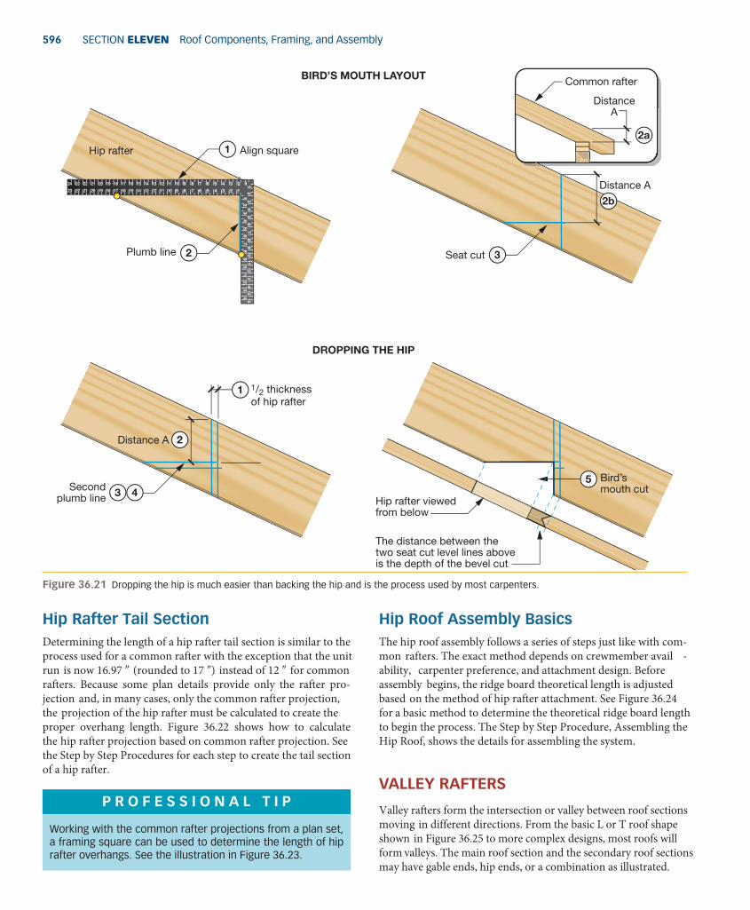
596 SECTion ElEvEn Roof Components, Framing, and assembly
hip Roof assembly BasicsThe hip roof assembly follows a series of steps just like with com-mon rafters. The exact method depends on crewmember avail -ability, carpenter preference, and attachment design. Before assembly begins, the ridge board theoretical length is adjusted based on the method of hip rafter attachment. See Figure 36.24 for a basic method to determine the theoretical ridge board length to begin the process. The Step by Step Procedure, Assembling the Hip Roof, shows the details for assembling the system.
VaLLey RafTeRs
Valley rafters form the intersection or valley between roof sections moving in different directions. From the basic L or T roof shape shown in Figure 36.25 to more complex designs, most roofs will form valleys. The main roof section and the secondary roof sections may have gable ends, hip ends, or a combination as illustrated.
hip Rafter Tail sectionDetermining the length of a hip rafter tail section is similar to the process used for a common rafter with the exception that the unit run is now 16.97 ″ (rounded to 17 ″) instead of 12 ″ for common rafters. Because some plan details provide only the rafter pro-jection and, in many cases, only the common rafter projection, the projection of the hip rafter must be calculated to create the proper overhang length. Figure 36.22 shows how to calculate the hip rafter projection based on common rafter projection. See the Step by Step Procedures for each step to create the tail section of a hip rafter.
figure 36.21 Dropping the hip is much easier than backing the hip and is the process used by most carpenters.
The distance between the two seat cut level lines above is the depth of the bevel cut
Plumb line
Secondplumb line
12
34
56
78
8 7 6 5 4 3 2 114151617181920212223 13 12 11 10 9
8 7 6 5 4 3 2 11415161718192021222324 13 12 11 10 9
910
1112
1314
12
34
56
78
910
1112
1314
1516
2
43
DROPPING THE HIP
BIRD’S MOUTH LAYOUT
1
Seat cut
Hip rafter
2b
3
Align square
Common rafter
DistanceA
Distance A
2Distance A
1 1/2 thickness of hip rafter
2a
5 Bird’smouth cut
Hip rafter viewedfrom below
P R o f e s s i o n a L T i P
Working with the common rafter projections from a plan set, a framing square can be used to determine the length of hip rafter overhangs. See the illustration in Figure 36.23.
M36_POWE4171_01_SE_C36_582-613.indd 596 18/12/14 5:24 PM

ChapTER 36 Common, hip, and Valley Rafters 597
When the spans of the roofs are unequal, a supporting valley rafter runs from the wall plate up to the ridge board. On the other side, a shortened valley rafter runs from the wall plate to the support-ing valley rafter. The rest of the roof system is a series of various jack rafters discussed in Chapter 37. See the illustrations in Figure 36.27.
The span of the roof determines the type of valley rafter re -quired. For roofs with equal spans, valley rafters start on the wall plates and intersect at the main ridge board. When the end of the main roof is a hip, these valley rafters also run parallel to the hip rafters and are the same length as shown in Figure 36.26.
figure 36.22 Calculating a hip rafter projection.
figure 36.23 Understanding the framing square and the right triangle are important skills for carpenters who build roof systems.
The plan detail calls for a common rafter projection of 24"; complete this simple math procedure to calculate the hip rafter projection.
Step 1) Divide the projection by 12" to find the units of run. Remember the unit run is the same for common and hip rafters. 24" / 12" = 2 unit runs.
Step 2) Since the hip unit length is 17" inches instead of 12" as with common rafters, multiply the unit runs by 17". Calculate 17" × 2 (unit runs) = 34". This is theprojection of the hip rafter.
See the Step by Step Procedures for layout of the hiprafter tail.
Common rafter
Hip rafter
Hip jack rafters have same projection ascommon rafters
24"Projection
24"
Pro
ject
ion34"
Projection
Blade
Tongue
C2 = A2 + B2 C2 = 162 + 162 C2 = 512 C2 = 512 C = 22.62". We now have 22" plus the decimalconvert the decimal: .62 x 16 = 9.92round to 10/16, reduced to 5/8 for a total hip tail length of 22 5/8". Same as measured across the framing square in the illustration.
Common rafter
16"22
5 / 8"
Projection
12345678
87
65
43
21
1415
1617
1819
2021
2223
1312
1110
98
76
54
32
114
1516
1718
1920
2122
2324
1312
1110
9
9101112131412345678910111213141516
M36_POWE4171_01_SE_C36_582-613.indd 597 18/12/14 5:24 PM

598 SECTion ElEvEn Roof Components, Framing, and assembly
Valley Rafter Layout ProceduresWith equal span roofs, valley rafters have the same unit run (16.97″) as hip rafters; therefore they are marked and measured in the same way. The total run is also the same: for standard 45° hip and val -ley rafters the total run is always one-half the total span of the roof. Note the spans for an equal span roof in Figure 36.27. Only the seat cut and the tail section is different for valley rafters on equal span roofs. With supporting valley rafters, calculating the theoretical line length is also the same process (unit length 3 run).
Calculating a valley rafter Theoretical lengthRemember that the span is the base of the right triangle, called the total run. With intersecting roofs of equal spans, the total rise
figure 36.24 Determining the ridge board length for basic hip roof designs.
Hip rafter
Com
mon
raft
er
Com
mon
raft
er
Ridge board
Theoretical length
Buildinglength 52'
Theoreticalrafter line
Theoreticalhip rafter line
Buildingwidth 26'
When common rafters are on the end of the ridge board, the ridge must be extended 1/2 the thickness of the common rafter, usually 3/4".
Run of rafter 13'
Total span 26'
Square13' × 13'
Subtract the total span of the roof from the total length of the roof. 52' – 26' = 26' This is the theoretical ridge board length.
THEORETICAL RIDGE BOARD LENGTH FOR HIP ROOFS
RIDGE BOARD ADJUSTMENT WITHCOMMON RAFTERS ON THE END
RIDGE BOARD ADJUSTMENT WITHOUT COMMON RAFTERS ON THE END
Actual length
3/4" 3/4"
3/4"3/4" 3/4" 3/4"
Ridge board
Theoretical length
When only the hip rafters are on the ridge board end, extend the ridge board by 1/2 the thickness of the ridge board plus 1/2 the 45° thickness of the hip rafter.
Actual length
45°
Hip rafte
r
figure 36.25 Roof design is limited only by owner preference, design characteristics to support the load, and the purpose of the building. When valleys are formed, valley rafters and jack rafters are required to tie-in and complete the roof framing.
T-SHAPE
L-SHAPE
P R o f e s s i o n a L T i P
The cheek cuts described for hip rafters work with valley raft-ers and jack rafters. Jack rafters are shortened versions of common rafters and are calculated with the same technique.
M36_POWE4171_01_SE_C36_582-613.indd 598 18/12/14 5:24 PM

ChapTER 36 Common, hip, and Valley Rafters 599
2. Multiply the total run (same as hip rafters on equal span roofs) by the unit length found in step one (18.76 ″): 12 × 18.76 = 225.12″
3. Divide by 12 to convert to feet: 225.12>12 = 18.76′, which con-verts to 18′@9 1>8″ as the valley rafter total theoretical length.
Understanding the simple relationship of the rafters to the right triangle is essential to efficient, safe, and faster roof framing. As this section shows, the lengths of hip and valley rafters are the same on equal span roofs. Only the seat cut and tail, discussed in the following sections, are different.
figure 36.26 Equal span roofs have the same total span for each section, creating equal lengths for hip and valley rafters.
Span A andspan B are equal
Sp
an B
(hip
)
Span A (gable)
figure 36.27 Roofs with major and minor spans have valley rafters and jacks as typical framing components.
Maj
or s
pan
EQUAL SPAN ROOFS UNEQUAL SPAN ROOFS
Major span
Span
B
Maj
or s
pan
Span
B
Span AMinor span
Span A
Hip Jack RafterHip rafterCommon rafterShortened valley rafterCripple jack rafter
Major ridgeValley jack rafterSupporting valley rafterMinor ridge
m a T h T i P
When calculating total length for equal span and supporting valley rafters, the framing square table provides the unit length per foot of run. Use the procedure illustrated in Figure 36.28.
Valley Rafter seat CutsThe seat cut for valley rafters (Figure 36.29) is a unique cut with a double cheek cut on the bottom so the rafter will sit against the inside corner of the intersection wall plates. The seat cut is also longer because the rafter sits on the wall plates at a 45° an -gle, lengthening the effective support area (just like hip rafters). Remember, with all rafter types, the bird’s mouth must have full support from the wall plates below. See the Step by Step Procedure for making a valley rafter tail reverse cheek cut.
Valley Rafter Tail sectionThe length of a valley rafter tail is calculated by the same proce -dure used for hip rafters. See the description of the Hip Rafter Tail Section and Figures 36.22 and 36.23 as examples. The outward end of a valley rafter has a reverse cheek cut to allow the corner of the
is also the same. Therefore, the diagonal (length of hip and valley rafters) for this roof style are the same. The theoretical line length math procedure works for equal span rafters or supporting val -ley rafters. Compare the following math example, illustrated in Figure 36.28, with the hip rafter that was calculated in the text for Figure 36.18 (p.594) and confirm that the calculation methods are the same.
In this example we have a roof with a total span of 24′, so the total run (half the total span) is 12′. Use a roof slope of 8
12 and follow these steps to calculate valley rafter theoretical length. See the Step by Step Procedures section of the chapter for marking a valley rafter on the ridge board end.
1. Look under the 8″ mark on the second line of the framing square table; this is for hip and valley rafters. This line shows 18.76″ per foot of run.
M36_POWE4171_01_SE_C36_582-613.indd 599 18/12/14 5:24 PM

600 SECTion ElEvEn Roof Components, Framing, and assembly
1. At the theoretical line length, draw a plumb line. 2. Measure half the thickness of the supporting valley rafter
(3>4″ usually) perpendicular to the first plumb line. In other words, measure down the rafter 3>4″.
3. Make a second plumb line mark at the mark made in step two. 4. Cut the shortened valley rafter along the second plumb line
as the actual length.
finished fascia to remain in line with the rest of the fascia and soffit assembly, as shown in Figure 36.30. See the Step by Step Procedure at the end of the chapter for making this type of tail cut.
shortened Valley RafterWhen building an intersecting roof where the major and minor spans are not equal, a supporting and a shortened valley rafter are required. The length of a shortened valley rafter is calculated based on the run of the minor span. Use the framing square table for hip and valley rafters to get the unit length and make the calculations as in previous sections of this chapter.
The shortened valley rafter intersects the supporting valley rafter at a 90° angle as shown in Figure 36.31. This is a square cut designed to mate flush with the side of the supporting rafter. After the theoretical line length is calculated, shorten the valley rafter with the following easy steps:
figure 36.28 Valley rafter length is calculated in the same way as hip rafter length.
Framing squaretable
Hip rafter and valley rafter total theoretical length =
18' 9 1/8"
Supportingvalley rafterHip rafter
Shortenedvalley rafter
24' T
otal
spa
n
Theoretical line length
812
12' Total run24' Total span
figure 36.29 Seat cuts for valley rafters are designed to fit against the corner of intersecting wall plates.
Dashed line representsbottom edge of rafter
top plate of wall
Cheek cut
Valley rafter
View from outside View from inside
figure 36.30 The tail end of a valley rafter has a reverse cheek cut so the overhang fascia meets properly and square at the inside corner of the building.
Valley rafter
Valley jack rafter
Common rafter
Top plate
Fascia board
Reverse cheek cut
Seat cut (Bird's Mouth)
M36_POWE4171_01_SE_C36_582-613.indd 600 18/12/14 5:24 PM

ChapTER 36 Common, hip, and Valley Rafters 601
figure 36.31 Shortened valley rafters are cut square at the upper end to mate 90° to the supporting valley rafter.
1
3
2
Shortened valley rafter
90º
UPPER END
Theoretical line length Theoretical
line lengthPlumbline
Secondplumb line
(actual length)
3/4"
Common Rafter and Hip Rafter Theoretical Line Lengths1. Calculate these common rafter theoretical line lengths
(LL) for roof slopes of 512 , 9
12 , and 1612 . Each building
has a total span of 42 feet. notice the LL is actually the hypotenuse of a right triangle; in other words, C of the right triangle formula C2 5 a2 1 B2.
a. 512 : LL2 5 unit rise2 1 unit run2
LL2 5 25 1 144
LL2 5 √169
LL 5 13″
13″ 3 21 unit runs 5 273″
Reduce to feet and inches: 273>12 5 22.75 or 22′@8″.
b. 912 : LL2 5 unit rise2 1 unit run2
LL2 5 81 1 144
LL2 5 √225 5 15″
15″ × 21 unit runs 5 315″
Reduce to feet and inches: 315>12 5 26.25 or 26′@3″.
c. 1612 : LL2 5 unit rise2 1 unit run2
LL2 5 256 1 144
LL2 5 √400 5 20″
20″ × 21 unit runs 5 420″
Reduce to feet and inches: 420>12 5 35′.
For example c, what product could you use to create this rafter?
2. Calculate the hip rafter theoretical line length (LL) for a roof slope of 7
12 . The total span of the building end is 24 feet.
step
by s
tep
pRO
ced
URe
s
EXAMPLE A) 5:12
EXAMPLE B) 9:12
512
912
EXAMPLE C) 16:12
EXAMPLE D) 7:12
16
12
12
7
22'-8" theoretical line length
26'-3" theoretical line length
35'-0" theoretical line length
32'-13 /8"
theoretical line length
21' total run
21' total run
21' total run
12' total run
8'-1
"to
tal r
ise
15'-
9" t
otal
ris
e28
'-0"
tot
al r
ise
7'-0
"to
tal r
ise
(continued)
M36_POWE4171_01_SE_C36_582-613.indd 601 18/12/14 5:24 PM

602 SECTion ElEvEn Roof Components, Framing, and assembly
Remember, the unit run for a hip rafter is 16.97″; when calculating, some carpenters may round this up to 17″.
d. 712 : LL2 5 unit rise2 1 unit run2
LL2 5 49 1 288
LL2 5 √337 5 18.35″
18.35″ 3 21 unit runs 5 385.35″
m a T h T i P
For practical purposes, the unit run (16.97″) of a hip or valley rafter can be rounded up to 17″ for calculating.
(continued) Reduce to feet and inches: 385.35>12 = 32.11′ or
32′@13>8″.
Common Rafter Layout Using a Framing SquareFollow this procedure for common rafter layout using a framing square. notice in step 4b how the framing square can be used to lay out each unit of run (12) to develop the theoretical line length without calculations. however, the calculated and measured LL shown in the following steps is typically more common and eliminates most marking errors.
The roof system has a slope of 612 and a total span of
24′. Remember to check the rafter stock for any crowning and make sure the crowned edge is the upper edge as you begin marking the rafter. as always, the theoretical line length must be calculated first. Use the formula in step 1.
1. Calculate the theoretical line length: slope unit length 3 unit runs. half the total span is 12′, so you have 12 units of run. Look at the rafter table under the 6″ mark to find the unit length for a 6
12 slope is 13.42″. Multiply 13.42″ 3 the unit runs: 13.42 3 12 5 161.04″. Convert the fraction: .04 3 16 5 .64, and round to 1>16 for a total of 1611>16″ or 1611>16″>12″ = 13′@51>16″ total theoretical line length.
2. Using the 6″ mark on the framing square tongue and the 12″ mark on the blade, align the marks along the top edge of the rafter stock. Do this close to the end of the rafter to reduce waste.
3. When the square is in place, mark the plumb line along the tongue of the framing square. This will become the outward end of the rafter.
4. Starting from the plumb line mark, measure along the rafter stock the total theoretical line length calculated in step 1, 13′@51>16″, and make a mark. This is the ridge board end of the rafter.
5. Take half the ridge board stock thickness (typically 3>4″) and measure perpendicular (90°) to the plumb line made in step 4 and make a new plumb line mark. This new plumb line will be the actual cut line that takes into ac-count the ridge thickness.
6. align the framing square with the theoretical line length marked in step 3. This becomes the bird’s mouth plumb line.
7. Simply slide the framing square down the bird’s mouth plumb line, maintaining alignment, and then mark the level line. Make the line no longer than the width of the wall plate, which is usually 31>2″ for 2 3 4 wall stock or 51>2″ for 2 3 6 wall stock.
Complete the tail section as illustrated in the Step by Step procedure: Calculating and Marking the Common Rafter Tail Section.
step
by s
tep
pRO
ced
URe
s
612
13'-5 1/16" theoretical line length
12' total run
Framing squaretable
1
M36_POWE4171_01_SE_C36_582-613.indd 602 18/12/14 5:24 PM

ChapTER 36 Common, hip, and Valley Rafters 603
Mark rafterat 6" on tongue
12" on blade
12
34
56
78
8 7 6 5 4 3 2 114151617181920212223 13 12 11 10 9
8 7 6 5 4 3 2 11415161718192021222324 13 12 11 10 9
910
1112
1314
12
34
56
78
910
1112
1314
1516
2-3
Mark rafter
Measure 13'-5 1/16" 4A
12" on blade
6" on tongue
Mark rafter
Square
4B
3/4"
Actual cut line
Measureperpendicular
5
Draw plumbline at markfrom step 3
12
34
56
78
8 7 6 5 4 3 2 114151617181920212223 13 12 11 10 9
8 7 6 5 4 3 2 11415161718192021222324 13 12 11 10 9
910
1112
1314
12
34
56
78
910
1112
1314
1516
6
Draw plumbline at markfrom step 3
Level lineWall
width
7
M36_POWE4171_01_SE_C36_582-613.indd 603 18/12/14 5:24 PM

604 SECTion ElEvEn Roof Components, Framing, and assembly
Using a Speed Square (Rafter Square) to Lay Out a Common Raftera rafter square or Speed Square is the triangular square used by many carpenters because it is easy to carry in a tool pouch. The technique for using these smaller squares follows the same principles as using a full-size framing square. The steps that follow illustrate how to lay out a common rafter using a small rafter square. The example roof system has a slope of 6
12 and a total span of 24′. Because the total run of a rafter is always half the total span, our example has a total run of 12′, as in the preceding example using the traditional large framing square.
Take the given roof slope of 612 and go to the respec-
tive rafter table provided with the rafter square. These tables calculate the total rafter length based on the total run of the common, hip, or valley rafter. a typical chart will read, the total length for a 12′ total run is given as 13′@5″. You may notice the table value is slightly different from the calculated distance from the framing square method. This variance will be minimal and should not affect roof design in a meaningful way.
always check the rafter stock for any crown and make this the top edge before proceeding.
1. place the pivot point of the rafter square on the top edge (crown edge) and pivot the rafter square until the 6″ mark on the common line intersects with the edge of the rafter stock.
2. Mark along the ruler edge of the rafter square to make the plumb line mark.
3. To intersect with the plumb line marked in step 2, mark a centerline along the ridge stock (1/2” total width). This is the plumb line cut mark.
4. From the first plumb line marked in step 2, measure down the top edge of the rafter stock the length found in the rafter table from step 2. This is the line length of the rafter, 13′@5″ in our example.
5. at the 13′@5″ mark, set the rafter square on the pivot point and the 6″ common rafter slope line and make another plumb line mark. This plumb line represents the end of the rafter at the outer edge of the wall plane.
6. Line up the dashed line on the rafter square with the plumb mark. Make a mark along the edge opposite the ruler for the seat cut level line. Make sure this mark does not extend up more than one-third the thickness of the rafter stock.
With the above steps complete, the tail section can be cal-culated and marked. Use the same procedure shown next in the “Calculating and Marking the Common Rafter Tail Sec-tion”. The only difference is the tool used to mark the rafter.
step
by s
tep
pRO
ced
URe
s
1 Pivot point
6" mark (see square below)
3
2 Plumb line
1 /2
1 /2
30
30
24
24
2535
4555
6575
18
18
14
1215
15
10
10
8
8
7
7
5
5
5
4 4
3 3
2
21
1
6
6
2
3
4
5
6
1
2
3
4
5
413'-5"
5Plumb line
6" mark
Pivot point
6
Plumb line
Pivot point
Rafter
seat
M36_POWE4171_01_SE_C36_582-613.indd 604 18/12/14 5:24 PM

ChapTER 36 Common, hip, and Valley Rafters 605
Calculating and Marking the Common Rafter Tail SectionThe tail section is marked according to the projection provided in the plan set detail. Follow this procedure for a given projection of 24″ on a 6
12 roof slope.
1. Calculate the overhang length based on the given projection.
a. Divide the 24″ projection by the 12″ unit run: 24″>12″ = 2 unit runs
b. Refer to the framing square for a 612 slope and note
a unit run is 13.42″
c. Multiply 13.42″ 3 2 units for an overhang length of 26.84″
d. Convert the decimal of the 26.84″ calculated in step c: .84 3 16 5 13.44, rounded to the closest whole number gives 2613>16″ overhang length
2. Starting at the bird’s mouth plumb cut line, measure down the rafter top edge 2613>16″ and make a mark.
3. Set the framing square on the 6″ tongue and 12″ blade, just like any other plumb cut for a 6
12 roof slope, and mark a plumb line at the mark created in step 2. This is the rafter tail end plumb cut.
4. Use a level or the framing square, and make a level line cut intersecting with the rafter tail plumb line. This line should be long enough to allow full attachment of the soffit material.
step
by s
tep
pRO
ced
URe
s
Bird’s mouth
24" projection
6
12
Rafter1
Mark
26 13/16" overhang
2
End plumb cut
12" blade
6" tongue
12
34
56
78
8 7 6 5 4 3 2 114151617181920212223 13 12 11 10 98 7 6 5 4 3 2 11415161718192021222324 13 12 11 10 9
910
1112
1314
12
34
56
78
910
1112
1314
1516
3
Level
Levelline
4
M36_POWE4171_01_SE_C36_582-613.indd 605 18/12/14 5:24 PM

606 SECTion ElEvEn Roof Components, Framing, and assembly
Making a Plumb Cut on Common Rafter TailsSome carpenters will allow each rafter tail to run wild and make the final overhang plumb cut after all rafters are installed. if any rafters are not exactly the same length or the building has very long walls, this technique helps assure the finished eave construction is very straight and true.
First the carpenter must calculate the overhang length using the same method as the last example. once the length of the rafter tail is known carpenters mark and cut all rafters with the following steps.
1. Mark the rafter on each end of the wall with the calcu-lated length. Then pull a chalk line and snap the line to all other rafters. This transfers the calculated overhang length to all rafter tails.
2. Take a framing square or level and working from the line snapped in step 1, mark the plumb line on each rafter.
3. Use all necessary ppE and safety precautions when cut-ting the rafter tails, typically from a ladder at this stage of construction.
step
by s
tep
pRO
ced
URe
s
Chalkmarks
Plumblines
Markplumbline
1
2
3
4
5
6
7
8
87654321 14 15 16 17 18 19 20 21 22 2313121110987654321 14 15 16 17 18 19 20 21 22 23 24131211109
91011121314
1
2
3
4
5
6
7
8
910111213141516
2
1
Measuring and Marking Single Cheek Cuts for a Hip Rafter1. Start by marking the second plumb line (actual cut line)
described in the text under Shortening the hip Rafter at the Ridge Board (Figure 36.19).
2. Use a square and make a square mark across the top edge of the rafter at the actual cut plumb line.
3. Make another mark down the center of the hip rafter from the edge to below the mark made in step 2.
4. From the cut line marked in step 1, measure perpen-dicularly (square to the line) half the thickness of the hip rafter stock, usually 3>4″, and make a mark.
5. Draw a third plumb line that intersects the mark from step 4.
6. Draw a line that runs diagonally from the top edge at the third plumb line back through the centerline. This line is the angle of the cheek cut.
7. Lay the rafter on the wide edge, set a circular saw to 45°, and make the cheek cut.
step
by s
tep
pRO
ced
URe
s
2
Mark fromtheoreticalline length
Cut line
1
Square line
Hip rafter
1/16"
1
M36_POWE4171_01_SE_C36_582-613.indd 606 18/12/14 5:24 PM

ChapTER 36 Common, hip, and Valley Rafters 607
Center line3
Plumb line
4
5
3/4"
Diagonal line
Cheek cut
6
7
Measuring and Marking Double Cheek Cuts for a Hip Raftera double cheek cut is a continuation of the process for a single cheek cut. This may be required by plans depend-ing on where the closest common rafter intersects the ridge board.
1. From the third plumb line marked in the preceding single cheek cut procedure (steps 4 and 5), make a mark square across the top edge of the rafter.
2. Draw a diagonal from the end of the line made in step 1 through the centerline of the rafter.
3. Use the framing square and draw another plumb line on the other side of the rafter where the diagonal meets the edge of the rafter as a guide for the saw when making the cheek cut.
4. Set the saw base at 45° to make single and double cheek cuts and follow the lines.
step
by s
tep
pRO
ced
URe
s
Hip rafter
Third plumb line
Square line
1Diagonal line2
(continued)
M36_POWE4171_01_SE_C36_582-613.indd 607 18/12/14 5:24 PM

608 SECTion ElEvEn Roof Components, Framing, and assembly
(continued)
Plumb line
Flip sideof rafter
3
Double cheek cut
Ridge board
Commonrafter
Hip rafter
4
Calculating and Marking the Tail of a Hip Rafter1. Determine the common rafter projection; in this example
the projection is 30″.
2. Divide the 30″ by 12 to find the projection units of run. Remember the units of run for hips at 45° and common rafters is the same: 30″>12″ = 2.5 units of run.
3. Start at the plumb line marking the end of the hip rafter where the bird’s mouth is formed. Set the framing square tongue in line with the bird’s mouth plumb line and the blade 17″ mark intersecting the edge of the rafter. Make a mark; this is one unit of run for a hip rafter.
4. Repeat step 3 for all full unit runs calculated. For the final 1/2 unit run, see step 5.
5. now repeat the procedure for half a unit run because our example has 21>2 unit runs for the 30″ projection. half of17″ is 81>2, so set the blade of the framing square on the 81>2″ line and make the final mark.
6. plumb this line as the end of the hip rafter tail.
step
by s
tep
pRO
ced
URe
s
Common rafter
30"
30" / 12" =2.5 units of run
Projection1-2
Hip rafter
Blade
Plumb line
Tong
ue1
23
45
67
8
87654321 14 15 16 17 18 19 20 21 22 23131211109
87654321 14 15 16 17 18 19 20 21 22 23 24131211109
910
1112
1314
12
34
56
78
910
1112
1314
1516
17"
3
4
Plumb line at end of rafter
One full unit and one1/2 unit shown
17" mark
8 1/2"5
6
12
34
56
78
87654321 14 15 16 17 18 19 20 21 22 23131211109
87654321 14 15 16 17 18 19 20 21 22 23 24131211109
910
1112
1314
12
34
56
78
910
1112
1314
1516
M36_POWE4171_01_SE_C36_582-613.indd 608 18/12/14 5:24 PM

ChapTER 36 Common, hip, and Valley Rafters 609
Assembling the Hip Roofafter the ridge board theoretical length is adjusted to its ac-tual length and all components are precut, the roof assem-bly can begin. The process involves the same steps from raising a common rafter roof system, keeping the ridge board equally supported as the components are added. The hip ends will be different than a straight gable roof, of course, so follow these steps:
1. after the ridge board length is adjusted, set the board against the wall plates and transfer the rafter on-center marks to the ridge.
2. Use sheathing material to create a working platform. never try to build a roof system while walking on ceiling joists; this is very dangerous and may lead to serious injuries.
3. Depending on the size of the crew, set the ridge board at the total rise height either by using temporary braces or by attaching common rafters to the ridge and nailing the whole assembly in place.
4. nail the common rafters that butt the ends of the ridge board. Most hip roofs have one common rafter in the center.
5. Set and nail all hip rafters into place. hip rafters may be on both ends or on one end of the building, depending on the roof design.
6. nail the remaining common rafters and hip jack rafters to complete the process.
step
by s
tep
pRO
ced
URe
s
Transfer rafter marks fromtop plate to ridge board
Ridge board
Top plate
Ceiling joist
1
Sheathing and boards fastened to ceiling joists for lateral support and working platform
2
Hip rafters
5
Framing on far side of roof removed for clarity
Common rafters
Hip jack rafter
6
Ridge boardCommon rafters
Bracing
3
Common rafters atends of ridge board
Bracing removed asframe becomes stable
4
M36_POWE4171_01_SE_C36_582-613.indd 609 18/12/14 5:24 PM

610 SECTion ElEvEn Roof Components, Framing, and assembly
Supporting Valley Rafter Layout Procedure
once the valley rafter theoretical line length has been calcu-lated, the layout procedure can begin. Follow these steps to mark and cut the ridge board end of a supporting valley rafter. Equal-span valley rafters use the same cheek cut procedures shown in the Step by Step procedures for hip rafters. Refer to the procedures for single and double cheek cuts on hip raft-ers and apply the technique to equal-span valley rafters.
1. Start from the plumb line representing the theoretical line length of the rafter.
2. Draw a centerline down the top edge of the rafter stock.
3. Measure at 90° to the plumb line half the thickness of the ridge board and make a mark. For a single thickness ridge board this is 3>4″.
4. Draw a second plumb line at the mark made in step 3.
5. Use a small square and draw a square line across the top edge of the rafter at the intersection with the second plumb line.
6. Measure 90° to the second plumb line, half the valley rafter stock, and draw a third plumb line.
7. Draw a square line across the rafter edge at the third plumb line.
8. Draw a fourth plumb line on the other side of the rafter stock at the line drawn in step 7. This step creates cut lines on both sides of the rafter stock as a guide.
9. From the top edge of the third and fourth plumb lines, use a straightedge and draw a diagonal back that inter-sects the square line drawn in step 5. This forms a small triangle that represents the cut line for the cheek cuts.
step
by s
tep
pRO
ced
URe
s
2
1
Mark fromtheoreticalline length
Plumb line
Center line
Supportingvalley rafter
3/4" 3
4
7
Plumb line
Second square line
5 Square line
3/4"
6
Opposite side square line
8
9 Diagonal lines
Make single cheek cut on diagonal mark. Use two diagonals to make a double cheek cut.
M36_POWE4171_01_SE_C36_582-613.indd 610 18/12/14 5:24 PM

ChapTER 36 Common, hip, and Valley Rafters 611
P R o f e s s i o n a L T i P
a supporting valley rafter must have one edge backed (beveled) from the main ridge board down to the intersec-tion of the shortened valley rafter. otherwise, this edge will be above the roof plane when sheathing is applied.
45° angle from the center line outward, cut with a circular saw set at 45°
Major ridge
A CrossSection A
Minor ridge
Supporting valley rafter
Shortened valley rafter
Supporting valley rafter
45°
P R o f e s s i o n a L T i P
a centerline is easy to draw on the edge of rafter stock or any other lumber using a try square as shown in the ac-companying illustration. Some squares have indentations in the end of the square to set the pencil and “slide” down the lumber being marked.
12
1011
12
12
1
12
Set rule to the 3/4" mark and tighten the nut
12
34
56
78
910
1112
12
34
56
78
910
1112
12
12
12
1 1 /
2" d
ress
ed d
imen
sion
nom
inal
siz
e 2×
3/ 4
"
Pencil mark
Notch for pencil
Valley Rafter Tail Reverse Cheek CutThe final cut for a valley rafter tail is essentially a reverse cheek cut. The technique used for marking this cut is the same as other cheek cuts. Follow these steps:
1. To calculate the tail length for a valley rafter, follow the same procedure used for hip rafter tail lengths.
2. at the mark representing the length of the rafter tail, make a plumb line mark.
3. Make a centerline mark down the rafter tail in this area.
4. Measure 90° from the first plumb line half the thickness of the valley rafter (3>4″) and place a mark.
step
by s
tep
pRO
ced
URe
s
5. Make a second plumb line mark at the location meas-ured in step 4.
6. Take a small square and mark square lines across the top of the rafter edge at each plumb line.
7. Take a straightedge and mark from the second plumb line back through the centerline at the first plumb line, forming a small pyramid.
8. Cut along the marks made in step 7 to complete the reverse cheek cut.
(continued)
M36_POWE4171_01_SE_C36_582-613.indd 611 18/12/14 5:24 PM

612 SECTion ElEvEn Roof Components, Framing, and assembly
Plumbline
Center line
Reversecheek cut
2
3
1
Tail length as calculated
Plumbline
Square line
43/4"
5
6
View from top
Diagonal lines
7
View from top
Reversecheek cut
8
(continued)
M36_POWE4171_01_SE_C36_582-613.indd 612 18/12/14 5:24 PM

ChapTER 36 Common, hip, and Valley Rafters 613
reViewQUestiOns 1. Explain the difference between the theoretical line length and
the cut line length. 2. What are the rafter tables on a framing square used for
during framing? 3. How do the framing square rafter tables relate to the
Pythagorean Theorem and a right triangle? 4. Working with an
128 roof slope, what is the theoretical length
for a common rafter on a roof system with a 24′ total span? 5. Explain the difference between the overhang and the projection
of a common rafter. Draw and dimension an overhang of 12″ and a projection of 12″; then compare the results visually.
6. What is the typical angle at which hip rafters and supporting valley rafters attach to the main ridge board on an intersect -ing roof system?
7. What does shortening a rafter mean? How much is a sup-porting valley rafter shortened on the end that meets the ridge board?
8. For conventional intersecting roofs that create 45° angles, what relationship do the hip and valley rafters have with each other?
9. How many hip rafters are found on the main roof system when hips are designed for both ends of the roof?
10. Is there a difference between a single cheek cut and a side cut? What is it?
11. How would you define an equal span intersecting roof? 12. For a total run of 13 ′, what is the length of a common rafter
with a 612 slope roof? With a 15
12 slope roof using a 13 ′ total run, what would be the length of a hip rafter?
13. Using a framing square, determine the total length for a rafter with a slope triangle of 6 12 and a total run of 12′. How about 8
12 slope and a total run of 9′? 14. What is the overhang length for a rafter tail with a projection
of 20″ and a roof slope of 812 ?
15. What is the maximum depth of cut for a bird’s mouth? Why is this important?
16. How can the overhang length affect overall operating efficiency of a home?
rafter tables
theoretical line lengths
bird’s mouth
overhang
projection
closed soffit
open soffit
run wild
gable end studs
hip rafters
side cut
single cheek cut
double cheek cut
dropping the hip
backing the hip
supporting valley rafter
shortened valley rafter
KeyteRms
M36_POWE4171_01_SE_C36_582-613.indd 613 18/12/14 5:24 PM


![DA190759 Original Architectural Drawings - [A6402145].pdf](https://static.fdokumen.com/doc/165x107/6327476b5c2c3bbfa8041923/da190759-original-architectural-drawings-a6402145pdf.jpg)