V8 Series File Conversion
150
V8 Series File Conversion The V8 series can substitute for the MONITOUCH V series and GD-80 series. However, compatibility cannot be fully maintained, and there are some limitations. In this manual, notes on the substitution are described. For more information on functions and specifications for the V series, refer to the relevant manuals provided separately, such as V Series Reference Manual, V8 Series Reference Manual, and V8 Series Hardware Specifications. For more information on functions and specifications for the GD-80 series, refer to the relevant manuals provided separately, such as GD-80 User’s Manual and GD-80 Hardware Specifications. Hakko Electronics Co., Ltd.
-
Upload
khangminh22 -
Category
Documents
-
view
0 -
download
0
Transcript of V8 Series File Conversion

V8 Series File Conversion
The V8 series can substitute for the MONITOUCH V series and GD-80 series.However, compatibility cannot be fully maintained, and there are some limitations.
In this manual, notes on the substitution are described.
For more information on functions and specifications for the V series, refer to the relevant manuals provided separately, such as V Series Reference Manual, V8 Series Reference Manual, and V8 Series Hardware Specifications.For more information on functions and specifications for the GD-80 series, refer to the relevant manuals provided separately, such as GD-80 User’s Manual and GD-80 Hardware Specifications.
Hakko Electronics Co., Ltd.

Record of Revisions
Reference numbers are shown at the bottom left corner on the back cover of each manual.
Printing Date Reference No. Revised Contents
April, 2010 5068NE0 First edition
January, 2012 5068NE1 Second edition- Substitution from V6 to V8 added- Substitution from V4 to V8 added- Substitution from GD-80 to V8 added
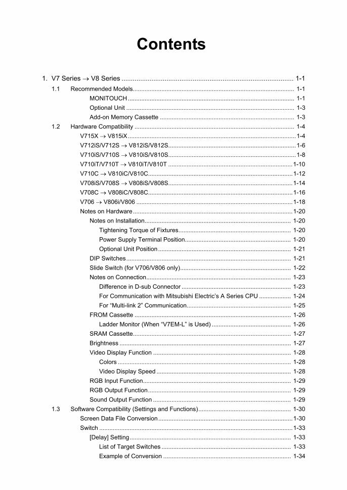
Contents
1. V7 Series → V8 Series ............................................................................................ 1-11.1 Recommended Models................................................................................................ 1-1
MONITOUCH................................................................................................... 1-1Optional Unit .................................................................................................... 1-3Add-on Memory Cassette ................................................................................ 1-3
1.2 Hardware Compatibility ............................................................................................... 1-4V715X → V815iX....................................................................................................1-4V712iS/V712S → V812iS/V812S............................................................................1-6V710iS/V710S → V810iS/V810S............................................................................1-8V710iT/V710T → V810iT/V810T ..........................................................................1-10V710C → V810iC/V810C......................................................................................1-12V708iS/V708S → V808iS/V808S..........................................................................1-14V708C → V808iC/V808C......................................................................................1-16V706 → V806i/V806 .............................................................................................1-18Notes on Hardware...............................................................................................1-20
Notes on Installation....................................................................................... 1-20Tightening Torque of Fixtures................................................................... 1-20Power Supply Terminal Position............................................................... 1-20Optional Unit Position ............................................................................... 1-21
DIP Switches.................................................................................................. 1-21Slide Switch (for V706/V806 only).................................................................. 1-22Notes on Connection...................................................................................... 1-23
Difference in D-sub Connector ................................................................. 1-23For Communication with Mitsubishi Electric’s A Series CPU ................... 1-24For “Multi-link 2” Communication.............................................................. 1-25
FROM Cassette ............................................................................................. 1-26Ladder Monitor (When “V7EM-L” is Used) ............................................... 1-26
SRAM Cassette.............................................................................................. 1-27Brightness ...................................................................................................... 1-27Video Display Function .................................................................................. 1-28
Colors ....................................................................................................... 1-28Video Display Speed ................................................................................ 1-28
RGB Input Function........................................................................................ 1-29RGB Output Function..................................................................................... 1-29Sound Output Function .................................................................................. 1-29
1.3 Software Compatibility (Settings and Functions)....................................................... 1-30Screen Data File Conversion................................................................................1-30Switch ...................................................................................................................1-33
[Delay] Setting................................................................................................ 1-33List of Target Switches ............................................................................. 1-33Example of Conversion ............................................................................ 1-34

[Function: Card Format] Switch...................................................................... 1-34Sampling...............................................................................................................1-35
Store Target ................................................................................................... 1-35No. of Samplings............................................................................................ 1-36
Primary Store Target ................................................................................ 1-36Secondary Store Target ........................................................................... 1-36
Example of Conversion .................................................................................. 1-37Macro ............................................................................................................. 1-38
SRAM ...................................................................................................................1-42Built-in SRAM / SRAM Cassette .................................................................... 1-42
SRAM/Clock Setting ................................................................................. 1-42Formatting of SRAM................................................................................. 1-43SRAM Data Conversion (Memory Manager)............................................ 1-43
SRAM Card (CREC + REC-MCARD) ............................................................ 1-44Formatting of SRAM................................................................................. 1-44How to Use SRAM Card Data (Data Logging) on V8 ............................... 1-44How to Use SRAM Card Data (Memory Manager) on V8 ........................ 1-44How to Substitute CF Card for SRAM Card (Memory Manager).............. 1-44
CF Card ................................................................................................................1-45How to Substitute V8-specific CF Card.......................................................... 1-45
Communication Setting.........................................................................................1-46Conversion into 8-way Communication.......................................................... 1-46Text Processing ............................................................................................. 1-46
Internal Memory....................................................................................................1-47$s (System Memory) ...................................................................................... 1-47
Network Table for Ethernet Communication.........................................................1-48Example: V7 Connected to the Ethernet-ready PLC................................ 1-48
2. V6 Series → V8 Series ............................................................................................ 2-12.1 Recommended Models................................................................................................ 2-1
MONITOUCH................................................................................................... 2-1Communication Interface Unit.......................................................................... 2-3Add-on Memory Cassette ................................................................................ 2-3
2.2 Hardware Compatibility ............................................................................................... 2-4V612 → V812iS/V812S...........................................................................................2-4V610S → V810iS/V810S ........................................................................................2-6V610T → V810iT/V810T.........................................................................................2-8V610C → V810iC/V810C......................................................................................2-10V608C → V808iC/V808C......................................................................................2-12V606i/V606 → V806i/V806 ...................................................................................2-14V609E → V808iC/V808C......................................................................................2-16V608CH → V808iCH/V808CH..............................................................................2-18

Notes on Hardware...............................................................................................2-19Notes on Installation....................................................................................... 2-19
Tightening Torque of Fixtures................................................................... 2-19Power Supply Terminal Position............................................................... 2-19
DIP Switches.................................................................................................. 2-20Notes on Connection...................................................................................... 2-21
Difference in D-sub Connector ................................................................. 2-21For Communication with Mitsubishi Electric’s A Series CPU ................... 2-22For Multi-link 2 Communication ................................................................ 2-23
FROM Cassette ............................................................................................. 2-24SRAM Cassette.............................................................................................. 2-25Video Display Function .................................................................................. 2-26
Colors ....................................................................................................... 2-26Video Display Speed ................................................................................ 2-26
RGB Input Function........................................................................................ 2-272.3 Software Compatibility (Settings and Functions)....................................................... 2-28
Screen Data File Conversion................................................................................2-28For V6 (except V609E) → V8......................................................................... 2-28For V609E → V808iC/V808C (only for 128 colors) ........................................ 2-30
Switch ...................................................................................................................2-35[Delay] Setting................................................................................................ 2-35
List of Target Switches ............................................................................. 2-35Example of Conversion ............................................................................ 2-36
[Function: Card Format] Switch...................................................................... 2-36Sampling...............................................................................................................2-37
Store Target ................................................................................................... 2-37No. of Samplings............................................................................................ 2-38
Primary Store Target ................................................................................ 2-38Secondary Store Target ........................................................................... 2-38
SRAM ...................................................................................................................2-38SRAM Cassette.............................................................................................. 2-38
SRAM/Clock Setting ................................................................................. 2-38Formatting of SRAM................................................................................. 2-39SRAM Data Conversion (Memory Manager)............................................ 2-39
SRAM Card (REC-MCARD)........................................................................... 2-40Formatting of SRAM................................................................................. 2-40How to Use SRAM Card Data (Data Logging) on V8 ............................... 2-40How to Use SRAM Card Data (Memory Manager) on V8 ........................ 2-40How to Substitute CF Card for SRAM Card (Memory Manager).............. 2-40

Communication Setting.........................................................................................2-41Conversion into 8-Way Communication......................................................... 2-41Text Processing ............................................................................................. 2-41
Internal Memory....................................................................................................2-42$s (System Memory) ...................................................................................... 2-42
Network Table for Ethernet Communication.........................................................2-43Example: V6 Connected to the Ethernet-ready PLC................................ 2-43
3. V4 Series → V8 Series ............................................................................................ 3-13.1 Recommended Models................................................................................................ 3-13.2 Hardware Compatibility ............................................................................................... 3-2
V4 → V810iT/V810T/V810iC/V810C ......................................................................3-2V4S → V806i/V806.................................................................................................3-5Notes on Hardware.................................................................................................3-7
Notes on Installation......................................................................................... 3-7Power Supply Terminal Position................................................................. 3-7
Notes on Connection........................................................................................ 3-8Difference in D-sub Connector ................................................................... 3-8For Communication with Mitsubishi Electric’s A Series CPU ..................... 3-9
3.3 Software Compatibility (Settings and Functions)....................................................... 3-10Screen Data File Conversion................................................................................3-10Data Compatibility.................................................................................................3-13
Switch............................................................................................................. 3-14List of Target Switches ............................................................................. 3-14[Function: Card Format] Switch ................................................................ 3-14
SRAM ...................................................................................................................3-15Sampling ........................................................................................................ 3-15SRAM Memory Card (REC-MCARD)............................................................. 3-16
Formatting of SRAM................................................................................. 3-16How to Use SRAM Card Data (Data Logging) on V8 ............................... 3-16How to Use SRAM Card Data (Memory Manager) on V8 ........................ 3-16How to Substitute CF Card for SRAM Card (Memory Manager).............. 3-16
4. GD-80 Series → V8 Series ...................................................................................... 4-14.1 Recommended Models................................................................................................ 4-14.2 Hardware Compatibility ............................................................................................... 4-2
GD-80T → V810iT/V810T/V810iC/V810C..............................................................4-2GD-80E → V808iC/V808C......................................................................................4-4GD-80S → V806i/V806...........................................................................................4-7GD-81S → V806i/V806...........................................................................................4-9

4.3 Software Compatibility (Settings and Functions)....................................................... 4-11Screen Data File Conversion................................................................................4-11
For GD-80T/80S/81S → V8 ........................................................................... 4-11For GD-80E → V808iC/V808C (only for 128 colors)...................................... 4-13
Screen Size Adjustment .......................................................................................4-16Compatible Functions ...........................................................................................4-18Incompatible Functions.........................................................................................4-27Switch ...................................................................................................................4-31
List of Target Switches ............................................................................. 4-31[Function: Card Format] Switch ................................................................ 4-31
SRAM ...................................................................................................................4-32Sampling ........................................................................................................ 4-32SRAM Memory Card (REC-MCARD)............................................................. 4-33
How to Use SRAM Card Data (Data Logging) on V8 ............................... 4-33How to Use SRAM Card Data (Memory Manager) on V8 ........................ 4-33How to Substitute CF Card for SRAM Card (Memory Manager).............. 4-33

1 V7 Series → V8 Series
1-1
1 V7 Series → V8 Series
1.1 Recommended Models
* The PLC connected with the V7 may not be compatible (under development) with the V8.For information on the available PLC models, contact your local distributor.
MONITOUCHThe following models are recommended when the V7 series is substituted by the V8 series.
* For information on the recommended optional units available for substitution, refer to page 1-3.
V7 Series V8 Series
15 inches V715X V815iX
V715XD V815iXD
12 inches V712iS V812iS
V712iSD V812iSD
V712iSM V812iSM
V712iSMD V812iSMD
V712S V812S
V712SD V812SD
V712SM V812SM
V712SMD V812SMD
10 inches V710iS V810iS
V710iSD V810iSD
V710S V810S
V710SD V810SD
V710iT V810iT
V710iTD V810iTD
V710iTM V810iTM
V710iTMD V810iTMD
V710C V810iCV810C
V710CD V810iCDV810CD
V710CM V810iCMV810CM
V710CMD V810iCMDV810CMD
8 inches V708iSD V808iSD
V708SD V808SD
V708CD V808iCDV808CD
1 V7 Series → V8 Series
1-2
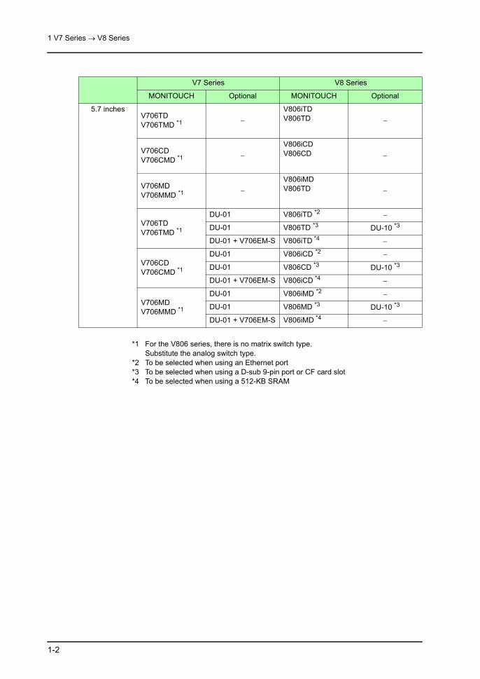
*1 For the V806 series, there is no matrix switch type.Substitute the analog switch type.
*2 To be selected when using an Ethernet port*3 To be selected when using a D-sub 9-pin port or CF card slot*4 To be selected when using a 512-KB SRAM
V7 Series V8 Series
MONITOUCH Optional MONITOUCH Optional
5.7 inchesV706TDV706TMD *1 −
V806iTDV806TD −
V706CDV706CMD *1 −
V806iCDV806CD −
V706MDV706MMD *1 −
V806iMDV806TD −
V706TDV706TMD *1
DU-01 V806iTD *2 −
DU-01 V806TD *3 DU-10 *3
DU-01 + V706EM-S V806iTD *4 −
V706CDV706CMD *1
DU-01 V806iCD *2 −
DU-01 V806CD *3 DU-10 *3
DU-01 + V706EM-S V806iCD *4 −
V706MDV706MMD *1
DU-01 V806iMD *2 −
DU-01 V806MD *3 DU-10 *3
DU-01 + V706EM-S V806iMD *4 −

1 V7 Series → V8 Series
1-3
Optional UnitThe following models are recommended for substitution.
*1 For information on “CU-ADP” and “DU-TL”, refer to the table on page 1-18.*2 For more information, contact your local distributor.
Add-on Memory CassetteThere is no add-on memory cassette available with the V8 series.For information on the precautions related to substitution, refer to page 1-26 for the FROM cassette, and page 1-27 for the SRAM cassette, respectively.
V7 Series V8 Series
Optional unit
EU-00 Video 4 channels + sound output
GU-00 Video 4 channels + sound output
GU-10 Video 2 channels + RGB IN 1 channel
EU-01 RGB IN 1 channel + sound output
GU-01 RGB IN 1 channel + sound output
GU-10 Video 2 channels + RGB IN 1 channel
GU-11 RGB IN 2 channels
EU-02 RGB OUT + sound output GU-02 RGB OUT + sound output
EU-03 Sound output GU-03 Sound output
Communication interface unit *1
CU-00 OPCN-1 CU-00 OPCN-1
CU-01 T-Link CU-01 T-Link
CU-02 CC-Link CU-02 CC-Link
CU-03Ethernet/FL-net
CU-03-3 Ethernet
CU-03-2 CU-08 FL-net
CU-04 PROFIBUS-DP CU-04 PROFIBUS-DP
CU-05 Net/10 None −
CU-06 SX-BUS CU-06 SX-BUS
CU-07 DeviceNet CU-07DeviceNet(Driver under development) *2

1 V7 Series → V8 Series
1-4
1.2 Hardware Compatibility
V715X → V815iX
Item V715X V815iX
Display device TFT color TFT color
Colors • 32,768 colors (with blinks) • 65,536 colors (without blinks)• 32,768 colors (with blinks)
Effective display area 15 inches 15 inches
Panel cut-out dimensions(Unit: mm)
369.4W × 299.4H 369.4W × 299.4H
Display resolution (W × H)
1024 × 768 dots 1024 × 768 dots
Touch switch type Analog Analog
Mounting angle 0 to 135° 0 to 135°
FROM Approx. 4.9 MB(variable depending on the font)
Approx. 12.5 MB(variable depending on the font)
Add-on memory cassette
• “V7EM-F”: 8 MB• “V7EM-L”: 4 MB
None
Built-in SRAM 128 KB 512 KB
SRAM cassette “V7EM-S”: 512 KB None
Screen data transfer • For MJ1:Hakko Electronics’ screen data transfer cable “V-CP”
• For USB-B:Commercially available USB cable
• For LAN port:Transfer via Ethernet
• For MJ1:Hakko Electronics’ screen data transfer cable “V-CP”
• For USB-B:Commercially available USB cable
• For LAN port:Transfer via Ethernet
Connection with PLC CN1:D-sub 25-pin (female), metric screw threads
CN1:D-sub 9-pin (female), inch screw threads
* When using the V7-specific cable, use the Hakko Electronics’ conversion cable “D9-D25” (0.3 m).
Temperature control/PLC2Way connection
MJ1/MJ2:Modular jack, 8-pin
MJ1/MJ2:Modular jack, 8-pin
Terminal converter (for CN1)
TC485Spade terminal
TC-D9Pin terminal
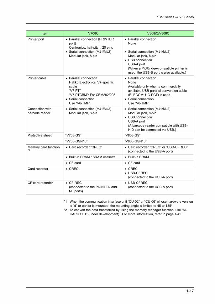
Printer port • USB connectionUSB-A port
• Serial connection (MJ1/MJ2)Modular jack, 8-pin
• USB connectionUSB-A port(When a PictBridge-compatible printer is used, the USB-B port is also available.)
• Serial connection (MJ1/MJ2)Modular jack, 8-pin

1 V7 Series → V8 Series
1-5
*1 To convert the data transferred by using the memory manager function, use “M-CARD SFT” (under development). For more information, refer to page 1-42.
Printer cable • USB connectionCommercially available USB cable (for USB-A)orCommercially available parallel-USB conversion cable(ELECOM: UC-PGT, etc.)
• Serial connectionUse “V6-TMP”.
• USB connectionCommercially available USB cable (for USB-A)orCommercially available parallel-USB conversion cable(ELECOM: UC-PGT)
• Serial connectionUse “V6-TMP”.
Connection with barcode reader
• Serial connection (MJ1/MJ2)Modular jack, 8-pin
• Serial connection (MJ1/MJ2)Modular jack, 8-pin
• USB connectionUSB-A port(A barcode reader compatible with USB-HID can be connected via USB.)
Protective sheet “V715-GS” “V715-GS”
“V715-GSN10” “V715-GSN10”
Memory card function *1
• Card recorder “CREC” • Card recorder “CREC” or “USB-CFREC” (connected to the USB-A port)
• Built-in SRAM / SRAM cassette • Built-in SRAM
• CF card • CF card
Card recorder • CREC • CREC• USB-CFREC
(connected to the USB-A port)
CF card recorder • USB-CFREC(connected to the USB-A port)
• USB-CFREC(connected to the USB-A port)
Item V715X V815iX

1 V7 Series → V8 Series
1-6
V712iS/V712S → V812iS/V812S
Item V712iS/V712S V812iS/V812S
Display device TFT color TFT color
Colors • 32,768 colors (with blinks) • 65,536 colors (without blinks)• 32,768 colors (with blinks)
Effective display area 12.1 inches 12.1 inches
Panel cut-out dimensions(Unit: mm)
313W × 246.2H 313W × 246.2H
Display resolution (W × H)
800 × 600 dots 800 × 600 dots
Touch switch type Analog Analog
Matrix Matrix
Mounting angle 15 to 135° 15 to 135°
FROM Approx. 4.9 MB(variable depending on the font)
Approx. 12.5 MB(variable depending on the font)
Add-on memory cassette
• “V7EM-F”: 8 MB• “V7EM-L”: 4 MB
None
Built-in SRAM 64 KB 512 KB
SRAM cassette “V7EM-S”: 512 KB None
Screen data transfer • For MJ1:Hakko Electronics’ screen data transfer cable “V-CP”
• For LAN port (V712i only)Transfer via Ethernet
• For MJ1:Hakko Electronics’ screen data transfer cable “V-CP”
• For USB-B:Commercially available USB cable
• For LAN port (V812i only)Transfer via Ethernet
Connection with PLC CN1:D-sub 25-pin (female), metric screw threads
CN1:D-sub 9-pin (female), inch screw threads
* When using the V7-specific cable, use the Hakko Electronics’ conversion cable “D9-D25” (0.3 m).
Temperature control/PLC2Way connection
MJ1/MJ2:Modular jack, 8-pin
MJ1/MJ2:Modular jack, 8-pin
Terminal converter (for CN1)
TC485Spade terminal
TC-D9Pin terminal
Printer port • Parallel connection (PRINTER port)Centronics, half-pitch, 20 pins
• Serial connection (MJ1/MJ2)Modular jack, 8-pin
• Parallel connectionNone
• Serial connection (MJ1/MJ2)Modular jack, 8-pin
• USB connectionUSB-A port(When a PictBridge-compatible printer is used, the USB-B port is also available.)

1 V7 Series → V8 Series
1-7
*1 To convert the data transferred by using the memory manager function, use “M-CARD SFT” (under development). For more information, refer to page 1-42.
Printer cable • Parallel connectionHakko Electronics’ V7-specific cable“V7-PT”“V7-PTCBM”: For CBM292/293
• Serial connectionUse “V6-TMP”.
• Parallel connectionNoneAvailable only when a commercially available USB-parallel conversion cable (ELECOM: UC-PGT) is used.
• Serial connectionUse “V6-TMP”.
Connection with barcode reader
• Serial connection (MJ1/MJ2)Modular jack, 8-pin
• Serial connection (MJ1/MJ2)Modular jack, 8-pin
• USB connectionUSB-A port(A barcode reader compatible with USB-HID can be connected via USB.)
Protective sheet “V712-GS” “V812-GS”
“V712-GSN10” “V812-GSN10”
Memory card function *1
• Card recorder “CREC” • Card recorder “CREC” or “USB-CFREC” (connected to the USB-A port)
• Built-in SRAM / SRAM cassette • Built-in SRAM
• CF card • CF card
Card recorder • CREC • CREC• USB-CFREC
(connected to the USB-A port)
CF card recorder • CF-REC(connected to the PRINTER and MJ ports)
• USB-CFREC(connected to the USB-A port)
Item V712iS/V712S V812iS/V812S

1 V7 Series → V8 Series
1-8
V710iS/V710S → V810iS/V810S
Item V710iS/V710S V810iS/V810S
Display device TFT color TFT color
Colors • 32,768 colors (with blinks) • 65,536 colors (without blinks)• 32,768 colors (with blinks)
Effective display area 10.4 inches 10.4 inches
Panel cut-out dimensions(Unit: mm)
289W × 216.2H 289W × 216.2H
Display resolution (W × H)
800 × 600 dots 800 × 600 dots
Touch switch type Analog Analog
Mounting angle 15 to 135° 15 to 135°
FROM Approx. 4.9 MB(variable depending on the font)
Approx. 12.5 MB(variable depending on the font)
Add-on memory cassette
• “V7EM-F”: 8 MB• “V7EM-L”: 4 MB
None
Built-in SRAM 64 KB 512 KB
SRAM cassette “V7EM-S”: 512 KB None
Screen data transfer • For MJ1:Hakko Electronics’ screen data transfer cable “V-CP”
• For LAN port (V710i only)Transfer via Ethernet
• For MJ1:Hakko Electronics’ screen data transfer cable “V-CP”
• For USB-B:Commercially available USB cable
• For LAN port (V810i only)Transfer via Ethernet
Connection with PLC CN1:D-sub 25-pin (female), metric screw threads
CN1:D-sub 9-pin (female), inch screw threads
* When using the V7-specific cable, use the Hakko Electronics’ conversion cable “D9-D25” (0.3 m).
Temperature control/PLC2Way connection
MJ1/MJ2:Modular jack, 8-pin
MJ1/MJ2:Modular jack, 8-pin
Terminal converter (for CN1)
TC485Spade terminal
TC-D9Pin terminal
Printer port • Parallel connection (PRINTER port)Centronics, half-pitch, 20 pins
• Serial connection (MJ1/MJ2)Modular jack, 8-pin
• Parallel connectionNone
• Serial connection (MJ1/MJ2)Modular jack, 8-pin
• USB connectionUSB-A port(When a PictBridge-compatible printer is used, the USB-B port is also available.)
Printer cable • Parallel connectionHakko Electronics’ V7-specific cable“V7-PT”“V7-PTCBM”: For CBM292/293
• Serial connectionUse “V6-TMP”.
• Parallel connectionNoneAvailable only when a commercially available USB-parallel conversion cable (ELECOM: UC-PGT) is used.
• Serial connectionUse “V6-TMP”.

1 V7 Series → V8 Series
1-9
*1 To convert the data transferred by using the memory manager function, use “M-CARD SFT” (under development). For more information, refer to page 1-42.
Connection with barcode reader
• Serial connection (MJ1/MJ2)Modular jack, 8-pin
• Serial connection (MJ1/MJ2)Modular jack, 8-pin
• USB connectionUSB-A port(A barcode reader compatible with USB-HID can be connected via USB.)
Protective sheet “V710-GS” “V810-GS”
“V710-GSN10” “V810-GSN10”
Memory card function *1
• Card recorder “CREC” • Card recorder “CREC” or “USB-CFREC” (connected to the USB-A port)
• Built-in SRAM / SRAM cassette • Built-in SRAM
• CF card • CF card
Card recorder • CREC • CREC• USB-CFREC
(connected to the USB-A port)
CF card recorder • CF-REC(connected to the PRINTER and MJ ports)
• USB-CFREC(connected to the USB-A port)
Item V710iS/V710S V810iS/V810S

1 V7 Series → V8 Series
1-10
V710iT/V710T → V810iT/V810T
Item V710iT/V710T V810iT/V810T
Display device TFT color TFT color
Colors • 32,768 colors (with blinks) • 65,536 colors (without blinks)• 32,768 colors (with blinks)
Effective display area 10.4 inches 10.4 inches
Panel cut-out dimensions(Unit: mm)
289W × 216.2H 289W × 216.2H
Display resolution (W × H)
640 × 480 dots 640 × 480 dots
Touch switch type Analog Analog
Matrix Matrix
Mounting angle 15 to 135° 15 to 135°
FROM Approx. 4.9 MB(variable depending on the font)
Approx. 12.5 MB(variable depending on the font)
Add-on memory cassette
• “V7EM-F”: 8 MB• “V7EM-L”: 4 MB
None
Built-in SRAM 64 KB 512 KB
SRAM cassette “V7EM-S”: 512 KB None
Screen data transfer • For MJ1:Hakko Electronics’ screen data transfer cable “V-CP”
• For LAN port (V710i only)Transfer via Ethernet
• For MJ1:Hakko Electronics’ screen data transfer cable “V-CP”
• For USB-B:Commercially available USB cable
• For LAN port (V810i only)Transfer via Ethernet
Connection with PLC CN1:D-sub 25-pin (female), metric screw threads
CN1:D-sub 9-pin (female), inch screw threads
* When using the V7-specific cable, use the Hakko Electronics’ conversion cable “D9-D25” (0.3 m).
Temperature control/PLC2Way connection
MJ1/MJ2:Modular jack, 8-pin
MJ1/MJ2:Modular jack, 8-pin
Terminal converter (for CN1)
TC485Spade terminal
TC-D9Pin terminal
Printer port • Parallel connection (PRINTER port)Centronics, half-pitch, 20 pins
• Serial connection (MJ1/MJ2)Modular jack, 8-pin
• Parallel connectionNone
• Serial connection (MJ1/MJ2)Modular jack, 8-pin
• USB connectionUSB-A port(When a PictBridge-compatible printer is used, the USB-B port is also available.)

1 V7 Series → V8 Series
1-11
*1 To convert the data transferred by using the memory manager function, use “M-CARD SFT” (under development). For more information, refer to page 1-42.
Printer cable • Parallel connectionHakko Electronics’ V7-specific cable“V7-PT”“V7-PTCBM”: For CBM292/293
• Serial connectionUse “V6-TMP”.
• Parallel connectionNoneAvailable only when a commercially available USB-parallel conversion cable (ELECOM: UC-PGT) is used.
• Serial connectionUse “V6-TMP”.
Connection with barcode reader
• Serial connection (MJ1/MJ2)Modular jack, 8-pin
• Serial connection (MJ1/MJ2)Modular jack, 8-pin
• USB connectionUSB-A port(A barcode reader compatible with USB-HID can be connected via USB.)
Protective sheet “V710-GS” “V810-GS”
“V710-GSN10” “V810-GSN10”
Memory card function *1
• Card recorder “CREC” • Card recorder “CREC” or “USB-CFREC” (connected to the USB-A port)
• Built-in SRAM / SRAM cassette • Built-in SRAM
• CF card • CF card
Card recorder • CREC • CREC• USB-CFREC (connected to the USB-A
port)
CF card recorder • CF-REC(connected to the PRINTER and MJ ports)
• USB-CFREC(connected to the USB-A port)
Item V710iT/V710T V810iT/V810T

1 V7 Series → V8 Series
1-12
V710C → V810iC/V810C
Item V710C V810iC/V810C
Display device TFT color TFT color
Colors • 128 colors (with 16-color blinks) • 65,536 colors (without blinks)• 32,768 colors (with blinks)• 128 colors (with 16-color blinks)
Effective display area 10.4 inches 10.4 inches
Panel cut-out dimensions(Unit: mm)
289W × 216.2H 289W × 216.2H
Display resolution (W × H)
640 × 480 dots 640 × 480 dots
Touch switch type Analog Analog
Matrix Matrix
Mounting angle 15 to 135° 15 to 135° *1
FROM Approx. 4.9 MB(variable depending on the font)
• For V810iC:Approx. 12.5 MB (variable depending on the font)
• For V810C:Approx. 4.5 MB (variable depending on the font)
Add-on memory cassette
• “V7EM-F”: 8 MB• “V7EM-L”: 4 MB
None(V810C: ladder monitor not available)
Built-in SRAM 64 KB • For V810iC:512 KB
• For V810C:128 KB
SRAM cassette “V7EM-S”: 512 KB None
Screen data transfer • For MJ1:Hakko Electronics’ screen data transfer cable “V-CP”
• For MJ1:Hakko Electronics’ screen data transfer cable “V-CP”
• For USB-B:Commercially available USB cable
• For LAN port (V810i only)Transfer via Ethernet
Connection with PLC CN1:D-sub 25-pin (female), metric screw threads
CN1:D-sub 9-pin (female), inch screw threads
* When using the V7-specific cable, use the Hakko Electronics’ conversion cable “D9-D25” (0.3 m).
Temperature control/PLC2Way connection
MJ1/MJ2:Modular jack, 8-pin
MJ1/MJ2:Modular jack, 8-pin
Terminal converter (for CN1)
TC485Spade terminal
TC-D9Pin terminal

1 V7 Series → V8 Series
1-13
*1 When the communication interface unit “CU-02” or “CU-06” whose hardware version is “d” or earlier is mounted, the mounting angle is limited to 45 to 135°.
*2 To convert the data transferred by using the memory manager function, use “M-CARD SFT” (under development). For more information, refer to page 1-42.
Printer port • Parallel connection (PRINTER port)Centronics, half-pitch, 20 pins
• Serial connection (MJ1/MJ2)Modular jack, 8-pin
• Parallel connectionNone
• Serial connection (MJ1/MJ2)Modular jack, 8-pin
• USB connectionUSB-A port(When a PictBridge-compatible printer is used, the USB-B port is also available.)
Printer cable • Parallel connectionHakko Electronics’ V7-specific cable“V7-PT”“V7-PTCBM”: For CBM292/293
• Serial connectionUse “V6-TMP”.
• Parallel connectionNoneAvailable only when a commercially available USB-parallel conversion cable (ELECOM: UC-PGT) is used.
• Serial connectionUse “V6-TMP”.
Connection with barcode reader
• Serial connection (MJ1/MJ2)Modular jack, 8-pin
• Serial connection (MJ1/MJ2)Modular jack, 8-pin
• USB connectionUSB-A port(A barcode reader compatible with USB-HID can be connected via USB.)
Protective sheet “V710-GS” “V810-GS”
“V710-GSN10” “V810-GSN10”
Memory card function *2
• Card recorder “CREC” • Card recorder “CREC” or “USB-CFREC” (connected to the USB-A port)
• Built-in SRAM / SRAM cassette • Built-in SRAM
• CF card • CF card
Card recorder • CREC • CREC• USB-CFREC
(connected to the USB-A port)
CF card recorder • CF-REC(connected to the PRINTER and MJ ports)
• USB-CFREC(connected to the USB-A port)
Item V710C V810iC/V810C

1 V7 Series → V8 Series
1-14
V708iS/V708S → V808iS/V808S
Item V708iS/V708S V808iS/V808S
Display device TFT color TFT color
Colors • 32,768 colors (with blinks) • 65,536 colors (without blinks)• 32,768 colors (with blinks)
Effective display area 8.4 inches 8.4 inches
Panel cut-out dimensions(Unit: mm)
220.5W × 165.5H 220.5W × 165.5H
Display resolution (W × H)
800 × 600 dots 800 × 600 dots
Touch switch type Analog Analog
Mounting angle 15 to 135° 15 to 135°
FROM Approx. 4.9 MB(variable depending on the font)
Approx. 12.5 MB(variable depending on the font)
Add-on memory cassette
• “V7EM-F”: 8 MB• “V7EM-L”: 4 MB
None
Built-in SRAM 64 KB 512 KB
SRAM cassette “V7EM-S”: 512 KB None
Screen data transfer • For MJ1:Hakko Electronics’ screen data transfer cable “V-CP”
• For LAN port (V708i only)Transfer via Ethernet
• For MJ1:Hakko Electronics’ screen data transfer cable “V-CP”
• For USB-B:Commercially available USB cable
• For LAN port (V808i only)Transfer via Ethernet
Connection with PLC CN1:D-sub 25-pin (female), metric screw threads
CN1:D-sub 9-pin (female), inch screw threads
* When using the V7-specific cable, use the Hakko Electronics’ conversion cable “D9-D25” (0.3 m).
Temperature control/PLC2Way connection
MJ1/MJ2:Modular jack, 8-pin
MJ1/MJ2:Modular jack, 8-pin
Terminal converter (for CN1)
TC485Spade terminal
TC-D9Pin terminal
Printer port • Parallel connection (PRINTER port)Centronics, half-pitch, 20 pins
• Serial connection (MJ1/MJ2)Modular jack, 8-pin
• Parallel connectionNone
• Serial connection (MJ1/MJ2)Modular jack, 8-pin
• USB connectionUSB-A port(When a PictBridge-compatible printer is used, the USB-B port is also available.)
Printer cable • Parallel connectionHakko Electronics’ V7-specific cable“V7-PT”“V7-PTCBM”: For CBM292/293
• Serial connectionUse “V6-TMP”.
• Parallel connectionNoneAvailable only when a commercially available USB-parallel conversion cable (ELECOM: UC-PGT) is used.
• Serial connectionUse “V6-TMP”.

1 V7 Series → V8 Series
1-15
*1 To convert the data transferred by using the memory manager function, use “M-CARD SFT” (under development). For more information, refer to page 1-42.
Connection with barcode reader
• Serial connection (MJ1/MJ2)Modular jack, 8-pin
• Serial connection (MJ1/MJ2)Modular jack, 8-pin
• USB connectionUSB-A port(A barcode reader compatible with USB-HID can be connected via USB.)
Protective sheet “V708-GS” “V808-GS”
“V708-GSN10” “V808-GSN10”
Memory card function *1
• Card recorder “CREC” • Card recorder “CREC” or “USB-CFREC” (connected to the USB-A port)
• Built-in SRAM / SRAM cassette • Built-in SRAM
• CF card • CF card
Card recorder • CREC • CREC• USB-CFREC
(connected to the USB-A port)
CF card recorder • CF-REC(connected to the PRINTER and MJ ports)
• USB-CFREC(connected to the USB-A port)
Item V708iS/V708S V808iS/V808S

1 V7 Series → V8 Series
1-16
V708C → V808iC/V808C
Item V708C V808iC/V808C
Display device STN color TFT color
Colors • 128 colors (16-color blinks) • 65,536 colors (without blinks)• 32,768 colors (with blinks)• 128 colors (16-color blinks)
Effective display area 7.7 inches 8.4 inches
Panel cut-out dimensions(Unit: mm)
220.5W × 165.5H 220.5W × 165.5H
Display resolution (W × H)
640 × 480 dots 640 × 480 dots
Touch switch type Analog Analog
Mounting angle 15 to 135° 15 to 135° *1
FROM Approx. 4.9 MB(variable depending on the font)
• For V808iC:Approx. 12.5 MB (variable depending on the font)
• For V808C:Approx. 4.5 MB (variable depending on the font)
Add-on memory cassette
• “V7EM-F”: 8 MB• “V7EM-L”: 4 MB
None(V808C: with limitations on use of ladder monitor)
Built-in SRAM 64 KB • For V808iC:512 KB
• For V808C:128 KB
SRAM cassette “V7EM-S”: 512 KB None
Screen data transfer • For MJ1:Hakko Electronics’ screen data transfer cable “V-CP”
• For MJ1:Hakko Electronics’ screen data transfer cable “V-CP”
• For USB-B:Commercially available USB cable
• For LAN port (V808i only)Transfer via Ethernet
Connection with PLC CN1:D-sub 25-pin (female), metric screw threads
CN1:D-sub 9-pin (female), inch screw threads
* When using the V7-specific cable, use the Hakko Electronics’ conversion cable “D9-D25” (0.3 m).
Temperature control/PLC2Way connection
MJ1/MJ2:Modular jack, 8-pin
MJ1/MJ2:Modular jack, 8-pin
Terminal converter (for CN1)
TC485Spade terminal
TC-D9Pin terminal
1 V7 Series → V8 Series
1-17
*1 When the communication interface unit “CU-02” or “CU-06” whose hardware version is “d” or earlier is mounted, the mounting angle is limited to 45 to 135°.
*2 To convert the data transferred by using the memory manager function, use “M-CARD SFT” (under development). For more information, refer to page 1-42.
Printer port • Parallel connection (PRINTER port)Centronics, half-pitch, 20 pins
• Serial connection (MJ1/MJ2)Modular jack, 8-pin
• Parallel connectionNone
• Serial connection (MJ1/MJ2)Modular jack, 8-pin
• USB connectionUSB-A port(When a PictBridge-compatible printer is used, the USB-B port is also available.)
Printer cable • Parallel connectionHakko Electronics’ V7-specific cable“V7-PT”“V7-PTCBM”: For CBM292/293
• Serial connectionUse “V6-TMP”.
• Parallel connectionNoneAvailable only when a commercially available USB-parallel conversion cable (ELECOM: UC-PGT) is used.
• Serial connectionUse “V6-TMP”.
Connection with barcode reader
• Serial connection (MJ1/MJ2)Modular jack, 8-pin
• Serial connection (MJ1/MJ2)Modular jack, 8-pin
• USB connectionUSB-A port(A barcode reader compatible with USB-HID can be connected via USB.)
Protective sheet “V708-GS” “V808-GS”
“V708-GSN10” “V808-GSN10”
Memory card function *2
• Card recorder “CREC” • Card recorder “CREC” or “USB-CFREC” (connected to the USB-A port)
• Built-in SRAM / SRAM cassette • Built-in SRAM
• CF card • CF card
Card recorder • CREC • CREC• USB-CFREC
(connected to the USB-A port)
CF card recorder • CF-REC(connected to the PRINTER and MJ ports)
• USB-CFREC(connected to the USB-A port)
Item V708C V808iC/V808C

1 V7 Series → V8 Series
1-18
V706 → V806i/V806
Item V706 V806i/V806
Display device • TFT color: V706T• STN color: V706C• STN monochrome: V706M
• TFT color: V806iT/V806T• STN color: V806iC/V806C• STN monochrome: V806iM/V806M
Colors • V706T, V706C32,768 colors (with blinks)
• V706M8-step gradation white mode
• V806iT/V806T, V806iC/V806C65,536 colors (without blinks)32,768 colors (with blinks)
• V806iM/V806M16-step gradation white mode
Effective display area 5.7 inches 5.7 inches
Panel cut-out dimensions(Unit: mm)
174W × 131H 174W × 131H
Display resolution (W × H)
320 × 240 dots 320 × 240 dots
Touch switch type • Analog• Matrix
Analog
Mounting angle 15 to 135° 15 to 135°
FROM Approx. 1.5 MB(variable depending on the font)
Approx. 4.5 MB(variable depending on the font)
Add-on memory cassette
“V706EM-F”: 4 MB None
Built-in SRAM 128 KB • For V806i:512 KB
• For V806:128 KB
SRAM cassette “V706EM-S”: 512 KB None
Screen data transfer • For MJ1:Hakko Electronics’ screen data transfer cable “V-CP”
• For USB-B:Commercially available USB cable
• For MJ1:Hakko Electronics’ screen data transfer cable “V-CP”
• For USB-B:Commercially available USB cable
• For LAN port (V806i only)Transfer via Ethernet
Connection with PLC • V706 onlyMJ2:Modular jack, 8-pin
• V706 + “DU-01”CN1:D-sub 25-pin (female), metric screw threads
• V806i/V806 onlyMJ2:Modular jack, 8-pin
• V806i/V806 + “DU-10”CN1:D-sub 9-pin (female), inch screw threads
* When using a cable for V706 + “DU-01”, use the Hakko Electronics’ conversion cable “D9-D25” (0.3 m).
Temperature control/PLC2Way connection
MJ1/MJ2:Modular jack, 8-pin
MJ1/MJ2:Modular jack, 8-pin
Terminal converter TC485 (only for V706 + “DU-01”)Spade terminal
TC-D9 (only for V806i/V806 + “DU-10”)Pin terminal
Ethernet connection • V706 + “DU-01” → V806i
T-Link connection • V706 + “DU-TL” → V806i/V806 + “CU-01”

1 V7 Series → V8 Series
1-19
*1 To convert the data transferred by using the memory manager function, use “M-CARD SFT” (under development). For more information, refer to page 1-42.
Communication interface unit
• “CU-ADP” + CU-00 (OPCN-1)• “DU-TL” (T-Link)• “CU-ADP” + CU-01 (T-Link)• “CU-ADP” + CU-02 (CC-Link)• “CU-ADP”
+ CU-03 (Ethernet/FL-net)“CU-ADP”+ CU-03-2 (Ethernet/FL-net)
• “CU-ADP”+ CU-04 (PROFIBUS-DP)
• “CU-ADP” + CU-05 (Net/10)• “CU-ADP” + CU-06 (SX-BUS)• “CU-ADP” + CU-07 (DeviceNet)
→ CU-00 (OPCN-1)→ CU-01 (T-Link)→ CU-01 (T-Link)→ CU-02 (CC-Link)
→ CU-03-3 (Ethernet)
→ CU-08 (FL-net)
→ CU-04 (PROFIBUS-DP)→ None→ CU-06 (SX-BUS)→ CU-07 (DeviceNet)
(driver under development)
Printer port • Serial connection (MJ1/MJ2)Modular jack, 8-pin
• USB connectionUSB-A port
• Serial connection (MJ1/MJ2)Modular jack, 8-pin
• USB connectionUSB-A port(When a PictBridge-compatible printer is used, the USB-B port is also available.)
Printer cable • USB connectionCommercially available USB cable (for USB-A)orCommercially available parallel-USB conversion cable(ELECOM: UC-PGT, etc.)
• Serial connectionUse “V6-TMP”.
• USB connectionCommercially available USB cable (for USB-A)orCommercially available parallel-USB conversion cable(ELECOM: UC-PGT)
• Serial connectionUse “V6-TMP”.
Connection with barcode reader
• Serial connection (MJ1/MJ2)Modular jack, 8-pin
• Serial connection (MJ1/MJ2)Modular jack, 8-pin
• USB connectionUSB-A port(A barcode reader compatible with USB-HID can be connected via USB.)
Protective sheet “V606-GS” “V806-GS”
“V606-GSN10” “V806-GSN10”
Memory card function *1
• Card recorder “CREC” • Card recorder “CREC” or “USB-CFREC” (connected to the USB-A port)
• Built-in SRAM / SRAM cassette • Built-in SRAM
• CF card • CF card
Card recorder • CREC • CREC• USB-CFREC
(connected to the USB-A port)
CF card recorder • USB-CFREC(connected to the USB-A port)
• USB-CFREC(connected to the USB-A port)
Item V706 V806i/V806

1 V7 Series → V8 Series
1-20
Notes on Hardware
Notes on InstallationTightening Torque of Fixtures
Power Supply Terminal Position
When substituting the following models, pay careful attention to the positions of the power supply terminals.
• 8-inch modelThe arrangement of power supply terminals differs between the V7 and the V8.
• 6-inch modelThe positions and arrangement of power supply terminals differ between the V706 and the V806.
V7 Torque (N•m) V8 Torque (N•m)
V715 0.7 to 1.0 V815 0.5 to 0.7
V712 0.5 to 0.7 V812 0.5 to 0.7 (Same as V7)
V710T/S/C 0.3 to 0.5 V810T/S/C 0.5 to 0.7
V708S/C 0.3 to 0.5 V808S/C 0.5 to 0.7
V706 0.3 to 0.5 V806 0.5 to 0.7
LAN U-B U-ACN1
24VDCFG
CN5
CN7
CF
MJ1 MJ2
+ -24V DC
FG
24VDC- +
LAN
CN1
MJ1 MJ2
PRINTER
CF
CN5 MEMORY
CN6
+ -24V DC
FG
V708 V808
Power supply Power supplyGrounding Grounding
24V DC
FG
U-AU-B
CN5
LANMJ2MJ1
232485
422
FG
24VDC
FG
24 VDC
V706 V806
Power supply
Power supply
Grounding Grounding

1 V7 Series → V8 Series
1-21
Optional Unit Position
For the 8-inch model, the mounting position of the optional unit differs between the V7 and the V8.
DIP SwitchesThe DIP switch functions differ between the V7 and the V8.
• V7 series / V8 series
DIP SW No.
Descriptions
V7 V8
1 CF auto-uploading CF auto-uploading
2 Not used CF slot cover access control
3 Not used Not used
4 Not used Not used
5 CN1+SD/-SD terminating resistance at pins 12 and 13
CN1+SD/-SD terminating resistance at pins 3 and 4
6 MJ1 (modular jack 1) terminating resistance
MJ1 (modular jack 1) terminating resistance
7 CN1+RD/-RD terminating resistance at pins 24 and 25
CN1+RD/-RD terminating resistance at pins 1 and 2
8 MJ2 (modular jack 2) terminating resistance
MJ2 (modular jack 2) terminating resistance
LAN U-B U-ACN1
24VDCFG
CN5
CN7
CF
MJ1 MJ2
CH1CH2CH3CH4
24VDC- +
LAN
CN1
MJ1 MJ2
PRINTER
CF
CN5 MEMORY
CN6
CH1CH2CH3CH4
AUDIO
V708iS V808iS
EU-xx GU-xxCU-xx CU-xx
ON
1 2 3 4 5 6 7 8
V7 V8ON
1 2 3 4 5 6 7 8
(Upon delivery) (Upon delivery)

1 V7 Series → V8 Series
1-22
• V706 series / V806 series
• DU-01 (for V706) / DU-10 (for V806)
Slide Switch (for V706/V806 only)The factory default setting for the slide switch differs between V706 and V806.
DIP SW No.
Descriptions
V706 V806
1 MJ1 (modular jack 1)Terminating resistance for RS-485
MJ1 (modular jack 1)Terminating resistance for RS-485
2 MJ2 (modular jack 2)SD terminating resistance for RS-422/485
MJ2 (modular jack 2)SD terminating resistance for RS-422/485
3 MJ2 (modular jack 2)RD terminating resistance for RS-422/485
MJ2 (modular jack 2)RD terminating resistance for RS-422/485
4 CF auto-uploading CF auto-uploading
DIP SW No.
Descriptions
DU-01 DU-10
1 CN1+RD/-RD terminating resistance at pins 24 and 25
CN1+RD/-RD terminating resistance at pins 1 and 2
2 CN1+SD/-SD terminating resistance at pins 12 and 13
CN1+SD/-SD terminating resistance at pins 3 and 4
3 Not used Not used
4 Not used CF slot cover access control
V706 V806
12
34 1
23
4O
FF
(Upon delivery) (Upon delivery)
12
34
OFF
DU-01 DU-10
12
34
(Upon delivery) (Upon delivery)
(Upon delivery)
• V706: Lower (RS-422)• V806: Upper (RS-232C/485)

1 V7 Series → V8 Series
1-23
Notes on ConnectionDifference in D-sub Connector
On the V7 series, the D-sub 25-pin connector is provided for CN1. (V706 series: CN1 on the optional unit “DU-01”)On the V8 series, the D-sub 9-pin connector is provided for CN1 instead. (V806 series: CN1 on the optional unit “DU-10”)Because of this difference, the conversion cable “D9-D25” (0.3 m) or the V8 terminal converter “TC-D9” (terminal block) must be used after substitution.
• Conversion cableUse “D9-D25” when using the V7-specific communication cable.
• Terminal converterWhen the terminal block “TC485” is mounted on the V7 series, use “TC-D9” on the V8 series as a substitute. However, note that the end of the cable must be modified since the structure of the terminal block is not the same.
F1
F2
F3
F4
F5
F6
F7
SYSTEM
POWER
F 1
F 2
F 3
F 4
F 5
F 6
F 7
SYSTEM
V7 V8
CN1:D-sub 25-pin
CN1:D-sub 9-pin
V8-specific conversion cable “D9-D25”
V7-specific communication cable
V7-specific communication cable
+5V SG +SD -SD+RD -RD FG
F1
F2
F3
F4
F5
F6
F7
SYSTEM
POWER
F 1
F 2
F 3
F 4
F 5
F 6
F 7
SYSTEM
V7 V8
V8-specific terminal converter “TC-D9”
* Spade terminals not available. Use a pin terminal.
CN1:D-sub 25-pin
CN1:D-sub 9-pin
V7-specific terminal converter “TC485”

1 V7 Series → V8 Series
1-24
For Communication with Mitsubishi Electric’s A Series CPU
For the V7 series, “GD-MDD”, “GD-MDD2” or “V-MDD” (2-port adaptor) can be used for communication with the A series CPU.For the V8 series, “GD-MDD” cannot be used. Substitute “V-MDD” for it.
ACPU
F 1
F 2
F 3
F 4
F 5
F 6
F 7
SYSTEM
GD
GPP
GD-MDD
V8
V-MDD
Not availableAvailable

1 V7 Series → V8 Series
1-25
For “Multi-link 2” Communication
* For “Multi-link 2” communication, whether or not the V8 series can be used together with the V7 or V6 series depends on the PLC model.For the PLC model that can be connected together with the V8 series and the V7 or V6 series, [Multi-link2 with V7/V6] is valid in the [Detail] tab window ([System Setting] → [Device Connection Setting]). When this box is checked, the V8 series can be used together with the V7 or V6 series (mixed connection). (When the PLC model with which this mixed connection is available is selected, this box is automatically checked.)
If one of the V7 units connected to a PLC has failed during multi-link 2 communication, it may not be possible to substitute the V8 for the failed unit only.In such a case, substitute the V8 for all the V7 and V6 units connected via “multi-link 2”.
* In “multi-link” communication, V8 can be used together with V7 and V6.In this case, it is possible to substitute any number of the V7 or V6 by the V8.
F 1
F 2
F 3
F 4
F 5
F 6
F 7
SYSTEM
F 1
F 2
F 3
F 4
F 5
F 6
F 7
SYSTEM
F 1
F 2
F 3
F 4
F 5
F 6
F 7
SYSTEM
F 1
F 2
F 3
F 4
F 5
F 6
F 7
SYSTEM
F1
F2
F3
F4
F5
F6
F7
SYSTEM
POWER
F1
F2
F3
F4
F5
F6
F7
SYSTEM
POWER
F1
F2
F3
F4
F5
F6
F7
SYSTEM
POWER
F1
F2
F3
F4
F5
F6
F7
SYSTEM
POWER
F 1
F 2
F 3
F 4
F 5
F 6
F 7
SYSTEM
PLC
CN1 MJ2 CN1 CN1 CN1
PLC
CN1 MJ2 CN1 CN1 CN1
NG
V7 V7 V7 V7
V8
V8 V8V8 V8
V8 cannot be used as a substitute for the failed V7 only.
Substitute the V8 series for all MONITOUCH units.

1 V7 Series → V8 Series
1-26
FROM CassetteThere is no FROM cassette available with the V8; however, since the capacity of FROM on the V8 is bigger than the V7, substitution by the V8 is possible without using the cassettes.For the V8C series, note that the models with “i” and without “i” differ in capacity of FROM.For more information, refer to the following table.
( : provided, : not provided, −: not available)
* For information on the precautions on substitution when the ladder monitor function is used, refer to the next section.
Ladder Monitor (When “V7EM-L” is Used)
When the ladder monitor function is used with the V7 series, “V7EM-L” (flash-memory cassette for ladder monitor) must be used.On the other hand, FROM cassette is not necessary for the V8C series; however, the ladder monitor function cannot be used with the models shown below:
• V810C (available with V810iC) *1
• V808C (available with V808iC) *1• V806 series
*1 When a Mitsubishi’s or Omron’s PLC is selected, the ladder monitor function can be used by using a CF card. For more information, refer to the Ladder Monitor Specifications provided separately.
MONITOUCH ModelsCombinations
FROMTotal CapacityMONITOUCH V7EM-F
(8 MB)V7EM-L*(4 MB)
V706EM-F(4 MB)
V7 series
V715V712V710V708
− Approx. 4.9 MB
− Approx. 13 MB
− Approx. 9 MB
V706− − Approx. 1.5 MB
− − Approx. 5.5 MB
V8 series
V815iXV812(i)SV810(i)SV810(i)TV808(i)S
− − − Approx. 12.5 MB
V8C series
V810iCV808iC − − − Approx. 12.5 MB
V810CV808C − − − Approx. 4.5 MB
V806 series V806(i) − − − Approx. 4.5 MB

1 V7 Series → V8 Series
1-27
SRAM CassetteThere is no SRAM cassette available with the V8; however, since the capacity of SRAM on the V8 is bigger than the V7, substitution by the V8 is possible without using the cassettes.For the V8C or V806 series, note that the models with “i” and without “i” differ in capacity of SRAM.For more information, refer to the following table.
( : provided, : not provided, −: not available)
BrightnessOn the V7 series with a TFT-color LCD, the brightness can be adjusted by using a macro command (BRIGHT).When the V8 series substitutes for the V7 series, note that the brightness varies even if the adjustment value for the macro is the same. Be sure to check and adjust the actual brightness on the V8 series before use.
MONITOUCH ModelsCombinations
SRAM CapacityMONITOUCH V7EM-S
(512 KB)V706EM-S(512 KB)
V7 series
V715− 128 KB
− 512 KB
V712V710V708
− 64 KB
− 512 KB
V706− 128 KB
− 512 KB
V8 series
V815iXV812(i)SV810(i)SV810(i)TV808(i)S
− − 512 KB
V8C series
V810iCV808iC − − 512 KB
V810CV808C − − 128 KB
V806 seriesV806(i) − − 512 KB
V806 − − 128 KB

1 V7 Series → V8 Series
1-28
Video Display FunctionColors
Because of hardware structural differences, colors displayed by the video input function slightly differ between the V7 and the V8.
When the image quality of the video display is adjusted by using a macro command (“Video2”), the quality differs between V7 and V8 even if the adjustment value is the same. The default value is shown below.
* When substituting the V8 series for the V7 series, be sure to check and adjust the actual image quality on the V8 series before use.
Video Display Speed
The video display speed differs between the V7 and the V8.The following table shows the case for the V708iS and the V808iS.
EU-00 (V7i)GU-00 (V715)
GU-00 (V8i)GU-10 (V8i)
Number of colors
V715:16,777,216 colors (monochrome 256-step gradation)
V712/V710/V708S:32,768 colors
V815/V812/V810:16,777,216 colors (monochrome 256-step gradation)
V808S:262,144 colors (monochrome 64-step gradation)
ItemDefault
V7 V8
Brightness: 0 (dark) - 31 (bright) 16
Contrast: 0 (low) - 31 (high) 16
Color shade: 0 (light) - 31 (dark) 16
Display Size Number of Displayed Frames (Base Screen: 1 Channel)
V708iS V808iS
640 × 480 Approx. 7 frames/sec
Approx. 30 frames/sec640 × 240 Approx. 9 frames/sec
320 × 240 Approx. 10 frames/sec
160 × 120 Approx. 12 frames/sec

1 V7 Series → V8 Series
1-29
RGB Input FunctionBecause of hardware structural differences, colors displayed by the RGB input function slightly differ between the V7 and the V8.
RGB Output FunctionBecause of hardware structural differences, colors displayed by the RGB display function slightly differ between the V7 and the V8.
Sound Output FunctionBecause of hardware structural differences, sound output specifications differ between the V7 and the V8.
EU-01 (V7i) GU-01 (V715/V8i) GU-10/GU-11 (V8i)
Number of colors
32,768 colors 65,536 colors (64-step gradation)
V815/V812/V810:16,777,216 colors (256-step gradation)
V808S:262,144 colors (64-step gradation)
EU-02 (V7i) GU-02 (V715) GU-02 (V8i)
Number of colors
32,768 colors 32,768 colors 65,536 colors
EU-03/02/01/00 (V7i) GU-03/02/01/00 (V715/V8i)
Sound file format
• Uncompressed PCM• Quantization bit
8 bits• Sampling frequency
8 kHz• Sound source
Monaural
• Uncompressed PCM• Quantization bit
8 bits/16 bits• Sampling frequency
8 kHz/16 kHz• Sound source
Stereo/Monaural
Plug • For stereo plug:
When outputting monaural sound, it comes out either from the right or left speaker since both L and R sides are connected on “EU-03”.
• For stereo plug:
When outputting monaural sound, it comes out from the L side only. Connect the L-side wire to the amplifier, or change the plug to a monaural type.
• For monaural plug:
Almost the same as “EU-03”. Use this plug to play monaural sound.
L R L R

1 V7 Series → V8 Series
1-30
1.3 Software Compatibility (Settings and Functions)
Screen Data File ConversionFollow the procedure below to convert the screen data file.
1. Launch V-SFT. Click the [Open] icon, or select [File] and [Open].
2. The [Open] dialog is displayed. Select [*.V7] for [Files of type].
3. Select a V7 screen data file to be converted and click [Open]. The selected V7 screen data file is opened.
or

1 V7 Series → V8 Series
1-31
4. Click [System Setting] and [Edit Model Selection]. The [Edit Model Selection] dialog is displayed.
5. Select the desired V8 model as the conversion target, and click [OK].

1 V7 Series → V8 Series
1-32
6. The following dialog is displayed. Click [Yes].
* When V7 data is converted into V8 data, it cannot be converted back to V7 data.
7. The selected screen data file is converted into the V8 file and displayed on the editor.Name the file and save it.

1 V7 Series → V8 Series
1-33
Switch
[Delay] Setting“ON repeat” and “double-touch” functions available with V8 are automatically enabled for the switches shown below to keep compatibility after screen data conversion.
List of Target Switches
V7 V8
Switch Functions Switch Functions Delay Setting
StandardRoll Up Roll Up
ON repeat function(150 ms)
Roll Down Roll Down
Entry
Char. Entry Character Input
Space Space
Backspace Backspace
DEL DELETE
+1 +1
-1 -1
Add Add
Subtraction Subtraction
← ←
→ →
↑ ↑
↓ ↓
80-Compatible HEX Key
80-Compatible HEX Key
Multi-char. Input Multi-char. Input
Char. Switching (+) Char. Switching (+)
Char. Switching (-) Char. Switching (-)
Table Data Display
Move Cursor R Cursor Movement to Right
Move Cursor L Cursor Movement to Left
Digital SwitchDigital Switch + Digital Switch +
Digital Switch - Digital Switch -
StandardReset Reset Double-touch
function(2 s)

1 V7 Series → V8 Series
1-34
Example of Conversion
• Example of [Function: Roll Up] switch
• Example of [Function: Reset] switch
[Function: Card Format] SwitchIn the [Function] setting on the [Switch] dialog, the [Memory Card: Card Format] switch is provided.With the V7 series, this switch is used for formatting the SRAM settings (built-in SRAM, SRAM cassette or SRAM memory card).With the V8 series, this switch is used only for the SRAM memory card, not valid for the built-in SRAM.(When the switch is pressed, a triple error beep sounds and the switch operation is not accepted.)For more information on formatting of SRAM, refer to Formatting of SRAM on page 1-43.

1 V7 Series → V8 Series
1-35
Sampling
Store TargetThe store target setting for the V8 varies according to the setting for [Store Target] in the [Buffering Area Setting] dialog made for the V7. For more information, refer to the following table.
*1 Some number of words are automatically allocated to the emulation area after conversion.On the V8, the number of words indicated at [Word Count] must be secured. Manually set the same number for [Set Word] as the one indicated at [Word Count] ([45 Word] in the example).
V7 V8
Store Target Other SettingsPrimary Store Target
Secondary Store Target Other Remarks
Internal Buffer − DRAM None −
SRAM
Built-in SRAM / SRAM cassette
Emulation area
Set word count> Used word count
SRAM None
In the emulation area ([SRAM/Clock Setting] dialog), some number of words are automatically allocated to [Primary Storage of Sampling] as well as [Memory Card Emulation Area]. *1
Emulation area
Set word count= Used word count
SRAM None
In the emulation area ([SRAM/Clock Setting] dialog), some number of words are automatically allocated only to [Primary Storage of Sampling].
[ CSV Output] checked SRAM CF Card −
CREC + SRAM card DRAM Memory Card
[ Use Card Recorder] for [Others] in the [Device Connection Setting] dialog is checked.
CF Card
No cache DRAM CF Card For more information on the number of samplings, refer to the next section.
DRAM cache DRAM CF Card
SRAM cache SRAM CF Card

1 V7 Series → V8 Series
1-36
No. of SamplingsPrimary Store Target
The setting for [No. of Samples] at the V8 may differ from the one set for the V7 depending on the setting such as for [Store Target] at the V7. For more information, refer to the following table.
Secondary Store Target
The same value as the one set for [No. of Samples] at the V7 is set.
V7 V8
Store Target Other Settings
Primary Store Target No. of Samples (primary store target)
Internal Buffer − DRAM The same as [No. of Samples] for V7
SRAM
Built-in SRAM / SRAM cassette SRAM The same as [No. of Samples] for V7
CREC + SRAM card DRAM
• Bit Synchronization / Constant Sampling / Device Memory Map256 words ÷ (2 words + word count)
• Alarm Logging256 words ÷ 3 words
• Time Order AlarmingNone
• Alarm Function{256 words − (6 words × number of sampling bits) − 7 words} ÷ 5 words
CF Card
No cache DRAM
• Bit Synchronization / Constant Sampling / Device Memory Map256 words ÷ (2 words + word count)
• Alarm LoggingFixed to 85 times (= 256 words ÷ 3 words)
• Time Order AlarmingNone
• Alarm Function{256 words − (6 words × number of sampling bits) − 7 words} ÷ 5 words
DRAM cache DRAM• Bit Synchronization / Constant Sampling / Device
Memory MapCache size ÷ (2 words + word count)
• Alarm LoggingCache size ÷ 3 words
• Time Order AlarmingNone
• Alarm Function{Cache size − (6 words × number of sampling bits) − 7 words} ÷ 5 words
SRAM cache SRAM

1 V7 Series → V8 Series
1-37
Example of ConversionThe following example shows the case where [CF Card] is selected for [Store Target], [SRAM] is selected with [Use Cache] checked, and the buffering area setting is made as shown below at the V7.
When the data is converted into V8 data, the buffering area settings are set as shown below.
• How to calculate [No. of Samples] for primary store target (refer to the previous page){Cache size − (6 words × number of sampling bits) − 7 words} ÷ 5 words= {4096 − (6 × 16 bits) − 7 words} ÷ 5 words= (4096 − 96 − 7) ÷ 5= 3993 ÷ 5= 798 (remainder 3) ← [No. of Samples] is calculated as “798”.

1 V7 Series → V8 Series
1-38
MacroSome macro commands related to sampling differ between the V7 and the V8. For more information, refer to the following table.
Command / Operation V7 V8
SMPL_BAK • File name • File name
• Location
The bin file is copied to the year/month/date folder.
• Location
The bin file is copied to the year/month/date folder under the year/month folder.
SMPLCSV_BAK • File name • File name
SMPxxxx.bin
0000 - 0011: Buffer No.
SMPxx_xx.bin
0000 - 0011: Buffer No.
00 - 99: Backup times
96M
B
CompactFlash Card
RECIPESAMPLE
DAT0000
SMP0000.binSMP0001.binSMP0002.bin
96M
B
CompactFlash Card
RECIPESAMPLE
070912
DAT0000
SMP0000.binSMP0001.binSMP0002.bin
SMP0002.bin
Copy
(Access folder) 96M
B
CompactFlash Card
RECIPESAMPLE
DAT0000
SMP0000.binSMP0001.binSMP0002.bin
96M
B
CompactFlash Card
RECIPESAMPLE
200709
DAT0000
SMP0000.binSMP0001.binSMP0002.bin
20070912SMP02_00.binSMP02_01.binSMP02_02.bin
Copy
(Access folder)
SMPxxxx.csv
0000 - 0011: Buffer No.
SMPxx_xx.csv
0000 - 0011: Buffer No.
00 - 99: Backup times

1 V7 Series → V8 Series
1-39
(SMPLCSV_BAK) • LocationWhen [Store Target: SRAM] is selected:
The CSV file is created in the year/month/date folder.
• LocationWhen [Primary storage target: SRAM] and [Secondary storage target: None] are selected:
The CSV file is created in the year/month/date folder under the year/month folder.
Command / Operation V7 V8
96M
B
CompactFlash Card
RECIPESAMPLE
070912
DAT0000
SMP0001.csv
Emulation area
Buffer No. 0
Buffer No. 1Buffer No. 2
Header
Memo pad
$L / $LD
Creates a CSV file.
96M
B
CompactFlash Card
RECIPESAMPLE
200709
DAT0000
SMP01_00.csv20070912
Primary storage target
Buffer No. 0
Buffer No. 1Buffer No. 2
Header
Memo pad
$L / $LD
Creates a CSV file.

1 V7 Series → V8 Series
1-40
(SMPLCSV_BAK) • LocationWhen [Store Target: CF Card] is selected:
The CSV file is created in the year/month/date folder.
• LocationWhen [Primary storage target: SRAM] and [Secondary storage target: CF Card] are selected:
The CSV file is created in the year/month/date folder under the year/month folder.
Command / Operation V7 V8
96M
B
CompactFlash Card
RECIPESAMPLE
DAT0000
SMP0000.binSMP0001.binSMP0002.bin
96M
B
CompactFlash Card
RECIPESAMPLE
DAT0000
SMP0000.binSMP0001.binSMP0002.bin070912
SMP0001.csv
Creates a CSV file.
96M
B
CompactFlash Card
RECIPESAMPLE
DAT0000
SMP0000.binSMP0001.binSMP0002.bin
96M
B
CompactFlash Card
RECIPESAMPLE
DAT0000
SMP0000.binSMP0001.binSMP0002.bin200709
SMP01_00.csv20070912
Creates a CSV file.

1 V7 Series → V8 Series
1-41
Automatic deletion
[System Setting] → [Unit Setting] → [General Settings] → [ Delete folders from the oldest if CF card is lacking in space for backup]
[date (~x)] folders created in the [SAMPLE] folder are to be deleted.
[year/month/date] folders created in the [year/month] folder under the [SAMPLE] folder are to be deleted.
Command / Operation V7 V8
96M
B
CompactFlash Card
RECIPESAMPLE
DAT0000
SMP0000.binSMP0001.binSMP0002.bin
SMP0001.csv
SMP0001.csv
070912
070912~0
SMP0001.csv070912~1
SMP0001.csv070912~Z
96M
B
CompactFlash Card
RECIPESAMPLE
DAT0000
SMP0000.binSMP0001.binSMP0002.bin200709
20070912
20070913
SMP01_01.csv
SMP01_02.csv
SMP01_99.csv
SMP01_00.csv
SMP01_01.csv
SMP01_02.csv
SMP01_99.csv
SMP01_00.csv

1 V7 Series → V8 Series
1-42
SRAM
Built-in SRAM / SRAM CassetteSRAM/Clock Setting
Some contents in SRAM differ between the V7 and the V8. For more information, refer to the following table.
V7 V8 Remarks
Memory card emulation area
Memory card emulation area
For V7:Secure when either of the built-in SRAM or SRAM cassette is used.
For V8:Secure the required amount of words only when the SRAM memory card is used.The area to be used for sampling is secured in the built-in SRAM as [Primary Storage of Sampling] described below.
Memo pad storage area ← the same as the left −
Non-volatile memory(Word) ($L)
← the same as the left−
Non-volatile memory(Double-word) ($LD)
← the same as the left−
CF card cache Not provided For V7:Automatically secured when [SRAM] is selected with [Use Cache] checked in the [CF Card] dialog.
For V8:[Cache] does not exist.[Primary storage target] is provided as a substitute for cache.
Japanese conversion function
← the same as the left−
−
Primary storage of sampling
When [SRAM] is selected for [Store Target], or [CF Card] is selected for [Store Target] and [SRAM] is selected with [Use Cache] checked for the buffering area setting at the V7, [SRAM] is set for [Primary storage target] at the V8.
The number of words allocated for the emulation area or CF card cache at the V7 is automatically allocated for [Primary Storage of Sampling] at the V8.
−
Operation log storage Used for the “operation log” function that is newly available on the V8.(For more information, refer to the V8 Series Reference Additional Functions manual.)

1 V7 Series → V8 Series
1-43
Formatting of SRAM
The SRAM formatting procedure differs between the V7 and the V8.For more information, refer to the following table.
* The built-in SRAM for the V8 can automatically be formatted.When [ SRAM Auto Format] is checked in the [SRAM/Clock Setting] dialog, no error message appears in step 3, and manual formatting of SRAM on the Main Menu screen becomes unnecessary.However, when the screen data is transferred to a new V8 unit, the error appears in step 3 even if the above setting has been made. In such a case, check the box for [Format the SRAM forcefully] in the [General Settings] tab window displayed by selecting [System Setting] → [Unit Setting].
SRAM Data Conversion (Memory Manager)
Transfer data using the V8-ready memory card editor “M-CARD SFT” (*) and convert it for the V8.
* Under development
V7(Built-in SRAM / SRAM cassette)
V8(Built-in SRAM)
Step 1 • Buffering area setting[Store Target: SRAM]
• SRAM/Clock settingSet the [Memory Card Emulation Area].
• Place a [Memory Card] item and a [Card Format] switch on the screen.
• Buffering area setting[Primary storage target: SRAM]
• SRAM/Clock setting[Primary Storage of Sampling] is secured.
• Card format switchNot required
Step 2 Transfer the screen data to MONITOUCH. ← the same as the left
Step 3 The error message “Data has some error. No. 161 (24: )” is displayed on MONITOUCH.On the Main Menu screen, execute the first formatting of SRAM.
The error message “Data has some error. No. 161 (24: )” is displayed on MONITOUCH.On the Main Menu screen, execute formatting of SRAM (*).
Step 4 Bring MONITOUCH into the RUN mode.Next, press the [Card Format] switch placed in step 1, and execute the second formatting.
Bring MONITOUCH into the RUN mode.The [Card Format] switch is not necessary.The built-in SARM becomes available.

1 V7 Series → V8 Series
1-44
SRAM Card (CREC + REC-MCARD)Formatting of SRAM
The same formatting procedure as the V7 can be used.
How to Use SRAM Card Data (Data Logging) on V8
Data stored by the data logging function on the V7 cannot be displayed on the V8. Make a backup copy of the data on the computer, format the SRAM, and execute data logging again on the V8.Press the [Function: Card Format] switch on the RUN screen of the V8 to execute data logging onto the SRAM.
* Even if SRAM is not formatted, data logging can be performed onto the primary store target (DRAM) for the set number of times.When SRAM has been formatted, data logging can be performed onto the secondary store target (Memory Card).
How to Use SRAM Card Data (Memory Manager) on V8
Data transferred by using the memory manager function on the V7 can also be used on the V8. Transfer the data from SRAM using “M-CARD SFT” (*), change the edit model to “V8” and then transfer it into the V8.
* Under development
How to Substitute CF Card for SRAM Card (Memory Manager)
Transfer data using the V8-ready memory card editor “M-CARD SFT” (*) and convert it for the V8.
* Under development

1 V7 Series → V8 Series
1-45
CF Card
How to Substitute V8-specific CF CardWhen the CF card that has been used on the V7 is used on the V8, some data are not available on the V8 because of the difference in the CF card functions.For more information, refer to the following table.
V7V8 Solution
Folder Name File Name
BITMAP BMPxxxx.BIN Store the V8 pattern data using V-SFT-5 again.
CARD MCMHEAD.BINMCMxxxx.BIN
Convert the data using the V8-ready memory card editor “M-CARD SFT” (under development).
DSP DSP0000.BIN Store the screen data again by using V-SFT-5 or inserting a CF card into V8.
JPEG xxxxx.JPGJPxxxxx.JPG −
MEMO MEMxxxx.BIN The memo pad data cannot be converted.Store new data on the V8.
RECIPE RECxxxx.CSVxxxxxxxx.CSV −
SAMPLE SMPxxxx.BIN The sampling data cannot be converted.Store new data on the V8.
SNAP VDxxxxx.JPG −
SRAM SRM0000.BIN The SRAM backup data cannot be converted.Perform backup again on the V8.
WAV WAxxxx.WAV −
WEBSERV *.SHT, *.HTML, *.TXT etc. −

1 V7 Series → V8 Series
1-46
Communication Setting
Conversion into 8-way CommunicationWhen V7 data is converted to V8 data, it is automatically converted to data ready for 8-way communication (PLC1 to PLC8) according to the communication type used for the V7. For more information, refer to the following table.
Text ProcessingOn the V7 series, the setting for [Text Process] (LSB/MSB) is made in the [Communication Parameter] dialog and applied globally. On the V8 series, it can individually be set for the items shown below; however, when the data has originally been converted from the V7 series, the setting for [Text Process] made for PLC1 is applied globally. For the target items, refer to the table show below.
* When [Barcode] is selected for [Device] while the PLC memory is selected for [I/F Memory], text processing is performed in the order of LSB → MSB unless otherwise specified after conversion.When [MSB → LSB] is selected on the V7, check [Storage Order] in the [Communication Setting] tab window that is displayed by selecting [System Setting] → [Device Connection Setting] and select [MSB → LSB].
V7 V8
PLC PLC1
Temperature control/PLC2Way network PLC2
Modbus slave PLC3
V-Link PLC3
Barcode reader PLC4
Character display (including those in each library or data sampling)
Recipe mode
Attribute setting
[CSV format] of the buffering area setting
MR-400 format table

1 V7 Series → V8 Series
1-47
Internal Memory
$s (System Memory)In “$s” memory, some addresses on the V7 are not the same as those on the V8.The detailed information is described below.
• $s17 (backlight status)On the V7 series, bit No. 15 is not used; however, it is used on the V8 series.To monitor the backlight ON/OFF status only on the V8, mask bit No. 15.
• $s167 (SRAM information)For the V7 series, the SRAM cassette and FROM cassette can be used in addition to the built-in SRAM, and its mounting status can be checked by bit Nos. 0 to 2.For the V8 series, there is no such cassette available, thus bit Nos. 0 to 2 are not used.
$s17
V7
V8
15 14 13 12 11 10 09 08 07 06 05 04 03 02 01 00
Backlight status
0: OFF 1: ON
15 14 13 12 11 10 09 08 07 06 05 04 03 02 01 00
Backlight status
0: OFF 1: ON0: Backlight burnt 1: Backlight normal
$s167
V7
V8
15 14 13 12 11 10 09 08 07 06 05 04 03 02 01 00
0 0 0 0 0 0 0 0 0 0 0
MSB
0: Battery normal1: Battery voltage drop2: Battery not mounted
Memory cassette information reserved (Setting: 0)
LSB
0: Not mounted1: FROM 2 Mbytes (V6)2: FROM 4 Mbytes (V6)3: SRAM 512 kbytes (V6/V7)4: FROM 8 Mbytes (V7)
Memory cassette information reserved (Setting: 0)
15 14 13 12 11 10 09 08 07 06 05 04 03 02 01 00
0 0 0 0 0 0 0 0 0 0 0 0 0 0
MSB
0: Battery normal1: Battery voltage drop2: Battery not mounted
System reserved (Setting: 0)
LSB
System reserved (setting: 0)

1 V7 Series → V8 Series
1-48
Network Table for Ethernet CommunicationFor the V7 series, all settings for the Ethernet communication network table are made on the network table edit window.For the V8 series, the settings for the Ethernet communication network table are made separately for PLC and MONITOUCH/PC.Some examples are given below.
Example: V7 Connected to the Ethernet-ready PLC
Register the network table on the V7 as shown below.
When the data is converted to V8 data, the same contents specified for the network table is automatically copied to the PLC table.PLC settings can be deleted from the network table.Settings for V8 or PC can be deleted from the PLC table.
• Network table (for V8/PC)
• PLC table (for PLC)
Can be deleted
Can be deleted

2 V6 Series → V8 Series
2-1
2 V6 Series → V8 Series
2.1 Recommended Models
* The PLC connected with the V6 may not be compatible (under development) with the V8.For information on the available PLC models, contact your local distributor.
MONITOUCHThe following models are recommended when the V6 series is substituted by the V8 series.
V6 Series V8 Series Optional
12 inches V612xx0 V812iSV812S -
V612xx0D V812iSDV812SD -
V612xx0M V812iSMV812SM -
V612xx0MD V812iSMDV812SMD -
V612Tx1 V812iS GU-00
V612Tx1D V812iSD GU-00
V612Tx1M V812iSM GU-00
V612Tx1MD V812iSMD GU-00
10 inches V610Sx0 V810iSV810S -
V610Sx0D V810iSDV810SD -
V610Sx1 V810iS GU-00
V610Sx1D V810iSD GU-00
V610Tx0 V810iTV810T -
V610Tx0D V810iTDV810TD -
V610Tx0M V810iTMV810TM -
V610Tx0MD V810iTMDV810TMD -
V610Tx1 V810iT GU-00
V610Tx1D V810iTD GU-00
V610Tx1M V810iTM GU-00
V610Tx1MD V810iTMD GU-00
V610Tx2 V810iT GU-01
V610Tx2D V810iTD GU-01

2 V6 Series → V8 Series
2-2
*1 For the V806 series, there is no matrix switch type.Substitute the analog switch type.
*2 For the V808iCD/V808CD, there is no matrix switch type.Substitute the analog switch type, or use V810iCM or V810CM.
*3 The panel adaptor “PAD-V608-01” is required because the panel cut-out dimensions for the V808(i)CD is smaller than those for the V6 series.
*4 The V808(i)CD is available only with the DC power supply.When it substitutes for V609E equipped with an AC power supply, the optional AC-to-DC converter “V808C-PW” must be used.
*5 The panel adaptor “PAD-002” is required because the panel cut-out dimensions for V810(i)CMx is larger than those for the V6 series.
10 inches V610Cx0 V810iCV810C -
V610Cx0D V810iCDV810CD -
V610Cx0M V810iCMV810CM -
V610Cx0MD V810iCMDV810CMD -
8 inches V608CD V808iCDV808CD -
5.7 inches V606iT10 V806iTDV806TD DU-10
V606iT10M *1 - -
V606iC10V606C10
V806iCDV806CD DU-10
V606iC10M *1V606C10M *1 - -
V606iM10V606M10
V806iMDV806MD DU-10
V606iM10M *1V606M10M *1 - -
8.9 inches
V609E30MV609E30MD
V808iCD *2V808CD *2
PAD-V608-01 *3V808C-PW *4
V810iCMV810CMV810iCMDV810CMD
PAD-002 *5
8 inches V608CH0 V808iCH0V808CH0 -
V608CH1 V808iCH1V808CH1 -
V608CH2 V808iCH2V808CH2 -
V608CH3 V808iCH3V808CH3 -
V6 Series V8 Series Optional

2 V6 Series → V8 Series
2-3
Communication Interface UnitThe following models are recommended for substitution.
*1 The applicable models for V606C and V606M are “CUS-00” and “CUS-01”.However, they cannot be used with the V8 series.Use “CU-00” or “CU-01” instead.
*2 For more information, contact your local distributor.
Add-on Memory CassetteThere is no add-on memory cassette available with the V8 series.For information on the precautions related to substitution, refer to page 2-24 for the FROM cassette, and page 2-25 for the SRAM cassette, respectively.
V6 Series V8 Series
Communication interface unit
CU-00 *1 OPCN-1 CU-00 OPCN-1
CU-01 *1 T-Link CU-01 T-Link
CU-02 CC-Link CU-02 CC-Link
CU-03Ethernet/FL-net
CU-03-3 Ethernet
CU-03-2 CU-08 FL-net
CU-04 PROFIBUS-DP CU-04 PROFIBUS-DP
CU-05 Net/10 None −
CU-06 SX-BUS CU-06 SX-BUS
CU-07 DeviceNet CU-07 DeviceNet(Driver under development) *2

2 V6 Series → V8 Series
2-4
2.2 Hardware Compatibility
V612 → V812iS/V812S
Item V612 V812iS/V812S
Display device • TFT color: V612T• STN color: V612C
TFT color
Colors • 128 colors (16-color blinks) • 65,536 colors (without blinks)• 32,768 colors (with blinks)
Effective display area 12.1 inches 12.1 inches
Panel cut-out dimensions(Unit: mm)
313W × 246.2H 313W × 246.2H
Display resolution (W × H)
800 × 600 dots 800 × 600 dots
Touch switch type Analog Analog
Matrix Matrix
Mounting angle 0 to 135° 15 to 135°
FROM Approx. 2.8 MB *1(variable depending on the font)
Approx. 12.5 MB(variable depending on the font)
Add-on memory cassette
“V6EM/4”: 4 MB None
Built-in SRAM None 512 KB
SRAM cassette “V6EM/RS”: 512 KB None
Screen data transfer • MJ1:Hakko Electronics’ screen data transfer cable “V-CP”
• For MJ1:Hakko Electronics’ screen data transfer cable “V-CP”
• For USB-B:Commercially available USB cable
• For LAN port (V812i only)Transfer via Ethernet
Connection with PLC CN1:D-sub 25-pin (female), metric screw threads
CN1:D-sub 9-pin (female), inch screw threads
* When using the V6-specific cable, use the Hakko Electronics’ conversion cable “D9-D25” (0.3 m).
Temperature control/PLC2Way connection
MJ1/MJ2:Modular jack, 8-pin
MJ1/MJ2:Modular jack, 8-pin
Terminal converter (for CN1)
TC485 Spade terminal
TC-D9 Pin terminal
Printer port • Parallel connection (PRINTER port)Centronics, half-pitch36 pins
• Serial connection (MJ1/MJ2)Modular jack, 8-pin
• Parallel connectionNone
• Serial connection (MJ1/MJ2)Modular jack, 8-pin
• USB connectionUSB-A port(When a PictBridge-compatible printer is used, the USB-B port is also available.)

2 V6 Series → V8 Series
2-5
*1 The FROM capacity varies depending on the hardware version.For more information, refer to the V6 Series Hardware Specifications.
*2 To convert the data transferred by using the memory manager function, use “M-CARD SFT” (under development). For more information, refer to page 2-39.
Printer cable • Parallel connectionHakko Electronics’ V6-specific cable“V6-PT”“V6-PTCBM”: For CBM292/293
• Serial connectionUse “V6-TMP”.
• Parallel connectionNoneAvailable only when a commercially available USB-parallel conversion cable (ELECOM: UC-PGT) is used.
• Serial connectionUse “V6-TMP”.
Connection with barcode reader
• Serial connection (MJ1/MJ2)Modular jack, 8-pin
• Serial connection (MJ1/MJ2)Modular jack, 8-pin
• USB connectionUSB-A port(A barcode reader compatible with USB-HID can be connected via USB.)
Protective sheet “V612-GS” “V812-GS”
Memory card function *2
• Card recorder “CREC” • Card recorder “CREC”orUSB-CFREC (connected to the USB-A port)
• SRAM cassette • Built-in SRAM
• Built-in memory card interface • CF card
Card recorder • CREC • CREC• USB-CFREC
(connected to the USB-A port)
Item V612 V812iS/V812S

2 V6 Series → V8 Series
2-6
V610S → V810iS/V810S
Item V610S V810iS/V810S
Display device TFT color TFT color
Colors • 128 colors (16-color blinks) • 65,536 colors (without blinks)• 32,768 colors (with blinks)• 128 colors (16-color blinks)
Effective display area 10.4 inches 10.4 inches
Panel cut-out dimensions(Unit: mm)
289W × 216.2H 289W × 216.2H
Display resolution (W × H)
800 × 600 dots 800 × 600 dots
Touch switch type Analog Analog
Mounting angle 0 to 135° 15 to 135°
FROM Approx. 2.8 MB *1(variable depending on the font)
Approx. 12.5 MB(variable depending on the font)
Add-on memory cassette
“V6EM/4”: 4 MB None
Built-in SRAM None 512 KB
SRAM cassette “V6EM/RS”: 512 KB None
Screen data transfer • MJ1:Hakko Electronics’ screen data transfer cable “V-CP”
• For MJ1:Hakko Electronics’ screen data transfer cable “V-CP”
• For USB-B:Commercially available USB cable
• For LAN port (V810i only)Transfer via Ethernet
Connection with PLC CN1:D-sub 25-pin (female), metric screw threads
CN1:D-sub 9-pin (female), inch screw threads
* When using the V6-specific cable, use the Hakko Electronics’ conversion cable “D9-D25” (0.3 m).
Temperature control/PLC2Way connection
MJ1/MJ2:Modular jack, 8-pin
MJ1/MJ2:Modular jack, 8-pin
Terminal converter (for CN1)
TC485 Spade terminal
TC-D9 Pin terminal
Printer port • Parallel connection (PRINTER port)Centronics, half-pitch36 pins
• Serial connection (MJ1/MJ2)Modular jack, 8-pin
• Parallel connectionNone
• Serial connection (MJ1/MJ2)Modular jack, 8-pin
• USB connectionUSB-A port(When a PictBridge-compatible printer is used, the USB-B port is also available.)

2 V6 Series → V8 Series
2-7
*1 The FROM capacity varies depending on the hardware version.For more information, refer to the V6 Series Hardware Specifications.
*2 To convert the data transferred by using the memory manager function, use “M-CARD SFT” (under development). For more information, refer to page 2-39.
Printer cable • Parallel connectionHakko Electronics’ V6-specific cable“V6-PT”“V6-PTCBM”: For CBM292/293
• Serial connectionUse “V6-TMP”.
• Parallel connectionNoneAvailable only when a commercially available USB-parallel conversion cable (ELECOM: UC-PGT) is used.
• Serial connectionUse “V6-TMP”.
Connection with barcode reader
• Serial connection (MJ1/MJ2)Modular jack, 8-pin
• Serial connection (MJ1/MJ2)Modular jack, 8-pin
• USB connectionUSB-A port(A barcode reader compatible with USB-HID can be connected via USB.)
Protective sheet “V610-GS” “V810-GS”
Memory card function *2
• Card recorder “CREC” • Card recorder “CREC”orUSB-CFREC (connected to the USB-A port)
• SRAM cassette • Built-in SRAM
• Built-in memory card interface • CF card
Card recorder • CREC • CREC• USB-CFREC
(connected to the USB-A port)
Item V610S V810iS/V810S

2 V6 Series → V8 Series
2-8
V610T → V810iT/V810T
Item V610T V810iT/V810T
Display device TFT color TFT color
Colors • 128 colors (16-color blinks) • 65,536 colors (without blinks)• 32,768 colors (with blinks)• 128 colors (16-color blinks)
Effective display area 10.4 inches 10.4 inches
Panel cut-out dimensions(Unit: mm)
289W × 216.2H 289W × 216.2H
Display resolution (W × H)
640 × 480 dots 640 × 480 dots
Touch switch type Analog Analog
Matrix Matrix
Mounting angle 0 to 135° 15 to 135°
FROM Approx. 2.8 MB *1(variable depending on the font)
Approx. 12.5 MB(variable depending on the font)
Add-on memory cassette
“V6EM/4”: 4 MB None
Built-in SRAM None 512 KB
SRAM cassette “V6EM/RS”: 512 KB None
Screen data transfer • MJ1:Hakko Electronics’ screen data transfer cable “V-CP”
• For MJ1:Hakko Electronics’ screen data transfer cable “V-CP”
• For USB-B:Commercially available USB cable
• For LAN port (V810i only)Transfer via Ethernet
Connection with PLC CN1:D-sub 25-pin (female), metric screw threads
CN1:D-sub 9-pin (female), inch screw threads
* When using the V6-specific cable, use the Hakko Electronics’ conversion cable “D9-D25” (0.3 m).
Temperature control/PLC2Way connection
MJ1/MJ2:Modular jack, 8-pin
MJ1/MJ2:Modular jack, 8-pin
Terminal converter (for CN1)
TC485 Spade terminal
TC-D9 Pin terminal
Printer port • Parallel connection (PRINTER port)Centronics, half-pitch36 pins
• Serial connection (MJ1/MJ2)Modular jack, 8-pin
• Parallel connectionNone
• Serial connection (MJ1/MJ2)Modular jack, 8-pin
• USB connectionUSB-A port(When a PictBridge-compatible printer is used, the USB-B port is also available.)

2 V6 Series → V8 Series
2-9
*1 The FROM capacity varies depending on the hardware version.For more information, refer to the V6 Series Hardware Specifications.
*2 To convert the data transferred by using the memory manager function, use “M-CARD SFT” (under development). For more information, refer to page 2-39.
Printer cable • Parallel connectionHakko Electronics’ V6-specific cable“V6-PT”“V6-PTCBM”: For CBM292/293
• Serial connectionUse “V6-TMP”.
• Parallel connectionNoneAvailable only when a commercially available USB-parallel conversion cable (ELECOM: UC-PGT) is used.
• Serial connectionUse “V6-TMP”.
Connection with barcode reader
• Serial connection (MJ1/MJ2)Modular jack, 8-pin
• Serial connection (MJ1/MJ2)Modular jack, 8-pin
• USB connectionUSB-A port(A barcode reader compatible with USB-HID can be connected via USB.)
Protective sheet “V610-GS” “V810-GS”
Memory card function *2
• Card recorder “CREC” • Card recorder “CREC”orUSB-CFREC (connected to the USB-A port)
• SRAM cassette • Built-in SRAM
• Built-in memory card interface • CF card
Card recorder • CREC • CREC• USB-CFREC
(connected to the USB-A port)
Item V610T V810iT/V810T

2 V6 Series → V8 Series
2-10
V610C → V810iC/V810C
Item V610C V810iC/V810C
Display device STN color TFT color
Colors • 128 colors (16-color blinks) • 65,536 colors (without blinks)• 32,768 colors (with blinks)• 128 colors (16-color blinks)
Effective display area 10.4 inches 10.4 inches
Panel cut-out dimensions(Unit: mm)
289W × 216.2H 289W × 216.2H
Display resolution (W × H)
640 × 480 dots 640 × 480 dots
Touch switch type Analog Analog
Matrix Matrix
Mounting angle 0 to 135° 15 to 135° *1
FROM Approx. 2.8 MB *2(variable depending on the font)
• For V810iC:Approx. 12.5 MB (variable depending on the font)
• For V810C:Approx. 4.5 MB (variable depending on the font)
Add-on memory cassette
“V6EM/4”: 4 MB None
Built-in SRAM None • For V810iC:512 KB
• For V810C:128 KB
SRAM cassette “V6EM/RS”: 512 KB None
Screen data transfer • MJ1:Hakko Electronics’ screen data transfer cable “V-CP”
• For MJ1:Hakko Electronics’ screen data transfer cable “V-CP”
• For USB-B:Commercially available USB cable
• For LAN port (V810i only)Transfer via Ethernet
Connection with PLC CN1:D-sub 25-pin (female), metric screw threads
CN1:D-sub 9-pin (female), inch screw threads
* When using the V6-specific cable, use the Hakko Electronics’ conversion cable “D9-D25” (0.3 m).
Temperature control/PLC2Way connection
MJ1/MJ2:Modular jack, 8-pin
MJ1/MJ2:Modular jack, 8-pin
Terminal converter (for CN1)
TC485 Spade terminal
TC-D9 Pin terminal

2 V6 Series → V8 Series
2-11
*1 When the communication interface unit “CU-02” or “CU-06” whose hardware version is “d” or earlier is mounted, the mounting angle is limited to 45 to 135°.
*2 The FROM capacity varies depending on the hardware version.For more information, refer to the V6 Series Hardware Specifications.
*3 To convert the data transferred by using the memory manager function, use “M-CARD SFT” (under development). For more information, refer to page 2-39.
Printer port • Parallel connection (PRINTER port)Centronics, half-pitch36 pins
• Serial connection (MJ1/MJ2)Modular jack, 8-pin
• Parallel connectionNone
• Serial connection (MJ1/MJ2)Modular jack, 8-pin
• USB connectionUSB-A port(When a PictBridge-compatible printer is used, the USB-B port is also available.)
Printer cable • Parallel connectionHakko Electronics’ V6-specific cable“V6-PT”“V6-PTCBM”: For CBM292/293
• Serial connectionUse “V6-TMP”.
• Parallel connectionNoneAvailable only when a commercially available USB-parallel conversion cable (ELECOM: UC-PGT) is used.
• Serial connectionUse “V6-TMP”.
Connection with barcode reader
• Serial connection (MJ1/MJ2)Modular jack, 8-pin
• Serial connection (MJ1/MJ2)Modular jack, 8-pin
• USB connectionUSB-A port(A barcode reader compatible with USB-HID can be connected via USB.)
Protective sheet “V610-GS” “V810-GS”
Memory card function *3
• Card recorder “CREC” • Card recorder “CREC”orUSB-CFREC (connected to the USB-A port)
• SRAM cassette • Built-in SRAM
• Built-in memory card interface • CF card
Card recorder • CREC • CREC• USB-CFREC
(connected to the USB-A port)
Item V610C V810iC/V810C
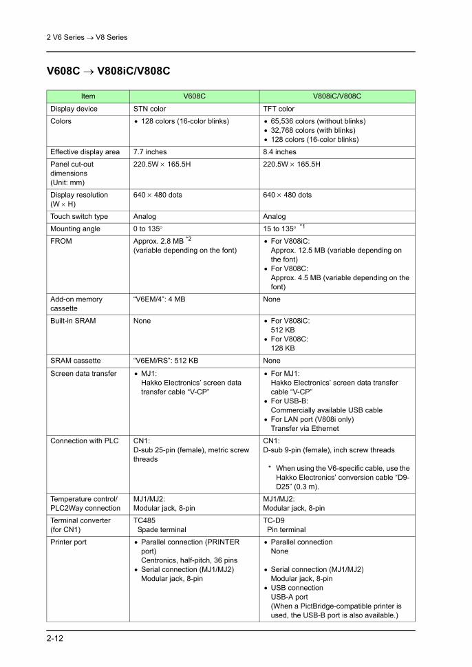
2 V6 Series → V8 Series
2-12
V608C → V808iC/V808C
Item V608C V808iC/V808C
Display device STN color TFT color
Colors • 128 colors (16-color blinks) • 65,536 colors (without blinks)• 32,768 colors (with blinks)• 128 colors (16-color blinks)
Effective display area 7.7 inches 8.4 inches
Panel cut-out dimensions(Unit: mm)
220.5W × 165.5H 220.5W × 165.5H
Display resolution (W × H)
640 × 480 dots 640 × 480 dots
Touch switch type Analog Analog
Mounting angle 0 to 135° 15 to 135° *1
FROM Approx. 2.8 MB *2(variable depending on the font)
• For V808iC:Approx. 12.5 MB (variable depending on the font)
• For V808C:Approx. 4.5 MB (variable depending on the font)
Add-on memory cassette
“V6EM/4”: 4 MB None
Built-in SRAM None • For V808iC:512 KB
• For V808C:128 KB
SRAM cassette “V6EM/RS”: 512 KB None
Screen data transfer • MJ1:Hakko Electronics’ screen data transfer cable “V-CP”
• For MJ1:Hakko Electronics’ screen data transfer cable “V-CP”
• For USB-B:Commercially available USB cable
• For LAN port (V808i only)Transfer via Ethernet
Connection with PLC CN1:D-sub 25-pin (female), metric screw threads
CN1:D-sub 9-pin (female), inch screw threads
* When using the V6-specific cable, use the Hakko Electronics’ conversion cable “D9-D25” (0.3 m).
Temperature control/PLC2Way connection
MJ1/MJ2:Modular jack, 8-pin
MJ1/MJ2:Modular jack, 8-pin
Terminal converter (for CN1)
TC485 Spade terminal
TC-D9 Pin terminal
Printer port • Parallel connection (PRINTER port)Centronics, half-pitch, 36 pins
• Serial connection (MJ1/MJ2)Modular jack, 8-pin
• Parallel connectionNone
• Serial connection (MJ1/MJ2)Modular jack, 8-pin
• USB connectionUSB-A port(When a PictBridge-compatible printer is used, the USB-B port is also available.)
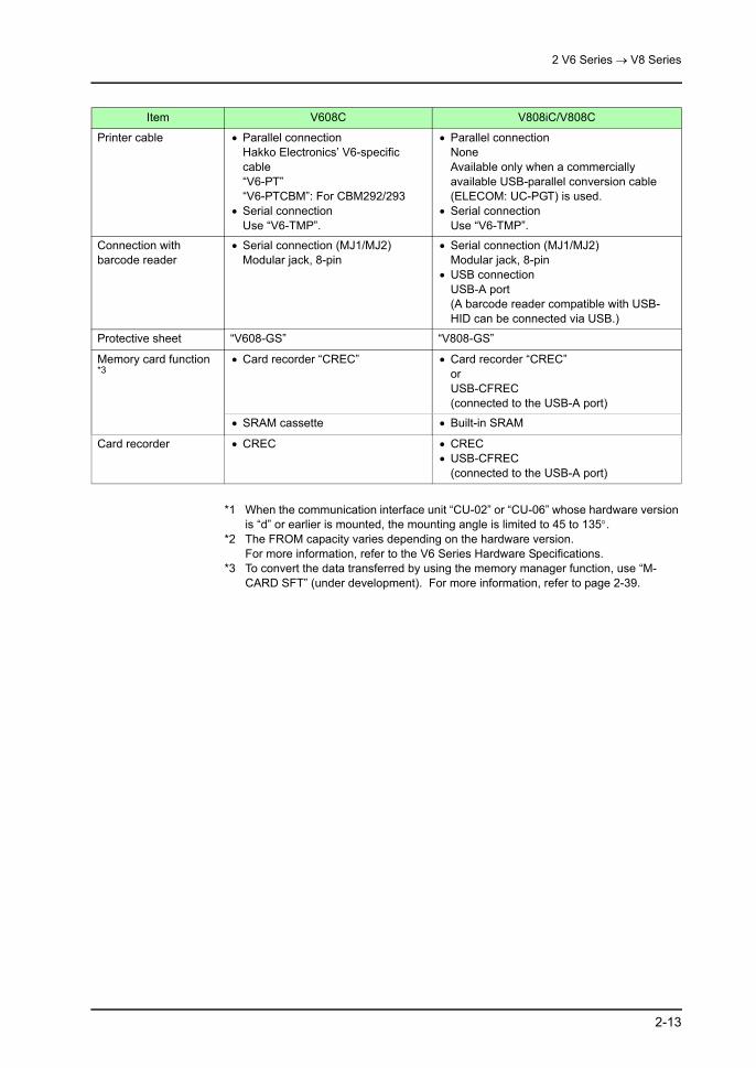
2 V6 Series → V8 Series
2-13
*1 When the communication interface unit “CU-02” or “CU-06” whose hardware version is “d” or earlier is mounted, the mounting angle is limited to 45 to 135°.
*2 The FROM capacity varies depending on the hardware version.For more information, refer to the V6 Series Hardware Specifications.
*3 To convert the data transferred by using the memory manager function, use “M-CARD SFT” (under development). For more information, refer to page 2-39.
Printer cable • Parallel connectionHakko Electronics’ V6-specific cable“V6-PT”“V6-PTCBM”: For CBM292/293
• Serial connectionUse “V6-TMP”.
• Parallel connectionNoneAvailable only when a commercially available USB-parallel conversion cable (ELECOM: UC-PGT) is used.
• Serial connectionUse “V6-TMP”.
Connection with barcode reader
• Serial connection (MJ1/MJ2)Modular jack, 8-pin
• Serial connection (MJ1/MJ2)Modular jack, 8-pin
• USB connectionUSB-A port(A barcode reader compatible with USB-HID can be connected via USB.)
Protective sheet “V608-GS” “V808-GS”
Memory card function *3
• Card recorder “CREC” • Card recorder “CREC”orUSB-CFREC (connected to the USB-A port)
• SRAM cassette • Built-in SRAM
Card recorder • CREC • CREC• USB-CFREC
(connected to the USB-A port)
Item V608C V808iC/V808C

2 V6 Series → V8 Series
2-14
V606i/V606 → V806i/V806
Item V606i/V606 V806i/V806
Display device • TFT color: V606iT• STN color: V606iC/V606C• STN monochrome: V606iM/V606M
• TFT color: V806iT/V806T• STN color: V806iC/V806C• STN monochrome: V806iM/V806M
Colors • V606iT/V606iC/V606C16 colors (with blinks)
• V606iM/V606MMonochrome (white mode) 8-step gradation
• V806iT/V806T, V806iC/V806C65,536 colors (without blinks)32,768 colors (with blinks)128 colors (16-color blinks)
• V806iM/V806MMonochrome (white mode) 16-step gradation
Effective display area 5.7 inches 5.7 inches
Panel cut-out dimensions(Unit: mm)
174W × 131H 174W × 131H
Display resolution (W × H)
320 × 240 dots 320 × 240 dots
Touch switch type • Analog• Matrix
Analog
Mounting angle 0 to 135° 15 to 135°
FROM Approx. 760 KB(variable depending on the font)
Approx. 4.5 MB(variable depending on the font)
Add-on memory cassette
“V6EM/4i”: 4 MB (V606i only) None
Built-in SRAM None • For V806i:512 KB
• For V806:128 KB
SRAM cassette “V6EM/RSi”: 512 KB (V606i only) None
Screen data transfer • MJ1:Hakko Electronics’ screen data transfer cable “V-CP”
• For MJ1:Hakko Electronics’ screen data transfer cable “V-CP”
• For USB-B:Commercially available USB cable
• For LAN port (V806i only)Transfer via Ethernet

2 V6 Series → V8 Series
2-15
*1 To convert the data transferred by using the memory manager function, use “M-CARD SFT” (under development). For more information, refer to page 2-39.
Connection with PLC CN1:D-sub 25-pin (female), metric screw threads
• V806i/V806 onlyMJ2:Modular jack, 8-pin
* When using the V6-specific cable, use the Hakko Electronics’ conversion cable “MJ2-PLC” (0.3 m). It cannot be used for direct connection with Mitsubishi’s A/QnA CPU. In such a case, use the “V706-ACPU- M” cable (both MJ2 and MJ1 are used).
• V806i/V806 + “DU-10”CN1:D-sub 9-pin (female), inch screw threads
* When using the V6-specific cable, use the Hakko Electronics’ conversion cable “D9-D25” (0.3 m).
Temperature control/PLC2Way connection
MJ1/MJ2:Modular jack, 8-pin
MJ1/MJ2:Modular jack, 8-pin
Terminal converter TC485 Spade terminal
TC-D9 (only for V806i/V806 + “DU-10”) Pin terminal
Printer port • Parallel connection (PRINTER port)Centronics, half-pitch36 pins
• Serial connection (MJ1/MJ2)Modular jack, 8-pin
• Parallel connectionNone
• Serial connection (MJ1/MJ2)Modular jack, 8-pin
• USB connectionUSB-A port(When a PictBridge-compatible printer is used, the USB-B port is also available.)
Printer cable • Parallel connectionHakko Electronics’ V6-specific cable“V6-PT”“V6-PTCBM”: For CBM292/293
• Serial connectionUse “V6-TMP”.
• Parallel connectionNoneAvailable only when a commercially available USB-parallel conversion cable (ELECOM: UC-PGT) is used.
• Serial connectionUse “V6-TMP”.
Connection with barcode reader
• Serial connection (MJ1/MJ2)Modular jack, 8-pin
• Serial connection (MJ1/MJ2)Modular jack, 8-pin
• USB connectionUSB-A port(A barcode reader compatible with USB-HID can be connected via USB.)
Protective sheet “V606-GS” “V806-GS”
Memory card function *1
Card recorder “CREC” Card recorder “CREC”orUSB-CFREC (connected to the USB-A port)
Card recorder • CREC • CREC• USB-CFREC
(connected to the USB-A port)
Item V606i/V606 V806i/V806

2 V6 Series → V8 Series
2-16
V609E → V808iC/V808C
Item V609E V808iC/V808C
Display device High-luminance EL TFT color
Colors • 2 colors (black and orange) + blinks • 65,536 colors (without blinks)• 32,768 colors (with blinks)• 128 colors (16-color blinks)
Effective display area 8.9 inches 8.4 inches
Panel cut-out dimensions(Unit: mm)
277W × 192H 220.5W × 165.5H
* Use Hakko Electronics’ panel adaptor “PAD-V608-01”. *1
Display resolution (W × H)
640 × 400 dots 640 × 480 dots *2
Touch switch type Matrix Analog
* When substituting a matrix-type MONITOUCH for V609E, use V810CM. In such a case, a larger panel cut-out hole is required. By using Hakko Electronics’ “PAD-002” is used, V810CM can be mounted without increasing the panel cut-out hole size. However, note that it has a depth greater than that of the V609E.
Power supply • AC power supply• DC power supply
DC power supply only
* When the AC power type is substituted, use Hakko Electronics’ AC power unit “V808C-PW”.
Mounting angle 0 to 135° 15 to 135° *3
FROM Approx. 760 KB(variable depending on the font)
• For V808iC:Approx. 12.5 MB (variable depending on the font)
• For V808C:Approx. 4.5 MB (variable depending on the font)
Built-in SRAM 8 KB • For V808iC:512 KB
• For V808C:128 KB
Screen data transfer • MJ1:Hakko Electronics’ screen data transfer cable “V-CP”
• For MJ1:Hakko Electronics’ screen data transfer cable “V-CP”
• For USB-B:Commercially available USB cable
• For LAN port (V808i only)Transfer via Ethernet
Connection with PLC CN1:D-sub 25-pin (female), metric screw threads
CN1:D-sub 9-pin (female), inch screw threads
* When using the V6-specific cable, use the Hakko Electronics’ conversion cable “D9-D25” (0.3 m).
Temperature control/PLC2Way connection
MJ1/MJ2:Modular jack, 8-pin
MJ1/MJ2:Modular jack, 8-pin

2 V6 Series → V8 Series
2-17
*1 When the panel adaptor is mounted, the front panel cannot be kept in compliance with IP65.
*2 The screen data created on the V609E can automatically be displayed in the center on V808iC/V808C although V609E and V808iC/V808C are different in resolution. For more information, refer to page 2-30.
*3 When the communication interface unit “CU-02” or “CU-06” whose hardware version is “d” or earlier is mounted, the mounting angle is limited to 45 to 135°.
*4 To convert the data transferred by using the memory manager function, use “M-CARD SFT” (under development). For more information, refer to page 2-39.
Terminal converter (for CN1)
TC609 Spade terminal
TC-D9 Pin terminal
Printer port • Parallel connection (PRINTER port)Centronics, half-pitch, 36 pins
• Serial connection (MJ1/MJ2)Modular jack, 8-pin
• Parallel connectionNone
• Serial connection (MJ1/MJ2)Modular jack, 8-pin
• USB connectionUSB-A port(When a PictBridge-compatible printer is used, the USB-B port is also available.)
Printer cable • Parallel connectionHakko Electronics’ V6-specific cable“V6-PT”“V6-PTCBM”: For CBM292/293
• Serial connectionUse “V6-TMP”.
• Parallel connectionNoneAvailable only when a commercially available USB-parallel conversion cable (ELECOM: UC-PGT) is used.
• Serial connectionUse “V6-TMP”.
Connection with barcode reader
• Serial connection (MJ1/MJ2)Modular jack, 8-pin
• Serial connection (MJ1/MJ2)Modular jack, 8-pin
• USB connectionUSB-A port(A barcode reader compatible with USB-HID can be connected via USB.)
Protective sheet “GD-GS80E” “V808-GS”
Waterproof protective cover
“GD-WP80E” “GD-WP80E”
Memory card function *4
Card recorder “CREC” Card recorder “CREC”orUSB-CFREC (connected to the USB-A port)
Card recorder • CREC • CREC• USB-CFREC
(connected to the USB-A port)
Item V609E V808iC/V808C
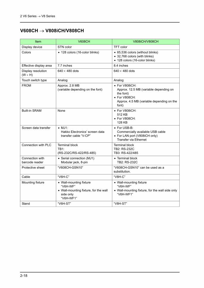
2 V6 Series → V8 Series
2-18
V608CH → V808iCH/V808CH
Item V608CH V808iCH/V808CH
Display device STN color TFT color
Colors • 128 colors (16-color blinks) • 65,536 colors (without blinks)• 32,768 colors (with blinks)• 128 colors (16-color blinks)
Effective display area 7.7 inches 8.4 inches
Display resolution (W × H)
640 × 480 dots 640 × 480 dots
Touch switch type Analog Analog
FROM Approx. 2.8 MB(variable depending on the font)
• For V808iCH:Approx. 12.5 MB (variable depending on the font)
• For V808CH:Approx. 4.5 MB (variable depending on the font)
Built-in SRAM None • For V808iCH:512 KB
• For V808CH:128 KB
Screen data transfer • MJ1:Hakko Electronics’ screen data transfer cable “V-CP”
• For USB-B:Commercially available USB cable
• For LAN port (V808iCH only)Transfer via Ethernet
Connection with PLC Terminal blockTB1:(RS-232C/RS-422/RS-485)
Terminal blockTB2: RS-232CTB3: RS-422/485
Connection with barcode reader
• Serial connection (MJ1)Modular jack, 8-pin
• Terminal blockTB2: RS-232C
Protective sheet “V608CH-GSN10” “V608CH-GSN10” can be used as a substitution.
Cable “V6H-C” “V8H-C”
Mounting fixture • Wall-mounting fixture“V6H-WF”
• Wall-mounting fixture, for the wall side only“V6H-WF1”
• Wall-mounting fixture“V6H-WF”
• Wall-mounting fixture, for the wall side only“V6H-WF1”
Stand “V6H-ST” “V8H-ST”

2 V6 Series → V8 Series
2-19
Notes on Hardware
Notes on InstallationTightening Torque of Fixtures
Power Supply Terminal Position
When substituting the following models, pay careful attention to the positions of the power supply terminals.
• 12/10-inch modelThe location and arrangement of power supply terminals differ between the V6 and the V8.
V6 Torque (N⋅m) V8 Torque (N⋅m)
V612 0.5 to 0.7 V812 0.5 to 0.7 (Same as V6)
V610T/S/C 0.5 to 0.7 V810T/S/C 0.5 to 0.7 (Same as V6)
V608C 0.3 to 0.5 V808C 0.5 to 0.7
V606i/V606 0.3 to 0.5 V806 0.5 to 0.7
V612/V610 V812/V810
U-AU-BLANCN1MJ2MJ1
CF
CN5CN7
AC100V-240V
L NFG
+ -
DC24V24V DC
FG
CN2
MJ1MJ2
CN
1
100-240VAC
L
N
NC
24 VDC
L
NNC NC
AC100V-240V DC24V
+
-
Power supply
Power supply
Grounding GroundingGrounding
Power supply
Power supply Grounding

2 V6 Series → V8 Series
2-20
• 8-inch modelThe location and arrangement of power supply terminals differ between the V6 and the V8.
DIP SwitchesThe DIP switch functions differ between the V6 and the V8.
*1 For the hardware versions with lower-case alphabet(Upper-case alphabet: Not used)
LAN U-B U-ACN1
24VDCFG
CN5
CN7
CF
MJ1 MJ2
+ -24V DC
FG
V608 V808
CN2
MJ2 MJ1
CN
1
DC 24V
TB1
DC 24V Power supply
Power supply
Grounding Grounding
ON
1 2 3 4 5 6 7 8
V6 V8ON
1 2 3 4 5 6 7 8
V806
12
34
OFF
(Upon delivery) (Upon delivery) (Upon delivery)
DIP SW No.
Descriptions
V6 V8 V806
1 Add-on memory 2(Except V606)
CF auto-uploading MJ1 (modular jack 1) terminating resistance
2 Not used CF slot cover access control MJ2 (modular jack 2)SD terminating resistance
3 Not used Not used MJ2 (modular jack 2)RD terminating resistance
4 Not used Not used CF auto-uploading
5 Not used CN1+SD/-SD terminating resistance at pins 3 and 4
-
6 MJ1 (modular jack 1) terminating resistance
MJ1 (modular jack 1) terminating resistance -
7 CN1+RD/-RD terminating resistance at pins 24 and 25
CN1+RD/-RD terminating resistance at pins 1 and 2
-
8 MJ2 (modular jack 2) terminating resistance *1
MJ2 (modular jack 2) terminating resistance -

2 V6 Series → V8 Series
2-21
Notes on ConnectionDifference in D-sub Connector
On the V6 series, the D-sub 25-pin connector is provided for CN1.On the V8 series, the D-sub 9-pin connector is provided for CN1 instead.Because of this difference, the conversion cable “D9-D25” (0.3 m) or the V8 terminal converter “TC-D9” (terminal block) must be used after substitution.
• Conversion cableUse “D9-D25” when using the V6-specific communication cable.
• Terminal converterWhen the terminal block “TC485” is mounted on the V6 series, use “TC-D9” on the V8 series as a substitute. However, note that the end of the cable must be modified since the structure of the terminal block is not the same.
F 1
F 2
F 3
F 4
F 5
F 6
F 7
SYSTEM
V6 V8
CN1:D-sub 25-pin
CN1:D-sub 9-pin
V8-specific conversion cable “D9-D25”.
V6-specific communication cable
V6-specific communication cable
+5V SG +SD -SD+RD -RD FG
F 1
F 2
F 3
F 4
F 5
F 6
F 7
SYSTEM
V6 V8
V8-specific terminal converter “TC-D9”
* Spade terminals not available. Use a pin terminal.
CN1:D-sub 25-pin
CN1:D-sub 9-pin
V6-specific terminal converter “TC485”

2 V6 Series → V8 Series
2-22
For Communication with Mitsubishi Electric’s A Series CPU
For the V6 series, “GD-MDD”, “GD-MDD2” or “V-MDD” (2-port adaptor) can be used for communication with the A series CPU.For the V8 series, “GD-MDD” cannot be used. Substitute “V-MDD” for it.
ACPU
F 1
F 2
F 3
F 4
F 5
F 6
F 7
SYSTEM
GD
GPP
GD-MDD
V8
V-MDD
Not availableAvailable

2 V6 Series → V8 Series
2-23
For Multi-link 2 Communication
* For “Multi-link 2” communication, whether or not the V8 series can be used together with the V7 or V6 series depends on the PLC model.For the PLC model that can be connected together with the V8 series and the V7 or V6 series (mixed connection), [Multi-link2 with V7/V6] is valid in the [Detail] tab window ([System Setting] → [Device Connection Setting]). When this box is checked, the V8 series can be used together with the V7 or V6 series. (When the PLC model with which this mixed connection is available is selected, this box is automatically checked.)
If one of the V6 units connected to a PLC has failed during multi-link 2 communication, it may not be possible to substitute the V8 for the failed unit only.In such a case, substitute the V8 for all the V7 and V6 units connected via “multi-link 2”.
* In “multi-link” communication, V8 can be used together with V7 and V6.In this case, it is possible to substitute any number of the V7 or V6 by the V8.
F 1
F 2
F 3
F 4
F 5
F 6
F 7
SYSTEM
F 1
F 2
F 3
F 4
F 5
F 6
F 7
SYSTEM
F 1
F 2
F 3
F 4
F 5
F 6
F 7
SYSTEM
F 1
F 2
F 3
F 4
F 5
F 6
F 7
SYSTEM
F 1
F 2
F 3
F 4
F 5
F 6
F 7
SYSTEM
PLC
CN1 MJ2 CN1 CN1 CN1
PLC
CN1 MJ2 CN1 CN1 CN1
NG
V6 V6 V6 V6
V8
V8 V8V8 V8
V8 cannot be used as a substitute for the failed V6 only.
Substitute the V8 series for all MONITOUCH units.

2 V6 Series → V8 Series
2-24
FROM CassetteThere is no FROM cassette available with the V8; however, since the capacity of FROM on the V8 is bigger than the V6, substitution by the V8 is possible without using the cassettes.For the V8C series, note that the models with “i” and without “i” differ in capacity of FROM.For more information, refer to the following table.
( : provided, : not provided, -: not available)
*1 The FROM capacity varies depending on the hardware version.For more information, refer to the V6 Series Hardware Specifications.
MONITOUCH ModelsCombinations
FROM Total CapacityMONITOUCH V6EM/4
(4 MB)V6EM/4i(4 MB)
V6 series
V612V610V608
- Approx. 2.8 MB *1
- Approx. 6.8 MB *1
V606i- Approx. 760 KB
- Approx. 4.8 MB
V606 - - Approx. 760 KB
V609E - - Approx. 760 KB
V608CH - - Approx. 2.8 MB
V8 series
V815iXV812(i)SV810(i)SV810(i)TV808(i)S
- - Approx. 12.5 MB
V8C series
V810iCV808iCV808iCH
- - Approx. 12.5 MB
V810CV808CV808CH
- - Approx. 4.5 MB
V806 series V806i - - Approx. 4.5 MB

2 V6 Series → V8 Series
2-25
SRAM CassetteThere is no SRAM cassette available with the V8; however, since the capacity of SRAM on the V8 is bigger than the V6, substitution by the V8 is possible without using the cassettes.For the V8C or V806 series, note that the models with “i” and without “i” differ in capacity of SRAM.For more information, refer to the following table.
( : provided, : not provided, -: not available)
MONITOUCH ModelsCombinations
SRAM CapacityMONITOUCH V6EM/RS
(512 KB)V6EM/RSi(512 KB)
V6 series
V612V610V608
- None
- 512 KB
V606i- None
- 512 KB
V606 - - None
V609E - - 8 KB
V608CH - - None
V8 series
V815iXV812(i)SV810(i)SV810(i)TV808(i)S
- - 512 KB
V8C series
V810iCV808iCV808iCH
- - 512KB
V810CV808CV808CH
- - 128 KB
V806 seriesV806i - - 512 KB
V806 - - 128 KB

2 V6 Series → V8 Series
2-26
Video Display FunctionColors
Because of hardware structural differences, colors displayed by the video input function slightly differ between the V6 and the V8.
When the image quality of the video display is adjusted by using a macro command (“Video”), the quality differs between V7 and V8 even if the adjustment value is the same. The default value is shown below.
* When substituting the V8 series for the V6 series, be sure to check and adjust the actual image quality on the V8 series before use.
Video Display Speed
The video display speed is almost the same between the V6 and the V8.
V6 GU-00/GU-10 (V8i)
Number of colors
260,000 colors V815/V812/V810:16,777,216 colors (monochrome 256-step gradation)
V808S:262,144 colors (monochrome 64-step gradation)
ItemDefault
V6 V8
Brightness: V6: 0 (dark) - 255 (bright)V8: 0 (dark) - 31 (bright) 171 16
Contrast: V6: 0 (low) - 255 (high)V8: 0 (low) - 31 (high) 24 16
Color shade: V6: 0 (light) - 255 (dark)V8: 0 (light) - 31 (dark) 44 16
Display SizeNumber of Displayed Frames (Base Screen: 1 Channel)
V6 V8i
640 × 480
Approx. 30 frames/sec Approx. 30 frames/sec640 × 240
320 × 240
160 × 120
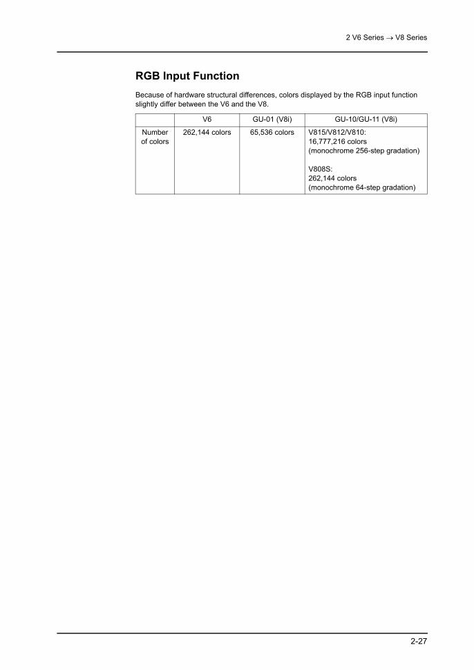
2 V6 Series → V8 Series
2-27
RGB Input FunctionBecause of hardware structural differences, colors displayed by the RGB input function slightly differ between the V6 and the V8.
V6 GU-01 (V8i) GU-10/GU-11 (V8i)
Number of colors
262,144 colors 65,536 colors V815/V812/V810:16,777,216 colors (monochrome 256-step gradation)
V808S:262,144 colors (monochrome 64-step gradation)

2 V6 Series → V8 Series
2-28
]
2.3 Software Compatibility (Settings and Functions)
Screen Data File Conversion
For V6 (except V609E) → V8Follow the procedure below to convert the screen data file.
1. Launch V-SFT. Click the [Open] icon, or select [File] and [Open].
2. The [Open] dialog is displayed. Select [*.V6] for [Files of type].
3. Select a V6 screen data file to be converted and click [Open]. The selected V6 screen data file is opened.
or

2 V6 Series → V8 Series
2-29
4. Click [System Setting] and [Edit Model Selection]. The [Edit Model Selection] dialog is displayed.
5. Select the desired V8 model as the conversion target, and click [OK].

2 V6 Series → V8 Series
2-30
6. The following dialog is displayed. Click [Yes].
* When V6 data is converted into V8 data, it cannot be converted back to V6 data.
7. The selected screen data file is converted into the V8 file and displayed on the editor.Give a name to the file and save it.
For V609E → V808iC/V808C (only for 128 colors)When the screen data for the V609E is converted into that for the V808iC/V808C, the screen size or layout may be changed due to difference in the resolution between them.To avoid such a problem, follow the procedure described below so that the screen display will be kept at the center on the V808iC/V808C. (This procedure is valid only when [128-Color] is selected for [Color].)
SYSTEM
F1
F2
F3
F4
F5
F6
F7
SYSTEM
F1
F2
F3
F4
F5
F6
F7
640
400
640
480
640
480
A 80-dot margin is created on one side.
The screen is centered between the top and bottom margins.(A 40-dot margin is created each on the top and bottom.)
When substitution is executed without making necessary settings:
When substitution is executed with necessary settings made:

2 V6 Series → V8 Series
2-31
Follow the procedure below to convert the screen data file.
1. Launch V-SFT. Click the [Open] icon, or select [File] and [Open].
2. The [Open] dialog is displayed. Select [*.V6] for [Files of type].
3. Select a V609E screen data file to be converted and click [Open]. The selected V609E screen data file is opened.

2 V6 Series → V8 Series
2-32
4. Click [System Setting] and [Edit Model Selection]. The [Edit Model Selection] dialog is displayed.
5. Select [V808C] and [Color: 128-Color], and click [OK].
6. The following dialog is displayed. Click [Yes].

2 V6 Series → V8 Series
2-33
7. The following dialog is displayed.
8. Check the box for [ GD-80E/V609E Compatible].When [ Color Batch Change] is checked, the screen turns to 2-color display, the same as the V609E.
* When a blink setting is used on the V609E, select a color from basic 16 colors. Otherwise, the blink color will be different from the selected one.
9. Click [OK]. The following dialog is displayed. Click [Yes].
* When the screen data on which pattern data is used is converted, the following message appears. In such a case, the pattern color remains the same.Click [OK].

2 V6 Series → V8 Series
2-34
10. The screen data is converted and displayed in two colors; black and the color selected in step 8.
* When V609E data is converted into V808C data, it cannot be converted back to V609E data.
11. The selected screen data file is converted into the V808C file and displayed on the editor.Name the file and save it.
* On the editor, when a switch or lamp part with [XOR] selected is turned ON after the screen data is converted from V609E, characters placed on the switch or lamp part will not be displayed. However, when this screen data is transferred into MONITOUCH, text will correctly be displayed in reverse video in the same way as the V609E.

2 V6 Series → V8 Series
2-35
Switch
[Delay] Setting“ON repeat” and “double-touch” functions available with V8 are automatically enabled for the switches shown below to keep compatibility after screen data conversion.
List of Target Switches
V6 V8
Switch Functions Switch Functions Delay Setting
StandardRoll Up Roll Up
ON repeat function(150 ms)
Roll Down Roll Down
Entry
Char. Entry Character Input
Space Space
Backspace Backspace
DEL DELETE
+1 +1
-1 -1
← ←
→ →
↑ ↑
↓ ↓
Table Data Display
Move Cursor R Cursor Movement to Right
Move Cursor L Cursor Movement to Left
Digital SwitchDigital Switch + Digital Switch +
Digital Switch - Digital Switch -
StandardReset Reset Double-touch
function(2 s)

2 V6 Series → V8 Series
2-36
Example of Conversion
• Example of [Function: Roll Up] switch
• Example of [Function: Reset] switch
[Function: Card Format] SwitchIn the [Function] setting on the [Switch] dialog, the [Memory Card: Card Format] switch is provided.With the V6 series, this switch is used for formatting the SRAM settings (SRAM cassette or SRAM memory card).With the V8 series, this switch is used only for the SRAM memory card, not valid for the built-in SRAM.(When the switch is pressed, a triple error beep sounds and the switch operation is not accepted.)For more information on formatting of SRAM, refer to Formatting of SRAM on page 2-39.

2 V6 Series → V8 Series
2-37
Sampling
Store TargetThe store target setting for the V8 varies according to the setting for [Store Target] in the [Buffering Area Setting] dialog made for the V6. For more information, refer to the following table.
*1 Some number of words are automatically allocated to the emulation area after conversion. On the V8, the number of words indicated at [Word Count] must be secured. Manually set the same number for [Set Word] as the one indicated at [Word Count] ([45 Word] in the example).
V6 V8
Store Target Other Settings Primary
Store TargetSecondary
Store Target Other Remarks
Internal Buffer - DRAM None -
SRAM
SRAM cassette
Emulation area
Set word count > Used word count
SRAM None
In the emulation area ([SRAM/Clock Setting] dialog), some number of words are automatically allocated to [Primary Storage of Sampling] as well as [Memory Card Emulation Area]. *1
Emulation area
Set word count = Used word count
SRAM None
In the emulation area ([SRAM/Clock Setting] dialog), some number of words are automatically allocated only to [Primary Storage of Sampling].
SRAM cardCREC + SRAM card DRAM Memory
Card
[ Use Card Recorder] for [Others] in the [Device Connection Setting] dialog is checked.

2 V6 Series → V8 Series
2-38
No. of SamplingsPrimary Store Target
For more information, refer to the following table.
Secondary Store Target
SRAM
SRAM CassetteSRAM/Clock Setting
Some contents in SRAM differ between the V6 and the V8. For more information, refer to the following table.
V6 V8
Store Target Other Settings Primary Store Target No. of Samples (primary store target)
Internal Buffer - DRAM The same as [No. of Samples] for V6
SRAM
SRAM cassette SRAM The same as [No. of Samples] for V6
SRAM cardCREC + SRAM card DRAM
• Bit Synchronization / Constant Sampling / Device Memory Map256 words ÷ (2 words + word count)
• Alarm Logging256 words ÷ 3 words
• Time Order AlarmingNone
• Alarm Function{256 words − (6 words × number of sampling bits) − 7 words} ÷ 5 words
V6 V8
Store Target Other Settings Secondary Store Target No. of Samples (primary store target)
SRAM SRAM cardCREC + SRAM card Memory Card The same as [No. of Samples] for V6
V6 V8 Remarks
Memory card emulation area
Memory card emulation area
For V6:Must be set when the SRAM cassette is used.
For V8:Secure the required amount of words only when the SRAM memory card is used. The area to be used for sampling is secured in the built-in SRAM as [Primary Storage of Sampling] described below.
Memo pad storage area ← the same as the left -
Non-volatile memory(Word) ($L)
← the same as the left -
Non-volatile memory(Double-word) ($LD)
← the same as the left -

2 V6 Series → V8 Series
2-39
Formatting of SRAM
The SRAM formatting procedure differs between the V6 and the V8.For more information, refer to the following table.
* The built-in SRAM for the V8 can automatically be formatted.When [ SRAM Auto Format] is checked in the [SRAM/Clock Setting] dialog, no error message appears in step 3, and manual formatting of SRAM on the Main Menu screen becomes unnecessary.However, when the screen data is transferred to a new V8 unit, the error appears in step 3 even if the above setting has been made. In such a case, check the box for [Format the SRAM forcefully] in the [General Settings] tab window displayed by selecting [System Setting] → [Unit Setting].
SRAM Data Conversion (Memory Manager)
Transfer data using the V8-ready memory card editor “M-CARD SFT” (*) and convert it for the V8.
* Under development
V6(SRAM cassette)
V8(Built-in SRAM)
Step 1 • Buffering area setting[Store Target: SRAM]
• SRAM/Clock settingSet the [Memory Card Emulation Area].
• Place a [Memory Card] item and a [Card Format] switch on the screen.
• Buffering area setting[Primary storage target: SRAM]
• SRAM/Clock setting[Primary Storage of Sampling] is secured.
• Card format switchNot required
Step 2 Transfer the screen data to MONITOUCH. ← the same as the left
Step 3 The error message “Data has some error. No. 161 (24: )” is displayed on MONITOUCH.On the Main Menu screen, execute the first formatting of SRAM.
The error message “Data has some error. No. 161 (24: )” is displayed on MONITOUCH.On the Main Menu screen, execute formatting of SRAM (*).
Step 4 Bring MONITOUCH into the RUN mode.Next, press the [Card Format] switch placed in step 1, and execute the second formatting.
Bring MONITOUCH into the RUN mode.The [Card Format] switch is not necessary.The built-in SARM becomes available.

2 V6 Series → V8 Series
2-40
SRAM Card (REC-MCARD)Formatting of SRAM
The same formatting procedure as the V6 can be used.
How to Use SRAM Card Data (Data Logging) on V8
Data stored by the data logging function on the V6 cannot be displayed on the V8. Make a backup copy of the data on the computer, format the SRAM, and execute data logging again on the V8.Press the [Function: Card Format] switch on the RUN screen of the V8 to execute data logging onto the SRAM.
* Even if SRAM is not formatted, data logging can be performed onto the primary store target (DRAM) for the set number of times.When SRAM has been formatted, data logging can be performed onto the secondary store target (Memory Card).
How to Use SRAM Card Data (Memory Manager) on V8
Data transferred by using the memory manager function on the V6 can also be used on the V8. Transfer the data from SRAM using “M-CARD SFT” (*), change the edit model to “V8” and then transfer it into the V8.
* Under development
How to Substitute CF Card for SRAM Card (Memory Manager)
Transfer data using the V8-ready memory card editor “M-CARD SFT” (*) and convert it into V8 data.
* Under development

2 V6 Series → V8 Series
2-41
Communication Setting
Conversion into 8-Way CommunicationWhen V6 data is converted to V8 data, it is automatically converted to data ready for 8-way communication (PLC1 to PLC8) according to the communication type used for the V6. For more information, refer to the following table.
Text ProcessingOn the V6 series, the setting for [Text Process] (LSB/MSB) is made in the [Communication Parameter] dialog and applied globally. On the V8 series, it can individually be set for the items shown below; however, when the data has originally been converted from the V6 series, the setting for [Text Process] made for PLC1 is applied globally. For the target items, refer to the table show below.
* When [Barcode] is selected for [Device] while the PLC memory is selected for [I/F Memory], text processing is performed in the order of LSB → MSB unless otherwise specified after conversion.When [MSB → LSB] is selected on the V6, check [Storage Order] in the [Communication Setting] tab window that is displayed by selecting [System Setting] → [Device Connection Setting] and select [MSB → LSB].
V6 V8
PLC PLC1
Temperature control/PLC2Way network
PLC2
Modbus slave PLC3
V-Link PLC3
Barcode reader PLC4
Character display (including those in each library or data sampling)
MR-400 format table

2 V6 Series → V8 Series
2-42
Internal Memory
$s (System Memory)In “$s” memory, some addresses on the V6 are not the same as those on the V8.The detailed information is described below.
• $s17 (backlight status)On the V6 series, bit No. 15 is not used; however, it is used on the V8 series.To monitor the backlight ON/OFF status only on the V8, mask bit No. 15.
• $s167 (SRAM information)For the V6 series, the SRAM cassette and FROM cassette can be used in addition to the built-in SRAM, and its mounting status can be checked by bit Nos. 0 to 2.For the V8 series, there is no such cassette available, thus bit Nos. 0 to 2 are not used.
$s17
V6
V8
15 14 13 12 11 10 09 08 07 06 05 04 03 02 01 00
Backlight status
0: OFF 1: ON
15 14 13 12 11 10 09 08 07 06 05 04 03 02 01 00
Backlight status
0: OFF 1: ON0: Backlight burnt 1: Backlight normal
$s167
V6
V8
15 14 13 12 11 10 09 08 07 06 05 04 03 02 01 00
0 0 0 0 0 0 0 0 0 0 0
MSB
0: Battery normal1: Battery voltage drop2: Battery not mounted
Memory cassette information reserved (Setting: 0)
LSB
0: Not mounted1: FROM 2 Mbytes (V6)2: FROM 4 Mbytes (V6)3: SRAM 512 kbytes (V6/V7)4: FROM 8 Mbytes (V7)
Memory cassette information reserved (Setting: 0)
15 14 13 12 11 10 09 08 07 06 05 04 03 02 01 00
0 0 0 0 0 0 0 0 0 0 0 0 0 0
MSB
0: Battery normal1: Battery voltage drop2: Battery not mounted
System reserved (setting: 0)
LSB
System reserved (setting: 0)

2 V6 Series → V8 Series
2-43
Network Table for Ethernet CommunicationFor the V6 series, all settings for the Ethernet communication network table are made on the network table edit window.For the V8 series, the settings for the Ethernet communication network table are made separately for PLC and MONITOUCH/PC.Some examples are given below.
Example: V6 Connected to the Ethernet-ready PLC
Register the network table on the V6 as shown below.
When the data is converted to V8 data, the same contents specified for the network table is automatically copied to the PLC table.PLC settings can be deleted from the network table.Settings for V8 or PC can be deleted from the PLC table.
• Network table (for V8/PC)
• PLC table (for PLC)
Can be deleted
Can be deleted

2 V6 Series → V8 Series
2-44

3 V4 Series → V8 Series
3-1
3 V4 Series → V8 Series
3.1 Recommended Models
The following models are recommended when the V4 series is substituted by the V8 series.
*1 For the V806 series, there is no matrix switch type.Substitute the analog switch type.Note that the two-point pressing function cannot be used.
V4 Series V8 Series Optional
10 inches
V4x0x0x-xV4x1x0x-x
• Using the 2-point pressing function:
V810iTMV810TMV810iCMV810CM
• Not using the 2-point pressing function:
V810iTV810TV810iCV810C
-
V4T2x0x-x
• Using the 2-point pressing function:
V810iTM• Not using the 2-point
pressing function:V810iT
GU-02
5.7 inches
V4SC0x0x-x
V806iTD *1V806TD *1V806iCD *1V806CD *1
DU-10
V4SW1x0x-xV4SB1x0x-x
V806iMD *1V806MD *1 DU-10

3 V4 Series → V8 Series
3-2
3.2 Hardware Compatibility
V4 → V810iT/V810T/V810iC/V810C
Item V4 V810iT/V810T/V810iC/V810C
Display device • V4T: TFT color• V4C: STN color• V4W: STN white mode• V4B: STN blue mode• V4H: STN semitransparent yellow
TFT color
Colors • V4T: 16 colors/8 colors• V4C: 16 colors/8 colors
• 65,536 colors (without blinks)• 32,768 colors (with blinks)• 128 colors (16-color blinks)
Effective display area 10.4 inches 10.4 inches
Panel cut-out dimensions(Unit: mm)
317W × 229H 289W × 216.2H
Use Hakko Electronics’ mounting panel adaptor “PAD-V610” (option). *1
Display resolution (W × H)
640 × 480 dots 640 × 480 dots
Touch switch type • Matrix • Analog
• Matrix
Mounting angle 0 to 135° 15 to 135°
FROM • ROM version 1.12 and laterApprox. 1 MB
• ROM version 1.00 to 1.11Approx. 512 KB
(variable depending on the font)
Approx. 12.5 MB(variable depending on the font)
Screen data transfer CN1:Hakko Electronics’ screen data transfer cable “GD-CPV”orHakko Electronics’ screen data transfer cable “V-CP”+ conversion adaptor “ADP25-M”
• For MJ1:Hakko Electronics’ screen data transfer cable “V-CP”
• For USB-B:Commercially available USB cable
• For LAN port (V810i only)Transfer via Ethernet
Connection with PLC CN1:D-sub 25-pin (female), metric screw threads
CN1:D-sub 9-pin (female), inch screw threads
* When using the V4-specific cable, use the Hakko Electronics’ conversion cable “D9-D25” (0.3 m).
RS-422 terminal block: Spade terminal
TC-D9 Pin terminal
Printer port CN2:Centronics, 14 pins(parallel connection)
• Parallel connectionNone
• Serial connection (MJ1/MJ2)Modular jack, 8-pin
• USB connectionUSB-A port(When a PictBridge-compatible printer is used, the USB-B port is also available.)

3 V4 Series → V8 Series
3-3
*1 When the panel adaptor is mounted, the front panel cannot be kept in compliance with IP65.
*2 Wiring for MJ←→D-sub 9-pin conversion cable
*3 To convert the data transferred by using the memory manager function, use “M-CARD SFT” (under development). For more information, refer to page 3-16.
Printer cable • Standard printer cable for PC-9801 • Parallel connectionNoneAvailable only when a commercially available USB-parallel conversion cable (ELECOM: UC-PGT) is used.
• Serial connectionUse “V6-TMP”.
Connection with barcode reader
CN7: D-sub, 9-pin(V4xx2/V4xx4/V4xx5 only)
• Serial connection (MJ1/MJ2)Create MJ←→D-sub 9-pin conversion cable by using Hakko Electronics’ barcode reader cable “V6-BCD”. *2
• USB connectionUSB-A port(A barcode reader compatible with USB-HID can be connected via USB.)
Protective sheet “V4-GS” “V810-GS”
Memory card function *3 *4
CN4: D-sub, 15-pin(V4xx5/V4xx6 only)Card recorder “GD-MREC02”
• Card recorder “CREC”• Built-in SRAM• CF card
CN5:Built-in memory card interface(V4xx2/V4xx4 only)
Screen data saving into memory card
Card recorder “GD-MREC01” • Card recorder “CREC”• CF card
REC-MCARD • For screen data transferFLASHSRAM
• Screen data can be used by importing it though V-SFT and converting it into V8-specific data. *3
• Data logging/memory manager functionSRAM
• When settings specified in the [Memory Card] dialog are the same: SRAM can be used without being formatted.
• When settings specified in the [Memory Card] dialog are not the same: SRAM can be used after being formatted. *4
External I/O CN6(V4Tx3 only)
Available with MONITOUCH + V-I/O (option)
Item V4 V810iT/V810T/V810iC/V810C
Pin No123456789
SignalCSRDSDRS
SG
+5V
Red: 0V
Orange: RDYellow: SD
Brown:+5V* Install a jumper between CS and RS.
D-sub 9pin
SignalRSSDRDCSSG+5V
Barcode reader

3 V4 Series → V8 Series
3-4
*4 When the memory card function is used on V4:There are two ways of converting the screen data file into V8-specific data; by using CF card or “CREC”. In either case, some settings must be made after conversion. For more information on the required settings, refer to page 16 “How to Use SRAM Card Data (Data Logging) on V8”.
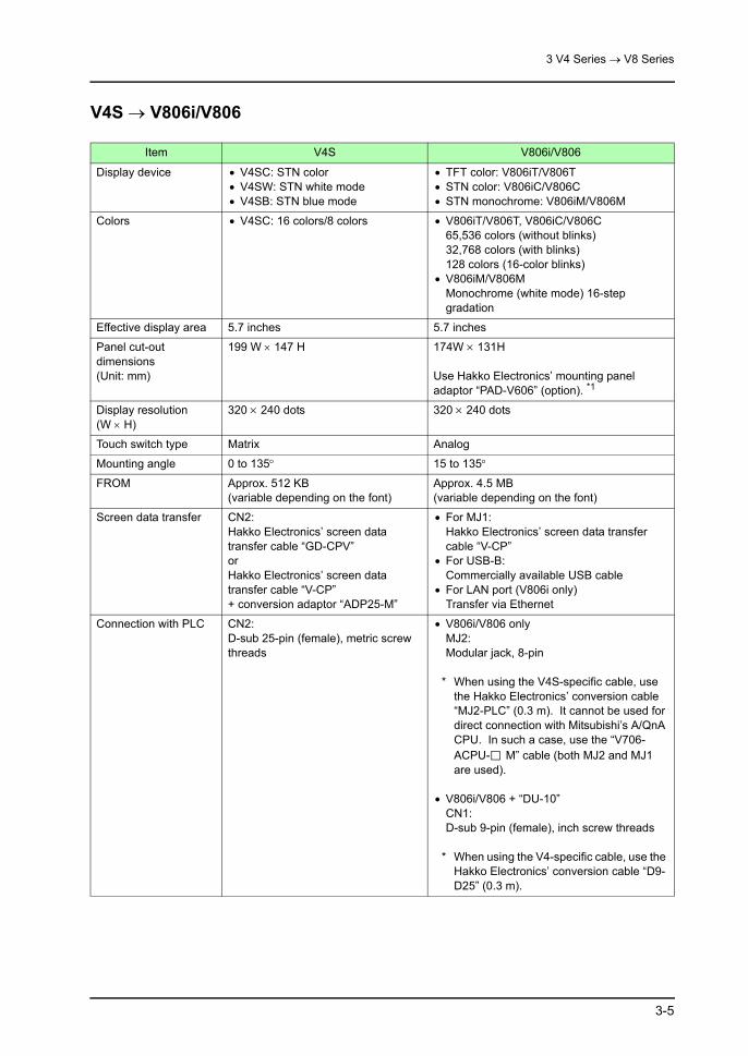
3 V4 Series → V8 Series
3-5
V4S → V806i/V806
Item V4S V806i/V806
Display device • V4SC: STN color• V4SW: STN white mode• V4SB: STN blue mode
• TFT color: V806iT/V806T• STN color: V806iC/V806C• STN monochrome: V806iM/V806M
Colors • V4SC: 16 colors/8 colors • V806iT/V806T, V806iC/V806C65,536 colors (without blinks)32,768 colors (with blinks)128 colors (16-color blinks)
• V806iM/V806MMonochrome (white mode) 16-step gradation
Effective display area 5.7 inches 5.7 inches
Panel cut-out dimensions(Unit: mm)
199 W × 147 H 174W × 131H
Use Hakko Electronics’ mounting panel adaptor “PAD-V606” (option). *1
Display resolution (W × H)
320 × 240 dots 320 × 240 dots
Touch switch type Matrix Analog
Mounting angle 0 to 135° 15 to 135°
FROM Approx. 512 KB(variable depending on the font)
Approx. 4.5 MB(variable depending on the font)
Screen data transfer CN2:Hakko Electronics’ screen data transfer cable “GD-CPV”orHakko Electronics’ screen data transfer cable “V-CP” + conversion adaptor “ADP25-M”
• For MJ1:Hakko Electronics’ screen data transfer cable “V-CP”
• For USB-B:Commercially available USB cable
• For LAN port (V806i only)Transfer via Ethernet
Connection with PLC CN2:D-sub 25-pin (female), metric screw threads
• V806i/V806 onlyMJ2:Modular jack, 8-pin
* When using the V4S-specific cable, use the Hakko Electronics’ conversion cable “MJ2-PLC” (0.3 m). It cannot be used for direct connection with Mitsubishi’s A/QnA CPU. In such a case, use the “V706-ACPU- M” cable (both MJ2 and MJ1 are used).
• V806i/V806 + “DU-10”CN1:D-sub 9-pin (female), inch screw threads
* When using the V4-specific cable, use the Hakko Electronics’ conversion cable “D9-D25” (0.3 m).

3 V4 Series → V8 Series
3-6
*1 When the panel adaptor is mounted, the front panel cannot be kept in compliance with IP65.
*2 Wiring for MJ←→D-sub 9-pin conversion cable
Printer port CN4:Centronics, 14 pins(parallel connection)
• Parallel connectionNone
• Serial connection (MJ1/MJ2)Modular jack, 8-pin
• USB connectionUSB-A port(When a PictBridge-compatible printer is used, the USB-B port is also available.)
Printer cable • Standard printer cable for PC-9801 • Parallel connectionNoneAvailable only when a commercially available USB-parallel conversion cable (ELECOM: UC-PGT) is used.
• Serial connectionUse “V6-TMP”.
Connection with barcode reader
• CN1: D-sub, 9-pin(V4xx2/V4xx4/V4xx5 only)
• Serial connection (MJ1/MJ2)Create MJ←→D-sub 9-pin conversion cable by using Hakko Electronics’ barcode reader cable “V6-BCD”. *2
• USB connectionUSB-A port(A barcode reader compatible with USB-HID can be connected via USB.)
Protective sheet “V4S-GS” “V806-GS”
Screen data saving into memory card
Card recorder “GD-MREC01” • Card recorder “CREC”• CF card
REC-MCARD • For screen data transferFLASH/SRAM
Screen data can be used by importing it though V-SFT and converting it into V8-specific data.
Item V4S V806i/V806
Pin No123456789
SignalCSRDSDRS
SG
+5V
Red: 0V
Orange: RDYellow: SD
Brown:+5V* Install a jumper between CS and RS.
D-sub 9pin
SignalRSSDRDCSSG+5V
Barcode reader

3 V4 Series → V8 Series
3-7
Notes on Hardware
Notes on InstallationPower Supply Terminal Position
When substituting the following model, pay careful attention to the positions of the power supply terminals.
• V4The location and arrangement of power supply terminals differ between the V4 and the V8.
CN1 TB2
CN1
S1
CN6
CN2
CN3CN4CN7CN5
TB1
V4 V810
U-AU-BLANCN1MJ2MJ1
CF
CN5CN7
AC100V-240V
L NFG
L
NNC
AC100V-240V
Power supply
Power supply
Grounding Grounding

3 V4 Series → V8 Series
3-8
Notes on ConnectionDifference in D-sub Connector
On the V4 series, the D-sub 25-pin connector is provided for CN1. TB2 is used as a terminal block for RS-422 communication.On the V8 series, the D-sub 9-pin connector is provided for CN1 instead.Because of this difference, the conversion cable “D9-D25” (0.3 m) or the V8 terminal converter “TC-D9” (terminal block) must be used after substitution.
• Conversion cableUse “D9-D25” when using the V4-specific communication cable.
• Connection for RS-422 terminal blockWhen TB2 is used for terminal block connection on the V4 series, use “TC-D9” on the V8 series as a substitute. However, note that the end of the cable must be modified since the structure of the terminal block is not the same.
F 1
F 2
F 3
F 4
F 5
F 6
F 7
SYSTEM
V4 V8
CN1:D-sub 25-pin
CN1:D-sub 9-pin
V8-specific conversion cable “D9-D25”.
V4-specific communication cable
V4-specific communication cable
CN1 TB2
CN1
S1
CN6
CN2
CN3CN4CN7CN5
TB1
+5V SG +SD -SD+RD -RD FG
F 1
F 2
F 3
F 4
F 5
F 6
F 7
SYSTEM
V4 V8
V8-specific terminal converter “TC-D9”
* Spade terminals not available. Use a pin terminal.
TB2:Terminal block connection
CN1:D-sub 9-pin

3 V4 Series → V8 Series
3-9
For Communication with Mitsubishi Electric’s A Series CPU
For the V4 series, “GD-MDD”, “GD-MDD2” or “V-MDD” (2-port adaptor) can be used for communication with the A series CPU.For the V8 series, “GD-MDD” cannot be used. Substitute “V-MDD” for it.
ACPU
F 1
F 2
F 3
F 4
F 5
F 6
F 7
SYSTEM
GD
GPP
GD-MDD
V8
V-MDD
Not available Available

3 V4 Series → V8 Series
3-10
]
3.3 Software Compatibility (Settings and Functions)
Screen Data File ConversionFollow the procedure below to convert the screen data file.
1. Launch V-SFT. Click the [Open] icon, or select [File] and [Open].
2. The [Open] dialog is displayed. Select [*.V4] for [Files of type].
3. Select a V4 screen data file to be converted and click [Open]. The selected V4 screen data file is opened.
or

3 V4 Series → V8 Series
3-11
4. Click [System Setting] and [Edit Model Selection]. The [Edit Model Selection] dialog is displayed.
5. Select the desired V8 model as the conversion target, and click [OK].

3 V4 Series → V8 Series
3-12
6. The following dialog is displayed. Click [Yes].
* When V4 data is converted into V8 data, it cannot be converted back to V4 data.
7. The selected screen data file is converted into the V8 file and displayed on the editor.Name the file and save it.

3 V4 Series → V8 Series
3-13
Data Compatibility
Item V4 V8
Switch[Action: ICON2]
Provided Not providedAutomatically chanted to [Action: ICON]
Switch When a point where two switches overlap one another is pressed, the switch placed over the first one is activated.When this point is pressed:
On the V4:
No. 1 is activated.
The order of placement on the editor determines which switch is to be activated when pressed. A switch having a smaller No. (or DIV No.) is recognized as the one placed first (behind), and the other one is recognized as the one placed later (front).
[General Settings] in the [Unit Setting] dialog:[ If a switch is overlaid on another, enable the upper switch]
• Checked: The switch placed at the front is activated (same as V4).
• Unchecked: The switch placed behind (first) is activated.
No. 0 is activated.
Numerical data display
When an overflow occurs, the upper two digits are displayed.
Example: D100 = 1234 Four-digit display = “1234” Two-digit display = “12”
When an overflow occurs, “--” is displayed as shown below:
Example: D100 = 1234 Four-digit display = “1234” Two-digit display = “--”
* [General Settings] in the [Unit Setting] dialog:When [ Num. Display: Displays the significant figures upon overflow] is checked, “34” is displayed.
XOR display - [System Setting] → [Edit Model Selection]
• When [Color: 128-Color] is selected: The XOR display is shown in the same way as the V4.
• Other than above: Only the XOR display using the basic 8 colors is shown in the same way as the V4.
Connection with barcode reader
Baud rate:2400 bps is available.
Baud rate:2400 bps is not available.
No. 0
No. 1
No. 0
No. 1
No. 1
No. 0
No. 1
No. 0
Basic 8 colors: Compatible
Other colors: Not compatible

3 V4 Series → V8 Series
3-14
Switch“ON repeat” and “double-touch” functions available with V8 are automatically enabled for the switches shown below to keep compatibility after screen data conversion.
List of Target Switches
[Function: Card Format] Switch
In the [Function] setting on the [Switch] dialog, the [Memory Card: Card Format] switch is provided.With the V4 series, this switch is used for formatting the SRAM memory card settings.With the V8 series, this switch is used only for the SRAM memory card, not valid for the built-in SRAM. (When the switch is pressed, a triple error beep sounds and the switch operation is not accepted.)
V4 V8
Switch Functions Switch Functions Delay Setting
StandardRoll Up Roll Up
ON repeat function(150 ms)
Roll Down Roll Down
Entry
Char. Entry Character Input
Space Space
Backspace Backspace
DEL DELETE
+1 +1
-1 -1
← ←
→ →
↑ ↑
↓ ↓
StandardReset Reset Double-touch
function(2 s)

3 V4 Series → V8 Series
3-15
SRAM
SamplingThe store target setting for the V8 varies according to the setting for [Store Target] in the [Buffering Area Setting] dialog made for the V4. For more information, refer to the following table.
V4 V8
Store Target
Data after Conversion
Primary Store Target
Secondary Store Target
Setting Procedure Store Target Note
Internal Buffer No change DRAM None - DRAM -
SRAM
No change DRAM Memory Card - DRAM
Sampling data is stored the number of times specified for DRAM ([Primary storage target]).It is not stored in the memory card.
Stored in SRAM memory card
DRAM Memory Card
Check [ Use Card Recorder] for [Others] in the [Device Connection Setting] dialog and mount “CREC” and the SRAM memory card.Press the [Card Format] switch in the RUN mode. Data is stored in the SRAM memory card.
DRAM and SRAM
memory card
-
Stored in built-in SRAM
Changed to [SRAM]
Changed to [None]
Set the same number for [No. of Samplings] as that specified for [Secondary storage target] immediately after conversion.The [Card Format] switch is not necessary.
Built-in SRAM -
Stored in CF card
Changed to [DRAM] or [SRAM]
Changed to [CF Card]
-
DRAM or SRAM, and CF
card
-

3 V4 Series → V8 Series
3-16
SRAM Memory Card (REC-MCARD)Formatting of SRAM
The same formatting procedure as the V4 can be used.
How to Use SRAM Card Data (Data Logging) on V8
Data stored by the data logging function on the V4 cannot be displayed on the V8. Make a backup copy of the data on the computer, format the SRAM, and execute data logging again on the V8.Press the [Function: Card Format] switch on the RUN screen of the V8 to execute data logging onto the SRAM.
* Even if SRAM is not formatted, data logging can be performed onto the primary store target (DRAM) for the set number of times.When SRAM has been formatted, data logging can be performed onto the secondary store target (Memory Card).
How to Use SRAM Card Data (Memory Manager) on V8
Data transferred by using the memory manager function on the V4 can also be used on the V8. Transfer the data from SRAM using “M-CARD SFT” (*), change the edit model to “V8” and then transfer it into the V8.
* Under development
How to Substitute CF Card for SRAM Card (Memory Manager)
Transfer data using the V8-ready memory card editor “M-CARD SFT” (*) and convert it into V8 data.
* Under development

4 GD-80 Series → V8 Series
4-1
4 GD-80 Series → V8 Series
4.1 Recommended Models
The following models are recommended when the GD-80 series is substituted by the V8 series.
*1 For the V806 series, there is no matrix switch type.Substitute the analog switch type.Note that the two-point pressing function cannot be used.
GD-80 Series V8 Series Optional
GD-80T0xxx-x
• Using the 2-point pressing function:V810iTMV810TMV810iCMV810CM
• Not using the 2-point pressing function:
V810iTV810TV810iCV810C
-
GD-80TAxxx-x
• Using the 2-point pressing function:V810iTM
• Not using the 2-point pressing function:
V810iT
GU-02
GD-80Exxxx-x V808iCV808C -
GD-80Sxx-x V806iMD *1V806MD *1
DU-10GD-81S
V806iTD *1V806TD *1V806iCD *1V806CD *1V806iMD *1V806MD *1

4 GD-80 Series → V8 Series
4-2
4.2 Hardware Compatibility
GD-80T → V810iT/V810T/V810iC/V810C
Item GD-80T V810iT/V810T/V810iC/V810C
Display device TFT color TFT color
Colors 16 colors • 65,536 colors (without blinks)• 32,768 colors (with blinks)• 128 colors (16-color blinks)
Effective display area 9.8 inches 10.4 inches
Panel cut-out dimensions(Unit: mm)
317W × 229H 289W × 216.2H
Use Hakko Electronics’ mounting panel adaptor “PAD-V610” (option). *1
Display resolution (W × H)
640 × 400 dots 640 × 480 dots
Touch switch type • Matrix • Analog
• Matrix
Mounting angle 0 to 135° 15 to 135°
Screen data transfer CN1:Hakko Electronics’ screen data transfer cable “GD-CPV”orHakko Electronics’ screen data transfer cable “V-CP” + conversion adaptor “ADP25-M”
• For MJ1:Hakko Electronics’ screen data transfer cable “V-CP”
• For USB-B:Commercially available USB cable
• For LAN port (V810i only)Transfer via Ethernet
Connection with PLC CN1:D-sub 25-pin (female), metric screw threads
CN1:D-sub 9-pin (female), inch screw threads
* When using the GD-80-specific cable, use the Hakko Electronics’ conversion cable “D9-D25” (0.3 m).
RS-422 terminal block (GD-80xxx0): Spade terminal
TC-D9 Pin terminal
CN6 (GD-80xxxM only)D-sub 15-pin (female), metric screw threads
CN1:D-sub 9-pin (female), inch screw threads
* When using the GD-80-specific cable, use the Hakko Electronics’ conversion cable “D9-D15” (0.5 m).
Printer port • CN2: Centronics, 14 pins (parallel connection)
• Parallel connectionNone
• Serial connection (MJ1/MJ2)Modular jack, 8-pin
• USB connectionUSB-A port(When a PictBridge-compatible printer is used, the USB-B port is also available.)

4 GD-80 Series → V8 Series
4-3
*1 When the panel adaptor is mounted, the front panel cannot be kept in compliance with IP65.
*2 Wiring for MJ ←→ D-sub 9-pin conversion cable
*3 To convert the data transferred by using the memory manager function, use “M-CARD SFT” (under development). For more information, refer to page 4-33.
*4 When the memory card function is used on GD-80xx2x:There are two ways of converting the screen data file into V8-specific data; by using CF card or “CREC”. In either case, some settings must be made after conversion. For more information on the required settings, refer to page 33 “How to Use SRAM Card Data (Data Logging) on V8”.
Printer cable • Standard printer cable for PC-9801 • Parallel connectionNoneAvailable only when a commercially available USB-parallel conversion cable (ELECOM: UC-PGT) is used.
• Serial connectionUse “V6-TMP”.
Connection with barcode reader
CN4: D-sub, 9-pin(GD-80xx2x only)
• Serial connection (MJ1/MJ2)Create MJ←→D-sub 9-pin conversion cable by using Hakko Electronics’ barcode reader cable “V6-BCD”. *2
• USB connectionUSB-A port(A barcode reader compatible with USB-HID can be connected via USB.)
Protective sheet “GD-GS80T” “V810-GS”
Waterproof protective cover
“GD-WP80T” Not requiredCompatible with IP65 as standard
Memory card function *3 *4
CN5: D-sub, 15-pin(GD-80xx2x only)Card recorder “GD-MREC02”
• Card recorder “CREC”• Built-in SRAM• CF card
Screen data saving into memory card
Card recorder “GD-MREC01” • Card recorder “CREC”• CF card
REC-MCARD • For screen data transferFLASHSRAM
• Screen data can be used by saving the data using GD-SFT80/GD-SFT80W, importing it through V-SFT and converting it into V8-specific data. *3
• Data logging/memory manager functionSRAM
• Data can be used after changing the edit model on “M-CARD SFT” (option). *4
Item GD-80T V810iT/V810T/V810iC/V810C
Pin No123456789
SignalCSRDSDRS
SG
+5V
Red: 0V
Orange: RDYellow: SD
Brown:+5V* Install a jumper between CS and RS.
D-sub 9pin
SignalRSSDRDCSSG+5V
Barcode reader
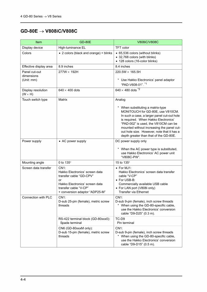
4 GD-80 Series → V8 Series
4-4
GD-80E → V808iC/V808C
Item GD-80E V808iC/V808C
Display device High-luminance EL TFT color
Colors • 2 colors (black and orange) + blinks • 65,536 colors (without blinks)• 32,768 colors (with blinks)• 128 colors (16-color blinks)
Effective display area 8.9 inches 8.4 inches
Panel cut-out dimensions(Unit: mm)
277W × 192H 220.5W × 165.5H
* Use Hakko Electronics’ panel adaptor “PAD-V608-01”. *1
Display resolution (W × H)
640 × 400 dots 640 × 480 dots *2
Touch switch type Matrix Analog
* When substituting a matrix-type MONITOUCH for GD-80E, use V810CM. In such a case, a larger panel cut-out hole is required. When Hakko Electronics’ “PAD-002” is used, the V810CM can be mounted without increasing the panel cut-out hole size. However, note that it has a depth greater than that of the GD-80E.
Power supply • AC power supply DC power supply only
* When the AC power type is substituted, use Hakko Electronics’ AC power unit “V808C-PW”.
Mounting angle 0 to 135° 15 to 135°
Screen data transfer CN1:Hakko Electronics’ screen data transfer cable “GD-CPV”orHakko Electronics’ screen data transfer cable “V-CP”+ conversion adaptor “ADP25-M”
• For MJ1:Hakko Electronics’ screen data transfer cable “V-CP”
• For USB-B:Commercially available USB cable
• For LAN port (V808i only)Transfer via Ethernet
Connection with PLC CN1:D-sub 25-pin (female), metric screw threads
CN1:D-sub 9-pin (female), inch screw threads
* When using the GD-80-specific cable, use the Hakko Electronics’ conversion cable “D9-D25” (0.3 m).
RS-422 terminal block (GD-80xxx0): Spade terminal
TC-D9 Pin terminal
CN6 (GD-80xxxM only):D-sub 15-pin (female), metric screw threads
CN1:D-sub 9-pin (female), inch screw threads
* When using the GD-80-specific cable, use the Hakko Electronics’ conversion cable “D9-D15” (0.5 m).

4 GD-80 Series → V8 Series
4-5
*1 When the panel adaptor is mounted, the front panel cannot be kept in compliance with IP65.
*2 The screen data created on the GD-80E can automatically be displayed in the center on the V808iC/V808C although the GD-80E and V808iC/V808C are different in resolution. For more information, refer to page 4-13.
Printer port • CN2: Centronics, 14 pins (parallel connection)
• Parallel connectionNone
• Serial connection (MJ1/MJ2)Modular jack, 8-pin
• USB connectionUSB-A port(When a PictBridge-compatible printer is used, the USB-B port is also available.)
Printer cable • Standard printer cable for PC-9801 • Parallel connectionNoneAvailable only when a commercially available USB-parallel conversion cable (ELECOM: UC-PGT) is used.
• Serial connectionUse “V6-TMP”.
Connection with barcode reader
CN4: D-sub, 9-pin(GD-80xx2x only)
• Serial connection (MJ1/MJ2)Create MJ ←→ D-sub 9-pin conversion cable by using Hakko Electronics’ barcode reader cable “V6-BCD”. *3
• USB connectionUSB-A port(A barcode reader compatible with USB-HID can be connected via USB.)
Protective sheet “GD-GS80E” “V808-GS”
Waterproof protective cover
“GD-WP80E” Not requiredCompatible with IP65 as standard
Memory card function *4 *5
CN5: D-sub, 15-pin(GD-80xx2x only)Card recorder “GD-MREC02”
• Card recorder “CREC”• Built-in SRAM• CF card
Screen data saving into memory card
Card recorder “GD-MREC01” • Card recorder “CREC”• CF card
REC-MCARD • For screen data transferFLASHSRAM
• Screen data can be used by saving the data using GD-SFT80/GD-SFT80W, importing it through V-SFT and converting it into V8-specific data. *4
• Data logging/memory manager functionSRAM
• Data can be used after changing the edit model on “M-CARD SFT” (option). *5
Item GD-80E V808iC/V808C

4 GD-80 Series → V8 Series
4-6
*3 Wiring for MJ ←→ D-sub 9-pin conversion cable
*4 To convert the data transferred by using the memory manager function, use “M-CARD SFT” (under development). For more information, refer to page 4-33.
*5 When the memory card function is used on the GD-80xx2x:There are two ways of converting the screen data file into V8-specific data; by using CF card or “CREC”. In either case, some settings must be made after conversion. For more information on the required settings, refer to page 33 “How to Use SRAM Card Data (Data Logging) on V8”.
Pin No123456789
SignalCSRDSDRS
SG
+5V
Red: 0V
Orange: RDYellow: SD
Brown:+5V* Install a jumper between CS and RS.
D-sub 9pin
SignalRSSDRDCSSG+5V
Barcode reader

4 GD-80 Series → V8 Series
4-7
GD-80S → V806i/V806
Item GD-80S V806i/V806
Display device • GD-80SE: High-luminance EL• GD-80SL: STN monochrome
(white mode)
• TFT color: V806iT/V806T• STN color: V806iC/V806C• STN monochrome: V806iM/V806M
Colors • GD-80SE: 2 colors (orange/black)• GD-80SL: 2 colors (white/black)
• V806iT/V806T, V806iC/V806C65,536 colors (without blinks)32,768 colors (with blinks)128 colors (16-color blinks)
• V806iM/V806MMonochrome (white mode) 16-step gradation
Effective display area 4.7 inches 5.7 inches
Panel cut-out dimensions(Unit: mm)
158.5 W × 122.5 H 174W × 131H
* A larger panel cut-out hole is required.When Hakko Electronics’ “PAD-001” is used, V806i or V806 can be mounted without increasing the panel cut-out hole size. However, note that it has a depth greater than that of GD-80S. It should also be noted that doing so makes MONITOUCH out of conformance to IP65.
Display resolution (W × H)
320 × 240 dots 320 × 240 dots
Touch switch type Matrix Analog
Mounting angle 0 to 135° 15 to 135°
Screen data transfer CN2:Hakko Electronics’ screen data transfer cable “GD-CPSV”
• For MJ1:Hakko Electronics’ screen data transfer cable “V-CP”
• For USB-B:Commercially available USB cable
• For LAN port (V806i only)Transfer via Ethernet
Connection with PLC CN2:D-sub 15-pin (female), metric screw threads
• V806i/V806 onlyMJ2:Modular jack, 8-pin *1
• V806i/V806 + “DU-10”CN1:D-sub 9-pin (female), inch screw threads *2
* The GD-80S cable cannot be used. Modify it or use a V8-specified cable.
Protective sheet “GD-GS80S” “V806-GS"
Screen data saving into memory card
Card recorder “GD-MREC01" • Card recorder “CREC"• CF card
REC-MCARD • For screen data transferFLASH/SRAM
Screen data can be used by saving the data using GD-SFT80/GD-SFT80W, importing it through V-SFT and converting it into V8-specific data.

4 GD-80 Series → V8 Series
4-8
*1 Since the connector of the communication cable used for GD-80SE/SL (CN2) is different from the one to be used for V806 (MJ2), it must be changed as shown in the following table.
*2 Since the connector of the communication cable used for GD-80SE/SL is different from the one to be used for DU-10, it must be changed as shown in the following table.
Pin No. Signal Descriptions
1 FG Frame ground
2 RD RS-232C receive data
3 SD RS-232C send data
4 CS RS-232C CS clear to send
5 RS RS-232C RS request to send
6
7 SG Signal ground
8
9 COM Output common
10 +RD RS-422 receive data (+)
11 -RD RS-422 receive data (−)
12 +SD RS-422 send data (+)
13 -SD RS-422 send data (−)
14 RUN RUN signal
15 BZ Buzzer signal
Pin No. Signal Contents
1 +SD/RD RS-485 data (+)
+SD RS-422 send data (+)
2 -SD/RD RS-485 data (−)
-SD RS-422 send data (−)
3 +5 V Externally supplied +5 VMax. 150 mA4
5 SG Signal ground
6
7 RD RS-232C receive data
+RD RS-422 receive data (+)
8 SD RS-232C send data
-RD RS-422 receive data (−)
GD-80S CN2 (D-sub 15-pin) V806 MJ2 (modular jack 8-pin)
Slide switch on the side of V806Upper: RS-232CLower: RS-422
GD-80S CN2 (D-sub 15-pin) DU-10 CN1 (D-sub 9-pin)
Pin No. Signal Descriptions
1 FG Frame ground
2 RD RS-232C receive data
3 SD RS-232C send data
4 CS RS-232C CS clear to send
5 RS RS-232C RS request to send
6
7 SG Signal ground
8
9 COM Output common
10 +RD RS-422 receive data (+)
11 -RD RS-422 receive data (−)
12 +SD RS-422 send data (+)
13 -SD RS-422 send data (−)
14 RUN RUN signal
15 BZ Buzzer signal
Pin No.
SignalDescriptions
232C 422
1 NC +RD Not used
RS-422 receive data (+)
2 RD -RD RS-232C receive data
RS-422 receive data (−)
3 SD -SD RS-232C send data
RS-422 send data (−)
4 NC +SD Not used
RS-422 send data (+)
5 SG SG Signal ground
6 NC +RS Not used
RS-422 RS send data (+)
7 RS -RS RS-232C RS request to send
RS-422 RS send data (−)
8 CS NC RS-232C CS clear to send
Not used
9 NC +5 V Not used
For terminating resistance

4 GD-80 Series → V8 Series
4-9
GD-81S → V806i/V806
Item GD-81S V806i/V806
Display device • GD-81SC: STN color• GD-81SW: STN monochrome
(white mode)• GD-81SB: STN monochrome (blue
mode)• GD-81SH: Semitransparent yellow
• TFT color: V806iT/V806T• STN color: V806iC/V806C• STN monochrome: V806iM/V806M
Colors 16 colors • V806iT/V806T, V806iC/V806C65,536 colors (without blinks)32,768 colors (with blinks)128 colors (16-color blinks)
• V806iM/V806MMonochrome (white mode) 16-step gradation
Effective display area 5.7 inches 5.7 inches
Panel cut-out dimensions(Unit: mm)
199 W × 147 H 174W × 131H
Use Hakko Electronics’ mounting panel adaptor “PAD-V606" (option). *1
Display resolution (W × H)
320 × 240 dots 320 × 240 dots
Touch switch type Matrix Analog
Mounting angle 0 to 135° 15 to 135°
Screen data transfer CN2:Hakko Electronics’ screen data transfer cable “GD-CPV"orHakko Electronics’ screen data transfer cable “V-CP" + conversion adaptor “ADP25-M"
• For MJ1:Hakko Electronics’ screen data transfer cable “V-CP"
• For USB-B:Commercially available USB cable
• For LAN port (V806i only)Transfer via Ethernet
Connection with PLC CN2:D-sub 25-pin (female), metric screw threads
• V806i/V806 onlyMJ2:Modular jack, 8-pin
* When using the GD-81S-specific cable, use the Hakko Electronics’ conversion cable “MJ2-PLC" (0.3 m). It cannot be used for direct connection with Mitsubishi’s A/QnA CPU. In such a case, use the “V706-ACPU- M" cable (both MJ2 and MJ1 are used).
• V806i/V806 + “DU-10"CN1:D-sub 9-pin (female), inch screw threads
* When using the GD-81S-specific cable, use the Hakko Electronics’ conversion cable “D9-D25" (0.3 m).

4 GD-80 Series → V8 Series
4-10
*1 When the panel adaptor is mounted, the front panel cannot be kept in compliance with IP65.
Printer port CN4:Centronics, 14 pins(parallel connection)
• Parallel connectionNone
• Serial connection (MJ1/MJ2)Modular jack, 8-pin
• USB connectionUSB-A port(When a PictBridge-compatible printer is used, the USB-B port is also available.)
Printer cable • Standard printer cable for PC-9801 • Parallel connectionNoneAvailable only when a commercially available USB-parallel conversion cable (ELECOM: UC-PGT) is used.
• Serial connectionUse “V6-TMP".
Protective sheet “GD-GS81S" “V806-GS"
Screen data saving into memory card
Card recorder “GD-MREC01" • Card recorder “CREC"• CF card
REC-MCARD • For screen data transferFLASH/SRAM
Screen data can be used by saving the data using GD-SFT80/GD-SFT80W, importing it through V-SFT and converting it into V8-specific data.
Item GD-81S V806i/V806

4 GD-80 Series → V8 Series
4-11
]
4.3 Software Compatibility (Settings and Functions)
Screen Data File Conversion
For GD-80T/80S/81S → V8Follow the procedure below to convert the screen data file.
1. Launch V-SFT. Click the [Open] icon, or select [File] and [Open].
2. The [Open] dialog is displayed. Select [*.80] for [Files of type].
3. Select a GD-80 screen data file to be converted and click [Open].
or

4 GD-80 Series → V8 Series
4-12
4. The [Edit Model Selection] dialog is displayed. Select the desired V8 model as conversion target, and click [OK].
5. The selected screen data file is converted into the V8 file and displayed on the editor.
6. Name the file and save it.

4 GD-80 Series → V8 Series
4-13
For GD-80E → V808iC/V808C (only for 128 colors)When the screen data for GD-80E is converted into that for the V808iC/V808C, the screen size or layout may be changed due to difference in the resolution between them.To avoid such a problem, follow the procedure described below so that the screen display will be kept at the center on the V808iC/V808C. (This procedure is valid only when [128-Color] is selected for [Color].)
Follow the procedure below to convert the screen data file.
1. Launch V-SFT. Click the [Open] icon, or select [File] and [Open].
SYSTEM
F1
F2
F3
F4
F5
F6
F7
SYSTEM
F1
F2
F3
F4
F5
F6
F7
640
400
640
480
640
480
A 80-dot margin is created on one side.
The screen is centered between the top and bottom margins.(A 40-dot margin is created each on the top and the bottom.)
When substitution is executed without making necessary settings:
When substitution is executed with necessary settings made:

4 GD-80 Series → V8 Series
4-14
2. The [Open] dialog is displayed. Select [*.80] for [Files of type].
3. Select a GD-80E screen data file to be converted and click [Open].The [Edit Model Selection] dialog is displayed.
4. Select [V808C] and [Color: 128-Color], and click [OK].

4 GD-80 Series → V8 Series
4-15
5. The following dialog is displayed.
6. Check the box for [ GD-80E/V609E Compatible].When [ Color Batch Change] is checked, the screen turns to 2-color display, the same as the GD-80E.
* When a blink setting is used on the GD-80E, select a color from basic 16 colors. Otherwise, the blink color will be different from the selected one.
7. Click [OK]. The following dialog is displayed. Click [Yes].
* When the screen data on which pattern data is used is converted, the following message appears. In such a case, the pattern color remains the same.Click [OK].

4 GD-80 Series → V8 Series
4-16
8. The screen data is converted and displayed in two colors; black and the color selected in step 8.
* When GD-80E data is converted into V808C data, it cannot be converted back to GD-80E data.
9. The selected screen data file is converted into the V808C file and displayed on the editor.Give a name to the file and save it.
* On the editor, when a switch or lamp part with [XOR] selected is turned ON after the screen data is converted from GD-80E, characters placed on the switch or lamp part will not be displayed. However, when this screen data is transferred into MONITOUCH, text will correctly be displayed in reverse video in the same way as the GD-80E.
Screen Size AdjustmentThe screen resolution varies depending on the model. To adjust the screen size, follow the procedure described below.
* The following procedure cannot be used when converting the screen data into the one for a matrix-type V8 series because a switch area (action area) may be misaligned from the switch grids after conversion.
As an example, the procedure of converting GD-80T screen data into V810T data is explained.When data is converted, a 80-dot margin is created at the bottom of the screen. This procedure describes how to adjust the screen size to eliminate this marginal area.

4 GD-80 Series → V8 Series
4-17
1. Select [View] → [Grid] → [Grid Setting], and remove checkmarks from [ON Grid] and [Place switches on switch grids].
2. Select all items placed on the screen.
3. Drag the handle at the bottom center of the selected items to adjust the screen size.
* If the screen includes a circle- or polygonal-shaped part, the screen size is adjusted in both horizontal and vertical direction with the same magnification ratio; it cannot be enlarged or reduced only in the vertical direction. When adjusting the screen size, delete all circle- and polygonal-shaped parts.
80 dotsEnlarging the Y size

4 GD-80 Series → V8 Series
4-18
Compatible Functions
Item GD-80 V8
Continuous buzzer
A continuous buzzer sounds while bit 10 of read area “n" is set (ON).
[General Settings] in the [Unit Setting] dialog:[ Use Continuous Buzzer Sound]• Checked: Same as the GD-80• Unchecked: Bit 10 is invalid.
Bit command for overlap display
The overlap display is shown while bit 12 of read area “n + 1" is set (ON).(It remains displayed if the screen is changed over.)
[General Settings] in the [Unit Setting] dialog:[ Display Overlap during bit ON]• Checked: Same as the GD-80• Unchecked: Bit 12 is recognized at the edge of OFF to
ON or ON to OFF.(The overlap display disappears when the screen is changed over.)
Character input mode
Characters can be entered continuously after the [Write] key is pressed.
[General Settings] in the [Unit Setting] dialog:[ Clear the text when inputting the first character in the character input mode]• Checked: Same as the GD-80• Unchecked: Press the [CLR] key before entering a
character.
Calendar display Messages to be displayed on the specified day of the week are registered in the [Message Edit] window.
Messages specified in the [Message Edit] window are converted and imported into a calendar part, and they are automatically copied and registered in the [Day-Week Message Setting] tab window of the [Calendar] dialog.
Barcode reader Data is read into the memory address specified for [I/F Memory] in [Barcode Setting] in the units of words.
[General Settings] in the [Unit Setting] dialog:[ Read Data from Barcode in Words]• Checked: Same as the GD-80 (in words)• Unchecked: In bytes
When [Action Area: Switch/Lamp] is selected for bit order alarming, page mode or direct mode
If the message cannot be held in one line, the portion that cannot be held in the switch/lamp area is not shown.
Example: Switch
The message continues to “P...U" following “O".
[General Settings] in the [Unit Setting] dialog:[ Make messages the same as the GD-80 if [Action Area] is [Switch/Lamp].]
• Checked: Same as the GD-80• Unchecked: The message that cannot be held in one
line is wrapped and shown.
Numerical data display
When an overflow occurs, the lower two digits are displayed.
Example: D100 = 1234 Four-digit display = “1234" Two-digit display = “34"
[General Settings] in the [Unit Setting] dialog:[ Num. Display: Displays the significant figures upon overflow]• Checked: Same as the GD-80• Unchecked: Displayed as below: Four-digit display = “1234" Two-digit display = “--"
ABCDEFGHIJKLMNOABCDEFGHIJKLMNOPQRSTU

4 GD-80 Series → V8 Series
4-19
Numerical data display
When [BCD] is selected for [Code], numerical data is displayed on MONITOUCH as shown below:
[General Settings] in the [Unit Setting] dialog:[ Num. Display: Displays the special characters A to F in BCD]
• Checked: Same as the GD-80• Unchecked: “A" to “F" are displayed as “0".
Switching of keypad blocks(Keypad mode, [Action: + block/-block] switch)
The keypad block is switched even if there is an unregistered block between the block numbers [Start No] and [End No].
Example:
All blocks are switched while unregistered blocks are skipped.
[General Settings] in the [Unit Setting] dialog:[ When operating the +/- block switch, skip keypad blocks that do not exist]
• Checked: Switching while skipping unregistered blocks
• Unchecked:Switching stopped when an unregistered block is encountered
Item GD-80 V8
PLC GD-80
0 to 9 0 to 9
A ./.
B :/:
C -/-
D +/+
E (Space)
F (Space)
No. 0
No. 4
Unregistered
No. 0 No. 4No. 1 No. 3
No. 0 No. 4No. 1 No. 2 No. 3
Unregistered
Switching possible Switching not possible

4 GD-80 Series → V8 Series
4-20
Graphic relay mode on the overlap display
When the graphic relay mode is set on the overlap display, registered graphics are placed with respect to the reference point of the screen.
Example: Graphic library
[General Settings] in the [Unit Setting] dialog:[ Regard the origin of graphic relay on an overlap as the origin of a screen]
• Checked: Same as the GD-80
• Unchecked:Registered graphics are placed with respect to the reference point of the overlap display.
Switch/Lamp When the OFF color of the switch or lamp part is the same as the screen background color, the OFF color becomes transparent.
Example:
[General Settings] in the [Unit Setting] dialog:[ If a switch/lamp OFF color is the same as the base, do not make it solid filled]
• Checked:On the editor, the part placed on top overwrites the existing one; however, on the V8, it is displayed in the same way as displayed on the GD-80 (the OFF color becomes transparent).
• Unchecked:The switch or lamp part placed on top overwrites the existing switch or lamp part on either editor or MONITOUCH.
Item GD-80 V8
Reference point Overlap
Screen
Reference point Overlap
Screen
Reference point Overlap
Screen
Lamp (on top)
Switch (on bottom)
On MONITOUCH
No lamp seen when it is OFF
Lamp (on top)
Switch (on bottom) No lamp seen when it is OFF
On MONITOUCH
Lamp (on top)
Switch (on bottom) Lamp overwrite
On MONITOUCH

4 GD-80 Series → V8 Series
4-21
Switch When a point where two switches overlap one another is pressed, the switch having a greater No. (DIV No.) is activated.When this point is pressed:
On the GD-80:
No. 1 is activated.
The order of placement determines which switch is to be activated when pressed. The switch having a smaller No. (or DIV No.) is recognized as the one placed first (bottom), and the switch having a greater No. is recognized as the one placed later (top).
[General Settings] in the [Unit Setting] dialog:[ If a switch is overlaid on another, enable the upper switch]
• Checked: The switch placed on top is activated (same as V4).
• Unchecked: The switch placed on bottom (earlier) is activated.
Character display Distinction is made between two-byte character (JIS) and one-byte character (ANK/ASCII).
• One-byte• Two-byte
Characters are converted into a character display part. When [ JIS/ASCII] is checked in the [Detail] tab window, GD-80 characters can be displayed.
→ [ JIS/ASCII] checked, [1-Byte] selected→ [ JIS/ASCII] checked, [2-Byte] selected
NULL code processing (LSB → MSB)
Character display ANK/ASCII/Shift-JIS code [ JIS/ASCII] in the [Detail] tab window: Unchecked
NULL code processing(LSB → MSB)
Item GD-80 V8
No. 0
No. 1
No. 0
No. 1
No. 1
No. 0
No. 1
No. 0
No. 0 is activated.
A CD BCDH 41 00 43 44 H 00 42 43 44
D100 = H0041D101 = H4443
D100 = H4200D101 = H4443
AH 41 00 43 44 H 00 42 43 44
D100 = H0041D101 = H4443
D100 = H4200D101 = H4443
Characters after “00" is not shown.

4 GD-80 Series → V8 Series
4-22
HEX input key on the keypad
The [-/+] key on the keypad is automatically changed to the HEX input key.
Example:
Switch [Function: 80-Compatible HEX Key]:Same as the GD-80
Data sampling Sampling counts are displayed at the extreme left.
Count
Data No. 15 on the sampling mode display area is automatically converted into count display.[Sampling Count Display] is added into the [Data [15]] dialog.
* Settings for the count number printing position designated as “C", which are required for sample print, are automatically assigned for “Data No. 15". (In the [Message Edit] window)
Screen library Screen example:
Screen libraryDiv 2 Screen library Div No. 3 Screen No. 4 Graphic
Example of conversion:
Item GD-80 V8
7 8 9
4 5 6
1 2 3 CL
0 . CR
7 8 9
4 5 6
1 2 3 CL
0 . CR
This key is available for entering a hexadecimal value.
When entering a hexadecimal value
000001002003004
5564334856
113119106121107
33453450325029562246
Screen No. 4 (DIV 3)
Screen No. 7
Alarm
SLIB
SLIB
OFF
The screen call setting is added both on the original screen and the screen to be called, respectively.
In the screen library, parts placed on the original screen are copied.
Screen No. 4 (DIV 3)
Screen No. 7
How to calculated the screen library No. after conversionScreen library No.= original screen No. + DIV No. × 150= 4 + 3 × 150= 454
Screen library No. 454 (DIV 3)
Alarm

4 GD-80 Series → V8 Series
4-23
→ Continued from the previous page
Screen library
When [ Graphics] is checked in the screen library for the GD-80, graphic items are copied into the screen library after conversion.
* Whether or not graphic items registered in the screen library are displayed on V8 varies depending on the [Graphic] setting made on the GD-80 for the screen having a greater number.
Read/write area
-
[GD-80 Compatible] ([System Setting] → [Read/Write Area]):[ GD-80 compatible read/write area]• Checked: Same as the GD-80• Unchecked: Same as the V series
Screen background
• Only background color is set.
→ Converted as an unregistered screen.
• Only background graphic is set.
→ Converted as a screen with graphic call.
• Both background color and graphic are set.
→ Converted as a screen in the specified background color with graphic call.
Overlap • NormalOnly DIV 0 is used; others are not used.
→ Automatically registered in the multi-overlap library of the same number as the screen number used on the GD-80.
• NormalAny function other than overlap display is registered in the other DIV No., or the overlap display is registered in a number other than “DIV No. 0".
→ Registered as a normal overlap display on the screen. At the same time, automatically registered in the multi-overlap library of the same number as the screen number used on the GD-80.
Switch/Lamp Frame Type: Graphic [Graphic Call] is placed on the switch or lamp part.
Item GD-80 V8
A B C D E
Pre NXT
A B C D E
Pre NXT
123412341234
123412341234
123412341234
123412341234
A B C D E
Pre NXT
A B C D E
Pre NXT
123412341234
123412341234
123412341234
123412341234
A B C D E
Pre NXT
OFF
SLIB
SLIB
Screen No. 4 (DIV 3)
Screen No. 7
Screen library No. 454 (DIV 3)
Screen No. 7
Screen No. 10 Screen No. 10
Alarm Display Alarm DisplayOn the V8, the screen having a smaller number is displayed differently from the one displayed on the GD-80.
The [Graphic] setting of the GD-80 screen having a greater number is effective on V8.
Screen library Graphic
Screen library Graphic
Screen example for the GD-80 Conversion example on the V8

4 GD-80 Series → V8 Series
4-24
Switch Switch memory in the following cases:Function [Normal] [Block] [+ Block] [− Block] [Mode] [Bit Operation]
Converted into [ Output Memory]
Bit order alarming • DIV0 → Converted into write area of “n + 5" with [ Relay Info. Output Memory]
• DIV1 → Converted into write area of “n + 8" with [ Relay Info. Output Memory]
• DIV2 → Converted into write area of “n + 11" with [ Relay Info. Output Memory]
• DIV3 → Converted into write area of “n + 14" with [ Relay Info. Output Memory]
Keypad mode
-
Entry mode• Contents in [Command Memory] are the same as those
for the GD-80.• [Info Output Memory] is converted into write area “n + 2".• Text on the keypad
[0] to [9] and [.] are converted into text in drawing placed on the screen while they are also entered in the [Switch] dialog (one-byte). Any text other than those are placed in the range outside the screen so that they will not overlap with text in drawing.
[Type: Direct] • [Type: Direct]• The numerical display part on the screen is set as
[Display Function: None].
[Type: Indirect] • [Type: Data Display]• [Target Memory: Output Memory]• [Input Item Select: External]• [GD-80 Compatible]
When no overlap display area is placed on the original screen, “4" is assigned. When it is placed, the corresponding DIV No. is assigned.
• The numerical display part on the screen is set as [Display Function: Entry Target].[Order INC] is automatically converted as shown in the following table:
Item GD-80 V8
GD-80 V8
DIV No. Data No. Order INC
0 0 to 31 0 to 31
1 0 to 31 32 to 63
2 0 to 31 64 to 95
3 0 to 31 96 to 127

4 GD-80 Series → V8 Series
4-25
Keypad mode [Type: Block] • [Type: Block]• [Target Memory: Output Memory]• [Input Item Select: Internal]• The [GD-80 Compatible] setting cannot be made as
desired (checked automatically).• Settings related to the keypad block are converted into
the [Data Block Area] mode for DIV No. 4.
[Data Block Area] mode:- [DIV No.: 4]- [Designate: Internal]- [Initial Display Block/Min. Block: (No. specified for
[Start No])]- [Max. Block: (No. specified for [End No])]- [Item Select Memory: None] (to be set as desired)- [GD-80 Compatible: Checked]
[Type: Block Direct] • [Type: Block]• [Target Memory: Direct]• [Input Item Select: Internal]• The [GD-80 Compatible] setting cannot be made as
desired (checked automatically).• Settings related to the keypad block are converted into
the [Data Block Area] mode for DIV No. 4.
[Data Block Area] mode:- [DIV No.: 4]- [Designate: (same as the GD-80)]
* When [External] is selected, the address to be set for [Block No. Read Memory] must be the same as the one set for [Command Memory] in the [Entry] dialog.
- [Item Select Memory: Checked]* Set the address specified for [Command
Memory] “n + 1" in the [Entry] dialog in double-word.
- [GD-80 Compatible: Checked]
[Type: Multi] • [Type], [Target Memory], [Input Item Select][GD-80 Compatible] is the same as [Type: Block Direct].
• Settings related the keypad block are almost the same as [Data Block Area] mode for [Type: Block Direct].
* When [Designate: External] is selected, the address to be set for [Block No. Read Memory] must be the same as the one set for [Command Memory] in the [Entry] dialog. However, if an overlap display area with keypad mode set is registered on another screen (with multi-overlap used), [Block No. Read Memory] is temporarily converted to [$u4000]. Change the address to the one set for [Command Memory] in the [Entry] dialog by yourself.
Item GD-80 V8

4 GD-80 Series → V8 Series
4-26
Character input mode
-
Entry mode• [Type: Data Display]• Contents in [Command Memory] are the same as those
for GD-80.• [Info Output Memory] is converted into write area “n + 2".• [Target Memory: Direct]• [Input Item Select: Internal]• [Detail] tab window
[Graphic] checked* Since the number set for [Graphic No] on the
GD-80 are specified both for [Start Graphic] and [End Graphic], [End Graphic] must be changed as necessary.
• The character display part on the screen is set as [Display Function: Entry Target].
Statistic graph mode
-
• Division numbers are converted into those as shown in the following table:
• When [Result Display] is selected, the division number of the static graph is also set for the numerical display part for which [Display Function: None] is selected. The memory address of the static graph is also set for the numerical display part.
• When [%] is selected, the division number of the static graph is also set for the numerical display part for which [Display Function: Statistic Graph % Display] is selected.
Item GD-80 V8
DIV No. 0 1 2
Graph No. 0 1 2 3 0 1 2 3 0 1 2 3
V8 DIV No. 0 10 11 12 1 20 21 22 2 30 31 32
DIV No. 3
Graph No. 0 1 2 3
V8 DIV No. 3 30 31 32

4 GD-80 Series → V8 Series
4-27
Incompatible Functions
Item GD-80 V8
Universal serial communication
A protocol specific to the GD-80 is used for universal serial communication.
A protocol specific to V series is used for universal serial communication (not compatible with the GD-80).
Communication parameter
Baud rate of 1200 and 2400 bps available
The baud rate of 1200 and 2400 bps are not available.It is automatically changed to 4800 bps.
Displayed characters
Characters are not enlarged regardless of the setting for the X/Y enlargement factors.
When an even number is specified for X/Y enlargement factors, characters are automatically displayed in 32-dot font. Thus, the appearance of the characters slightly differs from those displayed on the GD-80.
Overlap[Type: Multi]
Memory n:• Shown
The number of the screen on which the current overlap display is registered is set.
• HideThe number which was set previously remains.
Memory n:• Shown
The number of the multi-overlap display in which the current overlap display is registered is set.
• Hide“-1" (= H FFFF) is set.
Text on switch/lamp
Created as text in drawing Converted into text in drawing(Not converted into characters in the [Switch] (or [Lamp]) dialog.)
Keypad mode[Type: Direct]
Memory n:Clear (bit 15)
When this bit is set (0 → 1), the write completion flag and the value on the entry display part on the keypad are cleared.
[Command Memory] “n" in the entry mode:Clear (bit 15)
When this bit is set, the write completion flag is cleared and the entry display part disappears.When settings such as data type and number of digits, etc. are made while bit 15 is reset, data entry becomes enabled.
0 5130
0
Memory n = H 8084(Clear DEC/4-digit designation)
Memory n = H 0084(DEC/4-digit designation) → Numerical value entry
0 5130
0
Memory n = H 0084(DEC/4-digit designation)
Memory n = H 8084(Clear & data type designation)
→ Numerical value entry
→ Memory n = H 0084

4 GD-80 Series → V8 Series
4-28
Keypad mode[Type: Block]
Memory n:Clear (bit 15)
All keys on the keypad are disabled.When bit 15 is set (0 → 1), the write completion flag for the keypad is cleared and the keypad becomes enabled.
[Command Memory] “n" in the entry mode:Clear (bit 15)
Numeric keys except the [CLR] key are disabled. Once the [CLR] is pressed, the numeric keys become enabled.They will also become enabled when the cursor is moved to another entry target using the [↓] or [↑] key.Thus, the flag clear function of this bit is not effective on the V8.
Trend graph Control memory:Memory “n" specified for [Element Detail](“n" corresponds to the number of trend lines.)
Memory for graphic values:Memory “n + 1" and later specified for [Element Detail]
Control memory:Only memory “n" specified for graph No. 0 of the GD-80 (All trend lines are controlled only by memory “n".)
Memory for graphic values:Memory “n + 1" and later specified for [Element Detail]
Sampling(Bit/data/trend)
Nothing is displayed on the display area when you scroll on the sampling data using the [Roll Up], [Roll Down], [+ Block], and [- Block] switches.
A cursor is displayed when you scroll on the sampling data using the [Roll Up], [Roll Down], [+ Block], and [- Block] switches. It helps you to recognize which data is currently selected.
Sampling(Trend)
The count display is shown on MONITOUCH only.
The count for the reference point is displayed at the bottom left of the graph.
The numerical data display part is placed at the bottom left of the graph with the following settings: [Display Function: Sample Count Display], [Digits: 3] and [Property: 1/4].
The current count is displayed.
Sampling(Bit)
A one-byte space is left between the in-area display (bit ON/OFF display area) and the message.
Four one-byte spaces are left between the in-area display and the message.
Memory card mode
Card No./ Card name/ File name/ Record name edit
Number or names are temporarily stored in the PLC memory.
Card No./ Card name/ File name/ Record name edit
The number and names are directly written into the memory card; nothing is stored in the PLC memory.
Item GD-80 V8
0.0
0.00
0
0 7 8 9
4 5 6
1 2 3 CLR
0 . +- ENT
5130
0.0
0.00
0
0 7 8 9
4 5 6
1 2 3 CLR
0 . +- ENT
5130Key-in Key-in
All keys are disabled.(until the clear bit is set)
These keys are enabled.

4 GD-80 Series → V8 Series
4-29
Memory card mode
[Action] of switches• [File Select]• [Record Select]• [List Selection Comp.]
When selecting a file or record in the card, select [File Select] → (1) [List Selection Comp.] → (2) [List Selection Comp.] or [Record Select] → [List Selection Comp.] in order.
[Function] of switches→ [File Select]→ [Record Select]→ (None)
When selecting a file or record in the card, select [File Select] → (1) (2) (press the display area) or [Record Select] → (press the display area) in order.
On the V8, press the item to select in the display area instead of pressing the [List Selection Comp.] switch on the GD-80.
[Action] of switches• [File Name Edit]• [Record Name Edit]
Select a file or record and press the [File Name Edit] or [Record Name Edit]. A multi-overlap display on which the character entry mode is set is displayed.
[Function] of switches→ [File Name Edit]→ [Record Name Edit]
Press the [File Name Edit] or [Record Name Edit] switch to turn it on and then select a file or record. A multi-overlap display area on which the character entry mode is set is displayed.
Item GD-80 V8
Card No. 0
File Select
Select Finish
Record Select
File Select
Select Finish
Record Select
File Select
Record Select
File Select
Record Select
File No.
Product Qty
Product QtyTarget Qty
Target Qty
Card Name Hakko File Name
Card No. 0 File No.
Card Name Hakko File Name
Card No. 0 File No.
Card Name Hakko File Name
Card No. 0 File No.
Card Name Hakko File Name
File Name EditB C DA
F G HE
0. TUA1. TUB2. TUC
0. TUA1. TUB2. TUC3. TUD4. TUE5. TUF6. TUG
0. TUA1. TUB2. TUC3. TUD4. TUE5. TUF6. TUG
B C DA
F G HE
Record No. 0
File Name Edit
Record Name Edit Record Name Edit
File Name Edit
Record Name Edit
File Name Edit
Blinking
Record Name Edit
Record Name TUA
Record No. 0
Record Name TUARecord Name
ENT ENT
Product QtyTarget Qty

4 GD-80 Series → V8 Series
4-30
Editing of numbers and names for memory card mode
• The multi-overlap display must be used.
• Editing is disabled unless bit 12 (write enable) of memory used for editing numbers and names in the keypad mode or character entry mode is set (ON).
• When the [Write] key is pressed, the overlap display disappears and the card number, card name, file name or record name is set.
Cannot be used unless the following settings are made.
• Note the following points.(1) When the normal overlap display of [Type: Multi]
remains registered on the GD-80 screen, it is registered on the multi-overlap display having the same screen number.
(2) The entry mode on the overlap display must be changed to [Type: Memory Card].
(3) A numerical data or character display part of [Function: Entry Display] must be placed in the same division as that for the entry mode on the overlap display.
(4) When [Data Block Area] is set on the overlap display, it must be deleted.
(5) Since name display parts are automatically changed to “3 bytes", [No. of Bytes] must be changed if necessary.
The memory card mode will work normally when the above settings are correctly made.
• No change is necessary for [Command Memory] for the entry mode.
Line Four types of lines among eight can be edited as desired.
Not possibleAll types of lines (six types) are fixed.
Item GD-80 V8
Screen No. 20
B C DA
F G HE
Record Name
ENT
Screen on which nothing other than overlap display is registered on the GD-80
B C DA
F G HE
Record Name
File No.
File Name
Record No.
Record Name
File Select
Record Select
File Name Edit
Record Name Edit
ENT
On the V8, the normal overlap display is automatically registered in the multi-overlap display having the same number.
(2) Entry mode [Type: Data Display (or Block)]
↓ [Type: Memory Card]
(3) Function Entry Target
↓ Entry Display
(1) (5) Check the number of bytes.
Screen No. 19 (V8)Multi-overlap No. 20 (V8)

4 GD-80 Series → V8 Series
4-31
Switch“ON repeat" and “double-touch" functions available with the V8 are automatically enabled for the switches shown below to keep compatibility after screen data conversion.
List of Target Switches
[Function: Card Format] Switch
In the [Function] setting on the [Switch] dialog, the [Memory Card: Card Format] switch is provided.With the GD-80, this switch is used for formatting the SRAM memory card settings.With the V8 series, this switch is used only for the SRAM memory card, not valid for the built-in SRAM. (When the switch is pressed, a triple error beep sounds and the switch operation is not accepted.)
GD-80 V8
Switch Functions Switch Functions Delay Setting
StandardRoll Up Roll Up
ON repeat function(150 ms)
Roll Down Roll Down
Entry
Char. Entry Character Input
Space Space
Backspace Backspace
DEL DELETE
← ←
→ →
↑ ↑
↓ ↓
StandardReset Reset Double-touch
function(2 s)

4 GD-80 Series → V8 Series
4-32
SRAM
SamplingThe storage target for the V8 varies depending on the setting for [Type] for [File info] in the [Memory-Card Setting] dialog. For more information, refer to the following table.
GD-80 V8
Type(Memory Card
Setting)
Primary Store Target
Secondary Store Target Setting Procedure Store Target Note
Note used or type 1 (data file)
DRAM None - DRAM -
Type 2 (buffering file)
DRAM Memory Card - DRAM
Sampling data is stored the number of times specified for DRAM ([Primary storage target]).It is not stored in the memory card.
DRAM Memory Card
Check [ Use Card Recorder] for [Others] in the [Device Connection Setting] dialog and mount the card recorder and the SRAM memory card.Press the [Card Format] switch in the RUN mode. Data is stored in the SRAM memory card.
DRAM and SRAM
memory card
-
Changed to [SRAM]
Changed to [None]
Set the same number for [No. of Samplings] as that specified for [Secondary storage target] immediately after conversion.The [Card Format] switch is not necessary.
Built-in SRAM -
Changed to [DRAM] or
[SRAM]
Changed to [CF Card] -
DRAM or SRAM, and
CF card-

4 GD-80 Series → V8 Series
4-33
SRAM Memory Card (REC-MCARD)How to Use SRAM Card Data (Data Logging) on V8
Data stored by the data logging function on the GD-80 cannot be displayed on the V8. Make a backup copy of the data on the computer, format the SRAM, and execute data logging again on the V8.Press the [Function: Card Format] switch on the RUN screen of the V8 to execute data logging onto the SRAM.
* Even if SRAM is not formatted, data logging can be performed onto the primary store target (DRAM) for the set number of times.When SRAM has been formatted, data logging can be performed onto the secondary store target (Memory Card).
How to Use SRAM Card Data (Memory Manager) on V8
To use the GD-80 data transferred using the memory manager function, transfer it using the V8-ready memory card editor “M-CARD SFT" (*) and convert it into the V8 data.
* Under development
How to Substitute CF Card for SRAM Card (Memory Manager)
Transfer data using the V8-ready memory card editor “M-CARD SFT" (*) and convert it into the V8 data.
* Under development

4 GD-80 Series → V8 Series
4-34

5068NE1 20100000
Hakko Electronics Co., Ltd.
890-1, Kamikashiwano-machi, Hakusan-shi, Ishikawa, 924-0035 JapanTEL +81-76-274-2144 FAX +81-76-274-5208
Sales
www.monitouch.com