3,3 l V8 TDI Common Rail Injection System Self-Study ...
36
Service. For internal use only 3,3 l V8 TDI Common Rail Injection System Construction Features and Functions Self-Study Programme 227 227
-
Upload
khangminh22 -
Category
Documents
-
view
3 -
download
0
Transcript of 3,3 l V8 TDI Common Rail Injection System Self-Study ...
Service.
For internal use only
All rights reserved. Subject to technical modifications.
AUDI AGAbteilung I/VK-5D-85045 IngolstadtFax 0841/89-36367940.2810.46.20Technical status 07/99Printed in Germany
3,3 l V8 TDI Common Rail Injection System
Construction Features and Functions
Self-Study Programme 227
227
227

2
With its TDI engines, Audi AG has been a leader in diesel development since 1989. Its latest technological innovation, the unique V8 TDI bears testimony to this fact.
Common Rail
A new injection system for the V8 engine
Given that it can be integrated in existing engine concepts relatively easily, the common rail system is a new alternative injection system for modern diesel engines.
As with any injection system, the common rail serves the following tasks:
– Supplying the diesel engine with fuel – Generating a high pressure for the injection cycle and distributing fuel to the
cylinders– Injecting a precisely calculated quantity of fuel into the cylinders at the right point
in time.
3
Contents
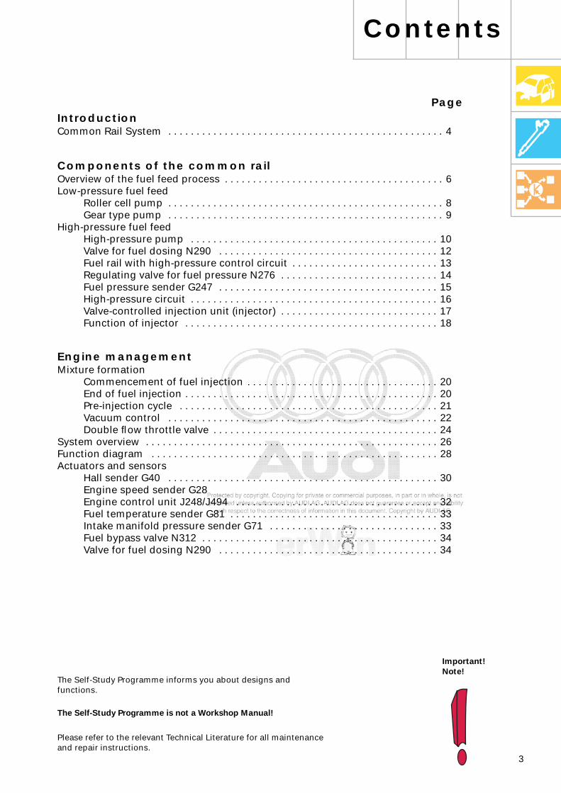
The Self-Study Programme is not a Workshop Manual!
The Self-Study Programme informs you about designs and functions.
Important!Note!
Please refer to the relevant Technical Literature for all maintenance and repair instructions.
PageIntroduction
Components of the common rail
Overview of the fuel feed process . . . . . . . . . . . . . . . . . . . . . . . . . . . . . . . . . . . . . . . 6Low-pressure fuel feed
Roller cell pump . . . . . . . . . . . . . . . . . . . . . . . . . . . . . . . . . . . . . . . . . . . . . . . . . 8Gear type pump . . . . . . . . . . . . . . . . . . . . . . . . . . . . . . . . . . . . . . . . . . . . . . . . . 9
High-pressure fuel feedHigh-pressure pump . . . . . . . . . . . . . . . . . . . . . . . . . . . . . . . . . . . . . . . . . . . . 10Valve for fuel dosing N290 . . . . . . . . . . . . . . . . . . . . . . . . . . . . . . . . . . . . . . . 12Fuel rail with high-pressure control circuit . . . . . . . . . . . . . . . . . . . . . . . . . . 13Regulating valve for fuel pressure N276 . . . . . . . . . . . . . . . . . . . . . . . . . . . . 14Fuel pressure sender G247 . . . . . . . . . . . . . . . . . . . . . . . . . . . . . . . . . . . . . . . 15High-pressure circuit . . . . . . . . . . . . . . . . . . . . . . . . . . . . . . . . . . . . . . . . . . . . 16Valve-controlled injection unit (injector) . . . . . . . . . . . . . . . . . . . . . . . . . . . . 17Function of injector . . . . . . . . . . . . . . . . . . . . . . . . . . . . . . . . . . . . . . . . . . . . . 18
Common Rail System . . . . . . . . . . . . . . . . . . . . . . . . . . . . . . . . . . . . . . . . . . . . . . . . . 4
Engine management
Mixture formationCommencement of fuel injection . . . . . . . . . . . . . . . . . . . . . . . . . . . . . . . . . . 20End of fuel injection . . . . . . . . . . . . . . . . . . . . . . . . . . . . . . . . . . . . . . . . . . . . . 20Pre-injection cycle . . . . . . . . . . . . . . . . . . . . . . . . . . . . . . . . . . . . . . . . . . . . . . 21Vacuum control . . . . . . . . . . . . . . . . . . . . . . . . . . . . . . . . . . . . . . . . . . . . . . . . 22Double flow throttle valve . . . . . . . . . . . . . . . . . . . . . . . . . . . . . . . . . . . . . . . . 24
System overview . . . . . . . . . . . . . . . . . . . . . . . . . . . . . . . . . . . . . . . . . . . . . . . . . . . . 26Function diagram . . . . . . . . . . . . . . . . . . . . . . . . . . . . . . . . . . . . . . . . . . . . . . . . . . . 28Actuators and sensors
Hall sender G40 . . . . . . . . . . . . . . . . . . . . . . . . . . . . . . . . . . . . . . . . . . . . . . . . 30Engine speed sender G28Engine control unit J248/J494 . . . . . . . . . . . . . . . . . . . . . . . . . . . . . . . . . . . . 32Fuel temperature sender G81 . . . . . . . . . . . . . . . . . . . . . . . . . . . . . . . . . . . . . 33Intake manifold pressure sender G71 . . . . . . . . . . . . . . . . . . . . . . . . . . . . . . 33Fuel bypass valve N312 . . . . . . . . . . . . . . . . . . . . . . . . . . . . . . . . . . . . . . . . . . 34Valve for fuel dosing N290 . . . . . . . . . . . . . . . . . . . . . . . . . . . . . . . . . . . . . . . 34
4
Common Rail System
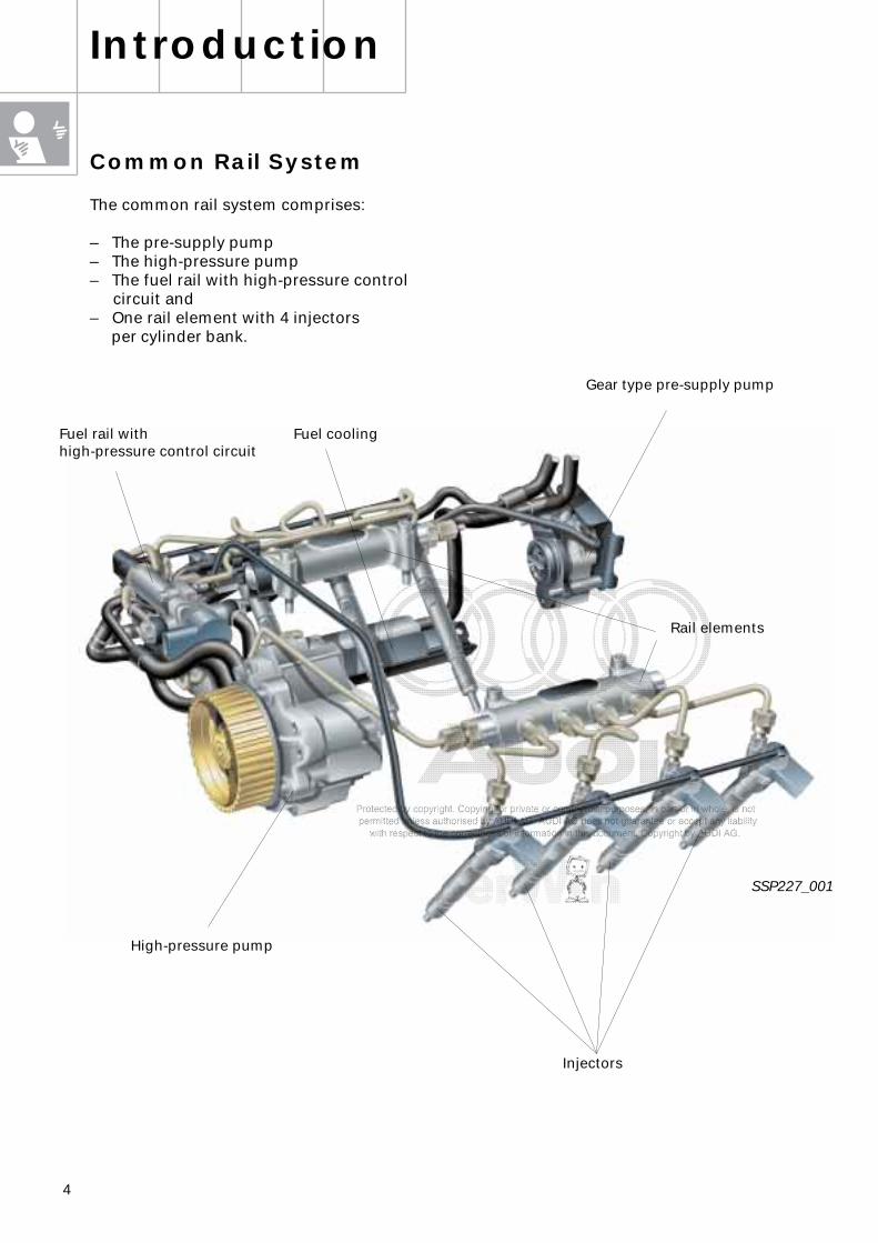
The common rail system comprises:
– The pre-supply pump– The high-pressure pump– The fuel rail with high-pressure control
circuit and– One rail element with 4 injectors
per cylinder bank.
Introduction
Fuel cooling
Gear type pre-supply pump
Rail elements
Injectors
High-pressure pump
SSP227_001
Fuel rail with high-pressure control circuit
5
3000
200
400
600
800
1000
1200
bar
1600
1000 2000 U/min 5000
1800
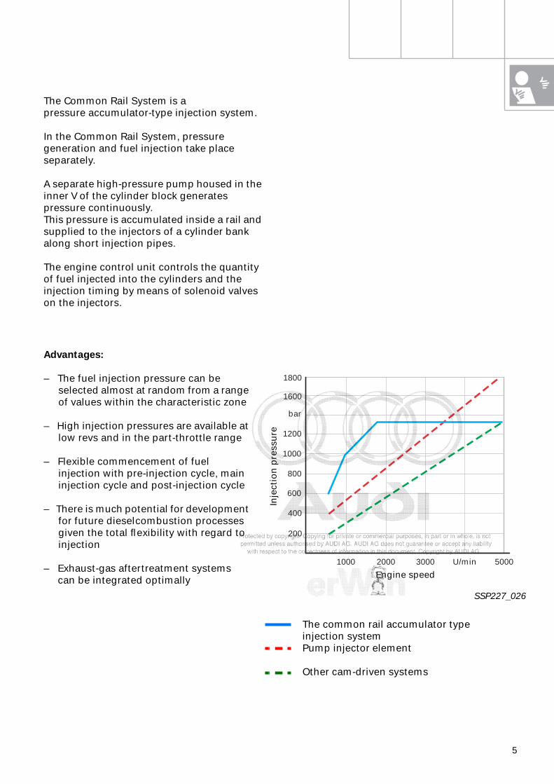
The common rail accumulator type injection systemPump injector element
Other cam-driven systems
The Common Rail System is apressure accumulator-type injection system.
In the Common Rail System, pressure generation and fuel injection take place separately.
A separate high-pressure pump housed in the inner V of the cylinder block generates pressure continuously.This pressure is accumulated inside a rail and supplied to the injectors of a cylinder bank along short injection pipes.
The engine control unit controls the quantity of fuel injected into the cylinders and the injection timing by means of solenoid valves on the injectors.
Advantages:
– The fuel injection pressure can be selected almost at random from a range of values within the characteristic zone
– High injection pressures are available at low revs and in the part-throttle range
– Flexible commencement of fuel injection with pre-injection cycle, main injection cycle and post-injection cycle
– There is much potential for development for future dieselcombustion processes given the total flexibility with regard to injection
– Exhaust-gas aftertreatment systemscan be integrated optimally
SSP227_026
Engine speed
Inje
ctio
n p
ress
ure
6
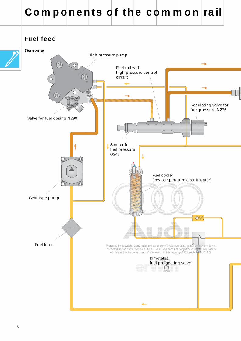
Fuel feed
Overview
Components of the common rail
Fuel filter
Gear type pump
High-pressure pump
Sender for fuel pressure G247
Regulating valve forfuel pressure N276
Fuel cooler (low-temperature circuit water)
Valve for fuel dosing N290
Bimetallicfuel pre-heating valve
Fuel rail with high-pressure control circuit
7
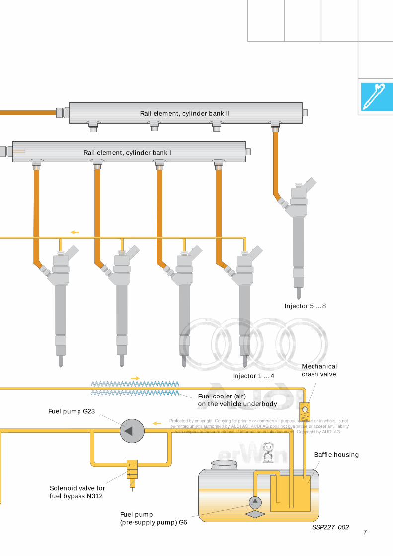
Fuel cooler (air) on the vehicle underbody
Injector 1 … 4
Injector 5 … 8
Rail element, cylinder bank II
Rail element, cylinder bank I
SSP227_002
Fuel pump G23
Fuel pump (pre-supply pump) G6
Mechanical crash valve
Baffle housing
Solenoid valve for fuel bypass N312
8
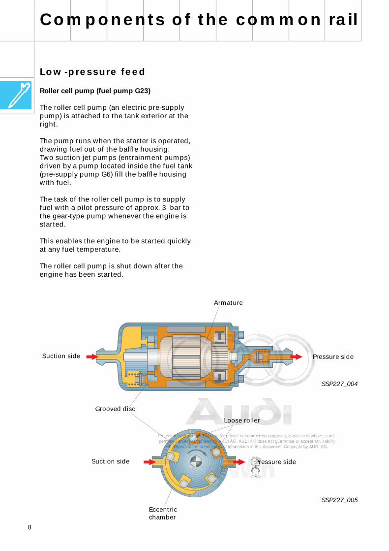
Low-pressure feed
Roller cell pump (fuel pump G23)
The roller cell pump (an electric pre-supply pump) is attached to the tank exterior at the right.
The pump runs when the starter is operated, drawing fuel out of the baffle housing.Two suction jet pumps (entrainment pumps) driven by a pump located inside the fuel tank (pre-supply pump G6) fill the baffle housing with fuel.
The task of the roller cell pump is to supply fuel with a pilot pressure of approx. 3 bar to the gear-type pump whenever the engine is started.
This enables the engine to be started quickly at any fuel temperature.
The roller cell pump is shut down after the engine has been started.
Components of the common rail
SSP227_004
Pressure sideSuction side
Armature
SSP227_005
Grooved disc
Loose roller
Pressure sideSuction side
Eccentric chamber
9
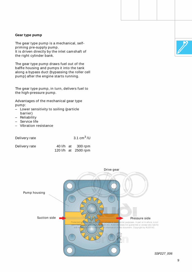
SSP227_006
Gear type pump
The gear type pump is a mechanical, self-priming pre-supply pump.It is driven directly by the inlet camshaft of the right cylinder bank.
The gear type pump draws fuel out of the baffle housing and pumps it into the tank along a bypass duct (bypassing the roller cell pump) after the engine starts running.
The gear type pump, in turn, delivers fuel to the high-pressure pump.
Advantages of the mechanical gear type pump:– Lower sensitivity to soiling (particle
barrier)– Reliability– Service life– Vibration resistance
Delivery rate 3.1 cm
3
/U
Delivery rate 40 l/h at 300 rpm120 l/h at 2500 rpm
Pump housing
Drive gear
Suction side Pressure side
10
Components of the common rail
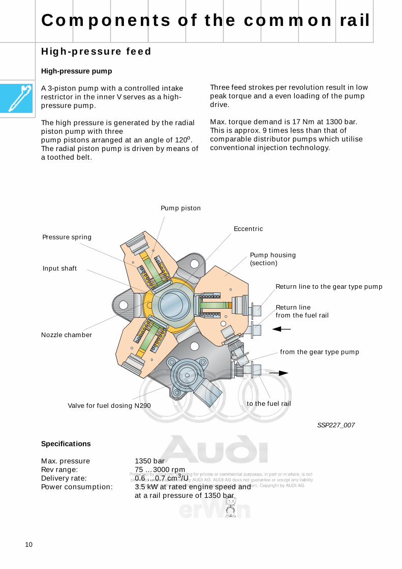
Three feed strokes per revolution result in low peak torque and a even loading of the pump drive.
Max. torque demand is 17 Nm at 1300 bar.This is approx. 9 times less than that of comparable distributor pumps which utilise conventional injection technology.
High-pressure feed
High-pressure pump
A 3-piston pump with a controlled intake restrictor in the inner V serves as a high-pressure pump.
The high pressure is generated by the radial piston pump with threepump pistons arranged at an angle of 120
o
. The radial piston pump is driven by means of a toothed belt.
SSP227_007
Specifications
Max. pressure 1350 barRev range: 75 … 3000 rpmDelivery rate: 0.6 … 0.7 cm
3
/UPower consumption: 3.5 kW at rated engine speed and
at a rail pressure of 1350 bar
Pump piston
Eccentric
Valve for fuel dosing N290
Nozzle chamber
Return line to the gear type pump
from the gear type pump
Pump housing (section)
Pressure spring
Input shaft
to the fuel rail
Return line from the fuel rail

11
The input shaft, with its eccentric cam, moves the pistons of the three pump elements up and down in a sine-wave pattern. The gear type pump forces fuel into the nozzle chamber or the lubricating and cooling circuit of the high-pressure pump through the restrictor bore of solenoid valve for fuel dosing N290.
If the fuel feed pressure exceeds the opening pressure of the safety valve (0.5 - 1.5 bar), the gear type pump can force fuel through the intake valves in the pump element thus causing the piston to move down (intake stroke).
SSP227_025
If a piston overshoots bottom dead centre, the intake valve closes due to the pressure drop.
The fuel in the pump element can no longer escape.The fuel can now be compressed beyond the feed pressure of the gear type pump.
The pressure which now builds up causes the exhaust valve to open once it exceeds the pressure present in the rail. The compressed fuel now enters the high-pressure circuit.
The pump element delivers fuel until top dead centre is reached (feed stroke).
Intake stroke Feed stroke
Pump piston
Pressure spring
Corrugated disc
Fuel supply from the gear type pump
High-pressure connection
Exhaust valve
Intake valve

12
Components of the common rail
Valve for fuel dosing N290
SSP227_009
The high-pressure pump is driven by the toothed belt of the camshaft drive whose gear ratio in relation to engine speed is i=2/3.In the part-throttle range and at high engine speeds, the high-pressure pump can feed and compress more fuel than is injected into the cylinders.
To reduce the power consumption of the high-pressure pump and avoid unnecessary fuel heating at these operating points, fuel can be redirected to the fuel return line (inner circuit) by means of the solenoid valve N290.
Pump piston
to rail
Return line, gear type pump
Supply line, gear type pump
Regulating piston
Valve for fuel dosing N290
High-pressure pump
Intake valve
Restrictor bore
Safety valve
Exhaust valve
Lubricating oil hole
Operated conditionof de-energised solenoid valve N 290
When it is de-energised, the solenoid valve is open. The control piston is pushed to the left by spring force and releases the minimum cross section to the high-pressure pump.The solenoid valve is more or less closed depending on load and engine speed.
Operated conditionof activated solenoid valve N290
When it is activated, the solenoid valve is closed. The control pressure drops and the control piston restricts the feed to the high-pressure pump.The control pressure and therefore the piston position are changed by varying the pulse duty ratio. The fuel cut off by the solenoid valve returns to the gear pump.
13
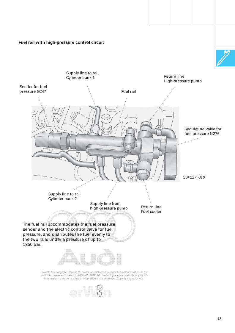
Fuel rail with high-pressure control circuit
SSP227_010
The fuel rail accommodates the fuel pressure sender and the electric control valve for fuel pressure, and distributes the fuel evenly to the two rails under a pressure of up to 1350 bar.
Regulating valve for fuel pressure N276
Fuel rail
Return lineFuel cooler
Return lineHigh-pressure pump
Sender for fuel pressure G247
Supply line to railCylinder bank 1
Supply line to railCylinder bank 2
Supply line fromhigh-pressure pump

14
Components of the common rail
Regulating valve for fuel pressure N276
The regulating valve is located in the fuel rail and generates a defined pressure in the high-pressure circuit in dependence upon operating point.
Engine – "OFF“
In the resting position (valve de-energised), the force of the pressure spring counteracts the high pressure from the high-pressure pump. In the process, a rail pressure of approx. 100 bar builds up.
SSP227_013
SSP227_028
Engine – "ON"
To increase the rail pressure, a magnetic force is opposed to the high pressure of the high-pressure pump by applying an electric current to the magnetic coil.
The flow cross-section and the redirected quantity are reduced as a result. This allows the rail pressure to be set optimally by the control unit and pressure fluctuation in the rail to be compensated.
The fuel quantity redirected at the pressure regulating valve returns to the tank along the return line.
Return line to high-pressure pump
High pressure
Pressure spring
Solenoid connection
Magnetic coil
Return line to tank
15
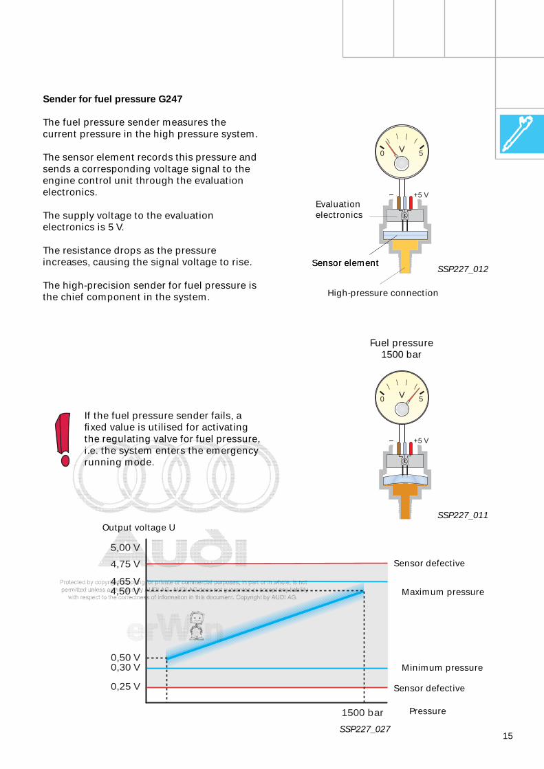
0,25 V
1500 bar
0,30 V0,50 V
4,50 V
4,75 V
4,65 V
5,00 V
Sender for fuel pressure G247
The fuel pressure sender measures the current pressure in the high pressure system.
The sensor element records this pressure and sends a corresponding voltage signal to the engine control unit through the evaluation electronics.
The supply voltage to the evaluation electronics is 5 V.
The resistance drops as the pressure increases, causing the signal voltage to rise.
The high-precision sender for fuel pressure is the chief component in the system.
SSP227_011
SSP227_012
If the fuel pressure sender fails, a fixed value is utilised for activating the regulating valve for fuel pressure, i.e. the system enters the emergency running mode.
+5 V
V0 5
+5 V
V0 5
Sensor element
Evaluationelectronics
High-pressure connection
Sensor element
Output voltage U
Sensor defective
Sensor defective
Maximum pressure
Minimum pressure
Pressure
Fuel pressure 1500 bar
SSP227_027
16
Components of the common rail
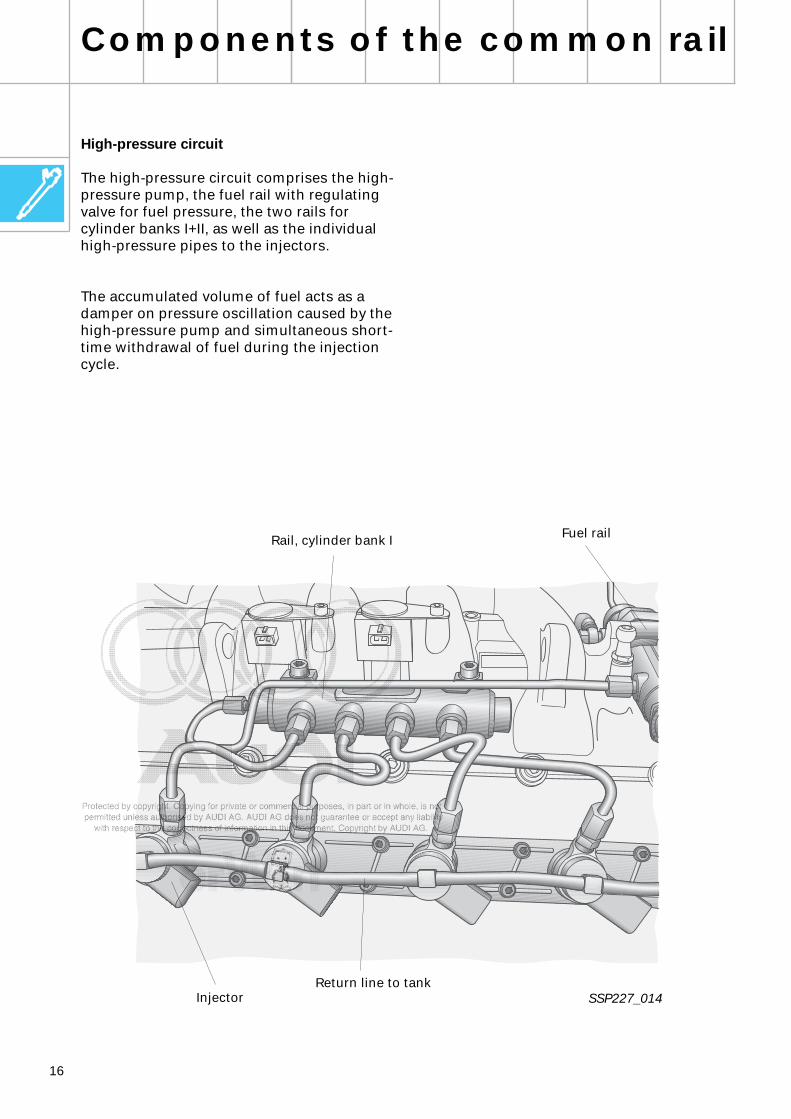
High-pressure circuit
The high-pressure circuit comprises the high-pressure pump, the fuel rail with regulating valve for fuel pressure, the two rails for cylinder banks I+II, as well as the individual high-pressure pipes to the injectors.
The accumulated volume of fuel acts as a damper on pressure oscillation caused by the high-pressure pump and simultaneous short-time withdrawal of fuel during the injection cycle.
SSP227_014
Fuel railRail, cylinder bank I
InjectorReturn line to tank
17
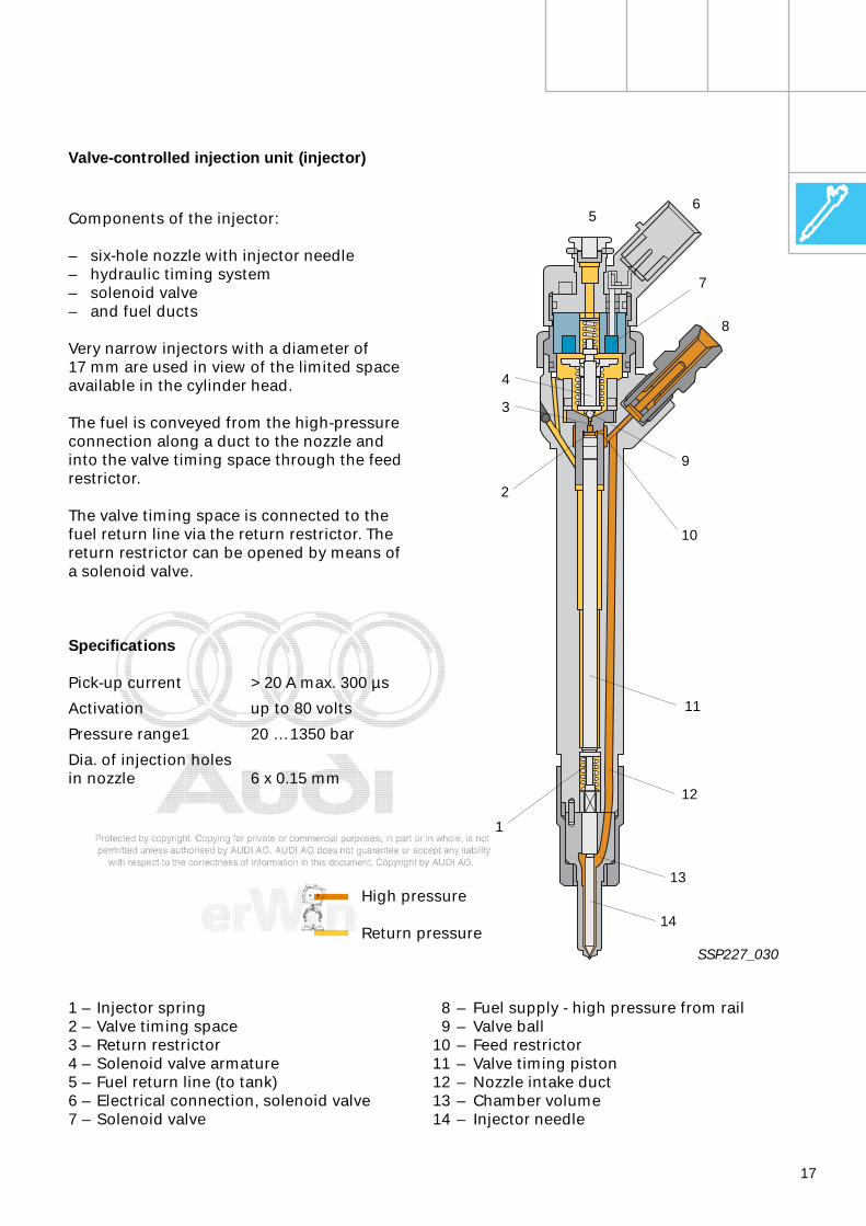
Valve-controlled injection unit (injector)
1 – Injector spring2 – Valve timing space3 – Return restrictor4 – Solenoid valve armature5 – Fuel return line (to tank)6 – Electrical connection, solenoid valve7 – Solenoid valve
8 – Fuel supply - high pressure from rail9 – Valve ball
10 – Feed restrictor11 – Valve timing piston12 – Nozzle intake duct13 – Chamber volume14 – Injector needle
Components of the injector:
– six-hole nozzle with injector needle– hydraulic timing system– solenoid valve– and fuel ducts
Very narrow injectors with a diameter of 17 mm are used in view of the limited space available in the cylinder head.
The fuel is conveyed from the high-pressure connection along a duct to the nozzle and into the valve timing space through the feed restrictor.
The valve timing space is connected to the fuel return line via the return restrictor. The return restrictor can be opened by means of a solenoid valve.
Specifications
Pick-up current > 20 A max. 300 µs
Activation up to 80 volts
Pressure range1 20 … 1350 bar
Dia. of injection holesin nozzle 6 x 0.15 mm
High pressure
Return pressure
2
9
8
7
65
11
12
14
3
10
13
4
1
SSP227_030

18
Components of the common rail
Function injector
Resting position - engine "OFF“
The fuel from the rail is constantly present at the high-pressure connection of the injector. The fuel floods the chamber volume and the valve timing space through the feed restrictor.
– There is a constant pressure between the chamber volume and the valve timing space.
– The solenoid valve of the injector is closed.
A pressure of 1.5 times the area of the control piston facing towards the injector is generated in order to make sure that the injector is leak-tight.
This means that the force exerted by the hydraulic control piston is approx. 50% higher than the nozzle opening force; in addition to the injector spring, the valve control piston presses the injector needle into its seat.
The injector spring keeps the injector closed up to a pressure difference of approx. 40 bar between the chamber volume and the valve timing space.
SSP227_015
Valve timing space
Valve control piston
Feed restrictor
Injector spring
Injector needle
Chamber volume
High-pressure connection
19
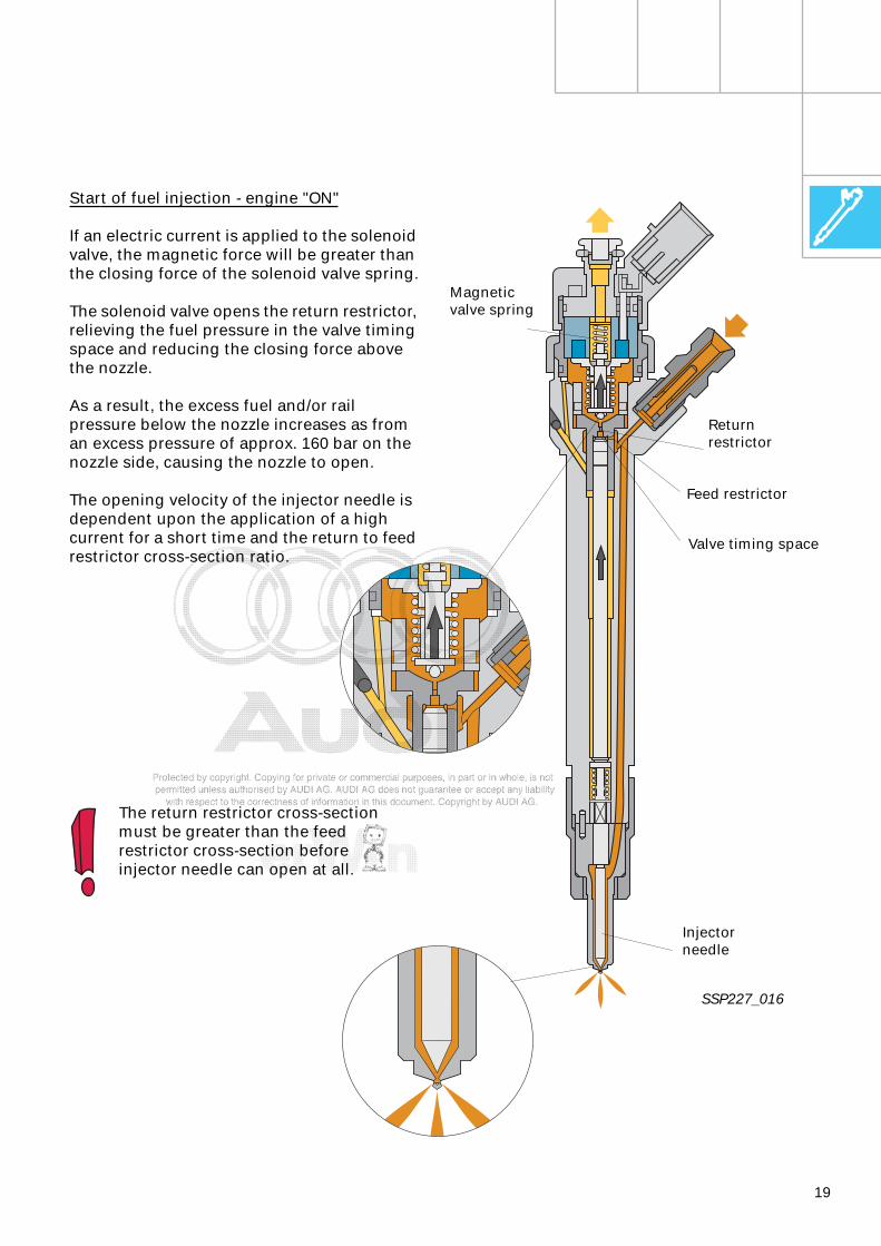
Start of fuel injection - engine "ON"
If an electric current is applied to the solenoid valve, the magnetic force will be greater than the closing force of the solenoid valve spring.
The solenoid valve opens the return restrictor, relieving the fuel pressure in the valve timing space and reducing the closing force above the nozzle.
As a result, the excess fuel and/or rail pressure below the nozzle increases as from an excess pressure of approx. 160 bar on the nozzle side, causing the nozzle to open.
The opening velocity of the injector needle is dependent upon the application of a high current for a short time and the return to feed restrictor cross-section ratio.
SSP227_016
Returnrestrictor
Magneticvalve spring
Valve timing space
Feed restrictor
Injector needle
The return restrictor cross-section must be greater than the feed restrictor cross-section before injector needle can open at all.
20
End of injection
If the solenoid valve is de-energised, the valve spring again presses the solenoid valve armature or the valve ball down onto the valve seat.
The return restrictor is closed and the pressure in the control space rises to system pressure. The closing force acting upon the nozzle above the control piston is greater than the opening force of the nozzle applied to the seat. This causes the injector to close.
Mixture formation
Commencement of fuel injection
If current is applied to the solenoid valve for longer, the valve control piston and injector needle will rise up to the control piston stop.
The nozzle is now open as far as it will go, and fuel is injected into the cylinders under approximately the same pressure as in the rail.
To inject a small quantity of fuel, the solenoid valve is only energised (clocked) for a short period to time. The injector needle is not opened as far as it will go, it is only raised slightly.
The quantity of fuel injected into the cylinders is defined by:
– solenoid valve activation time– needle opening and closing velocity– needle lift– hydraulic flow rate of nozzle– rail pressure
The solenoid valve opens completely during each injection cycle, even if only a very small quantity of fuel is to be injected.
In contrast to previous injection systems, injector closure is controlled even if the system pressure is very high (sharp end of injection drop).
Engine management
21
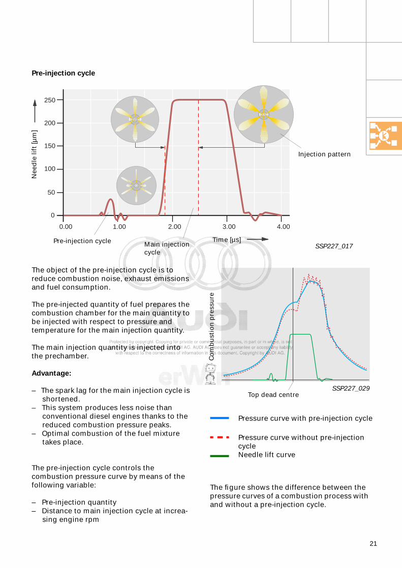
Pressure curve with pre-injection cycle
Pressure curve without pre-injectioncycleNeedle lift curve
Pre-injection cycle
SSP227_017
250
200
150
100
50
0
0.00 2.001.00 3.00 4.00
Nee
dle
lift
[µm
]
Time [µs]
The object of the pre-injection cycle is to reduce combustion noise, exhaust emissions and fuel consumption.
The pre-injected quantity of fuel prepares the combustion chamber for the main quantity to be injected with respect to pressure and temperature for the main injection quantity.
The main injection quantity is injected into the prechamber.
Advantage:
– The spark lag for the main injection cycle is shortened.
– This system produces less noise than conventional diesel engines thanks to the reduced combustion pressure peaks.
– Optimal combustion of the fuel mixture takes place.
The pre-injection cycle controls the combustion pressure curve by means of the following variable:
– Pre-injection quantity– Distance to main injection cycle at increa-
sing engine rpm
The figure shows the difference between the pressure curves of a combustion process with and without a pre-injection cycle.
SSP227_029
Co
mb
ust
ion
pre
ssu
re
Top dead centre
Pre-injection cycle Main injection cycle
Injection pattern
22
Engine management
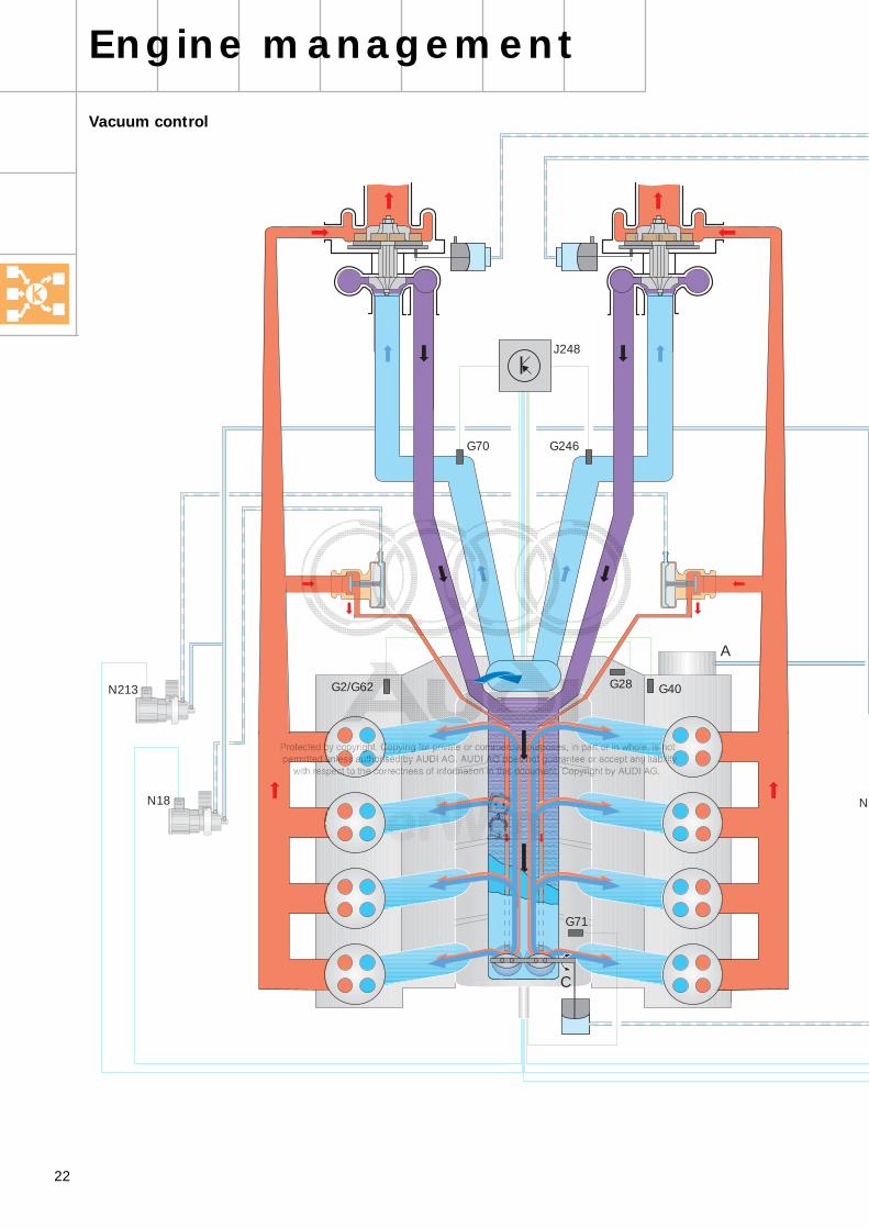
Vacuum control
N18
N213
N
G2/G62
G71
G70 G246
J248
A
C
G40G28

23
N239
N75
N274
B
SSP226_027
A Vacuum pump
B Brake servo
C Throttle valve
G2/G60 Coolant temperature sender
G28 Engine speed sender
G40 Hall sender
G70 Air-mass flow meter
G71 Intake manifold pressure sender
G246 Air-mass flow meter 2
J248 Diesel direct injection systemControl unit
N18 EGR valveCylinder bank 1
N75 Charge pressure control solenoid valve
N213 Exhaust gas recirculation valve -2-
N274 Solenoid valve 2 for charge pressure control
N239 Intake manifold flap change-over valve
In the V8 TDI engine, an engine-driven vacuum pump (A) supplies a sufficient quantity of medium required for vacuum control.
In addition to the brake servo (B), the vacuum controls the exhaust gas turbocharger, the EGR valve and the two throttle valves (C) in the intake module.
Charge pressure data is acquired via the intake manifold pressure sender (G71). The signals from the two hot-film air mass meters (G70/G246) are utilised for controlling the turbocharger via the charge pressure limiting valves (N75, N274).
The throttle valves (C), activated by intake manifold flap change-over valve N239, are in operation when the engine is shut down for a short time.
24
Engine management
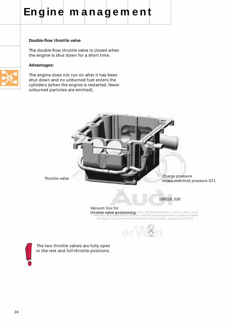
Double-flow throttle valve
The double-flow throttle valve is closed when the engine is shut down for a short time.
Advantages:
The engine does not run on after it has been shut down and no unburned fuel enters the cylinders (when the engine is restarted, fewer unburned particles are emitted).
The two throttle valves are fully open in the rest and full-throttle positions.
SSP226_026
Charge pressure intake manifold pressure G71Throttle valve
Vacuum box forthrottle valve positioning

25
Notes

26
Fuel temperature sender G81
Hot-film air mass meter G70/G246
System overview
Sensors
Engine speed sender G28
Sender for fuel pressure G247
Brake light switch F and Brake pedal switch F47
Coolant temperature sender G2 and G62
Sender for oil temperature G8
Accelerator pedal sender with accelerator position sender G79 and idling speed switch F60
Intake manifold pressure sender G71
Kick-down switch F8
Hall sender G40
Control unit 2 for diesel direct injection system J494
Diesel direct injection system control unit J248
ESP control unit J104
Operating and display unit for air conditioning system E82
Automatic gearbox control unit J217
Combination processor in the dash panel insert J218
Engine management
Auxiliary signals:Cruise control systemCoolant temperature senderDF signalTerminal 50Speed sensor signalCrash signal from airbag control unitHigh pressure sensor G65A/C readyAuxiliary heater coolant

27
Actuators
Solenoid valve for injector, cylinders 1-4; N30 – N33
Relay for pump charge air cooling J536Pump for charge air cooling V188
Glow plug relay J52Glow plugs 1-4; Q6
Solenoid valve for injector, cylinders 5-8; N83 – N86
Relay 2 for glow plugs J495Glow plugs 5-8; Q6
Intake manifold flap change-over valve N239
Regulating valve for fuel pressure N276
EGR valves 1 + 2; N18 + N213
Solenoid valve for fan control N313
Electro/hydraulic engine mounting left/right, solenoid; N14427/N145
Charge pressure control solenoid valves 1+ 2; N75/N274
Electric fuel pump II relay J49Fuel pump G23Diagnostic connection
Fuel bypass valve N312
Fuel pump relay J17Fuel pump (pre-supply pump) G6
Valve for fuel dosing N290
Pump relay, fuel cooling J445Pump for cooling fuel V166
Alternator cut-in relay J442
Auxiliary signals:
Fan speeds 1+2
SSP227_018
Auxiliary signals:
Air conditioner compressorAuxiliary heater, coolant

28
N213 Exhaust gas recirculation valve -2-N239 Intake manifold flap change-over valveN274 Solenoid valve 2 for charge pressure
controlN276 Regulating valve for fuel pressureN290 Valve for fuel dosingN312 Fuel bypass valveN313 Solenoid valve for fan controlQ6 Glow plugS FuseST Fuse carrierS204 Fuse, terminal 30V166 Pump for cooling fuelV188 Pump for charge air cooling
1 Fan speed
2 2nd fan speed
3 Terminal 61, alternator
4 Coolant temperature
5 Sensor earth
6 Speed sensor signal
7 Terminal 50
8 DF signal
9 Crash signal from airbag control unit
10 Additional heater, coolant
11 Additional heater, coolant
12 High pressure sensor G65
13 A/C ready
14 Air-conditioner compressor signal
15 Terminal 30a
CAN-BUS LCAN-BUS H
X Y Z ... Terminals within the function diagram
Diagnostic connection (K-wire)
= Input signal
= Output signal
= Bidirectional
= CAN-BUS
Function diagram
Code codes
= Positive
= Earth
Components
A BatteryE45 Cruise control system switchD Ignition switchF Brake light switchF8 Kick-down switchF47 Brake pedal switch for
cruise control systemF60 Idling speed switchG2 Coolant temperature senderG6 Fuel pump (pre-supply pump)G8 Oil temperature senderG23 Fuel pumpG28 Engine speed senderG40 Hall senderG62 Coolant temperature senderG70 Air-mass flow meterG71 Intake manifold pressure senderG79 Accelerator position senderG81 Fuel temperature senderG246 Air-mass flow meterG247 Fuel pressure senderJ17 Fuel pump relayJ49 Electric fuel pump II relayJ52 Glow plug relayJ248 Diesel direct injection
system control unit J317 Voltage supply relay
Terminal 30J442 Alternator cut-in relayJ445 Pump relay, fuel coolingJ494 Diesel direct injection
system control unit J495 Glow plug 2 relay J536 Pump relay, charge air coolingM9 Brake light bulb, leftM10 Brake light bulb, rightN18 EGR valveN30 Solenoid valve for injector, cylinder 1N31 Solenoid valve for injector, cylinder 2N32 Solenoid valve for injector, cylinder 3N33 Solenoid valve for injector, cylinder 4N75 Solenoid valve for charge pressure
controlN83 Solenoid valve for injector, cylinder 5N84 Solenoid valve for injector, cylinder 6N85 Solenoid valve for injector, cylinder 7N86 Solenoid valve for injector, cylinder 8N144 Electro/hydraulic engine mounting
left, solenoid N145 Electro/hydraulic engine mounting
right, solenoid
Engine management
} Connection to databus

29

30
Engine management
Actuators and sensors
Hall sender G40
The inlet camshaft of the second cylinder bank has a ferro-magnetic tooth.
When the tooth passes by the phase sensor, a voltage signal (Hall voltage) is generated for a short time.
The camshaft signal is generated once per revolution of the camshaft and indicates the position of the 1st cylinder to the master control unit in the compression phase.
Engine speed sender G28
The engine speed sender is an inductive sender. It acquires engine speed data and the exact angular position of the crankshaft.
If the engine speed sender fails, engine operation will not be possible.
SSP227_021
SSP227_032
Ferro-magnetic tooth
Engine speed sender G28
Segment gap
Sender wheel

31
T
1 5 4 8 6 3 7 2
SSP227_022
SSP227_023
Signal pattern from engine speed sender G28 and Hall sender G40 as generated by the oscilloscope function of the VAS 5051
G40
G28
Sender wheel
Reference mark 108o before TDC, 1st cylinder
TDC, 1st cylinder
Auto mode
Auto mode
G40
G28
Indication of the software reference mark
The reference mark is the point at which the control unit sets the crank angle to 0 (initialisation).
This reference mark is located approx. 108o crank angle before ignition TDC of the 1st cylinder.
10 V/div. 20 ms/div.
5 V/div. 20 ms/div.
5 V/div. 10 ms/div.

32
Engine management
Engine control unit J248/J494
In the V8 TDI, two engine control units, one master control unit and one slave (auxiliary) control unit are responsible for engine management.
The master control unit performs all the functions which are required to calculate and control parameters, e.g. injection point and injection period.
80 volts are required in order to activate the injectors for a short time. This calls for more highly rated output stages and capacitors. Therefore, the injectors of bank 2 can only by operated from the master control unit and the injectors of bank 1 can only be operated from the slave control unit.
The slave control unit controls the following electrical components:
– Fuel bypass valve N312– Valve for fuel dosing N290– Fuel pump relay J17 and fuel pump (pre-
supply pump) G6– Pump relay, fuel cooling J445 and pump
for cooling fuel V166– Alternator cut-in relay J442 (option)– Fan (stage 1+2).
The control units intercommunicateby CAN-BUS.The master control unit indicates to the slave control unit what functions it has to execute.
SSP186 describes how the CAN-BUS works.
Diesel direct injection system control unit 2 J494
Diesel direct injection system control unit J248
SSP227_031
Self-diagnosis Address word
master control unit 01
slave control unit 11
33
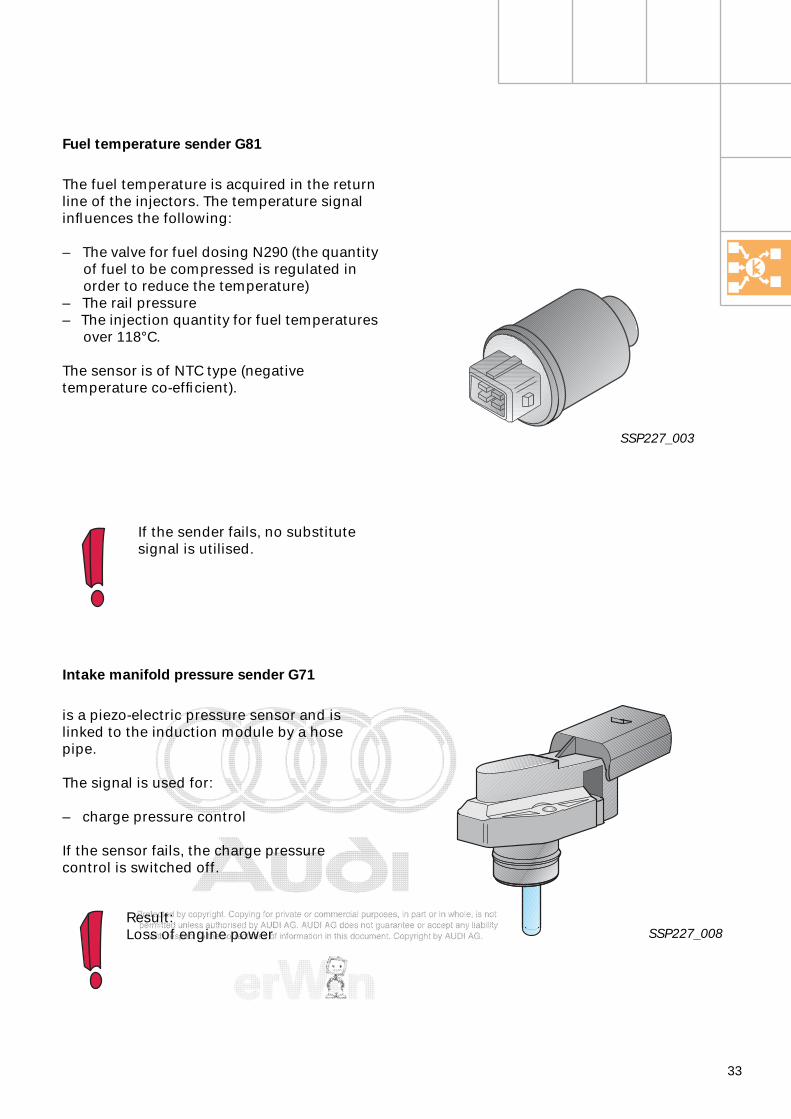
Fuel temperature sender G81
The fuel temperature is acquired in the return line of the injectors. The temperature signal influences the following:
– The valve for fuel dosing N290 (the quantity of fuel to be compressed is regulated in order to reduce the temperature)
– The rail pressure– The injection quantity for fuel temperatures
over 118°C.
The sensor is of NTC type (negative temperature co-efficient).
If the sender fails, no substitute signal is utilised.
Intake manifold pressure sender G71
is a piezo-electric pressure sensor and is linked to the induction module by a hose pipe.
The signal is used for:
– charge pressure control
If the sensor fails, the charge pressurecontrol is switched off.
SSP227_003
Result:Loss of engine power SSP227_008
34
Engine management
Fuel bypass valve N312
The valve is integrated in the bypass of the electric pre-supply pump.It opens for 40 seconds when the ignition is turned "ON" (terminal 15) and closes during the starting cycle (terminal 50).
When the engine speed signal is input, the solenoid valve opens and allows fuel to be withdrawn directly from the baffle housing, bypassing the electric pre-supply pump.
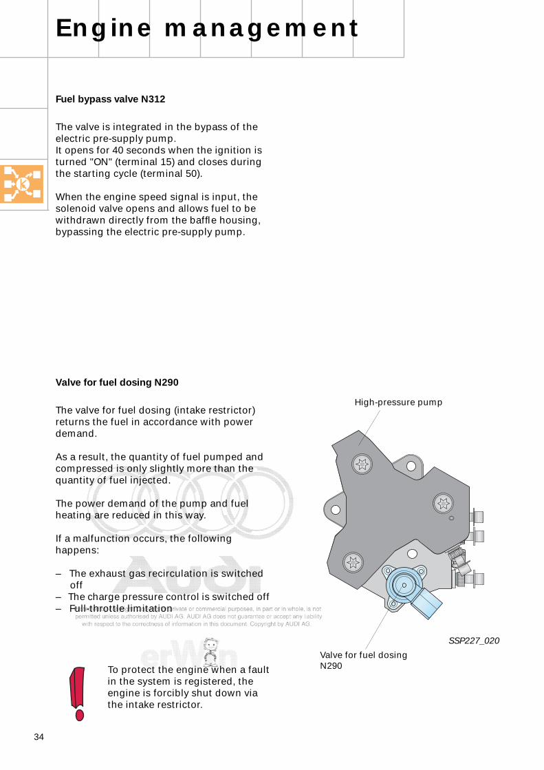
Valve for fuel dosing N290
The valve for fuel dosing (intake restrictor) returns the fuel in accordance with power demand.
As a result, the quantity of fuel pumped and compressed is only slightly more than the quantity of fuel injected.
The power demand of the pump and fuel heating are reduced in this way.
If a malfunction occurs, the following happens:
– The exhaust gas recirculation is switched off
– The charge pressure control is switched off – Full-throttle limitation
To protect the engine when a fault in the system is registered, the engine is forcibly shut down via the intake restrictor.
SSP227_020
Valve for fuel dosing N290
High-pressure pump

35
Notes

Service.
For internal use only
All rights reserved. Subject to technical modifications.
AUDI AGAbteilung I/VK-5D-85045 IngolstadtFax 0841/89-36367940.2810.46.20Technical status 07/99Printed in Germany
3,3 l V8 TDI Common Rail Injection System
Construction Features and Functions
Self-Study Programme 227
227
227

![Self-assembled monolayers of parent and derivatized [n]staffane-3,3(n-1)-dithiols on polycrystalline gold electrodes](https://static.fdokumen.com/doc/165x107/6328c589ce2aaeab5c0256a0/self-assembled-monolayers-of-parent-and-derivatized-nstaffane-33n-1-dithiols.jpg)