Volkswagen's New 2.0l TDI Engine Fulfils the Most Stringent ...
35
Dr.Ing. J. Hadler, Dipl.-Ing. F. Rudolph, Dipl.-Ing. R. Dorenkamp, Dipl.-Ing. H. Stehr, Dr.Ing. T. Düsterdiek, Dipl.-Ing. J. Hilzendeger, Dipl.-Ing. D. Mannigel, Dr. rer. nat. S. Kranzusch, Dipl.-Ing. B. Veldten, Dr. M. Kösters, Dipl.-Ing. A. Specht, Volkswagen AG, Wolfsburg Volkswagen's New 2.0l TDI Engine Fulfils the Most Stringent Emission Standards Abstract The new 2.0 l 4V TDI engine with Common Rail technology, available in the VW Jetta in the USA from mid 2008, will meet the world's toughest emissions standards as set forth in the BIN5/LEV2 emissions legislation. In addition to improvements within the engine, further developments to the Common Rail engine already introduced in Europe in the VOLKSWAGEN Tiguan and the AUDI A4 include the implementation of a NOx exhaust after-treatment system. The engine's technical features include an optimised injector system, a low pressure exhaust gas recirculation system, an innovative cylinder pressure regulation concept as well as a NOx storage catalytic converter. These new engine components require the development of new control algorithms and intensive co-ordination of parameters for the completely new combustion process. The result was the development of a new hardware and software architecture for the engine control unit, which has now been brought into production. 29. Internationales Wiener Motorensymposium 2008
-
Upload
khangminh22 -
Category
Documents
-
view
6 -
download
0
Transcript of Volkswagen's New 2.0l TDI Engine Fulfils the Most Stringent ...

Dr.Ing. J. Hadler, Dipl.-Ing. F. Rudolph, Dipl.-Ing. R. Dorenkamp, Dipl.-Ing. H. Stehr,
Dr.Ing. T. Düsterdiek, Dipl.-Ing. J. Hilzendeger, Dipl.-Ing. D. Mannigel, Dr. rer. nat. S. Kranzusch, Dipl.-Ing. B. Veldten, Dr. M. Kösters, Dipl.-Ing. A. Specht,
Volkswagen AG, Wolfsburg Volkswagen's New 2.0l TDI Engine Fulfils the Most Stringent Emission Standards Abstract The new 2.0 l 4V TDI engine with Common Rail technology, available in the VW Jetta in the USA from mid 2008, will meet the world's toughest emissions standards as set forth in the BIN5/LEV2 emissions legislation. In addition to improvements within the engine, further developments to the Common Rail engine already introduced in Europe in the VOLKSWAGEN Tiguan and the AUDI A4 include the implementation of a NOx exhaust after-treatment system. The engine's technical features include an optimised injector system, a low pressure exhaust gas recirculation system, an innovative cylinder pressure regulation concept as well as a NOx storage catalytic converter. These new engine components require the development of new control algorithms and intensive co-ordination of parameters for the completely new combustion process. The result was the development of a new hardware and software architecture for the engine control unit, which has now been brought into production.
29. Internationales Wiener Motorensymposium 2008

Objectives The engine used as the basis for the comprehensive redevelopment was the 2.0 l 4V TDI with Common Rail which was launched in 2007 and meets the exhaust emission limits as per EU5. With this conceptual starting point, the redevelopments to meet the BIN5/LEV2 norm result in the following technical data.
Table 1: Parameters of the 2.0 l 4V TDI BIN5/LEV2 As a result of the low emission limits stipulated by California law, the market for diesel cars in the USA has remained stagnant at a low level. In contrast to the European automobile market, in North America, and particularly in the U.S., passenger cars with diesel engines are much less common, due in large part to their image as being loud, uncomfortable, dirty and sluggish. Only a few manufacturers, VOLKSWAGEN among them, have had success selling diesel vehicles in recent years. In the meantime, radical changes in environmental consciousness and surging fuel prices have made diesel vehicles increasingly attractive for American customers. Another contributing factor was that after an initial period of euphoria, many customers recognised that the much-praised hybrid technology was not a real alternative for them, as the specific advantages of hybrids only manifested themselves for certain driving profiles. What make diesel engines attractive for American customers is primarily their significantly lower consumption and accordingly higher range, as well as the relatively high resale prices for diesel vehicles. Price differences between petrol and diesel fuel, by contrast, do not play a role as there are no tax advantages for diesel fuel. Notwithstanding American customers' renewed interest in diesel engines, certain technical challenges need to be met to ensure lasting success.
29. Internationales Wiener Motorensymposium 2008
Beyond meeting the world's most stringent exhaust emission limits, the primary requirement, in light of the comparatively poor and highly variable quality of American diesel fuel, is to provide the customer with a truly comfortable and compelling driving experience. VOLKSWAGEN is confident that its 2.0 l 4V TDI convincingly meets these requirements and has started a diesel offensive for the American market with its Dieselution Tour 2007. The technical challenge with regard to the reduction of particulate and NOx emissions as compared to the previous BIN10 limit is illustrated in figure 1.
Figure 1: Emissions targets for the fulfilment of BIN5/LEV2 limits One particular challenge with the new TDI engine with Common Rail is restricting the range of emissions to the greatest possible degree despite the variable fuel quality in the USA by achieving stable combustion. The introduction of the NOx storage catalytic converter places additional requirements on engine control and application, such as the need for a cyclical regeneration phase to function properly. The introduction of low emission vehicles in model year 2009 also places new requirements on the OBD system resulting from the strict standards of the California legislation. The law primarily affects emissions-related threshold value diagnoses. With the 2.0 l 4V Common Rail BIN5/LEV2 engine, VOLKSWAGEN is meeting these high requirements on the drive train in the compact and midsize classes.
29. Internationales Wiener Motorensymposium 2008
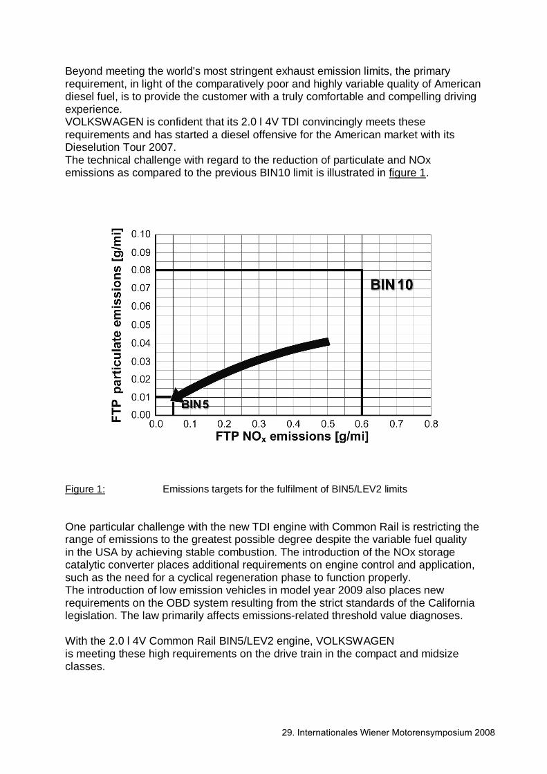
Engine-related Changes Meeting the low limit values for particulate matters and NOx requires comprehensive improvements in engine combustion in order to achieve significant reductions in raw emissions. Component changes and additional engine components for improving raw emissions are primarily concentrated in the areas of injector design, optimisation of the high pressure injection pump, regulation of the injection moulding sequence supported by a cylinder pressure-based engine control system and in the introduction of the high and low pressure exhaust gas recirculation system (dual circuit EGR system). These new developments are described in the following chapters. Emission-Optimised Injector Design The injector of the EU5 basis engine, with its 1800 bar Piezo technology and the mini blind hole nozzle with 8 conical flow-optimised spray orifices, was used for the 2.0 l CR BIN5/LEV2 engine. The spray cone angle, at 162°, was adapted to the e mission-optimised piston bowl.
Figure 2: Characteristics and design of the BOSCH CRI 3.2 injector
29. Internationales Wiener Motorensymposium 2008

While the EU5-type engines have a nozzle flow of 785 cm3/min with an orifice diameter of 0.123 mm, the BIN5 engine implements the emissions-reducing potential of smaller spray orifices together with higher rail pressures. Across nearly the entire engine map, significantly higher rail pressures have been achieved without increasing the combustion noise. This enables a reduction of particle and raw emissions at nearly-constant consumption and nitrogen oxide emission levels. A nozzle flow of 705 cm3/min with a spray orifice diameter of 0.117 mm have emerged as the optimal specifications for a BIN5 engine with 103 kW. Another important feature of the optimised nozzle is the new manufacturing method for rounding the injector orifice inlets, called "Advanced EDM" (Electrical Discharge Machining), which significantly increases the efficiency of the nozzle and thus enables realisation of the tiniest injector orifices with high specific performance. In conjunction with a reduced injector orifice length of 0.85 mm, the new EDM method also enables a reduction of the surface sensitivity. Compared to the EU5, the tolerances for elevation angle and the diameter of the injector orifices are reduced by half, significantly narrowing the range of emissions. Figure 3 shows a comparison of the characteristic values of the nozzles.
Figure 3: Characteristic values of the BIN5 nozzle design compared to the EU5 basis
29. Internationales Wiener Motorensymposium 2008
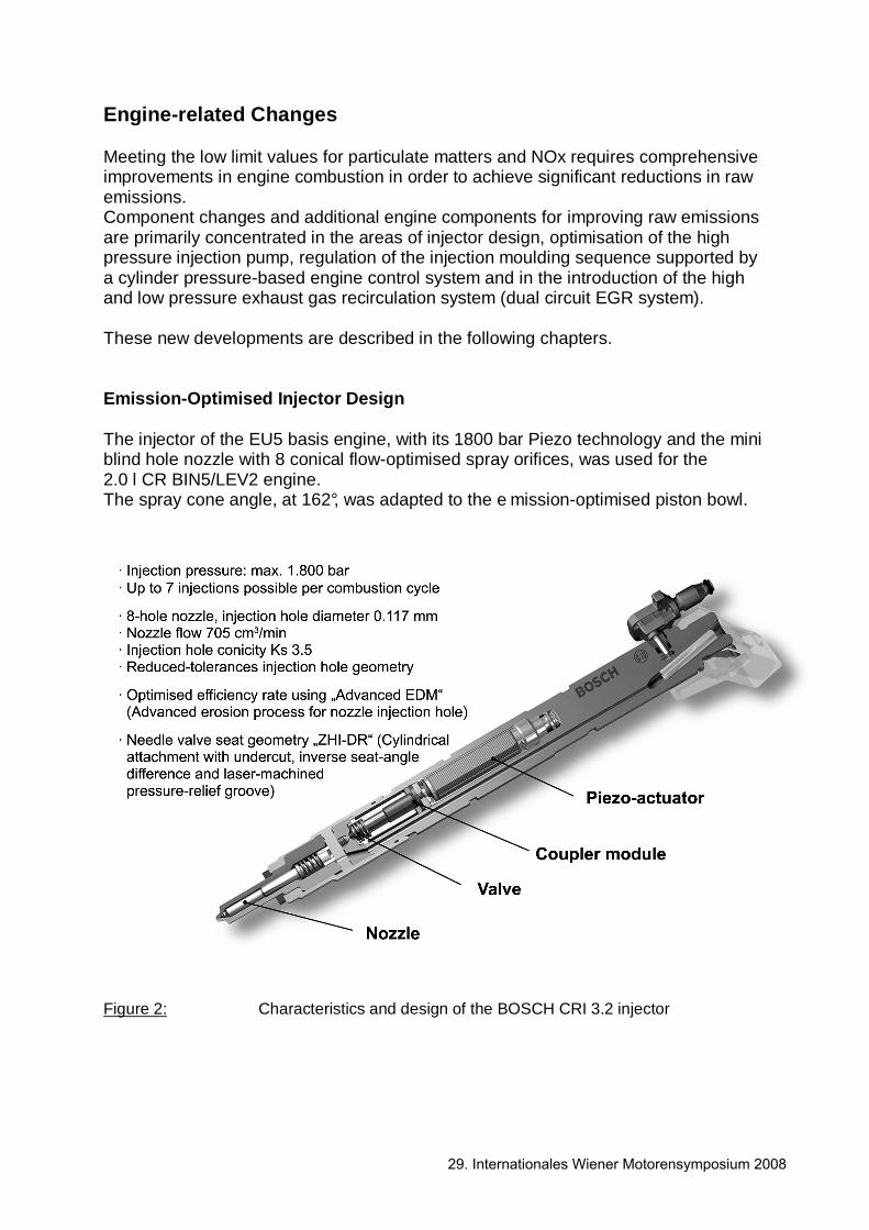
It also utilises the newly developed needle valve seat from Bosch with inverse seat angle difference and undercut (ZHI-DR), which drastically improves fuel quantity drift behaviour. Potential of New Injection Strategies High potential for improvement of the particulate/NOx trade-off is offered by the Piezo-Common-Rail system due to its high dosage precision, especially at low injection quantities. This makes it possible to apply very small pre- and post injection quantities at extremely small intervals for stable combustion. Of note in the engine application is the use of post injection or split main injection for particulate post oxidation in a broad load and speed range (figure 4).
Figure 4: "Split Main Injection" – injection sequences In the engine map, an optimal value for post injection quantity and the offset from the main injection was determined, which enabled an over 20% reduction of the particulate filter load at constant NOx values compared to the basis application (figure 5). As a coupled post injection causes the torque to vary according to position and quantity, engine management without closed-loop control, and in particular a torque-neutral post injection variation, would be difficult to achieve.
29. Internationales Wiener Motorensymposium 2008

A cylinder pressure-based engine control, by contrast, which sees its introduction into standard production in this engine, enables even non-stationary engine operation with post injection without any affects on performance or acoustics.
Figure 5: Potential for improvement through coupled post injection High Pressure Injection Pump of the 2.0l 4V TDI Engine for BIN5 Use
The BIN5 variant of the 2.0l 4V TDI engine utilises the CP4.1 high pressure pump from Bosch. The design of this pump corresponds to the EU5 variant of the VW 2.0l 4V TDI engine. The single piston pump is characterised by a very high pressure potential even at low pump speeds, good hydraulic efficiency and injection-synchronous conveyance. This positively affects emission quality, fuel consumption and engine smoothness. Further development of the high pressure pump became necessary as a result of the higher requirements engendered by the fuel quality in the U.S. To counteract greater wear due to higher water content and contamination, as well as reduced lubricity, the BIN-5 high pressure pump was equipped with an anti-wear package. This includes DLC coating of the high pressure piston on the top and shell surfaces as well as optimised heat treatment of the aluminium cast housing (Figure 6).
29. Internationales Wiener Motorensymposium 2008
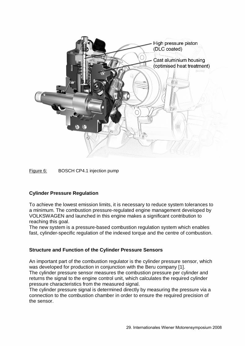
Figure 6: BOSCH CP4.1 injection pump Cylinder Pressure Regulation To achieve the lowest emission limits, it is necessary to reduce system tolerances to a minimum. The combustion pressure-regulated engine management developed by VOLKSWAGEN and launched in this engine makes a significant contribution to reaching this goal. The new system is a pressure-based combustion regulation system which enables fast, cylinder-specific regulation of the indexed torque and the centre of combustion. Structure and Function of the Cylinder Pressure Sensors An important part of the combustion regulator is the cylinder pressure sensor, which was developed for production in conjunction with the Beru company [1]. The cylinder pressure sensor measures the combustion pressure per cylinder and returns the signal to the engine control unit, which calculates the required cylinder pressure characteristics from the measured signal. The cylinder pressure signal is determined directly by measuring the pressure via a connection to the combustion chamber in order to ensure the required precision of the sensor.
29. Internationales Wiener Motorensymposium 2008
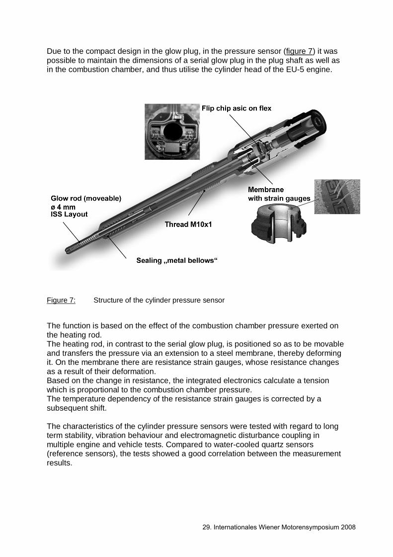
Due to the compact design in the glow plug, in the pressure sensor (figure 7) it was possible to maintain the dimensions of a serial glow plug in the plug shaft as well as in the combustion chamber, and thus utilise the cylinder head of the EU-5 engine.
Figure 7: Structure of the cylinder pressure sensor The function is based on the effect of the combustion chamber pressure exerted on the heating rod. The heating rod, in contrast to the serial glow plug, is positioned so as to be movable and transfers the pressure via an extension to a steel membrane, thereby deforming it. On the membrane there are resistance strain gauges, whose resistance changes as a result of their deformation. Based on the change in resistance, the integrated electronics calculate a tension which is proportional to the combustion chamber pressure. The temperature dependency of the resistance strain gauges is corrected by a subsequent shift. The characteristics of the cylinder pressure sensors were tested with regard to long term stability, vibration behaviour and electromagnetic disturbance coupling in multiple engine and vehicle tests. Compared to water-cooled quartz sensors (reference sensors), the tests showed a good correlation between the measurement results.
29. Internationales Wiener Motorensymposium 2008

Control The basis for this combustion control is a precise, real-time calculation of the regulation variables. This also involves calculating the two combustion characteristics centre of combustion AQ50 and indexed torque Mi, for each of the cylinders based on the respective cylinder pressure signal. Both variables are recorded and regulated for each cylinder, whereby each cylinder is regarded as a separate controlled system. For the calculation of the two cylinder pressure characteristics AQ50 and Mi, the cylinder pressure curves are scanned, digitised and saved from -180° to 180° from the upper DC in 1° crank angle steps. The indexed mean pressure of high pressure phase pmi_HP can be determined from the circular integral above the cylinder volume from a -180° to 180° crank angle (figure 8).
Figure 8: Determining the indexed mean pressure In order to determine the centre of combustion, it is necessary to determine the differential heat curve ∆QHR (derived from [3]) in accordance with the ϕ crank angle. The integral heat curve is determined by means of numerical integration of the smoothed differential heat curve ∆QHR,f. The crank angle position, the integral heat curve AQ50 (figure 9), is determined using the maximum and minimum of the integral heat curve.
29. Internationales Wiener Motorensymposium 2008

Figure 9: Calculation of the 50% yield point (AQ50)
Figure 10 shows a simplified illustration of the structure of the combustion regulator. It is primarily comprised of a cylinder-specific two variable control for the indexed torque and the combustion centre as well as the previously described calculation of the cylinder pressure characteristics. The structure of the injection control ("lower" path) is equivalent to the conventional engine control and functions in the new regulated system as a pilot control for the combustion control. Furthermore, the controlled structure is influenced by the cylinder pressure control: The position control of the centre of combustion generates a parameter that corrects the start duration of the main injection (1). The engine's target torque is achieved by means of an additional correction of the main injection’s fuel quantity (2).
29. Internationales Wiener Motorensymposium 2008
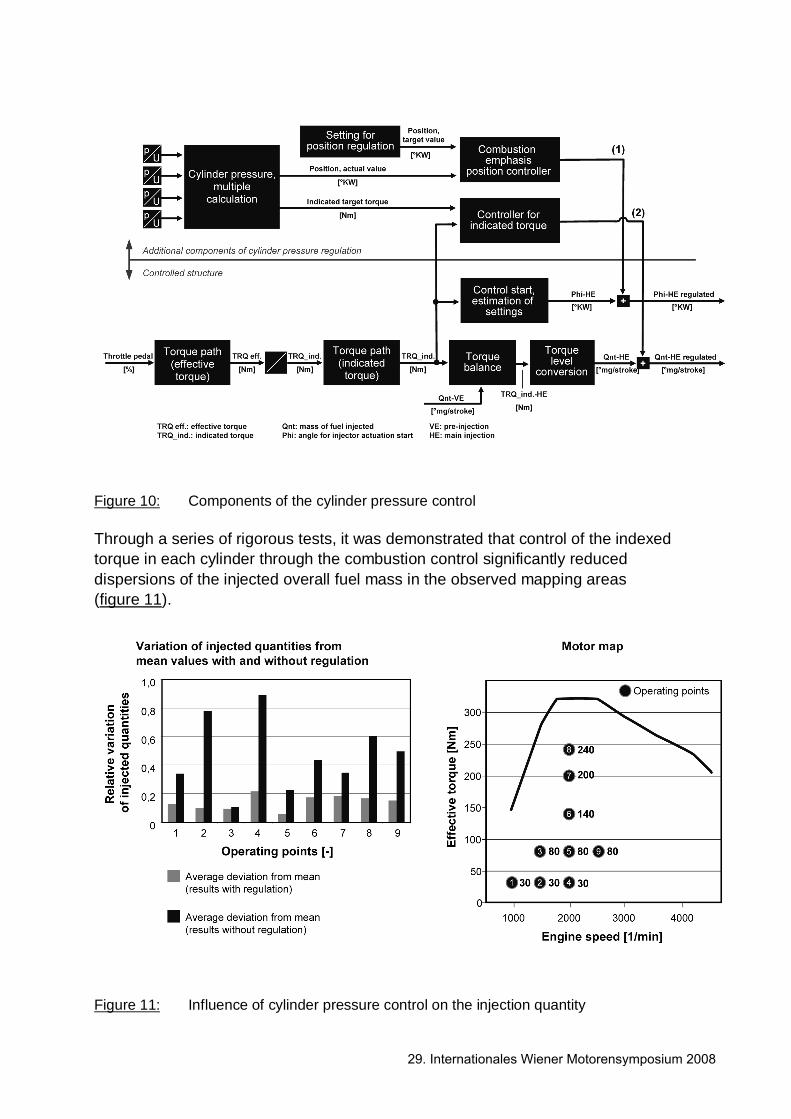
Figure 10: Components of the cylinder pressure control Through a series of rigorous tests, it was demonstrated that control of the indexed torque in each cylinder through the combustion control significantly reduced dispersions of the injected overall fuel mass in the observed mapping areas (figure 11).
Figure 11: Influence of cylinder pressure control on the injection quantity
29. Internationales Wiener Motorensymposium 2008
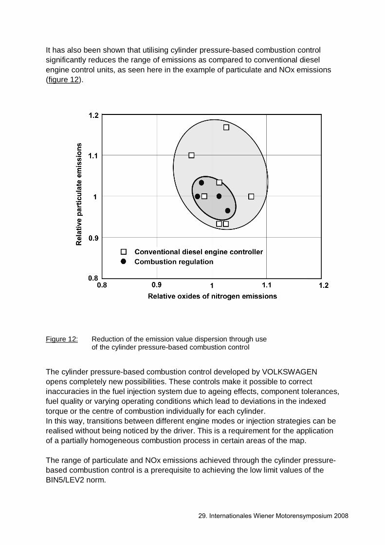
It has also been shown that utilising cylinder pressure-based combustion control significantly reduces the range of emissions as compared to conventional diesel engine control units, as seen here in the example of particulate and NOx emissions (figure 12).
Figure 12: Reduction of the emission value dispersion through use
of the cylinder pressure-based combustion control
The cylinder pressure-based combustion control developed by VOLKSWAGEN opens completely new possibilities. These controls make it possible to correct inaccuracies in the fuel injection system due to ageing effects, component tolerances, fuel quality or varying operating conditions which lead to deviations in the indexed torque or the centre of combustion individually for each cylinder. In this way, transitions between different engine modes or injection strategies can be realised without being noticed by the driver. This is a requirement for the application of a partially homogeneous combustion process in certain areas of the map. The range of particulate and NOx emissions achieved through the cylinder pressure-based combustion control is a prerequisite to achieving the low limit values of the BIN5/LEV2 norm.
29. Internationales Wiener Motorensymposium 2008
High and Low Pressure Exhaust Gas Recirculation System (Dual Circuit EGR System)
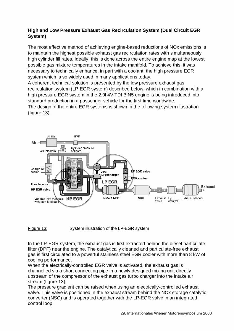
The most effective method of achieving engine-based reductions of NOx emissions is to maintain the highest possible exhaust gas recirculation rates with simultaneously high cylinder fill rates. Ideally, this is done across the entire engine map at the lowest possible gas mixture temperatures in the intake manifold. To achieve this, it was necessary to technically enhance, in part with a coolant, the high pressure EGR system which is so widely used in many applications today. A coherent technical solution is presented by the low pressure exhaust gas recirculation system (LP-EGR system) described below, which in combination with a high pressure EGR system in the 2.0l 4V TDI BIN5 engine is being introduced into standard production in a passenger vehicle for the first time worldwide. The design of the entire EGR systems is shown in the following system illustration (figure 13).
Figure 13: System illustration of the LP-EGR system In the LP-EGR system, the exhaust gas is first extracted behind the diesel particulate filter (DPF) near the engine. The catalytically cleaned and particulate-free exhaust gas is first circulated to a powerful stainless steel EGR cooler with more than 8 kW of cooling performance. When the electrically-controlled EGR valve is activated, the exhaust gas is channelled via a short connecting pipe in a newly designed mixing unit directly upstream of the compressor of the exhaust gas turbo charger into the intake air stream (figure 13). The pressure gradient can be raised when using an electrically-controlled exhaust valve. This valve is positioned in the exhaust stream behind the NOx storage catalytic converter (NSC) and is operated together with the LP-EGR valve in an integrated control loop.
29. Internationales Wiener Motorensymposium 2008

The turbocharger of the 2.0l 4V TDI EU5 basis engine was optimised for use with the LP-EGR. It features a pneumatically operated guide vane adjustment at the turbine; the respective current position of the guide vanes is detected by a position sensor. The compressor housing and the compressor wheel are coated to protect against acidic exhaust components. The pulsation damper flanged on to the compressor housing is made of stainless steel. After compression, the exhaust and air-mass flow is again cooled in a high performance charge air cooler and channelled to the engine inlet manifold. The following 3D view shows the central components of the EGR system and highlights their compact arrangement (figure 14).
Figure 14: Components of the low pressure EGR system
The fundamental advantages of the LP-EGR system are:
• nearly engine map-wide possibility of NOx emission reductions through exhaust gas recirculation
• EGR rates can be regulated independently of drops in charge air pressure
• low, homogeneously distributed NOx concentrations across the engine map
• low loss of exhaust gas enthalpy through extraction of exhaust gas energy after the turbocharger or particulate filter with simultaneous high air ratios
• nearly ideal equal distribution during exhaust gas recirculation through mixing in the diffuser in the compressor and in the charge air cooler
29. Internationales Wiener Motorensymposium 2008
• improved boost pressure build-up with partial load and high EGR rates
• no sooting of the EGR cooler as exhaust gas is cleaned of particulates
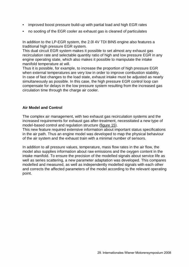
In addition to the LP-EGR system, the 2.0l 4V TDI BIN5 engine also features a traditional high pressure EGR system. This dual circuit EGR system makes it possible to set almost any exhaust gas recirculation rate and selectable quantity ratio of high and low pressure EGR in any engine operating state, which also makes it possible to manipulate the intake manifold temperature at will. Thus it is possible, for example, to increase the proportion of high pressure EGR when external temperatures are very low in order to improve combustion stability. In case of fast changes to the load state, exhaust intake must be adjusted as nearly simultaneously as possible. In this case, the high pressure EGR control loop can compensate for delays in the low pressure system resulting from the increased gas circulation time through the charge air cooler. Air Model and Control The complex air management, with two exhaust gas recirculation systems and the increased requirements for exhaust gas after-treatment, necessitated a new type of model-based control and regulation structure (figure 15). This new feature required extensive information about important status specifications in the air path. Thus an engine model was developed to map the physical behaviour of the air system and the exhaust train with a minimal number of sensors. In addition to all pressure values, temperature, mass flow rates in the air flow, the model also supplies information about raw emissions and the oxygen content in the intake manifold. To ensure the precision of the modelled signals about service life as well as series scattering, a new parameter adaptation was developed. This compares modelled and measured, as well as independently modelled signals with each other and corrects the affected parameters of the model according to the relevant operating point.
29. Internationales Wiener Motorensymposium 2008
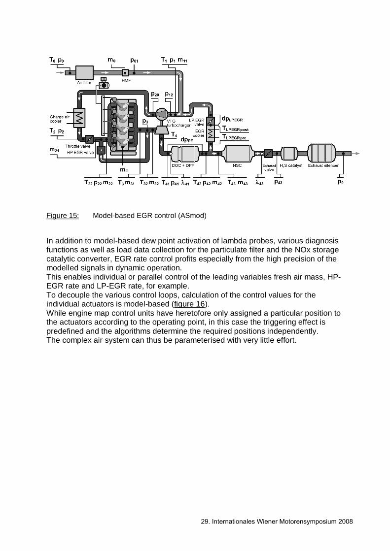
Figure 15: Model-based EGR control (ASmod) In addition to model-based dew point activation of lambda probes, various diagnosis functions as well as load data collection for the particulate filter and the NOx storage catalytic converter, EGR rate control profits especially from the high precision of the modelled signals in dynamic operation. This enables individual or parallel control of the leading variables fresh air mass, HP-EGR rate and LP-EGR rate, for example. To decouple the various control loops, calculation of the control values for the individual actuators is model-based (figure 16). While engine map control units have heretofore only assigned a particular position to the actuators according to the operating point, in this case the triggering effect is predefined and the algorithms determine the required positions independently. The complex air system can thus be parameterised with very little effort.
29. Internationales Wiener Motorensymposium 2008
Figure 16: Connections of the model-based EGR regulation Typical interference in air system regulation, such as dynamic pressure and temperature fluctuations or the load-dependent flow resistance of the particulate filter do not impair the performance of this new system. Furthermore, the newly developed system ensures that the various actuators do not interfere with each other with a co-ordinated control system. The new air flow regulation system from VOLKSWAGEN therefore combines excellent performance with simple parameterisation and low use of resources. Exhaust Gas After-Treatment Exhaust System Structure To attain the BIN5/LEV2 threshold value for emissions, in addition to the comprehensive engine optimisations and the new developments for reducing raw emissions and for narrowing the distribution range of particle and NOx emissions described in this document, an efficient system for exhaust gas after-treatment is also required. A NOx storage catalytic converter is to be used to supplement the established particulate filter system. The modular system mounted close to the engine which consists of an oxidation catalytic converter and a coated particulate filter and which is already in use in the new 2.0l 4V TDI EU5 engines in Europe [2], is distinguished by its extremely compact design (Figure 17).
29. Internationales Wiener Motorensymposium 2008
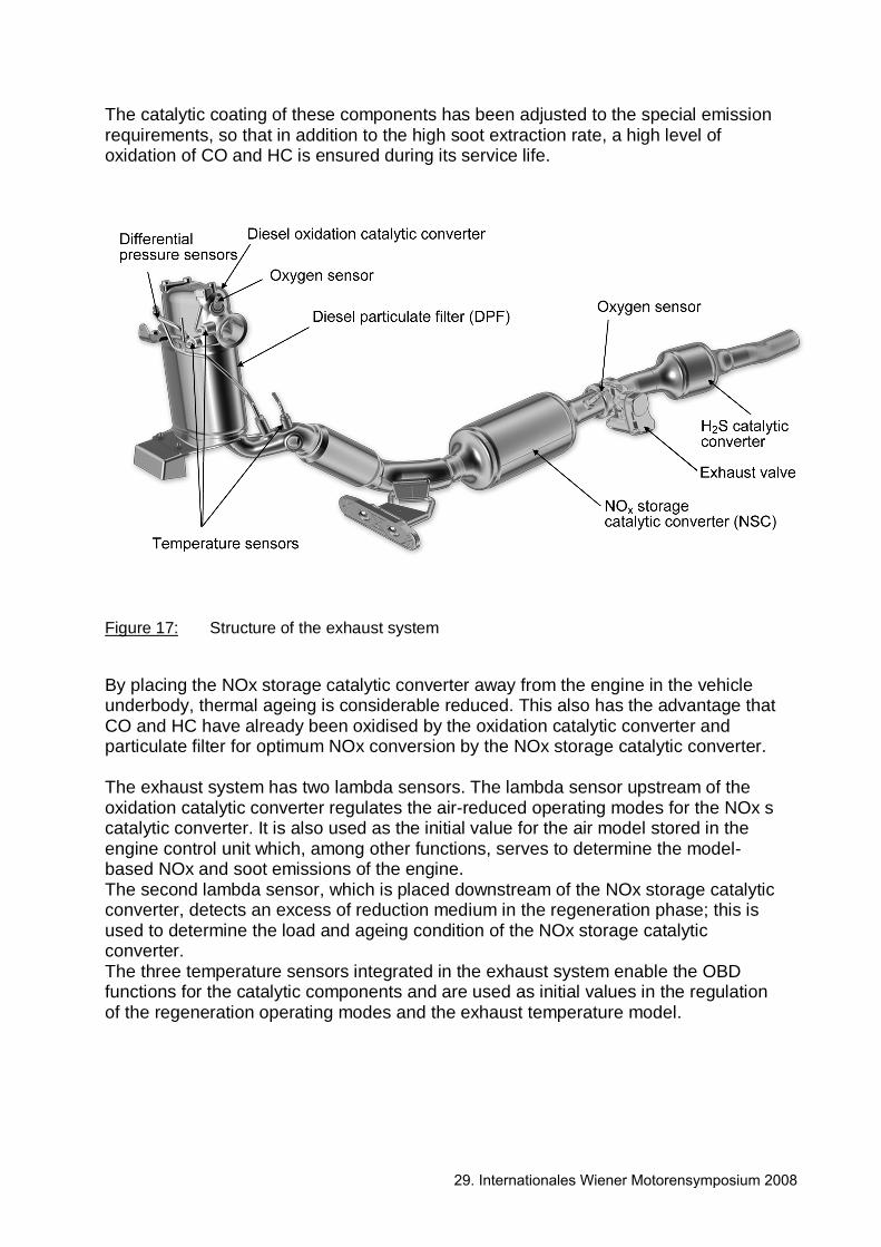
The catalytic coating of these components has been adjusted to the special emission requirements, so that in addition to the high soot extraction rate, a high level of oxidation of CO and HC is ensured during its service life.
Figure 17: Structure of the exhaust system By placing the NOx storage catalytic converter away from the engine in the vehicle underbody, thermal ageing is considerable reduced. This also has the advantage that CO and HC have already been oxidised by the oxidation catalytic converter and particulate filter for optimum NOx conversion by the NOx storage catalytic converter. The exhaust system has two lambda sensors. The lambda sensor upstream of the oxidation catalytic converter regulates the air-reduced operating modes for the NOx s catalytic converter. It is also used as the initial value for the air model stored in the engine control unit which, among other functions, serves to determine the model-based NOx and soot emissions of the engine. The second lambda sensor, which is placed downstream of the NOx storage catalytic converter, detects an excess of reduction medium in the regeneration phase; this is used to determine the load and ageing condition of the NOx storage catalytic converter. The three temperature sensors integrated in the exhaust system enable the OBD functions for the catalytic components and are used as initial values in the regulation of the regeneration operating modes and the exhaust temperature model.
29. Internationales Wiener Motorensymposium 2008

Additional Engine Operating Modes for Exhaust After-Treatment DPF Regeneration The process already successfully established for the 2.0l 4V TDI EU5 engine for the regeneration of the particle filter ensures its function over the entire characteristic range. The particulate filter is regenerated starting from a certain soot load threshold by an intervention in engine management. The regeneration time is determined in this process by the burning rate of the soot on the filter. The regeneration temperatures and the oxygen surplus (λ>1) are regulated as a function of the soot load and driving condition in such a way that in addition to filter regeneration that is as complete as possible, the thermal load threshold of the filter is not exceeded. DeNOx Mode The enhancement of the exhaust after-treatment system with a NOx storage catalytic converter necessitates the introduction of further, new regeneration modes to ensure the NOx conversion throughout the unit's service life. Unlike particulate filter regeneration, a sub-stochiometric exhaust gas composition is necessary for the regeneration of the NOx storage catalytic converter (DeNOx mode). In λ<1 operation the nitrous oxides stored during lean operation are reduced by the exhaust enriched reduction media consisting of HC, CO and H2. DeSOx Mode A further regeneration mode is provided by the sulphur removal of the NOx storage catalytic converter (DeSOx mode). This is necessary as the sulphur contained in fuel causes sulphate formation with slowly deactivates the NOx storage catalytic converter. Due to the high thermal stability of the sulphates, significant levels of sulphur reduction in a reducing atmosphere are only possible at temperatures above approx. 620 °C. The sulphur reduction procedure has been designed so that the storage capacity of the catalytic converter can largely be restored without irreversible damage to the storage material. The sub-stochiometric engine mode is very demanding in terms of engine management. Figure 18 and 19 show the most important interventions in the air and injection system.
29. Internationales Wiener Motorensymposium 2008
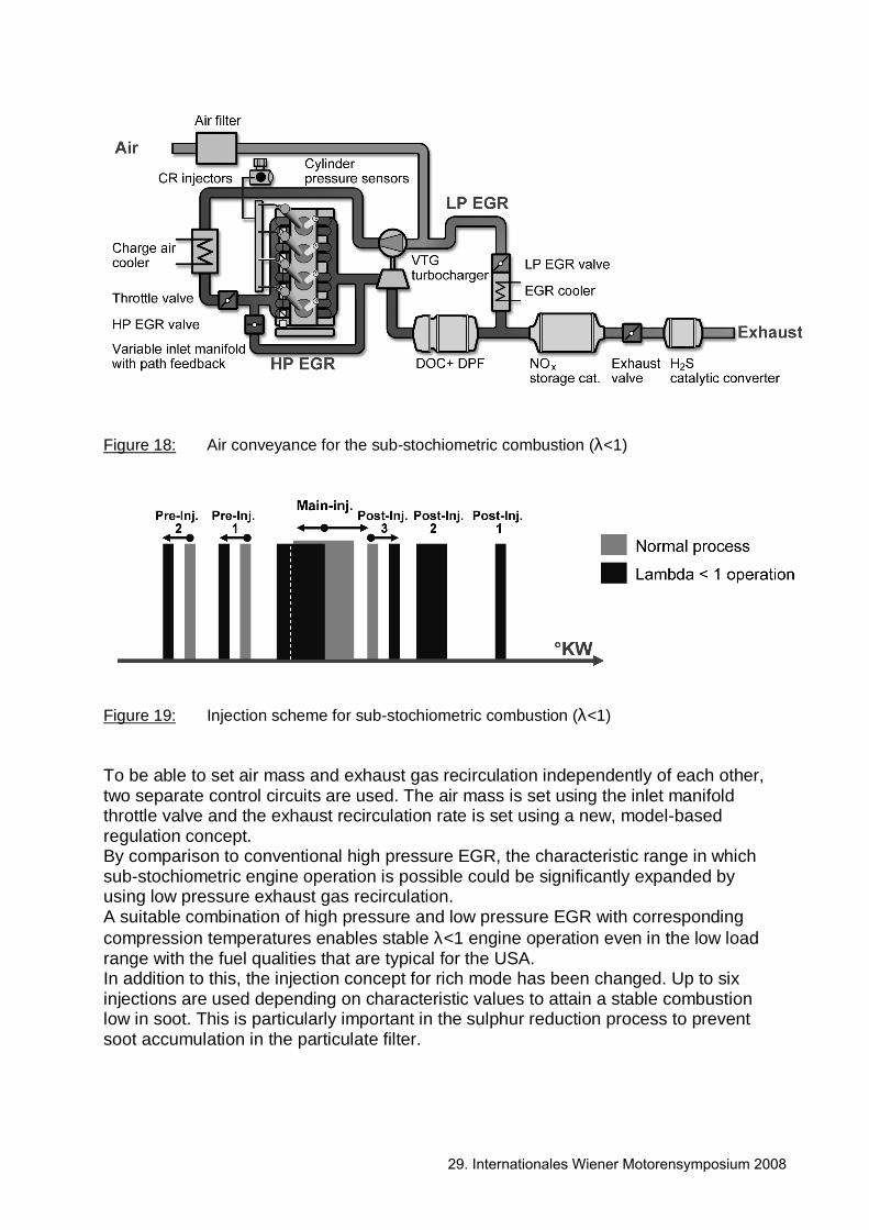
Figure 18: Air conveyance for the sub-stochiometric combustion (λ<1)
Figure 19: Injection scheme for sub-stochiometric combustion (λ<1) To be able to set air mass and exhaust gas recirculation independently of each other, two separate control circuits are used. The air mass is set using the inlet manifold throttle valve and the exhaust recirculation rate is set using a new, model-based regulation concept. By comparison to conventional high pressure EGR, the characteristic range in which sub-stochiometric engine operation is possible could be significantly expanded by using low pressure exhaust gas recirculation. A suitable combination of high pressure and low pressure EGR with corresponding compression temperatures enables stable λ<1 engine operation even in the low load range with the fuel qualities that are typical for the USA. In addition to this, the injection concept for rich mode has been changed. Up to six injections are used depending on characteristic values to attain a stable combustion low in soot. This is particularly important in the sulphur reduction process to prevent soot accumulation in the particulate filter.
29. Internationales Wiener Motorensymposium 2008

To attain the necessary exhaust gas temperatures in DeSOx operation, the conflict of interests between component protection of the turbocharger and higher sulphur reduction performance was resolved by using very late, non-combusting post-injection. This fuel partially reacts at the oxidation catalytic converter with the residual oxygen contained in the exhaust gas and hereby generates residual heat for the sulphur reduction of the NOx storage catalytic converter. These interventions in engine management are regulated to a neutral torque meaning that the process has no noticeable effect on driving characteristics. As shown in Figure 20, the regeneration intervals depend on the corresponding load conditions of the NOx storage catalytic converter with sulphur or nitrous oxide or the particulate filter's load in terms of soot. The maximum load conditions were adjusted to the permissible operating thresholds of the components.
Figure 20: Graph of DPF- and NSC-load conditions in the dynamic driving cycle Regeneration Concepts of NOx After-Treatment DeNOx Concept Taking the necessary engine operation and regeneration conditions as well as the catalytic converter properties into consideration, the corresponding regeneration mode is prioritised by a co-ordination program in the engine control unit.
29. Internationales Wiener Motorensymposium 2008
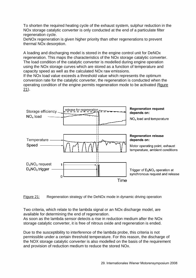
To shorten the required heating cycle of the exhaust system, sulphur reduction in the NOx storage catalytic converter is only conducted at the end of a particulate filter regeneration cycle. DeNOx regeneration is given higher priority than other regenerations to prevent thermal NOx desorption. A loading and discharging model is stored in the engine control unit for DeNOx regeneration. This maps the characteristics of the NOx storage catalytic converter. The load condition of the catalytic converter is modelled during engine operation using the NOx storage curves which are stored as a function of temperature and capacity speed as well as the calculated NOx raw emissions. If the NOx load value exceeds a threshold value which represents the optimum conversion rate for the catalytic converter, the regeneration is conducted when the operating condition of the engine permits regeneration mode to be activated (figure 21).
Figure 21: Regeneration strategy of the DeNOx mode in dynamic driving operation Two criteria, which relate to the lambda signal or an NOx discharge model, are available for determining the end of regeneration. As soon as the lambda sensor detects a rise in reduction medium after the NOx storage catalytic converter, it is free of nitrous oxide and regeneration is ended. Due to the susceptibility to interference of the lambda probe, this criteria is not permissible under a certain threshold temperature. For this reason, the discharge of the NOX storage catalytic converter is also modelled on the basis of the requirement and provision of reduction medium to reduce the stored NOx.
29. Internationales Wiener Motorensymposium 2008
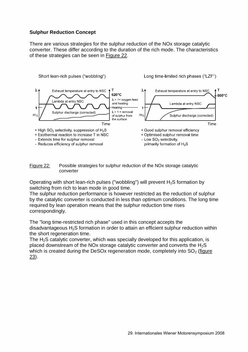
Sulphur Reduction Concept There are various strategies for the sulphur reduction of the NOx storage catalytic converter. These differ according to the duration of the rich mode. The characteristics of these strategies can be seen in Figure 22.
Figure 22: Possible strategies for sulphur reduction of the NOx storage catalytic converter Operating with short lean-rich pulses ("wobbling") will prevent H2S formation by switching from rich to lean mode in good time. The sulphur reduction performance is however restricted as the reduction of sulphur by the catalytic converter is conducted in less than optimum conditions. The long time required by lean operation means that the sulphur reduction time rises correspondingly. The "long time-restricted rich phase" used in this concept accepts the disadvantageous H2S formation in order to attain an efficient sulphur reduction within the short regeneration time. The H2S catalytic converter, which was specially developed for this application, is placed downstream of the NOx storage catalytic converter and converts the H2S which is created during the DeSOx regeneration mode, completely into SO2 (figure 23).
29. Internationales Wiener Motorensymposium 2008
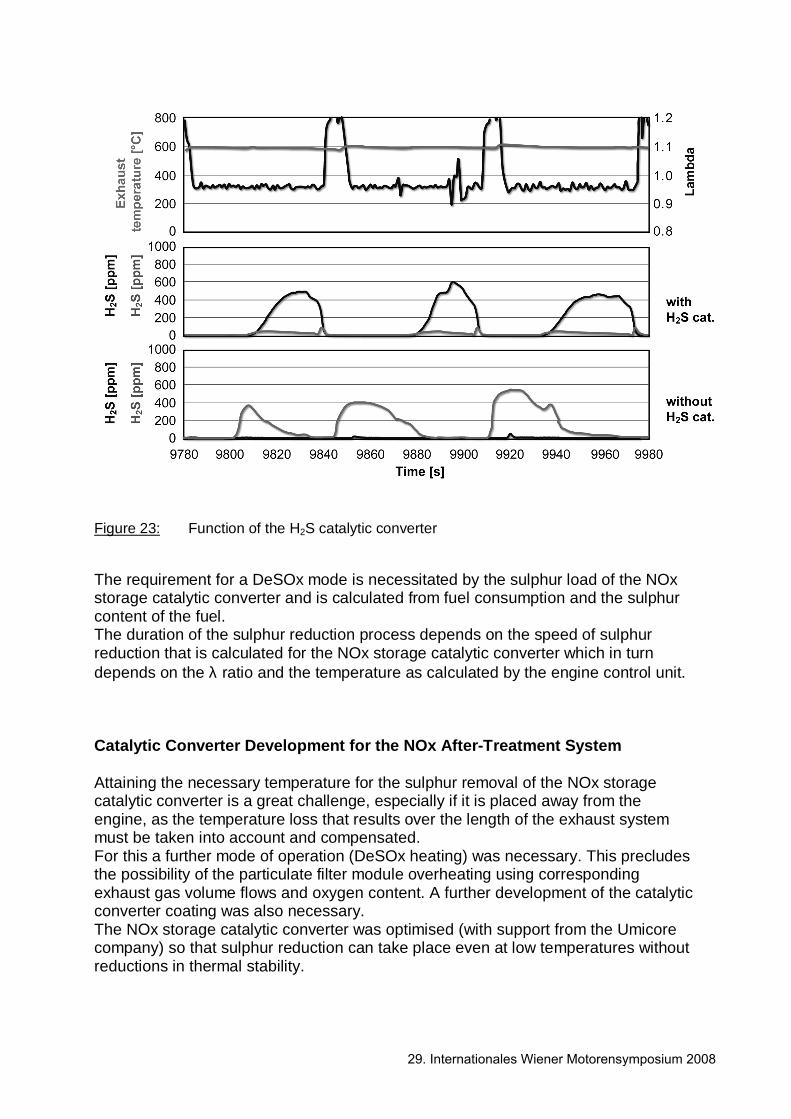
Figure 23: Function of the H2S catalytic converter The requirement for a DeSOx mode is necessitated by the sulphur load of the NOx storage catalytic converter and is calculated from fuel consumption and the sulphur content of the fuel. The duration of the sulphur reduction process depends on the speed of sulphur reduction that is calculated for the NOx storage catalytic converter which in turn depends on the λ ratio and the temperature as calculated by the engine control unit. Catalytic Converter Development for the NOx After-Treatment System Attaining the necessary temperature for the sulphur removal of the NOx storage catalytic converter is a great challenge, especially if it is placed away from the engine, as the temperature loss that results over the length of the exhaust system must be taken into account and compensated. For this a further mode of operation (DeSOx heating) was necessary. This precludes the possibility of the particulate filter module overheating using corresponding exhaust gas volume flows and oxygen content. A further development of the catalytic converter coating was also necessary. The NOx storage catalytic converter was optimised (with support from the Umicore company) so that sulphur reduction can take place even at low temperatures without reductions in thermal stability.
29. Internationales Wiener Motorensymposium 2008
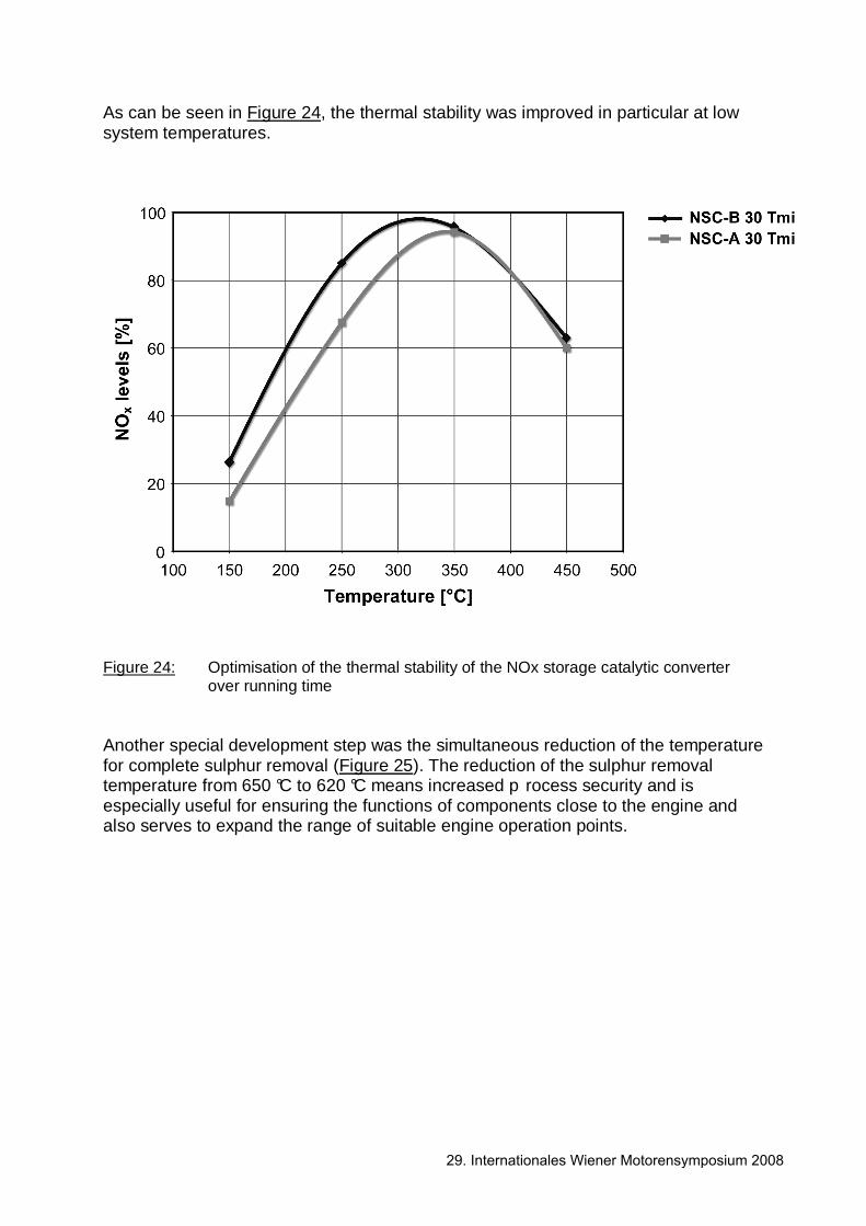
As can be seen in Figure 24, the thermal stability was improved in particular at low system temperatures.
Figure 24: Optimisation of the thermal stability of the NOx storage catalytic converter
over running time Another special development step was the simultaneous reduction of the temperature for complete sulphur removal (Figure 25). The reduction of the sulphur removal temperature from 650 °C to 620 °C means increased p rocess security and is especially useful for ensuring the functions of components close to the engine and also serves to expand the range of suitable engine operation points.
29. Internationales Wiener Motorensymposium 2008

Figure 25: Sulphur reduction behaviour of NSC coating variants The Regulation Concept of the New 2.0 l 4V CR BIN5 LEV2 Engine Operating Mode Co-ordination The use of the particulate filter and the NOx storage catalytic converter requires a large number of different combustion procedures and engine operation modes (Figure 26). To be able to co-ordinate these operating modes and their requirements, a new, complex operating mode management system with a hierarchically encapsulated and resource-protecting structure was developed. In total 10 different operating modes were implemented. These are divided within the co-ordinators into 2 normal operation modes and 8 exhaust after-treatment operating modes.
29. Internationales Wiener Motorensymposium 2008
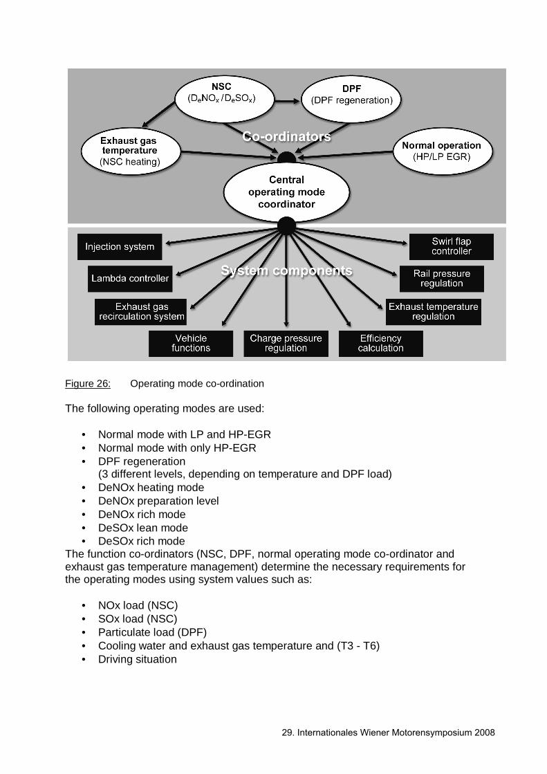
Figure 26: Operating mode co-ordination The following operating modes are used:
• Normal mode with LP and HP-EGR • Normal mode with only HP-EGR • DPF regeneration
(3 different levels, depending on temperature and DPF load) • DeNOx heating mode • DeNOx preparation level • DeNOx rich mode • DeSOx lean mode • DeSOx rich mode
The function co-ordinators (NSC, DPF, normal operating mode co-ordinator and exhaust gas temperature management) determine the necessary requirements for the operating modes using system values such as:
• NOx load (NSC) • SOx load (NSC) • Particulate load (DPF) • Cooling water and exhaust gas temperature and (T3 - T6) • Driving situation
29. Internationales Wiener Motorensymposium 2008
as well as the environmental conditions
• Ambient temperature • Atmospheric pressure
Interference between the co-ordinators is largely avoided. The 4 function co-ordinators communicate directly with a central operating mode co-ordinator. This prioritises the individual requirements and triggers a mode change if necessary. The central co-ordinator addresses the necessary characteristics and characteristic curves in the system components. During development, great value was set in attaining operating mode synergies. Thus, for example, DeSOx lean and DeSOx rich have the same preinjection configuration but different post-injection configurations. To save control unit resources and also development time, different direct and indirect operating mode transitions were introduced. A direct transition occurs for changes that can be expected frequently (such as from normal to DPF mode). An indirect transition is made for cases which seldom occur, such as from DPF to DeNOx mode. In this case, the system changes first to normal mode and than to the target mode. The new operating mode management system has implemented a simple function structure which is easy to maintain and parameterise.
29. Internationales Wiener Motorensymposium 2008
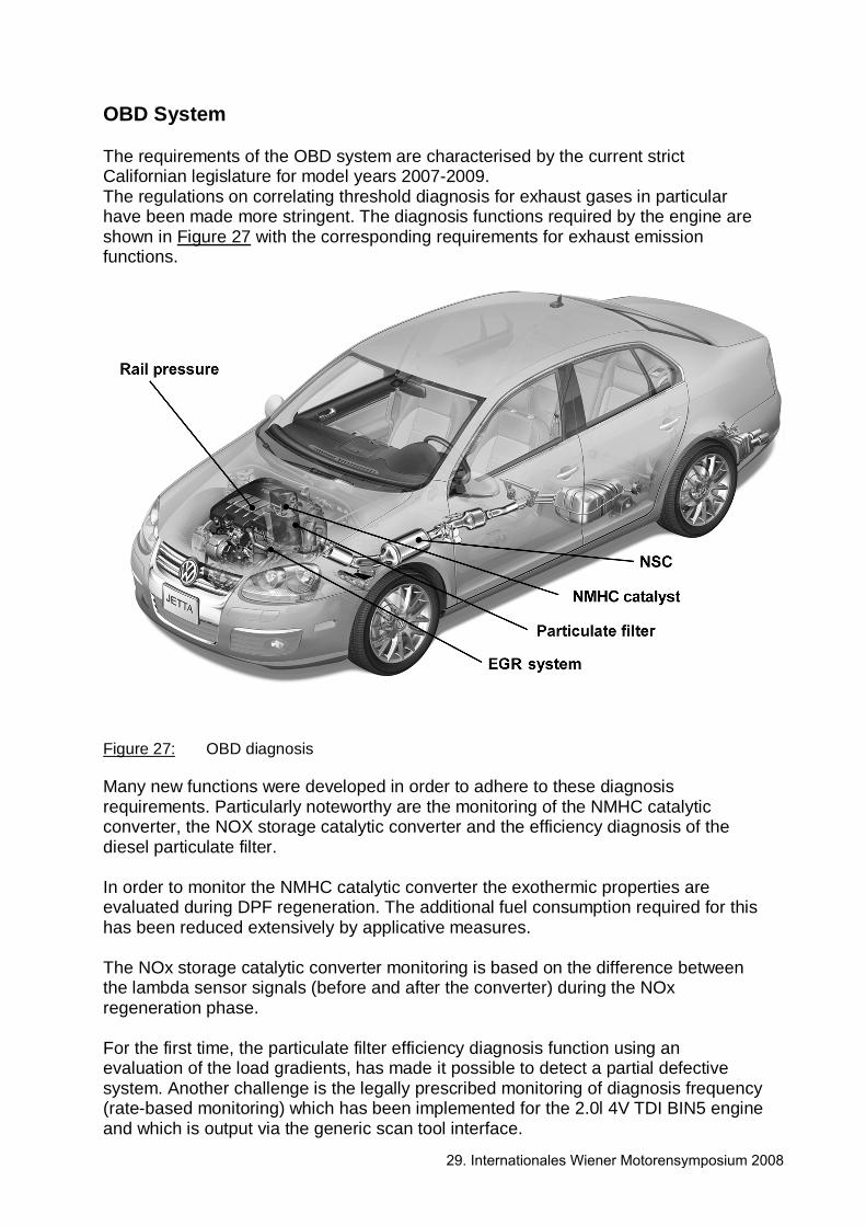
OBD System The requirements of the OBD system are characterised by the current strict Californian legislature for model years 2007-2009. The regulations on correlating threshold diagnosis for exhaust gases in particular have been made more stringent. The diagnosis functions required by the engine are shown in Figure 27 with the corresponding requirements for exhaust emission functions.
Figure 27: OBD diagnosis Many new functions were developed in order to adhere to these diagnosis requirements. Particularly noteworthy are the monitoring of the NMHC catalytic converter, the NOX storage catalytic converter and the efficiency diagnosis of the diesel particulate filter. In order to monitor the NMHC catalytic converter the exothermic properties are evaluated during DPF regeneration. The additional fuel consumption required for this has been reduced extensively by applicative measures. The NOx storage catalytic converter monitoring is based on the difference between the lambda sensor signals (before and after the converter) during the NOx regeneration phase. For the first time, the particulate filter efficiency diagnosis function using an evaluation of the load gradients, has made it possible to detect a partial defective system. Another challenge is the legally prescribed monitoring of diagnosis frequency (rate-based monitoring) which has been implemented for the 2.0l 4V TDI BIN5 engine and which is output via the generic scan tool interface.
29. Internationales Wiener Motorensymposium 2008
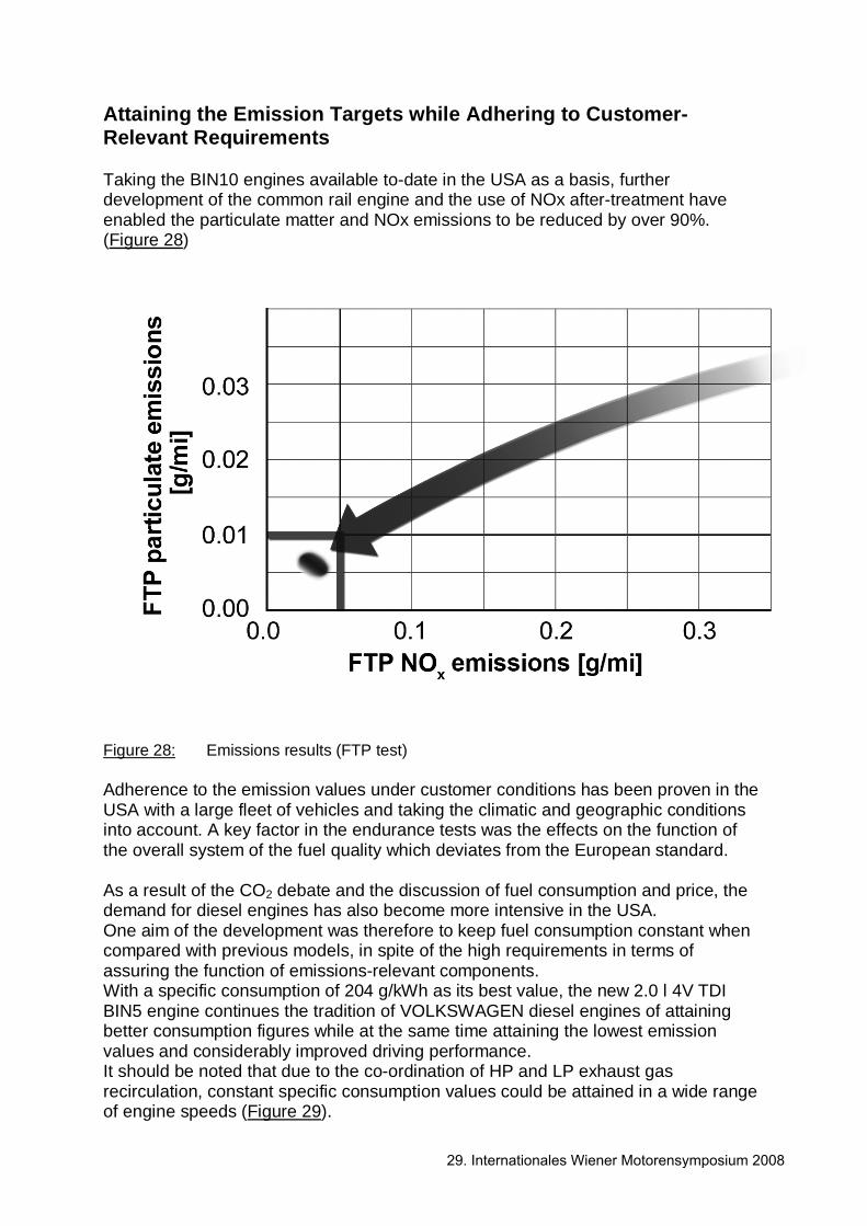
Attaining the Emission Targets while Adhering to Customer-Relevant Requirements Taking the BIN10 engines available to-date in the USA as a basis, further development of the common rail engine and the use of NOx after-treatment have enabled the particulate matter and NOx emissions to be reduced by over 90%. (Figure 28)
Figure 28: Emissions results (FTP test) Adherence to the emission values under customer conditions has been proven in the USA with a large fleet of vehicles and taking the climatic and geographic conditions into account. A key factor in the endurance tests was the effects on the function of the overall system of the fuel quality which deviates from the European standard. As a result of the CO2 debate and the discussion of fuel consumption and price, the demand for diesel engines has also become more intensive in the USA. One aim of the development was therefore to keep fuel consumption constant when compared with previous models, in spite of the high requirements in terms of assuring the function of emissions-relevant components. With a specific consumption of 204 g/kWh as its best value, the new 2.0 l 4V TDI BIN5 engine continues the tradition of VOLKSWAGEN diesel engines of attaining better consumption figures while at the same time attaining the lowest emission values and considerably improved driving performance. It should be noted that due to the co-ordination of HP and LP exhaust gas recirculation, constant specific consumption values could be attained in a wide range of engine speeds (Figure 29).
29. Internationales Wiener Motorensymposium 2008

Figure 29: Specific fuel consumption map The typical torque characteristics for a charged diesel engine support a start without delays; the acceleration was improved by 20% and elasticity by 15 % when compared to the 74 kW engine currently on offer. These advantages can be clearly seen in the engine map in Figure 30.
29. Internationales Wiener Motorensymposium 2008
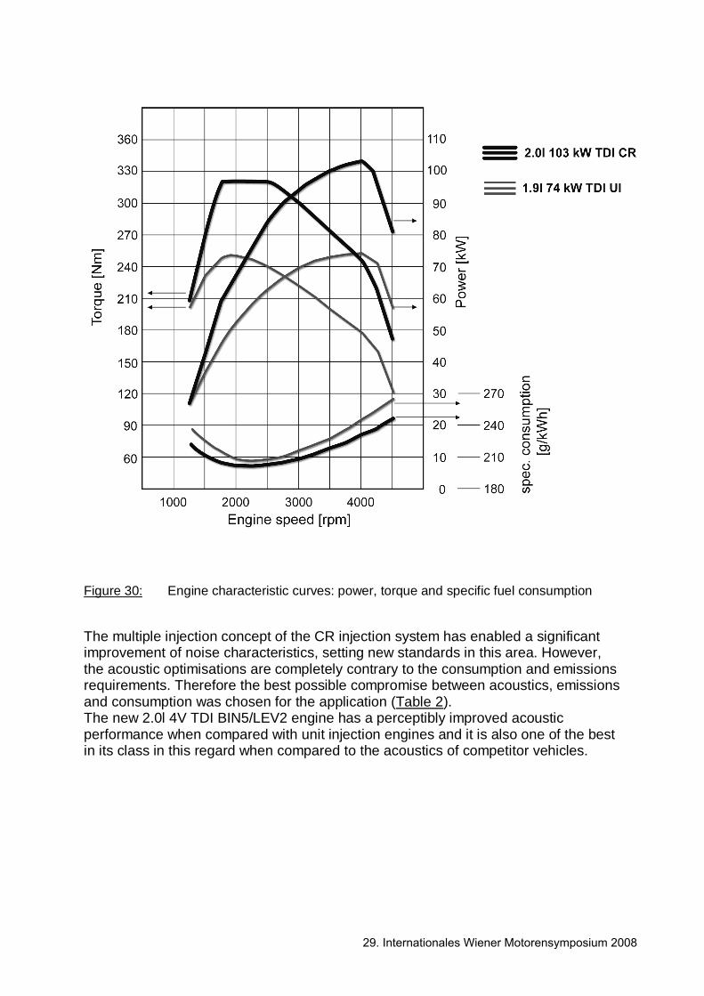
Figure 30: Engine characteristic curves: power, torque and specific fuel consumption The multiple injection concept of the CR injection system has enabled a significant improvement of noise characteristics, setting new standards in this area. However, the acoustic optimisations are completely contrary to the consumption and emissions requirements. Therefore the best possible compromise between acoustics, emissions and consumption was chosen for the application (Table 2). The new 2.0l 4V TDI BIN5/LEV2 engine has a perceptibly improved acoustic performance when compared with unit injection engines and it is also one of the best in its class in this regard when compared to the acoustics of competitor vehicles.
29. Internationales Wiener Motorensymposium 2008

Table 2: Preliminary vehicle results Summary and Outlook The new 2.0l 4V TDI BIN5/LEV2 continues the tradition of successful VOLKSWAGEN diesel engines on the American market. Engine characteristics have been improved thanks to the many improvements in combustion in the engine and in particular the use of completely new components, such as the combustion sensor and the combination of high pressure and low pressure EGR. The cylinder-based combustion regulation developed by Volkswagen has created new possibilities in terms of engine application. This means that diesel engines can be operated closer to the stability limits of combustion even with differing fuel qualities. It has also made it possible to compensate for interference factors such as component tolerance, ageing and changing operating conditions. In addition to the engine, a completely new, complex exhaust gas after-treatment system has been developed. Levels of efficiency and long-term stability that were regarded as impossible until very recently have been attained in collaboration with the Emitec, Corning and Umicore companies, in particular in the area of the NOx after-treatment system. Alongside the stationary test bench optimisations, the driving dynamics regulation concepts are also key to success. Therefore, in addition to the new individual components, particular emphasis was placed on ingenious regulation technology and the interaction of components in the system.
29. Internationales Wiener Motorensymposium 2008
The traditional strengths of the TDI, such as driving pleasure and economy are very much to the fore in the cleanest diesel engine in the world. We are therefore very certain that this new engine design will be a successful chapter in the history of diesel vehicles in the American market. With the "Clean Diesel" engine, VOLKSWAGEN has created a new milestone in diesel technology on the American market. Literature [1] Dr. Jens Jeschke, Thomas Lang, Jürgen Wendt, Dieter Mannigel,
Dr. Michael Henn, Dr. Hans-Georg Nitzke Combustion Control for Diesel Engines with Direct Injection 16th Aachen Colloquium Automobile and Engine Technology Aachen, 2007 [2] Dr. Jens Hadler, Falko Rudolph, Hermann-Josef Engler, Dr. Sven Röpke The New 2.0l 4V TDI with Common Rail – A Modern Diesel Technology by Volkswagen 16th Aachen Colloquium Automobile and Engine Technology Aachen, 2007 [3] G. Hohenberg The Cobustion Process – A Path for Evaluating Engine Processes 4th Vienna Motor Symposium VDI Progress Reports, Series 6, No. 3 Vienna, 1982
29. Internationales Wiener Motorensymposium 2008