Most - Often Needed - World Radio History
194
Most - Often Needed 1953 VOLUME TV -7 Television Servicing Information VOLUME TV -7 PRICE 3 Compiled by M. N. BEITMAN SUPREME PUBLICATIONS
-
Upload
khangminh22 -
Category
Documents
-
view
1 -
download
0
Transcript of Most - Often Needed - World Radio History

Most - Often Needed
1953VOLUME TV -7
TelevisionServicing Information
VOLUME TV -7
PRICE 3
Compiled by
M. N. BEITMAN
SUPREME PUBLICATIONS

Most - Often - Needed
1953Volume TV -7
TelevisionServicing Information
TI11..1)121"
PRA,' E ? KILNCE1FX 17r
Compiled by
M. N. BEITMAN
Supreme Publications3727 West 13th Street *** Chicago 23, Illinois

MOST -OFTEN -NEEDED 1953 TELEVISION SERVICING INFORMATION
2
Foreword
This new "1953 Television Servicing Information'manual is the seventh volume of the Supreme Publica-tions TV series. As in previous volumes, we havetried to include in this new manual circuit diagramsand all essential service facts on every popular TVset made during the past year. Factory prepared andchecked material was used in every case where it wasavailable. We believe that each manufacturer knowsits sets best and can prepare the most accurate andeasiest to apply service material on the very sets theyengineered, built, and distributed. The kind receptiongiven by servicemen to previous volumes of this seriesencourages us to believe that our selection and edit-ing of factory material incorporated in these manualsmeets with your needs and approval.
The data on 1953 TV models included in this newSUPREME manual brings exciting news of recent tech-nical developments that will prove of great interest toyou and will be the help you need when these sets arein your shop for service.
The list of Contents is given on pages 3 and 4,while a complete Index by manufacturers and model(or chassis) numbers begins on page 191. Refer tothis list and index to find the TV material you need.
Our sincere thanks and appreciation is extendedto all manufacturers through whose cooperation it waspossible to present technical information on the setsof their make.
M. N. BeitmanApril 1953Chicago, Illinois
Copyright 1953, by Supreme Publications.
All rights reserved. This book, or partsthereof, must not be reproduced in anyform without permission of the publisher.

MOST -OFTEN -NEEDED 1953 TELEVISION SERVICING INFORMATION
Contents
Admiral CorporationChassis 19B1, 19C1, 19E1, 19F1, 19F1A, 19G1, 19H1, 19K1, 19N1 . . . 5 to 11Chassis 22C2 and 22E2 (22A2, 22A2A, 22M1, 22Y1 are similar) . . . 12 to 18
(For list of models see first page of text)
Arvin Industries, Inc.6000 Series, Chassis TE-319, -330, -331, -332, various models . . . . 19 to 227200 Series, Chassis TE-337, TE-341 (see page 23 for list of models) 23 to 26
Capehart-Farnsworth CorporationCX-37 Series, versions CT -75, CT -77, CT -81 33 to 36
CBS -ColumbiaChassis 817, 820, 821, Models 17C18, 17M18, 17T18, 20M18, 20M28,
20T18, and 21C18 27 to 29Chassis 1021, Models 21C11, 21C11B, 21C21, 21C31B, 21C41, 21T11 30 to 32
Crosley Corp.Chassis 385, 386, 387, 396 (for list of models see page 37) 37 to 40
Allen B. Du Mont Laboratories, Inc.Chassis RA -166, -167, -170, -171, Models 17T350, 21T327, 21T328,
21T329, 21T359, 21T366, 21T376, -U, 21T377, -U, 21T378, -U 41 to 46Emerson Radio and Phonograph Corp.
Chassis 120163B, -D, 120164B, 120166D, 120167D, 120168D, 120169B 47 to 54(For list of models using these chassis see page 47)
Gamble-Skogmo, Inc. (Coronado)Models 25TV2-43-9045A, -B, -C, and 25TV2-43-9060A, -B 55 to 56
General Electric Co.Models 20C105, 20C106, 20T2, 21C200, 21T4, and 21T5 . . ..... 57 to 70
The Hallicrafters Co.Series 1200D, with prefix letters A, D, F, G, J, K, L, P, R, T, W, X,
Chassis A1300D is similar (see page 72 for list models) . . . . 71 to 77Hoffman Radio Corp.
Chassis 196, 196M, 196T, 197, 199, Models 21B116, 21B309, 21B701,21B907, 21M115, 21M308, 21M700, 21M906, 21P310, 21P702, etc. 78 to 82
The Magnavox Co.Series 105C, 105E, 105F, 105L, 105M (for list of chassis see page 83) 83 to 86
John Meck Industries, Inc.Chassis Types 9026, 9032, and 9033 (see page 87 for list of models) 87 to 88
Montgomery Ward & Co.25WG-3066A & B, 25WG-3071A & B, 25WG-3072A & B, 25WG-3073A,
25WG-3073B, 25WG-3075A & B, 25WG-3077A & B, -3079A &B 89 to 90
3

MOST -OFTEN -NEEDED 1953 TELEVISION SERVICING INFORMATION
Table of Contents, continued
Motorola, Inc.Chassis TS -292A & B, TS -324A & B, TS -395A, TS -400A, TS -401,
TS -408A, TS -410A, TS -501A (list of models on page 91) . . . 91 to 98
Olympic Radio & Television, Inc.Chassis Types TK and TL, Models 17T40, 17T48, 17C44, 17K41, 17K42,
17K50, 20T46, 20T47, 20C45, 20052, 20053, 20D49, 20K43, 20K51 99-102
Packard -Bell Co.Models 2421, 2422, 2423, and 2822 103 to 106
Philco CorporationDeflection Chassis G-1, H-1, J-1; R.F. Chassis 71, 81, and 91 107 to 124
(For list of similar chassis and models using these see page 107)
R.C.A. VictorModels 17T200, 17T201, 17T202, 17T211, 17T220, Chassis KCS72, 125 to 132
(Models 21T208, 21T217, 21T218, 21T227, 21T228, 21T229,using Chassis KCS72A; and 21T242, 21T244, using ChassisKCS72D-1, or -2, are similar to models covered.)
Models 17T250DE and 17T261DE, using Chassis KCS74 133 to 135
Raytheon Manufacturing Co.Chassis 17T1, 17T2, 21T1, 21T2, (see page 136 for list of models) 136 to 140
Sears, Roebuck and Co. (Silvertone)Set 1175-21, Chassis 478.380; Sets 1182-21, 1189-21 with 478.381 147 to 150
(Similar sets are listed and described on page 147)Sentinel Radio Corp.
Models 1U-458, 1U-459, 1U-460, 1U-461 141 to 146
The Sparks-Withington Co. (Sparton)Chassis 27D213, Models 5342A, 5343A, 5382A to 5386A, 10352, -53 151 to 154
Stewart -Warner ElectricModels 21T9211B, -C, -D, -E, -F (Model 9210C is similar) 155 to 158
Stromberg-Carlson Company417 Series, and 421 Series 159 to 166
Sylvania Electric Products, Inc.Chassis 1-508-1, 1-508-2, 1-510-1, 1-510-2, (1-504-1, -2 similar) 167 to 174
(See page 167 for a complete list of models using each chassis)Trav-ler Radio Corp.
Chassis 36A2, Models 217-32, 217-33, 217-37, 220-34, 220-35,221-36; Chassis 36B2 in Models 217-331 and 217-371 . . . . 175 to 178
Westinghouse Electric Corp.All 1953 TV sets issued to date of publication. To find chassis and
models covered refer to complete reference table page 179. 179 to 184
Zenith Radio Corp.Chassis 19K20, 19K22, 19K23, and 21K20 (List of models on page 188) 185 to 190
4

MOST -OFTEN -NEEDED 19! 3 TELEVISION SERVICING INFORMATION
AldmiralChassis 19B1, 19C1, 191 1, 19F1, 19F1A, 19G1, 19H1, 19K1, and 19N1
Used in Models 17DX10, 17DXI 1, 17DX12, 121DX10, -A, 121DX11, 121DX12, -A,121DX16, -A, -L, 121DX17, -A, -L, 221DX15, -A, -L, 221DX16, -A, -L, 221DX17,221DX17A, -L, 221DX26, -A, -I , 221DX38, -A, 222DX15, 321DX15, -A,-L,321DX16, -A, -L, 321DX17, -A -L, 321DX25A, -B, 321DX26, -A, -B, 321DX27A, -B.
Service notes presentedand circuit diagrams on pagAll 19 series chassis emplo,19C1, 19F1, 19F1A, 19H1,The 19E1, 19G1, and 19N1
below, alignment information on pages 6 to 9,s 10 and 11, apply to the above listed TV sets.the same basic television circuitry. The 19B1,
ind 19K1 chassis are television only models.hassis are used in combination models. These
chassis use various size pic ure tubes and some have tone controls. Twotypes of tuners have been us !d and both are shown on page 10.
INDIVIDUAL CHANNEL SLUG ADJUS1 KENTUSING A TELEVISION SIGNAL
Individual channel oscillator adjustn ent ofevery receiver should be checked upon nstalla-lion or servicing. If this adjustment is 1 roperlymade, it is possible to tune from one st lion toanother by merely turning the CHANNEL .ontrol.With correct oscillator channel adjustment, bet picturewill be located at the approximate center of the range ofthe TUNING control. However, this may not n ;:essarilybe maximum sound output.
Channel slug adjustment can be made withot remov-ing the chassis from the cabinet. Adjust as fo ows:a. Turn the set on and allow 15 minutes to arm up.b. Set the CHANNEL knob for a station in c ieration.
Set all other controls for a normal picture.c. Set TUNING control at center of its range
ing it approximately half -way.
d. Remove the CHANNEL and TUNING knole. Insert a 1/s" blade, NON-METALLIC screw&
consisting of one metallic and one non-metalldriver is available under part number 98Athe 1/4" hole adjacent to the channel tuniFor each channel in operation, carefully a,channel slug for best picture with clear disure that the Tuning control is set at the cenrange before adjusting each channel slug. Otrotation of the slug will be required; turningin too far will cause it to fall into the coil.slug falls into the coil, remove the coil, r
retaining spring aside, lightly tap the opetthe coil until the slug slips out. Replacereset retaining spring.)
y rotat-
ver (kitc screw -.0 -3) ing shaft.just theail. Be.?.r of itsly slightthe slug(If the
ove theend of
Lug and
TOUCH-UP OF RATIO DETECTOR SECONDARYUSING TELEVISION SIGNAL*This adjustment is accessible through the 1/4" hole
(just below T201) in bottom of the cabinet or the chassismounting shelf, located toward the left side facing therear of the set. Removal of the chassis is therefore notrequired. Adjustment need be made on one channelonly. Proceed as follows:a. Turn set on and allow about 15 minutes for warm up.b. Tune set for normal picture and sound.c. Carefully insert a non-metallic alignment tool through
the opening in cabinet bottom below T201. An align-ment tool with a screwdriver blade or hexagonal endis required depending on the transformer used, see" note below. When the alignment tool engages thebottom tuning slug A8, adjust the slug for bestsound with minimum buzz level. Do this carefully asonly slight rotation in either direction will generallybe required. Correct adjustment point is located be-tween the two maximum buzz peaks that will benoticed when turning the slug back and forth about1/4 to 1/2 turn.
d. If necessary, repeat individual channel slug adjust-ment and conclude with retouching the ratio detectorsecondary. Note: If oscillator adjustment is requiredfor other channels, it will not be necessary to repeatthe ratio detector secondary adjustment.
ALIGNMENT OF 4.5 MC TRAP Al2, USING ATELEVISION SIGNAL
Beat interference (4.5 MC) appears in picture as veryfine vertical or diagonal lines, very close together, havinga "gauze -like" appearance, the pattern will vary withspeech, forming a very fine herringbone pattern.
The trap can be tuned by watching the picture and ad-justing the slug for minimum 4.5 MC interference.
If ratio detector transformer (T201) ,has hollow hexag nal core slugs, bottom slug adjustment A8 can be made from top of chassis,if you use alignment tool (part number 98A30-7; availal e at Admiral Distributor). Bottom slug (A8) can be reached through thehole in the core of the upper slug (A10). 5

MOST -OFTEN -NEEDED 1953 TELEVISION SERVICING INFORMATION
Admiral Chassis 19B1, 19C1, 19E1, 19F1, 19F1A, 19G1, 19H1, 19K1, and
TELEVISION ALIGNMENT PROCEDUREGENERAL
Complete alignment consists of the following individualprocedures and should be performed in this sequence.a. IF Amplifier and Trap Alignment.b. IF Response Curve Check.c. 4.5 MC Sound IF and Trap Alignment.d. RF and Mixer Alignment.e. Over-all RF and IF Response Curve Check.f. HF Oscillator Adjustment.
IF AMPLIFIER ANDConnect bias battery; negative to test point "T", seefigure 9, positive to chassis. A 3 volt battery is requiredfor steps 1, 2, 3, 4 and 5.
Disconnect antenna. Connect a jumper wire across theantenna terminals.
ALIGNMENT TOOLS
19N1
An alignment tool kit consisting of one metallic andone non-metallic screwdriver is available under part num-ber 98A-30-3. A non-metallic alignment tool with a screw-driver point at one end and hexagonal wrench ( for hol-low hexagon core slugs) at the other is available underpart number 98A-30-7.
TRAP ALIGNMENTSet Channel selector to channel 12 or other unassignedhigh channel, to prevent interference during alignment.Set the Picture control fully to the left (counterclockwise).Allow about 15 minutes for receiver and test equipment towarm up.Use lowest DC scale on VTVM.
Step SignalGen. Freq.
VTVM and SignalGenerator Connections
Instructions Adjust
1 *27.25 MC VTVM high side to test point "V",common to chassis.Generator high side to 6J6 (V102)tube shield; insulate shield fromchassis. Connect low side to chassis
-near 6J6 tube base.
Use 3 volt bias battery.Use lowest DC scale on VTVM.When peaking, keep reducing gen-erator VTVM reading ofapprox. 1 volt or less.Set channel switch to channel 12 orother unassigned high channel.
Al for minimum.
2 25.3 MCA2 and A3 formaximum.
3 23.1 MCA4 and A5 formaximum.
4 *27.25 MCRepeat step 1
above.
5 To insure correct IF alignment, make the "IF Response Curve Check" given on opposite page.
* Before proceeding, be sure to check thequency standard for absolute frequency
After becoming familiar withalignment of sets by merely
A10 All Al2RF AMP. RF AMP. MIXER
Al3HF OSC.
ADJ.
signal generator used in alignment against a crystal calibrator or other fre-calibration required for this operation.
ALIGNMENT HINTalignment procedure, some servicemen simplify subsequentusing the essential alignment data given in figures below.
CIO4 C106
6BZ7
6BC5 6J6OR
A5 23.1 MC MAX. MIXER PLATE
Figure 8. Top View of TV TunerShowing Adjustment Locations.
6
NEG. OF C205ELEC. 4MFD
TEST POINTJCT. OF 0206R206 & R207
r- A523.1 MC MAX
MIXER PLATE
Al27 25MC MIN
TRAP
A3V 25.3MC MAX
1ST IF
A423.1 MC MAX
2ND IF43 046
A2 C206 A 20625.3MC MAX is
390011953RD IF
TEST POINT(AGC BUSS)
11305
1000 OHMS
1)30100
1000 OHMS
C205 L
TEST POINT ..7--.., j. 303
A8 A6 Al A9(BOTTOM SLUG) (TOP SLUG) 4.5MC MAX 4.5 MC MIN4.5 MC ZERO 4.5 MC MAX SOUND TRAP
SEC. RATIO DET. r.. RATIO DE T. TAKE OFF Jv-
OTEST POINT
JCT. OF L302AND L303
Figure 9. Bottom View of Chassis Showing Test Point Connectionsand IF Alignment Data.

MOST -OFTEN -NEEDED 19! 3 TELEVISION SERVICING INFORMATION
Admiral 19B1, 19C1, 19E1, 19F1, 19F1A, 19G1, 19H1, 19K1, 19N1 Chassis
Receiver Controlsand Bias Battery
Set Channel melee -tor on channel 12or an unassignedhigh channel. Pic-ture control fully tothe left. Connectnegative of 3 voltbias battery to testpoint "T"; positiveto chassis.
21.2511C
MARKER
(NAT NOT
BE VISIBLE)
LIT I FAST BST/.
IAPPROX.8S%- - -
IF RE ;PONSE CURVE CHECK(Using weep generator and oscilloscope)
SweepGenerator
Connect high sideto 6J6 mixer-osc.tube shield. Insu-late tube shieldfrom chassis, lowside to chassisground. Set sweepfrequency to 23MC,and sweep width ap-proximately 7MC.
4.5 MC
25.7t MAF
SO.,.
9- 30 %MARDIFFERENCE II HEIGHT OF PEAKSSHOULD NOT EXCEED 30/.
APVit0t. 3 NC-.-
24.31IC MARKER
HT ASURED FROM HIGHEST PEAK
Figure 6. Ideal IF Response Curve.
MarkerGenerator Oscilloscope Instructions
If an externalnarker generator isised, loosely couplesigh side to sweepvenerator lead onube shield, lowide to chassis.darker frequenciesndicated on IF Re-ponse Curve.
MC.ER TOUCH-UP OF A2 AND 1.3 WILL GENERALLY INCREASE PEAK. TOUCH -LIP OF A4 AND AS WILL GENERALLY INCREASE PEAK.
WILL ALSO CHANCE POSITION OF 25.75MC MARKER. WILL ALSO CHANGE POSITION OF 22NC MARKER.
Figure 7. IF Response Curves, Incorrect Shape.If it is necessary to adjust for approximate equal peaks and
marker location, carefully adjust alignment slugs as instructedunder the above figures. It should not be necessary to turn theslugs more than one turn in either direction.
If the curve cannot -be made to resemble the response curveshown at left, repeat all steps under "IF Amplifier and TrapAlignment" making sure that generator frequencies are accurateand adjustments are carefully made. If a satisfactory curve can-not be obtained after repeating these steps, it may be necessaryto change IF amplifier tubes or check for a defective circuitcomponent to be sure that each stage is operating properly.
Connect to testpoint "V". See fig-ure 9. Marker pipson scope will bemore distinct if acondenser from 100mmfd. to 1000mmfd. is connectedacross the oscillo-scope input.
25.75MGMARKER
Check curve obtained againstideal response curve in fig. 6.Note tolerances on curve.Keep marker and sweep out-puts at very minimum to pre-vent overloading. A reductionin sweep output should re-duce response curve ampli-tude without altering theshape of the response curve.If the curve is not withintolerance or the markers arenot in the proper location onthe curve, touch-up with IFslugs as instructed below.
25.75 MCMARKER
UM
4.5 MC SOW D IF AND TRAP ALIGNMENTa. Connect signal generator high side to P
(6AL5) through a .01 mfd. condenser, co]to chassis.
b. Allow about 15 minutes for receiver and tea equipment towarm up.
c. Set Picture control fully to the left (count) clockwise).
Step Signal Gen.Freq. (MC) VTVM Connecti
t 2 of V304sect low side
d. Use a NON-METALLIC alignment tool. If Ratio Det.Transformer (T201) has hollow core slugs, bottom slug ad-justment A8 can be made from top of chassis, if you usealignment tool #98A30-7 obtainable from Admiral Dis-tributor.
ns Instructions Adjust
When using a signal generator, b sure to check it against a crystal calibrator or other frequency standardfor accurate frequency calibratios at 4.5 MC. Accuracy required is within one kilocycle.IMPORTANT: If a signal genera or and frequency standard are not available, alignment can be made usinga TV station signal. Tune in a sta ion and follow steps 1, 2 and 3 below. If necessary use a higher scale onthe VTVM.
1
2
3
Set toexactly4.5 MC
High side totest point "Y";
common to chass A.Use lowest DC scale on VTVM.
A6 and A7 for maximum (keepreducing generator output tokeep VTVM at approx. 1 volt).
High side totest point "Z";
common to chass .Use zero center scale on VTVM,if available.
A8 for zero on VTVM (the cor-rect zero point is located betweena positive and a negative maxi-mum). If A6 was far off, re-peat step 1.
High side totest point "Y";
common to chase 1.
Connect a 10 mmfd. condenserfrom pin 5 of V305 (6CB6) topin 7 of V201 (6AU6).Use lowest DC scale on VTVM.
A9 for minimum. 7

MOST -OFTEN -NEEDED 1953 TELEVISION SERVICING INFORMATION
Admiral
8
RF AND MIXER ALIGNMENTa. Connect negative of 3 volt bias battery to test point "T",
positive to chassis. If it is difficult to obtain a curve ofsufficient amplitude, remove battery and connect a wirejumper from test point "T" to chassis.
b. Connect sweep generator to antenna terminals. If sweepgenerator does not have a built-in marker generator, looselycouple a marker generator to the antenna terminals. Toavoid distortion of the response curve, keep sweep gen-
(continued)
erator output at a minimum, marker pips just barely visible.c. Connect oscilloscope through a 10,000 ohm resistor to test
point "W" on tuner (Fig. 11). Keep scope leads awayfrom chassis.
d. Set channel selector to Channel 10.e. Allow about 15 minutes for receiver to warm up and test
equipment.
FOR SETS USING TV TUNER 94D52-1(This tuner uses a 6BC5 tube for RF amplifier V101.)
and -2
Step Marker Gen.Freq. (MC)
Sweep Gen.Frequency
Instructions
1
193.25 MC(Video Carrier)
197.75 MC(Sound Carrier)
SweepingChannel 10.
See frequencytable below.
Check for curve shown below. If necessary, adjust A10, All and Al2 (figure11) as required. Adjusting All will generally shift the center of the responsecurve in relation to the video and sound carrier markers. A10 and Al2 shouldbe alternately adjusted for best gain with flat top appearance. Consistentwith proper band width and correct marker location, response curve shouldhave maximum amplitude and flat top appearance.
2
Set the sweep generator tosweep the channel to bechecked. Set the marker gen-erator for the correspondingvideo carrier frequency andsound carrier frequency.
Check each channel operating in the service area for curve shown below.In general, the adjustment performed in step 1 is sufficient to give satisfactoryresponse curves on all channels. However, if reasonable alignment is not ob-tained on a particular channel, (a) check to see that coils have not been inter-mixed, or (b) try replacing the pair of coils for that particular channel, or(c) repeat step 1 for the weak channel as a compromise adjustment to favorthis particular channel. If a compromise adjustment is made, other channelsoperating in the service area should be checked to make certain that theyhave not been appreciably affected.
FOR SETS USING TV TUNER 94D46-2 and -3(This a 6BZ7 tube for RF amplifier V.10.1.)
Step Marker Gen.Freq. (MC)
Sweep Gen.Frequency
Instructions
1193.25 MC
(Video Carrier)197.75 MC
(Sound Carrier)
SweepingChannel 10.
See frequencytable below.
Check for curve below. If necessary, alternately adjust All and Al2 (figure11) as required to obtain equal peak amplitudes and symmetry, consistentwith flat top appearance, proper band width and correct marker location.
283.25 MC
(Video Carrier)87.75 MC
(Sound Carrier)
SweepingChannel 6.
See frequencytable below.
Check for curve below. If necessary, adjust A10 as required to obtain curvehaving maximum amplitude and flat top appearance consistent with properband width and correct marker location. After completing adjustment, re -check adjustment of step 1.
3
Set the sweep generator tosweep the channel to bechecked. Set the marker gen-erator for the corresponding
video carrier frequency andsound carrier frequency.
Check each channel operating in the service area for curve shown below.In general, the adjustment performed in steps 1 and 2 are sufficient to givesatisfactory response curves on all channels. However, if reasonable align -ment is not obtained on a particular channel, (a) check to see that coils havenot been intermixed, or (b) try replacing the pair of coils for that particularchannel, or (c) repeat step 1 for a weak high channel as a compromise ad -justment to favor the particular channel. Repeat step 2 for the weak lowchannel to favor the particular low channel. If a compromise adjustment ismade, other channels operating in the service area should be checked tomake certain that they have not been appreciably affected.
DIP SHOULD NOT
EXCEED 307. OFTOTAL HEIGHT 4.5 MC
fMARKER, VIDEO CARRIER MIER , SOUND CARRIER
Full skirt of curve will not be visible unless generatorsweep width extends beyond 10 MC.
Figure 10. RF Response Curve.
FREQUENCY TABLE
ChannelNumber
ChannelFreq.,MC
VideoCarrier,
MC
SoundCarrier,
MCHF Osc.,
MC2 54- 60 55.25 59.75 813 60- 66 61.25 65.75 874 66- 72 67.25 71.75 935 76- 82 77.25 81.75 1036 82- 88 83.25 87.75 1097 174-180 175.25 179.75 2018 180-186 181.25 185.75 2079 186-192 187.25 191.75 213
10 192-198 193.25 197.75 21911 198.204 199.25 203.75 22512 204-210 205.25 209.75 23113 210.216 211.25 215.75 237

Al5HF OSC
ADJ.
MOST -OFTEN -NEEDED 19! 3 TELEVISION SERVICING INFORMATIONAdmiral Series 19, continued
wA10 All Al2
RF AMP. RF AMP. MIXER
C101 C104 C106
A5 23.1 MC MAX. MIXER PLATE
Figure 11. Top of TV Tuner, Stu] gingAdjustment Location.
A5ADJUST FROM
TOP OR SIDE
I
2TUNING ROTOR
SHOWNAT HALF ROTATION
Fv
0
4
6160...1)1BE SHIELD
la.____412
-413HF OSCILLATOR
ADJUSTMENT
(TURRET POSITIONED TO
ADJUST CHANNEL 71
5
FLAT OF SELECTOR SHAFT CENTEREDBETWEEN CHANNEL COILS 3 AND 4
Figure 12. Front View of TV Tuner.
OVER-ALL RF A %ID IF RESPONSE CURVE CHECK(Using weep generator and oscilloscope)
Receiver Controlsand Bias Battery
SweepGenerator
MarkerGenerator Oscilloscope Instructions
Picture control ful-ly to the left. Chan-nel selector onchannel 10 orother unassignedhigh channel. Con-nect negative of 3volt bias battery totest point "T", posi-tive to chassis.
Connect to antennaterminals. Set gen-erator to sweepchannel selected.Keep generator out-put as low as pos-sible, to preventoverloading. Seefrequency table onpage 6.
fan external mark -r generator istsed, loosely couplesigh side to sweepenerator lead.larker frequenciesre shown in fre-uency table onage 8.
Connect to point"V". See figure 9.
50'4
MAXIMUM
DIFFERENCE IN HEIGHT OF PEAKSSHOULD NOT EXCEED SO'/.
50050 CARRIERMARKER
(NAT NOT BEVISIBLE)
AT L AST 95'/. POINT
Compare the response curveobtained against the idealcurve shown in figure 13. Ifthe curve is not within toler-ance, touch up the IF slugas instructed below. It shouldnever be necessary to turnslugs more than one turn ineither direction. If the curveis satisfactory on the channelchecked, all other channelsshould also be satisfactory.IMPORTANT: When sweepoutput is reduced, responsecurve amplitude on scopeshould also decrease, butcurve shape should remainthe same. If curve shapechanges, reduce sweep outputand/or the scope gain untilthe shape does not change.
NEASURED FROM RICHEST PEAK
Figure 13. Ideal Over-all RF and IF Response Curve.
Note that video carrier (marker) on the "Over-all RF-IFResponse Curve" will appear on the opposite side of thecurve as compared to the "IF Response Curve" figure 6.This is due to action of the mixer tube.
VIDEO CARRIER
WARNER
MORE THAN 30%
I -
SOUND
CARRIEI
CURVE NOT WITHIN TOLERANCE. CURVE CAN GENERALLT IECORRECTED NT INCREASING LOW SIRE SITS At AID AS.
VIDEO CARRIERNARVER
SOUNDCARRIER
MORE THAN 501.
CURVE NOT CHIN TOLERANCE. CURVE CAN GENERALLY BECORRECTED IT INCREASING LOW SIDE WITH AS AND AS.
Figure 14. Over-all RF and IF Response Cur es, Incorrect Shape.
HF OSCILLATOR ADJUSTMENT(I sing a signal generator)
Receiver Control Settings Signal Generator Instructions
Set channel selector for each chan-nel to be adjusted. Set "Tuning"control at half rotation. Turn vol-ume control fully to the right(clockwise).
Conne. to antenna terminals. Setgenera. 3r to exact frequency ofIIF os. Ilator. See frequency tableon pa e 8. Set generator formaxim in output.
Connect a wire jumper from test point"W" on the tuner to test point "Z". Seefigure 9. Remove the ratio detector tubeV202 (6AL5). Carefully adjust the os-cillator slug A13 on each channel until awhistle (beat) is heard in the speaker ofthe receiver. 9

MOST -OFTEN -NEEDED 1953 TELEVISION SERVICING INFORMATION
Admiral Corp. Schematic for 1961, 19C1, 19F1, 19F1A, 19H1 and 19K1 Television Chassis
This schematic is exact for later production of the above listed chassis.Chassis 19E1, 19G1, and 19N1, incorporate a radio tuner and switchingnetwork since they are used incombinations, but the televisionsection is identical to this circuit.
WAVEFORM DATA(Waveform given on schematic)
Waveforms taken with PICTURE control set fully to the right, all other controls set fornormal picture tin sync). WARNING: Incorrect adjustment of the DX Range Findercontrol will cause waveform distortion.
Waveforms at video and sync stages obtained with transmitted signal input to receiver.
The oscilloscope sweep is adjusted for 30 cycles (which is one-half of the verticalfrequency), or for 7875 cycles (which is one-half of the horizontal frequency) so that twopulses appear on the screen.
The peak -to -peak voltage readings shown are subject to some variations due to responseof the oscilloscope and parts tolerances.
Waveform at pins 1 and 4 of V403 and terminal "C" (2) of TiO4 taken with a 10 mmfd.condenser connected in series with the oscilloscope high side.
CAUTIONPulsed high voltage is present at pin 3 of N406. Do not make direct connection to this
point. Waveform at pin 3 of V406 taken by clipping or twisting lead from oscilloscopehigh side user lead connecting to terminal 3 of T403.
TV TUNER 94D52 -12c-2USED IN 19BI CHASSIS ONLY
V302, V303, & V304 CIRCUIT SHOWN BELOW USED ONLY
WITH 94D52 -I&-2 TUNERS (19BI CHASSIS)
SCHEMATIC NOTESRun numbers are rubber stamped at the rear of the chassis.Numerical symbols C), (:), C), etc. on schematic indicate a production change
covered by a run number.
Al c), a etc. indicate alignment points and alignment connections.
0 TV TUNER 94D46-2&-3USED IN 19 CI, 19F1, 19FIA, 19N1,6.19K1 CHASSIS
r1
1571 TAO RE 11111
1/1011.106
TURRET S111101 SETTIN SELECTS PAIR OF
COILS L101 1 L102 FON OIANNEL 0E311E1
BUILT. II ANTENNA
r
6BC5OF AMP.
VIOI
1.1015
-52
1102
411
TO 301
TO NA 3
OF 4301
-
11041000
L1024
I 120 1103
6J6RF MIXER
81024
-25
01065-3
JO 1107CIO! 10f
- 111140
SOY
1.109
C114
100 REO TO
1304
THIS CIRCUIT USED WITH 94D52-1&-2TUNERS (19BI CHASSIS)
6CB6 1/2 6U8 6AL5211D IF 3RD IF VIDEO DEIS ACC
8302 V3034 V304 T0001
SY
TO 03031
PIN5 301
1300
TO OR
1 8335
TO P116 AOPLATE OF 0301
120
11316 11131T
331 UN
0311 0312
I
300 f1213,:, ..2(21:11-
I ea0 /IOU
10 0502 10 11331
TO
JUNCTION1321 111312
10
6BZ7
RIOIIlk t
C111
11102
415
100
ISlie
5-1102
11111TF
V301.
0 8302 0
V303
V304
8203
V202
8204
8201
1.10213
CIIT
C115
DISCS 100
L307
150r
Of7307MM
OF
MIKAN WOKSI 2 3141 4 1 I
0311
12
L105 CII1.001
1.104
1 GREEN
1303
-ISP5
TURIN0110
HI/01155CI 2 VIOI
.1.201 68Z 7
8306
V1035YAC
5U4cRECTIFIER
V501
! >TE110115112
I 1102.42
I 1 e 1E0
J IIOVAC
1501
2101II
210
to SKIM FIELD
2. C501 0502TIC2130) IC4011)T
Imo 10110
6J6IF 1111E1
V1024
\2
1.109 CID
1333IS NEC
arNOM2.
seta
LOCK
10-1101101112.
NNE
11
LN
ISM
3.3 NU
111N11N
L103aim
0111
IN
1

MOST -OFTEN -NEEDED 19!;3 TELEVISION SERVICING INFORMATIONTV VOLTAGE DAT,
PICTURE control turned fully clockwise. CHANNEL -ontrol set on an unusued channel.Other front controls set at approximately half rotas ;n. Vert. Lin. and Height set atapproximately half rotation. DX Range Finder con ol sert fully to the left tat "0"position/.
Antenna disconnected from set with terminals shorted Voltages marked with an asterisk * will vary widely ith control setting. Line voltage 117 volts AC. Voltages measured with a vacuum tube voltmeter h tween tube socket terminals and
chassis, unless otherwise indicated.Voltages at V306 measured from top of socket with to oe removed.
6AU6 AsSOUND IF MEP.
V201 1201
120145N6
0.$
.Sr
IMF5 ISO
2
1202Si
6
2 3
II
XL3
1-*005
620330
/SOY
6AL5RATIO DET.v202
IV -.41.
Or
82042 10K
6205.106
0500C204450
6206310
1201
41K
C208.0022T
82084INEC 0011
C209
.01
6AV6SOUND AMP.
V203
Cs2,;1
1223-4-vvvv.-4 1 5
420 4,26224a 470
IOU swory /14 007150140S 441- OW 444
151/1/14/404SaS
C112
-2 3 6,01 I
R2111 11 /MYIMEC.4R213 0215
6AS5SOUND OUTPUT
V204
11112 srisoo 5%5% 4
7 MOO
130Y
Note: Tone control usedin the 19C1, 19F1, 19H1and 19K1 chassis.
CM IS .0511,011110/1/9010.4SSIS
- M20310214 SPEAKER-Al BLUE 1'202
4 4
TO 0501
10 IN 1 I
OF 5U4 L
RED r_ILK -VI
FIELD
1J.LIRJOA.15$),
80170 214 BOTTOM VIED
1200 Of SOCKET11201
TOP VIEW OF
MAC N202
104
6061ST IFV301
/JOY5 0303
/JOY2.2
5.4 130341
CIM
-1 )1-.00 .101
6364
15
436 1301VN.23I 25.3140
C
4
FE 11
1335$1000$
.001
63011000
6CB6DID IFv302
130Y01 5
2/1,
1336SI
0
130,
131110K
5 V.
1/26U8
130223 I MC
2 -
C30116
C319 .004
10E3-1312
1004
Or
6AL53RD IF VIDEO DET ACO.
V30 3A V304
6IMO
7 I
6313100 4
c3081
.004
31 6301
1303 0310
.24163 H- 227
4314330
0301
1
120
300
11331 =X40
56095
04 5
-5
633
1315
21E6DA
RANCE
FINDER
1317 "4303
C311 C312
.41 1.001
r L302 ,
113321804100 ) 0313
6611)
C213A 11138 C213C 65V
22410 a DNED D 40Mf0 HOWL
6CB6 - 1-15°-5-1VIDEO AMP.
V305
132001303 'NEC
03146.8
L3044.511C
411004
-DV 7
11321
IR 08BII 00
PIC uRE
142 11
'I(5114203311
1000
40ERT.
4VY
_L_tl 111111
fill
R32233K
4323AAA. 6_
13 2 4
o 10K
650VERT
IN piq
0316
.22
63265 AR
1321221
1801
R 331 1006
I 150 11111C1IIE 55
I _LC315 11391 '50 1 2101
[IL__C311
01
14534 smv)03
2.3 NEC
1/2 12AUTMG SEM Unit
V40t 1 413
101'
-Jr
il7".116
301VEIT
411
_2.1C-
40;
.01
1;6132
IRK
Pi 111111111011111111$
1/2 12AU7SYNC. CLIPPER
V4018
-I,
64062.16E0
Mc;
106VERT
_L
SOY
11111111111111111h
1/2 6SN7CT1101111 050 CONTROL
flOOY
//,
1413
1421 14231200 121
642236060%
V403A
2
3 CS,
/2 6SNICT140111 05C
3100 141304
ATIC411022
A4 t 3156
5%1501
6405191
IO
6443 3._1401___11108___11409__
8200 226 8200 6200 I
1 0403 0404 0405 I
1 .002-r1
L I
C1142021124201
1203 VERT. r -j(
1/2 6116r40;040
ILL[! RED
." 304 t'))1 ii160418111E3410
RtE4:0 -JOY
9
1404 -T-
L8425
3411
NEC
BT. HOLD
7541 BIZ.
VERT. OSC.
v30313
HOR1Z 4018426 6427
5412101
5.5
-0407041
VERT.
V4038r An T404/COY 8429 NOW
8200 OMitC12) 1401 10(41
0410681
1- GS
0 411
210
1
95,4
437
.01
10%
6430
1506
R43I
1201
501
650 312171,22K
660 ccre)10-160 SrSEMI
1200411 433 42)
118E5
0420R431
68 5
0408
8413INN 04036 z 24101:7; 201110)h,.
(0'120VVENT.
6S4VERT. OUTPUT
V40204 lI10
2 MEG
;1310111
1402BLUE
1000..
SA
8411 R416 3000
e20 vER Lip
4500 50
j.10000
j...........fiO-k1fT/ I--;; /iDLUE
f 'TEELON i ) 4411
.
I 14 034I 560 ' I vEricis
RED 1 5 DEE YORE
1
47,,4419 TOTAL
I 560BLACK I 6 - _I
th
1405
IB3GTHIGH VOLTAGE SECT
V4 05
soo,.: CONNECTS TO
P116 OF MOS-6806 ctROW, OUTPUT
V404
/SOY
m
443547
0122
I 3t
041
45401
143682
1431110021
442 7
11152100
C42/
1444 142856K 1.01
ITBP4A20DP4A2IWP4X
2IWP4
2IEP4A
2IZP4A
v306
3c)
0141026
1700
I303
T234.
354_.
470e 7
4.14.
2 OM
R/0
) CORONA SNIELO
6AX4CT RED
DuipEci,,v406 , 47 I
R440
I 1000NOY
L 402WIDTH
5
L_
2
T4 630nor/011AL
OFF. 0011020 TO 384TOTAL
8438 1439 1TE
1'3250' 1100000 0424
C4211tXITE
2 28 NOM
1403 rieratstor-if NIA 47111/a0414NOW 1111.
C044313 041
3/8 AMP, 2506 ME
11

MOST -OFTEN -NEEDED 1953 TELEVISION SERVICING INFORMATION
12
Admiral 22C2 and 22E2 CHASSISUsed in Models 222DX15S, 222DX16, 222DX17, 222DX26, 222DX27, 222DX48,222DX49, and 322DX16. The 22C2 chassis is used in straight television sets,while 22E2 chassis combines a radio receiver and is used in combination sets.The service material is applicable to both chassis, while the circuit on pages16 and 17 is exact for 22E2 chassis. The service material for these chassisbegins on this page and is completed on page 18.
22A2, 22A2A, 22M1 and 22Y1 CHASSISare similar to the 22C2 and 22E2 Chassis, but use slightly different tuners.These additional Admiral chassis are used in the following models:121K15A, 121K16A, 121K17A, 121M10, 121M11A, 121M12A, 221K45A, 221K46A,221K47A, 321M25A, 321M26A, 321M27A, 421M15A, 421M16A, 421M35, 421M36,421M37, 520M11, 520M12, 520M15, 520M16, 520M17.
TOUCH-UP OF RATIO DETECTOR SECONDARYUSING TELEVISION SIGNAL (Al2, BOTTOM
SLUG OF T201)
"This adjustment is accessible through the 1/4" holei just below T2011 in bottom of the cabinet or the chassismounting shelf. located toward the left side facing therear of the set. Removal of the chassis is therefore notrequired. Adjustment need be made on one channelonly. Proceed as follows:
a. Turn set on and allow about 15 minutes for warm up.
h. Tune set for normal picture and sound.
c. Carefully insert a non-metallic alignment tool throughthe opening in cabinet bottom below T201. An align-ment tool with a screwdriver blade or hexagonal endis required depending on the transformer used, see" note below. When the alignment tool engages thebottom tuning slug Al2, adjust the slug for bestsound with minimum buzz level. Do this carefully asonly slight rotation in either direction will generallybe required. Correct adjustment point is located be-tween the two maximum buzz peaks that will benoticed when turning the slug back and forth about1/4 to 1/, turn.
d. If necessary, repeat individual channel slug adjust-ment and conclude with retouching the ratio detectorsecondary. Note: If oscillator adjustment is requiredfor other channels, it will not be necessary to repeatthe ratio detector secondary adjustment after oncecorrectly adjusting it.
SERVICING RADIO TUBES AND DIAL LIGHTIN 22E2 SETS
The radio tubes can be serviced without removing theTV chassis from the cabinet. The radio tubes can bereached through the opening in the underside of thechassis shelf.
MYS V(Iii.....MSS POP IZONTAL
0 TOPOINA 0\CHANNEL TUNING
SLUG ADJUSTMENT
Figure 1. Control Panel in 22E2 Sets. Channeland Tuning Knobs Removed.
CHANNEL TUNING
SLUG ADJUSTMENT
Figure 2. Control Panel in 22C2 Sets. Channeland Tuning Knobs Removed.
CORRECTING
MAGNET
ks4
ALIGNMENT
TEST JACKS
PICTURE POSITIONING LEVER
MOVES SIDEWAYS ORUP AND DOWN
FOCUS COIL
ION TRAP
NORIZ.
LIN.
/WIDTH
HORIZ. DRIVE
HEIGHT
HORIZ. LOCK
DX RANCE FINDERVERT. LIN.
Figure 3. Chassis View Showing Adjustment Locations.
If ratio detector transformer (T201) has hollow hexagonal core slugs, bottom slug adjustment Al2 can be made from top of chassis,
if you use, alignment tool I part number 98A30-7; available at Admiral Distributor ) . Bottom slug Al2 can be reached through thehole in the core of the upper slug (All).

MOST -OFTEN -NEEDED 19! ;3 TELEVISION SERVICING INFORMATIONAdmiral TELEVISION ALIGNMENT PROCEDURE 22C2 and 22E2
IF AMPLIF ER AND TRAP ALIGNMENT Connect bias battery; negative to test p int "T", see
figure 7, positive to chassis. A 3 volt ham y is requiredfor steps 1, 2, 3, 4 and 7. A 11/2 volt bias battery is re,quired for steps 5 and 6.
Disconnect antenna. Connect a jumper v, e across theantenna terminals.
Set Channel selector to channel 12 or other unassignedhigh channel, to prevent interference during alignment.
Set the Picture control fully to the left (counterclockwise). Allow about 15 minutes for receiver and test equipment to
warm up. Use lowest DC scale on VTVM.
StepSignal
Gen. Freq.VTVM and ignal
Generator Con iections Instructions Adjust
1 25.3 MC
2 22.3 MC
3 23.5 MC
4 21.25 MC
VTVM high side to t st point "V",common to chassis.Generator high side t 6J6 (V102)tube shield; insulate shield fromchassis. Connect low ide to chassisnear 6J6 tube base.
Use 3 volt bias battery.Use lowest DC scale on VTVMWhen peaking, keep reducing gen-erator output for VTVM reading ofapprox. 1 volt or less.Set channel switch to channel 12 orother unassigned high channel.
Al, A2 and A3 formaximum.
A4 for maximum.
A5 for maximum.
A6 for minimum.
5 *27.25 MC
6 *19.75 MC
Connect Generator an VTVM sameas in step 1.
Use 11/2 volt bias battery. Set chan-nel switch between channels tobreak channel coil contact VTVMreading will change when coil con-tact is broken.
A7 for minimum.
A8 for minimum.
7 25.3 MC Connect Generator an VTVM sameas in step 1.
Use 3 volt bias battery. Set channelswitch same as in step 1.
Readjust Al and A2for maximum.
8 To insure correct IF alignment, ma ze the "IF Response Curve Check" given below.
IF RE ;PONSE CHECK(Using weep generator and oscilloscope)
Receiver Controlsand Bias Battery
SweepGenerator
Set Channel selec-tor on channel 12or an unassignedhigh channel. Pic-ture control fully tothe left. Connectnegative of 3 voltbias battery to testpoint "T"; positiveto chassis.
21 25 MCMARKER
EOM NO RE)
sic LE
AT LEAST 95%
Connect high sideto 6J6 mixer-osc.tube shield. Insu-late tube shieldfrom chassis, lowside to chassisground. Set sweepfrequency to 23MC,and sweep width ap-proximately 7MC.
25.75 MC
AKER
50%25 MC MARKER
F, TO 15%
DIFFERENCE 11I HEIGHT OF PEAKS SHOULD NOT EKCE ED 30%
DIP Al CENTER OF CORE SHOULD NOT EXCEED 30% MEASURED FROM HIGHEST PEAK
ITASUATO 1505 H/CHEST 1141
Figure 5. Ideal IF Response Curs.
MarkerGenerator Oscilloscope Instructions
H an externalmarker generator isused, loosely couplehigh side to sweepgenerator lead ontube shield, lowside to chassis.Marker frequenciesindicated on IF Re-sponse Curve.
22MC MARKER
Connect to testpoint "V". See fig-ure 7. Mark-er pips on scopewill be more dis-tinct if a condenserfrom 100 mmfd to1000 mmfd is con-nected across theoscilloscope input.
25.75MCMARKER
Check curve obtained againstideal response curve in fig. 5.Note tolerances on curve.Keep marker and sweep out-puts at very minimum to pre-vent overloading. A reductionin sweep output should re-duce response curve ampli-tude without altering theshape of the response curve.If the curve is not withintolerance or the markers arenot in the proper location onthe curve, touch-up with IFslugs as instructed below.
Figure 6. IF Response Curves, Incorrect Shape.
If it is necessary to adjust for approximate equal peaks, care-fully adjust slug AS 323.5 MC). It should not he necessary toturn slug AS more than one turn in either direction.
If the curve cannot be made to resemble the response curveshown at left, repeat all steps under "IF Amplifier and TrapAlignment" making sure that generator frequencies are accurateand adjustments are carefully made. If a satisfactory curve can-not be obtained after repeating these steps, it may be necessaryto change IF amplifier tubes or check for a defective circuitcomponent to be sure that each stage is operating properly.
* Before proceeding, be sure to check the sit -sal generator used in alignment against a crystal calibrator or other fre- 13quency standard for absolute frequency cal bration required for this operation.

MOST -OFTEN -NEEDED 1953 TELEVISION SERVICING INFORMATIONAdmiral
14
4.5 MC SOUND IF AND TRAP ALIGNMENT 22C2 and 22E2
a. Connect signal generator high side to Pin 1 of V304(12AU7 or 12AT7) through a .01 mfd. condenser, connectlow side to chassis.
b. Allow about 15 minutes for receiver and test equipment towarm up.
c. Set Picture control fully to the left (counterclockwise).
d. Use a NON-METALLIC alignment tool. If Ratio Det.Transformer (T201) has hollow core slugs, bottom slug ad-justment All can be made from top of chassis, if you usealignment tool #98A30.7 obtainable from Admiral Dis-tributor.
Step Signa Gen.Freq.l (MC) VTVM Connections Instructions Adjust
When using a signal generator, be sure to check it against a crystal calibrator or other frequency standardfor accurate frequency calibration at 4.5 MC. Accuracy required is within one kilocycle.IMPORTANT: If a signal generator and frequency standard are not available, alignment can be made usinga TV station signal. Tune in a station and follow steps 1, 2 and 3 below. If necessary use a higher scale onthe VTVM.
1
Set toexactly4.5 MC
High side totest point "Y";
common to chassis.Use lowest DC scale on VTVM.
A9, A10 and All for maximum(keep reducing generator out-put to keep VTVM at approx.1 volt).
2High side to
test point "Z";common to chassis.
Use zero center scale on VTVM,if available.
Al2 for zero on VTVM (the cor-rect zero point is located betweena positive and a negative maxi -mum). If Al2 was far off, re -peat step 1.
3High side to
test point "Y";common to chassis.
Connect a 10 mmfd. condenserfrom pin 8 of V305 (6AC7) topin 8 of V304 (12AU7 or12AT7).
Al3 for minimum.
RF AND MIXERa. Connect negative of 3 volt bias battery to AGC buss (test
point "T"), positive to chassis. If it is difficult to obtain acurve of sufficient amplitude, remove battery and connect awire jumper from test point "T" to chassis.
b. Connect sweep generator to antenna terminals. If sweepgenerator does not have a built-in marker generator, looselycouple a marker generator to the antenna terminals. To
ALIGNMENTavoid distortion of the response curve, keep sweep gen-erator output at a minimum, marker pips just barely visible.
c. Connect oscilloscope through a 10,000 ohm resistor to testpoint "W" on tuner (figure 10). Keep scope leads awayfrom chassis.
d. Allow about 15 minutes for receiver and test equipmentto warm up.
Step Marker Gen.Freq. (MC)
Sweep Gen.Frequency Instructions
1
193.25 MC(Video Carrier)
197.75 MC(Sound Carrier)
SweepingChannel 10.
See frequencytable below.
Check for RF response curve below. Alternately adjust A15 and A16 (figure10) as required to obtain equal peak amplitudes and symmetry consistent withproper bandwidth and correct marker location.
2
83.25 MC Sweeping(Video Carrier) Channel 6.
87.75 MC See frequency(Sound Carrier) table below.
Check for RF response curve below. Adjust A14 as required to obtain curvehaving maximum amplitude and flat top appearance consistent with properbandwidth and correct marker location. After completing adjustment, re-check adjustment of step 1.
3
Set the sweep generator tosweep the channel to bechecked. Set the marker gen-erator for the correspondingvideo carrier frequency andsound carrier frequency.
Check each channel operating in the service area for curve shown below.In general, the adjustment performed in steps 1 and 2 are sufficient to givesatisfactory response curves on all channels. However, if reasonable align-ment is not obtained on a particular channel, (a) check to see that coils havenot been intermixed, or (b) try replacing the pair of coils for that particularchannel, or (c) repeat step 1 for a weak high channel as a compromise ad-justment to favor the particular channel. Repeat step 2 for the weak lowchannel to favor the particular channel. If a compromise adjustment is made,other channels operating in the service area should be checked to make certainthat they have not been appreciably affected.
DIP SHOULD NOTEXCEED 30% OF
TOTAL HEIGHT
MARKER, VIDEO CARRIER
4.5 N C
(MARKER, SOUND CARRIER
Full skirt of curve will not be visible unlessgenerator sweep width extends beyond 10 MC.
Figure 9- RF Response Curve.
FREQUENCY TABLE
ChannelNumber
ChannelFreq.,MC
VideoCarrier,
MC
SoundCarrier,
MCHF Osc.,
MC2 54- 60 55.25 59.75 813 60- 66 61.25 65.75 874 66- 72 67.25 71.75 935 76- 82 77.25 81.75 1036 82. 88 83.25 87.75 1097 174-180 175.25 179.75 2018 180.186 181.25 185.75 2079 186-192 187.25 191.75 213
10 192-198 193.25 197.75 21911 198-204 199.25 203.75 22512 204-210 205.25 209.75 23113 210-216 211.25 215.75 237

MOST -OFTEN -NEEDED 195 3 TELEVISION SERVICING INFORMATIONAdmiral
417 iNoivinuAL CHANNE
A819.75 MCMIN TRAP
TRAPS AT -
(LikUNDERSIDE,OF CHASSIS
TESTPOINTw
C107
Figure 10. Top of TV Tuner, ShowingAdjustment Location.
AI25.3 MC MAXMIXER PLATE
AD.)
A77.25 MCIN TRAP
C104
FT1 6J6 \',, a6RZ7
V 102 M101
MIXER
Wm'
wOVER-ALL RF A .1D IF RESPONSE CURVE CHECK
RF AMP
Chassis 22C2 and 22E2
6J6 TUBE SHIELD
416
417INDIVIDUAL CHANNELSLUG ADJUSTMENT
(TURRET POSITIONED TOADJUST CHANNEL 71
FLAT OF SELECTOR SHAFT CENTEREDBETWEEN CHANNEL COILS 3 AND 4.
A 8 FRONT --
A7 REAR2
TUNING ROTOR
SHOWNAT HALF ROTATION
Figure 11. Front View of TV Tuner.
Receiver Controlsand Bias Battery
SweepGenerator
MarkerGenerator Oscilloscope Instructions
Picture control ful-ly to the left. Chan-nel selector onchannel 12 orother unassignedhigh channel. Con-nect negative of 3volt bias battery totest point "T", posi-tive to chassis.
Connect to antennaterminals. Set gen-erator to sweepchannel selected.Keep generator out-put as low as pos-sible, to preventoverloading. S e efrequency table onopposite page.
If an external mark-er generator isused, loosely couplehigh side to sweepgenerator lead.Marker frequenciesare shown in fre-quency table on op-posite page.
Connect to point"V". See figure 7.
505.
MAXIMUM
DIFFERENCE IN HEIGHT OF PEI SSHOULD NOT EXCEED 30%
SOUND CARRIER
MARKER
(NAY NOT BEVISIBLE)
AT LEAST
95: POINT
VIDEO CARRIERMARKER
MORE THAN 30%
CURVE NOT WITHIN TOLERANCE. CURVE CAN GEI WALLY BECORRECTED BY INCREASING LOW SIDE WITH AE
HUND
C TRIER
Compare the response curveobtained against the idealcurve shown in figure 12. Ifthe curve is not within toler-ance, touch up the IF slugas instructed below. It shouldnever be necessary to turnslugs more than one turn ineither direction. If the curveis satishictory on the channelchecked, all other channelsshould also be satisfactory.IMPORTANT: When sweepoutput is reduced, responsecurve amplitude on scopeshould also decrease, butcurve shape should remainthe same. If curve shapechanges, reduce sweep outputand/or the scope gain untilthe shape does not change.
MEASURED FROM HIGHEST PEAK
Figure 12. Ideal Over-all RF and IF Response Curve.Note that video carrier (marker) on the "Over-all RF-IF
Response Curve" will appear on the opposite side of thecurve as compared to the "IF Response Curve" figure 5.This is due to action of the mixer tube.
VIDEO CARRIERMARKER SOUND
CARRIER
MORE THAN 30%
CURVE NOT WITHIN TOLERANCE. CURVE CAN GENERALLY BECORRECTED BY INCREASING LOW SIDE WITH A5.
Figure 13. Over-i I RF and IF Response Curves, Incorrect Shape.
HF OSCILLATOR ADJUSTMENTUsing a signal generator)
Receiver Control Settings Signal Generator Instructions
Set channel selector for each chan-nel to be adjusted. Set "Tuning"control at half rotation. Turn vol-ume control fully to the right(clockwise).
Conne t to antenna terminals. Setgenert ar to exact frequency ofHF os illator. See frequency tableon opp osite page. Set generator formaxin 4111 output.
Connect a wire jumper from test point"W" on the tuner to test jack "Z".
Remove the ratio detector tubeV202 (6AL5). Carefully adjust the in-dividual oscillator slug A17 until a whistle(beat) is heard in the speaker of thereceiver. 15

MOST -OFTEN -NEEDED 1953 TELEVISION SERVICING INFORMATIONWAVEFORM DATA
Waveforms taken with picture control set fully to the right, all other controls set fornormal picture lin sync). DX Range Finder control set fully to the left (at "0" position).Warning: Incorrect adjustment of the DX Range Finder control will cause waveformdistortion.
Waveforms at video and sync stages obtained with transmitted signal input to receiver.The oscilloscope sweep is adjusted for 30 cycles (which is one-half of the vertical
frequency), or for 7875 cycles (which is one-half of the horizontal frequency) so that twopulses appear on the screen.
The peak -to -peak voltage readings shown are subject to some variations due to responseof the oscilloscope and parts tolerances.
TV VOLTAGE DATA
PICTURE control turned fully clockwise. CHANNEL control set on an unused channel.Other front controls set at approximately half rotation. Vert. Lin. and Height set atapproximately half rotation. DX Range Finder control set fully to the left (at "0"position).
Antenna disconnected from set with terminals shorted.
Line voltage 117 volts AC.
Voltages measured with a vacuum tube voltmeter between tube socket terminals andchassis, unless otherwise indicated.Voltages at V306 measured from top of socket with tube removed.
Voltages marked with an asterisk * will vary widely with control setting.In combination models, B+ voltages in TV chassis will be slightly higher when set isswitched to radio position. Alternate voltage readings for radio and TV are shown forsound output tube V204 (6V6GT).
PAT -111 /AIM
TV TUNER 94D47-2111501 541101 0E11110 SELECTS 1911 OF
Cali 1101 1 1102 IN 014181 *SIZED.
L1018
I LIOlA
I 1101
I 19 3 -an3
41)
; ;;L' 1102 `;°: 0115-/ 47.
6BZ71ST I 200 IF 1%2
0101
T 3023
4
T 3011303 2
130 3
%'1032,
11102A
C106
6J6OF NICER
V 10 2 A
24 0
47 11011 01075j: HOPI j
uomir - '5.3
1ST
1114 1103121 21.1118 8309
V301
T 301
-F HOP
2A062IF
T302
3A0. IF
/MP
4
2201
- '
0311
0 RC
ZIP 2
/** !ore, #oOP -- NOP 222112 0
611 21I --- 0 NOS
!;::21___ CALL 0% 0106 .11
;1_2;01,71305
' si 0 zoo N
L1020 vvIl
Il
11
C IRI':: .Y.1
RE, OSC.
1101
6121 11
3 91L13013
751 LI 0
_ my 5302 C301 C3I1_J1 I It 15-ig mc
iy, 3 RI ICS
Tr 0302/ CNN(--4.--.)
C324 In"
1110
01 3' .2 C101 10 -WI I 1 -W -C,
3%
10
L
1 ,t7r ,, -F1.11.11".70111 NI 1307330
0013 .0015
330
1313
I 11111 COLN/ ifs 1303
;ir I 151 4 0
I-309
L4I 2,'01 L203
6BE6
Admiral CorporationChassis 22C2 & 22E2(material continued)
*mom ,T7MINH I
1i."11 CONVERTER704 5
/1 v701 nor
1/2 12AT1O 6AU61ST SOUND IF 2I0 SOW IF RATIO
03 0 4 B 0201 1204 020
6BA6IF SNP
702 mr
12211 MOP041
L202 OF °
ZIP1202 LT 1201
4.3 NC
12031000
6AL
_HIT° _L-11(41.
1541 1330
1071r
WYE
1351
15 NEP 23 NEC
1/26SNiCTgal NC
2401 V401%If
148 Mt HOS 0404
221 500 1200I
CAN C402 ILI01NUNJON_ Ti.005 "E
NOW1111t 14531
11.3113
16
LOE MOP
-15,
6S4RENT. OITPUT
11402
1.340, T402
or V IONA
1101!/al5%
1404
1000
5 Off YOKE1 435 A.
55, 1 10111
01314271)I 20 NO
12AUTSYNC SEP
CLIP/E40403
1411
331 21.301104
1420271 20
4318
31111
L 2011201 C2024K 41N
A9 I
CNN
II
6CB6 6CB6 6AG5
11.
1/2 6SPITsTSYNC INV
V40113
254VEIT.
6AL5SYNC MSC
V404IP
4101211E
Isr VI
16SN1CT14011 OSC
1501V405 OOP
0 1321011
Tf;,?.1.
12411130 CI
CI
Hf
1113ir 1201
143215
9431
00 130
-;143tail 0010
141

MOST -OFTEN -NEEDED lf. 53 TELEVISION SERVICING INFORMATION
11701
20001
111111
11:
IIN4646.-4'KC
5ET.
355100St
S7030
57030
STO3A
IAD
44 703 HOo24111110E 11Tfl
al 704 m705 14 106 Pei i WW1;NOM N-1
00103/110 61 -OFF
Admiral CorporationSchematic for 22E2 Television and Radio ChassisChassis 22C2 is used in television only modelsand is exactly the same except for radio sectionand switching arrangement.
SCHEMATIC NOTESRun numbers are rubber stamped at the rear of the chassis. Numerical
symbols C), C), C), etc. on schematic, indicate a production change
0, (i), etc. indicate alignment points and alignment con-nections.
IMPORTANT: Before making waveform and voltage measurements, seeinstructions on adjoining page.
it°P IP
Ins111
221/
022
361
6AV6110(111(IMO fir0203Nr
1221 13613 tr.INC
0200005
gaaa 2210210
4_ 413/2
lit
001/ 1210
Isar = arr
r'r11(0
Jo 13110141 It
6V6cr00012 OVIPST
010/ .115, NRMr
101 C211" -trzos
MP",
o 22131
203/0
121111.1NI
50:AtenAii
I/212AT7 6AU67303VIOE0 OFT COED ACC n't213 NC 03044 0307
2305
113012301
1015
1311
1100
302
I 15
5%411
NY
261
1-1_2322ILI 1333
001
cut _kw
RP
tl$11
NIP
con
p.gor - 1
M203 M202
13)101
L
TEST ,,ACAS
P337
Taco I
2-.T25C__iVRoc 47010
2._yi°ao
12 nU7
24T'V304
_TEST POINT T1AGO BUSS
Figure 7. Bottom View ShowingTest Point Connections.
6ACTVIDEO MOP
0305N
1132 1,64111100
1344
2320.170034,
1315?TO
L303 Pate .11 1"rr7- eft' nit
0,20vw110 JIM MY21,01,-_-,
Irn n
r 143111 a
;ft% 1,111- _114.30 4- INL _ _1
10
II
1III
13221323'.C11OOis, 11
3
13311. LO0330
2/01,: ISO
1230/11 -eil(-2_ V_ 031112110 04,30031 '
fiff MIXESMOO IRX VIE OM,
ISOCIE1 afaWfo 1041 211(/
1311
11134 1000
10006161
MP '
0306 2040
210 11100E 1101.1.113
14.312
0000 153
000150
_1_
6CD6c001101
'0 0131 0406
144
Beni[115,.141
1440 144341 1101
21
145113,0
1111
Al CS /500 SW
2500 511
1B3cr11 1E21121E0
V4071404 1443
rr.161450 240 23 .
-vvvv-C434
.0001
406
136
L402MIN
2011101
6W4cr0111E130T06
!Mr
C42L25
2421 02 CM 04
aelar
3
1403 'N.".
4101
500
1E0--12431 TIN 11445 MEL_ TOT1Lw
NIKE6050
2"1"11401 ,
2501 I/O Mt Ft
400001.
310 WM 1300
14132
1144101
441311LEM 2100
1104
2439500
101100 1121 140401 303037
SOCHI30111.
2(0
240 -S1NA
102161400211.
41/Lill
656 9061100
7"
10011 21321230121SONO
331103
000
Itor:ZIEMNI
1003
HMINN T502
1221131E1 1 I
1
MEILoa L
VIM
V404
0406
0204
0401
VS06
0406
0405
0203
502
0505Coll
0302 Jos
1305O 0V301
O 0 00304
v307
4.1. N-TR 7101 1.1611
L105
1 7

MOST -OFTEN -NEEDED 1953 TELEVISION SERVICING INFORMATIONAdmiral
18
SERVICE HINTSTROUBLE SHOOTING
No picture or sound: Raster OK. Incorrect ad-justment of the DX Range Finder control in a weaksignal area may result in complete loss of picture andsound. In strong signal areas, incorrect adjustment mayalso result in picture bending, excessive contrast andpoor sync. See instructions for adjustment on page 3.
No sound and no raster. In the 22C2 chassis, nosound and no raster or distorted sound and no raster canbe due to a blown fuse M401.
EXCESSIVE SNOW IN PICTUREExcessive snow in the picture can be caused by faulty
tubes in the receiver. Check receiver as follows:Short circuit the antenna terminals and turn the pic-
ture control (contrast) fully clockwise.Connect a vacuum tube voltmeter from test point "V"
to chassis. Set the channel selector on an unassignedchannel. If the voltmeter reading exceeds .6 volt nega-tive, excessive receiver ( tube) noise is indicated. Thiscondition can usually be corrected by tube substitution.Substitute tubes in the following order: Video detectortube V304, RF oscillator tube V102, RF amplifier tubeV101 and IF amplifier tube V301, V302 and V303.
Corona or arcing in the second anode supply can alsocause a high noise reading at the video detector resultingin excessive snow in weak signal areas.
MISCELLANEOUS TROUBLES DUE TOFAULTY TUBES
Faulty tubes cause the majority of receiver troubles.The list below contains most common troubles which aregenerally due to faulty tubes.a. Poor fringe area reception due to low B plus voltage.
Check the 5U4G.tube.b. Poor fringe area reception due to low sensitivity.
Check the 6CB6, 6AG5 and 6BZ7 tubes.c. Picture and sound separated due to IF oscillation.
Check the 6CB6 and 6AG5 tubes.d. Picture bending caused by leakage between tube ele-
ments. Check the 6CB6 tubes.e. Poor sync stability, usually more noticeable in ver-
tical circuit. Check 12AU7 tube.f. Washed out picture due to negative grid current.
Check 6AC7 tube.
PRODUCTIOCHANGE FOR INCREASED SOUND LEVEL
Run 1 in 22C2 and 22E2 chassis
Early production sets used a 12AU7 tube for videodetector and first sound IF amplifier V304. Later pro-duction sets stamped Run 1 or higher used a 12AT7tube for V304. The schematic figure 16 shows a partialcircuit of the first IF amplifier in sets using the 12AU7tube. Important: The 12AU7 and 12AT7 tubes are notdirectly interchangeable. Replace with same type tubeused in receiver.
22C2 and 22E2
DISTORTED SOUNDDistorted sound can be caused by misalignment of the
ratio detector transformer T201. This misalignment issometimes due to frequency drift of the ratio detectortransformer. If realignment of the ratio detector trans-former does not correct this trouble permanently, a
permanent remedy for this trouble is to connect a 20mmfd, -750 temperature coefficient, ceramic condenser(part number 65C6-26) in parallel with condenser C204(180 mmfd, ceramic, connected across the secondary ofthe ratio detector transformer T201). Realign ratio de-tector after adding the 20 mmfd. condenser.
REPLACING FUSE M401
The horizontal output circuit of these receivers is pro-tected by fuse M401 (.25 amp., 250 volts). This fuse islocated in the rear of the high voltage compartment. Toreplace the fuse, remove the two screws at the base ofthe high voltage compartment and lift the cover awayfrom the base.
REMOVING PICTURE WINDOW FOR CLEANING
If the picture window has a removable molding(at the top). remove the window by first removing thePhillips head screws and molding at the top of the pic-ture window. Pull the top of the window away from thecabinet slightly and lift it up out of the channel at thebottom.
After cleaning the window, picture tube and picturetube mask as instructed below, install the window byplacing the bottom edge in the channel and replace themolding. Use care when tightening screws on molding toprevent stripping.
CLEANING GLASS PICTURE WINDOWClean the picture mask using a soft cloth, dampened
in mild soapy water. Clean the picture window and theface of the picture tube using a soft cloth, dampenedwith your favorite window cleaner. Wipe dry using achamois or soft, lint free cloth. Only use cloths whichare just dampened as presence of moisture or water in-side the set may cause damage. Install the window asinstructed above.
N CHANGESMECHANICAL CHANGE IN RADIO TUNER
USED IN 22E2 CHASSISMechanical changes were made to the later production
radio tuner sub -chassis used in 22E2 combination mod-els. The dimensions of the radio chassis were alteredslightly and the mounting position of the gang condenserwas changed.
Early production radio tuners used gang condenser(part number 68B53) which mounts in a vertical posi-tion. Later production radio tuners use gang condenser(part number 68B53-1) which mounts in a horizontalposition.

MOST -OFTEN -NEEDED 1933 TELEVISION SERVICING INFORMATION
6000 SERIESCHASSIS 330-332CHASSIS 319-331
Chassis TE330,
V20R F AMP6007
Arvin INDUSTRIES INC.Models 6173, 6175TM, 6179TM, 6213TB,
6213TM, 6215CB, and 6215CM.
(Other suffix letters may be used.UHF means UHF tuner included. )
TE332, are the same as TE319, TE331, but include UHF.
6
173
:4 70
100
6-II
1
2
LS C3
56
SENN1 L7
Iy
R2113470
LS
V2IMIXER
1/2 6,16
5
SWITCH SHOWN INCHANNEL 13 POSITION.
CI7I15
CII 1 LB39
Fr,
O CIS OF6200
1/2o 0M 6J6
10
156
Oct
TUNER UN T
221Re
4: MilliaRI R". 7
GRIOO3 RI C22
'MIU 2.
HEATER 8+ *50135V
LE 13+
250V
1:41TVOLUME
PICTURE__CONTRAST
L114FILTERG110116
VERTICALHP.5
O II
HORIZONTALHOLD KOUT
VERTICAL LOCAL -BRIGHTNESS LINEARITY DISTANCE
O
TI 12 NORIZ LII3WIDTH DRIVE HORIZ
CONTROL LOCK
CS C2
T107 ADJ.CATHODE
TRAP
of
0 ®'
LI II 1101 ADJ.4.52IG 4. 5 1110TRAP
FINETUNING
CHANNELSELECTOR
T104 ADJ.39.75 TRAP
1103 ADJ.MC TRAP
1105 ADJ., 47.25 MC TRAP
TOG ADJ.3..75 MC TRAP
TIOIRATIO SET.
TIOS ADJ.47.25 MG TRAP
1,7
0
In
-J
HO
Cr
oz O-F -
roul0/LJ a
MIAJN
ID
aQzZZ-Owlt -ccz 41ar
TOP VIEW - CHASSISBOTTOM VIEW
See pages 20 and 21 for circuit dial ram, and alignment table on page 22.
III CF;L-Y
GO 111 _1
-ILO
QID0
VOL VtiEAal IVARSI
OP. IOUNJ. MIMPAL.
19

MOST -OFTEN -NEEDED 1953 TELEVISION SERVICING INFORMATION
Arvin television CHASSIS TE 330-1
r
VHF100V H 1-
L_
TUNER UNIT -VHF -UHF
IF AGC
C1165000
NANc 7103C11536 T
CII7
B2IR20
R223i0K
UHF+85
R219158
C194
CGLATjI74' 30
MED
UHF+250
I ST PIX IFV5 .90V6CB6
I-075V
i5K
1318
HIGHEST SYMBOLNUMBERSASSIGNED
6195R223
L121
R221820
TO VHFTUNERTERMINAL VHF
BOARD +250
019510001000
SELRECT
FUSE1/2 AMP
TICKS40
= MED
CI88 .7 CI92.22 1 1000
CI22
7104 n3.731c47
+909 42.25118
11 tC12147
CI201CII9 1610
w81223300
822222
15.75
RI231000
1-C123
255
6124113K
-1-C124
t5./ 5_07,7 \f-kr-AfRI5722
MEG70
I RESISTANCE ARE SHORN IN CHMS; KICCO, MEG.I,C00,0C0.CAPACITANCE VALUES LESS THAN 111 ME IN MFD AND MORETHAN III IN AIMED UNLESS OTHERWISE NOTED.
1 COIL RESISTANCE VALUES LESS THAN OHM ARE NOT SHOWN.
4. ARROWS AT CONTROLS INDICATE CLOCKWISE ROTATION.
RI25ISO
D.C.VOLTAGES ARE READ WITH VOLTOHMYST USING COK Aftnr-___L
C101
68
I22
2ND PIX IFV6 490V
6CB6
ISOLATING RESISTOR ON THE PROBE. ANTENNA TERMINALSSNORTED. LINE VOLTAGE 117 V - VOLTAGES SHOULDREAD WITHIN 207 EXCEPT VERY LOW VALUES AND WHERENOTED WITH AN ASTERISK (AL BEFORE VOLTAGES ARE MEASUREDSTATION WAS TUNED IN AND ALL CONTROLS EXCEPT CONTRASTSET FOR PROPER FIX CONTRAST SET MA X.C.W 0..1 VOLTAGEVARIES WITH CONTROL SETTING.
G WHERE VOLTAGES ARE AFFECTED BY CONTROL SETTINGS, THE VOLTAGESSHOWN ARE READ WITH CONTROLS SET FOR PROPER PICTUREADJUSTMENT
7 RESISTANCE VALUES SHOWN ARE WITH FART DISCONNECTEDFROM CIRCUIT.
R ALL WAVE FORMS MEASURED WITH A STRONG SIGNAL INPUTAND WITH CONTRAST SET TO GIVE 309 OUTPUT PEAK TOPEAK AT JUNCTION OF R153 AND RI55; PICTURE TUNEDPROPERLY AND IN SYNC.
9 WITH A STRONG SIGNAL INPUT AND LOCAL -DISTANCE SWITCHIN LOCAL POSITION - 4.8 V IS MEASURED AT JUNCTION OF8I40 AND SWITCH STATOR CONTACT AND -2.66 V AT JUNCTIONOF 8142 AND 0147. WITH A WEAK SIGNAL AND SWITCH INDISTANCE POSITION -1.4 V. IS MEASURED AT JUNCTION OFRI 42 AND 6147 AND -as V. AT JUNCTION OF R143 AND 814 4.
RiSo1006
I ST SOUND IF
V9B1/2 I2AU7
SYNC SEP+29V.
1.7 VR103150
R104ICCO
010410X)
LIMITERV/
6 AU6
;07
RI06680K
CO5 75000 I2
R10K
8)0822K
SOO C
I I 0 V
R10990
tt7:
R101 -I470
7105 4,254c
R1281000
R2I522K
RI 7K
8160
3RD FIX IF
c V747 6CB6
.7 L103-
812 9150
560K 18 00
-075V6131IRK
R13247
8162-I820
4
100V
+29Vjii63 .
C45,71
C1551
HCRIZ. DISC.
V/46AL52
3
5
4R193 -I
II C156001
RI9412 K
HCRIZ. OSC
o/\// V/5.270pm> 6SN7
GT
CI71.01
X IMEG
R1921-.VII7 2-I 1- CI7
MEG." .0047 1.047
SEE -NOTE ID
,0 WITH SET TUNED IN ON STRONG SIGNAL, AND HORIZ HOLD CONTROL SET FOR A STRAIGHT VERT LINE AT TOP OF PIX,VOLTAGE SHOULD READ APPROX ZERO VOLTAGE SHOULD GO NEGATIVE WHEN CONTROL IS TURNED CC .w FROM ABOVESETTING AND PIX SHOULD SHIFT TO THE LEFT. VOLTAGE SHOULD GO POSITIVE WHEN CONTROL IS TURNED C W FROM
2ZERO VOLTAGE AND PIS SHOULD SHIFT TO THE RIGHT
T106 311"c
-CI32
110001
L1C131610
R
CC °I33119
SYNC.SPLIT
V12A6SN7
6 GT.31vRI641100
#1664700
6176100 325V
I--C175
R195 3903
100L104
813447
R13418K
CI36ICCO
II OK.
8200
174
(
NM _In .3- 770.--ICR19R KRI96 50K1200
HCLICRIZilla9
C4018.0
C313077
08147
7
R20450 C.112
X
R207,
C161.001
12'FK
CI6216160 DD47
R166 .0047'8.2KI
C159 VERTRI67 ope RI7q HOLD
82K2 2.5MEG.
81681158
0072 R171Z2 I( icoK
YELLOM
RI73
MEG.ME
R17210
MEG.
11PlOP
HORIZOUTPUT
V166R06
GT
R205 27 K27K
HORIZ HOLD MAX C W -II 5 VHORIZ HOLD MIN -15V

MOST-OFTEN-NEEDED 19 53 TELEVISION SERVICING INFORMATION
ARVIN Chassis TE330-1 --'ircuit Diagram (Differs from TE330 and TE332as explained in note below and differs from TE319, TE331 in UHF tuner.
RATIO DET
V2 6AL5 47RII K0
5
10J3V
3
C10 7500
2 -.15V.C109.047
0108.0033250K
4 MFD IVOLUMEII 50 V. COVITCL
I ST AUDIO AMP
V36AV6
7
C110
0047 2
8114
MEG.2
CIII I47
9115
150K
CI121 9116I 10001
I
C113DI
RI17
MEG
AUDIO OUTPUT
V46 v 6
GT190
4 23CV
7192014
RI1913
MFG220c
250V
75 4225 os.loo;),ON,LP.V.Vta) 3.
4500 42 75
4TH RIX IF floovV8
6
OVI
-03712 2
1107
136
5
2
+100V
- C138610
6139I'"
r,13let 1
L
91371000
8138150
1142
TI08 6 %Ease
27
j_C141IKEIO
L106iEl 723K9
2ND DET.
I2AU 7
V94 -0.45
LID00 MC.-
C14668
R141220K
956014011
C143__ 8143 ttK12622 3 ,2213K 3,30
7f+24V el8,44a = W IOK
C144 .-a C141Dc°0 Imo.C145 221
ii
C
SON
3IT
L109la
VIDEO AMP
WO +225V AC7 8 R c,i
R 54L47 I2°K
9 41191 9-
!2.
7 I 5 592160 / 1220K
7 .4
30v
300
110406 C 4
100MED
8148R145220K - -
91501 500'CONTRAST
LIIILII0 4.5 TRAP
000 V0 -Try.tr,G
P TO*1 111
orP TO P
M53
10K
9156 I C15227011 T 270
-0151.047
'77
II OV
VERT. OSC
VI286SN7GT
- 9V.
R175-1I.5 MEG
REiGIITRI762.5 Rt77MEG. f1800
1163 1.047
R121788-1 I7
4 440V
CI64.1
1
RI792.2
MEG.
H.V. RECT.
rTIII111. 9II Sr
).6,0 17.
22,0:
11/7183CT
702
Lr= - T112 WIDTH
ye.R20133.9
VERT CUTPUT+425VBLUE7VI3 9624
91801500
91813K -s-
6
*2 7 XD
PLVRA100MFD
C520MFD
017L1-12 014209 97102201 2:!01(
Ar. *.eds
84-*C183
CI047
DAMPER
VI86W4GT
TI10
GREEN
9211
22011Ns,
CI136
RED
82i
R841
16 LII8 3 KM( 2
RED 41-V
2500
3
5
7n8
U
51330-1 Differs from T8330 no follow.:
5195 (1000 oat. Disc.) added in candle]. with C27(8 from Releolua Rectifier)L121 (1.7 oh) added in aeries rite selenium Rectifierto Dual Tuner.
FUSEi /4 AMP.
91196
CcI36,3
HIC168
91858201
1 1 7
R217100K
9187220K
R189.1-
CMt 100K
NEBRoff_SS
06 V2231M +4
PI XTUBE
BRIGHTNESS MAX C.W4-I4 5VBRIGHTNESS MIN +110 V(CONTRAST MAX C W I X
R218 -I,00 3014 R213 -I
6.6 K
.0WER RECT 4300V
VI9 8, 25U4G
RED
LLat25114 103C-60MFD .F80 mrp
230VA C2D=5MFO
253!
2
lalsi
u Do r =121ue,E71 pal 001 02217
IC187101
220K T of9214 1 C186
SWI02
c:14-1Fe OC 1103
cn
270v
CONTRAST MAX.CW +1.93
CONTRAST MIN+ I I V
:BRIGHTNESS MAXC W +130V.BRIGHTN ESSMIN 0
nment information is given on page 22, over. 21

MOST -OFTEN -NEEDED 1953 TELEVISION SERVICING INFORMATION
22
ARVIN Chassis TE319, TE330, TE331, TE332, ALIGNMENT, continued.(Refer to page 19 for chassis views.)
VIDEO I.F. AND TRAP ALIGNMENT
I. SET TUNER TO CHANNEL 9 -10 OR 1 1 .
2. SET LOCAL -DISTANCE SWITCH IN LOCAL POSITION.
3. CONNECT A 3V BIAS TO THE JUNCTION OF R141 a RI 43 AND GROUND.
4. MAKE SURE THE T.V. RECEIVER, SIGNAL GENERATORS AND SCOPE ARE BONDED BY A COMMON GROUND.
STEP EQUIPMENT CONNECTION FREQUENCES ADJUSTMENT INSTRUCTIONS
I. V.T. V. M . ACROSS R147 ISOLATE V.T.V.M. LEAD WITH II1K RESISTORSET ON LOWEST SCALE.
2. R R.F. SIGNALNER TUNER TEST PONT 39.75 TIO4 I sr I.F.{TO06 3RD I.I.F.TUNEFORMINIMUM
3. SAME SAME 41.6 703CCA3TtlIZETLRAII: { TUOR NE BOTTOM
SAME SAME 47.25 TI06 2ND IP710114TH
LP { FrEBOTTOM
MINIMUM
5. SAME SAME 45.3 TI C007 ruTNEERR COIL ( JoUN E TOPMAXIMUM
ITUANT WITH- CORE ALL THE WAY IN AND
6. SAME SAME 45. TUNE TOPT1011 4TH. LP {
7. SAME SAME 43.I 1106 3FD.- IF TU(Fg"EMA
TO
8. SAME SAME 45.75 T105 ao. I. F. { TUNE TOPFOR MAXIMUM
9. SAME SAME 42.25 T03T"I04 IEVERI.F.IFFTORUNE TOP
MAXIMUM
10. SAM E TO CHASSIS NEARLST. I.F. TUBE VS
45.73 45 41.642.73 42.25 USED AS A MARKER GENERATOR
I I. OSCILLOSCOPE JUNCTION CI4911L120 ISOLATE SCOPE LEAD WITH IIIK RESISTOR
I 2 - GENERATORvEANTENNA
TERMINALS CHANNEL 10TOUCH UP TOP CORES FCR DESIREDRESPONCE CURVE RECEIVER TUNER SET TO CHANNEL 10
13. SAME SAME MARKER 41.6 TI07 CATHODE TRAP SEE CURVES BELOW
I 4. SAME SAME ALL CHANNELS CHECK CURVE ON ALL CHANNELS
r-1 41.60
45.75 42.25
A. TI05 AND TUNER COIL AFFECT SLOPE ON LEFT SIDE.
B. T106 AND TI08 AFFECT TILT OF CURVE.
C. T103 AND TI04 AFFECT WIDTH OF CURVE AND SLOPE OFRIGHT SIDE.
45 2 .75
INCREASE SCOPE GAIN. TUNE TIO7UNTIL TRACE LOOKS LIKE THIS.
41 .60
POSSIBLE POSITIONS
41.60
HIGH INFREQUENCY
OF CURVE AFFECTED BY CATHODE
41.60
CORRECT
TRAP TIO7
4160
LOW INFREQUENCY
SOUND I.F. ALIGNMENT AND 4.5 TRAP ALIGNMENT
STEP EQUIPMENT CONNECTION FREQUENCIES ADJUSTMENT INSTRUCTIONS
1 V. T. V. M.PIN I V2 TO GROUND
RATIO DETECTORSET ON 10 VOLT °nal F
2SIGNAL
GENERATORJUNCTION OF LI20
AND C1494.5 MC
BOTTOM TIOI RATIO DET. TOPLIOI tST SOUND I.F. TUNEFOR MAX. ON VTVM
SET GENERATOR OUTPUT TOREAD APPROX. 5 VOLT CN V.T.V.M
3.V.T.V.M. JUNCTION OF RII0AND C108
TUNE TOP OF TIOI RATIO DET.FOR ZERO.
SET METER ON LOWEST SCALETUNING TIOI SHOULD SWINGMETER ABOVE El BELCH ZERO
4 SAME SAME SAME CHECKSTUNE GENERATORABOVE AND BELOW 45WC
POSITIVE AND NEGATIVE FEM(SSHOULD READ WITHIN 30%
5. V.T V. M. PIN I V2 TO GROUNDRATIO DETECTOR
SET ON 10 VOLT SCALE
6. SIGNALGENERATOR
JUNCTION OFLII2 AND RI53
USE .01 ISOLATING CAP4.5 M C
TUNE 4.5 TRAP LI I 1 FOR
MINIMUM ON VTVM
REMOVE VIDEO MAP VIO CON -NECT 200,4,4 CAPACITORBETWEEN PIN 8 AND PIN 4

MOST -OFTEN -NEEDED 19 i3 TELEVISION SERVICING INFORMATION
7200 SERIES
CHASSIS 33 7- 341
Arvin INDUSTRIES INC.
Models 7210CB, 7210CM, 7210CR, 7212CFP,7212MEA, 7214CM, 7216CB, 7218CB, 7218CM,7219CM. (Some with additional suffix UHF.)
TE341 is the same as TE337, but : ricludes UHF.
ALIGNMENT (Continued o page 26)
CHART I AGC ADJUSTMENTSEQUIPMENT
I VACUUM TUBE VOLTMETER
2 0 TO -30 BIAS SUPPLY ( VARIABLE)
S DGESTED
_, --ela45 V = 501,
BATTERY= POT
;[
BIAS SUPPLY
PINTO 5 016, 200
ISOL ATIONRESISTOR
TO GROUND
STEP EQUIPMENT CONNECTION ADJUSTM NT INSTRUCTIONS
I PIN I V8 SHORT PIN I TO GROUND
2 VTVAI PIN B V I I B SET BIAS CONT DL R 165FOR ZERO VOL ; C6I V7VM
3 SET LOCAL-DIS DNCESWITCH ON DI TANCE
REMOVE KEYEDAMPLIFIER TUBE VI 6
4 VARIABLE BIASSUPPLY 0 TO -30
PIN 5 V 16TUBE SOCKET
SET FOR -7 VC T ONVT v M
5 VTVM ACROSS Cl 4 MFD,TUNER AGC LEAD
SET THRESHOL CONTROLR2OZ FOR - 1 75 DIN VTVM
6 MOVE LOCAL -DI TAN CETO LOCAL POSIT ON
VTVM SHOULD READAPPROXIMATLY -4 VOLT
AGC THRESHOLD (R207)
This control has been set at the factory for properoperation in both fringe and local areas and should bechecked only if on strong signal "overload" operation isindicated or excessive snow on fringe signal is evident.
Local area-strong signal1. Contrast setting for normal picture.
2. Set local -distance switch in "loc." position.3. Set control full counter -clockwise.4. Turn control clockwise until set does not over-
load (as evidenced by picture smear or bending).
Fringe area-weak signalIn isolated cases of operation where it appears thatthe "snow" is greater than normal for the particu-lar area, the setting of this control should bechecked. When the control is turned maximumcounter -clockwise, the receiver will operate at maxi-mum sensitivity. However, for this setting of thecontrol, strong signals could cause "overloading,"so it is advisable to approach the optimum settingof the above steps.
I-cr4xo6Y
O.n00elwNV/
o0co
wz coo o1=1-
w
I- 2 ;Z _, 0ILI 4 z2 w 8 1-
_IZ > o0 'ft >-_I x
Q).- ° 'J
"
LIZ .,:r to- o- LT (,)
..: 161 4
a- z CO2 44 F - w0 ,
3 ajw I
).- 4 crt ' < - , >ou, -j> 0UI lal0 0 z
.:5 sCr a. 0
1=4N 1"I.-
CCQ=0
'"1-,
4I0z,,,2,_u.,--
2a
a4,,t,
w_Ia.2001--zw
x, = '
i
w-2,7
c' 2r<
.4, i
0,..w03
-LA1
I-
2
g0
17o
0Z
a,_'CrZ
1`2820,0 oAz 0 1,33
_lasoM).-RI.7,>, co 0,7,I -to w>--koperLa 0 u.i- 0 ,,,r04- 7,-'xizwc ' r -t- w.c2C I ),13 0 0
w..-.;30
9
02>I->
0aZ<.w
c-0"0illx0
2
30
0
P.
1
g
ii=
I
ccwZ
taW
52V/4owU)D
;2
",.1
0......
X21.01,0wowzcoOW
SeI- 0o w0, =- , - -1-. ,
°0 Z:1,11'821..41--c' 000 c/11
P,
.v
AA
o
o
!Ti
S.r-.co
<sWO-
i,
0
zw2I_CO
D-,o4
0,,'''v( -
< aE6 31- =6P
0'asOD,_-za,z-,
o- gI-
Za -p1,0U
.
,_9
22 -221--cr
8,2
..°
`g 1-Da-
0.>.
Pm
.2
`cS2-I-2_... x
,9-
°i--2_.2.10(-,-,r22
°I- 2
S<32(_1-crg8.
-Tc
EaDa-ce32
-,,,,Ofx2Lu -z,.1i..m
02_ D1-2
,7(4
022i-i_cr82
i tjDRO,0o h.c 0CB '1(vI- CCw o0.-
W.0 41-1A. 0
tvo. ccotOoo,--ow5'-05>821f it1-400
LT
z 0/F-: 'ctgo_0,,,,,
w2r<°00 _Jr,. ,,,o - - -l' -'8,121c1
. J, 55 4
w0010ci.°i:050'>802S1-1-00
0w3n,oivccIA.
02,-air<
020,,-cr
02."r--<
02
0r<.1.
02
tvvt
020)
-0.
02ro.a
02op
-a
02.ev
0a
0000mmmm0 0 .0 0I. cs/ cs.1,I
0 ,I I.- -aaaa
2
c0st
o.0 ,0-
a vl
0._,wZz.4
5
0wwZzAiI0
i-,
0wZ28
co
_>u-oCO
-.°-
o3L,0---°-
i-2
Utw1-
Lif,
=01-
I-Z2I-2i-cr
L'D1-
I-Z2, -21-.o1--
I-
E.
LT,
1.-.o1.-
I-g2I -(0,
I-x0,-
g.
WI-,.
31-
iI -
'2,--Es
zp
'ix22(7/ 4LU Cr1--Mo. tr.,
Z' -P -Z1
'2 yF. 02-ri) 4WiCC0,0Cr ',.-r,
uiR,7,1-ing
, a-0 ,r)
SE-I-0 0tiZZ,,,,< ,
8icl
CO
x =0 >...., Le 0WoLit, CO
o zcT.
ILy17)
U-
X<wZ
0>u.o-za.
w r-, 0.,-z -io,_:,- ..,, 0'.ozo
r.,co Ei.
l ?( 6
rt0V-0u,I--L..,.,
w
wa_tZ 4z zw5I . - ,...Z n-<,
8,-a0 -w, cc
cr,
5'(3,
0a°Z <zzwiI-Z Cr
<1'2
,2.Ci-
0w
2>
1->
2>1-
'1e04,coCc
W, 6[co
It go<xow
j.2
20
:lpxa22too, ,Z
CEO
zl,Z<Q xco tvL ,Z
CLO
z4,-_,z40 cr,,,m,
lbw- " zKO
46zlz,9OWco,,,wXX 0
zc',_Z.<2.ow,E,CEO
15<coIvLf,
0
',,z0X2(0LLE,
C.0
5:9,
2cctowL,.,=
20
sI-
v.1,,,,-.
0
w§00 >o_.-1 I-09 >0
_ix112z
`,2,1xviw wZ
coo
cc0
..,.7,-lal ccww3xOW
0
cc0,0w1.--
w0
wo_
8V)
3Jo0
z0
1TtX'-Z'
Ow0
w0.o0'3_IG
0
idgZ'
Ow
fl.W
1,7,
- o.I I< Ar Al 1.0 1.- CO 0 Z cs1 to_ o .11 X, r - CO_a, 0 . t',/
C, 23

MOST -OFTEN -NEEDED 1953 TELEVISION SERVICING INFORMATIONARVIN Chassis TE341-3See notes belowhow this chassisdiffer from earlierproduction runs;TE337 does nothave UHF input.
rTUNER
7UNIT - V.H.F.
AOC HEATER I.E
L_
T8341-1 DIFFERS FROM 16341 AS FOLLOSSiR166,270K.,10% changed to 5166-1,160K.20%. 5167.4.7 meg.,changed to R167-1,2.2meg. R203.220K.,ohanged to 5203-1,100K.R202 as shown in schematic deleted.R202.1000 ohm.,10%,25.,reeietor added from jun-otion of 5161 & plaid of V12 to 4.218V.C10,5mfd..250V.,electrolytio condenseradded from junotim of 2161 and pinj6 ofV12 to ground. 5235 changed from 15K.10%,271.tol6K.,5%,2W. R242,16K,52,2N,added in parallel with R235. R235,10%.6%62.added from junction of 8235,5242& C194 to ground. Cn VHF tuner, C24ohaded from 47mmf.to 22mmf.$341-2 DIFFFRS FROM 12341-1 AS FOLLOWS
R220,91K.changed to R220 -1,100K. R221,150K.chonged to 5221-1,50K. 5244,1000
ohms added. R245,56K.added.C196,.01mfd.added.8210.330Kchanged to 8210-1,470K.P143.1011. deleted.C4,5mfd deleted.Junctionof 0127 and 5130 connected to 9218 voltsthrough R244(Waa connected to Finp6 of V10)Pin 6 of V10 col:mooted to 9136 V. R202con-nected to 4550 V.(Was oonneoted to +elev.,
TS341 -3 DIFFERS FROG 2E341-2 AS FOLLOWS,R150.3.9K.changed to 5150-1,2.7K. R182.1.5 meg.changed to 2.6 meg. 0104.1200hchanged to 185 uh. 5154.2.71 changed toR154 -1.3.9K. L106,120uh changed to185uh. 1108,93uh changed to 185 uh.L105,93uh changed to 600 uh.C148.10nnfdeleted.R246 25ohm6,145.added.5202 con.neotion changed from4250Vto4518V.C145lOonf. deleted.
8239
+250K +en +115V.
R242 I
1SK3
R2, 531 CI 4 11241100zw0ttt
V/LSE SOUND I.F.
6AU6A_
SOSCLev
16101
1350
) 810182
1250.TIO1
rIC
-31203, 15
R102 L1030
CI02-.0i I .01 I
o B0E:7,SV
1.1v
+0.2V.
0107 4
R103 .01MOO R105
R104 1560106I
6847K T =
V22.ND. SOUND I.F.
6AU6
R10656K
60V.
1100.01
02500
T 104
'20: 33
V6ISM PIX
* s
II
Si) 2522K
I 11
C121 .0047
R1244700
.2
82400200
205V
0 13 :1
RI29,...::22 . 4 C126 1_42.2._ _ __ ,.._1L
11127.3.100 *
.0047 1Z133)
TD047 TV.iV7 :). R2444 >
1000
1105 TOG---0128 -1 1- 0;i0
100 0,0512
0291 .0.0VD t
_j TL20 4
R1321.Vt131 56
V71.200V TI2.80 PI% I.F.
6CB6 A Ri6.8
3
001324
4461it-VA'
000
91 `8133;CI31 5338
VT +121v T1013
3.80 PI% I.F.
6CB6
-1=A837)4T88.
AlC133;.0047
RI
01396K
oasiAga?
AGC
CI22 1 6126.0047 I ICOO ;DcIZ,77
HIGHEST SYMBOLNUMBERS ASSIGNED
CI95R245
I. RESISTANCE ARE SHOWN IN WAS- K I. MEG. 1,000,003
2 CAPACITANCE %BLUES LESS THAN III ARE IN MFO AND MORETHAN (11 IN TAMED UNLESS OTHERWISE NOTED
3. COIL RESTANCE VALUES LESS THAN 111 OHM ARE NOT SHOWN.
4 ARROWS AT CONTROLS INDICATE CLOCKWISE ROTATION.
5 D.C.VOLTAGES ARE READ WITH YCATONMYST USING 100KISOLATING RESISTOR ON TOE PROBE. ANTENNA TERMINALSSHORTED LINE VOLTAGE 117 V -60- VOLTAGES SHOULDREAD WITHIN COIL EXCEPT VERY LOW VALUES AND WHERENOTED WITH AN ASTERISK 101
46 WHERE VOLTAGES ARE AFFECTED BY CONTROL SETTINGS.THE VOLTAGES SHOWN ARE READ WITH CONTROLS SETFOR PROPER PICTURE ADJUSTMENT.
7 RESISTANCE VALUES SHOWN ARE WITH FART N540.10E07E0FROM CIRCUIT
G ALL HAVE FORMS MEASuREC WITH A STRONG SEAM 0001AN0 WITH CONTRAST SET TO 610E bOv OuTPuT PEAK TOPE. AT JUNCTION GF L 100 [AD F061. PICTURE TUNESPROPERI.T AND IN SYNC
9 WITH A STRONG SIGNAL INPUT AND LOCAL -DISTANCESWITCH IN LOCAL POSITION -8v IS MEASURED AT PIN Et
0118 MID -65V ACROSS C7 WITH A WEAK SIGNAL ANDSWITCH IN DISTANCE POSITION -5V IS MEASURED AT PINVII 13 AND - IV. ACROSS C7.
24
,1 G170.047
+135V+218V
...r-L.Asn"rfar,
V118
:44 1-1Astri"AGC CATHODEFOLLOW.WER
12AXT-.20 7
1u3C.
SW.
DIST.
6207T. 3 /AEG
=4WD
IC169.0047
R20833 MEG
820633K
LT,T,
MFD 816200K
-5
0164100
1
R16320K10150
R2091200
0171
V/6KEYED
S AMPLIFIER6AU6
6.3300+050,
R20
470K
RIGS15 K
BIASADJUSTWENT
1051 SYNC. V/3T.017 AMR 52H
-I .440
12AU70420
4 9 5
RI67-12.2MEG xt. --
F27tPK+
CI72.001
7
R211W OK
8212IOOK
RI69478 IWA.
+0.-v
%Li3 fSS RITZS 220
-÷7
00 617110
x-33
V14 AS N6C., s.NTGLII 7
5 012v
6 + V
0154.47
R1751.10
R1764.70
1 1/ .031 3980173 0213
T VI7HeIV*2
3
Vr.+ 460 V
R2i433K
R177 WU,L2 X
II8176 056es 14
RITE, CI5722K .0O22\_' 01.-1
" 1414"E"'"ik..2C!
-SWINE
V18HORIZ.OSG
6SN7GT
-3vTo
+3v
0216 6MEG
GI77 100
C1713 .0039
R2I8 8.261W
CT
01110 ine°2 L:XA
01500 200U0 82192450
8 7
I R2171+8.4V
R2I5 1-7034C'774.7MEG =
1.0
428
47
s
079330
0270
9.5v S 0227
ClapI e2°°330.
R220-IICED
0221A500HOR1Z
= HOLD
0E12
370HDRIZ _DRIVE
5
+1350
HORIZONTAL LOCK ADJUSTMENT (Rear)
1. Set the Horizontal Hold Control to the center of itsrange.
2. Adjust the Horizontal Lock until picture is in sync.Then turn the Horizontal Lock right until the pic-ture goes out of sync. Next turn the Horizontal Lockto the left until the picture just pulls into sync.
3. Turn the Horizontal Hold Control full left. Switchthe Channel Selector off station then on again. Thepicture should then go out of sync. Turn the hori-zontal Hold Control full right. Switch the ChannelSelector off station then on again. The picture shouldgo out of sync.
4. Adjust the Horizontal Lock until the number of diag-onal bars are the same for both the right and leftout of sync positions.
VERTICAL PEAKING (R188)
1. Adjust height and vertical linearity controls as out-lined above.
2. After a normal picture is tuned in, adjust the con-trast control maximum to the left and adjust thebrightness in order that the picture can be seen.
3. Adjust the centering ring until the top of the picturecan be seen.
4. Adjust the vertical peaking control (R188) so that4 or 5 faint horizontal lines (covering verticallyapproximately I/0 inch) can be seen. This adjust-ment is made to give equal spacing of the individualraster lines.

MOST -OFTEN -NEEDED 19 s3 TELEVISION SERVICING INFORMATION
ARVIN Chassis TE 34 1- 3V5 +2600
RIO 9
320 V3R11047K CV SW. -MI
Rua10011 V4
F-, -1 RATIO OEM1 mv GALS G011 ?01321 "ARCM) .
0:041DL AWL/ L1 Aar,
_ BATS_
CI17 I2TO RP9 .1.C141
MO K
AUDIO OUTPUT6A05
GLUE
TIO 3500742vI
1. =
1t I,
1
.C.I 79
RIO7L. 333K 2 - J RIP
OK - i
me Li
,__41 .ca 450162
16BEG. C28 R120 RE07
SPEAKER
1.3m vAl
13/08,. R112 0.°(i)--. zl,264 :2, 1 LUNE
R117
',Pai OOK
1_15 5,,,,,, 470K
R121
5
--7 RI 22 R12321000
.1C109K i M11 JACK TONE 10
%C30 30 's ° G3 A A C34 5...I, X" -K-
I _n_ MEG t -.1 2014E0 I W x5 50 MFO - I5VG115
.0033 300 V
I 35V 250 V
am.: (15/AingAlEr''1-7.-X '''.:L5,-t'..4..ji..".'UW.NUAVA.15.-f i " -°:' r"'ACI4A4rLI MU. V/ IA LI05
250M1 5.. rThitBiorl"5VA DEE
1N64 ...711...1.11.-%'1
.
2. r."4"1".____,R150-1RI45 I T. VIDEO AMR
.., NOISEINVERTER
2.7K 004
elyr.......=A 91544
3.9K
4 ..._23." -13.//4.414//***// ino 2 ND. VIDEO AMP/ " ''' 6405 I-06 U07 MC TRAPV9 TE3V TI09 TIM 3.311 ..4904.TH. PI X LE
6086 1
70 TOA 7-&421,i C 1
rallWO
C144s6
1850.I2AX7 5
CM/ 1R6.1.1.9'21
Ida5I36
.004? 1 pm,. . CM i
; : 1102 r.--- It? r(3...... MA
A.7. 2 -.A V12.5 V 17 0 OCV41614L9 Itdov-.IRV
.,,-m
13-1 MKt 1
-
i...44Tx4
10 1
,1
_I, L103 i 30.
1.7 - ."A ii35 1 F2254
8152 -19p5Ri56 ).:40.r
1 MEG 5 46v
\ -*/
.71(MAO60
k'IT, 4-113715E0 Zall op:o
GI W MIRI'R146 3,4 k
47 - 33K11-- %Rt55
__,....,..._ -2Ri57
R.5101--,.2.5K -1% G10
K30
G1357 p .01 I .0.II -J.+
470K
-G---
- GAM.022
-5
2.7K 620 CONTRAST mio,_zx-15V - MO
1350
2164
1*. 5R 11
VI4rT-..,,-.. .-..tfirlf7-..-"'"8 V/54319833K
82016811
RION° C.W=19204 C.0'.77
470KTill VERT.OSC. etirs. lf
8197 SH+ .. .54354i 1.2.K ..., 6SN7GT c.f. ../ . 0 VERT.- -IFIED 430K ' i T.,
c,58 i 2' 9 R183 I4")" .E015 .
2
ow
22C160 mE.047
654IL
OUTPUT erZK1
: ALPSI 562 IRTII2 01
8RIGNINESS=-5
CI64
SKt-I0I
C16,5'.'
R203-11006
tY
IV,cc
°.i
RI81 IlL"G3 MEG *
RISO+348V 2
GREEN ''/ 8 I
,;1 1419, F,63 I A016 i
-HI I/ ..L1..E0VR1134
vERT..._ 10 NEGHOLD
k 9.1 k 5 5. . aL. L LI a 3 JR-50
R139B200
MAX +42VNM +98V II
c.
e.i.35v6R186
RI88 A% rat, ia, V24R.32- RI.52.5X1.5 K1E6
111 '-r t IMEG430 K
1 7.-"..'..'"1 Riglij9
R187+ vE.x, MIL F3K
LK.D..
I00 4WD .4\- 1.101.
firR203
(ILA KPICTURE TUBE
1 1 2IMP45 REG KEAKING
NE1GNT 460v .
111/J. 0166
500-0-
C193
10475
20Xv.-r
.%
H.V. RECT V249+1511V-- iB3GT
-----,v..
236 2237 R2313VI9r T113'I
220K 2201( 220132W 2W 2W
I1155HCRIZ..__I V3
I,
6 0 POWER RECTIFIERSId - YE 3000OUTPUT 61-94
6006 007414.
Il2F#246
71139 :2:ma 127229 5U4 25
I9°9232347
5 2164 + 3.9 V23 G313 ... E3..__I. , 834R223 ' \C188 5U4G
40mF D
a C2 A40 250v
5 iM410"4
GI 65:
I "-.' ..:2013 VI_ '- x WO
C19I.00., I F12X3+30V 2
4., 11111 Of ____FFX '6
24 85R224
+70K C184X ,
1-9Imo.In
i ,....I Lt_
3,7A,
I
DAMPER643
RED
RED 4,__,Ititit-YELLOW
. i.1
et 0901
7: IT'
+2192
43234ii 50JR226
_ Rd: __IA 4230
aLWO -m SW. ,..
9--134 50 5W
A.55f ,,,,, 0114011061304 I--0 13 54G163 .;,7,st7-729'
R225 " MOT9 -,1.111 WHITE DOT
°,..-p. 1114 VI.
12W
20 :L4WD i_.--,"2 - G182I .017FUSEi/ 4 AMP v 1 3000
WO R23100169.
CSC25
1.1-1.4.--."5...-- 223K 5Y1-104- tint BC.
NED
-15V 3002
i3S V
AGC THRESHOLD
VERTICAL PEAKING
PICTURE(OUTER RING )
ON -OFF VOLUME(INNER KNOB)
UHF PRISM WINDOW
CHANNEL SELECTOR( INNER KNOB )
TUNING -UHFFINE TUNING -VHF
(OUTER RING) 25

MOST -OFTEN -NEEDED 1953 TELEVISION SERVICING INFORMATION
ARVIN Chassis TE337, TE341, ALIGNMENT, continued.
SOUND. [F AND 4.5 MC TRAP ALIGNMENTEQUIPMENT -4.5 MC SIGNAL GENERATOR , V T V M
STEP EQUIPMENT CONNECTION FREQUENCIES ADJUSTMENT INSTRUCTIONS
I. V T V M PIN 5 OF V3 SET ON 10V SCALE.REMOVE V9 ( 4 THPICTURE I.F. TUBE).
2. SIGNALGENERATOR
PIN I OF V 10 4. 5 MC BOTTOM TI10 TOP &BOTTOM OF TIO1 &BOTTOM OF TIO 2FOR MAX. AFTERADJUSTMENTS HAVEBEEN MADE , SETGENERATOR OUTPUTFOR 18V READINGFOR NEXT STE P.
CALIBRATE 4.5 MCSIGNAL GENERATORBEFORE USING -- -PREFERABLY WITHA CRYSTAL.
3. VTVM JUNCTION OFC112 8 RII0
TUNE TOP OF 1102FOR ZERO ON VTVM
SET METER ON LOW -EST SCALE TUNINGTI02 SHOULD SWINGMETER ABOVE ANDBELOW ZERO.
4. VTVM JUNCTION OFC112 & R 110 4. 5 MC
CHECK- TUNE GEN-ERATOR ABOVE aBELOW 4.5 MC.
POSITIVE AND NEG-ATIVE PEAKS SHOULDREAD WITHIN 30%.
5. VTVM PIN 5 OF V 3 SET ON LOW SCALE .
6. JUMPER JUNCTION OFC168 a R 204TO PIN I OF V2.
7 SIGNALGENERATOR
PIN I OF SEC-OND VIDEOAMPLIFIER(V12)THROUGH A 100UU CONCENSER.
4.5 MC TUNE 4.5 MC TRAPL107 FOR MINIMUMON VTVM.
ON -OFF VERTICALVOL ME HOLD
TOP VIEW PICTURECONTRAST
HORZ.HOLD
BRIGHTNESS
TONEPHO 0 -TV
HEIGHT
VERTICALLINEARITY
LOCAL
I
(STANCECHANNEL
-SE L E CT OR
FINEVERTICALPEAKING I
TUAINC
--02.)03
- -K IN(C117,
tAF?
ESCOPE21 M P4
' V24 ,114
A GCTHRESHOLD---,__
o MI INIE MII El=
T102
CONVERTER- -
1104 TRAP39.75 M C
--"--
pp0
6827(V28\p3071,_./
I6S" IniG
(C.13I6S4 $
I
411).4166.1Ss_ 2
G3
- -C9
RATIO DET.
1104 ADJT.05 I** I FPLAT, -E -TR
V4AT.
7.01/Wa.CONVERTERI F
1102 RATIO DU CB
4 5 M C .,1106 0, I F N (vA,3_ Fmk
ragry1103
ir......,...------TIO5 ADJ.
/TRAP4125 MC.
GP D ------ --TIOI 1sT SOUND
N._ m!" . au
"F0 2
603 20 TRAP
,V3 5
TIO6 ADJ.
I F 4.5 M C V7 M 2'27 . 0 3G T
. %
__, `,1-2,1.N.c
7107 2,0
,CB6 0 V9 VIbCB
2"..--`\ el V2I F41 OMC - _I .
V17AL5 V20 I 10 T101 J.
. 7 / 4 5 MC
T108 3.., I F
455 MC -'
1114 ..-
, v. I
' 'rAx
V 2
M-1 I ORZL.NE cp e 0 8
V23 2.605
vIG 019I
db 0 ---5U4 0 4 /
G6SN7
GT6E10 6
TL
\1 .
'''' LII3
/ vouTHI
T109 4. I F "
AND IN64 ,--
I0 V22 0DETECTOR r \
..,'un 0182 LIO9 4 MC T110"ADJ. TIO9 ADJ
SFE4KER WIDTHDRIVE SOCKET
HORZ HORZ45M G / CONTROL \ LOCK \ DRIVE LOCK
SOUND
gtpl
, HORZ26 T110 /CENTRING
BOTTOM VIEW
4 5 MC 43.7 MO
AD
TRAP
JMENT ZOE

MOST -OFTEN -NEEDED 19! ;3 TELEVISION SERVICING INFORMATION
The service material on this paf eand the schematic diagram on thnext two pages are correct for t .e
following CBS -Columbia TV setE :Chassis 817
Models17C1817M1817T18
Chassis 820 ChasE is 821Models Mc del20M1820M2820T18
211:1.8
Chassis 817-1 and 820-1 are sin ilarand the differences are explainer inthe schematic diagram.
V21201414A
-11'7201 V9 :,`,1"
1 .. .,I V14 .:: VI3 (""1-')
(SiEFEvuNEI frzm;" "" ii -11,:, ' "'\- i LII4 t`/ Tao::TIME V 3*:::
LOCATION e -N "1' V15 Lo.v55i-
I MI I vi
1....?,.Z..o. ,"1.,,,_s L 392
(;5)Lia -./ ,_),% va .'"v12 (31"7)lme i '..a.
I200
V20
VIO
1150, )
L13
I
I
V5:2 7"--\ VW LIIQ V7""°
L203
L a
TUBE & ?RIMIER LOCATION
ti
V Vrr
: JI
VIP
A .Subt,hary Coltimbra Bralleastik; .Sy sin Inc
TUBE TUBE PIN NUMBERSLOC. TYPE 1 2 3 4 5 6 7 8 9
TUBE SOCKET VOLTAGESV 1 6BC5 -1 0 0 6.2 Sc 105 105 0V2 6J6 120 75 0 6.2 ac -2.5 -4 0V3 6C136 -0.4 0.6 6.0 ac 0 120 120 0V4 6CB6 -0.4 0.6 6.0 ac 0 120 120 0V5 6CB6 0 1.0 6.1 Sc 0 120 120 0V6 6AL5 0 0 0 6.3 ac 0 0 -0.4V7 128117 90 -0.4 2.0 6.3 ac 6.3 ac 165 0.5 3.5 0
to A 175 to A 40 to' 70V8 6AU6 -0.5 0 0 6.3 ac 120 50 0V9 6AL5 -0.5 -0.5 5.5 ac- 0 0 0V10 6SQ7GT 0 -1 0 0 0 85VII 6V6GT 0 0 200 210 0 0V12 12BH7 60 20 20 0 0 20V13 12BZ7 90 -0.8 0 0 0 90V14 12BH7 420 -.3° 22° 0 0 100°V15 6AL5 12 -12 0 5.5 ac 0.1 0V16 128117 290 0.1 15 6.3 ac 6.3 ac 120V17 E 6BQ6GT -20 0 0 155 -20 0
-1.56.3 ac 06.3 ac 10-0.4 0 6.3 ac-0.9 0 6.3 ac-30 0 6.3 ac0.1-5 15 0
6.3 ac 15V18 1%2A High - Voltage RectifierV19 6W4GT 320 0 525 0 310 0 525E 525cV20 5U4G 340 320 ac 320 ac. 340V21 1711P4° Pin1:0; Pint: 3 to Pin10: 515 Pm 11: 40 to Pin 12: 6.3 ac;
6; A 150; c
NOTE: All voltage measured with V. T. V. M. from pin to ground with linevoltage of 117V ac and antenna terminals shorted. Values are DC un-less otherwise noted. The Phono-TV switch, if provided, is in theTV position. Varies with contrast (picture) setting. On 820 end 820-1 tube type is 20HP4A and Pin 6 = 515Vc Varies with brightness setting.° Varies with linearity setting.E Varies with Horizontal Hold setting.F Pins 7 and 8 are filament terminals.
Vsries with height setting.HORIZONTAL LINEARITY
AUDIO TAKE OFF -
(08
WIDTHCONTROL
(0. 0VERT. HEIGHTLINE
PHONO- FOCUS
CENT
000°0 00 0 0o 000
A FCVERTCENT
HORIZ
DRIVE
REAR CHASSIS CONTROLS 27

MOST -OFTEN -NEEDED 1953 TELEVISION SERVICING INFORMATIONCBS -COLUMBIA Chassis 817, 820, 821
VI 8 V2R -F TUNER
R -F AMP, OSC -GONV
22.8 MC
L__
LINE 13V/ITCH GANGEDTO VOLUME CONT
S*I .01
C201-1-
28
11142125TRAP
T200
CI286.8
C 100
270
RIO3.911
V36CB6
V46CB6
82 I sr I.F. 2tio I.F.
C101 A 11102
1.1500 330
V205U4GRECTIFIER
V9 V156AL5 6AL5
TO TUNER
PICTURECARRIER
SOUNDCARRIER
2 55.25 59.75
3 61.25 65.754 67.25 71.75
5 77.25 81.75
6 83.25 87.757 175.25 179.75
8 181.25 185.75
9 187.25 191.75
0 193.25 197.75
199.25 203.75
12 20525 209753 211.25 215.75
R103 R10447K 47
J C101 Bi500
VI2 V6 V21 V5 C107B
12887 6AL5 NICTURE 6CB6 15000_ TUBE -
VI41281-17
CHASSIS PICTURENO. TUBE V21
817 8 817- I 1711P4
820 8 820-1 20111.4A
821 21FP9
L200
C104
270
L102L103228X
RFCMC
8107
1105 2201500
0106IMFD
C206-
V712887
VI612887
V4 C204 C205
6CB6 150001 500 0
NOTE
UNLESS OTHERWISE NOTEDALL CAPACITORS MARKED LESS THAN 1,1N MFD.ALL CAPACITORS MARKED MORE THAN I , IN MMF,
ALL CAPACITORS RATED 600 V.ALL RESISTORS IN OHMS.
IN CHASSIS DESIGNATED 817-I 8 820-1;0 HOR. HOLD CONTROL & 112I6 ARE OMITTED. AND R312 IS
CONNECTED TO GROUND.0 PHONO SWITCH e. JACK ARE OMITTED.
WHEN V18 IS IX2A; R315.24 OHMS
IN CHASSIS DESIGNATED 820 8 821;
0 C3I1 IS !Owe 2500v
6C3
IN CHASSIS EMPLOYING VERTICAL OUTPUT XFMR PART M0.10115-4
0 R217 IS 3.911 0 R222 MAY BE (K0 11218 MAY BE 1.5 MEG. 0 R234 MAY BE OMITTED
0 C 213 IS .05 MFD.
I.F. ALIGNMENT PROCEDURE
1 - Connect "high" lead of signal generator to the
test point located on the top of the IIF tunerunit (Refer to the R -F tuner location diagramlocated on inside of cabinet). Connect ground tochassis.
V56CB6
3RD I.F.
_LCIO7A
R10 15000'150
010922
L105is RFC
100K
R108 11111
220 15 K
ORANGE
2
YO MFD450 V
R300225o_n_
15W
GREEN
C2030
ITICMFD450v
V61/2 6AL5
DET.
V6BI/2 6AL5
VI2AI2BH7
SYNC. AMP
111101111
114.4611 ANON1,11114 11111'
"111101111,
R20227K
NOTE. * OSCILLOSCOPE SYNCED ATVERTICAL SWEEP RATE
* * OSCILLOSCOPE SYNCED ATHORIZONTAL SWEEP RATE.
PLUG
(PIN ENO)
VIDEO
GREEN
ORANGE
R301 11302
4.7 K 6.8K2W 2W
30V PP
11112
82
17 L 06
MEMI 0110I 10
11113
I _= 4.7K
MCP .11*11.
ldllll uMMoi
R203 C207
(121.4\AA..-1)2
o R20468KIC
V7
7V PP 12BH7VIDEO AMP.
RII83.3KM
1111'1111111111
!YR.%
TWO NINO
112072.28
40VPP
7
RIM150
RIM
V 13A
I2BZ740V SYNC. SEFPP
1-177°09C--
R20222x
1 0 301.001
Vls6AL5
HOR. PHASE DET.
R30330V Pp 100K
S NC
SOCKET(BOTTOM VIEW)
RED
C302.005 1
390VPP
20VPP
C303
111306 C303.3M .05
R307 030522K 38001W
2 - Connect DC VTVM lead (through 10K isolatingresistor) to 4.7K diode load resistor (11113);
ground to chassis. Set VTVM to 5 volt scale,negative polarity.
3 - Set 1.F. generator to 25.4 megacycles with suf-ficient output to read approximately 3 volts onthe VTVM.

V86AU6
RATIO DET. DRIVER
.006 100 KCI18
II111
16./.0 .....31[111,10 111161
R1251.8K
120VPP
V96AL5RATIO DU.
T100
CII9'1000
C120.05 P
PHONO
- 200VPP 4700
P213 R2I4 R 32 R 33-1 C2-1
22K 22K
12BH7
C306
1(390
MOST-OFTEN-NEEDED 19' ;3 TELEVISION SERVICING INFORMATIONCBS -COLUMBIA Chassis 817, 820, 821
vw VII6SQ7 6V6-GT
LII3AUDSO
TAKE OFFC414 4.5 MC
R12210K
P100A5000
RI20 RI2IIIK 18K2W 2W
C2I0 R211
.01 22K
R2I08.2K
60V
FIX
4.1300
AFC
18309
P2055K
HOR. HOLD
:m
C308
8.2 K
C222.005
A21050
?TT80VPP SOW BETS USE
vERT INTEGRATORIETWORK BROWN ABOVE
C30925-280HOR.DRIVE
390 C3/0
VOLUME
20 -1500 V
HOE. OUT
R2207C
P2C5 M11
1GHT P2211.5 N
L301WIDTH
.050314 HOR. LIN.
.05
4 - Carefully adjust L101 and L104 (see tubetuner location) for maximum deflection on VT M.Adjust sweep generator output to keep m terreading approximately 3 volts.
5 - Set I.F. signal generator to 22.8 megacycles T ithsufficient output to read approximately 3 v itson the VTVM.
AUDIO AMP. AUDIO OUTPUT
CI27.1.001I
*P.,"A'cNO
YELLOW
R2253 3K2W
R226so" 3.3 K
2W
B 20VPP
P301
0316 100 W 111 I.1
H R CE T.
RI29 8130470K 330
1W
BOTTOM VIEW 10" SPEAKERTIOI
C124 T1.01 CI25
C 126C'Lux+ 10 MFO
450 V
C218.05
11228
33K
.05 C220e-1(GREEN .01
gpri_BROWN
VERT.CENT.
V18
IAX2H.V. RECT.
C3182201000V
I L2038 1'1 I
_J
5 MFO12 V
PIN END
RI3132507W
PIN END
T 02
5" SPEAKER
P204100 K
BRIGHTNESS
R230IM
YELLOW
EN
P206IN
FOCUSCONTROL
V21
PICTURETUBE
Continued fromprevious page.
6 - Carefully adjust L404, L103 (see tube and tunerlocation) for maximum deflection on VTVM. Ad-just signal generator output to keep meter read-ing approximately 3 volts.
7 - Set I.F. signal generator to 21.25 megacycles,set VTVM to 10 volt scale (negative polarity),and adjust signal generator output for conven-ient deflection on VTVM.
8 - Adjust L114 for minimum deflection on VTVM. 29

MOST -OFTEN -NEEDED 1953 TELEVISION SERVICING INFORMATION
CBS -COLUMBIA Chassis 1021V17
6V6AUDIO OUTPUT
See page followingthe circuit diagramfor additional ser-vice information.
VI661 V6
AUDIO AMP.
PIOIA2501)
VOLUME
VI56AL5
RATIO DET.
110245 MGRATIODET.
250V
FCASCCOE TUNER
+150V AGG
UNE SWITCHON VOL.GOMTROL
C30101
J_ C302_---.01
301
See page following thecircuit diagram foradditional information.
30
2225MG
5 VAC
63 VAC
V46AU6
ST I.F.
V265U4
RECTIFIER
V56AU6
269 I.F.
10203100
L 3012 HY
idiT
r8704A
ro UFO450 V
R301
V23}V22 }VI66AX4 6CD6 6V6 6AV6
G306 0307
1500015000
L202
_1_ 6206100
R3021.2I W
NOTE)
V66AU6390 I.F.
VICO
KINESCOPE
V9 VS V21
12827 6AU6 I2BH7
V76CB6
4TH I.F.
C 209A5000
R304 VISA2.7KI W .1212BH7
R305 SYNC PHASE SPLITTEF
3.3KI W
G401_1_0051
R3062.76
I W
V 20
6AL5NOR. PHASE DET.
R40133K1W
UNLESS OTHERWISE NOTEDALL CAPACITORS MARKED LESS THAN I, IN MFD.ALL CAPACITORS MARKED MORE THAN I, IN MMFD.ALL CAPACITORS RATED 600 V.ALL RESISTORS IN OHMS. (K KILOHMS , IAEGOIIMS )

MOST -OFTEN -NEEDED 1953 TELEVISION SERVICING INFORMATION
V14 VI36AU6 6AU6
RATIO DET. DRIVER 4.5 Mc. AMPLIFIER
-6210-680
1205
23A
16112 L10147 4.5
MI
IN60VIDEO DET.
100
5
-CII35000
RIII § RII218K 82
L206VIDEO DET.ASSEMBLY
YELLOW
V86AU6
KEYED ACC
22165.66I W
V12
6AU61st VIDEO
2221 0214
8220 R22233K 2.2M
10213^ 002 MFD
V9I2BZ 7SYNC. SEP.
217 R2192.7K 6212 56K
1MFD100V R224 2 6216
.01 27M 270
.01 V188VERT INTEGRATOR NETW0IM T201 ti2 I2BH7
R 7 R31 R3 VERT OSC.RM.,
221 8.26 82K 700 03111 LIMED
DO -'. .01r1 R
.002TI
.Coo
C C
W C311/C-(2L_ _J i.5M
Rir 560T
R4021001( R405
R4034706 40
100K .05R404
C403
R4076.8K
3.3M
C4063900
V21
I2BH7HOR. OSC.
__L_
P4015K
1_401 HOR.AFC HOLD
R408
4.7K
P3025M
VERT.SIZE
CBS -COLUMBIA Chassis 1021
L102SLUE
a1014TE
C115
.05
R1164708
2114
RII52.7K2W
R226
2VI9
8.2K
AI4VERT. OUTPUT
T202
BLUE 33K REDC304C C305420 MFD .111 _ 80 MFD450V
=.450 V
V22
C410 0409 R411
GREEN
63040
10 MFD,==--.450V
6CD6HOR. OUTPUT
C48-1.- R4130 222:
VIIL104
6AQ5 43 Mc. TRAP2ND VIDEO
R 117270
1W
P101856
CONT
P201100K
IGI-ONESE/
C219J MFD
TO HOR. OUTTRANS.
C2I702
SLUE EPOWN
L105RED
1.107
2121392
R120471(
C220_ R104.05 " 2.2K2W
21 FP4V10
KINESCOPE
V24I B3
H. V. RECT.
R228
I M
FOCUSP202
COLOR PLUGSOCKET
COLOR PLUSPIN END
8.2 C414
20
.24;6-\C''716 ----.--1301(3302W 2WK
Cti6
1
S112 V2 33
°6AX4
YOKE DAMPERT AHOR.
lOOMFD12 V
Chassis 1021 is used in Models 21C11, 21C11B, 21C21, 21C31B, 21C41, 21T11. 31

MOST -OFTEN -NEEDED 1953 TELEVISION SERVICING INFORMATION
CBS -COLUMBIA Chassis 1021. (Circuit diagram on previous two pages).Models 21C11, 21C11B, 21C21, 21C31B, 21C41, & 21T11.
CBS -COLUMBIA
TELEVISION RECEIVERS
TEST POINT
ca r
®C36807
CI3
I
sit1 r TuNt / I
Tu.( r
vt(f-.11.0 . V20(mato)
.IN
VI4
TUBELOC.
TUBETYPE 1 2
VI 6BQ7 125 -2V2 6J6 70 140V1 6BZ7 240 140V2 6J6 120 140V4 6AU6 0 0V5 6AU6 0 0V6 6AU6 0 0V7V8
6CB66AU6
060
A 280-120
V9 12BZ7 90 -1.5vio 21FP4 0 0
Vii 6AQ5 0D
16V12 6AU6 -.5 0V13 6AU6 0 0V14 6AU6 -1.5 0V15 6AL5 -10V16 6AV6
E-100-4 0
V17 6V6 320 6.3 acV18 12BH7 70 -16V19 12A4 12 0V20 6AL5 10 -7V21 12BH7 110 -9V22 6CD6 100 0V23 6AX4 - -V24 1B36 14 kv 14 kvV25 5Y3 340 160V26 5U4 800 350
V011 MIMSMOLL. OMNI SIN
PICTURE TUBE010
21 FP4A
CONTRAST
L201
OsuC) LKE
®L205
Lica I
VI
32
.025MC,
301
TUBE B TRIMMER LOCATION
VOLTAGE MEASUREMENTS
3 4
PIN NUMBERS5 6 7 8 9 10 11
O 6.3 ac 0 225 125 125 06.3 ac 0 -2.5 -3.5 0 - -
140 6.3 ac 0 140 -2 0 0
6.3 sc 0 -4 -10 0 - -0 6.3 ac 130 130 1
6.3 ac 0 130 130 1 -6.3 ac 0 130 130 1 - -6.3 lac 0 130 130 0 -
0 6.3 ac 0 320A - -
1200 6.3 ac 6.3 ac 90 1.5 0 0
- - - 150V - - - 800 c80140
O 6.3 ac 150 135 - -6.3 ac 0 70 70 0
0 6.3 sc 110 110 .86.3 ac 0 125 60 0 - -
0 6.3 ac 0 0 -25 -6.3 ac 0 0 0 E80-200 - -
240 255 0 - 0 12 -0 6.3 ac 6.3 ac 80 20 22 0
6.3 ac 0 0 - - - 3405.6 ac 0 .3 0 .3 - -
15 6.3 ac 6.3 ac 260 2 15 0
F15 -40 -40 - 6.3 ac 100 -- - 340 800 6.3 ac 0 -
14 kir 14kv 14kv 14kv 14kv -340 190 ac - 190 ac 340 160 -- 320 ac - 320 ac - 350 -
ALL VOLTAGES MEASURED WITH VTVM FROM PIN TO GROUND.
LINE VOLTAGE MAINTAINED AT 117 VAC
ANTENNA TERMINALS SHORTED: LOCAL -DX SWITCH IN "LOCAL" POSITION.
A Top number - "Local" position. Bottom number - "DX" position.
140V)to(0
(303oov)c Varies with brightnessB Varies with focus
Varies with contrast (7 to 16V)E Varies with VolumeF Do not measure. High Voltage Pulse6 CAUTION: Use High Voltage Probe.
L -J CIS
NOTE,
CIVACnaTII "ICE ""(3P.CA,CISCIS &CAT AREFEED THRU CAPACITORSNOONAN CANON DENTEN-SHIELD ASST.
ilzarsocVIDEO LE;21.2611C AUDIO LF..
VI
6BQ7*F AMP -I
LS
AS1700
CIS
H TS 9 (IF)"LAM 111.111
130 2800
RFL3 TEST POINT
CS 7-17
V2
waR6J6
OSC.
RA 5 I10K
T
220N
5.3
ca
0
TUNING -F 162111000
SCHEMATIC FOR.CASCODE TUNER PC -5412I5
LI
CI7
IS I Nowa)RtA
130V

MOST -OFTEN -NEEDED 1953 TELEVISION SERVICING INFORMATION
CAPEHART - FARNSWORTH CORPORATIONThis servive material is for Capehart Chassis CX-37, versionsCT -75, CT -77, and CT -81. Alignment material below isnued on page 36, and the circuit diagram is on pages 34
VIDEO I -F ALIGNMENTNote:
1. Connect the sweep generator output cable (properly 8. Adjust the markerterminated in its characteristic impedance) to pin 1 the bottom slugsof V201 (grid of 1st I -F Amplifier) through a .001 amplitude of theufd. isolating capacitor and adjust it to sweep from to the bottom40 to 50 MC. If a separate marker generator is used trol from the frontit should be coupled to the same point through a 10K tool for the adjustment.resistor. 9. Connect the sweep
2. Remove the AGC Amplifier tube (V401, 6AU6) and point on the R -Fconnect a bias source from terminal 3 of the R -F, I -F capacitor. SetChassis Power Cable plug to chassis. A bias source the available equipmentmay be obtained from a 4.5 volt battery with a 1K MC and 45.75pot connected across its terminals. Connect the posi- 10. Adjust the overcoupledtive end of the battery to chassis ground and connect the R -F Tuner)the arm of the pot to terminal 3 of the R -F, I -F plug. curve similarConnect a VTVM to terminal 3 of the plug and adjust certain types ofthe pot for a minus 3.8 volt reading on the VTVM. usable due to the
3. Connect the oscilloscope high side to the junction of the scope whichR219 and pin 7 of V205A through a 10K isolating the generator.resistor. coupled stage should
4. Check the response curve for evidence of local oscil- nate method oflator influence by adjusting the fine tuning control must fall withinIf the shape of the curve changes, switch to another of the curve onchannel where oscillator influence is not present or fall within 40%else adjust the Channel Selector so that it is between The valley of thechannels. tilt should not
5. Adjust the marker generator to provide a marker at marker shouldthe high frequency41.25 MC and adjust the top slug of T202 (Co -Chan-
nel Sound I -F Trap) for minimum response at theirsimarker frequency. This adjustment may be made
easier by running the sweep generator output highso that the trap "dips" are easily visible.
6. Adjust the marker generator to 47.25 MC and adjust 12
the top slugs of T203 and T204 (Adjacent Channel (sos NP2
Sound I -F Traps) for minimum response at themarker frequency.
7. Reduce the sweep generator output so that a normalcurve is seen. Adjust the marker generator to 42.65MC and then adjust the bottom slugs of T202 andT204 to obtain maximum amplitude of the 42.65 MC Mirmarker.
VIDEO I -F ALIGNMENT CHART
conti-and 35.
generator to 45.3of T203 and T205
45.3 MC marker.slug of T205 remove
panel. Use a thin
and marker generatorsTuner through a
Channel Selector toallows, markers
MC should be providedI -F circuit,
and the slug ofto that shown in
sweep generatorsspureous response
are caused by the variousUnder these conditions
be aligned asI -F alignment. The30% to 70% of maximum
one side and the 45.75to 60% of maximum
curve should not exceedbe greater than + orfall within 5% of maximum
side of the curve.
'' - - '..-
"CX-37SERIES
TELEVISIONRECEIVERCHASSIS
MC and adjustto obtain maximum
To obtain accessthe contrast con -
blade alignment
to the test.001 ufd., isolatingChannel No. 9. If
at both 42.25simultaneously.
T101 (on top ofL201 to obtain aFigure 5. With
this method is notcurves obtained on
harmonics ofthe over -
in step 6 of alter -42.25 MC marker
amplitudeMC marker muston the other side.
10% and the-10%. A 45 MC
amplitudeon
011CO.0 )
45.7.5C002 -set)
12LAIC
- - - '- 45___ _- VI,VLL.C; P.P.OPT
PO%
-W% 44-
40Z-
-30:
Figure 5
StepNo.
SetSweepGeneratorto:
SetMarkerGeneratorto:
ConnectGenc "atorOutputCables to:
ConnectOscilloscopeto:
Adjust RefertoNote/s:
1. 41.25MC
pin 1 ofV201 (gridof 1st I -FStage)througha .001 ufd.capacitor
Junction ofR219 andpin 7 of V205Athrough a 10Kresistor
Top slug ofT202 for min.response at41.25MC
1, 2, 3, 4
2.Sweepfrom40 to 50MC
47.25MC Top slugs ofT203 & T204for min. re -sponse at47.25MC
1, 2, 4, 6
3. 42.65MC Bottom slugsof T202 &T204 for max.amplitude ofmarker
1, 2, 4, 7
4. 45.3MC Bottom slugsof T203 &T205 for max.amplitudeof marker
1, 2, 4, 8
5. Repeat Steps 1 & 2 after completing Steps 3 & 4
6. 42.25MC45.0 MC45.75MC
Test Pointon R -F Tunerthrough a.001 ufd.,capacitor
T101 (on top ofR -F tuner) andTop slug ofL201 for curveshown -in Fig. 5
2, 4, 9, 10

MOST -OFTEN -NEEDED 1953 TELEVISION SERVICING INFORMATION
Capehart CX-37V201
1202 202V4. 2.6. 2.1 F
IN I.F.6CB6y%
-I, 6C136
it :74'
IIIIEN .it ''' 5600
'----ii: fefg:'gg
... 41.71.117« Mt CM. c oes,c,,- a. j ono
VIOIA V102RF AMP OSC. 8 MIXERii 6807 6J6
Leos,
120 u..,3<MA
.
M -
ZYI'ls :,:: w /.0 2 MOO CIA1
115., MC ?at 4, T'"' ..:401( C21
. 5 L icel)1-
4-111 A 0. 513 il
, 0
.4...&il '
,,2AA.4.
II
65
1064.
51054573 03013 ° ll A5
11
COOS r-.. ra , POW* SOCK( T
" 0. Il ll1201
V101 8
' ' ."1::,..1.11c
V401RF AMP .lo 6
7a . A.G.0 AMPV26807
12g. ' T ' ,,.t,s 2 21156 6AU6
ID..:..t
ZrVg11." ill o K R .0 5
.1.1109 00,,,,
-
Igr cos. V11V0
1.I FAT
1125 V
w.1 SLIM
-
C AS BCC ::P1 4 4..T -I I 4522- 300
IV403AV402
SYNC SEP.60E6
PHASE SPUTTER°IwoY2121.17 .rair.'-r--is,7.1.,,1 1-.-Z, V502
" 'V501 .4. l''''' 4566 v - 66 ..6 VERT. OUTPU
c4011.crool. " r -', Ogg0 " VERT.&AOC
OSC.CLAMP ....
6V6GT
ell' 6E1F6
. 7* :In a, ..1. z C533 RS26
VA oT,C
...
'
715 =.,
...
Ry-
' 7
4'
R535
13619160 55322 46 1205
"R53
C60.00
300
A I
Z.5Z I.MK 32 V
.31rV403B
V503HOR12.0SC. V504
CSOSoo - -...
404 PHASE1h12 /11U7 All '''''
12AU7 HOR.6190661
OUTPUTR525
I- (SIO 5 5
AR506
1 0520 CS JOC316 A
71! 11509
ORT71.0
".' :, 1.1,0-I-1
,, 6200,. AR516 .1i'411
ggODA TWO
e-1
C306.., T OSC 'lc,,I
50 PO, 2 MAI C524
MOSC. 200 ote2"
TUBE SOCKET VOLTAGE CHART TUBE SOCKET TERMINALS
Tube Type& Ref. No.
Pin 1 Pin 2 Pin 3 Pin 4 Pin 5 Pin 6 Pin 7 Pin 8 Pin 9
V101 (6BQ7) 123 -0.3 0.7 0 6.3 A.C. 240 120 123
V102 (6J6) 94 88 6.3 A.C. 0 -1.8 -6.7 0 - -V201 (6CB6) -1.3 to
-1.60.5 0 6.3 A.C. 130 115 0 - -
V202 (6CB6) 140 140 6.3 A.C.(135 D.C.)
0 A.C.(135 D.C.)
290 275 140 - -V203 (6CB6) 130 135 6.3 A.C.
(135 D.C.)0 A.C.(135 D.C.)
275 250 130 - -V204 6CB6) 130 135 6.3 A.C.
(135 D.C.)0 A.C.(135 D.C.)
280 280 130 - -34 V205 (6X8)
V206 (6AQ5)0
1 to 9-1.210 to 18
300
6.3 A.C.6.3 A.C.
0221 to242
0.7130
-1.2N.C.
130- 90-

to
1
MOST -OFTEN -NEEDED 1953 TELEVISION SERVICING INFORMATION
CAPEHART "CX-37" CHASSISV203
»tic 3'i I.F.6C86
xo
(213I' 040I .40
2.020
V2062MI VIDEO6A05
V505H V RECT.
I B3GT
°
.22.500
C0.1.32
V2041251. 4
4* I.F.------ 6C56
Iczr
Srg..DEFLECT.
YOKEL502
V301 (6BN6)V302 (6BK5)V401 (6AU6)
V402 (6BE6)V403 (12AU7)V501 (6BF6)
V502 (6V6)V503 (12AU7)
V504 (6BQ6)
V207PICTURE TUBEI7LP4 on 2IFP4A
-4112VTA.TE (OWN
ILE0
012.1200
0.14.1.133
300 WTI
0.4112OVTIN
V601RECT.
nan 5U4G
V301AUDIO DETECTOR
6BN6
2130REACT.. 5002.
V302AUDIO OUTPUT
6E05
TTAIW SPE.E.
V205 AIC VIDEO AMP
1/2 6%8
V2058I SOUND I.F.
Vi 6 X8
CURRENT DISTRIBUTION DIAGRAM
sLOTES
[SS 00.44SE S.C4120 4.C. C.I.TIC CAPAC.10. ITILTED 412.0 01.240 I, 500 c DC 44.41.,(ADO? .CAN RATED no WO, SOO pc crOna00, RES.S10.3 *At c, .LD2 in 000AS lx 1,000 000S.
1.12G. 000,000 .1252 COLORS PIETER TO SOLID COLOR Or .1112 O. COLON On wine. co.
C04( 20.4S AONSIIKINTS Av. On inan to( 01S.S. .D.CATED An.. Pail,. DICO. IL.n0 AocuSTAINTS .444.1 Wain. T. C.SSIS Anc 004.20 4.005 .4421.6 inwow Oft .. 1.00- EA -.40.01 0.1 ALL CON.14.0s 054 (405 I- ---1
Pin 1 Pin 2
-6.4 to
C4021500
'"COTTLFir
0 A.C.(135 D.C.)
icnW
4.0 00140TO*C01.4..045
6.3 A.C.(135 D.C.)6. 3 A.C.
149 to 8 to 10
11.2. nowITS Nan..C .0 CON.CliONS S... DA.- DDT LOWS -
0 20.211 SwirCn S60 IS 0.2110 E0Cuir 1.0.112.0s nmSC. IS CLOSED
100
Pin 9
6.3 A.C.
(cap) 452to 541V506 (6W4) N.C. N.C. 550 N.C. 285 N.C. 6.3 A.C. 0 A.C. -
(135 D.C.) (135 D.C.)V601 (5U4) N.C. 320 D.C. N.C. 320 A.C. N.C. 320 A. C. N.C. 320 D.C. -(5 A r 1 15 A C 1All voltages measured with no signal input on a vacuum tube voltmeter from tube socket pin to chassis unless other-wise indicated. All voltages should be with ± 20% of the above stated values with line voltage of 117 volts, 60 cycle AC.Voltages on V206 vary with setting of Contrast. Voltages on V401 vary with setting of AGC Set. Voltages on V501 and 35V502 vary with settings of Vert. Hold, Vert. Lin. and Height. Voltages on V207 vary with setting of shading.

MOST -OFTEN -NEEDED 1953 TELEVISION SERVICING INFORMATION
Capehart-Farnsworth Chassis CX-37, Alignment4.5 MC. SOUND
Note:1. Connect generator output cables to junction of L206
and R219 (pin 2 of V205A).2. Connect vertical input leads of oscilloscope to detector
network shown in fig. 7. Clip the alligator clip of thedetector input over the insulated wire between pin 2of the 6BN6 and L303 so that there is no direct electri-cal connection between the input to the detector net-work and the circuit under test. The ground connec-tion of the detector circuit, however, should be con-nected to the chassis.
3. Short pin 1 to pin 2 of tube V202.4. Inject 4.5 Mc. Signal with 50% AM modulation and
adjust L301 for maximum. Use full vertical amplifieroscilloscope gain so that the signal level from thegenerator is kept as low as possible.
5. Adjust L303 for maximum indication and then recheckthe adjustment of L301.
I -F ALIGNMENT
continued.
6. Remove crystal detector network and connect the oscil-loscope directly to the junction of R308 and R309.
7. Inject 4.5 Mc. FM signal with 25 kc. deviation andusing full generator output to insure liniiting in the6BN6, adjust L302 (quadrature coil - accessiblethrough bottom hole in back of Shading Control) formaximum output.
8. Remove short from V202 and connect receiver toantenna through a signal attenuator (CentralabPCH-4, IRC QJ-3 or Equivalent). Adjust set for re-ception of a local TV signal. By attenuating the in-coming signal so that background noise is just notice-able at all times a more exact setting can be obtained.Adjust Noise Rejection Control (R307 - accessiblethrough top hole in back of Shading Control) for mini-mum background noise and hiss.
9. Remove attenuator and with full signal adjust L302for clearest sound.
4.5 MC. SOUND I -F ALIGNMENT CHART
StepNo.
Set Generatorto:
ConnectGeneratorOutputCable to:
Connect ScopeVertical InputCable to:
1. 4.5 Mc. 50%AM Modulation
Pin 2, V301throughdetector net-work fig. 7
2. 4.5 Mc. FM25 kc Deviation(maximum sig-nal output)
Junction L206,R219
JunctionR308 and R309
3. Remove short on V202 and connect set toantenna. Tune in station and attenuate sig-nal so that background hiss is apparent.
4. Set connected to antenna with full signalinput.
Adjust To ObtainReferto:Note/s
L301 and L303 MaximumIndication
1, 2, 4, 5
L302 MaximumIndication
7
R307 Minimum back-ground Hissand Noise
8
L302 ClearestSound
4.5MC. TRAP L214 ADJUSTMENT CHART
Step Set Connect ConnectNo. Marker Generator Oscilloscope
Generator Output Cables VerticalTo: To: Input Cable to:
1. 4.5 MC Junction of Junction ofA.M. L205 & R219 C234, R235, R232Modulation Ground side
to chassisthru detectornetwork Fig. 7
Adjust:
L214 slug forminimum ampli-tude of modu-lation.
ALLIGATOR
CLIP 560 'JO
INPUT 150 K
Figure 7
47 K
1N64 SCOPE
36
Adjustment of the AGC control (R238) should only bemade with the aid of a calibrated oscilloscope. Connect thevertical input of the scope to pin 1 of the 2nd Video Ampli-fier (V206). With the set connected to an antenna andadjusted for normal reception adjust the AGC control (ontop of chassis between power transformer and high voltagecage) for an indication of 12 volts peak -to -peak.
The AGC control is properly adjusted at the factory andthe setting is marked with colored cement across the shaftand bushing of the control. If the control should becomemisadjusted and a calibrated oscilloscope is not available,the control can be set approximately by resetting to itsoriginal position, as indicated by the cement.
Adjustment of the Quadrature Coil (L302) andNoise Rejection Control (R307) should be made atthe time the instrument is installed to insure thebest sound reproduction. Access to these adjustmentshave been provided from the front of the instrument.With a station properly tuned in remove the Volumeand Shading Knobs.
Adjustment of the Quadrature Coil can bemade by inserting an alignment tool through thebottom hole that is located behind the Volume and
Shading Knobs. Adjustment of this control shouldbe made for the strongest and clearest sound.
The Noise Rejection Control can best be setwith the signal attenuated until background noiseis apparent in the sound. With the signal attenuatedadjust the control for minimum background hiss andnoise. This control is located behind the top holethat is exposed by removing the Volume and Shad-ing Knobs.
Early production chassis may vary from the schematicshown in the following ways:
C209, C239, C240, C241 were not used.R225, R242, R306 were not used.R315 was 470K instead of 100K.R226 was 1800 instead of 820.R238 was 250K instead of 100K and was connected
between pin No. 1 and pin No. 7 with a 4.7K inseries. C526 (.047 mfd 400V) was connected fromjunction of C524 -R519 to +300V and H. V. fusewas .15 amp.
C525 was grounded instead of connected to pin No. 8of V502.

MOST -OFTEN -NEEDED 1953 TELEVISION SERVICING INFORMATION
CROSLEY
C0102
CHASSIS 385Models: EU-17COL Models:
EU-17COLBEU-17TOLaEU-17TOLB
I. F. ALIGNMENT1. To Check I. F. Alignment on Oscilloscope:
(a) Lift the shield of the Oscillator - Mixer tube V2sufficiently to clear the socked ground clips. Con-nect sweep signal generator "hot" lead to the under -grounded tube shield and generator ground lead tothe tuner chassis.
(b) Connect high side of oscilloscope to high side ofcontrast control (pin 2 and 7 of V108), and the lowside to chassis.
To Lug4ofS103
To minus (-) of 4 1/2 v. Battery...4
To chassis ground and plus (+) of4 1/2 V. Battery
5000 Mtn Control only, Part No. 144260
VARIABLE BIAS CONTROL ASSEMBLY
(c) Apply - 3.0 volts D.C. to lug 4 of S103 (Seesketch "Variable Bias Control"). Contrast controlshould be set in the maximum counter -clockwiseposition.
(d) With the generator sweep set at zero, connect anelectronic voltmeter between lug 2 of 8103 and chas-sis. Adjust the output of the generator to obtain areading of 2 volts D.C. on the meter.
(e) Set generator to sweep from 20 mc. to 30 mc.
0163
3306164
330
CA101
111 to.
R22 2K
v1
6805RF AMP
C3
CT
16
L2CHANNEL 13RF GRID ADJ
L3 iiiCHANNELRE PLATE ADJ.
CA
1(0 2
CHASSIS 386 CHASSIS 387EU-21COLd Models: EU-21COLeEU-21COLBd EU-21COLBeEU-21TOLEU-21TOLB
IB
C9
La
1070
R3
C5_
Ft;K 'BOO
22K
62
4,00* L6111
CHASSIS 396is similar.
Models: EU-17COLUEU-17COLBUEU-17TOLUEU-17TOLBU
(f) Connect marker generator to sweep generator out-put leads and adjust to provide markers that appearin the curve.
(g) Observe curve and position of markers (see nomi-nal response curve). Slight deviation in shape fromthe nominal response curve is permissible, but ifany great deviation is noted, it will be necessary torealign the I -F Amplifier.
2. Alignment, I. F. & Tuner Assembly (with electronicvoltmeter):
V26J6
TOG/MIXER
Connect - 3.0 Volts D.C. bias supply to lug 4 of5103.
Connect signal generator "hot" lead through a 1000mmf. capacitor to TP-1 (wire protruding from tun-er directly adjacent to the oscillator mixer tubeV2) and ground lead to the R. F. tuner case.
Connect high side of Electronic Voltmeter to lug2 of 5103 and low side to chassis.
Set signal generator to 25.0 mc. and adjust bottomof T103 for maximum meter deflection, limitingmeter deflection to 2 volts D.C. by adjusting inputattenuator.
Set signal generator to 23.3 mc. and adjust bottomof T102 for maximum D.C. meter indication. Ad-just signal generator amplitude to make this peakindication approximately 2 volts D.C.
Reset signal generator to 21.9 mc. and adjust thetop of T102 for minimum D.C. meter deflection.Signal generator amplitude must be sufficiently high
TP-20
6i OOC121
L CgrNAEDLJ 13/ 0 0 1._
FINE
- TUNING
DiANNEL 13MIX GRID
ADJ
IRO2206
C16
03
-10
CII
LBCHANNEL 605C ADJ.
GIG
1070
OTP 1
0.3
R6
i0K
R5
Cl
20.65 MC
L9
3L10T5 CIT)1
.005 RSMID 3.36
NAY100
'1470
Circuit of tuner, connects to main chassisdiagram on the next page. Alignment in-formation continued on page after diagram.
L II
'000CIT
T1300
C IB
I 00
4
.2r3 c.
0
-45OX
OH-4
oa)
0
O
a)
co
CO
U)En
C.)
37

MOST -OFTEN -NEEDED 1953 TELEVISION SERVICING INFORMATION I
CROSLEY
CO 101
mon
45MC0SOUND
TAKE -OFF
0149
66
61076AU6
4.5 MC AMP
no745 MC
81632200
6106GALS
RATIO DET
11 164
RIGS
CIS2 816610K
308I67 CI54 a 11116E1
0153 .005LjNIEGIc2:44i,270
01046C4
AUC4p 9AMr-
800317_.:
T.001MED C162
1005
1I55R1611
-11014FD
n61693311
Tuner diagramon previous page.
38
0116
ST ,ED
610610K
111050104
CIOS
.°()51. T"' Kum.= MFR
1,110447
AOC
ItcaIK44
61026C86
2ND 1-F
5
7
R109I2K
T0014- MED.
7102 ,03L,MG__ 6C86
3RD 1-F4
I
23 3MC.
5
Cilf2._
rI 108 1005K -. UFO
CIO! IM)1005 151;,
WOT -÷-
DTI
R115 4 TV 1-1AVMI MEG
L102
'HUw E
HMS
L113 6113
".1TI03
c::MC IN 64 I I 0
1"4"..."112"1
ANN
R 111CULL
K 001
SLIBLIRPANDISTANT
1LOCAL
'Nk
SW 102REAR VIEWAGC. CONTROL
390KR 113
MEG. -.11 lJ
II FO,
5103
Z 11116
MEG
814275
6117AN,2.2 MEG.
TESTSOCKETTOP VIEW
4.0
P102
CA102
C
100 MED
I35 517101
SR 102
E.
MFD.
00103
RED.OUICX
5,4101SWITCHSWITCH
O' VOLUMECONTROL
I.4
This circuit exact for Chassis 386 and 387.Chassis 385, and early 386, 387 are similar.
0115_
'aI
NOTES:
IALL VOLTAGES MEASURED WITH AN ELECTRONICVOLTMETER CONNECTED FROM SOCKET LUG TO CHASSIS
2. SUPPLY VOLTAGE 117V 60 CYCLE AC.
3 11.10004 ALL CAPACITANCE VALUES IN MMF AND ALL RESISTANCE
VALUES IN OHMS UNLESS OTHERWISE NOTED5 TERMINAL 13 TIED TO TERMINAL I ON INSIDE OF YOKE.
6 CAPACITOR USED ON 386 CHASSIS ONLY7. JUMPER MAT RE CONNECTED OR OPEN DEPENDING ON
REQUIREMENTS FOR OSCILLATOR ALIGNMENT.
0TP-3
C1371 Cap
GALSHOME. A EC
111504,7 MEG
2
101 6 T1C12
T T
C140
00311149 °Fa
4 7MEGC14I
-1.21'FD
T103
=1
V113 A1/26567 G1HOR1Z OSC.
61513K
J R F TUNER
TIO7 T 106
SEE NOTE 7
1115247K
RI72476
EARLY PRODUCTION SETS USED 680 MMF. FOR C145 AND 4.7 K OHM FORR157. TO INCREASE THE HORIZONTAL DRIVE IN LATER PRODUCTIONSETS, C145 IS 560 MMF. AND R157 IS 5.6 K OHM. IF EITHER COMPONENTREQUIRES REPLACING, REPLACE BOTH COMPONENTS WITH VALUES ASSHOWN IN THE SCHEMATIC.
SOKOHMSTOP

MOST -OFTEN -NEEDED 1953 TELEVISION SERVICING INFORMATION
VIII6W6 GT
1010 OUTPUT
01 MEG.
1109
c,5I 0o.002 MEG.
0*ED
Lf.X
SIOI Pr01
SEE PARTS UST
LII4
BRIGHTNESS
1_104ILLIE066 000MR( S"
R 119 .T.HCH(_7_
33
St V P. WOO6A116
VIDEO IOW
Glitie "0TiOurD
#1194
CC.41/1ASTCONT.005
I PFD.
&"'
0120Awe
L105-4. 45 MGTRAP
0121
4170smEG.
I1001STOPSTOPr
0 imFD
12
S
REF'
36 V P
Crosley Chassis 385, 386, 387.
PICTURE TUBEV1I6
litte3115 CPPSS4S
11 2 0
9 OTC 44.05
GREER 8122mar 3V2.66.811
412131.71
01236. 6123
P Frr 331
L107ORANGE11miTE
23v P -P
0124 jEt10K
220
R1254706
0047Mrs.
0124_
T22
0109GSN7GT
SYNC.CLIPPER
1012612 2
MEG.
41276801C125
.OSMIFD. 5601
.ASIN1
612,31-14
C
ro
CI I!
41282.21
22V P -P
#130
221
zo, 221MFD. CI 2r,_
0171I SUESFoCUS
.1E4IN SEE NOTE 5
5
C'-'0151515152n51515151P-°L1128
VERT DEFL.YOKE
GREE BLACK TR
I CRESS0139
V105.27v - I/2 12134C6C7
VERT .MPSawe pffitirl 7101
CI26,33 0134,,,111
111SO 5
ar
IC°47PFD. TEL
,. G129 _ 013610...i3K1
005 MFD - 3 31
G126f
im VERT.., 2 2..
R135
350K OHM
.047T 1137mFD I
G130_
=79
1
STOP ivv j
, P
1/2 12 Ewa 7,5Sv105 9
VERT OUTPUT 070
TICS
`231.1?.
9113911 6SN7 GT40R12. CSC.
R1562204
C1451
.7;390
7./ "IT6OUCTTPUT
!WV 1111 .\CI46 002\6\
560
R15633011
EARL',4121
V114
4174Am&10
0166
01200_A .5100
I '35MED
C168
4.0059112 MED. -_-_
64X4DAMPER
118
CI
20
R159or
4.71
204 v P -PVERT OSC
GMO
04042OEFL.YORE I
0131047
11129_
41-.
0138
HEIGHTCONT
5 MEG.
MEG.STOP
VERT.UNEAHlTy
G13
T.005DOD.
G133I
GlieD
101:11
01401.50MM750
R1418.7K
61_141-4tD
CMS
47CO
T10
V 115
183 GTH V RECT
reg.
S
R160 CENT wo"°"IZ
HORIZ-7CENT
3,
'17144 01
ps 101MFD
L109
WIDTHCOST
0 0161
2.2 SEE NOTE 6
500
C167_-1-0.1.F0 R173
1201
HORIZONTAL HOLD ADJUSTMENT1. Tune in a local television signal and adjust contrast con-
trol for normal picture.2. Connect electronic voltmeter between TP-3 (green lead)
and chassis.3. Short TP-4 (orange lead) to chassis and adjust electronic
voltmeter to zero.4. Remove short from TP-4. Do not change zero on elec-
tronic voltmeter.5. Connect a 0.1 mfd. plus 20%, 600 volt capacitor between
TP-5 (red lead) and chassis.
6. Adjust Horizontal Hold control for zero reading on themeter.
7. Remove the 0.1 mfd. capacitor from TP-5 and chassis.Do not disturb setting of horizontal hold control.
8. Adjust Horizontal Stabilizer coil (L108) for zero read-ing on the meter.
9. Remove electronic voltmeter from TP-3
10. Check horizontal pull -in range. The pull -in range shouldbe approximately 500 of the controls rotation. 39

MOST -OFTEN -NEEDED 1953 TELEVISION SERVICING INFORMATION
21.9 MC.
98%
Crosley Chassis
3.3MC 26 4MC -
24 65MC4 25 2MC
25 OMC
NOMINAL OVERALL I. F. RESPONSE CURVENOTE: Response as Seen by Means of Sweep Generator
65%
385, 386, 387, Alignment continued.
100%
I. F. ALIGNMENT (Continued)to produce a definite null. Meter must read atleast 0.5 volts at null.
(g) Repeat steps 5 and 6.
(h) Next set signal generator to 25.2 mc. and adjustbottom of T101 for maximum meter indication, lim-iting output of generator so peak reading will notexceed 2 volts D.C.
(i) Reset signal generator to 24.65 mc. Connect a 500ohm resistor in series with a 500 mmf. capacitorfrom TP-2 (wire protruding from.the tuner throughthe insulated eyelet between the brass adjustingscrews) on the R -F Tuner to the Tuner side of C101.Adjust L101 for maximum meter deflection, butlimit output of generator so this reading does notexceed 2 volts D.C. Remove the 500 ohm resistorand the 500 mmf. capacitor.
518102
OST
111155
NOR12/401.1)
8135 9160VERT WRITHOLD CENT MOTH
I I. I I 210
8171 R172Iwornass Focus
R140 813/3VERT UN 04E0PT
11111 L109STAB LIZER
41146906
GT
7101112 OUTPUT
Kra 050 role CANPUT HORT 1' C ST.C.CurPE14
V1136567
ELT
00103
R142
11126A14
0
SR 101
17
DAMKR
VERT 050VERT OUTPUT
JimdIWE acireD
IT:O%Kftm O 0103
3 "m4 WG T".SO4MT
4 50C g T 5" O0AWL
1.110 0 517C
KE-O
RA110VET
TRANS
11096567
GT
wiTE0*Art
TM)?
RATO 0E5
V1046C4
AUDIO WM.
LICK
24.6571C ®MIXER COUPLING
TV CHASSIS TOP VIEW(Tube and Alignment Locations)
tis
1103
eT 102
3511.7ArrL
#21071.7
7101
Al I-7walk
40 CONTRAST
RueP-077-0111-101.11NE FIRE TuNING
POMO. SELECTOR
(j) Set signal generator to 24.65 mc. Connect the 500ohm resistor and the 500 mmf. series capacitoracross L101 and adjust mixer output (L9) on R -FTuner for maximum meter indication. Adjustingamplitude of signal generator to make this maxi-mum indication approximately 2 volts D.C. Re-move the 500 ohm resistor and the 500 mmf. ca-pacitor.
(k) Check sensitivity. The input for 2 volts D.C. out-put and zero bias should not exceed 150 microvoltsat 24.65 mc. with a generator internal resistance of1.5 ohms or less, and the local oscillator set toproperly tune in channel 5.
SOUND ALIGNMENT
1. Connect crystal controlled 4.5 mc. 400 cycle amplitudemodulated signal, modulated 30% or greater, to lug 2 ofS103 and chassis.
2. Connect high side of scope through detector probe to thepicture tube cathode (pin 11). Connect low side of scopeto chassis. Adjust 4.5 mc. trap, L105 for minimum 400cycle deflection on scope.
3. Connect electronic voltmeter to lug 2 of ratio detector,V106, and adjust 4.5 mc. sound take -off (L110) and bottomof ratio transformer (T107) for peak reading on volt-meter. Adjust input to make this peak reading 4 volts.
4. Adjust input to obtain 12 volts output. Transfer elec-tronic voltmeter to junction of R167 and C153 (refer toSchematic Wiring Diagram). Adjust top of T107 for zerobalance on electronic voltmeter.
5. Recheck steps 2, 3 and 4 above.
712/021
2138
C12
2SW
374CADJVT
252P0161
T 103
V106C1116
7101
1101606
KRT Ur FOCUS
(1;173 1 RITZ
01028.7
VERT OSC VERT AlOt.
010E0YAK
3M11-7AWL
AUDIOAN71.
2119 I -FAre.
110965007
GT
9WOONESS 0408
SYNCCLIPER
V1084486
110
1:1, AG .INTERLOCK-
nn
1.105
NEAP
T107
MC
RATIOOCT
TRANS
"D'ETIO
10SACS
VIISRI
GT
AU010773812 OUIPIIT
L101 MIXER COUPLING
4931705 210.
C1013v-6uCT
R - F TUNER
7108AUDIO
R4 OM ADJST CONNECTCW
VIfef AWL
CHANNEL 13
N ot E KATE0.15,
24.65 MC
05C-17111ER MOT6)6
CliANNEL-e)OSC AD7VT
(CHANNEL 305C A137131
CHANNEL 13MIXER GRIT
VT
7-
NORD 4081CENT 7.00
RI
NOR1Z
TOLD
R135 1 17155
V1136567
GT1105
NORMSTABILIZER
V1126A
Dow
41146906
GT
NOWOUTPUT
LOCAL.CoST Sr
ALL,
SW ,02
C1,13
7106
1115
165
TV CHASSIS BOTTOM VIEW
SR
1502101
FINE TUNING
551 00108
CONTRAST
OFF -01.-vOLWIE

MOST -OFTEN -NEEDED 1953 TELEVISION SERVICING INFORMATION
ALLEN B. DU MONT LABORATORIES, INC.
RA -166/167, 170/171 CHASSISMODELS
Model Name Chassis CRT17T350 Chatham RA -166 17 inch
rect.21T327 Ridgewood RA -167 21 inch
"41" rect.21T328 Wakefield RA -167 21 inch
rect.21T329 Essex RA -167 21 inch
rect.21T359 Oxford RA -167 21 inch
rect.21T366 Lynwood RA -167 21 inch
rect.21T376 Somerset RA -170 21 inch
11 rect.21T377 Newbury RA -170 21 inch
11 rect.21T378 Hanover RA -170 21 inch
rect.21T3761.: Somerset RA -171 21 inch
11 rect.
21T3771: Newbury RA -1.71 21 inchII rect.
21T378U Hanover RA -171 21 inchii rect.
ServicesVHF
VHF
VHF
VHF
VHF
VHF
VHF. PhonoprovisionsVHF, PhonoprovisionsVHF, Phonoprovisions
CabinetTable Model,Mah. and BI.Console W/doors.Mah. and HI.Console W/doors.Mah. and Bl.Console W/doors,Mah.Table Model.Mah. and BI.Console,Mah. and HI.Console W/doors.Mah. and 131.Console W/doors.Mah. and BI.Console W/doors,Mah. and Bl.
UHF -VHF, Console W/doors,Phono Mah. and Bl.provisionsUHF -VHF, Console W /doors.Phono Mah. and BI.provisionsUHF -VHF. Console W/doors.Phono Mob. and BI.provisions
DEFLECTION YOKE ADJUSTMENT. - If the picture istilted, squeeze the ends of the yoke spring clip (A in Fig-ure 1 8 ) together and lift them off the CRT support ring.Rotate the yoke until the picture is horizontal. The deflec-tion yoke retainer (B in Figure 18) may rotate withthe yoke. If this occurs the retainer should be held in posi-tion while the yoke is rotated, making sure that the yokeend cover rotates with the yoke. When the deflection yokehas been properly adjusted, reset the spring clip to hold theyoke in position.
UHFANTENNA
.1209
POSITIONING ADJUSTMENT. - If the picture is notproperly positioned, readjust the positioning magnet usingthe following procedure:I. Push the positioning magnet assembly forward until ittouches the rear of the yoke retainer.2. Bring the protruding adjustment tabs (C in Figure1 8 ) together.
3. Rotate the entire positioning magnet assembly aroundthe neck of the tube until the picture is properly positioned.4. If the picture cannot be properly positioned in thismanner, separate the tabs slightly and rotate the entire as-sembly around the tube again. Continue to repeat thisstep, increasing the separation of the tabs each time, untilthe picture is properly positioned.
'filM11111111018
Figure 18.
300".INPUT
1
UHF TUNER89 012 921
IST RF 250 ft,TUNED LINE TUNED LINE
CI
,( 4TRIMMER
LI53
COUPLINGLOOPS
I33t
015810 Uhf
10%
iirF% LI55
OSC. DOUBLERRISI LOOK
POINTTUNED LINE
TRIMMER
L164
CR101HARMONIC
GENERATOR
1 TUNER 89 012 921 AND SIOI AREUSED IN RA 171 CHASSIS.
OSC. TANKCOIL
C1564.71.1uf
10%N330
COAX
IF OUTPUT41.25 MC
FREO.OSC.VI516J6
Schematic diagram of the UHF tuner.
.1209VHF ANTENNA
TO VHFTUNER
300^INPUT
1505
c.c)
vt,
O
to
CtiazO
-.1
CU
B)
41

MOST -OFTEN -NEEDED 1953 TELEVISION SERVICING INFORMATION I
42
NNTERNA.1201
r IP .6R.F. AMP
C112 I NIOI aNI! N2 6BK 7
-0" 130
R.F AMPVIOIA12 81,
0103
S
5 yPX o
0LiON
L J
C.000.1
50
PO120
0
PO
V101 V*20 0 0 0C121
LIVESOO
SLIT
C119C/20
110
CIO
51
MIXERV102A I :1&/
1/2 S.16
L'"L'" 0 006 24 -PS
C1N 0 .3yr
xro 19/0OO
Iov
OSC.V10211- 112 .b
TUNER CC 012 RCN MSS ONIONY6211/ UPI POSITION.
TVA
Ci141
RED
COAXIAL051.6
2051 0210
0203
v2I
TurNIP 01299 USEDIN R-1), OP6515
9.2146215103130 A5% IST.V1DEO 1.F.'. V201
6C B6
:71.1100 0220
0122
4 500 6,50
1
"gTL,T2"
11212 1023420011.
T 0D9
"AT"
02
:EZ
R.
P20
POINT
2202,V22.C
1,0,9750
2TOV
631e21000
c 204 I
.1330- -J DOT
6V0'
TO%R208
C206
2ND.VIDEO I.F.V202
ELBE
R2
27 11,
MVO'
MU,CSAINIEL
'666 3RD. VIDEO I.F.I
TOP V20312
SLUG 6006
0 220
0VO5V
09
2011500
119/ T 07,11: TEDOT
909 BOTTOMSLUGC201
2T.= 3913
20
R216
Mov
C 211
0216-TVW
C21.
°EA. ' ex,1===
T'
SOUND LF.V206
6.6
IS
002023
010T
sv
ISOW
0
320342.51.10
)00
8216
20%
2
20%
4114. VIDEO I. F.0 6204
POO,P150
8220
2- ;'Al
Y201
0 0
5V
C210
4.51/0
322 2 V,2016 IIO 2120
SOY
0I/202 205
0 0 0 01215 1216
120
0
SYNC NOISENOISE .10 1ST. SYNCINVERTER 33K CLIPPER
1212a,V2238 V20111111
1212.2
CMS
0 ..00 3302PK5
0
300v R235r
Ft2ND. SYNC
§3V0 CLIPPERNEG. V2088
1'2 12.2
O 006 R236 -1-1.11,
0 00
3RD. SYNCCLIPPERV209A1,2 126112
0
AGCa.6I16
N470: 6'W
300
236 _202.
To
;t0
A
0
500
0'N
. 0oifo
26
7g;.906,0P= EACEI
50VREGULATOR
V 223A6 1,2 12.7
0
7V
60Y
069
200
3002
R2E!it
NOTES1. All voltages are shown with the Contrast
control rotated fully clockwise. and the Du -monitor logo) control adjusted for - 6.5 volt.at P204, the age lest point.
2. Voltages ± 20% of those shown are normal.3. All resistors are 10%, one -hall watt, unless
otherwise Indicated.
4. All capacitor. are 20%. 500V, unless otherwiseIndicated.
5. All capacitors are ceramic, unless indicated asfollows:
M -mica, P -paper, -±-electrolytic
PHASESPLITTERSPLITTER
V20981,2124717
C2
000
NOR. PHASEDETECTOR
V2106415 NT:
0
crao°bg R 26
TO V2
r
0232
26
2!L
.0.02
VERT. OSC.62136664
CZSI
1314'
11CZ CC
005 .006
1::71715
PIM11006
20111TI:IrCR, NOLO
a
0 9
0.0 0
6 R269 c o33
200V

MOST-OFTEN-NEEDED 1953 TELEVISION SERVICING INFORMATION
r
X2-
MONDCtS0 .... VA S
JZOS .03 300.0. 1000 TOLIMA( OW IL INFOT -;
140003 SNITCH S203 AND TONE CONTROL USED IN RA. eTC.ill CHASSIS.
Ve010
,.., ,
TO C220.0232
520.3 g 7(:)
S. .:: ,,,
1(-0i
...Vt. .,,,',441:tn° 1130A
ttiSOUND CONVERTENAND VIDEO CET. 111E0 AMP
V205 VIIISACS toss 1211y2
TilfWa
OS L202
- 0S20111)31
- CONT'SAir.
aTHE WATER 0555. Hutt IA
CONNECTED TO whocc HIS CHASSIS.
Du Mont ChassisRA -166/167, 170/171
NON V401C.R.T.
C.R.T.
21.14A1,14
V401 s
-r-ov SOOST
$203 Tv
""Aii T Sol
/
;
I
s0v a
C2l(62 -..J7020
xaa C227 C2110I.CN 22g40011
**" 2,08E
026000
L 02020
1:011
SOS
11201
v[ siEE
1600 4).
:42 T-VW 2ov
NOR.OSCV219
6SNT-GT
0000
A
SC20
ICOOYSS.00S
eveA03.,
IICOV ioY
NOR.OEFL.AMP.V220
'SOS -ST
0326 '3:0:4710ISK 2011.
HOS. °SIVE
113301 uSIO IN00.1.0.0
vv. 112.110.1, cHAS3r,
r500V
J's\t"/
430.
VERT. DEFL .AMPV214
ISSN
5. SCOUT
Dr rote
lL
TO v203
A
450
- PIN VIE
11[1!aede SOY
NOM/0NT+
V6
__JNON° SINITCH 11.203OSLO 00,10,1711
Co 30S.02/3.32110 00E0 INSA -00.$71 000505.
A AUSE OF SYMBOLS
Solid symbol Indicates source el Voltage.
Open symbol indicates point to winch voltage Isapplied.
Solid bca Indicates an adJustable contra
10 +202 720)
DAMPERV221
6A21-GT3cov
CAS ANT600vrov.
L21.Hos 6122
D. SOO5T
H.V. RECT.V222
83-GT
C200SOOOH2080_
N310 AND 5203 USED IN4,120,21 CHASSIS.
0202N v. 14.510/
Power supply circuitis on page 45.
43

MOST -OFTEN -NEEDED 1953 TELEVISION SERVICING INFORMATION
VIDEO IF ALIGNMENT RA -166/167, 170/171Place STATION SELECTOR between channels to disable oscillator. Remove fuse, F201. Connect a shortlength of wire to pin 5 of V101 (see Figure 1). Use the lowest VTVM range for all steps.
StepSignal Generator
Output Indicator Connect to Adjust RemarksFrequency Connect to
144.5 mc
No Sweep
Pin SV101
0 VTVM
Pin 2. V2112205 for maximum
reading
Set signal generator output tomaintain reading on lowest rangeof VTVM.IVTVM
242.5 mc
No Sweep
As Above
0 VTVM
As AboveZ204 for maximum
readingSame
2VTVM
346.1 mc
Na Sweep
As Above
0 VTVM
As AboveZ203 (bottom) for
maximum readingSame
3VTVM
443.75 mc
No Sweep
As Above
0 VTVM
As AboveZ202 for maximum
readingSame
4VTVM
5 47.25 mc
As Above
0 VTVM
As AboveZ203 (top)
for minimum readingIncrease signal generator outputto obtain reading on VTVM.5VTVM
6
43.5 mccenter freq.
10 mcdeviation()
As Above
0Oscillograph
throughXTAL
Pin 5V201
Mixer Plate Coil (1.109)and Z201 (top) for 44.8mc marker on one peakZ201 (bottom) for 42.5
mc marker on otherpeak.
Adjust for waveform below.42 5 mC 44 8 MC
6XTAL
74.5 mc
400 CPSAM
Pin 2V211
0Oscillograph
through XTAL
Junction 11266,11267, and C239 L207 for minimum
reading7XTAL
SOUND IF ALIGNMENT
84.5 mcApprox.
1 MC sweep
Pin 5V20513
0Oscillograph
through XTAL
Pin 7V207 L204 and Z206
(bottom)
Adjust for waveform below.
8XTAL
9 As Above
As Above
0 OscillographDirect
Junction R232.C228 2206 top
Adjust for waveform below.
A.7...9DIR
ALTERNATE SOUND IF ALIGNMENT - USING TV SIGNALStep Signal Source Output Indicator Connect to Adjust Remarks
8 TV Signal VTVMPin 7, V207 L204 Z206 (bot.)
for maximumreading
Teleset must be tuned for bestpicture.8XTAL
9 As Above VTVM
Ratio Det.Test Point P206
Z206
Top for zeroreading
As Above
The material on Du Mont sets in this manual is presented
44 through the courtesy of Allen B. Du Mont Laboratories, Inc.

MOST -OFTEN -NEEDED 1953 TELEVISION SERVICING INFORMATION
DuMont Chassis RA -166/167, 170/171
P201
II V AC
ALIGNMENT TEST POINTS
Z201
V1ST.I.F
60N
6202 PART OFVOLUME CONTROL
6202
0202
BLK.-YEL.
PHONO AC PLUG J206 USEDIN RA -170,17I CHASSIS,
0 0 0 0 0OSC
MIXER R -F AMRV101V102
6J6
3RD V.I.F. LI 4TH V.I.FV201 V202 V203 V2046CB6 6CB6 6CB6 6C136
2NDV.I.F.
Z202 Z203 Z204 Z205
315V AC
6.3V
GRN.
L204SOUND SOUNDCONY. I.F.
V205 206GALS 6AU6
VIDEODET.
r -n FL, r--+ r_, ni_i r --1r-1 r-a 11 1-1r9 1-1 I I 1-1
POWER RECT.V2175Y3-GT
Z206
3t0V
RATIODET.V207GALS
r-1-1n r-1
' ELECTRICALE,L TAPE
Figure 1
CI P204
1ST & 2NDSYNC CLIPPER
V20812 AU7
PHASESPLITTER
V20912AT7
3
P205
PHASINGWhen the alignment procedure has been completed. the phasing of the
video IF strip should be checked and corrected if required.1. Tune the receiver to the best signal available. preferably a station
transmitting a test pattern.2. Adjust the Fine Tuning control until the sound in the picture is
eliminated.3. Carefully examine the picture for trailing whites, or the presence of
spurious black response (smear) following black elements of thepicture.
4. If either of these conditions is encountered, adjust the top slug ofZ201 not more than 1/2 turn to eliminate the condition.
VIDEOAMP.
V21112 BY7
uu1 luu
C282
L209
0283A C283B
4400V 4200V
POWERRECT.V2185Y3-GT
P206
1STAUDIOAMP.
V2I4BATS
300V-
1201DIAL LIGHT
.IS AMP
RA -I66,167 CHASSIS DONOT HAVE DIAL LIGHT.
2ND AUDIOAMP.V2I56W6
45

MOST -OFTEN -NEEDED 1953 TELEVISION SERVICING INFORMATION
Du Mont TROUBLESHOOTING PROCEDURES
PICTURE Symptom Procedure
Bright Horizontal LineLoss of Vertical Size
1. Substitute V213 and V2162. Check voltages, waveforms and associated components of V213
and V2163. Check yoke and vertical output transformer, T201
Critical Vertical Hold 1. Check waveforms in integrator network
Drive Line in Center 1. Check setting of drive control
Insufficient Horizontal Size1. Check settings of horizontal size and linearity controls2. Substitute V220, V221 and V2193. Check boosted B f and associated components4. Check C279 and C278
Insufficient Vertical Size
I. Check setting of vertical -size control
Control Has No Effect2. Check vertical size pot. R324
Control Does Not GiveNormal Size
2. Substitute V213 and V2163. Check voltages, waveforms
and associated componentsof V213 and V216
Loss of Horizontal and VerticalHoldProbable Cause: Faulty sync clipperstage
1. Check settings of front panel hold controls2. Substitute V208 and V2093. Check voltages, waveforms and associated components of V206
and V209
Loss of Vertical Hold Only I. Substitute V2082. Check associated components of V20813
No Horizontal Hold - or CriticalHorizontal Hold
Probable Cause: Defective a -f -c circuit
1. Check setting of front panel horizontal hold control2. Substitute V210 and V2193. Check setting of L210 horizontal -stabilizer control located on rear
of chassis4. Check voltages, waveforms and associated components of V210
and V219
Picture Oversize - Low BrightnessProbable Cause: Insufficient high voltage
1. Substitute V2222. Check h -v rectifier components
Picture Too Small (Horizontal andVertical)Probable Cause: B 1 low
1. Substitute V2.17 and V2182. Check Bi- line and associated components
Poor Focus I. Check setting of ion trap
Poor Horizontal Linearity
1. Check setting of horizontal -linearity control2. Substitute V220 and V2213. Check voltages, waveforms and components associated with V220
and V221
Poor Vertical Linearity
1. Check setting of vertical -linearity control2. Substitute V2I63. Check voltages, waveforms and associated components of V216
and 213
Sound Bars In PictureProbable Cause: Misalignment
1. Check tine tuning adjustment2. Check video i-f alignment
Vertical InstabilityProbable Cause: Faulty vertical oscillator
I. Check setting of front panel vertical hold control2. Substitute V213 and V2163. Check voltages, waveforms and associated components of V2I3
and V216
46 Weak Picture I. Substitute V2112. Check voltages and components associated with V2 I I

MOST -OFTEN -NEEDED 1953 TELEVISION SERVICING INFORMATION
EMERSON RADIO AND PHONOGRAPH CORPORATION
The service material presented below and on the next seven pages is applicable toEmerson television chassis listed in the first column of the table below and used inmodels enumerated in the second column. Parts of this service material is exact foronly Chassis 120163B, and notes in the column at the right explain major differencesthat exist for each of the other chassis.
Chassis Models Main differences from material given.120163B 716D, 717D, 719D Exact material given. Circuit on the next two pages.120163D 722D Cabinet only is different.120164B 711B, 712B, 720B Has phono input and switching arrangement, uses
21MP4 picture tube, 1B3 rectifier.120166D 721D, 728D Electrically same except for automatic horizontal
frequency control using a multi -vibrator V-13 con-trolled by phase detector V -12B; + L-11 phase coil.
120167D 731D Same as 120166D, except it is a combination + clock.120168D 716F, 717F, 719F,
727DIdentical to 120163B except has automatic frequencycontrol explained under 120166D.
120169B 711F, 712F, 720D,732B, 734B
Identical to 120164B except has automatic horizon -tal frequency control explained under 120166D.
In fringe areas there is generaneon signs, electrical motors, etc.)To reduce this condition this chassisThis compensator is located at theeffects of electrical interferencewith an on -off switch so that it
a higher ratio of electrical impulse noise (ignition,to signal which might tend to effect sync. operation.has been equipped with a "Fringe Compensator."
rear of the chassis, and can be adjusted to handle thein most fringe locations. This compensator is provided
can be disconnected when not required.
- - --/
NOES
TURRET SWITCH SETTING SELECTS I-T
L 3,, ,L 9, L-WANOL-IIARE MOUNTED ON INDIVIDUAL
/ CHANNEL STRIPS ON TURRET
I
COILS FOR CHANNEL DESIRED 7
2 SNITCH POINTS ARC UsISEREG/ IN THE ORDER OF THEIR RESPECTIVE
/ ;34 '7,4/ leg , 1R/
AMP.
C-3
/ LOCATION FROM THE REAR ENO
,10--1 OF THE TUNER3 ALL RESISTANCE VALUES ARE
--11// R F AMP 'I
1/2 V -Ir/-- -1 , 00
6807 1.0 5- 3
R-8470
I2
, I
I
IN OHMS AND CAPACITANCE VALUES
LI-9 RE IN MIFF UNLESS OTHERWISEINDICTE11
I
ANT. INPUT6807
1 , 'L 7 --N\N----.,.- I '
BAL.300 IL 7 I
L-33^ ' el2'1! I i LI-10 = L-12 c-21
1
-F L-4:ee
: 75 . C-7.01
1
MIXER L -I31/2 V-2 \.---.T -I VIDEO
II
... 1
1 eoicIII L-11 00Z I. F
L - - J I
L
6 J 6 -.atC X
OUTPUT
d L-6
c-i
)C
1 R -CI
C
.
K
C-10to1000
C- 6
FINETUNING
C-3
__I
C-6470.s-3
IR-10226
-1
AGC 0
3-e PkIGREEKL 6 C -I
1000R-92206 C-23
1000
+ 225 V 0 BLUE
icoa R-54200
I 6J6 -3 1
RED
C -I2000
TEST POINTN15-6"
+150V.0
6 3 v 0_ BLACKIcoOO L-8
'oo
A2-A13-1-C - 19-r,000-1-
.1....SCHEMATIC DIAGRAM OF TUNER #470696 USED ON CHASSIS 120163-D 47

MOST -OFTEN -NEEDED 1953 TELEVISION SERVICING INFORMATIONEmerson Chassis 120163B
RESISTANCE READINGS FOR CHASSIS 120163-D
SYMBOL
TUBE PIN NUMBERS
PIN I PIN 2 PIN 3 PIN 4 PIN 5 PIN 6 PIN 7 PIN 8 PIN 9 PIN 10 PIN II
V-1 1.1 sin 47 0.3 0 011 K ell K 0
V-2 1.1 mg 47 0.1 0 ell K .11 K 0
V-3 0.1 180 0.3 0 .11 K 011 K 0
V-4 0 800 K 0.5 0 5K 0 5K
V -S 1.2 megcontrast0-1.5 K .1 0 .18 K .11 K
cont.0-1.5 K
V-6 1.2 men 0 0 .1 011 K ell K 220V-7 47 K 0 0 .1 011 K 8 K 0
V-8 0 100 K 0 .1 200 K 0 100 K
V-9 10 meg 0 0 .1 1.6 meg
fr Ingecomp.
212 mg 240 K
V-10 n.c. 0 013 K 013 K *70 K 13.5 K 0 470
V-11 4700 2.3 meg 0 .1 .1 45 K 15 K 0 0
V-12 2.2 meg 10 K 0 2.4 meg 10 meg 0 0 .1
9-13 1.5 meg014 -HOLD
11K -55K 400 K 500 K 70K 0 0 0
V-14 n.c. 0 n.c. 0 18 K 470 K n.c. 0 100 Cap of 6E106 95K
V-15 PIN 2 MD 7 INFINITE PLATE 95K
V-16 n.c. n.c. 95 K n.c. 011.5 K n.c. 95K I 95 K
V-17 150 150 K 2200
V. Hold700 K-1.7 mg
V. Size1.2 meg2.8 meg
-2200 0 0
V-18 n.c. 0 011 K 011 K 2.2 meg11.7 meg 0V. Lin
470-5 KV-19 n.c. 911 K n.c. 21 n.c. 21 n.c. 011 KV-20 n.c. 011 K n.c. 21 n.c. 21 n.c. 011 K
V-23 0 0 n.c. n.c. n.c.
focus0-.5 meg-90 K n.c. n.c. n.c. 800 K 240 K
0 Varying resistance - wait until meter settles (about 30 sec.)
All controls in position for normal picture.All measurements taken with a vacuumAll readings listed in tables were taken
48
tube voltmeter and ohmmeter.between points shown and chassis.
30 C.P.S. 7875 C. P S.
IIIIIIIIIMMA MINIMII 'I .1,
P To P 50V
s'..,n7A,
P TO P 5 Ov
imr,
P TO P 100v P TO P 100 v
P TO P 44 VP TO P 4 4 V
'CZ11.:''VP TO P 38V
.-- ,
11
P TO P 36V
P TO P 8 V CEIMINIME
Connect 3 volt bias battery to both I.F. and R.F.AGC. circuits, positive terminal to chassis, nega-tive terminal to junction of R -l6, C-19, C -l8.Add a jumper wire from this junction to junctionof R-8, R-14, C-7 so that the bias battery is alsoapplied to I.F. AGC.
0
INN
P ro P I I V P TO P I I V
c:;PO,VFAIL .
,..-z;gaimasamimam
VIDEO AND/OR SYNC. TROUBLES(LACK OF CONTRAST, TEAR, OVER-LOAD, NO HORIZONTAL OR VERTICALHOLD, POOR HOLD, JITTER, ETC.)
FILTER TROUBLES (LOW SO AND 8-, A.C.PICTURE, NO SYNC., NON LINEAR SWEEPS)
NOTE
THE RIPPLEVOLTAGE AT OTHERPOINTS IN THEFILTER NETWORKIS LESS THAN02 VOLTS PEARTO PEAK.
60 N..\CPS.
arEMIEll
T.V. TUNER00 ND 470696
1/2V-22 i-6J6MIXER
v-21 6507 R.F.AMP.
V-22 6J6 05C.11MIXER
uNECONTR.,.
IIELL.CTOR
OFF -TOLL41."
CO4 TTTTT CONTROLMemvaNT HOLD DORIC. HOLD
FRONT PANEL CONTROLS
FOCUS
0Cull Nopir COmpEN- Nona HINT TENT
REAR CONTROLSCHASSIS
CODEDC-3 IS 6.81414FPT NO 928004
L -3
5c-iap
L -
ADJACENTSOUND
3+ 3+ ARC TRAP
11-49410
+ 1 DV +215 9.
F-1Fun
.3 AMP
T -I2
SW I
ONOcr SWITCHCONTI ON VOL OL)
L'2
SOUNDCARRIER
TRAP
LOW VOLTAGE RECTIFIERV-19 V-20
SUMO 5U402es C.
100100
L -15n+ 40 +
C 66
P-3
041
X-3
1ST VIDEOI. F. AMP
V-18086
.+235 V.
+215 V.
+ 130V
:2)117 VOLTS
::3i AC LINE.4. 160 CPS/
1'7 i' CHASSIS NO. 120163-D
Slight peak to peak voltage differences may be noticed if chassis is triangle code marked.The wave shapes shown here are arranged so as to give the serviceman an easy method of signal trac-
ing. The peak to peak voltage given may vary slightly depending on signal strength and component varia-tions.
To accurately observe the wave shapes, the relatively high input capacity of an oscilloscope must bereduced so as not to change the operating characteristics of the television set. Failure to do this will resultin wrong wave shape readings..
Connect antenna and tune receiver to channel where best reception has been obtained in the past.Low end of the probe is connected to CHASSIS and the contrast control is set at MAXIMUM CONTRAST.The 30 and 7875 C.P.S. oscilloscope sweep settings are used so as to permit the serviceman to ob-
serve two cycles of the wave shape.
7815C PS
HORIZONTAL T

ELMDDT
R-4470
R-5470
+19011
IMOST -OFTEN -NEEDED 1953 TELEVISION SERVICING INFORMATION
Emerson Chassis 120163B
- I.OU
0-6 10C0 -Di1000 .".7
ro
470- f C
I ST SOUND SOUNDI F AMP LIMITERV-6 V-7
6AU6 6AU6 snaz.,...r. 6A L 5pee ...I
T
k -C-°' 5-5v ,
TO
0
2ND VIDEOF AMP.
V-26C86 1.6
PREEN007
C-29 1 C-SIIM- 5000 11.38
F NSF 470
C-3050003131F
R 36- 10K
R-35
3RD VIDEOF. AMP.
OmV-3 F DOT
6Cee 2,0,0 1.441-ri 1114. --cir
SOUNDDISCRIMINATOR
VOLTAGE V-8
OeNEEN 007 T x
VOL T AGE
" tlArT"110 -V
VIDEO 6 AGO DETECTORV-4
6AL5
T ..T LISD
680 -X NW C -I1R-9 es° C.13 14
ELTEONTu 00470 IMF v-sE5
NSF
R.I1R -I2 R-13
C-10 100 C-12470 470 C te
5000 = . 1000
41500. MN'611U14
WM' +1500. +215 V.C-7 X +a CB.22 T L -5
VIDEO TO SYNC
SYNC. AMP10012 SEPARATOR
V -II12 AU7
R.57 R-5111011 2.2 MEO.
R -NI005
C220Nur
+150 V.
R-59WO 0
VIDEO TO SYNC.
1101112. SYNC.AMPLIFIER1/2 V-128ESN? GT
1ST AUDIO AMP,AGO CLAMP 6 NOISE AUDIO
SUPPRESSOR OUTPUTV-9 V-10
GAVE 6V6GT
c-31-050 047
VIDEO TO SYNC 01000 TO SYNC
10RI2 CONTROL TUBEN.88150 0 V----1010NTZtpYelIS
C.43 I \ 1/2 V -13A 1/2 V.132 HORIZ YELLOW275 821YR-83
V.HORIZ OSC.
6SN7 GT estcrwr TVR C-492 SOK ISOR.74 01C-41 C -42 .047 . 11,200
,C-51 R-77
R-49 001 48INOK O
3 R-45470K
R 43IMES
VOLUME 1150 V.CONTROL +2354
41111..........VIDEOAMPLIFIER
V-5GCSE
VERT SYNC.SEPARATOR
1/2 V -I2 A6SN7 GT
-13v
C-5747 NSF I
KI
R R-64R et 0K 350K
MEG Lisro
R.841011[0.iv
RESISTORS ,NOICATED III ORNS. A 1000 ORM,CAPACITORS INDICATED IN MICROPARAOS IOW)
14E sPEce
O NORIZC -47 R-71 PHASE.47 3900 22
VERTICALOSCILLATOR
V -I 7et TD ev6SN7 GT
R-87ISO 7
R91690K
OR8200
GREENDOT
NORIZ. OSC. ALIGNMENTLOCATED ON TOP REAROf CALM+ SEE TunLOCATION DI
VERT SIZE+215 V. [CONTROL
7v
-90MEG
T T VENT. TMOLD CONTRO.
R-95 C-6325E0. _1 10
C-62I R-96
22MEG
R -9t
R.76470K
11
X -2 P-2Rio
C- STMO
R-23 R-27220 2200
,asv L-8 047R-24 R.2116800 470
+ISO V. 12155
SEE PL ATE CIRCUITA OF V-3 6016.
CHASSIS WITH THISTRIANGLE COOS HAVE0-I3 OMITTED AID C -IREPLACED BY A JUMPERWIRE. 1+2155 NO LONGERCONNECTED IN THISCIRCUIT. I
HORIZONTAL J.
OUTPUTV -I4
6E06 GT
C-53 .1
12711100
R-150+215 V 33K
VERT. OUTPUTV -I8
6W6 GT
R-96
R-262000
UW1801711E58CONTROL
HIGHVOLTAGE
RECTIFIERV -I5IX2A
YELLOWooT
L-11 81°HORIZ.SIZE
CONTROL
C.85
+215 V.
FOCUSCONTROL
PICTURETUBE
V-2317 LP4
HIGH VOLTA OELEAD
V-166W4 GT
HORIZONTALDAMPER
X -I
BOTTOMOF SOCKET
o
DEFLECT ION YOREWHIRL,
521M
L-13NORIZCOILS
I
-04560
R.63560
L--
< L -14VERT.COILS
: FOR THIS MEASUREMENT READJUST4215V. VERTICAL HOLD TO STOP PICTURE ROLL.
12 K 5-970 2 HORIZ, GAIN ON SCOPE FULLY OPEN.00 NOT USE LOW CAPACITY PROBEFOR THIS MEASUREMENT.P To P PEAK TO PEAK.
7 470
VERT. rLIN. CONTROL
I
OUBLES ( POOR HOLD, TEAR, NO HORIZONTAL HOLD, NO HIGHVOLTAGE, POOR HORIZONTAL LINEARITY). VERTICAL TROUBLES ( NO VERTICAL HOLD, NO VERTICAL SIZE, POOR VERTICAL HOLD,
VERTICAL JITTER, POOR VERTICAL LINEARITY).
P TO P 80 V P To P 90 V EZMINnia LIELMIEM
0ALL WAVE SHAPES TAKEN
WITH HORIZ. OSC. TUBE )V-13)REMOVED WITH THE EXCEP-TION OF WAVE SHAPES 10THROUGH 18.
C PSLi -4 / ----
P TO P 360V. 111:EMZEI kaaili/El LIMMEnZa airWri EIMMIXIMI
A wave shape seen in your oscilloscope may be upside down from same wave shape shownhere. This will depend on the number of stages of amplification in the oscilloscope used. 49

MOST -OFTEN -NEEDED 1953 TELEVISION SERVICING INFORMATIONCLAMP -
IIIII
-'- \ ,../-Emerson Chassis 120163B, continued. ---;%. irk%. -\\""1.4111N..-
""gl,L_........../' \.,, --
ALIGNMENT ADJUSTINGo s, , .......":" : , 11)
ARM Oi(Presented on the next five pages.)'---..----j-- -. \ ,----%---,5=--.: - --
--------___=-----
t---'------. ,-------- /------- --
. -,---,---__-_- 11 ION TRAPALIGNMENT //;:::
t:,!---:- ADJUSTING ARMa. Equipment Required - A sweep generator, (10 MC.
sweep with center frequency of 44 MC. plus allnecessary R.F. sweep frequencies as listed in R.F.Table), accurate marker generator, oscilloscope
STANDARD
5 IGN l AN15 ,IA5
CENTERING UNIT
and V.T.V.M. ore required for alignment. The AAAAA N SIGNAL I
marker generator must supply frequencies of 4.5MC., 40 to 48 MC. and 50 to 216 MC.
GROUND TO CY45105AO _....._
b. Alignment Points - The location of all I.F. trans-formers, Tuned Circuits, trimmers in
...o .,
and shown
Figure 8.
TV R.F. & MIXER ALIGNMENT
SWEEP OVANATON
WITH 50 OHM
OUTPUT
5p 41.
ANTENNATERMINALS
C NO"
Connect 3 volt bias battery to both I.F. and R.F. sore INCIP GENERATOR
AGC. circuits, positive terminal to chassis, nega- o.rx 000 COINOUTPUT CONNECT
tive terminal to junction of R-16, C-19, C-18. DIRECTLY TO ANT.
Add a jumper wire from this junction to junctionTERIIIIALS
of R-8, R-14, C-7 so that the bias battery is also Figure 4. Generator Connectionsapplied to I.F. AGC. R.F. Channel Alignment.
for Television
SWEEP & MARKERGENERATOR
MARKER GEN. OSCILLOSCOPE MISCELLANEOUS TRIMMER TYPE OF ADJUSTMENT
CONNECTIONSFREQ.RANGE
FREQ.CONNECT IONS INSTRUCT IONS OR SLUG AND OUTPUT INDICATION
Connect asshown in Fig. 4and adjustsweep controls
Channel#12
209.75 MC.Sound Carrier
205.25 MC.
Vert. input ofscope through10K resistor totest point on
Set Channel Selector to #12
NOTE
Keep output of R.F. Marker
C-2R.F. Amp
InputTrimmer
Adjust Trimmers C-2, C-5 and C-6to obtain response shown in Fig. 5
IMPORTANT: When adjustingtrimmers C-2, C-5 and C-6 it will
for width sothat completechannel re-
207 MC.CenterFreq.
Pix Carrier tuner Fig. 8Low side tochassis
Generator at a level thatprovides a readable markerbut does not distort the
C-1I.F. Trap
be noted that the band pass char -acteristic can be broadened bysacrificing amplitude. It is under -
sponse may beobserved asshown in Fig. 5
curve that is being observedon the scope.
C-5R.F. Plate
Trimmer
sirable to overly broaden thecurve as that would result in aloss of sensitivity.
C-6MixerGrid
Trimmer
C-1 should normally be set at max -imum capacity (screw all the wayin) unless interference is encoun-tered. See note below.
#13213 MC.
*215.75 MC.**211.25 MC.
Set Channel Selector to #13(See Note Above)
The r -f bond pass characteristic of the othertelevision channels should now be checked
#11201 MC.
*203.75 MC.199.25 MC.
Set Channel Selector to #11(See Note Above)
without disturbing the settings of trimmersC-2, C-5 and C-6. Adjust the r -f sweep gen-
marker for operation on
010195 MC.
*197.75 MC.**193.25 MC.
Set Channel Selector to #10(See Note Above)
erator and generatorthe other television channels, observing posi-tion of both the sound carrier and picture car -
#9189 MC.
*191.75 MC."187.25 MC.
Set Channel Selector to #9Note
tier markers.`----1
(See Above)
#8#8183 MC.
*185.75 MC.**181.25 MC.
Set Channel Selector to(See Note Above)
Sameas
#7177 MC.
*179.75 MC.175.25 MC.
Sameas
Above
Set Channel Selector to #7(See Note Above)
..1"Above
#6 ' 87.75 MC. Set Channel Selector to #6 185 MC. ` 83.25 MC. (See Note Above)
"'"#5
79 MC. 81.75 MC.
0 77.25 MC.Set Channel Selector to #5
(See Note Above)
.1:T..."-"'
Figure 5 -- TUNER RESPONSE CURVE
#469 MC.
71.75 MC.' 67.25 MC.
Set Channel Selector to #4(See Note Above)
SHOWING BAND-PASS LIMITS.The response for all channels should meet with
#3
63 MC.* 65.75 MC.
** 61.25 MC.Set Channel Selector to #3
(See Note Above)
the requirements of Fig. 5. To do so it may benecessary to compromise by slightly changingthe initial channel #12 adjustments of C-2,
#257 MC.
59.75 MC.* 55.25 MC.
Set Channel Selector to #2(See Note Above)
C-5 and C-6 while switched to channel whichdoes not conform.
**Picture Carrier MarkerNOTE: C-1 IS AN I.F. TRAP AND CAN BE ADJUSTED IN THE FIELD TO REDUCE ANY INTERFERENCE WHICH
SO *Sound Carrier MarkerMAY AFFECT CHANNEL 02 FROM A NEARBY TRANSMITTER OPERATING IN THE 40 MC. BAND.

MOST -OFTEN -NEEDED 1953 TELEVISION SERVICING INFORMATIONI.F.
*KEEP
ALIGNMENT Emerson Chassis 120163B, etc., continued.1) Tune receiver to unused Channel 10 or 12.2) Connect 3 volt bias battery with negative terminal to I.F. AGC. (Junction R-8, C-7, R-14) positiveterminal to chassis.
3) Connect D.C. V.T.V.M. to Pin 7 V -11A sync. separator (video take off point) see Fig. 7.4) Connect terminated marker generator to floating shield of conver.er tube V-22 6J6. (Shield raised
slightly so that it does not make contact with chassis). Use unmoduloted marker. See Fig. 7.
MARKERGENERATOR ADJUST PROCEDURE45.75 MC.
Unmoduloted 1 -4 Peak for maximum response. Adjust output of signal generator so that maximum re -sponse does not produce more than -2V. D.C. on V.T.V.M.
43.2 MC.Unmodulated 1-3 "
45.3 MC.Unmodulated 1-2 .,
42.0 MC.Unmodulated
L-3T-1 It
41.25 MC.Unmodulated L-2 Adjust trap for minimum response. Increase output from signal generator so that a
true minimum position can be found.
5) Connect vertical input of an oscilloscope instead of V.T.V.M. to Pin 7 of V -11A with vertical scopegain set at, or near, maximum. (Horizontal scope sweep set at 400 cycles).
MARKERGENERATOR ADJUST PROCEDURE47.25 MC.
400 CyclesAmp. Mod.
L-1 With signal generator set at maximum output, adjust L-1 for minimum vertical re -sponse on scope.
6) Now that all the I.F. coils and transformers have been set, the overall response can be observed andadjusted if necessary.
SIGNAL GENERATOR INPUTMEASURINGADJUSTINSTRUMENT PROCEDURECONNECTION
FREQUENCY
SWEEP MARKER
Connect terminatedsweep and markeras shown in Fig. 7.
Centerfrequency44 MC.10 MC.Sweep
45.75 MC. Scopeconnectedto Pin 7
V -11A1
1-2 If 45.75 MC. doesn't lie from 60 to70% down adjust T-2 (see fig. 6 ) fortolerances. *
Providing overalltilt is not as specified,TRAPS L-1 and L-2ING OVERALL I.F.
OUTPUT SIGNALTUBE OVERLOAD MIGHT
4 IN
curve
MUSTRESPONSE
GENERATORRESULT
f--
is within tolerancesrepeat entire alignment
BE ADJUSTEDCURVE.
AS LOWAND THE RESPONSE
PERMISIBLE
'' 20% EITHER
as shown below, no further adjustments ore needed. If bond width orprocedure. If still out then a slight retouching is permissible.
AS INDICATED ABOVE. DO NOT RE -ADJUST WHILE OBSERV-
AS POSSIBLE WHEN OBSERVING THE OVERALL I.F. SHAPE SINCEWILL APPEAR INCORRECTLY FLAT AND WIDE.
TILTWAY
NOTE: It may be impossible toobserve the 47.25 MC. markerwith the average service equip-ment due to the high attenuationof trap L-1 (adjacent sound).
ADJACENTSOUND
.....' 60%
4 MC -1.1
RESPONSE
TO 70%
45.75 MC
4725 MC.
20 %MAx
41.25 MC
.-
35 TO
I.F.
iii--
Figure 6. OVERALL CURVE 51

MOST -OFTEN -NEEDED 1953 TELEVISION SERVICING INFORMATION
Alignment for Emerson Chassis 120163B, etc., continued.
w+114PFLOATINGSHIELD
roGENEw.CONNECT
PLACE ON yr vfrfWHEN NEEDED
TO MARKER
SWEEP
Figure 7. CONNECTIONS FOR I.F. ALIGNMENT.
All instrument leads should be dressed as directed and as short as possible to preventinteraction between input and output leads. Failure to do this may result in an un-stable response indication.
NOTE: It is important that the output cable of the sweep and marker generator be properlyterminated in their characteristic impedance which is usually from 50 to 75 ohms.If this termination has not been built into the end of the cable by the instrumentmanufacturer, then a resistor of the proper value (characteristic impedance) shouldbe connected across the output of each generator cable as shown above.
52
Il
A2 -A13ACCESSIBLETHRU HOLFIN TUNFRCHASSIS
FRONT OF CHASSISC-3
FINE TUNING
TEST POINT
T-142.0 MC.
T-245.3 MC.BOTTOM
L-3 42.0 MC. BOTTOM
L-2 41.25 MC. BOTTOMSOUND CARRIER TRAP
L -I 47.25 MC. BOTTOMADJACENT SOUND TRAP
1-343.2 MCBOTTOM /
C -I I.F. TRAP T-4ADJUSTMENT TUNED 45175 MC.IN FIELD TO REDUCE BOTTOMINTERFERENCE ONCHANNEL 2 DUE TONEARBY TRANSMITTERSBROADCASTING IN THEI.F. RANGE. IF NO INTER-FERENCE IS PRESENTTURN SCREW ALL THE WAY IN.
T-54.5 MC.
TOP ORBOTTOM
T- 64.5 MC.
TOP ANDBOTTOM
O
1-74.5 MC.TOP ANDBOTTOM
SECONDARY ON TOPFOR PT. NO. 708018
Figure 8 - LOCATION OF ALIGNMENT POINTS (TOP VIEW)

MOST -OFTEN -NEEDED 1953 TELEVISION SERVICING INFORMATION
Alignment for Emerson Chassis 120163B, etc., continued.
R.F. OSCILLATOR ALIGNMENT
1. Connect marker and sweep generator as shown in Figure 4, low side to chassis.
2. Connect scope to Pin #7 V -11A (12AU7).
3. Connect 3 volt bias battery as described under R.F. Alignment.
4. Before undertaking oscillator alignment be sure I .F . circuits are correctly aligned for band pass characteristic and trapsettings.
5. During oscillator alignment, it is necessary to set the fine tuning control so that the tooth on the fine turning cam pointsdownward.
MARKERSIGNAL
GENERATORFREQUENCY
SWEEPGENERATORFREQUENCY
MISCELLANEOUSINSTRUCTIONS
TRIMMEROR
SLUG
TYPE OF ADJUSTMENTAND OUTPUT INDICATION
*209.75 MC.** 205.25 MC.
Channel#12Center
Frequency207 MC.10 MC.
Sweep
Be sure that fine tuning control hasbeen properly positioned (tooth on thecam pointing down)
NOTE
During this step and thru-out all suc-ceeding steps it is necessary to:
1. Keep output of sweep generator at alevel that does not allow the readingon a VTVM to exceed minus 1 voltwhen connected across video detectorload at minimum sweep width.
2. Keep output of standard signal gen-erator at a level that provides areadable marker but does not distortthe curve that is being observed onthe scope.
AdjustSlugA-12
NOTE: Before making the following adjustment,advance the vertical gain control on the scope inorder to magnify the sound trap portion of the re -sponse curve.
Then, use a non-metallic screwdriver to adjustchannel #12 oscillator slug (accessible thru holeon front of r -f tuner unit and shift response curveso that sound carrier marker is located at theposition indicated below.
Now reduce gain control setting of scope to re -store pattern to normal amplitude and observeposition of picture carrier marker. This markershould appear on the high frequency side of thecharacteristic curve. The amplitude of the pic-ture carrier should be between 60 and 70% downfrom peak response.
*215.75 MC.**211.25 MC.
'203.75 MC.**199.25 MC.*197.75 MC.
**193.25 MC.
*191.75 MC.**187.25 MC.*185.75 MC.
**181.25 MC.
*179.75 MC.**175.25 MC.
* 87.75 MC.** 83.25 MC.* 81.75 MC.
** 77.25 MC.* 71.75 MC.
** 67.25 MC.* 65.75 MC.
61.25 MC.* 59.75 MC.
* 55.25 MC.
Channel #13213 MC.
Channel #11201 MC.
Channel #10195 MC
Channel #9189 MC.
Channel #8183 MC.
Channel #7177 MC.
Channel #685 MC.
Channel #579 MC.
Channel #469 MC.
Channel #363 MC.
Channel #257 MC.
Set Channel Selector to #13(See note above)
Set Channel Selector to #11(See note above)
Set Channel Selector to #10(See note above)
Set Channel Selector to #9(See note above)
Set Channel Selector to #8(See note above)
Set Channel Selector to #7(See note above)
Set Channel Selector to #6(See note above)
Set Channel Selector to #5(See note above)
Set Channel Selector to #4(See note above)
Set Channel Selector to #3(See note above)
Set Channel Selector to #2(See note above)
Adjust the r -f sweep generator and marker generator for op -eration on other television channels; set marker generator tosound carrier frequency. After setting Channel Selector to cor-responding channel, adjust oscillator slug thru hole on front ofr -f tuner unit. (A-2 to A-13)
This permits response curve to be shifted so that sound carriermarker will appear at the position indicated below.
-4----60 TO
7 0 %
PIX I.F._+_45.75 MC.
SOUND I. F.
41.25 MC.
TYPICAL OVERALL RESPONSE CURVE
NOTE: Make sure that cam on fine tuning control shaft re-mains properly positioned during this step (tooth on the campointing downward).
NOTE: If an unsatisfactory overall response is obtained for a particular channel, observe R -F amp. and Mixerresponse curve for that channel (as described in R -F Amp. and Mixer Alignment Table). If characteristicdoes not conform reasonably well within the typical curve shown in Figure 5, then do the following things:
1. Check method of connecting scope, voltmeter and generatcr leads to eliminate possible distortion ofobserved response, or:
2. Attempt to obtain a better compromise for R.F. response on all channels by realigning R -F Amp. andMixer circuits, or:
3. Try replacing Antenna, R -F and Oscillator coils for the particular channel.
*Sound Carrier Marker**Picture Carrier Marker
53

MOST-OFTEN-NEEDED 1953 TELEVISION SERVICING INFORMATION
Sound Alignment, Emerson Chassis 120163B, etc. , continued.
1. Set receiver to channel #3.
2. Keep output of signal generator as low as possible so that a sharp maximum meter reading will be ob-tained with slight adjustment of the sound transformers.
STEPSIGNAL GENERATOR INPUT MEASURING
CONNECTION FREQUENCYINSTRUMENT
ADJUST PROCEDURE
1 Marker gen. through.01 mfd. to Pin 7 ofV-4, Low side tochassis.
Marker -4.5 MC. Connect V.T.V.M.through 10K resistorto junction of C-29,R-33, R-34, Lowside to chassis.
T-5(top)
orbottom
Peak for maximum responseAdjust generator input toproduce one volt
2 0 Marker -4.5 MC. T-6(Topand
bottom)
0
3 Connect sweep gen-erator in parallelwith marker gen.(Marker gen. lightlycoupled)
Sweep -4.5 MC.(450 Kc. sweep)Marker -4.5 MC.
Replace V.T.V.M.with scope con-nected through 10Kresistor to junctionof R-48 and C-72.Low side to chassis,
T-7(second-
aryTop
#708018)
Position 4.5MC. markerat center ofS -curve byadjustingsecondary.
4.5 MC.
4 0 II II T-7
(Primary)
Peak primaryfor maximumamplitude andlinearity. Re-peat step 3.
Alignment of Miracle Picture LockThis can be done without removingchassis from cabinet. Short phasing
V-23ITLP4
TELEVISION(GLASS-RECT.;
SOUNDDISC
V.111TAM ALS
VITR
coil, see note in Figure 10. Turnhor. hold control clockwise whenviewed from front. Start with hor.
4110 .16OSC Oa
CONVERTER0 68072ND VIO I F 3RO. VID
et 4ct.; AI ST VID ' ....
.. -
1
I
V.7SV-9 U010
AU6AVG
''. 1ST.I v.6 SOUN I r
6AU6DV -I0IF VIDBIT 6.6
6AL54; 42 V16 AUDIO OUTPUT
GT
'I
fre. slug all the way out, rotate inuntil picture just locks into sync.Adjust hor. size if necessary. Ifpicture falls out of sync. , repeatprevious step. Remove short from
IF. _ SY t.ul . TUVE R I,
L V RECT L V RECT
0 NORIZ4D DAMPER5 UG . 4
DEFLECTIONYOKE
I2AU7 11)?
HORIZ SYNC. AMP X?,VENT SYNC. SEP 6.T.
phasing coil. Starting with phasingcoil slug all the way out rotate in -
until picture locks into sync.wardsRotate tuner turret
6W4 GTCENTERING
UNIT V-17
off channel and
POWER
VERT 6SN70SC GT.
back on same channel. If out of sync.
TRANSFORMER 10 TRAP HOR1ZOSCrotate phase coil inwards until pic-
' G iX2AH V NEC.
G
HOR1Z.
-13 V 065147 VERT. 6W6 ture locks again. Check all other
\OUTPUT GTOUTPUT OT channels in same manner. Picture
JP 3
0_3 Fl TERMINAL STRIP TO PERMIT should stay in sync. , if not rotateSHORTING OUT HORIZ. PHASECOIL SO THAT HORIZ. CIRCUIT CAN phase coil inwards until picture on
ANTENNACONNECTION <
Figure 10 - TUBE
54
BE ALIGNED WITHOUT REMOVINGCHASSIS FROM CABINET. on each channel stays in sync.
LOCATIONS DIAGRAM

MOST -OFTEN -NEEDED 1953 TELEVISION SERVICING INFORMATIONGamble -Skogmo *** Coronado Models 25TV2-43-9045C Table & 25TV2-43-9060B Console
Models 25TV2-43-9045Band 25TV2-43-9060Adiffer by having
V-8 6BL7R-48 1500R-57 1 meg.R-59 15,000
I Rf umr I
Model 25TV2-43-9045Ais like -9045B, butdoes not have AGC.
6.3v AC
ISO V
.2.50 V
V -I6CB6
/ST P/X I -F
8.2K 47
R-2%C -I.
1000
717
6 3VAC
V -I L I6CB6
C 161000r.
T C1O2oroA
T- I/ST PlY/-F COIL
13 1
13_
V-26CB6
2ND PI)! I -F
T-22 ND PaI -F COIL
(26 8-4 5
100022 K 47 1000
V-36CB6
3 RD P/X I -F
L-436.10 H
6 R-7 C-5R-8 C-4I K 22K 180
IG0 0 I1000
R-27K
I_C-23
V-26CB6
C-17
M1000
L-2
3 RD P/XI -F COIL
C-647
R-91.5 K
V-36CB6
= 1000
L-3
1083
C 7
'7-4A LB6AL5
C-191000=
=0.22
C-20 ..0-211:1 R-29=0 22 = 1000 150C-21000= 150
R-30 R -3I
2.7 MEG
/90 V
t R-28100 K
- oz*8-32
330 K
R-35 R-364710 1011 V-7
68E60-25.. SYNC. SEPAPATOP
01
WAveFORAINI
R -37R-37C-2
5
6381
270K. 1000 ME G j:
I R 397 5 MEGSYNC.STABILITY
C 27047 I
144068K
ALL RESISTANCE VALUESIN OHMS
ALL CAPACITANCE VALUESLESS THAN 1.0 IN ME. ANDABOVE I.0 IN IAMP, UNLESSOTHERWISE NOTED.
COIL RESISTANCE VALUESLESS THAN 1.0 OHM ARENOT SHOWN.
0I50
114820 h
C-281000
V-5 B12AT7
PHASE SPLIT TER
R-78 R-80100K 100K
6
R 460 R-460 R-460220 8216 8.26 zI
422211
R-433313
R-447.2
-..C-29 C-3041-1000 20 MF -
R-45K
250 V
V-156AL5
PHASE DE T
9 0-
R-79 R -8I4 7 MEG
No. 12-6AU6 A.G.C.450V P -P 15,750 C.P.S.
470KC-61
C-60. 0 I
C-62
.00471 270
R-8227 K
R-836 8 K
R-846.8 K
It, 0-318 C 310005 T 005.
L -I4NOR/Z.FREQ.
C-324700
A C THRESHOLDCONTROL
R-33 470K
MEG
6SN7-GTAi 2.5 MEG
R-34WAVEFORM 4711
V -B
VERT. OSC. d VERT OUTPUT
0-34
7100
C-3300471
5 L-12VERT DEFLECTION COIL4
H
R-47 C-36
47011 0 IR-48820
IMF
T-4VERTOSC.
R-49417VERT C-37LIN. .047
R-501.5 MEG.
8-51MEG
VERT-,HOLD
.t 0.300,10-65.1.
4700
R 8756
V-/66SN7-GTA
NOR/Z. OSC.
R-551.2 MEG.
R-532 2 MEG.
R-88220 8
C-6601
IC -64.047
R-85 R-8633V 2 2K
0-630.22
R-52 R 5418011 2 5MEG
HEIGHTCONTROL
F1 3
3
R 572.2 MEG.
R-5610 tt
38.01
T-5VERT.
OUTPUTTRANS. =
C-40-1000
V -V6AU6A. S. C.
R-59 ILC-706.810-r 30 MF
05300
00-0s
4
1C-41
+1044F
7 5.-1
04-1OU)a)
"c)o8 cp-o3 ;..4
lo 5
it ilko
0a.U)a)
;.4
O0
_o oiz
13tv
0(-)
R-89150 K HOR/Z. DRIVE
WAVEFORM. /6
C 67 ±300
..
C-681 C. 691430-- 3301 220
WAVEFORM715
R-91(150 K
R-925.6 K
R-9450 KHOR/2.HOLD
R-93470K
WAVEFORM.17
R-9047 K
/N SOME RECEIVERS 0.90 /5 ASSHOWN WITH 001 TED LINES.
VI76BQ6-GT
HOR/Z. OUTPUT
C -7I 0R-95 C-725 MF. 100 .047
R-96 C-73126 1000
300
LAIPILIPAINo. 16-6SN7 Hor. Osc. Plate
135V P -P 15,750 C.P.S.
No. 17-6BQ6 Grid120V P -P 15,750 C.P.S. 55

MOST -OFTEN -NEEDED 1953 TELEVISION SERVICING INFORMATION
Gamble-Skogmo *** Coronado Models 25TV2-43-9045C Table & 25TV2-43-9060B Console
1 0-
10
tu)
0 3A- orl S 0b0
C.)
;.t
04-40CO
70--1.4
a)
V -I A6AL5
PIX DET.
a)
534.o
Bo0. '3°CO
too -
000 110
Fw
12.o
1R710i22 K
v -to6AU6
1ST AUDIO -F
V -SA12AT7
1ST VIDEOAMP.
r -L-9
OOM41
V -II6AU6
1ND AUDIO /-F
V-46AH6
FIBEO OUTPUTWAVEFORM -1
C -II_.047
r L-10I ,eome N.
L__ _R-15 1
22 K_1
R -I3 N R-14I MEG 100
022CONTRAST I 5K 12
"5° v CONT.
AN'WR-212 2 It
T-77 SOUND RAT/0
---1 H 7. -DET. TRANS.
-igi'-7 - -L --ii ' - I- -.C-1 1 ... T-641
C-42 il R63 1"`1 -7 ISOUNDH100 !.___,1 /-F 1 1711tI_
L. I 1_-"L__ -- ' 'TRANSC-47- L-13 -
SOUND 1-45 1-46 5000
TAKE -OFFCOIL R-61
1K
1000 10056K .__,AAm,__.1 01.K65 I:5-40900R-62
7 ...0-64100 K
R-63133K
013 047
R-24100K
V-126AL5
RAT/0 DET.
L-41R 167K
8-1.8100 K R -I9
I MEG.WAVEFOR.U.2
.300 I,
C-1501
',soyR-25
500KBRIGHTNESSCONTROL
V-136AV6
1 ST AUDIO AMP.
TONECONTROL
C52 R-72047 I MEG
6.66 R-69 C5`41270 681( R-70 0047,-
IC -5347068 K
V -A B6AL5
--- D.C. RESTORER
V -El2IMP4
V-/46AQ5
AUDIO OUTPUT
-C-57- -101
F1.750 1I-15 I 14706 470K
L 2 J
C-54 _.. R-71C;_6
R . 30047 _I_ I MEG IC MEGr -e -
VOLUMECONTROL
T-8AUDIO OUTPUT
TRANS.
R 77I 1(
*250
00-
T-9NOR/Z. OUTPUTH. V TRANS.
I
-V -18
6W4-GTDAMPER
L- I6 #.3007
NOR/I. LINCONTROL
SIBNo. 2-12AT7 Plate No. 2-6AH6 Grid35V P -P 60 C.P.S. 8V P -P 60 C.P.S.
-99I MEG
V -I91B3-GT 130,1 250V .300
H. V REC7.
Rlet RV
R -I03330
V-205U4 -GL. V. RECT.
L-18 F,502. Fus
FILTER
T101 CHOKE
047 60500
10 K
30 MF 80- C-80 - C-358MF
80 MFC-795C-77
No. 3-Pix Tube Grid20-100V P -P 60 C.P.S.
- R -I09100 It
T-10POWER TRANSRE,r--__
GR
C.81 A
ON 01SW/ TCH
C-81 0T.01
NTER0005
No. 18-6W4 Damper Plote120V P -P 15,750 C.P.S.

MOST -OFTEN -NEEDED 1953 TELEVISION SERVICING INFORMATION
GENERAL
MODELS 20T2, 20
2114, AND 2115
ELECTRIC
C105, 20C106, 21C200,
TELEVISION RECEIVERS.
The service material on models listed above is printed on thenext fourteen pages. Separate circuit diagrams are shown forthe group of 20T2, 20C105, 20C106, 21C200, and for the groupof 21T4, 21T5, since there are minor differences in the circuitsused. Other information is applicable to all models except wherethis fact is noted to differ.
REPLACEMENT OF PICTURE TUBE:
1. Remove chassis as outlined above.2. Place cabinet on its front, being sure not to scratch it.3. Remove the two mounting bracket screws fastening the
bracket to the cabinet, see Fig. 4.4. Loosen the two tube mounting draw nuts and remove them
from their catch brackets.5. Remove ion trap.6. Slide out complete yoke assembly with attached PM focus
unit. Remove the four nuts and pressure plates which fasten thepicture tube support bracket to the cabinet.
7. Lift picture tube out of the cabinet and remove dust seal,tube strap and the four brackets by loosening the tube -strapscrew.
8. Place picture -tube strap around rim of new picture tube,inserting the picture -tube support brackets between tube rim andstrap as shown in Fig. 4.
9. Place the dust seal onto the eight hooks located around thetube mask inside the cabinet.
10. Place picture tube into cabinet repositioning the tubebrackets to fit over stud screws in corners of cabinet and movepicture tube to center tube in mask as viewed from front of thecabinet.
11. Unhook the dust seal and place it around the edge of thepicture -tube face so that it contacts both tube and tube mask.
12. Tighten tube strap mounting screw and the four bracketnuts.
13. Install yoke and PM focus unit assembly and fasten tubemounting bracket to cabinet.
14. Install ion trap.15. Connect picture tube socket to base of tube, high -voltage
lead to picture -tube anode lead, two yoke plugs and two loud-speaker leads.
16. Install knobs and chassis mounting screws.
WOBBLE PLATE ADJ. ARMLOOSENBLOCK SCREWS ANDMOVE LEVER OR*. ORSIDEWAYS TO CENDTER PICT-URE AVOIDING NECK SHADOW
ORE ADJUSTMENT
MOVE UP OR DOWNTO CENTER YOKE
MOUNTING PPM NUT
[TURN TO PRESS PICT. ITORE AGAINST MASK j
R01 El POORPLUGS FOR
OK CABLE
TILT LEVER
filiVALNAWMERT GUARE TORE
THIS (HSI
TO St
ROSE CLAMP SCREWLOOSEN BEFOREMOVING PICTURETILT LEVER
Early Production
YOKE MOUNTING SCREWLOOSEN SCREW AND MOVEPLATECENTER EUPT&RE DO ASSEMBLYWTO
FOCUS MIT CENTERING ADJ.[MOVE UP OR DOWN -T01
CENTER FOCUS UNIT j
FOCUS UNIT ADJ. SCREWMOVE FORWARD OR BAORWARD SO THAT DISTANCEBETWEEN FOCUS rITAND YOKE PS SIN
FOCUS CONTROL
ADJUSTABLE FROMBACK OF RECEIVER
10N TRAP
ROTATE. MOVE FORWARD
M\DX1rANIKVITHPAS
Fig. 3. Picture Tube Adjustments
REMOVAL OF CHASSIS FROM CABINET:
1. Remove knobs and cabinet back.2. Disconnect speaker leads, picture anode lead, yoke con-
nection and picture tube socket.3. Remove chassis mounting screws.
NOISE CANCELLER CIRCUITThe noise canceller circuit improves the sync stability in thepresence of severe noise. The noise is prevented from enteringthe sweep circuit where it would prematurely trigger the sweepcircuits with consequent loss of synchronization.
The negative going sync is fed into the grid of the sync ampli-fier V11A, 2 6SL7. Figure 6 shows a noise burst superimposedon the sync pulses. The pulses are amplified and appear aspositive going pulses across the plate resistor R352. At the sametime a composite sync with noise burst is fed over C315 into thecathode of the noise canceller V12A, 6AQ7. This tube is con-trolled by two bias controls. An automatic bias is provided bythe AGC fed to the grid, and a manual bias is provided by thePicture Stabilizer control, R341 connected to the cathode. Thenoise canceller tube is biased so that it starts to conduct onlywhen noise signals higher than the sync level occur. This tube isshunted across the sync amplifier tube VI1A, so that at themoment the noise canceller conducts, it virtually short circuitsthe sync amplifier output preventing any noise from passingalong to the clipper. The negative noise burst from the noisecanceller tube will not only cancel out the initial noise burst, butwill "bite" even down into the video information, so that nosync pulse is left. When a noise burst whose time duration ex-ceeds that of several horizontal lines occurs, several sync pulsesmay be wiped out and no sync information at all is passed to theclipper. During this time interval synchronization will not belost because of the inherent inertia or "fly -wheel" effect of thesweep generators. The AGC does not suffice to bias off the noisecanceller tube over a wide range of input signals. Therefore thePicture Stabilizer control, R341, provides a manual bias adjust.ment to permit a wide range of noise cancellation for changinglevels of input signal.
YOKE ADJUSTMENT
IrrI6U4TE:"417"
MOUNTNG ORAN NUTTURN To PRESS PIC-TURE TUBE ADMAST
WOMBLE PLATE ADIARII YOKE MOUNTING *GREWLOOSEN SCREWOR
DOWNAND MOVE
PLATE UP TOCENTER YOKE ASSEMSLY
LOOSEN TwO LOCK -SCREWS AND MOVE LEVERUP, DOwN.OR SIDEWAYS
LiOUNEGIFSZOW
DISTANCE BETWEENU mip YOKE TONBE T Snli
PP MOP
[mug,TILT LEVER
LOOSEN YOKE CLAMPSCREW AND TURN LEVERTo SQUARE P1CTuRE 3::9;L°:447E:I'?esfL7'"1
late Production
FOCUS UNIT ADJ. SCREWSLOOSEN NUTS CENTER wort.ADJUST NUTS AND MOVE LMTFORwARD OR IIACKRARD SOTHAT DISTANCE BETWEENTOGAS UNIT AND TONE IS Ste
1:2=41.7*
ION TRAPROTATE.MOVE FORWORD,AND BACKWARD FORANDIMUKI INNIKTRESS
7

MOST -OFTEN -NEEDED 1953 TELEVISION SERVICING INFORMATIONGeneral Electric Models 20T2, 20C105, 20C106, 21C200, 21T4, 21T5, continued.
VIDEO DET.
-VIDEO AMP.
L256
VIDEOAMPV7B
4--
PICT. STABILIZER-.CLOCKWISE
L268 R295
L258 L270
C315
-I I+SYNC PULSESTRVIUR
r406 BURST/ ° R339
0-00Ex mgr VCI, )..
0 1,1 95 0 2' e,
"rc;
2P1,8S'
..1]"°6'14,5 ca ,C)
ca V.4 V v
ti>,=3:t-°..0E87.de..- rn Cr0.";A.c.a-N> V° As 0
C °L.
- coFA7:1% I0 a,...) 0 a JJ°crE%, 0
`g.9.
07:1IZM
3
vO E zv"'
',;; .a 7-5, r,o a 01
al -0 to t.-,0 > o.") 0 a To a> co .E o > o
PM FOCUS UNIT (LATE PRODUCTION)
58
NOISE CANCELLVI2 A
6A072
SYNC. AMP.VITA
6SLT
IC312IR340
Fig. 6. Noise Canceller Circus
TUBE STRAP
PRESSURE PLATE
L264
.+SYNC PULSES
.."-NOISE BURST
-IP
III TO CLIPPERC354
R287
YOKE MOUNTING SCREWLOOSEN SCREW AND MOVEPLATE UP OR DOWN TOCENTER YOKE ASSEMBLY
LOOSEN LOCK SCREWS AND MOVELEVER UP DOWN OR SIDEWAYS TOCENTER PICTURE AVOIDING NECKSHADOW
YOKE ADJUSTMENTMOVE UP OR DOWN TOCENTER YOKE
KNURLED NUTTURN TO PRESS YOKEASSEM. AGAINST PICT. TUBE
-(*A0ION TRAPROTATE, HOVE FORWARDAND BACKWARD FORMAX. BRIGHTNESS WITH.OUT NECK SHADOW
PICTURE TILT LEVER r401LOOSEN YOKE CLAMP J401SCREW AND TURNLEVER TO SQUAREPICTURE P402
*J402
WIDTH CONTROL L353ADJUST SO THAT RASTEREDGES ARE NOT VISIBLE "43.
HORIZONTAL LINEARITY L352410ADJUST PICTURE FORCORRECT NOR. PRO'PORTION ADJUSTSIMULTANEOUSLY L353
t
VI1ST
VECOMPUTERORISLUTOR
PONT
WM.
MATT men. wet.WM,
Fig. S. R -F Tuner
TUBE MOUNTING BRACKET
PICTURE TUBESUPPORT BRACKET
YOKE ADJUSTMENT (SIDEWAYS)MOVE SIDEWAYS TO ADJUST YOKE
FOCUS UNIT CENTERING ADJUSTMENTMOVE UP OR DOWN TO CENTER FOCUS UNIT
YOKE ADJUSTMENTMOVE UP OR DOWN TO CENTER YOKE
GROUNDING STRIP
NON=b-
KNURLED MOUNTINGDRAW NUTTURN TOTID
FOCUS UNIT SWIVELMOVE FORWARD OR BACKWARD SOTHAT DiSiANCE BETWEEN UNIT ANDYOKE IS INCHES
FOCUS CONTROL KNOBADJUSTABLE FROM BACK OF RECEIVER
FOCUS UNIT CENTERING ADJUSTMENMOVE UP OR DOWN TO CENTER FOCUS UNIT
YOKE CLAMP SCREWLOOSEN BEFORE MOVINGPICTURE TILT LEVER
011
DIPOLE TERMINALS
INTERLOCK 1451
TRANSLATOR POWER
R.F. TUNER
HOR. HOLD NOR. DRIVEADJUST UNTIL PICT ADJUST FORIS SYNCED AND MAX. WIDTHPHASED AT CENTEROF RASTER@
L351 R388
HEIGHT CONTROL VERT. LIN.ADJUSTpCT. TO EX ADJUST FORT NOIIMBEYOND MASK. BEST SYMADJUT KIETRYSPWANE /. CORRECT0 OUSLY R3Sa Ivjg PROPORT
R341 R308 R3II
PICTURE STABILIZER
..FILAMENT IITRANSF.
1
T451
T405OUTPUT TRANSF
TURN CLOCKWISE TO STABILIZEPICTURE. PICTURE DISTORTIONMAY OCCUR IF ADVANCED TO FAR.
* DO NOT APPLY POWER FOR ANY LENGTH OF TIME WITHOUT ION TRAP ADJUSTED FOR SOME ILLUMINATION
Fig. 4. Preset Controls and Picture Tube Adjustments (PM Unit Early Prod.)

MOST -OFTEN -NEEDED 1953 TELEVISION SERVICING INFORMATION
General Electric Models 20T2, 20C105, 20C106, 21C200, 21T4, 21T5, continued.
R -FAMPL I
VI
R -F UNIT VIDEO
CONv 1STV 3A I F
1 V4
R -FA MPLI
V2
V3V3 B
Fig. 5. Block Diagram, Models 21T4 and 21T5
-P-
I-F AMPLIFIER VIDEO AMPLIFIER-1 1 -
3RD i 1 DE T AMPLII -F
1
Yi 41- V7A2ND
I - F5 V6
_J
AMPLV7B
SYNC.AMPLL8 CLIPPER
VII
HOR. DEFLECTION -15,750 C.P.S.
H -SUPPLY
VI5
C.R T
NOISECANCELLER
I/2 VI2
4.5nocI-
IT
L
DISC 8F C
1/2VI2 &VISA.
SWEEP
VI 3B
SWEEP-0- OUTPUT
V14
1DAMPER
VI61
VERT DEFLECTION -60 C PSF 1
SWEEP GEN __/.5WEEP GEN,1
8 OUTPUT 9.V9 VK)L _J
AUDIO I -F
I AMPLIV17
RECEIVER ALIGNMENTMake sure to read all notes before aligning your receiver. The
alignment procedure described follows the sweep method.
When using the G -E sweep equipment, the G -E ST -8Abalanced adapter should be used to obtain a balanced 300 -ohmoutput for R -F tuner alignment. The balanced adapter should beconnected to the R -F tuner unit through approximately 3 feetof 300 -ohms transmission line and a resistor pad, as shown inFigure 16-A located at the R -F tuner input connections. Connec-tions to the sweep generator are shown in Figure 13. When usingother test equipment of the unbalanced output type for align-ment of the R -F tuner unit, a pad as shown in Figure 16-B shouldbe used instead. For purposes of Receiver I -F system alignment,a balanced sweep output is not required. However, the sweepoutput cable should be properly terminated. In the case of G -Esweep equipment, an unbalanced cable with its terminatingattenuator is provided and connected to the sweep generator as
LIMITER RATIOA MPLI -9- DET
VI9
1STAUDIO
V20
AUDIOOUTPUT
V2ISPEAKER
shown in Figure 14. In cases where other sweep equipment is usedfor I -F alignment the output cable and an associated terminatingresistor (50-70 ohms) should be used.
Use an accurately calibrated marker generator (G -E ST5A orequivalent) to supply picture and sound carrier markers. Ifother equipment such as a conventional signal generator is usedto supply these markers, its output should be loosely coupled tothe sweep generator output terminals and the marker outputamplitude must be kept as low as possible to prevent distortionof the sweep waveform.
Consult the accompanying alignment charts for proper connec-tion of the sweep equipment to the required points in the receiverfor proper alignment.
It is often advisable to perform the alignment with the picturetube removed. The filament circuit can be completed by using atype 6SN7 tube with all pins clipped off except pins No. 7 andNo. 8 which must be plugged with No. 1 and No. 12 of the picturetube socket.
TEST EQUIPMENTThe following test equipment is necessary in order to effect
alignment of the tuned circuits of the receiver:
1. R -F SWEEP GENERATOR
(G -E Type ST -4A or Equivdeet)
a. Frequency requirements:4.5 MC with 500 KC and 2 MC sweep width.40-50 MC with approximately 10 MC sweep width.50-90 MC, 170-220 MC with 15 MC sweep width.
b. Constant output in the sweep range.c. Minimum output 0.1 volt.
2. MARKER GENERATOR
(G -E Type ST -SA or Equivalent)
The marker generator must have good frequency stability,accurate calibration and must cover the following frequencies:
a. 41.25 MC for video IF42.50 MC for video IF44.20 MC for video IF44.50 MC for video IF45.00 MC for video IF45.75 MC for video IF47.25 MC for video IF
SWEEP OUTPUTTO MARKER
.-3000LINE
RESPONSEFROM RECEIVER
Fig. 13. R -F Alignment Equipment C
OUTPUT TO VERT.OF SCOPE
NOR. SWEEP VOLTAGETO SCOPEUNSHIELDED PAIR
Lions
b. 4.5 MC for sound IF and trap alignment.c. Picture and sound carrier frequencies for Channel No. 2
through No. 13.
3. BALANCED OUTPUT ADAPTER
(G -E ST 8A or Evuivalent)
See R -F Alignment, note I.
4. OSCILLOSCOPE
The oscilloscope should have good sensitivity and preferablya 5 -inch screen with a good wide -band frequency response onthe vertical deflection circuits. Although the high frequencyresponse is not necessary for alignment, it is imperative whenmaking waveform measurements.
S. VACUUM TUBE VOLTMETER
A vacuum tube voltmeter (VTVM) is necessary to measurethe bias of 3 volts required for video and RF alignment.
6. DETECTOR NETWORK
A crystal detector network as shown in Figure 25 is necessarywhen aligning the 4.5 me trap, L260.
ST -5AMARKERGEN.
OUTPUT TO VERT.OF SCOPE
RESPONSEFROM RECEIVER
AT TENUATOR
NOR. SWEEP VOLTAGETO SCOPEUNSHIELDED PAIR
Fig. 14. I -F Alignment Equipment Connections 59

MOST -OFTEN -NEEDED 1953 TELEVISION SERVICING INFORMATIONGeneral Electric Models 20T2, 20C105, 20C106, 21C200, 21T4, 21T5, continued.
R -F TUNER
NOTES:
1. The R -F Tuner unit may be aligned without removing itfrom the main chassis. Disconnect the 300 -ohm transmission linefrom the antenna terminals of the R -F tuner and connect thesweep generator as described in the General paragraph.
2. Connect a bias battery to the junction of C284 and R288and picture control. Connect the positive lead from the batteryto the main chassis. Adjust the picture control to give a -3 voltbias measured from the AGC lead to chassis.
For purpose of R -F Alignment, the B+ voltage to the oscilla-tor tube V3A must be removed. Referring to the Figures 28 and35, note that the oscillator B+ wire is connected to the third lugfrom the right on the terminal board.
3. The inductance of the coils are adjusted by brass screwswith the exception of L111, L118 and L126 which are adjustedfor proper tracking by inserting a knife blade between the wind-ings. Adjust C104, C105, C106 and C108 for maximum gain andproper bandwidth of 4.5 mc across the top of curve on ChannelNo. 13, Fig. 19-A. Coil L122, may be dressed to aid inthe tracking of the high channels. C105 controls the bandwidthand C104, C106 and C108 bring the circuits into resonance.
4. With the channel switch on No. 6, tune L112, L114, L119and L127 for maximum gain, optimum curve flatness and 4.5mc bandwidth (Figure 19-B).
S. In Channel No. 5 coils L111, L118 and L126, mayhave their inductance adjusted for proper tracking by insertinga knife blade between the windings. On Channel No. 4, coilsL110, L117 and L125 may be "Knifed" to obtain good tracking.On Channel No. 6, coils L112, L119 and L127 tune the circuit toresonance and coil L114 controls the bandwidth.
6. With the channel switch on No. 3, adjust coils L109, L116and L124 for maximum gain and optimum curve flatness. (Figure19-B.)
7. Check tracking on Channel No. 2 and "Knife" coils L108,L115 and L123, to obtain good tracking.
8. On all channels the picture and sound carrier markershould not be less than 75% of the peak of the r.f. response
L124
CH 3 2ND R -FPLATE
STEP II
tl
CONV.-CISCV3
IIP
0106
CH.13 BANDWIDTHSTEP I
) 0\112 LII6 L119
CM.6 2ND-RFPLATE
STEP 8
60
CM. 3 2ND R -FGRID
STEP II
CH.6 2ND R -FGRID
STEP 8
L 12
I,S;( R F
CNA MT R -FPLATE
STEP 8
Fig. 15. R -F Tuner (Side View)
4300
406/1113000 TRANSMISSION ,LINE TO BALANCED 4OUTPUT ADAPTERGE -ST -BA
1114
1109Gn.3 MT R -F
PLATE
SWEEP CABLE IMPEDANCE Z.
1111111171Ire
1600
7E41,1211 DEAD-END
R. R,SOD SAC 200720 R20 10(1
92n an 00(1
Fig. 16. Sweep Generator Termination
ALIGNMENT
curve. If two minimum values occur the curve will look likeFigure 19-C. When the sound carrier is 25% down the curve weobtain curve of Figure 19-E; when the picture carrier is 25%down we obtain curve of Figure 19-F. For the low channels wemay obtain a limit curve like Figure 19-D.
9. Seal trimmer screw of C105 and the slugs in the coilsL114, L112, L109, L119, L116, L127, and L124 with wax toprevent detuning. Seal the tuning screws in trimmers C104,C106 and C108 with glue. Reconnect all leads to the R -F tunerfor normal operation.
OVER-ALL (RF-IF) ALIGNMENT CHECK
As an over-all alignment check after the I -F has been alignedfollow the given procedure:
a. Connect R -F sweep to the antenna terminals.b. Inject a 45 mc marker into the video I -F.c. The fine tuning control is set to place the picture carrier at
30% and the audio carrier between 5-8% as shown infigure 18.
In case an additional generator to provide the 45 mc marker isnot available, obtain the final I -F curve of Fig. 21E as in step 5of the video I -F alignment and check the percentage of the dis-tance between the 45 mc marker and the peak of the curve(between 40 and 60%). Adjust the curve so that 100% is repre-sented by 2" on the scope and the value of the rise is readilydetermined. Then adjust the R -F curve to the same height.Because 2" represents 100%, it is easy to determine the 30%point for the picture carrier and the 5-8% point of the soundcarrier.
d. If the curve does not agree with the limits the followingadjustments should be made to bring the audio carrierwithin limits:I. On high channels adjust C108; caution do not move
the adjustment screw more than 3 full turns ineither direction.
II. On channel No. 4, 5 and 6 adjust L127.III. On channel No. 2 and 3 adjust L124.
T100 1106
IN RAPUTI I -F TRATRAPTNS.
I "kir -4), 4,
1ST R -FVI 'Tr
CHANNEL 13PLATE
STEP I
T101
Fig. 17. R -F Tuner (Top View)
MariMENEM El FA 81...111
E131:111
PNIIIN4111.111
Fig. 111. Over-all Curve
CON130S0
01H8
a
C IELSW 'CH
TEST POINT.A.

MOST -OFTEN -NEEDED 1953 TELEVISION SERVICING INFORMATIONGeneral Electric Models 20T2, 20C105, 20C 106, 21C200, 21T4, 21T5, continued.
R -F ALIGNMENT CHARTSweep Generator Sweep Width 10.15 MC
ReceiverStep and MarkerNo. Marker Generator
Position Frequency
1 No. 13 211.25 MC,215.75 MC
2 No. 12 205.25 MC,209.75 MC
3 No. 11 199.25 MC,203.75 MC
4 No. 10 193.25 MC,197.75 MC
5 No. 9 187.25 MC,197.75 MC
6 No. 8 181.25 MC,185.75 MC
7 No. 7 175.25 MC,179.75 MC
8 No. 6 83.25 MC,87.75 MC
9 No. 5 77.25 MC,81.75 MC
10 No. 4 67.25 MC,71.75 MC
11 No. 3 61.25 MC,65.75 MC
12 No. 2 55.25 MC,59.75 MC
SignalInputPoint
ObserveResponseCurve at
Adjust
Antennaterminals
at head -end(see Note 1)
Test point
thru 10K -resistor
andhead -endchassis.
C104, C105, C106 and C108 for maximum gainand proper bandwidth. See Fig. 19-A.
SeeNote
1, 2, 3
No adjustment.Check tracking and adjust L122 if necessary.
3
L112, L114, L119 and L127 for maximum gain,optimum curve flatness and proper bandwidth.See Fig. 19-B.
1, 2, 4
No adjustments.Check tracking, see Note 5.
5
L109, L116 and L124 for maximum gain and op-timum curve flatness. See Fig. 19-B.
1, 2, 6
No adjustment.Check tracking, see Note 7. 7
BANDWIDTHLIMIT CURVES
R313 PIN 6 OF R4I9B V208
R407 C4I8
-A-CHANNELS * 7-13
PIN 2 OF VI1,651.7C356 B
=. R354
0316
2 3 2 3
R4I7 0410 R4I8C03022
250K .01 500KC003? 01
IZtA 8302
82K 39K
TRIODE COUPLATE VERTICAL INTEGRATORWIRING WIRING
Fig. 32. Wiring Diagram for Ceramic Couplate
NORMAL CURVES
Fig. 19.TENON. WARP
-B-CHANNELS * 2-6
R -F Alignment Curves
eseParr
TILTLIMIT CURVES
CHASSIS DECK -Al I CHASSIS DECK -
Fig. 33. Wiring Diagrams of Vertical Integrator 61

MOST -OFTEN -NEEDED 1953 TELEVISION SERVICING INFORMATIONGeneral Electric Models 20T2, 20C 105, 20C106, 21C200, 21T4, 21T5, continued.
6
OSCILLATOR ALIGNMENTGENERAL-Two methods of oscillator frequency adjustment aregiven below. The first method uses a transmitting station for theadjustment while the second method uses a sweep generator toalign the oscillator coils.
A. "On Station Signal" AlignmentR -F and video I -F alignment must be correct before attempting
oscillator alignment. An operating transmitting station is neededfor each one of the coils being adjusted. Tune in the station start-ing with the higher channels and adjust the tuning screws for allavailable stations so that with the fine tuning control in the fullclockwise position, audio is just visible in the picture. Then,check to see that best picture response on all channels takesplace approximately in the center of the oscillator tuning range.
B. Sweep AlignmentI. R -F and video I -F must be properly aligned before align-
ing the oscillator.2. Connect a bias battery from the junction of C284 and
R288 and the picture control with the positive terminal to chassisand adjust for -3 volt bias at pin 1 of V4.
3. Disconnect the 300 -ohm transmission line from the antennaterminals to the R -F terminals and connect the sweep generatorto the R -F tuner terminals as described in the General paragraphon page 13.
4. Set the fine tuning knob 180° (12; turn) from the counter-clockwise limit of its rotation, i.e. rotate the fine tuning knobcounterclockwise to the end of its travel, then turn the finetuning control knob 180° (IA turn) clockwise. This setting of thefine tuning control should be maintained for all oscillator adjust.ments.
5. Make the indicated adjustments so that the picture carriermarker for the channel falls at 50% on the high frequency side ofthe response curve.
CON:/. 305C.
L135CHANNEL 13
STEP 13
L134CHANNEL 12
STEP 14
L134CHANNEL II
STEP IS
L134CHANNEL 10
STEP 16
L134CHANNEL 9
STEP 17
L134CHANNELSTEP II
TIO1
L134CHANNEL 7
STEP 19
L 133
CHANNELSTEP 20
Fig. 20. Oscillator Adlustments
OSCILLATOR ALIGNMENT CHART
Sweep Generator Swoop Width 10-15 MC
CHANNEL 2STEP 24
CHANNEL 4STEP 22
L132CHANNEL 5STEP 21
StepNo.
Receiverand
MarkerPosition
MarkerGeneratorFrequency
SignalInputPoint
ObserveResponseCurve at
Adjust
13 No. 13 211.25 MC
Antennaterminals
(see Note 2)
Junction ofL256, R265,C268 thru10K ohms
andchassis
L135 Channel No. 13 oscillator adjustment.
14 No. 12 205.25 MC L134 Channel No. 12 oscillator adjustment.
15 No. 11 199.25 MC L134 Channel No. 11 oscillator adjustment.
16 No. 10 193.25 MC L134 Channel No. 10 oscillator adjustment.
17 No. 9 187.25 MC L134 Channel No. 9 oscillator adjustment.
18 No. 8 181.25 MC L134 Channel No. 8 oscillator adjustment.
19 No. 7 175.25 MC L134 Channel No. 7 oscillator adjustment.
20 No. 6 83.25 MC L133 Channel No. 6 oscillator adjustment.
21 No. 5 77.25 MC L132 Channel No. 5 oscillator adjustment.
22 No. 4 67.25 MC L131 Channel No. 4 oscillator adjustment.
23 No. 3 61.25 MC L130 Channel No. 3 oscillator adjustment.
1 24 No. 2 55.25 MC L129 Channel No. 2 oscillator adjustment.
SeeNote
1, 2, 3,4, 5

MOST -OFTEN -NEEDED 1953 TELEVISION SERVICING INFORMATIONGeneral Electric Models 20T2, 20C105, 20C106, 21C200, 21T4, 21T5, continued.
VIDEO I -FNOTES:
I. Connect a bias battery from junction C284, R288 andR284 (picture control) to chassis. Adjust picture control to givea -3 volt bias at the grid, pin 1, of tube V4 measured with aVTVM; disconnect VTVM after this adjustment.
2. Set channel switch to channel #11 and turn fine tuningcontrol to the counterclockwise stop.
3. The noise canceller V12 should be biased off during align-ment by rotating the Picture Stabilizer at the rear of the re-ceiver to the counterclockwise stop.
4. The sweep generator should be properly terminated inits characteristics impedance. Couple the signal to the point ofinput through the capacitor specified and adjust signal input togive a video response curve of 3 volt as shown in Fig. 21-A.
5. The traps L265 and L267 must be tuned before aligningthe video i-f amplifier for minimum amplitude at 47.25 mc; thisadjustment should be made with high scope gain.
6. In most cases it is only necessary to perform an over-allalignment of the video i-f to obtain the final curve. L251 will
ALIGNMENT
adjust the marker 42.5 mc of the audio or low -frequency sideof the response curve; coil L266 will adjust the marker 45.75 mcof the video or high -frequency side of the curve. T101 and L254should be adjusted simultaneously to obtain maximum gainand flatness of the curve as in Fig. 21-D. Then L266 is readjustedto give curve Fig. 21-E; slight readjustment of the core of someother coils in the video i-f may be necessary to obtain this curve.
7. It is necessary to detune the i-f coils by shorting as notedin the alignment chart to prevent the coil preceding the signalinput point from influencing the response curve.
8. The marker 41.25 mc should be 7% down with 45.00 mcmarker at 100%. The 45.75 mc marker should vary betweenthe limits 25% and 35%, and the 42.5 mc marker should varybetween the limits 50% and 90%, while the peak of the curveshould not vary more than 40-60% below the 100% line, seeFig. 21-E.
9. It is important that the cores of all coils, including traps,be tuned on the outside of their respective coils.
VIDEO I -F ALIGNMENT CHART
Step
1
MarkerGeneratorFrequency
47.25 MC
2
42.50 MC44.10 MC45.75 MC
3
41.25 MC42.50 MC45.00 MC45.75 MC
4
5
41.25 MC42.50 MC45.00 MC45.75 MC47.25 MC
SweepGeneratorFrequency
40 to50 MC
Signal InputPoints
Between
Converter grid test point "A"thru 100 mmf. capacitor as head -end chassis.
V6 grid (pin 1) thru .01 mf. cap.and chassis; short L266.
V5 grid (pin 1) thru .01 mf. cap.and chassis, short L251 and re-move short on L266.
V4 grid (pin 1) thru .01 mf.capacitor & chassis; removeshort on L251.
Converter grid test point "A"thru 100 mmf. cap. as head -endchassis.
ObserveResponse Curve
atAdjust
SeeNoteNo.
Junction L256,R292 & L268thru 10,000ohms resistorand chassis
Cores of L265 and L267 forminimum output at 47.25 MC.
1, 2,3, 4,5, 9
Core of L254, 3rd i-f for curveof Fig. 21-A.
1, 2,3, 4,7, 9
Core of L266, 2nd i-f for curveof Fig. 21-B.
1, 2,3, 4,7, 9
Core of L251, 1st i-f for curveof Fig. 21-C.
1, 2,3, 4,7, 9
Core of T201, T101 and L254for curve 21-E.
1, 2,3, 4,7, 8,9
3/4VOLT
.anlOORMIP
Wrill-ttNA1,,E
mil sap. Inkn11nos..4,1 ......I.. Milli IIIIII/011
. ....... A MEMpas.1NMlinalMUNI
11111UFAIMIIMMO...'BOI MMMNM
111:MT, ' M.= ,!!!.,,INO111111ELJ111111ONION110
OMEMM
NOW
-D-
'4!17-11GAVIJit"
-B-
mad,,,,Z1213:::r
NirPIMA ALLY'
:CM , CELT!:
GEN3 1
'11121:113MMMMMMMM
1
.....122j::::
Naw
macqu--46.cicoLorjouNC264
Fig. 21. Video 1F Curves
-C-
63

MOST -OFTEN -NEEDED 1953 TELEVISION SERVICING INFORMATIONGeneral Electric Models 20T2, 20C105, 20C106, 21C200, 21T4, 21T5, continued.
AUDIO I -F ALIGNMENT P404Or"*"I. Feed a 4.5 mc signal with a 500 kc sweep and adjust for
proper response curve as indicated in the chart.2. Transformer T401 is adjusted for maximum amplitude r6'''''''vie..,. Imo' i VI3
12917 C Vs
the 4.5 mc marker V7GT
IX2A
and symmetry of response curve about(Figure 23-A). T451
f .' .
7402
eArr
vo..., "VI6
25W4r"
3. The secondary of T402 is adjusted for curve, Figure 23-B. .t ..Cr( (01
260°'' L®6SL7 73521
This adjustment should give as straight a slope as possible be-tween the positive and negative peaks with the center of the 4.5 6AL5 VI7 1 .c.f.:41:
402U6 J
^04
I Imc marker falling midway between the peaks.4. The primary of T402 is adjusted for maximum of the posi- 1;:a
C3792 ..° AS,G
6S07 .T.,
J403 1
IfL254 - ---,Ar/
I -Live and negative peaks. necessary, readjust the secondary ofT402 so that the marker falls midway between the peaks. R.F. TU ER
VI2V2" 616)7 0464 111 .2:4 6.
5. Keep the input signal of the sweep generator low enough 25sr1-6
6CEI6!Mr...., 4401
so that limiting does not take place, otherwise the response curve TIOO
AAG1)
will broaden out, preventing correct adjustment. Check by in-creasing the output generator: the response curve should increasein amplitude.
6. As a final check (step 5), readjust the secondary of T402for minimum buzz on all available stations.
14
SeV2
tr361., 12SN7
''''" L267,II,M,"' vs x
6CB6vio
Tgl'"'"'25GT4.6
oliALFL...Ili
el. NT
7. An alternate method to the visual alignment is the soundoutput method using an operating television station, preferably
6AK5
vs
71010 lir 045I USED IN 20"
when transmitting tone modulation during test pattern trans-mission.
12/177
.im ,..,
P MODELS"-.----...-...
a. Tune the receiver for best detail. - -L451
b. Set the picture control to give reduced contrast or by l0-using a resistor pad in the antenna circuit.
c. Adjust transformer T401 and primary of T402 for maxi-mum sound output.
d. Adjust the secondary of T402 for best quality audioreception and for minimum buzz in the output.
AUDIO I -F ALIGNMENT CHART
Fig. 22. Tube
.5:V2... V.2'....
and Trimmer Location
StepNo.
MarkerGeneratorFrequency
SweepGeneratorFrequency
Signal InputPoints
Between
ObserveResponse Curve
atAdjust
SeeNoteNo.
1 Pin 1 of V17thru .01 mfd.cap. and chassis.
Junction of R404,C404, and secondaryof T401 thru 10Kand chassis.
Primary and secondaryamplitude and symmetry
of T401 for maximumof curve. See Fig. 23-A.
1, 2
2
4.5 MC 4.5 MC500 KC,
Keep signalbelow limit-ing level
Pin 1 of V18thru .01 mf. cap.and chassis.
Junction of R408,C411, and R411 thru10K resistor andchassis.
Secondary of T402marker and sweep atand base line.
to place zero beat of 4.5 mcthe cross -over of the curve 1, 3,
4, 5
3
ofreceiver. Primary of T402 for
tive and negative peaksnecting these peaks.
equal amplitude of the posi-with a straight line con-
See Fig. 23-B.
4 Secondary of T402marker at cross -overline. See Fig. 23-B.
to place zero beat of 4.5 mcpoint of curve and the base
5 Recheck alignment of Step 4 on operating station as in Note 6.
.411111111lie.a
-,-
ini 1
a IVIBOCIU
--4.5,,c
. Fig. 23Audio I -F64 -eximur-
Curves

Notes:
This trap is used to remove 4.5 mc audio i-f from the videoamplifier which shows up in the picture as a cross -hatch pattern.This trap will very rarely require adjustment. If adjustment isnecessary, proceed as follows.
MOST -OFTEN -NEEDED 1953 TELEVISION SERVICING INFORMATIONGeneral Electric Models 20T2, 20C 105, 20C 106, 21C200, 21T4, 21T5, continued.
TRAP ADJUSTMENTS
ALIGNMENT OF L106 I -F TRAP (R -F TUNER)
The trap, L106, Figure 17, is for the purpose to remove anyfrequency in the i-f range which may cause interference and itshould be aligned for minimum interference.
The trap, L106, may be aligned by tuning for minimum IFchannel interference pattern on the screen.
If the interference frequency is known, L106 may also bealigned for minimum interference as outlined below.
1. Connect 3 volts bias from the A.G.C. line to chassis.Connect the positive of bias battery to chassis.
2. Use an accurate marker generator to furnish marker of thesame frequency as the interfering frequency.
Connect the scope to view the response curve at output of thevideo detector.
Use a sweep generator with its center frequency set approxi-mately at the interference frequency.
3. Do not tune L106 so it will attenuate Channel No. 2.4. Use the GE-ST8A balanced adapter and a 3 -foot piece
of 300 -ohm transmission line to couple the r.f. sweep to theantenna terminals of the receiver, to properly match the inputimpedance of this receiver.
If the shape of the response curve changes when you graspthe 300 -ohm transmission line, a resistor pad, as shown in Figure16-A, should be inserted at the head -end antenna terminals. Inmost cases as you grasp the 300 -ohm transmission line theamplitude of the response curve will decrease, the shape will notchange.
L106 ALIGNMENT CHART
Sweep ChannelMarker Frequencies Observe Response Switch Adjust See
Frequency and Input Curve at Setting NotePoints
Interferencefrequency
40 to 50 MCto antennaterminals
Junction. R292, L256and L268
2 Core of L106 for minimumamplitude of curve at marker.
1, 2,3, 4
ADJUSTMENT OF VIDEO AMPLIFIER 4.5 MC TRAP(L260)
I. The trap (L260, C271) is adjusted for minimum amplitudeof the 4.5 mc marker. Use a detector network as shown in Figure25, connected from junction of L264 and C275 to chassis todetect the signal.
2. Adjust the Vertical Hold control to remove the verticalpulses from the response curve.
L260 ALIGNMENT CHART
Marker Sweep Signal Input Signal SeeGenerator Generator Points Oscilloscope Adjust NoteFrequency Frequency Between No.
4.5 MC 4.5 MC*1 MC
Junction L256, R292,L268 and Chassisthru .01 mfd.
Across 100K resistoras shown in Figure25. See Note 1.
L260 for min. amplitude of 4.5 mc marker.Increase scope gain, Figure 24.
1, 2,3
TOR364
GREEN
TOCHASSIS
YELLOW
TOR356
4.5 MC
Fig. 24. 4.5 MC Trap CvEtT
TO TOR289 R274
R365 R305 8276NOR. HOLD VERT. HOLD BRIGHTNESS
TOR 88
TO ACINTER-LOCK
RB2: :4413
ORANGE
Fig. 30. Wiring Diagram for Front Apron Controls VOLUME a PICTURECONTROL 8 SWI-CH
500 MMF
TORECEIVER
TO
TO X451SELENIUMRECTIFIER
68K
TO
I N6 4
Fig. 25. Detector Network
J401-6TO
C451
0453TO Fig. 31. Wiring Diagram of Terminal
TO VERTICALINPUT OF SCOPE
TO R276BRIGHTNESSCONTROL
TERMINAL BOARD(TOP DECK OF CHASSIS) WIRING
Board on Top Deck of Chassis
TO R313
65

V2
S O
D 6
0164
4 In
GO
MM
& 0
0611
108.
OA
KS
noM
- 00
1.6
02
410
R L
X -
035
DIO
DE
Vid
.. D
etec
tor
Ass
embl
y
0006
V5A
054 A
T 7
C11
4
var.
..142
nr,
1W
sic.
DI
It.01
0610
072
'161
0O
ld
Aco
Lsok
Ang
imer
013,
004
NO
MO
WN
=h7
242L
4om
s 44
2 ro
ma:
22U
TO
11-
vA
TM
2.0
0 A
l/VO
LTM
OT
E..
7112
4160
20 W
ITH
4 7
71,1
4
IWO KO "
L
L52
L43
510;
11
Gen
eral
Ele
ctri
c M
odel
s 21
T4,
21T
5 C
ircu
it D
iagr
amA
DA
04.
To.
V4
V5
s.VsyI
Ior
27 L
3.11
IFD
ET
.A
CI1
611
1C11
6G
CB
s11
164
caa
2504
12.7
47oL
701
23 4
1144
144
uG
AL,
L 0
Va,
77
73
44
3
ALL
624
727
0046
3 ...
le
"*"
t2,1
1T24
2:12
.'""'
5,63
.V.`
12:
C43
14.2
0 70
300
606
C43
1-10
010
211V
2121
8411
PR
OD
UC
TIO
N C
HA
NG
ES
kii
C te
e
-I-1
827
NI
"
336
VIL
A
LW
gS00
0 47
0
V 7
Im V
IDE
O. 1
2AT
7
1010
44LS
O
UF
O04
.
4407
-1-
c04
1 60
00
UZ
I
V 7
B.
214
VID
EO
e 12
AT
713
.001
VE
RT
ICA
L'U
T25
L661
C30
1 I'?
0210
41:
6
V20
I1S
O 7
lee
AU
010
I
.046
j ,004
1704
,712
Fla
. 55.
Sch
emat
ic D
iagr
am, M
odel
s 21
14 4
471
21T
5
I.P
RO
TE
CT
ION
OF
HO
RIZ
ON
TA
L O
UT
PU
T T
UB
E25
BQ
6
In o
rder
to r
educ
e th
e da
nger
of
over
driv
ing
the
hori
zont
alou
tput
tube
, 25B
Q6
the
Hor
izon
tal D
rive
pot
entio
met
er w
asch
ange
d fr
om a
val
ue o
f 25
,000
ohm
s to
500
0 oh
ms.
2.T
O I
MPR
OV
E V
ER
TIC
AL
SY
NC
In o
rder
to in
crea
se v
ertic
al s
ync
tight
ness
the
capa
cito
r C
305,
V14
25 5
06M
OR
.O
UT
PU
T
VP
ICT
UR
E T
ullE
21E
P41
3
16"
L271
C27
7
Cr
lig=
11
1111
1V1!
0401
0
V IS 1%
2AM
.V. R
EC
TIF
IER
ars
114'
ic77
7.41
44
C 3
74
Si 2
:
1000
mm
f in
the
grid
cir
cuit
of th
e ve
rtic
al s
wee
p, V
9, 1
2SN
7 w
asch
ange
d to
C31
6, 1
200
mm
f. S
ome
rece
iver
s ha
d a
220
mm
f m
ica
capa
cito
r ad
ded
to th
e 10
00 m
mf
capa
cito
r.
3.IM
PR
OV
EM
EN
T O
F V
ER
TIC
AL
SY
NC
ST
AB
ILIT
Y
In la
te p
rodu
ctio
n re
ceiv
ers
the
stab
ility
of
the
vert
ical
syn
cw
as im
prov
ed b
y di
scon
nect
ing
the
AG
C to
the
3rd
I -F
tube
,V
6, 6
CB
6; th
e gr
id w
as c
onne
cted
to g
roun
d.
ea. J
0 33
2 4Z
O.-
168.
020L
KT
ION
CO
LA
:n:

0.00no
C ,L
CC
0
s 10
0 S
.VIN
C.I.
L4 P
OS
ITIO
NV
2S
AK
S1401
-E
VI
6484
ler
RF
.
co
T10
0,
VS
RIT
IM5.
1NA
.
UG
C12
3
3100
000
CC
:
VII
I C10
3
C3I
5
3101
-41
R 3
16M
EG
o
J
V9
sM
L
0130 10
C11
9
L
*""5
. Al g.
ST
AV
CT
io
'0',`
411:
°21.
1:!*
.001
14, O
R14
00E
L3 P
OC
IO3
C 5
AD
O B
r13
P
KIK
OP
L S
UD
O D
I..1 11
,110
. LA
TE
Mom
,.oc
ALA
0MIA
SF
.1.1
3390
1204
1100
.01,
443
9100
0714
55O
ST
ooT
S .4
2 P
1 M
P.
TO
e 0
111.
0100
0 4,
00§1
1451
4111
0 R
AG
A V
T01
1
V4
I.,I.F
.
6C8$
110
if"
Bif
iaC
213
5
Al -
-
0.42
1B
OO
5000
12.5
.?50
0050
00
I500
0c2
5/
P31
,
KSI
5500
3032 '"
eoo
""V
0V53
4 C
CO
NY
7(1
.12
AT
7
.00
1-
0R3
ru
CS 40
0
91
0035
0317
F-4
94po
t
L451 35
0
',132
.44
1.13
11M
C
1
clop
4117
-17;
i2t4
Nan
000
2555
C5
MI
200r
Col
. TR
.V
S5.
1,3
V6
YI
2.I.
E3.
7FD
ET
.6C
86eg
o 60
8616
64r-
CP
.1
cxw
t1U
LI1 14
15
1;41
1/
1125
6M
o0ex
.Ls
,01
420.
111
4234
A.L
TG
414
cora
01loco
VE
RT
ICA
L S
WE
EP
Dr
GE
NE
RA
TO
R-,
ipw
2113
.
!MLA
A51
9
310
71iit
zej;;
L45
0.3.
L.3
L454
L455
WO
.30
00lO
OT /0
.2.1
.1c"
TO
WO
L450
PT
33 001
1,61
1 v1
4LL
.EA
TE
R C
NO
ES
1.0
0
44*
CO
OS
-1(
306
vow
s
6R
318
47K
1000
100K
215V
8304
CO
K
5 20
V1
603
12
C90
4
.1 IA
F0.
1.
R39
06
3.9M
EG
8317
0307
R30
410
0050
0068
K
4S
3,01
,1=
ME
oNG
TR
IST
.
R 3
05R
308
- C
308R
1.2
326
125K
3 M
EG
,025
6F M
EG
16
VE
RT
HO
LD
0NT
113:
C 3
1410
00
I
1V2B
HO
7R
ULE
VE
RT
ICA
LO
UT
PUT
V17
SA
UG
PP
UZ
I
V 7
4le
r V
IDE
O12
477
V78
V8
2. V
IDE
OP
ICT
UR
E T
UB
Ees
, 12A
T 7
20C
P4
OR
2IE
P41
3C
175
LE.
-
it_00
000
VE
RT
ICA
LVIO
OU
TP
UT
1286
7
;Int
=ca
nL
PIL
IGN
T
1304
-ca
rol?
'3
RE
G../
4 A
EG
1/;1
2
.Eo
T;c
ols
4 I
401B
P.P
R
0110
IC3.
0
1.1%
dr:
acV
s
0435
4704
LIIN
TE
RA
Icis
I
00 -
4
C05
-04-
450
00
co 5
405
9300
1
tr. V
D; t
0, 1.40
6
4100
cssI
ocA
3
TO
Rli
VII
//6S
L7G
TS
YN
C. A
MP
&C
LIP
PE
R
V12
6gta
ri 10
00
100
0355
00
V13
414
12 5
6701
A.F
.C.
rale
V 1
381
25N
7GT
MO
R.O
SC
.
31f
09
11
git'C
5000
v a
- -4
1:05
---,
V19
,
6AU6
:64L
5.D
ET
EC
TO
R .1
%.
o.1
!,9
*5
..LI
. 1.
1 1940
7
411
73V
C01
7Ile
e°4r
.C.'1
3I
5000
4445
501 V20
6507
itA
UD
IOE
C1
R15
.043
.,,,
V IS 15
24IT
V R
EC
TIF
IER
VZ
I25
LIG
T7.
1:14
AU
DIO
OU
TP
UT
ZIN
rr°1
%:4
c11
414.
0PO
O
25W
4 G
TD
AM
PE
R
010-
;1C
ALF
L9i 0
41-1
1
C. s
ap
O8
C41
6
Fig
. OS
.S
ebes
eetis
Dle
sren
t, M
.A.I.
207
2, 2
0CI0
5, 2
0010
6, e
nd 2
1C20
0
T 302
1451
AT
v60
10 2
1
38
RE
DR
324
C45
48,..
.LC
310
330 -
00F
-30
311
MM
F
nEN
NeT
imiT
,.T
Ver
t. S
woo
p C
ircui
t of E
arly
Pro
duct
ion
Rec
eive
rs
Iwo
olg2
603r
so C
:95
W1
-25
805
1250
1103
651.
/03
251.
401
6.6
GA
L 5
L 5
62
77
57
115
73
3
v5
v6
V II
12.0
7E020
630'
150
566
AU
6
5L5
2L5
3L5
4L4
55C
459
026
0441
5000
4000
5000
It z0
462
VO
VI
VII
VS
Vie
v19
NO
TE
SE
E V
10
ALL
ME
A .0
015
1.40
Fila
men
t Wiri
ng fo
r M
odel
21C
200
V.
12
I
R42
9
Ver
t. S
wot
', C
ircui
t of M
odel
21C
200
as

CIV
3B CO
NY
.
il2A
T7
RII2
TE
ST
PO
INT
/C1.
7101
T 2
01
WA
VE
FO
RM
S
V4
Isr
I -F
6CB
6
0251
.5M
F
25 "
CT
RA
P
L267
C26
0 X
I F
R28
568
K
GE
N
* S
CO
PE
SY
NC
ED
AT
VE
RT
ICA
L F
RE
QU
EN
CY
* *S
CO
PE
TIN
= A
T t/
zH
OR
IZO
NT
AL
FR
EQ
UE
NC
Y
R -
F C
UR
VE
S
a.Fo
r w
avef
orm
mea
sure
men
t, us
e a
scop
e w
ith g
ood
wid
eba
nd f
requ
ency
res
pons
e.b.
The
wav
efor
ms
show
n w
ere
phot
os ta
ken
from
a ty
pica
lre
ceiv
er, t
uned
to a
goo
d si
gnal
, pro
perl
y ad
just
ed f
or s
ync
and
linea
rity
. Mea
sure
men
ts a
re m
ade
from
the
poin
ts in
dica
ted
and
grou
nd.
R35
CO
ME
8363
476
686
aC
LIP
PE
RV
I2B
VI2
AN
OIS
ED
isc
CA
NC
ELL
ER
T40
6
CH
ASS
IS
1 L_
V9
VE
RT
ICA
LS
WE
EP
GE
NE
RA
TO
Ra
BLA
NK
ING
12 S
N7
8302
396
F --
C36
303
65
0364
2
1401
4.
I/13%
5D
R35
6EIM
EG
R35
7IM
EG
V18
L I M
.- A
MP C
406
-II
-050
00
6361 ME
G
R40
706
"4
0170
1(M
F
2.
OS
C.
V13
L351
6 270
V7A
Iv V
IDE
O
1/2
I2A
T 7
V7B
2.0V
IDE
O1/
2 I2
AT
7
4T
RA
P
R27
086
6 2.
2ME
G
6061
P T
OM
_C36
8--
R37
i15
6
rxe
;72
CI
00. l
alf
0412
-00
2 -
ME
6800
1.26
111
0
RE
D
R26
91.
56
VIO
VE
RT
ICA
L O
UT
P25
L6G
T
HE
IGH
T
R30
83M
EG
14R
382
5R38
014
K A
T4K
140V
0
V E
R T
.
LIN
EA
RIT
Y
.IMF
CO
NN
EC
TG
ET
NE
TW
OR
KS
EE
PA
GE
19
0275
IMP
C43
B10
0MF
L353
WID
TH
C38
5L3
5203
74.IM
FIM
F
CH
AS
SIS
L264
R42
7447
6 S
BR
IGH
TN
ES
S
I -F
CU
RV
ES
V8
PIC
TU
RE
TU
BE
WA
VE
SH
AP
ES
AP
O V
OLT
AG
ES
AR
E M
EA
SU
RE
DS
ET
WE
EN
PO
INT
S IN
DIC
AT
ED
AN
D C
HA
SS
IS.
ST
EP
CIR
CLO
FE
D N
UR
SE
R R
FE
IFI.u
.ZA
DJU
ST
ME
NT
IN A
LIG
NM
EN
T C
HA
RT
INE
SA
MS
QU
AR
ED
NU
RS
ER
S R
EF
ER
TO
SIG
NA
LGE
NF
RA
TO
RC
ON
NE
CT
1041
AS
OU
TLI
NE
D W
ITH
ALI
GN
ME
NT
CH
AR
T S
TE
P O
F T
IE S
AM
EM
AIE
R
0 0
CD
CD 3 LJ
CD A O CD
tsa
o1-
, 1-3
1-3 b./ 0
Hr's
cn
o c_n
0b.
.)
C.) O C)
CD FL

MOST -OFTEN -NEEDED 1953 TELEVISION SERVICING INFORMATIONGeneral Electric Models 20T2, 20C 105, 20C 106, 21C200, 21T4, 21T5, continued.
TROUBLE SHOOTINGIn most cases a trouble may be localized by observing the picture to test pattern and the presence or absence of sound.In general, the tubes in defective circuits should be checked first since this check does not take much time and the probability
of breakdown is higher in tubes than in components. When substituting tubes in the R -F or video I -F circuits, the original tubeshould be replaced in the socket if it is found in order. Always make sure that all tubes are making proper contact. In some casesit may be necessary to clean the tube pins to eliminate intermittances.The waveform diagram (Figure 27) may be used to locate trouble. Alignment equipment may be used to isolate defective R -F,video I -F or audio I -F stages by checking for the response curve as given in the alignment procedure.
SYMPTOM CHECK
DEFECTS OF THE R.F. AND I.F. CIRCUITS
A. No Picture, No Sound, Raster Normal 1. The R -F Tuner circuits of tubes V1, 6AB4 and V2, 6AK52. That the oscillator V3B, 12AT7, is operating properly.3. Video I.F. amplifier circuits of V4, V5 and V6, 6CB6 tubes.4. Crystal detector, Y1, 1N64 inside 3rd I.F. can.5. Channel switch, S100, A, B, C and D.
B. Snow in Picture 1. Capacitors C278 and C279 in antenna input circuit.2. For defective antenna installation or transmission line.3. Antenna orientation.
C. Lack of Picture Detail (Focus Satis-factory)
1. For misalignment of Video I -F amplifier.2. For misalignment of R -F amplifier.3. For mismatch of input impedances at antenna input terminals of receiver.4. For overloading of R -F stages.
D. Motorboating or Flutter in Pictureand Audio
1. For open by-pass capacitor C251 in AGC circuit.2. For open filament by-pass capacitors C121 and C122.3. For misalignment of video I -F and R -F amplifiers.
E. Wiggles in Picture Background Trail-ing Whites on Picture, Sound Normal
1. For misalignment of R -F and I -F amplifiers.2. For improper tuning.
F. Sound Bars in Picture (Black Horiz.Bars)
1. For microphonic tubes: V3, 12AT7; V4, 6CB6; V7, 12AT7; V8, picture tube.2. For misalignment of adjacent channel sound traps, L267 or L265.
DEFECTS OF THE VIDEO AMPLIFIER
A. No Picture, Sound Satisfactory, Ras-ter Satisfactory
1. For open video chokes L261, L263 and L264.2. For shorted capacitors C270 or C273 in video amplifier.3. For open coupling capacitor C268 in grid circuit of V7A.4. For open resistors R269 and R272 in plate circuits of V7, 12AT7.5. For short from pin 2 to 11 of picture tube, V8.
B. Poor Low Freqn. Response (TrailingWhites after Black)
1. For low value of R292, plate resistance R269 and R272 in V7, 12AT7 circuit.2. For low capacity of the coupling capacitor C268 or C275.
C. Lack of Picture Detail (Focus Satis-factory) (Smearing of Vert. Wedges)
1. For shorted grid chokes L269 or L262 in V7, 12AT7 circuits; shorted V7A plate chokeL261.
2. For open grid chokes L269 or L262 in V7, 12AT7 circuit.3. For high resistance of grid re...ist. R292 in V7A circuit, or plate resistors R269 or R272
in V7, 12AT7 circuit.D. Bright Picture with Black Lines 1. For shorted grid capacitor C275 in picture tube circuit; Picture control R284 will not
work.
DEFECTS OF THE SYNC SECTION
A. No Vertical Sync, Horizontal SyncSatisfactory
1. Waveform of sync input, pin 5 to V9, 12SN7.2. For leakage of C292 and C293 in V9 input circuit.3. For shorted resistors R301 and R302 in the integrator plate.4. Resistors R336 and R305 and capacitor C304 in V9 circuit.5. For leakage of coupling capacitor C309 on pin 1 of V9.
B. Weak Vert. Sync, Hor. Sync andPict. Normal
1. For leakage or low value of cap. C316 in V9 plate circuit.2. For leakage or incorrect value of cap. C292 and C293 in the integrator plate of V9
circuit.3. For frequency determining components: C304, R336 and R305 in V9 grid circuit.
C. Weak or No Vert. Es Hor. Sync, Pic-ture Present and Sound Normal
1. Waveform at pin 4 of V11A, 6SL7.2. For improper B+ voltages on V11, 6SL7.3. For correct value of R354 in V11 plate circuit.4. For defective coupling cap. C353 or C354 in VII plate circuit.
D. Weak or No Horiz. Sync, Vert. SyncSatisfactory
1. Waveform at pin 2 of discriminator tube V12, 6AL5.2. Sweep frequency determining components in the grid circuit (pin 1) of V13B, 12SN7:
L351, R364, C364 and C320.3. For leakage in the V12 circuit components: C356, C357, C358 and C360.4. For proper value of resistors R356 and R357 in the discriminator circuit and of re-
sistors R358 and R361 in the V13A grid circuit.5. For capacitors C363 and C365 and R366 in V13A circuit. 69

MOST -OFTEN -NEEDED 1953 TELEVISION SERVICING INFORMATIONGeneral Electric Models 20T2, 20C105, 20C106, 21C200, 21T4, 21T5, continued.
TROUBLE SHOOTING CHART (Cont'd)
SYMPTOM CHECK
DEFECTS OF THE VERTICAL SWEEP
A. Keystoning (Picture Narrows at Rightor left)
1. For defective vertical deflector coil, D302.2. For resistor R327 and R328 parallel to deflection coil, D302.
B. No Vertical Deflection (Single WhiteHor. Line)
1. For open deflection coil, D302.2. For defective sweep output transformer, T302.3. For Vertical sweep generator tube V9, 12SN7 or output tube V1O, 25L6GT defective
no B+ to tube V1O: open resistor R325 or shorted electrolytic capacitor C311.
C. Insufficient Height 1. For open electrolytic capacitor C311 in the plate circuit (pin 3) of vertical outputtube V1O, 25L6GT.
2. For high resistance of resistor R329 in the plate circuit (pin 5) of vertical gen. tube V9,12SN7.
3. For excessive leakage of capacitor C307 in grid circuit of VIO, 25L6GT.4. For defective vertical sweep output transformer, T302.5. For incorrect voltage values on VIO, 25L6GT.6. For low capacity of electr. cap C431B in cathode of V10; this also results in poor vert.
linearity.
D. Poor Vertical Linearity, Size Normal 1. For leakage or improper value of electr. capacitor C431B.2. For E+ to sweep output tube V10, 25L6GT.3. For capacitor C316 in plate circuit (pin 5) of V9, 12SN7.
E. Poor Vertical Linearity, InsufficientHeight
1. For defective vertical output tube V1O, 25L6GT.2. For inadequate drive voltage from tube V9, 12SN7; check waveform at pin 5 of V9.3. For low plate voltage of V9 or V10.4. For open or low capacity of electr. capacitor C311 in plate circuit V10.
F. Excessive Height, Sync Satisfactory 1. For low value of plate resistor R329 in plate circuit of V9, 12SN7.2. For open or low capacity of cap. C307 in grid circuit of V10, 25L6GT.3. For low picture tube anode voltage.
G. No Vertical Sync, Vert. Hold has noEffect, Insufficient Height
1. For shorted capacitor C304 in the grid circuit (Pin 4) of V9, 12SN7.2. For shorted vertical hold control, R305.
H. Poor Vertical Lin., Fold -over at Bot-torn, Insufficient Height
1. For short or high leakage of C316 in plate circuit (pin 5) of tube V9, 12SN7.
I. Curtain Raising Effect (Picture rollsup from bottom as Vert. Hold is ad-vanced)
1. For leaky capacitor, C304 in grid circuit (pin 4) of V9, 12SN7.2. For low value of resistor R336 in the grid circuit (pin 4) of V9.
J. Poor Vertical Sync 1. For vertical output tube V10, 25LG-GT high secondary emission.
DEFECTS OF THE HORIZONTAL SWEEP
A. Inadequate Sweep Width 1. For low 5+ boost to plate of tube V15, 1X2 -A or low 5+ to screen of V14, 255Q6.2. For shorted turn of Width control, L353.3. For shorted turns or arc -over in hor. sweep output transformer, T352.4. For parasitic oscillations in circuit of V14, 25BQ6 (defective tube or open filament
by-pass. C462)
B. Too Great Sweep Width 1. For Open Width control, L353.2. For low value of picture tube anode voltage.3. For voltages of horizontal output tube V14, 25BQ6.
C. Poor Horizontal Linearity 1. For short or shorted turns of Hor. Linearity contr., L352.2. For leaky capacitor C370 in grid circuit of V14, 25BQ6.3. For by-pass cap. C380 on screen of V14, 25BQ6.4. For defective hor. sweep output transf., T352.
D. Black Deady Line or Lines (BarkhausenOsc.)
1. For Tube V14, 25BQ6.
E. Keystoning 1. For shorted turns of horizontal deflection coil, D352.
F. No Horizontal Sync, Bright Vert. Bars 1. For shorted, open or leaky capacitor C365 at pin 1 of V13B, 12SN7.2. For shorted resistor R366, at pin 1 of V13B, 12SN7.
G. Gear -tooth Effect, Tearing of Picture 1. For open or low capacity of C375 at grid circuit of V13A, 12SN7.2. For open or high resistance R362 at grid circuit of V13A.
H. Poor Hor. Lin., Bright Vert. Bars,Inadequate Width
1. For open or low capacity of C374 at the Hor. Linearity control L352.
70.. DwimdthPictd.,HPoohrt Hor. Lin., Insuff. 1. For open or low capacity of C377 at terminal board in circuit of T352

MOST -OFTEN -NEEDED 1953 TELEVISION SERVICING INFORMATION
hallicraftersSERIES 1200D TELEVISION CHASSIS
WITH PREFIX LETTERS
A, D, F, G, J, K, L, P, R, T, W & XCOMPARISON OF 1200 SERIES CHASSIS
The A1200D may be considered the basic chassis in the series 1200 chassis. The D, F, G, K, L, W and X1200D chassisare all based on the A1200D chassis with any one or more of the modifications shown on the following pages. See chartbelow for modifications used in any particular chassis.
COMPARISON CHART FOR 1200 SERIES
CHASSISPDC TUBE SIZE
SeeModification I
HEATER CIRCUITSee
Modification IV
TUNER TYPESee
Modification VII
MODIFICATIONS USEDand/or
NOTES FOR RUN 1
A1200D 17" glass Series -parallel 1C1345 Pentode Basic 1200 series chassis.
D1200D 20" glass Series -parallel 1C1345 Pentode I except step D & H
F1200D 17" glass Transformer 1C1376 Cascode II, HI, W, VI & VII
G1200D 20" glass Transformer 1C1376 Cascode I, H, IV, VI & VIIOn some chassis, R-181 is 270,000ohms and R-194 value is 100,000or 120,000 ohms.
71200D 21" metal Transformer 1E1380 Cascode I, IV, VI, VIII, IX, X, XI
K1200D 17" glass Transformer 1C1345 Pentode IV & V
L1200D 20" glass Transformer 1C1345 Pentode I except step D, II, IV & V
P1200D 17" glass Series -parallel 1C1345 Pentode VI, IX & X
R1200D 21" metal or glass Series -parallel 1C1345 Pentode I, VI, VIII, IX & X
T1200D 21" metal Transformer 1C1376 Cascode I, IV, VI, VII, VIII, IX, X
W1200D 17" glass Series -parallel 1C1345 Pentode II & VI
X1200D 20" glass Series -parallel 1C1345 Pentode I, II & VI
Chassis A1300D used in Model 1075 is similar to T1200D.For a complete list of models using each chassis see next page, over.
71

MOST -OFTEN -NEEDED 1953 TELEVISION SERVICING INFORMATION
CHASSIS IDENTIFICATION HALLICRAFTERS
CHASSIS NO. MODELS CHASSIS MAY BE USED IN
A1200D, K1200D or W1200D 1010P, 1012P After determining which
D1200D, L1200D or X1200D 1021P, 1026Pchassis is used in the set
are servicing, referF1200D 1013C
youto comparison chart on
G1200D 1022C, 1027C previous page to find what
/1200D 1062C, 1063Cchanges if any apply toschematic diagram shown.
P1200D 1051P, 1052P Circuits for A1200D basicR1200D 1053P, 1054P
chassis and for T1200Dwith almost all modifica-
T1200D 1055C, 1056C, 1060C, 1061C tions are shown.
COMPARISON OF 1200 SERIES CHASSIS (Cont.)
MODIFICATION I LIST OF MODIFICATIONS
To change from a 17 inch to a 20 or 21 inch picture tube the following changes are made:
LOCATION OF CHANGE CHANGE MADE
A. High side of Horizontal Hold control 82,000 ohms, 1 watt resistor (R-178) added.
B. Plate (pin 2) circuit of HorizontalOscillator
220,000 ohms, 1 watt resistor (R-179) added.
C. Plate supply decoupling of HorizontalOscillator (pin 2)
.1 mfd., 600 v. paper capacitor (C-162) added.
D. Plate supply decoupling of HorizontalOscillator (pin 2)
120,000 ohms, 1 watt resistor (R-156) replaced by180,000 ohms, 1 watt resistor (R-194).
E. Plate (pin 2) circuit of HorizontalOscillator
4700 ohms, 1 watt resistor (R-157) replaced by8200 ohms, 1 watt resistor (R-180).
F. Plate (pin 2) circuit of HorizontalOscillator
470 mmf. silver mica capacitor (C-145) replaced by390 mmf. silver mica capacitor (C-163).
G. Horizontal Output stage grid coupling 5000 mmf. disc ceramic capacitor (C-146) replaced by560 mmf. silver mica capacitor (C-164).
H. Horizontal Output stage grid leak 330,000 ohms, 1 watt resistor (R-158) replaced by390,000 ohms, 1 watt resistor (R-181).
I. Horizontal Output stage screw bypass .047 mfd., 400 v. paper capacitor (C-165) added
J. Horizontal Output stage screenresistor
10,000 ohms, 2 watts resistor (R-182) added.
K. Horizontal Output stage output trans-former
Horizontal output transformer T-106 (55D193) replaced byT-109 (55D197).
L. Servo Loop feedback from HorizontalOutput to AGC tube
Two 150,000 ohms, 1 watt resistors (R-151 & R-152) series con -netted replaced by 33,000 ohms, 1 watt resistor (R-177).
M. Series capacitor in doubler powersupply
140 mfd., 150 v. electrolytic capacitor (C-135) replaced by200 mfd., 150 v. electrolytic capacitor (C-161).
N. Audio voltage amplifier cathoderesistor
1500 ohms, 1 watt resistor (R-169) replaced by1200 ohms, 1 watt resistor (R-176)
72 0. Speaker Speaker with field coil resistance of 85 ohms replaced byspeaker with field coil resistance of 61 ohms

MOST -OFTEN -NEEDED 1953 TELEVISION SERVICING INFORMATIONHALLICRAFTERS COMPARISON OF 1200 SERIES CHASSIS (Cont.)MODIFICATION II
The 75 mmf., 500 V. ceramic capacitor (C-142) connected from plate pin 5 to ground of the Horizontal Oscillator,V-108, is replaced by a 100 mmf., 500 v. silver mica capacitor (C-170). Some chassis have neither C-142 orC-170. The 100 mmf. capacitor, C-170, is the preferred capacitor.
MODIFICATION III
The horizontal integrating network in the grid circuit (pin 4) of the Horizontal Oscillator is changed as follows:A. 4.7 megohms, i watt resistor (R-149) is replaced by 470,000 ohms, 1 watt resistor (R-189).B. .003 mfd., 400 v. paper capacitor (C-139) is replaced by .005 mfd.,400 v. paper capacitor (C-167).C. .01 mfd., 400 v. paper capacitor (C-141) is replaced by .05 mfd., 400 v. paper capacitor (C-168).
MODIFICATION IV
To replace series parallel heater arrangement with a heater transformer the following changes are made:LOCATION OF CHANGE CHANGE MADE
A. Between power line and Damperheater pin 8
190 ohms cold/19 ohms hot, 5 watts negative temperature coefficientresistor (R-143) deletea.
B. Heater string shunt 80 ohms, 10 watts, 5% resistor (R-144) deleted.C. Heater string shunt 42 ohms, 3 watts, 5% resistor (R-145) deleted.D. Heater string choke Air core r -f choke (L-113) deleted.E. First I.F. Amplifier heater bypass 4000 mmf. dual disc ceramic capacitor (C-104) deleted.F. Ratio Detector heater bypass 5000 mmf. disc ceramic capacitor (C-106) deleted.G. Video Amplifier heater bypass 5000 mmf. disc ceramic capacitor (C-158) deleted.H. 4.5 MC Amplifier heater bypass 5000 mmf. disc ceramic capacitor (C-159) deleted.I. Heater transformer Auto transformer T-110 (52C258) added.J. Sync. Clipper V-105 12SN7GT tube replaced by 6SN7GT tube.K. Horizontal Output V-109 25BQ6GT tube replaced by 6BQ6GT tube.L. Audio Output V-115 25L6GT tube replaced by 6W6 tube.M. Audio Output tube socket wiring Cathode pin 8 connected directly to heater pin 7 to place both heater
and cathode at the same potential.
MODIFICATION V
LOCATION OF CHANGE CHANGE MADE
A. Integrating network in Vert. Osc.grid circuit
22,000 ohms, i watt resistor (R-133) replaced by47,000 ohms; 1 watt resistor (R-183).2
B. AGC divider network in Sync. Clip.plate circuit
3300 ohms, watt resistor (R-132) replaced by12200 ohms, a watt resistor (R-184).
C. Horizontal Oscillator cathoderesistor
1200 ohms, i watt resistor (R-153) replaced by1.500 ohms, a A watt resistor (R-185).
D. Horizontal Oscillator plate circuit(pin 2)
4700 ohms, 1 watt resistor (R-157) replaced by8200 ohms, 1 watt resistor (R-180).
E. Horizontal Oscillator plate circuit(pin 2)
470 mmf. silver mica capacitor (C-145) replaced by390 mmf. silver mica capacitor (C-163).
MODIFICATION VI
This modification is composed of MODIFICATION V plus the following changes:
LOCATION OF CHANGE CHANGE MADE
A. Sync. Clipper plate circuit (pin 2) 680,000 ohms, 1 watt resistor (R-127) replaced by1.2 megohms,ri watt resistor (R-190).
B. Sync. Clipper grid leak (pin 4) 22,000 ohms, z watt resistor (R-130) replaced by47,000 ohms, 1- watt resistor (R-191).
C. High side of Horizontal Holdcontrol
82,000 ohms, z watt resistor (R-178) added.
D. Sync. Clipper plate (pin 5) circuitsupply
10,000 ohms, 1 watt resistor (R-192) added.
E. Sync. clipper plate (pin 5) circuitsupply
22,000 ohms, 1 watt resistor (R-193) added.
F. Sync. Clipper plate (pin 5) circuitsupply
10 mfd., 150 v. electrolytic capacitor (C-169) added.
G. AGC Control Switch Switch S-102 (60B500) replaced by S-103 (60B507).H. AGC Control Switching 22,000 ohms, 1 watt resistor (R-188) added. 73

MOST -OFTEN -NEEDED 1953 TELEVISION SERVICING INFORMATIONHALLICRAFTERS COMPARISON OF 1200 SERIES CHASSIS (Cont.)MODIFICATION VII
To use a 1C1376 Cascode tuner in place of the 1C1345 Pentode tuner the following changes are made:
A. The 1C1345 Pentode tuner is removed and replaced by the 1C1376 Cascode tuner. These two tuners do nothave the same terminal connections. Refer to schematic diagram. The 1C1376 Cascode tuner may be usedonly with chassis which have a heater transformer.
B. A wire to supply 260 volts d -c is added between tuner terminal 4 of the Cascode tuner and the junction ofR-120 (33,000 ohms, 1 watt, the video amplifier screen resistor) and the 260 volt "B" supply.
MODIFICATION VIII
Whenever the picture tube used has a metal cone which eliminates the high voltage filter capacitor built intotubes with an outer aquadag coating, C-166 (500 mmf. 20,000 volts) is required between pin 7 and ground of the1B3GT high voltage rectifier.
MODIFICATION IX
A. A deeper chassis with a depth of 3 3/4" instead of 3" is used.B. The tuner, three i-f amplifiers, video detector, video amplifier, 4.5 MC amplifier and the ratio detector are
mounted on a separate sub -chassis.C. Test socket SO -101 is deleted.D. The 6C4 audio amplifier tube, V-144, is moved to a new location slightly forward and to one side of the
vertical output transformer.
MODIFICATION X
The horizontal stabilizer coil L-108 (55B1536) is replaced by coil 51B1642 and its mounting plate 63A902. Whencoil 51B1642 is used for L-108, plate 63A902 must also be used and either C-142 (75 mmf.) or C-170 (100 mmf.)connected between pin 5 of the horizontal oscillator and ground is deleted. Coil 51B1642 is preferred. However,the 55B1536 coil will be found in some chassis. Use coil 51B1642 and plate 63A902 for replacement purposes.
MODIFICATION XI
To use a 1E1380 Cascode tuner in place of the 1C1345 Pentode tuner the following changes are made:
A. The 1C1345 Pentode tuner is removed and replaced by the 1C1380 Cascode tuner. The 1E1380 tuner doesnot have terminal lugs on the back. The wire leads from this tuner must be connected to the correct pointsin the chassis as shown in the schematic diagram. The 1E1380 tuner also requires a supply voltage ofapproximately 250 volts as shown in the schematic diagram. The 1E1380 tuner may be used only with 3 3/4"deep chassis which have a heater transformer.
B. Resistor R-101 (100,000 ohms, z watt) in the A.G.C. bus is not required.
Chassis Alignment Location for Chassis A, D, W & X1200D
ST IF
GONG
T101
21 7516C
T2;)
6CB63RD IF
24 SWION 801-110M1
1- - -
V2 I
OSCOMEER
ETEIME
r VI
OF AMP 1
PICTURE TUBEV-116r
\ ua
4-115.10.180T110105RATIO DET.
564L5
G1-01121VTr1107 1\
.5 MG
6AU6.514C AmP
6C4AUDIO AMP
4.516C"°A111.GRID DJ.
GANGL105
DEO AMP 4.5NCTRAP
RT OSC
1211,vERT 05C
OUTPUT
6A L5SYNC. CLIPPER NOR1Z A FO
V -I05
AUDIO OUTPUTV -I15
DAMPERV -I IV
MOLIZOONTALSTARBILINZER
MORIZ 05CV-108
// /
25806
TZ OUTPUT1,109
V TEST POINTFOUND ON A a Dt2OODCHASSIS ONLY
Top View Alignment Locations for Chassis J & T1200D
\ TUNER
tOt
1ST 1
6036
01022NO IF
6C86
T102
0103
3RD IF6C86
-OSC 0414ER
1:T924757;cv I I
RI AMP
L 101C1)'' 24 7514C
101-)
o14-25 4
BOTT014/ 0113
RATIO OFTGALS
23 4 mCION BOTTORI
21 75 MCY LII0 -o 45 MC AMP Tt0711 \
TRAP 051E
VIO VII2
VIOE0 AMP 4.5 MC AMP I
61`66AL/6
24 514ION BOTT
PICTURE TUBEVii6
0 LION 5 NCLL CNASSISno. TRAP
(01 VERT OSC 10)
V106
TER OSC
B OUTPUT SYNC
12BH7 CLIPPER
VII.AUDIO AMP
6C4
V107140147AFC
64L5
/tVIIIii113/c-17
iNV RECTI
L 100MORI?
STABILIZER
AUDIO OUTPUT
DAM OW OUTPUT
T110
65147
v108
OSC ' III r(T

I2A
X4
GT
VII.
, A
IM
3 IO
C M
II
fV
II)
liki.A
MT
IOU
Rta
ntai
lo
GA
O
Tip
IlfV
ILV
SA
PO
TR
.V
tV
Pvi
RIO
TP
O11
.4-6
7866
111
MA
W. I
MO
WA
S.
GA
SN
M*
.R
OLA
It.1-
111
2580
6G
T
DA
MP
ER
HO
RIZ
. OU
TP
UT
V -
I10
V-1
09
HE
IGH
TLIOB-.
HO
RIZ
ON
TA
LS
TA
BIL
IZE
R
6SN
7G
T
HO
R1Z
. OS
Cv-
1003
fig -
14s.
11
TE
ST
PO
INT
FO
UN
D O
N A
8212
000
CH
AS
SIS
ON
LY
Hor
izon
tal O
scill
ator
CilA
djus
tmen
t Poi
nt fo
r C
hass
isw
ith S
erie
s-P
aral
lel H
eate
rs
VIP
.vv
.ts
t.s.c
rro
WO
KS
AM
AU
DIO
CO
IIPU
T
rios
0111
CM
IN
SW V
My
!ft A
SK
AA
T
1.01
.32
0 0
@
1411
..7 -
AT
IPA
IL G
IG
0 0,
0 0
tl.
1.10
5
SP
AR
PR
TR
AP
LA. I
NV
AR
INC
RN
renr
t MO
S IR
. A
RO
mai
(em
o...V
oct
PLY
W.V
.M
P a
s au
V10
11P
4P3
AT
M[L
IPK
A
AllA
O-A
rIP
RIZ
OU
TIN
IT
110t
.6.1
11.1
11.
v,v,
VIG
RA
IR 1
.1V
IIrt
10-3
0M
ILE
S0-
10O
VE
R 3
0M
ILE
SN
ILE
S
VE
RT
FO
CU
SB
RIG
HT
NE
SS
AC
INP
UT
WID
TH
HO
RIZ
VE
RT
HO
RIZ
LIN
EA
RIT
YIN
TE
RLO
CK
CE
NT
ER
ING
HO
LDH
OLD
Rea
r C
ontr
ols
for
Cha
ssis
A, D
, F, G
, K, L
, P, R
, W a
nd X
1200
D
Litt
mor
r
PiC
ivA
L vII
vtlrf
OU
TP
UT vtA
lI.
/MA
IO
VIII
1.3.
0.D
Rv
Rte
l
u,
AG
CC
ON
TR
OL
fA
SW
ITC
H
t.1

MOST -OFTEN -NEEDED 1953 TELEVISION SERVICING INFORMATION
Hallicrafters 1C1345 Pentode Tuner used in 1200D Chassis with prefix A, D, K, L, P, R, W, X.
ANT TERNTS 101
.0600 I11.67 CNN
r1
1
I
a;
1
RF AMP68C5
VIRF PLATE ADJ.
CHANNEL 13
L3 I.,__..,,___
it
...
i 3I(
FINE C7 -P;: 3
0 TP,
1
II_
C4-4
O Ct
:0 042 40.
TUNING;-I 0tao --I
c...1 _ 0 >1116 330 I
,... al. Z
I r.).
1270,000CHANNEL 6OSC. ADJ.
L8
I."cis _
5 oo a A1
L2CHANNEL 13RF GRID ADJ.
NA.*
...4
C3.0 I 0:
o0
-,-,- c.) .u),..,
0,... 0 ul. o .4U U
L.Two
Hallicrafters 1C1376 Cascode Tuner used in 1200D Chassis with prefix F, G, and T.
1
1
11-I
L324.75MC o
V I CHANNEL 13Arl--t-
68270R RF PLATE ADJ.LT
050CHANNAE413 CISL9 :L,0 E a;110
R 6F 6 .AMP°7 1('--- CISI FINES. . -. r w - 'I. I CAM
5000
j--4..1 PM
cd o$4 o.TERM.3 TurmN CII I-.
ANT L2.36 0.. L6 7 13300 b.0
TS 01 Cd -4-'
..:V a)
0_ 0JL
1
'nC .1.27
- ..., 00.000 .44 LB
c IT
CHANNEL 6
.-1.3000
561 0cd
A:-.
OSC ADJ1070'00
1=
1.!
-4-4 00 0
C%1
..si 2 -i
ICe . _L lit. '41 rn
Mi * TP-1 c16 I.... o E-4
T..0 l:.=
= V ..vn O r.12
760p00 0 rCit/2
c:n413ADJ.
CIA
.311
20 01-1
a
PPOO
Spoo T20
Cf
rl
100
CT
L6
V2
6J6OSC/ MIXER
=ismOo
03.0
V2LII
24.75 MC
L9LK!!CM -.-
IS
300016
- C
Hallicrafters 1C1345 Pentode Tuner
C.00
11166 333
470000
1.11110 c101
76
111
1
L
. el
CS
A
I .M
1
1(
1656
5V053
:; 0
Ca
010
.30
CHANNEL 13MIX. GRIN
ADJ.
V2
6J6050/MIXER
Ct.
RR8.000
-
LIE
100
0
L12 V2L I 3
Ix Vet,:
Hallicrafters 1C1376 Cascode Tuner.
0U U

Lot
(-)
1-3
rn C
OA
.O
f M
C 2
1.0
01 _
L-0
POO
10C
1-7
*WC
2,05
.0 0
.121
1.2
0111
01
IS))
)16MU
M 5
.22.
2.2
Lo05
5r.
5.04
1.
024_
2512
:12,
55
7.01
25 o
rlooK
II 75
MC 41
171,
02
15
VC
...
02.2
051
00
oCa
INC
2105
MC
CO
NT
RO
L
Mor
0 NC
O
Litt
:22
i
PIC
,. rt
.vo
lt
v.-7
1"-r
zr,7
4.-T
1-°-
I-L
.
oft M
em,
vorin
DS
C
L101
3H
OR
IZ. S
TA
BIL
IZE
RA
DJ.
CI
(.0
PO
O10
3.0
V10
2
.L5 11
.12C
1111
1111
1111
1111
1
T 1
10
3.
Hor
izon
tal O
scill
ator
1141
Adj
ustm
ent P
oint
for
Cha
ssis
with
Hea
ter
Tra
nsfo
rmer
r-
11.1
2 01
C
.000
1/2
0.7-
02M
OM
S 0
5C
RIZ
L.LO
0.11
0.12
t=
PE
[Mt -
Cr
1.01
1or
OU
TPt
i
.eas
e Im
o.O
NO
000
Pc
*fie
1/21
2101
Orr
vtur v.
7Li
tt fti
lr
voco
l
1, p
ctr
.c7
HE
IGH
TV
ER
TLI
NE
AR
ITY
FO
CU
SB
RIG
HT
NE
SS
AC
INP
UT
INT
ER
LOC
K
WID
TH
Rea
r C
ontr
ols
for
Cha
ssis
J12
00D
and
712
00D
HO
RIZ
CE
NT
ER
ING
10 -
30
MIL
ES
0-10
OV
ER
30
MIL
ES
I/M
ILE
S
AG
C C
ON
TR
OL
SW
ITC
H
C

MOST -OFTEN -NEEDED 1953 TELEVISION SERVICING INFORMATION
116ffirinSERVICE DATAan
TELEVISION CHASSIS
196, 196M, 196T197 199
CHASSIS 197
CHASSIS 196MODELS21M115, 2113116
CHASSIS 196MMODELS21M115, 21B116, 21M308, 2113309,
21P310, 21M700, 21B701, 21P702
CHASSIS 196TMODELS21M308, 21B309, 21P310, 21M700,
21B701, 21P702
MODEL 27M709 CHASSIS 199 MODELS 21M906, 21B907, 21P908
The 197 chassis is similar to 196 chassis, exceptfor the variations to be pointed out.
Chassis No. 197 uses a separate sub -chassisdeflection system. This system contains its own low -voltage power supply, which consists of two 5U4's inparallel. Also two 6CD6's are used in parallel for thehorizontal output circuit, plus two 6AX4's in parallelfor the damper circuit.
The 6CB6 video amplifier has been replaced witha 6CL6 and the vertical output has been changed from a6S4 to 6BX7GT.
The audio output has been changed from a singleended output stage using a 6K6 to a push-pull type usingtwo 6V6's, which uses a unique phase inversion scheme.
J301 S102 R609COLOR CON V SPEAKER VERT.RECEPTACLE SWITCH LINEARITY
\ JI01 AUDIO7102 \
INPUTOUTPUT
TRANS.
6AL5V103
RATIO DET.n 6s,(160G5T
AUDIO -OUTPUT
7102 6507V104 6S4
[4.5 MC V402 DELAYED OUTP
ElAU6V102
C1212nd SOUND AMP c605
1,101 4.5MC
2VERT
6SN7GTV6Dy
VERT. OSC
R608VERT.SIZE R7I0
HHOLDOR1Z.
L701HORI7FREQ.
6SN7GT 6SN7GTV502) v-roy
2nd-SYN C. SEP,ES V702 1/s HORIZ' HORIZ
OSC.PHASE DET.
F.16 C60 T601VV I0)) 1st SYVNrISEP. cC780065 VERT OUTPUT
1st. SOUND AMP /C1,1107 TRANS.
L210 L2088 39.75MC 41.24120 47.21-250M3A4.SMC®/L207,----, L206 ,.---, L204 ,---., L2
Ce .I.U. 6 ei6 ff) 6CB6 ig) 6CB6 0i8 6CB6 (8)6AL51102 L301 V301
V20542.7MC \---" 44 'MC\ ---,42 25M0--/ 45.6MC 6CB6
A.G.C. 4.51ACG9 VIDEO VIDEO V204 V203 . V2024MI.F. 3rd IF. 2nd /.F. V'EC'l (14) .-14hicKEYER AMP. DET. 8
V701 AMP. AMP. AMP. 1st I.F. AMP.
1/z HORIZ. PHASE DET.
R7I I F601HORIZ. 3 AMP.DRIVE SLO-BLO
(FUSE
F(1136GT)
\ `V77006)
H. V. RECT.
R313 L705FOCUS WIDTH
ACLOCK
L704 1.10(212 LIN.(UNDER T701)
FUSE
68?)6GT
cv9,46W4GTV507 HORIZ.
HORIZ. OUTPUT OUTPUTDAMPER TRANS.
V 302PICTURE TUBE
21MP4 (CHASSIS I96M)21 FP4 (CHASSIS 196, I96T)
7R302
:11 ZfOtFINEEil
CON T RAST 5101 -S301 -R117HOL
TUNINGTV-PHONO El TONE R3I I
SWITCH BRIGHTNESSS801 -R112
OFF -ON VOLUMEFigure 10. Top View Parts Layout
45.05MC
I 801
C91
CHANNELSELECTOR
Chassis 199 is designed to be used in conjunctionwith Chassis 182B, an AM -FM radio chassis, in com-bination models. Because of this arrangement theaudio amplifier and audio output stages used in the196 are not used in Chassis 199. The output from theratio detector, V103, is terminated by a shielded cablewhich serves as the audio link between Chassis 199,the TV component, and Chassis 182B, the radio andaudio amplifier component. The VOLUME control isnecessarily deleted and the CONTRAST control is asingle potentiometer with OFF -ON switch.
Material on these sets is continuedbelow and on the next four pages.
SIGNALGENERATOR .005 of
) TO GRID
Figure 5. Signal Generator Isolation
42.25 45.60L _ -
10% LIMIT ONTILT AT
FREQUENCIESINDICATED
50%DOWN
10% LIMIT ON.DIP
3.6 MIN i
I.- 3.8 MAX -11
42.25 45.60
10% LIMIT ONROUNDED
CORNERS ATFREQUENCIES
I INDICATED
50%DOWN
39.75 41.25 45.75 47.25FREQUENCY, mc
Figure 9. Picture I -F Response Curve
AUDIO -AMP Et V60

MOST -OFTEN -NEEDED 1953 TELEVISION SERVICING INFORMATION
HOFFMAN
0ca
0-0.0CO
0
5)
cc;
OJ
blbl)
4.4
c.
no
TABLE III - TV ALIGNMENT PROCEDURE
STEPNO.
SIGNALGENERATORFREQUENCY,
MC
CONNECTSIGNAL
TOOUTPUT
INDICATOR ADJUST INSTR UCTIONSSPECIAL CONNECTIONS
AND SETTINGS
SOUND 1-F AND RATIO DETECTOR
1 4.5CW
Pin 7of
V205
Meter acrosspin 7 of V103and ground.
T101 Pri.(bottom)
L101L210
Tune for maxi-mum reading onmeter.
Signal level should be lowenough to obtain approxi-mately 6.5 to 7 volts onmeter. Use isolation net-works shown in Figures 5and 6.
2 4.5CW
Meter acrossjunction of R111and R112 andswitch side ofR110.
T101 Sec.(top)
Tune for zerometer reading;use same sig-nal level as instep 1.
Repeat tuning of T101 pri-mary and secondary untiladjustments do not change.
TRAPS AND PICTURE 1-F
3 4.5CW
Pin 7of
V205
Meter connectedthrough detectornetwork to pic-ture tube cathodelead.
L302 Tune for mini-mum reading onmeter.
Detector and isolating net-works shown in Figures 5and 7. Temporarily detuneL210.
4 39.75CW
Mixer grid Voltmeter acrosspin 1 of V301 andground.
L208 Tune for mini-mum reading onmeter.
Apply -3V bias to AGC bus.See text for connection tomixer grid. Use isolatingresistor between negativevoltmeter lead and pin 1 ofV301. Keep generator out-put low. Remove 1/4 amp.fuse or bias V704 with -60Vfor remainder of procedure.
5 41.25CW
L205
6 47.25CW
L203
7 42.70CW
Mixer grid L207 Tune for maxi-mum reading onmeter.
Set CONTRAST control formaximum contrast. Adjustsignal level throughout I -Falignment so that a 1 voltDC output is maintained atpin 1 of V301.
8 44.10CW
L206
9 42..25CW
L204
10 45.60CW
L202
11 41.90CW
L201 Temporarily tune mixerplate transformer for mini-mum voltmeter reading at41.90 mc.
12 45.05Cw
MixerPlate
Coil, L4
13 Repeat s eps 4 through 12 until adjustments do not change.
14 Approximately43.8 with 10-mc sweep.Marker re-quired.
Mixer grid High gainscope to pin 1of V301.
MixerPlate Coiland L2011st. Othercoils ifnecessary.
Set 45.75 mcmarker at 50%point with MixerPlate trans-former T25.Eliminate tiltwith L201
See Figure 8 for isolationnetwork. Use markers todetermine bandpass betweenpicture carrier and 50g,point on opposite skirt.Bandpass should be between3.8 mc and 3.6 mc. Adjustother 1-F coils to obtainproper curve only whenabsolutely necessary.
(Continued on the next three pages.) 79

MOST -OFTEN -NEEDED 1953 TELEVISION SERVICING INFORMATION
Hoffman Chassis 196, 196M, 196T
L 6
C21
ANL INPUT 11-300 OHMS,Tir,
265
R201IK
C201
.005
80
C22
68
C5.001
RI SEC
10. 8 II
ANT RET1-1-12213-104
IWIMP 4R75
Le
C23
R2I 5K
65./V,4
G 63
7
R61006
3-81
2/.
91
v
330K
001
PR
R4IBOK
4-.00
120 -
COIL TURRET
6
-"CS? 3MMF
L2
G001
L3
117 V60-
I IINTERLOCK
P801
SSDI
AC
F80
ARCWH
SEC
4 3 V 2, 2
6 J 6MIXER-OSC.
CII47
I 5 K
R8
R 9L6 4.7T 6.8
C5-
I
2206 F
L7
7
FIL. 0202
4 3
C13.001
C19
7 Z201OSC CHANNEL ) tatlgoli
1-2TP-1 2-13_1
T25
4605/AC*14w0
-1_2156 IO
017/ FINETUNING
RIO10 K
4 Z202
FTTI-01
Lo
ED E
L2011.9MC
it 20347IC
C203_.0015
0401.22
LYE.6086
Ise PICTURE 1 F
20
R401470
6C86241 PICTURE 1.F.
G B.001
15K
- °-t.0O2131
P201J201
105
RED
V 101 0026Au6 6 Au6
16 SOUND I F 24d SOUND I I
R 2022.2 Ir
C13447MMF
1_1__G
T47 », 4 5MMF .
3 0102
122
RIO
005C 101
005RCA47K
:Li2031;
60863r4 PICTURE I F
6C be461 PICTURE 1 F
R206470
L20245.6MC
C206470 -
R20447 0205
X.0015
V8015U4G
L.V.RECTIFIER
TELBL
4
C2071.5
1 .1
1_14 _C,206
47.25 2°MC
R20747K
R402 R403
156 50K
COLOR CODE
WH WHITEBL BLUEGRN GREENYEL YELLOWOR ORANGERED REDBR BROWNBLK BLACKGY GRAY
6601
0 BLD
-11-11PLK
C 8O C102
in .
in 1
60
150
28040
R 20800
ReC9f
C2710I
22100015
0209470
1.204
02121.0015
265 .60 )05RED OR
R803 6504U00 BOO
R 80208037 CE3D47 t_ ISO
4 0 MF 30MI - Ceat2w
R2I03.9K
C 5010022
10806 cero_7,. Am.F-
R2I3NO
L206461 MC
R2I2
R4053.36
120
042-g -
R2I1 G2I647
2X00t5
C215
C403005
I
8214826 4
C4C68406 005470K
A. 4.2"?330K
V5016A 26
Al SYNC SEPARATOR
V 701
6AL5HORIZONTAL
PHASE7 7 7 7 DETECTOR
703 TOR .2 00 MP VIO.B 8 4 B 7 8
NOTES
THESE NUMBERS REFER TO THE I B3GT PIN NUMBERINGR V 205 AND v70 OCCUPY SAME ENVELOPE
T V 002 AND v702 OCCUPY SAME ENVELOPE- - ASSEMBLY
SHELD (DASHED LINE AROUND v -NUMBER INDICATES EXTERNAL %BE SHIELD)BUS VOLTAGES ARE FOR 37v. LINE. ZERO StGNAL.0 VOLTS A.G.C.NORMAL CONTROL. SETTINGS EXCEPT MAX CONTRAST AND MIN. BRIGHTNESS
633 LS102 USED ONLY IN CONSOLE MODELS.
OENDIES 5101 56301 ARE °MGM TOGETHER AND ARE SHOWN IN
CLOCKWISE ROTATION.ALL CAPACITIES SHOWN AS DECIMAL FRACTIONS ARE MICRO FARADSAND WHOLE NUMBERS MICRO MICRO FARADS UNLESS OTHERWISENOTED- K.1,000 M.I,000,000
20;
50482
7 160
R2I5120
T U 5021/2 6 SN7GT2EH SYNC SEPARATOR
R5062.2
R50722K
R50131.86
R5091.8K
R510390
V 7036SN7GT
HORLZONTAL OSCILLOC703 7280
7)4,,
0702-T 0702 °°' -
i6SN7GE
G7010015
006R 701
R 702*OK
67034706
C 7040047
:7_)(,
7
HORIZ,
.0039
*C706- 10M6
P70700 K
----"Ve7r-r-108 470
R705 2 1 IS
4'7°4 R7061.5K
HORIZHOLD
Schematic Diagram for Chassis 196, 196M, 196T
a

MOST -OFTEN -NEEDED 1953 TELEVISION SERVICING INFORMATION
7
V036ALS
RATIO DETECTORRIO1511
CI I4.004E.-4-I
#11
5101~
EC 12
13112 005 5MF
IOK
C113 - R114OW 50011
VOLUME
31(331(
0115
.005
7 LV2056AL5
VIDEO DEC TECTOR 120
V104I/z 6507
AUDIO AMPLIFIERg02
D2M87AGC
J101txt31, PHONO
INPUT
-.265
01160052
3
+105V .00;
6AH6viD60 AMPLIFIER
8216470
L207
021928.0015
0220
G216 470
R2171211
C2211.5
20E1
C 22
6
C22220
2s0 r-4.5MC
0225150 1.'1543. I 5
C2241--W?-iR 31839K
L
L21170011
82194.78
R116I8M
1r37.4.1;Wis. a,.ig
Lk3"*1,2J 0160
I r 1303 -I R307156350u
R
8301613D
7
R30339K
R3021,56
CONTRAST
_c
Hoffman Chassis 196, 196M, 196TV
5K6G7AUDIO OUTPUT
2 80
V 4016 A U6
AG.0 KEYER
30R 6
ti4 7K
R ?sit
83093311
R308
R305 IM
158 .280
C303.22
I
r -R2301I:2301 COL.OR.....,
S3°C."--.' #5301(
.4N,NESS
R3124711
5
840947 Meg
Z 501
R511 R512 R513 12
228 8.26 6.211
L3 02 T.005 .005TC 504 C505 C506 -
J
-05030047
V60165670T
VERTICAL OSCILLATOR
2 701 I
860147
V 70461306GT
HORIZONTAL OUT PUT
841022 K
R6071 5.611
I C6031 .1
V602654
VERTICAL OUTPUT
C6040.1
V 7056 W4GTDAMPER
SIZE
R6I 2
1311
R313 man
0607.047
T.' 0606- 2 OW
V 7061 8 3
H V RECTIFIER
0606.02SRN
OR
P301
4110
COLORCONY.PLUG
KL
R/
:.Z30
rDM 301
YOKE I
VERT *3L601
['EFL 560614
$R70982 K
Lig 71025K
HORIZ.DRIVE
711
250713
100 5
C 7100047
C711390
R7I 48.211
R7158712 1205606
GAP
137166.8K
C712.1
0713.47
Z Z
101
HORIZ. LIN. _84 T701L704,
C 8 C717_1_.033 7
07164 1111(__7_
13717
II 6a 3.9
L705WIDTH
#71822
CAP
2.1,3,57,6
_0718
AM?
RD R719 C724071.'r
2 I K 3
715 7.06 °EFL
2IFP4 A CHASSIS 19621M P4 CHASSIS 196M
PICTURE TU86702
(Service material continued on the next page, over.) 81

MOST -OFTEN -NEEDED 1953 TELEVISION SERVICING INFORMATIONHOFFMAN (Continued)
265
VIM6415
TAI.PHASE
DETECTOR
c nr-law 001
i6SN7G7
0701
75
82
160
F SO.1/2 K
v50.6406
III SYNC SIPARATOR
8705470K
85062.2 K
8509I.86
R5I0390
V 703.6SN7GT
KetzoNTAL OSCILLATOR.200
MR7011
14081HOLD
Z 501
R5I2 8513
11.21 6.26
SO5 °5T ./cros
HOR12.DRIVE
14 711
25K
C 7100047
c7139
WAVEFORMSH INDICATES SCOPE FREQUENCY EQUAL TO HORIZONTAL SWEEP FREQUENCY.V INDICATES SCOPE FREQUENCY EQUAL TO VERTICAL SWEEP FREQUENCY.NUMBERS AT BOTTOM OF WAVEFORMS ARE PEAK TO PE AK VOLTAGE VALUES OF WAVEFORMSOBTA/NED WITH NORMAL SETTINGS OF ALL CONTROLS, AVERAGE SIGNAL INPUT AND RAISED LINE VOLTAGE.
R602WOK
V7046130627
HORIZONTAL OUTPUT
C7I3
VERT.SIZE
V 7056W4GTDAMPER
F 701
MAP.
L7U2
Z z
'601 81
8611
7 1506500.
a.GRN
4.RED
L705WIDTH
V 706IBS
/1 V. RECTIFIER
R7173.9
_C7113500
MMF
611Q6GT
165
YEL/BL
V2
VI6)6
V704
Bottom View Tube Layout and Pin Voltage Information
1121
6SN7GTV703
8.2
6W4GTV705
6.3ACA
C603C804C807
1235
8.26.3 AC
6SN7GTV502-702
-0.3 16.3 AC
13
6S4V602
2
6SN7GTV601
103
-4.5V
4.5V
55V
KEY
A - MEASURED RELATIVE TO OTHER HEATER PINB - PIN USED AS A TIE POINT ONLYC - FLUCTUATESV - MEASURED WITH A VACUUM TUBE VOLTMETER
EECI 0
El
21
OEM
6.3 AC
6K6GTV105
6.3 AC
65Q7VI 04- 4U2
42
444
111101
6AU6V501
V103
6-.3ACAC)
Op&Qv'
j25
JVC
F-4.8vc]
EN oia0 0100,
OUR
VOLTAGE AT PIN 8 WHEN OPERATING UNDER SPECIFIED CONDITIONS
125
0E1
6 AU6V102
0.7VC
EIS
febIbtels0 00 0DEO
6AU6V401
167
125
6A U6VIG1
6.3 AC
6.3ACA
52C
1. RATED LINE VOLTAGE2. SIGNAL THAT DEVELOPED -3 V I -F ACC BIAS3. NORMAL SETTING OF ALL CONTROLS EXCEPT MIN. BRIGHTNESS, MAX. CONTRAST, AND MIN.
VOLUME4. ALL VOLTAGES ARE DC VALUES MEASURED RELATIVE TO GROUND AND ARE OBTAINED WITH
A 20,000 OHMS/ VOLTMETER UNLESS OTHERWISE NOTED

T350V.
4-
MOST -OFTEN -NEEDED 1953 TELEVISION SERVICING INFORMATION
Malnavox 105 SeriesMagnavox 105 Series TV receivers were made in a number of chassis and a
suffix letter is employed to differentiate each type. At the time of publication, Lversion was issued and this circuit is printed on pages 84 and 85. This series 105Lwas used in some sets having Chassis No. CT362, CT363, CT372, and CT373.Series 105M used in the same type chassis numbers, differs only in a minor wayfrom 105L, and these differences are covered in the table on page 84. An earlierSeries 105C, 105E, and 105F are covered by the circuit on page 86, with a tableof differences. At times these series have been used in Chassis No. CT331, CT332,CT333, CT334, CT335, CT336, CT337, CT338, CT339, CT340, CT341, CT342,CT343, CT344, CT345, CT346, CT347, CT348, CT349, CT350, CT351, CT352,CT353, CT354, CT355, CT356, CT357. Parts of these two group of series thatare alike are combined in parts of circuits shown on page 85. While sets of the105 Series having other suffix letters may differ in some important respects fromthe circuits shown, in the main this material can be used as a guide in servicingMagnavox Series 105 sets.
Service Hints on the 105 Series TV ChassisIntercarrier Buzz -- Check alignment of secondary (top slug) of discriminator trans-former. Adjust for minimum buzz on transmitted signal. Try several station to checkif buzz is due to overmodulation at transmitter.
Loss of Horizontal and Vertical Sync. -- Check adjustment of horizontal drive trimmer.Check bias on noise inverter (V301A) grid. This voltage should be -9 to -13.5 volts.White Raster; No Picture or Sound -- Check AGC amplifier (6AU6), check keyer coiland width coil, try other I.F. tubes (should have nearly equal mutual conductances).Insufficient Height -- Check 6W6GT vertical output tube.Picture Smear -- Check peaking coils in video amplifier circuit.
.22242,L4,__, +285V
40MF
A -FOUTPUT
23°5VMFI
12014
350V.
2NDV
1STV I -F
v\A"2519"
1STA -F I -F
3RDV I -F
J30MF
250V.
_15MF
25ov
VERT.65ME1 OUTPUT50Vm
HOR.OUTPUT
HOR.DAMPER
B+ BOOST
HOR O -Sa A.E.G.
VERT.MV
1OMF1450V
H. V.
RECT,
30MF
2.50V
5 Mf___
350i
NO SEINV
1ST A -FAMP
1A G.0
POWER DISTRIBUTION BLOCK DIAGRAM
210V
210V210V
ELIMTER
+85V
1_30MF
25" 0-
ESG (6005)RF AMP(PLATE)MIXEROSC.
SYNCSEP
SYNC.AMP
SYNC.CLIP
83

MOST -OFTEN -NEEDED 1953 TELEVISION SERVICING INFORMATION
Qo
I-c)X 2
Ce
U
9CU
10-
Magnavox Series 105L and 105M
L101 0101
45PAC
R -FAMC
T201
7-47. 16071
41"
L_
R235000
x63 V AC
2100
6AU6LIMITER
V101
859SOURCE
6CB6
r
04156
210V
1ST VIDEO I -F
V2OI
V2 I2AX7NOISE INVERTER
V3014
#4121/2 6SN7GT1" HOP. A.EC.
V4014H. HOLDR401
31014.5MC
1/2 6T8DISCRIMINATOR
V1024
11108688
R,o, 010500K -,-CO
R106100K
IN SETS WITHOUTTONE CONTROL0106 101000 MME.
6CB6%lc
2ND VIDEO I -FV202 452
rao °, g°3
0303240
R30364K
302
R20747
0203470
8206IBOK
2100.
V2 I2AX7SYNC SEP
V3018
8209470
280.7
1204
4:cI 1664 686 10
rti t1 65/AC
_, L204 L2CAgOR-ORis.
1/2 6T8IST A -F AMP
V1028
0108AIMF
R109I NEG.VOL.
.8%
210V
FOR SETS WITH R112
TONE CONTROL.
SHIELDED TWISTED PAIR
6CB63RD VIDEO I -F
V203
0205
R219220
2105.
6V6GTAf OUTPUT
V103TiO2
C503RII6390
21104
6AU6SOUND I -F
V204
L202WH
1130uh
L203BK-SKIIK
1000th
0221 0209SOOD SECO
K K--
#4iO'
2000
MODELS- CT362 (etc )(oViiREEZZELZE)
SERIES- 105L
6SN7GT '
SYNC AMP SYNC. CLIPPER
V3024 V30260311011.6
5II mem
90 3018207 37 226 8200 8200
MEG 7 eI 20 5000
R321 R322226 47K R323
#3253900
R3206.66806 4854
R406 R407 R408...,2;04,A,..3068208 1506
--T°47
:200 1141g;
X
1/2 6SN7GTHOR. OSC.
V40113
0406110-560
= 11 DRIVE
0409
4:00 6806GT
HOR. OUTPUT
V402
84 Ma3navox
1402
C413.047
F501150MA.SLOWBLOW
IB3GTH V RECT
V403
4194.7 11416
18E011v115601
92135600
V 102A
6CB6VIDEO AMP 39K
V205
9216
CONTRAST
2104
R2193300 RYE
OK
C2178218 .22MF2200
L.171111F7FEIAIllEiM1V207 FIIIZTIIIF71.127_11
6W6GTOUTPUT
.047 V304 8517i.514t0.
06022
R32727 K
.204
ALL UNUSED ELEMENTS OF V102URNS 6,691 ARE GROUNDED.
SERIES 105 LESS A-FAMP.

MOST-OFTEN-NEEDED 1953 TELEVISION SERVICING INFORMATION
6AU6LIMITER
V101.159
5
R103CIEM SACO q2B 103
APR.T
1/2 6182524 DISCRIMINATOR
4'1149 - - V 1 0 2 A
4 5000 4000 26000
6AU6
f ASC.6
8230 021633K ia
1301
22K
.2500
,L301
CAPACITOR -
CHOSEN FORPAN. TRANSIENTS -
THIS RECEPTACLE NOTUSED IN CHASSIS HAVINGA -F AMPLIFIER.
12
210V
V2 6T81ST A -F AMP
V10282.2, R109 55
9V
R107 Ag103
ao sz _Ho47 75 4
100K RIIB liEGTONE
CONTROL 0112
SEETABLE
V207
88.3MUGHLIMITER STAGE 56 -Mr
952-T
.210
eSi?
1220
R502300 C50IC
501
TASBLEE
S501ON CONTRAST
CONTROL
Power Supply Circuit,Applicable to all 105 Series.
RIO10
N V. 115121
5U4GL. V RECT.
V501
T501
AIPOSITS
SEE TABLE
6V6GTA -F OUTPUT
R117 if V1032409
0109OIMF
1
.470K VPIRIII
42109
7
RIM- 390
TIO2
39390
290V.
74
Audio SectionPart of 105C,E, F, circuitshown on page86, over.
JIOl
11 2112V103
V102E1
OiMF---101111
RING390 5101 ON
8109
C 503A-20 MP
.290V1.5k
1.4018
SEETABLER501 R502
300
RAIL.21001*01 TY SET
:45Fiff -1-C-71 4111PI SF
V402
THESE CONNECTIONS USED WITH CR325 TUNER ONLY
Correct for all 105 Series
Horizontal Oscillator and AFC Adjustments1. Horizontal freq. adjustment, top slug T401a. Short out terminals C and D of the hori-
zontal oscillator and AFC transformer.Set the Horizontal Lock trimmer 1 turnfrom full clockwise position and Horizon-tal Drive trimmer to 1-1/2 turns fromtight.
b. Turn Horizontal Hold control to full clock-wise position and adjust the top slug ofT401, until picture locks in.
c. Check Horizontal Drive, Linearity, andWidth controls.
2 Horizontal waveform adjust. , bottom slug.a. Remove short from terminals C and D of
T401.b. Connect oscilloscope probe in series with
15 mmfd. capacitor to terminal C. Setscope at horizontal frequency and adjustbottom slug of T401 so that the roundedand sharp peaks of the curve are of equalamplitude.
c. Remove scope. With Horizontal Hold con-trol in full clockwise position, adjust fre-quency slug (top of T401) until picture isjust out of sync. as indicated by blankingbar appearing at left of picture. Back offfrequency slug slightly until picture againlocks in sync. This adjustment is madewith Brightness control in full clockwiseposition. 85

(10
show
n on
pag
e 85
.
OI
rn
W9
5.-
11/9
3-x
70
5-...
115V
z
R -
F
u,6
-- A
G.c
07-
.240
0
44 o R. M
I(1
)
<
0C
) X
1-3
cnC
a C
DC
a 11 E
n
CD
<-t-
p Cu1 T
JJ
L206
6CB6
1ST
VID
EO
I -F
V20
112
01II5
V25
.3
1201
I -F
150
0A
CC
IOU
Con
nect
s to
Aud
io S
ectio
n
6CB6
2ND
VID
EO
I -F
V20
2T
202
2704
423
.4 M
C.
41
127 .2
10
6AU6
,4,..____41, -..-.;?:.11
1204
VID
EODET. a
1ST
A -
FI -
F
6BC5/6AG5
_.T
.l"
45M
CL
__ _
_77-
---.
.._ p
m.
V20
4
3RD
VID
EO
I- F
V20
3T
203
..62
32--
SE
E28
0225
.514
Q =
1aM
NT
AB
LE
1500
0205
1209
0503
8
410
54F
T
ZT
*200
V.
TH
IS C
AP
AC
ITO
R B
EC
OM
ES
AS
ING
LE U
NIT
OF
IOM
F IN
CH
AS
SIS
WIT
HO
UT
A -
F A
MP
L202
13K
-13
K
L201
U-B
LU
478
0208
12J2
0G
CLO
RC
ON
VO
UT
PU
T
g V
IOLE
T
1406
7
V2 12AX7
NO
SE
INV
ER
TE
RV
30IA
CO
NT
RA
ST
1512
13600
L 20
4C
OO
IMF
176
75 C
PS
4500
P/P
6AU6
21EP4A
A G
C17BP4A OR 20CP4A
V20
6V
207
100V
39K
2,11
0;34
LW
HIT
E#2
22#2
23L2
DO
T47
0(47
ME
G
6CB6
VID
EO
AM
PV
205
4. 1
5021
1219
A ^
5MF
T
SE
ET
AB
LE
165V
R30
2C
309
627
00.,,
1
-
3°4
C30
34.
7
ME
M
240
=M
EG
1/2 6SN7GT
SY
NC
AM
PV
3024
1/2 12AX7
SY
NC
. SE
PV
30IB
78V
68K
R30
3
3300
7875
C P
S25
V P
/P
C30
447
20V
1/2 6SN7GT
SY
NC
. CLI
PP
ER
V30
28
R32
247
8,3,
447
K
855(
R32
003
0168
08R
306
680K
4706
314
0410
470
HO
W F
RE
O
1134
1,E
HT
4F
Im
ot
AI
290V
IL
- -
z- _
_J
R41
147
84
AA
II,A
,R
4I0
04cr
?02
00.0
1,A
F 1
090
1/2 6SN7GT
HO
R. O
SG
V40
18
550
EE
TA
BLE
75G
PS
22V
P/P
#130
1r
22X
S82
001
6BQ6GT
HO
R O
UT
PU
TV
402
R41
347
60-
60N
OR
DR
IVE
IIV
3/ 5
4+1
2200
R41
7I
YE
1447
T04
7F68
7975
CP
S14
0V P
/P79
75 C
PS
55 V
. P/P
2101
1
KE
R C
OIL
CP
I L40
121
3#2
12
445
0139
K
101-
0M
F22
14
R 2
30
IV;
330
F41
227,
BR
IGH
TN
ES
S
0212
0212
.m
it'
= C
211
11M
5k1-
F9-
FA
.GC
.A
6.0
NO
TE
TH
ES
E V
OLT
AG
ES
MU
ST
BE
ME
AS
UR
ED
WIT
H A
NE
LEC
TR
OS
TA
TIC
VO
LT -
ME
TE
R.
+22
100.
2100
.
.280
0.
8026
R31
31
HE
IGH
T2.
5 M
EC
6SN7GT
1306
VE
RT
MV
.V
303
0141
NE
ISIC
SE
E W
M 2
170,
35V
R31
064
06
L401
SIZ
EV
t7"
M.
L402
0413
.IMF
(-4-
k414
.047
6W6GT
ER
T O
UT
PU
TV
304
C30
804
7MF
6315
X
2200
DO
N T
ME
AS
UR
E
F50
12
500
7875
CP
SS
EE
40V
P/P
TA
BLE
8317
1.56
1EG
.
6W4GT
DA
MP
ER
V40
4
7875
CP
S50
44 P
/P
30 C
PS
750
V. R
V
7301
CA
PA
CIT
OR
CH
O$E
N F
OR
563
MIN
TR
AN
SW
.NT
S
7875
CP
S14
00 P
/P
es00
6.1
I 30
CP
SI
1120
V P
/P
L301
EM
I
AW
AF
ITT
OW
TW
ITIII
I7,5
11:F
41 F
MB
rei
filf
gRa
wili
omor
iwzm
n=77
.,f.T
TIM
BIL
4000
vT4
iirrn
mar
tixai
01.,,
-.1
Em
ieSM
AK
TII
VIM
E1-
14"M
ti171
1.1:
Xd
Tif
iral
lr12
111M
ET
TA
EM
ZE
IRE
INE
INIF
F711
Mit
7411
1714

MOST -OFTEN -NEEDED 1953 TELEVISION SERVICING INFORMATION
j°111"nv-Iam--1.11" industries
Chassis Types 9026, 9032, and 9033.Models 17PCSB2, 17PCW2, 17PTE2, 20PCSB2, 20PCW2, 2OPTE2,
2OPTSB2, 2OPTW2, 20TPRS2, 21PCS2, 21QDCS2, 24QDCS2,MM -617C, MM -617T, MM -620C, MM -620T, JM-717C,JM-717T, JM-720C, JM-720T, JM-721C, and JM-721CD.
SPECIFICATIONSElectrical Input, 117 v. A.C.Intermediate Frequency
Video 26.1 MCSound 21.6 MCIntercarrier SoundFrequency 4.5 MC
Antenna Input 300 ohms.
CI
C
...0:
5 AMR
TI
V1
L .V. RECT.
5U42
111111
360V.
2C 0 -10W 14 AMP 1500-1W
RI R240 uf 40 ur
3A C3B
Power SupplyCircuit Diagram
Circuits of the front end using either Standard Coil or Sarkes Tarzian tuners.Corresponding numbered terminals connect to main schematic diagram shownon the next page.
01, oa
4111
co
o,0 -1.
This separation is made for441 1C
O.
O
0 o01
rit -
000 0
cD
a16-11-111, 2 8
O
0
IHII
HII
8 0N_000
r0,* 0001
'NO''' ?II- 6i-111ct-1-r-- 2
1
(0 g .cc
a)402
>
14.00 \-4--
oHIII
,00tr\0
4
o
II N 44
I- I
5cr0
00040cr
-1000cr40z
printing convenience only.
O (ID
Luco
III
O OO0 I _
NOS,U
O
O
Nrr N
I- 01 oc,
`(;.,
0
110
111
00OO
0111
20 ur
C 30
+350V.
Q ,
0 lie' J-44- HII
I
X111
ll
vwv,
SISLUDS-Q-Ajm crifo
1-110
II
87

w atV
23
4.4M
C _ 7
°8.
2K"n
R10
50
5100
54
rn cr)1
.10
0
R10
6
2ND
.3R
D.
VID
EO
I.F
.V
IDE
O I,
F.
6AU
6V
246C
B6
L12
3 A L
G-1
0019
82 R10
7 5000 1C
104
5
2 2.
8MC
\
102
10%
R10
9T
5-10
054
100
-I--
500
0R
108
470
T10
5
6
SR
I180 10 50
00
C10
7
4TH
.V
IDE
O I.
F.
6CB
6LI
3V
25 5
.,
i1.
23 2
MC
,/
6' 0,4
6",-a+
-110
6rn
C50
-.00
522
0 051
R5I
470K
2.2M
R52
I8K
R50
6 8K
IOy
TS
-I0
054
500
C10
8
00 RII2
F4
-= 180
R11
4 5000
IN 6
0
25.4
7_,M
CC
HI -
r- 5
IC-I
-_L
CI1
51-
14
15-1
0054
0109
3 10
0'R
115
VID
EO
L15
AM
P64
0712
0u1,
'Ho
.1 HIC
130V
3i0
IMR
I20
RI3
0X
8.2K
8010
%C
131
41
110
-=
5% R13
1
R13
2K
-vvv
s.75
0C
13,2
P
CO
NT
RA
ST
TIO
ufC
ON
TR
OL
P60
936B
4 O
u=
0150 5
4.5M
C
TS
-10
050
AU
DIO
RA
TIO
T51
0051
4 25
6ckM
PT
57
05[6
:1E
MS
TO
R6A
U6
=10
'7
(120
LI8'
-/-3
9
3004
I-S
ELF
L16
LG-1
0015
ER
ES
ON
AN
T-r
- Q
AT
4 5
MG
...or
5LL
7C
I 3 .0
2
I
CI3
3
4.73
KR
5S
YN
C. A
MP
a
C5
SY
NC
. CLI
PP
ER
V9A
1.05
85
X
I2A
U7
7
270
47K
-..-
---_
--11
°R
58
47K
053
100K
R54
18K
R57
R56
I NT
O12
A-
TO
R8.
2K82
K22
K
ti15
' 0ac
t`1
CIO
-.0
05P
(19
RIO
330
K"
Cn
pV
2(1
) CD
a17
i '0
33K
Rir
x80
K47
.kR
(DI
0 CD
L -r
-005
1.00
5 -1
-.00
2
VE
RT
. OS
C.
6SN
7GT
022
V28
.005
R12
3
K
01M
VE
RT
._
SP
EE
D-
PI
RI5
20K
3 1 ICA
IX-1
0012
100K
R55 /1
2 I 2
AU
7
ALL
CA
PA
CIT
AN
CE
VA
LUE
S L
ES
S T
HA
N O
NE
IN M
ICR
OF
AR
AD
Sa
GR
EA
TE
R T
HA
N O
NE
IN M
ICR
OM
ICR
OF
AR
AD
SU
NLE
SS
OT
HE
RW
ISE
SP
EC
IFIE
D.
R59
680K
ALL
RE
SIS
TA
NC
E V
ALU
ES
IN O
HM
SK
. 1,0
00M
. 100
0,00
0P
HA
SE
DE
TE
CT
OR
47K
ALL
RE
SIS
TO
RS
AR
E I/
2 W
AT
T
611
24X
7rF
ro,
VIO
AC
5410
00
-I-
-47
0K.0
05R
6 I
C55
RI 3
3 IOK
+35
0 V
.
10%
11K
-4W
8134
+36
0V. 22
0R10
'4
Y Y
5R01
520
cR11
51
R15
5
I2K
15
39K
02'1
53
7c16
9J .0
005
CI
K R15
4
t
r- 1000
V41
3
I5K
C15
7
R7I
JR
7010
0K.(
8416
--N
ES
S P
5C
ON
TR
OL
10
390-
IW
R80
.005
RI5
66.
8K
4uf
10%
0158
6.8K
10%
RI5
7
+ 1
4 0
V.
/21
I2A
X7
IOM
470K
C80
AU
DIO
AM
R
R82 VO
LUM
EC
ON
TR
OL
Ca
.01
P61
325
0K
AU
DIO
OU
TP
UT
6V6
R81
3,-
f 465
.01
XC
82
330K
5%
,AS
OIN
A 8
3
180K
XV
8
V3
14 2.R
617
,"-
-
4.7K
100
25M-
----
--.
CI5
A
Tur
5K P3
VE
RT
. SIZ
E
T2
5VE
RT
. OU
T.
6SN
7GT
A4
7061
0045
E
P2
VE
RT
.LI
N.
3013
19
CI5
13
-20u
fI4
5OV
.
C37 11
5 uf
GIM
MIC
K
IB3
7
N.V
. EC
T.
V7
HO
RIZ
ON
TA
L O
SC
.a
DIS
CH
AR
GE
V4B
/126
SN
7k6
SN
727
0-10
%V
444
C31
I6
R 3
0I.5
K5.
8K
R31
R32
82K
-21,
/.S
S10`
A.F
. C.
L3/
C34 27
0R
3
25-
X43
0
100K
--w
C31
Toy
.G
TE
CT
HO
RIZ
,50
KD
RIV
EH
OR
IZ.
T4-
SP
EE
220K
-10%
i,2.
R33
ffff
1G-1
0017
HO
RIZ
ON
TA
LO
UT
PU
T
V5
3IM R
34
6BG
6
.05 H
+35
0V.
C36 R
36
a
13
:,=.4
--A
,00,
10z-
4ga
h70
6-10
0014
ET
M-1
0003
.25
oM
1Fat 10
38
WID
TH
CO
NT
RO
L +36
0V.56
C39
TO
-10
023
5%
4
R84
HO
RIZ
DA
MP
ER
6W4
V6
T4
TO
-10
034
/
TS
83ouf

MOST -OFTEN -NEEDED 1953 TELEVISION SERVICING INFORMATION
MONTGOMERY WARD
rARREr .17 Errh7c-`68Q 7 5EL ECrs COILS FOROR CHANNEL DES/RED
6BZ7R -F AMP
ON
C 2035
IC 2077 6/
1-1 C 2,611
WHITE BLACK
A L.C.HEATER 6.3 V
VT G
INTERLOCK
iv
5-204 5-205
MODELS
25WG-3066A & B25WG-3071A & B25WG-3072A & B25WG-3073A & B
6J6MIXERS OSC.
0"'B//R-Fl A1.50/
TUNER
T-10POWER TRANS.
6.3 VAC
GAN A.
(G,1 SRN. 1.I SRN.' A'
T-7SOUND RATIODET. TRANS.
T-6SOUND I -FTRANS.4.5 MC.
PR/ 4 5 MC.
L-7TRAP4 5 MCII0
6 T
V-205 U4 -GL. V. RECT.
pf;;AL. L -/O R-57330
FILTERCHOKEI"
L58 L-59
MODELS
25WG-3075A&B25WG-3077A&B25WG-3079A&B
6 C B 6I ST P/X I -F
L
T- I/ST PIXI -F COIL
6CB6 L-1
BIki/rtit, ./50v
SEA/ES "A"A C C CIRCUIT
R-91.5 K
V-26CB6
2ND P/X 1-F
/5O V
This circuit diagramcontinued on page 90.
T-2 V -J 1-3
I -F COIL 3 R6DCP8/X6 I -P ` ,31:-RFD-C.971-
2N0 P/XI
C-32 TO 6.16 DIODES=1000
9.333 9 MEG
F 63 V-747K 106 :145 6BE6
SYNC. SEPARATOR
R-61 1R-62 6mI P..65}R-66,270 K 1.5 MEG. 68 K 8206
R-397.5 MEG.
p59 SYNC. STABILITY10K
Bottom Chassis Videoand Audio I -F Adjustments.
FRONT APRON
T-33RD PIX I -F24 I MC.
T-11ST PIX I -F23.1 MC
T-22ND PIX i-F25.9 MC
0 /50 v
L-436 -UN
R-722K
R-8180
6CB64 3 .5,,
O9"
6AL5R-9 P/X CET.1.5 K
0 ISO V
do
R-332 7 MEGM4A
R -346AL5 470K3A4
0 6406 0/00
O
3
O4-7
-4-, 6cr,
9-69 e00 b.0.,c:d
364
344970
R -68A 9-608 9-680-1,74g 5 0I.. 22 8.2 8.2
21, ,--V ... 3.3 K
O
::":, 1,:i b o °
-I-, -1-,
I , on , I
-- - - - - , - - _''. 8 TI m
,--i 5I 'T 1
-0 0V-58(1.)
;1.imI2AT7
,-- C.)PHASE SPLITTER ,.,'§ii OCd "6-'
0-67a,
2 2 K En C.)
a)Circuit separation zcdis made for print- r-i .!CZ
ing convenience. p. ,$)
- ANTENNA ADJf7,7, C-2010L±..\1.
T- I ,*I S. PIA F e
T-22 ND Pi% F
25 c Air
FRONT APRON
p -CONVERTER GRID ADJ C-209
R.F TEST POINT
CONVERTER COIL ADJ L-59252 SAC
1
RF PL ATE ADJ. C-206
L-13SOUNDTAKE -OFFCOIL4 5 Acr., RA
2ERO CENTER
T-3SOUND TR A
71 /NC
Top Chassis Videoand Audio I -F Adjustments
1-7SOuNCRATIO DETTRANS.
LITO 6A,N5
7-6SOUND I -F TRANS5C
L-7'RAP4 5 VC
89
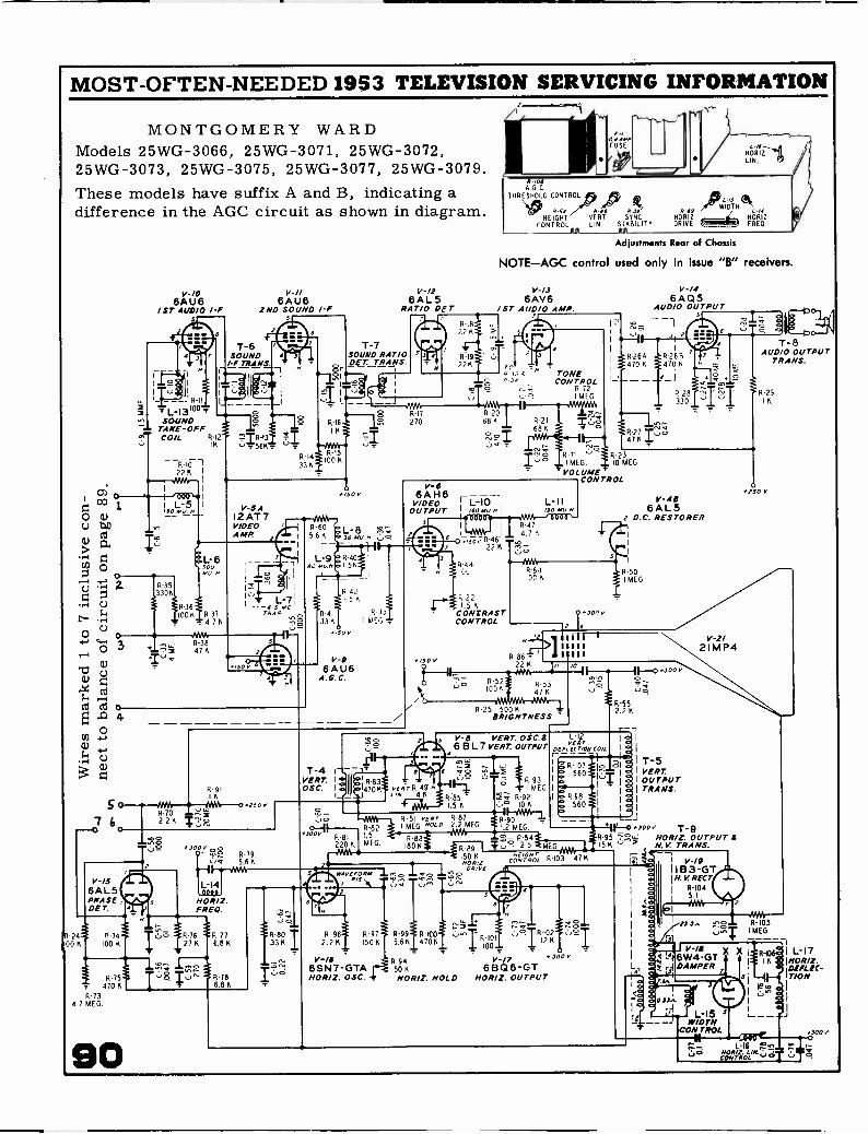
MOST -OFTEN -NEEDED 1953 TELEVISION SERVICING INFORMATION
MONTGOMERY WARDModels 25WG-3066, 25WG-3071, 25WG-3072,25WG-3073, 25WG-3075, 25WG-3077, 25WG-3079.These models have suffix A and B, indicating adifference in the AGC circuit as shown in diagram.
CA'
z 0D 1OU
O cl,Cd
D 2.
04-;
1-1
O
ca cd 0
O
R-24,00 K
O
3
4
6A 116/ST ALIO/0 b.'
1
L -13'°v;SOUND
TAKE -OFFCOIL R12
16
I22 6 1
MK 1
000I L-5160M,
S 0 AVA
7 68-702 20_
V -IS6AL5PHASE ,DET.
R-75470 6
R-734.7 MEG
90
.6-3847 K
V -I/6AU8
2ND SOUND /-F
V-5 A12AT7VIDEOAMP
MN 0 Teo
0 0os
2
sr -IS6AL5
RAT/0 DE r
1-7SOUND RATIO_DE2:211.42,/S.
01
un
R-60566
/50 V
L-8 'AV;36 MUM
so 56
R -S..,
I MEG
V-06AU6
A.G.C.
T-4VERT. I
OSC. 1
8.308AGC
THRESHOLD CONTROL )6)WIDTH,.44 i
HEIGHT VERT SYNC
CONTROL LIN. STABILITY
Adjustments Rear of Chassis
NOTE-AGC control used only in issue "B" receivers.
V-/.16AV6
/ sr AUDIO AMP.
TONECONTROL
R 721 MEG
R-71 R-23I MEG. 10 MEG
1. VOLUME'CONTROL
/00 Mt/
R-22
4-3001.5
CONTRASTCONTROL
2,er: I
R-86 11111
tU7
la
7- R-52
22 6 //
LnR-5347 K100K
R 25 500 6BRIGHTNESS
v -e VERT. OSC.S L-12
6 B L7 VERT. OUTPUT 74,4 Cm,4
7. 7vtar R-49
/AV 4 IS r- R-926. 10 6--0-14Wra
R 51 root R-87MEG,
R-90MEG.I NOLO 2.2 MEL, 1.2 MEG.
V -I46 AQ5
AUDIO OUTPUT
egriZIL(
V -AB6AL5
2 D.C. RESTORER
R-50I MEG
"000 `.3 ! 679I.--, 5.6 K
6,-,609,,,,,15.9"651170tw4:340 N.V. TRANS.OUTPUT9 sR -8I LS
1;07R2-554
MEGmiG
.
1
220 K MEG
WAVEFORM
OM6-4 6 6,
0.01VECDVZOrl. R 103 47 K
7 4c - --,1I
I IB3-GTI V-/9
IN.K RECT.5 Nit
K
.... m.o kra,L 114'. "A
1 RI04
HRIZ. 5.1
FREDA I NA
= '. 1
,S5 R 76 R-7127 6 6.8 K
R-80 I33 6 2.2 6
6-96 R 97 R-99111100`4 6150 K 5.66 4706
R-102
1 R100I12 K
- _Igo.'V -I6 R-94 V-/7
R-78 HORIZ. OSC. . NOR/Z. HOLD HOR Z OUTPUT68Q6-GT12. 6SN7-GTA 50 6
6.8 K
R.3 v
T-8AUDIO OUTPUT
TRANS.
6.291K
.250 V
173.3.. uNT RIDSMEG1.
V -I86W4-GTDAMPER
R106 I L-17K 1/101t/Z.
!If tr>ii/C-
13007

MOST -OFTEN -NEEDED 1953 TELEVISION SERVICING INFORMATION
otorolaThe circuit diagram on the next page, over, is exact for Chassis TS -292A and TS -324A.
All other chassis listed in the table below are similar and their main differences are ex-plained. Separate circuits of series filament connections, audio section, and conventionaltuner used in some chassis are shown separately. Alignment information applies to all sets.
Chassis Used in Models Tuner Tube How different from TS -292ATS -292A 21C1, 21C1B, 21F2, 21F2B,
21F3, 21F3B, 21K4, 21K4A,21K4B, 21K4W, 21K5, 21K5B,21K6, 21K7
Cascode 21FP4Use TS -292A Chassis shownin schematic diagram.
TS -292B 21T4AC, 21T4ACE, and alsoseveral models listed above.
Cascode 21FP4 C-74 changed to 10 mfd., alsoother minor part changes.
TS -324A(or -B)
21T4A, 21T4EA, 21T5A,21T5BA
Cascode 21MP4 Same as TS -292A except fordifferences shown in main schematic
TS -395A 17F13, 17F13B, 17K14,17K14A, 17K14B, 17K14W,17K15, 17K15B, 17K16,17T11, 17T12, 17T12B, -W
Conven-tional
17LP4 Audio circuit differs, see diagram.Filament transformer has 3 windings
TS -400A 17T11E Conven. 17LP4 Series filament, audio diff., see diagTS -401 17F12D, 17K13D, 17T9EF,
17T9F, 17T1ODConven-tional
17TP4 Audio circuit differs, see diagram.
TS -408A 17F13C, 17F13BC, 17K14C,17K14BC, 17K14WC, 17K15C,17K15BC, 17K16C, 17T11C,17T11EC, 17T12C, 17T12WC
Cascode 17LP4 Main difference in picture tube,otherwise same as TS -292A Chassisshown in schematic diagram.
TS -410A 17T13 Conven. 17HP4 See note under TS -400A.TS -501A 21T3 Cascode 21MP4 Same as TS-324A,but no tone control
I17 vOLTSGO CYCLES
SAFETYINTERLOCK
19
189
VI626X461 2580661
VI5 V12 v13 V8125N7GT 12817 6006W V2 V6
608 GANG
L26net.
VIB V10PICT TUBE 656761 65N7GT
V14
/\
IBC ONLTIGRAY 16 8
--17 7 2 / 8 5 4 3 4\--", I' 12 7 8
BUCK
2 3 80 120-,AW---
DO, TO Of A OFF -ON SWITCH R9090R9I
2
ION VOL 60611
2556 6C86 6086 6086 64L5 6(86
-=
0CD C,
®
r.
IP
VII V3 V4 V5 V9 VI
Above is the circuit of series wired tube filaments
00 00e 0 0 ED 8
cused in Chassis TS -400A and TS -410A.
At left is a drawing showing tube layoutof Chassis TS -292A and TS -324A. (Continued on the
next seven pages).

NI T
ON
I TT
-N
A
L241
1.
--"1
Con
vent
iona
l tun
er u
sed
in C
hass
isT
S -3
95A
, TS
-400
A, T
S -4
01, T
S -4
10A
4431
)01
DA
NN
430
3LN
I 044
.334
4344
3
'tor
44 O
NN
OW
N.
MO
NA
OR
IN. M
UN
N
mor
rs.0
0,61
rya
val.
434
4va
s P
oo, 4
13{4
,44
TO
CA
NN
N.T
444
43
AT
VS
I 414
34U
OP
ON
NP
UT
O 0
4 4.
PO
SIT
ON
I
µ--
--
sib
NO
V
Mot
orol
a
Wri
t: ,A
,F...
"7.7
=Ir
t
--P
fT
UN
ER
TT
-44
TE
LE
VIS
ION
CE
AB
SIS
TS
-292
A-0
0&
TS
-324
A-0
0
vta
1/2-
1111
.w
ee
/2-8
/111
...T
NIO
N
Aud
io c
ircu
it us
ed in
Cha
ssis
TS
-395
A,
TS
-400
A, T
S -4
01, a
nd T
S -4
10A
.
sits
o.>
'CO
Gtr 4r
o
4305 C5r
33
45U
M'
yeIe
.at
.
SM
IGT
WO
N 0
1;:4
sass
yW
OO
OU
TP
UT
LOC
AL
PA
3-
sueu
sem
iI R
OW
E
PO
WN
3
14.N
I 31
", J
14,7
i3T
hr-
1-1
_"
,.. f47
.

MOST -OFTEN -NEEDED 1953 TELEVISION SERVICING INFORMATION
J5
MOTOROLA 1953 Models. General Information and Production Changes.
AREA L23SELECTOR HORIZ VERT HORIZ HORIZ HORIZ BRIGHT- FOCUS VERT VERT
SWITCH HOLD HOLD CENT SIZE OSC. NESS LIN. SIZE
YOKE ADJUSTMENT!THUMBSCREW
RASTER CORRECTORMAGNETS
CENTERING ARMS
CENTERING DEVICE
DEFLECTION YOKE
ION TRAP
YOKE SADDLESCREWS TS -292A-02
TS -324A -02
PRODUCTION CHANGES
With the current line of TV chassis (TS -292, TS -324,TS -395 & TS -400), a new system of chassis coding has beenstarted. The first production chassis number carries thesuffix "A-00" (i.e., TS -292A-00, TS -395A-00). With thefirst minor revision, the suffix becomes "A-01", and witheach subsequent minor change "A-02", "A-03", etc. Thefirst major revision changes the suffix to "B-00" and, asbefore, each following minor change is labeled "B-01","B-02", etc.
ChassisCoding Change
TS -292A-01TS -324A -01TS -395A-01TS -400A-01
HORIZONTAL HOLD ADJUSTMENT
The HORIZONTAL HOLD control should have a syncrange of approximately 50°. If the control is too critical,adjust as follows:
1. Shunt the HORIZONTAL OSCILLATOR coil L-23 toground with a .25 mf 400V capacitor. This may be donewith the chassis in the cabinet by placing the capacitoracross the two -pin receptacle (J-5) located as shown in Fig-ure 2.
2. With the HORIZONTAL CENTERING control, move thepicture to the left so that the right edge of the raster can beseen, as viewed from the front of the set. Adjust the HOR-IZONTAL HOLD control for about 1/16" of sync pulse. (Thesync pulse appears as a darker gray bar at the right edge ofthe blanking pulse. The blanking pulse is the gray bar atat the right edge of the raster.)
3. Remove the .25 mf capacitor from across the HORI-ZONTAL OSCILLATOR coil.
4. Adjust the HORIZONTAL OSCILLATOR coil until thesame amount of sync pulse can be seen as was noted in step2.
FOCUS
The zero focus type of electrostatically focused tubeused in these chassis requires a fixed potential applied tothe focusing anode which is supplied through the focus con-trol potentiometer. This control, in effect, provides ameans of compensating for differences in gun structure be-tween tubes, but is far less critical in adjustment than wasthe focus control in the electromagnetically focused tubes.
TS -292A-03TS -324A-03
TS -292A-04TS -324A-04
TS -292B-00TS -324B-00
TS -292B-01TS -324B -01TS -408A-01TS -501B-00
TS -292B-02TS -408A-02TS -501B-01
TS -292B -03TS -408A-03TS -410A-02TS -501B-02
TS -408A -00
TS -410A-01
TS -501A-00
R-65, the sand coated 8700 ohm resistor onthe vertical linearity control, was replaced bytwo 2 -watt carbon resistors in series - R-65(4700) and R-93 (3900).
The centering device, E-2, is mounted on theyoke cover instead of being a separate unit.
R-94 (0.47 ohms) was put in series with theheaters of V-10, the 1st Audio Amp & PhaseDetector, to reduce heater -to-cathode leakage.
Increased high voltage by revising high voltagetransformer, T-11 (has issue "C" coding afterpart number). The following horizontal cir-cuit changes were also made to increase highvoltage: C-84 changed from 220 mmf to 100;R-81 changed from 120K to 100K, and R-84(470) omitted.
Filament transformer changed to auto trans-former type. This boosts the AC input, re-sulting in a raise in the high voltage applied tothe 2nd anode. Transformer has new partnumber.
Revised 3rd IF transformer. Differs from theoriginal only in that L-13 is mounted on thetransformer and becomes a part of the T-6assembly. Transformer has new part num-ber.
C-74 changed from 20 mf to 10 mf to elimi-nate vertical flutter due to line voltage vari-ations.
C-75 (5000 mmf) omitted and a 100K 1 -wattresistor added between the focus control armand the blue lead to the picture tube focusinganode. This adds protection to the focus con-trol potentiometer.
Original production incorporated the changesof the TS -292A-03.
C-61 changed from .005 to .01 mf and C-IO2(. 02 mf) added to improve tone.
Original production incorporated changes ofTS -324A-04.
93

MOST -OFTEN -NEEDED 1953 TELEVISION SERVICING INFORMATION
MOTOROLA 1953 Models.
ALIGNMENTSince the power cord circuit is broken by the interlock
when the cabinet back is removed, it will be necessary toobtain an extra power cord with the female interlock recep-tacle in order to make a power connection to the receiver.Order Motorola Part No. 30B470756.
It is important that an isolation transformer be used be-tween the receiver and the line when any test equipment isattached to the chassis. Due to the full wave rectifier,there is always a potential difference between the chassisand earth, and it is very important that an isolation trans-former be used when servicing the receiver. This precau-tion is especially important if grounded test equipment isused. NEVER GROUND THE RECEIVER CHASSIS DURINGTESTING OPERATIONS OR INSTALLATION UNLESS ANISOLATION TRANSFORMER IS USED.
ORDER OF ALIGNMENT
A complete receiver alignment can be most convenientlyperformed in the following order:
1. IF & Mixer Transformers
2. Oscillator & RF Sections
3. 4.5 Mc Trap
4. Audio Take -Off, Interstage Coil, & Ratio Detector
IF AMPLIFIER ALIGNMENT
Equipment Required:
IF Sweep Generator meeting the following requirements:
1. 18 to 30 mc, approximately 12 mc sweep width.
2. Output constant and adjustable to at least 0.1 volt max-imum.
3. Accurately calibrated, adjustable markers
ON -OFFVOLUME
CONTRAST
TONE
94
TOP VIEW OF CHASSIS
FINE TUNING
Alignment Information.
Cathode Ray Oscilloscope - Preferably one with a calibratedattenuator.
AM Signal Generator - Adjustable Output
NOTE: If there is no built-in marker in the sweep genera-tor, loosely couple the output of an accurately calibrated AMsignal generator to the IF strip. At all times, keep themarker output low enough to prevent the marker from dis-torting the response curve.
If a wide band scope is used, the marker will be moredistinct if a capacitor of 100 to 1000 mmf is placed acrossthe scope input. Use the smallest size possible, since toolarge a value will affect the shape of the curve.
Procedure:
1. Remove the horizontal output tube, V-15, to eliminateRF interference in the oscilloscope.
2. By means of an external battery, apply a negative 3 voltbias, through a decoupling resistor of 4'7K ohms, to the AGCline, which is connected to pin 1 of the test receptacle (J-4).See Figure 4 for receptacle location.
3. Through a 47K ohm decoupling resistor, connect the os-cilloscope across the video detector load resistor R-27(4700) which may be reached from pin 3 of test receptacle(J-4). If a stronger output is required, connect the scopebetween picture tube cathode (yellow lead) and chassis. Thecurve seen at this position will be the reverse of the polarityshown in Figures 5 & 6.
4. Turn Area Selector Switch (S-2) to LOCAL position.
5. Using leads as short as possible, connect the sweepgenerator, through a 1000 mmf capacitor, to jack J-3, feed-ing into the grid of 1st IF tube V-3. See Figure 4. (Do notuse the loose or "spraying" method of coupling.) Set thegenerator center frequency to 24.6 mc, with a sweep de-viation of 10 mc.
CHANNEL SELECTOR
RECEPTACLE
if®T7 PRI-1 e-
Li'dL21 -
LI7-
VI2
T5
J3
T3 PRI
LII TRAP T41219 MCI
L12 TRAP121S MCI
16L20
J4
TONE
ON -OFFVOLUME
CONTRAST
BOTTOM VIEW OF CHASSIS
VI6BZ7
V2
J2
6U8
40.3
055
el IA R45
Ti SEC
R27 4 LI7
C42 CRT
TEL
RNIGHTME SS
FIGURE 4, ALIGNMENT
ADJUSTMENT LOCATIONS

MOST -OFTEN -NEEDED 1953 TELEVISION SERVICING INFORMATION
MOTOROLA 1953 Models.
6. Detune the oscillator by placing a shunt wire across theoscillator inductance (from position 2 to position 13 on thebandswitch).
7. Tune the 1st IF transformer, T-4, to place a 26.6 mcmarker on the high side of the response curve 50% downfrom maximum response. At the same time, adjust T-6 toprovide a flat top or symmetrical response curve. Tuningthe two transformers together will make for proper markerplacement and "jacking" action of T-6. See Figure 5.
CAUTION: A. Keep the signal input low, to prevent flatten-ing the top of the curve, due to limiting inthe video or scope amplifiers.
B. The dressing of plate and grid componentsin the IF circuit affects tuning. Do not moveindiscriminately.
C. The resonance point of the IF coils and thetrap will be found at two settings of the core.The correct setting is the one with the coreat the outer end of the winding.
8. Tune the 2nd IF transformer, T-5, to place a 22.8 mcmarker on the low side of the response curve 50% downfrom maximum response. At the same time, adjust T-6 toprovide a flat top or symmetrical response curve as in step6. See Figure 5.
9. Tune trap L-12 for maximum attenuation on the curveat 21.9 mc, as in Figure 5. Make sure the core is towardthe outside of the trap winding (toward the top).
10. Tune trap L-11 for maximum attenuation on the curveat 27.9 mc, as in Figure 5. Make sure the core is towardthe outside of the trap winding (toward the top).
11. Move the generator and capacitor to jack J-2. See Fig-ure 7. Short out R-11 (4700) located between the jack andthe mixer grid.
12. Turn the primary and secondary of the mixer IF trans-former, T-3 so that the bandpass appears as in Figure 6.
NOTE: This is a double -tuned circuit. Make sure theslugs are tuned away from the center of the coil.NOTE: It is important that the 21.9 mc and 27.9 car-riers are attenuated as much as shown in Figure 6. Tocalculate, connect an AM generator to the mixer gridand a VTVM across the detector load resistor. Takevoltage readings at 21.9 mc, 24.6 mc, and 27.9 mc anddivide per following formula: With proper attenuation -
and
219
voltage reading at 24.6 between 50 and 80voltage reading at 21.9
voltage reading at 24. 6 = at least 100voltage reading at 27.9
27.9
FIGURE 5.IF RESPONSE CURVE
21.9
T10% VALLEYPERMISSIBLE
27'.9
FIGURE 6.MIXER RESPONSE CURVE
Alignment Information, continued.BANDWIDTH
The IF bandwidth may be checked with an AM signalgenerator, if desired. Connect the generator, through a1000 mmf capacitor, to jack J-2 in the grid circuit of themixer tube, V -2B, and an electronic voltmeter across thevideo detector load resistor R-27 (4700). Short out R-11(4700), set the generator frequency to 24. 6 mc, and adjustits output for a 1 volt reading on the meter. Double theoutput of the generator. Tune to both sides of 24.6 mc andnote the frequencies at which the meter again reads 1 volt.These frequencies indicate the 6 db bandwidth points andshould be 22.9 mc and 26.4 mc. By watching the meterwhile tuning slowly through the band, any serious peaks orholes in the response curve can be detected.
REGENERATION
After the mixer and IF stages have been aligned, a checkfor regeneration in the IF strip should be made as follows:
1. Remove the battery bias and observe the response curveon the scope as taken between the picture tube cathode (yel-low lead) and chassis. The bandwidth may change with thebias removed, but should not change more than 0.2 mc. Ifthe bandwidth does change more than 0.2 mc, check thecathode resistors or change tubes.
2. Set the contrast control at maximum gain (fully clock-wise).
3. Decrease the generator input until the output signal showsa marked decrease.
4. Any regeneration present will be indicated by sharppeaks on the overall response curve.
NOTE: The oscillator should be detuned, as described above,during this procedure
MIXER SENSITIVITY MEASUREMENTS
1. Connect an AM signal generator, set at 24.6 mc, mod-ulated 30% with 400 cycles, to jack J-2 through a capaci-tor of 1000 mmf. Short out R -I I (4700),
2. Remove the battery bias from the AGC line.
C98 L20
L2E
LIB
ANTSECT.
LIC
L7C
L70
L7E
RFSECT
OSCSECT
FINETUNING
L9E
L9D
L2C L2B C97 L2A
VI6B27
L9C L98 C99 L9A L8 RI I
LIA
LIF
L7B
CI5
FIGURE 7. ANTENNA, RF & OSC LOCATIONS III 5

MOST -OFTEN -NEEDED 1953 TELEVISION SERVICING INFORMATIONMOTOROLA 1953 Models.
3. Remove shunt wire from oscillator.
4. Connect the oscilloscope to the cathode of the picturetube. Turn contrast control to maximum.
5. Turn the station selector switch to the low channel po-sition which gives the Lowest noise reading on the meter.
6. The signal required to produce 20 volts peak -to -peak onthe scope should be less than 100 microvolts.
NOTE: To calibrate scope, connect it across the 6.3 voltfilament supply. The peak -to -peak amplitude on the screenwill then be approximately 18V (6.3 x 2.8).
IF SENSITIVITY MEASUREMENT
1. Move generator to jack J-3 feeding into the grid of the1st IF 'tube (V-3, 6CB6).
2. Connect the electronic voltmeter, through a lOOK de -coupling resistor, across the video detector load resistor
-27 (4700).
3. The signal required to produce 1 volt on the voltmetershould be less than 750 microvolts.
ANTENNA, RF & OSCILLATOR ALIGNMENTFREQUENCY CHART
Chan Frequency Picture
2 54-60 55.253 60-66 61.254 66-72 67.255 76-82 77.256 82-88 83.257 174-180 175.258 180-186 181.259 186-192 187.25
10 192-198 193.2511 198-204 199.2512 204-210 205.2513 210-216 211.25
Equipment Required:
Alignment Information, continued.AM Signal Generator having:
I. Frequency range 40-220 mc2. Accurate frequency and attenuator calibration3. 400 cycle, AM modulation
Oscilloscope: Preferably one with a calibrated input atten-uator.
ANTENNA & RF ALIGNMENT PROCEDURE
1. Remove the horizontal output tube V-15, to eliminate RFinterference in the oscilloscope. Connect a 5000 ohm 10watt resistor between the red B.- bus and chassis to nor-malize the bus voltages.
2. Detune the oscillator by placing a shunt wire across theoscillator inductance (from position 2 to position 13 on thebandswitch).
3. Remove th,nett the sweepthe leads fromternal markers
antenna lead-in from the chassis, and con -generator to the antenna receptacle. Keepthe generator to the socket short. Use in -or an accurately calibrated external signal
generator for markers.
4. Connect the'oscilloscope, through a decoupling resistorof 47K ohms to jack J-2 in the grid circuit of the mixer tubeV-25. See Figure 7.
5. Ground the AGC lead to the mixer and RF stages bymoving the area selector switch to the suburban or fringe
Sound
59.7565.7571.75
Oscillator
81.6587.6593.65
position.
6. Refer to Figure 7 for the location of the trimmers andcoils. The chart listed above gives the picture and soundcarrier frequencies.
81.75 103.65 7. The antenna coils are tuned to the video carrier side87.75 109.65 and the RF coils are tuned to the sound carrier side. Fig-
179.75 201.65 ure 8 shows the shape of the curve which should appear on185.75 207.65 the oscilloscope.191.75 213.65197.75 219.65 8. Set the screw in channel 13 RF coil, L-6, midway in203.75 225.65 the coil.209.75 231.65215.75 237.65 9. Turn the station selector switch to channel 8. Set the
Sweep generator having:I. Frequency range 40-220 mc2. 10 mc sweep width3. Output constant and adjustable4. Adjustable markers (markers should be calibrated
occasionally by checking against an accurate signalgenerator).
96
207.
center frequency of the sweep generator to the center fre-quency of channel 8 (183 mc).
10. Adjust ceramic trimmer, C-11, so that the video andsound markers appear on the response curve within thelimits shown in Figure 8.
NOTE: The two impedance matching transformers, T-1 andT-2 must be a minimum of 1/4" apart or a "suck -out" willbe noted on channel 12 or 13.
#
CHANNELS 2 THRU 6 CHANNELSIDEAL WAVE FORM (PERMISSIBLE
NOMINAL VARIATIONS FROM MARKERPOSITIONS MAY BE EXPECTED.THESE SHOULD NOT EXCEED 516EXCEPT AS SHOWN.
0-10%
CHANNEL 2 AFTERTRAP SETTING
FIGURE 8. RF RESPONSE CURVE
2 THRU 6VARIATIONS)
t%
T-5%
CHANNELS 7 THRU 13(PERMISSIBLE VARIATIONS)

MOST -OFTEN -NEEDED 1953 TELEVISION SERVICING INFORMATION
MOTOROLA 1953 Models.
11. Move the station selector switch to channel 13, and setthe generator to the center frequency of the channel (211 mc).Adjust the screw in coil L-6 for the proper response onchannel 13 (see Figure 8).
12. Recheck channel 8 for proper response. Readjust trim-mer C-11, if necessary.
13, Check channels 13 through 7 and compare the curvesin Figure 8, It is important that the antenna primary coil(L -1F) is not changed. The wave shapes maybe narrowedby reducing the inductance in the coil but the signal-to-noiseratio will be seriously affected.
NOTE: If the response is checked with the cover on the tun-er, the picture marker will move up the left side of thecurve a short distance, but the markers should be withintolerance.
14. Move the station selector switch to channel 6 and setthe generator to the center frequency of the channel (85 mc).
15. Compress or spread the channel 6 antenna coil, L -2E,and RF coil, L -7E, to obtain the proper response. SeeFigure 7 for coil locations and Figure 8 for response curve.The antenna coil affects the video carrier and the RF coilaffects the sound carrier.
NOTE: The tilt on the low channels, particularly channels5 and 6, can be controlled by adjusting the antenna match-ing coil, L -1C.
16. Align channels 5 through 2, in that order, in the samemanner as channel 6. As the coils are in series, the properphasing of channel 6 will simplify the alignment of the lowerchannels. On one of the lower channels, check that thesame waveform is obtained with the sweeper head reirersed.Waveform deviations indicate a faulty coil.
CAUTION: Make certain the bandswitch is on the cor-rect channel before checking bandpass.
17. With channel selector on channel 2, adjust the two trapsformed by C-97 & C-99 across L -2A and L -7A, respec-tively. Proceed as follows:
a. Move the oscilloscope to thi picture tube cathode(yellow lead), and connect an AM generator, set at 104.7mc and modulated 30%, to the antenna input.
b. With the contrast control at maximum gain (fullyclockwise), adjust the fine tuning control for maximum amp-litude on scope.
c. Adjust coils L -2A and L -7A (by spreading or com-pressing) for minimum amplitude on scope. These coilscan be reached with the tuner cover on through two holes inthe cover.
d. To check rejection of 104.7 mc, set the generatoroutput high enough so that a 20 volt peak -to -peak waN e ap-pears on the scope. Note the generator output reading.
e. Tune the generator to 57 mc, tune fine tuning trim-mer for ;maximum amplitude on scope, and adjust the gen-erator output to give a 20 volt peak -to -peak wave on thescope. Again note the generator output reading.
f. Using figures noted in steps (d) and (e), divide usingformula shown in step (g).
g. For proper rejection;generator output at 104. 7 mc at least 6000generator output at 57 mc
h. If voltage ratio in (g) is less than 6000, repeat steps(a) through (g).
Alignment Information, continued.
OSCILLATOR ADJUSTMENT
1. Remove shunt wire from oscillator inductance.
2, Connect the oscilloscope, through a 47K ohm resistor,across the video detector load resistor R-27 (4700). Re-store AGC to the mixer and RF tubes by placing the AreaSelector Switch into LOCAL position.
3. Refer to Figure 7 for the locations of the trimmers andcoils. The sound carrier frequencies may be obtained fromthe preceding chart.
4. Set fine tuning trimmer for mid -capacity,
5. Turn station selector switch to channel 10.
6. Set the sweep generator to channel 10, with a centerfrequency of 195 mc. Keep the output low enough to showno evidence of limiting in the overall response curve.NOTE: The curve should be substantially that of the mixeras in Figure 6. Any consistent tilting of the response curveindicates that the mixer and IF stages are not properlyaligned.
7. Introduce a marker corresponding to the sound carrierof channel 10 (197. 75 mc). Keep marker signal as low aspossible.
8, Adjust the oscillator trimmer C-15 to place the soundmarker slightly higher in frequency than the 21.9 mc trapdip. This allowance must be made for the shift caused bythe bottom shield being off. When the shield is replaced,the sound marker will move down into the trap dip. Thepicture marker will then be approximately one-half downfrom the base line on the opposite side of the curve.
9. Check channels 7 through 13, noting whether the soundmarker falls just above the trap dip, with the fine tuningtrimmer at approximately mid -capacity.
10. If more than a 30 degree change in the fine tuning trim-mer was needed in step 9, adjust the channel 13 oscillatorcoil L-8 by spreading or compressing the turns. If L-8 isadjusted, it may be necessary to readjust trimmer C-15 onchannel 10. Coil L-8 has more effect on channels 10 to 13than on channels 7 to 9.
11. Turn the station selector switch to channel 6, and setthe sweep generator center frequency to 85 mc.
12. Set the fine tuning trimmer to 15° off mid -capacity(toward less capacity) as in Figure 9.
NOTE: It is important that the rotor be set as nearly aspossible to the drawing. Otherwise, the fine tuning trim-mer may not have sufficient range to suitably tune a weaksignal.
ROTOR
MID CAPACITY
FIGURE 9. FINE TUNING TRIMMER SETTING 97

13. Introduce a marker corresponding to the sound carrierof channel 6 (87. 75 mc).
14. Compress or spread the channel 6 oscillator coil L -9Euntil the sound marker is placed just above the dip in the21.9 mc trap.
15. Align channels 5 through 2, in that order, in the samemanner as channel 6, so that the sound marker falls justabove the trap dip, with the fine tuning trimmer within 15degrees of initial setting in step 12.
NOTE: Since the oscillator coils are in series, it is neces-sary to adjust the high channel coils first, before proceed-ing to a lower channel.
OVERALL SENSITIVITY MEASUREMENTS
An overall measurement of sensitivity is made as fol-lows:
Connect an AM signal generator to the antenna recep-tacle on the receiver chassis, matching the generator to thereceiver with a resistor network. In the case of a genera-tor with a 50 ohm output impedance, insert a 100 ohm re-sistor in series with the output terminal, and a 150 ohm re-sistor in series with the ground terminal.
2. From the cathode of the picture tube (yellow lead) tochassis, connect a calibrated oscilloscope. NOTE: To cal-ibrate scope, connect it across the 6. 3 volt filament sup-ply. The peak -to -peak amplitude on the screen will then beapproximately 18V (6.3 x 2.8).
3. Set the contrast control for maximum sensitivity (fullyclockwise).
4. Set the signal generator for 30% modulation at 400cycles, tune it to the mid -carrier frequency of the channelbeing checked, and rotate the fine tuning trimmer for max-imum output.
5. The generator signal necessary to produce 20 voltspeak -to -peak on the scope should be less than:
a) 20 microvolts for channels 2 through 6b) 30 microvolts for channels 7 through 13
4.5 MC TRAP ALIGNMENT
Equipment Required:
AM Signal Generator: Accurately calibrated at 4.5 mcAdjustable output
DC Meter: Low range electronic voltmeter
Procedure:
1. Connect the signal generator to pin 3 of test receptacle,J-4.
2. Set CONTRAST control for maximum gain (fully clock-wise).
3. Connect the voltmeter and a germanium crystal detec-tor, as shown in Figure 10, between the cathode of the pic-ture tube (yellow lead) and chassis.
4. With the signal generator accurately set at 4.5 Inc andmaximum output, adjust trap L-17 for minimum reading onthe lowest voltage scale of the meter.
98
MOST -OFTEN -NEEDED 1953 TELEVISION SERVICING INFORMATION
MOTOROLA 1953 Models. Alignment Information, continued.AUDIO TAKE -OFF, INTERSTAGE COIL,& RATIO DETECTOR
Refer to Figure 4 for location of adjustments.1. If possible, it is desirable to align the audio sectionfrom an actual station signal, since the 4.5 mc alignmentfrequency will be exact. To permit operation below thelimiting level of the audio driver tube, for sharp alignment,the fine tuning trimmer should be turned off the stationslightly so that there is between 6 and 8V as measured fromone side of C-54 and chassis.
2. If a signal generator is used, tune it accurately to 4.5mc, and adjust the output to approximately 5,000 micro-volts. Connect the high side of the signal generator to pin 3of the test receptacle and the low side to chassis. The fol-lowing steps apply whether the station signal or signal gen-erator is used.
3. From either side of electrolytic capacitor C-54 (10 mf)through a 10K ohm decoupling resistor, connect an elec-tronic voltmeter to chassis.
4. Tune audio take -off coil L-20 for maximum reading onmeter.
5. Tune inter stage coil L -21 for maximum reading onmeter.
NOTE: As adjustments are brought to resonance, it is ad-visable to reduce the signal generator output to preventoverloading.
6. Tune ratio detector (T-7) primary (top core) for maxi-mum reading on meter.
DC PROBE 220K 100MMF
220K1N34
FIGURE 10. ELECTRONIC VOLTMETER CONNECTIONS
NOTE: Both the primary and secondary of the ratio detec-tor transformer have two tuning points. Only one, with thecores at the outer end of the windings, is the proper point.
7. Move the meter and decoupling resistor to the junctionof R-45 (33K) and C-55 (1000 mmf).
8, Adjust T-7 secondary (bottom core) for zero responseon the lowest scale of the meter. Be sure the slug is tunedto the outside of the winding (toward the top). This corres-ponds to the cross -over point of the FM detector curve. Ifdesired, the symmetry of the curve may be checked by tun-ing the, signal generator 25 kc above and below 4. 5 mc andnoting the plus and minus voltage produced, reversing themeter connections, as necessary. For proper balance ofthe ratio detector system, the voltages in each directionshould be approximately equal. If not, check the tuning ofL-20, L-21, and both the primary and secondary of T-7,the ratio detector transformer. If necessary, replace theratio detector tube V-9,
9. Repeat steps 4 through 8 for maximum accuracy.

MOST -OFTEN -NEEDED 1953 TELEVISION SERVICING INFORMATION
OLYMPIC RADIO & TELEVISION INC.
OLYMPIC TELEVISION RECEIVERS, CHASSIS TYPES TK AND TLThese models are nineteen tube direct viowing tele-
vision receivers differing only in type of cabinet, sizeof speaker and their use in conjunction with a radioreceiver and automatic record changer in the combina-tion models. A 17" electrostatically focused rectangulartube (I7HP4) is used in the 17" models and a 20"electrostatically focused rectangular tube (20HP4A) isused in the 20" models.
TO REMOVE CHASSIS FROM CABINET
Remove: (I)
(2)
(3)
(4)
(5)
(6)
Line cord from power outletMasonite back.
Antenna Lead-in from terminal posts.Speaker plug from rear of chassis.
Knobs from front of cabinet.
Four mounting screws and washersfrom bottom of cabinet.
In 20" models the picture tube is mounted as a partof the cabinet and therefor the CR tube socket, theyoke plug and the high voltage connector will have tobe disconnected before removing the chassis.
In sliding chassis out of cabinet, be careful that thekinescope tube does not strike against speaker or anyother obstruction.
Before proceding it will be necessary to use an extraline (or "cheater-) cord to supply AC current to thechassis as the set's line cord is attached to the masoniteback of the cabinet.
PICTURECONT ROL
OFF -ON SWITCHAND SOUNDVOLUME CONTROL
_N
SELECTORSWITCH
FINE TUNINGCONTROL
Figure 6.
60 MFD/450 V60 MFD/450
6W6/GT
ELECTCOND
6W4/GT
MODELS20T46 20053
17T40 17K41 20T47 20D4917T48 17K42 20C45 20K4317C44 17K50 20052 20K51
IF ALIGNMENT PROCEDUREAfter removing chassis from cabinet re -connect power
speaker plugs, and Kinescope and yoke connections.
If a local station is not operating on Channel 9 setthe tuner to this channel, turn on power switch andproceed as follows: (If 9 is a local station, use Channel8 or 10.)
ACCOMPANYING SOUND TRAP
Insert a 100,000 ohm 1/2 watt resistor in series withthe "Hot Lead" of the electronic voltmeter and con-nect to the junction of L7 and L8. Meter switch shouldbe set to the lowest negative scale. Ground lead ofmeter should be connected to chassis.
Remove the shield of the RF Oscillator and Mixertube (V2) from ground clips and connect hot lead of theRF Signal Generator to it. This will couple generatoroutput to mixer plate.
Set the generator frequency accurately to 21.75MC, and adjust (L6) sound trap (See Fig. 6 Tube andTrimmer Layout) for minimum reading on voltmeter.
SHIELD
KINESCOPE SECONDANODE HIGH VOLTAGE VERTCONNECTOR OSC.
II
RECTANGULARKINESCOPE TUBE17HP4 OR 20HP4A
VIS
L 301
C302
C303
LI7HORIZONTAL
PHASE
60 MFD/200 V125 MFD/25 V
SHIELDS TEST POINTC304
12 CHANNEL R.F. TUNER(PART Ni CL -2755-I)
L2, UNDERSIDE OFCHASSIS 45 MC
47 VS
®p ®7L3 L4
POWER
TRANSFORMER
6SN7/GT
6SN7/GT
LII 45e L9 45 MGCAVII
Z:7V 10
SPEAKERCABLE
L19 WIDTH
LINE CORDINTERLOCK'MOUNTED TOMASONITECABINET BACK
ION TRAP(BEAM BENDER)
CENTERINGMAGNET
L16 HORIZONTALFREQUENCY
L6,ACC. SOUND TRAPUNDERSIDE OF CHASSIS
Alignment continued on page 102.
L5,PIX IF ANTENNA BINDING POST
99

MOST -OFTEN -NEEDED 19S3 TELEVISION SERVICING INFORMATION I
2.NTENNA POSTS
O.xiiFCTIL CA. 5- FLO
OUL!NE OF 'ARV' :ONTA.NNGTELVE :IA, SETS OE F.50 E!COLS EAC-
S*A-150,._0 OR
nsTo,N,
304.S-3Nuf
GBK7-,6BQ7
2 21OLL
OfC 3013.9)44
R.F. ANPL,E.E4 000`
V2R.F. CSC. 4 CONVERTER
sN (1.0
F
G
Co. 4CL
12 C-ANNEL R. F. TUNER(PART No. CL- 2755-9
For alignment instructionsee pages 99 and 102.
ON- OFF SW TOMON SOJND VOLUME
INTERLOCKCONTROL
SOCKEToN LLA5041.re
CAONET 505*
PLUG ONCAASSIS
100
POWERTRANSFORMER
RED/BLACK
01/0051.
KED
cuow
YELLOW
GREEN
GREEN
BROWN!
o BROWN
1K 2 -'OA"
L30125.1.c. 2C L.WF
5U4GV1E5
RECTIFIER
4.5 V.5.0A.
AG C.
.10E0 IF
11 +145 V.
OLYMPIC TK 17 *TM CHASSIS17" TK MODELS : 17140, 17K41,17K42,17c44, 17148 AHD 171(5020" TL MODELS: 20K43,20C45,20T46,20T47,20D49,20K51,20052 AND5 MECO 053
BOUND I.F.
IJOTE5:I. ALL RESISTORS 0020.% TOLERANCE, Y2 WATT UNLESS
OTHERWISE SPECIFIED.Z. ALL MICA AND CERAMIC CONDENSERS }20% TOLERANCE
UNLESS OTHERWISE SPECIFIED.3. ALL VOLTAGES MEASURED BETWEEN 0011./TS ,14DIEATED
AND CHASSIS, 0511.00 414 SLECTRCtIle. VOLTMETER.ALL VOLTAGE READINGS 213 %,.EASUREO WITH ANINPUT VOLTAGE OF .17 VOLTS, 60 CYCLES, A.C. 10THINCOMING SIGNAL. AND WITH CONTRAST CONTROL SETTO PRODUCE 50 VOLTS PEAK TO PEAK AT 5154050000 .
4. ELECTROLYTIC CONDENSERS CO9 lk C30 ARE IN CAN ® C'2 &C41ARE IN CAN O. ALL OTHERS ARE TABULAR TYPE.
5. 0.4 CLIA3313 DEARING Set AL : R 44 AA/OMITTED, AND TERMINAL No l OE 44T/CAL INTEGRATORNITLNOEN. NAT CONNECTED TO PIN No. 5 V 12. 543WAS CONNECTED TO GROLND NSTEAD OF R44, C33WAS
C14_ROLL MT
ReA/WV!,te ',Rte.
m1FILAMENTS
T131.A /0/1.. to Trace,.
11.
O X
oy6.3 V.1.0 A. oy
FLYERC NONE
C49 (-2) 50C
GOOFS - AR rAF0/430V./45500..iles
435
6CB6 L323. . 6C 136 L415.y'r Fix ;.F.V8 PIE IF
I.' PIE LF. TRANSFORMER 5" PIE I.F. TRANSFOR%
R17io AA
SIC',(
CI7o4004/4
PIS X ,112.1f. R18 4191a7I1 330A I 0,9,_ A711
X;4.3V2;
+300 V.
+300 V.
R58100E2L
051.05400 V.
50 PC CL
610015014TAL0005 CONTROL
R59100 An
NFO/4C30,411-59
C52
CI8
4203300
SYNC
C33s.Nsw.3 .o.-R37
47 470Kfl
R3622o Kfl.
1053
IF*
= C54.00W000v.
65N7/GTV14
HORIZONTAL A.F. C.& OSCILLATOR
R60560Ka}I.%
RGI5200a;10.2.
R6215050 R64to% ..catio%
563150 KIL
L16HORIZONTALFREOJENCV
330)A*
5053.3 HE310,1/.

MOST -OFTEN -NEEDED 1953 TELEVISION SERVICING INFORMATION
C347.4115
21
1000E4
6A U6V3
SOUND 1 F
R247 KA
L245MC
L IL.aM 6A L5
DISCRIMINATOR V 4TRANSFORMER DISCRIMINATOR
R3I Ka
12000to%
G.
22 CO.
R4 CE.
3.106...7.0v2/coo v.
6CB6V9
34 FIX I.E.
R21 "'"1-4,20.7
Ile%
1 100
C195.011.06
C 2Cove
'45 V.
UuD
2.3.25NC
L5 L 6 vtoPX I F ACC SCION° TRAP-1 !DEC DrECT, A GC.
+ 300V.
6BA6
15iell.)._
C24/nos/
.
000.
so,
1723 026Si000.
1441.01.10 4.11
IIC25/voov.
:WHO POT)
160
CaVao o V.
VOLUMECONTROL
6AV6V5
AUDIO AMPLIFIER
C9.z.i/Evav
6W6/GTV6
AU010 OUTPUTAUDIO
oOTUT SPEAKERTRomOsORIIRR
0700 ,,oI/LOORto
R10C11
50MiX /3500.
$21<cilio /43
II.04/4F4Y
:01. OK lea
® C12012=
60 000/2000I e,
-"A"-84. +300 V.3900
145 V.
LW.
(WHITE 00.01714 DA TUB 17" MODELS
RECTANGULARCOIL WOUND1,E0L,AD RES 5,00
OR' --.- TUBE MODELS
C27 V11 4.5mC TRAP cm1/400V.
20 H P4 AV19
T'u'TBE 2.3/10- NT'S
1/4000.
"VIDEO AMPLIFIER 1.1c4111-', . t 7
L11
YELLOWIC NESCORE
028vEG
C28
s,DocAv; z zorvi
R276,800 0. 1,500 fa
CONTRASTcotzTROL
Lt3 020
2006)'Aa (GREEN DST)
+300 V.
1As y
14cow/.
6SN7/G7V12
SYNC SEPARATOR 4 CLIPPER
R.5911464.0
PRINTED CIRCUIT(RI K TA 402-002A
VERTICALINTEGRATING NETWORK
C37
I
I .0.72i400v. eN
R42 R43 Rma 1 oKa I C38 it
. 'me&I .0osic.v. rR40 tw.
I R4C36
1
C39 Cr'
400 Y..005rot ,
44.- R44L _____ _____, 222006- 5,00o1Lt wr. ...:. ,o%
450
466geravoa
LI7
RIZONTALPHASE
C 58
viA00,/Rm. FINR0)
R67180 KIL±10%
RG1333K fa
.002 LOOK
0.N. 0,,,ROR,C2,0 *CG7.ox
NoI.01+TL011)1 CONTROL
GB Q 6/G TV15
HORIZONTAL OUTPUT
R714702
..zotz3
470 47000
RG9SOoca.
+300V.
R72loon
33004 PULSeDO NOT MEASURE
C6205/
22K11.t107:,
C6314.2S/sooT
+300V.
SY.
12E3H7vERT/CAL BLOCKING V13Os(,LLATOQ TRANSFORMER VERTICAL OSCILLATOR El, OUT PUT
ELLori
R4822000
C40
5.0047/6000.*1%
(OIL r.0 LAED)
MEG fl
449t.Se6.6
VERTICALIACAO CONTROL
y SHIELD
LOT
C41
/250. -o
SKILVERTICALL.EARITYCONTROL
I 13 3/G TV1G
HIGH VOLTAGERECTIFIER
PLATE CLIP
(PEST NA ,R2711)moR ZoNTAL OUTPUT
71 Cm VOLTAGETRAM STORTARR
to
500 04.
BRIGHTNESSCONTROL
43433
vERTICAL OUTPUTTRANSA0RvER
va,Low
1-9-1® 1+550V. 5 KV.
BLUE Wm TOANY OF THE RuLLOMIN0FOR Plans FCC US
B+ 300V.OR
8+ 550 V.
B- CHASSIS
VERTICALISLANKINIK
rc 444'4 02/4000.
.25/400VC42 %RAM
CR51
45SMOG('
1- 1014 I 452IC 4. IL
z,smEc.rt
453470 vv.
CALHEIGHT
_O rTROL
+ 300V.
6W4/GTV17
DAMPER
ION VOLTAGE
RS4L0001,-1,4
YOKEJERT.CAL DEFLECTION
12.141 C46- 50M F0/3500
+550V. +300V.TO K1NE5LoPE
15 KV.
REG
1- 550V
Y Y
Cv4
1/voo
+300
YOKEHORIZONTAL (.;Ef LECTION COIL
2 7
R 740,7000
C165
3.A.,v i 0,0%(2Kv)
101
6056 L12

MOST -OFTEN -NEEDED 1953 TELEVISION SERVICING INFORMATION
OLYMPIC Television ChassisPIX IF COIL ADJUSTMENT
Adjust the following slugs for maximum output at fre-quencies and sequence indicated with meter and gen-erator connected as above:
L301 25.5 MC
L3 23.25 MC
L4 25.25 MC
L5 23.25 MC
If oscillation occurs during alignment, temporarilyraise frequency of L3 by turning screw counter -clockwiseuntil screw projects approximately 3/4".
After properly adjusting L301, L4 and L5 reset L3to proper frequency. Oscillation is evidenced by highreading on voltmeter (-5v to -20v) with signal gen-erator OFF and no signal coming in through the an-tenna terminals.
Disconnect RF signal generator leads, connect hotlead of sweep generator through a 330 uuf condenserto test point on tuner and ground lead to chassis.
Connect vertical input terminal of oscilloscope tojunction of peaking coils L7 and L8 and connect groundlead of scope to chassis.
Connect I.5v flashlight battery with positive terminalto chassis and negative terminal to junction of R26 andC25. This point is origin of AGC bigs voltage. Settuner to Channel 9 unless local station is operating onthis frequency, in which case an adjacent channel shouldbe used.
Set Sweep Generator frequency to IF sweep on the20 to 30 MC range.
Adjust sweep generator output to produce a curveon the scope which is approximately 2/3 of the screendiameter.
Loosely couple output of RF signal generator byusing shield on V2 and set frequency of RF signal gen-erator to 26.25 MC (marker).
Curve shown on scope should be similar to the re-sponse curve shown in Figure 4. For proper setting ofthe pix carrier the 26.25 MC marker should appear onthe curve at a point approximately 50% of the verticalheight of the curve.
To obtain this setting retouch L301 and L4.
FIG.4
1O26TANDARD RESPONSE CURVE
Types TK and TL, Alignment continued.Reset RF signal generator frequency to 24.0 MC
and retouch L3 and L5 for correct positioning of markeron shoulder of curve.
Recheck setting of 26.25 MC marker to make surethat position has not shifted on curve.
Disconnect bias battery.
Note: If the curve cannot be mode to appear asabove due to a local station or other inter-ference, or if multiple markers appear, remove(VI -6BK7 or 61307) RF tube from tuner.
4.5 MC TRAP ALIGNMENT
Connect voltmeter lead to Diode crystal rectifier asshown in Fig. 5. Connect Diode crystal rectifier betweenC.R. Tube Cathode lead (yellow wire) and chassisground. Signal generator is connected at junction ofthe two peaking coils L7 and L8. Set contrast control atmaximum and voltmeter to 3 volt scale (negative).Remove 6CB6 (V9) from socket. Use maximum output ofgenerator at 4.5 MC. Adjust L II trap for minimumreading on meter.
When it is necessary to retouch this trap in the field,proper adjustment can be made by using the localstation signal and turning the Fine Tuning Control tobring fine herringbone sound beat into the picture. The4.5 MC trap (LI I) should then be adjusted to minimizethis beat interference.
1-220K11 10
L_
1
TO C.R.TUBECATHODE LEAD(YELLOW WIRE)
WI0NNI
VOLTMETER AND CRYSTAL DIODECONNECTIONS
FIG.5
SOUND IF TRANSFORMER, (4.5 MC) ANDDISCRIMINATOR ADJUSTMENT
In view of the fact that the transmitted sound signalfrom a TV station is probably the most accurate avail-able, as far as frequency is concerned, it is recom-mended that a working signal be used for sound align-ment. The set should be connected to an antenna, turnedon, allowed to warm up for about 5 to 10 minutes andthen tuned for the best picture. A vacuum tube volt-meter should be connected to the junction of R4 and R5and the meter set to the minus 30 volt scale. The 4.5MC Sound IF Transformer (L9) and the primary ofthe Discriminator (L2 - bottom of chassis) should betuned for maximum deflection of the meter. The vacuumtube voltmeter should then be connected to the junc-tion of R6 and C7 and one side of the volume controland the secondary of the discriminator (LI - top ad-justment) should be adjusted for a zero reading withthe meter set to the 3 volt scale. The secondary canalso be adjusted by ear by tuning LI for the elimina-tion of buzz in the sound.

MOST -OFTEN -NEEDED 1953 TELEVISION SERVICING INFORMATION
Packard -Bell Television Models 2421, 2422, 2423, and 2822, are coveredby the service material below and on the next three pages. Chassis used ineach of these models are essentially the same. Major differences betweenchassis are picture tube size and additional components necessary for AMreception in Model 2822. This model uses a separate AM Chassis, while thetelevision chassis is the same as 2423 except that it is designed for use in acombination model.
PRODUCTION MODIFICATIONS:Although the frequency response of these models is not
as wide as the 26 tube series, some overshoot or haloeffect is noticed on some stations. This can be reduced byclipping (C24) 330 mmf from the cathode of the 2nd videoamplifier to ground. Due to the physical layout of the 24tube chassis it has been possible to bring a lead from (C24)330 mmf capacitor to the top of the chassis near the lowvoltage power transformer where it is grounded. Clippingthis wire will remove the capacitor from the circuit withoutthe necessity of removing the chassis from the cabinet.
During early production some difficulties were experi-enced with a form of lockout which was caused by the widevariation in grid cut-off voltage encountered with electro-static tubes. On some tubes where the grid cut-off was inthe vicinity of 35 to 45 volts, advancing the contrast controlbeyond normal would make the grid of the picture tubedraw current. This in turn reduced the high voltage, therebyreducing the keying pulse below normal for the keyedAGC. When this happened the IF strip was running wideopen which aggravated the situation even more. To com-pensate for this condition a 100K resistor was inserted be-tween the arm of the brightness control and the picturetube cathode.
This form of cathode -limiting controls the amount ofcurrent that can be drawn by the plate of the picture tubewithout affecting the high voltage regulation.Vertical Oscillator Buzz:
Due to the spacing between the 6J5 vertical oscillatorand the 6V6 audio output, a few reports of 60 cycle buzzhave been cured by replacing a glass 6J5 with a metaltube. This condition was most noticeable when set was noton station.Width Reduction and Improved Keying Pulse:
In some areas where high line voltages are encountered,excessive width has been reported which could not be com-pensated for by setting the horizontal drive control. Allproduction after 4/15/52 has incorporated the change asshown below to give a further reduction in width. In con-junction with this modification a change was made in con-nections to the high voltage transformer. The junction pointof C-44 .05 mmfd and R-73 5600 ohms was moved fromtap #3 to #1. This changes the turns ratio with referenceto the keying pulse tap thereby increasing the keyed pulsefor the keyed AGC about 75%. This makes the keyed AGCmuch more stable under varying line voltage conditions.
LOCATING TROUBLE BY PICTURE TUBE OB-SERVATION:
A great percentage of circuit failures may be easilyisolated by observing certain visible characteristics presentin the picture. The following are hypothetical trouble casesand the probable cure.No Raster On Picture Tube:
1. Incorrect adjustment of Ion Trap Magnet.2. V-15, V-17, V-20, V-21 defective, check voltages and
associated components.3. V-14 defective (no horizontal drive); change tube
then check voltages and components.4. Check horizontal sweep waveforms.5. No high voltage; check T-2 for defects.6. Blown fuse; if fuse continues to blow out, check for
short in B boost voltage.7. Defective picture tube or picture tube socket.
Picture Stable But Poor Resolution:1. V-11 may be defective. Change tube and check volt-
ages and associated circuit components.2. Check Centering Magnet for proper adjustment.3. R -F or I -F Circuit improperly aligned.4. Check video peaking coils (open or shorted).
Weak Raster:1. Low B plus or line voltage.2. V-21 defective; change tube then check voltages.3. V-15, V-17, V-20 defective; change tubes then check
voltages and associated circuit components.4. Power transformer defective; check plate winding.5. Check filter capacitor (short or drawing excessive
current).
Picture Jitter:1. If regular sections of the left picture are displaced
V-15 may be defective; check voltages.2. Check for loose connections or noise.
Poor Vertical Lineariy:1. Incorrect adjustment of Vertical Linearity Control.2. Vertical Output Transformer defective.
No Horizontal Deflection:1. Horizontal Deflection Coil open.
No Vertical Deflection:1. V-19 defective; change tube then check voltages and
associated components.2. Vertical Deflection Coil open. 103

MOST -OFTEN -NEEDED 1953 TELEVISION SERVICING INFORMATION
Packard -Bell Models 2421, 2422, 2423, Schematic Diagram.
- -FRONT END 18... 250 VTUNER NO /053/
V-23 V -Z4 _3900681(72Wche 6J6
68Q7R-KAA4P 030 ..tiDe.
.40./usrMENTS 5-13THROUGH 5-29
C/4T 0 ae of 8
- C3/.05200V
92/688
/
7-47
P -I
6A U6/5r sothvo
4.5 MC,4 264 it 73
25-I
toc.
6/13
g`r():.o
IC2A4000
II
-I
6CB6LIMITER4 5MC
7./93 V
-_3
5-4=D -14
I$2:
1R7 1 9
\7
,'330V
V-6 5-6 26 5"C V-7 s -e 205mc6CB6 6C86/.U- RIX I -F 2'/.PP/X. /-FA-5 1-6
/OKTR22C/5
47
032RS3 '5003300 80v
V-42
/2AU7SYNC. AMP. f' 5ER
rI.
2000 228 13
5000 82001II I
5000 82001
II,L _ _ _ _ J
2 C47002
C46 W.,INTEGRATOR 575
68KNETWORK V-/8
6./5VERT 05C.
24.3 MC
5 7f 7,1NIwe. 4 ,Y
IH_ 0/6
5000
C/7 -1.0 T
/
V-/36AL5
R8//508ANS,
5-916
22K L _A
5-5
11+
C4A14000 /8K,4000- 2W.
V-6 V - 9A
6AU6 26AL535-.0 FIX /-1- "9/X. DET-23.0Anc
22.3 MC
39K C/8 R29C/5eg. T5000
V-/45-12 10--44ono 65N7- GT03.5 600 HORI2CA5C
411- /2006
4/0%00R
ii
31 R60 .. 5 ,./20140.00538
4 X/00K %
4R65f220
i K
/008
048/200 1./63 V
980470K
* TO REDUCE VIDEO FREQUENCYRESPONSE, C4/7- BLUE 46-.40.
104
4-/4HOR/Z11040
-C36.05200V
.4785/006
.05
-R83 .00/5//50K
VERT POLO
HHC39.002
R64/00K/W/0%
C52.0/
.1 II NAA,R89
T,-53 /5000, '
C551200
12814c54
R86/5M.
MA,R873M
HEIGHT
R884ezAe
- C56
600v
L - 7
R32/BO
,c/26. V
V-4.5
6,15NOR/2 DISCH
-4R67
500KOR/VE
850014 7-3
V -/9654
VERT OUTPUT
3214
cz58:700
50 V
R90820
/29/5K
vERT.L1N
.520V
4
V-36A L5
PATIO DECC5
5000
C65M,50V
/28 v
V-///2A U7
/52- 9 259 V/DEO
v-6AU6
3 KEYED A 6C
R34476 4
t74v
R68c564 K
702
4.744.
V-/66AV5- GT6AU5-GT 700 V
NOR/2. OUTPUT
VERTOurPurTRANS
4
2 7 R72/06X 2W-1I -C43/
v-zo6AX4-67-
DAMPER
A.A. /25V
PO56
7 8
X
C57 4-155
-02347o/KV
C44_05
7 3894/0 R95 058/,44 /8 72,t- V
4408/z
4.520 V
CS.02
-8/3A5008
4...c 9
R/44.7M
74 V
!,./0250 Vb
V-46AV6Sr Auoic
71 751.:
56
4
X 2/5 'e220
-6?25O'..4
ca
450V.
V-/7
/B3-6H. V. SECT
R76
2 7 87AVR75g /M, /W
erAvsso
C45I 500ZOKV
520 V.
L -/67,- C7/8 7,1 ,,,c
-1
40ME450K 450 ix
000P
Schematic Diagram-Television Models 2421, 2422, 2423

MOST -OFTEN -NEEDED 1953 TELEVISION SERVICING INFORMATION
v-96V6 -6T
Aup/o OUTPUT
C/0 02
R/6/00K
C//A/00.4141. _200 14*
# 290vC/30051 a
-)14. r3/0 V.
PACKARD-BELLSCHEMAT/C
MODEL242/, 2422, 2423
40MF /BOXC/2 R/9
3.50V R/8470
#330 V
C27
Tl./
7/STANCE L-/393vh
R4433K214!VoN
#330 V
Tr/ER
C28.0.5
R46/OK 4t.
{247R45 4 470K3300ene
248470K
%2 6ALSD.C.REST
#1059.4 71c59,9_ 40MF O
450,4 450V
#3571/.
V-10
V -21MODELS 242/ 9' 2422 -17"
MODEL 2423 - 20"LOW voLrAGE ELECTROSTAF/C FOCUS
RECTANGULAR PIK. TL/8E
// /0
R97
250 C30eoec
C2925NF 25 V-1
7- 4
6..9V
50V 5z
940VAC
6a
v-2/.5046L. V REC7:
44278 j.3hf
FOCUS
5-4
V-12
V-13
5-12
4_S6
7
/COLOR
CONVERTER
5-105-2 ' S-1
V-2 V-11 V-1 I V-9
TEST POINT "I"S-9 5-14
V-20 V-16 V-14 V-17 V-19 V-18 V-5Top View of Television Chassis
TEST POINT "B"
S-18 THRU 5-29
S-6
COLOR CO//V A.C.
A.C./A/TER-
OCK
//0-/20 VAC604., ONLY
TEST POINT "A"
S- 8
TEST POINT "D"
S-11
S-16
V-24S-17
S-15
S-13
V-7
5-7
V-6
V-3
V-15
V-4
5-3
TEST POINT "E"
TEST POINT "F"
TEST POINT "C"
S-5
TEST POINT "H"
TEST POINT "G"
WIDTH
Bottom View of Television Chassis 105

MOST -OFTEN -NEEDED 1953 TELEVISION SERVICING INFORMATION
ALIGNMENT INSTRUCTIONS Packard -Bell
GENERAL:
The majority of realignment cases in the field, generallyspeaking, require only slight readjustments which can beaccomplished by aligning the picture I -F response curve onthe oscilloscope alone. If, however, complete realignment isnecessary, the service technician should follow the step by
step instructions carefully.It will be noted that the sweep generator is fed in through
the antenna terminals. This being the case, it is imperativethat steps be taken to match its output impedance with the300 ohm Antenna input impedance. At the factory a Syl-vania Type 500 sweep generator was used. The servicetechnician will be obliged to determine the output impe-dance of his generator. The instruction manuals which ac-company these units will, in all probability, provide thisinformation.
The signal generator is loosely coupled to the convertertube. This is accomplished by merely "lifting" the tube shieldfrom ground and connecting the signal generator to it.
LOCATIONS OF TEST POINTS ARE SHOWN ON THESCHEMATIC DIAGRAM.
PICTURE I -F ALIGNMENT:
1. Connect VTVM between Point A and ground.
2. Loosely couple (See General Instructions) signal gen-erator to converter tube and adjust for maximum out-put. Set to frequencies shown in following two steps.
3. Adjust 20.5 MC (S-8) trap for minimum reading onVTVM.
4. Adjust 26.5 MC (S-6) trap for minimum reading onVTVM.
5. Set signal generator to 21.8 MC and adjust converterI -F trimmer (on tuner) for maximum reading onVTVM. Signal generator output should be sufficientto produce a reading of 2.5 to 3 volts on VTVM.
6. Set signal generator to 24.3 MC and adjust 1st PixI -F (5-6) as above.
7. Set signal generator to 22.3 MC and adjust 2nd PixI -F (S-9) as above.
8. Set signal generator to 23.0 MC and adjust 3rd PixI -F (S-10) as above.
AT THIS POINT RECHECK ALL PRECEDING STEPS.
9. Disconnect VTVM.
10. Connect oscilloscope to Point B.
11. Connect sweep generator to antenna terminals (SeeGeneral Instructions).
12. Rotate tuner to any low frequency channel and setsweep generator to center frequency of channel used;10 MC sweep width.
13. With signal generator loosely coupled to the con-verter tube, adjust to provide markers shown on the
response curve. (Check the position of the markersone at a time.)
14. Observe the waveform obtained on the oscilloscope;compare it with the waveform shown in Figure 1.
Slight retouching of the I -F adjustment may be neces-sary.
106
Models 2421, 2422, 2423, 2822.
20.5 MCSOUND CARRIER 26.5 MC
25.0 MCPICTURECARR/ER
50%
21.8 MC
Figure 1. I -F Response Curve
a. The 20.5 and 26.5 MC markers will be at minimumresponse.
b. The 25.0 MC marker will be at 50% response.c. The 21.8 MC marker will be at 100% response.
4.5 MC TRAP ALIGNMENT:1. Connect an R -F VTVM between Point C and ground.
**2. Connect signal generator between Point B andground.
3. Set signal generator to 4.5 MC (Exact) with an out-put of approximately 2V.
**If the service technician does not have a signal generatorcapable of 2 volts output, it will be necessary to adjustthe visual means; observe the picture and adjustthe trap to eliminate the 4.5 MC beat.
SOUND I -F AND RATIO DETECTOR ALIGN-MENT:
1. Connect signal generator between Point D andground.
2. Connect VTVM between Points E and F.3. Adjust 1st and 2nd sound I -F (S-1, S-2, S-3) to 4.5
MC observing VTVM for maximum output.4. Connect VTVM between Point G and ground.5. Adjust Ratio Detector Primary to 4.5 MC (S-5) ob-
serving VTVM for maximum output.6. Connect VTVM between Points G and H.7. Adjust Ratio Detector (S-4) secondary to zero be-
tween positive and negative peaks.
LOCATING TROUBLE BY PICTURE TUBE OB-SERVATION: (Continued from page 103)Insufficient Width:
1. V-21 defective; change tube then check for adequateB plus voltage.
2. Defective power transformer; check plate winding.3. V-15, V-17 defective; change tubes then check volt-
ages4. Defective Horizontal Output Transformer.5. Check horizontal sweep waveforms.
Non -Symmetrical Raster:1. Check Ion Trap and Centering Magnet adjustments.2. Defective yoke assembly.3. Check Vertical Adjustment.

MOST -OFTEN -NEEDED 1953 TELEVISION SERVICING INFORMATION
PHILCO CORPORATIONVarious Philco models of this period were made in the form of dual chassis.
The Deflection Chassis employed contained power and sync circuits, while theR.F Chassis contained the balance of circuits. Models that were changed fromone type of chassis to another during production have a different code number andare so listed in the table below at left.
MODEL CODER -F
CHASSISDEFLECTION
CHASSIS
52-T1 802* 124 71 G-152-T1821 124 71 G-152-T1822 124 71 G-152-T2120 124 71 G-152-T21 50W 124 71 G-152-T2151 124 71 G-152-T2252 124 71 G-153-T1824 123 81 H-153-T1824 124 71 G-153-T1825 123 81 H-153-T1825 124 71 G-153-T1826 123 81 H-153-T1826 124 71 Cr'-153-T1827 126 91 J-153-T1852 124 71 G-153-T1853 126 91 J-153-T1883 123 84 H-453-T1883 125 44 G-453-T1884 123 84 H-453-T1884 125 44 G-453-T1886 123 84 H-453-T1886 125 44 G-453-T2125 123 81 H-153-T2125 124 71 G-153-T2126 125 42 G-253-T2127 126 91 J-153-T2152 123 81 H-153-T2152 124 71 G-153-T2183 123 84 H-453-T2183 125 44 G-453-T2227 123 81 H-153-T2228 126 91 J-153-T2260 123 81 H-153-T2260 125 42 G-253-T2262 125 42 G-253-T2264 123 81 H-153-T2264 125 42 G-253-T2266 126 91 J-153-T2268 126 91 J-153-T2269 126 91 J-153-T2270 126 91 J-353-T2271 126 91 J-153-T2272 123 81 H-153-T2273 126 91 J-153-T2285 126 94 J-453-T2286 126 94 J-453-T2287 126 94 J-4::52-T1802, Code 123, is inTV -6, 1952 TV manual.
To find the service material you need,first look up below at left the model numberwith the correct code reference of the setyou are servicing, and the correspondinglisting in the table will tell you what R.F.and Deflection Chassis are used.
After looking up what R.F. and Def-lection Chassis are used, see the list be-low for reference to pages in this manualwhere this information is presented.
Deflection Chassis No. PageG-1 110G-2 and G-4 are similar to G-1H-1 111H-4 is similar to H-1J-1 116J-2, J-4, J-5 are similar to J-1
R.F. Chassis No.42 similar to 41 in 1952 TV manual44 is in 1952 TV manual71 108-10981 112-11384 is similar to 819194 is similar to 91
114-115
The additional models listed below have a prefix53-T or AT- and use some of the chassis coveredin this manual: 2279
1814 1888 22801816 2230 22811817 2232 22881818 2 233 22891856 2 234 22901858 2274 22921887 2 277 2294
Alignment information given on pages117 to 124 applies to all these models, andany differences are covered by additionaltext. The material on Philco TV sets inthis manual is reproduced through the co-operation and courtesy of the Philco Corp.
107

MOST -OFTEN -NEEDED 1953 TELEVISION SERVICING INFORMATIONPHILCO Chassis 71, Schematic Diagram
BUILT -1N AERIAL
C527AERIALTUNING
2501
513
C504
600SSII
2201
0512 ,E(5
I M C50
911001011E,G 1502 210
300 OHMBALANCED
LOOT =ON.._L--/glogio__
INPUT ION220
C525 1504
5001 WEG
:L505 m.C501
F4 TRAP T 20
I I 8V
TAPERED LINE ASSEMBLY 2500 j
i(503T.00DISK
1511
L5I0
TUNER AGC
ROOT
L 515
235V
0
3
611.10.1.RE 11P1
6. V
BROWN
L 511
TC503WS -50086F)
W S-5008( Ft/
C5065-3
05052IUPDISK
R5022.2
MEG
05032.211EG t
626
0510F-47
C511wm399.
R5011
2200
GI/TEST
POINT
"1000
C:1322:
0512
7000
C5I5 SECTION 5 -IRF220 L530
92V" I29
mC516 L531
6222
I/O 621TC.5517*/
2-1 1518 IF LINK
-2VMIXER
7 1500 11.
51151.-3 R510
R50795V
C5I9
82002
I(39
-7V5 V2B
1(2 621
'115:'
05C
0
ORANGE
1 1507
TbooDISK
C5O9
iE2.2
L522TC504
915-500C (F)
W5 -500C SRI
g(520FINETUNING
526
L526
L5251524
TC 505
R5I13300
TC5 08TI5"erfiTC509
TLC 572516
TCSI
TCSII
TC512
4t.
*4rfgit!,ttOt
,...
*. ' "' NO_Am
8+240V
1115-5200(1)
L 537TC5I1
L5TC15315
L53551514
1202 1200
0200
2200
L200
TUNER
®
00
12012.2 0201
120
120V
6C 86ITT VIE
4Tv
R20247
L211RFC
SECTION 2 -IFR207
0203
121V
L2
222201
12()V1110(206 i44
240 VIE
22. 8201
II
1204 1205.1R205
118
0210220
121V
At3V C207
10209 T 1000
cm :40T980
JE7VS
ectse300 VIE
9 4 3
V 1210
VINAL 5
C 14:10ETI
,C212L 208
821311006
C2I6 R214 021533068 3300
C219T9ea
330m.C216
100
12111 2200
T. VIDEO- AG C= TES'
C215
I(!ELF
C2111500
108

1/2071200 7
1ST VIDEO
AMPL
C300
04711F
1301
1.2
MEG
-7.
*300I5MEG
MOST -OFTEN -NEEDED 1953 TELEVISION SERVICING INFORMATIONChassis 71, Runs 3TS, 4S, and 5, Schematic Diagram
VOSAWSIT
2400
;: 0111/5
0401
t.L400 Am
1..5
TC40
4002.2
04018402 -- -1
100
475V I L401 )1.403L,
..-I1- ?uolr.L.102
4
76V
0403 my C40T43300 1500 111401
,121IW
B+ 240VC1012113000
L402515
*405 8404
VISA
1/2 ITSOISCRININATOR
7
C407.0 CA002 OFT 330sov+
2417211C401 me C410 CIII310 T T1500 12200
*4032500
SW
J400
SECTION 4 -SOUND
111011
1/2 ITOTUNER AGC AND
1ST ANDO
C415
.01 1 F
R4I0*MEG
1111
1V1
470V 001010
OUTPUT
-SVI-4Vic:n
-1404: RFC
710
R4172701
270K
7400
4230V
2251414
4700
eo
450 L7
4.3V1413R4I3120
R4I2160K
twC CIA
*415 T sus
R404
331
C 411140110300V
150VTC1300
300 R303
C30215
2700
L R302 10301100 3300
4,5 MC C303Too40161$
R30411--ANVH/
C304
VI1A05
VIDEOOUTPUT
-5V
41,*135V
5235V,3Io1100
7W
.22 OF
-1301:400w 11 11
7 OHMS
R3013300
R3011
i 1.2MEG
R301.21110
2
3 4
tOV TOAIT5V
waC301154
it f
FRONT 1AND
I7JP4CRT
301VOLTAGESPOWER
HT1130
OITE" 7
R317 11V
47C17 SUPPLY
1110VL502
1315TO 68V
100
ii R3I4
+390V1
N 7(.301
2
I
'eNUS elP3 VA"1201 44 60 V 12
ITO 90Vv.-IOR 1312
2 2 I
L _ _ _ _CoC:.1TiRt ST
2500
*313321 .1. C3011
.015UF
R311
Cap/ 500
SECTION 3 -VIDEO
6311100
PART OF SECT
ma CO F1F
W2""1700
I 111".15T1SALAW
PROPI141400VIEW
10
I
.01u412,
VOLCONTROL
AUDIO SECTION
SECTION 6 -SYNC
C000.022U0
11500
R1003.36E6
$111103301
TUNERAGC
240V 0,V12'ATI
CATHODEFOLLOWER
ANDNOISE GATE
lOy
5,1
4 7.5VR102101
C.0133
R5011201
R103 *336
IC1020..015 It F
1/2 12007SYNC SEP
C403 WMP
100
8104
270111405
2 11EG
R11011
4.7 MEG
C101Jur VOTES
RESISTOR VALUES ARE IN OHMS, 1/2 WATT, AND CONDENSER VALUESARE IN UllF, 000V. UNLESS OTICAWISE 11401CATED1.1000 OHMS, 1.1,000,000 011113,0 YL (SS THAN ONE OHMSIGNAL PATHS ARE SHOWN BY HEAVY CONNECTING LINES11ARROW INDICATES ARIA MOVEMENT WHEN CONTROL 13
ROTATED CLOCKWISE.VOLTAGES MEASURED WITH A 20100 -0H05 -PER -VOLT METER*271 IN MI 371
$ VARIES WITH CONTRAST CONTROL SETTINGOS YAKS WITH 0010071(53 CONTROL SETTING
RIO,
110E6
R00510011
25V
-15V
100
SCUM REG
R10715*
vbv80 0y9
V120 1) ovio
ve0
V50
OV4
0V3
vipVI
+240V
...HEATERS
1.7VAC
-15V
SYNC
O
04
CONTRAST -5 FINE TUNINGBRIGHTNESS CH. SEL
+390V
1E100NITEMCONNECT1N6
CABLE
109

MOST -OFTEN -NEEDED 1953 TELEVISION SERVICING INFORMATIONPHILCO Deflection Chassis G-1 (G-2 and G-4 are similar )
The video -output peaking coil, L302, is adjusted atthe factory for proper transient response of the videoamplifiers. Ordinarily this coil will require no furtheradjustment by the serviceman. On some stations,where excessive overshoot or excessive smear ispresent, however, a slight adjustment of L302 mayimprove the picture quality on that station, but at apossible sacrifice of quality on other channels.
Before adjusting L302, check the tuner alignmentand i-f alignment. (Never adjust L302 until the align-ment of the receiver is correct.) Then tune in a sta-tion and adjust L302 so there are no trailing whites orsmear in the picture. Turning TC301 clockwise re-duces trailing whites and overshoot; turning TC301counterclockwise reduces picture smear and increasestrailing whites.
SECTION 8 - SYNC1/2 (SWOTlw
ow 50VIIM
-.4NIl 4
V
700
4.4 40404047
NF
I
VOA
II1612
MOOliv
Rau
C4477NC-411I001
""-WE 09 Na
t 12R
7 21
ION
SECTION 7- VERT SWEEP
O 700
130V5 T70, Gm I
40s- JNur4100 awn
NW/00 Ill00.1
urT.,DD
NO CMS
'1700:22011
IS
1/2 1175701ART OSC
*171
-17Lf1704
180
53100 R,R70162004702
1.3300
239444114GT
YtRT OUT
C102.114F
C703.4.041
51042 50Es
NEIGNT
I KG
1101
20000vENT1104
J400 0.600
010 10
COOS
414C1100120
4100 no'620
1102
RIOS
NORIZREO
COAT
NOR12 COSA
cso.... 145V 'c'
sir
O 005
41$
2200 w
4,01°4
10112LOCH
1100 *120VTO 210V v
c -.5VTO -3V
moo 1112t1 2N V
TO5V
_
V 11417GT,!, WASE COWW OR MI AND 140Ritzn SS% OSC
wCINS NM yeis yr 4700
a2001111.31. -Cl"'
022Mr
1100
-s7E001
10216
:0440
VIII g00 011143
00 eo7
L _ Ws; _
csas270 /3SS%
_J
1007N0
CIO
2200
110101NOM OWL
vm
-35V4
4700
4003
mEG
1
Cal0m.
470 T
,s.
DO NOT
NEASWE001(300
++120VTO
140V
1113
Nunn
Rail
cell ir
µF4200SW
SECTION 8 - HORIZ SWEEP
T10
C614
0SI
A':0116:24 40 L
WSW.20
: 22.01440
Er '0m
RIM
0120
Car]II
t.1200
Ma J.C1105
p -1110µE#4300
1.604--,111141
2 INNISRFC
103DAMPER
V17
4240V
(co 6721100 11.4001 I.; LOOT
MR I:22 : 2 ONMS
0144 1.41 RFC
II140.12 (CI 92
v 41uf -WOO II.80)
J
PIN a r
J600 00100
Pim v:1
.1100
LUG 11E0
0
010
;IM,,.
SEVENMG
r7Mv
-15V
0.0 TO 75V
7
6.7v Ac
-15V
Lc,.12007
0 i 00 omms I ICI02
CIO r.- -, my100 L ISO
3000 1 IN 1
1 ==,11 - T14:r -E1:11'N-S-' I 0 I 4, syN FIELD 1 SEL WcT._____J
CR100RECT
11102
ISO
RIGS47IO
25V
0
2100
110
4'390V
.1100
LUG 0000
RIO,z
(17-m0 24 VMR0
300 = FIDI
WATtilLINN
1100
NOTES
IKAISTOR VALUES ARE IN 01141;1011, AND CONDENSER vALLIS
ARE IN 007,100 V,UNLESS OTHERWISE INOICATED.
11000 IJ1.004000 ONMs *LESS TNAN ONE 0005VOLTAGES MEASURED MTN A ?WOO -01043-KR-W11.7 METER.SOW. PATOIS ME SNOW RI WAVY CONNECTING LINES.
tARUN! ON CONTROL ARM INDICATES ARM MOVEMENT WHENCOMM. IS WTATED CLOCKWISE
+WIWI *RIES ifinTm 110812 MOLD CONTROL SETTING
**YOUNG( MISS MTN WIGIITIESS CONTROL SETTING
C: 4.2-OHMS
3000smiTC11 0N'.0
REAR OF IVOL GCNT rr
YINLaAuy
12101
117v
GO cYCLES
01. 101
SECTION 1 -POWER
018
rn 0
WRITNOLO
1011`001
'03XV REET
1/14
Deflection Chassis G -I, Runs IV, 2V, and 3 Schematic Diagram

MOST -OFTEN -NEEDED 1953 TELEVISION SERVICING INFORMATION
PHILCO Deflection Chassis H-1
Mixer JigConnections to the grid of the mixer tube may be
made through the alignment jack provided for thatpurpose. To connect the generator to this point, amixer -grid jig, Philco Part No. 45-1739, and a con-necting cable, Philco Part No. 45-1635, may be used.As an alternate, a Philco alligator -clip adapter, Part
No. 45-1636, with as short a ground lead as possible,may be used to connect the alignment jack. The groundlead should be connected as close as possible to themixer tube. It is essential that the signal -generatoroutput lead be terminated with a 68 -ohm resistor(carbon), so that regenerat;on, caused by connectionof the lead to the mixer, is held to a minimum.
SECTION 7-VERT SWEEP
C700
6102 V 0703
4700
R700 C701
002214F6800
IF3'18(00
TO
=
IIC 704
T8706 VI2A .
047$,!.,.,.,.,11 I/2 126117
0.- - - - - -,,io -VERT OSC ;60VROD ozys TO
WA, 100V700
8716
470
C70
07052300VERTHOLD
87042700
350 CONKS
#;-15VTO- 23V
07076200 7109
C 705
.111F
1rat'cc, r171:176
2.5474HEIGHT
670611/1
(--.11r--0
-5V4T0-10
8711 68001MEG
BLU
VI2B1/2 126117VERT OUTPUT
330V
4
C707.0 33UF
3V0713
T50
1701
900 01114
ACK2800
1,41.41113
0 51101000
ED
87131000
2100
PIN,
r6
2
01/3MS
3
OH2MS
Y4 :
700
701
VERTD L
COILS
SECTION 8 -HORIZ SWEEP
080000111
VISA1/2 6AL5
ra& 6/ 51 .00110
C802
013 l -It- 125VPHASE COMP
TC800
L600
30M:1'1
BLUE
F07100
C/051100
Caws
86044.7916
03021008
VI3BV2 6025
Irt
:803
C801-I.0111
a
(6062200
t.C.t4AOut304
1014
VI41/A VI482 12447 V2 12/47
T'a
RISOS470
I37V
11012I MEG
-27V
C609001711
-I0Vceor
TO -15V
390
8605 6.5V 85091200 100
03012 HOLDtENTERING
R6102300
C801 R617
13O1130 IN
8811
500
C 606693,0
0814100
PRIV:4701'
1101111
HOLD
8+230
V15660667
RORIEOUTPUT
140 V1111.
0310
100
RIBS9014
1C41-201
ALC811T.0470f
616
13
1801RIDFC
R6196500
T500
TOV17
C Tt: 52S OHMS
e 25 OHMS
T2121 OHMSC T6
C813.1.1181.
C0117M5
1.9 OHMS
1RFC804
P1117 YI
.1800
8820270 PIN 3
2600
C612.0471IFT
--."-I . 7--M 48
555555
ROI T 17'422K 72W
8522680iw
1110222
01198
8621
iz470OHM
PIN 8 443
J800
CMS541 VI6
DAMPER608467
2605RFC
Do 1417.11 MIS
2ORD
115
7
7
230V
SECTION I -POWER SUPPLY
_ 350V2 0-
3 Oi
ICK
4.8 V
5° 210Vor.
ro 6.7
a
907
100
23CV
11°
INTEROIASS $SOCAET JI01
s.-I6V
0
Av.=J00V 102
T2141=Riot1146
[-SKR IELD
LIDO
.t -'"60H50114S
7 I 1 0 I
C1000.12041
C10112011
- 1000
cam,-OrasA
TI
0102
17 INCHES.24 WIRE
Deflection Chassis 11-1. Schematic Diagram
CROO "°5i
100
SFL ION FUSE'(CT
6.011
2100
(1050411
5001
6 31/4°-E0_0
6 70
P L 100
TO
1600
117VAC60C1CLES
-`103
2.1....Is
VI7183GT
HY RUT
NODSRESISTOR VALUES ARE IN DRAG, I/2 WATT, NV CONOENSERVALUES ARE IN DUF, 600V, UNLESS OTMERWISL INDICATED0-10 0 0 &LESS THAN ONE OHM
I 0 I METVOLTAGES MEASURED WITH A 20,000 -OHIO -PER- VOLT
ER
HEATER SIGNAL PONS ARE SHOWN BY HEAVY CONNECTING LINES.FUSE ARROW ON CONTROL ARM INDICATES ARM MOVEMENT
111011 CONTROL IS MUTED CLOCKWISE+VOICE NAM WITH HORIZ HOLD CONTROL SETTINGfIVOLTAGE VARIES WITH VERT HOLD CONTROL SETTING.
TO HY ANOOE
OV16
OVI5V140
OVI3
0V12
U 111

MOST -OFTEN -NEEDED 1953 TELEVISION SERVICING INFORMATIONPHILCO Chassis 81, Schematic Diagram
0500 TAPERED LOC ASSEMBLY
R500 1500 L500
111EG 110
1501
301 OHM0 0 0
BALANCEDINPUT L502
*-1 0 6.0
C501 15031-F-011- TINTS
410
IMEG1502wL1.54- 1
20R501
VIRI ANPL
6821
Iev
C505 wm2.2
050410
215 V
6
9
IQ V
0502220
ic521T 150 WRITE
/TO TUNER AGOIN SECTFON 6
L512
0 0,-
495V
C5065-3.0
1,50,T'5°
SECTION 5- RF
0510
.5111
R5061000
TESTPOINT
01
*-2V
0511 512 0507 0503.Q5-3079 1000
V2AMIXER
1/212001
V2Bosc
1/212AZ7
145 V
170 V
528 L529
TC500
Csn
9500
TEST POINT
C518
C514
2.2
*-6.6 V7
C515 0556 9512TINE
TUNING
115
1500
519
1000
i SECT'T°,0,,
2.2 MEG
J.C506 10507 R504
7150 TOINF
=2.211EG
V1
6607
L530
V212A17
L531 4
RFC RI
C111)2001
BROWN
6.3V
* VOLTAGE MEASURED WITH 4j000 010 ISOLATINGRESISTOR IN SERIES WITH METER PROBE.
* W COILS ARE SHOWN WITH WAFER SWITCHES INCHANNEL 13 POSITION. FOR SWITCHING ANOCOIL INFORMATION REFER TO TUNER SCHEMATICIN FIGURE 33
PROM
Or SECTION
62166 10
11111217
T200
L200
L201
1203
020124
RJR
1200
Role
L2020200
70201
TC200
R20015K
112V
V36066
1ST v0
TC202
L204
1-00-11.1.22
2C4L115 V ".:
2
.5 V$
R201
41
C203IWO
TC203
SECTION 2-IF
V46C 6
VIF
-Le 107 V,
R203C206^1000 8204
3
1201
112V I.TCOO4
0206
C207500
V56CENI
3RD Al
105 VII
2\4820616K 210
CD 2001594 L211
vii) DU 40 MN
r'2'0Us
- -120: :1Nov
C210
MOO
'R210sin
500
Tay
*202
330IN
RbE
IK
220 L206
0 0 0 ,--00,1RFC 0
02115
L212400
4 L213 8213OHMS 1250H 6600
R211
3900
L214175-500MH
TC206
VIDEO TEST ANDFRINGE SWITCH
SOCKET(LUG VIEW)
.1200
0282
1 MEG
R20725006.2W
ciase
3003
+NINC2711A_T 430.1g PL200
NOTES
RESISTOR MLLES ARE IN OHMS, W2 WATT, AND CONDENSER VALUESARE IN MME, 6000 UNLESS OTHERWISE INDICATED.401000 OHMS 100LESS THAN ONE OHM.; MINES WITH CONTRAST CONTROL SETTING.it VARIES WITH BRIGHTNESS CONTROL SETTING.SIGNAL PATHS ARE SHOWN BY HEAVY CONNECTING LINES.ALL VOLTAGE READINGS TAKEN WITH NO SIGNAL INPUT.
5200FRINGE -LOCAL SWITCH
112

MOST -OFTEN -NEEDED 1953 TELEVISION SERVICING INFORMATION
R -F Chassis 81, Schematic Diagram
57 V
IV
ONMS L402 11400
j TC400iwjt ,00 210
"1- 71400
7.177 22
V76M.Sr
4 =0403
.7
R4142211
R140
2400
VOLUMECON
SOCKET .7400(LW VIEW)
V8A1/2618
RATIO DETECTOR
1409 C4103301N T217F
8402 11403
2/1) 2211406 1407 04013714
2200150 TtsoO
Call
01(21
11404
3311
RA051016E1
11:1406130070 V
SECTION 4 -SOUND
J401V9 SPERMGT SOCKEAKET
00040 OUTPUT (LUG WEN)
17400
500D
V8B1/2 6781ST AUDIO
200
I4C412T 4
T1500 2
L404RFC
0
413
R4064701
17 VIO
4409
k 5:
264180 V
44104100
1.1
0415-' otour 23007 =
PL401
L100CRIME
SECTION 3-VIDEO
V6121371
YID OUTPUT
L300
C300 rs_5 071115
4165 V TO220 V
C300
3177
9300 >
83012500
1.30125011H
...ro6 OURS L302 1303
C301 11303 IUF
27 6800
#85 V TO120V
)e1 6
20306017 020
= 7
302300
414C3061000
CONTRAST
410302
IT:or
113041211
03053900
R306IDOK
*---1C304TOLL`
5 MEG 7BRIGHTNESS
Vls111P4
20204421E1144
11300
##I4 V TO230 V
12
BR
1
FRONTBRNO
7.20 111011 VOLTAGE
POWER SUPPLY
10 ORANGE
2 GREEN
03051003
9
R31410K
0307
1UF
HUM
BUCKING
EM SPEAKER
01IMS
PY SPENWR
P1400
1f14U1." RED
11;12 VOL12 MEG CONT
0416.6..031.17 7
684R4I3
0051110417
0011166.CONTROL
PLUGPRON6 YEW)
8611
VIOA1/2606
SYNC AMP
120 VIO
R600.e
8601 47°°snA,
2
2700
TUNERAOC
R40322K2W
ers
4, T 4I53.3 V 8602
330
40061000 b
R605
0600.601
3303300
R60
1602.1.1511F T 0610
3304
0705
SECTION 6-SYNC
160315171
411EG
06,22204 VII
68E6SYNC SOP
IC;T.02211!
22 V
20 V907
401456K
82001111
R4/9
ISMER
VIOB1/2 6011
SYNC RN
C607
6-1(606 OMIT
Tsar
0605T.01117
41,350 V
L
210 V'Or
06060,1000
71166 11616 407 7 V
134620K 2760
11661.21106
424.8 V
-.71.05**--°K
6.7 VAC!
230 Vis
O
O.00, 0
vo VII
V9 y.c 0(>1
0 J400Ve 0
V2 VI
0
42-16 V
PLIOI
113

MOST -OFTEN -NEEDED 1953 TELEVISION SERVICING INFORMATIONPHILCO Chassis 91, Schematic Diagram
SECTION 5- k F
220
oes
TRAP
2501 C501 a,o,
050
450322 O-- 300 02111
BALANCEDINPUT
1504
b7510P-c502500
114,0
.26,21.1 TRAP
-32
TAPERED LINE ASSEMBLY
501
TC501508
4011(INPUT3500
,20
682
6
EL04
5007(11)
5
C522L545 1000
C505 L615 1.516
20 125 VIO6
245 V
R542 grgC2-22234
.o
504.82V
125V 2
503 VI47 5607
RP ANIL
C5003-3
506
C510
0.4702
8TEST C511
POINT 220
LESS
i11505 21.C509 8507221224 Via <21YE6
1,544
N
225500061
*5500 DM
8, cP oao
12427
C520200
I534
C5137,5 T
C324
±- 10-50 e
-3.6 V Ls3s:""ex
C512 V 2A05-10 la 12427
111XER
C515
1536
C517
7.5
5
32 LIMA 7
INO
C526 = LIAR
T 11511
1.(511
Tn°
csa15
C520woo g 125 v C522
225500 C (12)
*-4.8 V
C5523± 9511
T1021
to
,V117,
RS18
1511
LOWEDIN Rm.
su.GASS.
C524
1155001310.1
TC500
70548COUPLING
UNIT
47.2511C 4125104TRAP TRAP
V3157 017
ecte
1205
L.
V42ND VI76486
SECTION 2-IF
V53110 VIA
ICU
T202
C2231r 1C2212112 660
V64TH VII
11016
2203 T2
114

MOST -OFTEN -NEEDED 1953 TELEVISION SERVICING INFORMATION
Figure 37. R -F Chassis 91, Schematic Diagram
124 V
R401MG,
R4001MEG
V 91F15T S600
246 VIP
N-4TC401
t4F1
1500X53
1
MC403 C404i
TT -C4,1" III 3
248 V 7PM43 0405100115
R403220
- C4001500
.T500
MK
210 51FV*(405 !0M
12_\ 0401 3
-1
jite3 ""73VO I 1
cud; 1C407
. T TC402I 1
L a i 413 :
75 As ----4---/
V IIAPATIO DETECTOR
1/2 411
400
nunLIGHT
C4062200
C405
12
3
CA0city 2.
Ti MO33A
7\ft =
.IC41400
4111:
R407 R4041J4012_ 22
C401 C410 C4ttT 130 T1500 TD02201
SECTION 4-SOUND
V118 V121ST *. AND MOO OUTPUT
TUNER AOC DELAY MGT1/2 503
L405RFC
UE CONTROLSOCAET
(LOU VIEWS
75 V
C411
01111
245 VD,
1:3
C415 b
ILF
C4I400130.1
1/F10004
4
=240 V, 7
T400
R413
_L 6110K'
R414"'MA*151/EG
R30012K
YVVVY-4 OHM
1301
V 7AYID MPV2 1116
95 V
!00RLC.30022 .25 V
HI.C301
TC3001 10
0301
C2303 C304-H-4 OHMS
OffTC.301--4ft 1300
4510TRAP
108 V
R304
C312 02
03068200
03061.304 0471/F
HI-
2501/
Alft. 150M5: L305
2710,-.700 -10 V
V8VIDEO OUTPUT
$170 V"05TO250 V
0204.011E1
L30616001
210MCC
DEILY* '"Th."UNIT
0200
250 V1-7
03501 < 3
8 f= _L
CONTRAST
1307 ft50-170,115
5 OHMS 1(303
2500
SECTION 3-VIDEO
8312
04711
V 22PICTURE TIM
17,4 OR NONAOR 20144,
2
CRT
0
SI
0*It
313 I
<
DRICATNESS
,j1
12
10041BAND
4704
0 =
320 V
OPT
71
05µF
wft C307TINF
11420
402
60 01110IM
WA CONNECTORS
EZOO010 DOT
1104
C214213 5
6 0 A5
00213
3100
12114001.1
04145
VI3ACK GATE
BAUD
J2000 AGE TEST SEA
(LUG YEW)
CATE PULSEPLUG
0416310 VIEW)
.0225T0471/1
V 14AGATED LEV1/2 12401
0601 INIn
(600.0111F
<2
71413
NOISE INV1/212441
SECTION 6-SYNC sYNc7s14
01:7
C602ft.IDS
C603
11(4700
2200P601/ R4432
2 711EG
604 R40613A
1501
25 V
BLK
320 V OR
BLK
NC 7 BLUE
CO
Cr
V 14
R61
4'25V
It4445 VTO100 V
HEATERS
250 V RED
10 V TO155 VRETRACE SIP
04
06
-22 V-41,
NOTE5- P1100RESISTOR VALUES ME IN OH 1/2 WATT, AND CONDENSE011/E5 ANEW Mg 6006 UNLESS OTHERWISE INDICATED
KNOWS 111014000 OHMS. LESS THAN ONE OHMVOLTAGES MEASURED WITH A 29000 0005 -PER -VOLT NETERWITH NO SIGNAL INPUT TO RECEIVER, SIGNAL PATHS ARESHOWN II HEAVY CONNECTING LINESLARNWN CONTROL ARA INDICATES ARM' WHENO CONTROLS ROWED CLOCKWISE
MOVEMENT
*VOLTAGE YAMS CM CONTRAST CONTROL SETTING*VOLTAGE YARNS WITH 15M6HTNE55 C0NT101. SETTING*VOLTAGE MEASURED WITH A10.000 004 RESISTOR IN
SERIES WITH METER PROBE
115

MOST -OFTEN -NEEDED 1953 TELEVISION SERVICING INFORMATION
PHILCO Deflection Chassis J-1
(Alignment material for R.F. Chassis71, 81, and 91, begins on the nextpage and continues for eight pages.)
SIGNAL GENERATOROUTPUT
(75 OHMS)
106 OHMS
300 TO106 OHMS OHMS T8500
Figure 38. Deflection Chassis J-1, Schematic Diagram
150 OHMS
= Antenna -Input Matching Network
R61,1
3900
C605
I-I IDA7L1Y
VISA1/2 12ALT
RINSESPLITTE
8613MEGI
8615
49.8V618
41.
2200
8617 R618
2211 4100
0511E
0607.002211E
SECTION 6SYNC
ICZET C705
DUE
+41'RED RI 122 V
175 OHMS TO1100 158V=
310 0711.5*f+R 2
000 g° -23 V0331.15 TO -29 V=
8701
2506DERHOLD RIOR
25 MEGIATIGHT
C7O C702
VI5B F .015 US
V2 12AU7VERT 8705 7 Cm
1 OSC 5600 111F 0.9
R/033306
R7061NEG
VERT LIN
C708 wiw
RIM2811EG
RIOTI YES
300 V
V1612E1117
VERT
5710
N
1000 0OHMS3,
On/S
FR
RED
C707
-I(0151LF
4°11109
47
-
r Y6
.1800J800
1101
ED
2NO
2800PIO
81121000
L100 a,
8113tOW
46 OHMSTOTAL
SECTION 7VERT SWEEP
3301
0061F
R60047 MEG
VITAI/EARLS
PHASE COMP
8801100K
14002
C010400V
180030-60 MN
200 OHMSTOW
1
C1104 _C1 a
C8104
2200 1011F
R606156
+145 V5
TOCM 150 V00111F
17204
VI713GALSRINSE 8803 C802COMP
22M804 T
;5.6VTO 6.4 V
VISA i'zoo1,2 12A07HORI2 05C
R807
06
T135 VR506
390 TOC6051.1. 165Vvoor
-5V TO-I6V
2
809
SECTION 8HORIZONTAL SWEEP
10
Z N0.DCENTERING
R611SOK
50612HOLD
BO
0C)
0 2800
5612MEG
Teo2A121
14 T
DO NOT 0NOM 052MEASURE
8m0s
DEFLECTION SOCKETLUG VIEW
0191 RFC
V1813 OUTPUT2.0 OHMS
Cdia R817
06LF
cao p TT 155 VT5
4510 TO175V 250310 OHMS 12
-WOW I- 25
1 601 1181526
3900
390 ro
20100
All
225 68203900
NTH 2W
25Or6/5
8619'815E1 C612300
2WTDCLIST.°4W TVV,
S
V20566447
DAMPER
1504RFC
2 OHMS
P3 V7
2500
Pe
250V
20
502
OHMS
22OHMS
503
JainGATE SOCKET
320 VO
116
20
30
.1 0
50 21V
-22 V
"TV60
CYCLES
50OHMS
1100
PEW ADO
0-*3100
50
90
100
250V
V
SPKR FIELD
NTCRCHASSIS
211LUG YEW
II 17 INCHES 000024 WIRE Z
;4110 V TO 155 V
4++45 V TO 100 V
.25
1/00 R100
250V Fus1 OW
y. C10020111
NOTESRESISTOR VALUES ARE IN OHMS, 1/2 WATTS, AND COND015ERVALUES ARE IN LU1F.600v, UNLESS OTHERWISE INDICATED/01000 101,000,000 OHMS ®-LESS THAN ORE OHMVOLTAGES MEASURED 811H A 20,000 ONSIS-PER-VOLTMETER WITH NO SIGNAL INPUTSIGNAL PATHS ARE SHOWN BY HEAVY [(INFECTING LINES*ARROW ON CONTROL ARM INDICATES ARM MOVEMENT WHENCONTROL IS ROTATED CLOCKWISE10017AGE VARIES WITH 1101112 HOLD AND WRIT HCLD CENTERINGCONTROL SETTING411 VOLTAGE YAMS WITH BRIGHTNESS CONTROL SETTINGEt/ VOLTAGE WAILS WITH VERT HOLD CONTROL SETTING
03TA
C1WI77
300V
H C101
-500
01101350W
.1,100
ONAAS
L _ JSPA FIELD
RIO
V211830
KVRECT
TONE HORIZ HOLD
VOLUME I I VERT HOLD
2
5103
2T
TO HV
SECTION I
POWERSUPPLY

MOST -OFTEN -NEEDED 1953 TELEVISION SERVICING INFORMATION
Alignment Information for PHILCO models using Chassis 71, 81, and 91.
The alignment of Philco R.F. Chassis 71, 81, and 91 are similar in many ways, butdo differ in some steps of the procedure. In particular, major differences exist in thetuner oscillator alignment, video I.F. alignment, and types of jigs required. The in-formation presented below is applicable to all three chassis, except for the paragraphsthat are boxed -in and noted to refer only to a specific chassis. When servicing any oneof these chassis, follow the general material and the specific (boxed -in) data on the R.F.chassis on hand. Also find the specific illustrations for the construction of jigs neededfor any one particular chassis.
TELEVISION TUNER ALIGNMENTAfter the tuner is serviced, or if an i-f alignment is
required, or if a replacement tube does not exactlymeet the requirements, the tuner alignment should bechecked. If realignment is necessary, use the proceduregiven below.
Since the frequency of the local oscillator affects thetuner response, the local oscillator alignment shouldbe made first.
Procedure Using Station SignalThe following simplified procedure may be used to
align the oscillator when the television i-f alignmentis satisfactory and a station signal is available:
1. Mechanically preset the FINE TUNING cam tothe center of its range.
2. Tune in the highest -frequency channel to be re-ceived.
3. Adjust the tuning core for that channel, or thenext highest channel, for the best picture; that is,starting with sound in the picture, turn the tuningcore until the sound disappears. Repeat for each chan-nel received in the area.
Data for Chassis 71 and 91, only.Procedure Using Signal Generators
An r -f signal (unmodulated), at the video carrierfrequency of the channel, is fed into the antenna input,and an i-f signal, at the i-f carrier frequency, is fed tothe first i-f amplifier. Two AM signal generators areused to supply the above signals. An oscilloscope isconnected to the video detector output. The oscillatorcore is then adjusted for zero beat on each channel.
SOLDERED
CORRECTORIENTATION
ISOLATINGTO RESISTO
SCOPE PART NO.66-3478340
2200OHMS
PART NO.66-2228340
PLUG PART NO.27-4785-3
GND
TERMINAL STRIP
2200 OHM RESISTORINSULATED WITH SPAGHETTI
SHIELD PART NO. 56-56 29E.t3
SOLDERED
SHELL PART NO. 56-1146-1
PLUG PART No. 27- 4785-3
ALIGN TEST Jack Adapter
for Chassis 71PART OF POTENTIOMETER
- 3 VOLT- BATTERY
SHORT-CIRCUIT 10,000 OHM POTENTIOMETER
PROTECTIONPART NO. 45-5010
RESISTOR ( over)
Procedure Using Signal Generator Chassis 81.An r -f signal (unmodulated) ), at the oscillator fre-
quency, is fed into the antenna input from an AMsignal generator, and the oscillator tuning cores areadjusted for zero beat. The r -f signal frequency shouldbe accurately determined. It is preferable that the sig-nal be taken from a crystal -controlled source.
Chassis 81TV Tuner,Adjustments.
9®TC508,8
05 Tc5iiTC509, 6 TC510
62 TC512
O
nC506
C5I2
TC5I3
O
V212AZ7MIXER
OSC
68Z7RE AMPL
TC502 TC500
TC505 TC503 TC501
O CD CD1. Connect the hot lead of the oscilloscope to the
mixer plate test point, G2, through a 1000 -ohm resistor,and connect the ground lead of the oscilloscope to thechassis, near the test point. (High oscilloscope gainmay. be necessary to obtain a visual beat. In this in-stance, base -line hum may be ignored.)
2. Connect the AM (marker) generator to the 300 -
ohm antenna -input terminals. For this purpose theantenna -input matching network is not required.
3. If the tuner is being aligned out of the chassis,connect the white lead to the negative terminal of a1.5 -volt battery. Ground the positive terminal.
4. Mechanically preset the FINE TUNING cam,as shown in figure.
5. Feed in an r -f signal (unmodulated), at theoscillator frequency for Channel 13, with the CHAN-NEL SELECTOR set for Channel 13.
6. Adjust the tuning core for Channel 13 (see fig-ure ).
7. Reset the signal -generator frequency and theCHANNEL SELECTOR, and adjust the tuning coresfor Channels 11 and 9, respectively.
8. Repeat steps 5, 6, and 7 until Channels 13, 11,and 9 are within plus or minus 500 kc. of the correctfrequency.
9. Feed in r -f (unmodulated) signals, at the oscil-lator frequencies for Channels 7, 6, and 4, consecu-tively (see NOTE below), and adjust the respectivetuning cores. (See figure. )
NOTE: The exact position of the FINETUNING cam should be marked whenChannel 4 is correctly aligned. 117

MOST -OFTEN -NEEDED 1953 TELEVISION SERVICING INFORMATIONAlignment for PHILCO Chassis 71, 81, and 91, continued.
Data for Chassis 71 and 91, continued.See adjacent column at right, for part1 of text and tuner drawings for # 91,which differ from material below ap-plicable in the main to both 71 and 91.To align the oscillator, proceed as follows:1. To observe the zero beat, connect the oscillo-
scope to the video detector output through the.ALIGN TEST jack adapter. See figure, Bias thetuner and i-f a -g -c circuits with one and one-halfvolts, by means of the adapter.
2. To feed in the i-f comparison signal, remove theshield from the first v-i-f tube and wrap several turnsof insulated copper wire around the tube. Connectthe output leads of the v-i-f signal generator to thetwo ends of the wire loops, and set the generator forunmodulated output at 45.75 mc.
3. To feed in the signal representing the channelfrequency, set the r -f signal generator at the videocarrier frequency of channel 13, and connect theoutput to the aerial terminals of the receiver, throughthe proper matching jig.
4. Mechanically preset the fine-tuning cam, asshown in figure, and set the CHANNEL SE-LECTOR to channel 13.
5. Adjust the channel -13 tuning core for zero beat,as indicated by the oscilloscope.
6. Retune the r -f signal generator and the CHAN-NEL SELECTOR for channels 12, then 11, etc., eachtime adjusting the respective tuning core for zerobeat. The tuning cores should be adjusted progres-sively from the highest to lowest channel, becausethe higher channel adjustments will affect the lowerchannels.
Applicable only to Chassis 91.To align the oscillator, proceed as follows:1. To observe the zero beat, connect the oscilloscope
to the video detector output through the video i-falignment jig. See figure. Bias the tuner and i-f a -g -ccircuits with one and one half volts and remove thegate pulse plug PL801, from the socket J801. To applythe bias to the tuner connect the battery to the whitelead which comes out of the top of the tuner. On laterruns of this tuner, the white a -g -c lead connects to afeed through condenser on the top of the tuner. Tomake certain that good connection is made to the tunera -g -c circuit remove the glyptol coating on this con-denser terminal.
T
TC509
100KTEMPORARILY
SOLDERED
Television Tuner,Adjustments
RESISTOR
TO G -I
FINE TUNING
otC528
Showing
70516
4
FAZIECLYTNEVDON CHANNEL 8TUNING CORE
J500©
0 5070C5180 0 C 514
GI
0512
Location of
TC13506
TC507I2_ 0 TAT
C508 Viic, c3,-TC5I5
0 0"/TC514TC5I0 O 05
9 0 0. ITC"TC511 - TC512
TC504 r C5°2 TC500
® O CD
TC505 TC503 TC501® ® ®
Chassis 71. Television Tuner, Showing Location of Adjustments
C520
CHANNEL SELECTOR
FINE TUNING
FINE TUNINGCAM CENTEREDON CHANNEL 8TUNING CORE
118
C520
C517
G1
C514
100K CONNECTRESISTOR VERTICAL
TEMPORARILY INPUT OFSOLDERED SCOPE
TO G1 HERE..-------
6E10711.fAMPL
TC 502(RF PL ATE CHANNEL 13)
IC 500(AERIAL CHANNEL 13)
TC 503(RF PLATE CHANNEL 6)
TC 501(AERIAL CHANNEL 6)
Use this drawingwhen aligningChassis 71, only.
OC520
TC507
TC508 11- TC5170TC509,
0TC516
Q.a)TC510 O O TC515
TC 511 0 0 TC514
TC512 TC513

MOST -OFTEN -NEEDED 1953 TELEVISION SERVICING INFORMATION
Alignment for PHILCO ChassisTuner Bandpass AlignmentGeneral
The bandpass alignment consists of aligning thetuner at Channels 13 and 6 and then making it trackproperly.
During the alignment, a fixed bias of 1.5 volts isapplied to the r -f amplifier tube through the whitea -g -c lead.
An FM (sweep) signal is applied to the antenna -input circuit through the proper matching jig, and anoscilloscope is connected through a 100,000 -ohm re-sistor to the mixer -grid test point. The oscilloscopegain should be as high as possible, consistent with"hum" level and "bounce" conditions. Hum conditionswill cause distortion of the time base and response.Bounce conditions, a result of poor line regulation,will cause the response and the time base to jump upand down. The use of too high an oscilloscope gainaggravates these conditions, whereas the use of toolow a gain necessitates increasing the generator outputto a point where the tuner may be overloaded. Thescope controls should be adjusted so that the width ofthe presentation is double the height. Overload maythen be checked by changing the generator outputwhile observing the shape of the response curve. Whenthe generator output is changed, the vertical gain ofthe oscilloscope should be readjusted to keep the scopepresentation amplitude the same. Do not readjust thehorizontal gain control. Any change in the shape ofthe curve indicates overload, in which case a lowergenerator output and higher oscilloscope gain mustbe used.
The signal generator output must be properlymatched to the antenna input of the tuner. The An-tenna -Input Matching Network, shown in figure 2 ofPR2170, or Philco Antenna Matching Jig, Part No.45-1637, may be used for this purpose. If a matchingjig is not used, the result obtained will be extremelyunreliable.
Regeneration in the test setup will also cause poorand unreliable results. To check for regeneration movethe hand along the generator cable after all equip-ment is connected, and observe the response curve onthe oscilloscope screen. If the response curve on theoscilloscope changes as the hand is moved along thecable, regeneration is indicated. A check for regenera-tion may also be made by adjusting the VOLUMEcontrol until the noise in the speaker can be heard.If the level of the noise changes as the hand is movedalong the generator cable, regeneration is indicated.The symptoms which indicate regeneration may alsobe caused by failure to use the proper matching jigas described above.Procedure
CAUTION: When comparing the responsecurves from channel to channel, maintainthe 2 to 1 width to height relationship inthe oscilloscope presentation as describedabove.
1. Connect the FM (sweep) and AM marker gen-erators to the 300 -ohm aerial input through an aerial -input matching jig.
2. Connect the oscilloscope to the mixer -grid testpoint through a 100,000 -ohm, one-half watt resistor, asshown in figures. Connect the ground lead of theoscilloscope as close to the mixer tube as possible.
3. Apply 1.5 volts bias to the white tuner a -g -c lead.
71, 81, and 91, continued.Applicable only to Chassis 71.
4. Disconnect the tuner coupling link at wiringpanel B-11 terminals 5 and 6, and solder a 68 -ohm,one -half -watt carbon resistor to the open link comingfrom the tuner. See figure 34. Remove the first i-ftube from its socket.
Applicable only to Chassis 8)4. Disconnect the tuner link at terminal board
B11-7 and B11-8 (see figure 34), and connect a 40- to70 -ohm carbon resistor to the two leads of the link.
Applicable only to Chassis 91.4. Disconnect the tuner coupling link at wiring
panel B-13 terminals 1 and 4, and solder a 68 -ohm,one-half watt carbon resistor to the open link comingfrom the tuner. See figure 7. Remove the first i-f tubefrom its socket.
5. Set the CHANNEL SELECTOR and FM (sweep)generator to Channel 13 (213 mc.). Adjust the gen-erator for sufficient sweep width to show the completeresponse curve.
6. Establish channel limits (see figure 5) by usingthe marker (AM r -f ) signal generator to producemarker pips on the response curve. (Set the markergenerator first to 210 mc., then 216 mc.) The responsecurve should be reasonably flat between the limits.
7. Adjust TC502 and TC504 (figure 4) for a sym-metrical, approximately centered pass band. Set markergenerator to 213 mc. Detune TC504 counterclockwiseuntil a single peak appears. Adjust TC502 until thepeak falls on the 213-mc. marker. (It may be necessaryto increase the output of the generator during thisadjustment.) Then adjust TC500 for maximum curveheight and symmetry of the single peak. The antennacircuit is now tuned for the high band channels.
NOTE: On later runs of the tuner, L506 is not tun-able and TC500 is omitted, therefore, the adjustmentsin step 7 should be confined to TC502 and TC504 whenlater -run tuners are encountered.
II MC MA14.5 MC MIN
RESPONSE MUSTFALL INSIDE SHADEDAREA
CHANNEL CARRIERSMUST LIE BETWEENTHESE LIMITS
Figure S. Television Tuner Response Curve. 1 1 9Showing Bandpass Limits

=lb
1-1)
N O SA
TE
NO
ISE
GA
TE
'CA
TH
OD
EF
OLL
OW
ER
VI2
ALI
GN
TE
ST
JAC
K
SY
NC
SE
P1S
TV
IDE
O
J200
Vfo
x--v
At
Vir
rrug
gi2N
D V
IFA
MP
L
aV
4
0205
MA
X4
2.65
MC
V7
VID
EO
OU
T
TC
300
L300
4.5
MC
TR
AP 24
00
TC
400
VID
DE
TA
GC
RE
CT
V6 0 C
212
4 3.
6 5
MC 3R
D V
IFA
MP
LV
S
C20
0M
AX
5.42
0
TU
NE
RC
OU
PLI
NG
LIN
K1S
T V
IFA
MP
L
V3® C20
3M
IN47
.251
4C
3068
BR
IGH
TN
ES
S
LLI
IC 3
01
L302
BO
TT
OM
IC 4
01
SIF
AM
PL
2401
V9
-TO
PT
C40
2
CO
NT
RA
ST
VO
LUM
EC
ON
TR
OL
J400
TU
NE
R A
GC
151
AU
DIO
FM
DE
TV
10A
UD
IO O
UT
PU
TVII
C T
400
\A
UD
IO O
UT
PU
TT
RA
NS
FO
RM
ER I
RF
AM
PL
VI
PL4
01
SP
EA
KE
R P
LUG
ecso
a
C 5
14
Fig
ure
34.
RF
Cha
ssis
71,
Run
s 31
3, 4
5, a
nd 5
, Bas
e La
yout
PHIL
CO
Cha
ssis
71,
81,
and
91,
Top
Vie
ws
show
ing
loca
tion
ofad
just
men
ts n
eede
d fo
r al
ignm
ent.
SY
NC
AM
PL
0 S
YN
C IN
VT
C 4
004.
5MC
12B
Y7
VID
EO
OU
T
OT
C20
6V
IDE
O T
ES
TA
ND
FR
ING
ES
WIT
CH
SO
CK
ET
VSORB
IST
VI
IST
VIF
TC
201
25.7
MC
SY
NC
SE
P
OT
C30
04.
5MC
MIN
0702
0524
.5M
C
3RD
VIF
OT
C 2
0426
.4M
C
C30
2C
415
VO
LUM
E4.
5 M
CC
ON
TR
OL
TO
PS
OC
KE
TT
C 4
02Z
400
0B
OT
TO
MT
C 4
01R
AT
IO D
ET
4.5M
C1S
T A
UD
IOA
GC
CLA
MP
AU
DIO
OU
T
T40
0A
UD
IO O
UT
PU
TT
RA
NS
.
J401
SP
EA
KE
RS
OC
KE
T
OT
C51
2
024
MC
G2
1:*O
NT
RA
ST
BR
IGM
TN
ES
S
Fig
ure
34.
R -
F C
hass
is 8
1. B
ase
Layo
ut
VV
14I4
1201
11G
AT
EDLEV
NOISE INV.
V7
608
VID
AM
PL
SY
NC
SE
P
J200
VID
EO
-AG
CT
ES
T J
AC
K
e
V6 0 60
864T
H V
IF ®La
imc
VS
6086
3RD
VIF
0210
450
MC
V4 O 6036
2ND
VIE
V 3 0 6086
IST
VIF 613
C20
4
4.;,4
(S.)
Iza
TRAP c20
047
25 P
AC
c201
TRAP
301
(I)
TC
30i
V.
6005
VID
OU
T
0224
C24
000150 TEST
SOCKET
4
TC
303
0c2
00 Jot
vOL
CO
NT
SOCKET
TC
302
To,
V7
v970
00
VIO
TC
T4o
3V
II
(4-)
2,10
0
6846
°TT
?'2
.717SOUR
?CZ
/.6
TIS
T S
IF"4
RA
TIO
PE
TIS
T A
UD
IOT
UN
ER
AR
CD
ELA
Y.
VI2
6V6G
TA
UD
IO O
UT
AUDIO OUT TRAMS
T400
.411
=11
.
4402
SPEAKER
SOCKET
V13 0 6006
AG
O G
AT
E
4500
6827
O ,,
,CR
F A
MP
LIN
PU
T
0512
500
507
Gr
SEE
013PN,
42 ir
Ce
V2
1242
7O
SC
MIO
Ocs
re
"an
WC
. TR
ES
S
cox
ST
Fig
ure
7.R
-F
Cha
ssis
91.
Top
Vie
w. S
how
ing
Loca
tion
of A
djus
tmen
ts

MOST -OFTEN -NEEDED 1953 TELEVISION SERVICING INFORMATION
Alignment for PHILCO Chassis 71, 81, and 91, continued.
rm.
SO
TO
VAL
01.4iNAL COAEPENSATM
Figure 6. Television Tuner Response Curve.Showing Tracking Compensation
8. Readjust TC502 and TC504 for a symmetrical re-sponse, centered about 213 mc. and falling within thespecifications as shown in figure 5.
9. Set the CHANNEL SELECTOR and FM genera-tor to Channel 7 (177 mc.). Establish the channellimits by using the marker -signal generator to pro-duce marker pips on the response curve. (Set themarker generator first to 174 mc., and then to 180 mc.)The curve should be reasonably flat between thelimits.
10. On Channel 7, observe the tilt, and center fre-quency of the response curve. The curve should becentered in the pass band and should be symmetrical.If it is not symmetrical and appears unbalanced, as infigure 6, adjust C507 and C512 (figure 4) to obtaina response curve which is the mirror image (tilt inthe opposite direction) of the original; for example,if Channel 7 response curve appears as in figure 6A,adjust C506 and C514 until the curve appears as infigure 6B. This adjustment overcompensates to makeallowance for the effect of Channel 13 adjustments (tobe made in step 11) upon Channel 7 response.
11. Reset the CHANNEL SELECTOR and genera-tors to Channel 13, and repeat steps 8 through 10 asmany times as necessary to obtain most symmetricaland centered response curves on Channels 13 and 7.Channels 7 through 13 are now correctly aligned.
12. Set the CHANNEL SELECTOR and sweep gen-erator to Channel 6 (85 mc.).
13. Establish the channel limits, using the markergenerator to produce marker pips on the responsecurve. (Set the marker generator first to 82 mc., thento 88 mc.)
14. Adjust TC503 and TC505 for a symmetrical, ap-proximately centered pass band. Set the marker gen-erator to 85 mc. Detune TC505 counterclockwise untila single peak appears. Adjust TC503 until the peakfalls on the 85-mc. marker. It may be necessary to in-crease the output of the generator during this adjust-ment. Then adjust TC501 for maximum curve heightand symmetry of the single peak. The antenna circuitis now tuned for Channels 2 through 6.
15. Readjust TC503 and TC506 for a symmetricalresponse, centered about 85 mc. and falling within thespecifications as shown in figure 6. Channels 2 through6 are now correctly ali ned.
NOTE: C212 and C515 control the topof curve. C205 controls the slope atsound side of curve. C208 controls thevideo carrier level. Do not disturb thesetting of C203 from that obtained instep 2 and 7 above
VIDEO I -F ALIGNMENTPRELIMINARY
Before proceeding with the alignment or makingan alignment check, observe the following preliminaryinstructions:
1. Preset the CONTRAST and BRIGHTNESS con-trols to the maximum counterclockwise position.
2. Preset the CHANNEL SELECTOR to Channel 4.3. Insert the video i-f alignment jig into J200.
0sl
0t
0t
0
0tt
a
aT
T
0
100
Applicable only to Chassis 71.rocedure
1. Adjust the r -f and i-f a -g -c bias jig for 3 vol.2. Set the AM generator for 47.25-mc. modulateitput, and adjust C203 for minimum indication on t]'ope.3. Set the AM generator for 43.65-mc. modulateitput, and adjust C212 for maximum indication (
ie scope.4. Set the AM generator for 45.4-mc. modulatlitput, and adjust C208 for maximum indication ;
ie scope.5. Set the AM generator for 42.85-mc. modulatlitput, and adjust C205 for maximum indication I
ie scope.6. Set the AM generator for 44.4-mc. modulatlitput, and adjust C517 for maximum indication I
he scope.7. Recheck the adjustment of C203, as madeep 2 (above).8. If it is desired to check the over-all response
he receiver, an r -f sweep generator signal may 1ijected through the proper matching jig into t]
..rial terminals, and the over-all response observe1 the oscilloscope. Set the CHANNEL SELECTCId sweep generator to channel 4. Set the FMUNING cam to the mark as indicated in step 6rocedure Using Signal Generators (under OSCILL.OR ALIGNMENT). The response should fall with
he limits shown in figure.
./IIMINI II 111111111111111011111111111111. ...T....F.......................1i....................................................
.......11......111.1imemoilm........... mr... :Fsillirainurre ji 11.111rime I V1.... .11. Mow me EM.luir 111 11111111111 111111
I..
111111111111:11111111211ZA.RIEumiiiiiiiiiiiIIIIIIIIIIIIIIIIIIIII
.....m.mommommllmom
......rwm.............
mum..
1111111111111411111111111 1111..................m..... .11.......................
1
1
....70.25 69.35 67.25
VIDEOFREQUENCY IN MC CARRIER(A) (D)
s.
dle
dn
dn
dn
dn
in
ofbe
he
IR
FE
ofA-
in
121

MOST -OFTEN -NEEDED 1953 TELEVISION SERVICING INFORMATION
4
Alignment of PHILCO Chassis 71, 81, and 91, continued.Video I.F. Alignment, continued.Applicable to Chassis 81, only.
3CORRECT
ORIENTATION
.SOLDERED
TOSCOPE
2200OHMS
PART NO.66-2228340
PLUG PART NO27-4785-3
TERMINAL STRIP
2200 OHM RESISTORINSULATED WITH SPAGHETTI
SHIELD PART NO. 56-5629FA3
SOLDERED
SHELL PART NO. 56-1146-I
PLUG PART NO 27-4785-3
Video I -F Alignment Jig
GNDPART OF POTENTIOMETER
3 VOLT- BATTERY
SHORT-CIRCUIT 10,000 OHM POTENTIOMETER
PROTECTIONPART NO. 45-5010
RESISTOR
PROCEDURE for Chassis 81.1. Tune the AM generator to 28.1 mc., and adjust
TC200 (see figure 7) for minimum output, as observedon the oscilloscope.
2. Tune the AM generator to 22.1 mc., and adjustTC203 for minimum output, as observed on the oscil-loscope.
NOTE: In steps 1 and 2 it is necessary tokeep the generator output sufficiently highthat a null indication may be observed on theoscilloscope; however, avoid overloading ofthe receiver by excessive signal.
3. Tune the AM generator to the frequencies indi-cated below, and adjust the tuning cores for maximumoutput.a. 24.0 mc.-adjust TC512. d. 26.4 mc.-adjust TC204.b. 25.7 mc.-adjust TC201. e. 24.5 mc.-adjust TC205.c. 23.6 mc.-adjust TC202.
4. Connect the sweep generator and r -f marker gen-erator to the antenna terminal through a matching jig.( If a separate oscilloscope is used, connect the sweepoutput of the generator to the horizontal input of theoscilloscope.) Set the CHANNEL SELECTOR to Chan-nel 4, and tune the sweep generator for output onChannel 4. After the equipment is propertly connected,adjust the FINE TUNING control to the mark, asindicated in the NOTE under OSCILLATOR ALIGN-MENT.
5. If the response curve does not fall within thelimits shown in figure 8, the adjustment of the tuningcores may be touched up slightly, while observing theresponse curve with the sweep generator. Do not re-touch the setting of TC200 and TC203. To adjust thecurve, adjust TC201 and TC204 for proper video car-rier level. The top of the curve may be leveled byadjusting TC205, and the low -frequency side of thecurve may be adjusted by adjusting TC202. By meansof these adjustments the response curve should bebrought within the limits shown in figure 8.
CAUTION: Do not turn any of the tuning
122 cores excessively. To retouch, only turn thetuning cores slightly.
0
0
50re
100
/ I I I 1 1 I 1--..- ' ' Li ,
-4 4 + ^ I I -t ,
T' I -t7
- 1- t-1' 1
I-- t
, -r-i--4 ,
--t-II
- tjam'
--,--{-1- r-,- -,---,-.
-r;i
1\14 11
I
344
I
/I1 11,
\I11
11i /,
I i k/1' 1,
H l'../\L
a_41_1 I 1
66 685 71
67.25 70.25VIDEO 50%
CARRIER CHECK POINTFREQUENCY IN MC
Figure 8. Over-all R -F. I -F Response Curve.Showing Tolerance Limits
Applicable to Chassis 91, only.Procedure for Chassis 91.
1. Tune the AM generator to 39.75 mc. and adjustC518 (see figure 7) for minimum output as observedon the oscilloscope.
2. Tune the AM generator to 47.25 mc. and adjustC201 for minimum output as observed on the oscillo-scope.
3. Tune the AM generator to 41.25 mc. and adjustC203 for minimum output as observed on the oscillo-scope.
NOTE: In steps 1, 2, and 3 it is necessary to keepthe generator output sufficiently high so that a nullindication may be observed on the oscilloscope; how-ever, avoid overloading of the receiver by excessivesignal.
4. Tune the AM generator to the frequencies indi-cated and adjust the trimmers for maximum output.
a. 42.7 mc. adjust C514b. 45.4 mc. adjust C204c. 42.0 mc. adjust C206d. 45.0 mc. adjust C210e. 44.4 mc. adjust C215f. 43.0 mc. adjust C218
5. Connect the sweep generator and r -f marker gen-erator to the antenna terminal through a matching jig.(If separate oscilloscope is used, connect the sweep out-put of the generator to the horizontal input of the oscil-loscope.) Set the CHANNEL SELECTOR to Channel 4and tune the sweep generator for output on Channel 4.Tune the r -f marker generator for the video carrierfrequency of Channel 4 (67.25 mc.) and tune the i-fmarker generator (connected to mixer grid) to 45.75mc. Note that two marker generators are used forthis procedure. The r -f marker generator is connectedto the antenna terminals while the i-f marker generatoris connected to the mixer grid test point, G1. A jig

MOST -OFTEN -NEEDED 1953 TELEVISION SERVICING INFORMATIONAlignment of PHILCO Chassis 71, 81, and 91, continued.
Applicable to Chassis 91, only.10K
C+
SCOPEGROUND
/Ago,52 4SOLDEREDTO SHELL
1500 1.11.1.F
PART NO. 62-215001001
C BIAS -7.5V
TO OSCILLOSCOPE
C+
SCOPEGROUND
C BIAS -7.5V
TO OSCILLOSCOPE
15K, I/2 WATT/PART NO.66-3158340
10K, 1/2 WATTPART Na 66-3108340MINIATURETUBE SHIELDPART NO. 56-5629FA3
SHELLPART NO. 56-1146-1
5 PIN PLUGPART NO. 27-4785-3
Video I -F Alignment Jig (VIDEO TESTJack Adapter)
constructed from a piece of fiber tubing, with 3/16inch inside diameter, and a brass machine screw whichfits tightly into the tubing is used to connect the gen-erator to the test point. The screw is adjusted so thatit clears the test point by approximately 1/64 inch.The output cable of the marker generator is connectedto the head of the brass screw in the jig and to chassisnear the mixer tube. Both marker generators shouldbe adjusted for the minimum output required to makethe markers barely visible. Failure to observe this pre-caution or the use of excessive output from the sweepgenerator will cause misleading results. After theequipment is properly connected, adjust the FINETUNING control for zero -beat of the two markers,as observed on the oscilloscope. When zero beat isobtained, remove the i-f marker.
6. If the response curve does not fall within thelimits as shown in figures the adjustment of the trim-mers may be touched up slightly, while observing theresponse curve with the sweep generator. Do not re-touch thesetting of C518, C201, C203, or C206. Toadjust the curve, first adjust C215 and C218, alternatelyuntil maximum improvement has been obtained. C215affects the tilt of the curve and C218 affects the dipof the curve. After C215 and C218 have been adjusted,adjust C514 for proper slope at the 42.25 mc. side ofthe curve, then adjust C204 and C210 for proper levelat the video carrier (45.75 mc.).
CAUTION: Do not turn any of the trim-mers excessively. To retouch, only turn thetrimmers slightly.
100
141
I
lilt'
67 69.567.25VIDEO
CARRIERFREQUENCY IN MC
Overall R -F, I -F Response Curve
7270.7550%
CHECK POINT
Applicable to Chassis 91, only.S -I -F ALIGNMENT
The sound i-f system may be aligned by means ofthe station signal or an accurately calibrated signalgenerator as the signal source. If the station signal isused, tune the FINE TUNING control for the bestpicture regardless of sound. It will be necessary toreduce the signal input to the receiver so that the d -coutput at the sound detector, as measured between pins2 and 3 of J400, is kept below 10 volts maximum andpreferably below 5 volts. In strong signal areas thismay require shorting of the antenna terminals andthe application of bias to the a -g -c circuit. The signalinput to the receiver may be adjusted by varying the
BIAS -7.5V
SHELL PARTNO. 56-1146-I
2200, 1/2 WATTPART NO.
66-2228340
TO SIGNAL GENOR SCOPE(SHORT LEAD)
TO SIGNAL GENOR SCOPE
TO SIGNAL GENOR SCOPE
BIAS+SIGNAL GEN
OR SCOPE
SOLDER TOSHELL
PLUG PARTNO.27-4785-3
Figure 2. Sound I -F Input Alignment Jig (VIDEO TESTJack Adapter) 123

MOST -OFTEN -NEEDED 1953 TELEVISION SERVICING INFORMATION
Sound I.F.
Figure 3. Sound I -F Output Alignment Jig (FM TESTJack Adapter)
length of the shorting lead. The bias may be appliedto the a -g -c circuit by means of the jig shown infigure 2. The s-i-f output alignment jig shown infigure 3 should be used for convenient connection ofthe meter to the sound detector output.
When an accurately calibrated signal generator isused, bias should be applied to the a -g -c circuit to aidin the reduction of circuit noises from the i-f system.The receiver should be adjusted to a channel on whichno station can be received. The generator should beconnected to pin 2 of J200 through the 2200 ohmsresistor in the sound i-f input alignment jig. The gen-
Alignment for PHILCO R.F. Chassis 91, continued.erator should be adjusted for unmodulated output at4.5 mc.
After the above conditions have been met, proceedas follows:
1. Connect the 20,000 ohms -per -volt meter to theleads from pins 2 and 3 of the sound i-f output align-ment jig, negative terminal to pin 2 and positive ter-minal to pin 3.
2. Adjust TC300, TC400, TC401, and TC402 formaximum output as indicated on the meter. If theoutput exceeds 10 volts, reduce the signal input to thereceiver.
3. Connect the meter to the junction of the two15,000 -ohm resistors in the sound i-f output alignmentjig and to pin 3. Adjust TC403 for zero crossover.Zero crossover is indicated by a zero indication on themeter, and when TC403 s turned in one directionfrom this zero point, the meter will swing positive;turning TC403 in the opposite direction will cause anegative swing. (To aid in reading a positive andnegative swing of the meter, set the pointer by meansof the zero adjust screw to a convenient calibrationmark on the scale before connecting to the circuit.)
Sound I.F. Alignment for PHILCO Chassis 81 (Alignment for 71 is similar).SOUND I -F ALIGNMENT
1. Remove the first i-f tube, and connect a v.t.v.m.or a 20,000 -ohms -per -volt voltmeter to the FM TESTjack adapter. Adjust the VOLUME control for mod-erate speaker output.
2. Feed in an accurately calibrated 4.5-mc. AM sig-nal through the 2200 -ohm resistor in the video i-falignment jig to pin 2 of J200.
3. Tune TC400, TC401, and TC402 for maximumindication on the meter. The point of maximum meterindication for TC402 should also be the point of mini-mum speaker output.
4. Tune TC402 for minimum speaker output.5. Connect an r -f probe or crystal detector to the
grid (pin 2) of the picture tube. See NOTE below.
6. Tune TC300 for minimum indication on oscillo-scope. If a crystal detector is not available, TC300may be adjusted for minimum beat pattern, observedon the picture tube, with a station picture present.
VTVM OR20,000 -OHMS -PER -VOLT
VOLTMETER
12
PLUG PL400HERE
TO J400
SOCKET (BOTTOM VIEW)PART NO. 27-6214
GND
TO OSCILLOSCOPE
PLUG PART NQ27-4785-3
7. Replace the first i-f tube. Tune in a station anduse the speaker output as an indication.
8. Turn the FINE TUNING control clockwise toobtain a slightly fuzzy picture.
9. Tune TC402 for minimum AM (noise) output.NOTE: The R -F Probe, Part No. 76-3595, isused as a detector of the 4.5-mc. signal, andthe oscilloscope as an indicating device. Analternate crystal detector may be made up asshown in figure.
TOOSCILLOSCOPE
GND
I/4" 4-40NUTS AND BOLTS
METAL BRACKETSSOLDERED TO
SHIELD
MINIATURE SHIELDPART NO.
56-5629FA3
SHELLPART NO. 56-1146-1
PLUGPART NO. 27-4785-3
100,000 OHMSPART NO.66-4108340
VOLTM TER
GND
Sound I -F Alignment Jig
1N34CRYSTALPART NO.54-6001
14701111FTPART NO.
62-147001001
2201111FPART NO.
62-122001001
SOCKETPART NO. 27-6214NOTE CONNECTIONSINSULATED WITHSPAGHETTI
SOLDERED
OSCILLOSCOPE
TERMINAL STRIP
1/4" HOLE
SOLDERED
100,000 OHMSPART NO. INPUT06-4108340
CORRECTORIENTATION

MOST -OFTEN -NEEDED 1953 TELEVISION SERVICING INFORMATION
RCAVI CTORTELEVISION RECEIVERS
MODELS 171200, 171201,
171202, 171211, 17T220Chassis No. KCS72
The material presented below and on the next seven pages is exact for themodels listed above and using Chassis KCS-72. The group of models listedbelow and using Chassis KCS-72A are almost identical to the sets covered onthese pages. There is almost no difference in circuit connections and align-ment is identical. Models using Chassis KCS-72A employ 21AP4 kinescope.
MODELS 211208, 21T217, 211218, 211227, 211228, 211229Also combination Models 21T242 and 21T244 using Chassis KCS72D-1 or -2,have the circuit of the TV section basically the same as the models described.
KINESCOPESOCKET
ION TRAPMAGNET
FOCUS MAGNETMOUNTING SCREW
FOCUSCONTROL
PIN -CUSHIONCORRECTION
MAGNET
O
'ADJUSTMENT
11
CENTERINGADJUSTMENTLOCK SCREW
NINE
KINECUSHION
CENTERINGADJUSTMENT
LEVER
Figure 1-Yoke and Focus Magnet Adjustments
Horizontal Frequency Adjustment.-Turn the horizontalhold control to the extreme clockwise position. Tune in atelevision station and adjust the T110 horizontal frequencyadjustment at the rear of the chassis until the picture is just outof sync and the horizontal blanking appears as a vertical ordiagonal black bar in the raster. Then turn the T110 coreuntil the bar moves out of the picture leaving it in sync.
Horizontal Locking Range Adjustment.-Set the hori-zontal hold control to the full counter -clockwise position.Momentarily remove the signal by switching off channel thenback. The picture may remain in sync. If so turn the T110 rearcore slightly and momentarily switch off channel. Repeat untilthe picture falls out of sync with the diagonal lines slopingdown to the left. Slowly turn the horizontal hold controlclockwise and note the least number of diagonal bars obtainedjust before the picture pulls into sync.
If more than 3 bars are present just before the picture pullsinto sync, adjust the horizontal locking range trimmer C161Aslightly clockwise. If less than 2 bars are present, adjust C161Aslightly counter -clockwise. Turn the horizontal hold controlcounter -clockwise, momentarily remove the signal and re-check the number of bars present at the pull -in point. Repeatthis procedure until 2 or 3 bars are present.
Repeat the adjustments under "Horizontal Frequency Ad-justment" and "Horizontal Locking Range Adjustment" untilthe conditions specified under each are fulfilled. When thehorizontal hold operates as outlined under "Check of Horizon-tal Oscillator Alignment" the oscillator is properly adjusted.
If it is impossible to sync the picture at this point and theAGC system is in proper adjustment it will be necessary toadjust the Horizontal Oscillator by the method outlined in thealignment procedure
FOCUS MAGNET ADJUSTMENT.-The focus magnetshould be adjusted so that there is approximately three -eighthsinch of space between the rear cardboard shell of the yokeand the flat of the front face of the focus magnet. This spacinggives best average focus over the face of the tube.
R -FUNIT
R173HEIGHT
CONTROLR181
VERTICALLINEARITYCONTROL
3*$ ,D
410°°°°°0 PHONO VIDEO 0
JI01 JIOZ
INPUT JACK LOCKINGHORIZ \
RANGE
CIG1AW
\t. RI49AGC
CONTROL
i 1 CIG1BHORIZONTAL
DRIVE
T110 L1OSHORIZONTAL HORIZONTALOSCILLATOR LINEARITY
FREQ. ADJ. CONTROLLIOG
WIDTHCONTROL
Figure 2-Rear Chassis Adjustments
AGC THRESHOLD CONTROL.-The AGC thresholdcontrol R149 is adjusted at the factory and normally shouldnot require readjustment in the field.
To check the adjustment of the AGC Threshold Control,tune in a strong signal and sync the picture. Momentarilyremove the signal by switching off channel and then back. Ifthe picture reappears immediately, the receiver is not over-loading due to improper setting of R149. If the picture requiresan appreciable portion of a second to reappear, or bendsexcessively, R149 should be readjusted.
Turn R149 fully counter -clockwise. The raster may be bentslightly. This should be disregarded. Turn R149 clockwiseuntil there is a very, very slight bend or change of bend inthe picture. Then turn R149 counter -clockwise just sufficientlyto remove this bend or change of bend.
If the signal is weak, the above method may not work asit may be impossible to get the picture to bend. In this case,turn R149 clockwise until the snow in the picture becomesmore pronounced, then counter -clockwise until the best signalto noise ratio is obtained.
The AGC control adjustment should be made on a strongsignal if possible. If the control is set too far clockwise on aweak signal, then the receiver may overload when a strongsignal is received.
FM TRAP ADJUSTMENT.-In some instances inter-ference may be encountered from a strong FM station signal.A trap is provided to eliminate this type of interference. Toadjust the trap tune in the station on which the interferenceis observed and adjust the L203 core on top of the antennamatching transformer for minimum interference in the picture
CAUTION.-In some receivers, the FM trap L203 will tunedown into channel 6 or even into channel 5. Needless to say,such an adjustment will cause greatly reduced sensitivity onthese channels. If channels S or 6 are to be received, checkL203 to make sure that it does not affect sensitivity onthese two channels.
DEFLECTIONYOKE

MOST -OFTEN -NEEDED 1953 TELEVISION SERVICING INFORMATION17T200, 17T201, 17T202,
17T211, 17T220 ALIGNMENT PROCEDURE
TEST EQUIPMENT. -To properly service the televisionchassis of this receiver, it is recommended that the followingtest equipment be available:
R -F Sweep Generator meeting the following requirements:
(a) Frequency Ranges20 to 30 mc., 1 mc. and 10 mc. sweep width50 to 90 mc., 10 mc. sweep width
170 to 225 mc., 10 mc. sweep width(b) Output adjustable with at least .1 volt maximum.(c) Output constant on all ranges.(d) "Flat" output on all attenuator positions.
Cathode -Ray Oscilloscope. -For alignment purposes, theoscilloscope employed must have excellent low frequency andphase response, and should be capable of passing a 60 -cyclesquare wave without appreciable distortion.
For video and sync waveform observations, the oscilloscopemust have excellent frequency and phase response from 10cycles to at least two megacycles in all positions of the gaincontrol.
Signal Generator to provide the following frequencies withcrystal accuracy.
(a) Intermediate frequencies22.25 and 25.5 mc. cony. and first pix i-f trans.22.75 mc. second picture i-f transformer24.25 mc. fourth picture i-f transformer25.5 mc. third picture i-f transformer25.50 mc. picture carrier27.00 mc. adjacent channel sound trap
(b) Radio frequencies
ChannelNumber
Picture SoundCarrier Carrier
Freq. Mc. Freq. Mc.2 . 55.25 59.753 61.25 65.754 67.25 71.755 77.25 81.756 83.25 87.757 175.25 179.758 181.25 ,, 185.759 187.25 ,,, 191.75
10 193.25 197.7511 199.25 203.7512 205.25 209.7513 211.25 215.75
(c) Output of these ranges should be adjustable and atleast .1 volt maximum.
Heterodyne Frequency Meter with crystal calibratorwhich covers the frequency range from 80 mc. to 109 mc. andfrom 200 mc. to 237 mc.
Electronic Voltmeter of Junior or Senior "VoltOhmyst"type and a high voltage multiplier probe for use with thismeter to permit measurements up to 15 kv.
Service Precautions. -If possible, the chassis should beserviced without the kinescope. However, if it is necessary toview the raster during servicing, it would be a great con-venience fo have a bench mounted kinescope and speakercomplete with a set of extension cables.
CAUTION: Do not short the kinescope second anode lead.Its short circuit current presents a considerable overload onthe high voltage rectifier V117.
Adjustments Required. -Normally, only the r -f oscillatorand mixer lines will require the attention of the servicetechnician. All other circuits are either broad or very stableand hence will seldom require readjustment.
ORDER OF ALIGNMENT. -When a complete receiver
12lignmentthis
e following order:it canbe most conveniently performed
in
(1) R -F unit
(2) Picture i-f transformers(3) Picture i-f trap(4) Sweep of picture i-f(5) Ratio detector
alignment
RCA Victor (continued)
( 6) Sound i-f alignment( 7) 4.5 Mc Trap Adjustment( 8) Check of overall response( 9) AGC control adjustment(10) Horizontal oscillator
alignment
R -F UNIT ALIGNMENT. -Disconnect the co -ax linkfrom terminal 2 of the r -f unit terminal board and connect a39 ohm composition resistor between lugs 1 and 2.
Detune Tl by backing the core all the way out of the coil.Back the L44 core all the way out. Back the L203 core all
the way out.
In order to align the r -f tuner, it will first be necessary toset the channel -13 oscillator to frequency. The shield over thebottom of the r -f unit must be in place when making anyadjustments.
The oscillator may be aligned by adjusting it to beat witha crystal -calibrated heterodyne frequency meter. Couple themeter probe loosely to the receiver oscillator.
Set the channel selector switch to 13.
Adjust the heterodyne frequency meter to the correct fre-quency (236.75 mc).
Set the fine tuning control 30 degrees clockwise from themechanical center of its range.
Adjust Cl for an audible beat on the heterodyne frequencymeter.
Now that the channel -13 oscillator is set to frequency, wemay proceed with the r -f alignment.
Turn the AGC control fully clockwise.
Obtain a 7.5 volt battery capable of withstanding appre-ciable current drain and connect the ends of a 1,000 ohmpotentiometer across it. Connect the battery positive terminalto chassis and the potentiometer arm to terminal 3 of ther -f unit. Adjust the bias box potentiometer to produce -3.5volts of bias at the r -f unit terminal board.
Connect the oscilloscope to the test point TP1 on top ofthe r -f unit.
Connect the r -f sweep oscillator to the receiver antennaterminals. The method of connection depends upon the outputimpedance of the sweep. The P300 connections for 300 -ohmbalanced or 72 -ohm single -ended input are shown in thecircuit schematic diagram. If the sweep oscillator has a50 -ohm or 72 -ohm single -ended output, 300 -ohm balancedoutput can be obtained by connecting as shown in Figure 10
Connect the signal generator loosely to the receiver antennaterminals.
Set the receiver channel switch to channel 8.Set the sweep oscillator to cover channel 8.
Insert markers of channel 8 picture carrier and sound car-rier, 181.25 mc. and 185.75 mc.
Adjust C9, Cll, C16 and C22 for approximately correctcurve shape, frequency, and band width as shown in Figure 11.
The correct adjustment of C22 is indicated by maximumamplitude of the curve midway between the markers. C16tunes the r -f amplifier plate circuit and affects the frequencyof the curve most noticeably. C9 tunes the converter grid cir-cuit and affects the tilt of the curve most noticeably (assumingthat C22 has been properly adjusted). Cll is the coupling ad-justment and hence primarily affects the response band width.
Set the receiver channel switch to channel 6.
Adjust the heterodyne frequency meter to the correct fre-quency (108.75 mc.).
Set the fine tuning control 30 degrees clockwise from themechanical center of its range.
Adjust L5 for an audible beat on the heterodyne frequencymeter.

MOST -OFTEN -NEEDED 1953 TELEVISION SERVICING INFORMATION
RCA Victor (continued) 17T200, 17T201, 17T202,ALIGNMENT PROCEDURE 17T211, 17T220
Set the sweep generator to channel 6.From the signal generator, insert channel 6 sound and
picture carrier markers, 83.25 mc. and 87.75 mc.Adjust L42, L45 and L49 for proper response as shown in
Figure 11.L42 is adjusted to give maximum amplitude of the curve
between the markers. L45 primarily affects the tilt of the curve.L49 primarily affects the frequency of response.
Connect the "VoltOhymst" to the r -f unit test point TP1.Adjust C7 for -3.0 volts at the test point.Retouch L42, L45 and L49 for proper response if necessary.
If necessary, retouch C11 for proper band width on channel 6.Continue these retouching adjustments until proper responseis obtained and -3.0 volts of oscillator injection are presentat the test point, TP1.
Set the receiver channel selector switch to channel 8 andreadjust Cl for proper oscillator frequency.
Set the sweep oscillator and signal gerierator to channel 8.Readjust C9, C16 and C22 for correct curve shape, fre-
quency and band width. Readjust C11 only if necessary.Switch the receiver, the sweep oscillator and signal gen-
erator to channel 13.Adjust L52 for maximum amplitude of the curve midway
between markers and then overshoot the adjustment by turn-ing the slug in the same direction from the initial setting alittle more than the amount of turning required to reach maxi-mum amplitude of response.
Adjust C22 for maximum amplitude of response.Turn off the sweep generator. Adjust the L43 core for correct
channe113 oscillator frequency, then overshoot the adjustmentby turning the slug a little more in the same direction fromthe initial setting. Reset the oscillator to proper frequency byadjustment of Cl.
Turn the sweep oscillator back on.Check the response of channels 7 through 13 by switching
the receiver channel switch, sweep oscillator and markeroscillator to each of these channels and observing theresponse and oscillator injection obtained. See Figure 11 fortypical response curves. It should be found that all thesechannels have the proper shaped response with the markersabove 80' ; response.
If the markers do not fall within this requirement, switch tochannel 8 and readjust C9, C11, C16 and C22 as necessary.If C22 required adjustment, the adjustment should be overshota small amount and corrected by adjlistment of L52 to givemaximum amplitude of response between the sound and pic-ture carrier markers. The antenna circuit (L52, C22) is broadso that tracking is not particularly critical.
If the valley in the top of the selectivity curves for the highchannels is deeper than normal, the curve can be flattenedsomewhat by decreasing the inductance of L44 by turning thecore stud in. Be sure to check for undesirable resonant suck -outs on channels 7 and 8 if this is done.
Turn the sweep oscillator off and check the receiver channel8 r -f oscillator frequency. If the oscillator is off frequencyovershoot the adjustment of Cl and correct by adjusting L43.
Turn the receiver channel selector switch to channel 6,Adjust L5 for correct oscillator frequency.
Turn the sweep oscillator on and to channel 6 and observethe response curve. If necessary readjust L42, L45 and L49.It should not be necessary to touch C11.
Check the oscillator injection voltage at the test point TP1.If necessary adjust C7 to give -3 volts injection. If C7 isadjusted, switch to channel 8, and readjust C9 for propercurve shape, then recheck channel 6.
Switch the receiver through channel 6 down throughchannel 2 and check for normal response curve shapes andoscillator injection voltage.
Likewise check channels 7 through 13, stopping on 13 forthe next step.
With the receiver on channel 13, check the receiver oscilla-tor frequency. Correct by adjustment of Cl if necessary.
Adjust the oscillator to frequency on all channels by switch-ing the receiver and the heterodyne frequency meter to eachchannel and adjusting the appropriate oscillator trimmer toobtain a beat on the freq. meter. It should be possible to adjustthe oscillator to the correct frequency onall channels with thefine tuning control 30 degrees clockwise from the mechanicalcenter of its range.
ChannelNumber
PictureCarrier
Freq. Mc.
SoundCarrier
Freq. Mc.
ReceiverR -F Osc.Freq. Mc.
ChannelOscillator
Adjustment2 55.25 59.75 80.750 Ll3 61.25 65.75 86.750 L24 67.25 71.75 92.750 L35 77.25 81.75. 102.750 L46 . 83.25 87.75 108.750 L57 175..25 179.75. 200.750 L68 181.25 185.75 . 206.750 L79 187.25 191.75. 212.750 L8
10 193.25 197.75 218.750 L911 199.25 203.75 .224.750 Ll 012 205.25 209.75 230.750 L1113 211.25 215.75 236.750 Cl
Switch to channel 8 and observe the response.Adjust T1 clockwise while watching the change in response.
When T1 is properly adjusted, the selectivity curve will beslightly wider with a slightly deeper valley in its top.
Switch through all channels and observe response, oscilla-tor injection and r -f oscillator frequency. Minor touch-ups ofadjustments may be made at this time. However, if C7 or C9are changed appreciably, then a recheck of the oscillatorfrequency on all channels should be made.
Reconnect the link from T101 to terminal 2 of the r -f unitterminal board.
Since T1 was adjusted during the r -f unit alignment it willbe necessary to sweep the overall i-f response.
R -F UNIT TUBE CHANGES. -Since most of the circuitsare low capacitance circuits the r -f unit may require readjust-ments when the tubes are changed.
If the 6CB6 r -f amplifier tube is changed, it may be neces-sary to readjust C16 and C22.
If the 616 oscillator and mixer tube is changed, then moreextensive adjustments are required.
For good conversion efficiency, the oscillator injection to atriode mixer must be held reasonably close to the optimumvalue. Although there is some latitude in this level, it is nearlyexpended in the normal variation in injection from channelto channel. Consequently, the adjustment of C7 is limited pri-marily to establishing the conditions for good conversion.Since changes in oscillator injection affect conversion gain, italso affects the input capacity of the mixer, thus also affectingtracking of the mixer grid circuit. These tube variations withtheir consequent effect on circuit alignment thereby requirereadjustment of the r -f unit if maximum conversion efficiencyis to be retained after the 616 tube is changed. It may bepossible, however, to try several 6J6 tubes and select onewhich gives satisfactory performance without realignment.
PICTURE I -F TRANSFORMER ADJUSTMENTS. -Connect the "VoltOhmyst" to the junction of R142 and R143.
Turn the AGC control fully clockwise.Obtain a 7.5 volt battery capable of withstanding appre-
ciable current drain and connect the ends of a 1,000 ohmpotentiometer across it. Connect the battery positive terminalto chassis and the potentiometer arm to the junction R142and R143. Adjust the potentiometer for -5.0 volts indicationon the "VoltOhmyst".
Set the channel switch to channel number 9, 10 or 11.Connect the "VoltOhmyst" to pin 4 of V110 and to ground.Connect the output of the signal generator to the mixer grid
test point TP2 in series with a 1500 mmf ceramic capacitor.Connect a separate -5 volt bias supply to TP1 with the
positive terminal to ground.Set the generator to each of the following frequencies and
with a thin fiber screwdriver tune the specified adjustmentfor maximum indication on the "VoltOhmyst". In each in-stance the generator should be checked against a crystalcalibrator to insure that the generator is on frequency. 127

MOST -OFTEN -NEEDED 1953 TELEVISION SERVICING INFORMATION
17T200, 17T201, 17T202,17T211, 17T220 ALIGNMENT PROCEDURE
Adjust the signal generator output to give 3 volts on the"VoltOhmyst" as the final adjustment is made.
(1) 24.25 mc.-T107 (3) 22.75 mc.-T105(2) 25.5 mc.-T106PICTURE I -F TRAP ADJUSTMENT. -With the same
connections as above, tune the generator to 27.00 mc. andadjust the T104 top core for minimum d -c on the "VoltOhmyst".Set the generator output so that this minimum is about 3 voltswhen final adjustment is made. If necessary, the i-f bias maybe reduced in order to obtain the 3 volt reading on the"VoltOhmyst".
SWEEP ALIGNMENT OF PIX I -F. -To align Ti andT104, connect the sweep generator to the mixer grid test pointTP2. In series with a 1500 mmf ceramic capacitor use theshortest leads possible, with not more than one inch ofunshielded lead at the end of the sweep cable. Connect thesweep ground lead to the r -f unit outer shield.
Connect a separate -5.0 volt bias supply to TP1 with thepositive terminal connected to gad.
Set the channel selector switch between channels 2 and 13.Clip 330 ohm resistors across terminals A and B of T106
and T107.Preset C115 to minimum capacity.Adjust the bias box potentiometer to obtain -5.0 volts of
bias as measured by a "VoltOhmyst" at the junction of R142and R143. Leave the AGC control fully clockwise.
Connect a 180 ohm composition resistor from pin 5 of V106to terminal A of T105. Connect the oscilloscope diode probeto pin 5 of V106 and to ground.
Couple the signal generator loosely to the diode probe inorder to obtain markers.
Adjust T1 (top) and T104 (bottom) for maximum gain andwith 25.5 mc. at 70' , of maximum response.
Set the sweep output to give 0.3 volt peak -to -peak on theoscilloscope when making the final touch on the aboveadjustment.
Adjust C115 until 22.25 mc. is at 70' ; response with respectto the low frequency shoulder of the curve as shown inFigure 12.
Disconnect the diode probe, the 180 ohm and two 330ohm resistors.
Connect the oscilloscope to pin 4 of V110 socket.Leave the sweep generator connected to the mixer grid
test point TP2 with the shortest leads possible.Adjust the output of the sweep generator to obtain 3.0 volts
peak -to -peak on the oscilloscope.Couple the signal generator loosely to the grid of the first
pix i-f amplifier. Adjust the output of the signal generator toproduce small markers on the response curve.
Retouch T105, T106 and T107 to obtain the response shownin Figure 13.
It is especially important that the 22.4 mc. marker shouldfall at 5574.) on the overall i-f response curve. If the markershould fall appreciably higher than 55%, trouble may beexperienced with sound in the picture. If the marker shouldfall appreciably below 55% response, the sound sensitivitymay be reduced and may cause the sound to be noisy inweak signal areas.
RATIO DETECTOR ALIGNMENT. -Set the signal gen-erator at 4.5 mc. and connect it to the first sound i-f grid,pin 1 of V101.
As an alternate source of signal, the RCA WR39B orWR39C calibrator may be employed. In such a case, connectthe calibrator to the grid of the third pix i-f amplifier, pinI of V108.
Set the frequency of the calibrator to 25.50 mc. (pixcarrier) and modulate with 4.5 mc. crystal. The 4.5 mc.signal will be picked off at L102 and amplified through thesound i-f amplifier.
Connect the "VoltOhmyst" to pin 2 of V103.Tune the ratio detector primary, T102 top core for maximum
d -c output on the "VoltOhmyst". Adjust the signal level fromthe signal generator for 6 volts on the "VoltOhmyst" when128Molly peaked. This is approximately the operating level ofhe ratio detector for average signals.
RCA Victor (continued)
Connect the "VoltOhmyst" to the junction of R106 and C108.Tune the ratio detector secondary T102 bottom core for zero
d -c on the "VoltOhmyst".Repeat adjustments of T102 top for maximum d -c at pin 2
of V103 and T102 bottom for zero d -c at the junction of 8106and C108. Make the final adjustments with the signal inputlevel adjusted to produce 6 volts d -c on the "VoltOhmyst" atpin 2 of V103.
SOUND I -F ALIGNMENT. -Connect the signal genera-tor to the first sound i-f amplifier grid, pin 1 of V101.
As an alternate source of signal, the RCA WR39B orWR39C calibrator may be employed as above.
Connect the "VoltOhmyst" to pin 2 of V103.Tune the T101 top core for maximum d -c on the "Volt-
Ohmyst".The output from the signal generator should be set to
produce approximately 6.0 volts on the "VoltOhmyst" whenthe final touches on the above adjustment are made.
4.5 MC. TRAP ADJUSTMENT. -Connect the signalgenerator in series with a 1,000 ohm resistor to pin 2 of V109.Set the generator to 4.5 mc. and modulate it 30' with 400cycles. Set the output to approximately 0.5 volts.
Short the third pix i-f grid to ground, pin 1, V108, toprevent noise from masking the output indication.
Connect the crystal diode probe of an oscilloscope to theplate of the video amplifier, pin 8 of V110.
Adjust the core of L103 for minimum output on the oscillo-scope.
Remove the short from pin 1, V108 to ground.As an alternate method, this step may be omitted at this
point in the alignment procedure and the adjustment made"on the air" after the alignment is completed.
If this is done, tune in a station and observe the picture onthe kinescope. Ii no 4.5 mc. beat is present in the picture, whenthe fine tuning control is set for proper oscillator -frequency,then L103 requires no adjustment. If a 4.5 mc. beat is present,turn the fine tuning control slightly clockwise so as to exagger-ate the beat and then adjust L103 for minimum beat.
CHECK OF OVERALL RESPONSE. -If desired, theoverall response of the receiver can be checked on eachchannel.
Connect the r -f sweep generator to the receiver antennainput terminals. If necessary, employ one of the pads shownin Figure 10 to match the sweep output cable to the r -f unit.
Connect the signal generator loosely to the first pix i-famplifier grid.
Adjust the bias potentiometer to obtain -5.0 volts of biasas measured by a "VoltOhmyst" at the junction of R142and 8143.
Connect the oscilloscope to pin 4 of V110.Check the response of channels 2 through 13 by switching
the receiver channel switch and sweep oscillator to each ofthese channels and observing the response obtained. Oneach channel, adjust the output of the sweep generator toobtain 3.0 volts peak -to -peak on the oscilloscope.
I -F markers at 22.4 mc., 24.75 mc. and 25.5 mc. should beprovided by the signal generator.
The response obtained in this manner should be very similarto that shown in Figure 13.
Some curves may show a 10% sag in the top between22.75 mc. and 24.75 mc. while others may show a 10% peakin this region. This may be considered normal.
If the picture carrier is consistently high or low on allchannels, T106 may be adjusted slightly. Do not adjust T105.
AGC CONTROL ADJUSTMENT. -Disconnect all testequipment except the oscilloscope which should be connectedto pin 8 of V110.
Connect an antenna to the receiver antenna terminals.Turn the AGC control fully counter -clockwise.Tune in a strong signal and adjust the oscilloscope to see
the video waveform.Turn the AGC control clockwise until the tips of sync begin
to be compressed, then counter -clockwise until no compressionis obtained.

MOST -OFTEN -NEEDED 1953 TELEVISION SERVICING INFORMATION
RCA Victor (continued)ALIGNMENT PROCEDURE
HORIZONTAL OSCILLATOR ADJUSTMENT.-Nor-molly the adjustment of the horizontal oscillator is not con-sidered to be a part of the alignment procedure, but since theoscillator waveform adjustment may require the use of anoscilloscope, it can not be done conveniently in the field. Thewaveform adjustment is made at the factory and normallyshould not require readjustment in the field. However, thewaveform adjustment should be checked whenever the re-ceiver is aligned or whenever the horizontal oscillator opera-tion is improper.
Horizontal Freguency Adjustment.-Tune in a stationand sync the picture. If the picture cannot be synchronizedwith the horizontal hold control R170B, then adjust the T110frequency core on the rear apron until the picture willsynchronize. If the picture still will not sync, turn the T110waveform adjustment core (under the chassis) out of the coilseveral turns from its original position and readjust the T110frequency core until the picture is synchronized.
Examine the width and linearity of the picture. If picturewidth or linearity is incorrect, adjust the horizontal drivecontrol C161B, the width control L106 and the linearity controlL108 until the picture is correct.
Horizontal Oscillator Waveform Adjustment.-Thehorizontal oscillator waveform may be adjusted by either oftwo methods. The method outlined in paragraph A below maybe employed in the field when an oscilloscope is not available.The service shop method outlined in paragraph B belowrequires the use of an oscilloscope.
A.-Turn the horizontal hold control completely clockwise.Place adjustment tools on both cores of T110 and be preparedto make simultaneous adjustments while watching the pictureon the screen. First, turn the T110 frequency core (on the rearapron) until the picture falls out of sync and three or fourdiagonal black bars sloping down to the right appear on thescreen. Then, turn the waveform adjustment core (under thechassis) into the coil while at the same time adjusting the fre-quency core so as to maintain three or four diagonal blackbars on the screen. Continue this procedure until the oscillatorbegins to motorboat, then turn the waveform adjustment coreout until the motorboating just stops. As a check, turn the T110frequency core until the picture is synchronized then reversethe direction of rotation of the core until the picture falls outof sync with the diagonal bars sloping down to the right.Continue to turn the frequency core in the same direction. Nomore than three or four bars should appear on the -screen.Instead, the horizontal oscillator should begin the motorboat.Retouch the adjustment of the T110 waveform adjustment coreif necessary until this condition is obtained.
B.-Connect the low capacity probe of an oscilloscope toterminal C of T110. Turn the horizontal hold control one -quarter turn from the clockwise position so that the picture isin sync. The pattern on the oscilloscope should be as shownin Figure 14. Adjust the waveform adjustment core of T110until the two peaks are at the same height. During thisadjustment, the picture must be kept in sync by readjustingthe hold control if necessary.
This adjustment is very important for correct operation ofthe circuit. If the broad peak of the wave on the oscilloscopeis lower than the sharp peak, the noise immunity becomespoorer, the stabilizing effect of the tuned circuit is reducedand drift of the oscillator becomes more serious. On the otherhand, if the broad peak is higher than the sharp peak, theoscillator is overstabilized, the pull -in range becomes inade-quate and the broad peak can cause double triggering of theoscillator when the hold control approaches the clockwiseposition.
Remove the oscilloscope upon completion of this adjustment.
Horizontal Locking Range Adjustment.-Set the hori-zontal hold control to the full counter -clockwise position.Momentarily remove the signal by switching off channel thenback. The picture may remain in sync. If so turn the T110frequency core slightly and momentarily switch off channel.
17T200, 17T201, 17T202,17T211, 17T220
Repeat until the picture falls out of sync with the diagonal linessloping down to the left. Slowly turn the horizontal hold controlclockwise and note the least number of diagonal barsobtained just before the picture pulls into sync.
If more than 3 bars are present just before the picture pullsinto sync, adjust the horizontal locking range trimmer C161Aslightly clockwise. If less than 2 bars are present, adjustC161A slightly counter -clockwise. Turn the horizontal holdcontrol counter -clockwise, momentarily remove the signal andrecheck the number of bars present at the pull -in point.Repeat this procedure until 2 or 3 bars are present.
Turn the horizontal hold control to the maximum clockwiseposition. Adjust the T110 frequency core so that the diagonalbar sloping down to the right appears on the screen and thenreverse the direction of (adjustment so that bar just moves tothe left side of the screen leaving the picture in synchronization.
SENSITIVITY CHECK.-A comparative sensitivity checkcan be made by operating the receiver on a weak signalfrom a television station and comparing the picture and soundobtained to that obtained on other receivers under the sameconditions.
This weak signal can be obtained by connecting the shopantenna to the receiver through a ladder type attenuator pad.The number of stages in the pad depends upon the signalstrength available at the antenna. A sufficient number ofstages should be inserted so that a somewhat less than normalcontrast picture is obtained when the picture control is at themaximum clockwise position. Only carbon type resistors shouldbe used to construct the pad.
RESPONSE CURVES are shown in the classical manner ofpresentation, that is with "response up" and low frequency tothe left. The manner in which they will be seen in a given testset-up will depend upon the characteristics of the oscilloscopeand the sweep generator. The curves may be seen invertedand or switched from left to right depending on the deflec-tion polarity of the oscilloscope and the phasing of thesweep generator,
NOTE ON R -F UNIT ALIGNMENT.-Because of thefrequency spectrum involved and the nature of the de /ice,many of the r -f unit leads and components are critical in somerespects. Even the power supply leads form loops which coupleto the tuned circuits, and if resonant at any of the frequenciesinvolved in the performance of the tuner, may cause seriousdepartures from the desired characteristics. In the design ofthe receiver these undesirable resonant loops have beenshifted far enough away in frequency to allow reasonablelatitude in their components and physical arrangement with-out being troublesome. When the r -f unit is aligned in thereceiver, no trouble from resonant loops should be experi-enced. However, if the unit is aligned in a jig separate fromthe receiver, attention should be paid to insure that unwantedresonances do not exist which might present a faulty repre-sentation of r -f unit alignment.
A resonant circuit exists between the r -f tuner chassis andthe outer shield box, which couples into the antenna and fr-plate circuits. The frequency of this resonance depends on thephysical structure of the shield box, and the capacitance be-tween the tuner chassis and the front plate. In the KRK8 units,this resonance should fall between 120 and 135 mc. and iscontrolled in the design by using insulating washers of dif-ferent thicknesses (in the front plate to tuner chassis mounting)to compensate for differences in the shield boxes of differentmodels of receivers. The performance of the tuner, particularlyon channels 7 and 8 will be impaired if the proper washersfor the particular shield box involved are not used. Obviouslythen, if the r -f unit is removed for service, the washers shouldbe replaced in the correct order when the unit is replaced.
129

130
MOST -OFTEN -NEEDED 1953 TELEVISION SERVICING INFORMATION
RCA Victor (continued)
ANT TB
4.°Atice.
P3004- MREARVIEW
TO ANT
72 A.COAX
P30013 -MREARVIEW
ANT NIATCNIN3UNIT F,103,
1200 1201L203
J 200-F 7200 C202 C200FRONT ANT. op iaVIEW TRANS.
N C201 c2032, le se
1.37
L36
90LFRONT L"a.
L33
SICFRONT
ofIto
125 CIO100K 390
I
1 T6P1TESTCORN
FRONT
TP2
1.17
LIG
L's
us
325FINE TUNING
51C R AR
128 L26
L29 125L30 124
131 1.23149 L22
ur 50-75
Ft.F. UNIT
C20 6CsiB2 6270 R -F AMPL. 3900
C227-30
1.52
OR -3.BCI 11
31C4
SIBREAR178
LI C3 -1.10 15
121
L45 147illL43
85V. - 2 +1353
L50(0N W I)
C18'1500
R11 RIOISO
21R7 15000
22K
-1-C17A IC1411500 ;1500
16.8
}L44
11500-C19
C7110 LI CHANNEL SELECTOR
SI A L9t53,r0.1 (51) VIEWED "-L4 #(0%9- 3.8
FRONTFROM FRONT, AND 391/100X
L13 sg:-Zo":,Ma,1102N
1
c23.1...23L6 L5 I
COLOR CODES MOULDED PAPER CAPACITORSMULTIPLIER
DIGITS TOLERANCE
VOLTAGERATING
OUTER FOIL END(MAY BE ON. EITHER END)
MULTIPLIER
DIGITS TOLERANCE
VOLTAGERATING
)OUTER FOIL END(MAY BE ON EITHER END
CHANGES IN 17T200 AND 21T208 SERIESThe video amplifier V110 was changed to a 6CL6 or a6AG7 tube. The end of the picture detector plate resistor2126, previously connected to the junction of R142 and2143 was reconnected to the junction of 2143 and 2144.
The V110 screen resistor was changed to 39K. The V110plate load resistors R131 was changed to 2200 ohms, 2133was changed to 18K, 2135 was changed to 15K and C130was changed to 270 mmf. Picture detector plate resistor2126 was changed to 2.2 meg and the end previouslyconnected to the junction of R143 and R144 was recon-nected to the junction of R200 and 2201 in the V116 gridcircuit. Brightness control bleeder resistor R183 waschanged to 150K, R185 was omitted and terminal 1 of
R184 connected to ground.
V101
500140 1-F6AU6 r ioi
*H6V.C1Or2f
6
IST SOUNDI -F MARL
120KI39 -:1C2ri:7311i
MIA C1018 -S R 102.01 .01 1000
1.35V
t R213i 000`01311 -.Vg:
V106
6CB 6IST PIX1-F AMPL
+1083.ATS NO 516NA
w102
11041ST PIX.
TRANS
.2VIRIIt115I 15
470 1.5-70 NC RII
1.2. TRAP
RI17,%Kr.
41795C11134700
5 RI40moo 1.8 MEG.
101199
;"00 021100
c
r3;:k 1470015 +260 V.
RI164650W.
5 mF. I C133.1 R142.C1856
0.331 39K0 143120 K
RI181000 14700
R1201000
V102
6AU62ND. SOUNDI -F AMPL.
EIIOV. IF
+1203,1
C 104 -of
1;12.t
TIO2RATIO DET
TRANS.4.5 MC.
F AGC
TioS V107 T1062ND. PIX 6C B 6 3R0 PIX-F TRANS 1F TRANS22 75 MC. 2ND. put MC.B o 141'ke B o
gali g',..
+5 . -121232.
Cf. iTI-1°/ A f. C124,
2 4700+1
Iigg'i Zin'T= 4 -1_
A V.-1C120 C122 E4700 47213...,?n,
41,4012122t39 .
*C1861.125 V AT 14100NO SIGNAL
va36C B6380. PIX1F AMPL.
NS V.
Is
CIZEA47001
C125514700
c R155I MEG
F AGC
135 v.
f 16 14:5
R147470K
_C137 :11
.0033 ;
VIII6A U 6AGC AMPL.
+2.3v.
ZIC 1854
110 mF
+260V
C163.001
C161410-160HOI2
LOCKING'RANGE
R144 1 C13447K I .012523. - 074
560K
019322
+260 V
R15210 K
*NOV4.138V.
R14.9500 KAECCoNTR
V112A V109 B
6SN7-6T V° 12AU 7NOR. SYNC C140 VERT SYNCSEPARATORSEPARATOR
+250 v270
RI57 C144270K 0.1
CI43330
R153 0159
150 MEGMEG
8150 R154 1C1394700 680 K T.0033
+260V + 260V
5164(3900
75 K 1R170 8
moR. HOLD 0142 lSCONTR.6602 82 6SN7-GT
VOLTAGERATING
NOR SWEEP 050AND CONTR.
160V. .120V.
OUTERARROW
POINTS
TOLERANCE
DIGITS MULTIPLIER
TII0NOR. SWEEP05C. TRANS.
* 260V.
01991320K
0171680
8198471(

MOST -OFTEN -NEEDED 1953 TELEVISION SERVICING INFORMATION
v 103
6A L5RATIO
DETECTOR
0 7V.
6
40.7y
5V
CI21' T470
C107470
C t09
I v.
R10547
R10710 K
Toe10K
AlR106 .1,083915 1.0022
5101 7
REAR
0110.0047
121091 MEGVOL
COATS
C 111
z -,.6
R NO410MEG
0215'27K
CI881.012GRA+
7F5'7
O41140'NOiNPUT
11074TH PIA68 TRANS24.25 MC
17 P.C12613O 14700
33K
V1094
12AU7 L1012ND P1% 36 MUR
DET OF11.7,
4
0187
1°'
C 127Ito
t 1012322015 4700
V1046A V615T AUDIO
ANAPL
7 *7" C3101
- Ala
V1OS
6K6-GTAUDIO
OUTPUT
3
-.0027
0,061 1211331T 020184
7.-
5101 FUNCTION SWITCHVIEWED FROM FRONT ANDSHOWN IN POSITION NO.1(MAX COUNTER CLOCKWISE)
POs _ Tv onlw HIGHS2 - TV NORMAL3 -PLIONO NORMAL.
VIL103 i 0
4.5 NC 6AC7 L104 C130TRAP ,,,,,,0 93 Nou-E 120=NT 461171. RED (T-A E.
R1293900 CI20
47
SOOL102LEM
GRN-WIIT
C129.015
3
3
8 10 V.
30V6
01848
8132K
+260V
III 013,3300 39
0.2164 LiD5OK V,lt?. 4
1D -'81.1C OLD
'0103AUDIOOUTPUTTRANS.
131_1)---
CII4 -0027-1 I
tine. I10
R2122200
0-4/VS,-
+260V
L114250 MU E
GAN
C1320.1
R13715 K
in PICTURECONTR
R 1331 12135 1
27N 1215
+2605
R1385000
8139150K
II
17T200, 17T201, 17T202, 17T211, 17T220
CIRCUIT SCHEMATIC DIAGRAM
P -MSPEAKER
1278310015
RI84200K
PRIVATESCONTR
R185100K
OR SEP
0158-0.7
10
5112 IS
65N7-GT65 SYNC00 OUTPUT44 +548V
14620 4
6
G7 C148K OOttit If
CI47 R16618 K
R168390K,
S
301704
1.2 MEGVERTHOLD
CONTR
+260v.
01500.1
v1136J5
VERT. SWEEP 0174 0175 C155 C1570SC. 150 K Too N .0015 .022
.447 li S44 11 11
3 6FF 10149 J-0 151 .Ze,li!'
,3901.0047 ,i C1530.1)/
10156-.068l'670%
t 4E2e .`01:3
2 I
C.)183 81715601,
2R7gg
0154 1820010022
R1801.2MEG
V1146K6 -6TVERT. SWEEP
OUTPUT
253,
T108VERT SWEEPOUTPUT TR
ISLAI
E. I
llILJ
R182470
260 V
8201475.4
0161810-160POR
DRIVE
68G6 -6TNOR SWEEP
OUTPUT
2o36800
0 172.0012
F tot0.2 AMP.L0 -BLOWAFTLD--
01741 R2020.27 I 180
R204565
T111
TRAM0205v 117
B3- GTH- V RECT
2 13 600 V
DEFL YOKE01030.1
PIN VIEW
Models 21T208, 21T217,21T218, 21T227, 21T228,21T229, employ 21AP4,but use almost identicalcircuit to the one shownon these pages.
17a P4KINESCOPE
GLASS
COATING
CHANNELIND. LAMP
®B, y
TO V11,-4
T 105
6.30
5Y3-GT 5U46 GR
JI03 FREARVIEW
No
0177 :: '' -'7'''°01.,,11 C175 0207.022 ,.... .'z' 330 560_HI 6- - I (--w.
5118.C.2j 6W4-GT,1_10.,.. DAMPER
_C-4 1.
5
2607
4 OR. LINECONTR
7
r -i RED10181 VERT COILS
el L110 L109R2101000
8208 0209560 560
AR
TEL
BLK
SECT RECT.
L113
a aCM,. -C11324
MFI 280 MF
+260 VSUPPLY
ED
nREDQ
GRN. RE
I
275 V 104 0YEL
BRN6.3v7 I A
81.4.11R
All resistance values in ohms. K =1000.
All capacitance values less than 1 in MFand above 1 in MMF unless otherwise noted.
All voltages measured with ''VoltOhmyst"and with no signal input. Voltages shouldhold within ±20%, with 117 v. a -c supply.
Direction of arrows at controls indicatesclockwise rotation.
In some receivers, V119-10 was con-nected to the junction of R171 and C183.
BLuI
BLU TEL L___J
0.94 I
In weak signal areas,noisy sound can be im-proved by followingthese suggestions.Watch the picture fromthe top of the chassis,turn T105 one-half toone turn clockwise toimprove sound. Thisshould not weaken ordecrease picture con-trast. On high chan-nels, a slight impro-vement in both pictureand sound may be ob-tained by retouchingthe R.F. tuner antennatrimmer C22, locatedbetween 6CB6 R.F.tube and antenna mat -
5102
ching transformer unit.In some cases, adjust-ing the tuning of T101
r sound I.F. transformermay improve sound.
115 v60,SUPPLY
Schematic Diagram
131

MOST -OFTEN -NEEDED 1953 TELEVISION SERVICING INFORMATION
RCA Victor (continued)
C7OSCILLATOR
INJECTIONON THIS SIDE
71CONVERTER
TRANS.
SELECTORSWITCH
S1011010CNI-Orf .17011,01. CONTROL
C2 TEST TESTFINE POINT POINT
TUNING TP2 TP1
ALIGNMENT DATA
C IGR -F PLATE
L44
Figure 6-R -F Unit Adjustments
Figure 7-R -F Oscillator Adjustments
NS, SNP Fr 75MG.
Gum ("21) raft* ..-IvAx(tscaZZSPI;(23 1. :
43.2efm, 11111; itve
Figure 8-Top Chassis Adjustments
2R-CE2GI
L52IN
BACK
CI IBAND
WIDTH
BACK
TRANS
,o5 Two Tsol 4;31
0 4.1) 0 at) Gra c0., r,.) t(7102
rm. &SRC1
GK GT locnT ouT
SY7Gnog
132 T7-----ig:"re9-13oitom hassis Adjustments
17T200, 17T201, 17T202,17T211, 17T220
PAD FOR PAD FOR PAD FORSO it. COAX. 72 sL COAX. A 300.CL BAL
INPUT
4711
4711
30011BALANCED
OUTPUT
Figure 10-Sweep Attenuator Pads
I \Figure I - R- I' Response
Figure 12Ti and TIO4
Response
4711300
BALANCEDOUTPUT
Figure 13Over-all 1-F
Response
AINCORRECTfrj/ B
C CORRECT
Figure 14-Horizontal Oscillator Wave Forms

MOST -OFTEN -NEEDED 1953 TELEVISION SERVICING INFORMATION
RCAVICTOR MODELS 17T250DE, 17T261DE
VIP Chassis No. KCS74
A complete circuit diagram is printed across the next two pages, over.For alignment information refer to material on pages 131 to 135, in the1952 Television Servicing manual, Volume TV -6. That alignment datapresented in connection with other RCA Victor sets is applicable to theseadditional models.
ION TRAP MAGNET ADJUSTMENT. - Set the ion trapmagnet approximately in the position shown in Figure 1.
Starting from this position immediately adjust the magnet bymoving it forward or backward at the same time rotating itslightly around the neck of the kinescope for the brightestraster on the screen. Reduce the brightness control settinguntil the raster is slightly above average brilliance. Turn thefocus control (shown in Figure 1) until the line structure of theraster is clearly visible. Readjust the ion trap magnet formaximum raster brilliance. The final touches of this adjust-ment should be made with the brightness control at the maxi-mum clockwise position with which good line focus can bemaintained.
FOCUS MAGNETMOUNTING SCREW
KINESCOPESOCKET
ION TRAPMAGNET
Pm -CUSHIONCORRECTION i
MAGNET
ODEFLECTION
YOKEADJUSTMENTill! I
DEFLECTIONYOKE
FOCUSCONTROL
CENTERINGADJUSTMENTLOCK SCREW
CENTERINGADJUSTMENT
LEVER
NINE
NINECUSHION
Figure 1-Yoke and Focus Magnet Adjustments
DEFLECTION YOKE ADJUSTMENT. - If the lines of theraster are not horizontal or squared with the picture mask,rotate the deflection yoke until this condition is obtained.Tighten the yoke adjustment wing screw.
PICTURE ADJUSTMENTS. - It will now be necessary toobtain a test pattern picture in order to make further adjust-ments. Connect the antenna transmission line to the receiver.
If the Horizontal Oscillator and AGC System are operatingproperly, it should be possible to sync the picture at this point.However, if the AGC control is misadjusted, and the receiveris overloading, it may be impossible to sync the picture.
If the receiver is overloading, turn R181 on the rear apron(see Figure 2) counter -clockwise until the set operates normallyand the picture can be synced.
CHECK OF HORIZONTAL OSCILLATOR ALIGNMENT. -Turn the horizontal hold control to the extreme counter.clockwise position. The picture should remain in horizontalsync. Momentarily remove the signal by switching off channelthen back. Normally the picture will be out of sync. Turnthe control clockwise slowly. The number of diagonal blackbars will be gradually reduced and when only 2 or 3 barssloping downward to the left are obtained, the picture willpull into sync upon slight additional clockwise rotation of thecontrol. Pull -in should occur before the control has beenturned 120 degrees from the extreme counter -clockwise posi-tion. The picture should remain in sync for approximately 90degrees of additional clockwise rotation of the control. At theextreme clockwise position, the picture should remain in syncand should not show a black bar in the picture.
R -FUNIT
R211VERTICALLINEARITY
CONTROL
R199HEIGHT
CONTROLR18IAGC
CONTROL
T113HORIZONTALOSCILLATOR
FREQ. ADJ.
L107HORIZONTALLINEARITYCONTROL
LIONWIDTH
CI919 CONTROLHORIZONTAL
DRIVE
JI01 J102 C191A
(0)PRORD VIDEO 6LOCKING dINPUT JACK RANGE
Figure 2-Rear Chassis Adjustments
CENTERING ADJUSTMENT. - No electrical centering con-trols are provided. Centering is accomplished by means of aseparate plate on the focus magnet. The centering plates in-clude a locking screw which must be loosened before cen-tering. Up and down adjustment of the plate moves the pictureside to side and sidewise adjustment moves the picture upand down.
It a corner of the raster is shadowed, check the position ofthe ion trap magnet. Reposition the magnet within the rangeof maximum raster brightness to eliminate the shadow andrecenter the picture by adjustment of the focus magnet plate.In no case should the magnet be adjusted to cause any lossof brightness since such operation may cause immediate oreventual damage to the tube. In some cases it may be neces-sary to shift the position of the focus magnet in order toeliminate a corner shadow.
WIDTH. DRIVE AND HORIZONTAL LINEARITY ADJUST.MENTS. -- Adjustment of the horizontal drive control affectsthe high voltage applied to the kinescope. In order to obtainthe highest possible voltage hence the brightest and bestfocused picture, adjust horizontal drive trimmer C191B counter.clockwise until the picture begins to "wrinkle" in the middlethen clockwise until the. "wrinkle" disappears.
Turn the horizontal linearity control L107 clockwise untilthe picture begins to "wrinkle" on the right and then counter-clockwise until the "wrinkle" disappears and best linearityis obtained.
Adjust the width control L106 to obtain correct picture width.A slight readjustment of these three controls may be neces-
sary to obtain the best linearity.
STATION SELECTORFINE TUNING
TO REMOVE ESCUTCHEON, SLIDESPRING CLIP TO LEFT
OSCILLATOR ADJUSTMENTFOR rHANNEL NUMBER
Figure 3 -RI' Oscillator Adjustments 133

MOST -OFTEN -NEEDED 1953 TELEVISION SERVICING INFORMATIONRCA Victor Models 17T250DE and 17T261DE, using Chassis KCS-74.
TO ANT
PI B- MREARVIEW
I UNIT
1500
C12.270
ANT TB.
30ortBAL.
PIA- MREARVIEW
100
9°
SIR SIRI FRONT REAR 0O2 120
3 N 0
SICFRONT
2
147 LIZSTRAIGHT
WIRE
128 126
L29 175
L30 124
131123
LI
12
/ L3
ANT MATCHING UNIT
L59I-FTRAP F-1.4
45.75 MC. TRAP
L601-F TRAP
41.25 MC. C25
15442
143
144L45 L52
C161-4
SICREAR 149
127 C15oat -3.8
RE47
7 6 C14122 270
SIBREAR
113
119
120
137
L36L35
L34LE3
L32
L35159
140
141
C19 R12 R13 C21622 3300 150 4700
1-1-4W-r21:n-.--71-12i6111500 1.13 MEG.
RII00
51DFRONT
V
6130.7 R8 R14R -F AMPL 470K 1000 7
C17 RIO C231500T 82 15001
-V C32
L57
t II c31y vvort%550 22 vosc.44o %ER
R43300 164 163
,711`C 21 L561500
100 K i / 22V o
C7 CHANNEL SELECTOR SWITCHES VIEWED
T0.68FROM FRONT AND SHOWN IN CHANNEL
L6 L5 NO, 2(54- GO MC.) POSITION.
ALIGNMENT OF HORIZONTAL OSCILLATOR. - If in theabove check the receiver failed to hold sync with the holdcontrol at the extreme counter -clockwise position or failed tohold sync over 90 degrees of clockwise rotation of the controlfrom the pull -in point, it will be necessary to make the follow-ing adjustments.
Horizontal Frequency Adjustment. - Turn the horizontal holdcontrol to the extreme clockwise position. Tune in a televisionstation and adjust the T113 horizontal frequency adjustmentat the rear of the chassis until the picture is just out of syncand the horizontal blanking appears as a vertical or diagonalblack bar in the raster. Then turn the T113 core until the barmoves out of the picture leaving it in sync.
Horizontal Locking Range Adjustment. - Set the horizontalhold control to the full counter -clockwise position. Momentarilyremove the signal by switching off channel then back. The
C 1914picture may remain in sync. If so turn the T113 rear core 10-160slightly and momentarily switch off channel. Repeat until theLoHcriLpicture falls out of sync with the diagonal lines sloping down RTG4to the left. Slowly turn the horizontal hold control clockwise cow s-
and note the least number of diagonal bars obtained justbefore the picture pulls into sync. C193
If more than 3 bars are present just before the picture pullsinto sync, adjust the horizontal locking range trimmer C191Aslightly clockwise. If less than 2 bars are present, adjust C191Aslightly counter -clockwise. Turn the horizontal hold controlcounter -clockwise, momentarily remove the signal and re-check the number of bars present at the pull -in point. Repeatthis procedure until 2 or 3 bars are present.
134
12
C2815001
t L6543.5 NC.
TICONY. Ti
R3if,f_ TRANS. -tF -A ;01 3
22o0 re l
LsiciI
1C2211500
B
C6 -G30C315001 15 )) 5162
270K
-C157C1568 10.474700 4.
1-1I- C158.047
#2es V.
R.F A.G C
V101
6AU61ST SOUNDVF AMPL.
3 1018Y 101
C10IA R101.01 82
T101SOUND I -F
TRANS.rb,,,.4 5 MC
C103IS -
C105
"1V
RI023300
veoz6AU62 NO. SOUNDI -F AMPL.
CIO7A C1078
R 1071000
FUNCTION SWITCHES VIEWEDFROM FRONT, AND SHOWN IN P03(MAO COUNTER- CLOCKWISE )
POS. 1 TV me. iNGNS2 -TV NORMAL3 -TV MIN LOWS4 -PRONo. MIN. HIGHS.5-P140NO. NORMAL.6-PRONO LOWS
+28!
VTIO4 I0615T PIA 1-F 6AU6GRID TRANS 1ST. P112
I -F AmPl.
3975 C- C1251tti- 20
OV.
I R124e, 5600
C 126r -I4700Rt26.01100
C13:i R1254700 1000
C 156A4700
R194200 K
VIIIGCSE.
AGC AMPL
R163 $ -C160 R169 5172MEG. 4 .0033 47 5600
C 159 -.0015
"a-
5 HOG -NO SIGNAL
C1264700
3 R12970 100
IC124.04-/ Tio3:
C123A11C127
T105 T i06151. P1X. I -F 2ND. PIO. I -FPLATE TRANS. GRID TRANS.
C132 IDI
R130 100 -C134 r1 4700 13 12
6 1J L16'
R 132
LI ,421
7.1gRI346R1013.1.
B
R1385600
RI282000
+285 V.
VIII
R171 NO65N7- C.GTR SYN AMIN_
12K R17612 K
*152 V *AM. 980 .-1i -L-C 162 2 5 i CI64
001N 00,
8174 24V 4
3.9 3 5177 RI60MEG >
N INES 39KR181 y25K AAGCCONTR.
RI75R 173 100012 K o +285V.
R I97B Ck4z375 K
NOR. HOLD22./
22K GBKCONTR. R226
rr-"Ar--4,2e5 V. C190 - C197
.001 T.047
R221330K
-C192
vi1665N7- GTNOR. SWEEP 05C
AND CONTR
C198 I
V107
6CB62140. PIK.1-F AMPL.
160 V.
T 1073RD. RIX 1-F
TRANS.41.15 MC
131 V. -NO SIGNAL AR136660C
Oy
C 137A C13785 0 4700 4700
C1364700
V113
65N7 -6TSYNC. SEPARATOR
T I13HOE. OSC.TRANS.
1
+285v.
DI
J
12188620K
59V C1700.1
-11V
R17911 C 165150/1 .01
C
8137 R101000 66
R184.18K
V 114A
330CI66
6SN7-CvERT.
AMPL.
C 171.047
5189 R1902.2 18 KNEG.
R231820K
C200 R233680 4753
R232.1. 4 7 K
C1915JO -1601401212.DRIVECONTR.
VIII65 Us-GTHOR. SWEEPOUTPUT
R Z3*7900.101
C 20
C201 6235 CO.0072 180 To.1C 183 _
5 MP0101
.25 AN
All resistance values in ohms. K = 1000. Coil resistance values less than I ohm areAll capacitance values less than 1 in MF not shown.
and above 1 in MMF unless otherwise noted. Direction of arrows at controls indicatesclockwise rotation.

MOST -OFTEN -NEEDED 1953 TELEVISION SERVICING INFORMATION
TIO 2RATIO DE T GALS
TRANS. RATIO4_524S DETECTOR
V103R 1392300
RATIO DET.BALANCE
IF
: 5 5: C109
I rt!..14
f1
rt, _100r.li ,6 -- - -0 2
-CIII .,.VAIR470
4044.12,50 9111
1000
R108
4.?...ICII347 10022
C c
$101-B 5101-BFRONT REAR.
10
RIO96800
91106800
C 115.0047
-1R11.6I MEGVOL.
COBTR
CUB.01
GAV61ST. AUDIOAMPL.
TEL
811310
MEG.
R11510K
JI01 -C117P140010 1.039INPUT
C I14'1100
17T250DE, 17T261DE SCHEMATIC DIAGRAM
v104 V105
0.5 AUDIOAUDIO
TI036AOUTPUT OUTPUT TR.
Emu (-----
-1- CI20 3 "6" ET_ ! -2 1 17 *95V.
..''''' I ' II.0162720 RED I-1-7
.4027 Y =v
3 Cos 4706 3ZR I 17
- 19116 R119:40211 03306 Geo 20 MF.
v1086CB63RD. PIN.I -F AMPL.
5 121V
T 10$4TH. P1X. I -F
TRANS.45.5 MC.
A
C1404 C140114 9 4700 4700
C139 R141 R1424700 10K 1000
:rK3
CAC
5114_ PIX. I -F SOUND6C136 TRANS. L102 THE --OFFMN. PIK. 0 A 36 TRANS.I- F AM . 1- - (Tow 14)4-1) rE
4701:'"
3
V109 7 109 T110
5 I
C14111-4700 T
7 914610K
L__
R145 C1421000
R101
4317D j
C 1441500
91476800 0148
° IC 14t4..0)
+285 V.
CI46 I C14710 I 10
tt I
SICB-
1484701(
RIZO470
IAI10 N1F. +2135V.
S101- AFRONT 4,
7 G
V110L105 6CL6L 103 4Tra 510E0
RED -RED oR.5EL AMPL.
RI3300
915i3900
1.104 10250Hoo:
GRN 1R15447 CI51
3.0068
C 14991
AA 72V.
J102
3+142v
RI53220
R1642200
C- 167ISO 1110
¶000IA) -14
8 -K -OR
C2118.10 MC
CI52-100
R1554700
R1566750
+285V
P-14SPEAKER
C15359 3
0R157690
4C154
15
91592200
RISESf 15 K1 PICTURECONTR.
2
R I S 43082K
vni TEL
3241C155150K .3-0.1
PC 101
R19568K>
9196390K
3
:10Tt tVERT. HOLD
CONTR.
V114 B
65N7-GTVERT. SWEEP050.4 DISCH.
1.70V.C 174
- 390
0-4-118 7
Y
520268K
R203 C178 CI79100K .0022 .022
)
01750.1 CI76 0177
1002210022mie.
R20510KI
-1-
V"R200.? C180 C173820K> .033 5198 1.0022
i 2' -. 3 56" ' R206R199 .
12OK2.5 MEG
HEIGHT CONTR.
R209436
R2072.2MEG
C182
52)08200
v,.56A0.5VERT SWEEPOUTPUT
267V
R214220K
3
nn R216 f R215VERT 200K I 1501A +101
OuTPuT BRIGHT1491124749 COQ-TR.
blur -9213330
2850.4.26v.C2I2CISO ME
IFSR21.11500VERTLINECONTR/mEm.
4712470
L 5
42855
-V
9217 -1-C1850186 100K 0.1.047
II V3300 C187 12219R218
.0047-r 15 KV
CHANNEL'NO. LAMP
3 .1
i9.300v.
10
4560 V.
v 120
17GP4Hi/4E5009E
711414012. SWEEPOUTPUT f.14-V TRANS
B BOOST
WA920166 K
i 0205.027
)
0206_ C207...1_107.022 1 270+ 111 140R. LIN
47 CONTR5
183-6TH -V RECT
AA12237.5.1
-C 104220
CONTRWIDTH
w L 10G
3 5119
L. 109 6W4-GT1.5 mu -I4 DAMPER
2130V
IEJ
DEFL *YOKE
3IC2013 VERT COILS I RED91 LII2 LIII 100,
7J7R24I100001
5259 R240 I
560 560 I yEL
P102-4PIN VIEW
C2114a100 MFI
.1102-FREARVIEW
L 115FILTERC11065
elto
+2851,-..uPPLT
C 209150 NIF
BLU L
CR102
o 61
c J00)(00000
mcles 0188.047 .047
10
wI03
0
ZY
6300.44 1
7112 1
5102
5103INTERLOCK
115V GO,SUPPLY
Lir'cuit Schematic Diagram
11 voltages measured with "VoltOhmyst" For waveform photographs and service sug- In some receivers, a 6AG7 tube may be. with no signal input. Voltages should gestions, refer to the Fourth Edition of the employed in place of the 6CL6 video amplifier.1 within ±20% with 117 v. a -c supply. 17T153 Service Data. 135

MOST -OFTEN -NEEDED 1953 TELEVISION SERVICING INFORMATION
RaytheonRAYTHEON TELEVISION AND RADIO CORPORATION
A Subsidiary of Raytheon Manufacturing Company
1771, 1712, 2171
SERVICE ADJUSTMENTSHorizontal Hold Control (L-30):
The horizontal hold control is located on the rearflange of the chassis and should be adjusted in the fol-lowing manner.
Set the picture control to its normal operating posi-tion. Turn the thumb screw clockwise until it reaches itsstop. Turn two complete turns counter -clockwise. Thethumb screw is a vernier adjustment and will then be inthe center of its range.
Turn the iron core with a small screwdriver or adjust-ing too! until the picture is steady (no horizontal move-ment). Set the core to the middle of its range.
After the iron core has been properly adjusted thethumb screw should then be used as a vernier adjust-ment to control synchronization when necessary.
Horizontal Linearity Magnet - 17" onlyThe horizontal linearity magnet affects the linearity
of the right side of the picture only. The magnet pulls orstretches the right side and has a greater effect closerto the picture tube.
Anti -Pin Cushion Magnet - 21" onlyAdjust centering until an edge of the raster is visible.
Loosen the positioning screws and slide the magnet back-ward or forward until the edge of the raster is verticallystraight. If keystoning is noticed adjust magnets in
vertical plane.
PRE -ALIGNMENT PRECAUTIONS
1. If sweep generator does not have a balanced output, V H.F TUNE
connect a 150 ohm resistor in series with the groundlead and 150 ohms minus the internal resistance ofthe generator in series with the hot lead.
2. Connect a 1000 mmf capacitor across scope ter-minals and a 10K ohm resistor in series with hotscope lead as close to test point as possible.
3. Connect signal generator through a 1000 mmf capa-citor.
4. Set F -S -L switch to "Fringe" position.5. When aligning the IF Amplifier be sure tuner is
turned to high band channel 13.
MODEL IDENTIFICATION CHART
Model Chassis Sales Name
M -1733A 17T1 Saratoga*M -1734A 17T2 NorthbrookC -1735A 1771 LakewoodC -1736A 1771 GlendaleM -2107A 2171 BeverlyC -2108A 21T1 Westport
*C -2109A 21T2 MontclairC -2110A 21T1 MalibuC -2111A 21T1 Plymouth
* NOTE: Models include Raytheon's Continuous UHF Tuner
AND 2172 CHASSIS
136
T6VERT.
OSCILLATORTRANS.
UHFPOWER
SOCKET
T3RATIO
DETECTORTRANS.
(Continued on next page.)
CTOFILTER
Ion Trap MagnetThe position of the ion trap magnet MUST be over the
grid of the picture tube (second cylinder from the baseidentified by a flared forward lip) If the adjustment isnecessary, loosen the wing nut and rotate until the posi-tion which gives maximum illumination is found. Adjustthe screw for maximum illumination. Repeat the abovetwo steps. Rotate and slide magnet until the best focusposition is found. Tighten wing nut.
Centering MagnetThe centering magnet should be rotated and the
control adjusted until the picture is properly framedkeeping in mind that the effect of the control is governedby the position of rotation. If the control is above orbelow the neck of the picture tube, the picture will bemoved up or down. To the left or right of the neck ofthe picture tube, the picture will be moved either to theleft or right.
Deflection YokeThe correct position for the deflection yoke is as far
forward on the neck of the picture tube as the shape ofthe tube will allow. Tube shadow or a tilted raster mayresult from an incorrectly positioned yoke. If a position-ing adjustment is necessary, loosen the yoke wing nutlocated at the top of the picture tube assembly,
Top Chassis View 14AUDIO
OUTPUTTRANS.
L15
L
6
B
f.
1'
UHFSIGNALPLUG C72
FILTERLYTIC
J OUTP2L1
0 coNTRoikV.LIN. VTIAILD2cO
\V. SIZE FRINGE
CONTROL SUBURBANR73 LOCAL
SWITCH
ME
C91
FUSIBLERESISTOR
C
R52POWER
RESISTOR
SELENIUMRECTIFIERS
R101FILAMENTDROPPINGRESISTOR
T8H. V. DEFLECTION
TRANSFORMER
V. HOLDCONTROL
R69
AC PUTRECEPTACLE (r)
SYNC.STABILIZER
ADJUSTCONRTROL61
H. SIZECONTROL
L30CEADJORUSTMENT
H. HOLDCONTROL

MOST -OFTEN -NEEDED 1953 TELEVISION SERVICING INFORMATION
RAYTHEON VIDEO I -F ALIGNMENT (Continued)
Step
No.
SignalGeneratorFreq. (mc.)
SweepGeneratorFreq. (mc.)
SignalInputPoint
OutputPoint
Remarks Adjust Response
1 23.526.2 25
Pin 1 oftube 5
Scope at junc.tion of L25,
R27, C58
Connect shortbetween pin 5 and
pin 6 of tube 4
T2 pri.T2 sec.
Couplingrod
215 26.2
2Calibrate scope for sensitivity of one volt per inch. Adjust peak response for one inch deflection. Marker
should fall 10% down. If response curve is not as shown readjust coupling rod (bottom of T2) for proper band-width and T2 primary and secondary for flat response and maximum gain.
3 21.4Converter
gridVTVM at
junction ofL25, R27, C58
Remove Short.Adjust generator for
output of approx.2 volts DC
L19 -B
(top ofChassis)
L19 -A(bottom of
chassis)
MaximumReading
MaximumReading4
5
6
7
26.5Converter
grid*
VTVM atjunction of
L25, R27, C58
Adjust generator foroutput of approx.
2 volts DC
21.4Converter
grid*
VTVM atjunction of
L25, R27, C58
Remove Short.Adjust generator for
outpDCut
of approx.2 volts
L19 -B
(top of chassis)
MaximumReading
23.8Converter
grid*
VTVM atjunction of
L25, R27, C58
Adjust generator foroutput of approx.
2 volts DCL16
L15
MaximumReading
MaximumReading25.0
Convertergrid
*
VTVM atjunction of
L25, R27, C58
Adjust generator foroutput of approx.
2 volts DC
8 25Converter
grid*
Scope at junc.tion of L25,
R27, C58
T2 pri.(top of chassis)
Check
only
Rock for flatresponse
215 26.75923.5
26.525
Convertergrid
*
Scope at junction of L25,
R27, C58
dMarkern,sp should be 50%curveresponse
shown-fshould be asnot, repeat alignment.
Picture IF frequency 26 75 MC - Sound. IF frequency 22.25 MC.* NOTE: A very short lead from the generator must be used to prevent regeneration.
VIDEO TRAP COIL (L-29) ADJUSTMENT1. Tune in a station.2. Adjust the tuner until sound bars just appear.3. Turn L-29 slug all the way out (counter -clockwise).
4. Turn the slug in (clockwise) until the horizontalscanning lines are smooth and continuous
SOUND I -F ALIGNMENTShort antenna to ground.
1 4.5Junction ofL25, R27,
C58
VTVM atjunction of
R44, C65, C67
T3 pri.(bottom of
chassis)
T3 sec.
(bottom ofchassis)
MaximumReading
2 4.5Junction of
L25, R27,C58
Scope at junc+ion of R44,C65, C67
Sweep approximately±100 kc-Adjust for
maximum linearity
3 4.5Junction of
L25, R27,C58
Scope at junc.tion of R44,C65, C67
Sweep approximately±100 kc-Adjust forsymmetry of peaks
T3 pri.(bottom of
chassis) j\ilik:L-29 coil shouldonly be adjustedas prescribed. Do not ad ust for maximum sound.

AR ENNATERMINAL
0
MOST -OFTEN -NEEDED 1953 TELEVISION SERVICING INFORMATIONRaytheon 17T1, 17T2, 21T1, 21T2 Chassis
NTENNA 035TRANSFORMER 1.5--
06BK7
IR. F. AMPLIFIER ICE1.5
CI22 1 5
Ogle0TIB
C35000
470K
PILOT LIGHT NOTEPILOT LIGHT ASSEMBLIES NOTINCORPORATED IN 17T1 OR 1712CHASSIS. 1771A CHASSIS HAS ONEOINAPLETE ASSEMBLY AND 175113HAS TWO ASSEMBLIES WITH ONEPILOT LIGHT BULB
T3 NOTE: PART NO -13+4.19643AN ALTERNATE RATIO DETECTORTRANSFORMERTERMINAL 1 IS CONNECTED TOPIN 2 OF 6406 TUBE , TERMINAL 2TO PIN 6 OF 6A06 TUBE, TERMINAL3 TO PIN 7 OF GALS TUBE, TERM-INAL TO PIN S OF GALS TUBE,TERMINAL 6 TO RESISTOR 1.43AND .P.1,1111 C66 WILL THENRE 020 771
-C7822w1
L-5 -F ---w
R2
LI
L6 R51000
0-0R9 C32
1000
C20
.68
1200 2 0 2" "'E. 7"
0 0 Clo
01000
L2
1000
R4
Teo
L3 5
CO C12
3 C11 TU
-11 CI000 _LH10600 5
4
L26
13
C
CI
O
I I0
IC24C22 ®
1.0
I2AT7[CONVERT OSC
SO
21V
0151C17.000 SRE
00016
0
0 0
,N,2200
C262.5
0220v
0
C27
Re10K
51
LIO
LI I
C29
C315-10
- C30-0NOTESFE
TN
p47LOT
I
R1051 I
LIGHT
5.6IC23 4=To00o
.-. C5615000 C
LI31.14
C365000
C34
2400
U.H.F.POWERSOCKET PLUG
RI527K
C576AH6V
5000 I VIDEO AMP] IS5V
ry
C58
R32
.240v
1231470 K
0
o I0o
C72C0 m130040
Ir
i 1.70
L27270764
R3615K
C5911.1
+50BOOST
R39$000
00
Et -A33.5
S R332500 R34
5600
- [Plc UREI
C77002 2 ntl
158 1z
_ADCoct1156.
ro'. -
LOCAL - SUBURBAN -FRINGE SWITCH
R61500 K
DJ I
I
SYNC STABILIZER
NOTE; VOLTAGE MEASURED WITH20K -^./ V METER CORRECT ONLY WITHNO SIGNAL INPUT, NORMAL OPERATION ANDLINE VOLTAGE 115 VOLTS AC.
CAPACITOR VALUES SHOWN IN'MMFO' UNLESS OTHERWISEMARKED.
RESISTOR WATTAGE SHOWN INV2 WATT UNLESS OTHERWISEMARKED.
GROUND SYMBOL 11) DENOTESTOP CHASSIS PAN. IV / DENOTESSIDE FLANGE.
138
lI-
/R35560027/
+155 R38
R37100K
BRIGHTNESS)
L28240V
27071
20
oo
(2)6BE6
I SYNC. CLIPPER]
+155VR64
7K
1.- C80 10.1m1
R65
33K
C79100
C95seo
12
166.240V
C96220
1,T.7
ON TRAP TAIENr":1:46"qp
MAGNET 6I*00AU6AMP.1
C63"
OV DEFLECTIONYOKE
WOO
L29,
+24ovTRAP
R71I600
HIGH00 TAGE
V OSCILLATOR CI34TRANSFORMER I .D47.st
YELLOW
R83
469 GREEN
-15 V)
0
R680200
C8202201
0
R9I6130K
175736
100K
54066142
C62 R41=SOOOT 120
CBS.047E V. SIIE
41.
Vol
SO4
0
RED
BLUE
R72126
V. SIZE I245V
C8747w,
04504
O
CO
I2SN7GTIv oscl IV. OUT PU=T
C70OKg*25.
21V
9751000-4000
EERD
240 V
O0
6AL5
0
2404
R150K85
C973900
I A. E c. DISCS]
0
00
CIOI680
II
0
OV
R86
R876B OK
L 3UIR HOLD[
R925600
+240 Y
C103
212174-330
R9600 K
C985000
0V.
RB82.2mm
16150089
R9056K
C10022R1
O0
-C99047ml
- 9V
0
0
C104
59 V 0
6SN7GT[R MDLT.I
O
-IOU
00
S 020
`27,;f-II
75,1
47
0106
1711
R946zo0
61O05
HORIZONTALWINDING OFDEFLECTIONYOKE

MOST -OFTEN -NEEDED 1953 TELEVISION SERVICING INFORMATION
IF CONNECTION FORG37 U. N. OPERATION
0 C
6CB6I ....ET' [1ST I. F. 1 1.16
L15 BLUE 1 II
C38
R74 077220K - 44500
BOOST.
C88
I° -'
100
C640022.
R42(12002W
2400R53
I VOLUME I
C41
R761.01
+4500BOOST.
400.
BLUE
R78150
0ET
V. OUTPUTTRANSFORMER
LLOW
47
NOTE PLUG NOT USEDWREN UHF TUNER IS
INCORPORATED
,GREEN
LIB0 0 0
06AV6
[ AUDIO A111111
O6CB6RENO I. 01
VERTICAL WINDINGOF DEFLECTION YOKE
SHIELDED
BLUE
C71.0,111
1.19
Raytheon 17T1, 17T2, 21T1, 21T2 Chassis
6CB613R0
r 7
I 0147
leGREE
R26220
0140V
:OUTPUT I F.
,TRANSFORMER
'6 id
C505000
Igg_
140.21
025L6GT140010 OUTPUT
C89.IM
AUD 0 OUTPUT
1.23
TRANSFORMER
R50
4240
125VDC.
GREE
+155V
CRYSTALDETECTOR
CA 706C51
155V
SOURCE
1.24
1.32
SOURCE00 0 0 0
155241C708
258674 150047. OW -.T100141
POWER 3001RESISTOR
9824121-4
0101
P ok
SELENIUMRECTIFIER?
P
L25
R275600
690
100141250V
150v
1.0011ISO,
251.5GT 2550601 125N7GT
11520W
FILAMENTRESISTOR
2 7
OREES8.5 VaFILAMENT
TRANSFORMER
GREEN
BLACK
C52
125 VDC.
B
BL AC
ON -OFF SWITCHION VOL. CONT
SAFETYINTER- LOCK
See next page, over, for trouble -shooting hints.
A.C. INPUT115 VOLTS50 CYCLES
139

MOST -OFTEN -NEEDED 1953 TELEVISION SERVICING INFORMATION
TROUBLE -SHOOTING Raytheon 17T1, 17T2, 21T1, 21T2, continued.
Trouble Probable Location Trouble Probable Location
No Raster 1. Defective tubes 11-13-16. No Sync 1. Defective tube 12.
No Sound 2. Defective selenium rectifier.2. Improper voltages or resistances at
socket of tube 12.3. Defective resistors R52-82-101. 3. Defective F -S -L switch or in wrong4. Defective capacitors C70-72-74-90-91. position.5. Defective transformer T9 or choke L32. 4. Sync stabilizer adjust control misadjusted.6. Defective safety interlock or on -off
switch.
Insufficient or no 1. Defective tube 13.
Vertical Sweep 2. Defective transformer T5-6 or yoke Ti.
No Raster 1. Insufficient or no high voltage, (refer 3. Defective capacitor C70-85-86-87.
Sound Normal to "No High Voltage" section). 4. Defective resistor R68-73-74-75-76-77.
2. Defective picture tube.3. Second anode lead disconnected.4. Ion trap magnet misadjusted. Picture Cannot be 1. Defective picture tube.
5. Defective C.R.T. socket. Centered 2. Defective centering magnet.3. Defective ion trap magnet.
No High 1. Defective tubes 15-16-17-18. Poor Focus 1. Improper adjustment of Ion trap.
Voltage 2. Defective transformer T8, yoke 17 orcoil L30-31.
2. Defective picture tube.
3. Defective capacitor C105-106-107-108-110-111-112.
Poor Horizontal 1. Improper adjustment of linearity mag4. Defective resistor R92-96-97-98-99-100.
Linearity net (17") or anti -pin cushion magne-s(21").
2. Defective tube 16-17.. 3. Defective capacitor C105-106-111.
No Picture 1. Defective antenna or lead-in. 4. Defective transformer 18 or coil L31.No Sound 2. Defective tuner tube 1-2.
Raster Normal 3. Defective tuner (refer to page 12).4. Defective tubes 3-4-5-6. Snow or Poor 1. Insufficient signal input.5. Improper voltages or resistances at
sockets of tubes 3-4.5-6. Picture 2.
3.
Defective antenna or lead-in.Improper alignment of CI -A -B.
6. Improper alignment. 4. Weak tubes 1-2-3-4-5.7. Defective crystal detector. 5. Improper video IF alignment.8. UHF power plug not in place.
Lack of Contrast 1. Defective tube 6.
No Sound 1. Defective tubes 8-9-10-11.2. Defective crystal detector.
Picture Normal 2. Improper voltages or resistances atsocket of tube 8-9-10-11.
3. Improper video IF alignment.
3. Defective speaker or leads brnken ornot in place. Washed Out or 1. F -S -L switch in wrong position.
4. Defective transformer T3-4 or coil L29. Picture Smear2. Defective crystal detector.
5. Improper sound alignment. 3. Gassy tube 1-3-4.4. Improper video IF alignment.
SERVICE HINTSA.G.C.The A.G.C. is a negative bias voltage proportional tothe average composite video signal, developed by thenetwork of R-59 and C-78 and applied to the R F andfirst and second I F amplifiers. The magnitude of theA.G.C. voltage will vary according to the strength ofthe signal being received. However, it will closely cor-respond to the detector output voltage (across R-27).As a fast and simple check to determine whether theA.G.C. voltage is normal, measure both the A.G.C. anddetector output voltage. Under normal operating con-ditions these two voltages will be approximately thesame.
140
Sync Stability:For optimum sync stability the following points shouldbe considered. A three position F -S -L switch and a syncstabilizer adjust control are provided along with the twohold controls. The position of the switch is governed bythe strength of the signal being received and the con-trol should be adjusted for a steady picture. The po-sition of the switch and the adjustment of the controlare important for good sync stability (control will notfunction in "local" switch position).
For good horizontal sync stability both the horizontalhold thumb screw and coil core should be set to thecenter of their respective ranges. (Center position be-fore going out of sync in either direction).
For good vertical sync stability the vertical hold con-trol can be adjusted to reduce the effect of noise thatmay interrupt synchronization in reception areas wherenoise conditions exist.

MOST -OFTEN -NEEDED 1953 TELEVISION SERVICING INFORMATION
SentinelALIGNMENT DATA
Generally under normal conditions only the INDIVIDUALCHANNEL TRIMMERS in the tuner unit may requireadjustment by the service technician.
RATIO DETECTOR AND SOUND I -F ALIGNMENT
In most cases only the secondary of the ratio detector coilwill require adjustment. This can be done simply by ad-justing the top adjustment screw of the ratio detector forminimum buzz with the sound carrier of a TV station. Forcomplete alignment use steps 1, 2, and 3 in the alignmenttable.
PICTURE I -F ALIGNMENT
Receiver should be run for at least !/2 hour before proceed-ing with alignment.Use just enough signal output voltages at all stages ofalignment to prevent distortion and overload. Maintainreadings on low volt scale.
StepNo.
Sentinel Radio CorporationModels 1U-458, 1U-459, 1U-460, 1U-461
(Presented on the next 6 pages).
EQUIPMENT REQUIRED
VACUUM TUBE VOLTMETERSIGNAL GENERATOR supplying a 4.5 MC. (within .25% )20 to 30 MC. and 50 to 216 MC. (within 1%) signal. Withoutput adjustable to at least .1 volt maximum.CATHODE-RAY OSCILLOSCOPE. Must have good fre-quency and phase response from 10 cycles to at least 2 MC.SWEEP GENERATOR. Capable of covering 20 to 30 MC.and 40 to 270 MC. with a 10 MC. sweep with output adjust-able to at least .1 volt maximum.71/_ Volt Battery to provide 6 Volts fixed bias duringvideo I -F alignment.3 Volt "A" Battery to provide fixed bias during RF andRF oscillator alignment.
ALIGNMENT TABLERATIO DETECTOR AND SOUND ALIGNMENT
Connect SignalGenerator to
I In series with .001 MFD.cond. to junction of R -2Iand C-25. See Fig. 5.
2 In series with .001 MFD.cond. to junction of R -2Iand C-25. See Fig. 5.
Sig. Gen.Freq. Connect Voltmeter to Miscellaneous Instructions Adjust
4.5 MC.
4.5 MC.
3 In series with .001 MFD.cond. to junction of R -2Iand C-25. See Fig. 5.
4 Ungrounded convertertube (6J6) shield.
5 Ungrounded convertertube (6J6) shield.
6 Ungrounded convertertube (616) shield.
7
8
Ungrounded convertertube (6J6) shield.
4.5 MC.
26.4 MC.
20.4 MC.
21.9 MC.
25.2 MC.
In series with 47,000 ohm resistoracross C-45 a 10 MFD. Cond.
See fig. 5.
In series with 47,000 ohm resistor tojunction of C-29 and C -3I.
See fig. 5.
In series with R.F. probe to junctionof R-62 and R -I28.
See fig. 5.
In series with 47,000 ohm resistorto junction of R -2I and C-25.
See fig. 5.
Remove the 6AU6 tube 4th videoI.F. Maintain reading on low volt
Remove the 6AU6 tube 4th videoI.F. Maintain reading on low volt
scale.
Remove the 6AU6 tube 4th videoI.F. Maintain reading on low volt
scale.
Tuner on channel 3.No external bias
In series with 47,000 ohm resistorto junction of R-2! and C-25.
See fig. 5.
In series with 47,000 ohm resistorto junction of R -2I and C-25.
See fig. 5.
In series with 47,000 ohm resistorto junction of R -2I and C-25.
See fig. 5.
Ungrounded convertertube (6J6) shield.
23.5 MC.
Tuner on channel 3.No external bias
Tuner on channel 3.No external bias
T-7 (top), T-8(top and bottom),T-9 (bottom) formaximum reading.See fig. 4 & 5.
T-9 (top) for zeroreading.
See fig. 4.
T -I2 (top) forminimum reading.
See fig. 4.
T-4 (bottom) forminimum reading.
See fig. 5.
T-3 (bottom), T-5(bottom) for min-imum reading. See
fig. 5.
T -I I (top) for min -,mum reading. See
fig. 4.
Tuner on channel 3. 6 volt biasto junction of R-59 and C-53.Positive side to ground. See fig. 5.
In series with 47,000 ohm resistorto junction of R -2I and C-25.
See fig. 5.
9 Ungrounded convertertube (6J6) shield.
I0 Ungrounded convertertube (6J6) shield.
25.9 MC. In series with 47,000 ohm resistorto junction of R-21 and C-25.
See fig. 5.
22.8 MC. In series with 47,000 ohm resistorto junction of R -2I and C-25.
See fig. 5.
NOTENOTE
I: ALTERNATE 4.5 M.C. TRAP adjustment: Adjust T-12 (top) for2: For minimum buzz always adjust T-9 (top) with the sound ca
Tuner on channel 3. 6 volt biasto junction of R-59 and C-53.Positive side to ground. See fig. 5.
Tuner on channel 3. 6 volt biasto junction of R-59 and C-53.Positive side to ground. See fig. 5.
Tuner on channel 3. 6 volt biasto junction of R-59 and C-53.Positive side to ground. See fig. 5.
T-6 (top) for max-imum reading. See
fig. 4.
T-5 (top) for max-imum reading. See
fig. 4.
T-4 (top) for max-imum reading. See
fig. 4.
T-3 (top) for max-imum reading. See
fig. 4.
minimum 4.5 M.G. beat on a strong station signal.rrier of a TV station. 141

MOST -OFTEN -NEEDED 1953 TELEVISION SERVICING INFORMATIONSENTINEL Models 1U-458, 1U-459, 1U-460, 1U-461, continued.
ALIGNMENT TABLE-(Cont.)
25.5MCFIG. 2
RESPONSE CURVE FOR T -I & T-2 RESPONSE CURVE FOR R.F. ALIGNMENT IN TUNER
Step Connect Marker Marker Connect Sweep Sweep ConnectNo. Generator to Gen. Freq. Gen. to Freq. Oscilloscope to
11 Couple to un- 26.4 MC. Direct to un- 20 In series with 47,000grounded convert- and grounded con- to ohm res. to junctioner tube shield. 23.0 MC. verter tube
shield.30 MC. of R -2I and C-25.
See fig. 5.
MiscellaneousInstructions Adjust
Shunt 470 ohm re- T -I and T-2 to corre-sistors across pri- spond with responsemanes of T-3, T-4, curve. See fig. 2.T-5, T-6 (plate &
screen).
NOTE 3: Steps 4 thru 10 should be repeated if any adjustments require more than 1/2 turn in either direction.NOTE 4: T1 primary and T-2 SECONDARY part of a double tuned circuit cannot be aligned io a set frequency, therefore. must be aligned
to obtain the response curve shown in figure 2.NOTE 5: T -I affects the high side of response curve.
T-2 affects the low side of response curve. TUNER R.F. ALIGNMENT
NEVER ADJUST C -I, C-7 and C-8 UNLESS ABSOLUTELY NECESSARY. THEY BY SPECIAL EQUIPMENT.
Step Connect Marker Marker Connect Sweep Sweep ConnectNo. Generator to Gen. Freq. Gen. to Gen. Chan. Oscilloscope to
MiscellaneousConnections Adjust
12 Loosely couple to 205.25 MC. 300 ohm an- 12 Lead extending from Tuner on channel 12 C -I, C-7 and C-8 forsweep gen. leads. and tenna terminals. top of tuner. See fig. 4 3 volt bias to center max. response having
209.75 MC. terminal of AGC linear peaks with pic-level control. Lure and sound mark-
ers at 90% maximumresponse. See fig. 3
13 OBSERVE RESPONSE CURVE FOR ALL CHANNELS USING CORRECT FREQUENCIES AND CHANNELS.A SLIGHT COMPROMISE SHOULD BE MADE WITH C -I, C-7 AND C-8 IF MARKERS ARE BELOW 70%.
142
FOR RF OSCILLATOR ALIGNMENT. SET FINE TUNING CONTROL IN CENTER POSITION. ADJUST INDIVIDUAL CHANNELTRIMMERS FOR BEST PICTURE DETAIL WITH THE PATTERNS OF A TV STATION. NOTE: USE AN INSULATED SCREWDRIVER.
26.4 MC5.0 DB
FIG. 7
23.0 MC
3.0 DB
OVERALL IF RESPONSE CURVE.
20.4 MC
21.9MC
FIG. 8EXPLODED VIEW OF 21-9,AND 20-4 MC TRAP MARKERS

MOST -OFTEN -NEEDED 1953 TELEVISION SERVICING INFORMATIONSENTINEL Models 1U-458, 1U-459, 1U-460, 1U-461, continued.
TRIMMER LOCATION AND ALIGNMENT CONNECTION POINTS
STEP -I SOUND IF1-7 4 5 mC
STEP 3 THROUGH R.E. PROBECONNECT VOLTMETER TOJUNCTION OF R-62 AND R-129
4.5 MC
STEP -2 SECONDARY OF PATIODETECTOR 1-9 4 5MC
STEP -I SOUND INTERSTADE]PAT -e 5C ITOPI
ISTEP -7 5 P VIDEOIF T-6 252 MC
STEPS 4 5 AILSOUND TRAP 7I2SfAC
2Au7
R-,213
[TO CATHODE OFPICTURE TUBE
&R 62
PIN 7
STEP 1 SOUND IF1,7 4 5 mt
STEPS 7 THROUGH 10CONNECT 6 VOLTS BIASTO JUNCTION OF R-59AND C-53 POSITIVESIDE TO GROUND,
STEP I IN SERIES wiTly41,000 OHm RESISTORCONNECT VOLTMETER
ACROSS C-45
STEPS 2, AND 3 SOUNDALIGNMENT CONNECTSIGNAL GENERATOR TO
PIN 2 JUNCTION OF R-21 ANDC-25 w5MC
STEP 4 TRAP PART OF346 VIDEO I.F. T-4
26.4 MC
STEP- 4,VIDEO I F T-5235 MC
525
STEP -ID 2 vAv10E0 IF T-32, BMC
STEP -9 390 VIDEOIF 1,4 259 MC
STEP II CONNECTOSCILLISCOPE THROUGH41,000 OHM RESISTORTO JUNCTION OF R-21
AND C-25
STEPS 4 THROUGH 10CONNECT VOLTMETERTHROUGH 47,000 OHMRESISTOR TO JUNCTIONOF R -2I AND C-25
C-25
STEP S TRAP PART OFVIDEO i.F T-520.4 MC
0
STEP I SOUND INTERSTAGET-13 4.550
l! TEP PRIMARY PATIODETECTOR T-9 4.5MC
STEP 2 IN SERIES WITH47,000 OHM RESISTORTO JUNCTION OF C-29
AND C -3I
O FOR REALIGNMENTC. I , C-7 fl C-13
STEPS I2 B 13
EON SF ALIGNMENT STEPS 12 81OSCILLOSCOPE CONNECTiON
STEP -6 21 9 mCTRAP T.11
STEP1i SECONDARY OFis, VIDEO 1.F T-2
STEPS 12 13 13 CONNECT3 VOLTS SIAS TO CENTERTERMINAL OF AGC CONTROLPOSITIVE SIDE TO GROUND.
STEP 5 TRAP PART OF2H6 VIDEO I.F. 1-3
20 4 MC
TUNER UNIT
FIG. 4
7.2
143

MOST -OFTEN -NEEDED 1953 TELEVISION SERVICING INFORMATION
144
SENTINEL Models 1U-458, 1U-459, 1U-460, 1U-461, Circuit Diagram
6AU6 6CB6 6AU6 12BY72..o I F AMP 320 I F AMP 42. I F AMP VIDEO AMP
11,
310.5
6-55
130.5
.56
.0 NC G., 700.,
.110,000
01/
.000.540.0
5*. I I TRANS6 ViDt0 OCT T 6
60 -
C- SO
56000.5
.
.E0r LINE
1000 Ow.
0.62 .6C
"
.50000.5
" 59
C
1.21
`W.
C 2
400001----ooco,
001
C ST
w 9
....0('0°°1:0'60 AO
60
511''!t.1 -L
.00poo,... SY
12AU7 6BE6SYNC AMP 8 PHASE NOISE GATE
6AU6SYNC. AMP
6AU6A.G.C. NEVER
SPLITTER
3
!Or
)000 LINE
25r_L
6AL5PHASE MY
;1-:tP"::
6SN7GTHoRiz
1 _, 11-75
-4
ri
§T
Ylr
600 V
I
/ 10(6.5
2 '000 .5
.6.7(621.7[1.
11 2opoo., *zoo,. exoo,..
6SN7GTVERT. OSC.
VERTBLOC. *16 OSC
TRANS 7 11
GREEN
1r
C 9. <I
v21.11 601.0WIG 2,
.\1.1 .25
.105
22,000 n.46
...2
C-60
SIZE220000 A Vi 2" oT p
6
4,0000.,
6BL7GTVERT AMP
Nr 2(15

MOST -OFTEN -NEEDED 1953 TELEVISION SERVICING INFORMATION
6AU6kr SOUND IF
SENTINEL Models 1U-458, 1U-459, 1U-460, 1U-461, Circuit Diagram6AU6
2.a SOUND IF6AL5 6AV6 6K6GT
RATIO DETECTOR AUDIO AMP B BIAS CLAMP AUDIO OUTPUT
70000.".
C54100 NYE
C.D.
6BG6GHORIZ. OUTPUT
NO71.2OUTPUT
Tf17.4.3 7-3
03
2- -I
.25://y,
I-62
1133GTH.V RECTIFIER
2 n.
-74
NEG.,
I7
0
I-.
ONIPsI125 .0
2
5U4GL V RECTIFIER
to--
C11.611t.--4r
6W4GTDAMPER
NOR I2 MO NEII172
00000..3
2-9S90.000 n St
e N-.09
'202 " .L I IS1
DEFLECTION1022 2-.5
50,000n.00> Nr I IS
ISE
SALE
v(14, 0v7PuTTWINS -16
EN, 0NEN4
4t, 00000
E 95
4r
On-PPINOW99--41
.29
L
5Y3GTL .V. RECT.
TO TOIL § e--91
62C.TU041PER SE
- N410 OE1.ico7.
MODELS
1U-4581U-4591U-4601U-461
NOTENNE, SET NIS 20E769 11,7.0O E TEMA IT IS CONNECTED SSNOt 6.002
MIEN SET kS 2021n1 VW.O (*(07011 IA .5 ComPALCTIO ASSAOw. 111(001v
6AL5RATIO DETECTOR
I
oN.I
AIEA ,,.4 00000
30 6if 60 tor 0 7.7r
C9.
145

MOST -OFTEN -NEEDED 1953 TELEVISION SERVICING INFORMATION
SENTINEL Models 1U-458, 1U-459, 1U-460, 1U-461, continued.
_ _ __ i .6CB6
i 6BQ7 6J6I
In. I F. AMP.PRI0.5, STRIP MAIM
R
.I R. F AMP CONVERTER AL T E CM. E 1ST I F TEO..
1 .v
FA
"C)-.1..
TL -I-411::-475.3.1P-1T1
,.,-..,
...: 1 .21.6
+. ,...
-.7......'
,,2 ,..,,ei c
-t4:
Z..:::
(1.)
ANT STRIP .11 IMF
,
I
1 g -c/ cd
1-1.
3
I 3)0
! 2E. 0 Al 1-1
1
.r.
§
4 .,
..L
5 I
I
'5.
...
e11) 'CIC..)
7I
I
-- 2.,11.1.,,
IO Mar
I
I
..
0 ..,:
C PE 4a..)
1 1-1-'
I''. :
.,,,EOl.
V.-. 01.1,
c.n 4..1 °0,
1
.?7-ii.,
R- ,0UL...,.. 0 1-1
CtS3
I Nor
o
,,3
En ti-i0
.11. 0.,-'
.01ve, C IR,
.5 4-'T=11. C -J T 0 Z
.1P 0110.1griF CRT,T 2..7 C.) Q.110=FIF C-9,, CHOKEN0001-11.
77.1= 7
- _J __I
F6J6 6B07
CO...ERTEN * F IFIF 6K6GT 6AV6 6AL5 6AU6 I i to
(fiat00,0,1111t4
P1411,0,100 qt010)9
AUDIO OUTPUT AUDIO MAP RTo:n DOT 210 50u00 1.F.
3 75 '30
' 000FRO 0
BIAS CLAMP
40T0#, 6,401%.,,ik eye...)
A 24
L __ J
a mem ttel*alVs %LI'. , . -
TN, Iv., VARY MTN FOCUS6AU6 6CB6 6AU6 6 3. .35 CONTROL SETTING
Us LF ANA 3 LP AMR ...FR IF AMPA _Or*I. ." 6AU6 TN.s 1LL vaRT .IT. I-1016CB6
1T I. ANN .G]/Flt 0 ovirc,A dirt4 ..1 No ,., SOWED LF N.H., NESS SOO
CONTROL SITTING
.4 110) ' . * ----g,tok ,,,1.-'1 040, i40 V.10.... 00 no vOLTS
014 , .3, 0 IS6AU6 *ROVE GROWS° L 0
"NC RIP 10WO* ,, 3,,,12 150 Olt% 50
'
to ,i, as
146
no Am L vAire Art.Art.SET TOM OfAlte,I5 1,S. 411TN(51 AND CONTRAST CONTROL
6BE6 o 6AU6NOISE HATE .0 C. PETER
LOCL.TT OFL,STO* CONTROL 11.1 MAXIMUM 12BY7 -4 15 IFI5 5U4GcoLGRvelSE POSITION 7,0E0 Abi L YOL PELTCONTRAST CONTROL T 1.111imulA P1114k 0,I LOYCIA ono 0WT.., NESS CONTROL T MIN MUM /*Ali 0vOLumE CONTROL T mINIMLINI ,,,Lore,,,,-- 4,111111M (PI300 ONIAS .CROSS NTENN TERMINLS * kip ICAAV SlIrLL RE01N4S UNLESS SPECIFIED MEASURED MA 4Aram NO SIGNAL INPUT. 2 5 lit,r- 2
..,, 25S ,,,, ,,a.. f1.111.1 vOLTOf NtOINC TO BE TANEN oNL r OP 01.0
SAT SECOND. ANNODE Of PICTURE TUBE 0 290.
.LL vOLTGE READINGS usOl .ITN I 2 AU7 6AL5vCuuld Tv. vOLTME TER SYNC AmY PASE OE T
PNSE SPL .! TER 0A AC VOLTAGES
°40101 P 5Y3GT
ARa ..ON FE PULSES DO NOT MEASURE.. ---- FID 0 '° LON vOL RFCT
0 OE 7 ERIPNED BY SETTING OF locus CONTROL. 4 pra. 4014, 0.0..7 OV.24 440A07 °
LL RESISTORS BELO.. .00poo ONMS IN ...WE *010, %AO0 0 0
ARE !An TOL [NANCE VAIL ISS 07 NERwISE SPECIFIEDARERESISTORS BOvE .opoo OHMS IN VALuE
F10.6 TOLERNCE UNLESS OINERPoSE SPECO.110 6W4 6SN7GTo....p, ...z os c.
A o ,0 250
4.0,, To,.6 0 6 3 35 6
- vtoviv is -vow* " 464.0* x ,
500 0 "0 .0 HO
6 BL 7GT 6 SN7GT 6BG6GvERT OEN! 05C
mOR.2 0, Pm,'
.5 0 TO -AS 0, ii DO NOT MEASURE r0.144ES4,0Y0A ON THIS TUNE.
?CAA60. .,,.-..,,tit) A *bit*4 1 B3GT
. V RFC,

MOST -OFTEN -NEEDED 1953 TELEVISION SERVICING INFORMATION
Sears, Roebuck and Co.Set No. 1175-21, using Chassis 478.380, andSets 1182-21 and 1189-21 with Chassis 478.381.
These models are 20 tube, AC operated, direct view, 21 inch rectangular metal picture tube television re-ceivers. The chassis are electrically similar to those used for Catalog Nos. 163-16 (478.319 chassis),153-16 (478.341 chassis), 1163-17 (478.375 chassis) and 1132-17 (478.376 chassis). The major differ-ences consist of the use of a 21 inch rectangular metal picture tube (21AP4) and the Sarkes-Tarzian TT5Tuner.
Circuit diagram on pages 148-149, additional service material on page 150.TO REMOVE THE CHASSIS FROM THE CABINET:1 - Remove the knobs on the front panel by pulling them straight forward,in line with the shafts on which
they are mounted.2 - Remove the screws holding the masonite back to the cabinet and remove the back.3 - Loosen the screws holding the antenna terminal strip to the cabinet and slide out the antenna terminal
strip.4 - Reach into the cabinet from the rear and remove the speaker plug from the front of the chassis.5 - Remove the six chassis mounting screws from the bottom of the cabinet.6 - Slide the chassis straight out, being careful not to hit the picture tube.
FOSS ANUSNIENT
CORTARO LEVEa
LOCK SCREW
APNmaNWANIONWNIRMSW
Focus Magnet TPM 103 -DA
0PERT LIM
0MenaCENT
MOOJACK
COLOR SOCREI
RECEIVER REAR CHASSIS CONTROLS
(Using Focus Magee. TPM 110-D)
CENTER= a
CEIFTWON LONg SCRIM
POLYETHYLENE MOIRE TUBE BOOTCNN ARAPITNINT PPM,
YOKE ADA/STMENT
FOCUS ADJUSTMENT
CENTERMG LEVERB
LOCK SCREW
IROTM 5WITOmOMPPOPF
TRAP
(POSMCM MAY VARY)
FOCUS MAENETXORIZOP151
0 RORIEPREO
LOCK
TIKE BRACE
TIME MOUVTMG STRAP
POLYETHYLENE PCTURE TUBE RMG
I
ANODE COPWECTOR CLP
PICTURE TUBE MOUNTING DETAIL
VOLTAGE CHECK CHART
SCHEMATICLOCATION TUBE FUNCTION TUBE
PIN NUMBERS1 2 3 4 5 6 7 8 9
V 1 1st Vid. I.F. 6CB6 -.5 1 0 6.3 A.C. 110 110 0V 2 2nd Vid. I.E. 6CB6 -,5 t 0 6.3 A.C. 110 110 0V 3 3rd Vid. I.F. 6CB6 0 1.2 0 6.3 A.C. 110 110 0V 4 Vid.Detector & A .G .0 . 6AL5 0 -.2 6.3 A.C. 0 1.2 -.5V 5 1st & 2nd Vid. Ampl. 12AU7 120 -3.5 3.5* 6.3 A.C. 6.3 A.C. 160 -1 .8 0V 14 4.5 M.G. Ampl. 6AU6 0 0 0 6.3 A.C. 110 110 1.2V 15 Ratio Detector 6AL5 .4 1 A.C. 6.3 A.C. 0 0 0V 16 1st Audio Ampl. 6AT6 -0.9 0 0 6.3 A.C. 0 0 50V 17 Audio Output 6K6 0 120 130 -14 6.3 A.C. 0V 7 Sync. Separator 6SN7 _3.5 0 0 - 15* 235 4 6.3 A.C. 0Sync. Limiter andV 6 Vertical Oscillator 6SR7 0 -45+ 0 -154' -15* 150++ 6.3 A.C. 0V 8 Vertical Amplifier 6S4 -58 6.3 A.G. 0 -70 410Hor. Oscillator andV 9 Sync, Guide 6SN7 -100 35 -125 180 110 -105 6.3 A.C. 0V 10 Hor. Output 6BG6 6.3 A.G. -95 -110 0 190V 12 Damper 6W4 475 280 120 120V 13 Power Rectifier 5U4 300 -90 -90 300
Conditions:1. Switch on - set connected to 117 Volt 60 cycle AC.2. No antenna connected and set tuned to unused channel.3. All controls at "Normal Setting".4. Measurements taken with a Vacuum tube Voltmeter.
Notes:Reading will vary with setting of Picture Control.
Reading will vary with setting of Horizontal Hold Co+ Reading will vary with setting of Vertical Hold Cont++Reading will vary with setting of Height Control.
ntrol.
"1. 147

R9500
MOST -OFTEN -NEEDED 1953 TELEVISION SERVICING INFORMATION
Sears, Roebuck and Co. Sets Catalog Numbers 1175-21, 1182-21, and 1189-21,Silvertone Chassis No. 478.380 and 478.381, Circuit Diagram.
vie6BC5
R.F. AMPLIFIER72,, INPUTDEI KEEN182(LINK CLOSET)
300., INPUTBETWEEN 184
(LINK OPEN)
(SARKES-TARZIAN "ITS' RF TUNER)
2,7 C402,3
1408
Sr.
C4I01470
L407
C408
68
CIF09
(5
VI96
OSC.68
JMIXER
`VI -HI
7V;
I(:)TEST
C4 \Z./POINT470
L404
R40415K
C4I310
C414.1_
L405
R4054700
S
C4I5
115
036.0M01 CR5
100
0L4030
0
c8611_1_ _LR9c867
3.11 Rik
.005 T. 1-1500
I
I .11913
IBM
C416.51
R402 C4032200 7-5000
R401 1c40115K 1.001
NOTES.I.UNLESS OTHERWISE NOTED ALL CARBON RESISTORS
ARE 1/2 WATT ARE INWITH 500V RATINGS
TEST SOCKET(TOP VIEW)
°YELLOW
O GREEN
2. e MOLDED PAPER , K.1,000 , M1,000,000
3. VOLTAGES MEASURED WITH A VACUUM TUBE VOLTMETER.
4.RESISTANCE READINGS OF WINDINGS ARE APPROXIMATEAND MAY VARY 15%
5 IN SOME RECEIVERS A 30 mh. DEFLECTION YOKE (TTR 224-0)MAY HAVEBEEN USED INSTEAD OF THE 8.3 mh. DEFLECTION YOKE (TTR 242-0),IN THESE RECEIVERS THE CHASSIS ARE DENOTED 478.380-1 OR478.381-I AND THE HORIZONTAL DEFLECTION CIRCUIT WILL BE ASFOLLOWS: VII
IB3GT
1
VOLTGERECTIFIER
I WIDTH CONTROL
R926.8K
WIDTH , C78 I
SWITCH I 1
75-1.5KVL _J
+2804
V4 V3 V2 VI6AL5 6CB6 6CB6 6CB6
0.+235 v.RED' -'(EXTERNAL
SHORT)
COLOR SOCKET(TOP VIEW)
148
L15 L14 V146AU6r-,2
C405.001I
6VI8C85
3
C4041.001
478.380 and 478.381 CHASSIS
itg
C54--4I
220f
TE
Al
VI 34 8MC V26C86 6CB
let I F VIDEO AMPLIFIER 2nd IF VIC/ECTI
R2;Jos41n
-4-
IC5-100
%t C4
10%
1500
- 1111110%
+140v
RA47
10%
R5C! 3301500
V76SN7GT
SYNC SEPARATOR
C21.04 7,,r00v (§)
RII330
V6A 7
6SR7SYNC LIMITER K
C22100
827I5K28-10%
R26IM
4-235v
c 2 3-+235v -354 °T
R306 SK10%
*C 3682
C3782
846150K-10%AW
-70 V9-6SN7GT-HOR12 SYNC GUIDE 8LOCKING MORI/ OSCRANGE
1. ° T6
R47330K10%
*-11
R 8.24 2,3isr<53
O42 ,1
- - - -J180.111
C39 R50 022004791 3.9K .400V400V 10%
4T4848 }R49 -,. .
820K 582K10% ,W
-90v
0
R2930%9M L -
REC.
R31 11152ION -we22K 5200
10%
1.02602,1
- 6004
R54132K
W 53.
c,oliR52 '010.6'0 v150KIvo 5', ®C44
.00141 C461111 v 2 2 ' R5660JV SOK
NOR951 HOLD330KIN R575% 82K
C e 5-90v
.047,A=6004
T4
C2I.00601
c 7 R602'0 47II wee -
R5510011 R561* 10K10% ,04
01
280v
591M
10%

V14 BOTTOM TOP6A U6
5 M C AMPL I TS t
R6415K
3-10% x
645 C55.020200V
661K 056
C .056 0
P1400100
VI5GALS
RATIO DETECTOR
T. V. PHONO-TV-w+ 1401 22.1.,:m
1953 TELEVISION
PMONOo TV
C6100214600..
V166AT6 (Or 6AV6)
I.f AUDIO AMPLIFIER
C62R73 -IMOUND VOL Alof 674
CONTROL 4006 1018
679221
C53 C64Dow 010600V 4006
36 961C V3 34 13 MC6CB6
IPLIFIER 3rd i F VIDEO AMPLIFIERT2 T 3
----1 i"---'-- -1 fi-1.4,41 Rs 5 stic a"g 2,264 Olq ill -r C6
'H1-,2'150016* Cl cs
005yf
+140v
005:1
2
612-IC12 5613KI250 10%200V
V686 SR 7
VERT OSC
R910010%
1613
C11000
+140v
V4 A6A L5
VIDEO DETECTOR CISLi 0470-200v
WHITE15101
120K
CI!470
1-9
V48
L2:1800
ORANGEPURPLE
RI439K'0% RI5
39M
R36IK
5 7)6GACLD5E TUTOR/AV
C15.005T V8
P1 1 6S4VERT AMPLIFIER
C28 fi/0470SOOV
C300470
R33IM
C 29OI
600V
R34ISMPERTMOLD
3
VIO6 BG 6 G
H0RIZ OUTPUT
"IC 399$0 160HoRIE
,-- OR, v E
7
600V
R354.76,Oi
C St 122..1 -
6009
Z R37t 470 6
6362 TMHEIGHT
66V PULSEDO NOT MEASURE
C9D47
600V
'c601 I 4.711AC2
,2* -050 2* 0.'wr, 410 W.W.200v
-90v 0
4-280v. -weR63.0K
R392 2M0%
94092010
R4x1
VERTLIN **
R414AI
617ILPICTURE
-3 5v.
BLU
REDL 15
IC7 1 C
-90v
509
9,1256010%
R43J 560
Kr/.
RT2 C A2.MA, II
5
L3 V5GREEN 19011 12 AU7
mi 6 2nd VIDEO AMPL
CI?047(1° te.1
R4207 1 RI11:11
CI9
400V
4
901TOT
L8A
R753306
R76470K
VI76K 6GT
AUDIO OUTPUTC65
.00470600V
111
AUDIO OUTPUT TRANS
TIO ;
R7535005w
CsitsSOO400v.
140v. -90v. +235v. -90v_ _ _ _ _ _ _ - - - - - - - - -.-1+280v.
I
1
----U2 I4.5 MC +235 v.TRAP LT 1001 624
6251
i
L6 120on t- MIn-- 500K
2, 22
C20 22K66 19-10% 10
L5 '711,3809L4 RED
180 86MANNPURPLE
6163.31116-10%
- -3.5 v. +140 v.
100K 0047IW-10% 6001
C714 --I- 64510K
475v. 5vs-i0v.WW
4190T7 !.3
6213 36 + 12000 c19-10t
APPROX.
V20
PICTURETUBE
cif220400v
600%R28
82K10%
+235v.
R22620-10%
+2 35 v
11111191TNESS
1
1123471
+140v.
+12000v.APPROX. G2 +280v.+235v +140v -35v -14v. -90v
0 0 0 0 0 0682
33t 8-10S
R68262K
2w-10./.
-90v B++ +280v.
VIIIB3GT
HIGH VOLTAGERECTIFIER
WIDTH
1
'C 73 -1-"DatCONTROL
5 . WIDT.I
R85
2:1
C72
12.53630V.
,LID "SWITCH L88 :
C77
-11r.0 8.... ,I L, TOT I;
110------ ' C re.0020 I 56 . SK V iL _J600v
L 1-.4=HA
000436
+280v
B++
k AMP
FUSE
C74 C75.03511 .050
16.9
C70C10 M.
4001FDT -90v
R8827K
_LC76
V126W4
DAMPER R8600K2*
680,41125ROW
6909 691 - 6999 26 62 650SW 2W-10% 208
I/C7011Am3OMFD-300V
R83
C82.47442006
k R813311IW
25010W -10% -WW
R84- HORIZ. CENT.50-2W-10%
11
L9t 35"
*C7ID30MF0-400V
m. C7041IOMFD-450V
4
zc >re
V13-5U4GLOW VOLTAGERECTIFIER
O4:1
T 40 MFD150V
I/ C718GOMFD- 450v
707
21 22 TO NEAT
a a
T II w ---"011901110s---
C79 C80ON -OFF .010 .01v,SWITCH __ 400V * 400V
ON gliSOUNDVOLUMECONTROL

MOST -OFTEN -NEEDED 1953 TELEVISION SERVICING INFORMATIONSears, Roebuck and Co., Silvertone Chassis 478.380 and 478.381, continued.
AIJDMGK.
ME TIRING
SPEAKERCONNEC OR
CYI
ICE -147D
CHAMEL SELECTOR
RESISTOR SOS
ANTBRACKET
VERTICAL P141,47 HORMINTALBRIGHTNESS MOLD TV WED
WITCH
6S4 6SN KG TVERY AWL SYNC. SE
VERT OUf.TRANS
TS
SU6RECT
VERT LIN
V2061AP
PICT'WE TUBE
ti,)47.11NDElRANi
E ADLISTING SCREW
P41060LACK
HE IGH FOCUS AWDJJSTKENTSCRE LIN
CENTERING ADJLEVER pl TRW
OFF-011-{1-11
.4 -PICTURE
RESISTANCE CHECK CHART
6W4GTDAMPER
VC4_TA6E0014NECTOR
NV SOSLOCKINGSCREW
IS SGTN V RECT
y-MORII OUTPUTa NV TRANS
NOR FRED
N V BOX
WIDTH WIDTHSW
TOP VIEW OF CHASSIS
SCHEMATICLOCATION TUBE FUNCTION TUBE
PIN NUMBERS1 2 3 4 5 6 7 8 9
V 1 1st Vid. I.F. 6CB6 700K 47 0 Fil. 10K 10K 0V 2 2nd Vid. I.F. 6CB6 700K 47 0 Fil. 10K 10K 0V 3 3rd Vid. I.F. 6CB6 0 100 0 Fil. 10K 10K 0V 4 Vid.Detector &A.G.C. 6AL5 0 120K Fil. 0 1.1K 3.9KV 5 1st & 2nd Vid. Ampl. 12AU7 12K 1 Meg 5K Fil. Fil. 13K 1 Meg 47 0V 14 4.5 M.C. Ampl. 6AU6 1.5 0 0 Fil. 10K 10K 180V 15 Ratio Detector 6AL5 15K 15K 0 Fil. Inf. 0 Inf.V 16 1st Audio Ampl. 6AT6 10 Meg 0 0 Fil. 0 0 400KV 17 Audio Output 6K6 0 13K 13K 470K Fil. 0V 7 Sync. Separator 6SN7 1.2 Meg 27K 0 5 Meg 10K 6.8K Fil. 0
Sync. Limiter andV 6 Vertical Oscillator 6SR7 0 1.8 Meg 0 4.7 Meg 4.7 Meg 600K Fil. 0
V 8 Vertical Amplifier 6S4 3K Fil. 0 2.7 Meg 120KHor. Oscillator and
V 9 Sync. Guide 6SN7 1.6 Meg 60K 450K 500K 100K 800 Fil. 0
V 10 Horizontal Output 6BG6 Ill. 950 1 Meg 0 16KV i2 Damper 6W4 330K 10K 8K 8KV 13 Power Rectifier 5U4 10K 850 850 10K
150on itions.
1. Readings may be taken with a VTVM type multimeter, a Simpsonmeter or any reliable resistance measuring device.
Z. Ali controls at "Normal Setting."
3. Switch off-line cord disconnected.4. All tubes left in sockets.Note: Filament resistance too low to read.

MOST -OFTEN -NEEDED 1953 TELEVISION SERVICING INFORMATION
SPARTON TELEVISION CHASSIS TYPE 27D2I3THE SPARKS-WITHINGTON COMPANY - JACKSON. MICHIGAN
Models 5342A, 5343A, 5382A, 5383A, 5384A, 5385A, 5386A, 10352, and 10353.
ALIGNMENT PROCEDURE
SOUND TRAP ALIGNMENT: FIRST, Connect the R.F. Signal generator to the grid of V-2by means of the I.F. inpTIEWdapter as shown in Figure 5.
R. F. Generator
_,OutputU}
50 -n -Coax.- - - - - -
Figure 5 I.F. Input Adapter
SECOND:
THIRD:
50_n_
500 UMFTo grid of V2Point (A)
pw To chassis ground
0 AAMA,220 K
Set the R.F. tuner to Channel #13.
Connectchassisrespect
I -
3 volt biasbattery
a 4.5 volt bias battery between the A.G.C. buss (Point C) andground so that the voltage on the A.G.C. buss is -4.5 volts into the chassis. Remove AGO tube 6AU6 V.
FOURTH: Connect the electronic voltmeter across the picture detector loadresistor R41, Point C,and set the voltmeter on the low D.C. volt scale.
FIFTH: Set the R.F. signal generator to the frequency shown below and tune thespecified adjustment for minimum indication on the voltmeter. It isadvisable to check the output of the generator with the crystal calibratorto make certain that it is exactly on frequency.
27.75 Mc.21.75 Mc.
L9 (Top of ChassisL10(Top of Chassis
Figure 3).
Fig. 3)as shown in
PICTURE I.F. ALIGNMENT: FIRST: Connect the R.F. Signal generator, voltmeter andbias battery to the receiver as described in Steps 1,2,3 and 4 of the sound trapalignment instructions.
SECOND: Set the signal generator to each of the following frequencies and peak thespecified adjustments for maximum indication of the voltmeter.
22.5 Lc.25.25 lc.24.25 lc.23.25 Mc.26.0
L6 (Top ofL11 (Top ofL12 (Top ofL13 (Top ofL14 (Top of
tuner as shown in Fig. 3)chassis as shown in Fig. 3)chassis as shown in Fig. 3)chassis as shown in Fig. 3)chassis as shown in Fig. 3)
SOUND I.F. ALIGNMENT FIRST: Connect the R.F. signal generator to Point Cas shown or. Schematic diagram.
SECOND: Set the signal generator accurately to 4.5 Mc. This is very importantbecause the picture and sound carriers sent out from the television stations areexactly 4.5 Mc. apart.
THIRD: Connect the electronic voltmeter across R69 from Point E to ground.Set the voltmeter on the 10 volt scale, (-DC Volts).
FOURTH: Peak the following coils for maximum reading on the voltmeter.
Alignment informationcontinued on page 154.
L17 Top of chassis as shown in Fig. 3.Ti Top of chassis as shown in Fig. 3 and
bottom of chassis as shown in Fig. 4.T2 (Pri. Ratio Det) Top of chassis as shown in Fig. 3. 151

MOST-OFTEN-NEEDED 1953 TELEVISION SERVICING INFORMATION
Sparton Television Chassis Type 27D213(Service data continued)
IB3GT v am,T -a
HORIZ. OUTPUT
Mocit,T,
6W46T
viT
w §51, WIT ISZt11.02..
/41 T-4
CONS. /MOCina. Mt IAA.
6462.7
5046
6S7117
T -I
SEC.
T-2
0.711:4
T-7POWER TRANS.
L-17 t
6AL5L-14
mwo Taw
triIg411:STAGe ED
6BA6
a
6gA66BA6
6?4,6 A g
el -620"XurrTS-
a.LeA
.15ATAS
FIG. 3CHASSIS DIAGRAM (TOP VIEW)
TRIMMER AND SLUG LOCATIONS
055U4G U40
,g,P§ Ok-Nc0 0 6AU6
6A1161,8 6AL5 'Lgr
-`8Et ca. .) 0.`,b e
cpin°
6C86I. ..41,34 6A U6 0OL-s <Nam 0 I2AU7
O6AU6
O6AL5
6AT60
6BA6
L-32
6BA6
1=M:0 L-31
6CB6
152
Co ......
I 1
CI L-25I I
1 I
65N7GT
e
0GALS
to
613Q607
R r. TUNER
-38
613Q607
6W4GT0 60W4GT
6511707FIG. 4
CHASSIS DIAGRAM (IOTTOm VIEW)
0654
06V6 GT
D: POLEANT.
10
0126047,600 V.I
W'TO L'PEA'll'OIE
JUMPER
Cg?AtIPIAMNS
c. ,w1TCNON OLUNE
A.C. TKEOTIONF FORCOMBAINAS.
SPARTON TELEVISION SCHEMATIC DIAGRAMCHASSIS TYPE 270213
VI MODELS 5342A, 5343A, 5382A,6647 5383A,5384A, 5385A L 5386AR.F.AMP
C'31- 10352 & 10353
INTERLOCK
L.
ITE
V265U40
T
V26J6 R.F. TUNER
05C L MIXER
L-36
RED
GALE
IIIr
11
I
11
POWER SUPPLY
$e - IV' - ii01:r.
L 28
:i 0 0 \-1
IV275U40MED.v AEG,.
wm
L-29
2 '4.350v.
jw.C114A
I..I :yap V20 l V21
2.311T0 0
E07?leCY 1.VISCT.
(2,,. 0 6 26 e'el. "6
0 6B A60
o 20K
65N7GT a L3 'C"C)rvr TOE.
nTJAC'SnXiTTW..t.)BOT .e6
°AT!,.V.
AI MIA
0
FRONT
L
MO
140V 020 MA.
; Ult
'20S MA.t
VOLTAM MST SISCIFICATORS:
I. Clausal SM. Poe.. blame I M
ImswirmalMmaltrwsl -1VSVS0vmmeD. Was Mee* Sagami all ya.. W leslam wpm.. Gmesd
_s 1K 3K
I MVOLTS
R., TUNER
+-.-C751AI40..,f
'31°K
473V.
L -
VI V2 I
4
C2
L-6
3
V33 4
Pd03 4
IVI2V 3
HEATER HOOKUP
NOTE. (DIThe p.n. Lndicated by e Ieuer. A, B.G.D.E. F G G .re the alLgnment
IA) F,5 05 0 vz ()61 cH. a ...terYuheIS)APPIv mmis here Iur F Alignment or 1 F Sweep
JIM Apply minus 5 through .220K Ohnm to A1 termini,. located hetamen
ICI Dip. Load ReststorRead C output Sere for spot I. F Almoment ID)Connect mope here for viaml I F Al.gnment
CMod of Ismture TubeRead A.G. output her< la,
Ratio electo Output
Ratio elector Balanced OMputRd C. here .T alIgnment of secondary of 'MI. ,et. lmns.A.G.G LtneApply .S volts Inas hem for visual check ol 1.F. or orer11 with omillomore..
ADJUSTMENT OF THE FOLLOWING CONTROLSWILL CHANGE VOLTAGES , POINTS INDICATED
Ptn 11 of V10. Pto or V16BrIghtnem Control - 2 of V10
3 Focus Contro! PM 6 of VIO
HoNsonua 01,, Control - Pan stiffo V2 V23Pin 3 01 V20 V.21.

MOST -OFTEN -NEEDED 1953 TELEVISION SERVICING INFORMATIONVII
6AU C1ST SOUND I.F
V3 V400 6CB6 6BA8
pi, ST I.P. AMP 2ND I.F AMP
SK
GRD t
?'i
2300 ii
R163." R221Z ez
NT°?C25
VARID
7/O25
VI6I2AU7
AM I. CRSYNC. STRIPPERP
------
ITO
LIPPE
Bow. ica,0541
600V.
RI34100K
iiuR 135
VI7B6SN7OTRASE SPLITTER
7c4.7
L-32 L-33
VI26AU6
2ND SOUND 1.i
013 VI46ALDET5 6AT600010PATIO At, ee
VAN.70 C70 270K
F00 v.
- CONTROL
AM
V5 V6 V7 "-z.c,o V96BA6 6CB6 6AL5 I'°° 6AH63RD 1.7 AMP. 4TN 1., AMP. VIDEO DET VIDEO AMP.
R30RO.
0J5
VERT.DEFL. SYSTEM
V25AL5
HOIN 6Z PHASE OCT
pgi ?gga'
O''71)ft
C10605
VIDEO I.F.
VI7A65N73T
REDvERT. OSC DISC. TUBE
h.)BLUE
SOO.,
YELLOW ° 0 Ay GREE:
R.2 FIELD BLOCKINGOSC. TRANS.
RIMVERT OLO
iggg
V2461.3TNORSN7 DISCHARGETUBE
10'310
IlLa ;;1nSOw
I I
1 ANNAPOI22Klw
1 1 T co:f HORIZ. DEFL.SYSTEM
v17 v,11 V22 v22 V24 V25_,
Ir 7
4.
I
11;
ERT. S
tkl
IF*
RI26 170ION 22
812850K
NOR12.HOLD
V154 7
v165
TO 6.3 VOLTS
CI
Va.0 0 0 0 0 0NtrELOCP Focus Nom, wi0TN
OSC.
CHASSIS BACK VIEW
AV
COS
400vR 101
V23680/60T11011112. OUTPUT
R2.
VIS654
vERT.OUTFuT
Ri04VEX L
V2268'060THOR 12. OUTPUT
PA)
DRIVE
TigPOINT6
WAVE FORMS TAKEN WITHCONTRAST CONTROL ADJUST.FOP SOP P b Pt PIN 11 of VIO
GR EE
c"'400v
BLUE
"CL17.3
VI56V66TPWR. AMP.
Sfv
ov.LOUTPUT TRANS
T-3
GREE
30.yELLOWWIRE TO
OOSnf 28000.
c7312201( AZ5V
OUTPOR12
UT TRANS.T
HORIZONT 1AL nCCNTRAST
VERTICAL 4BRIGHTNESS
CHASSIS FRONT VIEW
RT7
VIO2IFP4A
PIR. TUBE
200 ANODE
1N1v. -612.1E
12
12
113 E201E%
MO.
VI9IB3GTH. v. RECT.
SOCKET
PULSE PRESENT20000
RIMY
.V21 V206nST
Additional dataon the next page.
153

MOST -OFTEN -NEEDED 1953 TELEVISION SERVICING INFORMATION
SPARTON TELEVISION CHASSIS TYPE 27D213
ALIGNMENT PROCEDURE (CONT'D)
RATIO DETECTOR TRANSFORMER ALIGNMENT: FIRST: Connect the R.F. signal generatorto the receiver as described in Step 1 of the sound I.F. alignment instructions.
SECOND: Connect the electronic voltmeter from Point F to ground.Set the voltmeter on the lowest DC scale.
THIRD: Set the signal generator output to 4.5 Nc. Adjust the secondary of T2(3ottom view of chassis as shown in Fig. 4). Notice that it is possible toproduce a positive or negative voltage indication on the meter by varying thisadjustment. As the voltage swings from positive to negative, adjust T2 forzero output as indicated by the voltmeter. This point is called zero ratiodetector output and indicates correct alignment of T2 transformer.If the secondary of T2 is found to be way out of alignment it will benecessary to re -peak the primary as described in the preceeding section onsound I.F. alignment.
4.5 MC. TRAP ALIGNMENT FIRST: Connect the R.F. signal generator as describedin Step 1 of the sound I.F. alignment.
SECOND: Connect the electronic voltmeter from the cathode of the picture tubeto ground (Point D).The voltmeter must be capable of giving a reading at 4.5 :lc. of approximately1 to 2 volts.
THIrtD: Peak L21 (Top of chassis as shown in Fig. 3) for minimum outputon the voltmeter.
PICTURE I.F. TOUCH UP: Connect the a.F. sweep generator output to the grid ofV-2 by means of the I.F. input adapter shown in Figure 5.
SECOND: Apply bias to A.G.C. line as described in Step 3 of sound trap alignment.
Set R.F. selector to Channel #13.
THIRD: Connect the oscilloscope to the picture detector load resistor R41(Point C) by means of the shielded cable and the filter system shown inFigure 6.
FOURTH: Set the R.F. sweep generator so that it sweeps from approximately 20 to 30 Mc.
FIFTH: Adjust the oscilloscope so that the swept I.F. response is visible on thecathode-ray tube screen.
SIXTH: Loosely couple the output of the R.F. signal generator to the grid of V-2so that marker signals of proper frequency can be mixed in with the R.F.sweep signal.
SEVENTH: Observe the band width, relative position of the picture carrier, and flatnessof the overall I.F. response curve. If necessary slightly vary the tuning ofthe picture I.F. coils L6, L11, L12, L13, L14 until the picture I.F.responseshown in Figure 7 is obtained. The solid curve in Fig. 7 depictsthe ideal I.F. response while the dotted curves show permissable variations.
154
Oscilloscope
I I Shielded Cable
Figure 6
47K
50 uuf.
To Point (C)
To ground
22.7 Mc.
Figure 7
25.5 Mc.
26.25 Mc.
The picture I.F. carrier should appear approximately half way down the I.F. responsecurve as shown in Figure 7. Variation in the pix carrier position should not exceed10% from the half way point.

MOST -OFTEN -NEEDED 1953 TELEVISION SERVICING INFORMATION
STEWART-WARNER TELEVISIONModels 21T -9211B, 21T -9211C, 21C -9211D, 21C -9211E, & 21C -9211F
The service material below and circuits on the next three pages are exact forthe Stewart -Warner models listed above. Model 9210C is very similar to thesemodels. For convenience of printing, the circuit diagram is presented on a doublepage spread (over) and on the single page which follows. Such separation into sec-tions is not to be taken to mean that the actual circuits are divided physically inthis manner. Since the alignment information on other Stewart -Warner sets givenon pages 160-162, in the 1952 Television Manual, Volume TV6, is applicable tothese sets, it will not be repeated here.
PRODUCTION CHANGESThe following tabulation furnishes complete details onchanges which occurred during receiver production. The re-ceivers incorporating these changes are identified by codingstamped on rear surface of chassis. This coding consists ofone or more letters following the word SERIES, as SERIES B,SERIES AC, etc., and corresponds to similarly lettered changesshown below. Chassis incorporate only that change indicatedby letter designation; i.e., chassis stamped "SERIES BE" doesnot include changes "A" or "C" or "D".
The circuit shown appliesto "SERIES ABC" chassis.
LETTER INCLUDEDIN DESIGNATIONFOLLOWING THEWORD "SERIES"
CHANGE INCORPORATEDIN CHASSIS
UNCODED INITIAL PRODUCTION
The following change was incorporated to allow thevertical hold control to operate in the center of its range.1. Resistor 223 in grid circuit of V19A (Vertical Blocking
Oscillator) was changed from 2 Meg. to 1.8 Meg.
The following change was incorporated only to facilitateproduction in bringing about a more consistent I.F.
response curve.1. Resistor 106 in grid circuit of VI3 (3rd. I.F. Amp.)
was changed from 6800 Ohms ± 10% to 4700Ohms ± 5%.
"C" This change was incorporated due to the unavailabilityof type 6BL7GT tube.1. Tube V19 (Vert. Blocking Oscillator and Vert. Scan-
ning Output) 6BL7GT, a duo -triode, was removedand replaced by two separate triode type tubes-V19,a 6C4 which is utilized as the Vert. Blocking Oscillatorand V20, a 654 which is used for the Vertical Scan-ning Output stage.
2. The circuit of the former 6BL7GT tube is shown below.
3. Resistor 223 in grid circuit of V19 (Vert. BlockingOscillator) was changed to 1.5 Meg.
4. Resistor 226 in grid circuit of V19 (Vert. BlockingOscillator) was omitted.
5. The value of all the other components as well as
their schematic location, utilized in the two stagesremain the same.
QPNMLK JHGFE520645 R.F. TUNER UNI1
(SHOWN WITH SIDE SHIELD REMOVED)
-cBLUE-WRITE
DWHITE
AGREEN -WHITE
RE0f1MaE
BOTTOM VIEW OF CHASSIS SHOWINGCONNECTIONS TO RF TUNER UNIT
22
224A1.4[6.
ERino..0
'41111.7GTVERTICAL
BLOCKING OSC.
225
226 24BWO.
f101,
,6BL7GTVERTICAL
SCANNING OUTPUT
2332
.l 212B100
2.32
VERTICA e401
Continued on thenext three pages.
ao241
155

MOST -OFTEN -NEEDED 1953 TELEVISION SERVICING
6016Id I.F. AMP.
B0
CO
93
3 V.
6C162,11 I.F. AMP.
23.5 MC.5, 97206 2
6 2.
60163r1 I.F. AMP.
25.9 SIC.
10462
r
Luel
25! NC.
336111K
113 11612454
3371
cb3
108 12400n.
121
660
117- s
-
J
111E0
1250.1
Ti'96
27760
-I
COMT
185 volts 0-
125 volts 0
265 volts 0
21 mL. 20 32mc 4mm
151210 163um!.OI
-4152210n
81vt6SN7GTSYNC. AMP.
25 V
can
VIA
3/411A117
SYNC. CLIPPER
112
v,12AtriPHASE SPLITTER
6AL5NORM A.F.C.
MUSE IETECTOI
236 V
310 volts o-
For printing convenience parts of this circuitare shown on the next page. Points markedA, B, C,. D, and "Audio" as well as voltagepoints above, connect to identically labeledpoints in the circuits on the next page, over.
OSCILLOGRAMS
All oscillograms taken with ground lead of 'scope connected toreceiver chassis (unless otherwise indicated) and with receiver con-trols set for normal reception of a station transmitting its standardtest pattern.
Number appearing below asterisk specifies setting of horizontal
156 frequency control on 'scope.
1696000
6511761
1101312. SCANNING
MILTIVIUATOR
235 10021
1733900
220
220, ..2
*-This symbol on illustration indicates that wave form walobserved on a 'scope whose vertical amplifier had verylimited high frequency response (50 to 100 Kc).
**-This symbol indicates that wave form was observed on c'scope whose vertical amplifier frequency response was flatto within 20% up to 2 Mc.

61106CTNORIZONTAL
SCANNING ONTPOT
185
186187 .05
22
MOST -OFTEN -NEEDED SERVICING INFORMATION
Audio (take -off)C7 4.6 MC.
-"13381 97147/4°
2 ,
111
9,6SE6T 3 4.g'?NOISE LIMITER Loc,
CONTROL
1791000
,860-ttrr
177 DRIVE66011
let
182
122
222
223.$ 5
PCO.
224AME O.
TER f$C,
225
127
TIT
6C40VERT. BLOCKING
OSCILLATOR
129
MO'" 132
1B3GT/8016MON VOLTAGE
RECTIFIER
226 23i227 6.15A
we 0
22482.5
MEG.NTIONT
1340.,
1411014 TRAP
MAGNETASSEMBLY
!N 45140, 2.E16
11211007125.5
ithIGTNORIZ. DAMPING
208C .MI.
6540VERTICAL
SCARRING OUTFIT
VCR TICLLiACARiTy
142FOCUS
MAGNETA556616122
FOCUS
Stewart -WarnerModels 21T -9211B,21T -9211C, 21C -9211D21C -9211E, 21C -9211F
Parts of this circuitare printed on thenext page, over.

MOST -OFTEN -NEEDED 1953 TELEVISION SERVICING INFORMATION400
SUILT-N ANTENNA
.T LTERMINALS
13
Stewart -Warner Models 21T -9211B, 21T -9211C, 21C -9211D, etc. (continued)(See preceding two pages for main circuit diagram)
413E ---
SANSOUND I.F. AMP.
LIMITER
238ISK
OrJ. 2OAJ_
6
6187(46BZ7R.F. AMP.
20
° 244fon
242S000
17WooI nu,
19.714
SO
406
20B
24524 O^
22 05326A
66
260.0,6
2 A
UNIE -
416
6T8SOUND IISCRIM.-301110 AMP.
28
1
2930
32
31170
20
I27C
LA
DEFLECTION
agf,
158
5648RECTIFIER
fl4JKJ
RED
61,VIT
6WAIST°SLUE
209
20852088,f,f.T _
6,16
MIXER-QSC.
36.01
-C
335TONE
23.1 MC.24 427
680
334
3
SASSTOM OUTFIT
2 5
265
NI
39 <I
210
211
42
2`T.
71.06 POINTSCONNECT TODEISTICALLY
> %E 11T
INPUT TOre I.F. STACIE
PM
EGREEN 1
0.15,-
SLAMS I
*Audio..-,..,
a"
ca.
s-4 Tici) ul .
a)
4-lca biperi.... ... ,-1 o.o 310 volts c) o
a) .-,o 0., a) tto4 Z4 c1 c.) ,--4
4-, 4-'CI) U)o 265 volts a. oC.) 71)4 0 a)ci
, c.)
o185 volts 0c) u °",a.. , 4a) a). > . 40125 volts A -a o ca 4-, -'-'
H cd cd 0.4 -i
202 204 206
vC" 205 6"' 2075000-r 5000
MAW
6C96 2 IVA' p 6 1:617 6 LS 70T 660:01. 6VA':/
VOLTAGES SHOWN ON CIRCUIT DIAGRAM WERE MEASURED WITH ANTENNATERMINALS SHORTED TO GROUND AND CHANNEL SELECTOR SET TO ANINACTIVE CHANNEL. ALL CONTROLS ARE SET FOR NORMAL OPERATIONEXCEPT FOR POWER BOOSTER CONTROL WHICH WAS SET TO MAXIMUMCOUNTER -CLOCKWISE POSITION.
.2141.16 16T6
R.F. TUNERFILAMENT CONNECTION
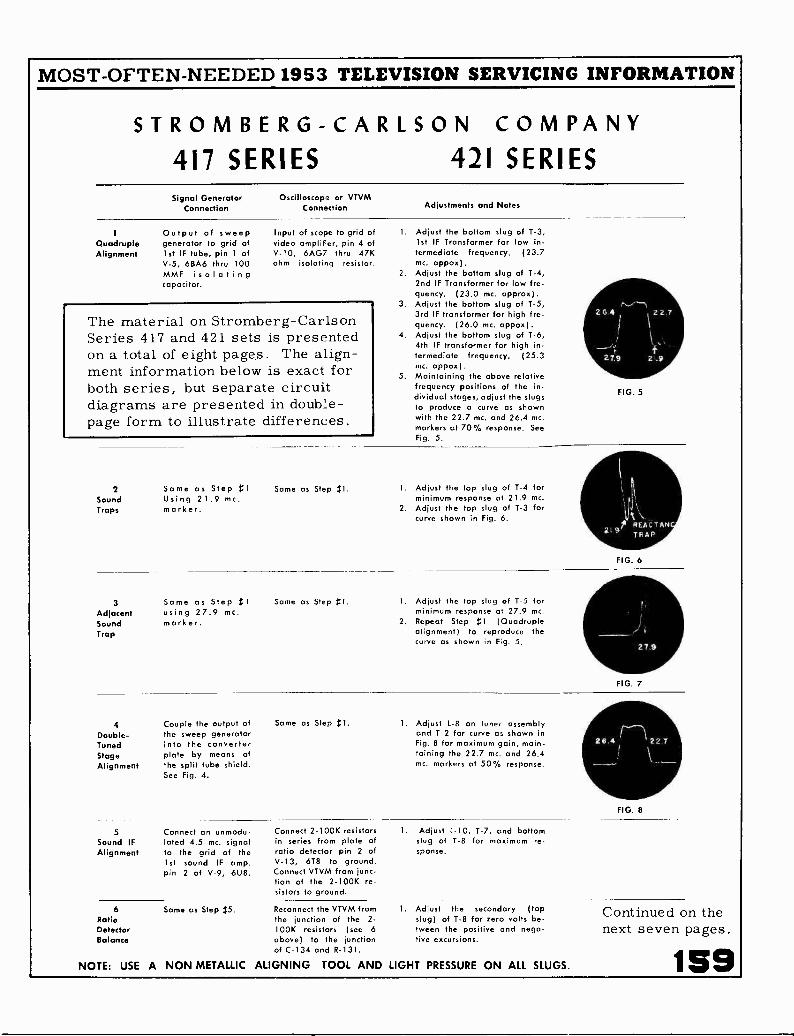
MOST -OFTEN -NEEDED 1953 TELEVISION SERVICING INFORMATION
STROMBERG-CARLSON COMPANY417 SERIES 421 SERIESSignal Generator Oscilloscope or VTVM
Connection Connection Adjustments and Notes
1 Output of sweep Input of scope to grid ofQuadruple generator to grid of video amplifier, pin 4 ofAlignment 1st IF tube, pin 1 of V-10, 6AG7 thru 47K
V-5, 6BA6 thru 100 ohm isolating resistor.MMF isolatingcapacitor.
1. Adjust the bottom slug of 1-3,1st IF Transformer for low in -termediate frequency. (23.7mc. appox).
2. Adjust the bottom slug of T-4,2nd IF Transformer for low fre-quency. (23.0 mc. approx).
3. Adjust the bottom slug of 1-5,3rd IF transformer for high fre-quency. (26.0 mc. appox).
4. Adjust the bottom slug of 1-6,4th IF transformer for high in-termediate frequency. (25.3mc. appox).
5. Maintaining the above relativefrequency positions of the in -
dividual stages, adjust the slugsto produce a curve as shownwith the 22.7 mc. and 26.4 mc.markers at 70% response. SeeFig. 5.
0-.....,-Th2G.4) 22.7
-,., f -I.
2 7.9 2,.9
FIG. 5
The material on Stromberg-CarlsonSeries 417 and 421 sets is presentedon a total of eight pages. The align-ment information below is exact forboth series, but separate circuitdiagrams are presented in double-page form to illustrate differences.
2 Same as Step Il Same as Step tl. 1. Adjust the top slug of T-4 forSound Using 21.9 mc. minimum response at 21.9 mc.Traps marker. 2. Adjust the top slug of 1-3 for
curve shown in Fig. 6.
ll
219p REAL TANTRAP
FIG. 6---
3 Same as Step 11 Same as Step Bl. 1. Adjust the top slug of 1-5 forAdjacent using 27.9 mc. minimum response at 27.9 mc.Sound marker. 2. Repeat Step 1$1 (QuadrupleTrap alignment) to reproduce the
curve as shown in Fig. 5.
I)27.9
FIG. 7
4 Couple the output of Same as Step 1. 1 Adjust L-8 on tuner assemblyDouble- the sweep generator and 1-2 for curve as shown inTuned into the converter Fig. 8 for maximum gain, main-Stage plate by means of taining the 22.7 mc. and 26.4Alignment the split tube shield. mc. markers at 50% response.
See Fig. 4.
26.4 22.7
\--- ......._
FIG. 8
5 Connect an unmodu- Connect 2-100K resistors 1. Adjust 1-10, 1-7, and bottomSound IF lated 4.5 mc. signal in series from plate of slug of 1-8 for maximum re -Alignment to the grid of the ratio detector pin 2 of sponse.
1st sound IF amp. V-13, 6T8 to ground.pin 2 of V-9, 6118. Connect VTVM from junc-
tion of the 2-100K re-sistors to ground.
6 Same as Step 15. Reconnect the VTVM from 1. Adjust the secondary (topRatio the junction of the 2- slug) of 1-8 for zero volts be -Detector 100K resistors (see 6 tween the positive and nega-Balance above) to the junction Live excursions.
of C-134 and R-131.
NOTE: USE A NON METALLIC ALIGNING TOOL AND LIGHT PRESSURE ON ALL SLUGS.
Continued on thenext seven pages.
159

MOST -OFTEN -NEEDED 1953 TELEVISION SERVICING INFORMATIONSTROMBERG - CARLSON 417 Series(Continued from the previous page)The service material below and on theadjacent page to the right is exact onlyfor 417 series, but can be used as anaid in servicing sets of the 421 series.
C -2I C-20
°SC.&CONV.
6J6
L-8
C-15
OR 6807(REPLACE WITHORIGINAL TYPE)
CONVSEC.
417 TUBE LOCATION
VID.I.F. AMP. HORIZ.A.F.C.PHASE DET.
T-3
IE VID.I F.
VID.I.F.AMP.
T-4
2ND.VID.I F.
3Ro VID.I.F.AMP.
T-5
VID.I.F.
41_,1 VID.I.F.AMP.
41.111VI D.
I. F.
P ON 0PLUG
WITCH
L-19
HORIZ.05C.
HORIZ. OSC.
25! SYNC. CLIPPER
RATIO DET., & PHASE INV.A.G.0 DELAY DIODE,a la AUDIO AMP.
r T-8
RATIO DET.
RATIO DET.DRIVER
T-7 .OO
2n. SOUND I.F.
VIDEO DET. aIK SOUND I.F.AMP.
T-6
5.
L -I0
I ST SYNC. CLIPPERa HORIZ. RETRACE
BLANKING
KEYED A.G.C.
L-15 6, -.n)4.5 MC \:--`1".
TRAP
VIDEO AMP
I sT SOUNDI.F.
REAR
FRONT
R-198
HORIZ.DRIVE
The following photographs were taken from a Du Mont 208-BOscilloscope, using a standard receiver adjusted for normal picture.
Plate of Keyed AGC (pin 5 of V -I6,6AU6), 300 volts peak -to -
peak -15.75 Kc.
Cathode of phase detector (pin 1 ofV-25, 6AL5), 12 volts peak -to -
peak - 15.75 Kc.
Cathode of phase detector (pin 5 ofV-25, 6A15), 13 volts peak -to -
peak - 15.75 Kc.
Plate of phase detector (pin 7 ofV-25, 6AL5), 12 volts peak -to -
peak -15.75 Kc.
Plate of horizontal oscillator (pin 5of V-19, 65N7), 70 volts peak -
to -peak - 15.75 Kc.
Grid of horizontal amplifier (pin 1 ofV-20, 6AU5-GT), 150 volts peak -
to -peak - 15.75 Kc.
LINEFUSE
L-20 C -I96 0 L-26 R -l88 R-186
O®0 M5 0
HORIZ. HORIZ. HORIZ. VERT. VERT.LIN. FRED SIZE SIZE LIN.
CONTROL

MOST -OFTEN -NEEDED 1953 TELEVISION SERVICING INFORMATION
Plate of sync clipper (pin 5 of V-17,6SN7), 30 volts peak -to -
peak - 60 cps.
4-11111F
Output of vertical integrating networkM-1, 25 volts peok-to-peak -
60 cps.
Yellow lead to T-11, 50 volts peak -to -peak - 60 cps.
Grid of vertical output (pin 1 of V-18,6B17), 100 volts peak -to -
Plate of vertical output (pin 2 ofV-18, 6BL7), 900 molts peak -
to -peak - 60 cps.
Red lead of vertical output trans-former T-10, 70 volts peak -to -
peak - 60 cps.
417 VOLTAGE CHART
1 - Measurements ore made at 117 V. line using vacuum tube voltmeter. All voltages are D.C.positive with respect to chassis ground except where noted.
2 - All voltages shown in telev. section measured with range switch in TV position.
3 - Contrast control set maximum, brightness control set at minimum, antenna disconnected.
4 - Voltages shown with asterisk (' ) vary considerably with control settings.
5 - Where no voltage is indicated, pin may be used as a tie point.
V-235U4G
310
2C0 y
310VAC.
3300 60 v 400V.
V -I866L7
LOOKING AT INSIDEBOTTOM OF CHASSIS
REAR
300
V- I I
KINESCOPE
V-22I B3 - GT
3-166V.
15-16Kv
15-1664.
V-216W4 -GT
5202
520 v6.3 v.A.C.
202
200 V
-35
V- I96SN7 -GTQV 150N
GNO
TUNER UNIT
ONO
REPLACE WITHORIGINAL TYPE
V- I6BK7 OR 61307
o CND.
2502
0 D
CND. V-2 6.3 VAC
6J6
75V
V-56AL5 s
V-250 c )
6.3 V AG.
V-176SN 7-GT6V 9V.
-50v1002
600V -I5
12AU76x
ONO
0.
260
3000 110 V.
V-20 V- ID6AU5 6AG7
CND.
1650. 6 Al,
fgE 6.3 VA. G. v
250 100
r T-8
1 0PAT.Dyr
29,1°D
,SOUND
D.
0
02NDyip
0350
1<5'V
2 I,
161

MOST -OFTEN -NEEDED 1953 TELEVISION SERVICING INFORMATION
Stromberg-Carlson 417 Series Schematic Diagram
The video IF system consists of a double -tuned con-verter plate transformer followed by four single -tunedstages. These are the 1st, 2nd, 3rd, and 4th IF stages.They are aligned as a "Quadruple" unit, previous tothe adjustment of the double -tuned stage. Threeabsorption type traps are located in the plates of the1st, 2nd, and 3rd IF circuits. They are adjusted forthe following frequencies: 1st IF ( reaction trap) -21.6 mc. approximately, 2nd IF (sound trap) 21.9mc., 3rd IF (adjacent sound trap) 27.9 mc.
L
REPLACE 1PITN T VPI
6867 OR 6807
ToRRET SIT, SELECTS CO1LS FOR OESINED CR NNNNN
4-I MEGOHMRESISTORS
162
C22*F. TEST POINT
4TO S3
2 RI
I V -12
6AU6RATIO DETECTOR DRIVER
ALl0i0 IF
TRANSFOIN GREEN DOT
EIEW*T011
V136T8
RATIO DETECTOR I STAUDIO AMPLIFIER
01
010137-M,
VHF - UHF- TUNER
NINES OSC
.1;,.)707,`*"
ai- .0-
EFS
SPLIT TUBE SHIELD
I I
N if.1.2K
3 3 YES
00110,
V:111
,N.e
C.152
17CTES TIM MELO
6D6v1i1116]
SI I NC
El If AMP foi, DOT[§.7-dhl
0
000110 c -s
I
AT PIN
23v
10
ISO I/2 Pi
V.256 AL5
PRASE DETECTOR
SOO
St
ITS
AO,
ASV
TUBE SHIELDS.C. PART NO 151036
LEADS
SOO

IMOST -OFTEN -NEEDED 1953 TELEVISION SERVICING INFORMATIONv -
6V6-67AUDIO OUTPUT
Eutodro
cPIN
Atli. ORIENT STROMBERG-CARLSON No. 417 SCHEMATIC DIAGRAM
TTTTTTT RAVE 1011111
1111NC 15 TO XC
TTEMP SIM 10.0103 1r
r6GB6" 1
3 RO vibrdifioorL
01
7. NC INAI
rvri-11.1110 Doi Le_ctiAl/ TII VIDEO IF AMP . T ,"..
0
0 0 i
o oIRK
C-13
RTNNE
ntiv110
GAG?
cnat81. 0104
SW ERA,L 15
--r R/1111 RElle-N/NNANE-0-NINVV,---
iTONC111 C151
1-10.01
66L7VERT 09C
11
VERTICAL VERT OUTPUT
,
DINT -..,1111- MT
Vi R-103. ... C 1.3... 410
IM . NTO
111-14
TE:TICALLINENNIT
.00,-11-1,ERTICnNITENT
TTTTTT 000.13
-Not/NEN
V..vMTMK
No
I7HP4KINESCOPE
RE 0
NEN C MI
4,901300 1Ef
"a.
NEEN-E/NTE
C1114
10 N
. REELECTION TONE
---NO .2... mai DERECTIO1
1000003000. 3 7
wolf nvosee 4. NN-
TO T
C13,111MI ME
11.
000 11
NoNSONTAL AIlr
C10.0
L111
C MO L 1AIYr
":,71r4".ixe cOATRCKEn
4411N/ \
i 00.1
NOE 1113111111.00 re 440'R110Ted3 1
11114 R -2e0 C .1.5NnoW3-ENNNE-0-11--,
mi n RINE
001 of
VEi34114. DIETEDT
1133
Ns, Of IC TIT it
EMU111
VEl6W4 -G7
C110NE. BOO m831 C....
10 ICl/-1
NoTE1-
ANA0111 FOR TOTE 1.1101.1[3 Ns INDICATEWICKWIRE NOTATION
ER 1 ----- 1
MODEL 417 AND 421 SERIES RECEIVERS-ResistorSubstitutions.
When resistor R-7 in the 417 series receivers (R-166 in 421 series)is 3.3 megohms, resistor R-165 is 22K, 1/2 watt in value. When a3.9 megohm, 1/2 watt resistor (Part No. 28198) is used as a sua-stitute in production in the R-7 (R-166) position, then R-165must be a 27K, 1/2 watt resistor (Part No. 28174).
V135U4-0
LT RECTIFIER
ON OFT SWITCNON VOLUME CONTROL
5U4 -GLE RECTIFIER
ROOM FAIN
rEISTED PAM
--.-..._ TERM. PAIR3, Z.1
163

MOST -OFTEN -NEEDED 1953 TELEVISION SERVICING INFORMATION
MODEL 421 RECEIVERS - Component Part Substitutions.
The following parts may be substituted in production for the originally specified parts.
Schematic SpecifiedPosition Value
C-221 220 mmf., 500 V.C-198 470 mmf., 500 V.
SubstituteValue
270 mmf., 500 V.470 mmf., 500 V.
001
C-183 100 mf., 50 V. 40 mf., 400 V.R-215 27 ohms, 1 W. 20% 33 ohms, 1 WattR-81 180 ohms, 1/2 W. 10% 180 ohms, 1/2 W. 5%R-107 2000 ohms, 7 W. 10% 2000 ohms, 10 W. 10%R-211, R-212 560 ohms, 1/2 W. 10% 560 ohms, '/2 W. 10%R-135 10 Megohms, 1/2 W. 20% 6.8 Megohms, 1/2 W. 10%R-185 10K ohms 1/2 W. 20% 15K ohms, 1 W. 20%R-238, R-239 270K ohms, Y2 W. 10% 330K ohms, 1 W. 10%R-111 1 Megohm, 1/2 W. 20% 1.5 Megohms, Y2 W. 20%R-52 1K ohms, 1/2 W. 20% 470 ohms, 1/2 W. 20%R-196 2200 ohms, 1/2 W. 10% 2200 ohms, 1/2 W. 20%
2222ARATERMINAL
22A,ATE OsiGNAL TTA2
6E187086807RE AMPL11.22
C i2
L
L
TuRRET SwITCR SITTING SC
MI
CCTS C0%51012 02S.RED CRANNEL
NT 2211 POINT
100 MALI200
MODEL 421 RECEIVERS - Capacitor Revisions.
Schematic Specified Revised
Position Value Value
C-183 100 mf., 50 volt 50 mf., 50 volt
C-182 .22 mf., 600 volt .1 mf., 600 voltC-140 .01 mf., 450 volt .01 mf., 600 voltC-170 .01 mf., 450 volt .01 mf., 600 voltC-210 .033 mf., 400 volt .068 mf., 400 voltC-203 .22 mf., 400 volt .047 mf., 600 voltC-202 .047 mf., 600 volt Capacitor removed
164
TL.
7700110,
co
00.
VHF -UHF TUNER
0ATIO
RATIO DETECTOR DRIVER A'T.M.
6RT10 DETTE8CTOR 8 1ST
UDICI AMPLIFIER
TOP <OR
AK'r
- AIR
0 2120.
40
6J6
cOD4. lam"
L-0 c 2,006 T --II-_
R 10
ARED-A
7.t "r
6002
mer2.12
MOLD
1
T-2CONVERTER SEC
tam
NE2CTANCE
TRA
IftoecArcs twit skim,
[68A6DOT zwiirola FAMP :BRUN 002
0°040kkrO. 0 0
111l7_ir 1111
H. V. POWER SUPPLY
\r/_A M2VIS 222C
V-206AV5 - GT
RORIE AMPLIFIER
C210

MOST -OFTEN -NEEDED 1953 TELEVISION SERVICING INFORMATION
6V6- GT STROMBERG-CARLSON No. 421 SCHEMATIC DIAGRAMUE110 OUTPUT
5 N -.2
11.
UDIO OUTPUT
SEE /KITES:ma ES So. ILWEDS 11110.
11 0 EION. MAE.
',TS KC 1TN TUT
.T3 Yc TRAPT S
3RD VIDEO;
r-77;,, _, r ,. 1 ..,EA114i : RED DOT iMitAi .
5120 VIDEO IF AMP *TN VIDEO IF AA 0 44 Nvloa $1r
isK
No
Cfi papa
0,1".
r6UBJ
I ST VIDEO AMPLIFIERI ST AUDIO IF
v.TEsT r*****
.3 TS KC v .0
6W6-GTVIDEO AMPLIFIER
\ 1111
C.1.3SHOW
R MS1012
100021,
0000 0
".).t2E0
NED
NS VARY
, 101 1
11'1 :
C
or L 22
v ,1
2IFP4ASCOPE
P SOO v
11,
017
E4 IO
IE.. RC1.11,1 TEST TTTTTTT
S
NO O- N
420,
VE14'I'GLBLOCKINGTRANSFORMER
ORE
soo
PILLOW
C -2 311
1 -pow>/. AT .01 Fax
:
r.,5,
-r R IONWOO
vERTICALr_z LINEAR.,
NO,R Not
sON
30- 0V
V
6BLTVERT OSC.
VERT OUTPUT AMP
Elli R.2311
TOK 210xC-.1111 CESS
1,113.A100 KSRL., REsscONTROL
Os'
CONNECTED TO TERMINAL.2. R3 OF DEFLECT..
.ORE PLUG SON OPTIMUM FOCUS
ORLONINF
11.a UNITED PA11
itE OF. WHEN SET E ON
NIT.. ON VOLNNEco TTROT
No 12
T ioV E ;TAW' OSNWir
IE. E1.. Moo.9 MME
RED2. ME
HEN C Mi2.2 Mr
C 1113
100 NIsov
mom__DEFLECTION POKE
SON
vENTICAL DEFLECTION
1
...<-112.12ONTAL DEFLUTIoN
1: 11.1,74:°""`
TERld s OFKINESCopE
c:x L- 20
r.I.T11"4"TR.
0.3
n--13 N.=Taii SuAE7
tBSt,
osET 4, 33 , w ow,
V-22I B3
NV RECTIFIER
110111.10IITAL OUTPUT 7220RANSPORMER vp.
T-9
v-216W4
DAMPER
CE13
c.2.02.0
12.0.0 KT.
TIAISTE0 FAIR
NOTENROWS FOR POTENTIOMETERSINDICATE CLOCKWISE ROTATION
7Either Part No. 161429 or No. 161442 Power Transformers areto be used in production on 421 series receivers. Since the B plusvoltage is about 15 volts greater when using No. 161429, resistorR-231 must be 1200 ohms 20 Watt (Part No. 149366) when usingthis transformer. When using No. 161442 transformer resistorR-231 will be 470 ohms, 2 watt (Part No. 149074).
Ills NsSO 165

MOST -OFTEN -NEEDED 1953 TELEVISION SERVICING INFORMATIONStromberg-Carlson Series 417 and 421, Revisions and Production Changes
MODELS 417 AND 421 RECEIVERS - Redesign toReduce Dissipation of 6V6GT-Audio Output Tube.
The value of R142, cathode resistor for the 6V6GT audio outputtube has been increased from 270 ohms, 1 watt to 330 ohms,1 watt (New Part No. 149135, 149073 or 149229).Series dropping Resistor R-231 is specified as a 470 ohms, 2 wattvalue with the use of Power Transformer No. 161442. The
value of this R -23I resistor is now being increased to 1250 ohm,5 watt.
MODEL 421 RECEIVERS - More Uniform HorizontalOscillator Operation.
The operation of the horizontal oscillator has been made moreuniform from sot to set and the tendency to pull horizontally atthe top of the picture has been reduced by the following changesin Productions
1. R-194, 1500 ohm resistor is now a 5% tolerance valueinstead of the previous 10%.
2. Resistor R-195 has been changed from a 220K, Y2 watt, 20%value to a 180K, 1/2 watt, 10% value (New Part No. 28182).
3. Capacitor C-193 has been increased in from 270 MMF, 20%to a 390 MMF, 10% value (New Part No. 110262).
4. C-198, 470 MMF capacitor is now a 10% valuc instead of a20% value.
5. A 33 MMF, 10% mica capacitor (Part No. 110250) has beenadded between plate (No. 5 pin) of the 6SN7 HorizontalOscillator (V-19) and ground.
MODELS 417 AND 421 RECEIVERS - DamperTube Revision.
A 6AX4 tube (Part No. 162161) is now being used in place of a6W4GT tube in the Damper Circuit. Tube location diagrams inthe receivers show those receivers which use either type.
The 6AX4 tube is being used in those receivers which use PowerTransformer No. 161442 which has one less heater winding.The jumper lead between No. 7 pin of the Damper Socket andNo. 4 terminal of the Horizontal Output Transformer is not neces-sary with the use of the 6AX4 tube since the heater and cathodebreakdown value is higher and they do not have to be main-tained at relatively the same potential as in the case of the6W4 tube.
MODELS 417 AND 421 RECEIVERS - Revisions ofFiltering in Tuner Supply Leads.
The 100 MMF capacitors in positions C-1, C-2, C-3 and C-4 andresistors R-3 and R-4 have been removed from the circuits of thesubject receivers because of rearrangement of the supply leads tothe tuner thereby eliminating the need for this filtering.
MODEL 417 AND 421 RECEIVERS - AdditionalChanges for Improving Vertical Hold.
This complete change is as follows:1. A 100,000 ohm resistor (R-240) rather than 150,000 ohm
resistor has been added directly in series with the connectionbetween the No. 5 pin (plate) of the V-17, 6SN7 PhaseInverter -2nd Sync Clipper tube and the input to the M-1vertical integrator network.
2. Resistor R-184 has been increased in value from 680K to 1
megohm, (Part No. 149119). A 2 megohm resistor, (PartNo. 149121) has been bridged in parallel across the twooutside terminals of the R -187A, 2 megohm Vertical HoldPotentiometer. At a later date a new 1 megohm potentiometer(Part No. 145146) will replace the above combination 2
megohm potentiometer and parallel 2 megohm resistor.
3. The vertical oscillator transformer has been moved from theprevious position near mid -chassis to the area behind thevolume control which results in interlace improvement andpossibly contributes to better vertical hold.
166
MODEL 421 SERIES RECEIVERS - Vertical Drift.
Repeated failure of the 6B17 "Vertical Blocking Oscillator andVertical Output Tube" has dictated the following change on allchassis date coded 52-20-1:-A 6C4 tube was added in an unused tube socket punchout onthe front left hand corner of all 421 chassis to replace 1/2 of the6BL7 tube, i.e., the vertical blocking oscillator section of V-18.-The lead going to Pin 4 of V -I8 was reconnected to Pin 6of the 6C4.- The lead going to Pin 5 of V-18 was reconnected to Pin 1 orPin 5 of the 6C4.- The lead going to Pin 6 of V-18 was reconnected to Pin 7 ofthe 6C4.- The filament Pins 3 and 4 of the 6C4 are connected to thefilament string.- The unused Pins 4, 5 and 6 of the 6BL7 are grounded.If an earlier 421 receiver is encountered having a 6BL7 causingvertical roll and not incorporating the 6C4, it is suggested thatthe 6817 be changed to one of the improved 6BL7's. These tubescan be identified by referring to the coding etched in the top ofthe glass envelope beneath the 6BL7 tube type designation.
MODEL 421 SERIES RECEIVERS - Proper Set-upAdjustments for Maximum In -Focus Picture Area.
Since the 421 receivers use fixed -voltage -electrostatic -focus,picture tubes (2IFP4A) the following suggestions will be helpful inobtaining maximum in -focus picture -area at the time the receiveris initially set-up.
1. The ion trap should be adjusted in the normal manner formaximum brightness but within the adjustment range of
maximum brightness, a specific setting of the ion trap willbe observed where maximum in -focus -picture -area can be
obtained.
2. The centering assembly, which consists of a device similarin appearance to an ion trap (except for a rotatable magnetin the form of a black button), should be placed away fromthe ion trap and up close to the deflection yoke on the neckof the picture tube. In this way, magnet field interferencebetween the ion trap and centering device is minimized andbetter focus can be obtained.
3. Additional physical separation between the ion trap magnetand the centering device magnet can be obtained by keepingthe two magnets on opposite sides of the picture tube. Properbrightness adjustment and proper picture centering shouldstill be observed.
4. It should be noted that the picture tube focusing anode (whitelead) can be connected to one of three voltage take -offpoints in the receiver: (1) Ground (2) B -I Supply (3)Boosted D. C.
MODEL 421 SERIES RECEIVER - Noise CancellationCircuit Adjustment.
All 421 model television receivers coded 52-30-1 or later in-corporate a new circuit development known as "Noise Cancella-tion". All chassis having this circuit can be readily identified byan additional potentiometer to the right of the phono switch onthe rear chassis flange labeled "Noise Cancellation Control". Itis important that this control be properly adjusted in order torealize full value of the noise cancelling circuit. When the "noisecancel" control is in its extreme counterclockwise position, thenoise cancellation circuit is ineffective; when it is in its extremeclockwise position, the cancellation circuit will clip sync and pictureand cause a dark picture with no sync action.
The proper procedure for adjusting the "noise cancel" control is
to first make all picture adjustments, size, linearity, etc., with the"noise cancel" control in its extreme counter -clockwise position.After all picture adjustments are made, properly tune in thestrongest signal in the area and slowly advance the "noisecancel" control clockwise until the picture starts to lose sync, thenback off the control until the pjcture is stable.

MOST -OFTEN -NEEDED 1953 TELEVISION SERVICING INFORMATION
Chassis 1-508-1,
Chassis 1-510-1,Chassis 1-504-1,
SYLVANIA1-508-2, used in Models 172K, -KU, -M, -MU; 175B, -BU, -L, -M, -MU;
176B, -BU, -L, -M, -MU; 177B, -BU, -M, -MU; 178B, -BU, -M, -MU.1-510-2, used in Models 120B, -BU, -M, -MU; 126B, -BU, -L, -M, -MU.1-504-2, used in Models 105B, -BU, -M, -MU, is a 17 -inch version
of 1-510-1, -2, and is electrically similar to these chassis.
Service material on the above listed Sylvania TV sets is presented on the next eightpages. General information is given below and top view of sets is shown on page 168.Alignment information is given on pages 169-170; circuits are printed on pages 171and 172; and on pages 173-174 are presented important revisions and code changes.
Chassis 1-508-1 and 1-510-1 provide receptionof the twelve commercial VHF television chan-nels, 2 through 13 inclusive. In these chassis,provisions are made for the simple additionof a UHF tuner, thus permitting reception ofchannels 14 through 83 of the UHF band. Modelsincorporating chassis 1-508-1 and 1-510-1 showa single alphabetical suffix after the body num-ber. (For example: 176M, )
Chassis 1-508-2 and 1-510-2 include the UHFtuner and thus provide reception of VHF chan-nels 2 through 13 and UHF channels 14 through83 inclusive. Models incorporating these chas-sis show a double alphabetical suffix after thebody number. (For example: 176MU. )
Combination models incorporating these chas-sis also include a 1-603-1 radio chassis whichprovides reception of standard and frequencymodulation broadcast bands.
Chassis 1-508-1 operates with twenty-seventubes plus the picture tube. Of this totalthere are two low voltage rectifiers, two highvoltage rectifiers and one regulator tube. Agermanium diode is also incorporated ir thecircuit. Chassis 1-508-2 incorporates twoadditional germanium diodes and one receivingtype tube in the UHF tuner.
Chassis 1-510-1 incorporates a total of twenty-two tubes in addition to the picture tube. Ofthese tubes one is a low voltage rectifier, twoare high voltage rectifiers and one is a regu-lator tube. A germanium diode is also incor-porated on this chassis. Chassis 1-510-2, inaddition to the previous complement, includestwo receiving type tubes as part of the UHFtuner.
NOTE: For convenience in servicing, separateschematics are furnished.
Sylvania television chassis 1-504-1 and 1-504-2are the 17 inch versions of the 1-510-1 and1-510-2 TV chassis, respectively. Electrically,the two chassis series are very similar.
AGC CONTROL ADJUSTMENT(1-508-1, 1-508-2)
1. Connect a good antenna installation to thereceiver.
2. Set Picture (Contrast) control to approx-imately 7/8 of maximum position leavingBrightness control at normal setting.
3. Tune receiver to the strongest stationavailable in area.
4. Turn AGC control fully clockwise so thatpicture is "blacked" out.
5. Retard AGC control to a point where thepicture reappears and does not tear orfall out of synchronization as the FineTuning control is rocked through the picture.
6. If, when the AGC control is finally ad-justed, the picture has too much contrast,reduce the contrast with the Picture (Con-trast) control. DO NOT use the AGCcontrol as a contrast control.
7. Turn Volume control to normal level.Intercarrier buzz should be negligible asthe Fine Tuning control is rocked nearthe correct tuning point. Retard AGC con-trol slightly if objectionable. (Note: Inter -carrier buzz is merely a reference forcorrect adjustment of the AGC controland only a slight touch up should be neces-sary. If much adjustment is required toremove intercarrier buzz, the sound sectionis maladjusted and requires realignment. )
Note: The intent of the AGC control adjust-ment is to ensure proper AGC voltage consistentwith correct synchronizing action and negligibleintercarrier buzz. This condition ensures thebest possible synchronization under interferenceconditions, and also the greatest amount ofpicture contrast.
167

MOST -OFTEN -NEEDED 1953 TELEVISION SERVICING INFORMATION
SYLVANIAChassis 1-508-1, 1-508-2,
and 1-510-1, 1-510-2.
CHANNEL SELECTOR
FINE TUNING ANDUHF CHANNEL SELECTOR
(510-2/
L 540
L8
1(g) 5R F AMP
L3 ANTENNATERMINALS
V3
6C B 6
1E7 VIDEOF AMP
FUSE
01/4 AMP
168
7550
'LOOKER -POINT
HIGH PASS FILTER
11-510-2 ONLY)
VO
6CB6
25.4 VIDEOF AMP
T560
VHF CHANNEL SELECTOR
FINE TUNING ANDUHF CHANNEL SELECTOR
(508-21
BRUME
BRIGHTNESS
,(1747,
FIGURE 4 - TOP LAYOUT FOR 1-508-1,1-508-2 TV CHASSIS
V2
6J6OSC. mix
04303
OC12
C6
Oe
4(7R.F. AMP
C4(9ER
L540
L530
UHF -VHFSWITCH
(7508-2 ONLYI
V9
T55 /%=-7.'
6CB6 0 6C66
11) VIDEO 250 VIDEOF AMP I F AMP
HIGH PASS FILTER
11-508-2 ONLYI
T560
FUSE L51FILTERCHOKEAmP
V5
6G 66
3812 VIDEOI F AMP
T570
L55
0V6
6CB6
418 VIDEOIF AMP
6AH4GT 6C4VERT -'OSC
VERT OuTPUI
T51
0
V9
6A U6SOUND
"Th LIMITER6A U6
SOUNDIF. AMP
126Y7
VIDEO AMP
LOU®V14
172 AF 6TUNER A GC 6AV6CLAMP
r 1520
L69
0L62
D440 0 VI9
VIDEODET 6CB6
HOR CONTROL
V7 V20
124U7
HOR OSCHOR DISCO
v18
124X7 6AL5\,_,/ .........,
AGCRECT HOR DISCR8 SYNC SEP
viS v13
I2AU- 7 6AU6\...._,/ \,_.,
SYNC AMP AG C
B CLIPPER AMP
v,o
"--"N6A L5
RATIO PET
/e-.\6V 6GTAf
A fOUTPUT
V21
4041OCR REG
SPEAKERSOCKET
10
0
HALOL1GHT ANDCHANNELINDICATOR
IGHT SOCKET
$3
v23
at)DAMPER
HOR YOKECONNECTORSOCKET
630
HOR SCAN AND HCONNECTOR SOCKET v22
(I) 660 6GT
HOP OUTPUTLS
VS
6C B6
311.8 VIDEOIF AMP
VERT. HOLD VERT. L. HEIGHT
FIGURE 5 - TOP LAYOUT FOR1-510-1,1-510-2 TV CHASSIS
T570
L55
0V6
6C B6
481 VIDEO1F AMP
6AH4GT 6 C4
VERT OSC
VERT OUTPUT
VERT. LIN. HEIGHT
V8
/--"N6A U6
SOUNDIF AMP
L62
D440 0VIDEODET
v7
12BY7,_.,VIDEO AMP
OL61
1,2 ]
L68
HORFRED
V12 VI5/"--
I2AU7 6A L5
SYNC - SEP HOR PHASEEl SYNC. AMP DETECTOR
PICTURE(BRIGHTNESS(
PICTURE(CONTRAST)
v,o
6AV- 6
AFll
AMPV9
6A L- 5
SOUNDRATIO DET
HOR. SCAN AND HUCONNECTOR SOCKET
HOR SIZE
off(
4 041HOR REG
SPEAKERSOCKET
008 HOLD
oar DRIVE
A G c HOP SIZE
R.
00
HOR HOLD HOR DRIVE
OR LIN
W ciQ. zo oo0
O4
00-J
FA Wa_ a.-o>- 0C4 2V) 0W 00 IdWZ
410
1-1ti
W=
I- DD 0a.z r;:i

MOST -OFTEN -NEEDED 1953 TELEVISION SERVICING INFORMATION
SYLVANIA VIDEO I F ALIGNMENT -ALL CHASSIS
STEPSIGNAL GENERATOR
Connection Freq.
SWEEP GENERATOR
Connection Freq.
VTVM
CONNECTIONOSCILLOSCOPE
CONNECTION ADJUSTOUTPUT
READING COMMENTS
1
To raisedtube shield
onOsc.-Mixer
39.75Mc.
AcrossDiode
Load Res.
(1-508-1, -2)R152 3.3M
(1-508-1, -2)Top Core L53
Min.
Set Tuner to free channel.Apply -12V. between
junction of R137 andC131 and Chassis on1.508-1 and -2;-3V. between C136and Chassis on1-510-1, -2. Use suffi-cient output forsatisfactory readings.
(1-510-1, -2)Top Core L54( 1-510-1, -2)
R149 4.7M
2
Loosely Cou-.ple Marker toControl Gridof Osc.-Mixer
( 1-508-1, -2)through Hole
in TunerCover to
Pin 5 of 6J6
45.75Mc.42.1Mc.
( 1-508-1 -2),
through Holein TunerCover to
Pin 5 of 6J6
43.25Mc.
10 Mc.Sweep
ThroughLowerDetectorCircuit
(Fig. 11)to
Cathode,Pin 2 ofV3-6CB6
(1-508-1, -2)L53
(Bot. Core)L8 ( Tuner)
L54Response
Curveshown
inFig. A
Remove A GC voltage.Short pin 5 to pin 6 on
V3-6CB6.Osc.- Mixer tube
shield to normal posi-tion.
Sett -508-1,-2 VHF tunerbetween any twochannels.
Set 1-510-1,-2 VHF tunerto any free highchannel.
L54 controls width ofcurve on 1-508-1,-2.
( 1-510-1, -2)L54
(Bot. Core)
T2 (Tuner)(1-510-1, -2)Pin 7 of 6X8
(1-510-1, -2)Pin 7 of 6X8
3 Repeat step 2 adjustments until curve is flat with 42.1 Mc. and 45.75 Mc. markers on corners. REMOVE SHORT FROM V3before proceeding with step 4.
4
To raisedtube shield
onOsc.-Mixer
41.25Mc.
AcrossDiode
Load Res.
(1-508-1, -2)R152 3.3M
L554th VideoI F Trap
Min .
Set Tuner to free channel.Apply -12V. between
junction of R137 andC131 and Chassis on1-508-1, -2.--3V. between C136and Chassis on
cient output forsatisfactory readings.
(1-510-1, -2)R149 4.7M
5 Same as 4 47.25Mc .
- Same as 4 Top Coreof T56 Min. Same as 4
6 Same as 4 41.25Mc. Same as 4 Top Core
of T55 Min. Same as 4
7 Same as 4 44.0Mc. - Same as 4 T58 Max.
Same as 4. Reduce Sig.Gen. output to keepVTVM reading be-tween 1 and 2 Volts.
8 Same as 4 U.oc. - Same as 4 T57 Max. Same as 7
9 Same as 4 45. 2Mc. Same as 4
T56(Bot. Core) Max. Same as 7
10 Same as 4 43.2Mc. Same as 4 (BoTt.
55Core) Max. Same as 7
11 Repeat step. 4 to 6 inclusive.
12
Looselycouplemarker
to raisedtube shieldonwithOsc.-Mixer
41.25Mc.42.1Mc.
45 75.
Mc.47.25Mc.
To raisedtube shield
onOsc.-Mixer
43.25Mc.
10 Mc.Sweep
AcrossDiode
Load Res.with 33MResistorin series
hotscope lead
T58, T57T56 ( Bot.Core) andT55 ( Bot.
Core)
ResponseCurveshown
inFig. B
Same as 4
Use low signal input andhigh sco pe gain.
L5442.1 MC.
L53(TOP)39.75MC.
1-508-1,-2
L53( 80T.)
L8(TUNER)45.75 MC.
42.1 MC.
L54(TOP)39.75MC.
L54 (80T.)T2(TUNER)45.75 MC.
1-510-1,-2
FIG. A
45.0 MC. RESPONSE=100%
42.1 MC.
SOUND 70%41.25 MC 50% 47.25 MC.
L___
PIX45.75MC.
FIG. B 169

MOST -OFTEN -NEEDED 1953 TELEVISION SERVICING INFORMATIONSYLVANIA 4.5 MC. TRAP ALIGNMENT -ALL CHASSIS (Continued)STEP
SIGNAL GENERATORConnection Freq.
VTVM CONNECTIONSProbe Ground Lead ADJUST
OUTPUT
READINGCOMMENTS
1
To Pin 2 of12BY7Video
Amplifier(all chassis)
4.5Mc.
R F Probeconnected to
Cathode(Pin 11)
ofPicture Tube
To chassis L61 Min.Short Pin 1 of V6-6CB6
4th Video IF Ampli-fier to Chassis
SOUND ALIGNMENT -ALL CHASSIS
STEPSIGNAL GENERATOR
CONNECTIONVTVM CONNECTIONS
D C Probe Ground Lead ADJUSTOUTPUT
READINGCOMMENTS
1
ALL CHASSIS
45 Mc. and 4.5 Mc.generators each connected
through a 1000 ohmresistor to pin 1 of
V3-6CB6 1st video IFAmplifier.
(1-508-1, -2)To junction ofR103 and C104.
(1-508-1, -2)To chassis.
(1-508-1, -2)T51 Sec.(top core)
pri. (bot. core)and L62.
Max.
Set tuner to free channelOr
45 Mc. generatorwith 4.5 Mc. marker
(preferably crystalcontrolled) through1000 ohm resistorto pin 1 of V3.
(1-510-1, -2 )To pin 5 of V9-
6AL5
(1-510-1, -2 )To pin 7 of
V9.
(1-510-1, -2)T52 Sec.(top core)
pri. (bot. core)and L62.
Max.
with minimuminterference.
2 Same as 1.1-508-1, -2 only.
To pin 5 of V10-6AL5
1-508-1, -2only
To pin 7 ofV10.
1-508-1, -2only
T52 primary.Max.
On 1-508-1. -2 keepoutput of signal
togeneratorwhere olta
valuevoltage across
R103 does not exceed1.0 volt negative.
3 Same as 1.
(1-508-1, -2)To junction of 2matched 100M
resistorsconnected in series
across R109.
(1-508-1, -2)To junction ofR105, R106and C106. T52 secondary
Set VTVM to lowestDC scale. Slight turnof core will produce
( 1-510-1, -2)Same as above
with 100Mresistors
across RIOS.
( 1-510-1, -2)To junction
of R103and C103.
( top core). Zero either a positive ornegative deflectionon VTVM.
4 Remove test equipment and resistors.
ALTERNATE SOUND ALIGNMENT -ALL CHASSISThis method prevents inaccuracies of test equipment from affecting sound alignment
STEP SIGNAL SOURCEVTVM CONNECTIONS
D C Probe I Ground Lead ADJUSTOUTPUT
READINGCOMMENTS
1 Connect a good antenna installation to the receiver
2
Chassis 1-508-1, 1-508
Strong station
2 only
To terminal3 of T51 To chassis
L62T51
( Both Cores)Max. Repeat all adjustments until
maximum is reached
(1-508-1, -2)To pin 5 of
V10-6AL5
(1-508-1, -2)To pin 7 of
V10-6AL5
(1-508-1, -2)T52 Pri.
( Bottom Core) Repeat all adjustments until3 Strong station(1-510-1, -2)To pin 5 of
V9-6AL5
(1-510-1, -2)To pin 7 of
V9-6AL5
(1-510-1, -2)L62
T52 Pri.(Bottom Core)
Max. maximum is reached
4 Strong station
(1-508-1. -2)To junction of
R105, R106
To junction oftwo 100MResistors inseries from:
( 1-508-1, -2)pin 5 to pin 7 T52 Sec. Zero
Use lowest meter scale set to zerocenter. At correct setting, a slight
(1-510-1, -2) of V10-6AL5(Top Core) turn of core will give either a
positive or negative reading
170To terminal
5 of T52(1-510-1, -2)
pin 5 to pin 7of V9-6AL5
Remove test equipment and resistors

S Y
L V
A N
I A
DIA
GR
AM
FO
R 1
-508
-1 A
ND
1-5
08-2
TV
CH
AS
SIS
PA
RT
S W
ON
GV
HF
TU
NE
R -
--C
IT
O C
22,
RI
TO
RIO
SO
UN
DV
ISE
CT
ICM
- -
--.
00 T
O C
OE
,01
00 T
O 0
115
VID
EO
SE
CT
ION
----
---0
1x52
3 T
O 0
150,
RIT
ZIIS
TO
RIG
S-
0175
TO
CIS
(T
O R
I.S
YN
C. S
EP
AR
AT
OR
, A S
C A
MP
LIF
IER
AN
DV
ER
TIC
AL
SW
EE
P S
EC
TIO
N-
- cl
opT
Oov
a, A
top
TO
253
0H
OR
, SW
EE
P A
NO
V P
OW
ER
SU
PP
LY S
EC
TIO
N-.
OM
TO
CE
TI,
0150
TO
Rt.
TH
E H
IGH
ES
T C
OM
PO
NE
NT
NU
MB
ER
S O
N T
HIS
SC
RE
W..
DI-
----
AK
. CE
TI,
LTI,
RE
TS
, TN
3 A
ND
WE
S
ME
AS
UR
ED
win
. AN
ELE
CT
RO
ST
AT
ICOR
ZE
RO
CU
RR
EN
T M
ET
ERELECTROSTATIC
AT
LIN
EV
OLT
AG
E M
ET
ER
RE
AM
. OF
IIT
VO
LTS
,LI
ND
ER
CO
ND
ITIO
NS
OF
NO
RM
AL
RO
NA
LA
ND
NO
AR
IGN
TN
ES
S
SO
UR
CE
OF
VO
LTA
GE
N 'K
im C
ON
TR
AS
TA
HIG
H K
AN
VO
LTA
GE
OF
.CR
TC
ON
TR
OL
AT
*M
M.
prIA
AA
Z47
3°.'i
s:b°
7&"T
trs
OR
IGH
TN
ISS
CO
NT
RO
LM
EA
SU
RE
ME
NT
AT
I.A
IND
IA H
IGH
K. V
OLT
AG
E...
CO
NN
EC
TE
D T
O IN
DIC
AT
ED
MO
RE
T.1
100
0 00
011
VO
LTA
GE
SO
UR
CE
.
VO
LTA
GE
S A
RE
ME
AS
UR
ED
TO
CH
AS
SIS
UN
LES
S O
TH
ER
WIS
E IN
DIC
AT
ED
, 0.0
. TA
NE
N A
T 5
0,00
0 .1
0I K
R V
OLT
,G
. 01.
1,00
0 O
HM
S K
R V
OLT
. ME
AS
UR
EM
EN
T C
ON
DIT
ION
S, U
NLE
SS
OT
HE
RW
ISE
NO
TE
D: S
OU
RC
E II
? V
OLT
ILO
CY
CLE
. AN
TE
NN
A D
ISC
ON
NE
CT
ED
wIT
H N
O S
IGN
AL
INP
UT
, PIC
TU
RE
CO
NT
RA
ST
AT
MA
XIM
UM
, 'R
IGH
TN
ES
SA
T M
INIM
. - O
TH
ER
CO
NT
RO
LS A
T N
OR
MA
L P
OS
ITIO
NS
.A
VE
RA
GE
VO
LTA
GE
S A
ND
CO
L R
ES
IST
AN
CE
S A
RE
IND
ICA
TE
D. R
ES
IST
AN
CE
OF
TA
PP
ED
CO
ILS
IS F
OR
EN
TIR
EW
IND
ING
. CO
IL R
ES
IST
AN
CE
IS N
OT
SP
IOW
N W
HE
RE
RE
AD
ING
S A
SS
TO
O W
ALL
OR
IDE
L1 V
AR
IAS
ILL
WO
KS
! IF
AD
JUS
TM
EN
TS
155
(BO
TT
OM
CO
RE
,1.
54LA
ITLI
NE
R1
43.5
S10
. ON
G S
WE
EP
Iss.
BIT
LS
L51
0124
8126
07.0
04T
.7".
!SIN
G
, 5U
4G5U
4G .2
1I
T50
110
SE
CT
L.V
. SE
CT
M.O
.
ON
-O
FF
PIT
SS
WIT
CH
nor v.
v22
Av
3A
DO
AC
T
Gin
CIT
ow
Tx
E. V
IDE
OI
AP
O
CO
AT
DO
.C
041
0101
34w
36
SA
LI6
22.0
.OA
W
CO
IM
tC
M3
CM
AC
OI
03i
CO
I
6A66
6Au
eE
LLS
AE
NA
CT
.cV
A
RO
D
0200
Mv2
0G
CS
E12
AU
T
6AU
6sa
ne IF
AM
P
DV
AM
0*.
T51
/2T
OY
.
L.35
r
r 74
'MA
;41
! VID
EO
OP
. AM
P
v9D
OU
GS
OU
NO
F L
iM
0440
DE
TE
CT
OR
Ir
eT
A1
'A
IORW
GA
LSR
AT
IO O
ET
.
0rA
6 12
12/7
s12
AU
?6G
4S
YN
C. S
EP
MG
. AIE
RV
ER
T O
SC
.....
T60
-C
t. M
NK
MK
W K
O IT
ST
A-1
2 7
TT
IVI.
......
....
...r
_.0
122
110.
2M, S
IR.0
013
0205
.4:2
06...
RO
T,.
raT
IA
M .0
0S00
5
L_
Rt
C25
0,.
00.7
6AL5
ION
. DO
OR
arl. -
R25
3C
Vs,
SE
rtm
12:
U.9
--ir
CO
NO
LI
LAM
ED
.
CO
NT
RA
CO
NT
6 3v
AC
151
v.
6AV
6A
.P.IU
6 T
UN
ER
111C
CLA
MP
aan
4111
110.
0S
5La
w
Asa
.270
v.
055
HO
RIZ
ON
TA
LD
EF
CT
./C
OLS +
330v
VI2
6V6G
T F
OU
TP
UT
T30
oteN
EL
NO
.O
R.O
NT
ILV
4
T53
6017
545
OE
N
2IE
P4A
KT
UN
I 111
66
360v
.3.
.330
v.
RE
ST
.CT
.
L65
.2.
tan
H
VO
T1 R26
,DO
MO
T A
TT
EM
PT
TO
111.
111
IRLT
I.00S
OM
R
EC
TIF
IER
TU
RE
S
W.
GM
C.A
.,11
267
NN
N4.
3033
0v.
TO
OT
T10
1,C
ON
TR
AS
T G
ON
TO
l
SK
.ER
C/D
NO
201T
Al.
SQ
UIR
M
,,,10
= r
arC
al.
IB3G
TM
u R
IM
1.27
2 6I
3R
ET
O
wO
NM
1123
0100
AC
Tvea
Let
0
TIC
NO
P S
C4N
AN
O 1
11.1
05
A,
INA
/6Is
e m
emo
SO
NA
R'S

N E
L
NSY
LV
AN
IAD
IAG
RA
M F
OR
1-5
10-1
AN
D 1
-510
-2T
V C
HA
SS
IS
PA
RT
S C
OD
ING
VH
F T
UN
ER
SE
CT
ION
-C
IT
O C
OO
,R
IT
O 0
0U
HF
TU
NE
R S
EC
TIO
NC
26T
O 0
39,
R26
TO
R29
SO
UN
D S
EC
TIO
N-
0100
TO
011
0,51
00 T
O P
113
VID
EO
SE
CT
ION
- -
-C
MS
TO
015
2,81
26 T
O R
159
L V
. PO
WE
R S
UP
PLY
SE
CT
ION
C17
5T
O .3
0,01
75 A
ND
0176
SY
NC
. SE
PA
RA
TO
R A
ND
VE
RT
ICA
L S
WE
EP
SE
CT
ION
0200
TO
021
5,82
00 T
O 8
227
NO
R. S
WE
EP
AN
D N
.V. P
OW
ER
SU
PP
LY S
EC
TIO
N-
- -
- -
--02
50 T
O 0
267,
825
0 T
O R
26B
TH
E H
IGH
ES
T C
OM
PO
NE
NT
NU
MB
ER
S O
N T
HIS
SC
HE
MA
TIC
DIA
GR
AM
AR
E: 0
267,
L71
, MB
, T61
AN
D 1
23
19 M
EA
SU
RE
D W
ITH
AN
ELE
CT
RO
ST
AT
IC O
Rr
PIC
TU
RE
CO
NT
RA
ST
HIG
H P
EA
K V
OLT
AG
E O
F S
HO
RT
ZE
RO
CU
RR
EN
T M
ET
ER
AN
D A
T L
INE
CO
NT
RO
L A
T M
INIM
UM
.D
UR
AT
ION
IPP
RO
x, 5
000V
.Imay
VO
LTA
GE
ME
TE
R R
EA
DIN
G O
F II
7 V
OLT
S,
DA
MA
GE
ME
TE
R U
SE
D F
OR
TH
ISU
ND
ER
CO
ND
ITIO
NS
OF
NO
RM
AL
SIG
NA
L B
RIG
HT
NE
SS
CO
NT
RO
LM
EA
SU
RE
ME
NT
.A
ND
NO
BR
IGH
TN
ES
S.
AT
MA
XIM
UM
.. N
IGH
PE
AK
VO
LTA
GE
SO
UR
CE
OF
VO
LTA
GE
.--
A)
CO
NN
EC
TE
D T
O IN
DIC
AT
ED
IMO
RE
TH
AN
100
0 V
OLT
S/
VO
LTA
GE
SO
UR
CE
.
VO
LTA
GE
S A
RE
ME
AS
UR
ED
TO
CH
AS
SIS
UN
LES
S O
TH
ER
WIS
E IN
DIC
AT
ED
, CC
. TA
KE
N A
T 2
0,00
0 00
0AS
PE
R V
OLT
,A
.C. A
T 0
00 O
HM
S P
ER
VO
LT. M
EA
SU
RE
ME
NT
CO
ND
ITIO
NS
, UN
LES
S O
TH
ER
WIS
E N
OT
ED
. SO
UR
CE
117
VO
LT60
CY
CLE
, AN
TE
NN
A D
ISC
ON
NE
CT
ED
WIT
H N
O S
IGN
AL
INP
UT
, PIC
TU
RE
CO
NT
RA
ST
AT
MA
XIM
UM
, BR
IGH
TN
ES
SA
T M
INIM
UM
- O
TH
ER
CO
NT
RO
LS A
T N
OR
MA
L P
OS
ITIO
NS
.A
VE
RA
GE
VO
LTA
GE
S A
ND
CO
IL R
ES
IST
AN
CE
S A
RE
IND
ICA
TE
D. R
ES
IST
AN
CE
OF
TA
PP
ED
CO
ILS
IS F
OR
EN
TIR
EW
1109
010.
CO
IL R
ES
IST
AN
CE
IS N
OT
SH
OW
N W
HE
RE
RE
AD
ING
S A
RE
TO
O S
MA
LL O
R W
IDE
LY V
AR
IAB
LE.
BA
ND
PA
SS
IF A
DJU
ST
ME
NT
S05
4(1
10T
0311
CO
RE
)T
O(T
UN
ER
)32
5 M
C. 1
0 M
C. S
WE
EP
IS O
.R T
AR 2
O
54
Fan
-R
-4 d IC
I25
Io7
0D
OT
1 aJ
001
C12
8*2
7/H
O
C
)129
.004
7 W
o47
0047
T55
r v3
-1L6
'B61
II2o
mod
'Y
I VID
EO
I.F
. AY
R
6.3V
.I2
125V
.
47:
rT
50
6.3V
. Al
21a0
A
R13
0R
I
IR..
0130
.004
7
rte
r:§
C13
6iti
20 V
IDE
O 1
. F. A
m,
RI3
2T
A1
T56
0131
0I32
01 3
4
-).0
0400
47 .0
47
17,1
"L
'!,37
,
1175
40,
4140
0v.
76
50
6 6G
-113
31.
004]
12 5
401
+12
5V.
r 7*
r,0
661,
§ces
j3V
IDE
01.-
CA
MP
MA
ME
ET
T.F
. AM
P
LUIS
CIII
7.0
047
.004
7
2;74
4-0
.54
6013
66.
6
11C
I.C
1 .7
910
001
vaa
vi5
305
VT
6AH
4GT
604
12.7
CO
LS12
.7
6?G
T61
7364
106G
T61
.116
6Z5
6416
0125
6.3v
AC
1E
/
T57 .0
047
C
270r
1251
SR
IC
C13
91.
.004
7
.A.z
i
145
6AU
6S
OU
ND
I.F
. AM
P
RI.
89./.
1051
T52
6;11
5R
AT
IO H
EY
FM
1C
OLO
R1
150.
1
101.
I 1:2
08v
7:71
1:ra
ir_35
.4Ls
,
4.7,
58
CM9
g'1?
P4"
6851
vil
6AV
m 6
6Y6G
IQ A
.F. A
MP
.A
. F O
UT
Pu
0108
E
F155
O12
515Y
+
.041
.4,E
.2M
3107
.
0201
051
047
V12
OM
V12
11/2
1V
13V
I4
12A
U7
12A
U7
6C4
6AH
4GT
R20
1S
YN
C. S
EP
.S
YN
C. A
MP
VE
RT
OS
C..2
,,,,
VE
ST
OU
TP
UT
7051
c.,
I13
/11
R2I
0R
211
7 C
20R
214
a.
)1...
.,22
8.2
15.c
2,%
1.00
22C
204
C20
5a
351
T59
`i02
247
.5.0
05I
4.5.
-L.0
ISO
M
NA
,V
L-
-.--
-1R
215
. C20
9 R
.a,
,,9 +
3922
05.
C23 IF
082
.t(,
1---
.05.
202.
251
0203
tI
f'all
I62
,1,=
gg,'.
,.
0-.3
,4,-
4,31
0Y.
.._54
'C21
43.
351
R21
202
20P
IOC
203 1-
-1
3511
-.0
0331
-.6.
-.1
-99-
.0
fV.T
. NO
LOI
'ON
TR
01.
CO
NT
RR
11,2
r.:I
.L.
1°I
465
.047
.035
3
470m
R22
3 1: IT
.1_
0216
6804
.17
x,00
115
25 A
^E5
100
0151 I(
Ri
P TURF
200E,
245v
.)O
v.2S
0v_
1125
4
81 1
0
1-31
014
V15
GA
LSN
OR
. PH
AS
E O
ET
.
00.1
1".F
.
DS
O l
$,;m
1025
1I
ON
#mi
V16
11/
2IV
16 1
/21
6SN
7GT
6SN
7GT
HO
R.
DIS
C.
1.54
56IIOA. DISC.
09.
+M
Y
1.22
5R
226
TA
CIT
560
0L6
4L6
5
L67 -
o/74
0.R
. YO
KE
CO
NN
EC
TO
RS
OC
KE
TM
EE
MA
IRE
R5
4444
06/
0259
P26
2
11-1
1-10
00
.1/:2
53
391
731
3500
/.7
2R°2
76 :
0253
I
4.74
1..5
51
202 12051
R25
9 7
C'm
tam
L.
10,
co,DLPO
2IE
P4A
PIC
TU
RE
1;00
0V ±
100
0V. 1
9
vi?
6806
GT
HO
RO
UT
PU
R26
310
00 0264
SP
EA
KE
R
A.
lb,
TR
aNgg
at4
a-49
.9LT
.A14
1111
4 C
MG
.vz
oI6
3GT
0.0
RE
CT
R26
5 R
266
8267
0267
SO
W/
v21
163G
TM
r R
EC
T.
L7i
w.!
2kt
v13
M:1
061
3,D
AM
PE
R -to
m
,

MOST -OFTEN -NEEDED 1953 TELEVISION SERVICING INFORMATION
SYLVANIA REVISIONS AND CODE CHANGES TO CHASSIS 1-508.1, -2, 1-510-1, -2 AS NOTED
CHASSIS 1-508-1 C01, CO2, CO3 AND 1-508-2
Reduction of sound interference in the pictureis accomplished under code change CO1 onchassis 1-508-1 and in original production ofchassis 1-508-2 by connecting pin 6 of V11,the 6AV6 1st A. F. Amplifier and Tuner AGCClamp as indicated in Figure 27.
VII
6AV6A.F. a TUNER
A.G.C. CLAMPTO TUNER
A.G.C. DELAY
TOCIII AND
RI10
TOC112, C113,AND R111
FIGURE 27 - PARTIAL SCHEMATICDIAGRAM CHASSIS 1-508-1 CO1
R215, the Vertical Hold control on chassis1-508-1 and 1-508-2 is changed from 1.5 meg-ohms to 2.0 megohms, Service Part 153-0018,to increase its range. This revision is codedCO2 in chassis 1-508-1 and incorporated ininitial production of chassis 1-508-2.
C218A and C218B, 470Mmfd. , 500V. capacitorsare combined into C218, a 220 Mmfd. , 1000 V.capacitor, Service Part 160-1032 on chassis1-508-1 and 1-508-2. This revision bears nocode change number in either chassis.
CHASSIS 1-510-1 C01, CO2, CO3,C04 AND 1-510-2
C215, . 0047 Mfd. , 500 V. ceramic capacitoris changed to a . 0047 Mfd. , 600 V. paper unit,Service Part 162-06247 in chassis 1-510-1 asCO1 and in original production of chassis1-510-2. The revision provides greater voltagetolerance for this capacitor.
V9
6AL5RATIO DET.
TO T52 R10568M
FIGURE 28 - RATIO DETECTORCIRCUIT CHANGE CHASSIS 1-510-1 CO2
The following revisions constitute code changeCO2 in chassis 1-510-1. These revisions willbe included in initial production of chassis1-510-2.
1. C106, 2 Mfd. capacitor and R105, 68Mohm resistor are now connected as inFigure 28 to prevent possible sound inter-ference in the picture at high volume levels.
2. The ventilation of R176, 68 ohm resistor(75 ohms in certain initially producedchassis) is improved by physically re-locating both this resistor and C136, . 22Mfd. capacitor.
3. R255, 5,600 ohm resistor has been phy-sically relocated as a factory change.
Sensitivity in chassis 1-510-1 and 1-510-2 isincreased by the following component changes.These changes constitute code CO3 in chassis1-510-1 and are incorporated in initial produc-tion of chassis 1-510-2.
1. R126 - 680 ohm resistor is removed.2. R130, R135 and R140 are changed from
6,800 ohms to 4,700 ohms Service Part181-0472.
3. R136 and R141 are changed from 12,000ohms to 6,800 ohms, Service Part 183-0682.
A factory revision under code change CO3 alsoeliminates C215 - . 0047, 600 V. capacitor,previously added by code change C01.
Code change C04 in Chassis 1-510-1 and initialproduction of chassis 1-510-2 includes thefollowing changes.
1. R222 has been changed from 680 ohms to1000 ohms, Service Part 182-0102 to im-prove the range of R220, the VerticalLinearity control.
2. The stability of the horizontal oscillator hasbeen improved by changing R258 from 680ohms to 820 ohms, Service Part 181-0821.
\no6AL5
RATIO DET.
TO T52 R10968M
FIGURE 29 - PARTIAL SCHEMATICCHASSIS 1-508-1 C04 173

MOST -OFTEN -NEEDED 1953 TELEVISION SERVICING INFORMATIONSYLVANIA Revisions and Code Changes to Chassis 1-508-1, -2, 1-510-1, -2, continued.
CHASSIS 1-508-1 C04, C05 & 1-508-2 COO
C110, 2 Mfd. capacitor and R109, 68M ohmresistor are now connected as shown in Fig-ure 29 to eliminate a 4.5 Mc. harmonic inter-ference in the picture. This revision is codedC04 in the 1-508-1 chassis, and is includedin initial production of chassis 1-508-2.
Code change C05 for chassis 1-508-1 adds ashield that extends over the 3rd and 4th VideoIF Amplifier tube sockets on the underside ofthe chassis in addition to the existing VideoDetector circuit shield. Original productionof chassis 1-508-2 incorporates this change.
CHASSIS 1-510-1 C05 & 1-510-2 COO
A shield over the 3rd and 4th Video IF Amplifiertube sockets on the underside of the chassishas been added to the 1-510-1 chassis. Usedin addition to an existing shield over the VideoDetector circuits, this change is coded C05.Initial production of chassis 1-510-2 will includethis change.
CHASSIS 1-508-1 CO6 & 1-508-2 CO1
Code change CO6 for TV chassis 1-508-1 andcode change CO1 for chassis 1-508-2 revisethe circuits of V14 12AX7 - the Sync Separator& AGC Rectifier, and V15 12AU7 - the SyncAmplifier & Clipper. The change, in effect,adds a "noise gate" action between the synctake -off circuit and the sync separator circuit,and functions to stabilize vertical and horizon-tal sync and AGC operation under interferenceconditions.
Component changes are as follows:1. C203 - . 047 Mfd. capacitor is changed
from a 200 volt to a 400 volt capacitor.2. R208 - 10M ohm resistor is changed to a
15M ohm resistor.3. R199 - 33M ohm resistor is added and
connected in parallel with R208.
174
CENTERING
TOPIN 2V14 10
C202TOPINT .0047514
R20333M
R204
VII I/212AX7SYNC. SEP
4 2705.
TO +560V.A
RI98360M
R210680M
""25V R208IS
33M
3
V15I2AU7SYNC MP,CLIPPER, BNOISE GATE
TO C252
TO R212
RISE
6.8MJ:1.51_41
6.8M
1125V.
R1593.9M
FIGURE 30 - PARTIAL SCHEMATIC
OF CHASSIS 1-508-1 C06,1-508-2 CO1
4. R198 - 360M ohm resistor is added andconnected between +560 volts and V14 andV15 as shown in the partial schematic.
Wiring revisions for these 1-508-1 and 1-508-2code changes are illustrated in the partialschematic in Figure 30.
CHASSIS 1-510-1 CO6
Code change C06 for TV chassis 1-510-1changes the values of the following componentsin the sync separator circuit to improve syncstability.
1. C200 - 470 Mmfd. capacitor is changed toa 220 Mmfd. capacitor.
2. C201 - . 047 Mfd. capacitor is replaced bya . 01 Mfd. capacitor.
3. R200 - 2.2 Megohm resistor is replacedby a 470M resistor.
4. R201 - 220M resistor is changed to a470M resistor.
HEIGHT
VERTICAL LINEARITY
VERTICAL HOLD
PICTURE
11.6 0.4
00
(CONTRAST 508-1,508-2)(BRIGHTNESS 510-1,510-2)
FOCUS
AGC (508-1,508-2 ONLY)
HORIZONTAL SIZE
HORIZONTAL LIN. (508-1,508-2 ONLY)
HORIZONTAL DRIVE
HORIZONTAL HOLD
REAR CHASSIS CONTROLS
?TO L59 &VIDEO AMP.
L60

MOST -OFTEN -NEEDED 1933 TELEVISION SERVICING INFORMATION
TRAV-LER RABID CORPORATIONChassis 36A2 used in Models 217-32, 217-33, 217-37,
220-34, 220-35, 221-36.At the time of publication Chassis 36B2 was plannedto be used in new Models 217-331 and 217-371, andusing electromagnetic focusing. In the main, thematerial on these pages for 36A2 will apply to 36B2.
TO RECEIVERR ANT. TERMINALS
SIGNAL GENERATOROUTPUT CABLE.
R150 OHM LESS ONE HALF THEOUTPUT IMPEDANCE OF SIGNALGENERATOR
FIG. 3. Dummy Antenna Detail
FOCUS-Focusing on low voltage electrostatic focus picture tubes is controlled by the primary B+ in the receiver.In order to compensate for variations among the picture tubes, a focus control is used in the circuit. Although thiscontrol varies the voltage to the focusing electrode of the picture tube by 300 VDC, the visible change may appearslight and will require a careful adjustment. With the ion trap properly adjusted, and the picture properly cen-tered, there should be no necessity to adjust this control. Should any change in focus be found necessary, the iontrap may be re -touched slightly to obtain the desired result.
ALIGNMENT INSTRUCTIONS (Continued on the page after the circuit diagram).Refer to Fig. 8 for location of alignment adjustments. Refer to the schematic for location of the test points indicatedby the circled letters in the following chart.
PRESETTING IF TRAP COILS USING AM SIGNAL GENERATOR AND VTVM
Connect the negative lead of a 3 -volt battery at point (B) shown on the schematic diagram; connect the positive lead to the chassis.Connect the signal generator to the grid of the 1st IF tube. Connect the DC probe of the VTVM at point (A); connect thenegative lead to the chassis. Set the picture and fine tuning controls fully clockwise. Set the receiver to channel 13.
SIGNALDUMMY GENERATOR
ANTENNA COUPLING
SIGNALGENERATOR CHANNELFREQUENCY i
CONNECTVTVM
ADJUST REMARKS
Direct To 1stIF grid
20.6 Mc(linmod.)
13 DC probe topoint (A).Common to
chassis.
Bottom adjust-ments of L -42B
and L -42C.
Adjust forVTVM.
maximum voltage at
OVERALL IF AMP. RESPONSE CHECK
Connect the synchronized sweep voltage from the sweep signal generator to the horizontal input of the oscilloscope for horizontaldeflection. Connect the sweep generator to the loosely coupled shield of the 6J6 tube, making certain that the shield is not grounded;connect the ground lead to t le chassis.
DUMMYANTENNA
SWEEPGENERATORCOUPLING
SWEEPGENERATORFREQUENCY
MARKERGENERATORFREQUENCY
CHANNELCONNECT
SCOPEADJUST REMARKS
Direct High sideto looselycoupledshield of6J6; lowside tochassis.
24 Mc(10 Mcsweep)
21.75 Mc26.25 Mc
13 Verticalamplifier topoint (A).Common to
chasss.
L -13AL -42B
(top)L -42C
(top)L-6L-38
Check for response curve similar toFig. 5 with markers as shown. It isgenerally necessary to retouch settingsof L -13A, L -42B (top), and L -42C(top) for proper response. Note thatthe adjustment of L -13A will affectthe video side of the curve, L -42B(top) the audio side, and L -42C (top)the intermediate range. It may benecessary to touch up settings of L-6and L-38 for proper symmery, flatness,and bandpass. A pass band width of3.5 Mc measured at the 50% responsepoints is recommended at this point.
SOUND IF AMP ALIGNMENT USING AM SIGNAL GENERATOR AND VTVM
DUMMYANTENNA
SIGNALGENERATORCOUPLING
SIGNALGENERATORFREQUENCY
CHANNEL CONNECTVTVM
ADJUST
High side to Dc probe toDirect point (A).
Low side tochassis.
4.5 Mc(Unmod.)
Any channelunusedlocally.
point (C).Common to
chassis.
L -16Aand bottomadjustmentof L-17.
/IDC probe topoint (E).Common to
chassis.
Adjust topslug of L-17.
REMARKS
Adjust for max. voltage at VTVM.
Adjust for zero voltage. A positive andnegative reading will be obtained all 75either side of the correct setting.

MOST -OFTEN -NEEDED 1953 TELEVISION SERVICING INFORMATION
4
8
VT -168617RF AMP. 6 I-1
6------7--"'°'r-,,
C -JR-3 5-3 I L-3
ioo K V - it = I
C-1
R I601(
81----17ci
r.O+glRt <>,5
1
,L-2
0-139
TV -TA -9 TUNER
(4 C-223 5
L-4
c 1'-5>1215
L-
a
3 C -5
RE TEST POINTVT -26J 6/ MIXER OSC.
5
I 12
4
C-8105
TUNING
--"C- 1 8,o00
C -I2
4DL-B
C 7
L-10 L-6D5I/N
R-10106
R-18 R-19,AAAA,
2200 1W 6800 SW
CAPACITORS ARE SHOWN IN MICRO MICRO FARADS UNLESSOTHERWISE SPECIFIED.
RESISTORS ARE 1/2 W. CARBON UNLESS OTHERWISE SPECIFIED.
POWERTRANSFORMER
LINE SWITCH OHVOLUME CONTROL
C-101
/ 2AMP SLO BLO
CAB:NET US..
INTERLOCKTG -102- SCOO
67sv VT -205U4 G
639X
3V
HEATER CHOKE DETAIL
VT -36AU6
400
CHOKEinEC -I6
10 .1,
VT -46AU6
ROLIFASOV
R-115
SW2.1171
+ EC -23614.30 OFF
509
VT 56AU6
VT- 66AL 5
C -23B j..11 --.C278 .c-io3 C35B1 000coo
L-22 ,' L-22 - L-22 -
RFC. RFC RFC
CHASSIS REMOVAL FOR SERVICE ADJUSTMENTS1. Disconnect the cabinet antenna or outside antenna leads from the cabinet antenna terminals.2. Remove rear cabinet cover. Note that the line cord inter -lock connector is part of the rear cover and dis-
connects power to the chassis when this cover is removed. A substitute line cord must be provided if thereceiver must be turned on for service adjustments.
3. Disconnect the speaker.4. Remove the wood screws holding the antenna terminal strip bracket to the cabinet.
176 S. Remove the front panel control knobs.6 Remove four chassis bolts holding chassis to cabinet and slide chassis. out rear of cabinet.
PUSS
4 AMP.
C-98
6004 I
R-1044,02 U F ktomaarrm_C-11
R-103 C-70106 t VI 220 15004
2,,--
I.0
VT -36AU6 1554
5
R23 R-244200 82
C-23.1-1004
C-67
C 2coo
R-2610
R-644706
R-68 (1-03p,-).
Ic6eT,00
MORIZ WIDTH 4 SOCKET109N,71...,44
R-102 C-93 VT -18copy ( 5)
FIG. 9. Schematic Diagram (Chassis 36421
*C-100 USED ONLY WITH GLASSKINESCOPE WITHOUT OUTER -CONDUCTIVE COATING.
° FEED THRU CAPACITORS 800 uuF EACH
IIC -21
1000
R-221005
VT -11PM SPEAKER 3600. 6K5CT
/./c.te.
EC -17B4Our450 9
R-67390
57055 i3597
V
15oV 1 EC -17A
R -6Gnuj
C-97ur =
8009
FOCUSVC -28B
2.5M
R-110220
VT -196W4GT
R -99 141,MAAW.
BK I W

MOST -OFTEN -NEEDED 1953 TELEVISION SERVICING INFORMATION
C - 24
I3A
35v
-95v-V T-46A06 my,
2
1;2,27
C-26
1:4213
135
Trav-ler Radio Corp. Chassis 36A2 Circuit Diagram
C-281100
C- 7A R-301000 too
V T-56AU6
1300 t.OV 'L -42C
3 5v
R-3147 22I1 I8V
C5
R -2I220
C-300 V4L0 T-6
to V65
-20100
R35
R-34l000
2-3V
TC- 2525ur
VT -1075v. 6AU6
R-63.2
Ry29
C -3I50. T
VT -9 Av.
VC 36-B R-6esoo
1.40R61
EJOurC-6
.134 .05UT
-55Ic-54 A602200 33K C 53
47
L-14-5"-{r
4034 7110
R-38ip4 4700
R-37V
C-3725UF 0.0
COIOV -.35A
VC -36 AQTuRcC-36
;5000
R-396200
I5K2.0
C-33.11..,F
Ft4704
R416
1. 17i°Qw
R-462200
L-17
2
V T- 76BA6
2700.tr 1404.
C-38oo
A
1.5V cag150
1R,4242; r:
25uF600V
R-32IRK
w
L -31 L- 16 -B C -56
'rtr C-40 1"-PrPPIC._
K 1WIr33
41°
R -44.T.11. " C=41 35V60UP",w-110412.
A
R-43 R-452200 6800
5w
L -32A
1R-4768K
BRIGHTiv131;
100K 220KVC -32A R-49
VORTICAL10
VERTICAL OUTPUTTRANSFQ. HER
VC -29 A
2.514VERT 401GHT
140V 4
C-78uF
R-97
3700
VT -156S4
19V
EC -23A100UF250.
39
220--NNWR -7I
VT -I 76B06GT
33K2W06uF
0-76
VT -146C 4
VERTICAL,LINEARITv
QV
C-80--.2skar
600V
R-96.N.NY
3" too
F7 9e, R-995
4.7 1
C -50jwoo'
VERTICALISLOCKINQ OSCILLATOR
VTRApeSPORMER
-45V. 4700
6 C-82R74
11.2
VC- 39VERTICAL(3)
NOLOI 81I.
R-75
C-77470
II
Tc.ii
IW
I1211C-7
T.470
NORIZONTALDRIVE
VT -166SN7GT
R-94 I65 V.
e2oo C B11390
R-93 100I3K
R-92SOn
22KR-89
"TOT'
4
R-5766
C-47
33
48
-56
L-16 A
C-49 EC 23CIS000 .160Ur
150y
CC -26
R- 79A R-79 B R- 79C
6200 8200 2215
-87A C -87B C -87C2000
R-54.7.4
5547K
C-46TzgeQV
1207C-442sur 3306
R -5I
2200
2
10/
CONTRAST
VC -32-Btoo A
VT- 12SC 4
135V.
64.
3610
R-484711
R-53too A
R-50
330K
C-43.05uf
c -s4 2200
.11IF R-766007 WOO
0C-83---- .----, 02UF
6 1.671 T.A 14V C -,-r
VC-3 ti8
1 -91. 3900150K 500
R-905600
1/2 VT -131/2 6SN7GT
R-80OV
10015
R-883311
C 86L -I8 V"'
R -8I1004
-.40
C-88its/so 5.82
,00K
f ill C -90-t .0.1 uovr,16,e,,,co C.0-,a2F. 33".-
C -9I R-87 R-86
4700
Olu F
Power Supply 110-125 V. 60 cycles ACPower Consumption._Tuning RangeIF Amplifier Response -
Picture carrier 26.25 McSound carrier . 21.75 Mc
Model Differences -Model 217-32, 217-33Model 220-35Model 221-36
TELEVISION CHASSIS 36A2110-125V.60 CYCLES A.C.ONLY.
TRAV- LER RADIO CORP.
PRODUCTION CHANGES(I) C-90. 2200 In early models.(2)C-79. 680 In early models.
Verticalhold I Meg In early models VC -39 was VC -30(41 R -OP Added In later models.(5) Early models used a IX 2A with a 33 ohm. filament ballast.
_..._...._...._ ..... 185 WattsTV channels 2 thru 13
Intercarrier sound 4.5 McIF Traps 20.6 Mc
..Picture tube 17HP4Picture tube 20HP4-APicture tube 21FP4-A
2.
3.
4.
LINE VOLTAGE 117 V. AC. ALL VOLTAGES D.C.ALL VOLTAGES MEASURED TO CHASSIS AND ARE POSITIVEUNLESS OTHERWISE SPECIFIED.VOLTAGE READINGS TAKEN WITH ZERO SIGNAL INPUTAND PICTURE CONTROL SET MAX. CLOCKWISE.ALL OTHER CONTROLS SET FOR NOR:2ALOPERATION.
VOLTAGE READINGS TAKEN WITH ANELECTRONIC VOLTMETER. L-38
177

MOST -OFTEN -NEEDED 1953 TELEVISION SERVICING INFORMATIONTrav-ler Radio Corp. Chassis 36A2, Alignment continued
CHECK ON SOUND IF AMP ALIGNMENT USING FM SIGNAL GENERATOR AND OSCILLOSCOPE
Connect the synchronized sweep voltage from the signal generator to the horizontal input of the oscilloscope for horizontal deflection.
DUMMYANTENNA
SWEEPGENERATORCOUPLING
SWEEPGENERATORFREQUENCY
MARKERGENERATOR CHANNELFREQUENCY
CONNECTSCOPE
ADJUST REMARKS
Direct High side topoint (A).Low side to
chassis.
4.5 Mc(500 Kcsweep)
4.45 Mc4.5 Mc4.55 Mc
Anychannelunusedlocally.
Verticalamplifierinput to
point (C).Common to
chassis.
L-17Touch up the adjustments of L-17 main -taining max. amplitude while adjustingfor max. steepness and straightness ofthe slope. See Fig. 6. Note that the 4.5Mc marker pip tends to disappear asthe correct setting of the top adjustmentof L-17 is reached.
4.5 MC TRAP ADJUSTMENT
DUMMYANTENNA
SIGNALGENERATORCOUPLING
SIGNALGENERATORFREQUENCY
CHANNEL CONNECTVTVM
ADJUST REMARKS
Direct High side topoint (A).Low side to
chassis.
4.5 Mc(Unmod.)
Any channelunusedlocally.
AC probe tocathode of
picture tube.Test point (D).
rnmmrus tn
L -16B Adjust for minimum voltage. A crystaldetector shown in Fig. 4 may be usedwith the VTVM in place of a com-mercial AC probe if desired.
NOR ZONTAL HORIZONTALWIDTITI LINEAR,
HORIZONTAL NCRaaNTAL PICT JOE LECHBLO FUSE VERTICAL SLCHILO FUSE VERTICAL
DRIVE FREQUENCY nTRAST TYPE 3.16 HEIGIIT TYPE SAG LINEARITYTYPE MPAmp
VT -I8IAX2
RECTIIILN
6506NORM .OUTPUT
-BPHI TINE
va SMC TRAP
L -I6 -A
0 SIX SOUNDTRAP
VT -8
VT -7
VIDEO AMP.
VT -II
4.311C I.F. AMP. vnv MlFM OCT.TRANS.
AUDIO OUTPUT
VT -9
4.3MC FM DIT.
VT-IO
AUDIO AMP
L.-17TOP- S ECONDA/gYDOT TOM-PRINARY
VT -19 VT -20
OSC. DAMPER
DEFLECTION YOKE
SOCKET
VT -I2
SYNC SEPARATORa D.C. RESTORER
VT -6
VID10 ors. AGE
L -42C
RECTIFIER
VT -I3
Sot. PHASE INVERTERH0511 PHASE DE r.
VT -5
IF AGMTOP- IF AMP COILBOTTOM- LF TRAP
SPEAKERSOCKET
TV-TR-.0VERTICAL
BLOCKING
OSCILLATOR
VT- 4
L -42B
VT -14
VERT OSC.
L -13-A
VT -3
VT -IS
VERT. AMP.
6AU6 L-38O szco.o
I"'"P IF AMPCO, 'CAMPION tOP-EF AMP COILBOTTOM -IF TRAP
TV -TA -9
VT -IR F AM
C-3 R F AMPTOWNE
MIXERPLATECOIL
VT -2MIXER-OSC.
FIG. 8. Alignment Adjustment and Tube Location Chart (Chassis 36A2)
4-PICTURE
17 OFF SOUND
FINE TUNING -.-SHAY'SHAFT
CHANNEL SELECTORSWITCH.
ELECTRO-LYT/C
C-13 RF AMPTRIMMER
F TEST PT0
OSCILLATORADJuST.
ANT.
) E R
YAMMER
TO TEST TO DC PROBE.POINT OF VTVM
t\ 10000mks,. ioo.000 f
IN34OR EQUAL --jr--"
TO CHASSIS COMMON
FIG. 4. Diode Detector Detail
21.75 MC- - - - - - - - - - - -
20.421C`..-35h1L-
Bandwidth
5 BIC
211.25MC 50%
-100%
FIG. 5. IF Response Curve
FIG. 6. Audio Response Curve
FIG 7. Overall RF Response Curve

MOST -OFTEN -NEEDED 1953 TELEVISION SERVICING INFORMATION
WestinghouseFOR LIST OF CHASSIS AND
TELEVISION
MODELS COVEREDSEE TABULATION -INDEX BELOW
Practically all Westinghouse TV sets produced during the past yearare covered with the service material on the next six pages. You mustuse the tabular index below to find material needed for any specific set.Since two or even three different chassis were used in some of the mo-dels, it will be best to look up material by chassis number. The cir-cuit diagrams are exact for sets stated and, in case of others, minordifferences are pointed out. Diagrams of all tuners used are printed.
Chassis Models using this chassis Tuner No. Where to look for information:V-2207-1 H -706T16 V-11385-1 Page 180 circuit, page 181 tunerV-2214-1 H -689T16 V-10880-1 Same as V-2216-1 but uses 16AEP4V-2215-1 H-681T17(V-2215-2, -3 also used) V-10880-1 Same as V-2216-1 but uses 17HP4V-2216-1 H -667T17, H -668T17, H -678K17,
H -679K17 V-10880-1 Page 182 circuit, page 183 tunerV-2216-2 H -699K17, H -700T17, H -701T17,
H -702K17, H -703K17, H -704T17,H -705K17 V-10880-1
Exactly like V-2216-1 except forcabinet parts and speaker
V-2216-3 Models as under V-2216-2 V-11333-1 Same as V-2216-1 except for tunerV-2216-4(V-2216-5)
H -704T17, H -714K21, H -715K21,H -720K21, H -721K21, H -722K21,H -754K21 V-11333-1
See page 183 for tuner circuit anddifferences in Sound -IF -Audio.Like V-2216-1 in other respects
V-2217-1 H -673K21, H -676T21, H -690K21,H -691K21 V-10880-1
Same as V-2216-1 but uses 21FP4A+ 30 mfd. in parallel with C502, etc.
V-2217-2 H -692T21, H -695K21, H -710T21,H -711T21, H -713K21, H -714K21,H -715K21, H -720K21, H -721K21,H-722K21 V-10880-1
Same as V-2216-1, see pages 182and 183, but uses 21FP4A picturetube, T501 is V-9958-2, and diffe-rences in other tubes and parts
V-2217-3 Models under V-2217-2 V-11333-1 Same as V-2216-1 except for tunerV-2217-4 H -710T21, H -711T21, H -714K21,
H -715K21, H -720K21, H -721K21,H -722K21, H -754K21
V-11333-1Same as V-2216-4, but uses 21FP4Apicture tube and different yoke items
V-2217-5 H -710T21, H -711T21,H -723K21, H -754K21
V-11333-1 See note under V-2216-4, also somedifferences in tubes and parts
V-2218-1 H -7.30C21, H -732C21, H -733C21 V-10880-1 Combination, basically like V-2216-2V-2218-11 Models as under V-2218-1 V-11333-1 As V-2218-1, but different tuner, etcV-2219-1 H -688K24 V-10880-1 As V-2218-1, 24" tube + other diff.V-2220-1 H -708T20 V-11385-1 Page 180 circuit, page 181 tunerV-2220-2 H -718K20, H -724T20, H -725T20 V-11485-1 Electrically the same as V-2220-11V-2220-3 H -708T20 V-11485-1 Like V-2220-11 with diff. in sync cirV-2220-4 H -718K20, H -724T20, H -725T20, V-11485-1 As V-2220-3, except shafts shorterV-2220-11 H -708T20 V-11485-1 Like V-2220-1 except for differences
explained on page 181. 179

1...C
1).
co 0
2:
0 0
SE
CT
ION
2 S
OU
ND
IF A
ND
AU
DIO
__I
-FC
HA
SSIS
...,_
__ _
_ _
____
I_6
_ikf
tefi
.e.
. 602
5,12
0222
222.
72
1ST
2072
23 A
NN
FA O
TT
IN
IPT
`.0:
M 0 Ul
0 FP
.5
0ii
"...
74'
q"
H4
2.1
'I°
(T)
so,
4223
CM
ION
_.r
,17
WO
KI
1--.
'11
'
7,22
2-1-
11...
),,
CZ
.11.
...
'0
0 0
1.2
..,"0
5-1.
- 0
"0
,,C21
620
°'.6
C21
9.0
05
C2.
7.47 M
IL
IM0§
22IM
OL
.. _
l71
°.
NE
07.0
222
0850
0K4
6
WO
wO
LL
RT
E21
15.0
4C
ON
TR
OL
I
20I
"1o
St)
c05+
1:1
r P
C/C
1U
2 0
5. 0
crq
CD
CD
crq
ffq
crta
(I)
1--.
fpC
Dc.
4.1-
3'"
"C
O
1
th.
I I
Ina
300
02.I
.P2
.°C
CH
TM
CK
.1E
2
'I_
I
.rw
ia,s
i \ A
,
'12°
TM
LN
CH
q ri Z-.
10.
., 1....
.1
(1)
...C
O
1....
.m,r
gC
DZ
.'
i:'...
tri
CL
0" 1
)-05
a)o
1
ISM
SSA
I23
10IS
MSi
t MC
N16
42-
017'
3.L
303
2323
v M
OH
UT
SO
K23
20ri
i(1
)II
I -S
iirIF
25
2.71
470
2 5.
321
70 1
1,60
r.0
322
N 2
20.
Oo
/118
2V
ICA
O D
M
AI.
H..
2700
WN
W..
...O
tt
'CS
CD
(I)
1r/
)I
575
7T
IM5
SOT
it -i
-ri:
[33
'"-o
r.',
0323
2320
C3.
)53
.Q
I.i..
,,ca
.,-
fpco
I
"tV
..II
-I-
:,7
503
-- -
-I-
-1
56 6
1022
KW
V.1 rn.
1.60
1.4.
340
nor
g'V
'SV
--ii.
. .n
it:i
vjfp
.e,-
,()
z.-
1,
c....
<-.
..$.
.0-
3C2
C30
2..
.
9143
,60
0.IP
4j.'
7%)?
1,_
2I,
V !
Ii
,
04,
V4
%i
: MT
, L _
Tak
217,
C32
9
,_-
.4.6
v
....._
,t.
3. ..
,.I
250,
0 ,,
2
g atv
(-9.
,..,,,
-..
1....
.cD
tri
..,p.
,,o
o al
1
0C
D1-
, ,
4505
.,,.
o::,
'/
Lz
zi:_
c ,,o
, -.-
v.'
11.3
09til
(i2
_°
.,T,.-
-I
,,oT
T -
OM
,I
°,,
-
, 3K
2
I.
.
.
t---
-1-
:g--
L
i-T
3) I
-r.1
304F
c-4
-L
305
.. .`
7,
=lc
,K73
T ''
'"
.-3-
'T
re'"
2.,
i.'a
7 1-
7.2"--
.-.
7 \ LI.
0 I-. 1
111
Uli
l.0
1,'
AI
-I41
-,..
En
0-t
- H
2730
7IO
N
41i
' a.,
TX
43,9
154
,r.',
,,4T
1T.E
......
"--i
4. '
_M
AC
.-
20H
7H1A
0072
3
0 0 144.
in (03
c 01"
'l(1
)'a
j,,,
,,,C
ON
TR
OL
12K
-I I
0li
(49
HiO
7S
EC
TIO
NV
IDE
OG
317
ws
2/5
2
.__
__n
- __
___
_ __
__.
_11
1 rei
1149
0V
VI
Le.
?2-,
40E
D A
Or
ItA
r.\-
-6S
N7G
T64
44v'
iC1
60i T
H 7
7F
.1 .1
701
117.
PA
WT --
t ti,r
-C
412
04,
56.
540) E
n57
.1C
501
, 6 N
OM
CU
TT
ER
_EI
,2
2772
NO
TE
5-I
-2 '.0
1.."
rnW
I,
,I
..402
±44
45 <
'.'..
"3.
iK
. - _
_ _
.05
,7,.
222
111.
22C
.10
0.1
±.
c,4
Nar
ks,
3 34
VI
Ill,
.
PL .A
's.
.2.0
470
.5
i34
mot
.oat
-'-1.
14 ,r
.,, -
§'
R41
7"W
AR
MR
,2
r54
02
TO
.2
402
,_:_
r___
_:_
___.
_
..iff
iala
ial+
I
0012
t
WI e
"Ili
I(L
_ _
_ _
2123
"n`
a__
C41
4t..
)
o'-A
-cc, I
.09
c-'"
, 340
2 11
-7-5
07E
6
NO
Tfj
....
IT:g
f,=
,, L .1
1
C41
0.
tia
30
.0.1
4-7
_ .5
0=
.0,
.24
:3. C
::
,IL
-ti
,,-J-
5+.-
.0:
v""'
2-22
074-
0411
.2"0 -4
.,27
!Can
.;.15
S10
02N
C, 7
501.
re:
WPC
H3L
0
*1'
'Eh
.3.1
.0 2
-222
0-1
OA
..-3
-I0
Me
nVir
GN
OT
E 6
470
--C
ON
NO
LC
ON
TR
OL
C46
1-1
ess
-r°
j R47
16.7
2 _.
_;c7
s,s
SViE
EP
CH
ASS
ISts
r
i .rs
PX
li
2:'''
iy...
,C
A53
,,,,,0
20,
4I-
2*i
330
WM
..7
322
72I-
--
-iW
S
SVt
C25
1'
1500
5001
Iel
-7.
1774
0/...
11 1
6
//aI°
.:I
ND W
ION
S Z00
52II
4N
S,I
,C
255
SI
_i2
041
MI.
L5C
,
3"'H
f'T
'"'
LSD
-,.
,L4-
....,
1-7-
4/1
0.2
FOrE
n11
423.
0C
IC
OIL
332
CA
I22
mon
4I
1.11
11.
0002
17N
730i
SIN
601
-C 4
.37
C-i
g._
"471
7'I
It2a
llO
N
I IIII0
2-0.
i '7
tati
MIT
CH
1.17
OF
1-1
WI
"31
M-_
Ca.
°°V
AV
M'
1403
14 0
2213
62_
. ,,,
l.:O
4Gt
Zee
1/1?
MN
MIL
'IG
VIN
GT
6__
,N
S12
2227
AP
HU
LK
I.,
L.
2240
E.
.-
.. HI
C27
20.
1711
1H
T2
02
i
-III
IN
N,,.
1
.111
1C1T
E 6
7L''
O.
C22
7 ....
3
1.71
02 1
13 -
MC
OIL
250.
CN
N22
02C
M
.A...
i,..
1-1-
,J_
,_
J-,
Z"5
,, C
.7%
NT
1.34 33
177.
dr&
14
C.2
130
. C43
0.0
6
_ C23
1
01 °M3
-1/1
/12-
412-
W.-
-14-
-j_
5.6K
---
1011
11,1
4
SE
CT
ION
4 S
WE
EP
....
SE
CT
ION
5 P
OW
ER
pie
CH
AS
SIS
NO
.V
-220
7-1
AN
D V
-222
0-1
Z

MOST -OFTEN -NEEDED 1953 TELEVISION SERVICING INFORMATIONWestinghouse RF Tuners V-11385-1, V-11485-1, and other information
NOTES I. ALL WITCH wFCRS AR, SHOWN AS NWT.. I.ROM THE FRONTIIIFRONT OF reFFR OBI RE AR OF RAKER
2. ALL CIciTANCE vLUES rN H F TUNER ARE SHORN .N WNW
To accommodate the tuner, a 6800 ohm 2watt resistor (R491) is connected between the 340volt line and terminal #10 of the tuner to provide225 volts at terminal #10, and a .005 mfd capacitor(C140) is added between terminal #10 and ground.In addition, C301 in the grid circuit of the 1st IFstage is changed to 3.3 mini, the trap coupling ca-pacitor (C302) is changed to 0.47 rnmf, and thepart number of T301 is changed.
V-11485-1 RF TUNERUSED IN V-2220-11
CHASSIS ASSEMBLY
ACUADAGGROUNDINGSPRING
DEFLECTION YOKE ADJ. CRT. CUSHION
CRY CUSHION ADJCRT.. CUSHION ADJ.
ION TRAP MAGNET
6 EICSR F AMR.
SECTION I R -F
NOM:NALL SWITCH *VCRS VIEWED FR. THE FRONT ON CHANNEL O.LT FRONT Of RAPER KAP Of WAFER.S. NUMBERS CM WAFER SHOW CHORMEL POSITIONSCS/Lust OF ALL CAPACITORS IH RP TONER GIVEN NKr. RF Tuner V-11385-1
RID
sTINN
R Ty.
GIS9 -.05T
CENTERING MAGNETSADJS.
FIG. 1 - CRT ADJUSTMENTS
um.. TAM
y
'222 Nutt. tS2
I?,A_T7 NW 11TSyNG.7.22P "*-62%thNO232 GoPPEN SONG. SEA NESID C CAtt 5
MINT CK)TPLIT
6C86 6C86 6C661ST IF 2ND .2 550 rP
2.0 Ma SCIumy IF FM CT.
Gag247,y .r42
.1"7-L
CAIy
NOTIS:. ALL GAPAGDMIGt vALL.E1 IN MFG 140 ALL 131$SVING. SALONS OHMSUNLESS OTNEONNtE SPEGOTEO.
K. EARLY INIODuCTION CHASSIS FEW COMPONENTS *En OF IlaterrLy INFINIMIENTvALL Tow. xvS REPLAGENENT purls DOSS RE 0 1.01.101 SNOWS
3.y.2t07.1 OAFS ISAAC c. M. T. ARM y-IttICH GHAttit WES MONAGN T
4. ALL yO2A2M0 KLASLME0 MOM CMASSIS ISM) IONS 80400 021m/LOLT CREPE.Lem IALTAK tit v. Le. NTAINNKS 1.2.11.5 AM SNOB. t tO CA OK!.
5.60 G PS. PULSE NERTiTION NATI.
II. 15,750 c S PULSE REPETITION RATE.
voLTASE mfAtullEG INTN Go022214. SET AT MAXIMUM 511.51001.
The circuit at the left is apart of the main circuit ofV-2207-1, etc. The cor-responding numbered wi-res of both drawings areelectrically connected.The separation is madefor convenience of print-ing and does not exist inthe physical sense.
181

0 al
C)
0H
.H.,0
CD
CC
CC
CD
P,
10,9
CI:1
01C
)(1
)
CD
E.
5' 5
oo
e
CD
Crc
k01
1cp
(1)
5:co
gP.
g. g
a) O'1
Fa.
0.(I
)
(DO
0rn
CD
CD
CD
CD O.
0
SE
CT
ION
2 S
OU
ND
IF A
ND
AU
DIO
- -
- --
----
- --
51. C
HA
SS
ISV
- 2
213-
2
ass
6(i7
1241
2S
PE
RN
ER
,H
alv
L011
477
Mud
..1
.g2i
tt,J1
14iir
6A06
&A
la_
55 S
OU
ND
IF N
.10
50 o
r *1
1R
AT
IO O
CT
.I I
T .0
10 A
wn
T20
1
Li42
15
I1 C
ITO
9r
too
UV
4 -
-
viV
is11
-4 -
Laos
--
S al
.
s1<
T.
-42
02=
CLi
fV
A.
I.002 Grim
too:
'
C21
9-fs
1,7:
("4
;011
212
I.,s
o
9229
956
0
!Si:
I
TC
2.2
...C
all
C..
R 2
.1ao
T-
so50
000
-4o
NI
lax
IF40
.11
30
O 0
00
C05
.30.
c.pa
005
1.10
4
Nor
oil
4.70
3*0$
1. 0
5*
110
11,A
ge_B
IEU
r/-
Lao
7L
302
Lti;.
3041
1FL-
T-4
32-4
F-I
GN
V\-
1-.7
7'11
123.
3=
-M
IS
OO
NS
WC
326
SE
CT
ION
3 V
IDE
OA
CC
TE
ST
754
4110
471-
-....
I. 00
3
5.65
C07
1714
0LS
CT
. 144
4.17
2S
OA
H6
V C
OO
AM
R
1309
L 30
393
2344
..4
43.4
00*
9.1
4111
,C
315
/.90V
0.31
0
R31
915
0C
317
P1C
tl166
Oos
CO
NT
RO
L
_j
0109
0 T
ES
T r
EN
T.K
0
IR
N)
O 5
20U
n.r.
ittc1
*.
$
MS
T20
5
-C
313
\\_v\
TU
E
.""
c41
,5
462
NO
TE
T
.005
4410
NO
TE
/
1141
2
1 04
54,o
U0 10
0
0414
000
1211
5-.E
1S-1
405
50
EN
O
con
436
336
CH
AS
SIS
0-22
12-2 49
9IO
S.1
18-H
70.1
PN
ER
..S
..1
Lfo_
T :0
05 I
.005
7 j.
,11/
011
He
5413
1000
6SH
7G1A
6-91
1486
1110
6
C06
'Mar
'III
?C
ON
TR
OL
.69
4706
,H13 'SF
0440
*
R50
1000
C10
R19
SO
ON
vER
T. N
OLO
CO
NT
RO
L
C
,= 711
CO
NT
RO
L S
ET
AT
HA
IG X
S.
070
:R46
5
1743
14-.
1
31H
`
1,21
1.C
ON
TR
OL
TO
RT
OT
ITO
LIT
7404
.12.
00s.
TO
NE
4o2
.wn
74C
14
*424
400
41
5
0 rn ti PIj
1-3
tTl z
rcrq
tl(T
)
CI
mow
s
o rto
s0)
id
bob'g
coP4
a Ps
Ct4
1.
L02
11
NO
*. U
N.
C.:
11 S
"54
51
%S
ET
H
040
0
_ _J
ok10
0
C t
074
PO
RE
S
54 5
(401
4. 0
?? s
oar,
MIT
OF
1
3-22
15, C
NA
SS
OI
L904 60
6.3
v
5U46
0.30
L.V
.111
C1.
SE
CT
ION
5 P
OW
ER
3Or
CH
AS
SIS
NO
V -
2216
-I

MOST -OFTEN -NEEDED 1953 TELEVISION SERVICING INFORMATION
Westinghouse RF Tuners V-10880-1, V-11333-168776007R.F.AMP.
ANT.
NOTES:(.ALL SWITCH VAFERS VIEWED FROM THE FRONT ON CHANNEL 13.5..A. FRONT OF WAFER V REAR OF WAFER.3. NUMBERS ON WAFER SHOW CHANNEL POSITIONS.4. WILUES OF ALL CAPACITORS IN RF TUNER GIVEN IN AND. V-11333-1
Terminal #10 of the tuner is connected toa 225 volt source rather than to the UHF socket.To provide the 225 volt source, a 5600 ohm 2 wattresistor (R491) and a 33,000 ohm watt resistor(R495) in parallel are connected between the 310volt B plus line in the sweep chassis and terminal#10 of the tuner.
6X8Mix. OSG
FACTORYTESTPOINT
ei75'rTOP
IF OUTPUT
13+113931
FIL
8+1UHFI
TIUHF)
RTERm
TOP
UHF IWI44 MC
UHF IlF1
AGC
O FILIPILOTI10
\ 0 8.(21511
10C"').1 LRF TUNER - L TERM
wr
gagsaN F AMP
SECTORS ON FRONT OF WAFERS."30 sections OR REAR or WAFERSWAFERS NUMBERED FRONT TO REAR
SECTION I RF
RF Tuner V-10880-1
FACTORYTEST POINT,
goo
OIBOTTOM VIEW
UHF.
L.TERM.R110
CAPACITOR FrLII:E132
RESISTOR47K
OOSCILLOSCOPE
oc)::.1,-- Z 6
_L
TO SWEEPGENERATOR
CHASSIS VIDEO TESTGROUND TERMINAL
FIG. 2 - OSCILLOSCOPE CONNECTIONS
NOP
SPRING
MIXER -OSCTUBE SHIELD
11 11-1
FIG. 3 - COUPLING SIGNAL GEN-ERATOR TO MIXER TUBE
COPPER BRAID(SIGNAL INPUT)
INSULATION BETWEENBRAID AND SHIELD
FLARED COPPER BRAID
144TUNER
'NONNI SEP
fi_ALGIAUDIO (WINO
1 2'Th MAL LAMP
6060III IF
1.1Ian RALE 991 T OU5 VERTPUTSYNC.CLIPPER X0. WM NOR. A.F.C.
BUS kg&2H01f 58°ott113i 44ir 1300
LTAflAhf 6A116. It'll RATIO Oft
07-1._vERT. Ikv. VIDEO AMP 10 SONO IF 25 SCOOP ILI NIOO AMR
4.LOKT AWL. .0c:n
r 7 8 5(11 -124ljC38.005
ROTES:I. ALL CAPACITANCE ROUES IN RFD MO ALL RESOURCE VALUES IN OHMS
UNLESS OTHERWISE SPECIFIED.2.8 EARLY PROCILICTION CHASSIS A FEW COMPONENTS WERE OF SLIGHTLY DIFFERENT
VALUE TITAN SHOWN. REPLACEMENT PART, SHOULD BE OF HALVES SHOWN.3.v5'LTABES ATE ASUREO FROM CHASSIS Ammo USING A 20000 01421/VOLT METER.
LINE SOLTAAE 117 O.A.C. READINGS SHOULD CE AS !MOWN ± 20%.4.01STALL TWO 1002 RESISTORS II' SERIES FOR ALIGNMENT ONLY, TO
ESTABLISH TEST POINT A.5 DEFL. TO, AST T y40214.3 ro5 56 MO, CAPACITOR NO 00911.4 HAS A 33 NYE
CAPACITOR.G. GO C P. S. 'LASE /RPM, i011 NOE7.15,7S0 C., S. PULSE REPETITION PTr
% 8000T colaccnoms FdT SUBSTITUTE NAAS 4,4 SO. EEL. ALL OTTERRESENT SURSTITUTE TUNES AXE DIRECT REPLACEMENT.
2
DAG2
The circuit at the left andabove are parts of the maincircuit of V-2216-1 givenon page 182. The corres-ponding numbered wiresof both drawings are con-nected electrically.For Sound -IF -Audio sectionof V-2216-4 see this part ofcircuit on page 180, balanceof V-2216-4 is similar to thecircuit on page 182. 183

MOST -OFTEN -NEEDED 1953 TELEVISION SERVICING INFORMATION
Westinghouse Electric, Brief Alignment Information for Sets Covered.(Some of the sets may have slightly different position of parts or tubes,but in general this material will be applicable to all chassis covered. )
COMMON I -F SECTION
Remove the RF amplifier tube from its socket, and turn the channelselector to channel 13.
Connect the oscilloscope to the video test terminal through the decouplingnetwork shown in Fig. 2.
Connect a 9 volt bias battery to the AGC line.Adjust the sweep generator for a center frequency of 44 mc. with a 10 mc.
sweep deviation, and couple the marker generator to the sweep generator.
Step
Connect Sweepand Marker
Generators to - Marker Use
ConnectDetuningClip to - Adjust -
1. 3rd I -F amp.grid
Check for equal re-sponse at 42.25 mcand 45.75 mc usingweak signal. Also43 mc and 45 mc.
2nd I -F amp.plate
Pri, of T304 for max.response and sec. ofT304 for symmetricalcurve shown in Fig.5A.
2. 2nd I -F amp.grid
Same as step 1 1st I -F amp.plate
Pri. of T303 for max.response and sec. ofT303 for symmetricalcurve shown in Fig.5B.
3. 1st I -F amp.grid
Same as step 1 Not used Pri. of T302 for max.response and sec. ofT302 for symmetricalcurve shown in Fig.5C.
4. To mixert hr o ughcoupling de-vice shown inFig. 3.
Check at 44 mc.Markerpip must beat center of flatregion on curve
Not used Turn L301 adj. com-pletely clockwiseand adjust T101 formax. response. Ad -just T301 for sym-metrical.
5. Same as pre-ceding step
Adjust to41.25 mc.and increase outputuntil pip is readilyvisible.
Not used L301 to minimize am -plitude of 41.25 mc.marker pip.
6. Same as pre-ceding step
Check curve at fre-quencies shown onFig. 5.
Not used Re -adjust T101 andT301 to obtain curveshown in Fig. 5D.
7. Tune L308 to 47.25 mc.
FIG.
.9
4 - TOP VIEW OF CHASSIS 4.5 MC. TRAP
A
B
42.25Mc 44.0 Mc 45.75 Mc
41.25Mci 43.0Mc 45 OW
r
41 0Mc 43 0Mc 45.0mc I 47 0Mc
42 0Mc 44 0 Mc 46 0Mc
FIG. 5 - RESPONSE CURVES ATVARIOUS STAGES OF ALIGNMENT
6CB62 "Lo if AMP
730
6BN6FM DET.
2256 7
75154 3
6CB6
3
325 IF AMP
J5 907 6 90 P
T304
6AU6IT SOUND IF
70.57
7015
FIG. 6 -
CONNECT R F
TRAP ACJKA( FOR 0.5 Mc
BOTTOM VIEW
Connect the signal generator to the video test terminal (point "D" on Fig. 4) through a .001 mfd capacitor.
184Step
Signal Gen.Frequency VTVM Connections Remarks Adjust -
1. 4.5 mc. RF probe to point "E" (see Use strong signal from gen- L309 for minimum voltageunmodulated Fig. 6) and common lead to
chassis.erator

MOST -OFTEN -NEEDED 1953 TELEVISION SERVICING INFORMATION
ZENITH RADIO CORPORATION1953 TELEVISION RECEIVERS
CHASSIS 19K20 -19K22 -19K23 - 21 K20
The 19K20, 19K22, 19K23 and 21K20 chassis de-scribed in this manual are basically alike. Alignmentand adjustment procedures are identical. The slightdifferences which exist are as follows:19K20: This chassis utilizes a 17 inch rectangularpicture tube and is the basic chassis.191(22: This chassis is the same as the 19K20 with-out a tone control.19K23: This is the 191(20 chassis with a 21 inchpicture tube and the addition of the new picturecontrol circuit as in the 211(20 chassis.
A.C. INTERLOCK
PHONEVISION SOCKET A.C.
L28 WIDTHL29 HORIZONTAL
LINEARITY
T8 POWERTRANS.
175 MA. SLO- BLOFUSE
PHONEVISIONCONNECTION POINT 086.
DISCHARGE
ELEPLYTICCAMITOR
CORRECTOR MAGNET
VERTICALOUTPUT
OUTPUT*A.F.C. TEST POINT
( V. T.COVNNEMETER
OLTCTION)
SPEAKER COMPENSATIONJUMPER WIRE
R33 VOLUMECONTROL &ON -OFF SWITCH
R24 FOCUS
L27 HORIZONTAL HOLD
R55 HEIGHT CONTROL
R48 BRIGHTNESSR40 VERTICAL RANGE-
VI46SN7
GT
VI6A
GT073 *".
; VII )65E6 LECTROLYTICCAPACITORT.
)HORIZ. PHASE DE
CONTROL
r2AX7VERT.
OSC.A.G.C.
I7LP4PI X
BEAM BENDE
IS6AX4
GT
VIS6506
HORIZ.OUTPUT
ASSEM.
YOKE ADJUSTMEN @"'"-DEFLECTION
'1,....)1-1.4F. TRANS.4TH e...,,
..r..,... 0B XTAL - 6U8 SOUND
DET. , 111, VIDEO,,'V5 M
3RD I.F. ,/,' 6 kej \\_e_6686 `----e,
0' V
, "1411,11k,4".
Ve
21K20: This chassis is the same as the basic 19K20chassis except for the 21 inch picture tube and theaddition of a 51.14-G low voltage rectifier and a 1X2tube in the high voltage circuit. The 1X2 is used inconjunction with the 1B3GT rectifier to boost thepicture tube second anode voltage to 18.5 Kv. Thischassis uses a 6V3GT damper and a 6CD6 in thehorizontal output circuit. In addition, the new picturecontrol circuit has been incorporated in the 21K20chassis.
For complete list of models see page 188.Layout of 19K20, 19K22 and 19K23 Chassis
R24 FRINGE LOCK
.e-oo)DVI/ ; H.v
ANTENNA TERMINALSR30 BUZZ CONTROLF L9 ASSOCIATED SOUND TRAP COIL 41.25 MC.
TEST POINT A"(SCOPE CONNECTION FORRE. BAND PASS OBSERVATION)
qcgs 08G. L6 CONV. PLATE TUNINGX SCREEN FEED THROUGH
C22 CONY. GRID CAP. TUNING
3 PRONG TURRET CONNECTOR
L3 RE. PLATE IND. TUNING
C5 R.F. PLATE CAP. TUNING
C2 R.F. GRID TUNING
CORRECTOR MAGNETLI9 INTERCARRIER COIL
6BN6 AUDIO DETECTOR
ESCS6-k-*2ND I.F.
*VIDEO DETECTOR TEST POINT(cSoWNPEEcTioN)
L20 OUADRATURE COIL
*AUDIO TEST POINT (SCOPE CONNECTION)
L12 SOUND TAKE -OFF COILT3 3RD I.F. TRANS.LIO 39.75 MC. TRAP - AD J.CHANNEL PICTURE
LII 47 25 MC. TRAP-ADJ.CHANNEL SOUND
L13 1ST I.F. CATHODE TRAP
T2 2ND I.F. TRANS.
TI 1ST I.F. TRANS.
* TEST POINTS USED INPRODUCTION
CHANNEL SELECTOR
PILOT LIGHT SOCKETR32 TONE CONTROL**
FINE TUNINGR40 A.G.C. DELAY CONTROL
R45 CONTRAST CONTROLR57 VERTICAL LINEARITY
R73 VERTICAL HOLD
* R32 TONE CONTROLNOT USED ON MODEL19K22.
185

MOST -OFTEN -NEEDED 1953 TELEVISION SERVICING INFORMATION
ALIGNMENTTO RECEIVER ANTENNA TERMINALS
MODIFIED 5-15369MATCHING TRANSFORMER
HOOKED ENDFOR CONNECTINGTO VARIOUS GRIDS
470 MMFD.CERAMICCAPACITOR
56111/2 W 5%
i'f CARBONRESISTOR
GROUND DIRECTLYTO CHASSIS. DO NOTUSE LEADS.
Zenith Chassis 19K20, etc. (continued)type of coupling adjustment utilizes an insulatedsleeve by means of which coupling can be changedby turning the rod in or out.
SWEEP GENERATOROUTPUT CABLE
Fig. 11 IF-RF Alignment Fixtures
VIDEO IF ALIGNMENT
1. Connect the negative lead of a 2 volt batterysupply to terminal "F" (Fig. 25) and the positivelead to chassis. The bias supply should be madevariable so that it can be varied from negative 3volts to positive 3 volts. Keep the supply leadsshort.
2. Connect the calibrated oscilloscope through a10,000 ohm isolation resistor between terminal "E"and chassis. The sweep generator input to the re-ceiver should be adjusted for 2 volts peak to peakdetector output. Do not exceed this output levelduring any of the adjustments.
3. Feed the output from the sweep generator throughthe special termination unit shown in Fig. 11 to point"D" (Pin 1 of 6CB6, 3rd IF). Adjust the generatoruntil a pattern similar to Fig.14 is obtained.
4. Set the Marker Generator to 44 Mc and alter-nately adjust the top and bottom slugs and the coup-ling adjustment of the 4th IF transformer for max-imum gain and symmetry with the 44 Mc Markerin the center of the response curve. The wire rod
186
44 MC.
Fig. 14 4th IF Response
If the correct response curve cannot be obtained inthis step, check the position of the two slugs to seethat they are entering their respective coils from theopposite ends of the coil form. The position of theslugs near the center of the coils may change thecoefficient of coupling, making correct alignmentdifficult if not impossible.
5. Connect the sweep generator cable to point "C".Adjust the attenuator for a 2 volt peak to peak de-tector output.
,`44 MC.
Fig. 15 3rd IF Response
6. As a preliminary adjustment for the 3rd IF, turnthe bottom slug half way into its coil and the top slugcompletely out of its coil. Alternately adjust the topand bottom slugs until a pattern somewhat similarto Fig. 15 is obtained. When the tuning slugs areproperly positioned each slug will move both humpsof the response curve.
7. Connect the sweep generator cable to terminal"B" (Converter Grid). In this step it may be nec-essary to disconnect the bias battery and temporarilyground the AGC in order to see the highly attenuatedtrap slots with the oscilloscope vertical gain nearmaximum.
8. Adjust the 47.25 Mc, 41.25 Mc and 39.75 Mc trapsfor minimum marker amplitude (See Fig. 16). It canbe seen that maximum oscilloscope gain has been usedand as a result the top of the response curve has been"run off" the oscilloscope screen in order to see a"blow-up" of the trap slots.
47.25 MC.
39.75 MC. TRAP TRAP
41.25 MCTRAP
Fig. 16 Exploded View of Traps

MOST -OFTEN -NEEDED 1953 TELEVISION SERVICING INFORMATIONZenith Chassis 19K20, etc. (continued)
9. Re -connect the bias battery and readjust the oscil-loscope to the calibrated position. Adjust the sweepgenerator for a 2 volt peak to peak output from thevideo detector. Bear in mind that only one tuning slugis used in each of the following stages to be aligned.
10. With the test equipment set up as in Step 10,alternately adjust the converter plate coil, the 2ndIF and the 1st IF transformers until an overall re-sponse curve similar to Fig. 17 is obtained. If theproper response curve cannot be obtained, it may benecessary to retouch the 4th IF coupling adjustmentor make a slight readjustment of the other stages toobtain the correct overall response curve.
Iri'45.75 MC
42.75MG. 45 MC.
Fig. 17 Overall IF Response
11. Adjust the bias so that point "F" is 3 volts posi-tive with respect to ground. Reduce the signal gen-erator input to obtain 2 volts peak to peak output atterminal "E". The response curve should be similarto the solid line portion of Fig. 18 . At this point,adjust the cathode trap L13 to flatten the 45 Mc humpin the response curve as much as pa3sible. It willbe noted that with proper alignment some tunedcircuits will flatten out more than others, as illustra-ted by the broken lines.
12. Readjust the bias to negative 2 volts as in Step 9and check the overall response as in Step 10. A slightreadjustment may be necessary after trap L13 hasbeen aligned.
41.25 MC.
45.75 MC.
45 MC.
Fig. 18 Cathode Trap Response
IMPORTANT: The purpose of this procedure is toobtain a response curve similar to Fig. 17 . Thecurves for the other stages may or may not be thesame as those shown in the manual after the overallcurve has been obtained.
FRINGE LOCK ADJUSTMENT
1. Turn the fringe lock control fully clockwise andthen back it off approximately 1/4 turn. Adjust thevertical and horizontal hold controls and check opera-tion of the receiver to see that it syncs normally whenthe turret is switched from channel to channel.2. If the picture jitters or shows evidence of delay,tearing, split phase, etc., back down the fringe lockcontrol further, a few degrees at a time, each time re-adjusting the hold controls and switching from channelto channel until normal sync action is obtained. It willbe found that under normal signal conditions, thecorrect adjustment will be near the counterclockwiseposition of the control.3. In fringe and noisy areas, the best adjustment willbe found at or near the maximum clockwise positionof the control.
SOUND ALIGNMENT
Proper alignment of the 4.5 Mc intercarrier soundchannel can only be obtained if the signal to the re-ceiver antenna terminals is reduced to a level belowthe limiting point of the 6BN6 Gated Beam Detector.This level can be easily identified by the "hiss" whichthen accompanies the sound.
Various methods may be used to reduce the signallevel, however, it is recommended that a step atten-uator similar to the S-17203 unit be used for mostsatisfactory results. To prevent leakage, certainprecautions must be taken when connections are made.Use as short a lead as possible between the atten-uator and receiver antenna terminals and approxi-mately 6 feet of 300 ohm shielded line between theantenna transmission line and the attenuator. Theshield from the transmission line should be connectedto the attenuator and the attenuator itself groundedto the TV chassis under test.
After the connections have been made, proceed asfollows:
1. Tune in a tone modulated TV signal and adjust thestep attenuator until the signal is reduced to a levelwhere "hiss" is heard with the sound.
2. Adjust the sound take -off coil L12 (top and bottomslugs), intercarrier coil L19, quadrature coil L20and buzz control R30 for the cleanest sound andminimum buzz. It must be remembered that any ofthese adjustments may cause the "hiss" to disappearand further reduction of the signal will be necessaryso that the "hiss" does not disappear during alignment.
If intercarrier buzz is in evidence, after all normalsound adjustments have been made, the cause may beattributed to one or more of the following:
1. Improper adjustment of the AGC delay control.
2. Defective 6U8 intercarrier sound amplifier.
3. Extremely high signal levels which require atten-uation in the antenna circuit.
4. Transmitter overmodulation. 187

MOST -OFTEN -NEEDED 1953 TELEVISION SERVICING INFORMATION I
MODEL CHASSIS
K1812EK1812RK1815EK1815RK1820EK1820RK1846EK1846RK1850EK1850RK1880RK2229RK2230EK2230RK2240EK2240RK2258RK2260RK2263EK2266K2266RK2267EK2268RK2270HK2270RK2286RK2287RK2288EK2290RK2291E
19K2219K2219K2019K2019K2019K2019K2019K2019K2019K2019K2019K2321K2021K2021K2021K2019K2321K2021K2021K2021K2021K2021K2021K2021K2019K2321K2019K2321K2021K20
OSC ER
6pNTL.05
r(WFU
v10
VIDEO
6SNIST06C INSPI
6.815SOUND
SAVGTNON A FC
v 56CB63RD 1F
271°12°°,
S;V6
V1010 101A
V76 ONG
DISC
PIN TUBE
06 BE6
SYNC
TH
45 0
O 0
O 0
O 0
O 0
O 0
0 00
O 0
O 0
O 0Cr. 0
O 0
r--05
%GRID
0.15 v WHENTuNED TO uNFCHANNEL
-ceoNt10%MVP
216 V
G04Nul cset.E
6
22
Ls
VIB
1/2 6BK7R.F.
CAP
OSCILLATOR FEED FOR u.N F.
Pr RAi
R6
,97
5% I
L2
I DENOTES FEES THROUGHTYPE OF LERAFAIC CONDENSER
120
058V.
41oN ,iceVIA 5\:-.
6BK7R F.
C6
000 N
F
G1440
FLET.140v wITIPREG TUNED TOCHANNEL 13 ,
7.2fCONVERTER W.,..F
GRID CD Irk ::1.5
MI
V2A otimsorV2B:
er,/
L7
6XERU8 1/2 61.17O
250 v.SC.
sto
1,00
R5
vti V WITH10C TUNED TOGUNNEL t 2 6 V WITH
CHAREC
NNETUNLED,3 TO
IMO10%
Ce
CIO
RIO
5
,23.3 v VTRRFC 1.0 TOCHANNEL 2
°UNPILE& °2%5 V. vain
mix(02"
nc.,ar,'
70
.00106FT
G OP V
71!
4-2505
(F_22REPAZI,20NTROL
SWITCH ON
CONTROL
17 FL C Utga°N:Trir gP?L'F"
V IA
5U4GRECT.
ATE,BR
FEL
RED
g sc/TEL
Q RED
GO
R EL
AGC ADJUSTMENTS
The AGC delay control can be adjusted from the frontof the cabinet.
Connect the calibrated oscilloscope through a 10Kisolation resistor to terminal "E" (Fig.25 ). Selectthe strongest TV signal and observe the deflectionon the oscilloscope screen. Adjust the AGC delaycontrol for 2 volt peak output.
VI4BV2 6SN7GT
HONZ.
V15
6C D6GHORIZ.
13 OUTPUT
R62
AptIO%
360 V
0.0.0
1..9
L.. 1
V 9AV2 12AX7
AGO
.150 V
1' 9
+250 v7
Satisfactory adjustment can also be made by observingthe picture and slowly turning the AGC delay controlfrom its maximum clockwise position, counterclock-wise until a point is reached where the picture dis-torts and buzz is heard in the sound. The controlshould then be turned slowly clockwise and set at apoint comfortably below this level of inter carrierbuzz, picture distortion and improper sync.
vtiIX2A
H.V. RECT.
16R V
188 Part of schematic of 21K20 Chassis showing some of the differences from 19K20.

MOST -OFTEN -NEEDED 1953 TELEVISION SERVICING INFORMATION
ZENITH RADIO CORPORATION
V36CB61ST. I.F.
T
V V56CB6 6CB62ND I.F. 3RD I.F.
vo v. . -0111.37NGcoracx)(
T4
1IyILINo
L14
L16III
BTB
IOi
SRO. FRINGELOCKR29R" ..0;°0
120K ROO
% 10%
T5ME
4-250 V
VIOA VIOB1/2 12AU7 1/2 12AU7
2ND VIDEOAMP
V°S 2009
z 3900lo%
V 13B 2.
V26A07GTHORI Z.
CONT
47 G. ao,VISA
I/2 6AQ7GT
V19
21FP4.,17LP4
PI X
317 v.
VI4A
V6AI/2 6U81ST VIDE AMP
V6 V T
1/2 6U8INTERCARRER
SOUND1 AMP
37 U.
ION
6BN6AUDIO MT.,
.0SCO
BUZZCO,
V BI/2 12AX7
c-IVERT.OSC
V15
6BQ6GTHORIZ.
a OUTPUTi2OV TOi60v.
i75.411
d."SLO-BLO FUSE
,B9
RS
RZT
032
TOME CCMTR1..
O
zs
RTCALNEAM,
1500
R5bBWG
107.
6E10
V IT
IB3GTH.V. RECT.
s<DAMPERRI TILL
Fig. 25 Schematic Diagram - 19K20, 19K22 and 19K23 Chassis
NOTES:ALL VOLTAGES MEASURED FROM CHASSIS TO POINTS INDICATED.ALL VOLTAGES ARE DC. UNLESS OTHERWISE SPECIFIED.ALL D.C. VOLTAGES TO BE. MEASURED WITH VACUUM TUBE VOLTMETER HAVING II
MEGOHM INPUT RESISTANCEALL VOLTAGE MEASUREMENTS 10 BE MADE WITH NO SIGNAL PRESENT NORMAL SETTING
OF CONTROLS B WITH CHANNEL SELECTOR SET TO 2 UNLESS OTHERWISE SPECIFIED.ALL CONDENSER VALUES IN MICROFARADS UNLESS OTHERWISE SPECIFIED.ALL RESISTORS* 20% TOLERANCE UNLESS OTHERWISE SPECIFIED.ALL CONDENSER CAPACITY TOLERANCEI20% UNLESS OTHERWISE SPECIFIED.RESISTANCE MEASUREMENTS SHOWN WITH COILS DISCONNECTED FROM CIRCUIT.COIL RESISTANCES NOT GIVEN ARE UNDER ONE OHM.CATHODE RAY TUBE 2ND ANODE VOLTAGE TO BE MEASURED WITH ELECTROSTATIC
OR 20K MIN. OHM PER VOLT HIGH VOLTAGE METER.ARROWS ON POTENTIOMETERS INDICATE CLOCKWISE ROTATION.
OALIGNMENT CIRCLED ALPHABETS INDICATE ALIGNMENT AND TEST POINTS.POINTS
NM AND CSIMENOT USED ONMODEL MESE
E. V 8
6BK5SOUND OUTPUT
T3
VC
400ED 703 Rad0T COPbNlo TIONS
ONLY
R34470
NOTE. MODEL 19023 SAME AS .9020 EXCEPT 100PCTURE TUBE. PICTURE CONTROLAND DUAL BRIGHTNESS B CONTRASTCONTROLS
DENOTESCHASSIS
189
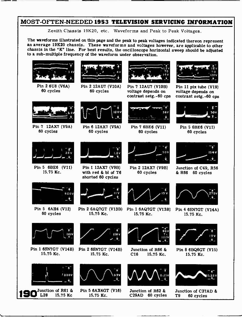
MOST -OFTEN -NEEDED 1953 TELEVISION SERVICING INFORMATIONZenith Chassis 19K20, etc. Waveforms and Peak to Peak Voltages.
The waveforms illustrated on this page and the peak to peak voltages indicated thereon representan average 19K20 chassis. These waveforms and voltages however, are applicable to otherchassis in the "K" line. For best results, the oscilloscope horizontal sweep should be adjustedto a sub -multiple frequency of the waveform under observation.
' 1 8V
Pin 2 6118 (V6A)60 cycles
PRP
Pin 7 12AX7 (V9A)60 cycles
-jv
Pin 5 6BE6 (V11)15.75 Kc.
TIT 17rP"1 , 4V
Pin 2 12AU7 (V10A)60 cycles
106V
Pin 6 12AX7 (V9A)60 cycles
Pin 1 12AX7 (V9B)with red & bl of T6shorted 60 cycles
,..1100 11 ve"" _
- 4-:"'"-'10="---' I , 2 VTO
f 4 V_+.
Pin 7 12AU7 (V10B)voltage depends oncontrast setg.-60 cps
'411rPriMe38V
Pin 7 6BE6 (V11)60 cycles
APin 2 12AX7 (V9B)
60 cycles
13V
I wrifir.'IITIPrr I 42-v
TOI 20 V
Pin 11 pix tube (V19)voltage depends oncontrast setg.-60 cps
Pin 5 6BE6 (V11)60 cycles
IS 4 V
Junction of C49, R56& R66 60 cycles
27 sv
Pin 5 6AH4 (V12) Pin 2 6AQ7GT (V13B) Pin 1 6AQ7GT (V13B) Pin 4 6SN7GT (V14A)60 cycles 15.75 Kc. 15.75 Kc. 15.75 Kc.
Iiev90VT
10 OV
Pin 1 6SN7GT (V14B) Pin 2 6SN7GT (V14B) Junction of R66 &15.75 Kc. 15.75 Kc. C16 15.75 Kc.
190
93V \ / \ AO.ISV
Junction of R61 & Pin 5 6AX4GT (V16) Junction of R62 &L28 15.75 Kc 15.75 Kc. C29AD 60 cycles
Pin 8 6BQ6GT (V15)15.75 Kc.
Junction of C37AD &T9 60 cycles

MOST -OFTEN -NEEDED 1953 TELEVISION SERVICING INFORMATION
Index Under each manufacturer's name are listed that make chassisand models in numerical order, at left. The corresponding pagenumber at right of each listing refers to the first page of each sec-
tion dealing with such material.
Admiral Corp. Arvin Industries Crosley, cont. Hallicrafters17DX10 5 TEMP 19 385 37 1010P 7217DX11 5 TEZZO, -1 19 386 37 1012P 7217DX12 5 TE331 19 387 37 1013C 7219B1 5 TE332 19 393 like 386 1021P 721901 5 TE337 23 394 like 386 1022C 7219E1 5 TE341 23 396 37 1026P 7219F1, -A 5
19G1 51981 5
19K1 519N1 5
22A2 1222A2A 1222C2 1222E2 1222M1 12221 12121DX10,-A 5
121DX11 5
121DX12,-A 5
121DX16,-A,-L 5
TE341-3 246000 Series 196173 196175TM 196179TM 196213TB, -TM 196215C8, -CM 197200 Series 237210CB, -CM 237210CR 237212CFP 237212 MEA 237214CM 237216CB 237218CB, -CM 23
Du Mont Labs, 1027C 721051P 721052P 721053P 721054P 721055C 721056C 721060C 721061C 721062C 721063C 721075 711200 Series 71A1200D 71012008 71
17T350 4121T327 4121T328 4121T329 4121T359 4121T366 4121T376, -U 4121T377, -U 4121T378, -U 41RA -166 41RA -167 41RA -170 41RA -171 41
121DX17,-A,-L 5 7219CM 23 Emerson F1200D 71121K15A 12 G1200D 71711B, -F 47121K16A 12121K17A 12121M10 12
qapehart-Farnsworth
712B, -F 47716D, -F 47717D, -F 47
J12008 71K1200D 71L1200D 71CX-37 33
121011A 12 CT -75 33 719D, -F 47 P12000 71121M12A 12 CT -77 33 720B, -D 47 R1200D 71221DX15,-A,-L 5 CT -81 33 721D 47 T1200D 71221DX16,-A,-L 5 722D 47 1112000 71221DX17,-A,-L 5 CBS -Columbia 727D 47 X1200D 71221DX26,-A,-L 5 17C18 27 728D 47 A1300D 71221DX38,-A 5 176118 27 731D 47 Hoffman221K45A 12 17T18 27 732B 47 21B116 78221K46A 12 20108 27 733F uses 218309 78221K47A 12 20228 27 chassis 120169F 21B701 78222DX15 5 20T18 27 734B 47 21B907 78222DX15S 12 21C11, -B 30 736B 21M115 78222DX16 12 21C18 27 uses 1201718 21M308 78222DX17 12 21021 30 741D uses 2124700 7822=26 12 21C31B 30 chassis 1201688 21M906 78222DX27 12222DX48 12222DX49 12321DX15,-A,-L 53218X16, -A, -L 53210X17, -A, -L 5321DX25A,-B 5321DX26,-A,-B 5321DX27A, -B 5
21C41 3021T11 30817, -1 27820, -1 27821 271021 30
Coronado
120163B, -D 471201648 47120166D 47120167D 471201688 47120169B 47120169F combin.like 120169B
21P310 7821P702 7821P908 7827M709 78196 78196M, -T 78197 78199 78see Gamble-Skog.
321M25A 12321M26A 12321M27A 12322DX16 12421H15A 12421M16A 12421M35 12421M36 12421M37 12520M11 12520M12 12520M15 12520M16 12520M17 12
Crosley Corp.1201718 similar
to 120166D
Farnsworth - see
MagnavoxEU-17C0L 37EU-17COLB 37EU-17COLBU 37EU-17COLU 37EU-17TOLa 37EU-17TOLB 37EU-17TOLBU 37EU-17TOLU 37EU-21COLBd 37EU-21COLBe 37EU-21COLBU
uses 394EU-21COLd 37
105 Series 83105C 83105E 83105F 83105L 83105M 83CT331 83CT332 83CT333 83CT334 83CT335 83CT336 83CT337 83
Capehart -Far .
Gamble-Skogmo25TV2-43-9045A25TV2-43-9045B25TV2-43-9045C25TV2-43-9060A25TV2-43-90608all on page 55
EU-21C0Le 37 General -Electric CT338 83EU-21COLU 20C105 57 CT339 83
Air King -- see uses 394 20C106 57 CT340 83CBS -Columbia. EU-21TOL 37 20T2 57 CT341 83
EU-21TOLB 37 210200 57 CT342 83Airline -- see EU-21TOLU 21T4 57 CT343 83
Montgomery -W uses 293 21T5 57 CT344 to -348 83
191

MOST -OFTEN -NEEDED 1953 TELEVISION SERVICING INFORMATION
Magnavox, cont. Motorola, cont. Philco, cont. Sparton Westinghouse +CT349 83 21K5, -B 91 53-T2269 107 (Sparks-Withingron) H -690K21 179CT350 83 21K6 91 53-T2270 107 27D213 151 H -691K21 179CT351 83 21K7 91 53-T2271 107 5342A 151 H -692T21 179CT352 83 21T3 91 53-T2272 107 5343A 151 H -695K21 179CT353 83 21T4A, -AC 91 53-T2273 107 5383A 151 H -699K17 179CT354 83 21T4ACE, -EA 91 53-T2285 107 5384A 151 H -700T17 179CT355 83 21T5A, -BA 91 53-T2286 107 5385A 151 H -701T17 179CT356 83 TS -292A 91 53-T2287 107 5386A 151 H -702K17 179CT357 83 TS -292B 91 71 108 10352 151 H -703K17 179CT362 83 TS -324A, -B 91 81 112 10353 151 H -704T17 179CT363 83 TS -395A 91 84 107 H -705K17 179CT372 83 TS -400A 91 91 114 H -706T16 179CT373 83 TS -401 91 94 107 H -708T20 179
TS -408A 91 Stewart -Warner H -710T21 179Meek Industries TS -410A 91 H -711T21 17921C -9211D 155
21C -9211E 15517PCSB 87C
TS -501A 91 RCA Victor H -713T21 179H 17917T200 125
17PTE2 87 Qlympic Radio 17T201 125 21C -9211F 155 -714K21H 179
20PCSB2 8720PCW2 87209TE2 87
17T202 12517T211 12517T220 125
21T-92118 15521T -9211C 1559210C 155
-715K21H -716T17 usesV-2208-1
H -718K20 179
TK 99TL 9917C44 99
2OPTSB2 87 17K41 99 17T250DE 133Stromberg- H -720K21 179
2OPTW2 8720TPRS2 8721PCS2 8721QDCS2 87
17K42 9917K50 9917T40 9917T48 99
17T261DE 13321T207, and -Guse KCS-72A
21T208 125
H-721K21 179H -722K21 179H -723K21 179H -724T20 179
Carlson417 Series 159421 Series 159
24qDCS2 87MM -617C, -M 87MM -620C, -T 87JM-717C, -T 87JM-720C, -T 87JM-721C 87JM-721CD 879026 879032 87
20C45 9920052 9920053 9920D49 9920K43 9920K51 9920T46 9920T47 99
21T217 12521T218 12521T227 12521T228 12521T229 12521T242 12521T244 125KCS-72 125KCS-72A 125
Sylvania Elect. H -725T20 179H -730C21 179H -732C21 179H -733C21 179H -754K21 179V-2207-1 179V-2208-1 is like
V-2207-1V-2214-1 179
1-504-1 1671-504-2 1671-508-1 1671-508-2 1671-510-1 1671-510-2 167105B, -BU 167
9033 87 Packard -Bell KCS-72D-1 125KCS-72D-2 125
105M, -MU 167120B, -BU 167 V-2215-1 179
V-2215-2 1792421 103lignIgomery Ward 2422 103
2423 1032822 103
KCS-74 133
Raytheon
120M, -MU 167126B, -BU 167126L 167
V-2215-3 179V-2216-1 179V-2216-2 179
25WG-3066A 8925WG-3066B 8925WG-3071A 89 17T1 136 126M, -MU 167
V-2216-3 17925WG-3071B 8925WG-3072A 89
Philco Corp. 17T2 13621T1 136
172K, -KU 167172M, -MU 167 V-221-5
V-221761
-1 to -579G-1 11025WG-3072B 8925WG-3073A 8925WG-3073B 8925WG-3075A 8925WG-3075B 8925WG-3077A 8925WG-3077B 8925WG-3079A 89
H-1 111J-1 116G-2 1070-4 107H-4 107J-4 10752-T1802 10752-T1821 107
21T2 136M -1733A 136M -1734A 136C -1735A 136C -1736A 136M -2107A 136C -2108A 136C -2109A 136
175B, -BU 167175E 167175M, -MU 167176B, -BU 167176L 167176M, -MU 167177B, -BU 167177M, -MU 167
all on 179V-2218-1 179
179V -2219-1V-2218-11 179V-2220-1 to -4
all on 179V-2220-11 179
25W0 -3079B 89 52-T1822 107 C -2110A 136 178B, -BU 167Zenith Radio
52-T2120 107 C -2111A 136 178M, -MU 16719K20 185
Motorola 52-T2150W 107 19K22 18517F12D 91 52-T2151 107 Sears, Roebuck 19K23 185
153-16 14717F13, -B 91 52-T2252 107 Trav-ler Radio 211(20 18517F13BC, -C 91 53-T1824 107 163-16 147 36A2 175 K1812E, -R 18517K13D 91 53-T1825 107 1132-17 147 36B2 175 K1915E, -R 18517K14, -A,-B 91 53-T1826 107 1163-17 147 217-32 175 K1820E, -R 18517K14BC,-C 91 53-T1827 107 1175-21 147 217-33 175 K18465, -R 18517K14W, -WC 91 53-T1852 107 1182-21 147 217-37 175 K1850E, -R 18517K15, -B 91 53-T1853 107 1189-21 147 217-331 175 K1880R 18517K15BC, -C 91 53-T1883 107 478.319 147 217-371 175 K2229R 18517K16, -C 91 53-T1884 107 478.341 147 220-34 175 K2230E, -R 18517T9EF, -F 91 53-T1886 107 478.375 147 220-35 175 K2240E, -R 18517T1OD 91 53-T2125 107 478.376 147 221-36 175 K2258E, -R 18517T11, -C 91 53-T2126 107 478.380 147 K22605 18517T11E, -EC 91 53-T2127 107 478.381 147 Westinghouse K2263E 18517T12, -B,-C 91 53-T2152 107 H -667T17 179 K2266, -R 18517T12W, -WC 91 53-T2183 107 Sentinel H -668T17 179 K22675 18517T13 91 53-T2227 107 1U-458 141 H -673K21 179 K2268R 18521C1 91 53-T2228 107 1U-459 141 H -676T21 179 K2270H, -R 18521C1B 91 53-T2260 107 1U-460 141 H -678K17 179 K2286R 18521F2, -B 91 53-T2262 107 10-461 141 H -679K17 179 K2287R 18521F3, -B 91 53-T2264 107 H -681T17 179 K22885 18521K4, -A 91 53-T2266 107 Silvertone, see H -688K24 179 K2290R 18521K4B, -W 91 53-T2268 107 Sears, Roebuck H -689T16 179 K22915 185
192

ti Another
Supreme Publications
Service Manual
Yi.P.P./V.VCAVVe.14%%"1.1.N4A/VerVietWVANYWANVONAN'OdWiel
Supreme Publications are Available at All Leading Parts Jobbers