Operating Instructions - Panasonic
40
English 中文 Operating Instructions Air Conditioner Model No. Indoor Unit Outdoor Unit CS-RU18YKA CS-RU24YKA CU-RU18YKA CU-RU24YKA ACXF55-32320 操作說明書 空調器 2-19 在操作空調器前,請細讀此操作說明,並保存此書以備日後參 考。 安裝前,安裝人員應: 閱讀安裝說明,並要求顧客保留此安裝説明以備將來參考。 取出包裝在室内機箱子的遙控器。 如果將本空調器轉讓給新的用戶或送往回收廠,請務必將 本説明書一并交出。 Operating Instructions Air Conditioner 20-37 Before operating the unit, please read these operating instructions thoroughly and keep them for future reference. Before installation, the installer should: Read the Installation Instructions, then request the customer keep them for future reference. Remove the remote control packed with the indoor unit. If the equipment is transferred to a new user or delivered to a recycling plant, be sure also to hand over the manual.
-
Upload
khangminh22 -
Category
Documents
-
view
0 -
download
0
Transcript of Operating Instructions - Panasonic

Eng
lish
中文
Operating InstructionsAir Conditioner
Model No.Indoor Unit Outdoor UnitCS-RU18YKACS-RU24YKA
CU-RU18YKACU-RU24YKA
ACXF55-32320
操作說明書空調器
2-19
在操作空調器前,請細讀此操作說明,並保存此書以備日後參考。安裝前,安裝人員應: 閱讀安裝說明,並要求顧客保留此安裝説明以備將來參考。取出包裝在室内機箱子的遙控器。如果將本空調器轉讓給新的用戶或送往回收廠,請務必將本説明書一并交出。
Operating InstructionsAir Conditioner
20-37
Before operating the unit, please read these operating instructions thoroughly and keep them for future reference.Before installation, the installer should:Read the Installation Instructions, then request the customer keep them for future reference.Remove the remote control packed with the indoor unit.If the equipment is transferred to a new user or delivered to a recycling plant, be sure also to hand over the manual.

2
簡易指南裝入電池
3
OPEN 21
1 拉出遙控器的背蓋。
2 裝入 AAA 或 R03 電池。
3 把蓋關上。
新的內置網絡適配器,使您可以從任何地方控制空調的操作。
請在室內機遙控接收器的 8 米範圍内使用遙控器。
A 時間設定
1 按下 ,然後按下
並設置時間。
• 持續按下 大約
5 秒,以顯示 12 小時 (am/pm) 或 24 小時的格式。
2 按下 確認。
POWERFUL/ECO
FAN SPEED/QUIET
ON
OFF
TIMER
POWERFUL/ECO
FAN SPEED/QUIET
ON
OFF
TIMER
A
B

3
B 基本操作
2 按 選擇所需的
模式。
DRYAUTO COOL
1 按 開始/停止
操作。
POWER
• 當本機ON(開啟) 時, 將從遙控器顯示屏上消失。
3 按下TEMP UP(溫度上升),TEMP DOWN(溫度下降)以選擇所需的溫度。
上升
下降
選擇範圍: 16.0 °C ~ 30.0 °C / 60 °F ~ 86 °F。• 持續按下 大約 10 秒,以顯示 °C 或 °F 的格式。
目錄
安全措施 ..........................4-11
如何使用 ........................12-13
學習更多… .........................14
清洗空調器 .........................15
故障檢修 ........................16-18
信息 ....................................19
附件• 遙控器
• AAA 或 R03 電池 × 2• 遙控器托架
• 用於遙控器托架的螺釘 × 2
本操作說明書裡的圖解僅作為說明用途,並且可能與實際產品有所區别。若發生變更,恕不另行通知。
感謝您購買 Panasonic 空調器。
中文
4
安全措施
警告
室内機及室外機
此裝置不適合殘疾、感應欠佳或智障,經驗與知識不足的人士(包括兒童)使用。除非負責其安全的監督人從旁監督或指示如何正確使用此裝置。務必監督兒童以確保他們不會玩弄本機。
請諮詢授權經銷商或專業人員清潔内部零件,修理、安裝、拆除、拆卸、和重新安裝本機。安裝及處理不當將導致漏電,觸電或火災。
請向授權經銷商或專業人員確認有關任何指定製冷劑類型之運用。使用所指定以外的製冷劑類型會導致產品損壞,爆裂並導致傷害等。
切勿使用除製造商建議以外的方法來加速除霜過程或清理。任何不適當的方法或使用不相容的材料可能導致產品損壞,爆裂和嚴重傷害。
切勿將本機安裝在爆炸或可燃性的環境中。否則會導致火災。
切勿把手指或其他物件插入空調器的室内或室外機以免受到旋轉部件傷害。
閃電時切勿觸摸室外機,否則會導致觸電。
切勿長時間受冷氣流直接吹拂以免過冷。
切勿坐或踩踏在主機上以免意外摔跤。
遙控器
切勿讓嬰兒和小孩玩遙控器以免不小心吞下電池。
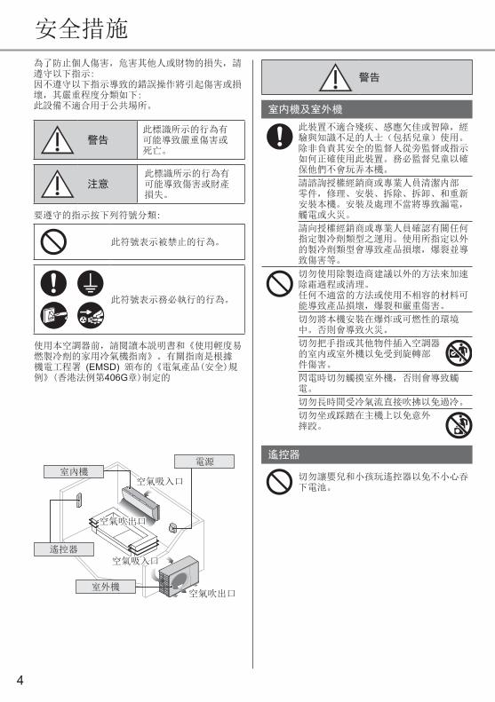
為了防止個人傷害,危害其他人或財物的損失,請遵守以下指示: 因不遵守以下指示導致的錯誤操作將引起傷害或損壞,其嚴重程度分類如下:此設備不適合用于公共場所。
警告此標識所示的行為有可能導致嚴重傷害或死亡。
注意此標識所示的行為有可能導致傷害或財產損失。
要遵守的指示按下列符號分類:
此符號表示被禁止的行為。
此符號表示務必執行的行為。
使用本空調器前,請閱讀本説明書和《使用輕度易燃製冷劑的家用冷氣機指南》。有關指南是根據機電工程署 (EMSD) 頒布的《電氣產品(安全)規例》(香港法例第406G章)制定的
室內機
室外機
遙控器
空氣吸入口空氣吸入口空氣吸入口空氣吸入口
空氣吸入口空氣吸入口
空氣吹出口空氣吹出口
空氣吹出口空氣吹出口
電源

5
安全措施
注意
室内機及室外機
切勿用水、苯、稀釋劑或潔亮粉末清洗室内機以免損壞或腐蝕本機。
切勿充作其他用途,如貯藏食物、動物、植物、藝術品或其他物件。否則會破壞品質等。
切勿在氣流出口使用任何易燃器具以免引起火災。
切勿讓植物或寵物受冷氣流直接吹拂以免損傷等。
切勿觸摸尖銳的鋁散熱片以免受到尖銳部件傷害。
當在地面打蠟時切勿ON(開啟)室内機。打蠟完畢之後,請先讓房間良好通風再操作本機。
切勿將本機安裝在油煙重的場所以免損壞本機。
切勿拆卸本機來進行清洗工作以免受傷。
當清洗本機時切勿踩踏在不穩固的架子上以免受傷。
切勿將花瓶或水容器放置在本機上。水會進入本機而導致絕緣受到破壞。這會引起觸電。
在操作過程中切勿長時間打開窗戶或門,否則可能導致低效的電力使用和不舒適的溫度變化。
為免漏水,請確保排水軟管:- 連接正確,- 不受通水道及容器阻擋,或- 不浸在水裏
長時間使用或與其他易燃設備一起使用後請定時讓房間通風換氣。
長期使用後,請注意安裝支架是否有損壞以免主機墜落。
遙控器
切勿使用可充電電池 (Ni-Cd)。它會損壞遙控器。
為免遙控器失靈或損壞:• 如果準備長期不使用本機,務必將電池取出。
• 務必採用同類型的新電池並對準電極插入。
電源
切勿以抽拉電線的方式來拔除插頭以免觸電。
電源
切勿採用改裝電線,接合電線,延長電線或非指定的電線,以免過熱及火災。
為免過熱,火災或觸電:• 切勿與其他設備共用一個電源插座。• 切勿用潮濕的手操作。 • 切勿過度扭曲電線。• 切勿以插入或拉出插頭的方式來操作或停止本機。
如果電線損壞,必須由製造商、其服務代理商或具有同等資格的合格人員進行更換以免遭受危害。
強烈建議您安裝接地漏電電源斷路器 (ELCB) 或殘餘電流裝置 (RCD) 以免觸電或火災。
為免過熱,火災或觸電:• 妥當插入插頭。• 務必定時用乾布擦掉插頭上的灰塵。
當出現任何異常/故障時,請停止使用本機,拔出電插頭或關掉電源開關及斷路器。(煙霧/火災/觸電危險)異常/故障舉例• 接地漏電電源斷路器 (ELCB) 頻繁跳閘。
• 出現燒焦味。• 本機出現異常噪音或振動。• 室内機漏水。• 電線或插頭變得異常熱。• 無法控制風量。• 本機立即停止運轉,雖然已經打開準備操作。
• 雖然已經停止操作, 風扇仍然不停止轉動。
立即諮詢經銷商以進行保養/修理。
更換或安裝電源插頭必須由授權/合格人員進行。主導電體裏的電線由下列不同的顏色分類:
接頭紅色
電線負載線
中線
接地線
顏色(BS 標準)
藍色
綠色-黃色
褐色黑色
綠色/黃色
電線顏色會隨國家電線代碼的標準而有所區别。
本設備必須接地以免觸電或火災。
為免觸電,請在下列情況時關閉電源並拔出插頭:- 清洗或維修之前,- 長期不使用時,或- 異常強烈閃電時。
中文
6
安全措施
nanoe™-G 產生器
請勿觸摸尖角,以免造成傷害。
警告
此設備灌有R32(微可燃性製冷劑)。
如果製冷劑洩漏並暴露於外部的點火源,則存在火災的風險。
室内機及室外機
此裝置需安裝和/或操作於地面面積大於 Amin (m²)的房間內,並遠離點火源,如熱氣/火花/明火或危險的地方(如氣體用具,烹飪氣體,網狀氣體供應系統或電炊具等放置的地方)。(請參閱安裝說明表中, 關於Amin (m²)的A表)
請注意,製冷劑可能不含異味。因此,強烈建議設置合適的可燃性製冷劑氣體探測器,此探測器必需正常操作並能夠在發現氣體洩漏時提出警告。
請保持所有的通風口暢通無阻。
當此裝置加壓時,切勿刺穿或燃燒它。切勿把此裝置暴露於熱氣,火焰,火花或其它點火源。否則可能導致爆炸並造成傷害或死亡。
使用R32製冷劑的注意事項
基本的安裝作業程序與常規的製冷劑型號 (R410A,R22) 相同。
由於R32型號製冷劑的作業壓力高於R22型號,一些管道,安裝和維修工具是特殊的。特別是,當用新的R32型號製冷劑更換舊的R22型號製冷劑時,必需把室外機常規的管道和鍛壓螺母更換為R32和R410A型號的管道和鍛壓螺母。於R32和R410A型號的製冷劑,室外機可以使用相同的管道和鍛壓螺母。
禁止在同一個系統內混合不同的製冷劑。 使用R32和R410A型號的製冷劑,其充灌端螺紋直徑不同,這是爲了防止使用R22製冷劑進行錯誤充灌和確保其它安全事宜。因此,請事先檢查。[R32和R410A的充灌端螺紋直徑為1/2英寸。]
務必隨時確保異物(油和水等)不進入管道。此外,在存儲管道時,請夾緊,並用膠帶等牢固地密封開口。(R32的操作和R410A相似。)• 操作、保養、修理和製冷劑回收務必由經訓練及合格使用易燃製冷劑的人員處理,並按照製造商的建議進行。對系統或設備相關部件進行操作、維修或保養的任何人員都必需經訓練並持有合格的認證。
• 製冷迴路的任何部分(蒸發器、空氣冷卻器,空調箱 (AHU),冷凝器或液體接收器)或管道不得置放在熱源、明火、操作中的氣體用具或電熱器附近。
• 用戶/擁有人或其授權代理人必須按照國家法規,定期(每年至少一次)檢查警報器、機械通風設備和探測器,以確保這些器材正常運行。
• 需備存一本記錄簿。檢查的結果必須記錄在記錄簿内。
• 在佔用空間換氣的情況下,務必確保無障礙物。
• 在新的製冷系統投入服務前,負責安置系統的人務必確保經訓練及合格的操作人員根據製冷系統說明書的指示,了解製冷系統的構建、監督、運行和保養,並按照指示處理該系統,同時遵守其安全措施,以及了解相關製冷劑的性質和處理方法。
• 經訓練及合格人員的基本要求如下:a) 擁有易燃製冷劑法律、規章和標準的
相關知識;及, b) 擁有處理易燃製冷劑、個人防護裝
備、製冷劑洩漏預防、鋼瓶處理、充灌、洩漏探測、回收和報廢的詳盡知識和技能;及,
c) 能夠理解和實踐國家法律、規章和標準的要求;及,
d) 不斷參加定期和進一步的培訓,以維持這方面的專業知識。

7
安全措施
e) 佔用空間內的空調管道應以一種可以避免操作和維修時發生意外損壞的方式安裝。
f) 必需採取預防措施來避免製冷管道過度振動或脈動。
g) 請確保防護裝置、製冷管道和配件都獲得良好的保護以防止不利的環境因素(例如釋放管道内積水和結冰,或污垢和碎屑積聚的危險)影響。
h) 製冷系統中長管道的膨脹和收縮必需設計和安裝牢固(架穩和加上防護),以減少液壓衝擊而損壞系統的可能性。
i) 保護製冷系統免因移動家具或裝修活動而意外破裂。
j) 為確保無洩漏,現場製作的室內製冷劑接頭應進行密封性測試。試驗方法的靈敏度需在每年5克製冷劑或更好,在最大允許壓力的至少0.25倍(> 1.04 MPa,最多4.15 MPa)氣壓下。不應檢測到洩漏。
1. 安裝(空間)• 帶有易燃製冷劑的產品需按照安裝說明表A中提到的最小房間面積Amin (m²) 進行安裝。
• 在現場充灌的情況下,不同長度的管道對製冷劑充料的影響必須量化、測量和標籤。
• 必需確保最低限度的管道安裝作業。避免使用凹陷管道,也不允許急性彎曲。
• 必需確保管道作業不導致物質上的損壞。
• 必須符合國家天然氣法規,州政府規章和立法。根據適用的法規,通知有關當局。
• 必須確保機械連接的部分在進行保養時可被接觸。
• 在需要機械通風的情況下,通風口需暢通無阻。
• 在報廢本產品時,需遵守注意事項第12條的規則並需符合國家的規定。 請聯繫當地的市政局辦公室以進行正確的處理。
2. 維修2-1. 維修人員• 有關的系統務必由用戶或責任方僱用的經訓練及合格的服務人員檢查,並定期監督和保養。
• 請確保實際的製冷劑充料體積與相應的空間(製冷劑充灌在内)大小相符。
• 請確保製冷劑充料無洩漏。• 任何參與或進入製冷劑迴路作業的人員必需持有業界認可評估機構發出的當前有效證書,此證書授權他們根據行業認可的評估規範,合格的安全處理這項工作。
• 維修只能按照設備製造商的建議進行。保養和修理需要其他技術人員的協助,並需在合格使用可燃性製冷劑人員的監督下進行。
• 維修只能按照製造商的建議進行。
2-2. 作業• 對含有可燃性製冷劑系統開始作業前,安全檢查工作是必需的,以確保點火風險降至最低。 在修理製冷系統前,注意事項第2-2至2-8條的規則必需遵守。
• 作業需在受控程序下進行,以便把作業時出現可燃性氣體或蒸氣的風險降至最低。
• 所有保養人員和當地的工作人員必需根據工作的本質,在受指導和監督的情況下進行工作。
• 避免在有限的空間內作業。隨時確保遠離源頭,保持至少2米的安全距離,或半徑至少2米的自由空間。
• 在條件允許的情況下,佩戴合適的防護設備,包括呼吸防護。
• 確保點火源和熱金屬表面遠離現場。
中文
8
安全措施
2-3. 檢查製冷劑的存在• 在作業前和作業期間,需使用適當的製冷劑探測器檢查該區域,以確保技術人員了解潛在的可燃性環境。
• 請確保所使用的洩漏探測設備適用於可燃性製冷劑,即無火花,充分密封或本質上安全。
• 在發生洩漏/溢出的情況下,立即讓該區域通風,並保持風向向上,遠離溢出/釋放的地方。
• 在發生洩漏/溢出的情況下,通知下風人員,緊急隔離危險區域並確保無非授權人員在場。
2-4. 滅火器存在• 如果任何熱作業必需在製冷設備或任何 相關部件上處理,適當的滅火設備必須唾手可得。
• 在充灌區附近需備有一個乾粉或CO2滅火器。
2-5. 無點火源• 任何人不得在危險的情況下作業,包括在暴露含有或已含有可燃性製冷劑的任何管道作業,其使用任何點火源可能導致火災或爆炸的風險。他們在進行此作業時必定不能吸煙。
• 所有可能性的點火源(包括吸煙),必需與安裝,修理,拆卸和報廢地點保持足夠遠的距離,這是爲了避免作業期間可燃性製冷劑釋放到周圍的空間。
• 在進行作業前,必需先調查設備周圍的區域,以確保沒有可燃性危險或點火風險。
• 需顯示“禁止吸煙”標識。
2-6. 通風區• 在進入系統或進行任何熱作業前,請確保該區域處於開放狀態或有足夠的通風。
• 在進行工作期間,需持續保持特定程度的通風。
• 通風作業必需安全地疏散任何釋放的製冷劑,最好把它排放到大氣中。
2-7. 檢查製冷設備• 更換電器組件時,需確保該組件用於正確的目的及符合正確的規格。
• 任何時候都必需遵守製造商的保養和維修指南。
• 如有疑問,請諮詢製造商的技術部門以尋求幫助。
• 以下檢查適用於使用可燃性製冷劑的安裝。 - 實際的製冷劑充料體積與相應的空間 (製冷劑充灌在内)大小相符。 - 通風機和出口必需充分的操作,不受任何阻礙。 - 如果使用間接的製冷迴路,則第二迴路必需檢查,以確定是否出現製冷劑。 - 設備的標記必需持續可見和清晰。字跡模糊的標記及標識必需更正。 - 製冷管或組件安裝的位置可以防止它們暴露於任何有害物質,此有害物質可能腐蝕含製冷劑的組件,除非這些組件由防腐蝕材料製成,可保護組件免受腐蝕。
2-8. 檢查電器設備• 電器組件的修理和保養必需包括初步的安全檢查和組件檢查程序。
• 初步的安全檢查必需包括但不限於:- - 電容器釋電:這項作業必需以安全的方式進行,以避免可能產生的火花。 - 在充灌,回收或清理系統時,沒有帶電的電器組件和電線暴露在外。 - 有持續性的地面連接。
• 任何時候都必需遵守製造商的保養和維修指南。
• 如有疑問,請諮詢製造商的技術部門以尋求幫助。
• 如果出現危及安全的故障,在妥善的處理前,不可將電源連接到電路。
• 如果故障不能立刻糾正,但又必需繼續操作時,應使用適當的臨時解決方案。
• 必需通知物主或向設備的物主報告,以讓他把信息傳達給其他人。
9
安全措施
6. 可燃性製冷劑的探測• 在任何情況下,不得使用潛在點火源來尋找或探測製冷劑洩漏。
• 鹵化物燈(或使用明火的任何檢測器)不得使用。
7. 以下的洩漏探測方法可應用在所有的製冷劑系統
• 采用其檢測洩漏靈敏度為每年5克製冷劑或靈敏度更好的探測器(例如:通用嗅探器)時,在氣壓比最大允許範圍(> 1.04 MPa,最多4.15 MPa)多出0.25倍的情況下,不應檢測到洩漏。
• 電子洩漏探測器可用來探測易燃製冷劑,但其敏感度可能不足,或需重新校準。(探測設備需在無製冷劑區域校準。)
• 請確保探測器不是潛在的點火源,並適用於該製冷劑。
• 洩漏探測器必需設定在製冷劑LFL的百分 比並需根據使用的製冷劑校準,其適當的氣體百分比需確定(最高25%)。
• 洩漏探測器流體適合用於大多數的製冷劑,例如氣泡法和熒光法製冷劑,但應避免使用含氯的清潔劑,因為氯與製冷劑會產生化學反應,導致銅管道腐蝕。
• 如果懷疑有洩漏,所有的明火必需熄滅/撲滅。
• 如果發現製冷劑洩漏而需進行釬焊,所有的製冷劑必需從系統回收,或在系統遠離洩漏的部分隔離(通過正確的關閉閥)。必須遵守安全措施事項第8條移除製冷劑。
3. 密封組件的修理• 在拆卸密封蓋以修理密封組件的期間,所有電源必需從操作的設備中切斷。
• 如果維修期間絕對需要電流供應至設備,則須將永久式洩漏探測器安置在最危急的地點,以警告潛在的危險狀況。
• 需特別注意以下事項,以確保在電器組件上作業時,外殼不會變形,而影響其防護程度。 這包括電纜損壞,連接數量過多,未按原規範製造的終端,密封處損壞,密封管安裝不正確等。
• 請確保該設備牢固的鑲嵌。• 請確保密封處或密封的材料未失效,以致它無法防止可燃性氣體進入。
• 更換的部件必需符合製造商的規格。注意:使用矽膠密封劑可能會影響某些類型洩漏探測設備的效率。操作本質上安全的組件時,無需事先隔離。
4. 本質上安全組件的修理• 在還未確認使用中的設備不超過允許的電壓和電流前,不要對電路施加任何永久性電感或電容負載。
• 本質上安全的組件是唯一可以在可燃性環境中作業的類型。
• 測試儀器必需有正確的額定值。• 僅用製造商指定的部件更換組件。製造商未指定的部件可能在氣體洩漏的環境下導致製冷劑點火。
5. 佈線• 檢查電纜以確保它不受磨損,腐蝕,超壓,振動,尖銳邊緣或任何其它不利環境影響。
• 檢查也需考量來自壓縮機或風扇等來源的老化或持續振動的影響。
中文

10
安全措施
10. 解除調試• 在進行此程序前,技術人員完全熟悉該設備及其所有細節是非常重要的。
• 所有的製冷劑安全的回收是推薦的良好做法。
• 在進行此任務前,必需抽取油和製冷劑樣品,這是爲了在重用回收製冷劑時能夠提供樣品做分析。
• 在任務開始前,確保電源正常的供應是非常重要的。a) 請熟悉設備及其操作。b) 以電器式隔離系統。c) 在進入程序前,請確保:• 機械處理設備存在,如有需要,用來處理製冷劑鋼瓶;
• 所有個人防護裝備均存在並正確的使用;
• 合格人員全程監督回收流程;• 回收設備和鋼瓶符合相關的標準。d) 如果可能,排空製冷劑系統。e) 如果無法真空,製作歧管,以從系統
的各個部分移除製冷劑。f) 在回收之前,請確保鋼瓶處在正確的
標度。g) 啟動回收機器並按照說明操作。h) 切勿過度充灌鋼瓶。(不超過液體充
灌量的80%)。i) 切勿超過鋼瓶的最大作業壓力,即使
是暫時性的。j) 當鋼瓶正確的充灌至流程完成后,請
確保鋼瓶和設備及時移出現場,並關閉設備上的所有隔離閥。
k) 回收的製冷劑不得充灌至另一個製冷系統,除非經過清理和檢查。
• 在充灌或排放時,靜電荷可能積聚並產生危險狀況。爲了避免火災或爆炸,在充灌/排放之前,請通過接地和連接容器及設備來釋放靜電。
11. 標籤• 設備需貼上標籤,說明它已經解除調試並清空製冷劑。
• 標籤需註明日期和簽字。• 確保設備上貼有標籤,說明該設備含有可燃性製冷劑。
8. 移除和排空• 進入製冷劑迴路進行修理工作 - 或因其它原因 - 應使用常規程序。無論如何,考量其可燃性,良好的做法是非常重要的。以下的程序必須遵守:移除製冷劑 -> 用稀有氣體吹掃迴路 -> 排空 -> 用稀有氣體吹掃 -> 切斷釬焊打開迴路。
• 製冷劑充料必需回收到正確的回收鋼瓶。
• 系統需用OFN來吹掃,以確保設備的安全。
• 此流程可能必需重複數次。• 壓縮空氣或氧氣不得用於此任務。• 吹掃可通過用OFN進入系統的真空並繼續充灌至達到作業的壓力,然後排放到空氣中,最後拉下到真空。
• 該流程必需重複,直到系統內沒有製冷劑為止。
• 使用最后的OFN充料時,系統必需排放至大氣壓的水平,讓作業能夠進行。
• 如果要對管道工件進行釬焊,這種操作是絕對重要的。
• 請確保真空泵的出口不靠近任何點火源,並且可以通風。
OFN = 無氧氮,一種稀有氣體。
9. 充灌程序• 除常規充灌程序外,以下要求必需遵守。 - 使用充灌設備時,請確保不同的製冷劑污染不會發生。 - 軟管或管線需盡量短小以減少其製冷劑含量。 - 鋼瓶需根據說明存放在適當的位置。 - 在為系統充灌製冷劑前,請確保製冷系統接地。 - 充灌完成後(如果尚未),請標籤該系統。 - 需格外小心以確保不過度充灌製冷系統。
• 對系統重新充灌前,需用OFN進行壓力測試(請參閲第7條)。
• 系統在充灌後,調試前需進行洩漏測試。
• 在離開現場前,請進行後續的洩漏測試。
• 在充灌或排放時,靜電荷可能積聚並產生危險狀況。爲了避免火災或爆炸,在充灌/排放之前,請通過接地和連接容器及設備來釋放靜電。
11
安全措施
12. 回收• 從系統中移除製冷劑時,無論是爲了維修還是解除調試,所有的製冷劑安全的移除是推薦的良好做法。
• 將製冷劑轉移到鋼瓶時,請確保只使用適當的製冷劑回收鋼瓶。
• 請確保維持系統總充灌的鋼瓶數量正確。
• 所有使用的鋼瓶是指定用於回收製冷劑並已貼上指明該製冷劑的標籤(如: 製冷劑回收特別鋼瓶)。
• 鋼瓶必需配有壓力釋放閥和連帶的關閉閥,兩者都必需處在良好的工作狀態。
• 回收鋼瓶被抽空,並且可以的話,在回收前先冷卻。
• 回收設備需處在良好的工作狀態,而且手上擁有一套關於設備的說明。這些設備必須適合回收可燃性製冷劑。
• 此外,需有一套校準的稱重秤,並且處於在良好的工作狀態。
• 軟管必需配有無洩漏的斷開接頭,並且處於在良好的狀態。
• 在使用回收機前,檢查它是否處在良好的工作狀態,妥善的保養以及任何連帶的電器組件已經密封以防止製冷劑釋放時點火。如有疑問,請諮詢製造商。
• 回收的製冷劑必須退還給製冷劑供應商並收納在正確的回收鋼瓶。同時,安排相關的廢料轉移單。
• 切勿在回收單位內混合製冷劑,尤其不要在鋼瓶內混合。
• 如果需要移除壓縮機或壓縮機油,請確保先排空至可接受水平,以確保可燃性製冷劑不會殘留在潤滑劑中。
• 排空流程需在壓縮機退還給供應商前進行。
• 只有對壓縮機機體電加熱,才能用來加速此流程。
• 從系統排放壓縮油時必須安全地作業。中文
12
POWERFUL/ECO
FAN SPEED/QUIET
ON
OFF
TIMER
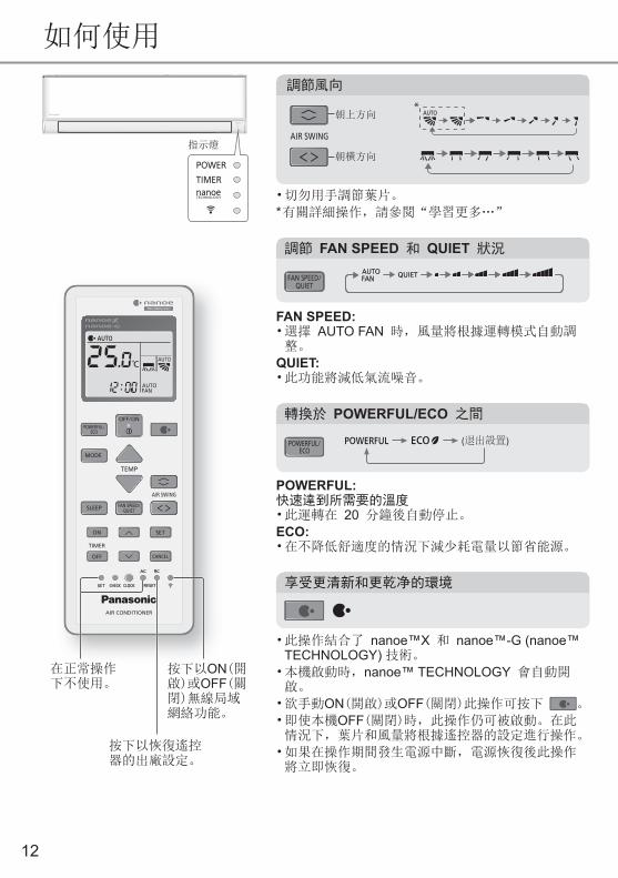
如何使用
• 切勿用手調節葉片。
* 有關詳細操作,請參閱“學習更多…”
AIR SWING
朝上方向
朝橫方向
調節風向
調節 FAN SPEED 和 QUIET 狀況
FAN SPEED:• 選擇 AUTO FAN 時,風量將根據運轉模式自動調整。
QUIET: • 此功能將減低氣流噪音。
FAN SPEED/QUIET
指示燈
POWER
TIMERnanoeTECHNOLOGY
在正常操作下不使用。
按下以ON(開啟)或OFF(關閉)無線局域網絡功能。
按下以恢復遙控器的出廠設定。
POWERFUL:快速達到所需要的溫度• 此運轉在 20 分鐘後自動停止。
ECO: • 在不降低舒適度的情況下減少耗電量以節省能源。
轉換於 POWERFUL/ECO 之間
POWERFUL/ECO
(退出設置)
• 此操作結合了 nanoe™X 和 nanoe™-G (nanoe™ TECHNOLOGY) 技術。
• 本機啟動時,nanoe™ TECHNOLOGY 會自動開啟。
• 欲手動ON(開啟)或OFF(關閉)此操作可按下 。
• 即使本機OFF(關閉)時,此操作仍可被啟動。在此 情況下,葉片和風量將根據遙控器的設定進行操作。
• 如果在操作期間發生電源中斷,電源恢復後此操作將立即恢復。
享受更清新和更乾净的環境
13
參閲“學習更多…”以獲取詳情。
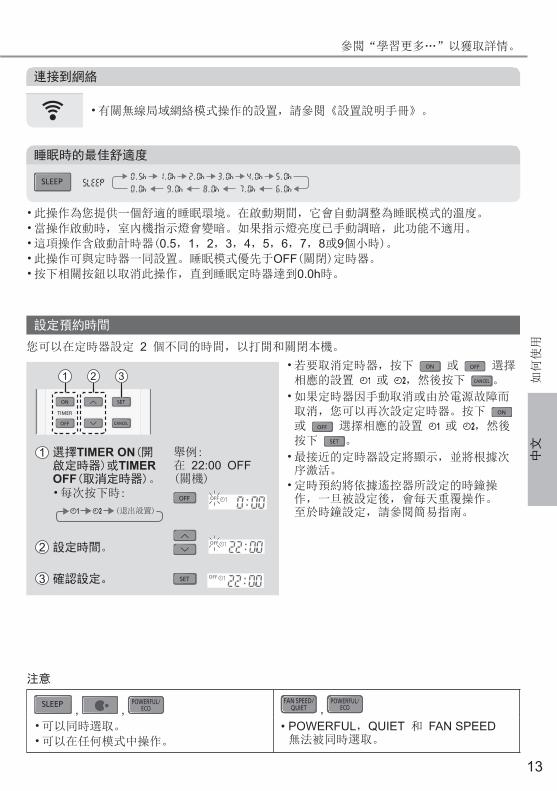
注意
SLEEP , , POWERFUL/
ECOFAN SPEED/
QUIET , POWERFUL/
ECO
• 可以同時選取。
• 可以在任何模式中操作。
• POWERFUL,QUIET 和 FAN SPEED 無法被同時選取。
• 此操作為您提供一個舒適的睡眠環境。在啟動期間,它會自動調整為睡眠模式的溫度。
• 當操作啟動時,室內機指示燈會變暗。如果指示燈亮度已手動調暗,此功能不適用。
• 這項操作含啟動計時器(0.5,1,2,3,4,5,6,7,8或9個小時)。 • 此操作可與定時器一同設置。睡眠模式優先于OFF(關閉)定時器。
• 按下相關按鈕以取消此操作,直到睡眠定時器達到0.0h時。
SLEEP
如何使用
連接到網絡
• 有關無線局域網絡模式操作的設置,請參閱《設置說明手冊》。
設定預約時間
ON
OFF
SET
TIMER
CANCEL
1 2 3
1 選擇TIMER ON(開啟定時器)或TIMER OFF(取消定時器)。
舉例: 在 22:00 OFF (關機)
• 每次按下時: OFF
退出設置
2 設定時間。
3 確認設定。 SET
• 若要取消定時器,按下 ON 或 OFF 選擇相應的設置 或 ,然後按下 CANCEL 。
• 如果定時器因手動取消或由於電源故障而取消,您可以再次設定定時器。按下 ON 或 OFF 選擇相應的設置 或 ,然後按下 SET 。
• 最接近的定時器設定將顯示,並將根據次序激活。
• 定時預約將依據遙控器所設定的時鐘操作,一旦被設定後,會每天重覆操作。至於時鐘設定,請參閱簡易指南。
您可以在定時器設定 2 個不同的時間,以打開和關閉本機。
睡眠時的最佳舒適度
中文

14
運轉模式
AUTO(自動) : POWER(電源)指示燈在開始時閃爍。本機將根據室溫選擇操作模式。
COOL(製冷) : 提供高效舒適製冷,以滿足您的需求。
DRY(除濕) : 空調以低速運轉,進行極為柔和的製冷運轉。
節能溫度設定
在所建議的溫度範圍內操作,本機可為您節省能源。COOL(製冷): 26.0 °C ~ 28.0 °C / 79 °F ~ 82 °F。
氣流方向
在COOL/DRY(製冷/除濕)模式下:水平風向葉片將固定於中間位置。達到溫度後,水平風向葉片將自動向上/下擺動。
在COOL/DRY(製冷/除濕)模式下:水平風向葉片自動向上/向下擺動。
自動重新啟動控制
如果發生電源中斷,電源恢復后將自動重啟先前的運轉模式和風向。• 當定時器被設置時此功能將無效。
nanoe™X 濾塵網抗菌功能
取決於本機的累計運轉時間,在本機關閉待機模式後,每天只能激活一次 nanoe™X。在nanoe™X 濾塵網抗菌功能操作期間,如果本機處於COOL/DRY(製冷/除濕)模式,葉片會以低風量稍微打開 2.5 小時; 如果處於 nanoe™ TECHNOLOGY 模式,則打開 2 小時,然後本機將關閉。這是為了清除周圍的病毒/細菌。
當風扇停止和葉片關閉時,濾塵網抗菌功能操作即完成。在此操作時,請勿關閉電源。電源中斷後,此操作將無法恢復。
操作條件
在表中所示的溫度範圍內使用此空調器。
溫度 °C (°F)室內 室外
DBT WBT DBT WBT
COOL (製冷)最高 32 (89.6) 23 (73.4) 46 (114.8) 26 (78.8)
最低 16 (60.8) 11 (51.8) 16 (60.8) 11 (51.8)
DBT: 乾球溫度, WBT: 濕球溫度
學習更多…
15
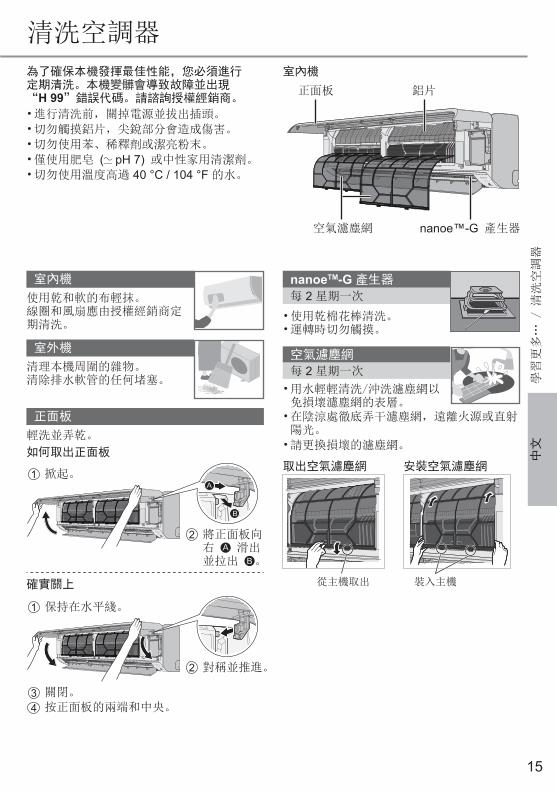
為了確保本機發揮最佳性能,您必須進行定期清洗。本機變髒會導致故障並出現“H 99”錯誤代碼。請諮詢授權經銷商。
• 進行清洗前,關掉電源並拔出插頭。
• 切勿觸摸鋁片,尖銳部分會造成傷害。
• 切勿使用苯、稀釋劑或潔亮粉末。
• 僅使用肥皂 ( pH 7) 或中性家用清潔劑。
• 切勿使用溫度高過 40 °C / 104 °F 的水。
室內機
室內機
使用乾和軟的布輕抹。線圈和風扇應由授權經銷商定期清洗。
室外機
清理本機周圍的雜物。清除排水軟管的任何堵塞。
正面板
輕洗並弄乾。
如何取出正面板
2 將正面板向右 A 滑出並拉出 B 。
1 掀起。
B
A
確實關上
2 對稱並推進。
1 保持在水平綫。
3 關閉。
4 按正面板的兩端和中央。
nanoeTM-G 產生器
每 2 星期一次
• 使用乾棉花棒清洗。• 運轉時切勿觸摸。
空氣濾塵網
每 2 星期一次
• 用水輕輕清洗/沖洗濾塵網以免損壞濾塵網的表層。
• 在陰涼處徹底弄干濾塵網,遠離火源或直射陽光。
• 請更換損壞的濾塵網。
取出空氣濾塵網 安裝空氣濾塵網
從主機取出 裝入主機
鋁片正面板
空氣濾塵網 nanoe™-G 產生器
學習更多… / 清
洗空調器
清洗空調器
中文

16
以下現象並非表示故障。
現象 原因
在打開主機以前POWER(電源)指示燈會閃爍。
• 這是設定定時器後,準備TIMER(定時器)操作的初始步驟。
• 當定時器的設置ON(開啟)時,本機可能會在設置的時間之前更早啟動(最多 15 分鐘),以及時達到所需要的溫度。
TIMER(定時器)指示燈一直ON(亮著)。 • 一旦設定後,定時預約會每天重覆操作。
重新啟動後,運轉延遲幾分鐘。 • 此延遲用於保護本機壓縮機。
在自動風量設定中,室內風扇時開時停。 • 這是為了排除周圍所發出的異味。
室內有異味。 • 這可能是牆壁、地毯、家具或衣物散發出來的氣味。
運轉時發出吱嗄噪聲。 • 温度變化造成本機膨脹或收縮。
運轉時,聽見類似流水聲。 • 機內製冷劑流動的聲音。
室內機散發出霧氣。 • 製冷操作過程中,排出的冷空氣可能導致冷凝現象。
室外機滴水或蒸氣。 • 製冷操作過程中,配管表面發生冷凝現象,冷凝水可能會從室外機滴落。
一些塑膠部件變色。 • 變色是受塑膠部件使用的材料種類影響。當暴露於熱、太陽光線、紫外線或環境因素會加速變色。
長時間使用後,本機的正面板、格柵和四周牆壁可能長滿灰塵。
• 灰塵積累的原因是 nanoe™-G 的負離子產生的空氣淨化效果。定時用清潔的微濕布來清除灰塵。
當 nanoe™ TECHNOLOGY 操作時,室內機發出微小的嗡嗡聲。
• 這是 nanoe™X 產生器作業時的正常現象。如果您介意此聲音,請取消 nanoe™ TECHNOLOGY 操作。
本機OFF(關閉)時,無線局域網絡指示燈會ON(亮著)。
• 本機與路由器的無線局域網絡已被激活。
在進行维修之前請先檢查以下各項。
現象 檢查
在COOL(製冷)模式運轉時無法有效地操作。 • 設定正確溫度。
• 關上所有房門及窗戶。
• 清洗或更換濾塵網。
• 移除阻擋空氣吸入或吹出口的任何阻礙物。
運轉時產生噪音。 • 檢查是否装斜了主機。
• 妥善關閉正面板。
遙控器不操作。(顯示屏變暗或傳輸信號微弱。)
• 正確地安装電池。
• 更換微弱的電池。
本機不能啟動。 • 檢查是否是電流斷路器跳開了。
• 檢查是否已設定預約時間。
本機沒有從遙控器收到信號。 • 確認接收器不受阻礙。
• 某種類型的螢光燈可能會影響訊號接收。請諮詢授權經銷商。
當 nanoe™ TECHNOLOGY 被激活時,室內機的 nanoe™ TECHNOLOGY 指示燈不亮。
• 使用遙控器檢索錯誤代碼並諮詢授權經銷商。
故障檢修

17
當。。。
■遙控器丟失或發生故障
AUTOOFF/ON
1. 向上提起正面板。2. 按一次AUTO OFF/ON(自動關閉/開啟)按鈕以使用AUTO(自動)模式。3. 持續按下AUTO OFF/ON(自動關閉/開啟)按鈕直到聽見一聲“嗶”,然
後鬆開以使用強制性COOL(製冷)模式。4. 再次按下AUTO OFF/ON(自動關閉/開啟)按鈕以關閉本機。
■指示燈太亮• 請在遙控器持續按下 5 秒,以調暗或恢復主機的指示燈亮度。
■ 長期不使用本機后,請進行換季檢查• 檢查遙控器的電池。
• 檢查並確保室內機或室外機的空氣吸入或吹出口順暢無阻。
• 使用本機的AUTO OFF/ON(自動關閉/開啟)選擇COOL(製冷)模式。有關詳細信息,請參閱以上的“遙控器丟失或發生故障”部分。運轉 15 分鐘後,在正常情況下,室內機空氣吸入及吹出口的溫差為:COOL(製冷): ≥ 8 °C / 14.4 °F
■ 長期不使用本機• 啟動 nanoe™ TECHNOLOGY 模式運轉 2 至 3 小時,以徹底排除留在内部機件的濕氣。這是爲了防止微菌滋生。
• 關閉電源並拔出插頭。
• 取出遙控器的電池。
不可維修的情況關閉電源並拔出插頭。然後諮詢授權經銷商:• 運轉時發出異常噪音。
• 有水/異物進入遙控器。
• 室內機漏水。
• 電源斷路器經常跳閘。
• 電線異常發熱。
• 開關鈕或按鈕不能正常操作。
故障檢修
中文
18
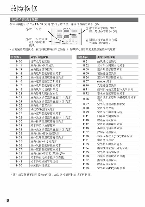
如何檢索錯誤代碼
如果主機停止操作及TIMER(定時器)指示燈閃爍,用遙控器檢索錯誤代碼。
ON
OFF
SET
TIMER
CANCEL
ON
OFF
SET
TIMER
CANCEL
按下 5 秒
按下 5 秒即可退出故障診斷模式
按下直到您聼見“嗶”聲,然後抄下錯誤代碼
關閉本機並將故障代碼告知授權經銷商。
21
3 4
• 至於某些錯誤代碼,在運轉啟動時如果您聽見 4 聲嗶聲可重新啟動主機於某些限制運轉。
* 某些錯誤代碼不適用於您的型號。請諮詢授權經銷商以了解狀況。
故障檢修
診斷顯示 異常/保護控制
H 00 沒有故障的記憶
H 11 室內/室外異常通訊
H 12 室內機容量不匹配
H 14 室內進氣溫度感應器異常
H 15 室外壓縮機溫度感應器異常
H 16 室外電流變壓器(CT)異常
H 17 室外吸氣溫度感應器異常
H 19 室內風扇馬達機制鎖定
H 21 室內浮球開關操作異常
H 23 室內熱交換器溫度感應器 1 異常
H 24 室內熱交換器溫度感應器 2 異常
H 25 室內離子裝置異常
H 26 減低ION(離子)異常
H 27 室外空氣溫度感應器異常
H 28 室外熱交換器溫度感應器 1 異常
H 30 室外排放管溫度感應器異常
H 31 異常的游泳池感應器
H 32 室外熱交換器溫度感應器 2 異常
H 33 室內/室外錯誤連接異常
H 34 室外散熱器溫度感應器異常
H 35 室內/室外水逆流異常
H 36 室外氣管溫度感應器異常
H 37 室外液管溫度感應器異常
H 38 室內/室外不匹配(品牌代碼)
H 39 異常的室內操作機或預備機
H 41 異常的電線或管道連接
H 50 抽風機馬達鎖定
診斷顯示 異常/保護控制
H 51 抽風機馬達鎖定
H 52 左右限位開關固定異常
H 58 室內氣體感應器異常
H 59 環保感應器異常
H 64 室外高壓感應器異常
H 67 nanoe 異常
H 70 光線感應器異常
H 71 控制板内的直流製冷風扇異常
H 72 蓄水器溫度感應器異常
H 85 室內機和無線局域網模組的異常通訊
H 97 室外風扇馬達機制鎖定
H 98 室內高壓保護
H 99 室內操作機防凍保護
F 11 四路閥門開關異常
F 16 總運行電流保護
F 17 室內預備機凍結異常
F 18 小功率電路阻塞異常
F 87 控制箱過熱保護
F 90 功率因數校正(PFC)電路保護
F 91 製冷循環異常
F 93 室外壓縮機異常變革
F 94 壓縮機排氣壓力過衝保護
F 95 室外製冷高壓保護
F 96 功率晶體模塊過熱保護
F 97 壓縮機過熱保護
F 98 總運行電流保護
F 99 室外直流(DC)高峰偵測
19
信息
故障檢修 / 信
息
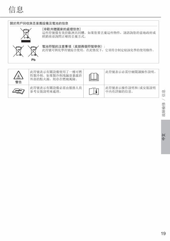
關於用戶回收與丟棄舊設備及電池的信息
[非歐共體國家的處理信息]這些符號僅有效於歐洲共同體。如果您要丟棄這些物件,請諮詢您的當地政府或 經銷商並詢問正確的丟棄方式。
Pb
電池符號的注意事項(底部兩個符號舉例): 此符號可與化學符號綜合使用。在此情況下,它須符合制定給該化學的使用條件。
警告
此符號表示有關設備使用了一種可燃性製冷劑。如果製冷劑洩漏並暴露於外部的點火源,則存在燃燒風險。
此符號表示必需仔細閱讀操作說明。
此符號表示有關設備必需由服務人員參考安裝說明來處理。
此符號表示操作說明和/或安裝說明中内有詳細的信息。
中文
20
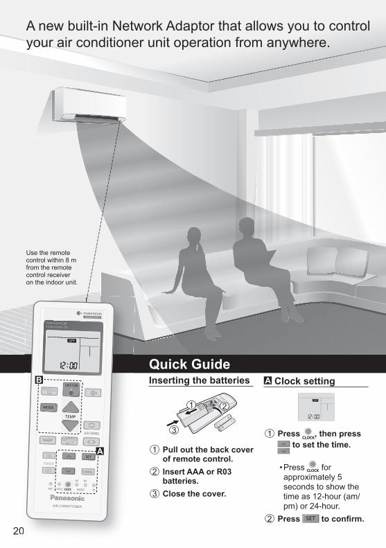
Quick GuideInserting the batteries
3
OPEN 21
1 Pull out the back cover of remote control.
2 Insert AAA or R03 batteries.
3 Close the cover.
A Clock setting
1 Press , then press to set the time.
• Press for approximately 5 seconds to show the time as 12-hour (am/pm) or 24-hour.
2 Press to confi rm.0
POWERFUL/ECO
FAN SPEED/QUIET
ON
OFF
TIMER
POWERFUL/ECO
FAN SPEED/QUIET
ON
OFF
TIMER
A
B
Use the remote control within 8 m from the remote control receiver on the indoor unit.
A new built-in Network Adaptor that allows you to control your air conditioner unit operation from anywhere.

21
B Basic operation2 Press to select
the desired mode.
DRYAUTO COOL
1 Press to start/stop the operation.
POWER
• When the unit is ON, disappears from the remote control display.
3 Press TEMP UP, TEMP DOWN to select the desired temperature.
Up
Down
Selection range: 16.0 °C ~ 30.0 °C / 60 °F ~ 86 °F.• Press for approximately 10 seconds to show the temperature as °C or °F.
Table of Contents
Safety Precautions ........22-29
How to Use ...................30-31
To Learn More... .................32
Cleaning the Air Conditioner ....................33
Troubleshooting ............34-36
Information .........................37
Accessories• Remote control• AAA or R03 batteries × 2• Remote control holder• Screws for remote control holder × 2
The illustrations in this manual are for explanation purposes only and may differ from the actual unit. They are subject to change without notice.
Thank you for purchasing Panasonic Air Conditioner.
Eng
lish
22
Safety Precautions
WARNING
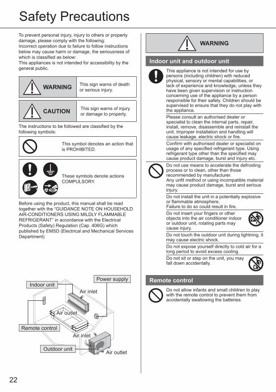
Indoor unit and outdoor unitThis appliance is not intended for use by persons (including children) with reduced physical, sensory or mental capabilities, or lack of experience and knowledge, unless they have been given supervision or instruction concerning use of the appliance by a person responsible for their safety. Children should be supervised to ensure that they do not play with the appliance.Please consult an authorised dealer or specialist to clean the internal parts, repair, install, remove, disassemble and reinstall the unit. Improper installation and handling willcause leakage, electric shock or fi re.Confi rm with authorised dealer or specialist on usage of any specifi ed refrigerant type. Using refrigerant type other than the specifi ed may cause product damage, burst and injury etc.Do not use means to accelerate the defrosting process or to clean, other than those recommended by manufacturer.Any unfi t method or using incompatible material may cause product damage, burst and serious injury.Do not install the unit in a potentially explosive or fl ammable atmosphere. Failure to do so could result in fi re.Do not insert your fi ngers or other objects into the air conditioner indoor or outdoor unit, rotating parts may cause injury.Do not touch the outdoor unit during lightning, it may cause electric shock.Do not expose yourself directly to cold air for a long period to avoid excess cooling.Do not sit or step on the unit, you may fall down accidentally.
Remote controlDo not allow infants and small children to play with the remote control to prevent them from accidentally swallowing the batteries.
To prevent personal injury, injury to others or property damage, please comply with the following: Incorrect operation due to failure to follow instructions below may cause harm or damage, the seriousness of which is classifi ed as below:This appliances is not intended for accessibility by the general public.
WARNING This sign warns of death or serious injury.
CAUTION This sign warns of injury or damage to property.
The instructions to be followed are classifi ed by the following symbols:
This symbol denotes an action that is PROHIBITED.
These symbols denote actions COMPULSORY.
Before using the product, this manual shall be read together with the “GUIDANCE NOTE ON HOUSEHOLD AIR-CONDITIONERS USING MILDLY FLAMMABLE REFRIGERANT” in accordance with the Electrical Products (Safety) Regulation (Cap. 406G) which published by EMSD (Electrical and Mechanical Services Department)
Indoor unit
Outdoor unit
Power supply
Remote control
Air inletAir inlet
Air inletAir inlet
Air outletAir outlet
Air outletAir outlet
23
Saf
ety
Pre
caut
ions
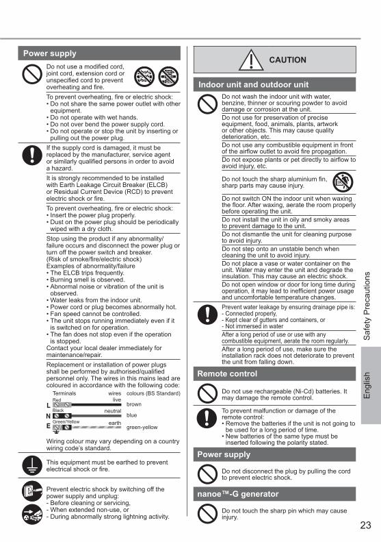
CAUTION
Indoor unit and outdoor unitDo not wash the indoor unit with water, benzine, thinner or scouring powder to avoid damage or corrosion at the unit.Do not use for preservation of precise equipment, food, animals, plants, artwork or other objects. This may cause quality deterioration, etc.Do not use any combustible equipment in front of the airfl ow outlet to avoid fi re propagation.Do not expose plants or pet directly to airfl ow to avoid injury, etc.
Do not touch the sharp aluminium fi n, sharp parts may cause injury.
Do not switch ON the indoor unit when waxing the fl oor. After waxing, aerate the room properly before operating the unit.Do not install the unit in oily and smoky areas to prevent damage to the unit.Do not dismantle the unit for cleaning purpose to avoid injury.Do not step onto an unstable bench when cleaning the unit to avoid injury.Do not place a vase or water container on the unit. Water may enter the unit and degrade the insulation. This may cause an electric shock.Do not open window or door for long time during operation, it may lead to ineffi cient power usage and uncomfortable temperature changes.Prevent water leakage by ensuring drainage pipe is:- Connected properly,- Kept clear of gutters and containers, or- Not immersed in waterAfter a long period of use or use with any combustible equipment, aerate the room regularly.After a long period of use, make sure the installation rack does not deteriorate to prevent the unit from falling down.
Remote control
Do not use rechargeable (Ni-Cd) batteries. It may damage the remote control.
To prevent malfunction or damage of the remote control:• Remove the batteries if the unit is not going to
be used for a long period of time.• New batteries of the same type must be
inserted following the polarity stated.
Power supply
Do not disconnect the plug by pulling the cord to prevent electric shock.
nanoe™-G generator
Do not touch the sharp pin which may cause injury.
Power supplyDo not use a modifi ed cord, joint cord, extension cord or unspecifi ed cord to prevent overheating and fi re.
To prevent overheating, fi re or electric shock:• Do not share the same power outlet with other
equipment.• Do not operate with wet hands. • Do not over bend the power supply cord.• Do not operate or stop the unit by inserting or
pulling out the power plug.If the supply cord is damaged, it must be replaced by the manufacturer, service agent or similarly qualifi ed persons in order to avoid a hazard.It is strongly recommended to be installed with Earth Leakage Circuit Breaker (ELCB) or Residual Current Device (RCD) to prevent electric shock or fi re.To prevent overheating, fi re or electric shock:• Insert the power plug properly.• Dust on the power plug should be periodically
wiped with a dry cloth.Stop using the product if any abnormality/failure occurs and disconnect the power plug or turn off the power switch and breaker.(Risk of smoke/fi re/electric shock) Examples of abnormality/failure• The ELCB trips frequently.• Burning smell is observed.• Abnormal noise or vibration of the unit is
observed.• Water leaks from the indoor unit.• Power cord or plug becomes abnormally hot.• Fan speed cannot be controlled.• The unit stops running immediately even if it
is switched on for operation.• The fan does not stop even if the operation
is stopped.Contact your local dealer immediately for maintenance/repair.Replacement or installation of power plugs shall be performed by authorised/qualifi ed personnel only. The wires in this mains lead are coloured in accordance with the following code:
TerminalsRed
wireslive
neutral
earth
colours (BS Standard)
blue
green-yellow
brownBlack
Green/Yellow
Wiring colour may vary depending on a countrywiring code’s standard.
This equipment must be earthed to prevent electrical shock or fi re.
Prevent electric shock by switching off the power supply and unplug:- Before cleaning or servicing,- When extended non-use, or- During abnormally strong lightning activity.
Eng
lish
24
Safety Precautions
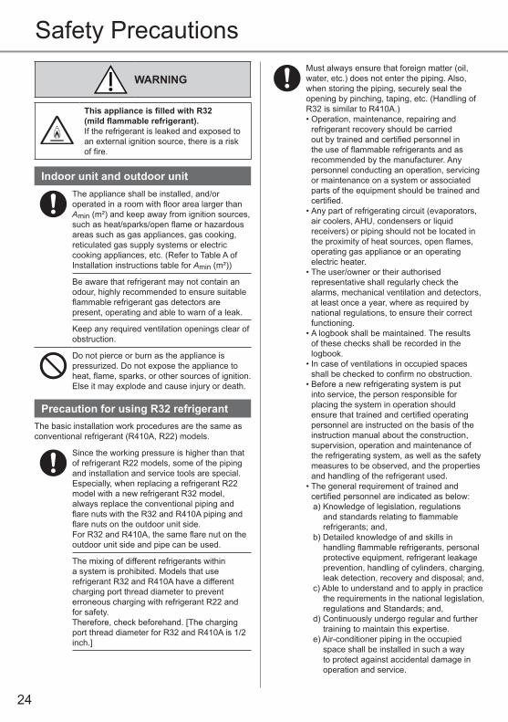
WARNING
This appliance is fi lled with R32 (mild fl ammable refrigerant). If the refrigerant is leaked and exposed to an external ignition source, there is a risk of fi re.
Indoor unit and outdoor unitThe appliance shall be installed, and/or operated in a room with fl oor area larger than Amin (m²) and keep away from ignition sources, such as heat/sparks/open fl ame or hazardous areas such as gas appliances, gas cooking, reticulated gas supply systems or electric cooking appliances, etc. (Refer to Table A of Installation instructions table for Amin (m²))
Be aware that refrigerant may not contain an odour, highly recommended to ensure suitable fl ammable refrigerant gas detectors are present, operating and able to warn of a leak.
Keep any required ventilation openings clear of obstruction.
Do not pierce or burn as the appliance is pressurized. Do not expose the appliance to heat, fl ame, sparks, or other sources of ignition. Else it may explode and cause injury or death.
Precaution for using R32 refrigerantThe basic installation work procedures are the same as conventional refrigerant (R410A, R22) models.
Since the working pressure is higher than that of refrigerant R22 models, some of the piping and installation and service tools are special. Especially, when replacing a refrigerant R22 model with a new refrigerant R32 model, always replace the conventional piping and fl are nuts with the R32 and R410A piping and fl are nuts on the outdoor unit side. For R32 and R410A, the same fl are nut on the outdoor unit side and pipe can be used.
The mixing of different refrigerants within a system is prohibited. Models that use refrigerant R32 and R410A have a different charging port thread diameter to prevent erroneous charging with refrigerant R22 and for safety. Therefore, check beforehand. [The charging port thread diameter for R32 and R410A is 1/2 inch.]
Must always ensure that foreign matter (oil, water, etc.) does not enter the piping. Also, when storing the piping, securely seal the opening by pinching, taping, etc. (Handling of R32 is similar to R410A.)• Operation, maintenance, repairing and
refrigerant recovery should be carried out by trained and certifi ed personnel in the use of fl ammable refrigerants and as recommended by the manufacturer. Any personnel conducting an operation, servicing or maintenance on a system or associated parts of the equipment should be trained and certifi ed.
• Any part of refrigerating circuit (evaporators, air coolers, AHU, condensers or liquid receivers) or piping should not be located in the proximity of heat sources, open fl ames, operating gas appliance or an operating electric heater.
• The user/owner or their authorised representative shall regularly check the alarms, mechanical ventilation and detectors, at least once a year, where as required by national regulations, to ensure their correct functioning.
• A logbook shall be maintained. The results of these checks shall be recorded in the logbook.
• In case of ventilations in occupied spaces shall be checked to confi rm no obstruction.
• Before a new refrigerating system is put into service, the person responsible for placing the system in operation should ensure that trained and certifi ed operating personnel are instructed on the basis of the instruction manual about the construction, supervision, operation and maintenance of the refrigerating system, as well as the safety measures to be observed, and the properties and handling of the refrigerant used.
• The general requirement of trained and certifi ed personnel are indicated as below:a) Knowledge of legislation, regulations
and standards relating to fl ammable refrigerants; and,
b) Detailed knowledge of and skills in handling fl ammable refrigerants, personal protective equipment, refrigerant leakage prevention, handling of cylinders, charging, leak detection, recovery and disposal; and,
c) Able to understand and to apply in practice the requirements in the national legislation, regulations and Standards; and,
d) Continuously undergo regular and further training to maintain this expertise.
e) Air-conditioner piping in the occupied space shall be installed in such a way to protect against accidental damage in operation and service.
25
Saf
ety
Pre
caut
ions
f) Precautions shall be taken to avoid excessive vibration or pulsation to refrigerating piping.
g) Ensure protection devices, refrigerating piping and fittings are well protected against adverse environmental effects (such as the danger of water collecting and freezing in relief pipes or the accumulation of dirt and debris).
h) Expansion and contraction of long runs piping in refrigerating systems shall be designed and installed securely (mounted and guarded) to minimize the likelihood hydraulic shock damaging the system.
i) Protect the refrigerating system from accidental rupture due to moving furniture or reconstruction activities.
j) To ensure no leaking, field-made refrigerant joints indoors shall be tightness tested. The test method shall have a sensitivity of 5 grams per year of refrigerant or better under a pressure of at least 0.25 times the maximum allowable pressure (>1.04 MPa, max 4.15 MPa). No leak shall be detected.
1. Installation (Space)• Product with flammable refrigerants, shall
be installed according to the minimum room area, Amin (m²) mentioned in Table A of the Installation Instructions.
• In case of fi eld charge, the effect on refrigerant charge caused by the different pipe length has to be quantifi ed, measured and labelled.
• Must ensure the installation of pipe-work shall be kept to a minimum. Avoid use dented pipe and do not allow acute bending.
• Must ensure that pipe-work shall be protected from physical damage.
• Must comply with national gas regulations, state municipal rules and legislation. Notify relevant authorities in accordance with all applicable regulations.
• Must ensure mechanical connections be accessible for maintenance purposes.
• In cases that require mechanical ventilation, ventilation openings shall be kept clear of obstruction.
• When disposal of the product, do follow to the precautions in #12 and comply with national regulations.Always contact to local municipal offi ces for proper handling.
2. Servicing2-1. Service personnel• The system is inspected, regularly supervised
and maintained by a trained and certifi ed service personnel who is employed by the person user or party responsible.
• Ensure the actual refrigerant charge is in accordance with the room size within which the refrigerant containing parts are installed.
• Ensure refrigerant charge not to leak.• Any qualifi ed person who is involved with
working on or breaking into a refrigerant circuit should hold a current valid certifi cate from an industry-accredited assessment authority, which authorizes their competence to handle refrigerants safely in accordance with an industry recognised assessment specifi cation.
• Servicing shall only be performed as recommended by the equipment manufacturer. Maintenance and repair requiring the assistance of other skilled personnel shall be carried out under the supervision of the person competent in the use of fl ammable refrigerants.
• Servicing shall be performed only as recommended by the manufacturer.
2-2. Work• Prior to beginning work on systems containing fl ammable refrigerants, safety checks are necessary to ensure that the risk of ignition is minimised. For repair to the refrigerating system, the precautions in #2-2 to #2-8 must be followed before conducting work on the system.
• Work shall be undertaken under a controlled procedure so as to minimize the risk of a fl ammable gas or vapour being present while the work is being performed.
• All maintenance staff and others working in the local area shall be instructed and supervised on the nature of work being carried out.
• Avoid working in confi ned spaces. Always ensure away from source, at least 2 meter of safety distance, or zoning of free space area of at least 2 meter in radius.
• Wear appropriate protective equipment, including respiratory protection, as conditions warrant.
• Keep all sources of ignition and hot metal surfaces away.
Eng
lish

26
Safety Precautions2-3. Checking for presence of refrigerant• The area shall be checked with an
appropriate refrigerant detector prior to and during work, to ensure the technician is aware of potentially fl ammable atmospheres.
• Ensure that the leak detection equipment being used is suitable for use with fl ammable refrigerants, i.e. non sparking, adequately sealed or intrinsically safe.
• In case of leakage/spillage happened, immediately ventilate area and stay upwind and away from spill/release.
• In case of leakage/spillage happened, do notify persons down wind of the leaking/spill, isolate immediate hazard area and keep unauthorised personnel out.
2-4. Presence of fi re extinguisher• If any hot work is to be conducted on the
refrigerating equipment or any associated parts, appropriate fire extinguishing equipment shall be available at hand.
• Have a dry powder or CO2 fi re extinguisher adjacent to the charging area.
2-5. No ignition sources• No person carrying out work in relation to a
refrigerating system which involves exposing any pipe work that contains or has contained flammable refrigerant shall use any sources of ignition in such a manner that it may lead to the risk of fire or explosion. They must not be smoking when carrying out such work.
• All possible ignition sources, including cigarette smoking, should be kept suffi ciently far away from the site of installation, repairing, removing and disposal, during which fl ammable refrigerant can possibly be released to the surrounding space.
• Prior to work taking place, the area around the equipment is to be surveyed to make sure that there are no fl ammable hazards or ignition risks.
• “No Smoking” signs shall be displayed.
2-6. Ventilated area• Ensure that the area is in the open or that it is
adequately ventilated before breaking into the system or conducting any hot work.
• A degree of ventilation shall continue during the period that the work is carried out.
• The ventilation should safely disperse any released refrigerant and preferably expel it externally into the atmosphere.
2-7. Checks to the refrigerating equipment• Where electrical components are being
changed, they shall be fi t for the purpose and to the correct specifi cation.
• At all times the manufacturer’s maintenance and service guidelines shall be followed.
• If in doubt consult the manufacturer’s technical department for assistance.
• The following checks shall be applied to installations using fl ammable refrigerants.
- The actual refrigerant charge is in accordance with the room size within which the refrigerant containing parts are installed. - The ventilation machinery and outlets are operating adequately and are not obstructed. - If an indirect refrigerating circuit is being used, the secondary circuit shall be checked for the presence of refrigerant. - Marking to the equipment continues to be visible and legible. Markings and signs that are illegible shall be corrected. - Refrigerating pipe or components are installed in a position where they are unlikely to be exposed to any substance which may corrode refrigerant containing components, unless the components are constructed of materials which are inherently resistant to being corroded or are properly protected against being so corroded.
2-8. Checks to electrical devices• Repair and maintenance to electrical
components shall include initial safety checks and component inspection procedures.
• Initial safety checks shall include but not limit to:-
- That capacitors are discharged: this shall be done in a safe manner to avoid possibility of sparking. - That there no live electrical components and wiring are exposed while charging, recovering or purging the system. - That there is continuity of earth bonding.
• At all times the manufacturer’s maintenance and service guidelines shall be followed.
• If in doubt consult the manufacturer’s technical department for assistance.
• If a fault exists that could compromise safety, then no electrical supply shall be connected to the circuit until it is satisfactorily dealt with.
• If the fault cannot be corrected immediately but it is necessary to continue operation, an adequate temporary solution shall be used.
• The owner of the equipment must be informed or reported so all parties are advised thereinafter.

27
Saf
ety
Pre
caut
ions
3. Repairs to sealed components• During repairs to sealed components, all
electrical supplies shall be disconnected from the equipment being worked upon prior to any removal of sealed covers, etc.
• If it is absolutely necessary to have an electrical supply to equipment during servicing, then a permanently operating form of leak detection shall be located at the most critical point to warn of a potentially hazardous situation.
• Particular attention shall be paid to the following to ensure that by working on electrical components, the casing is not altered in such a way that the level of protection is affected. This shall include damage to cables, excessive number of connections, terminals not made to original specifi cation, damage to seals, incorrect fi tting of glands, etc.
• Ensure that apparatus is mounted securely.• Ensure that seals or sealing materials have
not degraded such that they no longer serve the purpose of preventing the ingress of fl ammable atmospheres.
• Replacement parts shall be in accordance with the manufacturer’s specifi cations.
NOTE: The use of silicon sealant may inhibit the effectiveness of some types of leak detection equipment.Intrinsically safe components do not have to be isolated prior to working on them.
4. Repair to intrinsically safe components• Do not apply any permanent inductive or
capacitance loads to the circuit without ensuring that this will not exceed the permissible voltage and current permitted for the equipment in use.
• Intrinsically safe components are the only types that can be worked on while live in the presence of a fl ammable atmosphere.
• The test apparatus shall be at the correct rating.
• Replace components only with parts specifi ed by the manufacturer. Unspecifi ed parts by manufacturer may result ignition of refrigerant in the atmosphere from a leak.
5. Cabling• Check that cabling will not be subject
to wear, corrosion, excessive pressure, vibration, sharp edges or any other adverse environmental effects.
• The check shall also take into account the effects of aging or continual vibration from sources such as compressors or fans.
6. Detection of fl ammable refrigerants• Under no circumstances shall potential
sources of ignition be used in the searching or detection of refrigerant leaks.
• A halide torch (or any other detector using a naked fl ame) shall not be used.
7. The following leak detection methods are deemed acceptable for all refrigerant systems
• No leaks shall be detected using detection equipment with sensitivity to detect leakage of 5g/year of refrigerant or better under a pressure of at least 0.25 times the maximum allowable pressure (>1.04 MPa, max 4.15 MPa), for example, a universal sniffer.
• Electronic leak detectors may be used to detect fl ammable refrigerants, but the sensitivity may not be adequate, or may need re-calibration.(Detection equipment shall be calibrated in a refrigerant-free area.)
• Ensure that the detector is not a potential source of ignition and is suitable for the refrigerant used.
• Leak detection equipment shall be set at a percentage of the LFL of the refrigerant and shall be calibrated to the refrigerant employed and the appropriate percentage of gas (25 % maximum) is confi rmed.
• Leak detection fluids are also suitable for use with most refrigerants, for example, bubble method and fluorescent method agents. The use of detergents containing chlorine shall be avoided as the chlorine may react with the refrigerant and corrode the copper pipe-work.
• If a leak is suspected, all naked fl ames shall be removed/extinguished.
• If a leakage of refrigerant is found which requires brazing, all of the refrigerant shall be recovered from the system, or isolated (by means of shut off valves) in a part of the system remote from the leak. The precautions in #8 must be followed to remove the refrigerant.
Eng
lish

28
Safety Precautions8. Removal and evacuation• When breaking into the refrigerant circuit
to make repairs – or for any other purpose – conventional procedures shall be used. However, it is important that best practice is followed since fl ammability is a consideration. The following procedure shall be adhered to: remove refrigerant -> purge the circuit with inert gas -> evacuate -> purge with inert gas -> open the circuit by cutting or brazing.
• The refrigerant charge shall be recovered into the correct recovery cylinders.
• The system shall be purged with OFN to render the appliance safe.
• This process may need to be repeated several times.
• Compressed air or oxygen shall not be used for this task.
• Purging shall be achieved by breaking the vacuum in the system with OFN and continuing to fill until the working pressure is achieved, then venting to atmosphere, and finally pulling down to a vacuum.
• This process shall be repeated until no refrigerant is within the system.
• When the fi nal OFN charge is used, the system shall be vented down to atmospheric pressure to enable work to take place.
• This operation is absolutely vital if brazing operations on the pipe work are to take place.
• Ensure that the outlet for the vacuum pump is not close to any potential ignition sources and there is ventilation available.
OFN = oxygen free nitrogen, type of inert gas.
9. Charging procedures• In addition to conventional charging
procedures, the following requirements shall be followed.
- Ensure that contamination of different refrigerants does not occur when using charging equipment. - Hoses or lines shall be as short as possible to minimize the amount of refrigerant contained in them. - Cylinders shall be kept in an appropriate position according to the instructions. - Ensure that the refrigerating system is earthed prior to charging the system with refrigerant. - Label the system when charging is complete (if not already). - Extreme care shall be taken not to over fill the refrigerating system.
• Prior to recharging the system it shall be pressure tested with OFN (refer to #7).
• The system shall be leak tested on completion of charging but prior to commissioning.
• A follow up leak test shall be carried out prior to leaving the site.
• Electrostatic charge may accumulate and create a hazardous condition when charging and discharging the refrigerant. To avoid fi re or explosion, dissipate static electricity during transfer by grounding and bonding containers and equipment before charging/discharging.
10. Decommissioning• Before carrying out this procedure, it is
essential that the technician is completely familiar with the equipment and all its details.
• It is recommended good practice that all refrigerants are recovered safely.
• Prior to the task being carried out, an oil and refrigerant sample shall be taken in case analysis is required prior to re-use of recovered refrigerant.
• It is essential that electrical power is available before the task is commenced.a) Become familiar with the equipment and
its operation.b) Isolate system electrically.c) Before attempting the procedure ensure
that: • mechanical handling equipment is
available, if required, for handling refrigerant cylinders;
• all personal protective equipment is available and being used correctly;
• the recovery process is supervised at all times by a competent person;
• recovery equipment and cylinders conform to the appropriate standards.
d) Pump down refrigerant system, if possible.
29
Saf
ety
Pre
caut
ions
e) If a vacuum is not possible, make a manifold so that refrigerant can be removed from various parts of the system.
f) Make sure that cylinder is situated on the scales before recovery takes place.
g) Start the recovery machine and operate in accordance with instructions.
h) Do not over fi ll cylinders. (No more than 80 % volume liquid charge).
i) Do not exceed the maximum working pressure of the cylinder, even temporarily.
j) When the cylinders have been fi lled correctly and the process completed, make sure that the cylinders and the equipment are removed from site promptly and all isolation valves on the equipment are closed off.
k) Recovered refrigerant shall not be charged into another refrigerating system unless it has been cleaned and checked.
• Electrostatic charge may accumulate and create a hazardous condition when charging or discharging the refrigerant. To avoid fi re or explosion, dissipate static electricity during transfer by grounding and bonding containers and equipment before charging/discharging.
11. Labelling• Equipment shall be labelled stating that it
has been de-commissioned and emptied of refrigerant.
• The label shall be dated and signed.• Ensure that there are labels on the equipment
stating the equipment contains fl ammable refrigerant.
12. Recovery• When removing refrigerant from a system,
either for servicing or decommissioning, it is recommended good practice that all refrigerants are removed safely.
• When transferring refrigerant into cylinders, ensure that only appropriate refrigerant recovery cylinders are employed.
• Ensure that the correct number of cylinders for holding the total system charge are available.
• All cylinders to be used are designated for the recovered refrigerant and labelled for that refrigerant (i.e. special cylinders for the recovery of refrigerant).
• Cylinders shall be complete with pressure relief valve and associated shut-off valves in good working order.
• Recovery cylinders are evacuated and, if possible, cooled before recovery occurs.
• The recovery equipment shall be in good working order with a set of instructions concerning the equipment that is at hand and shall be suitable for the recovery of fl ammable refrigerants.
• In addition, a set of calibrated weighing scales shall be available and in good working order.
• Hoses shall be complete with leak-free disconnect couplings and in good condition.
• Before using the recovery machine, check that it is in satisfactory working order, has been properly maintained and that any associated electrical components are sealed to prevent ignition in the event of a refrigerant release. Consult manufacturer if in doubt.
• The recovered refrigerant shall be returned to the refrigerant supplier in the correct recovery cylinder, and the relevant Waste Transfer Note arranged.
• Do not mix refrigerants in recovery units and especially not in cylinders.
• If compressors or compressor oils are to be removed, ensure that they have been evacuated to an acceptable level to make certain that fl ammable refrigerant does not remain within the lubricant.
• The evacuation process shall be carried out prior to returning the compressor to the suppliers.
• Only electric heating to the compressor body shall be employed to accelerate this process.
• When oil is drained from a system, it shall be carried out safely.
Eng
lish

30
POWERFUL/ECO
FAN SPEED/QUIET
ON
OFF
TIMER
How to Use
• Do not adjust the fl ap by hand.* For details operation, refer “To Learn More....”
AIR SWING
Upper direction
Lateral direction
To adjust airfl ow direction
To adjust FAN SPEED and QUIET condition
FAN SPEED:• When AUTO FAN is selected, the fan speed is adjusted automatically according to the operation mode.
QUIET: • This operation reduces airfl ow noise.
FAN SPEED/QUIET
POWERFUL:To reach the desired temperature quickly• This operation is automatically stop after 20 minutes.ECO: • To reduce power consumption for better energy saving without sacrifi cing comfort.
To switch between POWERFUL/ECO
POWERFUL/ECO
(exit setting)
Indicators
POWER
TIMERnanoeTECHNOLOGY
Not used in normal operation.
Press to turnthe WirelessLAN featureON or OFF.
Press to restore the remote control to default setting.
• This operation combines both nanoe™X and nanoe™-G (nanoe™ TECHNOLOGY).
• nanoe™ TECHNOLOGY automatically starts when the unit is turned on.
• Press to turn ON or OFF this operation manually.
• This operation can be activated even when the unit is OFF. Note that the fl ap and fan speed will operate according to the remote control setting.
• If a power failure occurs during this operation, this operation resumes immediately when power resumes.
To enjoy fresher and cleaner environment
31
See "To Learn More..." for details.
Note
SLEEP , , POWERFUL/
ECOFAN SPEED/
QUIET , POWERFUL/
ECO
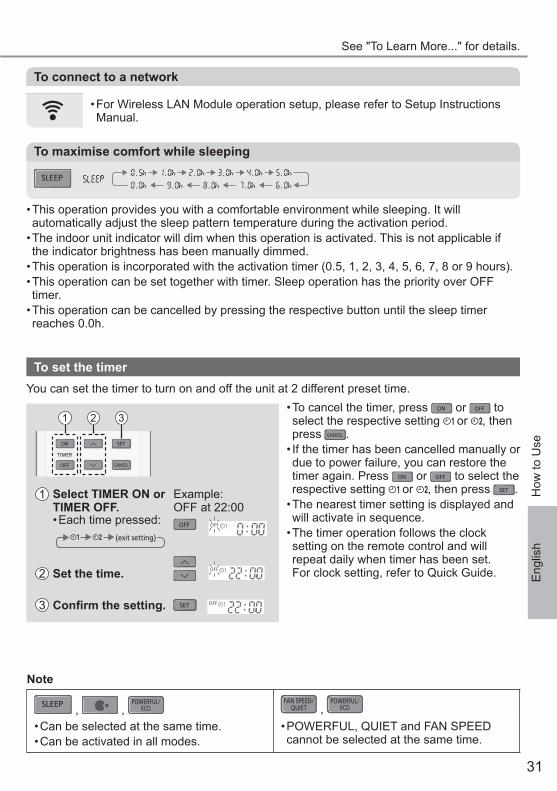
• Can be selected at the same time.• Can be activated in all modes.
• POWERFUL, QUIET and FAN SPEED cannot be selected at the same time.
To maximise comfort while sleeping
• This operation provides you with a comfortable environment while sleeping. It will automatically adjust the sleep pattern temperature during the activation period.
• The indoor unit indicator will dim when this operation is activated. This is not applicable if the indicator brightness has been manually dimmed.
• This operation is incorporated with the activation timer (0.5, 1, 2, 3, 4, 5, 6, 7, 8 or 9 hours). • This operation can be set together with timer. Sleep operation has the priority over OFF timer.
• This operation can be cancelled by pressing the respective button until the sleep timer reaches 0.0h.
SLEEP
How
to U
se
To connect to a network
• For Wireless LAN Module operation setup, please refer to Setup Instructions Manual.
To set the timer
ON
OFF
SET
TIMER
CANCEL
1 2 3
1 Select TIMER ON or TIMER OFF.
Example: OFF at 22:00
• Each time pressed: OFF
(exit setting)
2 Set the time.
3 Confi rm the setting. SET
• To cancel the timer, press ON or OFF to select the respective setting or , then press CANCEL .
• If the timer has been cancelled manually or due to power failure, you can restore the timer again. Press ON or OFF to select the respective setting or , then press SET .
• The nearest timer setting is displayed and will activate in sequence.
• The timer operation follows the clock setting on the remote control and will repeat daily when timer has been set. For clock setting, refer to Quick Guide.
You can set the timer to turn on and off the unit at 2 different preset time.
Eng
lish

32
Operation mode
AUTO : The POWER indicator blinks at the initial stage.The unit will select an operation mode depending on the room temperature.
COOL : Provides effi cient comfort cooling to suit your needs.DRY : Operates at low fan speed for a gentle cooling operation.
Energy saving temperature settingYou may save energy when operating the unit within the recommended temperature range.COOL : 26.0 °C ~ 28.0 °C / 79 °F ~ 82 °F.
Air fl ow directionIn COOL/DRY mode:The horizontal fl ap is fi xed at middle position setting.Once the temperature is achieved, the horizontal fl ap swings up/down automatically. In COOL/DRY mode:The horizontal fl ap swings up/down automatically.
Auto restart controlWhen power is resumed after a power failure, the operation will restart automatically with thelast operation mode and airfl ow direction.• This control is not applicable when TIMER is set.
nanoe™X filter deactivationDepending on the unit’s accumulated operation time, the nanoe™X may be activated onlyonce a day after the unit is turned off standby mode. During the nanoe™X filter deactivationoperation, the flap will open slightly with low fan speed operation for 2.5 hours if the unit wasin COOL/DRY mode, and 2 hours if the unit was in nanoe™ TECHNOLOGY, before the unitis turned off. This is to remove viruses/bacteria from the surroundings.The filter deactivation operation is complete when the fan stops and the flap closes. Do notturn off the power supply during this operation. After a power failure, this operation will notresume.
Operating conditionsUse this air conditioner in the temperature range indicated in the table.
Temperature °C (°F)Indoor Outdoor
DBT WBT DBT WBT
COOL Max. 32 (89.6) 23 (73.4) 46 (114.8) 26 (78.8)
Min. 16 (60.8) 11 (51.8) 16 (60.8) 11 (51.8)
DBT: Dry bulb temperature, WBT: Wet bulb temperature
To Learn More...

33
Cleaning the Air Conditioner
To L
earn
Mor
e...
/ Cle
anin
g th
e A
ir C
ondi
tione
r
Aluminium fi nFront panel
Air fi lters nanoeTM-G Generator
Cleaning has to be carried out at regular intervals to ensure the unit is at optimal performance. A dirty unit may cause malfunction and you may retrieve “H 99” error code. Consult an authorised dealer.• Before cleaning, switch off the power supply and unplug the unit.
• Do not touch the aluminium fi n as the sharp parts may cause injury.
• Do not use benzine, thinner or scouring powder.
• Use soap ( pH 7) or neutral household detergent only.
• Do not use water hotter than 40 °C / 104 °F.
Indoor unit
nanoeTM-G GeneratorOnce every 2 weeks
• Clean with dry cotton bud.• Do not touch during operation.
Air fi ltersOnce every 2 weeks
• Wash/rinse the fi lters gently with water to avoid damaging the surface.
• Dry the fi lters thoroughly under a shade, away from fi re or direct sunlight.
• Replace any damaged fi lters.Remove air fi lter Attach air fi lter
Remove from the unit Insert into the unit
Indoor unitWipe the unit gently with a soft and dry cloth.The coils and fans should be cleaned periodically by an authorised dealer.
Outdoor unitClean the debris that surround the unit.Clear any blockage from the drain pipe.
Front panelWash gently and dry.How to remove front panel
2 Slide the front panel to right A and pull out B .
1 Raise up.
B
A
Close it securely
2 Match and push in.
1 Hold horizontally.
3 Close down.4 Press both ends and center of the front
panel.
Eng
lish

34
The following symptoms do not indicate malfunction.
Symptom CausePOWER indicator blinks before the unit is switched on.
• This is the preliminary step to prepare for the TIMER operation after it has been set.
• When Timer is set ON, the unit may start earlier (up to 15 minutes) before the actual set time to achieve the desired temperature on time.
TIMER indicator is always ON. • When Timer has been set, the Timer setting repeats daily.Operation is delayed a few minutes after restarting. • The delay is a protection to the unit’s compressor.Indoor fan stops occasionally during automatic fan speed setting.
• This is to help remove the surrounding odour.
The room has a peculiar odour. • This may be due to damp smell emitted by the wall, carpet, furniture or clothing.
Cracking sound during operation. • Changes in temperature caused the unit to expand and contract.
Water fl owing sound during operation. • Refrigerant fl ow inside the unit.Mist emerges from indoor unit. • During cooling operation, the discharged cold air may
condense to water vapour.Outdoor unit emits water or steam. • During cooling operation, condensation occurs on cold pipes
and the condensed water may drip from the outdoor unit.Discoloration of some plastic parts. • Discoloration is subjected to the types of materials used in
plastic parts. It is accelerated when exposed to heat, sun light, UV light or environmental factors.
After extended use, dust may cover the front panel, grilles and the wall surrounding the unit.
• The dust accumulation is due to the air purifi cation effect of negative ions from nanoe™-G. Remove the dust regularly with a clean dampened cloth.
Soft buzzing sound from indoor unit duringnanoe™ TECHNOLOGY operation.
• It is normal when the nanoe™X generator is working. If you are concerned about the sound, cancel the nanoe™ TECHNOLOGY operation.
Wireless LAN indicator is ON when the unit is OFF. • The unit’s wireless LAN connection with the router has been activated.
Check the following before calling for servicing.
Symptom CheckOperation in COOL mode is not working effi ciently. • Set the temperature correctly.
• Close all doors and windows.• Clean or replace the fi lters.• Clear any obstruction at the air inlet and air outlet vents.
Noisy during operation. • Check if the unit has been installed at an incline.• Close the front panel properly.
Remote control does not work.(Display is dim or transmission signal is weak.)
• Insert the batteries correctly.• Replace weak batteries.
The unit does not work. • Check if the circuit breaker is tripped.• Check if timers have been set.
The unit does not receive the signal from the remote control.
• Make sure the receiver is not obstructed.• Certain fl uorescent lights may interfere with the signal
transmitter. Consult an authorised dealer.The nanoe™ TECHNOLOGY indicator at the indoor unit is not ON when nanoe™ TECHNOLOGY is activated.
• Use the remote control to retrieve the error code and consult an authorised dealer.
Troubleshooting

35
When...■The remote control is missing or a malfunction has occurred
AUTOOFF/ON
1.Raise the front panel.2.Press AUTO OFF/ON once to use in AUTO mode.3. Press AUTO OFF/ON until you hear 1 beep, then release to use in forced
COOL mode.4.Press AUTO OFF/ON again to turn off the unit.
■The indicators are too bright• To dim or restore the indicators’ brightness on the unit, press on the remote for 5 seconds.
■ Conducting a seasonal inspection after extended period of non-use• Check the batteries.• Check that there is no obstruction around the air inlets and outlet vents.• Use AUTO OFF/ON on the unit to select COOL mode. For details, refer “The remote control is missing or a malfunction has occurred” above. After 15 minutes of operation, it is normal to have the following temperature difference between the air inlet and outlet vents: COOL: ≥ 8 °C / 14.4 °F
■ The units will not be used for an extended period• Activate nanoe™ TECHNOLOGY mode for 2~3 hours to remove any moisture left in the internal parts thoroughly. This is to prevent mould growth.
• Turn off the power supply and unplug the unit.• Remove the batteries from the remote control.
NON SERVICEABLE CRITERIASTURN OFF THE POWER SUPPLY AND UNPLUG THE UNIT. Then consult an authoriseddealer in the following conditions:• Abnormal noise during operation.• Water/foreign particles have entered the remote control.• Water is leaking from the indoor unit.• The circuit breaker switches off frequently.• The power cord becomes unnaturally warm.• The switches or buttons are not functioning properly.
Trou
bles
hoot
ing
Eng
lish
36
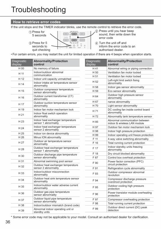
How to retrieve error codesIf the unit stops and the TIMER indicator blinks, use the remote control to retrieve the error code.
ON
OFF
SET
TIMER
CANCEL
ON
OFF
SET
TIMER
CANCEL
Press for 5 seconds
Press for 5 seconds to quit checking
Press until you hear beep sound, then write down the error code
21
3 Turn the unit off andinform the error code to anauthorised dealer.
4
• For certain errors, you may restart the unit for limited operation if there are 4 beeps when operation starts.
Troubleshooting
Diagnostic display
Abnormality/Protection control
H 00 No memory of failure
H 11 Indoor/outdoor abnormal communication
H 12 Indoor unit capacity unmatched
H 14 Indoor intake air temperature sensor abnormality
H 15 Outdoor compressor temperature sensor abnormality
H 16 Outdoor current transformer (CT) abnormality
H 17 Outdoor suction temperature sensor abnormality
H 19 Indoor fan motor mechanism lock
H 21 Indoor fl oat switch operation abnormality
H 23 Indoor heat exchanger temperature sensor 1 abnormality
H 24 Indoor heat exchanger temperature sensor 2 abnormality
H 25 Indoor ion device abnormalityH 26 Minus ION abnormality
H 27 Outdoor air temperature sensor abnormality
H 28 Outdoor heat exchanger temperature sensor 1 abnormality
H 30 Outdoor discharge pipe temperature sensor abnormality
H 31 Abnormal swimming pool sensor
H 32 Outdoor heat exchanger temperature sensor 2 abnormality
H 33 Indoor/outdoor misconnection abnormality
H 34 Outdoor heat sink temperature sensor abnormality
H 35 Indoor/outdoor water adverse current abnormality
H 36 Outdoor gas pipe temperature sensor abnormality
H 37 Outdoor liquid pipe temperature sensor abnormality
H 38 Indoor/outdoor mismatch (brand code)
H 39 Abnormal indoor operating unit or standby units
Diagnostic display
Abnormality/Protection control
H 41 Abnormal wiring or piping connectionH 50 Ventilation fan motor lockedH 51 Ventilation fan motor locked
H 52 Left-right limit switch fi xing abnormality
H 58 Indoor gas sensor abnormalityH 59 Eco sensor abnormality
H 64 Outdoor high pressure sensor abnormality
H 67 nanoe abnormalityH 70 Light sensor abnormality
H 71 DC cooling fan inside control board abnormality
H 72 Abnormality tank temperature sensor
H 85 Abnormal communication between indoor & wireless LAN module
H 97 Outdoor fan motor mechanism lockH 98 Indoor high pressure protectionH 99 Indoor operating unit freeze protectionF 11 4-way valve switching abnormalityF 16 Total running current protection
F 17 Indoor standby units freezing abnormality
F 18 Dry circuit blocked abnormalityF 87 Control box overheat protection
F 90 Power factor correction (PFC)circuit protection
F 91 Refrigeration cycle abnormality
F 93 Outdoor compressor abnormal revolution
F 94 Compressor discharge pressureovershoot protection
F 95 Outdoor cooling high pressure protection
F 96 Power transistor module overheating protection
F 97 Compressor overheating protectionF 98 Total running current protection
F 99 Outdoor direct current (DC) peak detection
* Some error code may not be applicable to your model. Consult an authorised dealer for clarifi cation.

37
Information
Trou
bles
hoot
ing
/ Inf
orm
atio
n
Information for Users on Collection and Disposal of Old Equipment and used Batteries
[Information on Disposal in other Countries outside the European Union]These symbols are only valid in the European Union. If you wish to discard these items, please contact your local authorities or dealer and ask for the correct method of disposal.
Pb
Note for the battery symbol (bottom two symbol examples): This symbol might be used in combination with a chemical symbol. In this case it complies with the requirement set by the Directive for the chemical involved.
WARNING
This symbol shows that this equipment uses a fl ammable refrigerant. If the refrigerant is leaked, together with an external ignition source, there is a possibility of ignition.
This symbol shows that the Operation Instructions should be read carefully.
This symbol shows that a service personnel should be handling this equipment with reference to the Installation Instructions.
This symbol shows that there is information included in the Operation Instructions and/or Installation Instructions.
Eng
lish

Memo

Memo

Printed in Malaysia
Panasonic Corporation1006 Kadoma, Kadoma City,Osaka, JapanWebsite: http://www.panasonic.com
© Panasonic Corporation 2021ACXF55-32320
SS0122-0