Service and Maintenance Instructions - Climaproyectos
124
50HC Single Package Rooftop Electric Cooling Unit with Puron (R---410A) Refrigerant 3 to12.5 Nominal Tons (Sizes 04---14) Service and Maintenance Instructions TABLE OF CONTENTS SAFETY CONSIDERATIONS 1 .................... UNIT ARRANGEMENT AND ACCESS 2 ........... SUPPLY FAN (BLOWER) SECTION 4 .............. STAGED AIR VOLUME CONTROL -2 SPEED FAN WITH VARIABLE FREQUENCY DRIVE (VFD) 7 .... ADDITIONAL VARIABLE FREQUENCY DRIVE (VFD) INSTALLATION AND TROUBLESHOOTING. 8 MOTOR 8 ...................................... COOLING 12 ................................... THERMOSTATIC EXPANSION VALVE (TXV) 14 .... PURONR (R -410A) REFRIGERANT 15 ............. COOLING CHARGING CHARTS 17 ................ COMPRESSOR 21 ............................... CONVENIENCE OUTLETS 24 .................... SMOKE DETECTORS 25 ......................... SENSOR AND CONTROLLER TESTS 29 ........... PROTECTIVE DEVICES 32 ....................... PREMIERLINK CONTROL 33 ................... RTU-OPEN CONTROL SYSTEM 33 ................ SENSORY/ACCESSORY INSTALLATION 34 ........ ADDITIONAL RTU-OPEN INSTALLATION AND TROUBLESHOOTING 34 ......................... ECONOMIZER UNITS 36 ........................ PRE -START -UP/START -UP 44 .................... START-UP, GENERAL 45 ........................ START-UP, PREMIERLINK CONTROLS 46 ....... START -UP, RTU-OPEN CONTROLS 46 ............ FASTENER TORQUE VALUES 47 ................. APPENDIX I. MODEL NUMBER SIGNIFICANCE 48 . APPENDIX II. PHYSICAL DATA 49 ................ APPENDIX III. FAN PERFORMANCE 52 ........... APPENDIX IV WIRING DIAGRAMS 71 ............ APPENDIX V. MOTORMASTER SENSOR LOCATIONS 121 ................................ UNIT START-UP CHECKLIST 124 ................. SAFETY CONSIDERATIONS Installation and servicing of air-conditioning equipment can be hazardous due to system pressure and electrical components. Only trained and qualified service personnel should install, repair, or service air-conditioning equipment. Untrained personnel can perform the basic maintenance functions of replacing filters. Trained service personnel should perform all other operations. When working on air-conditioning equipment, observe precautions in the literature, tags and labels attached to the unit, and other safety precautions that may apply. Follow all safety codes. Wear safety glasses and work gloves. Use quenching cloth for unbrazing operations. Have fire extinguishers available for all brazing and unbrazing operations. Read these instructions thoroughly and follow all warnings or cautions attached to the unit. Consult local building codes and National Electrical Code (NEC) for special requirements. Recognize safety information. This is the safety ALERT symbol . When you see this symbol on the unit and in instructions or manuals, be aware of the potential for physical injury hazards. Understand the signal words DANGER, WARNING, and CAUTION. These words are used with the safety-ALERT symbol. DANGER indicates a hazardous situation which, if not avoided, will result in death or severe personal injury. WARNING indicates a hazardous situation which, if not avoided, could result in death or personal injury. CAUTION indicates a hazardous situation which, if not avoided, could result in minor to moderate injury or product and property damage. NOTICE is used to address practices not related to physical injury. NOTE is used to highlight suggestions which will result in enhanced installation, reliability, or operation.
-
Upload
khangminh22 -
Category
Documents
-
view
1 -
download
0
Transcript of Service and Maintenance Instructions - Climaproyectos

50HCSingle Package Rooftop Electric Cooling Unitwith Puron (R---410A) Refrigerant3 to 12.5 Nominal Tons (Sizes 04---14)
Service and Maintenance Instructions
TABLE OF CONTENTSSAFETY CONSIDERATIONS 1. . . . . . . . . . . . . . . . . . . .
UNIT ARRANGEMENT AND ACCESS 2. . . . . . . . . . .
SUPPLY FAN (BLOWER) SECTION 4. . . . . . . . . . . . . .
STAGED AIR VOLUME CONTROL --2 SPEED FANWITH VARIABLE FREQUENCY DRIVE (VFD) 7. . . .
ADDITIONAL VARIABLE FREQUENCY DRIVE(VFD) INSTALLATION AND TROUBLESHOOTING. 8
MOTOR 8. . . . . . . . . . . . . . . . . . . . . . . . . . . . . . . . . . . . . .
COOLING 12. . . . . . . . . . . . . . . . . . . . . . . . . . . . . . . . . . .
THERMOSTATIC EXPANSION VALVE (TXV) 14. . . .
PURONR (R--410A) REFRIGERANT 15. . . . . . . . . . . . .
COOLING CHARGING CHARTS 17. . . . . . . . . . . . . . . .
COMPRESSOR 21. . . . . . . . . . . . . . . . . . . . . . . . . . . . . . .
CONVENIENCE OUTLETS 24. . . . . . . . . . . . . . . . . . . .
SMOKE DETECTORS 25. . . . . . . . . . . . . . . . . . . . . . . . .
SENSOR AND CONTROLLER TESTS 29. . . . . . . . . . .
PROTECTIVE DEVICES 32. . . . . . . . . . . . . . . . . . . . . . .
PREMIERLINK CONTROL 33. . . . . . . . . . . . . . . . . . .
RTU--OPEN CONTROL SYSTEM 33. . . . . . . . . . . . . . . .
SENSORY/ACCESSORY INSTALLATION 34. . . . . . . .
ADDITIONAL RTU--OPEN INSTALLATION ANDTROUBLESHOOTING 34. . . . . . . . . . . . . . . . . . . . . . . . .
ECONOMIZER UNITS 36. . . . . . . . . . . . . . . . . . . . . . . .
PRE--START--UP/START--UP 44. . . . . . . . . . . . . . . . . . . .
START--UP, GENERAL 45. . . . . . . . . . . . . . . . . . . . . . . .
START--UP, PREMIERLINK CONTROLS 46. . . . . . .
START--UP, RTU--OPEN CONTROLS 46. . . . . . . . . . . .
FASTENER TORQUE VALUES 47. . . . . . . . . . . . . . . . .
APPENDIX I. MODEL NUMBER SIGNIFICANCE 48.
APPENDIX II. PHYSICAL DATA 49. . . . . . . . . . . . . . . .
APPENDIX III. FAN PERFORMANCE 52. . . . . . . . . . .
APPENDIX IV WIRING DIAGRAMS 71. . . . . . . . . . . .
APPENDIX V. MOTORMASTER SENSORLOCATIONS 121. . . . . . . . . . . . . . . . . . . . . . . . . . . . . . . .
UNIT START-UP CHECKLIST 124. . . . . . . . . . . . . . . . .
SAFETY CONSIDERATIONSInstallation and servicing of air-conditioning equipmentcan be hazardous due to system pressure and electricalcomponents. Only trained and qualified service personnelshould install, repair, or service air-conditioningequipment. Untrained personnel can perform the basicmaintenance functions of replacing filters. Trained servicepersonnel should perform all other operations.
When working on air-conditioning equipment, observeprecautions in the literature, tags and labels attached tothe unit, and other safety precautions that may apply.Follow all safety codes. Wear safety glasses and workgloves. Use quenching cloth for unbrazing operations.Have fire extinguishers available for all brazing andunbrazing operations.
Read these instructions thoroughly and follow allwarnings or cautions attached to the unit. Consult localbuilding codes and National Electrical Code (NEC) forspecial requirements.
Recognize safety information. This is the safety ALERT
symbol . When you see this symbol on the unit and ininstructions or manuals, be aware of the potential forphysical injury hazards.
Understand the signal words DANGER, WARNING, andCAUTION. These words are used with the safety--ALERTsymbol. DANGER indicates a hazardous situation which,if not avoided, will result in death or severe personalinjury. WARNING indicates a hazardous situation which,if not avoided, could result in death or personal injury.CAUTION indicates a hazardous situation which, if notavoided, could result in minor to moderate injury orproduct and property damage. NOTICE is used to addresspractices not related to physical injury. NOTE is used tohighlight suggestions which will result in enhancedinstallation, reliability, or operation.

2
ELECTRICAL OPERATION HAZARD
Failure to follow this warning could result in personalinjury or death.
Before performing service or maintenance operationson unit, LOCK--OUT/TAGOUT the main powerswitch to unit. Electrical shock and rotating equipmentcould cause severe injury.
! WARNING
ELECTRICAL OPERATION HAZARD
Failure to follow this warning could result in personalinjury or death.
Units with convenience outlet circuits can usemultiple disconnects. Check convenience outlet forpower status before opening unit for service. Locatethe disconnect switch and lock it in the open positionit. LOCK--OUT/TAGOUT this switch to notify others.
! WARNING
UNIT OPERATION AND SAFETY HAZARD
Failure to follow this warning could cause personalinjury, death and/or equipment damage.
Puron (R--410A) refrigerant systems operate at higherpressures than standard R--22 systems. Do not useR--22 service equipment or components on Puronrefrigerant equipment.
! WARNING
! WARNINGFIRE, EXPLOSION HAZARD
Failure to follow thiswarning could result indeath, serious personalinjury and/or propertydamage.
Never use air or gases containing oxygen for leak testingor for operating refrigerant compressors. Pressurizedmixtures of air or gases containing oxygen can lead to anexplosion.
! WARNINGFIRE, EXPLOSION HAZARD
Failure to follow thiswarning could result indeath, serious personalinjury and/or propertydamage.
Never use non--certified refrigerants in this product.Non--certified refrigerants could contain contaminatesthat could lead to unsafe operating conditions. UseONLY refrigerants that conform to AHRI Standard700.
UNIT DAMAGE HAZARD
Failure to follow this caution may result in reducedunit performance or unit shutdown.
High velocity water from a pressure washer, gardenhose, or compressed air should never be used toclean a coil. The force of the water or air jet willbend the fin edges and increase airside pressure drop.
CAUTION!
OPERATIONAL TEST ALERT
Failure to follow this ALERT can result in anunnecessary evacuation of the facility.
Pressing the controller’s test/reset switch for longerthan seven seconds will put the duct detector into thealarm state and activate all automatic alarm responses.
NOTICE
IMPORTANT: Lockout/Tagout is a term used whenelectrical power switches are physically lockedpreventing power to the unit. A placard is placed onthe power switch alerting service personnel that thepower is disconnected.
UNIT ARRANGEMENT ANDACCESS
General
Fig. 1 and Fig. 2 show general unit arrangement andaccess locations.
50HC

3
FILTER ACCESS PANEL
OUTDOOR-AIR OPENING ANDINDOOR COIL ACCESS PANEL
COMPRESSORACCESS PANEL (04-07 only)
C08449
Fig. 1 -- Typical Access Panel Locations
BLOWERACCESSPANEL
CONTROL BOXCOMPRESSOR(08-09 only)
C160062
Fig. 2 -- Blower Access Panel Location
Routine Maintenance
These items should be part of a routine maintenanceprogram, to be checked every month or two, until aspecific schedule for each can be identified for thisinstallation:
Quarterly Inspection (and 30 days after initial start)
S Return air filter replacement
S Outdoor hood inlet filters cleaned
S Belt tension and condition checked
S Pulley alignment checked
S Fan shaft bearing locking collar tightness checked
S Condenser coil cleanliness checked
S Condensate drain checked
Seasonal Maintenance
These items should be checked at the beginning of eachseason (or more often if local conditions and usagepatterns dictate):
Air Conditioning
S Condenser fan motor mounting bolts tightness
S Compressor mounting bolts
S Condenser fan blade positioning
S Control box cleanliness and wiring condition
S Wire terminal tightness
S Refrigerant charge level using chart
S Evaporator coil cleaning
S Evaporator blower and condenser motor amperage
Economizer or Outside Air Damper
S Inlet filters condition
S Check damper travel (economizer)
S Check gear and dampers for debris and dirt
Air Filters and Screens
Each unit is equipped with return air filters. If the unit hasan economizer, it will also have an outside air screen. If amanual outside air damper is added, an inlet air screenwill also be present.
Each of these filters and screens will need to beperiodically replaced or cleaned.
50HC

4
SUPPLY FAN (BLOWER) SECTION
ELECTRICAL SHOCK HAZARD
Failure to follow this warning could cause personalinjury or death.
Before performing service or maintenance operationson unit, LOCK--OUT/TAGOUT the main powerswitch to unit. Electrical shock and rotatingequipment could cause severe injury.
! WARNING
Supply Fan (Direct--Drive)
For unit sizes 04, 05 and 06, a direct--driveforward--curved centrifugal blower wheel is an availableoption. The motor has taps to provide the servicer with theselection of one of five motor torque/speed ranges to bestmatch wheel performance with attached duct system. SeeFig. 3 and Fig. 4 .
ECM Motor
Motor Plug Position(95° from vertical)
95°ECM PowerTransformer(460, 575v)
C09260
Fig. 3 -- Direct--Drive Supply Fan Assembly
ECM Motor — The direct--drive motor is an X13Electronically Commutated Motor (ECM). An ECMmotor contains electronic circuitry used to convertsingle--phase line AC voltage into 3--phase DC voltage topower the motor circuit. The motor circuit is a DCbrushless design with a permanent magnet rotor. On theX13 ECM Motor design, the electronic circuitry isintegral to the motor assembly and cannot be serviced orreplaced separately.
208/230V units use a 230V motor. 460V units use a 230Vmotor with a stepdown transformer (mounted on the endof the fan housing, see Fig. 3). 575V units use a 460Vmotor with an autotransformer. Motor power voltage is
connected to motor terminals L and N (see Fig. 4 andFig. 5); ground is connected at terminal G. The motorpower voltage is ALWAYS present; it is not switched offby a motor contactor.
L2YEL
GndGRN/YEL
L1BLU
C
1 2 3 4 5
L G N
MotorPowerConnections
SpeedTaps
ComBRN
VIODefault Connection
C09261
Fig. 4 -- ECM Motor Connectors
Evaluating motor speed — The X13 ECM Motor uses aconstant torque motor design. The motor speed is adjustedby the motor control circuitry to maintain the programmedshaft torque. Consequently there is no specific speed valueassigned to each control tap setting. At the Position 5 tap,the motor speed is approximately 1050 RPM (17.5 r/s) butvaries depending on fan wheel loading.
Selecting speed tap — The five communication terminalsare each programmed to provide a different motor torqueoutput. See Table 1. Factory default tap selection isPosition 1 for lowest torque/speed operation.
Table 1 – Motor Tap Programing(percent of full--load torque)
Unit Size Tap 1 Tap 2 Tap 3 Tap 4 Tap 504 32 38 45 50 10005 46 58 61 69 10006 73 82 85 90 100
Factory Default: Tap 1 (VIO)
Selecting another speed:
1. Disconnect main power to the unit. Applylockout/tagout procedures.
2. Remove the default motor signal lead (VIO) fromterminal 1 at the motor communications terminal.
3. Reconnect the motor signal lead to the desired speed(terminals 1 through 5).
4. Connect main power to the unit.
50HC

5
460, 575-v Units
208/230-v UnitsC09260
Fig. 5 -- Direct--Drive Supply Fan Assembly
Motor “rocking” on start--up — When the motor firststarts, the rotor (and attached wheel) will “rock” back andforth as the motor tests for rotational direction. Once thecorrect rotational direction is determined by the motorcircuitry, the motor will ramp up to the specified speed.The “rocking” is a normal operating characteristic ofECM motors.
Troubleshooting the ECM motor — Troubleshooting theX13 ECM requires a voltmeter.
1. Disconnect main power to the unit.2. Remove the motor power plug (including the controlBRN lead) and VIO control signal lead at the motorterminals.
3. Restore main unit power.4. Check for proper line voltage at motor power leadsBLK (at L terminal) and YEL (at N terminal). SeeTable 2.
Table 2 – Motor Test Volts
Unit Voltage Motor Voltage Min---Max Volts208/230 230 190---250460 230 210---250575 460 420---500
5. Using a jumper wire from unit control terminals R toG, engage motor operation. Check for 24v output atthe defrost board terminal IFO.
6. Check for proper control signal voltages of 22V to28V at motor signal leads VIO and BRN.
7. Disconnect unit main power. Apply lockout/tagoutprocedures.
8. Reconnect motor power and control signal leads atthe motor terminals.
9. Restore unit main power.10. The motor should start and run. If the motor does not
start, remove the motor assembly. Replace the motorwith one having the same part number. Do notsubstitute with an alternate design motor as thetorque/ speed programming will not be the same asthat on an original factory motor.
Replacing the X--13 ECM Motor — Before removingthe ECM belly--band mounting ring from old motor:
1. Measure the distance from base of the motor shaft tothe edge of the mounting ring.
2. Remove the motor mounting band and transfer it tothe replacement motor.
3. Position the mounting band at the same distance thatwas measured in Step 1.
4. Hand--tighten mounting bolt only. Do not tightensecurely at this time.
5. Insert the motor shaft into the fan wheel hub.6. Securely tighten the three motor mount arms to thesupport cushions and torque the arm mounting screwsto 60 in--lbs (6.8 Nm).
7. Center the fan wheel in the fan housing. Tighten thefan wheel hub setscrew and torque to 120 in--lbs (13.6Nm).
8. Ensure the motor terminals are located at a positionbelow the 3 o’clock position (see Fig. 3). Tighten themotor belly--band bolt and torque to 80 in--lbs (9.0Nm).
Supply Fan (Belt--Drive)
The belt--drive supply fan system consists of aforward--curved centrifugal blower wheel on a solid shaftwith two concentric type bearings, one on each side of the
50HC

6
blower housing. A fixed--pitch driven pulley is attached tothe fan shaft and an adjustable--pitch driver pulley is onthe motor. The pulleys are connected using a V--belt. (SeeFig. 6.).
BLOWER PULLEY
V---BELT
MOTORPULLEY
MOTOR MOUNTINGPLATE
MOTOR
MOUNTINGBOLTS (4)
C11504
Fig. 6 -- Typical Belt Drive Motor Mounting
Belt
Check the belt condition and tension quarterly. Inspect thebelt for signs of cracking, fraying or glazing along theinside surfaces. Check belt tension by using a spring--forcetool, such as Browning’s “Belt Tension Checker” (p/n:1302546 or equivalent tool); tension should be 6--lbs at a5/8--in (1.6 cm). deflection when measured at thecenterline of the belt span. This point is at the center ofthe belt when measuring the distance between the motorshaft and the blower shaft.
NOTE: Without the spring--tension tool, place a straightedge across the belt surface at the pulleys, then push downon the belt at mid--span using one finger until a 1/2--in.(1.3 cm) deflection is reached. See Fig. 7.
Adjust belt tension by loosening the motor mounting platefront and rear bolts and sliding the plate toward the fan (toreduce tension) or away from fan (to increase tension).Ensure the blower shaft and the motor shaft are parallel toeach other (pulleys aligned). When finished, tighten allbolts and torque to 65--70 in--lb (7.4 to 7.9 Nm).
BROWNING BELTTENSION CHECKER
STRAIGHTEDGE
1/2”(1.3 cm)
BELTDEFLECTION
C12025
Fig. 7 -- Checking Blower Motor Belt Tension
Replacing the Belt:
NOTE: Use a belt with same section type or similar size.Do not substitute a FHP--type belt. When installing thenew belt, do not use a tool (screwdriver or pry--bar) toforce the belt over the pulley flanges, this will stress thebelt and cause a reduction in belt life. Damage to thepulley can also occur.
Use the following steps to replace the V--belt. See Fig. 6.
1. Loosen the front and rear motor mounting plate bolts.2. Push the motor and its mounting plate towards theblower housing as close as possible to reduce thecenter distance between fan shaft and motor shaft.
3. Remove the belt by gently lifting the old belt overone of the pulleys.
4. Install the new belt by gently sliding the belt overboth pulleys and then sliding the motor and plateaway from the fan housing until proper tension isachieved.
EQUIPMENT DAMAGE HAZARD
Failure to follow this CAUTION can result inpremature wear and damage to equipment.
Do not use a screwdriver or a pry bar to place the newV--belt in the pulley groove. This can cause stress onthe V--belt and the pulley resulting in premature wearon the V--belt and damage to the pulley.
CAUTION!
5. Check the alignment of the pulleys, adjust if necessary.6. Tighten all bolts and torque to 65--70 in--lb (7.4 to 7.9Nm).
7. Check the tension after a few hours of runtime andre--adjust as required.
Adjustable--Pitch Pulley on Motor
The motor pulley is an adjustable--pitch type that allows aservicer to implement changes in the fan wheel speed tomatch as--installed ductwork systems. The pulley consistsof a fixed flange side that faces the motor (secured to themotor shaft) and a movable flange side that can be rotated
50HC

7
around the fixed flange side that increases or reduces thepitch diameter of this driver pulley. (See Fig. 8.)
STRAIGHT EDGEMUST BE PARALLELWITH BELT
SETSCREWS
MOTOR ANDFANSHAFTS
MUST BEPARALLEL
FIXED FLANGE
MOVABLEFLANGE
SINGLE - GROOVE
FAN PULLEY
MOTOR PULLEY
C07075
Fig. 8 -- Supply--Fan Pulley Adjustment
As the pitch diameter is changed by adjusting the positionof the movable flange, the centerline on this pulley shiftslaterally (along the motor shaft). This creates arequirement for a realignment of the pulleys after anyadjustment of the movable flange. Reset the belt tensionafter each realignment.
Inspect the condition of the motor pulley for signs ofwear. Glazing of the belt contact surfaces and erosion onthese surfaces are signs of improper belt tension and/orbelt slippage. Replace pulley if wear is excessive.
Changing the Fan Speed:
1. Shut off unit power supply. Use proper lockout/tagoutprocedures.
2. Loosen belt by loosening fan motor mounting nuts.(See Fig. 6.)
3. Loosen movable pulley flange setscrew. (See Fig. 8.)4. Screw movable flange toward fixed flange to increasespeed and away from fixed flange to decrease speed.Increasing fan speed increases load on motor. Do notexceed the maximum specified speed.
5. Set movable flange at nearest keyway of pulley hub.Tighten setscrew and torque to 65--70 in--lb (7.4 to 7.9Nm).
Aligning Blower and Motor Pulleys:
1. Loosen blower pulley setscrews.2. Slide blower pulley along blower shaft. Make angularalignment by loosening motor mounting plate frontand rear bolts.
3. Tighten blower pulley setscrews and motor mountingbolts. Torque bolts to 65--70 in--lb (7.4 to 7.9 Nm).
4. Recheck belt tension.
Bearings
The fan system uses bearings featuring concentric splitlocking collars. A Torx T--25 socket head cap screw isused to tighten the locking collars. Tighten the lockingcollar by holding it tightly against the inner race of thebearing. Tighten the socket head cap screw. Torque capscrew to 65--70 in--lb (7.4--7.9 Nm). See Fig. 9. Check the
condition of the motor pulley for signs of wear. Glazing ofthe belt contact surfaces and erosion on these surfaces aresigns of improper belt tension and/or belt slippage. Pulleyreplacement can be necessary.
T---25 TORX SOCKET
HEAD CAP SCREW
LOCKING COLLAR
C11505
Fig. 9 -- Tightening Locking Collar
STAGED AIR VOLUME CONTROL --2 SPEED FAN WITH VARIABLEFREQUENCY DRIVE (VFD)
Staged Air Volume (SAV) Indoor Fan SpeedSystem
The Staged Air Volume (SAV) system utilizes a FanSpeed control board and Variable Frequency Drive (VFD)to automatically adjust the indoor fan motor speed insequence with the unit’s ventilation, cooling and heatingoperation. Per ASHRAE 90.1 2010 standard section6.4.3.10.b, during the first stage of cooling operation theSAV system will adjust the fan motor to providetwo--thirds (2/3) of the design airflow rate for the unit.When the call for the second stage of cooling is required,the SAV system will allow the design airflow rate for theunit established (100%). During the heating mode, theSAV system will allow total design airflow rate (100%)operation. During ventilation mode, the SAV system willoperate the fan motor at 2/3 speed.
Identifying Factory Option
This supplement only applies to units that meet thecriteria detailed in Table 3. If the unit does not meet thatcriteria, discard this document.
Table 3 – Model--Size / VFD Option Indicator
Model / Sizes Position inModel Number
VFD FIOPIndicator
50HC / 08---28 17 G, J
NOTE: See Fig. 57 for an example of Model NumberNomenclature.
Unit Installation with SAV Option
50HC Rooftop — Refer to the base unit installationinstructions for standard required operating and serviceclearances.
50HC

8
NOTE: The Remote VFD Keypad is a field--installedoption. It is not included as part of the Factory installedVFD option.See “Variable Frequency Drive (VFD) Installation, Setupand Troubleshooting Supplement” for wiring schematicsand performance charts and configuration.
See Figs 10, 11 and 12 for locations of the VariableFrequency Drive (VFD) as mounted on the various 50HCmodels.
VARIABLEFREQUENCYDRIVE (VFD)
C11528
Fig. 10 -- VFD Location for size 08--09
VARIABLEFREQUENCYDRIVE (VFD)
C11529
Fig. 11 -- VFD Location for size 12
VARIABLEFREQUENCYDRIVE (VFD)
C11530
Fig. 12 -- VFD Location for size 14
ADDITIONAL VARIABLE FREQUENCYDRIVE (VFD) INSTALLATION AND
TROUBLESHOOTING
Additional installation, wiring and troubleshootinginformation for the Variable Frequency Drive can befound in the following manuals: “Variable FrequencyDrive (VFD) Installation, Setup and TroubleshootingSupplement.”
MOTOR
When replacing the motor, use the following steps. SeeFig. 13.
BLOWER PULLEYV-BELT
MOTOR PULLEY
MOTOR
MOTOR MOUNTING BRACKET BOLTS (4)
MOTOR MOUNTINGBRACKET (2)
JACK BOLT JAM NUT (2)JACK BOLT (2)
C12034
Fig. 13 -- Replacing Belt Driven Motor
Replacing the MotorUse the following steps to replace the belt--driven motor.1. Turn off all electrical power to the unit. Use approvedlockout/tagout procedures on all electrical powersources.
2. Remove cover on motor connection box.3. Disconnect all electrical leads to the motor.4. Loosen the two jack bolt jamnuts on the motormounting bracket.
5. Turn two jack bolts counterclockwise until motorassembly moves closer to blower pulley.
6. Remove V--belt from blower pulley and motor pulley.
EQUIPMENT DAMAGE HAZARD
Failure to follow this CAUTION can result inpremature wear and damage to equipment.
Do not use a screwdriver or a pry bar to place the newV--belt in the pulley groove. This can cause stress onthe V--belt and the pulley resulting in premature wearon the V--belt and damage to the pulley.
CAUTION!
7. Loosen the four mounting bracket bolts and lockwashers.
8. Remove four bolts, four flat washers, four lockwashers and four nuts attaching the motor mounting
50HC

9
plate to the unit. Discard all lock washers.9. Remove motor and motor mounting bracket fromunit.
10. Remove four bolts, flat washers, lock washers andsingle external--tooth lock washer attaching motor tothe motor mounting plate. Discard all lock washersand external--tooth lock washer.
11. Lift motor from motor mounting plate and set aside.12. Slide motor mounting band from old motor.13. Slide motor mounting band onto new motor and set
motor onto the motor mounting plate.14. Remove variable pitch pulley from old motor and
attach it to the new motor.15. Inspect variable pitch pulley for cracks and wear.
Replace the pulley if necessary.16. Secure the pulley to the motor by tightening the
pulley setscrew to the motor shaft.17. Insert four bolts and flat washers through mounting
holes on the motor into holes on the motor mountingplate.
18. On one bolt, place a new external--tooth lock washerbetween the motor and motor mounting band.
19. Ensure the teeth of the external--tooth lock washermake contact with the painted base of the motor.This washer is essential for properly grounding motor.
20. Install four new lock washers and four nuts on thebolts on the bottom of the motor mounting plate.
21. Do Not tighten the mounting bolts at this time.22. Set new motor and motor mounting bracket back onto
the unit. See Fig. 13.23. Install four bolts, four flat washers, four new lock
washers and four nuts attaching the motor assemblyto the unit.
24. Do Not tighten the mounting bolts at this time.25. Install motor drive V--belt to motor pulley and blower
wheel pulley. See CAUTION.26. Align the motor pulley and blower wheel pulley using
a straight edge. See Fig. 8.27. Adjust the V--belt tension using adjustment tool.28. Turn two jack bolts clockwise, moving the motor
assembly away from the blower pulley, increasing theV--belt tension.
29. Tighten the four bolts securing the motor mountingbrackets to the unit. Torque four bolts to 120 12in--lbs (14 1.4 Nm).
30. Remove cover on motor connection box.31. Re--connect all electrical leads to the motor and
replace the connection box cover.32. Re--connect all electrical power to the unit. Remove
lockout tags on all electrical power sources.33. Start unit and allow to run for a designated period.34. Shut off unit and make any necessary adjustments to
the V--belt tension or the motor and blower wheelpulley alignment.
When replacing the motor, also replace the external--toothlock washer (star washer) under the motor mounting base;this is part of the motor grounding system. Ensure the
teeth on the lock washer are in contact with the motor’spainted base. Tighten motor mounting bolts to 120 12in--lbs.
Changing Fan Wheel Speed
Changing fan wheel speed by changing pulleys: Thehorsepower rating of the belt is primarily dictated by thepitch diameter of the smaller pulley in the drive system(typically the motor pulley in these units). Do not install areplacement motor pulley with a smaller pitch diameterthan provided on the original factory pulley. Change fanwheel speed by changing the fan pulley (larger pitchdiameter to reduce wheel speed, smaller pitch diameter toincrease wheel speed) or select a new system (bothpulleys and matching belt).
Before changing pulleys to increase fan wheel speed,check the fan performance at the target speed and airflowrate to determine new motor loading (bhp). Use the fanperformance tables or use the Packaged Rooftop Buildersoftware program. Confirm that the motor in this unit iscapable of operating at the new operating condition. Fanshaft loading increases dramatically as wheel speed isincreased.
To reduce vibration, replace the motor’s adjustable pitchpulley with a fixed pitch pulley (after the final airflowbalance adjustment). This will reduce the amount ofvibration generated by the motor/belt--drive system.
50HC
10
REMOTEVFDKEYPA
DREFERENCE
Table4–SR
TUnitVFDParam
eters—
50HC**
08--12
VFD
Part
Number
ABBPartNumber
Description
Motor
Part
Number
Voltage
(9905)
NomAmps
(9906)
Motor
NomFreq
(9907)
NomRPM
(9908)
Nom HP
(9909)
Const
SpeedSel
(1201)
Const
Speed1
(1202)
Const
Speed2
(1203)
Const
Speed3
(1204)
Relay
Out3
(1403)
Max
Amps
(2003)
Min
Freq
(2007)
MaxFreq
(2008)
Switch
Freq
(2606)
Start
Fcn
(2101)
StopFcn
(2102)
Accel/
Decel
(2201)
Accel
(2202)
Decel
(2203)
HK30WA352
ACH550---U0---012A---2
1.7HP230V
HD56FR233
230
5.8
60Hz
1725
1.7
DI2,3
40Hz
60Hz
60Hz
16FLT/
Alarm
6.7
0Hz
60Hz
4kHz
Auto
Ramp
NotSel30sec
30sec
HK30WA356
ACH550---U0---06A9---4
1.7HP460V
HD56FR463
460
2.9
60Hz
1725
1.7
DI2,3
40Hz
60Hz
60Hz
16FLT/
Alarm
3.3
0Hz
60Hz
4kHz
Auto
Ramp
NotSel30sec
30sec
HK30WA360
ACH550---U0---03A9---6
1.7HP575V
HD56FR579
575
3.1
60Hz
1725
1.7
DI2,3
40Hz
60Hz
60Hz
16FLT/
Alarm
3.6
0Hz
60Hz
4kHz
Auto
Ramp
NotSel30sec
30sec
HK30WA352
ACH550---U0---012A---2
2.4HP230V
HD56FE653
230
7.9
60Hz
1725
2.4
DI2,3
40Hz
60Hz
60Hz
16FLT/
Alarm
9.1
0Hz
60Hz
4kHz
Auto
Ramp
NotSel30sec
30sec
HK30WA356
ACH550---U0---06A9---4
2.4HP460V
HD56FE653
460
3.6
60Hz
1725
2.4
DI2,3
40Hz
60Hz
60Hz
16FLT/
Alarm
4.1
0Hz
60Hz
4kHz
Auto
Ramp
NotSel30sec
30sec
HK30WA360
ACH550---U0---03A9---6
2.4HP575V
HD56FE577
575
3.8
60Hz
1725
2.4
DI2,3
40Hz
60Hz
60Hz
16FLT/
Alarm
4.4
0Hz
60Hz
4kHz
Auto
Ramp
NotSel30sec
30sec
HK30WA352
ACH550---U0---012A---2
2.9HP230V
HD58FE654
230
9.2
60Hz
1725
2.9
DI2,3
40Hz
60Hz
60Hz
16FLT/
Alarm
10.6
0Hz
60Hz
4kHz
Auto
Ramp
NotSel30sec
30sec
HK30WA356
ACH550---U0---06A9---4
2.9HP460V
HD58FE654
460
4.2
60Hz
1725
2.9
DI2,3
40Hz
60Hz
60Hz
16FLT/
Alarm
4.8
0Hz
60Hz
4kHz
Auto
Ramp
NotSel30sec
30sec
HK30WA353
ACH550---U0---017A---2
3.7HP230V
HD60FE656
230
11.7
60Hz
1725
3.7
DI2,3
40Hz
60Hz
60Hz
16FLT/
Alarm
13.5
0Hz
60Hz
4kHz
Auto
Ramp
NotSel30sec
30sec
HK30WA357
ACH550---U0---08A8---4
3.7HP460V
HD60FE656
460
5.4
60Hz
1725
3.7
DI2,3
40Hz
60Hz
60Hz
16FLT/
Alarm
6.2
0Hz
60Hz
4kHz
Auto
Ramp
NotSel30sec
30sec
HK30WA361
ACH550---U0---06A1---6
3.7HP575V
HD58FE577
575
4.9
60Hz
1725
3.7
DI2,3
40Hz
60Hz
60Hz
16FLT/
Alarm
5.6
0Hz
60Hz
4kHz
Auto
Ramp
NotSel30sec
30sec
HK30WA354
ACH550---U0---024A---2
5.3HP230V
HD60FK658
230
13.6
60Hz
1740
5.3
DI2,3
40Hz
60Hz
60Hz
16FLT/
Alarm
15.6
0Hz
60Hz
4kHz
Auto
Ramp
NotSel30sec
30sec
HK30WA358
ACH550---U0---012A---4
5.3HP460V
HD60FK658
460
6.4
60Hz
1740
5.3
DI2,3
40Hz
60Hz
60Hz
16FLT/
Alarm
7.4
0Hz
60Hz
4kHz
Auto
Ramp
NotSel30sec
30sec
HK30WA362
ACH550---U0---09A0---6
5.3HP575V
HD60FE576
575
6.0
60Hz
1725
5.3
DI2,3
40Hz
60Hz
60Hz
16FLT/
Alarm
6.9
0Hz
60Hz
4kHz
Auto
Ramp
NotSel30sec
30sec
50HC

11
REMOTEVFDKEYPA
DREFERENCE(CONT)
Table5–SR
TUnitVFDParam
eters—
50HC**
14
VFD
Part
Number
ABBPartNumber
Description
Motor
Part
Number
Voltage
(9905)
NomAmps
(9906)
Motor
NomFreq
(9907)
NomRPM
(9908)
Nom HP
(9909)
Const
SpeedSel
(1201)
Const
Speed1
(1202)
Const
Speed2
(1203)
Const
Speed3
(1204)
Relay
Out3
(1403)
Max
Amps
(2003)
Min
Freq
(2007)
MaxFreq
(2008)
Switch
Freq
(2606)
Start
Fcn
(2101)
StopFcn
(2102)
Accel/
Decel
(2201)
Accel
(2202)
Decel
(2203)
HK30WA352
ACH550---U0---012A---2
2.4HP230V
HD56FE653
230
7.9
60Hz
1725
2.4
DI2,3
40Hz
60Hz
60Hz
16FLT/
Alarm
9.1
0Hz
60Hz
4kHz
Auto
Ramp
NotSel30sec
30sec
HK30WA356
ACH550---U0---06A9---2
2.4HP460V
HD56FE653
460
3.6
60Hz
1725
2.4
DI2,3
40Hz
60Hz
60Hz
16FLT/
Alarm
4.1
0Hz
60Hz
4kHz
Auto
Ramp
NotSel30sec
30sec
HK30WA360
ACH550---U0---03A9---6
2.4HP575V
HD56FE577
575
3.8
60Hz
1725
2.4
DI2,3
40Hz
60Hz
60Hz
16FLT/
Alarm
4.4
0Hz
60Hz
4kHz
Auto
Ramp
NotSel30sec
30sec
HK30WA352
ACH550---U0---012A---2
2.9HP230V
HD58FE654
230
9.2
60Hz
1725
2.9
DI2,3
40Hz
60Hz
60Hz
16FLT/
Alarm
10.6
0Hz
60Hz
4kHz
Auto
Ramp
NotSel30sec
30sec
HK30WA356
ACH550---U0---06A9---4
2.9HP460V
HD58FE654
460
4.2
60Hz
1725
2.9
DI2,3
40Hz
60Hz
60Hz
16FLT/
Alarm
4.8
0Hz
60Hz
4kHz
Auto
Ramp
NotSel30sec
30sec
HK30WA353
ACH550---U0---017A---2
3.7HP230V
HD60FE656
230
11.7
60Hz
1725
3.7
DI2,3
40Hz
60Hz
60Hz
16FLT/
Alarm
13.5
0Hz
60Hz
4kHz
Auto
Ramp
NotSel30sec
30sec
HK30WA357
ACH550---U0---08A8---4
3.7HP460V
HD60FE656
460
5.4
60Hz
1725
3.7
DI2,3
40Hz
60Hz
60Hz
16FLT/
Alarm
6.2
0Hz
60Hz
4kHz
Auto
Ramp
NotSel30sec
30sec
HK30WA361
ACH550---U0---06A1---6
3.7HP575V
HD58FE577
575
4.9
60Hz
1725
3.7
DI2,3
40Hz
60Hz
60Hz
16FLT/
Alarm
5.6
0Hz
60Hz
4kHz
Auto
Ramp
NotSel30sec
30sec
HK30WA354
ACH550---U0---024A---2
5.0HP230V
HD60FL657
230
17.1
60Hz
1760
5DI2,3
40Hz
60Hz
60Hz
16FLT/
Alarm
19.7
0Hz
60Hz
4kHz
Auto
Ramp
NotSel30sec
30sec
HK30WA358
ACH550---U0---012A---4
5.0HP460V
HD60FL657
460
8.6
60Hz
1760
5DI2,3
40Hz
60Hz
60Hz
16FLT/
Alarm
9.9
0Hz
60Hz
4kHz
Auto
Ramp
NotSel30sec
30sec
HK30WA362
ACH550---U0---09A0---6
5.0HP575V
HD60FK577
575
7.6
60Hz
1745
5DI2,3
40Hz
60Hz
60Hz
16FLT/
Alarm
8.7
0Hz
60Hz
4kHz
Auto
Ramp
NotSel30sec
30sec
50HC

12
COOLING
UNIT OPERATION AND SAFETY HAZARD
Failure to follow this warning could cause personalinjury, death and/or equipment damage.
This system uses PuronR refrigerant which hashigher pressures than R--22 and other refrigerants. Noother refrigerant may be used in this system. Gaugeset, hoses, and recovery system must be designed tohandle Puron refrigerant. If unsure about equipment,consult the equipment manufacturer.
! WARNING
Condenser Coil
The condenser coil is fabricated with round tube copperhairpins and plate fins of various materials and/or coatings(see Model Number Format in the Appendix to identifythe materials provided in this unit). The coil may beone--row or composite--type two--row. Composite two--rowcoils are two single--row coils fabricated with a singlereturn bend end tubesheet.
Condenser Coil Maintenance and CleaningRecommendation
Routine cleaning of coil surfaces is essential to maintainproper operation of the unit. Elimination of contaminationand removal of harmful residues will greatly increase thelife of the coil and extend the life of the unit. Thefollowing maintenance and cleaning procedures arerecommended as part of the routine maintenance activitiesto extend the life of the coil.
Remove Surface Loaded Fibers
Surface loaded fibers or dirt should be removed with avacuum cleaner. If a vacuum cleaner is not available, asoft non--metallic bristle brush may be used. In eithercase, the tool should be applied in the direction of the fins.Coil surfaces can be easily damaged (fin edges can beeasily bent over and damage to the coating of a protectedcoil) if the tool is applied across the fins.
NOTE: Use of a water stream, such as a garden hose,against a surface loaded coil will drive the fibers and dirtinto the coil. This will make cleaning efforts moredifficult. Surface loaded fibers must be completelyremoved prior to using low velocity clean water rinse.
Periodic Clean Water Rinse
A periodic clean water rinse is very beneficial for coilsthat are applied in coastal or industrial environments.However, it is very important that the water rinse is madewith a very low velocity water stream to avoid damagingthe fin edges. Monthly cleaning as described below isrecommended. Rinsing coils in the opposite direction ofairflow is recommended.
Routine Cleaning of Coil Surfaces
Periodic cleaning with TotalineR environmentally soundcoil cleaner is essential to extend the life of coils. Thiscleaner is available from Replacement ComponentsDivision as part number P902--0301 for a one galloncontainer, and part number P902--0305 for a 5 galloncontainer. It is recommended that all coils, includingstandard aluminum, pre--coated, copper/copper orE--coated coils be cleaned with the Totalineenvironmentally sound coil cleaner as described below.Coil cleaning should be part of the unit’s regularlyscheduled maintenance procedures to ensure long life ofthe coil. Failure to clean the coils may result in reduceddurability in the environment.
Avoid use of:
S coil brighteners
S acid cleaning prior to painting
S high pressure washers
S poor quality water for cleaning
Totaline environmentally sound coil cleaner isnonflammable, hypo allergenic, non bacterial, and aUSDA accepted biodegradable agent that will not harmthe coil or surrounding components such as electricalwiring, painted metal surfaces, or insulation. Use ofnon--recommended coil cleaners is strongly discouragedsince coil and unit durability could be affected.
One--Row Coil
Wash coil with commercial coil cleaner. It is notnecessary to remove top panel.
Two--Row Coils
Clean coil as follows:
1. Turn off unit power, tag disconnect.2. Remove top panel screws on condenser end of unit.3. Remove condenser coil corner post. See Fig. 14. Tohold top panel open, place coil corner post betweentop panel and center post. See Fig. 15.
C08205
Fig. 14 -- Cleaning Condenser Coil
50HC

13
C08206
Fig. 15 -- Propping Up Top Panel
4. Remove screws securing coil to compressor plate andcompressor access panel.
5. Remove fastener holding coil sections together at re-turn end of condenser coil. Carefully separate the out-er coil section 3 to 4 in. from the inner coil section.See Fig. 16.
C08207
Fig. 16 -- Separating Coil Sections
6. Use a water hose or other suitable equipment to flushdown between the 2 coil sections to remove dirt anddebris. Clean the outer surfaces with a stiff brush inthe normal manner.
7. Secure inner and outer coil rows together with afield--supplied fastener.
8. Reposition the outer coil section and remove the coilcorner post from between the top panel and centerpost. Reinstall the coil corner post and replace allscrews.
Totaline Environmentally Sound Coil CleanerApplication Equipment
S 2--1/2 gallon garden sprayer
S Water rinse with low velocity spray nozzle
UNIT DAMAGE HAZARD
Failure to follow this caution may result in reducedunit performance or unit shutdown.
High velocity water from a pressure washer, gardenhose, or compressed air should never be used toclean a coil. The force of the water or air jet willbend the fin edges and increase airside pressure drop.
CAUTION
UNIT DAMAGE HAZARD
Failure to follow this caution may result in acceleratedcorrosion of unit parts.
Harsh chemicals, household bleach or acid or basiccleaners should not be used to clean outdoor or indoorcoils of any kind. These cleaners can be very difficultto rinse out of the coil and can accelerate corrosion atthe fin/tube interface where dissimilar materials are incontact. If there is dirt below the surface of the coil,use the Totaline environmentally sound coil cleaner.
CAUTION
Totaline Environmentally Sound Coil CleanerApplication Instructions
1. Proper eye protection such as safety glasses is recom-mended during mixing and application.
2. Remove all surface loaded fibers and dirt with a vacu-um cleaner as described above.
3. Thoroughly wet finned surfaces with clean water anda low velocity garden hose, being careful not to bendfins.
4. Mix Totaline environmentally sound coil cleaner in a2--1/2 gallon garden sprayer according to the instruc-tions included with the cleaner. The optimum solutiontemperature is 100_F.
NOTE: Do NOT USE water in excess of 130_F, as theenzymatic activity will be destroyed.5. Thoroughly apply Totaline environmentally soundcoil cleaner solution to all coil surfaces includingfinned area, tube sheets and coil headers.
6. Hold garden sprayer nozzle close to finned areas andapply cleaner with a vertical, up--and--down motion.Avoid spraying in horizontal pattern to minimize po-tential for fin damage.
7. Ensure cleaner thoroughly penetrates deep into finnedareas.
8. Interior and exterior finned areas must be thoroughlycleaned.
9. Finned surfaces should remain wet with cleaningsolution for 10 minutes.
10. Ensure surfaces are not allowed to dry before rinsing.Reapplying cleaner as needed to ensure 10--minutesaturation is achieved.
11. Thoroughly rinse all surfaces with low velocity cleanwater using downward rinsing motion of water spraynozzle. Protect fins from damage from the spraynozzle.
Evaporator Coil
Cleaning the Evaporator Coil
1. Turn unit power off. Install lockout tag. Removeevaporator coil access panel.
2. If economizer or two--position damper is installed, re-move economizer by disconnecting Molex plug andremoving mounting screws.
3. Slide filters out of unit.
50HC

14
4. Clean coil using a commercial coil cleaner or dish-washer detergent in a pressurized spray canister. Washboth sides of coil and flush with clean water. For bestresults, back--flush toward return--air section to re-move foreign material. Flush condensate pan aftercompletion.
5. Reinstall economizer and filters.6. Reconnect wiring.7. Replace access panels.
THERMOSTATIC EXPANSIONVALVE (TXV)
All 50HC’s have a factory installed nonadjustablethermostatic expansion valve (TXV). The TXV will be abi-flow, bleed port expansion valve with an externalequalizer. TXVs are specifically designed to operate withPuronR or R-22 refrigerant, use only factory authorizedTXVs. Do not interchange Puron and R-22 TXVs.
TXV Operation
The TXV is a metering device that is used in airconditioning and heat pump systems to adjust to thechanging load conditions by maintaining a presetsuperheat temperature at the outlet of the evaporator coil.
The volume of refrigerant metered through the valve seatis dependent upon the following:
1. Superheat temperature is sensed by cap tube sensingbulb on suction tube at outlet of evaporator coil. Thistemperature is converted into pressure by refrigerantin the bulb pushing downward on the diaphragmwhich opens the valve using the push rods.
2. The suction pressure at the outlet of the evaporatorcoil is transferred through the external equalizer tubeto the underside of the diaphragm.
3. The pin is spring loaded, which exerts pressure on theunderside of the diaphragm. Therefore, the bulb pres-sure works against the spring pressure and evaporatorsuction pressure to open the valve. If the load in-creases, the temperature increases at the bulb, whichincreases the pressure on the top side of the dia-phragm. This opens the valve and increases the flowof refrigerant. The increased refrigerant flow causesthe leaving evaporator temperature to decrease. Thislowers the pressure on the diaphragm and closes thepin. The refrigerant flow is effectively stabilized tothe load demand with negligible change in superheat.
Replacing TXV
1. Recover refrigerant.2. Remove TXV support clamp using a 5/l6-in. nutdriver.
3. Remove TXV using a wrench and an additionalwrench on connections to prevent damage to tubing.
4. Remove equalizer tube from suction line of coil. Usefile or tubing cutter to cut brazed equalizer lineapproximately 2 inches above suction tube.
5. Remove bulb from vapor tube inside cabinet.
6. Install the new TXV using a wrench and an additionalwrench on connections to prevent damage to tubingwhile attaching TXV to distributor.
7. Attach the equalizer tube to the suction line. If thecoil has mechanical a connection, then use a wrenchand an additional wrench on connections to preventdamage. If the coil has a brazed connection, use a fileor a tubing cutter to remove the mechanical flare nutfrom the equalizer line. Then use a new coupling tobraze the equalizer line to the stub (previous equalizerline) in suction line.
8. Attach TXV bulb in the same location where the ori-ginal (in the sensing bulb indent) was when it was re-moved, using the supplied bulb clamps. See Fig. 17.
TXV SENSINGBULB
CLAMP
THERMAL EXPANSION(TXV) VALVE
SENSING BULB INSULATION REMOVED FOR CLARITYC10372
Fig. 17 -- TXV Valve and Sensing Bulb Location
9. Route equalizer tube through suction connectionopening (large hole) in fitting panel and install fittingpanel in place.
10. Sweat the inlet of TXV marked “IN” to the liquidline. Avoid excessive heat which could damage theTXV valve. Use quenching cloth when applying heatanywhere on TXV.
Refrigerant System Pressure Access Ports
There are two access ports in the system -- on the suctiontube near the compressor and on the discharge tube nearthe compressor. These are brass fittings with black plasticcaps. The hose connection fittings are standard 1/4 SAEmale flare couplings.
The brass fittings are two--piece High Flow valves, with areceptacle base brazed to the tubing and an integralspring--closed check valve core screwed into the base. SeeFig. 18. This check valve is permanently assembled intothis core body and cannot be serviced separately; replace
50HC

15
the entire core body if necessary. Service tools areavailable from RCD that allow the replacement of thecheck valve core without having to recover the entiresystem refrigerant charge. Apply compressor refrigerantoil to the check valve core’s bottom o--ring. Install thefitting body with 96 10 in--lbs (10.85 1.1 Nm) oftorque; do not overtighten.
PURONR (R--410A) REFRIGERANT
This unit is designed for use with Puron (R--410A)refrigerant. Do not use any other refrigerant in thissystem. Puron (R--410A) refrigerant is provided in pink(rose) colored cylinders.
Puron (R--410A) refrigerant is provided in pink (rose)colored cylinders. These cylinders are available with andwithout dip tubes; cylinders with dip tubes will have alabel indicating this feature. For a cylinder with a diptube, place the cylinder in the upright position (accessvalve at the top) when removing liquid refrigerant forcharging. For a cylinder without a dip tube, invert thecylinder (access valve on the bottom) when removingliquid refrigerant.
Because Puron (R--410A) refrigerant is a blend, it isstrongly recommended that refrigerant always be removedfrom the cylinder as a liquid. Admit liquid refrigerant intothe system in the discharge line. If adding refrigerant intothe suction line, use a commercial metering/expansiondevice at the gauge manifold; remove liquid from thecylinder, pass it through the metering device at the gaugeset and then pass it into the suction line as a vapor. Do notremove Puron (R--410A) refrigerant from the cylinder as avapor.
Refrigerant Charge
Amount of refrigerant charge is listed on the unit’snameplate. Refer to Carrier GTAC2--5 Charging,Recovery, Recycling and Reclamation training manualand the following procedures.
Unit panels must be in place when unit is operating duringthe charging procedure.
No Charge
Use standard evacuating techniques. After evacuatingsystem, weigh in the specified amount of refrigerant.
Low--Charge Cooling
Using Cooling Charging Charts, Fig. 19 through Fig. 26,vary refrigerant until the conditions of the appropriatechart are met. Note the charging charts are different fromtype normally used. Charts are based on charging the unitsto the correct sub--cooling for the various operatingconditions. Accurate pressure gauge and temperaturesensing device are required. Connect the pressure gauge tothe service port on the liquid line. Mount the temperaturesensing device on the liquid line and insulate it so thatoutdoor ambient temperature does not affect the reading.Indoor--air cfm must be within the normal operating rangeof the unit.
SIZE DESIGNATION NOMINAL TONSREFERENCE
04 305 406 507 608 7.509 8.512 1014 12.5
EXAMPLE:
Model 50HC*A04
Outdoor Temperature 85_F (29_C). . . . . . . . . . . . . . . . . .
Suction Pressure 140 psig (965 kPa). . . . . . . . . . . . . . . . .
Suction Temperature should be 60_F (16_C). . . . . . . . . .
Using Cooling Charging Charts
Take the outdoor ambient temperature and read the liquidpressure gauge. Refer to chart to determine what liquidtemperature should be. If liquid temperature is low, addrefrigerant. If liquid temperature is high, carefully recoversome of the charge. Recheck the liquid pressure as chargeis adjusted.
50HC

16
1/2-20 UNF RH
30
0.596
.475/8” HEX
SEAT CORE
WASHERDEPRESSOR PER ARI 720+.01/-.035 FROM FACE OF BODY
7/16-20 UNF RH
O-RING
45
o
o
(Part No. EC39EZ067)
This surface provides a metal to metal seal whentorqued into the seat. Appropriate handing isrequired to not scratch or dent the surface.
1/2” HEX
C08453
Fig. 18 -- CoreMax Access Port Assembly
50HC

17
COOLING CHARGING CHARTS
C14053
Fig. 19 -- Cooling Charging Charts -- 3 Ton
C14054
Fig. 20 -- Cooling Charging Chart -- 4 Ton
50HC

18
COOLING CHARGING CHARTS (cont.)
C14055
Fig. 21 -- Cooling Charging Chart -- 5 Ton
Add Charge if Above the Curve
Remove Charge if Below the Curve
CHARGING CHART - R410A REFRIGERANTCOOLING MODE-ALL OUTDOOR FANS MUST BE RUNNING
20
40
60
80
100
120
140
160
150 200 250 300 350 400 450 500 550 600
Compressor Discharge Pressure, [psig]
)F seergeD( ,erutarepmeT gnivaeL lioC roodtuO
48TM502680 rev. -
C14056
Fig. 22 -- Cooling Charging Chart -- 6 Ton
50HC

19
COOLING CHARGING CHARTS (cont.)
Add Charge if Above the Curve
Remove Charge if Below the Curve
CHARGING CHART - R410A REFRIGERANTCOOLING MODE-ALL OUTDOOR FANS MUST BE RUNNING
20
40
60
80
100
120
140
160
150 200 250 300 350 400 450 500 550 600
Compressor Discharge Pressure, [psig]
)F seergeD( ,erutarepmeT gnivaeL lioC roodtuO
48TM502681 rev. -
C14059
Fig. 23 -- Cooling Charging Chart -- 7.5 Ton
Add Charge if Above the Curve
Remove Charge if Below the Curve
CHARGING CHART - R410A REFRIGERANTCOOLING MODE-ALL OUTDOOR FANS MUST BE RUNNING
20
40
60
80
100
120
140
160
150 200 250 300 350 400 450 500 550 600
Compressor Discharge Pressure, [psig]
)F seergeD( ,erutarepmeT gnivaeL lioC roodtuO
48TM502682 rev. -
C14060
Fig. 24 -- Cooling Charging Chart -- 8.5 Ton
50HC

20
COOLING CHARGING CHARTS (cont.)
C14057
Fig. 25 -- Cooling Charging Chart -- 10 Ton
20
40
60
80
100
120
140
150 200 250 300 350 400 450 500 550 60020
40
60
80
100
120
140
150 200 250 300 350 400 450 500 550 600
50TM501188 -
12.5 TON HC CKT A CHARGING CHART(COOLING MODE ONLY)(R410A REFRIGERANT)
12.5 TON HC CKT B CHARGING CHART(COOLING MODE ONLY)(R410A REFRIGERANT)
ADD CHARGE IF ABOVE THE CURVE
REMOVE CHARGE IF BELOW THE CURVE
ADD CHARGE IF ABOVE THE CURVE
REMOVE CHARGE IF BELOW THE CURVE
COMPRESSOR DISCHARGE PRESSURE, [psig]
OU
TDO
OR
COIL
LEA
VIN
G T
EMPE
RATU
RE, [
Deg
rees
F]
COMPRESSOR DISCHARGE PRESSURE, [psig]
OU
TDO
OR
COIL
LEA
VIN
G T
EMPE
RATU
RE, [
Deg
rees
F]
C14058
Fig. 26 -- Cooling Charging Chart -- 12.5 Ton -- Circuit A and B
50HC
21
COMPRESSOR
Lubrication
The compressor is charged with the correct amount of oilat the factory.
UNIT DAMAGE HAZARD
Failure to follow this caution may result in damage tocomponents.
The compressor is in a PuronR refrigerant system anduses a polyolester (POE) oil. This oil is extremelyhygroscopic, meaning it absorbs water readily. POEoils can absorb 15 times as much water as other oilsdesigned for HCFC and CFC refrigerants. Avoidexposure of the oil to the atmosphere.
CAUTION
! WARNINGFIRE, EXPLOSION HAZARD
Failure to follow thiswarning could result indeath, serious personalinjury and/or propertydamage.
Never use air or gases containing oxygen for leak testingor for operating refrigerant compressors. Pressurizedmixtures of air or gases containing oxygen can lead to anexplosion.
! WARNINGFIRE, EXPLOSION HAZARD
Failure to follow thiswarning could result indeath, serious personalinjury and/or propertydamage.
Never use non--certified refrigerants in this product.Non--certified refrigerants could contain contaminatesthat could lead to unsafe operating conditions. UseONLY refrigerants that conform to AHRI Standard700.
Replacing CompressorNOTE: Only factory--trained service technicians shouldremove and replace compressor units.
INSTALLATION SITE DAMAGE
Failure to follow this caution can result in damage toequipment location site.
Puron (R--410A) refrigerant contains polyolester(POE) oil that can damage the roof membrane.Caution should be taken to prevent POE oil fromspilling onto the roof surface.
The factory also recommends that the suction anddischarge lines be cut with a tubing cutter instead ofusing a torch to remove brazed fittings.
CAUTION
Compressor Rotation
EQUIPMENT DAMAGE
Failure to follow this caution can result in equipmentdamage.
Scroll compressors can only compress refrigerant ifrotating in the right direction. Reverse rotation forextended times can result in internal damage to thecompressor. Scroll compressors are sealed units andcannot be repaired on site location.
CAUTION
NOTE: When the compressor is rotating in the wrongdirection, the unit makes an elevated level of noise anddoes not provide cooling.
On 3--phase units with scroll compressors, it is importantto be certain compressor is rotating in the properdirection. To determine whether or not compressor isrotating in the proper direction:
1. Connect service gauges to suction and dischargepressure fittings.
2. Energize the compressor.3. The suction pressure should drop and the dischargepressure should rise, as is normal on any start--up.
NOTE: If the suction pressure does not drop and thedischarge pressure does not rise to normal levels:
4. Note that the evaporator fan is probably also rotatingin the wrong direction.
5. Turn off power to the unit.6. Reverse any two of the three unit power leads.7. Reapply electrical power to the compressor.8. The suction pressure should drop and the dischargepressure should rise which is normal for scrollcompressors on start--up.
9. Replace compressor if suction/discharge pressures arenot within specifications for the specific compressor.
The suction and discharge pressure levels should nowmove to their normal start--up levels.
50HC
22
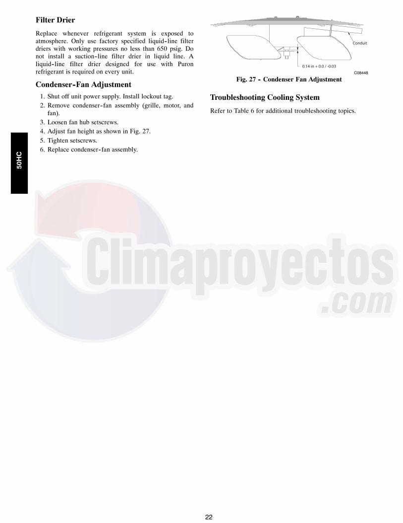
Filter Drier
Replace whenever refrigerant system is exposed toatmosphere. Only use factory specified liquid--line filterdriers with working pressures no less than 650 psig. Donot install a suction--line filter drier in liquid line. Aliquid--line filter drier designed for use with Puronrefrigerant is required on every unit.
Condenser--Fan Adjustment1. Shut off unit power supply. Install lockout tag.2. Remove condenser--fan assembly (grille, motor, andfan).
3. Loosen fan hub setscrews.4. Adjust fan height as shown in Fig. 27.5. Tighten setscrews.6. Replace condenser--fan assembly.
Conduit
0.14 in + 0.0 / -0.03C08448
Fig. 27 -- Condenser Fan Adjustment
Troubleshooting Cooling System
Refer to Table 6 for additional troubleshooting topics.
50HC

23
Table 6 – Cooling Troubleshooting
PROBLEM CAUSE REMEDYCompressor andOutdoor FanWill Not Start.
Power failure. Call power company.Fuse blown or circuit breaker tripped. Replace fuse or reset circuit breaker. Determine root cause.Defective thermostat, contactor, transformer,control relay, or capacitor.
Replace component.
Insufficient line voltage. Determine cause and correct.Incorrect or faulty wiring. Check wiring diagram and rewire correctly.Thermostat setting too high. Lower thermostat setting below room temperature.High pressure switch tripped. See problem ‘‘Excessive head pressure.’’Low pressure switch tripped. Check system for leaks. Repair as necessary.Freeze-up protection thermostat tripped. See problem ‘‘Suction pressure too low.’’
Compressor Will NotStart But OutdoorFan Runs.
Faulty wiring or loose connections in compressorcircuit.
Check wiring and repair or replace.
Compressor motor burned out, seized, orinternal overload open.
Determine cause. Replace compressor or allow enough time forinternal overload to cool and reset.
Defective run/start capacitor, overload, startrelay.
Determine cause and replace defective component.
One leg of 3-phase power dead. Replace fuse or reset circuit breaker. Determine cause.Compressor Cycles(Other ThanNormally SatisfyingThermostat).
Refrigerant overcharge or undercharge. Recover refrigerant, evacuate system, and recharge to nameplate.Defective compressor. Replace and determine cause.Insufficient line voltage. Determine cause and correct.Blocked outdoor coil or dirty air filter. Clear or clean coil. Replace filter.Defective run/start capacitor, overload, or startrelay.
Determine cause and replace.
Defective thermostat. Replace thermostat.Faulty outdoor-fan (cooling) or indoor-fan(heating) motor or capacitor.
Replace.
Restriction in refrigerant system. Locate restriction and remove.Compressor OperatesContinuously.
Dirty air filter. Replace filter.Unit undersized for load. Decrease load or increase unit size.Thermostat set too low (cooling). Reset thermostat.Low refrigerant charge. Locate leak; repair and recharge.Air in system. Recover refrigerant, replace filter dryer, evacuate system, and
recharge.
Outdoor coil dirty or restricted. Clean coil or remove restriction.Compressor MakesExcessive Noise.
Compressor rotating in the wrong direction. Reverse the 3-phase power leads as described inStart-Up.
Excessive HeadPressure.
Dirty outside air or return air filter (heating). Replace filter.Dirty outdoor coil (cooling). Clean coil.Refrigerant overcharged. Recover excess refrigerant.Air in system. Recover refrigerant, replace filter dryer, evacuate system, and
recharge.
Condensing air restricted or air short-cycling. Determine cause and correct.Head PressureToo Low.
Low refrigerant charge. Check for leaks; repair and recharge.Compressor scroll plates defective. Replace compressor.Restriction in liquid tube. Remove restriction.
Excessive SuctionPressure.
High heat load. Check for source and eliminate.Compressor scroll plates defective. Replace compressor.Refrigerant overcharged. Recover excess refrigerant.
Suction PressureToo Low.
Dirty air filter (cooling). Replace filter.Dirty or heavily iced outdoor coil (heating). Clean outdoor coil. Check defrost cycle operation.Low refrigerant charge. Check for leaks; repair and recharge.Metering device or low side restricted. Remove source of restriction.Insufficient indoor airflow (cooling mode). Increase air quantity. Check filter and replace if necessary.Temperature too low in conditioned area. Reset thermostat.Field-installed filter drier restricted. Replace.Outdoor ambient below 25_F (cooling). Install low-ambient kit.Outdoor fan motor(s) not operating (heating). Check fan motor operation.
50HC

24
CONVENIENCE OUTLETS
ELECTRICAL OPERATION HAZARDFailure to follow this warning could result inpersonal injury or death.
Units with convenience outlet circuits may usemultiple disconnects. Check convenience outlet forpower status before opening unit for service. Locateits disconnect switch, if appropriate, and open it.Tag--out this switch, if necessary.
! WARNING
Convenience Outlets: Two types of convenience outletsare offered on 50HC models: Non--powered andunit--powered. Both types provide a 125VACGround--Fault Circuit--Interrupt (GFCI) duplex receptaclerated at 15A behind a hinged waterproof access cover,located on the end panel of the unit. See Fig. 28.
CONVENIENCEOUTLET GFCI
PWD-CO FUSE SWITCH
PWD-CO TRANSFORMER
CONTROL BOXACCESS PANEL
C08128
Fig. 28 -- Convenience Outlet Location
Installing Weatherproof Cover: A weatherproofwhile-in-use cover for the factory installed convenienceoutlets is now required by UL standards. This covercannot be factory-mounted due its depth. The cover mustbe installed at unit installation. For shipment, theconvenience outlet is covered with a blank cover plate.
The weatherproof cover kit is shipped in the unit’s controlbox. The kit includes the hinged cover, a backing plateand gasket.
NOTE: DISCONNECT ALL POWER TO UNIT ANDCONVENIENCE OUTLET. Use approved lockout/tagoutprocedures.
1. Remove the blank cover plate at the convenienceoutlet; discard the blank cover.
2. Loosen the two screws at the GFCI duplex outlet,until approximately 1/2-in (13 mm) under screw headsare exposed.
3. Press the gasket over the screw heads. Slip thebacking plate over the screw heads at the keyholeslots and align with the gasket; tighten the two screwsuntil snug (do not over-tighten).
4. Mount the weatherproof cover to the backing plate asshown in Fig. 29.
5. Remove two slot fillers in the bottom of the cover topermit service tool cords to exit the cover.
6. Check cover installation for full closing and latching.
TOP
TOP
TOP
WET LOCATIONS
WET LOCATIONS
COVER - WHILE-IN-USEWEATHERPROOF
BASEPLATE FORGFCI RECEPTACLE
GASKET
GFCI RECEPTACLENOT INCLUDED
C09022
Fig. 29 -- Weatherproof Cover Installation
Non--powered type: This type requires the fieldinstallation of a general--purpose 125--volt 15--A circuitpowered from a source elsewhere in the building. Observenational and local codes when selecting wire size, fuse orbreaker requirements and disconnect switch size andlocation. Route 125--v power supply conductors into thebottom of the utility box containing the duplex receptacle.
Unit--powered type: A unit--mounted transformer isfactory--installed to step--down the main power supplyvoltage to the unit to 115--v at the duplex receptacle. Thisoption also includes a manual switch with fuse, located ina utility box and mounted on a bracket behind theconvenience outlet; access is through the unit’s controlbox access panel. See Fig. 28.
The primary leads to the convenience outlet transformerare not factory--connected. Selection of primary powersource is a customer--option. If local codes permit, thetransformer primary leads can be connected at theline--side terminals on a unit--mounted non--fuseddisconnect or Heating, Air Conditioning and Refrigeration(HACR) breaker switch; this will provide service power tothe unit when the unit disconnect switch or HACR switchis open. Other connection methods will result in theconvenience outlet circuit being de--energized when theunit disconnect or HACR switch is open. See Fig. 30.
50HC

25
CO8283
Fig. 30 -- Powered Convenience Outlet Wiring
UNITVOLTAGE
CONNECTAS
PRIMARYCONNECTIONS
TRANSFORMERTERMINALS
208,230 240 L1: RED +YEL
L2: BLU + GRAH1 + H3H2 + H4
460 480L1: REDSplice BLU + YELL2: GRA
H1H2 + H3H4
575 600 L1: REDL2: GRA
H1H2
Duty Cycle: The unit--powered convenience outlet has aduty cycle limitation. The transformer is intended toprovide power on an intermittent basis for service tools,lamps, etc; it is not intended to provide 15A loading forcontinuous duty loads (such as electric heaters forovernight use). Observe a 50% limit on circuit loadingabove 8A (i.e., limit loads exceeding 8A to 30 minutes ofoperation every hour).
Maintenance: Periodically test the GFCI receptacle bypressing the TEST button on the face of the receptacle.This should cause the internal circuit of the receptacle totrip and open the receptacle. Check for proper groundingwires and power line phasing if the GFCI receptacle doesnot trip as required. Press the RESET button to clear thetripped condition.
Fuse on powered type: The factory fuse is a BussmannFusetron T--15, non--renewable screw--in (Edison base)type plug fuse.
Using unit--mounted convenience outlets: Units withunit--mounted convenience outlet circuits will oftenrequire that two disconnects be opened to de--energize allpower to the unit. Treat all units as electrically energizeduntil the convenience outlet power is also checked andde--energization is confirmed. Observe National ElectricalCode Article 210, Branch Circuits, for use of convenienceoutlets.
SMOKE DETECTORS
Smoke detectors are available as factory--installed optionson 50HC models. Smoke detectors may be specified forSupply Air only or for Return Air without or witheconomizer or in combination of Supply Air and ReturnAir. Return Air smoke detectors are arranged for verticalreturn configurations only. All components necessary foroperation are factory--provided and mounted. The unit isfactory--configured for immediate smoke detectorshutdown operation; additional wiring or modifications tounit terminal board may be necessary to complete the unitand smoke detector configuration to meet projectrequirements.
System
The smoke detector system consists of a four--wirecontroller and one or two sensors. Its primary function isto shut down the rooftop unit in order to prevent smokefrom circulating throughout the building. It is not to beused as a life saving device.
Controller
The controller (see Fig. 31) includes a controller housing,a printed circuit board, and a clear plastic cover. Thecontroller can be connected to one or two compatible ductsmoke sensors. The clear plastic cover is secured to thehousing with a single captive screw for easy access to thewiring terminals. The controller has three LEDs (forPower, Trouble and Alarm) and a manual test/reset button(on the cover face).
DUCT SMOKE SENSORCONTROLLER
CONDUIT NUTS(SUPPLIED BY INSTALLER)
CONDUIT SUPPORT PLATE
TERMINAL BLOCK COVER
COVER GASKET(ORDERING OPTION)
CONTROLLER COVER
FASTENER (2X)
CONDUIT COUPLINGS(SUPPLIED BY INSTALLER)
CONTROLLER HOUSINGAND ELECTRONICS
ALARM
TROUBLE
POWER
TEST/RESETSWITCH
C08208
Fig. 31 -- Controller Assembly
50HC

26
Smoke Detector Sensor
The Smoke Detector Sensor (see Fig. 32) includes aplastic housing, a printed circuit board, a clear plasticcover, a sampling tube inlet and an exhaust tube. Thesampling tube (when used) and exhaust tube are attachedduring installation. The sampling tube varies in lengthdepending on the size of the rooftop unit. The clear plasticcover permits visual inspections without having todisassemble the sensor. The cover attaches to the sensorhousing using four captive screws and forms an airtightchamber around the sensing electronics. Each sensorincludes a harness with an RJ45 terminal for connecting tothe controller. Each sensor has four LEDs (for Power,Trouble, Alarm and Dirty) and a manual test/reset button(on the left--side of the housing).
Air is introduced to the duct smoke detector sensor’ssensing chamber through a sampling tube that extends intothe HVAC duct and is directed back into the ventilationsystem through a (shorter) exhaust tube.
The difference in air pressure between the two tubes pullsthe sampled air through the sensing chamber. When asufficient amount of smoke is detected in the sensingchamber, the sensor signals an alarm state and thecontroller automatically takes the appropriate action toshut down fans and blowers, change over air handlingsystems, notify the fire alarm control panel, etc.
The sensor uses a process called differential sensing toprevent gradual environmental changes from triggeringfalse alarms. A rapid change in environmental conditions,such as smoke from a fire, causes the sensor to signal analarm state but dust and debris accumulated over timedoes not.
The difference in air pressure between the two tubes pullsthe sampled air through the sensing chamber. When asufficient amount of smoke is detected in the sensingchamber, the sensor signals an alarm state and thecontroller automatically takes the appropriate action toshut down fans and blowers, change over air handlingsystems, notify the fire alarm control panel, etc.
For installations using two sensors, the duct smokedetector does not differentiate which sensor signals analarm or trouble condition.
SEE DETAIL A
DETAIL A
PLUG
SAMPLING TUBE(ORDERED SEPARATELY)
COUPLING
MAGNETICTEST/RESET
SWITCH
ALARMTROUBLE
POWERDIRTY
SENSOR COVER
COVER GASKET(ORDERING OPTION)
SENSOR HOUSINGAND ELECTRONICS
EXHAUST GASKET
EXHAUST TUBE DUCT SMOKE SENSOR
INTAKEGASKET
TSD-CO2(ORDERING OPTION)
C08209
Fig. 32 -- Smoke Detector Sensor
Smoke Detector Locations
Supply Air: The Supply Air Smoke Detector Sensor islocated to the left of the unit’s indoor (supply) fan. SeeFig. 33. Access is through the fan access panel. There isno sampling tube used at this location. The sampling tubeinlet extends through the side plate of the fan housing(into a high pressure area). The controller is located on abracket to the right of the return filter, accessed throughthe lift--off filter panel.
SUPPLY AIR SMOKE DETECTOR
C08245
Fig. 33 -- Typical Supply Air Smoke Detector SensorLocation
50HC

27
Return Air Smoke Detector Sensor withoutEconomizer: The sampling tube is located across thereturn air opening on the unit basepan. See Fig. 34. Theholes in the sampling tube face downward, into the returnair stream. The sampling tube is connected through tubingto the return air sensor that is mounted on a bracket highon the partition between return filter and controllerlocation. (This sensor is shipped in a flat--mountinglocation. Installation requires that this sensor be relocatedto its operating location and the tubing to the samplingtube be connected. See installation steps below.)
*RA detector must be moved from shipping position to operating position by installer
RETURN AIR DETECTORSAMPLING TUBE
RETURN AIR DETECTOR MODULE(Shipping position shown)*
CONTROLLERMODULE
C07307
Fig. 34 -- Typical Return Air Smoke Detector Location
Return Air Smoke Detector Sensor with Economizer:The sampling tube is inserted through the side plates ofthe economizer housing, placing it across the return airopening on the unit basepan. See Fig. 35. The holes in thesampling tube face downward, into the return air stream.The sampling tube is connected using tubing to the returnair sensor mounted on a bracket high on the partitionbetween return filter and controller location. The sensor isshipped in a flat--mounting location. Installation requiresthe sensor be relocated to its operating location and thetubing to the sampling tube be connected. See installationsteps below.
RETURN AIR SAMPLING TUBE
C08129
Fig. 35 -- Return Air Sampling Tube Location(View is reoriented to show opposite side for clarity.)
Completing Installation of Return Air SmokeDetector:
SAMPLE TUBE
SCREWS
FLEXIBLE EXHAUST TUBES
C12049
Fig. 36 -- Return Air Smoke Detector ModuleShipping Position
Use the following steps to complete the installation of theReturn Air Smoke Detector.
1. Unscrew the two screws holding the Return AirSensor Detector plate. See Fig. 36. Save the screws.
2. Remove the Return Air Smoke Sensor Module and itsdetector plate.
3. Rotate the detector plate so the sensor is facing out-wards and the sampling tube connection is on the bot-tom. See Fig. 37.
4. Screw the sensor and detector plate into its operatingposition using screws from Step 1. Ensure thesampling tube connection is on the bottom and the ex-haust tube is on the top. See Fig. 37.
5. Connect the flexible tube on the sampling inlet to thesampling tube on the basepan.
6. For units with an economizer, the sampling tube isintegrated into the economizer housing butconnecting the flexible tubing to the sampling tube isthe same.
RETURN AIR SENSOR(Operating Position Shown)
C12050
Fig. 37 -- Return Air Sensor Operating Position
50HC

28
FIOP Smoke Detector Wiring and Response
All units: FIOP smoke detector is configured toautomatically shut down all unit operations when a smokecondition is detected. See Fig. 38, Smoke DetectorWiring.
Highlight A: JMP 3 is factory--cut, transferring unitcontrol to smoke detector.
Highlight B: Smoke detector NC contact set will open onsmoke alarm condition, de--energizing the ORNconductor.
Highlight C: 24V power signal using the ORN lead isremoved at the Smoke Detector input on LCTB; all unitoperations cease immediately.
PremierLink and RTU--OPEN Controls: Unitoperating functions (fan, cooling and heating) areterminated as described above. In addition:
Highlight D: On smoke alarm condition, the smokedetector NO Alarm contact will close, supplying 24--vpower to GRA conductor.
Highlight E: GRA lead at Smoke Alarm input on LCTBprovides 24--v signal to FIOP DDC control.
Premier--Link: This signal is conveyed to PremierLinkFIOP’s TB1 at terminal TB1--6 (BLU lead). This signalinitiates the FSD sequence by the PremierLink control.FSD status is reported to connected CCN network.
RTU--OPEN: The 24--v signal is conveyed toRTU--OPEN -- J1--10 input terminal. This signal initiatesthe FSD sequence by the RTU--OPEN control. FSD statusis reported to connected BAS network.
Using Remote Logic: Five conductors are provided forfield use (see Highlight F) for additional annunciationfunctions.
Additional Application Data: Refer to Catalog No.HKRNKA--1XA for discussions on additional controlfeatures of these smoke detectors including multiple unitcoordination. See Fig. 38.
A
E
F
CD
B
C08246
Fig. 38 -- Typical Smoke Detector System Wiring
50HC

29
SENSOR AND CONTROLLERTESTS
Sensor Alarm TestThe sensor alarm test checks a sensor’s ability to signal analarm state. This test requires that you use a field providedSD--MAG test magnet.
OPERATIONAL TEST ALERT
Failure to follow this ALERT can result in anunnecessary evacuation of the facility.
This test places the duct detector into the alarm state.Unless part of the test, disconnect all auxiliaryequipment from the controller before performing thetest. If the duct detector is connected to a fire alarmsystem, notify the proper authorities beforeperforming the test.
NOTICE
Sensor Alarm Test Procedure
1. Hold the test magnet where indicated on the side ofthe sensor housing for seven seconds.
2. Verify that the sensor’s Alarm LED turns on.3. Reset the sensor by holding the test magnet againstthe sensor housing for two seconds.
4. Verify that the sensor’s Alarm LED turns off.
Controller Alarm TestThe controller alarm test checks the controller’s ability toinitiate and indicate an alarm state.
OPERATIONAL TEST ALERT
Failure to follow this ALERT can result in anunnecessary evacuation of the facility.
This test places the duct detector into the alarm state.Unless part of the test, disconnect all auxiliaryequipment from the controller before performing thetest. If the duct detector is connected to a fire alarmsystem, notify the proper authorities beforeperforming the test.
NOTICE
Controller Alarm Test Procedure
1. Press the controller’s test/reset switch for sevenseconds.
2. Verify that the controller’s Alarm LED turns on.
3. Reset the sensor by pressing the test/reset switch fortwo seconds.
4. Verify that the controller’s Alarm LED turns off.
Dirty Controller TestThe dirty controller test checks the controller’s ability toinitiate a dirty sensor test and indicate its results.
OPERATIONAL TEST ALERT
Failure to follow this ALERT can result in anunnecessary evacuation of the facility.
Pressing the controller’s test/reset switch for longerthan seven seconds will put the duct detector into thealarm state and activate all automatic alarm responses.
NOTICE
Dirty Controller Test Procedure
1. Press the controller’s test/reset switch for twoseconds.
2. Verify that the controller’s Trouble LED flashes.
Dirty Sensor TestThe dirty sensor test provides an indication of the sensor’sability to compensate for gradual environmental changes.A sensor that can no longer compensate for environmentalchanges is considered 100% dirty and requires cleaning orreplacing. You must use a field provided SD--MAG testmagnet to initiate a sensor dirty test. The sensor’s DirtyLED indicates the results of the dirty test as shown inTable 7.
OPERATIONAL TEST ALERT
Failure to follow this ALERT can result in anunnecessary evacuation of the facility.
Holding the test magnet against the sensor housing formore than seven seconds will put the duct detectorinto the alarm state and activate all automatic alarmresponses.
NOTICE
Table 7 – Dirty LED Test
FLASHES DESCRIPTION1 0---25% dirty. (Typical of a newly installed detector)2 25---50% dirty3 51---75% dirty4 76---99% dirty
50HC

30
Dirty Sensor Test Procedure
1. Hold the test magnet where indicated on the side ofthe sensor housing for two seconds.
2. Verify that the sensor’s Dirty LED flashes.
OPERATIONAL TEST ALERT
Failure to follow this ALERT can result in anunnecessary evacuation of the facility.
Changing the dirty sensor test operation will put thedetector into the alarm state and activate all automaticalarm responses. Before changing dirty sensor testoperation, disconnect all auxiliary equipment from thecontroller and notify the proper authorities ifconnected to a fire alarm system.
NOTICE
Changing the Dirt Sensor TestBy default, sensor dirty test results are indicated by:S The sensor’s Dirty LED flashing.
S The controller’s Trouble LED flashing.S The controller’s supervision relay contacts toggle.
The operation of a sensor’s dirty test can be changed sothat the controller’s supervision relay is not used toindicate test results. When two detectors are connected toa controller, sensor dirty test operation on both sensorsmust be configured to operate in the same manner.
To Configure the Dirty Sensor Test Operation
1. Hold the test magnet where indicated on the side ofthe sensor housing until the sensor’s Alarm LED turnson and its Dirty LED flashes twice (approximately 60seconds).
2. Reset the sensor by removing the test magnet thenholding it against the sensor housing again until thesensor’s Alarm LED turns off (approximately 2seconds).
Remote Station TestThe remote station alarm test checks a test/reset station’sability to initiate and indicate an alarm state.
OPERATIONAL TEST ALERT
Failure to follow this ALERT can result in anunnecessary evacuation of the facility.
This test places the duct detector into the alarm state.Unless part of the test, disconnect all auxiliaryequipment from the controller before performing thetest. If the duct detector is connected to a fire alarmsystem, notify the proper authorities beforeperforming the test.
NOTICE
SD--TRK4 Remote Alarm Test Procedure1. Turn the key switch to the RESET/TEST position forseven seconds.
2. Verify that the test/reset station’s Alarm LED turnson.
3. Reset the sensor by turning the key switch to theRESET/TEST position for two seconds.
4. Verify that the test/reset station’s Alarm LED turnsoff.
Remote Test/Reset Station Dirty Sensor TestThe test/reset station dirty sensor test checks the test/resetstation’s ability to initiate a sensor dirty test and indicatethe results. It must be wired to the controller as shown inFig. 39 and configured to operate the controller’ssupervision relay. For more information, see “Changingsensor dirty test operation.”
1
12
14
13
19
15
2
20
3
Reset/Test
Trouble
Power
Alarm
Supervision relaycontacts [3]
5
4
1
3
2
SD-TRK4
2
1
TB3
18 Vdc ( )+
18 Vdc ( )−
Auxiliaryequipment+
−
Wire must beadded by installer
Smoke Detector Controller
C08247
Fig. 39 -- Remote Test/Reset Station Connections
OPERATIONAL TEST ALERT
Failure to follow this ALERT can result in anunnecessary evacuation of the facility.
If the test/reset station’s key switch is left in theRESET/TEST position for longer than seven seconds,the detector will automatically go into the alarm stateand activate all automatic alarm responses.
NOTICE
OPERATIONAL TEST ALERT
Failure to follow this ALERT can result in anunnecessary evacuation of the facility.
Holding the test magnet to the target area for longerthan seven seconds will put the detector into the alarmstate and activate all automatic alarm responses.
NOTICE
Dirty Sensor Test Using an SD--TRK41. Turn the key switch to the RESET/TEST position fortwo seconds.
50HC

31
2. Verify that the test/reset station’s Trouble LEDflashes.
Detector Cleaning
Cleaning the Smoke Detector
Clean the duct smoke sensor when the Dirty LED isflashing continuously or sooner if conditions warrant.
OPERATIONAL TEST ALERT
Failure to follow this ALERT can result in anunnecessary evacuation of the facility.
If the smoke detector is connected to a fire alarmsystem, first notify the proper authorities that thedetector is undergoing maintenance then disable therelevant circuit to avoid generating a false alarm.
NOTICE
1. Disconnect power from the duct detector then removethe sensor’s cover. See Fig. 40.
Airflow
HVAC ductSamplingtube
Retainerclip
Opticplate
Optichousing
Sensor housing
C07305
Fig. 40 -- Sensor Cleaning Diagram
2. Using a vacuum cleaner, clean compressed air, or asoft bristle brush, remove loose dirt and debris frominside the sensor housing and cover.Use isopropyl alcohol and a lint--free cloth to removedirt and other contaminants from the gasket on thesensor’s cover.
3. Squeeze the retainer clips on both sides of the optichousing.
4. Lift the housing away from the printed circuit board.5. Gently remove dirt and debris from around the opticplate and inside the optic housing.
6. Replace the optic housing and sensor cover.7. Connect power to the duct detector then perform asensor alarm test.
Indicators
Normal State
The smoke detector operates in the normal state in theabsence of any trouble conditions and when its sensingchamber is free of smoke. In the normal state, the PowerLED on both the sensor and the controller are on and allother LEDs are off.
Alarm State
The smoke detector enters the alarm state when theamount of smoke particulate in the sensor’s sensingchamber exceeds the alarm threshold value. (See Table 8.)Upon entering the alarm state:S The sensor’s Alarm LED and the controller’s AlarmLED turn on.
S The contacts on the controller’s two auxiliary relaysswitch positions.
S The contacts on the controller’s alarm initiation relayclose.
S The controller’s remote alarm LED output is activated(turned on).
S The controller’s high impedance multiple fan shutdowncontrol line is pulled to ground Trouble state.
The SuperDuct duct smoke detector enters the troublestate under the following conditions:
S A sensor’s cover is removed and 20 minutes pass beforeit is properly secured.
S A sensor’s environmental compensation limit is reached(100% dirty).
S A wiring fault between a sensor and the controller is
detected.
An internal sensor fault is detected upon entering thetrouble state:
S The contacts on the controller’s supervisory relayswitch positions. (See Fig. 41.)
S If a sensor trouble, the sensor’s Trouble LED the
controller’s Trouble LED turn on.
S If 100% dirty, the sensor’s Dirty LED turns on and thecontroller’s Trouble LED flashes continuously.
S If a wiring fault between a sensor and the controller, thecontroller’s Trouble LED turns on but not the sensor’s.
Alarm Power
Test/resetswitch
Trouble
C07298
Fig. 41 -- Controller Assembly
NOTE: All troubles are latched by the duct smokedetector. The trouble condition must be cleared and thenthe duct smoke detector must be reset in order to restore itto the normal state.
Resetting Alarm and Trouble Condition Trips:
Manual reset is required to restore smoke detector systemsto Normal operation. For installations using two sensors,
50HC

32
the duct smoke detector does not differentiate whichsensor signals an alarm or trouble condition. Check eachsensor for Alarm or Trouble status (indicated by LED).Clear the condition that has generated the trip at thissensor. Then reset the sensor by pressing and holding thereset button (on the side) for 2 seconds. Verify that thesensor’s Alarm and Trouble LEDs are now off. At thecontroller, clear its Alarm or Trouble state by pressing andholding the manual reset button (on the front cover) for 2seconds. Verify that the controller’s Alarm and TroubleLEDs are now off. Replace all panels.
Troubleshooting
Controller’s Trouble LED is On
1. Check the Trouble LED on each sensor connected tothe controller. If a sensor’s Trouble LED is on, de-termine the cause and make the necessary repairs.
2. Check the wiring between the sensor and the control-ler. If wiring is loose or missing, repair or replace asrequired.
Controller’s Trouble LED is Flashing
1. One or both of the sensors is 100% dirty.2. Determine which Dirty LED is flashing then cleanthat sensor assembly as described in the detectorcleaning section.
Sensor’s Trouble LED is On
1. Check the sensor’s Dirty LED. If it is flashing, thesensor is dirty and must be cleaned.
2. Check the sensor’s cover. If it is loose or missing, se-cure the cover to the sensor housing.
3. Replace sensor assembly.
Sensor’s Power LED is Off
1. Check the controller’s Power LED. If it is off, de-termine why the controller does not have power andmake the necessary repairs.
2. Check the wiring between the sensor and the control-ler. If wiring is loose or missing, repair or replace asrequired.
Controller’s Power LED is Off
1. Make sure the circuit supplying power to the control-ler is operational. If not, make sure JP2 and JP3 areset correctly on the controller before applying power.
2. Verify that power is applied to the controller’s supplyinput terminals. If power is not present, replace or re-pair wiring as required.
Remote Test/Reset Station’s Trouble LED Does Notflash When Performing a Dirty Test, But the Control-ler’s Trouble LED Does
1. Verify that the remote test/station is wired as shownin Fig. 39. Repair or replace loose or missing wiring.
2. Configure the sensor dirty test to activate the control-ler’s supervision relay. See “Changing sensor dirtytest operation.”
Sensor’s Trouble LED is On, But the Controller’sTrouble LED is OFF
Remove JP1 on the controller.
PROTECTIVE DEVICES
Compressor Protection
Overcurrent
The compressor has internal line--break motor protection.
Over--temperature
The compressor has an internal protector to protect itagainst excessively high discharge gas temperatures.
High Pressure Switch
The system is provided with a high pressure switchmounted on the discharge line. The switch isstem--mounted and brazed into the discharge tube. Tripsetting is 630 psig 10 psig (4344 69 kPa) when hot.Reset is automatic at 505 psig (3482 kPa).
Low Pressure Switch
The system is protected against a loss of charge and lowevaporator coil loading condition by a low pressure switchlocated on the suction line near the compressor. Theswitch is stem--mounted. Trip setting is 54 psig 5 psig(372 34 kPa). Reset is automatic at 117 5 psig (807 34 kPa).
Evaporator Freeze Protection
The system is protected against evaporator coil frostingand low temperature conditions by a temperature switchmounted on the evaporator coil hairpin. Trip setting is30_F 5_F (--1_C 3_C). Reset is automatic at 45_F(7_C).
Supply (Indoor) Fan Motor Protection
Disconnect and lockout power when servicing fan motor.
The standard supply fan motor is equipped with internalovercurrent and over--temperature protection. Protectiondevices reset automatically.
The High Static option supply fan motor is equipped witha pilot--circuit Thermix combination over--temperature/overcurrent protection device. This device resetsautomatically. Do not bypass this switch to correcttrouble. Determine the cause and correct it.
50HC

33
Table 8 – Detector Indicators
CONTROL OR INDICATOR DESCRIPTION
Magnetic test/reset switch Resets the sensor when it is in the alarm or trouble state. Activates or tests the sensor when it is inthe normal state.
Alarm LED Indicates the sensor is in the alarm state.Trouble LED Indicates the sensor is in the trouble state.
Dirty LED Indicates the amount of environmental compensation used by the sensor(flashing continuously = 100%)
Power LED Indicates the sensor is energized.
Condenser Fan Motor Protection
The condenser fan motor is internally protected againstover--temperature.
Relief Device
A soft solder joint at the suction service access portprovides pressure relief under abnormal temperature and
pressure conditions (i.e., fire in building). Protect thisjoint during brazing operations near this joint.
Control Circuit, 24--V
The control circuit is protected against overcurrentconditions by a circuit breaker mounted on controltransformer TRAN. Reset is manual.
C08199
Fig. 42 -- PremierLink Controller
PREMIERLINK CONTROL
The PremierLink controller (see Fig. 42) is compatiblewith Carrier Comfort Networkr (CCN) devices. Thiscontrol is designed to allow users the access and ability tochange factory--defined settings, thus expanding thefunction of the standard unit control board. CCN serviceaccess tools include System Pilott, Touch Pilott andService Tool. Standard tier display tools, Navigatort andScrolling Marquee, are not suitable for use with the latestPremierLink controller (Version 2.x).
The PremierLink control is factory--mounted in the unit’smain control box to the left of the LCTB. Factory wiringis completed through harnesses connected to the LCTBthermostat. Field connections are made at a 16--poleterminal block (TB1) located on the bottom shelf of theunit control box in front of the PremierLink controller Thefactory--installed PremierLink control includes thesupply--air temperature (SAT) sensor. The outdoor air
temperature (OAT) sensor is included in theFIOP/accessory EconoMi$er 2 package.
The factory--installed PremierLink Controller includes thesupply--air temperature (SAT) sensor. The outdoor airtemperature (OAT) sensor is included in theFIOP/accessory EconoMi$er 2 package.
Refer to Fig. 42 for PremierLink connection locations.
NOTE: Refer to PremierLinkt Installation, Start--Upand Configuration Instructions. Have a copy of thismanual available at unit start--up.
RTU--OPEN CONTROL SYSTEM
The RTU Open controller is an integrated component of theCarrier rooftop unit. Its internal application programmingprovides optimum performance and energy efficiency. RTUOpen enables the unit to run in 100% stand--alone controlmode, Carrier’s I--Vu Open network, or a Third PartyBuilding Automation System (BAS). On--board DIP
50HC

34
switches allow you to select your protocol (and baud rate) ofchoice among the four most popular protocols in use today:BACnet, Modbus, Johnson N2 and LonWorks.
The RTU Open control is factory--mounted in the unit’smain control box, to the left of the Light CommercialTerminal Board (LCTB). Factory wiring is completedthrough harnesses connected to the LCTB. Fieldconnections for RTU Open sensors will be made at thePhoenix connectors on the RTU Open board. Thefactory--installed RTU Open control includes thesupply--air temperature (SAT) sensor. The outdoor airtemperature (OAT) sensor is included in theFIOP/accessory EconoMi$er2 package.
SENSORY/ACCESSORYINSTALLATION
There are a variety of sensors and accessories availablefor the RTU-OPEN. Some of these can be factory or fieldinstalled, while others are only field installable. TheRTU-OPEN controller may also require connection to abuilding network system or building zoning system. Allfield control wiring that connects to the RTU-OPEN mustbe routed through the raceway built into the corner post ofthe unit or secured to the unit control box with electricalconduit. The unit raceway provides the UL requiredclearance between high and low-voltage wiring. Pass thecontrol wires through the hole provided in the corner post,
then feed the wires thorough the raceway to theRTU-OPEN. Connect the wires to the removable Phoenixconnectors and then reconnect the connectors to the board.IMPORTANT: Refer to the specific sensor or accessoryinstructions for its proper installation and for rooftop unitinstallation refer to base unit installation instructions andthe unit’s wiring diagrams.
ELECTRICAL SHOCK HAZARD
Failure to follow this warning could result in personalinjury, death and/or equipment damage.
Disconnect and lock--out/tagout electrical powerbefore wiring the RTU--OPEN controller.
! WARNING
ADDITIONAL RTU--OPENINSTALLATION ANDTROUBLESHOOTING
Additional installation, wiring and troubleshootinginformation for the RTU--OPEN Controller can be foundin the following manuals: “Controls, Start--up, Operationand Troubleshooting Instructions,” and “RTU OpenInstallation and Start--up Guide.”
50HC
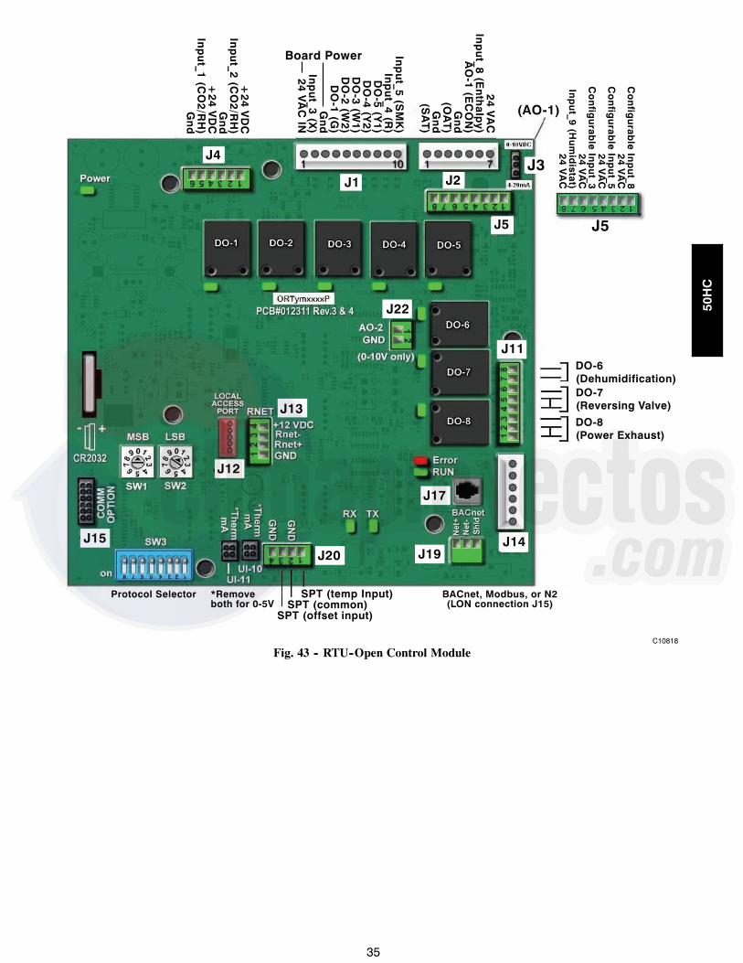
35
DO-6(Dehumidification)DO-7(Reversing Valve)
DO-8(Power Exhaust)
+24 V
DC
Inp
ut_2 (C
O2/R
H)
Gn
d+
24 VD
CIn
pu
t_1 (CO
2/RH
)G
nd
Inp
ut_5 (S
MK
)In
pu
t_4 (R)
DO
-5 (Y1)
DO
-4 (Y2)
DO
-3 (W1)
DO
-2 (W2)
DO
-1 (G)
Gn
dIn
pu
t_3 (X)
24 VA
C IN
Board Power
24 VA
CIn
pu
t_8 (En
thalp
y)A
O-1 (E
CO
N)
Gn
d(O
AT
)G
nd
(SA
T)
Co
nfig
urab
le In
pu
t_824 V
AC
Co
nfig
urab
le In
pu
t_524 V
AC
Co
nfig
urab
le In
pu
t_324 V
AC
Inp
ut_9 (H
um
idistat)
24 VA
C
BACnet, Modbus, or N2(LON connection J15)
SPT (temp Input) SPT (common)SPT (offset input)
*Removeboth for 0-5V
Protocol Selector
J3
J5
(AO-1)
J4
J1 J2
J5
J14
J11
J22
J13
J12
J15J20
J17
J19
C10818
Fig. 43 -- RTU--Open Control Module
50HC

36
ECONOMIZER SYSTEMS
The unit may be equipped with a factory--installed oraccessory (field--installed) economizer system. Two typesare available: with a logic control system (EconoMi$erIV) and without a control system (EconoMi$er2). See Fig.44 and Fig. 45 for component locations on each type. SeeFig. 46 and Fig. 47 for economizer section wiringdiagrams.
Both economizers use direct--drive damper actuators.
IMPORTANT: Any economizer that meets theeconomizer requirements as laid out in California’s Title24 mandatory section 120.2 (fault detection anddiagnostics) and/or prescriptive section 140.4 (life--cycletests, damper leakage, 5 year warranty, sensor accuracy,etc), will have a label on the economizer. Any economizerwithout this label does not meet California’s Title 24. Thefire year limited parts warranty referred to in section140.4 only applies to factory installed economizers. Pleaserefer to your economizer on your unit.
ECONOMI$ER IVCONTROLLER
OUTSIDE AIRTEMPERATURE SENSOR
LOW AMBIENTSENSOR
ACTUATOR
WIRINGHARNESS
C06021
Fig. 44 -- EconoMi$er IV Component Locations
ECONOMI$ER2PLUG
BAROMETRICRELIEFDAMPER
OUTDOORAIR HOOD
HOODSHIPPINGBRACKET
GEAR DRIVENDAMPER
C06022
Fig. 45 -- EconoMi$er2 Component Locations
FOR OCCUPANCY CONTROLREPLACE JUMPER WITHFIELD-SUPPLIED TIME CLOCK
LEGENDDCV— Demand Controlled VentilationIAQ — Indoor Air QualityLA — Low Ambient Lockout DeviceOAT— Outdoor-Air TemperaturePOT— PotentiometerRAT— Return-Air Temperature
Potentiometer Defaults Settings:Power Exhaust MiddleMinimum Pos. Fully ClosedDCV Max. MiddleDCV Set MiddleEnthalpy C Setting
NOTES:1. 620 ohm, 1 watt 5% resistor should be removed only when using differential
enthalpy or dry bulb.2. If a separate field-supplied 24 v transformer is used for the IAQ sensor power
supply, it cannot have the secondary of the transformer grounded.3. For field-installed remote minimum position POT, remove black wire jumper
between P and P1 and set control minimum position POT to the minimumposition.
8
7
C06028
Fig. 46 -- EconoMi$er IV Wiring
50HC

37
4
3
5
2
8
6
7
1
10
11
9
12
PINK
VIOLET
BLACK
BLUE
YE
LLO
W
NOTE 1
NOTE 3
RUN
500 OHMRESISTOR
50HJ540573ACTUATORASSEMBLY
RED
WHITE
ECONOMISER2 PLUG
DIRECT DRIVEACTUATOR
4-20mA SIGNAL
OAT SENSOR
4-20 mATO J9 ONPremierLinkBOARD
24 VAC
TRANSFORMERGROUND
NOTES:1. Switch on actuator must be in run position for economizer to operate.2. PremierLink™ control requires that the standard 50HJ540569 outside-air sensor be replaced by either the CROASENR001A00 dry bulb sen
sor or HH57A077 enthalpy sensor.3. 50HJ540573 actuator consists of the 50HJ540567 actuator and a harness with 500-ohm resistor.
C08310
Fig. 47 -- EconoMi$er2 with 4 to 20 mA Control Wiring
Table 9 – EconoMi$er IV Input/Output Logic
INPUTS OUTPUTS
Demand ControlVentilation (DCV)
Enthalpy*Y1 Y2
Compressor N Terminal†
Outdoor Return Stage1
Stage2
Occupied UnoccupiedDamper
Below set(DCV LED Off)
High(Free Cooling LED Off) Low
On On On OnMinimum position ClosedOn Off On Off
Off Off Off Off
Low(Free Cooling LED On) High
On On On Off Modulating** (between min.position and full-open)
Modulating** (betweenclosed and full-open)On Off Off Off
Off Off Off Off Minimum position Closed
Above set(DCV LED On)
High(Free Cooling LED Off) Low
On On On On Modulating†† (between min.position and DCVmaximum)
Modulating†† (betweenclosed and DCVmaximum)
On Off On OffOff Off Off Off
Low(Free Cooling LED On) High
On On On OffModulating*** Modulating†††On Off Off Off
Off Off Off Off
* For single enthalpy control, the module compares outdoor enthalpy to the ABCD setpoint.† Power at N terminal determines Occupied/Unoccupied setting: 24 vac (Occupied), no power (Unoccupied).** Modulation is based on the supply-air sensor signal.†† Modulation is based on the DCV signal.*** Modulation is based on the greater of DCV and supply-air sensor signals, between minimum position and either maximum
position (DCV) or fully open (supply-air signal).††† Modulation is based on the greater of DCV and supply-air sensor signals, between closed and either maximum position
(DCV) or fully open (supply-air signal).
50HC

38
C06053
Fig. 48 -- EconoMi$er IV Functional View
EconoMi$er IV Standard Sensors
Table 48 provides a summary of EconoMi$er IV.Troubleshooting instructions are enclosed. A functionalview of the EconoMi$er is shown in Fig. 46. Typicalsettings, sensor ranges, and jumper positions are alsoshown. An EconoMi$er IV simulator program is availableto help with EconoMi$er IV training and troubleshooting.
Outdoor Air Temperature (OAT) Sensor
The outdoor air temperature sensor (HH57AC074) is a 10to 20 mA device used to measure the outdoor-airtemperature. The outdoor-air temperature is used todetermine when the EconoMi$er IV can be used for freecooling. The sensor is factory-installed on theEconoMi$er IV in the outdoor airstream. See Fig. 49. Theoperating range of temperature measurement is 40_ to100_F (4_ to 38_C). See Fig. 51.
Supply Air Temperature (SAT) Sensor
The supply air temperature sensor is a 3 K thermistorlocated at the inlet of the indoor fan. See Fig. 49. Thissensor is factory installed. The operating range oftemperature measurement is 0 to 158_F (--18_ to 70_C).See Table 49 for sensor temperature/resistance values.
SUPPLY AIRTEMPERATURE
SENSOR(SEALED
INSIDE CRIMPEND)
SUPPLYAIR TEMPERATURE
SENSOR MOUNTINGLOCATION
C06033
Fig. 49 -- Supply Air Sensor Location
The temperature sensor looks like an eyelet terminal withwires running to it. The sensor is located in the “crimpend” and is sealed from moisture.
Outdoor Air Lockout Sensor
The EconoMi$er IV is equipped with an ambienttemperature lockout switch located in the outdoorairstream which is used to lock out the compressors belowa 42_F (6_C) ambient temperature. See Fig. 44.
EconoMi$er IV Control Modes
IMPORTANT: The optional EconoMi$er2 does not includea controller. The EconoMi$er2 is operated by a 4 to 20mA signal from an existing field-supplied controller. SeeFig. 45 for wiring information.
Determine the EconoMi$er IV control mode before set upof the control. Some modes of operation may requiredifferent sensors. The EconoMi$er IV is supplied from the
50HC
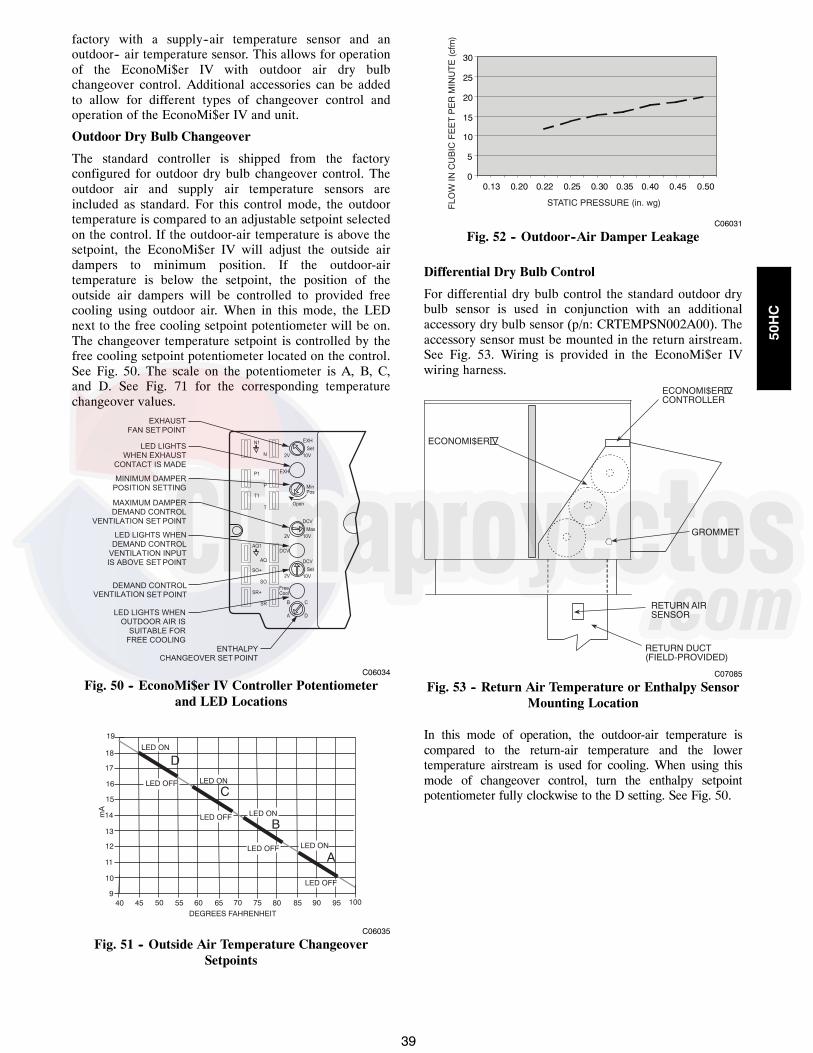
39
factory with a supply--air temperature sensor and anoutdoor-- air temperature sensor. This allows for operationof the EconoMi$er IV with outdoor air dry bulbchangeover control. Additional accessories can be addedto allow for different types of changeover control andoperation of the EconoMi$er IV and unit.
Outdoor Dry Bulb Changeover
The standard controller is shipped from the factoryconfigured for outdoor dry bulb changeover control. Theoutdoor air and supply air temperature sensors areincluded as standard. For this control mode, the outdoortemperature is compared to an adjustable setpoint selectedon the control. If the outdoor-air temperature is above thesetpoint, the EconoMi$er IV will adjust the outside airdampers to minimum position. If the outdoor-airtemperature is below the setpoint, the position of theoutside air dampers will be controlled to provided freecooling using outdoor air. When in this mode, the LEDnext to the free cooling setpoint potentiometer will be on.The changeover temperature setpoint is controlled by thefree cooling setpoint potentiometer located on the control.See Fig. 50. The scale on the potentiometer is A, B, C,and D. See Fig. 71 for the corresponding temperaturechangeover values.
C06034
Fig. 50 -- EconoMi$er IV Controller Potentiometerand LED Locations
LED ON
LED ON
LED ON
LED ON
LED OFF
19
18
LED OFF
LED OFF
LED OFF
17
16
15
14
13
12
11
10
940 45 50 55 60 65 70 75 80 85 90 95 100
DEGREES FAHRENHEIT
mA
D
C
B
A
C06035
Fig. 51 -- Outside Air Temperature ChangeoverSetpoints
0
5
10
15
20
25
30
0.13 0.20 0.22 0.25 0.30 0.35 0.40 0.45 0.50
STATIC PRESSURE (in. wg)FLO
WIN
CU
BIC
FE
ET
PE
RM
INU
TE
(cfm
)
C06031
Fig. 52 -- Outdoor--Air Damper Leakage
Differential Dry Bulb Control
For differential dry bulb control the standard outdoor drybulb sensor is used in conjunction with an additionalaccessory dry bulb sensor (p/n: CRTEMPSN002A00). Theaccessory sensor must be mounted in the return airstream.See Fig. 53. Wiring is provided in the EconoMi$er IVwiring harness.
ECONOMI$ERIV
ECONOMI$ERIVCONTROLLER
GROMMET
RETURN AIRSENSOR
RETURN DUCT(FIELD-PROVIDED)
C07085
Fig. 53 -- Return Air Temperature or Enthalpy SensorMounting Location
In this mode of operation, the outdoor-air temperature iscompared to the return-air temperature and the lowertemperature airstream is used for cooling. When using thismode of changeover control, turn the enthalpy setpointpotentiometer fully clockwise to the D setting. See Fig. 50.
50HC

40
Outdoor Enthalpy Changeover
For enthalpy control, accessory enthalpy sensor (p/n:HH57AC078) is required. Replace the standard outdoordry bulb temperature sensor with the accessory enthalpysensor in the same mounting location. See Fig. 73. Whenthe outdoor air enthalpy rises above the outdoor enthalpychangeover setpoint, the outdoor-air damper moves to itsminimum position. The outdoor enthalpy changeoversetpoint is set with the outdoor enthalpy setpointpotentiometer on the EconoMi$er IV controller. Thesetpoints are A, B, C, and D. See Fig. 74. Thefactory-installed 620-ohm jumper must be in place acrossterminals SR and SR+ on the EconoMi$er IV controller.
TR1
24 VacCOM
TR
24 VacHOT
1 2
3 4
5
EF EF1
+ _
P1
T1
P
T
N
EXH
2V 10V
EXH
Set
Set
2V 10V
2V 10V
DCV
DCV
FreeCool
B C
A D
SO+
SR+
SR
SO
AQ1
AQ
DCV
MinPos
Open
Max
N1
C06038
Fig. 54 -- EconoMi$er IV Control
Differential Enthalpy Control
For differential enthalpy control, the EconoMi$er IVcontroller uses two enthalpy sensors (HH57AC078 andCRENTDIF004A00), one in the outside air and one in thereturn air duct. The EconoMi$er IV controller comparesthe outdoor air enthalpy to the return air enthalpy todetermine EconoMi$er IV use. The controller selects thelower enthalpy air (return or outdoor) for cooling. Forexample, when the outdoor air has a lower enthalpy thanthe return air, the EconoMi$er IV opens to bring inoutdoor air for free cooling.Replace the standard outside air dry bulb temperaturesensor with the accessory enthalpy sensor in the samemounting location. See Fig. 45. Mount the return airenthalpy sensor in the return air duct. See Fig. 53. Wiringis provided in the EconoMi$er IV wiring harness. See Fig.46. The outdoor enthalpy changeover setpoint is set withthe outdoor enthalpy setpoint potentiometer on theEconoMi$er IV controller. When using this mode ofchangeover control, turn the enthalpy setpointpotentiometer fully clockwise to the D setting.
CONTROLCURVE
ABCD
CONTROL POINTAPPROX. deg. F (deg. C)
AT 50% RH
73 (23)70 (21)67 (19)63 (17)
12
14
16
18
20
22
24
26
28
30
32
34
36
38
40
42
44
46
90100
8070
6050
40
30
20
10
ENTHALP
Y BTU
PER P
OUND D
RY AIR
85(29)
90(32)
95(35)
100(38)
105(41)
110(43)
35(2)
35(2)
40(4)
40(4)
105(41)
110(43)
45(7)
45(7)
50(10)
50(10)
55(13)
55(13)
60(16)
60(16)
65(18)
65(18)
70(21)
70(21)
75(24)
75(24)
80(27)
80(27)
85(29)
90(32)
95(35)
100(38)
A
A
B
B
C
C
D
D
RE
LATI
VE
HU
MID
ITY
(%)
HIGH LIMITCURVE
APPROXIMATE DRY BULB TEMPERATURE--degrees F (degrees C)
C06037
Fig. 55 -- Enthalpy Changeover Setpoints
50HC

41
Indoor Air Quality (IAQ) Sensor Input
The IAQ input can be used for demand control ventilationcontrol based on the level of CO2 measured in the spaceor return air duct.Mount the accessory IAQ sensor according tomanufacturer specifications. The IAQ sensor should bewired to the AQ and AQ1 terminals of the controller.Adjust the DCV potentiometers to correspond to the DCVvoltage output of the indoor air quality sensor at theuser-determined setpoint. See Fig. 56.
0
1000
2000
3000
4000
5000
6000
2 3 4 5 6 7 8
800 ppm
900 ppm
1000 ppm
1100 ppm
RA
NG
EC
ON
FIG
UR
AT
ION
(ppm
)
DAMPER VOLTAGE FOR MAX VENTILATION RATE
CO SENSOR MAX RANGE SETTING2
C06039
Fig. 56 -- CO2 Sensor Maximum Range Settings
If a separate field-supplied transformer is used to powerthe IAQ sensor, the sensor must not be grounded or theEconoMi$er IV control board will be damaged.When using demand ventilation, the minimum damperposition represents the minimum ventilation position forVOC (volatile organic compounds) ventilationrequirements. The maximum demand ventilation positionis used for fully occupied ventilation.When demand ventilation control is not being used, theminimum position potentiometer should be used to set theoccupied ventilation position. The maximum demandventilation position should be turned fully clockwise.
Exhaust Setpoint Adjustment
The exhaust setpoint will determine when the exhaust fanruns based on damper position (if accessory powerexhaust is installed). The setpoint is modified with theExhaust Fan Setpoint (EXH SET) potentiometer. See Fig.50. The setpoint represents the damper position abovewhich the exhaust fans will be turned on. When there is acall for exhaust, the EconoMi$er IV controller provides a45 15 second delay before exhaust fan activation toallow the dampers to open. This delay allows the damperto reach the appropriate position to avoid unnecessary fanoverload.
Minimum Position Control
There is a minimum damper position potentiometer on theEconoMi$er IV controller. See Fig. 50. The minimumdamper position maintains the minimum airflow into thebuilding during the occupied period.When using demand ventilation, the minimum damperposition represents the minimum ventilation position forVolatile Organic Compound (VOC) ventilation
requirements. The maximum demand ventilation positionis used for fully occupied ventilation.When demand ventilation control is not being used, theminimum position potentiometer should be used to set theoccupied ventilation position. The maximum demandventilation position should be turned fully clockwise.Adjust the minimum position potentiometer to allow theminimum amount of outdoor air, as required by localcodes, to enter the building. Make minimum positionadjustments with at least 10_F temperature differencebetween the outdoor and return-air temperatures.To determine the minimum position setting, perform thefollowing procedure:
1. Calculate the appropriate mixed air temperatureusing the following formula:
(TO xOA
) + (TR x RA) =TM100 100
TO = Outdoor-Air TemperatureOA = Percent of Outdoor AirTR = Return-Air TemperatureRA = Percent of Return AirTM = Mixed-Air TemperatureAs an example, if local codes require 10% outdoorair during occupied conditions, outdoor-airtemperature is 60_F, and return-air temperature is75_F.(60 x .10) + (75 x .90) = 73.5_F
2. Disconnect the supply air sensor from terminals Tand T1.
3. Ensure that the factory-installed jumper is in placeacross terminals P and P1. If remote damperpositioning is being used, make sure that theterminals are wired according to Fig. 52 and that theminimum position potentiometer is turned fullyclockwise.
4. Connect 24 vac across terminals TR and TR1.5. Carefully adjust the minimum positionpotentiometer until the measured mixed airtemperature matches the calculated value.
6. Reconnect the supply air sensor to terminals T andT1.
Remote control of the EconoMi$er IV damper is desirablewhen requiring additional temporary ventilation. If afield-supplied remote potentiometer (Honeywell p/n:S963B1128) is wired to the EconoMi$er IV controller, theminimum position of the damper can be controlled from aremote location.To control the minimum damper position remotely,remove the factory-installed jumper on the P and P1terminals on the EconoMi$er IV controller. Wire thefield-supplied potentiometer to the P and P1 terminals onthe EconoMi$er IV controller. (See Fig. 55.)
Damper Movement
Damper movement from full open to full closed (or viceversa) takes 21/2 minutes.
50HC

42
Thermostats
The EconoMi$er IV control works with conventionalthermostats that have a Y1 (cool stage 1), Y2 (cool stage2), W1 (heat stage 1), W2 (heat stage 2), and G (fan). TheEconoMi$er IV control does not support spacetemperature sensors. Connections are made at thethermostat terminal connection board located in the maincontrol box.
Occupancy Control
The factory default configuration for the EconoMi$er IVcontrol is occupied mode. Occupied status is provided bythe black jumper from terminal TR to terminal N. Whenunoccupied mode is desired, install a field--suppliedtimeclock function in place of the jumper between TR andN. When the timeclock contacts are closed, theEconoMi$er IV control will be in occupied mode. Whenthe timeclock contacts are open (removing the 24V signalfrom terminal N), the EconoMi$er IV will be inunoccupied mode.
Demand Control Ventilation (DCV)
When using the EconoMi$er IV for demand controlledventilation, there are some equipment selection criteriawhich should be considered. When selecting the heatcapacity and cool capacity of the equipment, themaximum ventilation rate must be evaluated for designconditions. The maximum damper position must becalculated to provide the desired fresh air.Typically the maximum ventilation rate will be about 5 to10% more than the typical cfm required per person, usingnormal outside air design criteria.A proportional anticipatory strategy should be taken withthe following conditions: a zone with a large area, variedoccupancy, and equipment that cannot exceed the requiredventilation rate at design conditions. Exceeding therequired ventilation rate means the equipment cancondition air at a maximum ventilation rate that is greaterthan the required ventilation rate for maximumoccupancy. A proportional-anticipatory strategy will causethe fresh air supplied to increase as the room CO2 levelincreases even though the CO2 setpoint has not beenreached. By the time the CO2 level reaches the setpoint,the damper will be at maximum ventilation and shouldmaintain the setpoint.In order to have the CO2 sensor control the economizerdamper in this manner, first determine the damper voltageoutput for minimum or base ventilation. Base ventilationis the ventilation required to remove contaminants duringunoccupied periods. The following equation may be usedto determine the percent of outside air entering thebuilding for a given damper position. For best results thereshould be at least a 10 degree difference in outside andreturn-air temperatures.
(TO xOA
) + (TR x RA) =TM100 100
TO = Outdoor-Air TemperatureOA = Percent of Outdoor AirTR = Return-Air TemperatureRA = Percent of Return Air
TM = Mixed-Air TemperatureOnce base ventilation has been determined, set theminimum damper position potentiometer to the correctposition.The same equation can be used to determine the occupiedor maximum ventilation rate to the building. For example,an output of 3.6 volts to the actuator provides a baseventilation rate of 5% and an output of 6.7 volts providesthe maximum ventilation rate of 20% (or base plus 15 cfmper person). Use Fig. 56 to determine the maximumsetting of the CO2 sensor. For example, an 1100 ppmsetpoint relates to a 15 cfm per person design. Use the1100 ppm curve on Fig. 56 to find the point when the CO2sensor output will be 6.7 volts. Line up the point on thegraph with the left side of the chart to determine that therange configuration for the CO2 sensor should be 1800ppm. The EconoMi$er IV controller will output the 6.7volts from the CO2 sensor to the actuator when the CO2concentration in the space is at 1100 ppm. The DCVsetpoint may be left at 2 volts since the CO2 sensorvoltage will be ignored by the EconoMi$er IV controlleruntil it rises above the 3.6 volt setting of the minimumposition potentiometer.Once the fully occupied damper position has beendetermined, set the maximum damper demand controlventilation potentiometer to this position. Do not set to themaximum position as this can result in over-ventilation tothe space and potential high humidity levels.
CO2 Sensor Configuration
The CO2 sensor has preset standard voltage settings thatcan be selected anytime after the sensor is powered up.See Table 10.Use setting 1 or 2 for Carrier equipment. See Table 10.
1. Press Clear and Mode buttons. Hold at least 5seconds until the sensor enters the Edit mode.
2. Press Mode twice. The STDSET Menu will appear.
Table 10 – EconoMi$er IV Sensor Usage
APPLICATIONECONOMI$ER IV WITH OUTDOOR AIR DRY
BULB SENSORAccessories Required
Outdoor AirDry Bulb
None. The outdoor air dry bulb sensor isfactory installed.
DifferentialDry Bulb CRTEMPSN002A00*
Single Enthalpy HH57AC078DifferentialEnthalpy HH57AC078 and CRENTDIF004A00*
CO2 for DCVControl using aWall-MountedCO2 Sensor
33ZCSENCO2
CO2 for DCVControl using aDuct-MountedCO2 Sensor
33ZCSENCO2† and33ZCASPCO2**
OR CRCBDIOX005A00††
* CRENTDIF004A00 and CRTEMPSN002A00 accessories areused on many different base units. As such, these kits maycontain parts that will not be needed for installation.
† 33ZCSENCO2 is an accessory CO2 sensor.** 33ZCASPCO2 is an accessory aspirator box required for duct-mounted applications.
†† CRCBDIOX005A00 is an accessory that contains both33ZCSENCO2 and 33ZCASPCO2 accessories.
50HC

43
3. Use the Up/Down button to select the presetnumber. See Table 10.
4. Press Enter to lock in the selection.5. Press Mode to exit and resume normal operation.
The custom settings of the CO2 sensor can be changedanytime after the sensor is energized. Follow the stepsbelow to change the non-standard settings:
1. Press Clear and Mode buttons. Hold at least 5seconds until the sensor enters the Edit mode.
2. Press Mode twice. The STDSET Menu will appear.3. Use the Up/Down button to toggle to the NONSTDmenu and press Enter.
4. Use the Up/Down button to toggle through each ofthe nine variables, starting with Altitude, until thedesired setting is reached.
5. Press Mode to move through the variables.6. Press Enter to lock in the selection, then press Modeto continue to the next variable.
Dehumidification of Fresh Air with DCV (DemandControlled Ventilation) Control
If normal rooftop heating and cooling operation is notadequate for the outdoor humidity level, an energyrecovery unit and/or a dehumidification option should beconsidered.
EconoMi$er IV Preparation
This procedure is used to prepare the EconoMi$er IV fortroubleshooting. No troubleshooting or testing is done byperforming the following procedure.
NOTE: This procedure requires a 9--v battery, 1.2kilo--ohm resistor, and a 5.6 kilo--ohm resistor which arenot supplied with the EconoMi$er IV.IMPORTANT: Be sure to record the positions of allpotentiometers before starting troubleshooting.
1. Disconnect power at TR and TR1. All LEDs shouldbe off. Exhaust fan contacts should be open.
2. Disconnect device at P and P1.3. Jumper P to P1.4. Disconnect wires at T and T1. Place 5.6 kilo--ohmresistor across T and T1.
5. Jumper TR to 1.6. Jumper TR to N.7. If connected, remove sensor from terminals SO and +.Connect 1.2 kilo--ohm 4074EJM checkout resistoracross terminals SO and +.
8. Put 620--ohm resistor across terminals SR and +.9. Set minimum position, DCV setpoint, and exhaust po-tentiometers fully CCW (counterclockwise).
10. Set DCV maximum position potentiometer fully CW(clockwise).
11. Set enthalpy potentiometer to D.12. Apply power (24 vac) to terminals TR and TR1.
Differential Enthalpy
To check differential enthalpy:
1. Make sure EconoMi$er IV preparation procedure hasbeen performed.
2. Place 620--ohm resistor across SO and +.3. Place 1.2 kilo--ohm resistor across SR and +. TheFree Cool LED should be lit.
4. Remove 620--ohm resistor across SO and +. The FreeCool LED should turn off.
5. Return EconoMi$er IV settings and wiring to normalafter completing troubleshooting.
Single Enthalpy
To check single enthalpy:
1. Make sure EconoMi$er IV preparation procedure hasbeen performed.
2. Set the enthalpy potentiometer to A (fully CCW). TheFree Cool LED should be lit.
3. Set the enthalpy potentiometer to D (fully CW). TheFree Cool LED should turn off.
4. Return EconoMi$er IV settings and wiring to normalafter completing troubleshooting.
DCV (Demand Controlled Ventilation) and PowerExhaust
To check DCV and Power Exhaust:
1. Make sure EconoMi$er IV preparation procedure hasbeen performed.
2. Ensure terminals AQ and AQ1 are open. The LED forboth DCV and Exhaust should be off. The actuatorshould be fully closed.
3. Connect a 9--v battery to AQ (positive node) and AQ1(negative node). The LED for both DCV and Exhaustshould turn on. The actuator should drive to between90 and 95% open.
4. Turn the Exhaust potentiometer CW until the ExhaustLED turns off. The LED should turn off when the po-tentiometer is approximately 90%. The actuatorshould remain in position.
5. Turn the DCV setpoint potentiometer CW until theDCV LED turns off. The DCV LED should turn offwhen the potentiometer is approximately 9--v. The ac-tuator should drive fully closed.
6. Turn the DCV and Exhaust potentiometers CCW untilthe Exhaust LED turns on. The exhaust contacts willclose 30 to 120 seconds after the Exhaust LED turnson.
7. Return EconoMi$er IV settings and wiring to normalafter completing troubleshooting.
DCV Minimum and Maximum Position
To check the DCV minimum and maximum position:
50HC

44
1. Make sure EconoMi$er IV preparation procedure hasbeen performed.
2. Connect a 9v battery to AQ (positive node) and AQ1(negative node). The DCV LED should turn on. Theactuator should drive to between 90 and 95% open.
3. Turn the DCV Maximum Position potentiometer tomidpoint. The actuator should drive to between 20and 80% open.
4. Turn the DCV Maximum Position potentiometer tofully CCW. The actuator should drive fully closed.
5. Turn the Minimum Position potentiometer to mid-point. The actuator should drive to between 20 and80% open.
6. Turn the Minimum Position Potentiometer fully CW.The actuator should drive fully open.
7. Remove the jumper from TR and N. The actuatorshould drive fully closed.
8. Return EconoMi$er IV settings and wiring to normalafter completing troubleshooting.
Supply--Air Sensor Input
To check supply--air sensor input:
1. Make sure EconoMi$er IV preparation procedure hasbeen performed.
2. Set the Enthalpy potentiometer to A. The Free CoolLED turns on. The actuator should drive to between20 and 80% open.
3. Remove the 5.6 kilo--ohm resistor and jumper T toT1. The actuator should drive fully open.
4. Remove the jumper across T and T1. The actuatorshould drive fully closed.
5. Return EconoMi$er IV settings and wiring to normalafter completing troubleshooting.
EconoMi$er IV Troubleshooting Completion
This procedure is used to return the EconoMi$er IV tooperation. No troubleshooting or testing is done byperforming the following procedure.
1. Disconnect power at TR and TR1.2. Set enthalpy potentiometer to previous setting.3. Set DCV maximum position potentiometer to previ-ous setting.
4. Set minimum position, DCV setpoint, and exhaust po-tentiometers to previous settings.
5. Remove 620--ohm resistor from terminals SR and +.6. Remove 1.2 kilo--ohm checkout resistor from termin-als SO and +. If used, reconnect sensor from termin-als SO and +.
7. Remove jumper from TR to N.8. Remove jumper from TR to 1.9. Remove 5.6 kilo--ohm resistor from T and T1. Recon-nect wires at T and T1.
10. Remove jumper from P to P1. Reconnect device at Pand P1.
11. Apply power (24 vac) to terminals TR and TR1.
PRE--START--UP/START--UP
PERSONAL INJURY HAZARDFailure to follow this warning could result in personalinjury or death.
! WARNING
1. Follow recognized safety practices and wearapproved Personal Protective Equipment (PPE),including safety glasses and gloves whenchecking or servicing refrigerant system.
2. Do not use a torch to remove any component.System contains oil and refrigerant underpressure. To remove a component, wear PPE andproceed as follows:a. Shut off all electrical power to unit. Apply
applicable Lock--out/Tagout procedures.b. Recover refrigerant to relieve all pressure
from system using both high--pressure andlow pressure ports.
c. Do not use a torch. Cut component connec-tion tubing with tubing cutter and removecomponent from unit.
d. Carefully un--sweat remaining tubing stubswhen necessary. Oil can ignite when exposedto torch flame.
3. Do not operate compressor or provide any electricpower to unit unless compressor terminal cover isin place and secured.
4. Do not remove compressor terminal cover untilall electrical power is disconnected and approvedLock--out/Tagout procedures are in place.
5. Relieve all pressure from system before touchingor disturbing anything inside terminal boxwhenever refrigerant leak is suspected aroundcompressor terminals.
6. Never attempt to repair a soldered connectionwhile refrigerant system is under pressure.
ELECTRICAL OPERATION HAZARD
Failure to follow this warning result in personal injuryor death.
The unit must be electrically grounded in accordancewith local codes and NEC ANSI/NFPA 70 (AmericanNational Standards Institute/National fire ProtectionAssociation.
! WARNING
Proceed as follows to inspect and prepare the unit forinitial start--up:
1. Inspect for exterior shipping and handling damage.Document any exterior or interior issues. Remove allaccess panels.
50HC

45
2. Read and follow instructions on all WARNING,CAUTION, and INFORMATION labels attached to,or shipped with, unit.
3. Make the following inspections:a. Inspect for shipping and handling damages suchas broken lines, loose parts, or disconnectedwires, etc.
b. Inspect for oil at all refrigerant tubing connec-tions and on unit base. Detecting oil generallyindicates a refrigerant leak. Leak--test all refri-gerant tubing connections using electronic leakdetector, halide torch, or liquid--soap solution.
c. Inspect all field--wiring and factory--wiring con-nections. Be sure that connections are completedand tight. Be sure that wires are not in contactwith refrigerant tubing or sharp edges.
d. Inspect coil fins. If damaged during shipping andhandling, carefully straighten fins with a fincomb.
4. Verify the following conditions:a. Make sure that condenser--fan blade are correctlypositioned in fan orifice. See Condenser--FanAdjustment section for more details.
b. Make sure that air filter(s) is in place.c. Make sure that condensate drain trap is filledwith water to ensure proper drainage.
d. Make sure that all tools and miscellaneous looseparts have been removed.
START--UP, GENERAL
Unit Preparation
Make sure that unit has been installed in accordance withinstallation instructions and applicable codes.
IMPORTANT: Follow the base unit’s start-up sequenceas described in the unit’s installation instructions:In addition to the base unit start-up, there are a few stepsneeded to properly start-up the controls. RTU-OPEN’sService Test function should be used to assist in the baseunit start-up and also allows verification of outputoperation. Controller configuration is also part of start-up.This is especially important when field accessories havebeen added to the unit. The factory pre-configures optionsinstalled at the factory. There may also be additionalinstallation steps or inspection required during the start-upprocess.
Additional Installation/InspectionInspect the field installed accessories for properinstallation, making note of which ones do or do notrequire configuration changes. Inspect the RTU-OPEN’sAlarms for initial insight to any potential issues. Refer tothe following manual: “Controls, Start--up, Operation andTroubleshooting Instructions.” Inspect the SAT sensor for
relocation as intended during installation. Inspect specialwiring as directed below.
Return--Air Filters
Ensure correct filters are installed in unit (see Appendix II-- Physical Data). Do not operate unit without return--airfilters.
Outdoor--Air Inlet Screens
Outdoor--air inlet screen must be in place before operatingunit.
Compressor Mounting
Compressors are internally spring mounted. Do not loosenor remove compressor hold down bolts.
Internal Wiring
Check all electrical connections in unit control boxes.Tighten as required.
Refrigerant Service Ports
Each unit system has two 1/4” SAE flare (with checkvalves) service ports: one on the suction line, and one onthe compressor discharge line. Be sure that caps on theports are tight.
Compressor Rotation
On 3--phase units with scroll compressors, it is importantto be certain compressor is rotating in the properdirection. To determine whether or not compressor isrotating in the proper direction:
1. Connect service gauges to suction and discharge pres-sure fittings.
2. Energize the compressor.3. The suction pressure should drop and the dischargepressure should rise, as is normal on any start--up.
If the suction pressure does not drop and the dischargepressure does not rise to normal levels:
4. Note that the evaporator fan is probably also rotatingin the wrong direction.
5. Turn off power to the unit and install lockout tag.6. Reverse any two of the unit power leads.7. Re--energize to the compressor. Check pressures.
The suction and discharge pressure levels should nowmove to their normal start--up levels.
NOTE: When the compressor is rotating in the wrongdirection, the unit will make an elevated level of noiseand will not provide cooling.
Cooling
Set space thermostat to OFF position. To start unit, turn onmain power supply. Set system selector switch at COOLposition and fan switch at AUTO. position. Adjustthermostat to a setting below room temperature.Compressor starts on closure of contactor.
Check unit charge. Refer to Refrigerant Charge section.
50HC

46
Reset thermostat at a position above room temperature.Compressor will shut off. Evaporator fan will shut offafter a 30--second delay.
To shut off unit, set system selector switch at OFFposition. Resetting thermostat at a position above roomtemperature shuts unit off temporarily until spacetemperature exceeds thermostat setting.
Ventilation (Continuous Fan)
Set fan and system selector switches at ON and OFFpositions, respectively. Evaporator fan operatescontinuously to provide constant air circulation. When theevaporator--fan selector switch is turned to the OFFposition, there is a 30--second delay before the fan turnsoff.
START--UP, PREMIERLINKCONTROLS
ELECTRICAL OPERATION HAZARD
Failure to follow this warning could result in personalinjury or death.
The unit must be electrically grounded in accordancewith local codes and NEC ANSI/NFPA 70 (AmericanNational Standards Institute/National Fire ProtectionAssociation.)
! WARNING
Use the Carrier network communication software to startup and configure the PremierLink controller.
Changes can be made using the ComfortWORKSrsoftware, ComfortVIEWt software, Network ServiceTool, System Pilott device, or Touch Pilott device. TheSystem Pilot and Touch Pilot are portable interfacedevices that allow the user to change system set--up andsetpoints from a zone sensor or terminal control module.During start--up, the Carrier software can also be used toverify communication with PremierLink controller.
NOTE: All set--up and setpoint configurations are factoryset and field--adjustable.
For specific operating instructions, refer to the literatureprovided with user interface software.
SET--UP INSTRUCTIONS
All set--up and set point configurations are factory setand field--adjustable.
Refer to PremierLinkt Installation, Start--Up andConfiguration Instructions .for specific operatinginstructions for the controller. Have a copy of thismanual available at unit start--up.
NOTICE
Perform System Check--Out1. Check correctness and tightness of all power andcommunication connections.
2. At the unit, check fan and system controls for properoperation.
3. At the unit, check electrical system and connectionsof any optional electric reheat coil.
4. Check to be sure the area around the unit is clear ofconstruction dirt and debris.
5. Check that final filters are installed in the unit. Dustand debris can adversely affect system operation.
6. Verify that the PremierLink controls are properly con-nected to the CCN bus.
START--UP, RTU--OPEN CONTROLS
SET--UP INSTRUCTIONS
Refer to the following manuals for additionalinstallation, wiring and troubleshooting informationfor the RTU--OPEN Controller.: “Controls, Start--up,Operation and Troubleshooting Instructions,” “RTUOpen Installation and Start--up Guide” and“RTU--Open Integration Guide”. Have a copy of thesemanuals available at unit start--up.
NOTICE
50HC
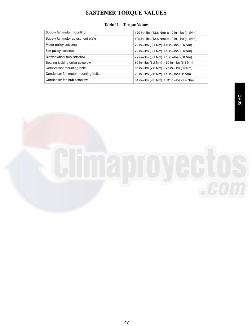
47
FASTENER TORQUE VALUES
Table 11 – Torque Values
Supply fan motor mounting 120 in--- lbs (13.6 Nm) 12 in--- lbs (1.4Nm)Supply fan motor adjustment plate 120 in--- lbs (13.6 Nm) 12 in--- lbs (1.4Nm)Motor pulley setscrew 72 in--- lbs (8.1 Nm) 5 in--- lbs (0.6 Nm)Fan pulley setscrew 72 in--- lbs (8.1 Nm) 5 in--- lbs (0.6 Nm)Blower wheel hub setscrew 72 in--- lbs (8.1 Nm) 5 in--- lbs (0.6 Nm)Bearing locking collar setscrew 50 in--- lbs (6.2 Nm) ---60 in--- lbs (6.8 Nm)
Compressor mounting bolts 65 in--- lbs (7.3 Nm) ---75 in--- lbs (8.5Nm)
Condenser fan motor mounting bolts 20 in--- lbs (2.3 Nm) 2 in--- lbs 0.2 Nm)Condenser fan hub setscrew 84 in--- lbs (9.5 Nm) 12 in--- lbs (1.4 Nm)
50HC

48
APPENDIX I. MODEL NUMBER NOMENCLATURE
1 2 3 4 5 6 7 8 9 10 11 12 13 14 15 16 17 185 0 H C --- D 0 8 A 3 A 5 --- 0 A 0 A 0
Product Type Packaging50 --- Elect Heat Pkg. Rooftop 0 --- Standard
1 --- LTLModel Series --- WeatherMasterHC --- High Efficiency Electrical Options
A --- NoneElectric Heater Option B --- HACR breaker--- --- Standard (No Electric Heat) C --- Non--- fused disconnectA --- Low Electric Heat D --- Thru the base connectionsB --- Medium Electric Heat F --- Non---fused disconnect & thru the baseC --- High Electric Heat G --- 2---speed indoor fan (VFD) controller
J --- 2---spd contr (VFD) & non--- fused disc.Refrigerant System Options K --- 2---spd contr (VFD) & thru the baseA ---Single stage cooling models M --- 2---spd cont (VFD) non---fused disc. &B --- Single stg cooling w/Humidi---MiZer thru the base connectionsD --- 2 stage CoolingE --- 2 stg cooling w/Humidi---MiZer Service OptionsF --- Single stg cool w/MotorMaster low amb cntl 0 --- NoneG --- 2 stg cool w/Motormaster low amb cntl 1 --- Un---powered Convenience Outlet
2 --- Powered Convenience OutletNominal Cooling Capacity (Tons) 3 --- Hinged Panels04 --- 3 ton 09 --- 8.5 ton 4 --- Hinged Panels, un---powered C.O.05 --- 4 ton 11 --- 10 ton (12.0 EER) 5 --- Hinged Panels, powered C.O.06 --- 5 ton 12 --- 10 ton (11.7 EER) C --- Foil faced insulation07 --- 6 ton 14 --- 12.5 ton08 --- 7.5 ton Intake / Exhaust Options
A --- NoneSensor Options B --- Temperature Economizer w/Barometric ReliefA --- None F --- Enthalpy Economizer w/Barometric ReliefB --- RA Smoke Detector K --- 2 position DamperC --- SA Smoke Detector U --- Temp Ultra Low Leak Economizer w/Baro ReliefD --- RA + SA Smoke Detector W --- Enthalpy Ultra Low Leak Econo w/Baro ReliefE --- CO2 SensorF --- RA Smoke Detector + CO2 Base Unit ControlsG --- SA Smoke Detector + CO2 0 --- Base Electromechanical Controls. Can be used withH --- RA + SA Smoke Detector + CO2 W7212 EconoMi$er IV (Non---Fault Detection and
Diagnostic)Indoor Fan Options 3, 4, 5 Ton Models Only* 1 --- PremierLink Controller0 --- Electric (Direct) Drive X13 motor 2 --- RTU Open Multi---Protocol Controller2 --- Medium Static Option --- Belt Drive 6 --- Electromechanical Controls. Can be used with3 --- High Static Option --- Belt Drive W7220 EconoMi$er X (Non---Fault Detection and
Diagnostic)Indoor Fan Options 6---12.5 Ton Models Only D --- ComfortLink Controls1 --- Standard Static Option --- Belt Drive2 --- Medium Static Option --- Belt Drive Design Revision3 --- High Static Option --- Belt Drive --- Factory Design RevisionC --- High Static Option w/Hi---Effy Motor --- Belt Drive (14 size only)
VoltageCoil Options (RTPF) (Outdoor---Indoor---Hail Guard) 1 --- 575/3/60A --- Al/Cu --- Al/Cu 3 --- 208---230/1/60B --- Pre---coat Al/Cu --- Al/Cu 5 --- 208---230/3/60C --- E---coat Al/Cu --- Al/Cu 6 --- 460/3/60D --- E---coat AL/Cu --- E---coat AL/CuE --- Cu/Cu --- Al/CuF --- Cu/Cu --- Cu/Cu Note: On single phase (---3 voltage code) models, the followingM --- Al/Cu --- Al/Cu --- Louvered Hail Guard are not available as a factory installed option:N --- Pre---Coat Al/Cu --- Al/Cu --- Louvered Hail Guard --- Humidi---MiZerP --- E---Coat Al/Cu --- Al/Cu Louvered Hail Guard --- Coated Coils or CU Fin CoilsQ --- E---Coat Al/Cu --- E---coat Al/Cu --- Louvered Hail Guard --- Louvered Hail GuardsR --- Cu/Cu --- Al/Cu --- Louvered Hail Guard --- Economizer or 2 Position DamperS --- Cu/Cu --- Cu/Cu --- Louvered Hail Guard --- Powered 115 Volt Convenience Outlet
* See Price Page details for specific Humidi---MiZer models
Not all possible options can be displayed above --- see price pages or contact your Carrier Expert for more details
Fig. 57 -- Model Number Nomenclature
50HC
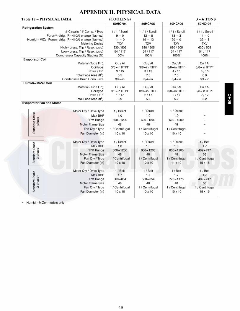
49
APPENDIX II. PHYSICAL DATATable 12 – PHYSICAL DATA (COOLING) 3 -- 6 TONS
50HC*04 50HC*05 50HC*06 50HC*07Refrigeration System
# Circuits / # Comp. / Type 1 / 1 / Scroll 1 / 1 / Scroll 1 / 1 / Scroll 1 / 1 / ScrollPuronr refrig. (R---410A) charge (lbs---oz) 9 --- 0 12 --- 8 13 --- 3 14 --- 0
Humidi---MiZer Puron refrig. (R---410A) charge (lbs---oz) 11 --- 0 19 --- 12 20 --- 0 22 --- 8Metering Device TXV TXV TXV TXV
High---press. Trip / Reset (psig) 630 / 505 630 / 505 630 / 505 630 / 505Low---press. Trip / Reset (psig) 54 / 117 54 / 117 54 / 117 54 / 117
Compressor Capacity Staging (%) 100% 100% 100% 100%Evaporator Coil
Material (Tube Fin) Cu / Al Cu / Al Cu / Al Cu / AlCoil type 3/8--- in RTPF 3/8--- in RTPF 3/8--- in RTPF 3/8--- in RTPFRows / FPI 3 / 15 3 / 15 4 / 15 3 / 15
Total Face Area (ft2) 5.5 7.3 7.3 8.9Condensate Drain Conn. Size 3/4--- in 3/4--- in 3/4--- in 3/4--- in
Humidi---MiZer CoilMaterial (Tube Fin) Cu / Al Cu / Al Cu / Al Cu / Al
Coil type 3/8--- in RTPF 3/8--- in RTPF 3/8--- in RTPF 3/8--- in RTPFRows / FPI 1 / 17 2 / 17 2 / 17 2 / 17
Total Face Area (ft2) 3.9 5.2 5.2 5.2Evaporator Fan and Motor
StandardStatic
1phase
Motor Qty / Drive Type 1 / Direct 1 / Direct 1 / Direct ---Max BHP 1.0 1.0 1.0 ---
RPM Range 600---1200 600---1200 600---1200 ---Motor Frame Size 48 48 48 ---Fan Qty / Type 1 / Centrifugal 1 / Centrifugal 1 / Centrifugal ---
Fan Diameter (in) 10 x 10 10 x 10 10 x 10 ---
StandardStatic
3phase
Motor Qty / Drive Type 1 / Direct 1 / Direct 1 / Direct 1 / BeltMax BHP 1.0 1.0 1.0 1.7
RPM Range 600---1200 600---1200 600---1200 489---747Motor Frame Size 48 48 48 56Fan Qty / Type 1 / Centrifugal 1 / Centrifugal 1 / Centrifugal 1 / Centrifugal
Fan Diameter (in) 10 x 10 10 x 10 11 x 10 15 x 15
StandardStatic
3phase*
Motor Qty / Drive Type 1 / Belt 1 / Belt 1 / Belt 1 / BeltMax BHP 1.7 1.7 1.7 1.7
RPM Range 560---854 560---854 770---1175 489---747Motor Frame Size 48 48 48 56Fan Qty / Type 1 / Centrifugal 1 / Centrifugal 1 / Centrifugal 1 / Centrifugal
Fan Diameter (in) 10 x 10 10 x 10 10 x 10 15 x 15
* Humidi---MiZer models only
50HC

50
APPENDIX II. PHYSICAL DATA (CONT’D)Table 23 (cont.) -- PHYSICAL DATA (COOLING) 3 -- 6 TONS
50HC*04 50HC*05 50HC*06 50HC*07
Evaporator Fan and MotorMediumStatic
3phase
Motor Qty / Drive Type 1 / Belt 1 / Belt 1 / Belt 1 / BeltMax BHP 1.7 1.7 2.4 2.9
RPM Range 770---1175 920---1303 1035---1466 733---949Motor Frame Size 48 56 56 56Fan Qty / Type 1 / Centrifugal 1 / Centrifugal 1 / Centrifugal 1 / Centrifugal
Fan Diameter (in) 10 x 10 10 x 10 10 x 10 15 x 15
MediumStatic
3phase*
Motor Qty / Drive Type 1 / Belt 1 / Belt 1 / Belt ---Max BHP 1.7 1.7 2.4 ---
RPM Range 770---1175 770---1175 1035---1466 ---Motor Frame Size 48 48 56 ---Fan Qty / Type 1 / Centrifugal 1 / Centrifugal 1 / Centrifugal ---
Fan Diameter (in) 10 x 10 10 x 10 10 x 10 ---
HighStatic
3phase
Motor Qty / Drive Type 1 / Belt 1 / Belt 1 / Belt 1 / BeltMax BHP 2.4 2.9 2.9 4.7
RPM Range 1035---1466 1208---1639 1303---1687 909---1102Motor Frame Size 56 56 56 14Fan Qty / Type 1 / Centrifugal 1 / Centrifugal 1 / Centrifugal 1 / Centrifugal
Fan Diameter (in) 10 x 10 10 x 10 10 x 10 15 x 15
Cond. CoilMaterial (Tube/Fin) Cu / Al Cu / Al Cu / Al Cu / Al
Coil type 3/8--- in RTPF 3/8--- in RTPF 3/8--- in RTPF 3/8--- in RTPFRows / FPI 2 / 17 2 / 17 2 / 17 2 / 17
Total Face Area (ft2) 12.7 21.3 21.3 20.5Cond. fan / motor
Qty / Motor Drive Type 1/ Direct 1/ Direct 1/ Direct 2/ DirectMotor HP / RPM 1/8 / 825 1/4 / 1100 1/4 / 1100 1/4 / 1100Fan diameter (in) 22 22 22 22
FiltersRA Filter # / Size (in) 2 / 16 x 25 x 2 4 / 16 x 16 x 2 4 / 16 x 16 x 2 4 / 16 x 20 x 2
OA inlet screen # / Size (in) 1 / 20 x 24 x 1 1 / 20 x 24 x 1 1 / 20 x 24 x 1 1 / 20 x 36 x 1
* Humidi---MiZer models only--- Not applicable--- Not applicable
50HC

51
APPENDIX II. PHYSICAL DATA (cont.)
Table 23 -- PHYSICAL DATA (COOLING) 7.5--12.5 TONS50HC*08 50HC*09 50HC*11 50HC*12 50HC*14
Refrigeration System# Circuits / # Comp. / Type 2 / 2 / Scroll 2 / 2 / Scroll 2 / 2 / Scroll 2 / 2 / Scroll 2 / 2 / Scroll
Puron Refrig (R---410A) charge A/B (lbs---oz) 9 --- 10 / 9 --- 10 9 --- 14 / 9 --- 14 12 --- 10 / 13 --- 0 12 --- 11 / 12 --- 5 16 --- 7 / 15 --- 5Humidi---MiZer Puron Refrig (R---410A) charge
A/B (lbs---oz) 17---0 / 17---0 15---2 / 15---0 18---0 / 18---0 18---3 / 17---3 25---8 / 22---8
Metering device TXV TXV TXV TXV TXVHigh---press. Trip / Reset (psig) 630 / 505 630 / 505 630 / 505 630 / 505 630 / 505Low---press. Trip / Reset (psig) 54 / 117 54 / 117 27 / 44 54 / 117 54 / 117
Compressor Capacity Staging (%) 50% / 100% 50% / 100% 50% / 100% 50% / 100% 50% / 100%Evaporator Coil
Material (Tube/Fin) Cu / Al Cu / Al Cu / Al Cu / Al Cu / AlCoil type 3/8--- in RTPF 3/8--- in RTPF 3/8--- in RTPF 3/8--- in RTPF 3/8--- in RTPFRows / FPI 4 / 15 4 / 15 4 / 15 4 / 15 4 / 15
total face area (ft2) 11.1 11.1 11.1 11.1 17.5Condensate drain conn. size 3/4--- in 3/4--- in 3/4--- in 3/4--- in 3/4--- in
Humidi---MiZer CoilMaterial (Tube/Fin) Cu / Al Cu / Al Cu / Al Cu / Al Cu / Al
Coil type 3/8--- in RTPF 3/8--- in RTPF 3/8--- in RTPF 3/8--- in RTPF 3/8--- in RTPFRows / FPI 2 / 17 2 / 17 2 / 17 2 / 17 1 / 17
total face area (ft2) 6.3 8.4 8.6 8.6 13.8Evaporator fan and motor
StandardStatic
3phase
Motor Qty / Drive type 1 / Belt 1 / Belt 1 / Belt 1 / Belt 1 / BeltMax BHP 1.7 1.7 2.4 2.4 2.9RPM range 518---733 518---733 591---838 591---838 440---609
Motor Frame Size 56 56 56 56 56YFan Qty / Type 1 / Centrifugal 1 / Centrifugal 1 / Centrifugal 1 / Centrifugal 1 / Centrifugal
Fan Diameter (in) 15 x 15 15 x 15 15 x 15 15 x 15 18 x 18
MediumStatic
3phase
Motor Qty / Drive type 1 / Belt 1 / Belt 1 / Belt 1 / Belt 1 / BeltMax BHP 2.4 2.4 3.7 3.7 3.7RPM range 690---936 690---936 838---1084 838---1084 609---778
Motor Frame Size 56 56 56HZ 56HZ 56HZFan Qty / Type 1 / Centrifugal 1 / Centrifugal 1 / Centrifugal 1 / Centrifugal 1 / Centrifugal
Fan Diameter (in) 15 x 15 15 x 15 15 x 15 15 x 15 18 x 18
HighStatic
3phase
Motor Qty / Drive type 1 / Belt 1 / Belt 1 / Belt 1 / Belt 1 / BeltMax BHP 3.7 3.7 4.9 4.9 6.1RPM range 838---1084 838---1084 1022---1240 1022---1240 776---955
Motor Frame Size 56 56 145TY 145TY S184TFan Qty / Type 1 / Centrifugal 1 / Centrifugal 1 / Centrifugal 1 / Centrifugal 1 / Centrifugal
Fan Diameter (in) 15 x 15 15 x 15 15 x 15 15 x 15 18 x 18
Condenser CoilMaterial (Tube/Fin) Cu / Al Cu / Al Cu / Al Cu / Al Cu / Al
Coil type 3/8--- in RTPF 3/8--- in RTPF 3/8--- in RTPF 3/8--- in RTPF 3/8--- in RTPFRows / FPI 2 / 17 2 / 17 3 / 17 3 / 17 2 / 17
Total Face Area (ft2) 25.1 25.1 25.1 25.1 2 at 23.1Condenser fan / motor
Qty / Motor drive type 2 / direct 2 / direct 1 / direct ECM 1 / direct 3 / directMotor HP / RPM 1/4 / 1100 1/4 / 1100 1 / 1050 1 / 1175 1/4 / 1100Fan diameter (in) 22 22 30 30 22
Filters
RA Filter # / size (in) 4 / 20 x 20 x 2 4 / 20 x 20 x 2 4 / 20 x 20 x 2 4 / 20 x 20 x 2 6 / 18 x 24 x 2Vert 2/24 x 27 x 1
OA inlet screen # / size (in) 1 / 20 x 24 x 1 1 / 20 x 24 x 1 1 / 20 x 24 x 1 1 / 20 x 24 x 1 Horz 1/30 x 39 x1
50HC

52
APPENDIX III. FAN PERFORMANCE
Table 13 – 50HC Size 04 1 Phase HUMIDI--MIZER 3 Ton Vertical Supply
CFMAvailable External Static Pressure (in. wg)
0.2 0.4 0.6 0.8 1.0RPM BHP RPM BHP RPM BHP RPM BHP RPM BHP
900 594 0.15 740 0.25 867 0.37 981 0.52 1084 0.68975 618 0.17 758 0.28 881 0.40 991 0.55 1092 0.711050 642 0.19 777 0.30 896 0.43 1003 0.58 1102 0.751125 668 0.22 797 0.34 912 0.47 1017 0.62 1113 0.791200 695 0.25 818 0.37 930 0.51 1032 0.66 1126 0.831275 722 0.29 841 0.41 949 0.55 1048 0.71 1140 0.881350 750 0.33 864 0.46 968 0.60 1065 0.76 1155 0.931425 778 0.37 888 0.50 989 0.65 1083 0.81 1171 0.991500 807 0.42 913 0.56 1011 0.71 1103 0.87 1188 1.05
CFMAvailable External Static Pressure (in. wg)
1.2 1.4 1.6 1.8 2.0RPM BHP RPM BHP RPM BHP RPM BHP RPM BHP
900 1180 0.86 1269 1.05 --- --- --- --- --- ---975 1186 0.89 1275 1.08 --- --- --- --- --- ---1050 1194 0.92 1281 1.12 --- --- --- --- --- ---1125 1204 0.97 1289 1.16 --- --- --- --- --- ---1200 1215 1.01 --- --- --- --- --- --- --- ---1275 1227 1.06 --- --- --- --- --- --- --- ---1350 1240 1.12 --- --- --- --- --- --- --- ---1425 1254 1.18 --- --- --- --- --- --- --- ---1500 --- --- --- --- --- --- --- --- --- ---
NOTE: For more information, see General Fan Performance Notes.Boldface indicates field---supplied drive is required.
Standard static 560---854 RPM, 1.2 BHP maxMedium static 770---1175 RPM, 1.2 BHP maxHigh static --- N/A
Table 14 – 50HC Size 04 3 Phase Non--HUMIDI--MIZER 3 Ton Vertical Supply
CFM
Available External Static Pressure (in. wg)0.2 0.4 0.6 0.8 1.0
RPM BHP RPM BHP RPM BHP RPM BHP RPM BHP
900 594 0.15 740 0.25 867 0.37 981 0.52 1084 0.68975 618 0.17 758 0.28 881 0.40 991 0.55 1092 0.711050 642 0.19 777 0.30 896 0.43 1003 0.58 1102 0.751125 668 0.22 797 0.34 912 0.47 1017 0.62 1113 0.791200 695 0.25 818 0.37 930 0.51 1032 0.66 1126 0.831275 722 0.29 841 0.41 949 0.55 1048 0.71 1140 0.881350 750 0.33 864 0.46 968 0.60 1065 0.76 1155 0.931425 778 0.37 888 0.50 989 0.65 1083 0.81 1171 0.991500 807 0.42 913 0.56 1011 0.71 1103 0.87 1188 1.05
CFM
Available External Static Pressure (in. wg)1.2 1.4 1.6 1.8 2.0
RPM BHP RPM BHP RPM BHP RPM BHP RPM BHP
900 1180 0.86 1269 1.05 1354 1.25 1434 1.47 1511 1.70975 1186 0.89 1275 1.08 1358 1.29 1437 1.51 1513 1.741050 1194 0.92 1281 1.12 1363 1.32 1441 1.54 1516 1.781125 1204 0.97 1289 1.16 1370 1.37 1447 1.59 1520 1.821200 1215 1.01 1298 1.21 1378 1.42 1454 1.64 1526 1.871275 1227 1.06 1309 1.26 1387 1.47 1462 1.69 1533 1.921350 1240 1.12 1321 1.32 1397 1.53 1471 1.75 1541 1.991425 1254 1.18 1333 1.38 1409 1.59 1481 1.82 --- ---1500 1270 1.24 1347 1.45 1421 1.66 1492 1.89 --- ---
NOTE: For more information, see General Fan Performance Notes.Boldface indicates field---supplied drive is required.
Medium static 770---1175 RPM, 1.2 BHP maxHigh static 1035---1466 RPM, 2.4 BHP max
50HC

53
APPENDIX III. FAN PERFORMANCE (cont.)
Table 15 – 50HC Size 04 3 Phase HUMIDI--MIZER 3 Ton Vertical Supply
CFM
Available External Static Pressure (in. wg)0.2 0.4 0.6 0.8 1.0
RPM BHP RPM BHP RPM BHP RPM BHP RPM BHP
900 594 0.15 740 0.25 867 0.37 981 0.52 1084 0.68975 618 0.17 758 0.28 881 0.40 991 0.55 1092 0.711050 642 0.19 777 0.30 896 0.43 1003 0.58 1102 0.751125 668 0.22 797 0.34 912 0.47 1017 0.62 1113 0.791200 695 0.25 818 0.37 930 0.51 1032 0.66 1126 0.831275 722 0.29 841 0.41 949 0.55 1048 0.71 1140 0.881350 750 0.33 864 0.46 968 0.60 1065 0.76 1155 0.931425 778 0.37 888 0.50 989 0.65 1083 0.81 1171 0.991500 807 0.42 913 0.56 1011 0.71 1103 0.87 1188 1.05
CFM
Available External Static Pressure (in. wg)1.2 1.4 1.6 1.8 2.0
RPM BHP RPM BHP RPM BHP RPM BHP RPM BHP900 1180 0.86 1269 1.05 1354 1.25 1434 1.47 1511 1.70975 1186 0.89 1275 1.08 1358 1.29 1437 1.51 1513 1.741050 1194 0.92 1281 1.12 1363 1.32 1441 1.54 1516 1.781125 1204 0.97 1289 1.16 1370 1.37 1447 1.59 1520 1.821200 1215 1.01 1298 1.21 1378 1.42 1454 1.64 1526 1.871275 1227 1.06 1309 1.26 1387 1.47 1462 1.69 1533 1.921350 1240 1.12 1321 1.32 1397 1.53 1471 1.75 1541 1.991425 1254 1.18 1333 1.38 1409 1.59 1481 1.82 --- ---1500 1270 1.24 1347 1.45 1421 1.66 1492 1.89 --- ---
NOTE: For more information, see General Fan Performance Notes.Boldface indicates field---supplied drive is required.
Standard static 560---854 RPM, 1.2 BHP maxMedium static 770---1175 RPM, 1.2 BHP maxHigh static N/A
Table 16 – 50HC Size 04 1 Phase HUMIDI--MIZER 3 Ton Horizontal Supply
CFMAvailable External Static Pressure (in. wg)
0.2 0.4 0.6 0.8 1.0RPM BHP RPM BHP RPM BHP RPM BHP RPM BHP
900 574 0.13 707 0.23 817 0.34 913 0.47 999 0.61975 597 0.15 727 0.25 835 0.37 929 0.50 1015 0.641050 621 0.18 747 0.28 853 0.40 946 0.53 1030 0.681125 646 0.20 768 0.31 872 0.43 964 0.57 1047 0.721200 671 0.23 790 0.34 892 0.47 982 0.61 1064 0.761275 696 0.26 812 0.38 912 0.51 1001 0.65 1082 0.811350 723 0.30 835 0.42 933 0.55 1020 0.70 1100 0.861425 749 0.34 859 0.46 955 0.60 1040 0.75 1119 0.911500 776 0.38 883 0.51 977 0.65 1061 0.80 1138 0.97
CFMAvailable External Static Pressure (in. wg)
1.2 1.4 1.6 1.8 2.0RPM BHP RPM BHP RPM BHP RPM BHP RPM BHP
900 1078 0.77 1151 0.93 1220 1.11 --- --- --- ---975 1093 0.80 1165 0.97 1233 1.15 --- --- --- ---1050 1108 0.84 1180 1.01 1247 1.19 --- --- --- ---1125 1123 0.88 1195 1.05 --- --- --- --- --- ---1200 1140 0.92 1210 1.10 --- --- --- --- --- ---1275 1157 0.97 1226 1.15 --- --- --- --- --- ---1350 1174 1.02 1243 1.20 --- --- --- --- --- ---1425 1192 1.08 --- --- --- --- --- --- --- ---1500 1210 1.14 --- --- --- --- --- --- --- ---
NOTE: For more information, see General Fan Performance Notes.Boldface indicates field---supplied drive is required.
Standard static 560---854 RPM, 1.2 BHP maxMedium static 770---1175 RPM, 1.2 BHP maxHigh static N/A
50HC

54
APPENDIX III. FAN PERFORMANCE (cont.)
Table 17 – 50HC Size 04 3 Phase NON--HUMIDI--MIZER 3 Ton Horizontal Supply
CFM
Available External Static Pressure (in. wg)0.2 0.4 0.6 0.8 1.0
RPM BHP RPM BHP RPM BHP RPM BHP RPM BHP
900 574 0.13 707 0.23 817 0.34 913 0.47 999 0.61975 597 0.15 727 0.25 835 0.37 929 0.50 1015 0.641050 621 0.18 747 0.28 853 0.40 946 0.53 1030 0.681125 646 0.20 768 0.31 872 0.43 964 0.57 1047 0.721200 671 0.23 790 0.34 892 0.47 982 0.61 1064 0.761275 696 0.26 812 0.38 912 0.51 1001 0.65 1082 0.811350 723 0.30 835 0.42 933 0.55 1020 0.70 1100 0.861425 749 0.34 859 0.46 955 0.60 1040 0.75 1119 0.911500 776 0.38 883 0.51 977 0.65 1061 0.80 1138 0.97
CFM
Available External Static Pressure (in. wg)1.2 1.4 1.6 1.8 2.0
RPM BHP RPM BHP RPM BHP RPM BHP RPM BHP
900 1078 0.77 1151 0.93 1220 1.11 1284 1.30 1346 1.49975 1093 0.80 1165 0.97 1233 1.15 1297 1.33 1358 1.531050 1108 0.84 1180 1.01 1247 1.19 1311 1.38 1371 1.581125 1123 0.88 1195 1.05 1261 1.23 1325 1.42 1385 1.621200 1140 0.92 1210 1.10 1276 1.28 1339 1.47 1399 1.681275 1157 0.97 1226 1.15 1292 1.33 1354 1.53 1414 1.731350 1174 1.02 1243 1.20 1308 1.39 1370 1.59 1429 1.801425 1192 1.08 1260 1.26 1325 1.45 1386 1.65 1444 1.861500 1210 1.14 1278 1.33 1342 1.52 1403 1.72 1461 1.93
NOTE: For more information, see General Fan Performance Notes.Boldface indicates field---supplied drive is required.
Medium static 770---1175 RPM, 1.7 BHP maxHigh static 1035---1466 RPM, 2.4 BHP max
Table 18 – 50HC Size 04 3 Phase HUMIDI--MIZER 3 Ton Horizontal Supply
CFMAvailable External Static Pressure (in. wg)
0.2 0.4 0.6 0.8 1.0RPM BHP RPM BHP RPM BHP RPM BHP RPM BHP
900 574 0.13 707 0.23 817 0.34 913 0.47 999 0.61975 597 0.15 727 0.25 835 0.37 929 0.50 1015 0.641050 621 0.18 747 0.28 853 0.40 946 0.53 1030 0.681125 646 0.20 768 0.31 872 0.43 964 0.57 1047 0.721200 671 0.23 790 0.34 892 0.47 982 0.61 1064 0.761275 696 0.26 812 0.38 912 0.51 1001 0.65 1082 0.811350 723 0.30 835 0.42 933 0.55 1020 0.70 1100 0.861425 749 0.34 859 0.46 955 0.60 1040 0.75 1119 0.911500 776 0.38 883 0.51 977 0.65 1061 0.80 1138 0.97
CFMAvailable External Static Pressure (in. wg)
1.2 1.4 1.6 1.8 2.0RPM BHP RPM BHP RPM BHP RPM BHP RPM BHP
900 1078 0.77 1151 0.93 1220 1.11 1284 1.30 1346 1.49975 1093 0.80 1165 0.97 1233 1.15 1297 1.33 1358 1.531050 1108 0.84 1180 1.01 1247 1.19 1311 1.38 1371 1.581125 1123 0.88 1195 1.05 1261 1.23 1325 1.42 1385 1.621200 1140 0.92 1210 1.10 1276 1.28 1339 1.47 1399 1.681275 1157 0.97 1226 1.15 1292 1.33 1354 1.53 1414 1.731350 1174 1.02 1243 1.20 1308 1.39 1370 1.59 1429 1.801425 1192 1.08 1260 1.26 1325 1.45 1386 1.65 1444 1.861500 1210 1.14 1278 1.33 1342 1.52 1403 1.72 1461 1.93
NOTE: For more information, see General Fan Performance Notes.Boldface indicates field---supplied drive is required.
Standard Static 560---854 RPM, 1.7 BHP maxMedium Static 770---1175 RPM, 1.7 BHP maxHigh Static 1035---1466 RPM, 2.4 BHP max
50HC

55
APPENDIX III. FAN PERFORMANCE (cont.)
Table 19 – 50HC Size 05 1 Phase HUMIDI--MIZER 4 Ton Vertical Supply
CFMAvailable External Static Pressure (in. wg)
0.2 0.4 0.6 0.8 1.0RPM BHP RPM BHP RPM BHP RPM BHP RPM BHP
1200 695 0.25 818 0.37 930 0.51 1032 0.66 1126 0.831300 731 0.30 849 0.43 955 0.57 1053 0.72 1145 0.891400 769 0.36 880 0.49 982 0.63 1077 0.79 1166 0.971500 807 0.42 913 0.56 1011 0.71 1103 0.87 1188 1.051600 847 0.49 948 0.63 1042 0.79 1130 0.96 1213 1.141700 887 0.57 983 0.72 1073 0.88 1158 1.06 --- ---1800 928 0.66 1020 0.82 1106 0.98 1188 1.16 --- ---1900 969 0.76 1057 0.92 1140 1.09 --- --- --- ---2000 1010 0.87 1095 1.04 1175 1.21 --- --- --- ---
CFMAvailable External Static Pressure (in. wg)
1.2 1.4 1.6 1.8 2.0RPM BHP RPM BHP RPM BHP RPM BHP RPM BHP
1200 1215 1.01 1298 1.21 --- --- --- --- --- ---1300 1231 1.08 --- --- --- --- --- --- --- ---1400 1249 1.16 --- --- --- --- --- --- --- ---1500 --- --- --- --- --- --- --- --- --- ---1600 --- --- --- --- --- --- --- --- --- ---1700 --- --- --- --- --- --- --- --- --- ---1800 --- --- --- --- --- --- --- --- --- ---1900 --- --- --- --- --- --- --- --- --- ---2000 --- --- --- --- --- --- --- --- --- ---
NOTE: For more information, see General Fan Performance Notes.Boldface indicates field---supplied drive is required.
Standard static 560---854 RPM, 1.2 BHP maxMedium static 770---1175 RPM, 1.2 BHP max
Table 20 – 50HC Size 05 3 Phase Non--HUMIDI--MIZER 4 Ton Vertical Supply
CFM
Available External Static Pressure (in. wg)0.2 0.4 0.6 0.8 1.0
RPM BHP RPM BHP RPM BHP RPM BHP RPM BHP
1200 695 0.25 818 0.37 930 0.51 1032 0.66 1126 0.831300 731 0.30 849 0.43 955 0.57 1053 0.72 1145 0.891400 769 0.36 880 0.49 982 0.63 1077 0.79 1166 0.971500 807 0.42 913 0.56 1011 0.71 1103 0.87 1188 1.051600 847 0.49 948 0.63 1042 0.79 1130 0.96 1213 1.141700 887 0.57 983 0.72 1073 0.88 1158 1.06 1239 1.241800 928 0.66 1020 0.82 1106 0.98 1188 1.16 1266 1.351900 969 0.76 1057 0.92 1140 1.09 1219 1.28 1295 1.482000 1010 0.87 1095 1.04 1175 1.21 1251 1.41 1325 1.61
CFM
Available External Static Pressure (in. wg)1.2 1.4 1.6 1.8 2.0
RPM BHP RPM BHP RPM BHP RPM BHP RPM BHP
1200 1215 1.01 1298 1.21 1378 1.42 1454 1.64 1526 1.871300 1231 1.08 1313 1.28 1390 1.49 1465 1.71 1536 1.941400 1249 1.16 1329 1.36 1405 1.57 1478 1.79 1547 2.031500 1270 1.24 1347 1.45 1421 1.66 1492 1.89 1561 2.131600 1292 1.34 1367 1.54 1440 1.76 1509 1.99 1576 2.231700 1315 1.44 1389 1.65 1459 1.88 1527 2.11 1593 2.351800 1341 1.56 1412 1.77 1481 2.00 1547 2.23 1612 2.481900 1367 1.68 1437 1.90 1504 2.13 1569 2.37 1632 2.622000 1395 1.82 1463 2.04 1528 2.28 1591 2.52 1653 2.77
NOTE: For more information, see General Fan Performance Notes.Boldface indicates field---supplied drive is required.
Medium Static 920---1303 RPM, 1.7 BHP maxHigh Static 1208---1639 RPM, 2.9 BHP max
50HC

56
APPENDIX III. FAN PERFORMANCE (cont.)
Table 21 – 50HC Size 05 3 Phase HUMIDI--MIZER 4 Ton Vertical Supply
CFMAvailable External Static Pressure (in. wg)
0.2 0.4 0.6 0.8 1.0RPM BHP RPM BHP RPM BHP RPM BHP RPM BHP
1200 695 0.25 818 0.37 930 0.51 1032 0.66 1126 0.831300 731 0.30 849 0.43 955 0.57 1053 0.72 1145 0.891400 769 0.36 880 0.49 982 0.63 1077 0.79 1166 0.971500 807 0.42 913 0.56 1011 0.71 1103 0.87 1188 1.051600 847 0.49 948 0.63 1042 0.79 1130 0.96 1213 1.141700 887 0.57 983 0.72 1073 0.88 1158 1.06 1239 1.241800 928 0.66 1020 0.82 1106 0.98 1188 1.16 1266 1.351900 969 0.76 1057 0.92 1140 1.09 1219 1.28 1295 1.482000 1010 0.87 1095 1.04 1175 1.21 1251 1.41 1325 1.61
CFMAvailable External Static Pressure (in. wg)
1.2 1.4 1.6 1.8 2.0RPM BHP RPM BHP RPM BHP RPM BHP RPM BHP
1200 1215 1.01 1298 1.21 1378 1.42 1454 1.64 1526 1.871300 1231 1.08 1313 1.28 1390 1.49 1465 1.71 1536 1.941400 1249 1.16 1329 1.36 1405 1.57 1478 1.79 1547 2.031500 1270 1.24 1347 1.45 1421 1.66 1492 1.89 --- ---1600 1292 1.34 1367 1.54 1440 1.76 1509 1.99 --- ---1700 1315 1.44 1389 1.65 1459 1.88 1527 2.11 --- ---1800 1341 1.56 1412 1.77 1481 2.00 1547 2.23 --- ---1900 1367 1.68 1437 1.90 1504 2.13 --- --- --- ---2000 1395 1.82 1463 2.04 1528 2.28 --- --- --- ---
NOTE: For more information, see General Fan Performance Notes.Boldface indicates field---supplied drive is required.
Standard Static 560---854 RPM, 1.7 BHP maxMedium Static 770---1175 RPM, 1.7 BHP maxHigh Static 1208---1550 RPM, 2.9 BHP max
Table 22 – 50HC Size 05 1 Phase HUMIDI--MIZER 4 Ton Horizontal Supply
CFM
Available External Static Pressure (in. wg)0.2 0.4 0.6 0.8 1.0
RPM BHP RPM BHP RPM BHP RPM BHP RPM BHP
1200 671 0.23 790 0.34 892 0.47 982 0.61 1064 0.761300 705 0.28 820 0.39 919 0.52 1007 0.67 1088 0.821400 740 0.33 851 0.45 947 0.58 1034 0.73 1113 0.891500 776 0.38 883 0.51 977 0.65 1061 0.80 1138 0.971600 813 0.45 916 0.58 1007 0.73 1089 0.89 1165 1.051700 851 0.52 949 0.66 1038 0.81 1118 0.97 1192 1.151800 888 0.60 984 0.75 1069 0.90 1148 1.07 --- ---1900 957 0.69 1019 0.84 1102 1.00 1179 1.18 --- ---2000 965 0.78 1054 0.94 1135 1.11 --- --- --- ---
CFM
Available External Static Pressure (in. wg)1.2 1.4 1.6 1.8 2.0
RPM BHP RPM BHP RPM BHP RPM BHP RPM BHP1200 1140 0.92 1210 1.10 --- --- --- --- --- ---1300 1162 0.99 1232 1.16 --- --- --- --- --- ---1400 1186 1.06 --- --- --- --- --- --- --- ---1500 1210 1.14 --- --- --- --- --- --- --- ---1600 --- --- --- --- --- --- --- --- --- ---1700 --- --- --- --- --- --- --- --- --- ---1800 --- --- --- --- --- --- --- --- --- ---1900 --- --- --- --- --- --- --- --- --- ---2000 --- --- --- --- --- --- --- --- --- ---
NOTE: For more information, see General Fan Performance Notes.Boldface indicates field---supplied drive is required.
Standard static 560---854 RPM, 1.2 BHP maxMedium static 770---1175 RPM, 1.2 BHP max
50HC

57
APPENDIX III. FAN PERFORMANCE (cont.)
Table 23 – 50HC Size 05 3 Phase Non--HUMIDI--MIZER 4 Ton Horizontal Supply
CFM
Available External Static Pressure (in. wg)0.2 0.4 0.6 0.8 1.0
RPM BHP RPM BHP RPM BHP RPM BHP RPM BHP
1200 671 0.23 790 0.34 892 0.47 982 0.61 1064 0.761300 705 0.28 820 0.39 919 0.52 1007 0.67 1088 0.821400 740 0.33 851 0.45 947 0.58 1034 0.73 1113 0.891500 776 0.38 883 0.51 977 0.65 1061 0.80 1138 0.971600 813 0.45 916 0.58 1007 0.73 1089 0.89 1165 1.051700 851 0.52 949 0.66 1038 0.81 1118 0.97 1192 1.151800 888 0.60 984 0.75 1069 0.90 1148 1.07 1221 1.251900 927 0.69 1019 0.84 1102 1.00 1179 1.18 1250 1.362000 965 0.78 1054 0.94 1135 1.11 1210 1.29 1280 1.48
CFM
Available External Static Pressure (in. wg)1.2 1.4 1.6 1.8 2.0
RPM BHP RPM BHP RPM BHP RPM BHP RPM BHP
1200 1140 0.92 1210 1.10 1276 1.28 1339 1.47 1399 1.681300 1162 0.99 1232 1.16 1297 1.35 1360 1.55 1419 1.751400 1186 1.06 1254 1.24 1319 1.43 1381 1.63 1439 1.841500 1210 1.14 1278 1.33 1342 1.52 1403 1.72 1461 1.931600 1236 1.23 1302 1.42 1365 1.62 1425 1.82 1483 2.041700 1262 1.33 1328 1.52 1390 1.72 1449 1.93 1505 2.151800 1289 1.44 1354 1.63 1415 1.84 1473 2.05 1529 2.271900 1317 1.55 1380 1.75 1441 1.96 1498 2.18 1553 2.412000 1345 1.68 1408 1.88 1467 2.10 1524 2.32 1579 2.55
NOTE: For more information, see General Fan Performance Notes.Boldface indicates field---supplied drive is required.
Medium Static 920---1303 RPM, 1.7 BHP maxHigh Static 1208---1639 RPM, 2.9 max BHP
Table 24 – 50HC Size 05 3 Phase HUMIDI--MIZER 4 Ton Horizontal Supply
CFM
Available External Static Pressure (in. wg)0.2 0.4 0.6 0.8 1.0
RPM BHP RPM BHP RPM BHP RPM BHP RPM BHP
1200 671 0.23 790 0.34 892 0.47 982 0.61 1064 0.761300 705 0.28 820 0.39 919 0.52 1007 0.67 1088 0.821400 740 0.33 851 0.45 947 0.58 1034 0.73 1113 0.891500 776 0.38 883 0.51 977 0.65 1061 0.80 1138 0.971600 813 0.45 916 0.58 1007 0.73 1089 0.89 1165 1.051700 851 0.52 949 0.66 1038 0.81 1118 0.97 1192 1.151800 888 0.60 984 0.75 1069 0.90 1148 1.07 1221 1.251900 927 0.69 1019 0.84 1102 1.00 1179 1.18 1250 1.362000 965 0.78 1054 0.94 1135 1.11 1210 1.29 1280 1.48
CFM
Available External Static Pressure (in. wg)1.2 1.4 1.6 1.8 2.0
RPM BHP RPM BHP RPM BHP RPM BHP RPM BHP1200 1140 0.92 1210 1.10 1276 1.28 1339 1.47 1399 1.681300 1162 0.99 1232 1.16 1297 1.35 1360 1.55 1419 1.751400 1186 1.06 1254 1.24 1319 1.43 1381 1.63 1439 1.841500 1210 1.14 1278 1.33 1342 1.52 1403 1.72 1461 1.931600 1236 1.23 1302 1.42 1365 1.62 1425 1.82 1483 2.041700 1262 1.33 1328 1.52 1390 1.72 1449 1.93 1505 2.151800 1289 1.44 1354 1.63 1415 1.84 1473 2.05 1529 2.271900 1317 1.55 1380 1.75 1441 1.96 1498 2.18 --- ---2000 1345 1.68 1408 1.88 1467 2.10 1524 2.32 --- ---
NOTE: For more information, see General Fan Performance Notes.Boldface indicates field---supplied drive is required.
Standard Static 560---854 RPM, 1.7 BHP maxMedium Static 770---1175 RPM, 1.7 BHP maxHigh Static 1208---1550 RPM, 2.9 BHP max
50HC

58
APPENDIX III. FAN PERFORMANCE (cont.)
Table 25 – 50HC Size 06 1 Phase HUMIDI--MIZER 5 Ton Vertical Supply
CFMAvailable External Static Pressure (in. wg)
0.2 0.4 0.6 0.8 1.0RPM BHP RPM BHP RPM BHP RPM BHP RPM BHP
1500 794 0.41 902 0.55 993 0.69 1074 0.85 1147 1.001625 840 0.49 945 0.64 1034 0.80 1113 0.96 1185 1.131750 888 0.59 988 0.75 1075 0.92 1153 1.09 1223 1.261875 936 0.70 1033 0.87 1117 1.05 1193 1.23 1263 1.412000 984 0.82 1078 1.00 1160 1.19 1235 1.39 --- ---2125 1033 0.96 1124 1.15 1204 1.35 --- --- --- ---2250 1083 1.11 1170 1.32 1248 1.53 --- --- --- ---2375 1133 1.28 1217 1.50 --- --- --- --- --- ---2500 1183 1.47 --- --- --- --- --- --- --- ---
CFMAvailable External Static Pressure (in. wg)
1.2 1.4 1.6 1.8 2.0RPM BHP RPM BHP RPM BHP RPM BHP RPM BHP
1500 1214 1.16 1277 1.33 1336 1.50 --- --- --- ---1625 1251 1.30 1313 1.47 --- --- --- --- --- ---1750 1289 1.44 --- --- --- --- --- --- --- ---1875 --- --- --- --- --- --- --- --- --- ---2000 --- --- --- --- --- --- --- --- --- ---2125 --- --- --- --- --- --- --- --- --- ---2250 --- --- --- --- --- --- --- --- --- ---2375 --- --- --- --- --- --- --- --- --- ---2500 --- --- --- --- --- --- --- --- --- ---
NOTE: For more information, see General Fan Performance Notes.Boldface indicates field---supplied drive is required.
Standard static 770---1175 RPM, 1.2 BHP maxMedium static 1035---1466 RPM, 1.5 BHP max
Table 26 – 50HC Size 06 3 Phase Non--HUMIDI--MIZER 5 Ton Vertical Supply
CFM
Available External Static Pressure (in. wg)0.2 0.4 0.6 0.8 1.0
RPM BHP RPM BHP RPM BHP RPM BHP RPM BHP
1500 794 0.41 902 0.55 993 0.69 1074 0.85 1147 1.001625 840 0.49 945 0.64 1034 0.80 1113 0.96 1185 1.131750 888 0.59 988 0.75 1075 0.92 1153 1.09 1223 1.261875 936 0.70 1033 0.87 1117 1.05 1193 1.23 1263 1.412000 984 0.82 1078 1.00 1160 1.19 1235 1.39 1303 1.582125 1033 0.96 1124 1.15 1204 1.35 1277 1.56 1343 1.762250 1083 1.11 1170 1.32 1248 1.53 1319 1.74 1385 1.962375 1133 1.28 1217 1.50 1293 1.72 1363 1.95 1427 2.172500 1183 1.47 1265 1.70 1339 1.93 1406 2.17 1470 2.41
CFM
Available External Static Pressure (in. wg)1.2 1.4 1.6 1.8 2.0
RPM BHP RPM BHP RPM BHP RPM BHP RPM BHP
1500 1214 1.16 1277 1.33 1336 1.50 1392 1.67 1445 1.851625 1251 1.30 1313 1.47 1371 1.65 1427 1.83 1479 2.021750 1289 1.44 1350 1.63 1407 1.81 1462 2.01 1514 2.201875 1327 1.60 1387 1.80 1444 1.99 1498 2.19 1550 2.402000 1366 1.78 1426 1.98 1482 2.19 1535 2.40 1586 2.612125 1406 1.97 1464 2.18 1520 2.40 1573 2.62 1623 2.842250 1446 2.18 1504 2.40 1559 2.62 1611 2.85 1661 3.092375 1487 2.40 1544 2.63 1598 2.87 1650 3.11 --- ---2500 1529 2.64 1585 2.89 1638 3.13 --- --- --- ---
NOTE: For more information, see General Fan Performance Notes.Boldface indicates field---supplied drive is required.
Medium Static 1035 --- 1466 RPM, 2.4 BHP maxHigh Static 1303 --- 1687 RPM, 2.9 max BHP
50HC

59
APPENDIX III. FAN PERFORMANCE (cont.)
Table 27 – 50HC Size 06 3 Phase HUMIDI--MIZER 5 Ton Vertical Supply
CFMAvailable External Static Pressure (in. wg)
0.2 0.4 0.6 0.8 1.0RPM BHP RPM BHP RPM BHP RPM BHP RPM BHP
1500 794 0.41 902 0.55 993 0.69 1074 0.85 1147 1.001625 840 0.49 945 0.64 1034 0.80 1113 0.96 1185 1.131750 888 0.59 988 0.75 1075 0.92 1153 1.09 1223 1.261875 936 0.70 1033 0.87 1117 1.05 1193 1.23 1263 1.412000 984 0.82 1078 1.00 1160 1.19 1235 1.39 1303 1.582125 1033 0.96 1124 1.15 1204 1.35 1277 1.56 1343 1.762250 1083 1.11 1170 1.32 1248 1.53 1319 1.74 1385 1.962375 1133 1.28 1217 1.50 1293 1.72 1363 1.95 1427 2.172500 1183 1.47 1265 1.70 1339 1.93 1406 2.17 1470 2.41
CFMAvailable External Static Pressure (in. wg)
1.2 1.4 1.6 1.8 2.0RPM BHP RPM BHP RPM BHP RPM BHP RPM BHP
1500 1214 1.16 1277 1.33 1336 1.50 1392 1.67 1445 1.851625 1251 1.30 1313 1.47 1371 1.65 1427 1.83 1479 2.021750 1289 1.44 1350 1.63 1407 1.81 1462 2.01 1514 2.201875 1327 1.60 1387 1.80 1444 1.99 1498 2.19 1550 2.402000 1366 1.78 1426 1.98 1482 2.19 1535 2.40 --- ---2125 1406 1.97 1464 2.18 1520 2.40 --- --- --- ---2250 1446 2.18 1504 2.40 --- --- --- --- --- ---2375 1487 2.40 1544 2.63 --- --- --- --- --- ---2500 1529 2.64 --- --- --- --- --- --- --- ---
NOTE: For more information, see General Fan Performance Notes.Boldface indicates field---supplied drive is required.
Standard Static 770---1175 RPM, 1.7 BHP maxMedium Static 1035---1466 RPM, 2.4 BHP maxHigh Static 1303---1550 RPM, 2.9 BHP max
Table 28 – 50HC Size 06 1 Phase HUMIDI--MIZER 5 Ton Horizontal Supply
CFMAvailable External Static Pressure (in. wg)
0.2 0.4 0.6 0.8 1.0RPM BHP RPM BHP RPM BHP RPM BHP RPM BHP
1500 725 0.33 840 0.46 937 0.60 1023 0.75 1101 0.901625 765 0.40 876 0.54 970 0.68 1054 0.84 1131 1.001750 806 0.48 912 0.63 1004 0.78 1087 0.94 1162 1.111875 847 0.57 950 0.72 1039 0.88 1120 1.05 1194 1.232000 889 0.66 988 0.83 1075 1.00 1154 1.18 1226 1.362125 931 0.78 1027 0.95 1112 1.13 1189 1.31 1260 1.502250 974 0.90 1067 1.08 1149 1.27 1224 1.46 --- ---2375 1018 1.03 1107 1.23 1187 1.43 --- --- --- ---2500 1061 1.19 1148 1.39 --- --- --- --- --- ---
CFMAvailable External Static Pressure (in. wg)
1.2 1.4 1.6 1.8 2.0RPM BHP RPM BHP RPM BHP RPM BHP RPM BHP
1500 1172 1.06 1239 1.23 1302 1.40 --- --- --- ---1625 1201 1.16 1267 1.34 1329 1.52 --- --- --- ---1750 1231 1.28 1296 1.46 --- --- --- --- --- ---1875 1262 1.41 --- --- --- --- --- --- --- ---2000 --- --- --- --- --- --- --- --- --- ---2125 --- --- --- --- --- --- --- --- --- ---2250 --- --- --- --- --- --- --- --- --- ---2375 --- --- --- --- --- --- --- --- --- ---2500 --- --- --- --- --- --- --- --- --- ---
50HC

60
APPENDIX III. FAN PERFORMANCE (cont.)
Table 29 – 50HC Size 06 3 Phase Non--HUMIDI--MIZER 5 Ton Horizontal Supply
CFM
Available External Static Pressure (in. wg)0.2 0.4 0.6 0.8 1.0
RPM BHP RPM BHP RPM BHP RPM BHP RPM BHP
1500 794 0.41 902 0.55 993 0.69 1074 0.85 1147 1.001625 840 0.49 945 0.64 1034 0.80 1113 0.96 1185 1.131750 888 0.59 988 0.75 1075 0.92 1153 1.09 1223 1.261875 936 0.70 1033 0.87 1117 1.05 1193 1.23 1263 1.412000 984 0.82 1078 1.00 1160 1.19 1235 1.39 1303 1.582125 1033 0.96 1124 1.15 1204 1.35 1277 1.56 1343 1.762250 1083 1.11 1170 1.32 1248 1.53 1319 1.74 1385 1.962375 1133 1.28 1217 1.50 1293 1.72 1363 1.95 1427 2.172500 1183 1.47 1265 1.70 1339 1.93 1406 2.17 1470 2.41
CFM
Available External Static Pressure (in. wg)1.2 1.4 1.6 1.8 2.0
RPM BHP RPM BHP RPM BHP RPM BHP RPM BHP
1500 1214 1.16 1277 1.33 1336 1.50 1392 1.67 1445 1.851625 1251 1.30 1313 1.47 1371 1.65 1427 1.83 1479 2.021750 1289 1.44 1350 1.63 1407 1.81 1462 2.01 1514 2.201875 1327 1.60 1387 1.80 1444 1.99 1498 2.19 1550 2.402000 1366 1.78 1426 1.98 1482 2.19 1535 2.40 1586 2.612125 1406 1.97 1464 2.18 1520 2.40 1573 2.62 1623 2.842250 1446 2.18 1504 2.40 1559 2.62 1611 2.85 1661 3.092375 1487 2.40 1544 2.63 1598 2.87 1650 3.11 --- ---2500 1529 2.64 1585 2.89 1638 3.13 --- --- --- ---
NOTE: For more information, see General Fan Performance Notes.Boldface indicates field---supplied drive is required.
Medium Static 1035 --- 1466 RPM, 2.4 BHP maxHigh Static 1303 --- 1687 RPM, 2.9 max BHP
Table 30 – 50HC Size 06 3 Phase HUMIDI--MIZER 5 Ton Horizontal Supply
CFMAvailable External Static Pressure (in. wg)
0.2 0.4 0.6 0.8 1.0RPM BHP RPM BHP RPM BHP RPM BHP RPM BHP
1500 725 0.33 840 0.46 937 0.60 1023 0.75 1101 0.901625 765 0.40 876 0.54 970 0.68 1054 0.84 1131 1.001750 806 0.48 912 0.63 1004 0.78 1087 0.94 1162 1.111875 847 0.57 950 0.72 1039 0.88 1120 1.05 1194 1.232000 889 0.66 988 0.83 1075 1.00 1154 1.18 1226 1.362125 931 0.78 1027 0.95 1112 1.13 1189 1.31 1260 1.502250 974 0.90 1067 1.08 1149 1.27 1224 1.46 1294 1.662375 1018 1.03 1107 1.23 1187 1.43 1261 1.63 1329 1.842500 1061 1.19 1148 1.39 1226 1.59 1297 1.81 1364 2.02
CFMAvailable External Static Pressure (in. wg)
1.2 1.4 1.6 1.8 2.0RPM BHP RPM BHP RPM BHP RPM BHP RPM BHP
1500 1172 1.06 1239 1.23 1302 1.40 1361 1.58 1418 1.771625 1201 1.16 1267 1.34 1329 1.52 1388 1.71 1444 1.901750 1231 1.28 1296 1.46 1358 1.65 1416 1.84 1472 2.041875 1262 1.41 1326 1.60 1387 1.79 1445 1.99 1499 2.202000 1294 1.55 1357 1.74 1417 1.95 1474 2.15 1528 2.362125 1326 1.70 1388 1.90 1447 2.11 1504 2.33 --- ---2250 1359 1.87 1420 2.08 1479 2.29 1534 2.51 --- ---2375 1393 2.05 1453 2.27 1511 2.49 --- --- --- ---2500 1427 2.24 1487 2.47 1543 2.70 --- --- --- ---
NOTE: For more information, see General Fan Performance Notes.Boldface indicates field---supplied drive is required.
Standard Static 770 --- 1175 RPM 1.7 BHP maxMedium Static 1035---1466 2.4 BHP maxHigh Static 1303---1687 2.9 BHP max
50HC

61
APPENDIX III. FAN PERFORMANCE (cont.)
Table 31 – 50HC Size 07 3 Phase Non--HUMIDI--MIZER 6 Ton Vertical Supply
CFMAvailable External Static Pressure (in. wg)
0.2 0.4 0.6 0.8 1.0RPM BHP RPM BHP RPM BHP RPM BHP RPM BHP
1800 446 0.33 534 0.50 609 0.70 676 0.91 736 1.141950 467 0.39 552 0.57 625 0.77 690 0.99 750 1.232100 489 0.45 571 0.64 642 0.86 706 1.08 764 1.332250 511 0.53 591 0.73 660 0.95 722 1.19 779 1.442400 534 0.61 611 0.82 678 1.05 739 1.30 795 1.562550 558 0.71 631 0.93 697 1.17 756 1.42 811 1.692700 581 0.81 652 1.04 716 1.29 774 1.55 828 1.832850 605 0.93 674 1.17 736 1.43 792 1.70 845 1.983000 630 1.06 696 1.31 756 1.58 811 1.86 863 2.15
CFMAvailable External Static Pressure (in. wg)
1.2 1.4 1.6 1.8 2.0RPM BHP RPM BHP RPM BHP RPM BHP RPM BHP
1800 791 1.39 843 1.65 892 1.93 938 2.22 981 2.531950 804 1.49 855 1.76 903 2.04 949 2.34 992 2.652100 818 1.59 868 1.87 915 2.16 961 2.46 1003 2.782250 832 1.71 882 1.99 928 2.29 973 2.59 1015 2.922400 847 1.83 896 2.12 942 2.43 986 2.74 1028 3.072550 862 1.97 910 2.27 956 2.58 999 2.90 1041 3.232700 878 2.12 926 2.42 971 2.74 1013 3.07 1055 3.412850 895 2.28 941 2.59 986 2.92 1028 3.25 1069 3.603000 912 2.46 958 2.78 1001 3.11 1043 3.45 1083 3.80
NOTE: For more information, see General Fan Performance Notes.Boldface indicates field---supplied drive is required.
Standard Static 489---747 RPM, 1.7 BHP maxMedium Static 733---949 RPM, 2.9 BHP maxHigh Static 909---1102 RPM, 4.7 BHP max
Table 32 – 50HC Size 07 3 Phase Non--HUMIDI--MIZER 6 Ton Horizontal Supply
CFMAvailable External Static Pressure (in. wg)
0.2 0.4 0.6 0.8 1.0RPM BHP RPM BHP RPM BHP RPM BHP RPM BHP
1800 415 0.28 510 0.46 588 0.65 655 0.85 715 1.081950 431 0.32 525 0.51 601 0.71 668 0.93 727 1.162100 448 0.38 540 0.57 615 0.78 681 1.01 740 1.252250 465 0.43 555 0.64 629 0.86 694 1.10 753 1.342400 483 0.49 571 0.71 644 0.94 708 1.19 766 1.452550 501 0.56 587 0.79 659 1.04 722 1.29 779 1.562700 519 0.64 603 0.88 674 1.14 737 1.40 793 1.682850 538 0.72 620 0.98 689 1.24 751 1.52 807 1.803000 557 0.82 637 1.08 705 1.36 766 1.64 822 1.94
CFMAvailable External Static Pressure (in. wg)
1.2 1.4 1.6 1.8 2.0RPM BHP RPM BHP RPM BHP RPM BHP RPM BHP
1800 770 1.31 821 1.56 868 1.82 913 2.09 955 2.361950 782 1.40 832 1.66 879 1.92 924 2.20 966 2.492100 794 1.50 844 1.76 891 2.03 935 2.32 977 2.612250 806 1.60 856 1.87 903 2.15 947 2.45 988 2.752400 819 1.71 868 1.99 915 2.28 958 2.58 1000 2.892550 832 1.83 881 2.12 927 2.42 971 2.73 1012 3.052700 845 1.96 894 2.26 940 2.57 983 2.88 1024 3.212850 859 2.10 907 2.41 953 2.72 995 3.05 1036 3.383000 873 2.24 921 2.56 966 2.89 1008 3.22 1049 3.56
NOTE: For more information, see General Fan Performance Notes.Boldface indicates field---supplied drive is required.
Standard Static 489---747 RPM, 1.7 BHP maxMedium Static 733---949 RPM, 2.9 BHP maxHigh Static 909---1102 RPM, 4.7 BHP max
50HC

62
APPENDIX III. FAN PERFORMANCE (cont.)
Table 33 – 50HC Size 08 3 Phase Non--HUMIDI--MIZER 7.5 Ton Vertical Supply
CFMAvailable External Static Pressure (in. wg)
0.2 0.4 0.6 0.8 1.0RPM BHP RPM BHP RPM BHP RPM BHP RPM BHP
2250 482 0.36 577 0.51 659 0.66 732 0.82 799 0.982438 505 0.43 597 0.59 676 0.75 748 0.92 813 1.092625 529 0.51 617 0.68 694 0.85 764 1.03 827 1.222813 554 0.60 638 0.78 713 0.97 781 1.16 843 1.353000 579 0.70 660 0.89 732 1.09 799 1.29 860 1.503188 604 0.81 683 1.02 753 1.23 817 1.44 877 1.653375 630 0.94 706 1.15 774 1.37 836 1.60 895 1.823563 657 1.08 729 1.31 795 1.54 856 1.77 913 2.013750 683 1.23 753 1.47 817 1.71 877 1.96 933 2.21
CFMAvailable External Static Pressure (in. wg)
1.2 1.4 1.6 1.8 2.0RPM BHP RPM BHP RPM BHP RPM BHP RPM BHP
2250 860 1.14 917 1.31 971 1.48 1022 1.66 1071 1.842438 873 1.27 929 1.45 983 1.63 1033 1.81 1081 2.002625 887 1.40 942 1.59 995 1.78 1045 1.98 1092 2.182813 901 1.55 956 1.75 1008 1.95 1057 2.15 1104 2.363000 917 1.70 970 1.91 1021 2.13 1070 2.34 1117 2.563188 933 1.87 986 2.09 1036 2.32 1084 2.54 1130 2.773375 950 2.05 1002 2.29 1051 2.52 1098 2.76 1144 3.003563 967 2.25 1018 2.49 1067 2.74 1113 2.99 1158 3.243750 985 2.46 1035 2.71 1083 2.97 1129 3.23 1173 3.49
NOTE: For more information, see General Fan Performance Notes.Boldface indicates field---supplied drive is required.
Standard static 518 --- 733 RPM, 1.7 BHP maxMedium static 690 --- 936 RPM, 2.4 BHP maxHigh static 838 --- 1084 RPM, 3.7 BHP max
Table 34 – 50HC Size 08 3 Phase Non--HUMIDI--MIZER 7.5 Ton Horizontal Supply
CFMAvailable External Static Pressure (in. wg)
0.2 0.4 0.6 0.8 1.0RPM BHP RPM BHP RPM BHP RPM BHP RPM BHP
2250 433 0.29 518 0.41 596 0.54 667 0.67 733 0.812438 454 0.35 535 0.48 609 0.61 677 0.75 741 0.902625 477 0.42 553 0.55 624 0.69 689 0.84 751 1.002813 500 0.49 572 0.64 640 0.78 703 0.94 763 1.103000 523 0.58 592 0.73 657 0.88 718 1.05 775 1.223188 547 0.68 613 0.83 675 1.00 733 1.17 789 1.343375 571 0.78 634 0.95 694 1.12 750 1.30 804 1.483563 596 0.90 656 1.07 713 1.25 768 1.44 820 1.633750 621 1.03 679 1.21 734 1.40 786 1.59 837 1.79
CFMAvailable External Static Pressure (in. wg)
1.2 1.4 1.6 1.8 2.0RPM BHP RPM BHP RPM BHP RPM BHP RPM BHP
2250 795 0.96 854 1.11 910 1.27 963 1.43 1014 1.602438 802 1.05 859 1.21 913 1.38 966 1.55 1016 1.722625 810 1.16 865 1.32 919 1.49 970 1.67 1019 1.852813 819 1.27 874 1.44 925 1.62 975 1.80 1023 1.993000 830 1.39 883 1.57 934 1.76 982 1.95 1029 2.143188 843 1.53 894 1.71 943 1.90 990 2.10 1036 2.303375 856 1.67 905 1.86 953 2.06 1000 2.27 1045 2.483563 870 1.83 918 2.03 965 2.23 1010 2.44 1054 2.663750 885 1.99 932 2.20 978 2.42 1022 2.64 1065 2.86
NOTE: For more information, see General Fan Performance Notes.Boldface indicates field---supplied drive is required.
Standard static 518 --- 733 RPM, 1.7 BHP maxMedium static 690 --- 936 RPM, 2.4 BHP maxHigh static 838 --- 1084 RPM, 3.7 BHP max
50HC

63
APPENDIX III. FAN PERFORMANCE (cont.)
Table 35 – 50HC Size 09 3 Phase Non--HUMIDI--MIZER 8.5 Ton Vertical Supply
CFMAvailable External Static Pressure (in. wg)
0.2 0.4 0.6 0.8 1.0RPM BHP RPM BHP RPM BHP RPM BHP RPM BHP
2550 495 0.43 570 0.56 634 0.70 693 0.83 746 0.962750 522 0.52 593 0.66 656 0.80 712 0.94 764 1.093000 556 0.65 623 0.80 684 0.95 738 1.11 789 1.263200 583 0.76 648 0.93 707 1.09 760 1.26 809 1.423400 611 0.89 674 1.07 730 1.24 782 1.42 831 1.593600 639 1.04 700 1.22 754 1.41 805 1.59 852 1.783850 675 1.24 733 1.44 785 1.64 834 1.83 880 2.034050 704 1.42 760 1.63 811 1.84 858 2.05 903 2.254250 733 1.62 787 1.84 836 2.06 883 2.28 926 2.49
CFMAvailable External Static Pressure (in. wg)
1.2 1.4 1.6 1.8 2.0RPM BHP RPM BHP RPM BHP RPM BHP RPM BHP
2550 795 1.09 841 1.23 885 1.36 926 1.50 965 1.642750 813 1.23 858 1.37 901 1.52 942 1.66 981 1.813000 836 1.42 881 1.57 923 1.73 963 1.89 1001 2.053200 856 1.58 899 1.75 941 1.92 980 2.08 1018 2.253400 876 1.76 919 1.94 960 2.12 998 2.29 1036 2.473600 897 1.96 939 2.14 979 2.33 1017 2.52 1054 2.703850 923 2.23 964 2.42 1004 2.62 1041 2.82 1077 3.024050 945 2.46 986 2.67 1024 2.88 1061 3.08 1097 3.294250 968 2.71 1007 2.93 1045 3.15 1081 3.36 1117 3.58
NOTE: For more information, see General Fan Performance Notes.Boldface indicates field---supplied drive is required.
Standard static 518 --- 733 RPM, 1.7 BHP maxMedium static 690 --- 936 RPM, 2.4 BHP maxHigh static 838 --- 1084 RPM, 3.7 BHP max
Table 36 – 50HC Size 09 3 Phase Non--HUMIDI--MIZER 8.5 Ton Horizontal Supply
CFMAvailable External Static Pressure (in. wg)
0.2 0.4 0.6 0.8 1.0RPM BHP RPM BHP RPM BHP RPM BHP RPM BHP
2550 468 0.39 546 0.52 618 0.66 684 0.80 747 0.962750 492 0.47 566 0.61 634 0.75 698 0.91 759 1.073000 523 0.58 592 0.73 657 0.88 718 1.05 775 1.223200 549 0.68 614 0.84 676 1.00 735 1.17 790 1.353400 575 0.80 637 0.96 696 1.14 752 1.31 806 1.503600 601 0.93 661 1.10 717 1.28 771 1.47 823 1.663850 635 1.11 691 1.29 745 1.48 796 1.68 846 1.884050 662 1.27 716 1.46 767 1.66 817 1.87 865 2.084250 689 1.45 741 1.65 790 1.86 838 2.07 885 2.29
CFMAvailable External Static Pressure (in. wg)
1.2 1.4 1.6 1.8 2.0RPM BHP RPM BHP RPM BHP RPM BHP RPM BHP
2550 806 1.11 863 1.28 916 1.45 968 1.62 1018 1.802750 816 1.23 871 1.40 923 1.58 973 1.76 1022 1.943000 830 1.39 883 1.57 934 1.76 982 1.95 1029 2.143200 843 1.53 894 1.72 944 1.91 991 2.11 1037 2.313400 858 1.69 907 1.88 955 2.09 1001 2.29 1046 2.503600 873 1.86 921 2.06 967 2.27 1012 2.48 1056 2.703850 894 2.09 940 2.30 985 2.52 1028 2.74 1071 2.974050 911 2.29 956 2.51 1000 2.74 1042 2.97 1083 3.204250 930 2.51 973 2.74 1015 2.97 1057 3.21 1097 3.45
NOTE: For more information, see General Fan Performance Notes.Boldface indicates field---supplied drive is required.
Standard static 518 --- 733 RPM, 1.7 BHP maxMedium static 690 --- 936 RPM, 2.4 BHP maxHigh static 838 --- 1084 RPM, 3.7 BHP max
50HC

64
APPENDIX III. FAN PERFORMANCE (cont.)
Table 37 – 50HC Size 11 3 Phase Non--HUMIDI--MIZER 10 Ton Vertical Supply
CFMAvailable External Static Pressure (in. wg)
0.2 0.4 0.6 0.8 1.0RPM BHP RPM BHP RPM BHP RPM BHP RPM BHP
3000 556 0.65 623 0.80 684 0.95 738 1.11 789 1.263250 590 0.79 655 0.96 713 1.13 766 1.29 815 1.463500 625 0.96 687 1.14 742 1.32 794 1.50 841 1.683750 661 1.16 719 1.35 773 1.54 822 1.73 869 1.934000 697 1.37 753 1.58 804 1.79 852 1.99 897 2.204250 733 1.62 787 1.84 836 2.06 883 2.28 926 2.494500 770 1.89 821 2.13 869 2.36 914 2.59 956 2.824750 807 2.20 856 2.45 902 2.69 945 2.94 986 3.185000 844 2.54 891 2.80 936 3.06 978 3.31 1018 3.57
CFMAvailable External Static Pressure (in. wg)
1.2 1.4 1.6 1.8 2.0RPM BHP RPM BHP RPM BHP RPM BHP RPM BHP
3000 836 1.42 881 1.57 923 1.73 963 1.89 1001 2.053250 861 1.63 904 1.79 945 1.96 985 2.13 1023 2.303500 886 1.86 929 2.04 969 2.22 1008 2.40 1045 2.583750 912 2.12 954 2.31 994 2.50 1031 2.70 1068 2.894000 940 2.40 980 2.61 1019 2.81 1056 3.02 1092 3.224250 968 2.71 1007 2.93 1045 3.15 1081 3.36 1117 3.584500 996 3.05 1035 3.28 1072 3.51 1108 3.74 1142 3.974750 1026 3.42 1063 3.66 1100 3.91 1135 4.15 1168 4.395000 1056 3.82 1093 4.08 1128 4.34 1162 4.59 --- ---
NOTE: For more information, see General Fan Performance Notes.Boldface indicates field---supplied drive is required.
Standard static 518 --- 733 RPM, 1.7 BHP maxMedium static 690 --- 936 RPM, 2.4 BHP maxHigh static 838 --- 1084 RPM, 3.7 BHP max
Table 38 – 50HC Size 11 3 Phase Non--HUMIDI--MIZER 10 Ton Horizontal Supply
CFMAvailable External Static Pressure (in. wg)
0.2 0.4 0.6 0.8 1.0RPM BHP RPM BHP RPM BHP RPM BHP RPM BHP
3000 523 0.58 592 0.73 657 0.88 718 1.05 775 1.223250 555 0.71 620 0.87 681 1.04 739 1.21 794 1.393500 588 0.86 649 1.03 707 1.21 762 1.39 815 1.583750 621 1.03 679 1.21 734 1.40 786 1.59 837 1.794000 655 1.23 709 1.42 761 1.61 812 1.82 860 2.034250 689 1.45 741 1.65 790 1.86 838 2.07 885 2.294500 723 1.69 773 1.90 820 2.12 866 2.35 910 2.574750 758 1.96 805 2.19 850 2.42 894 2.65 937 2.895000 793 2.26 838 2.50 881 2.74 923 2.98 965 3.23
CFMAvailable External Static Pressure (in. wg)
1.2 1.4 1.6 1.8 2.0RPM BHP RPM BHP RPM BHP RPM BHP RPM BHP
3000 830 1.39 883 1.57 934 1.76 982 1.95 1029 2.143250 847 1.57 897 1.76 946 1.96 993 2.16 1039 2.363500 865 1.77 914 1.97 961 2.18 1007 2.38 1051 2.603750 885 1.99 932 2.20 978 2.42 1022 2.64 1065 2.864000 907 2.24 952 2.46 996 2.68 1038 2.91 1080 3.144250 930 2.51 973 2.74 1015 2.97 1057 3.21 1097 3.454500 954 2.81 996 3.05 1037 3.29 1076 3.54 1115 3.794750 979 3.13 1019 3.38 1059 3.63 1097 3.89 1135 4.155000 1005 3.49 1044 3.74 1082 4.01 1119 4.27 1156 4.55
NOTE: For more information, see General Fan Performance Notes.Boldface indicates field---supplied drive is required.
Standard static 591 --- 838 RPM, 2.4 BHP maxMedium static 838 --- 1084 RPM, 3.7 BHP maxHigh static 1022 --- 1240 RPM, 4.9 BHP max
50HC

65
APPENDIX III. FAN PERFORMANCE (cont.)
Table 39 – 50HC Size 12 3 Phase Non--HUMIDI--MIZER 10 Ton Vertical Supply
CFMAvailable External Static Pressure (in. wg)
0.2 0.4 0.6 0.8 1.0RPM BHP RPM BHP RPM BHP RPM BHP RPM BHP
3000 556 0.65 623 0.80 684 0.95 738 1.11 789 1.263250 590 0.79 655 0.96 713 1.13 766 1.29 815 1.463500 625 0.96 687 1.14 742 1.32 794 1.50 841 1.683750 661 1.16 719 1.35 773 1.54 822 1.73 869 1.934000 697 1.37 753 1.58 804 1.79 852 1.99 897 2.204250 733 1.62 787 1.84 836 2.06 883 2.28 926 2.494500 770 1.89 821 2.13 869 2.36 914 2.59 956 2.824750 807 2.20 856 2.45 902 2.69 945 2.94 986 3.185000 844 2.54 891 2.80 936 3.06 978 3.31 1018 3.57
CFMAvailable External Static Pressure (in. wg)
1.2 1.4 1.6 1.8 2.0RPM BHP RPM BHP RPM BHP RPM BHP RPM BHP
3000 836 1.42 881 1.57 923 1.73 963 1.89 1001 2.053250 861 1.63 904 1.79 945 1.96 985 2.13 1023 2.303500 886 1.86 929 2.04 969 2.22 1008 2.40 1045 2.583750 912 2.12 954 2.31 994 2.50 1031 2.70 1068 2.894000 940 2.40 980 2.61 1019 2.81 1056 3.02 1092 3.224250 968 2.71 1007 2.93 1045 3.15 1081 3.36 1117 3.584500 996 3.05 1035 3.28 1072 3.51 1108 3.74 1142 3.974750 1026 3.42 1063 3.66 1100 3.91 1135 4.15 1168 4.395000 1056 3.82 1093 4.08 1128 4.34 1162 4.59 --- ---
NOTE: For more information, see General Fan Performance Notes.Boldface indicates field---supplied drive is required.
Standard static 591 --- 838 RPM, 2.4 BHP maxMedium static 838 --- 1084 RPM, 3.7 BHP maxHigh static 1022 --- 1240 RPM, 4.9 BHP max
Table 40 – 50HC Size 12 3 Phase Non--HUMIDI--MIZER 10 Ton Horizontal Supply
CFMAvailable External Static Pressure (in. wg)
0.2 0.4 0.6 0.8 1.0RPM BHP RPM BHP RPM BHP RPM BHP RPM BHP
3000 523 0.58 592 0.73 657 0.88 718 1.05 775 1.223250 555 0.71 620 0.87 681 1.04 739 1.21 794 1.393500 588 0.86 649 1.03 707 1.21 762 1.39 815 1.583750 621 1.03 679 1.21 734 1.40 786 1.59 837 1.794000 655 1.23 709 1.42 761 1.61 812 1.82 860 2.034250 689 1.45 741 1.65 790 1.86 838 2.07 885 2.294500 723 1.69 773 1.90 820 2.12 866 2.35 910 2.574750 758 1.96 805 2.19 850 2.42 894 2.65 937 2.895000 793 2.26 838 2.50 881 2.74 923 2.98 965 3.23
CFMAvailable External Static Pressure (in. wg)
1.2 1.4 1.6 1.8 2.0RPM BHP RPM BHP RPM BHP RPM BHP RPM BHP
3000 830 1.39 883 1.57 934 1.76 982 1.95 1029 2.143250 847 1.57 897 1.76 946 1.96 993 2.16 1039 2.363500 865 1.77 914 1.97 961 2.18 1007 2.38 1051 2.603750 885 1.99 932 2.20 978 2.42 1022 2.64 1065 2.864000 907 2.24 952 2.46 996 2.68 1038 2.91 1080 3.144250 930 2.51 973 2.74 1015 2.97 1057 3.21 1097 3.454500 954 2.81 996 3.05 1037 3.29 1076 3.54 1115 3.794750 979 3.13 1019 3.38 1059 3.63 1097 3.89 1135 4.155000 1005 3.49 1044 3.74 1082 4.01 1119 4.27 1156 4.55
NOTE: For more information, see General Fan Performance Notes.Boldface indicates field---supplied drive is required.
Standard static 591 --- 838 RPM, 2.4 BHP maxMedium static 838 --- 1084 RPM, 3.7 BHP maxHigh static 1022 --- 1240 RPM, 4.9 BHP max
50HC

66
APPENDIX III. FAN PERFORMANCE (cont.)
Table 41 – 50HC Size 14 3 phase 12.5 Ton Vertical Supply
CFMAvailable External Static Pressure (in. wg)
0.2 0.4 0.6 0.8 1.0RPM BHP RPM BHP RPM BHP RPM BHP RPM BHP
3438 383 0.46 458 0.66 530 0.91 601 1.20 668 1.533750 402 0.56 474 0.77 540 1.01 605 1.30 670 1.644063 422 0.67 491 0.90 552 1.14 613 1.43 674 1.764375 443 0.79 508 1.04 567 1.29 623 1.58 680 1.904688 464 0.93 527 1.19 583 1.46 636 1.75 689 2.075000 486 1.10 546 1.37 600 1.65 651 1.95 700 2.275313 509 1.28 565 1.56 618 1.86 666 2.17 713 2.495625 533 1.48 585 1.77 636 2.09 683 2.41 728 2.745938 557 1.71 605 2.01 655 2.34 701 2.67 744 3.026250 581 1.97 626 2.26 673 2.61 718 2.96 760 3.32
CFMAvailable External Static Pressure (in. wg)
1.2 1.4 1.6 1.8 2.0RPM BHP RPM BHP RPM BHP RPM BHP RPM BHP
3438 729 1.88 783 2.25 2.62 879 2.99 921 3.373750 731 2.00 787 2.39 838 2.78 885 3.18 929 3.594063 733 2.13 789 2.52 841 2.94 890 3.36 935 3.794375 736 2.27 791 2.67 843 3.10 892 3.54 938 3.994688 741 2.43 794 2.83 845 3.26 894 3.72 941 4.195000 749 2.63 799 3.02 848 3.45 896 3.90 942 4.395313 760 2.85 806 3.23 853 3.66 899 4.11 944 4.605625 772 3.10 816 3.48 860 3.90 904 4.35 947 4.835938 786 3.38 827 3.76 869 4.18 911 4.62 952 5.096250 801 3.69 841 4.07 880 4.49 920 4.93 959 5.40
NOTE: For more information, see General Fan Performance Notes.Boldface indicates field---supplied drive is required.
Standard static 440 --- 609 RPM, 2.9 BHP maxMedium static 609 --- 778 RPM, 3.7 BHP maxHigh static 776 --- 955 RPM, 6.19 BHP max
Table 42 – 50HC Size 14 3 phase 12.5 Ton Horizontal Supply
CFMAvailable External Static Pressure (in. wg)
0.2 0.4 0.6 0.8 1.0RPM BHP RPM BHP RPM BHP RPM BHP RPM BHP
3438 379 0.48 455 0.69 526 0.94 593 1.23 655 1.543750 399 0.59 469 0.80 536 1.06 600 1.35 660 1.674063 420 0.71 486 0.93 549 1.19 609 1.49 667 1.814375 442 0.84 503 1.08 562 1.35 620 1.65 675 1.974688 464 1.00 522 1.25 578 1.52 632 1.83 685 2.165000 486 1.17 541 1.44 594 1.72 646 2.03 696 2.375313 509 1.37 561 1.64 612 1.94 661 2.26 708 2.605625 532 1.58 582 1.87 630 2.18 677 2.51 722 2.865938 555 1.82 603 2.13 649 2.45 694 2.78 737 3.146250 578 2.09 625 2.41 669 2.74 711 3.09 753 3.45
CFMAvailable External Static Pressure (in. wg)
1.2 1.4 1.6 1.8 2.0RPM BHP RPM BHP RPM BHP RPM BHP RPM BHP
3438 713 1.89 766 2.25 816 2.64 863 3.04 907 3.463750 717 2.02 770 2.39 820 2.79 867 3.20 911 3.634063 722 2.17 774 2.55 824 2.95 870 3.37 914 3.814375 728 2.33 779 2.72 828 3.13 874 3.56 918 4.004688 736 2.52 785 2.91 832 3.32 878 3.76 922 4.215000 745 2.73 792 3.12 838 3.54 883 3.98 926 4.445313 755 2.97 801 3.36 846 3.78 889 4.23 931 4.695625 767 3.23 811 3.63 854 4.05 896 4.50 937 4.975938 780 3.52 822 3.92 864 4.35 904 4.80 944 5.276250 794 3.84 835 4.25 875 4.68 914 5.13 952 5.61
NOTE: For more information, see General Fan Performance Notes.Boldface indicates field---supplied drive is required.
Standard static 440 --- 609 RPM, 2.9 BHP maxMedium static 609 --- 778 RPM, 3.7 BHP maxHigh static 776 --- 955 RPM, 6.19 BHP max
50HC
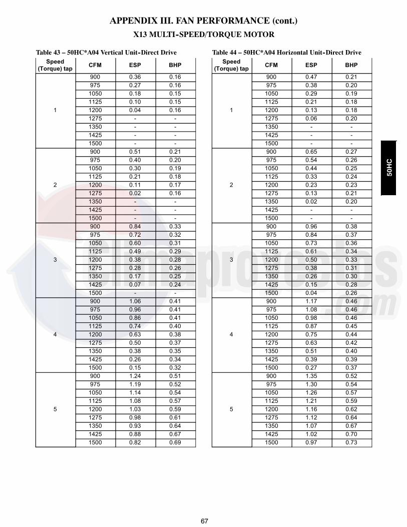
67
APPENDIX III. FAN PERFORMANCE (cont.)
X13 MULTI--SPEED/TORQUE MOTOR
Table 43 – 50HC*A04 Vertical Unit--Direct DriveSpeed
(Torque) tap CFM ESP BHP
1
900 0.36 0.16975 0.27 0.161050 0.18 0.151125 0.10 0.151200 0.04 0.161275 - -1350 - -1425 - -1500 - -
2
900 0.51 0.21975 0.40 0.201050 0.30 0.191125 0.21 0.181200 0.11 0.171275 0.02 0.161350 - -1425 - -1500 - -
3
900 0.84 0.33975 0.72 0.321050 0.60 0.311125 0.49 0.291200 0.38 0.281275 0.28 0.261350 0.17 0.251425 0.07 0.241500 - -
4
900 1.06 0.41975 0.96 0.411050 0.86 0.411125 0.74 0.401200 0.63 0.381275 0.50 0.371350 0.38 0.351425 0.26 0.341500 0.15 0.32
5
900 1.24 0.51975 1.19 0.521050 1.14 0.541125 1.08 0.571200 1.03 0.591275 0.98 0.611350 0.93 0.641425 0.88 0.671500 0.82 0.69
Table 44 – 50HC*A04 Horizontal Unit--Direct DriveSpeed
(Torque) tap CFM ESP BHP
1
900 0.47 0.21975 0.38 0.201050 0.29 0.191125 0.21 0.181200 0.13 0.181275 0.06 0.201350 - -1425 - -1500 - -
2
900 0.65 0.27975 0.54 0.261050 0.44 0.251125 0.33 0.241200 0.23 0.231275 0.13 0.211350 0.02 0.201425 - -1500 - -
3
900 0.96 0.38975 0.84 0.371050 0.73 0.361125 0.61 0.341200 0.50 0.331275 0.38 0.311350 0.26 0.301425 0.15 0.281500 0.04 0.26
4
900 1.17 0.46975 1.08 0.461050 0.98 0.461125 0.87 0.451200 0.75 0.441275 0.63 0.421350 0.51 0.401425 0.39 0.391500 0.27 0.37
5
900 1.35 0.52975 1.30 0.541050 1.26 0.571125 1.21 0.591200 1.16 0.621275 1.12 0.641350 1.07 0.671425 1.02 0.701500 0.97 0.73
50HC

68
APPENDIX III. FAN PERFORMANCE (cont.)
X13 MULTI--SPEED/TORQUE MOTOR
Table 45 – 50HC*A05 Vertical Unit--Direct DriveSpeed
(Torque) tap CFM ESP BHP
1
1200 0.57 0.311300 0.44 0.291400 0.30 0.271500 0.16 0.251600 0.03 0.251700 - -1800 - -1900 - -2000 - -
2
1200 0.68 0.351300 0.54 0.331400 0.40 0.311500 0.24 0.281600 0.10 0.261700 - -1800 - -1900 - -2000 - -
3
1200 1.15 0.541300 1.09 0.541400 1.02 0.551500 0.93 0.581600 0.82 0.571700 0.69 0.551800 0.54 0.521900 0.38 0.502000 0.21 0.47
4
1200 1.16 0.561300 1.12 0.591400 1.07 0.611500 1.00 0.651600 0.92 0.651700 0.80 0.661800 0.67 0.651900 0.51 0.622000 0.34 0.59
5
1200 1.16 0.591300 1.11 0.631400 1.00 0.671500 0.88 0.671600 0.96 0.751700 0.91 0.751800 0.86 0.831900 0.80 0.872000 0.74 0.91
Table 46 – 50HC*A05Horizontal Unit--Direct DriveSpeed
(Torque) tap CFM ESP BHP
1
1200 0.62 0.341300 0.48 0.321400 0.35 0.301500 0.23 0.281600 0.12 0.281700 0.02 0.271800 - -1900 - -2000 - -
2
1200 0.74 0.391300 0.60 0.371400 0.46 0.351500 0.32 0.321600 0.19 0.301700 0.07 0.271800 - -1900 - -2000 - -
3
1200 1.20 0.591300 1.12 0.601400 1.01 0.611500 0.89 0.621600 0.76 0.591700 0.61 0.561800 0.47 0.531900 0.32 0.502000 0.18 0.47
4
1200 1.24 0.601300 1.18 0.631400 1.11 0.651500 1.03 0.691600 0.93 0.691700 0.82 0.691800 0.70 0.691900 0.56 0.662000 0.41 0.63
5
1200 1.25 0.611300 1.20 0.651400 1.11 0.681500 1.03 0.681600 1.05 0.761700 1.01 0.761800 0.96 0.841900 0.91 0.892000 0.87 0.93
50HC

69
APPENDIX III. FAN PERFORMANCE (cont.)
X13 MULTI--SPEED/TORQUE MOTOR
Table 47 – 50HC*A06 Vertical Unit--Direct DriveSpeed
(Torque) tap CFM ESP BHP
1
1500 0.50 0.441625 0.32 0.421750 0.14 0.391875 - -2000 - -2125 - -2250 - -2375 - -2500 - -
2
1500 0.72 0.561625 0.53 0.531750 0.34 0.501875 0.18 0.482000 - -2125 - -2250 - -2375 - -2500 - -
3
1500 1.20 0.841625 1.02 0.821750 0.82 0.821875 0.61 0.792000 0.40 0.752125 0.20 0.712250 0.04 0.672375 - -2500 - -
4
1500 1.31 0.921625 1.17 0.921750 0.99 0.951875 0.80 0.942000 0.59 0.902125 0.37 0.862250 0.17 0.832375 0.00 0.792500 - -
5
1500 1.36 0.941625 1.24 0.991750 0.99 1.021875 0.80 1.052000 0.74 1.032125 0.53 0.992250 0.31 0.942375 0.08 0.902500 - 0.86
Table 48 – 50HC*A06 Horizontal Unit--Direct DriveSpeed
(Torque) tap CFM ESP BHP
1
1500 0.63 0.491625 0.45 0.461750 0.27 0.431875 0.10 0.392000 - -2125 - -2250 - -2375 - -2500 - -
2
1500 0.88 0.611625 0.69 0.581750 0.49 0.551875 0.30 0.512000 0.12 0.482125 - -2250 - -2375 - -2500 - -
3
1500 1.37 0.891625 1.20 0.871750 1.02 0.861875 0.81 0.832000 0.60 0.792125 0.39 0.752250 0.21 0.712375 0.07 0.672500 - -
4
1500 1.48 0.951625 1.35 0.951750 1.20 0.991875 1.03 0.992000 0.83 0.962125 0.63 0.932250 0.42 0.892375 0.22 0.842500 0.05 0.78
5
1500 1.52 0.971625 1.42 1.011750 1.20 1.051875 1.03 1.092000 1.00 1.092125 0.82 1.062250 0.62 1.022375 0.40 0.982500 0.16 0.93
50HC
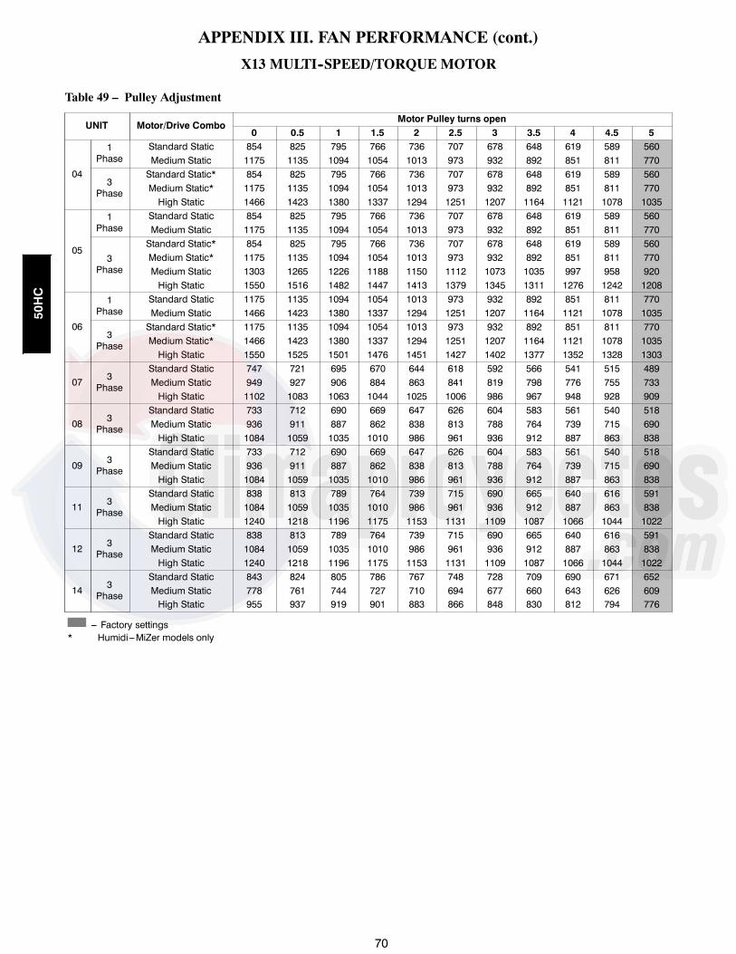
70
APPENDIX III. FAN PERFORMANCE (cont.)
X13 MULTI--SPEED/TORQUE MOTOR
Table 49 – Pulley Adjustment
UNIT Motor/Drive ComboMotor Pulley turns open
0 0.5 1 1.5 2 2.5 3 3.5 4 4.5 5
04
1Phase
Standard Static 854 825 795 766 736 707 678 648 619 589 560Medium Static 1175 1135 1094 1054 1013 973 932 892 851 811 770
3Phase
Standard Static* 854 825 795 766 736 707 678 648 619 589 560Medium Static* 1175 1135 1094 1054 1013 973 932 892 851 811 770High Static 1466 1423 1380 1337 1294 1251 1207 1164 1121 1078 1035
05
1Phase
Standard Static 854 825 795 766 736 707 678 648 619 589 560Medium Static 1175 1135 1094 1054 1013 973 932 892 851 811 770
3Phase
Standard Static* 854 825 795 766 736 707 678 648 619 589 560Medium Static* 1175 1135 1094 1054 1013 973 932 892 851 811 770Medium Static 1303 1265 1226 1188 1150 1112 1073 1035 997 958 920High Static 1550 1516 1482 1447 1413 1379 1345 1311 1276 1242 1208
06
1Phase
Standard Static 1175 1135 1094 1054 1013 973 932 892 851 811 770Medium Static 1466 1423 1380 1337 1294 1251 1207 1164 1121 1078 1035
3Phase
Standard Static* 1175 1135 1094 1054 1013 973 932 892 851 811 770Medium Static* 1466 1423 1380 1337 1294 1251 1207 1164 1121 1078 1035High Static 1550 1525 1501 1476 1451 1427 1402 1377 1352 1328 1303
07 3Phase
Standard Static 747 721 695 670 644 618 592 566 541 515 489Medium Static 949 927 906 884 863 841 819 798 776 755 733High Static 1102 1083 1063 1044 1025 1006 986 967 948 928 909
08 3Phase
Standard Static 733 712 690 669 647 626 604 583 561 540 518Medium Static 936 911 887 862 838 813 788 764 739 715 690High Static 1084 1059 1035 1010 986 961 936 912 887 863 838
09 3Phase
Standard Static 733 712 690 669 647 626 604 583 561 540 518Medium Static 936 911 887 862 838 813 788 764 739 715 690High Static 1084 1059 1035 1010 986 961 936 912 887 863 838
11 3Phase
Standard Static 838 813 789 764 739 715 690 665 640 616 591Medium Static 1084 1059 1035 1010 986 961 936 912 887 863 838High Static 1240 1218 1196 1175 1153 1131 1109 1087 1066 1044 1022
12 3Phase
Standard Static 838 813 789 764 739 715 690 665 640 616 591Medium Static 1084 1059 1035 1010 986 961 936 912 887 863 838High Static 1240 1218 1196 1175 1153 1131 1109 1087 1066 1044 1022
14 3Phase
Standard Static 843 824 805 786 767 748 728 709 690 671 652Medium Static 778 761 744 727 710 694 677 660 643 626 609High Static 955 937 919 901 883 866 848 830 812 794 776
--- Factory settings* Humidi---MiZer models only
50HC

71
APPENDIX IV. WIRING DIAGRAMS
Table 50 – Wiring Diagrams
50HC*A04--D14 UNITS
STANDARD HUMIDI---MIZER
SIZE VOLTAGE CONTROL POWER CONTROL POWER
A04---A06
230---1---60
48TM502410---H
48TM502523---G
48TM503087---K
48TM503090--- I
208/230---3---60
48TM502524--- I48TM503097---J
460---3---60
575---3---60 48TM503131---K
A07
208/230---3---60
48TM500928---S 48TM500737---T 48TM503176---K48TM503179---F
460---3---60
575---3---60 48TM503300---J
D08---D09
208/230---3---60
48TM501323---Q 48TM501324---Q 48TM503246---L48TM503247---E
460---3---60
575---3---60 48TM503248---G
D11
208/230---3---60
48TM504180---J
48TM504183---H
48TM504728---D
48TM504183---H
460---3---6048TM504551---D 48TM504551---D
575---3---60
D12
208/230---3---60
48TM501247---R 48TM501248---O 48TM503249---L 48TM503250---F460---3---60
575---3---60
D14
208/230---3---60
50TM501064---K
50TM501159---F
50TM501503--- I
50TM501506---G
460---3---6050TM501160---E
50TM501505---G
575---3---60 50TM501511---G
A04---A06 PremierLink* 48TM500983---L 48TM500983---LA07---D14 PremierLink* 48TM504587 48TM504587A04---A06 RTU---Open* 48TM502741---C 48TM502741---CA07---D14 RTU---Open* 48TM503310---C 48TM503310---C
50HC

72
APPENDIX IV. WIRING DIAGRAMS
A160135
Fig. 58 -- 50HC*A04--A06 PAC Control Diagram -- 208--1--60; 208/230--3--60; 460/575--3--60
50HC

73
APPENDIX IV. WIRING DIAGRAMS
A160136
Fig. 59 -- 50HC*A07 PAC Control Diagram -- 208/230--3--60; 460/575--3--60
50HC

74
APPENDIX IV. WIRING DIAGRAMS
A160137
Fig. 60 -- 50HC*D08--D09 PAC Control Diagram -- 208/230--3--60; 460/575--3--60
50HC

75
APPENDIX IV. WIRING DIAGRAMS
A160139
Fig. 61 -- 50HC*D11 PAC Control Diagram -- 208/230--3--60, 460/575--3--60
50HC

76
APPENDIX IV. WIRING DIAGRAMS
A160138
Fig. 62 -- 50HC*D12 PAC Control Diagram -- 208/230--3--60; 460/575--3--60
50HC

77
APPENDIX IV. WIRING DIAGRAMS
A160140
Fig. 63 -- 50HC*D14 PAC Control Diagram -- 208/230--3--60; 460/575--3--60
50HC

78
APPENDIX IV. WIRING DIAGRAMS
A160141
Fig. 64 -- 50HC*A04--A06 PAC Power Diagram -- 230--1--60
50HC

79
APPENDIX IV. WIRING DIAGRAMS
A160142
Fig. 65 -- 50HC*A04--A06 PAC Power Diagram -- 208/230--3--60; 460--3--60
50HC
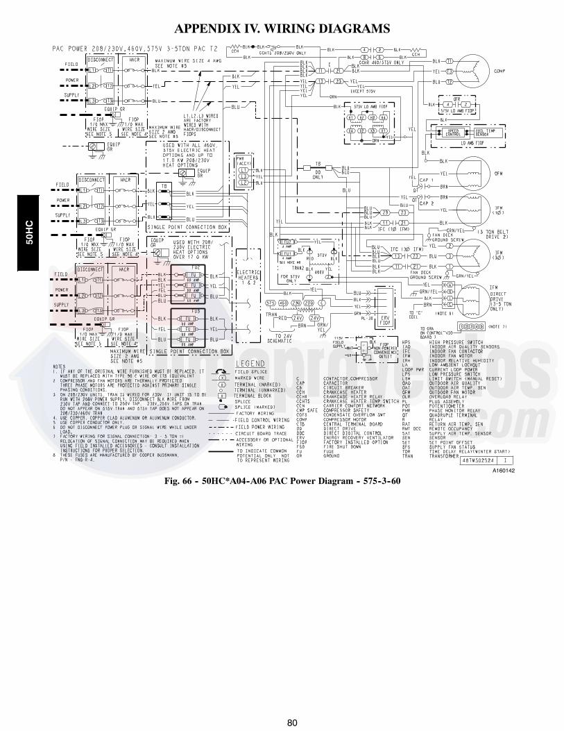
80
APPENDIX IV. WIRING DIAGRAMS
A160142
Fig. 66 -- 50HC*A04--A06 PAC Power Diagram -- 575--3--60
50HC

81
APPENDIX IV. WIRING DIAGRAMS
A160143
Fig. 67 -- 50HC*A07--A12 PAC Power Diagram -- 208/230--3--60, 460--3--60
50HC

82
APPENDIX IV. WIRING DIAGRAMS
A160143
Fig. 68 -- 50HC*A07--A12 PAC Power Diagram -- 575--3--60
50HC

83
APPENDIX IV. WIRING DIAGRAMS
A160144
Fig. 69 -- 50HC*D08--D09 PAC Power Diagram -- 230/460--3--60
50HC

84
APPENDIX IV. WIRING DIAGRAMS
A160144
Fig. 70 -- 50HC*D08--D09 PAC Power Diagram -- 575--3--60
50HC

85
APPENDIX IV. WIRING DIAGRAMS
A160146
Fig. 71 -- 50HC*D11 PAC Power Diagram 208/230--3--60
50HC
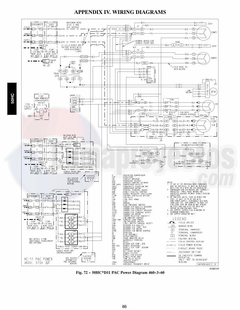
86
APPENDIX IV. WIRING DIAGRAMS
A160147
Fig. 72 -- 50HC*D11 PAC Power Diagram 460--3--60
50HC

87
APPENDIX IV. WIRING DIAGRAMS
A160147
Fig. 73 -- 50HC*D11 PAC Power Diagram 575--3--60
50HC

88
APPENDIX IV. WIRING DIAGRAMS
A160145
Fig. 74 -- 50HC*D12 PAC Power Diagram -- 230/460--3--60
50HC

89
APPENDIX IV. WIRING DIAGRAMS
A160145
Fig. 75 -- 50HC*D12 PAC Power Diagram -- 575--3--60
50HC

90
APPENDIX IV. WIRING DIAGRAMS
A160148
Fig. 76 -- 50HC*D14 PAC Power Diagram -- 230/460--3--60
50HC

91
APPENDIX IV. WIRING DIAGRAMS
A160149
Fig. 77 -- 50HC*D14 PAC Power Diagram -- 575--3--60
50HC

92
APPENDIX IV. WIRING DIAGRAMS
A160150
Fig. 78 -- 50HC*A04--A06 PAC Control Diagram -- 230--1--60; 230/460/575--3--60 with Humidi--MiZer
50HC

93
APPENDIX IV. WIRING DIAGRAMS
A160151
Fig. 79 -- 50HC*A07 PAC Control Diagram -- 230--1--60; 230/460/575--3--60 with Humidi--MiZer
50HC

94
APPENDIX IV. WIRING DIAGRAMS
A160152
Fig. 80 -- 50HC*D08--D09 PAC Control Diagram -- 230/460/575--3--60 with Humidi--MiZer
50HC

95
APPENDIX IV. WIRING DIAGRAMS
A160154
Fig. 81 -- 50HC*D11 PAC Control Diagram -- 230--1--60; 230/460/575--3--60 with Humidi--MiZer
50HC

96
APPENDIX IV. WIRING DIAGRAMS
A160153
Fig. 82 -- 50HC*D12 PAC Control Diagram -- 230/460/575--3--60 with Humidi--MiZer
50HC
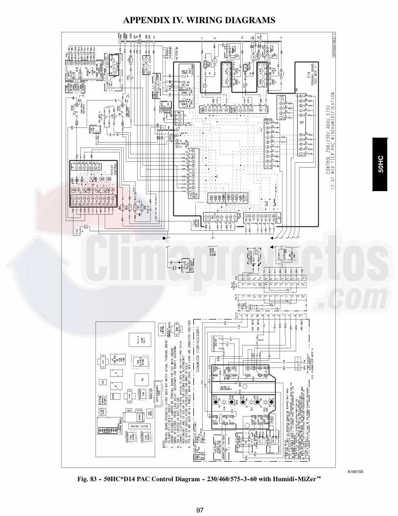
97
APPENDIX IV. WIRING DIAGRAMS
A160155
Fig. 83 -- 50HC*D14 PAC Control Diagram -- 230/460/575--3--60 with Humidi--MiZer
50HC

98
APPENDIX IV. WIRING DIAGRAMS
A160156
Fig. 84 -- 50HC*A04--A06 PAC Power Diagram -- 230--1--60 with Humidi--MiZer
50HC
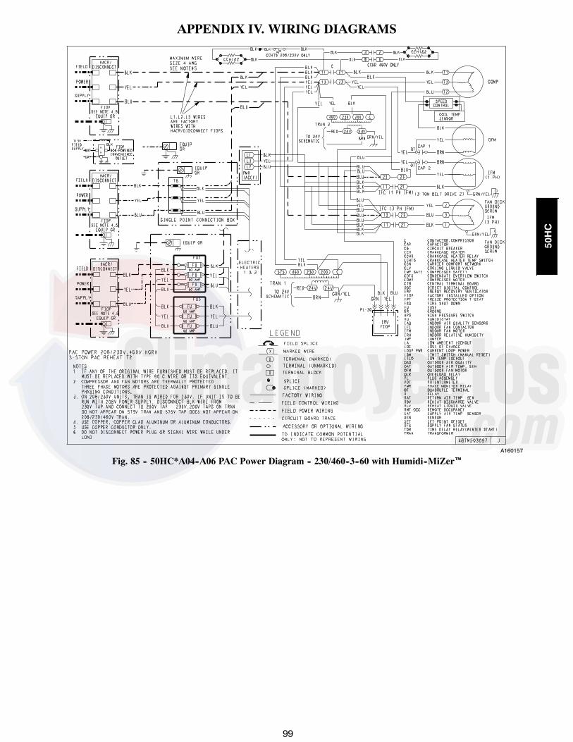
99
APPENDIX IV. WIRING DIAGRAMS
A160157
Fig. 85 -- 50HC*A04--A06 PAC Power Diagram -- 230/460--3--60 with Humidi--MiZer
50HC

100
APPENDIX IV. WIRING DIAGRAMS
A160158
Fig. 86 -- 50HC*A04--A06 PAC Power Diagram -- 575--3--60 with Humidi--MiZer
50HC

101
APPENDIX IV. WIRING DIAGRAMS
A160159
Fig. 87 -- 50HC*A07 PAC Power Diagram -- 230/460--3--60 with Humidi--MiZer
50HC

102
APPENDIX IV. WIRING DIAGRAMS
A160160
Fig. 88 -- 50HC*A07 PAC Power Diagram -- 575--3--60 with Humidi--MiZer
50HC

103
APPENDIX IV. WIRING DIAGRAMS
A160161
Fig. 89 -- 50HC*D08--D09 PAC Power Diagram -- 230/460--3--60 with Humidi--MiZer
50HC

104
APPENDIX IV. WIRING DIAGRAMS
A160162
Fig. 90 -- 50HC*D08--D09 PAC Power Diagram -- 575--3--60 with Humidi--MiZer
50HC

105
APPENDIX IV. WIRING DIAGRAMS
A160146
Fig. 91 -- 50HC*D11 PAC Power Diagram -- 230--3--60 with Humidi--MiZer
50HC

106
APPENDIX IV. WIRING DIAGRAMS
A160147
Fig. 92 -- 50HC*D11 PAC Power Diagram -- 460--3--60 with Humidi--MiZer
50HC

107
APPENDIX IV. WIRING DIAGRAMS
A160147
Fig. 93 -- 50HC*D11 PAC Power Diagram -- 575--3--60 with Humidi--MiZer
50HC

108
APPENDIX IV. WIRING DIAGRAMS
A160163
Fig. 94 -- 50HC*D12 PAC Power Diagram -- 230/460--3--60 with Humidi--MiZer
50HC

109
APPENDIX IV. WIRING DIAGRAMS
A160163
Fig. 95 -- 50HC*D12 PAC Power Diagram -- 575--3--60 with Humidi--MiZer
50HC

110
APPENDIX IV. WIRING DIAGRAMS
A160165
Fig. 96 -- 50HC*D14 PAC Power Diagram -- 230--3--60 with Humidi--MiZer
50HC

111
APPENDIX IV. WIRING DIAGRAMS
A160168
Fig. 97 -- 50HC*D14 PAC Power Diagram -- 460--3--60 with Humidi--MiZer
50HC

112
APPENDIX IV. WIRING DIAGRAMS
A160166
Fig. 98 -- 50HC*D14 PAC Power Diagram -- 575--3--60 with Humidi--MiZer
50HC

113
APPENDIX IV. WIRING DIAGRAMS
A160178
Fig. 99 -- PremierLink System A04--A06 Wiring Diagram
50HC

114
APPENDIX IV. WIRING DIAGRAMS
A160179
Fig. 100 -- RTU Open System Control A04--A06 Wiring Diagram
50HC

115
APPENDIX IV. WIRING DIAGRAMS
A160180
Fig. 101 -- PremierLink System A07 -- D14 Wiring Diagram50HC

116
APPENDIX IV. WIRING DIAGRAMS
A160181
Fig. 102 -- RTU--Open A07--D14 Wiring Diagram
50HC

117
APPENDIX IV. WIRING DIAGRAMS
A160178
Fig. 103 -- PremierLink System A04--A06 Wiring Diagram with Humidi--MiZer
50HC

118
APPENDIX IV. WIRING DIAGRAMS
A160179
Fig. 104 -- RTU Open System Control A04--A06 Wiring Diagram with Humidi--MiZert
50HC

119
APPENDIX IV. WIRING DIAGRAMS
A160180
Fig. 105 -- PremierLink System A07 -- D14 Wiring Diagram with Humidi--MiZert50HC

120
APPENDIX IV. WIRING DIAGRAMS
A160181
Fig. 106 -- RTU--Open A07--D14 Wiring Diagram with Humidi--MiZer
50HC

121
APPENDIX V. MOTORMASTER SENSOR LOCATIONS
C10273
Fig. 107 -- 50HC*A04 Outdoor Circuiting
C08260
Fig. 108 -- 50HC*A05/06 Outdoor Circuiting
C10274
Fig. 109 -- 50HC*A07 Outdoor Circuiting
C08262
Fig. 110 -- 50HC*A08 Outdoor Circuiting
50HC

122
APPENDIX V. MOTORMASTER SENSOR LOCATIONS (cont.)
C08263
Fig. 111 -- 50HC*A09 Outdoor Circuiting
CIRCUIT A CIRCUIT B
SENSORLOCATION
SENSORLOCATION
C12495
Fig. 112 -- 50HC*D14 Outdoor Circuiting (Circuit A and Circuit B)
50HC

123
APPENDIX V. MOTORMASTER SENSOR LOCATIONS (cont.)
TIE WRAPSENSOR LOCATION
9.0”
C12492
Fig. 113 -- 50HC*D08 Motormaster Sensor Location -- Novation Coils (MCHX)
TIE WRAPSENSOR LOCATION
11.0”
C12493
Fig. 114 -- 50HC*D12 Motormaster Sensor Location -- Novation Coils (MCHX)
50HC
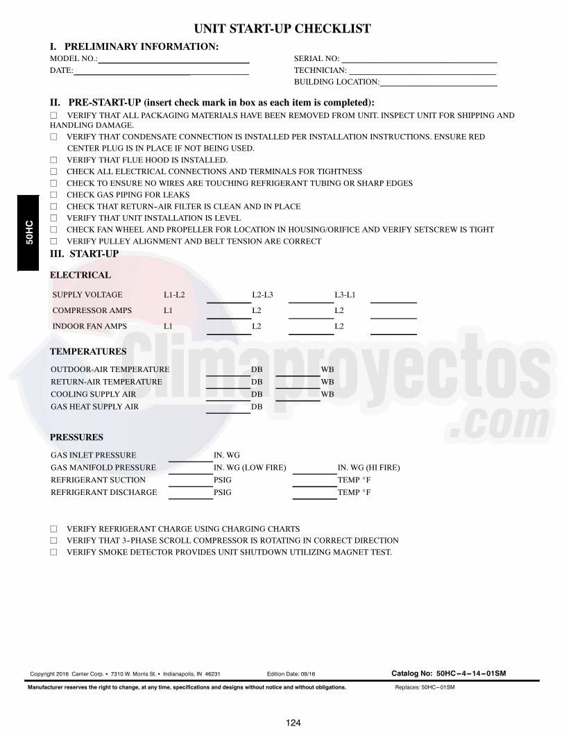
124
UNIT START-UP CHECKLISTI. PRELIMINARY INFORMATION:MODEL NO.:
DATE: ______________
SERIAL NO: _____________________________________
TECHNICIAN: ___________________________________
BUILDING LOCATION:____________________________
II. PRE-START-UP (insert check mark in box as each item is completed):j VERIFY THAT ALL PACKAGING MATERIALS HAVE BEEN REMOVED FROM UNIT. INSPECT UNIT FOR SHIPPING ANDHANDLING DAMAGE.
j VERIFY THAT CONDENSATE CONNECTION IS INSTALLED PER INSTALLATION INSTRUCTIONS. ENSURE RED
CENTER PLUG IS IN PLACE IF NOT BEING USED.
j VERIFY THAT FLUE HOOD IS INSTALLED.
j CHECK ALL ELECTRICAL CONNECTIONS AND TERMINALS FOR TIGHTNESS
j CHECK TO ENSURE NO WIRES ARE TOUCHING REFRIGERANT TUBING OR SHARP EDGES
j CHECK GAS PIPING FOR LEAKS
j CHECK THAT RETURN--AIR FILTER IS CLEAN AND IN PLACE
j VERIFY THAT UNIT INSTALLATION IS LEVEL
j CHECK FAN WHEEL AND PROPELLER FOR LOCATION IN HOUSING/ORIFICE AND VERIFY SETSCREW IS TIGHT
j VERIFY PULLEY ALIGNMENT AND BELT TENSION ARE CORRECT
III. START-UP
ELECTRICAL
SUPPLY VOLTAGE L1-L2 L2-L3 L3-L1
COMPRESSOR AMPS L1 L2 L2
INDOOR FAN AMPS L1 L2 L2
TEMPERATURES
OUTDOOR-AIR TEMPERATURE DB WB
RETURN-AIR TEMPERATURE DB WB
COOLING SUPPLY AIR DB WB
GAS HEAT SUPPLY AIR DB
PRESSURES
GAS INLET PRESSURE IN. WG
GAS MANIFOLD PRESSURE IN. WG (LOW FIRE) IN. WG (HI FIRE)
REFRIGERANT SUCTION PSIG TEMP _F
REFRIGERANT DISCHARGE PSIG TEMP _F
j VERIFY REFRIGERANT CHARGE USING CHARGING CHARTS
j VERIFY THAT 3--PHASE SCROLL COMPRESSOR IS ROTATING IN CORRECT DIRECTION
j VERIFY SMOKE DETECTOR PROVIDES UNIT SHUTDOWN UTILIZING MAGNET TEST.
Copyright 2016 Carrier Corp. S 7310 W. Morris St. S Indianapolis, IN 46231 Edition Date: 09/16
Manufacturer reserves the right to change, at any time, specifications and designs without notice and without obligations.
Catalog No: 50HC---4---14---01SM
Replaces: 50HC---01SM
50HC