
SERVICE & MAINTENANCE MANUAL Economical Electric ...
71
Version 03/2013 ECL10 -SHFW-001 SERVICE & MAINTENANCE MANUAL Economical Electric Stacker
-
Upload
khangminh22 -
Category
Documents
-
view
2 -
download
0
Transcript of SERVICE & MAINTENANCE MANUAL Economical Electric ...

Version 03/2013
ECL10 -SHFW-001
SERVICE & MAINTENANCE MANUAL
Economical Electric Stacker

2
CONTENT FOREWORD .............................................................................................................................................. 31. GENERAL ........................................................................................................................................... 4
1.1 INTRODUCTION – MAINTENANCE SAFETY PRECAUTIONS .............................................. 41.2 MEASUREMENT CONVERSIONS ........................................................................................... 8
2. SPECIFICATION .............................................................................................................................. 132.1 LOCATION OF COMPONENTS .............................................................................................. 132.2 SPECIFICATION SHEETS .................................................................................................... 142.2.1 TECHNICAL FEATURES ..................................................................................................... 142.3 LUBRICATION ...................................................................................................................... 16
3 ELECTRIC SYSTEM ........................................................................................................................ 173.1 ELECTRIC DIAGRAM ............................................................................................................. 173.2 ELECTRICAL INSTALLATION ............................................................................................... 203.3 DRIVE WHEEL ......................................................................................................................... 223.4 PUMP STATION ...................................................................................................................... 223.5 BATTERY ................................................................................................................................. 233.6 CHARGER ............................................................................................................................... 243.7 CURTIS CONTROLLER 1212................................................................................................ . 28 3.8 BATTERY DISCHARGE INDICATOR .................................................................................... 39 3.9 REPLACE THE ELECTRIC PARTS ........................................................................................ 403.10 TOOL FOR REPAIRING THE PIN OF ELECTRIC PLUG ...................................................... 46
4. HYDRAULIC SYSTEM...................................................................................................................... 49 4.1 PUMP STATION OPERATION ............................................................................................. 51 4.2 OPERATION OF CYLINDER ................................................................................................ 534.3 HYDRAULIC OIL FILLING .................................................................................................... 54
5. DRIVE WHEEL .................................................................................................................................. 555.1 REPLACE THE DRIVE WHEEL............................................................................................ 55 5.2 REPLACE THE ELECTRIC BRUSH..................................................................................... 58 5.3 ........................................................................................................ REPLACE THE BRAKE 59 5.4 ADJUST THE AIR GAP OF THE BRAKE...………………………………….……...……….. 60
6. CONTROL HANDLE ........................................................................................................................ 61 6.1 ................................................................................................REMOVE THE AIR SPRING .. 62 6.2 ....................................................................................................... REMOVE THE HANDLE 64 6.3 REPLACE THE SENSOR …………………………………………………………………………666.4 REPLACE THE TILLER…………………………………………………………………. … …….66 6.5 REPLACE THE ACCELERATOR……..………………………………………………………….67 6.6 REPLACE THE MICRO SWITCHES……………………………………….…………..………. .68
7. CASTER WHEEL ............................................................................................................................. 69 7.1 OPERATION OF THE CASTER WHEEL.............................................................................. 69 7.2 ADJUSTING THE PRESSURE FOR THE DRIVE WHEEL.................................................. 70
8. MAINTENANCE CHECK LIST......................................................................................................... 71 9. TROUBLE SHOOTING .................................................................................................................... 69

3
FOREWORD Proper operation, maintenance, troubleshooting and repairs are necessary to preserve the performance of the pallet truck over a long period and ensure that fault and breakdowns do not occur. The purpose of this service manual is to provide necessary information especially in inspections, repair and maintenance.
The majority of this pallet truck consists of steel, it can be completely recycled. Waste
material in conjunction with repairs, maintenance, cleaning or scrapping, must be collected and disposed of in an environment-friendly way and in accordance with the directives of respective countries. Such work must be carried out in areas intended for this purpose. Recyclable material should be taken care of specialized authorities. Environmentally hazardous waste, such as oil filters, batteries and electronics, will have a negative effect on the environment or health, if handled incorrectly.
All of the information reported herein is based on data available at the moment of
printing. Our products are constantly being developed and renewed, we reserves the right to modify our own products at any moment without prior notice and incurring in any sanction. So, it is suggested to always verify possible updates.

4
1. GENERAL 1.1 INTRODUCTION – MAINTENANCE SAFETY PRECAUTIONS Maintenance work may cause injuries. Always take care to perform work safe, at least observing the following. It is of utmost importance that maintenance personnel pay strict attention to these warnings and precautions to avoid possible injury to themselves, others or damage to the equipment. A maintenance program must be followed to ensure that the machine is safe to operate. The specific precautions to be observed during maintenance are inserted at the appropriate point in the manual. These precautions are, for the most parts, those that apply when servicing hydraulic and larger truck component parts.
MODIFICATION OF THE TRUCK WITHOUT CERTIFICATION BY A RESPONSIBLE
AUTHORITY THAT THE TRUCK IS AT LEAST AS SAFE AS ORIGINALLY MANUFACTURED, IS A SAFETY VIOLATION.
SINCE THE TRUCK MANUFACTURER HAS NO DIRECT CONTROL OVER THE
FIELD INSPECTION AND MAINTENANCE, SAFETY IN THIS AREA RESPONSIBIUTY OF THE OWNER OR OPERATOR.
FAILURE TO COMPLY WITH SAFETY PRECAUTIONS, LlSTED IN THIS SECTION
MAY RESULT IN MACHINE DAMAGE, PERSONNEL INJURY OR DEATH AND IS A SAFETY VIOLATION. When carrying out any operation or maintenance, have trained and experienced personnel to carry
out the work. When carrying out any operation or maintenance, carefully read operation and maintenance
handbook. Read all the precautions given on the decals which are fixed to the truck. Be sure you fully understand the content of the operation. It is important to prepare necessary tools
and parts for maintain the truck. Your safety, and that of others, is the first consideration when
engaging in the maintenance of equipment. Always be conscious of weight. Never attempt to move heavy parts without the aid of a mechanical device. Do not allow heavy objects to rest in an unstable position. When raising a portion of the equipment, ensure that adequate support is provided.

5
It should be noted that the machines hydraulic systems operate at
extremely high potentially dangerous pressures. Every effort should be made to relieve any system pressure prior to disconnecting or removing any portion of the system. Relieve system pressure by cycling the applicable control several times with the engine(motor) stopped and ignition on, to direct any line pressure back into the reservoir. Pressure feed lines to system components can then be disconnected with minimal fluid loss.
Remove all rings, watches and jewelry when performing any maintenance. Wear well-fitting helmet, safety shoes and working Clothes When
drilling grinding or hammering always. Wear protective goggles. Always do up safety clothes properly so that they do. Not catch on protruding parts of machines. Do not wear oily clothes. When checking, always release battery plug. DO NOT WEAR LONG HAIR UNRESTRAINED, OR LOOSE-FITTING CLOTHING AND NECKTIES WHICH ARE APT TO BECOME CAUGHT ON OR ENTANGLED IN EQUIPMENT.
During maintenance do not allow any unauthorized person, to
stand near the machine. Flames should never be used instead of lamps. Never use a naked
flame to check leaks or the level of oil or electrolyte. Immediately remove any oil or grease on the floor of the operator’s
compartment or on the handrail. It is very dangerous if someone slips while on the machine.
Always use pure oil or grease, and be sure to use clean containers. Oil is a dangerous substance. Never handle oil, grease or oily
clothes in places where there is any fire or flame. As preparation for use of fire extinguishers and other fire- fighting equipment.
Keep the battery away from fire hazards. The generated gases are explosive.
Store all the oils in a specified place. Keep the flammable things away from the machine. Do not
smoke at the working place. Battery should always be disconnected during replacement of electrical components.

6
Always use the grades of grease and oil recommended by NOBLELIFT choose the viscosity specified for the ambient temperature.
Exhaust gas is dangerous provide ventilation when working in a closed
space. Avoid breathing dust that may be generated when handling components
containing asbestos fibers. Wear a gas mask if necessary. When working on top of the machine, be careful not to lose your balance
and fall. Hand a caution sign in the operator’s compartment (for example “Do
not start” of “Maintenance in progress”). This will prevent anyone from starting or moving the machine by mistake.
When welding on the machine or working on the electrical system,
ALWAYS turn the key switch OFF and remove the battery plug from the battery. Park the machine on firm, flat ground. Lower the fork to the min. height and stop the motor.
Sulfuric acid in battery electrolyte is poisonous. It is strong enough to burn skin and eat holes in clothing. If you spill acid on your clothes or skin, immediately flush with large quantities or water.
When working on the battery, wear goggles or safety glasses. If
splashed into the eyes, flush with water and get medical attention immediately.
Battery terminals touched by metal objects can cause short circuit and
burn you. Keep tools away from the terminals. Keep sparks, lighted matches, and open flame away from the top of
battery. Battery (hydrogen) gas can explode. When disassembling and assembling the battery, make sure
that the battery terminals (+, –) are correctly connected. If water gets into the electrical system, abnormal operation or failure can
result. Do not use water or steam on sensors, connectors and instruments in the cab.
7
Do not handle electrical equipment while wearing wet gloves, or in wet places, as this can cause electric shock.
When working with other, choose a group leader and work according to his instructions. Do not perform any maintenance beyond the agreed work.
Unless you have special instructions to the contrary, maintenance should always be carried out with the motor stopped. If maintenance is carried out with the motor running, there must be two technicians present: One operating the stacker and the other one performing the maintenance. In such a case, never touch any moving part.
Before making adjustment, lubricating or performing any other maintenance, shut off all power controls.
When removing parts containing O-ring Gaskets or seal clean the mounting surface and replace with new sealing parts.
Thoroughly clean the machine. In particular, be careful to clean the grease fittings and the area around the dipsticks. Be careful not to let any dirt or dust into the system.
Use only approved nonflammable cleaning solvents. When changing the oil or fitter, check the drained oil and filter for any signs of excessive metal
particles or other foreign materials. Always use NOBLELIFT genuine parts for replacement. ENSURE REPLACEMENT PARTS OR
COMPONENTS ARE IDENTICAL OR EQUIVALENT TO ORIGINAL PARTS OR COMPONENTS. When checking an open gear case, there is a risk of dripping things in. Before removing the covers
to inspect such cases, empty everything from your pockets. Be particularly careful to remove wrenches and nuts.

8
1.2 MEASUREMENT CONVERSIONS Length
Unit cm m km in ft yd mile
cm 1 0.01 0.00001 0.3937 0.03281 0.01094 0.000006 m 100 1 0.001 39.37 3.2808 1.0936 0.00062 km 100000 1000 1 39370.7 3280.8 1093.6 0.62137 in 2.54 0.0254 0.000025 1 0.08333 0.02777 0.000015 ft 30.48 0.3048 0.000304 12 1 0.3333 0.000189 yd 91.44 0.9144 0.000914 36 3 1 0.000568
mile 160930 1609.3 1.6093 63360 5280 1760 1 1mm=0.1cm, 1µm=0.001mm Area
Unit cm2 m2 km2 a ft2 yd2 in2
cm2 1 0.0001 – 0.000001 0.001076 0.000012 0.155000 m2 10000 1 0.000001 0.01 10.764 1.1958 1550.000 km2 – 1000000 1 10000 1076400 1195800 – a 0.01 100 0.0001 1 1076.4 119.58 – ft2 – 0.092903 – 0.000929 1 0.1111 144.000 yd2 – 0.83613 – 0.008361 9 1 1296.00 in2 6.4516 0.000645 – – 0.006943 0.000771 1
1ha=100a, 1mile2=259ha=2.59km2
Volume
Unit cm3 = cc m3 l in3 ft3 yd3
cm3 = m l 1 0.000001 0.001 0.061024 0.000035 0.000001 m3 1000000 1 1000 61024 35.315 1.30796 l 1000 0.001 1 61.024 0.035315 0.001308
in3 16.387 0.000016 0.01638 1 0.000578 0.000021 ft3 28316.8 0.028317 28.317 1728 1 0.03704 yd3 764529.8 0.76453 764.53 46656 27 1
1gal(US)=3785.41 cm3=231 in3=0.83267gal(US) Weight
Unit g kg t oz lb
g 1 0.001 0.000001 0.03527 0.0022 kg 1000 10 0.001 35.273 2.20459 t 1000000 1000 1 35273 2204.59
oz 28.3495 0.02835 0.000028 1 0.0625 lb 453.592 0.45359 0.000454 16 1
1 tone (metric)= 1.1023 ton(US)=0.9842 ton(UK)

9
Pressure
Unit kgf/cm2 bar Pa=N/m2 kPa lbf/in2 lbf/ft2
kgf/cm2 1 0.98067 98066.5 98.0665 14.2233 2048.16 bar 1.01972 1 100000 100 14.5037 2088.6
Pa=N/m2 0.00001 0.001 1 0.001 0.00015 0.02086 kPa 0.01020 0.01 1000 1 0.14504 20.886
lbf/in2 0.07032 0.0689 6894.76 6.89476 1 144 lbf/ft2 0.00047 0.00047 47.88028 0.04788 0.00694 1
kgf/cm2=735.56 Torr(mmHg)=0.96784atm Standard tightening torque The following charts give the standard tightening torques of bolts and nuts. Exceptions are given in sections of “Disassembly and Assembly” METER TABLE
Classification 4T, 5T 10T
Bolt type
Bolt size Torque kgf · m (lbf · ft) Torque kgf · m (lbf · ft)
M4 0.2 ± 0.02 0.4 ± 0.04
M5 0.3 ± 0.03 0.8 ± 0.08
M6 0.5 ± 0.05 1.4 ± 0.14
M8 1.2 ± 0.12 3.3 ± 0.3
M10 2.3 ± 0.23 6.5 ± 0.7
M12 4.0 ± 0.4 11.3 ± 1.1
M14 6.4 ± 0.6 17.9 ± 1.8
M16 9.5 ± 0.9 26.7 ± 2.7
M18 13.5 ± 1.4 38.0 ± 3.8
M20 18.6 ± 1.9 52.2 ± 5.2
M22 24.7 ± 2.5 69.4 ± 6.9
M24 32.1 ± 3.2 90.2 ± 9.0
M30 62.6 ± 6.3 176.1 ± 17.6
M36 108.2 ± 10.8 304.3 ± 30.4
M42 171.8 ± 17.2 483.2 ± 48.3
M45 211.3 ± 21.1 594.3 ± 50.4
10.9

10
INCH TABLE
4T, 5T 10T
Classification Bolt type
Bolt size Torque kgf · m (lbf · ft) Torque kgf · m (lbf · ft) 1/4 0.6 ± 0.06 1.7 ± 0.2 5/16 1.2 ± 0.12 3.0 ± 0.3 3/8 2.0 ± 0.20 5.6 ± 0.5 7/16 3.2 ± 0.32 8.9 ± 0.9 1/2 4.7 ± 0.47 13.4 ± 1.3 9/16 6.8 ± 0.68 19.0 ± 1.9 5/8 9.3 ± 0.93 26.1 ± 2.6 3/4 16.0 ± 1.60 45.1 ± 4.5 7/8 25.5 ± 2.55 71.6 ± 7.2 1 38.0 ± 3.80 106.9 ± 10.7
1-1/8 54.1 ± 5.41 152.2 ± 15.2 1-1/4 74.2 ± 7.42 208.9 ± 20.9 1-3/4 98.8 ± 9.88 277.8 ± 27.8 1-1/2 128.2 ± 12.82 360.7 ± 36.1
The torque in above table shall not be applied to nylon or nonferrous bolts or washer. The same is valid for not standardized ones. H Newton meter : 1 Nm = 0.1kgfm TIGHTENING TORQUE OF SPLIT FLANGE BOLTS The following torque shall be applied to the split flange bolts.
Diameter (mm)
Flat width (mm)
Torque kgf·m N·m
10 14 6.7 ± 0.7 66.7 ± 6.8 12 17 11.5 ± 1 112 ± 9.8 16 22 28.5 ± 3 279 ± 29
11
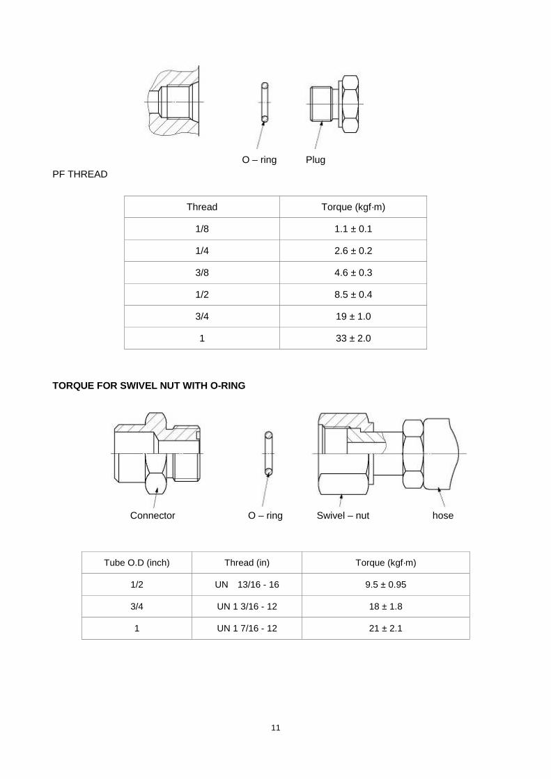
O – ring Plug PF THREAD
Thread Torque (kgf·m)
1/8 1.1 ± 0.1
1/4 2.6 ± 0.2
3/8 4.6 ± 0.3
1/2 8.5 ± 0.4
3/4 19 ± 1.0
1 33 ± 2.0
TORQUE FOR SWIVEL NUT WITH O-RING Connector O – ring Swivel – nut hose
Tube O.D (inch) Thread (in) Torque (kgf·m)
1/2 UN 13/16 - 16 9.5 ± 0.95
3/4 UN 1 3/16 - 12 18 ± 1.8
1 UN 1 7/16 - 12 21 ± 2.1

12
APPROXIMATE CONVERSIONS
SI Conv Non–SI Conv SI Unit Factor Unit Factor Unit
Torque Newton meter (N·m) × 8.9 = ln·in × 0.113 = N·m Newton meter (N·m) × 0.74 = lb·ft. × 1.36 = N·m Newton meter (N·m) × 0.102 = kg·m × 7.22 = lb·ft.*
Pressure (Pa = N/m2) kiloPascal (kPa) × 4.0 = in. H2 × 0.249 O = kPa kiloPascal (kPa) × 0.30 = in. Hg × 3.38 = kPa kiloPascal (kPa) × 0.145 = psi × 6.89 = kPa (bar) × 14.5 = psi × 0.069 = bar* (kg/cm2
× 14.22 ) = psi × 0.070 = k f/ 2* Newton/mm2
× 145.04 = psi × 0.069 = bar* MegaPascal (MPa) × 145 = psi × 0.00689 = MPa (Pa=N·m2 )
Power r (W = J/s) kiloWatt (kW) × 1.36 = PS (cv) × 0.736 = kW kiloWatt (kW) × 1.34 = HP × 0.746 = kW kiloWatt (kW) × 0.948 = Btu/s × 1.055 = kW Watt (W) × 0.74 = ft·lb/s × 1.36 = W (W=J/s)
Energy (J = N·m) kiloJoule (kJ) × 0.948 = Btu × 1.055 = kJ Joule (J) × 0.239 = calorie × 4.19 = J (J=N·m)
Velocity and Acceleration meter per sec2 (m/s2
×3.28 ) = ft/s2× 0.305 = m/s2
meter per sec (m/s) × 3.28 = ft/s × 0.305 = m/s kilometer per hour (km/h) × 0.62 = mph × 1.61 = km/h
Horse Power/Torque BHP × 5252 R.P.M. = TQ (lb·ft) TQ Z R.P.M. 5252 = B.H.P.
Temperature °C = (°F–32) ÷ 1.8 °F= (°C Z 1.8) + 32
Flow Rate liter/min (dm3
× 0.264 /min) = US gal/minZ3.785 = l/min Note : ( ) Non–SI Unit

13
2. SPECIFICATION 2.1 LOCATION OF COMPONENTS
No. Part Number Item Quantity
1 9000002061 Protecting meshwork 1
2 0000023555 Bolt M6x16 8
3 1000423003 Bolt M10X30 2
4 0000023076 Bolt M5x12 2
5 9000002060 Round cover 1
6 9000002059 Cover 1
7 9000002023 Mast 1
8 9000002009 Fork 1
14
2.2 SPECIFICATION SHEET 2.2.1 Technical Features
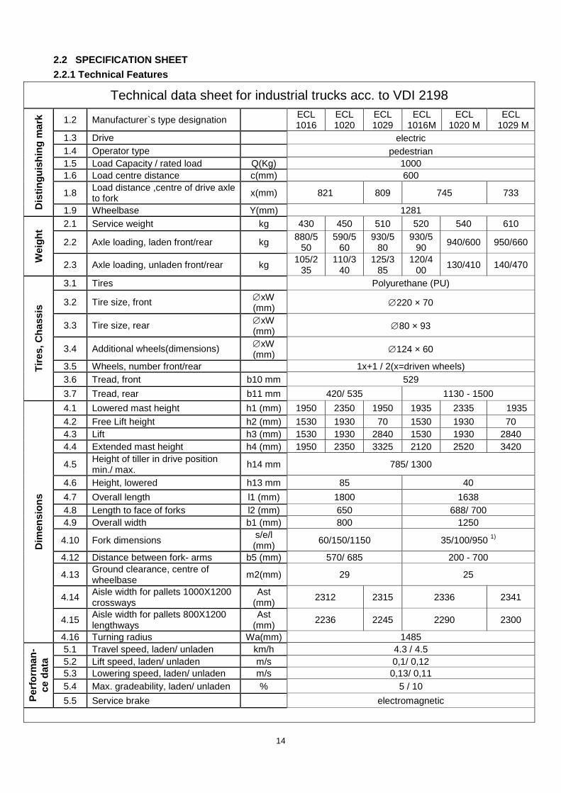
Technical data sheet for industrial trucks acc. to VDI 2198
Dis
tingu
ishi
ng m
ark 1.2 Manufacturer`s type designation ECL
1016 ECL 1020
ECL 1029
ECL 1016M
ECL 1020 M
ECL 1029 M
1.3 Drive electric 1.4 Operator type pedestrian 1.5 Load Capacity / rated load Q(Kg) 1000 1.6 Load centre distance c(mm) 600
1.8 Load distance ,centre of drive axle to fork x(mm) 821 809 745 733
1.9 Wheelbase Y(mm) 1281
Wei
ght 2.1 Service weight kg 430 450 510 520 540 610
2.2 Axle loading, laden front/rear kg 880/550
590/560
930/580
930/590 940/600 950/660
2.3 Axle loading, unladen front/rear kg 105/235
110/340
125/385
120/400 130/410 140/470
Tire
s, C
hass
is
3.1 Tires Polyurethane (PU)
3.2 Tire size, front ∅xW (mm) ∅220 × 70
3.3 Tire size, rear ∅xW (mm) ∅80 × 93
3.4 Additional wheels(dimensions) ∅xW (mm) ∅124 × 60
3.5 Wheels, number front/rear 1x+1 / 2(x=driven wheels) 3.6 Tread, front b10 mm 529 3.7 Tread, rear b11 mm 420/ 535 1130 - 1500
Dim
ensi
ons
4.1 Lowered mast height h1 (mm) 1950 2350 1950 1935 2335 1935 4.2 Free Lift height h2 (mm) 1530 1930 70 1530 1930 70 4.3 Lift h3 (mm) 1530 1930 2840 1530 1930 2840 4.4 Extended mast height h4 (mm) 1950 2350 3325 2120 2520 3420
4.5 Height of tiller in drive position min./ max. h14 mm 785/ 1300
4.6 Height, lowered h13 mm 85 40 4.7 Overall length l1 (mm) 1800 1638 4.8 Length to face of forks l2 (mm) 650 688/ 700 4.9 Overall width b1 (mm) 800 1250
4.10 Fork dimensions s/e/l (mm) 60/150/1150 35/100/950 1)
4.12 Distance between fork- arms b5 (mm) 570/ 685 200 - 700
4.13 Ground clearance, centre of wheelbase m2(mm) 29 25
4.14 Aisle width for pallets 1000X1200 crossways
Ast (mm) 2312 2315 2336 2341
4.15 Aisle width for pallets 800X1200 lengthways
Ast (mm) 2236 2245 2290 2300
4.16 Turning radius Wa(mm) 1485
Perf
orm
an-
ce d
ata
5.1 Travel speed, laden/ unladen km/h 4.3 / 4.5 5.2 Lift speed, laden/ unladen m/s 0,1/ 0,12 5.3 Lowering speed, laden/ unladen m/s 0,13/ 0,11 5.4 Max. gradeability, laden/ unladen % 5 / 10 5.5 Service brake electromagnetic
15
Elec
tric
- mot
or
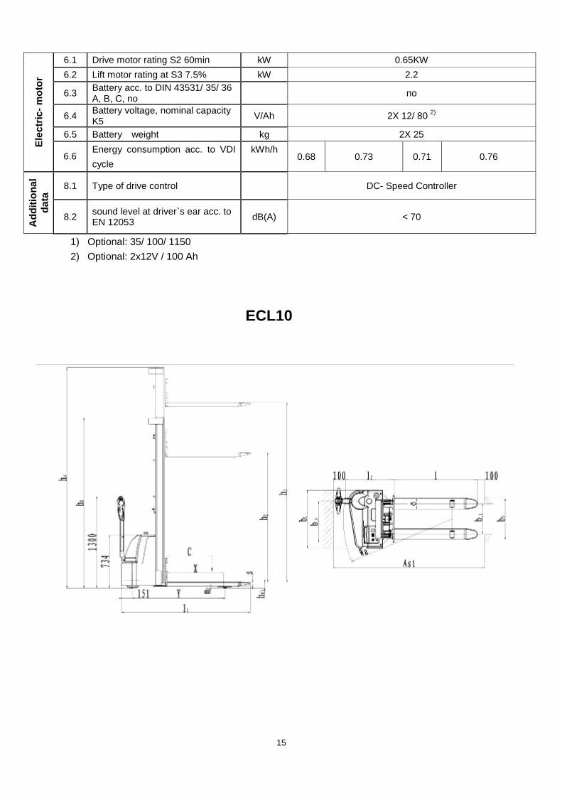
6.1 Drive motor rating S2 60min kW 0.65KW 6.2 Lift motor rating at S3 7.5% kW 2.2
6.3 Battery acc. to DIN 43531/ 35/ 36 A, B, C, no no
6.4 Battery voltage, nominal capacity K5 V/Ah 2X 12/ 80 2)
6.5 Battery weight kg 2X 25
6.6 Energy consumption acc. to VDI cycle
kWh/h 0.68 0.73 0.71 0.76
Add
ition
al
data
8.1 Type of drive control DC- Speed Controller
8.2 sound level at driver`s ear acc. to EN 12053 dB(A) < 70
1) Optional: 35/ 100/ 1150 2) Optional: 2x12V / 100 Ah
ECL10
16
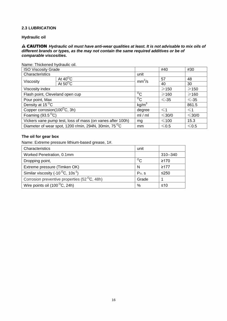
2.3 LUBRICATION Hydraulic oil
Hydraulic oil must have anti-wear qualities at least. It is not advisable to mix oils of different brands or types, as the may not contain the same required additives or be of comparable viscosities. Name: Thickened hydraulic oil. ISO Viscosity Grade #40 #30 Characteristics unit
Viscosity At 40OmmC 2 57 /s 48
At 50O 40 C 30 Viscosity index ≥150 ≥150 Flash point, Cleveland open cup O ≥160 C ≥160 Pour point, Max O ≤-35 C ≤-35 Density at 15 O kg/mC 3 861.5 Copper corrosion(100O degree C, 3h) ≤1 ≤1 Foaming (93.5 O ml / ml C) ≤30/0 ≤30/0 Vickers vane pump test, loss of mass (on vanes after 100h) mg ≤100 15.3 Diameter of wear spot, 1200 r/min, 294N, 30min, 75 O mm C ≤0.5 ≤0.5
The oil for gear box Name: Extreme pressure lithium-based grease, 1#. Characteristics unit Worked Penetration, 0.1mm 310--340 Dropping point, O ≥170 C Extreme pressure (Timken OK) N ≥177 Similar viscosity (-10 OC, 10s-1 Pa.s ) ≤250 Corrosion preventive properties (52 O Grade C, 48h) 1 Wire points oil (100 O % C, 24h) ≤10

17
3 ELECTRIC SYSTEM 3.1 ELECTRIC DIAGRAM
WIRING DIAGRAM
Electric diagram ECL 10
Fuses ECL10 FU1 : 10 A FU2 : 0,5 A FU01 : 60 A FU02 : 100 A
18
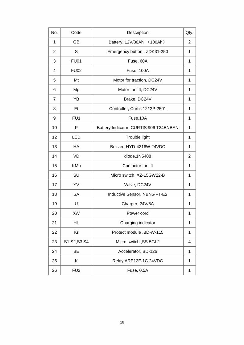
No. Code Description Qty.
1 GB Battery, 12V/80Ah (100Ah) 2
2 S Emergency button , ZDK31-250 1
3 FU01 Fuse, 60A 1
4 FU02 Fuse, 100A 1
5 Mt Motor for traction, DC24V 1
6 Mp Motor for lift, DC24V 1
7 YB Brake, DC24V 1
8 Et Controller, Curtis 1212P-2501 1
9 FU1 Fuse,10A 1
10 P Battery Indicator, CURTIS 906 T24BNBAN 1
12 LED Trouble light 1
13 HA Buzzer, HYD-4216W 24VDC 1
14 VD diode,1N5408 2
15 KMp Contactor for lift 1
16 SU Micro switch ,XZ-15GW22-B 1
17 YV Valve, DC24V 1
18 SA Inductive Sensor, NBN5-FT-E2 1
19 U Charger, 24V/8A 1
20 XW Power cord 1
21 HL Charging indicator 1
22 Kr Protect module ,BD-W-115 1
23 S1,S2,S3,S4 Micro switch ,SS-5GL2 4
24 BE Accelerator, BD-126 1
25 K Relay,ARP12F-1C 24VDC 1
26 FU2 Fuse, 0.5A 1

19
CABLE SYSTEM
No. Part Number Item Quantity
1 9000002409 cable B0 1
2 9000002410 cable B+ 1
3 9000002411 cable 1B+ 1
4 9000002412 cable 2B+ 1
5 9000002413 cable 3B+ 1
6 9000002414 cable 4B+ 1
7 9000002415 cable PB- 1
8 9000002416 cable B- 1
9 9000002417 Harness of drive wheel 1
10 9000002418 Positive cable B+ of charger 1
11 1020434003 Copper bar 1
20
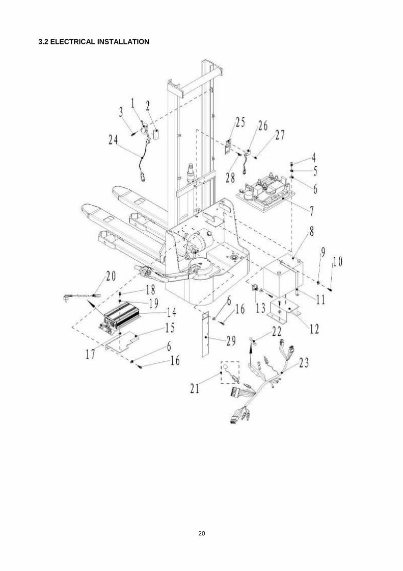
3.2 ELECTRICAL INSTALLATION

21
No. Part Number Item Quantity 备注
1 2040634001 Micro switch XZ-15GW22-B 2
2 2040603002 Protective cover of Micro-switch 2
3 0000023033 Bolt M4x25 4
4 0000023107 Bolt M5x16 6
5 0000025015 Spring washer 5 12
6 0000025014 Flat washer 5 6
7 9000002065 Controller assembly 1
8 1000432001 Battery 12V/80Ah 2
Selection 2100432001 Battery 12V/100Ah 2
9 0000025011 Flat washer 8 8
10 0000023012 Bolt M8x12 8
11 9000002062 Battery hoop 1
12 9000002063 Seat of battery 1 Compare to 100Ah battery
13 9000002064 Iron holder 2
14 1080420001 Charger 24V/8A QQE192-8CH17-26B 1 Input voltage 230AC
1080420002 Charger 24V/8A QQE192-8CH18-26B 1 Input voltage 115AC
15 1010404004 Charger holder 1
16 0000023076 Bolt M5X12 6
17 1000418002 Seal washer 11.5X7.5X3 1
18 0000023056 Bolt M4X12 4
19 0000025019 Flat washer 4 4
20 1010434009 Double spring plug3*0.75 1 Selection
21 9000002192 LED bug indicator assembly 1
22 9000002324 Fuse tube 5*20 0.5A 1
23 9000002407 Controller harness 1
24 9000002408 Micro switch harness 1
25 9000002079 Magnetic switch holder 1
26 Magnetic switch NBN5-FT-E2 1
27 0000023075 Bolt M3X20 2
28 0000023042 Bolt M6x10 2
29 9000005937 Cable holder frame 1

22
3.3 DRIVE WHEEL Type: 19EL-DC-0.45kw
Drive Motor Model ZD11265-650W24V
Rate voltage DC 24V R.P.M 2650rpm
Rate output 0.45kw Rate hour 60 min.
Rated current 36 A Insulation class F class
Electromagnetic Brake Model REB-05-06
Rate voltage DC 24V Output Torque 6N.M
Gear Box transmission ratio 1:28
3.4 PUMP STATION Type: CMB3-VB1111131-030
Item ECL10 Rated voltage 24V Rated output 2.2kw
R.P.M 3100 rpm Rated current 150 A
Rated hour 2 min. Insulation class F class
IP54 IP Code Displacement 2.0cc/rec
Max. operating pressure
23
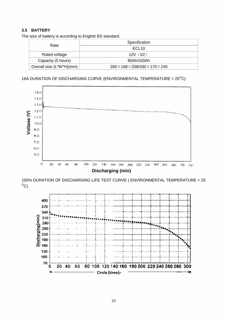
3.5 BATTERY The size of battery is according to English BS standard.
Rate Specification
ECL10 Rated voltage 12V(X2)
Capacity (5 hours) 80Ah/100Ah Overall size (L*W*H)(mm) 260×168×208/330×170×240
16A DURATION OF DISCHARGING CURVE (ENVIRONMENTAL TEMPERATURE = 25OC)
100% DURATION OF DISCHARGING LIFE TEST CURVE ( ENVIRONMENTAL TEMPERATURE = 25
OC)
Volta
ge (V
)
Discharging (min)

24
CHARGING CURVE
3.6 CHARGER Type: QQE192-8CH17-26B
MAIN PRODUCT SPECIFICATION
Max. output power battery capacity Input voltage Output voltage Output current
range 240W 80AH 115/230Vac +28.8Vdc 8A
ENVIRONMENTAL CONDITION
No. Item Technical specification Unit Remark 1 Humidity 5%-95% With package 2 Altitude ≦3000 m Work normally 3 Cooling Natural convection cooling Working under full load

25
ELECTRICAL CHARACTERISTICS
No. Item Technical specification Unit Remark 1 Input characteristics
1.1 Rated input voltage 115/230 Vac 115Vac/230Vac select switch
1.2 Input voltage range 90-132/180-264 Vac
1.3 AC input voltage frequency
47—63 Hz
1.4 Inrush current ≤100 A 264Vac input/start-up
in cold condition temperature is 25℃
1.5 Max input current 3.5 A Vin=90Vac, rated load
2 Output characteristics 2.1 Fast charge voltage 28.8 Vdc 2.2 Floating voltage 29.5 Vdc
2.3 Maintain voltage 28.8 Vdc 2.4 Constant current 8 A 2.5 Cross regulation ±3%
2.6 Power efficiency ≥85% Vin=220Vac,rated load
3 Protection characteristics
3.1 Output over voltage protection
31 V Lockout
3.2 Software over voltage protection
The charger software limits the maximum output voltage to a level suitable for the connected battery system
3.3 Thermal cutback An internal temperature monitor reduce charger output power in extreme operational temperature to prevent damage
3.4 Output current limiting protection
8A A @CC MODE
3.5 Output short circuit protection
Short circuit protection should be automatically recovery after remove the condition
3.6 Electronic reverse battery protection
The charger is electronically protected against permanent revers battery connection
3.7 Cell short circuit timer Internal software protection 4 Charger(LED) indicator 1 Power on LED ( GREEN) ON
2 Power off LED OFF
3 Fast Charge LED (RED) ON
4 Floating Charge LED (ORANGE) ON 5 Full Charging LED (GREEN) ON

26
INPUT TERMINAL DIAGRAM & DEFINITION
OUTPUT TERMINAL DIAGRAM & DEFINITION
LED CONNECTOR DIAGRAM & DEFINITION
FAN CONNECTOR DIAGRAM&DEFINITION
RELAY CONNECTOR DIAGRAM & DEFINITION

27
3.7 CURTIS CONTROLLER 1212

28
CONNECTIONS Low Current Connections A 14-pin Molex low current connector in the controller provides the low current logic control connections:
The mating connector is a Molex Mini-Fit Jr., receptacle p/n 39-01-2140 with appropriate 45750-series crimp terminals.
A 4-pin low power connector is provided for the programmer and the battery charger. The mating connector is a Molex Mini-Fit-Jr. p/n 39-01-2040 with appropriate 45750-series crimp terminals. (A mating connector is provided with the 1311 handheld programmer.).
A 2-pin low power connector is provided for the electromagnetic brake. The mating connector is a Molex Mini-Fit-Jr. receptacle p/n 39-01-2020 with appropriate 45750-series crimp terminals.
Four 1/4" Faston terminals are provided for the high current connections.
High Current Connections
The motor connections (M1, M2) and battery Connections (B+, B-) have one terminal each.

29
STANDARD_PARAMETER
Parameter Software
standard parameter
RANGE Unit DESCRIPTION
Drive menu
Accel Max Speed 1.8 0.2 to5.0 seconds
Sets the rate (in seconds) at which the speed command increases when throttle is applied with the speed limit pot is in its maximum speed position, and the vehicle is traveling forward. Larger values represent slower response.
Accel Min Speed 5.0 1.8 to 8.0 seconds
Sets the rate (in seconds) at which the speed command increases when throttle is applied while the speed limit pot is in its minimum speed position, and the vehicle is traveling forward. Larger values represent slower response
Decel High Speed 0.6 0.2 to 1.5 seconds
Sets the rate (in seconds) that is used to slow down the vehicle when it is traveling forward at high speed and throttle is reduced. Larger values represent slower response.
Decel Low Speed 1.5 0.6 to 8.0 seconds
Sets the rate (in seconds) that is used to slow down the vehicle when it is traveling forward at low speed and throttle is reduced. Larger values represent slower response.
Rev Accel Max Speed 1.8 0.2 to 5.0 seconds
Sets the rate (in seconds) at which the speed command increases when throttle is applied while the speed limit pot is in its maximum speed position, and the vehicle is traveling in reverse. Larger values represent slower response.
Rev Accel Min Speed 5.0 1.8 to 8.0 seconds
Sets the rate (in seconds) at which the speed command increases when throttle is applied while the speed limit pot is in its minimum speed position, and the vehicle is traveling in reverse. Larger values represent slower response.
Rev Decel High Speed 0.6 0.2 to 1.0 seconds
Sets the rate (in seconds) that is used to slow down the vehicle when it is traveling in reverse at high speed and throttle is reduced. Larger values represent slower response.
Rev Decel Low Speed 1.0 0.6 to 8.0 seconds
Sets the rate (in seconds) that is used to slow down the vehicle when it is traveling in reverse at low speed and throttle is reduced. Larger values represent slower response.
Keyoff Decel 0.7 0.2 to 4.0 seconds
Sets the rate (in seconds) that is used to slow down the vehicle when it is traveling in reverse at low speed and throttle is reduced. Larger values represent slower response.
E Stop Decel 0.6 0.2 to 4.0 seconds
Sets the rate (in seconds) that is used to slow down the vehicle during emergency reverse, i.e., when a throttle command >80% in the reverse direction is given while the vehicle is moving forward. This gives the operator a way to stop more quickly when unexpected conditions arise.
E Stop Pause 0.5 0.0 to 1.0 seconds
Sets a pause before reversing direction after an emergency reverse stop. This gives the operator time to return the throttle to neutral without moving backwards.
30
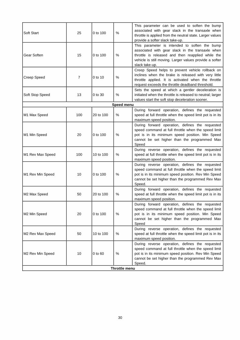
Soft Start 25 0 to 100 %
This parameter can be used to soften the bump associated with gear slack in the transaxle when throttle is applied from the neutral state. Larger values provide a softer slack take-up.
Gear Soften 15 0 to 100 %
This parameter is intended to soften the bump associated with gear slack in the transaxle when throttle is released and then reapplied while the vehicle is still moving. Larger values provide a softer slack take-up.
Creep Speed 7 0 to 10 %
Creep Speed helps to prevent vehicle rollback on inclines when the brake is released with very little throttle applied. It is activated when the throttle request exceeds the throttle deadband threshold.
Soft Stop Speed 13 0 to 30 % Sets the speed at which a gentler deceleration is initiated when the throttle is released to neutral; larger values start the soft stop deceleration sooner.
Speed menu
M1 Max Speed 100 20 to 100 % During forward operation, defines the requested speed at full throttle when the speed limit pot is in its maximum speed position.
M1 Min Speed 20 0 to 100 %
During forward operation, defines the requested speed command at full throttle when the speed limit pot is in its minimum speed position. Min Speed cannot be set higher than the programmed Max Speed
M1 Rev Max Speed 100 10 to 100 % During reverse operation, defines the requested speed at full throttle when the speed limit pot is in its maximum speed position.
M1 Rev Min Speed 10 0 to 100 %
During reverse operation, defines the requested speed command at full throttle when the speed limit pot is in its minimum speed position. Rev Min Speed cannot be set higher than the programmed Rev Max Speed.
M2 Max Speed 50 20 to 100 % During forward operation, defines the requested speed at full throttle when the speed limit pot is in its maximum speed position.
M2 Min Speed 20 0 to 100 %
During forward operation, defines the requested speed command at full throttle when the speed limit pot is in its minimum speed position. Min Speed cannot be set higher than the programmed Max Speed
M2 Rev Max Speed 50 10 to 100 % During reverse operation, defines the requested speed at full throttle when the speed limit pot is in its maximum speed position.
M2 Rev Min Speed 10 0 to 60 %
During reverse operation, defines the requested speed command at full throttle when the speed limit pot is in its minimum speed position. Rev Min Speed cannot be set higher than the programmed Rev Max Speed.
Throttle menu

31
Type 7 0 to 9
he 1212 controller can accept inputs from both 5kΩ, 3-wire pot throttles and voltage throttles. Set the throttle type parameter to match the throttle used in your application. 5kΩ, 3-wire pot throttles 0 = wigwag 1 = inverted wigwag 2 = single-ended; neutral when wiper at PotLow 3 = inverted single-ended; neutral when wiper at PotHigh 4 = unipolar. Voltage throttles 5 = wigwag 6 = inverted wigwag 7 = single-ended; neutral when wiper ≤ PotLow 8 = inverted single-ended voltage; neutral when wiper ≥ PotHigh 9 = unipola
PotHigh 5.0 3.0 to 5.0 volt Sets the maximum voltage for voltage throttles (Types 5–9). (For 5kΩ, 3-wire pot throttles, PotHigh is determined by the throttle itself.)
PotLow 0.0 0.0 to 2.0 volt Sets the minimum voltage for voltage throttles (Types 5–9). (For 5kΩ, 3-wire pot throttles, PotLow is determined by the throttle itself.)
Neutral Deadband 5 5 to 30 %
Sets the throttle range the controller interprets as neutral. Increasing the parameter setting increases the neutral range. This parameter allows the neutral deadband to be defined wide enough to ensure the controller goes into neutral when the throttle is released.
Throttle Max 85 40 to 100 %
Sets the pot wiper voltage required to produce 100% controller output. Increasing the Throttle Max setting reduces the wiper voltage required, and therefore reduces the stroke necessary to produce full output. This feature allows reduced-range throttle assemblies to be used.
HPD 1 0 or 1
When programmed On, vehicle drive is inhibited if a throttle command outside the neutral deadband is issued before the controller is powered up. Drive will continue to be inhibited until the throttle is returned to within the neutral deadband. If the HPD fault is not cleared within 10 seconds,
Speed Limit Pot 0 0 or 1 This parameter is used to enable/disable the speed limit pot. If no speed limit pot is used, set Speed Limit Pot to Off.
Throttle Map 30 20 to 80 % The throttle map parameter adjusts the static throttle map.
Tremor Suppression 50 0 to 100 % This parameter can be used to limit the controller’s response to sharp throttle movements, such as movements resulting from hand tremors.
Calibration 0 0 or 1 Wigwag and unipolar throttle pots should be centered. Setting this parameter to On inhibits driving and puts the controller into throttle autocalibration mode
Current menu

32
Main Current Limit 90 15 to 90 Ampere
Sets the maximum current the controller will supply to the motor during 15–90 A normal driving. By limiting the current supplied, this parameter can be used to protect the motor from potentially damaging currents or to reduce the maximum torque applied to the drive system.
Braking Current Limit 90 15 to 90 Ampere
Sets the maximum current the controller will supply to the motor during braking. By limiting the current supplied, this parameter can be used to protect the motor from potentially damaging currents or to reduce the maximum braking torque applied to the drive system.
Boost Current 90 90 to 90 Ampere The Boost Current parameter defines the motor current limit during the boost period.
Boost Time 3 0 to 10 Seconds This parameter sets the maximum time that the boost current is allowed.
Inhibit menu
Type 2 0 to 5
The flexible speed input at J1 Pin 6 can be used to limit or to inhibit speed under certain conditions. For example, a switch could be installed under the seat so that if the operator drives the scooter while they are standing the max speed will be limited. The Inhibit Type parameter is used to select how the inhibit function will be implemented. Depending on how the inhibit switch is wired into the system, set this parameter to: 0 = B- active 1 = B+ active 2 = Open circuit active 3 = B- inactive 4 = B+ inactive 5 = Open circuit inactive.
Speed 0 0 to 100 % This parameter limits the maximum speed allowed during speed inhibit mode. A setting of 0 prevents drive during inhibit mode.
Brake menu
Delay 0.3 0.0 to 1.0 Seconds Sets the length of delay between when zero speed is commanded and the electromagnetic brake is engaged.
Fault Check 1 0 or 1 Enables/disables the fault detection on the EM brake.
Hold Voltage 18 10 to 24 volt
A high initial voltage is applied to the brake coil when the brake is first released. After approximately 1 second, this peak voltage drops to the programmed Hold Voltage. The parameter should be set high enough to hold the brake released under all the shock and vibration conditions the vehicle will be subjected to.
Brake Light 0 0 to 1 When set to On, the horn output (J1 Pin 3) will act as a brake light driver. The brake light must be driven by a relay
Horn menu
Reverse Beep 1 0 or 1 When programmed On, the horn will sound whenever the vehicle is being driven in reverse.
Beep Constant 0 0 or 1 Sets the reverse beep to be a constant tone (when programmed On) or a 1Hz pulse (when programmed Off).
Motor menu

33
System Resistance 93 0 to 800 mOhms
Sets the system resistance (motor + brushes + wiring + connections) used for load compensation and speed estimation. Control system performance depends on this parameter being set correctly; it must be set to the actual cold motor resistance.
Resistance Auto Comp 0 0 to 1
Resistance is automatically measured under a preset low current before the brake is released. The measured motor resistance plays an important role in IR compensation.
Auto Comp Current Limit 20 5 to 50 % Sets the current limit used for automatic resistance testing, as a percentage of the Main Current Limit (see Current menu).
Speed Scaler 27 20 to 27 volt
The Speed Scaler parameter sets the maximum voltage that can be applied to the motor. It can be used to eliminate variations in maximum speed that would otherwise result when driving with a fully charged battery vs. a partially discharged battery. If Speed Scaler is set to 23 volts, for example, the maximum vehicle speed will be the same whether the actual battery voltage is 27 volts or 23 volts or any value in between.
Current Rating 30 0 to 30 Ampere This parameter should be set to the current rating provided by the motor manufacturer.
Max Current Time 80 0 to 80 Seconds Sets the maximum amount of time the motor is allowed to run at the main current limit.
Cutback Gain 5 0 to 100 %
When the motor overheats, the drive current is cut back until it reaches the programmed Current Rating. The Cutback Gain determines how quickly this cutback will occur, once the programmed Max Current Time has expired.
BDI menu Full Voltage 24.4 20.9 to 24.9 Volt Voltage when the battery is fully charged. Empty Voltage 20.8 0.0 to 24.3 Volt Voltage when the battery is fully discharged.
Full Charge Voltage 28.2 25.3 to 36.0 Volt Voltage when a charger is connected, above which the battery is considered finished charging.
Start Charge Voltage 25.2 24.5 to 28.1 Volt Voltage above which the battery is considered to start charging.
Reset Voltage 25.8 24.5 to 36.0 Volt Voltage at which the BDI calculator will be reset to 100%, after the charger is disconnected and the controller is powered up.
Discharge Factor 1.6 0.1 to 10.0 Discharge rate of the battery. Larger values are for larger batteries, which discharge more slowly.
Charge Factor 2.0 0.1 to 10.0 Charge rate of the battery. Larger values are for larger batteries, which discharge more slowly.
Low BDI Level 10 0 to 100 % Sets the battery charge level at which maximum vehicle speed will be limited in order to protect the battery from deep discharge.
Low BDI Max Speed 60 10 to 100 % Sets the maximum allowed vehicle speed when the battery charge falls below the programmed Low BDI Level.
External lift lock 1
When programmed On, Pin J1-9 will be used to receive an external lockout enable signal, lift Lockout is controlled by external signal. When programmed Off, lift lockout is controlled by the controller(See Lift Lockout Threshold)
Liftlock Enable 1 0 or 1 When programmed On, Lift lockout protection is enabled.

34
Liftlock Threshold 20 0 to 50 % Sets the battery charge level at which Lift locklock protection begins
Compensation menu
IR Comp 70 0 to 90 % Sets the motor load compensation. Higher values provide stronger disturbance rejection, while lower values provide smoother operation.
Anti Rollback Comp 90 70 to 125 %
Sets the motor load compensation after the throttle is released to neutral and the speed is estimated to be near zero. Higher values provide more hill-holding force.
Emergency Reverse menu
Speed 30 10 to 100 % Defines the maximum reverse speed of the motor, when emergency reverse is active, as % PWM output
Time Limit 1.2 0.0 to 10.0 Seconds Sets the Emergency reverse time.
Decel Rate 0.2 0.2 to 4.0 Seconds Sets the rate at which the vehicle brakes to a stop when emergency reverse is activated and the vehicle is moving forward.
Accel Rate 0.3 0.2 to 8.0 Seconds Sets the rate at which the vehicle accelerates in the opposite direction after it has been brough to a stop.
Max Braking Current 90 15 to 90 Ampere Sets maximum braking current limit Switch Normally Closed 1 0 or 1 Sets the Emergency reverse switch type, NC or NO
Misc menu
Sleep 0 0 to 60 Minutes
Sets the delay time between the last throttle request or serial communication and when the controller goes into sleep mode. Setting the delay to zero disables the sleep function.
Fault Code Type 0 0 to 2 This parameter selects which set of fault identification codes (Type 0,1, or 2) will be flashed by the status LED; see Section 7.
Reset Drive Time 0 0 or 1
The controller’s hourmeter logs the total drive time since the last reset; this record is accessible through the Monitor menu. Setting this parameter On zeroes the hourmeter and starts a new log; this is typically done when the vehicle is serviced. Reset Drive Time is automatically set to Off after the hourmeter is reset.
Emergency Stop 1 0 or 1 When programmed On, Emergency Stop is enabled. NOTE: for “standard parameter”, 1=on, 0=off

35
TROUBLESHOOTING CHART The 1212 controller provides diagnostics information to assist technicians in troubleshooting drive system problems. The diagnostics information can be obtained in two ways: by reading the appropriate display on the handheld programmer or by observing the fault codes issued by the status LED. PROGRAMMER DIAGNOSTICS The handheld programmer presents complete diagnostic information in plain language. Faults are displayed in the Faults menu, and the status of the controller inputs/outputs is displayed in the Monitor menu.
Additionally, the fault history file in the Faults menu provides a list of the faults that have occurred since the file was last cleared. Checking (and clearing) the fault history file is recommended each time the vehicle is brought in for maintenance.
Refer to the troubleshooting chart (Table 3) for suggestions about possible causes of the various faults. Faults are listed alphabetically.
For information on 1311 programmer operation, see Appendix C. LED DIAGNOSTICS During normal operation, with no faults present, the status LED is steadily on. If the controller detects a fault, the status LED flashes a fault identification code continuously until the fault is corrected.
Refer to the troubleshooting chart (Table 3) for suggestions about possible causes of the various faults. Faults are listed alphabetically.
Note: The status LED can only indicate one fault at a time. If multiple faults are detected, the highest priority fault code flashes until it is cleared.
Three sets of fault codes are available. The Fault Code Type parameter (Program » Misc » Fault Code Type) is used to select which set of fault codes will be used: Type 0, Type 1, or Type 2. The codes are listed in Tables 2-0, 2-1, and 2-2.

36

37
CURTIS 1311 HANDHELD PROGRAMMER Curtis programmers provide programming, diagnostic, and test capabilities for 1212 controllers. The power for operating the programmer is supplied by the host controller via a 4-pin connector. Two programmers are available: the PC Programming Station (1314) and the handheld programmer (1311). The Programming Station has features not available on the handheld unit; on the other hand, the handheld programmer has the advantage of being more portable. Typically the Programming Station is used to set up the parameters initially and the handheld programmer is used to made adjustments in the field.
Several versions of each programmer are available (User, Service, Dealer, OEM): the User programmers can adjust only User-access parameters, whereas the OEM programmers can adjust all the parameters.
The 1311 programmer is easy to use, with self-explanatory functions. After plugging in the programmer, wait a few seconds for it to boot up and gather information from the controller. For experimenting with settings, the programmer can be left plugged in while the vehicle is driven.
38
The bookmark keys allow you to quickly go back to up to three selected items without having to navigate back through the menu structure. To set a bookmark, press one of the bookmark keys for about three seconds, until the Bookmark Set screen is displayed. To jump to a set bookmark location, quickly press the appropriate bookmark key(1, 2, or 3). Note that the bookmarks are not permanently stored in the programmer. They are cleared when the programmer is unplugged. The bookmark keys can be used to make parameter adjustment easier. For example, in adjusting the throttle dead band, you might set a bookmark at the Throttle % readout [Monitor > THROTTLE %] and another at the Throttle Dead band parameter [Program > THROTTLE DB]; this way you can easily toggle between the readout and the parameter. 3.8 BATTERY DISCHARGE INDICATOR
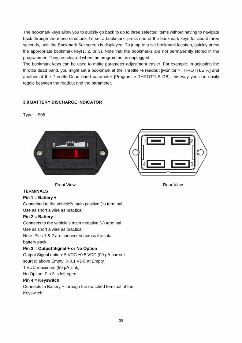
Type: 906
Front View Rear View
TERMINALS Pin 1 = Battery + Connected to the vehicle’s main positive (+) terminal. Use as short a wire as practical. Pin 2 = Battery – Connects to the vehicle’s main negative (–) terminal Use as short a wire as practical. Note: Pins 1 & 2 are connected across the total battery pack. Pin 3 = Output Signal + or No Option Output Signal option: 5 VDC ±0.5 VDC (90 μA current source) above Empty, 0-0.1 VDC at Empty 1 VDC maximum (90 μA sink); No Option: Pin 3 is left open. Pin 4 = Keyswitch Connects to Battery + through the switched terminal of the Keyswitch.
39
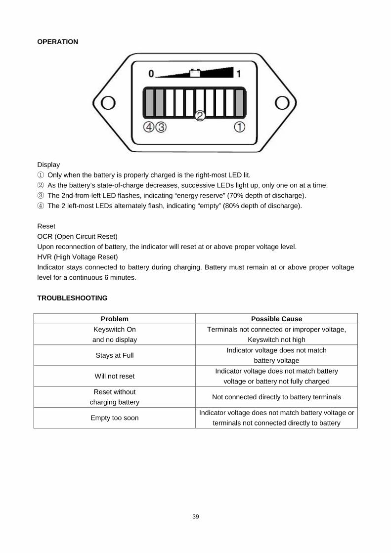
OPERATION
Display ① Only when the battery is properly charged is the right-most LED lit. ② As the battery’s state-of-charge decreases, successive LEDs light up, only one on at a time. ③ The 2nd-from-left LED flashes, indicating “energy reserve” (70% depth of discharge). ④ The 2 left-most LEDs alternately flash, indicating “empty” (80% depth of discharge). Reset OCR (Open Circuit Reset) Upon reconnection of battery, the indicator will reset at or above proper voltage level. HVR (High Voltage Reset) Indicator stays connected to battery during charging. Battery must remain at or above proper voltage level for a continuous 6 minutes. TROUBLESHOOTING
Problem Possible Cause
Keyswitch On and no display
Terminals not connected or improper voltage, Keyswitch not high
Stays at Full Indicator voltage does not match
battery voltage
Will not reset Indicator voltage does not match battery
voltage or battery not fully charged Reset without
charging battery Not connected directly to battery terminals
Empty too soon Indicator voltage does not match battery voltage or
terminals not connected directly to battery

40
3.9 REPLACE THE ELECTRIC PARTS
Dismantle 3 screws with Allen wrench,and remove the main cover
Dismantle 4 screws with Allen wrench (2 on each side)
Then you can remove the control panel.
41
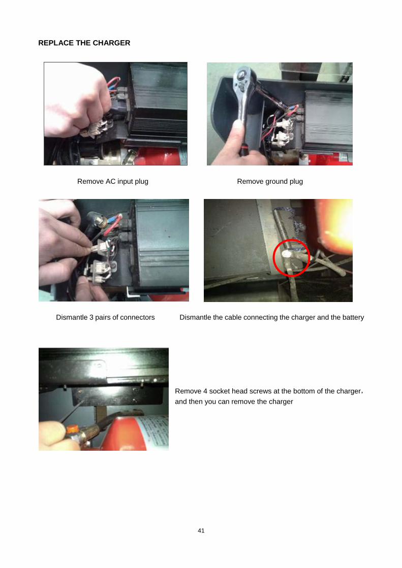
REPLACE THE CHARGER
Remove AC input plug Remove ground plug
Dismantle 3 pairs of connectors Dismantle the cable connecting the charger and the battery
Remove 4 socket head screws at the bottom of the charger,and then you can remove the charger

42
REPLACE THE BATTERY
Remove 4 screws consolidating the battery, and dismantle the iron band.
Remove 4 screws consolidating the harness with socket wrench, then you can remove the battery.

43
REPLACE THE BATTERY INDICATOR
Slightly remove the LED light from the back of the control panel
Remove the plugs at the back of indicator.
Remove 2 screws consolidating the indicator with Circuit Diagram of Battery Indicator screw-driver, then you can check and replace it.
REPLACE THE KEY SWITCH
Rotate anticlockwise the plastic screw, then dismantle the plug at another end, now you can check and replace the key switch.
检测及更换钥匙
开关
44
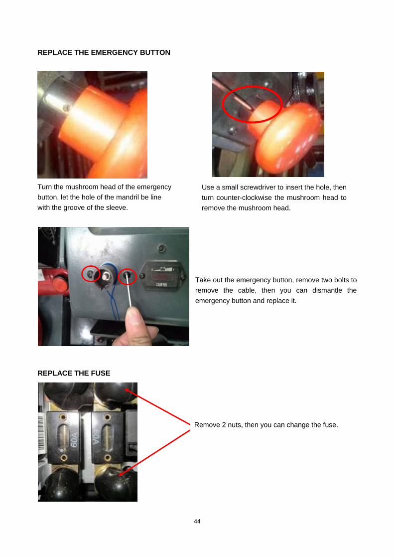
REPLACE THE EMERGENCY BUTTON
Turn the mushroom head of the emergency button, let the hole of the mandril be line with the groove of the sleeve.
Take out the emergency button, remove two bolts to remove the cable, then you can dismantle the emergency button and replace it.
REPLACE THE FUSE
Remove 2 nuts, then you can change the fuse.
Use a small screwdriver to insert the hole, then turn counter-clockwise the mushroom head to remove the mushroom head.

45
Open the cover of the fuse seat, then you can dismantle the fuse and replace it. REPLACE THE RELAY
Dismantle two screws. Dismantle the cables. Then you can dismantle the relay and replace it
OPERATION OF THE CONTROLLER
When replacing the controller, be carefully to check the plugs, specially note the cathode pillar
Two plug terminals (M1 and M2) are provided for the connections to the motor field winding. Do not allowed to access anti-Line, otherwise the motor will be reversed.
46
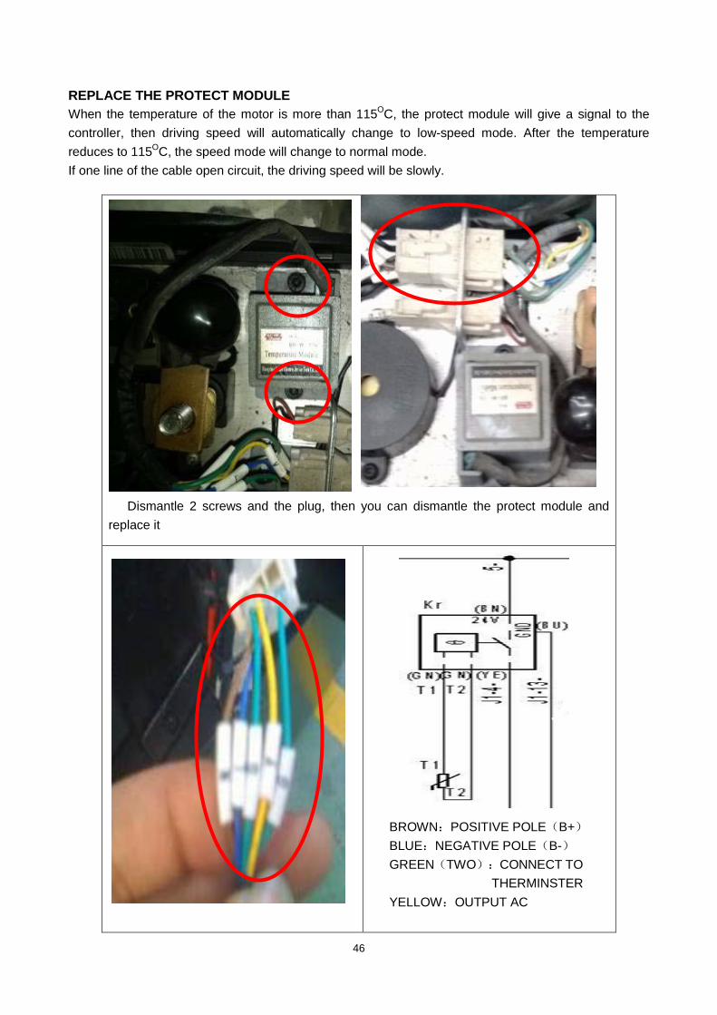
REPLACE THE PROTECT MODULE When the temperature of the motor is more than 115OC, the protect module will give a signal to the controller, then driving speed will automatically change to low-speed mode. After the temperature reduces to 115O
If one line of the cable open circuit, the driving speed will be slowly. C, the speed mode will change to normal mode.
Dismantle 2 screws and the plug, then you can dismantle the protect module and replace it
BROWN:POSITIVE POLE(B+) BLUE:NEGATIVE POLE(B-) GREEN(TWO):CONNECT TO
THERMINSTER YELLOW:OUTPUT AC

47
OPERATION OF THE LIFTING LIMIT SWITCH when the mast rise up to a fixed height,the Lifting limit switch contact with the contact plate, the switch(SU )turn off, then the relay stop working, then the mast will not lift .
OPERATION OF THE MAGNETIC SWITCH Magnetic switch
Dismantle 2 screws Dismantle the plug, then you can replace the switch
When Magnetic switch is close to the Magnetized plate, the pilot light is bright, the truck moves at high speed; when the mast rise up to a fixed height, Magnetic switch is far from Magnetized plate, the pilot light is dark, the truck moves at low speed
松开连接线,更换限位开关
Remove 2 screws Loosen 2 plugs, then you can replace it.
Circuit Diagram of Magnetic switch (SA) Circuit Diagram of Lifting limit switch (SU)

48
3.10 TOOL FOR REPAIRING THE PIN OF ELECTRIC PLUG
No. Figure Application
1
Tool for removal of pins / sleeves
2
Tool for application of pins / sleeves
3
Tool for release of lock
4
Tool for application of secondary locking 2 – pole
5
Tool for application of secondary locking 4 – pole
6
Tool for removal of pins / sleeves

49
4. HYDRAULIC SYSTEM HYDRAULIC FLOW DIAGRAM INSPECTION OF HYDRAULIC OIL External appearance Smell Condition Measurement Clear and no discoloration Fine Fine Possible to use
Clear but the color become brighter Fine Mixed with other oil Inspect the viscosity and if fine it can be continuously used
Color changed like milk. Fine Mixed with air and water Separate water or replace oil. Color changed into dark brown Bad Oxidized Replace oil. Clear but there are small black spots
Fine Mixed with other particles Use after filtering.
PUMP STATION OPERATION
Remove 2 screws with M10 wrench on the relay to dismantle 2 cables.
Remove the screw with hand, then you can remove the Magnet valve

50
3,揭开泵站电机上的黑色烟斗,用
M13 扳手卸掉螺母,拆掉蓝色头的白
Remove the joint of the hydraulic pipe on the Fix plate with M22 wrench
Remove another screw of the joint of the hydraulic pipe
Lift up the fork about 1 meter , ensure it won’t fall down.
Remove another end of the hydraulic pipe
Remove 2 screws consolidating the pump station with M8 wrench, then you can replace it.
Dismantle the nuts, remove the screws with M13 wrench to remove the cable.

51
4.1 CLEAN OIL TANK AND FILTER
Put the fork of the ground and drain out the hydraulic oil
Dismantle the lid on the top of the tank ,pour out the hydraulic oil
Remove out the pump station. Loosen the hoop Remove the oil tank Remove the suction filter Cleaning of oil tank and filter. Clean the Fix plate for valve etc. Clean up with compressed air and
inspect if the filter is stopped or damaged. If the filter is stopped or damaged, replace it.
Remove dust or foreign material from the tank.
Then assemble them.
TROUBLE DIAGNOSTICS Symptom Abnormality and cause Measurement
Bubble in hydraulic oil Mixed with air Check if there is any place where air can be entered. Tighten the loosened part again.
Discoloration Mixed with air and water Replace the oil.
Became inferior in quality by oxidizing or mixed with other particles.
Replace the oil.

52
The Plug Screw of port for adding oil is ventilating. When lower, the air will come out
from the tank, it might take out little oil vapor. So, it might appear little oil stains on the plug. Wait a little and ensure, that there is no oil leakage.
For the electric current of the Relay for the lifting motor is very big, and work
continually hourly, the contact terminal of the relay is easy damaged. Please check it continually.
The Magnet valve is a wearing part. If the forks automatically lower after lifting, the
magnet valve may be blocked or damaged, remove it to clear or replace.
HYDRAULIC PIPE
For shocking, the joint of the hydraulic pipe and hydraulic pipe might be loosed and
leak oil, so usually check and tighten it.

53
4.2 OPERATION OF CYLINDER
Remove 6 screws on the Protecting meshwork and dismantle it.
Remove the screws on the holding plate.
Remove 2 domede cap nuts M8, then you can remove the hoop.
Remove the joint of the hydraulic pipe
Lift up the inner mast Then you can replace the cylinder.
54
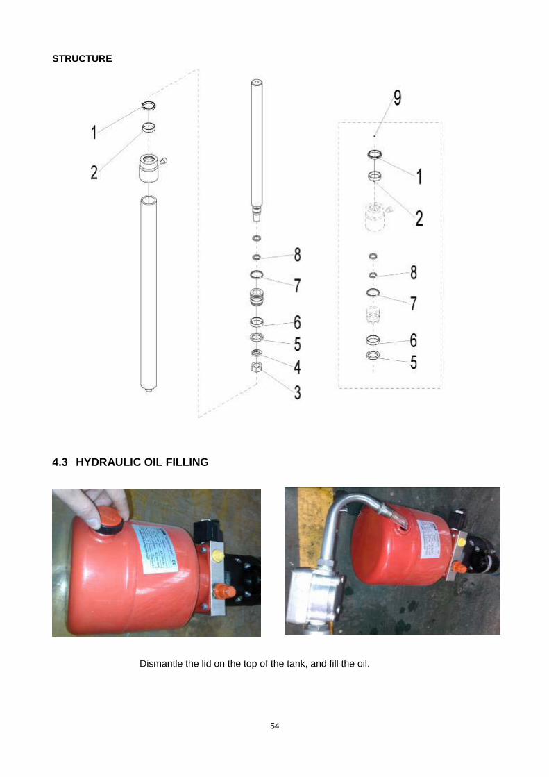
STRUCTURE
4.3 HYDRAULIC OIL FILLING
Dismantle the lid on the top of the tank, and fill the oil.

55
5. DRIVE WHEEL
5.1 REPLACE THE DRIVE WHEEL
Remove 3 screws consolidating the cover Remove the cover
Remove 6 screws on the frame of the drive wheel Remove 3 screws on the seat of the handle, cut off
the band on the harness and remove the handle .

56
Dismantle cable M1 and cable M2 on the controller and another plug of the brake,meanwhile cut off bands on the harness.
Take out the seat of the bearing
Hang the truck off the ground, then you can Dismantle the power cable of the motor and the brake take away the drive wheel and the temperature sensor

57
Dismantle the screws of the cable plate Remove the cable plate
Use four screws (8.8T or more better) to Screw in four “technologic screw holes”, so
that ejection the wheel.
2 pc guide pin holes
10 pc screw holes
4 pc technologic screw holes
Remove 10 pcs screws, then you can remove it.

58
5.2 REPLACE THE ELECTRIC BRUSH
Remove 3 screws, and dismantle the fixed cover of electric brush
Remove 4 screws and dismantle fixed plate of electric brush
Remove the screw fixed the electric brush, dismantle the Electric brush spring, then you
can remove and replace the electric brush.
You can see the electric brush at the back of the cover.

59
5.3 REPLACE THE BRAKE
No. Part name No. Part name 1 Fixed rotor 7 Hollow screw 2 Gag bit 8 Cover board 3 Friction disc components 9 Connect screw 4 Splined sleeve 10 Screw 5 O-ring 11 Elastic washer 6 Spring 12 Dust ring
Remove 3 pc screws Remove 3 screws and the circlip
Then you can replace the brake or repair it.

60
5.4 ADJUST THE AIR GAP OF THE BRAKE Rated air gap z is large due to wear. To ensure that the brakes have enough brake torque, must adjust the air gap before it reach the maximum air gap. Air gap can be adjusted several times, when the thickness of the friction brake reach to the most small thickness, friction brake disc must be replaced. The brake torque noise is relative to the air gap. When the air gap exceed the maximum value, it might cause the brakes not releasing, friction braking burn, braking or retention decrease, or even cause a major accident. Must be checked on a regular basis and adjust air gap, attention must disconnect the main power.
Keep the same clearance as showing
Standard torque (Nm)
Power (W)
Standard torque Air-gap (mm)
Install screw tightening torque
(Nm) 5 20 0.3-0.35 2.8
Replace the brake or brake disc, if the air gap exceeds 0.35 mm.
Brake slide should not contain grease,and nothing is blocked inside. Connected with
plug connection, should connected firmly.
Step 1: Loose the three screw that fix the brake
Step 1: Adjust the three hollow screws
Step 3: Use a feeler gauge to check the air gap z value is a rated air gap value or not

61
6. CONTROL HANDLE
Tiller

62
Remove the rubber block.
Then you can check or replace the air spring.
6.1 REMOVE THE AIR SPRING
Remove air spring screws with internal-hexagonal wrench.
6.2 REMOVE THE HANDLE AND SENSOR
Knock out the spring pin with the hammer and puncher, then knock out the shaft.

63
Remove 2 screws consolidating the senor through the hole, then dismantle the plug among the harness, now you can remove the sensor and replace it.
The front and back of the handle
检测及更换感应器
棕色线:电源正
极(B+) 蓝色线:电源负
极(B-) 黑色线:信号输

64
Remove 6 screws with internal-hexagonal wrench. Push slightly the upper cover about 10mm, then open it.
Remove 4 screws, then you can remove the tiller .
6.4 REPLACE THE TILLER
6.3 REMOVE THE TILLER

65
Remove 3 screws, then you can remove the module.
Dismantle the screw and remove the Butterfly. Take out the accelerator
6.4 REPLACE THE ACCELERATOR
66
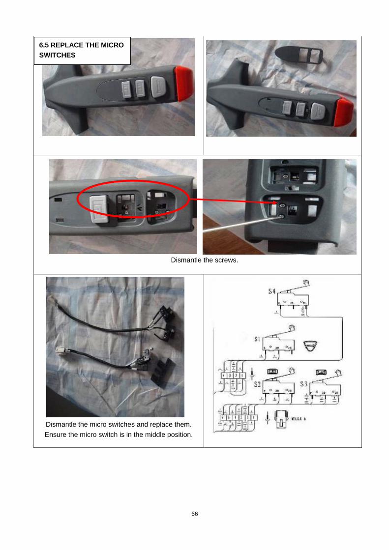
Dismantle the screws.
Dismantle the micro switches and replace them. Ensure the micro switch is in the middle position.
6.5 REPLACE THE MICRO SWITCHES

67
7. CASTER WHEEL 7.1 OPERATION OF THE CASTER WHEEL
Remove the screw and shaft, then you can replace the wheel and bearing. 7.2 ADJUSTING THE PRESSURE FOR THE DRIVE WHEEL
After using some time, the drive wheel might wear off, the pressure for the drive wheel will not be enough, and drive wheel can’t bit into the ground and slip. You can adjust it according to following steps: Step 1: Remove the four screws Step 2: Take away one or two piece washer. Note: the normal gap of the wheel and ground is 3-4 mm.
First, hang the truck off the ground. second, dismantle 4 screws. Then you can dismantle the caster and replace it.

68
8. MAINTENANCE CHECK LIST Maintenance Time Interval
Standard=● W M M M 1 3 6 12
Chassis and truck frame
1.1 Inspection of any damage of bearing parts ● 1.2 Inspection of all joints of bolts ●
Driving part 2.1 Inspection of noise and leakage of driving system ● 2.2 Replace lubrication ●
Wheel part 3.1 Inspection of wearing and damage state ●
3.2 Inspection of bearings inside wheels and ensure compact fit with wheels
●
Steering system 4.1 Inspection of steering operation motion ●
Braking system
5.1 Inspection of performance and adjust it ●
5.2 Inspection of reset function of filler gas spring and any leakage or damage
●
5.3 Inspection of wearing state of brake disc ● 5.4 Inspection of brake connectors and adjust if necessary ●
Lifting equipment 6.1 Inspection of wear and adjust if necessary ● 6.2 Inspection by sight of any wear of loading wheel ● 6.3 Inspection of any wearing or damage of edge of forks and pallet ●
Hydraulic system
7.1 Inspection of any leakage or damage of all joints ●
7.2 Inspection of any leakage or damage of hydraulic cylinder, safety and reliability of attachment
●
7.3 Inspection of hydraulic oil level ● 7.4 Replace hydraulic oil and filter ● 7.5 Inspection of adjustment function of pressure valve ●
Electrical system
8.1 Check correct function of the accelerator of the tiller, replace it necessary
●
8.2 Inspection of safety and reliability of connection of all cables, and if any damage
●
8.3 Check the fuse size
8.4 Inspection of safety, reliability and function of switches and unlocking cam equipment
●
8.5 Inspection of connector, replace if damaged 8.6 Inspection of function of horn ●
Motor
9.1 Check the air gap of the brake, adjust it if necessary ● 9.2 Test the emergency switch function ●
9.3 Clean motor frame with vacuum cleaner, inspection of wearing state of commutator
●
Battery
10.1 Check battery housing, voltage of battery ●
10.2 Inspection of safety device , applicability of grease ●
10.3 Clean terminal of battery, inspection of compactness of fit ●
10.4 Inspection of damage of battery cable, replace it if necessary ●
Lubrication 11.1 Grease the truck according to the time schedule of lubrication feeding
●
Integrated measurement
12.1 Inspection of electrical leakage to the chassis ●
12.2 Inspection of driving speed and braking distance ●
12.3 Inspection of lifting and lowering speed ●
12.4 Inspection of safety valve and closing valve ●
Function
13.1 Check the indicator, replace it if necessary ●
13.2 Check the micro switches of the tiller, replace them if necessary ●
13.3 Check the horn function ●
13.4 Test the emergency braking ●
13.5 Test the reverse and regenerative braking ●
13.6 Test the safety (belly) button function ●
Charger 14.1 Check the function of the charger, replace it if necessary ●
Geneal 15.1 Check the clearance of the castors, adjust the distance if necessary ●
Sticker 16.1 Check the sticker of the truck, add the new one if necessary ●

69
9. TROUBLE SHOOTIN
1. Turn onor replace
Notlight
2.Reconnectit
3.Reconnector replace
4.Reconnector replace
1. The fuseFU01 or FU02 isOK or not?
Without any actions
2. 7 core handlewiring harnessare in goodcondition?
abnormal
3. The plugs ofthe Wiring boardin the controhandle (8-pin)are in goodcondition?
4. The PCBboard of thecontrol handle isOK or not?
normal Replace controlhandle or controller
Check theSTATUS LED of
Natural flash
Bat
tery
Indi
cato
r
Not
driv
e or
lift
1. The Key switch (SY) /Emergency button (S) is off ordamaged ?Its plug is tight?
2. The battery cables are tightconnected to the post head ofthe battery?
3. The plug of battery indicatoris loose or bad?
4. The plug of charger is nottight connected to the socketXS or XS is damaged?
Replace or repair
Use CURTIS 1311 HANDHELD PROGRAMMER to check and clearing of fault.Flash
Not flash
Natural
Not natural Check it according to LED CODE list (page 26 and 27) and clearing of fault.
Connect to the CURTIS 1311 HANDHELD PROGRAMMER, watch the programmer is light or not
Check the signal of 16-pin of the controller is OK or not.
The controller is fault, replace it
The controller is fault, replace it
The key switch (SY) may be fault, check it.

70
NOMain contactor(KM) isoperated?
Yes
Light Not drive (can lift) The brake (YB)is OK or not? NO
1. Check theresistance of the coilof the brake is OK ornot?
Yes2. The role No. J1-5-,5-2- of the brake (YB)is OK or not?3. The clearance ofthe brake is OK ornot?
NOThe wiring of 7core for thehandle is OK ornot?
replace or repair
Yes1. check whether thesignal line J1-1 - andJ1-8 is conducted
Check the PCBboard is normal?
2. Check whether thevoltage between 5-10- and 2-4- is 24V.
Yes All normal
PCB board is bad,replace it
NOCheck drivemotor is OK ornot?
Check A1 and A2, S1and S2 of the drivemotor is OK or not?
1. The last twolighting bars ofbattery indicatorflashalternantly?
1. please properlycharge the battery
2. Checkwhether the No.3 of batteryindicator input24V voltage androle No.4 roleoutput 24Vvoltage?
2. If not 24V, replacebattery indicator
Cannot lift (can drive)3. Check thefuse FU2 is OKor not?
NO 3.Replace the fuseFU2
1.Check the socket connector of the coil of themain contactor is OK?2. The micre-switch SA) and its role No. 5-1 -,J1-13 is OK or not?.
Replace or repair
NO
Replace or repair

71
4. The role No.J1-6 - and 5-4-2for the coil ofrelay for motorof pump (KMp)is OK or not?
4.Repair or replace16 - pin plug ofcontroller
5. Check relayof pump motoris OK or not?
5. Repair orreplacement therelay.
6. Check micro -switche(SU) isOK or not?
6.Adjust or replacemicro - switche (SU)
7.The pumpmotor is normalor not?
7. repair or replacethe pump motor
8.The hydraulicvalve of thepump is OK ornot ?(dirty,plugged,etc.)
8. Clean up the valvecore
9.The hydraulicoil isinsufficient?
9.Add hydraulic oil
1. The lowermagnet valve(YV) is damagedor the role No.J1-9- and 5-7- isOK or not?
Cann't lower (othersnormal)
2.The lowermagnetic valveis plugged fordirty?
NO
Rapair or replace
1.Check thesignal line J1-1 -and J1-8 isconducted?
NOReplace the PCBboard of the controllhandle
2. Checkwhether thevoltage between5-10- and 2-4- is24V
Repair or replace thecable in the handle.
1. Check thesnail speedswitch is OK ornot2. Check theProtect moduleBD-W135/110and its plug areOK or not?
Replace or repair it.
3. The PCBboard of thecontrol handle isOK or not?
Can lift, but the drivespeed is very slowly
Can forward, notbackward / canbackward, not forward
No