CONCRETE BRIDGE MAINTENANCE
99
By Bayu Getachew Page I CONCRETE BRIDGE MAINTENANCE Bayu Getachew Azmera A Thesis Submitted to School of Graduate Studies of Addis Ababa University presented in partial fulfillment of the requirements for the Degree of Master of Science (School of Civil And Environmental Engineering) Addis Ababa University Addis Ababa, Ethiopia May 2013
-
Upload
khangminh22 -
Category
Documents
-
view
0 -
download
0
Transcript of CONCRETE BRIDGE MAINTENANCE

CONCRETE BRIDGE MAINTENANCE
By Bayu Getachew Page I
CONCRETE BRIDGE MAINTENANCE
Bayu Getachew Azmera
A Thesis Submitted to School of Graduate Studies of Addis Ababa University presented in partial fulfillment ofthe requirements for the Degree of Master of Science (School of Civil And Environmental Engineering)
Addis Ababa University
Addis Ababa, Ethiopia
May 2013

CONCRETE BRIDGE MAINTENANCE
By Bayu Getachew Page II
Addis Ababa University
School of Graduate studies
This is to certify that the thesis prepared by Bayu Getachew, entitled: Concrete Bridge maintenanceand submitted in partial fulfillment of the requirements for the degree of Degree of Master of Science(School of Civil And Environmental Engineering) complies with the regulations of the University andmeets the accepted standards with respect to originality and quality.
Signed by the Examining Committee:
Dr. Bikela Teklu
Chairman, Department Signature Date
Dr. Asnake Adamu
Advisor Signature Date
Dr. Ing. Adil Zekaria
Internal Examiner Signature Date
Dr. Ing. Girma Zerayohannes
External Examiner Signature Date
CONCRETE BRIDGE MAINTENANCE
By Bayu Getachew Page III
DECLARATION
I, the undersigned, hereby declare that this thesis titled “concrete bridge maintenance” is my originalwork carried out under the supervision of Dr. Asnake Adamu. It has not been presented as a thesis inany other university and all source of material used for this thesis are duly acknowledged.
Bayu Getachew
Candidate Signature Date
This is to certify that the above declaration made by the candidate is correct to the best of myknowledge.
Dr. Asnake Adamu
Advisor Signature Date

CONCRETE BRIDGE MAINTENANCE
By Bayu Getachew Page I
Acknowledgement
The completion of this research be impossible without generous help and unstoppable advice from thefollowing remarkable people.
First, I am very much grateful to my advisor Dr. Asnake Adamu, lecturer of AAiT; who played a decisive rolein my academic and professional development. His continues advice, guidance, and valuable suggestion as wellas his unreserved encouragement in providing the directions to work hard broaden my views and expanded myinterests.
And also I would like to extend my heart gratitude and sincere appreciation to Ato Girma Worku, head ofbridge department in Ethiopian road authority for his continuous assistance, suggestions, and follow up tocomplete my thesis work.
Tank you!
Bayu Getachew
May, 2013

CONCRETE BRIDGE MAINTENANCE
By Bayu Getachew Page II
ABSTRACT
So far, the usual practice in Ethiopia to maintain concrete structures is simply plastering and maskingthe defects (ugly looking) without considering the structural aspect of the structure. But such activitiesshould not be called maintenance unless the overall condition of the concrete structure is regainedthrough the task accomplished. When the defects or a failure of the concrete structure is a bitexaggerated, demolishing and reconstruction was the best option and was practiced so far.
In concrete bridge failures, reconstruction of the structure instead of rehabilitation for every defect orfailure is very difficult in terms of money and construction. That is the amount of money involved forreconstruction of bridge is much and very expensive. In addition closing of the road may interrupttraffic flow, which has significant impact on the economy of the country especially when the bridge ison the federal road. So rehabilitation or maintenance of concrete bridges become very crucial andmandatory to stop failure of bridges before reaching their design period and to avoid unnecessaryexpense to construct a new bridge instead of maintaining and lengthen the service life of the bridge.
Proper design and construction does not mean that the bridge will serve about its design life. Becauselack of inspection and controlling with minor rehabilitation may make the bridge to fail before servingto its maximum capacity. So monitoring, inspection, and maintenance of every concrete bridge have tobe done starting from construction day before failure, which leads to erection or construction of a veryexpensive new bridge.
Unlike the practice we used to do before, concrete bridge rehabilitation techniques, materials andprocedures are burning and crucial issue now a day, being many of the bridges are reaching about theirdesign life and need rehabilitation before failure. Considering the urgency of the issue, the universitiesin particular and the country in general with the respective parties have to think of the problem andparticipate on provision of possible solutions. Although not satisfactory or to the requirement of thecountry, Ethiopian Road Authority (ERA) in collaboration with Japan International CooperationAgency (JICA) has maintained some bridges within the last five to eight years.
Concrete bridge maintenance is not an easy task, because regaining the overall condition especially thestructural strength of concrete bridge by simple plastering is difficult. So the use of differentadmixtures (modifying agents), additives (fine mineral powers) and epoxies is mandatory following theprocedures and specifications given by the suppliers. At this time there are many suppliers for the constructioncompany involved in maintenance or construction.
Considering the importance of concrete bridge rehabilitation on a national base currently, this study has done toaddress the basic defects, causes of defects, materials for maintenance and possible techniques and proceduresof rehabilitation. It has also given some idea about rehabilitation, so that the respective sectors and researcherscan have an assignment on the issue for further investigation and work.

CONCRETE BRIDGE MAINTENANCE
By Bayu Getachew Page III
Table of contents Page
Acknowledgement………………………………………………………………………… I
Abstract……………………………………………………………………………………. II
Table of contents……………………………………………………………………………III
1 INTRODUCTION……………………………………………………………………..11.1 Background……………………………………………………………………………..11.2 Objective of the study…………………………………………………………………. 21.3 Scope of the thesis…………………………………………………………………….. 31.4 What is in the thesis………………………………………………………………….... 3
2 REVIEW OF BRIDGE DEFECTS AND THEIR CAUSES………………………….42.1 Inventory of Bridges…………………………………………………………………….….4
2.1.1 Inventory of bridges……………………………………………………………….. 42.1.2 Defect inspection………………………………………………………………….. 62.1.2.1 General…………………………………………………………………………….. 62.1.2.2 Standard Procedures of Inspection………………………………………………… 92.1.2.3 Defects and damage……………………………………………………………….. 102.1.2.4 Super structure…………………………………………………………………….. 112.1.2.5 Sub structure………………………………………………………………………. 112.1.2.6 Miscellaneous structural elements………………………………………………… 112.1.2.7 Channel, inlet and outlet…………………………………………………………… 112.1.3 Defects rating system……………………………………………………………….112.2 Defects of Concrete Structures……………………………………………………. 122.2.1 Cracking………………………………………………………………………….... 132.2.2 Peel off, Delaminating & Void……………………………………………………. 142.2.3 Honey Comb……………………………………………………………………….. 152.2.4 Spoiling, Scaling & Wearing………………………………………………………. 162.3 Causes of Concrete Defects………………………………………………………….162.3.1 General…………………………………………………………………………….. 162.3.2 Concrete Cracking…………………………………………………………………. 182.3.3 Concrete Peel off, Delaminating & Void…………………………………………. 182.3.4 Concrete Honey Comb…………………………………………………………….. 192.3.5 Concrete Spoiling, Scaling & Wear……………………………………………….. 202.4 Other Defects and their Causes……………………………………………………. 212.4.1 Scouring and Erosion ………………………………………………………….….. 212.4.1.1 Erosion and Scour- Impacts on Foundations ……………………………………… 232.4.1.2 Causes for Scouring……………………………………………………………………… 24

CONCRETE BRIDGE MAINTENANCE
By Bayu Getachew Page IV
2.4.2 Water Leakage and Deteriorations ……………………………………………….. 252.4.2.1 Causes of Water Leakage and Deteriorations ………………………………………….252.4.3 Concrete Deck – Slab and Pier Columns Deterioration and Repair Methods …………… 262.4.3.1 Causes of Deterioration …………………………………………………………….. 262.4.4 Rust Treatment of Concrete Reinforcing Bar ….…………………………………...... 262.4.4.1 Causes of Rust ……………………………………………………….…………….. 26
3 MATERIALS FOR REPAIR……………………………………………………………….... 283.1 General…………………………………………………………………………………………...283.2 What is Concrete Structure……………………………………………………………………...283.3 Concrete Repairing Materials…………………………………………………………………...293.4 The Trend or Practice in Ethiopia………………………………………………………………293.5 Materials for Repairing of Large Defects or Cracks……………………………………………293.6 Materials for Repairing of Small Defects or Cracks………………………………………….... .293.7 Crack Sealing Materials for Injection…………………………………………………………... 303.8 Materials for bonding……………………………………………………………………………31
4 METHODS OF REPAIR AND REHABILITATION………………………………334.1 General……………………………………………………………………………………... 33
4.1.1 Removal of Concrete……………………………………………………………… 334.1.2 Surface Cleaning………………………………………………………………….. 334.1.3 Substrate Preparation……………………………………………………………… 334.1.4 Repairing Material Application…………………………………………………… 334.2 Repairing Methods for Concrete Structures Cracks……………………………………… 334.2.1 General……………………………………………………………………………………...33
4.2.2 Stitching with reinforcement steel pins bonded with epoxy resin………………………. 37
4.2.3 Injection with flexible filler……………………………………………………………… 38
4.2.4 Injection with rigid epoxy filler…………………………………………………………… 39
4.2.5 Caulking using cements grout or epoxy filler…………………………………………….. 404.3 Repairing Method for Concrete Peel off, Delaminating and Void……………………….. 414.3.1 Concrete Void filling by dry-pack mortar…………………………………………………. 43
4.3.2 Concrete Void repair by port land cement………………………………………………… 444.4 Repair method for concrete structure honey comb……………………………………….. 464.5 Repair method for concrete spoiling, scaling and wear…………………………………… 474.6 Other defects repair methods…………………………………………………………..……494.6.1 Scouring and erosion…………………………………………………………………….….49
4.6.1.1 Repair Methods for Scouring……………………………………………………………….49
4.6.2 Water leakage and deteriorations…………………………………………………………...53
4.6.2.1 Repair by coating using Acrylic polymer………………………………………………….. 53
4.6.2.2 Repair by grouting using portal cement…………………………………………………..54
4.6.3 Concrete deck-slab and pier column deterioration and repair method……………………. 55
4.6.3.1 Repair of concrete deck-slab by removing and casting of concrete……………………….. 55

CONCRETE BRIDGE MAINTENANCE
By Bayu Getachew Page V
4.6.4 Repair of pier columns-Encasing…………………………………………………………...55
4.6.5 Practical example of deck repair on Awash River Bridge…………………………….……56
4.6.6 Concrete reinforcing steel rust treatment…………………………………………...………57
4.6.7 Repair of rust re-bars…………………………………………...............................……… 57
4.6.8 Mortar mix and plastering works………………………...............................……………. 59
4.6.9 General…………………………………………………...............................……………. 59
4.6.10 Plastering work for concrete defect repair……………………………………..........……. 60
4.6.11 Surface defects repair……………………………………........................................……. 60
4.6.11.1.1 Patching repair…………………………………………………………….………..…..61
4.6.11.1.2 Gunite (shotcrete) repair……………………………………………..…………………63
5 CURRENT DEFECT REPAIR PRACTICE IN ETHIOPIA…………………675.1 Discussion…………………………………………………………………………………..67
5.2 Sodo District, Kulfo Bridge Rehabilitation work…………………………………………. 69
5.2.1 Materials used for repair………………………………………………………….. 705.2.2 Honey comb repair work………………………………………………………….. 735.2.3 Repair work of hole on deck slab…………………………………………………. 745.2.4 Cracks Repair Work………………………………………………………………. 775.3 Debre Markos District, Kulech Wonz Bridge Repair…………………………………..… 79
5.3.1 Materials used for repair…………………………………………………………… 795.3.2 Timberbada bridge peel off, rebar exposure maintenance………………………… 815.3.3 Kulich wonz bridge RC. Deck girder crack……………………………………….. 83
6 CONCLUSION AND RECOMMENDATION…………………………………………….846.1 Conclusions…………………………………………………………………………………….84
6.2 Recommendations………………………………………………………………………….…..85
References…………………………………………………………………………………………..86

CONCRETE BRIDGE MAINTENANCE
By Bayu Getachew Page 1
1 INTRODUCTION
This study addresses the increasing needs of skill upgrading trainings on bridge maintenance which isnot available in universities or higher technical institutions learning in the country. Conducting thisresearch study is found necessary in order to make simple application of the methods considering thelocal condition by incorporating international maintenance methods and materials that can be availablein the country. In addition, it is intended to make it friendly applicable and usable for contractors,consultants, and other interested users.
This research outlines simple guide and procedure (including identification and selection of materialsavailable) for practicing engineers involving in the repair and maintenance of concrete bridges, andcould be useful reference document for researchers and students interested in the subject.
The study shall focus on maintenance of concrete bridges which is dominant defect type occurring inconstructed concrete works.
Since bridge structures suffer various kinds of deterioration and defects, many kinds of rehabilitationand strengthening methods have been considered.
In the light of the above, this thesis shall address the following,
Defects of concrete structure Causes of defects Material selection and Repairing
methods
1.1 Background
In 60 years of Ethiopian Roads Authority history, never before as today the need for bridge assetmanagement and maintenance has acquired attention. This calls for careful assessments of the longstayed problems and provision of an urgent action to establishing bridge database, updating, andinspection, prioritization for rehabilitation or maintenance.
Many bridges in Ethiopia have attained about design period, as most are constructed 40-70 years ago.Others have suffered abuse by unscrupulous (ignorant) transporters who overload or move over-heightcontainers. As a result, the structures exhibit cracks and deterioration leaving the steel rebar in mostcases exposed to aggressive climatic conditions.
Exposed rebar consequently rust and this could easily result in premature failure of the structure. Evenin cases where failure does not occur, the safe use of the structure cannot be guaranteed.

CONCRETE BRIDGE MAINTENANCE
By Bayu Getachew Page 2
Often under these circumstances, the first and the simplest option is to demolish and reconstruct thestructure. However demolition and replacing is very expensive. Besides, there is great inconvenienceto road users due to closure of the road while undertaking new construction.
Thus, maintaining and rehabilitation of existing bridges is a better option provided the relevantstrength requirements are satisfied. In this aspect tackling the problems, a number of constructionchemicals suppliers advertise wide variety of concrete repair products to meet the needs of all kinds ofrepair situations, indicating availability for use.
A concrete structure is expected to retain the required levels of its functions during the intendedservice life. Thus, concrete structure shall retain structural performance over the required levels withadequate reliability during the design service life. Consequently, in order to keep the performancealways above and to its required level, the adequate maintenance should be indispensable or necessaryfor most concrete structures.
The basic policies of the bridge maintenance consist of the following concepts. [1]
1) The maintenance procedureconsists of initial inspection, deterioration prediction, inspection evaluation, judgment,remedial measures, and recording.
2) Maintenance in the structure’sservice life need be considered from planning/design to the end of service life
3) Performance based concept isintroduced in accordance with the international trend of Codes.
4) Categories of maintenance aredefined, with considering engineers activities, which includes various repair option withrespect to durability, cost effective, and causes minimum disruption to traffic, in addition tocomplying with the increasingly stringent environmental regulation.
Bridge rehabilitation can be much more involving than designing and constructing a new bridge. Dueto the fact that lack of experience in bridge maintenance works, many professionals tend torecommend bridge replacement. This option calls usually for tremendous amount of budget andinterruption of traffic flow and should be the last option.
Currently as an output of BMS bridge prioritization, significant numbers of bridges are proposed forimprovement after conducting a detailed investigation. Following this effort, ERA, has allocatedconsiderable amount of budget dedicated to bridge improvement works.
1.2 Objective of The StudyThe objective of this research is:
To identify the basic and mostcommon defects of concrete structures, in general and our country in particular.

CONCRETE BRIDGE MAINTENANCE
By Bayu Getachew Page 3
To identify the causes of theirdefects.
To propose methods of selectingsuitable material and recommendations of maintenance procedure.
1.3 Scope of The ThesisThe thesis encompasses concrete bridges from failure to maintenance. But the special attention of thethesis is towards the materials and procedures for maintenance.In this thesis you will find
Different parts of concrete bridges Defects of different parts and causes of defects
Maintenance techniques or procedures of defect maintenance. Materials involved for maintenance
So, this thesis attempts to address procedures of concrete bridge maintenance with materials involvedon national bases.
1.4 What is In This ThesisThe thesis has five chapters, which each section representing distinct phase of an overall bridgemaintenance program. Chapter one addresses introductory and background information on the maintenance of bridges
as well as the scope and objective of the thesis. Inventory procedure and corresponding inspections for defects are very important for
maintenance; in this regard inventory, inspection and causes of defects are dealt in chapter two. The materials involved for maintenance are addressed in chapter three. The basic concern of this thesis is to give ideas about maintenance and rehabilitation of
concrete bridges, which is discussed in chapter four. Finally conclusions and possible recommendations are covered in chapter five.

CONCRETE BRIDGE MAINTENANCE
By Bayu Getachew Page 4
2 REVIEW OF BRIDGE DEFECTS AND THEIR CAUSES2.1 Inventory of Bridges2.1.1 Inventory of Bridges
Bridge inventory is a procedure where data and general information about a bridge is gathered whichis essentially not subjected to change unless a mistake exist in the first data entry. As a minimum thefollowing information are recorded for each bridge. [4]
1) Structure number: The official number assigned to the structure by the bridge owner2) Name: The full name of the bridge. Other common names by which it is known may be placed
in parenthesis following the official names
3a) Year built: Year of original construction
3b) Year of reconstruction: The years during which major reconstruction or widening occurred
4) Highway system: State whether or not the bridge is located on Federal Aid System. Describethe types of Federal Aid System and show the route number where applicable.
5) Location: Location of the bridge must be sufficiently described so that it can be readilyspotted on a map or found in the field. Normally the bridge should be located by route number,county and log mile.
6) Description of structure: Briefly give all relevant data concerning the type of structure.Include the type of super structure for both main and approach spans, the type of piers and typeof abutment along with their foundations. If the bridge is on piles, the type of piles should bestated. If data is available, indicate type soil up on which footings are founded, maximumbearing pressures, and pile capacities.
7) Skew: The skew angle is the angle between the center line of a pier and a line normal to theroad way center line. Normally the skew angle will be taken from the plans and it is to berecorded to the nearest degree. If no plans are available, the angle should be measured,computed or estimated. If the skew angle is zero degree, it should so stated.
8) Spans: The number of spans and the span lengths are to be listed. These shall be listed in thesame direction as the log mile. Spans crossing state highways will be normal listed from left toright looking in the same direction as the log mile for the route under the bridge. Span lengthshould be recorded and be noted whether the measurement is center to center(c/c) or clear open

CONCRETE BRIDGE MAINTENANCE
By Bayu Getachew Page 5
distance (clr.) between piers, bents or abutments. Measurements should be along the centerline of the bridge.
9) Structure length: This should be the overall length and shall be the length of road way whichis supported on the bridge structure. This normally be the length from paving notch to pavingnotch or between back faces of back walls measured along the center line
10) Bridge road way width: This shall be most restrictive of the clear width(s) between curbsrailings, or other restrictions for the road way on the bridge. On divided road ways, the roadway width will be taken as the traveled way between shoulder, but, also, the shoulder andmedian width will be given.
11) Deck width: The out to out width of bridge to be nearest tenth of meter.12) Clearances: A vertical and horizontal clearance diagram should be made for each structure
which restricts the vertical clearance over the highway, such as over crossings underpasses,and through truss bridge.The minimum number of vertical measurements shown on the diagram will be at each edge ofthe traveled way and the minimum vertical clearance within the traveled way.The report will state the minimum road way clearance. This will included each road way ondivided highway.
13) Wearing surface and deck protective system: The type and thickness of wearing surface andthe type of deck protective system should be noted.
14) Curb or sidewalk widths: The width of left and right curb or sidewalks to the nearest tenth ofmeter. If only one is present, the side walk should be noted thus “[email protected](east).” Sidewalkson both sides are noted thus “[email protected]”. If there are no sidewalks note “None”.
15) Railing and parapets: List the type and material of the railing and /or parapet .the dimensionsof the railing and/or parapet should also be recorded.
16) Bridge Approach Alignment: Note whether the bridge is tangent or on a curve. If the bridgeis on a curve, state the radius of the curve if plans are available for this information. On theolder roads and bridges, a comparison of the alignment with the general alignment of the roadshould be made. Note if there are any posted speed restriction.
17) Lanes on and under the structure: State the number of the traffic lanes carried by structureand begin crossed by the structure.
18) Average daily traffic and average daily truck traffic: State the ADT and ADTT, if knownalong with the date of record. This information should be updated at intervals of approximately5 years.
19) Design load: The live loading for which the bridge was designed should be stated if it isknown. A structure widened or otherwise altered so that different portions have different liveload designs is to have each live loading specified. If the design live loading is not known, thisshould be so indicated.
20) Feature intersected: List facilities over which the structure crosses in addition to the mainobstacle. For example a bridge with the name “wet-water river” Obviously carries traffic overthe river; it may also cross over a rail road or other roads, etc.

CONCRETE BRIDGE MAINTENANCE
By Bayu Getachew Page 6
21) Plane and dimension: State what planes are available, where they are filed and, if they are asbuilt when plane are available, dimensions and size of structural components should bechecked. When plane are not on file, sufficient drawings should be prepared during fieldinvestigations to permit an adequate structural analysis of the entire structure, where practical.
22)Critical features: Special structural details or situations, such as scour critical location, fracturecritical members, fatigue-prone details, pins and hangers, cathode protection and weatheringsteel should be emphasized and highlighted for special attention during field inspections.
2.1.1.1 Revised Inventory Data
When a bridge is significantly altered by widening lengthening, or by some other manner whichextensively modifies the structure, the bridge inventory data should be updated to reflect the changemade to be bridge. The bridge inventory data should also be updated to reflect change in wearingsurface, railings and others similar items.
2.1.2 Defect Inspection2.1.2.1 General
(A). Purpose of Inspection
Bridge inspection is an action to assess correctly the bridge conditions in a standardized manner and is the mostimportant element in the Bridge Management Cycle that is the systematic maintenance process of inspection,assessment, selection of measures, prioritization and repair to keep bridges in satisfactory levels. The purpose ofbridge inspection is not simply to collect the latest information about the present bridge conditions but, moreimportantly, it should be understood that the inspection is to provide essential information for BridgeManagement Cycle. The road administration sometimes must take the critical decisions such as closure and reconstruction of the bridge based on the inspection results.
Bridges can’t keep good conditions forever. Bridges start deteriorating soon after their completion because ofthe actions of weather, traffic and other various causes. If the bridge inspections are not carried out at all lots,bridges would collapse frequently across the country and would invite social and political troubles withoutdoubt. One bridge collapse can cause casualties and require considerable amount of money and time toreconstruct the new bridge. It is important to understand that a bridge consists of lots of members and elementsthat have different durability in nature due to the difference of materials, locations, and sensitivities againstweather and loads. This indicates that in order to keep the appropriate functions of bridges expected in design,appropriate maintenance is essential in response to the actual deteriorations. Service life of a bridge is usuallyexpected as long as fifty years and longer.
To do bridge inspection in the standardized manner can provide: Basic information to assess the safety of bridges Data and information to all the activities of Bridge Management Cycle Information on any potential trouble spots Information on a consistent maintenance strategy

CONCRETE BRIDGE MAINTENANCE
By Bayu Getachew Page 7
Information on the effect of any changes in traffic loads Information on the behavior of repair and new strengthening techniques Hard facts on the results of new constructions and measuresTherefore, bridge inspections should be conducted correctly by qualified inspectors who have good knowledgeabout bridge design, construction and maintenance.
(B). Work Flow of Inspection
No
No
NO
NO
NO
NO
YES
YES
YES
Start
Regular Inspection/Major Inspection
Annual Plan
Inspection
Emergency Inspection/Special Inspection
Further Inspection?
Rating/Coding
EmergencyMeasures
Emergency Measure?
Urgent Repair?
Repair?
Update Database
Inspection Report
End
Repair Plan
NO
YES
NO
NO
NO

CONCRETE BRIDGE MAINTENANCE
By Bayu Getachew Page 8
No
NO
(C). Classification of Inspection
Bridge inspections are classified into three types in terms of purposes and frequencies as shown in thefollowing table.
Classification Type Purpose Frequency Method Inspector
RegularInspection
PeriodicSuperficial
Assessing traffic safety andstructural safety. Finding majordefects
Once ayear
Visual fromground level.Report on checklist
Roadinspector,or bridgeinspector
MajorInspections
PeriodicDetail
Assessing conditions of allstructural components.
Once inthreeyears
Visual withequipment.Detailed reportwith damageratings.
Bridgeinspector orbridgeengineer.
EmergencyInspections
NonPeriodic(during anemergency)
Assessing traffic safety andstructural safety.
Whenneeded
Visual Bridgeinspector orbridgeengineer.
Regular InspectionThe regular inspection is a planned, periodic and superficial inspection to confirm the structural safety and safetraffic condition as frequently as possible. It is also expected that the regular inspections can detect themajor/serious defects and damages as soon as possible. The inspections are to be carried out by not only bridgeinspection staff but also road inspection personnel.
Inspectors must develop the annual plan for the regular inspection work to cover all bridges in the District tomeet the frequency requirement of once a year.
Major InspectionThe major inspection is a planned, periodic inspection to be conducted once in every three years by closevisual inspection method. The results of the major inspection are core information of the Bridge ManagementSystem and bridge inspectors of the District must conduct the major inspections.
Inspectors must develop the annual plan for the major inspection work to cover one third of the bridges in theDistrict to meet the frequency requirement of the bridge once every three years.
Emergency InspectionThe emergency inspection shall b e conducted when needed. After natural disasters and severe traffic accidentsthe emergency inspection may be needed. The purpose of this inspection is to provide information on structural
Figure 2.1.3(b): Work flow chart for inspection

CONCRETE BRIDGE MAINTENANCE
By Bayu Getachew Page 9
safety and safe traffic condition. If needed, bridge inspectors must do the emergency inspection without delayso as to judge necessity of emergency measures.
2.1.2.2 Standard Procedures of InspectionSometimes inspectors may follow the different procedures due to actual traffic conditions and seasonalconditions. Before going out for inspection, the inspector shall check the availability of past inspection recordsusing BMS and obtain the necessary information on the target bridges. Inspectors shall bring the necessaryequipment to manage the appropriate inspections. Thus, a standard inspection procedure is as shown below.
1. Arrive at the target bridge2. Park at the safe space with necessary traffic safety measures3. Check the location data and name of the bridge using the required BMS data4. Check the GPS indication5. Examine the entire carriageway condition form the abutment side(s)6. Examine the approach road section7. Examine the expansion joint8. Examine the pavement9. Examine the parapet and railing10. Examine the drainage inlets11. Examine the surrounding land condition12. Move down to underneath the bridge (channel, opening)13. Examine the abutments14. Examine the bearing(s) at the abutment(s)15. Examine the piers16. Examine the bearing(s) at the piers17. Examine the high water level18. Examine the river condition (river bank, sedimentation)19. Examine the girder(s)20. Examine the deck21. Take the pictures of defects/damages22. Check all the inspection records are correctly filled in the standard form23. Leave the bridge

CONCRETE BRIDGE MAINTENANCE
By Bayu Getachew Page 10
2.1.2.3 Defects and DamageThe table below shows the typical defects/ damages frequently observed in bridges in Ethiopia
BridgeType
Component Defects/Damages Principal Causes
Girder Flexural Crack Excessive Load
Shear Crack Excessive Load, Poor Design
ConcreteBridge
Spalling, Delamination Insufficient Cover, Excessive LoadRe-bar Exposure Insufficient cover, Re-bar Corrosion, Concrete DeteriorationMaterial Deterioration Poor ConstructionHoneycomb Poor ConstructionWater Leakage Excessive Load, Poor Design
Deck Slab Flexural Crack Excessive Load, Poor DesignSpalling, Delamination Insufficient Cover, Excessive LoadRe-bar Exposure Insufficient cover, Re-bar Corrosion, Concrete DeteriorationMaterial Deterioration Poor ConstructionHoneycomb Poor ConstructionWater Leakage Excessive Load, Poor Design
Bearing Break Failure Poor Design, Poor Construction, AbrasionDislocation Poor Design, Poor ConstructionAbnormal Restraint Poor Design,
Expansion Joint Abrasion AgingDistortion Aging
Pier, Abutment Crack Poor ConstructionSpalling, Delamination Insufficient CoverRe-bar Expose Insufficient cover, Re-bar Corrosion, Concrete DeteriorationMaterial Deterioration Poor ConstructionSettlement, inclination Poor Design, Poor Construction, Earth PressureScouring Poor Design
PavementAbrasion, Pothole AgingRutting Aging, OverloadingCracking Aging, Overloading
Parapet, Guardrail Deformation Vehicle CollisionBreak Failure Vehicle Collision
Clearance Sedimentation Poor Planning, Lack of Maintenance
Steel Bridge Girder/TrussBreak, Failure Excessive Load, CollisionDeformation CollisionCrack Fatigue, Excessive LoadBolt Missing Material Problem, Excessive LoadCorrosion AgingWearing AgingPaint Peel Off Aging
MasonryArch
Arch Rib, Barrel Crack Excessive Load, Poor DesignSpalling, Delamination Concrete DeteriorationDislocation of Block Excessive Load, Settlement of FoundationMaterial Deterioration Poor Construction
SpandrelMissing of Stones Poor ConstructionDeterioration of pointing AgingCrack Excessive Load, Aging, Settlement of Foundation

CONCRETE BRIDGE MAINTENANCE
By Bayu Getachew Page 11
Bulging Excessive Load, Aging, Settlement of FoundationFoundation Scouring Poor DesignParapet, Guardrail Deformation Vehicle Collision
Break Failure Vehicle Collision
2.1.2.4 SuperstructureInspectors shall examine the defects/damages of girders, deck slab, and other transverse beams, deteriorationof materials, straightness and flatness of members, abnormal noise and vibration, and deflection of girders.
2.1.2.5 SubstructureInspectors shall examine the settlement and inclination of substructures, defects/damages of materials,deterioration of materials, bulging and missing of masonry materials, and scouring.
2.1.2.6 Miscellaneous Structural Elements
A-AncillaryInspectors shall examine the defects/damages of pavement, expansion joints, drainage, railings/parapets, andbearings.
B-ApproachInspectors shall examine the settlement of backfill behind the abutments, displacement and erosion ofembankment, and surrounding land condition.
2.1.2.7 Channel, Inlet and OutletInspectors shall examine the water level, sedimentation of rocks and sand, other debris, vegetation, rip-raps,and condition of levee.
2.1.3 Defects Rating SystemEvery defect and damage found shall be rated based on the following rating system. Because the rating systemreflects the specific conditions and desirable interventions taken into account. Inspectors shall strictly followthe rating (ranking) description given in the table below [1]
Rating (Ranking) Condition Desirable Intervention
A Serious/major damages, defects, and deterioration causingreduction of load carrying capacity
Urgent repair
B Major Damages, defects, and deterioration affecting durability(reduction in durability)
Repair but not urgent
C Minor/no damages, defects and deterioration Routine maintenance
Damage Rating for Concrete [1]Damage Rank “A” Rank “B” Rank “C”
Single crack width of more than Single crack width of more than 3mm Single crack width of more

CONCRETE BRIDGE MAINTENANCE
By Bayu Getachew Page 12
Cracking
5 mm or multiple cracks widthof more than 3 mm, togetherwith water leakage. In bearingarea, single crack width ofmore than 3mm and multiplecrack width of 1mm whichcauses reduction in loadingcapacity.
or multiple cracks width of morethan 1mm, together with slight waterleakage. In bearing area, single crackwidth of more than 1mm and multiplecrack width of less than 1mm whichcauses reduction in durability.
than 1mm or multiple crackwidth of more than 1mm. Inbearing area single crackwidth of less than 1mm withno water leakage.
Peel Off
Serious peel off which affectsthe safety of third parties due toa possibility of concrete fallingdown. Total area is more than900 cm2.
Wide range of peel off due to rebarcorrosion, which causes a reduction inloading capacity. Total area isbetween 900 -400 cm2.
Small range of peel off due toexternal forces which affectsthe durability of the deckslab. Total area is between400 – 100 cm2.
RebarExposure
Serious and wide range of rebarexposure together withcorrosion which causes areduction in loading capacity.
Partial rebar exposure with corrosiondue to expansion or rebar, peel off orhoneycomb, which causes negativeeffect on loading capacity.
Partial rebar exposurewithout corrosion, whichaffects the durability of thedeck slab.
Honeycomb Wide range of honeycomb withvery serious damage to therebar, which causes the closureof the bridge
Wide range of honeycomb withseriously corroded rebar, which causesa reduction in loading capacity.
Wide range of honeycomb,which affects the durabilityof the deck slab.
Void
Wide range of voids withserious and continuous waterleakage, multiple voids volumeof more than 10x10x10Cm,which causes the closure of thebridge
Wide range of voids with seriouswater leakage, multiple voids volumeof 600 -1000 cm3, which causes areduction in loading capacity.
Wide range of voids, whichaffect the durability of thedeck slab. Volume of lessthan 600cm3
Water LeakageSerious and wide range ofwater leakage through cracks orvoids which may progress andcause a reduction in loadingcapacity, together with leachingfree lime or salt.
Serious and wide range of waterleakage through cracks or voids whichcause a reduction in the durability,together with leaching free lime orsalt.
Localized or partial waterleakage, which has negativeeffects on the deck slab.
DeformationOutstanding deformation,which affects the loadingcapacity due to buckling orpartial yielding.
Partial deformation on Primarymembers such as girder or cross-girder.
Partial deformation onsecondary members such asgirder or cross – girder.
CorrosionMajor corrosion, which affectsthe loading capacity byreducing cross sectional area onprimary member
Partial but wide range corrosion onprimary member on such as girder orcross –girder, which affects thedurability.
Partial corrosion secondarymembers.
WearingMajor wearing in almost allrange on bridge components,which affects the durability ofprimary and secondarymembers.
Wearing in wide range on bridgecomponents, which affects thedurability of primary members.
Wearing in wide range onbridge components, whichaffects the durability ofsecondary members.
Bolt Missing Missing or falling out of boltsin more than 3 pieces on aprimary member joints.
Missing or falling out of bolts in morethan 3 pieces on a secondary memberjoints.
Missing or loosening of boltin more than one piece onjoints.
Paint Peel Off Peel off of paint almost all ofarea, which affects the steeldurability, together with seriouscorrosion.
Peel off of paint less wide range,which affects the steel durability,together with corrosion.
Peel off paint in wide range,which affects the steeldurability, but withoutcorrosion.

CONCRETE BRIDGE MAINTENANCE
By Bayu Getachew Page 13
2.2 Defects of Concrete StructuresDefects of concrete structures can occur in different stage of life span due to internal or external reasons. Anytype of defect can be classified as undesired occurrence that leads to minor or major problem shortly todeterioration.
Deterioration is the process that adversely affects the performance of a structure over time due to defects anddamages occurred by naturally occurring chemical, physical or biological actions, repeated actions such as thosecausing fatigues, normal or severe environmental influences, and wear due to use, abuse, and others.Here, the initial defect basically should be repaired at construction stage. The instantaneous damage does notchange much in their degree with time after they arise. Therefore, in general, they may be treated promptly asemergency treatment. On the other hand, since the rate of performance degradation of structure due todeterioration would change apparently with time, the deterioration mechanism should be identified as much aspossible and appropriate actions concerning the prediction of deterioration and evaluation/judgment ofperformance degradations should be carried out. Therefore, the deterioration should be mainly dealt with as thetarget for the maintenance activities.
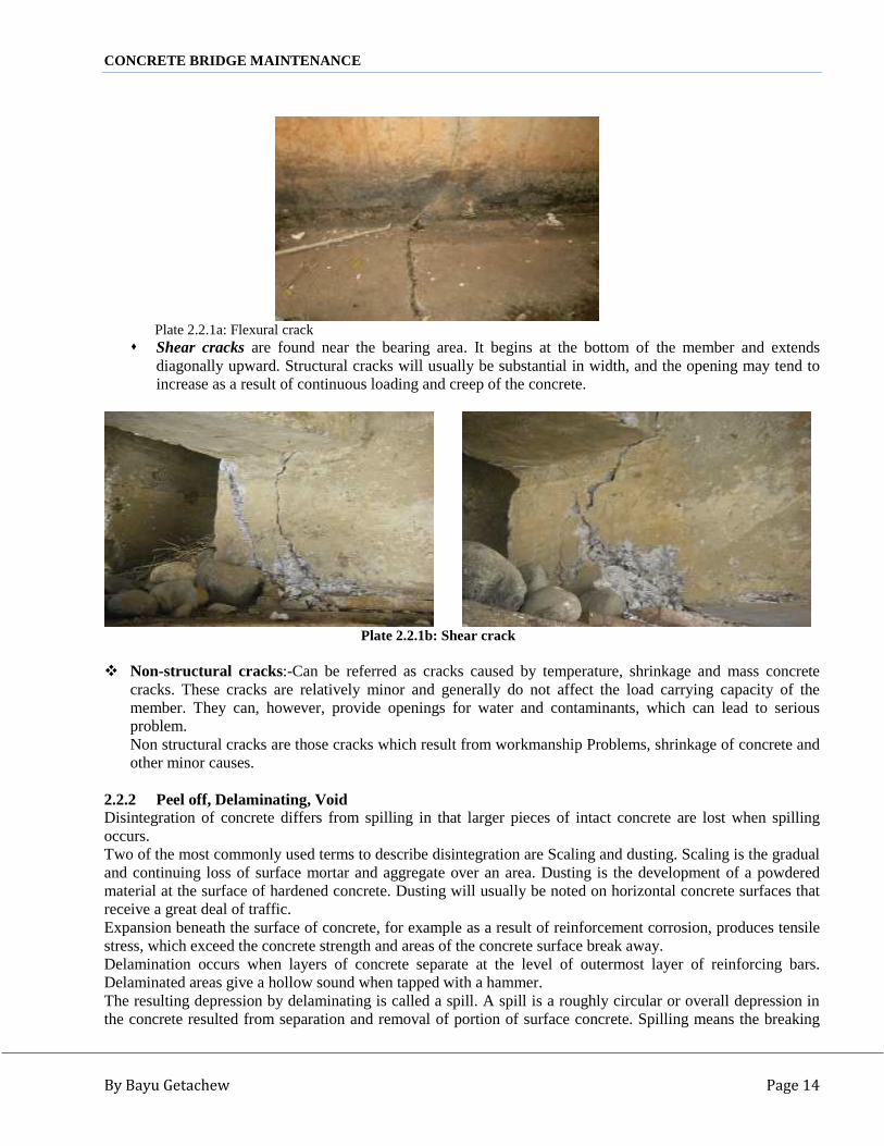
2.2.1 CrackingConcrete is by nature a brittle material, so reinforced concrete structures are destined to suffer cracking.Cracking cannot be prevented completely with present techniques. Not all types of concrete cracking, however,pose problems; some are detrimental to structures but others are not. Damaging cracking includes those typesthat cause water leakage due to cracking throughout the member, excessive deflection, aesthetic concerns anddefect to the durability of structure.Cracks in concrete may described in a variety of ways. Some of the more common ways are in terms of surfaceappearance, depth of cracking, width of cracking, current state of activity, and structural nature of the crack.Cracking can be an important indicator of deterioration taking place in concrete and possible corrosion ofreinforcement steel depending on the size, extent and location of the cracks.Cracks of concrete are classified as structural or non-structural cracks.Phenomenon: - Generally, cracking represents the deterioration of concrete. Surface appearance which ispattern or map cracks and individual cracks can give the first indications.Individual cracks indicate tension in the direction perpendicular to the cracking.Depth cracking is a self explanatory as may be surface, shallow, deep and through type. Active or dormant stateof cracks, width of cracks, and structural nature of crack (Structural or non structural) can be listed as differenttypes of it.Cracking after reinforcement corrosion owing to the increase of corrosion of reinforcement and cracking beforereinforcement corrosion that induces the corrosion of reinforcement are different options of crack. Structural Cracks: - Are those cracks which result from insufficiency of the section to withstand the
flexural, shear, settlement and other stresses developed in that section due to dead and live loads appliedupon it. Structural cracks are caused by load stress and are divided into flexure and shear cracks. Flexural cracks are vertical and start in the maximum tension zone and proceed toward the
compression zone.
CONCRETE BRIDGE MAINTENANCE
By Bayu Getachew Page 14
Plate 2.2.1a: Flexural crack Shear cracks are found near the bearing area. It begins at the bottom of the member and extends
diagonally upward. Structural cracks will usually be substantial in width, and the opening may tend toincrease as a result of continuous loading and creep of the concrete.
Plate 2.2.1b: Shear crack
Non-structural cracks:-Can be referred as cracks caused by temperature, shrinkage and mass concretecracks. These cracks are relatively minor and generally do not affect the load carrying capacity of themember. They can, however, provide openings for water and contaminants, which can lead to seriousproblem.Non structural cracks are those cracks which result from workmanship Problems, shrinkage of concrete andother minor causes.
2.2.2 Peel off, Delaminating, VoidDisintegration of concrete differs from spilling in that larger pieces of intact concrete are lost when spillingoccurs.Two of the most commonly used terms to describe disintegration are Scaling and dusting. Scaling is the gradualand continuing loss of surface mortar and aggregate over an area. Dusting is the development of a powderedmaterial at the surface of hardened concrete. Dusting will usually be noted on horizontal concrete surfaces thatreceive a great deal of traffic.Expansion beneath the surface of concrete, for example as a result of reinforcement corrosion, produces tensilestress, which exceed the concrete strength and areas of the concrete surface break away.Delamination occurs when layers of concrete separate at the level of outermost layer of reinforcing bars.Delaminated areas give a hollow sound when tapped with a hammer.The resulting depression by delaminating is called a spill. A spill is a roughly circular or overall depression inthe concrete resulted from separation and removal of portion of surface concrete. Spilling means the breaking

CONCRETE BRIDGE MAINTENANCE
By Bayu Getachew Page 15
away of concrete flake. Spilling is defined as the development of fragments, usually in the shape of flakes,detached form a layer mass. A spill is a roughly or oval depression in the concrete.This can be protected by providing a well cleaned and painted form work surface.
Plate 2.2.2: Peel off
2.2.3 Honey CombHoneycomb refers to voids in concrete due to failure of the mortar to effectively fill the spaces among coarse-aggregate particles. This may be due to leakage of mortar through formwork joints which is not well prepared.It usually becomes apparent when the formwork is stripped (exposed), revealing a rough and, ‘stony ‘concretesurface with air voids between the coarse aggregate. Sometimes, however, a surface skin of mortar masks theextent of the defect.Honeycombing may extend some depth into the member. Honeycombing is always an aesthetic problem, anddepending on the depth and extent may reduce both the durability performance and the structural strength of themember.Coarse aggregate with air space appear on the surface of concrete. Honeycombing occurs where the spacesbetween coarse aggregate particles are inadequately filled, with the result that the hardened concrete has anopen structure. Honeycomb preferably shall be repaired at the construction time, before handing over theoriginal work, with supervision.
.Plate 2.2.3: Honey comb
Concrete surface is not smooth as desired. Spots and small voids are visible, accumulation of bigger sizeaggregates may also be observed. Due to pour-out of cement paste, bondage of aggregates seems very poor.To minimize the incidence of honeycombed coarse aggregate:-

CONCRETE BRIDGE MAINTENANCE
By Bayu Getachew Page 16
Ensure the mix has sufficient fines to fill the voids between the coarse aggregate Use a mix with appropriate workability by repeatedly checking the slump test for the situation in which it is
to be placed Ensure the concrete is fully compacted and the placing methods minimize the risk of segregation Ensure the reinforcement layout and the section shape will permit the concrete to flow around the
reinforcement and completely fill the forms Check that the formwork is rigid and well braced, the joints are watertight and any penetrations through the
formwork e.g. form ties, are properly sealed
2.2.4 Spoiling, Scaling, WearingSpoiling is loose of quality appearance due to many external reasons. Wear and abrasion of the concrete surfaceare caused by being exposed to traffic and water flow.Wearing land abrasion is the result of external forces acting on the surface of concrete member like erosiveaction of sands in running water over the concrete surface.
Excessive water added at the time of delivery of concrete in order to increase the workability of concrete causesan increase in the water cement ratio of the concrete leading to a reduction in strength and durability ofconcrete, which can be manifested in surface defects like scaling, crazing and dusting.
Improper finishing and curing operations cause surface scaling. The materials for finishing and curingoperation cause the concrete to dusting and scaling. The procedures used to prevent dusting will prevent surfacescaling.
Plate 2.2.4: Surface scaling
2.3 Causes of Concrete Defects2.3.1 GeneralDefects that appear on the surface of concrete during construction or within a relatively short time aftercompletion, are usually caused by poor quality materials, improper mix design, lack of proper placing andcuring procedures, or poor workmanship. The repair of surface defect is both difficult and costly. The bestrepair work will not be as good as an original properly finished surface. Every effort should be made both priorto and during construction to avoid the use of materials or construction practices that can cause surface defects.
Various causes may have contributed to the formation of a particular defect. However every effort should bemade to determine the causes and ensure that the correct repair strategy is adopted. Clear factors like, naturaldisasters, fire, flood, vehicular collision; foundation settlement, excessive stress beyond the capacity of thedesigner are some of the causes of concrete defects.

CONCRETE BRIDGE MAINTENANCE
By Bayu Getachew Page 17
Structures may be overstressed by conditions outside the control of the designer and constructor, such asoverloading, change to the flow of a river, failure of adjacent structures and various natural causes.Settlement of a structure, which was not anticipated and allowed for in design, can result in very severe damageto concrete structures. Wide cracks and crushing where members come into unintentional contact may indicatethat settlement has occurred.
When settlement is suspected a structure should be carefully monitored to assess whether movement has ceaseor is continuing. Excessive settlement can cause complete collapse of a bridge.
Following a vehicular collision with a bridge, careful consideration of the structural effects must be carried outby an experienced structural engineer. Damage to primary elements can severely weaken a structure, or evencause collapse.
Similarly the effects of fire damage must be assessed by an experienced structural engineer. Defects such ascracks, spills, delaminating of the concrete cover, deformation of reinforcing bars and deflection of structuralmembers can seriously affect the performance of a bridge. Extensive fire damage may necessitate replacementor strengthening of affected members.
Generally defect in concrete structures may result from many factors such as poor design and detailing,construction deficiencies, overstress or loss of section resulting from, chemical attack, settlement of thefoundation, changes to the support or loading conditions caused by scour or silting, failure of bearings orexpansion joints, and traffic collision defect.
Deflection due to excessive and repetitive loading is a sign of deck slab deterioration and cracks.There are two causes of deflection:
1. Deflection induced by external force acting the concrete structure in excess of its design load. Flexural andshear cracks are generated such a factor, leading to acceleration of steel corrosion and other types of defect.
2. Fatigue is a phenomenon where cracks that have developed in concrete or reinforcement by repetitive loadinglead to cover scaling and steel failure. Fatigue failure may occur if excessive loads are applied repetitively. Anexample is the depression of a reinforced concrete slab by repetitive wheel loads on a bridge.
Common types of causes of defects in concrete bridges can be categorized as follow:
Design Errors: Common design errors which result in defects include: Incorrect concept –which includes inappropriate structural planning (arrangement), inappropriate
structural modeling, insufficient knowledge, and incorrect procedure. Calculation errors -which include Design specification error, inadequate factor of safety; Stress
analysis error, Omission of design consideration, arithmetic error and Failure to allow for theeffects of creep.
Drawing/detailing errors which include Poor reinforcement or pre stressing detail Failure to provide all of the required reinforcement Inadequate checking of drawings Incorrect movement joint spacing and locations Poor detailing of expansion joints Poor drainage details which result in leakage or clogging Insufficient development length Insufficient lap length Inadequate data in the drawing

CONCRETE BRIDGE MAINTENANCE
By Bayu Getachew Page 18
Insufficient provision of sections and details Lack of specification of material quality and procedures
Construction errors: Adequate supervision at the construction stage is essential to ensure that theworks comply with the design. Many defects and problems arise can be covered up during construction bythe resident engineer or responsible person.Typical construction defects are: Incorrect concrete mix proportions, failure to adequately support theformwork resulting in movement during concerting, improper reinforcement arrangement, inadequatecleaning out during preparation for concreting, failure to provide the specified concrete cover toreinforcement, insufficient compaction of concrete, lack of curing of concrete elements, and failure duringdismantling of the formwork.
Poor materials – This includes poor quality ingredients of concrete (cement, aggregate, sand and water),poor quality concrete mix, poor quality reinforcement, and use of incorrect grade of material,
Poor workmanship - This consists of unsuitable construction method or order of construction,inexperienced or careless workmen, temporary works failures (formwork and false work),inadequate supervision and deterioration of material caused by inadequate storage condition,
External effects – consists of increased traffic levels or overloading, accidental damage (collision, falls,fire), natural phenomena (flood, subsidence, heave, and earthquake), influences of the bridge approaches,chemical action (sea water, polluted water, de-icing salt, airborne pollution), and failure of adjacentstructures resulting from different ground conditions.
2.3.2 Concrete Cracking1. Structural Crack: heavy traffic loads and increment of the load acting frequencies that may occur throughtime after the construction of the bridge structures is one of the basic causes for structural cracks on reinforcedconcrete members. Insufficient structural design and errors in interpreting the drawings during construction,large impact forces caused by defect of road surfaces and aging of the concrete are also main causes of thestructural cracks. The structural cracks can further be classified as flexural, shear, torsion, and compressioncracks based on the internal stress which brings about the cracks. The user of this study shall identify the realcause of cracks, analyze loads and quantify the magnitude of stresses and strains developed in the sections andfinally arrive at amount of reinforcement that shall be applied to repair these types of cracks.
2. Non structural crack: there are several causes of non structural cracks which develop on reinforced concretebridge components. Among those causes, the most common ones are shrinkage of concrete due to lack ofproper curing mechanism, defect on concrete surface during formwork removal, absence of proper expansionjoints, and other similar workmanship problems.General Cause of cracks
- Lack of curing and quick removal of form, etc- Variation of temperature and moisture- External forces of bending moment, shearing force and fatigue- Differential settlement of foundation- Corrosion of rebar for lack of covering, chloride damage and carbonation, etc.
2.3.3 Concrete Peel off, Delaminating, VoidHowever thickness of concrete cover is generally indicated in the drawings: the cover could become insufficientdue to inadequate setting of spacer, error of reinforcement bar arrangement and movement of bars duringcasting of concrete.Insufficient cover is hardly detected at the time of casting concrete, however the reinforcement bar willgradually rust and swell and the concrete cover start to be peeled off.

CONCRETE BRIDGE MAINTENANCE
By Bayu Getachew Page 19
Plate 2.3.3: Rebar exposure due to peel off and delaminating
Spill can be caused by corroding reinforcement and friction from thermal movement due to which reinforcingsteel is often exposed.The major cause of delamination is expansion of corroding reinforcing bars. This is commonly caused byintrusion of chlorides or salt. An inadequate drainage system can severely limit the life span of a concrete deckdue to deterioration by leakage and corrosion of reinforcement bar which produces tensile stress exceeding theconcrete strength, so that area of the concrete surface break away.
Voids formed when the concrete fails to fill area in a form, typically those under large blackouts, in very deepplacements, or forms that are heavily reinforced. Voids are almost always structural defects requiring repair.Causes of honeycomb and voids include stiff or unworkable concrete, segregation, congested rebar, insufficientconsolidation, and improper placing practices.
2.3.4 Concrete Honey CombHoneycomb surfaces are caused by the use of a dry mix that was not properly consolidated. The concrete mixshould be designed to provide a workable mix for the type of consolidation that will be used on the job. Whenhoneycombing occurs, don’t just add water to the mix to correct the trouble. That will decrease the strength anddurability of the concrete. The mix should be redesigned to provide improved workability or the procedure forconsolidating the concrete should be improved.Honeycombing is caused either by the compaction not having been adequate to cause the mortar to fill the voidsbetween the coarse aggregate, or by holes and gaps in the formwork allowing some of the mortar to drain out ofthe concrete. In some cases, the member shape and detailing/placement of the reinforcement compounds theeffect of inadequate compaction.
It can be caused by segregation of material during concrete casting, insufficient compaction of concrete and itcan also be caused by the loss of cement grout, leaking of cement paste, where form work is inadequatelysealed.

CONCRETE BRIDGE MAINTENANCE
By Bayu Getachew Page 20
The defect may be purely cosmetic or, depending on the location and extent of honeycombing, may bestructural and require repair. For instance, honeycombing behind post-tensioning anchors may require repair sothe post-tensioning forces don’t cause compressive failure of concrete in the bearing area.
Preventing honeycomb and voids starts with attention to concrete mix proportions. Proper techniques forforming, rebar placement, providing enough paste, increasing of slump, controlling setting rate, concreteplacement and proper vibration are important activities to reduce or avoid honeycomb problems
Provide enough paste: Concrete not containing enough cementicious material and fine sand will be prone tosegregation and won’t flow well. Consider adding a blend sand or additional Portland cement or fly ash toincrease the amount of fines. Increasing the ratio of fine-to coarse aggregate will increase workability only if5% to 10% of the sand passes the No.100 sieve.
Increase slump: Even with the correct amount of paste, a mix can lack workability and won’t flow into place.To improve flow, increase slump from 15 to 20 centimeters by adding a water reducer or super plasticizer.Reduce aggregate size: If closely spaced reinforcement or other obstacles hindering concrete flow, considerreducing coarse aggregate size.
Control setting rate: Slow placement rates and high ambient and concrete temperatures can cause concrete tostiffen, reducing its flow ability. Adding a retarder may help, but retarders don’t necessarily prevent slump loss.Care should be taken to protect honeycomb defect in this process.
Forming and rebar placement: Review reinforcement details. Closely spaced rebar, insufficient clearancebetween the rebar and forms, and closely spaced lap splices all interfere with concrete flow and vibration. Workwith the steel detailer to minimize these problems. Provide access to forms. Narrow or tall forms preventobservation and access during concrete placement. You may have to cut placing ports into forms containingheavily reinforced sections.Tightly seal form joints, otherwise mortar loss through form joints may cause honeycomb.
Vibrate Properly: Workers must be trained to vibrate concrete correctly to ensure that it flows aroundreinforcing steel, embedment, and blackout. Build up a head of concrete on one side of small blackouts, andvibrate the concrete until it appears on the other side. Large block outs require concrete to flow many meterslaterally, so you may need to use pour pockets beneath these block outs.Drill holes in the bottom of a block out to allow displaced air to escape.Avoid delays: If the placement is not going as fast as planned, ready-mix trucks may have to wait beforedischarging material and the concrete will start to stiffen. You can reduce stiffening by using retardingadmixtures, but a better approach is to alert the concrete producer when unavoidable placing delays occur.
2.3.5 Concrete Spoiling, Scaling and WearSome aggregates used in concrete react chemically with high alkali cements, causing disruption of the concrete.This form of deterioration or spoil is called alkali aggregate reaction, and results in extensive cracking.
Scaling, i.e., local flaking or peeling away of the near-surface portion of a concrete slab is the most commontype of surface distress, especially in areas exposed to cyclic freezing and thawing, and de-icing chemicals. Acomprehensive evaluation of factors responsible for concrete surface scaling disclosed that, the following maycauses.(a) Concrete materials, proportions, and properties (air content, air void system, aggregate, cement paste,
aggregate-paste interface, compressive strength, water-cementations materials ratio, degree of saturation ofconcrete, and chemical admixtures);

CONCRETE BRIDGE MAINTENANCE
By Bayu Getachew Page 21
(b) Construction practices (consolidation, finishing, curing, hot and cold weather protections, drainage, andsurface treatments);
(c) Concrete maturity; and(d) De-icing salts (salt type, concentration, timing of exposure ) on scaling
Therefore,A) Concrete should be air-entrained for the protection of the paste during freezing. Concrete should have a
good air-void system consisting of numerous fine, discrete spherical and near-spherical air voids of sizes upto 1 mm, the majority of which should be very fine.
B) Concrete should be made using well-graded, well distributed, and frost-resistant aggregates.C) Concrete should be properly placed, finished, and cured.D) Concrete should be matured, i.e., it should undergo a period of air-drying and should attain a compressive
strength of at least 28 MPa (400 psi) prior to the first exposure to freezing and de-icing salts.
2.4 Other Defects and their Causes
2.4.1 Scouring and Erosion
Bridge scour is the removal of sediment such as sand and rocks from around bridge abutments or piers. Scour,caused by swiftly moving water, can scoop out scour holes, compromising the integrity of the bridge.
Bridge scour is one of the causes of bridge failure. It has been estimated that 60% of all bridge failures resultfrom scour and other hydraulic related causes. It is the most common cause of highway bridge failure in somecountries like the United States, where 46 of 86 major bridge failures resulted from scour near piers from 1961to 1976. Scour failures tend to occur suddenly without prior warning and are very difficult to monitor duringflood events.
Water normally flows faster around piers and abutments making them susceptible to local scour. At bridgeopenings, contraction scour can occur when water accelerates as it flows through an opening that is narrowerthan the channel upstream from the bridge. Degradation scour occurs both upstream and downstream from abridge over large areas. Over long periods of time, this can result in lowering of the stream bed.
Bridges that cross water channels require detailed inspection of channel characteristics and the condition ofsubstructure elements in the channel. The need for a detailed and thorough scour inspection program is a resultof the catastrophic effects which can be caused by excessive scour.
If constriction in the channel is significant, the velocity of the stream can increase such that the substructurefootings and/ or piles become undermined (damaged). Sharp bends or curves in the water channel also increasevelocity which can create cross-currents and turbulence. Scour either occur locally at specific substructurecomponents or over the entire structure crossing the channel.
The effects of foundation movements upon a structure will vary according to the magnitude of movements, typeof settlement, and type of structure.
Movement of large magnitudes, especially when differential settlement occurs it causes distress in thestructures. Large movements in a bridge will cause:
CONCRETE BRIDGE MAINTENANCE
By Bayu Getachew Page 22
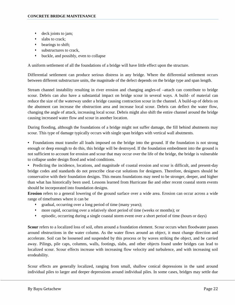
deck joints to jam; slabs to crack; bearings to shift; substructures to crack, buckle, and possibly, even to collapse
A uniform settlement of all the foundations of a bridge will have little effect upon the structure.
Differential settlement can produce serious distress in any bridge. Where the differential settlement occursbetween different substructure units, the magnitude of the defect depends on the bridge type and span length.
Stream channel instability resulting in river erosion and changing angles-of –attach can contribute to bridgescour. Debris can also have a substantial impact on bridge scour in several ways. A build- of material canreduce the size of the waterway under a bridge causing contraction scour in the channel. A build-up of debris onthe abutment can increase the obstruction area and increase local scour. Debris can deflect the water flow,changing the angle of attack, increasing local scour. Debris might also shift the entire channel around the bridgecausing increased water flow and scour in another location.
During flooding, although the foundations of a bridge might not suffer damage, the fill behind abutments mayscour. This type of damage typically occurs with single span bridges with vertical wall abutments.
Foundations must transfer all loads imposed on the bridge into the ground. If the foundation is not strongenough or deep enough to do this, this bridge will be destroyed. If the foundation embedment into the ground isnot sufficient to account for erosion and scour that may occur over the life of the bridge, the bridge is vulnerableto collapse under design flood and wind conditions. Predicting the incidence, locations, and magnitude of coastal erosion and scour is difficult, and present-daybridge codes and standards do not prescribe clear-cut solutions for designers. Therefore, designers should beconservative with their foundation designs. This means foundations may need to be stronger, deeper, and higherthan what has historically been used. Lessons learned from Hurricane Ike and other recent coastal storm eventsshould be incorporated into foundation designs.Erosion refers to a general lowering of the ground surface over a wide area. Erosion can occur across a widerange of timeframes where it can be gradual, occurring over a long period of time (many years); more rapid, occurring over a relatively short period of time (weeks or months); or episodic, occurring during a single coastal storm event over a short period of time (hours or days)
Scour refers to a localized loss of soil, often around a foundation element. Scour occurs when floodwater passesaround obstructions in the water column. As the water flows around an object, it must change direction andaccelerate. Soil can be loosened and suspended by this process or by waves striking the object, and be carriedaway. Pilings, pile caps, columns, walls, footings, slabs, and other objects found under bridges can lead tolocalized scour. Scour effects increase with increasing flow velocity and turbulence, and with increasing soilerodeability.
Scour effects are generally localized, ranging from small, shallow conical depressions in the sand aroundindividual piles to larger and deeper depressions around individual piles. In some cases, bridges may settle due

CONCRETE BRIDGE MAINTENANCE
By Bayu Getachew Page 23
to inadequate pile embedment, coupled with some combination of erosion, scour, and soil liquefactions thatleads to loss of bearing.
There is one other erosion and scour scenario to consider in foundation design- the loss of soil around or under abridge as a result of storm surge flow being channeled or directed across a bridge site. This process usuallytakes place where storm surge flow is constrained between gaps in shore protection, or when return flow to thesea follows path of least resistance, such as along canals and roads.
2.4.1.1 Erosion and Scour- Impacts on FoundationsErosion and scour have several adverse impacts on coastal foundations: Erosion and scour reduce the embedment of the foundation into the soil, causing shallow foundations to
collapse and making bridges on deep foundations more susceptible to settlement, lateral movement, oroverturning from lateral loads.
Erosion and scour increase the unbraced length of pile foundations increase the bending moment to whichthey are subjected, and can overstress piles.
Erosion over a large area between a foundation and a flood scour exposes the foundation to increased lateralflood loads (I.e., greater still-water depths, possible higher wave heights, and higher flow velocities).
Local scour around individual piles or a bridge foundation will not generally expose foundations to greaterflood loads, but linear scour across a bridge site may do so.
Bridge examination
The examination process is normally conducted by hydrologists and hydrologic technicians, and involves areview of historical engineering information about the bridge, followed by a visual inspection. Information isrecorded about the type of rock or sediment carried by the river, and the angle at which the river flows towardand away from the bridge. The area under the bridge is also inspected for holes and other evidence of scour.
According to Lacey’s formula, the width of a natural channel at bank-full flow is proportional to the root of thedischarge.To determine scouring depth:
d= 0.473 (Q/f)1/3 where,
Where, d = normal depth of scouring below HFLQ =d ischarge (in m3/S)F = Lacey’s silt factor, which is a function of bed material
F = 1.76 x
The effects of scour can change throughout the life of a structure. Accumulations of silt and debris may reducethe channel of a river or cause it to follow a different course.
Similarly the uncontrolled extraction of gravel or sand form river beds can affect the flow, causing scour atbridges further along the river. As scour can completely undermine the foundations of a bridge and therebycause it to collapse, it is essential that its occurrence is detected at an early stage or preferably prevented.

CONCRETE BRIDGE MAINTENANCE
By Bayu Getachew Page 24
Sometimes scour causes large holes in river beds or washes large sections of the bank away. Many bridges havebeen destroyed by scour. Rivers can easily damaged or destroy bridges. Usually, bridges are damaged when theriver is too big to go through the waterway under the bridge, or when the river changes its path.
There are three reasons why a river may not be able to go through the waterway of a bridge:1.A river can grow and become too big for the waterway.2.The waterway under the bridge can be blocked by parts of old bridges, trees, fences and other debris.3.The waterway under the bridge was not made big enough.
If there is a flood which is too big for the waterway under the bridge, the river may do 3 things:1.Wash away the bridge.2.Wash away the road embankment and the road, and go round the bridge.3.Wash away the fill in front of the abutments, and scour big holes in the river bed.
If the-waterway is too small, another bridge or some culverts may be needed to carry the extra; floodwater,otherwise the river can change their path slowly or very quickly. Change of path can, after a time, cause damageto a bridge.
2.4.1.2 Causes for ScouringAny type of substructure not founded on solid rock may be subject to settlement and lateral movement likepiles, earth retaining structures, such as abutments and retaining walls. Foundation movements may often bedetected by first looking for deviations from the proper geometry of the bridge. Change in direction and flowtype of flood specifically at pier or abutment footing area evidenced by turbulence, erodes materials from underfoundations. General scour occurs over a long period of time and is initiated by an alteration in channel flowpatterns. This mainly caused by a change in the supply of sediments to a large area.
Poor Design: Waterways should be inspected in order to determine whether any condition exists that couldcause defect to the bridge or the area surrounding the bridge. In addition to inspecting the channel’s presentcondition, a record should be made of any significant changes that may have taken place in the channel,attributable either to natural or artificial causes.In stream beds susceptible to scour and degradation, a channel profile should be taken periodically,generally at 30meter intervals, extending to a few hundred meters up-stream and downstream.The channel change steepens the channel and increase flow velocity. The entire section may degrade.Events which tend to produce local scour, channel degradation, or bank erosion are of primary importance.Scour can cause extensive settlement which may also be uneven. Since water will carry off particles of soilin suspension, a considerable hole can be formed around piers or other similar structural objects. Thiscondition results in a greater turbulence can be displaced.
Stream bed or banks near the abutments or piers may be eroded due to fast water flow; undermining theunprotected soil banks. If neglected, settlement will develop and bridges’ foundation and the embankmentswill be washed away.Scour is defined as the removal and transportation of material from the bed and banks of rivers and streamsas a result of the erosive action of running water.
CONCRETE BRIDGE MAINTENANCE
By Bayu Getachew Page 25
Stream bed degradation is usually due to artificial or natural alteration in the width, alignment, or profile ofthe channel. These alterations which may take place at the bridge site or some distance upstream for down-stream upset the equilibrium, or regime, of the channel.Stream bed degradation and scour seriously endanger bridges whose foundations are located in an erodibleriver-bed-deposit and where the foundation does not extend to a reasonable depth below that of theanticipated scour.
Channel Constrictions: Typical situations which tend to lead scour problem are Sediment deposits, Pierscour, loose riprap, Lined banks, Horizontal or vertical channel constructions that creates a high velocity,flooding, protruding abutments, debris, and river bends. Most foundation movements are caused bymovement of the supporting soil. Soil deformations are caused by volume changes in the soil or by a shearfailure. Slope slides and bearing failures are good examples of shear failures. Where loads are not largeenough to cause shear failure, Settlements may still occurs as a result of volume change.
Substructures that are supported directly by a cohesive soil may continue to settle through a long period oftime due to consolidation, which usually produces vertical settlement.
Slope failures (embankment slides) are shear failures manifested as lateral movements of hillsides, cutslopes, or embankments. Footing or embankment loads imposing shear stresses greater than the soil shearstrength are common causes of slides.Inadequacy of waterway results scour and streambed degradation. The geometry of the channel, the amountof debris carried during high water periods, and the adequacy of freeboard should be considered indetermining waterway adequacy.
2.4.2 Water Leakage and Deteriorations
2.4.2.1 Causes of Water Leakage
An extended water leakage largely contributes to the deterioration of the bridge part prone to this specificdefect. The repair technique dealt therefore enables to protect the concrete section from being continuouslydegraded. Water leakage under concrete may be caused due to cracks, voids, concrete porosity, absence ofimpermeable wearing course, defect to joint sealants, or blockage of drains.
Stopping serious and wide range of water leakage that passes through cracks or voids, which may cause areduction in loading capacity together with leaching of free lime or salt, is an essential activity.
Wide cracks may be repaired by filling with Portland cement grout. This method is effective in stopping waterleaks, but it will not structurally bond cracked section.
All defects associated with the concrete defects which were dealt previously shall be maintained as per thetechniques specified before.
Bridge drainage is also an important inspection-item, since any trapped or pounded water can cause a great dealof defect to a bridge and is also a safety hazard. Therefore, an effective system of drainage that carries the wateraway as quick as possible is essential to the proper maintenance of the bridge.
CONCRETE BRIDGE MAINTENANCE
By Bayu Getachew Page 26
Accumulation of debris is a principal cause for surface drainage inlet-clogging. The ponds and puddles of waterthat form on the bridge deck pose the problem which constitute a safety hazard and can cause extensive bridgedeterioration.
Downspouts and horizontal pipe-run, which are poorly designed with inadequate slopes and sharp directionalchanges at the elbows, are conducive to plugging drains.
Corrosion: - drainage water often carries corrosive element that attack drainage pipes and concrete. Cloggingand slow drainage accelerate deterioration of girder, side beam and internal part of deck slabs as well as rebarcorrosion.
2.4.3 Concrete Deck – Slab and Pier Columns Deterioration and Repair Methods
2.4.3.1 Causes of Deterioration
Concrete desk slab usually deteriorate due to long period water stay or leakage, poor workmanship during theoriginal construction period or external problems like crush and bomb blasting. Water may leak through deckslab due to the following causes.Cracks: - Cracks will occur on girder/beam and deck slab by the repeated and overload wheel load. Then watercan pass through the slab deck and finally some parts of the concrete will peel off.Porous construction joints honeycomb, cast-in-fittings such as drain pipe, Deterioration of concrete due toCarbonation, and Alkali reaction, etc. are other causes of leakage of water.
2.4.4 Rust Treatment of Concrete Reinforcing Bar2.4.4.1 Causes of RustReinforcement shall be free from pit, loose rust, mill scale, paint, oil, grease, adhering earth, ice or any othermaterials that may impair the bond between the concrete and the reinforcement or that may cause corrosion ofthe reinforcement or disintegration of the concrete.Reinforcing steel corrodes either where cracking induces the corrosion of reinforcing steel (cracking beforereinforcement corrosion) or where carbonation or salt defect corrodes reinforcing steel, which then causescracking after reinforcement corrosion.The point when corrosion-induced cracking occurs along the reinforcement in the concrete cover is consideredthe deterioration limit for the cracking caused by reinforcement corrosion.When reinforcement corrodes to a certain extent, the surrounding concrete cover tends to crack and split. Thecracks are caused by internal bursting pressures developing in the concrete as a result of a net increase involume by the formation of corrosion products. Spalling of the concrete cover will then permit the entry ofwater and other corrosion accelerating agents and the rate of corrosion will accelerate.When corrodes, the prestressing steel becomes vulnerable to fracture because it has been prestressed, and sothe durability of the structure is severely affected. When reinforcement corrodes, it expands causing tensilestress in the surrounding concrete which results in cracking and spalling.
Reinforcement bars in the permanent structures may be found exposed or uncovered due to concrete peel offresulting from external impact or concrete aging or formwork removal, lack of sufficient cover duringconstruction, and concrete void or honeycomb.

CONCRETE BRIDGE MAINTENANCE
By Bayu Getachew Page 27
If the deterioration of concrete has been caused by corrosion of reinforcement, the products of corrosion mustbe removed before placing the new concrete; otherwise the repair will not be effective. If the defect is due tochloride contamination, all rust shall be removed from the steel as any residual rust will be contaminated withchlorides that could restart the corrosion later.
Materials used for maintaining the concrete failures which finally attribute the reinforcement bar exposure areto be dealt with the respective concrete failures repair. Regarding the replacement of the defect reinforcement,curious investigation shall be made for determination of the defect portion. Based on the design calculations,the reinforcing of the structure can be made using steel plate bonding or carbon fiber reinforced polymermethods.
The corrosion of reinforcement may caused by carbonation and chloride attack. Carbonation or chloride attackinvolves the contamination (ineffectively) of protective alkaline environment provided by good qualityconcrete.The presence of excessive amounts of chloride ions, originating from the use of the admixture calciumchloride, will also destroy the passive layer, which prevents corrosion.

CONCRETE BRIDGE MAINTENANCE
By Bayu Getachew Page 28
3 MATERIAL FOR REPAIR3.1 GeneralConcrete is an essential material. With a worldwide estimated consumption of between 21 and 31 billion tonesof concrete in 2006, concrete is the second most consumed substance on Earth after water! A world withoutconcrete is almost inconceivable [17, 18, and 19]
The principles of producing concrete and understanding the laws of concrete behavior are well enoughestablished through long experience and extensive research to make it possible to design and erect structuresthat meet the recognized requirements of engineering use and safety. There is still a need for continuedresearch, however. New questions are constantly arising, and new methods and machines for constructionoperations are being developed. If concrete is to meet increasingly higher expectations with regard to durabilityand structural efficiency, and continue in the forefront as a building material, the new requirements need to bemet by ever-increasing knowledge obtained from research and experience.
Concrete sets, hardens, gains strength, and exhibits reduced permeability with the passage of time, but it is notthe passage of time alone that causes these things to happen. If the concrete is kept very cold, none of this willhappen. If all moisture is removed, none of this will happen.Many or even most concretes are confronted with potential deteriorative service conditions. If the concrete hasnot been provided with immunity against these influences, it may well slowly deteriorate as time passes, but notsimply because time passes. Concrete need not deteriorate.
3.2 What is Concrete Structure?Concrete is essentially a compressive material. While it has adequate strength for most structural uses, it is bestsuited for relatively massive members that transmit compressive loads directly to the founding material.Although concrete has low tensile strength, reinforcing it with steel bars produces a material that is suitable forthe construction of flexural members such as deck slabs, bridge girders, and the likes, etc.
Concrete is a mixture of sand, gravel and/or other aggregates (the matrix), bound together by a water-basedbinder, cement. Admixtures (modifying agents) and additives (fine mineral powers) are sometimes introducedto improve the characteristics of the fresh concrete, the mixing process and/or the final hardened material. ComponentsPortland Cement- The cement and water form a paste that coats the aggregate and sand in the mix. The pastehardens and binds the aggregates and sand together.
The invention of cement has been credited to Joseph Aspdin, and English mason. Aspdin patented his product in1824 and called it “Portland Cement” because it resembled the color of natural limestone found on the Isle ofPortland, a peninsular in the English Channel. Portland cement was first manufactured in the United States in1872 [14]Water- Water is needed to react chemically with the cement (hydration) and to provide workability with theconcrete. The amount of water in the mix as compared with the amount of cement is called the water cementratio. The lower the water cement (w/c) ratio, the stronger the concrete. (Higher strength, less permeability)Aggregates- sand is the fine aggregate. Gravel or crushed stone is the coarse aggregate in most mixes.

CONCRETE BRIDGE MAINTENANCE
By Bayu Getachew Page 29
3.3 Concrete Repairing MaterialThe different materials used for maintenance can be grouped in to three categories.
(1) Cement type repairing materials: this is simply Portland cement mortar (concrete) or non-shrinkage mortar (concrete)
(2) Polymer modified cement type : this is cement modified using different polymers and fibers(3) Resin type repairing materials: this is an epoxy or chemical used for repairing purpose
3.4 The Practice in Ethiopia [ 1 ]In collaboration with Japan International Cooperation Agency [JICA], ERA has accomplished maintenanceof different bridge defects. The materials used for maintenance are basically categorized in to four. These are: Materials used for large defects or cracks (pure cement or polymer modified cement type materials), Materials used for small defects or cracks (Resin type repairing materials or crack injection materials), Crack sealing materials so that small cracks will be ready for injection, and Materials for bonding
All of these are supplied by different companies in the country.
3.5 Materials for Repairing of Large Defects or Cracks (polymer and fiber reinforced repair mortar)These are materials used to repair large defects, especially those falling in rank “A” and “B”. We have differentmaterials to restore seriously damaged or injured members, some of them are: [15]
1. (EMACO S88C T)EMACO S88C T is a cementitious pre-bagged ready-to-use structural repair mortar in powder form. Whenmixed with the correct amount of water, it produces a thixotropic, high strength repair mortar, reinforced withacrylic polymer fibers. It possesses excellent bond characteristics to steel reinforcement and to concrete.
EMACO S88C T is shrinkage compensated which reduced risk of crack due to shrinkage and is formulated forsprayed or trowelled applications; in thickness up to 50mm in one layer by hand application. Greaterthicknesses can be achieved when spray applied.
2. Renderoc TGXtra + Polypropylene FiberShrinkage controlled polymer modified, vertical and overhead cementitious repair mortar system.It is suitable for hand application to repairs where light to medium load bearing is required. It is applicable togeneral concrete and masonry repairs, voids greater than 10mm deep, repairs to honeycombing.
3. Sika Mono Top-612Sika Mono Top-612 is wet sprayed/hand placed fiber reinforced repair mortar. It is a cementitious, polymermodified, low permeability, high strength mortar containing silica fume and synthetic fiber reinforcement.Excellent workability, adjustable consistency, excellent slump resistance, sprayable by the wet spray method,good mechanical strength, easily sprayed in layer thickness up to 30mm, and good resistance to water andchloride penetration are the characteristics of Sika Mono Top-612
3.6 Materials for Repairing of Small Defects or Cracks (crack injection material)These are materials used to repair small defects especially for cracks having width of crack less than 5mm. It isalso applicable for defects or damages which fall in rank “C”. We have different materials to restore lightlydamaged or injured members, some of them are: [15]
1. CONCRESIVE 1315CONCRESIVE low-viscosity injection resins are two component crack injection fluids for sealing cracks,filling cavities and voids in concrete and stopping water ingress. They can be injected in to cracks of varyingsizes (100 microns to 9mm) including cracks too fine to be filled with traditional materials. It is highly

CONCRETE BRIDGE MAINTENANCE
By Bayu Getachew Page 30
penetrative and cures to form a permanent seal. It is applicable to columns, bridge decks, floors, piers,abutments, tunnels, basements, beams, and underpasses.
2. Nitofill EPLVLow viscosity solvent free epoxy resin system used for injecting cracks in concrete or masonry to formpermanent bond or seal. Nitofill EPLV It has two components base and hardener mixed in proportion to formstrong permanent bond. The advantages of Nitofill EPLV are:
Low viscosity allows penetration in to the finest cracks Formulated for hot climates Suitable for structural cracks or repairs Excellent bond to concrete, brick and masonry Minimum creep under sustained load Resistant to wide range of chemicals Non-shrink, adheres with no loss of bond
Mixing Procedures
1) Stir each components separately to disperse settlement2) Pour hardener in to base & mix thoroughly3) Pour the mix in to injection gun4) Inject in to the pipes installed starting from lower elevations5) Bend pipe, carefully remove injection gun, tie pipe with wire6) Wash injection gun with thinner7) curing for 24hrs
3. Sikadur-52 ZAA two part solvent free, low viscosity injection liquid based on high strength epoxy resins applicable to civilengineering buildings, industrial buildings, columns, bridges, and foundations. It has advantage of hardness butnot brittleness, low viscosity, injectability, suitable for both dry and dump conditions, and high mechanical andadhesive strength.
3.7 Crack Sealing Materials for Injection (Epoxy resin mortar)Materials for sealing of very small cracks (crack width less than 5mm), so that ready for application of crackfilling or injection (resin type repairing) materials. Materials involved are: [15]
1. CONCRESIVE2200It is high strength, non-flow, epoxy bedding and repair mortar. It is a two packs, fine aggregate filled, fastcuring material, and ideal for a variety of bedding, gap filling and concrete repair applications.CONCRESIVE2200 is a stiff but easily workable compound that can be applied by trowel, spatula or knife. Itis impact resistance and mechanical strength is greater than that of concrete. It can be applied as a gap fillingadhesive, fixing slip bricks to concrete, dowel bar anchoring, bedding tiles, repairing concrete posts in-situ,securing bolts in to walls, and repairing surface defects or to honeycombing concrete in horizontal, vertical oroverhead situations.
2. Nitomortar FCHigh strength trowel grades, epoxy resin fairing coat, repair mortar, bedding and adhesive. It is suitable forfilling pinholes prior to over coating with nitocoat or nitoflor products, general reprofiling over large areas, upto 3mm depth, Sealing of surface cracks in preparation for crack injection, general purpose bedding mortar andadhesive. Nitomortar FC is a two component thixotropic, solvent free, compound based on epoxy resins,
CONCRETE BRIDGE MAINTENANCE
By Bayu Getachew Page 31
graded fillers and thixotropic agents. It is applied directly to concrete substrates, without primer, and cures to asurface ready for over coating. The base component is light gray coloured and the hardener black to easeidentification of uniform mixing.Generally:
- It is a two component thixotropic compound-Used for sealing of surface cracks in preparation for injection-Has strong adhesion to concrete substrate-1 Lit of nitomortar covers 5m2 with 0.2mm thickness but it’s heavily dependent on the surface condition(or with 2 mm thickness – 0.5m2)- Mix proportion ( 1 can base + 1 can hardener)
Mixing Procedures
1) Stir each components separately to disperse settlement2) Pour hardener in to base & mix thoroughly until uniform colour grey is obtained (it is very viscous
compound which makes stirring tedious)3) As soon as we finish mixing apply it on surface prepared using filling knives4) Clean all equipments used using solventCuring
3. Sikadur-31CF Normal
A moisture tolerant, thixotropic, structural two part adhesive and repair mortar, based on a combination ofepoxy resins and special fillers, designed for use at temperature between 10 and 30 degree centigrade. It can beused as a structural adhesive and mortar for concrete elements, hard natural stone, ceramics, bricks, masonrysteel, iron, and aluminum. Easy to mix and apply, suitability for dry and damp concrete surfaces, very goodadhesion to most construction materials, high strength adhesive, thixotropic (non-sag in vertical and overheadapplications), hardness without shrinkage, different colour components, high initial and ultimate mechanicalstrength, good abrasion resistance, and impermeability to liquids and water vapour are some of the advantagesof this epoxy.
3.8 Materials for Bonding [15]
1. CONCRESIVE 1414
Epoxy bonding agent for concrete repairs, bonding concrete to concrete, steel and granolithic toppings. It is apermanent epoxy adhesive for internal or external bonding and has greater tensile strength as compared to thatof tensile strength of concrete. CONCRESIVE 1414 may be applied to clean, sound and durable surfaces thatis steel, glazed tiles and bricks, ceramics and quarry tiles, terrazzo tiles and floors. high strength, non shrink,moisture tolerant, durability, and resistant to chemical attack are some of the advantages of this epoxy.
2. Nitobond EP
Epoxy resin concrete bonding agent used to bond fresh wet cementitious material to existing cementitioussurface. It is used for horizontal and vertical surfaces of roads, bridges, pavements, loading bays and factories

CONCRETE BRIDGE MAINTENANCE
By Bayu Getachew Page 32
both externally and internally. Nitobond EP has two components white base and green hardener mix togetherand applied on dry or damp substrates. The advantages of Nitobond EP are: exhibits high mechanical strength,positive adhesion-exceeds that of the tensile strength of the host concrete, slow cure allows time to erect steelreinforcement and formwork, and solvent free-can be used in enclosed locations.
Generally:
-It is a two component material (base and hardener)
-It is used for bonding existing concrete surface with the new mortar applied
-Exhibit high bonding (tensile) and mechanical strength
-Working life time – 160min (we have to apply it on the surface before this time)
-Max overlay time – 24hr (we have to apply EMACO before this time)
-1Lit of nitobond covers 3.5 – 4m2
-Mix proportion (1 can base + 1 can hardener)
Mixing Procedures
1) Stir each components separately to disperse settlement
2) Pour hardener in to base & mix thoroughly until uniform colour is obtained
3) As soon as we finish mixing apply it on surface prepared using brush
4) Clean all equipments used using solvent
3. SikaLatex
Water resistant bonding agent for mortar. It is a high quality, synthetic polymer emulsion for adding to cementmortars where good adhesion and water resistance are required. It can be applicable for thin layer patchingmortars, renders, floor screeds, concrete repair mortars, abrasion resistant lining, and tile fixing mortars.Sikalatex has greater elasticity, small shrinkage, better adhesion strength, excellent water resistance, betterchemical resistance, and non-toxic.
4. Sikadur-32 N
Wet to dry epoxy resin bonding agent. It is a two component solvent free, moisture insensitive, mediumviscosity, structural epoxy bonding agent used for bonding fresh concrete to an existing concrete or mortar

CONCRETE BRIDGE MAINTENANCE
By Bayu Getachew Page 33
substrate. It is suitable for vertical anchor bolt grouting. Sikadur-32 N has different advantages, some of themare: easy to mix and apply, solvent-free, excellent adhesion to concrete and a wide variety of other substrates,tensile strength far greater than concrete, and can be applied to damp substrates.
4 METHODS OF REPAIR AND REHABILITATION4.1 GeneralThe following four procedures are followed in almost all repair works. [1]
Removal of concrete Surface cleaning Substrate preparation Repair material application
4.1.1 Removal of ConcreteWhen removal of part of concrete structure is required, use power driven chipping tools or hydro demolishingequipment to remove all loose or defective concrete. Avoid defect and make sound concrete to remain in place.Avoid hitting reinforcement steel with the chipping tools. Once the initial concrete is removed, use smallpower-driven chipping or hydro demolishing equipment to undercut all exposed reinforcement steel. Expose theentire perimeter of the steel bars for the full area of the repair provide a minimum clearance of 1cm between theexposed steel and the surrounding concrete or two times the maximum aggregate size, whichever is greater.Remove additional concreter as necessary to keep the repair area to reasonably uniform depth. The Contractorshall obtain approval of the completed concrete removal before proceeding to surface preparation.
4.1.2 Surface CleaningThe area to be repaired shall be cleaned by abrasive blasting, high pressure water blasting, or other methodsapproved by the Engineer. All loose particles, dirt, deteriorated concrete or other substances that would impairthe bond of the repair material shall be removed. Exposed reinforcement steel of concrete, rust and othercontaminants shall be cleaned and this should be followed with a high pressure air blast for final cleaning.
4.1.3 Substrate PreparationUnless directed or specified, use a bonding agent if cement mortar or concrete is used for the repair material.

CONCRETE BRIDGE MAINTENANCE
By Bayu Getachew Page 34
Use either a cement scrub or epoxy as the bonding agent. Follow the manufacturer’s recommendations forbonding agents if pre-packed repair material is used. Apply a cement scrub coat bonding agent to the saturatedsurface-dry substrate by scrubbing, brushing, or other methods approved by the Engineer immediately beforeplacing the repair material. Apply an epoxy bonding agent in accordance with the manufacturer’srecommendations. Ensure that any bonding agent used does not set or cure prematurely, creating a bondbreaker.Where saturated surface-dry (SSD) conditions are needed, pre wet the substrate by pounding water on thesurface for 24 hours before placing the repair materials. If pounding is not possible, achieve SSD conditions byhigh-pressure water blasting 15 to 30 min. before placing the repair material. A saturated surface-dry conditionis achieved when the surface remains damp is exposed to sunlight for 15min.
4.1.4 Repair Material ApplicationPlace the repair material in an approved manner ensuring that the repair material is in intimate contact with thesubstrate and free of voids. Follow the manufacturer’s recommendations for pre packed repair materials. Placethe repair materials so that the original lines and surfaces of the structure can be restored.
4.2 Repair Methods for Concrete Structural Cracks4.2.1 GeneralIt is common practice by contractors to hack/chisel out cracked areas and to have them repaired by applicationof ordinary mortar constituted with cement and sand. These kinds of repairs eventually fail due to shrinkage andlack of proper bonding between the old and the new mortar or concrete.The purpose of the repair work is to stop progress of cracks and to maintain the original situation. Thus, typicalrepair systems for cracks are use of epoxy or cement based materials that can penetrate deep inside the crackedarea and bond the exposed surfaces.Epoxies are applicable to small, deep cracks. Application can be by gun injection or pouring after appropriatepreparation.
Cement rich mixing systems are used for large, shallow cracks. Application can be conventionally by hand,troweling or gun-spraying. If the crack is reasonably deep repairs are undertaken through buildup.
Before sealing or injecting any materials, it is important to ascertain why and how the cracks originated andtype of crack whether it is dormant or live; this will significantly affect the selection process of repair materials.
Dormant crack: is the one which stops its progress or no increment of crack width nor its length.
Live crack: is the one which continues its propagation or shows increment of crack in width and length fromday to day.
All cracks should be thoroughly cleaned to ensure a strong bond develops between interfaces.
In reinforced concrete, cracks wider than about 0.3 to 0.4 mm should be sealed and filled by injection. Beforedeciding the most appropriate method of / material for repairing/ sealing a crack, a determination should beattempted on its cause and whether it is active or dormant.
Whether the crack is active, may be determined by periodic observation. A crack resulting from a rare load-application, and which has ceased to propagate, can be repaired (if it is wider than about 0.3 to 0.4 mm) bypressure –injection with suitable epoxy- formulation so that the integrity is restored and any adverse influenceon the service life of the structure is eliminated or minimized.
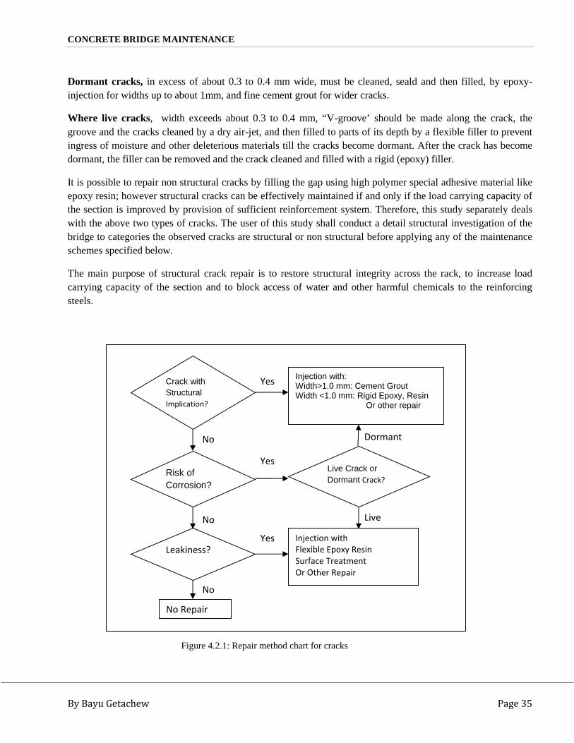
CONCRETE BRIDGE MAINTENANCE
By Bayu Getachew Page 35
Dormant cracks, in excess of about 0.3 to 0.4 mm wide, must be cleaned, seald and then filled, by epoxy-injection for widths up to about 1mm, and fine cement grout for wider cracks.
Where live cracks, width exceeds about 0.3 to 0.4 mm, “V-groove’ should be made along the crack, thegroove and the cracks cleaned by a dry air-jet, and then filled to parts of its depth by a flexible filler to preventingress of moisture and other deleterious materials till the cracks become dormant. After the crack has becomedormant, the filler can be removed and the crack cleaned and filled with a rigid (epoxy) filler.
It is possible to repair non structural cracks by filling the gap using high polymer special adhesive material likeepoxy resin; however structural cracks can be effectively maintained if and only if the load carrying capacity ofthe section is improved by provision of sufficient reinforcement system. Therefore, this study separately dealswith the above two types of cracks. The user of this study shall conduct a detail structural investigation of thebridge to categories the observed cracks are structural or non structural before applying any of the maintenanceschemes specified below.
The main purpose of structural crack repair is to restore structural integrity across the rack, to increase loadcarrying capacity of the section and to block access of water and other harmful chemicals to the reinforcingsteels.
Figure 4.2.1: Repair method chart for cracks
Injection with:Width>1.0 mm: Cement GroutWidth <1.0 mm: Rigid Epoxy, Resin
Or other repair
Crack withStructuralImplication?
Risk ofCorrosion?
Leakiness?
No Repair
Injection withFlexible Epoxy ResinSurface TreatmentOr Other Repair
Live Crack orDormant Crack?
Yes
No
Yes
Yes
No
Dormant
No Live

CONCRETE BRIDGE MAINTENANCE
By Bayu Getachew Page 36

CONCRETE BRIDGE MAINTENANCE
By Bayu Getachew Page 37Figure 4.2: Flow chart for repairing of Concrete Cracks
Post-tensioning Steel
Cracks
PROPAGATIONOF CRACK
Live
Crakes
Dormant
Cracks
Structural
Crack
Non-StructuralCrack
Flexure
Shear
Torsion
Vibration
Shrinkage
Temperature
Mass-Concrete
TYPE OFCRACK
CAUSE OFDAMAGE
B<0.2mm
0.2<B<0.3mm
0.3mm<B<1.0mm
B>1.0 mm
CRACKWIDTH: B
REPAIR
MATERIALS
No Repair
Caulking
Injection
Jacketing
Dry-pack
Shotcrete/Gunite
Patching
Coating
Grinding andOverlay
Stitching
ExternalPrestressing
Elastomeric Sealer
Cement GroutCement Mortar
Fast Setting Mortar
Flexible Epoxy Filler
Rigid Epoxy Filler
Cement Grout
Mortar
Concrete
Cement Concrete
Cement MortarCement Mortar
Cement Mortar
Epoxy Concrete
Bituminous Coating
Tar
Latex Modified Concrete
Higly Dense Concrete
Steel Plate
Reinforcement
Reinforcement
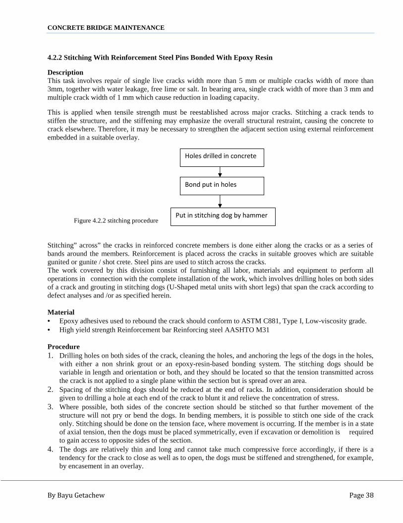
CONCRETE BRIDGE MAINTENANCE
By Bayu Getachew Page 38
4.2.2 Stitching With Reinforcement Steel Pins Bonded With Epoxy Resin
DescriptionThis task involves repair of single live cracks width more than 5 mm or multiple cracks width of more than3mm, together with water leakage, free lime or salt. In bearing area, single crack width of more than 3 mm andmultiple crack width of 1 mm which cause reduction in loading capacity.
This is applied when tensile strength must be reestablished across major cracks. Stitching a crack tends tostiffen the structure, and the stiffening may emphasize the overall structural restraint, causing the concrete tocrack elsewhere. Therefore, it may be necessary to strengthen the adjacent section using external reinforcementembedded in a suitable overlay.
Figure 4.2.2 stitching procedure
Stitching” across” the cracks in reinforced concrete members is done either along the cracks or as a series ofbands around the members. Reinforcement is placed across the cracks in suitable grooves which are suitablegunited or gunite / shot crete. Steel pins are used to stitch across the cracks.The work covered by this division consist of furnishing all labor, materials and equipment to perform alloperations in connection with the complete installation of the work, which involves drilling holes on both sidesof a crack and grouting in stitching dogs (U-Shaped metal units with short legs) that span the crack according todefect analyses and /or as specified herein.
Material Epoxy adhesives used to rebound the crack should conform to ASTM C881, Type I, Low-viscosity grade. High yield strength Reinforcement bar Reinforcing steel AASHTO M31
Procedure1. Drilling holes on both sides of the crack, cleaning the holes, and anchoring the legs of the dogs in the holes,
with either a non shrink grout or an epoxy-resin-based bonding system. The stitching dogs should bevariable in length and orientation or both, and they should be located so that the tension transmitted acrossthe crack is not applied to a single plane within the section but is spread over an area.
2. Spacing of the stitching dogs should be reduced at the end of racks. In addition, consideration should begiven to drilling a hole at each end of the crack to blunt it and relieve the concentration of stress.
3. Where possible, both sides of the concrete section should be stitched so that further movement of thestructure will not pry or bend the dogs. In bending members, it is possible to stitch one side of the crackonly. Stitching should be done on the tension face, where movement is occurring. If the member is in a stateof axial tension, then the dogs must be placed symmetrically, even if excavation or demolition is requiredto gain access to opposite sides of the section.
4. The dogs are relatively thin and long and cannot take much compressive force accordingly, if there is atendency for the crack to close as well as to open, the dogs must be stiffened and strengthened, for example,by encasement in an overlay.
Put in stitching dog by hammer
Holes drilled in concrete
Bond put in holes

CONCRETE BRIDGE MAINTENANCE
By Bayu Getachew Page 39
Note: Stitching will not close a crack but can prevent it from propagating further. Where there is a waterproblem, the crack should be made watertight as well as stitched to protect the dogs from corrosion. Thisrepair should be completed before stitching begins. In the case of active cracks, the flexible sealing methodmay be used in conjunction with the stitching techniques.
5. No remedies (repairs) to the newly repaired concrete shall be performed without the prior inspection andapproval of the Employer’s Representative.
6. On Completion of the works, the site shall be cleaned of all surplus materials and waste, and left in clean,tidy condition.
4.2.3 Injection With Flexible FillerThe task involves repair of single live cracks width of more than 1mm or multiple crack width of more than1mm. It can also be used in bearing area single crack of less than 1mm with no water leakage in concrete bridgestructures.This type of repair covers the repair of an active crack by flexible seals against the migration of water into thecrack. This method involves routing out active cracks; cleaning them by sandblasting, air –water jetting, orboth; and filling them with flexible Bonder or other suitable molded flexible sealant. Flexible bonder is used foractive cracks when a bond breaker is placed over the crack.
Figure 4.2.3: Injection procedure
Clean up concrete surface
Injection nipples bonded on
Crack sealed
Ready for injection
Injection
Nipples removed
Cleaned up sealing
Finishing

CONCRETE BRIDGE MAINTENANCE
By Bayu Getachew Page 40
Material
Flexible sealant or mastic, polyethylene strip/pressure-sensitive tape bond breaker are materials involved forrepair. Non Structural cracks observed on RC or Plain Concrete components of bridges are effectively repairedwith high polymer materials such as Epoxy resin, polyurethane resin, Acrylic and others: either by highpressure injection(up to 30 N/mm2) or low pressure injection (up to 2 N/mm2) techniques. The main purpose isto restore structural integrity across the crack and to block access of water and other harmful chemicals to thereinforcing steels.
Procedure
1. Traffic warning signs shall be established at both ends of the works section.2. The crack should then be cleaned by sandblasting, air- water jetting, or both.3. A bond breaker should be provided at the bottom of the slot to allow the sealant to change shape without a
concentration of stress on the bottom.4. The bond breaker may be a polyethylene strip, pressure-sensitive tape, or other material which will not
bond to the sealant before or during cure.5. Narrow cracks subject to movement, where esthetics are not important, may be sealed with a flexible
surface seal if the crack width is greater than 5mm.6. By using a bond breaker over the crack, a flexible joint sealant may be toweled over the bond breaker
providing an adequate bonding area.7. To maintain hydraulic efficiency in some structures, it may be necessary to cut the concrete surface
adjacent to the crack and to place the retaining cap flush with the original flow lines.8. The crack should then be cleaned by sandblasting, air –water jetting, or both. The mastic is placed into the
routed crack slot and a retaining cap placed over the mastic to confine it. A simple retainer can be made bypositioning a metal strip across the crack and fastening it to expandable anchors or grouted bolts installed inthe concrete along one side of the crack.
9. No remedies (repairs) to the newly repaired concrete shall be performed without the prior inspection andapproval the Employer’s Representative.
10. On completion of the works, the site shall be cleaned of all surplus materials and waste, and left in clean,tidy condition.
4.2.4 Injection With Rigid Epoxy FillerDescriptionThe task involves repair of single dormant crack width of more than 1 mm or multiple crack width of morethan 1 mm. In bearing area single crack width of less than 1mm with no water leakage in concrete bridgestructures such as deck slab and girder.
Epoxy injection of cracks in concrete is a highly skilled process and its success depends largely on theefficiency of the operator. Considerable skill and experience are needed for the successful application of epoxyresin materials. They have to be applied within a very limited time before they harden and have to be handledcleanly to avoid contamination of both the resin mixture and the people working with them.
Therefore, the Supervisor should make sure that the Contractor’s personnel appointed for this particular jobare a specialist on the matter.
Epoxy injection system can be applied for repair of cracks for rigid sealing, dry, moist or wet cracks inreinforced concrete members as well. However, unless the crack is dormant (or the cause of cracking isremoved, thereby making the crack dormant), cracking will probably reoccur, and structural repair by injectionshould not be used.

CONCRETE BRIDGE MAINTENANCE
By Bayu Getachew Page 41
This system shall consist of a paste epoxy used to seal the surface cracks and an injection epoxy used underlow pressure 1400 kPa (1.4 N/mm2) max. to penetrate and fill the cracks and bond the crack surfaces together.Material for each epoxy shall consist of a two-component modified resin bonding system, the base and thehardner.
Accurate batching and proper mixing of the components is crucial for attaining maximum strength and otherproperties of the epoxy materials. Chemical reactions start as soon as the resin components are combined andthe working time shall depend on the system, the temperature and the handling process.
Jacketing method involves fastening of external material over the concrete members to provide the requiredperformance characteristics and restoring the structural value. The jacketing materials are secured to concreteby means of bolts and adhesives or by bonding with existing concrete. Fiber-glass reinforced plastics, andpolypropylene can also be used for jacketing.
Figure 4.2.4 Jacketing method
MaterialsEpoxy Injection fluid shall confirm the following requirements: The resins for crack injection system shall havea two part solvent free low viscosity polymer. The flexible, low viscosity, polymer, crack injection resinsmixed in proportions specified by a supplier & injected in to cracks in concrete, the resin shall form a slightlyflexible & impermeable barrier in both dry & damp condition, and thus, shall form permanent seal in crackedconcrete.
4.2.5 Caulking Using Cement Grout (Hydraulic) or Cement Rigid Epoxy Filler
Description: The task involves repair of single dormant crack width of more than 5mm or multiple crackswidth of more than 3mm, together with water leakage, free lime or salt. In bearing area, single crack width ofmore than 3mm and multiple crack width of 1mm which causes reduction in loading requires repair. Caulkingmethod is used for cracks wider than about 0.5mm.
The job consists of cleaning the concrete along the crack, Cutting the concrete following along the crack with aconcrete saw or with hand or pneumatic tools and opening the crack sufficiently in to “V” or “U” shape toreceive the cement grout or mortar installing injection ports (grout nipples) at intervals aside the crack (to
Clean up damaged part
Bonding
Anchorage bar setting
Form work
Concreting

CONCRETE BRIDGE MAINTENANCE
By Bayu Getachew Page 42
provide a pressure-tight contact with the injection apparatus), sealing the crack between the injection ports,flushing the crack to clean it and test the seal, and then grouting the crack.
Materials: Mixtures of neat Portland cement, and water. Other additives and admixtures (siliceous residue,diatomite) may be added on the approval of the Engineer.
The proportions of ordinary Portland cement to sand will depend upon the size of the spaces to be filled andwill vary from a neat grout to about 1:2 mix. Mix containing two parts sand to one part cement can besuccessfully pumped if all the sand passes the No. 16 sieve and 15 percent or more passes the No.100 sieve. Theamount of water to be added depends upon the consistency required. Grouts with as little as 16 liters of waterper bag of cement could be handled and it should seldom be necessary to use more than 35 to 40 liters of waterper bag of cement. Where necessary and approved by the engineer, admixtures to Portland cement groutmixtures may be added for delaying the setting time, increasing flow ability minimizing segregation andshrinkage. Water shall be fresh, clean, and free form injurious amounts of sewage, oil, acid, alkali, or organicmatter.
.
Figure 4.2 crack arresting method using semicircular pipe during concrete repair
4.3 Repair Methods for Concrete Peel off, Delimitation and Void
Concrete voids are created due to poor vibration of fresh concrete during pouring (unable to vibrate itsufficiently) of failure to vibrate it before the initial setting time. Concrete voids on the permanent structureshave to be maintained to restore the integral concrete strength of the structure designed to act as a unit, and toprotect reinforcements and the concrete from effect of water leakage or dampness which potentially generatesrusting and deterioration. Removal of the defective concrete and replacement with a suitable material andworkmanship are the major techniques discussed under.

CONCRETE BRIDGE MAINTENANCE
By Bayu Getachew Page 43
Figure 4.3: Flow chart for repairing of Concrete Peel off, Delimitation and Void
Delimitation/Honeycombs
Reinforcement Exposed
Reinforcement notexposed
DEPTH OFDAMAGE
Superstructure
Substructure
LOCATION
0.1 m2>A
0.1 m2≤ A
SIZE OFDAMAGE
(A: AREA)
REPAIR METHOD
Dry-packing
Patching
Resurfacing
Shotcrete/Gunite
Pre-packing
ConcreteReplacement
Cement Mortar
Epoxy Concrete
Mortar
Concrete
MATERIALS
Epoxy Concrete
Polymer Concrete
Cement Concrete
Cement Mortar (Fast-setting Mortar)
Coarse Aggregate+
Cement Sand Grout
Portland CementConcreteLow-Slump, HighDense Concrete
High Almina CementConcreteEpoxy Mortar Cementand Concrete
Polymer Concrete
Latex-ModifiedConcrete

CONCRETE BRIDGE MAINTENANCE
By Bayu Getachew Page 44
4.3.1 Concrete Void Repair by Using Dry-Pack Mortar
The task involves repair of partial range of honeycomb or de lamination, which affect the durability of concretebridge structures. This item shall consist of furnishing the necessary labor, material and equipment to repairhoneycomb and delaminating in concrete bridges with dry-pack methodology, the item includes preparation,mixing placing, finishing and curing of the dry-pack mortar.
Dry packing is a process of ramming or tamping into a confined area a low water-content mortar. Because ofthe low W/c material, there is little shrinkage, and the patch remains tight and is of good quality with respect todurability, strength, and water tightness. This technique has an advantage in that no special equipment isrequired. However, the method does require that the craftsman making the repair be skilled in this particulartype of work.
Figure 4.3.1: A dry pack method
Materials: The material needed for maintenance by dry-packing method is a slurry bond and a low water-content mortar. The cement slurry bond coat consists of equal parts of cement and fine sand and the mortarconsists of one part cement, two and one-half (2 1/2) to three (3) parts sands passing a No. 16 sieve, and onlyenough water so that the mortar will stick together when molded into a ball by slight pressure of the hands andwill not exude (give off) water but will leave the hands dry.
If the patch must match the color of the surrounding concrete, a blend of Portland cement and white cement canbe used. About one-third white cement is adequate for blending, but the precise proportions should bedetermined by trial.Dry pack, mortal shall consist of type I or II Portland cement, clean sand that will pass a 1.18mm (No.16) sieve,and clean water.
Clean up damaged part
Form work
Full up the material
Tighting the material
Take care with 7 days
Remove form work

CONCRETE BRIDGE MAINTENANCE
By Bayu Getachew Page 45
Procedures1. The Employer’s Representative will indicate what part of the existing structure is to be removed and the
required dimension of the new work2. The area to be repaired should be undercut slightly so that the base width is slightly greater than the surface
width.3. After the area or slot is thoroughly cleaned and dried, a bond coat should be applied. Placing of the dry-pack
mortar should begin immediately.4. Dry-pack mortar should be placed in layers having a compacted thickness of about 10 mm (3/8 in.) Each
layer should be compacted by use of a hardwood stick. It is usually necessary to scratch the surface of thecompacted layers to provide bond for the next layer. One layer may be placed immediately after anotherunless an appreciable rubbery quality develops; if this occurs, work on the repair should be delayed 30 to 40minutes.
5. Successive layers of dry pack are placed without interval, unless the material becomes spongy, in which casethere should be a short wait until the surface stiffens. Area should be filled flush and finished by striking aflat-sided board or the flat of the hard wood stick against the surface.
6. After being finished, the repaired area should be cured. Procedures for curing and protection of dry packrepair area should be protected and not exposed to freezing temperatures for at least 3 days after applicationof the curing compound.
7. No remedies (repairs) to the newly repaired concrete shall be performed without the prior inspection andapproval the Employer’s Representative.
8. On completion of the works, the site shall be cleaned of all surplus materials and waste, and left in clean,tidy condition.
4.3.2 Concrete Void Repair by Using Portland Cement/Sand Mix Mortar Blended With Epoxy Resin
The task involves repair of wide range of voids, which affect the durability of concrete bridge structures havinga volume of less than 600 cm3.The concrete Void will be repaired by a Portland Cement/sand mix mortar blended with Epoxy Resin. Theplastering will be applied either using a pressure grout or conventional hand tools. In areas where formworkerection and concrete casting is possible, the maintenance operation is done using a Portland Cement Concrete.The suitable concrete mix shall have a minimum cement content of 340kg/m3 with a maximum aggregate sizeof 10mm and slump in the range of 25mm to 75 mm. The same techniques of mixing and paving of the cementbased polymer modified concrete shall be adopted as concrete peel of maintenance.
Materials
The Epoxy Resin and cement based polymer modified concrete shall also fulfill the criteria set above or like thematerials used for concrete void repair by using dry-pack mortar.
ProceduresA. Employer’s Representative will indicate what part of the existing structure is to be removed and the
required dimension of the new work.

CONCRETE BRIDGE MAINTENANCE
By Bayu Getachew Page 46
B. Determine the extent of defective area by sounding with a hammer or other approved method and mark thearea to be removed. Remove all defective concrete portions marked up to 10 mm below the reinforcement,if any, using the following techniques. Small pneumatic hammer Small electric Jackhammer Sludge hammer and chisel the concrete may be removed using high – pressure water blasting. In all the
above mentioned techniques, care must be taken to a avoid defect to the surrounding concrete.C. After properly cleaning the removed part, the old concrete surface shall be primed with Epoxy Resin (avoid
applying too thickly). The concrete Void will be repaired by a Portland cement/ sand mix mortar blendedwith Epoxy Resin. The plastering will then be applied either using a pressure grout or conventional handtools. In areas where formwork erection and concrete casting is possible, the maintenance operation is doneusing a Portland Cement Concrete. The suitable concrete mix shall have a minimum cement content of340Kg/m3 with a maximum nominal aggregate size of 10mm and a slump in the range of 25mm to 75mm.The same techniques of mixing and paving of the cement based polymer modified concrete shall be adoptedfor concrete peel of maintenance. Forms and scaffolds shall be erected both for the actual constructionpurpose and for curing of the fresh mortar or the Portland cement concrete.
D. No remedies (repairs) to the newly repaired concrete shall be performed without the prior inspection andapproval of the employer’s Representative.
E. On completion of the works, the site shall be cleaned of all surplus materials and waste, and left in clean,tidy condition.
Figure 4.3.2: Patching method
Traffic Control
Except deteriorated concrete
Clean up concrete surface
Install formwork
Concreting
Take care few hours-few days

CONCRETE BRIDGE MAINTENANCE
By Bayu Getachew Page 47
4.4 Repair Methods for Concrete Structure Honey CombHoney comp is the voids left in concrete due to failure of the mortar to effectively fill the spaces among coarseaggregate materials. This is caused by lack of vibration or over vibration, which creates air bubbles. Repairingof honey comp requires preparatory work and resurfacing.
I. Preparatory workIt is always better to avoid imperfections such as honeycombing in concrete rather than repairing. However, if
honeycombing does occur then it can be repaired using the following techniques. The extent and depth of the honeycombed area first needs to be defined. This can be done by chiseling out
the affected area to expose sound concrete or by using non-destructive testing techniques such as impact-echo.
If the honeycombed area is small in extent and depth does not significantly jeopardize the quality of thecover concrete protecting the reinforcement then it can be repaired by patching with mortar of a similarcolor to the base concrete. Remove any lightly attached stones before the mortar is worked into the spacesbetween the aggregate ensuring that it completely fills the honeycombed area.
The area should be slightly over filled and screeded off to give a similar texture to the surrounding surface.The patch should then be cured.
Consideration needs to be given to the appearance of the repaired surface relative to adjacent untreatedsurfaces.
As a general rule, mortar used for patching should be made from the same materials as the original concreteexcept to lighten the color and thus better match the existing surface.
If the honeycombing is extensive and requires penetration down to the reinforcement or even deeper, it isnecessary to cut out the defective concrete and replace it with sound concrete.
It is essential that the reinforcement be surrounded by sound concrete. The advice of a suitably qualifiedengineer should be obtained to check that the load-carrying capacity of the member, as repaired, will besatisfactory.
II. ResurfacingHoneycomb can be repaired by using Dry-Pack Patching or Gunite/shotcrete Pre-placed aggregate.Shotcrete (Pneumatically applied cement-concrete) and Gunite (pneumatically applied cement-mortar) aresuitable for forming the new concrete (i.e. the restoration- concrete) and for strengthening and jacketing ofvarious structural elements.Re-surfacing method, here –in after, describing about polymer concrete overly, a polymer concrete overlayprotective system has been used as an experimental project in several countries.The overlay consists of an application of monomer resin to the desk surface, followed by an application of thefine aggregate.The process is repeated until four layers have been placed. The overlay is relatively impermeable and skidresistant. Generally, the resin is over the deck and fine aggregate is covered over the resin. Afterpolymerization, the excessive aggregate is removed and the process is repeated for other layers. The four layersproduce a thickness of about 12 to 15 mm. The overlay system consists of the following steps for each layer.
1. Surface Preparation,2. Mixing and application of monomer resin,3. Fine aggregate application and compaction4. Polymerization of monomer and removal of excess aggregate.

CONCRETE BRIDGE MAINTENANCE
By Bayu Getachew Page 48
Figure 4.4.2a: Shotcrete/Gunite Method
4.5 Repair Methods for Scaling or spalling of Concrete1. Scaling: Scaling is a form of disintegration. A common cause of scaling is freezing and thawing conditions.
Localized flaking or peeling is normally a form of scaling. Scaling, which can also be referred to asspalling, is rated based on the depth of the defect. The rating system is as follows: Light spalling: is when the loss of surface mortar does not expose any coarse aggregate. Medium spalling: occurs when the damage has a depth of up to 10mm. Severe spalling: is determined when the depth of the damage ranges from 5mm to 10mm. There is also
some loss of mortar surrounding aggregate particles with a depth range of 10mm to 20mm. Very severe spalling: is the loss of coarse aggregate particles, as well as surface mortar and surrounding
aggregate, generally to a depth greater than 20mm.Scaled concrete surfaces can be repaired by applying a thin resurfacing of concrete properly bonded to theunderlying old concrete. All defective concrete must be removed from the surface, by scarifying or scrubbingwith hydrochloric acid, before applying the new concrete.A thin layer of neat cement paste should be brushed into the damp surface of old concrete is placed, finishedand cured by normal procedures. Any relief joints present in the old concrete should be carried through the newresurfacing.
Expossed deteriorated concrete
Clean up concrete surface
Cement Mortar Mix
Spread mixed cement

CONCRETE BRIDGE MAINTENANCE
By Bayu Getachew Page 49
Figure4.5 flow chart for repairing of Concrete Scaling or spalling
WEARING
Asphalt Concrete
Asphalt Cement
Concrete
Epoxy/PolymerConcrete
Latex ModifiedConcrete
PolymerConcrete
EpoxyConcrete
Concrete
Mortar
CoarseAggregate
+Cement Sand
Grout
Portlandcement
Concrete
Low-Slump,High DenseConcrete
Epoxy MortarCement Concrete
Polymer concrete
Latex-ModifiedConcrete
MATERIALS
ByVehicleRunning
By RiverFlow
Reinforcementexposed
Reinforcemtn notexposed
CAUSE OFDAMAGE
DEPTH OFDAMAGE
SUPER
ST.
SUB
ST
LOCATIO
1.0 M2>A
1.0 M2≤A
SIZE OFDAMAGE(A=AREA)
Overlaying
REPAIR METHOD
Resurfacing
Dry-packing
Pre- packing
Replacement

CONCRETE BRIDGE MAINTENANCE
By Bayu Getachew Page 50
4.6 Other Defects Repair Methods
4.6.1 Scouring and Erosion
4.6.1.1 Repair Methods for Scouring
Riprap remains the most common countermeasure used to prevent scour at bridge abutments. A number ofphysical additions to the abutments of bridges can help prevent scour, such as the installation of gabions andstone pitching upstream form the foundation. The addition of sheet piles or interlocking prefabricated concreteblocks can also offer protection.
Trapezoidal-shaped channels through a bridge can significantly decrease local scour depths compared tovertical wall abutments, as they provide a smoother transition through a bridge opening. This eliminates abruptcorners that cause turbulent areas. Spur dikes barbs, groins, and vanes are river training structures that changestream hydraulics to mitigate undesirable erosion or deposits. They are usually used on unstable streamchannels to help redirect stream flow to more desirable locations through the bridge. The insertion of piles ordeeper footings is also used to help strengthen bridges.
If a pier is found to be suffering from adverse scour conditions, the problem can be corrected by changing thestructure (enlarging the footing, strengthening or adding piles, providing a sheet piling barrier around the pierfoundation) or replacing the material which has been washed away (broken stone, concrete rip rap,..)Hydraulic protection techniques include slope protection, foot protection, river bed protection and riverrealignment depending on the extent and nature of the hydraulic problems encountered such as scour, erosion,and fold flow.
Slope protection is applicable to river banks adjacent to abutments where erosion is observed.Footing protection is applicable to footing of the slope area in order to prevent slope failure caused by scouringaction on the river bed. River bed protection is applicable to river bed surrounding the river piers where localscouring or river bed lowering is observed.River realignment work is applicable to extremely eroded banks of a meandering river located at the vicinity ofa bridge upstream.Selection of a specific protection technique depends on the stream type, river scale, flood flow velocity,foundation type and geology of each site. Gabion Protection for Scouring: The task involves preventing slope failure caused by scouring action on
the river bed, for small scale river.Materials used for construction of Gabion walls and mattresses are:
Rock: Rock used for gabion structures shall consist of clean, sound durable stones that are resistant toweathering and water action. Shale or other soft rock may not be used. The stones shall be angular in shape witha height and width dimension of at least one third the length.
The gradation of the mixture shall be such that at least 80 percent (by weight) of the stones have a minimumdimension of at least 125mm. The maximum dimension of a stone shall be the lesser of 300 mm or the gabionstructure thickness.

CONCRETE BRIDGE MAINTENANCE
By Bayu Getachew Page 51
Gabions: Gabion baskets shall be cubical in shape and shall be assembled from independent rectangular faceslaced or clipped together. They shall comprise galvanized steel wire of the following minimum diameters: meshwire 3mm (or Gauge 17), Perimeter/selvage to all edges 3.9mm (or Gauge 19), tying/binding 2.2mm (or Gauge15). The individual gabions shall not be greater than 2m x 1m x 1m although the contractor may substituteequivalent multiple of smaller sizes at his own additional cost. They shall be fitted with the manufacture’srecommendations such that the individual cells do not have a length exceeding the width. Meshes shall behexagonal with openings no greater than 100mm x 120mm.
Procedures
1. Traffic warning signs shall be established at both ends of the work section2. All stumps, roots debris and rocks shall be roved and disposed of as directed by the Consultant, prior to
placing gabions. Excavation to accommodate gabion installation shall be carried out to the lines andlevels as specified on the plans or as directed by the Consultant.
3. Gabion cages shall be assembled by tying the appropriate faces together along the self edges withbinding wire. The binding wire shall be tightly looped around every other mesh opening to form a spiralwith single and double loops alternating.When assembled, gabion baskets shall be divided by the diaphragms into compartments having a plandimension of one meter square. Gabion mattress shall be separated lengthwise by the dividers in to 1mwide strips. The diaphragms shall further subdivide the mattress into compartments that have a plandimension of 1m x 3m. Gabion units, grouped together to form a gabion structure, shall be securelybound to each other along all contacting self edges in the same manner as the faces are bound in theassembly of the cages.
4. Extend gabions, on slope, at least 1m below streambed or to non- erodible material. Where it is feasible,extend gabion out from the toe across the streambed of an erodible channel a horizontal distance of atleast 5 times the thickness of the gabion mattress.
5. Rock for filling gabion boxes and mattresses shall be hard durable stone of low porosity having aninterlocking texture with few discernible defects. Grading Rock filling for the gabion boxes shall complywith the following grading.
Sieve Size (mm) Percentage Passing
200 80 -100
150 0 – 40
75 0 -10
9.5 < 2
Rocks shall be filled in the assembled cage units either by machine or by hand. When machine is used, minorrock repositioning shall be done by hand to fill the voids between larger rocks and there by achieve a densestructure. Rocks along visible faces shall be selected and placed by hand form among the larger sizes with a flatface toward the exterior to produce a likely of a masonry structure and a neat and work man like appearance.

CONCRETE BRIDGE MAINTENANCE
By Bayu Getachew Page 52
6. Following the filling of each gabion unit, the lid shall be affixed in position so that the self edges coincidewith the perimeter of the filled gabion unit. The self edges shall then be laced together in the same manner asdescribed above.
7. Following filling of each gabion unit final level is reached, filling around gabions and sides of excavationswill be accomplished. Backfilling shall comprise compacted gravel or crushed rock, free from organic matterand clay lumps, conforming to the following grading.
Sieve Size (mm) Percentage passing
200 100
75 80 -100
0.075 0 – 15
Backfilling shall be placed and compacted in layers not exceeding 200 mm thickness. Backfilling shall becompacted to a density not less than 95% of the maximum dry density ratio determined for the in situ materialusing Standard Compaction. Material directly above gabion boxes shall be placed without compaction. Oncompletion of the works, the site shall be cleaned of all surplus materials and waste, and left in clean, tidycondition.
Spur Dike by Stone Masonry: The task involves reducing erosion caused by water flowing along theupstream side of the embankment. Scour may still occur with spur dikes, but it will be moved upstream andaway from the abutments. Spur dike is applicable for large-scale river. This item shall consist of providing thenecessary labor, materials and equipment to construct spur dike at the vicinity of a bridge upstream includingclearing, excavation, driving wooden log piles, and construction the spur dike as specified by the engineer.
1) Spur Dike by Stone Masonry2) (Type A)
Procedures1. Traffic warning signs shall be established at both ends of the work section2. Areas on which spur dike is to be constructed shall be cleared, grubbed, and excavated as specified on the
plans or as directed by the Consultant.3. A box like compartment shall be prepared by driving wooden piles of diameter 150mm at 15cm to 30 cm
center to center. The piles are secured by wooden bracings. The hollow spacing is filled up by boulders.4. The dike shall be constructed in successive layers of earth about 45cm thick by mechanical compaction. The
layers are thoroughly compacted by rollers of recommended weight and type. When compaction of one layeris fully achieved, the next layer should be laid and compacted. The designed spur dike section hence shall becompleted layer by layer.
5. These dikes shall consists segments of dikes located river ward from the existing bank with gaps between thedikes 2 or 2-1/2 times the structure length. The length of the gaps between the dikes hall be about 50 to 60percent of the length of each vane. The dikes should be placed at a slight angle to the direction of flow, about10 to 15 degrees, with the downstream end of the dike farther riverward than the upstream end.The side slopes (upstream and downstream faces) of spur dikes should be maintained on the natural angle ofrepose of the earth material used to construct the dikes.

CONCRETE BRIDGE MAINTENANCE
By Bayu Getachew Page 53
6. Slopes shall be finished to a reasonably smooth and compact surface within a tolerance of 15cm from thesurface lines shown on the plans. Immediately prior to placement of riprap bedding, the prepared base willbe inspected. Riprap or bedding shall not be placed until the prepared base has been approved.
7. The finished slope shall be back filled with gravel and sand which is spreaded uniformly. Compaction of thebedding material will not be required, but material shall be finished to a reasonably even surface, free formmounds or depressions.
8. Riprap shall be placed over the backfill material in a manner that will produce a reasonably well-gradedmass of rock with the minimum practicable percentage of voids. Riprap shall be placed to its full coursethickness in one operation and in a manner to avoid displacing underlying material.Finished riprap shall be free from objectionable pockets of small stones and clusters of larger stones. Handplacing may be required to the extent necessary to secure the results specified and form uniform slopes.Rock for grouted Riprap shall be thoroughly moistened and any excess of fines shall be sluiced to theunderside of the stone blanket before grouting. Stones shall weight between 50 and 150 pounds each. Atleast 60 percent shall weigh more than 100 pounds, and approximately 10 percent may weigh 50 pounds less.Care shall be taken during placing to keep earth or sand from filling spaces between stones. After stones arein place, spaces between them shall be filled with grout from bottom to top and the surface swept with a stiffbroom.
9. Grout shall consist of 1 part hydraulic cement and 3 parts sand, thoroughly mixed with water to producegrout having a thick, creamy consistency.Riprap shall not be grouted in freezing weather. In hot, dry weather, the work shall be protected fromsunlight and kept moist for at least 3 days after grouting by the use of saturated burlap.
The grout may be delivered to the place of final deposit by any means that will insure uniformity and preventsegregation of the grout. If penetration of grout is not obtained by gravity flow into the interstices, the groutshall spaded or roded to completely fill the voids in the stone blanket. Pressure grouting shall not unseat thestones; and during placing by this method, the grout shall be spaded or roded into the voids.
Penetration of the grout shall be to the depth specified on the project plans. When a rough surface isspecified, stone shall be brushed until from one-fourth to one-half of the depth of the maximum size stone isexposed. For a smooth surface, grout shall fill the interstices to within a 1.25cm of the surface.
On completion of the works, the site shall be cleaned of all surplus materials and waste, and left in clean,tidy condition.
Dumping StoneThe task involves preventing slope failure caused by scouring action on the river bed, for small to MediumRiver and foundation ground is relatively solid.
MaterialsThe rock material shall be sound and durable, angular in shape, resistant to weathering and water action. Thematerial should be free of overburden, spoil, shale or organic material, cracks or other structural defects andshall have a specific gravity of a t least 2.40.
Gradation of the rock shall be weighing not less than 5 kgs and at least 50 percent of the rock shall weightnot less than 50 kgs.

CONCRETE BRIDGE MAINTENANCE
By Bayu Getachew Page 54
Dumped Stone & Wire Mesh GabionProcedures1. Traffic warning signs shall be established at both ends of the work section2. Areas on which footing protection is to be constructed shall be cleared, grubbed, and excavated. A footing
trench shall be provided along the toe of the slope and the trench shall be constructed as detailed in theplans. The river bed should also be cleared and leveled and backfill the river bed in layers using gravel,broken stone or quarry waste up to a minimum depth of 0.5 to 1.5 m.
3. Place mass stone with minimum practicable percentage of voids and a minimum thickness of 24 mm. Thescoured area to be filled with rock using stone of 10-30 kg weight, or heavier, and place the smaller sizestone in the lower layer
4. Fill spaces between stones with smaller size stone5. Continue work layer after layer until final level is reached. The top layer should contain the heaviest stones
and have an even flat surface at river bed level6. When it is not possible to place stones in regular layers due to water flow, the scour area can be filled by
random filling of the scour depression. Drop stone blocks into scour depression either from the bridge orfrom the bank until the depression has been filled.
Placing of Rip RapThis methodology is applicable in preventing foundation failure caused by scouring action on the river bed, andat the base of abutments and piers.This item shall consist of providing the necessary labor, materials and equipment to repair foundation scouringincluding the preparation of the ground surface to receive gabions, the construction of the gabion structures inplace, complete with rock filling at locations specified on the drawings.
1) Stone Masonry (Type A)MaterialsMaterials used for rehabilitating scour are stone fulfilling the 2002 ERA standard Technical Bridge RepairManual, Division 8400 and 8900.
ProceduresStakeout the area around the river bed, the pier or abutment wall where scour has occurredExcavate the scoured area to the lowest eroded levelPlace riprap stones in layer in the excavated and prepared scoured hole starting with the smaller size stone inlowest layer.Fill space between stones with a cyclopean concrete (1cement: 4 sand: 8 stone by volume).Continue work layer after layer until normal bed level is reached. The top layer should contain the heavieststones and have a flat even surface at river bed level.
4.6.2 Water Leakage and Deteriorations
4.6.2.1 Repair by Coating – Using Acrylic Polymer
The task is applicable for stopping serious and wide range of water leakage through cracks or voids which mayprogress and cause a reduction in loading capacity, together with leaching free lime or salt.
Materials: Materials used under crack, voids, and blockage of drains are independently specified on therespective defect repairs. The material used for coating of concrete surface to prevent water leakage is AcrylicPolymer Coating.

CONCRETE BRIDGE MAINTENANCE
By Bayu Getachew Page 55
ProceduresFollowing the maintenance steps of the concrete, all surfaces to be treated with the acrylic polymer shall be dryand free from contamination such as oil, grease, loose particles, decayed matters, moss, algal growth, and alltraces of mould release oils and curing compounds. This is best achieved by lightly grit-blasting the surface.The surface shall be then treated to be pre-soaked with clean water.
The liquid formed from acrylic polymer modified cementitious coating supplied in ready to mix kit shall bepoured into a metal drum and an equal volume of clean fresh water shall be added for brush applicationconsistency.
Mixing shall be done with a propeller agitator attached to a slow speed drill all as per the supplier’s instruction.
The powder component shall be added gradually to avoid lump formation and mixed for 2 to 4 minutes.
The prepared mix shall then be immediately applied after mixing up to a total dry thickness of not less than2mm. For further detail, the user shall follow the supplier’s manual.
Coating is a kind of water- proofing “membrane” system (for preventing moisture ingress). The bitumionouswearing surface with “membrane” has been widely in Europe and United States, and its performance has beenacceptable.
The advantages of a membrane are its easy installation and relatively low cost. The advantages are as follows.
1. Premature deterioration of bituminous overly in area of high volume traffic and inadequate drainage.2. Blistering, caused by expansion of trapped and water vapor after placement3. Poor bonding at the protection layers in the area near the expansion joint.4. Local instabilities due to bleeding and bubbling5. Replacement of the membrane wherever the surface is removed
It is suggested that the minimum thickness of asphalt wearing surface over the membrane be a minimum of 65to 80 mm. If placed in two coarse, the lower course should be denser or more impermeable than the uppercourse in order to prevent trapping of water in the low course.
4.6.2.2 Repair by Grouting – using Portland cement
The task is applicable for stopping serious and wide range of water leakage through cracks or voids which mayprogress and cause a reduction in loading capacity, together with leaching free lime or salt.Wide cracks may be repaired by filling with Portland cement grout. This method is effective in stopping waterleaks, but it will not structurally bond cracked sections.
Materials: Grout mixtures may contain cement and water or cement plus sand and water, depending on thewidth of the crack. However, the water – cement ratio should be kept as low as practical to maximize thestrength and shrinkage.

CONCRETE BRIDGE MAINTENANCE
By Bayu Getachew Page 56
Procedures
Traffic warning signs shall be established at both ends of the work section Clean the concrete along the crack Install built-up seats (grout nipples) at intervals astride the crack to provide a pressure tight connection
with the injection apparatus and seal the crack between the seats with a cement paste. Pump grout into the crack through the nipples. Maintain the pressure for several minutes to ensure good
penetration of the grout. The grout should have a water-cement ratio of one part cement to one to fiveparts water.
No remedies (repairs) to the newly repaired concrete shall be performed without the prior inspectionand approval of the Employer’s Representative.
On completion of the works, the site shall be cleaned of all surplus materials and waste, and left inclean, tidy condition.
4.6.3 Concrete Deck – Slab and Pier Columns Deterioration and Repair Methods
4.6.3.1 Repair of Concrete Deck – Slab by Removing and Casting new Concrete Chiseling, Demolishing and Cleaning
A) All elements of the bridge shall be chiseled and plastered (horizontal, vertical and overhanging) andall surfaces, as directed by the Engineer.
B) Chisel out and remove all spelled, unsound, damaged, fouled, porous and loose concrete plusother identified area of unsound concrete. During removal of concrete, the concrete should be removedto expose the full circumference of steel reinforcement and should extend along the length of thecorroding bar for at least 50 mm beyond point at which corrosion is visible. Exercise care whenchipping out concrete so as not to cause structural damage.
C) All exposed reinforcement should be cleaned/ brushed to remove scale and rust. It must be ensuredthat all areas prior to treatment are free from all unsound materials such as dust, oil, grease, corrosion byproducts and organic materials.
D) Treat substrate using biowash. Placement of a new Rebars and Concrete
A) Prime substrate by bonding primer to obtain maximum adhesion.B) Apply polymer modified repair mortar using shot concrete or approved method for piers.C) Place reinforcement. Transverse bars shall be bent up so as not to block the traffic on the other laneD) Place form work for expansion gap at every end of pan.E) Pour polymer modified concrete as per the drawing.F) Cure using curing membrane as per the specification.G) After seven days coat with water proofing material including the main span.H) After curing as per the manufacturer specification, place asphalt concrete for the whole span to level
with the main span.
4.6.4 Repair of Pier Columns – Encasing
The repair work shall be conducted for all elements of the pier as indicated in the drawings and as directed bythe Resident Engineer (pier column, pier cap, bracing).

CONCRETE BRIDGE MAINTENANCE
By Bayu Getachew Page 57
A) Remove existing concrete cover.B) Brush cleans the existing reinforcement.C) Place additional reinforcement bars as per the design.D) Apply polymer modified repair mortar using shot concrete or approved method.E) Cure using curing membrane as per the specification. After the mortar is cured coat with water proofing
material.General procedure for Application of materials
A) The areas to be treated must be free from all unsound material that is dust oil, corrosion, byproducts andorganic growth.B) Smooth surfaces should be roughened; all loose material and surfaces has to be removed and steel cleanedto bright metal preferably using wet grit or water blasting techniques or equivalent approved methods.C) The prepared substrate concrete should be thoroughly soaked (preferably 24 hours before) with clean wateruntil uniformly saturated without any standing water. Highly porous substances may require sealing withpolymer admixture.D) Mix of priming material shall be as per the specification of the manufactureE) Placing shall be applied using spray techniques. Make sure air is not entrapped and ensure total protection isachieved to the satisfaction of the Resident Engineer. Manufacturer specification shall be strictly followed.F) Application of curing membrane should take place as soon as after any residual surface water form trawlinghas evaporated. But generally, manufacturer specification shall be strictly followed. It is important that thesurface of the coating is protected from strong sun light and drying wind with curing membrane.G) For maximum curing efficiency, if the surface is subject to strong sunlight or drying winds, a second coatshould be applied. This waiting time is generally 15 minutes.H) Overcoat as per the specification of the manufacturer.I) To obtain maximum adhesion to coatings and cement based substrates, the surfaces of the reveals should beprimed with bonding primes. Sealant must be applied as per the specification of the manufacturer.J) Biowash shall be spray applied. It kill active mould, fungal and bacterial spores and chlorophyll containingorganisms such a moss, Lichen and algae, within a maximum of two days, Remain active after its initialapplication, guarding against subsequent infection for up to two years.K) Application should take place after cleaning visible areas of growth by wire brush, scraper or mechanicalmeans. Apply biowash undiluted by brush, roller or airless spray to areas exhibiting visible contamination,ensuring that all surfaces are thoroughly wetted. Wash off bleach solution and remove dead growth by hosingor brushing. Allow to dry before subsequent treatment.
4.6.5 Practical example of deck repair on Awash River Bridge
General repair of Awash Bridge (along Addis - Jimma, A5 route) was conducted under capacity buildingprogram of ERA and JICA cooperation. The repair work focused on resurfacing of highly damaged girdersside, restoration of deteriorated decks and highly exposed Girders.
In repair of Deck slabs the following procedures were followed.Deck slabs at drainage locations
Remove deteriorated concrete (use hammer sounding technique)

CONCRETE BRIDGE MAINTENANCE
By Bayu Getachew Page 58
Remove the rust of exposed rebar and set a new rebar by welding or wiring considering the requiredoverlap which is not less than 60 cm,
Paint anti-rust paint to rebar Wet the surface by water to create a surface saturated water condition for bonding Prepare and plaster using a specially prepared mortar mix with bonding agent (if necessary use form
work) Apply the normal mortar mix shortly before bonding agent dries, use your hands to apply the mortar
hard Treat the surface with cement screed Then, use water spray to cure for avoiding drying shrinkage crack.
Along with the deck slab repair, drainage repair was made using the following procedures Removing the accumulated soil on the top of the deck blocking the drainage Removing the old drain pipe and making a hole for the new PVC drain pipe Set the new pipe of Dia,50 and 75 mm with enough length for avoiding damage by flushed water Fill up a gap between the pipe and the concrete by epoxy resin with sand to avoid water leakage Set bars at upper opening for protection against debris and set elbow at bottom of pipe for avoiding
flush of water to girder and deck Provide the upper draining area with a tapered surface for easy Apply the mortars like the above repairs Treat the surface with cement screed Then, use water spray and vinyl sheet to cure for avoid drying shrinkage crack
4.6.6 Rust Treatment of Concrete Reinforcing Bar
4.6.6.1 Repair of Rusted Re-barsThe purpose of reinforcement bar repairing is to replace the rusted or chemically affected and severely defectportion, and to cover the reinforcement for avoiding further strength deterioration. The task involves repair ofpartial rebar exposure without corrosion, which affects the durability of the deck slab and beams. For properrepairing or replacing of rebar exposure, the following steps may be usedStep 1 Concrete removal around the full circumference of the corroded re-barStep 2 Removal of rust and other bad material of re-barStep 3 Repair or replacement of defect bars or bars with critical section loss.Step 4 Anti-corrosion coatings may be applied to re-bar protection
If the reinforcing steel has lost more than 25% of its cross section, then repair of rebar is generally required. Inthis cause, supplemental bar over affected length has to be provided. New bar may be mechanically spliced toaffected bar or placed parallel to existing bar.
a. Repair Using Water-Abrasive BlastingWater-abrasive blasting is the most effective method for cleaning the reinforcement. The abrasion shall bedone till it remove all solid rust and water dissolves the chloride away. Enough concrete shall be cut away

CONCRETE BRIDGE MAINTENANCE
By Bayu Getachew Page 59
on the blind side of reinforcement to allow room for water-abrasive blasting. The space shall be used forproviding cover to reinforcement steel.
b. Repair Using Electro Chemical ExtractionInternal unexposed reinforcement bar corrosion can be cleaned using an electrochemical extract ion ofcorrosive chloride method. The chloride extraction shall be carried out by applying a regulated current inorder to create a safe electric field between the reinforcement in the concrete and a temporary, externallymounted anode mesh. During the treatment, negatively changed chloride ions are driven form the concreteby an induced positive/negative field effect. Concurrent to the chloride ion removal, electrolysis at thereinforcement surface produces a high PH environment which repassivates the steel within the effectivetreatment zone. “Cathoding method”
Materials for Treatment of Rusted Re-barA. Patch with Cement Concrete (Type A): The mixture shall consist of 1 part high-early-strength Portland
cement, 1and ½ Parts fine aggregate and 1-1/2 parts coarse aggregate by volume. Sufficient air-entrainingagent shall be added to maintain an air content of 8 plus or minus 2 percent. The slump shall be the minimumpractical for placing and in no case shall it exceed 50 mm. The materials shall be mixed at the site. Ready-mixed concrete shall not be permitted. The mix shall be placed in the area to be patched while the bondinggrout is still wet. Hand finishing with a wood float may be required to produce a tight, uniform surface.
B. Patching With Cement Mortar (Type B, or Type C :) Patching material shall be made using QuickSetting Concrete Mortar, Type 1 or 2, ASTMC 266. The mortar shall be mixed and placed as per manufacture’srecommendations. Coarse aggregate may be added in accordance with the manufacturer’s instructions when thedepth of the patch exceeds 25 mm.
C. Quick Setting Concrete Mortar: Provide prepackage mortar material that requires the addition of wateronly. Use materials capable of being extended 50 percent by dry mortar weight with aggregate meeting thefollowing requirements:
Do not use materials containing more than 50 parts per million of chloride. Do not use any admixture containing more than 50 parts per million of chloride in conjunction with
these materials. Provide quick setting concrete mortar packaged in strong moisture resistant paper bags or other suitable
containers capable of withstanding shipping, normal handling, and storage without breakage. Thepackage shall protect the material form deterioration when stored in a dry condition for a period of 1year. Each package or container must display information regarding the minimum nominal yield andinstructions for mixing. Calculate volumetric yield determinations using the manufacturers’recommended water content.
Work procedures
1. The Contractor will indicate what part of the existing structure is to be removed and the required
dimension of the new work.
2. The perimeter of all removal areas shall be sawed to a depth of 25 mm to produce a vertical or slightly
undercut face. Additional saw cuts may be required to facilitate removal. All unsound concrete

CONCRETE BRIDGE MAINTENANCE
By Bayu Getachew Page 60
including all patches other than sound Portland cement concrete, and all loose and disintegrated
concrete shall be removed. Chipping or hand dressing may remove the unsound concrete. Chipping
hammers shall not be heavier than the nominal 16 kg class and shall be operated at an angle of less than
45 degree measured from the surface of the deck. Concrete shall be removed in a manner that prevents
cutting, elongating or damaging of reinforcing steel. Where the bond between the concrete and a
primary reinforcing bar has been destroyed, or where more than one half of the periphery of such a bar
has been exposed, the adjacent concrete shall be removed to a depth that will provide a minimum of 19
mm clearance around the bar except where other reinforcing bar make this impracticable.
Reinforcement, which has become loose shall be adequately supported and tied back into place. After
completion of the secondary removal operations, the Engineer will re-sound the deck to insure that only
sound concrete remains.
4.7 Mortar Mix and Plastering Works
4.7.1 General
Mortar is a mixture of cement paste and fine aggregate. Grout is a mixture of cementitious material and water,
with or without fine aggregate proportioned to produce a pourable consistency without segregation of the
constituents. [1]
Mortar Sand: cement sand: lime: cement
General building
(Above ground) 5:1 5:1:1
Bridges and general
Building (below ground) 3:1 6:1:1
Internal walls 8:1 9:2:1
Mortar will take months to reach its full strength, however, after about 24 hours it should be fairly hard and
after 4 or 5 days, the strength should be enough to stand up to normal loading condition.
The Various Components Include the Following
Cement: For normal ‘around the house’ types jobs, Ordinary (or Portland) cement is required. This is normally
available in 50kg bags, although smaller 25kg bags are increasingly becoming available to take account of the
UK manual handling regulations. Try not to buy more cement that you need as it cannot be stored for very
long. Some special cements are available (i.e. quick drying) which may be required for special situation.

CONCRETE BRIDGE MAINTENANCE
By Bayu Getachew Page 61
Lime: Lime is sometimes used in cement and reduces the amount of water drawn into the bricks, thus
preventing the cement from drying out too quick and shrinking.
The main types of lime are:
Hydraulic: - which sets by combining with water
Non- hydraulic: - this hardens by drying out
Semi-hydraulic:- which a half-and-half, it mainly needs to dry out but has some hydraulic properties.
Hydrated hydraulic lime must be used straight from the bag. Semi hydraulic or non-hydraulic are better to use
after soaking in water for 24 hours, i.e - stir it into water and leave it overnight and the lime sinks to the
bottom and excess water can then be poured off. Mix the lime with the sand before adding cement.
Sand: Two type of sand are available but are not interchangeable in all applications, whichever type is being
used, always pass it though a sieve before use to remove any small stones etc.
Soft sand (or builders’ sand):- a smooth sand, non-gritty, loamy and with cohesive properties, can be
used for bricklaying mortar, for bedding paving slabs, for rendering walls, etc.
Sharp sand: - this has a gritty feel and is similar to that used to condition soils and potting composts and
can be used for concrete, and for rendering of floors and walls.
4.7.2 Plastering Work for Concrete Defects Repair
Mortar of a consistency suitable for toweling usually does not contain enough cement paste to coat the old
concrete surface or the reinforcement adequately. So a bonding coat of cement grout or polymer admixtures
shall be used.
Bonding coats containing polymer admixtures dry quickly and work shall be organized so that application of
mortar follows the bonding coat within few minutes.
4.7.2.1 Surface Defects Repair (Peel Off/Spalling/Scaling)
Concretes may be peeled off/scaled or spalled due to external impact, aging, or chemical attacks.
Surface defects such as small areas of Peel Off, Spalling, Scaling, honeycombing or cavities produced by form
ties, large isolated blow-holes, broken corner edges, etc, shall be repaired with mortar having a cement and
sand ratio equal to that of the concrete being repaired.
For the repair of large or deep areas of honeycombing and defects, special approved methods and techniques,
such as pneumatically applied mortar, pressure grouting, epoxy bonding agents, etc, may be used.
Where, in the opinion of the Engineer, the extent of the honeycombing or defects is of such a degree that doubt
exists about the effectiveness of repair work, making of a load test is necessary to prove that the structural
safety of the repaired member has not been prejudiced, failing which, the structure shall be rebuilt in part or in
full at the contractor’s cost.

CONCRETE BRIDGE MAINTENANCE
By Bayu Getachew Page 62
Where the concrete has been damaged by adhesion to the formwork panel, the cracked and loose concrete shall
be removed; or where the fresh concrete has lifted off at construction joints, the crack shall be scraped out
immediately on both sides of the wall to a depth of at least 50 mm. The cavities so formed shall then be
repaired as described above.
Rubbing the surfaces
If the finish of exposed formed surfaces does not comply with the requirements for uniformity of texture,
appearance and color, rubbing down the exposed surfaces of the entire structure or of any part of it is
necessary.
The surface shall be saturated with water for at least one hour. Initial rubbing shall be done with a medium-
coarse carborundum stone, where a small amount of mortar, having sand and cement ratio equal to that of the
concrete being prepared, is used on the surface.
Rubbing shall be continued until all form marks, projections and irregularities have been removed and a
uniform surface has been obtained. The paste produced by the rubbing shall be left in place. The final rubbing
shall be carried out with a fine carborundum stone and water: this rubbing shall continue until the entire
surface is of a smooth, even texture and is uniform in color. The surface shall then be washed with a brush to
remove surplus paste and powder.
Where the concrete surfaces formed by sliding formwork require treatment to achieve the surface finish
specified for the member, the concrete shall, as soon as the surfaces under the formwork are exposed, be
floated with rubber – lined floats to the desired finish.
4.7.2.1.1 Patching Repair
This method is applicable for maintenance of small range of peel off, spalling or scaling of otherwise sound
concrete due to external forces which affects the durability of concrete surface.
Total area is between 400 -100 cm2.
This item shall consist of furnishing the necessary labor, material and equipment to repair concrete bridge
decks and concrete surfaces using cement-sand mortar including the removal of deteriorated concrete,
preparation of concrete surface, placing, consolidating and curing the mortar.
Material
The economically recommended material for plastering of concrete honeycomb is a mortar having Cement –
Sand ratio equal to that of the concrete to be repaired (usually 1:3 by volume). Advance mortar containing
specialized binders such as potassium silicate, calcium aluminates, sulfur, and oxysulfate or polymer resins.
They cure or set through film drying (air setting), chemical reactions, thermo set bonds, hydraulic bonds, hot
melting, and multiple component binder systems. Unlike conventional construction products, specialty mortar
is not based on Portland cement. Instead, specialty mortar consist of specialty cement such as potassium

CONCRETE BRIDGE MAINTENANCE
By Bayu Getachew Page 63
silicate that is mixed with water, a coarse aggregate such as gravel or crushed stone, and a fine aggregate or
sand. Specialty cement mortar is used to join components and form structures.
Procedure
a. Traffic warning signs shall be established at both ends of the work section.
b. The Employer’s Representative will indicate what part of the existing structure is to be removed and the
required dimension of the new work.
c. The defects, unsound and contaminated concrete shall be removed and the edges of the patch area should be
prepared.
d. The reinforcement shall be cleaned if exposed and contaminated with rust.
e. Prepare the patch material and bonding coat (as per the maintenance designed) for the job. If a propriety pre-
packaged formulation is to be used the Contractor shall carefully follow the manufacturer’s recommendations.
For common repair jobs a cement and coarse sand mixture in the ratio of 1: 3 by weight is generally adequate.
f. The cement-sand mortar shall be prepared with minimum amount of water. Slump of the mix for shallow
patches should not exceed 25mm. To minimize shrinkage in place, the mortar shall be allowed to stand for half
an hour after mixing and re-mix prior to use. Water shall not be used to re-temper the mix.
g. The bonding coat shall be applied (as per the design) to concrete substrate and to the reinforcement.
h. The mortar shall be applied immediately following the bonding coat. The mortar shall be forcibly projected or
dashed onto the substrate and placed in layers about 10mm thick. Each surface using a blunt piece of wood or
hammers. Each layer shall be cross-patched to facilitate bonding with the next layer. Generally, there need be
no time delays between the layers. For vertical and overhead repairs of considerable thickness, in order to
prevent sagging of mortar, the repair may be limited to about 50mm thickness at one time, and shall then be
kept moist for a day before applying the successive layer.
i. The patch shall be finished to the texture of the surrounding concrete by using similar form material and
hammering with mallet or wood floating or steel trowel ling as instructed by the Engineer.
j. Curing shall be started as soon as possible. The curing should be thorough and continuous to develop strength
and impermeability and to reduce drying shrinkage to a minimum while bond strength is developing. Water
used for curing shall be free from ingredients harmful to concrete. Curing shall be continued for a minimum of
4 days in temperate weather and 7 days in hot, dry or windy conditions.
k. On completion of the work, the site shall be cleaned of all surplus materials and waste, and left in clean, tidy
condition.
CONCRETE BRIDGE MAINTENANCE
By Bayu Getachew Page 64
4.7.2.1.2 Gunite/ Shot-crete Repair
Gunite (pneumatically applied cement-mortar) and Shot Crete (pneumatically applied cement-concrete) are
suitable for forming the new concrete (i.e. the restoration-concrete) and for strengthening and jacketing of
various structural elements.
This task involves the maintenance of serious peel off, spalling or scaling which affects the safety of third
parties due to a possibility of concrete falling down. Total area is more than 900 cm2.
Pre- treatment of the exposed concrete surface is prime importance when using gunite /shot crete.
Sand blasting has proved to be efficient surface treatment procedure. The exposed sound concrete surface
should be sufficiently pre-moistened. No bonding agent is necessary because at the interface mortar enrichment
occurs as result of aggregate rebound.
Shotcreting in multiple layers requires that the preceding layer achieves a sufficient degree of hardness prior to
shooting- on the next layer. Some nominal reinforcement may be required for a thickness lager than 50 mm.
This reinforcement should be fixed in position in such a manner that it remains stiff and keeps its position
during shotcreting operations (chicken wire mesh is handy).
Curing may be accomplished by evaporation protection method, (e.g. plastic sheet cover), to prevent a rapid
drying out. If a freeze-thaw/salt resistant concrete is required, air entrainment admixture may have to be added
to the mix. Also, surface protection measures may be necessary in certain cases.
There are two basic gunites or gunite / shotcrete processes.
1. A “dry mix” process, where the mixing water is added at the nozzle to which the cement-sand mixture is
brought by compressed air through the delivery hose.
2. A” wet mix” process where all the ingredients, including water, are mixed before entering the delivery
hose.
The process consists of removal of deteriorated concrete using pneumatic hand hammers. Then the cracks are
grouted and dowel bars are anchored into the fasten temperature and shrinkage reinforcement bas (generally 10
mm dia, @ 150 mm centers, into orthogonal directions).
A form is placed around the perimeter of the repairs, then clean coarse-grade aggregate (minimum 16 mm size
for thick sections, and minimum 12 mm size for thin sections) is placed and compacted before pumping an
especially designed cement sand grout into the aggregate by especial insert fitting placed in the face of the
forms. The coarse aggregate may be of any suitable size, depending on the thickness of the repairs. Normal size
varies from 20 to 40 mm down.
Work Procedures
Material and Site Preparations
a. All unsound material should be removed from concrete and masonry surfaces. Chipping should continue
until there are no offsets in the cavity, which would cause an abrupt change in the thickness of the repair.
CONCRETE BRIDGE MAINTENANCE
By Bayu Getachew Page 65
b. Forms should be made of plywood sheathing, expanded metal sheat, or other suitable material, true to line
and dimension.
c. Safe, adequate scaffolding should be provided so that the toweler, plasterer or nozzle man can hold the tools
at the optimum angle and distance from the surface for all parts of the work. The scaffolding should also
provided easy access to the gunite/shot crete surface for screeding and finishing operations.
d. Concrete around the reinforcing should be removed until clean, un-corroded steel is reached. Concrete
behind reinforcing steel should be removed to a depth to allow proper placement from a nozzle angles not
more than 45 degrees to the surface. Cutting out the defective length and replacing with a new section of
reinforcing bar. Anchoring new bars in the existing, sound concrete should be done by drilling holes and
anchoring the ends with an epoxy grout.
e. New bar reinforcement must be sized and positioned to minimize interference with shot creating. Generally,
bar sizes smaller than 16 mm diameter should be used. One layer of reinforcement is generally sufficient for
sections 20 cm, or less. Wire fabric should be tied similarly to bar reinforcement for gunite /shot crete.
Fabric sheets should be lapped one and one-half space in all directions. At least one layer of fabric is used
for each 7.5 cm. of gunite/ shot crete.
f. Anchorage of gunite / shot crete follows practice for conventional concrete.
Batching and Mixing:
a. Mixing equipment must be capable of maintaining an adequate and continuous flow of uniform material.
Aggregate particles should be well coated with cement paste. Batching by mass is preferred and should
normally be required. Water may be batched by mass or volume. For small jobs, approval may be given to
batching by a volumetric container, provided periodic checks of mass are made, or batching by volumetric
mobile-mixing equipment.
b. Jobsite mixing: Since many gunite / shot crete jobs have a low production rate and are in isolated locations, a
small drum mixer at the jobsite often does the mixing. In such cases, the mixing time should not be less than
1 minute: where other mixers are proposed, satisfactory evidence should be presented to show they are
capable of thorough mixing. The mixer should be capable of discharging all batched material without any
carry –over from one batch to the next. It should be inspected and cleaned thoroughly at least twice a day,
more often if necessary, to prevent accumulations of batched material and minimize unplanned shutdowns.
c. Dry-mix process: The moisture content of the fine aggregate should be such that the aggregate- cement
mixture will flow through the delivery hose at a uniform rate. The optimum moisture content will depend
upon the delivery equipment being used, but it is generally within the range of 3 to 6 percent, by mass, for
the fine aggregate fraction. Volumetric batching and mixing plant operations conforming to ASTM C 685.
d. Wet-mix process: Where ready mixed concrete is used, it should conform to ASTMC 94. Continuous
batching and mixing meeting the requirements of ASTM C 685 may also be used.

CONCRETE BRIDGE MAINTENANCE
By Bayu Getachew Page 66
e. Admixture dispensers: For either the dry-mix or wet-mix process, admixture dispensers should receive
special attention to ensure that the material is dispensed with in plus or minus three percent of the required
batch quantity and is uniformly dispersed through the mixture.
Application Techniques:
a. Nozzle angle. Plane surfaces should generally be gunite/shot crete with the nozzle held at 90 degrees to the
surface. Interior corners should be gunned by directing the nozzle in the plane bisecting the angle of
intersection of the two surfaces, which reduces the amount of rebound entrapped in the corner. Areas with
reinforcing steel should be gunned at a slight angle from each side. When gunning horizontal work, the
nozzle should be held at a slight angel from vertical so that rebound is blown onto completed work for ease
of removal.
b. Nozzle distance: the optimum distance between the gunite / shot crete nozzle and the surface is generally
about 0.90meter.
c. Nozzle motion. A steady circular or elliptical movement of the nozzle across the surface is the proper
gunning technique.
d. Encasing reinforcement: A blowpipe should be used during the gunning operation to remove accumulation
on the front of the bars and entrapped rebound from behind the bars. All obstacles to the flow of the gunite/
shot crete material stream should be kept to a minimum size.
e. Progression of work
The bondable material to which gunite/ shot crete is to be applied should be clean and free of bond-
breaking substances such as dirt, grease, oil, curing agents, paints, or deteriorated material.
A thin initial coat of gunite / shot crete should be rapidly applied to the selected work surface before
starting the layering of guniter/shot crete. The work area should be of such size that the surface could be
maintained “wet” with fresh gunite / shot crete so that initial set does not occur until shooting of the area
is completed.
Once the initial bonding or wet coat is applied to the entire work area, a second pass over the area may
proceed at a slower rate. Corners should be filled first to prevent the accumulation of overspray and
rebound, followed by application onto the flat areas.
When the limited work area has been completed, rebound and overspray should be removed from
adjoining areas with air before the gunite/ shot crete takes initial set.
When gunning vertical work, gunite/shot crete should be applied from the bottom up. For thick walls,
“shelf” or “bench” gunning may be used, where, instead of gunning directly against the vertical surface, a
thick layer of gunite/shot crete is built up from the bottom, maintaining a 45-degree slope.

CONCRETE BRIDGE MAINTENANCE
By Bayu Getachew Page 67
f. Protection
Gunite/ shotcrete cannot normally be applied during period of rain, or high wind. If proper shields cannot be
erected to reduce the effects of the wind, the shotcreting should be discontinued. Because gunite/ shot crete
rebound, overspray, and dust can defect adjacent surfaces, protection for these surfaces may be needed.
Means of protection include plastic or cloth covers, masking materials, temporary coatings, or plywood or
other wood. If protection is not feasible, then adjacent surface should be cleaned before the contaminant
hardens
g. Construction joints:
Construction joints are normally tapered about one-half of the gunite/ shot crete thickness or a maximum of
25 mm thick to and edge, over a width of 250 to 500 mm. square joints can be cut by a trowel at initial set.
Ordinarily, square joints should be avoided in gunite/ shot crete construction because they form a trap for
overspray and rebound. However, if the joint will be subjected to compressive stress, square or butt joints
may be required. Steps must be taken to avoid or remove trapped rebound at the joint. The entire joint should
be thoroughly cleaned and wetted prior to the application of additional gunite/shot crete. These joints may be
required in some applications, such as canal linings, to control shrinkage cracking of the gunite/ shot crete.
Pre positioning strips of plastic or metal, and leaving them in place, or by saw cutting the newly hardened
gunite/ shot create may create the joints.
h. Water stop:
Due to the difficulty of placing gunite/ shot crete around water stops, use of water stops in gunite/ shot crete
applications should be avoided.
i. Multiple layers:
When a layer of gunite/ shot crete is to be covered by a succeeding layer, it should first be allowed to
develop its initial set. Then scraping, or other means should remove all loose material and rebound. Surface
deposits, which take a final set, should be removed by sand blasting and the surface cleaned with an air-
water jet.
Time limitations:
The time from the batching of gunite/ shot crete to final placement should not exceed 45 minutes during warm
weather, i.e ambient temperatures exceed 270c.

CONCRETE BRIDGE MAINTENANCE
By Bayu Getachew Page 68
5 CURRENT DEFECT REPAIR PRACTICE IN ETHIOPIA
5.1 Discussion
This study addresses the increasing needs of skill upgrading trainings on bridge maintenance which is notavailable in universities or higher technical institutions in the country. Conducting this research study is foundnecessary in order to make simple application of the methods considering the local condition by incorporatinginternational maintenance methods and materials that can be available in the country. In addition, it is intendedto make it friendly applicable and usable for contractors, consultants, and other interested users.
Many bridges in Ethiopia have attained about design period, as most are constructed 40-70 years ago. Othershave suffered abuse by unscrupulous (ignorant) transporters who overload or move over-height containers. As aresult, the structures exhibit cracks and deterioration leaving the steel rebar in most cases exposed to aggressiveclimatic conditions.
Thus, maintaining and rehabilitation of existing bridges is a better option provided the relevant strengthrequirements are satisfied. In this aspect to tackle the problems, a number of construction chemicals suppliersadvertise wide variety of concrete repair products to meet the needs of all kinds of repair situations, indicatingavailability for use.
Collection of inventory data and inspection (regular, major or emergency) of defects is the primary activityconducted during rehabilitation. Different defects like, cracking, peel off, rebar exposure, honeycomb, void,water leakage, deformation, corrosion, wearing, bolt missing on different structural parts (superstructure,substructure or miscellaneous structural elements) has to be rater based on the rating system specified. That iswhether the defect is in rank “A”, rank “B” or rank “C” shall be categorized.
Defects that appear on the surface of concrete during construction or within a relatively short time aftercompletion, are usually caused by poor quality materials, improper mix design, lack of proper placing andcuring procedures, or poor workmanship. The repair of surface defect is both difficult and costly. The bestrepair work will not be as good as an original properly finished surface. Every effort should be made both priorto and during construction to avoid the use of materials or construction practices that can cause surface defects.
Various causes may have contributed to the formation of a particular defect. However every effort should bemade to determine the cause to ensure that the correct repair strategy is adopted. Sometimes the cause is clear,for example fire or collision damage.Structures may be overstressed by conditions outside the control of the designer and constructor, such asoverloading, change to the flow of a river, failure of adjacent structures and various natural causes.
Settlement of a structure, which was not anticipated and allowed for in design, can result in very severe damageto concrete structures. Wide cracks and crushing where members come into unintentional contact may indicatethat settlement has occurred.
Following a vehicular collision with a bridge, careful consideration of the structural effects must be carried outby an experienced structural engineer. Damage to primary elements can severely weaken a structure, or evencause collapse.

CONCRETE BRIDGE MAINTENANCE
By Bayu Getachew Page 69
Generally defect in concrete structures result from many factors such as poor design detailing, constructiondeficiencies, structural failure due to overstress or loss of section resulting from other defects, free/thaw effects,chemical attack, settlement of the foundation, changes to the support or loading conditions caused by scour orsilting, failure of bearings or expansion joints, and traffic collision defect.
The defects mentioned above are rehabilitated by different materials, one of the fundamental materials andwidely used one is concrete. With a worldwide estimated consumption of between 21 and 31 billion tones ofconcrete in 2006, concrete is the second most consumed substance on Earth after water! A world withoutconcrete is almost inconceivable!
The principles of producing concrete and understanding the laws of concrete behavior are well enoughestablished through long experience and extensive research to make it possible to design and erect structuresthat meet the recognized requirements of engineering use and safety. There is still a need for continuedresearch, however new questions are constantly arising, and new methods and machines for constructionoperations are being developed. If concrete is to meet increasingly higher expectations with regard to durabilityand structural efficiency, and continue in the forefront as a building material, the new requirements need to bemet by ever-increasing knowledge obtained from research and experience.
Concrete sets, hardens, gains strength, and exhibits reduced permeability with the passage of time, but it is notthe passage of time alone that causes these things to happen. If the concrete is kept very cold, none of this willhappen. If all moisture is removed, none of this will happen.Many or even most concretes are confronted with potential deteriorative service conditions. If the concretehas not been provided with immunity against these influences, it may well slowly deteriorate as time passes, butnot simply because time passes. Concrete need not deteriorate.
Concrete is essentially a compressive material. While it has adequate strength for most structural uses, it is bestsuited for relatively massive members that transmit compressive loads directly to the founding material.Although concrete has low tensile strength, reinforcing it with steel bars produces a material that is suitable forthe construction of flexural members such as deck slabs, bridge girders, etc.
Concrete is a mixture of sand, gravel and/or other aggregates (the matrix), bound together by a water-basedbinder, cement. Admixtures (modifying agents) and additives (fine mineral powers) are sometimes introducedto improve the characteristics of the fresh concrete, of the mixing process and/or of the final hardened material.
Cement is the fundamental component of concrete, so cement alone or in combination with polymers or epoxycan be used for maintenance. Based on the type of the defects the materials used for maintenance can begrouped in to four. These are:(1) materials used for large defects or cracks (pure cement or polymer modified cement type materials)
Polymer modified cement type : this is cement modified using different polymers and fibers(2) materials used for small defects or cracks (Resin type repairing materials or crack injection materials)(3) crack sealing materials, so that small cracks will be ready for injection(4) materials for bonding
The repair work will be accomplished after conducting inspection and preparation of the repairing materials.During repairing the procedures has to be properly followed as per the specification or order of the expert. But

CONCRETE BRIDGE MAINTENANCE
By Bayu Getachew Page 70
removal of concrete if necessary, surface cleaning, substrate preparation and repairing material application arethe general steps applied during rehabilitation.
When removal of part of concrete structure is required, use power driven chipping tools or hydro demolishingequipment to remove all loose or defective concrete. Avoid defect to sound concrete to remain in place. Avoidhitting reinforcement steel with the chipping tools. Once the initial concrete is removed, use small power-drivenchipping or hydro demolishing equipment to undercut all exposed reinforcement steel. Expose the entireperimeter of the steel bars for the full area of the repair provide a minimum clearance of 1cm between theexposed steel and the surrounding concrete or two times the maximum aggregate size, whichever is greater.Remove additional concreter as necessary to keep the repair area to reasonably uniform depth. Defect to soundconcrete or to the bond of reinforcement steel outside the repair area shall be repaired at the Contractor’sexpense. The Contractor shall obtain approval of the completed concrete removal before proceeding to surfacepreparation.
The area to be repaired shall be cleaned by abrasive blasting, high pressure water blasting, or other methodsapproved by the Engineer. All loose particles, dirt, deteriorated concrete or other substances that would impairthe bond of the repair material shall be removed. Exposed reinforcement steel of concrete, rust and othercontaminants shall be cleaned and this should be followed with a high pressure air blast for final cleaning.
Unless directed otherwise, use a bonding agent if cement mortar or concrete is used for the repair material.Use either a cement scrub or epoxy as the bonding agent. Follow the manufacturer’s recommendations forbonding agents if pre-packed repair material is used. Apply a cement scrub coat bonding agent to the saturatedsurface-dry substrate by scrubbing, brushing, or other methods approved by the Engineer immediately beforeplacing the repair material. Apply an epoxy bonding agent in accordance with the manufacturer’srecommendations. Ensure that any bonding agent used does not set or cure prematurely, creating a bondbreaker.
Where saturated surface-dry (SSD) conditions are needed, pre wet the substrate by pounding water on thesurface for 24 hours. Before placing the repair materials, if pounding is not possible, achieve SSD conditions byhigh-pressure water blasting 15 to 30 min. before placing the repair material. A saturated surface-dry conditionis achieved when the surface remains damp when exposed to sunlight for 15min.
Place the repair material in an approved manner ensuring that the repair material is in intimate contact with thesubstrate and free of voids. Follow the manufacturer’s recommendations for pre packed repair materials. Placethe repair materials so that the original lines and surfaces of the structure can be restored.
So far there were no detailed specifications and standards for rehabilitation of concrete defects. This is due tolack of repairing materials and techniques, unavailability of expertise on the field (no university or collegeproviding courses on concrete rehabilitation), and lack of awareness about the cost and related problems inerecting of new bridged as compared to that of rehabilitation. Nearly some companies are providing repairingmaterials and techniques in Ethiopia with corresponding manuals and specifications for application. That is whycurrently rehabilitation is being practiced to some extent on some deteriorated bridges. For example EthiopianRoad Authority in collaboration with JICA has rehabilitated many bridges in the country for the last five years.The following are some of the rehabilitated bridges.
5.2 Sodo Destrict, Kulfo Bridge Rehabilitation Work
Kulfo Bridge is located in Southern Nation Nationalities &People Regional State in trunk road A7-5 at station497.2 km from Addis Ababa to Arba-Minch in road segment M/Abaya-A/Minch. This Bridge was constructedby Italian Engineers during a year 1974 G.C. But after 22 years the Bridge had failed and stopped giving service

CONCRETE BRIDGE MAINTENANCE
By Bayu Getachew Page 71
for traffic in 1996 G.C due to settlement of pier. Between November 1996 – June 1997 G.C. ERA replaced thesettled Pier and opened the road for traffic over the Bridge. A hole with deteriorated concrete around it & rebarexposure has been exhibited on the deck slab near to Arba-Minch side abutment in 2011 G.C. ERA hasaccomplished the maintenance work. See the Location Map of this Bridge below.
5.2.1 Materials Used for Repair
1. Nitobond EP: bonding agent
Plate 5.2.1a: NitoBond (hardener & base) Plate 5.2.1b: Pouring hardener in to base
Kulfo Bridge
Figure 5.2: Kulfo Bridge Location
Fig 4.6.1 Kulfo Bridge Location

CONCRETE BRIDGE MAINTENANCE
By Bayu Getachew Page 72
Plate 5.2.1c: NitoBond (hardener & base) Plate 5.2.1d: Mixed NitoBond
Plate 5.2.1e: Application of NitoBond Plate 5.2.1f: Cleaning of equipments
2. Nitofill & Concresive 1315: for filling cracks
Plate 5.2.1g: Nitofill) Plate 5.2.1h: Concresive 1315
Plate 5.2.1i: Nitofill (mixing) Plate 5.2.1j: Concresive (mixing)

CONCRETE BRIDGE MAINTENANCE
By Bayu Getachew Page 73
3. Nitomortar: for sealing of cracks
Plate 5.2.1k: Nitomortar (hardener & base) Plate 5.2.1l: Nitomortar (pouring)
Plate 5.2.1m: Nitomortar (stiring) Plate 5.2.1n: Nitomortar application)
4. Normal Mortar with fiber: - It is a mortar prepared by mixing sand and normal Portland cement with
ratio (1:3) and micro fibers. The fiber is used to improve dry shrinkage and tensile strength of normalmortar
Plate 5.2.1o: sand, fiber and Portland cement respectively from left to right
Mixing Procedures
1) Mix Portland cement & sand thoroughly using a shovel according to mix ratio2) Disperse the micro fibers in a water can (0.6kg/m3)3) Slowly add the water to cement-sand mix and mix it well4) Apply it on the prepared substrate
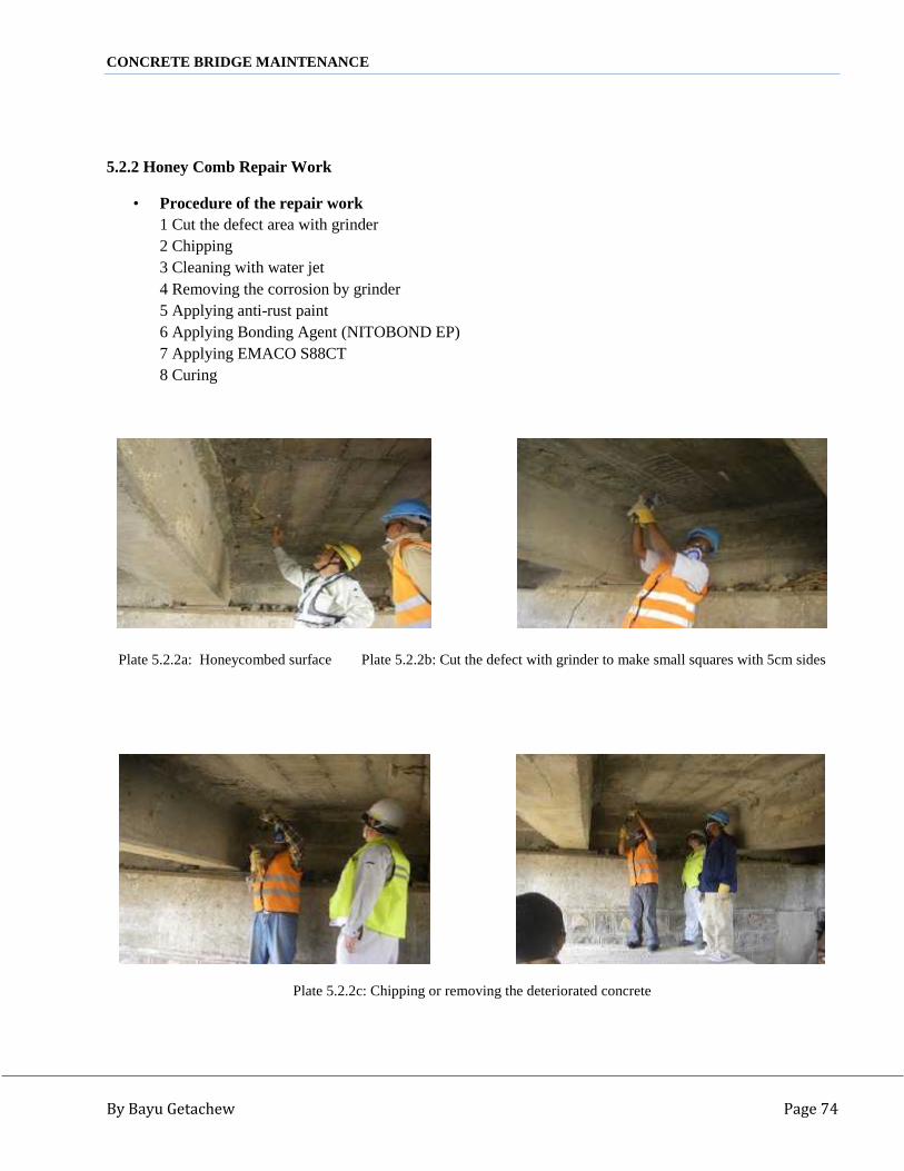
CONCRETE BRIDGE MAINTENANCE
By Bayu Getachew Page 74
5.2.2 Honey Comb Repair Work
• Procedure of the repair work1 Cut the defect area with grinder2 Chipping3 Cleaning with water jet4 Removing the corrosion by grinder5 Applying anti-rust paint6 Applying Bonding Agent (NITOBOND EP)7 Applying EMACO S88CT8 Curing
Plate 5.2.2a: Honeycombed surface Plate 5.2.2b: Cut the defect with grinder to make small squares with 5cm sides
Plate 5.2.2c: Chipping or removing the deteriorated concrete

CONCRETE BRIDGE MAINTENANCE
By Bayu Getachew Page 75
Plate 5.2.2d: Cleaning with water jetPlate 5.2.2e: Applying anti-rust paint
Plate 5.2.2f: (Nitobond EP) Plate 5.2.2g: Applying Bonding Agent (Nitobond EP)

CONCRETE BRIDGE MAINTENANCE
By Bayu Getachew Page 76
Plate 5.1.2h: Applying EMACO S88CT placing and curing
5.2.3 Repair Work of Hole on Deck Slab
• Procedure of the Repair Work1 Remove the deteriorated concrete around the hole with hammer2 Construct the formwork( soffit )3 Cleaning with water jet4 Removing the corrosion by grinder5 Applying anti-rust paint6 Applying Bonding Agent (NITOBOND EP)7 Placing EMACO S88CT8 Applying Bonding Agent (CONCRESSIVE 1414)9 Placing concrete treated with fiber(RHOFIBER)

CONCRETE BRIDGE MAINTENANCE
By Bayu Getachew Page 77
Plate 5.2.3a: Remove the deteriorated concrete around the holewith hammer, construct the formwork (soffit), Cleaning with water jet and applying anti-rust paint
Plate 5.2.3b: Concresive 1414 Plate 5.2.3c: Applying Bonding Agent Concresive 1414

CONCRETE BRIDGE MAINTENANCE
By Bayu Getachew Page 78
Plate 5.2.3d: Nitobond Plate 5.2.3e: Fiber (Rhofiber)
Plate 5.2.3f: Applying Bonding Agent Nitobond
Plate 5.2.3g: Mixing concrete with fiber (Rhofiber)

CONCRETE BRIDGE MAINTENANCE
By Bayu Getachew Page 79
Plate 5.2.3h: Placing concrete treated with Fiber (Rhofiber) Plate 5.2.3i: Finished repaired concrete
5.2.4 Cracks Repair Work
• Procedure of the Repair Work1 Cleaning the crack with water jet2 Sealing the crack with EMACO S88CT since the cracks more than 5mm3 Cleaning by grinder4 Cleaning with water jet5 Drilling holes a diameter of 6mm at 15 cm spacing6 Installing pipes in holes to a depth of 3cm7 Sealing the crack and the holes again with NITOMORTAR FC8 Injecting NITOFILL EPLV or CONCRESSIVE 14149 Cutting the pipes with grinder10 Removing 5cm width seal from the crack for monitoring
Plate 5.2.4a: Cleaning with water jet Plate 5.2.4b: Sealing the crack with EMACO S88CT

CONCRETE BRIDGE MAINTENANCE
By Bayu Getachew Page 80
Plate 5.2.4c: Sealing preparation Plate 5.2.4d: Cleaning using grinder
Plate5.2.4e: Drilling holes diameter of 6mm at 15 cm spacing Plate 5.2.4f: Installing pipes in holes to a depth of 3cm
Plate 5.2.4g: CONCRESSIVE 2200 Plate 5.2.4h: Sealing the crack and holes with NITOMORTAR

CONCRETE BRIDGE MAINTENANCE
By Bayu Getachew Page 81
Plate 5.2.4i: Injecting Nitofill EPLV or CONCRESSIVE 1414
Plate 5.2.4j: Cutting the pipes with grinder
5.3 Debre Markos District, Kulech Wenz and Timberbada Bridge Repair Work
1. Kulech Wenz Bridge: It is RC-Box Girder type, located on D/Markos – Dembecha road segment, 17kmfrom D/Markos town. It is located near to D/Markos town and the bridge river is wet by now, and it islocated on a curve road alignment.
2. Timberbada Bridge: It is RC Deck Girder a type, located on D/Markos – Dembecha road segment 43 kmfrom D/Markos Town. Timberbada River is wet at winter the water way adequacy is enough at all weatherconditions. But the bridge is highly deteriorating and no proper repair has been done so far.
5.3.1 Materials Used for Repair1. NitoBond EP

CONCRETE BRIDGE MAINTENANCE
By Bayu Getachew Page 82
It is special adhesive epoxy resin concrete bonding agent1 can of base = 0.75Kg, and 1 can of hardener = 0.41Kg, then mix and apply at cleaned substrate.
Plate 5.3.1a: NitoBond Plate 5.3.1b: NitoBond application
2. EMACO S88CTIt is a special mortar with RehoFiber to avoid crack due to shrinkage. One bag = 25 Kg of mortar mixed with3.5 – 4 liter of water and will be applied over the NitoBond Epoxy bonding material. The RehoFiber shall beadded to the mixed mortar.
Plate 5.3.1c: EMACOS88CT Plate 5.3.1d: RehoFiber
3. Renderoc TGXtra + RHEOFIBER (Polypropylene Fiber)
It is another type of Polymer modified mortar with Rheofiber to avoid crack.
One bag = 25Kg of Renderoc TGXtra mixed with 4.5 liters of water and 8g of Rheofiber.
4. Nitomortar FC or Concresive 2200It is high strength epoxy coating Mortar. One Can of base = 4.965Kg mixed with one Can of hardener =0.9Kg and applied over the crack, so that the crack will be sealed for injection.

CONCRETE BRIDGE MAINTENANCE
By Bayu Getachew Page 83
Plate 5.3.1e: Concresive 2200 Plate 5.3.1f: Concresive 2200 (mixing)
Plate 5.3.1g: Concresive 2200 (mixing) Plate 5.3.1h: Concresive 2200 application
5. Nitofill EPLV It is low viscosity epoxy injected in to the crack through the drilled holes by pressure.
Plate 5.3.1i: Nitofill EPLV
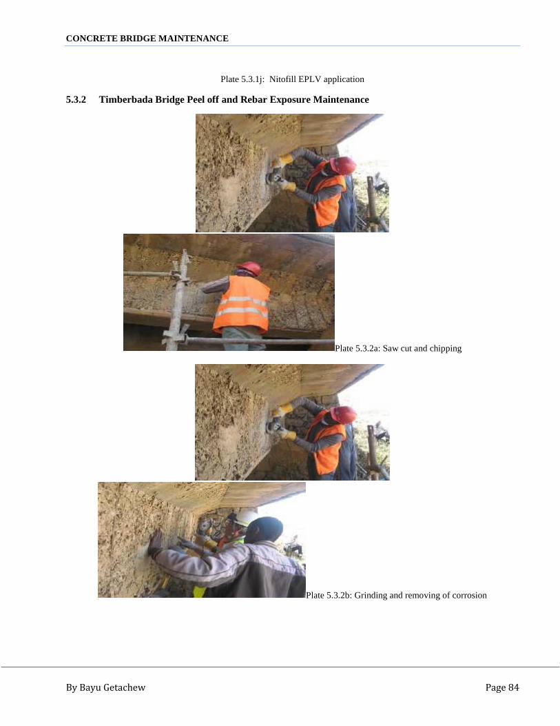
CONCRETE BRIDGE MAINTENANCE
By Bayu Getachew Page 84
Plate 5.3.1j: Nitofill EPLV application
5.3.2 Timberbada Bridge Peel off and Rebar Exposure Maintenance
Plate 5.3.2a: Saw cut and chipping
Plate 5.3.2b: Grinding and removing of corrosion

CONCRETE BRIDGE MAINTENANCE
By Bayu Getachew Page 85
Plate 5.3.2c: Cleaning by jet water and painting anti rust
Plate 5.3.2d: Applying NitoBond

CONCRETE BRIDGE MAINTENANCE
By Bayu Getachew Page 86
Plate 5.3.2e: Applying EMACO S88CT
Plate 5.3.2f: Applying Renderoc TGXtra + RHEOFIBER (PolypropyleneFiber)

CONCRETE BRIDGE MAINTENANCE
By Bayu Getachew Page 87
5.3.3 Kulech Wenz Bridge RC Deck Girder Crack
Plate 5.3.3a: Cleaning crack area by grinder and wire brushPlate 5.3.3b: Drilling injection hole
Plate 5.3.3c: Cutting and inserting injection pipes
Plate 5.3.3d: Sealing the crack by NitoMortar for injection byNitofill EPLV or CONCRESSIVE 1414

CONCRETE BRIDGE MAINTENANCE
By Bayu Getachew Page 88
6 CONCLUSION AND RECOMMENDATIONS
6.1 Conclusion
In concrete bridge failures, reconstruction of the structure instead of rehabilitation for every defect or failure isvery difficult in terms of money and construction. That is the amount of money involved for reconstruction ofbridge is much and very expensive. In addition closing of the road may interrupt traffic flow, which hassignificant impact on the economy of the country especially when the bridge is on the federal road. Sorehabilitation or maintenance of concrete bridges become very crucial and mandatory to stop failure of bridgesbefore reaching their design period and to avoid unnecessary expense to construct a new bridge instead ofmaintaining and lengthen the service life of the bridge.
Proper design and construction does not mean that the bridge will serve about its design life. Because lack ofinspection and controlling with minor rehabilitation may make the bridge to fail before serving to its maximumcapacity. So monitoring, inspection, and maintenance of every concrete bridge have to be done starting fromconstruction day before failure, which leads to erection or construction of a very expensive new bridge.
Unlike the practice we used to do before, concrete bridge rehabilitation techniques, materials and procedures areburning and crucial issue now a day, being many of the bridges are reaching about their design life and needrehabilitation before failure. Considering the urgency of the issue, the universities in particular and the countryin general with the respective parties have to think of the problem and participate on provision of possiblesolutions. Although not satisfactory or to the requirement of the country, Ethiopian Road Authority (ERA) incollaboration with Japan International Cooperation Agency (JICA) has maintained some bridges within the lastfive to eight years.

CONCRETE BRIDGE MAINTENANCE
By Bayu Getachew Page 89
Concrete bridge maintenance is not an easy task, because regaining the overall condition especially thestructural strength of concrete bridge by simple plastering is difficult. So the use of different admixtures(modifying agents), additives (fine mineral powers) and epoxies is mandatory following the procedures andspecifications given by the suppliers. At this time there are many suppliers for the construction companyinvolved in maintenance or construction.
Considering the importance of concrete bridge rehabilitation on a national base currently, this study has done toaddress the basic defects, causes of defects, materials for maintenance and possible techniques and proceduresof rehabilitation.
Before rehabilitation of any defect, inspection is the most important activity to know the types and causes ofdefects. Rating or ranking of the defect makes maintenance simple and avoids unnecessary expenditure ofmoney. So, inventory and inspection of defects with corresponding ranking is the primary activity beforeperforming any maintenance work.
Having bridges ready for maintenance, the next task is selection and preparation of materials involved formaintenance. The different materials used for maintenance can be grouped in to three categories.
(1) Cement type repairing materials: this is simply Portland cement mortar (concrete) or non-shrinkage mortar (concrete)
(2) Polymer modified cement type : this is cement modified using different polymers and fibers(3) Resin type repairing materials: this is an epoxy or chemical used for repairing purpose
Before applying any repairing materials, the substrate that receives repairing materials has to be prepared andmade ready to receive the new materials. Rehabilitation of concrete bridges is very wide, so that maintenancetechniques of all bridge defects might be a course by itself. However during maintenance of any defect works;removal of concrete, surface cleaning, substrate preparation, and repair material application are the basicprocedures that any worker has to follow.
6.2 Recommendations
The absence of detailed specifications and standards for rehabilitation of concrete defects makes maintenancedifficult in Ethiopia. This is due to lack of repairing materials, unavailability of expertise on the field (nouniversity or college is giving courses on concrete rehabilitation), and lack of awareness about the cost andrelated problems in erecting of new bridged as compared to that of rehabilitation.On the contrary many bridges in the country are deteriorated and needs replacement or rehabilitation. That iswhy preparation of documents vital for rehabilitation and production of expertise about rehabilitation ismandatory. Materials involved for maintenance in addition to cement or concrete have to be produced in thecountry or imported from abroad.
Considering the limitations to perform maintenance and the urgency of the need of maintenance the country ingeneral and the universities in particular should take the assignment and shall forward relevant contributiontowards rehabilitation. So:
The universities shall incorporateconcrete maintenance courses in the department, so that the country can have professionals or expertiseon concrete rehabilitation.
The universities and respectedofficials shall discuss and forward proper specifications and manuals for concrete rehabilitation.
The universities shall preparecourse material or module on concrete rehabilitation.

CONCRETE BRIDGE MAINTENANCE
By Bayu Getachew Page 90
Materials required for maintenanceshould be imported if not available in the country or the government should encourage domesticinvestors to produce locally.
Workshops shall be prepared, sothat well trained professionals will be produced in addition to creation of awareness about the topic forthe related industries.
References
1 Concrete bridge maintenancemanual, ERA, 2010
2 Concrete bridges, V.K. Raina,1996
3 AACRA bridge repair manual,AACRA, February 2004
4 AASHTO Manuals for conditionevaluation of bridges, AASHTO SUB COMMITES, AASHTO, 1994
5 ERA standard technical bridgerepair manual, ERA, 2002
6 Bridge engineering, Demetros E.Tonias, P.E., 1995
7 Concrete structures protection,repair and rehabilitation, R. DODGE WOODSON, 2009
8 Crack analysis in structuralconcrete, theory and application, ZIHAI SHI, ELSEVIER 2009

CONCRETE BRIDGE MAINTENANCE
By Bayu Getachew Page 91
9 Concrete structures protectionrepair and rehabilitation, R. DODGE WOODSON, ELSEVIER, 2009
10 Bridge design manual, TEXASDEPARTMENT OF TRANSPORTATION, December 2001
11 Bridge safety inspection manual,NICET, September 2004
12 Bridge inspection maintenanceand repair, departments of the army and the air force, December 1994
13 Manuals of TRL, ASTM, and BSstandards
14 Reinforced concrete mechanicsand design, JAMS K. WIGHT, JAMES G, MACGREGOR, 6th ed., Pearson, 2012
15 Specification and applicationmanuals for different repairing chemicals and epoxies
16 Sika concrete repairing epoxymanuals, 2012
17 FOSROC concrete repairing epoxymanuals, 2012
18 BASF concrete repairing epoxymanuals, 2012
19 ASTM standards related toconcrete, 2003
20 Basic construction materials,Theodore W. Marotta, 7th Edition, pearson, 2005
21 Evaluation and repair ofconcrete structures, JAMES D. CRAIG, 2002