
Precast concrete products — Concrete finishes — Identification
28
PD CEN/TR 15739:2008 ICS 91.100.30 NO COPYING WITHOUT BSI PERMISSION EXCEPT AS PERMITTED BY COPYRIGHT LAW PUBLISHED DOCUMENT Precast concrete products — Concrete finishes — Identification
-
Upload
khangminh22 -
Category
Documents
-
view
2 -
download
0
Transcript of Precast concrete products — Concrete finishes — Identification

PD CEN/TR15739:2008
ICS 91.100.30
NO COPYING WITHOUT BSI PERMISSION EXCEPT AS PERMITTED BY COPYRIGHT LAW
PUBLISHED DOCUMENT
Precast concreteproducts —Concrete finishes —Identification

This Published Documentwas published under theauthority of the StandardsPolicy and StrategyCommittee on 31 August2009© BSI 2009
ISBN 978 0 580 60337 2
Amendments/corrigenda issued since publication
Date Comments
PD CEN/TR 15739:2008
National foreword
This Published Document is the UK implementation of CEN/TR15739:2008.The UK participation in its preparation was entrusted to TechnicalCommittee B/524, Precast concrete products.A list of organizations represented on this committee can be obtained onrequest to its secretary.This publication does not purport to include all the necessary provisionsof a contract. Users are responsible for its correct application.Compliance with a British Standard cannot confer immunityfrom legal obligations.
TECHNICAL REPORT
RAPPORT TECHNIQUE
TECHNISCHER BERICHT
CEN/TR 15739
December 2008
ICS 91.100.30
English Version
Precast concrete products - Concrete finishes - Identification
Produits préfabriqués en béton - Surface et parements debéton - Éléments d'identification
Betonfertigteile - Betonoberflächen -Beschreibungsmerkmale
This Technical Report was approved by CEN on 23 March 2008. It has been drawn up by the Technical Committee CEN/TC 229.
CEN members are the national standards bodies of Austria, Belgium, Bulgaria, Cyprus, Czech Republic, Denmark, Estonia, Finland,France, Germany, Greece, Hungary, Iceland, Ireland, Italy, Latvia, Lithuania, Luxembourg, Malta, Netherlands, Norway, Poland, Portugal,Romania, Slovakia, Slovenia, Spain, Sweden, Switzerland and United Kingdom.
EUROPEAN COMMITTEE FOR STANDARDIZATIONC O M I T É E U R O P É E N D E N O R M A LI S A T I O NEUR OP ÄIS C HES KOM ITEE FÜR NOR M UNG
Management Centre: rue de Stassart, 36 B-1050 Brussels
© 2008 CEN All rights of exploitation in any form and by any means reservedworldwide for CEN national Members.
Ref. No. CEN/TR 15739:2008: E

PD CEN/TR 15739:2008CEN/TR 15739:2008 (E)
2
Contents Page
Foreword ..............................................................................................................................................................3
Introduction .........................................................................................................................................................4
1 Scope ......................................................................................................................................................6
2 Terms and definitions ............................................................................................................................62.1 Faces .......................................................................................................................................................62.2 Finishes ...................................................................................................................................................62.3 Surface characteristics .........................................................................................................................9
3 Principle of characterization and identification ............................................................................... 103.1 General ................................................................................................................................................. 103.2 Flatness ................................................................................................................................................ 103.3 Texture ................................................................................................................................................. 103.4 Colour ................................................................................................................................................... 103.5 Identification of the reference ............................................................................................................ 103.6 Definition of level of quality ............................................................................................................... 11
4 Test methods ....................................................................................................................................... 124.1 Flatness (deflection) ........................................................................................................................... 124.2 Check of appearance .......................................................................................................................... 14
5 Description of units ............................................................................................................................ 16
Annex A (informative) Surface characteristics ............................................................................................ 17
Annex B (informative) Example of specifications of requirements applicable to architectural units .............................................................................................................................................................. 18
Annex C (informative) Concrete sample surface finish example of acceptance report .......................... 19
Annex D (informative) Reference images to identify the severity of blowholes in concrete surfaces ............................................................................................................................................................ 20
Annex E (informative) CIB grey scale ........................................................................................................... 22
Annex F (informative) Examples of pictures deal with some methods of concrete finishes ................. 23
Bibliography ..................................................................................................................................................... 25

PD CEN/TR 15739:2008CEN/TR 15739:2008 (E)
3
Foreword
This document (CEN/TR 15739:2008) has been prepared by Technical Committee CEN/TC 229 “Precast concrete products”, the secretariat of which is held by AFNOR.

PD CEN/TR 15739:2008CEN/TR 15739:2008 (E)
4
Introduction
The visual perception of concrete finishes is determined by characteristics which can vary to different extents, i.e. variations which are intentional (more or less). Intended variations imply that one is acquainted with the material and is able to vary the characteristic within limits set by oneself, without the variations being regarded as defects.
Finishes depend on manufacturing techniques such as:
Before casting
The finish is determined by the surface of the mould:
smooth ex-mould finish,
profiled from the mould,
profiled/patterned from a lining in the mould,
cast-on elements,
use of retarders.
Mould-hardened off-the-form finish
As cast finish obtained through contact with the mould in the case of concrete hardened in the mould. The face may be smooth or textured.
Dry-cast off-the-form finish
As cast fair-faced finish obtained through contact with the mould in the case of immediate demoulding.
The characteristics of concrete finishes are:
Texture, from the most elaborated to evenness and, if it is more coarse, unevenness, possibility developing to a maximum unevenness, which is difficult to stipulate;
Colour which can be expressed in colour scale;
Grey tone which can be expressed in grey scales, sometimes with some colour incorporated;
Pattern, a characteristic, in another type and scale than three above, and which can be formed by variations in these characteristics.
In contrast to the consciously selected characteristics there can be additional surface aspects of sorts which are not desired which consequently should be named deviations (i.e. deviations from intentional characteristics or from the quality level for these characteristics). To these belongs blowholes, lumps, groove etc.
As a consequence one should separate between characteristics on one side and deviations on the other side and consider them as different matters, due to the great difference in their nature.

PD CEN/TR 15739:2008CEN/TR 15739:2008 (E)
5
In contrast one should observe that blowholes in certain cases can be intentional, if they are uniformly distributed over a concrete surface, to lend it a visual “softness”.
For some products, such as architectural components, the required surface appearance could be chosen on the basis of samples for coordinating the surface character. Before building and delivery, start reference surfaces are chosen from the sample surface. At the time an order is placed, agreement on the appearance of the face(s) is formalized by an acceptance report for the reference sample(s) proposed by the manufacturer. This report also identifies the conventional mean colour chosen from a reference colour chart to be used to subsequently assess consistency of colour (see Annex C and Annex E).
NOTE 1 Colour scales are not included in this CEN technical report because the paper publication is in black and white. Each country could establish special colour scales.
NOTE 2 The consistency of concrete appearance is governed by the uniformity of the raw materials from which it is made or of the pigments used. The fact that the raw materials are of natural mineral origin implies tolerances on the appearance of the concrete products supplied.
NOTE 3 Because of the time it takes for concrete to cure, the appearance of the reference sample can be assessed only after a certain minimum time, generally one week after treatment, or longer, depending on the cements used (e.g. CEM II A and CEM II B) and in all cases at delivery.
NOTE 4 When the colour consistency of several products is inspected at the same time, account should be taken of any age differences.

PD CEN/TR 15739:2008CEN/TR 15739:2008 (E)
6
1 Scope
This document provides guidelines for the surface appearance of precast concrete products and the methods for inspecting and assessing the conformity of appearance for use in conjunction with specific product standards. This document may also be used to describe the appearance of products for which there is no standard.
If there is a specific standard for a precast concrete product, it takes priority over this document.
2 Terms and definitions
For the purposes of this document, the following terms and definitions apply.
2.1 Faces
2.1.1 seen face surface intended to be seen when in use
2.1.2 facing layer layer of concrete on the seen face of a product of different material and/or properties to the main body or backing layer of a product. Facing layer may be not completely mixed colour concrete (marbling)
NOTE To be distinguished from wipe, i.e. a fine cement mortar or slurry applied to the surface of the product.
2.1.3 arris part of a product where two faces meet. It can be bevelled, rounded, chamfered, radiussed or splayed
2.1.4 draw intended angle of the side face from the vertical plane of a product
2.1.5 chamfer bevelled arris
2.2 Finishes
2.2.1 General
2.2.1.1 unformed surface surface not in contact with the mould during moulding. This surface may be given complementary treatment while the concrete is still green to give a more uniform finish. The different treatments possible are defined below
NOTE In certain special cases the shape of the precast unit may require application of a moulding surface to the upper face of the unit; this may result in a large number of blowholes which may be attenuated by one of the surface treatments defined below.
2.2.1.2 screeded finish obtained by drawing a straightedge, for example, across the surface of the concrete

PD CEN/TR 15739:2008CEN/TR 15739:2008 (E)
7
2.2.1.3 rubbed-off finish obtained by using a rubbing board , for example, or similar tool
NOTE Cement and sand may be sprinkled on and worked into bleeding concrete or mortar if the quantities are moderate and the work is regular and carried out with an equally proportioned mix of cement and very fine sand. Use of cement alone is prohibited.
2.2.1.4 trowelled finish obtained by using a steel or other kind of trowel, for example
2.2.1.5 semi-polished finish obtained when the surface of the concrete is semi-polished with a rag or expanded polystyrene, for example, or brushed with a soft or other kind of brush
2.2.1.6 imprinted finish obtained by using an indent roller or similar tool to be defined at the time of the order
2.2.2 Worked surfaces
2.2.2.1 Worked in plastic state
2.2.2.1.1 brushed roughness created by brushing the surface of the fresh mortar with a stiff brush
2.2.2.1.2 water-washed surface from which the first 2 mm and more of fine mortar is removed by washing
2.2.2.1.3 fine washed surface from which not more than 2 mm of the first fine mortar is removed by washing
2.2.2.2 Worked in hardened state
2.2.2.2.1 bush hammered result of scalling the surface of hardened concrete with a bush hammer
2.2.2.2.2 acid-etched exposed aggregate finish in which the aggregate has been exposed by putting an acid solution on the surface for a time and washing it off with water
2.2.2.2.3 chemically retarded exposed aggregate finish (to a greater or lesser extent) in which the concrete surface has been treated with a retarder and the hardened product has been washed down with water and/or brushed
2.2.2.2.4 splitted irregularly chipped or hammered face revealing all the constituents of the concrete, including broken coarse aggregate

PD CEN/TR 15739:2008CEN/TR 15739:2008 (E)
8
NOTE The above techniques require considerable skill in the work procedures, and require extra concrete cover in the case of reinforced products.
2.2.2.2.5 flamed exposed aggregate finish in which the top few millimetres of the surface have been flaked off by flame action, for example
2.2.2.2.6 finely ground surface ground back with a mechanical grinder, used wet or dry, to partially expose the fine aggregate (sand)
2.2.2.2.7 grinded description of a surface which is grinded once without abrading. Brush marks and pores can be visible
2.2.2.2.8 coarsely ground surface ground back to some depth with a mechanical grinder, used wet or dry, to reveal the deep texture of the concrete and provide rough surface retaining grinding marks
2.2.2.2.9 polished coarsely ground surface ground several times with increasingly fine grit heads to achieve a uniform finish without visible marks. Depending on the type of aggregate and the final treatment, the finish may be gloss, with or without blowholes
2.2.2.2.10 sawed raspy surface without any more preparation
2.2.2.2.11 abrasive blasted hardened concrete surface blasted with sand or grit. The grading of the grit, its hardness, and the spray pressure used enable variation from brush blasting (light abrasion of the surface skin) to heavy blasting that partially exposes the aggregate
2.2.2.2.12 pressure jetted hardened concrete surface sprayed with a high-pressure water jet
NOTE The water pressure and adjustment of the jet enable the depth of abrasion and therefore the resulting finish to be varied.
2.2.2.2.13 shot blasting erosion of surface by projection of steel shot
2.2.2.2.14 aging processing with special hammering techniques will give a rustic and antique look
2.2.2.2.15 bossed on the split surface, aris are broken to give an effect of cut stones
2.2.2.2.16 point tooling result of scalling the surface of hardened concrete with a pointed graver

PD CEN/TR 15739:2008CEN/TR 15739:2008 (E)
9
2.2.3 Painted or coated surface
2.2.3.1 coated surface surface faced at delivery in accordance with stipulations made at the time of the order
2.2.3.2 surface to be painted or coated surface to be painted or coated after delivery
NOTE 1 Since the requisite finish depends on the type and "build" of the paint to be used, these parameters should be known at the time of the order.
NOTE 2 Any mould release agent on the surface should be compatible with the stipulated paint or coating.
2.3 Surface characteristics Surface characteristics are defined in Table 1 and Annex A.
Table 1 — Surface characteristics
Characteristics Description
Blowholes
In mass concrete: voids at the surface of the concrete. For facing concrete: defects consisting of the appearance of bubbles (blisters) or pits (burst bubbles), generally around 5 mm deep and between a few millimetres and a few centimetres in diameter (cf. Annex D).
Large crack Crack more than 2 mm wide.
Scaling Thin layer of hardened mortar separating from the concrete surface in fragments called ‘flakes’.
Corner spalling Spalling at the corner of the concrete unit.
Efflorescence Fine, generally whitish crystalline deposit forming at the concrete surface. NOTE When efflorescence occurs it is not deleterious to the performance of the product in use and is not considered significant.
Spalling Detachment of fragments from a concrete surface.
Crazing Network of fine and shallow cracks forming a regular mesh. Appears at the surface of the concrete.
Crack More or less regular linear opening (discontinuity) in the concrete, between 0,2 mm and 2 mm wide. Any smaller or larger, and it is a micro crack or a large crack.
Surface crack Crack that does not go through the thickness of the structure. It is widest at the surface and becomes zero at depth.
Laitence Laitence is a mixture of water and the finer constituents of the concrete.
Swelling Swollen appearance of the concrete due to an increase in volume.
Micro crack Very tight, more or less regular, most commonly discontinuous linear crack less than 0,2 mm wide. May extend to form a network.
Honeycombing Defect with lack of fines or mortar between aggregates.
“aggregate transparency” Marbling effect
Large aggregate appearance through the concrete surface, creating a network of oval marks which may be darker or lighter than the rest of the surface, depending on the case.
Surface wear Wear of the concrete due to abrasion or erosion.
Colour variations Differences in concrete colour in the same section of the works.

PD CEN/TR 15739:2008CEN/TR 15739:2008 (E)
10
3 Principle of characterization and identification
3.1 General
The appearance of a concrete surface is defined by three criteria denoted by a letter:
P – Flatness
T – Texture
C – Colour
3.2 Flatness
Flatness is defined by the maximum deflection fmax = a - b as measured in accordance with 4.1.
3.3 Texture
This criterion has three sub-categories to distinguish between:
general appearance characterized by a mean concentration of blowholes distributed over the entire surface,
areas with a concentration (group) of blowholes, and
localized defects.
3.4 Colour
For each of these criteria, the letter is followed by a number between 0 and 4 corresponding to increasingly severe requirements.
0 Means that the criterion is not taken into account
1 – 2 – 3 Correspond to codified requirements
4 Corresponds to a requirement specified in the contract.
The characterization of the reference unit, namely a sample or a mock-up should be submitted to the client for approval before manufacturing. In addition, for surfaces intended to remain visible after the works are completed, the characterization should be complemented by reference to a colour chart identifying the mean colour of the reference sample.
NOTE The mean colour is the reference for subsequent assessment of the level of quality (consistency) of the colour of the products.
When the shape of a product requires that it be made in a multi-part mould with a joint on a surface intended to remain visible after completion of the works, the manufacturer informs the client beforehand and reaches an agreement with him about the position and/or treatment (featured joint, etc.) of the joints.
3.5 Identification of the reference
3.5.1 Reference sample
When an order is placed, the desired appearance is chosen from samples (an example of requirements is given in Annex B). For final agreement, a larger sample - about 1 m x 1 m - or a mock-up that is

PD CEN/TR 15739:2008CEN/TR 15739:2008 (E)
11
representative of the manufacturing process (shapes, reinforcement, mould, etc.) foreseen for the units to be made should be produced. As required, a repair may be made (e.g. making good of local spalling) to define the methods and limits of acceptance of repair.
Formal agreement on the surface appearance should take the form of an acceptance report prepared and signed by the parties concerned (an example of the report is given in Annex C).
The report should also mention the mean colour, if necessary.
3.5.2 Mean colour
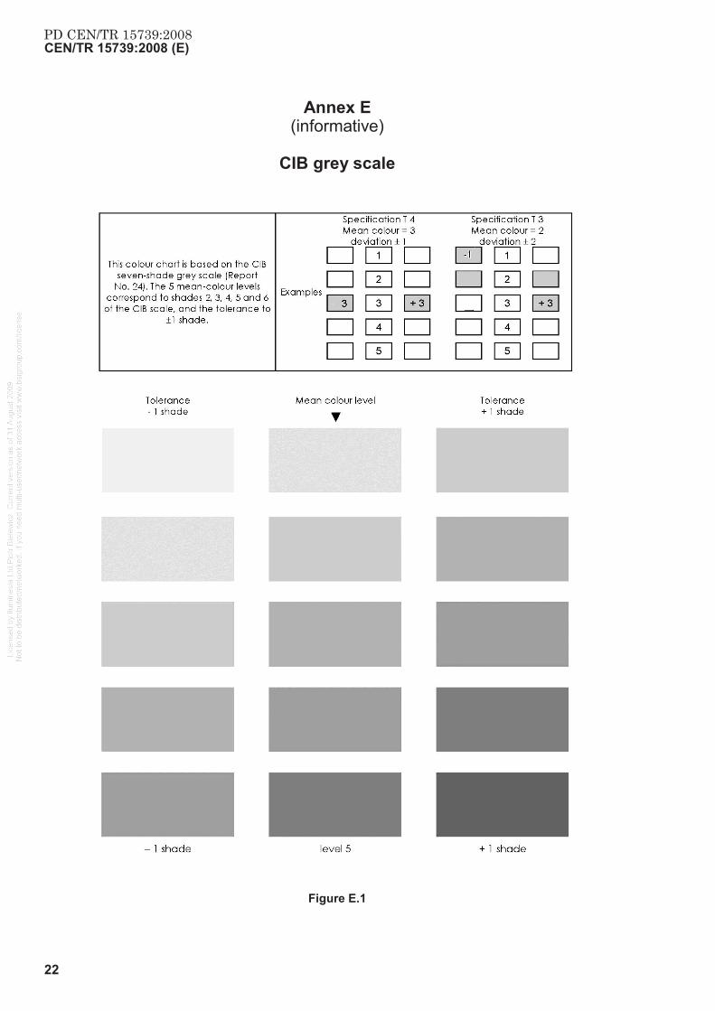
The mean colour is chosen, by agreement between the parties, from a colour chart.
Each colour chart should have the same format. The central vertical scale should have five levels of mean colour with, horizontally on each side, the shade tolerance for each level.
The “CIB grey scale” is appended (Annex E). Colour scales are available in place of use.
NOTE The 5 mean-colour levels of the colour charts correspond to levels 2, 3, 4, 5, and 6 of the CIB chart, and the tolerance is ± 1 shade. Other tolerances may be declared by the manufacturer.
3.6 Definition of level of quality
3.6.1 Flatness
Table 2 — Flatness
Flatness Type of finish Overall flatness (2 m straightedge)
Local flatness (20 cm ruler)
P(0) criterion not taken into account
P(1) ordinary ≤ 15 mm ≤ 6 mm
P(2) standard ≤ 8 mm ≤ 3 mm
P(3) fair ≤ 5 mm ≤ 2 mm
P(4) to be specified in contract
3.6.2 Texture
The level of quality of the surface texture, “T”, is defined by a number characterizing the acceptable concentration of blowholes both on the surface examined as a whole (mean concentration) and in concentrated areas (grouped blowholes).
The concentration of blowholes is codified in accordance with the six levels of the reference scale (see Annex D).
Grouped blowholes by definition concern only a part of the surface examined. The concentration within the group is characterized by the same scale as for the mean concentration of blowholes (area per blowhole, depth) with a higher percentage per unit area.

PD CEN/TR 15739:2008CEN/TR 15739:2008 (E)
12
T (0) criterion not taken into account in this document.
T (2) mean concentration of blowholes corresponding to level 5: maximum area per blowhole 1, 5 cm²; depth 3 mm; area with blowholes, 3 % of total surface area.
grouped blowholes = 10 %.
T (3) mean concentration of blowholes corresponding to level 3: maximum area per blowhole 0, 3 cm²; depth 2 mm; area with blowholes, 2 % of total surface area.
grouped blowholes = 5 %.
T (4) to be specified by contract.
3.6.3 Colour
The level of quality (consistency) of colour, “C”, is defined by a number characterizing accepted deviation from the mean colour, both between adjacent areas (same units, up to two adjacent units) and between two distant areas (non-adjacent units).
C (0) - C (1) - C (2) criteria not taken into account in this document.
C (3) acceptable deviation between two adjacent areas: one shade from the mean colour.
acceptable deviation between two non-adjacent areas: two shades from the mean colour.
C(4) acceptable deviation between two adjacent areas: one shade from the mean colour.
acceptable deviation between two non-adjacent areas: one shade from the mean colour.
4 Test methods
4.1 Flatness (deflection)
4.1.1 Overall flatness
The check is carried out with a 2 m long straightedge, “L”, and a 20 cm long ruler.
The straightedge is moved in all directions over the surface to be checked and the maximum distance fmax = a - b between the surface and the straightedge is the deviation from flatness.
4.1.2 Local flatness
The check of local flatness is carried out with a 20 cm ruler and a set of feeler gauges suitable for measuring down to 0,2 mm.
The measuring technique and expression of results are the same as for the check of overall flatness.

PD CEN/TR 15739:2008CEN/TR 15739:2008 (E)
13
4.1.3 Measuring surface characteristics
Dimensions in millimetres
Key 1 Lump: d0 – d2 Recess: d3 – d0 The straightedge should be moved to find the highest lump and the deepest recess. 2 Ridge: d1 – d2 Groove: d3 – d1 The largest difference is governing. 3 Step discontinuity: d2 – d1 4 Waviness: d1 – d2 Measured at the highest and lowest points beneath the straightedge.
Figure 1 – Measuring surface characteristics
In Figure 1, d0 is measured from the concrete surface at the location of the straightedge supports. In most cases it is the height of the supporting pieces.

PD CEN/TR 15739:2008CEN/TR 15739:2008 (E)
14
4.2 Check of appearance
4.2.1 General
The check of appearance is to check the conformity of the texture and colour of the units with the order. It involves comparing the units with the references (samples and colour chart) referred to in the order.
To check the uniformity of colour, the procedure in 4.2.3 should be followed.
4.2.2 Observation conditions
A distinction should be made between:
faces or parts of faces intended to be seen from close range (entrance hall, corridor, etc.), for which the visual inspection should by convention be carried out at a distance of 5 m,
faces or parts of faces intended to be seen from a distance (equivalent to the height of a three-storey building, for example), for which the visual inspection should by convention be carried out at a distance of at least 10 m.
NOTE The optical overall impression of a building or an element can only be assessed at adequate range and under usual lighting conditions. The following inspection ranges have proofed themselves in practice;
Building: The adequate range is this distance, which allows a realisation of the building with its significant elements which in doing so authoritative criteria of the design must be noticeable;
Element: The adequate range is the common distance of the user. A self contained overall impression should arise. Accidental irregularities are characteristic for the technology of exposed concrete and should be considered at the assessment of the overall impression.
4.2.3 Visual inspection procedure
A visual inspection checks the consistency of the colours within an individual unit and from unit to unit, distinguishing between whether units are or will be adjacent or not within the works. This inspection should be carried out using the colour chart referred to in the order.
The “CERIB” colour chart for direct and immediate comparison of acceptable colour variation may also be used.
The CERIB chart is placed on the sample accepted at the time of order. The combination of chart and sample is placed alongside the product(s) to be checked. The product checked is deemed to be compliant if its colour is deemed to fall within the tolerance displayed on the sample.
If the parties to the contract are in disagreement, the procedure in 4.2.4 should be applied.
4.2.4 Inspection procedure with photographs and photo colorimeter
A frame with the product references and the “CIB grey” colour chart of Annex E should be fixed to the units to be checked.
The units and the samples / mock-up(s) should be photographed in black and white. Photos should be taken from a distance of about 5 m.
In so far as possible, each photograph should show at least two units, and each unit should be shown on at least two photographs.
The photographs should be developed on matt paper of a size enabling the levels of grey on the “CIB grey “ colour chart to be seen.

PD CEN/TR 15739:2008CEN/TR 15739:2008 (E)
15
The assessment should consist of two qualitative analyses of the photographs carried out separately by three persons representing different interests.
The colour of each unit should be identified against the grey scale on the photograph. When all the units have been assessed, the following differences should be calculated:
between samples / mock-ups,
between units to be checked.
A second series of assessments should then be carried out, the reference scale this time being the “CIB grey” colour chart placed directly on the photographs so as to overlap them.
Each type of difference having been assessed six times (3 people x 2 assessments) and the actual difference should be deemed to be that corresponding to at least four of the six appreciations.
Should this method not result in a majority decision, the photographs should be sent to a laboratory equipped with a photoelectric colorimeter for quantitative assessment of the position of each unit on the grey scale by means of measurement of the degree of whiteness.
In the event of disagreement between the contracting parties, the assessment should be carried out as follows.
Colour measurements should be carried out with a colorimeter on each of the units whose colour variations are disputed, and, possibly on the sample. The colour measurements should be carried out on a dry concrete surface. Each measurement should give co-ordinates L, a, and b of the measuring point.
For the assessment of disputed colour variations within a given unit, at least six colour measurements should be carried out on the disputed part of the unit, and at least six colour measurements at points distributed uniformly over the entire unit.
For the assessment of disputed colour variations between different units, and if applicable between units and the sample, at least six colour measurements should be made on each disputed unit and if applicable on the sample, at measurement points uniformly distributed over each unit or over the sample.
The colour difference between the disputed part of a unit and the complete unit, between two units, or between a unit and the sample, should be calculated with the following formula:
( ) ( ) ( )222 baLE ∆+∆+∆=∆ (1)
Where
∆L, ∆a and ∆b are the differences between the mean coordinates of the colours of the disputed part of the unit and the mean coordinates of the colours of the complete unit, between two units, or between a unit and the sample.
The calculated colour difference, ∆E, is 0,5E∆ shades on the CIB scale of greys.
4.2.5 Single criteria assessment
At the assessment of fair-faced concrete surfaces the overall impression from a common distance is authoritative. Single criteria are only checked if the overall impression of the view surfaces does not fulfil the requirements.
Tolerated discrepancies in the appearance of the fair–faced concrete surface could be:

PD CEN/TR 15739:2008CEN/TR 15739:2008 (E)
16
Small structural differences for prepared concrete surface;
Clouds, marbling, and small colour variations (see above);
Cluster of pores;
Dark stripes and little bleeding at formwork joints;
Such requirements are technically not or unerring producible:
Constant colour at all view surfaces of the building;
Non-porous view surface;
Constant structure of pores (size and spreading);
Surface without fissures.
5 Description of units
The description of units comprises the following information:
type(s) of unit(s),
dimensional class,
characterization of facing (surface finish, texture, colour),
colour chart and mean colour.
EXAMPLE
parapet - P(3) - Sand-blasted finish T (3), C (3)– Mean colour: level 3.
Which, for the level of quality of the appearance, means:
flatness: P(3) : fair faced finishing
texture T (3):
Maximum uniform concentration of blowholes corresponds to level 3, the maximum area per blowhole is 0,3 cm2, the depth is less than 2 mm, the area with blowholes is 2 % of the total visible surface area of the parapet,
Areas in which the individual characteristics of the blowholes are identical to those above but where the concentration is greater than 2 % must not represent more than 5 % of the visible surface area of the parapet.
colour C (3):
The deviation between two adjacent parapet units, as measured on the reference colour chart, is limited to one shade from the mean colour of level 3, i.e. an acceptable deviation of - 3 to 3 or 3 to + 3. For two distant parapet units, this deviation is limited to 2 shades, i.e. an acceptable deviation of + 2 to 3 or 3 to – 4.

PD CEN/TR 15739:2008CEN/TR 15739:2008 (E)
17
Annex A (informative)
Surface characteristics
Key 1 Recess 2 Lump 3 Groove 4 Ridge 5 Step discontinuity 6 Undulation
Figure A.1 – Definition of surface characteristics

PD CEN/TR 15739:2008CEN/TR 15739:2008 (E)
18
Annex B (informative)
Example of specifications of requirements applicable to architectural
units
Reference text: ..................................................................................................................................................................... Reference: ........................................................................................................................................................................... Project: ................................................................................................................................................................................. Ordered by: .......................................................................................................................................................................... Type of unit: ......................................................................................................................................................................... 1 – Dimensional tolerance class P(3) P(2) P(1)
2 – Surface finish category (simplified list)
Worked (*) To be painted Off-the-form in plastic state or coated mould-hardened brushded immediate demoulding water-washed Material applied in hardened state bush hammered Unformed surface acid-etched screeded chemically retarded rubbed off splitted trowelled flamed (*) specify which face(s)
is/are (to be) treated. If a diagram is necessary to make it clear, append it to this form.
semi-polished finely ground imprinted coarsely ground polished abrasive blasted
3 – Surface appearance Sample reference: ...............................................
Mean colour (surfaces intended to be seen)
Expected quality level
Reference colour chart
Scale level colour texture 1 2 3 4 5 no requirement no requirement
CIB grey C(3) T(1) C(4) T(2) T(3) T(4) mean blowhole
concentration: scale No. …….
grouped blowholes: %
4 - Comments
.............................................................................................................................................................................................. .............................................................................................................................................................................................. ..............................................................................................................................................................................................
Date: ................................................................... Place: ..................................................................................................
Names and signatures:

PD CEN/TR 15739:2008CEN/TR 15739:2008 (E)
19
Annex C (informative)
Concrete sample surface finish example of acceptance report
Project: .............................................................................................................................................................
.............................................................................................................................................................
Ordered by: .............................................................................................................................................................
Units concerned:
- type: ................................................................................................................ quantity: ............................................
- surface finish:
. Finish category: ................................................................
. Specified quality level: Flatness: P1 - P2 – P3 (*)
Texture: T1 – T2 – T3 – T4 (*)
Colour: C3 – C4 (*)
Reference sample
- dimensions: ...................................................................... - reference: ..........................................................................
- date of production: ............................................................ - age (since treatment) at inspection: …………………………
INSPECTION
Texture (simplified list) Colour uniformity Repair test (if applicable)
Anomalies Conform Conform Type of repair Conform yes no yes no yes no
blowholes honeycombing laitence Colour chart / colour chosen spalling surface crack Reference: mean colour level (*) marbling effect 1 – 2 –3 – 4 - 5 crazing
Comments
Accepted Date: .................................................. Place: ................................................................................
Names and signatures

PD CEN/TR 15739:2008CEN/TR 15739:2008 (E)
20
Annex D (informative)
Reference images to identify the severity of blowholes in concrete
surfaces
These references have been taken from Annex 2 of CIB document n° 24 (scale 1/1).
Figure D.1

PD CEN/TR 15739:2008CEN/TR 15739:2008 (E)
21
Figure D.2
Figure D.3
CEN/TR 15739:2008 (E)
22
Annex E (informative)
CIB grey scale
Figure E.1
PD CEN/TR 15739:2008

PD CEN/TR 15739:2008CEN/TR 15739:2008 (E)
23
Annex F (informative)
Examples of pictures deal with some methods of concrete finishes
Grinted Finely ground
Polished Sawed
Water washed Fine washed
Blasted Flamed

PD CEN/TR 15739:2008CEN/TR 15739:2008 (E)
24
Acid-etched Splitted
Bossed Point tooling
Bush hammered Brushed
Figure F.1

PD CEN/TR 15739:2008CEN/TR 15739:2008 (E)
25
Bibliography
[1] CIB – Report No. 24 – Tolerances on defects in concrete finishes
[2] BFT International 07/2006 – Report on image-supported assessment of concrete surfaces (German journal of betonwerk + Fertigteil-Technik)
[3] "CERIB" colour chart for direct and immediate comparison of acceptable colour variation – CERIB/DQI - BP 30059 - F28230 EPERNON
[4] M.S. Thompson, Blowholes in concrete surfaces, London (documents kindly provided by John Laing (R and S))

PD CEN/TR15739:2008
BSI GroupHeadquarters 389Chiswick High Road,London, W4 4AL, UKTel +44 (0)20 8996 9001Fax +44 (0)20 8996 7001www.bsigroup.com/standards
BSI - British Standards InstitutionBSI is the independent national body responsible for preparing BritishStandards. It presents the UK view on standards in Europe and at theinternational level. It is incorporated by Royal Charter.
Revisions
British Standards are updated by amendment or revision. Users of BritishStandards should make sure that they possess the latest amendments oreditions.
It is the constant aim of BSI to improve the quality of our products and services.We would be grateful if anyone finding an inaccuracy or ambiguity while usingthis British Standard would inform the Secretary of the technical committeeresponsible, the identity of which can be found on the inside front cover. Tel:+44 (0)20 8996 9000. Fax: +44 (0)20 8996 7400.
BSI offers members an individual updating service called PLUS which ensuresthat subscribers automatically receive the latest editions of standards.
Buying standards
Orders for all BSI, international and foreign standards publications should beaddressed to Customer Services. Tel: +44 (0)20 8996 9001. Fax: +44 (0)20 89967001 Email: [email protected] You may also buy directly using a debit/creditcard from the BSI Shop on the Website http://www.bsigroup.com/shop
In response to orders for international standards, it is BSI policy to supply theBSI implementation of those that have been published as British Standards,unless otherwise requested.
Information on standards
BSI provides a wide range of information on national, European andinternational standards through its Library and its Technical Help to ExportersService. Various BSI electronic information services are also available whichgive details on all its products and services. Contact Information Centre. Tel:+44 (0)20 8996 7111 Fax: +44 (0)20 8996 7048 Email: [email protected]
Subscribing members of BSI are kept up to date with standards developmentsand receive substantial discounts on the purchase price of standards. For detailsof these and other benefits contact Membership Administration. Tel: +44 (0)208996 7002 Fax: +44 (0)20 8996 7001 Email: [email protected]
Information regarding online access to British Standards via British StandardsOnline can be found at http://www.bsigroup.com/BSOL
Further information about BSI is available on the BSI website at http://www.bsigroup.com.
Copyright
Copyright subsists in all BSI publications. BSI also holds the copyright, in theUK, of the publications of the international standardization bodies. Except aspermitted under the Copyright, Designs and Patents Act 1988 no extract maybe reproduced, stored in a retrieval system or transmitted in any form or by anymeans – electronic, photocopying, recording or otherwise – without prior writtenpermission from BSI.
This does not preclude the free use, in the course of implementing the standard,of necessary details such as symbols, and size, type or grade designations. Ifthese details are to be used for any other purpose than implementation then theprior written permission of BSI must be obtained.
Details and advice can be obtained from the Copyright and Licensing Manager.Tel: +44 (0)20 8996 7070 Email: [email protected]