CONCRETE FORMING SYSTEMS
61
1 Precast Concrete Products Bridge Deck Forming and Hanging Systems Reinforcing Bar Supports Concrete Anchoring Systems Rock Anchoring and Bolt Systems CONCRETE FORMING SYSTEMS LIGHT DUTY FORMING MEDIUM & HEAVY DUTY FORMING
-
Upload
khangminh22 -
Category
Documents
-
view
4 -
download
0
Transcript of CONCRETE FORMING SYSTEMS

1
PrecastConcrete Products
Bridge Deck Forming andHanging Systems
Reinforcing Bar Supports
Concrete Anchoring Systems
Rock Anchoring and Bolt Systems
CONCRETE FORMINGSYSTEMS
LIGHT DUTY FORMINGMEDIUM & HEAVY DUTY FORMING

32
TABLE OFCONTENTS
Table of Contents
MEDIUM/HEAVY DUTY
TYSCRU
Continuous Threaded Lagstud..................................42
Lagstud Bolt.............................................................43
Tyscru.................................................................44
Standard Tyscru........................................................47
Cone-Ty Tyscru.........................................................47
Waterseal Tyscru......................................................48
Adjustable Tyscru......................................................48
Heavy Tyscru (4-Strut and 6-Strut)...........................49
Ty-Anchor (2-Strut and 4-Strut)...............................50
TYSCRU ACCESSORIES
Ty-Frame..........................................................52
Tybow Anchor (2-strut, 4-strut and 6-strut)..............53
Lagnut....................................................................54
Handle Lagnut..........................................................54
Coil Nuts...................................................................55
Wing Nut...................................................................55
Flat Washer...............................................................56
Batter Washer...........................................................57
Lag Thread Coupler...................................................57
Plastic Cone-Tight Tycone.........................................58
Plastic Set Back Tyscru Plug......................................58
Cone Removal Wrench (T-Shape and L-Shape)........59
Lag Wrench..............................................................59
Plastic Coil Setting Plug.............................................59
TYLOOP
Tyloop (2-strut).........................................................60
Flared 2-Strut Tyloop (TL2F).....................................60
Flared 4-Strut Tyloop (TL4)......................................61
Heavy 4-Strut Offset Flared Tyloop (TL4-H)................61
Flared 6-Strut Tyloop................................................62
Tyback Tyloop...........................................................63
Coil Length...............................................................63
SINGLE SIDED FORMING SYSTEM
Single End Welding Tyscru.........................................64
Bent Single End Welding Tyscru................................64
Toggle Ty......................................................................65
Angle Ty-Bracket......................................................66
T4 Lag Ty..................................................................67
Rock Anchor.............................................................67
AR Rock Anchor Assembly........................................67
Drop-In Anchor.........................................................68
FormsaversTM.......................................................69
Welding Lagnut.........................................................70
Taper-Ty System.......................................................71
Tilt Washer................................................................72
She Bolt....................................................................73
High Tensile Inside Rod..............................................74
Crimped Anchor........................................................75
Dummy She-Bolt......................................................76
Bowlag Anchor.........................................................76
Heavy Hex Rod Coupler.............................................77
Washer
Minimum coil penetration
Fill Type Ty-Frame
Sloping SlabTy-Frame
Alternate Ty-Frame
Standard Ty-Frame
Dim. “L”
TABLE OFCONTENTS
Table of Contents
DIAGRAMS
Snap-Ty System.......................................................7
Quick Strip System...................................................8
Lagstud/Euro Rod System......................................10
Lagstud System......................................................12
LIGHT DUTY
SNAP-TY
Snap -Ty.................................................................16
Plastic Cone Snap-Ty (PC).......................................17
Plastic Washer Snap-Ty (PW)...................................18
Panel-Ty.................................................................18
No Washer Snap-Ty (NW)........................................19
No Spreader Form-Ty (NS)......................................19
Fascia Snap-Ty.......................................................20
Riser Support.........................................................20
Snap-Ty I-Beam Ty (blind wall)...............................21
Space-TyTM........................................................22
SNAP-TY ACCESSORIES
Pressed Steel Ty Wedge........................................24
Type H Ty-Wedge....................................................24
A-Bracket..........................................................24
Snap-Ty Wrench....................................................24
Waler Bracket Forming System..............................25
Single Waler Bracket..............................................25
Strong Back Bracket..............................................25
Plastic Snap-Ty Plug..............................................26
Plastic Space-TyTM Plug..........................................26
Form Brace Aligner.................................................27
Plyhole Patch.........................................................27
Scaffold Bracket.....................................................28
Rod Clamp.............................................................29
Pencil Rod.............................................................29
Pencil Rod Tightening Wrench...............................29
CAM-LOCK FORMING SYSTEM
Cam-Lock Self Centering D-Cone Ty........................30
Cam-Lock Stiff-Back Cam......................................31
Cam-Lock Bracket.................................................31
Cam-Lock Handrail Post.........................................31
Cam-Lock Scaffold Bracket...................................32
QUICK STRIP TY SYSTEM
Quick Strip Ty.........................................................34
Quick Strip Corner Hinges......................................35
Waler Bar...............................................................35
Quick Strip Form Panel Construction......................36
Residential Ty.........................................................37
Residential Ty Accessories.....................................37
STEEL PLY FORMING SYSTEM
X-Flat Ty.................................................................38
Stacking Ty.............................................................38
Spreader Cleat.......................................................38
FLATWORK
K-Form PVC Form..................................................39
Pin Pocket..............................................................39
Form Stake............................................................39
8’
3/4” Corner Hinges supplied by NCA
Outside Corner
Inside Corner
Carriage Bolts
1/4"
3/4"
1 3/16"
45˚
2 1/2"
Ty
Concrete surface
Space-Ty Wrench
2 X 4Lumber
PlywoodPanels
Snap-TyWaler
Bracket
2 X 4Lumber
PlywoodPanels
Snap-TyWaler
Bracket
54
Table of Contents
Hex Nut.....................................................................77
Euro Rod...................................................................78
Euro Rod Accessories...............................................78
FORMING ACCESSORIES
Hook Anchor Bolt......................................................82
Wall Plate Anchor......................................................82
Pig Tail Anchor Bolt...................................................83
Post Holders.............................................................83
AR Anchor Sleeve.....................................................84
AR Form Tubes..........................................................85
AR Handyform..........................................................85
AR Nails....................................................................85
AR Concrete Nails.....................................................85
Falsework Support Bracket.......................................86
Guardrail Base..........................................................87
AR Anti-Impalement Rebar Cap................................87
Linden Chairs............................................................88
(SB) Slab Bolster.......................................................89
(PSB) Slab Bolster and All Plastic Continuous High Chair...89
(CHC) Continuous High Chair......................................89
Tie Wire....................................................................90
Tie Wire Twister.........................................................90
PVC - Single Chamfer...............................................90
Formwork Pry Bar.....................................................91
Plastic Form Spreader..............................................91
Rich-Cote Form Release - Summer & Winter Grade....92
Form Sprayer............................................................92
Curb Clamp..............................................................93
Corner Clamp...........................................................93
Barrier Wall Control Joint..........................................94
Expanded Metal Form...............................................94
APPENDIX
General Guidelines and Conditions..........................96
Induced Tension Loads............................................100
Induced Shear Loads...............................................100
Combined Shear and Tension Loads........................100
Stripping of Snap-Tys and guidelines for break back....101
Concrete lateral pressures for wall form design - PUMPED..102
Concrete lateral pressures for wall form design - BUCKET..103
Maximum lateral pressure for design of COLUMN FORMS..104
Maximum lateral pressure for design of WALL FORMS.....105
Lateral Pressure......................................................106
Light Formwork.......................................................107
Medium Formwork..................................................108
Heavy Formwork.....................................................109
Approximate safe working loads & ultimate capacities
calculated for various concrete strengths................110
Conversion tables...................................................112
GENERAL INFORMATION.........................................116
Rod ties sized to suit
Collar of 1 X 6 forabove grade finish
Wood strong backsspaced and sizedto suit load
Rod clampssecuring ties
.71 X tie down load = shear load
.50 X tie down load = shear load
.26 X tie down load = shear load
Total shear load
Tension Tie Down Load
45˚
30˚
15˚
f t f v
Ft Fv( ) ( )53
+ < 1.0=
53
AnglePressure
Tension
Wedge properly positioned
CORRECT
Improperly positioned wedgeswill loosen and fall off
58 1200
62 1240
66 1300
71 1350
75 1410
106 1470
120 1530
134 1580
1 metre per hour 3'0" per hour
1.5 metre per hour 4'0" per hour
2 metres per hour 5'0" per hour
2.5 metres per hour 6'0" per hour
3 metres per hour 7'0" per hour
3.5 metres per hour 8'0" per hour
4 metres per hour 9'0" per hour
4.5 metres per hour 10'0" per hour
69 1450
74 1520
79 1580
85 1660
90 1700
128 1800
144 1870
1940
50 1030
54 1060
57 1130
61 1170
65 1220
91 1270
103 1310
115 1340
5° C (40° F) 10° C (50° F) 15° C (60° F)CONCRETE TEMPERATURE DURING POUR
NOTES: The above table is controlled rate of pours (concrete using type 10 or 30 cement, with no admixtures, ie. superplasticizer).
Rate of pour
BUCKET
kPa PSFkPa PSFkPa PSF
1 metre per hour 3’0” per hour
1.5 metre per hour 4’0” per hour
2 metres per hour 5’0” per hour
2.5 metres per hour 6’0” per hour
3 metres per hour 7’0” per hour
3.5 metres per hour 8’0” per hour
4 metres per hour 9’0” per hour
4.5 metres per hour 10’0” per hour
48 1000
48 1000
51 1000
54 1030
57 1080
80 1120
90 1150
101 1170
48 1000
48 1000
48 1000
48 1000
51 1000
71 1010
81 1030
90 1040
48 1000
48 1000
48 1000
48 1000
48 1000
65 1000
73 1000
81 1000
20° C (70° F) 25° C (80° F) 30° C (90° F)CONCRETE TEMPERATURE DURING POUR
Rate of pour
kPakPakPa PSF PSF PSF
1 metre per hour 3'0" per hour
1.5 metre per hour 4'0" per hour
2 metres per hour 5'0" per hour
2.5 metres per hour 6'0" per hour
3 metres per hour 7'0" per hour
3.5 metres per hour 8'0" per hour
4 metres per hour 9'0" per hour
4.5 metres per hour 10'0" per hour
86 1810
92 1900
99 1975
106 2075
112 2125
2250
2331
2425
62 1290
67 1325
71 1410
76 1460
81 1525
113 1590
128 1640
144 1675
10° C (50° F) 15° C (60° F)CONCRETE TEMPERATURE DURING POUR
NOTES: The above table is controlled rate of pours (concrete using type 10 or 30 cement, with no admixtures, ie. superplasticizer) plus 25% for pumped concrete.
Rate of pour
PUMPED
72 1500
77 1550
82 1625
88 1680
93 1760
132 1840
144 1910
1975
kPa PSFkPa PSFkPa PSF
5° C (40° F)
1 metre per hour 3'0" per hour
1.5 metre per hour 4'0" per hour
2 metres per hour 5'0" per hour
2.5 metres per hour 6'0" per hour
3 metres per hour 7'0" per hour
3.5 metres per hour 8"0' per hour
4 metres per hour 9'0" per hour
4.5 metres per hour 10'0" per hour
48 1000
58 1000
63 1130
67 1290
71 1350
100 1400
112 1440
126 1460
48 1000
48 1000
48 1000
51 1000
63 1130
88 1260
101 1290
112 1300
48 1000
48 1000
48 1000
48 1000
51 1000
81 1000
91 1000
101 1000
20° C (70° F) 25° C (80° F) 30° C (90° F)CONCRETE TEMPERATURE DURING POUR
Rate of pour
kPa PSFkPa PSFkPa PSF
1 foot per hour
2 feet per hour
3 feet per hour
4 feet per hour
5 feet per hour
6 feet per hour
7 feet per hour
8 feet per hour
9 feet per hour
10 feet per hour
12 foot per hour
14 feet per hour
16 feet per hour
18 feet per hour
20 feet per hour
22 feet per hour
24 feet per hour
26 feet per hour
28 feet per hour
30 feet per hour
P. maximum lateral pressure, psf, for temperature indicated.
NOTE:Form pressure is based on concrete weighing 150 lb/ft2.Do not use design pressures in excess of 150 x height of fresh concrete in forms.
Rate of placement
825
1050
1275
1500
1725
1950
2175
2400
2850
690
870
1050
1230
1410
1590
1770
1950
2310
2670
3000
750
900
1050
1200
1350
1500
1650
1950
2250
2550
2850
3000
664
793
921
1050
1178
1307
1436
1693
1950
2207
2464
2721
2979
3000
712
825
938
1050
1163
1275
1500
1725
1950
2175
2400
2625
2850
3000
650
750
850
950
1050
1150
1350
1550
1750
1950
2150
2350
2550
2750
2950
3000
50° F 60° F40° F 80° F 90° F70° F
3000 psf maximumgoverns
600 psf minimum governs
1 foot per hour
2 feet per hour
3 feet per hour
4 feet per hour
5 feet per hour
6 feet per hour
7 feet per hour
8 feet per hour
9 feet per hour
10 feet per hour
825
1050
1275
1500
1725
1795
1865
1935
690
870
1050
1230
1410
1466
1522
1578
750
900
1050
1200
1246
1293
1340
664
793
921
1050
1090
1130
1170
712
825
938
973
1008
1043
650
750
850
881
912
943
50° F 60° FRate of placement 40° F 80° F 90° F70° FP. maximum lateral pressure, psf, for temperature indicated
600 psf minimum governs
NOTE:Form pressure is based on concrete weighing 150 lb/ft2.Do not use design pressures in excess of 150 x height of fresh concrete in forms.
150
300
450
600
750
900
150
300
450
600
750
900
1050
1200 1200
1050
1200
13501350
1500
1050
900
750
600
450
300
150
Concrete inplastic state
Once bottomfoot is cured
Once second foot ofconcrete is cured
Lateral pressure decreases from bottom as concrete cures.
680
748
68
136
204
272
340
408
476
544
680
748
68
136
204
272
340
408
476
544
Feet10'
9'
5'
6'
7'
8'
1'
2'
3'
4'
As Concrete Cures
PSF KPa KPaPSF PSF
3,000
2,700
1,500
1,800
2,100
2,400
300
600
900
1,200
Millimeters
WallthicknessForm pressure kPa (PSF)
Typical 6100 mm (20'-0") High Wall Formwork, CONTROLLED RATE OF POUR
(1500)
72
610
(2'-0
")61
0(2
'-0")
610
(2'-0
")40
6(1'
-4")
406
(1'-4
")40
6(1'
-4")
406
(1'-4
")40
6(1'
-4")
406
(1'-4
")40
6(1'
-4")
406
(1'-4
")40
6(1'
-4")
W13
W12
W11
W10
W9
W8
W7
W6
W5
W4
W3
W2
6100
(20'
-0")
3050
(10'
-0")
3050
(10'
-0")
0 (0)
W1
MAX
.25
0(1
0")72
(1500)
A
G
C
DE
F
WallthicknessForm pressure kPa (PSF)
Typical 6100 mm (20'-0") High Wall Formwork, FULL LIQUID HEAD
610
(2'-0
")61
0(2
'-0")
610
(2'-0
")40
6(1
'-4")
406
(1'-4
")30
5(1
'-0")
305
(1'-0
")30
5(1
'-0")
305
(1'-0
")30
5(1
'-0")
305
(1'-0
")30
5(1
'-0")
305
(1'-0
")30
5(1
'-0")
W13
W12
W15
W14
W11
W10
W9
W8
W7
W6
W5
W4
W3
W1
W2
MAX
.
0 (0)
6100
(20'
-0")
144
(3000) 150
(6")
A
C
D
F
E
H
SEE LEGENDON PAGE 109
SEE GENERALNOTES ONPAGE 109
Snap-Ty10 kN (2,250 lbs)spacing:W1 to W10 @ 305(12") on centre
W11 @ 406(1'-4") on centre
W12 and W13@ 610 (2'-0")on centre
Space-Ty TM
13.4 kN (3,000lbs) spacing:W1 to W11@ 457 (1'-6")on centre
W12 and W13@ 610 (2'-0")on centre
Space-Ty TM
13.4 kN (3,000lbs) spacing:W1 to W12 @ 305(12") on centre
W13 @ 406 (1'-4")on centre
W14 and W15@ 610 (2'-0")on centre
F
E
DC
B
Typical 3050mm (10'-0") High Wall Formwork, CONTROLLED RATE OF POUR
(1000)
48
3050
(10'
-0") 20
32 (6
'-8")
1018
(3'-4
")
Form pressure kPa (PSF)
0 (0)
48
(1000)
Wallthickness
W5
W4
610
(2'-0
")
W3
610
(2'-0
")
W2
610
(2'-0
")61
0(2
'-0")
250
(10"
)M
AX.
W1
AG
C
A
E
D
F
WallthicknessForm pressure kPa (PSF)
Typical 3050 mm (10'-0") High Wall Formwork, FULL LIQUID HEAD
610
(2'-0
")61
0(2
'-0")
610
(2'-0
")40
6(1
'-4")
406
(1'-4
")
W6
W5
W3
W4
0 (0)
W1
W2
MAX
.
250
(10"
)
72
(1500)
3050
(10'
-0")
Snap-Ty10 kN (2,250 lbs)spacing:W1, W2 and W3@ 305 (12")on centre
W4 and W5@ 610 (2'0")on centre
Space-Ty TM
13.4 kN (3,000lbs) spacing:W1, W2 and W3@ 406 (1'-4")on centre
W4 and W5@ 610 (2'-0")on centre
Snap-Ty10 kN (2,250 lbs)spacing:W1, W2 and W3@ 305 (12")on centre
W4 @ @ 406(1'-4") on centre
W5, W6@ 610 (2'-0")on centre
Space-Ty TM
13.4 kN (3,000lbs) spacing:W1, W2 and W3@ 406 (16")on centre
W4, W5 and W6@ 610 (2'-0")on centre
WallthicknessForm pressure kPa (PSF)
Typical 6100 mm (20'-0") High Wall Formwork, CONTROLLED RATE OF POUR
(1500)
72
610
(2'-0
")61
0(2
'-0")
610
(2'-0
")40
6(1'
-4")
406
(1'-4
")40
6(1'
-4")
406
(1'-4
")40
6(1'
-4")
406
(1'-4
")40
6(1'
-4")
406
(1'-4
")40
6(1'
-4")
W13
W12
W11
W10
W9
W8
W7
W6
W5
W4
W3
W2
6100
(20'
-0")
3050
(10'
-0")
3050
(10'
-0")
0 (0)
W1
MAX
.25
0(1
0")72
(1500)
A
G
C
DE
F
WallthicknessForm pressure kPa (PSF)
Typical 6100 mm (20'-0") High Wall Formwork, FULL LIQUID HEAD
610
(2'-0
")61
0(2
'-0")
610
(2'-0
")40
6(1
'-4")
406
(1'-4
")30
5(1
'-0")
305
(1'-0
")30
5(1
'-0")
305
(1'-0
")30
5(1
'-0")
305
(1'-0
")30
5(1
'-0")
305
(1'-0
")30
5(1
'-0")
W13
W12
W15
W14
W11
W10
W9
W8
W7
W6
W5
W4
W3
W1
W2
MAX
.
0 (0)
6100
(20'
-0")
144
(3000) 150
(6")
A
C
D
F
E
H
SEE LEGENDON PAGE 109
SEE GENERALNOTES ONPAGE 109
Snap-Ty10 kN (2,250 lbs)spacing:W1 to W10 @ 305(12") on centre
W11 @ 406(1'-4") on centre
W12 and W13@ 610 (2'-0")on centre
Space-Ty TM
13.4 kN (3,000lbs) spacing:W1 to W11@ 457 (1'-6")on centre
W12 and W13@ 610 (2'-0")on centre
Space-Ty TM
13.4 kN (3,000lbs) spacing:W1 to W12 @ 305(12") on centre
W13 @ 406 (1'-4")on centre
W14 and W15@ 610 (2'-0")on centre
F
E
DC
B
Typical 3050mm (10'-0") High Wall Formwork, CONTROLLED RATE OF POUR
(1000)
48
3050
(10'
-0") 20
32 (6
'-8")
1018
(3'-4
")
Form pressure kPa (PSF)
0 (0)
48
(1000)
Wallthickness
W5
W4
610
(2'-0
")
W3
610
(2'-0
")
W2
610
(2'-0
")61
0(2
'-0")
250
(10"
)M
AX.
W1
AG
C
A
E
D
F
WallthicknessForm pressure kPa (PSF)
Typical 3050 mm (10'-0") High Wall Formwork, FULL LIQUID HEAD
610
(2'-0
")61
0(2
'-0")
610
(2'-0
")40
6(1
'-4")
406
(1'-4
")
W6
W5
W3
W4
0 (0)
W1
W2
MAX
.
250
(10"
)
72
(1500)
3050
(10'
-0")
Snap-Ty10 kN (2,250 lbs)spacing:W1, W2 and W3@ 305 (12")on centre
W4 and W5@ 610 (2'0")on centre
Space-Ty TM
13.4 kN (3,000lbs) spacing:W1, W2 and W3@ 406 (1'-4")on centre
W4 and W5@ 610 (2'-0")on centre
Snap-Ty10 kN (2,250 lbs)spacing:W1, W2 and W3@ 305 (12")on centre
W4 @ @ 406(1'-4") on centre
W5, W6@ 610 (2'-0")on centre
Space-Ty TM
13.4 kN (3,000lbs) spacing:W1, W2 and W3@ 406 (16")on centre
W4, W5 and W6@ 610 (2'-0")on centre
Option #2Option #1
Form pressure kPa (PSF)
Typical 6100 mm (20'-0") High Wall FormworkCONTROLLED RATE OF POUR
1220
(4'-
0")
914
(3'-
0")
914
(3'-
0")
914
(3'-
0")
914
(3'-
0")
914
(3'-
0")
200
(8")
914
(3'-
0")
1220
(4'-
0")
1220
(4'-
0")
1220
(4'-
0")
MAX
.
1220
(4'-
0")
200
(8")
T1
T2
T3
T4
T5
T6
T7T6
T5
T4
T3
T2
T1
0 (0)
3050
(10'
-0")
(1500)
72
3050
(10'
-0")
(1500)
72
6100
(20'
-0")
A
O
Q
P
F
Option #2Option #1
Form pressure kPa (PSF)
Typical 6100 mm (20'-0") High Wall Formwork, FULL LIQUID HEAD
914
(3'-
0")
1220
(4'-
0")
1220
(4'-
0")
1220
(4'-
0")
200
(8")
1220
(4'-
0")
T7T6
1220
(48"
)
T6
T5
914
(3'-
0")
914
(3'-
0")
T4 T5
T4
T3
T1
T2
MAX
.
914
(3'-
0")
T3
T2
T1 914
(3'-
0")
914
(3'-
0")
200
(8")
0 (0)
144
(3000)
6100
(20'
-0")
A
R
S
Q
F
LEGEND
LAYOUT and TY OPTIONS:
Diameter of Ty OptionsTyscru
LayoutOptions Taper Ty
6100 mm (20'-0") High WallControlled Rate of Pour
T4-27MOption
#1--
25 - 32(1"-1¼")
T4-18MOption
#220 - 25(¾"-1")
25 - 32(1"-1¼")
Diameter of Ty OptionsTyscru
LayoutOptions Taper Ty
6100 mm (20'-0") High WallFull Liquid Head
T4-27MOption
#1-
25 - 32(1"-1¼")
T4-18MOption
#220 - 25(¾"-1")
25 - 32(1"-1¼")
A = 19mm (¾") plywood B = 38X89 (2X4) studs @ 200 (8") on centre C = Two 38X89 (2x4) walers D = Tywedge (sweg-H)E = Snap-ty or Space-TyTM F = Footing G = 38X89 (2x4) studs @ 150 (6") on centre H = 38X89 (2x4) studs @ 100 (4") on centre I = 89X89 (4x4) studs @ 250 (10") on centre J = Double waler K = Lagstud bolt, Washer and Nut L = Cone-Tight TyscruM = 89X89 (4x4) studs @ 200 (8") on centre N = 89X89 (4x4) studs @ 150 (6") on centre O = Aluminum horizontal walers @ 254 (10") on centreP = Double strongbacks @ 1220 (4'-0") on centre Q = Form-ty (refer to Laout Options in table above)R = Aluminum beam or CB walers @ 200 (8") on centre S = Double strongbacks @ 610 (2'-0") on centre
Type of AnchorUltimate
kN lbs
68 24,000
137 31,000
200 40,000
222 50,000
160 36,000
160 36,000
160 36,000
160 36,000
240 54,000
240 54,000
240 54,000
88 20,000
120 27,000
177 40,000
240 54,000
106 24,000
128 29,000
177 40,000
196 44,000
240 54,000
Safe Working Load 2:1kN lbs
53 12,000
68 15,500
100 22,500
111 25,000
80 18,000
80 18,000
80 18,000
80 18,000
120 27,000
120 27,000
120 27,000
44 10,000
60 13,500
88 20,000
120 27,000
53 12,000
64 14,500
88 20,000
97 22,000
240 54,000
25 x 375
25 x 450
32 x 375
32 x 450
32 x 600
32 x 750
32 x 900
25 x 300
32 x 375
32 x 435
32 x 500
32 x 600
19 x 600
19 x 750
19 x 900
32 x 1050
25 x 750
25 x 900
25 x 1050
25 x 1200
20 x 450T2
T2
T2T2
T4
T4T4
T6T6
32 x 450
34 x 600
38 x 600
19 x 600
19 x 750
22 x 750
22 x 900
25 x 900
1" x 15"
1" x 18"
1¼" x 15"
1¼" x 18"
1¼" x 24"
1¼" x 30"
1¼" x 36"
1" x 12"
1¼" x 15"
1¼" x 18"
1¼" x 20"
1¼" x 24"
¾" x 24"
¾" x 30"
¾" x 36"
¾" x 42"
1" x 30"
1" x 36"
1" x 42"
1" x 48"
¾" x 18"
88 20,00044 10,00025 x 450 1" x 18"88 20,00044 10,00032 x 450 1¼" x 18"
1¼" x 18"
1½" x 24"
1½" x 24"
¾" x 24"
¾" x 30"7/8" x 30"7/8" x 36"
1" x 36"
Flared
4 strut
Flared 4-strut
and Offset
Offset
4-strut
Anchor Dimension
3.4 MPa (500 psi) Concrete Strength
Tyloop
Ty-Anchor
Crimped Anchor
Tybow
Bow-lag
2-strut
4-strut
Loads basedon mechanicalproperties only
T2
T4
T6
Not recommended in weak concrete
Not applicable
Not applicable
120 27,000
138 31,000
173 39,000
240 54,000
302 68,000
160 36,000
160 36,000
160 36,000
160 36,000
240 54,000
240 54,000
240 54,000
240 54,000
204 46,000
306 60,000
142 32,000
160 36,000
204 46,000
222 50,000
266 60,000
60 13,500
68 15,500
86 19,500
120 27,000
151 34,000
80 18,000
80 18,000
80 18,000
80 18,000
120 27,000
120 27,000
120 27,000
120 27,000
92
9292
184 30,00015,000
184 30,00015,000184 30,00015,000
10223,000
15330,000
162
324 72,00036,000
71 16,000
80 18,000
102 23,000
111 25,000
133 30,000
Tyloop
Ty-Anchor
Crimped Anchor
Tybow
Bow-lag
2-strut
4-strut
Loads basedon mechanicalproperties only
Safe Working Load 2:1kN lbs
66 15,000
75 17,000
106 24,000
133 30,000
133 30,000
66 15,000
75 17,000
133 30,000
151 34,000
133 30,000
151 34,000
213 48,000
266 60,000
266 60,000
UltimatekN lbs
4.8 MPa (700 psi) Concrete Strength
UltimatekN lbs
Safe Working Load 2:1kN lbs
10.3 MPa (1500 psi) Concrete Strength
Not recommended in weak concrete
Consult the National Concrete Accessories Technical Department (www.nca.ca) when concrete strengths are less than 3.4 MPa (500 psi). Estimated practical load values are shown for various strengths of concrete. Safety factors (ultimate load: working load) is determined at 2:1.
Use lighter anchor unit in concrete above 4.8 MPA (700 psi) for same load capacity.
A good forming practice is to preloadre-anchorage units to safe working load prior to pouring lift. Slippage will indicate inadequate concrete strength. This practice is especially critical in concrete under 3.4 MPa (500 psi).
These are guide figures drawn fromcomprehensive tests and accumulateddata, and performance will vary somewhat under different conditions.For specific job conditions a check testis recommended under field conditionsafter a selection is made. It is notconsidered desirable to plan canteliveroperation below 2.7 MPa (400 psi).Type 50, cement jobs have run as lowas 450 psi @ 7 days. Below 400 psi,cycle increases for 400 psi minimumare indicated as good procedures.
CONVERSION CHARTArea of rectangle = length x widthArea of triangle = base x 1/2 altitudeArea of parallelogram = base x altitudeArea of trapezoid = altitude x 1/2 the sum of parallel sidesCircumference of circle = diameter x 3.1416Diameter of circle = circumference x 0.3183Radius of a circle = circumference x 0.159155Area of a circle = square of diameter x 0.7854
APPROXIMATE WEIGHT OF DRY MATERIALSMaterials Per Per Per Cubic Metre Cubic Yard Cubic FootSand 1600 kg 2700 lbs. 100 lbs.Gravel 1760 kg 3000 lbs. 110 lbs.Crushed Stone 1475 kg 2500 lbs. 92 lbs.Slag 1185 kg 2000 lbs. 74 lbs.Cinders 770 kg 1300 lbs. 48 lbs.Limestone 1715 kg 2900 lbs. 107 lbs.Cement 1505 kg 2550 lbs. 94 lbs.Concrete: Cinder 1361 - 1762 kg 2300 - 3000 lbs. 85 - 110 lbs. Gravel or Limestone 2400 kg 4050 lbs. 150 lbs. Trap Rock 2485 kg 4200 lbs. 155 lbs. Slag 2240 kg 3800 lbs. 140 lbs.
CONCRETE ESTIMATOROne Cubic Metre of Concrete Will Place
Thickness m2 Ft2 Thickness m2 Ft2 Thickness m2 Ft2
25mm (1˝ ) 39.4 424 125mm (5˝ ) 7.9 85 225mm (9˝ ) 4.4 4750mm (2˝ ) 19.7 212 150mm (6˝ ) 6.5 70 250mm (10˝ ) 3.9 4275mm (3˝ ) 13.1 141 175mm (7˝ ) 5.6 60 275mm (11˝ ) 3.6 38100mm (4˝ ) 9.8 106 200mm (8˝ ) 4.8 52 300mm (12˝ ) 3.2 35
Blade
25 x 25 mm (1 x 1”)
230 mm(9”)
385 mm (15”)
TABLE OFCONTENTS
DIAGRAMS

76
APPLICATIONDIAGRAM
APPLICATIONDIAGRAM
APPL
ICAT
ION
DIAG
RAM
APPL
ICAT
ION
DIAG
RAM
A Fascia Snap-Ty .............................. page 20B Type H Ty-Wedge ........................... page 24C Space-Ty ........................................ page 22D Panel-Ty ........................................ page 18E No Spreader Form-Ty (NS) ................ page 19F Pressed Steel Ty Wedge .................. page 24G Plastic Cone Snap-Ty (PC) ................. page 17H Plastic Washer Snap-Ty (PW) ........... page 18 I Plastic Form Spreader ..................... page 91J Form Brace Aligner .......................... page 27K Scaffold Bracket ............................. page 28
A
C
D
F
H
K
B
J
I
G
E
Snap-Ty System

98
APPLICATIONDIAGRAM
APPLICATIONDIAGRAM
Quick Strip Outside A Quick Strip Ty ................................ page 34 B Waler Bar ...................................... page 35
Flat Bar Ty System C X-Flat Ty ........................................ page 38
Cam-Lock/Anchor-Lock Forming System D Cam-Lock Self Centering D-Cone Ty.. page 30 E Cam-Lock Stiff-Back Cam .............. page 31 F Cam-Lock Bracket ......................... page 31 G Cam-Lock Handrail Post .................. page 31 H Cam-Lock Scaffold Bracket ............ page 32
A
A
C
D
B
Quick Strip SystemAPPL
ICAT
ION
DIAG
RAM
APPL
ICAT
ION
DIAG
RAM
F
FEG
H

1110
APPLICATIONDIAGRAM
APPLICATIONDIAGRAM
Cam-Lock/Anchor-Lock Forming System A Lagstud Bolt ............................. page 43 B Lagnut ...................................... page 54 C Flat Washer .............................. page 56 D Plastic Cone-Tight Tycone ......... page 58 E Waterseal Tyscru - 4-Strut ....... page 48 F Dummy She-Bolt ....................... page 76 G Heavy Tyscru - 4-Strut ............. page 49 H Wing nut .................................. page 55 I She Bolt ................................... page 73 J High Tensile Inside Rod ........... page 74 K Taper Ty ................................... page 71 L Heavy Hex Rod Coupling .......... page 77M Euro Rod .................................. page 78 N Euro Rod Combo Plate ............. page 78 O Handle Lagnut .......................... page 54 P Plastic Form Spreader .............. page 91
C
E
F G
HI J
LK
K
O
O
Lagstud/Euro Rod SystemA
CD E B
A
P
APPL
ICAT
ION
DIAG
RAM
APPL
ICAT
ION
DIAG
RAM
M
N

1312
APPLICATIONDIAGRAM
APPLICATIONDIAGRAM
A Lagstud Bolt ................................. page 43B Batter Washer ............................... page 57C Plastic Cone -Tight Tycone ........... page 58D Waterseal Tyscru - 4-Strut ........... page 48E Flat Washer .................................. page 56F Lagnut .......................................... page 54
G Wingnut ....................................... page 54H Standard Tyscru - 2-Strut ............. page 47 I Standard Tyscru - 4-Strut ............ page 47J Handle Lagnut............................... page 55K She-Bolt ....................................... page 73L High Tensile Inside Rod ................ page 74M Lag Thread Coupler ...................... page 57N Crimped Anchor ............................. page 75O Flared Tyloop - 2-Strut .................. page 60P Continuous Threaded Lagstud ....... page 42Q Welding Lagnut ............................. page 70R T4 Lag Ty ...................................... page 67S Tilt Washer .................................... page 72T Angle Ty-Bracket .......................... page 66U Adhesive Anchor (refer to AR’s Rock Anchoring and Bolt System catalogue).V Rock Anchor ................................. page 67W Drop-In Anchor .............................. page 68
A C
J
K L
G
I
I
N
W
TK O
S
R
F V
U
J
G
F
P
BLagstud SystemAPPL
ICAT
ION
DIAG
RAM
APPL
ICAT
ION
DIAG
RAM
D E F
H
M
O
G
Q

1514
LIGHT DUTY
NOTES

1716
Plastic Cone Snap-Ty (PC)Snap-Ty
AR Snap-Tys are fabricated to fit either prefabricated panels or built-in-place forms. They are specifically designed for quick, easy and accurate erection of light formwork. End sizes can be as short as 32 mm (1¼”) for Steel Washer Snap-Tys or as long as you need them to fit a special condition. Snap-Tys can be fabricated for any required wall thickness up to 6 m (19’-6”) in length. Spreader washers are precisely located to give exact wall thicknesses. Break points are located at specified distances back from the wall face to permit clean stripping without spalling. All standard Tys are manufactured to provide set back from the wall face. The small Ty holes and washer indentations are easily pointed, grouted or plugged. Consult the Technical Department for minimum wall thicknesses. For exposed concrete or where a longer set back is required, the AR Space-TyTM is suggested.Snap-Tys are stocked in 120 mm or 211 mm (4¾” or 8½”) ends for standard wall hicknesses.
For architectural design, insert the Plastic Snap-Ty Plug once form work has been removed.
To order, please specify the following information
EXAMPLEName ............................ Plastic Cone Snap-Ty (PC)Type ............................................. Heavy Duty 3MEnd ............................................... 120 mm (43/4”)Wall ............................................... 450 mm (18”)End ................................................. 120 mm (43/4”)Break back ....................... (standard) 22 mm (7/8”)Strength ................................... 13.5 kN (3,000 lbs)Quantity ......................................................... 300
The AR Plastic Cone Snap-Ty and the AR Heavy Duty PlasticCone Snap-Ty are equipped with a Plastic Cone Spreader providing for a 25 mm (1”) set back manufactured for specified wall thicknesses. The plastic cone reduces the likelihood of concrete paste seepage and protects the break back. The break back is approximately 3 mm (1/8”) smaller than the cone length. The estimated break back is approximately 22 mm (7/8”). The table provides the length and taper of the cones. Special size cones are available as custom orders. Available in stainless steel. Also available in water seal.
SNAP-TYSNAP-TY
Plastic ConeSnap-Ty
Form13 mm (½")
Wall Form
Overall length (inside to inside of head)
End
13 mm (½")
End
Plastic ConeSnap-Ty
PlasticSnap-TyPlug
STANDARD 2.25MAPPROXIMATE SAFE
WORKING LOAD10kN (2,250 LBS)2:1 Safety Factor
HEAVY DUTY 3MAPPROXIMATE SAFE
WORKING LOAD13.5 kN (3,000 LBS)2:1 Safety Factor
Any typeSnap-Ty
EndEnd Wall
Form Wall Form
13 mm (½")13 mm (½")
NOTE: For Ty removal and break back guidelines please see page 101 of the Appendix.
10 kN (2,250 lbs) Snap-Tys are available in stainless steel upon request.
Refer to Lateral Pressure Design information on page 102 and typical Light Formwork on page 107 of the Appendix.
Set back Taper Inside to outside
25 mm (1”) 10 mm to 25 mm (3/8” to 1”)
SNAP
-TY
SNAP
-TY

1918
SNAP-TYSNAP-TY
No Spreader Form-Ty (NS)
The AR No Spreader Form-Ty and Heavy Duty No Spreader Form-Ty are plain rods with a hex headed end. These Snap-Tys are usually withdrawn from the wall or cut off after use. Can be equipped with a break back as a special order. Available in stainless steel.
NOTE: When equipped with break back please see page 101 of the Appendix for Ty removal and break back guidelines.
To order, please specify the following information
EXAMPLEName ............. No Spreader Form-Ty (NS)Type ............................. Standard 2.25MTotal Length ... End to End 400 mm (16”) Break back ............................ N/A (N/A)Strength ...................10.0 kN (2,250 lbs)Quantity .......................................... 200
Form13 mm (½")
Wall Form
Overall length (inside to inside of head)
End
13 mm (½")
End
STANDARD 2.25MAPPROXIMATE SAFE
WORKING LOAD10kN (2,250 LBS)2:1 Safety Factor
HEAVY DUTY 3MAPPROXIMATE SAFE
WORKING LOAD13.5 kN (3,000 LBS)2:1 Safety Factor
No Washer Snap-Ty (NW)
The AR No Washer Snap-Ty and Heavy Duty No Washer Snap-Ty have hex headed ends. These Snap-Tys are equipped with a 13 mm (½”) break back and are manufactured for specified wall thicknesses. Available in stainless steel. Also available in water seal.
NOTE: For Ty removal and break back guidelines please see page 101 of the Appendix.
To order, please specify the following information
EXAMPLEName ............. No Washer Snap-Ty (NW)Type ............................. Standard 2.25MEnd ................................ 210mm (8¼”)Wall ................................... 200mm (8”)End ................................ 210mm (8¼”)Break back ........................ 13mm (1/2”)Strength ...................10.0 kN (2,250 lbs)Quantity (lots of 100) ....................... 200
No WasherSnap-Ty
Form Wall Form
Overall length (inside to inside of head)
13 mm (½")
End
13 mm (½")
End
STANDARD 2.25MAPPROXIMATE SAFE
WORKING LOAD10kN (2,250 LBS)2:1 Safety Factor
HEAVY DUTY 3MAPPROXIMATE SAFE
WORKING LOAD13.5 kN (3,000 LBS)2:1 Safety Factor
Panel-Ty
The AR Panel-Ty is equipped with a head washer at each end andwith a large loose-fitting washer at one end. Its function is to tie together the end-studs of adjacent panel forms. Available in a range of sizes based on stud requirements. Also available in water seal.
To order, please specify the following information
EXAMPLEName ................................................. Panel-TyLength .......................................... 100 mm (4”)Quantity .................................................... 200SWL is based on an approximate 2:1 Factor of Safety
Length
Ty wedge
STANDARD 2.25MAPPROXIMATE SAFE
WORKING LOAD10kN (2,250 LBS)2:1 Safety Factor
Plastic Washer Snap-Ty (PW)
The AR Plastic Washer Snap-Ty and Heavy Duty Plastic Washer Snap-Ty are equipped with a plastic washer, provide for a 3 mm to 5 mm (1/8” to 3/16”) break back less than the Plastic Washer Thickness and are manufactured for specified wall thicknesses. The Hex Head allows the Ty end to be broken back prior to removal of the forms, allowing for ease of stripping. Available in stainless steel. Also available in water seal.
NOTE: For Ty removal and break back guidelines please see page 101 of the Appendix.
Plastic Washer break back is 3 mm to 5 mm (1/8” to 3/16”) less than the plastic washer thickness.
To order, please specify the following information
EXAMPLEName ....... Plastic Washer Snap-Ty (PW)Type ........................... Standard 2.25MEnd ................................. 210 mm (8¼”)Wall ................................ 250 mm (10”)End ................................. 120 mm (8¼”)Break back ....... (standard) 3 mm (1/8”)Strength ................. 10 kN (2,250 lbs)Quantity (pkg of 100) ....................... 400
Plastic WasherSnap-Ty
EndEnd Wall
Form Wall Form
13 mm (½")
13 mm (½")STANDARD 2.25M
APPROXIMATE SAFE WORKING LOAD10kN (2,250 LBS)2:1 Safety Factor
HEAVY DUTY 3MAPPROXIMATE SAFE
WORKING LOAD13.5 kN (3,000 LBS)2:1 Safety Factor
SNAP
-TY
SNAP
-TY

2120
SNAP-TYSNAP-TY
Riser Support
The AR Riser Support provides a simple solution to support bulk heads for concrete stairs. It comes equipped with flat washers and a chisel point at both ends. Also available in water seal.
To order, please specify the following information
EXAMPLEName ............................................. Riser SupportHeight of riser ................................... 150 mm (6”)Quantity ........................................................ 200
AR Snap-Ty I-Beam Tys are manufactured to fit around the I-Beam flange to support the formwork. A standard break back of 25 mm (1”) is provided.
Snap-Ty I-Beam Ty (blind wall)
To order, please specify the following information
EXAMPLEName ................... Snap-Ty I-Beam Ty (blind wall) Total Ty length: Sum of: Dimension “A” (as required) Dimension “B” (beam height) Dimension “C” (beam width) Dimension “B” (beam height) Dimension “A” (as required)Quantity .......................................................... 200
APPROXIMATE SAFEWORKING LOAD10 kN (2,250 LBS)2:1 Safety Factor
NOTE: Tolerance for wire bends will be calculated by AR. A 6 mm (¼”) tolerance may be added to the B & C dimension if desired for Ty placement.
2 X 4 stud
2 X 4 waler
Dimension "B"
Dimension "A"
Dimension "C"
Type H Ty-Wedge, nail or secure handle to prevent from opening during pour
3/4 plywood soffit
2 X 4 plate and liners
2 X 4 brace
2 X 4 brace
Snap-Ty I-Beam Ty
Refer to General Guidelines and Conditions on page 96 and Lateral Pressure Design Information beginning on page 102 of the Appendix.
Fascia Snap-Ty
The AR Fascia Snap-Ty is available for securing light outside spandrel beam forms to structural steel beams in the manner shown. Also available in water seal.
Available up to 200 mm (8") in height. Refer to Lateral Design information on page 102 and typical Light Formwork on page 107 of the Appendix.
To order, please specify the following information
EXAMPLEName ........................................... Fascia Snap-TyEnd .................................................. 200 mm (8”)Overall Length ................................. 600 mm (24”)Flange Depth ..................................... 20 mm (3/4”)Spreader ........................................... Plastic ConeBreak back ........................................... 15 mm (1/2”)Quantity ......................................................... 400
ALSO AVAILABLE WITH ANY TYPE OF
SPREADER WASHER AND PLASTIC CONE.
13 mm (½")
Break
Form
Overall length (inside of head to end of flange)
End
APPROXIMATE SAFE WORKING LOAD3.6 kN (800 LBS)2:1 Safety Factor
SNAP
-TY
SNAP
-TY
2322
Space-TyTM The Space-TyTM
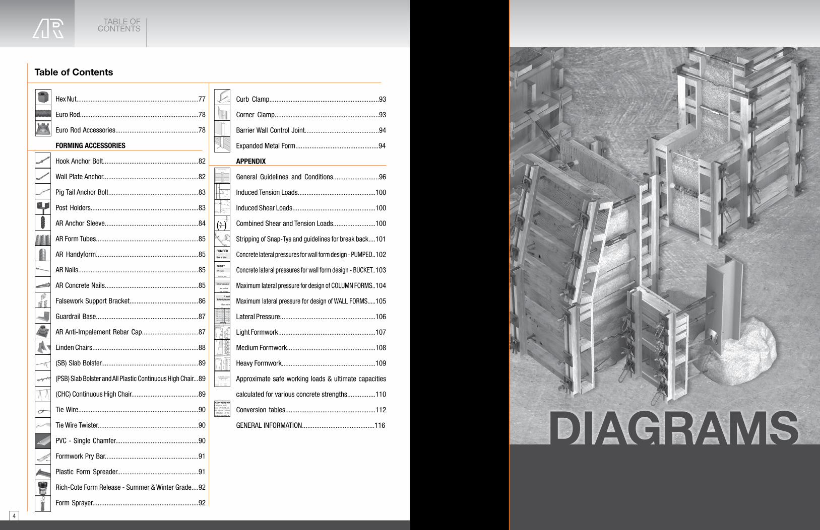
BREAK BACK ASSUREDThe Space-TyTM re-bar locating device protects the break point during the concrete placement assuring a positive break and easy removal of the Ty end.
IMPROVED WATER SEALThe plastic locating device is securely moulded to the Snap-Ty, effectively breaking the wire surface continuity, reducing the possibility of water seepage.
FIXED RE-BAR LOCATING DEVICEDesigned to accept and lock in place 10M, 15M, or 20M (#4, #5 or #6) re-bar into the correct position, preventing any movement during the concreteplacement.
REMOVABLE PLASTIC CONEThe Removable Plastic Cone provides for an architectural recess in the concrete which can be sealed using the AR Plastic Set Back Tyscru Plug or by using standard grouting practices.
GUARANTEES CONCRETE COVERThe re-bar locating device guarantees the concrete cover as outlined in CSA -A23-3-M90. The Space-TyTM rebar locating device complies with the RecommendedPractice for Concrete Formwork as outlined in Architectural Concrete (ACI 347-95).
NOTE: Space-TysTM have a guaranteed standard 40 mm (11/2”) set back. A 50 mm (2”) set back is available on special order. Refer to Lateral Pressure Design information on page 102 and typical Light Formwork on page 107 of the Appendix.
SPACE-TYTM ASSEMBLYThe Space-TyTM combines all essential features for light concrete forming. The Space-TyTM re-bar locating device securely locks the re-bar at a correct distance from the face of the form and eliminates the need for spacers.
Minimum end length of 120 mm (43/4”). Standard sizes stocked in 120 mm (43/4”) or 211 mm (8¼”) ends.
FORM TY SPECIFICATIONSInternal form ties shall be so arranged that when the forms are removed, no metal shall be within 40 mm or 50 mm (1½” or 2”) of any exposed surface as outlined in CSA-A23-3-M90 or ACI 347-95. Use Space-TysTM or approved equal and seal the tie holes with PVC plugs. The light grey plugs complement the adjacent concrete.
BREAK BACK TYTo facilitate the stripping of forms, the Space-TyTM can be broken back prior to form removal. Using a Space-TyTM wrench or standard 13 mm (½”) socket wrench, twist and remove the Ty end.
NOTE: For Ty removal and break back guidelines please see page 101 of the Appendix. Refer to Lateral Pressure Design information on page 102 and typical Light Formwork on page 107 of the Appendix.
Designed by AR, the Plastic Space-Ty Plug provides an easy and very economical means of sealing tie holes.
Guaranteed concrete cover
For exposed conditions of40 mm, 50 mm (11/2”, 2”)
SPACE-TYSPACE-TY
PlasticSpace-TyPlug
6 mm (¼")plug recess
Tight fit
Re-Bar affixed to Space-Ty locating device
Re-Barcover "C"
Concrete surface
Rebar
Space-Ty
RebarLocatingDevice
Break pointof Ty
RemovablePlasticCone
Ty end
Re-Bar
Re-Barlocating device
Ty Break Back40 mm (1½")or 50 mm (2")
Concretesurface
Ty
Concrete surface
Space-Ty Wrench
To order, please specify the following information
EXAMPLEName ....................................................... Space-TyEnd ................................................... 211 mm (8¼”)Wall ..................................................... 300 mm (8”)End .................................................... 211 mm (8¼”)“C” dimensions 40 mm or 50 mm (11/2” or 2”) ............ 40 mm (11/2”)Quantity (pkg of 50) ....................................... 200
APPROXIMATE SAFE WORKING LOAD
13.5 kN (3,000 LBS)2:1 Safety Factor
Consult the NCA Technical Department for minimum
wall thickness
Form + 13 mm (½")
End
Tywedge
Form + 13 mm (½")
EndWall thickness
"C"Re-bar cover
"C"
SPAC
E-TY
SPAC
E-TY

2524
Waler Bracket Forming SystemSNAP-TY ACCESSORIES
Single Waler Bracket
A-Bracket
The AR Waler Bracket is a proven method to form light weight walls and foundations. The basic unit of this system is the bracket with a moving wedge which provides the most effective type lock for the Snap-Ty. The basic components are the Waler Bracket and Snap-Tys, with plywood panels and loose 38 mm x 89 mm (standard 2x4 walers). No nailing is needed. Erection and stripping are made fast and simple and materials last longer. The Waler Bracket Forming System will save up to 50% of the forming cost.
The AR Waler Bracket is designed to be used with any AR Short-End Snap-Ty. The durable bracket can be used with both horizontal walers and vertical studs for any type of wall form; round, curved, battered, beam and/or columns. The Single Waler Bracket is fabricated from heavy gauge steel which is plated to resist corrosion for improved durability and reuse.
To order, please specify the following information
EXAMPLEName .................................... Single Waler Bracket Quantity .......................................................... 200
SNAP-TY ACCESSORIES
SNAP-TY ACCESSORIES
APPROXIMATE SAFE WORKING LOAD12 kN (2,700 LBS)2:1 Safety Factor
2 X 4Lumber
PlywoodPanels
Snap-TyWaler
Bracket
Pressed Steel Ty Wedge
The AR Pressed Steel Ty Wedge is designed to slip over the head of a standard or heavy duty Snap-Ty to safely secure the waler system in place. Caution should be used when used with hex head Space-TyTM or Snap-Ty products.
To order, please specify the following information
EXAMPLEName ...............................Pressed Steel Ty-WedgeQuantity .......................................................... 200
APPROXIMATE SAFE WORKING LOAD
13.5 kN (3,000 LBS)2:1 Safety Factor
Type H Ty-Wedge
AR Type H Ty Wedges are manufactured from a malleable cast iron material designed to slip over the head of a standard or heavy duty Snap-Ty. The Type H-Ty Wedge provides for long term durability, performance and bearing area to ensure proper load distribution on to the waler system.
The AR A-Bracket is used to hold a horizontal waler bar, or a vertical stud with any type of wall form. The built-in slot allows the bracket to slip over 4-3/4" L&W snapties, and can be installed before or after waler bars have been positioned. The swivel bracket allows the snaptie end to lock-in and tightens on the 2 x 4 waler. The swivel bracket allows for 5/8" of adjustment to compensate for lumber variations.
To order, please specify the following information
EXAMPLEName ...................................... Type H Ty-WedgeQuantity (lots of 50) ....................................... 200
APPROXIMATE SAFE WORKING LOAD
13.5 kN (3,000 LBS)2:1 Safety Factor
Any typeSnap-Ty
Type HTy-Wedge
Any typeSnap-Ty
Pressed Steel Ty Wedge
Strong Back
The AR Form Aligner Clamp is designed for use with a single 38 mm x 89 mm (2" x 4") strong back for either vertical or horizontal form alignment. The Form Aligner Clamp can be installed after erection of the forms and is not limited by form-ty spacing. Sturdy, galvanized construction reduces maintenance and replacement and speedy installation reduces forming costs.
FormAlignerClamp
RotateWedge
2 X 4Stiff-Back
TightenWedgewithhammer
To order, please specify the following information
EXAMPLEName ................................................. Strong BackQuantity .......................................................... 200
Ty
Concrete surface
Space-Ty Wrench
Snap-Ty Wrench
The AR Snap-Ty Wrench is designed to fit tight again the wall and facilitate the Snap-Ty break back once the concrete has cured. The angle of the Snap-Ty Wrench will prevent scraping of knuckles during the end removal. After the form has been removed, place the Snap-Ty Wrench on the Ty. Keep the Snap-Ty Wrench against the concrete, bend the Ty towards the concrete surface. Rotate the wrench using a cranking motion to break the Ty back within the concrete wall.
To order, please specify the following information
EXAMPLEName ......................................... Snap-Ty WrenchQuantity .............................................................. 2
Ty
Concrete surface
Space-Ty Wrench
SNAP
-TY
ACCE
SSOR
IES
SNAP
-TY
ACCE
SSOR
IES

2726
Plastic Snap-Ty Plug
AR Plastic Snap-Ty Plugs are designed to provide an economical means of sealing Snap-Ty Cone holes, eliminating the need for grouting. The Plastic Snap-Ty Plug provides an architectural design in concrete walls and should be installed with a commercial grade adhesive material. Available in a standard grey colour. Other colours are available on special orders based on minimum quantities.
Plastic Snap-Ty Plug provides a recess of approximately 5mm (¼”).
NOTE: Not designed for wind loads.
NOTE: Do not use Plastic Snap-TyPlugs with AR Space-TysTM.
Refer to General Guidelines and Conditions on page 96 and LateralPressure Design Information beginning on page 102 of the Appendix.
To order, please specify the following information
EXAMPLEName .............................. Plastic Space-TyTM PlugColour .................................................... light grayQuantity .......................................................... 200
SNAP-TY ACCESSORIES
SNAP-TY ACCESSORIES
Plastic Space-TyTM Plug
AR Plastic Space-TyTM Plugs are designed to fit securely in the cone hole of a AR Space-TyTM once the Ty break back is established in the concrete wall. The Space-TyTM Plug is a simple and economical means of sealing Space-TyTM holes providing an architectural design.
To order, please specify the following information
EXAMPLEName .................................... Plastic Snap-Ty PlugQuantity ......................................................... 200
Form Brace Aligner
The AR Form Brace Aligner is designed to assist in accurately positioning and plumbing vertical forms. The heavy 25 mm (1”) open style turnbuckle provides for fast, easy adjustments. The Form Brace Aligner is equipped with a bent nailing plate and holes. Manufactured from first quality materials for durability and repeat use. The Approximate Safe Working Loads of the aligner are limited by the fieldfastening and staking method. The Form Brace Aligner splicer unit provides for 90 mm (3½”) total adjustment. The overall maximum length is 1,040 mm (41”) with a minimum length of 950 mm (37½”).Also available in adjustable.
To order, please specify the following information
EXAMPLEName ..................................... Form Brace AlignerQuantity ............................................................. 2Snap-Ty
Cone cavity
Snap-Ty
PlasticSnap-TyPlug
Form Brace Aligner
2 x 42 x 6
To order, please specify the following information
EXAMPLEName ............................................... Plyhole PatchQuantity (lots of 1,000) ................................ 1,000
Plyhole Patch
The AR Plyhole Patch is designed to facilitate Ty hole repairs in wood formwork. Manufactured from 26 gauge galvanized steel, the 60 mm (2¼”) diameter patch comes complete with its own fastening system. The self contained barbs eliminates the requirement for nails.Also available in plastic.
Ty Hole
Plyhole Patch
SNAP
-TY
ACCE
SSOR
IES
SNAP
-TY
ACCE
SSOR
IES

2928
Pencil Rod
Rod Clamp
AR Rod Clamps are malleable castings for plain or deformed re-bar ty systems. The Rod is clamped by a set screw and nut arrangement which tightens the grip as the load is applied. The clamp housing may be used indefinitely. The only wearing element is the relatively inexpensive nut and screw which can be replaced at will. The Rod Clamps are supplied with nail holes to simplify the attachment operation on the walers. Once the Ty rod is tightened and secured, bending the rod behind the clamp at 90° will provide an additional measure of safety.
Consult your AR Area Sales Representative or the AR Technical Department for additional information.
PENCILROD
SNAP-TY ACCESSORIES
Scaffold Bracket
The AR Scaffold Bracket (TSB) meets most local code requirements and is suitable for most formwork systems. The Brackets are adjustable to fit vertical or horizontal wales and/or strongbacks by simply adjusting the pins position in the vertical or horizontal members. The AR Scaffold Bracket (TSB) can also be flush mounted to concrete surfaces and is also easily adapted to custom prefabricated forms.
Allow 175 mm (7") for Tightening Wrench and Rod Clamp
Rod Clamp
TighteningWrenchTo order, please specify the following information
EXAMPLEName ................................................... Rod ClampRod Diameter ....................................... 6 mm (¼”)Quantity .......................................................... 200
Diameter 6 mm (¼”)
10 mm (3/8”) 13 mm (1/2”)
Refer to General Guidelines and Conditions on page 96 and Lateral Pressure Design Information beginning on page 102 of the Appendix.
8' MaximumCenters
Built-inreceptaclefor 2 x 4HandrailPost
ScaffoldBracket
35"
40"
APPROXIMATE SAFE WORKING LOAD4.5 kN (1,000 LBS)4:1 Safety Factor
Pencil Rod Tightening Wrench
Caution: Do not use the Tightening Wrench for straightening forms or for pulling smooth rods from set concrete.
The AR Tightening Wrench is placed over a smooth or deformed rod behind a rod clamp and is used to draw the assembly tight, allowing the clamp to be properly tightened. The Tightening Wrench is available in ¼”, 3/8” and ½” sizes.
The AR Pencil Rod System is an economical forming system, used mainly for battered walls and foundations where the use of the AR Snap-ty is not feasible. Available in 1/4" diameter, cut to 10' or 20' lengths. Use where a clean breakback is not necessary. For use with the AR Rod Clamp and AR Tightening Wrench.
To order, please specify the following information
EXAMPLEName ....... Tightening WrenchSize ..................... 13 mm (1/2”)Quantity ......................... 200
Allow 100 mm (4") pastwale and bend rod at 90˚
Allow 175 mm (7") for Tightening Wrench and Rod Clamp
Rod ClampTighteningWrench
Diameter mm (in) kN (lbs)
6 mm (¼”) 5 kN (1,125 lbs) 10 mm (3/8”) 10 kN (2,200 lbs) 13 mm (1/2”) 15 kN (3,750 lbs)
Diameter mm (in) kN (lbs)
6 1/4" 10' 1,1256 1/4" 20' 1,125
APPROXIMATE SAFE WORKING LOADS2:1 Safety Factor
Insert2 x 4
SNAP
-TY
ACCE
SSOR
IES
PENC
ILRO
D

3130
CAM-LOCK &ANCHOR-LOCK
Cam-Lock Forming System
The AR Cam-Lock Forming System takes advantage of inexpensive forming materials, S4S 2x4s with 4’x8’x¾” or 2’x8’x¾” plywood sheets. When used for built-in-place forming, no ribbing or special hardware attached to the panels is necessary. The use of stiffbacks and walers is cut in half. Walers may be used either vertically or horizontally, but field tests have proved the latter method to be easier and faster.
The Cam-Lock Bracket holds the 2x4 waler in place by locking to the loop-end ty through caming pressure. Further rigidity of the form may be obtained through use of the Cam-Lock Stiff-Back Cam which connects to the ears on the back of the Cam-Lock Bracket, locking either a 2x4 or 2x6 in place with the same caming principle. This also assures perfect alignment of the form from top to bottom and enhances the system’s adaptability to extremely high, close tolerance work.
The extreme rigidity of Cam-Lock Forming System makes it adaptable to all types of construction, and this same rigidity, coupled with the Cam-Lock Scaffold Bracket, makes it especially desirable for high wall forming. Economy of the system is realized in labour costs through the simplicity of the system as well as the increased man-hourproduction that result from easier handling of the light weight plywood sheets. Since only half as much dimension lumber is used, further savings are derived from lower material costs.
Refer to General Guidelines and Conditions on page 96 and LateralPressure Design Information beginning on page 102 of the Appendix.
CAM-LOCK &ANCHOR-LOCK
Cam-Lock Self Centering D-Cone Ty
The AR Cam-Lock Self Centering D-Cone Ty features a high density polyethylene Cone Washer. This Cone Washer will not absorb moisture or stick to the concrete, preventing break back problems. A smooth, uniform hole results after break back, allowing easier grouting and faster, better finishing. The standard 25 mm (1”) D-Cone comes with a 25 mm (1”) break back. Self-centering tapered cones require a drill hole size of 21 mm (13/16”).
25 mm (1") break back
plywood
To order, please specify the following information
EXAMPLEName ........ Cam-Lok Self Centering D-Cone TyQuantity .................................................... 200
APPROXIMATE SAFE WORKING LOAD10 kN (2,250 LBS)2:1 Safety Factor
Refer to General Guidelines and Conditions on page 96 and LateralPressure Design Information beginning on page 102 of the Appendix.
Cam-Lock Stiff-Back Cam
Cam-Lock Handrail Post
The AR Cam-Lock Stiff-Back Cam is used in combination with the Cam-Lock Bracket to support the 2x4 strong-backs to the form, providing additional strength and form alignment. Also available as a 2x6 stiff-back as a special order.
The AR Cam-Lock Handrail Posts are required with the use of all Cam-Lock Scaffold Brackets. A 1,065 mm (42”) guard post with toeplate, mid-rail and top rail must be used. This requirement can easily and economically be met with the use of the Cam-Lock Handrail Post.
Cam-Lock Bracket
Cam-LockStiff-Back CamTo order, please specify the following information
EXAMPLEName .............................. Cam-Lock Stiff-Back CamQuantity ......................................................... 200
APPROXIMATE SAFE WORKING LOAD10 kN (2,250 LBS)2:1 Safety Factor
To order, please specify the following information
EXAMPLEName .............................. Cam-Lock Handrail PostQuantity .......................................................... 200
The AR Cam-Lock Bracket accomplishes many purposes in oneaccessory. It is a support for normal S4S, 2x4 walers. It has dual-earsfor the support of the Cam-Lock Scaffold Bracket and the Cam-LockStiff-Back Cam. The forged cam finger grips the Ty loop securing itfirmly to the form panel. The malleable cast bracket is designed withadditional strength provided for at the points of strain. The Cam-LockBracket may be used with either horizontal or vertical walers.Cam-Lock Brackets may be used as a built-in-place forming system or attached to the plywood when used for gang forming.
Cam-Lock Bracket
To order, please specify the following information
EXAMPLEName ................................. Cam-Lock BracketQuantity .................................................... 200
APPROXIMATE SAFE WORKING LOAD10 kN (2,250 LBS)2:1 Safety Factor
Cam-LockBracket
PlywoodBlock
Cam-LockStiff-Back Cam
2 X 4 Stiff-Back
HorizontalWaler
CAM
-LOC
K&
ANCH
OR-
LOCK
CAM
-LOC
K&
ANCH
OR-
LOCK

3332
CAM-LOCKCAM-LOCK
Ty spacing for regular forming
20 mm (¾") Plywood
Ty
2X4 Waler
DoubleWalersat joint
Stiffback Cam
Cam-lock Bracket
Panel
Panel
2X4 Stiffback
20 mm (¾") Plywood
Ty
2X4 Waler
StiffbackCam
Cam-lock Bracket
Panel
2X4 Stiffback
NOTE: Drill 13/16" Ty holes.
The AR Cam-Lock Scaffold Bracket is constructed of sturdy, heavy gauge pressed steel. Extra rigidity is obtained by spot welded corner gusset plate and tubular riveted bracing.Hanger arms attach to the Cam-Lock Bracket ears in the same manner as the Cam-Lock Stiff Back Cam. Secure, firm attachment in seconds is accomplished without bolts, nuts or nails. It is quickly adaptable for use with 2x6 Stiff-Back by removal and repositioning of hanger arms. All new Scaffold Brackets are factory tested to 3,000 lbs.
DON’Ts· Never use the Scaffold Bracket with a short 2x4. Always use full length 2x4s that extend to a solid base.· Never use the Scaffold Bracket with only one scaffold plank.· Always use two approved 2x12 scaffold planks side by side.
DOs· The vertical 2x4 stiff-back must always extend to a solid base — the concrete footing, a floor slab or to compacted soil.· The Scaffold Bracket must be attached to the second cam-lock form. Never attach the Scaffold Bracket to the top row of cam-lock brackets and form ties.· A 2x4 stiff-back cam must always be attached directly below the Scaffold Brackets.· A second 2x4 stiff-back cam must be attached directly below the Scaffold Bracket.· Add an additional stiff-back cam at the bottom of the vertical 2x4 stiff-back to stabilize it.· Scaffold Brackets are to be used on 6’ centers along the form with two 2 x 12” scaffold planks.· A 42” guardrail with a 2x4 toeplate, mid-rail and top rail must also be used.Since we cannot anticipate every problem that may arise on the job in conjunction with the use of our product, we urge you to work safely and refer to your manuals for proper construction of concrete wall forming and scaffolding procedures
Cam-Lock Scaffold Bracket
APPROXIMATE SAFE WORKING LOAD11 kN (2,500 LBS)2:1 Safety Factor
Cam-LockScaffoldBracket
Cam-LockHandrail Post
To order, please specify the following information
EXAMPLEName ............ Cam-Lok Scaffold BracketQuantity ........................................... 200
Not to be used above 6.0 m (20’-0”). Any scaffolding above six metres (twenty feet) should be checked with local, provincial code requirements.
CAM
-LOC
K
CAM
-LOC
K

3534
QUICK STRIPTY SYSTEM
QUICK STRIPTY SYSTEM
The AR Quick Strip Ty System is designed to provide a true, smooth wall for light forming applications. The AR Quick Strip Tys are designed to be simply inserted through pre-manufactured slots in 20 mm (¾”) plywood form panels. They are secured in place by using a waler bar, which allows for quick form erection as well as efficient form stripping operations.
AR Quick Strip Tys are available for wall thicknesses ranging from 100 mm to 750 mm (4” to 30”) and are designed to reduce waler and bracing requirements.
Quick Strip Ty System
Quick Strip Ty
To order, please specify the following information
EXAMPLEName ............................................ Quick Strip TyLength ............................................ wall thicknessQuantity ......................................................... 250
APPROXIMATE SAFEWORKING LOAD5 kN (1,150 LBS)2:1 Safety Factor
Refer to General Guidelines and Conditions on page 96 and Lateral Pressure Design Information beginning on page 102 of the Appendix.
PlywoodRemoved
AR Quick Strip Corner Hinges provide an alternative method to achieving corner details. Hinges are secured to the Form Ply by using a simple carriage bolt. The hinges allow for a 15 mm (5/8”) smooth rod or rebar to pass through, holding the forming securely in place. The corner hinges are designed to work for both inside and outside corners.
The AR Quick Strip Ty Waler Bar is used to secure the Quick Strip Tys and form panels in place. The Waler Bar overlaps the adjacent edge of the form ply to increase the wall stability when pouring concrete. The Waler Bars are 6 mm x 20 mm x 2,400 mm (¼” x ¾” x 8’) and are made from high quality carbon steel with milled edges for smooth installation.
Quick Strip Corner Hinges
Waler Bar
To order, please specify the following information
EXAMPLEName .............................................. Waler BarQuantity .................................................... 200
To order, please specify the following information
EXAMPLEName ......................................... Corner HingesQuantity .................................................... 200
Refer to General Guidelines and Conditions on page 102 and Lateral Pressure Design Informationbeginning on page 102 of the Appendix.
8’
3/4”
Staggered spacing of Waler Bars increases form stability
Waler Bars must overlap plywood edges
Waler BarsPlywood edges
QUIC
K ST
RIP
TY S
YSTE
M
QUIC
K ST
RIP
TY S
YSTE
M

3736
RESIDENTIALTY
QUICK STRIPTY SYSTEM
Standard 2’ x 8’ panel
NOTE: AR Quick Strip Tys can be used without plywood panels, if desired. Tys can be slipped between common board and steel bars set vertically, eliminating most of the nailing and walering required.
Please consult yourlocal AR TechnicalRepresentative or ourTechnical Departmentfor Ty spacing.
Quick Strip Form Panel Construction
Corner Hinges supplied by NCA
Outside Corner
Inside Corner
Carriage Bolts
1/4"
3/4"
1 3/16"
45˚
2 1/2"
Form panels are easily built. Rout ¼” x 1” ty slots in ¾” plywood. A template out of ¼” plywood 6” x 7” cut-outs centered over the location where the ty slots are to be cut. A 6” x 6” x ¼” block fastened to the face of an electric router using a ¼” carbide bit will cut the ty slots the required size, ¼” x 1”. If desired, 4’ x 8’ outside panels may be used.
Corners are made from ¾” plywood, and hinges supplied by AR. Corner shown is the standard 2’ and works best on most jobs. Corners are connected by inserting a 5/8” rod through the hinges.
Residential Ty
Wall Thickness Box Qty8"
2509"
10"12"13"14"
100
16"18"20"22"24"
The AR Residential Ty is designed for modular forming systems utilizing 1-1/8" plywood. Crimped wires are designed to be secured in place by clips on the outside of the form and then are snapped off after the stripping of the forms using a break off tool. Available in standard sizes of 8"-10", 12"-14", 16", 18", 20", 22" and 24". Additional sizes available on request.
AR offers the supporting accessories used in 1-1/8" plywood modular forming. Standard 6" latch, top waler and tie breaker tool, along with other accessories are available.
Residential Ty Accessories
Standard 6" Latch
Top Waler
Additional Accessories
Ty Breaker Tool
· Radius Wall Clip
· Stacking Clip
· Corner Latch
· Form Screws
· Shoulder Bolts
· E-Clip
· Half Clip
· Sleeve Nuts
QUIC
K ST
RIP
TY S
YSTE
M
RESI
DENT
IAL
TY

3938
STEEL PLY FORMING
SYSTEM
The AR X-Flat Ty is designed to be used with modular form systems. Used in conjunction with a wedge bolt, it creates a secure form tie. The AR X-Flat Ty comes with a standard 1/4" set back. Available for 8", 10" and 12" wall sizes, additional wall sizes available on request.
The AR Stacking Ty, also referred to as "Snapie Ty", is used in light duty 1-1/8" plywood forming systems. Available in 5-5/8" to 12" sizes. Additional sizes available on request.
The AR Spreader Cleat is used to spread and hold the top and bottom of forms during concrete pour. The nail holes can be used to secure the cleats to the form. Available in 6"-12" standard sizes, for use with 3/4" and 1-1/8" plywood systems. Additional sizes available on request.
X-Flat Ty
Stacking Ty
Spreader Cleat
Wall Size SWL (lbs)8" 3,000
10" 3,00012" 3,000
Plywood Size Size SWL (lbs) Box Qty
1-1/8"
5-5/8"
1,500 100
6"7-5/8"
8"9"
10"11-5/8"
12"
Plywood Size Size SWL (lbs) Box Qty
1-1/8"
5-5/8"
1,500 100
6"7-5/8"
8"9"
10"11-5/8"
12"
WALL THICKNESS
PLYWOOD
Steel Ply Forming System
K-Form PVC Form
Flatwork
K-FORM is a lightweight PVC cast in place formwork, replacing steel and wood forms where control joints are needed. The pre-drilled 1" holes on the vertical wall allow for locating dowel bars, and the holes on the horizontal surface are used for anchoring with mortar. This all-in-one screed rail system is easy to use and is designed to save time and labour on the job site. Once concrete is cured, they can be left in place, no need to remove and clean. K-Forms are available in 2", 4" and 6" heights and standard 8' length. Custom sizes and length can be requested.
Height
2”4”
Length
6”
8’
Pin Pocket
The AR Pin Pocket, also referred to as "curb clamp", is a strong and durable clamp used for securing pins and forming stakes to the wood form. Coated with black paint for corrosion protection. Available 40 pieces per box.
Form Stake
AR Form Stakes are manufactured from high quality steel with a sharp point to minimize rock deflection. Form Stakes are available in 20 mm (¾") and 22 mm (7/8") diameters and in standard lengths of 450 mm, 600 mm, 750 mm and 900 mm (18", 24", 30" and 36"). The Form Stake is equipped with spiral-patterned nail holes for use as form pins.
To order, please specify the following information
EXAMPLEName ............................ Form StakeDiameter ..................................... 3/4"Length ........................................ 24"Quantity ........................................ 10
FLATWORK
STEE
L PL
Y FO
RMIN
G SY
STEM
FLAT
WOR
K
APPROXIMATE SAFEWORKING LOAD2:1 Safety Factor
APPROXIMATE SAFEWORKING LOAD2:1 Safety Factor
APPROXIMATE SAFEWORKING LOAD2:1 Safety Factor
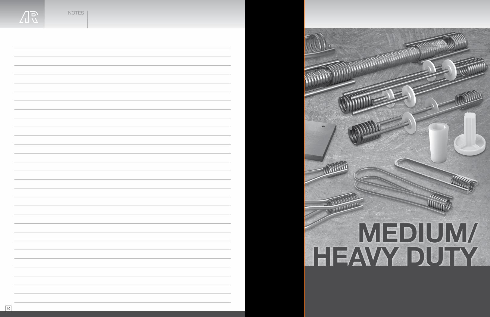
4140
MEDIUM/HEAVY DUTY
NOTES

4342
CONTINUOUS THREADED LAGSTUD
CONTINUOUS THREADED
LAGSTUD
Continuous Threaded Lagstud
To order, please specify the following information
EXAMPLEName ....... Continuous Threaded LagstudType ................................................... 9MDiameter .............................. 13 mm (1/2”)Length ................................... 3.6 m (12’)Grade of Steel ...................... High TensileQuantity .............................................. 50
To order, please specify the following information
EXAMPLEName ............. Lagstud BoltDiameter .......... 13 mm (1/2”)Length ......... 400 mm (16”)Type ........ 33 kN (7,500 lbs)Quantity ...................... 200
Refer to the Appendix for General Guidelines on page 96, Lateral Pressureinformation on page 102 and typical Medium and Heavy Formworkbeginning on page 108. See page 51 for approximate safe working load System Chart.
Continuous Threaded Lagstud
The Acrow-Richmond Lagstud is perhaps the most versatile of all the members of the AR Tyscru family. This versatile product can be used in combination with the complete line of Tyscru products. Continuous Threaded Lagstud is available in both mild steel and high tensile in 3 m (10’) and 3.6 m (12’) lengths respectively. Field cutting may be accomplished with bolt cutters or carborundum blades.The Lagstud is particularly adaptable in combination with Tyscrus to make adjustable Tys, embedded in concrete or rock as an adjustable anchorage for the Tyscru, or in combination with Handle Lagnuts as an emergency lagstud bolt.
½ (13) 4,500 (20) 16 (408) 12 (304)
½ (13) 6,750 (30) 20 (508) 15 (378)
¾ (20) 9,000 (40) 24 (609) 18 (458)
1 (25) 13,500 (60) 32 (816) 24 ( 609)
1¼ (32) 27,000 (120) 40 (1,020) 30 (760)
2,000 psi (13.8 MPa)
Diameter
in (mm) in (mm) in (mm)
Approx. Safe Working Loads @ 2:1
lbs (kN)
Embedment “H”
1,000 psi (6.9 MPa)
1 (25) 18,000 (80) 40 (1,020) 30 (760)
*When using 32 mm (1¼”) High Tensile Lagstud, use double nuts to obtain full capacity of Rod, 265 kN (60,000 lbs).
* *
1½ (38) Contact the AR Technical Department for details.
Safe Working Loadslbs (kN)
Diameterin (mm)
Safe Working Loads lbs (kN)
Ultimate Loadslbs (kN)
¾ (20) 18,000 (80)36,000 (160)
1 (25) 25,000 (110) 37,500 (165)50,000 (220) 75,000 (335)
1¼ (32) 37,000 (165) 49,000 (216)74,000 (330) 120,000 (530)
Ultimate Loadslbs (kN)
Mild Steel High Tensile Steel
½ (13) 9,000 (40)18,000 (80)15,000 (70) 7,000 (33)
LAGSTUD TENSILE PROPERTIES
LAGSTUD FOR EMBEDDED ANCHORS
H
Tyscru
Handle Lagnut
Washer
LagstudWasher
Lagstud
Lagstud
GroutTyscruLagstud
Lagstud Bolt
AR Lagstud Bolts are threaded for the coil of an AR Tyscru or insert. Available in ½”, ¾”, 1” and 1¼” (13 mm, 20 mm, 25 mm and 32 mm) diameters and lengths as required in 2” (50 mm) increments. All Lagstud Bolts have a hexagon nut welded to it as an integral head, and should be used with a running nut, handle lagnut or wingnut as shown.
*When using 1¼” (32 mm) High Tensile Lagstud, use double nuts to obtain full capacity of Rod, 60,000 lbs (265 kN). All lagstud bolts to be used with running nut, handle lagnut or wing nut.
½ (13) 7,000 (33) 9,000 (40)
¾ (20) N/A N/A 18,000 (80)
1 (25) 25,000 (110) 37,500 (165)
1¼ (32) 37,500 (165) 49,000* (216)
Diameterin (mm)
Mild Steellbs lbs (kN)
High Tensile(kN)
1½ (38) Contact the NCA Technical Department for details.
Washer
Minimum coil penetration
CONT
INUO
US
THRE
ADED
LA
GSTU
D
CONT
INUO
US
THRE
ADED
LA
GSTU
D
APPROXIMATE SAFEWORKING LOAD2:1 Safety Factor
APPROXIMATE SAFEWORKING LOAD2:1 Safety Factor

4544
TYSCRUTYSCRU
Tyscru
The minimum Lagstud Bolt length required is equal to the sum of the flat washer, waler studs, form ply, set back and the coil length plus 13 mm (1/2").
Tyscru
Flat Washer thickness Flat Washerthickness
Tyscru length
Coil penetration
Wall thicknessForm Form thickness
Setback Wedge
Lagstud Bolt length
Flat Washer thickness
Tyscru length
Coil penetration
Wall thicknessForm thickness
Setback (Tycones optional)
Lagstud Bolt length
The AR Tyscru is an extra strong, resistance welded Ty designed to take the abuse encountered in medium and heavy concrete construction. An extremely simple Ty, capable of many combinations and uses in the field, it may be used with or without Tycones or combined with Continuous Threaded Lagstud to form an Adjustable Tyscru
Determining your Tyscru Requirement
Tyscru: The Tyscru length is determined by subtracting each set back requirement from the wall thickness at the tie location. Lagstud or lagstud bolt length is determined by adding the form thickness to the set back on one side plus the Tyscru coil length plus 13 mm (½”). Lagstud or Lagstud Bolt are furnished standard in even 50 mm (2”) lengths. Select the next higher full unit over actual length determined. For extreme adjustment requirements, 25 mm to 50 mm (1” to 2”) may be added.
Wall Thickness: Distance between the form facings at the Tyscru location.
Set Back: Required distance of Ty metal from the finished concrete face with or without the use of Tycones. Set back may be required at one or both faces, usually both. Total set back is the sum of set backs from both wall faces. When Tycones are used, their length is equal to the required set back.
Form Thickness: Distance measured between the finished concrete surface to the outside face of the flat washer — includes plywood sheeting material, studs, wales and washer.
Coil Penetration: Distance the Lagstud should penetrate the Tyscru coil length plus 13 mm (½").General instructions: For extreme penetration or extended concrete curing requirements, the Lagstud or Lagstud Bolt is normally greased to facilitate removal. To break the bond and permit easy removal, it is a good practice to turn the lagstud or lagstud bolt a quarter to one-half turn, in and out, eight to twelve hours after the concrete has been poured.
Battered Wall Form
Plumb Wall Form
Refer to the Appendix for General Guidelines on page 96, Lateral Pressure information on page 102 and typical Medium and Heavy Formwork beginning on page 108. See page 51 for approximate safe working load System Chart.
TYSC
RU
TYSC
RU
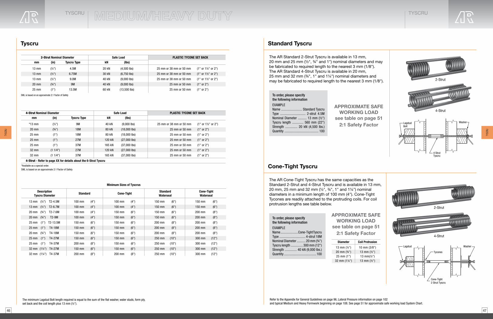
4746
4-Strut
TYSCRUTYSCRU
The minimum Lagstud Bolt length required is equal to the sum of the flat washer, waler studs, form ply, set back and the coil length plus 13 mm (1/2").
Tyscru Standard Tyscru
Cone-Tight Tyscru
2-Strut Nominal Diameter
mm (in) Tyscru Type
13 mm (½") 4.5M
13 mm 6.75M(½")
20 mm (¾") 9M
25 mm (1") 13.5M
Safe Load
kN (lbs)
20 kN (4,500 lbs)
30 kN (6,750 lbs)
40 kN (9,000 lbs)
60 kN (13,500 lbs)
PLASTIC TYCONE SET BACK
25 mm or 38 mm or 50 mm (1" or 1½" or 2")
25 mm or 38 mm or 50 mm (1" or 1½" or 2")
13 mm (½") 9.0M 40 kN (9,000 lbs) 25 mm or 38 mm or 50 mm (1" or 1½" or 2")
25 mm or 50 mm (1" or 2")
25 mm or 50 mm (1" or 2")
SWL is based on an approximate 2:1 Factor of Safety
4-Strut Nominal Diameter
4-Strut - Refer to page XX for details about the 6-Strut Tyscru
mm (in) Tyscru Type
*13 mm (½") 9M
20 mm 18M(¾")
25 mm (1") 27M
25 mm (1") 37M
Safe Load PLASTIC TYCONE SET BACK
25 mm or 38 mm or 50 mm (1" or 1½" or 2")
25 mm (1") 18M
25 mm or 50 mm (1" or 2")
25 mm or 50 mm (1" or 2")
25 mm or 50 mm (1" or 2")
25 mm or 50 mm (1" or 2")
32 mm (1 1/4") 27M
32 mm (1 1/4") 37M
kN (lbs)
40 kN (9,000 lbs)
80 kN (18,000 lbs)
120 kN (27,000 lbs)
165 kN (37,000 lbs)
80 kN (18,000 lbs)
120 kN (27,000 lbs)
165 kN (37,000 lbs)
25 mm or 50 mm (1" or 2")
25 mm or 50 mm (1" or 2")
SWL is based on an approximate 2:1 Factor of Safety
*Available as a special order.
DescriptionTyscru Diameter
13 mm (½") T2-4.5M
13 mm (½") T2-6.7M
20 mm (¾") T2-7.6M
20 mm (¾") T2-9M
25 mm (1") T2-13.5M
25 mm (1") T4-18M
20 mm (¾") T4-18M
25 mm (1") T4-27M
25 mm (1") T4-37M
32 mm (1¼") T4-27M
32 mm (1¼") T4-37M
Standard
100 mm (4")
100 mm (4")
100 mm (4")
100 mm (4")
150 mm (6")
150 mm (6")
150 mm (6")
150 mm (6")
200 mm (8")
150 mm (6")
200 mm (8")
Cone-Tight
100 mm (4")
100 mm (4")
150 mm (6")
150 mm (6")
150 mm (6")
150 mm (6")
150 mm (6")
150 mm (6")
150 mm (6")
150 mm (6")
200 mm (8")
StandardWaterseal
150 mm (6")
150 mm (6")
150 mm (6")
150 mm (6")
200 mm (8")
200 mm (8")
200 mm (8")
250 mm (10")
250 mm (10")
250 mm (10")
250 mm (10")
Cone-TightWaterseal
150 mm (6")
150 mm (6")
200 mm (8")
200 mm (8")
200 mm (8")
200 mm (8")
200 mm (8")
300 mm (12")
300 mm (12")
300 mm (12")
300 mm (12")
Minimum Sizes of Tyscrus
2-Strut
The AR Standard 2-Strut Tyscru is available in 13 mm, 20 mm and 25 mm (½", ¾" and 1") nominal diameters and may be fabricated to required length to the nearest 3 mm (1/8").The AR Standard 4-Strut Tyscru is available in 20 mm, 25 mm and 32 mm (¾", 1" and 1¼") nominal diameters and may be fabricated to required length to the nearest 3 mm (1/8").
The AR Cone-Tight Tyscru has the same capacities as the Standard 2-Strut and 4-Strut Tyscru and is available in 13 mm, 20 mm, 25 mm and 32 mm (½", ¾", 1" and 1¼") nominal diameters in a minimum length of 100 mm (4"). Cone-Tight Tycones are readily attached to the protruding coils. For coil protrusion lengths see table below.
To order, please specify the following information
EXAMPLEName ........................ Standard TyscruType ............................. 2-strut 4.5MNominal Diameter .......... 13 mm (1/2")Tyscru length ............. 560 mm (22")Strength .............. 20 kN (4,500 lbs.)Quantity ....................................... 100
To order, please specify the following information
EXAMPLEName .................... Cone-Tight TyscruType .............................. 4-strut 18MNominal Diameter .......... 20 mm (3/4")Tyscru length .............. 300 mm (12")Strength .............. 40 kN (9,000 lbs.)Quantity ..................................... 100
Washer
4 Strut Tyscru
LagstudBolt
Washer
Cone-Tight2 Strut Tyscru
Tycones
Lagstud
APPROXIMATE SAFE WORKING LOAD
see table on page 512:1 Safety Factor
APPROXIMATE SAFE WORKING LOAD
see table on page 512:1 Safety Factor
4-Strut
2-Strut
Diameter Coil Protrusion
13 mm (½")20 mm (¾")25 mm (1")
32 mm (1¼")
10 mm (3/8")13 mm (½")13 mm(½")13 mm (½")
Refer to the Appendix for General Guidelines on page 96, Lateral Pressure information on page 102 and typical Medium and Heavy Formwork beginning on page 108. See page 51 for approximate safe working load System Chart.
TYSC
RU
TYSC
RU

4948
4-Strut
TYSCRUTYSCRU
Waterseal Tyscru
Adjustable Tyscru
2-Strut
The AR Waterseal Tyscru has the same capacity as the standard 2-Strut and 4-Strut Tyscru. The Waterseal Tyscru is available as standard or cone tight in 13 mm, 20 mm, 25 mm and 32 mm (½", ¾", 1" and 1¼") nominal diameters in a minimum length of 100 mm (4") for a Cone-Tight Tyscru and 150 mm (6") for a Waterseal Tyscru. AR uses a unique manufacturing process to fuse a water stop plastic washer to each wire strut. The plastic washer will break the surface continuity and prevent seepage of water along the struts.
The AR Adjustable Tyscru, consisting of two Tyscrus (cone tight one end) and one Continuous Threaded Lagstud, is available in 13 mm, 20 mm, 25 mm and 32 mm diameters (½", ¾", 1" and 1¼") diameters.
To order, please specify the following information
EXAMPLEName ......................................... Waterseal TyscruType .............................................. 2-strut 6.75MNominal Diameter .............................. 13 mm (1/2")Tyscru length ................................. 250 mm (22")Strength .................................... 20 kN (4,500 lbs.)Quantity ........................................................ 200
To order, please specify the following information
EXAMPLEName ......................................... Adjustable TyscruType ............................................... 2-strut 4.5MNominal Diameter .............................. 13 mm (1/2")Length ............................................... 225 mm (9")Strength ..................................... 30 kN (6,750 lbs.)Quantity ......................................................... 200
Washer
Waterseal Tyscru
LagstudTycones
Lagstud
Adjustable Tyscru
Washer
APPROXIMATE SAFE WORKING LOAD
see table on page 422:1 Safety Factor
APPROXIMATE SAFE WORKING LOAD
see table on page 512:1 Safety Factor
Heavy Tyscru (4-Strut and 6-Strut)
Type
9 M
18 M18 M27 M37 M
40 kN
80 kN80 kN120 kN
165 kN
kN
*13 mm20 mm25 mm25 mm
25 mm
Diameter Safe Loadmm (in)
(9,000 lbs)(18,000 lbs)(18,000 lbs)(27,000 lbs)
(37,000 lbs)(27,000 lbs)
(lbs)
27 M 120 kN32 mm
(½")(¾")(1")(1")(1")
37 M 165 kN32 mm (37,000 lbs)(1¼")(1¼")
200 kN245 kN
kN
32 mm
38 mm
Diameter Safe Loadmm (in)
(45,000 lbs)(55,000 lbs)
(lbs)
(1¼”)(1½")
The AR 6-Strut Heavy Tyscru is available in 32 mm and 38 mm (1¼" and 1½") nominal diameter and may be fabricated to required lengths to the nearest 3 mm (1/8"). The AR 6-Strut Heavy Tyscru is available as a standard or water seal Tyscru for both diameters. A 32mm (1¼") Cone Tight 6-strut Heavy Tyscru is also available.
4-Strut
6-Strut
To order, please specify the following information
EXAMPLEName .............................. 4-Strut Heavy TyscruDiameter ....................................... 20 mm (3/4")Length ....................................... 300 mm (12")Strength ................................ 40 kN (9,000 lbs.)Quantity ..................................................... 100
Name .............................. 6-Strut Heavy TyscruDiameter ....................................... 32 mm (1")Length ....................................... 300 mm (12")Strength ........................... 165 kN (37,000 lbs.)Quantity ..................................................... 200
4-STRUT 6-STRUT
TYSC
RU
TYSC
RU
APPROXIMATE SAFE WORKING LOAD
see table on page 512:1 Safety Factor
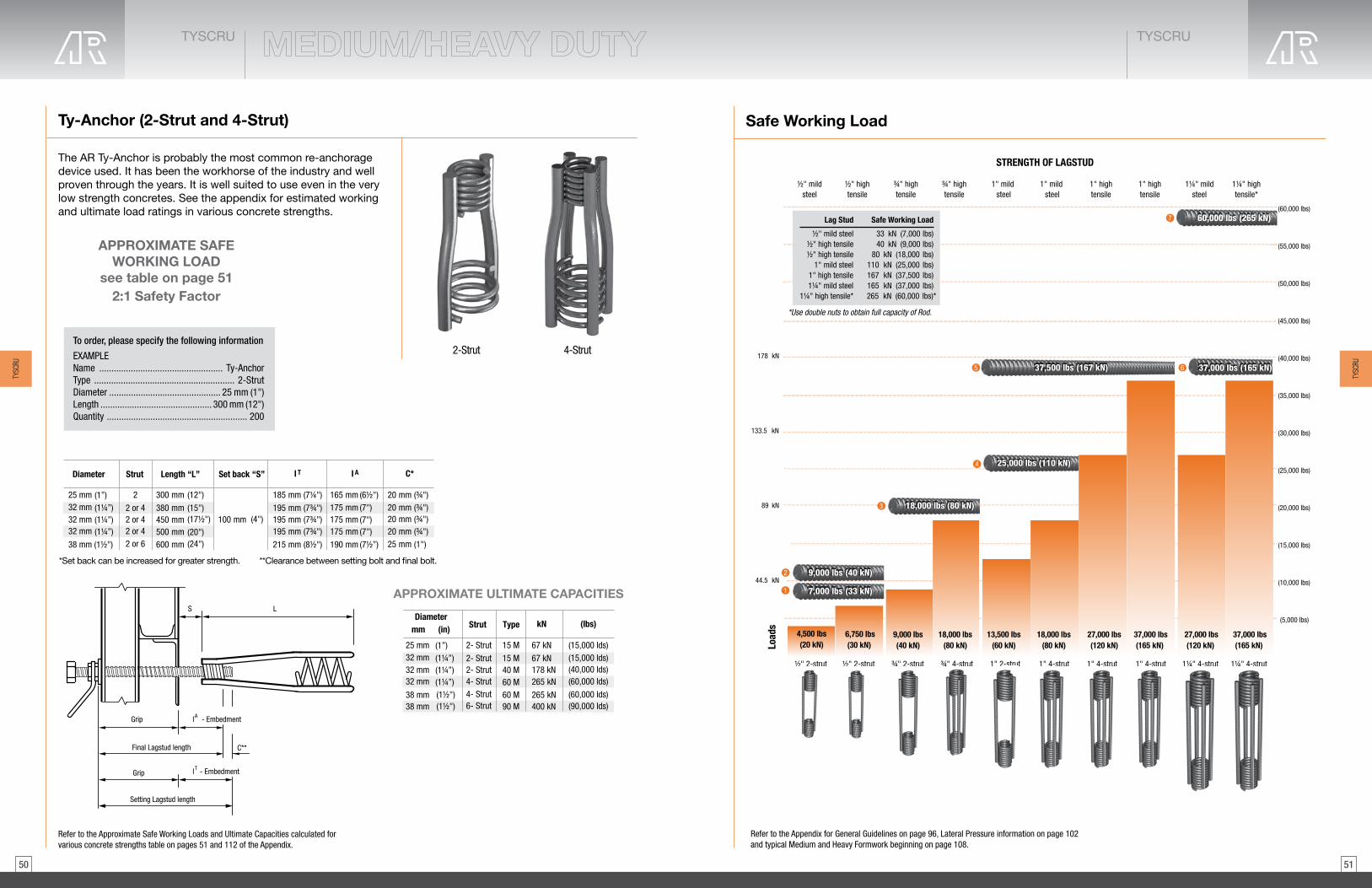
5150
TYSCRUTYSCRU
Refer to the Appendix for General Guidelines on page 96, Lateral Pressure information on page 102 and typical Medium and Heavy Formwork beginning on page 108.
Safe Working Load
½" 2-strut ½" 2-strut ¾" 2-strut 1" 2-strut 1" 4-strut 1" 4-strut 1" 4-strut 1¼" 4-strut1¼" 4-strut¾" 4-strut
44.5 kN
89 kN
133.5 kN
178 kN
Load
s
(5,000 lbs)
(10,000 lbs)
(15,000 lbs)
(20,000 lbs)
(25,000 lbs)
(30,000 lbs)
(35,000 lbs)
(40,000 lbs)
½" mildsteel
1¼" mildsteel
¾" hightensile
1" mild steel
½" hightensile
¾" hightensile
1" high 1" hightensile
tensile
1¼" hightensile*
STRENGTH OF LAGSTUD
1" mild steel
(50,000 lbs)
(55,000 lbs)
(60,000 lbs)
(45,000 lbs)
65
4
3
2
7
1
*Use double nuts to obtain full capacity of Rod.
½" mild steel ½" high tensile
½" high tensile 1" mild steel
1¼" mild steel 1" high tensile
1¼" high tensile*
40 kN (9,000 lbs) 80 kN (18,000 lbs)
110 kN (25,000 lbs) 167 kN (37,500 lbs)
165 kN (37,000 lbs) 265 kN (60,000 lbs)*
Lag Stud Safe Working Load
33 kN (7,000 lbs)
(20 kN)4,500 lbs 6,750 lbs
(30 kN)9,000 lbs(40 kN)
18,000 lbs(80 kN)
13,500 lbs 18,000 lbs 27,000 lbs 37,000 lbs(60 kN) (80 kN) (120 kN) (165 kN) (165 kN)
37,000 lbs 27,000 lbs(120 kN)
37,500 lbs (167 kN)
25,000 lbs (110 kN)
18,000 lbs (80 kN)
7,000 lbs (33 kN)
9,000 lbs (40 kN)
37,000 lbs (165 kN)
60,000 lbs (265 kN)
Ty-Anchor (2-Strut and 4-Strut)
The AR Ty-Anchor is probably the most common re-anchorage device used. It has been the workhorse of the industry and wellproven through the years. It is well suited to use even in the very low strength concretes. See the appendix for estimated working and ultimate load ratings in various concrete strengths.
APPROXIMATE ULTIMATE CAPACITIES
*Set back can be increased for greater strength.
2-Strut 4-Strut
**Clearance between setting bolt and final bolt.
Set back “S”
100 mm
Length “L”
300 mm2
2 or 42 or 42 or 42 or 6
(12")
380 mm (15")(17½") (4")
(24")
450 mm500 mm600 mm
185 mm (7¼")
195 mm (7¾")195 mm (7¾")195 mm (7¾")
(8½")215 mm
I T
25 mm32 mm32 mm32 mm
38 mm (1½")
Diameter Strut
(20")
165 mm (6½")175 mm (7")175 mm
190 mm (7½”)
I A
(7")175 mm (7")
20 mm (¾")20 mm (¾")20 mm (¾")20 mm (¾")
C*
25 mm (1")
(1”)(1¼”)(1¼”)(1¼”)
Type
15 M2- Strut
2- Strut2- Strut4- Strut4- Strut
15 M40 M60 M60 M
67 kN
67 kN178 kN265 kN
265 kN
kN
25 mm32 mm32 mm32 mm
38 mm
Diametermm (in) Strut
(15,000 lds)(15,000 lds)(40,000 lds)(60,000 lds)
(60,000 lds)(90,000 lds)
(lbs)
6- Strut 90 M 400 kN38 mm
(1”)(1¼”)(1¼”)(1¼”)(1½")(1½")
To order, please specify the following information
EXAMPLEName ................................................... Ty-AnchorType .......................................................... 2-StrutDiameter .............................................. 25 mm (1")Length .............................................. 300 mm (12")Quantity .......................................................... 200
Refer to the Approximate Safe Working Loads and Ultimate Capacities calculated forvarious concrete strengths table on pages 51 and 112 of the Appendix.
Setting Lagstud length
LS
Grip
C**Final Lagstud length
l - EmbedmentA
l - EmbedmentT
Grip
TYSC
RU
TYSC
RU
APPROXIMATE SAFE WORKING LOAD
see table on page 512:1 Safety Factor

5352
TYSCRUACCESSORIES
TYSCRUACCESSORIES
Ty-Frame
The AR Standard Ty-frame consists of four coils welded to a truss-like arrangement of wirestruts with a leg at the front face extending down to the soffit, for support of the riser form. Ty-frames are designed for the individual riser and seat bracket condition.
The AR Alternate Ty-frame may be supplied in its alternate form, at our discretion, if jobconditions warrant. This alternate form consists of a series of Tyloops, or Tyloops and Tyscru, welded to a strong vertical support member.
The AR Fill Type Ty-frame is made to fit the job condition where the riser is poured on fill. Usually manufactured in multiple units to support 2, 3, or 4 seat brackets with one unit.
The AR Sloping Slab Ty-frame consists of Tyscrus welded together in exact positions to support the riser form.
Fill Type Ty-Frame
Sloping SlabTy-Frame
Alternate Ty-Frame
Standard Ty-Frame
To order, please specify the following information
EXAMPLEName ........................ Alternate Ty-FrameSupply a sketch or complete details of risers and seat bracketQuantity ............................................ 200
Tybow Anchor (2-strut, 4-strut and 6-strut)
The AR Tybow Anchor combines the advantages of the Tyscru coil with the efficiency of the bow shaped continuous threaded struts to make a highly effective anchorage device. Used with lagstud bolts or He-Bolts, the Ty-Bow is applicable even in the lowest concrete strengths. See the appendix for estimated working and ultimate load ratings in various concrete strengths.
APPROXIMATE SAFE WORKING LOADS 2:1 Safety Factor
*Clearance between setting bolt and final bolt. Other sizes available upon request.
Set back “S”
100 mm
Length “L”
450 mm (18")
(18") (4")
(24")
450 mm610 mm600 mm
195 mm (7¾")
222 mm
230 mm (9")
I TSafe Working LoadkN (lbs)
67 kN (15,000 lbs)
134 kN (30,000 lbs)
200 kN (45,000 lbs)
2-Strut
4-Strut
6-Strut
20 mm, 25 mm, 32 mm(¾”, 1”, 1¼”)25 mm, 32 mm(1”, 1¼”)38 mm (1½")
DiameterAnchorType
(24 ")3/8
(8 ")3/8
175 mm (7")
190 mm
190 mm (7½”)
I A
(7½")
20 mm (¾")
32 mm
38 mm (1½”)
C*
(1¼")
TOP OF LIFT
Setting Lagstud penetration
Final penetration
C*
C*
LS
l T
l A
Grip
Grip
Setting length
Final Lagstud length
ContinuousLagstud
4-Strut
6"2-Strut
10½"
6-Strut
To order, please specify the following information
EXAMPLEName ........................................ Tybow AnchorType ..................................................... 2-StrutDiameter ................................... 32 mm (1¼")Length ...................................... 450 mm (18")Quantity .................................................... 200
Refer to the Appendix for General Guidelines on page 96, Lateral Pressure information on page 102 and typical Medium and Heavy Formwork beginning on page 108. See page 51 for approximate safe working load System Chart.
Refer to the Approximate Safe Working Loads and Ultimate Capacities calculated forvarious concrete strengths table on pages 51 and 112 of the Appendix.
TYSC
RUAC
CESS
ORIES
TYSC
RUAC
CESS
ORIES

5554
TYSCRUACCESSORIES
TYSCRUACCESSORIES
Coil Nuts
AR Coil Nuts Two standard coil nuts of each size equal the strength of one heavy duty tall coil nut of the same size.
ACD
HD Size
H Size
ACAcross Flats
BoxQty
Weight per 100pcslbs
APPROXIMATE SAFE WORKING LOAD
lbs1/2” 0.484 0.863 500 6.2 6,000
5/8" Finished 0.547 0.930 500 11.4 8,0003/4" Finished 0.641 1.107 500 11.4 9,0003/4" Heavy 0.734 1.231 250 17.8 9,000
7/8" 0.859 1.416 250 27.6 16,0001" 0.984 1.600 150 15.0 18,000
1-1/4" 1.219 2.123 70 75.2 27,0001-1/2" 1.469 2.682 40 122.6 40,000
Wing Nut
AR Wing Nuts are manufactured with a lag thread and are used with AR She-Bolts or Taper-Tys. Fabricated in 20 mm, 25 mm and 32 mm (¾”, 1” and 1¼”) diameters.
Wing Nut
40,000 (178)
1
11/4
82,000 (365)
115,000 (512)
in (mm)Ultimate Tensile Load
lbs (kN)Size
3/4
(25)
(32)
(20)
To order, please specify the following information
EXAMPLEName .................................. Wing NutQuantity ........................... 25 mm (1")
Lagnut
AR Lagnuts are manufactured with Lag thread and are available in ½” through 1½” (13 mm through 38 mm) diameters. Warning: when utilizing Lagnuts on through-Ty applications, such as Continuous Threaded Lagstud, double nuts are required to develop ultimate loads for 1¼” (32 mm) applications. For all other applications, AR Lagnuts are designed to develop the full published ultimate load of AR Lagstud.
*When using 1¼” (32 mm) High Tensile Lagstud, use double nuts to obtain full capacity of Rod, 60,000 lbs (265 kN).
SAFE WORKING LOADS
½ (13) 9,000 (40)¾ (20) 18,000 (80)1 (25) 37,500 (167)
1¼ (32) 49,000* (216)*
Diameterlbs (kN)in (mm)
NCA Technical Department for details.1½ (38)
APPROXIMATE SAFE WORKING LOADS2:1 Safety Factor
Lagnut
LagstudTyscru
To order, please specify the following information
EXAMPLEName ......................................................... LagnutDiameter .............................................. 25 mm (1”)Quantity .......................................................... 200
To order, please specify the following information
EXAMPLEName ............................................. Handle LagnutDiameter ............................................. 13 mm (1/2”)Quantity .......................................................... 200
Handle Lagnut
AR Handle Lagnuts are made of hex nuts welded to substantial wire loops. Available in ½”, ¾”, 1” and 1¼” (13 mm, 20 mm, 25 mm and 32 mm) diameters with lag thread. The handle eliminates the need for using a wrench and makes installation and/or stripping fast and simple.
APPROXIMATE SAFE WORKING LOADS2:1 Safety Factor
APPROXIMATE SAFE WORKING LOADS2:1 Safety Factor
FormBulkhead
Lagstud Bolt
Handle Lagnut
Washer
Bolt Diameterin (mm) in (mm)
Threads perinch (TPI)
Safe Working Loadlbs (kN)
Handle lengthfrom nut centre
1½
(38) Contact the AR Technical Department for details.
¾ (20) 4½ 47/8 18,000 (80)(120)
1 (25) 3½ 37,500 (167)5½ (140)
1¼ (32) 3½ 57,500 (256)83/8 (210)
½ (13) 6 9,000 (40)5 (125)
TYSC
RUAC
CESS
ORIES
TYSC
RUAC
CESS
ORIES
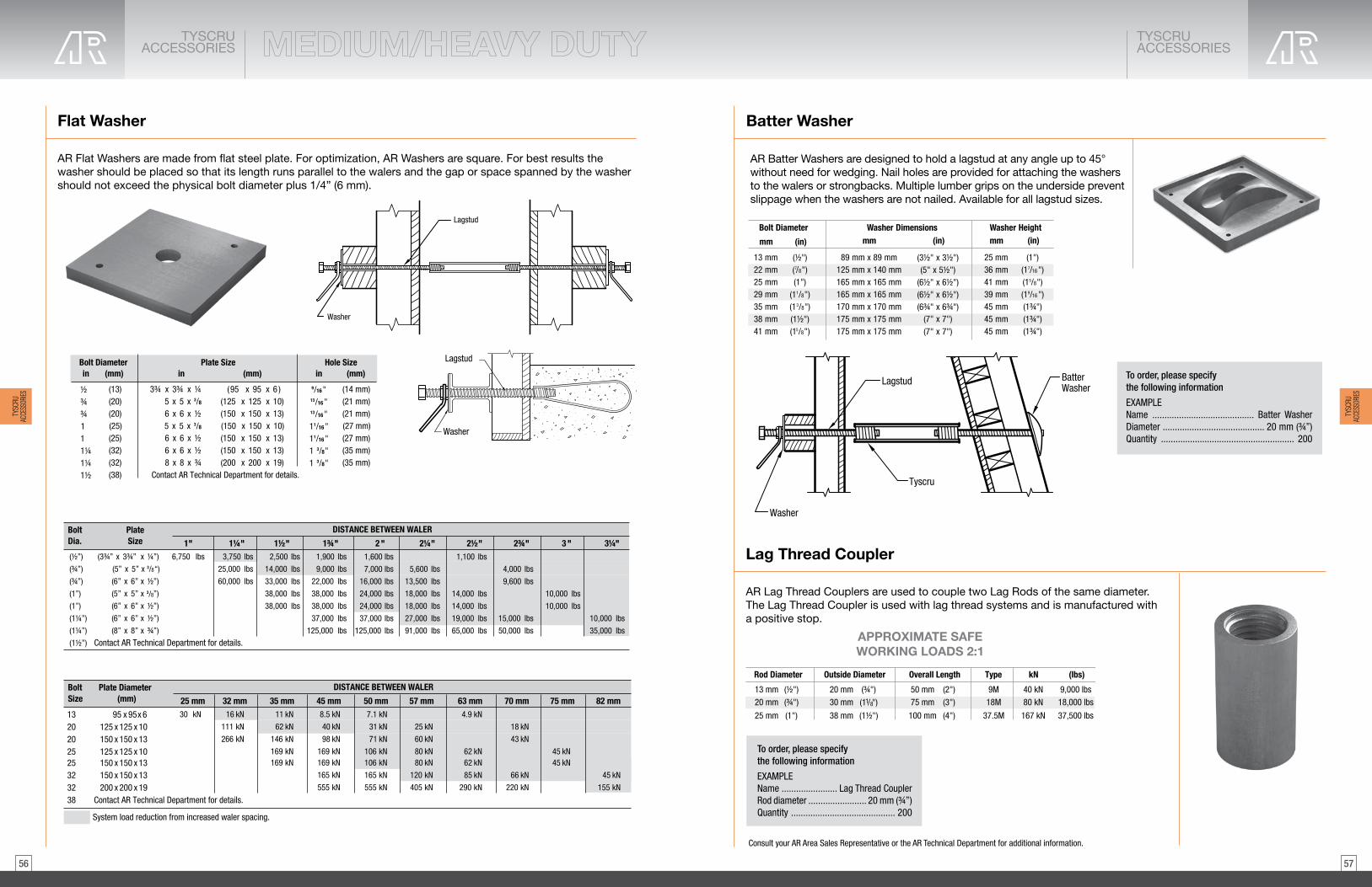
5756
TYSCRUACCESSORIES
TYSCRUACCESSORIES
Batter Washer
Lag Thread Coupler
AR Lag Thread Couplers are used to couple two Lag Rods of the same diameter. The Lag Thread Coupler is used with lag thread systems and is manufactured with a positive stop.
Consult your AR Area Sales Representative or the AR Technical Department for additional information.
13 mm20 mm (¾")
25 mm (1")
50 mm (2")75 mm (3")
100 mm (4")
kN (lbs)
40 kN 9,000 lbs80 kN 18,000 lbs
167 kN 37,500 lbs
Type
9M18M
37.5M
Outside Diameter Overall LengthRod Diameter
20 mm (¾")30 mm (11/8")
38 mm (1½")
(½")
APPROXIMATE SAFEWORKING LOADS 2:1
AR Batter Washers are designed to hold a lagstud at any angle up to 45° without need for wedging. Nail holes are provided for attaching the washers to the walers or strongbacks. Multiple lumber grips on the underside prevent slippage when the washers are not nailed. Available for all lagstud sizes.
Bolt Diameter
mm
Washer Dimensions(in)mm
13 mm22 mm25 mm
7/8")(
29 mm35 mm38 mm
125 mm x 140 mm165 mm x 165 mm165 mm x 165 mm170 mm x 170 mm175 mm x 175 mm175 mm x 175 mm
Washer Heightmm
25 mm36 mm41 mm39 mm45 mm45 mm45 mm
1/8")(13/8")(1
(1½")41 mm 5/8")(1
(1")
(½")
(in)
89 mm x 89 mm (3½" x 3½")(5" x 5½")
(6½" x 6½")(6½" x 6½")(6¾" x 6¾")
(7" x 7")(7" x 7")
(1")7/16")(15/8")(1
9/16")(1(1¾")(1¾")(1¾")
(in)
BatterWasher
Tyscru
Lagstud
Washer
To order, please specify the following information
EXAMPLEName .......................................... Batter WasherDiameter .......................................... 20 mm (3/4”)Quantity ....................................................... 200
To order, please specify the following information
EXAMPLEName ....................... Lag Thread CouplerRod diameter ........................ 20 mm (3/4”)Quantity ........................................... 200
Flat Washer
AR Flat Washers are made from flat steel plate. For optimization, AR Washers are square. For best results the washer should be placed so that its length runs parallel to the walers and the gap or space spanned by the washer should not exceed the physical bolt diameter plus 1/4” (6 mm).
Lagstud
Washer
Washer
LagstudBolt Diameter in (mm)
(13)(20)(20)
(25)(32)(32)(38)
½¾¾
11¼1¼1½ Contact AR Technical Department for details.
3¾ x 3¾ x ¼5 x 5 x 3/8
3/8
6 x 6 x ½
6 x 6 x ½6 x 6 x ½8 x 8 x ¾
Hole Sizein (mm)
(14 mm) (21 mm)(21 mm)
(27 mm)(35 mm)(35 mm)
9/16"13/16"13/16"
11/16"1 3/8"1 3/8"
Plate Size (mm)in
(25)1
(95 x 95 x 6 )(125 x 125 x 10)(150 x 150 x 13)
(150 x 150 x 13)(150 x 150 x 13)(200 x 200 x 19)
(150 x 150 x 10)5 x 5 x (27 mm)11/16"
(½”)
(¾”)
(¾”)
(1”)
(1¼”)
(1¼”)
(1½”) Contact AR Technical Department for details.
1" 6,750 lbs
1¼" 1½" 1¾" 2 " 2¼" 2½" 2¾" 3 " 3¼" 3,750 lbs
25,000 lbs
60,000 lbs
2,500 lbs
14,000 lbs
33,000 lbs
38,000 lbs
1,900 lbs
9,000 lbs
22,000 lbs
38,000 lbs
37,000 lbs
125,000 lbs
1,600 lbs
7,000 lbs
16,000 lbs
24,000 lbs
37,000 lbs
125,000 lbs
5,600 lbs
13,500 lbs
18,000 lbs
27,000 lbs
91,000 lbs
1,100 lbs
14,000 lbs
19,000 lbs
65,000 lbs
4,000 lbs
9,600 lbs
15,000 lbs
50,000 lbs
10,000 lbs
10,000 lbs
35,000 lbs
DISTANCE BETWEEN WALER
(3¾” x 3¾” x ¼”)
(5” x 5” x 3/8
3/8
“)
(6” x 6” x ½”)
(6” x 6” x ½”)
(6” x 6” x ½”)
(8” x 8” x ¾”)
Bolt PlateDia. Size
(1”) 38,000 lbs 38,000 lbs 24,000 lbs 18,000 lbs 14,000 lbs 10,000 lbs(5” x 5” x ”)
132020
25323238 Contact AR Technical Department for details.
25 mm30 kN
32 mm 35 mm 45 mm 50 mm 57 mm 63 mm 70 mm 75 mm 82 mm 16 kN
111 kN
266 kN
11 kN
62 kN
146 kN
169 kN
8.5 kN
40 kN
98 kN
169 kN
165 kN
555 kN
7.1 kN
31 kN
71 kN
106 kN
165 kN
555 kN
25 kN
60 kN
80 kN
120 kN
405 kN
4.9 kN
62 kN
85 kN
290 kN
18 kN
43 kN
66 kN
220 kN
45 kN
45 kN
155 kN
DISTANCE BETWEEN WALER Bolt Plate DiameterSize (mm)
95 x 95x 6125 x 125 x 10150 x 150 x 13
150 x 150 x 1325 169 kN 169 kN 106 kN 80 kN 62 kN 45 kN125 x 125 x 10
150 x 150 x 13200 x 200 x 19
System load reduction from increased waler spacing.
TYSC
RUAC
CESS
ORIES
TYSC
RUAC
CESS
ORIES

5958
TYSCRUACCESSORIES
TYSCRUACCESSORIES
Cone Removal Wrench (T-Shape and L-Shape)
Lag Wrench
Plastic Coil Setting Plug
The AR Lag Wrench is designed for tightening and removing of AR lag bolts when constructing the formwork assembly. The Lag Wrench solid 25 mm (1") diameter L-shape steel construction is equipped with a 300 mm (12") round handle and a 140 mm (5½") 90°radius. The Lag Wrench is supplied as a complete unit: handle and socket. Available for 13 mm, 20 mm, 25 mm and 32 mm (½", ¾", 1" and 1¼") bolt size.
The AR Lag Wrench is designed for tightening and removing of AR lag bolts when constructing the formwork assembly. The Lag Wrench solid 25 mm (1") diameter L-shape steel construction is equipped with a 300 mm (12") round handle and a 140 mm (5½") 90°radius. The Lag Wrench is supplied as a complete unit: handle and socket. Available for 13 mm, 20 mm, 25 mm and 32 mm (½", ¾", 1" and 1¼") bolt size.
Consult your AR Area Sales Representative or the AR Technical Department for additional information.
The AR Cone Removal Wrenches are designed to remove theplastic cones from Cone Tight Tyscrus. Available for 13 mm, 20 mm, 25 mm and 32 mm (½", ¾", 1" and 1¼") diameter cones.
Wrench TypeWasher Dimensions
(in)mm
T-ShapeL-Shape 25 mm, 32 mm
13 mm, 20 mm (½" x 3/4")(1" x 11/4")
PlasticCone-TightTycone
T-Shape ConeRemoval Wrench
PlasticCone-TightTycone
T-Shape ConeRemoval Wrench
To order, please specify the following information
EXAMPLEName ..................... Cone Removal WrenchType ............................................ T-ShapeDiameter .................................. 20 mm (3/4”)Quantity ................................................... 2
To order, please specify the following information
EXAMPLEName ................................. Lag WrenchRod diameter ........................ 25 mm (1”)Quantity ............................................... 1
Plastic Cone-Tight Tycone
Plastic Set Back Tyscru Plug
AR Plastic Set Back Tyscru Plugs are designed to provide an easy and economical means of sealing 13 mm, 20 mm and 25 mm (½", ¾" and 1") diameter Tycone holes at a required set back. While providing an interesting architectural effect. The Plastic Set Back Tyscru Plugs are available in light gray. Other colours are available on special order. The plugs may be used in exterior and/or interior applications. Additional sealing or caulking is optional.
Consult your AR Area Sales Representative or the AR Technical Department for additional information.
Tyscru Plug Diameter Approximate Recess
13 mm (½")
20 mm (¾")
25 mm (1")
25 mm (1")38 mm (1½")50 mm (2")25 mm (1")50 mm (2")25 mm (1")50 mm (2")
13 mm (½")16 mm (5/8")20 mm (¾")16 mm (5/8")32 mm (1¼")
6 mm (¼")10 mm (3/8")
Tycone Set Backmm (in) mm (in) mm (in) "S" Recess
SealingOptional
Tyscru
Set-Back PlugPlastic
AR Plastic Cone-Tight Tycones are designed to engage the protruding coil of a Cone-Tight Tyscru. Actual lengths are greater than the set back requirement. See accompanying chart for dimensions.
Nominal Diameter and DepthSet back
13 mm x 35 mm (½" x 13/8")13 mm x 48 mm (½" x 17/8")13 mm x 60 mm (½" x 23/8")20 mm x 38 mm (¾" x 1½")20 mm x 61 mm (¾" x 23/8")25 mm x 38 mm (1" x 1½")25 mm x 61 mm (1" x 23/8")32 mm x 38 mm (1¼" x 1½")32 mm x 61 mm 3/8")(1" x 2
Taper
25 mm (1")38 mm (1½")50 mm (2")25 mm (1")50 mm (2")25 mm (1")50 mm (2")25 mm (1")50 mm (2")
25 mm to 32 mm (1" to 1¼")
38 mm to 45 mm (17/16 to 111/16")
48 mm to 54 mm (17/8" to 21/8")
57 mm to 61 mm (2¼" to 23/8")
Tyscru Diametermm (in) mm (in) mm (in) mm (in)
13 mm (½")13 mm (½")13 mm (½")20 mm (¾")20 mm (¾")25 mm (1")25 mm (1")32 mm (1¼")32 mm (1¼")
BatterWasher
Tyscru
Lagstud
Washer
To order, please specify the following information
EXAMPLEName ............................. Plastic Cone-Tight TyconeNominal Diameter ............................... 20 mm (3/4”)Set back .............................................. 25 mm (1”)Quantity ........................................................... 200
To order, please specify the following information
EXAMPLEName ......... Plastic Set Back Tyscru PlugNominal diameter ................ 13 mm (1/2”)Colour ..................................... light grayQuantity ........................................... 200
TYSC
RUAC
CESS
ORIES
TYSC
RUAC
CESS
ORIES

6160
TYLOOPTYLOOP
Flared 4-Strut Tyloop (TL4)
Heavy 4-Strut Offset Flared Tyloop (TL4-H)
The AR Flared 4-Strut Tyloop is made with two looped wires welded to a helix coil. Suitable for heavy form anchorage in mass concrete construction. The standard length is 380 mm (15") for 25 mm (1") and 32 mm (1¼") diameters with struts flaring to 75 mm(3") diameters. The standard flare unit is supplied unless special size or shaped flares are requested.
The AR Offset Flared 4-Strut Tyloop is made of two looped wires welded to a helix coil. The loops are flared and offset so that the center of anchorage is below the center line of the coil to distribute the load well into the concrete and still keep the coil at or near thetop of the pour or other boundary restrictions.
TL4FLAG
TWF
TLO4F
LAG
TWF
½” - 6” (13 - 150)
¾” - 9” (20 - 225)
1” - 12” (25 - 300)
1¼” - 15” (32 - 380)
Sizesinch (mm)
1 x 15 (25 x 380)
1¼ x 18 (32 x 460)
Sizes
inch (mm)
Other sizes available
Size and Type inch (mm)
APPROXIMATE WORKING LOADS FOR TYLOOPS
*As Tielbs (kN) lbs (kN) lbs (kN)
TL2 ½” x 4” Standard Tyloop (13 x 100) 1,900 (8.5)
TL2 ¾” x 6” Standard Tyloop (20 x 150) 3,900 (17.5)
TL2-H ¾” x 6” Heavy Tyloop (20 x 150) 5,200 (23.0)
TL2F ½” x 9” Flared Tyloop (13 x 230) —
TL2F ¾” x 12” Flared Tyloop (20 x 305) —
TL4F 1”x 15” Flared 4-Strut (25 x 380) —
TL4F 1¼” x 15” Flared 4-Strut (32 x 380) —
As an Anchor**Tension Shear***
1,125 (5.0)
2,250 (10.0)
2,625 (12.5)
2,250 (10.0)
3,375 (15.0)
6,000 (26.5)
6,750 (30.0)
750 (3.5)
1,500 (7.0)
1,875 (8.3)
750 (3.5)
1,875 (8.3)
3,375 (15.0)
4,500 (20.0)
Tyloop (2-Strut)
The AR Standard 2-Strut Tyloop (TL-2) is made of a single looped wire welded to a helix coil in 13 mm and 20 mm (½" and ¾") nominal diameters. Suitable for light anchorage requirements or as emergency tie, tie down, corner tie, etc. Standard length is 100 mm (4") for 13 mm (½") diameter and 150 mm (6") for 20 mm (¾") diameters. This unit may be fabricated in lengths to suit the job site requirements. The AR Heavy 2-Strut Tyloop (TL-2-H) is made with heavier wire and are principally used as anchors for medium heavy construction. The standard length is 150 mm (6") for both 13mm (½") and 20 mm (¾") diameter. The Tyloop can also be fabricated in longer lengths.
Size
13 mm x 102 mm (½" x 4")13 mm x 152 mm (½" x 6")20 mm x 152 mm (¾" x 6")20 mm x 152 mm (¾" x 6")
20 mm (¾")20 mm (¾")29 mm (11/8")29 mm (11/8")
Inside radius “C”Safe Working Load
kN (lbs)
22.3 kN (4,500 lbs)40 kN (9,000 lbs)40 kN (9,000 lbs)
53.4 kN (12,000 lbs)
4.5M ½" Tyloop9M ½" Heavy Tyloop9M ¾" Tyloop
12M ¾" Heavy Tyloop
Type
Standard2 StrutTyloop
WasherLagstudBolt
C
Tie Application
Heavy2 StrutTyloop
Washer
LagstudBolt
To order, please specify the following information
EXAMPLEName .......................... Tyloop (2-Strut) (TL-2-H)Type ................................................... Heavy 9MNominal Diameter ............................ 20 mm (3/4”)Length ........................................... 150 mm (6")Coil type ............................................ Cone TightQuantity ....................................................... 200
Also available as a Cone-Tight and Ferrule Tyloop
Flared 2-Strut Tyloop (TL2F)
AR 2 Strut Flared Tyloops are made with the loop end flared for greater anchorage in the concrete. Standard lengths are 9” (230 mm) for 1/2” (13 mm) diameter and 12” (305 mm) for 3/4” (20 mm) diameter. Can be supplied in special lengths and flares to order.TO ORDER, give nominal diameter, by length, symbol and name. Example: - 1/2” x 9” (13 mm x 230 mm) TL2F 2 Strut Flared Tyloop.
TL2FLAG
TWFRefer to the Approximate Safe Working Loads and Ultimate Capacities calculated forvarious concrete strengths table on pages 51 and 112 of the Appendix.
TYLO
OP
TYLO
OP
APPROXIMATE SAFE WORKING LOADS 2:1
APPROXIMATE SAFE WORKING LOADS 4:1

6362
TYLOOPTYLOOP
Tyback Tyloop
Coil Length
The AR Tyback Tyloop is fabricated with two looped wires welded to a helix coil. The Tyback Tyloop is specially designed to tie into existing reinforcing bars to form bulkheads and for dam construction. Available as a 20 mm x 215 mm (¾" x 8½") standard size, the AR Tyback Tyloop can be custom fabricated to meet job site conditions.
APPROXIMATE SAFE WORKING LOAD80 kN (18,000 lbs)2:1 Safety Factor
To order, please specify the following information
EXAMPLEName ....................................... Tyback TyloopDiameter ..................................... 20 mm (3/4”)Quantity .................................................... 200
Washer
Minimum coil penetration
Diameter Coil LengthIncluding Penetration
44.5 kN (10,000 lbs)80.0 kN (18,000 lbs)80.0 kN (18,000 lbs)106.0 kN (24,000 lbs)
40 mm (1½")50 mm (2")50 mm (2")60 mm (23/8")
Ultimate Strength
13 mm (½")13 mm (½")20 mm (¾")20 mm (¾")
Standard Tyloop
Diameter Coil LengthIncluding Penetration
80 kN (18,000 lbs)106 kN (24,000 lbs)133 kN (30,000 lbs)213 kN (48,000 lbs)267 kN (60,000 lbs)
55 mm (21/8")50 mm (2")60 mm (23/8")75 mm (3")75 mm (3")
Ultimate Strength
13 mm (½")20 mm (¾")25 mm (1")25 mm (1")32 mm (1¼")
Flared Single and Double Flared Tyloop
Diameter Coil LengthIncluding Penetration
267 kN (60,000 lbs)267 kN (60,000 lbs)
75 mm (3")75 mm (3")
Ultimate Strength
25 mm (1")32 mm (1¼")
Double Looped Flared Tyloop
Diameter Coil LengthIncluding Penetration
80 kN (18,000 lbs)160 kN (36,000 lbs)
75 mm (3")75 mm (3")
Ultimate Strength
32 mm (1¼")38 mm (1½")
Tybow Anchor
Flared 6-Strut Tyloop
The AR Flared 6-Strut Tyloop is made with three wires welded to a helix coil. The three loops are flared to provide greater anchorage in concrete.
Offset Flared4-Strut TyloopFlared
4-Strut Tyloop
Washer
LagstudBolt
HandleLagnut
Flared 2-StrutTyloopReinforcing
Dowel
2-StrutTyloop
Washer
Lagstud
Washer
Lagstud
Washer
Lagstud
STANDARDAPPROXIMATE SAFE
WORKING LOAD207 kN (46,500 lbs)2:1 Safety Factor
HEAVYAPPROXIMATE SAFE
WORKING LOAD275 kN (61,800 lbs)2:1 Safety Factor
Diameter
32 mm (1¼")
38 mm (1½")
Length
380 mm (15")
Flare
170 mm (6¾")
Flared 6-Strut Tyloop
Edge condition limitations will govern.Contact the AR Technical Department for further details.Other configurations and designs are available.
Refer to the Approximate Safe Working Loads and Ultimate Capacities calculated forvarious concrete strengths table on pages 51 and 112 of the Appendix.
Refer to the Approximate Safe Working Loads and Ultimate Capacities calculated forvarious concrete strengths table on pages 51 and 112 of the Appendix.
TYLO
OP
TYLO
OP

6564
SINGLE SIDEDFORMINGSYSTEM
SINGLE SIDEDFORMING
SYSTEM
Toggle Ty
Toggle Ty
WasherHandle Lagnut
Lagstud Bolt
Toggle Ty
35 mm(1 3/8") diameterhole
Type Safe Load Steel Sheating Wood Sheating
13 mm (½") Standard 2.25M13 mm (½") Heavy 3.75M
10 kN (2,250 lbs)
17 kN (3,750 lbs)
TOGGLE SIZE
5 mm x 32 mm x 75 mm ( 3/16" x 1¼" x 3")6 mm x 32 mm x 75 mm (¼" x 1¼" x 3")
10 mm x 25 mm x 115 mm ( 3/8" x 1" x 4½")10 mm x 25 mm x 115 mm ( 3/8" x 1" x 4½")
AR Toggle Tys are used to anchor a facingformwork, back to steel or wood sheet piling and require a 35 mm (13/8") diameter hole through the sheathing to permit entry of the toggle. Toggle plate sizes are shown below.
To order, please specify the following information
EXAMPLEName ................................................................ Toggle TyType ....................................................... standard 2.25MDiameter ....................................................... 13 mm (1/2")Length ....................................................... 380 mm (15")Plate size ....... 5 mm x 32 mm x 75 mm (3/16" x 1¼" x 3)Quantity ..................................................................... 200
Single End Welding Tyscru
Bent Single End Welding Tyscru
The AR Single End Welding Tyscru is made with 2 struts welded to a coil at one end only, leaving the open end available for field welding, particularly suitable for heavy and special applications. Available in 13 mm, 20 mm and 25 mm (½", ¾" and 1") diameters.
The AR Bent Single End Welding Tyscru is made with 2 struts welded to a coil at one end. The other end of the 2 struts is bent at 90° in opposite directions away from the coil. This allows for field welding onto sheet piling and H-Pile construction. Available in 13 mm, 20 mm and 25 mm (½", ¾" and 1") diameters and may be fabricated to the required lengths.
To order, please specify the following information
EXAMPLEName ............................ Single End Welding TyscruNominal Diameter ............................... 20 mm (1/2”)Overall length ..................................... 100 mm (4")Quantity .......................................................... 200
To order, please specify the following information
EXAMPLEName ........... Bent Single End Welding TyscruNominal Diameter ........................ 13 mm (1/2”)Length (L) .................................... 100 mm (4")Leg depth ..................................... 25 mm (1")Quantity .................................................... 200SWL is based on an approximate 2:1 Factor of Safety
H-Pile
Bent Single EndWelding Tyscru
Diameter mm (in)
L mm (in)
13 mm (½")
20 mm (¾")
25 mm (1")
100 mm (4")
150 mm (6")
250 mm (8")
B mm (in)
25 mm (1")
38 mm (1½")
50 mm (2")
ShearSafe Working Load
22 kN (5,000 lbs)
22 kN (5,000 lbs)
44 kN (10,000 lbs)
APPROXIMATE SAFE WORKING LOADS
LagstudBolt
Washer
Single EndWelding Tyscru
HookedRebar
Diameter Safe Working LoadLength
13 mm (½") 100 mm (4")
20 mm (¾") 150 mm (6")
25 mm (1") 250 mm (10")
16.5 kN (3,750 lbs)
30.0 kN (6,750 lbs)
60.0 kN (13,500 lbs)
Weld Length
32 mm (1¼")
38 mm (1½")
50 mm (2")
APPROXIMATE SAFE WORKING LOADS
NOTE: Diameter of rebar will influence Single End Welding Tyscru strength.
NOTE: Weld both sides of both struts. Field test should be conducted to establish actual approximate safe working load. Failure will occur in shear.
Refer to the Appendix for General Guidelines on page 96, Lateral Pressure information on page 102 and typical Medium and Heavy Formwork beginning on page 108. See page 51 for approximate safe working load System Chart.
Refer to the Appendix for General Guidelines on page 96, Lateral Pressure information on page 102 and typical Medium and Heavy Formwork beginning on page 108. See page 51 for approximate safe working load System Chart.
SINGL
E SID
EDFO
RMIN
GSY
STEM
SINGL
E SID
EDFO
RMIN
GSY
STEM
APPROXIMATE SAFEWORKING LOADS 2:1
APPROXIMATE SAFE WORKING LOAD2:1 Safety Factor
APPROXIMATE SAFE WORKING LOAD2:1 Safety Factor

6766
SINGLE SIDEDFORMINGSYSTEM
SINGLE SIDEDFORMING
SYSTEM
T4 Lag Ty
Rock Anchor
AR Rock Anchor Assembly
The AR T4 Lag Ty is designed to be welded on structural members for single sided forming. The AR Lag Ty consists of a 20 mm (¾") diameter coil with a 75 mm (3") mild steel lag stud fabricated together with a typical 4-strut configuration.
AR Rock Anchors are used for anchoring with AR Lagstud or NC Rod in form tying and anchoring of concrete facings to rock excavation. Available in 13 mm, 20 mm and 25 mm (½", ¾" and 1") diameters.
Transition couplers give the AR mechanical cone shell anchors the ability to be used with lagstud or National Course thread, for single sided forming applications.
Consult the AR Technical Department for other thread patterns, other drill hole diameters and higher Approximate Safe Working Load requirements.
NOTE: Remove temporary plastic band before installation. The lagstud end must be against back-strap then forced to bottom of bore hole before tightening. Do not overtighten. Overtightening destroys the bond.
Refer to AR’s Rock Anchoring and Bolt System catalogue fortechnical information or consult the AR Technical Department.
To order, please specify the following information
EXAMPLEName ................................. T4 Lag TyQuantity ...................................... 200
Diametermm (in)
13 mm (½")20 mm (¾")25 mm (1")
Hole Depth (minimum)mm (in)
150 mm (6")200 mm (8")250 mm (10")
Drill Hole Diametermm (in)
Safe Working Load*kN (lbs)
20 kN (4,500 lbs)40 kN (9,000 lbs)80 kN (18,000 lbs)
35 mm (13/8")45 mm (1¾")45 mm (1¾")
H-Pile
H-Pile
LagstudBolt
Taper Ty
NOTE: Field welding to structural members should be performed by a certified licensed welder.
APPROXIMATE SAFE WORKING LOAD80 kN (18,000 lbs)2:1 Safety Factor
Rock Anchor
Hole Depth
Lagstud
Lagstud Bolt Tyscru
Drill HoleDiameter
Washer
*AR recommends that all Rock Anchors be tested under job-site conditions to determine if ambient stratum conditions will limit approximate safe working load.
The AR Angle Ty-Bracket is designed to tie single-sided forming to steel piles, metal beams, etc. Brackets are available from 13 mm to 25 mm (½" to 1") diameters as identified in the table below, with lag thread or can be special ordered with NC thread.The AR Angle Ty-Bracket allows a full 90° of pivot of the form-tie and will exceed the tensile capacity of the form-tie when correctly installed by a certified licensed welder.
Warning: To ensure proper engagement (final installation) the Form-tie must extend beyond the swivelpin a minimum of 13 mm (½"). An easy way to accomplish this is to line up the swivel pin and the Formtiein position A and thread the Form-tie through the swivel pin until it contacts the metal piling.
Note: Performance could varybased on the quality of weld.
To order, please specify the following information
EXAMPLEName ..................... Single End Welding TyscruForm-Ty Diameter ....................... 25 mm (1”)Quantity .................................................... 100
Form Tie Diameter Dim. “L”Position Amm (in)
13 mm (½") 115 mm (4½")115 mm (4½")152 mm (6")
20 mm (¾")25 mm (1")
40 kN (9,000 lbs)80 kN (18,000 lbs)140 kN (31,500 lbs)
Position B
28 kN (6,300 lbs)56 kN (12,500 lbs)98 kN (22,000 lbs)
Bracket SWL kN (lbs.)
APPROXIMATE SAFE WORKING LOADS
Contact AR for non-standard sizes or thread configurations.
Dim. “L”
Angle Ty-Bracket
45˚Position B
45˚
Position A
Heig
ht
Position B
Earth
H-Pile
InsideTie RodShe Bolt
Wood Lagging
WingNut
BatterWasher
Double Wales sized per load requirements
Swivel Pin
Form-Tie,such as a Taper-Ty, She Bolt, Lagstud, Etc.
H-Pile
Continuous,full lengthfillet weld
Pivot Bracket/AngleTy-Bracket
Refer to the Appendix for General Guidelines on page 96, Lateral Pressure information on page 102 and typical Medium and Heavy Formwork beginning on page 108. See page 51 for approximate safe working load System Chart.
Refer to the Appendix for General Guidelines on page 96, Lateral Pressure information on page 102 and typical Medium and Heavy Formwork beginning on page 108. See page 51 for approximate safe working load System Chart.
SINGL
E SID
EDFO
RMIN
GSY
STEM
SINGL
E SID
EDFO
RMIN
GSY
STEM
APPROXIMATE SAFE WORKING LOADS 2:1
APPROXIMATE SAFE WORKING LOAD2:1 Safety Factor

6968
SINGLE SIDEDFORMINGSYSTEM
SINGLE SIDEDFORMING
SYSTEM
FormsaversTM
AR FormsaverTM dowel bar assemblies provide continuity and structural integrity to reinforced concrete construction in segmental pour applications. The AR FormsaverTM is designed with our unique tapered thread system, factory installed thread protectors, and durable mounting plates for easy attachment to forms. The taper threaded design, like the complete family of couplers, provides load path continuity in tension, compression and stress reversal applications. AR FormsaverTM mechanical splices provide superior performance well beyond the yield strength of the reinforcing bar.
REBAR DESIGNATIONASTMin-lbs mm Type Soft Metric
4 12 m 10 M 13 mm
5 16 mm 15 M 16 mm
6 20 mm 20 M 19 mm
7 22 mm — 22 mm
8 25 mm 25 M 25 mm9 28 mm 30 M 29 mm
10 32 m - 32 mm11 36 mm 35 M 36 mm
Taper Threaded Rebar (Male) 1
Part Length “C”Number mm (in)
FS4M24 610 mm (24")FS4M36 914 mm (36")FS5M24 610 mm (24")FS5M30 762 mm (30")FS5M36 914 mm (36")FS6M36 914 mm (36")
FS7M36 914 mm (36")FS7M48 1219 mm (48")FS8M48 1219 mm (48")FS9M48 1219 mm (48")FS10M60 1524 mm (60")FS11M60 1524 mm (60")
Coupler/Rebar Assembly (Female) 2
Part Length “D”Number mm (in)
FS4F20 508 mm (20")FS4F24 610 mm (24")FS5F24 610 mm (24")FS5F30 762 mm (30")FS5F36 914 mm (36")FS6F24 610 mm (24")FS6F36 914 mm (36")FS7F36 914 mm (36")
FS8F52 1321 mm (52")FS9F52 1321 mm (52")FS10F64 1626 mm (64")FS11F64 1626 mm (64")
FS SIZE STYLE LENGTH X LENGTH E
Attachednailer plateform saver
Rebarsize
F indicates coupler/rebar,M indicates threaded rebar
(other styles on request)
In mm (inches)of “A”, “C”
or “D”
Epoxy(optional)
In mm(inches) of
“B” (optional)
Indicatesbent rebar(optional)
How to Order by Part Number
Non standard custom sizesand lengths available.
Form-SaverStairwell
Rebar
Highway/BridgeSlabs
1 Includes Rebar Thread Protector2 Includes Coupler Thread Protector
Specify D dimension
D
Specify C dimension
C Z
Specify A, Bdimension
A
BSpecify E, Bdimension
E
The lag thread AR Drop-in Anchor features an internally threaded all-steel shell, with an preassembled expansion cone insert. The Drop-In Anchors are designed to work as part of the forming system, matched to the thread of AR Lagstuds or Lagbolts. The Drop-In Anchors are made from carbon steel and electroplated galvanized for corrosion protection. The Drop-in Anchor is used for any application requiring anchorage in solid concrete or homogeneous igneous rock. Ideal for lagging, AR Drop-In Anchors are also effective for hanging bolting or anchoring application with AR Tylags, Lagstud Bolts or Lagstud. Not recommended for uncured concrete (less than 7 days old), lightweight concrete or masonry block or brick.
AR suggests a minimum safety factor of 2:1. On site conditions such as, poor concrete,placing technique, concentrated loads on the formwork, improper use of cranes or concretepumping could increase the risk. If such site conditions exist, the user must increase the safety factor to compensate.For anchoring situations not associated with forming, industry practice is to apply a safetyfactor of 4:1 minimum. For applications of greater risk a larger safety factor may be selected.For edge distance and load reductions contact AR technical representative.Specifications subject to change without notice.
To order, please specify the following information
EXAMPLEName .................................... Drop-In AnchorQuantity ................................................. 200
Anchor Drill Bit
NCA ½LTNCA ¾LT
5/8"1"
Thread
½" - 6 lagthread¾" - 4½ lagthread
Thread LengthAnchor Length
(Minimum Depth of Embedment)
50 mm (2")80 mm (3 3/16")
20 mm (¾")35 mm (13/8")
Anchor Tension
NCA ½LTNCA ¾LT
f’c = 15MPa (2,200 psi)
15 (3,300)
36 (8,100)
Shearf’c = 15MPa (2,200 psi)
20 (4,500)
42 (9,450)
f’c = 30MPa (4,400 psi)
27 (6,075)
49 (11,000)
Ultimate Shear and Tension Values (kN/lbs) in Concrete
Drop-In Anchor
Hole must be cleaned of dust and other material
Drop-In Anchor
Setting Tool
Drilled Hole
Min depth equals anchor length
1. Drill hole forexpansion anchor
2. Insert expansion anchorinto hole and tap flush
3. Using an NCA setting tool, set anchor by driving untilshoulder of the setting tool is seated against the anchor
Refer to the Appendix for General Guidelines on page 96, Lateral Pressure information on page 102 and typical Medium and Heavy Formwork beginning on page 108. See page 51 for approximate safe working load System Chart.
SINGL
E SID
EDFO
RMIN
GSY
STEM
SINGL
E SID
EDFO
RMIN
GSY
STEM

7170
TAPER-TYSYSTEM
TAPER-TYSYSTEM
Taper-Ty System
Diameter(large to small)
Safe Working Loads2:1 Safety Factor
20 mm to 13 mm (¾" to ½")
25 mm to 20 mm (1" to ¾")32 mm to 25 mm (1¼" to 1")38 mm to 32 mm (1½" to 1¼")
40 kN (9,000 lbs.)20 mm to 23 mm 89 kN (20,000 lbs.)
84 kN (19,000 lbs.)(35,000 lbs.)155 kN
253 kN (57,000 lbs.)
(¾" to )7 8"
Overall lengthmm (in)
953 mm (37½")1,067 mm (42")1,219 mm (48")
Taper Lengthmm (in)
540 mm (21½")560 mm (22")710 mm (28")
Length of Thread25 mm (1") 20 mm (¾")
Range of Wall Thickness*mm (in)
100 mm - 405 mm (4" - 16")150 mm - 535 mm (6" - 21")300 mm - 660 mm (12" - 26")
250 mm (10")250 mm (10")250 mm (10")
150 mm (6")250 mm (10")250 mm (10")
The AR Taper-Ty System is used where specifications permit the complete removal of the form-tie from the concrete wall. Taper-Tys are available with lag thread and a variety of hardware. While the system is available in the standard diameters shown, variations of these sizes are available on special order. The complete system consists of one Taper Ty, with 2 square or flat washers and 2 nuts, either lag Hex Nuts, special Handle Lagnuts or Malleable Wing Nuts. The standard units are furnished with up to 750 mm of taper. Other taper lengths are available on special order. The larger diameter end has a square wrench end. The smaller diameter end has been designed with a special end for removal without damaging the thread. Other specifications are shownon the detail drawing.
Small diameter
Taper up to 30" standard
1"
Usually form thickness + 4"Knock-out
end
Wall dimension + 1 1/2"
Large diameter
1"
Wrench end
Grip usually form thickness + 4"
W
Overall length
10" 6"
T S
WasherTaper-TyWing Nut
Washer
Use Handle Lagnut or Wing Nut
Taper-Ty
Taper Length
Overall Taper-Ty Length
Wall Thickness
Length of 1" thread Length of 3/4" thread
Taper-TyChart based on standard 825 MPa (120,000 psi) material. Special order materials available on request.
Taper Ty Wall Sizing
Taper Ty Wall Sizing
Not recommended where watertight walls are essential such as exterior walls, water reservoirs, treatment plants, etc. Use Waterseal Tyscrus instead.
To order, please specify the following information
EXAMPLEName .................................................... Taper-TyNominal SizeCalculate Length ...................................... (291/2")Thread Length Large diameter end 250 mm ............... (15") Small diameter end 150 mm .............. (6")Diameter ........... 20 mm to 13 mm (3/4" to 11/2")Quantity ........................................................ 200
Refer to the Appendix for General Guidelines on page 96, Lateral Pressure information on page 102 and typical Medium and Heavy Formwork beginning on page 108. See page 51 for Approximate Safe Working Load System Chart.
*Based on standard forming materials (typical 4x4 studs, walers, 3/4" form ply, plate washer and nut assembly).
Welding Lagnut
Diameter Depth of Lagnut
20 mm (¾") 38 mm (1½")
Safe Working Load
80 kN (18,000 lbs)
Ultimate
160 kN (36,000 lbs)
AR Welding Lagnuts are designed to be used in single sided (blind side) forming applications or when necessary to secure formwork to steel members. AR welding lagnuts are extra deep to allow for the welding operation and are only available in 20 mm (3/4") diameter. A licensed certified welder should perform all welding. Field-testing should be conducted to established actual approximate safe working loads.
APPROXIMATE SAFE WORKING LOAD2:1 Safety Factor
Batter Washer
Wing Nut
Lagnut
20 mm (¾")
25 mm (1")
32 mm (1¼")
13 mm (½")
20 mm (¾")
25 mm (1")
32 mm (1¼")
38 mm (1½") Consult the AR Technical Department for details.
80 kN (18,000 lbs)
160 kN (36,000 lbs)
333 kN (75,000 lbs)
512 kN (115,000 lbs)
13 mm (½")
20 mm (¾")
25 mm (1")
32 mm (1¼")
38 mm (1½") Consult the AR Technical Department for details.
80 kN (18,000 lbs)
160 kN (36,000 lbs)
333 kN (75,000 lbs)
435 kN (98,000 lbs)
20 mm (¾")
25 mm (1")
13 mm (½") 80 kN (18,000 lbs)160 kN (36,000 lbs)
334 kN (75,000 lbs)
Lag Thread Coupler
178 kN (40,000 lbs)
365 kN (80,000 lbs)
512 kN (115,000 lbs)
(5" x 5" x 3/8")
(6" x 6" x ½")
(8" x 8" x ¾")
(3¾" x 3¾" x ¼")95 x 95 x 6 mm125 x 125 x 10 mm
150 x 150 x 13 mm
200 x 200 x 19 mm
60 kN (13,500 lbs)222 kN (50,000 lbs)
266 kN (60,000 lbs)
1,110 kN (250,000 lbs)
Heavy Hex Rod Coupler
13 mm (½")
16 mm (5/8")
20 mm (¾")
22 mm (7/8")
25 mm (1")
80 kN (18,000 lbs)
134 kN (30,000 lbs)
160 kN (36,000 lbs)
220 kN (60,000 lbs)
334 kN (75,000 lbs)
Handle Lagnut
Consult the AR Technical
Department for details.
13 x 41 mm (1½" x 15/8")
Flat Washer
Refer topage 54
Refer topage 54
Refer topage 55
Refer topage 56
Refer topage 57
Refer topage 57
Refer topage 77
ProductSize
mm (in)
Ultimate Strength
kN (lbs)
PageReference
TAPE
R-TY
SYST
EM
TAPE
R-TY
SYST
EM
APPROXIMATE SAFEWORKING LOADS 2:1

7372
SHE-BOLTPRODUCTS
TAPER-TYSYSTEM
She-Bolt
AR She-Bolt Assemblies are high strength, adaptable units suitable for medium and heavy concrete construction. Manufactured with external lag threads, they provide a positive system for use with gang forms and/or steel forms. The Inside Rods are manufactured with either national coarse thread or lag thread. If desired, continuous threaded lagstud can be furnished in 1,500 mm or 3,000 mm (5' or 10') lengths for field cutting to required specifications.
To order, please specify the following information
EXAMPLEName ................................................ She-BoltNominal Diameter Inside Rod Diameter .................. 20 mm (3/4")Overall Length (O) ..................... 510 mm (20")Outside Thread (T) .................... 250 mm (10")Inside Thread Type (R) ............................. lagOutside Thread Type ................................. lagQuantity .................................................... 200
Tie-down position for2700 mm (9'-0")and 3000 mm (10'-0") pour
Lagstud
She Bolt
Tie-down positionfor 2400 mm(8'-0") pour
Tyscru anchorageScrew Anchor
Anchor position for 2400 mm (8'-0") pour
Anchor position for 2700 mm (9'-0") pour
Anchor position for 3000 mm (10'-0") pour
EL. 2400 mm (8'-0")
EL. 2700 mm (9'-0")
EL. 3000 mm (10'-0")
May beextendedforalignment
BatterWasher
WingNut
Screw AnchorBolt
Variable 2400 mm (8'-0") to 3000 mm (10'-0") Lift Form using She Bolts with High Tensile Lagstud
45˚30˚
6"
Lag thread
O (overall length)
3 mm (1/8") less nominal She Bolt diameter
100 mm (4")T
R
IW
APPROXIMATE SAFE WORKING LOAD2:1 Safety Factor
Refer to the Appendix for General Guidelines on page 96, Lateral Pressure information on page 102 and typical Medium and Heavy Formwork beginning on page 108. See page 51 for Approximate Safe Working Load System Chart.
13 mm (½")
Nominal Diametermm (in)
25 mm (1")29 mm (11/8")
32 mm (1¼")35 mm (13/8")
Internal Thread Diametermm (in)
500 mm (20")600 mm (24")
500 mm (20")600 mm (24")
600 mm (24”)800 mm (32")
Length O
mm (in) mm (in) mm (in) mm (in) mm (in)
She-Bolt Dimension Data
250 mm (10")300 mm (12")
250 mm (10")300 mm (12")
250 mm (10")300 mm (12")460 mm (18")
Thread T
20 mm (¾")
25 mm (1")
I W
20 mm (¾")20 mm (¾")
25 mm (1")25 mm (1")
25 mm (1")25 mm (1")25 mm (1")
13 mm (½")20 mm (¾")
20 mm (¾")
25 mm (1")
R
2 x
diam
eter
pl
us 6
mm
(2 x
dia
met
er
plus
¼")
38 mm (1½")
Flat Washer
Tilt Washer
The AR Tilt Washer is angularly adjustable up to 45°, eliminating the need for wedging on battered walls or when tying across corners. Nail holes are provided for attaching the Tilt Washer to the waler or strongbacks. Available for 25 mm and 32 mm (1" and 1¼") diameter bolts with nail holes to permit nailing to wales if desired.
Refer to page 56
Type
AR 1AR 1¼
Bolt Diameter
mm (in) mm (in)
25 mm (1")32 mm (1¼")
Size
160 mm x 133 mm (6¼" x 5¼")175 mm x 150 mm (7" x 6")
To order, please specify the following information
EXAMPLEName .......................................... Tilt WasherNominal Diameter .......................... 25 mm (1")Quantity .................................................... 200
Wing Nut
She-Bolt(contour thread)
Tilt Washer
SHE-
BOLT
PROD
UCTS
TAPE
R-TY
SYST
EM

7574
SHE-BOLTPRODUCTS
SHE-BOLTPRODUCTS
UltimateDiameter
13 mm (½")
20 mm (¾")
25 mm (1")
40 kN (9,000 lbs)
80 kN (18,000 lbs)
165 kN (37,500 lbs)
Safe Working Load
80 kN (18,000 lbs)
160 kN (36,000 lbs)
330 kN (75,000 lbs)
Crimped Anchor Safe Working Loads
Set back
Under 600 mm (24") 3 crimps,Over 600 mm to 916 mm
(24" to 36") 6 crimps, Over 900 mm (36") 9 crimps
ThreadDiameter
13 mm (½")
16 mm ( 5/8")
20 mm (¾")
22 mm (1")
25 mm (1¼")
Thread Length
32 mm (1¼")
38 mm (1½")
45 mm (1¾")
50 mm (2")
57 mm (2¼")
Standard (Overall) Lengths
450 mm, 600 mm, 750 mm (18", 24", 30")
600 mm, 750 mm, 900 mm (24", 30", 36")
750 mm, 900 mm, 1,050 mm (30", 36”, 42")
900 mm, 1,050 mm (36", 42")
900 mm, 1,050 mm, 1,200 mm (36", 42", 48")
102 mm (4")
102 mm (4")
102 mm (4")
102 mm (4")
102 mm (4")
Number of Crimps
Crimped Anchor
AR Crimped Anchors are used for form anchoring in mass concrete construction. Manufactured in the diameter and lengths shown with either national coarse thread or lag thread.
Refer to the Approximate Safe Working Loads and Ultimate Capacities calculated forvarious concrete strengths table on pages 51 and 112 of the Appendix.
To order, please specify the following information
EXAMPLEName .................................... Crimped AnchorDiameter ..................................... 13 mm (1/2")Length ....................................... 30 mm (12")Type of Thread ............................................ NCQuantity .................................................... 200 She-Bolt
BatterWasher
ThreadedInside Rod
Rod Coupling
DummyShe-Bolt
SettingBracket
CrimpedAnchor
CrimpedAnchor
Wing Nut
1500 mm (5'-0")
Approximately 10º
She-Bolt
High Tensile Inside Rod
40 9,00040 9,00040 9,00040 9,000
NominalShe-BoltDiameter
25 mm (1")29 mm (11/8")32 mm (1¼")38 mm (1½")
Internal Thread Diameter
mm (in)
13 mm (½")
kN lbs kN lbs kN lbs
80* 18,00080* 18,00080 18,00080 18,000
20 mm (¾")
---
---
165* 37,500
25 mm (1")
Ultimate TensionkN (lbs)
Diametermm (in)
13 mm (½")20 mm (¾")25 mm (1")
Safe Working LoadkN (lbs)
40 9,00080 18,000
160 37,500
80 18,000160 36,000330 75,000
AR High Tensile Inside Rods are manufactured with either National Coarse or lag thread. Inside Rods can be manufactured with crimps upon request. Rods up to 600 mm (24") long have 1 crimp. Rods over 600 mm (24") long have 3 crimps.
Wing Nut
High Tensile Inside Rod
She-Bolt
Lag Thread
She-BoltNC Thread
Flat WasherInside RodNC Thread
Flat WasherInside RodLag Thread
She-BoltLag Thread
LagThread
Handle Lagnut
Handle Lagnut
APPROXIMATE SAFE WORKING LOAD2:1 Safety Factor
NOTE: 50 mm (2") available as a special order. Consult your AR Sales Representative or AR Technical Department for more information.
*Maximum She-Bolt Approximate Safe Working Load capacity at minimum 2:1 Safety Factor which is highly recommended for reusable working parts.
Refer to the Appendix for General Guidelines on page 96, Lateral Pressure information on page 102 and typical Medium and Heavy Formwork beginning on page 108. See page 45 for Approximate Safe Working Load System Chart.
To order, please specify the following information
EXAMPLEName .................................. High Tensile Inside RodDiameter ............................................ 13 mm (1/2")Length ............................................. 600 mm (24")Crimped or non-crimped .......................... CrimpedType Thread .................................................... NCLength of Thread (each end) ............... 75mm (3")Quantity ......................................................... 200
SHE-
BOLT
PROD
UCTS
SHE-
BOLT
PROD
UCTS
APPROXIMATE SAFEWORKING LOAD 2:1
APPROXIMATE SAFEWORKING LOAD 2:1

7776
SHE-BOLTPRODUCTS
SHE-BOLTPRODUCTS
Dummy She-Bolt
Bowlag Anchor
Anchordiameter
20 mm (¾")
Length “L”
600 mm (24")
750 mm (30")
750 mm (30")
900 mm (36")
900 mm (36")
Drop “D”
150 mm (6")
150 mm (6")
225 mm (9")
225 mm (9")
225 mm (9")
@ 3.5 MPa (500 psi)
53 kN (12,000 lbs)
64 kN (14,500 lbs)
90 kN (20,000 lbs)
98 kN (22,000 lbs)
120 kN (27,000 lbs)
@ 4.8 MPa (700 psi)
71 kN (16,000 lbs)
80 kN (18,000 lbs)
102 kN (23,000 lbs)
111 kN (25,000 lbs)
135 kN (30,000 lbs)25 mm (1")
22 mm (7/8")
Working Loads
AR Dummy She-Bolts are manufactured slightly oversize for easy re-entry of standard She-Bolt. Furnished in standard sizes for either National Coarse or lag thread High Tensile Inside Rods or Crimped Anchors.
APPROXIMATE SAFE WORKING LOAD
See table on page 74
Refer to the Approximate Safe Working Loads and Ultimate Capacities calculated forvarious concrete strengths table on pages 51 and 112 of the Appendix.
Bowlag Anchor
D
Setback
TOP OF LIFT
Grip L
To order, please specify the following information
EXAMPLEName ............................................. Bowlag AnchorNominal Diameter .............................. 25 mm (1")Length ............................................. 900 mm (36")Quantity ......................................................... 200
To order, please specify the following information
EXAMPLEName ......................................... Dummy She-BoltNominal Diameter Length ................ 500 mm (20")Type of inside thread ......................................... NCQuantity ......................................................... 200
AR Bowlag Anchors provide an effective and efficient She-Bolt reanchorage for cantilever and Ty back lift forms. The continuous lag thread and the bow shape provide good anchorage even in green concrete and consistently outperforms smooth crimped rods and/or pigtails. The lag thread engagement is quick to install or disconnect. The bow shape prevents loosening during vibration and resists rotating or spinning during stripping.
Heavy Hex Rod Coupler
AR Heavy Hex Rod Couplers are used to couple two High Tensile Inside Rods of the same diameter. The Coupler is normally supplied with NC thread and is available with lag thread on request. Standard sizes are shown and other sizes are available on request.
Rod Diameter Overall Length
13 mm (½")16 mm (5/8")20 mm (¾")22 mm (7/8")25 mm (1")
45 mm (1¾")57 mm (2¼")57 mm (2¼")64 mm (2½")70 mm (2¾")
kN (lbs)
40 kN 9,000 lbs67 kN 15,000 lbs80 kN 18,000 lbs135 kN 30,000 lbs169 kN 37,500 lbs
To order, please specify the following information
EXAMPLEName ................................. Heavy Hex Rod CouplerNominal Rod Diameter ........................ 13 mm (1/2")Quantity .......................................................... 200
Hex Nut
AR Hex Nuts are manufactured with a UNC thread and are available from 13 mm to 38 mm (½" to 1½") diameter.
SHE-
BOLT
PROD
UCTS
SHE-
BOLT
PROD
UCTS
APPROXIMATE SAFEWORKING LOAD 2:1
APPROXIMATE SAFEWORKING LOAD 2:1

7978
EUROROD
EUROROD
Euro Rod Accessories
Euro Rod Hex Couplers
Euro Rod Hex Flange Nuts
Euro Rod She-Bolt Cones
Euro Rod Distance Tube
Euro Rod Distance Cones
Rod Diameter Coupler Lengthmm in mm in Box Qty15 5/8" 50 2" 7515 5/8" 100 4" 40
Rod DiameterDescription
Flange Nut Lengthmm in mm in Box Qty15 5/8" With Bottom Flange 25 1" 12515 5/8" With Hex End 106 4-1/8" 25
Rod Diameter Cone Lengthmm in mm in Box Qty15 5/8" 75 3" 4515 5/8" 100 4" 25
Rod Diameter Tube Lengthmm in mm in15 5/8" 2,000 79"22 7/8" 2,000 79"
Rod Diametermm in15 5/8"22 7/8"
Euro Rod
Euro Rod Accessories
The AR Euro Rod is a high tensile form tie used in industrial formwork systems, lost anchoring solutions, special connections and applications for cast-in-place. The rod has two flat sides in the thread pattern which provide a self-cleaning feature and allow a gripping surface for turning the bar without damaging the threads. Available in 5/8" and 7/8" bar diameters, in standard 19'-1" lengths. Additional sizes available on request.
Euro Rod Combo Plate
Euro Rod Single Wing Nut
Euro Rod Round Wing Nut
Diameter mm (in) kN SWL (lbs) 15 5/8" 19'-1" 22,00020 7/8" 19'-1" 38,900
Rod Diameter Washer Sizemm in mm in SWL (Lbs)15 5/8" 120x120 4-3/4" 21,90022 7/8" 120x120 4-3/4" 39,200
Rod Diameter Sizemm in mm in SWL (Lbs)15 5/8" 90x60 3-1/2"x2-3/8" 21,90022 7/8" 90x60 3-1/2"x2-3/8" 39,200
Rod Diameter Wing Nut Diametermm in mm in SWL (Lbs)15 5/8" 100 4" 21,90022 7/8" 100 4" 39,200
EURO
ROD
EURO
ROD
APPROXIMATE SAFEWORKING LOAD 2:1
APPROXIMATE SAFE WORKING LOAD 2:1
APPROXIMATE SAFE WORKING LOAD 2:1
APPROXIMATE SAFE WORKING LOAD 2:1
APPROXIMATE SAFE WORKING LOAD 2:1
APPROXIMATE SAFE WORKING LOAD 2:1
APPROXIMATE SAFE WORKING LOAD 2:1
APPROXIMATE SAFE WORKING LOAD 2:1APPROXIMATE SAFE WORKING LOAD 2:1

8180
FORMINGACCESSORIES
NOTES
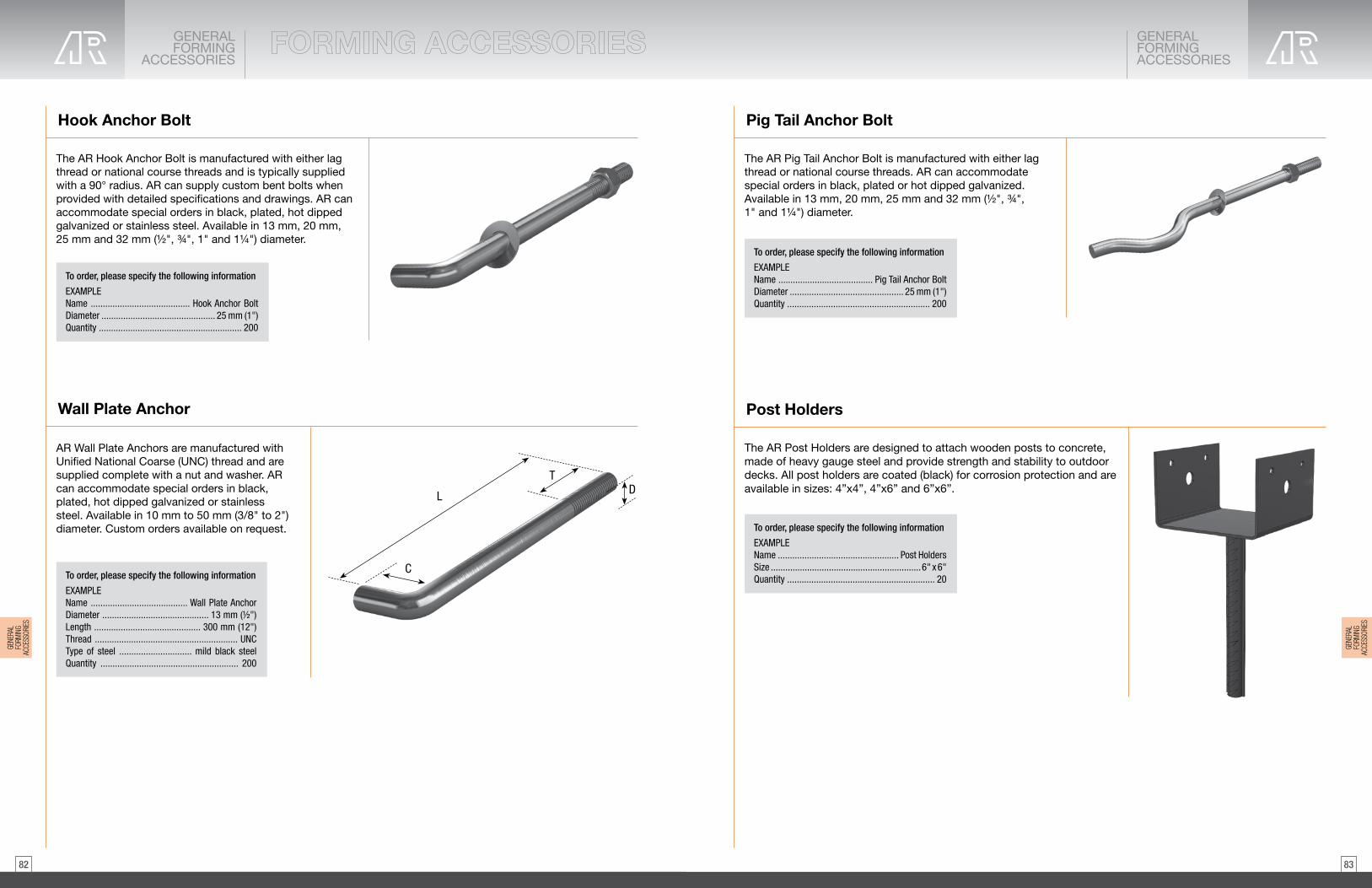
8382
GENERALFORMING
ACCESSORIES
GENERALFORMINGACCESSORIES
Hook Anchor Bolt Pig Tail Anchor Bolt
Post HoldersWall Plate Anchor
The AR Hook Anchor Bolt is manufactured with either lag thread or national course threads and is typically supplied with a 90° radius. AR can supply custom bent bolts when provided with detailed specifications and drawings. AR can accommodate special orders in black, plated, hot dipped galvanized or stainless steel. Available in 13 mm, 20 mm, 25 mm and 32 mm (½", ¾", 1" and 1¼") diameter.
The AR Pig Tail Anchor Bolt is manufactured with either lag thread or national course threads. AR can accommodate special orders in black, plated or hot dipped galvanized. Available in 13 mm, 20 mm, 25 mm and 32 mm (½", ¾", 1" and 1¼") diameter.
The AR Post Holders are designed to attach wooden posts to concrete, made of heavy gauge steel and provide strength and stability to outdoor decks. All post holders are coated (black) for corrosion protection and are available in sizes: 4”x4”, 4”x6” and 6”x6”.
AR Wall Plate Anchors are manufactured with Unified National Coarse (UNC) thread and are supplied complete with a nut and washer. AR can accommodate special orders in black, plated, hot dipped galvanized or stainless steel. Available in 10 mm to 50 mm (3/8" to 2") diameter. Custom orders available on request.
To order, please specify the following information
EXAMPLEName ......................................... Hook Anchor BoltDiameter ............................................... 25 mm (1")Quantity ........................................................... 200
To order, please specify the following information
EXAMPLEName ....................................... Pig Tail Anchor BoltDiameter ............................................... 25 mm (1")Quantity ........................................................... 200
To order, please specify the following information
EXAMPLEName .................................................. Post HoldersSize .............................................................. 6" x 6"Quantity ............................................................. 20To order, please specify the following information
EXAMPLEName ........................................ Wall Plate AnchorDiameter ............................................ 13 mm (1/2")Length ............................................ 300 mm (12")Thread ........................................................... UNCType of steel .............................. mild black steel Quantity ......................................................... 200
L
TD
C
GENE
RAL
FORM
ING
ACCE
SSOR
IES
GENE
RAL
FORM
ING
ACCE
SSOR
IES

8584
GENERALFORMING
ACCESSORIES
GENERALFORMINGACCESSORIES
AR Form Tubes
Handyform Tube
AR concrete forming tubes are built to withstand the rigors of construction. Designed to hold the full hydrostatic pressure load of concrete in a single continuous pour, AR tubes have earned their mark as a “go to” standard for the most demanding construction projects. Shields against moisture and adverse weather conditions to help keep the elements from impacting your construction schedule. Manufactured with 100% recycled paperboard. Available in diameters from 6 inches to 60 inches. Standard wall thickness to 12 feet, heavy wall thickness to over 30 feet.
AR Handyform tubes are built to be used in smaller projects by contractors and weekend warriors. Designed to hold the full hydrostatic pressure load of concrete in a single continuous pour, AR tubes have earned their mark as a “go to” standard for the most demanding construction projects. Shields against moisture and adverse weather conditions to help keep the elements from impacting your construction schedule. Manufactured with 100% recycled paperboard. Available in diameters from 10 inches to 36 inches, and length of 12 feet.
Anchor Sleeve
AR Anchor Sleeves are a plastic void form made of high density polyethylene that is non-rusting and non-conductive. They expedite the mounting of machinery and equipment, and are maintenance free and easy to use. When using the AR Anchor Sleeve, initial material and installation costs are greatly lowered, and all welding, pipe cutting, packing, bending, forming, cleaning and chipping out are eliminated.
Preparatory Work: NoneLimitations: The AR Anchor Sleeve is not recommended where high heat is used, such as inside an oven.Caution: When using the AR Anchor Sleeve outdoors or under freezing conditions, the sleeve must be sealed around the bolt to prevent moisture penetration or filled with Antifreeze.Installation: The bottom of the sleeve is passed over the top of the bolt until the threaded portion engages the self-threading top of the sleeve. The sleeve is turned until the proper projection is obtained. The entire assembly is cast into the concrete, with the top of the sleeve at foundation level. When the anchor bolt is ready for adjustment, the top of the sleeve is cut off and discarded. The bolt may now be adjusted within the sleeve. Expansion or non-shrinking grout is cast into the sleeve around the bolt when equipment is set. Other applications are done in a similar fashion.
.26
.25
.35
.341.061.002.752.602.902.669.508.80
TABLE — GROUT VOLUME REQUIRED
NOTE: Grout estimate based on .46 cu/ft yield per 55 lb of non-corrosive grout.
Bolt Diametermm (in)
13 mm (½")20 mm (¾")16 m (5/8")20 mm (¾")25 mm (1")32 mm (1¼")38 mm (1½")42 mm (1¾")50 mm (2")57 mm (2¼")64 mm (2½")76 mm (3")
Series
AXAXAABBCCDDEE
Sleeve Sizemm (in)
kgs (lbs)per bundle
50 mm x 130 mm (2" x 5")50 mm x 130 mm (2" x 5")50 mm x 180 mm (2" x 7")50 mm x 180 mm (2" x 7")75 mm x 255 mm (3" x 10")75 mm x 255 mm (3" x 10")100 mm x 380 mm (4" x 15")100 mm x 380 mm (4" x 15")100 mm x 460 mm (4" x 18")100 mm x 460 mm (4" x 18")150 mm x 610 mm (6" x 24")150 mm x 610 mm (6" x 24")
445566667788
# sleevesper carton
1001001001005050202020201010
Litres ofgrout per shell
15.9515.1621.4120.5065.8061.40
167.60158.00176.76161.82575.28523.44
Cubic inchesper shell
To order, please specify the following information
EXAMPLEName .................. AR Anchor SleeveAnchor Bolt Diameter ... 13 mm (1/2")Quantity ................................... 200
d
H
WilsonAnchorSleeve
WilsonAnchorSleeve
A
Length
8dminimum
Anchor Bolt
Grout
Top ofconcrete
Projectionas required
Wall PlateAnchor
d
A
Length
8d minimum
Anchor Bolt
Washerand nut
Grout
Top ofconcrete
Projectionas required
Material and Testing Data
Each Sleeve is approximately twice the bolt diameter with a depth of 8 bolt diameters, minimum.
Plastic:Density, gms/cc:Vicat softening point °F (°C):Brittleness temp. °F (°C):Torch application:Compression test:
High density polyethyleneASTM D 1505-68 .956ASTM D 1525-70 256°F (124°C)ASTM D 746-70 -180°F (-119°C)Slow burn12.7 kg (180 psi) per square inch
NutTemplateSTEP 3
ThreadLength
Bolt STEP 2
Flush
STEP 1
Template
Insert sleeved bolt into template. Hand tighten nut to secure in place.
Screw bolt through sleeve bottom up to top to thread length spec.
Grout
STEP 5STEP 4
See table for hole size in template
Install equipment: groutBefore installing equipment, cut out top of sleeve
AR Nails
AR Concrete Nails
AR Nails feature a round smooth shank which reduces wood splitting. Nails are available as common nails and duplex (double head) nails, commonly used for interior and exterior construction and framing. Available from 2” to 3½” in ¼” increments, 50 lb boxes. Nails conform to ASTM F1667 standard.
AR Concrete Nails feature a round smooth shank which reduces wood splitting. Available in 2” and 3”, 4.5 lb packs. Nails conform to ASTM F1667 standard.
GENE
RAL
FORM
ING
ACCE
SSOR
IES
GENE
RAL
FORM
ING
ACCE
SSOR
IES

8786
Safe Working LoadkN (lbs)
89 kN (20,000 lbs)178 kN (40,000 lbs)267 kN (60,000 lbs)
Falsework Support Bracket2 hole4 hole6 hole
Required Screw Anchors
two 32 mm (1¼") diameterfour 32 mm (1¼") diametersix 32 mm (1¼") diameter
Falsework Support Bracket
AR Falsework Support Brackets are used with 32 mm (1¼") AR Screw Anchors and Bolts to support pier cap forms. The use of Falsework Support Bracket eliminates posting or scaffolding which can be expensive and time consuming to erect. Brackets can be manufactured with 2, 4 or 6 holes.
Determining total loadTo determine the total load to be supported by each falsework bracket, compute the total mass (weight of concrete) plus the liveload (weight of form and other temporary loads) and divide by the number of brackets to be used.
Example:The dimension of a concrete beam to be poured over two columns and supported by 4 brackets is as follows:
750 mm wide x 1200 mm high x 18500 mm long (30" wide x 48" high x 740" long)
Density of concrete assumed = 2,400 kg/m3 (150 lb/ft3)Live load or mass per unit area assumed = 365 kg/m2 (75 lb/ft2)
Mass of beam .75 m x 1.2 m x 18.5 m x 2400 = 39,900 kg (18,100 lbs)Mass of live load .75 m x 18.5 m x 365 = 5,065 kg (2,300 lbs)
44,964 kg (20,400 lbs)
Force exerted by mass = 44,964 x .00981 = 441.10 kN (99,100 lbs)Force per bracket: 441.10 = 110.28 kN (24,800 lbs)
Therefore use 4 hole bracket with four 32 mm (1¼") diameter Screw Anchors.NOTE: 1 kilogram = .00981 kiloNewtons
To order, please specify the following information
EXAMPLEName ......................... Falsework Support BracketNumber of Holes ................................................. 4Quantity ......................................................... 200
4
GENERALFORMING
ACCESSORIES
GENERALFORMINGACCESSORIES
Guardrail Base
AR Anti-Impalement Rebar Cap
The single component AR Guardrail Base provides set backrequirements. The solid galvanized steel construction issignificantly stronger than typical wood fabrications and addssafety and reliability. The Guardrail Base is reusable and fastand simple to install on plywood or concrete surfaces.
Meets Load Requirements of Section 26.3 of the OntarioHealth and Safety Act and Regulations for Construction Projects(ISBN 0-7778-9412-2 Rev 06/00), when assembled with othercomponents to form guardrail system complying with the Act.
The AR Anti-Impalement rebar protection cap is a safety cap with a metal dome plate, used to prevent rebar from impaling workers in case of falls. The cap is OSHA compliant and is available for #3 (10 mm) to #8 rebar (25 mm), 25 pieces per box.
GuardrailBase
Plywood or concrete
2 X 4
WoodScrews
To order, please specify the following information
EXAMPLEName ....................................... Guardrail BaseQuantity .................................................... 200
GENE
RAL
FORM
ING
ACCE
SSOR
IES
GENE
RAL
FORM
ING
ACCE
SSOR
IES
APPROXIMATE SAFEWORKING LOAD 3:1 Safety Factor

8988
GENERALFORMING
ACCESSORIES
GENERALFORMINGACCESSORIES
(SB) Slab Bolster
(PSB) Slab Bolster And All Plastic Continuous High Chair
(CHC) Continuous High Chair
Reinforcing Bar Supports
Reinforcing Bar Supports are used to support and space reinforcing steel. AR Bar Supports are manufactured according to specifications published by the Concrete Reinforcing Steel Institute. To eliminate rust spots or similar blemishes on the concrete surface specify AR’s Plastic Bar Supports.
Used for supporting lower slab steel from slab form. Corrugations spaced 1” (25 mm) on centres serve as guides for spacing bars. Legs are spaced 5” (127 mm) on centre. Stocked in 3/4”, 1”, 1 1/2”, 2” (20, 25, 38 and 50 mm) in heights in 5’ (1525 mm) lengths.
AR Plastic Slab Bolster is used for supporting lower slab steel from slab form. Corrugations spaced 1” (25 mm) on centres serve as guides for spacing bars. Legs are solid plastic 4” (100 mm) on centre. Supporting cross bar is made from high strength plastic coated steel. Corrosion-proof and lightweight for handling.
Continuous High Chairs provide support for upper slab steel from slab form, eliminating carrier bars required with individual supports. Fabricated with plain steel legs (CHC) or with plastic tipped legs (PCHC). Supplied to order in heights from 2” to 12” (50 mm to 300 mm) in 1/4” (5 mm) increments and in 5’ (1525 mm) lengths with legs spaced at 6” (150 mm) o.c.
1 2 2
(25)
(50)
(63)
3 4 2 (70)
3 (76)
(20)
in (mm)
5 (125)
(138)(38)
1
(32)
2
3 4
1 2 1
(44)3 4 1
1 4 1
HEIGHT
1 2 5
in (mm)
6
7
1 2 6
(150)
(175)
(163)
Linden Chairs
Corrosion free All Plastic Linden Chairs are used in slabs for supporting all types of reinforcing steel. Excellent for supporting epoxy coated rebar in bridge deck construction, or where-ever a corrosion free support is required. The high sizes have an arch design for straddling lower mats of rebar. The chair is made of High Impact polypropylene and its design gives it the strength of steel. Linden chairs are strong yet light in weight and packaged in poly bags for convenience of carrying around job sites.
mm
LINDEN CHAIRS SIZES AND PACKAGING WEIGHTSPCS/BAGinch LBS/MFT
1 25 500 3032 500 3540 250 4645 250 50
2 50 250 6258 200 7863 200 8270 300 84
3 75 300 8577 300 8885 300 9092 200 93
4 100 200 95108 200 98110 200 112120125
200 119200 120
CTN SKID4040404040404025252525252525252525
SKID QTY20,00020,00010,00010,00010,00010,0008,0007,5007,5007,5007,5005,0005,0005,0005,0005,0005,0005
133 200 125140 200 130146 200 148
6 150 100 155158 100 160165 100 177170 100 184
7 175 100 195183 75 255190 75 310195 75 338
8 200 75 343210 75 350215 50 365220 50 378
9 228235
50 40050 415
2525252525252525252525252525252525
5,0005,0005,0002,5002,5002,5002,5002,5001,8751,8751,8751,8751,8751,2501,2501,2501,250
240 50 424247 50 430
10 254 50 440
252525
1,2501,2501,250
1 1 4
1 1 2
1 3 4
2 1 4
2 1 2
2 3 4
3 1 4
3 1 2
3 3 4
4 1 4
4 1 2
4 3 4
5 1 4
5 1 2
5 3 4
6 1 4
6 1 2
6 3 4
7 1 4
7 1 2
7 3 4
8 1 4
8 1 2
8 3 4
9 1 4
9 1 2
9 3 4
LINDEN CHAIR DATA SHEETSize Available 1-10 inches (25-254 mm)
every 1/4” (6 mm)
Colour concrete grey
Material
Strength a minimum 400 lbs. (180 kg) / chair
reinforced, high impact polypropylene
Chemical Resistancy excellent
Packaging in heavy-duty uv protected poly bags Quantity varies by size
Installation good for both Black and Corrosion resistant rebar place chairs on deck forms can straddle bottom steel barsspacing depends on loads standard spacing is every 3-4 feet (0.9 - 1.2 m)
GENE
RAL
FORM
ING
ACCE
SSOR
IES
GENE
RAL
FORM
ING
ACCE
SSOR
IES

9190
Plastic Form Spreader
The AR Plastic Form Spreader eliminates the need of cutting and placing wood strips and reduces patching and grouting needs. The Form Spreader is corrosion free and reduce water penetration. Available in 150mm, 200 mm, 250 mm and 300 mm (6", 8", 10" and 12").
Handle
Lagnut
DURING POUR SETTING FORMWORK
Form
Spreader
Form
Spreader
To order, please specify the following information
EXAMPLEName .................................. Plastic Form SpreaderQuantity .......................................................... 200
GENERALFORMING
ACCESSORIES
GENERALFORMINGACCESSORIES
45 mm (1 3/4")
90 mm (3 1/2")
25 mm (1")
Tie Wire
Tie Wire Twister
The AR Tie Wire is a fully annealed wire for use in general construction. It is packaged in Wire Loop Ties and Rolls designed to fit in standard reels. Available in 16 or 16.5 ga.
· 50 lbs. Coils· 3.5 lbs. Coils· Wire Loop Tys· Coated & Uncoated
The AR Tie Wire Twister is offered in a compact size that allows the tool to be used in tight spaces. Safely and easily twists wire bar ties with a durable design.
Formwork Pry Bar
Blade
To order, please specify the following information
EXAMPLEName ........................................ Formwork Pry BarQuantity .............................................................. 2
The AR Formwork Pry Bar is a heavy duty pry bar ideally suited for use by tilt-up erectors and form setters to strip forms and to “jockey” a panel into position or assist in removing forms. The Pry Bar is available with a 75 mm (3") blade widths.
NOTE: Wood chamfer also available. Consult your AR Sales Representative or AR Technical Department for more information.
PVC - Single Chamfer
B
A
Product Name Width A Height B Chamfer Angle Snap Single Chamfer 3/4” With Tape 0.75" 0.75" 45°
LC Single Chamfer 3/4” With Tape 0.5" 0.75" 45° LC Single Chamfer 1/2” With Tape 0.5" 0.5" 45°
Single Chamfer 3/4” Top / Inside Chamfer 0.75" 0.75" 45° Single Chamfer 1/2" x 45 Degree 0.5" 0.5" 45° LC Single Chamfer 1” With Tape 1” 1” 45°
GENE
RAL
FORM
ING
ACCE
SSOR
IES
GENE
RAL
FORM
ING
ACCE
SSOR
IES

9392
GENERALFORMING
ACCESSORIES
GENERALFORMINGACCESSORIES
Curb Clamp
Corner Clamp
AR Curb Clamps are strong and durable with special fast threadfor adjustment up to 385 mm (15") for securing curb on gutter forms.Custom sizes are available on request.
The AR Corner Clamp is fabricated of 6 mm x 95 mm (1/4" x 33/4") flat steel washer stock bent to form a wedge block with ample bearing flanges drilled for nailing to the wales. Its principal use is to provide bearing against the wales for the Tyholders on a diagonal corner tie. Most commonly used with Lag Rods.
25 x 25 mm (1 x 1”)
230 mm(9”)
385 mm (15”)
To order, please specify the following information
EXAMPLEName ............................ Curb ClampQuantity ..................................... 200
To order, please specify the following information
EXAMPLEName ......................... Corner ClampQuantity ..................................... 200
CornerClamp
Rich-Cote Form Release - Summer & Winter Grade
A premium liquid debonding agent developed especially for concrete. Through a chemical reaction, RICH-COTETM produces a smooth, white, flat concrete surface which is free of voids and will bond with paint, plaster, tiles and any other coating applied directly to the concrete.RICH-COTETM reacts positively with the alkalies in the concrete forming a water resistant barrier with the concrete that prevents it from binding to the forms.RICH-COTETM waterproofs plywood forms preventing the alkalies in the concrete from being absorbed and rotting the wood. It is compatible with any pre-oiling done at the mill or any other substance previously used for treating forms. It will not wick out or wash off. Continued use makes forms completely waterproof and extends their life considerably.RICH-COTETM can be sprayed at sub-freezing temperatures. It will not stain and will reduce finishing time by 50%. RICH-COTETM makes form stripping easier and faster. For the most effective and economical method of application use the AR Form Sprayer.
Drying Time:1 - 2 hours — leaving a completely workable, non-slip surface.
Coverage:12-18 square metres per litre on most forms.18 - 25 square metres per litre on plastic coated and steel forms.
Form Sprayer
The AR Form Sprayer is an industrial style Tri-Poxy coated metalunit with a capacity of 13.2 litres. The AR Form Sprayer comescomplete with: · 1200 mm (48") heavy duty hose· 600 mm (24") brass extension· three point closures· lock-in features for continuous spray· threaded fitting for easy changing of hose, shut-off and nozzle
To order, please specify the following information
EXAMPLEName .......................... Form SprayerQuantity ......................................... 2
GENE
RAL
FORM
ING
ACCE
SSOR
IES
GENE
RAL
FORM
ING
ACCE
SSOR
IES

9594
APPENDIX
Barrier Wall Control Joint
Expanded Metal Form
The AR Barrier Wall Control Joint is a pre-manufactured extruded PVC forming insert used in controlling the location of shrinkage cracks in concrete barrier walls. The Barrier Wall Control Joint is installed by mechanically attaching it to the edge of the concrete form at a predetermined joint spacing specified by the engineer. The spacing and location of the Barrier Wall Control Joint is calculated based on the concrete mass and length of wall cast. Comes as a 3 metre (10') length. Available in steel as a special order upon request.
NOTE: If properly installed may be reused a number of times. Referred in the OPSS904 specification as special provision 109S25.
AR Expanded Metal Form is adaptable to site conditions for stay-in-place forming. Use in applications such as bulkheads, blind sided walls, grade beams and pile caps. Expanded Metal Form reduces labour costs in difficult forming applications. Supplied pre-galvanized for job site storage.
Expanded Metal Form sheet size:685 mm x 244 mm (27" x 8'-0")
To order, please specify the following information
EXAMPLEName ........ Barrier Wall Control JointQuantity ..................................... 200
To order, please specify the following information
EXAMPLEName ................................... Expanded Metal FormQuantity ................................................. 10 sheets
Barrier WallControl Joint
¾" Plywood
Rod ties sized to suit
Collar of 1 X 6 forabove grade finish
Wood strong backsspaced and sizedto suit load
Rod clampssecuring ties
For corners, notch ribs 3/8"deep with "V" contouredrotary cut-off blade and bend to 90 degrees.
Wire-tie all laps andback with supports.
90˚
GENE
RAL
FORM
ING
ACCE
SSOR
IES
GENERALFORMING
ACCESSORIES

9796
General Guidelines and Conditions General Guidelines and Conditions
Approximate Safe Working Loads: The Approximate Safe Working Loads published in this brochure can only be obtained when AR products and accessories are used together. Products must be installed correctly to obtain the full strength development as illustrated below.
Ensure that internal vibration has not caused Snap-Ty Wedges to bounce around, loosen or fall off.It is important to properlyposition the Snap-Ty head andthe wedge.
Ty cones and metal washers are used to act as form spreaders only.The wedge should not be overtightened by any method.Attempting to draw-up warped wales with the wedge should not be attempted. Metal spreader washers will bend out of shape and plastic cones will break if over tightening is attempted, resulting in incorrectwall thickness.
The Ty Head must not be positioned lower than the midpoint of the wedge. The proper Ty Head position is at the midpoint of the wedge slot, or higher.
To achieve proper form structures, it is important that all form tys are installed and used properly.Excessive loads will be transferred to adjacent tys and can result in form failure if tys and/or their required hardware are omitted.Ensure that form tys are properlyaligned. Increased loads placedon form tys because ofmisalignment may cause formfailure to occur. Also, reducedload capacities can result fromform tys damaged because ofmisalignment during installation.
Walers spaced too far apart maycause crushing of the wales orbending of the wedge, causingthe form to bulge outward.Incorrect wall thicknesses willresult and cause the Ty SpreaderWashers or Cones to becomeembedded in the concrete.Embedded Ty Washers or Coneswill make it difficult to breakback the Tys.
Wedge properly positioned
CORRECT
Improperly positioned wedgeswill loosen and fall off
Ty is at midpoint of wedge slotTy is too high in the wedge slot
Metal washers will bend andplastic cones will shatter
CORRECT
The ty head must be positioned at themidpoint (or higher) of the wedge slot.
The ty head must not be positioned lowerthan midpoint of the wedge slot.
Midpointof
wedge slotTy Head
Wedge
CORRECT
Ty wedge positioned too high
Tys havebeenleft out
CORRECT
Break Back
Correct spacing between walers is15 to 20 mm (5/8” to 3/4”)
Walers will become damage
Walers aretoo far apart
Spreader washeror cone embeddedin concrete
CORRECT
GENERALGUIDELINES &
CONDITIONS
GENERALGUIDELINES & CONDITIONS
GENE
RAL
GUID
ELIN
ESCO
NDITI
ONS
GENE
RAL
GUID
ELIN
ESCO
NDITI
ONS
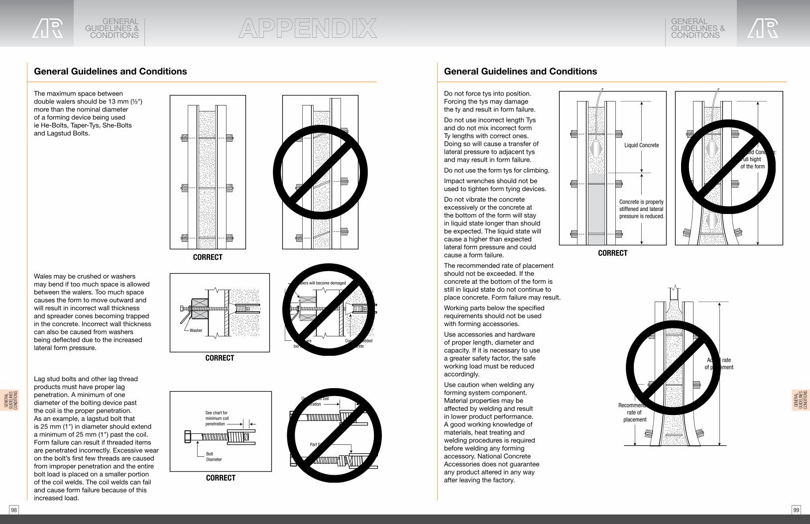
9998
General Guidelines and Conditions General Guidelines and Conditions
The maximum space betweendouble walers should be 13 mm (½") more than the nominal diameter of a forming device being used ie He-Bolts, Taper-Tys, She-Bolts and Lagstud Bolts.
Do not force tys into position.Forcing the tys may damage the ty and result in form failure.
Do not use incorrect length Tys and do not mix incorrect form Ty lengths with correct ones. Doing so will cause a transfer of lateral pressure to adjacent tys and may result in form failure.
Do not use the form tys for climbing.
Impact wrenches should not beused to tighten form tying devices.
Do not vibrate the concreteexcessively or the concrete at the bottom of the form will stay in liquid state longer than should be expected. The liquid state willcause a higher than expectedlateral form pressure and couldcause a form failure.
The recommended rate of placement should not be exceeded. If the concrete at the bottom of the form is still in liquid state do not continue to place concrete. Form failure may result.
Working parts below the specifiedrequirements should not be usedwith forming accessories.
Use accessories and hardware of proper length, diameter andcapacity. If it is necessary to usea greater safety factor, the safeworking load must be reducedaccordingly.
Use caution when welding anyforming system component.Material properties may beaffected by welding and resultin lower product performance. A good working knowledge ofmaterials, heat treating andwelding procedures is requiredbefore welding any formingaccessory. National ConcreteAccessories does not guaranteeany product altered in any wayafter leaving the factory.
Wales may be crushed or washers may bend if too much space is allowed between the walers. Too much space causes the form to move outward and will result in incorrect wall thickness and spreader cones becoming trapped in the concrete. Incorrect wall thickness can also be caused from washers being deflected due to the increased lateral form pressure.
Lag stud bolts and other lag thread products must have proper lag penetration. A minimum of one diameter of the bolting device past the coil is the proper penetration. As an example, a lagstud bolt that is 25 mm (1") in diameter should extend a minimum of 25 mm (1") past the coil. Form failure can result if threaded items are penetrated incorrectly. Excessive wear on the bolt’s first few threads are caused from improper penetration and the entire bolt load is placed on a smaller portion of the coil welds. The coil welds can fail and cause form failure because of thisincreased load.
CORRECT CORRECT
Liquid Concrete
Concrete is properlystiffened and lateralpressure is reduced.
Liquid Concrete:Full hight of the form
Washer
Walers aretoo far apart
Cone embeddedin concrete
Walers will become demaged
CORRECT Actual rateof placement
Recommendedrate of
placement
BoltDiameter
Part Failure
See chart forminimum coilpenetration
Unsufficient coilpenetration
CORRECT
GENERALGUIDELINES &
CONDITIONS
GENERALGUIDELINES & CONDITIONS
GENE
RAL
GUID
ELIN
ESCO
NDITI
ONS
GENE
RAL
GUID
ELIN
ESCO
NDITI
ONS

101100
Induced Tension Loads
Induced Shear Loads
Combined Shear and Tension Loads
Stripping of Snap-Tys and guidelines for break back
Induced Tension LoadsWhen tying at an angle be aware that an increase in the tension applied to an angled ty is increased. Sample angles and the corresponding multiplicationfactors for calculating the tension load on an angled ty are shown in the table.
It is important to note theillustration showing ty downsplaced at an angle and the shearloads produced. Total shear loadmay be many times greater thanthe shear load produced by theform weight alone.When deciding which form tysystem to use for a formingapplication, consider both thetension and the shear load.
The equation shown should besatisfied for form accessories and inserts subjected to combinedshear and tension loading.
Where:ft = induced tension loadFt = insert tension Approximate Safe Working Load or bolt tension Approximate Safe Working Load, whichever is lessfv = induced shear loadFv = insert shear Approximate Safe Working Load or bolt shear Approximate Safe Working Load, whichever is less
AR Snap-Ty break backs are manufactured to exacting standards that ensure that they perform to load requirements while providing a consistent and reliable breaking point. However, many factors affect the performance of the break backs. · Snap-Tys must not be bent during installation as the break back could be adversely affected.· For best results, Tys are not to be removed until concrete has gained sufficient strength to prevent the Ty upset from rotating — typically 2 to 3 days. Attempting to break the Ty in green concrete may result in the Ty rotation in the concrete and make it difficult to break the Ty.· Only Space-Tys have a guaranteed break back.· Other Snap-Ty products are designed to provide a consistent break back, but can be affected by the concrete, which could generate difficulties in achieving a consistent break back.· Products like the Steel Washer, No Washer and No Spreader Snap-Tys where the break back could be contained within the concrete require extra attention. With increased bond length AR cannot guarantee that the Ty will consistently provide the proper break back. For these products, this is especially important where break backs of over ¾" (20 mm) are desired. A good quality release agent/grease (acceptable non-staining) applied between the break back and the face of formwork (grease wire to be embedded, that will be removed — do not grease head area) may facilitate more consistent results. On site tests should be conducted to identify if consistent results can be achieved with the concrete mix and Ty.· If the washer or cone is not free of the concrete, chip away the concrete using a hammer, screwdriver or drill to free the embedded components. Failure to free up the embedded components could result in the break back closer to the surface of the concrete instead of the desired break back location. Use of the AR Snap-Ty and Space-Ty wrenches will assist with consistency, reduce risk of injury and speed up removal (see pages 22 and 23).
If in doubt, contact AR’s technical department for assistance.
Angle Multiplication Factor
15º 1.0430º 1.1645º 1.4260º 2.00
AnglePressure
Tension
.71 X tie down load = shear load
.50 X tie down load = shear load
.26 X tie down load = shear load
Total shear load
Tension Tie Down Load
45˚
30˚
15˚
f t f v
Ft Fv( ) ( )53
+ < 1.0=
53
INDUCEDTENSION
LOADS
SNAP-TYSSTRIPPING& BREAK BACK
Space-Ty Wrench
Snap-Ty Wrench
INDU
CED
TENS
ION
LOAD
S
SNAP
-TYS
ST
RIPP
ING
&BR
EAK
BACK

103102
Concrete lateral pressures for wall form design - PUMPED Concrete lateral pressures for wall form design - BUCKET
— Table conforms to CAN/CSA-S269.3-M92. — Table conforms to CAN/CSA-S269.3-M92.
1 metre per hour 3'0" per hour
1.5 metre per hour 4'0" per hour
2 metres per hour 5'0" per hour
2.5 metres per hour 6'0" per hour
3 metres per hour 7'0" per hour
3.5 metres per hour 8'0" per hour
4 metres per hour 9'0" per hour
4.5 metres per hour 10'0" per hour
86 1810
92 1900
99 1975
106 2075
112 2125
2250
2331
2425
62 1290
67 1325
71 1410
76 1460
81 1525
113 1590
128 1640
144 1675
10° C (50° F) 15° C (60° F)CONCRETE TEMPERATURE DURING POUR
NOTES: The above table is controlled rate of pours (concrete using type 10 or 30 cement, with no admixtures, ie. superplasticizer) plus 25% for pumped concrete.
Rate of pour
PUMPED
72 1500
77 1550
82 1625
88 1680
93 1760
132 1840
144 1910
1975
kPa PSFkPa PSFkPa PSF
5° C (40° F)
1 metre per hour 3'0" per hour
1.5 metre per hour 4'0" per hour
2 metres per hour 5'0" per hour
2.5 metres per hour 6'0" per hour
3 metres per hour 7'0" per hour
3.5 metres per hour 8"0' per hour
4 metres per hour 9'0" per hour
4.5 metres per hour 10'0" per hour
48 1000
58 1000
63 1130
67 1290
71 1350
100 1400
112 1440
126 1460
48 1000
48 1000
48 1000
51 1000
63 1130
88 1260
101 1290
112 1300
48 1000
48 1000
48 1000
48 1000
51 1000
81 1000
91 1000
101 1000
20° C (70° F) 25° C (80° F) 30° C (90° F)CONCRETE TEMPERATURE DURING POUR
Rate of pour
kPa PSFkPa PSFkPa PSF
58 1200
62 1240
66 1300
71 1350
75 1410
106 1470
120 1530
134 1580
1 metre per hour 3'0" per hour
1.5 metre per hour 4'0" per hour
2 metres per hour 5'0" per hour
2.5 metres per hour 6'0" per hour
3 metres per hour 7'0" per hour
3.5 metres per hour 8'0" per hour
4 metres per hour 9'0" per hour
4.5 metres per hour 10'0" per hour
69 1450
74 1520
79 1580
85 1660
90 1700
128 1800
144 1870
1940
50 1030
54 1060
57 1130
61 1170
65 1220
91 1270
103 1310
115 1340
5° C (40° F) 10° C (50° F) 15° C (60° F)CONCRETE TEMPERATURE DURING POUR
NOTES: The above table is controlled rate of pours (concrete using type 10 or 30 cement, with no admixtures, ie. superplasticizer).
Rate of pour
BUCKET
kPa PSFkPa PSFkPa PSF
1 metre per hour 3’0” per hour
1.5 metre per hour 4’0” per hour
2 metres per hour 5’0” per hour
2.5 metres per hour 6’0” per hour
3 metres per hour 7’0” per hour
3.5 metres per hour 8’0” per hour
4 metres per hour 9’0” per hour
4.5 metres per hour 10’0” per hour
48 1000
48 1000
51 1000
54 1030
57 1080
80 1120
90 1150
101 1170
48 1000
48 1000
48 1000
48 1000
51 1000
71 1010
81 1030
90 1040
48 1000
48 1000
48 1000
48 1000
48 1000
65 1000
73 1000
81 1000
20° C (70° F) 25° C (80° F) 30° C (90° F)CONCRETE TEMPERATURE DURING POUR
Rate of pour
kPakPakPa PSF PSF PSF
CONCRETELATERAL
PRESSURES
CONCRETELATERALPRESSURES
LATE
RAL
PRES
SURE
LATE
RAL
PRES
SURE

105104
Maximum lateral pressure for design of COLUMN FORMS Maximum lateral pressure for design of WALL FORMS
— Based on ACI Committee 347 pressure formula
Applies only for normal weight concrete made with type 1 cement, no admixtures or pozzolans, slump no more than 4 inches and vibration depth limited to 4 feet or less.
— Based on ACI Committee 347 pressure formula
Applies only for normal weight concrete made with type 1 cement, no admixtures or pozzolans, slump no more than 4 inches and vibration depth limited to 4 feet or less.
1 foot per hour
2 feet per hour
3 feet per hour
4 feet per hour
5 feet per hour
6 feet per hour
7 feet per hour
8 feet per hour
9 feet per hour
10 feet per hour
12 foot per hour
14 feet per hour
16 feet per hour
18 feet per hour
20 feet per hour
22 feet per hour
24 feet per hour
26 feet per hour
28 feet per hour
30 feet per hour
P. maximum lateral pressure, psf, for temperature indicated.
NOTE:Form pressure is based on concrete weighing 150 lb/ft2.Do not use design pressures in excess of 150 x height of fresh concrete in forms.
Rate of placement
825
1050
1275
1500
1725
1950
2175
2400
2850
690
870
1050
1230
1410
1590
1770
1950
2310
2670
3000
750
900
1050
1200
1350
1500
1650
1950
2250
2550
2850
3000
664
793
921
1050
1178
1307
1436
1693
1950
2207
2464
2721
2979
3000
712
825
938
1050
1163
1275
1500
1725
1950
2175
2400
2625
2850
3000
650
750
850
950
1050
1150
1350
1550
1750
1950
2150
2350
2550
2750
2950
3000
50° F 60° F40° F 80° F 90° F70° F
3000 psf maximumgoverns
600 psf minimum governs
1 foot per hour
2 feet per hour
3 feet per hour
4 feet per hour
5 feet per hour
6 feet per hour
7 feet per hour
8 feet per hour
9 feet per hour
10 feet per hour
825
1050
1275
1500
1725
1795
1865
1935
690
870
1050
1230
1410
1466
1522
1578
750
900
1050
1200
1246
1293
1340
664
793
921
1050
1090
1130
1170
712
825
938
973
1008
1043
650
750
850
881
912
943
50° F 60° FRate of placement 40° F 80° F 90° F70° FP. maximum lateral pressure, psf, for temperature indicated
600 psf minimum governs
NOTE:Form pressure is based on concrete weighing 150 lb/ft2.Do not use design pressures in excess of 150 x height of fresh concrete in forms.
150 = (9000*R)/T150 + (43400/T) = (2088*R)/T
Wall up to 7 feet150 + (43400/T) = (2088*R)/TWall between 7 and 10 feet
3000 PSF2000 PSFMaximum form pressure1000 PSF600 PSFMiminum form pressure
600/150 = 4 feet Full Liquid Head Pour Full Liquid HeadUp to 4'-0" wall
ACI formula for pour rate up to 7 feet/hour is more conservative
Lower maximum form pressure
Lower miminum form pressure
Higher form pressure between 0 to 7 feet/hour
Higher maximum form pressure
Higher minimum form pressure
Comments
ACISpec CAN/CSA-S269.3-M92
MAXIMUMLATERAL
PRESSURES
MAXIMUMLATERALPRESSURES
LATE
RAL
PRES
SURE
LATE
RAL
PRES
SURE

107106
Lateral Pressure Light Formwork
68 Kg(150 lbs)
68 Kg(150 lbs)
68 Kg(150 lbs)
600 mm(24')
300 mm(12')
150 mm(6')
Plastic concrete exerts the same pressure on forms regardless of their width.
Wall Thickness
WallthicknessForm pressure kPa (PSF)
Typical 6100 mm (20'-0") High Wall Formwork, CONTROLLED RATE OF POUR
(1500)
72
610
(2'-0
")61
0(2
'-0")
610
(2'-0
")40
6(1'
-4")
406
(1'-4
")40
6(1'
-4")
406
(1'-4
")40
6(1'
-4")
406
(1'-4
")40
6(1'
-4")
406
(1'-4
")40
6(1'
-4")
W13
W12
W11
W10
W9
W8
W7
W6
W5
W4
W3
W2
6100
(20'
-0")
3050
(10'
-0")
3050
(10'
-0")
0 (0)
W1
MAX
.25
0(1
0")72
(1500)
A
G
C
DE
F
WallthicknessForm pressure kPa (PSF)
Typical 6100 mm (20'-0") High Wall Formwork, FULL LIQUID HEAD
610
(2'-0
")61
0(2
'-0")
610
(2'-0
")40
6(1
'-4")
406
(1'-4
")30
5(1
'-0")
305
(1'-0
")30
5(1
'-0")
305
(1'-0
")30
5(1
'-0")
305
(1'-0
")30
5(1
'-0")
305
(1'-0
")30
5(1
'-0")
W13
W12
W15
W14
W11
W10
W9
W8
W7
W6
W5
W4
W3
W1
W2
MAX
.
0 (0)
6100
(20'
-0")
144
(3000) 150
(6")
A
C
D
F
E
H
SEE LEGENDON PAGE 109
SEE GENERALNOTES ONPAGE 109
Snap-Ty10 kN (2,250 lbs)spacing:W1 to W10 @ 305(12") on centre
W11 @ 406(1'-4") on centre
W12 and W13@ 610 (2'-0")on centre
Space-Ty TM
13.4 kN (3,000lbs) spacing:W1 to W11@ 457 (1'-6")on centre
W12 and W13@ 610 (2'-0")on centre
Space-Ty TM
13.4 kN (3,000lbs) spacing:W1 to W12 @ 305(12") on centre
W13 @ 406 (1'-4")on centre
W14 and W15@ 610 (2'-0")on centre
F
E
DC
B
Typical 3050mm (10'-0") High Wall Formwork, CONTROLLED RATE OF POUR
(1000)
48
3050
(10'
-0") 20
32 (6
'-8")
1018
(3'-4
")
Form pressure kPa (PSF)
0 (0)
48
(1000)
Wallthickness
W5
W4
610
(2'-0
")
W3
610
(2'-0
")
W2
610
(2'-0
")61
0(2
'-0")
250
(10"
)M
AX.
W1
AG
C
A
E
D
F
WallthicknessForm pressure kPa (PSF)
Typical 3050 mm (10'-0") High Wall Formwork, FULL LIQUID HEAD
610
(2'-0
")61
0(2
'-0")
610
(2'-0
")40
6(1
'-4")
406
(1'-4
")
W6
W5
W3
W4
0 (0)
W1
W2
MAX
.
250
(10"
)
72
(1500)
3050
(10'
-0")
Snap-Ty10 kN (2,250 lbs)spacing:W1, W2 and W3@ 305 (12")on centre
W4 and W5@ 610 (2'0")on centre
Space-Ty TM
13.4 kN (3,000lbs) spacing:W1, W2 and W3@ 406 (1'-4")on centre
W4 and W5@ 610 (2'-0")on centre
Snap-Ty10 kN (2,250 lbs)spacing:W1, W2 and W3@ 305 (12")on centre
W4 @ @ 406(1'-4") on centre
W5, W6@ 610 (2'-0")on centre
Space-Ty TM
13.4 kN (3,000lbs) spacing:W1, W2 and W3@ 406 (16")on centre
W4, W5 and W6@ 610 (2'-0")on centre
Liquid Head
3050 mm (10'-0") High Wall, Controlled Rate of Pour3050 mm (10'-0") High Wall, Full Liquid Head6100 mm (20'-0") High Wall, Controlled Rate of Pour6100 mm (20'-0") High Wall, Full Liquid Head
N/AN/AN/AN/A
5°C
N/AN/AN/AN/A
(40°F)
(8)N/A(10)N/A
(80°F)
3.5N/A4.5N/A
25°C
(5)N/A(8)N/A
(70°F)
2N/A3.5N/A
20°C
(3)N/A(6)N/A
(60°F)
1N/A2
N/A
15°C
N/AN/AN/AN/A
(50°F)
N/AN/AN/AN/A
10°C
CHART — MAXIMUM RISE OF CONCRETE IN FORMS IN METRES (FEET) PER HOUR
1'
2'
3'
4'
1350
1500
900
1050
1200
680
748
408
476
544
300
600
900
1,200
As you increase the height of plastic concrete to the forms, the pressure will build at a rate of 150 PSF per foot of depth. This will be true as long as all concrete remains in a plastic state.
Example: Ten feet of fluid or plastic concrete bears on the bottom foot of forms with a pressure of 10 X 150 lbs/ft3 or 1500 PSF.
10'
9'
5'
6'
7'
8'
150
300
450
600
750
68
136
204
272
340
Feet
3,000
2,700
1,500
1,800
2,100
2,400
Millimeters
Increased Wall Height
PSF KPa
150
300
450
600
750
900
150
300
450
600
750
900
1050
1200 1200
1050
1200
13501350
1500
1050
900
750
600
450
300
150
Concrete inplastic state
Once bottomfoot is cured
Once second foot ofconcrete is cured
Lateral pressure decreases from bottom as concrete cures.
680
748
68
136
204
272
340
408
476
544
680
748
68
136
204
272
340
408
476
544
Feet10'
9'
5'
6'
7'
8'
1'
2'
3'
4'
As Concrete Cures
PSF KPa KPaPSF PSF
3,000
2,700
1,500
1,800
2,100
2,400
300
600
900
1,200
Millimeters
150
300
450
600
750
900
150
300
450
600
750
900
1050
1200 1200
1050
1200
13501350
1500
1050
900
750
600
450
300
150
Concrete inplastic state
Once bottomfoot is cured
Once second foot ofconcrete is cured
Lateral pressure decreases from bottom as concrete cures.
680
748
68
136
204
272
340
408
476
544
680
748
68
136
204
272
340
408
476
544
Feet10'
9'
5'
6'
7'
8'
1'
2'
3'
4'
As Concrete Cures
PSF KPa KPaPSF PSF
3,000
2,700
1,500
1,800
2,100
2,400
300
600
900
1,200
Millimeters
LATERALPRESSURE
LIGHTFORMWORK
LATE
RAL
PRES
SURE
LIGHT
FORM
WOR
K

109108
Medium Formwork Heavy Formwork
Option #2Option #1
Form pressure kPa (PSF)
Typical 6100 mm (20'-0") High Wall FormworkCONTROLLED RATE OF POUR
1220
(4'-
0")
914
(3'-
0")
914
(3'-
0")
914
(3'-
0")
914
(3'-
0")
914
(3'-
0")
200
(8")
914
(3'-
0")
1220
(4'-
0")
1220
(4'-
0")
1220
(4'-
0")
MAX
.
1220
(4'-
0")
200
(8")
T1
T2
T3
T4
T5
T6
T7T6
T5
T4
T3
T2
T1
0 (0)
3050
(10'
-0")
(1500)
72
3050
(10'
-0")
(1500)
72
6100
(20'
-0")
A
O
Q
P
F
Option #2Option #1
Form pressure kPa (PSF)
Typical 6100 mm (20'-0") High Wall Formwork, FULL LIQUID HEAD
914
(3'-
0")
1220
(4'-
0")
1220
(4'-
0")
1220
(4'-
0")
200
(8")
1220
(4'-
0")
T7T6
1220
(48"
)
T6
T5
914
(3'-
0")
914
(3'-
0")
T4 T5
T4
T3
T1
T2
MAX
.
914
(3'-
0")
T3
T2
T1 914
(3'-
0")
914
(3'-
0")
200
(8")
0 (0)
144
(3000)
6100
(20'
-0")
A
R
S
Q
F
LEGEND
LAYOUT and TY OPTIONS:
Diameter of Ty OptionsTyscru
LayoutOptions Taper Ty
6100 mm (20'-0") High WallControlled Rate of Pour
T4-27MOption
#1--
25 - 32(1"-1¼")
T4-18MOption
#220 - 25(¾"-1")
25 - 32(1"-1¼")
Diameter of Ty OptionsTyscru
LayoutOptions Taper Ty
6100 mm (20'-0") High WallFull Liquid Head
T4-27MOption
#1-
25 - 32(1"-1¼")
T4-18MOption
#220 - 25(¾"-1")
25 - 32(1"-1¼")
A = 19mm (¾") plywood B = 38X89 (2X4) studs @ 200 (8") on centre C = Two 38X89 (2x4) walers D = Tywedge (sweg-H)E = Snap-ty or Space-TyTM F = Footing G = 38X89 (2x4) studs @ 150 (6") on centre H = 38X89 (2x4) studs @ 100 (4") on centre I = 89X89 (4x4) studs @ 250 (10") on centre J = Double waler K = Lagstud bolt, Washer and Nut L = Cone-Tight TyscruM = 89X89 (4x4) studs @ 200 (8") on centre N = 89X89 (4x4) studs @ 150 (6") on centre O = Aluminum horizontal walers @ 254 (10") on centreP = Double strongbacks @ 1220 (4'-0") on centre Q = Form-ty (refer to Laout Options in table above)R = Aluminum beam or CB walers @ 200 (8") on centre S = Double strongbacks @ 610 (2'-0") on centre
Liquid Head
3050 mm (10'-0") High Wall, Controlled Rate of Pour3050 mm (10'-0") High Wall, Full Liquid Head6100 mm (20'-0") High Wall, Controlled Rate of Pour6100 mm (20'-0") High Wall, Full Liquid Head
N/AN/AN/AN/A
5°C
N/AN/AN/AN/A
(40°F)
(8)N/A(10)N/A
(80°F)
3.5N/A4.5N/A
25°C
(6)N/A(8)N/A
(70°F)
2N/A3.5N/A
20°C
(3)N/A(6)N/A
(60°F)
1N/A2.5
N/A
15°C
N/AN/AN/AN/A
(50°F)
N/AN/AN/AN/A
10°C
CHART — MAXIMUM RISE OF CONCRETE IN FORMS IN METRES (FEET) PER HOUR
Liquid Head
6100 mm (20'-0") High Wall, Controlled Rate of Pour6100 mm (20'-0") High Wall, Full Liquid Head
N/AN/A
5°C
N/AN/A
(40°F)
(10)N/A
(80°F)
4.5N/A
25°C
(8)N/A
(70°F)
3.5N/A
20°C
(6)N/A
(60°F)
2.5N/A
15°C
N/AN/A
(50°F)
N/AN/A
10°C
CHART — MAXIMUM RISE OF CONCRETE IN FORMS IN METRES (FEET) PER HOUR
MEDIUMFORMWORK
HEAVYFORMWORK
6100 (20'-0") mm High WallFull Liquid Head
A
K
J
I
L
F
WallthicknessForm pressure kPa (PSF)
Typical 3050 mm (10'-0") High Wall Formwork, CONTROLLED RATE OF POUR
914
(3'-
0")
762
(2'-
6")
762
(2'-
6")
W4
W3
W2
W1
0 (0)
2032
(6'-
8")
3050
(10'
-0")
1018
(3'-
4")
48
(1000)
48
250
(10"
)
(1000)
MAX
.
A
M
J
K
L
F
Wallthickness
Form pressure kPa (PSF)
Typical 3050 mm (10'-0") High Wall Formwork, FULL LIQUID HEAD
1220
(4'-
0")
762
(2'-
6")
610
(2'-
0")
W4
W3
W2
W1
MAX
.
250
(10"
)
3050
(10'
-0")
72
0 (0)
(1500)
A
K
JM
L
F
WallthicknessForm pressure kPa (PSF)
Typical 6100 mm (20'-0") High Wall Formwork, CONTROLLED RATE OF POUR
1220
(4'-
0")
762
(2'-
6")
610
(2'-
0")
610
(2'-
0")
610
(2'-
0")
610
(2'-
0")
610
(2'-
0")
610
(2'-
0")
W9
W8
W7
W6
W5
W4
W3
W2
W1
0 (0)
72
(1500)
3050
(10'
-0")
6100
(20'
-0")
3050
(10'
-0")
MAX
.
250
(10"
)
72
(1500)
A
N
J
K
L
F
WallthicknessForm pressure kPa (PSF)
Typical 6100 mm (20'-0") High Wall Formwork, FULL LIQUID HEAD
762
(30"
)61
0(2
'-0")
610
(2'-0
")45
7(1
'-6")
457
(1'-6
")45
7(1
'-6")
406
(1'-4
")40
6(1
'-4")
406
(1'-4
")30
5(1
'-0")
305
(1'-0
")30
5(1
'-0")
305
(1'-0
")
W14
W13
W12
W11
W10
W9
W8
W7
W6
W5
W4
W3
W2
W1
150
(6")
MAX
.
0 (0)
6100
(20'
-0")
144
(3000)
TY and WALER OPTIONS
Tyscru spacing
T24.5 M
WalerOptions
T26.75 M
T29 M
T218 M
3050 mm (10'-0") High WallControlled Rate of Pour
610(2'-0")
Two 89x89(4x4)
- - -
-Two AluminumChannel Beams
762(30")
- -
-Two C4
x 5.4 lb/ft-
914(36")
1220(48")
3050 (10'-0") mm High WallFull Liquid Head
457(1'- 6")
Two 89x89(4x4)
610(2'-0")
- -
-Two AluminumChannel Beams
762(2'-6")
- -
-Two C4
x 5.4 lb/ft-
914(3'-0")
1220(4'-0")
6100 (20'-0") mm High WallControlled Rate of Pour
457(1'-6")
Two 89x89(4x4)
610(2'-0")
- -
-Two AluminumChannel Beams
762(2'-6")
- -
-Two C4
x 5.4 lb/ft-
914(3'-0")
1220(4'-0")
457(1'-6")
Two 89x89(4x4)
610(2'-0")
- -
-Two AluminumChannel Beams
762(2'-6")
- -
-Two C4
x 5.4 lb/ft-
914(3'-0")
1220(4'-0")
SEE LEGEND ON PAGE 109
SEE GENERAL NOTESON PAGE 109
NOTES:1) All lumber to be SPF, No. 2 grade or equal except for 4"x4"s and 2"x4"s to be SPF, construction grade or equal.2) Construction live load not to exceed:· 75 PSF (3.6 KPa) on deck · 50 PSF (2.4 KPa) on work platform3) Contractor to verify with structural engineer the capacity of structure to sustain imposed loads.4) Wallform concrete pour design basedon full liquid head pressure (unrestricted rate of pour) unless indicated otherwise at pouring information below.
5) Wood design is based on CAN3-086-M84 Engineering Design in Wood (working stress design).6) Formwork design based on CAN/CSAS269.3- M92 concrete formwork —National Standard of Canada.Wallform Pouring Information Form Tys are spaced for maximum concrete pressure of 1500 PSF at safe load values of Tys. Assumed pouring rate for “Portland Cement” concrete only at various temperatures as indicated in above charts.Estimated time of set for charts:1.75 hours @ 40° to 50° F, 1.25 hours @ 60°
to 70° F, 1.5 hours @ 50° to 60° F, 1 hour @ 70° to 80° FWallform and product design is based onthe following assumptions:— Concrete is placed by bucket from topof form (not pumped)— Concrete pressures are full liquid headunless a maximum concrete pressure isspecified above— Concrete mix using type 10 or type 30cements maximum slump of 100mm (4") for controlled pours— Compliance with “Concrete Formwork” standard CAN/CSA-S269.3-M92
MED
IUM
FORM
WOR
K
HEAV
YFO
RMW
ORK
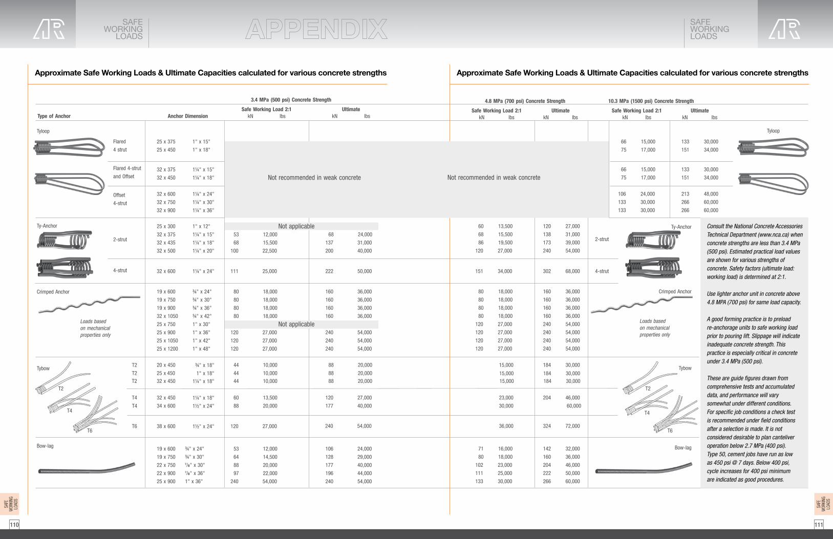
111110
Approximate Safe Working Loads & Ultimate Capacities calculated for various concrete strengths Approximate Safe Working Loads & Ultimate Capacities calculated for various concrete strengths
SAFEWORKING
LOADS
SAFEWORKINGLOADS
Type of AnchorUltimate
kN lbs
68 24,000
137 31,000
200 40,000
222 50,000
160 36,000
160 36,000
160 36,000
160 36,000
240 54,000
240 54,000
240 54,000
88 20,000
120 27,000
177 40,000
240 54,000
106 24,000
128 29,000
177 40,000
196 44,000
240 54,000
Safe Working Load 2:1kN lbs
53 12,000
68 15,500
100 22,500
111 25,000
80 18,000
80 18,000
80 18,000
80 18,000
120 27,000
120 27,000
120 27,000
44 10,000
60 13,500
88 20,000
120 27,000
53 12,000
64 14,500
88 20,000
97 22,000
240 54,000
25 x 375
25 x 450
32 x 375
32 x 450
32 x 600
32 x 750
32 x 900
25 x 300
32 x 375
32 x 435
32 x 500
32 x 600
19 x 600
19 x 750
19 x 900
32 x 1050
25 x 750
25 x 900
25 x 1050
25 x 1200
20 x 450T2
T2
T2T2
T4
T4T4
T6T6
32 x 450
34 x 600
38 x 600
19 x 600
19 x 750
22 x 750
22 x 900
25 x 900
1" x 15"
1" x 18"
1¼" x 15"
1¼" x 18"
1¼" x 24"
1¼" x 30"
1¼" x 36"
1" x 12"
1¼" x 15"
1¼" x 18"
1¼" x 20"
1¼" x 24"
¾" x 24"
¾" x 30"
¾" x 36"
¾" x 42"
1" x 30"
1" x 36"
1" x 42"
1" x 48"
¾" x 18"
88 20,00044 10,00025 x 450 1" x 18"88 20,00044 10,00032 x 450 1¼" x 18"
1¼" x 18"
1½" x 24"
1½" x 24"
¾" x 24"
¾" x 30"7/8" x 30"7/8" x 36"
1" x 36"
Flared
4 strut
Flared 4-strut
and Offset
Offset
4-strut
Anchor Dimension
3.4 MPa (500 psi) Concrete Strength
Tyloop
Ty-Anchor
Crimped Anchor
Tybow
Bow-lag
2-strut
4-strut
Loads basedon mechanicalproperties only
T2
T4
T6
Not recommended in weak concrete
Not applicable
Not applicable
120 27,000
138 31,000
173 39,000
240 54,000
302 68,000
160 36,000
160 36,000
160 36,000
160 36,000
240 54,000
240 54,000
240 54,000
240 54,000
204 46,000
306 60,000
142 32,000
160 36,000
204 46,000
222 50,000
266 60,000
60 13,500
68 15,500
86 19,500
120 27,000
151 34,000
80 18,000
80 18,000
80 18,000
80 18,000
120 27,000
120 27,000
120 27,000
120 27,000
92
9292
184 30,00015,000
184 30,00015,000184 30,00015,000
10223,000
15330,000
162
324 72,00036,000
71 16,000
80 18,000
102 23,000
111 25,000
133 30,000
Tyloop
Ty-Anchor
Crimped Anchor
Tybow
Bow-lag
2-strut
4-strut
Loads basedon mechanicalproperties only
Safe Working Load 2:1kN lbs
66 15,000
75 17,000
106 24,000
133 30,000
133 30,000
66 15,000
75 17,000
133 30,000
151 34,000
133 30,000
151 34,000
213 48,000
266 60,000
266 60,000
UltimatekN lbs
4.8 MPa (700 psi) Concrete Strength
UltimatekN lbs
Safe Working Load 2:1kN lbs
10.3 MPa (1500 psi) Concrete Strength
Not recommended in weak concrete
Consult the National Concrete Accessories Technical Department (www.nca.ca) when concrete strengths are less than 3.4 MPa (500 psi). Estimated practical load values are shown for various strengths of concrete. Safety factors (ultimate load: working load) is determined at 2:1.
Use lighter anchor unit in concrete above 4.8 MPA (700 psi) for same load capacity.
A good forming practice is to preloadre-anchorage units to safe working load prior to pouring lift. Slippage will indicate inadequate concrete strength. This practice is especially critical in concrete under 3.4 MPa (500 psi).
These are guide figures drawn fromcomprehensive tests and accumulateddata, and performance will vary somewhat under different conditions.For specific job conditions a check testis recommended under field conditionsafter a selection is made. It is notconsidered desirable to plan canteliveroperation below 2.7 MPa (400 psi).Type 50, cement jobs have run as lowas 450 psi @ 7 days. Below 400 psi,cycle increases for 400 psi minimumare indicated as good procedures.
SAFE
WOR
KING
LOAD
S
SAFE
WOR
KING
LOAD
S

113112
CONVERSIONTABLE
CONVERSIONTABLE
CONVERSIONS CONVERSIONS
CONVERSION CHARTArea of rectangle = length x widthArea of triangle = base x 1/2 altitudeArea of parallelogram = base x altitudeArea of trapezoid = altitude x 1/2 the sum of parallel sidesCircumference of circle = diameter x 3.1416Diameter of circle = circumference x 0.3183Radius of a circle = circumference x 0.159155Area of a circle = square of diameter x 0.7854
APPROXIMATE WEIGHT OF DRY MATERIALSMaterials Per Per Per Cubic Metre Cubic Yard Cubic FootSand 1600 kg 2700 lbs. 100 lbs.Gravel 1760 kg 3000 lbs. 110 lbs.Crushed Stone 1475 kg 2500 lbs. 92 lbs.Slag 1185 kg 2000 lbs. 74 lbs.Cinders 770 kg 1300 lbs. 48 lbs.Limestone 1715 kg 2900 lbs. 107 lbs.Cement 1505 kg 2550 lbs. 94 lbs.Concrete: Cinder 1361 - 1762 kg 2300 - 3000 lbs. 85 - 110 lbs. Gravel or Limestone 2400 kg 4050 lbs. 150 lbs. Trap Rock 2485 kg 4200 lbs. 155 lbs. Slag 2240 kg 3800 lbs. 140 lbs.
CONCRETE ESTIMATOROne Cubic Metre of Concrete Will Place
Thickness m2 Ft2 Thickness m2 Ft2 Thickness m2 Ft2
25mm (1˝ ) 39.4 424 125mm (5˝ ) 7.9 85 225mm (9˝ ) 4.4 4750mm (2˝ ) 19.7 212 150mm (6˝ ) 6.5 70 250mm (10˝ ) 3.9 4275mm (3˝ ) 13.1 141 175mm (7˝ ) 5.6 60 275mm (11˝ ) 3.6 38100mm (4˝ ) 9.8 106 200mm (8˝ ) 4.8 52 300mm (12˝ ) 3.2 35
METRIC CONVERION FACTORSAPPROX. CONVERSION TO METRIC MEASURES
When You Multiply To Know By FindLengthinches 2.5 centimetresfeet 30.0 centimetresyards 0.9 metresmiles 1.6 kilometres
Areasq. inches 6.5 sq. centimetressq. feet 0.09 sq. metressq. yards 0.8 sq. metressq. miles 2.6 sq. kilometresacres 0.4 hectares
Mass (weight)ounces 28.0 gramspounds 0.45 kilogramsshort tons 0.9 metric ton
Volume (U.S. measure)cubic inches 16.0 millilitresfluid ounces 30.0 millilitrescups 0.24 litrespints 0.47 litresquarts 0.95 litresgallons 3.8 litrescubic feet 0.03 cubic metrescubic yards 0.76 cubic metres
Pressurep.s.f. 47.8802 Pak.s.i. 6.89475 MPaKips 4.44822 kN
TorqueFoot-Pounds 1.35581 Nm
Temperature (exact)°F = °C x 9 +32 5
APPROX. CONVERSION FROM METRIC MEASURES
When You Multiply To Know By FindLengthcentimetres 0.4 inchesmetres 3.3 feetmetres 1.1 yardskilometres 0.6 miles
Areasq. centimetres 0.16 sq. inchessq. metres 10.76 sq. feetsq. metres 1.2 sq. yardssq. kilometres 0.4 sq. mileshectares 2.5 acres
Mass (weight)grams 0.035 ounceskilograms 2.2 poundsmetric ton 1.1 short tons
Volume (U.S. measure)millilitres 0.06 cubic inchesmillilitres 0.03 fluid ounceslitres 0.036 cupslitres 2.1 pintslitres 1.06 quartslitres 0.26 gallonscubic metres 35.0 cubic feetcubic metres 1.3 cubic yards
Pa 0.020885 p.s.f.MPa 0.145 k.s.i.kN 0.2248 Kips
Nm 0.73776 Foot-Pounds
Temperature (exact)°C = (°F - 32) x 5 9

115114
CONVERSIONTABLE
CONVERSIONTABLE
CONVERSIONS CONVERSIONS
CONVERSIONSSurface d’un rectangle = longueur x largeurSurface d’un triangle = base x 1/2 hauteurSurface d’un parallélogramme = base x hauteurSurface d’un quadrilatère irrégulier = hauteur x la 1/2 de la somme des côtés parallèlesCirconférence d’un cercle = diamètre x 3.1416Diamètre d’un cercle = circonférence x 0.3183Rayon d’un cercle = circonférence x 0.159155Surface d’un cercle = carré du diamètre x 0.7854
POIDS APPROXIMATIF DES MATÉRIAUX SECSMatériaux Par Par Par mètre cube verge cube pied cubeSable 1 600 kg 2 700 lb 100 lbGravier 1 760 kg 3 000 lb 110 lbPierre concassee 1 475 kg 2 500 lb 92 lbScories 1 185 kg 2 000 lb 74 lbMâchefer 770 kg 1 300 lb 48 lbChaux 1 715 kg 2 900 lb 107 lbCiment 1 505 kg 2 550 lb 94 lbBéton: mâchefer 1 361 - 1 762 kg 2 300 - 3 000 lb 85 - 110 lb gravier ou chaux 2 400 kg 4 050 lb 150 lb basalte 2 485 kg 4 200 lb 155 lb scories 2 240 kg 3 800 lb 140 lb
ESTIMATION POUR BÉTONUn mètre cube de béton couvrira
Épaisseur m2 pi2 Épaisseur m2 pi2 Épaisseur m2 pi2
25mm (1 po) 39.4 424 125mm (5 po) 7.9 85 225mm (9 po) 4.4 4750mm (2 po) 19.7 212 150mm (6 po) 6.5 70 250mm (10 po) 3.9 4275mm (3 po) 13.1 141 175mm (7 po) 5.6 60 275mm (11 po) 3.6 38100mm (4 po) 9.8 106 200mm (8 po) 4.8 52 300mm (12 po) 3.2 35
FACTEURS DE CONVERSIONS MÉTRIQUESCONVERSIONS APPROXIMATIVES JUSQU’AUX MESURES MÉTRIQUES
Si vous Mult. pour trouver connaissez parLongueurles pouces 2.5 les centimètresles pieds 30.0 les centimètresles verges 0.9 les mètresles milles 1.6 les kilomètres
Surfaceles pouces carrés 6.5 les centimètres carrésles pieds carrés 0.09 les mètres carrésles verges carrés 0.8 les mètres carrésles milles carrés 2.6 les kilomètres carrésles acres 0.4 les hectares
Poids (masse)les onces 28.0 les grammesles livres 0.45 les kilogrammesles tonnes courtes 0.9 les tonnes métriques
Volumeles pouces cubes 16.0 les millilitresles onces liquides 30.0 les millilitresles tasses 0.24 les litresles chopines 0.47 les litresles pintes 0.95 les litresles gallon 3.8 les litresles pieds cubes 0.03 les mètres cubesles verges cubes 0.76 les mètres cubes
Pressionlb/po 47,8802 Pak/po 2 6,89475 MPaKip 2 4,44822 kN
Torquelivre-pied 1.35581 Nm
Température (exacte)°F = °C x 9 +32 5
CONVERSIONS APPROXIMATIVES À PARTIR DES MESURES MÉTRIQUES
Si vous Mult. pour trouver connaissez parLongueurles millimètres 0.04 les poucesles centimètres 0.4 les poucesles mètres 3.3 les piedsles mètres 1.1 les vergesles kilomètres 0.6 les milles
Surfaceles centimètres carrés 0.16 les pouces carrésles mètres carrés 10.76 les piedsles mètres carrés 1.2 les verges carrésles kilomètres carrés 0.4 les milles carrésles hectares 2.5 les acres
Poids (masse)les grammes 0.035 les oncesles kilogrammes 2.2 les livresles tonnes métriques 1.1 les tonnes courtes
Volumeles millilitres 0.06 les pouces cubesles millilitres 0.03 les onces liquidesles litres 0.036 les tassesles litres 2.1 les chopinesles litres 1.06 les pintesles litres 0.26 les gallonsles mètres cubes 35.0 les pieds cubesles mètres cubes 1.3 les verges cubes
Pa 0,020885 lb/poMPa 0,145 k/po 2
kN 0,2248 kip 2
Nm 0,73776 livre-pied
Température (exacte)°C = (°F - 32) x 5 9

117116
Heavy Wall Light Wall
Up to 12" ID Pour at any convenient rate
Up to 24" ID 18 ft/hour 15 ft/hour
Up to 36" ID 11 ft/hour 9 ft/hour
Up to 42" ID 7 ft/hour 6 ft/hour
Up to 48" ID 6 ft/hour 5 ft/hour
Murs Lourds Murs Léger
Jusqu'à 12" ID Verser à n'importe quel taux convenable
Jusqu'à 24" ID 18 ft/heure 15 ft/heure
Jusqu'à 36" ID 11 ft/heure 9 ft/heure
Jusqu'à 42" ID 7 ft/heure 6 ft/heure
Jusqu'à 48" ID 6 ft/heure 5 ft/heure
Tube DiameterCubic Yards Concrete per
Foot of Column Height
6" .0073
8" .0129
10" .0202
12" .0291
14" .0396
16" .0571
18" .0654
20" .0808
22" .0978
24" .1164
26" .1368
28" .1584
30" .1818
36" .2618
48" .4654
Diamètre du TubeCubic Yards Béton par
ft de hauteur de colonne
6" .0073
8" .0129
10" .0202
12" .0291
14" .0396
16" .0571
18" .0654
20" .0808
22" .0978
24" .1164
26" .1368
28" .1584
30" .1818
36" .2618
48" .4654
CONCRETEPOURING
RATE
CONCRETEPOURINGRATE
Round Fibre Forming Tube - Pouring Rate Tube de Formation de Fibres Rondes - Taux de Coulée
Slump should not exceed 6" - max. pour hight on light wall - 12 ft La profondeur ne doit pas dépasser 6 "- max. verser la hauter sur un mur léger - 12 ft
For total concrete requirements per column: take figure beside diameter of tube and multiply by column height.
Pour les besoins totaux en béton par colonne:Utiliser la figure à côté du diamètre du tube et multiplier
par la hauteur de colonne.
CONCRETE REQUIREMENTS BÉTON EXIGENCES
SUGGESTED RATE OF POUR - PER HOUR TAUX DE DIFFUSION SUGGÉRÉ - PAR HEURE

119118
GENERAL INFORMATION
1. A qualified person must accurately calculate the applied loads and select the appropriate form tying products and determine compatible tie spacings.2. In form tying operations, proper installation practices must be maintained. Failure to follow approved practices, such as missing form ties, misalignment of form ties, incorrect form tie lengths, excessive pour rates, etc., can cause form failure.3. AR recommends the user of the information contained herein and the installer of our products adhere to the Canadian Standards Association CAN /CSA - S269.3 -M92 Concrete Formwork and American Concrete Institute -ACI 347 Guide to Formwork. The applied safety factor for a product will depend on the degree of hazard or risk involved in the product application. This safety factor is governed by National Codes, local codes and / or by design professionals. With regards to concrete construction, onsite conditions such as, poor concrete placing technique, concentrated loads on the formwork, improper use of cranes or concrete pumping could increase the degree of risk. If such site conditions exist, the user must increase the safety factor to compensate. For most applications AR suggests a minimum 2:1 safety factor for hanging accessories and stresses that this safety factor should be strictly adhered to or the application be reviewed by a design professional. The material included in this publication indicate the safety factor for convenience but also provides the ultimate capacities so other safety factors may be used where applicable. WARNING: Improper, careless and/or haphazard use of the products shown in this document can expose workers to extreme danger, injury and death. If uncertain about installations or use of any AR product, contact the nearest AR Sales office or Technical Department for explanations and/or recommendations. National Concrete Accessories products are manufactured according to strict specifications and are subject to numerous testsunder a stringent quality control program. These products are designed to be capable of meeting or exceeding all necessary safety requirements for the concrete construction and forming industry. All product test data shown, were obtained through an independent testing facility or tests conducted by AR. However, the performance of a quality product can be affected by the manner in which it is used in the field. Therefore, the following precautions should be taken by all involved persons.4. To avoid crushed wales and/or bent Tyholders when using a double waler system, maintain a spacing between the walers comparable to the tie diameter being used plus 13 mm (1/2”).5. Any welding should be performed by a certified welder. Bending or welding of high tensile steel products should not be permitted. Welding of precast accessories can be dangerous and should not be. Note: AR does not warrant any product that has been welded, altered or modified in any way after leaving an AR plant or warehouse. After final inspection of location and alignment, telltale devices should be installed in strategic places on the formwork to facilitate detection of formwork movement during concrete placement. During concrete placement, the formwork should be continuously monitored by competent persons. These monitors should have a reasonable area of safety and a means of communicating problems or emergencies to the placement crew.6. Never exceed listed product approximate safe working loads. Note that all product load ratings shown in this bulletin are ratings for new or “as new” products only. Extreme caution must be exercised when using any product that is in other than new condition. Any reusable product that shows wear, misuse, overloading, corrosion or any other factor that would compromise its approximate safe working load should be discarded.7. Caution must be exercised when using washer devices to span double wales. Waler gaps are excessive when the washer device does not bear directly on the primary waler members.8. AR products are not to be applied or installed until the user and/or the installer has a clear understanding of the information contained within the appropriate product publication. All contractors must instruct their employees in the appropriate use and installation of AR products. To avoid injury and possible form tie problems DO NOT CLIMB ONFORM TIES. Over-vibration or re-vibration will cause lower concrete to remain in a liquid state for an extended period of time. This can cause excessive lateral form pressure and possible form failure Plumbing of the form, after concrete placement, should not be attempted. It is virtually impossible to force a form back into position if it is misaligned or has bulged during concrete placement. Runways for moving equipment should be provided with struts or legs as required and be supported directly on the formwork or structural member. Formwork must be suitable to support such runways without intolerable deflection, vibration or lateral movement.9. Do not interchange products supplied by other manufacturers with those supplied by AR. AR cannot guarantee that products supplied by others will be compatible and/or interchangeable with AR’s quality concrete accessories.10.Drawings and/or sketches shown in this bulletin are for illustrative purposes only. Check actual forming conditions for specific applications. Metric values listed are a soft conversion of imperial values.
GENERALINFORMATION
GENERALINFORMATION
GENERAL INFORMATION
PRODUCT SAFETY AND INSTALLATIONThe approximate safe working loads included in this publication were established based on all items are new or “as new” condition. Inserts are installed correctly and embedded in sound concrete suited for the application so that the vertical axis of the insert is perpendicular to the lifting surface. Installed hardware shall have full bearing on the concrete surface. Caution must be taken to prevent side loading which will cause additional stresses. Attachment and erection bolt must be installed using the proper length and penetration to prevent hardware accessories from slippage or bending. Caution must be observed and loads not imposed until such time as the concrete strength has reached the specified strength required for the insert. Inserts must be properly situated in relation to the edge, corner andopenings so as to achieve the full capacity of concrete shear cone. The tensile loads applied to the insert included both axial and transverse loads transferred to the hardware from crane cables. Impact wrenches are not to be used for pre cast elements. Welding may cause embrittlement and could result in sudden failure. A metallurgical engineer must approve the process prior to any welding is undertaken. AR will not warrantee any modification or alterationsmade to its products.
SAFETY FACTORThe following chart is the suggested Safety Factors used by industry standard for the degree of risk for the application. For the precast industry, the degree of risk involved can increase because of the adhesion to theform, jerking movement, transportation over rough terrain or roads. Safety Factors should be increase to suit the conditions. The minimum Safety Factors as suggested by OSHA (Occupational Safety and Health Administration), ANSI (American National Standards Institute and the CPCI (Canadian Precast Prestress Concrete Institue) is as followed:
SAFETY FACTOR INTENDED PRODUCT USE2 to 1 Brace Anchors3 to 1 Permanent Connection4 to 1 Insert used for lifting and handling5 to 1 Hardware used for lifting and handling
For Safety Factors requirement that are different than included in this publications, approximate safe working loads must be adjusted by the user. The following equation is used to increase or reduce the approximate safe working load by the following: SWL + Publication Factor of Safety = New approximate safe working load Required Factor of Safety.
The information contained herein supersedes all previous versions printed prior to this edition and is based on data and knowledge considered true and accurate. AR reserves the right to update information without notice. Please read all statements, recommendations or suggestions in conjunction with AR’s condition of sale which apply to all goods supplied by AR. No statement, recommendations or suggestions is intended for any use that would infringeany patent or copyright.
NOTE: For applications not specifically identified herein, approval in writing is required by the AR Technical Department for special applications and uses of AR products.

120
Acrow Richmond specializes in manufacturing hardware and accessories for the concrete construction industry. With our in-house engineering departments and over 100,000 square feet dedicated to manufacturing, we produce high quality Canadian made products.
We manufacture a full line of:
· Concrete forming hardware products for a wide range of forming systems· Preset Anchoring systems ranging from street signs to high mast light systems· Precast products for forming, lifting and connecting· Rock Bolts for reinforcing severe slopes and tunnels· Bridge deck forming hardware
In addition to a full line of traditional configurations and sizes, we offer custom fabrication services to meet the most demanding specifications or creative designs. Our team of experts can work with your project drawings to provide cost effective solutions that meet your load demands.
AR strives to be your first and only call for all of your construction needs.
You can find Acrow-Richmond products on all National Concrete Accessories branches across Canada.
For catalogue updates go to:www.nca.ca
Contact us at: [email protected]
@NationalConcreteAccessories
Version 3 - August 2018
Social icon
Rounded squareOnly use blue and/or white.
For more details check out ourBrand Guidelines.