Container forming modeling - meaagg
29
Container forming modeling: Sensitivity to boundary conditions, material properties, and underlying physics modelling Matthew Hyre, Ph.D. University of Northwestern, St. Paul
-
Upload
khangminh22 -
Category
Documents
-
view
0 -
download
0
Transcript of Container forming modeling - meaagg

Container forming modeling:
Sensitivity to boundary conditions,
material properties, and underlying
physics modelling
Matthew Hyre, Ph.D.
University of Northwestern, St. Paul
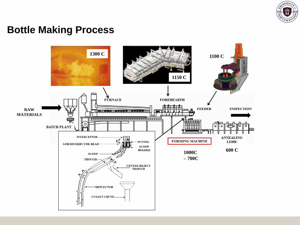
1300 C
1150 C
1100 C
1000C
– 700C
600 C
RAW
MATERIALS
Bottle Making Process

Gob Forming Models
Working End/Forehearth Feeder
Gob Creation at FeederGob Transfer to Blank Mold

Container Forming Modeling
Parison Pressing Inverted Reheat
Invert Reheat/Stretch Final Blow
Gob Loading

Goals of Container Forming Modeling Effort
• Inverse parison design
• Improved blank mold design and cooling strategies
• Investigation of problem areas during forming process:
• Large variation in container thickness
• Non-uniform temperature distribution
• Poor parison design
• Determine regions of high stress intensity
• Evaluate sources of high stress intensities and develop
strategies to eliminate regions of potential check
formation

Press & Blow Forming Process

Mold/Plunger Side Heat Transfer

Typical Container Forming Model

3.00
2.50
2.00
1.500 40 80 120 160
Th
ickn
ess,
mm
Distance from Neckring, mm
Container Forming Model – Beer

Typical Bottles Previously Simulated
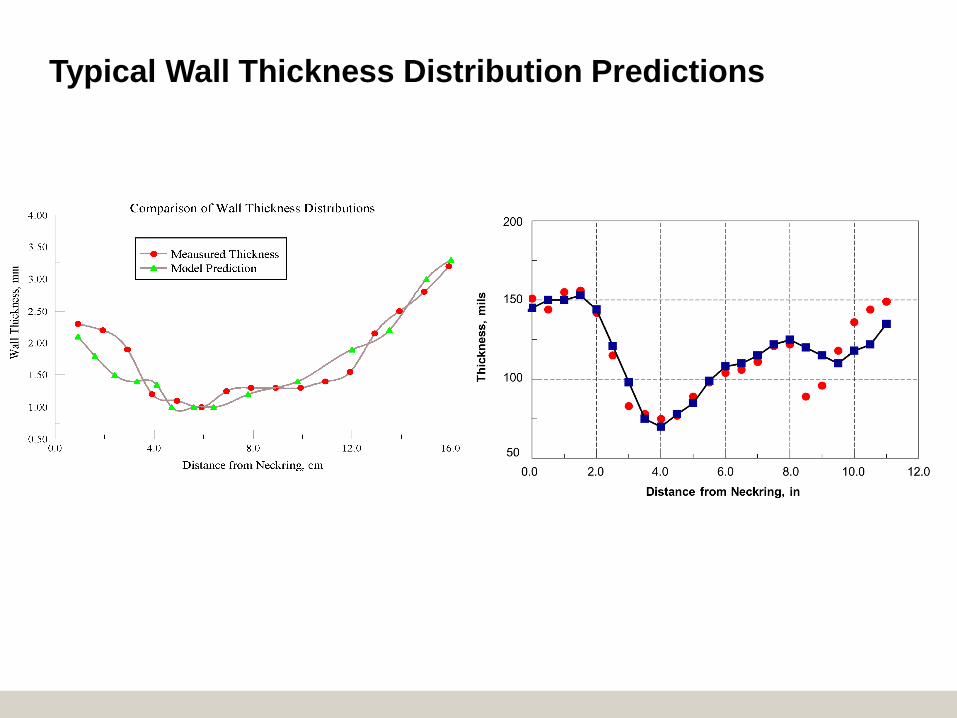
Typical Wall Thickness Distribution Predictions

Why Doesn’t it Always Work…?

Outstanding Forming Modeling Issues
• Fundamental understanding of glass/mold heat transfer
and the effects of mold lubricants
• Accurate material properties
• Numerical limits (mesh size/time step)
• Fluid dynamic (“slip”) condition at the glass mold interface
• Radiation modeling during forming
• Viscoelastic stress development and defect formation

Heat Transfer Boundary Conditions
• Perfect contact between mold and glass
• Heat transfer coefficient between glass and mold is constant
• Heat transfer coefficient usually based on overall heat balance rather
than local conditions
Most studies assume a combination of the following:
Perfect Contact
Assumption
Constant Contact
Conductance
Assumption

Glass/Mold Heat Transfer: Heat Flux Correlations
71 10
61 10
51 100 0.75 1.51.2 1.351.050.90.60.450.30.15
Heat F
lux (
W/m
2)
Time (seconds)

Glass/mold contact conductance experimentally
modeled and includes the effects of:
Heat Transfer Measurements
• Glass pressure
• Glass color
• Initial glass temperature
• Initial mold temperature
• Mold type
– (cast iron vs. Al-Br)

Governing Equation for Data Reduction
Assumptions
• Radial conduction much greater than axial or circumferential conduction
• Radiation is a diffusive process and can be included in an effective conductivity
• Plunger side heat transfer does not affect mold side heat transfer
One-dimensional Transient Heat Conduction Equation in Radial Coordinates
1( ) ( ) ( ) ( )p
T T TT C T k T k T
t r r r r
1
Temperature
Dependent
Properties
2
Interfacial Heat
Transfer
Coefficient
3
Time-varying
Heat Transfer
Coefficient
4
Discrete
Ordinates
Model for
Radiation
5
Plunger/air
convective
effects
6
Initial Mold
Temperature
Profile
Important Effects to
Include in Data
Reduction

Measured Material Properties
• Glass Viscosity
– Modified WLF equation including Simmon’s correlation for shear
thinning and generalized White-Metzner viscoelastic model
• Specific Heat of Glass
– Correlated vs. composition and temperature from 1500 K down to
300 K
• Glass Thermal Conductivity (Radiative Conductivity)
– Surface fit for glass thickness and temperature for various types of
glasses (flint, amber, dark green, etc.)
• Glass Thermal Expansion
– Curve fit as a function of temperature
• Glass Surface Tension
– Curve fit as a function of temperature

Glass Thickness Sensitivity to Parameter Input - NNPB
Most Sensitive Parameters:
• Glass specific heat
• Glass/blank heat transfer
coefficient
• Glass radiative properties
• Plunger heat transfer
coefficient
Most Sensitive Parameters:
• Gob temperature
• Blank temperature
• Plunger temperature
• Baffle temperature
The material properties were changed by ± 20%, and the
temperature parameters were changed by ±50 degrees to test
glass thickness sensitivity.
NNPB Material Property/Boundary
Condition Sensitivity
NNPB Temperature Sensitivity

Boundary Condition/Material Property Sensitivity
Analysis
1 Glass Specific Heat
2 Gob Temperature
3 Blank Temperature
4Glass/Blank Heat Transfer
5 Radiation modeling
6 Plunger Temperature
7 Glass/Plunger Heat Transfer

Forming Modeling Sensitivity Studies – Max Mesh Size
Min Size =
0.1*Max size
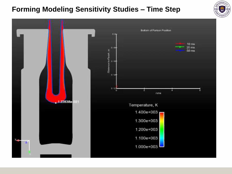
Forming Modeling Sensitivity Studies – Time Step

Still Missing
• Good data and physical model of glass/metal slip
• Studies on radiation model requirements:
– Effective conductivity vs. semi-transparent models
– Single or multi-banded

Initial Radiation Studies – DOM vs. Effective
Conductivity
• Using the diffusion approximation resulted in an error in the prediction of reheat stretch time of 41 percent compared to 13 percent using the DOM model.
• There was an increase in heat transfer from the glass to the mold using the DOM model.
• Differences in final container thickness were not large if reheat/stretch times adjusted to account for decreased heat transfer in keff.
• Inclusion of the radiative properties using the DOM/VOF approach is very computationally expensive.
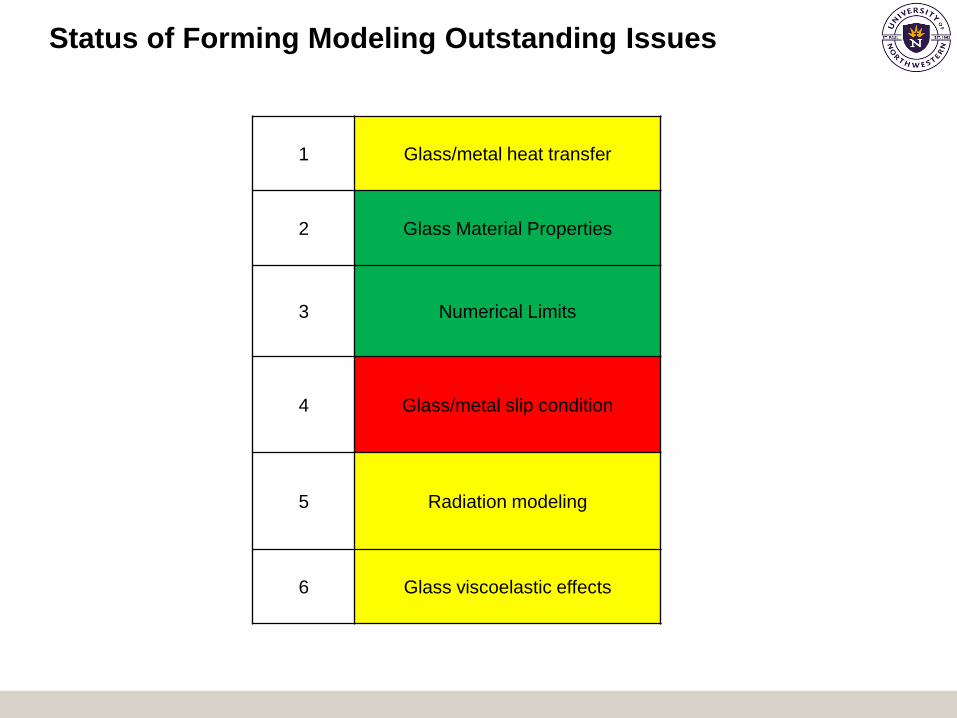
Status of Forming Modeling Outstanding Issues
1 Glass/metal heat transfer
2 Glass Material Properties
3 Numerical Limits
4 Glass/metal slip condition
5 Radiation modeling
6 Glass viscoelastic effects

So where is this all going now…?
Bottle
Analyzed –
300 mL
Longneck

Automated Parameter Changes

Glass Volume and Standard Deviation of Side
Wall Thickness Distribution vs. Design Iteration

Conclusions
• There are still no reliable physics based models for glass/mold heat transfer or
slip conditions that exist. All forumulations are semi-empirical at best.
• Forming models require intelligent input and evaluation. Too much process
variability exists for «canned» solutions.
• Forming models ultimately must be linked with mold and plunger cooling
models in order to complete forming process picture.
• Feeder and delivery equipment heat losses continue to be problemmatic in
developing accurate forming solutions.
• Even if forming models provide a «solution», it does not mean that they will
point to the correct direction in terms of mold cooling or parison design.
• However...we are getting closer.