Upgrading Missouri Transportation Infrastructure: Solid Reinforced-Concrete Decks Strengthened with...
15
Alkhrdaji, T., Nanni., A., Chen, G., and Barker, M. "Upgrading The Transportation Infrastructure: Solid RC Decks Strengthened with FRP," Concrete International: Design and Construction, Vol. 21, No.10, Oct. 1999, pp. 37-41. 1 UPGRADING THE TRANSPORTATION INFRASTRUCTURE: SOLID RC DECKS STRENGTHENED WITH FRP Tarek Alkhrdaji, Antonio Nanni, Genda Chen, and Michael Barker Introduction Nation growth and economical prosperity are closely related to the adequacy of the transportation infrastructure. Bridges, in particular, are considered one of the critical components of the transportation infrastructure. The National Research Board reports that, in the United States, there are approximately 590,000 structures in the National Bridge Inventory database (1). About 33% of theses bridges are either structurally deficient or functionally obsolete or both. Many US bridges are made of reinforced concrete and were designed in accordance to older codes to accommodate traffic loads smaller than currently permitted. Most of these bridges were designed for gravity loads only with no consideration to seismic vulnerability. At present, many of these bridges are structurally and functionally deficient. However, it may be economically unfeasible to replace every outdated bridge across the country. In addition, design and construction of new bridges requires time and causes significant traffic disturbance. A potential solution is the use of new technologies that allow for the upgrading of deficient bridges with minimal users’ inconvenience. To this extent, strengthening systems that utilize advanced composite materials (i.e., fiber reinforced polymer or FRP systems) in the form of “external” reinforcement may be of great interest to the civil engineering community. Laboratory tests are usually conducted on scaled down specimens that do not account for the boundary conditions of the structure. Field tests, on the other hand, demonstrate the actual behavior of a structure and can lead to a better strengthening design. To provide the necessary field verification of design methods and failure modes and capacities, a research program was tailored to investigate the behavior of a full-scale bridge strengthened with FRP composites systems. The program included the testing to failure of the strengthened decks and the seismically upgraded piers. The research program was tailored to investigate the behavior of an existing bridge with and without FRP strengthening in order to provide necessary field verifications of design method, structural performance, and failure mode. Bridge J857 was decommissioned and was scheduled for demolition. This allowed for the testing to failure of the strengthened decks and the seismically upgraded piers. Bridge J857 Bridge J-857 was located on Route 72 in Phelps County-Missouri, approximately 8 miles (13 km) east of Rolla. The bridge was built during the 1930’s and represented the typical conditions of many existing bridges in the Mid-America region. Due to the realignment
Transcript of Upgrading Missouri Transportation Infrastructure: Solid Reinforced-Concrete Decks Strengthened with...

Alkhrdaji, T., Nanni., A., Chen, G., and Barker, M. "Upgrading The Transportation Infrastructure: Solid RC Decks Strengthened with FRP," Concrete International: Design and Construction, Vol. 21, No.10, Oct. 1999, pp. 37-41.
1
UPGRADING THE TRANSPORTATION INFRASTRUCTURE:
SOLID RC DECKS STRENGTHENED WITH FRP
Tarek Alkhrdaji, Antonio Nanni, Genda Chen, and Michael Barker
Introduction Nation growth and economical prosperity are closely related to the adequacy of the transportation infrastructure. Bridges, in particular, are considered one of the critical components of the transportation infrastructure. The National Research Board reports that, in the United States, there are approximately 590,000 structures in the National Bridge Inventory database (1). About 33% of theses bridges are either structurally deficient or functionally obsolete or both. Many US bridges are made of reinforced concrete and were designed in accordance to older codes to accommodate traffic loads smaller than currently permitted. Most of these bridges were designed for gravity loads only with no consideration to seismic vulnerability. At present, many of these bridges are structurally and functionally deficient. However, it may be economically unfeasible to replace every outdated bridge across the country. In addition, design and construction of new bridges requires time and causes significant traffic disturbance. A potential solution is the use of new technologies that allow for the upgrading of deficient bridges with minimal users’ inconvenience. To this extent, strengthening systems that utilize advanced composite materials (i.e., fiber reinforced polymer or FRP systems) in the form of “external” reinforcement may be of great interest to the civil engineering community. Laboratory tests are usually conducted on scaled down specimens that do not account for the boundary conditions of the structure. Field tests, on the other hand, demonstrate the actual behavior of a structure and can lead to a better strengthening design. To provide the necessary field verification of design methods and failure modes and capacities, a research program was tailored to investigate the behavior of a full-scale bridge strengthened with FRP composites systems. The program included the testing to failure of the strengthened decks and the seismically upgraded piers. The research program was tailored to investigate the behavior of an existing bridge with and without FRP strengthening in order to provide necessary field verifications of design method, structural performance, and failure mode. Bridge J857 was decommissioned and was scheduled for demolition. This allowed for the testing to failure of the strengthened decks and the seismically upgraded piers. Bridge J857 Bridge J-857 was located on Route 72 in Phelps County-Missouri, approximately 8 miles (13 km) east of Rolla. The bridge was built during the 1930’s and represented the typical conditions of many existing bridges in the Mid-America region. Due to the realignment

Alkhrdaji, T., Nanni., A., Chen, G., and Barker, M. "Upgrading The Transportation Infrastructure: Solid RC Decks Strengthened with FRP," Concrete International: Design and Construction, Vol. 21, No.10, Oct. 1999, pp. 37-41.
2
of Route 72, the bridge was decommissioned in December 1998 and scheduled for demolition. Upon field inspection during the summer of 1998, the bridge was found in good condition (e.g., no corrosion of reinforcement or concrete spalling) and presented an excellent opportunity for in-situ testing to failure after strengthening with FRP composites. Bridge J-857 spanned a small, rocky creek bed. Water does not flow continually, but only when there has been precipitation upstream. The bed consists of sandy and rocky patches interspersed with areas of solid rock. The bridge consisted of three simply supported solid RC decks having a thickness of 18 in. (460 mm) and a roadway width of 25 feet (7.6 m). Each of the three decks spanned 26 ft (7.9 m). The original plans of the bridge (later confirmed by inspection) indicated that the decks were reinforced with #8 (25 mm) deformed steel bars at 5 in. (127 mm) on-center in the longitudinal direction, and #4 (13 mm) deformed steel bars at 18 in. (457 mm) on-center in the transverse direction. The two abutments and the two bents supporting the decks were at a 15-degree skew angle with respect to the roadway alignment. Each bent consisted of two piers connected at the top by a RC cap beam. The piers had a 2 by 2 ft (0.6 by 0.6 m) square cross-section and were reinforced with four #6 (19 mm) deformed steel bars located at the corners of the cross section. The transverse reinforcement was made of #2 (6 mm) steel ties at 18 in. (457 mm) spacing. Contrary to dimensions shown in the original drawings, the actual height of the four piers varied from a minimum of 6 ft (1.8 m) to a maximum of 11 ft (3.4 m). All piers were supported by spread footings with dimensions of 4 by 4 by 2.5 ft (1.2 by 1.2 by 0.75 m). The parapets were made of reinforced concrete segments that were 2.5 ft (0.76 m) in height and run the entire length of the bridge. Bridge dimensions were verified through field inspection. Steel reinforcement size and spacing and concrete cover thickness were verified using a bar locator. The material properties used in the preliminary analysis were based on the values recommended by MoDOT database (2). After completion of the structural tests, cores and reinforcements samples were collected and tested in the laboratory for material verification. According to preliminary calculations with the original bridge dimensions and reinforcing schedule, the moment and shear capacities of bridge deck were 78.5 k-ft/ft (349 kN-m/m) and 19 k/ft (277 kN/m), respectively. The bridge piers were originally designed for gravity loads. This paper only reports the strengthening and testing of the bridge decks. Bridge Decks Strengthening The bridge was strengthened in August of 1998 while in service. Bridge upgrading was rapid with no interruption of traffic. A crew of three workers carried out the installation of FRP reinforcement over a period of seven working days.

Alkhrdaji, T., Nanni., A., Chen, G., and Barker, M. "Upgrading The Transportation Infrastructure: Solid RC Decks Strengthened with FRP," Concrete International: Design and Construction, Vol. 21, No.10, Oct. 1999, pp. 37-41.
3
A decision was made to strengthen two of the three decks using two different FRP systems, while the third deck was left as a benchmark. The two FRP systems were externally bonded FRP sheets and near-surface mounted (NSM) FRP rods. Externally bonded FRP sheets installed by wet lay-up is a relatively common strengthening technique already implemented in many projects worldwide (3). Strengthening with near-surface mounted FRP rods, on the other hand, is a more recent and undocumented method. This technique involves the embedment of FRP rods in grooves cut into the concrete surface. The rods are bonded using an epoxy-based paste. Appropriately spaced wedges hold the rods in place until the epoxy cures. This technique provides benefits similar to those of externally bonded FRP sheets with some additional advantages: ability of anchoring the reinforcement into adjacent RC members, minimal surface preparation work, and rapid installation time. The NSM reinforcement considered in this project consisted of carbon fiber reinforced polymer (CFRP) rods with smooth surface roughened by sandblasting to improve bond properties. The rods were made of 48K continuous PAN carbon fibers tows at 63.6% volume fraction and 12K continuous PAN carbon fibers tows at 1.8% volume fraction in an epoxy resin matrix of 34.6% volume fraction. The fibers and the neat resin had a tensile strength of 11.0 ksi (76 MPa) and 525 ksi (3.62 GPa) and a modulus of 453 ksi (3.12 Gpa) and 33000 ksi (228 Gpa), respectively. The mechanical characteristics of the CFRP rods and sheets used in this project are given in Table 1.
Table 1. Material Characteristics
FRP Type Dimension
(in) [mm]
Design Strength (ksi)
[MPa]
Design Strain (in/in or mm/mm)
Tensile Modulus (ksi)
[GPa]
Carbon sheets*
Thickness tf = 0.0065
[0.165]
550 [3800] 0.017 33,000
[228]
Carbon rods**
D = 7/16 [11]
180 [1240] 0.0105 17,200
[119] * Fiber properties ** Rod properties
Two decks of the bridge were designed to be strengthened to the same level of nominal capacity using the two techniques mentioned above (see Table 2). Strengthening to about 30% of the nominal moment capacity was desirable to upgrade the bridge decks for HS20-modified truck load.
Table 2. Design Characteristics Required Nominal Capacity
(k-ft/ft) [ kN-m/m ] Computed Capacity
(k-ft/ft) [ kN-m/m] HS 20 HS 20 mod.
Desired Flexural Capacity
(k-ft/ft) [ kN-m/m] 78.5 [349]
91.1 [405.1]
101.6 [452]
101.7 [452.3]
% Over Computed Capacity +16% +29% +30%

Alkhrdaji, T., Nanni., A., Chen, G., and Barker, M. "Upgrading The Transportation Infrastructure: Solid RC Decks Strengthened with FRP," Concrete International: Design and Construction, Vol. 21, No.10, Oct. 1999, pp. 37-41.
4
Based on this approach, the design of externally bonded sheets called for eight, 20-in (500 mm) wide, single-ply CFRP strips to be applied to the deck soffit. The strips were evenly spaced over a width of 25 ft (8.2 m) and ran the entire length of the deck, as shown in Figure 1. Prior to the CFRP sheets installation, the concrete surface was prepared according to manufacturer’s specifications. Laitance and dirt that could interfere with the bond of the CFRP were removed by abrasive blasting. Bug holes and small surface voids were exposed prior to filling with epoxy filler. CFRP sheets were installed by the wet lay-up procedure (see Figure 2). Pull-off tests were conducted as a quality control measure to ensure adequate bond with the concrete. The design called for 20 NSM CFRP rods spaced at 15 in. (375 mm) on-center. The rods were embedded in 20 ft (6.6 m) long, ¾” (19 mm) deep, and 9/16” (14 mm) wide grooves cut onto the soffit of the bridge deck parallel to its longitudinal axis, as shown in Figures 1 and 3. The grooves were sand blasted to remove dust and any loose materials that could interfere with the bond between epoxy paste and concrete. For all decks, electrical strain gages and fiber optics sensors were applied to concrete, steel reinforcement and FRP reinforcement to monitor strain during testing. Bridge Decks Testing Before and after strengthening, the decks were tested under the weight to a moving vehicle. The test was repeated after saw cutting of parapets and cleaning of the joints. This portion of the research program is not discussed here. Each of the three decks was tested to failure by applying quasi-static load cycles. The load was incremented gradually for the successive cycle until failure of the deck was achieved. Four 200-kips (90-tons) hydraulic jacks were used to apply the static load, as shown in Figure 4. The jacks rested on the bridge deck and pulled against two steel girders made of two W36x150 standard steel shapes, which reacted against the cap beams as shown in Figure 5. The test set-up can, therefore, be described as a close loop. For the case of end decks, two rectangular holes were cut in each of the abutments to accommodate the ends of the steel girders, as shown in Figure 6. Bridge RC parapets were saw cut at 6 ft interval to eliminate their contribution to deck stiffness. Filler material in deck joints was removed to prevent continuity of the decks. Deck deformations as well as strain in the steel bars, CFRP bars and CFRP sheets were measured at different locations. Results and Discussion The mode of failure of each deck was dependent on the strengthening scheme. For the deck with NSM rods, failure was initiated by the rupture of some CFRP rods at the location of the widest crack. The failure mode of the deck strengthened with CFRP sheets was a combination of rupture and peeling of the sheets. As for the third deck, the

Alkhrdaji, T., Nanni., A., Chen, G., and Barker, M. "Upgrading The Transportation Infrastructure: Solid RC Decks Strengthened with FRP," Concrete International: Design and Construction, Vol. 21, No.10, Oct. 1999, pp. 37-41.
5
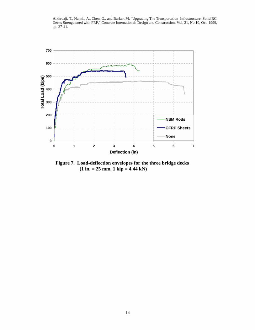
classical mode of failure of yielding of steel reinforcement followed by the crushing of concrete at ultimate was attained. The deck strengthened with NSM rods showed the highest capacity with a failure load of 596 kips (2649 kN), while the deck strengthened with CFRP sheets had a capacity of 543 kips (2413 kN) and a capacity of 462 kips (2053 kN) for the unstrengthened deck. Figure 7 shows the load-deflection curves for the three decks. This figure indicates that some trade off exists between the maximum capacity and the maximum deflection. At service levels (i.e., before the yielding of the steel reinforcement), both decks strengthened with FRP composites had higher stiffness and than the unstrengthened deck. Test results indicate that the measured ultimate capacity of the unstrengthened deck is about 46% higher that the initial prediction based on the material properties obtained from the DOT database. Comparing the field performance of strengthened vs. unstrengthened decks, it was found that the increase in the moment capacity were 17% and 27% for CFRP sheets and NSM CFRP rods, respectively. The contribution of FRP strengthening to the capacity of the member can be shown by comparing the load-strain relationship for steel reinforcement of the three decks, as shown in Figure 8. In this diagram, each curve has a different starting point depending on the level of residual strain accumulated during the previous load cycles. The cycles shown are the ones for which a maximum load of about 350 kips (1555 kN) was attained for the first time. It is apparent that the strain in the steel reinforcement for the strengthened decks is significantly smaller than that measured on the unstrengthened deck at the same location. For the unstrengthened deck, yielding of the steel occurred at a load of approximately 340 kips (1510 kN). Conclusions This article reports one portion of a research program aimed to demonstrate, through in-situ testing, the strengthening performance of a bridge upgraded using FRP composites. Two of the three decks of the bridge were strengthened with NSM FRP rods and externally bonded FRP sheets. Preliminary examination of the test results for the three decks clearly indicates the successful performance of both strengthening FRP systems. The strengthened decks had smaller deflections and higher load capacity at ultimate than the un-strengthend deck. The contribution of the strengthening system to the nominal capacity was less than originally predicted due to the significantly higher strength of the benchmark. In addition to the tests to failure described here in, the following experiments were performed: • The decks were tested elastically with a moving vehicle before and after
strengthening as well as after cutting the RC parapets and cleaning bridge joints. • Between the quasi-static loading cycles, the decks were excited with a dynamic
shaker in an attempt to correlate the level of damage to the natural frequency of the decks.

Alkhrdaji, T., Nanni., A., Chen, G., and Barker, M. "Upgrading The Transportation Infrastructure: Solid RC Decks Strengthened with FRP," Concrete International: Design and Construction, Vol. 21, No.10, Oct. 1999, pp. 37-41.
6
• The concept of natural frequency/damage was verified through laboratory testing. • Three of the four columns were seismically upgraded. All columns were tested using
a static lateral loading cycles. • Laboratory tests were performed to characterize the materials. • In-situ bond tests were performed at the test as a quality control measure. Acknowledgements The project was sponsored by the Missouri Department of Transportation (MoDOT), the Mid-America Transportation Center (MATC), and the University Transportation Center at the University of Missouri-Rolla (UMR/UTC). Master Builders Technologies (MBT), Cleveland, OH, provided the material systems and the installation was carried out by Structural Preservation Systems (SPS), Baltimore, MD. Chester Bross Construction Company, Hannibal, MO, was the general contractor. Reference: (1) Small, Edgar P., “Condition of the Nation’s Highway Bridges,” TR News,
Transportation Research Board, No. 194, Jan-Feb 1998, pp 3-8 (2) MoDOT Bridge Load Rating Manual, Missouri Department of Transportation,
Jefferson City, Missouri, 1996, pp 4.1-4.28. (3) Nanni, A., “Carbon FRP Strengthening: New Technology Becomes Mainstream,”
Concrete International: Design and Construction, Vol. 19, No. 6, 1997, pp. 19-23.

Alkhrdaji, T., Nanni., A., Chen, G., and Barker, M. "Upgrading The Transportation Infrastructure: Solid RC Decks Strengthened with FRP," Concrete International: Design and Construction, Vol. 21, No.10, Oct. 1999, pp. 37-41.
7
Tarek Alkhrdaji, is an associate member of ACI committee 440H. He received his MS in 1997 from the University of Missouri-Rolla where he is currently a Ph.D. Candidate in the Department of Civil Engineering. Tarek Alkhrdaji is a member of ASCE and EERI.
Antonio Nanni, FACI, is the V & M Jones Professor of Civil Engineering and Director of the University Transportation Center (UTC) at the University of Missouri-Rolla. Dr. Nanni is an active member in the technical committees of ACI, ASCE, ASTM and TMS.
Genda Chen, an assistant professor in the Department of Civil Engineering at the University of Missouri-Rolla. He received his Ph.D. degree in 1992 from the State University of New York at Buffalo. He is a registered Professional Engineer in the State of California. Dr Chen is a member of ASCE and EERI.
Michael Barker is an associate professor in the Department of Civil Engineering at the University of Missouri-Columbia. He received his BS and MS from Purdue University and his Ph.D. from the University of Minnesota in 1990.

Alkhrdaji, T., Nanni., A., Chen, G., and Barker, M. "Upgrading The Transportation Infrastructure: Solid RC Decks Strengthened with FRP," Concrete International: Design and Construction, Vol. 21, No.10, Oct. 1999, pp. 37-41.
8
Deck 1 Deck 2 Deck 3
External CFRP Sheets NSM CFRP Rods No Strengthening
Figure 1. Strengthening scheme of the three bridge decks

Alkhrdaji, T., Nanni., A., Chen, G., and Barker, M. "Upgrading The Transportation Infrastructure: Solid RC Decks Strengthened with FRP," Concrete International: Design and Construction, Vol. 21, No.10, Oct. 1999, pp. 37-41.
9
Figure 2. Externally CFRP sheets bonded to bridge deck

Alkhrdaji, T., Nanni., A., Chen, G., and Barker, M. "Upgrading The Transportation Infrastructure: Solid RC Decks Strengthened with FRP," Concrete International: Design and Construction, Vol. 21, No.10, Oct. 1999, pp. 37-41.
10
Figure 3. Installing the NSM CFRP rods on the bridge deck

Alkhrdaji, T., Nanni., A., Chen, G., and Barker, M. "Upgrading The Transportation Infrastructure: Solid RC Decks Strengthened with FRP," Concrete International: Design and Construction, Vol. 21, No.10, Oct. 1999, pp. 37-41.
11
Figure 4. Location of the hydraulic jacks on the bridge deck

Alkhrdaji, T., Nanni., A., Chen, G., and Barker, M. "Upgrading The Transportation Infrastructure: Solid RC Decks Strengthened with FRP," Concrete International: Design and Construction, Vol. 21, No.10, Oct. 1999, pp. 37-41.
12
Figure 5. Testing of the deck strengthened with CFRP sheets Photo by Bob Phelan, Photomasters Photography

Alkhrdaji, T., Nanni., A., Chen, G., and Barker, M. "Upgrading The Transportation Infrastructure: Solid RC Decks Strengthened with FRP," Concrete International: Design and Construction, Vol. 21, No.10, Oct. 1999, pp. 37-41.
13
Figure 6. Test setup for end decks
Alkhrdaji, T., Nanni., A., Chen, G., and Barker, M. "Upgrading The Transportation Infrastructure: Solid RC Decks Strengthened with FRP," Concrete International: Design and Construction, Vol. 21, No.10, Oct. 1999, pp. 37-41.
14
Figure 7. Load-deflection envelopes for the three bridge decks (1 in. = 25 mm, 1 kip = 4.44 kN)
0
100
200
300
400
500
600
700
0 1 2 3 4 5 6 7
Deflection (in)
Tota
l Loa
d (k
ips)
NSM Rods
CFRP Sheets
None

Alkhrdaji, T., Nanni., A., Chen, G., and Barker, M. "Upgrading The Transportation Infrastructure: Solid RC Decks Strengthened with FRP," Concrete International: Design and Construction, Vol. 21, No.10, Oct. 1999, pp. 37-41.
15
Figure 8. Maximum strain measured in steel at the loading level (1 kip = 4.44 kN)
0
50
100
150
200
250
300
350
400
0 200 400 600 800 1000 1200 1400 1600 1800
Strain (106 in/in)
Tota
l Loa
d (k
ips)
NSM Rods
CFRP Sheets
None