Modelling and analysis of FRP-strengthened masonry panels
19
Engineering Structures 30 (2008) 1842–1860 www.elsevier.com/locate/engstruct Modelling and analysis of FRP-strengthened masonry panels Ernesto Grande a , Gabriele Milani b , Elio Sacco a,* a Department of Mechanics, Structures and Environments, University of Cassino, Via G. Di Biasio 43, 03043 Cassino, Italy b Department of Engineering, University of Ferrara, Via Saragat 1, 44100 Ferrara, Italy Received 21 March 2007; received in revised form 3 October 2007; accepted 3 December 2007 Available online 22 January 2008 Abstract The aim of this paper is the development of suitable mechanical models able to reproduce and, hence, to predict the response of masonry structures. In particular, the study is addressed to the modelling of strengthened masonry structures in which the introduction of new types of reinforcement, particularly the FRP (fibre-reinforced plastic) materials, strongly affects the structural response through complex interaction mechanisms between masonry and strengthening elements. In this paper two different approaches able to model the behaviour of un-reinforced and reinforced masonry structures are proposed. The first one is based on a micro-mechanical and multiscale analysis combined with the use of the kinematic and static theorems of the limit analysis; in this case a rigid-perfectly plastic constitutive relationship is considered for the masonry material and for the FRP–masonry interaction. The second approach is based on the use of macroscopic models. In this case, the constitutive relationship for the masonry material accounts for the softening effect throughout the use of a smeared crack approach. Moreover, different modelling strategies and constitutive laws are adopted for the FRP-reinforcement addressing particular regard to the delamination phenomenon. Numerical computations are developed for un-strengthened and FRP-strengthened masonry panels. The obtained results, in terms of the global response of the examined panels, are compared with the data available from experimental tests and interesting aspects are remarked. c 2007 Elsevier Ltd. All rights reserved. Keywords: Masonry; FRP reinforcement; Constitutive modelling; Structural analysis; Validation 1. Introduction Civil and historical masonry constructions can present significant states of degradation due to the action of different possible causes. In fact, the damage of masonry structures can be induced by degradation of the construction materials, deficiencies in the design and action of new loading conditions. As a consequence, the evaluation of the structural safety state of masonry buildings represents an important task for the engineer. Although the masonry construction technique is very old, the analysis of masonry buildings is still a difficult problem, despite the fact that many efforts have been done by civil engineering researchers in this field. In fact, in the last decades, the scientific community has demonstrated great interest in the development of sophisticated numerical tools as an opposition to the tradition of rules- * Corresponding author. Tel.: +39 0776 2993659; fax: +39 0776 2993392. E-mail address: [email protected] (E. Sacco). of-thumb or empirical formulae adopted to evaluate the safety of masonry buildings. In particular, nonlinear models implemented in suitable finite elements formulations currently represent the most common advanced strategy to simulate the structural behaviour of masonry structures. The problem of performing reliable analyses becomes even more important when a decision is required about the opportunity of repairing the construction and to design the strengthening. Moreover, in the last decades the use of innovative FRP (fibre-reinforced plastic) materials for the strengthening of masonry structures has received great interest in the scientific and industrial world. The main problem in the development of accurate stress analysis for masonry structures is the definition and the use of suitable material constitutive laws. In the last twenty years several authors, (e.g. van Zijl [1], Berto et al. [2], Pietruszczak and Ushaksaraei [3]), have proposed different modelling strategies to predict the structural response of masonry structures and, consequently, to assess the safety level of existing buildings. 0141-0296/$ - see front matter c 2007 Elsevier Ltd. All rights reserved. doi:10.1016/j.engstruct.2007.12.007
-
Upload
independent -
Category
Documents
-
view
3 -
download
0
Transcript of Modelling and analysis of FRP-strengthened masonry panels

Engineering Structures 30 (2008) 1842–1860www.elsevier.com/locate/engstruct
Modelling and analysis of FRP-strengthened masonry panels
Ernesto Grandea, Gabriele Milanib, Elio Saccoa,∗
a Department of Mechanics, Structures and Environments, University of Cassino, Via G. Di Biasio 43, 03043 Cassino, Italyb Department of Engineering, University of Ferrara, Via Saragat 1, 44100 Ferrara, Italy
Received 21 March 2007; received in revised form 3 October 2007; accepted 3 December 2007Available online 22 January 2008
Abstract
The aim of this paper is the development of suitable mechanical models able to reproduce and, hence, to predict the response of masonrystructures. In particular, the study is addressed to the modelling of strengthened masonry structures in which the introduction of new typesof reinforcement, particularly the FRP (fibre-reinforced plastic) materials, strongly affects the structural response through complex interactionmechanisms between masonry and strengthening elements.
In this paper two different approaches able to model the behaviour of un-reinforced and reinforced masonry structures are proposed. The firstone is based on a micro-mechanical and multiscale analysis combined with the use of the kinematic and static theorems of the limit analysis;in this case a rigid-perfectly plastic constitutive relationship is considered for the masonry material and for the FRP–masonry interaction. Thesecond approach is based on the use of macroscopic models. In this case, the constitutive relationship for the masonry material accounts for thesoftening effect throughout the use of a smeared crack approach. Moreover, different modelling strategies and constitutive laws are adopted forthe FRP-reinforcement addressing particular regard to the delamination phenomenon.
Numerical computations are developed for un-strengthened and FRP-strengthened masonry panels. The obtained results, in terms of the globalresponse of the examined panels, are compared with the data available from experimental tests and interesting aspects are remarked.c© 2007 Elsevier Ltd. All rights reserved.
Keywords: Masonry; FRP reinforcement; Constitutive modelling; Structural analysis; Validation
1. Introduction
Civil and historical masonry constructions can presentsignificant states of degradation due to the action of differentpossible causes. In fact, the damage of masonry structurescan be induced by degradation of the construction materials,deficiencies in the design and action of new loading conditions.As a consequence, the evaluation of the structural safety state ofmasonry buildings represents an important task for the engineer.Although the masonry construction technique is very old, theanalysis of masonry buildings is still a difficult problem, despitethe fact that many efforts have been done by civil engineeringresearchers in this field.
In fact, in the last decades, the scientific community hasdemonstrated great interest in the development of sophisticatednumerical tools as an opposition to the tradition of rules-
∗ Corresponding author. Tel.: +39 0776 2993659; fax: +39 0776 2993392.E-mail address: [email protected] (E. Sacco).
0141-0296/$ - see front matter c© 2007 Elsevier Ltd. All rights reserved.doi:10.1016/j.engstruct.2007.12.007
of-thumb or empirical formulae adopted to evaluate thesafety of masonry buildings. In particular, nonlinear modelsimplemented in suitable finite elements formulations currentlyrepresent the most common advanced strategy to simulate thestructural behaviour of masonry structures.
The problem of performing reliable analyses becomeseven more important when a decision is required aboutthe opportunity of repairing the construction and to designthe strengthening. Moreover, in the last decades the use ofinnovative FRP (fibre-reinforced plastic) materials for thestrengthening of masonry structures has received great interestin the scientific and industrial world. The main problem in thedevelopment of accurate stress analysis for masonry structuresis the definition and the use of suitable material constitutivelaws. In the last twenty years several authors, (e.g. van Zijl [1],Berto et al. [2], Pietruszczak and Ushaksaraei [3]), haveproposed different modelling strategies to predict the structuralresponse of masonry structures and, consequently, to assess thesafety level of existing buildings.

E. Grande et al. / Engineering Structures 30 (2008) 1842–1860 1843
Notation
The following symbols are used in this paper:
Aeq(Ain) Assembled equality (inequality) constraintsmatrix for the lower bound LP problem
Aeq
Assembled equality constraints matrix for theupper bound LP problem
A(i) Area of the i th triangular elementb Body forcebeq(bin) Right-hand sides of equality (inequality) con-
straints for LP problemsb
eqRight-hand sides of equality (inequality) con-straints for the upper bound LP problem
b f (b) Width of FRP (width of the support)c1 Constant; assumed equal to 0.015 in Eq. (14)CT
E (CTI ) Assembled right-hand sides of masonry lin-
earized failure surface inequalities in continuum(interfaces)
CTI FRP(C
TFRP) Assembled right-hand sides of masonry/FRPinterface (FRP) linearized failure surface inequal-ities
E (i) Typical triangular element in FE limit analysisEFRP Young’s modulus of FRP reinforcementfb Ultimate shear strength of the interfacef +
d f ( f −
d f ) Failure tensile (compressive) strengths of thereinforcement corresponding to the failure of theFRP or to the delamination of the FRP–masonryinterface.
fmk Characteristic value of the compressive strengthof masonry
f f dd Design bond strengthfmtm Masonry average tensile strengthf f dd,rid Reduced value of the design bond strengthG f cx (G f cy) Fracture energies in the compression range
for x- (y-) directionG f x (G f y) Fracture energies in the tension range for x-
(y-) directionlb Bond length of FRP elementsle Optimal bond length of FRP elementsl(k)w kth FRP strip width
l(k)s kth FRP strip lengthLs Supports lengthm and n Generic triangular elementsnΣ = [α11 α22 α12]
T Versor in the macroscopic stressspace
N (k)E Typical node of an element E , kth FRP strip
Si j Vector of global linearly independent unknownsin the homogenization model
Sk Failure surface of component k (kth subdomain),corresponding to bricks or mortar
Sblock(Smortar) Block (mortar) failure surfaceShom Homogenized material strength domains(k) kth FRP strip thicknesss(k) Direction versor of the kth FRP strip
t(k) Versor perpendicular to s(k)
tFRP FRP thicknessui
xx (uiyy) i th node horizontal (vertical) velocity
uEM,i Masonry velocity in the direction of the
reinforcementuss Vector of interface directions velocitiesU Assembled vector of kinematic unknowns (UB
limit analysis)X LP optimization variablesxs Abscissa measuring points on rollersX(k)
i j (y) Vector containing geometrical information of theunit cell and subdomain
Y M (∂Y M ) Unit cell (boundary of the unit cell)α Macroscopic model, parameter which controls
the shear stress contribution to the failureβ Macroscopic model, parameter which controls
the coupling between the normal stress valuesγ Macroscopic model, parameter which controls
the shear stress contribution to failureγM Partial safety factor for masonryγ f d Reducing code factor, assumed equal to 1.2 or 1.5Γ E Interface jump of velocities field of element EΓFd Design specific fracture energy of the FRP-
strengthened masonry0 Assembled masonry/FRP interface jump of
velocities field∆uI Jump of velocities vector at each interface∆vi (∆ui ) Normal (tangential) jump of velocity on an
interface, node iϑ
(k)s Angle of the kth FRP strip with respect to the
horizontal directionλ Load multiplier
λI FRP,ass
Assembled masonry/FRP interface plastic mul-tiplier rates
λFRP,ass
Assembled FRP plastic multiplier ratesλ
(q)EFRP
(λ−(q)EFRP
) FRP plastic multiplier rates, element E ,
node q associated to τ (q)= fbd (τ (q)
= − fbd )λ
+(q)E I FRP
(λ−(q)E I FRP
) Masonry/FRP interface plastic multiplier
rates, element E , node q associated to σ(q)ss = f +
d f
(σ (q)ss = f −
d f )σ Microscopic in-plane stress tensorσ ss Reinforcement stress vectorσ Reference yield strength6(Σi j ) Macroscopic in-plane stress tensor (i j compo-
nent)σcx (σcy) uniaxial compressive strengths along x (y)σt x (σt y) uniaxial tensile strengths along along x (y)σ N
xx (σ Nxy) [σ N
yy] Horizontal, (vertical) [shear] stress ona node N of an element
τ Interface shear stressτ (k) Tangential stress acting at the interface masonry/kth
FRP stripτb Shear stress at the interfaces

1844 E. Grande et al. / Engineering Structures 30 (2008) 1842–1860
ϕ Rotation velocity at the supportsΩ Generic masonry wallΩ f Reinforced part of a wallΩm Un-reinforced part of a wall
Taking into account the heterogeneity of the masonrymaterial, which results from the composition of blocks joinedtogether by mortar beds, the models proposed in the literaturecan be categorized in the three different classes brieflydescribed below.
• Micro-models consider the units and the mortar jointsseparately, characterized by different constitutive laws;thus, the structural analysis is performed by consideringeach constituent of the masonry material. The mechanicalproperties that characterize the models adopted for units andmortar joints, are obtained through the experimental testsconducted on the single material components (compressivetest, tension test, bending test, etc.). This approach leadsto structural analyses characterized by great computationaleffort; in fact, in a finite element formulation framework,both the unit blocks and the mortar beds have to bediscretized, obtaining a problem with a high number of nodalunknowns. Nevertheless, this approach can be successfullyadopted for reproducing laboratory tests (e.g. Lofti andShing [4], Giambanco and Di Gati [5], Alfano andSacco [6]).
• Micro–macro models consider different constitutive lawsfor the units and the mortar joints; then, a homogenizationprocedure is performed by obtaining a macro-model formasonry which is used to develop the structural analysis.Also in this case, the mechanical properties of units andmortar joints are obtained through experimental tests. Themicro–macro models appear very appealing, as they allowus to derive in a rational way the stress–strain relationshipof the masonry, accounting in a suitable manner forthe mechanical properties of each material component.Moreover, this approach can lead to effective models(e.g. Luciano and Sacco [7], Milani et al. [8,9]).
• Macro-models, or macroscopic models, are based on theuse of phenomenological constitutive laws for the masonrymaterial; i.e. the stress–strain relationships adopted forthe structural analysis are derived by performing tests onmasonry, without distinguishing the blocks and the mortarbehaviour. A macroscopic model could be unable to describein a detailed manner some micro-mechanisms occurring inthe damage evolution of masonry, but it is very effectivefrom a computational point of view when structural analysesare performed [10,11].
With the aim of reproducing the behaviour of FRP-strengthened masonry panels, in this paper two models,based on a micro–macro and a macromodelling approach arepresented, adopting different constitutive laws and yieldingcriteria both for masonry and FRP strengthening.
The first model relies on a homogenized limit analysisapproach. The homogenized strength domain of masonry is
obtained by means of a simple equilibrated and admissiblemicro-mechanical model. The unit cell is subdivided intoa finite number of subdomains and for each subdomain, apolynomial expansion of the micro-stress field is assumed.In this way a lower bound approximation of masonryfailure surface is obtained, numerically solving a standardlinear programming problem for several assigned directionsof the macro-stress field. The macroscopic strength domainso recovered is finally implemented in limit analysis FE(finite elements) codes (both lower and upper bound) andentire un-reinforced and reinforced walls are analyzed at thecollapse. FRP strips contribution is taken into account byassuming that masonry and FRP layers interact by means ofinterfacial tangential actions. Furthermore, a limited tensilestrength for the reinforcement is also considered. In this way,the delamination phenomenon is taken into account in theframework of limit analysis only in an approximate way.
It can be remarked that the limit analysis approach is basedon the use of a perfectly plastic material response of masonry,FRP and of FRP–masonry interface, i.e. the softening effectcannot be considered in this framework. As a consequence, thefirst approach could fail in some cases.
Therefore, more sophisticated models able to take intoaccount masonry damage can be adopted. In fact, the masonryis characterized by a typical softening behaviour, essentiallydue to the formation and growth of the cracks in the bricksand mortar joints. Indeed, masonry shows a softening behaviournot only in tension, but also in compression and in the caseof shear stresses, i.e. when the mode II fracture is active. Thislatter mechanism consists of a slip of the brick–mortar interfaceunder shear loads.
In the nonlinear FE method, the presence of thestrain softening results in several computational troublesas localization and spurious mesh sensitivity [12]. Withthe purpose to overcome such difficulties, many authorshave proposed the introduction of mathematical conditions(localization limiters) in the material model. In particular, asimple and quite effective technique able to prevent the meshobjectivity and localization is the crack band model proposedby Bazant [12]. In this case, a regularization of the energydissipation is achieved by assuming that the inelastic workis uniformly distributed over an equivalent length h which isrelated to the area of a finite element.
A further modelling problem is related to the simulationof FRP-reinforcement behaviour, which are possibly glued onthe masonry external surfaces. Indeed, the FRP strips behaveas a linear-elastic material until a perfectly brittle failureoccurs; some modelling difficulties can arise when the possibledecohesion between the FRP and the masonry is considered.Different approaches can be developed in order to reproduce thepresence of the FRP strengthening and its possible decohesion.
On the basis of the above discussion, a macroscopic modelaccounting for the damage and softening is also adopted inthis paper to reproduce the behaviour of reinforced masonrystructures. Nowadays, several FE codes include the possibilityto perform nonlinear analyses by considering the materialdamage and softening. However, the use of these codes is not

E. Grande et al. / Engineering Structures 30 (2008) 1842–1860 1845
Fig. 1. Model adopted for the homogenized limit analysis approach. (a) Heterogeneous model; (b) un-reinforced masonry homogenization; (c) macroscopicapproach (masonry homogenized + FRP).
always easy, particularly when new structural features must besimulated. In fact, in these cases, it is important to exploit thecapabilities of the codes developing suitable strategies based onthe combination of special elements available in the FE codes.
In this paper, the commercial nonlinear FE code DIANA9.1 [13] has been used; different numerical models obtainedfrom the combination of constitutive laws and special featuresimplemented in DIANA are adopted to simulate the behaviourof the reinforced masonry, with a critical discussion of the useof the available elements.
In particular, two different models, denoted as MA andMB, are assumed for the masonry material. Model MAis an orthotropic elastic-perfectly plastic continuum modelwith a Hoffmann failure criterion, whereas Model MB isan orthotropic softening continuum model including a Hill-type yield criterion in compression and a Rankine-type yieldcriterion in tension (see [10]). For FRP-strengthened panels,only Model MB is adopted for masonry.
Regarding the behaviour of the layer between masonryand the FRP strengthening, it can be simulated by adopting“special” elements (interface elements) which connect thenodes of the mesh of panel to the nodes of the FRP elementsor, in a simplified manner, adopting “special” constitutive lawsfor FRP-strengthening elements. In this paper, for the FRPstrips, two different models, denoted as MRA and MRB, areused. Both models consider the reinforcement perfectly gluedto the masonry support. In model MRA the reinforcement ismodelled by a linear-elastic constitutive relation, whereas inmodel MRB a bilinear constitutive relation characterized bybrittle behaviour is adopted, assuming different values of theaxial strength of the FRP elements. In both cases, the FRPstrips are modelled using truss elements directly connected tothe nodes of the mesh of the panels.
The paper is organized as follows. In Section 2 themicro–macro model is presented, deriving the upper and lowerbounds of the collapse load. In Section 3 the macro modellingapproach is described, presenting two material models for themasonry and for the FRP–masonry interface. Section 4 dealswith numerical applications regarding five un-strengthenedand FRP-strengthened masonry walls. In this part, after a
detailed description of the examined cases, particular regardhas been addressed both to the phase of parameter setting andto the comparison between experimental and analytical results.Finally in the Section 5 of the paper, concluding remarks arereported, reviewing the proposed models features in the light ofthe obtained results.
2. Limit analysis with homogenization model
In this section, a homogenization approach combined withlimit analysis suitable for the evaluation of the collapse loadsand failure mechanisms of FRP-reinforced masonry panels ispresented.
The application of FRP strips on masonry (Fig. 1(a)) istreated by adopting a simplified multistep approach.
In the first step, denoted here as micro-scale (Fig. 1(b)),un-reinforced masonry, regarded as a periodic heterogeneousmaterial, is substituted with a homogeneous macroscopicmaterial using a homogenization technique. In particular, anestimation of the homogenized un-reinforced masonry strengthdomain is obtained by means of a micro-mechanical modelbased on the lower bound theorem of limit analysis, as proposedby Milani et al. [8,9].
In the second step, macro-scale (Fig. 1(c)), FRP-reinforcement strips are introduced on the already homogenizedmasonry material.
Adopting an associated flow rule for the constituentmaterials, a lower bound approximation of the homogenizedstrength domain Shom of un-reinforced masonry can beobtained, as proved in Ref. [8], by solving the followingproblem:
∂Shom= maxΣ |
6 = 〈σ (y)〉 =
1|Y M |
∫Y M
σ (y)dY M (a)
σ (y) · n(y) antiperiodic on ∂Y M (b)
divσ (y) = 0 on Y M (c)
withσ (y) ∈ Sblock
∀y ∈ blockσ (y) ∈ Smortar
∀y ∈ mortar(d)
(1)
where Y M and ∂Y M are the unit cell and its boundary, re-spectively (Fig. 1(b)); 〈·〉 is the average operator; ∂Shom is the

1846 E. Grande et al. / Engineering Structures 30 (2008) 1842–1860
∂ Shom=
P ≡ [Σ11 Σ22 Σ12]T
|
maxλ
such that
[Σ11 Σ22 Σ12] = λnΣ =1Y
4kmax∑k=1∫
Y
[σ
(k)11 σ
(k)22 σ
(k)12
]dY (a)
σ(k)i j = X(k) (y) ST
i j y ∈ Y k (b)
σ (k)∈ Sk k = 1, . . . , 4kmax (c)
Box I.
Fig. 2. Subdivision of the elementary cell in subdomains for the micro-mechanical model.
boundary of Shom; Sblock and Smortar represent the bricks andthe mortar strength domains, respectively.
Condition (1)(a) defines the macroscopic stress Σ as anaverage of the microscopic stress σ on the periodic cell,whereas condition (1)(b) represents the continuity of the micro-stress vector between two adjacent unit cells. Condition (1)(c)imposes micro-equilibrium on the cell and condition (1)(d)
represents the material admissibility for blocks and mortar,respectively.
An approximate but satisfactory estimation of masonryhomogenized strength domain Shom can be obtained byadopting the simplified micro-mechanical model [8,9]. One-fourth of the periodic unit cell is subdivided into ninegeometrical elementary entities (subdomains), as shown inFig. 2, so that the whole cell is subdivided into 36 subdomains.A plane stress state is assumed for masonry and polynomialdistributions of degree m are assumed a priori for the stresscomponents within each subdomain. In this way, (m + 1)(m +
2)/2 unknowns for each subdomain representing polynomialcoefficients are introduced.
In order to reduce the number of unknowns, continuity ofthe stress vector at each internal interface between adjacentsubdomains, equilibrium equations inside each subdomain andanti-periodicity conditions are imposed. In this way, the typicali j th component (i, j = 1, 2) of the micro-stress in the kthsubdomain can be written as:
σ(k)i j = X(k)
i j (y)STi j y ∈ Y k (2)
where, for each value of i and j , X(k)i j (y) is a vector which
contains only geometrical information of the unit cell and of the
subdomain and Si j is the vector of global linearly independentunknowns.
Since the polynomial stress field in Eq. (2) is equilibratedand satisfies periodicity conditions, problem (1) reduces to the(non)linear programming problem given in Box I.
In Box I
• ∂ Shom is the boundary of the approximate homogenizedstrength domain Shom;
• P ≡[Σ11 Σ22 Σ12
]T is a typical point of the surface∂ Shom;
• nΣ =[α11 α22 α12
]Tis a unit vector in the macroscopicstress space Σ11 Σ22 Σ12 , such that λnΣ represents amacroscopic stress state belonging to ∂ Shom;
• Sk stands for the set of admissible stresses of the component(unit or mortar) belonging to the kth geometrical subdomain.
A refined piecewise linear approximation of ∂ Shom can beobtained by collecting a sufficient number of stress states P on∂ Shom, evaluated by solving problem given in Box I.
In this way, a lower bound approximation of thehomogenized masonry strength domain is recovered. Suchstrength domain is implemented in lower and upper bound FElimit analysis codes and static and kinematic limit analyses ofmasonry structures reinforced with FRP strips (structural level)are performed.
2.1. The lower bound approach
In this section, a 2D lower bound FE limit analysisprocedure, based on a modification of the equilibratedtriangular element proposed by Sloan [14], is presented.

E. Grande et al. / Engineering Structures 30 (2008) 1842–1860 1847
Fig. 3. Geometry of a typical reinforced masonry wall, FE discretization and geometrical properties of FRP strips.
Fig. 4. Linear stress interpolation inside a triangular element and continuity of the stress vector on the edge between adjacent elements.
A reinforced masonry wall Ω = Ω f ∪ Ωm is considered,with Ωm and Ω f the un-reinforced and reinforced part of Ωrespectively. The reinforcement is constituted by FRP strips;the typical kth strip is characterized by width l(k)
w , length l(k)s
and fibre direction identified by the angle ϑ(k)s , as schematically
reported in Fig. 3. The unit vectors that are parallel andorthogonal to the fibre direction of the kth strip are denotedby s(k) and t(k) respectively. A finite element discretization isperformed by ensuring that there are no elements in which themasonry is only partially reinforced, as shown in Fig. 3.
Thus, a typical element E (i)∈ Ω f is constituted by a central
masonry layer of thickness t , subjected to a plane stress state,and by two additional external FRP layers of thickness s(k).It is assumed that only shear stresses τ (i) with direction s(k)
(see Fig. 3) can act at the interface between the masonry andthe reinforcement. In a typical element E (k)
∈ Ωm , the stressis assumed varying linearly, in agreement with the assumptionadopted in Ref. [14].
In this way, 9 unknown nodal stress parameters areintroduced for each element, so that 3 stress parameters(i.e. σ N
xx σ Nxy σ N
yy, see Fig. 4) are associated at each node
N (k)E of an element. Statically admissible stress discontinuities
can occur between adjacent triangles, assuming only the stressvector continuous at interfaces.
For each E (i)∈ Ω f , 2 equilibrium equations for the central
masonry layer are imposed by taking into account the shear
actions due to the presence of the reinforcement strips:
t div σ + tb − 2τ = 0 (3)
where b denotes the body forces and τ is the interface shearstress vector. As a linear interpolation is chosen for the stressstate within each element, 2 equilibrium equations can bewritten for each element, one for the x-direction and one forthe y-direction. Such equations can be re-written in terms of thenodal unknown stresses and of the shear actions τ (i) as follows:
tA(i)eq σ (i)
= −tb(i)+ 2R
(ϑ
(k)S
)τ (i) (4)
where:
• A(i)eq =
12A(i)
[η1 0 ζ1 η2 0 ζ2 η3 0 ζ30 ζ1 η1 0 ζ2 η2 0 ζ3 η3
], with
ζ i = x j − xk , η i = yk − y j , i = 1, 2, 3; k = 2, 3, 1; j =
3, 1, 2;• A(i) is the area of the i th element;
• R(ϑ
(k)S
)=
[cos
(ϑ
(k)S
)sin
(ϑ
(k)S
) ]T;
• σ (i), b(i) represent the 9 nodal unknown stresses and thebody forces vector relative to the i th element, respectively.
Regarding the external FRP layers of the typical elementE (i)
∈ Ω f , only the stress σss parallel to the fibre directionis assumed acting, whereas the other stresses are enforced tobe zero, i.e. σt t = σts = 0, as reported in Figs. 3 and 5.

1848 E. Grande et al. / Engineering Structures 30 (2008) 1842–1860
Fig. 5. Shear stress distribution on masonry/FRP interface. (a) masonry layer, (b) FRP layer.
Furthermore, the stress component σss is assumed varyinglinearly inside each FRP element.
Equilibrium is satisfied by imposing the following additionalequality constraint inside each element, that corresponds toimpose the equilibrium along the directions s:
s(i)[η(i)
1η(i)
2η(i)
3
] [σ (1,i)
ss σ (2,i)ss σ (3,i)
ss
]T= −2A(i)τ (i)
(5)
where:
• η(i)q = tk − t j , q = 1, 2, 3; k = 2, 3, 1; j = 3, 1, 2
(Fig. 5).
Additional constraints on the nodal stresses of each FRPelement are imposed in order to ensure the continuity of thestress vector along the edges of adjacent triangles.
It can be demonstrated (Fig. 5(a)) that such condition issatisfied by imposing σ
(3,i)ss = σ
(3, j)ss and σ
(2,i)ss = σ
(1, j)ss where
i and j are adjacent elements with common nodes (3, i) ≡
(3, j) and (2, i) ≡ (1, j).Admissibility conditions for the reinforcement layers are
imposed on σss stress for each element in the form − f −
d f ≤
σ(r,i)ss ≤ f +
d f ∀i r = 1, 2, 3 where f +
d f and f −
d f are thefailure tensile and compressive strengths of the reinforcementrespectively, corresponding to the failure of the FRP or to thedelamination of the FRP–masonry interface. In a similar wayshear interface actions τ (i) are assumed to satisfy the inequality∣∣τ (i)
∣∣ ≤ fb ∀i where fb is the ultimate shear strength ofthe interface, evaluated according to the indications containedin [22] (Appendix B).
Equilibrium constraints, boundary conditions on stressesand admissibility conditions for masonry, FRP and interfacesmasonry/FRP are suitably assembled and the following linear
programming problem is derived at a structural level:
maxλ|Aeq [
XT λ]T
= beq, Ain [XT λ
]T≤ bin
(6)
where λ is the load multiplier at failure and X containsthe (assembled) masonry in-plane stress parameters, thereinforcement stress vector σ ss and the interfaces shearstress vector τ . Matrices Aeq and Ain collect the coefficientsof the equilibrium equations, previously discussed, and thecoefficients of admissibility inequalities, respectively, whereasbeq and bin are the corresponding right-hand sides.
2.2. The upper bound approach
The upper bound approach adopted in this section isbased on the formulation originally developed by Sloan andKleeman [15], which assumes a triangular discretization of thedomain and possible discontinuities of the velocity field alongthe edges of adjacent triangles.
For each element E , two velocity unknowns per node i, uixx
and uiyy (one along x and one along y, see Fig. 6(a)) are
introduced.Jumps of velocities at interfaces are supposed to vary
linearly, thus four unknowns collected in the vector ∆uI=
[∆v1 ∆u1 ∆v2 ∆u2]T are introduced at each interface. Thecomponents of the vector ∆u represent the normal ∆viand tangential ∆ui jumps of velocities (with respect to thediscontinuity direction) evaluated at nodes i = 1 and i = 2of the interface (see Fig. 6(b)).
For any pair of nodes lying on the interface betweentwo contiguous elements m and n, the tangential and normalvelocity jumps can be written in terms of the Cartesian nodalvelocities of elements m − n; thus, four linear equations for

E. Grande et al. / Engineering Structures 30 (2008) 1842–1860 1849
Fig. 6. Upper bound limit analysis. (a) field of velocities and plastic multipliers rates. (b) jump of velocities on interfaces.
Fig. 7. Field of velocities on FRP and on the interfaces masonry/FRP.
each interface are obtained by assuming the form:
Aeq11uEm
+ Aeq12uEn
+ Aeq13∆uI
= 0 (7)
where uEm and uEn are vectors with six components, collectingthe velocities of elements m and n, respectively, and Aeq
11, Aeq12,
Aeq13 are matrices which depend only on ϑ the angle (Fig. 6(b)).Further kinematical variables are introduced, as schemati-
cally shown in Fig. 7, in order to model the effect of the FRPstrengthening. A sliding mode between masonry and FRP isconsidered by introducing a linear field 0
Eof interfacial jump
of velocities inside each element E (i)∈ Ω f . On the other hand,
a possible plastic dissipation due to the failure of the FRP sub-jected to axial stresses is taken into account, hence a linear fielduss of velocities inside each FRP element, acting along the fibredirection ϑ
(k)s is introduced.
The following compatibility constraint involving uss , 0E
and uEM occur for each node i ∈ E (i), with E (i)
∈ Ω f , seeFig. 7:
uEss,i = uE
M,i + Γ Ei (8)
where uEM,i represents the velocity in the brickwork, evaluated
along strips directions at node i .After assemblage operations, a linear programming problem
is obtained, in which the objective function consists in theminimization of the total internal dissipated power:
min
CT
E λE,ass
+ CTI λ
I,ass+ CT
I FRP λI FRP,ass
+ CTFRPλ
FRP,ass
such that
A
eqU = b
eq
λI,ass
≥ 0 λE,ass
≥ 0 λI FRP,ass
≥ 0 λFRP,ass
≥ 0
(9)
In Eq. (9) CTE and CT
I represent the assembled right-hand sides of the inequalities which determine the lin-earized failure surface of the homogenized material in thecontinuum and in the interfaces, respectively. CT
I FRP andCT
FRP are the assembled right-hand sides of the inequali-ties which determine the linearized failure surfaces of theinterface masonry/FRP and of FRP, respectively. U =
[uM λE,ass ∆uI,ass λ
I,ass0 λ
I FRP,assuss λ
FRP,ass] is the
assembled vector of kinematic unknowns and collects the vec-tors of assembled nodal velocities uM , elements plastic multi-plier rates λ
E,ass, jump of velocities on interfaces ∆uI,ass, inter-
face plastic multiplier rates λI,ass
, masonry/FRP interface jumpof velocities 0, masonry/FRP interface plastic multiplier rates
λI FRP,ass
, FRP velocities uss and FRP plastic multiplier ratesλ
FRP,ass.
The terms CTI FRP λ
I FRP,assand CT
FRPλFRP,ass
in Eq. (9) arethe total power dissipated at masonry/FRP interfaces and onFRP, respectively. Within each triangle E of area A, it can beshown that the power dissipated at the interface masonry/FRPis expressed by the linear equation:
P EI FRP =
A
3
3∑q=1
fb
(λ
+(q)E I FRP
+ λ−(q)E I FRP
)(10)
where λ+(q)E I FRP
and λ−(q)E I FRP
are the plastic multiplier rates of thetriangle E associated to node q and corresponding to plasticdissipation on interfaces when τ (q)
= fb and τ (q)= − fb,
respectively.
In a similar way, the power dissipated in the FRP materialcan be written as:

1850 E. Grande et al. / Engineering Structures 30 (2008) 1842–1860
Fig. 8. Anisotropic Rankine–Hill model implemented in DIANA [13]. (a) Rankine–Hill yield condition. (b) Hardening–softening law for Hill criterion. (c) Softeninglaw for Rankine criterion.
P EFRP =
A
3
3∑q=1
(f +
d f λ+(q)EFRP
+ f −
d f λ−(q)EFRP
)(11)
where λ(q)EFRP
and λ−(q)EFRP
are the plastic multiplier rates of thetriangle E associated to node q and corresponding to plasticdissipation of FRP when σ
(q)ss = f +
d f and σ(q)ss = f −
d frespectively.
Finally, Aeq
and beq
in Eq. (9) denote the overall constraintsmatrix and constraints right-hand sides, respectively, andcollect velocity boundary conditions, relations between velocityjumps on interfaces and elements velocities, constraints forplastic flow in velocity discontinuities, constraints for plasticflow in continuum and compatibility conditions among uss , 0
and uM .It could be remarked that a typical drawback of the
application of limit analysis theorems to the study of masonrystructures is represented by the assumption of an infinite ductilebehaviour of the material. Even if limit analysis results fit wellexperimental collapse loads in many cases of technical interest,it should be verified whether too large strains, incompatiblewith the masonry behaviour, occur in the structure. Therefore,more sophisticated models, able to take into account masonrydamage and the interface decohesion, are adopted in thefollowing section.
3. Macro-modelling approach
With the aim of simulating the structural behaviour ofmasonry material, FRP strengthening and the interactionbetween masonry/FRP elements, different models for the un-strengthened and FRP-strengthened panels have been adopted.
In the case of un-strengthened panels, two differentmodels labelled as Model MA and Model MB have beenproposed for the masonry. Model MA is an orthotropic elasto-plastic continuum model, whereas Model MB is a softeninganisotropic elasto-plastic continuum model.
For what concerns the FRP-strengthened panels, the ModelMB has been adopted to simulate the behaviour of the masonrymaterial, whereas for the FRP strips, two different modelshave been used, labelled as Model MRA and Model MRB.In Model MRA a linear-elastic constitutive relation for theFRP elements has been adopted, whereas in Model MRBa bilinear constitutive relation (brittle behaviour), assuming
different values of the axial strength of the FRP elements,has been used. In both models, the FRP truss elements havebeen considered directly connected to the nodes of the meshof panels without using interface elements. The choice to avoidthe use of interface elements is justified in the following.
3.1. Un-strengthened panels: Model MA and Model MB
The two adopted nonlinear constitutive models used forsimulating the behaviour of masonry are characterized bydifferent yielding criteria and nonlinear behaviour.
Model MA is an orthotropic elasto-plastic continuum modelwith Hoffmann yield condition [16] and characterized by anelastic-perfectly plastic behaviour in tension and compression.The adopted yield condition is an extension of the Hillmodel [17] and it can describe different yield strength in tensionand compression. An associate flow rule is adopted for thisyield criterion. The reader is referred to Hoffmann [16] andDIANA [13] for further details.
In this model the effect of softening behaviour of masonry isneglected. For this reason a further model, including differentsoftening laws in tension and compression, is adopted in thecase of Model MB.
Model MB is based on the studies conducted byLourenco [10] and it consists of an extension of classicformulations of isotropic quasi-brittle materials. In this model,different yield functions for tension and compression behaviourare considered: a Hill-type yield criterion in compressionand a Rankine-type yield criterion in tension. A graphicalrepresentation in terms of the full stress vector is shown inFig. 8, where the material axes are assumed to be defined by thebed joints direction (x-direction) and the head joints direction(y-direction).
The yield surface adopted in the compression region is arotated centred ellipsoid in the full-plane stress space and itis characterized by different compressive strengths along thematerial axes. The nonlinear behaviour of the Model MB ischaracterized in compression by a parabolic hardening followedby parabolic/exponential softening and in tension by anexponential tensile softening. In both tensile and compressionbehaviour, different fracture energies for vertical and horizontalaxis are considered (i.e. G f cx and G f cy for compression; G f xand G f y for tension).

E. Grande et al. / Engineering Structures 30 (2008) 1842–1860 1851
Summarizing, the two presented masonry models arecharacterized by different features. The first model (MA)is simpler and it allows us to determine the values ofthe parameters governing the model by means of standardexperimental tests. The second model (MB) is more completeas it accounts for the special orthotropic character of themasonry and, moreover, it considers the softening behaviour;on the other hand, the evaluation of all the parameters (sevenstrength parameters and five inelastic parameters) governingthe model requires the development of nonstandard laboratorytests.
3.2. FRP-strengthening models: Model MRA and Model MRB
One of the most important aspects in the application ofcomposite materials for strengthening structural elements isthe adhesion between the reinforcing and reinforced materials.In particular, when delamination from the support occurs, theeffectiveness of the reinforcement vanishes. This phenomenonis very complex to model, because it involves materials withdifferent properties (masonry, FRP and glue layer) and dependson several parameters. Some experimental and numericalinvestigations have been conducted in the last decades forconcrete structures but only in the last few years the decohesionproblem has been investigated for masonry structures [18–21].Experimental studies demonstrated that the decohesion occursbecause of the failure of the masonry material; in fact, thedelaminated FRP presents a not negligible layer of masonrymaterial on the debonded surface.
A rigorous methodology to directly take into account in anumerical model the behaviour of the layer between masonryand the FRP reinforcement is the use of the interface modelconcept. According to this model, the forces acting on theinterface are related to the relative displacement of the two sides(masonry and FRP). The use of this model is rather complexbecause it implies the knowledge of the parameters that definethe behaviour of the FRP/masonry layer. In fact, even if fromthe experimental tests available in the technical literature somecommon aspects have emerged, such as for instance the quasi-brittle behaviour and the mechanisms of separation of the FRPfrom the bricks surfaces, the heterogeneity of the masonrymaterial and the reduced number of performed tests, do notallow us to have at disposal a sufficiently wide data set tocompletely assess the interface behaviour.
In [22], a simplified approach is proposed to evaluatethe delamination phenomenon. In fact, it is suggested toevaluate the maximum strength f f dd of FRP elements usingthe following relation if the bond length lb is smaller than theoptimal bond length le:
f f dd,rid = f f ddlble
(2 −
lble
)(12)
or, the following relation if lb ≥ le:
f f dd =1
γ f d√
γM
√2 · EFRP · ΓF K
tFRP(13)
where all the symbols are defined in the list of symbols atthe end of the paper. Here it is worth noting that γ f d is afactor that takes into account the modality of the applicationof the reinforcement system (it is assumed to be equal to 1.20if the reinforcement is applied according to the indicationscontained in chapter 2 of [22]), or equal to 1.5 if this conditionis not satisfied; γ M is the partial safety factor for masonrymaterial [23], assumed to be equal to 1.0 for obtaining the
characteristic value of bond strength; le =
√EFRP·tFRP
2· fmtmis the
optimal bond length of FRP corresponding to the minimal bondlength able to carry the maximum anchorage force.
In the code, the term ΓFk is also introduced and it representsthe characteristic value of the specific fracture energy of theFRP strengthened masonry. In particular, when the debondinginvolves the first masonry layers, in [22] the following relationis proposed:
ΓFk = c1√
fmk · fmtm [ f in N/mm2] (14)
where all the symbols are defined in the list of symbols at theend of the paper.
In the light of these considerations, two different modelshave been adopted for the FRP elements in the framework ofa macro-modelling approach. In the first model (denoted asMRA) a linear-elastic behaviour has been considered while inthe second one (denoted as MRB), an elastic-brittle behaviourhas been adopted.
It is worth noting that, for both the adopted MRA andMRB models, truss elements have been used for FRP,imposing a “perfect adhesion” between the nodes of trussesand the corresponding nodes of the mesh of the panels, soavoiding relative displacements between the masonry and thereinforcement. The delamination phenomenon between FRPand masonry support has been accounted in a simplifiedmanner, i.e. adopting special constitutive laws for trusselements. This choice could be questionable but it simplifiesthe numerical model and, moreover, it allows us to obtainsolutions which are in satisfactory agreement with experimentalevidences.
In principle, as announced above, an enhanced modellingcould require the use of interface elements to model thebehaviour of FRP/masonry interaction.
Indeed, several interface constitutive laws are implementedin commercial computer codes, which are commonly based onthe assumption that damage state of the interface elements isfunction of the history of the relative displacements occurringbetween the nodes of the interface and it does not depend onthe damage evolution of the support material.
On the other hand, experimental evidences show that FRPdecohesion occurs because of the damage of a consistent layerof masonry support. In this way, the mechanical properties ofthis layer depend on mechanical properties of the masonry andon its actual state, e.g. on the level of damage of the masonrysupport. As a consequence, a structural model which doesnot consider the coupling between the interface and masonrydamage appears unreliable.
This implies that sophisticated models affecting the complexFRP/support interaction mechanisms should be developed.

1852 E. Grande et al. / Engineering Structures 30 (2008) 1842–1860
Fig. 9. Geometric dimensions [mm] and FRP strip arrangement of the examined panels.
Moreover, a further important aspect which is notwell reproduced by classic modelling approaches could beremarked. Indeed, the damage of the masonry material isgenerally treated by considering continuous models. Forinstance, the masonry model adopted in this paper is based onthe smeared crack approach with strain softening. The mainfeature of this method consists of representing fracture in asmeared manner [24]: the effect of infinitely many parallelcracks of infinitely small opening, that are considered to becontinuously distributed over the finite element, is modelledby reducing the material stiffness and strength in the directionnormal to the cracks after the peak of strength of the materialhas been reached.
When a certain level of damage occurs in the masonry,macro-cracks start to develop. The presence of the fracturesinduces local stress concentrations at the interface layerbridging the crack, leading to local redistributions of theinterface stresses. This phenomenon could influence the bondstrength and, hence, the overall behaviour of reinforcement andit could be not properly reproduced by considering continuousdamage models.
As a final comment, it could be emphasized that masonrystructures contain heterogeneities, i.e. discontinuities, whichare due to the presence of mortar joints. Of course, suchdiscontinuities cannot be considered adopting a homogeneouscontinuum model.
For all these reasons, the proposed very simple, but quitesatisfactory, models are adopted throughout this paper toreproduce the FRP and FRP–masonry interface behaviour.
4. Numerical applications
On the basis of the proposed models and numericalapproaches, several nonlinear analyses have been performedwith reference to un-strengthened and FRP-strengthenedpanels. The obtained results in terms of the global response ofthe panels, have been compared with the data available fromexperimental tests.
4.1. Experimental cases
Five masonry panels with and without CFRP (Carbon FRP)strips reinforcement are examined (Fig. 9). Two typologiesof panels with different dimensions and geometric aspect areconsidered: a panel without openings of dimensions 290 ×
270 mm2, here denoted as PAN-A and a panel of dimensions416 × 414 mm2, labelled as PAN-B with a central rectangularhole of dimensions 184 × 156 mm2. Different CFRP striparrangements characterize both PAN-A and PAN-B: horizontalstrips (PAN-A1), symmetrical diagonal strips (PAN-A2) andasymmetrical diagonal strips (PAN-B1), see Fig. 9.
For these panels, several results are available from a previousexperimental investigation conducted by Milani et al. [25]. The

E. Grande et al. / Engineering Structures 30 (2008) 1842–1860 1853
Fig. 10. Mechanical properties adopted in the homogenisation model for mortar joints reduced to interfaces.
Table 1Mechanical characteristics of the components of the panels
Brick average compressive strength ( fb-m ) 15.66 MPaMortar average compressive strength ( fc-m ) 2.13 MPaMasonry average compressive strength ( fm-m ) 6.76 MPaFibre C1-30 tensile strength ( ft-RP) 3430 MPa
Table 2Masonry mechanical parameters (Model MA)
Young’s modulus along x-direction (Exx ) 1412 MPaYoung’s modulus along y-direction (Eyy ) 1050 MPaPoisson’s ratio (νxy ) 0.1762Shear modulus (Gxy ) 367 MPaMass density (γm ) 1.6E−9 N s2/mm
Compressive strength (σcx ; σcy ) 6.67 MPaTensile strength (σt x ; σt y ) 0.7 MPaShear strength (τxy ) 0.33 MPa
experimental tests were performed by statically increasing theexternal load applied through steel plates located on the upperpart of panels as shown in Fig. 9.
The obtained results in terms of pushover curves (i.e. loadapplied versus displacement measured through displacementtransducers fixed on the steel plates that transfer the loadto the panel [25]) show key aspects induced by theCFRP reinforcement on the global response of the panels.Furthermore, the examination of the cracks path during andafter the tests shows important information both on theeffectiveness of the numerical model here proposed and on thecontribution of the reinforcement.
4.2. Parameters setting
The mechanical parameters adopted for the proposed modelsare shown from Tables 1–4. These parameters have beendeduced both from experimental tests [25] and from theoreticalconsiderations, also by making use of the indications containedin [22].
In particular, uniaxial compressive tests were conducted onbricks, mortar and masonry specimens in order to determinematerial compressive strengths, according to the ItalianCode [23]. For the mortar material, classified by the Italiancode as M4, preliminarily bending tests were conducted onspecimens of dimensions 40×40×160 mm3 and the resulting 6samples obtained after failure in bending were tested to uniaxial
Fig. 11. Comparison among homogenized strength domain, Hoffmannanisotropic failure surface and Rankine–Hill failure surface in the principalstress state.
compression. The reinforcement is constituted by high-strengthcarbon fibre ribbons (commercial identification: Mbrace FibresC1-30”) with nominal tensile strength value furnished by themanufacture (MAC S.p.A.).
Regarding the parameters used in the numerical applications,two different strategies have been adopted to deduce masonryand FRP mechanical parameters.
The mechanical properties of the bricks and mortar,obtained from the experimental tests, have been firstlyused in the homogenization approach (see Table 1 andFig. 10). Subsequently, adopting the homogenization techniqueproposed in [8,9] and with reference to an elementary masonrycell, some of the mechanical parameters adopted for masonrymaterial in the phenomenological approach (Model MA andModel MB) have been obtained. Nevertheless, since noinformation both on the fracture energy and the parameters α,β, γ were available (see Model MB), these parameters havebeen chosen according to the experimental results obtainedby Lurati and Thurlimann [26] and Van der Pluijm [27,28]on masonry specimens characterized by similar mechanicalproperties.
In Fig. 11, a comparison among the strength domainobtained by the homogenization approach, the Hoffmann andthe Rankine–Hill criterion is reported. It can be emphasized a

1854 E. Grande et al. / Engineering Structures 30 (2008) 1842–1860
Table 3Masonry mechanical parameters (Model MB, MRA, MRB)
Young’s Modulus along x-direction (Exx ) 1412 MPaYoung’s Modulus along y-direction (Eyy ) 1050 MPaPoisson’s ratio (νxy ) 0.1762Shear modulus (Gxy ) 367 MPaMass density (γm ) 1.6E − 9 N s2/mm
Tensile Strength along x-direction (σt x ) 8.0E–1 MPaTensile strength along y-direction (σt y ) 2.0E–1 MPaCompressive strength along x-direction (σcx ) 8.0 MPaCompressive strength along y-direction (σcy ) 6.67 MPa
Fracture energy in tension along x-direction (G f x ) 2.0E − 2 N mm/mm2
Fracture energy in tension along y-direction (G f y ) 2.0E − 2 N mm/mm2
Fracture energy in compression along x-direction (G f cx ) 5.00 N mm/mm2
Fracture energy in compression along y-direction (G f cx ) 10.0 N mm/mm2
Factor that determines the shear stress contribution to the tensile failure (α) 1.73Factor which couples the normal compressive stresses (β) −1.05Factor which controls shear stress contribution to compressive failure (γ ) 1.2Factor that specifies the equivalent plastic strain corresponding to the peak compressive stress (k p) 8.0E–4
Fig. 12. Schematic representation of the bond length of FRP truss element number 5 and values of the design bond strength along FRP strips.
good agreement between all the admissible stress sets. Somedifferences occur in certain regions particularly for the Hoffmanstrength domain.
For what concerns the mechanical parameters adopted forstrengthening elements, two different constitutive laws havebeen considered. In the case of the Model MRA, a linear-elastic behaviour has been assumed with a stiffness valueequal to Young’s modulus of the FRP-strengthening (EFRP =
160,000 MPa) and without limiting the axial strength ofFRP elements. In the case of model MRB, an elastic-brittlebehaviour has been considered by adopting an elastic stiffnessvalue equal to Young’s modulus of the FRP strengthening
and different values for the strength of the FRP elements. Inparticular, the strength of FRP elements has been evaluatedaccording to the relations (12) and (13) and for each trusselement (node-to-node of the mesh of the panel) the bond lengthlb has been assumed equal to the distance between the middlesection of the truss element and the closest edge of the FRP(Fig. 12). In Fig. 12 the values of the bond strength of theFRP elements have been depicted for PAN-A1 and PAN-A2reporting on the horizontal axis the FRP element number of theFE model. It is noticeable that the truss elements near the edgesof the panel present strength values less than the design valuef f dd .

E. Grande et al. / Engineering Structures 30 (2008) 1842–1860 1855
Table 4FRP-strengthening mechanical parameters (Model MRA, MRB)
Thickness of FRP reinforcement (tFRP) 0.2 mmElastic modulus of FRP reinforcement (EFRP) 160,000 MPa
Factor c1 [22] (c1) 0.015Factor γ f d [22] (γ f d ) 1.2Factor γM [23] (γM ) 1
Fracture energy [22] (ΓF K ) 0.073 N/mmDesign bond strength [23] ( f f dd ) 164 MPa
Fig. 13. Mesh used in the homogenized limit analysis approach. (a) PAN-A1series. (b) PAN-A and PAN-A2 series.
For PAN-B1 (Fig. 9), because of the small length of thediagonal FRP strips, the axial strength of the trusses has beenassumed the same for all the elements of each diagonal strip.In particular, the average values of the axial strengths of thetrusses of each strip have been assumed (i.e. f f dd = 90 MPafor the truss elements of the longer strip and f f dd = 79 MPafor the truss elements of shorter strip).
4.3. Comparison between experimental and numerical results
In this section, the accuracy of the numerical results obtainedby means of both the micro–macro and phenomenologicalapproaches proposed in Sections 2 and 3, respectively, areassessed through a comparison with experimental results.
The first set of analyzed examples refers to the series PAN-A, PAN-A1 and PAN-A2 (Fig. 9), consisting of masonry panelsacting as deep beams.
Fig. 14. External force-point P vertical displacement. Comparison betweennumerical and experimental results. (a) PAN-A series. (b) PAN-A1 series. (c)PAN-A2 series.
The second set of numerical simulations refers to the seriesPAN-B and PAN-B1 (Fig. 9) and they regard a masonrywall with a central rectangular opening subjected to a verticalconcentrated load applied on the top edge.
For what concerns limit analysis simulations, a linearizedLourenco and Rots [29] failure criterion for joints reduced tointerfaces has been used, see Fig. 10 for a synopsis of themechanical properties adopted. It is worth noting that jointscompressive strength fc adopted in the numerical simulationsis assumed equal to the experimental masonry compressivestrength value, because of the fact that both 3D effects andbrittle behaviour of bricks cannot be reproduced with therigid-plastic homogenization approach at hand. According toexperimental data, see Table 1, for bricks a Mohr–Coulomb
1856 E. Grande et al. / Engineering Structures 30 (2008) 1842–1860
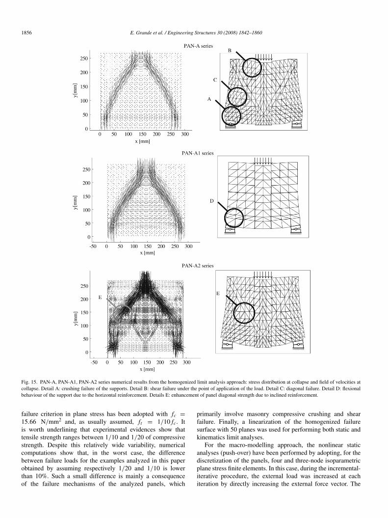
Fig. 15. PAN-A, PAN-A1, PAN-A2 series numerical results from the homogenized limit analysis approach: stress distribution at collapse and field of velocities atcollapse. Detail A: crushing failure of the supports. Detail B: shear failure under the point of application of the load. Detail C: diagonal failure. Detail D: flexionalbehaviour of the support due to the horizontal reinforcement. Details E: enhancement of panel diagonal strength due to inclined reinforcement.
failure criterion in plane stress has been adopted with fc =
15.66 N/mm2 and, as usually assumed, ft = 1/10 fc. Itis worth underlining that experimental evidences show thattensile strength ranges between 1/10 and 1/20 of compressivestrength. Despite this relatively wide variability, numericalcomputations show that, in the worst case, the differencebetween failure loads for the examples analyzed in this paperobtained by assuming respectively 1/20 and 1/10 is lowerthan 10%. Such a small difference is mainly a consequenceof the failure mechanisms of the analyzed panels, which
primarily involve masonry compressive crushing and shearfailure. Finally, a linearization of the homogenized failuresurface with 50 planes was used for performing both static andkinematics limit analyses.
For the macro-modelling approach, the nonlinear staticanalyses (push-over) have been performed by adopting, for thediscretization of the panels, four and three-node isoparametricplane stress finite elements. In this case, during the incremental-iterative procedure, the external load was increased at eachiteration by directly increasing the external force vector. The

E. Grande et al. / Engineering Structures 30 (2008) 1842–1860 1857
arc-length method was adopted and the linear stiffness iterationmethod was used, adopting the energy norm criterion to checkthe convergence at each step.
4.3.1. Panels PAN-A, PAN-A1 and PAN-A2Experimental load–displacement curves for the three series
of panels here analyzed show that the introduction both ofa horizontal reinforcement (PAN-A1) and a double diagonalreinforcement (PAN-A2) results in an increase of the ultimateload.
It is worth noting that (Fig. 13) all the series were placedon two steel plates of length Ls equal to 40 mm, disposed atthe lower edge extremes and positioned on little steel rollersallowing rotation of the supports.
In the FE limit analysis code, the effect introduced by thesteel rollers was considered imposing for the lower bound abending moment on the supports M = t
∫ Ls/2−Ls/2 Σyy xsdxs equal
to zero, where Ls is the support length, t is the masonrythickness, Σyy is the vertical stress in correspondence withthe edges of the elements adjacent to the support and xs isa horizontal abscissa measuring support length with origin incorrespondence with the middle of the support (see Fig. 13(a),where the triangular mesh used in the limit analysis approachfor PAN-A1 series is shown).
In a dual manner with respect to the lower bound approach,in the upper bound approach, a rotation velocity ϕ was allowedon the supports constraining vertical velocities of the nodesbelonging to the support to have a linear dependence on verticalvelocities v−
s and v+s = −v−
s of the nodes with abscissaxs = ±Ls/2, so that ϕ = 2v−
s /Ls (see Fig. 13(b), where thetriangular mesh used in the limit analysis approach for PAN-Aand PAN-A2 series is shown).
In the macro-modelling approach it was observed thatthe rotation allowed by the steel rollers does not affect thenumerical results. Consequently, in order to simplify the usedmodels, steel rollers have not been modelled both in the un-strengthened (PAN-A) and the strengthened panels (PAN-A1and PAN-A2).
In Fig. 14, (i) the force–displacement curves of the point ofapplication of the external load (centre of the steel plate) fromthe phenomenological approach, (ii) the ultimate load from thelower and upper bound limit analysis and (iii) the experimentalforce–displacement curves are reported for all the panels of theseries PAN-A.
For the un-strengthened panel (PAN-A), it is interesting tonotice that the results obtained by using the limit analysiscode and the Model MA (elastic-perfectly plastic) of themacro-modelling approach are almost identical and furnish astrength value less than the experimental one. In particular themaximum difference between the theoretical and experimentalstrength values is equal to 36% corresponding to the caseof lower bond limit analysis approach. On the other hand,the theoretical force–displacement curve obtained from theanisotropic plasticity model (Model MB) compares well withthe experimental data. In particular, the peak-strength, thestiffness and the softening behaviour are well reproduced.
Fig. 16. External force-point P vertical displacement. Comparison betweennumerical and experimental results. (a) PAN-B series. (b) PAN-B1 series.
For the strengthened panel PAN-A1, it is worth notingthat the macroscopic anisotropic plasticity model with elasto-brittle behaviour of the FRP elements (Model MRB), exhibitsa force–displacement curve in excellent agreement withexperimental data, also in the post-peak range. On the otherhand, the use of an elastic behaviour for FRP strengtheningleads to a strength value of the panel and to a correspondingdisplacement greater than the experimental ones (the differencein terms of strength is about 12% while in terms of displacementit is about 21%).
In contrast to PAN-A results, in this case the limit analysisapproach gives strength values similar to experimental ones (themaximum difference is about 23% for the lower bound and only3% for the upper bound).
The results obtained for PAN-A2 case show that MRA andMRB models give almost identical results both in terms ofpeak-strength and post-peak behaviour (the difference betweenthe experimental and theoretical strength value is equal to 4%).Limit analysis gives strength values less than the experimentalones (the difference between experimental and numericalfailure loads is equal to 24% for the upper bound approach and35% for the lower bound).
In Fig. 15 the deformed shapes at collapse and the principalstress distribution at the ultimate state obtained by means of thelimit analysis approach are reported for PAN-A, PAN-A1 andPAN-A2 series respectively.

1858 E. Grande et al. / Engineering Structures 30 (2008) 1842–1860
Fig. 17. PAN-B series numerical results. (a) macroscopic model MA, stress distribution at collapse at maximum load level. (b) macroscopic model MA, deformedshape at maximum load level. (c) homogenized limit analysis approach, stress distribution at collapse. (d) homogenized limit analysis approach, field of velocitiesat collapse. Detail A: compressive failure and formation of a compressed pier under the area of application of the load.
As the lower and upper bound FE simulations show, in PAN-A1 series the horizontal strip acts as a tie. Even though thetwo-strut model of the un-strengthened case remains essentiallyunchanged, both the compressed sections increase as well asthe intensity. In PAN-A2 series the principal stress distributionat collapse and the failure field of velocities result in achange both of the direction of the compressed struts andin the failure mechanism. The deformed shape at collapseshows compression near the supports, shear under the load anddelamination of the diagonal reinforcement.
4.3.2. Panels PAN-B and PAN-B1Experimental results collected for PAN-B and PAN-B1
series show that the introduction of the FRP reinforcement doesnot determine a significant improvement of the load bearingcapacity. In fact, failure occurs in both cases for compressionof the vertical masonry strut under the point of application ofthe load. This is captured by the numerical models adopted inthis paper.
In Fig. 16, the external force–displacement curves of thepoint of application of the load are reported, as well as thefailure load obtained by means of the lower and upper boundFE limit analyses.
For both PAN-B and PAN-B1, the adopted theoreticalapproaches lead to results which are in good agreementwith the experimental data (the maximum difference betweenthe experimental and theoretical strength values is less than16% corresponding to the lower bound approach adopted forPAN-B).
In the case of the un-strengthened panel (PAN-B) itis interesting to notice that the force–displacement curvesobtained from the macroscopic plasticity models MA and MBdiffer both in terms of peak-strength and stiffness values. Inparticular, the curve obtained from the Model MA shows astiffness reduction that starts from a load value equal to 43%of the peak-strength of the panel. This effect was not observedduring experimental tests.
Similarly to PAN-A1 series, in the case of PAN-B1 it isworth noting that the macroscopic anisotropic plasticity modelwith elasto-brittle behaviour of the FRP elements (ModelMRB), exhibits a force–displacement curve in good agreementwith experimental data. On the contrary, the adoption of anelastic behaviour for the FRP strips furnishes a limit load ofthe panel and a corresponding displacement greater than theexperimental ones (the difference in terms of load is about 9%while in terms of displacement is about 10%). On the other

E. Grande et al. / Engineering Structures 30 (2008) 1842–1860 1859
Fig. 18. PAN-B1 series numerical results. (a) macroscopic model MRB, stress distribution at collapse at maximum load level. (b) macroscopic model MRB,deformed shape at maximum load level. (c) homogenized limit analysis approach, stress distribution at collapse. (d) homogenized limit analysis approach, field ofvelocities at collapse. Detail A: the inefficient disposition of the reinforcement leads to a stress distribution at collapse similar to the un-reinforced case.
hand, also limit analysis predictions of the ultimate load are ingood agreement both with experimental data and Model MRB.
Finally, in Figs. 17 and 18 the deformed shapes at collapseand the principal stress distribution at the ultimate stateobtained both with the limit analysis and the macroscopicapproach are reported for PAN-B and PAN-B1. These resultsconfirm that the introduction of FRP strengthening does notaffect the stress distribution.
5. Conclusions
With the aim of reproducing the structural response ofun-strengthened and FRP-strengthened masonry panels, inthis paper a homogenized limit analysis and a macroscopicphenomenological approach have been adopted using differentconstitutive laws and yielding criteria.
In the modelling process, particular regard has beenaddressed to the phase of parameter setting and to the modellingstrategy adopted to reproduce masonry/FRP interactionphenomena. Simplified models able to take into account thedelamination of the FRP from the support have been proposedboth for the macroscopic and the limit analysis approach, alsoconsidering the indications contained in [22].
With the aim of assessing the adopted theoretical models,the obtained results in terms of force–displacement curves and
ultimate load have been compared with the experimental ones.Deformed shapes at collapse and principal stress distribution atthe ultimate state have also been reported.
In all the examined cases, the macroscopic phenomenolog-ical approach based on an orthotropic plasticity model for ma-sonry and on an elastic-brittle behaviour for FRP strengthening,reproduces the experimental behaviour well both for pre- andpost-peak range.
On the other hand, also the adoption of a homogenizationlimit analysis leads to ultimate load values in some cases ingood agreement with the experimental ones.
Both experimental failure loads and load–displacementcurves are satisfactorily reproduced with all the adoptedmodels. However, the post-peak behaviour is captured wellonly when brittle phenomena are taken into account, i.e. whenmodels MB and MRB are used.
The proposed models are able to capture the resistantmechanism of un-strengthened and FRP-strengthened masonrypanels. In particular, information about the load capacity andthe post-peak behaviour (i.e. the ductility) can be deduced inorder to assess the efficacy of the reinforcing system. It is alsoimportant to underline that the simplified approach proposed totake into account the contribution of the reinforcement is ableto reproduce the delamination process of the FRP strengtheningwhen the strips are not mechanically fixed to the masonry

1860 E. Grande et al. / Engineering Structures 30 (2008) 1842–1860
support and the delamination process starts from the free edgesof the strips. In fact, in this case the delaminated parts of thestrips are no more in contact with the masonry support and, asa consequence, they are not able to contribute to the strengthof the panel. On the contrary, when the ends of the FRP stripswere mechanically fixed to the surface of the panels this leadsto a resistant mechanism of the FRP strips quite different: theparts of the strips that are not in contact with the masonrysupport continue to contribute to the strength of panel till theFRP tensile strength is reached. In this case a different modelmust be chosen.
Acknowledgement
This research has been possible thanks to the financialsupports of the project RELUIS from the Italian Ministry ofthe Civil Protection.
References
[1] van Zijl G. Computational modelling of masonry creep and shrinkage.Ph.D. thesis. Delft (The Netherlands): Delft University of Technology;2000.
[2] Berto L, Saetta A, Scotta R, Vitaliani R. An orthotropic damage modelfor masonry structures. International Journal for Numerical Methods inEngineering 2002;55:127–57.
[3] Pietruszczak S, Ushaksaraei R. Description of inelastic behaviour ofstructural masonry. International Journal on Solids and Structures 2003;40:4003–19.
[4] Lofti HR, Shing BP. Interface model applied to fracture of masonrystructures. Journal of Structural Engineering, ASCE 1994;120:63–80.
[5] Giambanco G, Di Gati L. A cohesive interface model for the structuralmechanics of block masonry. Mechanics Research Communications1997;24(5):503–12.
[6] Alfano G, Sacco E. Combining interface damage and friction in acohesive-zone model. International Journal for Numerical Methods inEngineering 2006;68(5):542–82.
[7] Luciano R, Sacco E. Homogenization technique and damage model forold masonry material. Int J Solids and Structures 1997;34(4):3191–208.
[8] Milani G, Lourenco PB, Tralli A. Homogenised limit analysis of masonrywalls. Part I: failure surfaces. Computer Structures 2006;84:166–80.
[9] Milani G, Lourenco PB, Tralli A. Homogenised limit analysis of masonrywalls. Part II: structural examples. Computer Structures 2006;84:181–95.
[10] Lourenco PB. Continuum model for masonry: parameter estimation andvalidation. ASCE Journal of Structural Engineering 1998;124(6):642–52.
[11] Marfia S, Sacco E. Numerical procedure for elasto-plastic no-tensionmodel. International Journal for Computational Methods in EngineeringScience and Mechanics 2005;6:187–99.
[12] Bazant ZP. Fracture and size effect in concrete and other quasibrittlematerials. Boca Raton: CRC Press; 1998.
[13] DIANA 9.1. Displacement analysis finite element software. Version 9.1.Delf (The Netherlands): TNO-Building Division; 2000.
[14] Sloan SW. Lower bound limit analysis using finite elements andlinear programming. International Journal for Numerical and AnalyticalMethods in Geomechanics 1988;12:61–77.
[15] Sloan SW, Kleeman PW. Upper bound limit analysis using discontinuousvelocity fields. Computer Methods in Applied Mechanics and Engineering1995;127(1–4):293–314.
[16] Hoffmann O. The brittle strength of orthotropic materials. Journal onComputational Mathematics 1967;1:200–6.
[17] Hill R. A theory of the yielding and plastic flow of anisotropic materials.London (UK): Proc. Roy. Soc.; 1947.
[18] Roko K, Boothby TE, Bakis CF. Failure modes of sheet bonded fiberreinforced to brick masonry. In: Proceedings of the fourth internationalsymposium on fiber reinforced polymer for RC structures. ACI, SP-188.1999.
[19] Casareto M, Olivieri A, Romelli A, Lagomarsino S. Bond behaviour ofFRP laminates adherent to masonry. In: Proceedings of the internationalconference advancing with composites. 2003.
[20] Ceroni F, Pecce MR, Manfredi G, Marcari G. Experimental bondbehaviour in masonry elements externally reinforced with FRPlaminates. In: Proceedings of the international conference composites inconstructions. 2003.
[21] Aiello MA, Sciolti SM. Bond analysis of masonry structures strengthenedwith CFRP sheets. Journal of Construction and Building Materials 2006;20:90–100.
[22] CNR-DT200. Guide for the design and construction of externally bondedFRP systems for strengthening existing structures. Italy: C N R, NationalResearch Council; 2006.
[23] D.M.LL.PP. (1987) Norme tecniche per la progettazione, esecuzione ecollaudo degli edifici in muratura e per il loro consolidamento. Italy. 1987.
[24] Rashid YR. Analysis of prestressed concrete pressure vessels. NuclearEngineering Design 1968;7(4):334–5.
[25] Milani G, Rotunno T, Sacco E, Tralli A. Failure load of FRP strengthenedmasonry walls: Experimental results and numerical models. StructuralDurability and Health Monitoring 2006;2(1):29–50.
[26] Lurati F, Thurlimann B. Tests in concrete masonry walls. Report no. 8401-3. Zurich (Switzerland): Institute of Structural Engineering, ETH Zurich;1990.
[27] van der Pluijm R. Material properties of masonry and its componentsunder tension and shear. In: Proc. 6th Canadian masonry symposium.1992.
[28] van der Pluijm R. Shear behaviour of bed joints. In: Hamid AA, HarrisHG, editors, Proceedings of the 6th North American masonry conf.,Philadelphia (PA, USA): Drexel University; 1993.
[29] Lourenco PB, Rots J. A multi-surface interface model for the analysisof masonry structures. Journal of Engineering Mechanics ASCE 1997;123(7):660–8.