Prospects of Developing Prefabricated Masonry Walling ...
22
buildings Article Prospects of Developing Prefabricated Masonry Walling Systems in Australia Julian Thamboo 1 , Tatheer Zahra 2 , Satheeskumar Navaratnam 3, * , Mohammad Asad 2 and Keerthan Poologanathan 4 Citation: Thamboo, J.; Zahra, T.; Navaratnam, S.; Asad, M.; Poologanathan, K. Prospects of Developing Prefabricated Masonry Walling Systems in Australia. Buildings 2021, 11, 294. https:// doi.org/10.3390/buildings11070294 Academic Editor: Elena Ferretti Received: 3 June 2021 Accepted: 2 July 2021 Published: 6 July 2021 Publisher’s Note: MDPI stays neutral with regard to jurisdictional claims in published maps and institutional affil- iations. Copyright: © 2021 by the authors. Licensee MDPI, Basel, Switzerland. This article is an open access article distributed under the terms and conditions of the Creative Commons Attribution (CC BY) license (https:// creativecommons.org/licenses/by/ 4.0/). 1 Department of Civil Engineering, South Eastern University of Sri Lanka, Oluvil 32360, Sri Lanka; [email protected] 2 School of Civil Engineering and Built Environment, Queensland University of Technology, Brisbane 4000, Australia; [email protected] (T.Z.); [email protected] (M.A.) 3 School of Engineering, RMIT University, Melbourne 3000, Australia 4 Faculty of Engineering and Environment, Northumbria University, Newcastle upon Tyne NE1 8ST, UK; [email protected] * Correspondence: [email protected]; Tel.: +61-4525-08931 Abstract: Prefabrication has been shown to be an effective way of construction in the modern- day context. Although much progress has been made in developing reinforced concrete (RC), timber and steel prefabricated elements/structures, prefabrication of masonry walling systems has received limited attention in the past. Conventional masonry construction is labour-intensive and time-consuming; therefore, prefabrication can be an effective solution to accelerate the masonry construction to make it more cost-effective. Therefore, in this paper, an attempt has been made to evaluate the effectiveness of prefabricated masonry systems (PMS) in terms of their structural characteristics and sustainability perspectives in an Australian context. Subsequently, the available studies related to PMS and the prospects of developing prefabricated masonry walling systems were appraised and reported. In order to assess the applicability of PMS, a case study was carried out by designing four types of prospective prefabricated masonry walling systems for a typical housing unit in Australia. It was shown that the reinforced (RM), post-tensioned (PT) and thin layered mortared (TLM) masonry systems are better suited for prefabrication. Later, in order to assess the sustainability of the considered masonry walling systems, life cycle energy analyses were carried using the Environmental Performance in Construction (EPIC) database. It was found that there can be nearly 30% and 15% savings, respectively, in terms of energy saving and CO 2 emissions in prefabricated construction than the conventional masonry construction. Finally, the prospects of developing PMS and the need for future research studies on these systems are highlighted. Keywords: prefabrication; masonry; connections; life cycle analysis; design; reinforced masonry; post-tensioned masonry; thin layered mortared masonry 1. Introduction Masonry is one of the oldest construction materials in the world; nevertheless, it is still a preferred material for construction due to its simple construction method, relatively good loadbearing capacity, better fire and acoustic properties and aesthetic appeal. How- ever, the conventional masonry construction method is slow and labour intensive; thus, the masonry construction industries at present are dealing with challenges against the depleting skilled labour force, time bound economy driven nature of modern construction and new-generation materials/walling systems. Subsequently, many alternative masonry construction systems were developed to meet the demands and reduce the labour intensive- ness of masonry construction. These alternative masonry construction techniques include larger and lighter units (e.g., Aerated Autoclaved Concrete units), thin layer mortaring (TLM) and mortarless masonry systems [1–3]. Further, to improve the structural capacities Buildings 2021, 11, 294. https://doi.org/10.3390/buildings11070294 https://www.mdpi.com/journal/buildings
-
Upload
khangminh22 -
Category
Documents
-
view
3 -
download
0
Transcript of Prospects of Developing Prefabricated Masonry Walling ...

buildings
Article
Prospects of Developing Prefabricated Masonry WallingSystems in Australia
Julian Thamboo 1 , Tatheer Zahra 2 , Satheeskumar Navaratnam 3,* , Mohammad Asad 2 andKeerthan Poologanathan 4
�����������������
Citation: Thamboo, J.; Zahra, T.;
Navaratnam, S.; Asad, M.;
Poologanathan, K. Prospects of
Developing Prefabricated Masonry
Walling Systems in Australia.
Buildings 2021, 11, 294. https://
doi.org/10.3390/buildings11070294
Academic Editor: Elena Ferretti
Received: 3 June 2021
Accepted: 2 July 2021
Published: 6 July 2021
Publisher’s Note: MDPI stays neutral
with regard to jurisdictional claims in
published maps and institutional affil-
iations.
Copyright: © 2021 by the authors.
Licensee MDPI, Basel, Switzerland.
This article is an open access article
distributed under the terms and
conditions of the Creative Commons
Attribution (CC BY) license (https://
creativecommons.org/licenses/by/
4.0/).
1 Department of Civil Engineering, South Eastern University of Sri Lanka, Oluvil 32360, Sri Lanka;[email protected]
2 School of Civil Engineering and Built Environment, Queensland University of Technology, Brisbane 4000,Australia; [email protected] (T.Z.); [email protected] (M.A.)
3 School of Engineering, RMIT University, Melbourne 3000, Australia4 Faculty of Engineering and Environment, Northumbria University, Newcastle upon Tyne NE1 8ST, UK;
[email protected]* Correspondence: [email protected]; Tel.: +61-4525-08931
Abstract: Prefabrication has been shown to be an effective way of construction in the modern-day context. Although much progress has been made in developing reinforced concrete (RC),timber and steel prefabricated elements/structures, prefabrication of masonry walling systems hasreceived limited attention in the past. Conventional masonry construction is labour-intensive andtime-consuming; therefore, prefabrication can be an effective solution to accelerate the masonryconstruction to make it more cost-effective. Therefore, in this paper, an attempt has been madeto evaluate the effectiveness of prefabricated masonry systems (PMS) in terms of their structuralcharacteristics and sustainability perspectives in an Australian context. Subsequently, the availablestudies related to PMS and the prospects of developing prefabricated masonry walling systemswere appraised and reported. In order to assess the applicability of PMS, a case study was carriedout by designing four types of prospective prefabricated masonry walling systems for a typicalhousing unit in Australia. It was shown that the reinforced (RM), post-tensioned (PT) and thinlayered mortared (TLM) masonry systems are better suited for prefabrication. Later, in order toassess the sustainability of the considered masonry walling systems, life cycle energy analyses werecarried using the Environmental Performance in Construction (EPIC) database. It was found thatthere can be nearly 30% and 15% savings, respectively, in terms of energy saving and CO2 emissionsin prefabricated construction than the conventional masonry construction. Finally, the prospects ofdeveloping PMS and the need for future research studies on these systems are highlighted.
Keywords: prefabrication; masonry; connections; life cycle analysis; design; reinforced masonry;post-tensioned masonry; thin layered mortared masonry
1. Introduction
Masonry is one of the oldest construction materials in the world; nevertheless, it isstill a preferred material for construction due to its simple construction method, relativelygood loadbearing capacity, better fire and acoustic properties and aesthetic appeal. How-ever, the conventional masonry construction method is slow and labour intensive; thus,the masonry construction industries at present are dealing with challenges against thedepleting skilled labour force, time bound economy driven nature of modern constructionand new-generation materials/walling systems. Subsequently, many alternative masonryconstruction systems were developed to meet the demands and reduce the labour intensive-ness of masonry construction. These alternative masonry construction techniques includelarger and lighter units (e.g., Aerated Autoclaved Concrete units), thin layer mortaring(TLM) and mortarless masonry systems [1–3]. Further, to improve the structural capacities
Buildings 2021, 11, 294. https://doi.org/10.3390/buildings11070294 https://www.mdpi.com/journal/buildings

Buildings 2021, 11, 294 2 of 22
and ductility of the masonry, core grouting techniques, reinforcing, prestressing and surfacerendering with composites have been incorporated in the past [4–7].
On the other hand, increasing population, depleting skill labourers and therebyrising labour costs, and the requirement for rapid construction of infrastructures haveencouraged the embrace of prefabricated or modular construction techniques [8–11]. Inaddition, damages to the infrastructures due to ever increasing disasters, particularly inAustralia, such as bushfires, floods and cyclones, demand rapid reconstruction and favourprefabricated construction techniques. The prefabricated construction systems comprisemodular panels that are typically manufactured off-site in a quality-controlled environmentwith architectural finishes and services. These modules are then transported and installedon-site as load-resisting structural elements of the building [12]. Prefabrication enables aspeedy construction, high volume output and consistent quality at a competitive cost. Italso provides environmental benefits, such as the reduction of construction wastes, CO2emissions, and less constraints at the construction site by minimising on-site waste, noiseand dust [13,14]. These advantages drive many countries to adopt prefabricated buildingsystems and Australia is no exception to this scenario [15,16]. Subsequently, in Australia,the prefabricated construction system has been promoted as one of the eight key “visions”for improving the efficiency and performance of the Australian construction industry intheir Construction vision 2020 [17].
Accordingly, concrete, steel and timber industries have made substantial progress inestablishing prefabricated systems and their developments are well supported by system-atic research studies [18–24]. Subsequently, plenty of studies been carried out to assess theperformance of concrete, steel and wood based prefabricated construction systems [25–30].In relative terms, attention given to develop prefabricated masonry walling systems isminimal. While various forms of prefabricated masonry systems (PMS) were developed inmany parts of the world with adequate design requirements, these have not yet reachedthe criteria required for widespread mass production [31]. Figure 1 shows a prefabricatedmasonry façade walling panel. The reasons for limited development in establishing fully-fledged PMS varies across different countries. The economy-driven criteria of selecting astructural system primarily play a significant role in developing prefabricated masonry.Further, limited awareness among the architects and engineers on the performance, benefits,method and knowledge of PMS also restricts its extensive application.
Moreover, systematic research studies to investigate the structural performance ofPMS are limited [32–37]. It can be implied that most of the developed PMS in the past wereproprietary in nature with insufficient details provided on materials, structural design,fabrication and erection methods. Any PMS with connecting components should be ableto withstand loads induced by the occupancy of the structure as well as the externalloads exerted due to wind, fire and earthquake. In this regard, minimal research studieswere deliberated in the past, which is a major hindrance in confident uptake of PMS bythe industry.
Furthermore, the life cycle energy and life cycle cost (LCE and LCC) of the PMS arenot well accounted to highlight the benefits of the prefabricated masonry to the developersand end users. Comparing LCE and LCC of prefabricated concrete, steel and timbersystems with their corresponding conventional construction methods show that they aremore or less similar. The prefabricated systems are considered superior in the individualaspects of the life cycle analyses, such as construction time, wastage and reusability [38,39].Samani et al. [40] analysed the LCC of a prefabricated fibre reinforced composite wallingsystem and conventional masonry buildings in the US context. The results showed thatthe composite prefabricated walling systems consumed higher maintenance and lowerdemolition cost compared to the conventional masonry. It can be hypothesised that the PMSwould consume less maintenance cost and energy than other prefabricated systems due tothe good inherent thermal and acoustic insulation characteristics. Therefore, the overallLCE and LCC of the prefabricated masonry can be less than the other prefabricated systems.

Buildings 2021, 11, 294 3 of 22Buildings 2021, 11, x FOR PEER REVIEW 3 of 22
Figure 1. Lifting of a prefabricated façade masonry walling system.
Moreover, systematic research studies to investigate the structural performance of PMS are limited [32–37]. It can be implied that most of the developed PMS in the past were proprietary in nature with insufficient details provided on materials, structural de-sign, fabrication and erection methods. Any PMS with connecting components should be able to withstand loads induced by the occupancy of the structure as well as the external loads exerted due to wind, fire and earthquake. In this regard, minimal research studies were deliberated in the past, which is a major hindrance in confident uptake of PMS by the industry.
Furthermore, the life cycle energy and life cycle cost (LCE and LCC) of the PMS are not well accounted to highlight the benefits of the prefabricated masonry to the develop-ers and end users. Comparing LCE and LCC of prefabricated concrete, steel and timber systems with their corresponding conventional construction methods show that they are more or less similar. The prefabricated systems are considered superior in the individual aspects of the life cycle analyses, such as construction time, wastage and reusability [38,39]. Samani et al. [40] analysed the LCC of a prefabricated fibre reinforced composite walling system and conventional masonry buildings in the US context. The results showed that the composite prefabricated walling systems consumed higher maintenance and lower demolition cost compared to the conventional masonry. It can be hypothesised that the PMS would consume less maintenance cost and energy than other prefabricated systems due to the good inherent thermal and acoustic insulation characteristics. There-fore, the overall LCE and LCC of the prefabricated masonry can be less than the other prefabricated systems.
In summary, the development and practice of prefabricated masonry construction are not well taken by the industry due to limited research and industrial manufacturing facilities. Although the prefabricated masonry can be an attractive solution to accelerate
Figure 1. Lifting of a prefabricated façade masonry walling system.
In summary, the development and practice of prefabricated masonry constructionare not well taken by the industry due to limited research and industrial manufacturingfacilities. Although the prefabricated masonry can be an attractive solution to accelerate thelabour intensive conventional masonry construction, especially for the low-rise buildings,the uptake is hindered by a lack of understanding of the structural and sustainable charac-teristics of PMS. Therefore, in this paper, an attempt has been made to critically analyse thestatus quo of the PMS with their future prospects in the Australian context. Initially, thePMS developed in the past are outlined in terms of their construction type and structuralperformance. Thereafter, the available design guidelines and erection methodologies ofprefabricated systems have been applied to design a typical Australian housing unit withvarious kinds of PMSs as a case study. Further, for the selected masonry prefabricatedmasonry walling systems, LCC and LCE were analysed to verify the economic benefit orlimitation of the system.
2. Review of the Existing PMS
In order to comprehend the characteristics of prefabricated masonry, some of the PMSreported in the available literature were reviewed and outlined in this section. It mustbe mentioned that there are some patented PMS which were not evolved into successfulor widely used applications, and therefore are not considered in this review. Similarly,prefabricated composite or reinforced concrete walling systems, where pre-cut masonryslips were provided to give masonry a façade appearance [41], are not considered inthis review as these are not truly a masonry system which should consist of discretebricks/blocks and mortar joints. It is commonly understood that the prefabrication ofconventional unreinforced masonry system is not feasible, as the bond between the units(bricks or blocks) and conventional cement mortar is relatively weak, and thus would

Buildings 2021, 11, 294 4 of 22
crack during the transportation and erection stages. To encounter this limitation, mainlythe reinforced, post-tensioned and high bond strength masonry walling systems wereadopted for prefabrication [42]. Accordingly, some of those systems are briefly summarisedand discussed in this section for the prospect of developing prefabricated masonry in theAustralian context.
2.1. Reinforced Masonry
The reinforced masonry (RM) walls are preferred over unreinforced masonry wheresubstantial lateral load resistance is required due to seismic and wind load effects. Theintroduction of reinforcement in masonry improves the tensile resistance and ductility ofthe masonry. The reinforcing of the masonry wall is carried out by placing the steel bars inthe hollow vertical cores of the masonry blocks and grouting of cores. The vertical barsare also restrained horizontally by the steel bars provided in the bed joints. Additionally,depending on the design requirement, the walls can be fully or partially grouted andreinforced. In masonry building design and construction, the RM walls are consideredas a counterpart for reinforced concrete (RC) walls. While reinforcing helps to enhancethe structural performance of masonry, it also facilitates its use as a prefabricated system,where the reinforcement acts as an integral component for handing walls during theprefabrication, transportation and assemblage.
Few research studies have been reported on prefabricated reinforced masonry systems.Braun et al. [43] developed a prefabricated reinforced masonry system in Switzerland whichwas made of dry stacked hollow blocks with no mortar joints. The walling system wasfully reinforced with a vertical reinforcement inserted into each hollow vertical core withgrouting and horizontal bars placed in all bed joints. This study focused on investigatingthe suitable connection details between prefabricated wall and foundation through quasi-static cyclic in-plane shear tests in which two types of connection details between wall andfoundation were considered. The dowel thickness and anchorage lengths were differed inboth of these connections as shown in Figure 2. The in-plane cyclic shear testing of bothwalls revealed similar behaviour and thus are recommended for the wall to foundationconnection. Conventionally, RM walls require starter bars at foundation/floor levels; thus,it can be said that using dowels to connect the prefabricated walls at foundation/floor levelwould not be an additional effort or cost.
Buildings 2021, 11, x FOR PEER REVIEW 5 of 22
wall to foundation connection. Conventionally, RM walls require starter bars at founda-tion/floor levels; thus, it can be said that using dowels to connect the prefabricated walls at foundation/floor level would not be an additional effort or cost.
Figure 2. Prefabricated reinforced masonry: wall to foundation connection, Braun et al. [43]
Further, a team of researchers from Spain, Portugal and Italy have developed semi-prefabricated reinforced brick masonry light-weight vaults [44,45]. The construction of the vault consisted of two stages: (1) semi prefabricated steel-brick sheets were delivered at site and (2) construction was completed by filling and spraying the joints and top portion of the vaults. The structural performance of the semi-prefabricated vault was tested under instantaneous and sustain loading conditions to determine the load capacity, ductility and creep behaviour. Additionally, a predefined support displacement and instantaneous line loading were applied to verify the flexibility of the supporting members. The structural testing have revealed that the load capacity, ductility and joint integrity of the developed semi-prefabricated system were adequate.
Recently, Muirhead et al. [46] patented a prefabricated reinforced masonry system in the USA. Hollow concrete blocks with slits on the face shells were used to fabricate the walls, where a provisional reinforcement is embedded in the slits, as shown in Figure 3a. The purpose of providing provisional reinforcement is to increase the tensile resistance of the walls during the erection. Therefore, 3 mm FRP bars were embedded in the slits with epoxy grout bonding. Further, U shaped blocks were laid on top and bottom of the wall with provisional reinforcement and grouted. Similar arrangements were proposed where the openings are required for lintels as shown in Figure 3b. Further anchor slings as indi-cated in Figure 3b were used to lift and place the walls during the transportation. Subse-quently, the prefabricated reinforced masonry walls were transported to the site and the required vertical reinforcement was applied.
Figure 2. Prefabricated reinforced masonry: wall to foundation connection, Braun et al. [43].
Further, a team of researchers from Spain, Portugal and Italy have developed semi-prefabricated reinforced brick masonry light-weight vaults [44,45]. The construction of the

Buildings 2021, 11, 294 5 of 22
vault consisted of two stages: (1) semi prefabricated steel-brick sheets were delivered atsite and (2) construction was completed by filling and spraying the joints and top portionof the vaults. The structural performance of the semi-prefabricated vault was tested underinstantaneous and sustain loading conditions to determine the load capacity, ductility andcreep behaviour. Additionally, a predefined support displacement and instantaneous lineloading were applied to verify the flexibility of the supporting members. The structuraltesting have revealed that the load capacity, ductility and joint integrity of the developedsemi-prefabricated system were adequate.
Recently, Muirhead et al. [46] patented a prefabricated reinforced masonry system inthe USA. Hollow concrete blocks with slits on the face shells were used to fabricate thewalls, where a provisional reinforcement is embedded in the slits, as shown in Figure 3a.The purpose of providing provisional reinforcement is to increase the tensile resistanceof the walls during the erection. Therefore, 3 mm FRP bars were embedded in the slitswith epoxy grout bonding. Further, U shaped blocks were laid on top and bottom of thewall with provisional reinforcement and grouted. Similar arrangements were proposedwhere the openings are required for lintels as shown in Figure 3b. Further anchor slingsas indicated in Figure 3b were used to lift and place the walls during the transportation.Subsequently, the prefabricated reinforced masonry walls were transported to the site andthe required vertical reinforcement was applied.
Buildings 2021, 11, x FOR PEER REVIEW 6 of 22
Figure 3. Prefabricated RM system developed by Muirhead et al. [46] (a) Sectional view of the pre-fabricated wall and (b) lifting position of the walls.
Zhang et al. [47] has reported a prefabricated reinforced masonry system for which they investigated the in-plane shear characteristics by varying horizontal reinforcement detail, axial compressive stress and vertical joint detailing. The detail of the proposed ver-tical joint arrangement is shown in Figure 4, where the vertical joints were designed at the web of the walls to avoid a complex reinforcement arrangement at the joints. The horizon-tal reinforcement bars were embedded into the joints to act as shear key in the vertical joints. The in-plane shear test results revealed that the failure modes of the vertically jointed wall were similar to that of conventional cast in-situ walls. Based on this research, it can be said that with the connection details available (wall to foundation and wall to wall), the RM can be an effective system to establish prefabricated masonry walls.
Figure 4. Proposed vertical joints for prefabricated RM walls by Zhang et al. [47]
2.2. Post-Tensioned Masonry Similar to prefabricated RM walling system, pre-stressed/post-tensioned masonry
systems are also a prospective solution for prefabrication of masonry. However, not much research efforts have been invested in assessing the performance of prefabricated pre-stressed masonries. Nevertheless, many studies were dedicated to investigating the in-plane and out of plane response of the cast in-situ prestressed masonry in the past [48–52]. Subsequently, rational design rules are available in the masonry design standards.
200 mm
400 mm
100 mm
HorizontalReinforcement
Horizontal ReinforcementOverlap
Vertical Reinforcement
Stirrups
Figure 3. Prefabricated RM system developed by Muirhead et al. [46] (a) Sectional view of the prefabricated wall and (b)lifting position of the walls.
Zhang et al. [47] has reported a prefabricated reinforced masonry system for whichthey investigated the in-plane shear characteristics by varying horizontal reinforcementdetail, axial compressive stress and vertical joint detailing. The detail of the proposedvertical joint arrangement is shown in Figure 4, where the vertical joints were designedat the web of the walls to avoid a complex reinforcement arrangement at the joints. Thehorizontal reinforcement bars were embedded into the joints to act as shear key in thevertical joints. The in-plane shear test results revealed that the failure modes of the verticallyjointed wall were similar to that of conventional cast in-situ walls. Based on this research,it can be said that with the connection details available (wall to foundation and wall towall), the RM can be an effective system to establish prefabricated masonry walls.

Buildings 2021, 11, 294 6 of 22
Buildings 2021, 11, x FOR PEER REVIEW 6 of 22
Figure 3. Prefabricated RM system developed by Muirhead et al. [46] (a) Sectional view of the pre-fabricated wall and (b) lifting position of the walls.
Zhang et al. [47] has reported a prefabricated reinforced masonry system for which they investigated the in-plane shear characteristics by varying horizontal reinforcement detail, axial compressive stress and vertical joint detailing. The detail of the proposed ver-tical joint arrangement is shown in Figure 4, where the vertical joints were designed at the web of the walls to avoid a complex reinforcement arrangement at the joints. The horizon-tal reinforcement bars were embedded into the joints to act as shear key in the vertical joints. The in-plane shear test results revealed that the failure modes of the vertically jointed wall were similar to that of conventional cast in-situ walls. Based on this research, it can be said that with the connection details available (wall to foundation and wall to wall), the RM can be an effective system to establish prefabricated masonry walls.
Figure 4. Proposed vertical joints for prefabricated RM walls by Zhang et al. [47]
2.2. Post-Tensioned Masonry Similar to prefabricated RM walling system, pre-stressed/post-tensioned masonry
systems are also a prospective solution for prefabrication of masonry. However, not much research efforts have been invested in assessing the performance of prefabricated pre-stressed masonries. Nevertheless, many studies were dedicated to investigating the in-plane and out of plane response of the cast in-situ prestressed masonry in the past [48–52]. Subsequently, rational design rules are available in the masonry design standards.
200 mm
400 mm
100 mm
HorizontalReinforcement
Horizontal ReinforcementOverlap
Vertical Reinforcement
Stirrups
Figure 4. Proposed vertical joints for prefabricated RM walls by Zhang et al. [47].
2.2. Post-Tensioned Masonry
Similar to prefabricated RM walling system, pre-stressed/post-tensioned masonry sys-tems are also a prospective solution for prefabrication of masonry. However, not much re-search efforts have been invested in assessing the performance of prefabricated prestressedmasonries. Nevertheless, many studies were dedicated to investigating the in-plane andout of plane response of the cast in-situ prestressed masonry in the past [48–52]. Subse-quently, rational design rules are available in the masonry design standards. Caine [53]outlined some of past projects that utilised prefabricated post-tensioned (PT) masonry ele-ments in UK. It was highlighted that by using the PT method, horizontal masonry elementssimilar to bridge decks were prefabricated for pedestrian bridges. Figure 5 shows theschematic diagram of the prefabricated PT masonry deck used in Tring Bridge as outlinedin Caine [47]. It was mentioned that the prefabricated panels were built vertical and thenpositioned horizontally as shown in Figure 5a. Adequate camber for the prestressed sectionwas designed to match the required eccentricity of the pre-stressing force to resist thebending and shear actions. Figure 5b shows the cross-section view of the constructed footbridge using the prefabricated masonry deck.
In absence of research details specific to prefabricated PT masonry, a similar analogybetween RM and PT masonry can be drawn. Wight et al. [54] have outlined the applicationof PT masonry system for a single storey house in New Zealand. The walling system wasdesigned to resist seismic action as per NZS 4203 [55]. Figure 6a,b provides typical wallto floor/foundation detailing of the PT wall and control joint detail between two wallpanels. While detailing was specified for on-site construction, a similar technique could bedeveloped to connect prefabricated PT masonry panels.

Buildings 2021, 11, 294 7 of 22
Buildings 2021, 11, x FOR PEER REVIEW 7 of 22
Caine [53] outlined some of past projects that utilised prefabricated post-tensioned (PT) masonry elements in UK. It was highlighted that by using the PT method, horizontal ma-sonry elements similar to bridge decks were prefabricated for pedestrian bridges. Figure 5 shows the schematic diagram of the prefabricated PT masonry deck used in Tring Bridge as outlined in Caine [47]. It was mentioned that the prefabricated panels were built verti-cal and then positioned horizontally as shown in Figure 5a. Adequate camber for the pre-stressed section was designed to match the required eccentricity of the pre-stressing force to resist the bending and shear actions. Figure 5b shows the cross-section view of the con-structed foot bridge using the prefabricated masonry deck.
Figure 5. Prefabricated PT masonry bridge decks used (Caine): [53] (a) positioning of prefabricated masonry deck and (b) cross sectional view of the deck.
In absence of research details specific to prefabricated PT masonry, a similar analogy between RM and PT masonry can be drawn. Wight et al. [54] have outlined the application of PT masonry system for a single storey house in New Zealand. The walling system was designed to resist seismic action as per NZS 4203 [55]. Figure 6a,b provides typical wall to floor/foundation detailing of the PT wall and control joint detail between two wall panels. While detailing was specified for on-site construction, a similar technique could be devel-oped to connect prefabricated PT masonry panels.
It must be highlighted that the PT walling system reported in Wight et al. [54] used dry-stack concrete blocks, where no mortar was used in erecting the walls. Subsequently, this technique would facilitate to construct the walls quicker than the conventional block-works with the required bending and shear resistance provided by the PT. A similar dry-stack PT system was reported in Ota [56], where it was referred to as a Bolt-A-Blok wall system. The key feature of the system is the usage of bolts and treaded bars as the PT component in every layer of the blockwork. Moreover, there are plenty of studies on PT masonry walls with unbonded tendons [57–60], where unbonded tendons were mainly used to ease the requirement of grouting and as well as self-centring action during the lateral loading situation. Thus, it can be hypothesised that this technique can also be used in prefabrication of masonry walls, where the post-tensioning can be applied using the unbonded tendons off-site during the fabrication, which would facilitate transportation
Figure 5. Prefabricated PT masonry bridge decks used (Caine): [53] (a) positioning of prefabricated masonry deck and (b)cross sectional view of the deck.
Buildings 2021, 11, x FOR PEER REVIEW 8 of 22
and erection, and the tendons can be later released once the walls are positioned and con-nected. This might provide a cost-effective prefabrication solution for masonry with more research studies on this aspect in the future.
Figure 6. Connection detailing of PT masonry wall [54]: (a) wall to floor/foundation and (b) wall to wall with control joint.
2.3. Thin Layered Mortared Masonry Thin layered mortared (TLM) masonry is another construction technique that could
facilitate the erection of prefabricated masonry walls [61,62]. The main difference between the TLM and the conventional masonry is the composition and thickness of mortar used in the joints. Normally in TLM, the mortar thickness of 0.5 mm to 3 mm is adopted, which depends on the dimensional tolerance of units used. Typically, proprietary mortar mixes are used, where the constitutive materials (mainly sand) are much finer than those of con-ventional mortar mixes. Subsequently mortar application on unit layers in TLM masonry is carried out using mortar spreaders rather than traditional trowels, which make the TLM masonry construction relatively faster than the conventional construction with less wast-age at site [63]. It was generally reported that the TLM construction is about 2–3 times faster than the conventional masonry construction [64]. Other than the European stand-ards (EN 1996-1 [65]), other masonry design standards such as Australian standards AS 3700 [66], Canadian standards (CSA S304.1-04 [67]) and American standards (MSJC [68]) outline TLM mortar application with only Autoclaved aerated concrete (AAC) blocks.
It was concluded in the previous studies that some of the proprietary mortars used in TLM masonry provided relatively higher bond strength than the conventional mortar [69,70], which could provide better resistance against the transportation and erection ac-tions, if it is to be used as prefabricated systems. Additionally, if the bond strength of TLM masonry is not adequate to resist the erection forces, the system can be compensated with nominal reinforcement or prestressing. Comparatively fewer studies have been con-ducted on TLM masonry under various stress-states or investigating TLM masonry’s be-haviour at a structural scale. Da Porto et al. [71] have reported that the TLM masonry shear walls made of perforated clay blocks portrayed moderately higher in-plane shear resistance and less deformity due to relatively higher bond strength characteristics be-tween unit and mortar. Dhanasekar et al. [72] studied a high bond strength TLM masonry walling system to develop a prefabricated masonry walling system as shown in Figure 7.
85 mm
200 mm
300 mm
665 HRC mesh on2 chairs per pod
2/HD 121/HD 12Rib steel
1/HD 12Top steel
D 12 trim does not extend into edge beam
D 12 trim vertical beyond
D 12 trim horizontal below all openings
Typical Lintel2/D16 along, R6 at 140 centre to centre
R 16 lapping bars 800 mm longdebonded one side with plastic sleeve
This side debonded, withPlastic sleeve
Filler strip and Sealant to control joint
Vertical wall reinforcementto both sides of control joint
Horizontal wall reinforcement
(a) (b)
Figure 6. Connection detailing of PT masonry wall [54]: (a) wall to floor/foundation and (b) wall to wall with control joint.
It must be highlighted that the PT walling system reported in Wight et al. [54] used dry-stack concrete blocks, where no mortar was used in erecting the walls. Subsequently, thistechnique would facilitate to construct the walls quicker than the conventional blockworkswith the required bending and shear resistance provided by the PT. A similar dry-stackPT system was reported in Ota [56], where it was referred to as a Bolt-A-Blok wall system.The key feature of the system is the usage of bolts and treaded bars as the PT componentin every layer of the blockwork. Moreover, there are plenty of studies on PT masonrywalls with unbonded tendons [57–60], where unbonded tendons were mainly used to ease

Buildings 2021, 11, 294 8 of 22
the requirement of grouting and as well as self-centring action during the lateral loadingsituation. Thus, it can be hypothesised that this technique can also be used in prefabricationof masonry walls, where the post-tensioning can be applied using the unbonded tendonsoff-site during the fabrication, which would facilitate transportation and erection, and thetendons can be later released once the walls are positioned and connected. This mightprovide a cost-effective prefabrication solution for masonry with more research studies onthis aspect in the future.
2.3. Thin Layered Mortared Masonry
Thin layered mortared (TLM) masonry is another construction technique that couldfacilitate the erection of prefabricated masonry walls [61,62]. The main difference betweenthe TLM and the conventional masonry is the composition and thickness of mortar usedin the joints. Normally in TLM, the mortar thickness of 0.5 mm to 3 mm is adopted,which depends on the dimensional tolerance of units used. Typically, proprietary mortarmixes are used, where the constitutive materials (mainly sand) are much finer than thoseof conventional mortar mixes. Subsequently mortar application on unit layers in TLMmasonry is carried out using mortar spreaders rather than traditional trowels, which makethe TLM masonry construction relatively faster than the conventional construction withless wastage at site [63]. It was generally reported that the TLM construction is about2–3 times faster than the conventional masonry construction [64]. Other than the Europeanstandards (EN 1996-1 [65]), other masonry design standards such as Australian standardsAS 3700 [66], Canadian standards (CSA S304.1-04 [67]) and American standards (MSJC [68])outline TLM mortar application with only Autoclaved aerated concrete (AAC) blocks.
It was concluded in the previous studies that some of the proprietary mortars usedin TLM masonry provided relatively higher bond strength than the conventional mor-tar [69,70], which could provide better resistance against the transportation and erectionactions, if it is to be used as prefabricated systems. Additionally, if the bond strength ofTLM masonry is not adequate to resist the erection forces, the system can be compen-sated with nominal reinforcement or prestressing. Comparatively fewer studies have beenconducted on TLM masonry under various stress-states or investigating TLM masonry’sbehaviour at a structural scale. Da Porto et al. [71] have reported that the TLM masonryshear walls made of perforated clay blocks portrayed moderately higher in-plane shearresistance and less deformity due to relatively higher bond strength characteristics betweenunit and mortar. Dhanasekar et al. [72] studied a high bond strength TLM masonry wallingsystem to develop a prefabricated masonry walling system as shown in Figure 7. Thedeveloped system was demonstrated to withstand the handling actions as well as thein-plane shear and out of plane flexural actions. Further, Dhanasekar et al. [72] revealedthat under low pre-compression (<0.5 MPa), which corresponded to less than 5% of themasonry compressive strength, the TLM concrete masonry shear walls would fail by basesliding due to the higher bond strength between unit and mortar, as shown in Figure 8,where the wall behaved similarly to reinforced concrete walls. Moreover, out-of-planebending tests carried out by Kanyeto and Fried [73] revealed that the resistance is nearlyfour times higher than that of conventional masonry.

Buildings 2021, 11, 294 9 of 22
Buildings 2021, 11, x FOR PEER REVIEW 9 of 22
The developed system was demonstrated to withstand the handling actions as well as the in-plane shear and out of plane flexural actions. Further, Dhanasekar et al. [72] revealed that under low pre-compression (<0.5 MPa), which corresponded to less than 5% of the masonry compressive strength, the TLM concrete masonry shear walls would fail by base sliding due to the higher bond strength between unit and mortar, as shown in Figure 8, where the wall behaved similarly to reinforced concrete walls. Moreover, out-of-plane bending tests carried out by Kanyeto and Fried [73] revealed that the resistance is nearly four times higher than that of conventional masonry.
Figure 7. Lifting of TLM masonry walls made of concrete blocks [72].
(a) (b)
Figure 8. In-plane shear wall testing of TLM masonry walls [72]: (a) in-plane shear testing arrange-ment and (b) sliding failure of a TLM wall.
In addition, Ven der Meer et al. [74] have investigated creep and shrinkage charac-teristics of TLM masonry made of calcium silicate blocks to develop post-tensioned TLM masonry walls. It was reported that the final prestress loss due to creep and shrinkage were relatively less in the range of 16–24% due to reduced mortar thickness in TLM ma-sonry. Later, the same researchers [75] evaluated the in-plane shear behaviour of post–tensioned TLM masonry made of calcium silicate blocks and highlighted that the system behaved quite similar to conventional masonry with improved shear resistance. Overall, it can be stated that the TLM masonry is a prospect to develop a prefabricated masonry walling system. Similar design concepts as those of conventional masonry can be adopted for TLM masonry, with relatively higher bonding strength characteristics according to the used mortar types.
3. Case Study of an Australian Prefabricated Masonry House
Figure 7. Lifting of TLM masonry walls made of concrete blocks [72].
Buildings 2021, 11, x FOR PEER REVIEW 9 of 22
The developed system was demonstrated to withstand the handling actions as well as the in-plane shear and out of plane flexural actions. Further, Dhanasekar et al. [72] revealed that under low pre-compression (<0.5 MPa), which corresponded to less than 5% of the masonry compressive strength, the TLM concrete masonry shear walls would fail by base sliding due to the higher bond strength between unit and mortar, as shown in Figure 8, where the wall behaved similarly to reinforced concrete walls. Moreover, out-of-plane bending tests carried out by Kanyeto and Fried [73] revealed that the resistance is nearly four times higher than that of conventional masonry.
Figure 7. Lifting of TLM masonry walls made of concrete blocks [72].
(a) (b)
Figure 8. In-plane shear wall testing of TLM masonry walls [72]: (a) in-plane shear testing arrange-ment and (b) sliding failure of a TLM wall.
In addition, Ven der Meer et al. [74] have investigated creep and shrinkage charac-teristics of TLM masonry made of calcium silicate blocks to develop post-tensioned TLM masonry walls. It was reported that the final prestress loss due to creep and shrinkage were relatively less in the range of 16–24% due to reduced mortar thickness in TLM ma-sonry. Later, the same researchers [75] evaluated the in-plane shear behaviour of post–tensioned TLM masonry made of calcium silicate blocks and highlighted that the system behaved quite similar to conventional masonry with improved shear resistance. Overall, it can be stated that the TLM masonry is a prospect to develop a prefabricated masonry walling system. Similar design concepts as those of conventional masonry can be adopted for TLM masonry, with relatively higher bonding strength characteristics according to the used mortar types.
3. Case Study of an Australian Prefabricated Masonry House
Figure 8. In-plane shear wall testing of TLM masonry walls [72]: (a) in-plane shear testing arrangement and (b) slidingfailure of a TLM wall.
In addition, Ven der Meer et al. [74] have investigated creep and shrinkage charac-teristics of TLM masonry made of calcium silicate blocks to develop post-tensioned TLMmasonry walls. It was reported that the final prestress loss due to creep and shrinkage wererelatively less in the range of 16–24% due to reduced mortar thickness in TLM masonry.Later, the same researchers [75] evaluated the in-plane shear behaviour of post–tensionedTLM masonry made of calcium silicate blocks and highlighted that the system behavedquite similar to conventional masonry with improved shear resistance. Overall, it can bestated that the TLM masonry is a prospect to develop a prefabricated masonry wallingsystem. Similar design concepts as those of conventional masonry can be adopted for TLMmasonry, with relatively higher bonding strength characteristics according to the usedmortar types.
3. Case Study of an Australian Prefabricated Masonry House
The review carried out in Section 2 highlights that the RM, PT and TLM constructionmethods are the prospects for developing prefabricated masonry walling systems. There-fore, for establishing the concept of a prefabricated masonry house design, these threewalling systems along with the conventional masonry were taken into consideration fora case study of a typical house unit in Australia. The details of designing these wallingsystems for the considered house under various actions such as wind and earthquake asper the Australian standards were verified and outlined in this section. This case studydetails were then used to assess the life-cycle energy and a cost analysis later in the paper.

Buildings 2021, 11, 294 10 of 22
3.1. Prototype House
A typical house plan, as shown in Figure 9, was considered in this case study toexplore the prospects of prefabricated masonry design, erection procedure on site, life-cycleenergy and cost analyses. The typical housing plan was selected from a wider study of theexisting housing types in Australia [76,77]. The house was designed for a regional area inAustralia of medium seismicity (with a zone factor of 0.12 as per Australian EarthquakeStandards, AS1170.4 [78]), where prefabricated masonry would solve the issue of shortageof labour and provide resistance against bushfire and cyclonic destructions. The consideredhouse is a single-story dwelling, which is more common in housing, with a floor area ofaround 238 m2.
Buildings 2021, 11, x FOR PEER REVIEW 10 of 22
The review carried out in Section 2 highlights that the RM, PT and TLM construction methods are the prospects for developing prefabricated masonry walling systems. There-fore, for establishing the concept of a prefabricated masonry house design, these three walling systems along with the conventional masonry were taken into consideration for a case study of a typical house unit in Australia. The details of designing these walling sys-tems for the considered house under various actions such as wind and earthquake as per the Australian standards were verified and outlined in this section. This case study details were then used to assess the life-cycle energy and a cost analysis later in the paper.
3.1. Prototype House A typical house plan, as shown in Figure 9, was considered in this case study to ex-
plore the prospects of prefabricated masonry design, erection procedure on site, life-cycle energy and cost analyses. The typical housing plan was selected from a wider study of the existing housing types in Australia [76,77]. The house was designed for a regional area in Australia of medium seismicity (with a zone factor of 0.12 as per Australian Earthquake Standards, AS1170.4 [78]), where prefabricated masonry would solve the issue of shortage of labour and provide resistance against bushfire and cyclonic destructions. The consid-ered house is a single-story dwelling, which is more common in housing, with a floor area of around 238 m2.
(a)
(b)
Figure 9. House layout selected for the design and LCE analyses: (a) Plan view and (b) Elevation view. Figure 9. House layout selected for the design and LCE analyses: (a) Plan view and (b) Elevation
view.
For prefabricated masonry walling systems, several possible scenarios as discussedin Section 2 were assessed, as summarised in Table 1. The conventional brick and TLMmasonries were considered unreinforced (Type 1 and Type 2), and their thicknesses wereassumed as 110 mm and 190 mm, respectively. Grouting was only considered for the RMwall system (Type 3), while the PT masonry system (Type 4) was designed for unbondedtendons without any grout. The detailed design of the house for the PMS as listed in Table 1is described in the next sub-section.

Buildings 2021, 11, 294 11 of 22
Table 1. Considered masonry walling systems.
Notation Prefab Walling System Wall Thickness Reinforcement Grouting
Type 1 Conventional clay brickmasonry 110 mm × ×
Type 2 TLM Hollow blockmasonry 190 mm × ×
Type 3 PT block masonry 190 mm√
×Type 4 RM block masonry 190 mm
√ √
3.2. Design Approaches
The selected house for this case study was designed to withstand gravity, earthquakeand wind actions. A summary of design data used for the design scenarios is given inTable 2. The assumed parameters for soil type and terrain are also included in Table 2.Based on these assumed parameters, the design loads for gravity, earthquake and windwere calculated as shown under each category in the Table 2. The design standards thatwere followed to compute the different actions are also outlined.
Table 2. Loading scenarios and magnitudes.
Load Scenario Magnitude Relevant Code
Gravity Loads
Roof tiles and roof truss load 1.3 kPa AS1170.1 [79]
Imposed load 0.5 kPa AS1170.1 [79]
Masonry wall load 2.1 kPa AS1170.1 [79]
Earthquake Loads
Importance level 2 AS1170.0 [80]
Soil class (soft rock) Be AS1170.4 [78]
Zone factor (Z) 0.12 AS1170.4 [78]
Earthquake design category I AS1170.4 [78]
Base shear (V) 90 kN AS1170.4 [78]
Wind Loads
Wind region A3 AS1170.2 [81]
Regional wind speed 45 m/s AS1170.2 [81]
Terrain category 3 AS1170.2 [81]
Wind pressure on walls 0.8 kPa AS1170.2 [81]
The most critical walls subjected to compression due to gravity loads, in-plane sheardue to earthquake and out-of-plane bending due to wind forces were identified. Theseindividual walls were then designed, and their capacities were checked to resist theseloads using Australian Masonry Standards (AS3700 [66]) provisions. The design of thecritical walls was carried out for all the proposed conceptual PMS listed in Table 1. Forsafety against the tensile forces that can be caused due to lifting of prefabricated panels,TLM mortar of 3 mm thickness was used in all types of masonry walls design [82]. Thedesign parameters and determined capacity of each type of masonry system is presented inTable 3 for comparison. The design parameters mentioned in Table 3, such as unit strength,dimensions, flexural and shear bond strengths, were typical values, used for a commonmasonry design practice in Australia.

Buildings 2021, 11, 294 12 of 22
Table 3. Design details of critical walls for different masonry systems.
DesignParameter Type 1 Type 2 Type 3 Type 4
Unit strength 15 MPa 15 MPa 15 MPa 15 MPa
Unit height 76 mm 190 mm 190 mm 190 mm
Face-shellthickness n/a 30 mm 30 mm 30 mm
Mortar type M3 M3 M3 M3
Mortar thickness 3 mm 3 mm 3 mm 3 mm
compressivestrength 7 MPa 8 MPa 8 MPa 8 MPa
flexural strength ( f ′mt) 0.2 MPa 0.2 MPa 0.2 MPa 0.2 MPa
shear strength ( f ′ms) 0.25 MPa 0.25 MPa 0.25 MPa 0.25 MPa
Grout strength(
f ′cg)
n/a n/a n/a 25 MPa
Vertical bars n/a n/a 12.7 mm strand 1 N16
Horizontal bars n/a n/a n/a 1 N12
Compression Design (Maximum Load = 13.5 kN/m)
Compressioncapacity 190 kN/m (safe) 140 kN/m (safe) 232 kN/m (safe) 242 kN/m (safe)
In-plane Shear Design (Maximum Load = 7 kN/m)
In-plane shearcapacity 17 kN/m (safe) 9 kN/m (safe) 9 kN/m (safe) 70 kN/m (safe)
Out-of-plane bending Design (Maximum Load = 0.8 kPa)
Out-of-planebending capacity 0.1 kPa (unsafe) 0.5 kPa(unsafe) 6.2 kPa (safe) 5.7 kPa (safe)
As expected, all types of walling systems were found to be very safe in compressionas the gravity loading in the selected single-story house was not very significant. Themost critical wall under in-plane shear caused by the earthquake design loads shown inTable 2 also had sufficient capacity. However, for the out-of-plane wind pressure, bothunreinforced systems (brick and block masonry) were found unsafe with less capacityas compared to the design wind pressure. AS 3700 [66] limits the flexural bond strengthto be assumed for any masonry is 0.2 MPa; however, for TLM with high bond strengthmortars, the bond strength can be up to 1.0 MPa [83]; thus, TLM can be used to resisthigher out-of-plane bending if appropriate tensile and shear bond strength values arerecommended in the standards. Nevertheless, comparison showed that for a safe designagainst each type of critical load, RM and PT systems will be more suitable to choose forthe prefabricated masonry application.
3.3. Wall Erection Details
In this section, the possible concepts of prefabricated wall transportation and erectionsare discussed for the considered masonry walling systems in Section 3.1. Primarily, theprefabricated masonry wall sizes and shapes should be design based on the transport andlifting regulations as per the local requirements as well as considering the economy ofthe construction. Further, the prefabricated masonry wall support system relies on thetype of wall to floor/foundation connection, lifting and transportation methods. Someof these concepts are drawn from the methods of transporting and erecting prefabricatedconcrete/reinforced concrete walls and are highlighted in the following sub-sections.

Buildings 2021, 11, 294 13 of 22
3.3.1. Design of Wall Lifting
Specially made lifting hook clutches such as Reid Swift Lift or commercially availableferrules such as elephant foot ferrules combined with lifting eyes can be used to liftthe prefabricated masonry wall. These lifting systems shall be embedded into the topplinth/lintel beam and can be designed as per AS3850 [84]. These lifting systems shouldbe designed to an appropriate safety factor, which varies from 2.0 to 4.0 based on thetype of component. The embedded element shall be verified according to the design ofpost-installed and cast-in fastenings in the wall according to AS5216 [85]. Further, thegrout depth shall be increased locally where these lifting points are embedded if necessary.Depending on the span of the prefabricated masonry wall, the masonry shall rest onthe bottom plinth and shall be suspended from the top plinth through the embeddedreinforcement in the grout fills as shown in Figure 10, which implies that the RM andPT masonries (Type 3 and Type 4) can be effectively used to adopt these kinds of liftingarrangement. The spacing of the vertical reinforcement shall be determined based on thedepth of the bottom plinth beam and the depth of the top plinth beam shall be designedbased on the width of the panels. It must be mentioned that Type 1 and Type 2 masonry wallsystems being unreinforced would be vulnerable to damage during transport and lifting,and therefore they are not preferable prefab masonry options. Otherwise, reinforcementbars/anchorages should be added to lifting positions to transfer the stresses.
Buildings 2021, 11, x FOR PEER REVIEW 13 of 22
prefabricated masonry wall. These lifting systems shall be embedded into the top plinth/lintel beam and can be designed as per AS3850 [84]. These lifting systems should be designed to an appropriate safety factor, which varies from 2.0 to 4.0 based on the type of component. The embedded element shall be verified according to the design of post-installed and cast-in fastenings in the wall according to AS5216 [85]. Further, the grout depth shall be increased locally where these lifting points are embedded if necessary. De-pending on the span of the prefabricated masonry wall, the masonry shall rest on the bot-tom plinth and shall be suspended from the top plinth through the embedded reinforce-ment in the grout fills as shown in Figure 10, which implies that the RM and PT masonries (Type 3 and Type 4) can be effectively used to adopt these kinds of lifting arrangement. The spacing of the vertical reinforcement shall be determined based on the depth of the bottom plinth beam and the depth of the top plinth beam shall be designed based on the width of the panels. It must be mentioned that Type 1 and Type 2 masonry wall systems being unreinforced would be vulnerable to damage during transport and lifting, and therefore they are not preferable prefab masonry options. Otherwise, reinforcement bars/anchorages should be added to lifting positions to transfer the stresses.
Figure 10. Lifting method of masonry walls.
3.3.2. Erection Methods of Walls The prefabricated masonry wall system can be installed on the footing slab. Once the
wall is lifted and placed on the location, it must be supported through temporary props, as illustrated in Figure 11. The temporary props are commonly called push and pull props which can be used to prop the masonry panels temporarily onto the ground floor slab. The props shall be connected to the top plinth beam and the inserts need to be designed based on AS 5216 [85]. The props shall be spaced based on the wind and intended lateral action during the erection of the walls.
Moreover, Figure 12 shows the connection system between the prefabricated ma-sonry wall and the flooring slab/foundation. Dowels shall be used between the ground floor and the bottom plinth beam to connect the modules to the ground floor. These dow-els can be installed during the casting of the footing slab. The dowels shall be shorter and the same as the depth of the bottom plinth beam as there is minimal or no tension expected in dowels. The corrugated tubes on the bottom plinth shall be grouted using two grouting tubes (top and bottom) to ensure proper contact between the ground floor and the prefab-ricated masonry wall.
Figure 10. Lifting method of masonry walls.
3.3.2. Erection Methods of Walls
The prefabricated masonry wall system can be installed on the footing slab. Once thewall is lifted and placed on the location, it must be supported through temporary props, asillustrated in Figure 11. The temporary props are commonly called push and pull propswhich can be used to prop the masonry panels temporarily onto the ground floor slab. Theprops shall be connected to the top plinth beam and the inserts need to be designed basedon AS 5216 [85]. The props shall be spaced based on the wind and intended lateral actionduring the erection of the walls.

Buildings 2021, 11, 294 14 of 22
Figure 11. Propping method of masonry walls.
Moreover, Figure 12 shows the connection system between the prefabricated masonrywall and the flooring slab/foundation. Dowels shall be used between the ground floor andthe bottom plinth beam to connect the modules to the ground floor. These dowels can beinstalled during the casting of the footing slab. The dowels shall be shorter and the same asthe depth of the bottom plinth beam as there is minimal or no tension expected in dowels.The corrugated tubes on the bottom plinth shall be grouted using two grouting tubes (topand bottom) to ensure proper contact between the ground floor and the prefabricatedmasonry wall.
Buildings 2021, 11, x FOR PEER REVIEW 14 of 22
Figure 11. Propping method of masonry walls.
Figure 12. Connection of masonry walls with the base.
4. Life-Cycle Energy/Cost Analysis In order to evaluate the sustainability of PMS with conventional construction, the
life-cycle energy and cost analysis were carried out and reported in this section for the four types of masonry systems considered in Section 3. The energy consumptions and related greenhouse gas emissions (GHGE) were estimated for all four types of masonry wall systems. The energy consumptions and related GHGE for all the systems were as-sumed to be similar to the construction materials and the location of the house was the same for all systems. Thus, the energy and GHGE estimations were limited only to pro-duction and construction phases. The energy consumption and GHGE related to raw ma-terials and transportation were accounted for in the production phase. Then, the energy consumption and GHGE from the construction or installation was considered in the con-struction phase. The equivalent coefficient for GHGE from Environmental Performance in Construction (EPiC )database [86] was used to derive the GHGE from the materials. The type of equipment and fuel to be used, and travel distance, were accounted for to derive the energy consumptions and related GHGE from transportation to installation.
Thereafter, the bottom-up and top-down approach based on the economic data and energy intensity were used to estimate the embodied energy (EE). An average national input–output data [87] with hybrid energy coefficients were used as per Equation (1) to
Push & Pull Props
300-600
Pump until the grout exit through the top grouting tube
Pump grout exit through the bottom grouting tube
Seal the edges
Figure 12. Connection of masonry walls with the base.
4. Life-Cycle Energy/Cost Analysis
In order to evaluate the sustainability of PMS with conventional construction, thelife-cycle energy and cost analysis were carried out and reported in this section for thefour types of masonry systems considered in Section 3. The energy consumptions andrelated greenhouse gas emissions (GHGE) were estimated for all four types of masonrywall systems. The energy consumptions and related GHGE for all the systems wereassumed to be similar to the construction materials and the location of the house wasthe same for all systems. Thus, the energy and GHGE estimations were limited onlyto production and construction phases. The energy consumption and GHGE related toraw materials and transportation were accounted for in the production phase. Then, theenergy consumption and GHGE from the construction or installation was considered in the

Buildings 2021, 11, 294 15 of 22
construction phase. The equivalent coefficient for GHGE from Environmental Performancein Construction (EPiC) database [86] was used to derive the GHGE from the materials. Thetype of equipment and fuel to be used, and travel distance, were accounted for to derivethe energy consumptions and related GHGE from transportation to installation.
Thereafter, the bottom-up and top-down approach based on the economic data andenergy intensity were used to estimate the embodied energy (EE). An average nationalinput–output data [87] with hybrid energy coefficients were used as per Equation (1) tocalculate the EE. Table 4 shows the embodied energy intensities of materials used in bothprefabricated and traditional masonry wall systems:
EE =M
∑m=1
QmEEm (1)
where Qm and EEm are the quantity of material and the embodied energy coefficient(GJ/unit), respectively.
Table 4. The EE intensity, embodied greenhouse gas (GHGEE) intensity and density of constructionmaterial used in the wall systems [88].
Material Density(kg/m3) Unit EE Coefficient
(MJ/Unit)GHGEE Coefficient
(kg CO2-e/Unit)
Grout (25 MPa) 2400 m3 2581 361
Steel 7850 kg 38.8 2.9
Mortar 1858 kg 3.9 0.1
GypsumPlasterboard 885 kg 6.5 0.4
Brick 1920 kg 3.5 0.32
Rockwool 70 kg 57.1 3.8
Block 1400 kg 35.2 3.2
Then, Equation (2) was used to determine the GHGE from the production and construc-tion phases (GHGEP.C). Where GHGEE is the embodied GHGE of construction materials,GHGEP is the GHGE from the production of prefabricated wall systems, which includesconsumption of electricity and fuel by equipment. GHGET and GHGES are GHGE fromtransportation of materials and on-site construction activities (including fuel and electricityconsumption by the equipment), respectively. The GHGEE was obtained from Equation (3):
GHGEP.C = GHGEE + GHGEP + GHGET + GHGES (2)
GHGEE =M
∑m=1
QmGHGEm (3)
where GHGEE is the embodied GHGE coefficient (kg CO2-e/unit) of the constructionmaterials, which was obtained from Table 4. Yan et al. [89] specified that the GHGE factorfor diesel trucks used inland transport, which was used to estimate the GHGET usingEquation (4). This study assumed that the construction site was located within an 80 kmradius of the material sourced location. Then, the Equation (5) was used to calculate theenergy consumption for transportation (ET):
GHGET = ∑ QmDi fE fGHGE (4)
ET = ∑ QmDi fE (5)
Buildings 2021, 11, 294 16 of 22
where Di is the travel distance; fE is the fuel energy factor (0.002275 MJ/kg·km); and fGHGEis the GHGE factor for fuel (0.07 kg CO2-e/MJ) [89].
Further, in order to consider the workmanship in relation to the energy consumption,it was assumed that three skilled masons were employed to construct the wall systemsand the average working hours were 6 h/day. The construction of the conventional brickhouse in the case study consumed 28 days, whilst the other three types of masonry housesconsumed 40 days when traditional construction methods [90] are used. The numberof days required were selected from the labour catalogue data in the Australian contextand conservatively, 28 days for a brick masonry house and 40 days for RM, PT andTLM were fixed. As illustrated from the previous studies [91–93], the offsite constructiontime for the prefabricated element is less (i.e., about 20–30%). This offsite constructiontime can be further reduced by 20–40%, when using automation technologies. Thus, theconstruction duration was assumed to be reduced by 40% for manufacturing at a factory(i.e., prefabrication masonry systems), as the off-site construction reduces the constructioncomplexity. Tam et al. [92] highlighted that the onsite installation time for precast structuralwall is 15 min. Thus, the duration of on-site installation of a prefabricated masonry wallsystem was assumed to be 1.5 days. The office equipment (i.e., computers, printer, airconditioner, telephone and lighting) and other construction equipment (i.e., cement mixerand mobile crane) were assumed to be run on temporary power with a diesel engine. Theenergy content and GHGE factors for this engine were taken as 38.6 GJ/kL and 69.9 kgCO2-e/GJ [88]. The total energy consumption during the production and constructionphases (EP.C) was calculated based on Equation (6):
EP.C = EE + ET + EP + ES (6)
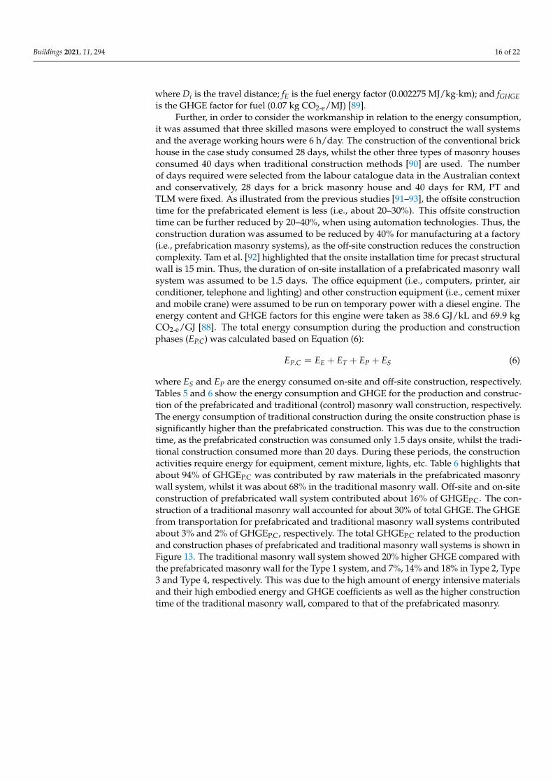
where ES and EP are the energy consumed on-site and off-site construction, respectively.Tables 5 and 6 show the energy consumption and GHGE for the production and construc-tion of the prefabricated and traditional (control) masonry wall construction, respectively.The energy consumption of traditional construction during the onsite construction phase issignificantly higher than the prefabricated construction. This was due to the constructiontime, as the prefabricated construction was consumed only 1.5 days onsite, whilst the tradi-tional construction consumed more than 20 days. During these periods, the constructionactivities require energy for equipment, cement mixture, lights, etc. Table 6 highlights thatabout 94% of GHGEP.C was contributed by raw materials in the prefabricated masonrywall system, whilst it was about 68% in the traditional masonry wall. Off-site and on-siteconstruction of prefabricated wall system contributed about 16% of GHGEP.C. The con-struction of a traditional masonry wall accounted for about 30% of total GHGE. The GHGEfrom transportation for prefabricated and traditional masonry wall systems contributedabout 3% and 2% of GHGEP.C, respectively. The total GHGEP.C related to the productionand construction phases of prefabricated and traditional masonry wall systems is shown inFigure 13. The traditional masonry wall system showed 20% higher GHGE compared withthe prefabricated masonry wall for the Type 1 system, and 7%, 14% and 18% in Type 2, Type3 and Type 4, respectively. This was due to the high amount of energy intensive materialsand their high embodied energy and GHGE coefficients as well as the higher constructiontime of the traditional masonry wall, compared to that of the prefabricated masonry.

Buildings 2021, 11, 294 17 of 22
Table 5. Energy consumption (GJ) production to and construction phases.
DetailsType 1 Type 2 Type 3 Type 4
Prefab Conv Prefab Conv Prefab Conv Prefab Conv
Embodied Raw materials (EE) 373 455 1328 1697 1337 1708 1442 1844
Offsite construction (EP) 70 - 75 - 75 - 75 -
Onsite Transport (ET) 12 12 7 7 8 8 23 23
Onsite construction (ES) 7 174 7 187 7 187 7 187
Total (EP.C) 462 641 1418 1891 1426 1902 1546 2054
Table 6. Comparison of GHGE between conventional and prefabricated constructions.
DetailsType 1 Type 2 Type 3 Type 4
Prefab Conv Prefab Conv Prefab Conv Prefab Conv
Embodied raw materials(GHGEE) 28 29 116 117 192 216 345 415
Offsite construction(GHGEP) 5.1 - 5.4 - 5.4 - 5.4 -
Onsite Transport(GHGET) 0.9 0.9 0.5 0.5 0.5 0.5 1.6 1.6
Onsite construction(GHGES) 0.5 13 0.5 14 0.5 14 0.5 14
Total (GHGEP.C) 34 43 123 132 199 230 352 430
Buildings 2021, 11, x FOR PEER REVIEW 17 of 22
Table 6. Comparison of GHGE between conventional and prefabricated constructions.
Details Type 1 Type 2 Type 3 Type 4
Prefab Conv Prefab Conv Prefab Conv Prefab Conv Embodied raw materials
(GHGEE) 28 29 116 117 192 216 345 415
Offsite construction (GHGEP) 5.1 - 5.4 - 5.4 - 5.4 -
Onsite Transport (GHGET) 0.9 0.9 0.5 0.5 0.5 0.5 1.6 1.6
Onsite construction (GHGES) 0.5 13 0.5 14 0.5 14 0.5 14
Total (GHGEP.C) 34 43 123 132 199 230 352 430
Figure 13. Comparison of GHGE for prefabricated and conventional masonry construction.
5. Prospects, Challenges and Need for Research It can be stated that the prefabricated masonry can be an alternative to the conven-
tional labour-intensive masonry construction. From Section 2, it was established that the RM, PT and TLM masonries are the main options for masonry prefabrication, as these systems facilitate the transport and erection of the walls within the regulations allowed for prefabricated construction systems. Nevertheless, systematic research studies are needed to establish fully fledged PMS using these construction methods. It can be men-tioned that the design guidelines for reinforced masonry, post-tensioned masonry and thin layered mortared masonry under various stress-states such as in-plane shear, out of plane bending and axial compression are already available in the standards. Therefore, system level research studies such as for the required connection configurations between the components (e.g., wall to floor/foundation and wall to wall), transportation and erec-tion of PMS are needed. Primarily, the system level performance against static and dy-namic (e.g., seismic) actions should also be evaluated for the PMS.
Furthermore, masonry is inherently a better material for fire and sound insulations. However, the performance of prefabricated masonry along with connection components should be assessed for fire and sound resistance. Additionally, sealing methods of con-nections and components of PMS is another area of concern against different environmen-tal conditions, which needs systematic research studies to address the gap in the knowledge. Further, the choice of a prefabrication masonry system must be based on the economic aspects of the construction I to make it viable with regard to the life cycle cost of the system in addition to an adequate structural performance.
0.00.20.40.60.81.01.21.41.6
Type 1 Type 2 Type 3 Type 4
GH
GE
(t C
O2-
e/m2 )
Masonry types
PrefabTraditional
Figure 13. Comparison of GHGE for prefabricated and conventional masonry construction.
5. Prospects, Challenges and Need for Research
It can be stated that the prefabricated masonry can be an alternative to the conven-tional labour-intensive masonry construction. From Section 2, it was established that theRM, PT and TLM masonries are the main options for masonry prefabrication, as thesesystems facilitate the transport and erection of the walls within the regulations allowed forprefabricated construction systems. Nevertheless, systematic research studies are neededto establish fully fledged PMS using these construction methods. It can be mentioned thatthe design guidelines for reinforced masonry, post-tensioned masonry and thin layeredmortared masonry under various stress-states such as in-plane shear, out of plane bendingand axial compression are already available in the standards. Therefore, system level re-search studies such as for the required connection configurations between the components(e.g., wall to floor/foundation and wall to wall), transportation and erection of PMS are

Buildings 2021, 11, 294 18 of 22
needed. Primarily, the system level performance against static and dynamic (e.g., seismic)actions should also be evaluated for the PMS.
Furthermore, masonry is inherently a better material for fire and sound insulations.However, the performance of prefabricated masonry along with connection componentsshould be assessed for fire and sound resistance. Additionally, sealing methods of connec-tions and components of PMS is another area of concern against different environmentalconditions, which needs systematic research studies to address the gap in the knowledge.Further, the choice of a prefabrication masonry system must be based on the economicaspects of the construction I to make it viable with regard to the life cycle cost of the systemin addition to an adequate structural performance.
6. Summary and Conclusions
Researchers and practitioners have paid limited attention to understanding and de-signing PMS in the past. The reason for limited research in establishing the PMS differsacross different countries due to cost effectiveness, limited awareness and lack of under-standing of such systems’ performance. Therefore, in this study, potentiality of developingPMS in the Australian context has been assessed. Initially, the available studies with regardto masonry prefabricated systems and possible conventional masonry construction systemsthat can be used as prefabricated systems were appraised. Thereafter, to establish theconcept of prefabricated design and construction, a prototype single storey house wasselected as a case study to design three types of prefabricated masonry walling systemsand their design and construction approaches were highlighted. Further to evaluate thesustainability of the prefabricated masonry construction systems, LCA analysis in terms ofenergy and carbon emissions were assessed and compared against conventional masonryconstruction system. Consequently, the following conclusions can be drawn on the prospectof prefabricated masonry construction in the Australian context.
• Reinforced, post-tensioned and thin layered mortared masonry systems are betteroptions for establishing prefabricated masonry systems (PMS), as they have beenshown to possess adequate structural capacities in different states of actions and theircomponents facilitate providing better solutions for lifting and erection processes.
• The design concepts of prefabricated masonry can be drawn from masonry designstandards for conventional masonry, while provisions for lifting and erections ofthe walling systems can be taken from well-established regulations available forprefabricated reinforced concrete walls. However, more systematic studies are neededto verify these provisions for prefabricated masonry walling systems.
• In terms of the sustainability perspective, the prefabricated masonry walling systemsmay perform better than the conventional masonry construction depending on thetype of construction method adopted. Additionally, the LCA of the prefabricatedmasonry walls can be further enhanced by the selection of more sustainable materialsand proper executions methods.
More systematic research studies are needed to establish fully-fledged PMS, espe-cially structural performance at system level, where the behaviour of wall panels with itsconnection components against various actions should be assessed. Additionally, stud-ies are needed for prefabricated masonry walls against realistic fire loadings and soundinsulations.
Author Contributions: Conceptualization, J.T. and S.N.; Methodology, J.T. and S.N.; Formal analysis,T.Z. and S.N.; Investigation, J.T., T.Z. and S.N.; Data curation, M.A.; Writing—original draft prepara-tion, J.T., T.Z. and S.N. Writing—review and editing, K.P.; Supervision, J.T. and K.P. All authors haveread and agreed to the published version of the manuscript.
Funding: This research received no external funding.
Institutional Review Board Statement: Not applicable.
Informed Consent Statement: Not applicable.

Buildings 2021, 11, 294 19 of 22
Data Availability Statement: Necessary data are already given in the paper. However, any specificdetails used to support the findings of this study are available from the corresponding authorupon request.
Acknowledgments: The authors acknowledge the technical support given to the project by the SouthEastern University of Sri Lanka, Queensland University of Technology, Royal Melbourne Institute ofTechnology and Northumbria University.
Conflicts of Interest: Authors declare there is no conflict of interest in the study reported.
References1. Foraboschi, P. Masonry does not limit itself to only one structural material: Interlocked masonry versus cohesive masonry. J.
Build. Eng. 2019, 26, 100831. [CrossRef]2. Thamboo, J.A.; Zahra, T.; Dhanasekar, R. Development of design methodology for mortarless masonry system: Case study—A
resettlement housing colony. J. Build. Eng. 2020, 27, 100973. [CrossRef]3. Zahra, T.; Dhanasekar, M. Characterisation and strategies for mitigation of the contact surface unevenness in dry-stack masonry.
Constr. Build. Mater. 2018, 169, 612–628. [CrossRef]4. Babatunde, S.A. Review of strengthening techniques for masonry using fiber reinforced polymers. Compos. Struct. 2017, 161,
246–255. [CrossRef]5. El-Dakhakhni, W.W.; Ahmed, A. Seismic response of reinforced-concrete masonry shear-wall components and systems: State of
the art. J. Struct. Eng. 2017, 143, 03117001. [CrossRef]6. Hassanli, R.; ElGawady, A.; Mills, J.E. In-plane flexural strength of unbonded posttensioned concrete masonry walls. Eng. Struct.
2017, 136, 245–260. [CrossRef]7. Shrive, N.G.; Dhanasekar, M.; Masia, M.J.; Page, A.W. The response of concrete masonry with widely-spaced reinforcement to
in-plane shear: State-of-the-art and research needs. Int. J. Mason. Res. Innov. 2018, 3, 369–381. [CrossRef]8. Minunno, R.; O’Grady, T.; Morrison, G.; Gruner, R.; Colling, M. Strategies for Applying the Circular Economy to Prefabricated
Buildings. Buildings 2018, 8, 125. [CrossRef]9. Navaratnam, S.; Ngo, T.; Gunawardena, T.; Henderson, D. Performance Review of Prefabricated Building Systems and Future
Research in Australia. Buildings 2019, 9, 38. [CrossRef]10. Gatheeshgar, P.; Poologanathan, K.; Gunalan, S.; Shyha, I.; Sherlock, P.; Rajanayagam, H.; Nagaratnam, B. Development of
affordable steel-framed modular buildings for emergency situations (Covid-19). Structures 2021, 31, 862–875. [CrossRef]11. Gatheeshgar, P.; Poologanathan, K.; Gunalan, S.; Tsavdaridis, K.D.; Nagaratnam, B.; Iacovidou, E. Optimised cold-formed steel
beams in modular building applications. J. Build. Eng. 2020, 32, 101607. [CrossRef]12. Li, M.; Li, G.; Huang, Y.; Deng, L. Research on investment risk management of Chinese prefabricated construction projects based
on a system dynamics model. Buildings 2017, 7, 83.13. Kamali, M.; Hewage, K. Life cycle performance of modular buildings: A critical review. Renew. Sustain. Energy Rev. 2016, 62,
1171–1183. [CrossRef]14. Teng, Y.; Pan, W. Estimating and minimizing embodied carbon of prefabricated high-rise residential buildings considering
parameter, scenario and model uncertainties. Build. Environ. 2020, 180, 106951. [CrossRef]15. Nadim, W.; Goulding, J.S. Off-site production: A model for building down barriers: A European construction industry perspective.
Eng. Construct. Archit. Manag. 2011, 18, 82–101. [CrossRef]16. Blismas, N.; Wakefield, R. Drivers, constraints and the future of off-site manufacture in Australia. Construct. Innov. Inf. Process
Manag. 2009, 9, 72–83. [CrossRef]17. Hampson, K.D.; Brandon, P. Construction 2020—A Vision for Australia’s Property and Construction Industry; CRC Construction
Innovation: Brisbane, Australia, 2004.18. Lawson, R.M.; Ogden, R.G. Hybrid’s light steel panel and modular systems. Thin Wall Struct. 2008, 46, 720–730. [CrossRef]19. Lacey, A.W.; Chen, W.; Hao, H.; Bi, K. Structural response of modular buildings—An overview. J. Build. Eng. 2018, 16, 45–56.
[CrossRef]20. Lacey, A.; Chen, W.; Hao, H.; Bi, K. Review of bolted inter-module connections in modular steel buildings. J. Build. Eng. 2019, 23,
207–219. [CrossRef]21. Ferdous, W.; Bai, Y.; Ngo, T.; Manalo, D.A.; Mendis, P. New advancements, challenges and opportunities of multi-storey modular
buildings—A state-of-the-art review. Eng. Struct. 2019, 183, 883–893. [CrossRef]22. D’Orazio, M.; Stipa, P.; Sabbatini, S.; Maracchini, G. Experimental investigation on the durability of a novel lightweight
prefabricated reinforced-EPS based construction system. Constr. Build. Mater. 2020, 252, 119134. [CrossRef]23. Loss, C.; Piazza, M.; Zandonini, R. Connections for steel–timber hybrid prefabricated buildings. Part I: Experimental tests. Constr.
Build. Mater. 2016, 122, 781–795. [CrossRef]24. Navaratnam, S.; Small, D.W.; Gatheeshgar, P.; Poologanathan, K.; Thamboo, J.; Higgins, C.; Mendis, P. Development of cross
laminated timber-cold-formed steel composite beam for floor system to sustainable modular building construction. Structures2021, 32, 681–690. [CrossRef]

Buildings 2021, 11, 294 20 of 22
25. Rinaldin, G.; Amadio, C.; Fragiacomo, M. A component approach for the hysteretic behaviour of connections in cross-laminatedwooden structures. Earthq. Eng. Struct. Dyn. 2013, 42, 2023–2042. [CrossRef]
26. Ronca, P.; Crespi, P.; Bonardi, D.; Palermo, A.; Pampanin, S. High performance wooden building subjected to seismic action. Int.J. Hous. Sci. Appl. 2014, 38, 161–172.
27. Kurpinska, M.; Grzyl, B.; Kristowski, A. Cost Analysis of Prefabricated Elements of the Ordinary and Lightweight Concrete Wallsin Residential Construction. Materials 2019, 12, 3629. [CrossRef] [PubMed]
28. Zhang, X.; Zhang, A.-L.; Liu, X. Seismic performance of discontinuous cover-plate connection for prefabricated steel plate shearwall. J. Constr. Steel Res. 2019, 160, 374–386. [CrossRef]
29. Longarini, N.; Crespi, P.; Scamardo, M. Numerical approaches for cross-laminated timber roof structure optimization in seismicretrofitting of a historical masonry church. Bull. Earthq. Eng. 2019, 18, 487–512. [CrossRef]
30. Gatheeshgar, P.; Poologanathan, K.; Thamboo, J.; Roy, K.; Rossi, B.; Molkens, T.; Perera, D.; Navaratnam, S. On the fire behaviourof modular floors designed with optimised cold-formed steel joists. Structures 2021, 30, 1071–1085. [CrossRef]
31. Biggs, D.T. Prefabricated Masonry Wall Panels. In Proceedings of the 7th International Masonry Conference, Dresden, Germany,4–7 July 2006.
32. Cavieres, A.; Gentry, R.; Al-Haddad, T. Knowledge-based parametric tools for concrete masonry walls: Conceptual design andpreliminary structural analysis. Autom. Constr. 2011, 20, 716–728. [CrossRef]
33. Da Porto, F.; Casarin, F.; Garbin, E.; Grendene, M.; Modena, C.; Valluzzi, M.R. Design Assisted by Testing of Semi-PrefabricatedReinforced Brick Masonry Vaults. In Proceedings of the 10th Canadian Masonry Symposium, Banff, AB, Canada, 8–12 June20052005.
34. Xu, W.; Yang, X.; Wang, F. Experimental Investigation on the Seismic Behavior of Newly-Developed Precast Reinforced ConcreteBlock Masonry Shear Walls. Appl. Sci. 2018, 8, 1071. [CrossRef]
35. Wang, G.; Li, Y.; Zheng, N.; Ingham, J. Testing and modelling the in-plane seismic response of clay brick masonry walls withboundary columns made of precast concrete interlocking blocks. Eng. Struct. 2017, 131, 513–529. [CrossRef]
36. Brameshuber, W.; Graubohm, M. Prefabricated masonry panel system with two-component polyurethane adhesive/VorgefertigteMauertafeln mit Zweikomponenten-Polyurethanklebstoff. Mauerwerk 2015, 19, 3–26. [CrossRef]
37. Aye, L.; Ngo, T.; Crawford, R.; Gammampila, R.; Mendis, P. Life cycle greenhouse gas emissions and energy analysis ofprefabricated reusable building modules. Energy Build. 2012, 47, 159–168. [CrossRef]
38. Teng, Y.; Li, K.; Pan, W.; Ng, T. Reducing building life cycle carbon emissions through prefabrication: Evidence from and gaps inempirical studies. Build. Environ. 2018, 132, 125–136. [CrossRef]
39. Zhu, H.; Hong, J.; Shen, G.Q.; Mao, C.; Zhang, H.; Li, Z. The exploration of the life-cycle energy saving potential for usingprefabrication in residential buildings in China. Energy Build. 2018, 166, 561–570. [CrossRef]
40. Samani, P.; Gregory, J.; Leal, V.; Mendes, A.; Correia, N. Lifecycle Cost Analysis of Prefabricated Composite and MasonryBuildings: Comparative Study. J. Arch. Eng. 2018, 24, 05017012. [CrossRef]
41. Roberts, J.J.; Hogg, J.; Fried, A.F. Prefabricated Brickwork A Review of Recent Applications. In Proceedings of the Ninth CanadianSymposium, Toronto, ON, Canada, 20–22 April 2001.
42. Brocato, M.; Deleporte, W.; Mondardini, L.; Tanguy, J.-E. A Proposal for a New Type of Prefabricated Stone Wall. Int. J. SpaceStruct. 2014, 29, 97–112. [CrossRef]
43. Braun, B.; Rupf, M.; Beyer, K.; Dazio, A. Quasi-static cyclic tests of two prefabricated, reinforced masonry walls. In Proceedingsof the 14th European Conference on Earthquake Engineering, Ohrid, Macedonia, 30 August–3 September 2010.
44. Lopez-Almansa, F.; Roca, P.; Sarrablo, V.; Cahís, X.; Canet, J.M. Experiments on Reinforced Brick Masonry Vaulted Light Roofs.ACI Struct. J. 2010, 107, 355–363. [CrossRef]
45. López-Almansa, F.; Sarrablo, V.; Lourenco, P.B.; Barros, J.A.O.; Roca, P.; da Porto, F.; Modena, C. Reinforced brick masonry lightvaults: Semi-prefabrication, construction, testing and numerical modelling. Constr. Build. Mater. 2010, 24, 1799–1814. [CrossRef]
46. Muirhead, D.; Gendron, J.; Biggs, D.; Winter, S. Prefabricated Masonry Walls. U.S. Patent 10,554, 583 B2, 28 June 2020.47. Zhang, Z.; Wang, F.; Chi, B. Seismic performance of shear-critical prefabricated reinforced masonry shear walls with innovative
vertical joint connections. Eng. Struct. 2020, 219, 110958. [CrossRef]48. Ryu, D.; Wijeyewickrema, A.C.; ElGawady, M.; Madurapperuma, M.A.K.M. Effects of tendon spacing on in-plane behavior of
posttensioned masonry walls. J. Struct. Eng. 2014, 140, 04013096. [CrossRef]49. Ismail, N.; Ingham, J.M. Cyclic Out-of-Plane Behavior of Slender Clay Brick Masonry Walls Seismically Strengthened Using
Posttensioning. J. Struct. Eng. 2012, 138, 1255–1266. [CrossRef]50. Hassanli, R.; ElGawady, M.A.; Mills, J.E. Strength and Seismic Performance Factors of Posttensioned Masonry Walls. J. Struct.
Eng. 2015, 141, 04015038. [CrossRef]51. Popehn, J.R.B.; Schultz, A.E. Influence of imperfections on the out-of-plane flexural strength of post-tensioned masonry walls.
Constr. Build. Mater. 2013, 41, 942–949. [CrossRef]52. Kalliontzis, D.; Schultz, A. Improved estimation of the reverse-cyclic behavior of fully-grouted masonry shear walls with
unbonded post-tensioning. Eng. Struct. 2017, 145, 83–96. [CrossRef]53. Caine, J. Developments in In Situ and prefabricated masonry for the 21st century. Prog. Struct. Eng. Mater. 1998, 1, 263–270.
[CrossRef]

Buildings 2021, 11, 294 21 of 22
54. Wight, G.D.; Ingham, J.M.; Wilton, A.R. Innovative seismic design of a posttensioned concrete masonry house. Can. J. Civil Eng.2007, 34, 1393–1402. [CrossRef]
55. NZS 4203:1992. General Structural Design and Design Loadings for Buildings; WorkSafe: Wellington, New Zealand, 1992.56. Ota, H. Experimental Study of Mortarless Post-Tensioned Masonry Walls and Development of Design Guidelines. Master’s
Thesis, The Pennsylvania State University, State College, PA, USA, 2011.57. Wight, G.D.; Ingham, J.M. Tendon Stress in Unbonded Posttensioned Masonry Walls at Nominal In-Plane Strength. J. Struct. Eng.
2008, 134, 938–946. [CrossRef]58. Bean, J.; Schultz, A. Flexural capacity of post-tensioned masonry walls: Code review and recommended procedure. PTI J. 2003, 1,
28–44.59. Hassanli, R.; ElGawady, M.A.; Mills, J.E. Simplified approach to predict the flexural strength of self-centering masonry walls. Eng.
Struct. 2017, 142, 255–271. [CrossRef]60. Kalliontzis, D.; Schultz, A.E. Characterizing the in-plane rocking response of masonry walls with unbonded posttensioning. J.
Struct. Eng. 2017, 143, 04017110. [CrossRef]61. Dhanasekar, M.; Da Porto, F. Review of the progress in thin bed technology for masonry construction. In Proceedings of the 11th
Canadian Masonry Symposium, Toronto, ON, Canada, 31 May–3 June 2009.62. Thamboo, J.A.; Dhanasekar, M. Behaviour of thin layer mortared concrete masonry under combined shear and compression.
Aust. J. Struct. Eng. 2016, 17, 39–52. [CrossRef]63. Dhanasekar, M.; Thamboo, J.A.; Nazir, S.; Nardone, A.; McGoldrick, T. State-of-the-art of the Australian Thin Bed Concrete
Structural Masonry, Concrete 2013. In Proceedings of the 26th Biennial National Conference of the Concrete Institute of Australia,Gold Coast, QLD, Australia, 16–18 October 2013.
64. Thamboo, J. Material characterisation of thin layer mortared clay masonry. Constr. Build. Mater. 2020, 230, 116932. [CrossRef]65. British Standards Institution. BS EN 1996-1-1: Eurocode 6: Design of Masonry Structures—Part 1–1: General Rules for Reinforced and
Unreinforced Masonry Structures; British Standards Institution: London, UK, 2005.66. Standards Australia. AS 3700, Design of Masonry Structures; Standards Australian: Sydney, NSW, Australia, 2018.67. CSA. Design of Masonry Structures; CSA S304.1-04 (R2010); Canadian Standards Association: Mississauga, ON, Canada, 2010.68. Masonry Standards Joint Committee (MSJC). Building Code Requirements for Masonry Structures; TMS 402/ASCE 5/ACI 530; MSJC:
New York, NY, USA, 2011.69. Thamboo, J.A.; Dhanasekar, M.; Yan, C. Flexural and shear bond characteristics of thin layer polymer cement mortared concrete
masonry. Constr. Build. Mater. 2013, 46, 104–113. [CrossRef]70. Thamboo, J.A.; Dhanasekar, M. Characterisation of thin layer polymer cement mortared concrete masonry bond. Constr. Build.
Mater. 2015, 82, 71–80. [CrossRef]71. Da Porto, F.; Guidi, G.; Garbin, E.; Modena, C. In-Plane Behavior of Clay Masonry Walls: Experimental Testing and Finite-Element
Modeling. J. Struct. Eng. 2010, 136, 1379–1392. [CrossRef]72. Dhanasekar, M.; Thamboo, J.A.; Nazir, S. On the in-plane shear response of the high bond strength concrete masonry walls. Mater.
Struct. 2017, 50, 214. [CrossRef]73. Kanyeto, O.; Fried, A. Flexural behaviour of thin joint concrete blockwork: Experimental results. Constr. Build. Mater. 2011, 25,
3639–3647. [CrossRef]74. Van der Meer, L.J.; Martens, D.R.W.; Vermeltfoort, A.T. Prestress loss due to creep and shrinkage of high-strength calcium silicate
element masonry with thin-layer mortar. Mater. Struct. 2013, 46, 2091–2108. [CrossRef]75. Van Der Meer, L.; Martens, D.; Vermeltfoort, A. UPT rectangular and flanged shear walls of high-strength CASIEL-TLM masonry:
Experimental and numerical push-over analysis. Eng. Struct. 2013, 49, 628–642. [CrossRef]76. Navaratnam, S. Wind Load Sharing and Vertical Load Transfer from Roof to Wall in A Timber-Framed House. Ph.D. Thesis,
James Cook University, Douglas, QLD, Australia, 2016.77. Satheeskumar, N.; Henderson, D.; Ginger, J.; Wang, C.-H. Finite element modelling of the structural response of roof to wall
framing connections in timber-framed houses. Eng. Struct. 2017, 134, 25–36. [CrossRef]78. Standards Australia. AS1170.4, Structural Design Actions Part 4: Earthquake Actions in Australia; Standards Australia: Sydney, NSW,
Australia, 2007.79. Standards Australia. AS/NZS 1170.1, Structural Design Actions Part 1: Permanent, Imposed and Other Actions; Standards Australia:
Sydney, NSW, Australia, 2002.80. Standards Australia. AS/NZS 1170.0, Structural Design Actions Part 0: General Principles; Standards Australia: Sydney, NSW,
Australia, 2002.81. Standards Australia. AS/NZS 1170.2, Structural Design Wind Actions Part 0: General Principles; Standards Australia: Sydney, NSW,
Australia, 2011.82. Thamboo, J.A.; Dhanasekar, M. Effect of concrete block height variation to the shear bond strength of thin layer mortared masonry.
Int. J. Mason. Res. Innovat. 2018, 3, 174–193. [CrossRef]83. Thamboo, J.A. Development of Thin Layer Mortared Concrete Masonry. Ph.D. Thesis, Queensland University of Technology,
Brisbane City, QLD, Australia, 2014.84. Standards Australia. AS 3850.1:2015, Prefabricated Concrete Elements General Requirements; Standards Australia: Sydney, NSW,
Australia, 2015.

Buildings 2021, 11, 294 22 of 22
85. Standards Australia. AS 5216:2018, Design of Post-Installed and Cast in Fastenings in Concrete; Standards Australia: Sydney, NSW,Australia, 2018.
86. Robert, C.; André, S.; Fabian, P. Environmental Performance in Construction (EPIC) Database; The University of Melbourne: Parkville,VIC, Australia, 2019.
87. Department of the Environment and Energy. National Greenhouse Accounts Factors; Department of the Environment and Energy:Canberra, ACT, Australia, 2019.
88. Crawford, R. Life Cycle Assessment in the Built Environment; Routledge: London, UK, 2011.89. Yan, H.; Shen, Q.; Fan, L.C.; Wang, Y.; Zhang, L. Greenhouse gas emissions in building construction: A case study of One Peking
in Hong Kong. Build. Environ. 2010, 45, 949–955. [CrossRef]90. Australian Bureau of Statistics. Building Activity Australia—Average Dwelling Completion Times; Australian Bureau of Statistics:
Belconnen, ACT, Australia, 2020.91. Jayalath, A.; Navaratnam, S.; Ngo, T.; Mendis, P.; Hewson, N.; Aye, L. Life cycle performance of Cross Laminated Timber mid-rise
residential buildings in Australia. Energy Build. 2020, 223, 110091. [CrossRef]92. Tam, V.W.; Fung, I.W.; Sing, C.P.; Ogunlana, S.O. Best practice of prefabrication implementation in the Hong Kong public and
private sectors. J. Clean. Prod. 2015, 109, 216–231. [CrossRef]93. Lawson, R.M.; Ogden, R.G.; Bergin, R. Application of Modular Construction in High-Rise Buildings. J. Arch. Eng. 2012, 18,
148–154. [CrossRef]