Simplified Macro-Model for Infill Masonry Panels
28
This article was downloaded by: [b-on: Biblioteca do conhecimento online UA] On: 15 January 2013, At: 02:31 Publisher: Taylor & Francis Informa Ltd Registered in England and Wales Registered Number: 1072954 Registered office: Mortimer House, 37-41 Mortimer Street, London W1T 3JH, UK Journal of Earthquake Engineering Publication details, including instructions for authors and subscription information: http://www.tandfonline.com/loi/ueqe20 Simplified Macro-Model for Infill Masonry Panels Hugo Rodrigues a , Humberto Varum a & Aníbal Costa a a Civil Engineering Department, University of Aveiro, Aveiro, Portugal Version of record first published: 01 Mar 2010. To cite this article: Hugo Rodrigues , Humberto Varum & Aníbal Costa (2010): Simplified Macro-Model for Infill Masonry Panels, Journal of Earthquake Engineering, 14:3, 390-416 To link to this article: http://dx.doi.org/10.1080/13632460903086044 PLEASE SCROLL DOWN FOR ARTICLE Full terms and conditions of use: http://www.tandfonline.com/page/terms-and-conditions This article may be used for research, teaching, and private study purposes. Any substantial or systematic reproduction, redistribution, reselling, loan, sub-licensing, systematic supply, or distribution in any form to anyone is expressly forbidden. The publisher does not give any warranty express or implied or make any representation that the contents will be complete or accurate or up to date. The accuracy of any instructions, formulae, and drug doses should be independently verified with primary sources. The publisher shall not be liable for any loss, actions, claims, proceedings, demand, or costs or damages whatsoever or howsoever caused arising directly or indirectly in connection with or arising out of the use of this material.
-
Upload
independent -
Category
Documents
-
view
13 -
download
0
Transcript of Simplified Macro-Model for Infill Masonry Panels

This article was downloaded by: [b-on: Biblioteca do conhecimento online UA]On: 15 January 2013, At: 02:31Publisher: Taylor & FrancisInforma Ltd Registered in England and Wales Registered Number: 1072954 Registeredoffice: Mortimer House, 37-41 Mortimer Street, London W1T 3JH, UK
Journal of Earthquake EngineeringPublication details, including instructions for authors andsubscription information:http://www.tandfonline.com/loi/ueqe20
Simplified Macro-Model for Infill MasonryPanelsHugo Rodrigues a , Humberto Varum a & Aníbal Costa aa Civil Engineering Department, University of Aveiro, Aveiro,PortugalVersion of record first published: 01 Mar 2010.
To cite this article: Hugo Rodrigues , Humberto Varum & Aníbal Costa (2010): Simplified Macro-Modelfor Infill Masonry Panels, Journal of Earthquake Engineering, 14:3, 390-416
To link to this article: http://dx.doi.org/10.1080/13632460903086044
PLEASE SCROLL DOWN FOR ARTICLE
Full terms and conditions of use: http://www.tandfonline.com/page/terms-and-conditions
This article may be used for research, teaching, and private study purposes. Anysubstantial or systematic reproduction, redistribution, reselling, loan, sub-licensing,systematic supply, or distribution in any form to anyone is expressly forbidden.
The publisher does not give any warranty express or implied or make any representationthat the contents will be complete or accurate or up to date. The accuracy of anyinstructions, formulae, and drug doses should be independently verified with primarysources. The publisher shall not be liable for any loss, actions, claims, proceedings,demand, or costs or damages whatsoever or howsoever caused arising directly orindirectly in connection with or arising out of the use of this material.

Journal of Earthquake Engineering, 14:390–416, 2010
Copyright � A.S. Elnashai & N.N. Ambraseys
ISSN: 1363-2469 print / 1559-808X online
DOI: 10.1080/13632460903086044
Simplified Macro-Model for Infill Masonry Panels
HUGO RODRIGUES, HUMBERTO VARUM,and ANIBAL COSTA
Civil Engineering Department, University of Aveiro, Aveiro, Portugal
In structural analyses, masonry infill walls are commonly considered to be non structural elements.However, the response of reinforced concrete buildings to earthquake loads can be substantiallyaffected by the influence of infill walls. In this article, an improved numerical model for thesimulation of the behavior of masonry infill walls subjected to earthquake loads is proposed andanalyzed. First, the proposed model is presented. This is an upgrading of the equivalent bi-diagonalcompression strut model, commonly used for the nonlinear behavior of infill masonry panelssubjected to cyclic loads. Second, the main results of the calibration analyses obtained with twoseries of experimental tests are presented and discussed: one on a single frame with one story andone bay tested at the LNEC Laboratory; and the second, on a full-scale four story and three-bayframe tested at the ELSA laboratory.
Keywords RC Buildings; Infill Masonry; Numerical Modeling; Non–Linear Analyses
1. Introduction
The vast majority of buildings, in earthquake prone areas in Europe, constructed
before the 1980s are seismic deficient in terms of our current understanding. In
fact, in some European countries until the 1960s no specific seismic design provi-
sions were included in building codes and, from that period on, only seismic
equivalent lateral loading were considered in building design. Provisions for the
design and detailing of members and structures resembling those of modern codes
only appeared in European national codes in the 1980s (e.g., Portuguese design code
- RSA [1983]; European design code - Eurocode 8 [CEN, 2003]). Consequently, most
of the existing buildings constitute a major source of risk of loss of human life and
property [Varum, 2003].
The presence of masonry infill walls in RC buildings is very common. However,
and even today, in the design of new buildings and in the assessment of existing ones,
infills are usually considered to be non structural elements and their influence on the
structural response is ignored [Stafford-Smith and Carter, 1969; Duarte and Campos-
Costa, 1988].
For the nonlinear analysis of large and complex structures under severe loadings, as
the induced by earthquakes, in many cases it is not suitable to adopt refined models. Thus,
many authors have in the last decades proposed and used simplified nonlinear models for
RC structures. For infilled frame structures, considering the complex behavior of the
masonry and its interaction with surrounding frame elements the need for simplified
models is even more evident.
Received 26 January 2009; accepted 25 May 2009.Address correspondence to Hugo Rodrigues, Civil Engineering Department, University of
Aveiro, Aveiro 3810-193, Portugal; E-mail: [email protected]
390
Dow
nloa
ded
by [
b-on
: Bib
liote
ca d
o co
nhec
imen
to o
nlin
e U
A]
at 0
2:31
15
Janu
ary
2013

However, as studied in previous works [Varum, 2003], in traditional bi-diagonal
masonry models, the behavior laws and hysteretic rules of each diagonal do not influence
the other. When structures are subjected to cyclic loadings, the damage of an infill panel
in one direction reduces the global stiffness and strength of the panel for any direction.
Therefore, it is proposed in this work a global infill panel model to account for the
interaction between the mechanical response of both struts.
The main objective of this work was to develop a numerical model to account for the
influence of infill masonry walls on the RC building’s response to cyclic loading, as
produced by earthquakes. The model was implemented in a computer program code,
VISUALANL [Rodrigues, 2005; Rodrigues et al., 2004].
2. The Influence of Infill Masonry Walls on Structural Seismic Response
It is inadequate to assume that masonry infill panels are always beneficial in terms of
structural response. The contributions of infills to the building’s seismic response can be
positive or negative, depending on a series of phenomena and parameters such as, for
example, relative stiffness and strength between the frames and the masonry walls
[Stafford-Smith, 1962; Mainstone, 1971; Oliveira, 1995].
In recent earthquakes, numerous buildings were severely damaged or even
collapsed as a result of the structural modifications to the basic structural system
induced by the non structural masonry partitions (Fig. 1). Even when relatively weak,
masonry infill can drastically modify the intended structural response, attracting
forces to parts of the structure that have not been designed to resist them [Paulay
and Priestley, 1992].
Masonry infill panels can increase substantially the global stiffness of the structure.
Consequently, its natural period will decrease and, depending on the seismic spectrum
values at the vicinity of the bare structure natural period, the seismic forces can increase
[Rodrigues et al., 2004; Liaw and Lee, 1977].
In some situations such as those, for example, in which masonry walls extend
to only part of the story-height (short-columns) leaving a relatively short portion of
the columns exposed, vulnerable behavior may also be induced. Frequently, a column
is shortened by elements which have not been taken into account in the global
building design (for example, window openings or staircase landing slabs; see
Fig. 2) [Varum, 2003].
FIGURE 1 Damage to masonry infill walls: a) RC frame building with almost fully
damaged masonry infills on the second story; b) diagonal tension failure of a masonry
wall.
Simplified Macro-Model for Infill Masonry Panels 391
Dow
nloa
ded
by [
b-on
: Bib
liote
ca d
o co
nhec
imen
to o
nlin
e U
A]
at 0
2:31
15
Janu
ary
2013

3. Infill Masonry Models and Standards Recommendations
To perform the safety assessment of existing RC infilled frame structures or to design
new ones, the highly nonlinear behavior of these structural systems during strong earth-
quakes should properly be taken into account [Dolsek and Fajfar, 2008].
There are many different techniques proposed in the literature for the simulation of
the infilled frames, which can be basically divided in two groups, namely the micro-
models and the simplified macro-models. The micro-models considers a high level of
discretization of the infill masonry panel, in which the panel is divided into numerous
elements to take into account the local effects in detail, the simplified models are
supported in simplifications with the objective of representing the global behavior of
the infill panel with a few structural elements [Crisafulli, 1997].
Micro-models can simulate the structural behavior with notable detail, requiring
different types of elements to represent, respectively, the bricks, mortar, interface
brick-mortar, interface masonry-frame, and the frame elements. However, they are
computational intensive and difficult to apply in the analysis of large structures.
Examples of application of micro-models can be found in [Asteris, 2003, 2008;
Combescure and Pegon, 2000]. This type of models can be very useful to study the
local behavior of masonry panels and to calibrate global simplified models. The analysis
of infilled frames with refined finite element models requires the use of at least three
types of elements to represent the masonry panel, the surrounding frame and the panel-
frame interfaces. In a more refined analysis, the masonry panels can be considered as a
two-phase material, in which the masonry units and the mortar joints are modeled
separately.
Relatively to the simplified models, the most commonly used technique to model
infill panels is based on a single or multiple compressive equivalent diagonal struts
strategy. The first model was proposed by Poliakov [Klingner and Bertero, 1976;
Polyakov, 1957], representing the infill panel by a diagonal bar under compression.
Other variants on the diagonal strut model, considering single or multiple compres-
sive equivalent diagonal struts, can also be found in the literature, for instance
Stafford-Smith [1962], Smyrou [2006], Puglisi et al. [2009a.b], Bertoldi et al.
[1994], Blandon-Uribe [2005], and Combescure and Pegon [2000]. A complete over-
view of the modeling techniques of infilled frame structures can be found in
Crisafulli et al. [2000].
FIGURE 2 Short column effect caused by: window openings, masonry walls, and stair-
case landing slabs.
392 H. Rodrigues, H. Varum, and A. Costa
Dow
nloa
ded
by [
b-on
: Bib
liote
ca d
o co
nhec
imen
to o
nlin
e U
A]
at 0
2:31
15
Janu
ary
2013

In global infill masonry models, the material/arrangement properties like anisotropy
of brick, dimension of brick, joint width, mechanical properties of bricks and mortar,
arrangement of bed joints, as well as the anisotropy of the masonry panel, are globally
expressed in the backbone curve and in the hysteretic rules associated to the model. To
fully describe the influence of these factors in the response of masonry infill walls, the
sophisticated numerical models are more appropriated.
Other weaknesses associated to the infill masonry panels are the out-of-plane failure
mechanisms, especially for high building floor accelerations [Magenes and Pampanin,
2004]. The common strut models cannot represent the out-of-plane response of an infill
masonry panel. The simplified infill masonry model proposed in this work for the
building’s analysis does not consider the out-of-plane behavior. Other authors have
already proposed simplified macro-models to account for the out-of-plane response of
infill masonry panels [Lam et al., 2003; Doherty et al., 2002]. In these approaches, it is
considered a combination of two simplified models, one for the in-plane behavior and
other for the out-of-plane behavior, which can be a good improvement to be implemented
in a future version of the proposed model for tridimensional analysis of buildings.
3.1. Codes Recommendations
Being aware of the importance of infill masonry elements in the behavior of RC buildings
in the last few years the new codes have included some provisions regarding the
consideration of the infills and their influence on the structural response. For example,
the European code, Eurocode 8 (EC8) [CEN, 2003], include provisions for the design of
infilled RC frames (in its Sec. 2.9). EC8 specifies that the period of a structure to be used
to evaluate the seismic base shear shall be the average of that for the bare frame and for
the elastic infilled frame. Frame member demands are then determined by modeling the
frame structure without the infills. The influence of irregular infill distributions, in plan
and in elevation, is addressed in EC8. The American guideline FEMA-273 [1997] and
FEMA 356 [2000] includes a procedure to assess the structural response of buildings,
considering the infills panels. According to this document, masonry infill panels shall be
represented by the equivalent diagonal struts. The struts may be placed concentrically
across the diagonals, or eccentrically to directly evaluate the infill effects on the columns.
The shear behavior of masonry infill panels is considered as a deformation controlled
action. FEMA-273 [1997] provided deformation acceptance criteria. The linear procedure
involves a comparison between the design elastic shear force in an infill panel with the
factored expected shear strength of the panel.
3.2. Limit States for Infill Masonry Panels
The definition of limit states for infill masonry panels can be directly related to the inter-
story drift demand. Based on the equivalent strut model, Magenes and Pampanin [2004]
proposed an empirical for the damage level at a masonry infill panel corresponding to a
certain Limit State, depending on the axial deformation. For example, an inter-story drift
value in the range of 0.4–1.0% can be associated to the infill panel’s failure.
The FEMA-306 [1999] and FEMA-307 [1999] documents provide also reference
values of inter-story drift ratios for RC buildings with infill masonry panels. The drift
limits proposed differ with the type of masonry, from 1.5% for brick masonry to 2.5%
for ungrouted concrete blocks masonry. In these documents are also indicated a drift
reference value of 0.25% for the initiation of diagonal cracking [FEMA-306, 1999;
FEMA-307, 1999; Bell and Davidson, 2001]. Other authors recommended inter-story
Simplified Macro-Model for Infill Masonry Panels 393
Dow
nloa
ded
by [
b-on
: Bib
liote
ca d
o co
nhec
imen
to o
nlin
e U
A]
at 0
2:31
15
Janu
ary
2013

drifts to be considered for the serviceability check ranging from 0.2%–0.5%, depending
on the type of partitions. Values close to 0.2% are recommended for brick masonry
infills in contact to the surrounding frame [Valiasis and Stylianidis,1989], whereas
0.5% is more appropriate for plywood, plaster, gypsum, and similar light panels
[Freeman, 1977].
4. Proposed Model for Masonry Infill Panel
Infill masonry models can be classified as either micro or macro models [Oliveira,
1995]. In micro-models, infill panels are detail modeled at the components level:
mortar, bricks, and mortar/brick interface elements. With the micro-models, a more
accurate representation of infill panel behavior can be obtained. However, a huge
calculation is required and a large number of parameters have to be calibrated. Such
models can be useful for local analysis, but impractical for the global analysis of a
building [Krstevka and Ristic, 2004].
Macro-models allow for the representation of infill panel behavior and its influence
on a building’s structural response [Riddington and Stafford Smith, 1977]. The most
commonly used macro-model is the bi-diagonal equivalent-strut model. Many examples
of other macro-models can be found in the literature: (i) homogenized frames sections
[Liaw and Lee, 1977]; (ii) theory of plasticity [39]; (iii) behavior coefficients [Duarte and
Campos-Costa, 1988], among many others.
The macro-model proposed here is an improvement on the commonly used equiva-
lent bi-diagonal-strut model. The proposed model considers the interaction of masonry
panel behavior in both directions; damage to the panel in one direction affects its
behavior in the other direction. Therefore, the proposed model more accurately represents
global response and energy dissipation during structural response. The limitation of the
typical bi-diagonal model has already been highlighted and studied by Varum [2003]. It
should be referred that the proposed simplified macro-model does not account for the
short-column effects. For infilled frames where the short-column effect can be induced,
multiple strut model strategy should be adopted.
In the proposed infill panel model, each masonry panel is structurally defined by
considering four support strut-elements, with rigid behavior, and a central strut element,
where the nonlinear hysteretic behavior is concentrated (Fig. 3a). The forces developed in
the central element are purely of tensile or compressive nature.
Centralelement
Struts
a)
1
2
3
4
5
dc dy dcr du
Fu
c
Fy
K0
K1
K2
K3
K4
F
d
Fcr
b)
FIGURE 3 Macro-model for the simulation of an infill masonry panel and force-
displacement monotonic behaviour curve.
394 H. Rodrigues, H. Varum, and A. Costa
Dow
nloa
ded
by [
b-on
: Bib
liote
ca d
o co
nhec
imen
to o
nlin
e U
A]
at 0
2:31
15
Janu
ary
2013

The nonlinear behavior is characterized by a multi-linear envelope curve, defined
by nine parameters (Fig. 3b), representing: (i) cracking (cracking force, Fc; cracking
displacement, dc); (ii) yielding (yielding force, Fy; yielding displacement, dy);
(iii) maximum strength, corresponding to the beginning of crushing (Fcr; and correspond-
ing displacement, dcr); (iv) residual strength (Fu) and corresponding displacement (du);
the fifth branch of the behavior curve is defined by its stiffness (K4). A different behavior
curve can be defined for each loading direction, which allows for the consideration of non
symmetrical behavior. The hysteretic rules calibrated for masonry models are controlled
by three additional parameters, namely: a - stiffness degradation; b – ‘‘pinching’’ effect;
and, g - strength degradation [Rodrigues et al., 2005].
The infill walls openings affect its lateral stiffness and strength. Mallick and Gorg
[1971] and Asteris [2003] performed a series of tests on infilled frames with centered
openings, with and without reinforcement around these openings. They observed that the
openings can reduce the stiffness and strength of the infilled frames of about 60–70% and
45%, respectively, when compared to solid infill panels. Asteris [2003], based on
numerical studies, studied the influence of openings percentage in the decrease of the
lateral stiffness of infilled frames. Comparing with the infilled frame, the bare frame
lateral stiffness decreases 87% (100% openings). For openings exceeding 50% of the
panel area, the stiffness reduction factor remains practically constant [Asteris, 2003].
Simplified empirical expressions have been proposed to account in the macro-models for
the openings influence, in terms of lateral stiffness and strength reduction. Anil and Altin
[2007] performed experimental tests on 1/3 reduced scale one-bay one-story reinforced
concrete frames specimens with fully and partial infill walls under cyclic lateral loading.
They derived reduction factors that can be used for initial and ultimate stiffness.
However, they underlined that frame-infill connection mechanism have a considerable
effect on the global infill behavior and must be taken into account. To consider in the
numerical models the influence of infill openings in the behavior of a infill masonry panel
simplified strength and stiffness reduction factors are often adopted, based on refined
parametric analyses [Combescure, 1996] or on simplified empirical expressions [Sortis
et al., 1999; Zarnic and Gostic, 1998].
5. Hysteretic Rules of the Infill Masonry Model
The nonlinear behavior of the central element is characterized by the proposed penta-
linear monotonic curve and the corresponding hysteretic rules, inspired on the Costa
and Costa tri-linear model for RC elements [Costa, 1989; CEB, 1996], allowing the
determination of the response to cyclic loads as a function of the material’s behavior
(defined by the envelope curve and hysteretic parameters). The hysteretic rules are
briefly exemplified in Fig. 4.
Loading rules: The loading stiffness depends on the maximum displacement value
reached in the previous cycle (dmax) and on the corresponding force value, F(dmax).
The loading begins at the point corresponding to null-force (dr) and its stiffness is
defined by Eq. (1):
Kr ¼FðdmaxÞ
dmax � dr
: (1)
Simplified Macro-Model for Infill Masonry Panels 395
Dow
nloa
ded
by [
b-on
: Bib
liote
ca d
o co
nhec
imen
to o
nlin
e U
A]
at 0
2:31
15
Janu
ary
2013
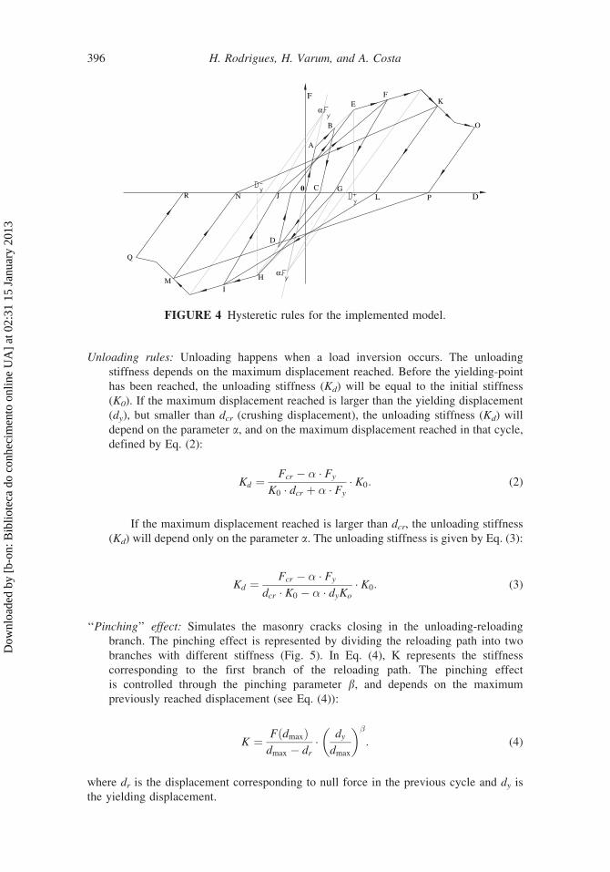
Unloading rules: Unloading happens when a load inversion occurs. The unloading
stiffness depends on the maximum displacement reached. Before the yielding-point
has been reached, the unloading stiffness (Kd) will be equal to the initial stiffness
(K0). If the maximum displacement reached is larger than the yielding displacement
(dy), but smaller than dcr (crushing displacement), the unloading stiffness (Kd) will
depend on the parameter a, and on the maximum displacement reached in that cycle,
defined by Eq. (2):
Kd ¼Fcr � � � Fy
K0 � dcr þ � � Fy
� K0: (2)
If the maximum displacement reached is larger than dcr, the unloading stiffness
(Kd) will depend only on the parameter a. The unloading stiffness is given by Eq. (3):
Kd ¼Fcr � � � Fy
dcr � K0 � � � dyKo
� K0: (3)
‘‘Pinching’’ effect: Simulates the masonry cracks closing in the unloading-reloading
branch. The pinching effect is represented by dividing the reloading path into two
branches with different stiffness (Fig. 5). In Eq. (4), K represents the stiffness
corresponding to the first branch of the reloading path. The pinching effect
is controlled through the pinching parameter b, and depends on the maximum
previously reached displacement (see Eq. (4)):
K ¼ FðdmaxÞdmax � dr
� dy
dmax
� ��: (4)
where dr is the displacement corresponding to null force in the previous cycle and dy is
the yielding displacement.
α.
α.
A
B
C
D
EF
G
H
I
J
K
L
M
N
O
P
Q
R0
F
D
FIGURE 4 Hysteretic rules for the implemented model.
396 H. Rodrigues, H. Varum, and A. Costa
Dow
nloa
ded
by [
b-on
: Bib
liote
ca d
o co
nhec
imen
to o
nlin
e U
A]
at 0
2:31
15
Janu
ary
2013

Stiffness degradation: The stiffness degradation is controlled by the parameter a (Eq. (2)).
Strength degradation: The strength degradation, for repeated cycles of certain dis-
placement amplitude, was implemented by taking into account the interaction
between the degradation in one direction with that in the other. The strength
degradation is given by Eqs. (5)–(8) (see also Fig. 6), where PD1 and PD2 are
the degradation factors in direction 1 and 2; di is the maximum displacement in
the cycle i; dy is the yielding displacement; df is a characteristic displacement
defined in function of the yielding displacement and of the parameter m; and, m,
c, n, and z are constant parameters that are calibrated with experimental results
or empirical formulae.
O
A
B
C
D
E
F
GH
I
JK
Q
L
M
N
P
R
S
T U
V
WX
Y
Z
Y'
S'
L'
V'
P'I'
F
d
FIGURE 5 ‘‘Pinching’’ effect.
O
A
B
C
D
E
F
G H
I
J K
Q
L
M
N
P
R
S
T U
V
W X
Y
Z
H'
N'
U'
K'
R'
F
FIGURE 6 Strength degradation.
Simplified Macro-Model for Infill Masonry Panels 397
Dow
nloa
ded
by [
b-on
: Bib
liote
ca d
o co
nhec
imen
to o
nlin
e U
A]
at 0
2:31
15
Janu
ary
2013

� ¼ c �XN
i¼1
di
df
(5)
df ¼ dy � � (6)
PD1 ¼en� � 1
en � 1� 1� PD2
�
� �(7)
PD2 ¼en� � 1
en � 1� 1� PD1
�
� �(8)
Internal cycles: When a load inversion takes place before the maximum force or the
maximum displacement is reached, the model is able to reproduce the so-called
internal cycles, with all the effects described above.
6. Calibration of the Proposed Infill Masonry Model
The proposed macro-model for the simulation of the influence of infilled masonry panels
on the behavior of the structure was verified using results obtained from two experimental
series. In the numerical models, the material parameters were defined accordingly to
results on test specimens for each material (concrete, steel, and masonry).
This article only presents the comparisons between the experimental and numerical
results in terms of overall structural response parameters, with the intention of illustrating
the validation of the proposed model.
The proposed model for infill masonry panels was implemented in the nonlinear
structural frame program PORANL. In these software, RC structural elements (beams and
columns) are modeled by a macro-element defined by the association of three bar finite
elements, two with nonlinear behavior at its extremities (plastic hinges), and a central
element with linear behavior. The nonlinear monotonic behavior curve of an element is
characterized through a tri-linear moment-curvature relationship, and is able to represent
the response evolution of the global RC section to cyclic demands and contemplates
mechanical behavior effects as stiffness and strength degradation, pinching, slipping and
internal cycles [Varum, 1996].
6.1. Concrete Model
To simulate the structural behavior of the building each RC structural element is modeled
by a macro-element defined by the association of three bar finite elements, two with
nonlinear behavior at its extremities (plastic hinges), and a central element with linear
behavior, as schematically represented in Fig. 7.
The nonlinear behavior of the plastic hinge elements is controlled through a modified
hysteretic procedure, based on the Takeda model, as illustrated in Fig. 8. This model
developed by Costa-and-Costa [CEB, 1996; Cotsa and Costa, 1987] represents the
response moment-curvature evolution of the RC section to cyclic actions and
398 H. Rodrigues, H. Varum, and A. Costa
Dow
nloa
ded
by [
b-on
: Bib
liote
ca d
o co
nhec
imen
to o
nlin
e U
A]
at 0
2:31
15
Janu
ary
2013

contemplates mechanical behavior effects as stiffness and strength degradation, pinching,
slipping, internal cycles, etc.
The nonlinear monotonic behavior curve of a cross-section is characterized through a
tri-linear moment-curvature relationship, corresponding, respectively, to: the initial non-
cracked concrete, concrete cracking, and steel reinforcement yielding. The monotonic
curve is obtained using a fiber model procedure from: the geometric characteristics of the
cross-sections, reinforcement and its location, and material properties.
1
2
3
4
5
6
7
8
9
10
11
12
13
14
15
16
17
18 19
2021
22
D+yD−
y D−c
D+c
F
23
D
12A
13A
FIGURE 8 Global hysteretic model for RC elements [Costa and Costa, 1987].
y'
l pesq
x'
dirpl
l
2Δ
1Δ
3Δ
5Δ4Δ
6Δ
FIGURE 7 Macro-element used for the behavior simulation of reinforced concrete
elements.
Simplified Macro-Model for Infill Masonry Panels 399
Dow
nloa
ded
by [
b-on
: Bib
liote
ca d
o co
nhec
imen
to o
nlin
e U
A]
at 0
2:31
15
Janu
ary
2013

6.2. One-Bay One-Story Infilled Frame
The proposed macro-model for infill masonry was first calibrated with the results of a
cyclic test performed by Pires [1990]. The infilled reinforced concrete model is a single-
story single-bay, scaled 2:3. The geometrical characteristics of the frame, the cross
sections dimensions and the reinforcement detailing of the columns and beam are
presented in Fig. 9. Vertical forces were applied to the top of the columns, to simulate
the dead load, and imposed cyclic horizontal displacements were applied (see Fig. 10).
The properties of the models (RC frame and masonry infill) were calibrated with test
results from material specimens. The reinforcement steel used in the construction of the
frame had an average Young modulus of 190 GPa and a yielding strength of 434 MPa.
–100
–80–60
–40
–20
020
40
6080
100
Dis
plac
emen
t (m
m)
FIGURE 10 Imposed cyclic horizontal displacement.
0.150.42 4.20 0.420.15
0.1650.20
1.625
0.35
[m]
a)
0.15
0.20ø4//0.05
3ø8
3ø8
ø4//0.05
0.15
0.15
8ø8
b)
c)
FIGURE 9 Single-story single-bay infilled masonry RC frame: a) Frame geometry,
b) Cross-section dimensions and detailing of RC elements; c) Testing layout [Bertoldi
et al., 1994].
400 H. Rodrigues, H. Varum, and A. Costa
Dow
nloa
ded
by [
b-on
: Bib
liote
ca d
o co
nhec
imen
to o
nlin
e U
A]
at 0
2:31
15
Janu
ary
2013

From the compressive strength tests on reference specimens it was obtained a compres-
sive strength of 25.3 MPa and a Young modulus of 30 GPa. From diagonal compressive
tests on masonry wallets it was obtained a tensile strength of 270 kPa, and a shear
modulus of 480 MPa. More detailed information about the experimental campaign on
masonry wallets and it components can be found in Pires [1990].
The results obtained with the numerical model are in good agreement with
the experimental response, in terms of shear-drift (Fig. 11) and energy dissipation
(Fig. 12), demonstrating the ability of the proposed macro-model to simulate the global
hysteretic response of infilled frames. The differences observed in the shear-drift
response are acceptable considering that the model proposed is simplified, modeling
globally the entire infill masonry panel and its interaction with the surrounding RC
frame elements.
–140
–100
–60
–20
20
60
100
140
–11.00 –5.50 0.00 5.50 11.00
Bas
e Sh
ear
(kN
)
Drift (cm)
Experimental
Numerical
FIGURE 11 Base-shear versus inter-story drift.
0
0.5
1
1.5
2
2.5
3
3.5
4
4.5
0 5000 10000 15000 20000 25000
Ene
rgy
(MN
.m)
Step
Experimental
Numerical
FIGURE 12 Total energy dissipation.
Simplified Macro-Model for Infill Masonry Panels 401
Dow
nloa
ded
by [
b-on
: Bib
liote
ca d
o co
nhec
imen
to o
nlin
e U
A]
at 0
2:31
15
Janu
ary
2013

In terms of energy dissipation, it was verified that the numerical results leads to a
slight overestimation of the energy dissipation. At the end of the test the difference in
terms of total energy dissipated was inferior to 10%. The evolutions of the energy
dissipated (numerical and experimental) follow a similar path, however it should be
mentioned that larger differences were noticed in the intermediate steps.
6.3. Three-Bay Four-Story Infilled Frame
The research network ICONS (financed by the European Commission) has addressed
the issue of seismic assessment and the retrofitting of existing structures, covering the
related deficiencies and viable retrofitting solutions. In particular, the assessment of
reinforced concrete buildings, with and without infill panels, and several strengthening
solutions and techniques, were investigated through numerical and experimental work.
The experimental research work includes several studies carried out at the ELSA
reaction-wall laboratory, at the JRC. In order to evaluate the efficiency of different
retrofitting solutions and to investigate bare and infilled frame test conditions, two
representative identical full-scale four-story, three-bay reinforced concrete frames (one
as a bare frame and one as a frame with brick infilled walls), were designed, constructed,
and placed parallel to each other and were tested in sequence using pseudo-dynamic
testing procedures (see Fig. 13).
The frames were subjected separately to pseudo-dynamic tests to assess the earth-
quake performance of both the bare concrete frame and the frame structure with infill
masonry walls.
The concrete frame under analysis was essentially designed for gravity loads. The
reinforcement details were specified in order to be representative of buildings constructed
up to the late 1970’s in European Mediterranean countries such as Portugal, Italy, Greece,
Turkey, etc.
The general layout and dimensions of the structure under investigation are given in
Fig. 14. This was a four-story frame with three bays, two with a 5.00 m span and one
external one with a 2.50 m span. Inter-story height was 2.70 m for all four stories, and a
concrete slab 2.00 m wide on each side and 0.15 m thick was cast together with the
beams. Equal beams (geometry and reinforcement details) were considered for all floors.
FIGURE 13 Four-stories, three-bays full-scale plane frame structures.
402 H. Rodrigues, H. Varum, and A. Costa
Dow
nloa
ded
by [
b-on
: Bib
liote
ca d
o co
nhec
imen
to o
nlin
e U
A]
at 0
2:31
15
Janu
ary
2013

All beams in the direction of loading were 0.25 m wide and 0.50 m deep. The stocky
column had section dimensions of 0.25 m · 0.60 m at the 1st and 2nd story and at the 3rd
and 4th story are 0.25 m · 0.50 m. The other columns had equal geometric characteristics
at all stories. The vertical loads are shown in Fig. 15.
15.1 15.1
15.1 15.1
15.1 15.1
12.7 12.7
15.1
15.1
15.1
12.7
56.4
56.4
56.4
44.3 76.1
88.2
88.2
72.3
72.3
60.2
72.3
88.2
40.5
40.5
40.5
28.4
FIGURE 15 Distribution of vertical static loads [kN; m].
2.70
2.70
2.70
2.70
5.00 5.00 2.50
(1.2x1.0)
(1.2x1.0)
(1.2x1.0)
(1.2x1.0)
(2.0x1.0)
(2.0x1.0)
(2.0x1.0)
(2.0x1.75)
[ m ]
1 2 3 4
FIGURE 14 Frame geometrical characteristics and infill openings dimensions.
Simplified Macro-Model for Infill Masonry Panels 403
Dow
nloa
ded
by [
b-on
: Bib
liote
ca d
o co
nhec
imen
to o
nlin
e U
A]
at 0
2:31
15
Janu
ary
2013

The brick masonry panels (0.20 m thick) were constructed according to the following
specifications: (a) the left-hand bay infill contained a window (1.20 m · 1.00 m) at each
level; (b) the central bay contained a doorway (2.00 m · 1.75 m) at ground level and
window openings (2.00 m · 1.00 m) at each of the upper three levels of the building; and,
(c) the right-hand (2.50 m span) bay contained solid infill, i.e., without openings.
The masonry blocks used in the construction of the infills are ceramic, horizontally
perforated, and have the following dimensions: 0.12 m thick, 0.245 m base-length, and
0.245 m height. The infill walls were constructed with the block units bedded on the
0.120 m · 0.245 m face and the hollows in the horizontal direction (0.120 m thick). The
mortar used in the joints and plaster was manually prepared as the current construction
practice until the late 1970’s. The mortar joints are approximately 1.5 cm thick for both
vertical and horizontal joints, so-called perpend and bed joints, respectively. A 1.5 cm
thick plaster was applied on both sides of the walls [Varum, 2003].
Tests on mortar specimens and block units were carried out in order to characterize
the masonry infill wall components. Wallets representative of the masonry infill walls
were also constructed and tested in compression (perpendicular and parallel to the bed
joints and in the diagonal direction). In the next, a summary of the test results on
specimens of block units, mortar, and infill wallets are presented. A more detailed
description of the infill properties can be found elsewhere [Varum, 2003; Pinto et al.,
2001]. Table 1 summarizes the results obtained for the tests on brick units, mortar and
masonry panels (parallel and perpendicular to the bed joints and diagonal compression
tests, for the nominal areas). Using the empirical expressions proposed by Zarnic and
Gostic [1998], to estimate the infill masonry global properties and the average mechan-
ical properties obtained from the tests on infill masonry wallets, were obtained the
behavior curves for each infill masonry panel used in the modeling of the infilled
frame structure.
The building studied in the present numerical analysis is represented by a plane
frame model (with three degrees of freedom per node, i.e., two translations and one
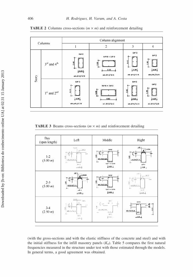
rotation) with four stories and three bays. The geometrical characteristics of the cross
sections and the reinforcement detailing of the columns and beams are summarized in
Tables 2 and 3, respectively. The reinforcement steel used in the construction of the
frames had an average Young modulus of 204.5 GPa and a mean yielding strength of
343.6 MPa [Pinto et al., 1999]. Compressive strength tests on concrete reference speci-
mens were performed for each casting phase. The average values obtained from these
tests are given in Table 4.
From diagonal compressive tests on masonry wallets it was obtained a tensile
strength of 575 kPa, and a shear modulus of 1.17 GPa. More detailed information
about the experimental campaign on masonry wallets and it components can be found
in Varum [2003].
Considering that two full scale test series were performed, one the bare and another
on the infilled frame, and both RC structures have the same dimensions, materials, and
detailing, the calibration of the infilled frame was made as explained in next. Firstly, a
model for the bare structure was developed and calibrated with the pseudo-dynamic test
results of the bare frame. To model the infilled structure, the mechanical parameters
adopted for the RC frame elements were the ones that resulted from the numerical model
calibration of the bare frame done in the first phase and discussed in Rodrigues [2005].
6.3.1. Bare Frame Structure. The nonlinear response of the RC bare frame was
computed for each earthquake input motion applied in the pseudo-dynamic tests
[Varum, 2003]. A first earthquake of 15 s duration corresponding to a 475 years return
404 H. Rodrigues, H. Varum, and A. Costa
Dow
nloa
ded
by [
b-on
: Bib
liote
ca d
o co
nhec
imen
to o
nlin
e U
A]
at 0
2:31
15
Janu
ary
2013

period (yrp), and subsequently, the first 7.5 s of an earthquake signal corresponding to a
975-yrp earthquake were applied to the structure (see Fig. 16). In the dynamic analysis
performed, it was considered an equivalent Rayleight damping of 1%, associated to the
first two natural modes.
The results obtained with the numerical model for the bare frame are compared with
the experimental pseudo-dynamic test results. The displacements time histories (experi-
mental pseudo-dynamic results and numerical calculations) are shown in Fig. 17.
Comparing the numerical results obtained with the nonlinear structural model for the
bare frame with the experimental results, it can be observed a good matching between the
experimental results and the numerical, despite the former tend to underestimate dis-
placement demands in the last cycle, corresponding to the imminent structure collapse.
6.3.2. Infilled Frame Structures. A first analysis of results in terms of natural frequen-
cies and modal shapes intends to constitute the first validation of the numerical models.
The natural frequencies were computed with the initial stiffness of the frame elements
TABLE 1 Summary table of materials (brick units and plaster) and masonry specimens
test results [Varum, 2003]
Element tested Test Symbol Units Value
Brick units Compressive strength
(parallel to the bed joints)
�nnc MPa 15.36
Compressive strength
(perpendicular to the bed
joints)
�?c MPa 2.80
Mortar (joints and
plaster)
Tensile strength �t MPa 0.59
Compressive strength �c MPa 1.33
Masonry wallets Vertical
and horizontal
compressive tests
(without plaster)1
Compressive strength
(parallel to the bed joints)
�nnc MPa 1.11
Compressive strength
(perpendicular to the bed
joints)
�?c MPa 1.10
Young modulus (parallel to
the bed joints)
Enn GPa 0.991
Young modulus
(perpendicular to the bed
joints)
E? GPa 1.873
Masonry wallets
Diagonal compressive
tests (without plaster)1
Tensile strength �t MPa 0.233
Shear modulus G GPa 0.657
Masonry wallets Tensile strength �t MPa 0.575
Diagonal compressive
tests (with plaster in
both sides)1
Shear modulus G GPa 1.171
1 – tests performed at laboratory of University of Pavia.
Simplified Macro-Model for Infill Masonry Panels 405
Dow
nloa
ded
by [
b-on
: Bib
liote
ca d
o co
nhec
imen
to o
nlin
e U
A]
at 0
2:31
15
Janu
ary
2013
(with the gross-sections and with the elastic stiffness of the concrete and steel) and with
the initial stiffness for the infill masonry panels (K0). Table 5 compares the first natural
frequencies measured in the structure under test with those estimated through the models.
In general terms, a good agreement was obtained.
TABLE 3 Beams cross-sections (m · m) and reinforcement detailing
TABLE 2 Columns cross-sections (m · m) and reinforcement detailing
406 H. Rodrigues, H. Varum, and A. Costa
Dow
nloa
ded
by [
b-on
: Bib
liote
ca d
o co
nhec
imen
to o
nlin
e U
A]
at 0
2:31
15
Janu
ary
2013

By the numerical models implemented, the nonlinear response of the RC infilled
frame was computed for each earthquake input motion applied in the pseudo-dynamic
tests. Earthquakes of 15 s duration and increasing return periods, corresponding to 475,
975, and 2,000 yrp, were applied to the infilled frame. During the pseudo-dynamic tests,
collapse was observed at 5.0 s of the 2,000-yrp earthquake input motion. Therefore, to
reproduce the testing sequence, the numerical analysis was performed for the earthquake
accelerogram shown in Fig. 18. The input motion is composed of three consecutive
accelerograms. The first two are 15 s in duration and correspond to the 475 and
975 yrp accelerograms, and the third corresponds to the initial 5 s of the 2,000 yrp
input motion. The three accelerograms are separated by 5 s of zero ground acceleration.
Therefore, the dynamic movement at the end of each 15 s accelerogram is damped till the
beginning of the subsequent accelerogram, reproducing real testing conditions. The
numerical analysis was performed for the 45 s duration earthquake input motion shown
in Fig. 18. In the dynamic analysis performed, it was considered an equivalent Rayleigh
damping of 1%, associated to the first two natural modes.
The results obtained with the numerical model are compared with the experimental
pseudo-dynamic test results. The time histories (experimental pseudo-dynamic results and
numerical calculations) in terms of story displacements are shown in Fig. 19. Figure 20
shows both the computed and the experimentally measured plots of story-shear force
versus inter-story drift, at story levels (shear-drift hysteresis diagrams). Figure 21 shows
the evolution of the dissipated energy, at story level, for the infilled frame under analysis.
Figure 22 shows the observed damage at the end of the pseudo-dynamic tests and
the numerical results in terms of plastic hinges location and damage state estimation in
these regions.
TABLE 4 Concrete properties
Columns Beams
Material properties
1st
story
2nd
story
3rd
story
4th
story
1st
story
2nd
story
3rd
story
4th
story
Ecm [GPa] 22.8 22.8 19.9 21.1 24.4 24.4 24.4 24.4
fcm [MPa] 16.6 13.78 16.50 13.58 13.24 18.10 21.63 16.98
–3
–2
–1
0
1
2
3
0 5 10 15 20 25
Acc
eler
atio
n (m
/s2 )
Time (s)
FIGURE 16 Earthquake input motion for the bare frame structure.
Simplified Macro-Model for Infill Masonry Panels 407
Dow
nloa
ded
by [
b-on
: Bib
liote
ca d
o co
nhec
imen
to o
nlin
e U
A]
at 0
2:31
15
Janu
ary
2013

Comparing the nonlinear dynamic numerical results for the infilled frame with the
experimental results, the following main conclusions can be drawn.
� The numerical model was able to reproduce the modifications in structural response
induced by the infill panels. The natural frequencies of the infilled structure were
considerably increased, when compared to the original bare frame. As already observed,
the numerical model also reproduces the frequencies of the structural system well.
� The numerical analyses confirm that the infill panels can protect the reinforced
concrete frame for low intensity seismic input, but for larger input motion, the
fragile behavior of the masonry induces an explosive rupture.
4th
Stor
y
–100
–50
0
50
100
150
0 5 10 15 20 25
Dis
plac
emen
t (m
m)
–100
–50
0
50
100
150
Dis
plac
emen
t (m
m)
Time (s)
Time (s)
Time (s)
Time (s)
Experimental
Numerical
Experimental
Numerical
Experimental
Numerical
Experimental
Numerical
3rd
Stor
y
0 5 10 15 20 25
2nd
Stor
y
–50–40–30–20–10
01020304050
0 5 10 15 20 25
Dis
plac
emen
t (m
m)
1st S
tory
–15
–10
–5
0
5
10
15
20
0 5 10 15 20 25
Dis
plac
emen
t (m
m)
FIGURE 17 Story displacement evolutions.
408 H. Rodrigues, H. Varum, and A. Costa
Dow
nloa
ded
by [
b-on
: Bib
liote
ca d
o co
nhec
imen
to o
nlin
e U
A]
at 0
2:31
15
Janu
ary
2013

� The numerical model was able to predict the failure of the infill walls well. In fact,
the soft-story mechanism at ground level is well identified with the numerical
models.
� Comparing the numerical with the experimental results, significant differences
were found at the 2nd-story global shear-drift curve. However, on one hand the
level of deformations at this story is significantly smaller then the corresponding to
the first story and, on the other hand, the global response of the overall structure is
leaded by the first story response, where the soft-story mechanism was verified.
The proposed numerical model was able to represents the global behavior of the
infilled RC structure.
� The global numerical model of the structure was able to reproduce the experi-
mental results, not only in terms of story shear and inter-story drift time-histories
and envelopes, shear-drift curves, but also in terms of energy dissipation.
� The numerical results confirm that the adopted models (RC elements with flexural
nonlinearity concentrated at their extremities and the macro-model for the infill
panels) are suitable for the simulation of the nonlinear seismic response of
masonry infilled RC frames.
7. Conclusions and Final Considerations
Masonry infill walls have a complex behavior due to the properties of their materials and
to the interaction with the surrounding frame. The global response of infilled RC frames
is largely dependent of the masonry infills properties and dimensions. However, its
TABLE 5 Natural frequencies and vibration modes of infilled frame
–3
–2
–1
0
1
2
3
0 5 10 15 20 25 30 35 40
Acc
eler
atio
n (m
/s2 )
Time (Sec)
FIGURE 18 Earthquake input motion.
Simplified Macro-Model for Infill Masonry Panels 409
Dow
nloa
ded
by [
b-on
: Bib
liote
ca d
o co
nhec
imen
to o
nlin
e U
A]
at 0
2:31
15
Janu
ary
2013

consideration is not current in the design practice. The response prediction of masonry
infilled frame structures can be achieved by computational modeling. The response of
such structures to horizontal loads is highly complex and depends on many factors, from
material properties to the quality of the workmanship. The development of simplified
nonlinear numerical models, together with increased computational power, permit the
inclusion of infill masonry models in the structural assessment of existing structures and
in the design of new buildings.
This article describes a proposed simplified macro-model for the representation
of the hysteretic behavior of infill masonry panels, and its implementation on a
computer program. The masonry model proposed consists in a variation of the typical
strut model, considering now the interaction of masonry panel behavior in both
directions, i.e., damage in the panel in one direction affects its behavior in the
other direction. The masonry panel hysteretic procedure consider different rules for
loading, reloading, and unloading and considers also stiffness and strength degrada-
tion, and pinching effect.
4th St
ory
3rd St
ory
2nd St
ory
1st St
ory
–0.04
–0.03
–0.02
–0.01
0.00
0.01
0.02
0 10 20 30 40
Time (s)
Time (s)
Time (s)
Time (s)
Dis
plac
emen
t (m
)
Experimental
Numerical
Experimental
Numerical
Experimental
Numerical
Experimental
Numerical
–0.03
–0.04
–0.02
–0.01
0.00
0.01
0.02
0.03
0 10 20 30 40
Dis
plac
emen
t (m
)
–0.04
–0.03
–0.02
–0.01
0.01
0.02
–0.04
–0.03
–0.02
–0.01
0.01
0.02
0 10 20 30 40
Dis
plac
emen
t (m
)D
ispl
acem
ent (
m)
0 5 10 15 20 25 30 35 40
FIGURE 19 Story displacement evolutions.
410 H. Rodrigues, H. Varum, and A. Costa
Dow
nloa
ded
by [
b-on
: Bib
liote
ca d
o co
nhec
imen
to o
nlin
e U
A]
at 0
2:31
15
Janu
ary
2013

4th S
tory
3rd S
tory
2nd S
tory
1st S
tory
–750
–550
–350
–150
50
250
450
650
–0.30 –0.20 –0.10 0.00 0.10 0.20 0.30
Drift (%)
–0.30 –0.20 –0.10 0.00 0.10 0.20 0.30
Drift (%)
–0.30 –0.20 –0.10 0.00 0.10 0.20 0.30
Drift (%)
–1.5 –1 –0.5 0 0.5 1 1.5
Drift (%)
Shea
r (k
N)
Shea
r (k
N)
Shea
r (k
N)
Shea
r (k
N)
ExperimentalNumerical
ExperimentalNumerical
ExperimentalNumerical
ExperimentalNumerical
–800
–600
–400
–200
0
200
400
600
800
–1000
–800
–600
–400
–200
0
200
400
600
800
1000
–1000
–800
–600
–400
–200
0
200
400
600
800
1000
FIGURE 20 Story-shear versus inter-story drift.
Simplified Macro-Model for Infill Masonry Panels 411
Dow
nloa
ded
by [
b-on
: Bib
liote
ca d
o co
nhec
imen
to o
nlin
e U
A]
at 0
2:31
15
Janu
ary
2013

4th S
tory
3rd S
tory
2nd S
tory
1st S
tory
0
0.5
1
1.5
2
2.5
3
3.5
0 5 10 15 20 25 30 35 40
Time (s)
0 5 10 15 20 25 30 35 40
Time (s)
0 5 10 15 20 25 30 35 40
Time (s)
0 5 10 15 20 25 30 35 40
Time (s)
Dis
sipa
ted
ener
gy (
kN.m
)D
issi
pate
d en
ergy
(kN
.m)
Dis
sipa
ted
ener
gy (
kN.m
)D
issi
pate
d en
ergy
(kN
.m)
ExperimentalNumerical
ExperimentalNumerical
ExperimentalNumerical
ExperimentalNumerical
0
2
4
6
8
10
0
5
10
15
20
25
30
35
40
0
20
40
60
80
100
FIGURE 21 Story energy dissipation evolution.
412 H. Rodrigues, H. Varum, and A. Costa
Dow
nloa
ded
by [
b-on
: Bib
liote
ca d
o co
nhec
imen
to o
nlin
e U
A]
at 0
2:31
15
Janu
ary
2013

The proposed infill masonry model was calibrated with the results of two tests on infilled
RC structures, namely of a cyclic test on a single-story single-bay, scaled 2:3, and on a full-
scale frame four-stories, three-bays frame. The structural response was calculated by impos-
ing, although the vertical load, the displacements history on the single-story, single-bay frame
structure, and for the full-scale frame four-stories structure it was applied the acceleration time
histories considered in the corresponding pseudo-dynamic tests. The numerical results were
compared to the experimental, for both test series, and generally it was observed that the
model proposed was able to represent the response of the structures in terms of displacements
evolution, global shear-drift at each story, and cumulative dissipated energy.
The proposed macro-model can be a useful tool in the development and calibration
of simplified rules for the analysis of infilled frame structures under horizontal loadings,
accounting for important mechanical features as hysteretic behavior, strength and stiff-
ness degradation, pinching, damage evolution, and function of the deformation demands.
A more exhaustive testing campaign on masonry infilled structures, considering the
effects of apertures dimensions and location, infill dimensions, relative stiffness frame/
infill, etc., would help to calibrate the model here proposed for a more wide range of
conditions. This could lead to empirical expressions valid for a broad range of situations,
which could be considered in future seismic structural assessment standards.
Acknowledgments
The experimental data used in this article were obtained from two test series. The first
were developed at the LNEC Laboratory, in Lisbon, and the second at the Joint Research
Centre’s ELSA Laboratory, financed by the European Commission, under the Training
and Mobility of Researchers program, the TMR- Large-Scale Facilities and the ICONS
TMR-Network.
FIGURE 22 Damage state a) experimental results [Varum, 2003]; b) numerical results.
Simplified Macro-Model for Infill Masonry Panels 413
Dow
nloa
ded
by [
b-on
: Bib
liote
ca d
o co
nhec
imen
to o
nlin
e U
A]
at 0
2:31
15
Janu
ary
2013

References
Anil, O. and Altin, S. [2007] ‘‘An experimental study on reinforced concrete partially infilled
frames,’’ Engineering Structures 29: 449–60.
Asteris, P. G. [2008] ‘‘Finite element micro-modeling of infilled frames,’’ Electronic Journal of
Structural Engineering 8:1–11.
Asteris, P. G. [2003] ‘‘Lateral stiffness of brick masonry infilled plane frames,’’ Journal of
Structural Engineering, ASCE 129(8):1071–1079.
Bell, D. K. and Davidson, B. J. [2001] ‘‘Evaluation of earthquake risk buildings with masonry infill
panels,’’ 2001 Technical Conference, Future Directions: A Vision for Earthquake Engineering
in New Zealand, New Zealand Society for Earthquake Engineering Taupo, New Zealand.
Bertoldi, S. H., Decanini, L. D., Santini, S., and Via, G. [1994] ‘‘Analytical models in infilled frames,’’
Proc. of the 10th European Conference in Earthquake Engineering, Vienna 1533–1538.
Blandon-Uribe, C. A. [2005] ‘‘Implementation of an infill masonry model for seismic assessment
of existing buildings,’’ Individual Study, European School for Advanced Studies in Reduction of
Seismic Risk (ROSE School), Pavia, Italy.
CEB [1996] ‘‘RC frames under earthquake loading,’’ Comite Euro-International du Beton,
Bulletin 231:1–303.
CEN [2003] ‘‘Eurocode 8: Design of structures for earthquake resistance - Part 1–3: Strengthening
and repair of buildings - European prEN 1998-1-3,’’ European Committee for Standardization,
Brussels, Belgium.
Combescure, D. [1996] ‘‘Modelisation du comportement sous chargement sismique des structures
de batiment comportant des murs de remplissage en maconnerie,’’ PhD thesis (in French Ecole
Centrale de Paris, France.).
Combescure, D. and Pegon, P. [2000] ‘‘Application of the local to global approach to the study of
infilled frame structures under seismic loading,’’ Proc. of the 12th World Conference on
Earthquake Engineering, Auckland, New Zealand.
Costa, A. G. [1989] ‘‘Analise sısmica de estruturas irregulares,’’ Ph.D. Thesis, Civil Engineering
Department, University of Porto (in Portuguese).
Costa, A. C. and Costa, A. G. [1987] ‘‘Hysteretic model of force displacement relationships for
seismic analysis of structures,’’ National Laboratory for Civil Engineering, Lisbon.
Crisafulli, F. J. [1997] ‘‘Seismic behavior of reinforced concrete structures with masonry infills,’’
Ph.D. thesis, University of Canterbury, New Zealand.
Crisafulli, F. J., Carr, A. J., and Park, R. [2000] ‘‘Analytical modelling of infilled frames structures -
A general review,’’ Bulletin of the New Zealand Society for Earthquake Engineering 33: 30–47.
Doherty, K., Griffith, M. C., Lam, N., and Wilson, J. [2002] ‘‘Displacement-based seismic analysis
for out-of-plane bending of unreinforced masonry walls,’’ Earthquake Engineering and
Structural Dynamics 31: 833–850.
Dolsek, M. and Fajfar, P. [2008] ‘‘The effect of masonry infills on the seismic response of a four-storey
reinforced concrete frame: a deterministic assessment,’’ Engineering Structures 30: 1991–2001.
Duarte, R. T. and Campos-Costa, A. [1988] ‘‘Earthquake behaviour of reinforced concrete frames
structures infilled with masonry panels,’’ Technical Report, LNEC, Lisbon.
FEMA-273 [1997] NEHRP Guidelines for the Seismic Rehabilitation of Buildings, Federal
Emergency Management Agency, Washington, D.C.
FEMA-306 [1999] Evaluation of Earthquake Damaged Concrete and Masonry Wall Buildings –
Basic Procedures Manual, Federal Emergency Management Agency, Washington, D.C.
FEMA-307 [1999] Evaluation of Earthquake Damaged Concrete and Masonry Wall Buildings –
Technical Resources, Federal Emergency Management Agency, Washington, D.C.
FEMA-356 [2000] Prestandard and Commentary for the Seismic Rehabilitation of Buildings,
Federal Emergency Management Agency, Washington, D.C.
Freeman, S. A. [1977] ‘‘Racking tests of high rise building partitions,’’ Journal of Structural
Division ASCE 103(ST8).
Klingner, R. Y. and Bertero, V. [1976] ‘‘Infilled frames in earthquake-resistant construction,’’
Report No. EERC 76-32, University of California, Berkeley.
414 H. Rodrigues, H. Varum, and A. Costa
Dow
nloa
ded
by [
b-on
: Bib
liote
ca d
o co
nhec
imen
to o
nlin
e U
A]
at 0
2:31
15
Janu
ary
2013

Krstevka, L. and Ristic, D. [2004] ‘‘Seismic response of RC infilled frames – micro-model for
non-linear numerical simulation,’’ Proc. of the 13th World Conference on Earthquake
Engineering, Vancouver, Canada, Paper No. 1119.
Lam, N. T. K., Griffith, M., Wilson, J., and Doherty, K. [2003] ‘‘Time-history analysis of URM
walls in out-of-plane flexure,’’ Engineering Structures 25:743–754.
Liaw, T. C. and Kwan, K. H. [1983] ‘‘Plastic theory of infilled frames with finite interface shear
strength,’’ Proc. of the Institution of Civil Engineers, Part 2, 75:707–723.
Liaw, T. C. and Lee, S. W. [1977] ‘‘Analysis of the behaviour of multi-storey infilled frames
subject to lateral loading,’’ Proc. of the Institution of Civil Engineers Part 2, 63:641–657.
Magenes, G. and Pampanin, S. [2004] ‘‘Seismic response of gravity-load design frames with
masonry infills,’’ 13th World Conference on Earthquake Engineering, Vancouver, B.C.,
Canada.
Mainstone, R. J. [1971] ‘‘On the stiffnesses and strengths of infilled frames,’’ Proc. of the
Institution of Civil Engineers, Supplement (IV), Paper 73605:57–90.
Mallick, D. V. and Garg, R. P. [1971] ‘‘Effect of openings on the lateral stiffness of infilled
frames,’’ Proc. of the Institution of Civil Engineers, Structural Buildings, 49:193–209.
Oliveira, D. [1995] ‘‘Comportamento de porticos de betao armado preenchidos com paredes de
alvenaria,’’ MSc Thesis, FEUP, Portugal.
Paulay, T. and Priestley, M. [1992] Seismic Design of Reinforced Concrete and Masonry Buildings,
John Wiley & Sons, Inc., New York.
Pinto, A. V., Verzeletti, G., Molina, F. J., Varum, H., Carvalho, E. C., and Coelho, E. [2001]
‘‘Pseudo-dynamic tests on non-seismic resisting RC frames (infilled frame and infill strength-
ened frame tests),’’ EU Special Publication, ELSA, JRC-Ispra, EC, Italy.
Pinto, A. V., Verzeletti, G., Molina, F. J., Varum, H., Coelho, E., and Pinho, R. [1999] ‘‘Pseudo-
dynamic tests on non-seismic resisting RC frames (bare and selective retrofit frames),’’ EUR
Report 20244 EN, ELSA, JRC-Ispra, EC, Italy.
Pires, F. [1990] ‘‘Influencia das Paredes de Alvenaria no comportamento de Estruturas Reticuladas
de Betao Armado sujeitas a Accoes Horizontais,’’ LNEC, Lisboa (in Portuguese).
Polyakov, S. V. [1957] Masonry in Framed Buildings. An Investigation into the Strength and
Stiffness of Masonry Infilling, Moscow.
Puglisi, M., Uzcategui, M., and Florez-Lopez, J. [2009a] ‘‘Modeling of masonry of infilled frames,
Part I: The plastic concentrator,’’ Engineering Structures 31:113–118.
Puglisi, M., Uzcategui, M., and Florez-Lopez, J. [2009b] ‘‘Modeling of masonry of infilled frames,
Part II: Cracking and damage,’’ Engineering Structures 31:119–124.
Riddington, J. R. and Stafford Smith, B. [1977] ‘‘Analysis of infilled frames subject to racking with
design recommendations,’’ The Structural Engineer 55(6):263–268.
Rodrigues, H. [2005] ‘‘Development and calibration of numerical models for building
seismic analysis,’’ MSc Thesis, Civil Engineering Department, University of Porto (in
Portuguese).
Rodrigues, H., Varum, H., and Costa, A. G. [2005] ‘‘Modelo numerico nao-linear para paineis de
alvenaria de enchimento em porticos de betao armado,actas do Congreso Metodos Numericos en
Ingenierıa,’’ E.T.S. de Ingenieros de Caminos de la Universidad de Granada, Spain.
Rodrigues, H., Varum, H., Costa, A. G., and Romao, X. [2004] ‘‘Interface Grafico para
Analise Nao-Linear de Porticos Planos Sujeitos a Cargas Dinamicas e/ou Estaticas,’’
Congresso de Metodos Computacionais em Engenharia - CMCE 2004, LNEC, Lisboa (in
Portuguese).
RSA [1983] ‘‘Regulamento de seguranca e accoes para estruturas de edifıcios e pontes - Decreto-
Lei N.� 235/83,’’ Imprensa Nacional, Casa da Moeda, Lisbon, Portugal (in Portuguese).
Smyrou, E. [2006] ‘‘Implementation and verification of Masonry panel model for nonlinear
dynamic analysis of Infilled RC frames,’’ MSc Thesis, European School for Advanced Studies
in Reduction of Seismic Risk (ROSE School), Pavia, Italy.
Sortis, A., Pasquale, G., and Nasini, U. [1999] ‘‘Criteri di calcolo per la progettazione degli
interventi - Terremoto in Umbria e Marche del 1997,’’ Servizio Sismico Nazionale, Editrice
Sallustiana, Roma (in Italian).
Simplified Macro-Model for Infill Masonry Panels 415
Dow
nloa
ded
by [
b-on
: Bib
liote
ca d
o co
nhec
imen
to o
nlin
e U
A]
at 0
2:31
15
Janu
ary
2013

Stafford-Smith, B. [1962] ‘‘Lateral stiffness of infilled frames,’’ Proc. of the American Society of
Civil Engineers, ASCE 88:183–199.
Stafford-Smith, B. and Carter, C. [1969] ‘‘A method of analysis for infilled frames,’’ Proc. of the
Institution of Civil Engineers, 44:31–48.
Valiasis, T. N. and Stylianidis, K. C. [1989] ‘‘Masonry infilled R/C frames under horizontal
loading — experimental results,’’ European Earthquake Engineering 3(3): 10–20.Varum, H.
[1996] ‘‘Modelo numerico para a analise de porticos planos de betao armado,’’ MSc Thesis,
Civil Engineering Department, University of Porto (in Portuguese).
Varum, H. [2003] ‘‘Seismic assessment, strengthening and repair of existing buildings,’’ PhD
Thesis, Department of Civil Engineering, University of Aveiro, Portugal.
Zarnic, R. and Gostic, S. [1998] ‘‘Non-linear modelling of masonry infilled frames,’’ Proc. of the
11th European Conference on Earthquake Engineering, Paris.
416 H. Rodrigues, H. Varum, and A. Costa
Dow
nloa
ded
by [
b-on
: Bib
liote
ca d
o co
nhec
imen
to o
nlin
e U
A]
at 0
2:31
15
Janu
ary
2013