INVESTIGATION OF THE SEISMIC BEHAVIOUR OF INFILL ...
11
16 th World Conference on Earthquake Engineering, 16WCEE 2017 Santiago Chile, January 9th to 13th 2017 Paper N° 3064 (Abstract ID) Registration Code: S-C1463230992 INVESTIGATION OF THE SEISMIC BEHAVIOUR OF INFILL MASONRY USING NUMERICAL MODELLING APPROACHES T. Kubalski (1) , C. Butenweg (2) , M. Marinković (3) , S. Klinkel (4) (1) Research Assistant, Chair of Structural Analysis and Dynamics, RWTH Aachen University, [email protected] (2) Professor, Faculty of Energy Technology, FH Aachen University of Applied Sciences, [email protected] (3) Research Assistant, University of Belgrade, Faculty of Civil Engineering, Department of engineering mechanics and theory of structures, [email protected] (4) Professor, Chair of Structural Analysis and Dynamics, RWTH Aachen University, [email protected] Abstract Masonry is a widely spread construction type which is used all over the world for different types of structures. Due to its simple and cheap construction, it is used as non-structural as well as structural element. In frame structures, such as reinforced concrete frames, masonry may be used as infill. While the bare frame itself is able to carry the loads when it comes to seismic events, the infilled frame is not able to warp freely due to the constrained movement. This restraint results in a complex interaction between the infill and the surrounding frame, which may lead to severe damage to the infill as well as the surrounding frame. The interaction is studied in different projects and effective approaches for the description of the behavior are still lacking. Experimental programs are usually quite expensive, while numerical models, once validated, do offer an efficient approach for the investigation of the interaction when horizontally loaded. In order to study the numerous parameters influencing the seismic load bearing behavior, numerical models may be used. Therefore, this contribution presents a numerical approach for the simulation of infill masonry in reinforced concrete frames. Both parts, the surrounding frame as well as the infill are represented by micro modelling approaches to correctly take into account the different types of failure. The adopted numerical model describes the inelastic behavior of the system, as indicated by the obtained results of the overall structural response as well as the formation of damage in the infilled wall. Comparison of the numerical and experimental results highlights the valuable contribution of numerical simulations in the study and design of infilled frames. As damage of the infill masonry may occur in-plane due to the interaction as well as out-of-plane due to the low vertical load, both directions of loading are investigated. Keywords: Infill masonry, reinforced concrete structures, horizontally loaded masonry, numerical modelling
-
Upload
khangminh22 -
Category
Documents
-
view
1 -
download
0
Transcript of INVESTIGATION OF THE SEISMIC BEHAVIOUR OF INFILL ...
16th World Conference on Earthquake Engineering, 16WCEE 2017
Santiago Chile, January 9th to 13th 2017
Paper N° 3064 (Abstract ID)
Registration Code: S-C1463230992
INVESTIGATION OF THE SEISMIC BEHAVIOUR OF INFILL MASONRY
USING NUMERICAL MODELLING APPROACHES
T. Kubalski(1), C. Butenweg(2), M. Marinković(3), S. Klinkel(4)
(1) Research Assistant, Chair of Structural Analysis and Dynamics, RWTH Aachen University, [email protected] (2) Professor, Faculty of Energy Technology, FH Aachen University of Applied Sciences, [email protected] (3) Research Assistant, University of Belgrade, Faculty of Civil Engineering, Department of engineering mechanics and theory of
structures, [email protected] (4) Professor, Chair of Structural Analysis and Dynamics, RWTH Aachen University, [email protected]
Abstract
Masonry is a widely spread construction type which is used all over the world for different types of structures. Due to its
simple and cheap construction, it is used as non-structural as well as structural element. In frame structures, such as
reinforced concrete frames, masonry may be used as infill. While the bare frame itself is able to carry the loads when it
comes to seismic events, the infilled frame is not able to warp freely due to the constrained movement. This restraint results
in a complex interaction between the infill and the surrounding frame, which may lead to severe damage to the infill as well
as the surrounding frame. The interaction is studied in different projects and effective approaches for the description of the
behavior are still lacking. Experimental programs are usually quite expensive, while numerical models, once validated, do
offer an efficient approach for the investigation of the interaction when horizontally loaded. In order to study the numerous
parameters influencing the seismic load bearing behavior, numerical models may be used. Therefore, this contribution
presents a numerical approach for the simulation of infill masonry in reinforced concrete frames. Both parts, the
surrounding frame as well as the infill are represented by micro modelling approaches to correctly take into account the
different types of failure. The adopted numerical model describes the inelastic behavior of the system, as indicated by the
obtained results of the overall structural response as well as the formation of damage in the infilled wall. Comparison of the
numerical and experimental results highlights the valuable contribution of numerical simulations in the study and design of
infilled frames. As damage of the infill masonry may occur in-plane due to the interaction as well as out-of-plane due to the
low vertical load, both directions of loading are investigated.
Keywords: Infill masonry, reinforced concrete structures, horizontally loaded masonry, numerical modelling

16th World Conference on Earthquake Engineering, 16WCEE 2017
Santiago Chile, January 9th to 13th 2017
2
1. Introduction
Masonry as a simple construction type has been used for centuries for the construction especially of residential
buildings all over the world. Besides being used as structural element, masonry is often used in frame structures
as infill in order to provide a partitioning of the different rooms. In everyday practice, it is considered as non-
structural element and thus is usually not taken into account during the design process. While this assumption is
correct for the case of vertical loads, when loaded horizontally the infill may fully participate at the load transfer
due to the interaction of the frame and infill. An increasing horizontal stiffness resulting in a larger seismic
response causing the structure to behave inelastically may be the consequence. This behavior needs to be studied
in order to provide seismic safety. A good way is the use of finite element models, which are able to predict the
response of reinforced concrete frame structures infilled with masonry walls under lateral loads and which can
be used to expand the understanding of the load-carrying mechanisms investigated by experiments.
1.1 Behavior of horizontally loaded infill masonry
When loaded horizontally, an arching mechanism causes the infill to participate at the load transfer. Because of
the interaction between frame and infill, different failure modes may occur in-plane, as can be seen in Fig. 1.
Several authors [1, 2, 3] distinguish four dominant types based for instance on geometry and material properties
of the infill and the surrounding frame. Those modes are the corner crushing mode (CC mode), the sliding shear
mode (SS mode), the diagonal compression mode (DC mode) and the diagonal cracking mode (DK mode). The
CC mode is related to weak infills surrounded by rather strong frames, while the SS failure mode mainly occurs
in cases of poor mortar joints. The DC mode arises in cases of slender infills, whilst the DK mode is the result of
strong infills in frames with rather weak beam-column joints. Detailed description of the different failure modes
can be found in [1, 2, 3].
Fig. 1 – In-plane failure modes of infill masonry [3]
Due to the spatial nature of the earthquake, the infill walls may additionally be loaded in the out-of-plane
direction. In this case, failure usually occurs as an one- (Fig. 2b) or two-sided bending mode (Fig. 2c) or a
complete infill falling out of the frame (Fig. 2a). Especially if prior damage in the in-plane direction has
occurred, the strength in the out-of-plane direction may be reduced significantly. The type of boundary
condition, thus the connection to the surrounding frame, is the main factor influencing the out-of-plane failure
mode and the out-of-plane resistance. The maximum pressure, which the infill is able to carry, increases with the
16th World Conference on Earthquake Engineering, 16WCEE 2017
Santiago Chile, January 9th to 13th 2017
3
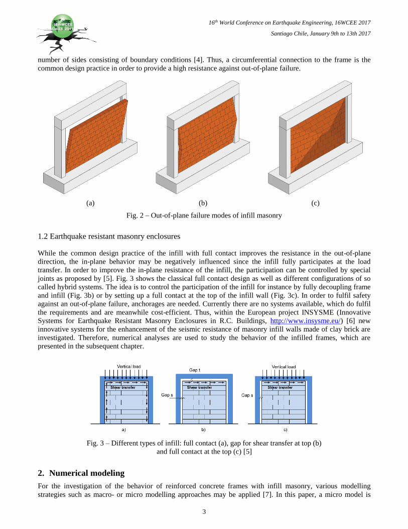
number of sides consisting of boundary conditions [4]. Thus, a circumferential connection to the frame is the
common design practice in order to provide a high resistance against out-of-plane failure.
(a) (b) (c)
Fig. 2 – Out-of-plane failure modes of infill masonry
1.2 Earthquake resistant masonry enclosures
While the common design practice of the infill with full contact improves the resistance in the out-of-plane
direction, the in-plane behavior may be negatively influenced since the infill fully participates at the load
transfer. In order to improve the in-plane resistance of the infill, the participation can be controlled by special
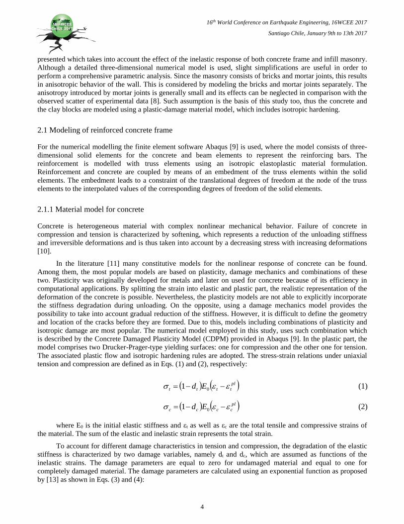
joints as proposed by [5]. Fig. 3 shows the classical full contact design as well as different configurations of so
called hybrid systems. The idea is to control the participation of the infill for instance by fully decoupling frame
and infill (Fig. 3b) or by setting up a full contact at the top of the infill wall (Fig. 3c). In order to fulfil safety
against an out-of-plane failure, anchorages are needed. Currently there are no systems available, which do fulfil
the requirements and are meanwhile cost-efficient. Thus, within the European project INSYSME (Innovative
Systems for Earthquake Resistant Masonry Enclosures in R.C. Buildings, http://www.insysme.eu/) [6] new
innovative systems for the enhancement of the seismic resistance of masonry infill walls made of clay brick are
investigated. Therefore, numerical analyses are used to study the behavior of the infilled frames, which are
presented in the subsequent chapter.
Fig. 3 – Different types of infill: full contact (a), gap for shear transfer at top (b)
and full contact at the top (c) [5]
2. Numerical modeling
For the investigation of the behavior of reinforced concrete frames with infill masonry, various modelling
strategies such as macro- or micro modelling approaches may be applied [7]. In this paper, a micro model is
16th World Conference on Earthquake Engineering, 16WCEE 2017
Santiago Chile, January 9th to 13th 2017
4
presented which takes into account the effect of the inelastic response of both concrete frame and infill masonry.
Although a detailed three-dimensional numerical model is used, slight simplifications are useful in order to
perform a comprehensive parametric analysis. Since the masonry consists of bricks and mortar joints, this results
in anisotropic behavior of the wall. This is considered by modeling the bricks and mortar joints separately. The
anisotropy introduced by mortar joints is generally small and its effects can be neglected in comparison with the
observed scatter of experimental data [8]. Such assumption is the basis of this study too, thus the concrete and
the clay blocks are modeled using a plastic-damage material model, which includes isotropic hardening.
2.1 Modeling of reinforced concrete frame
For the numerical modelling the finite element software Abaqus [9] is used, where the model consists of three-
dimensional solid elements for the concrete and beam elements to represent the reinforcing bars. The
reinforcement is modelled with truss elements using an isotropic elastoplastic material formulation.
Reinforcement and concrete are coupled by means of an embedment of the truss elements within the solid
elements. The embedment leads to a constraint of the translational degrees of freedom at the node of the truss
elements to the interpolated values of the corresponding degrees of freedom of the solid elements.
2.1.1 Material model for concrete
Concrete is heterogeneous material with complex nonlinear mechanical behavior. Failure of concrete in
compression and tension is characterized by softening, which represents a reduction of the unloading stiffness
and irreversible deformations and is thus taken into account by a decreasing stress with increasing deformations
[10].
In the literature [11] many constitutive models for the nonlinear response of concrete can be found.
Among them, the most popular models are based on plasticity, damage mechanics and combinations of these
two. Plasticity was originally developed for metals and later on used for concrete because of its efficiency in
computational applications. By splitting the strain into elastic and plastic part, the realistic representation of the
deformation of the concrete is possible. Nevertheless, the plasticity models are not able to explicitly incorporate
the stiffness degradation during unloading. On the opposite, using a damage mechanics model provides the
possibility to take into account gradual reduction of the stiffness. However, it is difficult to define the geometry
and location of the cracks before they are formed. Due to this, models including combinations of plasticity and
isotropic damage are most popular. The numerical model employed in this study, uses such combination which
is described by the Concrete Damaged Plasticity Model (CDPM) provided in Abaqus [9]. In the plastic part, the
model comprises two Drucker-Prager-type yielding surfaces: one for compression and the other one for tension.
The associated plastic flow and isotropic hardening rules are adopted. The stress-strain relations under uniaxial
tension and compression are defined as in Eqs. (1) and (2), respectively:
pl
tttt Ed 01 (1)
pl
cccc Ed 01 (2)
where E0 is the initial elastic stiffness and εt as well as εc are the total tensile and compressive strains of
the material. The sum of the elastic and inelastic strain represents the total strain.
To account for different damage characteristics in tension and compression, the degradation of the elastic
stiffness is characterized by two damage variables, namely dt and dc, which are assumed as functions of the
inelastic strains. The damage parameters are equal to zero for undamaged material and equal to one for
completely damaged material. The damage parameters are calculated using an exponential function as proposed
by [13] as shown in Eqs. (3) and (4):

16th World Conference on Earthquake Engineering, 16WCEE 2017
Santiago Chile, January 9th to 13th 2017
5
p
ca
c ed
1 (3)
p
ta
t ed
1 (4)
where ac and at are parameters for the uniaxial compression and tension respectively, and can be calibrated
from the uniaxial tensile and compressive tests. The damage evolution curves used in this study are shown in
Fig. 4.
(a) (b)
Fig. 4 – Damage curves for compression (a) and tension (b)
Abaqus [9] uses two factors, namely wt and wc, to control the recovery of the tensile and compressive
stiffness upon load reversal. The default values are wt = 0 and wc = 1. However, these values must be calibrated
to fit the specific hysteretic curve of the actual problem.
This model requires the definition of stress-strain curves to be assigned for compression and tension in
combination with plasticity parameters. A detailed description of the plasticity parameters and their selection is
given in [12]. Under uniaxial compression, the stress-strain relation is linear until the initial yield (fc0) followed
by the plastic regime, which is characterized by plastic hardening. This part is defined using an equation given in
Eurocode 2 [14], which can be regarded as a specialisation of the nonlinear stress-strain curve according to [15].
This curve is defined only up to the nominal ultimate strain. The descending part of the curve starting from the
nominal ultimate strain is calculated according to an approach proposed by [16]. Uniaxial tensile behavior is
defined using a stress-displacement curve instead of a stress-strain curve (Fig. 5). The material is behaving
elastically up to the maximum tensile strength. Afterwards the relationship between the crack width u and the
corresponding tensile stress (Eq. 5) as well as the maximal crack opening uc, which corresponds to the crack
opening if the tensile stress drops to zero, is calculated according to [17], with respect to the fracture energy GF
and maximum tensile strength ft0 as shown in Eq. (5):
2
2 3
1
3
1
0
11c
c
u
uc
ct
t ecu
ue
u
uc
f
uc
(5)
where c1 = 3, c2 = 6.93 and uc is the crack opening for σt = 0 calculated according to Eq. (6) as
follows:
0/14.5 tFc fGu (6)
16th World Conference on Earthquake Engineering, 16WCEE 2017
Santiago Chile, January 9th to 13th 2017
6
Fig. 5 – Stress-displacement curve for the concrete in tension until first crack opens (a) and
relationship between crack opening and tensile stress (b) [17]
The fracture energy of concrete is calculated according to an approach proposed in CEB-FIP Model Code
1990 [18] by using the following equation:
0/
0
7.0
cmf
cmf
FGGF (7)
Herein GF0 is the base value of fracture energy, depending on the maximum aggregate size, as given in
CEB-FIP Model Code 1990 [18]. Furthermore fcm is the mean compressive strength and fcm0 = 10MPa.
2.2 Modeling of masonry wall
Masonry is a heterogeneous material with anisotropic behavior due to the different constituent materials such as
the mortar, the units and the presence of mortar joints in the two directions. The progress in numerical methods
and computational power enabled masonry to be studied without expensive experiments. This approach consists
of developing numerical methods calibrated with experimental test results in order to use them for parametric
analyses that are not posible to be covered by experiments. In finite element analyses two main approaches are
distinguished for the modeling of the masonry, either as a macro model, where bricks and mortar are represented
as a homogenized continuum, or a micro model, where the bricks and the mortar are modelled separately as well
as the interfaces between them [7]. In this study, the masonry is modeled based on a reduced micro model, in
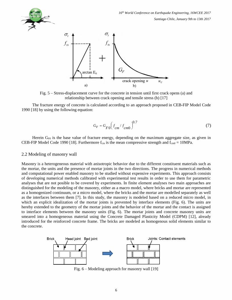
which an explicit idealization of the mortar joints is prevented by interface elements (Fig. 6). The units are
hereby extended to the geometry of the mortar joints and the behavior of the mortar and the contact is assigned
to interface elements between the masonry units (Fig. 6). The mortar joints and concrete masonry units are
smeared into a homogeneous material using the Concrete Damaged Plasticity Model (CDPM) [12], already
introduced for the reinforced concrete frame. The bricks are modeled as homogenous solid elements similar to
the concrete.
Fig. 6 – Modeling approach for masonry wall [19]
16th World Conference on Earthquake Engineering, 16WCEE 2017
Santiago Chile, January 9th to 13th 2017
7
An approach according to [20] is used to generate the required stress curves in compression and tension.
Since the numerical material model uses a curve for the description of the tensile behavior based on the crack
opening, the strain for calculating the tensile stress is determined using the following equation proposed by [21]:
eq
l
ucr (8)
Herein, εcr is the strain at the maximum tensile strength and leq is the length of the regarded finite element.
The parameters to fully describe the stress curves need to be calibrated by using experimental results. Further
description can be found in [20].
2.2.1 Modeling of masonry contact interface
The mortar, which is not modelled explicitly, is taken into account by employing adequate contact elements at
the interfaces of the different bricks. Therefore, a cohesive surface-based behavior was employed to model the
mortar joints using traction-separation of the interfaces [12]. This approach enables a linear elastic transmission
of compressive stresses as well as tensile and adhesive shear stresses until the maximum strength is reached.
After exceeding the maximum strength, friction is activated and thus contributes to the shear stress. A so called
hard contact [12] is used for the transfer of compressive stresses anytime when the surfaces are in contact. If the
head joints are not filled with mortar, the load transfer is directly limited to the transmission of compressive
stresses and frictional forces.
3. Numerical calculations
The ability of the proposed numerical model to predict the behavior of infilled reinforced concrete frames is
shown using data provided by the University of Padova, obtained from experiments conducted within the
framework of the European project INSYSME [6]. The experiments consist of tests of masonry assemblies as
well as bare and infilled reinforced concrete frames, where the infill is made of hollow clay bricks. The different
test set-ups of the infilled frames consist amongst others of cyclic in-plane and combined in-plane and out-of-
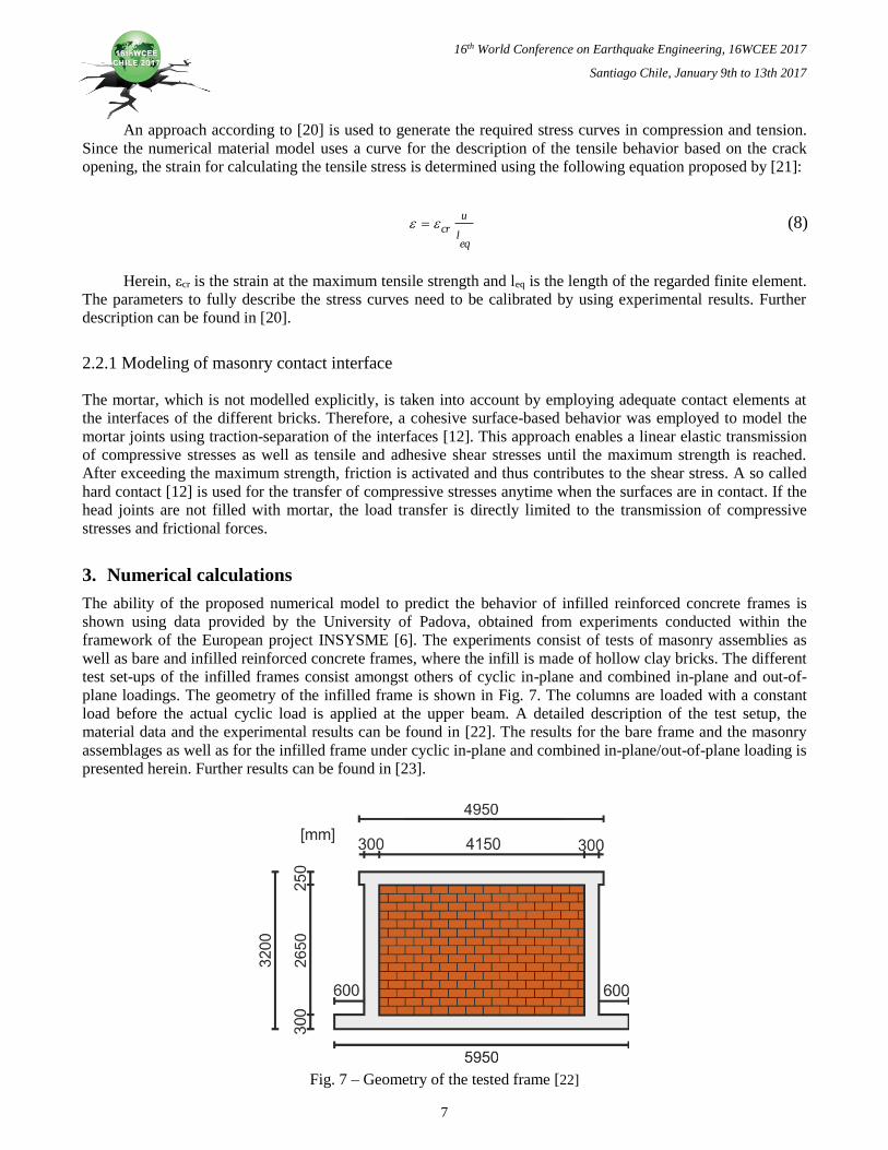
plane loadings. The geometry of the infilled frame is shown in Fig. 7. The columns are loaded with a constant
load before the actual cyclic load is applied at the upper beam. A detailed description of the test setup, the
material data and the experimental results can be found in [22]. The results for the bare frame and the masonry
assemblages as well as for the infilled frame under cyclic in-plane and combined in-plane/out-of-plane loading is
presented herein. Further results can be found in [23].
Fig. 7 – Geometry of the tested frame [22]
16th World Conference on Earthquake Engineering, 16WCEE 2017
Santiago Chile, January 9th to 13th 2017
8
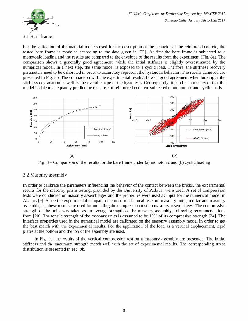
3.1 Bare frame
For the validation of the material models used for the description of the behavior of the reinforced conrete, the
tested bare frame is modeled according to the data given in [22]. At first the bare frame is subjected to a
monotonic loading and the results are compared to the envelope of the results from the experiment (Fig. 8a). The
comparison shows a generally good agreement, while the intial stiffness is slightly overestimated by the
numerical model. In a next step, the same model is exposed to a cyclic load. Therfore, the stiffness recovery
parameters need to be calibrated in order to accurately represent the hysteretic behavior. The results achieved are
presented in Fig. 8b. The comparison with the experimental results shows a good agreement when looking at the
stiffness degradation as well as the overall shape of the hysteresis. Consequently, it can be summarized, that the
model is able to adequately predict the response of reinforced concrete subjected to monotonic and cyclic loads.
0
50
100
150
200
250
300
350
0 20 40 60 80 100 120
Bas
e s
he
ar [
kN]
Displacement [mm]
Experiment (bare)
ABAQUS (bare)
(a) (b)
Fig. 8 – Comparison of the results for the bare frame under (a) monotonic and (b) cyclic loading
3.2 Masonry assembly
In order to calibrate the parameters influencing the behavior of the contact between the bricks, the experimental
results for the masonry prism testing, provided by the University of Padova, were used. A set of compression
tests were conducted on masonry assemblages and the properties were used as input for the numerical model in
Abaqus [9]. Since the experimental campaign included mechanical tests on masonry units, mortar and masonry
assemblages, these results are used for modeling the compression test on masonry assemblages. The compressive
strength of the units was taken as an average strength of the masonry assembly, following recommendations
from [20]. The tensile strength of the masonry units is assumed to be 10% of its compressive strength [24]. The
interface properties used in the numerical model are calibrated on the masonry assembly model in order to get
the best match with the experimental results. For the application of the load as a vertical displacement, rigid
plates at the bottom and the top of the assembly are used.
In Fig. 9a, the results of the vertical compression test on a masonry assembly are presented. The initial
stiffness and the maximum strength match well with the set of experimental results. The corresponding stress
distribution is presented in Fig. 9b.

16th World Conference on Earthquake Engineering, 16WCEE 2017
Santiago Chile, January 9th to 13th 2017
9
(a) (b)
Fig. 9 – (a) Results of masonry assembly under vertical compression; (b) Stress distribution of masonry assembly under vertical compression
3.3 Masonry infilled frame
In the experiments, amongst other, two infilled frames are tested. First they are loaded with a constant axial load
of 400kN on each column. Afterwards the horizontal displacement is applied in two levels of in-plane drift, to be
specific 0.5% and 1.2%. After carrying out the in-plane tests, the vertical load at the columns is kept constant,
while the infill wall is loaded monotonically in the out-of-plane direction.
3.3.1 Cyclic in-plane testing
Fig. 10 shows the results of the infilled frame under cyclic loading, obtained with the numerical model in
Abaqus [9], compared to the experimental results, as well as the distribution of damage in compression. The
hysteretic curves show that the overall response of the numerical model corresponds quite well to the
experimental results. The stiffness degradation and the load levels are achieved. However, the initial stiffness is
slightly overestimated.
(a) (b)
Fig. 10 – (a) Results of infilled frame under cyclic loading (drift = 0.5%); (b) Corresponding distribution of the damage in compression
16th World Conference on Earthquake Engineering, 16WCEE 2017
Santiago Chile, January 9th to 13th 2017
10
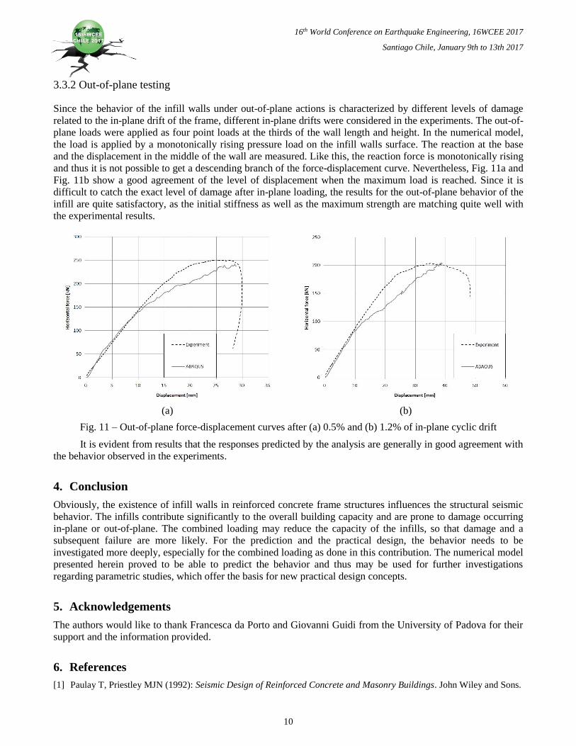
3.3.2 Out-of-plane testing
Since the behavior of the infill walls under out-of-plane actions is characterized by different levels of damage
related to the in-plane drift of the frame, different in-plane drifts were considered in the experiments. The out-of-
plane loads were applied as four point loads at the thirds of the wall length and height. In the numerical model,
the load is applied by a monotonically rising pressure load on the infill walls surface. The reaction at the base
and the displacement in the middle of the wall are measured. Like this, the reaction force is monotonically rising
and thus it is not possible to get a descending branch of the force-displacement curve. Nevertheless, Fig. 11a and
Fig. 11b show a good agreement of the level of displacement when the maximum load is reached. Since it is
difficult to catch the exact level of damage after in-plane loading, the results for the out-of-plane behavior of the
infill are quite satisfactory, as the initial stiffness as well as the maximum strength are matching quite well with
the experimental results.
(a) (b)
Fig. 11 – Out-of-plane force-displacement curves after (a) 0.5% and (b) 1.2% of in-plane cyclic drift
It is evident from results that the responses predicted by the analysis are generally in good agreement with
the behavior observed in the experiments.
4. Conclusion
Obviously, the existence of infill walls in reinforced concrete frame structures influences the structural seismic
behavior. The infills contribute significantly to the overall building capacity and are prone to damage occurring
in-plane or out-of-plane. The combined loading may reduce the capacity of the infills, so that damage and a
subsequent failure are more likely. For the prediction and the practical design, the behavior needs to be
investigated more deeply, especially for the combined loading as done in this contribution. The numerical model
presented herein proved to be able to predict the behavior and thus may be used for further investigations
regarding parametric studies, which offer the basis for new practical design concepts.
5. Acknowledgements
The authors would like to thank Francesca da Porto and Giovanni Guidi from the University of Padova for their
support and the information provided.
6. References
[1] Paulay T, Priestley MJN (1992): Seismic Design of Reinforced Concrete and Masonry Buildings. John Wiley and Sons.

16th World Conference on Earthquake Engineering, 16WCEE 2017
Santiago Chile, January 9th to 13th 2017
11
[2] Crisafulli FJ (1997): Seismic behaviour of reinforced concrete structures with masonry infills. Department of Civil
Engineering, University of Canterbury, Christchurch, New Zealand.
[3] El-Dakhakhni WW, Elgaaly M, Hamid AA (2003): Three-Strut Model for Concrete Masonry-Infilled Steel Frames.
Journal of Structural Engineering 129 (2), 177-185.
[4] Dawe JL, Seah CK (1989): Out-of-plane resistance of conrete masonry infilled panels. Canadian Journal of Civil
Engineering 16 (6), 854-864
[5] Biggs DT (2007): Hybrid masonry structures. 10th North American Masonry Conference, St. Louis, Missouri, US.
[6] Butenweg C, Meyer U, Fehling E (2014): EU-Projekt INSYSME: Innovative Techniken für erdbebensichere
Ausfachungswände aus Ziegelmauerwerk in Stahlbetonrahmentragwerken. Mauerwerk 18 (2), 78-81.
[7] Lourenço PB (1996): Computational strategies for masonry. Faculty of Civil Engineering and Geosciences, TU Delft,
The Netherlands.
[8] Hegemier GA, Nunn RO, Arya SK (1978): Behavior of concrete masonry under biaxial stresses. Proceedings of the
North American Masonry Conference, University of Colorado, Boulder, US.
[9] Simulia (2014a): Abaqus FEA. Dassault Systèmes Simulia Corporation.
[10] Grassl P, Nyström U, Rempling R, Gylltoft K (2011): A damage-plasticity model for the dynamic failure of concrete.
8th International Conference on Structural Dynamics, Leuven, Belgium.
[11] Chen WF (1982): Plasticity in reinforced concrete. McGraw-Hill.
[12] Simulia (2014b): Abaqus 6.14 Documentation. Dassault Systèmes Simulia Corporation.
[13] Lee J, Fenves GL (1998): Plastic-Damage Model for Cyclic Loading of Concrete Structures. Journal of Engineering
Mechanics 124 (8), 892-900.
[14] Eurocode 2 (2004): Design of concrete structures – Part 1-1: General rules and rules for buildings. Beuth Verlag.
[15] Sargin M (1971): Stress-strain relationship for concrete and the analysis of structural concrete section. Solid
Mechanics Division, University of Waterloo, Canada.
[16] Pavlović MS (2013): Resistance of Bolted Shear Connectors in Prefabricated Steel-Concrete Composite Decks.
University of Belgrade, Serbia.
[17] Hordijk DA (1992): Tensile and tensile fatigue behavior of concrete; experiments, modeling and analyses. Heron 37
(1), 3-79.
[18] CEB (1993): CEB-FIP Model Code 1990. Thomas Telford Ltd.
[19] Butenweg C, Kuhlmann W, Meskouris K, Mistler M (2004): Seismic Behaviour of Historic Masonry Buildings. 7th
National Congress on Mechanics of HSTAM, Chania, Crete, Greece.
[20] Stavridis A, Shing PB (2010): Finite Element Modeling of Nonlinear Behavior of Masonry-Infilled RC Frames.
Journal of Structural Engineering 136 (3), 285-296.
[21] Almansa FL, Alfarah B, Oller S (2014): Numerical simulation of RC frame testing with damaged plasticity model -
comparison with simplified models. Second European Conference on Earthquake Engineering and Seismology,
Istanbul, Turkey.
[22] Da Porto F, Guidi G, Dalla Benetta M, Verlato N (2013): Combined In-plane/Out-of-plane Experimental Behaviour of
Reinforced and Strengthened Infill Masonry Walls. 12th Canadian Masonry Symposium, Vancouver, British Columbia,
Canada.
[23] Kubalski T, Marinković M, Butenweg C (2016): Numerical Investigation of Masonry Infilled R.C. Frames. 16th
International Brick and Block Masonry Conference, Padova, Italy.
[24] Drysdale RG, Hamid AA, Baker LR (1999): Masonry Structures: Behavior and Design. The Masonry Society.