Seismic behaviour of single storey rat-trap bond masonry buildings retrofitted with GFRP
9
612 JOURNAL OF STRUCTURAL ENGINEERING Vol. 41, No. 6, FEBRUARY - MARCH 2015 Journal of Structural Engineering Vol. 41, No. 6, February - March 2015 pp. 612-620 No. 41-53 Seismic behaviour of single storey rat-trap bond masonry buildings retrofitted with GFRP S. Saileysh Sivaraja* , , R.Angeline Prabhavathy** and T.S.Thandavamoorthy*** Email: [email protected] *PhD Scholar, School of Civil Engineering, Hindustan University and Associate Professor, Department of Civil Engg, Dr MGR University, Chennai, India. **Building Science, School of Civil Engineering, Hindustan University, Chennai, India. ***Department of Civil Engineering, Adhiparasakthi Engineering College, Melmaruvathur - 603 319, India Received: 26 June 2013; Accepted: 15 January 2014 KEYWORDS: Brick masonry; rat-trap bond; impact loading; damages; repaired with GFRP; structural performance. The paper presents in detail the experimental and numerical investigation using ANSYS on 1/3 model of a Rat-trap building of size 2.0 m × 1.0 m × 1.0 m m with thickness of the wall of 92 mm with and without roof slab under base impact test using a shock table especially designed and fabricated for this purpose. One building was tested without a roof slab and the other was provided with a reinforced concrete roof slab consisting of weld mesh made of 3 mm mild steel rod spaced at 50 mm both ways. For each impact its velocity was calculated from the height of fall from which the energy imparted to the building was calculated. The energy absorbed by the building without roof slab was 3600 Nm after 24 impacts and that with roof slab was 4100 Nm after 21 impacts. The corresponding values for the model repaired with GFRP wrapping was 7363.71 Nm after 32 impacts. Pertinent conclusions drawn from the experimental and numerical investigations are also discussed. These conclusions have practical bearings in the construction of Rat- trap bond masonry. Rat-trap bond, a special type of masonry construction, is economical when compared to conventional masonry. It consists of construction of headers and stretchers where bricks are used to lay vertically on the edge of the masonry wall, so as to form a cavity inside the wall. Rat-trap bond masonry is being widely used in construction of buildings nowadays. Masonry suffers major damages, when it is subjected to dynamic loads such as earthquake or wind. The code of practice for brick masonry IS 4326 1 suggests that introduction of lintel band and roof band will help the structure to perform better, especially when it is subjected to seismic loads. Ragunath 2 has found out that one/two storeyed masonry buildings suffered a great deal of damage during earthquakes, leading to significant loss of lives. It was also true that out-of-plane collapse of walls caused maximum damage. It was, therefore, evident that imparting ductility to the brittle masonry was vital in preventing the out-of-plane failure of walls. Jagadish et al 3 studied the basic structural properties of masonry. The strength of bricks in India could vary from 3 MPa to 24 MPa depending on the location of brick manufactured. The bricks in south India using relatively coarse soil ranged in strength from 3 MPa to 10 MPa. However, ordinary bricks from north India where fine alluvial soil were available could provide strengths in the range of 15 MPa to 24 MPa. Murthy 4 made a number of earthquake tips about masonry buildings. He emphasized the necessity of horizontal bands in masonry buildings. The bands were provided to hold a masonry building as a single unit by tying all the walls together and were similar to a closed belt provided around cardboard boxes. He also emphasized the simple configuration for masonry buildings. Korany and Drysdale 5 investigated the earthquake damage
Transcript of Seismic behaviour of single storey rat-trap bond masonry buildings retrofitted with GFRP

612 Journal of Structural EnginEEring Vol. 41, no. 6, fEbruary - March 2015
Journal of Structural EngineeringVol. 41, no. 6, february - March 2015 pp. 612-620 No. 41-53
Seismic behaviour of single storey rat-trap bond masonry buildings retrofitted with GFRP
S. Saileysh Sivaraja*,, r.angeline Prabhavathy** and t.S.thandavamoorthy*** Email: [email protected]
*PhD Scholar, School of civil Engineering, hindustan university and associate Professor, Department of civil Engg, Dr Mgr university, chennai, india.**building Science, School of civil Engineering, hindustan university, chennai, india.
***Department of civil Engineering, adhiparasakthi Engineering college, Melmaruvathur - 603 319, india
received: 26 June 2013; accepted: 15 January 2014
KeywoRds: brick masonry; rat-trap bond; impact loading; damages; repaired with gfrP; structural performance.
The paper presents in detail the experimental and numerical investigation using ANsys on 1/3 model of a Rat-trap building of size 2.0 m × 1.0 m × 1.0 m m with thickness of the wall of 92 mm with and without roof slab under base impact test using a shock table especially designed and fabricated for this purpose. one building was tested without a roof slab and the other was provided with a reinforced concrete roof slab consisting of weld mesh made of 3 mm mild steel rod spaced at 50 mm both ways. For each impact its velocity was calculated from the height of fall from which the energy imparted to the building was calculated. The energy absorbed by the building without roof slab was 3600 Nm after 24 impacts and that with roof slab was 4100 Nm after 21 impacts. The corresponding values for the model repaired with GFRP wrapping was 7363.71 Nm after 32 impacts. Pertinent conclusions drawn from the experimental and numerical investigations are also discussed. These conclusions have practical bearings in the construction of Rat-trap bond masonry.
rat-trap bond, a special type of masonry construction, is economical when compared to conventional masonry. it consists of construction of headers and stretchers where bricks are used to lay vertically on the edge of the masonry wall, so as to form a cavity inside the wall. rat-trap bond masonry is being widely used in construction of buildings nowadays. Masonry suffers major damages, when it is subjected to dynamic loads such as earthquake or wind. the code of practice for brick masonry iS 43261 suggests that introduction of lintel band and roof band will help the structure to perform better, especially when it is subjected to seismic loads.
ragunath2 has found out that one/two storeyed masonry buildings suffered a great deal of damage during earthquakes, leading to significant loss of lives. it was also true that out-of-plane collapse of walls caused maximum damage. it was, therefore, evident
that imparting ductility to the brittle masonry was vital in preventing the out-of-plane failure of walls. Jagadish et al3 studied the basic structural properties of masonry. the strength of bricks in india could vary from 3 MPa to 24 MPa depending on the location of brick manufactured. the bricks in south india using relatively coarse soil ranged in strength from 3 MPa to 10 MPa. however, ordinary bricks from north india where fine alluvial soil were available could provide strengths in the range of 15 MPa to 24 MPa. Murthy4 made a number of earthquake tips about masonry buildings. he emphasized the necessity of horizontal bands in masonry buildings. the bands were provided to hold a masonry building as a single unit by tying all the walls together and were similar to a closed belt provided around cardboard boxes. he also emphasized the simple configuration for masonry buildings. Korany and Drysdale5 investigated the earthquake damage
Journal of Structural EnginEEring 613 Vol. 41, no. 6, fEbruary - March 2015
to un-reinforced masonry buildings and have shown the vulnerability of perimeter walls to out-of-plane failure. this described a study that was carried out to develop and test innovative fiber reinforced polymer (frP) rehabilitation techniques that met the stringent requirements for strengthening historical buildings and to be cost effective alternatives applicable to other existing masonry structures. oliveira et al6 have invetigated the experimental behaviour of solid clay brick masonry arches strengthened with glass fiber-reinforced Polymer (gfrP) composites. twelve half-scale segmental masonry arches subjected to a load applied at the quarter span were tested under displacement control up to failure. the arches were built using handmade low strength bricks and a commercial lime-based mortar, trying to mimic ancient structures. cheng and Mccomb7 conducted impact tests using drop-weight pendulum on nine 1.2 m high full-scale concrete masonry block walls to investigate the out-of-plane behaviour of unreinforced masonry (urM) walls externally strengthened with carbon-fiber-reinforced polymer (CFRP) composites. Lunn and rizkalla8 have evaluated the effectiveness of different externally bonded gfrP systems for increasing the out-of-plane resistance of infill masonry walls to loading. Parameters investigated in the experimental programme included aspect ratio, frP coverage ratio, number of masonry wythes, and type of frP anchorage. test results indicated that the type of frP anchorage had a significant effect on the failure mode. Research findings concluded that GFRP strengthening of infill masonry walls was effective in increasing the out-of-plane load-carrying capacity when proper anchorage of the frP laminate was provided.
El-Dakhakhni et al9 have developed macromodel to predict the in-plane behaviour of concrete masonry. in this multilaminate model, the masonry assemblage was replaced by an equivalent material which consisted of homogeneous medium intersected by two sets of plane of weakness along the head and bed joints. the macro behaviour of the equivalent material was determined by smearing the influence of the plane of weakness to determine the global behaviour of the model. the prediction of the response of unreinforced masonry by the proposed model was verified by comparison with the experimental results of masonry panels subjected to different biaxial stress conditions. gajalakshmi10 et al10 carried out transient dynamic nonlinear analysis
to find out the response of 1/3 masonry model with and without roof. Models representative of English bond masonry laid with a weak lime cement mortar including idealized openings investigated. it was observed that introducing rcc horizontal band at lintel level strengthened the model. it was concluded that, with increased mass because of heavy roof leads to the out-of-plane failure of the cross walls. the results were validated with the available experimental results.
the aim of the paper is to present experimental investigations carried out on rat-trap bond masonry houses without and with roof slabs as well as on those repaired with gfrP wrapping. the experimental values are compared with those obtained from numerical analysis using anSyS package. With gfrP wrapping the energy absorption increases by 80 per cent over that of the model with roof slab. by numerical analysis using anSyS software, the energy of the models is higher by 18-22 per cent than the experimental models.
eXPeRIMeNTAL INVesTIGATIoN
Preparation of scaled Bricks
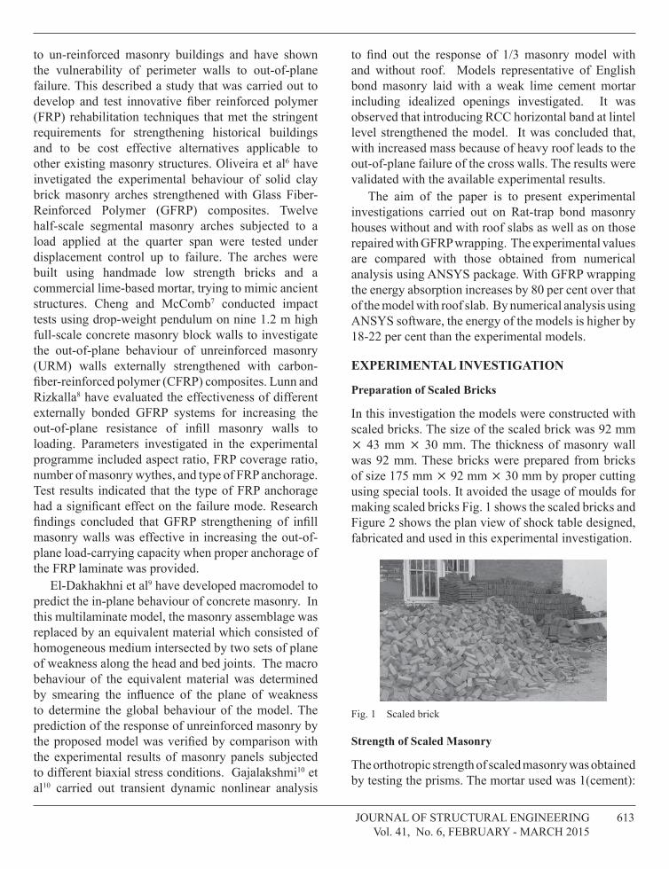
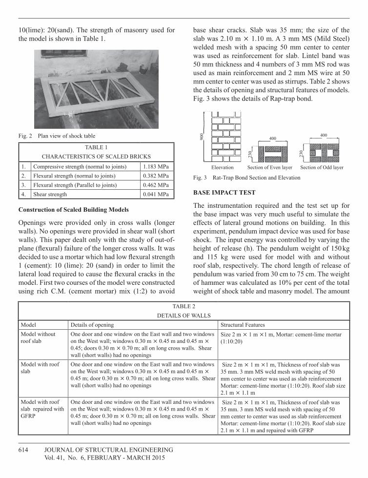
in this investigation the models were constructed with scaled bricks. the size of the scaled brick was 92 mm 43 mm 30 mm. the thickness of masonry wall was 92 mm. these bricks were prepared from bricks of size 175 mm 92 mm 30 mm by proper cutting using special tools. it avoided the usage of moulds for making scaled bricks fig. 1 shows the scaled bricks and figure 2 shows the plan view of shock table designed, fabricated and used in this experimental investigation.
fig. 1 Scaled brick
strength of scaled Masonry
the orthotropic strength of scaled masonry was obtained by testing the prisms. the mortar used was 1(cement):
614 Journal of Structural EnginEEring Vol. 41, no. 6, fEbruary - March 2015
10(lime): 20(sand). the strength of masonry used for the model is shown in table 1.
fig. 2 Plan view of shock table
tablE 1ChaRaCteRistiCs oF sCaLed bRiCKs
1. compressive strength (normal to joints) 1.183 MPa2. flexural strength (normal to joints) 0.382 MPa3. flexural strength (Parallel to joints) 0.462 MPa4. Shear strength 0.041 MPa
Construction of scaled Building Models
openings were provided only in cross walls (longer walls). no openings were provided in shear wall (short walls). this paper dealt only with the study of out-of-plane (flexural) failure of the longer cross walls. it was decided to use a mortar which had low flexural strength 1 (cement): 10 (lime): 20 (sand) in order to limit the lateral load required to cause the flexural cracks in the model. first two courses of the model were constructed using rich c.M. (cement mortar) mix (1:2) to avoid
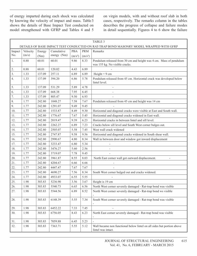
base shear cracks. Slab was 35 mm; the size of the slab was 2.10 m 1.10 m. a 3 mm MS (Mild Steel) welded mesh with a spacing 50 mm center to center was used as reinforcement for slab. lintel band was 50 mm thickness and 4 numbers of 3 mm MS rod was used as main reinforcement and 2 mm MS wire at 50 mm center to center was used as stirrups. table 2 shows the details of opening and structural features of models. fig. 3 shows the details of rap-trap bond.
900
230
400400
230
Eleevation Section of Even layer Section of Odd layer
fig. 3 rat-trap bond Section and Elevation
BAse IMPACT TesT
the instrumentation required and the test set up for the base impact was very much useful to simulate the effects of lateral ground motions on building. in this experiment, pendulum impact device was used for base shock. the input energy was controlled by varying the height of release (h). the pendulum weight of 150 kg and 115 kg were used for model with and without roof slab, respectively. the chord length of release of pendulum was varied from 30 cm to 75 cm. the weight of hammer was calculated as 10% per cent of the total weight of shock table and masonry model. the amount
tablE 2DEtailS of WallS
Model Details of opening Structural featuresModel without roof slab
one door and one window on the East wall and two windows on the West wall; windows 0.30 m 0.45 m and 0.45 m 0.45; doors 0.30 m 0.70 m; all on long cross walls. Shear wall (short walls) had no openings
Size 2 m 1 m 1 m, Mortar: cement-lime mortar (1:10:20)
Model with roof slab
one door and one window on the East wall and two windows on the West wall; windows 0.30 m 0.45 m and 0.45 m 0.45 m; door 0.30 m 0.70 m; all on long cross walls. Shear wall (short walls) had no openings
Size 2 m 1 m 1 m, thickness of roof slab was 35 mm. 3 mm MS weld mesh with spacing of 50 mm center to center was used as slab reinforcement Mortar: cement-lime mortar (1:10:20). roof slab size 2.1 m 1.1 m
Model with roof slab repaired with gfrP
one door and one window on the East wall and two windows on the West wall; windows 0.30 m 0.45 m and 0.45 m 0.45 m; door 0.30 m 0.70 m; all on long cross walls. Shear wall (short walls) had no openings
Size 2 m 1 m 1 m, thickness of roof slab was 35 mm. 3 mm MS weld mesh with spacing of 50 mm center to center was used as slab reinforcement Mortar: cement-lime mortar (1:10:20). roof slab size 2.1 m 1.1 m and repaired with gfrP
Journal of Structural EnginEEring 615 Vol. 41, no. 6, fEbruary - March 2015
of energy imparted during each shock was calculated by knowing the velocity of impact and mass. table 3 shows the details of base impact test conducted on model strengthened with gfrP and tables 4 and 5
on virgin models, with and without roof slab in both cases, respectively. the remarks column in the tables describes the progress of collapse and failure modes in detail sequentially. figures 4 to 6 show the failure
tablE 3DEtailS of baSE iMPact tESt conDuctED on rat-traP bonD MaSonry MoDEl WraPPED With gfrP
impact no.
Velocity (m/s)
Energy(nm)
cumulative energy (nm)
Pba(m/s²)
PrM (m/s²)
remarks
1. 0.88 60.01 60.01 9.86 8.33 Pendulum released from 30 cm and height was 4 cm. Mass of pendulum was 155 kg. no visible cracks.
2. 0.88 60.01 120.02 4.43 6.89 -3. 1.33 137.09 257.11 6.89 6.89 height = 9 cm4. 1.33 137.09 394.20 6.86 5.78 Pendulum released from 45 cm. horizontal crack was developed below
lintel level.5. 1.33 137.09 531.29 5.89 4.78 -6. 1.33 137.09 668.38 7.95 6.45 -7. 1.33 137.09 805.47 9.50 6.93 -8. 1.77 242.80 1048.27 7.58 7.67 Pendulum released from 45 cm and height was 14 cm9. 1.77 242.80 1291.07 9.49 9.45 -10. 1.77 242.80 1533.87 8.49 9.30 horizontal and diagonal cracks were visible at East and South wall.11. 1.77 242.80 1776.67 7.67 5.45 horizontal and diagonal cracks widened in East wall.12. 1.77 242.80 2019.47 9.39 6.23 horizontal cracks in between lintel and sill level.13. 1.77 242.80 2262.27 6.89 7.23 cracks below sill level and South West corner bulges out.14. 1.77 242.80 2505.07 5.58 7.45 West wall crack widened15. 1.77 242.80 2747.87 9.58 9.56 horizontal and diagonal cracks widened in South shear wall.16. 1.77 242.80 2990.67 4.80 8.34 Wall in between door and window got inward displacement 17. 1.77 242.80 3233.47 6.80 5.34 -18. 1.77 242.80 3476.27 5.60 2.56 -19. 1.77 242.80 3719.07 7.78 9.45 -20. 1.77 242.80 3961.87 8.55 8.03 north East corner wall got outward displacement. -21. 1.77 242.80 4204.67 6.66 6.66 -22. 1.77 242.80 4447.47 7.67 7.67 -23. 1.77 242.80 4690.27 7.56 8.34 South West corner bulged out and cracks widened.24. 1.77 242.80 4933.07 6.55 5.55 -25. 1.98 303.83 5236.90 3.56 3.67 height is 19 cm26. 1.98 303.83 5540.73 6.65 6.56 north West corner severely damaged - rat-trap bond was visible27. 1.98 303.83 5544.56 6.89 8.52 north West corner severely damaged - rat-trap bond ws visible
-28. 1.98 303.83 6148.39 5.55 7.34 South West corner severely damaged - rat-trap bond was visible
-29. 1.98 303.83 6452.22 7.33 7.45 -30. 1.98 303.83 6756.05 8.43 6.23 north East corner severely damaged - rat-trap bond was visible
-31. 1.98 303.83 7059.88 6.45 5.23 -32. 1.98 303.83 7363.71 5.55 5.12 Wall became non functional below lintel on all sides but portion above
lintel was intact.
616 Journal of Structural EnginEEring Vol. 41, no. 6, fEbruary - March 2015
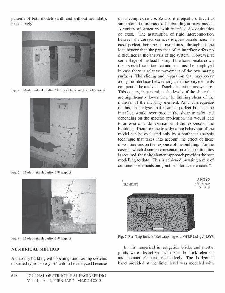
patterns of both models (with and without roof slab), respectively.
fig. 4 Model with slab after 5th impact fixed with accelerometer
fig. 5 Model with slab after 17th impact
fig. 6 Model with slab after 19th impact
NUMeRICAL MeTHod
a masonry building with openings and roofing systems of varied types is very difficult to be analyzed because
of its complex nature. so also it is equally difficult to simulate the failure modes of the building in macro model. a variety of structures with interface discontinuities do exist. the assumption of rigid interconnection between the contact surfaces is questionable here. in case perfect bonding is maintained throughout the load history then the presence of an interface offers no difficulties in the analysis of the system. however, at some stage of the load history if the bond breaks down then special solution techniques must be employed in case there is relative movement of the two mating surfaces. the sliding and separation that may occur along the interfaces between adjacent masonry elements compound the analysis of such discontinuous systems. this occurs, in general, at the levels of the shear that are significantly lower than the limiting shear of the material of the masonry element. as a consequence of this, an analysis that assumes perfect bond at the interface would over predict the shear transfer and depending on the specific application this would lead to an over or under estimation of the response of the building. therefore the true dynamic behaviour of the model can be evaluated only by a nonlinear analysis technique that takes into account the effect of these discontinuities on the response of the building. for the cases in which discrete representation of discontinuities is required, the finite element approach provides the best modelling to date. this is achieved by using a mix of continuous elements and joint or interface elements10.
1ELEMENTS APR 20 2012
06 : 36 : 21
fig. 7 rat -trap bond Model wrapping with gfrP using anSyS
in this numerical investigation bricks and mortar joints were discretized with 8-node brick element and contact element, respectively. the horizontal band provided at the lintel level was modeled with
Journal of Structural EnginEEring 617 Vol. 41, no. 6, fEbruary - March 2015
1NODAL SOLUTIONSTEP=1SUB =1TIME=1USUM (AVG)RSYS=0DMX = .118E-04SMX = .118E-04
APR 20 201207:29:40
1NODAL SOLUTIONSTEP=1SUB =1TIME=1USUM (AVG)RSYS=0DMX = .879E-06SMX = .879E-06
APR 20 201207:55:37
0 .263E-05.131E-05 .394E-05 .657E-05 .919E-05 .118E-04
.525E-05 .788E-05 .105E-04
0 .195E-06.977E-07 .293E-06 .489E-06 .684E-06 .879E-06
.391E-06 .586E-06 .782E-06
1NODAL SOLUTIONSTEP=1SUB =1TIME=1USUM (AVG)RSYS=0DMX = .357E-06SMX = .357E-06
APR 20 201207:51:43
0 .793E-07.396E-07 .119E-06 .198E-06 .277E-06 .357E-06
.159E-06 .238E-06 .317E-06
1NODAL SOLUTIONSTEP=1SUB =1TIME=1USUM (AVG)RSYS=0DMX = .397E-05SMX = .397E-05
APR 20 201207:51:43
0 .881E-06.441E-06 .132E-05 .220E-05 .308E-05 .397E-05
.176E-05 .264E-05 .352E-05
RAT TRAP WITH ROOF LOAD CASE 5 RAT TRAP WITHOUT ROOF LOAD CASE 1
RAT TRAP WITHOUT LOAD CASE 2 RAT TRAP WITHOUT LOAD CASE 3
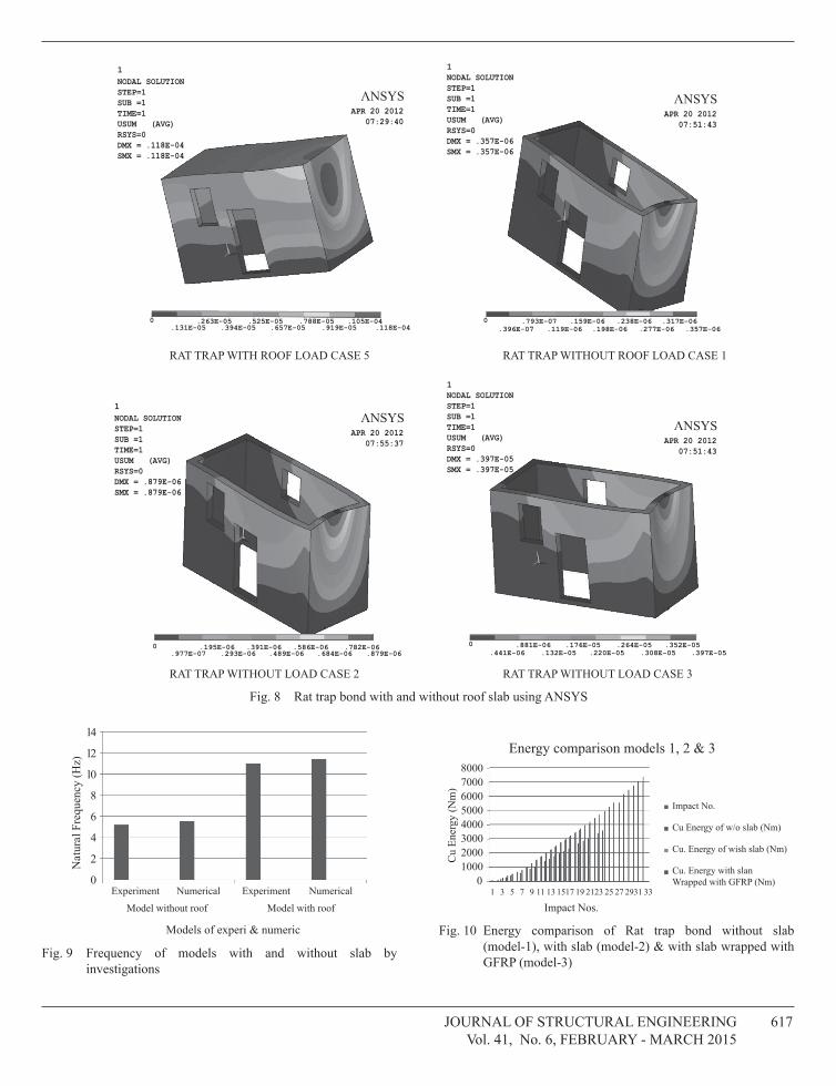
fig. 8 rat trap bond with and without roof slab using anSyS
14
12
10
Nat
ural
Fre
quen
cy (H
z)
8
6
4
2
0
Models of experi & numeric
Experiment
Model without roof Model with roof
Numerical Experiment Numerical
fig. 9 frequency of models with and without slab by investigations
Energy comparison models 1, 2 & 380007000600050004000300020001000
0
Cu
Ener
gy (N
m)
Impact Nos.1 3 5 7 9 11 13 1517 19 2123 25 27 2931 33
Impact No.
Cu Energy of w/o slab (Nm)
Cu. Energy of wish slab (Nm)
Cu. Energy with slanWrapped with GFRP (Nm)
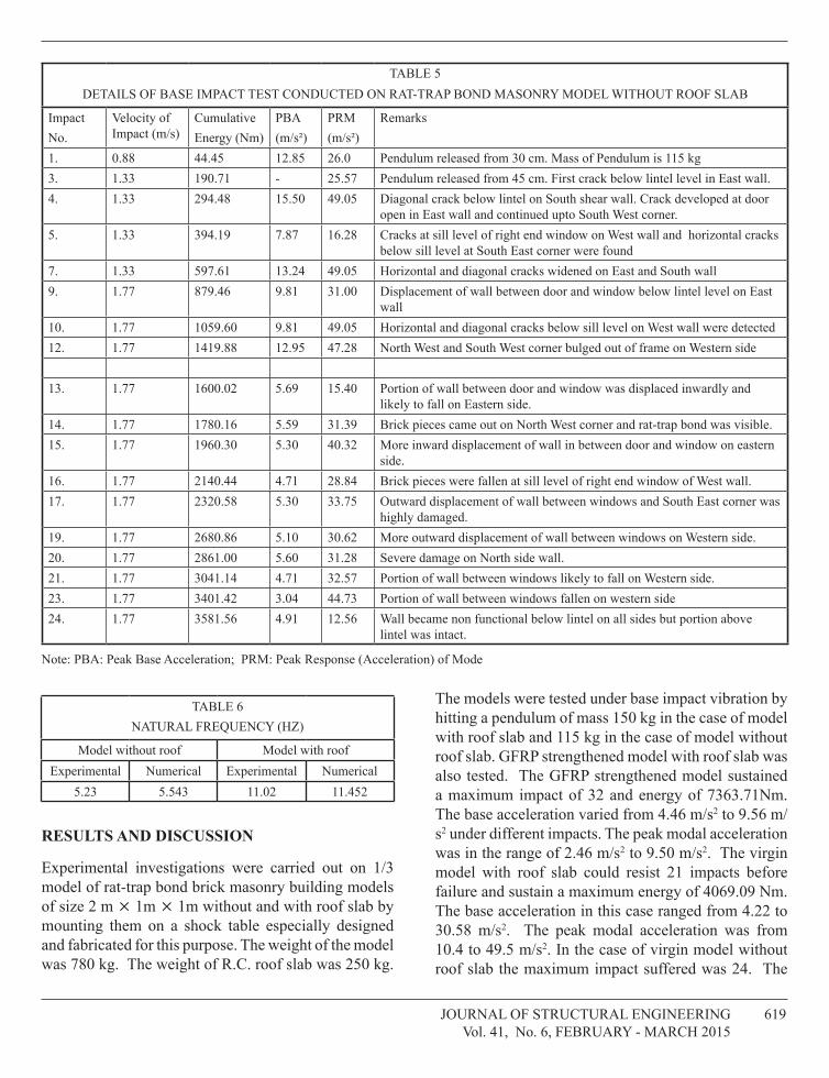
fig. 10 Energy comparison of rat trap bond without slab (model-1), with slab (model-2) & with slab wrapped with gfrP (model-3)
618 Journal of Structural EnginEEring Vol. 41, no. 6, fEbruary - March 2015
elastic beam element. the rcc roof was modeled with solid element. as the rc beam-slab system must remain elastic it was assumed that Ec = 22,360 MPa and Poisson’s ratio 0.15. for the post cracking behaviour of un-reinforced masonry, von mises model with uniaxial stress effect (total strain-based model) were considered. the brick was taken as elastoplastic orthoplastic material with Ex = 600 MPa, and Ey = Ez = 500 MPa with Poisson ratio of 0.1.the joint with frictional co-efficient = 0.7, b = 0.05 was used. figure 7 shows the meshing of model wrapped with gfrP. a nonlinear modal analysis of the models using anSyS software package was carried out to determine the natural frequency and modal acceleration of the model as well as the stress distribution across the building with and without roof slab. figure 8 shows the stress distribution of models with and without roof slab for different impacts as load cases.
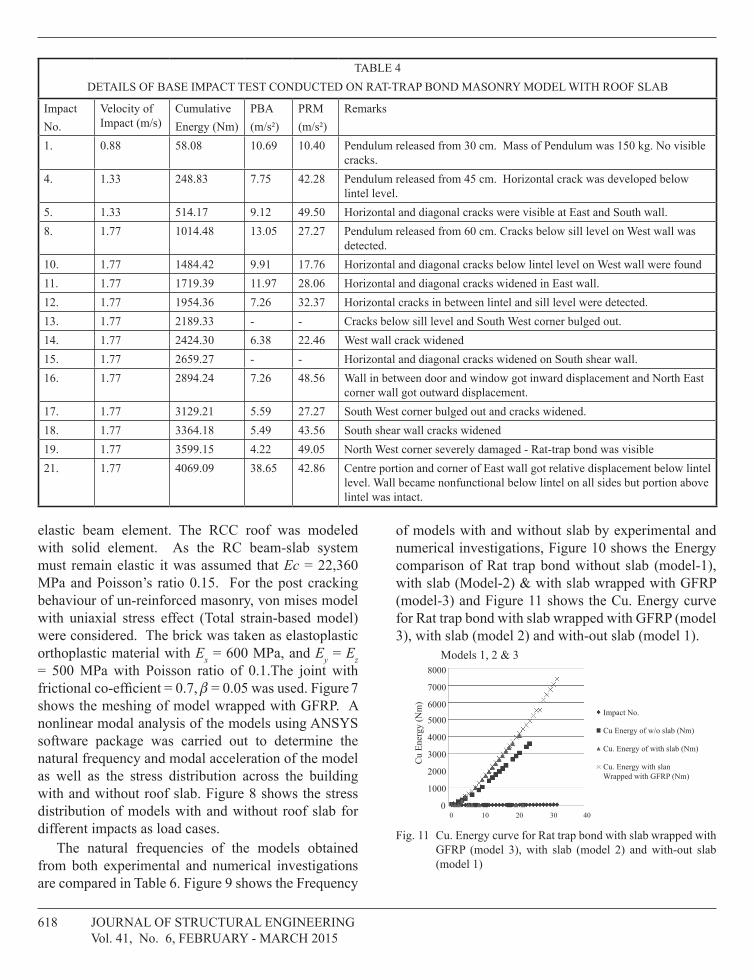
the natural frequencies of the models obtained from both experimental and numerical investigations are compared in table 6. figure 9 shows the frequency
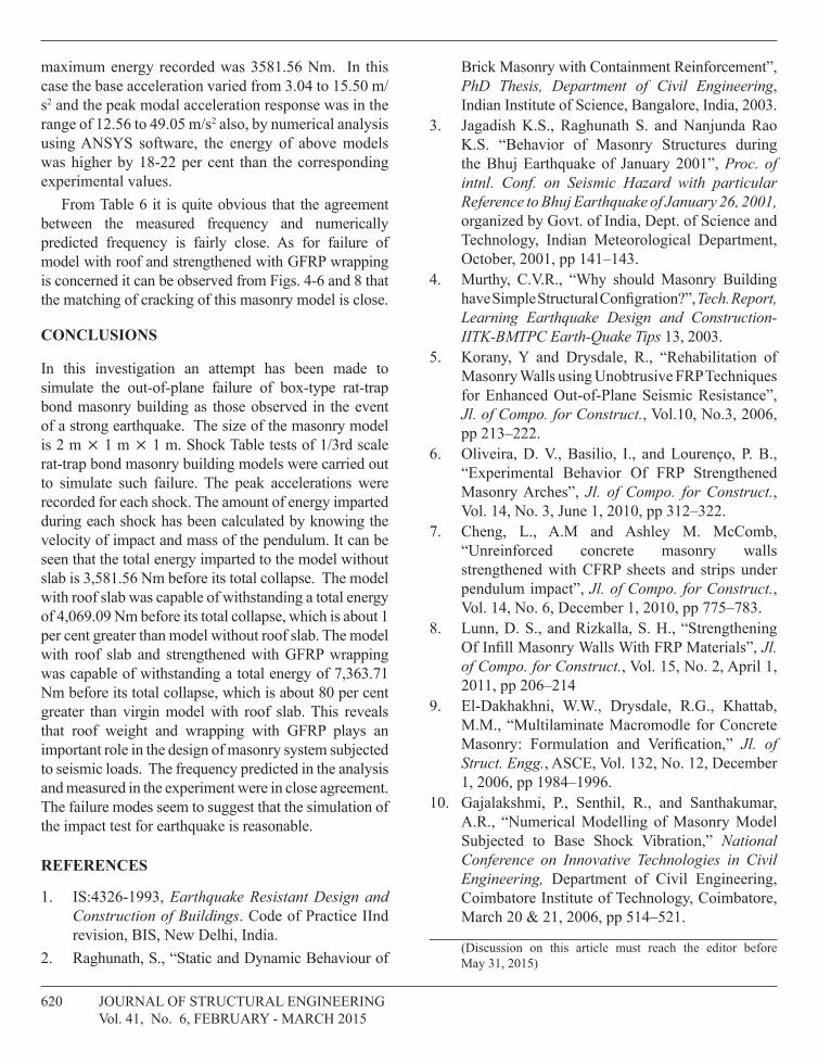
of models with and without slab by experimental and numerical investigations, figure 10 shows the Energy comparison of rat trap bond without slab (model-1), with slab (Model-2) & with slab wrapped with gfrP (model-3) and figure 11 shows the cu. Energy curve for rat trap bond with slab wrapped with gfrP (model 3), with slab (model 2) and with-out slab (model 1).
Models 1, 2 & 38000
7000
6000
5000
4000
3000
2000
1000
0
Cu
Ener
gy (N
m)
0 2010 30 40
Impact No.
Cu Energy of w/o slab (Nm)
Cu. Energy of with slab (Nm)
Cu. Energy with slanWrapped with GFRP (Nm)
fig. 11 cu. Energy curve for rat trap bond with slab wrapped with gfrP (model 3), with slab (model 2) and with-out slab (model 1)
tablE 4DEtailS of baSE iMPact tESt conDuctED on rat-traP bonD MaSonry MoDEl With roof Slab
impactno.
Velocity of impact (m/s)
cumulative Energy (nm)
Pba(m/s²)
PrM(m/s²)
remarks
1. 0.88 58.08 10.69 10.40 Pendulum released from 30 cm. Mass of Pendulum was 150 kg. no visible cracks.
4. 1.33 248.83 7.75 42.28 Pendulum released from 45 cm. horizontal crack was developed below lintel level.
5. 1.33 514.17 9.12 49.50 horizontal and diagonal cracks were visible at East and South wall.8. 1.77 1014.48 13.05 27.27 Pendulum released from 60 cm. cracks below sill level on West wall was
detected. 10. 1.77 1484.42 9.91 17.76 horizontal and diagonal cracks below lintel level on West wall were found11. 1.77 1719.39 11.97 28.06 horizontal and diagonal cracks widened in East wall.12. 1.77 1954.36 7.26 32.37 horizontal cracks in between lintel and sill level were detected.13. 1.77 2189.33 - - cracks below sill level and South West corner bulged out.14. 1.77 2424.30 6.38 22.46 West wall crack widened15. 1.77 2659.27 - - horizontal and diagonal cracks widened on South shear wall.16. 1.77 2894.24 7.26 48.56 Wall in between door and window got inward displacement and north East
corner wall got outward displacement.17. 1.77 3129.21 5.59 27.27 South West corner bulged out and cracks widened.18. 1.77 3364.18 5.49 43.56 South shear wall cracks widened19. 1.77 3599.15 4.22 49.05 north West corner severely damaged - rat-trap bond was visible21. 1.77 4069.09 38.65 42.86 centre portion and corner of East wall got relative displacement below lintel
level. Wall became nonfunctional below lintel on all sides but portion above lintel was intact.
Journal of Structural EnginEEring 619 Vol. 41, no. 6, fEbruary - March 2015
tablE 6natural frEquEncy (hz)
Model without roof Model with roofExperimental numerical Experimental numerical
5.23 5.543 11.02 11.452
ResULTs ANd dIsCUssIoN
Experimental investigations were carried out on 1/3 model of rat-trap bond brick masonry building models of size 2 m 1m 1m without and with roof slab by mounting them on a shock table especially designed and fabricated for this purpose. the weight of the model was 780 kg. the weight of r.c. roof slab was 250 kg.
the models were tested under base impact vibration by hitting a pendulum of mass 150 kg in the case of model with roof slab and 115 kg in the case of model without roof slab. gfrP strengthened model with roof slab was also tested. the gfrP strengthened model sustained a maximum impact of 32 and energy of 7363.71nm. the base acceleration varied from 4.46 m/s2 to 9.56 m/s2 under different impacts. the peak modal acceleration was in the range of 2.46 m/s2 to 9.50 m/s2. the virgin model with roof slab could resist 21 impacts before failure and sustain a maximum energy of 4069.09 nm. the base acceleration in this case ranged from 4.22 to 30.58 m/s2. the peak modal acceleration was from 10.4 to 49.5 m/s2. in the case of virgin model without roof slab the maximum impact suffered was 24. the
tablE 5DEtailS of baSE iMPact tESt conDuctED on rat-traP bonD MaSonry MoDEl Without roof Slab
impactno.
Velocity of impact (m/s)
cumulative Energy (nm)
Pba(m/s²)
PrM(m/s²)
remarks
1. 0.88 44.45 12.85 26.0 Pendulum released from 30 cm. Mass of Pendulum is 115 kg3. 1.33 190.71 - 25.57 Pendulum released from 45 cm. first crack below lintel level in East wall.4. 1.33 294.48 15.50 49.05 Diagonal crack below lintel on South shear wall. crack developed at door
open in East wall and continued upto South West corner.5. 1.33 394.19 7.87 16.28 cracks at sill level of right end window on West wall and horizontal cracks
below sill level at South East corner were found7. 1.33 597.61 13.24 49.05 horizontal and diagonal cracks widened on East and South wall9. 1.77 879.46 9.81 31.00 Displacement of wall between door and window below lintel level on East
wall10. 1.77 1059.60 9.81 49.05 horizontal and diagonal cracks below sill level on West wall were detected12. 1.77 1419.88 12.95 47.28 north West and South West corner bulged out of frame on Western side
13. 1.77 1600.02 5.69 15.40 Portion of wall between door and window was displaced inwardly and likely to fall on Eastern side.
14. 1.77 1780.16 5.59 31.39 brick pieces came out on north West corner and rat-trap bond was visible.15. 1.77 1960.30 5.30 40.32 More inward displacement of wall in between door and window on eastern
side. 16. 1.77 2140.44 4.71 28.84 brick pieces were fallen at sill level of right end window of West wall.17. 1.77 2320.58 5.30 33.75 outward displacement of wall between windows and South East corner was
highly damaged.19. 1.77 2680.86 5.10 30.62 More outward displacement of wall between windows on Western side.20. 1.77 2861.00 5.60 31.28 Severe damage on north side wall.21. 1.77 3041.14 4.71 32.57 Portion of wall between windows likely to fall on Western side.23. 1.77 3401.42 3.04 44.73 Portion of wall between windows fallen on western side24. 1.77 3581.56 4.91 12.56 Wall became non functional below lintel on all sides but portion above
lintel was intact.
note: Pba: Peak base acceleration; PrM: Peak response (acceleration) of Mode
620 Journal of Structural EnginEEring Vol. 41, no. 6, fEbruary - March 2015
maximum energy recorded was 3581.56 nm. in this case the base acceleration varied from 3.04 to 15.50 m/s2 and the peak modal acceleration response was in the range of 12.56 to 49.05 m/s2 also, by numerical analysis using anSyS software, the energy of above models was higher by 18-22 per cent than the corresponding experimental values.
from table 6 it is quite obvious that the agreement between the measured frequency and numerically predicted frequency is fairly close. as for failure of model with roof and strengthened with gfrP wrapping is concerned it can be observed from figs. 4-6 and 8 that the matching of cracking of this masonry model is close.
CoNCLUsIoNs
in this investigation an attempt has been made to simulate the out-of-plane failure of box-type rat-trap bond masonry building as those observed in the event of a strong earthquake. the size of the masonry model is 2 m 1 m 1 m. Shock table tests of 1/3rd scale rat-trap bond masonry building models were carried out to simulate such failure. the peak accelerations were recorded for each shock. the amount of energy imparted during each shock has been calculated by knowing the velocity of impact and mass of the pendulum. it can be seen that the total energy imparted to the model without slab is 3,581.56 nm before its total collapse. the model with roof slab was capable of withstanding a total energy of 4,069.09 nm before its total collapse, which is about 1 per cent greater than model without roof slab. the model with roof slab and strengthened with gfrP wrapping was capable of withstanding a total energy of 7,363.71 nm before its total collapse, which is about 80 per cent greater than virgin model with roof slab. this reveals that roof weight and wrapping with gfrP plays an important role in the design of masonry system subjected to seismic loads. the frequency predicted in the analysis and measured in the experiment were in close agreement. the failure modes seem to suggest that the simulation of the impact test for earthquake is reasonable.
ReFeReNCes
iS:4326-1993, 1. Earthquake Resistant Design and Construction of Buildings. code of Practice iind revision, biS, new Delhi, india.raghunath, S., “Static and Dynamic behaviour of 2.
brick Masonry with containment reinforcement”, PhD Thesis, Department of Civil Engineering, indian institute of Science, bangalore, india, 2003.Jagadish K.s., Raghunath s. and Nanjunda Rao 3. K.s. “behavior of Masonry structures during the bhuj Earthquake of January 2001”, Proc. of intnl. Conf. on Seismic Hazard with particular Reference to Bhuj Earthquake of January 26, 2001, organized by govt. of india, Dept. of Science and technology, indian Meteorological Department, october, 2001, pp 141–143.Murthy, c.V.r., “Why should Masonry building 4. have simple structural Configration?”, Tech. Report, Learning Earthquake Design and Construction-IITK-BMTPC Earth-Quake Tips 13, 2003.Korany, Y and drysdale, R., “Rehabilitation of 5. Masonry Walls using unobtrusive frP techniques for Enhanced out-of-Plane Seismic resistance”, Jl. of Compo. for Construct., Vol.10, no.3, 2006, pp 213–222.oliveira, D. V., basilio, i., and lourenço, P. b., 6. “Experimental behavior of frP Strengthened Masonry arches”, Jl. of Compo. for Construct., Vol. 14, no. 3, June 1, 2010, pp 312–322.cheng, l., a.M and ashley M. Mccomb, 7. “unreinforced concrete masonry walls strengthened with cfrP sheets and strips under pendulum impact”, Jl. of Compo. for Construct., Vol. 14, no. 6, December 1, 2010, pp 775–783.lunn, D. S., and rizkalla, S. h., “Strengthening 8. of infill Masonry Walls With FRP Materials”, Jl. of Compo. for Construct., Vol. 15, no. 2, april 1, 2011, pp 206–214el-dakhakhni, W.W., drysdale, R.G., Khattab, 9. M.M., “Multilaminate Macromodle for concrete Masonry: Formulation and Verification,” Jl. of Struct. Engg., aScE, Vol. 132, no. 12, December 1, 2006, pp 1984–1996.gajalakshmi, P., Senthil, r., and Santhakumar, 10. a.r., “numerical Modelling of Masonry Model Subjected to base Shock Vibration,” National Conference on Innovative Technologies in Civil Engineering, Department of civil Engineering, coimbatore institute of technology, coimbatore, March 20 & 21, 2006, pp 514–521.
(Discussion on this article must reach the editor before May 31, 2015)