
Structural planning and design of Three Storey Building
92
https://amity.academia.edu/AnkitGupta AMITY UNIVERSITY | NOIDA | +91 94 25 758922 1 ANKIT GUPTA (YASH) | B.E. (CIVIL) | SAIT, Indore Sri Aurobindo Institute of Technology (SAIT), Indore A Project Report for Fulfillment of Bachelor of Engineering In Civil Engineering On “STRUCTURAL PLANNING AND DESIGN OF THREE STOREY BUILDING” Submitted By: ANKIT GUPTA, ARCHIT JAIN & VARUN LUHADIYA Civil Engineering (7 th SEM) SAIT – Indore (M.P.) | RGPV – Bhopal (M.P.)
Transcript of Structural planning and design of Three Storey Building

https://amity.academia.edu/AnkitGupta AMITY UNIVERSITY | NOIDA | +91 94 25 758922
1 ANKIT GUPTA (YASH) | B.E. (CIVIL) | SAIT, Indore
Sri Aurobindo Institute of Technology
(SAIT), Indore
A Project Report for Fulfillment of
Bachelor of Engineering
In
Civil Engineering
On
“STRUCTURAL PLANNING AND DESIGN OF
THREE STOREY BUILDING”
Submitted By:
ANKIT GUPTA, ARCHIT JAIN & VARUN LUHADIYA
Civil Engineering (7th SEM)
SAIT – Indore (M.P.) | RGPV – Bhopal (M.P.)

https://amity.academia.edu/AnkitGupta AMITY UNIVERSITY | NOIDA | +91 94 25 758922
2 ANKIT GUPTA (YASH) | B.E. (CIVIL) | SAIT, Indore
INTRODUCTION
DESCRIPTION OF BUILDING PLAN
This building plan is basically prepared keeping in
mind the requirement of a middle class family. It has a ground
floor, first floor, second floor & third floor structure. Entire building
predominantly consists of one Drawing room, 2 Bedrooms, Dining
room & Kitchen. Necessary sanitation & ventilation facilities have
been provided as per requirements & as per bylaws.
PURPOSE
The purpose of this building is for residential use
& its aim to comfortably accommodate a middle class family.
TYPE OF BUILDING
It is four storied structure consisting of R.C.C columns
& beams framed structure. The columns are projected with isolated
footings as the bearing capacity of soil strata at the site is good. The
outer walls are 200mm thick & partition wall are 100mm thick brick
masonry.
Adequate doors & windows at suitable places have been
proposed for proper access & light & air circulation.

https://amity.academia.edu/AnkitGupta AMITY UNIVERSITY | NOIDA | +91 94 25 758922
3 ANKIT GUPTA (YASH) | B.E. (CIVIL) | SAIT, Indore
PLANNING
PRINCIPLE OF PLANING:-
The following are the principle of planning considered while
planning the building.
1. Aspect 2. Prospect 3. Grouping
4. Roominess 5. Circulation 6. Privacy
7. Elegance 8. Furniture layout or arrangement
9. Sanitation 10. Economy
ASPECT
When a room gets light & air through door &
window of the external wall from a particular direction the
room is said to have aspect to that direction. Suppose a room
gets light from south then that room has south aspect.
The direct sun rays do not enter from north as we are
staying on north hemisphere hence, the light in the room is
evenly distributed which is desirable in Class room, Study
room, Library etc. the large windows & north light roof trusses
are provided north side to get sufficient light.

https://amity.academia.edu/AnkitGupta AMITY UNIVERSITY | NOIDA | +91 94 25 758922
4 ANKIT GUPTA (YASH) | B.E. (CIVIL) | SAIT, Indore
PROSPECT
Prospect means to show good views of nature. Scenery &
hide bad views. At the same time hide bad views by providing
dead wall without any opening of small windows to the sides
to get air & light can be utilized properly. The rooms are
connected by passage. There should be proper light &
ventilation in passages. The passages should be straight one &
not winding one. For vertical Circulation Stairs are provided to
move from the floor to another one. In addition to stairs, lifts
are also provided if the building is more than 4- stories. They
should be placed near the entrance of the building. The stairs
& lifts should be easily accessible from various rooms.
PRIVACY
(A) Privacy for the whole building from the surrounding building &
streets. It is achieved by : 1. Proper placing of doors & windows in the external wall.
2. Fixing opaque i.e. non transparent glasses & curtains to the
doors & windows.
3. Grow trees & creepers in the courtyard around the building
they will acts as a screen & block the view.
(B) Privacy between the rooms, is obtained :
1. Proper grouping of rooms in proper sequence
2. Bedrooms will be place not front but at the back.
3. Provide doors not in the long walls but in the shorter wall at
the corner of the room with single shutter.
4. Provide entry to the room with the help of the door from
passages verandahs don’t provide door between the rooms
as far as possible.
5. The windows between the rooms should not be provided.

https://amity.academia.edu/AnkitGupta AMITY UNIVERSITY | NOIDA | +91 94 25 758922
5 ANKIT GUPTA (YASH) | B.E. (CIVIL) | SAIT, Indore
ELEGANCE
When a person looks the building it should look Elegant. It is
achieved by:
1. Good proportion of lengths, breadth & height.
2. Proper placing doors & windows.
3. If you construct only vertical/horizontal building it will not
look monotonous.
4. Use material for finishing of building from outside such as
sand face plaster, tiles, marble etc. So that front Elevation of
the building will look nice.
5. Choosing nice colour schemes with the consult of the
Architect & Interior Decorator.
FURNITURE LAYOUT OR ARRANGEMENT
In the building different rooms have different functions.
The type of Furniture will be as per the function of a room.
Furniture required for different rooms is as under:
For Living room – (a) Sofa set (b) Divan (c) Tea pot (d) Table for
Phone, T.V. (e) Showcase etc.
For Kitchen – (a) Kitchen Platform (b) Cupboards (c) Shelves (d)
Refrigerator.
For Bedroom – (a) Beds (b) Dressing table etc.
All the furniture should be as per requirement & as per size of the
room.

https://amity.academia.edu/AnkitGupta AMITY UNIVERSITY | NOIDA | +91 94 25 758922
6 ANKIT GUPTA (YASH) | B.E. (CIVIL) | SAIT, Indore
SANITATION: - It includes following:
(a) Light (b) Ventilation
(c) General Cleaning (d) sanitary units
A) Light:
For healthy condition there should be ample light in each &
every room. Minimum windows area should be 1/10th of the floor
area of the room provided vertical windows admits more light in a
room. In old city area where buildings are very close, some rooms
do not sufficient light. In such case, it is supplemented by artificial
light.
B) Ventilation:
The contaminated air should go out of the room & fresh air
should come inside is called Ventilation. It is essential for comfort 7
healthy living of the occupants, if proper ventilation is not provided
than they will feel uneasy. For achieving natural ventilation, the
doors & windows are provided with proper ventilation & are placed
in opposite walls. Where no. of occupants is more, then artificial
ventilation is provided with the help of exhaust fans & A.C.
C) General Cleaning:
Don’t provide ornamental plaster on the rooms as it collects
dust. The dust is breeding place for germs hence, provide hard
absorbent material for flooring such as Kota stones, Mosaic tiles,
Marbles etc. Skirting should also be provided as the floor can be
washed with water.

https://amity.academia.edu/AnkitGupta AMITY UNIVERSITY | NOIDA | +91 94 25 758922
7 ANKIT GUPTA (YASH) | B.E. (CIVIL) | SAIT, Indore
D) Sanitary units: It includes following:
(A) Urinals. (B) W.C.S. (C) Bathroom
No. of W.C.S., Bath, Urinals etc. will depend upon the no. of
occupants in a building.
ECONOMY:
The building planning depends upon the money that owner
can spend on the construction work. It controls the library of the
designer. Economy can be achieved by
a) Providing rooms of minimum length, breadth & height.
b) Providing Gears of doors & windows minimum as they are
more costly than wall.
c) Provide simple fixtures & fastening to the doors & windows
such as hinges, tower, bolts, handle, aldrops etc.
d) Use locally available material which is always cheap compared
to the material brought from outside.
e) Proper planning of construction work first collect all the
required Construction material such as cement, sand,
aggregate, bricks, stones etc. on site & then start the work.
Maintain proper coordination between different workmen such
as Mason, Carpenter and Plumber etc.

https://amity.academia.edu/AnkitGupta AMITY UNIVERSITY | NOIDA | +91 94 25 758922
8 ANKIT GUPTA (YASH) | B.E. (CIVIL) | SAIT, Indore
ORIENTATION OF BUILDING:
Orientation means setting of plan of the building
with reference to N S E W direction. This provides an opportunity to
User to enjoy sunshine & breeze when required & to avoid the same
when ever not required.
The orientation of building is fixed by studying the sun
diagram, indication the path of sun at particular place during the
year. The following suggestions will be helpful in orientation of a
building in India:
1. Place long walls towards North & South and short walls are in
East & West direction. This will help to reduce the area of
exposed to sun’s rays & which will absorb little heat.
2. Provide verandah & balcony on east & west.
3. The sun is towards the south during the hottest part of the day
then; exposure on south side can be reduced by Chajjas & sun
breaking device on doors & windows to protect the building
from the sun’s rays.
4. The exposure of the sun should be reduced by proper
orientation & by planting trees on sun side.
NORM OF SPACE:
As per prevailing by laws of Town & Country Planning
Department & as per by laws of Local Municipal Corporation.

https://amity.academia.edu/AnkitGupta AMITY UNIVERSITY | NOIDA | +91 94 25 758922
9 ANKIT GUPTA (YASH) | B.E. (CIVIL) | SAIT, Indore
LOAD CALCULATION:
What so ever load a building transfer to the foundation is quite
necessary to calculate. The load of slab is first calculated which is
transferred to beam from where through column it is transferred to
footings & then ultimately to the soil below it.
To calculate the load of various members IS-875 part 1st & 2nd
has been adopted.
DEAD LOAD (According to IS: 875 part 1st -1987):
It consists of weight of structure itself, weight of brick masonry
& finishing material as follows:
1. R.C.C. :
With 1% steel = 22.75 to 24.20 KN/m3
For slabs & beams = 24.20 KN/m3
With 2% steel = 23.25 to 24.80 KN/m3
~ 25.00 KN/m3
2. Brick masonry in cement mortar :
Common burnt clay bricks = 18.85 KN/m3
~ 19.00 KN/m3
3. Lime concrete with burnt clay aggregate
= 18.80 KN/m3
4. Lime mortar = 15.70 to 18.80 KN/m3
~ 17.00 KN/m3
5. Lime Stone = 24.00 KN/m3
6. Mosaic tiles = 0.50 KN/m3
https://amity.academia.edu/AnkitGupta AMITY UNIVERSITY | NOIDA | +91 94 25 758922
10 ANKIT GUPTA (YASH) | B.E. (CIVIL) | SAIT, Indore
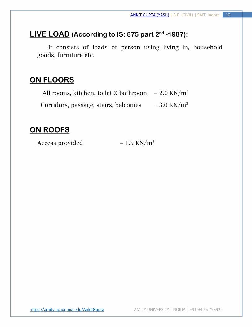
LIVE LOAD (According to IS: 875 part 2nd -1987):
It consists of loads of person using living in, household
goods, furniture etc.
ON FLOORS
All rooms, kitchen, toilet & bathroom = 2.0 KN/m2
Corridors, passage, stairs, balconies = 3.0 KN/m2
ON ROOFS
Access provided = 1.5 KN/m2

https://amity.academia.edu/AnkitGupta AMITY UNIVERSITY | NOIDA | +91 94 25 758922
11 ANKIT GUPTA (YASH) | B.E. (CIVIL) | SAIT, Indore
LOAD ON PLINTH SLAB
Loads have been calculated assuming slab thickness as 0.10 m.
Load on the slabs S1, S3, S5 and S6:-
Self weight of slab = 0.10×1×1×24.2 = 2.42 KN/m2
Lime mortar = 0.07×1×1×17 = 1.19 KN/m2
Kota stone floor = 0.025×1×1×24 = 0.60 KN/m2
Live load = 2 KN/m2
TOTAL LOAD = 6.21 KN/m2
Factored load = 6.21×1.5 = 9.315 KN/m2
Load on the slab S2:-
Self weight of slab = 0.10×1×1×24.2 = 2.42 KN/m2
Lime mortar = 0.07×1×1×17 = 1.19 KN/m2
Kota stone floor = 0.025×1×1×24 = 0.60 KN/m2
Live load = 2 KN/m2
Partition load = (0.10×19×4.4×5.4)/ (4×5)
= 2.26 KN/m2
TOTAL LOAD = 8.47 KN/m2
Factored load = 8.47×1.5 = 12.705 KN/m2
Load on the slab S4:-
Self weight of slab = 0.10×1×1×24.2 = 2.42 KN/m2
Lime mortar = 0.07×1×1×17 = 1.19 KN/m2
Kota stone floor = 0.025×1×1×24 = 0.60 KN/m2

https://amity.academia.edu/AnkitGupta AMITY UNIVERSITY | NOIDA | +91 94 25 758922
12 ANKIT GUPTA (YASH) | B.E. (CIVIL) | SAIT, Indore
Live load = 2 KN/m2
Partition load = (0.10×19×4.4×4.4)/ (4×4)
= 2.29 KN/m2
TOTAL LOAD = 8.51 KN/m2
Factored load = 8.51×1.5 = 12.76 KN/m2
LOAD ON SLAB OF DIFFERENT FLOORS
Load on the Ground Floor Roof Slab, First Floor Roof Slab and Second
Floor Roof Slab is same as the Load on Plinth Slab because these all
slabs are one on the other. Load on the Third Floor will be different as
the roof is terrace roof.
LOAD ON THIRD FLOOR ROOF SLAB
(S1, S2, S3, S4, S5, S6)
Self weight of slab = 0.10×1×1×24.2 = 2.42 KN/m2
Lime mortar = 0.07×1×1×17 = 1.19 KN/m2
Live load = 2 KN/m2
Ceiling plaster = 0.25 KN/m2
Chemical water proof treatment = 0.25 KN/m2
Mosaic tiles = 0.25 KN/m2
TOTAL LOAD = 6.61 KN/m2
Factored load = 6.61×1.5 = 9.915 KN/m2

https://amity.academia.edu/AnkitGupta AMITY UNIVERSITY | NOIDA | +91 94 25 758922
13 ANKIT GUPTA (YASH) | B.E. (CIVIL) | SAIT, Indore

https://amity.academia.edu/AnkitGupta AMITY UNIVERSITY | NOIDA | +91 94 25 758922
14 ANKIT GUPTA (YASH) | B.E. (CIVIL) | SAIT, Indore
DESIGN PROCEDURE OF TWO WAY SLABS
As the ratio of length & width of all slabs are less than 2,
two way slabs have been considered to design.
DESIGN CONSTANTS – Following design constants have been
adopted for steel & concrete as per IS 456 – 2000.
Steel – Fe 415 : (char. Strength) fy = 415 N/mm2
Concrete – M 20 (char. Comp. strength) fck = 20 N/mm2
(Max. depth of N.A.) : Xu max = 0.48 d
(Max. limiting moment) : Mu lim = 0.138 fck bd2
(% limit of steel) : Pt lim = 0.96%
(Factor): Ru max = 0.36 fck b Ku max. (1-0.42 Ku max) =2.76
Ku max. = Xu max. /d =0.48
All slabs are continuous. To satisfy vertical deflection limits for
loading class up to 3 KN/m2
Span/ D ratio = 0.8 x 40 = 32
D = 3500/32 = 109.40 ~ 110 mm
d = 110 – (15 + 8/2) = 91 mm for lower bar *
d = 110- (15 +8+8/2) = 83 mm for upper bar *
b = (for all slabs 1.00) = 1000 mm
Xu = 0.87 fy Ast/0.36fckb
LOADS ON SLABS
(As per limit state method a factored load is considered after
calculating total load)

https://amity.academia.edu/AnkitGupta AMITY UNIVERSITY | NOIDA | +91 94 25 758922
15 ANKIT GUPTA (YASH) | B.E. (CIVIL) | SAIT, Indore
Dead load due to self weight of slab
Finishing loads
Flooring loads
Live Loads
TOTAL LOAD = Total of all loads
Factored load Wd = 1.50 X Total loads
CALCULATIONS OF BENDING MOMENTS ON SLABS:
While calculating of B.M. of slab is done, ly/lx ratio is first calculated
to obtain the value of αx & αy (where, αx & αy are B.M. coefficient)
(as per IS 456: 2000 Table 26)
Calculate ly/lx
Obtain value of αx & αy (from IS 456: 2000 Table 26)
For corresponding value of ly/lx,
Calculate B.M.: Mx =αx Wd lx2 Mx =αy Wd lx2
DESIGN OF REINFORCMENT-
To calculate the area the area of steel by following formula:
𝑀𝑢 = 0.87 𝑓𝑦 𝐴𝑠𝑡 𝑑 [1 −𝐴𝑠𝑡
𝑏𝑑
𝑓𝑦
𝑓𝑐𝑘]
SPACING OF BARS = area of one bar x 1000/Ast
Maximum spacing for main reinforcement
< 3d or 300 mm (whichever is less)

https://amity.academia.edu/AnkitGupta AMITY UNIVERSITY | NOIDA | +91 94 25 758922
16 ANKIT GUPTA (YASH) | B.E. (CIVIL) | SAIT, Indore
CHECK:
1) Check for shear –
Shear force due to load Vu = Wd l/2
Nominal shear stress τv = Vu/bd
Percentage of tensile steel Pt = Ast x 100/bd
Shear strength of concrete τc (table 19 page 73 IS 456: 2000)
If τv < τc than no shear reinforcement is required.
Otherwise, shear reinforcement is required.
2) Check for Deflection-
α = 35 × 0.80 = 28 for simply supported two way slabs
α = 40 × 0.80 = 28 for continuous two way slabs
(24.1 note 2. Of IS 456: 2000)
3) Development Length –
Ld = fs xØ/ (4τbd) fs = 0.58 fy Ast required / Ast provided
Ø = 8 mm
τbd = design bond stress = 1.2 + 60% of 1.2
= 1.92 N /mm2 (26.2.1.1 IS 456:2000)
Area of bars Bars dia. in mm 6 8 10 12 16 Area in mm2 28 50 79 113 201

https://amity.academia.edu/AnkitGupta AMITY UNIVERSITY | NOIDA | +91 94 25 758922
17 ANKIT GUPTA (YASH) | B.E. (CIVIL) | SAIT, Indore
DESIGN OF SLABS
Ground Floor Slab:
SLAB S1:-
Ly/Lx = 5.2/4.2 = 1.23
For Ly/Lx 1.2 1.3 1.23 For all Ly/Lx
-αx 0.060 0.060 0.0615 -αy = 0.047
+αx 0.045 0.049 0.0462 +αy = 0.035
Wu = 9.315 KN Lx = 4.2 m Wu Lx2 = 164.32 KN-m
Span Position B.M Coefficient (α) Mu = α Wu Lx2 KN-m
Short – Support 0.0615 10.11 Short – Mid Span 0.0462 7.60 Long – Support 0.047 7.73 Long – Mid Span 0.035 5.75
DESIGN CALCULATION:-
𝑀𝑢 = 0.87 𝑓𝑦 𝐴𝑠𝑡 𝑑 [1 −𝐴𝑠𝑡
𝑏𝑑
𝑓𝑦
𝑓𝑐𝑘]
Location Mu KN-m
D Mm
Ast req mm2
Dia Mm
Spacing Mm
Ast provided mm2
Short Span Support 10.11 125 253 8 200 251.2 Mid Span 7.60 125 173.38 8 280 179.42 Long Span Support 7.73 117 189.32 8 250 200.96 Mid Span 5.75 117 130.41 8 300 167.46

https://amity.academia.edu/AnkitGupta AMITY UNIVERSITY | NOIDA | +91 94 25 758922
18 ANKIT GUPTA (YASH) | B.E. (CIVIL) | SAIT, Indore
SLAB S2:-
Wu = 12.71 KN Lx = 4.2 m Wu Lx2 = 224.20 KN-m
Span Position B.M Coefficient (α) Mu = α Wu Lx2 KN-m
Short – Support 0.0615 13.78 Short – Mid Span 0.0462 10.35 Long – Support 0.047 10.53 Long – Mid Span 0.035 7.84
DESIGN CALCULATION:-
𝑀𝑢 = 0.87 𝑓𝑦 𝐴𝑠𝑡 𝑑 [1 −𝐴𝑠𝑡
𝑏𝑑
𝑓𝑦
𝑓𝑐𝑘]
Location Mu KN-m
D Mm
Ast req mm2
Dia mm
Spacing Mm
Ast provided mm2
Short Span Support 13.78 125 322.6 8 150 334.9 Mid Span 10.35 125 238.7 8 200 251.2 Long Span Support 10.53 117 261.3 8 190 264.42 Mid Span 7.84 117 192.03 8 250 200.96
SLAB S3:-
Ly/Lx = 4/4=1 Wu = 9.315 KN Lx = 4.2 m Wu Lx2= 164.32KN-m
Span Position B.M Coefficient (α) Mu = α Wu Lx2 KN-m
Short – Support 0.037 6.079 Short – Mid Span 0.028 4.60 Long – Support 0.037 6.08 Long – Mid Span 0.028 4.60

https://amity.academia.edu/AnkitGupta AMITY UNIVERSITY | NOIDA | +91 94 25 758922
19 ANKIT GUPTA (YASH) | B.E. (CIVIL) | SAIT, Indore
DESIGN CALCULATION:-
𝑀𝑢 = 0.87 𝑓𝑦 𝐴𝑠𝑡 𝑑 [1 −𝐴𝑠𝑡
𝑏𝑑
𝑓𝑦
𝑓𝑐𝑘]
Location Mu KN-m
D Mm
Ast req mm2
Dia mm
Spacing Mm
Ast provided mm2
Short Span Support 6.079 125 173.74 8 300 167.46 Mid Span 4.60 125 103.68 8 300 167.46 Long Span Support 6.08 117 147.7 8 300 167.46 Mid Span 4.60 117 111.08 8 300 167.46
SLAB S4:-
Ly/Lx =1 Wu = 12.76 KN Lx = 4.2 m Wu Lx2 = 225.08 KN-m
Span Position B.M Coefficient (α) Mu = α Wu Lx2 KN-m
Short – Support 0.037 8.32 Short – Mid Span 0.028 6.30 Long – Support 0.037 8.33 Long – Mid Span 0.028 6.30
DESIGN CALCULATION:- 𝑀𝑢 = 0.87 𝑓𝑦 𝐴𝑠𝑡 𝑑 [1 −𝐴𝑠𝑡
𝑏𝑑
𝑓𝑦
𝑓𝑐𝑘]
Location Mu KN-m
D Mm
Ast req mm2
Dia Mm
Spacing Mm
Ast provided mm2
Short Span Support 8.32 125 190.36 8 250 200.96 Mid Span 6.30 125 142.98 8 300 167.47 Long Span Support 8.33 117 204.59 8 240 209.33 Mid Span 6.30 117 153.28 8 300 167.47

https://amity.academia.edu/AnkitGupta AMITY UNIVERSITY | NOIDA | +91 94 25 758922
20 ANKIT GUPTA (YASH) | B.E. (CIVIL) | SAIT, Indore
SLAB S5- S6:-
Ly/Lx =1 Wu = 9.315 KN Lx = 4.2 m Wu Lx2 = 164.32KN-m
Span Position B.M Coefficient (α) Mu = α Wu Lx2 KN-m
Short – Support 0.047 7.72 Short – Mid Span 0.035 5.75 Long – Support 0.047 7.72 Long – Mid Span 0.035 5.75
DESIGN CALCULATION:-
𝑀𝑢 = 0.87 𝑓𝑦 𝐴𝑠𝑡 𝑑 [1 −𝐴𝑠𝑡
𝑏𝑑
𝑓𝑦
𝑓𝑐𝑘]
Location Mu KN-m
D Mm
Ast req mm2
Dia Mm
Spacing Mm
Ast provided mm2
Short Span Support 7.72 125 176.20 8 280 179.42 Mid Span 5.75 125 130.21 8 300 167.47 Long Span Support 7.72 117 189.07 8 250 200.96 Mid Span 5.75 117 139.55 8 300 167.47
Roof Slab of 3rd Floor:-
SLAB S1 & S2:-
Ly/Lx =1 Wu = 9.915 KN Lx = 4.2 m Wu Lx2 = 174.90 KN-m
Span Position B.M Coefficient (α) Mu = α Wu Lx2 KN-m
Short – Support 0.0615 10.76 Short – Mid Span 0.0462 8.08 Long – Support 0.047 8.22 Long – Mid Span 0.035 6.12

https://amity.academia.edu/AnkitGupta AMITY UNIVERSITY | NOIDA | +91 94 25 758922
21 ANKIT GUPTA (YASH) | B.E. (CIVIL) | SAIT, Indore
DESIGN CALCULATION:-
𝑀𝑢 = 0.87 𝑓𝑦 𝐴𝑠𝑡 𝑑 [1 −𝐴𝑠𝑡
𝑏𝑑
𝑓𝑦
𝑓𝑐𝑘]
Location Mu KN-m
D Mm
Ast req mm2
Dia Mm
Spacing Mm
Ast provided mm2
Short Span Support 10.76 125 248.67 8 200 251.20 Mid Span 8.08 125 184.69 8 250 200.96 Long Span Support 8.22 117 201.78 8 240 209.33 Mid Span 6.12 117 117.30 8 300 167.47
SLAB S3 & S4:-
Ly/Lx =1 Wu = 9.915 KN Lx = 4.2 m Wu Lx2 = 174.90 KN-m
Span Position
B.M Coefficient (α) Mu = α Wu Lx2 KN-m
Short – Support 0.042 7.34 Short – Mid Span 0.031 5.42 Long – Support 0.037 6.47 Long – Mid Span 0.028 4.89
DESIGN CALCULATION:- 𝑀𝑢 = 0.87 𝑓𝑦 𝐴𝑠𝑡 𝑑 [1 −𝐴𝑠𝑡
𝑏𝑑
𝑓𝑦
𝑓𝑐𝑘]
Location Mu KN-m
D Mm
Ast req mm2
Dia Mm
Spacing Mm
Ast provided mm2
Short Span Support 7.34 125 167.27 8 300 167.47 Mid Span 5.42 125 123.47 8 300 167.47 Long Span Support 6.47 117 157.55 8 300 167.47 Mid Span 4.89 117 118.22 8 300 167.47

https://amity.academia.edu/AnkitGupta AMITY UNIVERSITY | NOIDA | +91 94 25 758922
22 ANKIT GUPTA (YASH) | B.E. (CIVIL) | SAIT, Indore
SLAB S5 & S6:-
Ly/Lx =1 Wu = 9.915 KN Lx = 4.2 m Wu Lx2 = 174.90 KN-m
Span Position
B.M Coefficient (α) Mu = α Wu Lx2 KN-m
Short – Support 0.037 6.47 Short – Mid Span 0.028 4.89 Long – Support 0.037 6.47 Long – Mid Span 0.028 4.89
DESIGN CALCULATION:-
𝑀𝑢 = 0.87 𝑓𝑦 𝐴𝑠𝑡 𝑑 [1 −𝐴𝑠𝑡
𝑏𝑑
𝑓𝑦
𝑓𝑐𝑘]
Location Mu KN-m
D Mm
Ast req mm2
Dia Mm
Spacing Mm
Ast provided mm2
Short Span Support 6.47 125 146.93 8 300 167.47 Mid Span 4.89 125 110.37 8 300 167.47 Long Span Support 6.47 117 157.55 8 300 167.47 Mid Span 4.89 117 118.22 8 300 167.47

https://amity.academia.edu/AnkitGupta AMITY UNIVERSITY | NOIDA | +91 94 25 758922
23 ANKIT GUPTA (YASH) | B.E. (CIVIL) | SAIT, Indore
DESIGN OF GROUND, 1st, 2nd, FLOOR ROOF SLABS
SLAB POSITION
Wu
KN/m2
Mu
KN-m
Span Ast req mm
2 Spacing mm c/c
Ast pro mm2
Pt
%
τv=Vu/bd fs
S1 (Supported) 9.315 10.11 4200 233 200 251.2 0.20 0.15 >τc
223.2
S1 (Midspan) 9.315 7.60 4200 173.33 280 179.42 0.15 0.17 >τc 232.52
S2 (Supported) 12.71 13.78 4200 322.6 150 334.9 0.26 0.21 >τc 231.85
S2 (Midspan) 12.71 10.35 4200 238.7 200 251.2 0.21 0.23 >τc 228.72
S3 (Supported) 9.315 6.079 4200 137.74 300 167.46 0.13 0.15 >τc 197
S3 (MidSpan) 9.315 4.60 4200 103.68 300 167.47 0.14 0.17 >τc 149.01
S4 (Supported) 12.76 8.32 4200 190.36 250 200.96 0.16 0.22 >τc 228.68
S4 (Midspan) 12.76 6.30 4200 142.98 300 167.47 0.14 0.23 >τc 205.50
S5,S6(Supported) 9.315 7.72 4200 176.20 280 179.42 0.14 0.15 >τc 236.38
S5,S6(Midspan) 9.315 5.75 4200 130.21 300 167.47 0.14 0.17 >τc 187.14
DESIGN OF 3rd FLOOR ROOF SLAB (TOP SLAB)
SLAB POSITION
Wu
KN/m2
Mu
KN-m
Span Ast req mm
2 Spacing mm c/c
Ast pro mm2
Pt
%
τv=Vu/bd fs
S1,S2(Supported) 9.915 10.76 4200 248.67 200 251.2 0.20 0.17 >τc 238.2
S1,S2 (Midspan) 9.915 8.08 4200 184.69 250 200.96 0.17 0.18 >τc 221.2
S3,S4(Supported) 9.915 7.34 4200 167.27 300 167.47 0.13 0.17 >τc 240.7
S3,S4 (Midspan) 9.915 5.42 4200 123.47 300 167.47 0.14 0.18 >τc 177.46
S5,S6(Supported) 9.915 6.47 4200 146.93 300 167.46 0.13 0.17 >τc 211.12
S5,S6 (MidSpan) 9.915 4.89 4200 110.37 300 167.47 0.14 0.18 >τc 158.53
https://amity.academia.edu/AnkitGupta AMITY UNIVERSITY | NOIDA | +91 94 25 758922
24 ANKIT GUPTA (YASH) | B.E. (CIVIL) | SAIT, Indore
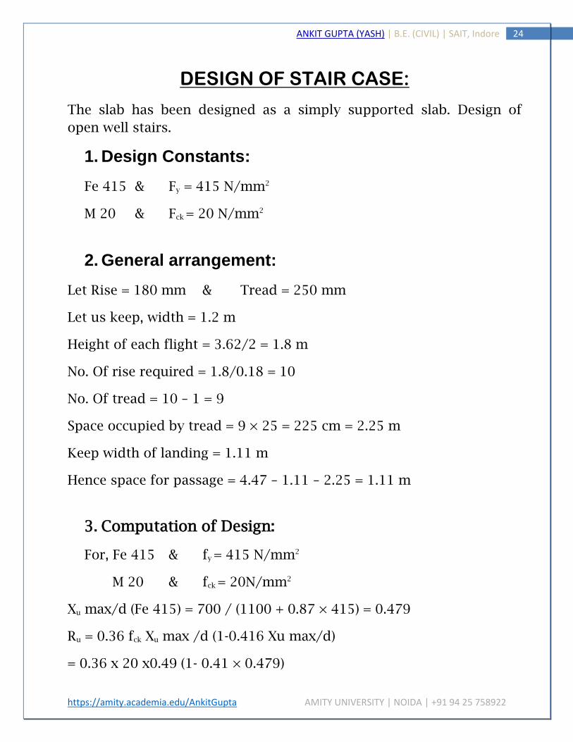
DESIGN OF STAIR CASE:
The slab has been designed as a simply supported slab. Design of
open well stairs.
1. Design Constants:
Fe 415 & Fy = 415 N/mm2
M 20 & Fck = 20 N/mm2
2. General arrangement:
Let Rise = 180 mm & Tread = 250 mm
Let us keep, width = 1.2 m
Height of each flight = 3.62/2 = 1.8 m
No. Of rise required = 1.8/0.18 = 10
No. Of tread = 10 – 1 = 9
Space occupied by tread = 9 × 25 = 225 cm = 2.25 m
Keep width of landing = 1.11 m
Hence space for passage = 4.47 – 1.11 – 2.25 = 1.11 m
3. Computation of Design:
For, Fe 415 & fy = 415 N/mm2
M 20 & fck = 20N/mm2
Xu max/d (Fe 415) = 700 / (1100 + 0.87 × 415) = 0.479
Ru = 0.36 fck Xu max /d (1-0.416 Xu max/d)
= 0.36 x 20 x0.49 (1- 0.41 × 0.479)

https://amity.academia.edu/AnkitGupta AMITY UNIVERSITY | NOIDA | +91 94 25 758922
25 ANKIT GUPTA (YASH) | B.E. (CIVIL) | SAIT, Indore
4. Computation of loading & Bending moment:
The landing of slab is assumed to span in same direction as the stair &
it consider as acting together to form a single slab. Let the bearing of
landing slab in wall be 90 mm.
So, the effective span = 2.25 + 1.11 + 0.09/2 = 3.405m ~ 3.4m
Let thickness of waist slab = 200mm
Therefore, weight of slab ‘w’ on slope = 200 × 1 × 1 × 25000/1000
= 5000N/m
Dead weight of horizontal area = w1 = [w (R2 + T2)0.5/T]
= 5000 (1802 + 2502)/250
= 6161.16 N/m
Dead Wt. of steps is given by:
W2 = R × 1 × 1 × 25000/ (2x 1000) = 2250 N/m2
Therefore total dead weight per m run = 6161 + 2250 = 8411N/m
Weight of finishing = 100 N/m
Live load = 2500 N/m
Total load = 11011 N/m
Factored load = 11011 × 1016516.5 N/m
Now, moment = Mu=wl2/8 = (16516.5 x 3.42)/8 = 23866.34 Nm
5. Design of waist Slab:
D = (Mu/Ru × b) 0.5 = (23.8 x 10⁶)/ (2.7 x 1000)0.5 = 93.83 mm
Adopt overall depth = 125 m

https://amity.academia.edu/AnkitGupta AMITY UNIVERSITY | NOIDA | +91 94 25 758922
26 ANKIT GUPTA (YASH) | B.E. (CIVIL) | SAIT, Indore
Using 15 mm nominal cover & 10 mm dia. bars.
Effective depth = 125 -15 -10/2 = 105 mm
6. Computation of reinforcement:
Since, actual d provided is more than the required for B.M.
Therefore, we have under reinforced section.
For which
Ast = (fck/2ffy) {1-√ [4.6xMux106)/ (fckbd2)]} bd
= (20/2×415) {1-√ [1-(4.6×23.8×106)/(20×1000×1052)]} 1000×105
= 737.05 mm2
Using 10 mm dia bars using gross area = 10/4 x 102 = 78.54 mm2
No. of bars required in 1.1 m = (1.1 × 737.05)/78.54 =10.532
No. Of bars required = 10
Spacing of bars = 1100/10 = 110mm
Distribution Reinforcement:
Ast = (0.12 × 180 × 1000) 100 = 216 mm2
Spacing 8mm dia. Bars = (1000x50.3) 216 =232.87 mm
Hence, provide 8mm dia. Bars @ 230 mm c/c.
7. Development Length:
Ld = 47 × Ø
= 47 × 10 = 470 mm.

https://amity.academia.edu/AnkitGupta AMITY UNIVERSITY | NOIDA | +91 94 25 758922
27 ANKIT GUPTA (YASH) | B.E. (CIVIL) | SAIT, Indore
https://amity.academia.edu/AnkitGupta AMITY UNIVERSITY | NOIDA | +91 94 25 758922
28 ANKIT GUPTA (YASH) | B.E. (CIVIL) | SAIT, Indore

https://amity.academia.edu/AnkitGupta AMITY UNIVERSITY | NOIDA | +91 94 25 758922
29 ANKIT GUPTA (YASH) | B.E. (CIVIL) | SAIT, Indore
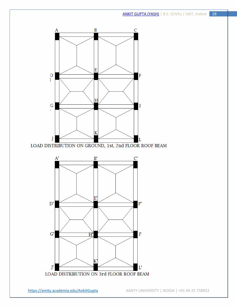
LOAD ON BEAM
Load on Plinth Level Beam, Ground Floor Roof beam, 1st Floor
Roof Beam and 2nd Floor Roof beam will be same as the structure
of all Floors is symmetric.
As the slabs are two ways slab the distribution of load on
corresponding beams is accordingly.
1. LOAD ON BEAM AB:-
For Triangular Loading = W Lx/3 KN/m
W = 6.21 KN Lx = 4.2 m
Load from Slab S1 = (6.21×4.2)/3 = 8.694 KN/m
Masonry Wt = 0.2×19×3.3 = 12.54 KN/m
Self Wt of Beam = 0.3×0.3×24.8 = 2.232 KN/m
TOTAL LOAD = 23.46 KN/m
Factored load = 23.46×1.5 = 35.196 KN/m
2. LOAD ON BEAM BC:-
For Triangular Loading = W Lx/3 KN/m
W = 8.47 KN Lx = 4.2 m
Load from Slab S2 = (8.47×4.2)/3 = 11.858 KN/m
Masonry Wt = 0.2×19×3.3 = 12.54 KN/m
Self Wt of Beam = 0.3×0.3×24.8 = 2.232 KN/m
TOTAL LOAD = 26.62 KN/m
Factored load = 26.62×1.5 = 39.42 KN/m

https://amity.academia.edu/AnkitGupta AMITY UNIVERSITY | NOIDA | +91 94 25 758922
30 ANKIT GUPTA (YASH) | B.E. (CIVIL) | SAIT, Indore
3. LOAD ON BEAM AD:-
For Trapezoidal Loading =(1 −1
3𝛽2) 𝑊 𝐿𝑋
2 KN/m
W = 6.21 KN Lx = 4.2 m β = Ly/Lx = 5.2/4.2 = 1.23
Load from Slab S1 = (1 −1
3×1.232) 6.21×4.2
2 = 10.16 KN/m
Masonry Wt = 0.2×19×3.3 = 12.54 KN/m
Self Wt of Beam = 0.3×0.3×24.8 = 2.232 KN/m
TOTAL LOAD = 24.93 KN/m
Factored load = 24.93×1.5 = 37.395 KN/m
4. LOAD ON BEAM CF:-
For Trapezoidal Loading =(1 −1
3𝛽2) 𝑊 𝐿𝑋
2 KN/m
W = 8.47 KN Lx = 4.2 m β = Ly/Lx = 5.2/4.2 = 1.23
Load from Slab S1 = (1 −1
3×1.232) 8.47×4.2
2 = 13.86 KN/m
Masonry Wt = 0.2×19×3.3 = 12.54 KN/m
Self Wt of Beam = 0.3×0.3×24.8 = 2.232 KN/m
TOTAL LOAD = 28.63 KN/m
Factored load = 28.63×1.5 = 42.94 KN/m

https://amity.academia.edu/AnkitGupta AMITY UNIVERSITY | NOIDA | +91 94 25 758922
31 ANKIT GUPTA (YASH) | B.E. (CIVIL) | SAIT, Indore
5. LOAD ON BEAM BE:-
For Trapezoidal Loading =(1 −1
3𝛽2) 𝑊 𝐿𝑋
2 KN/m
W S1=6.21 KN W S2=8.47 KN Lx = 4.2 m β = 1.23
Load from Slab S1 = (1 −1
3×1.232) 6.21×4.2
2 = 10.16 KN/m
Load from Slab S2 = (1 −1
3×1.232) 8.47×4.2
2 = 13.86 KN/m
Masonry Wt = 0.2×19×3.3 = 12.54 KN/m
Self Wt of Beam = 0.3×0.3×24.8 = 2.232 KN/m
TOTAL LOAD = 38.79 KN/m
Factored load = 38.79×1.5 = 58.185 KN/m
6. LOAD ON BEAM DE:-
For Triangular Loading = W Lx/3 KN/m
For Trapezoidal Loading =(1 −1
3𝛽2) 𝑊 𝐿𝑋
2 KN/m
W S1=6.21 KN W S3=6.21 KN Lx = 4.2 m β =4.2/4.2= 1
Load from Slab S1 = (6.21×4.2)/3 = 8.694 KN/m
Load from Slab S3 = (1 −1
3×12) 6.21×4.2
2 = 8.74 KN/m
Masonry Wt = 0.2×19×3.3 = 12.54 KN/m
Self Wt of Beam = 0.3×0.3×24.8 = 2.232 KN/m
TOTAL LOAD = 32.20 KN/m
Factored load = 32.20×1.5 = 48.31 KN/m

https://amity.academia.edu/AnkitGupta AMITY UNIVERSITY | NOIDA | +91 94 25 758922
32 ANKIT GUPTA (YASH) | B.E. (CIVIL) | SAIT, Indore
7. LOAD ON BEAM EF:-
For Triangular Loading = W Lx/3 KN/m
For Trapezoidal Loading =(1 −1
3𝛽2) 𝑊 𝐿𝑋
2 KN/m
W S2=8.47 KN W S4=8.47 KN Lx = 4.2 m β =4.2/4.2= 1
Load from Slab S2 = (8.47×4.2)/3 = 11.85 KN/m
Load from Slab S4 = (1 −1
3×12) 8.47×4.2
2 = 11.92 KN/m
Masonry Wt = 0.2×19×3.3 = 12.54 KN/m
Self Wt of Beam = 0.3×0.3×24.8 = 2.232 KN/m
TOTAL LOAD = 38.54 KN/m
Factored load = 38.54×1.5 = 57.81 KN/m
8. LOAD ON BEAM DG:-
For Triangular Loading = W Lx/3 KN/m
W = 6.21 KN Lx = 4.2 m
Load from Slab S3 = (6.21×4.2)/3 = 8.694 KN/m
Masonry Wt = 0.2×19×3.3 = 12.54 KN/m
Self Wt of Beam = 0.3×0.3×24.8 = 2.232 KN/m
TOTAL LOAD = 23.46 KN/m
Factored load = 23.46×1.5 = 35.196 KN/m

https://amity.academia.edu/AnkitGupta AMITY UNIVERSITY | NOIDA | +91 94 25 758922
33 ANKIT GUPTA (YASH) | B.E. (CIVIL) | SAIT, Indore
9. LOAD ON BEAM FI:-
For Triangular Loading = W Lx/3 KN/m
W = 8.47 KN Lx = 4.2 m
Load from Slab S4 = (8.47×4.2)/3 = 11.858 KN/m
Masonry Wt = 0.2×19×3.3 = 12.54 KN/m
Self Wt of Beam = 0.3×0.3×24.8 = 2.232 KN/m
TOTAL LOAD = 26.62 KN/m
Factored load = 26.62×1.5 = 39.42 KN/m
10. LOAD ON BEAM EH:-
For Triangular Loading = W Lx/3 KN/m
W S3=6.21 KN W S4=8.47 KN Lx = 4.2 m
Load from Slab S3 = (6.21×4.2)/3 = 8.69 KN/m
Load from Slab S4 = (8.47×4.2)/3 = 11.858 KN/m
Masonry Wt = 0.2×19×3.3 = 12.54 KN/m
Self Wt of Beam = 0.3×0.3×24.8 = 2.232 KN/m
TOTAL LOAD = 35.31 KN/m
Factored load = 35.31×1.5 = 52.97 KN/m

https://amity.academia.edu/AnkitGupta AMITY UNIVERSITY | NOIDA | +91 94 25 758922
34 ANKIT GUPTA (YASH) | B.E. (CIVIL) | SAIT, Indore
11. LOAD ON BEAM GH:-
For Trapezoidal Loading =(1 −1
3𝛽2) 𝑊 𝐿𝑋
2 KN/m
For Triangular Loading = W Lx/3 KN/m
W S3=6.21 KN W S5=6.21 KN Lx = 4.2 m β =4.2/4.2= 1
Load from Slab S3 = (1 −1
3×12) 6.21×4.2
2 = 8.74 KN/m
Load from Slab S5 = (6.21×4.2)/3 = 8.694 KN/m
Masonry Wt = 0.2×19×3.3 = 12.54 KN/m
Self Wt of Beam = 0.3×0.3×24.8 = 2.232 KN/m
TOTAL LOAD = 32.20 KN/m
Factored load = 32.20×1.5 = 48.30 KN/m
12. LOAD ON BEAM HI:-
For Trapezoidal Loading =(1 −1
3𝛽2) 𝑊 𝐿𝑋
2 KN/m
For Triangular Loading = W Lx/3 KN/m
W S4=8.47 KN W S6=6.21 KN Lx = 4.2 m β =4.2/4.2= 1
Load from Slab S4 = (1 −1
3×12) 8.47×4.2
2 = 11.91 KN/m
Load from Slab S6 = (6.21×4.2)/3 = 8.694 KN/m
Masonry Wt = 0.2×19×3.3 = 12.54 KN/m
Self Wt of Beam = 0.3×0.3×24.8 = 2.232 KN/m

https://amity.academia.edu/AnkitGupta AMITY UNIVERSITY | NOIDA | +91 94 25 758922
35 ANKIT GUPTA (YASH) | B.E. (CIVIL) | SAIT, Indore
TOTAL LOAD = 35.37 KN/m
Factored load = 35.37×1.5 = 53.06 KN/m
13. LOAD ON BEAM GJ & IL:-
For Trapezoidal Loading =(1 −1
3𝛽2) 𝑊 𝐿𝑋
2 KN/m
W = 6.21 KN Lx = 4.2 m β = Ly/Lx = 4.2/4.2 = 1
Load from Slab S5 & S6 = (1 −1
3×12) 6.21×4.2
2 = 8.74 KN/m
Masonry Wt = 0.2×19×3.3 = 12.54 KN/m
Self Wt of Beam = 0.3×0.3×24.8 = 2.232 KN/m
TOTAL LOAD = 23.50 KN/m
Factored load = 23.50×1.5 = 35.26 KN/m
14. LOAD ON BEAM JK & KL:-
For Triangular Loading = W Lx/3 KN/m
W = 6.21 KN Lx = 4.2 m
Load from Slab S5 & S6 = (6.21×4.2)/3 = 8.694 KN/m
Masonry Wt = 0.2×19×3.3 = 12.54 KN/m
Self Wt of Beam = 0.3×0.3×24.8 = 2.232 KN/m
TOTAL LOAD = 23.46 KN/m
Factored load = 23.46×1.5 = 35.196 KN/m

https://amity.academia.edu/AnkitGupta AMITY UNIVERSITY | NOIDA | +91 94 25 758922
36 ANKIT GUPTA (YASH) | B.E. (CIVIL) | SAIT, Indore
15. LOAD ON BEAM GJ & IL:-
For Trapezoidal Loading =(1 −1
3𝛽2) 𝑊 𝐿𝑋
2 KN/m
W = 6.21 KN Lx = 4.2 m β = Ly/Lx = 4.2/4.2 = 1
Load from Slab S5 = (1 −1
3×12) 6.21×4.2
2 = 8.74 KN/m
Load from Slab S6 = (1 −1
3×12) 6.21×4.2
2 = 8.74 KN/m
Masonry Wt = 0.2×19×3.3 = 12.54 KN/m
Self Wt of Beam = 0.3×0.3×24.8 = 2.232 KN/m
TOTAL LOAD = 32.25 KN/m
Factored load = 32.25×1.5 = 48.37 KN/m
LOAD ON 3rd FLOOR ROOF BEAM
1. LOAD ON BEAM A'B', B'C', D'G', F'I', J'K', K'L':-
For Triangular Loading = W Lx/3 KN/m
W = 6.61 KN Lx = 4.2 m
Load from Slab S1,S2,S3,S4,S5,S6 = (6.61×4.2)/3 = 9.254 KN/m
Masonry Wt = 0.2×19×3.3 = 12.54 KN/m
Self Wt of Beam = 0.3×0.3×24.8 = 2.232 KN/m
TOTAL LOAD = 24.02 KN/m
Factored load = 24.02×1.5 = 36.03 KN/m

https://amity.academia.edu/AnkitGupta AMITY UNIVERSITY | NOIDA | +91 94 25 758922
37 ANKIT GUPTA (YASH) | B.E. (CIVIL) | SAIT, Indore
2. LOAD ON BEAM A'D' & C'F':-
For Trapezoidal Loading =(1 −1
3𝛽2) 𝑊 𝐿𝑋
2 KN/m
W = 6.61 KN Lx = 4.2 m β = Ly/Lx = 5.2/4.2 = 1.23
Load from Slab S1 & S2 = (1 −1
3×1.232) 6.61×4.2
2 = 10.82 KN/m
Masonry Wt = 0.2×19×3.3 = 12.54 KN/m
Self Wt of Beam = 0.3×0.3×24.8 = 2.232 KN/m
TOTAL LOAD = 25.59 KN/m
Factored load = 25.59×1.5 = 38.38 KN/m
3. LOAD ON BEAM D'E', E'F', G'H', H'I':-
For Triangular Loading = W Lx/3 KN/m
For Trapezoidal Loading =(1 −1
3𝛽2) 𝑊 𝐿𝑋
2 KN/m
W S4=8.47 KN W S6=6.21 KN Lx = 4.2 m β =4.2/4.2= 1
Load from Slab S1, S2, S5, S6 = (6.61×4.2)/3 = 9.254 KN/m
Load from Slab S3 & S4 = (1 −1
3×12) 6.61×4.2
2 = 9.30 KN/m
Masonry Wt = 0.2×19×3.3 = 12.54 KN/m
Self Wt of Beam = 0.3×0.3×24.8 = 2.232 KN/m
TOTAL LOAD = 33.32 KN/m
Factored load = 33.32×1.5 = 49.98 KN/m

https://amity.academia.edu/AnkitGupta AMITY UNIVERSITY | NOIDA | +91 94 25 758922
38 ANKIT GUPTA (YASH) | B.E. (CIVIL) | SAIT, Indore
4. LOAD ON BEAM G'J' & I'L':-
For Trapezoidal Loading =(1 −1
3𝛽2) 𝑊 𝐿𝑋
2 KN/m
W = 6.61 KN Lx = 4.2 m β = Ly/Lx = 4.2/4.2 = 1
Load from Slab S1 & S2 = (1 −1
3×12) 6.61×4.2
2 = 9.30 KN/m
Masonry Wt = 0.2×19×3.3 = 12.54 KN/m
Self Wt of Beam = 0.3×0.3×24.8 = 2.232 KN/m
TOTAL LOAD = 24.07 KN/m
Factored load = 24.07×1.5 = 36.10 KN/m
5. LOAD ON BEAM B'E':-
For Trapezoidal Loading =(1 −1
3𝛽2) 𝑊 𝐿𝑋
2 KN/m
W = 6.61 KN Lx = 4.2 m β = Ly/Lx = 5.2/4.2 = 1.23
Load from Slab S1 = (1 −1
3×1.232) 6.61×4.2
2 = 10.82 KN/m
Load from Slab S2 = (1 −1
3×1.232) 6.61×4.2
2 = 10.82 KN/m
Masonry Wt = 0.2×19×3.3 = 12.54 KN/m
Self Wt of Beam = 0.3×0.3×24.8 = 2.232 KN/m
TOTAL LOAD = 36.41 KN/m
Factored load = 36.41×1.5 = 54.622 KN/m

https://amity.academia.edu/AnkitGupta AMITY UNIVERSITY | NOIDA | +91 94 25 758922
39 ANKIT GUPTA (YASH) | B.E. (CIVIL) | SAIT, Indore
6. LOAD ON BEAM E'H':-
For Triangular Loading = W Lx/3 KN/m
W = 6.61 KN Lx = 4.2 m
Load from Slab S3 = (6.61×4.2)/3 = 9.254 KN/m
Load from Slab S4 = (6.61×4.2)/3 = 9.254 KN/m
Masonry Wt = 0.2×19×3.3 = 12.54 KN/m
Self Wt of Beam = 0.3×0.3×24.8 = 2.232 KN/m
TOTAL LOAD = 33.28 KN/m
Factored load = 33.28×1.5 = 49.92 KN/m
7. LOAD ON BEAM H'K':-
For Trapezoidal Loading =(1 −1
3𝛽2) 𝑊 𝐿𝑋
2 KN/m
W = 6.61 KN Lx = 4.2 m β = Ly/Lx = 5.2/4.2 = 1
Load from Slab S5 = (1 −1
3×12) 6.61×4.2
2 = 9.30 KN/m
Load from Slab S6 = (1 −1
3×12) 6.61×4.2
2 = 9.30 KN/m
Masonry Wt = 0.2×19×3.3 = 12.54 KN/m
Self Wt of Beam = 0.3×0.3×24.8 = 2.232 KN/m
TOTAL LOAD = 33.37 KN/m
Factored load = 33.37×1.5 = 50.05 KN/m

https://amity.academia.edu/AnkitGupta AMITY UNIVERSITY | NOIDA | +91 94 25 758922
40 ANKIT GUPTA (YASH) | B.E. (CIVIL) | SAIT, Indore

https://amity.academia.edu/AnkitGupta AMITY UNIVERSITY | NOIDA | +91 94 25 758922
41 ANKIT GUPTA (YASH) | B.E. (CIVIL) | SAIT, Indore
BENDING MOMENT & SHEAR FORCE
CALCULATION OF BEAM
Calculation of Bending Moment has been made from
Moment Distribution Method. Bending Moment and Shear Force
will be same for the Ground Floor, 1st Floor and 2nd Floor as the
structure is same.
1. BEAM ‘ABC’:- BENDING MOMENT CALCULATION:-
FIXED END MOMENT (-VE MOMENTS):-
UDL (KN/m) SPAN L (m) MOMENT WL2/12 (KN-m) 35.19 4.2 MAB -51.73 35.19 4.2 MBA +51.73 39.42 4.2 MBC -57.94 39.42 4.2 MCB +57.94
DISTRIBUTION FACTOR:-
JOINT MEMBER RELATIVE STIFFNESS (R.S) TOTAL D.F. B BA ¾ I/L = ¾ I/4.2 = 0.81 I 0.36 I 0.50
BC ¾ I/L = ¾ I/4.2 = 0.81 I 0.50

https://amity.academia.edu/AnkitGupta AMITY UNIVERSITY | NOIDA | +91 94 25 758922
42 ANKIT GUPTA (YASH) | B.E. (CIVIL) | SAIT, Indore
MOMENT DISTRIBUTION:-
A B C
0.50 0.50 -51.53 +51.73
+51.73 25.865
-57.94 -28.97
+57.94 -57.94
0 77.595 +4.675
-86.91 +4.675
0
0 82.25 -82.25 0
FREE BENDING MOMENT (+VE MOMENTS):-
UDL (KN/m) SPAN L (m) MOMENT WL2/8 (KN-m) 35.19 4.2 MAB 77.59 39.42 4.2 MBC 86.92
FINAL SUPPORT MOMENT (-VE MOMENTS):-
M A = 0.00 KN-m M B = -82.25 KN-m M C = 0.00 KN-m
SHEAR FORCE CALCULATION:-
Taking B.M. at B = −4.2 𝑉𝐶 + 39.42×4.22
2− 82.25 = 0 VC = 63.19 KN
Taking B.M. at B = 4.2 𝑉𝐶 − 39.19×4.22
2+ 82.25 = 0 VA = 54.32 KN
VA + VB + VC = 313.362 KN VB = 195.85 KN

https://amity.academia.edu/AnkitGupta AMITY UNIVERSITY | NOIDA | +91 94 25 758922
43 ANKIT GUPTA (YASH) | B.E. (CIVIL) | SAIT, Indore
2. BEAM ‘DEF’:- BENDING MOMENT CALCULATION:-
FIXED END MOMENT (-VE MOMENTS):-
UDL (KN/m) SPAN L (m) MOMENT WL2/12 (KN-m) 48.31 4.2 MDE -71.02 48.31 4.2 MED +71.02 57.81 4.2 MEF -84.98 57.81 4.2 MFE +84.98
DISTRIBUTION FACTOR:-
JOINT MEMBER RELATIVE STIFFNESS (R.S) TOTAL D.F. E ED ¾ I/L = ¾ I/4.2 = 0.81 I 0.36 I 0.50
EF ¾ I/L = ¾ I/4.2 = 0.81 I 0.50
MOMENT DISTRIBUTION:-
D E F
0.50 0.50 -71.02 +71.02
+71.02 35.51
-84.98 -42.49
+84.98 -84.98
0 106.53 +10.47
-127.47 +10.47
0
0 117 -117 0

https://amity.academia.edu/AnkitGupta AMITY UNIVERSITY | NOIDA | +91 94 25 758922
44 ANKIT GUPTA (YASH) | B.E. (CIVIL) | SAIT, Indore
FREE BENDING MOMENT (+VE MOMENTS):-
UDL (KN/m) SPAN L (m) MOMENT WL2/8 (KN-m) 48.31 4.2 MDE 106.52 57.81 4.2 MEF 127.47
FINAL SUPPORT MOMENT (-VE MOMENTS):-
M D = 0.00 KN-m M E = -117 KN-m M F = 0.00 KN-m
SHEAR FORCE CALCULATION:-
Taking B.M. at E = −4.2 𝑉𝐹 + 57.81×4.22
2− 117 = 0 VF = 93.54 KN
Taking B.M. at E = 4.2 𝑉𝐷 − 48.31×4.22
2+ 117 = 0 VD = 73.59 KN
VD + VE + VF = 445.702 KN VE = 278.57 KN

https://amity.academia.edu/AnkitGupta AMITY UNIVERSITY | NOIDA | +91 94 25 758922
45 ANKIT GUPTA (YASH) | B.E. (CIVIL) | SAIT, Indore
3. BEAM ‘GHI’:- BENDING MOMENT CALCULATION:-
FIXED END MOMENT (-VE MOMENTS):-
UDL (KN/m) SPAN L (m) MOMENT WL2/12 (KN-m) 48.30 4.2 MGH -71.01 48.30 4.2 MHG +71.01 53.06 4.2 MHI -77.99 53.06 4.2 MIH +77.99
DISTRIBUTION FACTOR:-
JOINT MEMBER RELATIVE STIFFNESS (R.S) TOTAL D.F. H HG ¾ I/L = ¾ I/4.2 = 0.81 I 0.36 I 0.50
HI ¾ I/L = ¾ I/4.2 = 0.81 I 0.50
MOMENT DISTRIBUTION:-
G H I
0.50 0.50 -71.01 +71.01
+71.01 35.50
-77.99 -38.99
+77.99 -77.99
0 106.51 +5.235
-116.98 +5.235
0
0 111.745 -111.745 0

https://amity.academia.edu/AnkitGupta AMITY UNIVERSITY | NOIDA | +91 94 25 758922
46 ANKIT GUPTA (YASH) | B.E. (CIVIL) | SAIT, Indore
FREE BENDING MOMENT (+VE MOMENTS):-
UDL (KN/m) SPAN L (m) MOMENT WL2/8 (KN-m) 48.30 4.2 MGH 106.50 53.06 4.2 MHI 117.00
FINAL SUPPORT MOMENT (-VE MOMENTS):-
M G = 0.00 KN-m M H = -111.745 KN-m M I = 0.00 KN-m
SHEAR FORCE CALCULATION:-
Taking B.M. at H = −4.2 𝑉𝐼 + 53.06×4.22
2− 111.745 = 0 VI = 84.82 KN
Taking B.M. at H = 4.2 𝑉𝐺 − 48.30×4.22
2+ 111.745 = 0 VG = 74.82 KN
VG + VH + VI = 425.712 KN VH = 266.07 KN

https://amity.academia.edu/AnkitGupta AMITY UNIVERSITY | NOIDA | +91 94 25 758922
47 ANKIT GUPTA (YASH) | B.E. (CIVIL) | SAIT, Indore
4. BEAM ‘JKL’:- BENDING MOMENT CALCULATION:-
FIXED END MOMENT (-VE MOMENTS):-
UDL (KN/m) SPAN L (m) MOMENT WL2/12 (KN-m) 35.22 4.2 MJK -51.77 35.22 4.2 MKJ +51.77 35.22 4.2 MKL -51.77 35.22 4.2 MLK +51.77
DISTRIBUTION FACTOR:-
JOINT MEMBER RELATIVE STIFFNESS (R.S) TOTAL D.F. K KJ ¾ I/L = ¾ I/4.2 = 0.81 I 0.36 I 0.50
KL ¾ I/L = ¾ I/4.2 = 0.81 I 0.50
MOMENT DISTRIBUTION:-
J K L
0.50 0.50 -51.77 +51.77
+51.77 25.89
-51.77 -25.89
+51.77 -51.77
0 77.66 -77.66 0

https://amity.academia.edu/AnkitGupta AMITY UNIVERSITY | NOIDA | +91 94 25 758922
48 ANKIT GUPTA (YASH) | B.E. (CIVIL) | SAIT, Indore
FREE BENDING MOMENT (+VE MOMENTS):-
UDL (KN/m) SPAN L (m) MOMENT WL2/8 (KN-m) 35.22 4.2 MJK 77.66 35.22 4.2 MKL 77.66
FINAL SUPPORT MOMENT (-VE MOMENTS):-
M J = 0.00 KN-m M K = -77.66 KN-m M L = 0.00 KN-m
SHEAR FORCE CALCULATION:-
Taking B.M. at K = −4.2 𝑉𝐿 + 35.22×4.22
2− 77.66 = 0 VL = 55.42 KN
Taking B.M. at K = 4.2 𝑉𝐽 − 35.22×4.22
2+ 77.66 = 0 VJ = 55.42 KN
VJ + VK + VL = 295.84 KN VK = 185.08 KN

https://amity.academia.edu/AnkitGupta AMITY UNIVERSITY | NOIDA | +91 94 25 758922
49 ANKIT GUPTA (YASH) | B.E. (CIVIL) | SAIT, Indore
5. BEAM ‘ADGJ’:- BENDING MOMENT CALCULATION:-
FIXED END MOMENT (-VE MOMENTS):-
UDL (KN/m) SPAN L (m) MOMENT WL2/12 (KN-m) 37.39 5.2 MAD -84.25 37.39 5.2 MDA +84.25 35.19 4.2 MDG -51.73 35.19 4.2 MGD +51.73 35.26 4.4 MGJ -56.89 35.26 4.4 MJG +56.89
DISTRIBUTION FACTOR:-
JOINT MEMBER RELATIVE STIFFNESS (R.S) TOTAL D.F. D DA ¾ I/L = ¾ I/5.2 = 0.144 I 0.374 I 0.39
DG I/L = I/4.2 = 0.23 I 0.61 G GD I/L = I/4.2 = 0.23 I 0.40 I 0.56
GJ ¾ I/L = ¾ I/4.4 = 0.170 I 0.44
MOMENT DISTRIBUTION:-
A D G J
0.39 0.61 0.56 0.44 -84.25 +84.25
+84.25 42.125
-51.73 +51.73
-56.89 -28.45
+56.89 -56.89
0 126.36 -29.10
-51.73 -45.52
-51.73 +17.14
-85.34 +16.47
0
0 97.26 -97.26 -68.87 -68.87 0

https://amity.academia.edu/AnkitGupta AMITY UNIVERSITY | NOIDA | +91 94 25 758922
50 ANKIT GUPTA (YASH) | B.E. (CIVIL) | SAIT, Indore
FREE BENDING MOMENT (+VE MOMENTS):-
UDL (KN/m) SPAN L (m) MOMENT WL2/8 (KN-m) 37.39 4.2 MAD 126.38 35.19 4.2 MDG 77.59 35.26 4.2 MGJ 85.33
FINAL SUPPORT MOMENT (-VE MOMENTS):-
M A = 0.00 KN-m M D = -97.26 KN-m
M G = -68.87 KN-m M J = 0.00 KN-m
SHEAR FORCE CALCULATION:-
Taking B.M. at G = −4.4 𝑉𝐽 + 35.26×4.22
2− 68.87 = 0 VJ = 61.92 KN
Taking B.M. at D = 5.2 𝑉𝐴 − 37.39×4.22
2+ 97.26 = 0 VA = 78.51 KN
Taking B.M. at D =
(−61.92 × 8.6) − 4.2 𝑉𝐺 − 97.26 + 35.19×4.22
2+ (35.26 × 4.4 × 6.4) = 0
VG = 156.67 KN
VA + VD + VG + VJ = 497.37 KN VD = 200.27 KN

https://amity.academia.edu/AnkitGupta AMITY UNIVERSITY | NOIDA | +91 94 25 758922
51 ANKIT GUPTA (YASH) | B.E. (CIVIL) | SAIT, Indore
6. BEAM ‘BEHK’:- BENDING MOMENT CALCULATION:-
FIXED END MOMENT (-VE MOMENTS):-
UDL (KN/m) SPAN L (m) MOMENT WL2/12 (KN-m) 58.18 5.2 MBE -131.09 58.18 5.2 MEB +131.09 52.97 4.2 MEH -77.87 52.97 4.2 MHE +77.87 48.37 4.4 MHK -78.04 48.37 4.4 MKH +78.04
DISTRIBUTION FACTOR:-
JOINT MEMBER RELATIVE STIFFNESS (R.S) TOTAL D.F. E EB ¾ I/L = ¾ I/5.2 = 0.144 I 0.374 I 0.39
EH I/L = I/4.2 = 0.23 I 0.61 H HE I/L = I/4.2 = 0.23 I 0.40 I 0.56
HK ¾ I/L = ¾ I/4.4 = 0.170 I 0.44
MOMENT DISTRIBUTION:-
B E H K
0.39 0.61 0.56 0.44 -131.09 +131.09
+131.09 65.55
-77.87 +77.87
-78.04 -39.02
+78.04 -78.04
0 196.64 -46.31
-77.87 -72.43
-77.87 +21.95
-117.06 +17.24
0
0 150.33 -150.33 99.82 -99.82 0

https://amity.academia.edu/AnkitGupta AMITY UNIVERSITY | NOIDA | +91 94 25 758922
52 ANKIT GUPTA (YASH) | B.E. (CIVIL) | SAIT, Indore
FREE BENDING MOMENT (+VE MOMENTS):-
UDL (KN/m) SPAN L (m) MOMENT WL2/8 (KN-m) 58.18 4.2 MBE 196.65 52.97 4.2 MEH 116.80 48.37 4.2 MHK 117.06
FINAL SUPPORT MOMENT (-VE MOMENTS):-
M B = 0.00 KN-m M E = -150.33 KN-m
M H = -99.82 KN-m M K = 0.00 KN-m
SHEAR FORCE CALCULATION:-
Taking B.M. at H = −4.4 𝑉𝐾 + 48.37×4.22
2− 99.82 = 0 VK = 74.27 KN
Taking B.M. at E = 5.2 𝑉𝐵 − 58.18×4.22
2+ 150.33 = 0 VB = 122.36 KN
Taking B.M. at E =
(−74.27 × 8.6) − 4.2 𝑉𝐻 − 150.33 + 52.97×4.22
2+ (48.37 × 4.4 × 6.4) = 0
VH = 242.61 KN
VB + VE + VH + VK = 737.84 KN VE = 298.59 KN

https://amity.academia.edu/AnkitGupta AMITY UNIVERSITY | NOIDA | +91 94 25 758922
53 ANKIT GUPTA (YASH) | B.E. (CIVIL) | SAIT, Indore
7. BEAM ‘CFIL’:- BENDING MOMENT CALCULATION:-
FIXED END MOMENT (-VE MOMENTS):-
UDL (KN/m) SPAN L (m) MOMENT WL2/12 (KN-m) 42.44 5.2 MCF -96.76 42.44 5.2 MFC +96.76 39.93 4.2 MFI -58.70 39.93 4.2 MIF +58.70 35.26 4.4 MIL -56.89 35.26 4.4 MLI +56.89
DISTRIBUTION FACTOR:-
JOINT MEMBER RELATIVE STIFFNESS (R.S) TOTAL D.F. F FC ¾ I/L = ¾ I/5.2 = 0.144 I 0.374 I 0.39
FI I/L = I/4.2 = 0.23 I 0.61 I IF I/L = I/4.2 = 0.23 I 0.40 I 0.56
IL ¾ I/L = ¾ I/4.4 = 0.170 I 0.44
MOMENT DISTRIBUTION:-
C F I L
0.39 0.61 0.56 0.44 -96.76 +96.76
+96.76 48.38
-58.70 +58.70
-56.89 -28.45
+56.89 -56.89
0 145.14 -33.71
-58.70 -52.73
-58.70 +14.92
-85.34 +11.72
0
0 111.43 -111.43 73.62 -73.62 0

https://amity.academia.edu/AnkitGupta AMITY UNIVERSITY | NOIDA | +91 94 25 758922
54 ANKIT GUPTA (YASH) | B.E. (CIVIL) | SAIT, Indore
FREE BENDING MOMENT (+VE MOMENTS):-
UDL (KN/m) SPAN L (m) MOMENT WL2/8 (KN-m) 42.44 4.2 MCF 145.14 39.93 4.2 MFI 88.05 35.26 4.2 MIL 85.33
FINAL SUPPORT MOMENT (-VE MOMENTS):-
M C = 0.00 KN-m M F = -111.43 KN-m
M I = -73.62 KN-m M L = 0.00 KN-m
SHEAR FORCE CALCULATION:-
Taking B.M. at I = −4.4 𝑉𝐿 + 35.26×4.22
2− 73.62 = 0 VL = 60.84 KN
Taking B.M. at F = 5.2 𝑉𝐶 − 42.94×4.22
2+ 111.43 = 0 VC = 90.22 KN
Taking B.M. at F =
(−60.84 × 8.6) − 4.2 𝑉𝐼 − 111.43 + 39.93×4.22
2+ (35.26 × 4.4 × 6.4) = 0
VI = 169.15 KN
VC + VF + VI + VL = 546.13 KN VF = 225.92 KN

https://amity.academia.edu/AnkitGupta AMITY UNIVERSITY | NOIDA | +91 94 25 758922
55 ANKIT GUPTA (YASH) | B.E. (CIVIL) | SAIT, Indore
3rd FLOOR MOMENTS
1. BEAM ‘A'B'C'’:- BENDING MOMENT CALCULATION:-
FIXED END MOMENT (-VE MOMENTS):-
UDL (KN/m) SPAN L (m) MOMENT WL2/12 (KN-m) 36.03 4.2 MA'B' -52.96 36.03 4.2 MB'A' +52.96 36.03 4.2 MB'C' -52.96 36.03 4.2 MC'B' +52.96
DISTRIBUTION FACTOR:-
JOINT MEMBER RELATIVE STIFFNESS (R.S) TOTAL D.F. B' B'A' ¾ I/L = ¾ I/4.2 = 0.81 I 0.36 I 0.50
B'C' ¾ I/L = ¾ I/4.2 = 0.81 I 0.50
MOMENT DISTRIBUTION:-
A' B' C'
0.50 0.50 -52.96 +52.96
+52.96 26.48
-52.96 -26.48
+52.96 -52.96
0 79.44 -79.44 0

https://amity.academia.edu/AnkitGupta AMITY UNIVERSITY | NOIDA | +91 94 25 758922
56 ANKIT GUPTA (YASH) | B.E. (CIVIL) | SAIT, Indore
FREE BENDING MOMENT (+VE MOMENTS):-
UDL (KN/m) SPAN L (m) MOMENT WL2/8 (KN-m) 36.03 4.2 MA'B' 79.44
36.03 4.2 MB'C' 79.44
FINAL SUPPORT MOMENT (-VE MOMENTS):-
M A' = 0.00 KN-m M B' = -79.44 KN-m M C' = 0.00 KN-m
SHEAR FORCE CALCULATION:-
Taking B.M. at B' = −4.2 𝑉𝐶′ + 36.03×4.22
2− 79.44 = 0 VC' = 56.75 KN
Taking B.M. at B' = −4.2 𝑉𝐴′ + 36.03×4.22
2− 79.44 = 0 VA' = 56.75 KN
VA' + VB' + VC' = 302.65 KN VB' = 189.15 KN

https://amity.academia.edu/AnkitGupta AMITY UNIVERSITY | NOIDA | +91 94 25 758922
57 ANKIT GUPTA (YASH) | B.E. (CIVIL) | SAIT, Indore
2. BEAM ‘D'E'F'’:- BENDING MOMENT CALCULATION:-
FIXED END MOMENT (-VE MOMENTS):-
UDL (KN/m) SPAN L (m) MOMENT WL2/12 (KN-m) 49.98 4.2 MD'E' -73.47 49.98 4.2 ME'D' +73.47 49.98 4.2 ME'F' -73.47 49.98 4.2 MF'E' +73.47
DISTRIBUTION FACTOR:-
JOINT MEMBER RELATIVE STIFFNESS (R.S) TOTAL D.F. E' E'D' ¾ I/L = ¾ I/4.2 = 0.81 I 0.36 I 0.50
E'F' ¾ I/L = ¾ I/4.2 = 0.81 I 0.50
MOMENT DISTRIBUTION:-
D' E' F'
0.50 0.50 -73.47 +73.47
73.47 36.74
-73.47 -36.74
+73.47 -73.47
0 110.20 -110.20 0

https://amity.academia.edu/AnkitGupta AMITY UNIVERSITY | NOIDA | +91 94 25 758922
58 ANKIT GUPTA (YASH) | B.E. (CIVIL) | SAIT, Indore
FREE BENDING MOMENT (+VE MOMENTS):-
UDL (KN/m) SPAN L (m) MOMENT WL2/8 (KN-m) 49.98 4.2 MD'E' 110.20
49.98 4.2 ME'F' 110.20
FINAL SUPPORT MOMENT (-VE MOMENTS):-
M D' = 0.00 KN-m M E' = -110.20 KN-m M F' = 0.00 KN-m
SHEAR FORCE CALCULATION:-
Taking B.M. at E' = −4.2 𝑉𝐹′ + 49.98×4.22
2− 110.20 = 0 VF' = 78.72 KN
Taking B.M. at E' = −4.2 𝑉𝐷′ + 49.98×4.22
2− 110.20 = 0 VD' = 78.72 KN
VD' + VE' + VF' = 419.83 KN VE' = 262.27 KN

https://amity.academia.edu/AnkitGupta AMITY UNIVERSITY | NOIDA | +91 94 25 758922
59 ANKIT GUPTA (YASH) | B.E. (CIVIL) | SAIT, Indore
3. BEAM ‘G'H'I'’:- BENDING MOMENT CALCULATION:-
FIXED END MOMENT (-VE MOMENTS):-
UDL (KN/m) SPAN L (m) MOMENT WL2/12 (KN-m) 49.98 4.2 MG'H' -73.47 49.98 4.2 MH'G' +73.47 49.98 4.2 MH'I' -73.47 49.98 4.2 MI'H' +73.47
DISTRIBUTION FACTOR:-
JOINT MEMBER RELATIVE STIFFNESS (R.S) TOTAL D.F. H' H'G' ¾ I/L = ¾ I/4.2 = 0.81 I 0.36 I 0.50
H'I' ¾ I/L = ¾ I/4.2 = 0.81 I 0.50
MOMENT DISTRIBUTION:-
G' H' I'
0.50 0.50 -73.47 +73.47
73.47 36.74
-73.47 -36.74
+73.47 -73.47
0 110.20 -110.20 0

https://amity.academia.edu/AnkitGupta AMITY UNIVERSITY | NOIDA | +91 94 25 758922
60 ANKIT GUPTA (YASH) | B.E. (CIVIL) | SAIT, Indore
FREE BENDING MOMENT (+VE MOMENTS):-
UDL (KN/m) SPAN L (m) MOMENT WL2/8 (KN-m) 49.98 4.2 MG'H' 110.20
49.98 4.2 MH'I' 110.20
FINAL SUPPORT MOMENT (-VE MOMENTS):-
M G' = 0.00 KN-m M H' = -110.20 KN-m M I' = 0.00 KN-m
SHEAR FORCE CALCULATION:-
Taking B.M. at H' = −4.2 𝑉𝐼′ + 49.98×4.22
2− 110.20 = 0 VI' = 78.72 KN
Taking B.M. at H' = −4.2 𝑉𝐺′ + 49.98×4.22
2− 110.20 = 0 VG' = 78.72 KN
VG' + VH' + VI' = 419.83 KN VH' = 262.27 KN

https://amity.academia.edu/AnkitGupta AMITY UNIVERSITY | NOIDA | +91 94 25 758922
61 ANKIT GUPTA (YASH) | B.E. (CIVIL) | SAIT, Indore
4. BEAM ‘J'K'L'’:- BENDING MOMENT CALCULATION:-
FIXED END MOMENT (-VE MOMENTS):-
UDL (KN/m) SPAN L (m) MOMENT WL2/12 (KN-m) 36.03 4.2 MJ'K' -52.96 36.03 4.2 MK'J' +52.96 36.03 4.2 MK'L' -52.96 36.03 4.2 ML'K' +52.96
DISTRIBUTION FACTOR:-
JOINT MEMBER RELATIVE STIFFNESS (R.S) TOTAL D.F. K' K'J' ¾ I/L = ¾ I/4.2 = 0.81 I 0.36 I 0.50
K'L' ¾ I/L = ¾ I/4.2 = 0.81 I 0.50
MOMENT DISTRIBUTION:-
J' K' L'
0.50 0.50 -52.96 +52.96
+52.96 26.48
-52.96 -26.48
+52.96 -52.96
0 79.44 -79.44 0

https://amity.academia.edu/AnkitGupta AMITY UNIVERSITY | NOIDA | +91 94 25 758922
62 ANKIT GUPTA (YASH) | B.E. (CIVIL) | SAIT, Indore
FREE BENDING MOMENT (+VE MOMENTS):-
UDL (KN/m) SPAN L (m) MOMENT WL2/8 (KN-m) 36.03 4.2 MJ'K' 79.44
36.03 4.2 MK'L' 79.44
FINAL SUPPORT MOMENT (-VE MOMENTS):-
M J' = 0.00 KN-m M K' = -79.44 KN-m M L' = 0.00 KN-m
SHEAR FORCE CALCULATION:-
Taking B.M. at K' = −4.2 𝑉𝐿′ + 36.03×4.22
2− 79.44 = 0 VL' = 56.75 KN
Taking B.M. at K' = −4.2 𝑉𝐽′ + 36.03×4.22
2− 79.44 = 0 VJ' = 56.75 KN
VJ' + VK' + VL' = 302.65 KN VK' = 189.15 KN

https://amity.academia.edu/AnkitGupta AMITY UNIVERSITY | NOIDA | +91 94 25 758922
63 ANKIT GUPTA (YASH) | B.E. (CIVIL) | SAIT, Indore
5. BEAM ‘A'D'G'J'’:- BENDING MOMENT CALCULATION:-
FIXED END MOMENT (-VE MOMENTS):-
UDL (KN/m) SPAN L (m) MOMENT WL2/12 (KN-m) 38.38 5.2 MA'D' -86.48 38.38 5.2 MD'A' +86.48 36.03 4.2 MD'G' -52.96 36.03 4.2 MG'D' +52.96 36.10 4.4 MG'J' -58.24 36.10 4.4 MJ'G' +58.24
DISTRIBUTION FACTOR:-
JOINT MEMBER RELATIVE STIFFNESS (R.S) TOTAL D.F. D' D'A' ¾ I/L = ¾ I/5.2 = 0.144 I 0.374 I 0.39
D'G' I/L = I/4.2 = 0.23 I 0.61 G' G'D' I/L = I/4.2 = 0.23 I 0.40 I 0.56
G'J' ¾ I/L = ¾ I/4.4 = 0.170 I 0.44
MOMENT DISTRIBUTION:-
A' D' G' J'
0.39 0.61 0.56 0.44 -86.48 +86.48
+86.48 43.39
-52.96 +52.96
-58.24 -29.12
+58.24 -58.24
0 130.17 -30.11
-52.96 -47.09
-52.96 +19.95
-87.36 +14.48
0
0 100.06 -100.06 72.91 -72.91 0

https://amity.academia.edu/AnkitGupta AMITY UNIVERSITY | NOIDA | +91 94 25 758922
64 ANKIT GUPTA (YASH) | B.E. (CIVIL) | SAIT, Indore
FREE BENDING MOMENT (+VE MOMENTS):-
UDL (KN/m) SPAN L (m) MOMENT WL2/8 (KN-m) 38.38 4.2 MA'D' 129.72 36.03 4.2 MD'G' 79.46 36.10 4.2 MG'J' 87.36
FINAL SUPPORT MOMENT (-VE MOMENTS):-
M A' = 0.00 KN-m M D' = -100.06 KN-m
M G' = -72.91 KN-m M J' = 0.00 KN-m
SHEAR FORCE CALCULATION:-
Taking B.M. at G' = −4.4 𝑉𝐽′ + 36.10×4.22
2− 72.91 = 0 VJ' = 62.85 KN
Taking B.M. at D' = 5.2 𝑉𝐴′ − 38.38×4.22
2+ 100.06 = 0 VA' = 80.55 KN
Taking B.M. at D' =
(−62.85 × 8.6) − 4.2 𝑉𝐺′ − 100.06 + 36.03×4.22
2+ (36.10 × 4.4 × 6.4) = 0
VG' = 165.18 KN
VA' + VD' + VG' + VJ' = 509.75 KN VD' = 201.17 KN

https://amity.academia.edu/AnkitGupta AMITY UNIVERSITY | NOIDA | +91 94 25 758922
65 ANKIT GUPTA (YASH) | B.E. (CIVIL) | SAIT, Indore
6. BEAM ‘B'E'H'K'’:- BENDING MOMENT CALCULATION:
FIXED END MOMENT (-VE MOMENTS):-
UDL (KN/m) SPAN L (m) MOMENT WL2/12 (KN-m) 54.62 5.2 MB'E' -123.07 54.62 5.2 ME'B' +123.07 49.92 4.2 ME'H' -73.38 49.92 4.2 MH'E' +73.38 50.05 4.4 MH'K' -80.75 50.05 4.4 MK'H' +80.75
DISTRIBUTION FACTOR:-
JOINT MEMBER RELATIVE STIFFNESS (R.S) TOTAL D.F. E' E'B' ¾ I/L = ¾ I/5.2 = 0.144 I 0.374 I 0.39
E'H' I/L = I/4.2 = 0.23 I 0.61 H' H'E' I/L = I/4.2 = 0.23 I 0.40 I 0.56
H'K' ¾ I/L = ¾ I/4.4 = 0.170 I 0.44
MOMENT DISTRIBUTION:-
B' E' H' K'
0.39 0.61 0.56 0.44 -123.07 +123.07
+123.07 61.54
-73.38 +73.38
-80.75 -40/375
+80.75 -80.75
0 184.61 -43.38
-73.38 -67.85
-73.38 +27.70
-121.13 +20.06
0
0 141.23 -141.23 101.08 -101.08 0

https://amity.academia.edu/AnkitGupta AMITY UNIVERSITY | NOIDA | +91 94 25 758922
66 ANKIT GUPTA (YASH) | B.E. (CIVIL) | SAIT, Indore
FREE BENDING MOMENT (+VE MOMENTS):-
UDL (KN/m) SPAN L (m) MOMENT WL2/8 (KN-m) 54.62 4.2 MB'E' 129.72 49.92 4.2 ME'H' 79.46 50.05 4.2 MH'K' 87.36
FINAL SUPPORT MOMENT (-VE MOMENTS):-
M B' = 0.00 KN-m M E' = -141.23 KN-m
M H' = -101.08 KN-m M K' = 0.00 KN-m
SHEAR FORCE CALCULATION:-
Taking B.M. at H' = −4.4 𝑉𝐾′ + 50.05×4.22
2− 101.08 = 0 VK' = 87.14 KN
Taking B.M. at E' = 5.2 𝑉𝐵′ − 54.62×4.22
2+ 141.23 = 0 VB' = 114.85 KN
Taking B.M. at E' =
(−87.14 × 8.6) − 4.2 𝑉𝐻′ − 141.23 + 49.92×4.22
2+ (50.05 × 4.4 × 6.4) = 0
VH' = 228.29 KN
VB' + VE' + VH' + VK' = 713.91 KN VE' = 283.63 KN

https://amity.academia.edu/AnkitGupta AMITY UNIVERSITY | NOIDA | +91 94 25 758922
67 ANKIT GUPTA (YASH) | B.E. (CIVIL) | SAIT, Indore
7. BEAM ‘C'F'I'L'’:- BENDING MOMENT CALCULATION:-
FIXED END MOMENT (-VE MOMENTS):-
UDL (KN/m) SPAN L (m) MOMENT WL2/12 (KN-m) 38.38 5.2 MC'F' -86.48 38.38 5.2 MF'C' +86.48 36.03 4.2 MF'I' -52.96 36.03 4.2 MI'F' +52.96 36.10 4.4 MI'L' -58.24 36.10 4.4 ML'I' +58.24
DISTRIBUTION FACTOR:-
JOINT MEMBER RELATIVE STIFFNESS (R.S) TOTAL D.F. F' F'C' ¾ I/L = ¾ I/5.2 = 0.144 I 0.374 I 0.39
F'I' I/L = I/4.2 = 0.23 I 0.61 I' I'F' I/L = I/4.2 = 0.23 I 0.40 I 0.56
I'L' ¾ I/L = ¾ I/4.4 = 0.170 I 0.44
MOMENT DISTRIBUTION:-
C' F' I' L'
0.39 0.61 0.56 0.44 -86.48 +86.48
+86.48 43.39
-52.96 +52.96
-58.24 -29.12
+58.24 -58.24
0 130.17 -30.11
-52.96 -47.09
-52.96 +19.95
-87.36 +14.48
0
0 100.06 -100.06 72.91 -72.91 0

https://amity.academia.edu/AnkitGupta AMITY UNIVERSITY | NOIDA | +91 94 25 758922
68 ANKIT GUPTA (YASH) | B.E. (CIVIL) | SAIT, Indore
FREE BENDING MOMENT (+VE MOMENTS):-
UDL (KN/m) SPAN L (m) MOMENT WL2/8 (KN-m) 38.38 4.2 MC'F' 129.72 36.03 4.2 MF'I' 79.46 36.10 4.2 MI'L' 87.36
FINAL SUPPORT MOMENT (-VE MOMENTS):-
M C' = 0.00 KN-m M F' = -100.06 KN-m
M I' = -72.91 KN-m M L' = 0.00 KN-m
SHEAR FORCE CALCULATION:-
Taking B.M. at I' = −4.4 𝑉𝐿′ + 36.10×4.22
2− 72.91 = 0 VL' = 62.85 KN
Taking B.M. at F' = 5.2 𝑉𝐶′ − 38.38×4.22
2+ 100.06 = 0 VC' = 80.55 KN
Taking B.M. at F' =
(−62.85 × 8.6) − 4.2 𝑉𝐼′ − 100.06 + 36.03×4.22
2+ (36.10 × 4.4 × 6.4) = 0
VI' = 165.18 KN
VC' + VF' + VI' + VL' = 509.75 KN VF' = 201.17 KN

https://amity.academia.edu/AnkitGupta AMITY UNIVERSITY | NOIDA | +91 94 25 758922
69 ANKIT GUPTA (YASH) | B.E. (CIVIL) | SAIT, Indore
DESIGN OF BEAMS:
The design is based on bending moment calculated previously &
shown in summary.
GROUND FLOOR ROOF BEAMS
Design constants:
Steel fe-415, fy = 415 N/mm2
Concrete M-20, fck = 20 N/mm2
b = 200 mm d=300 mm D =350 mm
Xu max =0.48 d = 0.48 × 300 = 144 mm Mu lim =0.138 fck bd2 KN-m
Pt lim = 0.96% Ru max = 0.138 fck = 2.76 Ku max = Xu max /d = 0.48
Bar diameter and area Diameters of bars
6 8 10 12 16 20
Areas 28.26 50.2 78.5 113 201 314
DESIGN CALCULATIONS:
AS PER CONSIDERATION OF DEFLECTION
L/20 = 4970/20 = 246 MM <<370 mm
Mu = Ru bd2 or dreq = √ (Mu/Ru ×b)
Minimum reinforcement Ast = 0.85 bd/fy
(IS 456: 2000, 26.5.1.1 Page number 47) Ast = 151.6 mm2
Ast req. = (fck/2 fy) {1-√ [1-(4.6 Mu × 106 )/ (fck bd2)]} bd

https://amity.academia.edu/AnkitGupta AMITY UNIVERSITY | NOIDA | +91 94 25 758922
70 ANKIT GUPTA (YASH) | B.E. (CIVIL) | SAIT, Indore
1. DESIGN OF BEAM ABC:
Location Mu
KN-m
d req. mm
Ast req. mm2
No. – Dia of bar
Ast prov. mm2
(- ve support moments)
M B 82.25 300 917 5-16Ø 1005
(+ ve mid span moments)
M AB 77.59 300 982 4-16Ø 803.84 M BC 86.92 300 990 5-16Ø 1005
τc for M20 (Table 19 page 73 IS 456: 2000)
Pt 0.15 0.25 o.5 0.75 1.0 1.25 τc 0.28 0.36 0.48 0.56 0.62 0.67
τc max = 2.80 N/mm2 (Table 20 page 73 IS 456:2000)
Beam AB BC A B B C Shear force (Vu) KN
54.32 195.85 195.85 63.19
τv =Vu/bd N/mm2
0.65 0.83 0.83 0.73
Steel in Beam P%
0.54 0.54 0.54 0.54
τc from Table 19 of code
0.49 0.49 0.49 0.49
τV > τC τV > τC τV > τC τV > τC
Shear reinforcement
Req. Req. Req. Req.
Vur =Vu – τC bd KN
10.1 10.1 10.1 10.1

https://amity.academia.edu/AnkitGupta AMITY UNIVERSITY | NOIDA | +91 94 25 758922
71 ANKIT GUPTA (YASH) | B.E. (CIVIL) | SAIT, Indore
2. DESIGN OF BEAM DEF:
Location Mu
KN-m
d req. mm
Ast req. mm2
No. – Dia of bar
Ast prov. mm2
(- ve support moments)
M E 117 300 1190 6-16Ø 1205.76
(+ ve mid span moments)
M DE 106.50 300 983 5-16Ø 1004.8 M EF 117 300 1190 6-16Ø 1205.76
τc for M20 (Table 19 page 73 IS 456: 2000)
Pt 0.15 0.25 o.5 0.75 1.0 1.25 τc 0.28 0.36 0.48 0.56 0.62 0.67
τc max = 2.80 N/mm2 (Table 20 page 73 IS 456:2000)
Beam DE EF D E E F Shear force (Vu) KN
73.59 178.57 178.57 93.34
τv =Vu/bd N/mm2
1.02 1.86 1.86 1.21
Steel in Beam P%
1.08 1.08 1.08 1.08
τc from Table 19 of code
0.636 0.636 0.636 0.636
τV > τC τV > τC τV > τC τV > τC
Shear reinforcement
Req. Req. Req. Req.
Vur =Vu – τC bd KN
10.1 10.1 10.1 10.1

https://amity.academia.edu/AnkitGupta AMITY UNIVERSITY | NOIDA | +91 94 25 758922
72 ANKIT GUPTA (YASH) | B.E. (CIVIL) | SAIT, Indore
3. DESIGN OF BEAM GHI:
Location Mu
KN-m
d req. mm
Ast req. mm2
No. – Dia of bar
Ast prov. mm2
(- ve support moments)
M H 111.745 300 1109 6-16Ø 1205.71
(+ ve mid span moments)
M GH 106.50 300 993 5-16Ø 1004.57 M HI 117 300 1190 6-16Ø 1205.76
τc for M20 (Table 19 page 73 IS 456: 2000)
Pt 0.15 0.25 o.5 0.75 1.0 1.25 τc 0.28 0.36 0.48 0.56 0.62 0.67
τc max = 2.80 N/mm2 (Table 20 page 73 IS 456:2000)
Beam GH HI G H H I Shear force (Vu) KN
74,82 176.07 176.07 84.82
τv =Vu/bd N/mm2
1.02 1.52 1,52 1.09
Steel in Beam P%
0.64 0.74 0.74 0.54
τc from Table 19 of code
0.53 0.55 0.55 0.49
τV > τC τV > τC τV > τC τV > τC
Shear reinforcement
Req. Req. Req. Req.
Vur =Vu – τC bd KN
53.86 72.97 72.97 54.7

https://amity.academia.edu/AnkitGupta AMITY UNIVERSITY | NOIDA | +91 94 25 758922
73 ANKIT GUPTA (YASH) | B.E. (CIVIL) | SAIT, Indore
4. DESIGN OF BEAM JKL:
Location Mu
KN-m
d req. mm
Ast req. mm2
No. – Dia of bar
Ast prov. mm2
(- ve support moments)
M K 77.66 300 790 4-16Ø 803.84
(+ ve mid span moments)
M JK 77.66 300 790 4-16Ø 803.84 M KL 77.66 300 790 4-16Ø 803.84
τc for M20 (Table 19 page 73 IS 456: 2000)
Pt 0.15 0.25 o.5 0.75 1.0 1.25 τc 0.28 0.36 0.48 0.56 0.62 0.67
τc max = 2.80 N/mm2 (Table 20 page 73 IS 456:2000)
Beam JK KL J K K L Shear force (Vu) KN
55.42 185.08 185.08 55.42
τv =Vu/bd N/mm2
0.92 1.57 1.57 0.92
Steel in Beam P%
0.78 1.08 1.08 0.78
τc from Table 19 of code
0.57 0.63 0.63 0.57
τV > τC τV > τC τV > τC τV > τC
Shear reinforcement
Req. Req. Req. Req.
Vur =Vu – τC bd KN
15.95 35.72 35.72 15.95

https://amity.academia.edu/AnkitGupta AMITY UNIVERSITY | NOIDA | +91 94 25 758922
74 ANKIT GUPTA (YASH) | B.E. (CIVIL) | SAIT, Indore
5. DESIGN OF BEAM ADGJ:
Location Mu
KN-m
d req. mm
Ast req. mm2
No. – Dia of bar
Ast prov. mm2
(- ve support moments)
M D 97.26 300 995 5-16Ø 1004.80 M G 68.77 300 712 4-16Ø 803.84
(+ ve mid span moments)
M AD 126.38 300 1195 6-16Ø 1205.57 M DG 77.59 300 782 4-16Ø 803.84 M GJ 85.33 300 903 5-16Ø 1004.50
τc for M20 (Table 19 page 73 IS 456: 2000)
Pt 0.15 0.25 o.5 0.75 1.0 1.25 τc 0.28 0.36 0.48 0.56 0.62 0.67
τc max = 2.80 N/mm2 (Table 20 page 73 IS 456:2000)
Beam AD DG GJ
A D D G G J
Shear force (Vu) KN 78.51 200.27 200.27 156.67 156.67 61.92
τv =Vu/bd N/mm2 1.12 2.03 2.03 1.37 1.37 1.032
Steel in Beam P% 0.72 1.12 1.12 0.98 0.98 0.67
τc from Table 19 of code
0.55 0.64 0.64 0.61 0.61 0.52
τV > τC τV > τC τV > τC τV > τC τV > τC τV > τC
Shear reinforcement
Req. Req. Req. Req. Req. Req.
Vur =Vu – τC bd KN 17.11 56.39 56.39 22.23 22.23 15.93

https://amity.academia.edu/AnkitGupta AMITY UNIVERSITY | NOIDA | +91 94 25 758922
75 ANKIT GUPTA (YASH) | B.E. (CIVIL) | SAIT, Indore
6. DESIGN OF BEAM BEHK:
Location Mu
KN-m
d req. mm
Ast req. mm2
No. – Dia of bar
Ast prov. mm2
(- ve support moments)
M E 125.33 300 1185 6-16Ø 1205.7 M H 99.82 300 982 5-16Ø 1104.8
(+ ve mid span moments)
M BE 126.65 300 1192 6-16Ø 1205.7 M EH 116.80 300 1123 6-16Ø 1205.7 M HK 117.06 300 1157 6-16Ø 1205.7
τc for M20 (Table 19 page 73 IS 456: 2000)
Pt 0.15 0.25 o.5 0.75 1.0 1.25 τc 0.28 0.36 0.48 0.56 0.62 0.67
τc max = 2.80 N/mm2 (Table 20 page 73 IS 456:2000)
Beam BE EH HK
B E E H H K
Shear force (Vu) KN
122.36 189.59 189.59 142.61 142.61 74.27
τv =Vu/bd N/mm2 1.12 1.93 1.93 1.57 1.57 0.98
Steel in Beam P% 0.67 1.23 1.23 1.02 1.02 0.72
τc from Table 19 of code
0.52 0.66 0.66 0.62 0.62 0.55
τV > τC τV > τC τV > τC τV > τC τV > τC τV > τC
Shear reinforcement
Req. Req. Req. Req. Req. Req.
Vur =Vu – τC bd KN 14.78 73.42 73.42 57.19 57.19 19.32

https://amity.academia.edu/AnkitGupta AMITY UNIVERSITY | NOIDA | +91 94 25 758922
76 ANKIT GUPTA (YASH) | B.E. (CIVIL) | SAIT, Indore
7. DESIGN OF BEAM CFIL:
Location Mu
KN-m
d req. mm
Ast req. mm2
No. – Dia of bar
Ast prov. mm2
(- ve support moments)
M F 111.43 300 1057 6-16Ø 1205.76 M I 73.62 300 763 4-16Ø 803.84
(+ ve mid span moments)
M CF 145.14 300 1192 6-16Ø 1205.76 M FI 88.05 300 957 5-16Ø 1004.5 M IL 85.33 300 932 5-16Ø 1004.5
τc for M20 (Table 19 page 73 IS 456: 2000)
Pt 0.15 0.25 o.5 0.75 1.0 1.25 τc 0.28 0.36 0.48 0.56 0.62 0.67
τc max = 2.80 N/mm2 (Table 20 page 73 IS 456:2000)
Beam CF FI IL
C F F I I L
Shear force (Vu) KN
90.22 157.83 157.83 129.15 129.15 60.84
τv =Vu/bd N/mm2 1.03 1.83 1.83 1.42 1.42 0.82
Steel in Beam P% 0.62 1.12 1.12 0.92 0.92 0.54
τc from Table 19 of code
0.51 0.64 0.64 0.60 0.60 0.49
τV > τC τV > τC τV > τC τV > τC τV > τC τV > τC
Shear reinforcement
Req. Req. Req. Req. Req. Req.
Vur =Vu – τC bd KN 59.62 89.35 89.35 82.41 82.41 55.43

https://amity.academia.edu/AnkitGupta AMITY UNIVERSITY | NOIDA | +91 94 25 758922
77 ANKIT GUPTA (YASH) | B.E. (CIVIL) | SAIT, Indore

https://amity.academia.edu/AnkitGupta AMITY UNIVERSITY | NOIDA | +91 94 25 758922
78 ANKIT GUPTA (YASH) | B.E. (CIVIL) | SAIT, Indore
LOAD ON COLUMN:
Factored load on Plinth Level Column, Ground Floor Column, 1st
Floor Column and 2nd Floor column is same.
Category Column Beam Shear in KN from Direction Self Wt. Total load 1 2 3 4
1. E 99.29 139.29 99.29 139.29 10.8 487.96 H 121.31 133.04 121.31 133.04 10.8 519.49
2. B 61.18 97.93 --- 97.93 10.8 329.01 F 112.96 --- 112.96 46.67 10.8 330.06 I 84.58 --- 84.58 42.41 10.8 264.78 K --- 92.54 37.14 92.54 10.8 233.02 G 78.34 37.14 78.34 --- 10.8 204.89 D 100.14 36.80 100.14 --- 10.8 247.88
3. A 39.26 27.16 --- --- 10.8 77.22 C 45.11 --- --- 31.60 10.8 87.51 L --- --- 30.42 27.71 10.8 68.93 J --- 27.71 30.96 --- 10.8 69.47
LOAD ON 3rd FLOOR COLUMN:
Category Column Beam Shear in KN from Direction Self Wt. Total load 1 2 3 4
1. E' 141.82 131.14 141.82 131.14 10.8 556.71 H' 114.15 131.20 114.15 131.20 10.8 501.49
2. B' 57.43 94.58 --- 94.58 10.8 257.39 F' 100.59 --- 100.59 39.36 10.8 251.34 I' 82.59 --- 82.59 39.36 10.8 215.34 K' --- 94.88 42.57 94.88 10.8 244.13 G' 82.59 39.36 82.59 --- 10.8 215.34 D' 100.59 39.36 100.59 --- 10.8 251.34
3. A' 40.28 28.38 --- --- 10.8 79.46 C' 40.28 --- --- 28.38 10.8 79.46 L' --- 28.38 31.43 --- 10.8 70.61 J' --- --- 31.43 28.38 10.8 70.61

https://amity.academia.edu/AnkitGupta AMITY UNIVERSITY | NOIDA | +91 94 25 758922
79 ANKIT GUPTA (YASH) | B.E. (CIVIL) | SAIT, Indore
LO
AD
ON
CO
LU
MN
BY
IT
S O
WN
FL
OO
R B
EA
M:
Cate
gory
1.
2.
3.
Colu
mn
E
H
B
F
I K
G
D
A
C
J
L
3rd F
loor
556.7
1
501.4
9
257.3
9
251.3
4
215.3
4
244.1
3
215.3
4
251.3
4
79.4
6
79.4
6
70.6
1
70
.61
2n
d F
loor
487.9
6
519.4
9
329.0
1
330.0
6
264.7
8
233.0
2
204.8
9
247.8
8
77.4
2
87.5
1
69.4
7
68
.93
1st Flo
or
487.9
6
519.4
9
329.0
1
330.0
6
264.7
8
233.0
2
204.8
9
247.8
8
77.4
2
87.5
1
69.4
7
68
.93
G. Level
487.9
6
519.4
9
329.0
1
330.0
6
264.7
8
233.0
2
204.8
9
247.8
8
77.4
2
87.5
1
69.4
7
68
.93
Pli
nth
L.
487.9
6
519.4
9
329.0
1
330.0
6
264.7
8
233.0
2
204.8
9
247.8
8
77.4
2
87.5
1
69.4
7
68
.93
TO
TA
L L
OA
D O
N C
OL
UM
N O
F E
AC
H F
LO
OR
:
Cate
gory
1.
2.
3.
Colu
mn
E
H
B
F
I K
G
D
A
C
J
L
3rd F
loor
556
.7
1
501
.49
257
.39
251
.34
215
.34
244
.13
215
.3
4
251
.34
79
.46
79
.46
70
.61
70
.61
2n
d F
loor
1044
.6
7
1020
.98
586
.4
581
.4
480
.12
477
.12
420
.2
3
499
.22
156
.88
166
.97
140
.08
139
.54
1st Flo
or
1532
.6
3
1540
.47
915
.41
911
.44
744
.9
710
.17
625
.1
2
747
.1
234
.3
254
.48
209
.55
208
.47
G. Level
2020
.5
9
2059
.96
1244
.42
1241
.48
1009
.68
943
.19
830
.0
1
994
.98
311
.72
341
.99
279
.02
277
.4
Pli
nth
L.
2508
.5
5
2579
.45
1573
.43
1571
.52
1274
.46
1176
.21
1034
.9
1242
.86
389
.14
429
.5
348
.49
346
.33

https://amity.academia.edu/AnkitGupta AMITY UNIVERSITY | NOIDA | +91 94 25 758922
80 ANKIT GUPTA (YASH) | B.E. (CIVIL) | SAIT, Indore
ONLY COLUMN WITH MAXm LOAD IN EACH
CATEGORY:
3rd FLORR COLUMN:
Column E B A
Axial Load (required) (KN) Assume 2% Steel Ag = (Pu = 0.4 fck Ac + 0.67 fy Asc) Ac = Ag = Ac + Asc mm2 Asc =
556.71 41544.78 40713.12
830.08
257.39 19208.21 18824.04
384.16
79.46 5929.85 5811.25 118.59
Section of Column (b×D) (mm)
200×300 200×300 200×200
Unsupported Length (mm)
3600 3600 3600
Effective Length (mm)
3600 3600 3600
Slenderness Ratio Le/b
18 18 18
Column Type Long Long Long
Numbers of bars & Diameter (m)
8-12Ø 4-12Ø 4-12Ø
Area of Steel Ast (provided) (mm2)
904.32 452.16 425.16
Eccentricity Minimum (Emin) = (L/500) + (D/30) = 17.2
20 20 20
Mx = (S.F. × Emin)/1000 3.93 1.975 1.35
My = (S.F. × Emin)/1000 4.513 3.25 0.934
Mu (Design Moment) 8.443 5.225 2.284
Pu/fck × b × d 0.46 0.21 0.066
Mu/fck × b ×d2 0.023 0.014 0.078
HENCE SAFE

https://amity.academia.edu/AnkitGupta AMITY UNIVERSITY | NOIDA | +91 94 25 758922
81 ANKIT GUPTA (YASH) | B.E. (CIVIL) | SAIT, Indore
1st & 2nd FLORR COLUMN:
Column H B C
Axial Load (required) (KN) Assume 2% Steel Ag = (Pu = 0.4 fck Ac + 0.67 fy Asc) Ac = Ag = Ac + Asc mm2 Asc =
1540.47 114960.45 112661.24
2299.2
915.41 68314.18 66947.90 1366.28
254.48 18991.04 18611.22
379.82
Section of Column (b×D) (mm)
300×300 300×300 200×200
Unsupported Length (mm)
3600 3600 3600
Effective Length (mm)
3600 3600 3600
Slenderness Ratio Le/b
12 12 18
Column Type Short Short Long
Numbers of bars & Diameter (m)
6-12Ø 5-12Ø 4-12Ø
Area of Steel Ast (provided) (mm2)
2940 1570 452.16
Eccentricity Minimum (Emin) = (L/500) + (D/30) = 17.2
20 20 20
Mx = (S.F. × Emin)/1000 4.172 2.10 1.55
My = (S.F. × Emin)/1000 4.57 3.36 1.086
Mu (Design Moment) 8.742 5.46 2.63
Pu/fck × b × d 1.63 0.87 0.251
Mu/fck × b ×d2 0.016 0.010 0.0049
HENCE SAFE

https://amity.academia.edu/AnkitGupta AMITY UNIVERSITY | NOIDA | +91 94 25 758922
82 ANKIT GUPTA (YASH) | B.E. (CIVIL) | SAIT, Indore
GROUND FLORR COLUMN:
Column H B C
Axial Load (required) (KN) Assume 2% Steel Ag = (Pu = 0.4 fck Ac + 0.67 fy Asc) Ac = Ag = Ac + Asc mm2 Asc =
2059.96 153728.35 150653.79
3074.56
1244.42 92867.16 91009.82 1857.34
341.99 25521.64 25011.21
510.43
Section of Column (b×D) (mm)
350×300 350×300 250×250
Unsupported Length (mm)
3600 3600 3600
Effective Length (mm)
3600 3600 3600
Slenderness Ratio Le/b
9 9 15
Column Type Short Short Long
Numbers of bars & Diameter (m)
4-32Ø 6-20Ø 6-12Ø
Area of Steel Ast (provided) (mm2)
3215.36 1884 678.24
Eccentricity Minimum (Emin) = (L/500) + (D/30) = 17.2
20 20 20
Mx = (S.F. × Emin)/1000 4.172 2.10 1.55
My = (S.F. × Emin)/1000 4.57 3.36 1.086
Mu (Design Moment) 8.742 5.46 2.63
Pu/fck × b × d 0.84 0.51 0.140
Mu/fck × b ×d2 0.010 0.0063 0.0031
HENCE SAFE

https://amity.academia.edu/AnkitGupta AMITY UNIVERSITY | NOIDA | +91 94 25 758922
83 ANKIT GUPTA (YASH) | B.E. (CIVIL) | SAIT, Indore
PLINTH LEVEL COLUMN:
Column H B C
Axial Load (required) (KN) Assume 2% Steel Ag = (Pu = 0.4 fck Ac + 0.67 fy Asc) Ac = Ag = Ac + Asc mm2 Asc =
2579.45 192496.27 188646.34
3849.93
1573.43 117420.15 115071.75
2348.40
429.5 32052.24 31411.19
641.05
Section of Column (b×D) (mm)
400×400 400×400 300×300
Unsupported Length (mm)
1200 1200 1200
Effective Length (mm)
1200 1200 1200
Slenderness Ratio Le/b
3 3 12
Column Type Short Short Short
Numbers of bars & Diameter (m)
5-32Ø 5-25Ø 6-12Ø
Area of Steel Ast (provided) (mm2)
4019.2 2453.12 678.24
Eccentricity Minimum (Emin) = (L/500) + (D/30) = 17.2
20 20 20
Mx = (S.F. × Emin)/1000 4.172 2.10 1.55
My = (S.F. × Emin)/1000 4.57 3.36 1.086
Mu (Design Moment) 8.742 5.46 2.63
Pu/fck × b × d 0.81 0.49 0.13
Mu/fck × b ×d2 0.0068 0.0042 0.0021
HENCE SAFE
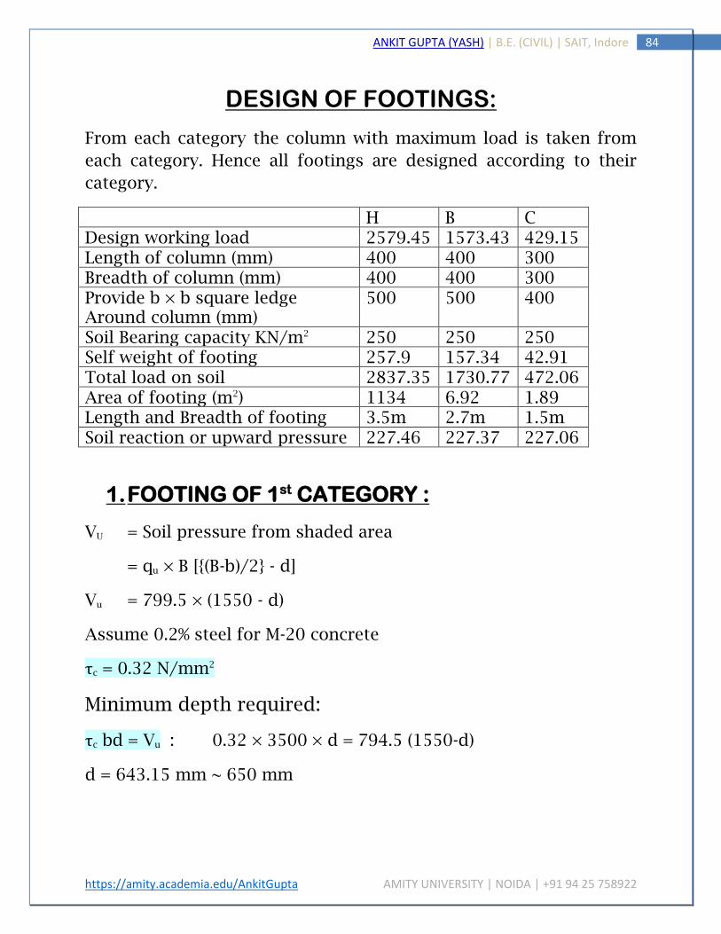
https://amity.academia.edu/AnkitGupta AMITY UNIVERSITY | NOIDA | +91 94 25 758922
84 ANKIT GUPTA (YASH) | B.E. (CIVIL) | SAIT, Indore
DESIGN OF FOOTINGS:
From each category the column with maximum load is taken from
each category. Hence all footings are designed according to their
category.
H B C Design working load 2579.45 1573.43 429.15 Length of column (mm) 400 400 300 Breadth of column (mm) 400 400 300 Provide b × b square ledge Around column (mm)
500 500 400
Soil Bearing capacity KN/m2 250 250 250 Self weight of footing 257.9 157.34 42.91 Total load on soil 2837.35 1730.77 472.06 Area of footing (m2) 1134 6.92 1.89 Length and Breadth of footing 3.5m 2.7m 1.5m Soil reaction or upward pressure 227.46 227.37 227.06
1. FOOTING OF 1st CATEGORY :
VU = Soil pressure from shaded area
= qu × B [{(B-b)/2} - d]
Vu = 799.5 × (1550 - d)
Assume 0.2% steel for M-20 concrete
τc = 0.32 N/mm2
Minimum depth required:
τc bd = Vu : 0.32 × 3500 × d = 794.5 (1550-d)
d = 643.15 mm ~ 650 mm

https://amity.academia.edu/AnkitGupta AMITY UNIVERSITY | NOIDA | +91 94 25 758922
85 ANKIT GUPTA (YASH) | B.E. (CIVIL) | SAIT, Indore

https://amity.academia.edu/AnkitGupta AMITY UNIVERSITY | NOIDA | +91 94 25 758922
86 ANKIT GUPTA (YASH) | B.E. (CIVIL) | SAIT, Indore
Check for Bending:
Mu lim = 0.138 × fck bd2
= 3995.78 × 106 N-mm
Mu = qu (B – b)2/8 × B
= 954.39 x 10⁶ N-mm < Mu lim.
Check for two way shear:
Perimeter of critical section = 4 × (b + d)
= 4200 mm
Area of critical section = 4200 × d
= 4200 × 650
2 way shear stress = upward pressure (shaded area)/ Area of
critical section = 0.227 (35002 – 10502)/ 4200 × 650
= 0.927 N/mm2
Max. Shear stress permitted = 0.25√fck = 0.25√20 = 1.118 N /mm2
Mu = 954.39 × 10⁶ N-mm
MU = 0.87fy Ast d (1 – Ast fy / bd fck)
Ast = 4229.90 mm2
Using 20 mm Ø 250 mm c/c
τv = Vu/ bd = 0.314
τc > τv Hence OK

https://amity.academia.edu/AnkitGupta AMITY UNIVERSITY | NOIDA | +91 94 25 758922
87 ANKIT GUPTA (YASH) | B.E. (CIVIL) | SAIT, Indore
2. FOOTING OF 2ND CATEGORY :
Vu = soil pressure of shaded area
= qu × B [{(B – b)/2} – d]
Vu = 612.9 (1150 – d)
Assume 0.2% of steel for M-20 concrete τc = 0.35 N/mm2
Minimum depth required:
τc bd = Vu : 0.35 × 2700 × d = 612.9 (1150 – d)
d = 442.76 mm ~ 450 mm
Check for bending:
Mu lim. = 0.138 fck bd2 =1509.03 × 106 N/mm
Mu = qu B (B – b) 2/8 = 40.52 × 10 6 N-mm2 < Mu lim.

https://amity.academia.edu/AnkitGupta AMITY UNIVERSITY | NOIDA | +91 94 25 758922
88 ANKIT GUPTA (YASH) | B.E. (CIVIL) | SAIT, Indore
Check for 2-way Shear:
Perimeter of critical section = 4 × (B+ d)
= 3400 mm
Area of critical section = 3400 ×d
= 3400 × 450 mm2
2 way shear stress = upward pressure (shaded area)/ Area of critical
section = 0.227 × (27002 - 8502)/3400 × 450
= 0.974 N/mm2
Maximum shear permitted = 0.25√fck = 1.118 N/mm2
Mu = 0.87 fy Ast d (1 – Ast fy/b d fck)
Ast = 2617.07 mm2
Use 20mm Ø @ 300 mm c/c
τv = Vu/ bd = 0.312
τc > τv Hence OK

https://amity.academia.edu/AnkitGupta AMITY UNIVERSITY | NOIDA | +91 94 25 758922
89 ANKIT GUPTA (YASH) | B.E. (CIVIL) | SAIT, Indore
3. FOOTIN NG OF 3rd CATEGORY :
Vu = Soil pressure from shaded area
Vu = 340.5 (600 – d)
Assume 0.2% of steel for M-20 Concrete τc = 0.35 N/mm2
Minimum depth required:
τc bd = Vu : 340.5 (600 – d) = 0.32 × 1500 × d
d = 247.96 ~ 250 mm
Check for Bending:
Mu lim. = 0.138 fck bd2 = 258.57 × 10⁶ N-mm
Mu = qu B (B – b) 2/8 = 61.29 x 10⁶ N-mm < Mu lim.

https://amity.academia.edu/AnkitGupta AMITY UNIVERSITY | NOIDA | +91 94 25 758922
90 ANKIT GUPTA (YASH) | B.E. (CIVIL) | SAIT, Indore
Check for 2 way Shear:
Perimeter of critical section = 4 (b + d)
= 2200 mm
Area of critical section = 2200 × d
= 2200 × 250
2 way shear stress = upward pressure (shaded area)/ Area of
critical section = 0.227 (15002 – 5502)
= 0.80 M/mm2
Maximum shear stress permitted = 0.25√fck
= 1.118 N/mm2
Mu = 0.87 fy Ast d (1 – Ast fy/b d fck)
Ast = 706.62 mm2
Use 12mm Ø @ 230 mm c/c
τv = Vu/ bd = 0.317
τc > τv Hence OK

https://amity.academia.edu/AnkitGupta AMITY UNIVERSITY | NOIDA | +91 94 25 758922
91 ANKIT GUPTA (YASH) | B.E. (CIVIL) | SAIT, Indore
CONCLUSION
The design of R.C.C. structured building done by Limit State
Theory.
Moment Distribution Method is adopted for calculating the
moment over the Spans.
All the slabs are designed as two way Slabs, by the method
provided by IS 456: 2000.
It is evident that load in a residential building is so less that
slab were safe in all aspects with the minimum reinforcement
as per IS 456: 2000.
Beams are designed individually as continuous beams &
reinforcement is provided for as well as for negative moment.
Isolated footing was provided of maximum size 3.5 m ×3.5 m
and safe bearing capacity of soil is 250 KN/m2.

https://amity.academia.edu/AnkitGupta AMITY UNIVERSITY | NOIDA | +91 94 25 758922
92 ANKIT GUPTA (YASH) | B.E. (CIVIL) | SAIT, Indore
REFERENCES
1. R.C.C. Theory & Design: S.S. Bhavikatti – New Age International
Publishers.
2. Theory of Structure: S. Ramamrutham & R. Narayan –
Dhanpat Rai Publishing Company.
3. Strength of Materials: S. Ramamrutham & R. Narayan –
Dhanpat Rai Publishing Company.
4. Structural Design & Drawing: N.K. Raju.
5. IS 456: 2000 Indian Standard Code of practice for Plain &
Reinforced Concrete.
6. IS 875: 1987 part-1 Code of practice for Design of Load for
Building & Structure.