Foundation: Building Material and Building Construction
39
SHALLOW FOUNDATION INTRODUCTION: Every structure has basically two components i.e. super structure and sub structure. In case of buildings, that sub structure is called as foundation. The super structure is that part of the building which is above the ground and visible to us and the sub structure or foundation is below the ground. Hence the foundation or sub structure (in case of buildings only) is in direct contact with the ground. The soil below foundation is called is sub soil or foundation soil and the lower most portion of the foundation which is in direct contact with the foundation soil or sub soil is called as footing. Hence footing is the lower most surface of the foundation which is in direct contact of the soil. Hence foundation may be defined as the lowermost portion of a building or any structure which transfers the super imposed load of the super structure to the soil beneath it. Hence the foundation relies upon the sub soil or foundation soil for doing so. The sub soil supporting foundation should be able to bear the super imposed load (stress) and should not fail. Generally two types of failure is found i.e. bearing capacity failure or shear failure and failure due to excessive settlement. When the foundation transfers higher load than that of foundation soil or sub soil capacity, then a sudden failure occurs due to bearing failure of the soil and this happen so as the soil can no longer bear the load any more. In case of settlement failure, the soil does not fail itself but undergoes very high settlement under the action of super structure loading. When the settlement is very high, the super structure fails due to distortion. However, the settlement is allowed for some limits within which the super structure experiences no problem. As per Indian standard code, the total settlement allowed for in case of isolated foundation is 25 mm and in case of mat/raft foundation, it’s 40 mm provided that the differential settlement does not exceed 20mm. The differential settlement is occurred due to various causes like weak stratum of sub soil, shrinking and expansive soil, ground water table variation, traffic and vibrations, slow process of consolidation and slippage of strata
Transcript of Foundation: Building Material and Building Construction

SHALLOW FOUNDATION
INTRODUCTION:
Every structure has basically two components i.e. super structure andsub structure. In case of buildings, that sub structure is called asfoundation. The super structure is that part of the building which isabove the ground and visible to us and the sub structure or foundationis below the ground. Hence the foundation or sub structure (in case ofbuildings only) is in direct contact with the ground. The soil belowfoundation is called is sub soil or foundation soil and the lower mostportion of the foundation which is in direct contact with thefoundation soil or sub soil is called as footing. Hence footing is thelower most surface of the foundation which is in direct contact of thesoil.
Hence foundation may be defined as the lowermost portion of a buildingor any structure which transfers the super imposed load of the superstructure to the soil beneath it. Hence the foundation relies upon thesub soil or foundation soil for doing so. The sub soil supportingfoundation should be able to bear the super imposed load (stress) andshould not fail. Generally two types of failure is found i.e. bearingcapacity failure or shear failure and failure due to excessivesettlement. When the foundation transfers higher load than that offoundation soil or sub soil capacity, then a sudden failure occurs dueto bearing failure of the soil and this happen so as the soil can nolonger bear the load any more. In case of settlement failure, the soildoes not fail itself but undergoes very high settlement under theaction of super structure loading. When the settlement is very high,the super structure fails due to distortion. However, the settlementis allowed for some limits within which the super structureexperiences no problem. As per Indian standard code, the totalsettlement allowed for in case of isolated foundation is 25 mm and incase of mat/raft foundation, it’s 40 mm provided that the differentialsettlement does not exceed 20mm. The differential settlement isoccurred due to various causes like weak stratum of sub soil,shrinking and expansive soil, ground water table variation, trafficand vibrations, slow process of consolidation and slippage of strata
etc. The bearing capacity failure occurs in case of sand orcohesionless soil and the settlement failure is more common in case ofclay or cohesive soil and loose sand having standard penetrationnumber (N) less than 5.
FUNCTIONS OF FOUNDATION:
The provision of the foundation is necessary for carrying outfollowing jobs/functions.
1. Reduced Load Intensity: Since the base of the foundation iswidened, the load of column or wall resting on it getsdistributed over a larger area i.e. foundation area. Hence theload intensity is reduced. It’s always essential that the superstructure load should confirm to safe load carrying capacity ofthe soil and should at no case exceed the ultimate bearingcapacity of the soil. The shallow foundation transmits the loadto soil through bearing while the deep foundation does so by bothbearing and friction.
2. Even Load Distribution: Foundation transfers the loads of thecolumns and walls of a structure to the building evenly i.e. ifthe two columns carry unequal loads, then the foundation providedbelow these two make the load uniform at the base of thefoundation by coinciding the C.G of the foundation with that ofapplied loading. Due to equal or even load distribution, thefoundation and ultimately the super structure does not sufferfrom any differential settlement. The load distribution patternis concave i.e. narrower at the base and wider at the apex/edgeat the base of the footing in case of cohesive soil and in caseof cohesionless soil it’s just opposite i.e. the loaddistribution is convex in shape.
3. Lateral Stability: The structure gets lateral stability due tofoundation as the foundation gets anchored to the soil andthereby prevents the lateral sway of the structure. The lateralsway is caused by lateral or horizontal forces like wind,earthquake and water current etc.
4. Safety against Undermining: The safety against undermining is gotby foundation too. The foundation does so by checking scouringeffects of flood and burrowing animals.
5. Protection against the Soil Movement: The foundation when treatedproperly proves very effective in minimizing or even eliminatingthe distress or cracks in super structure due to shrinkage andexpansion of the sub soil in some soils like black cotton soilswhich are highly shrinking and expansive soil.
REQUIREMENTS OF A GOOD FOUNDATION:
Following are some of the requirements of a foundation.
1. The settlement of the foundation due to the imposed loads and theself weight should be within acceptable limits so that it doesnot pose any threat to the super structure.
2. The base of the foundation should be rigid especially the base ofthe mat or raft foundation should be rigid enough to anticipateany excessive differential settlement.
The foundation depth should be so that the seasonal variation will notbe effecting on it. However, the minimum depth of the foundation isfixed to be 0.5m and at no case it should be lesser than that. Butgenerally a depth of 1m is provided even in case of hard soil. As perRankine, the minimum depth of foundation is given by,
Df = qγ×[
1−sinɸ1+sinɸ ]
2
Where q = load intensity in kN/m2 from super structure
γ = unit weight or weight density of soil in kN/m3
ɸ = shearing angle (found out from laboratory test)
3. In important structures, the foundation location should be suchthat the foundation does not get affected during the life span ofthe structure.
CLASSIFICATION/TYPES OF FOUNDATION:

Foundations are broadly classified as shallow foundation and deepfoundation. There are other types of foundations too i.e. machinefoundation and floating foundation etc. but these can be classifiedalso in the above two categories. The foundation classification,whether shallow or deep is done on many criteria but the most famouscriteria of classification is the classification based on KarlTerzaghi’s theory (1943). As per Terzaghi, the foundation having itsdepth less than or equal to width is classified as shallow foundationand the foundation having the depth greater than its width isclassified as deep foundation. As per British code i.e. CP-2004, anyfoundation having depth greater than 3m is classified as deepfoundation.
Indian standard has adopted Terzaghi’s theory of foundationclassification. Hence the foundation classification in this text willbe based on Terzaghi’s theory.
The shallow foundations are further categorized. They are:
i. Spread footing/ Isolated footingii. Combined footingiii. Cantilever/ Strap footingiv. Mat/Raft footing
Similarly the deep foundations are categorized as:
i. Pile foundationii. Pier foundationiii. Well foundation
Let’s discuss about them one after another.
SHALLOW FOUNDATION:
Shallow foundation is otherwise called as open foundation. It’sbasically divided in to following four categories i.e. spread footing,combined footing, cantilever footing and mat footing. Also there isanother type of footing named inverted arch footing and continuousfooting. These are discussed as below.
1. Spread/Isolated Footing:

These are the footings spreading the super imposed load over a largerarea and thereby reducing the load intensity considerably. Theysupport either wall or column on them. They are named as isolatedfooting also as they are separate from each other and support isolatedstructural elements like individual wall or column. They areclassified under following categories:
i. Single column footingii. Stepped footingiii. Sloped footingiv. Wall footing or strip footingv. Grillage footing
Students may refer to the figures for better understanding. Theisolated footing spreads the column load over a greater area asdiscussed earlier. Similarly the stepped footing is provided when thecolumn load is quite heavy and very large area of foundation isrequired. In that case, the foundation is stepped and therebyachieving considerable economy in the form of material saving. In caseof sloped footing, the foundation is made sloped from the column facetowards the ends. The slope is made uniform but not irregular. Theedge of the footings should have atleast a depth of 150 mm as perIndian standard code.
Similarly the strip footing or wall footing is that which carries awall on it. It may be either with out step or with steps. Normally theload bearing walls or masonry walls have stepped strip footingprovided underneath it.
These footings (except grillage footing) may or may not be providedwith reinforcement. If the reinforcement is absent, then the thicknessof the foundation slab is kept twice than that of the projection partor the part of the foundation which is in between the face of columnor wall and the edges of the foundation.
The grillage foundation is provided below the steel stanchion whichcarries very heavy load particularly on a poorly bearing capacitysoil. The depth of such foundation is kept generally 1 to 1.5 m. Theheavy load of stanchion is distributed on a very large area by the

arrangement of two rows of rolled I-section beams orthogonal to eachother. Also when the load is moderate, one row or one tier of the I-beam can be provided also. The tiers or rows are concreted so that thebeams do not get distorted. The concrete thus serves only to keep thebeams in position but do not carry any load. A normal practice is tokeep a gap of 80 mm in between the beams so that the concrete can beeasily placed in side it. Sometimes instead of providing steel I-beams, timbers are provided also to serve as grillage foundation.Planks are provided at the base of such footing and normally they areof single tire. These type of timber grillage is specially suitable inwater logged area where the bearing capacity is low and the steelgrillage may get corroded.
(Plain isolated footing) (Isolated sloped footing)
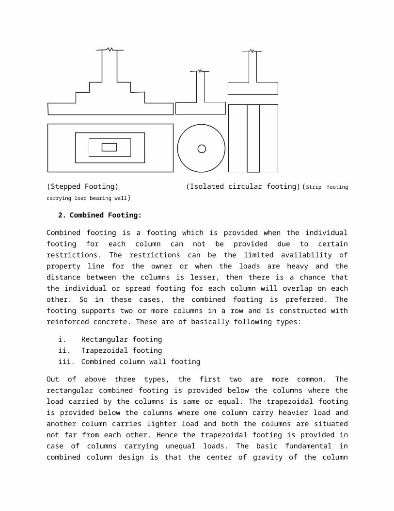
(Stepped Footing) (Isolated circular footing)(Strip footingcarrying load bearing wall)
2. Combined Footing:
Combined footing is a footing which is provided when the individualfooting for each column can not be provided due to certainrestrictions. The restrictions can be the limited availability ofproperty line for the owner or when the loads are heavy and thedistance between the columns is lesser, then there is a chance thatthe individual or spread footing for each column will overlap on eachother. So in these cases, the combined footing is preferred. Thefooting supports two or more columns in a row and is constructed withreinforced concrete. These are of basically following types:
i. Rectangular footingii. Trapezoidal footingiii. Combined column wall footing
Out of above three types, the first two are more common. Therectangular combined footing is provided below the columns where theload carried by the columns is same or equal. The trapezoidal footingis provided below the columns where one column carry heavier load andanother column carries lighter load and both the columns are situatednot far from each other. Hence the trapezoidal footing is provided incase of columns carrying unequal loads. The basic fundamental incombined column design is that the center of gravity of the column
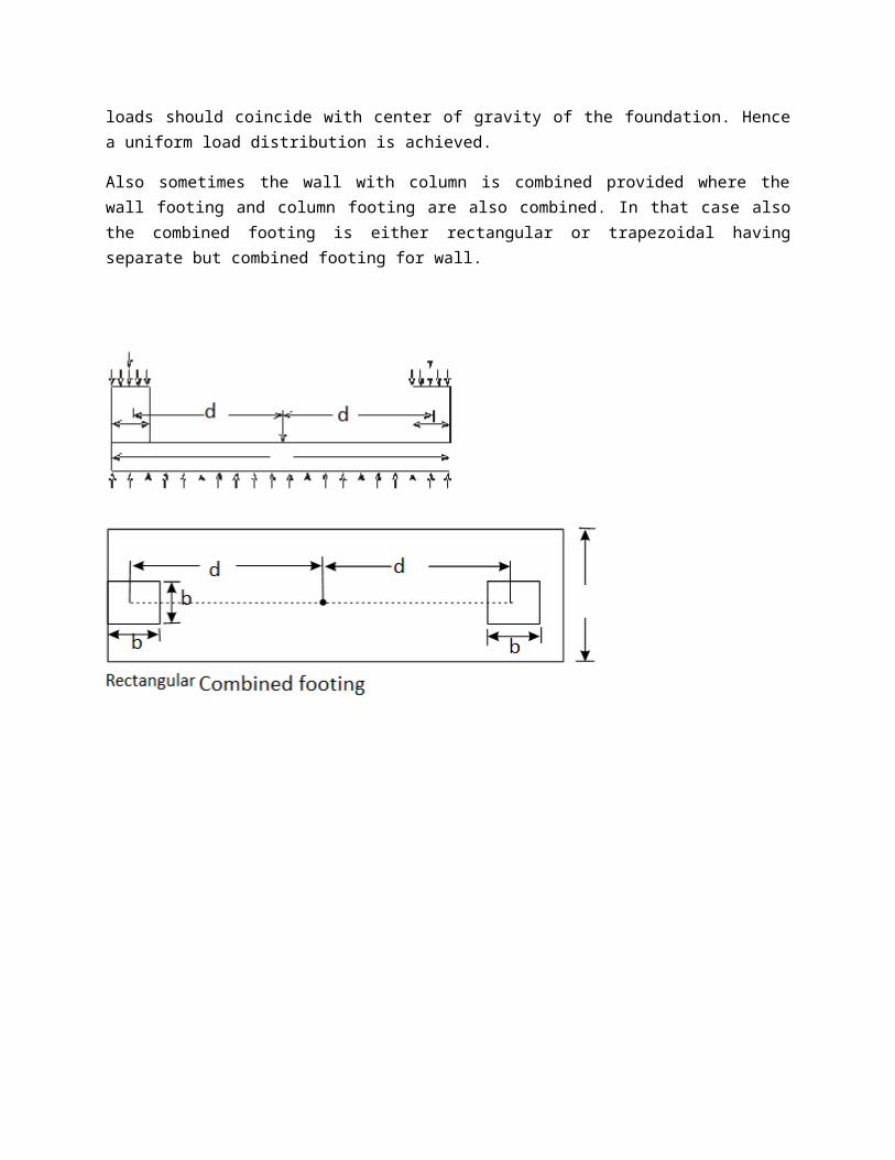
loads should coincide with center of gravity of the foundation. Hencea uniform load distribution is achieved.
Also sometimes the wall with column is combined provided where thewall footing and column footing are also combined. In that case alsothe combined footing is either rectangular or trapezoidal havingseparate but combined footing for wall.

3. Strap footing/Cantilever footing:
When the independent footings of two columns are connected by a beam,then it’s called as strap footing or cantilever footing and the beamis called as strap beam. The strap footing is provided when thetrapezoidal footing can not be provided due to very large distancebetween the two columns. Hence the bending moment comes too higheither or the provision of trapezoidal footing will result uneconomic.So in that case, a strap beam joins the two individual foundationsprovided below the two isolated columns. The strap beam is not allowedto come in contact with the foundation soil or sub soil.

4. Mat foundation:
Mat foundation is also called as raft foundation. A mat or raft is asolid slab supporting the columns or walls underneath it. Matfoundation is especially suitable in those areas where high settlementis expected and the bearing capacity of the foundation soil is quitelow. Due to low bearing capacity, if the spread footing is provided,then the footing would cover very large area and also the individualor spread footing will overlap on each other making it bothuneconomical and difficult to construct. Also as stated earlier, theareas where the settlement is quite high due to soil mass havingcompressible lenses or there is presence of erratic deposit, then atthat case mat foundation is provided to check the settlementespecially differential settlement. Hence in case of mat foundation,

the overall settlement is allowed to 40 mm provided the differentialsettlement does not exceed the limit of 20mm. now the question is howmat foundation proves better than others in case of checkingparticularly differential settlement? The answer is the mat foundationdue to covering a high area and carrying all most all the columns andwalls has a tendency to bridge over any differential settlement andthereby reduces the effects i.e. structural crack or irregularitiescaused by differential settlement. Also the mat foundation is heavilyreinforced than required so as to make it rigid one because it cansustain the differential or unequal pressure distribution caused dueto differential settlements on soft soil having low bearing capacity.Also this is the reason why the mat foundation is allowed to settle upto 40 mm against any other type of footings where they are allowed tosettle just 25mm overall.
There are various types of rafts or mat foundations. They are:
i. Flat plate typeii. Flat plate thickened under columniii. Flat plate type having pedestal below the columnsiv. Beam and slab typev. Cellular raft or cellular raft having basement wall (Box
structure raft )vi. Buoyancy raft
Flat plate type is the ordinary common type of raft footing. They havea flat slab of required thickness and support the columns which areplaced uniformly and loaded with small amount of load. Also thecolumns are spaced relatively nearer to each other.
Flat plate thickened under column or flat plate type having pedestalsupporting the columns is used when the columns carry heavier loads.But still in this case also the spacing is uniform and the columns arepresent nearer to each other. The extra thickness of the footing slabbelow the column or underneath the column (as the case may be) is usedto resist high negative bending moment and diagonal shear.
When the loads carried by columns are heavy and the spacing of thecolumns is at larger distances, then at that case, the raft is
designed as grid pattern or beam and slab type pattern because ofdevelopment of very high bending stress. In this case, the beams areprovided parallel to each other in both the directions and thejunction point of any two beams will be carrying a column. The slabsare provided in between the beams and the reinforcement in slabs islower than beam reinforcement generally.
When there exists very high bending stress at the column base, thistype of foundation is provided. In this type of foundation, the boxstructure has slabs and wall type arrangement. So in this type raftfoundation, the basement walls acts as rigid beam which stiffens themat against the bending.
Buoyancy rafts may be of two types i.e. either it’s placed on a pileor directly on the sub soil. In the first case, when the raft is onthe pile, the pile does not carry any load but just checks thesettlement. In the later case, i.e. in the second case when the raftis directly on the sub base, the depth of foundation is such that theweight of total excavated earth is equal to total weight of thestructure including the raft/mat.

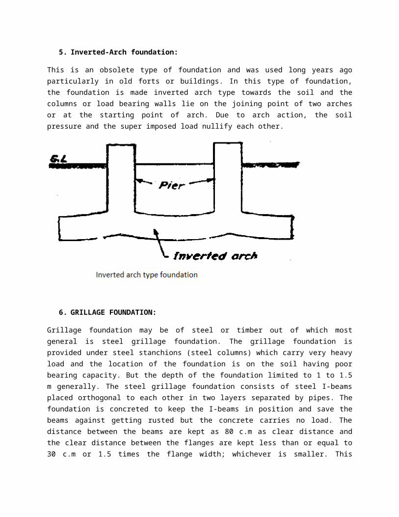
5. Inverted-Arch foundation:
This is an obsolete type of foundation and was used long years agoparticularly in old forts or buildings. In this type of foundation,the foundation is made inverted arch type towards the soil and thecolumns or load bearing walls lie on the joining point of two archesor at the starting point of arch. Due to arch action, the soilpressure and the super imposed load nullify each other.
6. GRILLAGE FOUNDATION:
Grillage foundation may be of steel or timber out of which mostgeneral is steel grillage foundation. The grillage foundation isprovided under steel stanchions (steel columns) which carry very heavyload and the location of the foundation is on the soil having poorbearing capacity. But the depth of the foundation limited to 1 to 1.5m generally. The steel grillage foundation consists of steel I-beamsplaced orthogonal to each other in two layers separated by pipes. Thefoundation is concreted to keep the I-beams in position and save thebeams against getting rusted but the concrete carries no load. Thedistance between the beams are kept as 80 c.m as clear distance andthe clear distance between the flanges are kept less than or equal to30 c.m or 1.5 times the flange width; whichever is smaller. This

provision is done for better placement of concrete inside thefoundation.
In case of wooden grillage footing, planks are used instead of timberbeams as cross beams whereas the main beams are timber beams.
The grillage foundation provides more area for load distribution andhence effectively distributes the load in a soil having poor bearingcapacity.

DEEP FOUNDATIONWhen the ratio of width to depth is less than one, then it’sclassified under deep foundation category as per Karl Terzaghi. Thereare basically three types of deep foundations present out of which

pile foundation is mostly used for buildings. The deep foundationsare:
i. Pile foundationii. Pier foundationiii. Well foundation
1. PILE FOUNDATION (REF: FOUNDATION ENGINEERING, ABHISEK PANDA, ALOKPUBLICATIONS)Pile foundation usage is from ancient time like nearly from 59A.D and is more common among all types of deep foundations.Though Romans were best pile drivers as far as technique isconsidered but modern steam driven piles were invented by Nasmythin 1845. Piles are classified basing upon (i) Material of construction, (ii) Mode of load transfer(iii) Classification based on usage(iv) Method of construction(v) Displacement of soil.
Note: Find the major type of figures at the lastMaterial of Construction
(a) Steel pile :They are generally of H-piles, pipe piles and sheet piles. The H-piles are nothing but rolled steel sections in general. Thesepiles have a shoe at the lower end for ease of driving. An epoxycoating is also applied to reduce the corrosion and a thickersection than that required is generally recommended.
(b) Concrete pile :Concrete piles are generally of two types i.e. precast and cast-in-situ.Pre cast piles are casted in a factory or prestressed and thentransported to the site. They are also designed and reinforced tocarry an extra stress developed during driving. Normally amaximum design load of 80 tones is to be carried by such pilesand designed accordingly.Cast-in-situ piles are constructed by making a required hole onthe ground and then filled up by concrete and if it is R.C.C.pile, then concrete is filled up after inserting the steel cage.
These are basically of :

Driven piles : cased or uncasedBored piles : pressure piles and under-reamed pilesThese are used generally for carrying a maximum of 75tons of loadas design load individually. A number of cast-in-situ piles usedare MacArthur compressed uncased pileFranki standard pileRaymond step-tapered pileRaymond standard pileWestern button bottom pileUnion metal pile of monotubeMacArthur cased pileSimplex standard pileSwage pileVibro piles etc.Under-reamed piles are special type of modified bored piles whichhas under-reamed bulb (which is nothing but a widened portion ofincreased diameter at some point in its length); provided toanchor the foundation in expansive soil subjected alternativeexpansion and contraction and also in highly shrinkable andexpansive soil or when floating foundation condition is achieved.
(c) Timber piles : These are prepared from wood and should bestraight and free from defects and cracks. They are generallyprovided with steel shoe to prevent damage during driving. Thesepiles exibit large life span inside water and lesser life span onthe water due to attack of insects. For that a coating ofcreosote oil or bitument coating is provided for long life. Theseare not to be used in marine construction.
(d) Composite pile : These are the piles made up of two differentmaterials and normally of two types. They are (i) Concrete and timber (ii) Concrete and steel.In both the cases concrete is normally provided in upper portionand lower portion is made up of steel or timber. Due todifficulty in joint it’s not preferred. However, when the requirelength is unavailable with cast-in-place concrete pile, steel andconcrete pile is used and where pile is driven under water,there timber is used under water and concrete over water; thereby making a composite pile.
Mode of Load Transfer

Basing on the mode of load transfer, these are of threecategories. They are end bearing type, friction type and combinedend bearing and friction type.
(a) End bearing piles : As the name suggests, these piles transferthe load to a hard stratum located some depth below the groundlevel by passing through soft layer of weak materials. Thecapacity of piles are dependent on the bearing capacity of hardstrata. If instead of rock, a fairly compacted and hard stratumis located below some depth, then these piles are driven intosome distance inside the strata. They act as columns and transferthe load with same mechanism. They are also called point bearingpiles.
(b) Friction piles : These piles do not require a hard strata forload transfer as they transfer the imposed load through skinfriction to the surrounding soil. These are used when the hardstrata is not reachable at a reasonable depth. The ultimate loadmust be equal to skin friction in these type of piles. They arealso termed as floating piles due to their floating conditionwithout reaching hard stratum.
(c) Combined End bearing and Friction piles :These are the piles which carry loads by combined mechanism ofend bearing and skin friction. Normally all the end bearing pilesdo exhibit some skin friction. Total load carried by these pilesare combination of both point bearing and skin friction.
(d) Battered pile : These are inclined piles mainly used to carry thelateral or horizontal load effectively, produced by wind andearthquake especially.
Classification based on usage The piles are normally classified as of these types.
(a) Load bearing piles : They carry and transmit load of superstructure to a suitable stratum through end bearing or throughskin friction or by combination of both mechanism.
(b) Compaction piles : These piles though themselves do not carry anyload but are used to compact the loose granular soil and thusincreases the bearing capacity of soil. These may be of differentmaterials out of which sand pile is the most common one. A piletube is driven and sand is filled inside which is then compactedby adding required water and applying vibration. Then the tube isgradually withdrawn and to check upward moment of sand due tolateral pressure, the top surface is made concrete.

(c) Tension pile : These piles remain in tension by anchoring thestructures which due to hydrostatic pressure, either tend tooverturn or tend to uplift. These are specially suitable in caseof floating foundation and marine constructions and also in theriver bridges of perenial rivers.
(d) Sheet piles : Sheet piles form a continuous wall or bulkheadwhich is used for retaining earth or water.These are used inbulkheads or cofferdams or at braced excavations and also neardam sites.
(e) Anchor piles : These are used to provide suitable anchorage tosheet piles so that it does not overturn due to horizontal pull.Note : The above two piles will be discussed in “AdvancedFoundation Engineering” book of the same publication.
(f) Fender piles and Dolphins : Fender piles are also sometimescalled dolphins and are used to protect water front structuresfrom impact of ships and vessels. They are widely used in seawall construction, harbers and ports etc.Classification on Method of Installation The piles are classified as follows :
(a) Driven piles : These are precast piles driven into the soil byapplying heavy blows on it by a hammer or by steam.
(b) Combined driven and Cast-in-situ piles : These are the piles inwhich casing is driven into the soil first. Then the casing isfilled up with concrete. Later it may or may not be required todrive the casing out of the hole by leaving concrete there.
(c) Bored piles : These piles are not driven into ground, rather in apre-excavated hole, after placing the steel reinforcing cage,concreting is done.
(d) Screw piles : These are the piles screwed to the soil.(e) Jacked piles : These are the piles jacked into the soil by
applying a force through hydraulic jack.Classification based on displacement of piles
(a) Displacement piles : All the driven piles are displacement pilesas the soil get displaced laterally and tends to be densified.Also due to lateral displacement, the upper soil tends to heaveup. The precast and pipe piles are high displacement piles and H-piles are low displacement piles.

(b) Non-displacement piles : Bored piles are classified as non-displacement type as soil do not get displaced and very minutechange of stress occurs.
i.(End Bearing pile) ii.(Friction pile) (iii)Combined End bearing & friction piles
(Compaction pile)


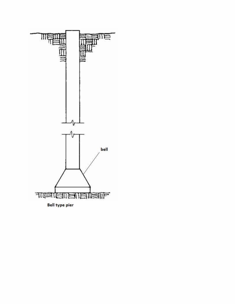
2. PIER FOUNDATION:
Pier foundation is otherwise called as drilled caissons. It is acylindrical column type structure which extends to deep in to theground having depth smaller than pile foundation. The differencebetween pile foundation and pier foundation is that the pilefoundation may be of end bearing type or friction type or both endbearing and friction type in load carrying but in case of pierfoundation, the load is carried through end bearing only. Thisfoundation is generally shallower than pile and is preferred in alocation where the broken rock exists at the top of the soil beneathwhich hard rock is found out. So in that case, it becomes difficult indriving the piles and hence pier foundation is preferred. There arebasically two types of piers which are:
i. Masonry pierii. Drilled pier
The drilled pier is further sub divided to concrete pier and steelpier. Also there is another type of special masonry pier which iscalled as arch pier. The masonry pier is made up of bricks and thesteel pier is made up of by driving the casing in to the ground whichmay be hollow or solid. In case of concrete piers the casing is drivenfirst followed by mass concreting. Sometimes, steel joists areprovided along with concrete. Also the drilled caissons are sometimesbelled at the bottom for providing larger surface area. The arch piers

are those which support an arch above it. The spacing o piers dependson the bearing capacity of soil.

3. WELL FOUNDATION (Ref: Foundation Engineering, Abhisek Panda, AlokPublications):
Well foundation is a box like structure which is that’s why alsocalled Caisson. It’s driven either in land or in water to desireddepth to transfer the load of super structure. Basically caissonis of three types i.e.(i) Box caisson(ii) Pneumatic caisson(iii) Open caisson (wells)Box caisson is closed at bottom and open at top and made up oftimber, steel or concrete. It’s used for light loading. Apneumatic Cassion has its lower portion behaving as workingchamber which contains compressed air and in turn water entry isnot allowed into the chamber. Hence these suitably permitexcavation in dry. The open caisson is generally referred as wellfoundation due to its shape as wells. Both top and bottom ofthese are open and made up of timber, steel and concrete. Thesewells formed the most common type of bridge foundation in India.However, now-a-days due to boring of piles, wells are not in muchof use. The wells are formed by sinking a shell by dredginginside it and it finally becomes a part of permanent structure.The advantage is that soil layer is not so loosen and hencescouring can be checked considerably.
Shapes of Well Foundation The choice of various shapes of well foundation basically dependon the shape of pier above it and vertical and horizontal/lateral

load it has to carry. Besides that cost of sinking/driving, typeof soil, tilting during sinking operation and maintenance costetc. are also taken into account. These are commonly used wellfoundations.
(i) Single circular Better as far as uniform sinking is considered and ratio ofsinking effort to skin friction is maximum. Also it has minimumperimeter. However, blockage of water way and gap between wellwall and pier wall in longitudinal direction of bridge makes itunsuitable for use at some points.
(ii) Double-D :This elliminates the
above disadvantage of circular shape by perfectly fitting to the piershape. Due to lesser dredge area, blockage of linear water wayget reduced too. The only disadvantage lies in closing in ormoving apart during sinking.
(iii)Double Hexagon :These are efficient in grabbing to all parts of the curb butdisadvantage with this is that owing to very sharp corners, theydig more and results in tilting along with high scour.
(iv) Double Octagon :This has basically same property as that of double hexagon butthe scouring effect is even higher in this case.
(v) Dumb-well(vi) Twin-circular(vii)Rectangular The last three basically suffer in water area squeezing nature and last one suffers due to scouring. As per suitability they are often used.

ii.(Double-D) iii.(Double hexagonal)
iv.(Double Octagonal) v.(Dumb well)
vi.(Twin circular)) (Rectangular)

EXCAVATION OF FOUNDATIONFor excavation of foundation basically following four operations are followed. They are site clearance, setting out work, timbering of trenches and pumping/lowering of ground water (if present). These functions are discussed one by one.
1. Clearance:
Before the excavation for the proposed foundation is commenced, thesite shall be cleared of vegetation, brushwood, stumps of trees etc.Roots of the trees shall be removed to at least 30 cm below thefoundation level. The pits formed due to roots of trees, oldfoundations etc. shall be filled up with soil and compacted.
2. Setting out work:
Setting out is done by preparing setting out plan or foundation layout plan which is prepared to some suitable scale which is usually1:50 and then the plan is transferred to the ground through suitablemethods. Then after clearing the debris etc. from the ground, theground tracing or the foundation setting out work starts processing.There are basically two methods of excavation i.e. circumscribingrectangle and centre line method. The later one is more suitable forsmall building works or when the building is irregular in shape. Butfor regular buildings, the first one is generally adopted. We will bediscussing the later one i.e. centre line method.
A bench mark shall be established at the site by a masonry pillar andconnected to the nearest standard bench mark. Levels of the siteshould be taken at 5 to 10 m intervals depending on the terrain andthe importance of the building. The centre lines of the walls aremarked by stretching strings across wooden pegs driven at the ends.The centre lines of the perpendicular walls are marked by setting outthe right angle with steel tapes or preferably with a theodolite. Thesetting out of walls shall be facilitated by having a permanent row ofpillars (not less than 15 cm side and 20 cm thick) parallel to thebuilding wall and located at a suitable distance beyond the peripheryof the building so that they do not foul with the excavation. The

pillars shall be located at the junctions of the cross walls andexternal wall and shall be bedded sufficiently deep so that they arenot disturbed during excavation for foundation. The centre lines ofthe walls shall be extended and marked on the plastered tops of thepillars. The tops of the pillars may be kept at the same level,preferably the plinth level. In rectangular or square settings, thediagonals shall be checked to ensure accuracy of setting out. However,for smaller buildings which foundation setting out can be done in oneday, the pegs may prove sufficient without requiring a masonry pillar.After tracing out, the string lines are marked with the help of drylime on the on the ground.
When pegs are used for small construction works, they may be driven ata distance of 2m intervals and may project 50mm above ground level.They are kept at a distance not less than 1m from the side of externalwall.
3. Timbering Trenches:
When the excavation process continues, the foundation trench can notbe remaining in stable form for sand and also for clay when the depthis greater than critical depth. Hence timbering or shoring operationhas to be done for stabilizing the trench against caving in. these arebasically of five types out of which first four types are commonlyused. They are:
i. Stay bracingii. Box sheetingiii. Vertical sheetingiv. Runner systemv. Sheet piling
i. Stay bracing: This method of excavation is done for trenchesdug in firm soil requiring little or no bracing againstlateral stability. This method uses polling board or verticalsheet placed adjoining to the wall of trench and the boardsare stabilized by using the struts normally placed in tworows. The sheets are placed at an interval of 2-4m and extend

to full depth of trench and have dimension as 200mm wide and40-50mm thick. The strut may be of 100mm×100mm for trenchwidth of 2m and 200mm×200mm for trench width as 4m.
ii. Box sheeting: This is used in case of loose soil having depthof excavation limited to 4m. This is just modified method ofstay bracing in which the vertical sheets are provided asabove and then two rows of wales are provided by placing itadjacent to it. Then the struts are provided across the wales.The wales may be of vertical or longitudinal as perrequirement.
iii. Vertical sheeting: This system is for deep trenches havingdepth up to 10m. The method is very similar to box sheetingbut instead of one time excavation, the excavation is made instages. At the end of each stage, offset is provided and hencethe trench goes on narrowing. Each stage of excavation islimited to 3m and the offset earth surface may be 25 to 50 cm.The timbering is done separately for each stage in whichvertical walling is done by horizontal sheeting followed bywales and then studs are placed as bracing.

iv. Runner system: This system is adopted in loose soil or sand orsoft clay where immediate support is needed before and duringexcavation for stability of trench. These are similar to boxsystem except the runners are placed in place of verticalsheeting made up of wooden sheets or planks having iron shoeat the ends. The struts and wales are normally provided asusual. The runners are driven 30cm in advance of excavation invery loose soils.
v. Sheet piling: This method is used in soft or loose soil foundespecially below water table and when the depth of foundationis very large. Also there is a chance of ground water table torise to the ground level and the width of trench is quitegreat. They are not generally used for buildings.
4. Pumping or Lowering of ground water table:

When there is ground water table present just below the ground levelor it’s expected that during the excavation process, the water tablemay rise to the ground level, and then the water table is loweredthrough suitable process. They are:
i. Sumps/ditches: These are the sumps dug and so the ground waterflows in to the sump which is collected and pumped outside.This is very simple type and most primitive method of loweringthe water table. These are no so deep.
ii. Well point system: In this system, well points are installedat some depth below the ground level and connected throughperforated pips which collect the water. Another pipe attachedto each well point is finally attached to pup unit. The pumpthrows out the water from the well point through pumpingoperation.
iii. Shallow well system: This is another primitive type watercollecting system. In this case, the well are dug and waterwhen accumulated is pumped out. The depth is generally up to10m and the diameter is kept 30 cm.
iv. Deep well system: This is another type of collecting system inwhich the well is dug deep in to the ground. The well is ofhaving 30 m deep and the diameter is kept generally 15 to 60cm.
v. Vacuum method: This is called as forced flow method. In thissystem, the hole is dug and sand filled. The filled sand actsas filter media and also the hole is made vacuum throughvacuum pump. That’s why the potential drop decreases whichforces the water of surrounding to flow in to it; hence itsname is forced flow method. The diameter of hole is generallykept as 25 cm.
vi. Electro-Osmosis method: This method was developed by Prof.Casagrande in 1952. As per this method, two electrodes aredriven in to the ground and direct current is passed. The soilwater will be moving from anode or +ve electrode to cathode/-ve electrode. The water is collected at cathode and pumpedout.

LOAD TESTS
(Ref: Foundation Engineering, Abhisek Panda, Alok
Publications)
1. PLATE LOAD TEST (IS 1888 : 1982)Plate load test is conducted as a field test on site to determinethe allowable bearing pressure. The test is of loading a rigidplate at foundation level and determining the settlementscorresponding to each load increment. The ultimate bearingcapacity is then taken as the load at which the plate startssinking at a rapid rate.Bearing plate :The plate is either circular or square in shape and is made up ofmild steel. The thickness of plate is kept grater than 1 inch or25mm and size varies from 12inch (300mm) to 30 inch (750mm) asper requirement of work and the bottom is made grooved to get arough surface since practical foundation base is rough one. Thewidth and depth of groove is kept 2.00mm and 1mm respectively andthe groove is made keeping a distance of 1.50mm from each other.The plate size is kept atleast 4 times than that of the maximumsize of soil particle over which the test is conducted. Forcircular footing and road constructions, circular plates areessential but for all other cases, rectangular or square platesmay be used.Test pit :A test pit of dimension 5 times the width of plate i.e. 5Bp willbe dug and a square pit is made generally. But depending uponfoundation shape, that type of pit should be made. The pit iskept levelled, cleaned and dug upto the level where foundation isexpected to be constructed.
Loading Methods :The loading is applied by hydraulic jack and pressure on jack isgiven by two methods generally. They are gravity loading methodand reaction truss method.Gravity Loading Method :In case of gravity loading method, a levelled widened platform tobear the load is constructed over hydraulic jack and connected to
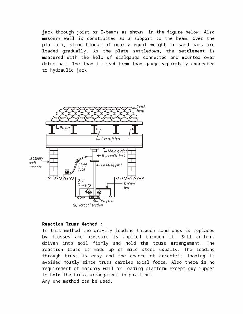
jack through joist or I-beams as shown in the figure below. Alsomasonry wall is constructed as a support to the beam. Over theplatform, stone blocks of nearly equal weight or sand bags areloaded gradually. As the plate settledown, the settlement ismeasured with the help of dialgauge connected and mounted overdatum bar. The load is read from load gauge separately connectedto hydraulic jack.
Sandbags
D atumbar
D ialG auges
L oading post
H ydraulic jackM ain girder
M asonrywallsupport F luid
tube
P lanks
C ross- joists
Test plate(a) Vertical section
Reaction Truss Method :In this method the gravity loading through sand bags is replacedby trusses and pressure is applied through it. Soil anchorsdriven into soil firmly and hold the truss arrangement. Thereaction truss is made up of mild steel usually. The loadingthrough truss is easy and the chance of eccentric loading isavoided mostly since truss carries axial force. Also there is norequirement of masonry wall or loading platform except guy ruppesto hold the truss arrangement in position.Any one method can be used.

P ost
J ackTube
D ialgauges
A nchorsD atum bar
A nchors
Test plate(a) Vertical section
R eaction truss
Cros
sgi
rder
Semi
-circ
ular
troug
h chan
nel
strap
Note : In the examination, students should write any one methodi.e. either gravity loading or reaction truss method or whichever method is asked in the question.The arrangement is done in such a manner that the load is appliedperfectly vertical. Also any eccentric loading is avoided. A sandlayer upto 5mm thick is applied below the plate and with plum boband spirit levelling, levelling is achieved and device iscentered. A minimum pressure of 7kN/m2 (0.7 t/m2) is applied andremoved before the test is started.Loading and Settlement :The loading is applied on the test plate without any impact oreccentricity, rather gradually. The load is increased upto 100kN/m2 (10t/m2) or of estimated ultimate bearing capacity, whichever is lesser.After application of a particular valued loading or particularamount of loading, the observation is taken at an interval of 1,2.25, 4, 6.25, 9, 16 and 25 minutes and then after hourlyintervals to the nearest of 0.02 mm/min settlement. The

increament in loading follows two different pattern for twodifferent type of soils. For clayey soil, the curve representingtime vs settlement is plotted at each stage of loading and theload is increased to the next stage after 24 hours or when thecurve indicates that the settlement of plate is already 70 to 80%of probable settlement at that stage, which ever is earlier. Forall other type of soils, each loading stage shall be kept eitherone hour or till the settlement is 0.02mm/min which ever is laterstage but in no case a particular loading will be remained for 24hours.The test should be done till a settlement of 25mm in general case
or 50 mm in special cases like dense gravel or gravel and sand mixturestrata. Otherwise if failure occurs before that then it should be taken to account. Also when the settlement does not reach 25mm, the load should be increased to two times that of estimated design load. Rebound observations may be taken if necessary.
Note: Pile load test is exactly similar to this test.
2. STANDARD PENETRATION TEST Standard penetration test is used to determine the unconfinedcompressive strength (and ultimately cohesion), angle of shearingresistance and relative density. This is extremely useful forcohesion less soil which can not be sampled and is used morewidely than any other in-situ test.Arrangement and ProcedureThe test is conducted as per IS:2131-1981 code in a clean hole of55 to 150 mm diameter, which is supported bycasing or bentonite slurry or any such type material. A splittube sampler of OD 50.8mm and ID 35mm is driven to undisturbedsoil at the bottom of hole by a drop hammer of 63.5kg massfalling through a height of 75cm @30 blows/minute. Number ofblows required for each 15cm penetration of the sampler iscounted. Total 3 stages of counting or 45cm of penetration isdone. The first 15cm penetration is disregarded and last twopenetration i.e. last 30 cm penetration is taken into account.

The number of blows required for last two penetration of total30cm is standard penetration number or ‘N’. If the number of blows for 15cm drive is more than 50, the testis repeated and getting same result, the test is discontinued.The obtained number is corrected for dilatancy and overburden.Dilatancy Correction :It’s also called as submergence correction. The silty fine sandand fine sand below water table develop pore pressure which isnot easily dissipated which ultimately increases soil resistanceand ‘N’ value.So corrected value is
, when N>15, when
Overburden Pressure Correction :In case of granular soil, for same relative density but differentconfining pressure, that sample with higher confining pressuregives higher penetration number. Also since the depth alters thepenetration number, shallow and greater depth respectively underestimate and over estimate the number. Hence a correction isapplied.
Where Nc = corrected value, N = observed value. = effective overburden pressure 280 kN/m2.
Also as per peck,