ANALYSIS OF LOW-COST BUILDING MATERIAL FOR THE ...
107
ANALYSIS OF LOW-COST BUILDING MATERIAL FOR THE MIXALCO PROCESS A Thesis by L. CLINTON TITZMAN Submitted to the Office of Graduate Studies of Texas A&M University in partial fulfillment of the requirements for the degree of MASTER OF SCIENCE December 2006 Major Subject: Chemical Engineering
-
Upload
khangminh22 -
Category
Documents
-
view
0 -
download
0
Transcript of ANALYSIS OF LOW-COST BUILDING MATERIAL FOR THE ...

ANALYSIS OF LOW-COST BUILDING MATERIAL
FOR THE MIXALCO PROCESS
A Thesis
by
L. CLINTON TITZMAN
Submitted to the Office of Graduate Studies of Texas A&M University
in partial fulfillment of the requirements for the degree of
MASTER OF SCIENCE
December 2006
Major Subject: Chemical Engineering

ANALYSIS OF LOW-COST BUILDING MATERIAL
FOR THE MIXALCO PROCESS
A Thesis
by
L. CLINTON TITZMAN
Submitted to the Office of Graduate Studies of Texas A&M University
in partial fulfillment of the requirements for the degree of
MASTER OF SCIENCE
Approved by:
Chair of Committee, Mark Holtzapple Committee Members, Charles Glover
Cady Engler Head of Department, N.K. Anand
December 2006
Major Subject: Chemical Engineering
iii
ABSTRACT
Analysis of Low-cost Building Material for the MixAlco Process. (December 2006)
L. Clinton Titzman, B.S., Texas A&M University
Chair of Advisory Committee: Dr. Mark Holtzapple The development of biofuels as an alternative fuel source highlights the MixAlco process
as one method to convert organic waste into alcohol fuels. The pretreatment and fermentation
of waste is integral to the process and represents a principal cost consideration due to the large
structure needed to encapsulate the fermenting materials. This research developed papercrete
as a potential construction material to reduce the cost of a structure. Papercrete is a mixture of
paper, cement, and sand. The strengths, thermal conductivity, and other physical properties
were compared with those of conventional building materials. This research identified
acceptable property ranges necessary for using a structural papercrete facility and recorded
compressive and tensile strengths that were too weak to build an economical structure. The
identification of a hybrid papercrete-concrete structure produced results and economics within
acceptable ranges. The papercrete-concrete alternative was tested on the same basis as the
papercrete for structural and economic analysis, which provided acceptable results. The results
indicate that a papercrete-concrete structure is a viable alternative structurally and economically
within a range of sizes for the structure.

iv
ACKNOWLEDGEMENTS
I would like to express my deepest gratitude to Dr. Mark Holtzapple for his guidance and
patience throughout my graduate studies. I would also like to thank Dr. Charles Glover and Dr.
Cady Engler for not only serving on my committee, but also for all the support they have given
me.
This research would not have been completed without the help and facilities of the
StarRotor Corporation. I would like to thank Mr. Andrew Rabroker for his invaluable advice and
time that he provided over the past year.
I would also like to thank the Department of Chemical Engineering for giving me the
opportunity to pursue my studies.
I would like to thank Shannon Eichmann for her friendship during my college career, and
especially for her help while I was completing graduate school.
Most importantly I want to thank my family for there love and support. I especially want
to thank my parents, who made me believe in myself and have given me inspiration along the
way. I would like to thank my brother Don for teaching me so much through the years. I would
also like to thank my sister Jeanette and her husband Gary for their guidance throughout my
educational career.

v
TABLE OF CONTENTS
Page
ABSTRACT ............................................................................................................................... iii ACKNOWLEDGEMENTS.............................................................................................................iv TABLE OF CONTENTS.................................................................................................................v LIST OF FIGURES ..................................................................................................................... viii LIST OF TABLES ......................................................................................................................... x CHAPTER I INTRODUCTION ................................................................................................... 1
1.1 Background ............................................................................................... 1 1.2 Research Goals......................................................................................... 3
II LITERATURE REVIEW ......................................................................................... 5
2.1 Origin ......................................................................................................... 5 2.2 Previous Work ........................................................................................... 6
III PROBLEM STATEMENT AND CHALLENGES .................................................... 9
3.1 Problem Statement.................................................................................... 9 3.2 Challenges ................................................................................................ 9
IV DESIGN BASIS.................................................................................................... 11
4.1 Wind Load ............................................................................................... 11 4.2 Dead Load............................................................................................... 13 4.3 Safety Factor ........................................................................................... 13
V METHODOLOGY................................................................................................. 15
5.1 Introduction.............................................................................................. 15 5.2 Preparing Samples.................................................................................. 15 5.3 Density..................................................................................................... 17 5.4 Compressive Strength............................................................................. 18
5.4.1 Procedures..................................................................................... 18 5.4.2 Analysis.......................................................................................... 20
5.5 Tensile Strength ...................................................................................... 22
5.5.1 Procedure ...................................................................................... 22 5.5.2 Analysis.......................................................................................... 24
5.6 Flexural Strength ..................................................................................... 25 5.7 Thermal Conductivity............................................................................... 27

vi
CHAPTER Page
5.8 Flammability ............................................................................................ 29 VI PAPERCRETE TESTING.................................................................................... 30
6.1 Composition ............................................................................................ 30 6.2 Optimization of Composition ................................................................... 31 VII COMPRESSIVE AND TENSILE STRENGTHS .................................................. 33 7.1 Results..................................................................................................... 33 7.2 Density..................................................................................................... 35 7.3 Final Composition.................................................................................... 36 7.4 Thermal Conductivity............................................................................... 40
VIII STRUCTURAL ANALYSIS .................................................................................. 42
8.1 Papercrete Arch ...................................................................................... 42 8.2 Concrete Testing ..................................................................................... 44 8.3 Layered Quonset Analysis ...................................................................... 48
IX BUILDING TECHNIQUES ................................................................................... 52
9.1 Introduction.............................................................................................. 52 9.2 Precast Wall Panel Building .................................................................... 52 9.3 Monolith Building ..................................................................................... 56
X COST ANALYSIS ................................................................................................ 63
10.1 Introduction............................................................................................ 63 10.2 Papercrete-Concrete Quonset Structure............................................... 63 10.3 Metal Quonset Structure ....................................................................... 65 10.4 Steel-Papercrete Comparison............................................................... 66
XI SUMMARY AND CONCLUSIONS ...................................................................... 68 XII FUTURE WORK .................................................................................................. 69 REFERENCES ........................................................................................................................... 71 APPENDIX A ............................................................................................................................. 72 APPENDIX B ............................................................................................................................. 75 APPENDIX C ............................................................................................................................. 85 VITA........................... ................................................................................................................. 98

vii
LIST OF FIGURES FIGURE Page
1 MixAlco process ............................................................................................................. 1
2 Quonset shape ............................................................................................................... 3
3 Tow mixer ....................................................................................................................... 7
4 Force diagram .............................................................................................................. 12 5 Wind profile of quonset hut........................................................................................... 12 6 Cylinder compression test ............................................................................................ 18 7 Cylinder displacement .................................................................................................. 19 8 Cylinder fracture ........................................................................................................... 19 9 Compressive test stress-strain curve ........................................................................... 21 10 Split cylinder tensile test............................................................................................... 23 11 Tensile test fracture...................................................................................................... 23 12 Tensile stress-strain curve ........................................................................................... 25 13 Center-point loading method ........................................................................................ 25 14 Center-point flexural strength test ................................................................................ 26 15 Thermal conductivity test.............................................................................................. 27 16 Light bulbs inside cylinder ............................................................................................ 28 17 Composition of papercrete batches ............................................................................. 30 18 Compressive strengths of various batches .................................................................. 33 19 Tensile strength ............................................................................................................ 34 20 Density.......................................................................................................................... 36 21 Compressive strength versus density .......................................................................... 36 22 Papercrete properties................................................................................................... 37 23 Cost of papercrete........................................................................................................ 38 24 Effect of water............................................................................................................... 39 25 Papercrete arch simulation model................................................................................ 43

viii
FIGURE Page
26 Layered arch................................................................................................................. 44 27 20-ft diameter arch maximum tensile stress ................................................................ 48 28 20-ft diameter arch with 3-inch inner and outer fillets .................................................. 49 29 20-ft diameter arch maximum displacement. ............................................................... 50 30 Papercrete in wall panel form....................................................................................... 53 31 Dried wall panel ............................................................................................................ 54 32 Angle iron on footing .................................................................................................... 54 33 Precast wall panel construction.................................................................................... 55 34 Monolith shell................................................................................................................ 57 35 Model monolith form..................................................................................................... 58 36 Papercrete applied to monolith form ............................................................................ 59 37 Window screen sag ...................................................................................................... 59 38 Papercrete quonset hut ................................................................................................ 60 39 Concrete layer on papercrete....................................................................................... 61
40 Material cost of papercrete-concrete quonset structure
as a function of diameter .............................................................................................. 64 41 Metal arch cost analysis ............................................................................................... 66
42 Comparison of steel to papercrete-concrete structure ................................................. 67

ix
LIST OF TABLES
TABLE Page
1 Cost of Materials........................................................................................................... 31
2 Compressive Strength Standard Deviation .................................................................. 34
3 Tensile Strength Standard Deviation............................................................................ 35
4 Thermal Conductivity Testing....................................................................................... 40
5 Thermal Conductivity of Selected Materials................................................................ 41
6 Tested Concrete Mix Volume Ratio.............................................................................. 46
7 Concrete and Mortar Strengths .................................................................................... 46
8 Concrete/Mortar Cost ................................................................................................... 47
9 Batch B Properties ....................................................................................................... 47
10 Diameter Cost Analysis ................................................................................................ 64

1
CHAPTER I
INTRODUCTION
1.1 Background
The declining supply and rising price of oil is a growing concern worldwide. The search
for alternative fuels is underway and many different energy sources are being explored. One
very popular source of alternative energy is biofuels. Biofuels are being developed to bring the
world a new fuel source. A process developed at Texas A&M University, called the MixAlco
process (Figure 1), is one way to convert organic waste into alcohol fuels. An important part of
the process is the pretreatment and fermentation of the organic materials.
Fig. 1. MixAlco process (Holtzapple)
During this process, the organics are pretreated and fermented in large covered piles under ideal
conditions.
_____________ This thesis follows the style and format of Materials in Civil Engineering.
2
For the MixAlco process to produce significant quantities to meet the nation’s energy needs, the
piles will require large encasement covering many acres of land. To make this process
economical, the pile encasement must be constructed from a material that is relatively
inexpensive, extremely durable, and completely waterproof. Papercrete, one alternative for
constructing the encasement is investigated in this research to determine if it is viable as an
option for maintaining the required conditions for pretreatment and fermentation piles. This
research will compare papercrete to other engineered building materials to ascertain if it is more
economical to use for large structures.
Papercrete is a mixture of cement, sand, and paper. When combined and cured, these
materials produce a product similar to concrete; however, it is very lightweight. Furthermore, the
cost efficiency gained by utilizing the ample supply of recycled paper reinforces the need for the
research of this alternative. All portions of the encasement structure have different strength
requirements. For example, the centerline of a beam does not need a large compressive
strength. If we can reduce the construction material density by adding paper and use material in
an efficient manner, we maintain a structurally sound building at a lower cost. It was decided to
study papercrete to measure its strength, workability, and other properties to determine if it could
be used to reduce the cost of buildings.
The quonset shape (Figure 2) was determined to be the building shape of choice. The
arch structure is strong and durable, and the structure length could vary depending on size
requirements. The strength and durability characteristics coupled with the size versatility make
the quonset shape ideal for encasement requirements of the MixAlco process.

3
Fig. 2. Quonset shape
1.2 Research Goals
This research investigates different papercrete compositions that can be used to
determine viability and efficiency by varying the compositions of the material mixes of cement,
sand, paper, and water. These composition alternatives have varying associated costs and
strengths; therefore this research will be used to choose an optimal mixture. Because the
strength of the material is directly related to its density, the amount of papercrete that will be
used for the structure varies with the composition. Therefore, an analysis of each composition
will be used to determine if it is practical.
To determine if papercrete is a suitable building material for our needs, an approach for
determining the physical properties is needed. The approach taken is similar to that of concrete.
The papercrete studies were conducted as closely to the ASTM standards (American Concrete
Institute 2004) for concrete as possible. Studies were performed to determine compressive,
tensile, and flexural strengths of several different compositions of papercrete. The testing for the
project was performed in the Structural Engineering Laboratory in the Department of Civil
Engineering at Texas A&M University. The equipment used gave a precise stress analysis that
includes the recording time, displacement, and force that was applied to the sample.

4
Compressive strength is needed to determine the wall thickness necessary to support
the weight of the structure and external loads. The tensile strength of the material needs to be
determined to counteract external loads on the structure. When the wind moves perpendicular
to the quonset-shaped structure, it results in a negative pressure on the down-wind side, which
will cause high tensile stresses on the structure. If these high tensile stresses are not mitigated,
the structure will roll or possibly lift off the ground.
A safety factor was then applied to the final strengths, which will determine the
maximum design stress that can be applied to the material before failure. These design stresses
will set the limit at which the material can perform.
The measured strengths were implemented in a finite element analysis program to
determine the necessary amounts of material needed for several sizes of structures. The five
building size alternatives that were investigated are 20-, 50-, 100-, 200- and 400-feet wide
quonset buildings. The cost per unit volume was determined for the various structure sizes. We
can then determine an effective size of structure that can be constructed from papercrete,
making the largest structure for the lowest cost.
After the size of the structure was determined, several construction techniques were
analyzed and tested to determine feasibility and cost. Monolith and precast wall panel structures
were explored to determine which is most efficient. The monolith structure consists of a
structure formed in place, to the specified size. Then, the papercrete is poured or applied to the
form, and cured in place. The forms are removed and the structure will stand completed. The
wall panel structure will have precast panels that will be formed and cured in a factory. The wall
panels will then be moved to their final location and assembled to make the building. Models will
be constructed to help determine benefits and possible problems with each building technique.
These investigations will allow us to determine how papercrete compares to the cost of
other materials. The comparisons will be used to determine if papercrete should be further
investigated using a scaled building model for the pretreatment and fermentation processes.

5
CHAPTER II
LITERATURE REVIEW
The research was started when very little was known about the strength of papercrete.
Several websites describe housing that was built from the material; however, most of the past
research pertaining to papercrete was not conclusive regarding its strength and building
properties. Several websites have since documented information on the properties of
papercrete. The websites include information on compressive strength, and some thermal
conductivity (Fuller 2004). There is no information available on the tensile or the flexural
strength of papercrete. Several books have been published on the subject, mainly do-it-yourself
manuals on how to make papercrete or how people have made low-cost houses from the
material (Fuller 2004; Solberg 1999). These books discuss how to make mixers, basic mixes of
papercrete, and other general construction techniques. This information has been used to
explore building techniques and establish starting compositions of the papercrete mix. These
resources have been used as guidelines to learn about papercrete, how to mix it, and some tests
that will be useful to determine its properties.
2.1 Origin
Originally patented in 1928, papercrete was very difficult to market because it was so
simple and inexpensive (Solberg 1999). After the original patent, the idea of papercrete
remained dormant until the 1980’s. Since this time, many people have used the material to build
houses and other buildings. Because the owners of these houses do most of the work
themselves, the cost estimates only include materials, not the cost of labor. These owners
shared their knowledge allowing others to use the same techniques to build their own homes.
As the knowledge was passed from one person to the next, many different methods were used
creating various building techniques and ideas. Even the name of the material differs from one

6
builder to the next, some calling it papercrete whereas others call it fibrous cement, or padobe.
Papercrete has been used in several ways with a variety of techniques. Over the years,
papercrete has changed considerably.
2.2 Previous Work
As previously stated, many people have used papercrete to build houses. Some
information has been published on uses for papercrete, other information was found on how
people made the material. However, there is a lack of information on the engineering properties
of the material.
The only engineering properties that had been published on this material, when this
research was started, were the compressive strength and thermal resistance. However, this
information was not given for a particular mix of papercrete. So it was difficult to know what the
composition of that mix was in order to verify the results.
The mixing methods and building techniques were thoroughly documented. Many
different types of mixers have been used to make papercrete. These mixers ranged in size from
5 to 1500 gallons. For small batches of papercrete, a 5-gallon bucket, an electric drill, and a
stucco mixer can be used. This method of mixing is very inexpensive, and is very effective for
small batches. Some larger mixers use electric motors mounted to 55-gallon drums, with lawn
mower blades used for impellers. However, the most unique mixer is a “tow mixer.” The “tow
mixer” (Figure 3) uses a rear axle from an automobile to drive the impeller. The inventors
removed the axle from the automobile, and turned the drive shaft to the vertical position. A hole
was cut into the bottom of a livestock tank and the tank was mounted so that the drive shaft
extended through the hole. Then the hole was sealed and a lawn mover blade was mounted on
the drive shaft. A hitch was assembled to the axle, so the mixer could be pulled behind a truck.
When the mixer is pulled behind the truck, the wheels turn the drive shaft which in turn moves

7
the blade which mixes the papercrete. The “tow mixer” created an inexpensive way to mix large
batches of papercrete. However, this invention is impractical for an industrial setting.
Fig. 3. Tow mixer (Fuller 2004)
The previously built structures have been constructed using several different building
techniques. Many of the builders make papercrete bricks that vary in size, but are still easy to
move by hand. These bricks are then assembled into the final structure by using papercrete as
a mortar. This technique uses forms that are built to a specific size. Papercrete is then poured
into these forms, allowed to set, and then the forms are removed. The papercrete is dried for
several weeks before the bricks are assembled. This technique is similar to conventional brick
houses, except the walls are load bearing. Other builders have used monolith structures that
use forms constructed to the dimensions of the building. The form is then covered with the
papercrete and allowed to set. When the papercrete is set, the forms are removed and
papercrete supports the structure. This technique requires less labor, but the cost is high if the
forms cannot be used again. The forms used for the bricks are reusable, but the monolith forms
must be in place until the material is strong enough to support the load.
One of the most challenging problems with papercrete is its fluid retention property.
When dry papercrete is exposed to water, the material acts like a sponge and absorbs the water.
The moisture then reduces the strength of the papercrete; therefore, the papercrete must be

8
sealed to stop water from penetrating the surface. Several different approaches have been used
to stop the water from penetrating the papercrete. The first is to seal the papercrete with an
elastomeric paint. This paint produces a thin, flexible rubber-like membrane when it dries. This
technique has been reported to have a good record for holding up over long periods of time.
However, the paint is very expensive. A less expensive alternative to the first approach is using
roofing tar. The roofing tar will form an impenetrable barrier; however, the material can harden
and crack due to sun exposure. If the cracks are not detected, the water can penetrate the
papercrete and produce mold or mildew and degrade the papercrete. Another material that can
be used to waterproof the papercrete is a crystalline waterproofing. The crystalline
waterproofing material is a dry powder compound of Portland cement, very fine treated silica
sand, and proprietary chemicals. This powder is mixed with water, and then applied to the
surface that results in a reaction that forms non-soluble crystalline fibers within the pores and
capillary tracts of the papercrete. “This compound is pricey, but said to be so effective that it is
possible to make ponds with papercrete (Fuller 2004).”
These building details have been used to gain information to challenges that will be
encountered when using the papercrete as a building material. These sources of information
were used as starting points for the studies that are needed to approach papercrete from an
engineering viewpoint.

9
CHAPTER III
PROBLEM STATEMENT AND CHALLENGES
3.1 Problem Statement
The pretreatment and fermentation steps of the MixAlco process require large covers to
maintain ideal conditions in the piles. Large buildings are one technique that can create a barrier
to maintain the conditions. To make the process efficient, the buildings must be constructed
from a material that is inexpensive, but still sufficiently strong. Papercrete will be investigated to
determine if it is sufficiently strong and less expensive than other building materials. This study
will determine if papercrete can be built into the large structures needed for the MixAlco process.
3.2 Challenges
Papercrete has not been researched for commercial applications until now. Only
houses have been made from papercrete; therefore, increasing the size of the buildings to cover
the MixAlco piles is a challenge. The weather will play a role in this process. Papercrete loses
strength when it absorbs water; therefore, it must be sealed to prevent moisture from reaching
the papercrete. However, the papercrete cannot be coated with waterproof material while the
papercrete is curing. To maximize its strength, papercrete needs to dry, as well as cure.
Concrete sets during the first 24 hours after pouring; the hydration process occurs over many
years. Concrete gains approximately 80% of its strength in the first 7 days of curing (Fintel
1985). If the concrete were wet for those 7 days, it would still gain the same strength. However,
if papercrete were kept wet for 7 days, the strength of the material would not increase until the
moisture was removed and the papercrete was allowed to dry. This means that the sealant for
the papercrete cannot be applied until after the papercrete is fully dried. For small structures,
this is not much of a concern because the small wall thickness takes less time to dry. However,
when the walls on the structures increase in thickness, the drying time for the papercrete also

10
increases. This will increase the construction time; therefore, weather plays a much larger role
in industrial structures.
The papercrete can be constructed to withstand wind loads; however, the walls must be
thick. This creates two problems. First, the amount of the material needed increases, which
increases the overall cost. But more important, the drying time of the papercrete increases to
the point where drying is difficult. Fluid transport through the wall slows as the wall becomes
thicker; therefore, the walls will not be strong enough to support themselves for many months.
This leaves a couple of options: (1) find a method to dry the walls quicker, which can be costly,
and does not eliminate the problem with the amount of material used; or (2) reduce the amount
of papercrete needed by adding a stronger material to the building.

11
CHAPTER IV
DESIGN BASIS
To determine the efficiency of building a large papercrete structure, the material
properties of papercrete are required. The minimum strength of papercrete is necessary for the
structural analysis of the building. The prototype building would be located in Bryan, Texas. The
minimum design loads for that location will help determine if the strength of the material is great
enough to be used for the pile buildings.
4.1 Wind Load
The most critical load on the prototype for Bryan, Texas is wind. According to the ASCE
standard, a 100-mph wind load is specified for Bryan, Texas (Engineers 2003). The shape of
the quonset building presents several problems for determining the loads and pressure
distributions on the building. The ASCE standards do not present information for wind pressures
on the quonset shape. The pressure distributions in the standards only include buildings with
vertical walls. Wind tunnel testing is the required procedure for determining the pressures on the
quonset shape. A study was found for wind tunnel pressure distributions on the quonset shape
(Chien et al. 1951). The information from the study made it possible to determine the forces
present on the structure at different wind speeds.
The pressure exerted at different locations of the structure makes it possible to develop
a force diagram (Figure 4). Because the pressure profile changes as the wind flows over the
arch, different forces are applied to the surface of the arch to determine the maximum stress that
will be applied to the building in the 100-mph wind.

12
Fig. 4. Force diagram
The wind forces on the structure were greatest when the direction of the wind was
perpendicular to the longest side of the arch. A combined wind profile, which shows the
maximum forces on the arch, is shown in Figure 5. It was necessary to combine several wind
angles to determine the maximum possible stress on the arch.
-70
-60
-50
-40
-30
-20
-10
0
10
20
30
-0.5 -0.4 -0.3 -0.2 -0.1 0 0.1 0.2 0.3 0.4 0.5
Horizontal Distance of Arch
Fo
rce (
lbf/ft
2)
Fig. 5. Wind profile of quonset hut
Wind Direction

13
As illustrated in Figure 5, most of the wind pressure on the arch is a vacuum. The arched
structure acts as an airfoil, which can cause the building to roll if proper footings are not installed.
For purposes of this structural analysis, the base of the walls is assumed to be properly secured.
The snow load and rain load on the structure were irrelevant, due to the location of the
building, and the shape of the roof, respectively. As stated previously, this analysis of loads only
included supporting the building weight and environmental loads. This preliminary analysis was
to determine if papercrete would be economical if used for the building structure. Any additional
loads would most likely result in an increase in wall thickness.
4.2 Dead Load
The dead load of the building is a stress factor on the building that is constantly present.
According to the ASCE Standards definition, “the dead loads consist of the weight of all
materials of construction incorporated into the building including but not limited to walls, floors,
roofs, ceilings, stairways, built-in partitions, finishes, cladding, and other similarly incorporated
architectural and structural items, and fixed service equipment including weights of cranes.”
(Engineers 2003)
The dead load, according to this definition, will be the weight of the walls. This depends
on the final thickness of the walls, which will be determined by the final strength of the material.
Finite element simulation will be used to calculate the dead load. To determine the dead load on
the building the density of the materials used must be determined in the testing phase of the
study.
4.3 Safety Factor
The safety factor of the building is determined by several considerations. An important
consideration is the nature of occupancy. Because this building will be used as an agriculture
warehouse, it is classified at the lowest importance. “In concrete structures, the overall factor of
safety may range between 1.56 and 1.82” (Calderone 2002). Because the importance of the
14
building is considered to be low, the safety factor of this building will be taken to be 1.56.
Therefore, the nominal strength of the papercrete will be equal to the tested strength divided by
1.56.

15
CHAPTER V
METHODOLOGY
5.1 Introduction
Written engineering standards do not exist for testing papercrete; therefore, concrete
standards were used as guidelines for the testing. Several different tests were conducted to
determine the strength of the new material. To perform these tests accurately, the test samples
must be made in a uniform fashion. These samples were then used to test the compressive,
tensile, and flexural strengths. These tests formed a basis for which a final composition was
determined. More tests were then performed on the final composition to learn more about
papercrete. This approach helped to minimize the cost of testing. Bonding and thermal
resistance were additional tests performed. Bonding helped determine how other materials bond
to the papercrete and thermal resistance determined the insulation value of the papercrete. This
section will cover all of the procedures used to make and test the samples.
5.2 Preparing Samples
When preparing the samples, it is very important for each batch and individual sample to
be made consistently. This reduces the error caused by bad sampling. The accuracy of the
samples for the compressive, tensile, and flexural tests greatly depends upon how the samples
are made. Some of the initial samples that were made varied greatly due to density variations
caused by sample preparation.
To make and cure the compressive or splitting tensile strength specimens, cylinder
molds were used. These cylinders, according to ASTM standards, must be at least 3 times the
maximum size of the aggregate (American Society of Testing and Materials 2000). In the case
of papercrete, because the paper fibers are very small, 4-inch-diameter cylinders were used.
The length of the cylinder is twice the diameter; therefore, the length is 8 inches. The 4 x 8 inch

16
cylinder is a common sample size for small aggregate concrete. These samples were set and
cured in the upright position to satisfy the ASTM standard.
After the size of the mold was established, a procedure for molding was determined.
Tamping the papercrete was determined to be the best way to make a consistent sample due to
the thickness of the material. A 0.75-inch and a 2-inch tamping rod were used to pack the
papercrete into the mold. The 0.75-inch rod has a rounded end that was used to tamp the
papercrete. The larger tamping rod was a pipe that had a 2-inch-diameter head.
The procedure for producing the sample, once the papercrete was made, started with
placing enough papercrete into the mold so that it was approximately one third full. Then, taking
the 0.75-inch tamping rod, the material was tamped 25 times by hand penetrating the papercrete
throughout its depth, distributing the tamping over the entire surface evenly. After the initial
tamping, the 2- inch tamping rod was used to tamp the material 15 times, evenly distributing the
tamps across the papercrete. When tamping with the 2-inch rod, the papercrete was penetrated
only about ½ inch. After tamping the papercrete, the sides of the mold were tapped by hand 10
to 15 times to help release any air voids. More papercrete was added to fill the mold to
approximately two-thirds full. The tamping was repeated with the 0.75-inch rod, penetrating the
bottom layer approximately 1 inch. Then the tamping was repeated with the 2-inch rod as
performed before. The sides of the mold were tapped by hand 10 to 15 times to release the air
voids. The mold was filled with additional papercrete until the mold overfilled. The tamping
process was repeated, as previously stated. The 0.75-inch rod was used to roll the spare
papercrete off the top of the mold and smooth the papercrete to the rim of the mold. This
procedure was used each time a cylinder mold was made making a consistent practice for
making test specimens.
The beams used for flexural strength testing were 12 inches long, 2 inches wide, and 2
inches tall. The beam dimensions were set according to ASTM standards for concrete flexural
strength testing. These beams were poured, set, and cured horizontally. Papercrete was
poured into the beam mold until it was above the rim. The 0.75-inch tamping rod was used to

17
tamp the material into the mold 30 times to evenly distribute the length of the form. The side of
the mold was then tapped by hand 10 to 15 times to release the trapped air in the mold. A
trowel was then used to level and remove excess papercrete from the form leaving a smooth top
surface of papercrete.
The cylinder and beam samples were left in the molds to set for 24 hours. After this time
period, the samples were removed from the forms. These samples were then placed in the
same position that they were poured. The next step in the process was to cure and dry the
samples. Because cement hydration occurs over a long time period, the samples needed to
stay moist for the hydration reaction to go to completion. The natural drying time of the
papercrete varies with various mixtures. The curing of the cement and the drying process of the
papercrete occurs simultaneously. In most cases, the drying time was longer than the 28-day
curing process. The samples were then tested after drying was complete. The drying period
was complete when the sample weight stabilized. Drying time results can be found in the
appendix. The test samples were kept in an air-conditioned building during the curing process,
which might have decreased the drying time from an outdoor location, where the humidity
changes frequently.
5.3 Density
The density of the papercrete was measured after the samples were completely dry. This
would reflect the conditions that the papercrete would need to perform when the structure was
erected.
To determine the density, the samples were weighed on a daily basis to determine when
they were completely dry. When the samples maintained a constant weight, the drying process
was completed and the density was then calculated by dividing the weight of the sample by its
volume. Once the density of the dry papercrete was determined, the weight of the structure
could be calculated.

18
5.4 Compressive Strength
The compressive strength of papercrete needs to be determined for the structural
analysis of the pile cover. The compressive strength can be used to judge the overall strength of
papercrete. The equipment needed to test the compressive strength is located in the Structural
Engineering Laboratory in the Department of Civil Engineering at Texas A&M University.
Computer-controlled static actuators provide the compressive loads needed for the testing.
Every 2 seconds the system records the compressive force applied and the displacement of the
test sample. These data provide the stress-strain curve needed to determine the failure point of
each sample. The papercrete compression tests were all performed using the same procedures.
5.4.1 Procedures
To determine the compressive strength of the material, a cylinder measuring 8 inches
tall and 4 inches in diameter was placed in the actuator (Figure 6). The actuator was set to load
the sample at 20 pounds per second.
Fig. 6. Cylinder compression test

19
The test was started by applying a force to the cylinder. When papercrete compresses,
the material has vertical displacement (Figure 7) and then fractures (Figure 8).
Fig. 7. Cylinder displacement
Fig. 8. Cylinder fracture

20
The time of testing varied according to the strength of the sample. The force and displacement
was automatically recorded every 2 seconds. The actuator was set to constantly increase the
load every second; therefore, the displacement varied as the force was applied. The test was
stopped when the sample became fractured, as shown in Figure 9. When concrete is
compressed, the vertical displacement is minimal, and when it fails, it has an abrupt fracture
(Hassoun 2002). In contrast, when papercrete is compressed, the material has more
displacement and then slowly fractures.
5.4.2 Analysis
After the data were recorded, an analysis was used to determine the exact failure point.
The initial deformation in the sample is called elastic deformation. Elastic deformation is non-
permanent, which means that when the applied load is released, the piece returns to its original
shape. The elastic deformation region of the stress-strain curve is linear. The failure point is
determined when the force causes non-recoverable or permanent deformation called plastic
deformation (Figure 9). The plastic deformation region of the stress strain curve is the non-
linear region.

21
Fig. 9. Compressive test stress-strain curve
The force applied every second to the sample is divided by the surface area to give the
stress at each data point. The original length divided into the displacement of the sample gives
the strain. The stress and strain at each point are then plotted giving the stress-strain curve.
The failure point is then determined from the stress-strain curve. Because papercrete was
considered a linear material, the failure point was found when the stress was no longer
proportional to the strain. When the stress-strain curve became non-linear, the failure point was
reached. In some cases papercrete is a non-linear material. However, by treating it as a linear
material, the test time was reduced. The determined papercrete strength from non-linear testing
would be greater than the linear and the difference between the two test methods would be
minimal, so the linear approach was taken to be conservative.
Engineering Stress (Callister 2001):
oA
F=σ

22
Engineering Strain (Callister 2001):
o
oi
l
ll −
=ε
=F Instantaneous load (lbf)
=oA Original cross-sectional area (in2)
=il Instantaneous length (in)
=ol Original length (in)
The sample shown in Figure 10 shows the compressive strength to be 81 pounds per square
inch. End effects cause the initial non-linear section of the stress-strain curve, which is caused
by irregularities in the ends of the papercrete. The modulus of elasticity is also calculated from
the stress-strain curve. The modulus of elasticity is equal to the slope of the linear section of the
stress-strain curve. This property will be needed for the structural analysis. This analysis was
repeated for all papercrete samples that were tested. The results of these tests are in Section
5.3.
5.5 Tensile Strength
A cylinder-splitting test was used to determine the tensile strength of the papercrete.
The same size cylinder is used for the tensile test as was used for the compression test. The
same data and equipment were used to determine the tensile strength that were used for the
compressive strength.
5.5.1 Procedure
To determine the tensile strength of the material, a cylinder was placed in the actuator
horizontally (Figure10). The actuator was set to load the sample at 10 pounds per second.

23
Fig. 10. Split cylinder tensile test
To start the test, a force was applied to the cylinder. When papercrete was compressed, the
material had vertical displacement and fractures (Figure 11). The force and displacement were
automatically recorded every 2 seconds. The test was stopped when the sample fractured, as
shown in Figure 11.
Fig. 11. Tensile test fracture

24
5.5.2 Analysis
The same stress-strain analysis was used for the tensile test. The main difference is
how the stress is calculated. Because a compressive force was used to determine the tensile
strength, the following equation was used to relate the two:
DL
PT
π
2=
where:
=T splitting tensile strength (lbf/in2)
=P maximum applied load indicated by the testing machine (lbf)
=L length (in)
=D diameter (in)
The splitting tensile strength will be determined by the stress-strain curve. A sample stress-
strain curve for the tensile test is shown in Figure 12. For this sample, the tensile strength was
taken to be 25.6 psi. The same elastic deformation region and plastic deformation region is
shown in the graph. This analysis was repeated for all papercrete samples that were tested.

25
Fig. 12. Tensile stress-strain curve
5.6 Flexural Strength
The flexural strength of the papercrete is needed for the structural analysis as well. To
determine the flexural strength, a center-point loading method was used. This method uses the
same actuator used in the previous test. However, another attachment is needed to perform the
test. The attachment supports a 2x2x8 inch papercrete beam at the ends. The top attachment
places a load on the center of the beam. When the test was started, the load increased at 2
pounds per second. The force is applied as shown in Figure 13.
Fig. 13. Center-point loading method

26
After the force was applied, the papercrete did not deflect visibly before the fracture occurred.
The break was sudden, and each sample broke in the middle third of the sample. The purpose
of the center-point loading flexural test (Figure 14) was to break the beam at the weakest part in
the middle third of the beam.
Fig. 14. Center-point flexural strength test
The maximum force applied to the beam was used to determine the flexural strength.
This force was used to calculate the modulus of rupture. The width and depth of the beam at the
fracture area was also needed for the calculation. The following equation is used to calculate
the modulus of rupture:
2bd
PLR =
where:
=R Modulus of rupture (lbf/in2)
=P Maximum applied load indicated by the testing machine (lbf)
=L Length of span (in)
=b Average width of specimen at fracture (in)
=d Average depth of specimen at fracture (in)
27
This equation is valid for all breaks that occur in the middle third of the beam. The
results of the testing are shown in Section 6.3.
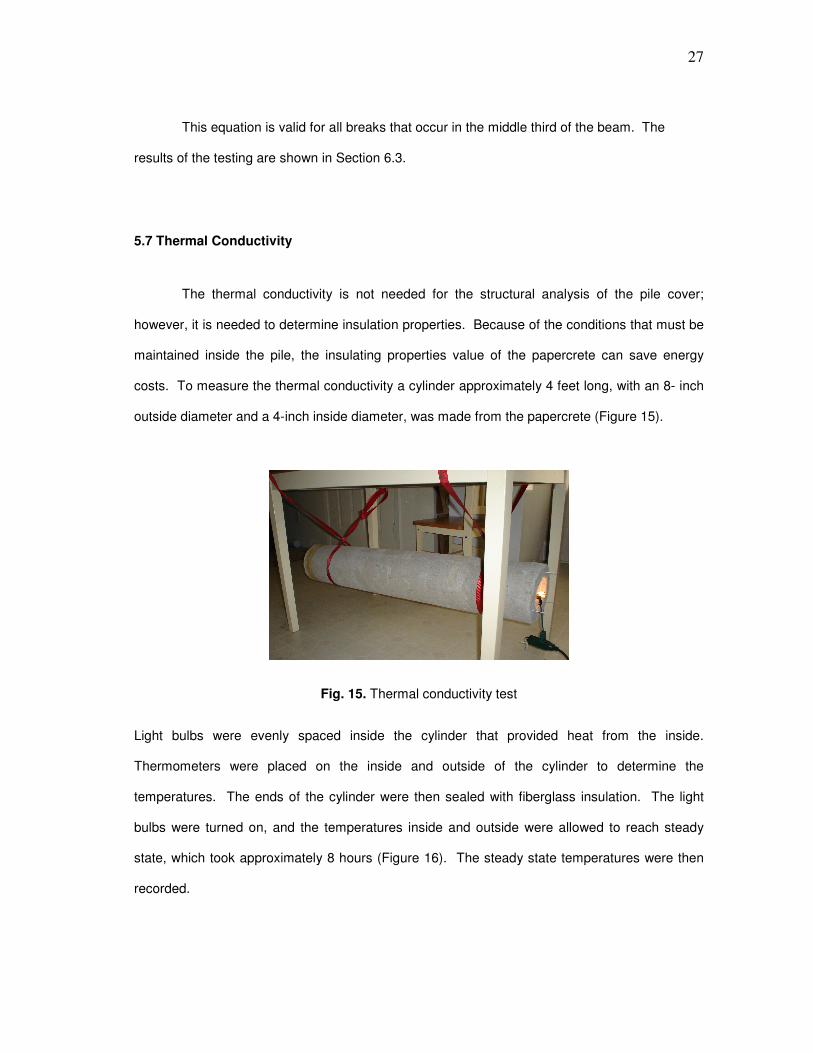
5.7 Thermal Conductivity
The thermal conductivity is not needed for the structural analysis of the pile cover;
however, it is needed to determine insulation properties. Because of the conditions that must be
maintained inside the pile, the insulating properties value of the papercrete can save energy
costs. To measure the thermal conductivity a cylinder approximately 4 feet long, with an 8- inch
outside diameter and a 4-inch inside diameter, was made from the papercrete (Figure 15).
Fig. 15. Thermal conductivity test
Light bulbs were evenly spaced inside the cylinder that provided heat from the inside.
Thermometers were placed on the inside and outside of the cylinder to determine the
temperatures. The ends of the cylinder were then sealed with fiberglass insulation. The light
bulbs were turned on, and the temperatures inside and outside were allowed to reach steady
state, which took approximately 8 hours (Figure 16). The steady state temperatures were then
recorded.

28
Fig. 16. Light bulbs inside cylinder
Knowing the power from the light bulbs, the cylinder dimensions, and the temperatures
inside and outside of the cylinder, the thermal conductivity of the papercrete was calculated
using the following equation (Incropera and Dewitt 2002):
:
)(2
ln
2,1,
1
2
ss
r
TTL
r
rq
k−
=
π
where
=k thermal conductivity (W/(m·K))
=rq wattage of the bulbs (W)
=L length of cylinder (m)
=1,sT Inner cylinder temp (K)
=2,sT Outer cylinder temp (K)
=1r Inner radius (m)
=2r outer radius (m)

29
This procedure was used to calculate the insulation value of the papercrete. By knowing
the insulation value, the heat lost from the pretreatment and fermentation piles can be
determined.
5.8 Flammability
The flammability of papercrete was briefly tested to determine if it would be fuel in the
event of a fire. A flame was applied to a papercrete sample. The flame was applied and the
papercrete did not ignite. The papercrete started to smolder; however, it never ignited. When
the flame was removed from the papercrete there were visible marks where the flame was
applied, but it self extinguished; therefore, papercrete is not a flammable material.

30
CHAPTER VI
PAPERCRETE TESTING
6.1 Composition
The composition of the papercrete used for the structure is one of the most important
parts of the research. To determine if large structures can be constructed from papercrete, the
material properties must be determined. Therefore, seven different compositions of papercrete
were tested to determine the compressive and tensile strengths of each. This narrowed the
number of compositions from seven to one. This one composition was then researched further
to determine the modulus of rupture, modulus of elasticity, and Poisson’s ratio.
The mixtures of papercrete tested (Figure 17) used different compositions of paper,
sand, and cement. The amount of water used for the mixture varied to keep the mixture at a
consistent viscosity to ensure proper mixing.
Fig. 17. Composition of papercrete batches
These papercrete samples were tested to determine the compressive and tensile strengths. The
results of the testing are shown below. The compositions were then eliminated for different

31
reasons until one was left. Compositions 2, 4, 5, and 6 were eliminated because they were very
soft after the 48-hour setting time. These compositions would be very difficult to handle for
several days, and their tensile strengths would not support the wind loads. Compositions 1 and
7 were eliminated because of their low tensile strength, which is needed to withstand the 100-
mph wind. The cost analysis showed that the highest strength composition was not significantly
higher than the weaker compositions. The cost of the strongest batch of papercrete was
approximately $0.95/ft3. This cost was based on the price of cement, sand, and recycled
newspaper in May 2006 (See Table 1). To put this price in perspective, a building that is 20 feet
wide, 53 feet long, and has a 6-inch thick wall will cost approximately $1600 for materials.
Table 1. Cost of Materials (U.S. Geological Survey January, 2006), (Central Texas Recycling Association 2006), (All American Stone and Turf 2006)
Recycled Newspaper $70/ton
Cement $90/ton
Sand $22/yd3
6.2 Optimization of Composition
Several different compositions of papercrete were tested to determine their physical
properties. The paper, cement, and sand percentages were varied in the mixture. Seven
compositions were tested to determine the compressive strength. The exact compositions were
chosen to create a variety of strengths, which would allow us to determine the most economical
and practical mixture to be used for the building.
The concrete provided bonding between the paper fibers; therefore, more concrete
added increases the strength more than the other two components. However, concrete was
more expensive than paper and sand; therefore, cost was directly related to strength. The paper
was used as a lightweight “filler” material that increased the volume, therefore making the
building material less expensive. The more paper used, the weaker the papercrete. Sand

32
increased the strength of the material during the setting period. Papercrete with a higher
concentration of sand was more stable after the setting period. This made handling the “wet”
papercrete less difficult, because the papercrete with the higher concentration of sand had more
strength upon setting. The sand is also believed to reduce the amount of shrinkage that
occurred in the samples. The reduction of shrinkage would reduce the tendency to crack upon
drying.
The amount of water in the compositions played an important role in the strength. This
phenomenon will be discussed further in Section 5.5. More water was needed to pulp the paper
than was needed in the hydration reaction; however, excess water weakened the papercrete.
This meant that any additional water reduced the strength of the papercrete; however, the
volume increased, which reduced the cost. Excess water in the mix also meant that the
papercrete needed more time to dry after the setting period. The papercrete became stronger
as it dried. The papercrete needed to be completely dry to increase the strength to a maximum.
Initially, water was added and mixed to maintain a similar viscosity throughout the various
compositions. The amount of water was then increased to make mixing the papercrete less
difficult. After testing the samples, it was determined that the water content of the papercrete
was very significant. It might be beneficial to mix the papercrete with higher water content and
then drain the water out of the mix to increase the strength of the papercrete, while still making it
less viscous during mixing. The results from different compositions are shown in the next
several sections.

33
CHAPTER VII
COMPRESSIVE AND TENSILE STRENGTHS
7.1 Results
The compressive strength of the papercrete had a large variance depending on the
composition tested. Results of the compressive testing are shown in Figure 18.
0
20
40
60
80
100
120
140
160
180
Batch 1 Batch 2 Batch 3 Batch 4 Batch 6 Batch 7
Co
mp
ressiv
e
Str
en
gth
(p
si)
Fig. 18. Compressive strengths of various batches
Figure 18 shows that compressive strength varies widely with composition. The compressive
strength for the initial test was taken from three samples and then averaged. The maximum and
minimum compressive strength of the papercrete was 143.6 and 28.3 psi, respectively. The
standard deviation of the samples are shown in Table 2.

34
Table 2. Compressive Strength Standard Deviation
Compressive Strength Standard Deviation (psi)
Batch 1-1 8.8 Batch 2-1 1.8 Batch 3-1 19.5 Batch 4-1 5.4 Batch 6-1 3.5
Batch 7-1 1
The results of the initial tensile strengths are shown in Figure 19. The strengths were
determined with the same method as used for the compressive tests.
0
5
10
15
20
25
30
35
Batch 1 Batch 2 Batch 3 Batch 4 Batch 6 Batch 7
Tensile
Str
ength
(psi)
Fig. 19. Tensile strength
The maximum and minimum tensile strength of the papercrete is 28.3 and 7.5 psi, respectively.
The tensile strength was also taken from three samples. The tensile strength standard
deviations are shown in Table 3. The compressive strength of papercrete is an important factor

35
of the strength; however, for determining the optimal composition of papercrete the most
important property is the tensile strength. The tensile strength of the papercrete was determined
to be the limiting strength. The tensile strength is needed to overcome the external wind load.
The wind force on the building will be counteracted by the tensile strength of the papercrete. If
the tensile strength of the papercrete is too low, the wall thickness must be increased to
withstand the wind.
Table 3. Tensile Strength Standard Deviation
Tensile Strength Standard Deviation (psi)
Batch 1-1 2.6
Batch 2-1 0.5
Batch 3-1 2.4
Batch 4-1 0.2
Batch 6-1 2.3
Batch 7-1 1.2
7.2 Density
The calculated densities are shown in Figure 20, which shows that the density of the
material increased when the percentage of cement in the mixture increased. When the amount
of paper in the mixture increased, the density decreased. Comparing the results of the density
and compressive strengths, the more-dense papercrete was stronger than the less-dense
material thus compressive strength was a function of density (Figure 21).

36
0.0
5.0
10.0
15.0
20.0
25.0
30.0
35.0
Batch 1 Batch 2 Batch 3 Batch 4 Batch 6 Batch 7
De
nsity (
lb/f
t3)
Fig. 20. Density
0
20
40
60
80
100
120
140
160
0 5 10 15 20 25 30 35
Density (lbm/ft3)
Co
mp
ressiv
e S
tren
gth
(p
si)
Fig. 21. Compressive strength versus density
7.3 Final Composition
The properties of papercrete are crucial to determine which composition is most efficient
for constructing a quonset building. Besides the strength and density of the papercrete, the cost,
shrinkage, and several other properties were estimated to determine the most efficient

37
composition. The ideal papercrete properties would have high compressive and tensile
strengths, low shrinkage, and a low cost (Figure 22). Most of the compositions tested can be
eliminated from this description due to their low strength. The strength of one composition
stands above the others. Batch 3 has a higher strength and lower shrinkage than the other
compositions.
0
20
40
60
80
100
120
140
160
Batch 1 Batch 2 Batch 3 Batch 4 Batch 6 Batch 7
Mixture
Compressive Strength (psi)
Tensile Strength (psi)
Shrinkage (%)
Density (lbm/ft3)
Fig. 22. Papercrete properties
However, due to its high percentage of cement in the papercrete, the cost of Batch 3 (Figure 23)
is higher than the costs of the other compositions. The cost of the papercrete is a major factor in
determining if the material is viable for use as a building material.

38
0.00
0.10
0.20
0.30
0.40
0.50
0.60
0.70
0.80
0.90
1.00
Batch 1 Batch 2 Batch 3 Batch 4 Batch 6 Batch 7
Co
st
($/f
t3)
Fig. 23. Cost of papercrete
It was determined that although Batch 3 was more expensive, per unit volume, the overall cost
would be reduced because the walls would be thinner. The cost (dollars per cubic foot of
material) includes only the cost of paper, cement, and sand. This does not consider the strength
of the material, which means that more volume of a weaker material is needed to create a
structurally sound building. Therefore, it was determined that the composition of Batch 3 would
be used for the quonset structure.
The composition of Batch 3 is 20 wt% paper, 60 wt% cement, and 20 wt% sand. The water
content was varied in the initial batches to create various viscosities of the wet mix. It was
difficult to determine how much water content affected the strength of the papercrete, but it
definitely affected the density. The initial water mixed into Batch 3 was 11.5 mL/g paper. To
determine the affect of the water on the mixture, it was increased 20% to 13.8 mL/g paper. The
effects of the increase are shown in Figure 24.

39
143.6
28.3
9.8
32.8
0.95
11.5
74.8
20.9
11.0
28.1
0.85
13.8
0.0
20.0
40.0
60.0
80.0
100.0
120.0
140.0
160.0
Compressive
Strength (psi)
Tensile
Strength (psi)
Shrinkage (%) Density
(lbm/ft3)
Cost ($/ft3) Water
Content (mL
water/g of
paper)
Batch 3-2
Batch 3-3
Fig. 24. Effect of water
The 20% increase in water dramatically reduced the compressive strength from 143.6 to 74.8
psi, or 48%. The tensile strength of the papercrete reduced from 28.3 to 20.9 psi, or 26%. The
shrinkage increased slightly by approximately 1.2%. The density reduced by 14%, and the cost
was reduced by approximately $0.10/ft3. The main benefit of the increased water was the ease
of mixing. Because large batches of papercrete will be required to construct a building, higher
water content will be necessary for mixing. The papercrete must be mixed with the exact
amount of water or the strength of the papercrete will vary dramatically.
The final composition that was used for thorough testing was a mixture of 20 wt %
paper, 60 wt% cement, and 20 wt% sand. The amount of water that was added was 13.8 mL/g
paper. This composition will give the strongest papercrete that can be easily mixed with a large
batch mixer. This high water content reduced the compressive strength dramatically and the
tensile strength modestly. The tensile strength is the more important feature for resisting wind
loads.

40
Tensile and compressive strengths were already determined through the initial
screening. Further investigation measured the modulus of rupture, modulus of elasticity, and
Poisson’s ratio, which were needed for the finite element analysis. The modulus of rupture was
determined to be 62 psi, the modulus of elasticity was 3580 psi, and Poisson’s ratio was 0.0141.
The modulus of rupture and Poisson’s ratio were estimated from compressive strength testing.
7.4 Thermal Conductivity
The thermal conductivity of the papercrete was tested to determine its insulation value.
After the lights were turned on inside of the cylinder, it took approximately 7 hours for the
temperatures to reach equilibrium. The lights were left on for several more hours to ensure the
temperatures stayed constant. A temperature distribution (Table 4) across the cylinder was
caused by papercrete porosity. The cylinder was poured in the upright position; therefore, the
weight of the papercrete made the bottom portion of the cylinder more dense than the top.
Table 4. Thermal Conductivity Testing
More Dense Less Dense
Outside Temperature Port 1 Port 2 Port 3 Port 4 Port 5 Port 6 Port 7
27 oC 97 oC 101 oC 103 oC 104 oC 104 oC 105 oC 106 oC
The cylinder was made 4 feet long so that end effects would have minimal effects on the
temperatures. The temperature in the middle section was constant showing that the
temperature loss from the ends did not affect the calculations. The testing shows that the
density of the papercrete affects the thermal conductivity. The temperature increased the most
near the thermometer ports where the density of the cylinder was the lowest. The density effect
was observed from the porosity of the material. A comparison for effect of density on the
thermal conductivity was not thoroughly analyzed; these were merely observations to explain the
testing results.

41
The reported thermal conductivity for the papercrete was based on the middle section of
the cylinder. The thermal conductivity was 0.10 W/(m·K) (0.06 Btu/(ft·h·oF)). Concrete has a
thermal conductivity between 1.25 and 1.75 W/(m·K). Papercrete has a much lower thermal
conductivity than concrete; therefore, its insulation value is much higher. The papercrete
thermal conductivity is similar to several other materials (Table 5).
Table 5. Thermal Conductivity of Selected Materials (Callister 2001)
Material kW/(m·K)
Fiberglass Insulation
0.038
Papercrete 0.1
Polyvinyl Acetate Cork
0.1
Plywood 0.12
Concrete 1.25
Table 5 shows that papercrete has great insulating value. Although papercrete must be
approximately 2.5 times thicker than fiberglass insulation to provide the same thermal
resistance, concrete must be 12.5 times thicker than papercrete to provide the same thermal
resistance. Papercrete is a very good insulating material.

42
CHAPTER VIII
STRUCTURAL ANALYSIS
8.1 Papercrete Arch
A structural analysis is needed to determine if a building can be constructed from
papercrete. This analysis will also give cost estimates for the material needed to construct the
building. The structural analysis was performed with a finite element program (Algor). The
analysis was used to determine the stress and strain of the structure when a wind force is
applied. This allows the maximum stress to be determined on the material before failure occurs
so that the material strength can be specified.
The finite element analysis allows the geometry of the walls to be varied so it is possible
to determine how much material is needed to construct a building that meets building codes.
The papercrete modulus of elasticity, modulus of rupture, Poisson’s ratio, and density were
entered into the material properties of the finite analysis. The finite element analysis then gives
the stress and the strain that occur on the structure under a 100-mph wind load.
The first size structure that was analyzed was an arch with a 20-foot diameter. The arch
was made 1 foot deep to determine the amount of material needed per foot of arch. The initial
20-foot diameter arch had 4-inch-thick walls (Figure 25). The wind pressure was then applied to
the arch to determine if the maximum allowable stress was exceeded. The base of the arch was
secured in the simulation, which meant the maximum stress would occur in the papercrete. This
assumption was made on all of the simulations. The assumption is validated in the Chapter IX.

43
Fig. 25. Papercrete arch simulation model
The initial run of the arch with 4-inch wall gave a maximum tensile stress of 74 psi. For
papercrete, the maximum allowed tensile stress is 13.5 psi, after the safety factor is applied.
The maximum tensile stress occurred at the outer surface of the wall. Therefore, the wall
thickness must be increased to lower the tensile stress; however, to lower the maximum tensile
stress to 13.5 psi, the wall thickness must be increased to approximately 15 inches at the base.
The drying time would increase to several months, which presents a challenge for passive air
drying. Active heating would be required.
To reduce the wall thickness, a new approach was taken. Because the maximum stress
occurred at the outer layer of the material, a stronger layer could be placed on the outside of the
papercrete that would provide sufficient strength (Figure 26).
Wind Direction

44
Fig. 26. Layered arch
Concrete was then tested to determine its physical properties so that it could be applied
in thin layers to the papercrete. This would reduce the wall thickness on the arch, because only
the area near the surface of the arch required the high strength. Because a higher strength
material would be on the surface, the stress could be higher and still maintain a structurally
sound building. It was determined that the center of the wall would have the lowest stress;
therefore, the papercrete would be used as a filler to separate the stronger material. The cost of
the building would be reduced because the portion of the wall, bearing the lower stress, would
be made from the less expensive material.
8.2 Concrete Testing
A determination was made that papercrete alone would not create the most efficient
building structure; therefore, concrete would be added as an additional layer to provide
additional strength. If a thin layer of concrete could be added to the papercrete structure, then
the amount of material could be reduced to make the building more economical. Several
important tests would be required to determine if a concrete layer could be added to the
papercrete to increase the overall strength. First, the strength of concrete mixtures would need
to be determined. Second, the concrete would need to be layered on the papercrete to
45
determine if they would bond properly so the layers would perform properly when placed under
stress. Finally, a process for layering the papercrete with concrete would need to be
established.
To determine the dimensions of the structure required to withstand the minimum design
requirements of a 100-mph wind, the compressive, and tensile strength of concrete needed to be
analyzed. The concrete analysis would be performed according to ASTM standards. Concrete
has been a well-researched material for many years; however, the best way to determine the
strength is to perform the tests using the same materials and mixtures that are being utilized in
the structure. This eliminates the error associated with variance of the materials used. The
coarse aggregate strength plays an important role in the physical properties of the mixture. If the
aggregate is not the same as the original structure, then the strengths will vary. Testing the
different mixtures will also allow us to determine the densities and the costs more effectively.
Riverbed pea gravel was used as the coarse aggregate in the concrete mixtures. The
size of the pea gravel allows the surface of the building to remain smooth. The smooth surface
would reduce water penetration into the concrete. Water traveling through concrete causes
several problems, such as impurities that lead to premature degradation. The concrete will also
be used as a sealant to protect the papercrete; therefore, water penetration needs to be
minimized to prolong the life of the structure.
Several compositions were tested to determine which would be most efficient. All of the
compositions were tested with and without nylon fibers. Nylon fibers have been known to
increase the tensile strength of concrete, and because additional tensile strength is required, the
nylon option was explored. Table 6 shows the list of concrete compositions that were tested.

46
Table 6. Tested Concrete Mix Volume Ratio
Concrete *Aggregate Sand
Batch A 1.5 1 3
Batch B 1 1 2
Batch C 2 1 3
*Pea gravel
Masonry mortar was also tested as a stucco layer to provide the needed additional
strength for the structure. Masonry mortars Type N and Type S were mixed and tested with and
without nylon fibers. Nylon was also explored in the stucco layer in the same manner as the
concrete. The nylon was added to each batch at a suggested ratio of 5 ounces per cubic foot of
concrete. If the nylon effectively increased the strength of the concrete, then other ratios could
be explored to find an optimal amount needed to maximize strength. These different mixtures
were tested to explore which layer could be used with papercrete to create the most economical
building.
The compressive, tensile, and flexural testing revealed which mixture was the strongest
and had the minimal cost. The averages of the three tested samples for tensile and
compressive strength are shown in Table 7.
Table 7. Concrete and Mortar Strengths
Without Nylon: Compressive (psi) Std. Deviation Tensile (psi) Std. Deviation
Batch A 5340 342 447 30.4
Batch B 6085 385 495 43.9
Batch C 4109 171 398 27.1
Type S 1440 100 252 4.3
Type N 2090 498 214 35.4
With Nylon:
Batch A 5456 53 339 12.7
Batch B 7769 242 456 71.2
Batch C 3470 68 296 14.0
Type S 1493 86 193 7.1
Type N 1613 496 240 7.0

47
In most cases, nylon actually decreased the tensile strength. The compressive strength was
increased in several of the mixtures; however, the compressive strength is not our limiting factor.
The option for using nylon was then eliminated. Therefore, the decision is based on the highest
tensile strength with the lowest cost. Table 8 shows Batch B is the lowest cost and it has the
highest strength.
Table 8. Concrete/Mortar Cost
Cost ($/ft3)
Batch A 2.76
Batch B 2.68
Batch C 3.04
Type S 6.11
Type N 6.12
The final properties of Batch B are shown in Table 9. These properties will determine
the thickness of the stucco layer. The finite element analysis will be used to estimate the
amount of concrete and papercrete needed to construct the quonset building.
Table 9. Batch B Properties
Batch B
Cost ($/ft3) 2.76
Compressive Strength (psi) 6,085
Tensile Strength (psi) 495
Modulus of Rupture (psi) 729
Density (lbm/ ft3) 144
Poisson's Ratio 0.2
Modulus of Elasticity (psi) 4,400,000

48
8.3 Layered Quonset Analysis
Now that the strength of the concrete is known, the finite element analysis of the
structure can be completed. Concrete will be added to both the inside and outside of the
papercrete. Concrete is the strongest, yet most expensive material in the structure. To create a
cost-effective structure, a minimal amount of concrete must be used.
The layers were created in the finite analysis program and the force of a 100-mph wind
was applied. A trial-and-error process was used to reduce the tensile stress on the concrete to
be below 390 psi. A safety factor of 1.56 was applied to the tensile strength to over-design the
building. The over-design will account for any flaws in assembly, material degradation, and
uncertainty of loads.
After several iterations, the stress was below the concrete strength everywhere except
where the concrete meets the footing. Figure 27 shows the maximum tensile stress for the arch.
Fig. 27. 20-ft diameter arch maximum tensile stress
Wind Direction

49
This 20-foot arch has a 3-inch papercrete center covered by one inch of concrete on the inside
and outside of the wall. The maximum tensile stress occurs at the base of the arch. To reduce
the stress at the base, a fillet was added to the bottom of the arch on both the inside and the
outside (Figure 28).
Fig. 28. 20-ft diameter arch with 3-inch inner and outer fillets
By adding the 3-inch fillets, the tensile stress was reduced below the maximum stress
requirements for the concrete. The cost was kept at a minimum because concrete was added
only in the required location.
The structural analysis also showed the deflection of the building in the 100-mph wind
(Figure 29). The deflection is exaggerated to show the deflected shape. The maximum
displacement of the material is approximately 0.9 inches.
Wind Direction

50
Fig. 29. 20-ft diameter arch maximum displacement.
The results indicated that a 3-inch papercrete center could be covered by a 1-inch layer
of Batch B concrete and withstand a 100-mph wind if the bottom of the wall had 3-inch fillets to
secure the building to the footing. The additional width at the base would reduce the stress of
the wall below the maximum tensile strength.
The cost of the building was analyzed per foot of arch. Buildings could be constructed at
varying lengths without significantly increasing the cost. Per foot of 20-ft-diameter arch, the
volume of papercrete would be approximately 6.22 ft3 and the volume of concrete would be
13.57 ft3. This analysis shows that it would cost about $54 per foot of arch for the building
materials. For a building 50-feet in length, the total cost of concrete and papercrete would be
about $2700, or $0.14 per square foot. However, the cost per square foot is misleading.
Because the piles will be built to use the vertical space as well as the floor space, the cost per
cubic foot of interior volume is the more important parameter. The papercrete/concrete designed
quonset hut will be compared to steel structures as an alternative structure. The cost per cubic
foot will also allow us to determine which diameter building minimizes the cost of storage space
Wind Direction
51
for the pile. The cost per cubic foot for a 20-foot arch is about $0.38. If the structure were made
completely from concrete the cost per cubic foot would be about $0.46; therefore, the papercrete
reduced the material cost about 20%.
The finite element analysis was also performed on arches with 50-, 100- 200-, and 400-
foot diameters. These additional diameters will provide a cost per volume that will allow us to
determine the optimal size structure. The optimal size will provide a structure that can hold the
pile at the most economical price. This cost is compared to standard current building materials
in the cost analysis section.

52
CHAPTER IX
BUILDING TECHNIQUES
9.1 Introduction
Several building techniques were researched to determine which would be the most
feasible and cost effective. Monolith and precast wall panel structures were the methods of
choice. The wall panel structure uses precast panels, formed and cured in a factory, then
moved and assembled at a final location. Using this approach, most of the critical processing
steps can be performed in a controlled atmosphere inside a factory. In contrast, the monolith
structure uses a preshaped form, to which papercrete is applied in the field. Once the
papercrete sets, the forms will be removed leaving the structure standing in its final location.
9.2 Precast Wall Panel Building
When the wall panel process begins, the papercrete will be mixed in large batches that
can be poured into reusable prefabricated forms (Figure 30). These forms can be built into any
shape and size that allows the process to be customized. “The forms are vitally important in
precast panel work and the type depends on considerations of cost, maintenance, reuse, and
detail. Concrete wood and steel forms are quite common” (American Concrete Institute 1965).
The prototype form was constructed from wood, which is less durable but costs less than steel.
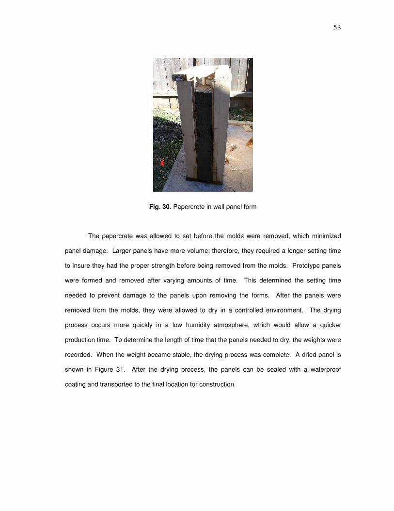
53
Fig. 30. Papercrete in wall panel form
The papercrete was allowed to set before the molds were removed, which minimized
panel damage. Larger panels have more volume; therefore, they required a longer setting time
to insure they had the proper strength before being removed from the molds. Prototype panels
were formed and removed after varying amounts of time. This determined the setting time
needed to prevent damage to the panels upon removing the forms. After the panels were
removed from the molds, they were allowed to dry in a controlled environment. The drying
process occurs more quickly in a low humidity atmosphere, which would allow a quicker
production time. To determine the length of time that the panels needed to dry, the weights were
recorded. When the weight became stable, the drying process was complete. A dried panel is
shown in Figure 31. After the drying process, the panels can be sealed with a waterproof
coating and transported to the final location for construction.

54
Fig. 31. Dried wall panel
At this point, the panels must be assembled to construct the building. The bottom panel
must be secured to the footing that will restrict it from moving both horizontally and vertically.
The panel can be secured using angle iron (Figure 32) that will run down the length of the arch
along the base. Figure 32 shows the holes in the angle iron along the base of the building.
Fig. 32. Angle iron on footing

55
Bolts can be used to secure the papercrete to the angle iron, which is attached to the foundation.
If the stress concentrations on the papercrete are too great for the papercrete the footing could
be bonded to the papercrete with glue or mortar. This would distribute the stress throughout the
papercrete, preventing the maximum stress from being exceeded. This method for securing the
arch to the footing validates the previous assumption that the base of the arch is stationary
(Chapter VIII). For the walls to be assembled, removable forms need to be constructed to
support the structure while the mortar sets. Testing showed that masonry mortar bonds well to
papercrete and costs less than other bonding agents. The structure can be built from the ground
upward, using forms to support the papercrete (Figure 33). After the mortar sets, the forms are
removed and the joints between the panels are sealed to prevent water from penetrating the
papercrete.
Fig. 33. Precast wall panel construction
This method has several advantages that make it a viable option. First, the panels can
be constructed in an environment that prevents rain from slowing down the drying process.
Second, the material is not subjected to the loads of the structure until after the drying process is
complete. This reduces over-design, because the loads are not applied to the material while in a
weak state. When the panels are sealed in the factory, the ends can be sealed as well,

56
preventing water leakage from panel to panel should the sealant be penetrated. Each panel
becomes an individual unit that is impermeable to water; therefore, if water penetrates the seal,
only one panel has a loss of strength.
Disadvantages to using this method include labor cost. Because the bricks are precast
and assembled, the time of construction is increased causing higher labor costs. The overall
cost of the building will increase, reducing the possibility of being cost effective.
9.3 Monolith Building
The cost of labor of the precast wall panel structure provided a basis for further research
in another building technique. The monolith structure was researched to determine if it was
feasible. The monolith allows the structure to be made at the final location and in one major
step.
The building will initially take shape using a large form. In an ideal situation, the form is
easily constructed and disassembled. This form is only a temporary part of the building. A
model was used to determine what materials could be used for the forms. Initially a shell (Figure
34) is formed using strong materials that will support the weight of the wet papercrete.

57
Fig. 34. Monolith shell
The model quonset shape shell had a diameter of 2-feet and was constructed from 3/8-inch
rebar, which was welded together, and wire-tied across the rebar to form the semi-circular
shape. The shell was then covered with a fine-mesh window screen (Figure 35) which held the
papercrete on the form. The small holes in the window screen allowed the water to penetrate
the papercrete and dry from both the inside and outside of the structure. The main purpose of
the window screen was to support the papercrete, while drying, to give the structure its final
shape.

58
Fig. 35. Model monolith form
The window screen was then covered with a poultry netting that had approximately 1-inch
diameters holes. The papercrete was pushed through the poultry netting to prevent the
papercrete from running down the sides of the form. Figure 36 shows the papercrete after it had
been applied to the form.

59
Fig. 36. Papercrete applied to monolith form
This experiment determined that the papercrete could be applied easily to a form, and will set
quick enough to hold a desired shape. A form that is designed to support the load of the wet
papercrete can be used to form the papercrete into the final shape of the building. One problem
that occurred with the model form was that the window screen deflected (Figure 37) on the
inside due to inadequate support.
Fig. 37. Window screen sag

60
To prevent reoccurrence of this problem, the screen will need to be supported in short intervals.
A wire that had 6 x 8 inch rectangular voids supported the screen. The papercrete was applied
to the screen approximately 2 inches thick. Poultry netting can be stretched across the wire, and
then applied to the screen to eliminate the deflection in the screen. After the papercrete dries,
the form can then be removed (Figure 38) leaving the self-supporting papercrete in place.
Fig. 38. Papercrete quonset hut
A scaled-up version of this form will probably consist of steel pipe, rebar, poultry netting
and a steel window screen. Initial costs may be high; however, the form is reusable, which will
reduce the cost per building making it more efficient.
The main advantage of this method is the reduced amount of manual labor. The
construction time will be decreased, and the forms can be reused for many different buildings.
The problem of drying is still present but using the window screen allows the drying to occur
quicker, because the moisture can evaporate from the inside and outside. The main problem
with this method is it cannot be protected from rain as would occur in a controlled environment.
During the setting period of the papercrete, it is crucial that rain is not in the forecast. After
approximately 24 hours, the papercrete sets and a tarp can be draped over the structure to
prevent damage from inclement weather.

61
The weather factor can be reduced by another approach that was taken to strengthen
the structure. The final structure will have a thin layer of concrete (Figure 39) that will add
strength to the outer shell of the papercrete. Because concrete does not absorb water like
papercrete, the outer layer will protect the papercrete from water penetration.
Fig. 39. Concrete layer on papercrete
The concrete layer should be applied as soon as the initial setting of the papercrete
occurs and while the papercrete is still wet. The drying process of the papercrete will be slower
but the concrete will strengthen because the moisture will allow the hydration reaction to
continue to completion.
Concrete gains its strength from the hydration reaction that occurs. The reaction occurs
for several months after the concrete is poured; therefore, it is crucial that the concrete stay
moist over the first 30 days to maintain enough water for a complete reaction. If the papercrete
is allowed to dry before the concrete is applied, the papercrete will absorb the water from the
concrete. The papercrete takes the moisture out of the concrete, preventing the hydration
reaction from reaching completion, therefore weakening the concrete. However, if the concrete

62
is applied to the papercrete while the papercrete is still wet, the papercrete will keep the concrete
moist for several weeks. This slows the drying of the papercrete, however the strength of the
papercrete is not as crucial because most of the stress will be placed on the concrete and the
forms. The concrete will also protect the papercrete from rain. The concrete can be
waterproofed with a less costly coating than the papercrete requires. Overall this method
appears to be less costly than the pre-cast wall panel construction, and just as feasible.

63
CHAPTER X
COST ANALYSIS
10.1 Introduction
Cost analysis of a model building will define the economic factors of papercrete to
determine its feasibility as an alternative to current building materials. The data from the
structural analysis will be used to determine the quantities of the building materials required. The
concrete, paper, and sand values were current market values from May 2006. The cost of the
cement was $90 per ton (U.S. Geological Survey January, 2006), the recycled newspaper was
$75 per ton (Central Texas Recycling Association 2006), the cost of sand was $22/yd3
(All
American Stone and Turf 2006), and the cost of the pea gravel was $30/yd (All American Stone
and Turf 2006). The cost of cement is an extrapolation of historical cement prices. The recycled
newspaper and sand were quotes from local wholesalers. The product of the structure data and
current cost factors provide the basis for economic evaluation. The analysis will also determine
the cost of the layered papercrete-concrete quonset structure compared to the cost of the same
structure constructed completely from concrete. Additionally, the layered quonset structure will
be compared to a building constructed from steel with similar dimensions.
10.2 Papercrete-Concrete Quonset Structure
This cost comparison analysis section defines different structure sizes to create a cost
analysis that illustrates the most economical building size. The structural analysis process used
to defined the building factors for a 20-foot arch was also utilitized on 50-, 100-, 200-, and 400-
foot arch structures. This initial analysis (Table 10) only includes the costs of the papercrete,
concrete, and wire needed for the structure. The cost does not include labor and equipment nor
materials needed during the construction that can be removed and reused. These additional
cost factors could materially affect this cost analysis.

64
Table 10. Diameter Cost Analysis
Diameter (ft) $/ft3
$/ft2
400 0.19 27.75
200 0.15 5.47
100 0.27 2.53
50 0.31 0.73
20 0.38 0.14
Table 10 shows that there is not an optimal cost per square foot; the cost is always lower at a
smaller diameter. However, there is an optimum cost per cubic foot. The lowest cost per cubic
foot would be a structure with a diameter of approximately 200 feet (Figure 40). The cost would
be approximately $0.14/ft3.
0.00
0.05
0.10
0.15
0.20
0.25
0.30
0.35
0.40
0 50 100 150 200 250 300 350 400 450
Diameter (ft)
Co
st ($
/ft3
)
Fig. 40. Material cost of papercrete-concrete quonset
structure as a function of diameter

65
This initial cost estimate includes only material costs determined by the finite element
analysis. The 200-foot structure would require the papercrete to be approximately 3.3 feet thick
at the base, and the layer of concrete covering the papercrete inside and out would be 2 feet
thick. A fillet at the base of the structure approximately 3 feet tall by 3 feet wide at the base
would be required. A major concern is the length of time needed for the papercrete to dry. Mass
transfer of water in papercrete is reduced with increasing wall thickness. The reduction in mass
transfer means the drying time will increase. If the papercrete is not completely dry, the strength
will be reduced and the structure will be compromised. The concrete layer that will cover the
papercrete will also increase the drying time; therefore, the total drying time of a structure with a
200-foot diameter may take many months. Likely, active heating will be required to reduce the
drying time.
There are no catalog-ready steel Quonset buildings available with a 200-ft diameter. To
determine the cost of such a structure, it must be custom engineered, which is beyond the scope
of this project. However, smaller buildings are available.
10.3 Metal Quonset Structure
This cost analysis compares a papercrete-concrete Quonset structure with the cost of a
metal building. The metal structure will have the same general shape as the proposed
papercrete-concrete structure, but a cost estimate was obtained from Miracle Span Building
Systems, which manufactures commercial buildings. The company makes and then ships
modular pieces to the location where the building will be erected.
A range of price estimates was obtained for structures that ranged from 20 to 70 feet
wide. Structures this size are pre-engineered and are ready to be shipped for assembly. The
cost estimate is for the metal and assembly materials needed. The cost of shipping and
assembly are not included in the price; therefore, the cost will be directly comparable to the cost
of material for a papercrete-concrete structure. Figure 41 shows the cost per cubic foot of
storage space.

66
Metal Arch
0.00
0.05
0.10
0.15
0.20
0.25
0.30
0.35
0.40
0.45
20 30 40 50 60 70
Diameter (ft)
Co
st
($/f
t3)
Fig. 41. Metal arch cost analysis (Miracle Steel Structures 2001)
10.4 Steel-Papercrete Comparison
The main objective of this research was to compare the cost of a papercrete structure to
other common building materials. It was already determined that a papercrete-concrete
structure will be more economical than a completely concrete structure; therefore, papercrete
can replace concrete in low-stress interior areas, while maintaining a structurally sound building.
The cost analysis in this section will evaluate the cost of the papercrete-concrete and
metal structures. The most effective way to compare the different building materials is to
compare similar size structures. Figure 42 illustrates the cost per cubic foot for papercrete-
concrete and metal structures. The papercrete-concrete structure is more economical at small
sizes; however, after the diameter of the building reaches 31 feet, steel becomes more
economical. Larger structures can encase larger quantities of material and therefore are more
economical. Therefore, it appears that steel structures will be more cost effective for large-scale

67
pretreatment and fermentation programs. However, the papercrete-concrete structure does
provide significantly more insulation than a metal building. Depending on the climate this may or
may not be an important consideration.
0.00
0.05
0.10
0.15
0.20
0.25
0.30
0.35
0.40
0.45
0 100 200 300 400 500
Diameter (ft)
Co
st
($/f
t3)
Steel Arch
Papercrete-Concrete Arch
Fig. 42. Comparison of steel to papercrete-concrete structure
A pilot-scale pretreatment and fermentation pile will need an encasement structure that
is approximately 20 feet in diameter. At this small scale, the analysis shows that it would be
more economical to construct the quonset building from papercrete-concrete. However, to
provide an economical building of large scale, the cost of the papercrete-concrete structure is
greater than a metal building. The main objective of this project was to conclude whether a
papercrete quonset building would be more economical than traditional building materials for
covering pretreatment and fermentation piles. A large metal building (70-ft diameter) would be
more economical and would cost approximately $0.23/ft3 of storage space. This would be about
$0.06/ft3 less than a building constructed from papercrete and concrete. The papercrete-
concrete building would cost 25% more for building materials.

68
CHAPTER XI
SUMMARY AND CONCLUSIONS
This study identified and evaluated a wide range of data about papercrete. Papercrete
is a very unique building material that can be used for many purposes. The focus of this study
was mainly on use for large structures to cover piles for the MixAlco process.
The strength of papercrete was measured to determine the amount of material needed
for the pile encasements. A structure made completely of papercrete would be difficult to
construct due to its low strength; therefore, a composite structure was studied. A papercrete-
concrete structure was evaluated to determine strength characteristic and the amount of material
needed to construct a building that would withstand a 100-mph wind. After the finite element
analysis was performed, the cost of each size building was calculated, and compared to metal
buildings of similar size. The analysis showed that the papercrete structure was more
economical for building material for structures up to 31 feet in diameter. However, to benefit
from economies of scale and minimize total cost of the pretreatment and fermentation process, a
large-scale building would be needed, for which a metal building would be more economical.
This does not mean that papercrete could not be used to construct the building; however, it
would be more expensive. Papercrete has an advantage of providing insulation, which may
have value in certain climates.
The cost analysis determined that the pilot scale papercrete structure, measuring 20 feet
in diameter, would be cost effective. Additional structural analysis could be used to optimize
material quantities needed for the structure. If the analysis showed similar results, a prototype
building should be constructed to get an estimate for the cost of labor needed to construct a
Quonset structure using the monolith building method. Such a study could more accurately
assess the total cost of the building, and project the total cost of large-scale buildings.

69
CHAPTER XII
FUTURE WORK
Costs of materials for this study were determined in May 2006. With the escalating cost
of metal, the price of traditional building materials could increase faster than the cost of the
papercrete. In this case, the papercrete could be come more economical and therefore future
studies could find papercrete to be a more economical approach for larger-scale buildings.
This study was an estimate of the cost of constructing a building from papercrete, and
little optimization was used to minimize to amount of material used. A further study should be
launched to optimize the use of papercrete in building structures. It is suggested that a pilot
scale building should be constructed from the papercrete to determine labor costs and material
workability. Because the papercrete was found to be economical for small-scale structures, it
could be used for emergency housing or small homes.
Another approach to reducing the amount of material in the structure would be inducing
a vacuum on the inside. The vacuum could be used to counteract the wind force; this would
reduce the required material needed for the structure therefore reducing the cost of the
papercrete-concrete structure. A study would be needed to determine if the vacuum could
reduce the cost of the structure enough to make the papercrete-concrete structure less
expensive than the metal building. The study would need to evaluate different vacuum
pressures on the inside to determine how they affect the required amount of material. This could
dramatically reduce the cost of the structures, and therefore making the papercrete-concrete
structure more economical than other building materials.
A pilot-scale study could also provide insight into the long-term degradation of the
papercrete. This study could provide insight into maintaining the material to prevent a
catastrophic failure. Long-term maintenance of the material could be minor; however, small
damage to the surface could allow water to penetrate the concrete and weaken the papercrete
structure to the point of failure.

70
Extracting water between the mixing and forming stages could increase the strength of
papercrete. This would increase the density of the material, which will increase its strength. The
process would need to be explored to determine the exact amount needed to be extracted to
maintain a consistent mixture. Catastrophic failure could occur if less water is extracted than is
required. A study would need to be performed to determine if the water could be extracted
appropriately to maintain structurally sound quonset building. If inconsistencies occurred
throughout the structure, “weak spots” would be possible points of failure. This may involve
building a prototype structure and testing its strength to determine its maximum load bearing
capability.

71
REFERENCES
All American Stone and Turf. (2006). "Gravel and Sand Price Quote." College Station, Texas. American Concrete Institute. (1965). Symposium on Precast Concrete Wall Panels, American
Concrete Institute, Detroit, Michigan, 26. American Concrete Institute. (2004). ACI Manual of Concrete Practice, ACI International,
Farmington Hills, MI. American Society of Testing and Materials. (2000). ASTM Standards, American Concrete
Institute, Farmington Hills, MI, 555. Calderone, A. (2002). "Safety Factor." http://www.kgainc.com/artman/publish/article_15.shtml. Callister, W. D. (2001). Fundamentals of Materials Science and Engineering, John Wiley and
Sons Inc., New York, 459-463. Central Texas Recycling Association. (2006). "Commodity Pricing."
http://www.cash4trash.com/pricing.html. Chien, N., Feng, Y., Wang, H.-J., and Siao, T.-T. (1951). Wind-Tunnel Studies of Pressure
Distribution on Elementary Building Forms, Iowa Institute of Hydraulic Research State University of Iowa, Iowa City, 10-113.
Engineers, A. S. o. C. (2003). Minimum Design Loads of Building and Other Structures, ASCE,
Structural Engineering Institute, Reston, Virginia. Fintel, M. (1985). Handbook of Concrete Engineering, Van Nostrand Reinhold Company, New
York, 169-179. Fuller, B. J. (2004). "How to Build with Papercrete, Fibercrete, or Fiberous Concrete."
http://www.livinginpaper.com/index.htm. Hassoun, M. N. (2002). Structural Concrete Theory and Design, Prentice-Hall, Inc., Upper
Saddle River,New Jersey, 17-19. Holtzapple, M. (2004) "MixAlco: Biofuels and Chemicals from Biomass."
http://www.epa.gov/Region6/6pd/pd-u-sw/wte_ftworth/cafo/holtzapple.pdf. Incropera, F. P., and Dewitt, D. P. (2002). Fundamentals of Heat and Mass Transfer, John Wiley
and Sons, New York, 104-107. Miracle Steel Structures, I. (2001). "Miracle Span Building Systems." Minneapolis, MN, Price
Quote. Solberg, G. (1999). Building with Papercrete and Paper Adobe, Remedial Planet
Communications, Radium Springs, NM. U.S. Geological Survey. (January, 2006). "Mineral Commodity Summaries." 2.

72
APPENDIX A

73
0
200
400
600
800
1000
1200
1400
1600
0 10 20 30 40 50 60 70
Day
We
igh
t o
f S
am
ple
(g
)
Batch 1
Batch 2
Batch 3
Batch 4
Batch 6
Batch 7
Fig. A1. Papercrete batch drying times

74
0
20
40
60
80
100
120
140
0 10 20 30 40 50 60
Day
We
igh
t o
f B
ric
k (
lbf)
Fig. A2. Papercrete drying time for prototype wall panel

75
APPENDIX B

76
Table B1. Papercrete batch compositions
% Paper % Cement % Sand
Water Content (mL water/g of paper)
Batch 1-1 40.0 60.0 0.0 11.5
Batch 2-1 60.0 40.0 0.0 11.5
Batch 3-1 20.0 60.0 20.0 11.5
Batch 4-1 40.0 40.0 20.0 11.5
Batch 6-1 40.0 20.0 40.0 11.5
Batch 7-1 20.0 40.0 40.0 11.5
Batch 3-2 20.0 60.0 20.0 13.8
Table B2. Summary of papercrete batch properties
Compressive Strength (psi)
Tensile Strength (psi)
Modulus of Rupture (psi) Shrinkage (%) Density (lb/ft
3) Cost ($/ft
3)
Batch 1-1 37.2 16.5 11.0 19.7 0.62
Batch 2-1 37.0 9.1 11.5 16.4 0.65
Batch 3-1 143.6 28.3 9.8 32.8 0.95
Batch 4-1 29.8 7.5 12.5 18.8 0.78
Batch 6-1 28.3 10.4 14.5 18.2 0.46
Batch 7-1 56.6 14.6 11.1 29.5 0.75
Batch 3-2 74.8 20.9 62.1 0.0 0.0 0.85

77
0
50
100
150
200
250
0 0.02 0.04 0.06 0.08 0.1 0.12 0.14 0.16 0.18 0.2
Strain (in/in)
Str
ess (
psi)
Sample 2
Sample 3
Sample 4
Sample 5
Fig. B1. Papercrete Batch 1-1 compressive stress-strain
0
20
40
60
80
100
120
140
0.0000 0.0500 0.1000 0.1500 0.2000 0.2500 0.3000
Strain (in/in)
Str
ess (
psi)
Sample 1
Sample 2
Sample 3
Sample 4
Sample 5
Fig. B2. Papercrete Batch 2-1 compressive stress-strain

78
0
50
100
150
200
250
300
350
400
0.00 0.01 0.02 0.03 0.04 0.05 0.06 0.07 0.08 0.09
Strain (in/in)
Str
es
s (
ps
i)
Sample 1
Sample 2
Sample 3
Sample 4
Sample 5
Fig. B3. Papercrete Batch 3-1 compressive stress-strain
0
20
40
60
80
100
120
140
0.0000 0.0500 0.1000 0.1500 0.2000 0.2500
Strain (in/in)
Str
es
s (
ps
i)
Sample 1
Sample 2
Sample 3
Sample 4
Fig. B4. Papercrete Batch 4-1 compressive stress-strain

79
0
50
100
150
200
250
0 0.1 0.2 0.3 0.4 0.5
Strain (in/in)
Str
ess (
psi)
Sample 1
Sample 2
Sample 3
Sample 4
Sample 5
Fig. B5. Papercrete Batch 5-1 compressive test stress-strain
0
10
20
30
40
50
60
70
80
90
100
0 0.05 0.1 0.15 0.2 0.25 0.3
Strain (in/in)
Str
ess (
psi)
Sample 1
Sample 2
Sample 3
Sample 4
Sample 5
Fig. B6. Papercrete Batch 6-1 compressive test stress-strain

80
0
50
100
150
200
250
0 0.02 0.04 0.06 0.08 0.1 0.12 0.14 0.16
Strain (in/in)
Str
es
s (
ps
i)
Sample 1
Sample 2
Sample 3
Sample 4
Sample 5
Fig. B7. Papercrete Batch 7-1 compressive text stress-strain
0.00
20.00
40.00
60.00
80.00
100.00
120.00
140.00
0.00 0.02 0.04 0.06 0.08 0.10 0.12 0.14 0.16
Strain (in/in)
Str
es
s (
ps
i)
Sample 1
Sample 2
Sample 3
Sample 4
Sample 5
Fig. B8. Papercrete Batch 3-2 compressive text stress-strain

81
0.000
5.000
10.000
15.000
20.000
25.000
30.000
0 0.1 0.2 0.3 0.4 0.5 0.6 0.7 0.8 0.9
Strain (in/in)
Str
ess (
psi)
Sample 1-1
Sample 1-2
Sample 1-4
Fig. B9. Papercrete Batch 1-1 tensile test stress-strain
0.000
2.000
4.000
6.000
8.000
10.000
12.000
14.000
16.000
18.000
0.00000 0.05000 0.10000 0.15000 0.20000 0.25000 0.30000
Strain (in/in)
Str
ess (
psi)
Sample 2-1
Sample 2-2
Sample 2-4
Fig. B10. Papercrete Batch 2-1 tensile test stress-strain

82
0.000
5.000
10.000
15.000
20.000
25.000
30.000
35.000
0 0.02 0.04 0.06 0.08 0.1 0.12 0.14
Strain (in/in)
Str
ess (
psi)
Sample 3-2
Sample 3-4
Fig. B11. Papercrete Batch 3-1 tensile test stress-strain
0.000
2.000
4.000
6.000
8.000
10.000
12.000
0 0.05 0.1 0.15 0.2 0.25 0.3 0.35 0.4 0.45 0.5
Strain (in/in)
Str
ess (
psi)
Sample 4-1
Sample 4-5
Fig. B12. Papercrete Batch 4-1 tensile test stress-strain

83
0.000
2.000
4.000
6.000
8.000
10.000
12.000
14.000
0 0.1 0.2 0.3 0.4 0.5 0.6 0.7 0.8 0.9 1
Strain (in/in)
Str
ess (
psi)
Sample 6-1
Sample 6-2
Sample 6-5
Fig. B13. Papercrete Batch 6-1 tensile test stress-strain
0.000
2.000
4.000
6.000
8.000
10.000
12.000
14.000
16.000
18.000
0 0.1 0.2 0.3 0.4 0.5 0.6 0.7 0.8
Strain (in/in)
Str
ess (
psi)
Sample 7-4
Sample 7-5
Sample 7-6
Fig. B14. Papercrete Batch 7-1 tensile test stress-strain

84
0.000
5.000
10.000
15.000
20.000
25.000
30.000
0.00 0.02 0.04 0.06 0.08 0.10 0.12 0.14
Strain (in/in)
Str
es
s (
ps
i)
Sample 1
Sample 2
Sample 3
Sample 4
Sample 5
Fig. B15. Papercrete Batch 3-2 tensile test stress-strain

85
APPENDIX C

86
Fig. C1. Maximum displacement (20-ft diameter)
Fig. C2. Maximum compressive stress (20-ft diameter)
Wind Direction
Wind Direction

87
Fig. C3. Maximum compressive stress (20-ft diameter)
Fig. C4. Maximum tensile stress (20-ft diameter)
Wind Direction
Wind Direction

88
Fig. C5. Maximum displacement (modified 20-ft diameter)
Fig. C6. Maximum compressive stress (modified 20-ft diameter)
Wind Direction
Wind Direction

89
Fig. C7. Maximum tensile stress (modified 20-ft diameter)
Fig. C8. Maximum displacement (50-ft diameter)
Wind Direction
Wind Direction

90
Fig. C9. Maximum compressive stress (50-ft diameter)
Fig. C10. Maximum tensile stress (50-ft diameter)
Wind Direction
Wind Direction

91
Fig. C11. Maximum displacement (100-ft diameter)
Fig. C12. Maximum compressive stress (100-ft diameter)
Wind Direction
Wind Direction

92
Fig. C13. Maximum tensile stress (100-ft diameter)
Fig. C14. Maximum displacement (200-ft diameter)
Wind Direction
Wind Direction

93
Fig. C15. Maximum compressive stress (200-ft diameter)
Fig. C16. Maximum tensile stress (200-ft diameter)
Wind Direction
Wind Direction

94
Fig. C17. Maximum displacement (400-ft diameter)
Fig. C18. Maximum compressive stress (400-ft diameter)
Wind Direction
Wind Direction

95
Fig. C19. Maximum tensile stress (400-ft diameter)
Table 11. Papercrete Thickness Requirements
Table C2. Concrete thickness requirements
Base of Arch Top of Arch
Inside Layer (ft) Outside Layer (ft) Inside Layer (ft) Outside Layer
(ft)
20 ft diameter 0.08 0.08 0.08 0.08
50 ft diameter 1.17 1.13 0.15 0.15
100 ft diameter 1.92 1.49 0.52 0.3
200 ft diameter 2.52 2.23 0.5 0.3
400 ft diameter 5 5 1.38 1
Base of Arch (ft) Top of Arch (ft)
20 ft diameter 0.25 0.25
50 ft diameter 0.5 0.5
100 ft diameter 1 1
200 ft diameter 2.1 2
400 ft diameter 4 4
Wind Direction

96
Table C3. Concrete fillet requirements
Inside Outside
Height (ft) Width (ft) Height (ft) Width (ft)
20 ft diameter 1.00 0.25 1.00 0.25 50 ft diameter - - - - 100 ft diameter 4 4 4 4 200 ft diameter 3 3 3 3 400 ft diameter 5.5 5.5 5.5 5.5
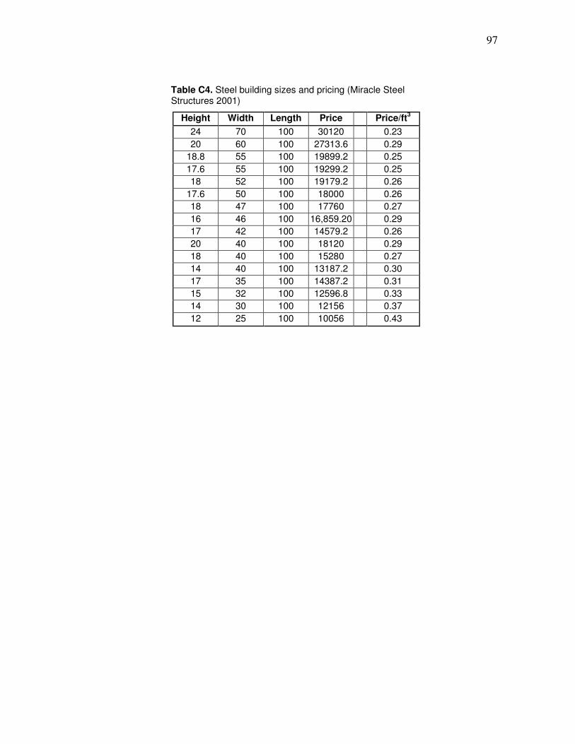
97
Table C4. Steel building sizes and pricing (Miracle Steel Structures 2001)
Height Width Length Price Price/ft3
24 70 100 30120 0.23
20 60 100 27313.6 0.29
18.8 55 100 19899.2 0.25
17.6 55 100 19299.2 0.25
18 52 100 19179.2 0.26
17.6 50 100 18000 0.26
18 47 100 17760 0.27
16 46 100 16,859.20 0.29
17 42 100 14579.2 0.26
20 40 100 18120 0.29
18 40 100 15280 0.27
14 40 100 13187.2 0.30
17 35 100 14387.2 0.31
15 32 100 12596.8 0.33
14 30 100 12156 0.37
12 25 100 10056 0.43

98
VITA
L. Clinton Titzman was born in San Antonio, Texas. He grew up on a ranch in south
Texas, near the town of Falls City, which is approximately 60 miles south of San Antonio. He
attended Falls City high school where he discovered his interests in chemistry, mathematics, and
physics. He graduated from High School in 1998, and then decided to attend Coastal Bend
Community College. While attending Coastal Bend he discovered his interest in chemical
engineering. He then transferred to Texas A&M University and graduated with a bachelor of
science in chemical engineering in May 2003. After working for a short time, he decided to
return to graduate school at Texas A&M, where he joined Dr. Holtzapple’s research group. He
then graduated in December 2006 with a Master of Science in Chemical Engineering.