Minimum Requirements for Masonry Wall Construction
76
' \ '* DEPARTMENT OF COMMERCE WASHINGTON ELIMINATION OF WASTE SERIES RECOMMENDED MINIMUM REQUIREMENTS FOR MASONRY WALL CONSTRUCTION REPORT OF BUILDING CODE COMMITTEE WM. ' ‘ - ''’i - : v • ' -r. '•*/. BUREAU OF STANDARDS WASHINGTON GOVERNMENT PRINTING OFFICE 1925
-
Upload
khangminh22 -
Category
Documents
-
view
0 -
download
0
Transcript of Minimum Requirements for Masonry Wall Construction

''
' •
'
' •
• \'*
DEPARTMENT OF COMMERCEWASHINGTON
ELIMINATION OF WASTE SERIES
RECOMMENDED MINIMUM
REQUIREMENTS FOR MASONRY WALL
CONSTRUCTION
REPORTOF
BUILDING CODE COMMITTEE
WM.' ‘
-
''’i' -
:v •
'.. -r.
'•*/.
BUREAU OF STANDARDS
WASHINGTONGOVERNMENT PRINTING OFFICE
1925


UNITED STATES DEPARTMENT OF COMMERCEHERBERT HOOVER, SECRETARY
ELIMINATION OF WASTE SERIES
RECOMMENDED MINIMUM
REQUIREMENTS FOR MASONRY WALL
CONSTRUCTION
REPORT OFBUILDING CODE COMMITTEE
JUNE 28, 1924
IRA H. WOOLSON, Chairman
EDWIN H. BROWNWILLIAM K. HATTALBERT KAHN
RUDOLPH P. MILLERJOHN A. NEWLINJOSEPH R. WORCESTER
FRANK P. CARTWRIGHT, Technical Secretary
JOHN M. GRIES, Chief, Division of Building and Housing
BUREAU OF STANDARDS
PRICE, 15 CENTSSold only by the Superintendent of Documents, Government Printing Office
Washington, D. C.
WASHINGTONGOVERNMENT PRINTING OFFICE
1925

MEMBERSHIP OF THE BUILDING CODE COMMITTEEOF THE DEPARTMENT OF COMMERCE
Ira H. Woolson, consulting engineer National Board of Fire Un-derwriters, New York, N. Y., chairman
;member American Society
of Mechanical Engineers, American Society for Testing Materials,
National Fire Protection Association, American Concrete Institute.
Edwin H. Brown, architect, Minneapolis, Minn.; secretary Ameri-
can Institute of Architects.
William K. Hatt, professor of civil engineering, Purdue Univer-
sity; member American Society of Civil Engineers; American
Concrete Institute.
Albert Kahn, architect, Detroit, Mich.;fellow American Institute
of Architects.
Rudolph P. Miller, consulting enginer, New York, N. Y.;presi-
dent Building Officials Conference; ex-superintendent of build-
ings, New York, N. Y.;member American Institute of Consulting
Engineers, American Society of Civil Engineers, American Society
for Testing Materials.
John A. Newlin, in charge of section of timber mechanics Forest
Products Laboratory, Forest Service, United States Department
of Agriculture, Madison, Wis.;member American Society for
Testing Materials, American Society of Civil Engineers, associate
member American Railway Engineering Association.
Joseph R. Worcester, consulting engineer, Boston, Mass.; memberAmerican Society of Civil Engineers, American Institute of Con-
sulting Engineers.
Frank P. Cartwright, technical secretary.
ii

CONTENTS
PART I.—INTRODUCTIONPage
Acknowledgment of assistance 2
Scope of report . 3
PART II.—RECOMMENDED MINIMUM REQUIREMENTS FOR MASONRYWALL CONSTRUCTION
Article I.—Definitions 4
Sec. 1. Definitions 4Article II.—Solid brick walls 5
Sec. 2. Quality of materials 5
Sec. 3. Lateral support i 6
Sec. 4. Working stresses 6
Sec. 5. Thickness of exterior walls 7
Sec. 6. Bond 8
Sec. 7. Piers ' 8
Sec. 8. Chases and recesses;arches and lintels^ 9
Article III.—Walls of hollow tile, concrete block or tile, and hollow walls
of brick 9
Sec. 9. Quality of materials 9Sec. 10. Lateral support 10
Sec. 11. Working stresses 10
Sec. 12. Thickness and height of exterior walls 10
Sec. 13. Bond ; 11
Sec. 14. Beam supports ., 11
Sec. 15. Piers 11
Sec. 16. Chases and recesses ; arches and lintels 11
Article IV.—Walls of plain concrete 12
Sec. 17. Concrete materials 12
Sec. 18. Lateral support 12
Sec. 19. Working stresses 13
Sec. 20. Thickness of walls 13
Sec. 21. Reinforcement 14
Sec. 22. Piers __ 14
Sec. 23. Chases and recesses 14
Article V.—Stonewalls . — 14
Sec. 24. Working stresses 14
Sec. 25. Lateral support and thickness 14
Sec. 26. Bond 15
Sec. 27. Chases and recesses 15
Article VI.—Veneered walls 15
Sec. 28. Quality of materials 15
Sec. 29. Working stresses 15
Sec. 30. Attachment of veneering 15
Sec. 31. Height of veneered walls 15
in

IV CONTENTS
PageArticle VII.—Faced walls ! 15
Sec. 32. Quality of materials 15
Sec. 33. Working stresses 16
Sec. 34. Thickness 16
Sec. 35. Bond Sj 16Article VIII.—Fire walls and fire division walls and partitions 16
Sec. 36. Brick and plain concrete fire walls 16
Sec. 37. Fire walls of hollow tile, concrete block or concrete tile, or
of hollow wall construction 17
Sec. 38. Fire division walls 17
Sec. 39. Alternate requirements for fire and fire division walls 17
Sec. 40. Parapet walls 18
Sec. 41. Bearing partitions 18
Sec. 42. Nonbearing partitions : 18
Article IX.—Foundation walls— . 18
Sec. 43. Foundation walls 18
Article X.—Skeleton construction 19
Sec. 44. Panel and inclosure walls ^Article XI.—New types of masonry construction 19
Sec. 45. New masonry construction 19
Article XII.—Miscellaneous requirements 20
Sec. 46. Anchoring walls 20
Sec. 47. Use of existing wallsj
2®
Sec. 48. Corbeling of chimneys 20
Sec. 49. Cornices 20
PART III.—APPENDIX
Par. 1. Purpose;
21
Par. 2. Justification for requirements, and influence of building inspec-
tion 21
Par. 3. Status of the committee’s recommendations 22
Par. 4. Function of walls 23
Par. 5. Variation in code requirements 23
Par. 6. Walls in skeleton construction 25
Par. 7. Fire and fire division walls 26
Par. 8. Concrete considered as masonry 28
Par. 9. Quality of brick 28
Par. 10. Mortar materials 30
Par. 11. Tests of compressive strength of brick masonry 31
Par. 12. Lateral support of walls 12^-———. 32
Par. 13. Elements affecting strength of brickwork 34
1. Strength of individual brick — 34
2. Mortar, materials, and proportions 36
3. Ratio of height to thickness 36
4. Bond and jointing 37
5. Workmanship — 37
6. Age of masonry I --- 38
7. Manner of loading —— 38
Par. 14. Factors of safety for brickwork 38
Par. 15. Stresses in brickwork , k—JO 39
Par. 16. Thickness of brick walls -- — 41
Par. 17. Heat transmission of masonry walls 42

CONTENTS V
Page
Par. 18. Factors affecting stability of walls 44
1. Foundation conditions 44
2. Vibration 44
3. Height and width of buildings 44
4. Methods of anchorage ' 44
5. Rigidity of floors 44
6. Influence of span 45
7. Fire exposure 45
8. Wind pressure—— 45
9. Percentage and arrangement of openings in walls 45
Par. 19. Bond for hrick walls 45
Par. 20. Height of brick piers 46
Par. 21. Height of masonry walls . 46
Par. 22. Lining existing walls . 46
Par. 23. Lintels 46
Par. 24. Quality of hollow tile and concrete block or concrete tile 46
Par. 25. Working stresses for hollow walls 48Par. 26. Support for slabs, beams, and girders 49
Par. 27. Concrete walls—solid and hollow 49
Par. 28. Walls and piers of stone masonry.
Par. 29. Parapet walls
Par. 30. Foundation walls
Par. 31. New masonry construction
Par. 32. Anchorage of walls : 51
Par. 33. Professional assistance rendered 52
Par. 34. Bibliography 52
FIGURES
1. Desirable methods of bonding brick walls of various thicknesses
and types;—||| 2 8
2. Compression test of 8-inch solid wall of brick. Note failure due to
breakage of headers. Bureau of Standards,Washington, D. C_ Facing 44
3. Compression test of 8-inch hollow wall of brick. Bureau of Stand-
ards, Washington, D. C ! Facing 45
4. Compression test of large brick pier in 10,000,000-pound machine.
Bureau of Standards laboratory at Pittsburg Facing 46
gg
§§

LETTER OF SUBMITTAL
Washington, October 1,192If..
Hon. Herbert Hoover,
Secretary of Commerce,Washington
,D. C.
Dear Sir : Under instruction from the Building Code Committee,
appointed by you for the purpose of standardizing and simplifying
building laws, I have the honor to submit herewith a report cover-
ing Recommended Minimum Requirements for Masonry Wall Con-
struction. If this report meets with your approval, the committee
recommends that it be printed for public distribution.
The same plan followed in preparing the committee’s report
on small dwelling construction was employed in drafting this re-
port, namely, to collect data, prepare a tentative report, solicit
cooperative criticism from every available source, and then draft
a final report based upon the weight of accumulated opinion, bal-
anced by the committee’s best judgment. The details of this pro-
cedure are described in the introduction. The committee believes
that an application of its recommendations in building code practice
will result in material reduction in building costs without impair-
ment of safety or permanency.
In this report, as in our first report, the Appendix forms a major
portion of the publication. It contains a digest of data used as a
basis for the requirements of Part II and considerable other matter
of an educational character. The committee is confident that, al-
though this material is not adapted for inclusion in a building
ordinance, except in an appendix, it is nevertheless a very impor-
tant part of the report and should be recognized as such.
Yours very truly,
Ira H. Woolson,
Chairman Building Code Committee,
Department of Commerce.VI

LETTER OF ACCEPTANCE
Department of Commerce,
Office of the Secretary,
Washington, October 23, 1924-.
Mr. Ira H. Woolson,Chairman Building Code Committee
,
Department of Commerce,Washington, D. C.
Dear Mr. Woolson : I have received with great satisfaction the
Recommended Minimum Requirements for Masonry Wall Construc-
tion, prepared by the Building Code Committee.
This report I know represents a great deal of painstaking labor
on the part of yourself and the other members of the committee.
Your work has been especially valuable, since it was on problems
that would otherwise have remained without comprehensive, sys-
tematic efforts at solution. This has been accomplished by further
cooperation between the Government and the public. The recom-
mendations are of great importance from the point of view of elimi-
nation of waste, and should result in greater returns to the public
for money spent on construction.
I have no hesitation in thanking you all in behalf of the Americanpublic, and I hope that the advantages of your recommendations
will be quickly availed of by our municipalities, and the construc-
tion industries generally.
Yours faithfully,
Herbert Hoover.


RECOMMENDED MINIMUM REQUIREMENTS FOR MASONRY
WALL CONSTRUCTION
Report of the Building Code Committee of the
Department of Commerce
This report is divided into three general headings, as follows
:
Part I.
—
Introduction:
Describes briefly the organization of the committee and its method
in preparing and presenting the recommendations.
Part II.
—
Minimxim requirements for safe and economical construc-
tion of masonry walls
:
These are briefly stated in the form of recommendations suitable
for State or municipal adoption.
Part III.
—
Appendix:Contains material not suited for incorporation in a building law,
but which is explanatory of the requirements recommended in Part
II and descriptive of good practice.
PART I.—INTRODUCTION
Several independent analyses have indicated forcefully that pres-
ent municipal code requirements for masonry wall construction are,
in general, unnecessarily restrictive of building enterprise, often re-
quire uneconomical construction, and are lacking in the uniformity
desirable for convenience of designers and builders. The follow-
ing report summarizes some of these analyses, describes investiga-
tions of the factors affecting masonry wall essentials, and presents
recommendations for uniform code practice.
The building code committee of the Department of Commercewas organized early in 1921, in response to a generally expressed
public demand for greater uniformity and economy in building code
requirements. Its first work concerned regulations affecting con-
struction of small dwellings and the final report on that subject waspublished in January, 1923.1
1 Recommended Minimum Requirements for Small Dwelling Construction; a. 100-page
report obtainable from the Superintendent of Documents, Government Printing Office,
Washington, D. C., at 15 cents per copy.
28934°—25 2 1
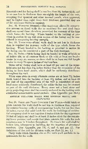
2 RECOMMENDED MINIMUM REQUIREMENTS
Following its organization the committee made an extensive
canvass of professional opinion as to what parts of building codes
most urgently needed revision and standardization. This showedthat masonry wall regulations differ widely in various cities; that
allowable masonry stresses and fire resistance requirements are basedon inadequate knowledge of service under loading and fire exposure
;
and that as a result there is lack of safety in some localities andunnecessary use of materials and labor in others.
It was decided to collect all reliable data available for guidance
of those drafting masonry wall provisions and to prepare recom-
mendations representing the best information obtainable on the sub-
ject. An investigation of fire resistance of masonry walls had been
instituted at the Bureau of Standards and has since been completed,
and the results made available for this committee. Tests were madeupon solid and hollow brick walls 11 by 16 feet in area and built
with different varieties of brick and mortar. In the meantime all
available data on the compressive strength of masonry were corre-
lated, with especial care to evaluate the effects of differing conditions
on strength and stability. These include results from an elaborate
investigation of the compressive strength of brick walls in the larg-
est units adapted to the 10,000,000-pound testing machine at the
Bureau of Standards’ former Pittsburgh laboratory. The advice of
many experienced masonry builders was also obtained.
With this information in hand the committee prepared a tenta-
tive draft of code requirements regulating masonry wall construc-
tion in all types of buildings, together with an appendix explanatory
of these requirements and including certain valuable material which
had resulted from the investigations mentioned. Over 800 copies of
this draft in mimeographed form, were submitted to architects, engi-
neers, building officials, contractors, insurance adjusters, and others,
whose experience and interest qualified them to discuss the subject
with authority.
The tentative draft was thoroughly reviewed. Over 150 letters
were received presenting the well-considered opinions of about 200
experienced observers. These were summarized in form for ready
reference and several meetings of the committee held for their con-
sideration in connection with preparation of this report.
SCOPE OF REPORT
This report deals with exterior and interior masonry walls for all
buildings. Walls for small dwellings are included, but are treated
more specifically in the report on Recommended Minimum Require-
ments for Small Dwelling Construction, previously mentioned.
Note.
—
For reasons given in the Appendix, paragraph 8-3, reinforced con-
crete walls have been omitted.

MASONRY WALL CONSTRUCTION 3
ACKNOWLEDGMENT OF ASSISTANCE
The committee desires to express its appreciation of the coopera-
tion extended by Bureau of Standards officials. S. H. Ingberg, of
the bureau staff, rendered valuable assistance by compiling data,
making available results of fire tests, by working with the committee
at several meetings, and by supplying a discussion ,of bending
stresses in walls due to wind loads and floor reactions. Theunequaled research facilities of the bureau have been freely
employed, and the results of numerous investigations made by the
bureau in the field of masonry construction have been most helpful.
The committee also acknowledges the invaluable cooperation
received from the great number of architects, engineers, building
inspectors, fire chiefs, and others with whom it has been in contact.
Their prompt and well-considered response to requests for informa-
tion has greatly facilitated the work and has been much appreciated.
It has been impracticable to report to each commentator the dispo-
sition of his suggestions. Many of the more important questions
raised have been discussed in the Appendix.

PART II.—RECOMMENDED MINIMUM REQUIREMENTSFOR MASONRY WALL CONSTRUCTION
ARTICLE I.—DEFINITIONS
Section 1. Definitions.
—
For the purposes of this code the terms
here defined shall have the following meanings.
1. Bearing wall.—A wall which supports any vertical load in
addition to its own weight.
2. Nonbearing wall.—A wall which supports no load other than
its own weight.
3. Panel wall.—A nonbearing wall in skeleton construction, built
between columns or piers and wholly supported at each story. (See
Appendix, par. 6-1.)
4. Inclosure wall.—An exterior nonbearing wall in skeleton con-
struction anchored to columns, piers, or floors, but not necessarily
built between columns or piers. (See Appendix, par. 6-2.)
5. Curtain wall.—A nonbearing wall between columns or piers and
which is not supported by girders or beams.
6. Party wall.—A wall used or adapted for joint service be-
tween two buildings.
7. Fire wall.—A wall which subdivides a building to restrict the
spread of fire, by starting at the foundation and extending con-
tinuously through all stories to and above the roof. (See Appendix,
par. 7.)
8. Fire division wall.—A wall which subdivides a fire resistive
building to restrict the spread of fire, but is not necessarily continu-
ous through all stories nor extended through the roof. (See Ap-pendix, pars. 7 and 17.)
9. Veneered wall.—A wall having a masonry facing which is not
attached and bonded to the backing so as to form an integral part
of the wall for purposes of load bearing and stability.
10. Faced wall.—A wall in which the masonry facing and back-
ing are so bonded as to exert common action under load.
11. Masonry.—Stone, brick, concrete, hollow tile, concrete block or
tile, gypsum block, or other similar building units or materials or a
combination of same, bonded together with mortar to form a wall,
pier, or buttress. (See Appendix, par. 8.)
12. Piers.—All bearing walls having a horizontal cross section of
4 square feet or less and not bonded at the sides into associated
masonry shall be considered as piers.
13. Portland cement mortar.—A mortar composed of 1 part Port-
land cement to not more than 3 parts of sand, proportioned by
volume, with an allowable addition of hydrated lime not to exceed
4 /

MASONRY WALL CONSTRUCTION 5
15 per cent of the cement by volume. (See Appendix, par. 10-4;
and 13-2.)
14. Cement-lime mortar.—A mortar composed of 1 part Portland
cement, 1 part hydrated lime, and not more than 6 parts of sand,
proportioned by volume.
15. Lime mortar.—A mortar composed of 1 part slaked lime (lime
putty) or dry hydrated lime and not more than 4 parts of sand, pro-
portioned by volume. (See Appendix, par. 13-2.)
16. Natural cement mortar.—A mortar composed of 1 part natural
cement to not more than 3 parts of sand, proportioned by volume.
17. Ashlar masonry.—Masonry of sawed, dressed, tooled, or
quarry-faced stone with proper bond.
18. Ashlar facing.—Sawed or dressed squared stones used in facing
masonry walls.
19. Random ashlar facing.—Sawed or dressed squared stone of
various sizes properly bonded or fitted with close joints used for the
facing of masonry walls.
20. Coursed rubble.—Masonry composed of roughly shaped stones
fitting approximately on level beds and well bonded.
21. Random rubble.—Masonry composed*of roughly shaped stone
laid without regularity of coursing, but fitting together to form
well-defined joints.
22. Rough or ordinary rubble.—Masonry composed of unsquared
or field stones laid without regularity of coursing.
23. Rubble concrete.—Portland cement concrete in which the finer
materials form a matrix for large stones and bowlders, sometimes
termed cyclopean concrete.
Notes.—1. Unless otherwise stated the word “ concrete ” for the purposes
of this code is understood to mean Portland cement concrete.
2. Unless otherwise stated units of materials other than burned clay, having
the same general shape and size of brick, are for the purposes of this code
considered as brick. (See Appendix, par. 9-1.)
3. Unless otherwise stated the term “ hollow tile ” used without a qualifying
adjective, is understood to mean clay hollow tile.
ARTICLE II.—SOLID BRICK WALLS
Sec. 2. Quality of materials.—Brick, and sand-lime brick, used
for bearing walls or piers shall be of quality at least equal to the“ medium brick ” described by the Standard Specifications for Build-
ing Brick of the American Society for Testing Materials, except that
when the average compressive strength of brick grading “ soft ” bythe absorption test, is more than 2,500 pounds per square inch, the
requirements as to absorption may be waived. When used for non-
bearing purposes and not exposed to the weather, brick may be of
quality not inferior in any respect to the “ soft ” brick described in
the above specifications. (See Appendix, pars. 9-2 and -3.)

6 RECOMMENDED MINIMUM REQUIREMENTS
The average compressive strength of concrete brick 28 days after
being manufactured or when delivered on the job, shall be not less
than 1,500 pounds per square inch of gross cross-sectional area tested
in the position as laid in the wall, and the compressive strength of
any individual brick thus tested shall be not less than 1,000 poundsper square inch. (See Appendix, par. 9-4.)
Concrete brick subjected to a 24-hour immersion test shall absorb
not more than 12 per cent of their dry weight, except that for such
brick weighing less than 125 pounds per cubic foot the average ab-
sorption in per cent by weight shall be not more than 12 multiplied
'by 125 and divided by the unit weight in pounds per cubic foot of
the concrete under consideration. (See Appendix, par. 9-5.)
All cements and limes used in mortar shall conform to the require-
ments of the standard specifications for these materials issued by the
American Society for Testing Materials. (See Appendix, par.
10-2.)
Sand used in mortar shall be clean and free from animal or vege-
table matter. (See Appendix, par. 10-1.) (For precautions neces-
sary in laying brickwork in freezing weather or in warm dry
weather see Appendix, par. 13-5.)
Sec. 3. Lateral Support.—Solid brick walls shall be supported
at right angles to the wall face at intervals not exceeding eight-
een times the wall thickness in the top story or twenty times
the wall thickness elsewhere. Such lateral support may be obtained
by cross walls, piers, or buttresses, when the limiting distance is
measured horizontally, or by floors when the limiting distance is
measured vertically. Sufficient bonding or anchorage shall be pro-
vided between the wall and the supports to resist the assumed vfind
force, acting in an outward direction. Piers or buttresses relied upon
for lateral support shall have sufficient strength and stability to
transfer the wind force, acting in either direction to the ground.
When walls are dependent upon floors for their lateral support,
provision shall be made in the building to transfer the lateral forces
resisted by all floors to the ground. (See Appendix, par. 12.)
'
Sec. 4. Working Stresses.—The maximum allowable compressive
stresses in brick masonry due to combined live and dead loads shall
not exceed the following limits. (See Appendix, par. 9-2.)
Brick masonry stresses
Maximum unit working stresses(pounds per square inch)
Unit Portlandcementmortar
Naturalcement orcement-limemortar
Limemortar
Brick (clay) medium grade 170 130 90
Sand-lime brick 170 130 90
Concrete br c 170 130 70'

MASONRY WALL CONSTRUCTION 1
Where the effects of eccentric loading and lateral forces are fully
analyzed and allowance made for them in the design, or under local
concentrated loads applied to a limited proportion of the total area
of the wall, the working stresses in this table may be increased by
50 per cent. (See Appendix, par. 15.)
Note.—See Appendix, paragraphs 13 and 14, respectively, for effect of dif-
ferent factors on strength and stability of masonry.
Sec. 5.—Thickness or Exterior Walls Other Than in Skele-
ton Construction. 2—-The thickness of solid brick bearing walls
shall be sufficient at all points to keep the combined stresses due to
live and dead loads for which the building is designed within the
limits prescribed by section 4. (See Appendix, par. 15.)
The minimum thickness for solid brick exterior bearing or party
walls shall be 12 inches for the uppermost 35 feet of their height,
and shall be increased 4 inches for each successive 35 feet or frac-
tion thereof measured downward from the top of the wall;except
that the top story exterior bearing wall of a building not exceeding
three stories or 40 feet in height, or the wall of a one-story commer-cial or industrial building may be 8 inches thick, provided that such
8-inch wall does not exceed 12 feet unsupported height and that the
roof beams are horizontal; and except that exterior solid brick bear-
ing walls of one and two family dwellings may be 8 inches thick
when not more than 30 feet in height. When gable construction is
used for such dwellings, an additional 5 feet is permitted to the peak
of the gable. (See Appendix, par. 16.)
Where solid brick exterior bearing or party walls are stiffened at
distances not greater than 12 feet apart by cross walls, or by internal
or external offsets or returns, at least 2 feet deep, they may be 12
inches thick for the uppermost 70 feet, measured downward from
the top of the wall, and shall be increased 4 inches in thickness for
each successive 70 feet or fraction thereof.
Note.—
S
ee Appendix, paragraphs 2-2 and 13-5 for influence of workman-
ship ; paragraph 21, for discussion of wall heights. See Part II, section 3, and
Appendix, paragraph 12, for lateral support of walls.
The minimum thickness of solid brick exterior nonbearing walls
shall be 12 inches for the uppermost 70 feet of their height, and
shall be increased 4 inches for each successive 35 feet or fraction
thereof, measured downward from the top of the wall, except that
the top story wall of a building not exceeding three stories or 40
feet in height, or the wall of a one-story commercial or industrial
building may be 8 inches thick, provided that such 8-inch wall does
not exceed 12 feet unsupported height, and that the roof beams are
2 For thickness requirements for walls in skeleton constructed buildings, see Part II,
sec. 44. For discussion on allowable percentage of openings, see Appendix, par. 18-9.

zo
8 RECOMMENDED MINIMUM REQUIREMENTS
horizontal;and except that solid brick nonbearing walls of one and
two family dwellings may be 8 inches thick when not more than 30
feet in height. Whengable construction is used
for such dwellings an addi-
tional 5 feet is permitted to
the peak of the gable. (See
Appendix, pars. 16 and 18.
For interior wall require-
ments, see Part II, secs. 36
to 39, also 41 and 42.)
Sec. 6. Bond.
—
In all
brick walls at least every
sixth course on both sides
of the wall shall be a
header course or there
shall be at least one full
length header in every 72
square inches of each wall
surface. In walls morethan 12 inches thick the
inner joints of header
courses shall be covered
with another headercourse which shall break
joints with the course
below. (See fig. 1 andAppendix, par. 19.)
Where running bond is
used, every sixth course
on each face shall be
bonded into the back-
ing by cutting the face
brick course and using
diagonal headers behind it
or by using a split brick.
Note.—For requirements ap-
plying to veneered walls, see
Part II, Article VI.
Sec. 7. Piers.
—
The un-
supported height of piers
shall not exceed ten times
their least dimension.(See Appendix, par. 20.)
rgr: :|t:ir Iff It W
Jt; m .11

MASONRY WALL CONSTRUCTION 9
Sec. 8. Chases and Eecesses.—There shall be no chases in 8-inch
walls or within the required area of any pier, and no chase in any
wall or pier shall be deeper than one-third the wall thickness.
No horizontal chase shall exceed 4 feet in length, nor shall the
horizontal projection of any diagonal chase exceed 4 feet.
Eecesses for stairways or elevators may be left in walls, but in
no case shall the walls at such points be less than the required
thickness of walls of the fourth story above the ground floor
unless reinforced by additional piers, by steel or reinforced
concrete girders, or steel or reinforced concrete columns and girders,
securely anchored to the walls on each side of such recesses. Ee-
cesses for alcoves and similar purposes shall have not less than 8
inches of material at the back. Such recesses shall be not morethan 8 feet in width and shall be arched over or spanned with lintels.
The aggregate area of recesses and chases in any wall shall not
exceed one-fourth the whole area of the face of the wall in any
story.
No chases or recesses shall be permitted in fire or fire division
walls that will reduce the thickness below the minimum specified in
this code. (See Part II, secs. 86 to 39.)
Openings for doors and windows shall have well-buttressed arches
or lintels of masonry, or of metal with bearing at each end of not
less than 4 inches on the wall. On the inside of openings less than 4
feet wide, in which the thickness of arches and lintels is less than that
of the wall supported, timber may be used, which will rest at each
end not more than 2 inches on the wall and be chamfered or cut to
serve as arch centers. (See Appendix, par. 18-4, and par. 32 for
discussion of anchorage.)
ARTICLE III.—WALLS OF HOLLOW TILE, CONCRETE BLOCK ORTILE, AND HOLLOW WALLS OF BRICK
Sec. 9. Quality of Materials.—Hollow tile.—Hollow tile used for
exterior bearing walls or piers or for party walls shall be of quality
at least equal to the “ medium class ” as prescribed by the Tentative
Specifications for Hollow Burned-Clay Load-Bearing Wall Tile of
the American Society for Testing Materials. (See Appendix, par.
24-1 and -2.)
When used for nonbearing purposes and not exposed to the
weather, hollow tile may be of quality not inferior in any respect to
the “ soft class ” described in the above specifications.
Note.
—
For quality of tile used in partitions, see Part II, sections 41 and 42.
Concrete block or concrete tile .—The average compressive strength
of concrete block or tile used for exterior or party walls or piers
shall be not less than 700 pounds per square inch of gross sectional
area tested in position as used in the wall. The absorption of con-
289340—25—
3

10 RECOMMENDED MINIMUM REQUIREMENTS'
Crete block or tile shall not exceed 10 per cent under a 24-hour im-
mersion test, except that where concrete block or tile have an average
compressive strength of over 1,200 pounds per square inch gross
area, or where they are not exposed to dampness, or where they are
coated with stucco, the requirement as to absorption may be waived.
For block or tile made of concrete weighing less than 140 pounds per
cubic foot, the average absorption in per cent by weight shall be not
more than 10 multiplied by 140 and divided by the unit weight in
pounds per cubic foot of the concrete under consideration. (See
Appendix, par. 9-5.)
Tests on concrete block shall be conducted in accordance with the
Standard Specifications of the American Concrete Institute. (See
Appendix, par. 24-3.)
Brick.—Brick for hollow walls shall conform to requirements of
Part II, section 2.
Mortar.—Either Portland cement mortar as defined in section 1,
or a special cement-lime mortar mixed in proportions of 1 part
Portland cement, 1 part slaked lime (lime putty) or dry hydrated
lime, and not more than 4 parts sand, shall be used for walls of
hollow unit construction or hollow walls of brick.
Sec. 10. Lateral Support.—Walls of hollow tile or of concrete
block or tile, and all hollow walls of brick shall be supported at
right angles to the wall face at intervals not exceeding sixteen times
the wall thickness in top stories, or eighteen times the wall thickness
elsewhere. Such lateral support may be in the form of cross walls,
piers, or buttresses when the limiting distance is horizontal, or by
floors when the limiting distance is vertical. Sufficient bonding or
anchorage shall be provided between the wall and the supports to
resist the assumed wind force acting in an outward direction. Piers
or buttresses relied upon for lateral support shall have sufficient
strength and stability to transmit the wind force, acting in either
direction, to the ground. When walls are dependent on floors for
their lateral support provision shall be made in the building to
transfer the lateral force resisted by all floors to the ground. (See
Appendix, par. 12.)
Sec. 11. Working Stresses.—The maximum allowable compres-
sive stresses in masonry of hollow tile, concrete block or concrete
tile, or hollow walls of brick, due to combined live and dead loads,
shall not exceed 80 pounds per square inch of gross sectional area,
when laid with Portland cement mortar, and 70 pounds per square
inch of gross sectional area when laid with special cement-lime
mortar. (See section 9, Mortar. See also Appendix, par. 25-1.)
Sec. 12. Thickness and Height of Exterior Walls Other Thanin Skeleton Construction. 3—Walls of hollow tile, concrete block or
3 For thickness requirements for walls in skeleton constructed buildings, see Part II,
sec. 44. For discussion on allowable percentage of openings, see Appendix, par. 18-9.

MASONRY WALL CONSTRUCTION 11
tile, or hollow walls of brick shall not exceed 50 feet in height above
the top of foundation walls.
The thickness of walls of the above materials and types shall be
sufficient at all points to keep the stresses due to combined live and
dead loads for which the building is designed within the limits pre-
scribed by section 11.
The minimum thickness of exterior walls of hollow tile, or con-
crete block or tile, or of hollow-wall construction shall be 12 inches
for the uppermost 35 feet of their height, and at least 16 inches
for the remaining lower portion; except that the top story wall
of a building not exceeding three stories or 40 feet in height, or the
wall of a one-story commercial or industrial building may be 8
inches thick, provided that the roof beams are horizontal; and
except that exterior walls of one and two family dwellings maybe 8 inches thick for the uppermost 20 feet. When gable construc-
tion is used for such dwellings an additional 5 feet is permitted to
the peak of the gable. (See Appendix, par. 16-6.)
Where walls are stiffened at distances not greater than 12 feet
by cross walls or by internal or external returns at least 2 feet
deep, the thickness may be 12 inches throughout, except that the
top story, or for one and two family dwellings the uppermost 20 feet,
may be 8 inches as previously provided. (See Appendix, par. 16-1
and -4. For interior wall requirements see Part II, secs. 36 to 39,
also 41 and 42.)
Sec. 13. Bond.
—
-Where two or more hollow units are used to
make up the thickness of a wall, the inner and outer courses shall
be bonded at vertical intervals not exceeding three courses by lapping
at least one cell completely over a cell of the unit below.
Sec. 14. Beam Supports.
—
Suitable provision shall be made at
each line of floor beams in hollow walls or walls of hollow units,
to shut off the spaces above from those below, and to ensure goodbearing for beams and uniform distribution of loads. (See Appen-dix, par. 26.)
Sec. 15. Piers.—Hollow tile or hollow concrete block or tile shall
not be used for isolated piers unless solidly filled with concrete. Theunsupported height of such piers shall not exceed 10 times their
least horizontal dimension. (See sec. 1, definition 12, and Appen-dix, par. 26.)
Sec. 16. Chases and Recesses.—Chases and recesses in walls of
hollow tile, hollow concrete block or tile, or in hollow walls of
brick shall not exceed in extent those permitted for solid brick
walls under the same conditions. Chases and recesses shall not be
cut in walls of the above types, but may be built in. No chases

12 RECOMMENDED MINIMUM REQUIREMENTS
or recesses shall be permitted in fire walls that will reduce thethickness below the minimum specified in this code.
Openings for doors and windows shall have well-buttressed archesor lintels of masonry or metal with bearing at each end of not less
than 4 inches on the wall. On the inside of openings less than 4feet wide, in which the thickness of arches and lintels is less thanthat of the wall supported, timber may be used, which will rest
at each end not more than 2 inches on the wall and be chamferedor cut to serve as arch centers.
ARTICLE IV.—WALLS OF PLAIN CONCRETE
Sec. 17. Concrete Materials.—Monolithic concrete construction
containing not more than two-tenths of 1 per' cent of reinforcement
shall be classed as plain concrete.
Materials for bearing walls and piers of plain concrete shall be
mixed in proportions of 1 part of Portland cement to not more than
3 parts of sand and 5 parts of coarse aggregate, by volume, or a mix-
ture of fine and coarse aggregates giving an equivalent strength anddensity.
Coarse aggregate shall consist of crushed stone, gravel, or crushed
slag, 85 per cent of which is retained on a No. 4 screen, and shall be
graded in size from small to large particles. The particles shall be
clean, hard, durable, and free from deleterious material. (See Ap-pendix, par. 27.)
Cement for plain concrete shall conform to the requirements of
the Standard Specifications and Tests for Portland Cement of the
American Society for Testing Materials.
Fine aggregate shall consist of sand, washed stone screenings or
other similar inert materials, or a combination thereof, having clean,
hard, strong, durable uncoated grains and free from injurious
amounts of dust, lumps, soft or flaky particles, shale, alkali, organic
matter, loam or other deleterious substances; and shall range from
fine to coarse. Not less than 95 per cent shall pass a No. 4 sieve, and
not more than 30 per cent shall pass a No. 50 sieve, when tested
according to standard practice prescribed by the American Society
for Testing Materials.
Sec. 18. Lateral Support.—Plain concrete walls shall be sup-
ported at right angles to the wall face at intervals of not exceeding
twenty times the wall thickness. Such lateral support may be in the
form of cross walls, piers, or buttresses when the limiting spacing is
horizontal, or by floors when the limiting distance is vertical. Suf-
ficient bonding or anchorage shall be provided between the wall and
the supports to resist the assumed wind force acting in an outward
direction. Piers or buttresses relied upon for lateral support shall

MASONRY WALL CONSTRUCTION 13
have sufficient strength and stability to transfer the wind force, act-
ing in either direction, to the ground. When walls are dependent
upon floors for their lateral support provision shall be made in the
building to transfer the lateral force resisted by all floors to the
ground. (See Appendix, par. 12.)
Sec. 19. Working Stresses.—The maximum allowable stresses in
masonry of plain concrete of the proportions specified in section 17
as a minimum due to combined dead and live loads shall not exceed
400 pounds per square inch in compression, 35 pounds per square
inch in tension or diagonal tension;or 90 pounds per square inch in
punching shear. When plain concrete of greater strength is used the
foregoing stresses may be increased to 20 per cent of the ultimate
compressive strength for concrete in compression, 2 per cent in ten-
sion or diagonal tension, and 4*4 per cent in punching shear.
Sec. 20. Thickness of Walls.
—
The minimum thickness of plain
concrete bearing walls shall be 10 inches for the uppermost 35 feet
of their height and shall be increased 4 inches for each successive 35
feet or fraction thereof, measured downward from the top of the
wall, except that the top-story wall of a building not exceeding
three stories or 40 feet in height, or the wall of a one-story commer-
cial or industrial building may be 8 inches thick, provided that such
8-inch wall does not exceed 12 feet unsupported height and that the
roof beams are horizontal, and except that exterior bearing walls of
one and two family dwellings may be 6 inches thick when not more
than 30 feet in height. When gable construction is used for such
dwellings an additional 5 feet is permitted to the peak of the gable.
(See Appendix, par. 16.)
When plain concrete bearing walls of buildings more than three
stories high are stiffened at points not more than 12 feet apart bycross walls, or by internal or external offsets or returns at least 2 feet
deep, they may be 10 inches thick for the uppermost 70 feet of their
height- and shall be increased 4 inches in thickness for each succes-
sive 70 feet or fraction thereof.
The minimum thickness of plain concrete exterior nonbearing walls
shall be 10 inches for the uppermost 70 feet of their height, and
shall be increased 4 inches for each successive 35 feet or fraction
thereof, measured downward from the top of the wall; except that
the top story wall of a building not exceeding three stories or 40
feet in height, or the wall of a one-story commercial or industrial
building may be 8 inches thick, provided that such 8-inch wall does
not exceed 12 feet unsupported height, and that the roof beams are
horizontal;and except that exterior nonbearing walls of one and two
family dwellings may be 6 inches thick when not more than 30 feet
in height. When gable construction is used for such dwellings an

14 RECOMMENDED MINIMUM REQUIREMENTS
additional 5 feet is permitted to the peak of the gable. (For dis-
cussion of heights, see Appendix, par. 21.)
Hollow monolithic walls of plain concrete shall have the same net
cross sectional area of material, irrespective of the space within the
wall, as required for solid walls. The inner and outer parts of such
walls shall be securely braced and tied together with noncorrodible
ties or other means to bring them into common action. Where floor
and roof systems are carried by such walls, provision shall be madefor the distribution of these loads to the full cross section of the wall.
(See Appendix, par. 27.) For interior wall requirements, see sec-
tions 36 to 39, also 41 and 42.
Sec. 21. Reinforcement.—Reinforcement, not less than two-
tenths of 1 per cent computed on a vertical height of 12 inches, shall
be placed over all wall openings and at corners of the structure to
prevent cracks. Floor and roof connection details shall be designed
to transmit safely the vertical and horizontal loads imposed.
Sec. 22. Piers.—The unsupported height of isolated piers of plain
concrete shall not exceed ten times their least dimension. (See sec.
1, definition 12.)
Sec. 23. Chases and Recesses.—Chases and recesses in plain con-
crete walls shall not exceed in extent those permitted for solid brick
walls under the same conditions. (See Part II, sec. 8.)
article v.—stone walls
Sec. 24. Working Stresses.—The maximum allowable compressive
stresses in rubble stonework due to combined live and dead loads
shall not exceed 140 pounds per square inch when laid in Portland
cement mortar, 100 pounds per square inch in natural cement or ce-
ment-lime mortar, and 70 pounds per square inch in lime mortar.
The maximum allowable compressive stress in ashlar masonry due
to combined live and dead loads shall not exceed the following limits
:
Maximum unit working stresses
(pounds per square inch) laidin—
Unit
Portlandcementmortar
Cement-lime ornaturalcementmortar
Limemortar
Granite 800 640 400Limestone 500 400 250Marble 500 400 250Sandstone 400 320 160
Sec. 25. Lateral Support and Thickness.—Rubble stone walls
shall be 4 inches thicker than is required for solid brick walls of the
same respective heights, but in no part less than 16 inches.

MASONRY WALL CONSTRUCTION 15
The minimum thickness for walls or piers of ashlar masonryproperly bonded shall be the same as required for solid brick walls
and piers under similar conditions.
The lateral support for stone walls shall conform to the samerequirements specified for solid brick walls, Part II, section 3.
(For discussion of heights, see Appendix, par. 21.)
Sec. 26. Bond.
—
Bond stones extending through the wall anduniformly distributed shall be provided to the extent of not less
than 10 per cent of the area, and there shall be at least one bondstone for every eight stretchers.
Sec. 27. Chases and Recesses.
—
Chases and recesses in stone walls
shall not exceed in extent those permitted for solid brick walls under
the same conditions. (See Part II, sec. 8.)
ARTICLE VI.—VENEERED WALLS
Sec. 28. Quality of Materials.
—
Materials used in the backing
and veneering of veneered walls shall conform in all respects to the
requirements prescribed for such materials in Part II, sections 2, 9,
and 17. Stone or architectural terra-cotta ashlar, or other approved
masonry material used for veneering, shall be not less than 3 inches
thick. In stone ashlar each stone shall have a reasonably uniform
thickness, but all stones need not necessarily be the same thickness.
Sec. 29. Working Stresses.
—
The maximum allowable compressive
stresses on the backing of veneered walls, due to combined live and
dead loads, shall not exceed those elsewhere prescribed for masonry
of the type which forms such backing. In no case shall the veneer-
ing be considered a part of the wall in computing the strength of
bearing walls, nor shall it be considered a part of the required
thickness of the wall.
Sec. 30. Attachment of Veneering.—When walls are veneered
with brick, terra cotta, stone or concrete trim stone the veneering
shall be tied into the backing either by a header for every 300
square inches of wall surface, or by substantial noncorrodible metal
wall ties spaced not farther apart than 1 foot vertically and 2 feet
horizontally. Headers shall project at least 3% inches into the
backing, and anchors shall be of substantial pattern. When veneer-
ing is used special care shall be taken to fill all joints flujsh with!
mortar around wall openings. (See Appendix, par. 32-8.)
Sec. 31. Height of Veneered Walls.—Veneered walls shall not
exceed 40 feet in height above foundations.
article vii.—faced walls
Sec. 32. Quality of Materials.—Materials used in the backing
and facing of faced walls shall conform in all respects to the require-
ments prescribed for such materials in Part II, sections 2, 9, and 17.
16 RECOMMENDED MINIMUM REQUIREMENTS
Materials used for facing shall be not less than 3% inches thick, andin no case less in thickness than one-eighth the height of the unit,
excepting that spandrel and other recessed panels, when approved,may be higher than eight times their thickness, provided they are
of the minimum thickness required.
Sec. 33. Working Stresses,—The maximum allowable compres-
sive stresses on faced walls due to combined live and dead loads
shall not exceed those elsewhere prescribed for masonry of the type
which forms the backing. Where bonded to the backing as pro-
vided in section 35 the full cross section of the facing may be con-
sidered in computing bearing strength.
Sec. 34. Thickness.—Faced walls shall be not less in thickness
than is required for masonry walls of the type which forms the
backing. Where bonded to the backing as provided in section 35
the facing may be considered a part of the wall thickness.
Sec. 35. Bond.—Brick facing shall be bonded to walls of brick or
of hollow tile, or of concrete block or tile with at least one header
course in every six courses, or there shall be at least one full length
header in every 72 square inches of wall surface.
Stone ashlar facing shall have at least 20 per cent of the super-
ficial area not less than 3% inches thicker than the remainder of the
facing to form bond stones, which shall be uniformly distributed
throughout the wall.
When some stone in every alternate course are at least 7% inches
thick, bonded into the backing at least 3% inches, and at least 20
per cent of the superficial area of the wall is constituted of such
bond stone uniformly distributed, the ashlar facing may be counted
as part of the wall thickness. Every stone not a bond stone andevery projecting stone shall be securely anchored to the backing with
substantial noncorrodible metal anchors. (See Appendix, par. 32-8.)
ARTICLE VIII.—FIRE WALLS, FIRE DIVISION WALLS, ANDPARTITIONS
Sec. 36. Brick and Plain Concrete Fire Walls.—Solid brick or
plain concrete fire walls shall be not less in thickness than required
for exterior bearing walls of corresponding height, but not less than
12 inches, except that solid brick fire walls for buildings of residen-
tial occupancy shall be not less than 8 inches thick for the uppermost
20 feet of height and shall be at least 12 inches thick for the remain-
ing lower portion;and except that plain concrete fire walls for such
structures may be 8 inches throughout. No 8-inch fire wall shall be
broken into, subsequent to building, for the insertion of structural
members. (See Appendix, par. 7-6, -8, and -9, and par. 17. Fordefinitions of fire and fire division walls, see Part II, sec. 1.)
Party walls which function also as fire walls shall conform to re-
quirements for fire walls.

MASONRY WALL CONSTRUCTION 17
A separation of at least 4 inches of solid masonry shall be pro-
vided in all fire and party walls between combustible members which
may enter such walls from opposite sides.
Sec. 37. Fire Walls of Hollow Tile, Concrete Block or Con-crete Tile, or of Hollow Wall Construction.—Fire walls of hol-
low tile or concrete block or concrete tile shall be not less than 16
inches thick in any part, except that for residental buildings they
may be not less than 12 inches thick throughout. Hollow walls of
brick used as fire walls shall be not less than 12 inches thick through-
out. No fire walls of the above types shall be broken into, subse-
quent to erection, for the insertion of structural members. (See Ap-2iendix, par. 7-5 and -6, and par. 17.)
Where combustible or unprotected steel building members frame
into hollow party or fire walls of thickness not greater than 12
inches, they shall not project more than 4 inches into the wall and
shall be so spaced that the distance between embedded ends is not
less than 4 inches. The space above, below, and between them shall
be filled solidly with burnt-clay materials, mortar, concrete, or
equivalent fire-resistive material, to a depth of not less than 4 inches
on all sides of the members.
All open cells in tile or blocks occurring at wall ends shall be
filled solid with concrete for at least a depth of 6 inches, or closure
tile set in the opposite direction shall be used.
Party walls which function also as fire walls shall conform to
requirements for fire walls.
Sec. 38. Fire Division Walls.
—
Fire division walls of solid brick
or plain concrete shall be not less than 8 inches thick.
Fire division walls of hollow tile, or of concrete block or tile,
shall be not less than 12 inches thick in any part, and for buildings
of storage and heavy manufacturing occupancy they shall be not
less than 16 inches thick throughout. Hollow walls of brick used
as fire division walls shall be not less than 12 inches thick through-
out. (See Appendix, pars. 7 and 17.)
Sec. 39. Alternate Requirements for Fire and Fire Division
Walls.—Wall constructions that in fire tests conducted according to
accepted standards develop safe fire-resistance periods of one andone-half hours may be permitted for fire walls and fire division
walls between residence occupancies, if otherwise adequate in point
of strength and stability. For general mercantile and manufactur-
ing occupancies, excluding buildings or portions of buildings used
for storage, wall constructions developing, on the same basis, a safe
fire-resistance period of three hours shall be similarly permitted.
Note.—For requirements for lateral support of walls, see Part II, sections
3, 10, and 18.
28934°—25 4

18 RECOMMENDED MINIMUM REQUIREMENTS
Sec. 40. Parapet Walls.—In commercial or industrial buildings
and in residential buildings over three stories high, all fire or party-
walls shall project above the roof as parapets.
Where not otherwise specified parapet walls shall be at least 32
inches high, but not higher than four times their thickness unless
laterally supported. They shall be at least as thick as the top story
wall, except that they need not in any case be more than 12 inches
thick.
In residential buildings not more than three stories high parapet
walls shall extend through combustible roofs to a height of at least
12 inches above the roof. All parapet walls shall be coped. (See
Appendix, par. 29.)
Sec. 41. Bearing Partitions.
—
All interior bearing walls, except
fire walls, fire division walls, and party walls, are considered as bear-
ing partitions.
For bearing partitions, materials meeting the ordinary accepted
local standards for the purpose may be used.
Where not utilized as party, fire, or fire division walls solid brick
bearing partitions shall be not less than 8 inches thick, and those of
hollow tile, concrete block or concrete tile, or hollow walls of brick
shall be not less in thickness than one-eighteenth of the height be-
tween floors or floor beams. (For conditions governing concentra-
tions see sec. 4.)
Sec. 42. Nonbearing Partitions.—For nonbearing partitions, ma-terials meeting the ordinary accepted local standards for the purpose
may be used.
Brick nonbearing partitions shall be not less than 3% inches thick
for a height not exceeding 12 feet between floors or floor beams andfor a length not exceeding 20 feet between vertical supports. Non-bearing partitions of hollow tile, concrete block or concrete tile,,
hollow walls of brick or of gypsum block or other similar materials
shall be built solidly against floor and ceiling construction below andabove, and shall not exceed the following unsupported heights
:
Thicknessexclusiveofplaster
Maximumunsupported
height
Thicknessexclusiveof plaster
Maximumunsupported
height
Inches Feet Inches Feet2 6 203 12 8 254 15
ARTICLE IX.—FOUNDATION WALLS
Seo. 43. Foundation Walls.
—
Foundation walls for solid-wall
construction shall be of stone, solid brick, concrete (plain, rubble,,
or reinforced), or concrete block. Solid brick foundation walls

MASONRY WALL CONSTRUCTION 19
and those of concrete block or coursed stone shall be not less in
thickness than the walls immediately above them and in no case
less than 12 inches thick, except that when the inclosure is not ex-
cavated, they may be 8 inches thick if included within the allow-
able height of 8-inch walls. When built of concrete cast in place,
foundation walls shall be at least as thick as the walls supported,
but in no case less than 8 inches. When built of rubble stone, they
shall be at least 16 inches thick. Rough or random rubble without
bonding or level beds shall not be used as foundations for walls
exceeding 35 feet in height nor shall coursed bonded rubble walls
be used as foundations for walls exceeding 75 feet in height. (See
Appendix, par. 18-1.)
Foundation walls for hollow tile, concrete block or tile, hollow
walls of brick, or frame construction, shall be of the same thick-
nesses, respectively, as required in the paragraph above, and shall
be built of brick, stone, concrete (plain, rubble, or reinforced), hol-
low tile, concrete block or tile, or hollow walls of brick. Tile foun-
dation walls shall be not less than 12 inches thick.
When the stresses due to earth pressure and superposed building
load exceed the maximum working stress elsewhere specified for
brick masonry, and the additional stresses are not otherwise pro-
vided for, the wall thickness shall be increased to bring them with-
in these limits. (See Appendix, par. 30.)
Foundation walls for frame construction shall extend at least 8
inches above the adjoining ground surface.
All foundation walls shall extend below the level of frost ac-
tion.
Materials for foundation walls shall be equal in quality in all
respects to those required for exterior bearing walls, except that
mortar containing lime in greater proportions by volume than 1
part to 1 part of cement and 6 parts of sand shall not be used for
exterior foundation walls below grade. (See Appendix, par. 30-2.)
ARTICLE X.—SKELETON CONSTRUCTION
Sec. 44. Panel and Inclosure Walls.—Panel walls in buildings
of skeleton construction shall be not less than 8 inches thick if
of solid brick, hollow tile, concrete block or tile, plain concrete,
or hollow walls of brick. Inclosure walls shall be not less than 8
inches thick nor less in thickness than one-twentieth the horizontal
distance between anchors. (See Appendix, par. 6-2.)
ARTICLE XI.—NEW TYPES OF MASONRY CONSTRUCTION
Sec. 45. New Masonry Construction.—The use of new or im-
proved masonry materials or methods not covered by this code may
20 RECOMMENDED MINIMUM REQUIREMENTS
be permitted, providing that they conform to specifications insur-
ing reasonable uniformity of the product; and that the stability
and durability of such construction, and its resistance under fire
exposure shall have been satisfactorily demonstrated. Workingstresses shall be fixed at not more than 20 per cent of the averageultimate strength of masonry walls constructed of such materials,
as determined by responsible authorities. (See Appendix, par. 31.)
ARTICLE XII.—MISCELLANEOUS REQUIREMENTS
Sec. 46. Anchoring Walls.
—
All walls shall be securely anchored
and bonded at points where they intersect. (See Appendix, par.
32.)
Sec. 47. Use of Existing Walls.
—
An existing brick wall may be
used in the renewal or extension of a building; or may be increased
in height beyond that allowed by this code for walls of its existing
thickness and materials of construction, provided that such wall is
structurally sound or can be made so by reasonable repairs. Walls
increased in height shall be at least 4 inches thicker than is re-
quired by this code for newly constructed walls of such increased
height, and in no case shall linings be less than 8 inches thick andlaid in Portland cement mortar. The foundations and lateral sup-
port shall be equivalent to those elsewhere required for newly con-
structed walls under similar conditions. All linings shall be thor-
oughly bonded into existing masonry by toothings of brick or stone
to assure combined action of wall and lining. Such toothings shall
be distributed fairly uniformly throughout the wall and shall ag-
gregate in vertical cross-sectional area not less than 15 per cent of
the total vertical area of the lining. (See Appendix, pars. 22 and
32-1.)
No existing wall shall be used for renewal or extension of a build-
ing, or increased in height without special written permission from
the building official.
Sec. 48. Corbeling of Chimneys.—No brick wall less than 12
inches thick shall be used to support a corbeled chimney. Such
corbeling shall not project more than 6 inches from the face of the
wall, and in all such cases the corbeling shall consist of at least
five courses of brick. No chimney shall be corbeled from a wall
built of hollow tile, hollow concrete block, concrete tile, or hollow
walls of brick.
Sec. 49. Cornices.—The centers of gravity of stone cornices shall
be inside of the outer wall face. Terra cotta or metal cornices shall
be structurally supported from the roof of the building.

PART III.—APPENDIX
PARAGRAPH i. PURPOSE
The Appendix consists of explanatory matter referring to PartII and is a vital part of this report. The committee believes thatevery building code should be accompanied by an appendix whichshould contain sufficient explanation of the code requirements to
make them easily understandable and such other information ongood practice as is not easily obtainable elsewhere in concise form.
PARAGRAPH 2. JUSTIFICATION FOR REQUIREMENTS, AND INFLU-ENCE OF BUILDING INSPECTION
1. It is recognized that the requirements recommended in Part IIconstitute in some particulars relaxations from those in force in cer-
tain cities and parts of the country. These modifications of existing
practice are justified by the facts developed through the committee’sinvestigations. In addition to the test data discussed in the follow-ing pages the experience has been noted of several large cities whichfor many years have utilized wall heights, thicknesses, and stress
limits fully as liberal as those recommended in Part II. The suc-
cess resulting with these moderate requirements in many places andunder varied circumstances is the most satisfactory answer to the
objections to their adoption in localities where present requirementsare more conservative.
The recommendations are 'predicated on the assumption that goodmaterials and workmanship will be used and all necessary care takenin assembling the various parts of the structure. Certain existing
code provisions applying to walls and other structural details, whichmight be classified as extreme, reflect in part the purpose of their
writers to offset poor design or workmanship by a greater factor ofsafety. In effect such codes penalize the builder, by requiring addi-tional material and labor because of a city’s failure to provide, orcompel the provision of adequate and competent supervision ofbuilding operations. It is felt that the extra expense thus causedmore than warrants energetic measures to insure such supervision,
and that it is the duty of all concerned with planning and super-vising building construction, both to the public and to their clients,
to use every influence toward securing it.
2. Where responsible supervision can be assured the code require-
ments recommended in this report are believed safe. Where inspec-
tion is of uncertain character relaxation of more restrictive or ex-
pensive existing requirements is not advocated. In modifying their
code provisions to reduce cost, local authorities should insist uponsupervision of construction by an adequate experienced personnel.
At the same time, city building inspectors should avoid the other
extreme. There is a tendency for the building inspection depart-
ments of municipalities to forget that theirs is primarily a police
function, concerned only with public safety, and to lay too muchstress on matters which are good building practice, but have nothingto do with the police power. This is reflected to a considerable
extent in some recent building codes, and in preparing these recom-mendations the effort has been made to keep them within the boundsof simplicity necessitated by safety considerations alone.
21

22 RECOMMENDED MINIMUM REQUIREMENTS
3. The committee for the most part has confined itself to structuralrequirements and has avoided matters of administration. The pub-lic discussion of the tentative report, however, discloses a strongsentiment for placing greater responsibility on those charged withbuilding construction, and a few remarks on this subject seemdesirable.
The municipal building inspector is not and should not be heldwholly responsible for safety of buildings. His duty, like that ofthe policeman, is to prevent dangerous conditions, so far as hisfacilities will permit, but reasonable precautions having been taken,he is no more responsible for failures than the policeman for crimes.The builder or his accredited representative, having undertakenerection of the structure, is responsible for safe prosecution of thework. Building erection, especially of the large structures nowprevalent, is an operation of great complexity involving numerouspossibilities of mishap, both to those engaged in the work and tofuture occupants. The risks involved and the knowledge demandedof those in charge are far greater than in the case of many tradesor occupations now rigidly controlled. Nevertheless, such work is
frequently undertaken by those having practically no experienceand often assuming an antagonistic attitude toward the buildinginspector’s efforts to insure safety.
In view of these facts some discretion should be accorded buildingofficials as to who may be granted permits. The committee does notnecessarily advocate licensing of builders, but does hold that local
practice should strongly favor the issuance of permits only to
responsible individuals experienced in building work and competentto assume responsibility for their employees and subcontractors;and that building officials should be empowered to refuse permits to
those known to be unfit for the work proposed or who have failed
formerly to cooperate sufficiently with municipal inspection to insure
reasonable safety. This means that permits would be issued onlyto the builder, architect, or person who is responsible for erection ofthe building, and not necessarily to the owner.
PARAGRAPH 3. STATUS OF THE COMMITTEE’S RECOMMENDATIONS
1. It has been called to the committee’s attention that some mis-understanding exists regarding the legal status of its recommenda-tions. It should be recognized that the committee’s functions arepurely advisory. Its recommendations can not be considered in anysense as obligatory, but are issued to make available to those locally
responsible for exercise of the police power the latest and mostreliable information obtainable on building regulations.
2. The recommended code requirements are in all cases the mini-mum consistent with safety predicated upon proper design andgood workmanship. The scope of the police power, upon whichall such ordinances depend for authority, does not justify require-
ments which are merely good building practice, and where suchrequirements are included in codes they are apt to be found unen-forceable.
When two or more materials or methods of construction are men-tioned in this report as satisfying a certain requirement, it does notfollow that they are considered on a par in all desirable respects,

APPENDIX 23
but merely that they meet the standards of performance regardedas essential.
3. It is not intended that these recommendations shall be regardedas fixed. Building laws can continue to be of the highest usefulnessonly when they reflect progress in the art of building construction.Many of the injustices and discrepancies of existing building codesresult from delay in their revision to meet changing conditions. It is
planned that these recommendations shall be amended at intervals,
keeping pace with changes in building art. In this way it is hopedthat best assistance may be rendered those responsible for revisionand enforcement of building ordinances.
PARAGRAPH 4. FUNCTION OF WALLS
Under prevailing interpretations of the police power there are
certain definite requirements which masonry walls in buildings mustmeet.
1. They must not fail structurally under loads or conditions in-
cidental to the building’s occupancy.2. They must resist moisture penetration to an extent which will
insure sanitary living or working conditions, and the permanency ofthe wall itself or of members framing into it.
3. Under fire exposure their stability must be such as to avoidpremature collapse endangering firemen, and they must dischargethe functions of support and heat insulation, necessary to preventundue fire loss.4
PARAGRAPH 5. VARIATION IN CODE REQUIREMENTS
So far as can be determined from an examination of presentmunicipal regulations, experience in satisfying these requirementshas not resulted in uniform practice. The committee had reference
to four independent investigations on this subject.
1. An analysis by the Bureau of Standards of the requirements of134 building codes, representing all parts of the country, disclosed
the following facts.
Average requirements and limitation's of 13Jf codes for brick foundations andsolid exterior walls for dwellings
THICKNESS WITHIN FIRE LIMITS ONLY
Foundation,in inches
Stories Limits of
First Second Third Fourth Height Length Width Area
12.5
Inches9.7
11.013.116.0
Inches Inches Inches Feet15.528.741.553.7
Feet65.969.880.280.6
Feet23.724.324.4
Si. ft.
1, 311
1, 31113 7 9.711.813.6
16.2 10.512.318.5 — 11.2 24.9
THICKNESS WITHIN OR OUTSIDE OF FIRE LIMITS
12.5
13.6
16.218.5
). 2
12.814.4
15.
9.211.5 10. 2
13.2 12.0 11.0
28.541.554.0
* The protection of stored, commodities or prevention of interior deterioration is also
an important function of walls and should be considered. It does not come within the
police power.

24 RECOMMENDED MINIMUM REQUIREMENTS
Among the 134 codes there were 3 different minimum thicknesses
prescribed for one-story residential buildings, 4 for two-story dwell-
ings, 8 for three-story dwellings, and no less than 12 different mini-
mum thickness arrangements allowable for the different stories of
four-story buildings. Other conditions being equal the thickest four-
story wall contained 125 per cent more brick than the thinnest. Asimilar situation was found to exit in regard to walls of hollow tile
and hollow concrete block.
2. A compilation by the Common Brick Manufacturers’ Associa-tion of America of the allowable thicknesses of solid brick exteriorwalls of dwellings as given in 113 building codes and summarized asfollows
:
Minimum, allowable thickness of solid, brick exterior walls for dwellings accord-ing to building codes of 113 cities
Dwellings Walls Cities
One-story 8-inch.. 88Do Over 8-inch 25
Two-story 8-inch, both stories 44Do Over 8-inch, first story 38Do Over 8-inch, both stories 31
Three-story 8-inch, all stories
Do Over 8-inch, first story 17Do Over 8-inch, first and second stories 30Do Over 8-inch, all stories 53
3. An investigation was made by the committee of code require-
ments for panel walls supported at each story, with the followingresults
:
Of 84 municipal building codes examined, 30 do not distinguish
between panel walls supported at every story and bearing walls ornonbearing walls not thus supported.
Six codes recognize panel walls as a separate class, but require
that their thickness for the lower stories be increased with theheight of the building in the same manner as for walls not thussupported.
Forty-eight ordinances specify minimum allowable thicknesses for
brick panel walls : Of these, 18 call for 8-inch thickness, and 30 call
for 12 or 13 inch thickness in such walls.
Thirty-three codes specify thicknesses for tile panel walls as fol-
lows: 14 require 8-inch thickness, and 19 call for 12 or 13 inchthickness.
In 39 cases specific requirements for thickness of reinforced con-
crete panel walls are given, namely: 2 require 4-inch thickness, 4require 6-inch thickness, 16 require 8-inch thickness, 12 require 12-
inch or 13-inch thicknesses.
Only one code specifically mentions the use of concrete units forpanel walls, the thickness required being 12 inches.
Fourteen codes make no difference between the various masonrymaterials, merely stating the thickness. Of these, six call for an8-inch wall and eight call for a 12-inch wall.
Two codes forbid such walls to be thinner than one-sixteenth or
one-twentieth of their height between horizontal supports.

APPENDIX 25
One code specifies that panel walls shall not be longer than 20feet between vertical supports, but does not limit their height.
Nine codes limit the height between horizontal supports, requir-
ing that the thickness be increased if the limits are exceeded. Theselimits vary between 10 and 20 feet. In some cases they apply to
specific materials only and in other cases their application appar-ently is general.
Ten codes limit both height and length of panel walls supportedat each story, the limits varying from 12 by 12 feet to 14 by 30 feet.
In most cases the larger limits are for the thinnest walls.
Two codes regulate thickness on basis of square feet of wall
surface.
Three codes require party wall panels to be 4 inches thicker thanexterior walls.
Omitting from consideration the codes which require increased
thickness with increasing height of building, the average of the
panel wall thicknesses specified in the 84 codes was 10.86 inches for
brick, 10 inches for hollow tile, and 8.57 inches for reinforced
concrete.
4. An analysis of requirements regarding necessary thickness ofbrick bearing walls for eight-story structures in 20 codes chosen at
random disclosed 18 different sets of requirements, and doubtlessfurther investigation would have discovered others. These varia-
tions, furthermore, bore no particular relation to requirements gov-erning other factors which should affect the wall thickness.
Variation, such as demonstrated above, arises in part from the
fact that standards of performance are unequal; that exposuresand allowable working stresses vary; and that materials and work-manship differ widely in different localities. It also is due in verylarge measure to local custom, unchecked by adequate knowledgeof construction practice elsewhere, and to slavish copying of otherordinances without due regard for the circumstances attending their
adoption. In theory, at least, minimum standards of performanceshould be uniform, irrespective of location and other conditions,
except, perhaps, those due to climate, and when departure is madefrom minimum standards scientifically determined the reasons for
such departure should be carefully considered.
Part II of this report presents all the requirements which theBuilding Code Committee considers essential to meet such uniformstandards of performance, and states these recommended require-ments in the minimum terms considered necessary for protection ofthe public health and safety.
PARAGRAPH 6. WALLS IN SKELETON CONSTRUCTION
1. In skeleton construction that portion of a panel wall betweenwindow sill and floor is sometimes called an apron wall. The por-tion between the window top and the floor construction above is
occasionally designated as a spandrel wall.
2. In view of some confusion which exists in use of the terms“ panel wall ” and “ curtain wall,” their definition in a code is con-
289340—25 5

26 RECOMMENDED MINIMUM REQUIREMENTS
sidered necessary. Inclosure walls, as defined in Part II, section 1,
refer only to nonbearing walls inclosing a structure, but not neces-sarily built between columns or piers and only sufficiently anchoredto them or to floors to insure stability against lateral forces. Theymay be supported at each story or at intervals of two or more stories,
as best suits the design.
3. Several critics of the tentative draft of this report suggestedthat the definition of “ panel wall ” be expanded to include those sup-ported at every second or third floor line, or at intervals of 20 or 30feet. It was evident, however, that several of these criticisms re-
ferred to a, somewhat different method of construction. The com-mittee has included these other types of walls under the term “ in-
closure walls.”
4. The tentative draft of this report permitted the use of metalfabric and cement plaster, or “ gunite ” walls. The consensus ofopinion obtained indicated that such walls do not properly belongunder the heading of masonry. The committee, therefore, hasomitted them.
5. Some existing codes regulate the thickness of walls in skeletonconstruction according to the length, height, or area in square feet
between columns and floors. If the limitations on spacing of lateral
supports recommended in Part II are observed, this will be unneces-sary. It is established, in fact, that the expansion of such walls underintense heat is less destructive, and the deformations are less, if
the panels are long, than if they approach a square in shape.
PARAGRAPH 7. FIRE AND FIRE DIVISION WALLS
1. In order adequately to discharge its functions, a fire wall mustbe thick enough to prevent communication of fire by heat conduction.It must have such stability as to remain intact after complete com-bustion of the contents of the building on one side of the wall
;and
its structural integrity must be such as to be not seriously affected byany wreckage resulting from the fire or its extinguishment.
2. It is no longer customary in steel and reinforced concrete con-
struction to build self-supporting fire walls up through a structure
independently of the floors, even though such walls are sometimesspecified in codes. The walls are supported by the structural frameor floor system in each story, and usually divided into moderatelysmall panels built between piers or columns. In case of fire, this
method of restrained construction serves to limit the heat deformationin a single unit to an amount which does not endanger the integrity
of the wall. Such walls are termed “ fire division walls ” in this re-
port to distinguish them from the walls commonly known as “fire
walls.”
3. Exhaustive tests under severe conditions at the Bureau of Stand-ards indicate that well-built 8-inch solid brick walls supported at
each story with no combustible members framing into them are re-
liable as fire stops, and that so long as the floor and roof construction
maintain their integrity, a safe fire barrier exists between buildings
or parts of buildings separated by such walls. (See also Appendix,par. 17.)

APPENDIX 27
4. The type of wall defined in Part II, section 1, as a “ fire wall ” is
the result of experience antedating successful fire resistive skeletonconstruction. Walls of considerable mass and stability, extendingunbroken from foundations to parapet, were and are necessary in“ ordinary ” and “ mill construction,” where floors can not be de-pended upon to resist the full duration of a fire and are liable tocollapse, or where beams and girders depend on such walls forsupport. The modem method of skeleton construction providesfloors, girders, and columns which support the walls and partitionsinstead of being supported by them.Experienced observers hold that high independent fire walls be-
tween buildings or parts of a building of ordinary construction areas apt to fail in event of a severe fire as the floors or roofs of well-built
fire-resistive skeleton structures, even though the fire walls conformto the usual rigid requirements. Consequently the panel wall be-
tween floors in buildings of fire-resistive skeleton construction is anadequate alternative for the old type of fire wall.
With these considerations in mind the committee has provided fortwo types of fire-resistive walls, the first corresponding to existing
standards, to be required for “ mill construction ” buildings andthose of “ ordinary ” or wood joist construction; the second to be per-
mitted wherever fire barriers are necessary within or between build-
ings of skeleton construction. (See also Appendix, par. 17.)
To prevent a fire lapping around the ends of a fire wall or fire
division wall the committee recommends that no openings be per-
mitted in the exterior walls of a building within five feet of their
intersection with fire walls. For the same reason, fire walls in frameconstruction should be built with wings at each end where theyintersect the exterior walls. Such wings should be the full heightof the fire wall and extend at least five feet on each side of the fire
wall in the plane of the exterior wall.
5. The requirements of Part II for hollow fire and fire division
walls, or those of hollow units, recognize the possibility of their
remaining unplastered. Such walls usually are plastered and anextra element of safety is thus introduced, as observation of suchwalls under fire exposure discloses that plaster applied to bothsurfaces is of considerable value in delaying transmission of dan-gerous temperatures and in preventing damage to the units. Plaster
also adds to the stability of thin tile walls, though not in proportionto the additional thickness. Its use on tile and concrete-block walls
is strongly advocated, especially in the case of party and fire walls.
6. The intent of Part II, section 36, is that no attempt shall bemade to break into an 8-inch party wall for insertion of buildingmembers, subsequent to its erection. It was felt that if joists or othertimbers were installed at the time of erection with ends staggered andthe masonry joints between them carefully filled with mortar, suchminimum thickness might be safely employed. Where members are
inserted subsequently, it is very difficult to be sure that joist ends are
properly staggered and that no dangerous crevices are left in the wallat the floor line. A similar but more drastic requirement was madefor walls of hollow units because of the greater danger that breakageof such units will open communication between opposite sides ofthe walL

28 RECOMMENDED MINIMUM REQUIREMENTS
7. The requirements of Part II, section 36, permit the uppermost20 feet of a fire wall in a building for residential purposes to be 8inches thick with joists inserted. This, of course, does not meanthat such walls will occur in the upper stories of high buildings, forcodes do not, in general, permit the use of joisted or mill constructionin buildings over five stories in height. Exterior walls receive sup-port from but one direction and the use of 8-inch thickness, therefore,was limited to the top stories of buildings not over three stories high,with further restrictions as to support and roof framing. (SeePart II, sec. 5.)
8. Kequirements for control of fire-wall openings are not con-sidered within the scope of this report.
9. The suitability of lime mortar for fire and fire division wallshas been questioned, but there appear to be no positive data indicat-ing that it is unsafe for solid brick walls. Hollow walls or those ofhollow units are required to be laid with cement or cement-limemortar, whether or not functioning as fire walls. (See Part II,
sec. 9.) (See also Appendix, par. 17-2, for discussion of mortars infire walls.)
PARAGRAPH 8. CONCRETE CONSIDERED AS MASONRY
1. Strictly speaking the term “ masonry ” is limited to the use ofstone units. In the early history of building trades, a mason was aworkman who dealt with stone work only. A mason, which also
implied stonecutter, was a somewhat different type of mechanicthan he who now builds with brick and tile. These terms, togetherwith that of plasterer, have come down to us from the ancient guilds,
but have gained recently a more general application.
2. Modern practice has developed the wall of mass concrete, andthat of rough stone grouted with mortar, having the same functionsand general requirements as masonry of the older types. It wasdecided that these should be termed masonry and treated in the samereport with walls laid up with masonry units.
3. Walls of reinforced concrete owe their strength and stability
largely to factors other than those governing masonry walls andtherefore have been omitted from the scope of this report.
PARAGRAPH 9. QUALITY OF BRICK
1. The requirements of many building codes date from a time whenburned clay units were practically the only materials classed as brick.
In order to prevent any misunderstanding of its recommendations,therefore, the committee believes it best to point out specifically as
in Part II, section 1, note 2, that for the purposes of this report,
unless otherwise stated, units of other materials having the samegeneral shape and size as brick are included with those of clay, it
being understood that all units shall meet the test specifications
provided herein.
2. The Building Code Committee has adopted the standard specifi-
cation of the American Society for Testing Materials for mediumbrick as the basis of a minimum requirement for clay and sand-lime

APPENDIX 29
building brick used in load-bearing masonry. On account of prac-tical code enforcement difficulties, no provision has been made forrecognition of several grades of building brick as described in thesociety’s standard specification. It is reported, however, that several
localities are using successfully a thoroughly burned brick with highcompressive strength and absorption considerably exceeding theAmerican Society for Testing Materials limits for “ medium ” brick.
No undesirable weathering of such brick is reported, though used insome cases under extremely adverse conditions, and the 2,500 poundalternative requirement, therefore, has been inserted to permit their
use.
Where a particular make of brick has been in general local usefor a period of years and has shown satisfactory service and weatherresistance
;or where such brick have demonstrated satisfactory
durability when tested by not less than 100 alternate freezings andthawings, or where climatic conditions make absorption limits unim-portant, the absorption requirements may be waived for all ordinarypurposes, subject to supervision by the building officials havingjurisdiction.
Where it is established to the satisfaction of those in authoritythat the quality of brick available for load-bearing masonry is uni-
formly higher in compressive and transverse strength than themedium grade described by the American Society for Testing Mate-rials standard, it is recommended that reasonable increases based oncompressive strength of the units, be allowed in the unit workingstresses recommended in Part II, section 4.
The use of so-called “hollow brick” also should be permitted if
they meet the requirements of Part II, section 2.
The following classification of brick is taken from the StandardSpecifications for Building Brick of the American Society for Test-
ing Materials:
Name of grade
Absorption limitsCompressive strength
on edgeModulus of rupture
Mean of
Indi-vidualmaxi-mum
Mean of 5 tests
Indi-vidualmini-mum
Mean of 5 tests
Indi-vidualmini-mum
Vitrified brickHard brick
Per cent5 or less...5-12
Per cent
61524
No limit.
Poundsper square
inch5.000 or over...3,500 or over2.000 or over1.000 or over
Poundsper square
inch4,0002,5001, 500800
Poundsper square
inch1,200 or over...
600 or over450 or over300 or over
Poundsper square
inch800400300200
Medium brick 12-20..
Soft brick 20 or over.
The standard specifications of the American Society for TestingMaterials represent an agreement of manufacturers and producersas to standards of quality. They are the best available at the present
time and the standards for structural materials are recommended for
the general purposes of those drafting or revising building codes.
3. Careful provision should be made for utilization of masonrybuilding materials or methods not included in this code, or whichmay hereafter be developed, by regulating their use on a perform-ance basis similar to that which underlies the requirements of PartII for those already well known. (See also Appendix, par. 31.)

30 RECOMMENDED MINIMUM REQUIREMENTS
4. Much consideration was given to the requirements for concretebrick. It was at first decided that all brick should be tested on edgein accordance with the -specification of the American Society forTesting Materials for building brick. However, in view of the factthat both that society and the American Concrete Institute haveissued tentative specifications permitting concrete brick to be testedflatwise, these recommendations were finally changed accordingly.Specifications for concrete brick should be set high enough so thatthey will not be unduly friable in handling. (See also Appendix,par. 13-1.)
5. The modification for light concrete is made necessary by theincreasing manufacture of units made from light aggregates.
PARAGRAPH io. MORTAR MATERIALS
1.
Sand varies widely in its characteristics and may seriouslyaffect the strength of mortar. Where masonry is stressed to theutmost, or where materials are of doubtful character the mortarshould be tested, and should develop a compressive strength not less
than the following:
Strengths of mortars under typical field conditions
Aggregates, by volume Water
Com-pressivestrength
at 28 days.Average offive 2-inchcubes orcylinders
stored in air
1 : 3 Portland cement and sand .
Per cent 1
22252530
Pounds persquare inch
50020030030
1:1:6 Portland cement, hydrated lime and sand...1:1:4 Portland cement, hydrated lime and sand1 : 3 Hydrated lime and sand
1 Percentages in terms of total weight of dry materials. The water proportions giv,en are those ordi-
narily used for mortar for laying brick; not those necessarily resulting in the greatest mortar strength.
2. There are not, at present writing, sufficient data on the perform-ance of proprietary mortar cements by which to judge their suit-
ability for load-bearing masonry. Where such cements have beenused for some time successfully there is no reason why their useshould be prohibited.
The influence of small proportions of clay and loam on strength
of mortar is so irregular it was felt unwise to set a permissible limit
on their presence. The requirement that sand be clean permits exac-
tion of a high standard where considered necessary by the authori-
ties and makes for ease of enforcement under practical workingconditions.
3. No quality requirement for mixing water was given in Part II,
as recent extensive investigations apparently show that the kinds andamounts of impurities carried in solution or suspension in waterfrom even the most doubtful sources have no particular effect onthe strength of concrete. The same is assumed to be true of mortar.
(See par. 13-5, Workmanship, for discussion of retempered mortar.)

APPENDIX 314.
In proportioning cement and lime for mortar it is convenientto remember that a bag of Portland cement equals about 1 cubicfoot, and a bag of hydrated lime equals about l1/^ cubic feet; also
that 1 cubic foot of stiff lime putty is approximately equal to a bagof dry hydrated lime. The limiting proportions of sand and cementspecified in Part II, section 1, are based on the assumption that dampsand will ordinarily be used. If sand is thoroughly dry, a slightly
smaller relative volume is advisable.
PARAGRAPH n. TESTS OF COMPRESSIVE STRENGTH OF BRICKMASONRY
In recommending maximum working stresses for brick masonrythe commmittee had reference to a number of test series, which are
here listed. These tests included in all 637 piers and 81 short walls,
and constitute the greater part of data on this subject, published in
English.1. Tests of 33 brick piers at Watertown Arsenal in 1884, under
supervision of J. E. Howard.2. Tests of 53 brick piers at Watertown Arsenal in 1886 and 1891,
under supervision of J. E. Howard.3. Tests of 14 brick piers at University of Toronto in 1918, under
supervision of P. Gillespie in interest of Toronto Building De-partment.
4. Tests of 50 brick piers at Bureau of Standards laboratory,Pittsburgh, Pa., in 1915, under supervision of J. G. Bragg.
5. Tests of 14 brick piers with special reinforced joints at CornellUniversity, in 1898 and 1899, under supervision of E. J. McCaust-land.
6. Tests of 70 brick piers at Columbia University under super-vision of James S. MacGregor, in 1914 and 1915.
7. Tests of 54 brick piers made at Technical High School in
Stockholm sometime previous to September, 1916, under direction ofH. Kreuger.
8. Tests of 26 brick piers at Watertown Arsenal in 1904, undersupervision of J. E. Howard.
9. Tests of 13 brick piers at Watertown Arsenal in 1905, undersupervision of J. E. Howard.
10. Tests of 15 brick piers at Watertown Arsenal in 1906, undersupervision of J. E. Howard.
11. Tests of 32 brick piers at Watertown Arsenal in 1907, undersupervision of J. E. Howard.
12. Tests of 17 brick piers at laboratory of School of Practical
Science, 1895 and 1896, under supervision of J. Keele.
13. Tests of 59 brick piers conducted under supervision of Com-mittee of Koyal Institute of British Architects, 1895 to 1897.
14. Tests of 16 brick piers at University of Illinois EngineeringExperiment Station in 1907, by Arthur N. Talbot and Duff A.Abrams.
15. Tests of 4 brick piers cut from masonry of wrecked building
16 years old in New York City, made at Columbia University in
1922 under supervision of R. P. Miller.

32 RECOMMENDED MINIMUM REQUIREMENTS
16. Tests of 135 clay, sand-lime and concrete brick piers at Colum-bia University in 1921 and 1922, under supervision of A. H. Beyerand W. J. Krefeld.
17. Tests of 12 thin brick walls in 1920 by Dr. Oscar Faber ininterests of British Government.
18. Tests of 33 brick walls at Bureau of Standards laboratory inPittsburgh in 1920 and 1921, under supervision of A. H. Stang.
19. Tests of 32 piers and short columns of clay and sand-limebrick, made by senior classes at Purdue University in 1906 and 1907.
20. Tests of 32 brick piers at Bureau of Standards laboratory inWashington in 1922 and 1923, under supervision of S. H. Ingberg.
21. Tests of 18 large and 18 small walls of sand-lime brick atBureau of Standards laboratory in Washington in 1924, under su-pervision of A. H. Stang.The widely different circumstances under which these walls and
piers were built and tested preclude a general summary or averageof results in arriving at unit working stresses for masonry. It waspossible, nevertheless, by segregating groups of experiments, alike
except in one particular, to trace with some certainty the effects ofvarious conditions on compressive strength, and to obtain light ondesirable factors of safety and working stresses. (See Appendix,pars. 13 and 14.)
PARAGRAPH 12. LATERAL SUPPORT OF WALLS
1. Part II, section 3, means in brief that if vertical supports, such,
as columns, piers, or cross walls, are provided not more than twentytimes the wall thickness apart, there need be no limits to the distancebetween floors; or that when floors are spaced not over twenty wallthicknesses apart the support of piers or other vertical members is
not required.
2. Spacing of Pilasters, Cross Walls, and Other Vertical Sup-ports.
—
The nature and necessary frequency of vertical supports, mat-ters commonly specified in building codes, depend on a number offactors. In small residential buildings the walls are short, and thesupport afforded by closely spaced partitions and floors is sufficient to
make buttresses or pilasters unnecessary. In commercial or industrial
buildings the heavier floor construction and loading assist in givingthe necessary stability. When floors are relied upon to support walls
against lateral forces the accumulated wind force will generally betransferred to the end or cross walls by means of the floors, acting as
horizontal beams;though partial assistance is sometimes effected by
stairway or elevator inclosures, chimneys, etc. The distance whichfloors can safely be depended upon to transfer the lateral forces is
influenced by the width of the floor and also by the material of whichit is composed. A slab of concrete is much more rigid than a floor of
frame construction, and properly can be counted upon for a greater
length than the latter. The committee suggests as suitable limits of
distance of transfer for buildings of ordinary width the following
allowable lengths, with the understanding that in exceptionally nar-
row buildings these lengths should be reduced, while in very widebuildings they may be increased. For wood joist construction, sixty
times the minimum wall thickness;for steel frame, fire resistive con-
struction, or mill or slow burning construction, ninety times the
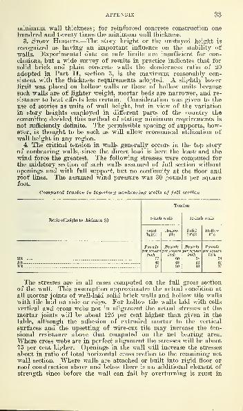
APPENDIX 33
minimum wall thickness; for reinforced concrete construction onehundred and twenty times the minimum wall thickness.
3. Story Heights.—The story height or the unstayed height is
recognized as having an important influence on the stability ofwalls. Experimental data on safe limits are insufficient for con-clusions, but a wide survey of results in practice indicates that for
solid brick and plain concrete walls the slenderness ratio of 20adopted in Part II, section 3, is the maximum reasonably con-sistent with the thickness requirements adopted. A slightly lowerlimit was placed on hollow walls or those of hollow units becausesuch walls are of lighter weight, mortar beds are narrower, and re-
sistance to heat effects less certain. Consideration was given to theuse of stories as units of wall height, but in view of the variation
in story heights employed in different parts of the country thecommittee decided this method of stating minimum requirements is
not sufficiently definite. The permissible spacing of supports, how-ever, is thought to be such as will allow economical utilization ofwall height in any region.
4. The critical tension in walls generally occurs in the top storyof nonbearing walls, since the direct load is here the least 1 and thewind force the greatest. The following stresses were computed forthe midstory section of such walls assumed of full section withoutopenings and with full support, but no continuity at the floor androof lines. The assumed wind pressure was 30 pounds per squarefoot.
Computed tension in top-story nontearing walls of full section
Ratio of height to thickness (t)
Tension
8-inch walls 12-inch walls
Solidbrick
Hollowtile
Solidbrick
Hollowtile
20t
Poundsper square
inch574536
Poundsper square
inch604839
Poundsper square
inch5443
Poundsper square
inch584718t
16t
The stresses are in all cases computed on the full gross section
of the wall. This assumption approximates the actual condition at
all mortar joints of well-Wd solid brick walls and hollow tile walls
with tile laid on side or edge. For hollow tile walls laid with cells
vertical and cross webs not in alignment the actual stresses at the
mortar joints will be about 125 per cent higher than given in the
table, although the adhesion of extruded mortar to the vertical
surfaces and the upsetting of wire-cut tile may increase the ten-
sional resistance above that computed on the net bearing area.
Where cross webs are in perfect alignment the stresses will be about
75 per cent higher. Openings in the wall will increase the stresses
about in ratio of total horizontal cross section to the remaining netwall section. Where walls are attached or built into rigid floor orroof construction above and below there is an additional element ofstrength since before the wall can fail by overturning it must in

34 RECOMMENDED MINIMUM REQUIREMENTS
tipping lift the construction above, thereby increasing the direct
load assumed by the wall from the floor construction, thus increasingthe stability of the wall.
There is little experimental data available on the transverse strengthof brick and tile masonry as limited by the tension in horizontaljoints. Tests made at various times at the Bureau of Standards onnine walls of side construction tile tested under center or 2-pointlateral load and a small direct load (5 to 20 pounds per square inch)gave an average value of 92 pounds per square inch outer fiber stress
in tension, with a range from 40 to 252 pounds per square inch. Themortar proportions varied from 1 : 3 Portland cement and sand, to
1: y2 :
3
y2 Portland cement, hydrated lime, and sand, all measure-ments by volume. Similar tests of two solid brick walls gave tensionvalues of 173 and 124 pounds per square inch and for a hollow brickwall (Ideal all-rowlock) 136 pounds per square inch as computed forthe gross wall section, and 151 pounds per square inch as computedfor the net bearing section, the mortar being 1 : 3 Portland cementand sand. It is apparent that the tensional stress can not exceed thetensional strength of the mortar and may be less due to lack ofperfect adhesion between the mortar and masonry units.
5.
In general, a 4-inch increase in wall thickness is not consid-
ered adequate as a substitute for the independent support pre-scribed in Part II. It is strongly recommended where exposuresare extreme or high winds prevail that long bearing walls bebroken as often as possible by angles or cross walls, and that chim-neys, elevators, and stair shafts be so placed as to reinforce suchlong walls whenever possible.
PARAGRAPH 13. ELEMENTS AFFECTING STRENGTH OF BRICKWORK
Following is a list of the factors affecting brick masonry strengthwhich through study of the experiments mentioned in paragraph11, it is possible to evaluate.
1. Masonry strength as related to strength of individual brick.
2. Mortar, materials and proportions.3. Ratio of height of wall or pier to its thickness.
4. Bond and jointing.
5. Workmanship.6. Age of masonry.7. Manner of loading.
1. Masonry Strength as Related to Strength of IndividualBrick.—Practically all the test series studied indicate that, otherconditions being equal, the compressive strength of brick masonryis roughly proportional to that of single brick. Recent experi-ments seem to indicate that the ratio of wall strength to brickstrength is considerably greater for clay brick of low compressivestrength than for those of medium grade or better. Apparentlythe ratio between strength of masonry and that of individual brickincreases as the brick strength decreases, at least down to a strengthapproximately equivalent to the “ medium grade ” of the A. S. T. M.specifications.
Experiments at Columbia University (see item 16, par. 11) indi-
cate that when laid in Portland cement mortar, concrete brick

APPENDIX 35
averaging from 1,500 to 2,500 pounds per square inch compressivestrength tested flatwise, will make a wall about as strong as onebuilt of clay brick averaging 3,000 to 5,000 pounds per square inchtested edgewise.
Tests recently made at the Bureau of Standards on piers andwalls laid in cement-lime mortar also indicate that masonry of con-crete brick has -greater strength than that of clay brick havingequal unit strength tested individually.
Test data furnished by the Bureau of Standards indicate that,
in general, the compressive strength of brick walls built of several
varieties of brick, all laid in cement-lime mortar, varies from 15to 40 per cent of the strength of the individual brick when the latter
are tested flatwise, with the range running considerably higherwhen compared with the compressive strength edgewise.
Tests on concrete brick piers in the investigation at ColumbiaUniversity mentioned above showed ratios of pier strength to brickstrength tested flatwise ranging from 43 to 95 per cent when 1 to 3Portland cement mortar was used. These results were exception-
ally high and have been the subject of much discussion.
The various investigations to which the committee had access
indicate that for any particular variety of brick the actual strength
of masonry is dependent upon other properties than strength ofthe uni ts alone. Undoubtedly quality of the mortar and the ef-
fectiveness of the bond between brick and mortar are importantfactors in the problem. The latter, in turn, is influenced by thepercentage and rate of absorption of the brick and particularly
by the degree of roughness of the brick surface. The tests giveevidence that masonry built of rough-surfaced brick has higherrelative strength to the individual units than develops with smooth-surfaced brick. This may be responsible to some extent for thegood showing made in tests of concrete and sand-lime brick of lowcompressive strength and rough surface texture. For further in-
formation on compressive strength ratios of brick masonry to in-
dividual units and their relation to the factor of safety, see para-graph 14, experimental data.
Sufficient data are not available on the ratio between modulusof rupture of single brick and the compressive strength of piers toafford a good basis for code requirements, and the variations thusfar disclosed are so wide, for clay brick at least, that no usefulratio can be said to exist. Concrete brick, on the other hand,showed a fairly definite ratio in the tests at Columbia University(see item 16, par. 11). Indications are that the different processes
used in making clay brick influence its modulus of rupture morestrongly than its crushing strength. In the course of recent com-pressive tests on brick walls the headers broke first in almost everycase, indicating that the modulus of rupture is an important ele-
ment in determining the strength of brick masonry. For ease ofcode enforcement, however, it seems that the crushing strength is
a better criterion and more easily interpreted than the modulus ofrupture. No attempt, therefore, has been made to base workingstresses on the modulus of rupture of brick, although it is admittedthat the transverse test is a better indication of quality than hasgenerally been held.

36 RECOMMENDED MINIMUM REQUIREMENTS
2. Mortar, Materials, and Proportions.
—
Customs regarding thecomposition and proportions of mortar vary in different localities,
but it was considered by the committee that sufficient guidance tothose drafting building codes would be afforded if recommendationswere made for five types of mortar, proportioned by volume, asfollows :
1 part Portland cement to not more than 3 parts sand, with per-missible addition of lime not to exceed 15 per cent of the cement.
1 part natural cement to not more than 3 parts sand.
1 part Portland cement, 1 part lime, and not more than 6 partssand.
1 part Portland cement, 1 part lime, and not more than 4 partssand.
1 part lime to not more than 4 parts sand.
Some question was raised by critics of the tentative report as to
the desirable richness of lime mortar. Limes vary in their sand-carrying capacity, but general experience is that proportions of 1 to
4 are adequate for all demands likely to be made on lime mortarmasonry.The addition of a certain percentage of lime to Portland cement
mortar is much preferred to its substitution for part of the cement,as being easier to control and resulting in better mortar. Additionrather than substitution is recommended by the manufacturers ofboth cement and lime.
Investigation of numerous test series showed that with conditionsotherwise equal the strength of masonry laid with 1 to 3 or 1 to 4lime mortar did not in any case average more than 70 per cent ofthat laid with Portland cement mortar, and in certain cases fell aslow as 30 per cent. In assigning lime mortar masonry a workingstress slightly more than one-half that for cement mortar masonry,the committee is influenced rather by long experience with its suc-
cessful use under moderate loading than by its performance in com-parative tests. Lime mortar is known to increase in strength moreslowly than cement mortar, and tests soon after laying probably arenot a fair indication of bearing strength. Masonry in a building,on the other hand, is likely to be subjected to full load within two orthree months and dependence on possible future strength is unjusti-fiable.
The data available indicate that masonry built with cement-limemortar, as defined in Part II, varies in strength from 70 to 85per cent of that laid with cement mortar to which a small percent-age of lime has been added. The limits on working stresses, there-
fore, have been placed approximately at 80 per cent of those forcement mortar masonry.
There are no data available on the strength of masonry laid
with natural cement mortar in which the cement is known to havecomplied with American Society for Testing Materials specifica-
tions. Many early tests, however, were made with natural cementmortar, and the results indicate that so far as strength is concernedthe material is adequate for all ordinary purposes.
3. Ratio of Height to Thickness.—Neither observation of the
behavior of masonry under practical conditions nor study of com-parative test, records indicates that the strength of brick masonry

APPENDIX 37
is affected to any extent by increases of the slenderness ratio be-tween 4 and 20. The headers of walls recently tested in compres-sion gave way fmst, the circumstances indicating failure in tensionor transverse bending, and the ultimate compressive strength of thespecimen is about coincident with this point of failure. The ratioof height to thickness of the wall is less important apparently thanthe spacing of headers. (See Appendix, par. 19.)
4. Bond and Jointing.—In spite of the foregoing, proof is not con-clusive that, within the limits set in Part II, the frequency of head-ers determines the strength of masonry. The limit set in section 6 is
based on standards of general practice rather than on experimentalinvestigations. The tests on brick walls mentioned above indicate theadvisability of closer header spacing in thin sections where com-pressive strength is important. Special bonding stones or metal mesh)between courses have proved ineffective unless placed in every course,
when they improve the strength considerably. The disadvantagesof bond stones spalling under heat exposure more than offset theadditional strength supplied, and the practical difficulties of plac-
ing metal mesh in masonry joints greatly limit its usefulness. Forload-bearing masonry, joints should preferably be as thin as is con-sistent with full bedding of the brick, but they apparently may beas much as three-eighths inch without affecting compressive strength.
5. Workmanship.—The recommendations of Part II are based onthe understanding that supervision or inspection will be suchas to insure good workmanship and utilization of materials. (See.
also Appendix, par. 2.)
The following suggestions as to what should be considered goodpractice in brickwork have been received from various authorities;
on the subject:
Care should be taken to insure even and complete bedding of themasonry units, and joints should be of sufficient thickness to permitthis. Vertical joints of exterior face courses should be butteredand bricks carefully shoved to place. Mortar should not be placedon the beds with a shovel or from the hod, but may, if desired, beplaced with special spreading devices. End joints of interior face
courses should also be carefully filled if the wall is to be furred.
Where dryness is more important in brickwork than compressivestrength no particular attempt to fill interior vertical joints by shov-
ing or slushing in mortar is necessary.
During warm and dry weather all brick should be thoroughlywet just previous to being laid in order that good adhesion may beobtained between brick and mortar and so that sufficient water will
be left in the mortar to permit its acquiring full set.
Brick should be thoroughly dry when laid in cold weather, andfor best results both bricks and mortar should be warm, so that thelatter may obtain at least a partial set before it is frozen.
The tentative draft offered opportunity for report of experiencewith retempered mortar. Such data as were obtained indicate thatmortars of hydraulic cement lose considerably in strength if retem-pered after initial set, but that these losses are not sufficient seriouslyto affect the strength of masonry not stressed near the workinglimits. Except under experienced supervision and for nonbearingmasonry it is recommended that use of retempered mortar be for-bidden.
38 RECOMMENDED MINIMUM REQUIREMENTS
6. Age of masonry.—Working stress requirements, and, in fact,
all recommendations of Part II, are based on the assumption that
brick masonry is not unlikely to be loaded within a period of twomonths to the full extent contemplated in the design. No provision
is made in the recommended working stresses for construction loads,
as it is considered that builders should not be penalized to provide
insurance against careless construction practice. It is doubtful if
reduction in working stresses for this reason would be effective if
made.7. Manner of loading.—Experimental data indicate a sharp de-
crease in bearing capacity when loading is eccentric. This decrease
ranges from 25 to 50 per cent in different series of experiments withsolid walls loaded one-fourth their width off center, but was only 7.3
per cent for hollow walls of brick, due probably to the large numberof headers and the greater proportion of solid material near the wall
surfaces. Available data are not complete enough to justify de-
tailed conclusions, but indicate strongly that eccentricity must beconsidered and that its influence may be computed quite closely byaccepted rules of mechanics.
PARAGRAPH 14. FACTORS OF SAFETY FOR BRICKWORK
Working stress requirements for brickwork determined by inter-
pretation of test data on compressive strength of walls and piers
depends on whether the ultimate compressive strength, or the loadat which cracks, snapping sounds, or other test phenomena occur, is
chosen as the point of failure.
It is established, however, that in individual cases the relation
between the stress causing initial signs of failure and the maximumstress is less certain and the human element more influential onobservation than in the case of recorded maximum stresses. Forthis and other reasons the committee has based its requirements on astudy of ultimate compressive stresses.
It has been customary in building code practice to consider thatestablished stress limits represented a “ factor of safety ” of 10based on crushing strength of the units used in the wall or pier.
This, to a certain extent, is unlike practice with other materials,
such as steel, concrete, and lumber, where the unit strength of thewhole structural member is practically the same as that of smallspecimens. If, in masonry, the factor of safety were applied to thewall or pier as a whole, it would be comparable to the factor usedwith other materials and would be much less than 10. The com-mittee has followed this policy and has chosen its factor of safetywith relation to the ascertained stresses at failure of brick masonryrather than the crushing strength of individual units.
A factor of safety should be increased with the number or im-portance of unregulated or uncontrollable elements affecting the
strength of a material. Conversely, as conditions of use and stand-
ards of quality are better defined and controlled the factor of safety
may be reduced. There has been some attempt in the past to regu-late quality of brick, but for the most part it appears that safety
of brick masonry has resulted rather from design for fictitious floor
loads and from empirical thickness requirements than from any con-
siderable margin of compressive strength over permissible working
APPENDIX 39
stresses. Certain occupancies, especially warehouses, support their
full assumed live loads, but in most cases brick walls are never ac-
tually subjected to the live loads they are assumed to carry.
In arriving at its recommendations for maximum working stresses
the committee has had reference both to careful investigation oftest data bearing on the subject and to successful practice in cities,
such as New York and Boston, where the quality of materials andthe conditions of use are known to have been fairly well controlled.
Experimental data.—Examination of a large group of test data,
including practically all series of importance which have been madein this country in recent years, shows an average ratio of 25 percent between the strength of masonry and that of brick from whichit is built, when tested on edge. This ratio applies only for brickwithin the lower ranges of strength ordinarily used for buildingpurposes. It increases for brick testing below 2,000 pounds persquare inch and decreases for brick averaging above 3,500 poundsper square inch. If brick averaging 2,400 pounds per square inchtested on edge are accepted as representative of the more unfavor-able conditions, the average ultimate compressive strength of bear-ing masonry as regulated by Part II would be about 600 poundsper square inch. This affords a factor of safety of about 3.5 overthe maximum unit working stress provided by Part II, section 4,
for piers of medium brick loaded concentrically and 2.4 for piers
on which the stress due to all factors approaches the maximumallowed in Part II.
To show the possibility of strength variation of piers' built ofthe same grade of materials under similar conditions, 85 smallgroups were selected, alike in all particulars so far as could be dis-
covered from the reports. The maximum individual variation fromthe average strength of each group was computed and was found to
be less than 25 per cent in all except four cases, which ranged from27 to 35 per cent. In 42 groups the variation was less than 10per cent. Variations above and below the average were about equally
balanced.These experiments as noted were all upon masonry piers. Com-
parison of results from the tests of masonry walls (see par. 11, item
18) shows that variations in strength between similar specimens andvariations in the ratio of masonry strength to strength of individual
brick are as great for walls as for piers, thus indicating that the
influence of workmanship and of variation in strength of materials
is not necessarily better compensated throughout the length of a
wall than in piers.
PARAGRAPH 15. STRESSES IN BRICKWORK
1. Though brick work is very old, its design to any appreciable
extent on a working stress basis is comparatively recent. Walls andpiers for many years were proportioned on an empirical basis en-
tirely, and inspection of old structures indicates that most errors
were well on the side of safety. Working stresses as first established
reflected this prevailing spirit of caution, and have since increased
considerably. The figure of 250 pounds per square inch for goodbrick in Portland cement mortar was first written into the code of
New York City in 1898 and has been widely copied.

40 RECOMMENDED MINIMUM REQUIREMENTS
Coincidently with increase of working stresses the number andextent of windows in certain types of buildings increased also. Steeland reinforced concrete construction permitted this without risk andthere was a strong tendency for brick bearing wall structures tocompete. It results that much modern brickwork approaches themaximum allowable working stresses prescribed in codes, and that,
careful analysis of the factors involved is necessary to make surethese stresses are not exceeded. The requirements advocated in PartII are predicated on the assumption that stress computations willtake into account the effects of eccentric loading, the local reactionsof lintels or spandrel arches, the possibility of lateral forces due tomerchandise within or wind pressure without, and of any otherunusual conditions affecting stress distribution.
2. In computing stresses in bearing walls it is usual to includethose due to the total amount of dead loads above the level in ques-tion plus the full live loads for the roof and uppermost floor, andcertain arbitrary percentages of the live loads on floors below theupper, except in buildings used for storage or warehouse purposeswhere no reduction in the floor live loads should be made. Windforces should be considered as producing bending from floor to
floor, and also for high narrow buildings, as producing overturningmoments on the building as a whole.
Further bending stresses are produced by eccentric bearing of thefloor system on the wall. A safe assumption for the latter conditionis to assume an effective moment at the floor line equal to the floor
reaction on the wall of the given story times the distance of the
center of application of this reaction from the center of the wall,,
neglecting all bending effects from the floors above and below;and
at the center of the story height, a moment one-half of that at thefloor lines. This assumes the wall supported against lateral move-ment at the floor lines, but otherwise not continuous. Investiga-
tions postulated on continuity of the wall throughout its height indi-
cate somewhat lower moments than those resulting with the assump-tion made.
Stresses in walls are further increased above those computed for thefull wall area, by openings and chases in the walls, and by concen-trated loads, such as floor beam and lintel reactions. The loads onan arch or lintel are generally considered as those of the wall andAvail bearings coming within an equilateral triangle having the
width of the opening as base. The stress produced by heavy beamreactions, particularly where the end of the beam is built solidly
into the masonry should be taken into account, in computing maxi-mum wall stresses. The reactions immediately under light closely-
spaced joists need,be added only to the general wall load for thepurpose of determining direct stresses, since they are distributed intothe masonry within a comparatively short distance below the bear-ings, adding in all cases bending stresses produced by eccentric bear-ings. The eccentricity of the loads is usually increased by thedeflection of the floors, producing maximum pressures at the innerface of the wall.
Computation of stresses for typical buildings indicates that withthe given limitations on story heights, the thinnest wall thicknesses
permitted by the recommendations of Part II, section 4, are ade-

APPENDIX 41
quate for the relatively light loads involved in residence occupancy,hut that for heavier floor loads and floor constructions it will fre-
quently be necessary to increase thicknesses beyond these minima.
PARAGRAPH 16. THICKNESS OF BRICK WALLS
1. Wall thicknesses specified in Part II are nominal, referring to
the minimum thickness obtainable with building units of standardsize. It is common in some parts of the country to designate brickwalls as 9, 13, and 17 inches in thickness, but with the standardiza-tion of brick and tile sizes now becoming general, it is more correct
to express the dimensions as 8, 12, and 16 inches.
2. The difference in treatment of residential and commercialbuildings less than 30 feet in height is based in part on the results
of a series of questionnaires, submitted to building inspectors, in-
surance rating organizations, and fire chiefs. These returns may besummarized as follows:
Building inspectors .—Of about 80 building inspectors who ex-
pressed their opinions on this subject, 75 per cent approved the use
of 8-inch walls for two-story residences and 15 per cent considered
them adequate for three-story buildings. These replies were con-
cerned only with one and two family dwellings. For light com-mercial occupancies 7 respondents only would allow 8-inch walls upto three stories, 30 would permit them two stories in height, and 14would confine them to one story. Thirteen inspectors consider thatcommercial occupancies demand a 12-inch wall under all circum-stances, 5 would make the first story of a three-story commercialstructure 12 inches
;and 2 would require the lower two stories to be
12 inches or thicker.
Insurance organizations .—Through their work in adjusting claimsthese have much experience with the relative stability of 8 and 12inch walls, as affected by fires. The consensus of opinion among the
37 reports received strongly supported the 12-inch wall as havinggreater resistance to bulging and collapsing under heat effects;
against damage from falling timbers; and as providing a superiorfire stop between small buildings. Its salvage value also is greater,
though this, of course, is an item with which a building code is notconcerned.
Fire chiefs and fire marshals .—Practically all of the 55 respondentswho had fought fires in buildings with 8 and 12 inch walls favor thelatter as less likely to collapse under a hot fire or the action of floor
beams, with resultant danger to firemen.
In view of the above consensus of opinion and of considerationselsewhere mentioned, and of the heavier floor loads and hotter fires
to be expected in commercial buildings, the committee decided to
limit 8-inch walls for these occupancies to one story.
3. In permitting the same minimum wall thickness for commercialor industrial buildings as for* the larger residential buildings, thecommittee had reference to the following considerations.
Commercial occupancies which involve vibration likely to affect
wall stability will, in practically all cases, involve live loads whichnecessitate a wall thicker than the minimum.The effects of even the hottest fires on 12 and 16 inch solid brick
walls were shown by the Bureau of Standards’ tests to be unimpor-

42 RECOMMENDED MINIMUM REQUIREMENTS
tant as regards transfer of heat through the walls or their deforma-tion within the period of exposure to be expected with residentialoccupancy.
Heavier floor loads, where not exceeding the allowable unitstresses, increase the vertical components of the applied pressureand add to the stability of walls against lateral forces, therebygiving the industrial building an advantage as compared to theresidential building.Within the economic height limits of buildings with brick bear-
ing walls the industrial or commercial building is more apt to havea rigid interior framework than the residential building.
4. In arriving at the minimum wall thicknesses prescribed inPart II the committee had in mind the usual heights to which bear-ing walls are erected under present economic conditions. Whensuch walls are used for buildings over seven stories in height, special
conditions may affect considerably the desirable thickness, and com-petent professional authority should be consulted.
5. Critics of the tentative draft of this report have suggested thatthe 12-inch thickness provided in Part II, section 5, might extenddown to the nearest line of floor beams in case the 35-foot limit fell
between floors. The 35-foot height, however, allows space for threefair height stories. A 12-inch wall four stories in height is believedundesirable under the circumstances, and three very high stories at
the top of a building are likewise considered inadvisable. Withthese restrictions in mind the 35-foot limit without modification is
seen to involve no particular hardship.6. In stating that roof beams must be horizontal where 8-inch
walls are used for top stories, it was the intention merely to distin-
guish between so-called flat roofs and those where lateral thrust maybe developed by the roof beams.
PARAGRAPH 17 . HEAT TRANSMISSION OF MASONRY WALLS
1. Experiments at the Bureau of Standards with brick masonrywalls of various thicknesses and types of construction have shownthat an 8-inch solid wall properly restrained, will prevent heattransmission to an extent threatening combustion of inflammablematerials in contact with the wall for a period considerably greaterthan the duration of the average fire. The walls were tested ac-
cording to the fire test specifications tentatively approved by theAmerican Engineering Standards Committee and adopted by otherorganizations; the test conditions being probably equivalent in in-
tensity and duration to the general maximum fire conditions obtain-ing in buildings. Temperatures on the outside of the 8-inch solid
clay brick walls did not rise to a point threatening combustion ofinflammable material resting against them on the opposite side until
from five to six hours after the tests were started, and heat trans-
mission through a 12-inch wall was even slower. Walls of sand-lime or concrete brick transmitted heat less readily than walls of
clay brick. Dangerous temperatures 5 on the outside of 4-inch brick
6 Combustible material is liable to begin to char at a temperature of 375 to 425° F. de-
pending upon conditions. In fire tests 300° is assumed as the permissible temperatureon the side of a wall opposite to that exposed to the fire, before the wall is considered
to have reached the danger point as a reliable fire barrier.

APPENDIX 43
walls were reached in from one and one-half to two hours, but dis-tortion due to unequal expansion was such as to indicate theprobability of undesirable cracks in less time. Eight-inch hollowwalls of brick afforded less insulation than solid walls
;temperatures
of 300° F., on the outer surfaces being reached in from two andone-half to three hours. Temperatures on the outside of 12 and13 inch hollow walls of brick were only 200° F. after six hours’test, indicating their reliability as fire walls where 8-inch hollowwalls are inadequate.
Temperatures in the interiors of walls increase more rapidlythan on the outside surfaces and the results indicate that 8-inchparty walls having wood or unprotected metal joists inserted areunwise where fires of long duration are probable.
2. Deflections of 1 to 5 inches occurred in the walls exposed to thefire test at the centers of the panels. Unrestrained walls deflected at
the top more than restrained walls at the center and were found less
likely to come back to the original position after cooling. Twelve-inch restrained walls recovered practically all deformation on cool-
ing and 8-inch walls from one-half to two-thirds. More crackingoccurred in brickwork with cement and cement-lime mortar thanwith lime mortar, but the greater strength and resistance to lateral
forces and erosion obtained with the cement mortars indicate these
advantages outweigh the consideration of cracks. Furthermore, thelime mortar disintegrated badly under heat action causing consider-
able loss in masonry strength. The results indicate that so far asdistortion is concerned, 12-inch restrained walls would be usable after
a fire of average severity, and 12-inch unrestrained walls in somecases; while 8-inch walls, either solid or hollow, are apt to showpermanent distortion unfitting them for further use after severe
fires.
3. The point has been raised that if a satisfactory contact is notsecured at the top of division walls built between fire-resistive floors
or beams they will be unstable under fire conditions. Experiencewith such walls under test shows that the heat expansion forces themtightly against the floors or girders at the top long before muchdeflection can take place. Due to deflection which always occurstoward the fire, the upper edge of the unexposed side of an 8-inch
wall will be parted from the under surface of the floor above, after
two or three hours’ exposure, but observation of several cases hasdisclosed no heat transmission at this location greater than may occurat any crack in the wall surface. There is small chance, further-
more, that combustible material will be stored close to the openingsthus caused.
Care should be taken to ensure that spaces at the tops of all suchwalls are completely filled with mortar, and the walls tightly wedged.
Twelve-inch walls under similar circumstances do not part fromthe floor surface above to an appreciable extent.
In view of the foregoing, the committee has decided that wallsthick enough to meet the general requirements for stability and com-pressive strength will be of sufficient thickness to withstand ordi-nary fire exposures and that except in the case of fire walls betweenbuildings or parts of buildings where very hot or long continued fires
may be expected, no account need be taken of resistance to heat

44 RECOMMENDED MINIMUM REQUIREMENTS
transmission in deciding upon the necessary thickness of walls. (Seealso Appendix, par. 18-7.)
The proper protection of openings of every character in suchwalls is much more vital than the consideration of wall thickness.
PARAGRAPH 18. FACTORS AFFECTING STABILITY OF WALLS
Consideration was given to a number of factors, which by affect-
ing the stability of walls, exert an influence on thiclmess requirementsadditional to that of unit working stresses. Building codes fre-
quently recognize the importance of these factors by calling for
greater wall thickness or other precautions where their influence is
thought to be dangerous, and it is believed that a statement as to
their relative effects on stability will be useful.
1. Foundation Conditions.—The stresses and wall thicknesses
recommended in Part II are based on the assumption that founda-tions will be sufficient to prevent settlement threatening the integrity
of the wall. For the purposes of wall design it should be assumedthat foundations are adequate and the wall is a unit.
2. Vibration.—Ordinarily vibration due to street or railway traf-
fic or to machinery within a building does not seriously affect goodbrickwork. Where such vibration is excessive, additional wall thick-
ness is of doubtful value. Where there is possibility of earthquakeshocks extra care should be taken to anchor intersecting walls to-
gether, and to tie the structural frame of the building to the walls.
Observations made after the recent earthquake in Japan are to theeffect that high masonry walls should not be built in localities subjectto earth shocks.
3 . Height and Width or Buildings.—From a structural view-point no limits are recommended affecting the relation of heightto width of buildings built with brick or plain concrete bearingwalls. Under present conditions such buildings are scarcely everbuilt over six stories and for walls of this height the effects ofgreater or less width on stability is usually unimportant. Forextremely high and narrow buildings increased wall thickness will
not generally confer the additional stability required.
4. Methods of Anchorage.—Regulations affecting the methodsof supporting or anchoring floor timbers, or of attaching walls
to intersecting walls or partitions, are considered outside the scopeof Part II of this report. In general, such connections shouldbe rigid in nature; adequate to transmit such lateral forces as
may occur and to develop the full supporting effect between struc-
ture and wall; and of a design which admits release of the floor
beam or slab in case of fire without serious resulting damage to
the wall. If these conditions are met the wall thicknesses per-
mitted in Part II will be found sufficient so far as this factor is
concerned. Nonbearing as well as bearing walls should beanchored into the floor construction since they are in themselvesless stable. (See Appendix, par. 32.)
5 . Rigidity of Floors.—The question has been raised as to
whether, other conditions being equal, the rigidity of fireproof ormonolithic or mill constructed floors does not differ sufficiently fromthat of joisted floors to justify different wall thicknesses for build-

Minimum Masonry Wall Requirements
Fig. 2.
—
Compression test of 8-inch solid wall of brick. Note failure due
to breakage of headers. Bureau of Standards, Washington, D. C.

Minir Masonry Wall Requirements
Fig. 3.
—
Compression test of 8-inch hollow wall of brick. Bureau of
Standards, Washington, D. C.

APPENDIX 45
ings of these types. The committee has received no evidence tend-
ing to establish the importance of this difference.
6. Influence of Span.—Many building codes establish limits ofspan for floors supported by bearing walls, requiring a greater wallthickness where such limits are exceeded. This practice is believed
to date back to the era when working stresses for masonry werenot limited directly, but by controlling the live loads likely to comeupon the walls. Where masonry stresses are kept within the limits
prescribed in Part II, the span of floor beams should not affect therequired thickness of masonry walls.
7. Fire Exposure.-—Results of a fire-test series at the Bureau ofStandards, made with 11 by 16 foot wall panels of various thick-
ness, indicate clearly that if sufficient provision is made, as in PartII, for bearing strength and structural stability and for joist re-
lease, fires of the usual duration and intensity will not seriously
displace 12-inch brick walls. In the case of the 8-inch exterior wallspermitted for one and two family dwellings three stories high andtop stories of other low buildings, the consequences are consideredto be relatively unimportant, even if failure should occur.
8. Wind Pressure.
—
In some places which are subject to highwinds, trouble is experienced with thin masonry walls, but no evi-
dence has been received indicating that where the structural frame-work of a building affords reasonably rigid support to the inclosingwalls, the pressure resulting from maximum wind velocities in mostparts of this country is an important factor in wall design. Neitheran 8-inch nor a 12-inch wall of any considerable height has theinherent stability to resist high wind pressures, but if the buildinginclosed possesses sufficient mass and stiffness to resist collapse as a
whole, it appears that, so far as wind pressure is concerned, eventhe lesser wall thicknesses may be employed freely within the limits
prescribed in Part II.
9. Percentage and Arrangement of Openings in Walls.—It is
customary in about one-third of existing codes to require that bear-
ing walls be increased 4 inches in thickness when a certain per-centage of the wall section (varying in different codes from 25 to
55 per cent) in any horizontal plane is removed for openings. Thispractice is a survival from the period when maximum masonrystresses were not prescribed and the increase of thickness was re-
quired to take care of possible excessive stresses in walls thus re-
duced in section. If the compressive stresses in masonry walls andpiers are kept within the limits prescribed in Part II, and if serious
eccentricity in loading of piers and short wall sections is avoided, it
is believed unnecessary to require increases in wall thickness onaccount of openings.
PARAGRAPH 19. BOND FOR BRICK WALLS
Recent tests on brick walls and piers show that failure usually
occurs through breaking of the headers and indicates the need of a
greater proportion of these than is generally customary in load-
earing masonry. (See figs. 2, 3, and 4.) A lesser ratio of headers to
stretchers is permissible for nonbearing brick walls or for the attach-
ment of brick veneer.

46 RECOMMENDED MINIMUM REQUIREMENTS
PARAGRAPH 20. HEIGHT OF BRICK PIERS
1. The tests of brick masonry piers (see Appendix, par. 11) dis-
closed very little difference between the strength of piers five andten times their least dimension in height, other conditions beingequal. Not enough data are available by which to establish the rela-
tive strength and stability for piers of greater slenderness ratio.
In the tentative draft of this report recommendations allowing wallsections an unsupported height of twenty times their thickness andpiers only ten times their least dimension were strongly criticized,
and it was apparent that the line between piers and walls must bedrawn more definitely than is now customary code practice. Thelimit established in Part II, section 7, will not cause hardship withordinary window and story heights, but will avoid very thin wallsections where stories are high and openings closely spaced.
2. Bond stones at intervals in the pier section are not advocated.They provide opportunity for concealing poor workmanship; theydo not add materially to the bearing capacity of brickwork; andthey are apt to split under fire exposure, causing failure of the pier.
PARAGRAPH 21. HEIGHT OF MASONRY WALLS
In view of the liberal requirements recommended for solid brick,
stone, and plain concrete walls, consideration was given to the
question whether they should be limited in total height. There are
certain types of structures, however, for which such limitations are
unnecessary and in fact undesirable. In general, economic factors
will influence choice of steel or reinforced concrete for buildings
over 75 feet high. Where brick or plain concrete bearing or non-bearing walls are used for greater heights they should receive verycareful inspection, both as to design and workmanship. Founda-tion and footing design should also be carefully investigated.
PARAGRAPH 22. LINING EXISTING WALLS
Old walls should be cleaned of all plaster or other coating before
the lining is built in order to afford good bond for the mortar. Inaddition to toothing, it is well to provide anchorage by suitable
wrought iron or steel anchors placed in staggered rows not morethan 2 feet apart vertically and horizontally. Such anchors may beattached to the old wall by through or expansion bolts, or by otherapproved methods.
PARAGRAPH 23. LINTELS
Arch lintels may be constructed successfully of hollow tile, butthe most practical form of tile lintel is made by butting a sufficient
number of tile end to end, filling the cells completely with concrete,
and inserting reinforcement rods in the lower tier of cells, therebyobtaining the effect of a reinforced concrete beam. The coarse
aggregate for such filling should not exceed one-half inch diameter.
PARAGRAPH 24. QUALITY OF HOLLOW TILE AND CONCRETE BLOCKOR CONCRETE TILE
1. During the last two years compression and absorption tests ofhollow tile from 28 representative sources have been made by theBureau of Standards. Freezing tests are also being made on tile

Minimum Masonry Wall Requirements
Fig. 4.
—
Compression test of large brick pier in 10,000,000-pound machine.
Bureau of Standards laboratory at Pittsburgh


APPENDIX 47
from 18 sources. Basing judgment on structure, strength, and freez-
ing effects tile from all but four sources could be used in a wallexposed to the weather. The absorption of each of these four lots
of tile was above 16 per cent.
All of these absorption figures were based on determinations withspecimens which had been saturated by boiling 5 hours, but com-parative tests at the bureau have shown that the differences in ab-
sorption indicated by 1 and 5 hour boiling tests are not signifi-
cant. Due to the thinness of material tile differ in this respect
from clay brick, for which a 5-hour test is advisable.
The bureau’s experience is that the determination of absorption byboiling is preferable, as it requires less time and gives more definite
and conclusive results. For sampling, the method given in thetentative specifications for Hollow Burned-Clay Load-BearingBuilding Tile of the American Society for Testing Materials is
recommended. Tile having an average absorption greater than 16per cent should not be used in a wall exposed to the weather, or in
foundation walls unless it shows adequate resistance in freezingtests.6 As different types of clays are used in the manufacture ofhollow building tile, color should not be taken as indicative of per-centage absorption or quality.
2. Tentative specifications for quality and testing of clay hollowload-bearing wall tile have been adopted by the American Societyfor Testing Materials.
The following are excerpts from these tentative standards:
According to the result's of physical tests, tile shall be classified as hard,medium, soft, on the basis of the following requirements
:
Class
Percentage absorption Compressive strength based on gross area
Mean of 5 tests
Indi-vidualmaxi-mum
End construction Side construction
Mean of 5 tests
Indi- *
vidualmini-mum
Mean of 5 tests
Indi-vidualmini-mum
HardMedium
12 or less
12 to 16...151928
1,800 or more1,800 to 1,400
1, 400 to 1,200
1,4001,000
700
1,000 or more1,000 to 700
700500350Soft 16 to 25... 700 to 500
Where end construction tile are used on side, they must meet the require-
ments of that construction, and vice versa.Tile under these specifications shall have the following dry weights deter-
mined as hereinafter specified
:
Size of unit (in inches)Numberof cells
Standardweight
Zz/i by 12 by 12, end construction 3
Pounds20
6 by 12 by 12, end construction 6 308 by 12 by 12, end construction 6 3610 by 12 by 12, end construction. 4212 by 12 by 12, end construction 6 483 by 5 by 12, side construction 1 •9
8 by 5 by 12, side construction. _ .. _ 16
8 by 5 by 12 (L shaped), side construction _ 4 16
8 by by 12 (t shaped),side construction 4 16
8 by 7^4 by 12 (square), side construction __ 24
8 by 1034 by 12 (H shaped), side construction 7 32
A tolerance of 5 per cent from the standard weights and a variation of notto exceed 3 per cent in the standard sizes is permitted.
6 See Appendix, par. 9-2, for freezing test requirements for building brick.

48 RECOMMENDED MINIMUM REQUIREMENTS
3. For purposes of code enforcement it has been found desirablethat concrete units be marked with the manufacturer’s distinctivebrand, and that the product be tested from time to time by a reliable
laboratory. Specifications for testing concrete blocks can be obtainedfrom the secretary of the American Concrete Institute.
4. The crushing strength required for acceptable concrete blockand tile is justified as being within the average demonstrated strengthof the material, also by the fact that the comparatively thick shells
and webs of the former afford a better distribution of stress in themortar joints.
PARAGRAPH 25. WORKING STRESSES FOR HOLLOW WALLS
1. After thorough consideration, the working stresses for tile laid
with cells vertical and those with cells horizontal have been made thesame. Tile laid with cells horizontal has the same net bearing areain the wall as it has when tested individually in that position. Withend construction tile, some or all of the vertical cross webs may notbe vertically aligned as set in the wall, thereby reducing the effective
bearing area below that in tests of individual units. It is believedthat this condition, together with the somewhat more uniform bed-ding of tile laid horizontally offsets the difference in strength be-tween individual units tested with cells vertical and horizontal. Thestresses given in Part II, section 11, will in almost all cases permitutilization of tile to the full limits of height and thickness per-mitted, and the factor of safety involved is considered adequate.When walls of hollow tile are built entirely with cells vertical andwith webs carefully superposed their strength is materially increased,
and may in some cases be 50 per cent greater than when tile are laid
horizontally.
2. The committee’s investigations have shown the desirability ofthorough tests by responsible authorities to determine the relative
strength of tile walls laid both with cells horizontal and vertical.
An extensive series of tests is now in progress at the Bureau of Stand-ards, but will not be completed in time to utilize results in this
report.
3. It is the committee’s belief that tile units should not be usedhaving a thickness greater than 814 inches, measured at right angles
to the wall face. For walls over 8 inches thick, more than one emit
should be used to make up the thickness, and bond should be pro-
vided.
4. Recent tests by the Bureau of Standards indicate that hollowwalls of brick laid in all-rowlock bond (see fig. 3) have practically
the same compressive strength as solid walls of the same thickness
when loads are applied concentrically, and somewhat greater strength
if loaded eccentrically. In the absence of fuller experience with its
possibilities of adaption to various building details, and for large
buildings, the committee hesitates to approve its use for heights
or stresses exceeding those prescribed in Part II.
The committee limits its recommendations for use of hollow walls
of brick to the type built with alternate headers and stretchers in each
course and known as “ all-rowlock bond,” until it obtains sufficient in-
formation on the merits of other types to justify their recognition.
(For discussion of hollow concrete walls, see Appendix, par. 27-2
and -3.)

APPENDIX 49
PARAGRAPH 26. SUPPORT FOR SLABS, BEAMS, AND GIRDERS
The requirements of Part II assume that adequate measures willbe taken to distribute local reactions of beams and heavy girdersthroughout the wall. Hollow walls or those of hollow units shouldhave two or three* solid courses of brick beneath the joists, or thecourse of hollow units on which the joists rest should be filled solidwith concrete. The filling of isolated piers of hollow units with con-crete is believed to add to their stability and to increase their
serviceability under fire exposure. No increase in loading is war-ranted because of the filling.
PARAGRAPH 27. CONCRETE WALLS—SOLID AND HOLLOW
1. Materials.—The maximum permissible size of large aggregatefor thin walls should be governed by the thickness of the smallest
construction member in which the concrete is placed, in general notmore than one-third of such least dimension.In the process of manufacturing aggregate there often are small
amounts of grits or coarse sand that come over the screens with thecoarse aggregate. A tolerance of 15 per cent of such material speedsup production, lowers prices, and does not appreciably affect results
with plain concrete. For the purposes in mind it is of little im-portance whether the screen prescribed for separating coarse aggre-
gates has round or square holes.
Where crushed slag is used as an aggregate for building construc-
tion it should meet the requirements of the tentative specifications
for concrete aggregates of the American Society for Testing Ma-terials.
The admixture of lime in volume not to exceed 10 per cent of thevolume of cement may safely be permitted for plain concrete walls.
(See Appendix, par. 10-4.) Where walls of plain concrete exceed35 feet in length, expansion joints should be provided to preventunsightly cracks in the structure.
2. Several systems of construction are used which produce hollowor double walls of plain concrete. Usually there are two shells,
each 3 or 4 inches thick, with an air space between. The inner andouter parts of such walls generally are tied together with wires ormetal strips sufficient for stability in small dwellings, but if the areaof both walls is needed for compressive strength and stability, posi-
tive means is required to bring them into common action. Unlesssome device or method adequate to do this is provided, the use of
such walls for commercial structures over two stories in height orresidences more than three stories is not advocated.
3. It is recognized that a hollow wall of plain concrete havingthe same net cross sectional area as one of concrete block would besomewhat thicker. It may be said, however, that concrete block are
better controlled as to quality, and their action under load is better
known at this time than that of hollow concrete walls.
4. Attention is especially directed to the fact that quartz gravel orother gravel having high siliceous content is a poor fire resistive
aggregate, and should not be used in concrete liable to be subjectedto fire, unless adequately protected.

50 RECOMMENDED MINIMUM REQUIREMENTS
PARAGRAPH 28. WALLS AND PIERS OF STONE MASONRY
1. Where cut or squared stone of small size, such as quarry wastes,are used to lay up solid walls of moderate height the thickness neednot be greater than that required for solid brick walls.
2. The tentative draft of this report restricted stone piers to openor unexcavated places on account of their tendency to spall underheat exposure. This requirement has been omitted as too stringent.Piers in unexcavated spaces are apt to be poorly constructed. Thosein monumental buildings and other similar locations are seldom ex-posed to intense heat until the building has reached a state of de-struction which renders their failure unimportant.
PARAGRAPH 29. PARAPET WALLS
1. To satisfy architectural considerations and eliminate expensethe requirements for parapet walls have been omitted wherever possi-
ble. When not provided along the edges of flat roofs on highbuilding, iron railings or other suitable barriers should be furnishedfor protection of firemen and safety of occupants.
2. Unless carefully moisture-proofed with stucco or other protec-
tive material, clay hollow building tile are undesirable for parapetwalls in parts of the country where freezing conditions occur. Whennot thus protected they are apt to become filled with water, whichmay freeze and break the tile.
PARAGRAPH 30. FOUNDATION WALLS
1. It has been customary to require that foundation walls be madethicker than those immediately above them. The committee does notbelieve this necessary in all cases. A foundation wall acts both as
a bearing wall and a retaining wall. As a bearing wall it has fewor no openings compared to the walls above it, and its unit com-pressive stresses are usually lower. As a retaining wall it owes prac-tically all its stability to the weight resting upon it, and except in
very thin walls the addition of 4 inches of thickness increases its
resistance to side thrust very little. Where analysis of the forces
acting upon it discloses combined stresses greater than those providedin Part II, sections 4, 11, and 19, or where such forces may causetension in the masonry, the thickness should be increased.
2. Foundation walls should be waterproofed with cement plaster,
or other effective means, and unless surrounded by sand or gravel,
or otherwise naturally drained, should have open tile drains aroundthe footings on the outside discharging into an outfall at a lowerlevel.
PARAGRAPH 31. NEW MASONRY CONSTRUCTION
1. A building code should encourage progress in the art of con-
struction, and to this end should provide for approval and utiliza-
tion of new materials or methods immediately on demonstration that
they meet the requirements of the situation under which it is
proposed that they be used. Two sections therefore have been in-
cluded in Part II (No. 39 on alternate requirements for fire anddivision walls, and No. 45 on new masonry construction) and several
minor references made which provide for such action.

APPENDIX 512.
The adequacy for fire and fire division walls of a special gradeof cinder concrete blocks of less thickness than prescribed in sections
37. and 38 for such walls of hollow units has already been demon-strated, and other similar possibilities are now under investigation.
The successful use of gypsum masonry units, properly protected
against moisture, for exterior walls is reported in several localities,
and specifications for quality of structural gypsum products are un-der consideration by a subcommittee of the American Society forTesting Materials. Commercial production of hollow units of lime is
also understood to be contemplated.
A somewhat greater, factor of safety is recommended for masonryof such new materials, or constructed by novel methods until suchtime as it has demonstrated continuing strength and integrity underservice conditions.
PARAGRAPH 32. ANCHORAGE OF WALLS•
1. The following is a description of what is considered good prac-
tice in satisfying the requirements of Part II, section 47. Wherewalls are not built at the same time, the perpendicular joint shouldbe regularly toothed with 4-inch offsets, and the joint should be pro-
vided with anchors not less than 2 by % inch metal, with bent upends or cross pins to form anchorage; such anchors should be notless than 3 feet long, extending 18 inches on each side of the joint
and spaced not more than 3 feet apart in height.
2. Each tier of floor joists should be securely anchored to masonrywalls with T-shaped steel anchors at intervals of not more than 6
feet. Anchors should be attached in a way to afford easy release in
case of fire burning through the joists.
3. The ends of lapped joists resting upon girders or bearing parti-
tions should be securely spiked. When abutted they should be con-nected with steel straps or dogs.
4. Joists running parallel to masonry inclosing walls should beanchored to the walls at least once between bearings with steel
anchors. Such anchors should extend back and engage at least threejoists.
5. Girders should be anchored to the walls and fastened to eachother in suitable manner with steel straps.
6. When inclosing walls are of wood, each joist, beam, and girderentering same should be securely spiked or anchored to the wall con-struction. Where joists rest upon ledger or ribbon boards theyshould be securely spiked to the studs.
7. The roof structure where resting on masonry walls should havesteel anchors not less than four-tenths square inch in cross section, ex-tending down into the wall not less than 2 feet, and spaced not over6 feet apart.
8. Anchors for attachment of facing or veneering to the backing,as required in Part II, sections 30 and 35, should be not less thanthree-sixteenths by 1 inch in cross section, and should either be bentor of sufficient length to develop their full strength in bond. Suchanchors should be thoroughly protected from moisture, or should beof noncorrodible metal.

52 RECOMMENDED MINIMUM REQUIREMENTS
PARAGRAPH 33. PROFESSIONAL ASSISTANCE RENDERED
Representatives of the following organizations cooperated in prep-aration of this report. Their suggestions were not in all cases
adopted, and their complete indorsement of the report is not im-plied, but the committee wishes to acknowledge their helpful interest
and assistance:
American Concrete Institute.
American Face Brick Association.American Institute of Architects.American Institute of Consulting Engineers.American Institute of Steel Construction.American Society of Civil Engineers.American Society of Safety Engineers.American Society for Testing Materials.Associated Engineers of Spokane.Associated Metal Lath Manufacturers.Builders Exchange of Norfolk.Building Officials Conference.Building Trades Employers’ Association of the city of New York.Detroit Engineering Society.Engineering Association of Nashville.Engineering Society of Western Massachusetts.Engineers’ Club of Minneapolis.Florida Engineering Society.General Contractors of San Francisco.Indiana Engineering Society.Indiana Limestone Quarrymen’s Association.National Board of Fire Underwriters.National Brick Manufacturers’ Association. »
National Fire Protection Association.National Lime Association.National Sand and Gravel Association.New York Board of Fire Underwriters.Office of Supervising Architect, United States Treasury Department.Oregon Chapter, American Association of Engineers.Portland Cement Association.Rochester Engineering SocietySafety Institute of America.The American Society of Mechanical Engineers.The Cleveland Engineering Society.
The Common Brick Manufacturers’ Association of America.The Connecticut Society of Civil Engineers.The Gypsum Industries.The Hollow Building Tile Association.
PARAGRAPH 34. SELECTED BIBLIOGRAPHY OF INFORMATION ONMASONRY CONSTRUCTION
GENERAL
Standards of the American Society for Testing Materials, 1924.
(Published triennially by the society, 1315 Spruce Street, Philadel-phia, Pa.)
Proceedings of the American Society for Testing Materials.
(Published annually by the society, 1315 Spruce Street, Philadel-
phia, Pa.)Proceedings of the American Concrete Institute. (Published an-
nually by the institute, 1807 East Grand Boulevard, Detroit, Mich.)Proceedings of the Building Officials’ Conference. (Published
annually by the conference.)
APPENDIX 53
la. Brick: Quality of Materials.—Brick,cement
,lime, etc.
—
Standards of the American Society for Testing Materials. Issuedtriennially by the society. Present issue 1924, pages 578-583. AlsoTentative Standards, issued annually.
lb. Brick Masonry.—Working stresses.—1. Tests of eight brickpiers at Watertown Arsenal in April, 1882, under supervision of
F. E. Kidder, in the interests of the Massachusetts CharitableMechanic Association. Variables.—Mortars. Tests.—Compressivestrength of bricks and piers. Kidder, F. E., crushing strength of
bricks and of brick piers, (1) American Architect and BuildingNews, vol. 11, pp. 256-258; June 3, 1882. (2) The Architect’s andBuilder’s Pocket-Book, by F. E. Kidder, 1st ed., pp. 169-173; 1885.
(3) Abridged in Kidder’s The Architects’ and Builders’ Handbook,.17th ed., pp. 271-272; 1921.
2. Tests of 12 brick piers at Watertown. Arsenal for the city ofPhiladelphia in 1883. Variables.—Four kinds of bricks, two kindsof mortars. Piers live courses high. Tests.—Strength and com-pression of piers. McArthur, John, jr., “Tests of building materialmade at the Watertown Arsenal, Mass., by the United States Ord-nance Department, at the request of the commissioners for the erec-
tion of the Philadelphia public buildings.” Tests of Metals, etc.,.
1884, p. 501, United States Ordnance Department, Watertown Arse-nal, Mass. Published in part in Trans. Am. Soc. of Civil Engineers,vol. 15, pp. 718-722
;October, 1886.
3. Tests of 33 brick piers at Watertown Arsenal, etc. Variables.—Bricks, mortars, breaking of joints, bricks flat and on edge, heightand cross section of piers solid and hollow, and age. Tests.—Com-pressive strength of bricks, mortars, and piers
;compression of mor-
tars and of piers. Tests of Metals, etc., pp. 69-124; 1884. Trans.Am. Soc. of Civil Engineers, vol. 18, p. 274; June, 1888. Royal In-stitute British Architects, Report on Brickwork Tests, pp. 138-139
;
1905 (abridged).4. Tests of 53 brick piers at Watertown Arsenal, in 1886 and 1891,
under supervision of J. E. Howard. Variables.—Bricks, height andlateral dimensions of piers, bondstones, grouting, solid and hollowpiers, one without mortar, and age of piers. Tests.—Strength andcompression of bricks and of brick piers. (1) Tests of Metals, etc.,
pp. 1138-1161; 1885. Tests of strength and compression of brickssame as used in pier tests reported in 1886 and 1891. (2) Tests ofMetals, etc., pp. 1691-1742; 1886. (Tests on 48 piers 21 months old.)
(3) Tests of Metals, etc., pp. 739-745; 1891. (Tests on five piers ofsame series six and one-half years old.)
5. Tests of six brick piers at Watertown Arsenal in 1893. (Piersexhibited at World’s Columbian Exposition.) Variables.—Limemortar and neat Portland cement, solid and hollow cores, bricks onedge in one pier. Tests.—Strength and elasticity of piers. Tests ofMetals, etc., pp. 323-334; 1893.
6. Tests of 17 brick piers at laboratory of School of PracticalScience, University of Toronto, 1895-96. Variables.—Bricks, mor-tars, and height of piers. Keele, Joseph, Brickwork Masonry, (1)Engineering Society of the School of Practical Science, Universityof Toronto, Papers and Transaction No. 9, pp. 153-160; 1895-96.
(2) Digest of Physical Tests, vol. 1, p. 219; July, 1896. (3) Re-

54 RECOMMENDED MINIMUM REQUIREMENTS
published with Gillespie’s report at the University of Toronto in“ Applied Science,” vol. 2, p. 69, December, 1908.
7. Tests of 59 brick piers conducted under supervision of Com-mittee of Royal Institute of British Architects, 1895-1897. (1) Streetand Clarke, Brickwork Tests. (Report on first, second, and thirdseries of tests.) Journal, Royal Institute of British Architects,third series, vol. 3, p. 333; April 2, 1896; vol. 4, p. 73; December17, 1896; vol. 5, p. 77; December 18, 1897. (2) Royal Institute ofBritish Architects, Report on Brickwork Tests, 1905. (Republica-tion of Street and Clarke’s reports in book form.)
8. Tests of 18 brick piers at Cornell University in 1897-98, undersupervision of E. J. McCaustland. Variables.—Bricks, height ofpiers, and age. Trans. Assn, of Civil Engineers of Cornell Uni-versity (The Cornell Civil Engineer), vol. 6, 1897-98. (Abstractedby Talbot & Abrams, in Bulletin 27, University of Illinois, Eng.Exp. Sta., September 29, 1908.)
9. Tests of 14 brick piers at Cornell University in 1898-99, undersupervision of E. J. McCaustland. Variables.—Bonding devices in
horizontal joints. Trans. Assn, of Civil Engineers of Cornell Uni-versity (The Cornell Civil Engineer), vol. 8, p. 22, 1899-1900. (Ab-stracts: (1) Burr’s Elasticity and Resistance of the Materials ofEngineering, 6th ed., p. 424, 1903. (2) Talbot and Abrams, in Bul-letin 27, University of Illinois, Eng. Exp. Sta., September 29, 1908.
(3) Bragg, in Bureau of Standards’ Technologic Paper No. Ill,
September 20, 1918.)10. Tests of 26 brick piers at Watertown Arsenal, in 1904, etc.
Variables.—Bricks, mortars, and age. Tests.—Strength and elas-
ticity, Tests of Metals, etc., pp. 421-449;1904. (Tests on Bricks, pp.
453-455.)
11. Tests of 14 piers (13 of clay brick, 1 of sand-lime brick) at
Watertown Arsenal, in 1905, etc. Variables.—Bricks, mortars, solid
and hollow cores, and age. Tests of Metals, etc., pp. 393—413;1905.
(Tests on bricks used, pp. 453—455, 1904, and p. 269, 1907.)
12. Tests of 15 piers (12 of clay brick, 3 of sand-lime brick)
at Watertown Arsenal, in 1906, etc. Variables.—Bricks and mor-tars. Tests.—Strength and elasticity of piers, with compressivestrength of the cement-lime mortar. Tests of Metals, etc., pp. 577-
599; 1906. (Tests of clay bricks given in 1904, p. 453; tests onsand-lime bricks in 1906, p. 617.)
13. Tests of 32 piers ;Ind short columns of clay and sand-lime
brick at the laboratory for testing materials. Purdue University,
in 1906-7. Tests.—Compression of piers and strength of indi-
vidual brick and of mortar. Engineering News, February 25, 1909.
(Abstract by H. H. Scofield presented at the annual meeting of the
Indiana Engineering Society at Indianapolis in January, 1909.)
14. Tests of 32 piers (30 of clay brick, 2 of sand-lime brick) at
Watertown Arsenal, in 1907, etc. Variables.—Bricks, mortars, hol-
low and solid cores, bricks flat and on edge, breaking joints, and age.
Tests of Metals, etc., pp. 291-351;1907. (Tests on sand-lime used,
p. 617, 1906; paving bricks, p. 270, 1907.)
15. Tests of 16 brick piers at University of Illinois Engineering
Experiment Station, 1907, by Talbot and Abrams. Variables.—Bricks, mortars, workmanship, concentric and eccentric loading, andage. Tests.—Strength and elasticity. Talbot and Abrams, Tests
APPENDIX 55
of brick columns and terra cotta block columns. University ofIllinois, Eng. Exp. Sta., Bulletin 27, September 29, 1908.
16. Tests of brick piers at University of Toronto, by P. Gillespie,
in 1908. Gillespie, Peter, Notes on brick and brick piers, AppliedScience, vol. 2, p. 58, December, 1908.
17. Tests of two brick piers at Bureau of Standards Laboratory in
Pittsburgh in 1913, under supervision of J. E. Howard. Varia-bles.—Mortars. Tests.—Strength and elasticity. Howard, JamesE., Tests of two brick piers of unusual size, Eng. Record, vol. 67,
p. 332; March 22, 1913. Clay Worker, vol. 59, p. 420, March, 1913.
18. Tests of 70 brick piers at Columbia University, 1914-15,under supervision of James S. Macgregor. Variables.—Mortars,bricks, and age of piers. Tests.—Strength of bricks, mortars, andpiers; and elasticity of piers. Macgregor, James S., “Report of a
series of tests conducted to determine the compressive strength andelastic properties of brick piers laid up in cement and cement-lime mortars.” Bulletin J of the Hydrated Lime Bureau of theNational Lime Association, Pittsburgh, Pa., pp. 9-32; June 1, 1916.
Reproduced in Bulletin 300, National Lime Association, 1st ed.,
pp. 6-29;1920. Abridged report in Bulletin 300, 2nd ed., pp. 8-12
;
1921.
19. Tests of 50 brick piers at Bureau of Standards laboratory,
Pittsburgh, Pa., under supervision of J. G. Bragg. Variables.—Bricks, mortars, bond, wire mesh in horizontal joints. Tests.—Strength and elasticity of piers. Griffith & Bragg, Some tests uponlarge brick piers, Clay-Worker, Yol. 63. p. 367 ;
March, 1915.
Bragg, J. G. Compressive Strength of Large Brick Piers, Bureauof Standards, Tech. Paper No. Ill; September 20, 1918.
20. Tests of 54 brick piers made at technical high school in
Stockholm, sometime previous to September 1916, under direction
of H. Kreuger. Variables.—Bricks, mortars, age, wire mesh in
horizontal joints, thickness of mortar joints, height of pier, centric
and eccentric loading of piers. Kreuger, H., Die Festigkeit desZiegelmauerwerks, Tonind, Ztg., vol. 40, pp. 597, 602, 609, 615, 621,
627, 633; September 9-21, 1916. Kreuger, H., Brickwork tests andformulas for calculation, Clay-Worker, Yol. 68, pp. 42, 126; Julyand August, 1917. (Abstract in Bureau of Standards Tech. PaperNo. Ill, p. 8; September 20, 1918.)
21. Tests of 14 brick piers at University of Toronto in 1918,under supervision of Peter Gillespie, in interest of Toronto BuildingDepartment. Variables.—Mortars and height of piers. Tests .
—
Strength and elasticity. Pearse, W. W., Strength of Brickwork,Proc. Fifth Annual Meeting of the Building Officials’ Conference,
pp. 25-38; February 7, 1919. Contract Record (Toronto), vol. 33,
pp. 151-155; February 19, 1919.
22. Tests of 12 thin brick walls in 1920 by Oscar Faber, in interests
of British government. Variables.—Bricks, mortars, thickness of
walls. Tests.—Compressive strength and resistance to lateral pull.
“Stability of thin walls” (British Government), Department of
Scientific and Industrial Research Building Research Board, Special
Report No. 3; October, 1921. (Reproduced in part; Carver, Wil-liam, The actual strength of brickwork and its relation to code

56 RECOMMENDED MINIMUM REQUIREMENTS
allowances, Proc. Eighth Annual Meeting of the Building Officials’
Conference, pp. 27-29; April 25, 1922.)23. Tests of 33 solid and hollow (ideal) brick walls at Bureau of
Standards laboratory in Pittsburgh, in 1920 and 1921. Stang, A. H.,Concentric and eccentric loading tests made by the United StatesBureau of Standards on brick panels for Common Brick Manu-facturers’ Association, Brick and Clay Record, vol. 62, pp. 312-314;February 20, 1923.
24. Tests of 131 clay, sand-lime, and concrete brick piers atColumbia University in 1921 and 1922. Beyer and Krefeld, Com-parative tests of clay, sand-lime, and concrete brick masonry, Bulle-tin 2, Department of Civil Engineering testing laboratories, Colum-bia University
;April, 1923.
25. Tests of four brick piers cut from masonry of wrecked build-
ing, 16 years old, in New York City, made at Columbia Universityin 1922, under supervision of R. P. Miller. Miller, R. P., Brickworkfrom buildings, stronger than laboratory specimens, Eng. New-Record, vol. 89, p. 354; August 31, 1922.
26. Tests of 18 large and 18 small walls, of sand-lime brick, at theBureau of Standards, 1924. Variables.—Mortars and thickness ofwalls. Tests.—Strength and elasticity. Stang, A. H., Compressivestrength of sand-lime brick walls. (1) Bureau of Standards, Tech-nical News Bulletin, No. 83, p. 4; March 10, 1924 (progress report)
;
(2) Reproduced in Concrete Products, vol. 24, No. 4, p. 58; April,
1924. (Complete report to be published shortly as a TechnologicPaper of the Bureau of Standards.)
lc. Brick Masonry.—Fire resistance.—1. Fire tests of sand-limeand clay brick walls, Ira H. Woolson, Proc. of the Sand-Lime BrickAssociation; 1905.
2. The fire-resistive properties of various building materials,
R. L. Humphrey. See fire tests of common clay, hydraulic-pressedand sand-lime brick walls, pp. 37, 39, 61, and 77. Bulletin 370,
United States Geological Survey, 1909. (Superintendent of Docu-ments, Washington, D. C., 30 cents per copy.)
3. Fire tests of brick walls, Bureau of Standards, under super-
vision of S. H. Ingberg. Tests of solid and hollow walls and par-
titions of clay, shale, concrete, and stand-lime brick, 1921-23. TheAmerican Architect and Architectural Review, September 26 andOctober 10, 1923.
ld. Brick Masonry.—Workmanship .—1. Seasonal Operation in
the Construction Industries, The Facts and Remedies: Report andRecommendations of a Committee of the President’s Conference onUnemployment. (McGraw-Hill Book Co. (Inc.), 370 Seventh Ave-nue, New York, N. Y.
2. Directions for Construction in Cold Weather (a summary of
the report, item Id, 2). (Superintendent of Documents, Washing-ton, D. G., 5 cents per copy.)
3. Discussion of the “Ideal” Wall. Proceedings of the BuildingOfficials’ Conference, eighth meeting, 1922.
2a. Concrete Units.—Quality of materials.—1. Proceedings of
the American Concrete Institute, vol. 19, 1923, pp. 376-386. (Pub-
lished by the institute, 1807 E. Grand Boulevard, Detroit, Mich.)

APPENDIX 57
2. Tentative Standards of the American Society for Testing Ma-terials. (Published annually by the society, 1315 Spruce Street,Philadelphia, Pa.)
3. Portland Cement Mortars and Their Constituent Materials, byRichard L. Humphrey and Wm. Jordan, 1905. Tests upon cements,aggregates, and mortars, Bulletin No. 331, United States GeologicalSurvey. (Superintendent of Documents, Washington, D. C.)
4. Hollow Concrete Building Units. Retardant Report No. 1555.Issued by the Underwriters’ Laboratories. An investigation of theeffects of fire exposure upon hollow concrete walls, conducted at theUnderwriters’ Laboratories, September, 1922, to May, 1924, jointlyfor the American Concrete Institute, Concrete Products Association,and Portland Cement Association.
2b. Concrete Units.—Working stresses.—1. Resultant strengthtests after fire tests upon Portland cement mortar and concreteblocks. Richard L. Humphrey. See item lc, 2.
2. Strength tests of hollow concrete block used in constructionof walls submitted to fire tests. See item 2a, 4.
3. Concrete Brick. See Brick Masonry, item lb. Test No. 24.
2c. Concrete Units.
—
Fire resistance.—1. Fire tests on 18 cementblock panels, pages 17-35 and 42-59. See item lc, 2.
2. Fire tests on 19 concrete block panels. See item 2a, 4.
3. Fire tests on 3 concrete brick walls. See item lc, 3.
2d. Concrete Units.—WorJcmanship.—1. Specification of mate-rials and construction, description of assembly, of hollow concreteblock walls submitted to fire tests. See item 2a, 4.
3a. Hollow Building Tile.—Quality of materials.—1. Tentativedefinitions of terms relating to hollow building tile. Serial designa-
tion C-43-23T. Proc. of the 26th Annual (1923) Meeting, Amer-ican Society for Testing Materials
;also Tentative Standards issued
annually.
3b. Hollow Building Tile.
—
Worhimg stresses.—1. Tests of 16terra-cotta block columns by Talbot and Abrams, 1908. See itemlb, 15.
2. Tests of Hollow Building Tiles, by B. D. Hathcock and E.Skillman; 250 strength tests at Pittsburgh, Pa., 1919. TechnologicPaper No. 120, Bureau of Standards. (Superintendent of Docu-ments, Washington, D. C., 5 cents per copy.)
3. Some Compressive Tests of Hollow Tile Walls, H. L. Whitte-more and B. D. Hathcock, 1923. Technologic Paper No. 238, Bureauof Standards. (Superintendent of Documents, Washington, D. C.,
5 cents per copy.)
3c. Hollow Building Tile.—Fire resistance.—1. Fire tests ofthree hollow building tile panels, Richard L. Humphrey. See pages
41, 64, and 81. Item lc, 2.
2. Fire resistance of clay hollow wall tile, Bureau of StandardsLetter Circular LC-113, February 27, 1924.


PUBLICATIONS IN RELATION TO HOUSING ANDMUNICIPAL REGULATION
[These publications may be obtained from the Superintendent Of Documents, Govern-ment Printing Office, Washington, D. C„ payments to be made by money order or NewYork draft ; currency at sender's risk, Postage or foreign money not accepted.]
Recommended Minimum Requirements for Small Dwelling Construction.By the Building Code Committee: Ira H. Woolson, chairman; Edwin H.Brown, William K. Hatt, Rudolph P. Miller, J. A. Newlin, Ernest J. Russell,and Joseph R. Worcester. 30 illustrations. 108 pages. Government PrintingOffice, Washington. Price, 15 cents.
Recommended Minimum Requirements for Plumsing in Dwellings and Simi-lar Buildings. By the Subcommittee on Plumbing : George C. Whipple, chair-
man :Harry Y. Carson, William C. Groeniger, Thomas F. Hanley, and A. E.
Hansen. 100 illustrations. 250 pages. Government Printing Office, Wash-ington. Price, 35 cents.
A Zoning Primer. By the Advisory Committee on Zoning: Edward M.Bassett, Irving B. Hiett. John Ihlder, Morris Knowles, Nelson P. Lewis, J.
Horace McFarland, Frederick Law Olmsted, and Lawrence Veiller. 12 pages.Government Printing Office, Washington. Price, 5 cents.
A Standard State Zoning Enabling Act. under which municipalities mayadopt zoning regulations. By the Advisory -Committee on Zoning. 12 pages.Government Printing Office, Washington. Price, 5 cents.
How To Own Your Home. By John M. Gries and James S. Taylor, with aforeword by Herbert Hoover, viii plus 28 pages. Governmant PrintingOffice, Price, 5 cents,
MIMEOGRAPHED MATERIAL
A list of zoned municipalities and references to State laws relating to zoningis kept by the Division of Building and. Housing. Department of Commerce,Washington, and copies may be obtained on application.

' - 1ES% c^3§B ,
5flBi NfPS?*W^ '. life*
'