CMA: Detailing of Concrete Masonry - Hollow Units - Specifile
88
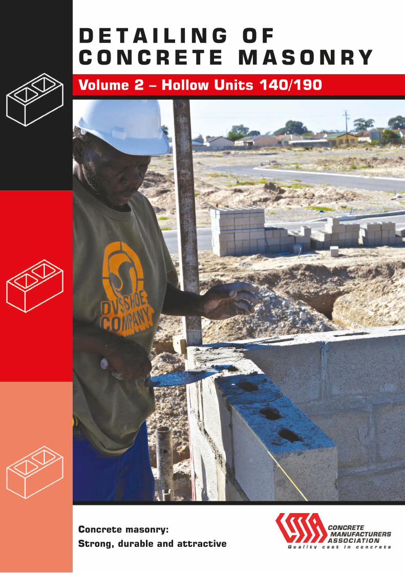
DETAILING OF CONCRETE MASONRY Concrete masonry: Strong, durable and attractive Volume 2 – Hollow Units 140/190
-
Upload
khangminh22 -
Category
Documents
-
view
1 -
download
0
Transcript of CMA: Detailing of Concrete Masonry - Hollow Units - Specifile
D E T A I L I N G O FC O N C R E T E M A S O N R Y
Concrete masonry: Strong, durable and attractive
Volume 2 – Hollow Units 140/190

Published byConcrete Manufacturers AssociationBlock D, Lone Creek, Waterfall Office Park,Bekker Road, MidrandTelephone: +27 11 805 6742Fax: +27 86 524 9216Email: [email protected]: www.cma.org.zaFifth Edition – revised 2011

1
Guidelines on the DETAILING OF
CONCRETE MASONRYVOLUME 2 HOLLOW UNITS – 140mm and 190mm
Editors: J W Lane J E Cairns JH Catsavis

2

3
Successful masonry depends on adequate design and specification of materials, sound construction practice and an acceptable quality of workmanship. Good workmanship is in turn dependent on access to accepted norms of local detailing practice and materials.
The purpose of this booklet is to provide guidelines for the detailing of concrete masonry structures. It should be read in conjunction with the Concrete Manufacturers Association’s Masonry Manual, the National Building Regulations, and National Home Builders Registration Council Home Building Manual the relevant South African Bureau of Standards specifications and codes of practice.
PREFACE

4

5
Preface 3
Reference coding system 6
General notes 7
DETAILS OF CONCRETE MASONRY 9
140 mm and 190 mm HOLLOW UNITS SINGLE LEAF WALLS (REFERENCE H-**-*)
COMPUTER
REFERENCE NUMBER
Foundation walls – external walls H-FG-01/04 9–10
– internal walls H-FG-05/07 11
Sills H-SI-01/05 12
Lintels H-LI-01/04 12
Window frames H-WF-01/02 13–14
Door frames H-DF-01/03 15–17
Suspended floors – index – 18
– external walls H-SF-01/10 19–23
– internal walls H-SF-11/17 24–25
Parapet walls H-PW-01/05 26
Roof screed H-RS-01 26
Roof trusses H-RT-01/07 27–28
Masonry bond patterns H-BP-01/08 29
Joint profiles H-JP-01/02 30
Column/Wall intersections – wall to wall H-WW-01/09 31–33
– wall to column-masonry H-CM-01/06 34–36
– wall to column-pilasters H-CP-01/03 37
– wall to column – concrete H-CC-01/13 38–42
– wall to column – steel H-CS-01/12 43–47
Beam to Wall H-BW-01/02 48
Control joints H-CJ-01/05 49–52
Reinforcing H-RE-01/13 53–58
Air-Conditioning unit H-AC-01 59
Services H-SV-01/06 60–62
Appendices 63
Appendix A: Definitions 65
Appendix B: References 66
Appendix C: Anchors-Walls 68
Appendix D: Roof Fixing 69
Appendix E: Ties, Straps and Bedding Reinforcement 70
Appendix F: Detailing practice for reinforced masonry 71
Appendix G: V-Joints in plaster and mortars 83
Reference:
Refer to: Volume 1 for details of 140 mm solid unit walls
Volume 3 for details of cavity walls
CONTENTS
6
DESCRIPTION OF WALL Computer Reference Number
SOLID UNIT SINGLE LEAF WALLS 140mm S -**-**
HOLLOW UNIT SINGLE LEAF WALLS 140 AND 190 mm H-**-**
CAVITY WALLS 240 TO 290 mm C-**-**
POSITION IN WALLS
AIRCONDITIONING UNITS H-AC-**
BEAM TO WALL H-BW-**
BONDING PATTERNS H-BP-**
CONTROL JOINTS H-CJ-**
DOOR FRAMES H-DF-**
FOUNDATIONS AND GROUND FLOOR SLAB H-FG-**
INTERSECTION WALL TO WALL H-WW-**
WALL TO COLUMN (CONCRETE) H-CC-**
WALL TO COLUMN (STEEL) H-CS-**
WALL TO COLUMN (MASONRY) H-CM-**
WALL TO COLUMN (PILASTERS) H-CP-**
JOINT PROFILES H-JP**
LINTELS H-LI-**
PARAPET WALLS INCLUDING COPING H-PW-**
REINFORCING H-RE-**
ROOF SLABS H-RS-**
ROOF TRUSSES H-RT-**
SERVICES H-SV-**
SILLS H-SI-**
SUSPENDED FLOOR H-SF-**
WINDOW FRAMES H-WF-**
NOTES H-**-NB
Notes:
The computer reference number is the file name under which the individual drawings are stored. The last two digits (indicated with an asterix above) represent the numbering of drawing in that particular category. Where the last two digits are replaced with the letter “NB”, this file contains notes which are pertinent to the drawings in the particular category.
GUIDELINES ON THE DETAILING OF MASONRY STRUCTURES REFERENCE CODING SYSTEM

7
Degree of fixity between elements and likely movement.
Special finishes and specification requirements.
Workmanship quality
Design Modular co-ordination of building elements-work
to 200mm module horizontally and 100mm (and 200mm when using facings) vertically.
Details in these guidelines do not necessarily apply to masonry structures over four storeys in height.
Unless otherwise stated, the details shown are based on the “deemed to satisfy” clauses of SANS 10400 and the NHBRC Home Building Manual (HBM).
In this code of practice, only strip foundations are covered, but there may be a need for special foundations in particular cases. Authoritative advice should be obtained in this regard.
The information contained in this publication is intended as a guide only. The Concrete Manufacturers Association cannot be held responsible for its interpretation and use.
Concrete masonry has wide applications in modern industrial, commercial, educational and residential buildings.
The main types of masonry walls dealt with in these guidelines are: single leaf walls using solid units (Part 1), single leaf walls using hollow units (Part 2) and cavity walls (Part 3).
The details shown in this publication are intended merely as a guide. Each construction situation is unique and there are many factors to be considered before a detail is finalised – far too many for inclusion here.
The purpose of good detailing is to assist in achieving sound construction and a buildable structure that will perform well in service.
The following factors must be taken into account when detailing for concrete masonry structures:
Materials: Concrete masonry units:
solid/hollow – dimensions non-face/face – texture, colour and profile properties and availability.
Mortar: Class to be used plus materials. (Will mortar sand result in high shrinkage of mortar and wall?)
Environmental conditions: Environment:
Orientation Likelihood of significant movement due to temperature and moisture variations
Earth/Seismic movement
Service conditions: Loading:
dead, imposed, wind, unexpected
Aggressive conditions: corrosion
Type of structure Unreinforced/reinforced/prestressed
Composite structure: masonry/reinforced concrete masonry/prestressed concrete masonry/structural steel masonry/timber and their interaction
GENERAL NOTES

8
9
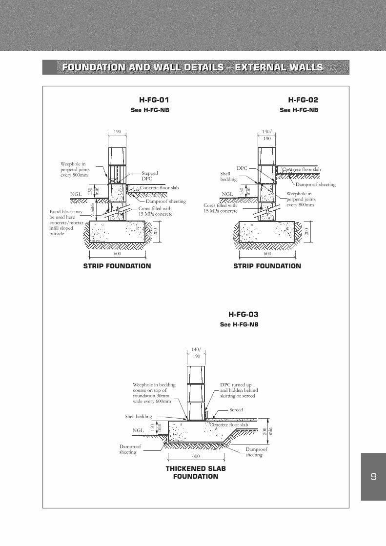
H-FG-01See H-FG-NB
150
min
Weephole in perpend joints every 800mm
NGL
Bond block may be used here concrete/mortar infill sloped outside
STRIP FOUNDATION
190
600
Stepped DPC
Concrete floor slab
Cores filled with 15 MPa concreteV
aria
ble
H-FG-02See H-FG-NB
190140/
Damproof sheeting
Concrete floor slabDPCShell bedding
150
min
NGL
Cores filled with 15 MPa concrete
200
STRIP FOUNDATION
600
200
Weephole in perpend joints every 800mm
H-FG-03See H-FG-NB
190140/
Weephole in bedding course on top of foundation 30mm wide every 600mm
Shell bedding
150
min
NGL
Damproof sheeting
THICKENED SLAB FOUNDATION
600Damproof sheeting
Damproof sheeting
DPC turned up and hidden behind skirting or screed
Screed
Concrete floor slab
200
min
FOUNDATION AND WALL DETAILS – EXTERNAL WALLS
10
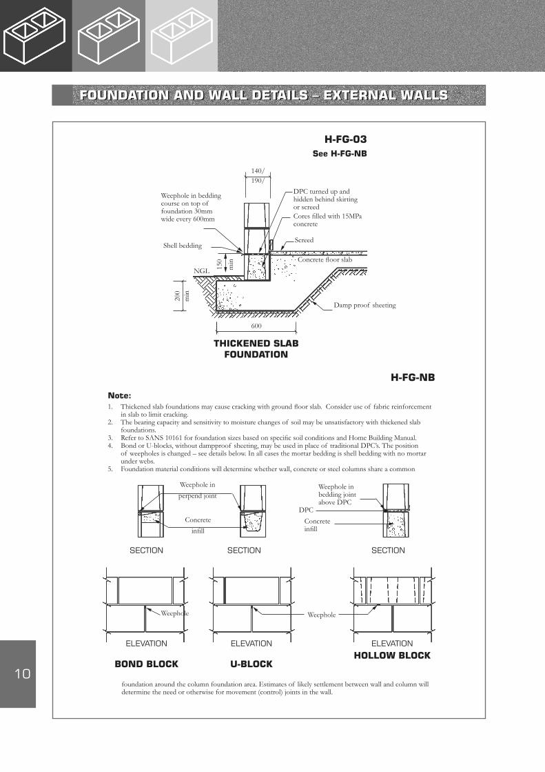
H-FG-03See H-FG-NB
Note:1. Thickened slab foundations may cause cracking with ground floor slab. Consider use of fabric reinforcement
in slab to limit cracking.2. The bearing capacity and sensitivity to moisture changes of soil may be unsatisfactory with thickened slab
foundations.3. Refer to SANS 10161 for foundation sizes based on specific soil conditions and Home Building Manual.4. Bond or U-blocks, without dampproof sheeting, may be used in place of traditional DPC’s. The position
of weepholes is changed – see details below. In all cases the mortar bedding is shell bedding with no mortar under webs.
5. Foundation material conditions will determine whether wall, concrete or steel columns share a common
SECTION SECTION SECTION
foundation around the column foundation area. Estimates of likely settlement between wall and column will determine the need or otherwise for movement (control) joints in the wall.
ELEVATION ELEVATION ELEVATION
BOND BLOCK U-BLOCKHOLLOW BLOCK
Weephole
Weephole in
perpend joint
Concrete
infill
Weephole in bedding joint above DPC
DPC
Concrete infill
Weephole
H-FG-NB
THICKENED SLAB FOUNDATION
600
150
min
NGL
DPC turned up and hidden behind skirting or screed
Concrete floor slab
Damp proof sheeting
200
140/190/
Weephole in bedding course on top of foundation 30mm wide every 600mm
Shell bedding
min
Cores filled with 15MPa concrete
Screed
FOUNDATION AND WALL DETAILS – EXTERNAL WALLS
11
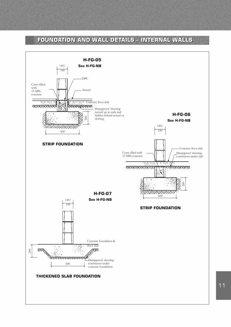
STRIP FOUNDATION
140/
190
600
DPC
Concrete floor slab
Cores filled with 15 MPa concrete
200
Screed
Dampproof sheeting turned up at ends and hidden behind screed or skirting
H-FG-05See H-FG-NB
H-FG-06See H-FG-NB
STRIP FOUNDATION
140/
190
600
Concrete floor slabCores filled with 15 MPa concrete
200
Dampproof sheeting continuous under slab
THICKENED SLAB FOUNDATION
140/
190
600
Concrete foundation &
floor slab
200
Dampproof sheeting continuous under concrete foundation
H-FG-07See H-FG-NB
FOUNDATION AND WALL DETAILS – INTERNAL WALLS
12
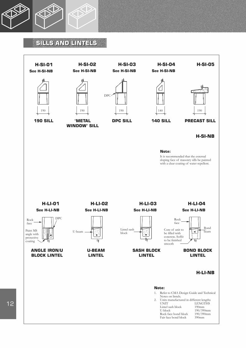
190 190 190 140 190
DPC
190 SILL ‘METAL WINDOW’ SILL
DPC SILL 140 SILL PRECAST SILL
H-SI-01See H-SI-NB
H-SI-02See H-SI-NB
H-SI-03See H-SI-NB
H-SI-04See H-SI-NB
H-SI-05
H-SI-NB
Note:It is recommended that the external sloping face of masonry sills be painted with a clear coating of water repellent.
H-LI-NB
Note:1. Refer to CMA Design Guide and Technical
Notes on lintels.2. Units manufactured in different lengths
UNIT LENGTHSLintel sash block 190mmU-block 190/390mmRock face bond block 190/390mmFair face bond block 390mm
H-LI-01See H-LI-NB
H-LI-02See H-LI-NB
H-LI-03See H-LI-NB
H-LI-04See H-LI-NB
Rock face
DPC
Paint MS angle with protective coating
U-beamLintel sash block
Rock face
Bond beamCore of unit to
be filled with concrete. Soffit to be finished smooth
ANGLE IRON/U BLOCK LINTEL
U-BEAM LINTEL
SASH BLOCK LINTEL
BOND BLOCK LINTEL
SILLS AND LINTELS
13
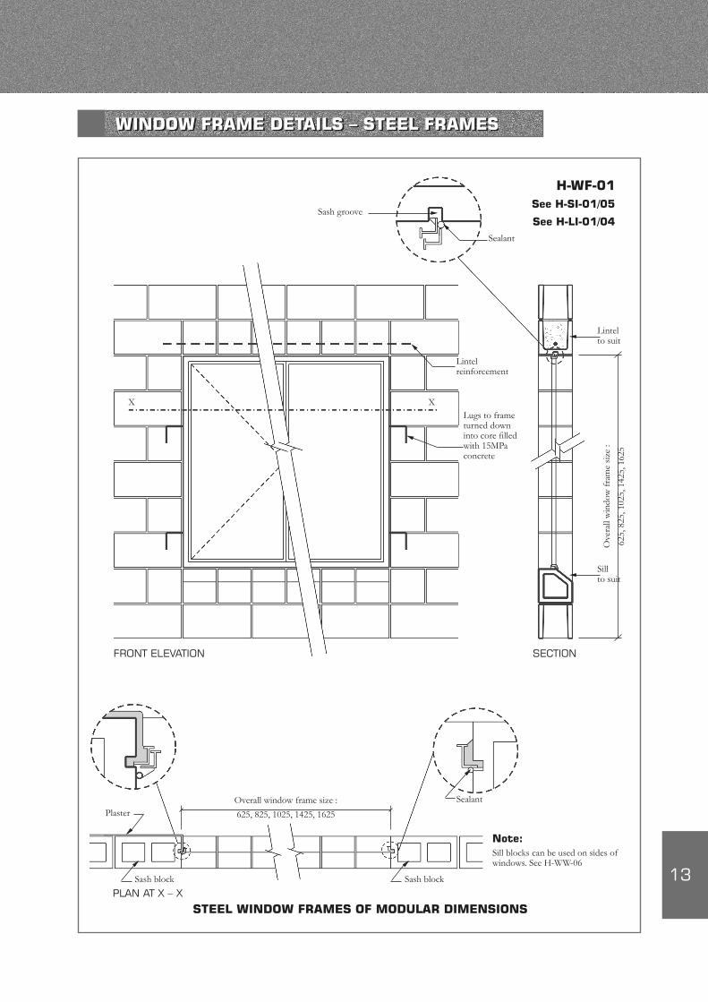
Sash groove
Sealant
Lintel reinforcement
X XLugs to frame turned down into core filled with 15MPa concrete
FRONT ELEVATION SECTION
Lintel to suit
Ove
rall
win
dow
fram
e si
ze :
625,
825
, 102
5, 1
425,
162
5
Sill to suit
Plaster
Sash block
PLAN AT X – X
Sealant
Sash block
Note:Sill blocks can be used on sides of windows. See H-WW-06
STEEL WINDOW FRAMES OF MODULAR DIMENSIONS
H-WF-01See H-SI-01/05
See H-LI-01/04
Overall window frame size :
625, 825, 1025, 1425, 1625
WINDOW FRAME DETAILS – STEEL FRAMES
14
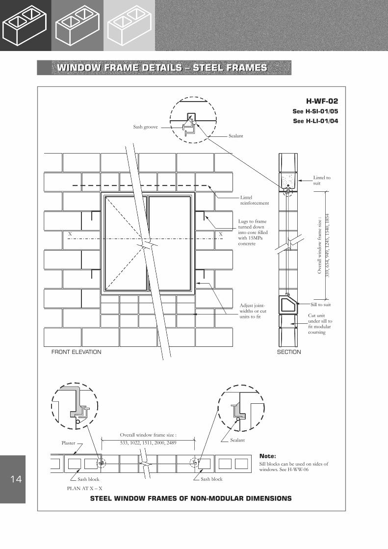
Sash groove
Sealant
Lintelreinforcement
Lugs to frame turned down into core filled with 15MPa concrete
Adjust joint-widths or cut units to fit
X X
FRONT ELEVATION SECTION
H-WF-02See H-SI-01/05
See H-LI-01/04
Ove
rall
win
dow
fram
e si
ze :
359,
654
, 949
, 124
5, 1
540,
185
4
Lintel tosuit
Sill to suit
Cut unit under sill to fit modular coursing
Overall window frame size :
533, 1022, 1511, 2000, 2489Plaster
Sash block
PLAN AT X – X
Sash block
Note:Sill blocks can be used on sides of windows. See H-WW-06
Sealant
STEEL WINDOW FRAMES OF NON-MODULAR DIMENSIONS
WINDOW FRAME DETAILS – STEEL FRAMES
15
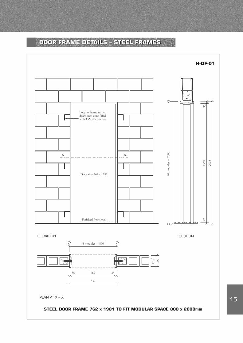
Lugs to frame turned down into core filled with 15MPa concrete
X X
Door size 762 x 1981
Finished floor level
ELEVATION SECTION
20 m
odul
es =
200
0
2038
3519
9122
8 modules = 800
762
832
35 35
140/
190
PLAN AT X – X
STEEL DOOR FRAME 762 x 1981 TO FIT MODULAR SPACE 800 x 2000mm
H-DF-01
DOOR FRAME DETAILS – STEEL FRAMES
16
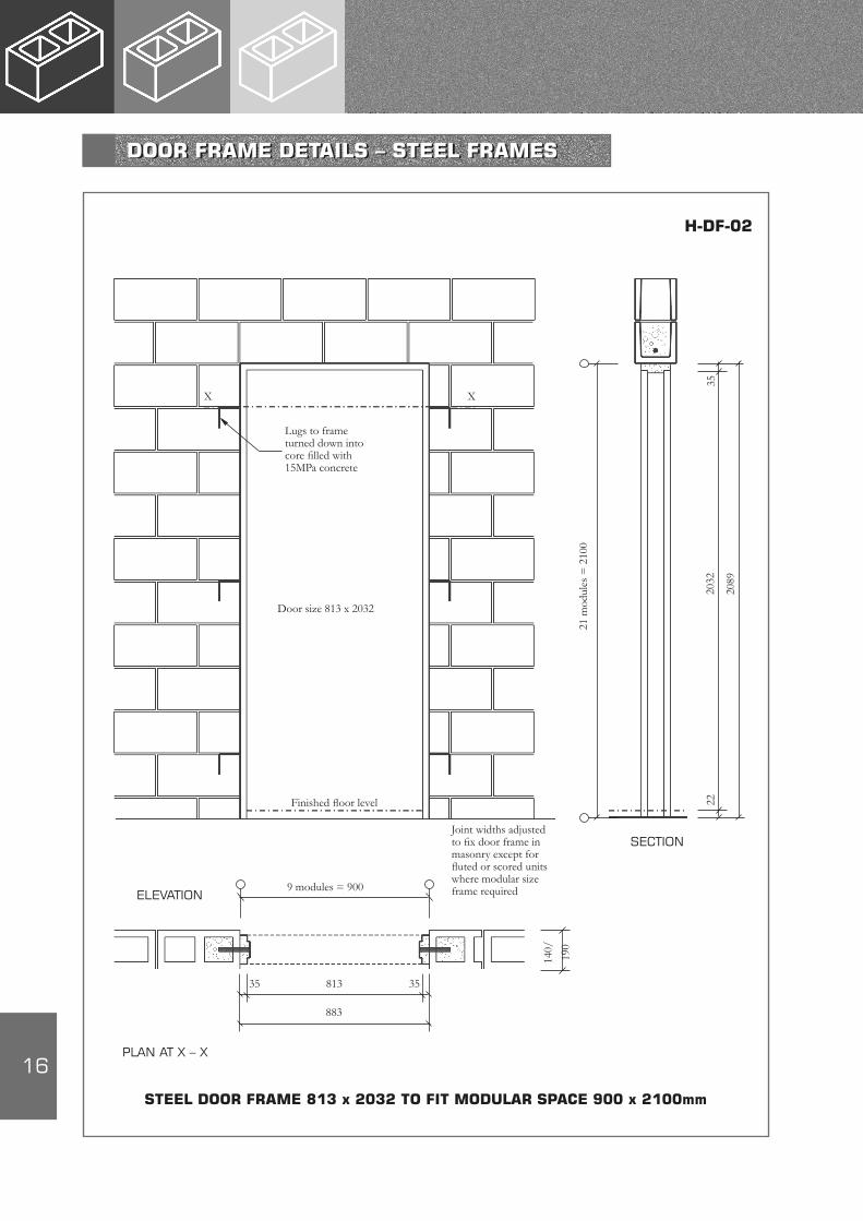
SECTION
21 m
odul
es =
210
0
2089
3520
3222
Lugs to frame turned down into core filled with 15MPa concrete
Door size 813 x 2032
Finished floor level
ELEVATION
Joint widths adjusted to fix door frame in masonry except for fluted or scored units where modular size frame required9 modules = 900
813
883
35 35
140/
190
PLAN AT X – X
STEEL DOOR FRAME 813 x 2032 TO FIT MODULAR SPACE 900 x 2100mm
X X
H-DF-02
DOOR FRAME DETAILS – STEEL FRAMES
17
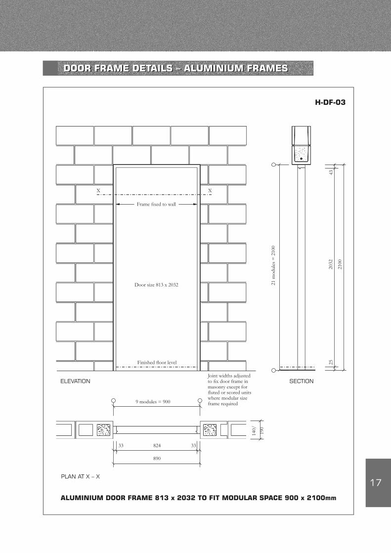
SECTION
21 m
odul
es =
210
0
2100
4320
3225
Frame fixed to wall
Door size 813 x 2032
Finished floor level
X X
Joint widths adjusted to fix door frame in masonry except for fluted or scored units where modular size frame required9 modules = 900
824
890
33 33
140/
190
PLAN AT X – X
ALUMINIUM DOOR FRAME 813 x 2032 TO FIT MODULAR SPACE 900 x 2100mm
ELEVATION
H-DF-03
DOOR FRAME DETAILS – ALUMINIUM FRAMES
18
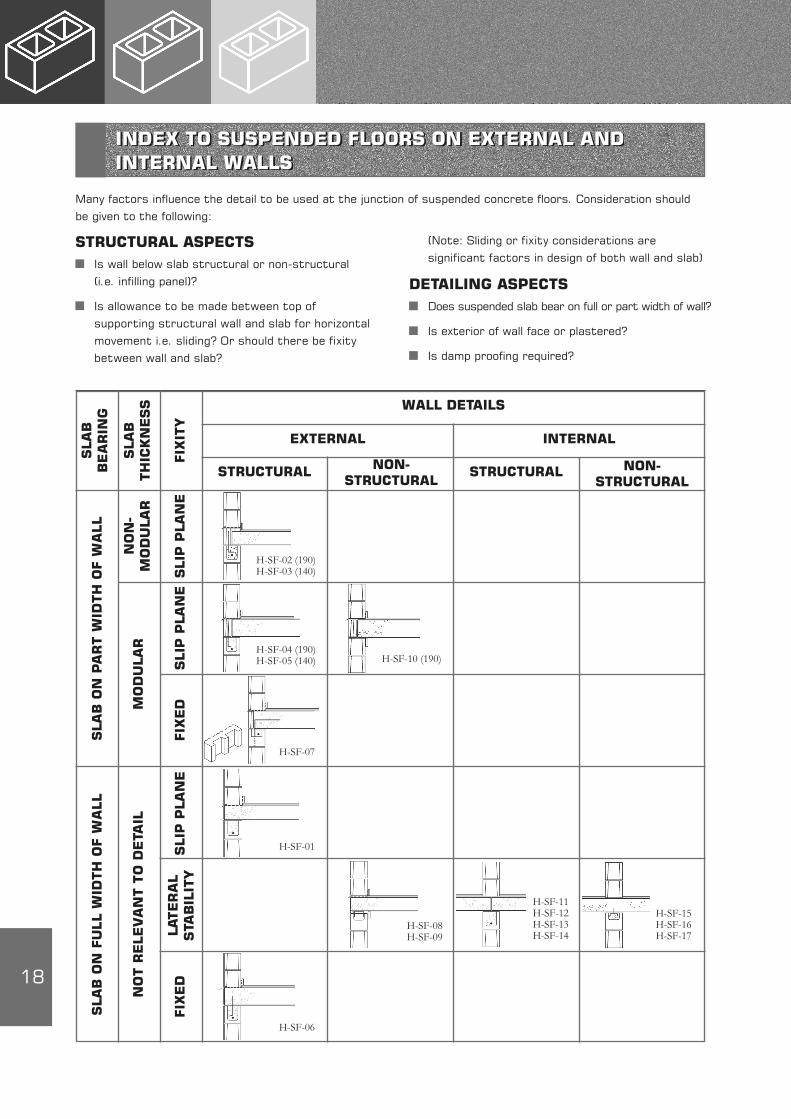
Many factors influence the detail to be used at the junction of suspended concrete floors. Consideration should be given to the following:
STRUCTURAL ASPECTS Is wall below slab structural or non-structural
(i.e. infilling panel)?
Is allowance to be made between top of supporting structural wall and slab for horizontal movement i.e. sliding? Or should there be fixity between wall and slab?
(Note: Sliding or fixity considerations are significant factors in design of both wall and slab)
DETAILING ASPECTS Does suspended slab bear on full or part width of wall?
Is exterior of wall face or plastered?
Is damp proofing required?
SLA
B
BEA
RIN
G
SLA
B
TH
ICK
NESS
FIX
ITY
NO
N-
MO
DU
LAR
SLIP
PLA
NE
MO
DU
LAR
SLIP
PLA
NE
FIX
ED
SLA
B O
N P
AR
T W
IDTH
OF W
ALL
SLIP
PLA
NE
LATER
AL
STA
BIL
ITY
FIX
ED
NO
T R
ELEV
AN
T T
O D
ETA
IL
SLA
B O
N F
ULL W
IDTH
OF W
ALL
WALL DETAILS
EXTERNAL INTERNAL
STRUCTURAL NON-STRUCTURAL
STRUCTURAL NON-STRUCTURAL
H-SF-02 (190)H-SF-03 (140)
H-SF-04 (190)H-SF-05 (140)
H-SF-07
H-SF-01
H-SF-06
H-SF-10 (190)
H-SF-08H-SF-09
H-SF-11H-SF-12H-SF-13H-SF-14
H-SF-15H-SF-16H-SF-17
INDEX TO SUSPENDED FLOORS ON EXTERNAL AND INTERNAL WALLS
19
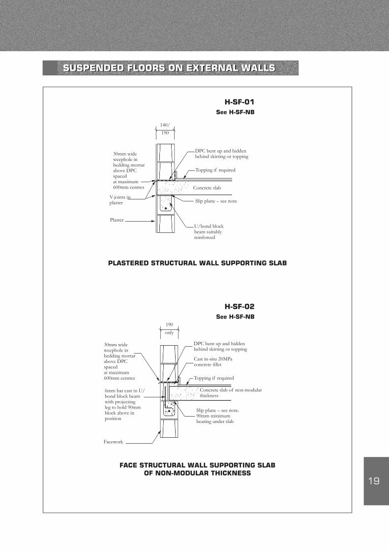
30mm wide weephole in bedding mortar above DPC spaced at maximum 600mm centres
V-joints in plaster
Plaster
140/
190
U/bond block beam suitably reinforced
Slip plane – see note
Concrete slab
DPC bent up and hidden behind skirting or topping
Topping if required
PLASTERED STRUCTURAL WALL SUPPORTING SLAB
H-SF-01See H-SF-NB
30mm wide weephole in bedding mortar above DPC spaced at maximum 600mm centres
DPC bent up and hidden behind skirting or topping
Cast in-situ 20MPa concrete fillet
Topping if required
Slip plane – see note.90mm minimum bearing under slab
Concrete slab of non-modular thickness
Facework
6mm bar cast in U/bond block beam with projecting leg to hold 90mm block above in position
190
only
H-SF-02See H-SF-NB
FACE STRUCTURAL WALL SUPPORTING SLAB OF NON-MODULAR THICKNESS
SUSPENDED FLOORS ON EXTERNAL WALLS

20
Note:1. If floor slab span exceeds 6m spanning on to wall and large
movements expected consider a slip joint on top of wall, such as two layers of DPC or galv. sheet iron with grease between sheets or kilcher bearing or similar.
2. Structural stability & robustness may preclude use of slip joint.3. If designer assumes wall laterally restrained by slab then slip joint
not advisable.4. Suspended floors either precast or cast-in-situ unless otherwise
stated.5. Where fixity required between slab and wall, reinforcement to be
used to be determined by calculation.6. Slabs of non-modular thickness require concrete infill (under
modular size) or cut block (over modular size) to restore block coursing.
DPC bent up and hidden behind skirting or topping
Cast in-situ 20MPa concrete fillet
Topping if required
Slip plane – see note.90mm minimum bearing under slab
Concrete slab of non-modular thickness
Facework
Cut block (hollow, U- or bond block) mortared to slab and use special ties
140
only
U/bond block beam suitably reinforced
Note:If upper wall structural check if load on cut block is sufficient to dislodge
Spacing of perpend joints
Special metal ties
FACE STRUCTURAL WALL SUPPORTING SLAB OF NON-MODULAR THICKNESS
H-SF-03See H-SF-NB
H-SF-NB
30mm wide weephole in bedding mortar above DPC spaced at maximum 600mm centres
SUSPENDED FLOORS ON EXTERNAL WALLS
21
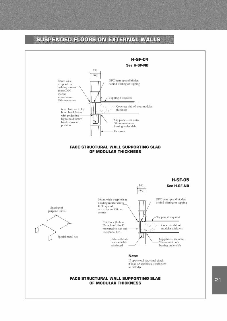
30mm wide weephole in bedding mortar above DPC spaced at maximum 600mm centres
DPC bent up and hidden behind skirting or topping
Topping if required
Slip plane – see note.90mm minimum bearing under slab
Concrete slab of non-modular thickness
Facework
190
only
6mm bar cast in U/bond block beam with projecting leg to hold 90mm block above in position
FACE STRUCTURAL WALL SUPPORTING SLAB OF MODULAR THICKNESS
H-SF-04See H-SF-NB
Spacing of perpend joints
Special metal ties
30mm wide weephole in bedding mortar above DPC spaced at maximum 600mm centres
DPC bent up and hidden behind skirting or topping
Topping if required
Concrete slab of modular thickness
Cut block (hollow, U- or bond block) mortared to slab and use special ties
140
only
Slip plane – see note.90mm minimum bearing under slab
U/bond block beam suitably reinforced
Note:If upper wall structural check if load on cut block is sufficient to dislodge
FACE STRUCTURAL WALL SUPPORTING SLAB OF MODULAR THICKNESS
H-SF-05See H-SF-NB
SUSPENDED FLOORS ON EXTERNAL WALLS

22
30mm wide weephole in bedding mortar above DPC spaced at maximum 600mm centres
V-joints in plaster
Plaster
Cast in-situ concrete slab incorporating projecting bar from U/bond block beam below
DPC bent up and hidden behind skirting or topping
Topping if required
140/
190
PLASTERED STRUCTURAL WALL WHERE FIXITY BETWEEN WALL & SLAB REQUIRED
H-SF-06See H-SF-NB
FACE STRUCTURAL WALL WHERE FIXITY BETWEEN WALL & SLAB REQUIRED OF MODULAR THICKNESS
Concrete infill
DPC bent up and hidden behind skirting or topping
Topping if required
Concrete slab with projecting bar cast into bond block beam
Cut face block forming outside shutter to cast in-situ concrete infill
30mm wide weephole in bedding mortar above DPC spaced at maximum 600mm centres
190
H-SF-07See H-SF-NB
SUSPENDED FLOORS ON EXTERNAL WALLS
23
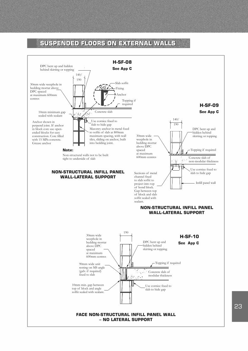
30mm wide weephole in bedding mortar above DPC spaced at maximum 600mm centres Topping if
required
Use cornice fixed to slab to hide gap
Concrete slab
Masonry anchor in metal fixed to soffit of slab at 800mm maximum spacing, with wall tiles, sliding on anchor, built into bedding joint.
Slab soffit
Fixing
Anchor
10mm minimum gap sealed with sealant
Anchor shown in perpend joint. If anchor in block core use open-ended blocks for easy construction. Core filled with 15 MPa concrete. Grease anchor
Note:Non-structural walls not to be built tight to underside of slab
NON-STRUCTURAL INFILL PANEL WALL-LATERAL SUPPORT
DPC bent up and hidden behind skirting or topping
140/
190
H-SF-08See App C
30mm wide weephole in bedding mortar above DPC spaced at maximum 600mm centres
140/
190
Sections of metal channel fixed to slab soffit to project into top of bond block. Gap between top of block and slab soffit sealed with sealant.
DPC bent up and hidden behind skirting or topping
Topping if required
Use cornice fixed to slab to hide gap
Concrete slab of non-modular thickness
Infill panel wall
H-SF-09See App C
NON-STRUCTURAL INFILL PANEL WALL-LATERAL SUPPORT
30mm wide weephole in bedding mortar above DPC spaced at maximum 600mm centres
190
90mm wide unit resting on MS angle (galv. if required) fixed to slab
DPC bent up and hidden behind skirting or topping
Topping if required
Use cornice fixed to slab to hide gap
Concrete slab of modular thickness
H-SF-10See App C
FACE NON-STRUCTURAL INFILL PANEL WALL – NO LATERAL SUPPORT
10mm min. gap between top of block and angle soffit sealed with sealant.
SUSPENDED FLOORS ON EXTERNAL WALLS

24
140/
190
Topping if required
Joint in slab
Concrete slab
H-SF-11See H-SF-NB1
Check if bearing area adequate
140/
190
Topping if required
Joint in slab
H-SF-12See H-SF-NB1
Concrete slab
Angle to support slab
140/
190
Topping if required
Concrete slab
H-SF-13See H-SF-NB1 140/
190
H-SF-14
Concrete slab
If slab and topping continuous over support consider light fabric reinforcement in topping
STRUCTURAL WALL SUPPORTING JOINTED SLAB & WALL ABOVE
STRUCTURAL WALL SUPPORTING JOINTED SLAB & WALL ABOVE
STRUCTURAL WALL SUPPORTING CONTINUOUS SLAB & WALL ABOVE
STRUCTURAL WALL SUPPORTING SLAB ONLY
Note:If thickness of slab is not modular then concrete infill or cut blocks to be used in first course above slab to restore unit coursing to bond with external walls
H-SF-NB1
SUSPENDED FLOORS ON INTERNAL WALLS
25
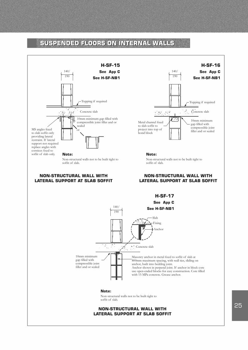
140/
190
Topping if required
10mm minimum gap filled with compressible joint filler and or sealed
Concrete slab
H-SF-15See App C
See H-SF-NB1
MS angles fixed to slab soffit only providing lateral restraint. If lateral support not required replace angles with cornices fixed to soffit of slab only.
or
NON-STRUCTURAL WALL WITH LATERAL SUPPORT AT SLAB SOFFIT
NON-STRUCTURAL WALL WITH LATERAL SUPPORT AT SLAB SOFFIT
Note:Non-structural walls not to be built tight to soffit of slab.
Note:Non-structural walls not to be built tight to soffit of slab.
140/
190
H-SF-16See App C
See H-SF-NB1
Topping if required
10mm minimum gap filled with compressible joint filler and or sealed
Metal channel fixed to slab soffit to project into top of bond block
Concrete slab
NON-STRUCTURAL WALL WITH LATERAL SUPPORT AT SLAB SOFFIT
Note:Non-structural walls not to be built tight to soffit of slab.
140/
190
H-SF-17See App C
See H-SF-NB1
Masonry anchor in metal fixed to soffit of slab at 800mm maximum spacing, with wall ties, sliding on anchor, built into bedding joint.Anchor shown in perpend joint. If anchor in block core use open-ended blocks for easy construction. Core filled with 15 MPa concrete. Grease anchor.
10mm minimum gap filled with compressible joint filler and or sealed
Concrete slab
Slab
Fixing
Anchor
SUSPENDED FLOORS ON INTERNAL WALLS
26
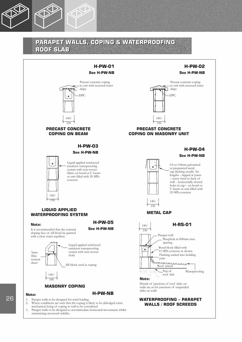
140/
190
DPC
H-PW-01See H-PW-NB
PRECAST CONCRETE COPING ON BEAM
Precast concrete coping to suit with recessed water drips
140/
190
DPC
H-PW-02See H-PW-NB
PRECAST CONCRETE COPING ON MASONRY UNIT
Precast concrete coping to suit with recessed water drips
140/
190
H-PW-03See H-PW-NB
Liquid applied reinforced emulsion waterproofing system with non-woven fabric on bond or U-beam or unit filled with 20 MPa concrete
LIQUID APPLIED WATERPROOFING SYSTEM
140/
190
H-PW-04See H-PW-NB
0.6 to 0.8mm galvanised or prepainted metal cap flashing usually 3m lengths – lapped at joints – screw fixed to back of wall – horizontally slotted holes in cap – on bond or U-beam or unit filled with 20 MPa concrete
METAL CAP
140/
190
H-PW-05See H-PW-NB
Liquid applied reinforced emulsion waterproofing system with non-woven cloth
MASONRY COPING
Note:1. Parapet walls to be designed for wind loading2. Where conditions are such that the coping is likely to be dislodged some
mechanical fixing of coping to wall to be considered3. Parapet walls to be designed to accommodate horizontal movements whilst
maintaining structural stability
Note:It is recommended that the external sloping face of sill block be painted with a clear water repellent.
Sill block used as coping
3mm fibre cement sheet
H-RS-01
Parapet wallWeephole at 600mm max. spacing
Bond block filled with 15 MPa concrete as shownFlashing tucked into bedding joint
Waterproofing
Roof screed
Top of roof slab
Note:Details of junctions of roof slabs on walls are as for junctions of suspended slabs on walls
WATERPROOFING – PARAPET WALLS / ROOF SCREEDS
140/
190
H-PW-NB
PARAPET WALLS, COPING & WATERPROOFING ROOF SLAB
27
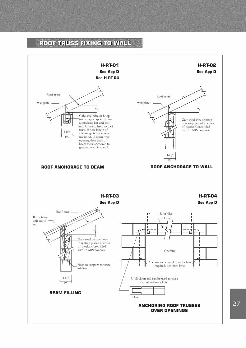
ROOF ANCHORAGE TO BEAM
Galv. steel wire or hoop iron strap wrapped around reinforcing bar and cast into U-beam, fixed to roof truss. Where length of anchorage is inadequate use bond/U-beam over opening then ends of beam to be anchored to greater depth into wall.
Roof truss
Wall plate
H-RT-01See App D
See H-RT-04
140/
190
ROOF ANCHORAGE TO WALL
Galv. steel wire or hoop iron strap placed in cores of blocks. Cores filled with 15 MPa concrete
Roof truss
Wall plate
H-RT-02See App D
140/
190
BEAM FILLING
Roof truss
Beam filling unit cut to suit
H-RT-03See App D
140/
190
Galv. steel wire or hoop iron strap placed in cores of blocks. Cores filled with 15 MPa concrete
Mesh to support concrete infilling
H-RT-04See App D
Roof tiles
ANCHORING ROOF TRUSSES OVER OPENINGS
Lintel
Opening
Anchors to tie lintel to wall where required, bent into lintel
U-block on end can be used to close end of masonry lintel
Plan
ROOF TRUSS FIXING TO WALL
28
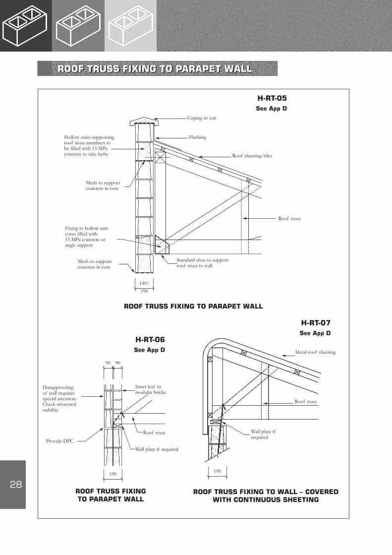
140/
190
H-RT-05See App D
Standard shoe to support roof truss to wall
ROOF TRUSS FIXING TO PARAPET WALL
Hollow units supporting roof truss members to be filled with 15 MPa concrete to take bolts
Mesh to support concrete in core
Fixing to hollow unit cores filled with 15 MPa concrete or angle support
Mesh to support concrete in core
Roof truss
Roof sheeting/tiles
Flashing
Coping to suit
Dampproofing of wall requires special attention. Check structural stability
Provide DPC
190
Wall plate if required
Roof truss
Inner leaf in modular bricks
90 90
ROOF TRUSS FIXING TO PARAPET WALL
H-RT-06See App D
H-RT-07See App D
Metal roof sheeting
Wall plate if required
Roof truss
190
ROOF TRUSS FIXING TO WALL – COVERED WITH CONTINUOUS SHEETING
ROOF TRUSS FIXING TO PARAPET WALL

29
H-BP-01400
module
STRETCHER OR RUNNING BOND
200
mod
ule
H-BP-02400
module
STACK BOND
200
mod
ule
H-BP-03400
module
QUARTER BOND
200
mod
ule
H-BP-04400
module
COURSED ASHLAR BOND
200
mod
ule
100
mod
ule
H-BP-05400
module
ASHLAR BOND
200
mod
ule
H-BP-06400
module
STRETCHER BOND WITH STACK BOND PIER
200
mod
ule
Ties required between pier and wall
MASONRY BOND PATTERNS AND JOINT PROFILES
30
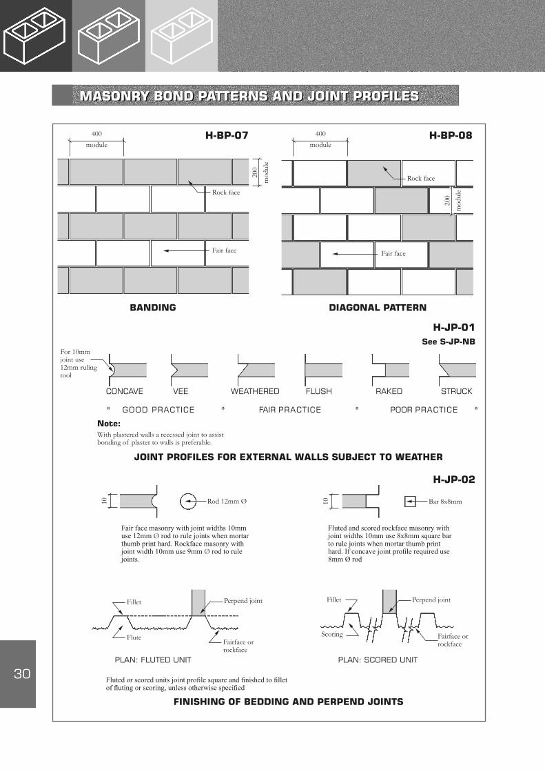
H-BP-07400
module
BANDING
200
mod
ule
H-BP-08400
module
DIAGONAL PATTERN
200
mod
uleRock face
Fair face
Rock face
Fair face
H-JP-01See S-JP-NB
For 10mm joint use 12mm ruling tool
CONCAVE VEE WEATHERED FLUSH RAKED STRUCK
GOOD PRACTICE
JOINT PROFILES FOR EXTERNAL WALLS SUBJECT TO WEATHER
Note:With plastered walls a recessed joint to assist bonding of plaster to walls is preferable.
H-JP-02
10 Rod 12mm Ø 10 Bar 8x8mm
Fair face masonry with joint widths 10mm use 12mm Ø rod to rule joints when mortar thumb print hard. Rockface masonry with joint width 10mm use 9mm Ø rod to rule joints.
Fluted and scored rockface masonry with joint widths 10mm use 8x8mm square bar to rule joints when mortar thumb print hard. If concave joint profile required use 8mm Ø rod
Perpend jointFillet
FluteFairface or rockface
Perpend jointFillet
Scoring Fairface or rockface
PLAN: FLUTED UNIT PLAN: SCORED UNIT
Fluted or scored units joint profile square and finished to fillet of fluting or scoring, unless otherwise specified
FINISHING OF BEDDING AND PERPEND JOINTS
FAIR PRACTICE POOR PRACTICE* * * *
MASONRY BOND PATTERNS AND JOINT PROFILES
31
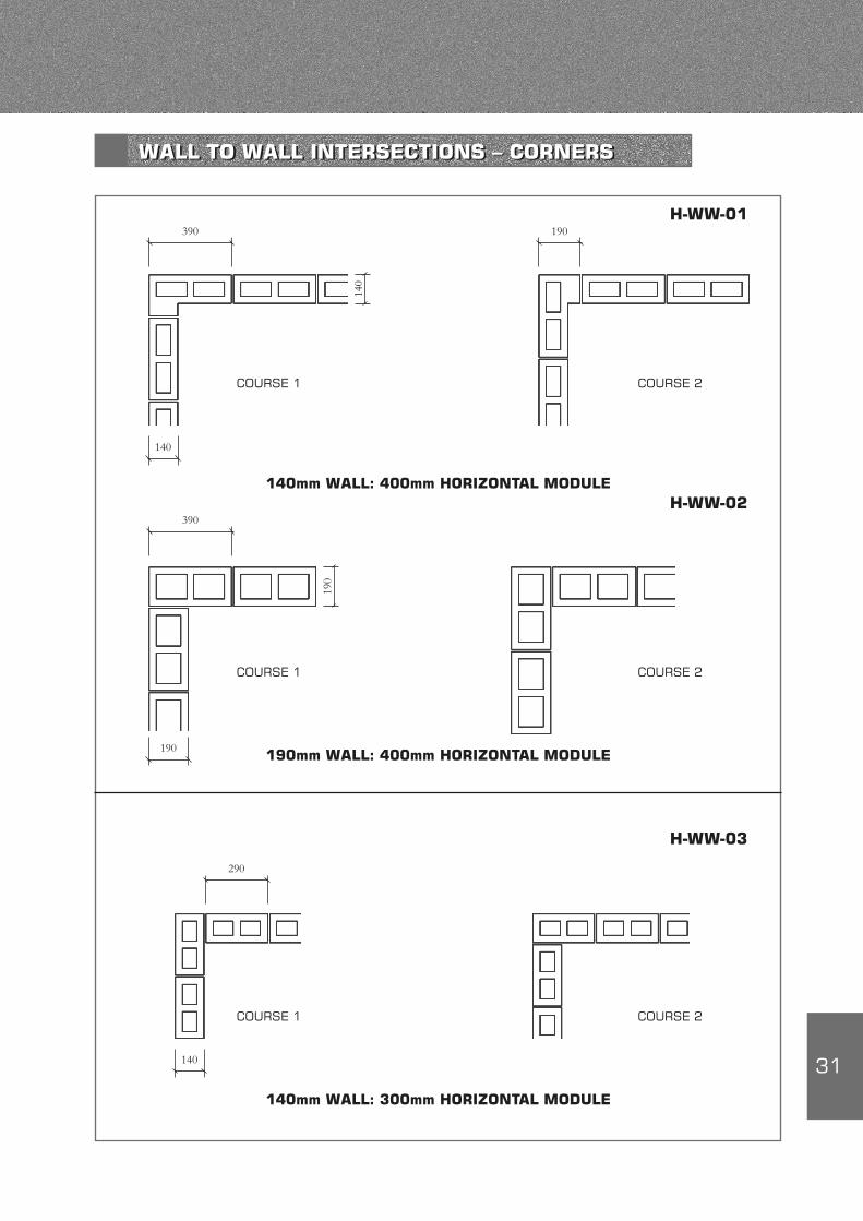
140
390
COURSE 1
190
COURSE 2
140mm WALL: 400mm HORIZONTAL MODULE
H-WW-01
190mm WALL: 400mm HORIZONTAL MODULE190
390
COURSE 1 COURSE 2
H-WW-02
140
190
140
140mm WALL: 300mm HORIZONTAL MODULE
290
COURSE 1 COURSE 2
H-WW-03
WALL TO WALL INTERSECTIONS – CORNERS

32
190
390
COURSE 1
FACE UNITS: EXTERIOR
H-WW-04See H-JP-02
190
Note:Bedding and perpend joint profiles, mortar – colour and texture – to suit profile, colour and texture of unit
SILL BLOCK FORMING CORNER
190
Modular infill brick
Mesh
Face units
190
Mesh
COURSE 2
COURSE 1 COURSE 2
‘L’ shaped corner block
Note:Bedding and perpend joint profiles, mortar – colour and texture – to suit profile, colour and texture of unit
H-WW-05See H-JP-02
Sill block filled solid with 15 MPa concrete
30mm wide x 3mm thick metal strap anchored in concrete every second course
COURSE 1
COURSE 2
H-WW-06200
50
50
30
FACE UNITS: INTERIOR AND EXTERIOR
WALL TO WALL INTERSECTIONS – FACE UNITS
33
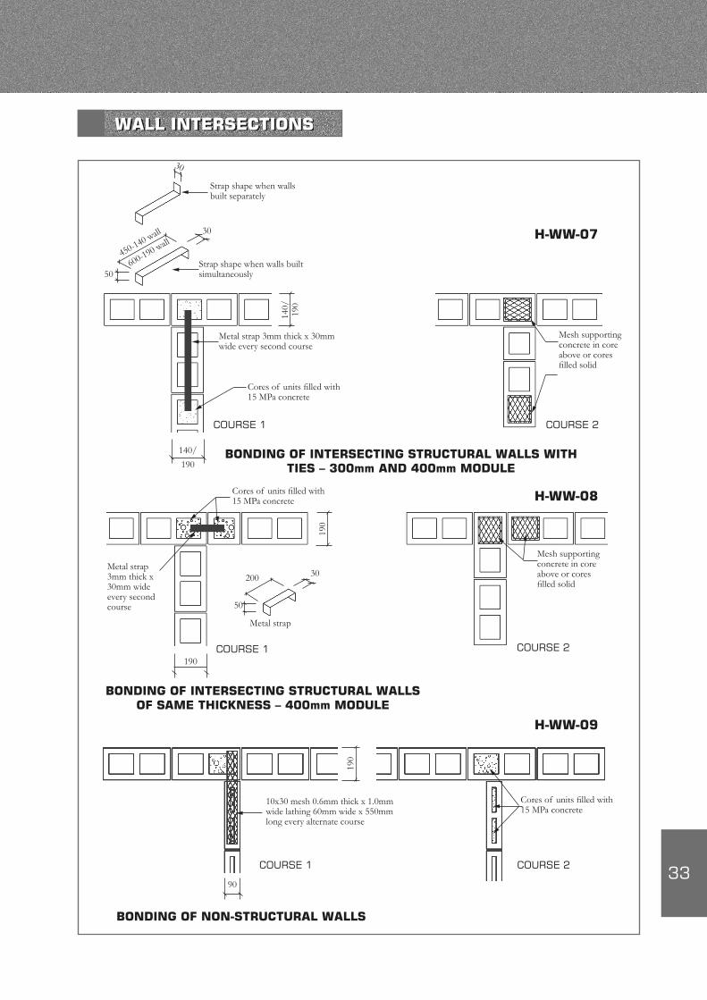
30
30
50
450-140 wall
600-190 wall
140/
190
Metal strap 3mm thick x 30mm wide every second course
Strap shape when walls built simultaneously
Cores of units filled with 15 MPa concrete
COURSE 1
140/
190
H-WW-07
Mesh supporting concrete in core above or cores filled solid
COURSE 2
BONDING OF INTERSECTING STRUCTURAL WALLS WITH TIES – 300mm AND 400mm MODULE
190
50
200 30Metal strap 3mm thick x 30mm wide every second course
Metal strap
COURSE 1
190
Mesh supporting concrete in core above or cores filled solid
COURSE 2
Cores of units filled with 15 MPa concrete H-WW-08
BONDING OF INTERSECTING STRUCTURAL WALLS OF SAME THICKNESS – 400mm MODULE
190
10x30 mesh 0.6mm thick x 1.0mm wide lathing 60mm wide x 550mm long every alternate course
COURSE 1
Cores of units filled with 15 MPa concrete
COURSE 2
H-WW-09
BONDING OF NON-STRUCTURAL WALLS
90
Strap shape when walls built separately
WALL INTERSECTIONS
34
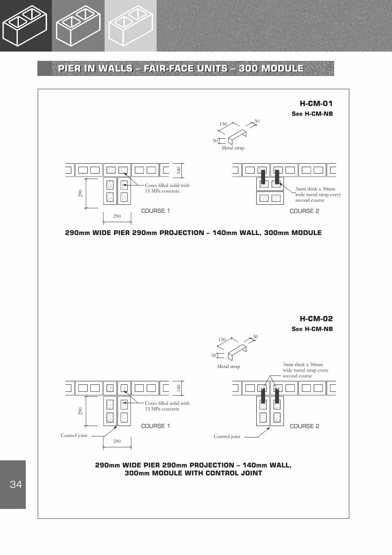
150 30
50Metal strap
COURSE 1
140
Cores filled solid with 15 MPa concrete
290mm WIDE PIER 290mm PROJECTION – 140mm WALL, 300mm MODULE
COURSE 2
3mm thick x 30mm wide metal strap every second course
H-CM-01See H-CM-NB
290
290
150 30
50
Metal strap
COURSE 1
140
Cores filled solid with 15 MPa concrete
COURSE 2
3mm thick x 30mm wide metal strap every second course
H-CM-02See H-CM-NB
290
290
Control joint Control joint
290mm WIDE PIER 290mm PROJECTION – 140mm WALL, 300mm MODULE WITH CONTROL JOINT
PIER IN WALLS – FAIR-FACE UNITS – 300 MODULE

35
150 30
50
Metal strap
H-CM-03See H-CM-NB
COURSE 119
0
Cores filled solid with 15 MPa concrete
390mm WIDE PIER 390mm PROJECTION – 190mm WALL, 400mm MODULE
COURSE 2
3mm thick x 30mm wide metal strap every second course
390
390
COURSE 1
190
390
390
Control joint Control joint
390mm WIDE PIER 390mm PROJECTION – 190mm WALL, 400mm MODULE WITH CONTROL JOINT
Cores filled solid with 15 MPa concrete
COURSE 2
H-CM-04See H-CM-NB
H-CM-NBNote:1. At the end of a free-standing wall the pier width and projection must be of the
same dimension as internal piers. The two adjacent piers at control joints must together be of the same overall dimension as an internal pier.
2. The thickness of the wall shown is that at the base and may be reduced nearer the top of the wall. See SANS 10400-K – Free Standing Walls
3. Refer to CMA Design Guide on Free Standing Walls, and SANS 10400-K
W-equal W-equal W-equal
END PIER INTERNAL PIER CONTROL JOINT PIER
PIER IN WALLS – FAIR-FACE UNITS – 400 MODULE

36
200
50
30
Metal strap
COURSE 1
Cores filled solid with 15 MPa concrete
390
390
3mm thick x 30mm wide metal strap every second course
Fair face units
10x30 mesh 0.6mm thick x 1.0mm wide lathing 150mm wide x 900mm long every second course
Rock face unit
200
50
30
H-CM-05See H-CM-NB
390mm WIDE PIER 390mm PROJECTION – 190mm WALL, 400mm MODULE – FACE UNITS
COURSE 2
400
50
30
Metal strap
190
390
Control joint
390
Rock face unit
3mm thick x 30mm wide metal strap every second course Cores filled solid
with 15 MPa concrete
2-10x30 mesh 0.6mm thick x 1.0mm wide lathing 150mm wide x 450mm long every second course
COURSE 1
390mm WIDE PIER 390mm PROJECTION – 190mm WALL, 400mm MODULE WITH CONTROL JOINT – FACE UNITS
COURSE 2
H-CM-06See H-CM-NB
190
3mm thick x 30mm wide metal strap every second course
Fair face units
Cores filled solid with 15 MPa concrete
PIER IN WALLS – ROCK FACE UNITS

37
140/
190
390
Pilaster block
H-CP-01See H-CP-NB
PILASTER BLOCK IN WALL
COURSE 1
140/
190
390
Pilaster block
H-CP-02See H-CP-NB
140/
190
PILASTER BLOCK AT T-JUNCTIONS
COURSE 1
390
190
140/
190
Metal ties between pier and wall required
Cores of block may be filled with concrete and reinforced
H-CP-03
OCTAGON SHAPED PIER BLOCK
Note:1. Pilaster blocks provide lateral support while permitting longitudinal movement,
provided no metal ties are used between wall and pilaster block.2. Pilaster block shape adjusted to suit number of intersecting walls and aesthetic
considerations.3. Pilaster blocks may be filled with concrete and reinforced if required.
H-CP-NB
COURSE 2
COURSE 2
PILASTER AND PIER BLOCKS IN WALLS
38
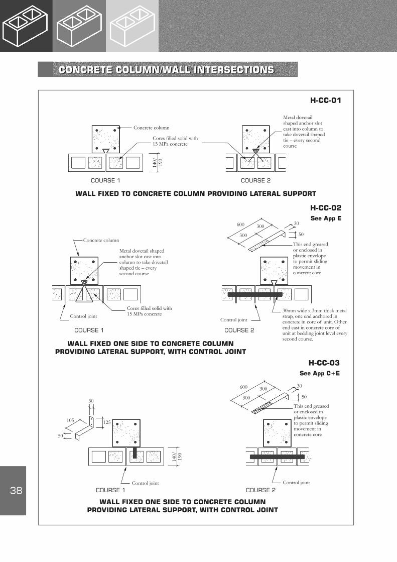
COURSE 1
140/
190
WALL FIXED TO CONCRETE COLUMN PROVIDING LATERAL SUPPORT
Cores filled solid with 15 MPa concrete
COURSE 2
Concrete column
Metal dovetail shaped anchor slot cast into column to take dovetail shaped tie – every second course
Concrete column
Metal dovetail shaped anchor slot cast into column to take dovetail shaped tie – every second course
Cores filled solid with 15 MPa concreteControl joint
600
50
30
300
300
This end greased or enclosed in plastic envelope to permit sliding movement in concrete core
Control joint
30mm wide x 3mm thick metal strap, one end anchored in concrete in core of unit. Other end cast in concrete core of unit at bedding joint level every second course.
H-CC-01
H-CC-02See App E
WALL FIXED ONE SIDE TO CONCRETE COLUMN PROVIDING LATERAL SUPPORT, WITH CONTROL JOINT
600
50
30
300
300
H-CC-03See App C+E
COURSE 1 COURSE 2
105
50
125
30
Control joint
140/
190
Control joint
WALL FIXED ONE SIDE TO CONCRETE COLUMN PROVIDING LATERAL SUPPORT, WITH CONTROL JOINT
COURSE 1 COURSE 2
This end greased or enclosed in plastic envelope to permit sliding movement in concrete core
CONCRETE COLUMN/WALL INTERSECTIONS

39
50
300
30
75 3mm thick x 30mm wide metal strap fixed to column every second course
190
Mesh to support 15 MPa concrete in core above, or cores filled solid with concrete without mesh
H-CC-04See App C+E
COURSE 1
190mm WALL RIGIDLY FIXED TO CONCRETE COLUMN – 400mm MODULE
COURSE 2
3mm thick x 30mm wide metal strap, one end anchored in concrete in core of unit. Other end cast in concrete core of unit at bedding joint level every second course.
Control joint
150
30
75This end greased or enclosed in plastic envelope to permit sliding movement
Control joint
COURSE 1
WALL FIXING TO CONCRETE COLUMN PERMITTING LONGITUDINAL MOVEMENT – 400mm MODULE
COURSE 2
H-CC-05See App C+E
190
15 MPa concrete in cores
50
230
30
75
COURSE 1
140mm WALL RIGIDLY FIXED TO CONCRETE COLUMN 300mm MODULE (OR 400mm MODULE)
COURSE 2
3mm thick x 30mm wide metal strap fixed to column every second course
Mesh to support 15 MPa concrete in core above or cores filled solid with concrete without mesh
H-CC-06See App C+E
CONCRETE COLUMN/WALL INTERSECTIONS

40
Concrete column
Metal angle fixed to column with outstanding leg projecting into groove of sash block
Column
Control joint
WALL FIXED TO CONCRETE COLUMN PERMITTING LONGITUDINAL MOVEMENT
Sash block
140/
190
Block
1515
H-CC-07See App C
H-CC-08See App C
Concrete column
Cold rolled light gauge metal channel fixed to column
Column
Control joint
140/
190
Unit
WALL FIXED TO CONCRETE COLUMN PERMITTING LONGITUDINAL MOVEMENT
ANGLE IN SASH GROOVE CHANNEL IN OPEN END OF UNIT
Concrete column
Metal angles fixed to concrete column
WALL FIXED TO CONCRETE COLUMN PERMITTING LONGITUDINAL MOVEMENT
140/
190
TWO ANGLES TO HOLD UNIT
H-CC-09See App C
Metal angles fixed to concrete column
140/
190
TWO ANGLES TO HOLD UNIT
CONCRETE COLUMN/WALL INTERSECTIONS

41
Concrete column
290mm or cut unit
CONCRETE COLUMN 400 x 400 WITH EXTERNAL FACE UNITS
190
190
COURSE 1
Rock face unit90
90
COURSE 2
H-CC-10
290mm or cut unit
CONCRETE COLUMN 400 x 400 BOXED IN WITH EXTERNAL FACE UNITS
COURSE 1 COURSE 2
H-CC-11
Concrete column
290mm or cut unit
190
190
Rock face unit90
90
290mm or cut unit
CONCRETE COLUMNS WITH ROCKFACE SURROUNDS
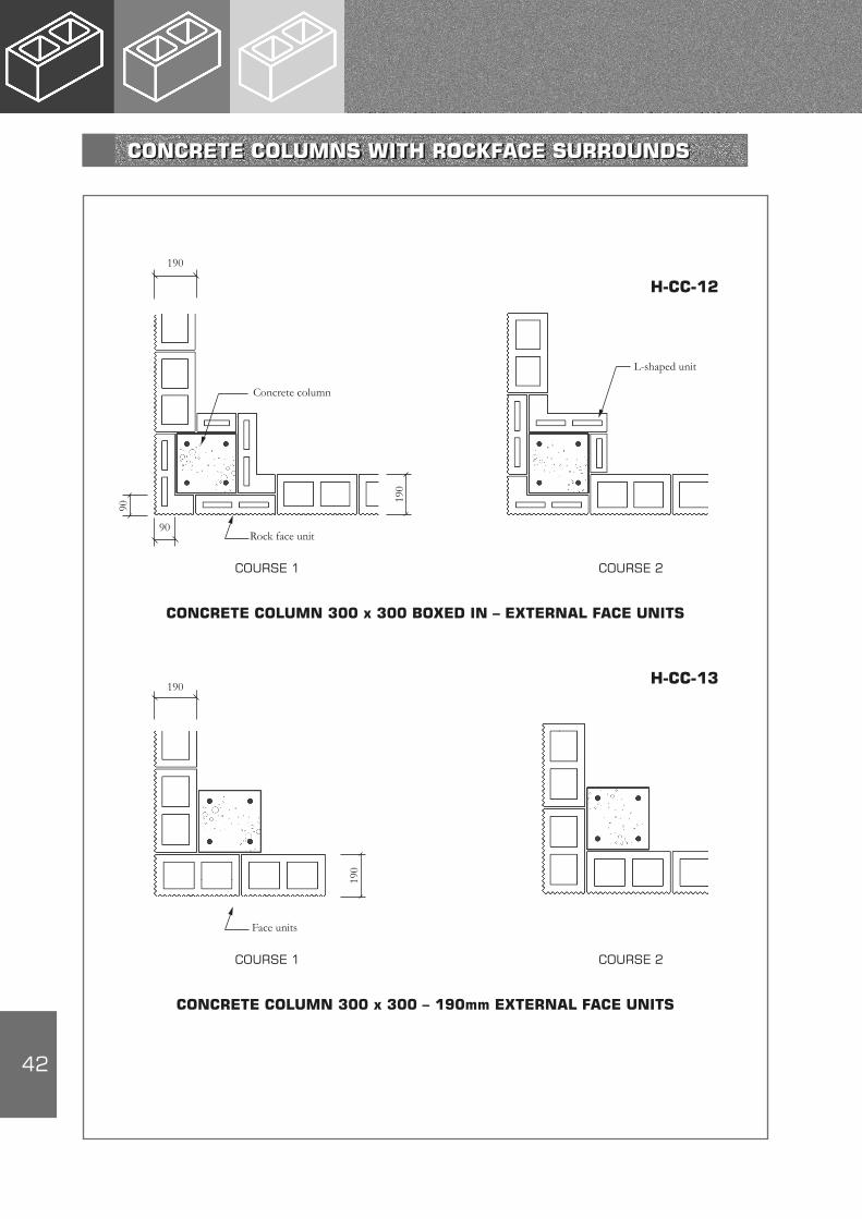
42
Concrete column
CONCRETE COLUMN 300 x 300 BOXED IN – EXTERNAL FACE UNITS
190
COURSE 1
Rock face unit90
90
COURSE 2
H-CC-12
L-shaped unit
190
CONCRETE COLUMN 300 x 300 – 190mm EXTERNAL FACE UNITS
190
COURSE 1
Face units
COURSE 2
H-CC-13
190
CONCRETE COLUMNS WITH ROCKFACE SURROUNDS
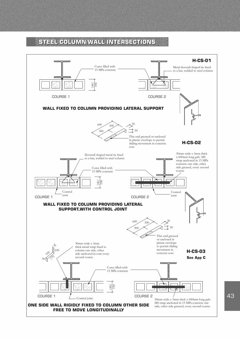
43
H-CS-01
H-CS-02
H-CS-03See App C
WALL FIXED TO COLUMN PROVIDING LATERAL SUPPORT
WALL FIXED TO COLUMN PROVIDING LATERAL SUPPORT,WITH CONTROL JOINT
ONE SIDE WALL RIGIDLY FIXED TO COLUMN OTHER SIDE FREE TO MOVE LONGITUDINALLY
600
50
30
300
300
600
50
30
300
300
50 (70)10
0
30
100
140/
190
140/
190
140/
190
COURSE 1 COURSE 2
COURSE 1 COURSE 2
COURSE 1 COURSE 2
Cores filled with 15 MPa concrete
Metal dovetail shaped tie fixed to a bar, welded to steel column
This end greased or enclosed in plastic envelope to permit sliding movement in concrete core
This end greased or enclosed in plastic envelope to permit sliding movement in concrete core
Dovetail shaped metal tie fixed to a bar, welded to steel column
Cores filled with 15 MPa concrete
30mm wide x 3mm thick x 600mm long galv. MS strap anchored in 15 MPa concrete one side, other side greased, every second course
Control joint
30mm wide x 3mm thick metal strap fixed to column one side, other side anchored in core every second course
30mm wide x 3mm thick x 600mm long galv. MS strap anchored in 15 MPa concrete one side, other side greased, every second course
Cores filled with 15 MPa concrete
Control joint
Control joint
STEEL COLUMN/WALL INTERSECTIONS
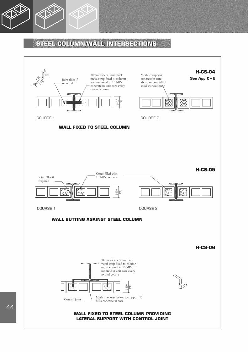
44
H-CS-04See App C+E
WALL FIXED TO STEEL COLUMN
50 (70)10
0
30100
COURSE 1 COURSE 2
Mesh to support concrete in core above or core filled solid without mesh
Joint filler if required
140/
190
30mm wide x 3mm thick metal strap fixed to column and anchored in 15 MPa concrete in unit core every second course
H-CS-05
WALL BUTTING AGAINST STEEL COLUMN
COURSE 1 COURSE 2
Joint filler if required
140/
190
Cores filled with 15 MPa concrete
H-CS-06
140/
190
30mm wide x 3mm thick metal strap fixed to column and anchored in 15 MPa concrete in unit core every second course
Control jointMesh in course below to support 15 MPa concrete in core
WALL FIXED TO STEEL COLUMN PROVIDING LATERAL SUPPORT WITH CONTROL JOINT
STEEL COLUMN/WALL INTERSECTIONS
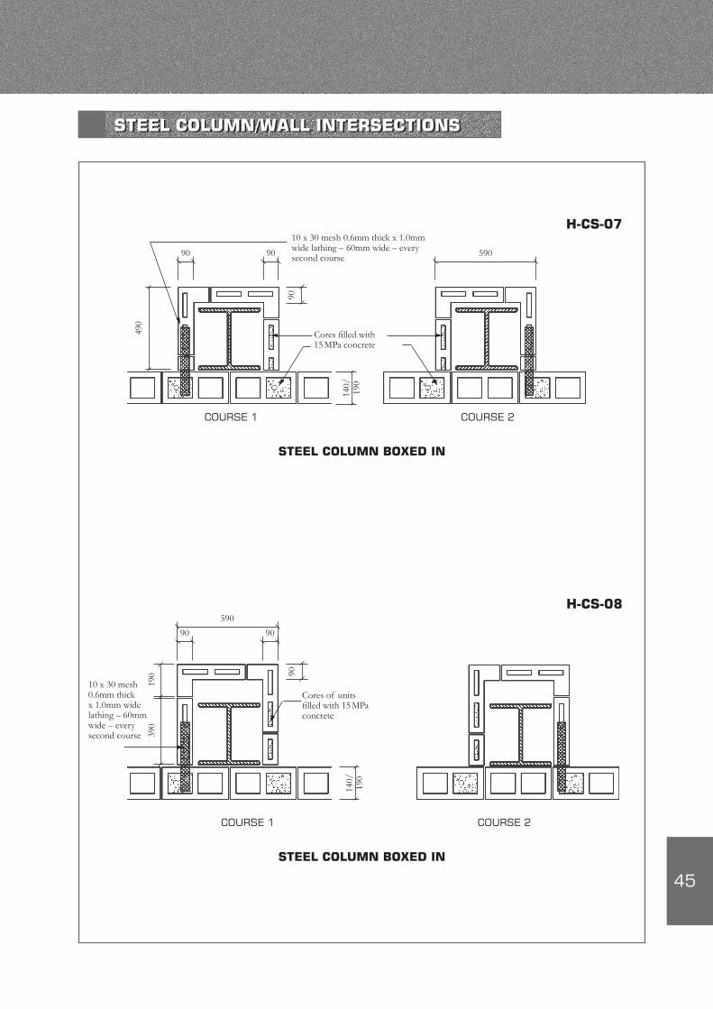
45
COURSE 1
Cores filled with 15 MPa concrete
490
10 x 30 mesh 0.6mm thick x 1.0mm wide lathing – 60mm wide – every second course
H-CS-07
STEEL COLUMN BOXED IN
COURSE 2
140/
190
90 90
90
590
COURSE 1
Cores of units filled with 15 MPa concrete
390
10 x 30 mesh 0.6mm thick x 1.0mm wide lathing – 60mm wide – every second course
H-CS-08
STEEL COLUMN BOXED IN
COURSE 2
140/
190
90 90
90
190
590
STEEL COLUMN/WALL INTERSECTIONS
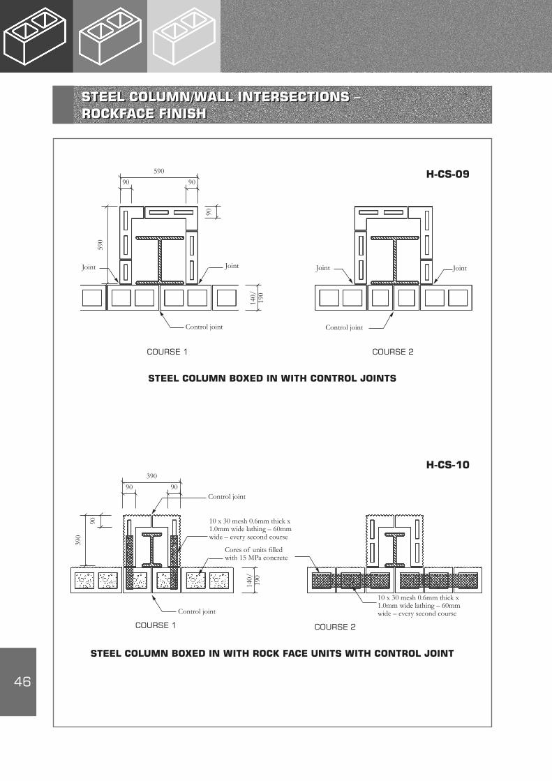
46
COURSE 1
Joint
590
H-CS-09
STEEL COLUMN BOXED IN WITH CONTROL JOINTS
140/
190
90 90
90
590
Joint Joint
Control joint
COURSE 2
Control joint
Joint
COURSE 1
Cores of units filled with 15 MPa concrete
390
H-CS-10
STEEL COLUMN BOXED IN WITH ROCK FACE UNITS WITH CONTROL JOINT
140/
190
90 90
90
390
Control joint
COURSE 2
Control joint
10 x 30 mesh 0.6mm thick x 1.0mm wide lathing – 60mm wide – every second course
10 x 30 mesh 0.6mm thick x 1.0mm wide lathing – 60mm wide – every second course
STEEL COLUMN/WALL INTERSECTIONS – ROCKFACE FINISH
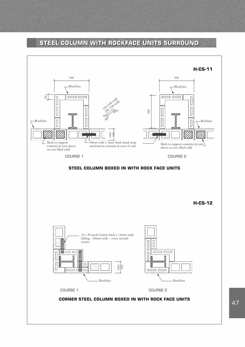
47
COURSE 1
H-CS-11
STEEL COLUMN BOXED IN WITH ROCK FACE UNITS
140/
190
90
590
Rockface
Mesh to support concrete in core above or core filled solid
COURSE 2
Rockface
Rockface
30mm wide x 3mm thick metal strap anchored in concrete in core of unit Mesh to support concrete in core
above or core filled solid
Rockface
590
590
5030
50150 (1
40 wall)
200 (1
90 wall)
COURSE 1
H-CS-12
Rockface
COURSE 2
10 x 30 mesh 0.6mm thick x 1.0mm wide lathing – 60mm wide – every second course
140/
190
CORNER STEEL COLUMN BOXED IN WITH ROCK FACE UNITS
Rockface
STEEL COLUMN WITH ROCKFACE UNITS SURROUND
48
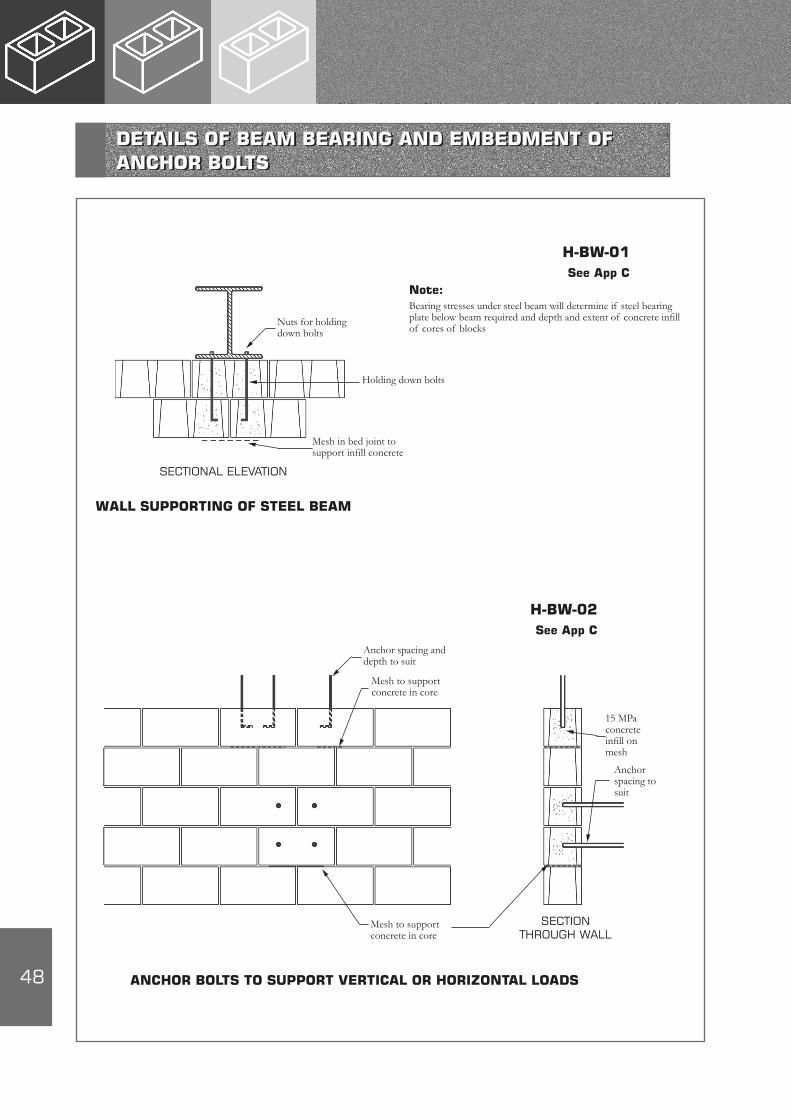
Note:Bearing stresses under steel beam will determine if steel bearing plate below beam required and depth and extent of concrete infill of cores of blocks
SECTIONAL ELEVATION
H-BW-01See App C
WALL SUPPORTING OF STEEL BEAM
Mesh in bed joint to support infill concrete
Holding down bolts
Nuts for holding down bolts
SECTION THROUGH WALL
H-BW-02See App C
ANCHOR BOLTS TO SUPPORT VERTICAL OR HORIZONTAL LOADS
Anchor spacing and depth to suit
Mesh to support concrete in core
Mesh to support concrete in core
Anchor spacing to suit
15 MPa concrete infill on mesh
DETAILS OF BEAM BEARING AND EMBEDMENT OF ANCHOR BOLTS
49
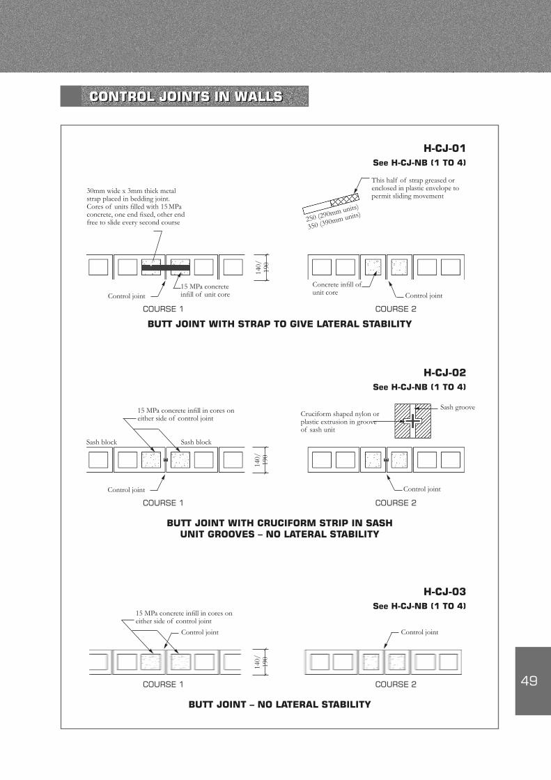
30mm wide x 3mm thick metal strap placed in bedding joint. Cores of units filled with 15 MPa concrete, one end fixed, other end free to slide every second course
This half of strap greased or enclosed in plastic envelope to permit sliding movement
250 (290mm units)
350 (390mm units)
15 MPa concrete infill of unit coreControl joint
Concrete infill of unit core Control joint
COURSE 1
BUTT JOINT WITH STRAP TO GIVE LATERAL STABILITY
COURSE 2
H-CJ-01See H-CJ-NB (1 TO 4)
15 MPa concrete infill in cores on either side of control joint
Cruciform shaped nylon or plastic extrusion in groove of sash unit
Control joint Control joint
BUTT JOINT WITH CRUCIFORM STRIP IN SASH UNIT GROOVES – NO LATERAL STABILITY
H-CJ-02See H-CJ-NB (1 TO 4)
Sash block
140/
190
140/
190
Sash block
Sash groove
COURSE 1 COURSE 2
BUTT JOINT – NO LATERAL STABILITY
COURSE 1 COURSE 2
H-CJ-03See H-CJ-NB (1 TO 4)
15 MPa concrete infill in cores on either side of control joint
Control joint Control joint
140/
190
CONTROL JOINTS IN WALLS
50
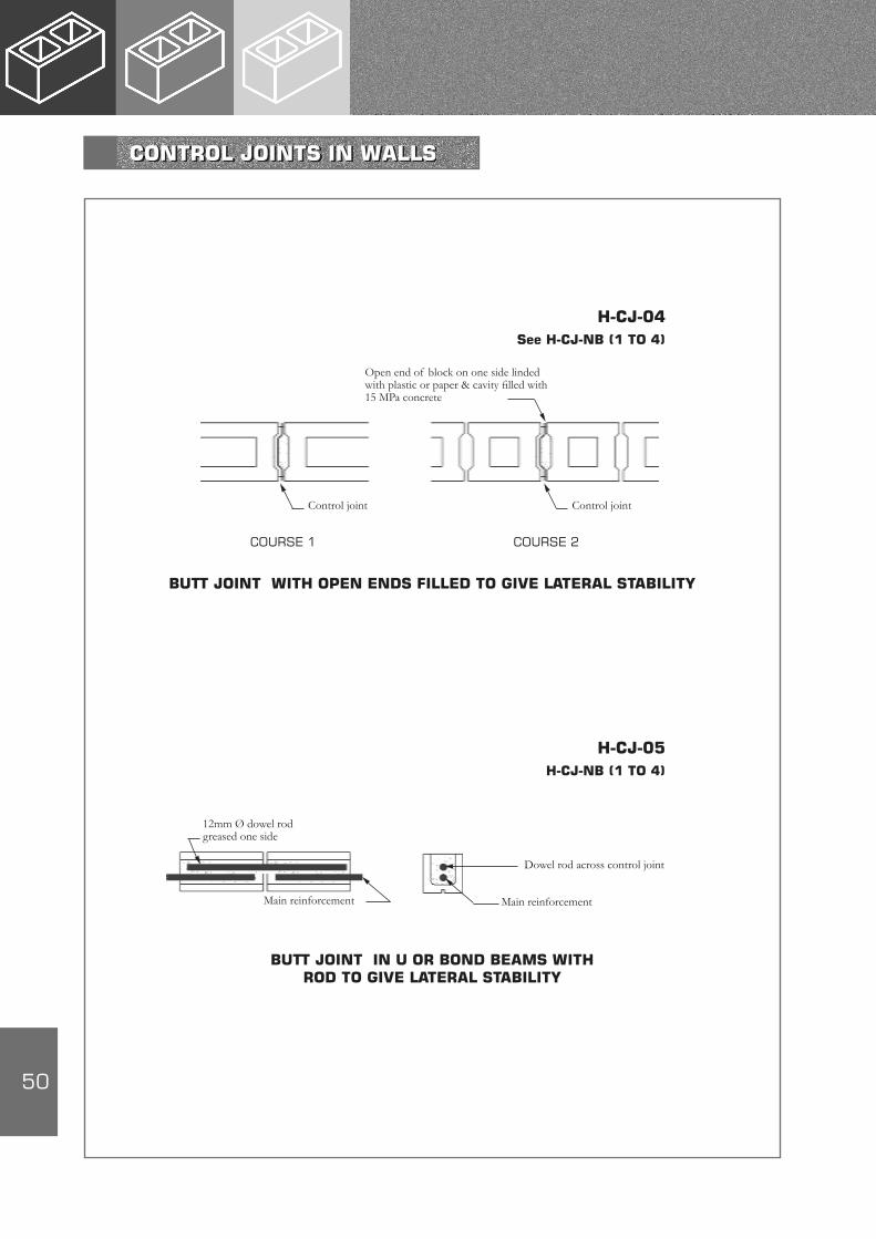
BUTT JOINT IN U OR BOND BEAMS WITH ROD TO GIVE LATERAL STABILITY
COURSE 1 COURSE 2
H-CJ-04See H-CJ-NB (1 TO 4)
Open end of block on one side linded with plastic or paper & cavity filled with 15 MPa concrete
Control joint Control joint
BUTT JOINT WITH OPEN ENDS FILLED TO GIVE LATERAL STABILITY
H-CJ-05H-CJ-NB (1 TO 4)
Dowel rod across control joint
Main reinforcementMain reinforcement
12mm Ø dowel rod greased one side
CONTROL JOINTS IN WALLS
51
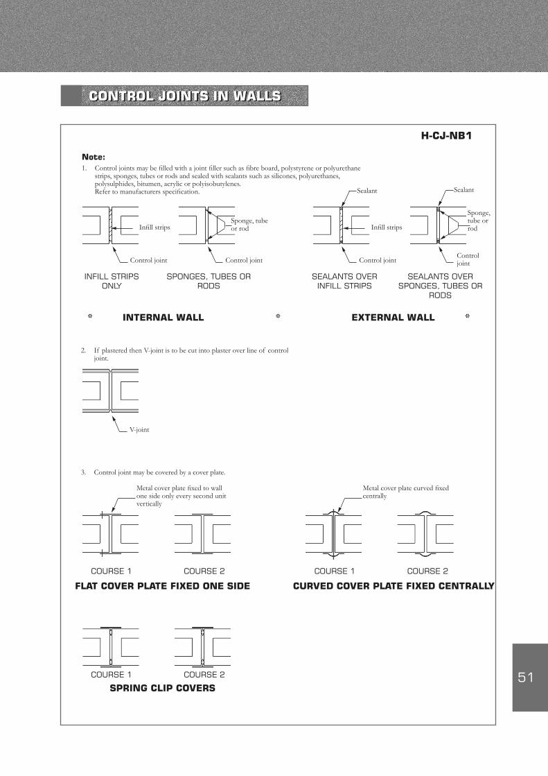
INFILL STRIPS ONLY
SPONGES, TUBES OR RODS
H-CJ-NB1
Metal cover plate fixed to wall one side only every second unit vertically
INTERNAL WALL
Note:1. Control joints may be filled with a joint filler such as fibre board, polystyrene or polyurethane
strips, sponges, tubes or rods and sealed with sealants such as silicones, polyurethanes, polysulphides, bitumen, acrylic or polyisobutylenes.
Refer to manufacturers specification.
SEALANTS OVER INFILL STRIPS
SEALANTS OVER SPONGES, TUBES OR
RODS
EXTERNAL WALL
Infill strips
Control joint Control joint
Sponge, tube or rod
Control jointControl joint
Sealant Sealant
V-joint
Metal cover plate curved fixed centrally
COURSE 1 COURSE 2
FLAT COVER PLATE FIXED ONE SIDE
COURSE 1 COURSE 2
CURVED COVER PLATE FIXED CENTRALLY
COURSE 1 COURSE 2
SPRING CLIP COVERS
Spring clip
3. Control joint may be covered by a cover plate.
2. If plastered then V-joint is to be cut into plaster over line of control joint.
Sponge, tube or rodInfill strips
** *
CONTROL JOINTS IN WALLS
52
SECTION ELEVATION
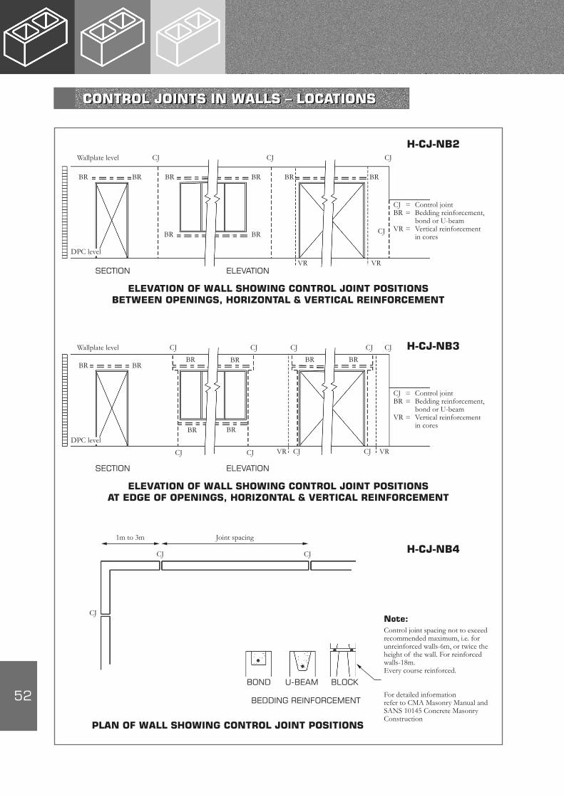
H-CJ-NB2Wallplate level
ELEVATION OF WALL SHOWING CONTROL JOINT POSITIONS BETWEEN OPENINGS, HORIZONTAL & VERTICAL REINFORCEMENT
CJ CJ CJ
BR BR BR BR BR BR
BR BR CJ
VR VR
DPC level
CJ = Control jointBR = Bedding reinforcement, bond or U-beamVR = Vertical reinforcement in cores
SECTION ELEVATION
H-CJ-NB3Wallplate level
ELEVATION OF WALL SHOWING CONTROL JOINT POSITIONS AT EDGE OF OPENINGS, HORIZONTAL & VERTICAL REINFORCEMENT
CJ CJ CJ
BR BRBR BR
BR BR
CJVR VR
DPC level
CJ = Control jointBR = Bedding reinforcement, bond or U-beamVR = Vertical reinforcement in cores
CJ CJ
BR BR
CJ
CJ CJ
BOND
H-CJ-NB4
PLAN OF WALL SHOWING CONTROL JOINT POSITIONS
U-BEAM BLOCK
BEDDING REINFORCEMENT
1m to 3m
CJ CJ
CJ
Joint spacing
Note:Control joint spacing not to exceed recommended maximum, i.e. for unreinforced walls-6m, or twice the height of the wall. For reinforced walls-18m. Every course reinforced.
For detailed information refer to CMA Masonry Manual and SANS 10145 Concrete Masonry Construction
CONTROL JOINTS IN WALLS – LOCATIONS

53
REINFORCEMENT BOTTOM ONLY
REINFORCEMENT TOP ONLY
REINFORCED AROUND CORNER
CUT HOLLOW UNITS TO ACCOMMODATE REINFORCEMENT
H-RE-01
H-RE-02
SINGLE VERTICAL BAR
VERTICAL AND HORIZONTAL BARS
VARIOUS WIRE POSITIONERS TO HOLD REINFORCEMENT IN POSITION BEFORE CONCRETING
DETAILS OF TYPES OF REINFORCEMENT AND FIXING
54
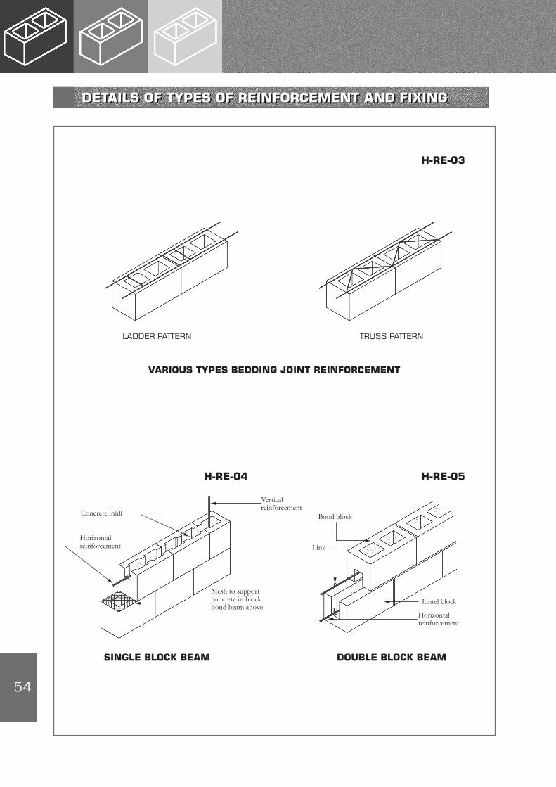
LADDER PATTERN TRUSS PATTERN
VARIOUS TYPES BEDDING JOINT REINFORCEMENT
H-RE-03
H-RE-05
SINGLE BLOCK BEAM DOUBLE BLOCK BEAM
Mesh to support concrete in block bond beam above
Concrete infill
Horizontal reinforcement
Vertical reinforcement
Horizontal reinforcement
Lintel block
Link
Bond block
H-RE-04
DETAILS OF TYPES OF REINFORCEMENT AND FIXING

55
SINGLE BAR IN BEAM
CANTILEVER WALL
H-RE-06
H-RE-07See H-RE-NB
Reinforcing bars alternate sides if required to engineers requirements
REINFORCEMENT DETAILS – BEAMS
56
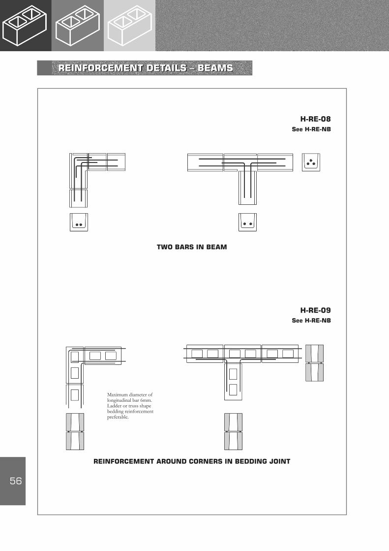
TWO BARS IN BEAM
H-RE-08See H-RE-NB
Maximum diameter of longitudinal bar 6mm. Ladder or truss shape bedding reinforcement preferable.
REINFORCEMENT AROUND CORNERS IN BEDDING JOINT
H-RE-09See H-RE-NB
REINFORCEMENT DETAILS – BEAMS
57
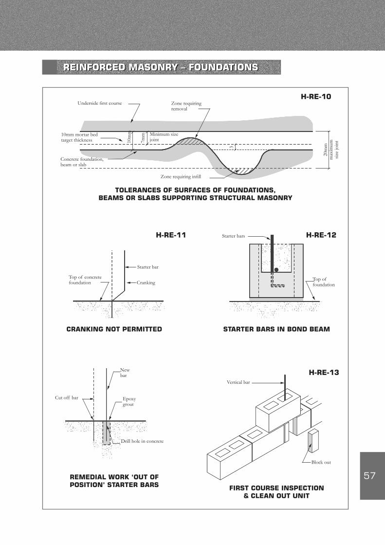
H-RE-10
H-RE-11
H-RE-13
Underside first course Zone requiring removal
10mm mortar bed target thickness
Minimum size joint
Concrete foundation, beam or slab
Zone requiring infill
10m
m
7mm
3
20m
m
max
imum
si
ze jo
int
TOLERANCES OF SURFACES OF FOUNDATIONS, BEAMS OR SLABS SUPPORTING STRUCTURAL MASONRY
H-RE-12
CRANKING NOT PERMITTED
Top of concrete foundation
Starter bar
Cranking
Starter bars
Top of foundation
STARTER BARS IN BOND BEAM
REMEDIAL WORK ‘OUT OF POSITION’ STARTER BARS FIRST COURSE INSPECTION
& CLEAN OUT UNIT
Vertical bar
Cut off bar
New bar
Epoxy grout
Drill hole in concrete
Block out
REINFORCED MASONRY – FOUNDATIONS

58
Note:Bond blocks can be cut or manufactured. Typical dimensions as shown.Outer shell thickness: • Fairface – 32mm • Rockface – 42mmBond blocks can be made with same colour and texture as standard blocks.
32 32
3215
8
190
15
32 4714
3
15
SECTION WITH SASH GROOVE
SECTION WITHOUT SASH GROOVE
Note:Usually 190mm long, in fair face only with sash groove in soffit
SECTION
PLANPLAN
SECTION SECTION
U-BEAM OR LINTEL BLOCK
BOND BLOCK
TWO BLOCK BEAM USING LINTEL BLOCK
TWO BLOCK BEAM USING BOND BLOCKS
Note:Two-block beams to be cast in one operation
Mesh supporting concrete
190
390
32/42 32
9010
0
190
H-RE-NBSee App E
Standard block
Lintel block
Bond block
Bond block
Cover not < 15mm
REINFORCEMENT COVER IN BEDDING JOINT
Reinforcing
REINFORCEMENT DETAILS – U-BEAM/LINTEL AND BOND BLOCKS
59
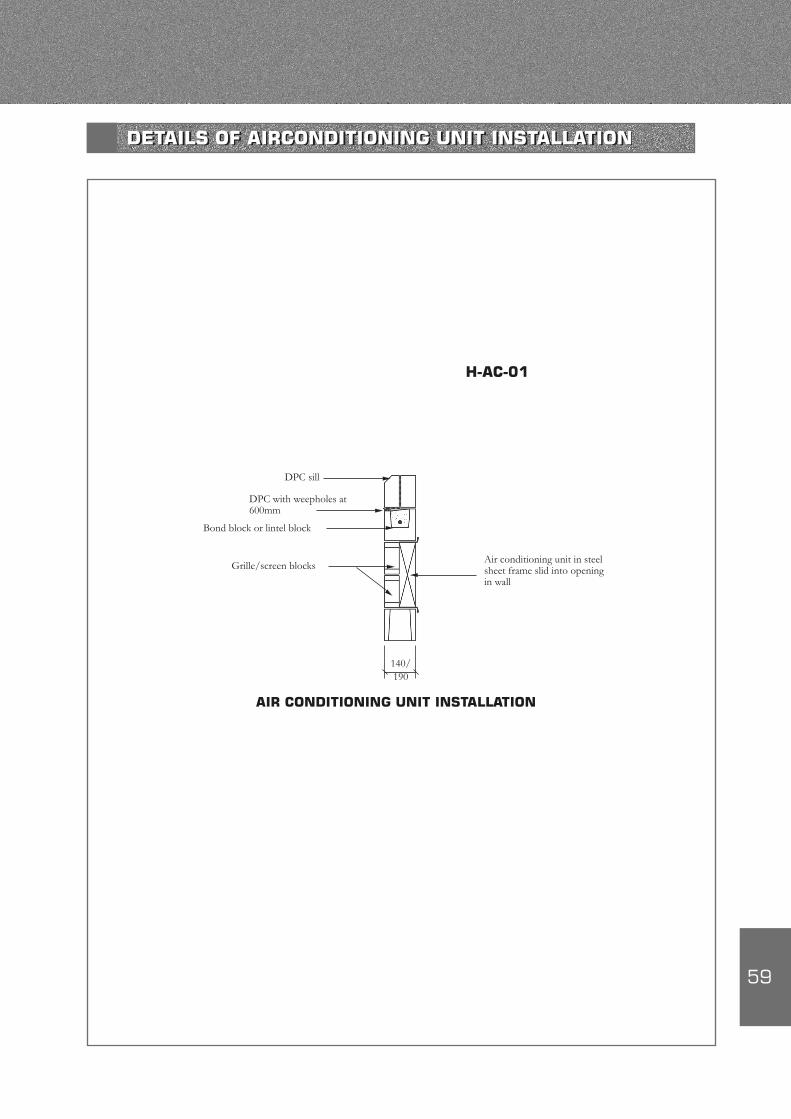
H-AC-01
Grille/screen blocksAir conditioning unit in steel sheet frame slid into opening in wall
140/ 190
AIR CONDITIONING UNIT INSTALLATION
DPC sill
DPC with weepholes at 600mm
Bond block or lintel block
DETAILS OF AIRCONDITIONING UNIT INSTALLATION
60
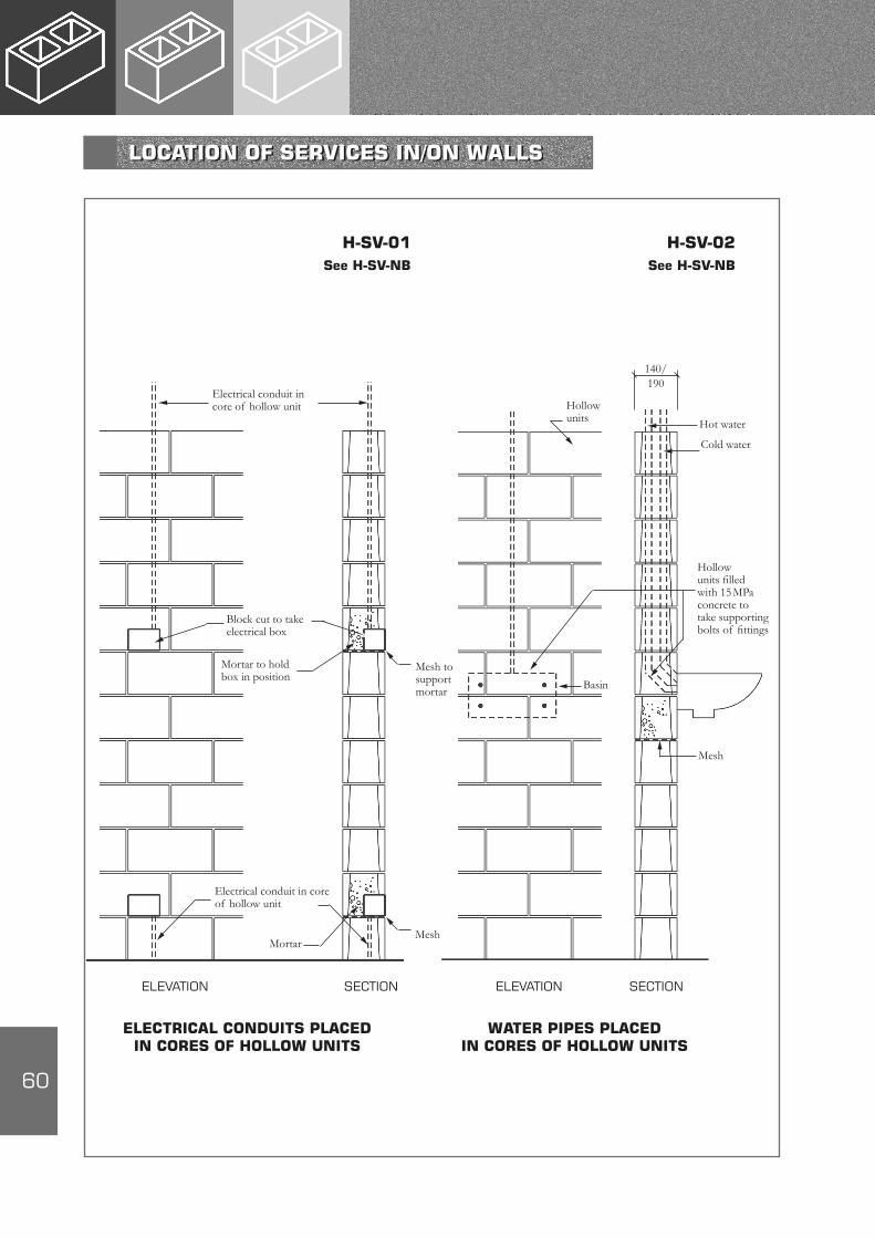
ELEVATION SECTION ELEVATION SECTION
ELECTRICAL CONDUITS PLACED IN CORES OF HOLLOW UNITS
WATER PIPES PLACED IN CORES OF HOLLOW UNITS
H-SV-01See H-SV-NB
H-SV-02See H-SV-NB
Electrical conduit in core of hollow unit
Electrical conduit in core of hollow unit
MortarMesh
Hollow units Hot water
Cold water
Mesh
Block cut to take electrical box
Mortar to hold box in position
Hollow units filled with 15 MPa concrete to take supporting bolts of fittings
Mesh to support mortar
140/190
Basin
LOCATION OF SERVICES IN/ON WALLS

61
ELEVATION SECTION ELEVATION SECTION
ELECTRICAL CONDUITS CHASED INTO SOLID UNITS
WATER PIPES CHASED INTO SOLID UNITS
H-SV-03See H-SV-NB
H-SV-04See H-SV-NB
Hollow units
Solid units
Elec. fittings
Conduit chased into solid units
190 190
190
190
Hollow units
Solid units
Pipes chased into walls
Basin
LOCATION OF SERVICES IN/ON WALLS

62
ELEVATION SECTION ELEVATION SECTION
HORIZONTAL SERVICES LOCATED IN U-BLOCKS
U-blocks
190
VERTICAL SERVICES CHASED INTO SHELLS OF HOLLOW UNITS
190
190
U-blocks
Hollow units
Services chased into shell of hollow units
–Chases cut into surface with angle grinder or similar
Service to be in shell of block
H-SV-NB
Note:If chases through shell of unit then core to be filled with 15 MPa concrete
Note:1. ‘Sleeves, chases and holes should, as far as possible, be provided during the erection of the masonry, or purpose-made
chased units should be built in position agreed by the designer’. Refer to SANS 10164-12. Vertical chases in solid units should not exceed one third of the wall/leaf thickness and horizontal chases should not
exceed one sixth of the wall/leaf thickness. (See Note 4)3. Walls constructed of hollow units should not be chased at all and services should be located in the unit cavities. Where
chasing in these units is unavoidable it should be no deeper than 15mm or the core of the unit shall be filled with 15 MPa concrete.
4. Horizontal chasing should be avoided where possible. Ensure that chases do not impare strength, stability and fire resistance properties of the walling below the minimum permitted.
H-SV-06See H-SV-NB
H-SV-05See H-SV-NB
LOCATION OF SERVICES IN/ON WALLS
63
APPENDIX A DEFINITIONS 65
APPENDIX B REFERENCES 66
APPENDIX C ANCHORS-WALLS 68
APPENDIX D ROOF FIXING 69
APPENDIX E TIES, STRAPS AND BEDDING REINFORCEMENT 70
APPENDIX F DETAILING PRACTICE FOR REINFORCED MASONRY 71
APPENDIX G V-JOINT IN PLASTERS AND MORTARS 83
APPENDICES

64
NOTES
65
¹ SANS 10164-2 (See Appendix B)
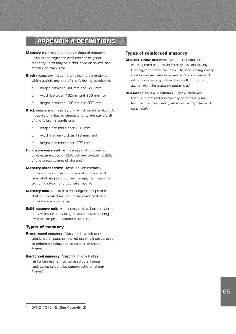
Types of reinforced masonryGrouted-cavity masonry: Two parallel single-leaf
walls spaced at least 50 mm apart, effectively tied together with wall ties. The intervening cavity contains steel reinforcement and is so filled with infill concrete or grout as to result in common action with the masonry under load¹.
Reinforced hollow blockwork: Hollow blockwork that is reinforced horizontally or vertically (or both) and subsequently wholly or partly filled with concrete¹.
Masonry wall means an assemblage of masonry units joined together with mortar or grout. Masonry units may be either solid or hollow, and of brick or block size¹.
Block means any masonry unit having dimensions, which satisfy any one of the following conditions:
a) length between 300mm and 650 mm;
b) width between 130mm and 300 mm; or
c) height between 120mm and 300 mm.
Brick means any masonry unit which is not a block. A masonry unit having dimensions, which satisfy all of the following conditions:
a) length not more than 300 mm;
b) width not more than 130 mm; and
c) height not more than 120 mm.
Hollow masonry unit: A masonry unit containing cavities in excess of 25% but not exceeding 60%, of the gross volume of the unit¹.
Masonry accessories: These include masonry anchors, connectors and ties other than wall ties; shelf angles and their fixings; wall ties that transmit shear; and bed joint mesh¹.
Masonry unit: A unit of a rectangular shape and that is intended for use in the construction of bonded masonry walling¹.
Solid masonry unit: A masonry unit either containing no cavities or containing cavities not exceeding 25% of the gross volume of the unit¹.
Types of masonryPrestressed masonry: Masonry in which pre-
tensioned or post-tensioned steel is incorporated to enhance resistance to tensile or shear forces¹.
Reinforced masonry: Masonry in which steel reinforcement is incorporated to enhance resistance to tensile, compressive or shear forces¹.
APPENDIX A DEFINITIONS

66
design guide.
Concrete Masonry Construction
SANS 073-1974
Safe application of masonry-type facings to
buildings
SANS 10145-2000
Concrete masonry construction
SANS 10155-1980
Accuracy in buildings
MATERIALS OF CONSTRUCTIONAggregates
SANS 794-2002 Aggregates of low density
SANS 1083-2002 Aggregates from natural sources – aggregates for cement.
Cement
SANS 50197-1:2000 Cement Part 1: Composition, specifications and conformity criteria, for common cements.
SANS 50413-1:1994 Masonry cement Part 1: Specification.
SANS 1491-1989 Portland cement extenders Part 1: Ground granulated blastfurnace slag. Part 2: Fly ash. Part 3: Condensed silica fume.
Dampproof courses
SANS 248-1973 Bituminous dampproof course
SANS 298-1975 Mastic asphalt for dampproof courses and tanking
SANS 952-1985
Polyolefin film for dampproofing and waterproofing
in buildings
Reinforcement
SANS 190-2:1984
Expanded metal
Part 2: Building products
STANDARDS AND CODES OF PRACTICE ON THE USE OF CONCRETE MASONRYMANUFACTURE OF CONCRETE MASONRY UNITS
SANS 1215 – 1984 Concrete masonry units
USE OF MASONRY UNITS
Planning, design and specifications
SANS 993-1972
Modular coordination in building
SANS 10021-2002
Waterproofing of buildings
SANS 10155-1980
Accuracy in buildings
SANS 10249-1993
Masonry walling
NBRI R/Bou – 602
Fire resistance ratings – wall constructed of
concrete blocks
Building Regulations
National Building Regulations and Building Standards
Act 1977 revised 1990
SANS10400-1990
Application of the National Building Regulations
National Home Builders Registration Council Home
Building Manual
Structural Design
SANS 10100-1:2000
The structural use of concrete
Part 1: Design
SANS 10160 -1989
The general procedures and loadings to be
adopted for the design of buildings.
SANS 10161-1980
The design of foundations for buildings
SANS 10164.
The structural use of masonry
Part 1-1980: Unreinforced masonry walling
Part 2-2003: Reinforced and prestressed
masonry walling
SANS 1504-1990
Prestressed concrete lintels
Crofts, FS: Lane JW Structural concrete masonry, a
APPENDIX B REFERENCES
67
SANS 920-1985
Steel bars for concrete reinforcement
SANS 1024-1991
Welded steel fabric for reinforcement of concrete
Sealants
SANS 110-1973 Sealing compounds for building industry, two-component, polysulphide base
SANS 1077-1984 Sealing compounds for the building and construction industry, two component polyurethane base
SANS 1305-1980 Sealing compounds for the building industry, one-component silicone-rubber base
Lime
SANS 523-2002 Limes for use in building
Sand
SANS 1090-2002 Aggregates from natural sources. Fine aggregate for plaster and mortar
Wall ties
SANS 28-1986 Metal ties for cavity walls
USEFUL BRITISH STANDARDSBS 1014-1975 (1986)
Pigments for portland cement and portland cement products
BS 4551-1998 Methods of testing mortar, screeds and plasters
BS 4887 Mortar admixtures Part 1: 1986: Specification for air-entraining (plasticizing) admixtures Part 2: 1987: Specification for set-retarding admixtures
BS 6477-1984 Water repellents for masonry surfaces
CONCRETE MANUFACTURERS ASSOCIATION PUBLICATIONSMasonry Manual 6th edition
Free-standing walls Design guide Technical note: Unreinforced Reinforced
Lintels Design guide Technical note
Build your house Step by step with building plans
68
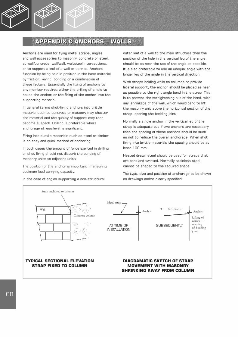
TYPICAL SECTIONAL ELEVATION STRAP FIXED TO COLUMN
DIAGRAMATIC SKETCH OF STRAP MOVEMENT WITH MASONRY
SHRINKING AWAY FROM COLUMN
AT TIME OF INSTALLATION
SUBSEQUENTLY
Strap anchored to column
Wall
Metal strap
AnchorAnchor
Lifting of corner – opening of bedding joint
Concrete column
Movement
Anchors are used for tying metal straps, angles and wall accessories to masonry, concrete or steel, at wall/concrete, wall/wall, wall/steel intersections, or to support a leaf of a wall or service. Anchors function by being held in position in the base material by friction, keying, bonding or a combination of these factors. Essentially the fixing of anchors to any member requires either the drilling of a hole to house the anchor, or the firing of the anchor into the supporting material.
In general terms shot-firing anchors into brittle material such as concrete or masonry may shatter the material and the quality of support may then become suspect. Drilling is preferable where anchorage stress level is significant.
Firing into ductile materials such as steel or timber is an easy and quick method of anchoring.
In both cases the amount of force exerted in drilling or shot firing should not disturb the bonding of masonry units to adjacent units.
The position of the anchor is important in ensuring optimum load carrying capacity.
In the case of angles supporting a non-structural
outer leaf of a wall to the main structure then the
position of the hole in the vertical leg of the angle
should be as near the top of the angle as possible.
It is also preferable to use an unequal angle with the
longer leg of the angle in the vertical direction.
With straps holding walls to columns to provide
lateral support, the anchor should be placed as near
as possible to the right angle bend in the strap. This
is to prevent the straightening out of the bend, with,
say, shrinkage of the wall, which would tend to lift
the masonry unit above the horizontal section of the
strap, opening the bedding joint.
Normally a single anchor in the vertical leg of the
strap is adequate but if two anchors are necessary
then the spacing of these anchors should be such
as not to reduce the overall anchorage. When shot
firing into brittle materials the spacing should be at
least 100 mm.
Heated drawn steel should be used for straps that
are bent and twisted. Normally stainless steel
cannot be shaped to the required shape.
The type, size and position of anchorage to be shown
on drawings and/or clearly specified.
APPENDIX C ANCHORS – WALLS
69
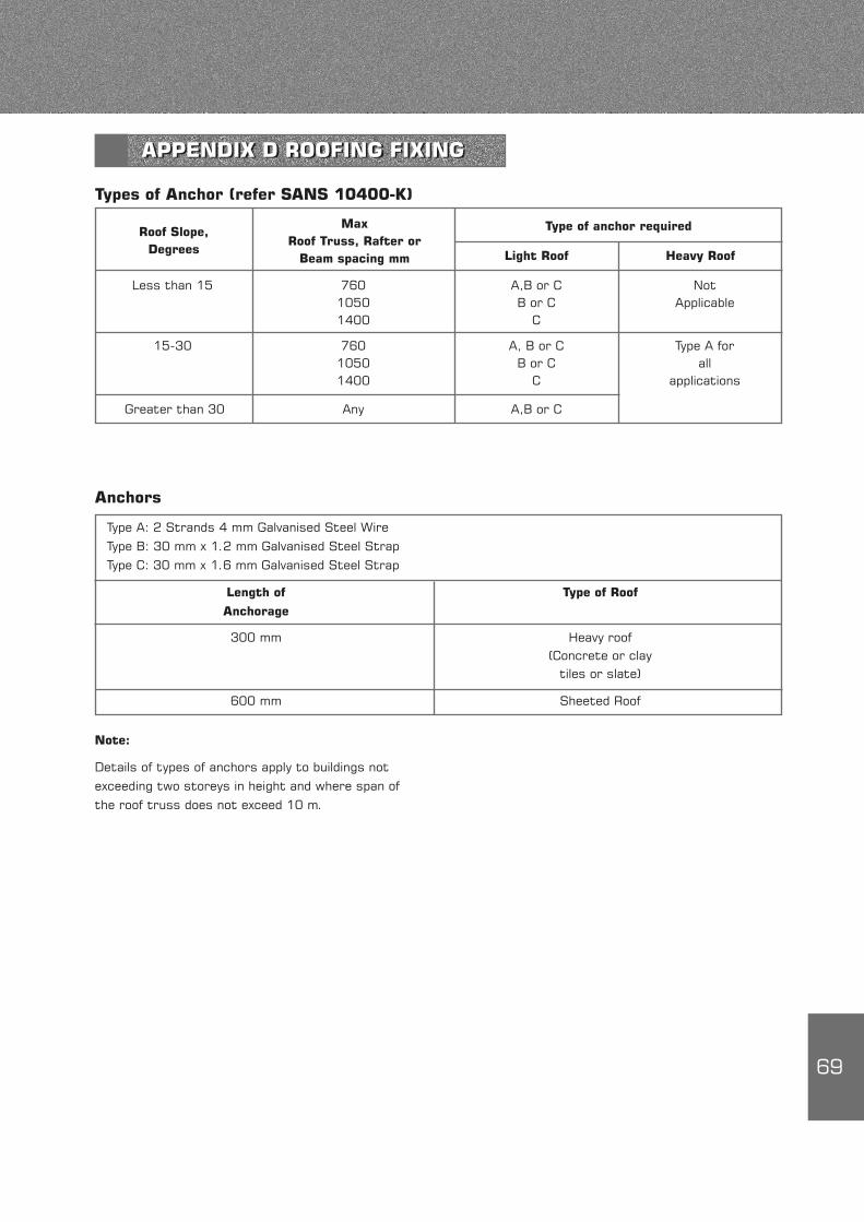
Less than 15 760 A,B or C Not 1050 B or C Applicable 1400 C
15-30 760 A, B or C Type A for 1050 B or C all 1400 C applications
Greater than 30 Any A,B or C
Types of Anchor (refer SANS 10400-K)
Anchors
Type A: 2 Strands 4 mm Galvanised Steel Wire Type B: 30 mm x 1.2 mm Galvanised Steel Strap Type C: 30 mm x 1.6 mm Galvanised Steel Strap
Length of Type of Roof
Anchorage
300 mm Heavy roof (Concrete or clay tiles or slate)
600 mm Sheeted Roof
Note:
Details of types of anchors apply to buildings not exceeding two storeys in height and where span of the roof truss does not exceed 10 m.
APPENDIX D ROOFING FIXING
Roof Slope,Degrees
MaxRoof Truss, Rafter or
Beam spacing mm
Type of anchor required
Light Roof Heavy Roof
70
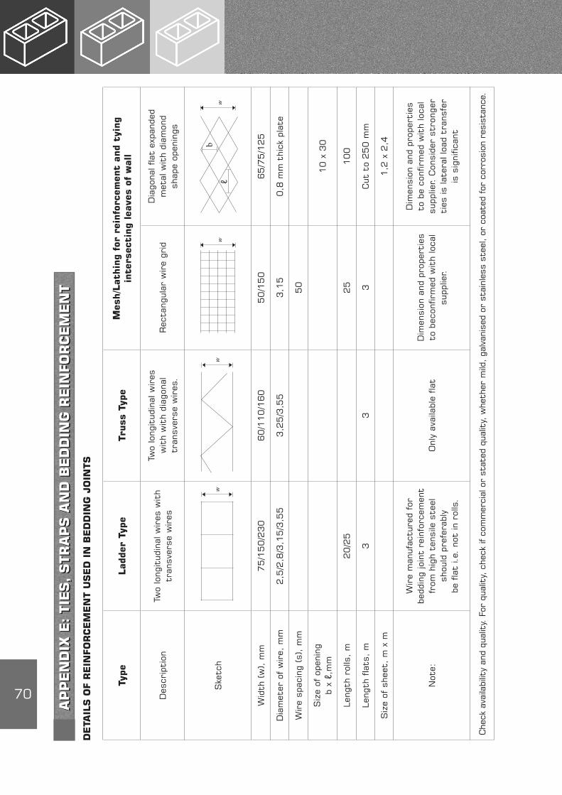
DETA
ILS O
F R
EIN
FO
RC
EM
EN
T U
SED
IN
BED
DIN
G J
OIN
TS
AP
PEN
DIX
E: TIE
S, STR
AP
S A
ND
BED
DIN
G R
EIN
FO
RC
EM
EN
T
Type
Lad
der
Type
Truss
Typ
eM
esh/L
athin
g fo
r re
info
rcem
ent
and
tyin
gin
ters
ecti
ng
leav
es o
f w
all
Des
crip
tion
Two
long
itud
inal
wir
es w
ith
tran
sver
se w
ires
Two
long
itud
inal
wir
esw
ith
wit
h di
agon
al
tran
sver
se w
ires
.R
ecta
ngul
ar w
ire
grid
Dia
gona
l fla
t ex
pand
ed
met
al w
ith
diam
ond
sh
ape
open
ings
Ske
tch
Wid
th (
w),
mm
75
/15
0/2
30
60
/11
0/1
60
50
/15
06
5/7
5/1
25
Dia
met
er o
f w
ire,
mm
2,5
/2,8
/3,1
5/3
,55
3,2
5/3
,55
3,1
50
,8 m
m t
hick
pla
te
Wir
e sp
acin
g (s
), m
m5
0
Siz
e of
ope
ning
b
x ℓ,
mm
10
x 3
0
Leng
th r
olls
, m
20
/25
25
10
0
Leng
th f
lats
, m
33
3C
ut t
o 2
50
mm
Siz
e of
she
et,
m x
m1
,2 x
2,4
Not
e:
Wir
e m
anuf
actu
red
for
bedd
ing
join
t re
info
rcem
ent
from
hig
h te
nsile
ste
el
shou
ld p
refe
rabl
y
be f
lat
i.e.
not
in r
olls
.
Onl
y av
aila
ble
flat
Dim
ensi
on a
nd p
rope
rtie
s to
bec
onfir
med
wit
h lo
cal
supp
lier.
Dim
ensi
on a
nd p
rope
rtie
s to
be
conf
irm
ed w
ith
loca
l su
pplie
r. C
onsi
der
stro
nger
ti
es is
late
ral l
oad
tran
sfer
is
sig
nific
ant
Che
ck a
vaila
bilit
y an
d qu
alit
y. F
or q
ualit
y, c
heck
if c
omm
erci
al o
r st
ated
qua
lity,
whe
ther
mild
, ga
lvan
ised
or
stai
nles
s st
eel,
or c
oate
d fo
r co
rros
ion
resi
stan
ce.
w
w
w
w
b
ℓ
71
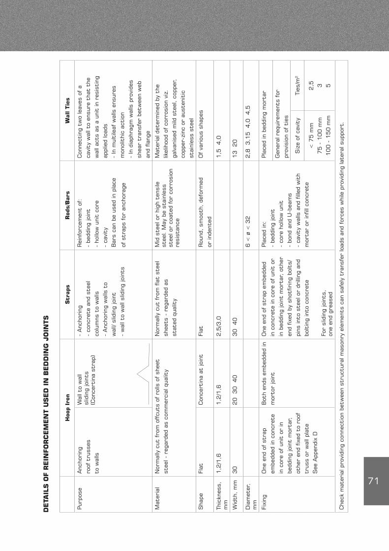
DETA
ILS O
F R
EIN
FO
RC
EM
EN
T U
SED
IN
BED
DIN
G J
OIN
TS
Hoo
p Ir
onStr
aps
Rod
s/B
ars
Wal
l Tie
s
Pur
pose
Anc
hori
ng
roof
tru
sses
to w
alls
Wal
l to
wal
l sl
idin
g jo
ints
(C
once
rtin
a st
rap)
- A
ncho
ring
- co
ncre
te a
nd s
teel
colu
mns
to
wal
ls
- A
ncho
ring
wal
ls t
o
wal
l/ sl
idin
g jo
int
- w
all t
o w
all s
lidin
g jo
ints
Rei
nfor
cem
ent
of:
- be
ddin
g jo
int
- ho
llow
uni
t co
re
- ca
vity
Bar
s ca
n be
use
d in
pla
ce
of s
trap
s fo
r an
chor
age
Con
nect
ing
two
leav
es o
f a
cavi
ty w
all t
o en
sure
tha
t th
e
wal
l act
s as
a u
nit
in r
esis
ting
appl
ied
load
s
- In
mul
tile
af w
alls
ens
ures
mon
olit
hic
acti
on
- In
dia
phra
gm w
alls
pro
vide
s
shea
r tr
ansf
er b
etw
een
web
and
flang
e
Mat
eria
lN
orm
ally
cut
fro
m o
ffcu
ts o
f ro
lls o
f sh
eet
stee
l - r
egar
ded
as c
omm
erci
al q
ualit
y
Nor
mal
ly c
ut fro
m fla
t st
eel
shee
ts -
reg
arde
d as
stat
ed q
ualit
y
Mid
ste
el o
r hi
gh t
ensi
le
stee
l. M
ay b
e st
ainl
ess
stee
l or
coat
ed for
cor
rosi
on
resi
stan
ce
Mat
eria
l det
erm
ined
by
the
likel
ihoo
d of
cor
rosi
on v
iz.
galv
anis
ed m
ild s
teel
, co
pper
,
copp
er-z
inc
or a
uste
niti
c
stai
nles
s st
eel
Sha
peFl
atC
once
rtin
a at
join
tFl
atR
ound
, sm
ooth
, de
form
ed
or in
dent
ed
Of va
riou
s sh
apes
Thic
knes
s,
mm
1,2
/1,6
1,2
/1,6
2,5
/3,0
1,5
4,0
Wid
th,
mm
30
20
3
0
40
30
4
013 20
Dia
met
er,
mm
6 <
ø <
32
2,8
3,1
5 4,0
4,5
Fixi
ngO
ne e
nd o
f st
rap
embe
dded
in c
oncr
ete
in c
ore
of u
nit
or in
bedd
ing
join
t m
orta
r,
othe
r en
d fix
ed t
o ro
of
trus
s or
wal
l pla
te
See
App
endi
x D
Bot
h en
ds e
mbe
dded
in
mor
tor
join
t
One
end
of st
rap
embe
dded
in c
oncr
ete
in c
ore
of u
nit
or
in b
eddi
ng jo
int
mor
tar, o
ther
end
fixed
by
shot
firin
g bo
lts/
pins
into
ste
el o
r dr
illin
g an
d
bolt
ing
into
con
cret
e
For
slid
ing
join
ts,
one
end
grea
sed
Pla
ced
in:
- be
ddin
g jo
int
- co
re h
ollo
w u
nit
- bo
nd a
nd U
-bea
ms
- ca
vity
wal
ls a
nd fill
ed w
ith
mor
tar
or in
fill c
oncr
ete
Pla
ced
in b
eddi
ng m
orta
r
Gen
eral
req
uire
men
ts for
prov
isio
n of
tie
s
Siz
e of
cav
ity
Ties
/m2
< 7
5 m
m
75 -
100 m
m
100 -
150 m
m
2,5 3 5
Che
ck m
ater
ial p
rovi
ding
con
nect
ion
betw
een
stru
ctur
al m
ason
ry e
lem
ents
can
saf
ely
tran
sfer
load
s an
d fo
rces
whi
le p
rovi
ding
late
ral s
uppo
rt.

72
R B Watermeyer Pr. Eng. B Sc Eng, MSAICE, MSAConsE Soderlund & Schutte Inc.
1. INTRODUCTIONDrawings depicting details of reinforcement in masonry elements, supplemented by specifications are required to translate designs into physical realities. Detailing is therefore the most important link between good design and quality construction. Accordingly detailing of reinforcement should be kept simple, clear and practical while drawings should clearly define and depict the design requirements in a comprehensible manner. SANS 10164-2 offers guidance in this regard, the main provisions of which are highlighted and illustrated hereunder.
Reinforcement should be located to suit simple masonry bonding patterns. Cutting of masonry units should be kept to a minimum while the bonding of masonry should be such that an adequate void for grouting is maintained. Common practical bonding arrangements are illustrated below.
The detailing of reinforced masonry differs somewhat to that of reinforced concrete; the principle differences being:
distribution steel is not required in certain masonry bonding patterns since bonded masonry can often span and distribute forces between reinforcing bars.
reinforcing bars often have to be protected against corrosion in reinforced masonry applications where mortar infill is employed.
the characteristic anchorage bond strength between mortar and steel is significantly less than that between concrete and steel.
2. MORTAR AND CONCRETE INFILL (SANS 10164-2; CI 5.4)
Only Class I and Class II mortar (refer to SANS 10164-1) should be used in the bedding course for reinforced masonry applications. Where masonry cement is used, the bond between steel and mortar should be investigated.
Infill concrete should be grade 25 concrete or better. Mixes should have adequate workability with a slump of between 75 and 175mm. The nominal aggregate in such concrete should be at least 5 mm less than the permitted cover to any reinforcement.
GROUTED CAVITY POCKET TYPE
HOLLOW UNITS QUETTA BOND
BED JOINT
APPENDIX F DETAILING PRACTICE FOR REINFORCED MASONRY

73
3. DETAILING RULES (SANS 10164-2; CI 7.6)
3.1 Main and secondary reinforcement
The main provisions of SANS 10164-2 which relate to the manner in which steel is located in reinforced elements in summarised in Table 1.
Table 1: Detailing of main and secondary reinforcement
LOCATION OF STEEL MAXIMUM SECONDARY MAXIMUM WITHIN BAR SIZE REINFORCEMENT+ BAR SPACING SPECIAL PROVISIONS ELEMENT mm mm
Grouted cavity 25 As > 0,05 bd 500 Low lift construction
100 Provide ties in accordance with SANS 10164-1 High lift construction Provide purpose made ties in accordance with Appendix A of SANS 10164-2
Pockets 32 Not required# No upper limit Only one bar may be used if pocket is less than 125 mm x 125 mm
Quetta bond 25 As > 0,05 bd 500 Only one bar may be used
100 if core is less than 125 mm x 125 mm
Cores of 25 As > 0,5 bd 500 Only one bar may be used
hollow units 100 if core is less than 125 mm x 125 mm
Bed joints 6# Not applicable Not applicable Wall has enhanced lateral resistance if As
> 14mm² is provided at vertical centres > 450 mm
* Prestraightened hard drawn wire with a minimum proof stress of 485 N/mm² as supplied by a manufacturer of welded steel fabric reinforcement is suitable for such reinforcement. (Standard bar diameters are 3,55;4 and 5,6);
+ b = breadth of section; d = depth to neutral axis. As = cross sectional area of reinforcement.
# Distribution steel is not required since bonded masonry, particularly in the horizontal direction, can span and
distribute forces between reinforcing bars. However, distribution steel may be required to control shrinkage.
Usually reinforcement acts in tension. However,
where reinforcement acts in compression, such
reinforcement must be restrained against the
tendency to buckle. This achieved by the inclusion
of secondary steel reinforcement in the form of distribution steel, links or binders.
In all cases, the minimum clear horizontal or vertical distance between parallel bars should be as follows:
Greater of aggregate size + 5mm and bar size
Greater of aggregate size + 5mmand bar size
< 10mm
< 10mm

74
1.2 Anchorage bond, laps and joints
For reinforcement to develop the design stress, it must be adequately bonded into the surrounding masonry. This may be achieved by ensuring that:
the cover of concrete or mortar infill is at least equal to the bar diameter; and
a sufficient length of bar (anchorage length) extends beyond any section to develop the necessary force at that section.
The length of bar required for anchorage purposes may be calculated as follows:
lba= fy mb Ø = K Ø
4 ms fb
where:
Ø = nominal bar diameter
mb= partial safety factor for bond strength
ms = partial safety factor for strength of steel
fb = characteristic anchorage bond strength
fy = characteristic tensile strength of reinforcing steelAs = cross sectional area of steel
K = ratio of anchorage bond length to bar diameter (see Table 2)
Thus 1ba required = K Ø As required
As provided
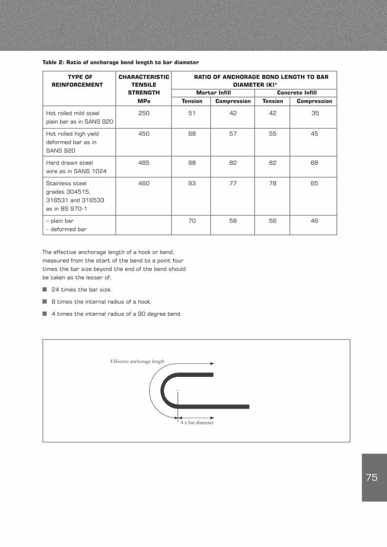
75
Table 2: Ratio of anchorage bond length to bar diameter
TYPE OF CHARACTERISTIC RATIO OF ANCHORAGE BOND LENGTH TO BAR REINFORCEMENT TENSILE DIAMETER (K)* STRENGTH Mortar Infill Concrete Infill
MPa Tension Compression Tension Compression
Hot rolled mild steel 250 51 42 42 35 plain bar as in SANS 920
Hot rolled high yield 450 68 57 55 45 deformed bar as in SANS 920
Hard drawn steel 485 98 82 82 68 wire as in SANS 1024
Stainless steel 460 93 77 78 65 grades 304515, 316531 and 316533 as in BS 970-1
– plain bar 70 58 56 46 – deformed bar
The effective anchorage length of a hook or bend, measured from the start of the bend to a point four times the bar size beyond the end of the bend should be taken as the lesser of:
24 times the bar size.
8 times the internal radius of a hook.
4 times the internal radius of a 90 degree bend.
Effective anchorage length
4 x bar diameter
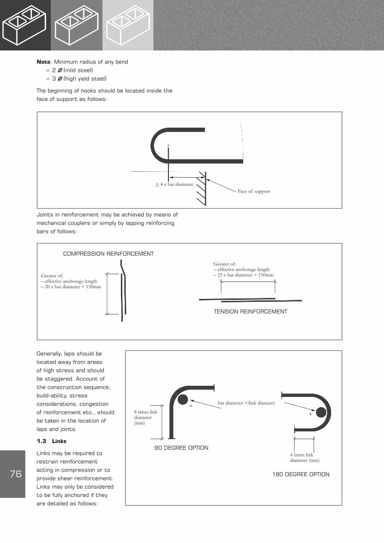
76
Note: Minimum radius of any bend = 2 Ø (mild steel) = 3 Ø (high yield steel)
The beginning of hooks should be located inside the face of support as follows:
Face of support
Joints in reinforcement may be achieved by means of mechanical couplers or simply by lapping reinforcing bars of follows:
Generally, laps should be located away from areas of high stress and should be staggered. Account of the construction sequence, build-ability, stress considerations, congestion of reinforcement etc., should be taken in the location of laps and joints.
1.3 Links
Links may be required to restrain reinforcement acting in compression or to provide shear reinforcement. Links may only be considered to be fully anchored if they are detailed as follows:
> 4 x bar diameter
COMPRESSION REINFORCEMENT
Greater of: – effective anchorage length – 20 x bar diameter + 150mm
Greater of: – effective anchorage length – 25 x bar diameter + 150mm
TENSION REINFORCEMENT
180 DEGREE OPTION
8 times link diameter (min)
4 times link diameter (min)
90 DEGREE OPTION
bar diameter < link diameter
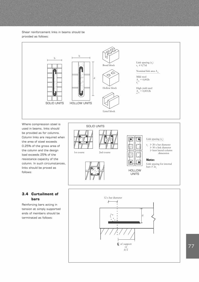
77
Shear reinforcement links in beams should be provided as follows:
bb
d
Bond block
Hollow block
Lintel block
SOLID UNITS HOLLOW UNITS
Link spacing (sv)sv < 0,75d
Nominal link area Asv
Mild steelAsv = 0,002bsv
High yield steelAsv = 0,0012bsv
Where compression steel is used in beams, links should be provided as for columns. Column links are required when the area of steel exceeds 0,25% of the gross area of the column and the design load exceeds 25% of the resistance capacity of the column. In such circumstances, links should be proved as follows:
SOLID UNITS
1st course 2nd course
HOLLOW UNITS
Link spacing (sv)
sv > 20 x bar diameter > 50 x link diameter > least lateral column dimension
Note:Link spacing for internal bars > 2sv
3.4 Curtailment of bars
Reinforcing bars acting in tension at simply supported ends of members should be terminated as follows:
12 x bar diameter
d
of supportor
d/2
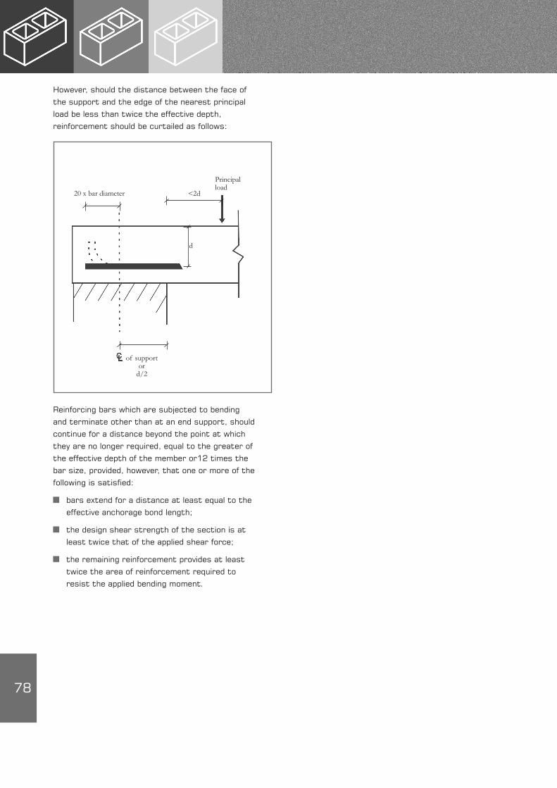
78
However, should the distance between the face of the support and the edge of the nearest principal load be less than twice the effective depth, reinforcement should be curtailed as follows:
Reinforcing bars which are subjected to bending and terminate other than at an end support, should continue for a distance beyond the point at which they are no longer required, equal to the greater of the effective depth of the member or12 times the bar size, provided, however, that one or more of the following is satisfied:
bars extend for a distance at least equal to the effective anchorage bond length;
the design shear strength of the section is at least twice that of the applied shear force;
the remaining reinforcement provides at least twice the area of reinforcement required to resist the applied bending moment.
of support or
d/2
d
20 x bar diameter <2d
Principal load
79
4. RESISTANCE OF METAL COMPONENTS TO CORROSION (SANS 10164-2; Cl 9.2)
4.1 General
The resistance of metal components to corrosion depends upon the following:
exposure environment
type and quality of cementitious surround, i.e., mortar or infill concrete
cover
type of protective coating of steel.
SANS 10164-2 contains recommendations regarding the minimum levels of protective coatings for reinforcement and masonry accessories used in various types of construction and exposure conditions. These recommendations are not necessarily the desirable levels of protection that may be required since local conditions or specific circumstances may warrant a higher degree of protection.
4.2 Exposure classification
The exposure classification may be established from Table 3 and Figure 1 or Table 17 of SANS 10164-2. Elements which may be subjected to more severe exposure than the remainder of a building, such as parapets, chimneys and sills should be regarded as being located in an environment classified as E3.
EXPOSURE EXPOSURE ENVIRONMENTS FOR SURFACES OF CLASSIFICATION REINFORCED MEMBERS
E1 Protected by an impermeable membrane Exposed to the elements in inland areas as shown in Figure 1. interiors of buildings. Beneath coatings that resist moisture penetration.
E2 Exposed to the elements in: inland areas as shown in Figure 1. interiors of industrial buildings where humidity is high or where repeatedly washed. Submerged in non-aggressive soils.
E3 Exposed to the elements in: areas within 3 km of industries that discharge atmospheric pollutants. areas within 1 km of the coastline or shoreline of large expanses of salt water. Submerged in fresh water.
S Submerged in aggressive soils. Submerged in sea water, running water or soft water. In contact with corrosive liquids or gas.
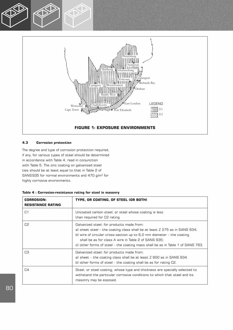
80
4.3 Corrosion protection
The degree and type of corrosion protection required, if any, for various types of steel should be determined in accordance with Table 4, read in conjunction with Table 5. The zinc coating on galvanised steel ties should be at least equal to that in Table 2 of SANS 935 for normal environments and 470 g/m² for highly corrosive environments.
FIGURE 1: EXPOSURE ENVIRONMENTS
LEGEND
E1
E2
WorcesterCape Town Port Elizabeth
East London
Durban
Oudtshoorn
Barkly West
Upington Bloemfontein
Mafikeng Johannesburg
Nelspruit
Pietersburg
Empangeni
Richards BayEstcourt
Table 4 : Corrosion-resistance rating for steel in masonry
CORROSION- TYPE, OR COATING, OF STEEL (OR BOTH)
RESISTANCE RATING
C1 Uncoated carbon steel; or steel whose coating is less than required for C2 rating.
C2 Galvanized steel; for products made from: a) sheet steel – the coating class shall be at least Z 275 as in SANS 934; b) wire of circular cross-section up to 6,0 mm diameter – the coating shall be as for class A wire in Table 2 of SANS 935; c) other forms of steel – the coating mass shall be as in Table 1 of SANS 763.
C3 Galvanized steel; for products made from: a) sheet – the coating class shall be at least Z 600 as in SANS 934. b) other forms of steel – the coating shall be as for rating C2.
C4 Steel, or steel coating, whose type and thickness are specially selected to withstand the particular corrosive conditions to which that steel and its masonry may be exposed.
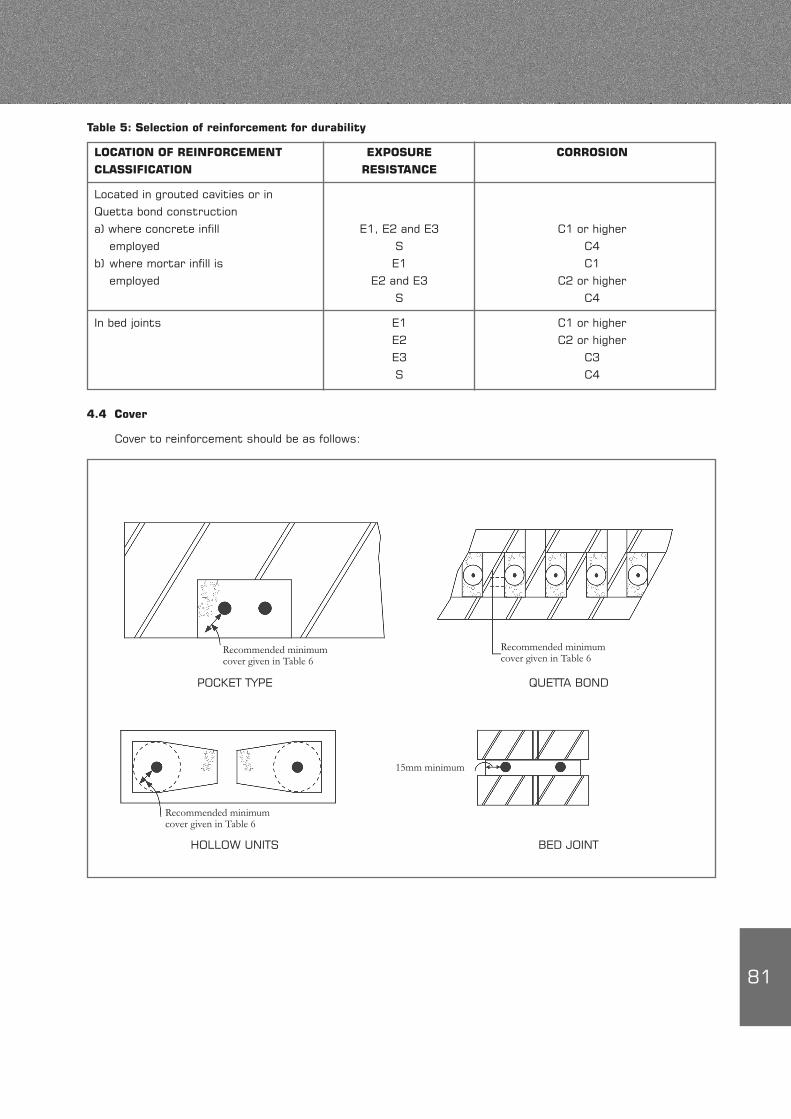
81
4.4 Cover
Cover to reinforcement should be as follows:
Table 5: Selection of reinforcement for durability
LOCATION OF REINFORCEMENT EXPOSURE CORROSION
CLASSIFICATION RESISTANCE
Located in grouted cavities or in Quetta bond construction a) where concrete infill E1, E2 and E3 C1 or higher employed S C4 b) where mortar infill is E1 C1 employed E2 and E3 C2 or higher S C4
In bed joints E1 C1 or higher E2 C2 or higher E3 C3 S C4
POCKET TYPE QUETTA BOND
HOLLOW UNITS BED JOINT
15mm minimum
Recommended minimum cover given in Table 6
Recommended minimum cover given in Table 6
Recommended minimum cover given in Table 6
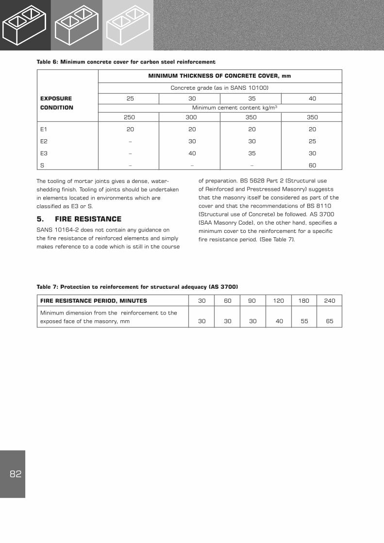
82
The tooling of mortar joints gives a dense, water-shedding finish. Tooling of joints should be undertaken in elements located in environments which are classified as E3 or S.
5. FIRE RESISTANCESANS 10164-2 does not contain any guidance on the fire resistance of reinforced elements and simply makes reference to a code which is still in the course
of preparation. BS 5628 Part 2 (Structural use of Reinforced and Prestressed Masonry) suggests that the masonry itself be considered as part of the cover and that the recommendations of BS 8110 (Structural use of Concrete) be followed. AS 3700 (SAA Masonry Code), on the other hand, specifies a minimum cover to the reinforcement for a specific fire resistance period. (See Table 7).
Table 6: Minimum concrete cover for carbon steel reinforcement
MINIMUM THICKNESS OF CONCRETE COVER, mm
Concrete grade (as in SANS 10100)
EXPOSURE 25 30 35 40
CONDITION Minimum cement content kg/m³
250 300 350 350
E1 20 20 20 20
E2 – 30 30 25
E3 – 40 35 30
S – – – 60
Table 7: Protection to reinforcement for structural adequacy (AS 3700)
FIRE RESISTANCE PERIOD, MINUTES 30 60 90 120 180 240
Minimum dimension from the reinforcement to the exposed face of the masonry, mm 30 30 30 40 55 65
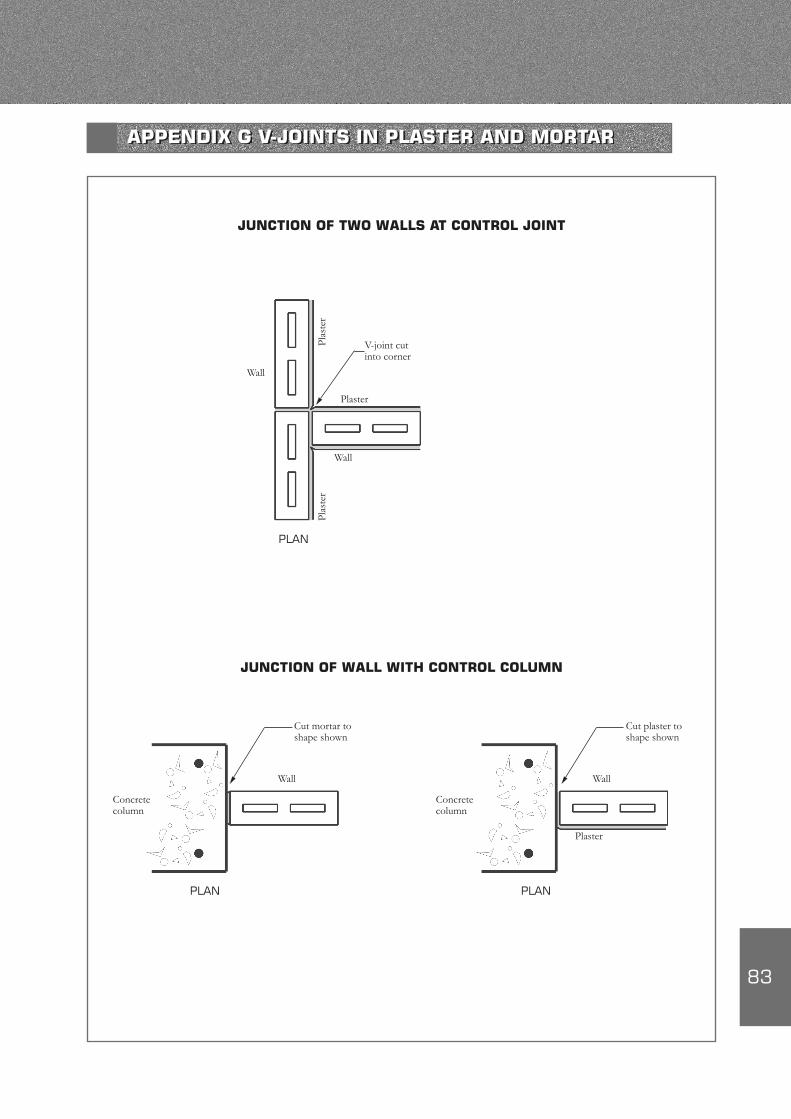
83
JUNCTION OF TWO WALLS AT CONTROL JOINT
JUNCTION OF WALL WITH CONTROL COLUMN
Plas
ter
V-joint cut into corner
Plaster
Wall
Plas
ter
Wall
Cut mortar to shape shown
Wall
Plaster
Wall
Concrete column
PLAN
PLAN PLAN
Concrete column
Cut plaster to shape shown
APPENDIX G V-JOINTS IN PLASTER AND MORTAR
84
NOTES NOTES

Block D, Lone Creek, Waterfall Office Park, Bekker Road, Midrand PO Box 168 Halfway House 1685Tel +27 11 805 6742, Fax +27 86 524 9216E-mail: [email protected], Website: www.cma.org.za
FS Crofts
Hilti
Institute for Timber Construction Limited
MITEK
Soderlund and Schutte
The South African Institute of Steel Construction
The South African Lumber Miller Association
The assistance of the following organisations in compiling this publication is acknowledged.
USE OF COMPUTER AIDED DESIGN (CAD)
The drawings in this manual are available on CD in various CAD formats.
Please contact the Concrete Manufacturers Association if you require this disc.
A Fick Cement Works 022 913 1921
Bafokeng Technicrete 014 538 0818
Boland Concrete 021 875 5365
Brick & Concrete Industries (Namibia) 00264 61 321 3000
Brickcast Industries cc 031 5075525
Cape Brick cc 021 511 2006
Columbia DBL 021 905 1665
Deranco Blocks 041 463 3338
Inca Concrete Products 021 904 1620
Inca Masonry Products 043 745 1215
Lategan’s Cement Works 021 873 1154
Neat Contech 046 624 3377
Panda, Botswana 00267 244 2106
Stanger Brick & Tile 032 457 0237
Technicrete 011 674 6900
Watston Concrete 011 740 0910
West End Cement Bricks 011 851 1098
Western Granite 021 904 1620
ACKNOWLEDGEMENTS
MASONRY PRODUCER MEMBERS (MAY 2011)
Members list above correct at the time of going to print.

Block D, Lone Creek, Waterfall Office Park, Bekker Road, Midrand PO Box 168 Halfway House 1685Tel +27 11 805 6742, Fax +27 86 524 9216E-mail: [email protected], Website: www.cma.org.za
Isikh
ova
/ 200
4 / M
AY 2
011
D E T A I L I N G O FC O N C R E T E M A S O N R Y
Concrete masonry: Strong, durable and attractive
Volume 1 – Solid Units 140mm