Review of modelling of masonry shear
31
1 Review of Modelling of Masonry Shear M. Dhansekar Professor, Faculty of Built Environment & Engineering, Queensland University of Technology, Brisbane, Australia. Ph. +61 7 3138 6666 Fax. + 61 7 3137 1170 Email: [email protected] URL: http://staff.qut.edu.au/staff/dhanasek/ This article is prepared on invitation from the editors Professors Muralikrishnan and Ramamurthy, IIT Madras, India. Abstract: Masonry is extensively used in buildings as structural and cladding elements. With the increase in demand for understanding the performance of all building elements, experts from various fields are seeking to include masonry as a sub-system of their respective major models. It is imperative that these models account for the true behaviour of masonry dictated by the presence of mortar joints acting as planes of weakness, the interaction between the grout and masonry shell as well as the grouted cores and unreinforced masonry in various forms of masonry design. The purpose of this paper is, therefore, to provide a state-of-the-art review on the modelling of masonry in the context of the fundamental behaviour of various forms of masonry to loading, with particular attention to shear loading. It is shown that the modelling methods and the parameters must be carefully chosen as one method cannot be claimed suitable for all circumstances. Keywords: Structural Masonry, Micro Modelling, Macro Modelling, Interface Modelling, Reinforced Masonry
Transcript of Review of modelling of masonry shear

1
Review of Modelling of Masonry Shear
M. Dhansekar
Professor, Faculty of Built Environment & Engineering, Queensland University of Technology, Brisbane, Australia.
Ph. +61 7 3138 6666
Fax. + 61 7 3137 1170
Email: [email protected]
URL: http://staff.qut.edu.au/staff/dhanasek/
This article is prepared on invitation from the editors Professors Muralikrishnan
and Ramamurthy, IIT Madras, India.
Abstract:
Masonry is extensively used in buildings as structural and cladding elements. With the increase in
demand for understanding the performance of all building elements, experts from various fields
are seeking to include masonry as a sub-system of their respective major models. It is imperative
that these models account for the true behaviour of masonry dictated by the presence of mortar
joints acting as planes of weakness, the interaction between the grout and masonry shell as well as
the grouted cores and unreinforced masonry in various forms of masonry design. The purpose of
this paper is, therefore, to provide a state-of-the-art review on the modelling of masonry in the
context of the fundamental behaviour of various forms of masonry to loading, with particular
attention to shear loading. It is shown that the modelling methods and the parameters must be
carefully chosen as one method cannot be claimed suitable for all circumstances.
Keywords: Structural Masonry, Micro Modelling, Macro Modelling, Interface
Modelling, Reinforced Masonry

2
1. Introduction
Masonry is widely used in buildings either as load bearing walls or cladding/ infill
walls. Whilst masonry in buildings do not exhibit measurable distress under
gravity loading, its failure often is widely reported even under moderate lateral
loading; such failures occur both in the load bearing and in the cladding masonry
elements causing significant loss of lives and damages to properties. With the
realisation of the more frequent occurrence of extreme events, loading codes of
most nations demand adequate detailing of the structural and nonstructural
(including fittings) elements against the lateral loading. To appropriately detail
masonry elements, design engineers require thorough understanding of masonry
behaviour and modelling methods. The purpose of this paper is to raise the
awareness of the proper understanding of the performance of masonry under
loading, with particular attention to shear loading, to minimise the vulnerability of
masonry (FEMA307 [37]).
2. Theory of Structural Masonry
Masonry is strong in compression but weak in tension; it is also characterised by
mortar joints acting as planes of weakness. Under loading (vertical, lateral or
combination of vertical and lateral) unreinforced masonry behaves in a complex
manner exhibiting modes of failure classed as brittle. Where fully reinforced,
masonry is said to behave similar to reinforced concrete and fails in a more ductile
manner [36, 67, 69]. Failure of mixed constructions involving reinforced
elements and unreinforced masonry can be defined anywhere within the broader
spectrum of highly brittle to moderately ductile range.
Modelling of masonry without full understanding of their behaviour, especially
the effect of mortar joints and/ or the manner in which the grout and masonry
shells interact, can lead to erroneous results.

3
2.1 Unreinforced Masonry
Masonry is predominantly unreinforced and is vulnerable to seismic and high
wind actions. Masonry derives stability and increased out-of-plane flexural and
in-plane shear capacities from imposed vertical loads; therefore, it is prudent to
use them as structural members with the slabs directly resting on them. In the
modern masonry buildings, walls running on two orthogonal vertical planes are
connected to each other transmitting loads from the slabs that form cellular system
capable of distributing the lateral loading efficiently across the walls in their
stiffer direction, thus requiring much thinner walls. With the reduction in
thickness, these walls become more sensitive to stress levels, especially where the
walls are ungrouted and only face shell bedded. As at least two materials with
vastly differing elastic properties form masonry, appropriate material modelling,
structural idealisation and choice of modelling method must be carefully
identified to obtain the desired results commensurate to the expected levels of
accuracy.
2.1.1 Shear in unreinforced masonry
Shear in unreinforced masonry is largely resisted due to deformation in mortar
bed joints and is defined conveniently by Mohr-Coulomb failure envelop that
relates the shear strength u to the shear bond strength 0 , an apparent friction
coefficient and vertical stress vf in the joint as shown in equation (1); this linear
equation is usually applicable to a small range of vf , typically 2MPa or lower
reflecting the significant nonlinearity the vertical stress can cause to masonry.
0u vf (1)
Where any insert is provided in masonry, such as flashing or damp proof course,
0 will vanish and the shear capacity of such elements is solely dependent on
and vf [17, 21]. The value of for cyclic loading is critical in earthquake design
of partition or cladding walls as may not have been mobilised and is usually
quite low compared to its static counterpart.

4
In spite of its simplicity, equation (1) provides a reasonable conservative estimate
of shear capacity of URM walls and hence is adopted in the European (BS5628
[8], BS-EN1996 [10]) and the Australian standards (AS3700 [2]). The American
(MSJC [56]) and Canadian standards (CSA-S304.1 [11]) relate the shear strength
of masonry to the square-root of its characteristic compressive strength 'mf ; the
proportionality constants vary between the standards.
Design of out-of-plane shear response is non-controversial and can be performed
using equation 1 for URM walls. Design of masonry walls for inplane shear is,
however, more complex; the provisions in various standards can at best be
described as reflecting the current poor state-of-the-art. Walls under inplane shear
loading are said to exhibit three modes of failure, namely, (1) diagonal shear (2)
sliding shear and (3) flexural rocking. It is claimed that the diagonal shear is more
brittle, although several test results on walls that exhibit diagonal shear failure
capable of being laterally drifted beyond 1%. For example although URM shear
walls that exhibit pinched cyclic load displacement relationship typically
associated with poor hysteretic energy dissipation capacity due primarily to the
rocking mechanism are considered not suitable for seismic zones, from a detailed
dynamic analyses and statistical studies of unreinforced masonry shear walls
exhibiting rocking mechanism and using the input of 164 recorded European
earthquake events, Lestuzzi et al. [50] concluded that the limited hysteresis does
not lead to excessive displacement demand. This is an important finding as it
contradicts the widely held perception on such masonry shear walls.
Generally the reinforced and unreinforced masonry shear walls exhibit mixed
modes of failure. Often another potentially brittle mode of failure, corner
crushing, is not considered in the design. Some detailed examination of the
strength properties of masonry (tensile bond, shear bond and compressive) by the
author [13] has shown the tensile and shear bond strengths increase significantly
(up to 175%) whilst the compressive strength remained relatively unaffected. It
was concluded that it’s not so much of the age, but the effect of drying of well-
cured specimens increase their two bond strengths (tensile & shear). The
compressive strength, whose failure depends on the crushing / cracking of the
5
units, has not shown any significant effect of drying / age. The masonry failure
surface, defined by these three strength properties of masonry, usually consider 28
day moist strength properties; to date no literature is found on the effect of non-
proportional changes in the strength properties of masonry, reflecting the effect of
drying, to the behaviour of masonry shear walls. When the shear and tensile bond
strength values are increased by 175% whilst the compressive strength are
retained at original level, it was possible to predict the localised compression
failure at the corners as the mid zone of the wall was able to resist higher lateral
load due to increased shear bond strength [13].
Another aspect that requires careful consideration for the evaluation of the
behaviour of masonry shear walls is dilatancy that is defined as the vertical
translation of masonry units during sliding, causing volume change, which in turn
can generate or increase confining pressure if the masonry is restrained in some
way. Ignoring dilatancy in the calculation of shear capacity can lead to very
conservative predictions, whereas inappropriate use of dilatancy (especially in
‘confined’ or infill masonry [39]) leads to highly unconservative predictions. Van
Zijl [72] has shown that dilatancy coefficients should be made pressure dependent
in order to make safe predictions.
For the determination of the lower bound capacities of diagonally compressed
URM wall panels, Roca [63] provided two simple expressions, one for deep
beams subjected to concentrated vertical loading and the other for deep beams
subjected to uniformly distributed vertical loading. These analytical expressions
can help calibrating FE models for problems with no experimental data.
2.2 Reinforced Masonry
Where the seismic/ wind forces are high, masonry is invariably reinforced. There
are many forms of reinforced masonry. In some designs all cores of walls are
grouted and reinforced and in others only a few selected hollow cores are grouted
and reinforced. In the later, the grouted and reinforced cores can be regarded as
concealed RM columns/ mullions [14, 42] – figure 1 shows a photo; where, it can

6
be seen that owing to the staggered web shell in hollow blocks, the grouted
mullion/ concealed column can never have straight edges.
Figure 1 Concealed mullion in wide spaced reinforced masonry
2.2.1 Compression behaviour
RM has outer masonry shells and inner grout containing reinforcing steel. The
outer shells consist of solid bricks or hollow blocks bonded together by mortar
bed joints. The inner grout is usually made from lean concrete and is poured into
the hollow cores containing steel reinforcement such that it forms a composite
vertical member by binding the outer shells and the reinforcing bars. Owing to
the limited space within the hollow cores of the masonry shells, it is difficult to
detail the lateral ties or spirals, which leaves the reinforcement laterally untied and
the grout remain unconfined laterally. Where the Poisson’s ratio of the grout is
much larger than that of the masonry shell, due to incompatibility of lateral
expansion of these two materials, the shells are subjected to lateral grout pressure
[47, 68]. This phenomenon leads to premature spalling of the shells. Similar
spalling of (highly stressed compression) shell also occurs where masonry is
subjected to eccentric loading or lateral bending [35, 60]. Figure 2 shows spalling
of web shells of grouted prisms under axial compression and hollow prism
(spalling circled) under eccentric compression.
Figure 2 Web shell spalling in axially loaded grouted prisms and eccentrically
loaded hollow (dry-stack) prisms

7
Although it is well known that the compressive strength of brittle materials
increase with lateral confinement, only a few researchers have examined methods
of improving the behaviour of masonry subjected to axial compression using
some form of confinement of the grout. Typically round bars, flat bars and plates
were used as joint reinforcement to confine the grout. Hatzinikolas et al. [43]
concluded that such joint reinforcement system adversely affected the behaviour
of the grouted masonry and reduced the strength due to stress concentration within
the joints. Drysdale and Hamid [35, 36] found that the round bars enhanced the
compressive strength of masonry by a small amount of 2% whilst the plate
reinforcement system provided 15% increase. A similar level of increase in
compressive strength of grouted concrete masonry was reported by Priestly and
Elder [58] based on tests carried out on prisms containing stainless steel plates in
the mortar joints to overcome the potential corrosion problem triggered by lack of
cover. With a view to minimizing lateral expansion of grout, fibre reinforcement
is sometimes used; more details on micro (fibre) and macro reinforcement effects
on masonry can be found in [7].
The idea of placing web reinforcement within the grouted cores of the vertically
reinforced masonry was first developed by Kumar and reported in [16, 47, 48,
49]. By placing triangular shaped web reinforcement within each reinforced cores
of clay block masonry, he achieved 32% increase in compressive strength of clay
block masonry over the grouted, unconfined clay block masonry strength.
2.2.2 Shear behaviour
Shear in RM is largely resisted due to aggregate interlock in the grout, dowel
action of the flexural reinforcement (perpendicular to the direction of shear) and
the tensile action of shear reinforcement (parallel to the direction of shear) with no
significant effect of mortar joint [67, 69]. Therefore the fully grouted reinforced
(in both horizontal and vertical directions) masonry could be regarded analogues
to reinforced concrete; unfortunately this analogy does not bring much comfort as
in spite of significant research, shear in reinforced concrete still remains as a
subject requiring further development [73, 74].

8
Walls subjected to vertical out-of-plane bending will invariably be provided with
vertical steel; horizontal shear in such walls would only derive marginal benefit of
the vertical steel but will derive excellent benefit from horizontal reinforcement if
provided in zones of high shear (mid high levels). If the same wall is subjected to
vertical shear, the vertical reinforcement can prove to be effective. Shear
behaviour of reinforced masonry can be inferred from the theory of reinforced
concrete as long as the masonry is fully grouted and reinforced - for example,
reinforced masonry beams [15, 17, 25, 31]. For the out-of-plane design, the
Australian [2], European [10] and British [9] Standards provide a singly
reinforced formula by either limiting the maximum effective tensile reinforcement
or by specifying the neutral axis parameter be less than a conservative limit far
below the balanced limit (for example, 0.40 in AS3700 [2]). Masonry is seldom
designed as doubly reinforced as restraining compression steel is always a
challenge.
The North American standards define the nominal shear strength of reinforced
masonry as a function of moment-to-shear ratio '0.16 2 m
Mf
Vd
. The CSA-
S304 [11] perhaps is the only standard that includes the size effect in reinforced
masonry beams; the nominal shear strength is defined for fully grouted and
reinforced masonry beam is defined as '4000.16 1
2000 m
df
.
Whilst fully reinforced masonry can be regarded behaving similar to reinforced
concrete under shear (both inplane and out-of-plane), behaviour under inplane
shear is not well understood. Designers may conceive the partially grouted
masonry walls as ‘mixed’ system consisting of reinforced core elements and
unreinforced masonry panels spanning between the cores by naming them as
partially grouted reinforced masonry. The wall may also be conceived as a
reinforced masonry in which the spacing of walls is spaced wider than the fully
reinforced masonry (for example, spacing of vertical reinforcement up to 2m) and
are called as wide spaced reinforced masonry [30, 42].

9
The design standards reflect the poor state-of-the-art of the shear wall failure
mechanisms as they provide widely differing design clauses with extremely
unconservative/ unsafe provisions in many places and too conservative/
uneconomical clauses in others. Through a comparative study of various masonry
standards using 75 test data on fully reinforced masonry shear walls reported in
the literature, Dickey and Lissel [34] determined that the North American codes
outperform the Australian, European and British codes in terms of economic
design – whilst all standards were conservative. The situation becomes rather
more complex when partially grouted/ wide spaced reinforced masonry walls are
considered. With limited data on 12 full-scale wide spaced reinforced masonry
shear walls, Dhanasekar et al [30] have shown that the provisions in CSA-S04
[11] and AS3700 [2] are unsafe.
It is therefore clear that whilst unreinforced and fully reinforced masonry walls
can be designed safely using the provisions in most design standards, it appears
safe design may not be achieved through standard provisions for the partially
reinforced/ wide spaced reinforced masonry walls. Further research is urgently
needed to examine the inplane shear behaviour of partially reinforced masonry
walls; this is especially so because these walls are quite economical and can prove
to be an adequate structural system for those countries that experience moderate,
intra-plate type earthquakes and/ or cyclonic wind. These walls can be analogised
to the much celebrated confined masonry system that has large unreinforced
masonry panels surrounded by tension columns and beams (that confine the
masonry) [39].
3. Modelling Strategies
Modelling of masonry is either for fundamental understanding of its material
behaviour or for the determination of its structural behaviour. For material
characterisation, detailed micro modelling in two or three dimension is necessary.
For structural characterisation, depending on the need, simplified or more
elaborate modelling can be performed.

10
Masonry cracks under serviceability loading conditions; cracking can also be an
important issue under concentrated loading. Fracture mechanics approach might
well be required to fully understand the masonry response to cracking;
unfortunately, it’s not easy to translate the classical theories of fracture to
masonry because masonry is a composite consisting of several brittle materials;
furthermore, masonry cracks at ultimate under compression in a direction parallel
to the direction of loading. Some limited research is reported in this area mainly
by Shrive and co-workers [61] and Rots [60] but the area remains largely
unexplored, leaving serviceability crack limit calculations wide open in all
standards for unreinforced masonry. This is despite the fact that such cracking is
quite common in masonry.
3.1 Geometrical Modelling
Masonry is generally used in walling applications, although columns/ piers, arches
and massive dams/ abutments are also built of masonry. The ultimate behaviour
characterised by the complete load deflection response of masonry is perhaps the
most important aspect for the design, which is mostly studied experimentally. It’s
seldom possible to carry out experiment on all common masonry types; therefore,
sound numerical modelling techniques are required for appropriate understanding.
In practical applications, masonry buildings consisting of shear walls are treated
as an assembly of springs for the determination of push-over drift. Recently,
Tena-Colunga and Cano-Licona [70] extended such models for partial and full
damage status of the walls using the definition of a shear area factor. The idea is
to adjust the shear area depending on the stiffness (or height to length ratio) of the
masonry shear walls. Such analytical method is useful to approximate
conservative analysis of large scale buildings.
Where out-of-plane flexure of wall or column is desired, one dimensional line
element modelling may be efficient. An efficient 1D layered finite element was
formulated by the author and coworkers [3, 4, 5] for the flexural analysis of RM
columns including bond-slip. The new 1D finite element was formulated using

11
mixed approach that satisfied the equilibrium and compatibility conditions
simultaneously. A special purpose computer program was developed using the
layered, 1D line element for the analysis of RM columns subjected to monotonic
axial and lateral loading. The 1D model prediction was validated using the lateral
load-deflection response of RM columns tested at the University of Calgary,
carried out as part of a collaborative research project. The model can also account
for bond-slip that is quite critical in wide spaced reinforced masonry applications
as there is only limited surface area of steel is available. Furthermore the grout in
masonry may not be compacted well, causing potential poor bond with the steel
surface.
As wall structures can generally be regarded as plane stress bodies, idealisation of
the walls on their mid thickness vertical plane is commonly adopted and meshed
using 2D plane stress continuum elements – especially for solid masonry.
However the hollow block masonry that is ungrouted and face shell bedded do not
strictly comply with the plane stress assumptions as the face shells (being thin
members) exhibit tendency for out-of-plane buckling under compression and the
web shells with no mortar joints beneath or above them acts like diaphragms
connecting the two face shells. The face shell buckling has the potential to induce
cracking in the web shells; in such situations, the effective heights of the face
shells will increase dramatically leading to pre-mature collapse that is often brittle
(many standards provide quite conservative capacity reduction factors to avoid
catastrophic failure). Shell elements can only predict such failure – thus
warranting expensive 3D modelling [66]. With a view to addressing the
computational costs, the author and his co-workers have developed a family of
quasi 3D elements (figure 3) that require only 2D meshing, saving enormous time
and cost [32, 33, 38, 77].
Figure 3 A Quasi 3D Finite Element
x
y
z
2h1
2h2
x
y
i j
k
l

12
Figure 3 shows a typical hybrid stress element formulated from the 3D Hellinger-
Reissner principle with the capability of predicting 3D states of the stresses and
strains. In this element is treated as a function of z to represent the traction
free condition on the lateral surfaces. According to the equilibrium equation in the
z-direction, and could not be zero everywhere but functions of (x, y, z).
3.2 Material Modelling
Where micro modelling is used, the properties of the units, mortar, grout and
reinforcement as well as the interface properties of interacting surfaces between
units and mortar/ units and grout/ mortar and grout/ and grout and reinforcement
are required. These properties are often determined from uniaxial tests on
standard sized test specimens subjected to uniform state of stress. Important
parameter is the interface properties as masonry behaviour can be significantly
affected by these properties. With the reduction in thickness of the bed joint,
significant strength gain of masonry can be obtained [18]. Higher bond strengths
of masonry can also increase the strength of masonry [65] as well as enhancing
the ductility of the masonry material [62]. Further details of brick-mortar
interaction can be seen in [75].
True behaviour of masonry can only be assessed through biaxial testing of panels,
which is quite an involved and expensive proposition. Although not attempted,
mesoscopic properties of masonry for its characterisation under biaxial loading
can be carried out using micro modelling; multi-scale modelling [54, 52] method
can be exploited for this purpose. Recent studies on multi-scale modelling
application to masonry exhibit the feasibility for such studies. The down side is
that multi-scale method is computationally expensive; it will, however, be less
expensive than the other alternate, biaxial testing. To date comprehensive study
on the biaxial behaviour of masonry is only determined experimentally for only
solid clay brick masonry [22, 26, 28]; these data are widely cited over the past
three decades. The test data are typically presented as a failure surface as shown
in figure 4. For hollow and grouted concrete masonry, some data are reported in
recent times [23, 24, 29].
z
yz zx

13
Figure 4: Failure surface for masonry [13]
All the failure surfaces are 3D shaped consisting of intersecting convex envelopes
of conical/ truncated conical/ cap shapes. They illustrate the profound influence of
shear stress on the normal stresses, which implicitly describe the effect of bed
joints. Flow theories of plasticity can be applied to these surfaces by considering
them as initial ‘yield’ surfaces as the flow vectors can be normal to these convex
surfaces containing no dips, gaps or overlaps. These material models are suitable
for implementation into commercial FE codes (eg. ABAQUS [1]).
These failure/ yield surfaces can only be implemented into modelling of masonry
where smeared cracking is considered. Unless care is taken, mesh size can
seriously affect the results of the analysis – known as mesh pathology that
adversely affects the uniqueness of unloading curves. These problems are widely
studied in reinforced concrete modelling, where it is shown that by limiting the
size of the elements to not less than three times the size of the coarse aggregates
and by explicitly defining the Mode I and Mode II energies in input data, mesh
pathology in reinforced concrete structures can be overcome by determining the
isotropic characteristic length h A where = 2 for linear elements and
A is the area of the largest element and incorporating h as a material property.
Similar approach is used for unreinforced masonry [6] although masonry is
distinctly orthotropic.
Theoretically there are two factors that affect the softening part of the load
displacement curves: (1) appropriate energy release criteria during crack opening

14
due to tension (Mode I fracture) and crack sliding due to shear (Mode II fracture)
and (2) inclusion of characteristic length in the material model to eliminate the
mesh size dependency problems.
3.2.1 Energy release criteria
Measuring fracture energies under tension and shear require careful preparation of
specimen as well as high-precision displacement control equipment. The work
carried out at Delft University of Technology, Netherlands [64] is considered
classical for the purpose; a typical result is provided in figure 5 for tension. A
similar result is provided for shear in [52]. As masonry exhibits significant
nonlinearity under compression, a complete stress-strain curve for compression,
including softening is essential for its appropriate modelling.
Figure 5 Crack Opening Mode I Fracture for Masonry [52]
The model shown in Figure 5 is useful when the structure is subjected to
monotonically increasing load. Where the load path involves cyclic deformation
of varying magnitude, much work is essential. Hypothetical cyclic strain – stress
models are provided in [40]. Experimentally measured cyclic stress-strain curves
for unconfined and confined masonry are reported in [23, 24].
3.2.2 Characteristic length
The second factor is the characteristic length – a mesh dependent parameter. The
maximum isotropic characteristic length 2 x yh h h (for elements with linear

15
shape function) where &x yh h are the length of the element in the 1 and 2
directions, should satisfy the energy criteria as shown in equation 2:
2
fi i
i
G Eh
f (2)
in which fG is the fracture energy (measured as area under curves shown in
figure 5), E and tf are the stiffness and strength in the direction of measurement
of fG respectively (subscript i stands for the direction of measurement). In other
words, it could be inferred that one should provide an upper limit of element size
during meshing if they have reliable experimental data on E, fG and tf ;
alternatively the model should be adjusted for h and G as usually E and f for
materials are reliably estimated.
However, for distinctly orthotropic materials like masonry, it appears that
different characteristic lengths for the two orthotropic directions are necessary.
Discrepancy between the values used for the characteristic lengths in the x and y
directions has been found in the analysis of URM walls reported in Lourenco [52].
For example, in the analysis of the ETH Zurich shear walls, the length and the
height of 4-noded plane stress elements used by Lourenco [52] were 150mm and
133.3mm respectively; the characteristic length of these elements, therefore, is
2 150 133.3 200h mm if isotropy is assumed. However this was not used
as inferred from the following calculation: the tensile strength of masonry parallel
to the x and y directions was reported equal to 0.28 MPa and 0.05 MPa
respectively; Young’s modulus of masonry parallel xE and perpendicular yE
to the bed joints was equal to 2460 MPa and 5460 MPa respectively. Fracture
energy for the x and y directions used in the analysis was 0.02 Nmm/mm2. The
characteristic length (h) of elements was thus determined as 628 mm and 43,680
mm respectively (compared to the isotropic characteristic length of 200 mm). This
shows that the value of the characteristic lengths of elements actually used in the
analysis by Lourenco [52] for the x and y directions were different; This
discrepancy from the established idea of characteristic length for isotropic

16
materials must be properly understood in modelling – especially where fracture
energy across the two orthotropic directions are not available. Based on the above
observation, two characteristic lengths, one for the normal (y) direction and the
other for the parallel (x) direction to masonry bed joint, were also adopted in [20].
Gambarotta and Lagomarsino [41] have also expressed the similar concern on the
characteristic length of elements for the modelling of URM shear walls to cyclic
loading in such a way that the localisation based mesh pathology can be avoided.
Whilst they specified the minimum height of smeared cracking masonry element
should be the related to the width of crack band (or mortar thickness), they agreed
that no guideline could be provided to the width of the element based on the
current knowledge. This leaves the analysts to come out their own interpretation
of characteristic length for masonry as it stands until some fundamental research
is carried out. Mosler and Meschke [55] have strongly recommended usage of a
tensorial characteristic length to deal with the mesh pathological problems of the
failure of anisotropic materials.
3.2.3 Application of damage mechanics
Recent modellers of unreinforced masonry walls tend to derive the properties of
masonry from repetitive unit volume elements of masonry using the theory of
homogenisation with a view to incorporating them into macro modelling. Whilst
elastic properties are determined accurately using homogenisation, its application
to nonlinear material properties is far from complete [52]. Therefore, an elastic
damage mechanics approach is tried with some limited success. In this method, a
simple positive scalar D that ranges from zero (no damage) to one (fully damaged)
is used in the theory of isotropic continuum damage mechanics. Equation 3 relates
the damaged state modulus and stress &E to their undamaged state counterparts
&E :
1
1
E D E
D
(3)

17
For masonry a damage tensor ijklD is more appropriate than the scalar D , because
the material is anisotropic consisting of interfaces. The weakening process of the
materials and the interfaces is represented by the ijklD .
For solid masonry in running bond, assuming damage occurs only in the mortar
matrix, Luciano and Saco [53] proposed a damage representation of a unit cell of
masonry using a six digit (000000 for undamaged to 111111 for fully damaged)
representation for monotonic loading condition. Gambarotta and Lagomarsino
[40, 41] proposed damage models for mortar only and then extended the damage
model using homogenisation for the masonry and applied the model for shear
walls subjected to cyclic lateral loading. These models together with simple
isotropic failure criterion for units and mortar were implemented into a FE code as
a user material subroutine and applied for 3D analysis of larger masonry
buildings.
4. Modelling Methods
Finite element method (FEM) is largely used in the modelling of masonry, similar
to other engineering problems. It is well known that FE methods only provide
solution to equilibrium problems and where modelling of instability is the primary
focus, they inherently fail. Although powerful contact modelling methods are
emerging to address such weaknesses, FE methods are overburdened with the
additional level of (contact) nonlinearity in addition to the material nonlinearities
that are integral to masonry modelling.
Contrary to achieving equilibrium through nodal connectivity in the FE methods,
nodal or surface contact is used to achieving equilibrium of assembled bodies in
distinct (or discrete) element method (DEM) [79] and spring connectivity between
nodes are used in applied element method (AEM) [46]. The bodies themselves
may be rigid or deformable but they are not formulated through shape functions as
the finite elements are. Large masonry buildings can be modeled using these
techniques (DEM/ AEM) with some simplified assumption that the nonlinearities
and failure are localised along the contacting planes.

18
4.1 Finite Element Methods
Finite element analysis of masonry walls in general, although have provided much
insight into the behaviour of masonry [27, 52, 57, 80], are generally regarded as
too cumbersome in terms of the requirement of large amount of input data,
especially related to nonlinear biaxial properties, as well as the time taken for the
analysis including post processing of the innumerable results affected by various
material interfaces.
4.1.1 FE Solution Techniques: Implicit/ Explicit
Common solution technique used in most finite element models reported in the
literature is related to the conventional implicit technique that requires the fully
assembled structural stiffness matrix for the solution of equilibrium equations. As
the masonry cracks, this stiffness matrix tend to become ill-conditioned posing
severe convergence problem, especially during the softening stages of the wall
behaviour. Through some highly powerful methods such as the arc-length method
[44], ill-posed equations are solved in commercial packages using double
precision arithmetic – a process that requires significant computational cost.
In contrast, explicit solution technique never assembles the full system stiffness
matrix; rather it solves for the internal variables using the theory of dynamic wave
propagation in solids. It can handle softening stages of the nonlinear response of
walls quite adequately and hence can be regarded computationally efficient.
Although explicit technique is more suitable for high dynamic events such as
impact, static load tests could also be simulated if due care is taken to minimise
the kinetic energy due to rapid cracking/ load shedding. As iterations are not
performed, much smaller increments of the applied load are required for the
explicit technique. This technique provides solution when the global energy
equilibrium is ensured; as such it is suitable where the global structural behaviour
is of prime importance; its application to stress analysis where accuracy is
primarily desired can be a problem. Unlike the implicit method, the explicit
solution technique is only conditionally stable. Choosing an appropriate time step
19
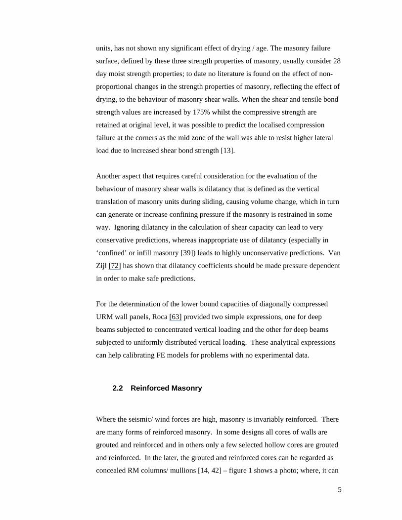
is vitally important to obtain stable solutions. The time step should be kept lower
than the maximum period maxt of the structure as given in equation 4.
2max
max
21t
(4)
In which max is the highest Eigen value of the system and is the
corresponding critical damping.
Explicit methods are shown to provide realistic results of the global behaviour of
masonry shear walls in recent times – by the author and coworker [19, 20] for
wide spaced reinforced masonry subjected to monotonic loading and recently by
Karapita et al. [45] for unreinforced masonry subjected to cyclic loading. These
early successes prompt further studies for comprehensive examination of this
method.
4.1.2 Material Nonlinearity in FE Formulation
Irrespective of the method of solving (implicit/ explicit), the FE models must
handle the material nonlinearity that includes plasticity, damage and cracking/
fracture. Nonlinearities due to interface bond failure/ slip in masonry structures
could be classed under material nonlinearity also. Nonlinear solution algorithms
have attained high level of perfection these days and many commercial packages
provide very good routines to take care of nonlinearities. Normally they use
incremental, iterative techniques that are automated and auto-scaled. Correct
choice of data and solution strategies are more important in the current scenario
rather than trying to improve the efficiency of the solution schemes.
In all nonlinear methods, the stiffness varies as a function of the accumulated
strains. For nonlinear analyses, displacement control techniques provide better
solution; therefore, predefined displacement history data are provided to infer the
structural response. The nonlinear algorithms could be regarded as “predictor –
corrector” schemes in which first elastic displacements are obtained (“predictive”)
for a given increment of external loading. The excess (or residual) load that

20
violates a yield criterion is then dissipated into the structure by allowing the
structure to deform (“corrective”) further through a process of iteration. This
scheme continues until the excess/ residual load becomes negligibly small. At
this stage it is regarded that nonlinear equilibrium is achieved.
Material nonlinearity is usually defined in two facets: First definition of a yield
criterion and second a flow rule. There are many classical yield criteria and flow
rules available in the theory of plasticity. For example, concrete/ rock type brittle
materials are modelled using Drucker-Prager yield criterion. For masonry, the
failure criteria reported in Section 3.2 of this paper are the best available to date.
There is a tendency to treat fully reinforced masonry as reinforced concrete by
disregarding the planes of weakness (bed joints); this proposition requires further
thorough examination prior to adoption as a standard process. The author
believes that there is absolutely no justification to assume isotropy of the partially
reinforced or confined masonry.
The second facet of a flow rule is typically well established in the theory of
plasticity. The flow rules may be “associated” (plastic strain tensor direction
remains outward normal to the yield surface) or “non-associated” (plastic strain
tensor oblique to the yield surface). It should be noted that the flow rule provides
only the direction of strain tensor. As stresses cannot exceed yield, any excess
stress (calculated based on elastic predictor) must be reduced back to the yield
surface. The direction predicted by the flow rule helps in reducing the excess
stresses to the yield surface. Furthermore, the yield surface itself might change its
shape/ size or position depending on the material data/ load history. When the
loading is simple monotonic, isotropic hardening rule is considered sufficient; for
cyclic loading, kinematic hardening rule allowing for the translation of the yield
surface away from the origin to account for the accumulation of residual stresses
(plastic strains) must be accounted for in detail.
Lofti and Shing [51] provided an appraisal of smeared crack modelling techniques
and used the approach for masonry and steel reinforcement for the analysis of
reinforced masonry walls. It was assumed that the uncracked masonry followed a
plasticity model, the cracked masonry an orthotropic material model and the steel

21
reinforcement an elastic hardening-plastic material. This approach predicted
flexure dominant behaviour but couldn’t capture the brittle shear behaviour of RM
walls due to the unrealistic kinematic constraint introduced by the smeared crack
assumption. This problem can be overcome with the use of discrete crack
approach [12, 52, 55] to model the major diagonal crack in a shear wall. Although
this approach predicts the behaviour well, it requires the location of the major
diagonal crack as a priori.
By modelling the shear walls using plasticity-based interface elements for mortar
joints and smeared crack elements for masonry units and by treating the
reinforcing steel as an elastic-hardening plastic material by means of a smeared
overlay on top of the smeared crack elements, RM shear walls are modelled. The
compressive and tensile behaviour of masonry units can be governed by Von
Mises failure surface with a Rankine type tension cut-off. A similar failure
criterion was formulated for masonry by Lourenco [52], who presented a macro
model capable of accurately predicting the behaviour of the URM shear walls
until the walls exhibited large lateral drift associated with wide crack.
Zhuge [80] developed a two-dimensional plane stress element model for the non-
linear analysis of URM shear walls. This model was developed using a
homogeneous material model to predict the detailed load-deflection characteristics
and critical limit states of URM walls under inplane earthquake ground
acceleration.
4.1.3 New Generation Finite Elements
A four noded 2D isoparametric hybrid stress element with six degrees of freedom
per node termed as a quasi 3D element with 24 stress parameters (Q3D24) is
reported in Section 3.1 of this paper. In spite of exhibiting convergence with h-
refinement, the element has remained computationally more expensive than the
standard plane element, but unlike the plane element it could provide out-of-plane
deformation and stress fields just from quasi 2D analysis. With reference to this
22
capability, it can be argued that the Q3D24 element is less expensive than the 3D
counterpart in an overall sense.
Trefftz Finite Element (TFE) [59] technique is preferred where there exist
significant nonlinearities due to contact or moving boundaries or discontinuities.
Since 1926 when Trefftz published the first paper on this formulation, a number
of contributions that examine problems of some elastic and non elastic fields
using Trefftz approach have emerged. The advantage is that TFE is formulated
using two shape functions (as against a single shape function that formulates
conventional finite elements); first is a domain shape function that accounts for
intra element nonlinearities and the second is a boundary (or, frame) shape
function that allows for inter-element compatibility. The separation of the intra
and inter element shape functions possess the advantage of not imposing explicit
relation between nodal degrees of freedom and the intra element deformation
point-by-point. Trefftz approach can be referred to as the boundary-type solution
procedure employing regular T-complete functions satisfying the governing
equations.
Masonry containing cracks, voids or other defects can be analysed using very
complex, fine mesh especially around the defects in the conventional finite
element analysis. To effectively describe singularity of stress fields at the crack
tip, commercial finite element programs provide singular elements formulated by
collapsing rectangular elements into triangular shape for 2D analysis and
rectangular prism elements into triangular pyramid shape for 3D analysis.
Depending on the anticipated state of stress singularity around the crack tip, mid
side nodes in the collapsed elements could either be moved to the quarter point
position closer to the crack tip or left unchanged in their original location.
With the objective of making the meshing simpler especially around the crack or
other defects, using the variational principle, complex variable technique, and
mapping function Tong et al [71] formulated several super-elements based on
hybrid element technique. As the stress singularity at the crack tip has been
included in the formulation of these elements, the stress intensity factors were

23
reported directly from the nodal displacements, thus eliminating the use of any
weak forms such as the J-integrals for this purpose.
The author and co-workers presented two Trefftz boundary element formulations
based on the Galerkin technique and the collocation point technique with
particular attention to modelling mode III fracture problems [76]. First, original
formulations and the solution of the Mode III crack on elastic problem are
deduced based on the Trefftz functions satisfying the Laplace governing equation.
Then stiffness matrix and equivalent nodal flow vector are formed from the
approximate solution satisfying the boundary condition using the Galerkin method
and the collocation point method [78]. Near crack tips results are improved
through an auxiliary function.
Trefftz finite element (TFE) formulations appear more suitable for dealing with
cracking in masonry; they do not appear to have significant advantage in dealing
with material plasticity and damage although some contributions have emerged in
the literature in recent times for plasticity.
4.2 Other Numerical Methods
As stated earlier, AEM and DEM are emerging as popular methods for modelling
masonry – especially larger building assemblages. The fundamental idea of these
two methods is defining contact between boundaries of blocks. Contact problems
have attracted much attention due to their inherent complexity and frequent
occurrence in engineering practice. A variety of numerical approaches for
calculating contact zones, and dividing them into stick and slip subzones, as well
as determining the contact stresses, are available in the literature. Amongst these
approaches the interface element (IE) methodology, due to its ease of numerical
implementation, has been investigated by many researchers. The kinematic
inconsistency associated with the classical joint element of Goodman [13, 27]
usually results in spurious oscillations of tangential traction. To circumvent this
difficulty, the Newton-Cotes integration scheme was used by several authors
instead of the widely adopted Gaussian quadrature [5,20].

24
As TFE approach assimilates the merits of the conventional FE and boundary
element (BE) methods and, moreover, discards some of their drawbacks: Firstly,
the element formulation calls for integration along the element boundaries only,
and secondly, some problems with singular or local effects can be treated easily if
exact local solution functions are available. The author and coworkers have
developed a TFE model specifically for elastic contact problems with the help of
Kaliakin-Li (KL) interface elements [76]. The model consisted of a 4-node hybrid
Trefftz element used in the discretisation of both contacting bodies; 4-node KL
elements have been embedded for simulating the potential contact zone. To assess
the reliability of the KL elements for predicting the contact behaviour, an
interfacial constitutive relation, namely penalized normal contact and tangential
friction law, has been adopted. The TFE-interface model has been implemented
into a commercial FE package, ABAQUS, via user element subroutine (UEL).
Two benchmark examples have been presented to illustrate the applicability of the
overall model to contact problems. Good agreements have been achieved between
the results from the present approach and analytical as well as the conventional
FE solutions obtained from ABAQUS software [1].
From static contact analysis using finite elements, one could discover that the
uniform bearing stress assumption at the interface is inappropriate. From the
results reported, it could be inferred that although the bulk of the interface is
under an “average” stress, at the point of singularity (where there is a sudden
discontinuity) the stress was found to peak significantly (approximately four times
average stress – sufficient to cause local damage). Contact interface failure in
masonry is so important and the TFE method with KL contact appears to be an
effective approach for solving the problem.
5. Summary and Conclusions
This paper has provided a review of the fundamental behaviour of masonry under
loading with a view to identifying appropriate modelling method; both the
unreinforced and reinforced masonry as well as the wide space reinforced

25
masonry are considered. The following conclusions have emerged from the
review:
Unreinforced and fully reinforced masonry behaviour under out-of-plane
shear is reasonably well understood.
Inplane shear behaviour of masonry in general is not fully well
understood; all masonry walls are thought to fail due to diagonal shear/
sliding shear/ rocking flexure, of which the diagonal shear is believed to
be more brittle than the other two modes of failure – although
contradicting results are reported in the literature. Modelling inplane shear
behaviour of masonry is currently the most sought topic of research.
Some inplane shear design provisions in AS3700 [2] and CSA-S304 [11]
are unsafe. As this form of construction is quite economical, there is a
pressing need to urgently revise the current provisions so that safer designs
can be achieved.
Shear and tensile bond strengths can increase dramatically when masonry
is bone-dry whilst its compressive strength will remain relatively
unaffected. This can cause highly brittle corner crushing mode of failure –
especially if masonry walls are designed to transfer concentrated lateral
loading at corner rather than distributed by the rigid diaphragm.
Some special elements are formulated specially for simplified geometric
modelling of masonry; they are:
o 1D element incorporating grouting and reinforcement including
bond-slip;
o 2D element capable of providing three dimensional state of stress.
Masonry can be modelled using micro modelling approach in FE; however
careful interface modelling is essential. Masonry can also be analysed
using macro modelling; such models require special failure surface for
masonry under biaxial stress state.
Smeared crack modelling of masonry is commonly adopted as it is
economical; energy based characteristic length of the element must be
included in such models to avoid mesh pathology. As modern masonry is
distinctly orthotropic, research should be directed to evaluating
characteristic lengths for each of the axis of orthotropy.

26
Explicit solution technique is emerging as a viable approach for modelling
statically loaded masonry walls subjected to nonlinearity and cracking.
Trefftz finite element method, that incorporates two shape functions – one
for deformation of interior of the element and the other for the boundary
deformation related to inter-element compatibility – is proving to be
efficient for dealing cracking and contact problems; the method can be
tried for efficient masonry modelling.
Applied element method (AEM) and distinct (or discrete) element method
(DEM) are emerging as powerful methods in modelling masonry as these
methods largely rely on the interface contact formulation between large
blocks that may be rigid or deformable. Progressive failure of structure,
that cannot be easily modelled using FE methods can be readily modelled
in AEM/ DEM.
Acknowledgements
The author acknowledges a range of undergraduate and research students who have contributed to
the development of the ideas/ data reported in the paper. Recent deliberations with Professors Page
(Newcastle, NSW), Shrive (Calgary, Canada) and Drysdale (McMaster, Canada) as well as
industry partners Alan Pearson (CMAA) and Wayne Holt (AdBri Masonry) are also fondly
acknowledged.
References:
1. ABAQUS. Theory manual. Hibbit, Karlson & Sorenson, Inc (2005).
2. AS3700. Australian Standard- Masonry Structures, Standards Australia International,
Sydney. (2001).
3. Assa B,and Dhanasekar M. A numerical model for the flexural analysis of short
reinforced masonry columns including bond-slip, Computers & Structures, 80(5), 547-
558 (2002).
4. Assa B, and Dhanasekar M. The significance of transverse steel reinforcement to the
behaviour of RC columns. Proc. 17th Australasian Conf on Mech of Structures and
Materials, Balkema, 139-144 (2002).
5. Assa B, and Dhanasekar M. A layered line element for the flexural analysis of cyclically
loaded reinforced concrete beam-columns. Computers and Structures, 78, 517-527,
(2000).
6. Bazant ZP and Planas J. Fracture and size effect in concrete and other quasi brittle
materials. CRC press, ISBN. 084938284X, (1997).

27
7. Bosiljkov V. Micro vs. macro reinforcement of brick masonry. Materials and Structures,
39, 235 – 245 (2006).
8. BS5628. Structural Use of Masonry: Part-1 Unreinforced Masonry. British Standards
Institution, UK (1985).
9. BS5628. Structural Use of Masonry: Part-2 Reinforced Masonry. British Standards
Institution, UK (1985).
10. BS EN1996. Eurocode 6: Design of masonry structures. British adopted European
standard. ISBN: 9780580687372 (2005).
11. CSA-S304.1. Design of masonry structures. Canadian Standards Association. ISBN 1-
55397-402-6 (2004).
12. DeJong MJ. Seismic Assessment Strategies for Masonry Structures. PhD thesis.
Massachusetts Institute of Technology, USA (2009).
13. Dhanasekar M. The performance of brick masonry subjected to inplane loading. PhD
thesis, University of Newcastle, Australia (1985).
14. Dhanasekar M. Requirement of high performance grout for the partially reinforced
masonry. Proc. The First USA - Australia Workshop on High Performance Concrete,
Sydney, 341-355 (1997).
15. Dhanasekar M. Evaluation of cyclic M- relations of reinforced masonry. 16 ACMSM,
Sydney. 607-612 (1999).
16. Dhanasekar M. On the confined masonry, Journal of the Institution of Engineers (India)
V(CE), 26-30, (2004).
17. Dhanasekar M., On the shear capacity equation formula in AS3700, Proc Australasian
Structural Engineering Conference, Gold Coast, 2, 555 – 562 (2001).
18. Dhanasekar M, and daPorto F. Review of the thin bed technology for masonry
construction”, Paper B.7-3, Proc. 11th Canadian Masonry Symposium, Toronto, ISBN
978-0-9737209-2-1 (2009)
19. Dhanasekar M, and Haider W. An explicit finite element modelling for the analysis of
masonry shear walls containing reinforcement. Proc. Australasian Conf. Mech of Mat
and Struct, Christchurch, 967-73, ISBN 13 978 0 415 42692 3 (2006).
20. Dhanasekar M. and Haider W. An explicit finite element model for masonry. Computers
& Structures 86: 15-26 (2008).
21. Dhanasekar M, and Kelly W. Shear resistance of masonry joints containing damp proof
courses. Proc. 7NAMC, Notre Dame, USA, 666-676 (1996),
22. Dhanasekar M, Kleeman PW, and Page, AW. The failure of brick masonry under biaxial
stress. Proc Inst of Engrs, Part 2, London, 72, 295 – 313 (1985).
23. Dhanasekar M, Loov R, Shrive NG. Stress-Strain relations for grouted concrete masonry
under cyclic compression. Proc 15th Australasian Conference on Mechanics of
Structures and Materials, Melbourne, Balkema, 663-668 (1997).
24. Dhanasekar M, Loov RE, McCoullough D, and Shrive NG. Stress-strain relations for
hollow concrete masonry under cyclic compression. Proc. 11th International Brick &
Block Masonry Conference, Shanghai, 1269-1278 (1997).

28
25. Dhanasekar M, Maes P, and Shrive NG. Response of the cores of partially reinforced
masonry to cyclic flexure. Proc. 11th Int. Brick & Block Masonry Conference, Shanghai,
239-248 (1997).
26. Dhanasekar M, Page AW, and Kleeman PW. The elastic properties of brick masonry. Int
J of Mas Constn (Now Masonry International), 2(4), 155 – 160 (1982).
27. Dhanasekar M, Page AW, and Kleeman PW. A finite element model for the inplane
behaviour of brick masonry. Proc. 9th Australasian Conference on Mechanics of
Structures and Materials, Sydney, 262 – 26 (1984).
28. Dhanasekar M, Page AW, and Kleeman PW. Biaxial stress - strain relations for brick
masonry. J of Struct Engg., ASCE, 111(5), 1085-1100 (1985).
29. Dhanasekar M, and Shrive NG. Strength and stiffness of confined and unconfined
concrete masonry. ACI Structural Journal. 99(6), 819-826 (2002).
30. Dhanasekar M, Shrive NG, Page AW, and Haider W. Wide spaced reinforced masonry
shearwalls. Computer Analysis and Design of Masonry Structures, John Bull (Ed), Saxe-
Coburg Publishers, UK, ISBN 978-1-874672-44-9 (2010).
31. Dhanasekar M, and Wong K. Evaluation of shear capacity equation for masonry beams
without web reinforcement, Proc. 6th Australasian Masonry Conference, Adelaide, 115-
124 (2001).
32. Dhanasekar M, and Xiao QZ. A 2D element for 3D analysis of masonry prisms, Proc. 6th
Australasian Masonry Conference, Adelaide, 125-134 (2001).
33. Dhanasekar M, and Xiao QZ. A Plane hybrid stress element method for 3D hollow bodies
of uniform thickness. Computers and Structures. 79(5).483-497(2001).
34. Dickie JE, and Lissel SL. Comparison of inplane masonry shear models. Proc. 11th
Canadian Masonry Symposium, Toronto (2009).
35. Drysdale RG. and Hamid AA. Capacity of concrete block masonry prisms under
eccentric compressive loading. ACI Journal, 102-108 (1983).
36. Drysdale RG, and Hamid AA. Masonry structures: behaviour and design. Canada
masonry design centre. ISBN 0-9737209-0-5 (2005).
37. FEMA 307 (1998). Evaluation of earthquake damaged concrete and masonry wall
buildings, Washington DC, http://www.fema.gov/library/viewRecord.do?id=1652 .
38. Feng ML, and Dhanasekar M. Improving out-of-plane fields of a quasi-3d element using
Fourier series expansion, Int J Structural Engineering & Mechanics, 13(5),(2002),
39. Franch KAG, Morbelli GMG, Inostroza MAA and Gori RE. A seismic vulnerability
index for confined masonry shear wall buildings and a relationship with damage. Journal
of Engineering Structures, 30, 2605-2612 (2008).
40. Gambarotta L, and Lagomarsino S. Damage models for the seismic response of brick
masonry shear walls. Part I: The mortar joint model and its applications. Journal of
Earthquake Engg and Struct Dyn, 26, 423-439 (1997).
41. Gambarotta L, and Lagomarsino S. Damage models for the seismic response of brick
masonry shear walls. Part II: The continuum model and its applications. Journal of
Earthquake Engg and Struct Dyn, 26, 441-462 (1997).

29
42. Haider W, and Dhanasekar M. Experimental study of monotonically loaded wide spaced
reinforced masonry walls, Aust J of Structural Engineering, 5(2), 101-118 (2004).
43. Hatzinikolas M, Longworth J, and Warwaruk J. The effect of joint reinforcement on the
vertical load carrying capacity of hollow concrete block masonry, Structural Engineering
Report, Alberta Masonry Institute (1978).
44. Hellweg HB and Crisfield MA. A new arc-length method for handling sharp snap-backs,
Computers & Structures, 66(5), 705 - 709 (1998).
45. Karapitta L, Mouzakis H and Carydis P. Explicit finite-element analysis for the in-plane
cyclic behaviour of unreinforced masonry structures, Earthquake engineering and
structural dynamics, DOI 10.1002/eqe.1014 (2010).
46. Karbassi A and Nollet MJ. Application of the applied element method to the seismic
vulnerability evaluation of existing buildings, CSCE Annual Conference, Quebec (2008).
47. Kumar M. Development of reinforced clay block masonry columns subjected to
concentric and eccentric compression, Master of Engineering Thesis, Central Queensland
University, Australia, (1995).
48. Kumar M, and Dhanasekar M. Response of slender reinforced masonry columns to
eccentric compression. Proc. 4th Australasian Masonry Conference, Sydney, 189-198
(1995).
49. Kumar M, and Dhanasekar M. Effect of lateral reinforcement detailing on the strength
and stiffness of reinforced clay block masonry. Proc 5th East Asia Pacific Conference on
Structural Engineering and Construction, 1, 1006-1010 (1995).
50. Lestuzzi P., Belmouden Y. and Trueb M. Nonlinear seismic behaviour of structures with
limited hysteretic energy dissipation capacity. Bull earthquake engineering Springer. 5:
549-569 (2007).
51. Lotfi, H. R. and Shing, P. B. An appraisal of smeared crack models for masonry shear
wall analysis. Computers and Structures. 41(3), 413-425 (1991).
52. Lourenco P B. Computational strategies for masonry structures. PhD thesis, Delft
University, Netherlands, (1996).
53. Luciano R, and Sacco E. A damage model for masonry structures. European Journal of
Mechanics and Solids. 17(2), 285-303 (1998).
54. Massarat TJ. Multiscale modelling of damage in masonry structures. PhD Thesis.
Technical university of Eindhoven, Netherlands (2003).
55. Mosler J and Meschke G. Embedded crack vs smeared crack models: a comparison of
elementwise discontinuous crack path approaches with emphasis on mesh bias. Computer
methods in applied mechanics and engineering, 193, 3351-3375, (2004).
56. MSJC. Building code requirement for masonry structures. ACI530/ ASCE 5/ TMS 402.
USA (2008).
57. Page AW. Finite element model for masonry. Journal of structural division, ASCE
104(ST8). 1267-1285 (1978).
58. Priestley MJN, and Elder DM. Stress-strain curves for unconfined and confined concrete
masonry. ACI Journal, 80(3), 192 – 201 (1983).

30
59. Qin QH. The Trefftz Finite and Boundary Element Method, WIT Press, UK(2000).
60. Ramamurthy K, and Ganesan TP. Analysis of concrete hollow block masonry prisms
under eccentric compression. Magazine of Concrete Research, 45(163), 147-153 (1993).
61. Reda-Taha MM, Xiao X, Yi J and Shrive NG. Evaluation of flexural fracture toughness
for quasi-brittle structural materials using a simple test method, Canadian Journal of
Civil Engineering, 29, 567–575 (2002).
62. Reddy BVV, and Vyas UV. Influence of shear bond strength on compressive strength and
stress – strain characteristics of masonry. Materials and Structures, 41, 1607-1712
(2008).
63. Roca P. Assessment of masonry shear walls by simple equilibrium models. Construction
and Building Materials, 20, 229-238 (2006).
64. Rots JG. Numerical simulation of cracking in structural masonry. Heron, 36(2), 49–63
(1991).
65. Sarangapani G, Reddy BVV, and Jagdish KS. Brick mortar bond and masonry
compressive strength. J Materials in Civil Engineering, ASCE, 17(2), 229-237 (2005).
66. Sayed-Ahmed EY. and Shrive NG. Numerical analysis of face-shell bedded hollow
masonry walls subjected to concentrated loads. Can J Civ Eng, 22,802-18 (1995).
67. Schulz AE. Minimum horizontal reinforcement requirements for seismic design of
masonry shear walls. The Masonry Society Journal 14(1): 49-64 (2006).
68. Scrivener JC, and Baker L. Factors influencing grouted masonry prism compressive
strength. Proc. 8th IB2MaC, Dublin, UK, 875-883 (1986).
69. Shedid MT, El_Dhakhakhni WW and Drysdale RG. Analysis of seismic response of fully
grouted reinforced concrete masonry shear walls. Proc. 14th World Conference on
Earthquake Engineering, Beijing, (2008).
70. Tena-Colunga, A, and Cano-Licona, J. Simplified method for the seismic analysis of
masonry shear-wall buildings, Journal of Structural Engineering, ASCE 136, 5, (2010).
71. Tong P, Pian TTH, and Lasy SL. A hybrid-element approach to crack problems in plane
elasticity. International Journal of Numerical methods for engineering. 7, 297-308
(1973).
72. Van Zijl GPAG. Modelling masonry shear-compression: role of dilatancy highlighted. J
Engineering Mechanics ASCE. 130(11), 1289-1296 (2004).
73. Vecchio FJ. Disturbed stress field model for reinforced concrete: formulation. J
Structural Engineering, ASCE. 126(9), 1070-1077(2000).
74. Vecchio FJ, and Collins MP. The modified compression field theory for reinforced
concrete elements subjected to shear. ACI Structural journal, 219-231(1986).
75. Vermeltfoort AT. Brick mortar interaction in masonry under compression. PhD thesis,
Eindhoven University of Technology, The Netherlands, ISBN 90-6814-582-7 (2005).
76. Wang KY, Dhanasekar M, Qin QH, and Kang Y L. Contact analysis using Trefftz and
interface finite elements, J. Computer Assisted Mechanics and Engineering Sciences,
13(3), 457-471(2006).

31
77. Xiao Q Z, and Dhanasekar M. Plane hybrid stress element for 3D problems. Proc. 5th
International Conf on Computational Structures Technology, Belgium, 147-158 (2000).
78. Xiao Q Z, and Dhanasekar M. Coupling of FE and EFG using collocation approach, Int J
Advances in Engineering Software, Elsevier Science, 33(7-10), 507-516, (2002).
79. Zhuge Y. Distinct element modelling of URM under seismic loads with and without cable
retrofitting. Trans. Tianjin Univ. 14:471-475. DOI 10.1007/s12209-008-0080-0 (2008).
80. Zhuge Y, Thambiratnam D and Corderoy J. nonlinear dynamic analysis of unreinforced
masonry, Journal of Structural Engineering, ASCE, 124(3), (1998).