Analysis and control of transitional shear flows using global ...
Upload
independentCategory
view
1download
0
Structural Engineering and Mechanics, Vol. 37, No. 1 (2011) 39-59 39
Shear strength analysis and prediction of reinforced concrete transfer beams in high-rise buildings
R.S. Londhe
Government College of Engineering, Staion Road, Osmanpura, Aurangabad-431 005, India
(Received November 30, 2009, Accepted September 7, 2010)
Abstract. Results of an experimental investigation on the behavior and ultimate shear capacity of 27reinforced concrete Transfer (deep) beams are summarized. The main variables were percent longitudinal(tension) steel (0.28 to 0.60%), percent horizontal web steel (0.60 to 2.40%), percent vertical steel (0.50to 2.25%), percent orthogonal web steel, shear span-to-depth ratio (1.10 to 3.20) and cube concretecompressive strength (32 MPa to 48 MPa).The span of the beam has been kept constant at 1000 mm with100 mm overhang on either side of the supports. The result of this study shows that the load transfercapacity of transfer (deep) beam with distributed longitudinal reinforcement is increased significantly.Also, the vertical shear reinforcement is more effective than the horizontal reinforcement in increasing theshear capacity as well as to transform the brittle mode of failure in to the ductile mode of failure. It hasbeen observed that the orthogonal web reinforcement is highly influencing parameter to generate the shearcapacity of transfer beams as well as its failure modes. Moreover, the results from the experiments havebeen processed suitably and presented an analytical model for design of transfer beams in high-risebuildings for estimating the shear capacity of beams.
Keywords: shear resisting capacity; horizontal and vertical steel bars; shear span-to-depth ratio;national codes; transfer beam.
1. Introduction
High-rise buildings are characterized by their high susceptibility to lateral drift under the effects of
lateral loads such as wind and earthquake loads. Therefore, in order to achieve architectural and
functional requirements of large column-free space in high-rise buildings, the RC columns are
placed at the periphery of the built-up plan area. With a view to developing high flexural and
torsional stiffness, these columns are very closely spaced and interconnected through very stiff
beams; called as Spandrel beams. These closely spaced columns at the periphery, however, pose
hindrance to the free flow of people and goods at the ground floor and basement levels. To fulfill
this requirement, the columns at these floor levels have to be placed at larger spacing. As a result,
an interface has to be provided between the closely spaced columns of upper floors and the widely
spaced columns at the ground/basement floor level. This interface has to be a horizontal RC element
and hence is referred to as Beam. Conventionally, a beam is a flexural member of a structural
system. The above mentioned interface beam, however, does not behave as a flexural member since
it gets sandwiched between closely spaced upper columns and a little widely spaced supporting
*Corresponding author, Associate Professor, E-mail: [email protected]
40 R.S. Londhe
columns below it. Also to transfer the high magnitude of loads collected from all the upper floors of
a high-rise building, the depth of the interface beams has to be kept much higher than the
conventional beams, ranging from 1 m to 4.5 m. As a result of this, a/d ratio of such beams
becomes different than the conventional beam which in tern makes the load transfer mechanism
through these beams altogether different. Such a beam is also referred to as a Transfer Beam.
Transfer (deep) beams are horizontal members, and have shear span-to-depth ratio < 2, which
transfer heavy gravity loads predominantly through shearing action by forming a diagonal crack,
Since a diagonally cracked deep beam behaves as a tied arch (Ley et al. 2007, Zhang and Tan
2007), the conventional plane section remaining plane approach is not applicable to analyses of deep
beams (Kong 1990). Besides, for beams without web reinforcement, it has been shown that shear
strength decreases as member size increases. This is associated with a phenomenon called size effect
(Tan and Cheng 2006, Tan et al. 2008, Yang et al. 2007).
Shear strength in reinforced concrete beams has been the subject of many controversies and
debates since the beginning of 20th century and it has been extensively studied over the last five
decades (Russo et al. 2005). A large number of experimental and analytical works have been
carried out for the case of slender beams (having a shear span to depth ratio a/d > 2.5) with and
without shear reinforcement under two-point loading (Ahmad and Shaha 2009, Ashor and Yang
2008, Foster and Gilbert 1998) and proposed a design equation for predicting the shear strength of
deep beams (Bakir and Boduroglu 2002, Hwang et al. 2000, Leong and Tan 2003, Russo et al.
2004). Transversely loaded reinforced concrete beams may fail in shear before attaining their full
flexural strengths if they are not adequately designed for shear. Unlike flexural failures, shear
failures are very sudden and unexpected, and sometimes violent and catastrophic (Londhe 2007). A
thorough knowledge of the different modes of shear failures and the mechanisms involved is
necessary to prevent them (Zarris 2005).
2. Discussion on shear
Shear force is present in beams at sections where there is a change in bending moment along the
span. It is equal to the rate of change of bending moment. An exact analysis of shear strength in
reinforced concrete beam is quite complex. Several experimental studies have been conducted to
understand the various modes of failure that could occur due to possible combination of shear and
bending moment acting at a given section (Oh and Shin 2001, Pendyala and Mendis 2000, Vecchio
et al. 1994, Yang et al. 2003).
Despite the great research efforts, however, there is still not a simple, albeit analytically derived
formula to predict quickly and accurately the shear strength of slender beams. In addition, many of
the factors that influence the determination of the required minimum amount of shear reinforcement
are not yet known. As a consequence, the current provisions for shear in standard codes such as
ACI code, BIS code, BS code are still based on empirical or semi empirical considerations.
3. Experimental program
3.1 Test material and material properties
Ordinary Portland Cement of 43-grade confirming to Indian Standard3, (specific gravity and
Shear strength analysis and prediction of reinforced concrete transfer beams in high-rise buildings 41
fineness respectively were 3.14 and 275 m2/kg), locally available Yamuna river sand of specific
gravity was 2.60 and fineness modulus was 2.29, Crushed granite metal of maximum size 20 mm
obtained from a local source. and thermo-mechanically treated (TMT) rebar of 8 mm, 10 mm and
12 mm diameter of Fe 415 grade as reinforcement were used throughout the investigation.
3.2 Concrete mix design
The concrete mix was designed in accordance with the Indian Standard4 recommended method of
concrete mix design. The concrete mix was prepared for various cement content. To improve the
workability of concrete and to get high strength, a modified melamine base highly effective high
range water reducing concrete admixture was used. The detail of the mix design is shown in Table 1.
The beams were cast taking special care in placing and vibrating the concrete externally to ensure
the uniform compaction. For each of the series of beams, three cubes (150 mm × 150 mm × 150 mm),
three cylinders (150 mm, 300 mm high) and three prisms (500 mm × 500 mm × 1000 mm in length)
as control specimens were also cast to ensure the quality and strength of each concrete mix.
3.3 Design and details of the beam specimens
Twenty seven simply supported rectangular beams of constant width of 100 mm and varying
depth were cast and tested in the laboratory. A bottom clear covers of 20 mm, and side converse of
15 mm for reinforcement, were provided according to the Indian Standards. The specimens were
cast in two batches of same concrete compressive strength producing two sets of geometrically
identical specimens. A table vibrator was used for compaction of the specimens. After twenty four
hour, the specimens were removed from the mould and placed in the water tank for 28 days curing.
The full details are given in Table 2.
Based on the various influencing parameters of shear capacity of beams and to generate the shear
capacity, the beams were divided into six series. Series I specimens are beams with varying
percentage of longitudinal tension steel (ρl =0.28% to 0.60%) provided at the bottom of the beam
and without transverse steel, Series II specimens are beams with varying percentage of horizontal
web steel (ρh = 0.60% to 2.40%) provided from the bottom of the beam up to 50% of total depth of
beam and without transverse steel (Figs. 1(a) to (d)), Series III specimens are beams with varying
percentage vertical (transverse) steel (ρv = 0.50% to 2.25%) with constant percentage of longitudinal
Table 1 Concrete mix proportions
Descriptions
Cement Content (kg/m3)
320 360 400 440
Cube compressive strength of Concrete (MPa)
32 37 43 48
Water-Cement Ratio 0.40 0.36 0.32 0.29
Water (Liter) 7.800 7.800 7.800 7.800
Plasticizer as% of wt. of cement 0.60 0.75 0.85 1.00
Mix-Proportions 1:2.36:4.31 1:2.10:3.75 1.:1.82:3.31 1:1.63:2.93

42 R.S. Londhe
Table 2 Details of the Specimens of Series-I, II, III, IV, V & VI
Test Beam Designation
Beam Size(b×D)
Effective depth (mm)
a/d ratio
Concrete strength Long. Reinf. Vertical Reinf.
fcu
MPafc'
MPaft
MPaρl
(%)fy
(MPa
Dia. & spacing
mm
ρv
(%)fy
MPa
Series I Specimens
I-1/1.10//43/0.28 100×400 375 1.10 43.69 32.19 3.79 0.28
445.38 --- --- --
I-2/1.10//43/0.42 100×400 375 1.10 43.62 32.17 3.82 0.42
I-3/1.10/43/0.60 100×400 375 1.10 43.81 32.21 3.79 0.60
Series II Specimens
II-1/1.10//43/0.60 100×400 375 1.10 43.81 32.21 3.79 0.60
II-2/1.10/43/1.20 100×400 375 1.10 43.62 32.18 3.80 1.20
II-3/110/43/1.80 100×400 375 1.10 43.58 32.22 3.81 1.80
II-4/1.10/43/2.40 100×400 375 1.10 43.68 32.15 3.78 2.40
Series III Specimens
III-1/1.10/43/0.60/0.00 100×400 375 1.10 43.79 32.19 3.77
0.60 444.98
--- 00
445.38
III-2/1.10/43/0.60/0.50 100×400 375 1.10 43.68 32.14 3.80 8φ @250 0.50
III-3/1.10/43/0.60/0.75 100×400 375 1.10 43.74 32.19 3.80 8φ @150 0.75
III-4/1.10/43/0.60/1.25 100×400 375 1.10 43.81 32.20 3.83 8φ @100 1.25
III-5/1.10/43/0.60/2.25 100×400 375 1.10 43.70 32.16 3.82 8φ @50 2.25
Series IV Specimens
IV-1/1.10/43/2.40/0.00 100×400 375 1.10 43.79 32.19 3.77
2.40 445.98
--- 00
445.28
IV-2/1.10/43/2.40/0.50 100×400 375 1.10 43.68 32.14 3.80 8φ @250 0.50
IV-3/1.10/43/2.40/0.75 100×400 375 1.10 43.74 32.19 3.80 8φ @150 0.75
IV-4/1.10/43/2.40/1.25 100×400 375 1.10 43.81 32.20 3.83 8φ @100 1.25
IV-5/1.10/43/2.40/2.25 100×400 375 1.10 43.70 32.16 3.82 8φ @50 2.25
Series V Specimens
V-1/43/0.80/1.10 100×400 375 1.10 43.00 33.0 3.30
0.80 445.38 --- --- --
V-2/43/0.80 /1.23 100×350 325 1.23 42.50 3.3.5 3.35
V-3/43/0.80 /1.45 100×300 275 1.45 43.25 34.0 3.40
V-4/43/0.80 /1.78 100×250 225 1.78 43.50 34.2 3.42
V-5/43/0.80 /2.28 100×200 175 2.28 42.50 34.10 3.41
V-643//0.80 /3.20 100×150 125 3.20 42.75 33.21 3.30
Series VI Specimens
VI-1/1.10/0.60/32 100×400 375 1.10 32.30 24.44 2.91
0.60 444.12 ---- ---- ---VI-2/1.10/0.60/37 100×350 325 110 36.48 27.43 3.48
VI-3/1.10/0.60/43 100×300 275 1.10 43.27 32.15 3.82
VI-2/1.10/0.60/48 100×250 225 1.10 47.55 36.67 4.46

Shear strength analysis and prediction of reinforced concrete transfer beams in high-rise buildings 43
Fig. 1 (a to d) Series-II specimens

44 R.S. Londhe
Fig. 2 (a to e) Series-III specimens

Shear strength analysis and prediction of reinforced concrete transfer beams in high-rise buildings 45
Fig. 2 Continued
Fig. 3 (a to e) Series-IV Specimens

46 R.S. Londhe
steel (Figs. 2(a) to (e)), Series IV specimens are beams with varying percentage vertical (transverse)
steel (ρv = 0.50% to 2.25%) with constant percentage of horizontal steel distributed across the depth
of beam (Figs. 3(a) to (e)), Series V specimens are beams with varying shear-span-to-depth ratio
(a/d-ratio = 1.25 to 3.20) with constant percentage of longitudinal steel of 0.80% and Series VI
specimens are beams with varying cube compressive strength of concrete (32 MPa to 48 MPa) with
constant percentage of longitudinal steel of 0.60%.
3.4 Specimen identification
This paper addresses the effect of various influencing parameter on the shear capacity of
reinforced concrete transfer (deep) beams. In the beam natations under Table 1, in series I beam
specimens, the series number is given first; this is followed by beam serial number, followed by
a/d-ratio, then cube compressive strength of concrete and then longitudinal steel percent. For
example, Beam I-1/1.10/43/0.28 refers to a specimen in series I of serial number 1 with a/d-ratio of
1.10, cube compressive strength of concrete as 43 MPa and 0.28 percent longitudinal steel.
For series II beam specimens, the series number is given first; this is followed by beam serial
number, followed by a/d-ratio, then cube compressive strength of concrete and then horizontal web
steel percent. For example, Beam II-1/1.10/43/0.60 refers to a specimen in series II of serial number 1
with a/d-ratio of 1.10, cube compressive strength of concrete as 43 MPa and 0.60 percent horizontal
web steel.
For series III beam specimens, the series number is given first; this is followed by beam serial
Fig. 3 Continued
Shear strength analysis and prediction of reinforced concrete transfer beams in high-rise buildings 47
number, followed by a/d-ratio, then cube compressive strength of concrete, constant longitudinal
steel and then vertical steel percent. For example, Beam III-1/1.10/43/1.20/0.50 refers to a specimen
in series III of serial number 1 with a/d-ratio of 1.10, cube compressive strength of concrete as
43 MPa, 1.20 percent longitudinal steel and 0.50% vertical steel.
For series IV beam specimens, the series number is given first; this is followed by beam serial
number, followed by a/d-ratio, then cube compressive strength of concrete, constant horizontal
distributed web steel and then vertical steel percent. For example, Beam IV-1/1.10/43/2.40/0.50 refers
to a specimen in series IV of serial number 1 with a/d-ratio of 1.10, cube compressive strength of
concrete as 43 MPa, 2.40 percent constant horizontal distributed web steel and 0.50% vertical steel.
For series V beam specimens, the series number is given first; this is followed by beam serial
number, followed by cube compressive strength of concrete, constant longitudinal (tension) steel
and then a/d-ratio. For example, Beam V-1/43/0.80/1.10 refers to a specimen in series V of serial
number 1 with cube compressive strength of concrete as 43 MPa, 0.80% constant longitudinal
(tension) steel and a/d-ratio of 1.10.
For series VI beam specimens, the series number is given first; this is followed by beam serial
number, followed by a/d-ratio, constant longitudinal (tension) steel and then cube compressive
strength of concrete. For example, Beam VI-1/1.10/0.60/32, refers to a specimen in series VI of
serial number 1 with a/d-ratio of 1.10, 0.60 percent constant longitudinal (tension) steel and cube
compressive strength of concrete as 43 MPa.
4. Test procedure
4.1 Test setup and loading apparatus
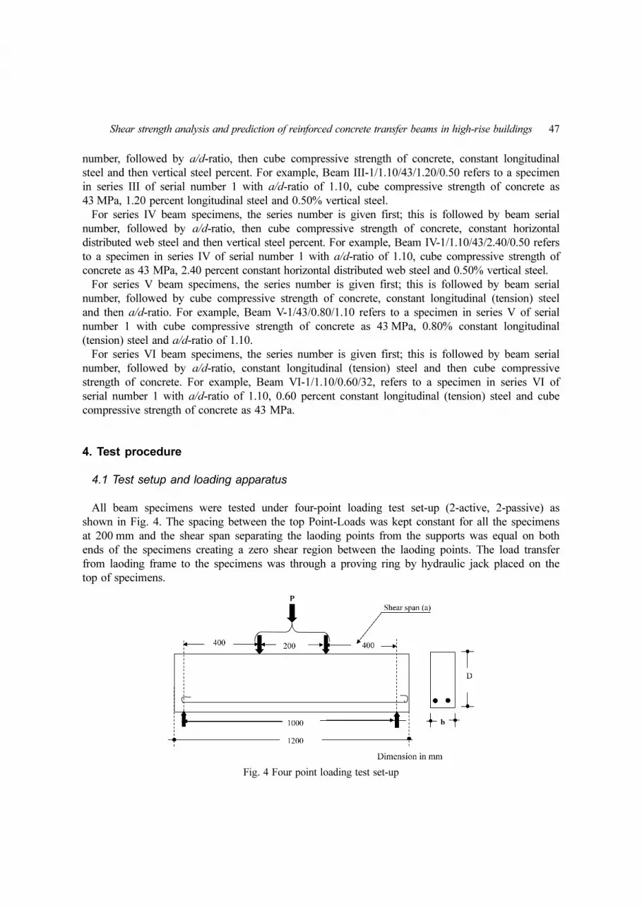
All beam specimens were tested under four-point loading test set-up (2-active, 2-passive) as
shown in Fig. 4. The spacing between the top Point-Loads was kept constant for all the specimens
at 200 mm and the shear span separating the laoding points from the supports was equal on both
ends of the specimens creating a zero shear region between the laoding points. The load transfer
from laoding frame to the specimens was through a proving ring by hydraulic jack placed on the
top of specimens.
Fig. 4 Four point loading test set-up

48 R.S. Londhe
After 28-days curing period, the beam specimens were removed from the curing tank and both
sides of the beam were white-washed to aid observations of the crack development during testing.
Load was applied gradually with the help of jack and deflection of proving ring was recorded to
find the failure load.
4.2 Test results and discussion
The results obtained from the experimental investigation are tabulated in Table 3. From the results
obtained, the effect of various parameters on shear strength of concrete are analyzed and discussed
as follows.
Table 3 Test results of Series I, II, III, IV, V & VI
Test Beam Designation
a/d ratio
Concrete strength Long.
ReinfVertical Reinf.
Vmax.
(kN)τ = V/bd(MPa)
τ/√fcu Mode of failure fcu
MPafc'
MPa
I-1/1.10//43/0.28 1.10 43.69 32.19 0.28 -- 60 1.60 0.24 Flexure
I-2/1.10//43/0.42 1.10 43.62 32.17 0.42 -- 75 2.00 0.30 Flexure-shear
I-3/1.10/43/0.60 1.10 43.81 32.21 0.60 -- 90 2.40 0.36 Shear
II-1/1.10//43/0.60 1.10 43.81 32.21 0.60 -- 90 2.40 0.36 Diagonal-splitting
II-2/1.10/43/1.20 1.10 43.62 32.18 1.20 -- 140 3.76 0.57 Diagonal-splitting
II-3/110/43/1.80 1.10 43.58 32.22 1.80 -- 165 4.40 0.67 Diagonal-splitting
II-4/1.10/43/2.40 1.10 43.68 32.15 2.40 -- 185 4.96 0.75 Diagonal-splitting
III-1/1.10/43/0.60/0.00 1.10 43.79 32.19
0.60
0.00 90 2.40 0.36 Diagonal-splitting
III-2/1.10/43/0.60/0.50 1.10 43.68 32.14 0.50 105 2.80 0.42 Shear-flexure
III-3/1.10/43/0.60/0.75 1.10 43.74 32.19 0.75 125 3.33 0.50 Flexure
III-4/1.10/43/0.60/1.25 1.10 43.81 32.20 1.25 150 4.00 0.60 Shear-compression
III-5/1.10/43/0.60/2.25 1.10 43.70 32.16 2.25 160 4.27 0.64 Shear-compression
IV-1/1.10/43/2.40/0.00 1.10 43.79 32.19
2.40
0.00 185 4.93 0.75 Diagonal-splitting
IV-2/1.10/43/2.40/0.50 1.10 43.68 32.14 0.50 292 7.79 1.18 Shear
IV-3/1.10/43/2.40/0.75 1.10 43.74 32.19 0.75 315 8.40 1.27 Flexure-shear
IV-4/1.10/43/2.40/1.25 1.10 43.81 32.20 1.25 320 8.53 1.29 Flexure-shear
IV-5/1.10/43/2.40/2.25 1.10 43.70 32.16 2.25 330 8.80 1.33 Flexure-compression
V-1/43/0.80/1.10 1.10 43.00 33.0
0.80
-- 98.25 2.62 0.40 Diagonal-splitting
V-2/43/0.80 /1.23 1.23 42.50 3.3.5 -- 65 2.00 0.31 Diagonal-splitting
V-3/43/0.80 /1.45 1.45 43.25 34.0 -- 44 1.60 0.24 Diagonal-splitting
V-4/43/0.80 /1.78 1.78 43.50 34.2 -- 29.25 1.30 0.20 Diagonal-splitting
V-5/43/0.80 /2.28 2.28 42.50 34.10 -- 21 1.20 0.18 Diagonal-splitting
V-6/43//0.80 /3.20 3.20 42.75 33.21 -- 14 1.12 0.17 Diagonal-splitting
VI-1/1.10/0.60/32 1.10 32.30 24.44
0.60
-- 77 2.05 0.36 Diagonal-splitting
VI-2/1.10/0.60/37 110 36.48 27.43 -- 80 2.13 0.35 Diagonal-splitting
VI-3/1.10/0.60/43 1.10 43.27 32.15 -- 84 2.24 0.34 Diagonal-splitting
VI-2/1.10/0.60/48 1.10 47.55 36.67 -- 88 2.34 0.34 Diagonal-splitting

Shear strength analysis and prediction of reinforced concrete transfer beams in high-rise buildings 49
4.3 Ultimate strength
Shear capacity is defined as the maximum shear force that a critical section can sustain. It is
widely accepted that a main contributor to shear resistance in concrete is aggregate interlock. The
use of web reinforcement to carry shear force is necessary when the concrete portion alone is
unable to sustain the force. The presence of sufficient web reinforcement can help to prevent the
brittle failure in a transfer beam. The ultimate strengths (VnTEST) of different beam specimens are
given in Table 3.
4.4 General behavior
The general behavior of all the specimens was quite similar. First, the fine flexural cracks were
initiated in the pure bending region and with further increase of load, new flexural-shear cracks
formed in the shear spans and subsequently, curved toward the loading points. Failure in these
specimens was always sudden with loud sound at failure and in diagonal tension, shortly after
diagonal shear cracks appeared.
4.5 Modes of failure
The failure modes of the specimens are indicated in the Table 3. Four failure modes are identified,
i.e., diagonal splitting (shear) failure, shear-flexure failure, flexure and shear-compression failure.
The diagonal-splitting failure, characterized as shear failure, is brittle, sudden and hence treacherous.
A critical diagonal crack joining the loading point at the top and support point at bottom is
developed. In the shear-compression mode of failure, after the appearance of the inclined crack, the
concrete portion between the top load point experiences high compression and it then finally fails.
This mode of failure is equally a brittle mode of failure. The shear-flexure mode of failure is the
combined failure in shear and flexure. Flexural cracks are formed followed by the partly diagonal
crack. This is ductile mode of failure in which the beam deflects at the centre and no explosive
sound was heard at the time of failure.
4.6 Effect of percent longitudinal (tension) steel and percent horizontal web steel
Table 3 presents the measured the ultimate strength (failure load) of the transfer beams. The shear
strength was observed to be increased with the increase in the percent longitudinal tension steel
provided at the bottom of beams (Series-I specimens). However, a significant increase in the shear
capacity was observed by longitudinal steel provided from the bottom of the beam up to 50% of
total depth of beam in the web of the beam (Series-I specimens) but beyond 1.80% this increase is
nominal. This fact is primarily because of longitudinal steel affects the amount of longitudinal strain
and thereby affects crack width, interface shear transfer, dowel action, and thereby the shear
strength. A flexure, flexure-shear, shear and diagonal splitting modes of failure are observed in this
series specimens.
4.7 Effect of percent transverse steel ratio
The failure shear strength and modes of failure of beam specimens are indicated in Table 3. The

50 R.S. Londhe
addition of transverse steel improves the shear response of the transfer beams by increasing the
failure shear strength and a higher ductile response in comparisons with Series-I & II specimens. A
significant increase in the shear capacity was observed up to 1.25% transverse steel. Beyond 1.25
percent, the increase in shear capacity was not significant for this range of beam specimens and
failure occurs in concrete compression zone, between the two-load points.
4.8 Effect of percent horizontal distributed steel
In the Series IV beam specimens, a constant percentage of horizontal steel (2.40%) distributed
across the depth of beam and varying percentage vertical (transverse) steel (ρv = 0.50% to 2.25%).
The beam specimen were cast and tested with view to see the influence of horizontal steel provided
in the whole depth of the beam along with varying percentage vertical (transverse) steel. The
placement of horizontal steel in the whole body of the beam, improves the shear response of the
transfer beams by increasing the failure shear strength significantly and a higher ductile response in
comparisons with Series-III specimens. An initially diagonal splitting mode of failure has been
transformed in to flexure-compression mode of failure with increase in the percentage of transverse
steel.
4.9 Effect of shear span-to-depth (a/d) ratio
The shear strength of concrete beams for different depths at 28 days curing age is given in Table 3.
Fig. 11 shows the effect of shear span-to-depth ratio (or moment-shear ratio) on nominal shear
stress at diagonal cracking, which is obtained by dividing measured failure load to the nominal
cross sectional area (b × d). As the shear span-to-depth (a/d) ratio decreases, the shear strength
increases. The increase in shear strength is significant in RC beam specimens with a/d ratio less
than about 1.78, because of a significant portion of the shear is transmitted directly to the support
by an inclined strut. This mechanism is frequently referred to as arch action and the magnitude of
the direct load transfer increases with decreasing a/d-ratio. The shear strength of RC beams with a/d-
ratio less than 1.78 is higher than those of the RC beams with a/d-ratio more than 1.78. This result
is due to the beneficial effect of direct load transfer to the support by arch action or so called strut-
and-tie load transfer mechanism. The transition point between the arch action and beam action (or
transfer beams and normal beams) lies between a/d-ratio of 1.45 to 1.78. Either side of this a/d
ratio, behavior of RC beams, in terms of load resisting mechanism, failure pattern and the noise at
failure, were entirely different.
4.10 Effect of cube compressive strength of concrete
The beam specimens of Series VI, were cast and tested to see the effect of cube compressive
strength of concrete on shear strength of transfer beams. The specimens of this series are without
any transverse steel and a constant percentage of longitudinal steel is provided. A small increase in
the shear strength has been observed with increase in the cube compressive strength of concrete. As
transverse steel is not provided in the beam specimens, failure is in diagonal-splitting with loud
noise at failure with increase in the cube compressive strength of concrete.

Shear strength analysis and prediction of reinforced concrete transfer beams in high-rise buildings 51
4.11 The shear design models and proposed shear strength expression
Four design methods, namely, the ACI Code 318-05, the UK’s CIRIA Guide-2, the BS Code:
8110-1997 and the IS Code: 456-2000 are used to estimate the ultimate shear strength of the
specimens.
4.11.1 ACI 318-2005 design model
The shear provisions apply to both simple and continuous beams when the span to depth ratio L/D
is less than 5. The calculations are carried out for the critical section, which is defined as follows.
For concentrated load, the critical section is located midway between the load and the face of the
support; for a uniformly distributed load it is at 0.15l from the support where l is the clear span.
The ACI code assumes that Vc is equal to the shear strength of a beam without stirrups, which in
turn, is taken equal to the load at which inclined cracking occurs, is calculated as:
The shear strength of deep beam is divided into two parts:
1. The concrete contribution (Vc) and
2. The contribution of steel (Vs)
The concrete contribution to the shear strength can be computed by Eq. (1),
In S.I. system (N, mm system)
where
(1)
where Mu and Vu are the ultimate moment and shear at the section under consideration. fc' is the
concrete strength in MPa, ρw is the longitudinal reinforcement ratio (AS/bwd). And As is the area of
longitudinal reinforcement.
The contribution of the orthogonal web reinforcement to the shear strength can be computed as by
Eq. (2)
(2)
fy the strength of the web steel and should not be more than the 410 MPa
Av = the area of vertical web reinforcement within a distance Sv in inch2
Ah = the area of horizontal web reinforcement within a distance Sh, in inch2
4.11.2 CIRIA Guide - 2 - “Supplementary Rules” design model
The CIRIA Guide- 2 method is applicable for the range of .
In this Eqs. (3) and (4), the ultimate shear strength of deep beam is made up of two parts: the
contribution of the concrete and the contribution of the web reinforcement as
Vc 3.5 2.5Mu
Vud--------–⎝ ⎠
⎛ ⎞ 0.16 fc′ 17ρw
Vud
Mu
--------+⎝ ⎠⎛ ⎞bwd=
0.5 fc′ bwd≤
3.5 2.5Mu
Vud-------- 2.5≤–
Vs
Av
Sv
-----
1ln
d---+
12-------------
Ah
Sh
-----
11ln
d---–
12---------------+
νv νc–( )fy
------------------- b⋅= =
0.5 xe/h 01.25≤ ≤

52 R.S. Londhe
Vn = Vn + Vs (3)
(4)
Where
λ1 = (0.75 × 0.52 × C1) / γmc = 0.44 for normal weight aggregates
= (0.75 × 0.52 × C1) / γmc = 0.32 for lightweight aggregates
λ2 = [(0.75 × 0.52 × C2) / γms]/100 = 1.95 MPa for deformed bars
= [(0.75 × 0.52 × C2) / γms]/100 = 0.85 MPa for plain round bars
C1 = empirical coefficient for concrete = 1.40 for normal weight concrete.
C2 = empirical coefficient for deformed bars = 415 MPa.
γmc & γms material safety factor for concrete & steel, respectively
In the expression of empirical coefficients for λ1 and λ2, CIRIA used a statistical factor of 0.75
just to convert the mean test values to characteristic values consistent with British design codes; and
a factor of 0.52 to convert the cylinder splitting strength ft to √fcu. The material partial safety factors
for concrete and steel (γmc & γms) were given the standard values of 1.25 and 1.15, respectively.
4.11.3 Indian Standard: IS456: 2000
The magnitude of the design shear strength τc depends on various factors that are related to the
grade of concrete (fck) and the percentage tension steel pt = 100Ast/(bd). The value given in Code
(Table 19) are based on the following empirical formula given by Eq. (5)
(5)
Where,
β = or 1 whichever is greater.
4.11.4 British Standard: BS 8110-1997
The value of the design shear strength of concrete given in code (Eq. (6)) is based on the
empirical formula
(6)
= size effect factors and should not be less than unity and pt% should not be
grater than 3.0. This formula gives values of vc for concrete grade 25. For higher grades of concrete,
values should be multiplied by (fcu/25) 1/3. The value of fcu should not be greater than 40.
4.11.5 Authors’ proposed empirical expression for transfer beamsThe Proposed Four-term formula (Eq. (7)) for shear capacity of Transfer Beam is as follows:
Where
Vn λ11 1 0.35xe
ha
-----–⎝ ⎠⎛ ⎞ fcubha λ2
100Aiyisin2ai
ha
--------------------------------n
∑+=
τc
0.85 0.85fck( )6β
----------------------------------- 1 5β+( ) 1–( )=
0.8fck( )/ 6.89pt( )
νc0.79
γm----------
100As
bvd--------------⎝ ⎠⎛ ⎞
1/3 400
d---------⎝ ⎠⎛ ⎞
1/4 fcu25------⎝ ⎠⎛ ⎞
1/3
=
K 400/d( )1/4=
V Vc Vms Vwh Vwv+ + +=

Shear strength analysis and prediction of reinforced concrete transfer beams in high-rise buildings 53
(7a)
(7b)
(7c)
where,
V = Total shear capacity
Vc = The concrete contribution to shear strength
Vms = The contribution of the main longitudinal tension steel to shear strength.
Vwh = The contribution of the horizontal web steel
Vwv = The contribution of the vertical web steel
As = Area of main steel
a = Shear span
fck = Characteristics compressive strength of concrete
b and d = width and effective depth of beam
θi = Angle of reinforcement with notional splitting line
yi = Distance from top as shown in Fig. 5
α1 & α2 = empirical coefficient for concrete and reinforcing steel bars respectively
C1 = empirical coefficient for concrete = 1.40 for normal weight concrete.
C2 = empirical coefficient for deformed bars = 415 MPa.
γmc & γms material safety factor for concrete & steel, respectively
Vc α1 1 0.30a
d---–⎝ ⎠
⎛ ⎞ 0.80fckbd Vms α2
100Asdsin2θi
D-------------------------------⎝ ⎠⎛ ⎞= =
Vwh α2
100Aiwh yisin2θi
D-------------------------------------
i 1=
n
∑⎝ ⎠⎜ ⎟⎛ ⎞
Vwv α2
100Aiwv yisin2θi
D-------------------------------------
i 1=
n
∑⎝ ⎠⎜ ⎟⎛ ⎞
==
α1
0.75 0.50× C1×γmc
-------------------------------------⎝ ⎠⎛ ⎞= α2
0.75 C2×γms
---------------------1
100---------=
Fig. 5 The meaning of the symbols in the proposed formula

54 R.S. Londhe
4.12 Comparison of test results with proposed equation and shear design equations
Four design methods, namely, the ACI Code, the CIRIA Guide Code, the BS8110 Code and IS
456 Code are used to estimate the ultimate shear capacity. The Tables 4 to 8 and Figs. 6 to 10
compares effect of various influencing parameters on shear strength.
Table 4 Shear strength of RC transfer beams without transverse steel: effect longitudinal (tension) steel (%)
Test Beam Designation
Shear strength (kN) Shear strength ratio
VACI VCIRIA VBS VIS VTESTVEQ.
Eq. (7)VTEST/VACI
VTEST/VCIRIA
VTEST/VBS
VTEST/VIS
VTEST/VEQ
I-1/1.10//43/0.28 84 81 34 28 60 68 0.71 0.74 1.76 2.14 0.88
I-2/1.10//43/0.42 87 86 39 33 75 75 0.86 0.87 1.92 2.27 1.00
I-3/1.10/43/0.60 92 94 44 38 90 83 0.78 0.75 1.61 1.82 1.10
Table 5 Shear strength of RC transfer beams without transverse steel: effect of horizontal web steel (%)
Test Beam Designation
Shear strength (kN) Shear strength ratio
VACI VCIRIA VBS VIS VTESTVEQ.
Eq. (7)VTEST/VACI
VTEST/VCIRIA
VTEST/VBS
VTEST/VIS
VTEST/VEQ
II-1/1.10//43/0.60 92 94 44 38 90 83 0.98 0.96 2.00 2.37 1.10
II-2/1.10/43/1.20 110 110 55 51 140 106 1.27 1.27 2.55 2.75 1.32
II-3/110/43/1.80 110 125 64 59 165 124 1.50 1.32 2.58 2.80 1.33
II-4/1.10/43/2.40 110 137 70 65 185 138 1.68 1.35 2.64 2.85 1.34
Table 6 Shear strength of RC transfer beams with transverse steel: effect of vertical web steel (%)
Test Beam Designation
Shear strength (kN) Shear strength ratio
VACI VCIRIAVEQ.
Eq. (7)VTEST
VTEST/VACI
VTEST/VCIRIA
VTEST/VEQ.7
III-2/1.10/43/0.60/0.50 140 105 74 105 0.79 1.00 1.42
III-3/1.10/43/0.60/0.75 140 110 81 125 1.10 1.14 1.54
III-4/1.10/43/0.60/1.25 140 116 90 150 1.14 1.30 1.67
III-5/1.10/43/0.60/2.25 140 118 95 160 1.18 1.36 1.68
Table 7 Shear strength of RC transfer beams without transverse steel: effect of shear span-to-depth ratio
Test Beam Designation
Shear strength (kN) Shear strength ratio
VACI VCIRIA VBS VIS VTESTVEQ.
Eq. (7)VTEST/VACI
VTEST/VCIRIA
VTEST/VBS
VTEST/VIS
VTEST/VEQ
V-1/43/0.80/1.10 92 94 44 38 90 83 0.98 0.96 2.00 2.36 1.10
V-2/43/0.80 /1.23 90 82 33 29 60 74 0.67 0.73 1.82 2.10 0.81
V-3/43/0.80 /1.45 88 72 24 21 40 64 0.44 0.56 1.67 1.90 0.63
V-4/43/0.80 /1.78 86 53 18 14 30 52 0.34 0.57 1.67 2.14 0.58

Shear strength analysis and prediction of reinforced concrete transfer beams in high-rise buildings 55
Table 8 Shear strength of RC transfer beams without transverse steel: effect of cube compressive strength ofconcrete
Test Beam Designation
Shear strength (kN) Shear strength ratio
VACI VCIRIA VBS VIS VTEST VEQ.VTEST/VACI
VTEST/VCIRIA
VTEST/VBS
VTEST/VIS
VTEST/VEQ
VI-1/1.10/0.60/32 82 84 37 38 77 77 0.94 0.92 1.99 2.00 1.00
VI-2/1.10/0.60/37 87 89 41 38 82 80 0.94 0.92 2.02 2.18 1.02
VI-3/1.10/0.60/43 92 94 41 38 90 84 0.98 0.96 2.10 2.34 1.10
VI-2/1.10/0.60/48 97 98 41 38 98 88 1.01 1.00 2.25 2.55 1.11
Fig. 6 Transfer beams without transverse steel: effectof main steel on shear strength
Fig. 7 Transfer beams without transverse steel:effect of horizontal web steel (%) on shearstrength
Fig. 8 Transfer beams with transverse steel: effect ofvertical web steel (%) on shear strength
Fig. 9 Transfer beams without transverse steel: effectof compressive strength of concrete on shearstrength

56 R.S. Londhe
5. Conclusions
Based on the experimental and analytical studies on transfer (deep) beam in high-rise building,
The addition of longitudinal beyond 1.80% and transverse steel beyond 1.25% improves the shear
response of the transfer beams by increasing the failure shear strength and a higher ductile response,
represents a practical upper limit in maximizing the longitudinal steel to augment the shear strength.
Moreover, a significant increase in the shear capacity is observed by providing orthogonal web
reinforcement and a desired mode of ductile failure can be achieved through orthogonal web
reinforcement. It is evident that the shear span-to-depth (a/d-ratio) ratio is a significant influencing
parameter of the shear strength. For shear span-to-depth (a/d-ratio) ratio < 1.8, the load transfer
mechanism of beams is observed to be altogether different primarily because of the tied arch action/
Fig. 10 Transfer beams without transverse steel: effect of shear span-to-depth ratio on shear strengthpredictions
Fig. 11 The effect of shear span-to-depth ratio (or moment-shear ratio) on nominal shear stress

Shear strength analysis and prediction of reinforced concrete transfer beams in high-rise buildings 57
truss action, than the shear span-to-depth (a/d-ratio) ratio > 1.8. Thus a/d-ratio of 1.8 is a
differentiating line between the normal and transfer (deep) beams.
Based on the study of different design codes of deep beams (Transfer beams), it is concluded that
that no design code has given complete guidelines for the design of the Transfer beam except ACI
Code. The CIRIA Guide-2 gives some useful guidelines for design procedures but warns that there
is no experimental evidence to substantiate these procedures. The suitability of the proposed
empirical expressions was studied by comparing the shear strength predictions from test data and
four design methods viz. ACI, CIRIA Guide-2, BS Code and IS Code through parametric studies
and it shows vary good agreements among the other design methods considered for all percentage
of tension reinforcement, all grades of concrete and three a/d ratios, indicating the consistency of
the proposed expressions.
References
American Concrete Institute Committee (2005), “Building code requirements for structural concrete (ACI 318-05) and commentary (ACI 318R-05)”, American Concrete Committee, Detroit, Michigan, USA.
Ahmad, S. and Shaha, A. (2009), “Evaluation of shear strength of high strength concrete corbels using strut andtie model”, Arab. J. Sci. Eng., 34(1), 27-35.
Ashor, A. and Yang, K.H. (2008), “Application of plasticity theory to reinforced concrete deep beams: a review”,Mag. Concrete Res., 60, Special Issue, 657-664.
Bakir, P.G. and Boduroglu, M.H. (2002), “A design equation for predicting the shear strength of short beams”,Proceedings of the Sixth Conference on Computational Structures Technology, Edinburgh, UK.
BS 8110 (1997), “Structural use of concrete-part 1: code of practice for design and construction”, BritishStandard Institution, Milton Keynes, London.
Construction Industry Research and Information Association, CIRIA Guide 2 (1977), “The design of deep beamsin reinforced concrete”, Ove Arup and Partners and CIRIA, London.
European Committee for Standardization, EN1992-1-1:2004 NO002 (2002), “Design of concrete structures, Part1: General rules and regulations for buildings”, English Edition, British Standards Institution, London.
Foster, S.J. and Gilbert, R.I. (1998), “Experimental studies on high-strength concrete deep beams”, ACI Struct. J.,95(4), 383-391.
Hwang, S.J., Lu, W.Y. and Lee, H.J. (2000), “Shear strength prediction for deep beams”, ACI Struct. J., 97(3),367-377.
IS 456 (2000), “Indian standard code of practice for plain and reinforced concrete for general buildingconstruction”, Bureau of Indian Standards, New Delhi, India.
Kong, F.K. (1990), Reinforced Concrete Deep Beams, Van Nostrand Reinhold, New York.Leong, C.L. and Tan, K.H. (2003), “Proposed revision on CIRIA design equation for normal and high strength
concrete deep beams”, Mag. Concrete Res., 55(3), 267-278.Ley, T.M., Riding, K.A., Widianto, Bae, S.J. and Breen, J.E. (2007), “Experimental verification of strut-and-tie
model design method”, ACI Struct. J., 104(6), 749-755. Londhe, R.S. (2007), “Experimental studies in transfer Beams for high-rise buildings”, Thesis Submitted to
Roorkee for Ph.D., Dept. of Civil Engineering, Indian Institute of Technology, Roorkee, India.Oh, J.K. and Shin, S.W. (2001), “Shear strength of reinforced concrete deep beams”, Struct. J., 98(2), 164-173. Pendyala, R.S. and Mendis, P. (2000), “Experimental study on shear strength of high-strength concrete beams”,
ACI Struct. J., 97(4), 564-571.Russo, G., Somma, G. and Angeli, P. (2004), “Design shear strength formula for high-strength concrete beams”,
Mater. Struct., 37, 680-688.Russo, G., Somma, G. and Mitri, D. (2005), “Shear strength analysis and prediction for reinforced concrete
beams without stirrups”, J. Struct. Eng., 131(1), 66-74. Tan, K.H. and Cheng, G.H. (2006), “Size effect on shear strength of deep beams: Investigation with strut-and-tie

58 R.S. Londhe
model”, J. Struct. Eng., 132(5), 673-685.Tan, K.H., Cheng, G.H. and Zhang, N. (2008), “Experiment to mitigate size effect on deep beams”, Mag.
Concrete Res., 60(10), 709-723. Vecchio, F.J., Collins, M. and Aspoitis, J. (1994), “High strength concrete elements subjected to shear”, ACI
Struct. J., 91(4), 423-433.Yang, K.H., Chung, H.S. and Eun, H.C. (2003), “Shear characteristics of high-strength concrete deep beams
without shear reinforcements”, Eng. Struct., 25(10), 1343-1352. Yang, K.H., Chung, S.H. and Ashour, A.F. (2007), “Influence of section depth on the structural behaviour of
reinforced concrete continuous deep beams”, Mag. Concrete Res., 59(8), 575-586. Yang, K.H. and Ashor, A.F. (2008), “Code modeling of reinforced concrete deep beams”, Mag. Concrete Res.,
60(6), 441-454. Zarris, P.D. (2005), “Discussion of shear compression failure in reinforced concrete deep beams”, J. Struct. Eng.,
131(6), 988-991. Zhang, N. and Tan, K.H. (2007), “Size effect in RC deep beams: Experimental investigation and STEM
verification”, Eng. Struct., 29(12), 3241-3254.
Notaions
a : shear spanav : distance of a section from supportAi = ai : area of a typical transverse bar intersecting to a notional splitting lineAs : area of a main longitudinal tension steel intersecting to a notional splitting lineAv : area of a vertical steel Aiwh and Aiwv : area of horizontal and vertical web steel respectively cutting to notional splitting line as
shown in Fig. 5b : width of beam (mm)bw : width of web of beam (mm)d : effective depth of beam (mm) C1 : empirical coefficient for concrete = 1.40 for normal weight concreteC2 : empirical coefficient for deformed bars = 415 MPaD : overall depth of beamh : overall depth of beamha : active height of beamfck : characteristics compressive strength of concretefcu : concrete cube compressive strength fc' : concrete cylinder compressive strength fcu : concrete cube compressive strengthfy : yield strength of reinforcement ln : clear span measured face-to-face of supportsMu : factored bending moment pt : longitudinal tension steel (%)τc : shear strength of concrete MPash : spacing of horizontal web reinforcementsv : spacing of vertical web reinforcementV : total shear capacityVc = Vn : calculated nominal shear strength of concrete Vms : the contribution of the main longitudinal tension steel to shear strength. Vs : the contribution of the vertical web steel Vu : factored shear force Vwh : the contribution of the horizontal web steel Vwv : the contribution of the vertical web steel

Shear strength analysis and prediction of reinforced concrete transfer beams in high-rise buildings 59
Yi = yi : distance from top as shown in Fig. 5 xe : clear shear span measured from inside edge of bearing block at support to outside edge of
bearing block at loading point θi : angle of reinforcement with notional splitting lineα1 & α2 : empirical coefficient for concrete and reinforcing steel bars respectivelyγmc & γms : material safety factor for concrete & steel, respectively, 1.50 and 1.15λm : material factor of safety of concreteυc : shear strength of concrete MPaυv : nominal shear strength of concrete MPaλ1 and λ2 : empirical coefficient for concrete and steelρl : longitudinal (main) steel percentage (100As/(bd)ρv : vertical steel ratio (Av /(bsv)
Copyright © 2022 FDOKUMEN