
Strength analysis of propeller shafting on orca class fisheries ...
13
See discussions, stats, and author profiles for this publication at: https://www.researchgate.net/publication/321146628 Strength analysis of propeller shafting on orca class fisheries inspection boat using finite element method Article in International Journal of Civil Engineering and Technology · October 2017 CITATIONS 0 READS 192 2 authors: Harris Nubly Universitas Diponegoro 2 PUBLICATIONS 0 CITATIONS SEE PROFILE Hartono Yudo Universitas Diponegoro , Kyushu University 18 PUBLICATIONS 23 CITATIONS SEE PROFILE All content following this page was uploaded by Harris Nubly on 07 December 2017. The user has requested enhancement of the downloaded file.
-
Upload
khangminh22 -
Category
Documents
-
view
2 -
download
0
Transcript of Strength analysis of propeller shafting on orca class fisheries ...

See discussions, stats, and author profiles for this publication at: https://www.researchgate.net/publication/321146628
Strength analysis of propeller shafting on orca class fisheries inspection boat
using finite element method
Article in International Journal of Civil Engineering and Technology · October 2017
CITATIONS
0READS
192
2 authors:
Harris Nubly
Universitas Diponegoro
2 PUBLICATIONS 0 CITATIONS
SEE PROFILE
Hartono Yudo
Universitas Diponegoro , Kyushu University
18 PUBLICATIONS 23 CITATIONS
SEE PROFILE
All content following this page was uploaded by Harris Nubly on 07 December 2017.
The user has requested enhancement of the downloaded file.

http://www.iaeme.com/IJCIET/index.asp 1599 [email protected]
International Journal of Civil Engineering and Technology (IJCIET) Volume 8, Issue 10, October 2017, pp. 1599–1610, Article ID: IJCIET_08_10_160
Available online at http://http://www.iaeme.com/ijciet/issues.asp?JType=IJCIET&VType=8&IType=10
ISSN Print: 0976-6308 and ISSN Online: 0976-6316
© IAEME Publication Scopus Indexed
STRENGTH ANALYSIS OF PROPELLER
SHAFTING ON ORCA CLASS FISHERIES
INSPECTION BOAT USING FINITE ELEMENT
METHOD
Muhammad Harris Nubly, Hartono Yudo
Naval Architecture Department, Diponegoro University,
Semarang- 50275, Central Java, Indonesia
ABSTRACT
Propeller shafting system is machinery elements which important for ship propulsion.
The function of propeller shafting is to distribute the power from the main engine or main
gearbox to shaft propeller. The rigid coupling system is a type of shafting system which is
simpler and most used in ship machinery. The disadvantage of this coupling is not
permiting any misaligned in the mids of coupling to shaft end and cannot reduce the
transmission impact. The torsion that taken out by main engine will be causing failure or
breaking the coupling, particularly on key and bolt. Damage in coupling is a major
problem because the main engine cannot distribute the power to the propeller. Thus, the
ship cannot be able to move. The goal of this investigation is known the proper material
with considering the yield strength of materials. Finite Element Method is a numerical
simulation which not needed a real test. Contact mechanics are considered for the bearing
frictions which the shaft using the water-lubricated seal, which required a durable material
against corrosion. According to the results, the maximum stress which is obtained located
on keyway element when maximum continuous rating condition. This condition should be
damaged the shaft and key Meanwhile the maximum stress which is obtained under 75%
of engine rating condition was in safety limit. Thus, UNS 41600 is a superior choice for
aluminum used parts.
Key words: Propeller Shafting, Rigid Coupling, Contact Mechanics, Water-Lubricated
Bearings.

Muhammad Harris Nubly and Hartono Yudo
http://www.iaeme.com/IJCIET/index.asp 1600 [email protected]
Cite this Article: Muhammad Harris Nubly and Hartono Yudo, Strength Analysis of
Propeller Shafting On Orca Class Fisheries Inspection Boat Using Finite Element Method,
International Journal of Civil Engineering and Technology, 8(10), 2017, pp. 1599–1610.
http://www.iaeme.com/IJCIET/issues.asp?JType=IJCIET&VType=8&IType=10
1. INTRODUCTION
Indonesia is in 3rd world place of fisheries production. Due to Indonesia have large fisheries
resources. This thing makes Indonesian waters are vulnerable to be illegal fishing target.
Therefore, the fisheries inspection boats are necessary as law enforcement duties. The fisheries
inspection boat must have high endurance, due to the high operational hour. That is an important
thing to planned the material selection, particularly on propeller shafting.
Dymarski and Narewski have performed an analysis of ship shaft line coupling bolts failure.
According of their analysis, cause of the failure is excessive wearing of bearings, accelerated stern
bearing clearance growth and shaft vibrations. [1] Pantazopoulos and Papaefthymiou were
performed a fracture analysis of austenitic stainless steel propeller shaft. They were using SEM
(scanning electron microscope). The fracture of austenitic stainless steel which used for shaft is
caused by misaligned installation, excessive clearance and vibration. [2] Jaiswal and Pasarkar have
analyzed the failure of flange coupling for industrial machinery. The design criteria for flange
coupling is consider by stiffness of material, RPM and environmental factors. [3] Jose Ananth and
Hameed have performed an analysis by comparing the steel shaft propeller with the composite of
E-Glass fiber reinforced plastic shaft. The usage of composite material can be reduce the weight
of shaft. [4] Litwin was investigated an experiment of the properties of propeller shaft with water-
lubricated bearing. Comparison between water-lubricated bearing with oil-lubricated that is the
water-lubricated bearing is more environmental friendly as no risk of pollution. [5]
The failure of machinery elements on the propulsion system usually occurred, sometimes
during ship cruise. Particularly the failure on propeller shafting system. Such as, broken bolts of
coupling and the key. To prevent failure on propeller shafting, therefore a numerical simulation is
necessary. The simulation also considering the contact mechanics of each component, for instance
the friction of bearing. The goal of this research is to obtain the von mises stress, deflection value
and safety factor using finite element method. Then, finding the appropriate materials for each
component of propeller shafting.
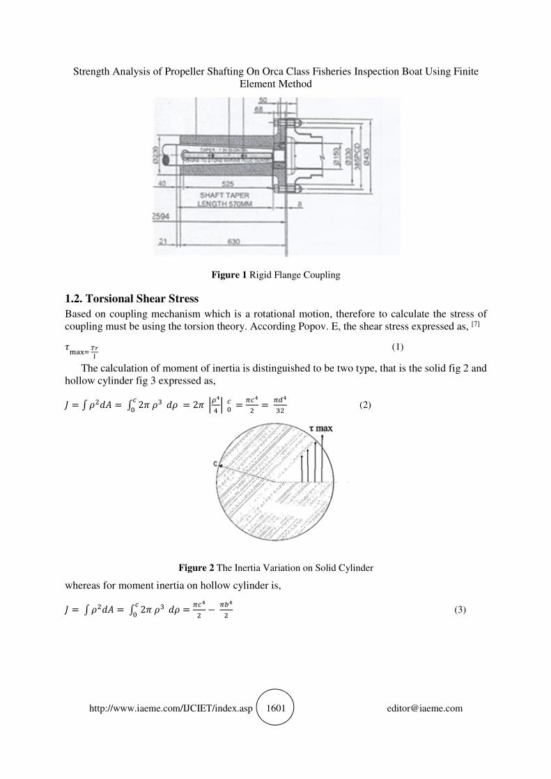
1.1. Rigid Coupling
Rigid coupling used if the ends of the shaft are axially connected. The flange coupling fig 1 consists
of the flange hub, which is made from cast steel or forged steel, and assembled at the end of shaft
with key, then fastened with bolts. [6]
This coupling not allowed any misaligned on each end of the shaft and cannot reduce any
vibration of transmission. At it installation, each end of the shaft must be attempted in a line before
the bolts of flange have fastened.
Strength Analysis of Propeller Shafting On Orca Class Fisheries Inspection Boat Using Finite
Element Method
http://www.iaeme.com/IJCIET/index.asp 1601 [email protected]
Figure 1 Rigid Flange Coupling
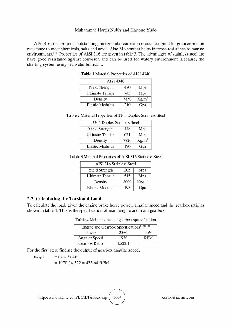
1.2. Torsional Shear Stress
Based on coupling mechanism which is a rotational motion, therefore to calculate the stress of
coupling must be using the torsion theory. According Popov. E, the shear stress expressed as, [7]
����� ��
(1)
The calculation of moment of inertia is distinguished to be two type, that is the solid fig 2 and
hollow cylinder fig 3 expressed as,
= � ��� = � 2� ��� � = 2� ���
� � � � = ���
� = ���
�� (2)
Figure 2 The Inertia Variation on Solid Cylinder
whereas for moment inertia on hollow cylinder is,
= � ��� = � 2� ��� � = ���
� − ���
� (3)

Muhammad Harris Nubly and Hartono Yudo
http://www.iaeme.com/IJCIET/index.asp 1602 [email protected]
Figure 3 The Inertia Variation on Hollow Cylinder
1.3. Failure Criterion
There are the various stress if a structure was charged by load. It is depended by the vector of load
and the behavior of material. For the instance, there are axial stress and shear stress if a structure
charged by compressive load. Likewise the torsional load, however the axial stress was smaller.
The impact of structure under load, it can be change the shape and volume of structure. There are
some theory which is studied about maximum distortion energy as M. T Hueber and R. Von
Mises.[8] To calculate the stresses on the problem of three dimensional material. It more convenient
if using equivalent stress (σe). Defined as the value of uniaxial tensile stress that would produce
the same level of distortion energy as the actual stress involved. The equivalent stress equation
expressed as,
�� = √�� ["�� − �# $ + "�� − �# $ + "�� − �� $�]
'( (4)
where σn is principal stress by the cross section of axis. It can be derived depend on each cross
section, the equivalent stress equation is,
"�)� + �*� − �)�* + 3�)*� $'( (5)
As shown in fig 4, the failure of material is limiting by it yield strength. To knows the elastic
limit of material, we have Von Mises circle and Tresca hexagon. Assumed that σ1 is 1st principal
stress and σ2 is 2nd principal stress. Thus, those for each principal stresses cannot be exceeds the
yield strength of material (σy).

Strength Analysis of Propeller Shafting On Orca Class Fisheries Inspection Boat Using Finite
Element Method
http://www.iaeme.com/IJCIET/index.asp 1603 [email protected]
Figure 4 Von Mises Circle and Tresca Hexagon
1.4. Safety Factor
Safety factor is a ratio of structure capacity under given load. Safety factor is used to Calculated
the strength on a structure design. To reach safety factor, the yield strength of material must be
larger than working stress. According Young. W, safety factor is a fractional number of the
structure highest capability which is necessary to withstand a load.[9]
,-./01 02 3-24/5 = 67�8� 9:;�<=:>?@;A7<= 9:;�BB (6)
A structure with specific safety factor will be withstand only the load which is planned. Each
material have different resistance, therefore the rasio of safety factor obtained by comparison
between yield stress against working stress on the structure.
2. DATA USED AND MATERIAL SELECTION
The investigation of propeller shafting consisted of three important component. Thus, this section
discussed the material properties, the torsional load and the contact mechanics.
2.1. Material Properties
Material selection is an important to plan the machinery components. The material has a different
properties and have a different function. In this case, Molybdenum steel (AISI 4340) is used for
the flange. This steel contains about 15% to 30% of molybdenum (Mo). Containing 0.4% carbon
and high strength martensitic steel which is desirable used very frequently to manufacture critical
components in aerospace engineering and automotive transmission.[10] Properties of AISI 4340 are
given in table 1.
Stainless Steel 2205 Duplex is used for shaft and key. The duplex structure improves stress-
corrosion crack resistance.[11] Properties of Stainless Steel 2205 Duplex are given in table 2. For
bolts and nuts are using AISI 316 Stainless Steel.
Muhammad Harris Nubly and Hartono Yudo
http://www.iaeme.com/IJCIET/index.asp 1604 [email protected]
AISI 316 steel presents outstanding intergranular corrosion resistance, good for grain corrosion
resistance to most chemicals, salts and acids. Also Mo content helps increase resistance to marine
environments.[12] Properties of AISI 316 are given in table 3. The advantages of stainless steel are
have good resistance against corrosion and can be used for watery environment. Because, the
shafting system using sea water lubricant.
Table 1 Material Properties of AISI 4340
AISI 4340
Yield Strength 470 Mpa
Ultimate Tensile 745 Mpa
Density 7850 Kg/m3
Elastic Modulus 210 Gpa
Table 2 Material Properties of 2205 Duplex Stainless Steel
2205 Duplex Stainless Steel
Yield Strength 448 Mpa
Ultimate Tensile 621 Mpa
Density 7820 Kg/m3
Elastic Modulus 190 Gpa
Table 3 Material Properties of AISI 316 Stainless Steel
AISI 316 Stainless Steel
Yield Strength 205 Mpa
Ultimate Tensile 515 Mpa
Density 8000 Kg/m3
Elastic Modulus 193 Gpa
2.2. Calculating the Torsional Load
To calculate the load, given the engine brake horse power, angular speed and the gearbox ratio as
shown in table 4. This is the specification of main engine and main gearbox,
Table 4 Main engine and gearbox specsification
Engine and Gearbox Specifications[13],[14]
Power 2560 kW
Angular Speed 1970 RPM
Gearbox Ratio 4.522:1
For the first step, finding the output of gearbox angular speed,
noutput = ninput / ratio
= 1970 / 4.522 = 435.64 RPM

Strength Analysis of Propeller Shafting On Orca Class Fisheries Inspection Boat Using Finite
Element Method
http://www.iaeme.com/IJCIET/index.asp 1605 [email protected]
Then calculating the torsional load, from equation below,[15]
T = D×F�×G��< = �HF� ×F�×#���
��.#���H.F� = 56144.06 N.m (7)
where K is 1000 if using metric unit.
2.3. Contact Mechanics
Due to each components are independently assembled, contact definition is needed. In this case,
each components must be use penalty contact. In the real operation, friction between component
surfaces were occurred on propeller shafting system. Hence, the friction coefficient should be
attached on contact definition. Each components on propeller shafting system have a different
friction coefficient. For contact between steel-ThorPlas, according G.Ren and J. Feng the ThorPlas
which contacting the shaft at wet condition is about 0.1 to 0.17.[16] And the friction coefficient
between steel-steel is 0.8 at dry condition for contact between bolt, nut, coupling and key.
3. RESULTS AND DISCUSSION
The result was performed by Finite Element software, in this case Solidworks Simulation was
used. The Von Mises stress (σv) and resultant deformation (utotal) were calculated to found the
behavior of those material, considered by friction coffecient with Thor-Plas bearing. The axial
stresses assumed zero, due to the load is torsional. To known the material still in safety limit. The
safety factor was calculated as a parameter of material selection.
Figure 5 Maximum Von Mises Stress

Muhammad Harris Nubly and Hartono Yudo
http://www.iaeme.com/IJCIET/index.asp 1606 [email protected]
Figure 6 Detailed Maximum Von MIses Stress on cut-section of Key
As shown in fig. 5 and 6, the value of maximum Von Mises stress which located on key
component, the value of stress is 1796.84 N/mm2. While, minimum Von Mises stress which
located on female flange which the value of stress is 3.02E-3 N/mm2. Where, the axial stress can
be asummed by zero due to the torsional load. Thus, for the stress we have torsional shear stress.
This stresses value are obtained at maximum continuous rating of main engine, which about
110% rating and maximum torque.
Figure 7 Maximum of Total Displacement

Strength Analysis of Propeller Shafting On Orca Class Fisheries Inspection Boat Using Finite
Element Method
http://www.iaeme.com/IJCIET/index.asp 1607 [email protected]
Figure 8 Maximum of Total Displacement on cut-section of Key
As shown in figure 7 and 8 the maximum displacement is located on the edge of flanges, which
have 9.753mm of displacement value. The minimum value is located on the end of after shaft,
which have 0.812mm. In this case, the displacement values are obtained from total displacement.
Due to torsional load, suppose assumed that the axial displacement valus is zero. Thus, the
rotational displacement will be used. Although, the axial displacement also occurred, however the
value is too small.
From the simulation above, obtained the working stress of each components. Thus, the yield
strength of components can be compare to working stress which is occurred to obtained the value
of safety factor. In this simulation we have two conditions of main engine rating. The calculation
of safety factor can be shows in table 5 and 6,
Table 5 The Value Of Safety Factor at 110% Rating of Main Engine
Component Max. Working Stress
(N/mm2) FoS
Male Flange 120.05 3.9
Female Flange 1380.3 0.3
Key 596.52 0.8
Shaft 1796.8 0.2
Bolts and Nuts 49.756 4.1

Muhammad Harris Nubly and Hartono Yudo
http://www.iaeme.com/IJCIET/index.asp 1608 [email protected]
Table 6 Value of safety factor at 75% rating of main engine
Component Max. Working
Stress (N/mm2) FoS
Male Flange 53.496 8.8
Female
Flange 366.95 1.3
Key 285.48 1.6
Shaft 538.7 0.8
Bolts and Nuts 24.675 8.3
According the BKI: Part. I Vol.III “Rules for Machinery Instalation”.[17] For the value of safety
factor which is applied on propeller shafting system (not between main engine to gearbox),
obtained the limit value 2.5.
4. CONCLUSION
Based on the field data. The engine load condition is divide by 110% and 75% of continous rating.
It is considered because of the ship used the engine for cruise between 110% to 75% of engine
rating. The conclusions can be mentioned as,
1. The maximum Von Mises stress which obtained is located on key and keyway (part of shaft).
Which the stress value is 1796.84 N/mm2 at 110% rating of main engine and 538.7 N/mm2 at 75%
rating of main engine. Thus, it can be expressed that the propeller shafting system still safe during
the operational cruise if the rating of main engine is not exceed 75%, except at short operational
for instance during sea trial.
2. The minimum safety factor of each components is located on the keyway (part of shaft), that is 0.8.
3. According the rules of BKI: Vol.III “Rules for Machinery Instalation”, the value of safety factor is
not exceed 2.5. Therefore, the material selections which is adviced is has higher yield strength. For
the shaft is adviced to using Stainless Steel UNS 41600, which is have 1050 n/mm2 of yield strength.
Thus, from the result of finite element simulation, can be obtained the Von Mises stress and
deflection. Then, defining a material which is compatible.
REFERENCES
[1] Dymarski Czesław, M. Narewski., 2009, Analysis of Ship Shaft Line Coupling Bolts Failure,
Journal of Polish CIMAC, Gdansk University. Available from:
https://www.researchgate.net/profile/Czeslaw_Dymarski/publication/228778249_Analysis_O
f_Ship_Shaft_Line_Coupling_Bolts_Failure/links/5405bf7e0cf2c48563b189bd/Analysis-Of-
Ship-Shaft-Line-Coupling-Bolts-
Failure.pdf?inViewer=1&pdfJsDownload=1&origin=publication_detail., [Accessed 22
September 2016]
[2] G. Pantazopoulos, S. Papaefthymiou, 2015, “Failure and Fracture Analysis of Austenitic
Stainless Steel Marine Propeller Shaft”, Journal of Failure Analysis and Prevention ASM
International, Vol. 15.
[3] S.B Jaiswal, M. D. Pasarkar, 2012, “Failure Analysis of Flange Coupling in Industrial”,
International Journal of Engineering Technology and Advanced Engineering, Vol. 2

Strength Analysis of Propeller Shafting On Orca Class Fisheries Inspection Boat Using Finite
Element Method
http://www.iaeme.com/IJCIET/index.asp 1609 [email protected]
[4] V. Jose Ananth Vino, J. Hameed Husein, 2015, Design and Analysis of Propeller Shaft,
International Journal of Innovative Research in Science Engineering and Technology, Vol. 4
[5] W. Litwin, 2010, Influence of main design parameters of ship propeller shaft water-lubricated
bearings on their properties, Polish Maritime Research, Vol. 17., Available from:
https://www.degruyter.com/downloadpdf/j/pomr.2010.17.issue-4/v10012-010-0034-
z/v10012-010-0034-z.pdf., [Accessed 26 September 2017]
[6] Sularso, Suga Kiyokatsu., 1987. Dasar Perencanaan dan Pemilihan Elemen Mesin. Jakarta,
Pradnya Paramita., pp: 31. ISBN 979-408-126-4
[7] Popov E. P. 1978. Mechanics of Materials, 2nd edition, Prentice-Hall.Inc. Englewood Cliffs.
New Jersey., USA., pp: 69-71 ISBN 978-0135713563
[8] Robert C. Juvinall, Kurt M. Marshek., 2011., Fundamentals of Machine Component Design,
5th Edition., John Wiley & Sons., New York., USA., pp: 267 ISBN 978-1118214114
[9] Young, W.C. and Budynas., R.G., 2002., Roark's formulas for stress and strain (Vol. 7)., New
York McGraw-Hill., pp: ISBN 978-0071003735
[10] A. Agrawal, S. Goel, W. Bin Rashid, M. Price., 2015., Prediction of Surface Roughness During
Hard Turning of AISI 4340 Steel (69 HRC)., Applied Soft Computing., Elsevier., Vol. 30,.
Available from:
https://www.researchgate.net/profile/Saurav_Goel/publication/271442759_Prediction_of_sur
face_roughness_during_hard_turning_of_AISI_4340_steel_69_HRC/links/5557bef808ae6fd
2d824f2b8.pdf., [Accessed 28 September 2017]
[11] P. Shelvaraj, Chandramohan, M. Mohanraj., 2014., Optimization of Surface Roughness,
Cutting Force and Tool Wear of Nitrogen Alloyed Duplex Stainless Steel in a Dry Turning
[12] Process using Taguchi Method., Journal of the International Measurement Confederation.,
Elsevier., Vol. 49., Available from:
https://www.researchgate.net/profile/M_Mohanraj/publication/259512524_Optimization_of_
surface_roughness_cutting_force_and_tool_wear_of_nitrogen_alloyed_duplex_stainless_stee
l_in_a_dry_turning_process_using_Taguchi_method/links/54d257000cf2b0c614693ab0/Opti
mization-of-surface-roughness-cutting-force-and-tool-wear-of-nitrogen-alloyed-duplex-
stainless-steel-in-a-dry-turning-process-using-Taguchi-method.pdf., [Accessed 28 September
2017]
[13] F. de Lima, S. Sankare., 2014., Microstructure and Mechanical Behavior of Laser Additive
Manufactured AISI 316 Stainless Steel Stringers., Materials & Design., Elsevier., Vol. 55.,
Available from:
https://www.researchgate.net/profile/Milton_Sergio_Fernandes_De_Lima/publication/27753
4447_Microstructure_and_mechanical_behavior_of_laser_additive_manufactured_AISI_316
_stainless_steel_stringers/links/557331f808ae7521586a7744.pdf., [Accessed 28 September
2017]
[14] MTU Friedrichshafen GmbH., MTU Marine Specs 16V4000 M73., Available from:
http://www.mtu-online.com/mtu/products/engine-program/diesel-engines-for-marine-main-
propulsion-dieselelectric-drives-and-onboard-power-generation/diesel-engines-for-yachts.,
[Acceseed 23 September 2016]

Muhammad Harris Nubly and Hartono Yudo
http://www.iaeme.com/IJCIET/index.asp 1610 [email protected]
[15] MTU Friedrichshafen GmbH, Technical Data Sheet: ZF 9300., Available from:
http://www.marinepartsexpress.com/prodbullzf07/ZF_9300.pdf., [Acceseed 23 September
2016]
[16] Doug Woodyard, C. Pounder., 2004, Pounder’s Marine Diesel and Gas Turbines., 8th edition.
Elsevier Butterworth-Heinemann. Burlington, pp: 15, ISBN 978-0-080-51421-5.
[17] G. Ren and J. Feng, 2011, Friction and Wear Characteristics of ThorPlas Bearings and
[18] Their Application in Hydro Turbines, Thordon Bearings Inc, Canada., The 2011 Conference
Proceedings of HydroVision International, July 19-22, 2011 Sacramento, CA USA.
[19] L.Umamaheswararao and Mohammed Ashif, Fluid flow Analysis of Centrifugal Fan by using
FEM, International Journal of Mechanical Engineering and Technology, 7(2), 2016, pp. 45–
51.
[20] Devendra Singh, Structural Analysis of Spur Gear Using FEM. International Journal of
Mechanical Engineering and Technology, 7(6), 2016, pp. 01–08
[21] BKI, Part. II (Seagoing Ship), Vol. III “Rules for Machinery Installation” 2016 Edition. Jakarta,
Biro Klasifikasi Indonesia.
View publication statsView publication stats