
2019 propeller buyer's guide - KITPLANES
84
2019 PROPELLER BUYER’S GUIDE ® JANUARY 2019 www.kitplanes.com In the Shop: • Auxiliary Fuel Tank • Pitot-Static Testing • Precise Measuring Tools KITPLANES JANUARY 2019 Propeller Buyer’s Guide • Three Bearhawks • Second Hand Pitts • Perfect Landings • First Flight Accidents • Aux Fuel Tank • Pitot-Static Testing • Building Efficiently BELVOIR PUBLICATIONS THREE BEARHAWKS Building One of Each PERFECT LANDINGS It’s Simple, Basically HOMEBUILT ACCIDENTS First Flights Second Hand Pitts First-Rate Performer
-
Upload
khangminh22 -
Category
Documents
-
view
0 -
download
0
Transcript of 2019 propeller buyer's guide - KITPLANES

2019 PROPELLER BUYER’S GUIDE
®
January 2019
www.kitplanes.com
In the Shop: •AuxiliaryFuelTank•Pitot-StaticTesting•PreciseMeasuringTools
KITPLA
NESJA
NUARY2019PropellerBuyer’sG
uide•ThreeBearhawks•SecondH
andPitts•PerfectLandings•FirstFlightAccidents•A
uxFuelTank•Pitot-StaticTesting•BuildingEfficiently BELVO
IR PUBLIC
ATION
S
Three Bearhawks Building One of Each
PerfecT Landings It’s Simple, Basically
homeBuiLT accidenTs First Flights
Second Hand Pitts
First-Rate Performer

DynonAvionics.com (425) [email protected]
Meet SkyView HDX - the flagship system from the market
leaders in experimental and light sport avionics.
Clear, Vibrant DisplaysBeautiful DesignUnrivaled Control Ergonomics Improved Touch InterfaceCapable and Compatible

26
18
6 On the Cover: Scott Thomson flies Second Hand, a modified Pitts S-1C, near Pylon 2 at the 2018 Reno National Championship Air Races. Photographed by Bradley Haskin.
January 2019 | Volume 36, Number 1
KITPLANES January 2019 1
Propeller Buyer’s Guide26 There’s a PerfecT ProP for every Plane:
By LeRoy Cook.
Builder Spotlight6 The Three Bear(hawk)s: Collin Campbell has built
a 4-Place, Patrol, and LSA. By Jared Yates.
14 In search of The PerfecT landIng: It’s simple, basically. By LeRoy Cook.
18 second hand Is fIrsT raTe: Pitts happens when you have 11 months, talent, friends, spare parts, and a little cash. By Tom Wilson.
34 addIng an auxIlIary fuel Tank To an rv-8: Circle track racing fuel cells can extend the range of your plane. By Glen Salmon.
42 homeBuIlT accIdenTs—fIrsT flIghTs: Builder error is a major factor in first-flight accidents. By Ron Wanttaja.
66 comPleTIons: Builders share their successes.
72 ask The dar: Hiring a professional build center to build an Experimental Light Sport Aircraft. By Mel Asberry.
Shop Talk46 Plane and sImPle: Don’t blow into the pitot tube!
By Jon Croke.
53 maInTenance maTTers: Using precision measuring tools. By Dave Prizio.
60 home shoP machInIsT: More doodads. By Bob Hadley.
73 aero ’lecTrIcs: Touch (the go-bag) and go. By Jim Weir.
Shop Tip75 vacuumIng connecTors: By David Paule.
Designer’s Notebook76 wInd Tunnel: Design process—balance.
By Barnaby Wainfan.
Exploring2 edITor’s log: The honor system. By Paul Dye.
48 The dawn PaTrol: Good things come in threes. By Dick Starks.
58 BuIldIng TIme: Narrowed focus. By Kerry Fores.
63 checkPoInTs: More toys. By Vic Syracuse.
78 rear cockPIT: Summer school. By Tom Wilson.
Kit Bits4 leTTers67 lIsT of adverTIsers68 BuIlders’ markeTPlace80 kIT sTuff: Drawing on experience. By cartoonist Robrucha.
For subscription information, contact KITPLANES® at 800/622-1065 or visit www.kitplanes.com/cs.
CONTENTS

2 KITPLANES January 2019 www.kitplanes.com & www.facebook.com/kitplanes
I have been seeing more and more comments on experimental aircraft message boards regarding letters, emails, and phone calls from the FAA regarding ADS-B issues. Pilots and air-craft owners are being contacted by a group at the agency when their airplane is flagged by the mysterious “system” as spitting out error codes or failing to pass muster in some way or another. I per-sonally received a very pleasant phone call from an FAA inspector in Atlanta asking for my email address so that he could send me a report on one of my registered airplanes. He wanted me to take a look at the report and see what I could do about fixing the errors “as soon as I could.”
My dealings with this particular inspector were friendly all the way down the line, and I actually appreci-ated the mild kick in the rear to make sure that my handful of airplanes was all up to snuff in the ADS-B world. It was a gentle reminder that January 2020 is just around the corner, and if you’re going to find major problems with your installation, it would be better to find that out sooner rather than later. I guess that as frightening as it can be to get a call from an FAA inspector, in this case it was nice to receive. But getting the calls to point out problems with your system is not what I want to talk about.
The interesting thing about these calls and letters is that a number of people have gotten them when, in fact, their air-plane is not yet flying or does not even have an ADS-B Out transmitter installed.
Yet they were forwarded a report that lists the performance characteristics of an airplane with their N-number. Clearly, the data came from somewhere, and that somewhere had to be an airplane—with the wrong N-number. And this points out a fundamental problem with the ADS-B system: It is all based on the honor system, much like all of our flying. Honesty and integrity are assumed in many of the rules that govern aviation—but they also seem to be diminishing qualities in today’s world.
In the end analysis, it probably doesn’t make a measurable difference in the aviation safety statistics if a per-son goes out to fly and doesn’t have a valid medical. In fact, in the few cases of pilot incapacitation accidents that you can find, almost all of the pilots had a medical—it’s just that on that particular day, they weren’t medically fit to fly. So the fact that there are probably people at your airport flying without a medical means that they are dishonest and doing something
Paul DyePaul Dye, KITPLANES® Editor in Chief, retired as a Lead Flight Director for NASA’s Human Space Flight program, with 40 years of aerospace experience on everything from Cubs to the Space Shuttle. An avid homebuilder, he began flying and working on airplanes as a teen, and has experience with a wide range of construction techniques and materials. He flies an RV-8 that he built, an RV-3 that he built with his pilot wife, as well as a Dream Tundra they completed. Currently, they are building a Xenos motorglider. A commercially licensed pilot, he has logged over 5000 hours in many different types of aircraft and is an A&P, EAA Tech Counselor and Flight Advisor, as well as a member of the Homebuilder’s Council. He consults and collaborates in aerospace operations and flight-testing projects across the country.
The Honor System
EDITOR’s LOG
You can set the tail number for your transponder (through your EFIS) to anything you want—but are you being honest with all the other aviators out there?

Photo: Paul Dye KITPLANES January 2019 3
illegal. But it doesn’t mean that they are outright dangerous.
So in the ADS-B world, it is an easy thing to go into your transponder’s setup routine and key in the ICAO iden-tifier or N-number that will be broad-cast from that aircraft. Anyone can do it, and given that there are people who can hack any computer, regardless of the security measures in place, trying to build ADS-B boxes that don’t allow the code to be changed is probably futile. But there is nothing preventing a dishonorable person from keying in some random N-number—or one that they saw on their neighbor’s plane. This is probably what is happening when reports are generated by airplanes with no transmitter installed. Their code is either accidently being used or is being stolen so that someone can fly in the system without being identified.
(By the way, the system integrity level, the measure of how “good” your posi-tion reporting is in the ADS-B system, is also keyed in by the owner, making it
easy to say that you have a solid system when, in fact, it is poor.)
Once this cat is out of the bag, it’s pretty much impossible to put back—unless all ADS-B Out transmitters are redesigned. It’s a fundamental flaw if you depend on pilots being honest, which is something I’d like to believe in. But more and more these days, I see pilots and builders looking for ways to cheat the system. Honor and integrity—which are fundamental to almost every-thing we do in aviation—are beginning to wane in our society. Sooner or later, we’ll all be flying in the Wild West, with pilots flying the wrong direction at alti-tudes or simply ignoring the right-of-way rules. Oh…right, let’s look at the 2018 arrival fiasco at Oshkosh, where some pilots pretty much ignored the NOTAM and the instructions of the ATC controllers—same thing.
The bottom line is that we have to first acknowledge that aviation rules are fun-damentally enforced via the honor sys-tem. No one has ever asked to randomly
see my medical before I launched into the blue, and no one other than me checks the paperwork on my airplane each year. We then have to recognize that if we allow others to defy the rules and strike out in whatever direction pleases them, we have no system, and we have no rules. We really do have to develop a culture that shuns outlaws—or we’ll have no law at all.
It could be argued that the reason we have ADS-B, and the fact that it identi-fies each aircraft uniquely, is because pilots have been breaking the rules, and this is one way for the FAA to know who is doing it. The fact that they designed a system to monitor pilots who break the rules but built it so that it is laughably easy to do so is ironic. So if you suddenly get a report that your LSA has been fly-ing in and out of JFK and the FAA would like to talk to you about it, you’ll know that someone is out there spoofing the system. It will be interesting to see what the FAA will do about it—and I’m not sure we’re going to like it. J

Website information: General homebuilt aircraft information, back issue availability, online directories ordering info, plus a Kitplanes® article index and selected articles can be found at www.kitplanes.com.Unsolicited manuscripts: are welcome on an exclusive basis, but none can be acknowledged or returned unless accompanied by a stamped, self-addressed envelope. no responsibility is assumed for loss or damage to unsolicited material.Kitplanes® (issn 0891-1851) is published monthly by aviation publishing Group, llC, an affiliate of belvoir publications, 535 Connecticut avenue, norwalk, Ct 06854-1713, robert englander, Chairman and Ceo; timothy H. Cole, exec. Vice pres./editorial Director; philip l. penny, Coo; Greg King, exec. Vice pres./marketing Dir.; ron Goldberg, Cfo; tom Canfield, Vice pres., Circulation.
periodicals postage paid at norwalk, Ct, and at additional mailing offices. Copyright ©2019 aviation publishing Group, llC. all rights reserved. reproduction in whole or in part is strictly prohibited. printed in Usa. revenue Canada Gst account #128044658. Canada publishing agreement #40016479.
subscriptions: one year (12 issues) is $29.95 U.s. $41.95 in U.s. funds in Canada, includes Gst. $41.95 in U.s. funds for foreign surface mail or $57.95 in U.s. funds for foreign air mail. single copy price $4.99 U.s., $5.99 Canadian.postmaster: please send address changes and subscription inquiries to: Kitplanes®, p.o. box 8535, big sandy, tX 75755-8535, or Canada post: return undeliverables to p.o. box 2601, 6915 Dixie rd, mississauga, on l4t 0a9 or call 800/622-1065. Kitplanes® is a registered trademark of aviation publishing Group, llC.
4 KITPLANES January 2019 www.kitplanes.com & www.facebook.com/kitplanes
eDitorial Editor in Chief paul Dye [email protected] Executive Editor mark schrimmer Art Direction Dan maher Contributing Editors leroy Cook, Jon Croke, robert Hadley, Dan Horton, louise Hose, amy laboda, Dave martin, sid mayeux, David paule, Dave prizio, Ken scott, elliot seguin, Dick starks, eric stewart, Vic syracuse, barnaby Wainfan, Jim Weir, tom Wilson. Web Editor omar filipovic Cartoonist robrucha Editorial Director, Aviation Division larry anglisano
aDVertisinG Sr. Advertising Manager Chuck preston 805/382-3363 [email protected]
bUsiness offiCebelvoir media Group, llC535 Connecticut avenuenorwalk, Ct 06854-1713
eDitorial offiCe535 Connecticut avenuenorwalk, Ct [email protected]
CirCUlationCirculation Manager laura mcmann
sUbsCription Department800/622-1065www.kitplanes.com/csp.o. box 8535, big sandy, tX 75755-8535
reprints for pUbliCation anD Web postinG aVailableminimum order: 500Contact Jennifer Jimolka, 203/857-3144
Change of address?Missing issue?subsCription Question? Visit www.kitplanes.com/cs. Or call 800/622-1065 from the u.s. and Canada.
foreign 903/636-1112 or fax 203/857-3100.
Need for SpeedNigel Speedy needs to be careful not to exceed 180 knots CAS. I noticed in his article, “Effects of Fairings on Speed” [March 2018], that his bird does not have 12-inch N-numbers displayed. Is there an exception to FAR 45.29 (b) (1) (iii) in cases like this?
Jim AumAN
Thanks for the note. The problem with that FAR (in the experimental world) has always been the actual definition of cruise speed because it depends on if you mean DESIGN cruise speed or what a person actually f lies. An RV-8 can be built with anything from 150 to 200+ horsepower, and while Van had a design cruise speed in the original design (that can be derived), the cruise speed of a par-ticular aircraft will depend on the build-er’s engine and prop choice. Since Van’s is not the builder of record for each aircraft, it is hard to say what the design cruise speed of each individual aircraft really is supposed to be. That and the fact that Nigel usually f lies near Mojave, California, where the density altitude is high, so at his maximum TAS his CAS is rarely going to be very high, so that makes it a moot point.—Ed.
maintenance matters This idiot is very thankful each month for “Maintenance Matters,” the idiot’s guide to maintenance. It’s a brilliant series of articles that I have been filing away for reference for our RV-8. Keep them coming!
ANdrzeJ zmySlowSki
Glad you enjoy the column. We never con-sider anyone an idiot here in aviation—
there are just some things that some people have yet to learn.—Ed.
Climb PerformanceI read Nigel Speedy’s article [“Using Level Accelerations to Determine Climb Performance,” November 2018] with great interest, but it seemed to me there might be some things missing that would enable me to use this technique. Page 24 states a polynomial can be used to smooth the curve, and a polynomial equation is shown at the top of the page. This equation shows y as a function of x. Since these values are likely to change for each aircraft tested, I would think the multipliers for each term of the equation would need to change. Or have I missed something?
Jim BelCher
Nigel Speedy responds: Thanks for the question, Jim. Yes, you are correct that each aircraft will have different coef-ficients for the polynomial equation. In fact, the same aircraft will have different coefficients under different conditions like altitude and gross weight. You would fly the level acceleration in your aircraft under specific conditions and then deter-mine the corresponding curve fit for your data. You would then use these aircraft-specific numbers to determine your climb performance under the conditions tested. The numbers shown are for my specific aircraft and were for example only. Yours will almost certainly be different. J
Completed ProjectsRecently completed a homebuilt? After all that hard work, you deserve a little fame! Send a photo and brief descrip-tion to KITPLANES®. See page 66 for details on how to submit your plane. J
LETTERS

©2017 Garmin Ltd. or its subsidiaries.
YOUR AIRPLANE WAS A JOY TO BUILD. WE MADE SURE IT’S A JOY TO FLY, TOO.Here at Team X we’re not just engineers. We’re also pilots and builders, so we design avionics we want to fl y behind. And when you see what we’ve created — from fl ight displays to radios, autopilots, GPS navigators and audio panels, and everything in between — you’ll fi nd we have just what you need for your project, too. Visit us at Garmin.com/Experimental.
17-MCJT910 Team X Joy Ad-7.875x10.5-Kitplanes.indd 1 8/2/17 8:34 AM

www.kitplanes.com & www.facebook.com/kitplanes6 KITPLANES January 2019

Photos: Jared Yates KITPLANES January 2019 7
Collin Campbell has built a 4-Place, Patrol, and LSA.By Jared yates
The Three Bear(hawk)s
Meet Collin Campbell, a builder of things. Lately, those things are air-planes, including each of the three Bob Barrows Bearhawk designs: the Bearhawk 4-Place, Bearhawk Patrol, and Bearhawk LSA. Collin is the first single customer to build all three types. He is retired from his career of build-ing houses, during which he learned to fly, raised three children with his wife Sarah, and completed four other air-plane projects.
Like many Bearhawk builders, Col-lin’s project started with Budd Davis-son’s article in the October 1995 issue of Sport Aviation. Bob first flew his pro-totype Bearhawk to Oshkosh in 1994, but it didn’t get much attention. Budd noticed it and wrote about it a year later and plans started selling quickly. Collin purchased plans number 360 and began construction in 1999, when building from plans was the only option.
His journey to the Bearhawk makes plenty of sense in retrospect. He was always interested in airplanes but didn’t try flying until a pilot buddy recom-mended he take a flight lesson in 1977. He did and was hooked. It took three months to earn his private pilot cer-tificate, spending $20 per hour for the airplane and $20 per hour for the instructor. Rental airplanes were abun-dant, and Collin flew the usual Cess-nas and Pipers that he had access to. His first step in ownership was to buy a Cessna 172. It was advertised as freshly overhauled, and perhaps it was, but
the crank was ground undersize, and the bearings were standard size. Once the engine warmed up, oil would flow through the resulting big gap, causing the oil pressure to drop. Collin recalls about that, “You learn things…that was an education.” In this case the tuition for that education was surprisingly low. The seller/overhauler agreed to buy the airplane back for what Collin had paid for it, rather than instigate a dispute that might have disparaged the reputation of the seller’s business.
Collin’s first homebuilt was called a Zippy Sport (Green Sky Adventures), powered by a half VW engine. It was
unfortunately destroyed in a flight test mishap. His was one of the first of that design to fly, so he was in unknown ter-ritory while testing propellers. Prior tests had yielded insufficient thrust to lift off, so on the day of the crash he was expecting the same, and hadn’t even buckled his seatbelt. The new prop delivered such an improvement that the plane leapt into the air, but not so much of an improvement to continue the climb. The wing stalled and he came down hard on the nose. This les-son was more expensive than the Sky-hawk, but he was able to sell a few parts from the wreck and he recovered from
Collin and Sarah. An airplane builder’s achievements are even more meaningful when they are concurrent with 47 years of harmonious marriage.

his injuries. Thankfully we have much better resources available to educate ourselves about flight test preparations these days.
Taming TaildraggersCollin learned about tailwheel flying in a Champ. As he says, “You’ve got to know what your feet are for!” He briefly owned part of an Aeronca Chief, in which he learned how to do good forward slips. These two airplanes are similar, but the Chief has side-by-side seating, versus the Champ’s tandem seating. After the Chief, he restored a Champ from a basket case, having found that he had a preference for tail-draggers with centerline seating.
After the Champ, Collin owned a Cessna 170 with a constant-speed prop and upgraded 180-horsepower engine. The Cessna 170 is the same type that Bob Barrows owned when he designed the Bearhawk, which was to be its replacement. Collin purchased the airplane and fixed it up with panel and cosmetic upgrades. He enjoyed flying it, but the fellow he bought it from called one day and offered to buy it back at a very favorable price. Col-lin accepted and used the proceeds to purchase a Maule MX-7 with a fixed-pitch prop and 160 horsepower. This was a good airplane that he flew to AirVenture three times, but it did not perform as well as the C-170. Collin
lives on a 1320-foot-long grass strip that he owns near the small town of Bolivar, Missouri, just north of Springfield. Good takeoff and landing performance is not optional.
Next in the lineup, for something completely different, Collin built an RV-6A from 1986–1993. He first flew it from that small strip on his 44th birth-day. The airplane could handle the short strip marginally, but he found “it wasn’t really my kind of flying.”
Bearhawk 4-PlaceIf it were possible to somehow plot each of Collin’s airplanes on a flight enve-lope diagram, the Bearhawk would fall right in the middle. He appreciated the
8 KITPLANES January 2019 www.kitplanes.com & www.facebook.com/kitplanes
(Left) The panel is familiar and reliable, with a recently added Stratus ESG transponder for ADS-B Out. (Right) The sunshades are from RAM, the same folks that make mounts for electronic gadgets. The large skylight opens up the feeling of the cabin and makes the horizon visible in steep turns. Fuel sight gauges are simple and reliable. The elevator trim system is overhead.
N370CC is now owned by Wayne Packard, based at Tullahoma, Tennessee. After purchasing it from Collin, Wayne flew it to California and based it there until he moved to Tennessee.

performance, but also just “liked the way the airplane went together,” with its sturdy steel fuselage and aluminum wings. These construction methods were not new to him, but he continued to learn as he went. He took things one step at a time, and as he said about each task, “I read about it, practiced, and did it.” By 1999 Collin’s house-building business had come a long way from his start, digging a septic tank hole with a shovel and pick, and his three chil-dren had grown beyond school age. He worked on the Bearhawk on the week-ends and evenings, finding the time in the workshop to be therapeutic. “I do my best thinking out there,” he says. Collin has found that work is most enjoyable when we don’t feel required
KITPLANES January 2019 9
All three of the Barrows designs provide easy engine access, making thorough preflight inspections easy, an advantage to having a cowl designed by an engine builder.
The Bearhawk 4-Place is famous for its cavernous cargo door and baggage area. Most operators are able to fill the space and stay well within weight and balance limitations. In this case, full 50-gallon fuel tanks yield 879 pounds to distribute in the cabin before reaching max gross weight.
The Bearhawk 4-Place can accommodate a 6-cylinder Lycoming, but it still performs well on a 4-cylinder. The prop is in the same location for either, which makes for plenty of maintenance room behind the smaller engine.

to do it, and he’s certainly onto some-thing there. This feeling of deadlines and compulsion is perhaps the only thing that separates a hobby from a job. Much of scratch building could be mis-taken for work otherwise.
His Bearhawk project became N370CC, painted white and red. The 180-horsepower O-360 engine came from Mattituck, and he added an 80-inch constant-speed Hartzell prop. The empty weight was 1321 with a “round gauge” panel. Max gross weight is 2500, living up to the Bearhawk’s hauling capability. Collin flies only VFR, a preference he realized half-way through his instrument training decades ago. He flew his Bearhawk for 76 hours, including a trip to AirVenture in 2008, before selling it to Wayne Packard, who generously provided it for photos in this piece.
When Collin started building, there was only one “Bearhawk” to talk about, but by the time he sold N370CC, Bob had started selling plans for the Bearhawk Patrol, a two-seat airplane kind of like a Super Cub that can cruise fast. The original Bearhawk became the Bearhawk 4-Place, just as Collin was getting the itch to build again. He realizes not everyone understands this itch, but sometimes we are defined by the things we “can’t not” do. Col-lin is the type of guy who can’t not be building something.
Since he usually flies by himself, Col-lin didn’t need the extra size of the four-seat Bearhawk. If the centerline seating designs had been around when he first started, he might not have even built the four-seater. When it came time to choose his next project, he consid-ered RANS and Zenith airplanes but
felt an impression that Bob’s designs were built more durably. He purchased Patrol plans number 56 and started building in 2006.
Bearhawk PatrolTimes had changed since his last build. Bearhawk Aircraft had started offer-ing quickbuild kits for the Bearhawk 4-Place (but not yet the Patrol), and Mattituck was no longer selling engines. So, Collin built the Patrol from plans rather than from a kit, and when it came time for an engine he said, “If I’m going to build the airplane, why not build the engine?” Just as he had learned each skill in building the airframes, he learned how to build the engine one step at a time. The parts came in a pile of boxes, and he studied the overhaul, parts, and assembly manuals. He also credits help-ful videos and materials like those from
www.kitplanes.com & www.facebook.com/kitplanes10 KITPLANES January 2019
(Left) The Bearhawk Patrol is shaped like several other airplanes in its class, but it is one of the fastest among them. (Right) With a cowl that opens this far, preflight inspections can be much more complete, and minor maintenance is faster. Swapping out a fouled plug takes minutes.
Collin’s strip is short enough to require reasonable STOL performance.

Collin made this custom lower cowl fairing to feed the Van’s filtered air box.
KITPLANES January 2019 11
Sacramento Sky Ranch. The engine has 42 hours of flying so far, with excellent reliability and oil temperatures that are almost a little too cool in the winter. The prop is a fixed-pitch Sensenich 76x58, yielding 130 mph indicated at 70% power, or economy cruise of 120 mph at 2300 rpm. Comparing the Patrol to the 4-Place, he likes to say, “It’s a little bit faster, and a little bit slower,” meaning that the cruise speed is higher and the stall speed is slower on the same horse-power and a fixed-pitch prop.
Like his first Bearhawk, the Patrol is covered with Poly-Fiber, but this time he chose Bahama Blue, to mix things up. Walking up to the airplane, it feels brand new. About half of the surface area is not fabric, which makes for a challenge in matching the texture of the final coatings. Collin addressed this by using Poly-Tone everywhere, spraying the color coat into a tacky coat of primer on the aluminum parts. This gives the whole airplane a soft and con-sistent semi-gloss texture. The empty
weight is a respectable 1178 pounds, with a max gross takeoff weight of 2000 pounds. Stall speed is in the 40s, and thanks to the modern Riblett air-foil, the stall characteristics are much safer than most antique airplanes in this form factor.
Collin’s experience as a builder shows in the fit and finish, or it could be said
that it doesn’t show. A casual observer just sees a harmonious finished air-plane. Sometimes the best design and execution produce invisibility at first glance. But anyone who has built the same type of airplane soon has a list of questions. How did he make that air intake so smooth? It’s a fiberglass part that he cast in place. What about the
(Left) Tandem seating means plenty of elbow room. (Right) The back seat spans the full width of the fuselage, making it a great shelf for cargo when it isn’t occupied by a person.
IFR approaches inside!
grtavionics.com/approach

rod ends on the upper and lower ends of the landing gear shock struts? They are mirror-threaded so that he can adjust their length like a turnbuckle. Every-thing is clean, neat, and orderly. I asked him, did he not get bored after building two very similar airplanes? After all, isn’t there a reduced return on the “edu-cation” factor, having already learned how to do things once? He says he finds joy in finding a better way. Maybe it’s faster, maybe it’s easier, maybe the end result just looks better. The proof is in the results, and the build quality shows that this is his sixth airplane project.
Bearhawk LSACollin first flew the Patrol in 2014 and loves it, but it didn’t take long for that
itch to start coming back. By then, Bearhawk Aircraft had started offering a quickbuild kit for the Patrol and also Bob’s third public design, the Bearhawk LSA. The LSA looks very much like the Patrol, but it’s a clean-sheet design, prompted by numerous builders consult-ing with Bob about how to build a Patrol to meet the LSA regulatory limitations.
Collin called Mark Goldberg of Bear-hawk Aircraft (www.bearhawkaircraft.com) to talk about ordering a kit. Mark says, “I was pleasantly surprised to hear from Collin, knowing that he had already scratch built two airplanes.” Mark considered Collin’s interest to be a nice compliment on the quality of the workmanship in the kits. Collin’s kit was one of the earliest off of the
production line, and he was able to sort out a few minor adjustments that were still in the prototype phase.
Bearhawk Aircraft’s quickbuild kits come with the fuselage and tail parts completely welded and painted. The wings are skinned from the top trailing edge around to the bottom of the wing spar, and the rest of the skin is dimpled and ready to rivet once the builder installs the wing wires, controls, and plumbing. For a guy who has scratch-built two similar airplanes, this level of completion is downright luxurious. The LSA has less complexity overall, includ-ing its flapless wings. Collin completed his LSA in a very atypical 800 hours of build time over just 18 months. That includes the time he spent overhauling
12 KITPLANES January 2019 www.kitplanes.com & www.facebook.com/kitplanes
(Left) Oil temperatures were high before Collin added this filter and cooler adapter from Steve’s Aircraft. (Right) The Bearhawk LSA interior looks a lot like the Bearhawk Patrol in dimensions. Collin left the interior unfinished to save weight in the LSA.
Yellow is a great color for a light taildragger, the better to “see and be seen” with.

the engine. This time he painted the whole thing Cub Yellow, thankfully sav-ing future generations from confusion by not adding a black lightning bolt on the side of the fuselage. He resolved a cowl-ing clearance problem with the spark plugs by creating two fiberglass bumps on the cowl. He tried to adapt off-the-shelf products, but just couldn’t make it look right. “Sometimes it’s just easier to make it from scratch rather than adapt someone else’s.” This mindset isn’t always present in kit builders—scratch building brings about a strong level of empower-ment to create and solve problems.
The engine is a Continental O-200-A that he rebuilt in his shop, produc-ing 100 hp with a 74x40 Catto prop. He finds that the Continental likes to spin a little faster to produce good per-formance, running 2600 rpm in this case. Empty weight came to 856, with the max gross weight of 1320 per LSA requirements. Folks who aren’t building to LSA requirements have Bob’s bless-ing to make the airplane’s max gross weight 1500 pounds, so even at 1320 it is still in the middle of its envelope and a strong performer. Collin’s LSA is another clean, simple airplane that flies honestly and performs well. In early testing with just 8 hours so far, he’s find-ing cruise speeds of 100 mph at around 5 gallons per hour. The oil temperatures were running high initially, but he’s added an adapter from Steve’s Aircraft (www.stevesaircraft.com) that provides for a spin-on oil filter and an oil cooler. This has brought temps back into a reasonable range. The stick and rudder characteristics are very straightforward. Collin says, “It’s a fun airplane, a good old man’s airplane” that he hopes to fly for as long as he can, with the benefit of a low fuel burn and the option to self-certify medically.
Collin has an ideal vantage point to compare the Bob Barrows designs. The benign stall characteristics stand out to him above all. “When you stall them, they stay straight. CFIs on flight reviews have been surprised.” He likes the strong flight control authority at slow speeds. When landing his 4-Place at AirVenture, the crosswinds were
strong and a big crowd was watching, but the airplane handled it fine. He says he’s never had any close calls, or even any bad landings, not that he wants to sound like he’s bragging. It’s nice to have plenty of extra thrust for a go-around if things aren’t going as he’d like.
Anyone who has built one airplane knows how big of a job it is. Seeing some-one like Collin puts that job in a different context, especially considering his con-current happy marriage of 47 years and
counting. Both Collin and Sarah credit this to Collin’s ability to find balance in his airplane building, always placing fam-ily obligations first. There is still plenty of time left to build airplanes. Sarah helps out in the hangar sometimes, but for the most part they each have separate hobbies and entertain themselves. He is support-ive of her ideas and interests. Together they have built trust not in large leaps, but in small steps, one at a time, the same way we build airplanes. J
KITPLANES January 2019 13

www.kitplanes.com & www.facebook.com/kitplanes14 KITPLANES January 2019
It’s simple, basically.By LeRoy Cook
In Search of the Perfect Landing
All of us, I imagine, are occasionally (or frequently) embarrassed by a land-ing that doesn’t turn out the way we intended. What we always intend is a glassy-smooth transition from flare-out to taxiing. What we sometimes get is a noticeable arrival that awakens slum-bering passengers and draws comments from those on board.
It is incorrect to speak in terms of a “good landing” as just a smooth touch-down. There’s much more to landing an airplane than placing the rubber on the runway. Landing involves making a sta-bilized approach, and it continues with the techniques of crosswind correction, power reduction, flaring from a glide
path to a zero descent rate, and smooth control of the touchdown and rollout.
But, let’s face it; we usually grade ourselves by the jar that’s felt when the wheels hit. You and I try to finesse that moment, and sometimes it works, some-times it doesn’t. As I’ve heard it said, “It’s not my fault, it’s not your fault…it’s just the asphalt.” Like most pilots, I’ll take luck over skill, as long as it works.
The fact is, getting a “grease job” arrival is luck in a lot of ways. Some air-planes, particularly homebuilts, are just plain unpredictable to land. Not neces-sarily dangerous, but just a tad inconsis-tent in the way they pay off at the end. Some airfoils are fat with lift well into
the stall, while others seem to quit flying as soon as you raise the nose. A lot of tail-wheel airplanes need to be flown onto the runway just before the tailwheel makes contact, rather than plopped on tailwheel first. The type and placement of the main gear plays a large part in cov-ering for the pilot’s imperfections.
For the tricycle-gear crowd, trailing-link main gear designs are pilot (and passenger) pleasers, but they are heavy, expensive, and take up extra fuel tank space if they are folded into the wings. A short, straight-leg gear is simple and rug-ged, but it’s capable of transferring every nuance of pavement and piloting to the airframe. If the main gear is located far

Photos: LeRoy Cook KITPLANES January 2019 15
In Search of the Perfect Landing
aft, it takes special care to avoid pound-ing it into the runway while flaring out from the descent, and one needs to “fly” the nose gear down to the runway after touching down on the mains, before elevator control is lost.
Compounding the problem is that high-performance airplanes, like many of the fast-glass homebuilts, need to be landed now, not floated along while oozing off every ounce of energy from the descent. High wing loadings mean a lot of energy is being carried into the flare, and that energy must be dis-sipated before running out of runway. Braking is crucial to getting stopped in the available space, and the sooner you spike on the tires, the quicker the brakes can start going to work. So, we accept a graceless clunk that jars the air-frame, in favor of a safe turnoff.
In thousands of hours of research, involving even more thousands of land-ings, I’ve learned that the perfect land-ing, or touchdown, requires adherence to a few simple rules: •Getaslowasyoucan•Getasslowasyoucan•Zerooutthesinkrate•Havethewheelsrollingstraight.
That’s it! So let’s take a closer look at each factor.
Get the Tires Near the RunwayYou can’t make a smooth landing by parking the airplane ten feet in the air and waiting for it fall out of the sky. The third rule, eliminating sink rate, will be compromised if gravity takes over and the gap between tire and pave-ment closes suddenly. Learning how to place the main gear just inches from the asphalt takes experience with the air-craft; your eye level is somewhat above the wheels, and just how much distance to allow for is something you have to learn to judge, using sight references along the runway edge. Pause to take a good look at the sight picture before
As this RV-6A pilot knows, even a light crosswind should be given a bit of correc-
tive action, touching down with one wheel just before the other to negate the side drift. A perfect landing requires no side
load or misalignment of the gear.

beginning a takeoff, absorbing that relationship with the runway so you can remember it for a consistent land-ing flare and hold-off.
Get as Slow as You CanExcess kinetic energy transfers to the landing gear, so if you can eliminate extra speed at touchdown you’ll get a smoother arrival. The problem is that some wings and tails don’t hold onto the airflow if you try to slow down into the near-stall regime. Experience with the aircraft tells you how far you can push the slow-down. Do not pursue touchdown speed reduc-tion so far that you suddenly lose lift and thump to the ground.
Zero Out the Sink RateIdeally, we want to skim the tires along in absolutely level flight as they contact the pavement. A Navy carrier landing, designed to catch the ideal number three wire, is predicated on sink rates of ten feet per second or more; car-rier-qualification traps are painful to watch, but they are done for a purpose. Since we have the luxury of more than a few hundred feet of runway length, we can use the transition from a stabilized VREF approach speed, usually around 1.3 times the landing stall speed, to bring the sink rate down to zero. Tim-ing the flare and power reduction, how-ever, takes practice.
Have the Wheels StraightThe last ingredient, keeping the tires lined up with the direction of travel, is often overlooked as we devote our attention to the flare-out and holding-off tasks. In one case, many otherwise acceptable landings are spoiled because the aircraft’s longitudinal axis is not aligned with the runway centerline, leaving the tires slightly skewed as they contact the surface. This jerks the air-plane around to force the tires into the direction the plane is traveling, and the shock is felt through the airframe. Or, alternatively, the tires are in alignment, but they are drifting sideways, either from uncorrected crosswind drift or an
16 KITPLANES January 2019 www.kitplanes.com & www.facebook.com/kitplanes
The Skybolt, like any tailwheel airplane, is easier to land smoothly on a grass surface. The natural lubricant of the turf masks any slight imperfections in your handling. But even on grass, it requires constant attention to keep it tracking straight.
Once off the runway, this RV is safely headed for the tiedowns. But the landing isn’t over until the ropes are tied to the wings and tail; be ready to arrest a swerve caused by a wind gust or prop blast.

unwanted bit of crossed controls that create sideslip. Again, there’s a palpable jerk at touchdown as the sideways move-ment is forced into a forward rollout.
A lot of pilots neglect the five knots of crosswind or a minor misalignment, accepting the bit of roughness as the tires touch as being within their personal standards of acceptability. And their landings never improve because they are not watching the details needed to make a perfect landing.
Do Not Ignore DriftIf the wind is blowing from anywhere but directly down the runway, you need to drop a wing and place the upwind main tire on the ground just before the downwind one arrives, just enough to hear “chirp, chirp” from the gear. I know you can kick the plane straight to negate a crosswind during the flare, but the timing of that kick has to be perfect, so the inertia of forward motion won’t be altered by crosswind drift before the tires hit. And a tad of crossed controls
has to be applied during the de-crabbing maneuver to avoiding lifting the upwind wing as the airplane’s yaw/roll coupling takes effect. I still prefer to sideslip for a flawless touchdown in a crosswind, within the aircraft’s limitations.
Unless you’re sitting on the centerline of the aircraft, in single-seat or tandem configuration, it’s easy for your seating position to allow the airplane to touch down while cocked slightly from the runway alignment. Use tire marks, pave-ment seams, and painted markings to give you the clues you need to kick out all misalignment. Cockpit visibility may be restricted during the nose-high arrival, but stretch as much as you can in order to see the runway clearly.
I have observed some unintentional mechanical inputs as the stick or yoke is moved aft, particularly from pilots of short stature or those favoring a forward seat adjustment. This could stem from the space between hands and torso closing into a small gap. The human arm joints have to bend as the hand is pulled toward
the torso, and the wrist can pick up some rotation movement, placing unwanted force on the controls and generating a bit of roll. Thus, the airplane touches down one wheel first, without a crosswind to negate, causing a slight lurch.
I’ve also observed unintended rud-der inputs during a flare before land-ing, perhaps because the pitch force required became greater as the airplane slowed or insufficient trim was used. It turned out that the pilot was “stand-ing” on the rudder pedals to get more leverage, and uneven pressure yawed the aircraft out of alignment. An adjustment of seat position or cushions usually cured the problem.
There’s a multitude of ways to spoil a landing effort, and I am conversant with most of them. It has been my privilege to fly with some truly “natural” pilots, those born with bird blood in their veins and displaying a oneness with the aircraft as they manipulate the controls at the end of a flight. I can only stand in awe and envy. J
KITPLANES January 2019 17

www.kitplanes.com & www.facebook.com/kitplanes18 KITPLANES January 2019
Pitts happens when you have 11 months, talent, friends, spare parts, and a little cash.
By Tom Wilson
Second Hand is First Rate

Photos: Tom Wilson KITPLANES January 2019 19
Scrounging, once the fiscal staple of experimental aircraft construction, is not so highly valued in this age of super-complete airplane kits. After all, if every last tool and rivet is a mouse click away, there’s less call for the ability to spot opportunity in that pile of dusty stuff in the back of so many hangars.
But for those working with plansbuilt designs, the advantage is all sorts of fal-low parts and assemblies are useful fod-der for the craftsman. And so it was when
Scott Thomson, late of Uncle Sam’s C-17 and U-2 cockpits, found himself lined up for a second career shepherding 737s and an interest in pylon racing.
The racing had started innocently enough. After the Air Force, Scott bought a 172 and was making the fly-in rounds when in 2014 he came across a gorgeous Glasair at Marysville, Califor-nia. “The build quality was so amazing,” said Scott, that he hung around the air-plane until the owner, Eric Scheppers,
showed up. The two became friends, and ultimately partners in the Glasair, which not quite incidentally, won a Lindy at AirVenture in 2017 thanks to Eric’s handiwork.
Also not incidentally, both Scott and Eric are based at Rio Linda Airport, hard under the Class B of Sacramento International. Dubbed “the fastest lit-tle airport in the world” by Scott, Rio Linda is a hotbed of experimental, and especially pylon racing, activity. This

includes Jeff Rose, the Biplane Gold winner in 2016, whose Mong Sport lost its corroded tail as documented in “A Cautionary Tail” in our September 2018 issue. Other Rio Linda Sport rac-ers are Lee Ulrich with the world’s fast-est RV-7 (turbo) and Dan West with the similarly fastest RV-8 (supercharged).
In 2017 Scott raced Jeff Rose’s stock Pitts, and the die was set such that at the awards banquet Scott was thinking out loud about his next step. He figured he could put his own Pitts racer together in a few years when Eric started mentally counting Pitts parts he knew were lying around Rio Linda hangars and came up with just about everything except the fuselage weldment and a set of wings. Before the night was over the game was on—Eric and Scott would build a Pitts for next year. Eric would bring an engine, propeller, and his building expertise while Scott would write checks and contribute what building he could.
To find the fuselage truss and wings, a want ad was placed on Barnstormers, and “Luckily, a lot of people have Pitts parts in their hangar,” said Scott. The fuselage truss was located in the San
Francisco Bay area, and a set of unfin-ished Pitts S-1C wings turned up in Van Nuys, California. By late October the Pitts was under construction.
As construction began in Eric’s han-gar, the project goals were defined. “We aren’t doing an IAC work with it,” says Scott, “but we want to race and do well, and also use it as an aerial motorcycle.”
That is, they wanted a comfortable, day VFR sport plane with a strong empha-sis on racing. Eric and Scott are not interested in thin airfoils with hair-trigger stall habits, so the stock Pitts S-1C M6 airfoil was retained. In fact, Eric had a set of S-1C plans to check dimensions on, so that was what the plane was built to.
20 KITPLANES January 2019 www.kitplanes.com & www.facebook.com/kitplanes
Co-owners Eric Scheppers (left) and Scott Thomson take a moment with their new racer. Both are Air Force veterans, Scheppers for a four-year stint and Thomson for a first career. Scheppers, an AirVenture Lindy winner, has numerous builds to his credit and with a move to full-time building soon should have many more. Thomson has C-17, U-2, and U-2 instructor piloting experience.
“Simplify and add lightness” is the hallmark of all performance machinery as exemplified by Second Hand ’s cockpit. The curved seat back shows here although the similarly curved seat bottom is not so obvious. All electronic boxes are along the side of the right footwell; hydraulics and engine controls are on the left. As for the light glowing through the fabric in the right corner, it’s due to the AirTech process. It has UV protection in the primer that Second Hand currently wears, so there’s no light-blocking silver coat. Once the team is convinced all airframe speed mods are in place they’ll add paint.
Second Hand’s angry clock graphic, designed by team friend Jesse Barrasoso, draws attention from one of the plane’s excellent features: completely removable fuselage skins in the forward cock-pit area. This panel covers the electronics located in the cockpit footwells and is removable, thanks to nut plates and countersunk machine screws around its perimeter (Second Hand has no exterior buttonhead hardware). This was achieved by cutting off the lower several inches of the standard Pitts panel and riveting it in place so the wing root would not cover the removable portion of the panel. Anyone who’s serviced anything at the bottom of a typical biplane cockpit will applaud this arrangement.

In any case, Scott knew the build would be to Eric’s exacting standards, but to a budget. With no major sponsor other than Scott’s wallet, some things would have to wait such as a hot rod engine, but there was no limit on crafty thinking and nifty details.
Naturally the effort snowballed with the Rio Linda crowd. While Eric was the chief builder, others made signifi-cant contributions. Jeff Rose was critical to the build, supplying endless parts plus doing all the fabric work, much of it in his living room. Lee Ulrich handled the wiring and installed the Dynon avionics. Dan West came by every day after work and put hours into Second Hand —typi-cal quitting time in Eric’s hangar was 11 p.m. and weekends were 16-hour days. Scott characterized himself as the administrative guy and found keeping the FAA inspections coming was a task unto itself. Because the build was so fast paced, admin tasks normally spread over five or more years were squeezed into just a few months. Everyone constantly had their calendars out, and talk was often about the schedule.
FuselageOf course there was a lot more than talk going on. The fuselage weldment was configured for bungee gear, but Eric had a more streamlined spring aluminum gear handy, so the frame went to Chico, California, where Josh Phillipson holds forth as Dimension Three, a Formula
One and biplane racing-oriented fab-rication shop. Josh’s pro welding skills soon had the bungee gear attachments gone and the lower longerons/gearbox reinforced for the spring gear, along with the bushings necessary to capture the spring gear’s U-bolts. This gear change is critical as the loads are distributed
KITPLANES January 2019 21
Second Hand finished a close third in the Gold race in its debut event. Teething issues were surprisingly few; the left cylinders could run cooler, and as visible here, the lower cowl shape deforms at speed. Straight on the ground, it’s distinctly concave
here. Eric says this slab-sided lower cowl shape was an expedient anyway, and he’ll replace it with a slightly convex—and slightly larger—exit.
(Photo: Courtesy of Bradley Haskin)
Eric Dienst of Rev’d Up Composites blew this perfectly clear, distortion-free canopy for Second Hand. Eric mated it to the airframe with a carbon fiber skirt. It’s one of relatively few carbon parts on the biplane, other notable pieces being the spinner Eric splashed off an RV piece, the cowling, wheel pants, and gear leg fairings.

completely differently between a bun-gee and spring gear, so the work calls for reengineering the fuselage, along with competent welding.
Other Dimension Three framework included removing existing tabs so the Second Hand team could weld on their own former fittings.
To lower the upper fuselage height and thus make a larger airway under the upper wing, plus lower the canopy, the seat was dropped 2 inches, along with the fuel tank. Furthermore, the typical slab back and bottom Pitts seat was curved
on both surfaces to form a sling-like sup-port. Eric did this by simply rolling the aluminum seating surfaces, thus forming a recess for a seat-and-back emergency parachute, along with a much more com-fortable shape. Both Eric and Scott rave about how comfortable the seat is, and when queried about any cramping or loss of legroom from the lowered seat and fuel tank, Scott said not at all. At nearly 6 feet 2 inches tall, he finds no con-straints in Second Hand ’s cockpit.
Behind the cockpit Eric formed the lower-than-stock turtle deck from 3/32-inch
thick mahogany skin over ¼-inch ply-wood formers. Again, because the Pitts is plansbuilt, this wasn’t even much of a modification, just another builder option.
Underneath the mahogany skin Eric placed the GPS antenna, plus glued his homemade ½-inch copper tape com antenna. He’s big on this design, which he got from Jim Weir’s column in KITPLANES®, saying, “It’s amazing how well this stuff works. With the right tape width for the bandwidth [it works great]. We were 20 miles away in Lincoln, and I could
22 KITPLANES January 2019 www.kitplanes.com & www.facebook.com/kitplanes
Everyone got a kick out of Second Hand ’s beer can fairings at Reno last year, but not as many noticed the clear plastic water bottle cabane fairing taped in place. All of these were Reno expedients and will be replaced with more tradi-tional aircraft materials.
In the meantime, Eric points out Smart Water makes a wonderful fairing bottle. “It’s real thick plastic and has no ribs like other bottles, plus it comes in two sizes!” In fact, besides that old standby, cardboard, Eric uses Smart Water bottles as template material while fabricating in the shop. Also visible in the photos is the extensive use of tape as a control surface gap seal and for fairing over what few holes and edges Second Hand has.
—T.W.
Beer Can Fairings
Eric and the Second Hand crew went to considerable lengths to provide a well-streamlined spring gear. The gear legs from Jeff Rose have been wrapped in an aluminum fairing riveted at the trailing edge; the wheel pants are Dimension Three units wrapped around the 5.00-5 rolling stock that came with the fuselage weldment.
Aviation Products, Inc. built this tailwheel and spring assembly, and Flyboy Accessories made the single-arm RV Rocket steering link. Scott reports a pleasant, positive action and that the first tire (old) shredded on the second flight, so it was replaced. Scott said the noise when the tailwheel failed and the spring hit the pavement “was like being inside a gramophone.”

hear him on a handheld! I’m telling you, it’s pretty cool.”
As for the engine mount, it was donated by Jeff Rose, who had it in his hangar. As Scott said, “It was one of these things that looked like it should have been in a scrap heap. But we blasted it and checked it, primed it, and are using it.”
WingsBecause the wings came to Second Hand as pretty much just spars and ribs, it was relatively easy for Eric to finish them as desired. Overall he describes them as “just clipped stan-dard S-1C wings.” Saying it “looked
draggy,” Eric closed “the semicircle in the upper trailing edge where the handhold is…so the trailing edge alu-minum just goes straight across. And I got rid of the laminate bow at the tips…there’s just a rib there.”
Eric also removed the standard Pitts 1.5-degree positive incidence on the upper wing, setting it flat relative to the lower planes. As the incidence is par-tially set by the cabanes—which were already welded to the fuselage—Eric did this with new intermediate brack-ets on the triangle attach plates inside the upper wing. Because the wings and fuselage came from separate homes,
it seems some sort of accommodation might have been necessary anyway.
Looking to reduce drag, Eric built the aileron coves much tighter than normal Pitts practice. At the upper and lower edges, the cove-to-aileron gap is a mere 1/16 inch, and this is sealed with tape at the races.
Because of the clipped wings, the aileron’s trailing edge also had to be straightened at the outboard ends. He did the same with the wing tips, which are 9/16-inch-thick birch. “You can smash your head into them!” says Eric. “They’re really strong. I got them from a guy remodeling a house;
KITPLANES January 2019 23
Simple, battleship-strong wing tips speeded wing construc-tion. Mad Ink is the printing company that provided the team with graphics.
Streamlined stainless steel wires are an expensive part of biplane construction today; luckily veteran biplane racer Jeff Lo had a used set available through Jeff Rose. The javelins stabilizing the wire intersections were fabbed from old carbon fiber archery arrows.
Rushed to Reno, Second Hand was light on paint and a few finishing details. Empty weight at Reno was an admirable 738 pounds, a bit less than most Pitts, thanks to a well-focused build as a day VFR sport plane. The pireps for Second Hand say it’s a comfortable little plane with surprising stability and docile handling.

they’re old door jambs, about 20 years old, aged, and cured so they’ll never change their shape. I just milled them…they’re perfect.”
EngineIf cost containment is reasonably pos-sible during airframe construction, engine building offers few such oppor-tunities. Therefore, the starting point for Second Hand ’s engine was a stock
O-360 off of a Beechcraft Duchess. This was the same wrecked Duchess Jeff Rose bought both engines off of to power his Mong Sport, as reported in our September 2018 article. Jeff had given the engine to Eric for work he had done on the Mong, and for duty on Second Hand, Eric prepped the engine with a mild cleanup using 10:1 pistons, Bendix fuel injection overhauled by Airflow Performance, and a Superior
cold air sump. Furthermore, Eric says everyone at Rio Linda happily runs Light Speed ignitions, so a pair of Dual Plasma IIIs was a given. With no mag-netos and a glass panel, he also needed plenty of reliable electrical power, so he fitted a 25-amp B&C alternator to the vacuum pump pad. A tiny backup
24 KITPLANES January 2019 www.kitplanes.com & www.facebook.com/kitplanes
Biplane racing rules allow extensive engine hot-rodding within the 360-cubic-inch limit, but Second Hand ’s IO-360 Lycoming has so far remained relatively stock due to finances. In this view the cooling air plenum cover has been removed. The plenum cooling system is Van’s RV-6,-7, -8 system cut to fit by Eric. At $290 it’s an easy choice to begin with. The two round-to-rectangular inlet ducts are custom by Eric.
Eric did not skimp on oil cooler size for Second Hand, and the installation runs cool enough. Besides the expected lightweight accessories, the Lycoming sports a custom individual runner exhaust system from Vetterman. Clint Buseritz at Vetterman asked Eric for just two basic measurements, then supplied this perfectly fitting exhaust.
New Dynon avionics saved weight and money over any combination of used steam gauges and legacy talking boxes that could be had today. The Dynon gear even gives more information, plus there was great tech support from Dynon’s David Webber. Fuel level is indicated by the blue vinyl sight gauge, and the throttle and mixture were placed so the mixture can be twisted while resting a palm on the loud lever in the full throttle position—useful while racing. Elevator trim is via the gray knob forward of the throttle.
One reason everything electric, even the starter and master solenoids, is mounted in the cockpit is to keep the firewall absolutely clean to improve cooling airflow. Eric borrowed the curved fairing above the cooling air exit from an RV-8, but even so thinks Second Hand could use a touch more cooling air exit area.

KITPLANES January 2019 25
Fun as it is to have a brand-new Pitts rac-ing at Reno, there are other new biplane racers on the scene. Eric Zine just debuted his updated racing Pitts, while Jeff Rose has a real go-fast carbon fiber one-off building as well. It’s called Element 6.
These new projects helped Eric and Scott with Second Hand because there was enthusiasm, knowledge, parts, and materials passed down to them, especially by Jeff Rose. “Jeff has been a great parts store!” noted Scott as he acknowledged the tremendous number of parts Jeff has donated to Second Hand. This underscores the advantage of seek-ing out fellow builders no matter what it is you’re constructing. The mutual support from other builders is often the decisive reason in getting a project over the finish line.
—T.W.
More Biplanes Coming
It looks large here, but Second Hand’s tail group is standard Pitts size, as are the ailerons. It’s the shorter wings that make the ailerons look so long. Aileron linkage fairings will be added by the next race.
Another area for improvement is the propeller. The borrowed fixed-pitch Catto unit runs smoothly, but turns “just” 3000 rpm instead of the 3250-rpm target speed. Either more power or a different prop seems indicated. The cowling was designed and the plug made in Chico, California, by Josh Phillipson at Dimen-sion Three using digital measurements, SolidWorks software, and a CNC mill. Eric made the mold followed by the carbon fiber cowling using scrap material from Jeff Rose’s all-carbon racer at Rio Linda. Eric was amazed by the accuracy and ease of obtaining the plug. “When they gave it to me, it was darn near done. I just sanded it a little and primed it.” All the hard shape and clearance work was done in the computer.
alternator was originally considered, “but they just don’t charge enough,” says Eric.
Likewise, the Catto propeller had pre-viously been given to Eric from Jeff. In fact, this engine and prop combination had been raced on Jeff’s Mong in 2014, which did give the team an interesting baseline for the new Pitts. Between the engine and prop is an 8-inch spacer that belonged to Eric Zine for his upcoming Pitts racer but was appropriated by the Second Hand crew in their rush to get their plane flying. “We’ll buy him a new one,” says Eric.
Second Hand FlyingMost amazing to everyone was how well Second Hand handled right out of the box. Eric’s voice was still a bit incredulous when he said, “Two min-utes into the first flight, Scott put both his hands in the air. What? He was just showing us it would fly hands off. I figured I got lucky on that! We had put the rigging boards on it, and it should have been close, but we didn’t touch a thing.”
“Jeff and I and Scott have flown it,” says Eric. “It breaks straight out [of the stall] at 69 mph indicated. It doesn’t matter at different weights, it’s the same mph. It breaks straight, it’s amazing. I thought it would be twisting wings or something, but no.”
At its debut at Reno in 2018, Sec-ond Hand qualified at 202 mph and
averaged 192 mph in the Gold final. Alternatively, Scott reports straight and level at 7000 feet density altitude, Second Hand clocks 230 mph. Con-sidering the mildly hopped-up engine, that’s a testament to the airplane’s inherent aerodynamic cleanliness. It also fits the racer’s rule of thumb where straight-line speed at 7000 feet density altitude minus 10 percent is what the plane will average around the pylons. “We’re within three percent of that,” notes Eric.
The only issue to date is cooling the left-side cylinders. At Reno this was a limiting factor as Scott had to richen the mixture after a couple of laps as the engine heated up. This allowed John D’Alessandris in the RB Special to sneak around Scott in a heat race, and for second in the Gold race behind Andrew Buehler in the untouchable Phantom. The Sec-ond Hand team never had time to balance injectors or fully investigate cooling airf low before the 2018 race, but is definitely working on a solution for 2019.
In fact, while no one is going to beat a healthy Phantom in a conventionally configured Pitts, we detected a distinct competitive urge from the Second Hand crew. They certainly have an excellent little racer for not much outlay and a lot of labor. A bit of tuning and tapping into the Lycoming’s hot rodding poten-tial should do the rest. J

www.kitplanes.com & www.facebook.com/kitplanes26 KITPLANES January 2019
There’s a perfect prop for every plane.
By LeRoy Cook
®

Photos: LeRoy Cook, Paul Dye, and courtesy of the manufacturers KITPLANES January 2019 27
Propellers, like wing spars, are among the few parts on an airplane that abso-lutely, positively, must not ever break. Under continual stress while absorbing engine power and converting it into thrust, the lowly propeller has to keep performing its function, year in and year out, with scant attention paid to it. Catastrophic propeller failure imme-diately produces severe vibration as the engine continues to run with an out-of-balance prop, and the resulting stresses can lead to failure of the engine mount. If the engine departs the airframe, the airplane becomes uncontrollable due to the shift in CG. And yet, most of the time we just give the prop a light caress during our preflight inspection and say “Yep, it’s still there.”
Propellers deserve a little more respect. The design and creation of these exquisitely shaped rotating airfoils is as much akin to art as to science. The effi-ciency of some propellers can reach into the 90% range, as they screw their way into thin air while pushing or pulling the entire aircraft. Nothing could be simpler—or more complex. The sim-plest of all aircraft propeller types is, of course, the humble fixed-pitch two-blade airscrew, found on basic airplanes optimized for low-cost operation and uncomplicated piloting.
Perfect PitchThe term “propeller pitch” refers to the amount of forward motion that could theoretically be achieved in
one revolution of the propeller under perfect conditions, assuming that it’s turning in a medium devoid of slippage or resistance. Think of a screw boring itself into soft wood. Usually expressed in inches, a propeller’s pitch is com-monly quoted in conjunction with the diameter, as with a 72/56 prop being one with 72 inches of disc diameter and 56 inches of perfect forward movement in one revolution. For aircraft certifi-cation, propellers of a certain size and pitch are part of the approved equip-ment, and a minimum-permissible static (full-power runup) rpm may be specified as part of the limitations. Static rpm proves that the engine and propeller combination is capable of producing the thrust suitable for flight.
Proper choice of propeller pitch is criti-cal to achieve maximum efficiency. There are actually several pitches and blade thicknesses existing in the twisted airfoil along the propeller’s length. The adver-tised pitch is usually measured at a mid-point blade station about 75% outward
from the hub. At the blade’s tip, the speed of the airfoil’s movement through the air is vastly different than it is near the root, thus the tip requires a minimal amount of pitch and thickness as the effective speed nears supersonic flow. Tip speeds in excess of Mach .75 result in loss of efficiency. A propeller with too much angle of attack, or pitch, retards rotation and places an inordinate load on the engine. One with too little pitch, on the other hand, allows the engine to overspeed.
Changing airspeed away from a designed peak performance target results in less efficiency. At low speed, engine rpm may be limited by the large bite of a high propeller pitch, as in “high angle of attack,” while at a high diving speed, the rpm may rise to beyond red-line as the engine becomes unloaded. Owners of airplanes with fixed-pitch propellers sometimes exchange props to maximize one or the other edge of the performance envelope, referring to a “climb prop” as one with a low pitch angle allowing extra rpm for takeoff, or a “cruise prop” with a higher pitch to optimize speed rather than climb.
The Best of BothObviously, it would be desirable to be able to change a propeller’s pitch, giving the best of both worlds without having to swap between two or more propellers. The first efforts to do this were ground-adjustable arrangements, with the blades held in a hub that permitted their shank to be rotated for pitch change. Such propellers are still available today.
In-flight pitch changing came next, using various methods of “shifting gears” from climb to cruise. The Kop-pers Aeromatic propeller, used on light
Sensenich ground-adjustable prop on an RV-4.
WhirlWind composite propeller on a trigear RV.

aircraft of the 1940s, balanced centrifu-gal force against airspeed to adjust pitch for best performance without cockpit control. Aeromatic props may be return-ing to at least the experimental market; the rights to the design are now owned by Tarver Propellers in Fallon, Nevada.
Simple manual propeller-pitch shift-ing, adjusted by pulling or pushing a control to shift from a low-pitch take-off/climb setting into a higher-pitched cruise position, was incorporated in the Hoffman Dimona motorglider I flew back in the 1980s. One idled the Dimona’s Limbach engine to reduce stress when making the change, and when the engine was shut down for soaring, a third position could move the blades into feather.
Controllable propellers, with vari-able pitch adjustment using an elec-tric motor or oil pressure to position the blade angle, were developed in the 1930s to allow the pilot full control of optimum engine power, although rpm still varied with airspeed because the propeller was essentially in a fixed-pitch setting once adjusted. This short-coming was alleviated by coupling the pitch-change mechanism to a governor that operated to automatically main-tain a constant rpm, the constant-speed propeller in use today.
How Many Blades?The best number of blades to use, fre-quently two blades versus three blades, is a frequent topic of discussion. With lower horsepower engines, adding an extra blade is largely a matter of sex appeal and noise conversion; all things being equal, a two-blade propeller is more efficient than an equivalent three-blade, although the three-blade prop will boost thrust at low airspeed during takeoff and climb. How-ever, with increasing horsepower, extra blades will be needed to absorb the addi-tional power. Both the disturbing quality of the perceived noise and the noise level itself are reduced by adding blades. And, adding a blade allows the same thrust to be developed with a shorter blade length, reducing tip speed to a quieter level.
Yes, there was a single-blade propel-ler. Built by Sensenich for the Everel
Propeller Corporation in the 1940s, it was reportedly the most efficient pro-peller design. But its weird look, with a counterbalancing weighted stub on one side of the hub, kept it from becoming popular.
In experimental aviation, we are per-mitted to build any part of the aircraft, and that includes carving our own pro-peller; some dedicated individuals have done just that. Unless you are particu-larly gifted or inclined toward propeller fabrication, however, it makes more sense to purchase a ready-made prop from the dozens of suppliers specializing in them. A simple laminated-wood propeller is no longer sufficient for most homebuilts; carbon fiber blades, ground-adjustable pitch angles, and even in-flight control-lable and constant-speed governing are available to maximize the performance envelope of our homebuilts.
Use of a non-certified propeller, even if the Lycoming or Continental engine is bone stock, usually requires an expansion of the Phase I flight test-ing period from 25 hours to 40 hours, just as would a non-certified engine. The effect of any pitch adjustments or other changes needs to be documented as part of the testing regimen.
Picking a PropAs with choosing a certified Continen-tal, Lycoming, or Rotax engine, there are a limited number of suppliers of certified propellers, perhaps five or six, which is the reason one finds Hartzell, McCauley, Sensenich, and MT propel-lers attached to most of the world’s cer-tificated airplanes. Hartzell has been in the propeller business for over 100 years, and Sensenich isn’t far behind. Even the new kids on the block have a long his-tory behind them.
However, the lower-horsepower kit and E/A-B airplanes can be equipped with propellers from a large number of companies. Some are handcrafted by cottage-industry entrepreneurs, each with their own following and specialties. Laminated wood predominates as the medium of choice for low-performance aircraft, but many prop builders are turning to composite materials as well.
A buyer’s guide of any type is bound to have some flaws in it, but we’ve attempted to cover the propel-ler industry as thoroughly as we can. In the accompanying tables, certified propellers are listed first, followed by the burgeoning list of non-certified propeller manufacturers. The tabula-tion includes contact information, the date of the company’s founding, types of construction, and horsepower range available.
Some of the larger propeller com-panies concentrate on type-approved props for certified engine applications, while the smaller firms market to the experimental non-certified user. And some are doing both, offering a line of certified props but also more than will-ing to build a custom non-certified pro-peller for a specific project.
Established propeller manufacturers may sell their products through a distrib-utor or dealer network, through suppliers like Aircraft Spruce, Univair, Wag-Aero and SportairUSA, and aircraft kit mak-ers may have distributor arrangements to supply props to their customers.
Certified Propeller CompaniesGT Propellers Founded in 1969, GT has produced over 30,000 propellers. At last count, more than 200 propeller variations were available.
GT fixed-pitch propellers and vari-able-pitch propeller blades are made from a variety of laminated hardwoods that are reinforced with composite laminations. Many models comply with JAR/EASA 21P Rules.
28 KITPLANES January 2019 www.kitplanes.com & www.facebook.com/kitplanes
Three-blade GT ground-adjustable prop.

Ground-adjustable LSA props are made with monolithic carbon tech-nology and incorporate a metal strip to protect the leading edge. Two- and three-blade configurations are available for engines up to 110 hp. On ground-adjustable propellers for larger engines, GT uses the same blades found on their variable-pitch props.
GT also makes “old style” propellers for replica aircraft and original aircraft that date back to the 1920s–1940s. Although they follow original draw-ings, these props are often updated with modern airfoils.
Hartzell Propeller, Inc.Hartzell has been in the propeller busi-ness for almost as long as airplanes have been flying. Robert Hartzell and Orville Wright were near neighbors in Day-ton, Ohio, when the company made its first airplane propeller in 1917. Today, Hartzell supplies certified constant-speed propellers for nearly any propeller-driven airplane, including turboprops with six-blade configurations.
In addition to forged-aluminum blades, Hartzell has been making structural composite propellers since 1978 and is now building ASC-II (Advanced Structural Composite) propellers with carbon fiber lami-nates and a stainless steel shank. The Hartzell Trailblazer composite props feature a swept tip and are now avail-able for 17 aircraft models, includ-ing the Bearhawk 4-Place and Patrol; CubCrafters XCub, Carbon Cub, and Top Cub; Glasair Sportsman; and Vans RV-8.
Sensenich Propeller CompanyThe venerable Sensenich Propeller Com-pany, established in 1932, now operates as two divisions: the original company based in Lancaster, Pennsylvania, which makes only metal props, and a division in Plant
City, Florida, that builds wood and com-posite propellers, established in 1999 to better serve airboat propeller customers.
Sensenich does just about everything in propellers; it still makes fine laminated wood props, it has ground-adjustable
KITPLANES January 2019 29
Hartzell three-blade constant-speed prop.Sensenich fixed-pitch aluminum prop on a Bearhawk.
Certified PropellersCompany Date Founded Construction Horsepower Range
GT PropellersVia del Commercio, 7 47838 Riccione (RN) Italyphone +39 0541 69 33 99fax +39 0541 69 33 31 www.gt-propellers.com
1969 Wood and composite 30 to 2500 hp
Hartzell Propeller, Inc.One Propeller PlacePiqua, OH 45356phone (800) 942-7767 or (937) 778-4200fax (937) 778-4321www.hartzellprop.com
1917 Metal and composite Up to 2180 hp
McCauley Propeller Systems10511 East Central AvenueWichita, KS 67206phone (800) 621-7767 or (316) 831-4021www.mccauley.txtav.com
1938 Metal and composite 100 to 1200 hp
MT-Propeller USA, Inc.1180 Airport Terminal DriveDeland, FL 32724phone (386) 736-7762fax (386) 736-7696www.mt-propellerusa.com
1981 Natural composite Up to 5000 hp
Sensenich Wood Propeller Co.2008 Wood CourtPlant City, FL 33563phone (813) 752-3711fax (813) 752-2818www.sensenich.com
1932 Wood and composite 50 to 275 hp
Sensenich Propeller Mfg. Co. Inc.14 Citation LaneLititz, PA 17543phone (717) 569-0435fax (717) 560-3725www.sensenich.com
1932 Metal 65 to 200 hp

composite propellers for experimental and ASTM-certified LSA airplanes, and it builds aluminum two-blade fixed-pitch models for both homebuilt and cer-tified applications.
McCauley PropellersThe McCauley Propeller Systems divi-sion of Textron Aviation originated in 1938, introducing its first forged alu-minum propeller in 1946. McCau-ley was purchased by Cessna Aircraft Company in 1960, hence its pres-ent ownership by Cessna par-ent Textron, which also owns the Beechcraft and Hawker brands. McCauley’s sales and engineer-ing offices are in Wichita, Kansas, while manufacturing takes place in Columbus, Georgia.
Long a builder of certified alu-minum-blade props in both fixed-pitch and constant-speed variants, McCauley is also experienced with composite propeller construction, supplying the composite two-blade propeller for the Cessna 162 Skycatcher Light Sport air-plane. Among the composite
prop projects on McCauley’s plate is a Black Mac Carbon five-blade reversible constant-speed propeller that will be on the Cessna Denali turboprop single.
MT-PropellerMT founder Gerd Muehlbauer began working with composite propellers in 1968 and founded his company, MT-Propeller Entwicklung GmbH, in 1981. Based in Germany, MT pro-pellers are well supported in North
America by a service center in Deland, Florida, and other loca-tions. Although primarily known for its “natural composite” propel-lers, some MT applications have an aluminum blade option.
MT-Propeller has extensive experi-ence providing propellers for Experi-mental/Amateur-Built aircraft, from RV-4s to Lancair Evolutions. The company has supplied certified pro-pellers for engines of 5000 hp, incor-porating up to six-blade hub systems. In addition to hydraulic constant-speed propellers, an ELCOPROP electrically controlled propeller is
available for engines up to 350 hp.
Non-Certified Propeller CompaniesAs would be expected, the world of pro-pellers built specifically for experimen-tal aircraft is expansive and active. The freedom to innovate and modify designs means a lot of choices are out there, in both materials and execution. Some propeller manufacturers have been in the same location for decades, others are more recent start-ups or continuations under new ownership.
Airmaster Propellers, Ltd.New Zealand-based Airmaster offers a wide range of options in electrically controlled constant-speed propellers for experimental and ultralight-type aircraft. Their unique mode selector allows the pilot to dial in preset takeoff, climb, and cruise pitches, after which it holds the desired rpm with little interaction. Two- and three-blade hubs hold a variety of blade styles; Airmaster builds no blades of its own, providing complete propeller systems in collabo-ration with existing blade makers. U.S. resellers include Custom Flight Cre-ations, The Airplane Factory, Kitfox LLC, RANS Aircraft, Kaolin Aviation Services and Arion Aircraft.
Arrowprop Company, Inc.Primarily a builder of fixed-pitch wooden propellers for ultralight and light experimental airplanes, along with other specialty props, Arrowprop supplies props up to 72 inches in diam-eter. The Oklahoma-based company has been in business since 1961.
Bolly AviationBased in South Australia, Bolly Propel-lers first established itself in RC (radio
www.kitplanes.com & www.facebook.com/kitplanes30 KITPLANES January 2019
McCauley prop on a Cessna Skycatcher. MT-Propeller has extensive experience with composite props on experimental aircraft.
Airmaster electrically controlled constant-speed prop.

KITPLANES January 2019 31
control) model aircraft as a supplier of wood and composite props, then branched out into full-size aircraft. Spe-cializing in ground-adjustable carbon fiber blade construction, Bolly propellers are available in five Optima Series models for increasing horsepower ratings, using two-, three- and four-blade hub styles.
Catto PropellersCraig Catto started Catto Propellers in 1974, building two- and three-blade fixed-pitch props for a variety of non-certified applications. Construction utilizes a wood core encapsulated with structural composite overlay. Catto Pro-pellers has achieved ASTM certification to equip Light Sport Aircraft with its props. Optional electro-formed nickel leading edges create a durable leading edge for the blades.
Competition Aircraft, Inc.Also known by its primary product name, Ultra-Prop, Competition Aircraft has long been a builder of ground-adjustable composite props for ultralights, trikes, gyrocopters, and powered parachutes with engines up to 50 hp. It is now pro-ducing the Ultra-Prop II, a carbon fiber reinforced propeller for applications of 25 hp per blade at about 2500 rpm, making it suitable for engines up to 100 hp. The 66-inch diameter Ultra-Prop II can be furnished in two-blade to six-blade configurations.
Culver PropsValley Engineering, suppliers of Culver Props, bought the Culver propeller com-pany in 2000 to complement its line of ultralight and light E/A-B airplanes. The two-blade fixed-pitch props are available
Three-blade Catto fixed-pitch prop.
Company Date Founded Construction Horsepower Range
Airmaster Propellers, Ltd.20 Haszard Road, MasseyAukland 0614, New Zealandphone +64 9 833 1794fax +64 9 833 1796www.airmasterpropellers.com
1999 Metal/composite 80 to 200 hp
Arrowprop Company, Inc.P.O. Box 610Meeker, OK 74855phone (405) 279-2377www.arrowprop.com
1960 Wood and composite Up to 100 hp
Bolly AviationHangar 1 Calvin Grove AirfieldVirginia, South Australia 5120phone +61 8 8380 8396fax +61 8 8380 9083www.bollyaviation.com.au
1978 Composite 15 to 180 hp
Catto PropellersJackson Westover Airport12370 Airport Road, Hangar 156Jackson, CA 95642phone (209) 754-3553www.catoprops.com
1974 Composite 65 to 300 hp
Competition Aircraft, Inc.10925 Shire CourtGrass Valley, CA 95949(888) 634-9839or phone (530) 268-3048fax (530) 268-2321www.competitionaircraft.com
1984 Composite Up to 100 hp
Culver Props15685 Co. Road 7100Rolla, MO 65401(573) 364-6311www.culverprops.com
1983 Wood Up to 300 hp
DUC HélicesAérodrome de Villefranche-Tarare289 Avenue Odette & Edouard Durand69620 Frontenas, FRANCEphone +33 (0) 4 74 72 12 69fax +33 (0) 4 74 72 10 01www.duc-helices.com
1997 Composite 100 to 160 hp
GSC Systems, Inc.#8 - 2440B 14th AvenueVernon, BC, Canada V1T 8C1phone (250) 549-3772fax (250) 549-8441www.gsc-systems.com
1984 Wood 35 to 115 hp
Ivoprop Corporation2615 East 67th Street, Unit ELong Beach, CA 90805phone (562) 602-1451www.ivoprop.com
1986 Composite Up to 700 hp
Performance Propellers USA, LLC466 Pr 5832Donie, TX 75838phone (713) 417-2519www.performancepropellersusa.com
2009 Wood 50 to 300 hp
Powerfin Propellers705 S. 5300 W., Suite 4-5Hurricane, UT 84737phone (435) 627-0942www.powerfin.com
2008 Composite Up to 160 hp
Non-Certified Propellers

for engines up to 300 hp, using laminated maple, mahogany, birch, and cherry wood. Much of Culver Props’ expertise is devoted to replica propellers for WW-I and antique airplanes, including scimitar shapes favored by those early planes.
DUC HélicesThe DUC line of forged-carbon com-posite propellers from France carries European Aviation Safety Agency certifi-cation and is available for a wide range of ultralight and experimental aircraft up to 140 hp. DUC Hélices’ ground-adjustable propellers come in “Swirl” and “Wind-spoon” models, the former reportedly
giving a constant-speed effect for higher speed airplanes, while the Windspoon is designed for slower aircraft.
GSC SystemsBased in British Columbia, Canada, GSC makes its Tech Series wood
propellers in fixed-pitch and ground-adjustable styles, and it also builds a GSC-GTA in-f light adjustable-pitch prop, using a mechanical adjustment. The GSC-GTA can be supplied with either GSC wood blades or Warp Drive composite blades. An 18-degree adjust-ment is possible. Fixed-pitch propellers are available in 32- to 72-inch diam-eters. GSC focuses largely on Rotax engine applications, including powered-parachute propellers.
Ivoprop CorporationIvoprops are widely known for the tor-sion rod embedded in each blade, allow-ing pitch adjustment by tightening or loosening the adjustment rod to slightly twist the blade. The Ivoprop Magnum propeller can be manually adjusted on the ground or fitted with an electric in-flight variable-pitch control in the cockpit. Ivo-prop’s latest innovation is an electronic governor for constant-speed operation. Blade construction is carbon fiber com-posite, finished with black gelcoat and a stainless steel leading edge. Two-, three-, or six-blade systems are available.
Performance Propellers USA, LLCFrank Johnson’s Performance Propellers company supplies two- and three-blade CNC-cut laminated wood propellers for experimental and aerobatic aircraft.
32 KITPLANES January 2019 www.kitplanes.com & www.facebook.com/kitplanes
Culver fixed-pitch wood prop.
Ivoprop ground-adjustable prop.
DUC Hélices composite prop.
Non-Certified Propellers (Continued)Company Date Founded Construction Horsepower Range
Prince Aircraft Company6774 Providence StreetP.O. Box 2669Whitehouse, OH 43571phone (419) 877-5557fax (419) 877-5564www.princeaircraft.com
1979 Wood and composite 100 to 300 hp
Props, Inc.354 S.E. 2nd StreetNewport, OR 97365phone (541) 265-3032www.propsinc.net
1984 Wood Up to 260 hp
Edward Sterba Propeller Company9660 Southeast 72nd AvenueOcala, FL 34472phone (941) 778-3103www.greatplainsas.com/ed.html
1980 Wood 30 to 200 hp
Tarver Propellers1500 Rio Vista Drive, Hangar C-4Fallon, NV 89406(775) 423-0378www.aeromatic.com
2003 Wood/composite Up to 170 hp
Tennessee Propellers, Inc.7031 Highway 157Rising Fawn, GA 30738(706) 398-0651www.tn-prop.com
1981 Wood 28 to 100 hp
Ultra-Prop(see Competition Aircraft)
Warp Drive, Inc.1207 Highway 18 EastVentura, IA 50482phone (641) 357-6000or (800) 833-9357www.warpdriveinc.com
1989 Composite Up to 180 hp
WhirlWind Propellers Corp.1860 Joe Crosson Drive, Suite CEl Cajon, CA 92020(619) 562-3725www.whirlwindpropellers.com
1973 Composite 80 to 400 hp

Custom tweaking is provided, allow-ing the customer to test-fly and return the prop for changes after static and max rpm are verified. A rainproof lead-ing edge and fiberglass tips are then installed, along with a clear finish.
Powerfin PropellersPowerfin builds ground-adjustable car-bon fiber propellers for a variety of light experimental aircraft, primarily for Rotax engine installations. Hub styles for up to five blades are available, and the company is working on a six-way hub for drone use. Powerfin denotes its products as “professionally designed, handcrafted,” with over 20 years of experience producing propellers.
Prince Aircraft Co.Lonnie Prince has been in the propel-ler business since 1979, building custom props for everything from ultralights to NASA wind tunnels. Prince props are created from rock-hard laminated maple and carbon fiber laid over a wood core, and feature a scimitar shape that pro-duces an aerodynamic pitch change as speed increases, reportedly a four-inch change in pitch from takeoff to cruise. The famous P-Tip option remains avail-able, delaying the tip vortices by curling the prop tip to create the effect of a longer blade length.
Props, Inc.Oregon-based Jeff Bertuleit has been carving fine wood propellers since 1984 for homebuilts and ultralights. He focuses primarily on two-blade fixed-pitch props for E/A-B airplanes up to 260 hp. Props, Inc. propellers are made from laminated eastern maple and are up to 35 pounds lighter than a constant-speed prop. As Bertuleit points out, wood’s natural damping avoids having rpm restrictions.
Sterba PropellersEd Sterba started carving handmade propellers in 1980, initially focusing on props for converted Volkswagen powerplants, and he’s still producing his beautiful laminated wood two-blade fixed-pitch propellers. Sterba Propellers are available for engines up to 200-hp, as used in the RV kit aircraft series.
Tarver PropellersThe legendary Aeromatic propeller, with its automatically shifting blade pitch and blade construction using wood core and laminate overlay, has a long history dating from the 1940s. The Aeromatic’s prin-ciple of aerodynamic shifting of propeller pitch, with no pilot interaction required, was popular for postwar planes until the general aviation collapse in the late 1940s. The rights to the Koppers design is now owned by Kent Tarver of Fallon, Nevada. At this point, no certified production is planned, but new Aeromatic props for the experimental aircraft market are under development, with one currently flying on a VariEze for testing.
Tennessee Propellers, Inc.Although it’s now based in Georgia, just outside Chattanooga, Tennessee Propel-lers continues to supply two-blade fixed-pitch wood props for ultralights and small experimental aircraft, along with propellers for airboats and other users.
Construction is of rock-hard maple, using resorcinol-type glue and finished with a two-part polyurethane coating.
Warp Drive, Inc.Warp Drive propellers have been in production since 1989. They are well-regarded ground-adjustable props with solid carbon blades. Many of the Warp Drive blades are fitted into other brands of ground-adjustable hubs. Warp Drive markets primarily to ultralights, trikes, gyrocopters, powered parachutes and light experimental planes, along with airboats and other users. Two-, three-, and four-blade styles are available.
WhirlWind Propellers CorporationWhirlWind Propellers makes carbon fiber ground-adjustable propellers for the experimental aircraft market in two- and three-blade styles. Whirl Wind Aviation is the company’s con-stant-speed propeller division. Whirl-Wind blades are used by some other brands of ground-adjustable props, showing the esteem to which they are regarded in the industry. The company also offers such diverse products as replacement blades for Russian Vperod propellers on the M-14P engine.
We trust that you’ll find this over-view of the propeller industry useful. Help us keep it up to date by passing along changes or corrections. J
KITPLANES January 2019 33
Three-blade Warp Drive prop. WhirlWind prop on a CubCrafters Cub.
Performance Propeller wood prop. Sterba fixed-pitch wood prop. Tennessee propellers are made in Georgia.

www.kitplanes.com & www.facebook.com/kitplanes34 KITPLANES January 2019
Circle track racing fuel cells can extend the range of your plane.
By Glen Salmon
Adding an Auxiliary Fuel Tank to an RV-8
When built according to the plans, the Van’s RV-8 has 42 gallons of fuel split between two wing tanks. This pro-vides good range. However, there are a few reasons to want more fuel—going faster, avoiding fuel stops when there’s a nice tailwind, or cross-country flying to remote grass strips that don’t have fuel service. An auxiliary tank provides that extra range when it’s wanted and can be removed when it’s not.
After some quick research, I found most of the solution for an auxiliary fuel tank project that fits my airplane. What follows is my implementation, based on a brief description from Jon Thocker, who admits to having borrowed his solution from Robert Gibbons, who likely brainstormed the setup with his aerobatic teammates.
The centerpiece of this project is a circle track racing fuel cell. These tanks come in a wide range of shapes and capacities. They are polyethylene tanks with a fuel pickup and breather vent with rollover spill prevention. The vari-ety makes it easy to choose a tank to fit most any aircraft or flying mission.
I made a conscious decision—based on weight and balance—that I would not fly with both a passenger and the auxiliary tank. This made choosing the location for the auxiliary tank easy: It would go in place of the passenger seat. It also meant the switch between seating and the tank needed to be simple, quick, and require no tools.
The “quick and easy” requirement was satisfied by using quick-disconnect fittings for both the fuel hose and vent
hose. These fittings have an integrated spring value in the coupler, which pre-vents fuel in the hose from dripping when disconnected.
The process I followed is broken into a series of steps, each with its own parts list. We’ll start at the aircraft fuel selec-tor, move to the tank, and then out to the external vent. But first we need to do some planning to determine the following:•Wherewilltheauxiliarytank
be located when in use?•Wherewillthefuellineconnect
into the aircraft fuel system?•Wherewillthefuelvent
exit the aircraft?The answer to these questions will
help with choosing the most suitable tank, the length of the hoses and tubing, and the placement of various assemblies.

Photos: Glen Salmon KITPLANES January 2019 35
Adding an Auxiliary Fuel Tank to an RV-8
Fuel Selector Parts Needed• 1AN816-6Dmale-maleflared
tube to pipe thread adapter• 2AN818-6Dcouplingnuts• 2AN819-6Dcouplingsleeves• 1lengthof 3/8-inchOD
aluminum tube fuel line• 1AN832-6Dmale-malestraight
bulkhead union (alternately an AN837-6D45-degreeorAN833-6D90-degreebulkheadelbow)
• 1AN924-6Daluminumnut• 1Jiffy-tite3000Seriesquick-dis-connectplugto6ANfemalethread
There is an empty port on the stan-dard Van’s fuel selector. I used this port for the auxiliary fuel system. If your fuel selector does not have an unused port, you’ll need an alternate solution for integrating the auxiliary tank fuel sup-ply into your aircraft fuel system.
In my RV-8 the short fuel line ter-minates near the fuel selector through a bulkhead fitting and then the quick-disconnectplug.Dependingonhowthefuel selector is plumbed, you will need a 90-degree, 45-degree, or straight bulk-head fitting. Most Van’s Aircraft instal-lations will use the straight fitting.
Locate the NPT plug in the unused port of the fuel selector and remove it. The plug will likely accept a hex key wrench. The 6AN-to-NPT adapter isinstalled in place of the plug.
Find a suitable location for the quick-disconnect plug. The plug threads directly onto the bulkhead fitting. In my RV-8, I chose a spot near the fuel selec-tor. If you want to hide most of the fuel line, you should locate the quick-discon-nect closer to the fuel cell. You’ll need more tubing here, but less of the fuel hose in a later step.
Plan out the route from the fuel port 6AN fitting to the location for thebulkhead fitting.
Cut a length of 3/8-inch aluminum tube to fit the planned route. Add coupling nuts and flare sleeves, and flare each end.
In my RV-8, the bulkhead fitting passes through the panel that already contains the fuel selector. You may need to make a washer or install an extra plate
Auxiliary tank and hoses on the platform. Auxiliary tank installed in the RV-8 passenger area.
View of the fuel selector port plug from the underside.
Removal of the spare port plug from the fuel selector.
AN816-6D flared tube to pipe thread adapter.
Fabricated fuel line oriented for installation.
New fuel selector cover plate with the quick-disconnect.
Fabricated fuel line between the fuel selector and the quick-disconnect.
Fabricated fuel line correctly oriented and installed.
Completed quick-disconnect is located near the fuel selector.
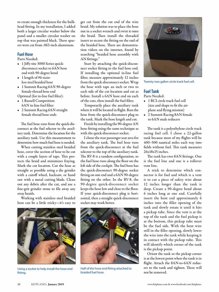
to create enough thickness for the bulk-head fitting. In my installation, I added both a larger circular washer below the panel and a smaller circular washer on top that was painted black. These spac-erswerecutfrom.063-inchaluminum.
Fuel Hose Parts Needed:• 1Jiffy-tite3000Seriesquick-
disconnectsocketto6ANhoseendwith90-degreebend
• 1lengthof#6stain-less steel braided hose
• 1SummitRacing6AN90-degreefemale-thread hose end
Optional(forin-linefuelfilter):• 1RussellCompetition
6ANin-linefuelfilter• 2SummitRacing6ANstraight
female thread hose ends
The fuel hose runs from the quick-dis-connect at the fuel selector to the auxil-iarytank.Determinethelocationfortheauxiliary tank. Use this measurement to determine how much fuel hose is needed.
When cutting stainless steel braided hose, cover the section of hose to be cut with a couple layers of tape. This pro-tects the braid and minimizes fraying. Mark the cut location. Cut the hose as straight as possible using a die grinder with a cutoff wheel, hacksaw, or bandsaw with a metal cutting blade. Clean out any debris after the cut, and use a fine-grit grinder stone to file away any stray braids.
Working with stainless steel braided hose can be a little tricky—it’s easy to
get cut from the cut end of the wire braid. My solution was to place the hose nut in a socket wrench and twist it onto the braid. Then install the threaded insert to secure the fitting on the end of the braided hose. There are demonstra-tion videos on the internet, found by searching “braided hose assembly with AN fittings.” Start by attaching the quick-discon-
nect socket fitting to the fuel hose end. If installing the optional in-line fuel filter,measureapproximately12inchesfrom the quick-disconnect socket. Wrap the hose with tape an inch or two to each side of the cut location and cut as before.Installa6ANhoseendoneachof the cuts, then install the fuel filter.
Temporarily place the auxiliary tank where it will be located in flight. Run the hose from the quick-disconnect plug to the tank. Mark the hose length and cut.Finishbyinstallingthe90-degreeAN
hose fitting using the same technique as with the quick-disconnect socket.
I chose the rear passenger seat area for the auxiliary tank. The fuel hose runs from the quick-disconnect at the fuel selector to the top of the auxiliary tank. The RV-8 is a tandem configuration, so the fuel hose runs along the floor on the left side of the cockpit. The fuel hose has the quick-disconnect 90-degree socketfittingononeendanda6AN90-degreefitting on the other. In the RV-8, the 90-degree quick-disconnect socketkeeps the hose low and close to the floor. If your quick-disconnect plug is hori-zontal, then a straight quick-disconnect socket may work better.
Fuel TankParts Needed:• 1RCIcircletrackfuelcell
(size and shape to fit the air-planeandflyingmission)
• 2SummitRacing8ANfemaleto6ANmalereducers
The tank is a polyethylene circle track racing fuel cell. I chose a 22-gallon tank because most of my flights will be 400–500 nauticalmiles eachway intofields without fuel. This tank measures 26x18x15inches.
The tank has two 8AN fittings. One is the fuel line and one is a rollover vent line.
A trick to determine which con-nector is for fuel and which is a vent is to cut a piece of safety wire about 12 inches longer than the tank isdeep. Create a 90-degree bend about6 inches long at one end. Carefullyinsert the bent end approximately 6inches into the filler opening of the tank and slowly rotate it until it hits apickuptube.Sincetheventisatthetop of the tank and the fuel pickup is at the bottom, this pickup tube must be the fuel side. With the bent wire still in the filler opening, slowly lower the wire into the tank while keeping it in contact with the pickup tube. This will identify which corner of the tank is the pickup point.
Orient the tank so the pickup corner is at the lowest point when the tank is in flight.Attach the8AN-to-6ANreduc-ers to the tank and tighten. These will not be removed.
36 KITPLANES January 2019 www.kitplanes.com & www.facebook.com/kitplanes
Using a socket to help install the hose end fitting.
Half of the hose end fitting attached to braided fuel hose.
Twenty-two gallon circle track fuel cell.

Vent Line Parts Needed:• 1Jiffy-tite2000Seriesquick-dis-connectplugto6ANfemalethread
• 1AN833-6Dmale-male90-degreebulkheadelbow
• 1AN924-6Daluminumnut• 1SummitRacing6ANfemale
to 4AN male reducer • 3SummitRacing4ANtubenuts(black)
• 3SummitRacing4ANtubesleeves(black)
• 1lengthof¼-inchaluminumtube(insidethefuselage)
• 1AN833-4Dmale-male90-degreebulkheadelbow
• 1AN924-4Daluminumnut• 14-inchlengthof¼-inchalu-minumtube(gentle90-degreebendforoutsidethefuselage)
The vent line starts with a quick-dis-connect plug and uses aluminum tub-ing to run to the bottom of the airplane where it exits with a forward facing vent tube. Since the RV-8 wing tank vents
were¼-inchaluminumtube,Ichosetohave the auxiliary tank use the same tub-ing and installed it using 4AN fittings.
For simplicity, the auxiliary tank vent hose uses the same 6AN hose as thefuel hose. The vent line in the fuselage uses¼-inch aluminum tube,matchingthe vent tubes for the wing tanks. This requiresreducingthe6ANventhoseto4AN for the aluminum tube.
I wanted to avoid having the vent line pass through any removable panels to simplify the annual condi-tion inspection. This meant passing through the bulkhead at the back of the baggage compartment. Fortu-nately, there was an unused hole (two actually)inthebulkhead.The 6AN bulkhead fitting requires
one or more spacers to create a thick enough surface to tighten the bulkhead nut. After tightening the bulkhead fitting in place, attach the quick-dis-connect plug facing the axillary tank location. On the opposite side of the bulkhead fitting, attach and tighten the 6AN-to-4ANreducer.
Vent HoseParts Needed:• 1SummitRacing6ANswivel
90-degreefemale-threadhoseend• 1lengthof#6stainlesssteelracing
hose (measured from auxiliary tank totheventlinedisconnectplug)
• 1Jiffy-tite2000Seriesquick-disconnectsocketto6ANhoseendwith90-degreebend
The vent hose runs from the tank to the quick-disconnect plug for the vent line.Theventhosehasa6AN90-degreefitting on one end and a quick-disconnect socket90-degreefittingontheother.The vent hose uses a Jiffy-tite 2000
series quick-disconnect, rather than the 3000 series used for the fuel line.Thedifferentseriesconnectorsaredifferentphysical sizes and cannot be swapped. This prevents any confusion between the vent hose and the fuel hose.
The vent hose is assembled with the same steps as the fuel hose. Attach the 6AN 90-degree hose end fitting ontothe braided hose. Measure the distance to the vent line quick-disconnect plug. Cut the hose to length and install the hose end quick-disconnect socket.
In my RV-8, the quick-disconnect plug for the vent is installed horizontally in a bulkhead in the aft baggage compart-ment. The 90-degree quick-disconnectsocket directs the vent line down and keeps it out of the way along the side of the baggage compartment. Dependingon your aircraft installation, a straight disconnect may be more appropriate. Plan the placement of your vent hose quick-disconnect plug to determine which fitting works best for you.
KITPLANES January 2019 37
Vent hose quick-disconnect installed in a bulkhead frame.
The vent line is routed to remain clear of obstacles.
Vent hose quick-disconnect is located on the rear baggage compartment bulkhead.
Vent line 90-degree bulkhead fitting pass-through on the bottom of the fuselage.
Finished vent line on the bottom of the fuselage.

placing it at the same CG as the rear pas-senger seat. This means the tank strad-dles the flap actuator bar. The ramp is constructed of ¼-inch
panel plywood and 2x4-inch stock. The stock iscutwitha4.5-degreebevelonthe top to fit the slope of the RV-8 aft seat area.
The platform has a series of supports made of strips of wood running the width of a thin sheet of plywood. The
forward most strip runs just behind the rear seat crotch strap anchor point. The next two strips flank the flap tube. The ramp slopes 4.5 degrees from
the rear seat’s crotch strap mount to the back of the baggage compartment bottom. The slope provides the neces-sary clearance for the strap mount and flap tube. It also gently slopes the tank in flight so the fuel pickup is at the lowest point.
38 KITPLANES January 2019 www.kitplanes.com & www.facebook.com/kitplanes
Locate the point where the vent tube will exit the fuselage. The exit point will most likely be some place on the bottom of the fuselage. This is the location for the 4AN 90-degree bulkhead fitting.Drillaholeforthelongendofthe4AN90-degreebulkheadfitting.
Insert the long end of the bulkhead fitting into the hole so the fitting is pointed straight out of the fuselage. This will orient the bulkhead fitting to keep the vent line low and close to the floor of the fuselage. The 4AN bulkhead fit-ting requires one or more spacers to cre-ate a thick enough surface to tighten the bulkhead nut. Install one spacer on the outside of the fuselage, then install the bulkhead nut.
Plan out the route of the aluminum tube vent line from the 4AN reducer to the bulkhead fitting exiting the fuselage. The vent line should finish by running along the inside skin of the fuselage into a 90-degree bulkheadfit-ting, which provides the turn to exit the fuselage. Use rubber grommets when passing through intermediate holes to protect the tubing.Cutalengthof¼-inchtubetofitthe
planned route. Add coupling nuts and flare sleeves, and flare each end.
Install and route the vent tube. Attach it to the 4AN reducer at one end and the 90-degree4ANbulkheadfittingattheother. Tighten all of the fittings.Cut 4 inches of ¼-inch aluminum
tube and forma large-radius90-degreebend. Add a coupling nut and flare sleeve, and flare one end. Attach the tube to the exposed end of the bulkhead fit-ting on the exterior of the fuselage with the open end of the tube facing forward.
With all of the assemblies complete, hoses fabricated, and tubing installed, trace the complete route from the fuel selector to the exterior vent, and check that all the fittings are tight.
Tank PlatformThe tank installation will be specific to each aircraft. The key goal of the tank platform is to provide a secure location so the tank cannot move in any axis.
In my RV-8, the tank installs in the passenger area, as far forward as possible,
Layout of the platform using a jury stick.
Fitting the platform with perimeter strips to keep the tank from sliding.
The tank platform fitted into the RV-8 passenger area.
Location for the auxiliary tank platform in the RV-8 passenger area.
Test fitting the platform panel material.
Close-up of support strips and jury stick.

I created a jury stick with all of the locations and measurements. The jury stick simplifies the layout and glue-up of the support strips on the platform panel.
The ramp has perimeter blocking to keep the tank from sliding fore or aft and left or right. It is primed and painted light gray.
InstallationBecause I chose to use the rear seat loca-tion for my auxiliary tank, the first step in using the tank is to remove the rear seat. In an RV-8, the seat cushion is held in place with Velcro. The seat back is held in place by removable hinge pins. It takes less than 2 minutes to remove the seat and seat back.Install the fuel hose 6AN 90-degree
hose endfitting to the6ANreduceronthe fuel port of the auxiliary tank. The fit-ting will not be removed, so make it tight.Installtheventhose6AN90-degree
hose end fitting to the 6AN reduceron the vent port of the auxiliary tank.
KITPLANES January 2019 39
Auxiliary tank with attached fuel and vent hoses.
Auxiliary tank platform and vent hose quick-disconnect plug.

Again, the fitting will not be removed, so be sure it’s tight.
Installing the auxiliary tank starts by placing the tank platform in the aircraft. Next, the tank is placed on the platform and secured with a strap.
The fuel hose is run in position to the quick-disconnect. Holding the spring-loaded retaining collar up, press the quick-disconnect socket onto the quick-disconnect plug, releasing the retaining collar.
The vent hose is installed similar to the fuel hose. Gently tug each quick-discon-nect to ensure they have locked in place.
Before removing the tank, make sure it is empty or mostly so. A 22-gallon auxiliary tank weighs approximately 150poundswhen full,making itdiffi-cult to handle.
Remove the vent hose by pressing in on the quick-disconnect socket while pulling back on the spring-loaded retaining collar. This will release the connectoranditwillpulloff.Thefuelhose is removed similarly to the vent hose, but leave both hoses connected to the tank. When the auxiliary tank is not in use, I have a little rubber ducky that covers the fuel quick-dis-connect plug.
Flight Test ProcedureAs with any alteration to an experi-mental aircraft, it’s important to estab-lish a test procedure to determine safe operationsandanyeffectsthemodifi-cation may have.
Leak Test: With only the vent line quick-disconnect connected, apply a
small amount of air pressure to the vent line at the bottom of the fuselage. Con-firm that both the vent line and fuel line hold pressure. Place a blue, lint-free absorbent towel under the fuel selector. With the fuel selector on the auxiliary tank, apply a small amount of air pres-sure to the vent tube on the exterior of the fuselage. Hold this pressure for 1minute. Check the absorbent towel for any signs of fuel.
Leave the absorbent towel under the fuel selector for the remaining test proce-dures and inspect at the end of each test.
Ground Operation Test: With both the vent and fuel quick-disconnects attached, engage the boost pump and switch between left, right, and the aux-iliary tank at 10–15 second intervals.Turnofftheboostpumpandchecktheabsorbent towel for any signs of fuel.
Ground Run Test: Start on awingtank. Turn on the boost pump. Move the fuel selector to the auxiliary tank position. Initially, the boost pump will indicate air. Within a few seconds, the boost pump sound will change as fuel flows from the auxiliary tank. Observe the engine fuel-pressure measurement. Switchtheboostpumpoffandcontinueto observe the engine fuel pressure mea-surement. If all conditions are nominal, perform taxi tests to evaluate the per-formance of the auxiliary tank during groundmaneuvers. Shutdown the air-craft and inspect the absorbent towel for any signs of fuel.
In the case of a tailwheel aircraft, the auxiliary tank may be low and suf-ficiently aft of the engine to provide
inadequate fuel flow. If this is the case, the POH should indicate use of the aux-iliary tank is restricted to cruise or level flight only.
Flight Operations Test: Take offonawingtankandclimbto4000feetover the local airport. Switch on theboost pump, then switch to the auxil-iary tank. Monitor fuel flow, fuel pres-sure,andenginerpm.After15seconds,switch off the boost pump. Periodi-cally verify fuel flow, fuel pressure, and engine rpm. Perform a series of gentle turns and gradually increase to steep turns.Switchbacktoawingtankandwait 2 minutes before starting descent-to-land procedures. J
40 KITPLANES January 2019 www.kitplanes.com & www.facebook.com/kitplanes
Fuel hose connection at the fuel selector. Vent hose connection in aft baggage compartment.
Fuel quick-disconnect plug covered by rubber ducky when not in use.
Glen
Salm
on
As a buyer of an RV-8 and not the original builder, Glen ventured into the experimental aircraft world by completing small projects and upgrades to improve his building skills. Often working with a local E/A-B savvy A&P, he moved on to more difficult projects like replacing an O-320 with an O-360, installing a new instrument panel, and using a 3D printer to mold a custom carbon fiber airbox. Glen’s day job is developing STEM and Maker projects to inspire and challenge the next generation. Having an amateur-built aircraft provides both a platform for projects and inspiration for youth who visit his shop.

KITPLANES October 2011 41 Photos:

www.kitplanes.com & www.facebook.com/kitplanes42 KITPLANES January 2019
Back in Part 2 of this series, we com-pared the accident rate of homebuilts to that of common general aviation production aircraft. The homebuilt rate was, to no one’s surprise, higher.
But several KITPLANES® readers pointed out a key factor: None of those production aircraft were on their first flight. A bunch of new homebuilts take to the air every year, with what one would assume would be an elevated degree of risk.
This triggers a variety of questions. How many new homebuilts make their first flight each year? What per-centage of new homebuilts suffer acci-dents? What are the major causes of first-flight accidents?
Let’s take a look at finding some answers.
Extracting the DataTo determine the rate, we need to know how many new homebuilts are produced each year and how many first-flight accidents occur. Neither is simple to determine.
Counting “new homebuilts” by com-paring the total number of Experimental/Amateur-Built (E/A-B) aircraft to the
previous year doesn’t work. That pro-vides the net change. Hundreds of new E/A-B are added to the registry each year, but hundreds are also removed. In 2017, for instance, the net count was down nearly 400 airplanes from 2016. Yet there were still nearly a thousand new homebuilts completed.
Fortunately, the FAA provides a list of deregistered aircraft and the date they were removed from the rolls. So to
determine how many new homebuilts are added in a particular year, we’ll use the net change from year to year, and add the number of E/A-B aircraft dereg-istered that year. So if the net change was zero, but 100 E/A-Bs had been deregis-tered, we know that those 100 planes had been replaced by new ones.
Figure 1 shows the results. During 2007 through 2016, an average of about 1040 new homebuilts were added each year.
Builder error is a major factor in first-flight accidents.
By Ron Wanttaja
Homebuilt Accidents: First Flights
Figure 1: Homebuilt aircraft production by year.
While two types may seem similar, it’s better to get type-specific checkouts prior to first flight.

Photos and illustrations: Ron Wanttaja KITPLANES January 2019 43
Back in Part 1 of this series, I esti-mated the overall annual homebuilt f leet accident rate as being 0.90%. Does that 0.72% rate sound pretty good in comparison?
Keep in mind that the overall fleet rate covers an entire year of operations. The first-flight 0.72% rate is for a single hour.
So, yes—the first flight of a homebuilt aircraft is a lot more hazardous than ordinary operations.
Remember, too, that these numbers are based on accidents actually recorded in the NTSB database. This doesn’t include the kinds of incidents that don’t meet the NTSB reporting criteria due to a low degree of damage, or those that the NTSB doesn’t find out about.
A Look at CausesFigure 2 shows a breakdown of the causes of first-flight accidents. As with the overall accidents, pilot miscontrol (mistakes in stick-and-rudder work) predominate. It’s interesting to note that the percentage is almost identical to that of the overall fleet—37.3% for first-flight accidents, vs. 38.5% for all homebuilt accidents.
What’s scary is the rate of accidents due to builder error. Over 20% of first-flight accidents were due to builder error, vs. just 5% for the overall E/A-B fleet.
Figure 3 illustrates what systems are typically affected by builder error on the aircraft’s first flight. As expected, the fuel system was the most affected, with almost a quarter of the builder-error crashes attributed to problems with the fuel supply on the maiden flight.
Second place was a three-way tie: pro-peller/rotor, carburetor, and control sys-tems, each at 18%.
Most of the propeller cases were improper pitch settings. The carburetor cases saw blocked inlets, improper set-tings, inoperable/non-existent carbu-retor heat, and several cases where the throttle cable wasn’t securely attached. The majority of the control system issues were related to the ailerons.
One of the odd coincidences was the percentage of accidents due to a loss of engine power for any cause. About 34%
Finding the first-flight accidents takes a little detective work. NTSB investiga-tors often comment when a homebuilt was on its maiden flight. The problem is, there are almost as many accidents where the aircraft is listed as having zero air-frame hours, but the narrative does not state the plane was on its maiden flight. And some aircraft that the NTSB lists as “maiden flight” are listed as having more than 10 hours of flight time.
The investigators are probably record-ing the time based on a recording tach or Hobbs meter. It’s recommended that the engine on a new homebuilt receive at least one hour of ground testing, so the typi-cal homebuilt will already have an hour on its Hobbs meter prior to first takeoff. Plus, first-flight accidents can occur on the return to the airfield, adding another hour to the ground-running time.
So for my analysis, I assume the aircraft is on its first flight if (a) the NTSB report so indicates, or (b) the aircraft total time is listed as two or fewer flight hours.
First-Flight Accident RateSo, how often do homebuilts crash on their first flight?
Let’s look at a ten-year period from 2007 through 2016, inclusive. During that time, there were 78 accidents that occurred during the first flight.
With 10,400 new homebuilts added during this same period, that’s an acci-dent rate of 0.75%. About one in every 130 new homebuilts suffers a reportable accident on its first flight.
Figure 2: First-flight accident causes.
Figure 3: Systems affected by builder error in first-flight accidents.
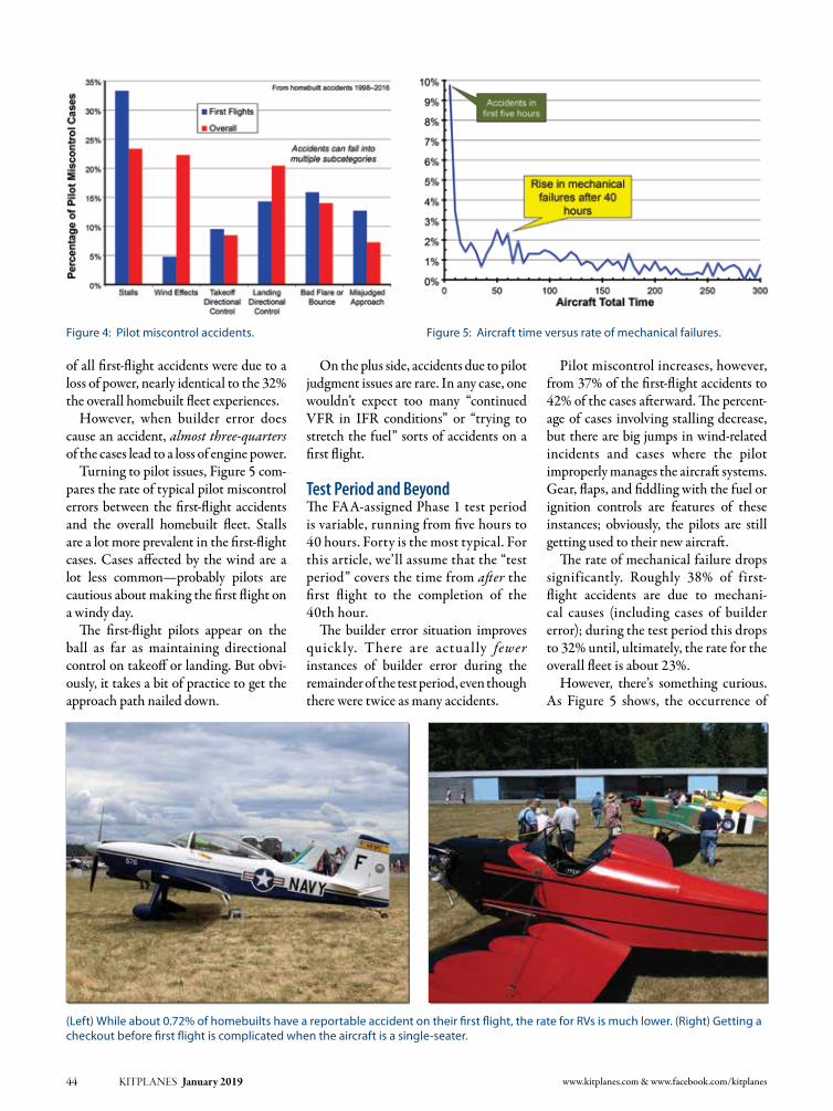
Pilot miscontrol increases, however, from 37% of the first-flight accidents to 42% of the cases afterward. The percent-age of cases involving stalling decrease, but there are big jumps in wind-related incidents and cases where the pilot improperly manages the aircraft systems. Gear, flaps, and fiddling with the fuel or ignition controls are features of these instances; obviously, the pilots are still getting used to their new aircraft.
The rate of mechanical failure drops significantly. Roughly 38% of first-flight accidents are due to mechani-cal causes (including cases of builder error); during the test period this drops to 32% until, ultimately, the rate for the overall fleet is about 23%.
However, there’s something curious. As Figure 5 shows, the occurrence of
of all first-flight accidents were due to a loss of power, nearly identical to the 32% the overall homebuilt fleet experiences.
However, when builder error does cause an accident, almost three-quarters of the cases lead to a loss of engine power.
Turning to pilot issues, Figure 5 com-pares the rate of typical pilot miscontrol errors between the first-flight accidents and the overall homebuilt fleet. Stalls are a lot more prevalent in the first-flight cases. Cases affected by the wind are a lot less common—probably pilots are cautious about making the first flight on a windy day.
The first-flight pilots appear on the ball as far as maintaining directional control on takeoff or landing. But obvi-ously, it takes a bit of practice to get the approach path nailed down.
On the plus side, accidents due to pilot judgment issues are rare. In any case, one wouldn’t expect too many “continued VFR in IFR conditions” or “trying to stretch the fuel” sorts of accidents on a first flight.
Test Period and BeyondThe FAA-assigned Phase 1 test period is variable, running from five hours to 40 hours. Forty is the most typical. For this article, we’ll assume that the “test period” covers the time from after the first flight to the completion of the 40th hour.
The builder error situation improves quickly. There are actual ly fewer instances of builder error during the remainder of the test period, even though there were twice as many accidents.
44 KITPLANES January 2019 www.kitplanes.com & www.facebook.com/kitplanes
(Left) While about 0.72% of homebuilts have a reportable accident on their first flight, the rate for RVs is much lower. (Right) Getting a checkout before first flight is complicated when the aircraft is a single-seater.
Figure 4: Pilot miscontrol accidents. Figure 5: Aircraft time versus rate of mechanical failures.

mechanical failures drops as the plane gains more hours—but rises again in the 40- to 70-hour period. Note that this is just mechanical issues, not pilot judg-ment issues (which rise as well).
Just because a component survives the first flight doesn’t mean that it’s been installed properly. Wear will be accel-erated, and it appears that much of the impact is happening 40 to 70 hours later. Even if the plane made its first flight without problems or completed its test period with no mishaps, don’t assume everything is good for the coming years.
ConclusionObviously, builder error should be a major concern when preparing for the first flight. Test and inspect as thoroughly as possible. Get EAA technical counselors and other experienced builders involved. Ensure your own training is up to the potential for having to execute a rapid emergency landing in case of a problem.
Be aware that successful first-flight completion does not mean the plane is mechanically perfect. Remember that spike in mechanical issues in the 40- to 70-hour range; the NTSB may not declare them due to builder error, but most of that hardware should be lasting a lot longer.
There’s an odd coincidence here: According to FAA figures, the average homebuilt flies about 50 hours per year. An E/A-B’s first condition inspection is
due about a year after the first flight. This means that these additional failures are occurring near the time of the first con-dition inspection.
One of the greatest features of the Experimental/Amateur-Built aircraft cat-egory is that the builder can receive a repairman certificate that permits him or her to perform the yearly condition inspection on that aircraft. Certainly, the builder will have the best understanding of how the aircraft is constructed.
But that experience does not familiar-ize the builder with how the components will wear over time. An A&P inspecting a production-type airplane has probably looked at hundreds of aircraft previously
and has noted a variety of wear-related conditions. The repairman certificate holder won’t have that experience.
The solution is the same as reducing failures for the first flight: Get more eyes on your airplane for the first condition inspection. Experienced builders and EAA tech counselors are good sources. Consider even hiring an A&P to examine the aircraft for the first condition inspec-tion, with the understanding that you will be performing the formal signoff.
The ability to build, maintain, and inspect your own aircraft is a precious aspect of the world of homebuilding. But there are definite risks, and builders should approach them carefully. J
KITPLANES January 2019 45
Determining how many homebuilts are completed each year is complicated by the registration renewal process instituted by the FAA in 2010. The owner of this KIS TR-1C did not renew his registration, and the plane was removed from the registry in 2017. (Right) Older designs such as this Thorp T-18 are still being completed.
Percentage of accidents versus aircraft test phase.

As much as it seems like a natural thing to do (in order to see if the air-speed indicator is working), we have all been warned to never blow into the pitot tube. Whether using a mechanical gauge or an electronic airspeed display, there is a genuine need to see if the plumbing is functioning correctly during installation or maintenance of our pitot system. A loose tube or even a small leak (or block-age) anywhere in the system can drasti-cally alter the accuracy of the indicated airspeed. A separate but related system, the static plumbing has a similar need for testing as it can adversely affect not only the airspeed but several other indicators such as vertical speed and the altimeter.
If we are not allowed to blow for test-ing, then what is an alternative? With just a couple of inexpensive household items, you can perform a very rigorous test of both the pitot and static systems of your homebuilt.
First, obtain a dental irrigation syringe (use this term to search Amazon or a local drugstore) as pictured here.
There is no needle included, just a plas-tic nose that is perfect to slip some tub-ing over. I like to use surgical tubing of the appropriate size as it lends itself to adjusting to a wide range of diameters and makes a good seal. This is the hose used for building slingshot toys—that’s another project!
While many aircraft’s pitot tube may differ from the one shown here, the prin-ciple is the same. The tubing is used to
connect the end of the syringe and the pitot tube with an airtight seal. Now, be careful! You never want to push the syringe plunger more than ¼ inch at a time before evaluating your next move. Just like the warning to never blow into the pitot tube, never move the plunger more than this small distance or dam-age could occur to your sensitive instru-ments. With a long enough tube, you should be able to make these plunger
Don’t Blow into the Pitot Tube!
46 KITPLANES January 2019 www.kitplanes.com & www.facebook.com/kitplanes
PLANE SIMPLEand
By Jon Croke
To test your pitot/static system, use a dental irrigation syringe and a piece of surgical tubing in a diameter that will make an airtight seal.
With your airspeed indicator displaying 0, push (never pull) your plunger a ¼ inch at a time. There should not be a loss of more
than 10 knots in one minute’s time.

Photos: Jon Croke KITPLANES January 2019 47
PLANE SIMPLEand
Jon
CRo
KE
As the founder of Homebuilt HELP.com, Jon Croke has produced instructional videos for experimental aircraft builders for over 10 years. He has built (and helped others build) over a dozen kit aircraft of all makes and models. Jon is a private pilot and currently owns and flies a Zenith Cruzer.
movements while watching your air-speed indicator.
Testing is simple. With your airspeed indicator displaying 0, push (never pull) your plunger a ¼ inch at a time. You should immediately see an increase of airspeed. (If you do not, then stop—you have a problem that needs to be investi-gated.) Note the new airspeed and wait a full minute. According to FAA Advi-sory Circular 43.13-1B, there should not be a loss of more than 10 knots indicated in one minute’s time. If you pass this test, your pitot system is in great shape (demonstrating no leaks). If not, you need to investigate the leak or blockage in your system. Pitot system testing is just that simple!
Checking the static system is simi-lar but has one unique challenge: Not all static ports provide an easy way to slip a tube over for an airtight seal. You may need to disconnect or otherwise “T” into your static line for the syringe tube connection. Once the syringe is in line, you will then “pull” the syringe plunger back about ¼ inch, creating a small suction. Note the change in reading on the altimeter (as pressure drops, the reading should go up). AC 43.13-1B states that a good static sys-tem should display less than a 100-foot loss of altitude in one minute.
It is always better to discover and rec-tify pitot/static problems when building your aircraft on the ground. This method is inexpensive and plane simple! J
JAN
. 23-26, 2019Sp
ortA
viatio
nExp
o.c
om
Sebring, Florida in January: THE place to try, fly and buy everything aviation.
FLY ITlike you stole it...
...and leave your enginemonitoring to EIS.
Trusted with everything from 2-strokesto turbines for over two decades.
Proud sponsor of Tiger Airshows and airplane “thief” extraordinaire, Hotwire Harry!
www.grtavionics.com • (616) 245-7700

48 KITPLANES January 2019 www.kitplanes.com & www.facebook.com/kitplanes
Dick Starks has written two books about the joy of flying; “You Want To Build And Fly A What?” and “Fokkers At Six O’clock!!” He was the recipient of Flying’s 2001 Bax Seat Award “for perpetu-ating the Gordon Baxter tradition of communicating the excitement and romance of flight.” Dick and his wife, Sharon, both fly WW-I replica aircraft.
There I was in the garage hopelessly searching for a lost tool somewhere on the floor when the phone rang. The caller ID screen is in the house. Our phone had been inundated with political ads until we just didn’t answer it anymore. Why I picked it up this time remains a mystery. I call situations like this “a momentary lapse of reason.”
I picked the phone up, being ready to slam it down. As soon as the voice at the other end started blaring in my ear, I knew exactly who it was.
“Lemme speak to the famous WW-I fly-ing ass!” (That is not a typo by the way.)
It was Jay Williams. He’s another deni-zen of the bums and misfits that fly out of beautiful Liberty Landing Interna-tional Airport. He’s got a real nice Zenith 701 that he built.
“Whddaya want, Shrek?” I snarled. Now this calls for an explanation. Jay
and I have known each other for years. He loves torturing me. I respond in a like manner. If we ever start being nice
to each other, that means something is seriously wrong.
I’m the “flying ass.” (Actually, that’s the only thing he calls me that can be printed in this fine family magazine.)
At the airport, Jay’s either “Ghost Rider” or “Shrek.” Ghost Rider comes from the movie “Ghost Rider” with Sam Elliot and Nicholas Cage. Shrek comes naturally. Jay is a big teddy bear of a man. He’s also the strongest man I’ve ever met. You do not want Jay to get upset with you. He’d rip your arms off and then beat you to death with them. It’s a really good thing Jay’s the most easygoing 800-pound grizzly bear you’ll ever come across.
“Just how strong is he?” I hear you ask. Case in point: Jay asked me to come over and help him do the different cables in the Zenith 701 he was building. He asked me because, one, I have a Nicopress tool and, two, a go/no-go gauge. We were getting ready to install a cable, and I asked him for his Cleco pliers to take out some Clecoes that were in the way.
“Cleco pliers!” he growled. “I don’t need no steenkin’ Cleco pliers,” he snorted. “Get outta my way.”
Then, using his thumb and two fingers, Jay took all the offending Clecoes out so I could get in there and do what needed to be done. The watching crowd just stood there in stunned awestruck silence.
For years, Jay was a very respected motorcycle racer in the Midwest. He had business sponsors and raced for Kawasaki.
In 1999 he had a bad crash and perma-nently messed up his right leg and knee. That didn’t stop him from racing though. He just had his bikes modified for his right leg’s limited mobility.
During this time, Jay owned and oper-ated a bicycle shop in the Kansas City River Market area from 1991 until 2016. And these weren’t bicycles like you’ll find in Walmart and Kmart. Jay sold the high-dollar, super-lightweight carbon fiber bikes like you’ll find in the Tour de France. These bikes were for serious riders. He sold his bike business in 2016 and moved
Good Things Come in Threes
THE DAWN PATROL
The WW-I flight line at Columbia. In the foreground is Darryl Porter’s yellow Airdrome Aeroplanes Fokker D.VII and Ken Hines’ Airdrome Aeroplanes Nieuport 28.

Photos: Dick Starks KITPLANES January 2019 49
to Marceline, Missouri, where he’s now a gentleman farmer and raises cattle.
That’s enough about him. Any more and he’ll get a big head. Back to the phone call.
“Why are you bothering me today?” I asked.
“What would it take for me to become a member of the Dawn Patrol?” he asked.
“Well, first you need something that looks like a WW-I airplane,” I answered. “Have you got one?”
“No. I figured you and the rest of the Dawn Patrol clowns can help me find one.”
After a rather spirited conversation peppered with insults better not related here, we decided to pay a visit to “Bull-whip Baslee’s House of Pain.” (It is also known as Robert Baslee’s Airdrome
Aeroplanes workshop and airstrip, eight miles south of Bates City, Missouri.) Bull-whip has a hangar full of his planes and told Jay to try them on for size.
The bottom line is that none of Rob-ert’s planes could fit the bill. Jay’s right leg just wouldn’t bend enough for him to get in any of the cockpits. When I sug-gested using an engine hoist to get him into a plane, I made sure I was far enough away from Jay to have a good head start. I was fairly certain I could outrun him. With disappointed faces we headed back home. The search was not over for a Dawn Patrol plane for Jay.
New MembersA day or so later, I got an email from a retired Coast Guard commander, Ken
Hines. Ken lives in Columbia, Missouri, and had just finished a beautiful Robert Baslee full-scale Nieuport 28. He asked about getting in the Dawn Patrol. Ken is also a scarred veteran of Bullwhip Baslee’s House of Pain. So, we gained a new member. This was a good thing.
Then I got another call from Shrek.“I’ve got a plane!” Jay yelled in my ear.
“It’s a Mariner amphibian in U. S. Coast Guard Colors.”
“Good deal,” I said. “You’re now in the Dawn Patrol.”
“It doesn’t have an engine on it,” he continued.
“You’re out of the Dawn Patrol,” I replied.“Wait a minute,” Jay went on. “I may
have an alternate to tide me over until I get an engine for the Mariner. I just bought a 1941 Vultee BT-13 with a nine-cylinder 450-hp Pratt and Whitney 985-cubic-inch engine swinging a nine-foot Hartzell two-speed prop.”
“Gulp…I think we’ll be able to stretch the rules a little bit to allow that in the Dawn Patrol.”
The bottom line was that after I’d contacted the HMIC (head momma in charge) of the Salute to Veterans Airshow, Jay got invited to show his plane there and give rides to selected vets in the crowd. The Dawn Patrol had gained another member.
Then I got another out of the blue email from a man in Washington, D.C. Willy Hackett introduced himself and
Ken Hines’s impressive Airdrome Aeroplanes full-scale Nieuport 28 stands tall and proud on the flight line.
Jay Williams greases in his BT-13.

50 KITPLANES January 2019 www.kitplanes.com & www.facebook.com/kitplanes
the Memorial Day weekend for Willy to be an honored guest at the show. Now this was an honor—not to be compared in any way with being an honorary mem-ber of the Dawn Patrol.
We extended an invitation for Willy to fly into Kansas City the Thursday before the Memorial Day weekend and hang with us throughout the weekend. He could have flown into Columbia, Mis-souri, and stayed there with the rest of the honored guests for the airshow, but in a classic momentary lapse of reason, he chose to hang with us and absorb the entire Dawn Patrol experience.
On with the ShowWe picked Willy up at the airport after his plane landed. He was easy to find. Willy was wearing his official Dawn Patrol “I Don’t Need No Steenkin’ Nosewheel” T-shirt that I had printed up and sent to him.
Final Gulp! He received an MBE (Mem-ber of the Order of the British Empire) for services to aviation personally from Her Majesty the Queen in 1999.
In his personal flying, Willy is a gliding instructor and member of the Yakovlevs display team flying Yak 50 aircraft. He is a Shuttleworth Collection pilot, flying anything from a Tiger Moth to a Hawker Hind and a German Storch. He also instructs in and demonstrates the Fol-land Gnat. And Willy currently flies two-seat Spitfires with the Boultbee Flight Academy at Goodwood Aerodrome, giving rides to members of the public.
Did you get all that? This guy’s the real deal! And, he wants to hang out with us? Doesn’t he realize what this would do to his reputation? I warned him, but he said he didn’t care.
We set it up with him and the HMIC of the Salute to Veterans Airshow being held at Columbia Regional Airport over
said he had been reading my articles in this fine magazine. He was very inter-ested in WW-I aviation and asked if he could come out some weekend and hang out with us at Liberty Landing International Airport.
“Sure,” I replied. “The more the mer-rier.” Then after a few more emails, Willy finally started giving me some of his history.
Gulp! He’s in the R.A.F.Gulp! He’s a group captain in the
R.A.F. That’s the equivalent rank of a colonel in the U. S. Air Force! (Our only experience with colonels of any kind has been getting our rears chewed on by them at different airshows held on different military fields.)
Gulp! He’s on detached duty in Wash-ington, D.C. Willy, his wife Debb, and his two daughters moved to Washington, D.C., where he serves as the U.K. lead of the F-35 Lightning project.
Willy Hackett with a 1918 Bristol Fighter F.2B that is the only original airworthy example in Europe. This airplane is extra special to the Hackett family as Debb’s grandfather Edward Evans flew Bristol Fighters in the Great War as a sergeant pilot.
This particular spitfire was fully restored by Stephen Boultbee-Brooks, including turning the fuselage into a two-seater by moving the fuel tank. Willy Hackett has flown two veterans of the Battle of Britain in it. (Photo: Richard Paver)
Dick Starks and Willy Hackett in his daily R.A.F. uniform getting ready for the Memorial Day parade in Columbia, Missouri. Dick is about to take Willy in the Trench Cat to his parade car.
On a recent trip back to the U.K., Willy Hackett was flying passengers in a two-place Spitfire wearing his official Dawn Patrol “I’m a taildragger pilot!” T-shirt.

KITPLANES January 2019 51
We noticed one thing about Willy right off the bat…he talks funny. For a while we thought we were in the middle of filming Downton Abbey. People in the ter-minal were tripping over their roller bags trying to figure out where the foreign language was coming from.
Since Willy had told us he wanted to absorb the entire Dawn Patrol experi-ence, we went straight to Liberty Land-ing and put him to work washing planes, disassembling planes to put in trailers, pumping up tires, gathering tools, and all the other tasks needing to be done so the Trailer Weenies could blast outta Dodge Friday morning early. While he was doing all this, Willy flew several dif-ferent planes at the airport, proving him-self a master pilot.
Friday morning we blasted off for Columbia. Once there, aircraft assembly started with a vengeance. There was a Fokker D.VII, Nieuport 11, Nieuport
16, Morane Parasol, Fokker E.III, SPAD XIII, full-scale Morane Parasol, full-scale Sopwith Camel project, and Nieuport 28 being assembled. While all this was going on, Jay roared in with the BT-13. He made a couple of ear-splitting passes down the runway and landed. Jay taxied up and promptly threw Willy in the back seat and away they went. When they landed, Jay came up to me with bugged out eyes and quietly told me that just as soon as they lifted off, Jay gave the plane to Willy. Willy flew the entire flight includ-ing a greaser wheel landing all by him-self. Jay was way past impressed.
One little event happened on Saturday morning. One of the acts had to cancel, so the air boss came by the Dawn Patrol cluster and asked Jay if he’d be willing to give a little demo of the BT-13 for the crowd. Not a big deal.
We pushed the BT out on the taxiway and got it ready to go.
Jay came over and quietly ordered Sharon to get in the rear cockpit. Nobody asked why. When they were taxiing out, Jay explained on the intercom why he wanted her along.
The runway in use was Two-Zero. The fifteen-knot wind was a ninety-degree crosswind from the left. Jay figured he might have to kick a lotta right rudder on takeoff, which his right leg might not be capable of doing. He told Sharon over the intercom that if he yelled “Right rudder!” he wanted her to kick right rudder as hard as she
(Above) Willy Hackett (left) and Jay Williams ready to go in the BT-13. (Right) Here’s our Wild Willy looking very tame indeed. This is his official work photo for his role as the F-35 British national deputy. Willy, Debb, and their girls moved to Washington, D.C., for him to take the position after beginning his work with the Lightning 2 project.
Willy Hackett shakes hands with Dennis Brooks after flying Dennis’ UltraCruiser. He liked it.
Sharon Starks and Willy Hackett take turns turning the prop on Jay’s beautiful BT-13 trainer before cranking it up.

52 KITPLANES January 2019 www.kitplanes.com & www.facebook.com/kitplanes
could. She didn’t need to worry about too much rudder because he’d have no problem countering her with left rud-der if needed…The takeoff was a non-event. He didn’t even need her on the rudder pedal.
The airshow, as usual, was a great suc-cess. Jay flew both days and was the only plane flying over the parade in down-town Columbia on Monday.
Willy was invited to come again in 2019. We sure do hope he’ll want to do it again (if the psychic scars aren’t too deep).
Call SignsNow, a short note on pilot call signs. I found an excellent description of call signs on the internet. Basically, it said there are three rules of call signs: One, if you don’t already have one, you will be assigned one by your “buddies.” Two, you probably won’t like it. And three, if you complain and moan too much
about one and two, you’ll get a new nickname you’ll like even less!
Every member of the Dawn Patrol has a call sign. Some, unfortunately, can’t be printed in this magazine. But one of the more socially acceptable ones is “Wild Willy” for Willy Hackett.
I’m the “Junkyard Dog.” I got that one the day a squadron of twin-rotor Chinook helicopters was flying circles over the air-port getting staged for a flyover at a foot-ball game. I scrambled the Gray Falcon, and we started chasing them over the field. I never got close. One of the watch-ing individuals in the crowd mentioned I looked like a tiny Chihuahua junkyard dog up there chasing a pack of pit bulls.
Sharon’s call sign is unique. At one of the Gathering of Eagles fly-ins at Gardner Municipal Airport, every pilot was given a real neat lapel pin saying, “You Need These to Fly a WW-I Aircraft.” Hanging from the badge were two brass nuts.
Well, this presented a challenge. What do we do for Sharon’s badge?
Fortunately, her call sign name came naturally. This came about right after her adventure in the soybeans where she ended up “gear up” in the beans. (That means upside down.) The repairs took a couple of weeks, but she was finally ready to fly again. A few of the more seasoned pilots in the crowd asked her if she’d like them to take it around the first time to check it out. Sharon snorted, jumped in the cockpit, fired up the mighty four-stroke Valley Engineering Big Bad Twin, taxied out, and blasted off. As she made her first pass down the runway, one of the watching crowd murmured, “That woman has leather ovaries.” Yup…a call sign was born. So when you see Sharon in her Dawn Patrol jacket, you’ll know what the letters L.O. stand for written across her shoulders.
Yup…the adventure continues. J
Willy Hackett tries out the “office” in Dick Starks’ Graham Lee Nieuport 11 replica.
Darryl Porter’s impressive Airdrome Aeroplanes Fokker D.VII replica.
Charlie Radford gets ready to aviate in his Airdrome Aeroplanes Fokker E-III as Carl Melin holds on.
Great War Aeroplanes Association www.gwaero.com
The Great War Association www.great-war-assoc.org
The Kansas City Dawn Patrol www.dawnpatrol.org
National World War I Museum www.theworldwar.org
Salute To Veterans Airshow www.salute.org
The Western Front Association www.westernfrontassociation.com
Willy Hackett’s Dawn Patrol page www.dawnpatrol.org/willy-hackett.htm

Photos: Dave Prizio KITPLANES January 2019 53
Precision measuring tools have an important role to play in quality main-tenance, just as they do in quality construction. Precision means that the instrument is capable of measur-ing accurately to .001 inch or less. This leaves out tools such as the machinist’s rule. For this article we will take a look at calipers, micrometers, dial indicators, and the bore gauge. To get precise mea-surements with all of these tools, the instrument must be in good condition and it must be properly used.
AccuracyThe accuracy you need for any job depends on what you are measuring. Checking the diameter of a bolt obvi-ously doesn’t require great accuracy, cer-tainly +/- .001 inch is fine. It is the same for measuring the thickness of a piece of aluminum sheet metal. You rarely care if the thickness of a sheet of .025-inch-thick metal is .02495 or .02505. Thus, in most cases a tool that can accurately measure to within .001 inch is all you need. How-ever, if you are measuring the diameter of a crankshaft journal, accuracy to .0001 inch is needed to do quality work. Or if you are measuring a cylinder bore as part of an overhaul, you may be looking for such precision.
It is one thing to have a tool that will measure to .001 inch. It is another thing to actually know that it is that accurate. For that you will need some gauge blocks. These are precision ground steel blocks that have been measured to extremely fine tolerances. They come in
various sizes and grades, and are priced accordingly. A reasonably priced set that is plenty accurate enough for our needs can be purchased from Amazon for about $70. They even have a 1x2x3-inch block accurate to +/-.0002 inch for about $16, which will meet the needs of most aviation maintenance technicians. The point is to pay for only what you
need, but get something that is accurate enough and in the size range you will be using. For example, if most of your mea-surements are one inch or less, a one-inch gauge block is what you need.
Once you have some gauge blocks, check your measuring tools to make sure they are reading correctly. If they are not, you will need to adjust them if possible,
Using Precision Measuring Tools
MAINTENANCE MATTERS
Dave Prizio has been plying the skies of the L.A. basin and beyond since 1973. Born into a family of builders, it was only natural that he would make his living as a contractor and spend his leisure time building airplanes. He has so far completed three—a GlaStar, a Glasair Sportsman, and a Texas Sport Cub—and is helping a friend build an RV-8. When he isn’t building something, he shares his love of aviation with others by flying Young Eagles or volunteering as an EAA Technical Counselor. He is also an A&P mechanic, Designated Airworthiness Representative (DAR), and was a member of the EAA Homebuilt Aircraft Council for six years.
Dave Prizio
There are three main types of calipers. The vernier type (top) is usually the least expensive but most difficult to read, the dial calipers (middle) are the most common and have the advantage of not requiring a battery, and the digital (bottom) is the easiest to read but does require a battery.

54 KITPLANES January 2019 www.kitplanes.com & www.facebook.com/kitplanes
get a new tool, or at least note that it is not suitable for precise measurements. Proper care and handling of precision tools will keep them in good working order for years, but a drop onto a concrete floor can easily knock a micrometer or set of calipers out of tolerance permanently. The best practice is to check the accuracy of your tool before every use if high precision is required.
Positioning the measuring tool cor-rectly will make for precise measure-ments, but a poorly positioned tool will yield worthless numbers. It is very important to hold the tool exactly square with the object being measured. When measuring the outside diameter of larger round objects, positioning the tool so it is not only square but at the exact largest diameter point is crucial. The tool should slide all the way to the largest point without being too loose. Similarly, when measuring a large diam-eter hole, it is vital to be sure you are measuring the largest possible diame-ter. Move the tool around to be sure you are at the correct point, then double-check to be sure you are square with the object being measured.
CalipersCalipers are probably the most com-mon precision measuring tools used by amateur airplane builders. They are very handy for verifying the diameter of a bolt or the thickness of a piece of metal. They are also handy to check the thickness of brake pads. They come in two basic styles—dial and vernier. Dial calipers are almost always the preferred choice because they are easier to read. But the budget-minded builder may use less expensive vernier calipers and still achieve the same level of accuracy.
Note that the larger jaws of calipers are best suited for measuring outside diameters, whereas the smaller points opposite the large jaws are preferred for measuring inside diameters. Calipers are particularly handy for measuring the diameter of small drills. Often the size marking on a small drill will be missing or very difficult to read. Calipers can tell you the diameter in a few seconds.
You can use the depth gauge feature of the calipers to measure the thickness of a brake pad to see if there is enough mate-rial left to go to the next scheduled inspec-tion. Extend the depth gauge beyond the expected dimension and position the end against the brake caliper body. Then slide the calipers down to meet the surface of the brake pad, all the time keeping the calipers square with the face of the brake pad. When the calipers bottom out, read the thickness of the pad. Then check the manufacturer’s recommended thick-ness tolerance to decide whether or not
the pad needs to be replaced. The depth gauge feature is also handy to measure the length of a bolt.
Micrometers A micrometer is the best tool for measur-ing the wear on a brake rotor. It can be done with calipers, but the micrometer will allow you to get to the point of least thickness if it is not on the edge of the rotor, where it seldom is. The shortcom-ing of micrometers is that they only mea-sure a range of one inch. Thus, if you have some items to measure that are less than an inch thick, you will need a zero-to-one-inch micrometer. If you then need to measure something that is, say, 1.5 inches in diameter, you will need another micrometer that covers that size range.
Where a micrometer shines is in measuring the diameter or thickness of something to great precision. Many micrometers are calibrated to .0001 inch (one ten-thousandth of an inch). This
Parts of the caliper: (1) lower jaws for outside measurements, (2) upper jaws for inside measurements, (3) scale, (4) dial with indicator needle, (5) bezel, (6) clamp screw, (7) beam, (8) depth rod.
➊
➋
➌➍
➎➏
➐
➑
The depth rod of a dial caliper is used to check the thickness of a brake pad. This new pad measures .240 inches thick. When it gets down to .125 inch it will need to be replaced.

KITPLANES January 2019 55
kind of precision is needed to evaluate the condition of internal engine parts such as crankshaft journals. Calipers that measure to .001 inch are not adequate for this task. A micrometer can also be used to set up a bore gauge, which we will address shortly. For example, the diameter of the main crankshaft journal on a Lycoming O-360 engine is 2.375 inches. Acceptable dimensions range from 2.3745 to 2.376 inch. It takes a pre-cision instrument used with care to take such precise measurements. This is what a micrometer is made for.
To take such a measurement, you will need a two- to three-inch micrometer graduated in ten-thousandths of an inch (.0001). When closing the micrometer onto the journal, be sure to use the small knob on the end of the micrometer to avoid overtightening the instrument and thus making the reading inaccurate. Check more than one place on the journal to make sure it is not out of round or vary-ing from one point to the next.
Vernier ScalesThe most basic calipers and micrometers use vernier scales. They can be a bit diffi-cult to read, but with practice and a logi-cal approach, they can be mastered (see Figure 1 for an example).
From the scale we can see that the mea-surement shown is something over 1.4 inches, since the large divisions are obvi-ously one inch with 1/10-inch increments in between. These divisions are divided
further into .025-inch increments. Since the zero indicator on the moveable jaw is past the first .025 mark, we have a mea-surement that is at least 1.425 inch. Now looking at the vernier scale, we see that the 16 line best lines up with a mark on
the main scale, so we add 16/1000th to the 1.425 we have from before. That gives us a total measurement of 1.441 inch. Vernier micrometer scales work in a similar man-ner, but the vernier scale is usually used to determine .0001-inch increments.
(Left) Gauge blocks are an important part of your precision measuring toolbox. Here a dial caliper is checked with a one-inch gauge block. Always check your measuring tools before using them for precise measurements. A drop onto a hard surface can throw them out of adjustment. (Right) Micrometers come in sizes with one-inch increments. To measure the diameter or thickness of something that is about 2.5 inches, you will need a two- to three-inch micrometer. Shown here are zero- to one-inch and two- to three-inch micrometers.
Figure 1: Some calipers and micrometers have vernier scales rather than dials. These tend to be less expensive, but they can still be quite accurate. Here is how to read this instrument: The zero on the bottom jaw is the pointer (blue arrow). Note that it is past the 1.4-inch mark and also past the first small .025-inch mark. Thus the dimension must be at least 1.425 inch. To see how much past, we go to the vernier scale and see which mark lines up best with the larger scale. In this case it looks like the 16 (red arrow) lines up best, so we add .016 to 1.425 to get the exact measurement of 1.441 inch.

56 KITPLANES January 2019 www.kitplanes.com & www.facebook.com/kitplanes
Another good example of how to use a tool with a vernier scale is a “Hints for Homebuuilders” video available from EAA. Check it out at https://tinyurl.com/eaa-measuring-tools.
Dial IndicatorsDial indicators always need to be attached to some sort of mount, depending on the measuring task at hand. Many times a magnetic base will do the job, but
at other times a custom mount will be needed. The trick is to get a mount that is steady and solid so there is no deflec-tion in the mount as measurements are being taken. This can require real cre-ativity in some cases.
Dial indicators generally come in two types—those that measure small deflections and those that can handle a larger range, sometimes up to several inches. If there is concern about a bent
crankshaft after a prop strike, a small displacement dial indicator can be set up to measure the runout of the crank-shaft flange. While this alone is not a sufficient test for verifying the condition of an engine after such a mishap, it can give you a quick indication of how much damage was done to the straightness of the crankshaft.
Another use of a dial indicator is to measure the wobble of the valve stems in a Lycoming engine. Service Bulletin 338 C shows an alternate method of measuring valve clearance using a dial indicator. Of course, you can make your own mount instead of buying Lycoming’s tool.
Dial indicators also have many uses for machining processes, but that is beyond the scope of ordinary airplane maintenance.
Bore GaugeThe bore gauge is designed to mea-sure the inside diameter of cylinders or other round objects. It is typically used in conjunction with a micrometer, which is needed to set it up. It is designed to measure small deviations from a pre-set dimension, for example the recom-mended inside diameter of an engine
(Left) Every time you service the brakes, usually at condition inspection, be sure to check the thickness of the rotors. A micrometer works best for this because it can more easily measure worn spots in the center of the rotor. (Right) A Jabiru cylinder gets checked with a bore gauge to detect wear. The bore gauge is zeroed at a nominal dimension. The dial then reads deviation from that nominal dimension. Some care must be taken to keep the bore gauge square with the walls of the cylinder to get an accurate reading.
Unless you do serious engine work, you may never use a bore gauge. Here is a bore gauge set with different length rods for different sized holes.

KITPLANES January 2019 57
cylinder. The scale is usually graduated in .0001 inch. The nominal dimension is set on the bore gauge, and then any devia-tion from that dimension will be shown on the bore gauge as a variation from that dimension.
In the case of a cylinder for a Lycoming O-360 engine, the factory only lists a maximum dimension of 5.1305 inches. You would thus set up the bore gauge to that dimension and reject the cylinder if at any point the maximum dimension was exceeded. Of course, the cylinder could potentially be bored out to an oversized dimen-sion and overhauled as per Lycoming standards if it was otherwise in good condition. Needless to say, you would need a five- to six-inch micrometer to set up the bore gauge and a five- or six-inch gauge block to verify its accu-racy. If you needed to make such mea-surements often, you could consider having a ring machined to an inside diameter of 5.1305 inches and use it to set up your bore gauge.
The bore gauge is a little tricky to use because you must be sure you are exactly square with the bore every time you take a reading. It works best to gently rock the gauge back and forth until you get the
minimum reading. Then check another spot the same way. Check the top, mid-dle, and bottom of each cylinder, and then take some more measurements with the gauge perpendicular to the ear-lier readings. That way you can tell if the bore is out of round.
Digital Measuring ToolsJust as with everything else, electronic digital measuring tools are becom-ing more popular. They have the great advantage of being easy to read, espe-cially compared to vernier instruments. On the other hand, as a corollary of Mur-phy’s Law, the batteries that power these tools are bound to fail at the worst pos-sible time. To avoid this, you may want to hang onto the old-school mechanical measuring tools…or you could just keep some extra batteries on hand.
As builders, many of you probably invested in a good set of calipers and perhaps a micrometer. To that you should add gauge blocks appropriate for the sizes of things you are likely to measure. Then take care of these tools to keep them accurate. Other preci-sion tools may be acquired as they are needed. With some good care these tools can last a lifetime. J
Here a dial indicator mounted to a magnetic base is used to measure valve wobble in a Lycoming cylinder. Typically this test is performed with the cylinder on the engine. Lycoming Service Bulletin 388C describes the test in detail.

58 KITPLANES January 2019 www.kitplanes.com & www.facebook.com/kitplanes
Imagine it’s your first day in freshman algebra class and you’ve been handed a thick textbook. You page through ten-tatively but keep returning to Page 341, where you swear the typesetter used every letter and symbol on their key-board in a single formula. You’re con-vinced you’ve gotten in over your head. Your spirit sinks. What you’re staring at, however, is a problem you’ll grasp in nine months, after you’ve gained additional algebra knowledge and familiarity by working through the textbook page by page. But even on that first day of class, if you narrow your focus on the formula’s bits and pieces, I bet you’ll see portions you already understand, if only n2.
Airplane builders are no different. We page through a kit’s plans or build man-ual, subconsciously assigning a difficulty level to each page until we freeze on the page that has the most ink. And if the ink doesn’t get us, a pre-conceived belief that we won’t be able to fit the canopy or cowl, or rig the wings, will surely freeze us in our tracks. Even builders who have progressed well into their project, regard-less of their success to date, continue to glance ahead, fretting over an upcom-ing assembly or procedure because, as humans, we enjoy worrying.
Highly experienced builders aren’t immune, either. No matter how many air-planes they’ve built, they still worry about an unfamiliar procedure or struggle to accept a particular designer’s unique way of doing something, such as building a turtle deck by fitting the formers to the skins, rather than fitting the skins to the formers. If it isn’t familiar, it’s feared. And
fear can freeze your progress or prevent you from building, or finishing, the air-plane you really want.
The way to begin moving forward, or keep moving forward, is to narrow your focus to a smaller, more manageable task. Circling back to the algebra anal-ogy, if you look at an algebraic formula as a collection of individual addition, subtraction, division, and multiplication tasks performed in a particular sequence, the formula itself looks less ominous. Air-plane construction can be approached the same way. An airplane is a collection of individual parts, and each part is its own project. The individual parts become individual assemblies (rear spars, aileron bellcranks, flaps), and each assembly can be thought of as a project unto itself. In time, the assemblies become an airplane.
Tail kits are a perfect example of build-ing with narrowed focus and a great way to get started building an airplane. Not only can you test the water without a large financial commitment, you can wade into a project surrounded by fewer parts and a more attainable goal. The tail is a great place to begin, even if you have commit-ted to a full airframe kit, as very quickly you’ll have recognizable airplane parts to show for your effort. That is a great way to boost your confidence, impress your friends, and scare your spouse. “You’re really doing this, aren’t you?”
If your chosen kit was supplied with a builder’s manual, it has a Step 1. It very likely has many Step 1s, one for each sub-stantial task. For instance, the AeroVee Engine Assembly Manual has 45 Step 1s. If your kit was provided with plans, there is
Narrowed Focus
Building Time
Kerry “Danger” Fores grew up on the fence of Wittman Field in Oshkosh, Wisconsin, mowed and shoveled his way to a private pilot license by age 17, bartered and bled his way through scratch-building a Sonex, and begged his way into a job at Sonex Aircraft in 2003, where he remains as technical support manager. Kerry’s polished Sonex, Metal Illness, was awarded Plans Built Champion at AirVenture 2006. Kerry maintains his world headquarters at www.thelifeofdanger.com.
Kerry Fores
A seemingly complicated part layout can be simplified by narrowing your focus from the part as a whole, to a single hole in the part.

Photos: Kerry Fores KITPLANES January 2019 59
a drawing on which you are supposed to begin construction, or a beginning draw-ing for each major assembly. A plans page for an aileron may show both the details for the parts and how to assemble the parts into an aileron. A manual may have a single step that says, “Make the parts shown on Page A-22.” That can leave you staring at seven or 10 or 20 parts. Narrow your focus to one part. Then another. If a part looks particularly complicated, narrow your focus further—I call it tun-nel vision—to an individual dimension, bend, or hole placement. When all of the parts are made, assembling the aileron can be approached as individual tasks, like positioning a hinge, match-drilling a rib, and bolting a counterweight in place. When you narrow your focus to a single Step 1, a single drawing, a single part, you reduce a significant project to a series of single tasks.
As you work through the plans or build manual, and advance your project (and skills) incrementally, you’ll also become familiar with the aircraft designer’s way of communicating. You’ll begin to recognize visual cues at a glance and their meaning will register subconsciously. Your abil-ity to absorb and interpret the plans will take less effort. The pages bathed in ink will become less daunting. Once more to the algebra comparison: When you were new to the formula for volume (Length x Width x Height, or LxWxH), seeing just the letters may have seemed foreign, but now you can apply it without thought, recognize it at a glance, and quote the formula to anyone who asks, “How do you calculate volume?”
Narrowing your focus is a great tool to employ when your project has you feel-ing overwhelmed, discouraged, or stuck, as it reduces a multi-year project down to how you’ll spend the next 10 minutes. Think of the ink on a page as multiple opportunities to move forward, not a sin-gle task to be conquered at once. Don’t fixate on your plan’s equivalent of the last problem in the algebra textbook. Wrap-ping this up with a different analogy: When faced with a cornfield full of deer, a successful hunter takes aim on a single deer, not the whole herd, and they never take the hardest shot as their first. J
Print & Digital
Either Format–Great Savings!Subscribe now at www.kitplanes.com/subscribe

60 KITPLANES January 2019 www.kitplanes.com & www.facebook.com/kitplanes
Bob Hadley is the R&D manager for a California-based consumer products company. He holds a Sport Pilot certificate and a Light-Sport Repairman certificate with inspection authorization for his Jabiru J250-SP. Bob Hadley
Back in the June 2016 issue of KITPLANES®, I wrote about some simple, but very useful, doodads. Since you can never have too many doodads, whether it’s to spiff up your airplane or make main-tenance and inspection easier, I figured it’s about time to throw out a couple more.
Valve Stem Access Cover DoodadI made a set of these plastic doodads for my Jabiru a few years ago. These are best described as “spring-loaded swing-away covers to conceal the valve-stem access hole in the wheel pants.” These doo-dads are as much conversation pieces as functional components (perhaps more). Granted, most people cover small holes like this with tape (which I admit is lighter and more aerodynamic), but I like the way these work, and not having to worry about pulling up paint or having the tape losing its stickiness on some far-flung ramp.
To line up the valve stem with the hole, I painted a line on each of the tires so that the valve is lined up with the opening when the line is straight up and down. It’s as simple as flipping open the cover
More Doodads
HOME SHOP MACHINIST
(Left) The teardrop protrusions on the sides of the wheel pants are spring-loaded swing-away covers for valve stem access. Or more simply, wheel pant doodads. (Right) The cover pivots on a spring-loaded axle. You can download the 3D CAD file at www.kitplanes.com/ hadley-valve-cover. This file will work with any 3D printer and material.
(Left) Profiling the backside lip of the doodad and milling the outside profile. Delrin machines beautifully, but is sensitive to spindle speeds and feed rates. Too much of one and too little of the other can easily melt the material. Flood coolant on the CNC machine allows for more aggressive speeds and feeds. (Center and Right) Using a band saw to cut the first operation from the 2-inch x 1-inch rectangle bar milling stock.
This close-up shows the difference in shape and surface finish between the machined part (top) and the 3D printed part. Note the 3D printed doodad is tapered front to back.
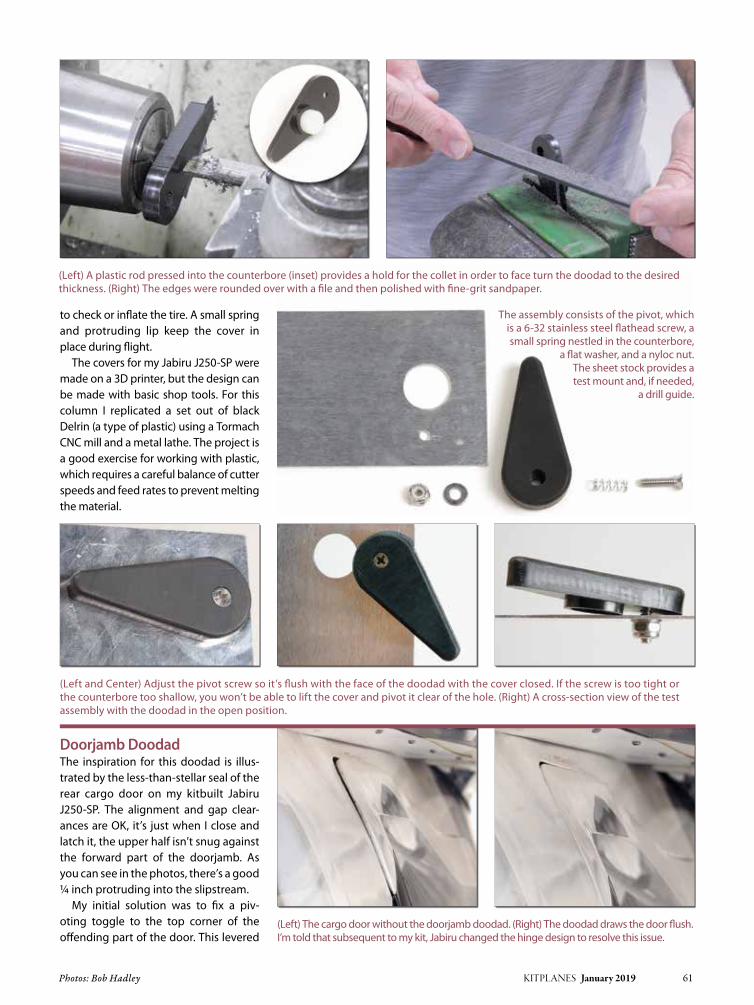
Photos: Bob Hadley KITPLANES January 2019 61
to check or inflate the tire. A small spring and protruding lip keep the cover in place during flight.
The covers for my Jabiru J250-SP were made on a 3D printer, but the design can be made with basic shop tools. For this column I replicated a set out of black Delrin (a type of plastic) using a Tormach CNC mill and a metal lathe. The project is a good exercise for working with plastic, which requires a careful balance of cutter speeds and feed rates to prevent melting the material.
Doorjamb DoodadThe inspiration for this doodad is illus-trated by the less-than-stellar seal of the rear cargo door on my kitbuilt Jabiru J250-SP. The alignment and gap clear-ances are OK, it’s just when I close and latch it, the upper half isn’t snug against the forward part of the doorjamb. As you can see in the photos, there’s a good ¼ inch protruding into the slipstream.
My initial solution was to fix a piv-oting toggle to the top corner of the offending part of the door. This levered
The assembly consists of the pivot, which is a 6-32 stainless steel flathead screw, a small spring nestled in the counterbore,
a flat washer, and a nyloc nut. The sheet stock provides a test mount and, if needed,
a drill guide.
(Left) A plastic rod pressed into the counterbore (inset) provides a hold for the collet in order to face turn the doodad to the desired thickness. (Right) The edges were rounded over with a file and then polished with fine-grit sandpaper.
(Left and Center) Adjust the pivot screw so it’s flush with the face of the doodad with the cover closed. If the screw is too tight or the counterbore too shallow, you won’t be able to lift the cover and pivot it clear of the hole. (Right) A cross-section view of the test assembly with the doodad in the open position.
(Left) The cargo door without the doorjamb doodad. (Right) The doodad draws the door flush. I’m told that subsequent to my kit, Jabiru changed the hinge design to resolve this issue.

62 KITPLANES January 2019 www.kitplanes.com & www.facebook.com/kitplanes
against the jamb to pull the door into place. But it kept coming loose and needed con-stant adjustment to keep the door flush.
One day the pivot screw that I epoxied into the door frame worked loose and the toggle popped off. That forced me to rethink this doodad, hopefully once and for all.
I started off by fixing the pivot. The new version was an 8-32 flathead screw, but instead of the screw itself being epoxied to the door, this time I bonded in a modified 8-32 self-threading brass insert (for wood) using a peanut-buttery mixture of flox and West System fast-curing epoxy. The modifi-cation to the insert was a lathe-turned ¼-inch diameter flange on the end to serve as a bushing for the pivot.
With the epoxy cured and the anchor sol-idly in place, I made a large-diameter alu-minum retaining washer. The idea is a big washer spreads out the load across the face of the arm.
Next it was over to the lathe to make a mini jackscrew to dial in the amount of ten-sion needed to pull the door flush. This was turned from 6061 T6 aluminum. The head was knurled (see “Gnarly Good Knurls,” November 2016) and counterbored (see “Counterbores,” May 2016), and the shank threaded using an 8-32 die.
Taking a clue from carburetor adjusting screws, a small spring was added to keep it from vibrating loose. The end of the screw is capped with a Delrin plastic “foot” to keep the screw from gouging the fiber-glass doorjamb.
After a test fit confirmed the feasibil-ity of my new doodad, I decided to add a small knob to the long end of the pivoting arm. A snap ring holds the knob in place and makes for a very low profile and sim-ple installation (see “Feeling Groovy,” June 2018). The knob makes it easier to reach back and flip the lever down so I can open the door (if I try to open the door with the doodad engaged, it won’t!). The final step was to electro-etch the date of installation (see “Trail of Crumbs,” June 2017).
This was one of those projects that was done without any formal design or technical drawings. It was strictly a design-as-you-go affair. Doodads are fun to make. They usually don’t take very long, and it’s always reward-ing to work up trick solutions to fix or improve your kit aircraft. J
Detail view of the brass anchor pivot (left) and the doorjamb doodad.
This backside view shows the plastic foot on the jackscrew and
the snap-ring retainer on the knob.
A few grams of aluminum and an afternoon in the shop resulted in a simple solution to an annoying problem!
Inside cabin view of the doorjamb doodad with the lever open (left) and engaged for flight (right). The tensioning screw adjusts the door in or out as needed, to bring it flush with the fuselage.

Photos: Vic Syracuse KITPLANES January 2019 63
Vic is a Commercial Pilot, CFII with ASMEL/ASES ratings, an A&P/IA, DAR, and EAA Technical Advisor and Flight Counselor. Passionately involved in aviation for over 40 years, he has built 11 aircraft and logged over 9000 hours in 72 different kinds of aircraft. Vic volunteers as a Young Eagle pilot and Angel Flight pilot. He chairs the EAA Homebuilt Council and is a member of EAA’s Board of Directors. He also has his own sport aviation business called Base Leg Aviation.
Vic Syracuse
Back in July 2014, I wrote a column justifying all of the toys we pilots like to have in the cockpit. Some are pricey, no doubt, some are nice to have, and every once in a while one of them saves the day. Or so we like to think so as to justify another expenditure.
Since technology in the cockpit is probably changing faster than anything else in aviation, it seems there is always another opportunity to upgrade or add a new toy. I am just as guilty as the next pilot, so I thought I would share an update on some things I’ve done since that last column. While it might seem like a product review, in no way do I intend for it to be. I am just sharing some of the choices and changes I’ve made, along with my experiences and opinions. Plus, I do a fair amount of work on airplanes for my customers, so I get to see how some of these things work out for them.
Electronic IgnitionBy now most of you know that I am a believer in electronic ignition. I do a lot of high altitude flying since I live in the southeast. In the summertime I am rou-tinely flying in the mid teens to avoid all of the pop-up thunderstorms. Fly-ing at those altitudes usually ensures a cool, smooth flight, and rarely do I get wet. In fact, 99% of my flights are able to be completed VFR. The RV-10 is a really nice performer at those altitudes, with fuel burns around 10–12 gph and TAS of 162–170 knots, depending upon temps, altitudes, and weights. With my currently installed Light Speed Plasma III ignition system, I can see the ignition timing advance on the cockpit display,
and it is usually around 30–33 degrees at those altitudes. If I turn off the Light Speed so that I am only running on the magneto, there is a substantial drop in power due to the magneto’s 25-degree fixed timing. Yes, I am still a believer in one magneto and one EI, just for safety’s sake. I know there is a growing base out there of pilots with dual electronic igni-tion systems, including one of my cus-tomers, but I am still a holdout. I even ask myself “why not” sometimes, since I have never had an electrical failure in any of the airplanes I have built.
Yes, I have tried some of the other elec-tronic ignition systems. I even installed an Electroair ignition system on my own RV-10, and have installed them on a num-ber of other airplanes as well. I find it to be reliable, and Electroair even sells a certified version of their system. But even the certified version still requires one mag to be left on the airplane. Seems as though I have a supporter in my own way of thinking! I do like the cheap price of the auto plugs used on electronic ignition systems, and I routinely replace them every 100 hours.
More Toys
CHECKPOINTS
I have been a proponent of one electronic ignition and one mag forever, and the switch panel from Electroair makes it easy to use clearly labeled and guarded switches. I also like the circuit breaker for the electronic ignition close to the switch so I don’t need to look for it.
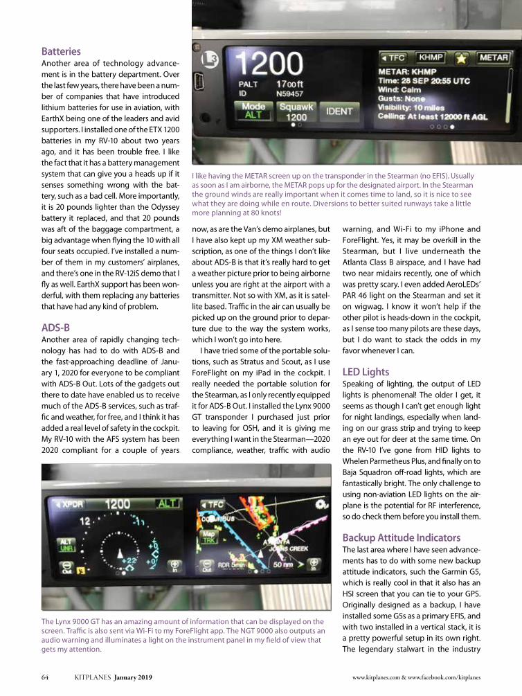
64 KITPLANES January 2019 www.kitplanes.com & www.facebook.com/kitplanes
BatteriesAnother area of technology advance-ment is in the battery department. Over the last few years, there have been a num-ber of companies that have introduced lithium batteries for use in aviation, with EarthX being one of the leaders and avid supporters. I installed one of the ETX 1200 batteries in my RV-10 about two years ago, and it has been trouble free. I like the fact that it has a battery management system that can give you a heads up if it senses something wrong with the bat-tery, such as a bad cell. More importantly, it is 20 pounds lighter than the Odyssey battery it replaced, and that 20 pounds was aft of the baggage compartment, a big advantage when flying the 10 with all four seats occupied. I’ve installed a num-ber of them in my customers’ airplanes, and there’s one in the RV-12iS demo that I fly as well. EarthX support has been won-derful, with them replacing any batteries that have had any kind of problem.
ADS-BAnother area of rapidly changing tech-nology has had to do with ADS-B and the fast-approaching deadline of Janu-ary 1, 2020 for everyone to be compliant with ADS-B Out. Lots of the gadgets out there to date have enabled us to receive much of the ADS-B services, such as traf-fic and weather, for free, and I think it has added a real level of safety in the cockpit. My RV-10 with the AFS system has been 2020 compliant for a couple of years
now, as are the Van’s demo airplanes, but I have also kept up my XM weather sub-scription, as one of the things I don’t like about ADS-B is that it’s really hard to get a weather picture prior to being airborne unless you are right at the airport with a transmitter. Not so with XM, as it is satel-lite based. Traffic in the air can usually be picked up on the ground prior to depar-ture due to the way the system works, which I won’t go into here.
I have tried some of the portable solu-tions, such as Stratus and Scout, as I use ForeFlight on my iPad in the cockpit. I really needed the portable solution for the Stearman, as I only recently equipped it for ADS-B Out. I installed the Lynx 9000 GT transponder I purchased just prior to leaving for OSH, and it is giving me everything I want in the Stearman—2020 compliance, weather, traffic with audio
warning, and Wi-Fi to my iPhone and ForeFlight. Yes, it may be overkill in the Stearman, but I live underneath the Atlanta Class B airspace, and I have had two near midairs recently, one of which was pretty scary. I even added AeroLEDs’ PAR 46 light on the Stearman and set it on wigwag. I know it won’t help if the other pilot is heads-down in the cockpit, as I sense too many pilots are these days, but I do want to stack the odds in my favor whenever I can.
LED LightsSpeaking of lighting, the output of LED lights is phenomenal! The older I get, it seems as though I can’t get enough light for night landings, especially when land-ing on our grass strip and trying to keep an eye out for deer at the same time. On the RV-10 I’ve gone from HID lights to Whelen Parmetheus Plus, and finally on to Baja Squadron off-road lights, which are fantastically bright. The only challenge to using non-aviation LED lights on the air-plane is the potential for RF interference, so do check them before you install them.
Backup Attitude IndicatorsThe last area where I have seen advance-ments has to do with some new backup attitude indicators, such the Garmin G5, which is really cool in that it also has an HSI screen that you can tie to your GPS. Originally designed as a backup, I have installed some G5s as a primary EFIS, and with two installed in a vertical stack, it is a pretty powerful setup in its own right. The legendary stalwart in the industry
I like having the METAR screen up on the transponder in the Stearman (no EFIS). Usually as soon as I am airborne, the METAR pops up for the designated airport. In the Stearman the ground winds are really important when it comes time to land, so it is nice to see what they are doing while en route. Diversions to better suited runways take a little more planning at 80 knots!
The Lynx 9000 GT has an amazing amount of information that can be displayed on the screen. Traffic is also sent via Wi-Fi to my ForeFlight app. The NGT 9000 also outputs an audio warning and illuminates a light on the instrument panel in my field of view that gets my attention.

KITPLANES January 2019 65
wider viewing angle, and the new dis-plays have been incorporated into the 540s as well.
I wrote this sitting in our camper at AirVenture 2018 on Sunday morning. It had been a wet couple of days, and when the ceilings and rain finally lifted, I enjoyed watching all of the pent-up arrivals. At the same time, Carol was working on my schedule so I wouldn’t have time to find any more new toys at AirVenture. No problem—I snuck a meeting onto my calendar called “fun” and told her it was mandatory! J
has been the Dynon EFIS-D10A for many years, and I had one installed in a few of my airplanes. When I needed more panel space, I opted for the self-contained Dynon D2 affixed to the instrument panel dash. Prior to these kinds of prod-ucts, some of us were known to use gyro apps on our iPhones as a backup when poking into the clouds. Once while in IMC, I did have a certain manufacturer’s screens do a complete reboot due to a bug, and I was able to keep everything upright using the D10A while the screens rebooted. I was very glad I had added a backup or I probably would not be here writing this column.
Another neat backup that caught my eye was the new Avidyne 550, as it has a built-in ADAHRS. When I first saw it, I really liked it but couldn’t justify chang-ing out my Avidyne 540. However, when Avidyne announced an upgrade path for current owners, I jumped at it. My logic to the CFO (Carol!) was that we could remove the D2 from the dash and increase the view out of the newly installed window in the RV-10. It sounded really good to me anyway. The eye-roll-ing indicated otherwise, but suffice it to say it is now installed. A surprise for me was that when I first powered it up, I noticed how much brighter it was than the IFD 540. At first I thought it was just me wishing it to be brighter, but a quick call to Avidyne assured me I wasn’t see-ing things. It’s a brighter display with a
The D2 has been a stalwart backup indicator for many years in my airplane, but with the new IFD 550 with an internal attitude indicator, I have finally removed it. The added benefit is better visibility out of the cockpit, too!
The IFD 550 attitude display is really impressive, showing a track, your target, and compass card. The screen is super bright as well!

www.kitplanes.com & www.facebook.com/kitplanes66 KITPLANES January 2019
COMPLETIONSCOMPLETIONS
Submissions to “Completions” should include a description (250 words maximum) of the project and the finished aircraft. Also include a digital image of the aircraft. Minimum digital image size is 1500 pixels wide x 900 pixels high (5 x 3-inch print size at 300 dpi). Other builders may want to contact you by email, but let us know if you prefer not to have your email address published. Email text and photos to [email protected] with a subject line of “Completions.” Additional information can be found at www.kitplanes.com/completions.
Richard Guy’s RANS S-6S CoyoteMy RANS S-6S, N428WG, was delivered in August 2010 and issued its airworthiness certificate in August 2011. It was as much fun to build as it is to fly. Setting aside 3 or 4 hours every weekday by cutting back on TV reruns, the build was quick. Instructions were easy to fol-low, and my two technical questions were quickly answered by Ed at RANS. I hang skis in place of the wheels in the winter, so this is truly a four-season airplane that goes where I want to go. I’m happy to discuss my Coyote with anyone; contact me via the email below.
Woodsville, NeW HampsHire [email protected]
Bill Prokes’ Stolp StarletStarlet N23ME was completed in November 2016. The project spanned approximately four years. The engine is a Franklin 4AC-199 E-3 (90 hp) with a Prince prop. The Starlet is a ball to fly. Everyone should have one!
gilbert, arizoNa
Barry Haley’s PelicanMy Ultravia Pelican PL was started back in the 1990s by Dick Randolph, a WW-II P-47 fighter pilot who served with the 313th Fighter Squadron, 50th Fighter Group. As a first lieuten-ant he was involved with battles at Ardennes and Rhineland in Central Europe. Dick might very well have flown missions over battlegrounds where my dad was fighting as a sniper with the Canadian Lincoln and Welland regiment. Dick was active in EAA Chapter 444 when he started the Peli-can, but he didn’t get to finish the aircraft due to failing health. Bob Stafford bought it in 2013 but then determined he didn’t have enough time to work on it. I was very lucky to acquire it from Bob in 2014 and to have the opportunity to complete it over the last four years. It was a privilege to continue the work of a member of the Greatest Generation. Dick passed away in 2015. I hope he would have been pleased with how his plane turned out. N712PL has a Rotax 912 ULS, Warp Drive prop and AvMap panel. First flight was in April 2018 and it flew great, but maybe that has more to do with Dick’s work than mine.
HaiNes City, [email protected] J
builders sHare tHeir suCCesses

KITPLANES January 2019 67
Aircraft Spruce & Specialty CV4 877-4SPRUCE
Avemco Insurance Company CV3 888-241-7890
Avemco Insurance Company 39 800-752-4208
Bede Corp. 57 See Advertisement
Better Aircraft Fabric 59 907-229-6792
California Power Systems 57 800-AIRWOLF
Cub Crafters 3 509-248-9491
Dynon Avionics CV2 425-402-0433
Garmin International 5 See Advertisement
Grand Rapids Technologies 11 See Advertisement
Grand Rapids Technologies 47 616-245-7700
KITPLAnES® Bookstore 65 970-726-5111
Progressive Aerodyne 47 352-253-0108
Sensenich Propeller 39 See Advertisement
Sonex Aircraft, LLC 59 920-231-8297
Sport Aviation Expo 47 See Advertisement
Van’s Aircraft 17 See Advertisement
Warp Drive 9 See Advertisement
Wicks Aircraft Supply 13 618-654-7447
Builders’ Marketplace
Aeromarine–LSA 69 262-408-0124
AeroMomentum Aircraft Engines 70 772-240-2266
Aerotrek Aircraft 69 812-384-4972
Airflow Performance 71 864-576-4512
Bearhawk Aircraft 71 877-528-4776
Beringer 69 864-214-4274
Better Half VW 69 281-383-0113
Carlson Aircraft 69 330-426-3934
Crow Enterprises 70 714-879-5970
Custom Welding Products 69 702-306-3590
Flight Data Systems 71 831-325-3131
Flight Grip 68 800-204-7625
Glen-L 69 888-700-5007
Grove Aircraft 70 619-562-1268
Homebuilt Help 68 See Advertisement
InFInITY Aerospace 71 See Advertisement
Kuntzleman Electronics Inc. 70 610-326-9068
MATCO Manufacturing 69 801-335-0582
MT Propeller 70 See Advertisement
northwest Aviation Services 68 208-435-4002
Osprey Aircraft 68 See Advertisement
Performance Propellers 71 713-417-2519
Recreational Power Engineering 69 800-583-3306
Simplex Aero 69 801-830-0612
Softie Parachutes 70 360-435-7220
Tormach LLC 71 See Advertisement
Viking Aircraft Engines 68 386-566-2616
WhirlWind Propellers 68 619-562-3725
advertiser page # telephone advertiser page # telephone
Please tell them you saw their ad in KITPLANES® Magazine.
KITPLANES® interactive makes it quick and easy for you to receive instant information about products or services directly from our advertisers’ websites.
➥ Go to: www.kitplanes.com/links for a virtual shopping tour via links to their websites.
➥ Call the phone numbers listed below and be sure to tell them you saw their ad in KITPLANES® Magazine.
❏December 2018 2019 Homebuilt Aircraft Directory, Click Bond, Buying a Used Homebuilt, Breaking in an Engine
❏november 2018 Bel-Aire 4000, Titans of Tungsten, Wooden Tailwheel Lift, ADS-B Update, UMA Instruments
❏October 2018 Davis DA-2, Time-to-Climb Record, Optimizing Induction Air, GRT’s Inexpensive HUD Option
❏September 2018 Backcountry Cub, Front Seat in a Pietenpol, Rutan Aircraft Flying Experience, Cautionary Tail
❏August 2018 Bede BD-4, Going Retractable, GlaStar Project, Homebuilt Accidents, Paul Poberezny’s House
❏July 2018 CubCrafters EX-3/FX-3, Meeting the ADS-B Requirements, Emergency Locator Transmitters
❏June 2018 Belite Chipper, BRS Installation in an RV-9, Homebuilt Accidents, Jet Eze, Part 2
❏May 2018 Jet Eze, Starduster Cross-Country, Continental Diesel RV-10, The Real McKee
❏April 2018 Tarragon, Supercharged RV-8, Designing the Perfect Seat, Sky Polaris, Part 2
❏March 2018 Durand Mark V, nEXRAD, Fairings and Speed, Tricked-Out Tailwheel, EFII’s System 32
BACK ISSUESONEW eBOOK O
eBook download is exactly the same magazine as on the newsstand.
The difference is:
you get it now! &
no shipping costs for e-books!
(a big savings for our international customers)
eBooks download as a single, full size, full color .pdf document which you can view on your desktop, laptop or tablet computer.
PDF eMagazine issues are fully searchable and are compatible with all Adobe Acrobat functions such as highlighting, page notes
and spoken word audio.
O Individual monthly issues are $6.95
O A compiled Aircraft Buyer’s Guide is $12.95
Visit:
www.kitplanesbooks.com
to order
LIST OF ADVERTISERS

68 KITPLANES January 2019 www.kitplanes.com & www.facebook.com/kitplanes
BUILDERS’ MARKETPLACE
619-562-3725
• ROTAX
• JABIRU
• CONTINENTAL
• LYCOMING
GROUND ADJUSTABLECOMPOSITE PROPELLERS
www.whirlwindpropellers.com
406 & 121.5 ELT Tester
$648.00Plus Shipping & Handling
(208) 435-4002
• Affordable and effective• Simple to use• Provides Pass/Fail indication• Displays hex identifi cation• Identifi es beacon type
• Does a comprehensive test• Tests all COSPAS SARSAT Beacons• Uses readily-available AA batteries
$648.00Plus Shipping &
(208) 435-4002
P.O. Box 2466Orofi no, Idaho 83544
www.beacon-tester.com
CUSTOMIZE OUR GRIP FOR YOUR AIRCRAFT
Easy Installation
Comfortable
Rocker (shown) or push button trigger style
Thumb Switches:Push Button, Toggleand/or 4-Way Trim
Fit to 5/8" thru 1-1/8" sticks
Next day shipping for virtually any confi guration you desire.
push button trigger style
sticks
Next day shipping for virtually any confi guration you desire.
812 Jacquelyn St. • Milton-Freewater, Oregon 97862800-204-7625 • 541-938-0533 • Fax: 541-938-7242
“OSPREY 2” AMPHIBIAN
2-Place, all wood, 12 sec. water take-off, full builder support, Oshkosh award winner. Info Pak $14 ($17 overseas), Plans $250 ($290 overseas).
OSPREY AIRCRAFT3741 El Ricon Way, Sacramento, CA 95864
Email: [email protected]
Builders’ Marketplace reaches tens of thousands of
homebuilders and pilots who are eager to buy
new products and services.
Call 805-382-3363 or email: [email protected]
Working With a tight Budget?

KITPLANES January 2019 69
Highlights: • Revamped and expanded Aircraft Buyer’s Guide for quicker, better search results • All New Classifi ed Ads section for deals on aircraft and accessories • Unlimited access to back issues as an easy- to-use, tablet-friendly downloadable PDFIt’s easy to register. Just visit WWW.KITPLANES.COM and click on GET WEB ACCESS.
Have You Seen Us Lately?
The KITPLANES® website is now better than ever!KITPLANES.COM is YOUR guide to the most comprehensive homebuilt information available, and access to our archives and aircraft database are FREE to registered subscribers!
®
“Like” us on Facebook, follow us on Twitter and get an RSS feed from our Newsline
HIRTH AIRCRAFT ENGINES 15 thru 110 hp. 1000 hour rated TBO. One year warranty. Sales, service, and parts. Highest power to weight ratio in the industry. BlueMax 2-cycle aviation oil. Contact:
RECREATIONAL POWER ENGINEERING5479 East County Rd. 38, Tiffin, Ohio 44883 Tel: 800-583-3306 • Fax: 419-585-6004. Visit us on the web at www.recpower.com
Poor Cabin Heat???Efficient Affordable Solution (702) 306-3590
Find TURBO HEAT Distributors at
www.customweldingproducts.com
Build Your Dream BoatProven plans & full size patterns to build your own boat. Send $9.95 for Catalog of 300 designs for sail, power & row 6' to 55', free dinghy plans & 9.95 coupon off your first order.
Glen-L Marine Designs232 Avenida Fabricante #105/KB, San Clemente, CA 92673
888-700-5007 • Glen-L.com/KB
SPARS, STREAMLINE STRUTS, RIBS 6061T6 - EXTRUDED - CERTIFIED ANALYSIS
SPARS - 6 sections - 3” to 6 5/8” STRUTS - Large, Small, Heavy Duty, Jury
RIBS - Stc’d, Experimental, Custom Write/Call for free info:
CARLSON AIRCRAFT INC.330-426-3934 • [email protected]
www.carlsonaircraft.com
INTRODUCING THE “DOUBLE EAGLE”
2 Place Sports Plane powered by reliable 4 cyl. VW.Empty wt. 385#. Plans, videos, propeller hubs:
L.E. MILHOLLANDPO Box 747, Brookshire, TX 77423
Email: [email protected] • www.betterhalfvw.comKits & materials pkgs., welded fuselages: John Bolding,
281-383-0113. Estimated cost $5,000-$7,500.
Follow us on Facebook at www.facebook.com/kitplanes
Share Your Enthusiasm for

70 KITPLANES January 2019 www.kitplanes.com & www.facebook.com/kitplanes
BUILDERS’ MARKETPLACE
www.groveaircraft.com1800 Joe Crosson Dr.
El Cajon, CA 92020619.562.1268Aircraft Landing Gear Systems Inc.
Grove
LANDING GEAR
Factory Direct
Your Complete Source for Wheels, Brakes
& Landing Gear
The must-read for the
GA Community!
Log-in for
FREE News Alertswww.avweb.com/kit

KITPLANES January 2019 71
Buy a Plane or Sell a
Plane with a Free ad online.
Any individual may post a flying homebuilt
or partial project complete with photos at no cost for quick
global response. www.kitplanes.com/classifieds
111 Airflow DriveSpartanburg, SC 29306(864) 576-4512(864) 576-0201 (Fax)www.airflowperformance.comEmail: [email protected]
Aircraft Multi-point Fuel Injection• Operates all engines from 65 to 800 HP• Applications for V6/V8 engines• Manual Mixture Control• Bolt on Kits for Lycoming Engines• No Carburetor heat required• Instant throttle response• All Mechanical, No Electronics• Increases mid-range HP• Approved for Aerobatic use• Compatible with all Fuels• Precise Fuel Metering under all conditions
1204-8 Airflow 1/10/05 2:35 PM Page 1
Get the latest. Follow us on Twitter at #Kitplanes.
Can’t Get Enough
?

72 KITPLANES January 2019 www.kitplanes.com & www.facebook.com/kitplanes
Please send your questions for DAR Asberry to [email protected] with “Ask the DAR” in the subject line.
Hiring a professionl build center to build an Experimental Light Sport Aircraft.
By Mel AsBerry
Question: I know that an ELSA must be built originally as if it were an SLSA. If a build center builds the entire aircraft for a customer and it’s going to be registered as an ELSA, is there any wiggle room for it to be different than the original SLSA? For example, would it be possible to change the instrument panel or move the location of the throttle?
Answer: An ELSA must be built exactly per the plans with absolutely no changes of any kind for certification as an ELSA.
Question: If I hire a professional build center to build an ELSA, does the build center have to complete the entire airplane or can I build part of it? Is there a certain percentage the build center must complete? For example, can the build center do, say, 75 percent of the work and I build the remaining 25 percent?
Answer: There are no restrictions on the percentage of the build for an ELSA. The build center may build the entire air-craft or any part of it.
Question: With all of the differ-ent aircraft out there, how does a DAR determine if an airplane is built
exactly to ELSA standards and mir-rors the SLSA it’s supposed to repli-cate? Is it up to the individual DAR to let certain things pass the inspection and to focus more on the “spirit” of it meeting ELSA rules and regulations?
Answer: An individual DAR may not allow any changes from the plans.
Question: I’d like to contract with a build center to build most or all of an ELSA. However, I already know I’d like to change a few things. Dur-ing the build, can they do things to make it easier for me to make modi-fications after certification?
For example, if I’m planning on converting from a carburetor to fuel injection, can they have the fuel line plumbing already in place to accommodate a return line? I’d like to avoid having to rip out and redo a lot of things I already know I’d like to change.
Answer: If you register your aircraft as ELSA, any changes from the plans must be done after certification.
Question: Can I build and certify an ELSA in my own hangar, or does an ELSA have to be built in an official builder center?
Answer: You can build an ELSA in your own hangar. It must be built from a certified ELSA kit with everything supplied by the kit manufacturer and be built exactly per the plans.
Question: From my understand-ing of the rules, once an ELSA has its airworthiness certificate, the owner can take a 16-hour maintenance course and is then allowed to make changes to the original design/equipment and also do his/her own maintenance and condition inspec-tion. Are there any restrictions on what modifications can be done?
Answer: When you take the mainte-nance course, you still must apply for and receive the repairman certificate from the FAA. You do not need the certificate to maintain or modify your airplane. Anyone can do that. The repairman cer-tificate only allows you to perform the condition inspection. After certification, you may make any changes that do not take the aircraft out of LSA parameters as stated in Part 1 of the FARs. J

Photos: Jim and Cyndi Weir KITPLANES January 2019 73
Jim is the chief avioniker at RST Engineering. He answers avionics questions in the Maintenance Bay section of www.pilotsofamerica.com. His technical advisor, Cyndi Weir, got her master’s degree in English and journalism and keeps Jim on the straight and narrow. Check out their website at www.rstengineering.com/kitplanes for previous articles and supplements.
Jim Weir
Do the names Melody, James, Emily, Brian, Don, Jeremy, Braden, and Jarius mean anything to you? They mean a lot to me, as these are some of the firefight-ers and victims of the 6000 wildfires that occurred in California in 2018, the worst year on record.
The year really started out great. I was hoping last winter that my rain gauge here a few hundred meters south of Grass Valley Intentional Airpatch that reads to 99.9 inches of rain would over-flow. I was curious what would hap-pen. As it turned out, the rainy season stopped about three tenths of an inch short of that goal, but when the rainy season stopped, the brutally hot sum-mer started about three weeks later—just in time for that 8+ feet of water to germinate all the tall grass and weed seeds that accumulated in the last three years of drought. Then the winds dried out the grass, and then came the fires.
Most of us who live in the Sierra foot-hills keep a “go-bag” somewhere in the house. When the bell dings and the evacuate now orders come, we grab that go-bag with our insurance papers, wed-ding license, wills, irreplaceable pictures of grandma, and other mementos of our
lives and get the hell out of the house…along with the cats, dogs, birds, rab-bits…hurriedly scooped into the wait-ing cages. Houses can be replaced; the important stuff cannot.
Cyndi and I have a deal. She gets the house go-bag and the pets. I get the radio go-bag and the radios. I’ve spent time being the radio officer for the Coast Guard Auxiliary, the Humane Society, the County Deputy Sheriff Search and Rescue, the local radio station, and the County Emergency Services. One thing is sure: One or more of them will have some impairment of their normal communica-tions channel(s) and it is always, “Jim, how long would it take you to set up a mobile radio station?” My answer with the radio go-bag is always the same: “About half an hour, or maybe a little less.”
In the BagSo what is in that magic radio go-bag that I grab on my way out the front door with the flames coming up the hill
Touch (the Go-Bag) and Go
AERO ’LECTRICS
The go-bag in the corner by the door, always loaded and ready to go.
The S2s getting ready for a fire. The red stuff you see them dropping is actually a retardant made of ammonium phosphate that smothers the fire, and then when it dries, it is a fertilizer to help the burned areas revegetate.

74 KITPLANES January 2019 www.kitplanes.com & www.facebook.com/kitplanes
at me? Very simply, a charged aircraft band handheld transceiver, a charged amateur radio 2-meter handheld trans-ceiver, a portable antenna, and a charged gel-cell battery and charger.
Actually, I keep two antennas in the go-bag—an aircraft band antenna and a 2-meter amateur band antenna. Why separate antennas? Because the normal “rubber duckie” has a range approxi-mately one-tenth that of a plain-old ground plane antenna. If the range with a regular antenna is 20 miles, you will be lucky to get two miles with the duck.
I also keep a 12-volt gel-cell and char-ger. I try to keep the gel-cell charged at all times, but the flesh is sometimes weak, and the battery gets charged when I get to the evacuation center.
With a minimal amount of equipment, I can quickly set up a radio station either in the aviation band or in the amateur
radio 2-meter band. And how will the station be used?
As I said, I live a football field south of Grass Valley Airport (KGOO). When any disaster hits up here, I can help any of the out-of-town news media that come up in their company airplane and use a legiti-mate disaster air-to-ground frequency to guide them to where the hot spots are.
“Where is Lake Wildwood?” “260 at 14 nautical from KGOO or 230
at 12 from RANGO.” “How do I get to Alta Sierra from
Nevada City?” “See that big lake just south of you?
Go to it and turn right to 240 for about five miles.”
This isn’t on the Unicom frequency and not on the fire tanker frequency. Those are legitimately used for truly emergency aircraft, but on the legiti-mate disaster channels (see Code of
Federal Regulations [“CFR”] Part 87, Sec-tions 87.371 and 87.393 for guidance on frequencies available in an emergency condition. I prefer 123.1, but your situa-tion may allow other frequencies.)
How about amateur (ham) radio? How does that help? Most communi-ties have what is called ARES (Amateur Radio Emergency Services). In most of the ARES groups, you have really sharp folks who can make their little handheld radios sit up and be useful…and in most places there are dozens of them that are there to help.
ARES are not going to go in and get into the firefight with the first respond-ers. ARES are the rear echelon that takes care of such things as staffing emer-gency shelters and coordinating evacu-ation folks into the right location. Here’s an example:
“CQ, I’ve got an evacuated mother here in Nevada Union High School gym-nasium whose kids were evacuated from their school. Mother’s name here is Mary Jones. Anybody got any kids there whose mother is Mary Jones, over?”
“Nevada Union, we’ve got Brett and Kelly Jones over at the fairgrounds, and they want to know if their mother is OK.”
And so on.
Making Antennas Romex wire and scrap aluminum are your friend. Make it cheap because at one time or another it will be time to abandon the cheap antenna, throw the expensive radios into the car and ske-daddle out of the way with no time to tear the setup down. Or, after a couple
Close-up of the construction detail of the vertical radiating element, the four horizontal ground plane elements, and the black aluminum mounting base.
(Left) A typical airport setup for emergency communications at KGOO. The antenna is fastened to a PVC pipe and held in place by the left rear window. In the background you can see the S2 fire bomber aircraft. (Right) Close-up of the antenna. This one is around ten years old and about ready for a rebuild.

KITPLANES January 2019 75
of dozen deployments and wrapping up when done, metal fatigue will get that copper wire, and you will be making another one.
The radiating (vertical) element is sol-dered onto a plain-old panel-mount BNC connector, and a hole is drilled into the center of the small plate to mount the connector. Ground radial wires are sol-dered to ground lugs and mounted on the four corners of the plate. Total assem-bly time is less than 5 minutes. For the aircraft band, the radiating element is 22 inches long, and the ground wires are 23 inches long including the distance from the ground lug hole to the center of the radiating rod hole. For the 2-meter oper-ation, these lengths are 19 inches and 20 inches respectively.
The small aluminum antenna mount-ing plate has a tab cut and bent down on one end so that the plate can be affixed to a mounting pole with a regular old radiator worm clamp.
How big a 12-volt gel-cell to bring to keep the handhelds going past their inter-nal battery life? The one in the go-bag is 8 amp-hours. On the average, the aircraft band handheld (Vertex VXA-700) uses 100 mA, and the amateur radio handheld uses 50 mA. This gives me roughly 80 hours of continuous operation on the aircraft band and double that (160 hours) on the ham band. Three days and change for aircraft and six days on the ham bands, 24 hours a day. The charger is the one that was fea-tured in “Harbor Freight leads the charge!” in the May 2018 issue. Wonderful little device and nearly bulletproof.
As I write this in early September 2018, most of the California fires are contained, but my colleagues in the Carolinas are grabbing their radio go-bags and get-ting ready for hurricane Florence to hit. My best wishes for all of you working these disasters.
See you next month. Until then…Stay tuned… J
The gel-cell battery for extended operations. Note the fuse. Elsewhere in the go-bag is a five-pack of replacement fuses.
Old 88 departing for a fire about 10 miles south of KGOO.
A buddy was working on his new instrument panel, with some of the electronics boxes already mounted and wired, when I noticed a tiny chip from drilling had gotten into one of the boxes. I had him vacuum it out. Can you imagine how hard that would have been to trouble-shoot if it had been missed?
For that matter, vacuum all of the connectors before installing them. It’s a lot easier than trying to figure out a glitch on some box that checks out fine on the bench. J
Vacuuming Connectors
By DaviD Paule
SHOPTIPS

76 KITPLANES January 2019 www.kitplanes.com & www.facebook.com/kitplanes
Barnaby Wainfan
WIND TUNNEL
is a Technical Fellow for Northrop Grumman’s Advanced Design organization. A private pilot with single engine and glider ratings, Barnaby has been involved in the design of unconventional airplanes including canards, joined wings, flying wings, and some too strange to fall into any known category.
In our continuing journey through the process of designing an airplane, we have reached the point where we have a preliminary configuration layout, have made initial estimates of the weight of the airplane, and have initially sized the wing. It is now time to turn our attention to where the mass of the airplane is situ-ated and how the airplane is balanced.
StabilityIn order to be safely flyable, the airplane must be both stable and controllable. With highly sophisticated control sys-tems such as those on military fighters, it is possible to relax the stability require-ment and fly an unstable, but control-lable, airplane. For general aviation machines with mechanical controls, the stability requirement remains critical.
CG ConsiderationsWhen pilots do weight and balance cal-culations to evaluate the loading of an airplane before flight, they are looking to ensure two things: first, that the air-plane’s gross weight does not exceed the maximum allowable takeoff weight, and second, that the CG is within limits.
Getting the airplane to balance requires the aerodynamic characteristics and the mass properties of the airplane to be properly matched. Both factors are critical to the proper balance of the machine.
Allowable CG Range (CG Limits)The first consideration is the allowable CG range, which is determined by the aerodynamic configuration of the air-plane. The allowable CG range is the
range of positions over which the CG can vary while still maintaining safe flying qualities. The airplane is only flyable if the CG is somewhere between the aero-dynamically determined forward and aft CG limits. Typically, the forward CG limit is set by trim and controllability consid-erations, and the aft CG limit is set by stability requirements. (These will be dis-cussed in more detail in a future article).
Mass Properties (Physical CG Position)The second balance factor we need to consider is the mass properties of the airplane. While the allowable CG range determined the CG positions at which it is safe to fly the airplane, the mass properties determine the actual physical range of CG positions that can occur.
The CG of the airplane is a function of the weight and CG of the empty airplane and the weight and position of the items loaded into the airplane. The crew, pas-sengers, payload/baggage, and fuel all
have mass, and all affect the position of the CG. We need to ensure that all potential loading conditions in which the airplane will be flown have CG posi-tions that fall within the aerodynamically defined limits.
When developing a new design, it’s important to start tracking its mass prop-erties early in the design cycle. Balance is critical to a successful airplane. It’s vital to have a good idea of where the CG will be before defining the aerodynamic config-uration of the airplane in too much detail.
Many mass properties factors are dif-ficult to change and only get more so as the design progresses. This is because some of the major masses that go into the airplane do not scale and have rela-tively strict limitations of where they must be placed. For example, the engine of a conventional tractor single-engine airplane must be hung off of the front of the fuselage. There is a minimum allowable distance between the back of the engine and the firewall. Aft of
Design Process:
BalanceWIND TUNNEL
During flight testing of this prototype LSA, they actually marked the CG positions on the outboard wing tip rib.

Photo: Barnaby Wainfan KITPLANES January 2019 77
the firewall, there is a minimum allow-able distance from the firewall to the pilot’s seat. This sets the relative posi-tion of two of the heaviest things in the airplane. While it’s possible to move the engine forward with a longer mount, it can’t go any farther aft. Likewise, we can move the pilot aft relative to the firewall, but not forward. The CG of the fuselage structure itself will always tend to be at the same percentage of fuselage length back from the nose, and the tail, while it may vary in size and weight, will always be on the aft end of the fuselage. The designer has relatively little freedom in moving these major things around, so the first step in getting the balance of the airplane right is to calculate the CG based on the positions of the major masses as defined in our preliminary configuration inboard profile drawing.
We can then proceed to move items around to adjust mass properties and define the tail size and wing position to get a balanced design.
The overall goal is to end up with a configuration where the CG travels as little as possible between the possible loading conditions, and where all phys-ically-achievable CG positions fall within the aerodynamically acceptable limits for safe flying qualities.
Empty CGThe most significant “empty” CG is at what is called “zero fuel weight.” In this condition, the airplane has no fuel, pay-load, or crew aboard, but it does have critical fluids like engine oil and any other potentially removable items that are car-ried routinely on every flight. This zero-fuel loading condition is the starting point for all other CG calculations.
The position of the empty CG has some very significant effects. First, the relative position of the empty CG and the positions of the disposable load masses (people, fuel, payload, etc.) have a large effect on CG travel. If the empty CG is at or near the position of the large variable masses, there will be very little CG varia-tion between loading conditions. If the empty CG and the variable masses are far apart, the CG will move a lot as the load-ing condition of the airplane changes.
It is highly desirable to have the empty CG be within the allowable flight CG limits.
LoadingAs masses are loaded into the airplane, both the gross weight and the CG change. Early in the design process, the designer should calculate the CG posi-tion for a wide variety of loadings to determine the most forward and most aft CG positions to which the airplane can be loaded.
CG positions should be determined for pilot weight varying from the lightest to the heaviest pilots who will be flying the airplane. If the airplane has more than one seat, the loading conditions for mul-tiple combinations of occupant weight and seat position must be considered. In addition to informing the designer of the possible CG travel, this information might also be used to define operating limits for the airplane. For example, in a multi-row airplane it’s not uncommon to limit the weight allowable in the back seat as a function of the front-seat occu-pant weight, or to require that the front seats be occupied before seating people in the aft row (or rows). It’s not reason-able, for example, to require a 3-row, nominally 6-seat airplane to be flyable with a just single 110-pound pilot and two 200+ -pound people sitting in the rear two seats.
In addition to considering various occupant configurations, we also need to evaluate these loadings at both full fuel and with empty tanks, since both of these conditions can happen in flight.
If the airplane has baggage capacity, then the effect of baggage weight must also be considered.
CG Travel in FlightIt is not only the initial (takeoff) posi-tion of the CG that is important. The CG can move in flight. The most com-mon cause of this is changes of weight due to fuel burn or release of payloads. CG shift due to dropping of payload is very common on military airplanes, but some civilian aircraft (e.g., crop dusters, fire-fighting water bombers, sailplanes with water ballast, and skydiving jump planes) also drop significant masses in
flight. For some airplanes, we also need to consider what might happen if masses move around in flight, as would be the case if a passenger decided to change seats in flight. One extreme case of this is with skydiving drop airplanes with aft fuselage doors. Prior to drop, the skydiv-ers will often get up and try to all get close to the door so they can all exit the airplane close to each other. This moves the CG far aft. There have been accidents where this pre-jump movement of the jumpers moved the CG so far aft that the pilot could not maintain control of the airplane. The too-aft CG led to a pitch-up, stall, and spin.
Fuel Burn-OffFor general aviation airplanes and homebuilts, the most common source of in-flight CG movement is fuel burn. It’s vital that the airplane remain within its allowable CG limits all the way from take-off to empty tanks.
This has proven to be a problem in the past. There has been at least one case of a high-performance kit airplane that was configured with its primary fuel tanks in the wings and a header tank in the nose just behind the firewall. The fuel was pumped from the wing tanks to the header tank and then gravity-fed to the engine from there. The header tank was small enough that in normal operations it was never emptied. The fuel capacity of the header was about right to hold what would normally be considered reserve fuel, so for most flights the header tank remained full. Unfortunately, it was even-tually discovered that when loaded with two large occupants, the airplane’s CG would actually move aft of the aft limit if the header-tank fuel was used. This meant that the fuel in the header was not real-istically useable, since if it was burned in flight the airplane’s pitch stability would degrade to the point where it was unac-ceptably difficult to fly. In essence, the fuel in the header tanks was not really useable fuel—it was really flammable ballast.
Next month we will continue our discussion of balance with a look at how configuration and the position of various airplane components affect CG position and travel. J

78 KITPLANES January 2019 www.kitplanes.com & www.facebook.com/kitplanes
Pumping avgas and waxing flight school airplanes got Tom into general aviation in 1973, but the lure of racing cars and motorcycles sent him down a motor journalism career heavy on engines and racing. Today he still writes for peanuts and flies for fun.Tom Wilson
Tech forums have to be one of the best things in experimental aviation today. This is where a person hopefully more learned than yourself stands on their hind legs in front of a crowd to speak about almost any aviation sub-ject. Occasionally found in the better EAA chapter meetings or regional fly-ins, tech forums rise to importance at the big AirVenture to-do. Maybe it’s because the EAA dedicates a whole village of palapas in a park-like setting for these talks, or possibly it’s because some of the best minds in the business are on stage, but all that education in one spot is tough to pass by.
If nothing else, there are so many tech forums at OSH they fall into the “Valid Reason for Going” column when making your summer plans.
True, the topics covered in these meet-ings range from seriously new and inter-esting to “What I Did on My Summer Vacation” snooze-a-thons, but for what-ever chaff may be in the air, there are so many forums offered there’s always something of interest on offer.
This last year I determined to attend as many forums as allowed between riding the trams and drying out my tent. Thus, I found myself listening to the gospel according to Mike Busch. Now Mr. Busch is a well-known engine technologist thanks to being every-where from AVweb to AOPA, plus he has extensive real-world hands-on experience with mainly certified Lycs and Continentals. The congregations at his talks are justifiably large.
Unlike myself, Mr. Busch was able to succinctly sum up much of what a pilot needs to know about traditional general
aviation engine operation, which mainly boils down to interpreting and controlling EGT and especially CHT measurements.
Busch also provided succinct sum-mations of what such typical engine parameters really are, i.e., EGT is power wasted out the exhaust pipe, and CHT is power wasted to the cooling system on the power stroke. Busch ground down on EGT absolute values like an old ciga-rette butt. As absolute values they’re nearly useless unless troubleshooting a specific issue, in which case they’re wonderful for pinpointing stuck valves, fouled spark plugs, and so on. But for setting the fuel mixture, only relative EGT measurements are needed.
What Busch is interested in is CHTs. He finds the 500/460° F upper limits from the manufacturers far too high, say-ing he much prefers holding Lycoming CHTs to 400° F and the inherently cooler running Continentals to 380° F in legacy aircraft and 380/360° F in more modern
applications (Cirrus) with their better engineered cooling systems.
Interestingly for we experimental types, higher compression ratios trans-late into slightly lower CHT readings, all other things being equal. That’s because increasing the compression ratio fun-damentally increases an internal com-bustion engine’s efficiency. Greater efficiency means more heat goes into moving the pistons and less wasted heat-ing the cylinder heads, oil, or cooling air.
These numbers fit with my experi-ence managing a 10:1 Lycoming 540. The engine is just a couple hundred hours out of a major overhaul and runs well. Fitted to my Starduster Too, it grins like a baleen whale from behind a Piper Comanche nose bowl and wears tight, well-sealed baffling. The cowling exit is, um, the average right-angle hole, and the 13-row oil cooler boasts its own ded-icated inlet and exit air ducting, which has proven a good cooling arrangement.
Summer School
REAR COCKPIT
There’s a whole village of these forum sheds at AirVenture. This one is dedicated to welding, but most are simply fitted with a podium, screen, projector, and chairs so they can be used for any subject.

Photo: Tom Wilson KITPLANES January 2019 79
Typical rich of peak cruise numbers for the combination are CHTs around 375° F and oil temps of 210° F given one shirt and leather jacket ambient temps. Call it 70° F.
Pull the red knob to lean of peak and the CHTs drop to 320° F pretty fast, while the oil temps slowly amble down to the Vernatherm setting of 185° F or maybe 190° F at 65° F ambient. Run lean long enough at 60° F OAT and the CHTs will also ever so slowly drop as the oil cools. Give it a half hour or so and the CHTs will go sub-300° F. About 295° F is typi-cal when cruising lean of peak at altitude, and I have to think these numbers are a little cooler than average thanks to—besides the tight baffling and generous cooling air—the high compression. I must add that those cruise figures are at mumbling power settings and typi-cal OAT figures. Start dragging the wheel pants through the brush in summer at high power and things warm up now, but never quite 400° F CHT toasty.
At high power settings some of this engine’s CHT behavior is attributable to an exceptionally free-flowing exhaust system, but that’s another column for another issue.
So, can CHTs get too low? Only sec-ondarily and then under special condi-tions says Busch. There’s no worry the engine itself gets too cool, it’s when combustion energy gets so low the EGTs fall below the fuel’s lead-scavenging threshold. This is quite low but is likely during ground idling and possible in loitering operations such as fish spot-ting, pipeline patrols, and law enforce-ment work. At such low temperatures the ethylene dibromide added to the fuel doesn’t convert the lead oxide pro-duced by combustion, and you get all those glassy round balls in your spark plugs that are so much fun to pick out during condition inspections.
But far more generally, too high CHTs are the issue. Enough so Busch says he fits a big ’ol yellow master caution light
to his instrument panel. Any number of circuits could be wired to illuminate such a bulb, but in the present context Busch says his is set for 400° F CHTs. It’s a great way to protect against overlook-ing out-of-parameter readings when otherwise occupied.
Of course it’s hardly just engine mat-ters in the forums. Our own Barnaby Wainfan’s learned expositions on all things aerodynamic are not to be missed. Other experts are easy to find as well. Dan Rihn gave a thorough history les-son regarding his One Design aerobatic craft that put his airplanes, and aerobatic flight in general, in better perspective for me. And naturally I found a few less mainstream forums to attend. One such detailed flight testing a Messerschmitt 109 in Germany using modern data log-ging equipment. The subject plane was esoteric but of interest to me, and hear-ing the testing protocol detailed was illu-minating. If nothing else, my tent was dry by the time I got back to it. J
Kitplanes subscriber alert!several of our Kitplanes subscribers have received what appear to be “renewal notices” or “automatic renewal notices” from a company known as preMier subscriptiOn serVice, 5star subscriptiOns, rapiD MaGaZine cOllectiOn, MaGaZine billinG serVices, publisHer’s billinG serVices, circulatiOn billinG center or other
similar names. Addresses for these firms include Dallas, tX; lincoln, ne; Omaha, ne; san luis Obispo, ca; salt lake city, ut; White city, Or and prescott, Fl.
These firms have nOt been authorized by us to sell subscriptions or renewals for Kitplanes and we cannOt Guarantee that any order or payment sent to them will be forwarded to us.
Kitplanes does nOt offer a subscription term of more than 2 years, nor do we retain your bank account information. if you see an offer for 3 or more years or if you receive a notice that references your subscription anD your banking information, it is nOt an authorized offer. We urge you to report these notices to us, as well as to your state’s attorney General and better business bureau. any offer you receive that does not bear our
company logo or corporate/customer service address or 800 numbers should not be considered approved by us.
the only autHOriZeD inFOrMatiOn for Kitplanes is:toll free via telephone 1-800-622-1065, Dial america renewal telemarketing, or www.kitplanes.com/cs
Our texas customer service center: 1-800-622-1065, pO box 8535, big sandy tX 75755
Or our corporate offices at:belvoir Media Group, llc.
aviation publishing Group535 connecticut ave norwalk ct 06854
should you have any questions at all about mail that you receive, please contact us at our website: www.kitplanes.com/cs or call us toll free to speak to customer service.

KIT STUFF BY ROBRUCHA
www.kitplanes.com & www.facebook.com/kitplanes80 KITPLANES January 2019
Ave
mco
In
sura
nce
Co
mp
any
is a
mem
ber
of
the
Toki
o M
arin
e H
CC
gro
up
of
com
pan
ies.
AD
S0
165
(01/
18)