Shear tests on masonry panels - ESECMaSE
36
Civil Infrastructure Van Mourik Broekmanweg 6 P.O. Box 49 2600 AA Delft www.tno.nl T +31 15 276 30 00 F +31 15 276 30 18 TNO report 2004-CI-R0171 Shear tests on masonry panels; Literature survey and proposal for experiments Date October 21, 2004 Author(s) Dr. ir. M.R.A. van Vliet Copy no No. of copies Number of pages 36 Number of appendices Sponsor Project name ESECMaSE Project number 006.42213/01.01 All rights reserved. No part of this publication may be reproduced and/or published by print, photoprint, microfilm or any other means without the previous written consent of TNO. In case this report was drafted on instructions, the rights and obligations of contracting parties are subject to either the Standard Conditions for Research Instructions given to TNO, or the relevant agreement concluded between the contracting parties. Submitting the report for inspection to parties who have a direct interest is permitted. © 2004 TNO
-
Upload
khangminh22 -
Category
Documents
-
view
0 -
download
0
Transcript of Shear tests on masonry panels - ESECMaSE
Civil Infrastructure Van Mourik Broekmanweg 6 P.O. Box 49 2600 AA Delft www.tno.nl T +31 15 276 30 00 F +31 15 276 30 18
TNO report 2004-CI-R0171
Shear tests on masonry panels; Literature survey and proposal for experiments
Date October 21, 2004 Author(s) Dr. ir. M.R.A. van Vliet Copy no No. of copies Number of pages 36 Number of appendices Sponsor Project name ESECMaSE Project number 006.42213/01.01 All rights reserved. No part of this publication may be reproduced and/or published by print, photoprint, microfilm or any other means without the previous written consent of TNO. In case this report was drafted on instructions, the rights and obligations of contracting parties are subject to either the Standard Conditions for Research Instructions given to TNO, or the relevant agreement concluded between the contracting parties. Submitting the report for inspection to parties who have a direct interest is permitted. © 2004 TNO

TNO report | 2004-CI-R0171 |
2 / 36
Contents
1 Shear tests on masonry ..................................................................................................3 1.1 Introduction ......................................................................................................................3 1.2 Two types of shear tests ...................................................................................................3 1.3 Discussion of the overviews in [2, 3, 4] ...........................................................................4
2 Inventory of experiments on in-plane loaded masonry panels...................................8 2.1 Introduction ......................................................................................................................8 2.2 Benjamin and Williams (1958) [11].................................................................................8 2.3 Hinkley (1966) [15]........................................................................................................12 2.4 Porter, Ahmed and Wolde-Tinsae (1983/1985) [16, 17]................................................14 2.5 Galegos and Casabone (1983) [18] ................................................................................15 2.6 Richardson and Dawe (1986) [19] .................................................................................16 2.7 Woodward and Rankin (1985) [21]................................................................................17 2.8 Various publications from Japan (1986) [22, 23]...........................................................19 2.9 Jiango and Jinqian (1986) [24] .......................................................................................20 2.10 Li, Chen and Hunang (1986) [25] ..................................................................................21 2.11 Huizer and Shrive (1986) [26]........................................................................................22 2.12 Ganz (1984) [27] and Lurati and Thürlimann (1990) [38] .............................................23 2.13 Pook and Dawe (1986) [28] ...........................................................................................24 2.14 Seible and Hegemeier (1987) [29] .................................................................................25 2.15 Shing et all (1987/1989) [30,33] ....................................................................................26 2.16 Matsumura (1987/1990) [31, 36] ...................................................................................27 2.17 Johal and Anderson (1988) [32] .....................................................................................28 2.18 Abrams and Epperson (1989/1990) [34, 37] ..................................................................29 2.19 Larbi and Harris (1990) [35] ..........................................................................................30
3 Discussion of the various test methods .......................................................................31
4 References .....................................................................................................................33

TNO report | 2004-CI-R0171 |
3 / 36
1 Shear tests on masonry
1.1 Introduction
The shear behaviour of masonry can be investigated at different levels. At the lowest level, the micro-level, the joint and the bricks are considered separately (Figure 1a). TNO Building and Construction has made an inventory of different loading schemes that can be applied for performing such a shear test on the bed joint. If the shear behaviour of a relatively small part of the masonry is considered, and no distinction is made between bricks and joint, this is called the meso-level (Figure 1b). For the experiments on wall panels dimensions of approximately 1 m times 1 m are considered, so that the masonry is studied at the meso-level. Finally, when considering the behaviour of a one-storey high wall panel with possible openings, we speak of the macro-level. This report discusses experiments on both the meso-level and the macro-level.
(a) (b) Figure 1 Shear tests on masonry; micro (a) and meso (b) level
An overview with respect to shear tests on masonry is given in literature by among others Trautsch [2], Müller [3] and Van de Haar and Van Leeuwen [4] in 1971, 1974 and 1978 respectively. In paragraph 1.3 a summary of these references will be given. In chapter 2 a number of individual investigations will be discussed.
1.2 Two types of shear tests
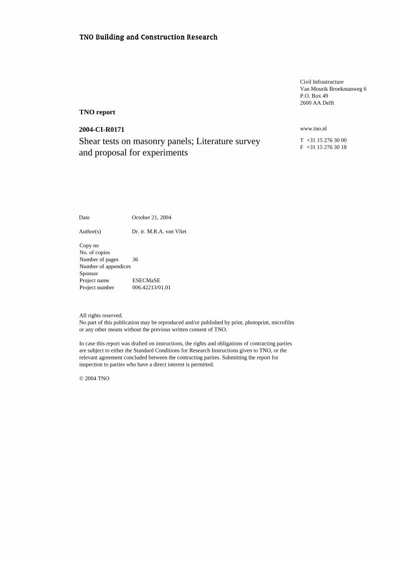
When studying literature with respect to shear tests on masonry, different types of test are found. In this report two types of test will be distinguished, that are characterised by the way in which the load is applied. Shear test type 1: The loading is applied by means of a compression force only. Since the bed joints are at an angle with the loading direction, the masonry is loaded by a combination of normal compression and shear. Tests according to this principle can be found in [5, 6, 7, 8, 9, 10] (see Figure 2). In the shear test of Monk [9] the specimen is enclosed by a frame with open corners, consisting of steel [-sections. By means of hinges the external compression forces are decomposed in shear components. In this report no further attention will be paid to this type of test.
TNO report | 2004-CI-R0171 |
4 / 36
Figure 2 Shear tests by means of compression tests
Shear test type 2: A masonry wall panel with bed joints in horizontal direction is supported at the lower side, and at the upper side loaded in-plane by a horizontal force. At the upper side of the wall panel different boundary conditions can be applied. Also the way in which the horizontal force is introduced can vary. The shear tests on masonry that are discussed in this report, are of type 2. In the discussion attention will mainly be paid to: − the applied boundary conditions, including the way in which the load is introduced; − the principle of the test set-up. For certain cases, also interesting results like for instance a crack pattern will be shown.
1.3 Discussion of the overviews in [2, 3, 4]
Besides variations in wall panel dimensions, brick type and mortar quality, the various test methods mainly differ by the way in which the load is introduced [3]. Benjamin and Williams [11] performed tests like shown schematically in Figure 3 (see also 2.2). With respect to the surrounding frame three alternatives were tested: − a frame of reinforced concrete − a steel frame − no frame Wood [12] used a comparable test set-up.
(a) (b)
(c) (d) (e)
TNO report | 2004-CI-R0171 |
5 / 36
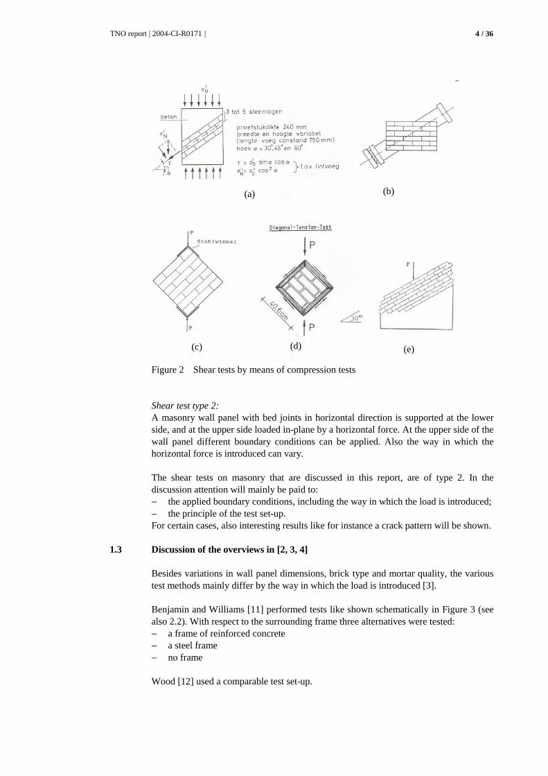
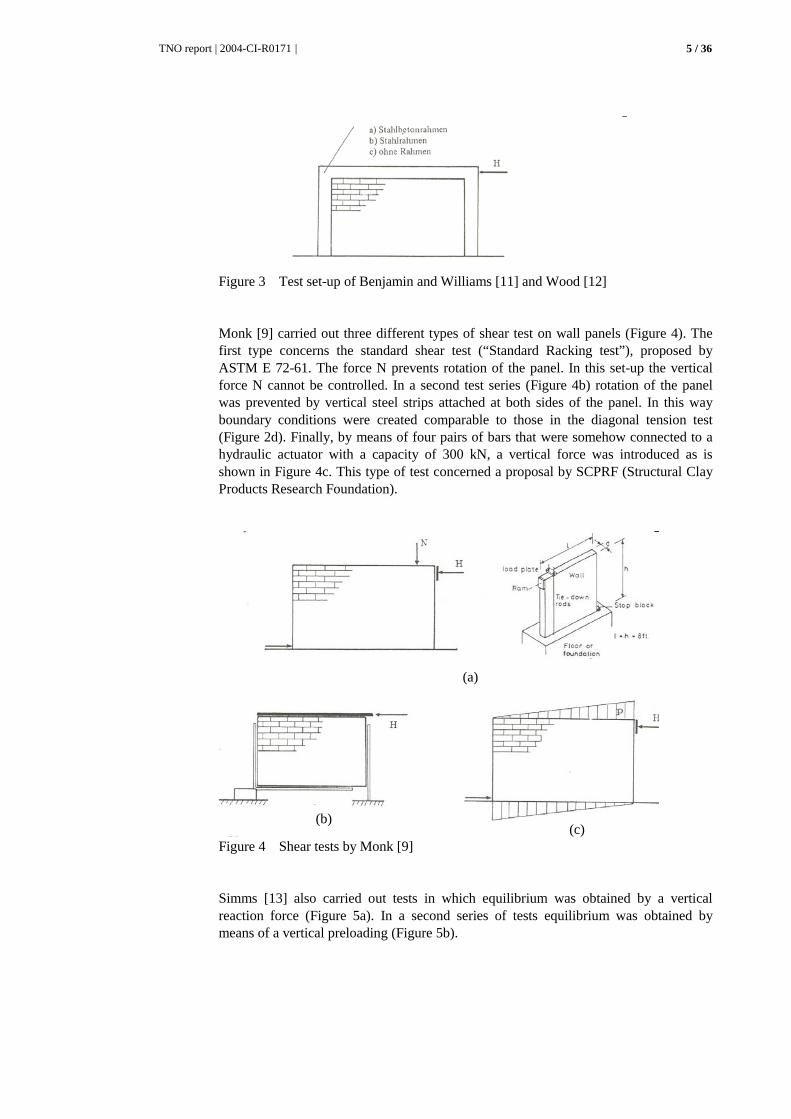
Figure 3 Test set-up of Benjamin and Williams [11] and Wood [12]
Monk [9] carried out three different types of shear test on wall panels (Figure 4). The first type concerns the standard shear test (“Standard Racking test”), proposed by ASTM E 72-61. The force N prevents rotation of the panel. In this set-up the vertical force N cannot be controlled. In a second test series (Figure 4b) rotation of the panel was prevented by vertical steel strips attached at both sides of the panel. In this way boundary conditions were created comparable to those in the diagonal tension test (Figure 2d). Finally, by means of four pairs of bars that were somehow connected to a hydraulic actuator with a capacity of 300 kN, a vertical force was introduced as is shown in Figure 4c. This type of test concerned a proposal by SCPRF (Structural Clay Products Research Foundation).
Figure 4 Shear tests by Monk [9]
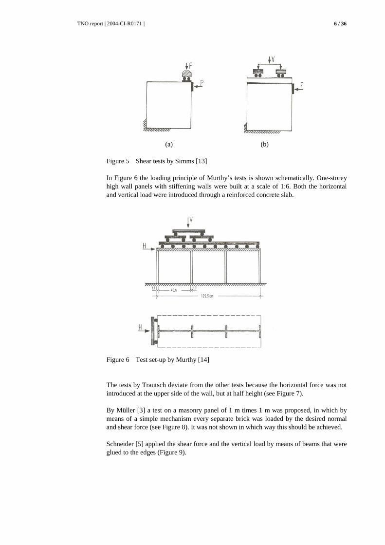
Simms [13] also carried out tests in which equilibrium was obtained by a vertical reaction force (Figure 5a). In a second series of tests equilibrium was obtained by means of a vertical preloading (Figure 5b).
(a)
(b) (c)
TNO report | 2004-CI-R0171 |
6 / 36
(a) (b)
Figure 5 Shear tests by Simms [13]
In Figure 6 the loading principle of Murthy’s tests is shown schematically. One-storey high wall panels with stiffening walls were built at a scale of 1:6. Both the horizontal and vertical load were introduced through a reinforced concrete slab.
Figure 6 Test set-up by Murthy [14]
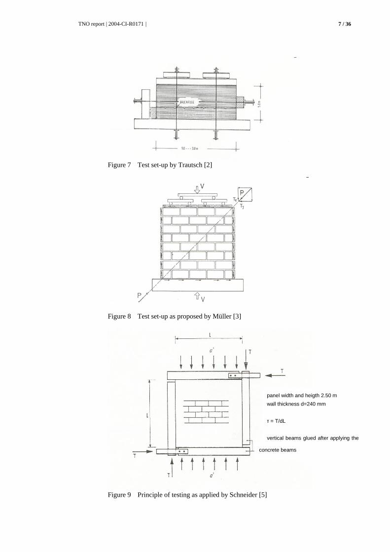
The tests by Trautsch deviate from the other tests because the horizontal force was not introduced at the upper side of the wall, but at half height (see Figure 7). By Müller [3] a test on a masonry panel of 1 m times 1 m was proposed, in which by means of a simple mechanism every separate brick was loaded by the desired normal and shear force (see Figure 8). It was not shown in which way this should be achieved. Schneider [5] applied the shear force and the vertical load by means of beams that were glued to the edges (Figure 9).
TNO report | 2004-CI-R0171 |
7 / 36
Figure 7 Test set-up by Trautsch [2]
Figure 8 Test set-up as proposed by Müller [3]
Figure 9 Principle of testing as applied by Schneider [5]
panel width and heigth 2.50 m
wall thickness d=240 mm
τ = T/dL
vertical beams glued after applying the
concrete beams

TNO report | 2004-CI-R0171 |
8 / 36
2 Inventory of experiments on in-plane loaded masonry panels
2.1 Introduction
In this chapter a number of researches that have been found in literature, will be discussed in short. Starting point is to get an impression of the way in which a shear test has been carried out. This concerns for instance: − the applied boundary conditions − the applied loading frame − the type of test panel that has been used − the dimensions of the masonry panel that was tested For a number of cases also a specific result will be shown. As for the test panel, unreinforced, reinforced and pretensioned wall panels can be distinguished. Furthermore, stand alone masonry walls have been tested as well as masonry infilled frames. Remark: for a number of publications only the test set-up is shown by means of a
figure or a photograph.
2.2 Benjamin and Williams (1958) [11]
Experimental set-up
Figure 10 Test set-up (see also Figure 3)
TNO report | 2004-CI-R0171 |
9 / 36
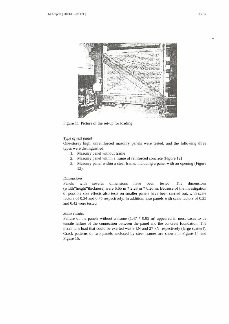
Figure 11 Picture of the set-up for loading
Type of test panel One-storey high, unreinforced masonry panels were tested, and the following three types were distinguished:
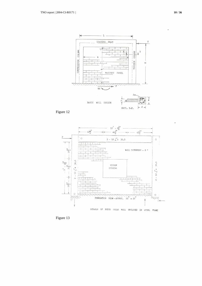
1. Masonry panel without frame 2. Masonry panel within a frame of reinforced concrete (Figure 12) 3. Masonry panel within a steel frame, including a panel with an opening (Figure
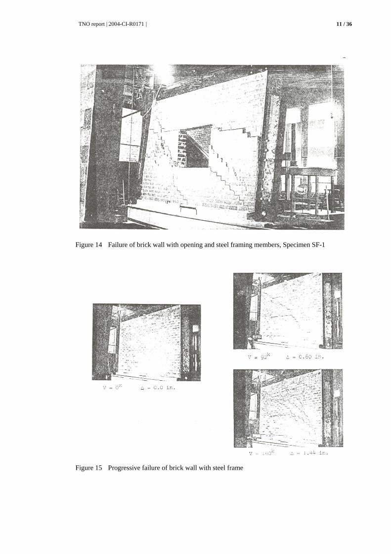
13). Dimensions Panels with several dimensions have been tested. The dimensions (width*height*thickness) were 6.65 m * 2.28 m * 0.20 m. Because of the investigation of possible size effects also tests on smaller panels have been carried out, with scale factors of 0.34 and 0.75 respectively. In addition, also panels with scale factors of 0.25 and 0.42 were tested. Some results Failure of the panels without a frame (1.47 * 0.85 m) appeared in most cases to be tensile failure of the connection between the panel and the concrete foundation. The maximum load that could be exerted was 9 kN and 27 kN respectively (large scatter!). Crack patterns of two panels enclosed by steel frames are shown in Figure 14 and Figure 15.
TNO report | 2004-CI-R0171 |
10 / 36
Figure 12
Figure 13
TNO report | 2004-CI-R0171 |
11 / 36
Figure 14 Failure of brick wall with opening and steel framing members, Specimen SF-1
Figure 15 Progressive failure of brick wall with steel frame
TNO report | 2004-CI-R0171 |
12 / 36
2.3 Hinkley (1966) [15]
Experimental set-up
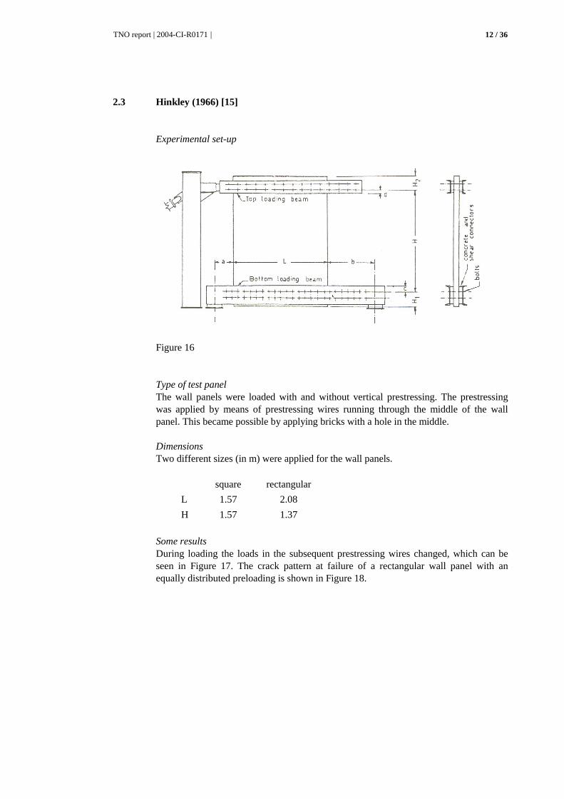
Figure 16
Type of test panel The wall panels were loaded with and without vertical prestressing. The prestressing was applied by means of prestressing wires running through the middle of the wall panel. This became possible by applying bricks with a hole in the middle. Dimensions Two different sizes (in m) were applied for the wall panels.
square rectangular
L 1.57 2.08
H 1.57 1.37
Some results During loading the loads in the subsequent prestressing wires changed, which can be seen in Figure 17. The crack pattern at failure of a rectangular wall panel with an equally distributed preloading is shown in Figure 18.

TNO report | 2004-CI-R0171 |
13 / 36
Figure 17 Load in the prestressing wires
Figure 18 Crack pattern at failure
TNO report | 2004-CI-R0171 |
14 / 36
2.4 Porter, Ahmed and Wolde-Tinsae (1983/1985) [16, 17]
Experimental set-up
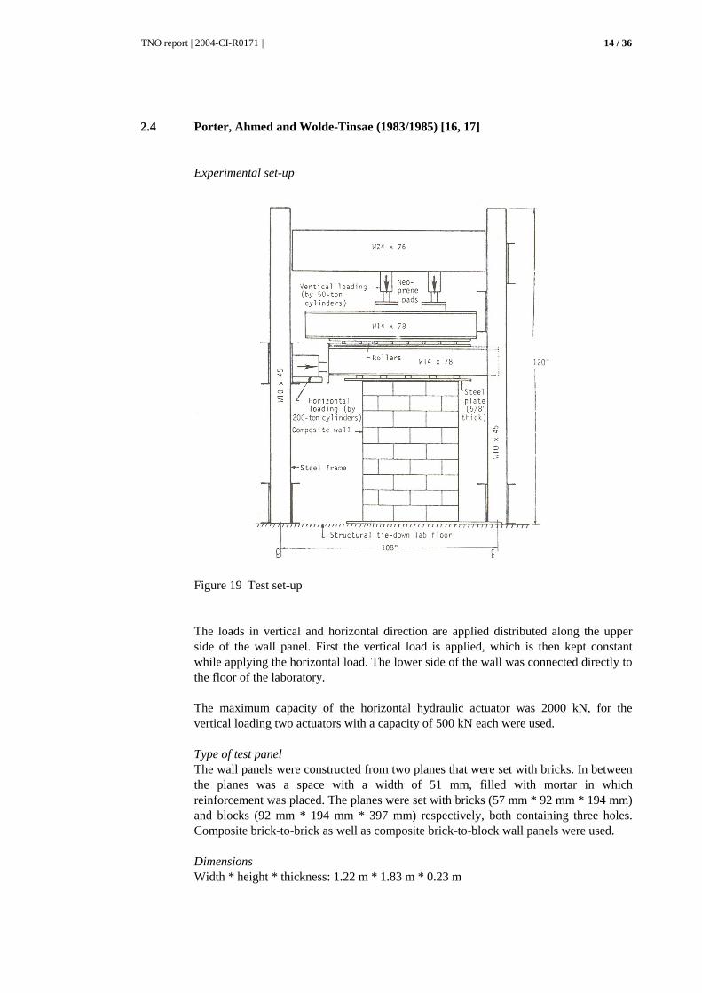
Figure 19 Test set-up
The loads in vertical and horizontal direction are applied distributed along the upper side of the wall panel. First the vertical load is applied, which is then kept constant while applying the horizontal load. The lower side of the wall was connected directly to the floor of the laboratory. The maximum capacity of the horizontal hydraulic actuator was 2000 kN, for the vertical loading two actuators with a capacity of 500 kN each were used. Type of test panel The wall panels were constructed from two planes that were set with bricks. In between the planes was a space with a width of 51 mm, filled with mortar in which reinforcement was placed. The planes were set with bricks (57 mm * 92 mm * 194 mm) and blocks (92 mm * 194 mm * 397 mm) respectively, both containing three holes. Composite brick-to-brick as well as composite brick-to-block wall panels were used. Dimensions Width * height * thickness: 1.22 m * 1.83 m * 0.23 m

TNO report | 2004-CI-R0171 |
15 / 36
2.5 Galegos and Casabone (1983) [18]
Experimental set-up Cyclic loading in horizontal direction was applied to the upper side of the wall panel under deformation control. The horizontal loading was applied on a heavily reinforced beam at the upper side of the wall. The frame that has been used to apply the horizontal loading was not described.
Figure 20 Schematic loading system
Type of test panel Tests on three types of reinforced masonry wall panels are described. The three types of panels can be characterised by the way in which the reinforcement was applied, namely:
1. inside a concrete frame surrounding the wall panel 2. inside the hollow bricks that were injected afterwards 3. inside the mortar that was used as cavity filling
Figure 21 Test panel type 1
Dimensions Width * height: 2 m * 2 m
TNO report | 2004-CI-R0171 |
16 / 36
2.6 Richardson and Dawe (1986) [19]
Experimental set-up
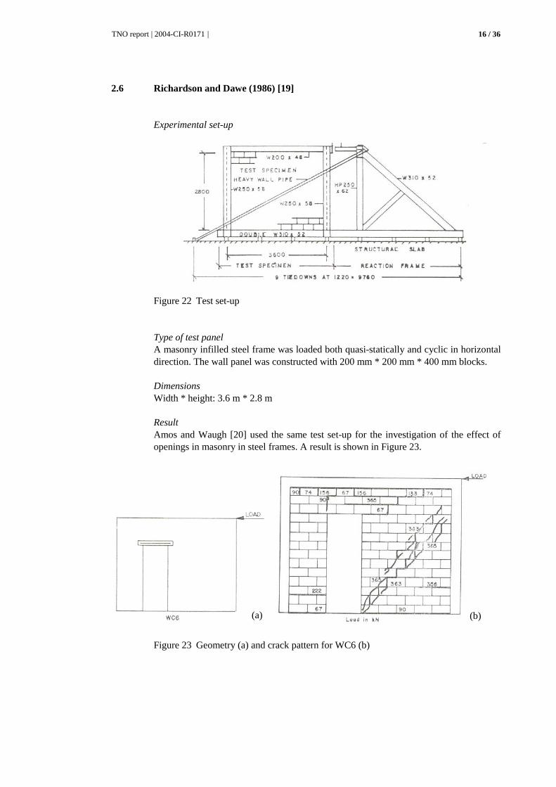
Figure 22 Test set-up
Type of test panel A masonry infilled steel frame was loaded both quasi-statically and cyclic in horizontal direction. The wall panel was constructed with 200 mm * 200 mm * 400 mm blocks. Dimensions Width * height: 3.6 m * 2.8 m Result Amos and Waugh [20] used the same test set-up for the investigation of the effect of openings in masonry in steel frames. A result is shown in Figure 23.
Figure 23 Geometry (a) and crack pattern for WC6 (b)
(a) (b)
TNO report | 2004-CI-R0171 |
17 / 36
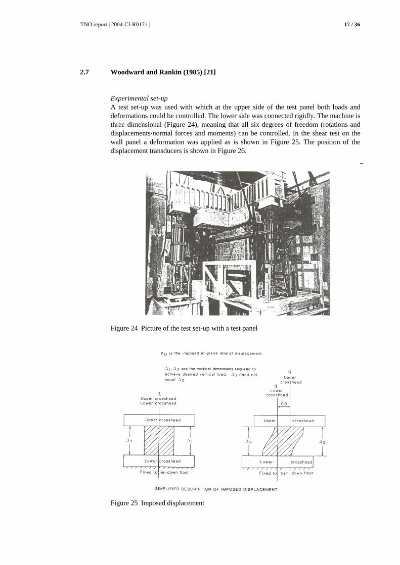
2.7 Woodward and Rankin (1985) [21]
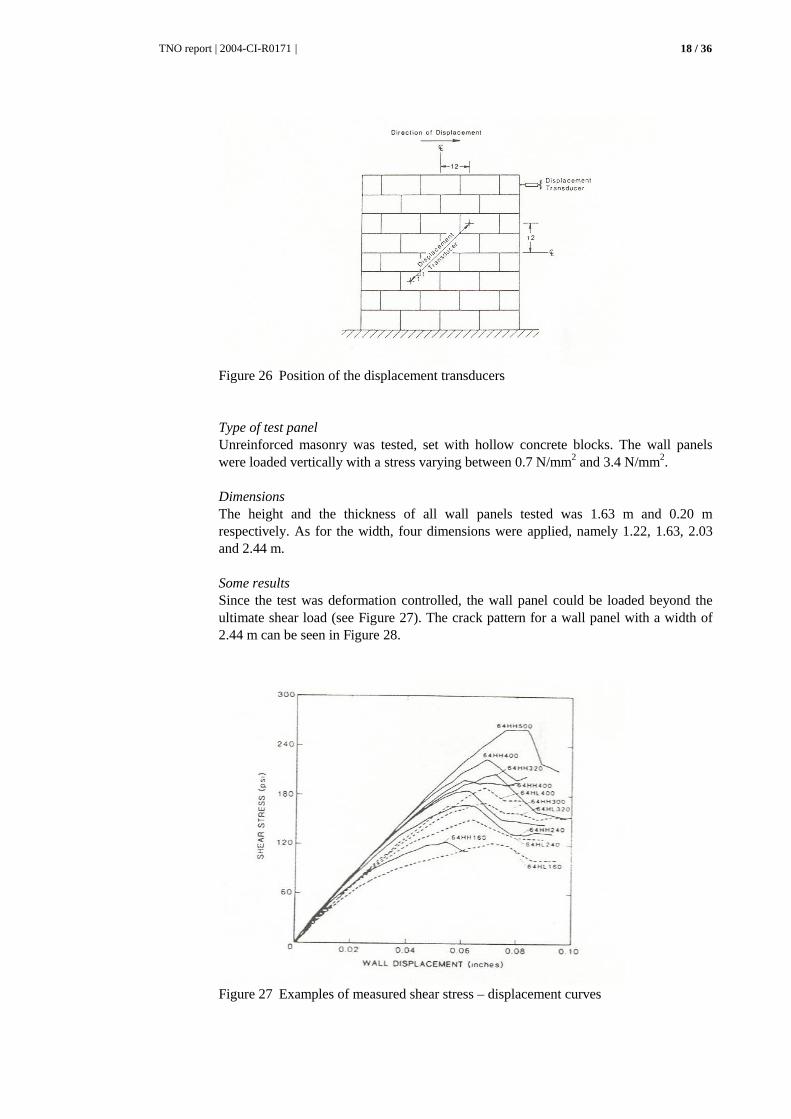
Experimental set-up A test set-up was used with which at the upper side of the test panel both loads and deformations could be controlled. The lower side was connected rigidly. The machine is three dimensional (Figure 24), meaning that all six degrees of freedom (rotations and displacements/normal forces and moments) can be controlled. In the shear test on the wall panel a deformation was applied as is shown in Figure 25. The position of the displacement transducers is shown in Figure 26.
Figure 24 Picture of the test set-up with a test panel
Figure 25 Imposed displacement
TNO report | 2004-CI-R0171 |
18 / 36
Figure 26 Position of the displacement transducers
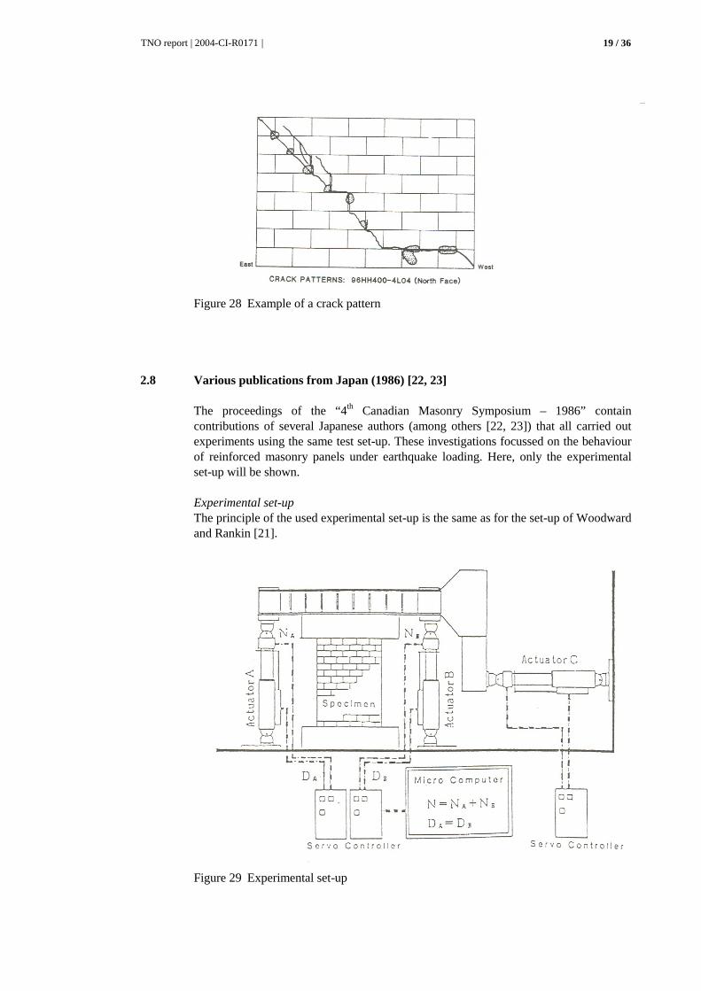
Type of test panel Unreinforced masonry was tested, set with hollow concrete blocks. The wall panels were loaded vertically with a stress varying between 0.7 N/mm2 and 3.4 N/mm2. Dimensions The height and the thickness of all wall panels tested was 1.63 m and 0.20 m respectively. As for the width, four dimensions were applied, namely 1.22, 1.63, 2.03 and 2.44 m. Some results Since the test was deformation controlled, the wall panel could be loaded beyond the ultimate shear load (see Figure 27). The crack pattern for a wall panel with a width of 2.44 m can be seen in Figure 28.
Figure 27 Examples of measured shear stress – displacement curves
TNO report | 2004-CI-R0171 |
19 / 36
Figure 28 Example of a crack pattern
2.8 Various publications from Japan (1986) [22, 23]
The proceedings of the “4th Canadian Masonry Symposium – 1986” contain contributions of several Japanese authors (among others [22, 23]) that all carried out experiments using the same test set-up. These investigations focussed on the behaviour of reinforced masonry panels under earthquake loading. Here, only the experimental set-up will be shown. Experimental set-up The principle of the used experimental set-up is the same as for the set-up of Woodward and Rankin [21].
Figure 29 Experimental set-up
TNO report | 2004-CI-R0171 |
20 / 36
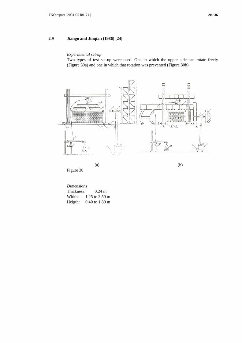
2.9 Jiango and Jinqian (1986) [24]
Experimental set-up Two types of test set-up were used. One in which the upper side can rotate freely (Figure 30a) and one in which that rotation was prevented (Figure 30b).
(a) (b) Figure 30
Dimensions Thickness: 0.24 m Width: 1.25 to 3.50 m Heigth: 0.40 to 1.80 m
TNO report | 2004-CI-R0171 |
21 / 36
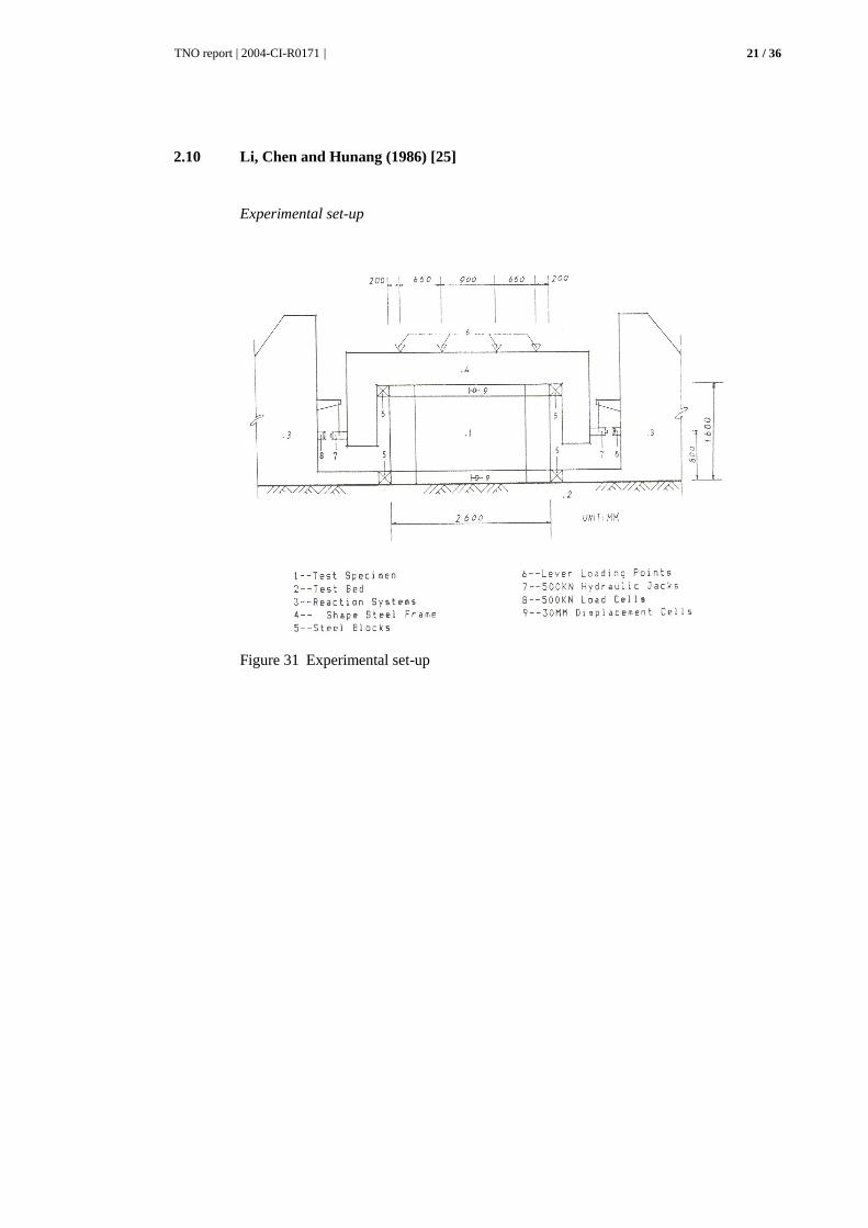
2.10 Li, Chen and Hunang (1986) [25]
Experimental set-up
Figure 31 Experimental set-up

TNO report | 2004-CI-R0171 |
22 / 36
2.11 Huizer and Shrive (1986) [26]
Experimental set-up The paper does not contain a schematic presentation of the loading frame. A schematic presentation of the wall panel can be seen in Figure 32. The horizontal load was applied by means of a hydraulic actuator, over the height of two bricks at the right upper side of the wall panel. The horizontal load was measured by means of a 500 kN load cell. The wall is post tensioned in both horizontal and vertical direction. The position of the post tensioning, the post tensioning loads and the position of the displacement transducers are also shown in Figure 32. Type of test panel As can be seen in Figure 32 a wall panel with an opening was tested.
Figure 32 Test panel
TNO report | 2004-CI-R0171 |
23 / 36
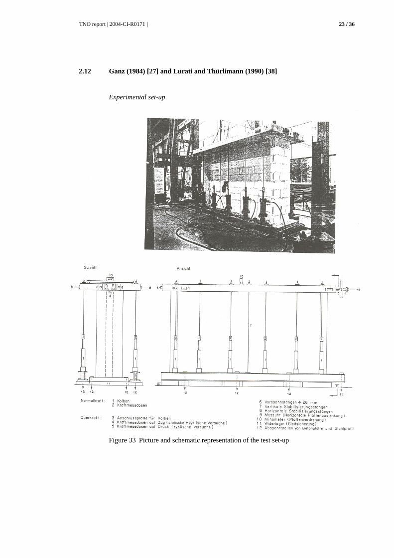
2.12 Ganz (1984) [27] and Lurati and Thürlimann (1990) [38]
Experimental set-up
Figure 33 Picture and schematic representation of the test set-up
TNO report | 2004-CI-R0171 |
24 / 36
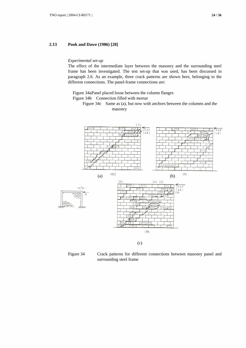
2.13 Pook and Dawe (1986) [28]
Experimental set-up The effect of the intermediate layer between the masonry and the surrounding steel frame has been investigated. The test set-up that was used, has been discussed in paragraph 2.6. As an example, three crack patterns are shown here, belonging to the different connections. The panel-frame connections are: Figure 34a Panel placed loose between the column flanges Figure 34b Connection filled with mortar Figure 34c Same as (a), but now with anchors between the columns and the
masonry
Figure 34 Crack patterns for different connections between masonry panel and
surrounding steel frame
(a) (b)
(c)
TNO report | 2004-CI-R0171 |
25 / 36
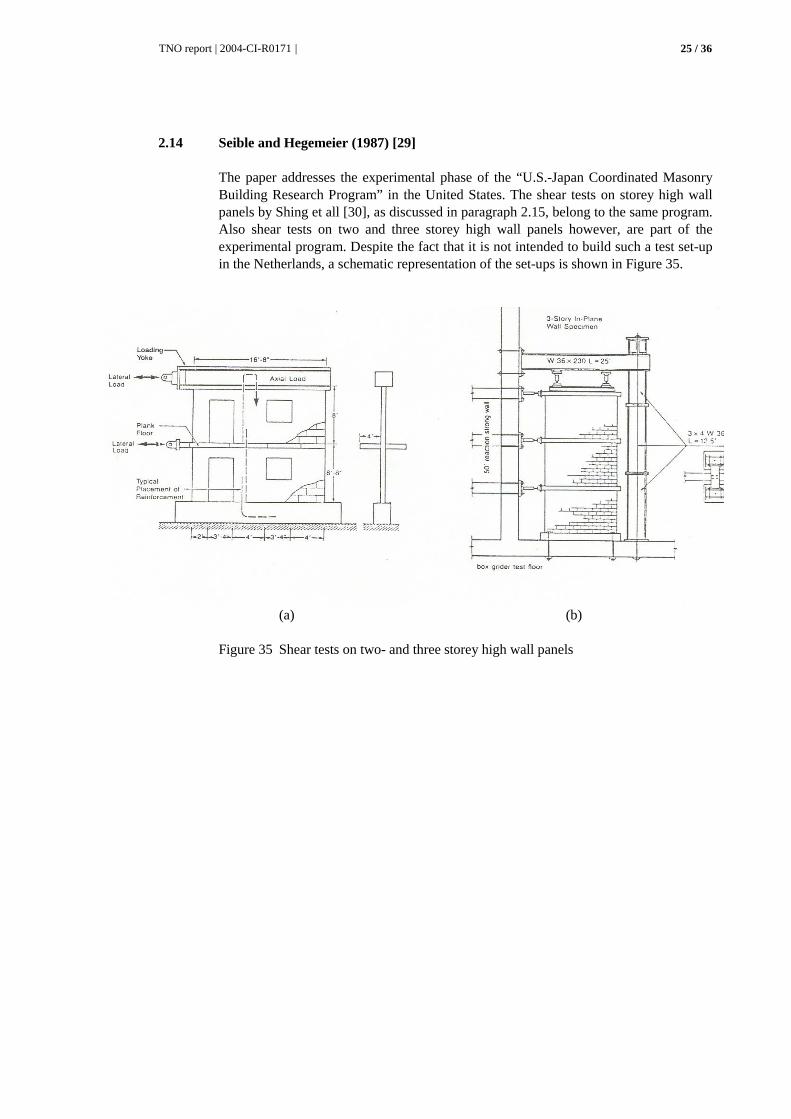
2.14 Seible and Hegemeier (1987) [29]
The paper addresses the experimental phase of the “U.S.-Japan Coordinated Masonry Building Research Program” in the United States. The shear tests on storey high wall panels by Shing et all [30], as discussed in paragraph 2.15, belong to the same program. Also shear tests on two and three storey high wall panels however, are part of the experimental program. Despite the fact that it is not intended to build such a test set-up in the Netherlands, a schematic representation of the set-ups is shown in Figure 35.
(a) (b) Figure 35 Shear tests on two- and three storey high wall panels
TNO report | 2004-CI-R0171 |
26 / 36
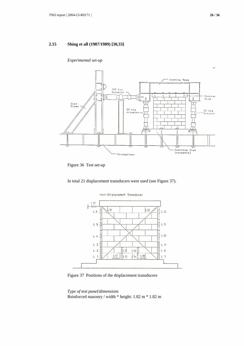
2.15 Shing et all (1987/1989) [30,33]
Experimental set-up
Figure 36 Test set-up
In total 21 displacement transducers were used (see Figure 37).
Figure 37 Positions of the displacement transducers
Type of test panel/dimensions Reinforced masonry / width * height: 1.82 m * 1.82 m

TNO report | 2004-CI-R0171 |
27 / 36
2.16 Matsumura (1987/1990) [31, 36]
Experimental set-up
Figure 38 Test set-up

TNO report | 2004-CI-R0171 |
28 / 36
2.17 Johal and Anderson (1988) [32]
Experimental set-up The way in which the shear load was introduced differs from most other experimental set-ups. A pier of masonry was made between two reinforced masonry beams. By means of a hydraulic actuator and tension bars, a diagonal compression force was introduced in the test panel. The resolved force in horizontal direction gave the shear force in the pier. Two braces compensated the resolved force in vertical direction, one on each side of the pier (see Figure 39b), so that no resulting normal stress was present in the pier. The forces in the two vertical hydraulic actuators were kept equal. Hence, the pier was purely loaded by a combination of shear stress and bending. Since the tension bars were placed along both diagonals of the test panel, alternate loading could be applied. The position of the displacement transducers d1, d2, h1 and h2 can be seen in Figure 39c.
Figure 39 Test set-up
Dimensions Pier: 0.91 m * 0.91 m
(a)
(b)
(c)

TNO report | 2004-CI-R0171 |
29 / 36
2.18 Abrams and Epperson (1989/1990) [34, 37]
Shear test on an unreinforced masonry panel from an existing building that had to be demolished. Experimental set-up
Figure 40 Test set-up
Figure 41 Crack pattern
TNO report | 2004-CI-R0171 |
30 / 36
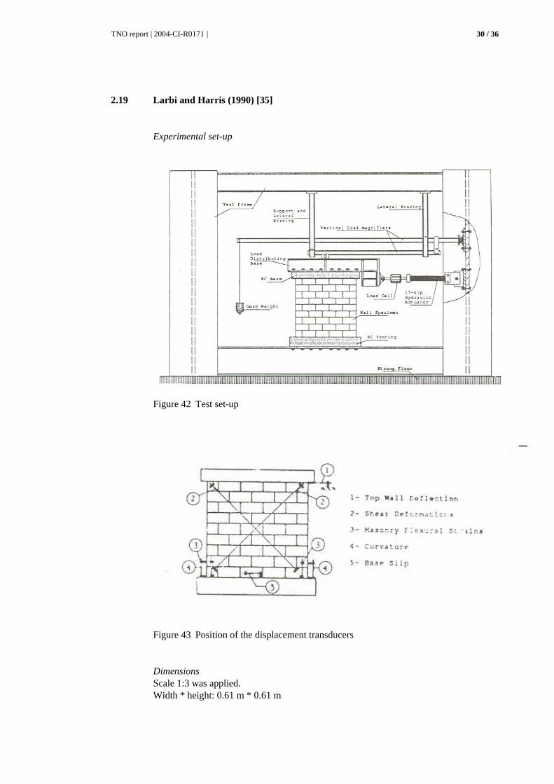
2.19 Larbi and Harris (1990) [35]
Experimental set-up
Figure 42 Test set-up
Figure 43 Position of the displacement transducers
Dimensions Scale 1:3 was applied. Width * height: 0.61 m * 0.61 m

TNO report | 2004-CI-R0171 |
31 / 36
3 Discussion of the various test methods
First of all it is mentioned that many variations have been found in the tests on masonry wall panels. These variations concern: − the applied brick or block type − the possible presence of openings in the wall panel − the presence or absence of reinforcement − the presence or absence of a frame surrounding the wall panel − the way in which the load is spread − the boundary conditions at the upper side − the presence or absence of a vertical preloading − the type of loading (monotonic, cyclic or impact) Hereafter, as for the applied boundary conditions, it will be attempted to structure the variety of information as found in literature. First of all, it can be stated that for shear in principle a deformation state occurs as is shown in Figure 44. The upper edge has moved in horizontal direction with respect to the lower edge, while remaining parallel to that edge.
Figure 44 Deformed shape for shear loading
For the shear loading of a wall that is fixed for rotation at the lower edge, in first instance it is necessary to apply somehow at the upper edge an in-plane horizontal force. In several experiments this horizontal force is applied:
1. as a concentrated force at the side of the wall (Figure 45a); 2. by means of a very stiff beam at the upper side of the wall, thus creating a
uniform shear stress along the upper side of the wall panel (Figure 45b); 3. using a beam with a low stiffness compared to the wall panel, thus creating a
situation in between 1 and 2; 4. on to a frame that surrounds the complete wall panel (Figure 45c).
(a) (b) (c) Figure 45 Different ways in which the horizontal load can be introduced
TNO report | 2004-CI-R0171 |
32 / 36
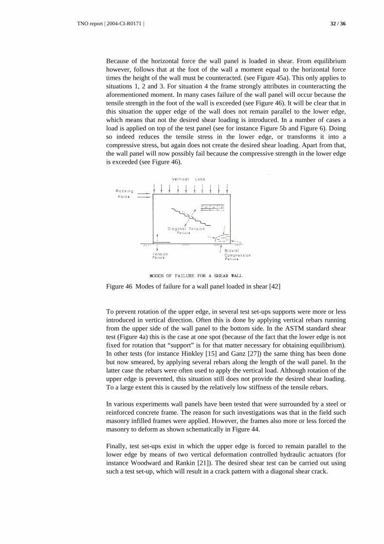
Because of the horizontal force the wall panel is loaded in shear. From equilibrium however, follows that at the foot of the wall a moment equal to the horizontal force times the height of the wall must be counteracted. (see Figure 45a). This only applies to situations 1, 2 and 3. For situation 4 the frame strongly attributes in counteracting the aforementioned moment. In many cases failure of the wall panel will occur because the tensile strength in the foot of the wall is exceeded (see Figure 46). It will be clear that in this situation the upper edge of the wall does not remain parallel to the lower edge, which means that not the desired shear loading is introduced. In a number of cases a load is applied on top of the test panel (see for instance Figure 5b and Figure 6). Doing so indeed reduces the tensile stress in the lower edge, or transforms it into a compressive stress, but again does not create the desired shear loading. Apart from that, the wall panel will now possibly fail because the compressive strength in the lower edge is exceeded (see Figure 46).
Figure 46 Modes of failure for a wall panel loaded in shear [42]
To prevent rotation of the upper edge, in several test set-ups supports were more or less introduced in vertical direction. Often this is done by applying vertical rebars running from the upper side of the wall panel to the bottom side. In the ASTM standard shear test (Figure 4a) this is the case at one spot (because of the fact that the lower edge is not fixed for rotation that “support” is for that matter necessary for obtaining equilibrium). In other tests (for instance Hinkley [15] and Ganz [27]) the same thing has been done but now smeared, by applying several rebars along the length of the wall panel. In the latter case the rebars were often used to apply the vertical load. Although rotation of the upper edge is prevented, this situation still does not provide the desired shear loading. To a large extent this is caused by the relatively low stiffness of the tensile rebars. In various experiments wall panels have been tested that were surrounded by a steel or reinforced concrete frame. The reason for such investigations was that in the field such masonry infilled frames were applied. However, the frames also more or less forced the masonry to deform as shown schematically in Figure 44. Finally, test set-ups exist in which the upper edge is forced to remain parallel to the lower edge by means of two vertical deformation controlled hydraulic actuators (for instance Woodward and Rankin [21]). The desired shear test can be carried out using such a test set-up, which will result in a crack pattern with a diagonal shear crack.
TNO report | 2004-CI-R0171 |
33 / 36
4 References
1 Pluijm, R. van der, Afschuifproeven op metselwerk; Inventarisatie en voorstel. TNO-Bouw rapport BI-90-215, 1990, pp. 1-17.
2 Trautsch, W., Versuche zum Schertragverhalten von Mauerwerk. Dissertatie
Technische Hochschule Braunschweig, 1971, 58 p. 3 Müller, H., Untersuchungen zum Tragverhalten von querkraftbeanspruchtem
Mauerwerk. Dissertatie Technische Hochschule Darmstadt, 1974, 139 p. 4 Van de Haar, P.W. en Van Leeuwen, J., Literatuurstudie met betrekking tot
sterkte- en stijfheidseigenschappen van metselwerk. IBBC-TNO rapport BI-78-44, 1978.
5 Schneider, H., Versuche über die Schubfestigkeit von Mauerwerk. 4e Int.
Mauerwerkkonferenz, Brugge, België, 1976, contribution 4b12. 6 Zelgler, C., Neue Erkenntnisse bei der Bemessung von Bewehrter
Ziegelstürtzen. Die Zíegelindustrie, 9, 1965 (after [4]). 7 Yorulmaz, M. en Sozen, A.M., Behaviour of single story reinforced concrete
frame with filler walls. Technical report of the department of defence, office of the secretary of the army. Office of civil defence, Urbana, I11., 1967 (after [4]).
8 Kelch, N.W., Methods used in testing masonry specimens for bonding, tension
and shear. Journal American Ceramic Society, 14(2), 1931, 125 p. (after [2]). 9 Monk, C.B., Testing high-bond clay masonry assemblages. American Society
for Testing and Materials (ASTM), 320, 1962 (after [3]). 10 Vogt, H., Modellversuche mit bewehrten and unbewehrten
Ziegelkonstruktionen. Die Ziegelindustríe, 14(4), 1961, 110 p. (after [2]). 11 Benjamin, J.R. en Williams, H.A., The behaviour of one-story brick shear
walls. J. Structural Division 108(4), 1958, pp. 1723/1-1723/30. 12 Wood, R.H., The stability of tall buildings. Proceedings of the Institution of
Civil Engineers, 11, paper nr. 6280, 1958, 69 p. (after [2]). 13 Simms, L.G., The shear strength of some story-height brickwork and
blockwork walls. CPTB Technical Note, 1(5), 1964 (after [3]). 14 Murthy, C.K., Racking tests on story height shear wall structures subjected to
pre-compression. Structural Ceramics Research Unit, University of Edinburgh, Research report CKM/3/3, 1964 (after [3]).
15 Hinkley, A.T., Tests of one-story prestressed brickwork shear walls. New
Zeeland Engineering 21(6), 1966, pp. 245-252.

TNO report | 2004-CI-R0171 |
34 / 36
16 Porter, M., Ahmed, M. en Wolde-Tinsae, A., Preliminary work on reinforced composite masonry shear walls, Proceedings 3rd Canadian Masonry Symposium '83 (authors: J. Longworth and J. Warwaruk), Edmonton, Canada, 6-8 juni 1983, paper 15, 12 p.
17 Wolde-Tinsae, A.M., Porter, M.L. en Ahmed, M.H., Shear strength of
composite brick-to-block panels. Proceedings of the Third North American Masonry Conference (authors: J.H. Matthys en J.G. Borchelt), Arlington, Texas, 3-5 juni 1985, paper 40, 13 p.
18 Gallegos, H. en Casabonne, C., Cyclic test of three different types of masonry
walls. Proceedings 3rd Canadian Masonry Symposium '83 (authors: J. Longworth en J. Warwaruk), Edmonton, Canada, 6-8 juni 1983, paper 33., 15 p.
19 Richardson, J. en Dawe, J.L., Experimental investigation of the behaviour of
masonry infilled steel frames subjected to cyclic racking loads. Proceedings 4th Canadian Masonry Symposium (authors: J.L. Dawe e.a.), Fredericton, Canada, 2-4 juni 1986, Vol. 2, pp. 922-934.
20 Amos, K.A. en Waugh, L.M., Behaviour of perforated masonry shear panels in
a steel frame. Proceedings 4th Canadian Masonry Symposium (authors: J.L. Dawe e.a.), Fredericton, Canada, 2-4 juni 1986, Vol. 2 pp. 569-580.
21 Woodward, K. en Rankin, F., Shear resistance of unreinforced hollow concrete
block masonry walls. Proceedings of the Third North American Masonry Conference (authors: J.H. Matthys en J.G. Borchelt), Arlington, Texas, 3-5 juni 1985, paper 38, 15 p.
22 Kaminosono, T., Isoishi, H., Yamaguchi, Y. en Kawai, R., Seismic capacity of
reinforced masonry walls including effects of axial stress. Proceedings 4th Canadian Masonry Symposium - 1986 (authors: J.L. Dawe, R.M. Francis en A.J. Valsangkar), Vol. 1, Fredericton, N.B., Canada, pp. 163-173.
23 Fujisawa, M., Kawashima, T. en Yamaguchi, Y., Seismic capacity of
reinforced masonry walls; effect of shear span ratio. Proceedings 4th Canadian Masonry Symposium - 1986 (authors: J.L. Dawe, R.M. Francis en A.J. Valsangkar), Vol. 1, Fredericton, N.B., Canada, pp. 377-395.
24 Jiango, F. en Jinqian, X., Experiment study of shear strength of reinforced
masonry walls under cyclic loading. Proceedings 4th Canadian Masonry Symposium -1986 (authors: J.L. Dawe, R.M. Francis en A.J. Valsangkar), Vol. 1, Fredericton, N.B., Canada, pp. 581-595.
25 Li, J-Q, Chen, Z-G en Huang, X-X, Behaviour of hollow concrete wall column
composite masonry under vertical and lateral loads. Proceedings 4th Canadian Masonry Symposium - 1986 (authors: J.L. Dawe, R.M. Francis en A.J. Valsangkar), Vol. 1, Fredericton, N.B., Canada, pp. 619-631.
26 Huizer, A. en Shrive, N.G., Performance of a post-tensioned, single wythe,
clay brick masonry wall tested in shear. Proceedings 4th Canadian Masonry Symposium -1986 (authors: J.L. Dawe, R.M. Francis en A.J. Valsangkar), Vol. 1, Fredericton, N.B., Canada, pp. 609-618.

TNO report | 2004-CI-R0171 |
35 / 36
27 Ganz, H., Versuche an Mauerwerksscheiben unter Normalkraft and Querkraft. Institut für Baustatik and Konstruktíon ETH Zurich, Bericht nr. 7502-4, 1984.
28 Pook, L.L. en Dawe, J.L., Effects if interface conditions between a masonry
shear panel and surrounding steel frame. Proceedings 4th Canadian Masonry Symposium - 1986 (authors: J.L. Dawe, R.M. Francis en A.J. Valsangkar), Vol. 1, Fredericton, N.B., Canada, pp. 910-921.
29 Seible, F. en Hegemeier, G., From materials and components to masonry
prototype structures; the TCCMAR-U.S. experimental program. Proceedings Fourth North American Masonry Conference (authors: G.C. Hart en J. Kariotis), Vol. II, Los Angeles, 1987, paper 40, 17 p.
30 Shing, P.B., Noland, J.L., Spaeh, H. en Klamerus, E., Inelastic behaviour of
masonry wall panels under in-plane cyclic loads. Proceedings Fourth North American Masonry Conference (authors: G.C. Hart en J. Kariotis), Vol. II, Los Angeles, 1987, paper 42, 14 p.
31 Matsumura, A, Shear strength of reinforced hollow unit masonry walls.
Proceedings Fourth North American Masonry Conference (authors: G.C. Hart en J. Kariotis), Vol. II, Los Angeles, 1987, paper 50, 16 p.
32 Johal, L.S.P. en Anderson, E.D., Shear strength of masonry piers under cyclic
loading. In Masonry: Materials, Design, Construction, and Maintenance, (author: H.A. Harris), ASTM STP 992, 1988, pp. 1832.
33 Shing, P.B., Schuller, M., Klamerus, E., Hoskere, V.S. en Noland, J.L., Design
and analysis of reinforced masonry shear walls. Proceedings 5th Canadian Masonry Symposium, Vol. 1, 5-7 juni 1989, Vancouver, Canada, pp. 291-300.
34 Abrams, D.P. en Epperson, G.S., Evaluation of shear strength of unreinforced
brick walls based on nondestructive measurements. Proceedings 5th Canadian Masonry Symposium, Vol. 2, 5-7 juni 1989, Vancouver, Canada, pp. 817-826.
35 Larbi, A. en Harris, H.G., Seismic behaviour of reinforced block masonry
shear walls using 1/3 scale direct models. Proceedings Fifth North American Masonry Conference, Vol. I, 3-6 juni 1990, Urbana Champaign, pp. 321-332.
36 Matsumura, A., Planar shear loading test on reinforced fully grouted hollow
clay masonry walls. Proceedings Fifth North American Masonry Conference, Vol. I, 3-6 juni 1990, Urbana-Champaign, pp. 347-358.
37 Epperson, G.S. en Abrams, D.P., Evaluating lateral strength of existing
unreinforced brick piers in the laboratory. Proceedings Fifth North American Masonry Conference, Vol. II, 3-6 juni 1990, Urbana-Champaign, pp. 735-746.
38 Lurati, F. en Thurlimann, B., Versuche an Mauerwerkswänden aus
Zementstein. Eidgenössische Technische Hochschule Zürich, 1990. 39 Coenraads, A., Numerieke detailberekeningen van penanten in metselwerk;
Onderzoek naar modelleringsaspecten binnen DIANA., TNO Bouw rapport nr. BI-91-073, 1991, 71 p.

TNO report | 2004-CI-R0171 |
36 / 36
40 Antonucci, R., Carboni, M. en Cocchi, G., On the subject of numerical modelling of the structural behaviour of masonry walls under plane stress: an application on shear walls. Proceedings 5th Canadian Masonry Symposium, Vol. 1, 5-7 juni 1989, Vancouver, Canada, pp. 263272.
41 Qamaruddin, M., Qadeer, A., Usmani, S.A. en Kumar, P., Displacement and
stress analysis of shear wall panels with openings. Proceedings 5th Canadian Masonry Symposium, Vol. 1, 5-7 juni 1989, Vancouver, Canada, pp. 301-307.
42 Page, A.W., A parametric study of the behaviour of masonry shear walls.
Proceedings 5th Canadian Masonry Symposium, Vol. 1, 5-7 juni 1989, Vancouver, Canada, pp. 817-826.
43 Seible, F., LaRovere, H.L. en Kingsley, G.R., Nonlinear analysis of reinforced
concrete masonry subassemblages. Proceedings Fifth North American Masonry Conference, Vol. I, 3-6 juni 1990, Urbana-Champaign, pp. 261-274.