Buckling Behaviour of Cylindrical Panels
9
Nonlinear Engineering 2015; 4(2): 67–75 R.B. Ashok*, C.V. Srinivasa, Y. J. Suresh, and W. P. Prema Kumar Buckling Behaviour of Cylindrical Panels DOI 10.1515/nleng-2014-0019 Received November 2, 2014 ; accepted February 27, 2015. Abstract: Experimental studies were made on isotropic cylindrical panels made of Aluminum 7075-T6 under uni- axial compression. The experimental values of the critical buckling load were determined using four dierent meth- ods. The critical buckling load was also determined us- ing MSC/NASTRAN and CQUAD8 nite element. The ex- perimental values of the critical buckling load obtained by dierent methods were compared with the nite element solution. The eects of the panel angle, panel length and panel thickness on the critical buckling load of isotropic cylindrical panels made of Aluminum 7075-T6 were stud- ied. It is found that the Method III (based on a plot of applied load versus average axial strain) yields the high- est value for critical buckling load and Method II (based on a plot of applied load versus square of out-of-plane- deection) the lowest value for critical buckling load. The experimental values given by Method III are seen to be closest to the nite element solution. Critical buckling load increases monotonically as panel angle increases. Keywords: Cylindrical Panel; Panel Angle; Panel Length; Finite Element Analysis; Critical Buckling Load Introduction Cylindrical panels are widely used as structural compo- nents in pipelines, large dams, shell roofs, liquid retain- *Corresponding Author: R.B. Ashok: Department of Mechanical Engineering, S. M. V. Institute of Technology and Management, Bantakal, Udupi, Karnataka, India-574 115, E-mail: [email protected]; Tel.: +91 820 25989182/83, Fax: +91 820 2589184 C.V. Srinivasa: Department of Mechanical Engineering, GM Insti- tute of Technology, Davangere, Karnataka, India-577006, E-mail: [email protected] Y. J. Suresh: Department of Mechanical Engineering, J.N.N. College of Engineering, Shivamogga, Karnataka, India-577204, E-mail: [email protected] W. P. Prema Kumar: Department of Civil Engineering, Reva Insti- tute of Technology and Management, Bangalore, Karnataka, India- 560064, Member of Academic Council, Reva University, Bangalore, Karnataka, India-560064, E-mail: [email protected] ing structures, aerospace, automotive, and marine engi- neering structures. Experience shows that such structures fail frequently on account of instability arising from the slenderness of the members and their design requires ac- curate assessment of the critical buckling. The structures susceptible to buckling can be categorized as one dimen- sional (columns), two dimensional (plates and cylindri- cal shells), or three dimensional (substructures and struc- tures). Buckling can be caused by in-plane compression loads, shear loads, or torsional loads. Buckling is one of the main important modes of failure in panels. Buckling Characteristic on cylindrical curved panels is of considerable importance to the structural analyst. Over the past four decades, a lot of research has been focused on the static and dynamic buckling collapse and post buck- ling behavior of cylindrical curved panel using dierent techniques viz. experimental, linear stability, non-linear and nite element methods. There are few studies made on experimental determi- nation of critical buckling load of isotropic and laminated composite cylindrical panels and most of them have been discussed in detail by Singer et al. [1]. Becker et al. [2] stud- ied the instability behavior of composite cylindrical pan- els. Hahn et al. [3] investigated the post-buckling strength of simply supported corrugated board panels subjected to edge compressive loading using a specially developed test xture experimentally. Rao and Gopalkrishna [4] dealt with the optimization of the orientation of plies in pan- els made of composite materials for maximum buckling strength. A sandwich curved beam subjected to a uniform loading was experimentally investigated by Bozhevolnaya and Kildegaard [5]. Han et al. [6] investigated the response of aluminum cylinders with a cutout subject to axial com- pression using the experimental method and the results were compared with the nite element solution. Li and Batra [7] investigated the buckling of axially compressed thin cylindrical shells with functionally graded middle lay- ers using experimental techniques. Guduru and Xia [8] in- vestigated shell buckling of imperfect multiwalled carbon nanotubes subjected to uniaxial compression. Young and Zhou [9, 10] made an extensive study on aluminum tub- ing sections and proposed design equations. Shariati et al. [11] carried out experimental studies of buckling and post-buckling of cylindrical panels subjected to axial com- pressive load and determined the eects of variation of Authenticated | [email protected] author's copy Download Date | 6/24/15 6:38 AM
Transcript of Buckling Behaviour of Cylindrical Panels

Nonlinear Engineering 2015; 4(2): 67–75
R.B. Ashok*, C.V. Srinivasa, Y. J. Suresh, and W. P. Prema Kumar
Buckling Behaviour of Cylindrical Panels
DOI 10.1515/nleng-2014-0019Received November 2, 2014 ; accepted February 27, 2015.
Abstract: Experimental studies were made on isotropiccylindrical panels made of Aluminum 7075-T6 under uni-axial compression. The experimental values of the criticalbuckling load were determined using four di�erent meth-ods. The critical buckling load was also determined us-ing MSC/NASTRAN and CQUAD8 �nite element. The ex-perimental values of the critical buckling load obtained bydi�erent methods were compared with the �nite elementsolution. The e�ects of the panel angle, panel length andpanel thickness on the critical buckling load of isotropiccylindrical panels made of Aluminum 7075-T6 were stud-ied. It is found that the Method III (based on a plot ofapplied load versus average axial strain) yields the high-est value for critical buckling load and Method II (basedon a plot of applied load versus square of out-of-plane-de�ection) the lowest value for critical buckling load. Theexperimental values given by Method III are seen to beclosest to the�nite element solution. Critical buckling loadincreases monotonically as panel angle increases.
Keywords: Cylindrical Panel; Panel Angle; Panel Length;Finite Element Analysis; Critical Buckling Load
1 IntroductionCylindrical panels are widely used as structural compo-nents in pipelines, large dams, shell roofs, liquid retain-
*Corresponding Author: R.B. Ashok: Department of MechanicalEngineering, S. M. V. Institute of Technology and Management,Bantakal, Udupi, Karnataka, India-574 115, E-mail:[email protected]; Tel.: +91 820 25989182/83,Fax: +91 820 2589184C.V. Srinivasa: Department of Mechanical Engineering, GM Insti-tute of Technology, Davangere, Karnataka, India-577006, E-mail:[email protected]. J. Suresh: Department of Mechanical Engineering, J.N.N. Collegeof Engineering, Shivamogga, Karnataka, India-577204, E-mail:[email protected]. P. Prema Kumar: Department of Civil Engineering, Reva Insti-tute of Technology and Management, Bangalore, Karnataka, India-560064, Member of Academic Council, Reva University, Bangalore,Karnataka, India-560064, E-mail: [email protected]
ing structures, aerospace, automotive, and marine engi-neering structures. Experience shows that such structuresfail frequently on account of instability arising from theslenderness of the members and their design requires ac-curate assessment of the critical buckling. The structuressusceptible to buckling can be categorized as one dimen-sional (columns), two dimensional (plates and cylindri-cal shells), or three dimensional (substructures and struc-tures). Buckling can be caused by in-plane compressionloads, shear loads, or torsional loads. Buckling is one ofthe main important modes of failure in panels.
BucklingCharacteristic on cylindrical curvedpanels isof considerable importance to the structural analyst. Overthepast four decades, a lot of researchhasbeen focusedonthe static and dynamic buckling collapse and post buck-ling behavior of cylindrical curved panel using di�erenttechniques viz. experimental, linear stability, non-linearand �nite element methods.
There are few studies made on experimental determi-nation of critical buckling load of isotropic and laminatedcomposite cylindrical panels and most of them have beendiscussed in detail by Singer et al. [1]. Becker et al. [2] stud-ied the instability behavior of composite cylindrical pan-els. Hahn et al. [3] investigated the post-buckling strengthof simply supported corrugated board panels subjectedto edge compressive loading using a specially developedtest �xture experimentally. Rao andGopalkrishna [4] dealtwith the optimization of the orientation of plies in pan-els made of composite materials for maximum bucklingstrength. A sandwich curved beam subjected to a uniformloading was experimentally investigated by Bozhevolnayaand Kildegaard [5]. Han et al. [6] investigated the responseof aluminum cylinders with a cutout subject to axial com-pression using the experimental method and the resultswere compared with the �nite element solution. Li andBatra [7] investigated the buckling of axially compressedthin cylindrical shellswith functionally gradedmiddle lay-ers using experimental techniques. Guduru and Xia [8] in-vestigated shell buckling of imperfect multiwalled carbonnanotubes subjected to uniaxial compression. Young andZhou [9, 10] made an extensive study on aluminum tub-ing sections and proposed design equations. Shariati etal. [11] carried out experimental studies of buckling andpost-buckling of cylindrical panels subjected to axial com-pressive load and determined the e�ects of variation of
Authenticated | [email protected] author's copyDownload Date | 6/24/15 6:38 AM

68 | R.B. Ashok et al., Buckling Behaviour of Cylindrical Panels
panel length, panel angle and boundary conditions on thecritical buckling load. Shariati and Rokhi [12] examinedthe in�uence of the cutout size, cutout angle and the shellaspect ratios L/D and D/t on the pre-buckling, bucklingand post-buckling responses of the cylindrical shells.
Tsuji andMeshii [13] have proposed an image process-ing strainmeasurement system to evaluate fracture behav-ior of thin walled pipes. Prabu et al. [14] studied the neigh-borhood e�ect of two circumferential short dents on thebuckling behavior of thin short stainless steel cylindricalshell using �nite element analysis. Prabu et al. [15] investi-gated the individual and combined e�ects of distributedand local geometrical imperfections on the limit load ofan isotropic, thin-walled cylindrical shell under axial com-pression using nonlinear static �nite element analysis.Tahir and Mandal [16] have presented a numerical studyon buckling and post-buckling behavior of laminated car-bon �ber reinforced plastic (CFRP) thin-walled cylindricalshells under axial compression using asymmetric mesh-ing technique (AMT). Zhao et al. [17] used digital imagecorrelation (DIC) method to predict the buckling load inshells and concluded that the theoretical value of bucklingstrength is much higher than the experimental value. Na-jafov et al. [18] studied the vibration and stability behaviorof axially compressed three-layer truncated conical shellswith a functionally graded (FG) middle layer surroundedby elastic media. Recently srinivasa et al presented a ex-perimental and �nite element studies on buckling and freevibration studies on skew plates and cylindrical panels
A great need exists for an extensive study of the buck-ling behavior of cylindrical panels. The present investiga-tion deals with the buckling studies on isotropic cylindri-cal panels using experimental and�nite elementmethods.The experimental results are compared with the �nite ele-ment solution obtained by using CQUAD8 �nite elementof MSC/NASTRAN. The accuracy of the elements has beenveri�ed with literature values. In this study the e�ects ofpanel angle, panel length, thickness of the panel wall andboundary conditions on the critical buckling load of cylin-drical panels are investigated.
2 Material and methods
2.1 Material
Isotropic cylindrical panel specimens made of Aluminum7075-T6 were used in the studies. The material was sup-plied by Rio-Tinto Alcon, Canada. The material propertiesof the isotropic cylindrical panelsmadeofAluminum7075-
T6 are: E = 71.7 GPa, µ= 0.33 and ρ = 2800 kg/m3 andthese data were supplied by the manufacturer. The valuesprovided by the manufacturer were veri�ed by conduct-ing experiments as per ASTM standards. The experimentalvalues obtained were quite close to those supplied by themanufacturer and hence the values given by themanufac-turer were adopted. The isotropic assumption was veri�edby conducting experiments.
In this study the panel angle is varied from60° to 120°,panel lengths are 100 mm, 150 mm and 200 mm and thepanel wall thickness considered are 1.6 mm and 2.0 mm.The Extreme precaution was taken to ensure that the com-pressive load was applied axially and no geometric imper-fections were present in the test specimens.
2.2 Methods
2.2.1 Finite element method
A linear buckling analysis was performed usingMSC/NASTRAN software. CQUAD8 and CQUAD4 �nite el-ements were validated in the present study. The CQUAD4element is a four-node plate element having six degrees offreedom / node (translational (u, v, w) and rotational (θx,θy, θz )). The CQUAD8 element is a eight-node isopara-metric shell element having six degrees of freedom /node (translational (u, v, w) and rotational (θx, θy, θz)).Both the elements take into account the shear deforma-tions [20–26].
Elastic buckling incorporates the e�ect of the di�eren-tial sti�ness, which includes higher order strain displace-ment relationships that are functions of the geometry, ele-ment type, and applied loads. From a physical standpoint,the di�erential sti�ness represents a linear approximationof softening (reducing) the sti�ness matrix for a compres-sive axial load and sti�ening (increasing) the sti�ness ma-trix for a tensile axial load.
In buckling analysis, the equations are solved for theeigenvalues that are scale factors thatmultiply the appliedload in order to produce the critical buckling load. In gen-eral, only the lowest buckling load is of interest, since thestructure will fail before reaching any of the higher orderbuckling loads. Therefore, usually only the lowest eigen-value needs to be computed.
The buckling eigenvalue problem reduces to:
[K] + λi [Kd] = 0 (1)
Where K is the system sti�ness matrix, Kd is the dif-ferential sti�ness matrix (generated automatically byMSC/NASTRAN, based on the geometry, properties, and
Authenticated | [email protected] author's copyDownload Date | 6/24/15 6:38 AM
R.B. Ashok et al., Buckling Behaviour of Cylindrical Panels | 69
applied load), and are the eigenvalues to be computed.Once the eigenvalues are found the critical buckling loadis calculated by using the equation:
Pcr = λiP (2)
where Pcr are the critical buckling loads and P are the ap-plied loads.
Lanczos method was used in the present study as itcombines the best features of the other methods and com-putes accurate eigenvalues and eigenvectors [22, 26].
Table 2 shows the results of validation. It is clear fromTable 2 that the CQUAD8 element is more accurate thanthe CQUAD4 element of MSC/NASTRAN. Hence it was de-cided to employ CQUAD8 element for further computa-tion in the present work. To arrive at the mesh densityto be used in the �nite element mesh for reliable results,a convergence study was undertaken. The entire panelwas taken for discretization. It was performed on bothsimply supported-free-simply supported-free (S-F-S-F) andclamped-free-clamped-free(C-F-C-F) isotropic cylindricalpanels subjected to axial compression. The convergencedetails are presented in Table 1.
Table 1. Convergence study for critical buckling load on cylindricalpanels subjected to uniform in-plane loads (L=100 mm, θ =60°,R=38.5 mm, t=1.6 mm, ν =0.3, E=71.1x10¹⁰N/m2)
Table 2. Validation for critical buckling load on cylindrical pan-els subjected to uniform in-plane loads (ν =0.3, t =0.096 in,E=10x106 psi)
Cylindrical Panel Dimensions (in) Critical Buckling Load (lb/in)
a b R K. P. Rao [4] Timoshenko [19] Present 100 10 1000 323 323 323.7 (336.9) 100 20 1000 89 90 86.2 (93.9) 50 10 500 329 329 327.6 (334.7) 25 5 100 1340 1340 1310.8 (1349.3)
Parenthesis values for CQUAD-4 elements
2.2.2 Experimental method
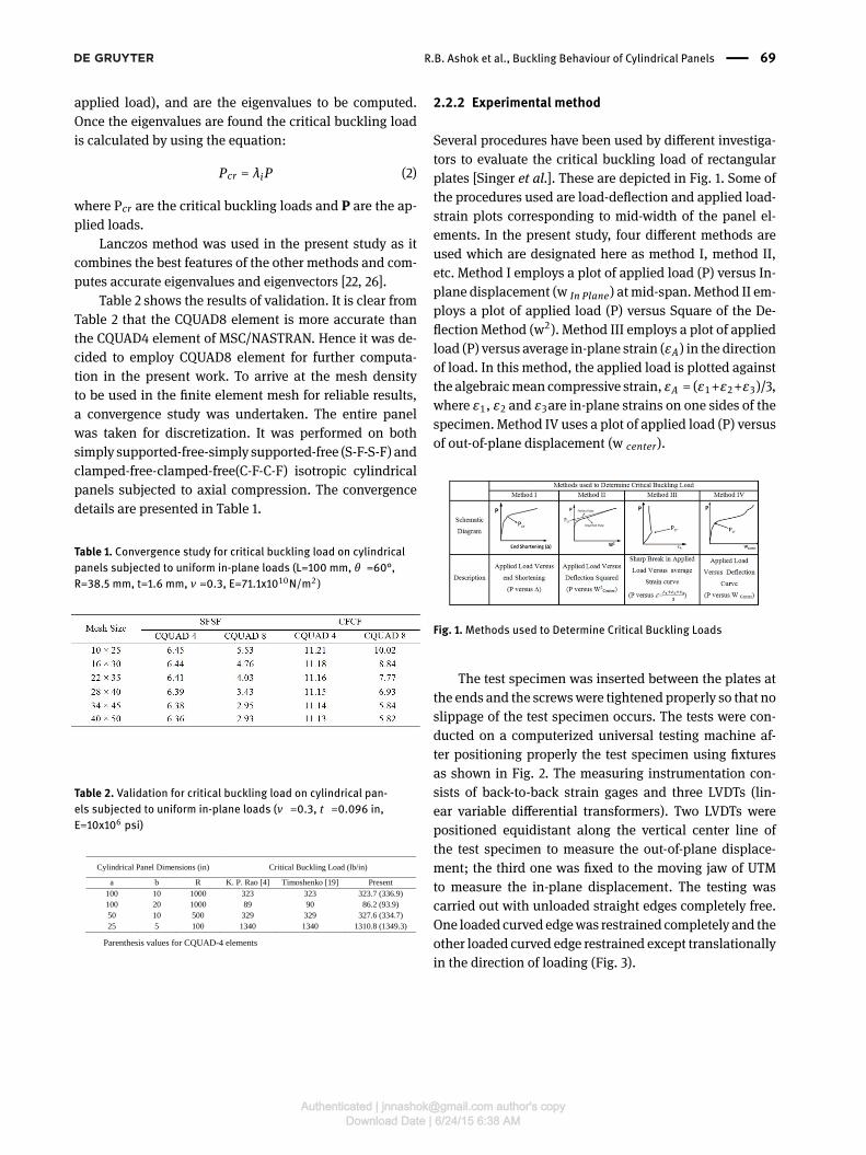
Several procedures have been used by di�erent investiga-tors to evaluate the critical buckling load of rectangularplates [Singer et al.]. These are depicted in Fig. 1. Some ofthe procedures used are load-de�ection and applied load-strain plots corresponding to mid-width of the panel el-ements. In the present study, four di�erent methods areused which are designated here as method I, method II,etc. Method I employs a plot of applied load (P) versus In-plane displacement (w In Plane) atmid-span. Method II em-ploys a plot of applied load (P) versus Square of the De-�ection Method (w2). Method III employs a plot of appliedload (P) versus average in-plane strain (εA) in the directionof load. In this method, the applied load is plotted againstthe algebraicmean compressive strain, εA = (ε1+ε2+ε3)/3,where ε1, ε2 and ε3are in-plane strains on one sides of thespecimen. Method IV uses a plot of applied load (P) versusof out-of-plane displacement (w center).
Fig. 1.Methods used to Determine Critical Buckling Loads
The test specimen was inserted between the plates atthe ends and the screwswere tightened properly so that noslippage of the test specimen occurs. The tests were con-ducted on a computerized universal testing machine af-ter positioning properly the test specimen using �xturesas shown in Fig. 2. The measuring instrumentation con-sists of back-to-back strain gages and three LVDTs (lin-ear variable di�erential transformers). Two LVDTs werepositioned equidistant along the vertical center line ofthe test specimen to measure the out-of-plane displace-ment; the third one was �xed to the moving jaw of UTMto measure the in-plane displacement. The testing wascarried out with unloaded straight edges completely free.One loaded curved edgewas restrained completely and theother loaded curved edge restrained except translationallyin the direction of loading (Fig. 3).
Authenticated | [email protected] author's copyDownload Date | 6/24/15 6:38 AM

70 | R.B. Ashok et al., Buckling Behaviour of Cylindrical Panels
Fig. 2. Fixture for holding the test specimen
3 Results and discussionsIsotropic cylindrical panels were tested in uniaxial com-pression; the panel angle varying from 60° to 120°, panellength varying from 100 mm to 200 mm and the panelwall thickness considered are 1.6 mm and 2.0 mm. The ex-perimental values of the critical buckling load were deter-mined in accordance with the Methods I through IV forboth simple supported-free- simple supported –free(S-F-S-F) and Clamped-free-clamped-free (C-F-C-F) boundaryconditions.
Fig. 4 shows a typical buckled shape of the test speci-men. The test results are presented in Tables 3 through 6.Figs 5 through 20 shows the typical plots of applied load(P)versus in-plane displacement (∆), out-of-plane displace-ment(W), square of out-of-planedisplacement (W2) andal-gebraic mean strain (ε) from which the experimental criti-cal buckling load values have been determined accordingto the Method I through IV.
Fig. 3. Experimental Set-up
Fig. 4. A typical buckled shape of the cylindrical specimen (θ =60°,L=150 mm, R=38.5 mm)
Table 3. Critical Buckling Load for Cylindrical Panels under C-F-C-FBoundary Conditions (R=38.5 mm, t - 1.6 mm)
Authenticated | [email protected] author's copyDownload Date | 6/24/15 6:38 AM

R.B. Ashok et al., Buckling Behaviour of Cylindrical Panels | 71
Table 4. Critical Buckling Load for Cylindrical Panels under S-F-S-FBoundary Conditions (R=38.5 mm, t - 1.6 mm)
Table 5. Critical Buckling Load for Cylindrical Panels under C-F-C-FBoundary Conditions (R=58.5 mm, t - 2 mm)
Table 6. Critical Buckling Load for Cylindrical Panels under S-F-S-FBoundary Conditions (R=58.5 mm, t - 2 mm)
Fig. 5. Applied load versus In- plane displacement (Method I) underC-F-C-F boundary condition(R=38.5 mm, t=1.6 mm)
Fig. 6. Applied load versus out-of-plane displacement squared(Method II) under C-F-C-F boundary condition(R=38.5 mm, t=1.6 mm)
Fig. 7. Applied load versus average strain (Method III) under C-F-C-Fboundary condition(R=38.5 mm, t=1.6 mm)
Fig. 8. Applied load versus In- plane displacement (Method IV) un-der C-F-C-F boundary condition (R=38.5 mm, t=1.6 mm)
Authenticated | [email protected] author's copyDownload Date | 6/24/15 6:38 AM

72 | R.B. Ashok et al., Buckling Behaviour of Cylindrical Panels
Fig. 9. Applied load versus In- plane displacement (Method I) underS-F-S-F boundary condition (R=38.5 mm, t=1.6 mm)
Fig. 10. Applied load versus out-of-plane displacement squared(Method II) under S-F-S-F boundary condition (R=38.5 mm,t=1.6 mm)
Fig. 11. Applied load versus average strain (Method III) under S-F-S-Fboundary condition (R=38.5 mm, t=1.6 mm)
Fig. 12. Applied load versus In- plane displacement (Method IV)under S-F-S-F boundary condition (R=38.5 mm, t=1.6 mm)
Fig. 13. Applied load versus In- plane displacement (Method I) underC-F-C-F boundary condition (R=58.5 mm, t=2.0 mm)
Fig. 14. Applied load versus out-of-plane displacement squared(Method II) under C-F-C-F boundary condition (R=58.5 mm,t=2.0 mm)
Authenticated | [email protected] author's copyDownload Date | 6/24/15 6:38 AM
R.B. Ashok et al., Buckling Behaviour of Cylindrical Panels | 73
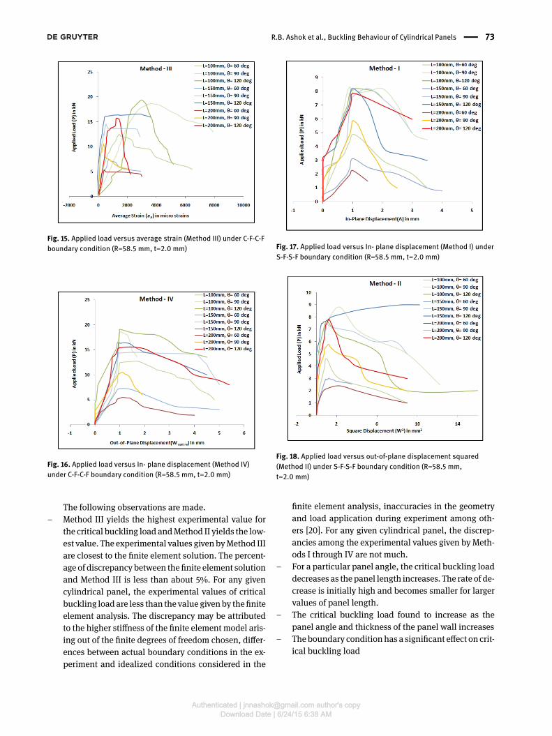
Fig. 15. Applied load versus average strain (Method III) under C-F-C-Fboundary condition (R=58.5 mm, t=2.0 mm)
Fig. 16. Applied load versus In- plane displacement (Method IV)under C-F-C-F boundary condition (R=58.5 mm, t=2.0 mm)
The following observations are made.– Method III yields the highest experimental value for
the critical buckling load andMethod II yields the low-est value. The experimental values given byMethod IIIare closest to the �nite element solution. The percent-age of discrepancy between the �nite element solutionand Method III is less than about 5%. For any givencylindrical panel, the experimental values of criticalbuckling loadare less than the value givenby the�niteelement analysis. The discrepancy may be attributedto the higher sti�ness of the �nite element model aris-ing out of the �nite degrees of freedom chosen, di�er-ences between actual boundary conditions in the ex-periment and idealized conditions considered in the
Fig. 17. Applied load versus In- plane displacement (Method I) underS-F-S-F boundary condition (R=58.5 mm, t=2.0 mm)
Fig. 18. Applied load versus out-of-plane displacement squared(Method II) under S-F-S-F boundary condition (R=58.5 mm,t=2.0 mm)
�nite element analysis, inaccuracies in the geometryand load application during experiment among oth-ers [20]. For any given cylindrical panel, the discrep-ancies among the experimental values given by Meth-ods I through IV are not much.
– For a particular panel angle, the critical buckling loaddecreases as the panel length increases. The rate of de-crease is initially high and becomes smaller for largervalues of panel length.
– The critical buckling load found to increase as thepanel angle and thickness of the panel wall increases
– Theboundary conditionhas a signi�cant e�ect on crit-ical buckling load
Authenticated | [email protected] author's copyDownload Date | 6/24/15 6:38 AM
74 | R.B. Ashok et al., Buckling Behaviour of Cylindrical Panels
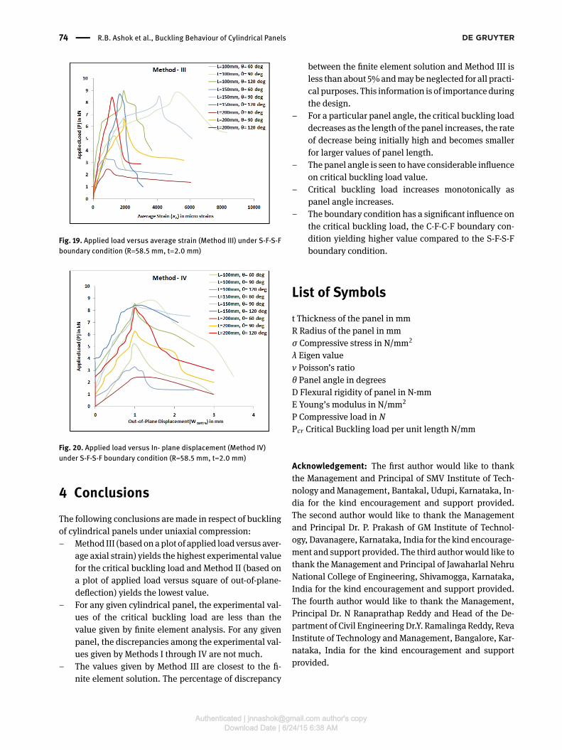
Fig. 19. Applied load versus average strain (Method III) under S-F-S-Fboundary condition (R=58.5 mm, t=2.0 mm)
Fig. 20. Applied load versus In- plane displacement (Method IV)under S-F-S-F boundary condition (R=58.5 mm, t=2.0 mm)
4 ConclusionsThe following conclusions aremade in respect of bucklingof cylindrical panels under uniaxial compression:– Method III (basedonaplot of applied loadversus aver-
age axial strain) yields the highest experimental valuefor the critical buckling load and Method II (based ona plot of applied load versus square of out-of-plane-de�ection) yields the lowest value.
– For any given cylindrical panel, the experimental val-ues of the critical buckling load are less than thevalue given by �nite element analysis. For any givenpanel, the discrepancies among the experimental val-ues given by Methods I through IV are not much.
– The values given by Method III are closest to the �-nite element solution. The percentage of discrepancy
between the �nite element solution and Method III isless than about 5%andmaybeneglected for all practi-cal purposes. This information is of importanceduringthe design.
– For a particular panel angle, the critical buckling loaddecreases as the length of the panel increases, the rateof decrease being initially high and becomes smallerfor larger values of panel length.
– The panel angle is seen to have considerable in�uenceon critical buckling load value.
– Critical buckling load increases monotonically aspanel angle increases.
– The boundary condition has a signi�cant in�uence onthe critical buckling load, the C-F-C-F boundary con-dition yielding higher value compared to the S-F-S-Fboundary condition.
List of Symbolst Thickness of the panel in mmR Radius of the panel in mmσ Compressive stress in N/mm2
λ Eigen valueν Poisson’s ratioθ Panel angle in degreesD Flexural rigidity of panel in N-mmE Young’s modulus in N/mm2
P Compressive load in NPcr Critical Buckling load per unit length N/mm
Acknowledgement: The �rst author would like to thankthe Management and Principal of SMV Institute of Tech-nology andManagement, Bantakal, Udupi, Karnataka, In-dia for the kind encouragement and support provided.The second author would like to thank the Managementand Principal Dr. P. Prakash of GM Institute of Technol-ogy, Davanagere, Karnataka, India for the kind encourage-ment and support provided. The third author would like tothank the Management and Principal of Jawaharlal NehruNational College of Engineering, Shivamogga, Karnataka,India for the kind encouragement and support provided.The fourth author would like to thank the Management,Principal Dr. N Ranaprathap Reddy and Head of the De-partment of Civil EngineeringDr.Y. Ramalinga Reddy, RevaInstitute of Technology and Management, Bangalore, Kar-nataka, India for the kind encouragement and supportprovided.
Authenticated | [email protected] author's copyDownload Date | 6/24/15 6:38 AM

R.B. Ashok et al., Buckling Behaviour of Cylindrical Panels | 75
References[1] Singer J, Arbocz J, Weller T. Buckling Experiments: Experimen-
tal methods in buckling of thin-walled structures. Volume 1 &2, John Wiley & Sons Inc., New York, 2002.
[2] Becker ML, Palazotto AN, Khot NS. Experimental investigationof the instability of composite cylindrical panels. Exp Mech,1982, 372-376.
[3] Hahn EK, Ruvo A, Westerlind B S, Carlsson LA. Compressivestrength of edge-loaded corrugated board panels. Exp Mech,1992, 32(3), 259-265.
[4] Rao KP, Gopalkrishna HR. Optimization of composite cylindri-cal panels for buckling by ranking. Compos Struct, 1992, 21:131-140.
[5] Bozhevolnaya E, Kildegaard A. Experimental study of a uni-formly loaded curved sandwich beam. Compos Struct 199740(2): 175-185.
[6] Han H, Cheng J, Taheri F. Numerical and experimental investi-gations of the response of aluminum cylinders with a cutoutsubject to axial compression. Thin Wall Struct. 2006, 44:254-270.
[7] Li SR, Batra RC. Buckling of axially compressed thin cylindricalshells with functionally graded middle layer. Thin Wall Struct.2006, 44:1039-1047.
[8] Guduru PR, Xia Z. Shell buckling of imperfect multiwalledcarbon nanotubes-experiments and analysis. Exp Mech. 2007,47(1): 153-161.
[9] Young B, Zhou F. Aluminum tubular sections to web cripplingPart II: Proposed design equations. Thin Wall Struct. 2008,46:352-361.
[10] Young B, Zhou F. Aluminum tubular sections to web cripplingPart I: Test and �nite element analysis. Thin Wall Struct. 2008,46:339-351.
[11] Shariati M, Sedighi M, Saemi J, Eipakchi HR. An experimentalstudy on buckling and post buckling behaviour of cylindricalpanels with clamped and simply supported ends. Ind J EngMat Sci. 2010, 17:86-90.
[12] Shariati M, Rokhi MM. Buckling of steel cylindrical shells withan elliptical cutout. Int J Steel Struct. 2010, 10(2):193-205.
[13] Tsuji M, Meshii T. Extending image processing strain mea-surement system to evaluate fracture behavior of wall-thinnedpipes. Nucl Sci Des. 2011, 241(9): 3605-3612.
[14] Prabu B, Raviprakash AV, Venkatraman A Neighbourhood ef-fect of two short dents on buckling behaviour of short thinstainless steel cylindrical shells. Int J Comput Aided Eng Tech-nol. 2012, 4(2): 143-164.
[15] Prabu B, Raviprakash AV, Rathinam N. Numerical bucklinganalysis of thin cylindrical shells with combined distributedand local geometrical imperfections under uniform axial com-pression. Int J Comput Aided Eng Technol. 2012, 4(4): 295-320.
[16] Tahir ZR, Mandal P. A new perturbation technique in numericalstudy on buckling of composite shells under axial compres-sion. World Acad Sci, Eng Technol. 2012, 70:10-27.
[17] Zhao C, Matsuda H, Lou S, Guan ZC, Tian JS. Visualizationof buckling on thin-walled cylindrical shell by digital imagecorrelation method. Appl Math Inf Sci. 2013, 7 (3): 999-1004.
[18] Najafov A, So�yev A, Ozyigit P, Yucel KT. Vibration and stabilityof axially compressed truncated conical shells with function-ally graded middle layer surrounded by elastic medium. J VibControl. 2014, 20(2)303-320.
[19] Timoshenko SP, Gere JM. Theory of Elastic Stability, Interna-tional Students ed., McGraw-Hill, New York. 1986.
[20] Srinivasa CV, Suresh YJ, Prema Kumar WP. Free Flexural Vibra-tion Studies on Laminated Composite Skew Plates. Interna-tional Journal of Engineering, Science and Technology, 2012,4(4), 13-24.
[21] Srinivasa CV, Suresh YJ, Prema Kumar WP. Buckling Studieson Laminated Composite Skew Plates, International Journal ofComputer Applications, 2012, 37(1), 35-47.
[22] Srinivasa CV, Suresh YJ, Prema Kumar WP. Finite Element Stud-ies on Buckling of Laminated Cylindrical Skew Panels, Scienceand Engineering of Composite Materials, 2014, 21(4), 551-558.
[23] Srinivasa CV, Suresh YJ, Prema Kumar WP. Experimental andFinite Element Studies on Buckling of Skew Plates Under Uni-axial Compression, Science and Engineering of CompositeMaterials, December 2013. DOI: 10.1515/secm-2013-0153.
[24] Srinivasa CV, Suresh YJ, Prema Kumar WP. Experimental andFinite Element Studies on Free Vibration of Skew Plates, Inter-national Journal of Advanced Structural Engineering, 2014, 6(1)(Article ID: 48).
[25] Srinivasa CV, Suresh YJ, Prema Kumar WP. Finite Element Stud-ies on Free Vibration of Laminated Composite Cylindrical SkewPanels, Advances in Mechanical Engineering, Vol. 2014 (ArticleID: 174085), 13 pages.
[26] Srinivasa CV, Suresh YJ, Prema Kumar WP. Experimental andFinite Element Studies on Free Vibration of Cylindrical SkewPanels, International Journal of Advanced Structural Engineer-ing, 2014, 6(1).
Authenticated | [email protected] author's copyDownload Date | 6/24/15 6:38 AM