SHEAR CAPACITY PREDICTION OF CONFINED MASONRY WALLS SUBJECTED TO CYCLIC LATERAL LOADING
13
SHEAR CAPACITY PREDICTION OF CONFINED MASONRY WALLS SUBJECTED TO CYCLIC LATERAL LOADING Abdelkrim BOURZAM 1 , Tetsuro GOTO 2 and Masakatsu MIYAJIMA 3 1 PhD cand., Kanazawa University (Kakuma-machi, Kanazawa, Ishikawa 920-1192, Japan) E-mail: [email protected] 2 Senior Researcher, Housing Dept. of National Institute of Land and Infrastructures Management (NILIM) of Tsukuba (1, Tatehara, Tsukuba, Ibaraki 305-0802, Japan) E-mail: [email protected] 3 Professor, Dept. of Civil Eng., Kanazawa University (Kakuma-machi, Kanazawa, Ishikawa 920-1192, Japan) E-mail: [email protected] This study describes an analytical proposal to predict lateral shear capacity of confined masonry walls that fail by diagonal splitting, where the maximum shear is evaluated as the dowel action of confined columns’ reinforcement added to the shear capacity of the plain masonry panel. In order to validate the proposed approach, experimental test results and gathered data from literature were used. The experimental tests concerned two confined clay brick walls subjected to different level of gravity load and cyclic lateral loading. The applicability of some empirical formulae found in literature regarding the stiffness degrada- tion was investigated. Good correlation between the predicted lateral resistance using the proposed ap- proach and all data was achieved. Key Words : confined masonry, brick panel, cyclic load, dowel action, stiffness, shear capacity 1. INTRODUCTION In building masonry system, piers between open- ings are usually the most vulnerable in case of earthquakes; the failure of walls is due in the majority of cases to shear mechanism. However, it is very important to remedy this weakness by one of the multitude existing solutions as well as reinforcing the masonry panel with steel bars or confining it by tie-columns…etc. Confined masonry consists of a load-bearing wall surrounded by small cast-in-place reinforced con- crete columns and beams called tie-columns (con- fining columns) and bond-beams or gravity beams, respectively. This system is such that the wall must resist to both, vertical and lateral loads. The R.C tie-columns and bond-beams are intended to confine the masonry panel, thus enhancing the wall defor- mation capacity to improve the behavior due to a cyclic lateral loading and assure the connections with other walls and floor diaphragms. The R.C tie-columns and bond-beams should have cross-section dimensions and reinforcement ratios sufficiently enough to resist overturning moments and shear force due to earthquakes. According to the requirements of European codes 1), 2) , no contribution of vertical confinement to vertical and lateral resis- tance should be taken into account in the calculation. The amount of reinforcement is determined arbitrar- ily on the basis of experience, and depends on the height and size of the building. In Algerian aseismic code 3) , the confined masonry walls are assimilated to a triangulated system (truss system), formed by the surrounded tie columns and beams, and the diagonal elements which are consti- tuted by the active struts susceptible to be formed in the masonry. As known, flexural failure is favored in seismic resistant design because it is accompanied by large plastic deformation and energy absorption and dis- sipation capacities 4) . Shear failure, on the other hand, is more brittle with limited ductility, from where, confining the plain masonry can remedy in a certain extent this weakness. Few experimental investigations have been carried out so far on the seismic behavior of confined ma- 47s Structural Eng./Earthquake Eng., JSCE, Vol.25, No.2, 47s-59s, 2008 (Copy of Dobokugakkai Ronbunsyuu A Vol.64 No.4, 692-704, 2008.11)
Transcript of SHEAR CAPACITY PREDICTION OF CONFINED MASONRY WALLS SUBJECTED TO CYCLIC LATERAL LOADING
SHEAR CAPACITY PREDICTION OF CONFINED
MASONRY WALLS SUBJECTED TO CYCLIC LATERAL LOADING
Abdelkrim BOURZAM1, Tetsuro GOTO2 and Masakatsu MIYAJIMA3
1PhD cand., Kanazawa University (Kakuma-machi, Kanazawa, Ishikawa 920-1192, Japan) E-mail: [email protected]
2Senior Researcher, Housing Dept. of National Institute of Land and Infrastructures Management (NILIM) of Tsukuba (1, Tatehara, Tsukuba, Ibaraki 305-0802, Japan)
E-mail: [email protected] 3Professor, Dept. of Civil Eng., Kanazawa University (Kakuma-machi, Kanazawa, Ishikawa 920-1192, Japan)
E-mail: [email protected]
This study describes an analytical proposal to predict lateral shear capacity of confined masonry walls that fail by diagonal splitting, where the maximum shear is evaluated as the dowel action of confined columns’ reinforcement added to the shear capacity of the plain masonry panel. In order to validate the proposed approach, experimental test results and gathered data from literature were used. The experimental tests concerned two confined clay brick walls subjected to different level of gravity load and cyclic lateral loading. The applicability of some empirical formulae found in literature regarding the stiffness degrada-tion was investigated. Good correlation between the predicted lateral resistance using the proposed ap-proach and all data was achieved. Key Words : confined masonry, brick panel, cyclic load, dowel action, stiffness, shear capacity
1. INTRODUCTION
In building masonry system, piers between open-ings are usually the most vulnerable in case of earthquakes; the failure of walls is due in the majority of cases to shear mechanism. However, it is very important to remedy this weakness by one of the multitude existing solutions as well as reinforcing the masonry panel with steel bars or confining it by tie-columns…etc.
Confined masonry consists of a load-bearing wall surrounded by small cast-in-place reinforced con-crete columns and beams called tie-columns (con-fining columns) and bond-beams or gravity beams, respectively. This system is such that the wall must resist to both, vertical and lateral loads. The R.C tie-columns and bond-beams are intended to confine the masonry panel, thus enhancing the wall defor-mation capacity to improve the behavior due to a cyclic lateral loading and assure the connections with other walls and floor diaphragms.
The R.C tie-columns and bond-beams should have cross-section dimensions and reinforcement ratios
sufficiently enough to resist overturning moments and shear force due to earthquakes. According to the requirements of European codes1), 2), no contribution of vertical confinement to vertical and lateral resis-tance should be taken into account in the calculation. The amount of reinforcement is determined arbitrar-ily on the basis of experience, and depends on the height and size of the building.
In Algerian aseismic code3), the confined masonry walls are assimilated to a triangulated system (truss system), formed by the surrounded tie columns and beams, and the diagonal elements which are consti-tuted by the active struts susceptible to be formed in the masonry.
As known, flexural failure is favored in seismic resistant design because it is accompanied by large plastic deformation and energy absorption and dis-sipation capacities4). Shear failure, on the other hand, is more brittle with limited ductility, from where, confining the plain masonry can remedy in a certain extent this weakness.
Few experimental investigations have been carried out so far on the seismic behavior of confined ma-
47s
Structural Eng./Earthquake Eng., JSCE, Vol.25, No.2, 47s-59s, 2008(Copy of Dobokugakkai Ronbunsyuu A Vol.64 No.4, 692-704, 2008.11)
sonry walls and buildings, from which reliable em-pirical calculation procedures for the design of con-fined masonry wall panels have been developed.
By testing a series of single storey masonry houses with dynamically imposed sinusoidal displacements with increasing amplitudes, it has been concluded that vertical tie-columns significantly improve the ductility of masonry buildings, but have little effect on the lateral resistance5). Similar conclusions have been obtained by static cyclic tests5),6),7). Correlation studies between the behavior of plain masonry wall panels with poor quality masonry and the confined ones have also been conducted8),9), showing the im-proved seismic behavior of confined masonry ele-ments. However, no attempt has been made to ana-lytically predict the seismic behavior of confined masonry walls until 199710). In this respect, Tomaževič and Klemenc11) proposed a method to predict the shear capacity of confined masonry walls, where the seismic behavior of piers is modeled by considering the effect of interaction forces between bond-beam, tie-columns and masonry panel, with the effect of vertical tie-columns (dowel action). In this approach, the shear force coming from lateral rein-forcement (stirrups) composing the tie-columns was not considered in the calculation. A careful compu-tation of the shear forces of the same specimens, using the same equations developed by these authors, revealed an overestimation in the shear resistances (experimental shear forces) from 23.6% to 53.8% (depending on tested specimen11)). This large over-estimation is due principally to the interaction effect between tie columns and brick panel as was intro-duced by the authors11). However, the authors have simulated the same principle of interaction in the case of the infill wall to the confined masonry system only by changing the interaction coefficient, whereas, the confined wall behavior is totally different from the infill wall construction system.
In 2003 and 2006 Hori et al.12), 13), proposed an analytical approach on seismic resistance of confined concrete block masonry walls, where, the authors adopted a rigid body spring model; the resisting mechanism of the structural system on the lateral load, was a combination of the tension force in the tension side of tie column and the inclined compres-sive force in a concrete block masonry wall.
In this research work, the main idea of Tomaževič and Klemenc11) (combination of the shear resistance of masonry panel and tie columns) was maintained but excluding the interaction effect, and by another attempt, a new analytical approach to predict the shear resistance of confined masonry walls which fail by diagonal splitting is developed herein to be con-sistent to a certain extent with the results of the ex-perimental data.
This study consists mainly of two parts. The first part deals with the elaboration of an approach which leads to predict the maximum shear capacity of con-fined masonry walls, where the total shear of the wall is taken as the summation of the brick panel shear capacity and the shear supported by the R.C con-finements (tie-columns). In this method the brick panel is considered as a homogeneous and isotropic material, the basic equation for the evaluation of the shear resistance of plain masonry walls can be de-rived by taking into account the assumptions of the elementary theory of elasticity. The tie-columns re-sistance is formulated from the dowel action of R.C confinement vertical bars and stirrups effect. The second part concerns the validation of the proposed approach according to an experimental study and gathered data from literature. The experimental study was conducted on two full scale confined clay brick walls CM30J-1 and CM30J-2, where the specimens were subjected to different levels of gravity load 0.4 MPa and 1.4 MPa, respectively, and in-plane cyclic lateral loads. The specimen CM30J-1 was tested by the authors recently, while the other specimen (CM30J-2) similar to the first one was tested in March 199314). The collected data from different published works represent various confined masonry walls of different characteristics as given in Table 3, where the masonry material properties, the column section, the reinforcing details the height to length ratio h/l and the gravity load are presented. The study also includes an evaluation of the stiffness degrada-tion of walls. Furthermore, to verify the effectiveness of empirical formulae of Tomaževič and Klemenc11) regarding the stiffness degradation, the experimental data of the same authors obtained by testing three 1:5 model scaled of confined masonry walls (AH-1, AH-2 and AH-3) with an h/l ratio equals to 1.5 and carrying a gravity load of 0.28 MPa, and the current test results of the specimens CM30J-1 and CM30J-2 were used (refer to Table 2). 2. TEST SPECIMEN AND MECHANICAL
CHARACTERISTICS OF USED MATE- RIALS
As known in masonry construction system, two
major types of shear failure can occur: - Shear failure by diagonal splitting - Shear failure by mortar-joint separation
In this study, only the case of failure by diagonal splitting is investigated. In such mechanism of rup-ture, it is permitted to assume the brick panel as a homogenous material as reported in the majority of
48s
earthquake resistant codes (e.g., ancient design codes, or more recently, Eurocode 6 1)), Moreover, accord-ing to the elementary theory of elasticity, the influ-ence of the tensile strength of the masonry panel ft which is related to the brick unit and mortar qualities, the shape factor β , the gravity load effect σN and the cross section of the masonry Am affect the shear re-sistance of the brick panel as shown in the Eq. (3a). When an important gravity load σN is applied to the wall, then, the compressive strength f’
m of the ma-sonry is introduced into the formulation of the shear resistance (Eq. (3b)). As for the effect of tie columns, the action of the brick panel on both tie-columns creates dowels in the columns’ toes from where the resulting shear resistance is added to the shear of the brick panel (see Eqs. (9a) and (9b)).
In the case of masonry walls which fail by joint separation and/or by shear occurs in the beds of mortar, the hypothesis of homogeneity is not relevant anymore and leaves room to the heterogeneity dominance, where the bond stress between bricks and mortar, the shear of the mortar itself, the tensile strength of the brick units…etc, should be taken into account when assessing the shear resistance of the brick panel. The failure of the brick wall by joint separation or by shear in the beds of mortar is usually occurs when a poor quality of mortar (with small compressive and small shear strengths) is used to construct the wall and/or the gravity load is very small or null.
Despite of the high costs and the difficulties of carrying out the experimental work in the laboratory, experiments remain incontestably imperative for identifying the mechanical behavior of this structural system.
The test specimens CM30J-1, CM30J-2 as intro-duced before, are the full scale of a common window pier with h/l ratio equal to 1.5 surrounded by RC ties. The panel of walls was composite of Japanese solid clay brick units with 210x100x60 mm of nominal dimensions and a characteristic compressive strength of 30 MPa. The bricks were laid with plain cement mortar, with a joint thickness of 10 mm and 27 MPa of compressive strength.
The concrete used for surrounding frame had a compressive strength of 20 MPa. The yielding stress of principal bars (vertical reinforcements) of the specimen CM30J-1 was 415 MPa and 600 MPa for stirrups steel, and 385 MPa for all the steel used in the case of specimen CM30J-2. Details of dimensions and arrangement of reinforcement of specimens and member sections are shown in Fig.1.
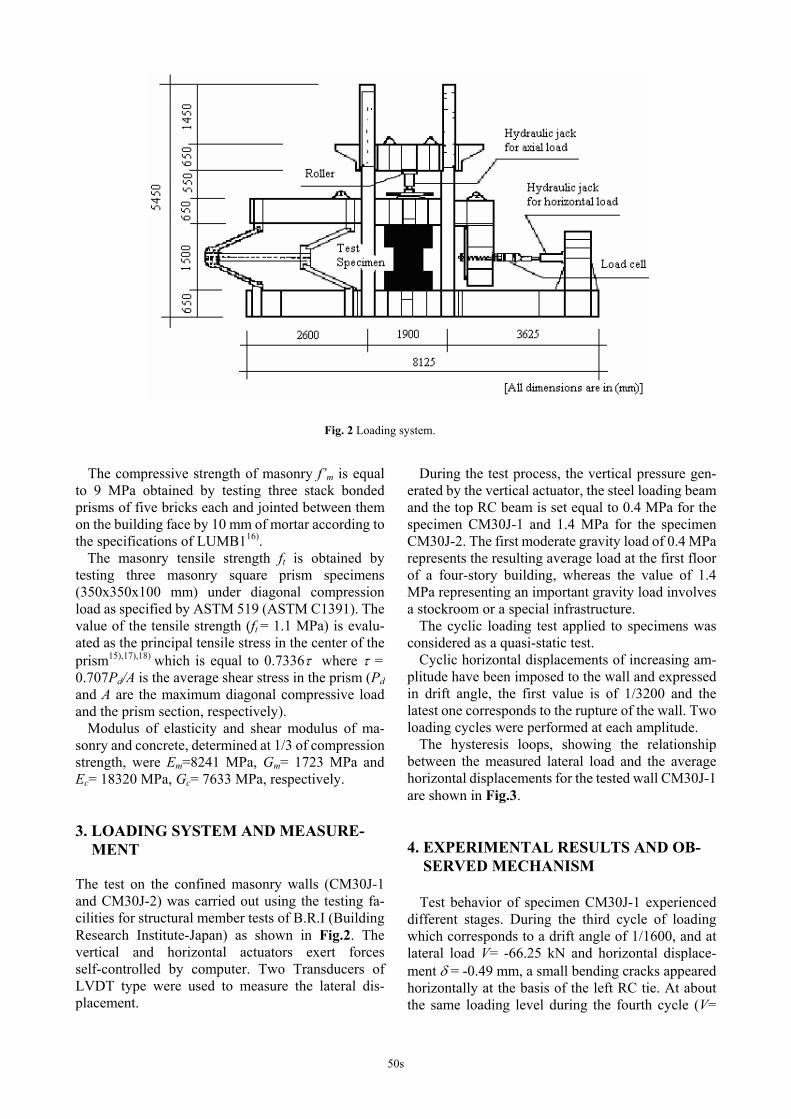
The wall is erected on an RC beam foundation. A similar beam is cast in place on the top of the wall after constructing the brick panel and the RC tie columns. This beam permits a sufficient anchorage of the vertical reinforcing bars in both columns and provides also an adequate transfer of the applied horizontal load to the wall. The RC beams are bolted to the reaction frame as shown in the Fig.2.
CM30J-1 & CM30J-2
N
V
10010
10
100
D8
D10
4D8
1500
l = 870 215100
h =
1330
2230
450
450
D22
100
Diagonal test (According to ASTM 519)
Compression test (Stack of 05 bricks bonded with mortar according to LUMB116))
- +
210
340
[All dimensions are in mm]
350
350
D4
D4 @ 100
D4 @ 40 (*)
(*) Concerns the specimen CM30J-2 only
215 100
10
10
250 250
Fig. 1 Test specimens.
49s
The compressive strength of masonry f’m is equal to 9 MPa obtained by testing three stack bonded prisms of five bricks each and jointed between them on the building face by 10 mm of mortar according to the specifications of LUMB116).
The masonry tensile strength ft is obtained by testing three masonry square prism specimens (350x350x100 mm) under diagonal compression load as specified by ASTM 519 (ASTM C1391). The value of the tensile strength (ft = 1.1 MPa) is evalu-ated as the principal tensile stress in the center of the prism15),17),18) which is equal to 0.7336τ where τ = 0.707Pd/A is the average shear stress in the prism (Pd and A are the maximum diagonal compressive load and the prism section, respectively).
Modulus of elasticity and shear modulus of ma-sonry and concrete, determined at 1/3 of compression strength, were Em=8241 MPa, Gm= 1723 MPa and Ec= 18320 MPa, Gc= 7633 MPa, respectively. 3. LOADING SYSTEM AND MEASURE-
MENT The test on the confined masonry walls (CM30J-1 and CM30J-2) was carried out using the testing fa-cilities for structural member tests of B.R.I (Building Research Institute-Japan) as shown in Fig.2. The vertical and horizontal actuators exert forces self-controlled by computer. Two Transducers of LVDT type were used to measure the lateral dis-placement.
During the test process, the vertical pressure gen-erated by the vertical actuator, the steel loading beam and the top RC beam is set equal to 0.4 MPa for the specimen CM30J-1 and 1.4 MPa for the specimen CM30J-2. The first moderate gravity load of 0.4 MPa represents the resulting average load at the first floor of a four-story building, whereas the value of 1.4 MPa representing an important gravity load involves a stockroom or a special infrastructure.
The cyclic loading test applied to specimens was considered as a quasi-static test.
Cyclic horizontal displacements of increasing am-plitude have been imposed to the wall and expressed in drift angle, the first value is of 1/3200 and the latest one corresponds to the rupture of the wall. Two loading cycles were performed at each amplitude.
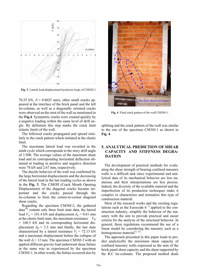
The hysteresis loops, showing the relationship between the measured lateral load and the average horizontal displacements for the tested wall CM30J-1 are shown in Fig.3. 4. EXPERIMENTAL RESULTS AND OB- SERVED MECHANISM
Test behavior of specimen CM30J-1 experienced different stages. During the third cycle of loading which corresponds to a drift angle of 1/1600, and at lateral load V= -66.25 kN and horizontal displace-ment δ = -0.49 mm, a small bending cracks appeared horizontally at the basis of the left RC tie. At about the same loading level during the fourth cycle (V=
Fig. 2 Loading system.
50s
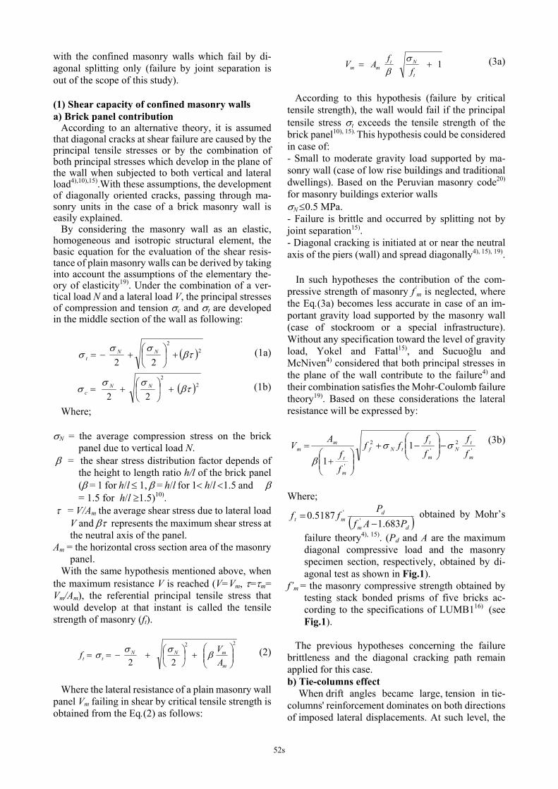
70.25 kN, δ = 0.6025 mm), other small cracks ap-peared at the interface of the brick panel and the left tie-column, as well as a diagonally oriented cracks were observed on the strut of the wall as mentioned in the Fig.4. Symmetric cracks were created quickly by a negative loading within the same level of drift an-gle. By definition this step marks the crack limit (elastic limit) of the wall.
The followed cracks propagated and spread simi-larly to the crack pattern which initiated at the elastic limit.
The maximum lateral load was recorded in the ninth cycle which corresponds to the story drift angle of 1/500. The average values of the maximum shear load and its corresponding horizontal deflection ob-tained at loading in positive and negative direction were 78 kN and 2.67 mm, respectively.
The ductile behavior of the wall was confirmed by the large horizontal displacements and the decreasing of the lateral load in the last loading cycles as shown in the Fig. 3. The CMOD (Crack Mouth Opening Displacement) of the diagonal cracks became im-portant and the cracks passed through the tie-columns to form the corner-to-corner diagonal shear cracks.
Regarding the specimen CM30J-2, the gathered data14) contain only three limit state data, the lateral load Vel = 101.4 kN and displacement δel = 0.61 mm at the elastic limit state, the maximum resistance VW = 160.5 kN and its corresponding horizontal dis-placement δW = 2.5 mm and finally, the last state characterized by a lateral resistance Vf = 72.13 kN and a maximum displacement before the collapse of the wall δf = 12 mm. The specimen CM30J-2 with an applied different gravity load underwent shear failure in the same way as experienced by the specimen CM30J-1. In other words, the failure occurred also by
splitting and the crack pattern of the wall was similar to the one of the specimen CM30J-1 as shown in Fig. 4. 5. ANALYTICAL PREDICTION OF SHEAR
CAPACITY AND STIFFNESS DEGRA-DATION
The development of practical methods for evalu-
ating the shear strength of bearing confined masonry walls is a difficult task since experimental and ana-lytical data of its mechanical behavior are less nu-merous and their interpretations are less precise. Indeed, the diversity of the available material and the imperfection of its production techniques make it complex to characterize and normalize this type of construction material.
Most of the research works and the existing regu-lations such as the Eurocode 6 1) applied to the con-struction industry, simplify the behavior of the ma-sonry with the aim to provide practical and easier criteria for the analysis of the structural behavior. In general, these regulations recommend the use of a linear model by considering the masonry such as a homogeneous material1), 15).
The approach presented in this paper leads to pre-dict analytically the maximum shear capacity of confined masonry walls expressed as the sum of the brick panel shear capacity and the shear supported by the R.C tie-columns. The proposed method deals
Fig. 3 Lateral load-displacement hysteresis loops of CM30J-1.
-90
-70
-50
-30
-10
10
30
50
70
90
-9 -8 -7 -6 -5 -4 -3 -2 -1 0 1 2 3 4 5 6 7 8
δ (mm) V
(kN
)
The fi rst observed cracks -1
Fig. 4 Final crack pattern of the wall CM30J-1.
51s
with the confined masonry walls which fail by di-agonal splitting only (failure by joint separation is out of the scope of this study). (1) Shear capacity of confined masonry walls a) Brick panel contribution According to an alternative theory, it is assumed that diagonal cracks at shear failure are caused by the principal tensile stresses or by the combination of both principal stresses which develop in the plane of the wall when subjected to both vertical and lateral load4),10),15).With these assumptions, the development of diagonally oriented cracks, passing through ma-sonry units in the case of a brick masonry wall is easily explained. By considering the masonry wall as an elastic, homogeneous and isotropic structural element, the basic equation for the evaluation of the shear resis-tance of plain masonry walls can be derived by taking into account the assumptions of the elementary the-ory of elasticity19). Under the combination of a ver-tical load N and a lateral load V, the principal stresses of compression and tension σc and σt are developed in the middle section of the wall as following:
( )22
22βτ
σσσ +⎟
⎠
⎞⎜⎝
⎛+−= NN
t (1a)
( )22
22βτ
σσσ +⎟
⎠
⎞⎜⎝
⎛+= NN
c (1b)
Where; σN = the average compression stress on the brick
panel due to vertical load N. β = the shear stress distribution factor depends of
the height to length ratio h/l of the brick panel (β = 1 for h/l ≤ 1, β = h/l for 1< h/l <1.5 and β = 1.5 for h/l ≥1.5)10).
τ = V/Am the average shear stress due to lateral load V and βτ represents the maximum shear stress at the neutral axis of the panel.
Am = the horizontal cross section area of the masonry panel.
With the same hypothesis mentioned above, when the maximum resistance V is reached (V=Vm, τ=τm= Vm/Am), the referential principal tensile stress that would develop at that instant is called the tensile strength of masonry (ft).
22
22 ⎟⎟⎠
⎞⎜⎜⎝
⎛+⎟
⎠⎞
⎜⎝⎛+−==
m
mNNtt A
Vf βσσσ (2)
Where the lateral resistance of a plain masonry wall panel Vm failing in shear by critical tensile strength is obtained from the Eq.(2) as follows:
1+=t
Ntmm f
fAV σβ
(3a)
According to this hypothesis (failure by critical tensile strength), the wall would fail if the principal tensile stress σt exceeds the tensile strength of the brick panel10), 15). This hypothesis could be considered in case of: - Small to moderate gravity load supported by ma-sonry wall (case of low rise buildings and traditional dwellings). Based on the Peruvian masonry code20) for masonry buildings exterior walls σN ≤0.5 MPa. - Failure is brittle and occurred by splitting not by joint separation15). - Diagonal cracking is initiated at or near the neutral axis of the piers (wall) and spread diagonally4), 15), 19).
In such hypotheses the contribution of the com-pressive strength of masonry f’
m is neglected, where the Eq.(3a) becomes less accurate in case of an im-portant gravity load supported by the masonry wall (case of stockroom or a special infrastructure). Without any specification toward the level of gravity load, Yokel and Fattal15), and Sucuoğlu and McNiven4) considered that both principal stresses in the plane of the wall contribute to the failure4) and their combination satisfies the Mohr-Coulomb failure theory19). Based on these considerations the lateral resistance will be expressed by:
'
2'
2
'
11 m
tN
m
ttNf
m
t
mm f
fff
ff
ff
AV σσ
β−⎟⎟
⎠
⎞⎜⎜⎝
⎛−+
⎟⎟⎠
⎞⎜⎜⎝
⎛+
= (3b)
Where;
( )dm
dmt PAf
Pff
683.15187.0 '
'
−= obtained by Mohr’s
failure theory4), 15). (Pd and A are the maximum diagonal compressive load and the masonry specimen section, respectively, obtained by di-agonal test as shown in Fig.1).
f’m = the masonry compressive strength obtained by testing stack bonded prisms of five bricks ac-cording to the specifications of LUMB116) (see Fig.1).
The previous hypotheses concerning the failure brittleness and the diagonal cracking path remain applied for this case. b) Tie-columns effect
When drift angles became large, tension in tie- columns' reinforcement dominates on both directions of imposed lateral displacements. At such level, the
52s
cracked masonry panel pushes the tie-column side-ward inducing tension in the reinforcing bars. In other words, the RC confining elements prevent the collapse of the masonry and cause additional com-pression stress in the vertical and horizontal direc-tions; hence a certain amount of additional shear can be transmitted by dowel action of the vertical bars. This mechanism occurs mainly at wall corners.
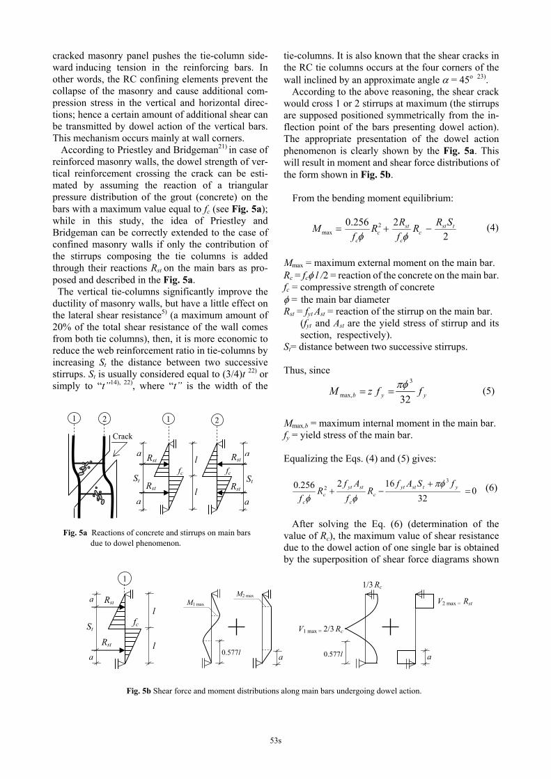
According to Priestley and Bridgeman21) in case of reinforced masonry walls, the dowel strength of ver-tical reinforcement crossing the crack can be esti-mated by assuming the reaction of a triangular pressure distribution of the grout (concrete) on the bars with a maximum value equal to fc (see Fig. 5a); while in this study, the idea of Priestley and Bridgeman can be correctly extended to the case of confined masonry walls if only the contribution of the stirrups composing the tie columns is added through their reactions Rst on the main bars as pro-posed and described in the Fig. 5a. The vertical tie-columns significantly improve the ductility of masonry walls, but have a little effect on the lateral shear resistance5) (a maximum amount of 20% of the total shear resistance of the wall comes from both tie columns), then, it is more economic to reduce the web reinforcement ratio in tie-columns by increasing St the distance between two successive stirrups. St is usually considered equal to (3/4)t 22) or simply to “t”14), 22), where “t” is the width of the
tie-columns. It is also known that the shear cracks in the RC tie columns occurs at the four corners of the wall inclined by an approximate angle α = 45o 23).
According to the above reasoning, the shear crack would cross 1 or 2 stirrups at maximum (the stirrups are supposed positioned symmetrically from the in-flection point of the bars presenting dowel action). The appropriate presentation of the dowel action phenomenon is clearly shown by the Fig. 5a. This will result in moment and shear force distributions of the form shown in Fig. 5b.
From the bending moment equilibrium:
2
2256.0 2max
tstc
c
stc
c
SRRfRR
fM −+=
φφ (4)
Mmax = maximum external moment on the main bar. Rc = fcφ l /2 = reaction of the concrete on the main bar. fc = compressive strength of concrete φ = the main bar diameter Rst = fyt Ast = reaction of the stirrup on the main bar.
(fyt and Ast are the yield stress of stirrup and its section, respectively).
St= distance between two successive stirrups. Thus, since
yyb ffzM32
3
max,πφ
== (5)
Mmax,b = maximum internal moment in the main bar. fy = yield stress of the main bar. Equalizing the Eqs. (4) and (5) gives:
032
162256.0 32 =
+−+ ytstyt
cc
stytc
c
fSAfR
fAf
Rf
πφφφ
(6)
After solving the Eq. (6) (determination of the
value of Rc), the maximum value of shear resistance due to the dowel action of one single bar is obtained by the superposition of shear force diagrams shown
Crack
l Rst
2
a
StRst
a
11 2
fcfc
Rst
Rst
a
a
St
l
Fig. 5a Reactions of concrete and stirrups on main bars due to dowel phenomenon.
M1 max
0.577l
M2 max
1
l Rst
fc St
0.577l
V2 max = Rst
V1 max = 2/3 Rc
a
1/3 Rc
al Rst
a
a
Fig. 5b Shear force and moment distributions along main bars undergoing dowel action.
53s
in Fig. 5b, where: )3
1,32(maxmax, stccb RRRV += (7)
Taking into account that, Rc = fcφ l /2, the value of
the dowel length 2l is then deduced. In case 2l ≤ St (stirrups positioned outside of the
dowel length), the stirrups will not contribute to the shear resistance due to dowel mechanism, however, only the effect of concrete would be considered and the reaction of the concrete Rc will be recalculated consequently.
The shear resistance of n vertical bars, which represents the total resistance induced by the tie- columns (confinements), is equal to:
∑=
=n
ibicf VV
1max,
(8)
In this experimental study n is equal to eight bars. The diagonal crack developed through the wall is
assumed passing by the inflexion point of the steel bars of the confining columns which form dowels at the four corners of the wall. The shear force in the steel bars (coming from the dowel action) will be the force to be added to the shear resistance of the brick panel. As a result, the maximum shear resistance of a confined masonry wall VW is then:
1- Failure by critical tensile stress (principal tensile stress):
∑=
++=+=n
ibi
t
NtmcfmW V
ff
AVVV1
max,1σ
β (9a)
2- Failure by biaxial combination of principal stresses:
'2
'2
'
11 m
tN
m
ttNf
m
t
mcfmW f
fffff
ff
AVVV σσβ
−⎟⎟⎠
⎞⎜⎜⎝
⎛−+
⎟⎟⎠
⎞⎜⎜⎝
⎛+
=+=
∑=
+n
ibiV
1max,
(9b)
(2) Idealized hysteresis envelope curve and stiff- ness degradation a) Hysteresis envelope curve
According to Tomaževič10), the experimentally re- sistance envelope curve representing the relationship between the cyclic lateral load and the corresponding displacement, is idealized with a trilinear relation-ship. Three limit states are defined on the experi-mental curve using three pairs of parameters as fol-lows: - Elastic (crack) limit: determined by lateral load (Vel) and displacement (δel) when the first significant crack in the wall appears and changes the initial stiffness. - Maximum resistance: Noted by lateral load (VW) and displacement (δW) when the maximum resistance of the wall is reached. - Ultimate (final) state: determined by lateral resis-tance (Vf) and the maximum corresponding dis-placement (δf) just before collapse of wall.
Vel and V f are evaluated empirically 10), 11) where: Wcrel VCV = (10) and
Wsdf VCV = (11)
Ccr = reduction factor, vary from 0.6 to 0.8. Csd = strength degradation factor, vary from 0.4 to
0.8. Ccr = 0.7 and Csd = 0.6 (average value of each interval)
are considered in the calculation of Vel and Vf.
In the case where the contribution of tie-columns in the small deformation range is neglected11), then in the Eq. (10) VW will be replaced simply by Vm.
The experimental and theoretical values of shear resistance are reported in the Table 1. b) Stiffness
The element’s stiffness depends on the mechanical properties of constituent materials, the geometry and boundary conditions.
When subjected to a lateral load V, a confined masonry wall generates a horizontal deflection δ
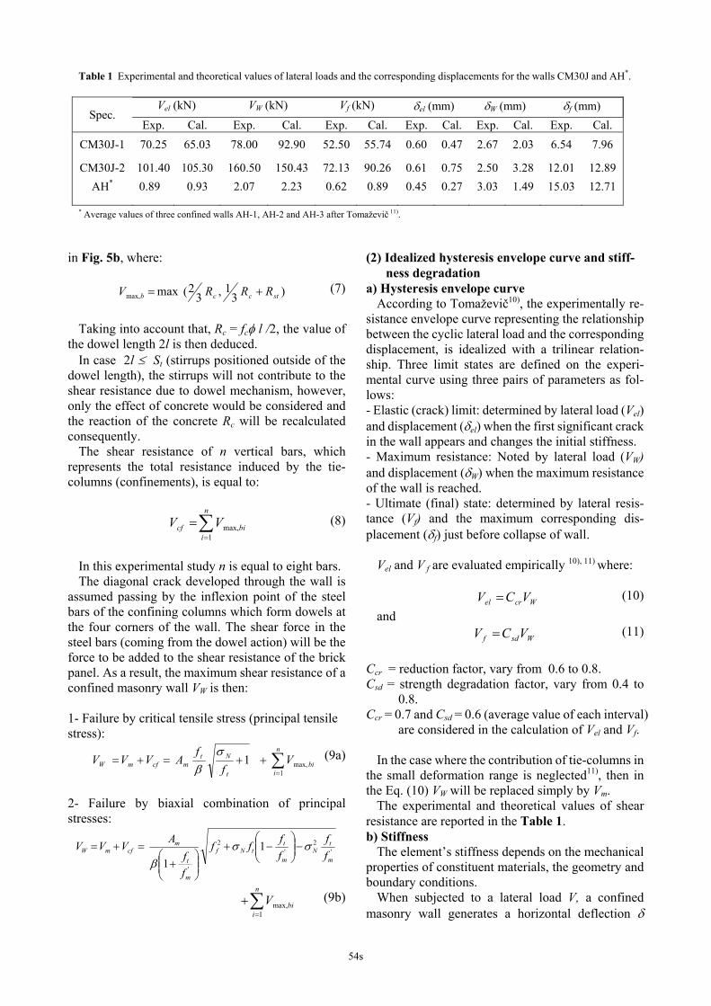
Table 1 Experimental and theoretical values of lateral loads and the corresponding displacements for the walls CM30J and AH*.
Vel (kN) VW (kN) Vf (kN) δel (mm) δW (mm) δf (mm) Spec.
Exp. Cal. Exp. Cal. Exp. Cal. Exp. Cal. Exp. Cal. Exp. Cal. CM30J-1 70.25 65.03 78.00 92.90 52.50 55.74 0.60 0.47 2.67 2.03 6.54 7.96
CM30J-2 101.40 105.30 160.50 150.43 72.13 90.26 0.61 0.75 2.50 3.28 12.01 12.89 AH* 0.89 0.93 2.07 2.23 0.62 0.89 0.45 0.27 3.03 1.49 15.03 12.71
* Average values of three confined walls AH-1, AH-2 and AH-3 after Tomaževič 11).
54s
(Fig.6). This lateral displacement is the sum of the deflection due to flexure and the deformation due to shear as defined in the Eq. (12a).
weqvweqv AG
VhIE
Vh 2.13
+=α
δ (12a)
δeKV = (12b) Where, Ke = the effective stiffness of the confined wall. Iw = tl3/12, moment of inertia of the wall’s cross sec-
tion. Aw = area of the wall’s horizontal cross section. 1.2= the shear coefficient for rectangular
cross-section. α = coefficient depends on the boundary conditions
α=3 for cantilever panel and α =12 in case of fixed-ended wall.
Eeq = modulus of elasticity equivalent. Geq = shear modulus equivalent
cm
ccmmeqv AA
AEAEE22
++
= (13a)
cm
ccmmeqv AA
AGAGG
22
++
= (13b)
After substituting the value of V from Eq. (12b)
into Eq. (12a) and rearranging its different terms, the general equation for the effective stiffness of con-fined masonry wall in the elastic domain is obtained and expressed as follows:
⎥⎥⎦
⎤
⎢⎢⎣
⎡⎟⎠⎞
⎜⎝⎛+
=2
12.1lh
EG
h
AGK
eqv
eqv
weqve
μ
(14)
μ = coefficient describes the applied restraint condi- tions of the wall, μ=3.33 for cantilever walls and μ=0.83 in case of a fixed-ended walls.
In the plastic range, however, secant stiffness K is calculated as a function of effective stiffness Ke and the index damage Id
10), 11).
baIKK de −−= (15) a,b = stiffness degradation parameters10), 11).
Id = Index damage defined as following: Id = 0.25: the appearance of the first significant di-agonal crack in the wall (crack limit). Id = 0.50: a network of diagonally oriented cracks. Usually, when the maximum resistance is achieved. Id = 0.75: increased width of cracks. Crushing of masonry units in the middle of the wall, splitting of units and grout at the compressed zones of the wall. Id = 1.00: heavy damage (beyond repair) or collapse of the wall. As has been found by the analysis of experimental results10), just before, or at Id = 1.00, secant stiffness accounts only with 2 to 5 % of the wall’s effective stiffness Ke.
According to the experimental test conditions, Ke corresponds to Id = 0.25 and the final (ultimate) se-
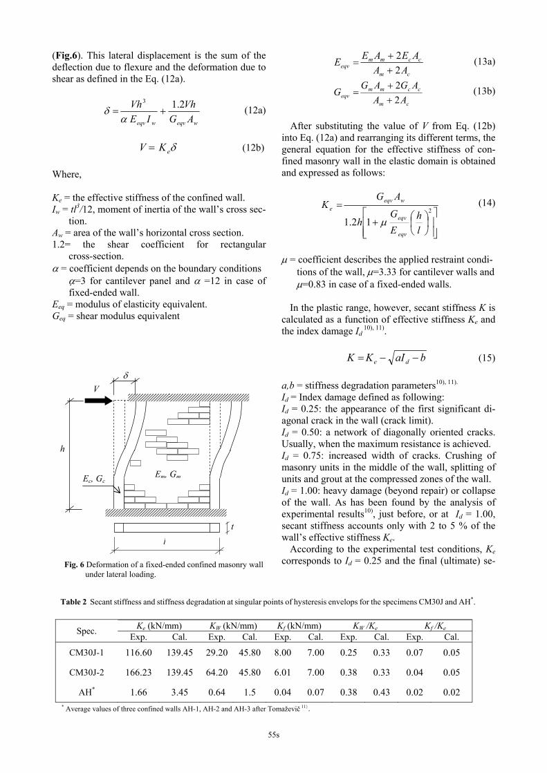
Table 2 Secant stiffness and stiffness degradation at singular points of hysteresis envelops for the specimens CM30J and AH*.
Ke (kN/mm) KW (kN/mm) Kf (kN/mm) KW /Ke Kf /Ke Spec. Exp. Cal. Exp. Cal. Exp. Cal. Exp. Cal. Exp. Cal.
CM30J-1 116.60 139.45 29.20 45.80 8.00 7.00 0.25 0.33 0.07 0.05
CM30J-2 166.23 139.45 64.20 45.80 6.01 7.00 0.38 0.33 0.04 0.05
AH* 1.66 3.45 0.64 1.5 0.04 0.07 0.38 0.43 0.02 0.02 * Average values of three confined walls AH-1, AH-2 and AH-3 after Tomaževič 11).
δ
Em, Gm Ec, Gc
V
h
l
t
Fig. 6 Deformation of a fixed-ended confined masonry wall under lateral loading.
55s
cant stiffness corresponds to Id = 0.75, which repre-sents an amount of 5 % of Ke as shown in the Table2.
The stiffness degradation parameters a and b equal to 1.805 and 0.451 are obtained when these two boundary conditions (K=Ke , Id=0.25) and (K=Kf=5%Ke , Id=0.75) are replaced simultaneously into Eq. (15). In this respect, Eq. (15) becomes:
)451.0805.11( −−= de IKK (16)
In this study, secant stiffness of walls is calculated at three defined stages (crack limit, maximum and ultimate loading). In the order to estimate the stiff-ness degradation of confined walls, the ratios Kw/Ke and Kf/Ke were experimentally and analytically cal-
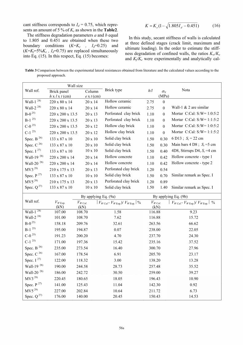
Table 3 Comparison between the experimental lateral resistances obtained from literature and the calculated values according to the proposed approach.
Wall size Wall ref. Brick panel
h x l x t (cm) Column e x t (cm)
Brick type h/l σN
(MPa)
Nota
Wall-1 24) 220 x 80 x 14 20 x 14 Hollow ceramic 2.75 0
Wall-2 24) 220 x 80 x 14 20 x 14 Hollow ceramic 2.75 0 Wall-1 & 2 are similar
B-0 25) 220 x 200 x 13.5 20 x 13 Perforated clay brick 1.10 0 Mortar C:Cal: S:W= 1:0:5:2
B-1 25) 220 x 200 x 13.5 20 x 13 Perforated clay brick 1.10 0 Mortar C:Cal: S:W= 1:1:5:2
C-0 25) 220 x 200 x 13.5 20 x 12 Hollow clay brick 1.10 0 Mortar C:Cal: S:W= 1:0:5:2
C-1 25) 220 x 200 x 13.5 20 x 12 Hollow clay brick 1.10 0 Mortar C:Cal: S:W= 1:1:5:2
Spec. B 26) 133 x 87 x 10 20 x 10 Solid clay brick 1.50 0.30 6 D13 ; St = 22 cm
Spec. C 26) 133 x 87 x 10 20 x 10 Solid clay brick 1.50 0.30 Main bars 4 D8 ; St =5 cm
Spec. I 27) 133 x 87 x 10 10 x 10 Solid clay brick 1.50 0.40 4D8, Stirrups D4, St =4 cm
Wall-19 28) 220 x 200 x 14 20 x 14 Hollow concrete 1.10 0.42 Hollow concrete - type 1
Wall-20 28) 220 x 200 x 14 20 x 14 Hollow concrete 1.10 0.42 Hollow concrete - type 2
MV3 29) 210 x 175 x 13 20 x 13 Perforated clay brick 1.20 0.54
Spec. P 27) 133 x 87 x 10 10 x 10 Solid clay brick 1.50 0.70 Similar remark as Spec. I
MV5 29) 210 x 175 x 13 20 x 13 Perforated clay brick 1.20 0.89 Spec. Q 27) 133 x 87 x 10 10 x 10 Solid clay brick 1.50 1.40 Similar remark as Spec. I
By applying Eq. (9a) By applying Eq. (9b) Wall ref. VW Exp.
(kN) VW Cal. (kN)
⎜VW Cal.- VW Exp.)/ VW Exp. ⎜% VW Cal.
(kN) ⎜ VW Cal.- VW Exp.)/ VW Exp. ⎜ %
Wall-1 24) 107.00 108.70 1.58 116.88 9.23 Wall-2 24) 101.00 108.70 7.62 116.88 15.72 B-0 25) 158.18 209.76 32.61 263.56 66.62 B-1 25) 195.00 194.87 0.07 238.00 22.05 C-0 25) 191.23 200.20 4.70 237.70 24.30 C-1 25) 171.00 197.36 15.42 235.16 37.52 Spec. B 26) 235.00 273.54 16.40 300.70 27.96 Spec. C 26) 167.00 178.54 6.91 205.70 23.17 Spec. I 27) 122.00 118.32 3.00 138.20 13.28 Wall-19 28) 190.00 244.58 28.73 257.48 35.52 Wall-20 28) 186.00 242.72 30.50 259.00 39.27 MV3 29) 220.45 180.65 18.05 196.43 10.90 Spec. P 27) 141.00 125.43 11.04 142.30 0.92 MV5 29) 227.00 202.84 10.64 211.72 6.73 Spec. Q 27) 176.00 140.00 20.45 150.43 14.53
56s
culated, their values are summarized in Table 2.
6. DISCUSSION AND CONCLUSION By applying Eq. (9a) to specimen CM30J-1 char-
acterized by a moderate gravity load (0.4 MPa), on show clearly that the masonry brick panel itself contributes to 80% to the total shear capacity (Vm = 73.7 kN), while the remaining 20 % comes from the tie-columns (Vcf = 19.2 kN), which is in ac- cordance with Umek5).
Results summarized in Table 1 reveal that the calculated value of the shear force at the crack limit Vel is underestimated by 7.4 % as to test data, while the total shear VW and the final resistance Vf are overestimated by 19.1 % and 6.2 %, respectively.
The maximum shear resistance in the case of the confined masonry wall CM30J-2 is calculated by Eq. (9b) instead of Eq. (9a) because this equation is more appropriate when an important gravity load is applied. The Eq. (9b) underestimates the shear resistance by only 6.27 % while if the Eq. (9a) is used the under-estimation becomes 12.77 %.
The lateral load was affected by the intensity of the gravity load. The maximum experimental lateral load increased by two times (VW exp CM30J-2 = 2VW exp CM30J-1) when the gravity load increased from 0.4 MPa to 1.4 MPa, whereas, the theoretical calculations reveal an increase of 1.6 times.
It is worth to notice that the elastic limit force of the specimen CM30J-2 is overestimated by 3.8 % while the final resistance Vf is overestimated by 25.1 %, and the participation of the tie columns themselves count for 29.1% of the total lateral shear resistance (Vf.= 43.82 kN).
The specimen CM30J-2, with a different applied gravity load, underwent shear failure in much the same as exhibited by the specimen CM30J-1.
As well known for masonry structural members, there are many factors that influence their resistance; such as the heterogeneity caused by join mortars and the variability of the compressive strength of brick units. It is of importance to mention that several masonry codes in the world such as Eurocode 6 1) or RPA99 3) propose a partial safety factor “γM” which reduces the tensile and the compression strengths of the masonry, thus the shear strength of the brick wall.
In the case of walls AH-1, AH-2 and AH-3 made at 1:5 scale11), RC ties effect is estimated at 40% of the total shear resistance. The crack limit, the maximum and the final shear forces were overestimated by 4.5 %, 7.7 % and 43 %, respectively. According to the obtained results it is concluded that the predicted shear capacity VW using the proposed approach cor-relates adequately with the rough experimental val-ues of the tested walls CM30J-1 and CM30J-2 as well as for the specimens obtained from literature11) (AH-1, AH-2 and AH-3). In fact, the induced maximum shear capacity of walls was predicted with an error of 7.7%, while Tomaževič and Klemenc estimated the same shear capacity with an average error of 38.7% for the same tested specimens.
The stiffness ratios (Kw/Ke)exp.= 0.25 and (Kw/Ke)cal.= 0.33 of the specimen CM30J-1 as pre-sented in Table 2, show clearly the degradation of the stiffness in the interval located between the crack limit and the maximum lateral loading. In other words, at the attained maximum lateral loading, the experimental and the theoretical effective stiffness Ke are decreased by 75 % and 67 %, respectively.
0
20
40
60
80
100
120
140
160
0 1 2 3 4 5 6 7 8 9 10 11 12 13δ (mm)
V (k
N)
Exp. enve lope c urve of CM30J -1
Theo. e nve lope c urve of CM30J -1
Exp. enve lope c urve of CM30J -2
The o. e nve lope curve of CM30J -2
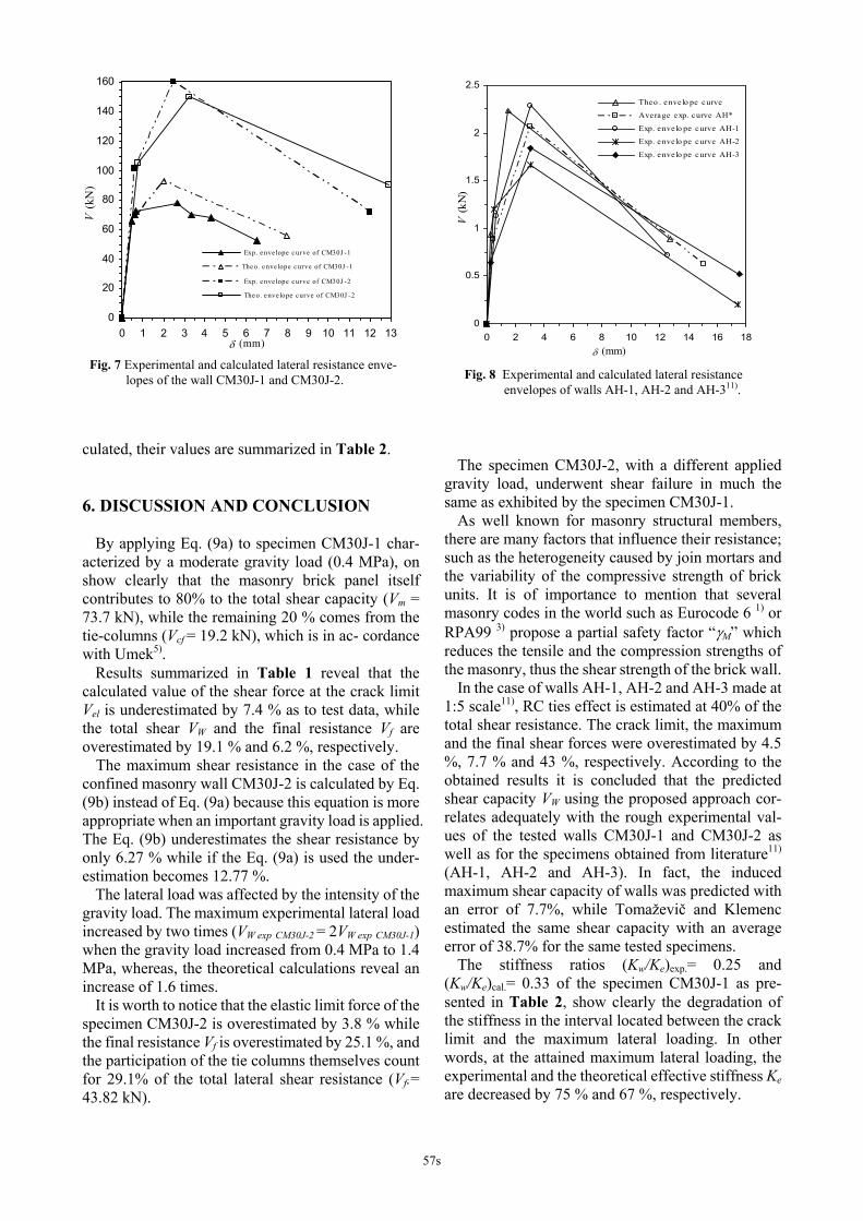
Fig. 7 Experimental and calculated lateral resistance enve- lopes of the wall CM30J-1 and CM30J-2.
0
0.5
1
1.5
2
2.5
0 2 4 6 8 10 12 14 16 18δ (mm)
V (k
N)
Theo . enve lo pe curve
Average exp. curve AH*
Exp. envelo pe curve AH-1
Exp. envelo pe curve AH-2
Exp. envelo pe curve AH-3
Fig. 8 Experimental and calculated lateral resistance envelopes of walls AH-1, AH-2 and AH-311).
57s
In the post-peak (see Fig.7) the confined wall continue to carry the vertical load at large displace-ment amplitudes, despite substantial damage that has been caused to the wall at repeated lateral load re-versals. At the final stage (ultimate stage), the secant stiffness is 7 % of the effective stiffness Ke which is in accordance with the predicted value Kf = 5 %Ke (following the classification of the degree of damage illustrated before).
The degradation of the elastic stiffness in case of the specimen CM30J-2 can be considered similar to the case of the specimen CM30J-1 when the peak was reached.
Regarding AH walls, the stiffness at maximum attained load Kw is 62 % of the effective stiffness Ke of the experimental data while analytically the value is 57 %. As to the ultimate stiffness Kf the experi-mental value matches the predicted one which is equal to 2 %.
The general applicability of the proposed approach regarding the maximum lateral resistance was con-firmed by a good correlation between calculated values and experimental data of previous published works of various confined masonry walls of different characteristics and material properties as given in Table 3 (brick unit type, concrete and mortar strengths, column section, reinforcing details, h/l ratio and gravity load). The calculation of lateral resistance of specimens without any gravity load or carrying a small to a moderate gravity load reveals that Eq. (9a) gives an average error of 13.4 % con-trary to Eq. (9b) which gives an average error of 28.6 %, almost two times greater than the value obtained from the previous equation. As for specimens car-rying a high gravity load (MV3, Spec. P, MV5 and Spec. Q), Eq. (9a) gives an average error of 15 % while Eq. (9b) gives an error of 8.3 % only. It has been observed that the critical stress value of the vertical load which separates the low gravity loading and the high gravity loading is located into the in-terval of 0.42 MPa to 0.54 MPa (refer to Table 3), the determination of the exact value of this stress re-quires more experimental tests of walls in that range. Furthermore, according to the Peruvian masonry code20) which limits the confined masonry buildings to five stories, the exterior walls are less loaded than the interior walls where the maximum gravity load is estimated to 0.5 MPa.
Based on the common gravity load relative to five story masonry buildings adopted in Chile and Peru also, the value of 0.5 MPa seems appropriate as an upper limit for small to moderate loaded walls. This value also can be considered as a median value for the interval 0.42 MPa to 0.54 MPa corresponding to the data given in Table 3.
In this study, it is assumed that the failure in the brick panel is brittle and occurs by diagonal splitting and not by joint separation. The approach is based on predicting the diagonal cracking strength, considered as the shear capacity of the brick panel and an amount of shear coming from the tie-columns. In this type of structural members, tie-columns are used mainly to provide post-cracking deformation capacity by maintaining the integrity of the masonry after di-agonal cracking.
The proposed method has been found satisfactory through the participation of the tie-columns in the maximum resistance of the wall and by an additional deformation in the post-cracking. The modeling is based on the dowel action including an additional effect of the stirrups. ACKNOWLEDGMENT: The experimental work was supported by Japan International Cooperation Agency (JICA), and carried out at the Building Re-search Institute (BRI) in Tsukuba-Japan.
The advice of Dr. Hassane Ousalem from the University of Tokyo and the continuous help of Prof. Masaru Kitaura, Dr. Toshikazu Ikemoto and Dr. Akira Murata from Earthquake Engineering Labo-ratory of Kanazawa University, are well acknowl-edged. REFERENCES 1) Eurocode 6. Design of masonry structures. part 1-1. : General
rules for buildings. Rules for reinforced and unreinforced masonry, ENV 1996-1-1: 1995, 1995.
2) Eurocode 8. Design provisions for earthquake resistance of structures. part 1-3. : General rules – Specific rules for various materials and elements. ENV 1998-1-3: 1995, 1995.
3) CGS. : Règles Parasismiques Algériennes, RPA99/ver. 2003, D.T.R. – B.C. 2.48.
4) Sucuoğlu, H. and McNiven, H. D. : Seismic shear capacity of reinforced masonry piers, J. Struct. Engrg.,Vol. 117, No. 7, pp. 2166-2186, 1991.
5) Umek, A.: Comparaison between unreinforced, confined and horizontally reinforced masonry walls, Civil Engrg. J.,Vol. 20 (Society of Civil Engineers, Ljubljana), pp. 241-248, 1971.
6) Meli, R. : Behavior of masonry walls under lateral loads, Proc. of 5th World Conf. Earthquake Engrg., Paper 101a., 1973.
7) Aguila, V., Delfin, F. and Astroza, M. : Estudio experimental de soluciones de reparación y refuerzo para elementos de al-bañilería, Pub. SES I 1/88 (221), Universidad de Chile, Santiago, 1988.
8) Bolong, Z., Mingshun, W. and Deyuan, Z. : Shaking table study of five-story unreinforced block masonry model build-ing strengthened with reinforced concrete columns and tie bars, Proc. US-PRC Joint Workshop on Seismic Resistance of Masonry Struct., pp. IV-11-1-11, Harbin, 1988.
9) Wenzhong, Y. and Zhaohong, J. : Functions of ties concrete columns in brick walls, Proc. of 9th World Conf. Earthquake Engrg., Vol. 6, pp. VI-139-144, 1988.
58s
10) Tomaževič, M. : Earthquake-resistant Design of Masonry Buildings (Innovation in Structures and Construction, Vol. I), Imperial college press, 1999.
11) Tomaževič, M. and Klemenc, I. : Seismic behaviour of confined masonry walls, Earthquake Engrg. Struct. Dynamics, Vol. 26, pp. 1059-1071, 1997.
12) Dangol, P., Hori, N., Inoue, N., Nishida, T. and Kobayashi, J. : Analytical studies on seismic resistance of composite block masonry wall by rigid body spring model, J. Struct. Engrg., Vol. 49B, pp.243-250, 2003.
13) Hori, N., Inoue, N., Dangol, P., Nishida, T. and Kobayashi, J.: Experimental and analytical studies on earthquake resisting behaviour of confined concrete block masonry structures, Earthquake Engrg. Struct. Dynamics, Vol. 35, pp. 1699-1719, 2006.
14) Goto, T., Mizuno, H., Iiba, M. and Kato, H. : Cyclic loading tests of confined masonry walls, Research report, B.R.I, Tsukuba, Japan, March 1993.
15) Yokel, F. Y., and Fattal, S, G. : Failure hypothesis for ma-sonry shear walls, J. Struct. Div., ASCE, Vol. 102, No. 3, pp. 515-532, 1976.
16) Rilem. Technical recommendations for the testing and use of constructions materials, LUMB1, Compressive strength of small walls and prisms, 1994 (b).
17) Chiostrini, S., Galano, L. and Vignoli, A.: On the determi-nation of strength of ancient masonry walls via experimental test, Proc. of 12th World Conf. Earthquake Engrg., CD-ROM, 2000.
18) Sucuoğlu, H. and Erberik, A.: Performance evaluation of three-storey unreinforced masonry building during the 1992 Erzincan earthquake, Earthquake Engrg. Struct. Dynamics, Vol. 26, pp. 319-336, 1997.
19) Timoshenko, S. : Strength of materials, Chap. 10, part II, 3rd ed., D. Van Nostrand Co. Inc., Princeton, N.J., 1956.
20) Reglamento Nacional de Edificaciones. Norma E 070 Al-bañilería, Perú, 2006.
21) Priestley, M.J.N. and Bridgeman, D.O. : Seismic resistance of brick masonry walls, Bull. of the New Zealand Nat. Soc. for Earthquake Engrg., Vol. 7, No. 4 (New Zealand National
Society for Earthquake Engineering, Wellington), pp. 167-187, 1974.
22) Yoshimura, K., Kikuchi, K., Okamoto, T. and Sanchez, T. : Effect of vertical and horizontal wall reinforcement on seismic behavior of confined masonry walls, Proc. of 11th World Conf. Earthquake Engrg. (11thWCEE), CD-ROM, No. 191, 1996.
23) Pillai, S.U. and Kirk, D.W. : Reinforced concrete design, Canadian Cataloguing in Publication Data, 2nd ed., 1988.
24) Diez, J., Astroza, M. and Delfin, F. : Estudio experimental de modalidades de refuerzo para muros de albañilería de unida-des cerámicas, Jornadas en español y portugués sobre es-tructuras y materiales, Madrid, España, Vol. VI, pp. 319-338, 1988.
25) San Bartolomé, A. : Ensayos de carga lateral en muros de albañilería confinados por elementos de concreto arma-do-Correlación de resultados entre especimenes a escala na-tural y pequeñas probetas, Ponencia al V Congreso Nacional. de Ingeniería Civil, Tacna, Perú, 1983.
26) Kato, H., Goto, T. and Mizuno, H. : Cyclic loading tests of confined masonry wall elements for structural design devel-opment of apartment houses in the third world, Proc. of 10th World Conf. Earthquake Engrg. (10thWCEE), Balkema Rot-terdam, pp.3539-3544, 1992.
27) Goto, T., Mizuno, H., Iiba, M. and Kato, H. : Structural characteristics of confined masonry wall : Part 3 quasi static loading test-effect of lateral reinforcements in brick walls, Sum. of tech. papers of Annual meeting AIJ, Structures II, Vol.1994(19940725), pp. 1869-1870, 1994.
28) Muñoz, W. : Estudio experimental del comportamiento de muros de albañilería de bloques de hormigón sometidos a carga lateral alternada, Civil Eng. Thesis, Universidad de Chile, 1992.
29) San Bartolomé, A. and Echeverria, G. : Ensayos de carga lateral en muros de albañilería confinada-Efectos de la carga vertical, Ponencia al VI Congreso Nacional. de Ingeniería Civil, Cajamarca, Perú, 1986.
(Received June 7, 2007)
59s