
CONCRETE AND MASONRY DAM CONSTRUCTION IN NEW ...
28
1 t ELEVATION OF OUTLET CHAMBERS. SECTIONAL ELEVATION OF OUTLET CHAMBERS. CROSS SECTION OF DAM. PARRAHATTA. Fiy 16. T4Y WORTH 13. __ S C A LE S PARKES. COOTAMU N DRA /' GENERAL PL4W. C A T A R A C T TYPE SECTION OF DAM . D A m . LITHGOW NO I L.A.B. WOE, PLAN AHD HORIZONTAL SECTION OF OUTLETS. QUEEN CHARLOTTE VALE Downloaded by [ University of Sussex] on [19/09/16]. Copyright © ICE Publishing, all rights reserved.
-
Upload
khangminh22 -
Category
Documents
-
view
1 -
download
0
Transcript of CONCRETE AND MASONRY DAM CONSTRUCTION IN NEW ...

1 t
ELEVATION OF O U T L E T C H A M B E R S .
S E C T I O N A L E L E V A T I O N O F O U T L E T C H A M B E R S . C R O S S S E C T I O N OF D A M . P A R R A H A T T A .
F i y 16.
T 4 Y W O R T H
13.
_ _ S C A L E S
P A R K E S . C O O T A M U N D R A /'
G E N E R A L P L 4 W .
C A T A R A C T
T Y P E SECTION OF D A M . D A m .
L I T H G O W N O I
L.A.B. W O E ,
PLAN AHD HORIZONTAL S E C T I O N OF OUTLETS. Q U E E N C H A R L O T T E V A L E
Downloaded by [ University of Sussex] on [19/09/16]. Copyright © ICE Publishing, all rights reserved.

I N N E W S O U T H W A L E S .
U
L I T H G O W NO I , - P L A N
C O O T A M U N D R A , - - P L A N .
M E D L 0 W ,- P L A N .
W O L L O N G O N G , - P L A N . - S C A L E S
Downloaded by [ University of Sussex] on [19/09/16]. Copyright © ICE Publishing, all rights reserved.

THE:
INSTITIJTION OF
C I V I L E N G I N E E R S . SESSION 1908-190'5.--PABT IT.
SECT. I.-iJZINUTE8 011 PROCEEDINGS. ___
9 iJlarcl1, 1909. JAMES CHARLES I.NGLI8, President,
in the Chair.
(Pcyer No. 3791.) _ _ _ ~
" Concrete and Masonry Dam-Construction in New South Wales."
By LESLIE AUGCSTUS BURTO.N WADE, M. Inst. C.E.
UNDER two Acts of Parliament, the State of Wew South Wales pro- vides separate powers for the construction of water-supply works either for country towns or for the metropolis. The Country Towns Water-Supply and Sewerage Act admits of alternative courses of procedure : either loans can be raisecl and the works constructed by the local municipalities, or the worlks may be constructed by the State Government on the request of the municipalities with funds provided from S h t e loans, In the lat ter case the w-orks on comple- tion are handed over to the municipalities, who assume the liability and liquidate the debt over periods varying according to the nature of the structures, but never exceeding 50 years. The State being in a position to borrow money at lower rates of interest than the local municipalities, the majority of those bodies avail themselves of the privilege afforded by the Act, and request the Government to construct works for their use. The Metropolitan Water and Sewerage Act provides for the constru.ction of all works by the State Government, the works on completion being handed over to the hfetropolitnn Water and Sewerage Board, which in constitution is Imrtly elective and partly nominative ; this body then maintains the works, assesses rates, and collects revenue. It thus comes about that the Public Works Department o!F New South Wales is charged with the construction of practically the whole of the public water- supply works in the State. The oficers of the department, there- fore, are called upon to design works, in some of which the cost is not a first consitleration, while in other cases the cost must be kept
[rm TNST. C.E. YOL. CLXYVIIJ.] B Downloaded by [ University of Sussex] on [19/09/16]. Copyright © ICE Publishing, all rights reserved.

2 W’AUE OS Uh;\I-CONSTllECTION [;\lilmtes of
witllin the narrow financial capabilities of townAips and villages situated in sparsely populated and undeveloped districts.
Of the many different classes of work involved in the schemes of water-supply carried out under very varied conditions by the Public Works I)epu%nlent, the Author proposes here to describe only certain dams constructed for storing water.
CUllVED DAMS FOR COUK’!XY TOWNS’ WATER-SUPPLY.
I n thirteen cases dams have been built curved in plan, reliance for stability being placed only on the ctlpacity of the material in the wall and sides of the valley to resist compression. I n designing these dams the complex question of the exact stresses that mty occur and the assistance that may be afforded by the weight of the wall hns been disregarded ; as it has been considered that all practical requirements would be met if in theory the darns were treated simply :M sections of rigid cylinders subject to exterior water-pressure.
The formulas used for determining the widths of a wall a t dif- ferent levels below the highest water-surface are deduced from the exlwession
Where T denotes the thickness at any level in feet. It ), ,, d i u s in feet. l’ ,) 7 7 water-pressure in tons per square foot. S ,, 7 7 stress in tons per square foot.
Tlle widths vary as follows, according to the limiting stresses nllowed for different materials--
If L) denotes the depth of water in feet, Tllen T is equal to R 13 X 0.0014 when S is 20 tons.
7, ), KI) X 0-0018 ), ,, 15 ,, ‘I’ ,, ,, RDxO.0023 ,, ,, 12 ,, T 7 7 7 7 R D X 0.0027 ,) ,, 10 ,)
The theoretical cross section would tllen be represented lop n triangle, having its apex at the highest orerflow-level of the water- surface. Usu:llly in practice i t h:ts been found advisable to make the top thickness of the wdl not less than 3 feet 6 inches, this thickness being increased according to the depth of water and the weight of timber passing over the crest in flood-time. The climatic conditions of New South Wales are such that stresses resulting from the form:Ltion of heavy ice need not be provided for. In all of the thirteen cli~ses it has been found convenient to pass flood-waters over R portion of the lellgtll of the wall ; B maximum depth of
Downloaded by [ University of Sussex] on [19/09/16]. Copyright © ICE Publishing, all rights reserved.

Proceedings.] I N NEW SOUTH WALES. 3
3 feet has been thus dealt with at F’arkes, where the crest width is 3 feet only, without any bad resultt; following. The top thickness being determined, the wall for a short distance from the top is carried down vertically, and is then eased by an intermediate batter into the theoretical profile.
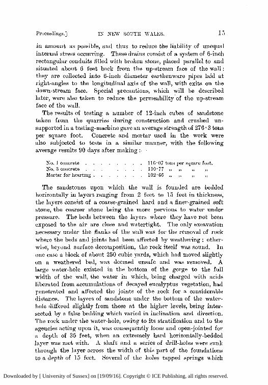
It will be seen by Figs. 2-13, P h t e 1, that three different types of cross section have been used :-
l. A wall having similar profileswn both its up-stream and tlown- stream faces, so that the centre of gravity of all layers is in a vertical line in the centre of the wall. (Fig. 3.)
2 . A wall battered on the up-stream face, with a vertical down- stream face, additional stability being afforded in theory by the downward pressure of water on the up-stream fa.ce. (Figs. 4 and 6.)
3. A wall battered on the down-stream face, and with a vertical up-stream face.
Practical considerations have caused the abandonment of Types 1 and 2 and the final adoption of Type 3, as it affords greater facilities for the handling of the swivel-jointed type of draw-off pipe that is used. The radii used in the calculations were measured to the centre of gravity of the wall in ‘Type 1 and to the vertical faces of the walls in Types 2 and 3.
Nine of the thirteen walls are curved on p1a.n over their whole length and abut against the rock sides of the gorges up to their top levels ; while of the remainder the Cootamundra dam has been constructed with two tangents of gravity cross section, and the Tamworth, Parkes and Wollongong walls each with one tangent of gravity cross section (Plate 2).l The Cootamundra, Tarnworth and Wollongong gravity tangents abut against the rock sides of the gorges to their top levels. The gravity ttmgent a t Parkes is constructed on a flat bench of rock a t a level of about 13 feet below the top of the wall, and the thrust of the arched length is resisted by the weight of the gravity wall, assisted by an anchorage of steel rails placed vertically so as to connect the wall with the rock foundation.
It is found as a rule that the positions of the horns of the curve are more or less fixed by local conditions and that a radius giving a versed sine of about one-third of its length tllen forms the most economicttl 1oc;Ltion betw-een those points. Occasions arise, however, when this rule will not apply, and the radius may be altered with achntage to suit the configuration of the va1le;y. A few trial curves marked on the gromlcl are in all cases necessary to secure the best results.
1 The plans reprocluced in Plate 2 were furnished by t h e Author ip reapunse t u a suggestion m d e in the course of the discusaion. They are numbered 2.1, .i~, etc., to correspond with the cross sections in Plate l.-Sec. INST. C.E.
_ _ _ ~ _ _ _ _ _ _ ~ ~ ~~~~~~
B 2
Downloaded by [ University of Sussex] on [19/09/16]. Copyright © ICE Publishing, all rights reserved.

4 WADE ON DAM-CONSTRUCTION [Minutes of
Of the thirteen walls constructed, all but four have been carried in the first instance to the full height proposed ; of the remainder, those a t Parramatta, Parkes and Picton were constructed to the full cross sectional widths but stopped short of the full height pro- posed. The Katoomba dam was constructed to the less height shown in Fig. 10, Plate 1, with n cross section reduced to afford the same c.rushing-resistance as that to be allowed in the higher wall when completed. I n this case buttresses 3 feet thick were carried to the fnll cross-sectional width of the proposed higher wall, being sptcecl 7 feet ap:Lrt, and putlog-holes were left in them for the subsequent insertion of bonding iron when the wall was being c:trried to the full height m d the spaces between the buttresses were being filled in.
The Table on p. 5 gives the full particulars of each of the thirteen structures under review.
It will be noted that in two cases maximum pressures of 24 and 25 tons per square foot have been allowed where the material in the wall and foundations consisted of hard granite :md diorite ; later practice, however, has been to reduce this limit to 20 tons per square foot, which is considered to afford an ample factor of safety where sound igneous rocks are being dealt with. Hard slates, sandstones, conglomerates and ironstones are limited to pressures of 15 and l 2 tons per square foot according to qu:tliby, and softer standatones to 10 tons per square foot. These limiting pressures refer more to the material used in the construction of the wall than to that met with in the abutments, :LS should the wall have a greater crushing resistance than the abutments, it is a simple matter to splay the m:dl where it meets the rock and thus to reduce the pressure per unit of area at that point. The walls have in all cases been constructed of Portland-cement concrete, with plums of selected stone having a greater resistance to crushing than the concrete surrounding them. The crushing-strength of the concrete used is therefore the nletsure of the cruslling-resistance within the mall. The proportions of the concrete have in all cases been 1 cwk (equal to about 4fr cubic leet) of cement, llfr cubic feet of sand, 10 cubic feet of shivers from $-inch to ;-inch gauge and 13 cubic feet of metal of l.$-inch gauge. Samples of concrete for testing purposes have been taken from time to time from the mixings used in the work and have been tested for crushing-strength orer various a.ges. The results obtained from a number of tests of 6-inch cubes, 6 months old and crushed unsupported in a testing- machine, have been utilized to fix an average standard strength for concrete made of the different classes of rock dealt with. These results give a mean crushing-resistance ranging from 50 tons per square foot for the soft smdstone to 100 square tons per foot for the
Downloaded by [ University of Sussex] on [19/09/16]. Copyright © ICE Publishing, all rights reserved.

"j 0, 0, 0- 0, c> 3 0 o a o c;'
a o - 1 5 + m -r 9 0.. 0- c=-
0 0 0 0 c> 0 0 0 0 c>
0 0 0 0 c> i d 0
+? W 1 r n ri W c 1
G L? 0 0
4 2 0 m ~ m . . .
0 0 1 5 O ' N 0 3 1 $1 c ri
m 0 0 0 0 0 LT) 0 N O W O r n 0 l N H
Downloaded by [ University of Sussex] on [19/09/16]. Copyright © ICE Publishing, all rights reserved.

6 WADE O N DbM-CONSTRUCTION [Minutes of
sound igneous rocks. It has been assumed that concrete in bulk offers a crushing-resistlice 50 per cent. grwter than in the unsupported &inch cubes. The ulasirrlunl tlleoreticd pressures allowed in the construction of the walls have been adjusted to give a factor of safety of 5 on the basis of results obtained from UIF.
supported concrete cubes ; and if the assumption as to increased strength is correct, the factor will be 7 4 for concrete in bulk.
The cross section of a curved wall 500 feet in radius and calculated to resist a stress of 20 tons per square foot, or of a curved wall of 270 feet radius to resist a stress of l 0 tons per square foot, closely approximates to the cross section of a gravity wall designed to retain a similar depth of water. The Author is of opinion that gravity walls in narrow gorges should be constructed straight on plan, the employment of a curve presenting no adrantages-as regards either additional strength, elimination of tensional strains, or adaptability to meet contraction-sufficient to justify the extra cost involved by the increased qmntities. The economical limit where it will be jnstifittble to substitute curved m-alls, such as those described, for gravity walls will then be with r d i i rather less t h m these, bearing in mind the additional quantities involved by the greater length of the curved wall over the straight one. It will be seen that the use of curved walls is thus restricted to compa.ratively narrow valleys and gorges.
The igneous rocks met with in the construction of these works afforded not only the best foundations, but also the most imper- rions media to leakage under their foundations. It was necessary, however, particularly with grmite, to exercise great care in fol- lowing out all soft seams, which at times were found liRble to develop into serious faults. I n sandstones and conglomerates the weakness as a rule was found along horizontnl beck, and in several cases leakages took place under the flanks of the wall, the water entering some distance up-stream and the exit being some distance down-stream of the ~vall. In two instances short drives have been carried under the flank of a wall to cut out weak horizontal joints and fissures in the rock; the drives were filled with concrete, and finally grouted up solid under pressure, holes being drilled to the top of the concrete for this purpose. The worst leakages have been experienced in shale and slate, particularly where the formation has been disturbed and the beds do not lie horizontall?.
In preparing rock foundations to receive the wall, i t has not generally been found necessary to cut out skewbacks. It is found as a rule that the harder igneous rocks require very little preparation and that in their natural state the surfaces are sufficiently irregular
Downloaded by [ University of Sussex] on [19/09/16]. Copyright © ICE Publishing, all rights reserved.

Proceedings.] IX NEW SOUl!H VALES.
to form a key ; where the surfa.ces a,re flat or smooth a few '( pop '" shots will afford the required key. When using even small pops, however, awe must be taken, as the sting of the shot results in minute cracks which weaken the adjacent rock. In the sedimentary rocks, where the surfaces are more or less soft and weathered, skew- backs are provided to a greater extent than in the igneous rocks. A similar practice prevails in regard to cut-off trenches under the foundations. The surfaces of the harder igneous rocks are first of all well washed with a jet of water under pressure ; they are then grouted and a $-inch layer of good mortar is applied before placing the concrete ; this as a rule renders the surface sufficiently rough to afford a good connection and to prevent leakage under the base of the wall. I n the softer sedimentary rocks, however, it is usual to channel a shallow trench for the reception of a cut-off wall. The curved wall has an advantage over the straight wall, inasmuch as its stability is not endangered to the same extent by small leakages occurring between its base and the foundations.
The proportions of the materials in the concrete used are sufficient to afford the required resistance against crushing at the minimum cost, but when placed in a thin wall they do not form an impervious medium against the passage of water under pressure. In t he earlier walls constructed, a 6-inch layer of special concrete was placed on the up-stream face to secure watertightness. Subsequent experience proved that watertightness couid be more effectually and economically secured by the fornlat'ion of a skin of neat cement on the up-stream and down-stream faces of the wall. I n practice it WRS
found that if sloppy concrete was used and was well cut and worked against the mould-boards forming the boxing, a skin of cement was formed at the surface, and a practically impervious wall was obtained. When, however, the surplus moisture dried out, longitudinal contraction, with the development of a number of vertical cracks, took place. Further experience demonstrated that longitudinal contraction is much less in a wall c'onstructed of concrete placed in position fairly dry and well rammed, and that under such conditions verticnl cracks either do not occur or occur only in a less degree. A skin, however, could not be obtained under such conditions, and the thin walls so built were found to leak excessively. Experiments were carried out to ascertain the best means of securing a water- tight wall by painting the faces, and it was found that two coats of neat cement applied with a hard brush to the green concrete, immediately after the timber was stripped, gave the best results. The practice now adopted is to construct the walls of concrete mixed with n minimum quantity of water and well
e I
Downloaded by [ University of Sussex] on [19/09/16]. Copyright © ICE Publishing, all rights reserved.

8 WADE ox DAhl-COSST11CCTIOS [Jtinutes of
rammed and cut against the mould-boards : two coats of neat cement are then applied t o the up-stream and do\r-n-stream faces immediately after the boxing has been removed and while the concrete is green and moist. This system of construction has yielded excellent results under the climatic conditions of New South Wales, but tlle application of the neat cement coating is not recommended where the walls would be subject to the influence of many degrees of frost, as scaling then results. A facing of richer coneretre under these latt'er conditions is preferable.
I n order to reduce the cost of concrete, phms hare been used in the walls where the cross sections are of suflicient width to allow it to be done. With the exception of such a wall a s Lithgow KO. 2 (Fig. 11, Plate l), where the quantities to be dealt with justified the installation of plant to handle large stones, the plums have been of a maximum size that could be handled by two men. By this method it has been found that 30 per cent. of plums can be advantageously inserted where the stone is rough from the quarry and the pieces are of irregular dimensions with no work done in squaring. Any larger proportion of such stone is 1i:hle to resdt in inefficient packing of the concrete aronnd them. Xhen stone with natmal beds, such 9s can be quarried of fairly sqnare dimensions, is availa.ble, this proportion may be slightly increased. It is necessary to use concrete in a fairly sloppy condition to secure sntisf:tctory bedding of the plums, as when concrete is used so dry that plums cannot be sunk and worked in, it has been fount1 that in most cases a.ir-spaces exist under them. There is also ,'L
tendency in working with R dry concrete to place plums in horizontal layers, which, comhined with inefficient bedding, wonltl form horizontd lines of cleavage. The Author considers that for the purpose of a\-oitling contraction a.nd shrinkage, with resulting vertical cra.cking, the desirability of nsing concrete mixetl with as little w:tter :M practicnble is unquestionable ; and that if plnms are then used, it is necessary for them t o be embedded in mortar. Where the stones used have naturally flat beds the proportionate quantity of mortar required will not be large and the use of plun~s will reduce the cost of the wall ; but, where stones are irregularly shaped and the quantities in the w:~ll are such that the installation of' machinery for hsxndling large. stones is not justified, it is doubtful, having regard t o the cost of labour and Portland cement in the State, whether the use of plums of small dimensions with mortar beds is more economical than the me of concrete only.
A danger more appa.rent t h m real iu dam-walls which rely upon their cnryature for stability is the occtlrrence of vertical c r s c h ;
Downloaded by [ University of Sussex] on [19/09/16]. Copyright © ICE Publishing, all rights reserved.

Proceedings.] IS ~ E I V SOUTII WALICS. 9
such cracks have appeared more or less in five of the longest of the thirteen structures under review, but no failures have resulted. All these structures have been kept under observation since their completion, and an inspection a t t'he end of the summer of 1908 showed their individual conditions to be as follows :-
Pnrlces Dam (Fig. 3, Plate l).-A vertical crack from top to base near the deepest portion of the wall,. A horizontal crack 35 feet in length in the right wing of the darn, a t the level where the change of cross section from vertical to battered faces takes place. Leakage through cracks slight. (Constructed of dry concrete and plums.)
&tnazundra Dam (Fig. 4, Plate 1, and Fig. 4 A , Plate 2).-A vertical crack in the straight gravity tangent extending from the top to half-way down. A vertical crack in the curved portion of the wall from the top to 8 feet down. Leakage through cracks very slight. (Constructed of dry concrete and plums.)
Tanzwqrth Dam (Fig. 6).-A vertical crack in the curved portion at 43 feet from the abutment, extending from top to base. Very slight leakage. (constructed of dry concrete and plums.)
Wellington Dam (Fig. 7).-Eight vertical cracks extending from 8 to 12 feet down from the top. Leakage very slight. (Constructed of dry concrete and plums.)
Mudgee Daw (Fig. 8, Plate 1, and Fig. SA, Plate a).-Seven vertical cracks extending from top to base., an average distance of 54 feet apmt. Leakage slight. (constructed of sloppy concrete and plums.)
No vertical or horizontal cra.cks exist in any of the other walls. It will he seen that the largest number of cracks have occurred
in the Mudgee wall, constructed of sloppy concrete with a view, a t the time, of working up a watertight skin on the faces. The cracks in this wdl, in addition to being more numerous, are deeper and luore open than those in any of the walls constructed of dry concrete. None of the vertical cracks which have occurred in the walls follow radial lines, nor a;s a rule do they go down in a vertical plane, but twist in their course. The vertical cracks are in all cases due to both shrinkage from drying-out of the water with which the concrete has been mixed, and contraction as the result of low temperature. When once formed, they close and open with changes of temperatures and with the absorption or loss of moisture by the concrete. They almost disappear in the hot periods of summer when water-levels are low and in the cold periods of winter when water-levels are high, showing their maximum opening if water-levels are low in the cold period of the winter. They occur as a rule at, points where there are quick changes in the foundation-levels, but are not confined to such
Downloaded by [ University of Sussex] on [19/09/16]. Copyright © ICE Publishing, all rights reserved.

10 TI"ZDE: OX DAM-CONSTRUCTIOS [Ninutes of
places. The Author is of opinion that vertical cracks may be expected to oc"cur in the top levels of long, thirl, curved walls such a s those described, : t n d that such cracks, since they occur naturally, do not endanger the stability of the walls. Seeing, however, that they are liable to develop, i t is better to provide parting joints, to a l l o ~ o f the cracks forming on radial lines spaced a t intervals, than to allow them to occur naturally. The building of iron horizontally into the top levels of the walls has been suggested as a means of preventing vertical cracks, but the Author considers that this step would probably lead to the occurrence of longitudinal cracks. It might, however, be advisable thus to build in iron if the parting joints suggested were provided, and the iron did not cross these joints.
Observations of the Cootamundra wall, made before any water had been stored behind it or any vertical cracks had developed, showed a maximum movement in the centre of 2 inch on a radial line. Observations were made in connection with some of the other walls, but no similar movement was noted, probably because the dams then stored large bodies of wn.ter and the conditions were constant.
The provisions made for passing water through the walls during construction, and for scouring and drawing-off purposes after com- pletion, usually consist of a 24-inch cast-iron scour-pipe controlled on the outside of the wall by a single-faced sluice-valve. The valve is protected by an arched concrete hood, and access to the top of the hood is obtained from the top of the wall by step-irons placed on the down-stream side of the wall. Repairs to sluice-valves have been effected when water was retained to its full depth behind the wall, access being afforded by closing the bell-mouth of the pipe with a wooden door lowered into position from the top. For supply purposes, a cast-iron pipe of larger diameter than the proposed main is built into the wall with a trunnion joint on the inner side, and two branches on the outer side. A wrought-iron galvanized pipe with a wire-netting screen over the inlet-end is connected to the trunnion joint and is raised or lowered by means of a cmb-winch, which is fixed on the top of the wall and worked from a plat.form OF wrought- iron brackets. This pipe is worked in a plane radial to the curve of the wall and is of sufficient length to enable supplies to be drawn from near the surface of the stored water.
The construction of these walls has been carried out both by con- tractors and by day labour under the officers of the department. The most satisfactory way that has been found, however, is to lay bare the foundations by the latter method and then to build the wall by contract, the department supplying all cement and the
Downloaded by [ University of Sussex] on [19/09/16]. Copyright © ICE Publishing, all rights reserved.

Proceedings.] I N SEW SOUTH WALES. 11
contractor providing only labour ancl plant. By this p l m most of the risks to which a contractor is liable are eliminated, economy is obtained in the nrauagement of l;~bo~w, and the cluality of the work is guaranteed so far as the quantity of cement used is concerned. The Lithgow No. 2 wall was the only dam of sufficient magnitude to justify the installation of plant for handling large blocks of stone. The usual plant provided on the snmller works consists only of R portable engine and a stone-crusher to break the metal for concrete. All concrete is mixed by hand above the levels where it is to be used and is wheeled into place in barrows or trucks. The “gravity ” type of concrete mixer, consisting of a shoot slightly inclined from the vertical and fitted with staggered rows of pins, is sometimes usecl where levels permit ; but the materials are thoroughly mixed dry before being cast down, and the mixer is only used in lieu of the wet turnings, water being added to the materials during their passage downwards. The wall is then built up in 3-foot courses, fairly dry concrete being placed in 12-inch layers and rammed until water appears on the surface. The methods of carry- ing up the boxing to retain the concrete have been described by Mr. H. A. Blomfielrl, M. Inst. C.E., in a Paper published in 1897.’
In the Author’s opinion, the experience gained with these structures since the first W:LS completed in 1895 shows :-
That curved walls relying for shbility on their resistance to crushing form a safe and economical means of storing large bodies of water.
That such walls may be safely treated theoretically as rigid cylinders subject to outside water-pressure, provided the limiting stresses are xdjusted to give a factor of safety of 5 for the various classes of materials used.
That it is desirable to provide parting joints to secure that any cracks occurring may be radial to tht, 1 curve.
That where it is economical to (do so, it is admissible to use tangential lengths of gravity wall in order to obtain a curve of short radius.
That the minimum thickness of wall should be not less than 3 feet 6 inches.
That concrete should be placed in situ as dry as practicable and well rammed, and if plum-stones are used they should be embedded in mortar.
Mr. C. W. Darley, M. Inst. C.’E., then Engineer-in-Chief for
c‘ Junee Water-Supply Works, N.S.W.” Minutes of Proceedings Inst. C.E., vol. cxxix, p. 317.
Downloaded by [ University of Sussex] on [19/09/16]. Copyright © ICE Publishing, all rights reserved.

12 TVADE O N DAM-COXSTRUCTIOS [Minutes of
Public Works, was responsible for the initiation of this type of dam, and for the construction of the earlier structures. The Author acted under Mr. Darley as supervising engineer over these works, and, subsequently succeeding him, was responsible for the design and construction of the Lithgow KO. 2, Katoomba and Medlow dams.
Gravity-Type Concrete D a m for Coztnfry Water-Slc~~)ly.-Straigllt gravity ~ d l s have been built for the storage of water in connection with the country towns of Orange, Junee, Armidale ancl Goulburn. The Junee wall has been described by Mr. H. A. Blomfield in the Paper alrendy referred to. The others are of the usual type and present no special features of interest, except that the experience gained in their construction confirms wllat has been stated regarding the use of dry and sloppy concrete, and the bedding of the plums.
CATARACT DAM FOR SYDNEY WATER-SUPPLY.
Sydney, the metropolis of the State, is supplied with water from a catchment-area of 354 square miles, mostly Crown lands. The supply is conveyed from the catchment a distance of 40 miles by tunnel and canal to the Prospect storage-reservoir of 11,500 million gallons capacity, only 6,000 millions of which can be drawn off by gravitation. These tunnels and canals have a capacity of only 150 million gallons per diem, and consequently large volumes of water were running to waste when the flow from the catchment-a,rea exceeded that amount. A succession of dry years demonstrated that the dry-weather flow from the catchment, supplemented by the volume available by gravitation from the Prospect reservoir was insugcient for the increasing requirements of the metropolis ; and further, that portions of the earth embankment across the valley forming that reservoir were in an unstable condition when water was drawn below certain levels. It was therefore deemed advisable to augment the supply to Sydney by constructing storage-reservoirs 011
the catchment-area itself, the capacity of the tunnels and canals being more than sufficient for the daily requirements of many times the present population. An examination was made for suitable sites, with the result that six were located on different branch streams. The first selected for construction is situated on the Cataract River, having a catchment-area above it of 53 square miles. The geological forma- tion of the Cataract catchment consists of Hawkesbury sandstone overlying coal-measures, and the area is bounded on its upper end by a range of high hills rising abruptly a short distance back from the ocean, Coal-seams outcrop on the side of tbe hills facing the
Downloaded by [ University of Sussex] on [19/09/16]. Copyright © ICE Publishing, all rights reserved.

Proceedings.] IN S E W SOUTH WALES. 13
ocean and dip with a fairly rapid inclination underneath the Cataract catchment. The seams have been worked from the face of the hills for some years, and coal-mining operations now extend under and past the divide. These operations, although so far well under the catchment-area, have not extenlded underneath that portion which will be covered by the stored water ; when this does occur the minimum cover between the stored water and the coal-seams at the upper end of the storage will be 800 feet, increasing to 1,600 feet at the dam-site (Fig. 14, Plate 1). Thl: Water and Sewerage Board, to whom, as already mentionetl, all works are handed over by the Public Works Department on completion, suggested to the Department of Mines the advisability of reserving from coal-mining operations all Crown land within the whole Sydney catchment-area that would be enclosed by boundary lines $ mile outside of and parallel to the edge of the stored water a t each proposed r'eservoir. I n accordance with a joint report made by Mr. E. J. Pittman, Government Geologist, and Mr. A. A. Atkinson, Chief Inspector of Coal and Shale Mines, however, the Government considered that there was not sufficient reason to prohibit mining under the site. A portion of the report embodying these recommendations is given in the Appendix (p. 25).
The dam built across the Cataract, River as a first instalment of the additional storage-works for the metropolis is straight on plan and, when the reservoir is full, will retain 21,411 million gallons of water, covering an area of 2,400 acres. Figs. 15 and 15w, Plate 1, illustrate the leading features of the dam, and the principal dimen- sions are : -
Feet. Lellgtll of wall . , . . , . . . , . 811 Height above river-bed . . . . . . . . 157 Depth below river-bed . . , . . . . . 35 Maximum total height from t u top . . . 192 Top width . . . . . . . . . . . 1% Bottom width . . . . , . . . . . 158 Maxinlum clepth of wster stored . . . . . 150 Length of spillway weir . . . . . . . f l B
All flood-waters are passed over the weir, which has a spill- way leading into a gully that joins the river about 200 yards down-stream of the wall. The greatsest estimated flood when at its maximum would be equal in volume to a depth of 4 feet 6 inches passing over this weir. The top of the dam-wall is 7 feet above the crest of the weir, leaving a freeboard of 2 feet 6 inches for wave-action. No account has been taken of the effect on floods of storage above the level of the weir-crest.
iXctterinZs and Constrzwtio~~.--The only matelial ~vailable in bulk
Downloaded by [ University of Sussex] on [19/09/16]. Copyright © ICE Publishing, all rights reserved.

1.4 WADE ON DAM-UOMSTltUCTION [Miuutes of
on the site, for use in constructing the dam, n-as locd sltndstone of the Hawkesbury series.
The Author was of opinion, from the results of experiments made and of observations on the site, that this sandstone was suitable for use in large blocks if carefully quarried from selected layers and disposed in the work so as to be free from the influences of weathering. In breaking to a gauge for concrete, however, it w:ts found that the best of these sandstones became very shaken, so much so that n clause prohibiting their use for concrete was subsequently inserted in the specification.
The Hawkesbury sandstones are intersected by numerous basaltic dikes, which are in the majority of cases so decomposed as to be unfit for use as concrete, but in all cases the sandstone walls enclosing them are more or less vitrified by tlle heat of the basalt flow, and afford in limited quantities an excellent material for such a purpose. I n designing the wall i t was assumed that it would be built of large blocks of the local Hawkesbury sandstone surrounded with basalt or altered-sandstone concrete, the average weight being taken at 140 lbs. per cubic foot.
Up to that date no structure of the magnitude and nature of the dam proposed had been built in the State using a sedimentary rock of the nature of Hawkesbury sandstone. This material was well known to expand and contract in a, very marked degree with absorption or loss of moisture. A sample block of sandstone, therefore, 20 feet by 2 feet by 2 feet, was cut in one of the quarries during the construction of the works ; this was placed 011 free rollers, protected from tlle weather, and tested for contraction and expansion. The maximum contraction between the green con- dition as taken from the quarry and a thoroughly dried-out condition amounted to 2; inch ; the nlaximum expansion from the dried-out condition to a condition when the stone was thoroughly siLturated with water was T;3 inch. The observations were taken a t similar temperatures, it being considered that in a dam of such thickness the eff'ects of variations of temperature might be ntrglected.
It was considered advisable, when preparing the design, to make a liberal allowance in the cross section, on account of the unknown internal strains that might be set up in the wall by the unequal absorption and distribution of moisture from the stored water ; wit11 this in view the maximum crushing stress to which the m;bterial would be subjected was liruited to 84 tons per square foot. It has been sought, by the insertion of drains, to keep the moisture retained within the wall as evenly distributed and as nearly constant
Downloaded by [ University of Sussex] on [19/09/16]. Copyright © ICE Publishing, all rights reserved.
Proceecli11gs.I 1s NEW SOUTlI 1~~ALb:S. 15
in amount a s possible, and thus to reduce the liability of unequal internal stress occurring. These drains consist of a system of 6-inch rectangnlw conduits filled with broken stone, placed parallel to and situated about 6 feet back from the up-stream face of the wall : they are collected into 6-inch diameter earthenware pipes laid at right-angles to the longitudinal axis of the wall, with exits on the down-stream face. Special precautions, which will be described later, were also taken to reduce the permeability of the up-stream face of the wall.
The results of testing a number of 12-inch cubes of sandstone taken from the quarries during construction and crushed un- supported in a testing-machine gave an average strength of 276 a 3 tons per square foot. Concrete and mortar used in the work were also subjected to tests in a similar manner, with the following average results 90 days after making :-
No. l concrete . . . . . . . . 116.07 tom per square foot. No. 3 concrete . . . . . . . 110.77 ,, ,, ,, ,, Mortar for heartiug . . . . . . . 102.66 ,, ,, ,, ,,
The sandstones upon which tlle wall is founded are bedded horizontally in layers ranging from 2 feet to 15 feet in thickness, tlle layers consist of a coarse-grained. harrl and a finer-grained soft stone, the coarser stone being the :more pervious to water under pressure. The beds between the layers where they have not been exposed to the air are close and watertight. Tlle only exavation necessary under the flanks of the wall was for the removal of rock where the beds and joints had been ,affected by weathering ; other- wise, beyond surface decomposition, the rock itself was sound. In one case a block of about 250 cubic yards, which had moved slightly on a weathered bed, was deemed unsafe and u'as removed. A large w:tter-hole existed in the bottom of the gorge to the full width of the wall, the water in which, being charged with acids liberated from accumulations of decayed eucalyptus vegetation, had penetrated and affected the joints of the rock for a considerable distance. The layers of sandstone under the bottom of the water- hole differed slightly from those at the higher levels, being inter- sected by a false bedding which varied in inclination and direction. The rock under the water-hole, owin,g to its stratification and to the agencies acting upon it, was consequently loose and open-jointed for ;L depth of 35 feet, when an extremely hard horizontally-bedded layer was met with. A shaft :Lnd a series of drill-holes were sunk through the layer across the width (of this pLrt of the foundations to B depth of 15 feet. Several of the holes tapped springs which
Downloaded by [ University of Sussex] on [19/09/16]. Copyright © ICE Publishing, all rights reserved.

16 WADE ON DAM-CONSTHUCTIOX [Minutes of
were brought to the surface through pipes, and, after flowing freely for some time, drained, and were subsequently unaffected by the levels of the stored water behind the wall. A few small springs met with in other parts of the foundations were treated in the same way and the same results were obtained, showing that they were fed from an accumulation of water supplied probably from the hill- side. A thin layer of a soft, coarse, sandy nature between two hard layers of sandstone, and situated under the right flank, was cut out, by a drive measuring 5 feet by 3 feet and about 50 feet in length ; this was filled with concrete and pressure-grouted on top through drill-holes.
The bedding of the sandstones necessitated the excavat,ion of the foundations under the flanks of the wall being taken out in a series of rectangular steps. A vertical key was in all cases exca- vated in the sides of the steps, a short distance back from the face of the wall.
It was anticipated when the dam was projected that there would be leakage under the flanks of the wall through the coarser layers of sandstone, though no real loss of water would result from such leakage as it would be diverted from the river lower down and conveyed by the tunnels and canals to Prospect. With the present head of water retained-l07 feet-this leakage is much less than anticipated, having only developed to D small extent through one coarse layer of rock about 2 feet in thickness.
In determining tlle composition of the wall, regard was had to the relative quantities of the different materials available, which were then disposed as follows :-The body of the dam was constructed of cyclopean rubble masonry consisting of roughly x-ecbangular blocks of sandstone weighing 2 to 44 tons, built to break joint vertically and horizontally and to have a maximunl of bond. The stones were bedded in cement mortar and the vertical joints were made with basalt and altered-sandstone concrete. The up-strenm ftrce consists of basalt-concrete blocks 5 feet by 2 feet by 2 feet 6 inches, set with special cement mortar and backed with concrete. The down-stream face is of basalt concrete, 6 feet thick in the lower and 3 feet thick in tlle upper levels. Reinforced concrete was used in the construction of the valve-hoods and penstock-chambers.
The following specified classes of concrete were used in the work :-
No. 1 concrete, for use in the up-stream face-blocks, the lining of &-take vertical shafts, and all surfaces exposed to the water : Cement, 375 lbs. (about 4; cubic feet) ; sand, 74 cubic feet ; bluestone and
Downloaded by [ University of Sussex] on [19/09/16]. Copyright © ICE Publishing, all rights reserved.

Proceedings.] IN NEW SOUTH WALES. 17
shivers, 15 cubic feet ; the bluestone and shivers being in the ratio of 3 parts of 2i)-inch stone to 2 parts of 2-inch shivers.
No. 2 concrete, for use on the outside of the 4-foot off-take pipes, the tunnel and the lower valve-chahmber, and for filling cut-off trenches: Cement, 375 lbs. ; sand, 10 cubic feet ; bluestone and shivers, 20 cubic feet.
KO. 3 concrete, for use in the down-stream face of the dam, in the hearting work where voids were large enough, for filling the shaft, and between the back of the blocks and the facing-boards : Cement, 375 lbs. ; sand, 113 cubic feet ; and l3-inch bluestone, 20 cubic feet. Approved sandstone metal was accept'ed under certain conditions in lieu of the bluestone.
The cement used was manufactured locally and supplied by the Government to the contractor without payment.
The sand was crushed from sandstone quarried out of a soft saddle in the vicinity, and broken by a Gates rotary crusher. This machine reduced the bulk of the material to sand, and the residue which would not pass through the screens was finally dealt with by rolls. The crushed material was washed by a stream of water in a flume and cast out by hand-labour. The resulting sand was of excellent quality, sharp, and with a gradual gradation from coarse to fine.
Basalt for Nos. 1, 2 and 3 concrmetes was quarried from a dike about Si) miles away, broken in a Gates crusher and then conveyed on a 2-foo.'--gauge railroad to the site of the dam.
The bulk of the sandstone which was accepted for No. 3 concrete in place of bluestone was quarried from the walls of the dike from which the basalt was obtained. It was broken and conveyed to the site by the same means, and a smaller quantity was also obtained froin the walls of a decomposed basalt dike situated about 2& miles away. The sandstone blocks forming the cyclopean rubble masonry were quarried from selected layers in the spillway quarry and a quarry at the opposite end of the wall. The face of the quarry was broken down by blasting in large masses ; .the stones were then cut from the selected layers by means of wedges, and required a very small amount of additional work to meet the requirements of the specification. About 50 per cent. of the sandstone material quarried was run to spoil as unsuitable for use in the wall.
The methods adopted in the construction of the body of the wall were the following. The hearting masonry was measured in its com- pleted bulk, and no account was taken of the relative quantities of sandstone blocks, cement mortar and NO. 3 concrete of which it was composed. The contractor was allowed to vary the relative quanti-
[THE INST. C.E. VOL. CLXXVIII.] C
Downloaded by [ University of Sussex] on [19/09/16]. Copyright © ICE Publishing, all rights reserved.

18 WADE ON DAM-CONSTRUCTION [Minutes of
ties of stone, mortar and concrete, making up the hearting ma.sonry by putting more or less work on to the sandstone blocks of which it was chiefly composed, provided always that the sandstone blocks formed not less than 70 per cent. of the total bulk of the hearting masonry. Should the contractor put in a less propor- tion of sandstone blocks than the 70 per cent. specified, the engineer had power to value the additional cement used, and to deduct such value from any money due, or becoming due, in respect of the con- tract. It was found during construction, however, that the 'ratio 65 to 35, of sandstone blocks to concrete and mortar, represented better work in securing bond and packing than the 70 per cent. of blocks specified, and the specification was deviated from to that extent.
The whole of the hearting between the up-stream and down-stream facework was composed of masonry built of sandstone blocks of as large a size as practicable, and hewn to a roughly rectangular form, no stone being less than 2 feet in depth, or with a less cubical capacity than 20 feet when measured on its smallest dimensions, The bulk of the stones were used green as they came from the quarry and were thoroughly wetted before laying. No horizontal courses were permitted. Vertical joints between adjacent stones, which were large enough and in such a position as to admit of con- crete being thoroughly rammed therein, were filled with No. 3 concrete, all other joints being thoroughly filled with cement mortar. In cases where it was necessary to make up a bed No. 3 concrete was used, or the contractor was allowed, with the approval of the superintending officer, to build in selected hand-stones, laid in cement mortar. The use of cement mortar in beds, joints or filling where No. 3 concrete or sandstone rubble could be used was not allowed, nor was the use allowed of sandstone blocks SO roughly hewn as to cause the mortar and concrete used in the hearting masonry to exceed the specified proportions.
NO difficulty was experienced in securing good bedding of the large blocks : a system :of wriggling the stones on the mortar beds with bars expelled all air and gave much better results than ramming. Of the many stones lifted after being set, all were found to be free from air-spaces in their beds.
The concrete blocks for the up-stream faces of the dam were cast in wooden boxes. The corners of the exposed face were made with a flat chamfer, which chipped rather in handling, and a rounded chamfer is recommended for future work. The blocks were com- posed of No. 1 basalt concrete with a maximum of 25 per cent. of basalt hand-stones, and with the neat cement worked to a skin on
Downloaded by [ University of Sussex] on [19/09/16]. Copyright © ICE Publishing, all rights reserved.

Proceedings.] I N NEW SOUTH[ WALES. 1 9
all sides, were practically impervious ,to water under pressure. The success attained in the efforts to make the wall impermeable, as demonstrated by the small quantity of water issuing from the drainage-pipes and by the dryness of the down-stream face of the wall under the greatest head experienced, is due in the opinion of the Author largely to the use of the concrete blocks ; these, in addition to their impermeability, presented true vertical back faces against which concrete packing could be cut and worked, securing a further cement skin against the penetration of water to the hearting. It may be argued that the vertical backs of such blocks form a cleaner line of cleavage than would ashlar masonry with undressed backs. The Author is of opinion that there is very little choice on this score, provided a sufficient pro- portion of headers are inserted. A great advantage that concrete blocks hold over cut stone is the rahpidity with which they can be manufactured, as well as the saving in cost over cut stone of sufficiently hard quality to be plac'ed on the face of a dam-wall. This is particularly applicable to cornice-blocks, which were quickly turned out with clean and sharp arrises and of uniform dimensions.
The down-stream facing of basalt; concrete was made 6 feet in thickness on the lower portion of the wall, but this was reduced to 3 feet on the upper portion, where sections of the sandstone hearting blocks were omitted at 10-foot intervals and concrete ties were carried through from back to front.
The deep excavation for foundations across the bed of the gorge was carried down vertically, and was ]made of sufficient width up and down stream to receive a cross section of wall calculated for the greatest total depth below the top. The whole of the excavation was then filled in to the bed-level of the gorge with hearting masonry. The projecting step formed by this filling was joined to the calcu- lated profile of the wall above that level by a flat curve, for the purpose of easing and deflecting flood-waters overflowing the wall during construction (Figs. 15, Plate 1). The top levels of the wall during construction were carried up so that a low-level gap was always in existence above this eased-off length, for the passage of flood-waters. The remaining l'engths of the dam-wall were constructed to the calculated cross ;section, the excavation on the up-stream side being taken out of mfficient width to allow of the concrete facing-blocks being placed and pointed to foundation-levels. AS a continuation of the up-stream fabcing-blocks, No. 1 concrete was carried underneath the up-stream 10 feet of the wall and tucked into a 6-foot by %foot trench channelled out of the sandstone foundations. The sandstone forming the foundations presented rough
c 2 Downloaded by [ University of Sussex] on [19/09/16]. Copyright © ICE Publishing, all rights reserved.

20 WADE ON DAM-CONSTRUCTION [Minutes of
surfaces which, when properly washed bya jet of water and grouted, afforded an excellent seating for the base of the wall down-stream of the trench.
Provisions for Storage during Consfruction-The arrangements provided for the passage and control of freshets and minor floods during construction consisted of four lines of 48-inch pipes (Fig. 16, Plate 1). These are carried through the wall slightly above the bed-level of the river, being open at their up-stream ends 'and controlled by 36-inch sluice-valves placed at their down-stream ends. The sluice-valves were situated below the centre of the temporary gap provided for the passage of flood-water, and were protected by arched concrete hoods projecting from the flattened toe of the wall ; these hoods were strongly reinforced with railway rails to withstand the impact of the falling water. The valves were provided in order that the pipes could he closed and accumulations of flood-debris removed from their up-stream ends during construction, if necessary, and for the purpose of storing water if required before the completion of the work. On the completion of the wall the up-stream ends of the four pipes were closed by cover-plates, the two outside pipes were thrown out of use and the two inner ones were retained as a permanent means for the passage of supplies. The permanent supply is drawn off through four penstocks at different levels and then dropped down separate wells into each pipe. The wells and penstock-chambers are fashioned in a rectangular mass of masonry projecting from the up-stream face and tied to the dam by circumferential courses of reinforced concrete; these courses also serve to tie together the projecting mass, which is divided by vertical openings for the insertion of screens to keep timber and debris from the penstocks. The whole is surmounted by a cut-stone house of appropriate design.
The contract for the construction of the work provided for the storage of water before completion, the outlet-valves to be closed when the level of the temporary gap was 80 feet above the bed of the river. Water, if available, was then to be stored to a maximum level of 100 feet above the river-bed as work proceeded.
It was in connection with this provision that a remarkable coincidence occurred, resulting in the discharge of a very large volume of water over the wall. An exceedingly dry period of 15 months' duration, prior to the 30th August, gave rise to fears of a depletion of the existing supply to the city. An arrangement was accordingly made with the contractors that the valves should be closed on the 30th August, and water, if any, impounded, regardless of the level of the gap in the wall. At that date the gap
Downloaded by [ University of Sussex] on [19/09/16]. Copyright © ICE Publishing, all rights reserved.

Proceedings.] I N NEW SOUTH WALES. 21
was 76 feet above the river-bed, :and about 65 feet in width. A t 5 p.m. the valves were closed, and at 6 p.m. the same day, after 15 months of dry weather, he,avy rain began to fall on the catchment-area. By 6 8.m. on the following day water was flowing over the dam to a depth of 16 feet in the gap, the lake above the dam holding at that time approximately 2,000 million gallons. One of the 36-inch valves was opened to reduce the surcharge, but it was not considered advisable to open the other three valves, on account of the vibration found to result from the high velocity, the fixing of the valves not being then complete. Rain ceased on the 31st August, 10 inches having fallen, and on the 3rd September the discharge from the open valve and over the wall1 had reduced the level of the hke to the level of the top of the gap, when the vdve was partia.lly closed and work was resumed. N o damage was done to the structure, though one or two blocks of sandstone not yet set were carried from the top of the wall, anld in falling struck the roof of the valve-hoods which were directly underneath.
Arrangements for Contractors and Labour.-The whole of the area liable to be submerged by the stored water was cleared by day labour. All the plant required for the construction of the wall was purchased and installed by the Government. The whole of the preliminary work, consisting of thle construction of aocess-roads, the opening of suitable quarries, the: laying down of tramways, the laying out of the block-making yard, the preparation of founda- tions, building a portion of the cyclopean rubble in the deep foundations below the bed of the river, and the installation of plant, was carried out by day labour. A contract was then let for the construction of the wall, all cement being supplied by the Government to the contractor, who also had the use of the plant.
The system of carrying out preliminary work by day labour, and the provision of all necessary plant by the Government, had the effect of widening the area of competition when tenders were invited, as many contractors capable of successfully handling the labour required in the execution of such a work ha.d not the financial means to meet the large expenditure involved by the pre- liminary operations and the purchase (of suitable plant. The plant also had to be gathered from various parte: of the world, and arrangements were made for its supply immediately approval was obtained for the construction of the work. It wm installed and ready for use by the time the preliminary operations requiring only small plant had been completed.
The excavation of the foundations by the Government, particu- larly t h t portion under the bed of t,he river, also relieved iptepdipg
Downloaded by [ University of Sussex] on [19/09/16]. Copyright © ICE Publishing, all rights reserved.

22 WADE ON DAM-CONSTRUCTION [Minutes of
contractors of all risks regarding the depths to which excavations had to be carried, and from risks of floods during that period.
The plant provided and installed by the Government cost in position .€33,000. A portion of it was actuated electrically, being supplied with power from a central station, and the remainder was driven by separate steam-units.
The electric plant consisted of three generating-units of 65 kilo- watts each, supplying current a t 500 volts to the following:- Two Lidgerwood cableways of 1,100 feet span, suspended from towers 57 feet in height, one set being stationary and the other traversing. These cables were operated by Lidgerwood hoists, the drums being 53 inches in diameter, giving maximum hoisting- and traversing-speeds of 200 feet and 1,200 feet per minute, respectively, for a load of 44 tons. There were in addition six 6-ton back-leg electric cranes ; two of these were of American manufacture with the winch separate from the crane, this being traversed by means of a wire-rope and bull-wheel ; the other four were of English manufacture with the winch attached to the king-post of the crane. The four Messent concrete-mixers of l cubic yard capacity were also electrically driven.
The principal steam-units consisted of six locomotive cranes in the quarries, four of 10 tons, one of 5 tons, and one of 3 tons capacity ; one air-compressor for driving rock-drills ; two Gates stone-crushers ; and various steam-pumps, etc.
All stone for concrete and all firewood, the latter amounting to a very large item, were drawn over a 2-foot-gauge railway, 6& miles in length. Plant and cement were conveyed from the nearest railway-station 16 miles distant, both by traction-engines and by horse-teams.
The experience gained showed that, provided the generating-plant had comprised a sufficient number of suitable units, it would have been more economical in such a work to have actuated all plant electrically from a central station. With regard to the cableways, it is more advantageous to have both sets capable of being traversed ; if practicable, each pair of towers should be placed a t different levels so that they can be traversed to overlap, thus enabling both cables to be brought together to command the upper levels of the wall where space is confined and work with cranes is costly.
The policy of providing plant for the use of the contractor proved satisfactory. Stringent conditions regarding its upkeep, and powers for the Government to step in and make repairs in case of neglect, were provided in the specification. The whole of the plant was returned in an excellent state of repair.
Downloaded by [ University of Sussex] on [19/09/16]. Copyright © ICE Publishing, all rights reserved.

Proceedings.] IN NEW SOUTH WALES. 23
The area liable to he submerged by the stored wnter consisted of alluvial flats and rocky hillsides covered with eucalyptus timber 18 inches to 10 feet in diameter. The large timber was cut off as near to the level of the ground. as practicable, and all scrub and undergrowth was removed, The timber on the flats, which however formed only a small portion of the whole, could have been grubbed out, but the grubbing-out of timber among the rocks on the hillside would have been very costly; it was therefore decided to treat the whole area as described. It was necessary to leave the large trees for a period of 12 months after felling, before they could be burnt, and even then they had to be broken up with dynamite for the purpose. A thick under- growth rapidly grew over the area :so soon as the big trees were cut down, resulting from the germination of seeds which had lain in the ground for many years, and now for the f i s t t ime became exposed to warmth and light, and al.so from the bursting of certain seed-shells through the burning of fires. The whole area had to be subsequently scrubbed and suckered three times. For these clearing operations day-labour methods were considered the more suitable.
A temporary township was established for the occupation of people engaged on the works, the tradespeople, and others connected therewith; and as this was unavoidably situated within the catch- ment-area, special precautions had to be taken to provide against pollution of the Sydney water-supply. The township was divided into two sections, for married and. unmarried men respectively. For the latter, large barrack buildings were erected and partly furnished by t,he Government, a cha1:ge being made for the accom- modation, while married men were allowed to erect their own dwellings under regulation. The sanitary arrangements were subject t o stringent regulations, and were under the supervision of a resident medical officer appointed by the Government. The sale of intoxicants was absolutely forbidden.
The arnount of material in the completed work is :LS follows :--
C'ulric Yards. Hearting masonry . . . . , . . 111,455 Rubble masonry . . . . . . . . 1,975 Concrete in situ . . . . . . . . 23,846 Concrete facing bluul<a. . . . . . . 8,966
146,242
Total cement used . . . . . . . . . 19,000 tons. Quantity of excavation taken out 0 0 foundations
by washes, etc. . . . . . . . . . Ironwork in pipes, valves, etc. . . . . . . 319 tons.
Downloaded by [ University of Sussex] on [19/09/16]. Copyright © ICE Publishing, all rights reserved.

24 WADE ON DAM-CONSTRUCTION [Minutes of
The total cost of the work was 2329,000, made up as follows :-
Clearing . . . . . . . . . . . Excavation . . . . . . . . . . Concrete, etc., in the dam and other works . Outlet works . . . . . . . . . . Road of access . . . . . . . . . River diversion . . . . . . . . . Valve-house . . . . . . . . . . Sanitary, medical and insurance ,
Supervision and contingencies . . . . .
+E S. d . 22,908 1 0 48,622 5 8
213,663 1 6
5,701 6 0 4,000 0 0 4,849 0 0 5,178 10 2
18,821 6 10
5,393 1 5
f329.136 12 7
The initial work in connection with the construction of the wd1 was put in hand in October, 1902, and the actual time covered by the operations until completion was 4 years and 11 mont,hs.
The Author, who holds the position of Chief Engineer of the Rivers, Water-Supply and Drainage Branch of the Puhlic Works Department was responsible for the whole work. Mr. C. W. Darley, M. Inst. C.E., who represented the New South Wales Govern- ment as Consulting Engineer in London, advised as to and selected the electrical plant, after having examined the various systems in use on the construction of large dams in America. Mr. E. M. de Burgh, M. Inst. C.E., acted as Supervising Engineer. Mr. J. Symonds filled the position of Resident Engineer during the whole of the construction, both by day labour and contract, and was responsible for the disposition of the plant and general lay-out of the construction.
The Paper is accompanied by tracings, from which Plates 1 and 2 have been prepared.
[APPENDIX.
Downloaded by [ University of Sussex] on [19/09/16]. Copyright © ICE Publishing, all rights reserved.

Proceedings.] IN NEW SOUTH WALES.
APPENDIX.
25
EXTRACT FROU THE JOINT REPORT ON THE CATARACT DAM SITE, by Messrs. E. J. PITTMAN and A.. A. ATKINSON.
I ' Before going into the question of the possibility of the loss of water from the reservoir through leakage resulting from the extraction of the coal from beneath it, it may be as well to consider what loss would be involved if the requests of the Board were conceded.
The area of the reservoir, when full, will be approximately 2,518 acres, and if to this be added the &mile barrier previously referred to, we arrive a t a total of 9,065 acres. Assuming that only one workable coal seam, 5 feet in thickness, underlies this site, the value of the coal (at 9s. per ton) under the area first mentioned (2,518 acres) would be &5,665,500 and the royalty payable to the Government (reckoned a t 6d. per ton for round coal and 3d. per ton for small) would amount to &314,750. The value of the coal under the larger area (9,065 acres) would be X20,396,250, and the royalty payable thereon would amount to 21,133,125.
It is understood that the Water and Sewage Board have even gone so far as to question the advisability of allowing the coal to be worked under any portion of the reserve for the water supply of Syd.ney. This reserve has an area of 354 square miles, and on the assumption thak it is underlain by only one workable seam, of a thickness of 5 feet, the ultimate value of the coal would be about L509,760,000 and the royalty payable thereon would amount to S28,320,000.
These figures are necessarily only approximations, but they are quite as likely t o fall short of as they are to exceed the truth, and their magnitude will give an impression of the vast importance of the interests involved in this question. The water supply of Sydney would surely be a very costly one if its maintenance entailed the locking up of mineral of a valu'e approaching &500,000,000 sterling ; and if i t could be shown that the extraction of the coal would seriously affect the catchment area it appears t o us that it would be a fair subject for the considera- tion of the Government as to whether it would not be preferable to seek for another source of water supply rather than sacrifice mineral resources whose prospective value exceeds sixfold the national debt of the State.
We believe, however, that there will be no necessity to consider this alternative, for we are strongly of opinion that the coal can be extracted without detriment to the surface of the catchment area, and without affecting the holding capacity of the reservoir.
Accompanying this report is a geological section of a portion of this coalfield from the sea near Bulli to the Cataract Reservoir, showing approximately the thickness of cover over the Bulli seam. This cover is composed of what is known as the Hawkesbury series, consisting of considerable thicknesses of tuffaceous shales and massive beds of sandstone. The experience gained in the working of coal seams in other parts of the world convinces us that with this thickness of shales and sandstone intervening between the coal
This section is reproduced in Fig. 14, Plate l.-L.A.B.W.
Downloaded by [ University of Sussex] on [19/09/16]. Copyright © ICE Publishing, all rights reserved.

26 WADE ON DAM-CONSTRUCTION. [Minutes of
seam and the floor of the reservoir, the working of the coal can be accomplished without any danger of injury to or undue leakage from the reservoir. For while a slight subsidence of the surface may occur when the coal is entirely removed, there is no reason whatever to fear that this would be accompanied by any such leakage as would interfere with the water supply.
With a view of guarding against the slightest possibility of damage to the stability of the retaining wall of the Cataract Dam through subsidence, a solid pillar of coal should, we think, be left beneath it, and this should be of such dimensions as to extend for a distance of 300 yards beyond the base of the wall in all directions.
If these precautions be observed, we feel convinced that the valuable stores of coal under the reserve can be extracted without any danger to the water supply of Sydneg.”
Downloaded by [ University of Sussex] on [19/09/16]. Copyright © ICE Publishing, all rights reserved.