Damage forecast for masonry infilled reinforced concrete framed buildings subjected to earthquakes...
13
RESEARCH ARTICLES CURRENT SCIENCE, VOL. 94, NO. 1, 10 JANUARY 2008 61 *For correspondence. (e-mail: [email protected]) Damage forecast for masonry infilled reinforced concrete framed buildings subjected to earthquakes in India Arshad K. Hashmi and Alok Madan* Department of Civil Engineering, Indian Institute of Technology Delhi, New Delhi 110 016, India The present study is based on analytical investigation of seismic performance and potential seismic damage of typical masonry infilled reinforced concrete (R/C) framed buildings due to earthquakes in India, using rational nonlinear modelling and displacement-based analysis techniques. The study focuses on the structural configurations of masonry infilled frames that are commonly constructed in urban India and have been observed to be particularly vulnerable to earthquakes recorded in the Indian subcontinent, such as those in which the infill panels are interrupted at the ground level, thus resulting in an open (‘soft’ and/or ‘weak’) storey at that level. The results of nonlinear dynamic analysis are compared with the seismic demands pre- dicted by the simpler nonlinear static force–displace- ment (pushover) analysis. Keywords: Capacity spectrum method, dynamic and pushover analysis, masonry infills, reinforced concrete. SIGNIFICANT experimental research has been performed in the last few decades to evaluate the contribution of in- fill panels to the inelastic response of masonry infilled frames under simulated earthquake loading 1–6 . The vari- ous theoretical models reported in the literature for pre- dicting the seismic behaviour of masonry infilled frames and the masonry infill panel can be broadly classified into two distinct categories: (i) microelement-based and (ii) macroelement-based models. Theoretical microelement models such as the finite element model provides a rigor- ous analytical approach for evaluating the dynamic res- ponse of masonry infilled frames. The spatial variation of local conditions within the masonry infill panels as well as the frame is captured by multiplicity of small elements, each satisfying equilibrium and compatibility conditions. A number of finite element models have been developed and used to predict the in-plane lateral load behaviour of masonry infilled frames 7–9 . However, these rigorous micro- element modelling techniques are tedious and time- consuming for application in structural analysis of large building structures with a large number of infills. Macro- element modelling offers an alternative approach 9–15 in which the entire masonry infill panel is represented as a single unit (e.g. a diagonal strut) and only the equivalent global behaviour of the infill panel is taken into account in the analysis. Thus, for analyses focusing on overall structural response, macroelement models can be imple- mented in place of microelement models without signifi- cant loss in accuracy and with considerable gain in computational efficiency. More elaborate macroelements based on a multi-strut approach were also proposed to ac- count for the diverse parameters that influence the in- plane behaviour of masonry infilled frames 5,16 . There is strong evidence that masonry infills enhance the lateral strength of framed building structures under severe earthquake loads and have been successfully used to strengthen the existing moment-resisting frames in some countries 17 . However, there is a common miscon- ception that masonry infills in reinforced concrete (R/C) or structural steel frames can only enhance their lateral load performance and must therefore always be beneficial to the earthquake resistance 18 of the structure. As a matter of fact, there are numerous cases of seismic damage that can be attributed to modification of the dynamic response parameters of the basic structural frame by so-called non- structural masonry infills or even partitions. The addition of masonry infill panels to an originally bare moment resisting frame increases the lateral stiffness of the struc- ture, thus shifting the natural time period on the earthquake response spectrum in the direction of higher seismic base and storey shears, and attracting earthquake forces to parts of structures not designed to resist them. Furthermore, if the structure is designed to act as a moment resisting frame with a ductile response to the design level earth- quakes, neglecting the contribution of infills, the stiffening effect of the infills may increase the column shears result- ing in the development of plastic hinges at the top of the columns that are in contract with the infill corners 18 . One of the lessons learnt from past experiences in earthquakes is that abrupt changes in stiffness along the height of a building due to irregular distribution of masonry infill panels over the elevation of the building frame can unfavourably and sometimes catastrophically affect the seismic performance of the frame. The complexity in predicting the seismic performance of masonry infilled frames with irregular distribution of masonry infill panels
-
Upload
independent -
Category
Documents
-
view
3 -
download
0
Transcript of Damage forecast for masonry infilled reinforced concrete framed buildings subjected to earthquakes...

RESEARCH ARTICLES
CURRENT SCIENCE, VOL. 94, NO. 1, 10 JANUARY 2008 61
*For correspondence. (e-mail: [email protected])
Damage forecast for masonry infilled reinforced concrete framed buildings subjected to earthquakes in India Arshad K. Hashmi and Alok Madan* Department of Civil Engineering, Indian Institute of Technology Delhi, New Delhi 110 016, India
The present study is based on analytical investigation of seismic performance and potential seismic damage of typical masonry infilled reinforced concrete (R/C) framed buildings due to earthquakes in India, using rational nonlinear modelling and displacement-based analysis techniques. The study focuses on the structural configurations of masonry infilled frames that are commonly constructed in urban India and have been observed to be particularly vulnerable to earthquakes recorded in the Indian subcontinent, such as those in which the infill panels are interrupted at the ground level, thus resulting in an open (‘soft’ and/or ‘weak’) storey at that level. The results of nonlinear dynamic analysis are compared with the seismic demands pre-dicted by the simpler nonlinear static force–displace-ment (pushover) analysis. Keywords: Capacity spectrum method, dynamic and pushover analysis, masonry infills, reinforced concrete. SIGNIFICANT experimental research has been performed in the last few decades to evaluate the contribution of in-fill panels to the inelastic response of masonry infilled frames under simulated earthquake loading1–6. The vari-ous theoretical models reported in the literature for pre-dicting the seismic behaviour of masonry infilled frames and the masonry infill panel can be broadly classified into two distinct categories: (i) microelement-based and (ii) macroelement-based models. Theoretical microelement models such as the finite element model provides a rigor-ous analytical approach for evaluating the dynamic res-ponse of masonry infilled frames. The spatial variation of local conditions within the masonry infill panels as well as the frame is captured by multiplicity of small elements, each satisfying equilibrium and compatibility conditions. A number of finite element models have been developed and used to predict the in-plane lateral load behaviour of masonry infilled frames7–9. However, these rigorous micro-element modelling techniques are tedious and time-consuming for application in structural analysis of large building structures with a large number of infills. Macro-element modelling offers an alternative approach9–15 in
which the entire masonry infill panel is represented as a single unit (e.g. a diagonal strut) and only the equivalent global behaviour of the infill panel is taken into account in the analysis. Thus, for analyses focusing on overall structural response, macroelement models can be imple-mented in place of microelement models without signifi-cant loss in accuracy and with considerable gain in computational efficiency. More elaborate macroelements based on a multi-strut approach were also proposed to ac-count for the diverse parameters that influence the in-plane behaviour of masonry infilled frames5,16. There is strong evidence that masonry infills enhance the lateral strength of framed building structures under severe earthquake loads and have been successfully used to strengthen the existing moment-resisting frames in some countries17. However, there is a common miscon-ception that masonry infills in reinforced concrete (R/C) or structural steel frames can only enhance their lateral load performance and must therefore always be beneficial to the earthquake resistance18 of the structure. As a matter of fact, there are numerous cases of seismic damage that can be attributed to modification of the dynamic response parameters of the basic structural frame by so-called non-structural masonry infills or even partitions. The addition of masonry infill panels to an originally bare moment resisting frame increases the lateral stiffness of the struc-ture, thus shifting the natural time period on the earthquake response spectrum in the direction of higher seismic base and storey shears, and attracting earthquake forces to parts of structures not designed to resist them. Furthermore, if the structure is designed to act as a moment resisting frame with a ductile response to the design level earth-quakes, neglecting the contribution of infills, the stiffening effect of the infills may increase the column shears result-ing in the development of plastic hinges at the top of the columns that are in contract with the infill corners18. One of the lessons learnt from past experiences in earthquakes is that abrupt changes in stiffness along the height of a building due to irregular distribution of masonry infill panels over the elevation of the building frame can unfavourably and sometimes catastrophically affect the seismic performance of the frame. The complexity in predicting the seismic performance of masonry infilled frames with irregular distribution of masonry infill panels

RESEARCH ARTICLES
CURRENT SCIENCE, VOL. 94, NO. 1, 10 JANUARY 2008 62
further underscores the importance of modelling and ana-lysing the structural contribution of the masonry infill panels to the seismic response of the infilled frame. De-spite rather intense research7–16 in theoretical modelling of masonry infilled frames during the past few decades, displacement-based nonlinear analyses of masonry in-filled frames with explicit consideration of infill panels as structural elements is far from common practice, mostly due to lack of realistic and computationally efficient models for representing the nonlinear hysteretic response of masonry infill panels subjected to cyclic load rever-sals. The displacements are of particular interest from the viewpoint of performance-based design, the emerging paradigm for the next generation of international standard codes of practice for earthquake-resistant design. Madan et al.19 proposed a smooth hysteretic macroelement model based on the equivalent strut approach for representing masonry infill panels in nonlinear displacement-based analysis of masonry infilled frame structures subjected to earthquake ground motion. The hysteretic model is more generalized and versatile than the models reported earlier, since the model furnishes a ‘smooth’ hysteresis rule that is rate-independent and accounts for the hysteretic char-acteristics typically exhibited by masonry elements under reversed cyclic loading such as stiffness deterioration, strength degradation and ‘pinching’ of hysteresis loops due to cracking slip19. A large number of multi-storey reinforced concrete (R/C) framed building structures in urban India are con-structed with masonry infills for architectural, aesthetic or economic reasons. A particular configuration of engi-neered masonry infilled R/C framed buildings that was observed to suffer severe damage, and in some cases complete collapse, in the recent major Bhuj (2001) earth-quake in Gujarat, India and the Turkey earthquake (1999) in Adapazari, Turkey, was the one in which the masonry infill panels were discontinued at the base for reasons of functionality to create an open storey, commonly known as a ‘soft’ or ‘weak’ storey, at the base of the building. During the architectural planning of these buildings, the masonry panels were omitted at the base for functional purposes such as providing parking spaces at the ground level, resulting in a seismically vulnerable structural con-figuration, wherein the columns at the base act as stilts and the entire building mass is supported on these stilt columns. The catastrophic experience of engineered ma-sonry infilled frame structures with certain layouts of in-fill panels in the Bhuj (2001) earthquake has once again underlined the importance of considering the influence of masonry infills on the seismic performance of building frames. The literature review1–16 indicates that there is need for a systematic study for the assessment and quan-tification of the effect of vertical distribution of masonry infill panels on the seismic performance and possible seismic damage of practical masonry infilled R/C framed building structures under the influence of design level as
well as maximum credible earthquakes in India using nonlinear displacement-based analysis procedures. How-ever, the theoretical evaluation of seismic damage in practical masonry infilled frame structures presents a complex problem, since a realistic assessment of structural damage due to earthquake ground motion, strictly speak-ing, requires a nonlinear dynamic analysis of the entire structure taking into account the hysteretic response of various structural components. This article presents an analytical investigation of the effect of the layout of ma-sonry infill panels over the elevation of masonry infilled R/C frames on the seismic performance and potential seismic damage of the frame under strong ground motions using rational analytical methods such as nonlinear dyna-mic time-history analysis and nonlinear static push-over analysis based on realistic and efficient computational models.
Computational analysis and design of masonry infilled R/C framed building in accordance with standard codes of practice
The architectural drawings and structural framing plans for a number of existing and proposed multi-storey R/C framed buildings in the field were reviewed to identify the commonly implemented configurations of masonry infilled R/C frames, particularly the configurations with seismically vulnerable distributions of masonry infill panels. Figure 1 shows a typical planar frame in a multi-bay multi-storey masonry infilled R/C framed building with seven storeys (ground + six) and three bays in the weak direction that was considered in the present study. The building is used for residential purposes and is loca-ted in seismic zone IV (next to the highest seismicity zone V) of the Indian seismicity zonal map, with a raft foundation on medium soil (intermediate between hard rock and poor soil). The building structure was designed using the computer program STAAD Pro, a popular soft-ware for structural analysis and design in the construction industry worldwide. The design earthquake loading for the R/C framed building and the structural response were computed using the response spectrum method for equivalent static 3D analysis in accordance with the con-temporary and latest Indian Standard criteria20 for earth-quake-resistant design of structures IS: 1893 (Part 1)-2002. Assuming that the structural system of the building is a moment resisting R/C frame with ductile detailing, the response reduction factor (strength reduction factor) was specified as 5.0 to account for the inherent capability of the frame to undergo inelastic deformations without loss of strength or stiffness. Following standard design practice, the contribution of the masonry infill panels was ignored in the structural analysis for code-based design of the R/C frame members with the exception that the time period of masonry infilled frames was calculated using

RESEARCH ARTICLES
CURRENT SCIENCE, VOL. 94, NO. 1, 10 JANUARY 2008 63
the formulation specified for brick infilled frames by the current seismic code (IS: 1893-2002), thus resulting in a much shorter natural time period of the building in com-parison to a corresponding bare fame. The dead weight of the masonry infill panels, however, was taken into ac-count and assumed to act as a uniformly distributed load on the supporting beams. The masonry infilled R/C frame with an open or ‘soft’ ground storey was designed for two cases: (i) the columns and beams in the open ground sto-rey were designed for the horizontal seismic base shear computed using the response spectrum method specified by the current seismic code for masonry infilled frames thus disregarding the ‘soft’ storey effect, and (ii) the col-umns and beams in the open (‘soft’) ground storey were designed for 2.5 times the horizontal seismic base shear
Figure 1. Typical multi-bay multi-storey masonry infilled planar R/C frame in elevation.
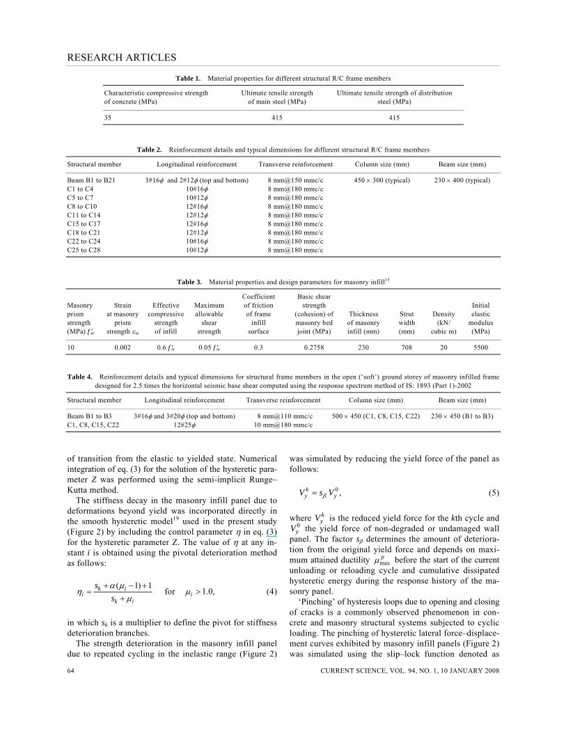
computed using the response spectrum method to account for the ‘soft’ storey effect as recommended by the current seismic code. The structural frame elements were designed using the limit state method of design (strength or capacity design) according to the Indian Standard code of practice for the design of concrete structures (IS: 456-2000). Tables 1 and 2 present the material properties, typical dimensions and reinforcement details for different structural frame members for a seven (ground + six) storey masonry in-filled R/C frame building with three bays in the weak di-rection. Table 3 presents the material properties and thickness of masonry infills. Table 4 presents the dimen-sions and reinforcement details for the structural frame members of the open (‘soft’) ground storey in the masonry infilled frame with the soft storey designed for 2.5 times the horizontal seismic base shear calculated using the res-ponse spectrum method as specified by the current seis-mic code.
Nonlinear modelling of masonry infill panels for displacement based analysis
The smooth hysteretic model19 used to represent the ma-sonry infill panels in the nonlinear dynamic analysis fur-nishes a rate-independent hysteresis rule shown in Figure 2, for the relationship between the lateral force and lateral displacement of the infill panel that may be expressed as: [ (1 ) ],i y i iV V Zαμ α= + − (1)
where V is the lateral shear force in the panel, subscript i is used to refer to the instantaneous values, subscript y denotes yield values, α the ratio of the post-yield to ini-tial elastic stiffness, μi the normalized displacement at the ith instant calculated as
,ii
y
uuμ = (2)
and Zi is the hysteretic component determined from the following equation:
.d | | { sgn(d ) } ,..d [1 ( ) ( | | { sgn(d ) })]
n
nZ A Z Z
p Z A Z Zβ μ γ
μ η β μ γ− +
=+ − +
(3)
in which the signum function may be written as:
sgn( ) 1 if ( ) 0
1 if ( ) 0.= >= − <
In eq. (3), A, β and γ are constants that control the shape of the generated hysteretic loops and n controls the rate
RESEARCH ARTICLES
CURRENT SCIENCE, VOL. 94, NO. 1, 10 JANUARY 2008 64
Table 1. Material properties for different structural R/C frame members
Characteristic compressive strength Ultimate tensile strength Ultimate tensile strength of distribution of concrete (MPa) of main steel (MPa) steel (MPa)
35 415 415
Table 2. Reinforcement details and typical dimensions for different structural R/C frame members
Structural member Longitudinal reinforcement Transverse reinforcement Column size (mm) Beam size (mm)
Beam B1 to B21 3#16φ and 2#12φ (top and bottom) 8 mm@150 mmc/c 450 × 300 (typical) 230 × 400 (typical) C1 to C4 10#16φ 8 mm@180 mmc/c C5 to C7 10#12φ 8 mm@180 mmc/c C8 to C10 12#16φ 8 mm@180 mmc/c C11 to C14 12#12φ 8 mm@180 mmc/c C15 to C17 12#16φ 8 mm@180 mmc/c C18 to C21 12#12φ 8 mm@180 mmc/c C22 to C24 10#16φ 8 mm@180 mmc/c C25 to C28 10#12φ 8 mm@180 mmc/c
Table 3. Material properties and design parameters for masonry infill15
Coefficient Basic shear Masonry Strain Effective Maximum of friction strength Initial prism at masonry compressive allowable of frame (cohesion) of Thickness Strut Density elastic strength prism strength shear infill masonry bed of masonry width (kN/ modulus (MPa) f ′m strength εm of infill strength surface joint (MPa) infill (mm) (mm) cubic m) (MPa)
10 0.002 0.6 f ′m 0.05 f ′m 0.3 0.2758 230 708 20 5500
Table 4. Reinforcement details and typical dimensions for structural frame members in the open (‘soft’) ground storey of masonry infilled frame designed for 2.5 times the horizontal seismic base shear computed using the response spectrum method of IS: 1893 (Part 1)-2002
Structural member Longitudinal reinforcement Transverse reinforcement Column size (mm) Beam size (mm)
Beam B1 to B3 3#16φ and 3#20φ (top and bottom) 8 mm@110 mmc/c 500 × 450 (C1, C8, C15, C22) 230 × 450 (B1 to B3) C1, C8, C15, C22 12#25φ 10 mm@180 mmc/c
of transition from the elastic to yielded state. Numerical integration of eq. (3) for the solution of the hysteretic para-meter Z was performed using the semi-implicit Runge–Kutta method. The stiffness decay in the masonry infill panel due to deformations beyond yield was incorporated directly in the smooth hysteretic model19 used in the present study (Figure 2) by including the control parameter η in eq. (3) for the hysteretic parameter Z. The value of η at any in-stant i is obtained using the pivotal deterioration method as follows:
( 1) 1k i
ik i
ssα μ
ημ
+ − +=
+ for 1.0,iμ > (4)
in which sk is a multiplier to define the pivot for stiffness deterioration branches. The strength deterioration in the masonry infill panel due to repeated cycling in the inelastic range (Figure 2)
was simulated by reducing the yield force of the panel as follows: 0 ,k
y yV s Vβ= (5)
where k
yV is the reduced yield force for the kth cycle and 0yV the yield force of non-degraded or undamaged wall
panel. The factor sβ determines the amount of deteriora-tion from the original yield force and depends on maxi-mum attained ductility max
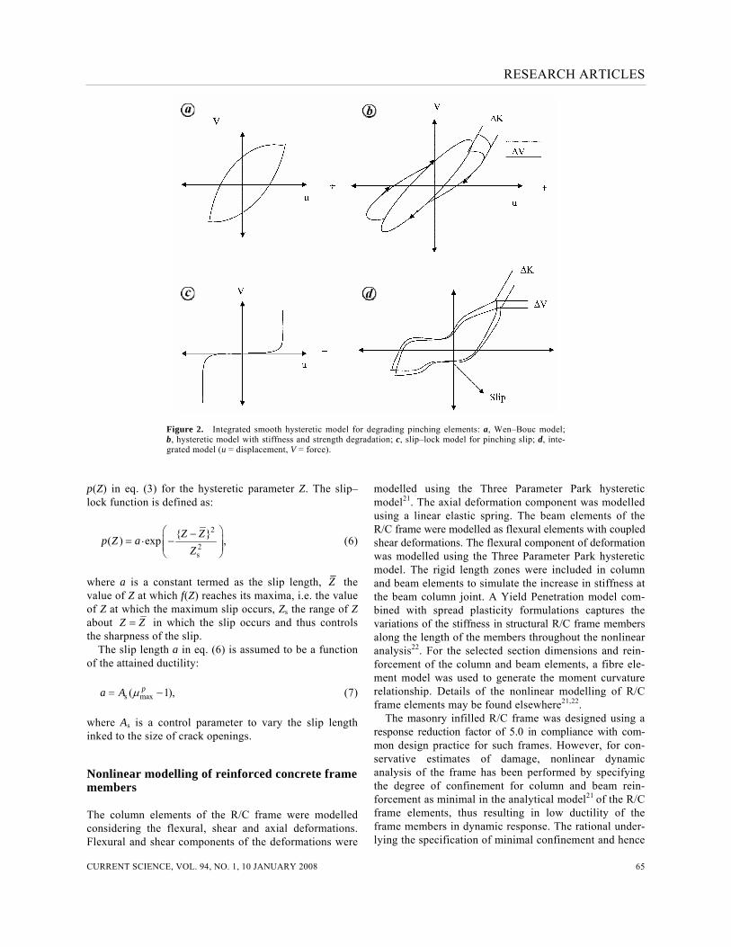
pμ before the start of the current unloading or reloading cycle and cumulative dissipated hysteretic energy during the response history of the ma-sonry panel. ‘Pinching’ of hysteresis loops due to opening and closing of cracks is a commonly observed phenomenon in con-crete and masonry structural systems subjected to cyclic loading. The pinching of hysteretic lateral force–displace-ment curves exhibited by masonry infill panels (Figure 2) was simulated using the slip–lock function denoted as
RESEARCH ARTICLES
CURRENT SCIENCE, VOL. 94, NO. 1, 10 JANUARY 2008 65
Figure 2. Integrated smooth hysteretic model for degrading pinching elements: a, Wen–Bouc model; b, hysteretic model with stiffness and strength degradation; c, slip–lock model for pinching slip; d, inte-grated model (u = displacement, V = force).
p(Z) in eq. (3) for the hysteretic parameter Z. The slip–lock function is defined as:
2
2s
{ }.( ) exp ,Z Zp Z aZ
⎛ ⎞−= −⎜ ⎟⎜ ⎟
⎝ ⎠ (6)
where a is a constant termed as the slip length, Z the value of Z at which f(Z) reaches its maxima, i.e. the value of Z at which the maximum slip occurs, Zs the range of Z about Z Z= in which the slip occurs and thus controls the sharpness of the slip. The slip length a in eq. (6) is assumed to be a function of the attained ductility: s max( 1),pa A μ= − (7) where As is a control parameter to vary the slip length inked to the size of crack openings.
Nonlinear modelling of reinforced concrete frame members
The column elements of the R/C frame were modelled considering the flexural, shear and axial deformations. Flexural and shear components of the deformations were
modelled using the Three Parameter Park hysteretic model21. The axial deformation component was modelled using a linear elastic spring. The beam elements of the R/C frame were modelled as flexural elements with coupled shear deformations. The flexural component of deformation was modelled using the Three Parameter Park hysteretic model. The rigid length zones were included in column and beam elements to simulate the increase in stiffness at the beam column joint. A Yield Penetration model com-bined with spread plasticity formulations captures the variations of the stiffness in structural R/C frame members along the length of the members throughout the nonlinear analysis22. For the selected section dimensions and rein-forcement of the column and beam elements, a fibre ele-ment model was used to generate the moment curvature relationship. Details of the nonlinear modelling of R/C frame elements may be found elsewhere21,22. The masonry infilled R/C frame was designed using a response reduction factor of 5.0 in compliance with com-mon design practice for such frames. However, for con-servative estimates of damage, nonlinear dynamic analysis of the frame has been performed by specifying the degree of confinement for column and beam rein-forcement as minimal in the analytical model21 of the R/C frame elements, thus resulting in low ductility of the frame members in dynamic response. The rational under-lying the specification of minimal confinement and hence
RESEARCH ARTICLES
CURRENT SCIENCE, VOL. 94, NO. 1, 10 JANUARY 2008 66
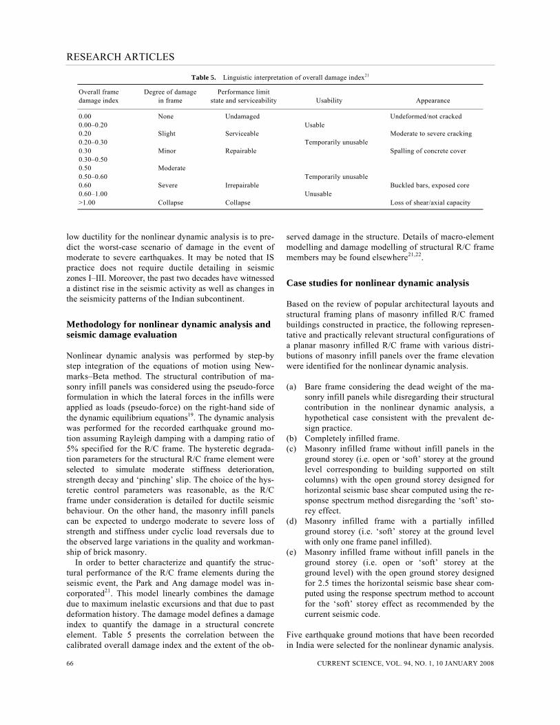
Table 5. Linguistic interpretation of overall damage index21
Overall frame Degree of damage Performance limit damage index in frame state and serviceability Usability Appearance
0.00 None Undamaged Undeformed/not cracked 0.00–0.20 Usable 0.20 Slight Serviceable Moderate to severe cracking 0.20–0.30 Temporarily unusable 0.30 Minor Repairable Spalling of concrete cover 0.30–0.50 0.50 Moderate 0.50–0.60 Temporarily unusable 0.60 Severe Irrepairable Buckled bars, exposed core 0.60–1.00 Unusable >1.00 Collapse Collapse Loss of shear/axial capacity
low ductility for the nonlinear dynamic analysis is to pre-dict the worst-case scenario of damage in the event of moderate to severe earthquakes. It may be noted that IS practice does not require ductile detailing in seismic zones I–III. Moreover, the past two decades have witnessed a distinct rise in the seismic activity as well as changes in the seismicity patterns of the Indian subcontinent.
Methodology for nonlinear dynamic analysis and seismic damage evaluation
Nonlinear dynamic analysis was performed by step-by step integration of the equations of motion using New-marks–Beta method. The structural contribution of ma-sonry infill panels was considered using the pseudo-force formulation in which the lateral forces in the infills were applied as loads (pseudo-force) on the right-hand side of the dynamic equilibrium equations19. The dynamic analysis was performed for the recorded earthquake ground mo-tion assuming Rayleigh damping with a damping ratio of 5% specified for the R/C frame. The hysteretic degrada-tion parameters for the structural R/C frame element were selected to simulate moderate stiffness deterioration, strength decay and ‘pinching’ slip. The choice of the hys-teretic control parameters was reasonable, as the R/C frame under consideration is detailed for ductile seismic behaviour. On the other hand, the masonry infill panels can be expected to undergo moderate to severe loss of strength and stiffness under cyclic load reversals due to the observed large variations in the quality and workman-ship of brick masonry. In order to better characterize and quantify the struc-tural performance of the R/C frame elements during the seismic event, the Park and Ang damage model was in-corporated21. This model linearly combines the damage due to maximum inelastic excursions and that due to past deformation history. The damage model defines a damage index to quantify the damage in a structural concrete element. Table 5 presents the correlation between the calibrated overall damage index and the extent of the ob-
served damage in the structure. Details of macro-element modelling and damage modelling of structural R/C frame members may be found elsewhere21,22.
Case studies for nonlinear dynamic analysis
Based on the review of popular architectural layouts and structural framing plans of masonry infilled R/C framed buildings constructed in practice, the following represen-tative and practically relevant structural configurations of a planar masonry infilled R/C frame with various distri-butions of masonry infill panels over the frame elevation were identified for the nonlinear dynamic analysis. (a) Bare frame considering the dead weight of the ma-
sonry infill panels while disregarding their structural contribution in the nonlinear dynamic analysis, a hypothetical case consistent with the prevalent de-sign practice.
(b) Completely infilled frame. (c) Masonry infilled frame without infill panels in the
ground storey (i.e. open or ‘soft’ storey at the ground level corresponding to building supported on stilt columns) with the open ground storey designed for horizontal seismic base shear computed using the re-sponse spectrum method disregarding the ‘soft’ sto-rey effect.
(d) Masonry infilled frame with a partially infilled ground storey (i.e. ‘soft’ storey at the ground level with only one frame panel infilled).
(e) Masonry infilled frame without infill panels in the ground storey (i.e. open or ‘soft’ storey at the ground level) with the open ground storey designed for 2.5 times the horizontal seismic base shear com-puted using the response spectrum method to account for the ‘soft’ storey effect as recommended by the current seismic code.
Five earthquake ground motions that have been recorded in India were selected for the nonlinear dynamic analysis.

RESEARCH ARTICLES
CURRENT SCIENCE, VOL. 94, NO. 1, 10 JANUARY 2008 67
Figure 3. Acceleration time-histories of earthquake ground motions.
The peak ground accelerations and Richter scale magni-tudes of these earthquakes are given in Table 6. For pur-
poses of comparison, the El-Centro (California, USA, 1940) and San Fernando (California, USA, 1971) earth-

RESEARCH ARTICLES
CURRENT SCIENCE, VOL. 94, NO. 1, 10 JANUARY 2008 68
Table 6. Summary of results of nonlinear dynamic time-history analysis of the masonry infilled R/C frames under recorded earthquake ground motions
Masonry infilled Masonry infilled Masonry infilled frame without frame with a frame open (‘soft’) infills in single infill ground storey Completely ground storey panel in ground designed for Structural configuration of frame → infilled (open or ‘soft’ storey (‘soft’ 2.5 times seismic Earthquakes ↓ Bare frame frame ground storey) ground storey) base shear
Schematics of infill layouts →
Bhuj (2001) Base shear (kN) 325.58 1036 818.83 972.19 1158 (pga = 0.1 g, Displacement at level 1 (mm) 6.79 3.42 10.92 8.33 5.75 M = 6.9) Displacement at top level (mm) 54.68 16.87 23.13 22.1 23.7 Overall damage index 0.045 0.017 0.071 0.048 0.02 Dt/H (%), V/W 0.26, 0.059 0.08, 0.189 0.11, 0.149 0.105, 0.178 0.112, 0.212 Degree of damage Slight Almost none Slight Slight Almost none Limit state Serviceable Undamaged Serviceable Serviceable Undamaged Uttarkashi (1999) Base shear (kN) 366.42 1383.12 1071.38 1251.44 1473 (pga = 0.3 g, Displacement at level 1 (mm) 6.14 6.05 24.41 17.58 8.23 M = 6.5) Displacement at top level (mm) 53.03 34.4 52.47 47.16 40.1 Overall damage index 0.036 0.031 0.168 0.101 0.03 Dt/H (%), V/W 0.252, 0.06 0.169, 0.25 0.249, 0.196 0.22, 0.22 0.19, 0.269 Degree of damage Slight Slight Slight to minor Slight Slight Limit state Serviceable Serviceable Near to repairable Serviceable Serviceable Northeast (1988) Base shear (kN) 503.37 1428.54 1038.14 1206 1465 (pga = 0.33 g, Displacement at level 1 (mm) 11.43 10.26 21.62 17.85 10.6 M = 7.2) Displacement at top level (mm) 41.21 38.3 46.65 43.34 48.5 Overall damage index 0.067 0.052 0.154 0.116 0.06 Dt/H (%), V/W 0.19, 0.09 0.18, 0.26 0.22, 0.19 0.2, 0.22 0.23, 0.268 Degree of damage Slight Slight Slight to minor Slight Slight Limit state serviceable serviceable Near to repairable Serviceable Serviceable Koyna (1967) Base shear (kN) 528.85 1387.29 1077.91 1243.88 1509 (pga = 0.489 g, Displacement at level 1 (mm) 9.79 7.5 22.44 21.98 8.76 M = 6.5) Displacement at top level (mm) 45.76 30.94 45.19 41.84 39.7 Overall damage index 0.049 0.033 0.163 0.135 0.05 Dt/H (%), V/W 0. 21, 0.09 0.147, 0.25 0.215, 0.19 0.197, 0.22 0.188, 0.276 Degree of damage Slight Slight Slight to minor Slight Slight Limit state Serviceable Serviceable Near to repairable Serviceable Serviceable Chamoli (1999) Base shear (kN) 555.39 1683.72 1213.93 1382.19 1763 (pga = 0.35 g, Displacement at level 1 (mm) 22.26 19.4 65.06 44.58 18.8 M = 6.6) Displacement at top level (mm) 203.71 94.94 132.55 102.13 97.9 Overall damage index 0.155 0.125 0.408 0.222 0.11 Dt/H (%), V/W 0.97, 0.101 0.452,0.3 0.63, 0.22 0.486, 0.25 0.466, 0.317 Degree of damage Slight Slight Minor to moderate Minor Slight Limit state Near to Serviceable Repairable to Repairable Serviceable repairable unrepairable EL-Centro, Base shear (kN) 466.08 1536.24 1142.23 1319.25 1575 California (1940) Displacement at level 1 (mm) 14.27 13.07 32.57 26.43 12.1 (pga = 0.33 g, Displacement at top level (mm) 142.83 52.04 62.96 60.31 55.7 M = 7.2) Overall damage index 0.119 0.075 0.269 0.188 0.08 Dt/H (%), V/W 0.68, 0.08 0.24, 0.281 0.299, 0.2 0.28, 0.24 0.26, 0.288 Degree of damage Slight Slight Minor Slight to minor Slight Limit state Serviceable Serviceable Near to repairable Near to repairable Serviceable San Fernando, Base shear (kN) 749.34 1805.32 1389.1 1526.3 2154 California (1971) Displacement at level 1 (mm) 88.62 98.35 180.44 155.53 52.2 (pga = 1.22 g, Displacement at top level (mm) 505.5 374.94 293.9 484.69 369 M = 6.6) Overall damage index 0.402 0.569 >1 0.90 0.37 Dt/H (%), V/W 2.4, 0.137 1.78, 0.33 1.39, 0.25 2.3, 0.27 1.75, 0.39 Degree of damage Minor to moderate Moderate Collapse Severe Minor to moderate Limit state Repairable Repairable Collapse Irrepairable Repairable to irrepairable to irrepairable to irrepairable
V, Base shear (kN); Dt, Top displacement (mm); H, Height of building (mm) = 21,000; W, Seismic weight of frame (kN) = 5460; V/W, Base shear coefficient; Dt/H (%), Top deformation/height (%); pga, Peak ground acceleration, g, Acceleration due to gravity; M, Richter scale magnitude.
RESEARCH ARTICLES
CURRENT SCIENCE, VOL. 94, NO. 1, 10 JANUARY 2008 69
quakes were also considered in the study. Figure 3 dis-plays the acceleration time-histories of the recorded earthquake ground motions considered in the study.
Results of nonlinear dynamic analysis and interpretation
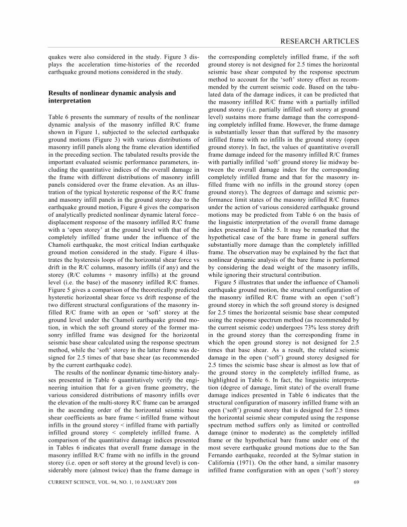
Table 6 presents the summary of results of the nonlinear dynamic analysis of the masonry infilled R/C frame shown in Figure 1, subjected to the selected earthquake ground motions (Figure 3) with various distributions of masonry infill panels along the frame elevation identified in the preceding section. The tabulated results provide the important evaluated seismic performance parameters, in-cluding the quantitative indices of the overall damage in the frame with different distributions of masonry infill panels considered over the frame elevation. As an illus-tration of the typical hysteretic response of the R/C frame and masonry infill panels in the ground storey due to the earthquake ground motion, Figure 4 gives the comparison of analytically predicted nonlinear dynamic lateral force–displacement response of the masonry infilled R/C frame with a ‘open storey’ at the ground level with that of the completely infilled frame under the influence of the Chamoli earthquake, the most critical Indian earthquake ground motion considered in the study. Figure 4 illus-trates the hysteresis loops of the horizontal shear force vs drift in the R/C columns, masonry infills (if any) and the storey (R/C columns + masonry infills) at the ground level (i.e. the base) of the masonry infilled R/C frames. Figure 5 gives a comparison of the theoretically predicted hysteretic horizontal shear force vs drift response of the two different structural configurations of the masonry in-filled R/C frame with an open or ‘soft’ storey at the ground level under the Chamoli earthquake ground mo-tion, in which the soft ground storey of the former ma-sonry infilled frame was designed for the horizontal seismic base shear calculated using the response spectrum method, while the ‘soft’ storey in the latter frame was de-signed for 2.5 times of that base shear (as recommended by the current earthquake code). The results of the nonlinear dynamic time-history analy-ses presented in Table 6 quantitatively verify the engi-neering intuition that for a given frame geometry, the various considered distributions of masonry infills over the elevation of the multi-storey R/C frame can be arranged in the ascending order of the horizontal seismic base shear coefficients as bare frame < infilled frame without infills in the ground storey < infilled frame with partially infilled ground storey < completely infilled frame. A comparison of the quantitative damage indices presented in Tables 6 indicates that overall frame damage in the masonry infilled R/C frame with no infills in the ground storey (i.e. open or soft storey at the ground level) is con-siderably more (almost twice) than the frame damage in
the corresponding completely infilled frame, if the soft ground storey is not designed for 2.5 times the horizontal seismic base shear computed by the response spectrum method to account for the ‘soft’ storey effect as recom-mended by the current seismic code. Based on the tabu-lated data of the damage indices, it can be predicted that the masonry infilled R/C frame with a partially infilled ground storey (i.e. partially infilled soft storey at ground level) sustains more frame damage than the correspond-ing completely infilled frame. However, the frame damage is substantially lesser than that suffered by the masonry infilled frame with no infills in the ground storey (open ground storey). In fact, the values of quantitative overall frame damage indeed for the masonry infilled R/C frames with partially infilled ‘soft’ ground storey lie midway be-tween the overall damage index for the corresponding completely infilled frame and that for the masonry in-filled frame with no infills in the ground storey (open ground storey). The degrees of damage and seismic per-formance limit states of the masonry infilled R/C frames under the action of various considered earthquake ground motions may be predicted from Table 6 on the basis of the linguistic interpretation of the overall frame damage index presented in Table 5. It may be remarked that the hypothetical case of the bare frame in general suffers substantially more damage than the completely infillled frame. The observation may be explained by the fact that nonlinear dynamic analysis of the bare frame is performed by considering the dead weight of the masonry infills, while ignoring their structural contribution. Figure 5 illustrates that under the influence of Chamoli earthquake ground motion, the structural configuration of the masonry infilled R/C frame with an open (‘soft’) ground storey in which the soft ground storey is designed for 2.5 times the horizontal seismic base shear computed using the response spectrum method (as recommended by the current seismic code) undergoes 73% less storey drift in the ground storey than the corresponding frame in which the open ground storey is not designed for 2.5 times that base shear. As a result, the related seismic damage in the open (‘soft’) ground storey designed for 2.5 times the seismic base shear is almost as low that of the ground storey in the completely infilled frame, as highlighted in Table 6. In fact, the linguistic interpreta-tion (degree of damage, limit state) of the overall frame damage indices presented in Table 6 indicates that the structural configuration of masonry infilled frame with an open (‘soft’) ground storey that is designed for 2.5 times the horizontal seismic shear computed using the response spectrum method suffers only as limited or controlled damage (minor to moderate) as the completely infilled frame or the hypothetical bare frame under one of the most severe earthquake ground motions due to the San Fernando earthquake, recorded at the Sylmar station in California (1971). On the other hand, a similar masonry infilled frame configuration with an open (‘soft’) storey

RESEARCH ARTICLES
CURRENT SCIENCE, VOL. 94, NO. 1, 10 JANUARY 2008 70
Completely infilled frame Infilled frame with soft storey at ground level
Figure 4. Comparison of nonlinear dynamic force–displacement response of the completely infilled frame with the masonry infilled frame with an open (‘soft’) storey at ground level under the Chamoli earthquake ground motion.
that is not designed for 2.5 times that base shear is predicted to collapse under the action of the San Fernando earthquake (Table 6). Further, it is worthwhile to note that the masonry infilled frame with a partially infilled ground storey (i.e. a single infilled panel at
the ground level) is predicted to survive the earthquake. It is noteworthy that the San Fernando (1971) earth- quake with a peak ground acceleration of 1.22 g was one of most devastating earthquakes in Californian history.
RESEARCH ARTICLES
CURRENT SCIENCE, VOL. 94, NO. 1, 10 JANUARY 2008 71
Soft storey at ground level Soft storey designed for 2.5 times base shear
Figure 5. Comparison of nonlinear dynamic force–displacement response of the open (‘soft’) ground storey of the masonry in-filled frame designed for the horizontal seismic base shear computed using the response spectrum method with that of the open storey designed for 2.5 times that storey shear under the Chamoli earthquake ground motion.
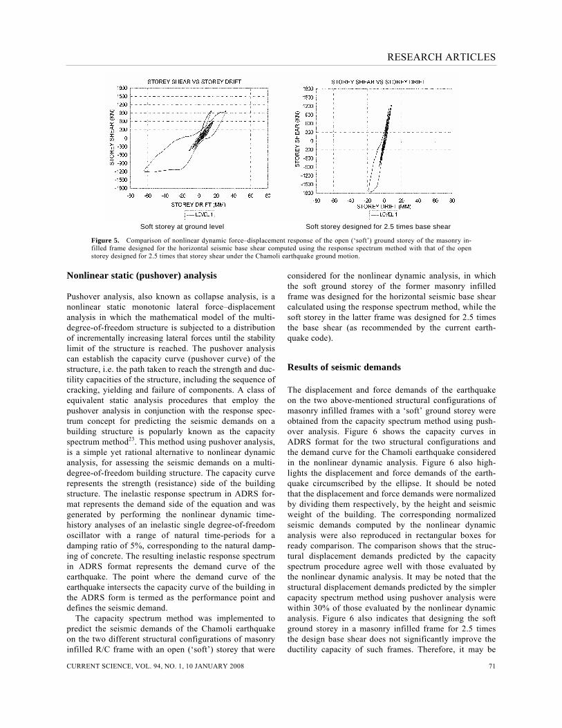
Nonlinear static (pushover) analysis
Pushover analysis, also known as collapse analysis, is a nonlinear static monotonic lateral force–displacement analysis in which the mathematical model of the multi-degree-of-freedom structure is subjected to a distribution of incrementally increasing lateral forces until the stability limit of the structure is reached. The pushover analysis can establish the capacity curve (pushover curve) of the structure, i.e. the path taken to reach the strength and duc-tility capacities of the structure, including the sequence of cracking, yielding and failure of components. A class of equivalent static analysis procedures that employ the pushover analysis in conjunction with the response spec-trum concept for predicting the seismic demands on a building structure is popularly known as the capacity spectrum method23. This method using pushover analysis, is a simple yet rational alternative to nonlinear dynamic analysis, for assessing the seismic demands on a multi-degree-of-freedom building structure. The capacity curve represents the strength (resistance) side of the building structure. The inelastic response spectrum in ADRS for-mat represents the demand side of the equation and was generated by performing the nonlinear dynamic time-history analyses of an inelastic single degree-of-freedom oscillator with a range of natural time-periods for a damping ratio of 5%, corresponding to the natural damp-ing of concrete. The resulting inelastic response spectrum in ADRS format represents the demand curve of the earthquake. The point where the demand curve of the earthquake intersects the capacity curve of the building in the ADRS form is termed as the performance point and defines the seismic demand. The capacity spectrum method was implemented to predict the seismic demands of the Chamoli earthquake on the two different structural configurations of masonry infilled R/C frame with an open (‘soft’) storey that were
considered for the nonlinear dynamic analysis, in which the soft ground storey of the former masonry infilled frame was designed for the horizontal seismic base shear calculated using the response spectrum method, while the soft storey in the latter frame was designed for 2.5 times the base shear (as recommended by the current earth-quake code).
Results of seismic demands
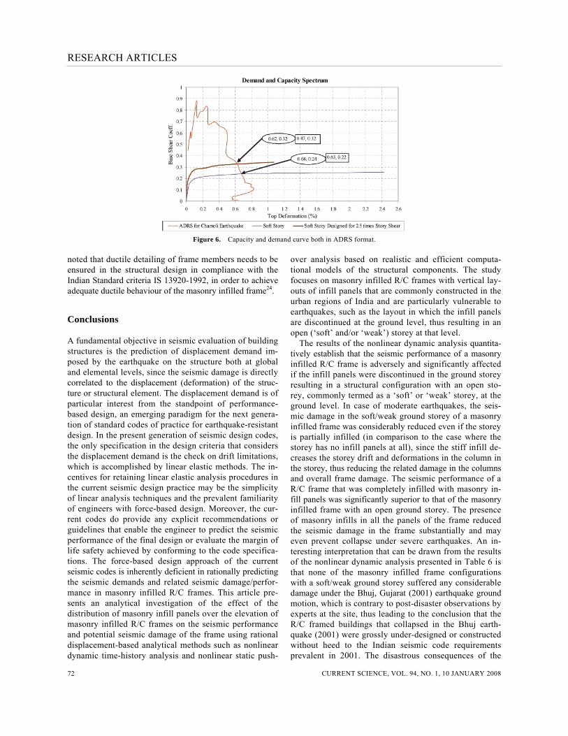
The displacement and force demands of the earthquake on the two above-mentioned structural configurations of masonry infilled frames with a ‘soft’ ground storey were obtained from the capacity spectrum method using push-over analysis. Figure 6 shows the capacity curves in ADRS format for the two structural configurations and the demand curve for the Chamoli earthquake considered in the nonlinear dynamic analysis. Figure 6 also high-lights the displacement and force demands of the earth-quake circumscribed by the ellipse. It should be noted that the displacement and force demands were normalized by dividing them respectively, by the height and seismic weight of the building. The corresponding normalized seismic demands computed by the nonlinear dynamic analysis were also reproduced in rectangular boxes for ready comparison. The comparison shows that the struc-tural displacement demands predicted by the capacity spectrum procedure agree well with those evaluated by the nonlinear dynamic analysis. It may be noted that the structural displacement demands predicted by the simpler capacity spectrum method using pushover analysis were within 30% of those evaluated by the nonlinear dynamic analysis. Figure 6 also indicates that designing the soft ground storey in a masonry infilled frame for 2.5 times the design base shear does not significantly improve the ductility capacity of such frames. Therefore, it may be
RESEARCH ARTICLES
CURRENT SCIENCE, VOL. 94, NO. 1, 10 JANUARY 2008 72
Figure 6. Capacity and demand curve both in ADRS format. noted that ductile detailing of frame members needs to be ensured in the structural design in compliance with the Indian Standard criteria IS 13920-1992, in order to achieve adequate ductile behaviour of the masonry infilled frame24.
Conclusions
A fundamental objective in seismic evaluation of building structures is the prediction of displacement demand im-posed by the earthquake on the structure both at global and elemental levels, since the seismic damage is directly correlated to the displacement (deformation) of the struc-ture or structural element. The displacement demand is of particular interest from the standpoint of performance-based design, an emerging paradigm for the next genera-tion of standard codes of practice for earthquake-resistant design. In the present generation of seismic design codes, the only specification in the design criteria that considers the displacement demand is the check on drift limitations, which is accomplished by linear elastic methods. The in-centives for retaining linear elastic analysis procedures in the current seismic design practice may be the simplicity of linear analysis techniques and the prevalent familiarity of engineers with force-based design. Moreover, the cur-rent codes do provide any explicit recommendations or guidelines that enable the engineer to predict the seismic performance of the final design or evaluate the margin of life safety achieved by conforming to the code specifica-tions. The force-based design approach of the current seismic codes is inherently deficient in rationally predicting the seismic demands and related seismic damage/perfor-mance in masonry infilled R/C frames. This article pre-sents an analytical investigation of the effect of the distribution of masonry infill panels over the elevation of masonry infilled R/C frames on the seismic performance and potential seismic damage of the frame using rational displacement-based analytical methods such as nonlinear dynamic time-history analysis and nonlinear static push-
over analysis based on realistic and efficient computa-tional models of the structural components. The study focuses on masonry infilled R/C frames with vertical lay-outs of infill panels that are commonly constructed in the urban regions of India and are particularly vulnerable to earthquakes, such as the layout in which the infill panels are discontinued at the ground level, thus resulting in an open (‘soft’ and/or ‘weak’) storey at that level. The results of the nonlinear dynamic analysis quantita-tively establish that the seismic performance of a masonry infilled R/C frame is adversely and significantly affected if the infill panels were discontinued in the ground storey resulting in a structural configuration with an open sto-rey, commonly termed as a ‘soft’ or ‘weak’ storey, at the ground level. In case of moderate earthquakes, the seis-mic damage in the soft/weak ground storey of a masonry infilled frame was considerably reduced even if the storey is partially infilled (in comparison to the case where the storey has no infill panels at all), since the stiff infill de-creases the storey drift and deformations in the column in the storey, thus reducing the related damage in the columns and overall frame damage. The seismic performance of a R/C frame that was completely infilled with masonry in-fill panels was significantly superior to that of the masonry infilled frame with an open ground storey. The presence of masonry infills in all the panels of the frame reduced the seismic damage in the frame substantially and may even prevent collapse under severe earthquakes. An in-teresting interpretation that can be drawn from the results of the nonlinear dynamic analysis presented in Table 6 is that none of the masonry infilled frame configurations with a soft/weak ground storey suffered any considerable damage under the Bhuj, Gujarat (2001) earthquake ground motion, which is contrary to post-disaster observations by experts at the site, thus leading to the conclusion that the R/C framed buildings that collapsed in the Bhuj earth-quake (2001) were grossly under-designed or constructed without heed to the Indian seismic code requirements prevalent in 2001. The disastrous consequences of the

RESEARCH ARTICLES
CURRENT SCIENCE, VOL. 94, NO. 1, 10 JANUARY 2008 73
poor design and construction practices precipitated in the seismic event due to the ‘soft’ and/or ‘weak’ ground sto-rey failures. Pushover or nonlinear static analysis methods have gained considerable popularity, as they can be employed to assess the seismic demands on building structures while avoiding the complexities and difficulties associated with nonlinear dynamic time-history analysis. The results of the nonlinear static analysis indicate that the seismic demands predicted by the capacity spectrum method using the pushover analysis for a performance-based seismic evaluation of masonry infilled R/C frames were reasonably consistent with those evaluated by the nonlinear dynamic analysis. The results of the present study quantitatively corroborate the traditional engineering wisdom that the horizontal seismic base shear coefficient is significantly influenced by the density and distribution of the masonry infill panels in the R/C frame, an effect that is disregar-ded by the present generation of seismic codes. The current seismic codes simply specify a more stringent formula-tion for calculating the natural time-period of masonry infilled frames and/or recommend a scaling factor for augmenting the design horizontal seismic base shear in case of masonry infilled frames with a soft/weak ground storey, for example, the latest Indian seismic code rec-ommends a blanket multiplicative factor of 2.5. The code specified factor of 2.5 was found to be adequate in the present study for preventing the collapse (survival limit state) and limiting the seismic damage (damage control limit state) of the masonry infilled R/C frame with an open (‘soft’) ground storey in a rare and severe seismic event earthquake for the Indian subcontinent such as the San Fernando (1971) earthquake, provided the masonry infilled R/C framed building was designed and con-structed in compliance with all the other applicable crite-ria of the contemporary Indian seismic code. However, such specifications lend themselves to subjectivity in case of masonry infilled frames with a partially infilled ground storey or sparse distribution of infill panels over the frame elevation. The present study demonstrates rational nonlinear displacement-based analysis methods for a more objective performance-based seismic evaluation of masonry infilled R/C frames with seismically undesirable (and preferred) distributions of masonry infill panels over the frame elevation.
1. Fiorato, A. E., Sozen, M. A. and Gamble, W. L., An investigation of the interaction of reinforced concrete frames with masonry filler walls. Report No. UILU-ENG 70-100, University of Illinois at Urbana-Champaign, 1970.
2. Klingner, R. E. and Bertero. V. V., Infilled frames in earthquake resistant construction. Report No. EERC/76-32, University of California, Berkeley, 1976.
3. Bertero, V. V. and Brokken, S., Infills in seismic resistant build-ing. J. Struct. Eng., 1983, 109, 1337–1361.
4. Zarnic, R. and Tomazevic, M., Behaviour of repaired masonry in-filled R/C frames. A Report to US–Yugoslav Joint Board on Sci-entific and Technical Cooperation, Institute for Testing and Research in Materials, Ljubljana, Yugoslavia, 1990.
5. Mander, J. B. and Nair, B., Seismic resistance of infilled frames. Proceedings, Suppl (IV), Paper 7360S, Institution of Civil Engi-neers, London, 1994.
6. Mehrabi, A. B. and Shing, P. B., Finite element modeling of masonry infilled RC frames. J. Struct. Eng., 1997, 123, 607–613.
7. Dhanasekar, M. and Page, A. W., The influence of brick masonry infill properties on the behavour of infilled frames. Proc. Inst. Civ. Eng. Part 2, 1986, 81, 593–605.
8. Shing, P. B., H. R., Barzegarmehrabi, A. and Brunner, J., Finite element analysis of shear resistance of masonry wall panels and without confining frames. Proceedings of Tenth World Conference on Earthquake Engineering, A. A. Balkema, The Netherlands, 1992, vol. 8, pp. 2581–2586.
9. Mosalam, K. M., Modeling of the nonlinear seismic behaviour of gravity load designed infilled frames, 1995 EERI Student Paper, LA, CA, 8–10 February 1996.
10. Holmes, M., Steel frames with brickwork and concrete infilling. Proc. Inst. Civ. Eng., Part 2, 1961, 73, 473–478.
11. Stafford Smith, B., Behaviour of square infilled frames. J. Struct. Eng., 1966, 92, 381–403.
12. Stafford Smith, B. and Carter, C., A method of analysis for infill frames. Proc. Inst. Civ. Eng., 1969, 44, 31–48.
13. Mainstone, R. J., Supplementary note on the stiffness and strength of infilled frames, Current Paper CP13/74, Building Research Es-tablishment, London, 1974.
14. Prakash, V., Powell, G. H., Campbell, S. D. and Filloppou, F. C., DRAIN-2DX Preliminary Element User Guide, University of Cali-fornia at Berkeley, California, 1992.
15. Saineinejad, A. and Hobbs, B., Inelastic design of infilled frames. J. Struct. Eng., 1995, 121, 634–650.
16. Chrystomou, C. Z., Gergely, P. and Abel, J. F., Nonlinear seismic response of infilled steel frames. Proceedings of Tenth World Conference on Earthquake Engineering, A. A. Balkema, The Netherlands, 1992, vol. 8, pp. 4435–4437.
17. Amrhein, J. E., Anderson, J. C. and Robles, V. M., Masonry saves lives in Mexico earthquake. Masonry Design West, November–December 1985.
18. Paulay, T. and Priestley, M. J. N., Seismic Design of Reinforced Concrete and Masonry Buildings, John Wiley, 1992.
19. Madan, A., Reinhorn, A. M., Mander, J. B. and Valles, R., Model-ing of masonry infill panels for structural analysis. J. Struct. Eng., 1997, 123, 1295–1302.
20. IS 1893–2002 (Part 1): Indian Standard criteria for earthquake re-sistant design of structures, Part 1 – General provisions and build-ings. Bureau of Indian Standards, New Delhi, 2002.
21. Park, Y. J., Reinhorn, A. M. and Kunnath, S. K., IDARC: Inelastic damage analysis of reinforced concrete frame–shear wall struc-tures. Technical Report NCEER-87-0008, National Center for Earthquake Engineering Research, SUNY Buffalo, USA, 1987.
22. Valles, R. E., Reinhorn, A. M., Kunnath, S. K., Li, C. and Madan, A., IDARC Version 4.0 – A program for the inelastic damage analysis of buildings. Technical Report NCEER-96-0010, National Center for Earthquake Engineering Research, SUNY/Buffalo, USA, 1996.
23. ATC-40, Seismic evaluation and retrofit of concrete buildings. Report SSC 96-01, California Seismic Safety Commission, Ap-plied Technology Council, Redwood, CA, USA, 1996.
24. BIS, IS 13920-1993 (Part 1): Indian Standard code of practice for ductile detailing of reinforced concrete structures subjected to seismic forces, Bureau of Indian Standards, New Delhi, 1993.
Received 29 December 2006; revised accepted 30 November 2007