An experimentally based analytical model for the shear capacity of FRP-strengthened reinforced...
14
AN EXPERIMENTALLY BASED ANALYTICAL MODEL FOR THE SHEAR CAPACITY OF FRP-STRENGTHENED REINFORCED CONCRETE BEAMS C. Pellegrino and C. Modena Keywords: concrete beams, steel reinforcement, external strengthening, side bonding, U jacketing This paper deals with the shear strengthening of Reinforced Concrete (RC) flexural members with externally bonded Fiber-Reinforced Polymers (FRPs). The interaction between an external FRP and an internal trans- verse steel reinforcement is not considered in actual code recommendations, but it strongly influences the effi- ciency of the shear strengthening rehabilitation technique and, as a consequence, the computation of interacting contributions to the nominal shear strength of beams. This circumstance is also discussed on the basis of the results of an experimental investigation of rectangular RC beams strengthened in shear with “U-jacketed” carbon FRP sheets. Based on experimental results of the present and other investigations, a new analytical model for describing the shear capacity of RC beams strengthened according to the most common schemes (side-bonded and “U-jacketed”), taking into account the interaction between steel and FRP shear strength contributions, is proposed. Introduction The shear failure of Reinforced Concrete (RC) beams is generally sudden and more dangerous than the flexural fail- ure. When the shear capacity of a structural member is lower than its flexural capacity, the shear strengthening could be neces- sary. A recent technique consists in the use of externally bonded Fiber-Reinforced Polymer (FRP) sheets as an additional web reinforcement. The common methods of FRP strengthening include side bonding, “U-jacketing,” and complete wrapping. The available experimental data indicate that almost all beams strengthened by complete wrapping and few ones strengthened by “U-jacketing” fail due to the rupture of FRP. In contrast, almost all beams strengthened by side bonding and most of those strengthened by “U-jacketing” fail owing to FRP debonding or peeling off [1]. The shear strengthening of RC members with FRP is actually a research problem that is far from being completely solved and is still under investigation. The geometric and mechanical properties of the transverse reinforcing steel, in relation to the geometric and mechanical properties of FRP strengthening and their interaction mechanism, have an important influence on the shear capacity of strengthened structural members [2, 3]. A number of interesting papers about the FRP shear strength- ening of RC beams have been published in the last years [2-23]. Some of these studies have resulted in the first design guide- lines for concrete structures strengthened with externally bonded FRP [24-26]. 231 0191-5665/08/4403-0231 © 2008 Springer Science+Business Media, Inc. Department of Construction and Transportation Engineering, University of Padova, Via Marzolo 9, 35131 Padova, It- aly. Russian translation published in Mekhanika Kompozitnykh Materialov, Vol. 44, No. 3, pp. 339-356, May-June, 2008. Original article submitted August 20, 2007; revision submitted April 4, 2008. Mechanics of Composite Materials, Vol. 44, No. 3, 2008
Transcript of An experimentally based analytical model for the shear capacity of FRP-strengthened reinforced...

AN EX PER I MEN TALLY BASED AN A LYT I CAL MODEL
FOR THE SHEAR CA PAC ITY OF FRP-STRENGTH ENED
RE IN FORCED CON CRETE BEAMS
C. Pellegrino and C. Modena
Keywords: con crete beams, steel re in force ment, ex ter nal strength en ing, side bond ing, U jacketing
This pa per deals with the shear strength en ing of Re in forced Con crete (RC) flex ural mem bers with ex ter nally
bonded Fi ber-Re in forced Poly mers (FRPs). The in ter ac tion be tween an ex ter nal FRP and an in ter nal trans -
verse steel re in force ment is not con sid ered in ac tual code rec om men da tions, but it strongly in flu ences the ef fi -
ciency of the shear strength en ing re ha bil i ta tion tech nique and, as a con se quence, the com pu ta tion of
in ter act ing con tri bu tions to the nom i nal shear strength of beams. This cir cum stance is also dis cussed on the
ba sis of the re sults of an ex per i men tal in ves ti ga tion of rect an gu lar RC beams strength ened in shear with
“U-jack eted” car bon FRP sheets. Based on ex per i men tal re sults of the pres ent and other in ves ti ga tions, a new
an a lyt i cal model for de scrib ing the shear ca pac ity of RC beams strength ened ac cord ing to the most com mon
schemes (side-bonded and “U-jack eted”), tak ing into ac count the in ter ac tion be tween steel and FRP shear
strength con tri bu tions, is pro posed.
In tro duc tion
The shear fail ure of Re in forced Con crete (RC) beams is gen er ally sud den and more dan ger ous than the flex ural fail -
ure. When the shear ca pac ity of a struc tural mem ber is lower than its flex ural ca pac ity, the shear strength en ing could be nec es -
sary. A re cent tech nique con sists in the use of ex ter nally bonded Fi ber-Re in forced Poly mer (FRP) sheets as an ad di tional web
re in force ment. The com mon meth ods of FRP strength en ing in clude side bond ing, “U-jacketing,” and com plete wrap ping. The
avail able ex per i men tal data in di cate that al most all beams strength ened by com plete wrap ping and few ones strength ened by
“U-jacketing” fail due to the rup ture of FRP. In con trast, al most all beams strength ened by side bond ing and most of those
strength ened by “U-jacketing” fail owing to FRP debonding or peeling off [1].
The shear strength en ing of RC mem bers with FRP is ac tu ally a re search prob lem that is far from be ing com pletely
solved and is still un der in ves ti ga tion. The geo met ric and me chan i cal prop er ties of the trans verse re in forc ing steel, in re la tion
to the geo met ric and me chan i cal prop er ties of FRP strength en ing and their in ter ac tion mech a nism, have an im por tant in flu ence
on the shear ca pac ity of strength ened struc tural mem bers [2, 3]. A num ber of in ter est ing pa pers about the FRP shear strength -
en ing of RC beams have been pub lished in the last years [2-23]. Some of these stud ies have re sulted in the first de sign guide -
lines for con crete structures strengthened with externally bonded FRP [24-26].
2310191-5665/08/4403-0231 © 2008 Springer Sci ence+Busi ness Me dia, Inc.
De part ment of Con struc tion and Trans por ta tion En gi neer ing, Uni ver sity of Padova, Via Marzolo 9, 35131 Padova, It -
aly. Rus sian trans la tion pub lished in Mekhanika Kompozitnykh Materialov, Vol. 44, No. 3, pp. 339-356, May-June, 2008.
Orig i nal ar ti cle sub mit ted Au gust 20, 2007; re vi sion sub mit ted April 4, 2008.
Me chanics of Com pos ite Ma te rials, Vol. 44, No. 3, 2008
Some pre vi ous ex per i men tal stud ies have been car ried out by the au thors at Ma te rial Test ing Lab o ra tory of the De -
part ment of Con struc tion and Trans por ta tion En gi neer ing of the Uni ver sity of Padova on RC beams strength ened in shear with
side-bonded and “U-jack eted” FRP sheets [2, 3, 14]. In the pres ent pa per, the main re sults of an other ex per i men tal pro gram,
car ried out at the Uni ver sity of Padova, on RC beams hav ing a trans verse steel re in force ment and strength ened with dif fer ent
amounts of FRP “U-jack eted” sheets are shown. The aim of the pres ent work is to in crease the still scarce da ta base of ex per i -
men tal in ves ti ga tions into FRP shear-strength ened RC beams con tain ing a trans verse steel re in force ment and, in par tic u lar, to
in ves ti gate the com plex mech a nisms of crack ing and fail ure of FRP shear-strength ened beams and their in flu ence on the de sign
pro ce dures of such el e ments. Since the in ter ac tion be tween ex ter nally bonded FRP and in ter nal trans verse steel re in force ment
is not con sid ered in ac tual rec om men da tions [24-26], it is gen er ally as sumed that the trans verse steel re in force ment does not in -
flu ence the shear re sis tance caused by FRP strength en ing, and the same for mu la tion for the shear ca pac ity of FRP-strength ened
beams is used for beams both with and with out a shear steel re in force ment. For these rea sons, some doubts re main about the re -
li abil ity of the cur rent for mu la tions, since they all have been calibrated by using a scarce quantity of tests mainly on
FRP-strengthened beams without a shear steel reinforcement.
Based on ex per i men tal re sults of the pres ent and other in ves ti ga tions, a new an a lyt i cal method is de vel oped, which al -
lows one to es ti mate the nom i nal shear ca pac ity of RC beams strength ened ac cord ing to the most com mon schemes
(side-bonded and “U-jack eted” FRP), tak ing into ac count the in ter ac tion be tween the steel and FRP shear strength
contributions.
Cur rent Rec om men da tions
The cur rent codes for shear-strength ened RC beams [24-26] gen er ally rec om mend es ti mat ing the nom i nal shear re sis -
tance Vn at the ul ti mate limit state by sim ply sum ming of the con tri bu tions of con crete, steel, and FRP capacities:
V V V Vn = + +c s f ,
where Vc , Vs, and Vf are the con tri bu tions of con crete, the in ter nal steel re in force ment, and the ex ter nally bonded FRP, re spec -
tively.
The quan ti ties Vc and Vs can be cal cu lated by us ing the cur rent codes for nonstrengthened RC struc tures, as sum ing
that the FRP strength en ing does not af fect the shear re sis tance pro vided by con crete and/or the steel re in force ment. This as -
sump tion has been ques tioned by many re search ers on the ba sis of test ob ser va tions and results [2, 3].
The strength of an in clined con crete strut, which can also be com puted ac cord ing to the cur rent codes, clearly rep re -
sents the up per limit of the nom i nal shear capacity.
De spite the fact that the shear steel re in force ment is in ter nally bonded and the FRP strength en ing is ex ter nally bonded,
the con tri bu tion of the FRP sys tem Vf to the shear strength is gen er ally found by us ing the truss anal ogy and is based on fi ber
ori en ta tion and an as sumed crack pat tern. The shear strength con tri bu tion from FRP sheets can be de ter mined by cal cu lat ing
the force re sult ing from the ten sile stress in the FRP across the crack. All the FRP strips in ter sected by the mean shear crack are
as sumed to con trib ute the same ef fec tive stress, and the cal cu la tion mod els dif fer mainly in the definition of the effective stress.
In the fib model [24], the con tri bu tion of FRP is given by
V E bdf fe f f cot cot= +e r q a a( )sin , (1)
where e fe is the ef fec tive strain (the max i mum strain that can be achieved in the FRP sys tem at the ul ti mate load stage; in gen -
eral, it is smaller than the FRP ten sile frac ture strain e fu ), Ef is the elas tic modulus of FRP in the prin ci pal fi ber ori en ta tion,
r f f f f f= ( )( )2n t b w s is the FRP strength en ing ra tio, nf is the num ber of lay ers, t f is the thick ness of FRP (one layer), wf
is the width of FRP, sf is the spac ing of FRP strips, b is the width of the cross sec tion, d is the ef fec tive depth of the cross sec -
tion, q is the an gle of the di ag o nal crack (of ten as sumed to be 45°), and a is the in cli na tion an gle of fi bers.
232

The ef fec tive strain is gov erned by the fail ure mode of the FRP sys tem in the strength ened RC mem ber, and its for mu -
la tion mainly de pends on the con fig u ra tion of the ex ter nal FRP re in force ment in re la tion to the char ac ter is tics of the RC beam.
The crack ing of con crete causes stress con cen tra tions in the FRP and may pro duce a lo cal debonding. There fore, e fe also de -
pends on the ef fec tive bond length Le of FRP, through which the FRP-con crete in ter fa cial shear bond stress de vel ops. On the
ba sis of these con cepts, one may ar gue that the prob lem of shear is strictly cor re lated to the prob lem of bond. Nev er the less, the
quan ti fi ca tion of the ef fec tive strain e fe in the FRP and, es pe cially, the de ter mi na tion of the ef fec tive bond length Le remains
critical points of the formulation [27].
The fib model [24] states that the ef fec tive strain e fe de pends on the quan tity E ff f cm2 3r [28], where fcm is the cy lin -
dri cal com pres sive strength of con crete:
· for full CFRP-FRP wraps
er
efecm
f ffu=
æ
è
çç
ö
ø
÷÷
0172 3
0 30
.
.f
E;
· for side or U-shaped CFRP jack ets
er
;r
fecm
f f
cm
f
=æ
è
çç
ö
ø
÷÷
× -min . .
.
065 10 0172 3
0 56
32 3f
E
f
E ffu
æ
è
çç
ö
ø
÷÷
é
ë
êê
ù
û
úú
0 30.
e ;
· for full AFRP-FRP wraps
er
efecm
f ffu=
æ
è
çç
ö
ø
÷÷
00482 3
0 47
.
.f
E,
where fcm is in MPa and Ef is in GPa.
The ACI model [25] is based on the work by Khalifa et al. [16]. In this case, the con tri bu tion of the FRP shear re in -
force ment is given by
VA E d
sf
fv fe f f
f
cos=
+e a a(sin ), (2)
where A n t wfv f f f= 2 (the area of FRP re in force ment), and d f is the ver ti cal dis tance from the top edge of the FRP shear re in -
force ment to the cen troid of the in ter nal lon gi tu di nal re in force ment.
For mu la tions (1) and (2) are very sim i lar, but the ex pres sions for e fe are quite dif fer ent:
· for full FRP wraps
e efe fu= £0004 075. . ;
· for side or U-shaped FRP jack ets
e k efe v fu= £ 0004. (k v is the bond re duc tion co ef fi cient),
ke
ve
fu
= £k k L1 2
11900075
,. , L
n t Ee
f f f
=23 300
0 58
,
( ) .,
kf
1
2 3
27=
æ
èç
ö
ø÷
cm , k
d L
d
d L
d
22
=
-
-
ì
í
ïf e
f
f e
f
U- jacketing),
side bonding).
(
(
ï
î
ïï
233

Ad di tional re duc tion fac tors y f = 0.95 for com plete wraps and y f = 0.80 for U-jack ets or side strips are rec om -
mended to be ap plied to the shear con tri bu tion of the FRP re in force ment Vf ex pressed in Eq. (2).
The Ital ian CNR model [26] quan ti fies the con tri bu tion of the FRP shear re in force ment as
V d h f tw
pRd,f
Rdw fed f
f
f
= ×1
09 2g
b
qmin{ . , }
sin
sin (side bond ing),
V d f tw
pRd,f
Rdfed f
f
f
cot cot=1
09 2g
q + b. ( ) (“U-jacketing”/com plete wrap ping).
Here, g Rd is a par tial fac tor ( = 1.20), d is the ef fec tive depth, hw is the height of the beam web, t f is the FRP thick ness, b is the
in cli na tion of fi bers, q is the in cli na tion of the shear crack, wf is the width of the FRP strip, and pf is the spac ing of FRP strips;
ffed is the ef fec tive stress in the FRP re in force ment, namely
f fz
d h
l
zfed fdd
rid,eq
w
eq
rid,eq
= -æ
è
çç
ö
ø
÷min{ . , }
.09
1 06÷
2
(side bond ing),
f fl
d hfed fdd
e
w
= - ×é
ëê
ù
ûú1
1
3 09
sin
min{ . , }
b (“U-jacketing”),
f fl
d hf ffed fdd
e
wR fd f= - ×
é
ëê
ù
ûú + -1
1
6 09
1
2
sin
min{ . , }(
bf dd
e
w
)sin
min{ . , }1
09-
é
ëê
ù
ûú
l
d h
b (com plete wrap ping),
where
fRc
w
= +02 16. .r
b, 0 05£ £
r
bc
w
. ,
z z lrid,eq rid eq= + , z d h lrid w e= -min{ . , } sin09 b, ls
f Eeq
f
fdd f
= sin b;
ffd is the ul ti mate de sign strength of FRP, l lE t
fe b,max
f f
ctm
= =2
is the ef fec tive bond length, leq is the an chor age length for the
ef fec tive strain e fdd , sf is the ul ti mate slip (= 0.2 mm), Ef is the elas tic modulus of FRP in the prin ci pal fi ber ori en ta tion, rc is
the ra dius of cur va ture of the FRP jacket, fE
tfdd
f,d c
f Fk
f
=1 2
g g
G is the de sign delamination strength,
GFk b ck ctm= 003. k f f is the frac ture en ergy (N × mm), kb b
bb
f
f
=-
+³
2
1 4001, and g f,d is a par tial fac tor (= 1.10-1.20).
The cur rent rec om men da tions [24-26] for es ti mat ing the ef fec tive FRP strain dif fer con sid er ably. In the fib code, the
com pu ta tion of the strain is based on a re gres sion of a few ex per i men tal re sults, and no dis tinc tion is made be tween
side-bonded and “U-jack eted” strengthenings. In the ACI code, the for mu la tion of the ef fec tive bond length Le is ques tion able
(it shows an op po site trend with re spect to other for mu la tions in a Le vs. n t Ef f f di a gram), and com pu ta tion of the FRP ef fec -
tive strain is based on a few ex per i men tal re sults. The more re cent Ital ian CNR code [26] gives three dif fer ent for mu la tions for
the FRP shear con tri bu tion and the ef fec tive FRP stress [19], which are rather com plex, but more ac cu rate than those in the ACI
and fib mod els; how ever, the three con tri bu tions (Vc , Vs, and Vf ) are still con sid ered in de pend ent (ne glect ing the in ter ac tion be -
tween them), since the con crete and steel con tri bu tions are the same as in the current codes (not modified by the presence of the
FRP).
234

Ex per i men tal In ves ti ga tion
The ex per i men tal in ves ti ga tion, car ried out at the Ma te rial Test ing Lab o ra tory of the De part ment of Con struc tion and
Trans por ta tion En gi neer ing of the Uni ver sity of Padova, was the sec ond part of a wide ex per i men tal pro gram, whose first part
was described in [3].
The in ves ti ga tion in volved six tests on rect an gu lar beams de signed so that their ul ti mate shear ca pac ity was reached
be fore the flex ural fail ure. Tests were con ducted ac cord ing to a “con tin u ous” load ing scheme, in which the max i mum shear and
the max i mum bend ing mo ment were op er at ing si mul ta neously at the sup port. In Figs. 1a and b, the load ing scheme and the
con fig u ra tion of the trans verse and lon gi tu di nal steel, re spec tively, are shown. In all the tests, a shear span-to-depth ratio a d =
3 was adopted.
The con trol spec i mens (nonstrengthened) are la beled “U0”, whereas the spec i mens strength ened with FRP are la beled
“U1” or “U2” (con tin u ous “U-jacketing” with one or two bonded lay ers). The sym bol “C” is used for the “con tin u ous” scheme.
The num ber “14” or “17” in di cate the spac ing of stirrups (in cm).
The con crete was made from ce ment 430 kg/m3, a coarse ag gre gate 570 kg/m3, and a fine ag gre gate 1430 kg/m3, with
a wa ter/ce ment ra tio of 0.6, and its cy lin dri cal com pres sive strength was fñ = 46.2 MPa and ten sile strength fñt = 3.8 MPa on
the av er age. The yield strength of the re in forc ing steel was fy = 534 MPa.
The rect an gu lar cross sec tion of the beams was 150 ́ 300 mm. The com pos ite ma te rial was a uni di rec tional car bon fi -
ber fab ric, which was used in the form of a con tin u ous “U shape” with one (t f = 0.165 mm) layer (“U1” beams) or two (t f =
0.330 mm) lay ers (“U2” beams). A con tin u ous ver ti cal strength en ing was cho sen to re li ably in ter cept the di ag o nal cracks. The
235
480
12540 1657575
30
15
à
221
480
19
i=17
224
i=14
16
b
2 1
30
15
26
11
30
Fig. 1. Loading scheme (a) and configuration of the transverse and longitudinal steel (b). 1 —
stirrup; 2— cross section. (All dimensions in cm)

fol low ing me chan i cal char ac ter is tics were ob tained for the CFRP: the ul ti mate CFRP strength ffu = 3450 MPa and the elastic
modulus Ef = 230,000 MPa.
Four-point flex ural tests were car ried out. The load was ap plied by us ing a 500-kN hy drau lic jack with a man ual con -
trol. The read ings were taken and mon i tored by an au to matic data ac qui si tion sys tem. The ver ti cal dis place ments were mea -
sured with Lin ear Vari able Dif fer en tial Transformers (LVDT).
Main Re sults
The con trol beams showed a typ i cal shear-ten sile fail ure, with the for ma tion of a prin ci pal di ag o nal crack,
subhorizontal near the sup port and the load ap pli ca tion point and ori ented at ~ 45° in the central zone.
The FRP-strenghthened beams failed in shear, al ways with peel ing off of the FRP, in volv ing the con crete cover in a
lat eral tri an gu lar por tion above the prin ci pal di ag o nal crack, ex tend ing from the bear ing to the load point. Be fore com plete
debonding of at least one end of the most vul ner a ble strip, a peel ing pro cess be gan from the main shear crack. Once the FRP and
the con crete cover started to peel off, the beam failed very quickly, show ing a very limited ductility.
As an ex am ple, the con fig u ra tion of the beam B-U1-C-17 af ter its fail ure is shown in Fig. 2. Lon gi tu di nal cracks were
of ten seen at the up per sur face of the beams.
The ex per i men tal nom i nal shear strength Vn,test and the FRP shear con tri bu tion Vf,test , cal cu lated by sub tract ing the
shear strength of the strength ened beam from that of the cor re spond ing con trol beam, are shown in Table 1.
236
Fig. 2. Beam B-U1-C-17 at fail ure.
TABLE 1. Main Results of Tests
SpecimenFRP thickness,
mmStirrup spacing,
cmVn, test , kN V f, test , kN Increment of shear
strength, %
B-U0-C-14 – 14 228.5 – –
B-U1-C-14 0.165 14 252.9 24.4 10.7
B-U2-C-14 0.330 14 264.8 36.3 15.9
B-U0-C-17 – 17 227.2 – –
B-U1-C-17 0.165 17 238.9 11.7 5.1
B-U2-C-17 0.330 17 243.3 16.1 7.1
The mi nor spac ing of stir rups did not cause a rel e vant in crease in the shear strength for the con trol beam, be cause the
num ber of stir rups in ter cepted by the pri mary shear crack was the same for the two beams (also if the spac ing of the shear re in -
force ment was var ied). The in cre ment in the shear strength was also sim i lar for the strength ened beams with 14- and 17-cm
spac ings of stir rups. Small in cre ments in the strength were ob served for the beams strength ened with one or two lay ers of FRP,
be cause of the low ef fi ciency of the strength en ing sys tem when a high quan tity of trans verse steel was present [2, 3].
Ex per i men tal Da ta base
Us ing the ex per i men tal data avail able in the lit er a ture [2-23], an ex per i men tal da ta base for FRP shear-strength ened
RC beams fail ing in shear was cre ated. Only spec i mens for which the ex per i men tal data were com plete and the FRP and load -
237
n° tests = 27C = 85.2%NC = 14.8%v. = 1.307
St. Dev. = 0.45A
50 100 150 200 250 300 3500
350
300
250
200
150
100
50
V , kNn
c
expV , kNnC
NC
n° = 27 tests C = 100%NC = 0%Av. = 1.670St. Dev. = 0.81
d
50 100 150 200 250 300 3500
350
300
250
200
150
100
50
V , kNn
expV , kNnC
NC
n° = 27tests C = 48.1%NC = 51.9%Av. = 0.959St. Dev. = 0.23
à
50 100 150 200 250 300 3500
350
300
250
200
150
100
50
V , kNn
expV , kNnC
NC
n° = 27 tests C = 37%NC = 63%Av. = 0.922St. Dev. = 0.20
b
50 100 150 200 250 300 3500
350
300
250
200
150
100
50
V , kNn
expV , kNnC
NC
n° = 27 tests C = 59.3%NC = 40.7%Av. = 0.990St. Dev. = 0.21
e
50 100 150 200 250 300 3500
350
300
250
200
150
100
50
V , kNn
expV , kNnC
NC
n° = 27 tests C = 40.7%NC = 59.3%Av. = 0.955St. Dev. = 0.19
f
50 100 150 200 250 300 3500
350
300
250
200
150
100
50
V , kNn
expV , kNnC
NC
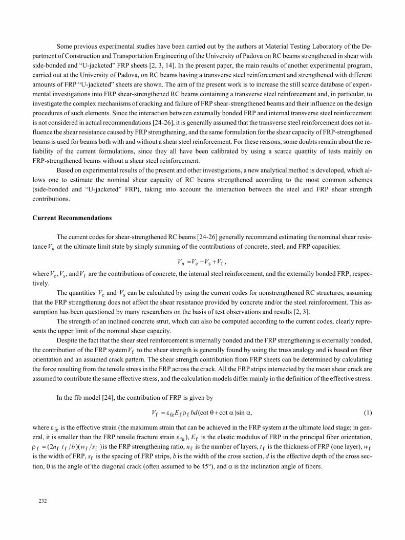
Fig. 3. Comparison between the code provisions Vn and experimental results Vnexp for
“U-jacketed” beams with (à, c, e) and without stirrups (b, d, f): EC2 + FIB (à, b), ACI318 +
ACI440 (c, d), and Italian Building Code + CNR-DT200 (e, f).

ing con fig u ra tions were rel a tively sim ple were con sid ered. Data for a to tal of 119 beams were col lected (27 beams with
“U-jack eted” FRP and stir rups, 27 beams with “U-jack eted” FRP with out stir rups, 18 beams with side-bonded FRP and stir -
rups, and 47 beams with side-bonded FRP without stirrups).
The code pro vi sions were com pared with ex per i men tal data for each test of the da ta base.
The nom i nal shear ca pac i ties were com puted sum ming three con tri bu tions as fol lows:
· con crete and steel con tri bu tions of Eurocode 2 [29] and the FRP con tri bu tion of the fib code;
· con crete and steel con tri bu tions of ACI 318 [30] and the FRP con tri bu tion of ACI 440 [25];
· con crete and steel con tri bu tions of the Ital ian Build ing Code [31] and the FRP con tri bu tion of CNR-DT 200 [26].
In Figs. 3 and 4, a com par i son for “U-jack eted” beams with and with out stir rups and for side-bonded beams with and
with out stir rups, re spec tively, are shown for these com bi na tions of codes. The num bers of tests n, the con ser va tive C and
nonconservative NC cir cum stances (%), the av er age ra tios Av be tween the ex per i men tal and the o ret i cal nom i nal shear ca pac i -
ties, and the cor re spond ing stan dard de vi a tions St.Dev. are also indicated for each combination.
238
n° = 18tests C = 50%NC = 50%Av. = 1.039St. Dev. = 0.29
50 100 150 200 250 300 350 4000
400
350
300
250
200
150
100
50
V , kNn
c
expV , kNnC
NC
n° tests = 18C = 27.8%NC = 72.2%Av. = 0.823St. Dev. = 0.31
50 100 150 200 250 300 350 4000
400
350
300
250
200
150
100
50
V , kNn
à
expV , kNnC
NC
n° = 47tests C = 12.8%NC = 87.2%Av. = 0.761St. Dev. = 0.32
50 100 150 200 250 300 350 4000
400
350
300
250
200
150
100
50
V , kNn
b
expV , kNnC
NC
n° = 47tests C = 78.7%NC = 21.3%Av. = 1.296St. Dev. = 0.49
50 100 150 200 250 300 350 4000
400
350
300
250
200
150
100
50
V , kNn
d
expV , kNnC
NC
n° = 18tests C = 55.6%NC = 44.4%Av. = 1.053St. Dev. = 0.29
50 100 150 200 250 300 350 4000
400
350
300
250
200
150
100
50
V , kNn
e
expV , kNnC
NC
n° = 47tests C = 53.2%NC = 46.8%Av. = 1.015St. Dev. = 0.19
50 100 150 200 250 300 350 4000
400
350
300
250
200
150
100
50
V , kNn
f
expV , kNnC
NC
Fig. 4. The same for side-bonded beams.

The Ital ian model al ways gives the best re sults, while the ACI model seems too con ser va tive. All the mod els are less
pre cise for strength ened beams with stir rups, prob a bly be cause they do not con sider the in ter ac tion be tween the FRP and the
steel re in force ment. The pres ence of ex ter nally bonded FRP, in fact, can af fect the con tri bu tion of the transverse steel.
New An a lyt i cal For mu la tion for the Shear Ca pac ity of
FRP-Strength ened Beams
On the ba sis of the typ i cal ex per i men tal fail ure modes of side-bonded and “U-jack eted” beams ob served in the pres ent
and other ex per i men tal in ves ti ga tions [2, 3], which are shown in Fig. 5, the peel ing-off fail ure of the FRP, in volv ing the con -
crete cover in a lat eral tri an gu lar por tion above the prin ci pal di ag o nal crack from the bear ing to the load point, is as sumed for
the “U-jack eted” beams, and the sim i lar fail ure in a lat eral tri an gu lar por tion un der the prin ci pal di ag o nal crack is as sumed for
239
à b
Fig. 5. Typical failure of “U-jacketed” (a) and side-bonded beams (b).
à
b
Fig. 6. Typical configeration of “U-jacketed” (a) and side-bonded beams (b) after removing
FRP sheets.

the side-bonded beams. In Fig. 6, the typ i cal con fig u ra tions of side-bonded (a) and “U-jack eted” beams (b) af ter re mov ing the
FRP sheets are shown. In Fig. 7, the cor re spond ing shapes of the frac ture sur face as sumed for side bonded (a) and “U-jack eted”
beams (b) on the basis of the experimental failure modes are depicted.
As sum ing the ex ter nal FRP strains equal to those of in ter nal stir rups [3], the ef fec tive FRP strain e fe and, con se -
quently, the FRP shear con tri bu tion Vf can be ob tained from the ro ta tional equi lib rium of the forces Ff and Fc op er at ing in the
FRP and con crete sur face, re spec tively, at fail ure (see Fig. 8). The equi lib rium equa tion is writ ten with re spect to the point
around which the ex per i men tally ob served peel ing-off ro ta tion oc curs (see Fig. 5). This point is in the lower part of cross sec -
tion for “U-jack eted” beams and in the up per lat eral part for side-bonded ones (see Fig. 8). Thus, we have
240
à b bf
bc
bc,v
hfFfbc,v
hf
Ff
bf
bc
Fig. 8. Forces acting in the cross section of “U-jacketed” (a) and side-bonded beams (b).
1 2 3 4 5 6
c
d-c
Fig. 9. Typical shear crack with a variable amplitude in the tensile zone.
à b
q
bc,v
Lf q Lf
o45
Fig. 7. Shape of the fracture surface of “U-jacketed” (a) and side-bonded beams (b).

F b F b n t Ld l
dE bf f c c f f f
f e
ff fe f= Þ
-e
= +( cos cos sin cos )f A A bct c c c c,vf f t f f
Þ =-
ef
fect c c,v
f f f ff e
ff
2 2f A b
n t L Eh l
hb
cos, V
n t L w E h
sf
f f f f fe f f
f
=2 e
.(3)
The mean ing of the sym bols used is clear from Figs. 7 and 8. f is the an gle char ac ter iz ing the con ven tional rough ness
of the in ter face, which is as sumed equal to 79°, ac cord ing to the calibration pro cess based on the ex per i men tal ul ti mate shear
ca pac i ties ob tained here and those de scribed in [3]. Other de tails on the con ven tional roughness are given in [3].
A new for mu la tion for the con tri bu tion of the trans verse steel, mod i fied with re spect to that pro posed by the codes for
nonstrengthened RC struc tures, is also pro posed for FRP shear-strength ened beams on the ba sis of the fol low ing con cepts (Fig.
9):
· as sum ing a vari able am pli tude for the di ag o nal crack, a re duc tion co ef fi cient a = 0.75 for the trans verse steel stress isin tro duced to take into ac count the fact that not all the stir rups in ter cepted in the ten sile zone reach the yield limit;
· in the pres ence of an ex ter nal FRP re in force ment, the max i mum stress in the in ter nal trans verse steel is equal to its yieldvalue only if the ef fec tive FRP strain is higher than the steel yield stress.
There fore, the for mu la tion for the steel con tri bu tion in the pres ence of an ex ter nal FRP re in force ment is
241
n° tests = 27C = 40.7%NC = 59.3%Av. = 0.966St. Dev. = 0.14
50 100 150 200 250 300 3500
350
300
250
200
150
100
50
V , kNn
a
expV , kNnC
NC
n° = 18tests C = 50%NC = 50%Av. = 1.017St. Dev. = 0.24
50 100 150 200 250 300 350 4000
400
350
300
250
200
150
100
50
V , kNn
b
expV , kNnC
NC
n° = 27tests C = 55.6%NC = 44.4%Av. = 1.059St. Dev. = 0.23
50 100 150 200 250 300 3500
350
300
250
200
150
100
50
V , kNnc
expV , kNnC
NC
n° = 47tests C = 34%NC = 66%Av. = 0.939St. Dev. = 0.14
50 100 150 200 250 300 350 4000
400
350
300
250
200
150
100
50
V , kNnd
expV , kNn
NC
C
Fig. 10. Com par i son be tween the pro vi sions Vn of the new model and ex per i men tal re sults Vnexp
for “U-jack eted” (à, c) and side-bonded beams (b, d) with (à, b) and with out stir rups (c, d).

Vc
dE f b ds v fe s y wcot= -
æ
èç
ö
ø÷
é
ëê
ù
ûúar q e1 min ( ; ) , (4)
where r v is the trans verse steel ra tio, fy is the yield stress of the trans verse steel, c is the depth of the neu tral axis, and d is the
ef fec tive depth.
Fi nally, the nom i nal shear ca pac ity can be cal cu lated by sum ming the con crete con tri bu tion pro vided by Eurocode 2
[29] and the steel and FRP con tri bu tions de fined by Eqs. (3) and (4), re spec tively. In Fig. 10, a com par i son be tween the nom i -
nal shear strength given by the new model and the ex per i men tal re sults for “U-jack eted” and side-bonded beams with and
with out stir rups is shown. The num bers of tests n, the con ser va tive C and nonconservative NC cir cum stances (%), the av er ages
ra tios Av be tween the ex per i men tal and the o ret i cal nom i nal shear ca pac i ties, and the cor re spond ing standard deviations
St.Dev. are also indicated.
As is seen, the new model, which is based on ex per i men tally ob served fail ure modes and takes into ac count the in ter -
ac tion be tween the in ter nal steel and ex ter nally bonded FRP con tri bu tions, ap prox i mate the ex per i men tal results well.
Con clu sions
The cur rent codes for the shear ca pac ity of beams strength ened with ex ter nally bonded FRP [24-26] pro vide the sum
of three in de pend ent con tri bu tions (con crete, steel, and FRP) with out tak ing into ac count that the con tri bu tion of con crete and,
es pe cially, of steel can be af fected by the pres ence of FRP, ow ing to the in ter ac tion be tween the ex ter nal FRP and the in ter nal
shear re in force ment (ac tu ally not con sid ered in any rec om men da tion, but ob served ex per i men tally) influencing the efficiency
of the technique.
A wide ex per i men tal da ta base has been im ple mented to as sess the for mu la tions of the prin ci pal cur rent codes [24-26].
A new sim ple model, based on ex per i men tal fail ure modes of “U-jack eted” and side-bonded beams (the most com mon
strength en ing schemes) and con sid er ing the in ter ac tion be tween the ex ter nal FRP and the in ter nal shear re in force ment, has
been pro posed. The new model well ap prox i mate the ex per i men tal re sults collected in the database.
Ac knowl edg ments. The au thors wish to thank the Degussa Group (Treviso, It aly) for sup ply ing the fi bers and the ad -
he sion sys tem, and for the tech ni cal sup port. We are also grate ful to Federica Iannello and the tech ni cians of the Ma te rial Test -
ing Lab o ra tory of the De part ment of Con struc tion and Trans por ta tion En gi neer ing of the Uni ver sity of Padova for their work.
REF ER ENCES
1. C. Pellegrino, D. Tinazzi, and C. Modena, “An ex per i men tal study on bond be tween con crete and FRP re in force ment,”
ACSE J. Com pos. Conctruct. (in press, sched uled for pub li ca tion in the April 2008 is sue).
2. C. Pellegrino and C. Modena, “Fi ber-re in forced poly mer shear strength en ing of re in forced con crete beams with trans -
verse steel re in force ment,” J. Com pos. Con struct., 6, No. 2, 104-111 (2002).
3. C. Pellegrino and C. Modena,. “Fi ber re in forced poly mer shear strength en ing of re in forced con crete beams: ex per i men -
tal study and an a lyt i cal mod el ing,” ACI Struct. J., 103, No. 5, 720-728 (2006).
4. B. B. Adhikary, H. Mutsuyoshi, and M. Ashraf, “Ef fec tive shear strength en ing of con crete beams us ing FRP sheets
with bonded an chor age,” in: K. H. Tan (ed.), Fi bre-Re in forced Poly mer Re in force ment for Con crete Struc tures, Proc.
of the 6th In tern. Symp. FRPRCS-6, Sin ga pore, 8-10 July 2003, World Sci en tific Pub lish ing Co. Pte. Ltd., Sin ga pore
(2003), pp. 457-466.
5. B. B. Adhikary and H. Mutsuyoshi, “Be hav iour of con crete beams strength ened in shear with car bon-fi ber sheets,” J.
Com pos. Con struct., 8, No. 3, 258-264 (2004).
6. J. A. O. Barros and S. J. E. Dias, “Near-sur face-mounted CFRP lam i nates for shear strength en ing of con crete beams,”
Ce ment Concr. Com pos., 28, 276-292 (2006).
242

7. A. Bousselham and O. Chaallal O, “Be hav iour of re in forced con crete T-beams strength ened in shear with car bon-fi -
ber-re in forced poly mer. An ex per i men tal study,” ACI Struct. J., 103, No. 3, 339-347 (2006).
8. A. Bousselham and O. Chaallal, “Ef fect of trans verse steel and shear span on the per for mance of RC beams strength -
ened in shear with CFRP,” Com pos ites, Pt. B, 37, 37-46 (2006).
9. A. Carolin and B. Taljsten, “Ex per i men tal study of strength en ing for in creased shear bear ing ca pac ity,” J. Com pos.
Con struct., 9, No. 6, 488-496 (2005).
10. O. Chaallal, M.-J. Nollet, and D. Perraton, “Shear strength en ing of RC beams by ex ter nally bonded side CFRP strips,”
J. Com pos. Con struc tion, 2, No. 2, 111-113 (1998).
11. C. Deniaud and J. J. Cheng, “Re in forced con crete T-beams strength ened in shear with fi ber-re in forced poly mer sheets,”
J. Com pos. Con struct., 7, No. 4, 302-310 (2003).
12. G. Donatone, A. Oliva, A. Sollazzo, and F. Trentadue, “Rinforzi strutturali con l’uso di compositi a matrice polimerica.
Indagine sperimentale. Pt. I,” Giornale AICAP, No. 12, 3-8 (2003).
13. G. Donatone, A. Oliva, A. Sollazzo, and F. Trentadue, “Rinforzi strutturali con l’uso di compositi a matrice polimerica.
Indagine sperimentale. Pt. II,” Giornale AICAP, No. 1, 4-7 (2004).
14. C. Modena, C. Pellegrino, and G. Golfetto, “Shear strength en ing of con crete beams with FRP lam i nates,” in: Y. Ohama
and M. Puterman (eds.), Ad he sion Be tween Poly mers and Con crete, Proc. of 2nd In tern. RILEM Symp. ISAP ’99,
RILEM Publ., Cachan (1999), pp. 375-386.
15. U. Ianniruberto and M. Imbimbo, “Role of fi ber-re in forced plas tic sheets in shear re sponse of re in forced con crete
beams. Ex per i men tal and an a lyt i cal re sults,” J. Com pos. Con struct., 8, No. 5, 415-424 (2004).
16. A. Khalifa, G. Tumialan, A. Nanni, and A. Belarbi, “Shear strength en ing of con tin u ous re in forced con crete beams us -
ing ex ter nally bonded car bon-fi ber-re in forced poly mer sheets,” in: C. W. Dolan, S. H. Rizkalla and A. Nanni (eds.),
Fourth Int. Symp. Fi ber-Re in forced Poly mer Re in force ment for Re in forced Con crete Struc tures, Proc. of the 4th Int.
Symp. FRPRCS-4, Bal ti more, 31 Oc to ber-5 No vem ber 1999, Amer i can Con crete In sti tute, Farmington Hills, Mich.
(1999), pp. 995-1008.
17. A. Khalifa, A. Belarbi, and A. Nanni, “Im prov ing the shear ca pac ity of ex ist ing RC T-sec tion beams us ing CFRP com -
pos ites,” Ce ment Concr. Com pos., 22, 165-174 (2000).
18. A. Khalifa and A. Nanni, “Re ha bil i ta tion of rect an gu lar sim ply sup ported RC beams with shear de fi cien cies us ing
CFRP com pos ites,” Con struct. Build. Ma ter., 16, 135-146 (2002).
19. G. Monti and M. Liotta, “FRP-strength en ing in shear: test and de sign equa tions,” Con struct. Build. Ma ter., 21, 799-809
(2006).
20. L. Taerwe, H. Khalil, and S. Matthys, “Be hav iour of RC beams strength ened in shear by ex ter nal CFRP sheets,” in:
Non-Me tal lic (FRP) Re in force ment for Con crete Struc tures, Proc. of the 3th Int. Symp. FRPRCS-3, Sapporo, 14-16
Oc to ber 1997, Ja pan Con crete In sti tute, Tokio (1997), pp. 483-490.
21. B. Taljsten, “Strength en ing con crete beams for shear with CFRP sheets,” Con struct. Build. Ma ter., 17, 5-26 (2003).
22. T. C. Triantafillou, “Shear strength en ing of re in forced con crete beams us ing ep oxy-bonded FRP com pos ites,” ACI
Struct. J., 95, No. 2, 107-115 (1998).
23. Z. Zhang and C.-T. T. Hsu, “Shear strength en ing of re in forced con crete beams us ing car bon FRP lam i nates,” J. Com -
pos. Con struct., 9, No. 2, 158-169 (2005).
24. FIB Task Group 9.3. Ex ter nally Bonded FRP Re in force ment for RC Struc tures (FIB bul le tin 14), Fed er a tion
Internationale du Beton, Lausanne (2001).
25. ACI Com mit tee 440. Guide for the De sign and Con struc tion of Ex ter nally Bonded FRP Sys tem for Strength en ing Con -
crete Struc tures (ACI 440.2R-02), Amer i can Con crete In sti tute, Farmington Hills (2002).
26. CNR–Ital ian Re search Coun cil, Ital ian Ad vi sory Com mit tee on Tech ni cal Rec om men da tions for Con struc tion. Guide
for the De sign and Con struc tion of Ex ter nally Bonded FRP Sys tems for Strength en ing Ex ist ing Struc tures. Ma te ri als,
RC and PC Struc tures, Ma sonry Struc tures (CNR-DT 200/2004), Rome (2004).
27. J. F. Chen and J. G. Teng, “Shear ca pac ity of fi ber-re in forced poly mer-strength ened re in forced con crete beams. Fi -
ber-re in forced poly mer rup ture,” J. Struct. Eng., 129, No. 5, 615-625 (2003).
243
28. T. C. Triantafillou and C. P. Antonopoulos, “De sign of con crete flex ural mem bers strength ened in shear with FRP,”
ASCE J. Com pos. Con struct., 4, No. 4, 198-205 (2000).
29. CEN, Eurocode 2: De sign of Con crete Struc tures — Part 1-1: Gen eral Rules and Rules for Build ings (ENV 1992-1-1),
Comite Europeen de Nor mali sa tion, Brussels (1991).
30. ACI Com mit tee 318. Build ing Code Re quire ments for Struc tural Con crete (ACI 318-05) and Com men tary (318R-05),
Amer i can Con crete In sti tute, Farmington Hills (2005).
31. Ital ian Build ing Code. Norme Tecniche per il Calcolo, l’Esecuzione ed il Collaudo delle Strutture in Cemento Armato,
Normale e Precompresso e per le Strutture Metalliche, 9/1/1996, Rome (1996).
244