Multifunctional FRP-Aluminum Foam Production Setup for ...
9
Technologies for Lightweight Structures 4(1) (2020), pp. 9–17 Digital Object Identifier: http://dx.doi.org/10.21935/tls.v4i1.115 www.lightweight-structures.de This is an open access article under the CC BY license (http://creativecommons.org/licenses/BY/4.0/) Multifunctional FRP-Aluminum Foam Production Setup for Battery Housings of Electric Vehicles R. Schmerler 1 , T. Gebken 2 , C. Lies 1 , M. Kühn 2 , W.-G. Drossel 1 , K. Dröder 3 1) Fraunhofer Institute for Machine Tools and Forming Technology, [email protected], Reichenhainer Straße 88, 09126 Chemnitz, Germany 2) Volkswagen AG, [email protected], Berliner Ring 2, 38440 Wolfsburg, Germany 3) Institute of Machine Tools and Production Technology, [email protected], Technische Universität Braunschweig, Langer Kamp 19b, 38106 Braunschweig, Germany Keywords Aluminum Foam, Lightweight Construction, Electric Mobility, Organo Sheet Forming, Multi-Material Design Abstract The battery systems of electrified vehicles are characterized by increasing weight due to larger battery modules. A lightweight battery carrier structure can reduce the system weight by replacing heavy metallic housing components with materials such as fiber-reinforced plastics (FRP) and aluminum. The battery housing must meet several requirements, e.g. stiffness, crash and intrusion protection and thermal management. Today’s battery housings are manufactured using die-cast or extrusion parts and are actively cooled. A novel approach is a lightweight hybrid battery housing consisting of a thermoformed FRP as a stiff outer shell and an integrated closed-cell aluminum foam infiltrated with phase change material (PCM) for passive thermal management. This multi-material structure enables the substitution of functionally separated systems in one intelligent solution. In the Open Hybrid LabFactory an entire process chain was established, including the aluminum foaming process, the thermoforming of FRP with heating and consolidating as well as the integrated forming and joining process of FRP with aluminum foam. With the goal of application-oriented research, a battery housing of an existing electric car was used to define requirements such as design space and mechanical specifications. Based on parameter studies an optimized process design was achieved, which is described in this paper. 1 Introduction The integration of several functions in a multi-material mix is one approach of current research. The shell construction of current battery housing subshells is replaced by an aluminum sandwich design, resulting in a higher specific bending stiffness. The aluminum top layer ensures a good heat transfer into the foam that stores the thermal energy. The inserts for connecting the battery modules are directly joined during the foaming process. Furthermore, the closed-cell aluminum foam that forms the sandwich core has excellent energy absorption properties, which are used for intrusion protection. To smooth out thermal peeks und store thermal energy, a PCM is infiltrated into the highly conductive foam, which acts as thermal inertia. During its liquid-solid phase change, the paraffin, whose melting temperature range can be adjusted, is able to store a large amount of energy. The FRP outer shell protects the structure from corrosion and supports the intrusion protection. In addition to combining functions in material composites, another approach in current research activities is the integration of several manufacturing steps into a single one. In this paper, an integral forming and joining process for the manufacturing of a lightweight part consisting of an aluminum cover sheet,
-
Upload
khangminh22 -
Category
Documents
-
view
2 -
download
0
Transcript of Multifunctional FRP-Aluminum Foam Production Setup for ...
Technologies for Lightweight Structures 4(1) (2020), pp. 9–17
Digital Object Identifier: http://dx.doi.org/10.21935/tls.v4i1.115 www.lightweight-structures.de
This is an open access article under the CC BY license (http://creativecommons.org/licenses/BY/4.0/)
Multifunctional FRP-Aluminum Foam Production Setup for Battery Housings of Electric Vehicles
R. Schmerler1, T. Gebken2, C. Lies1, M. Kühn2, W.-G. Drossel1, K. Dröder3
1) Fraunhofer Institute for Machine Tools and Forming Technology, [email protected], Reichenhainer Straße 88, 09126 Chemnitz, Germany
2) Volkswagen AG, [email protected], Berliner Ring 2, 38440 Wolfsburg, Germany
3) Institute of Machine Tools and Production Technology, [email protected], Technische Universität Braunschweig, Langer Kamp 19b, 38106 Braunschweig, Germany
Keywords
Aluminum Foam, Lightweight Construction, Electric Mobility, Organo Sheet Forming, Multi-Material Design
Abstract
The battery systems of electrified vehicles are characterized by increasing weight due to larger battery modules. A lightweight battery carrier structure can reduce the system weight by replacing heavy metallic housing components with materials such as fiber-reinforced plastics (FRP) and aluminum. The battery housing must meet several requirements, e.g. stiffness, crash and intrusion protection and thermal management.
Today’s battery housings are manufactured using die-cast or extrusion parts and are actively cooled. A novel approach is a lightweight hybrid battery housing consisting of a thermoformed FRP as a stiff outer shell and an integrated closed-cell aluminum foam infiltrated with phase change material (PCM) for passive thermal management. This multi-material structure enables the substitution of functionally separated systems in one intelligent solution.
In the Open Hybrid LabFactory an entire process chain was established, including the aluminum foaming process, the thermoforming of FRP with heating and consolidating as well as the integrated forming and joining process of FRP with aluminum foam.
With the goal of application-oriented research, a battery housing of an existing electric car was used to define requirements such as design space and mechanical specifications. Based on parameter studies an optimized process design was achieved, which is described in this paper.
1 Introduction
The integration of several functions in a multi-material mix is one approach of current research. The shell construction of current battery housing subshells is replaced by an aluminum sandwich design, resulting in a higher specific bending stiffness. The aluminum top layer ensures a good heat transfer into the foam that stores the thermal energy. The inserts for connecting the battery modules are directly joined during the foaming process. Furthermore, the closed-cell aluminum foam that forms the sandwich core has excellent energy absorption properties, which are used for intrusion protection. To smooth out thermal peeks und store thermal energy, a PCM is infiltrated into the highly conductive foam, which acts as thermal inertia. During its liquid-solid phase change, the paraffin, whose melting temperature range can be adjusted, is able to store a large amount of energy. The FRP outer shell protects the structure from corrosion and supports the intrusion protection.
In addition to combining functions in material composites, another approach in current research activities is the integration of several manufacturing steps into a single one. In this paper, an integral forming and joining process for the manufacturing of a lightweight part consisting of an aluminum cover sheet,
Technologies for Lightweight Structures 4(1) (2020)
10
aluminum foam core and FRP outer shell is described. The foaming process, the organo sheet forming as well as the joining of both products are explained in detail.
2 Integrated manufacturing process for a hybrid aluminum FRP battery housing subshell
The manufacture of hybrid components requires a complex process chain to form and join different materials and semi-finished products into one final part. Additional production steps increase production costs, so that a functionally integrated production process is required. Therefore, the hybridization of a formed FRP with an aluminum foam is realized in one production step and no further bonding process is necessary.
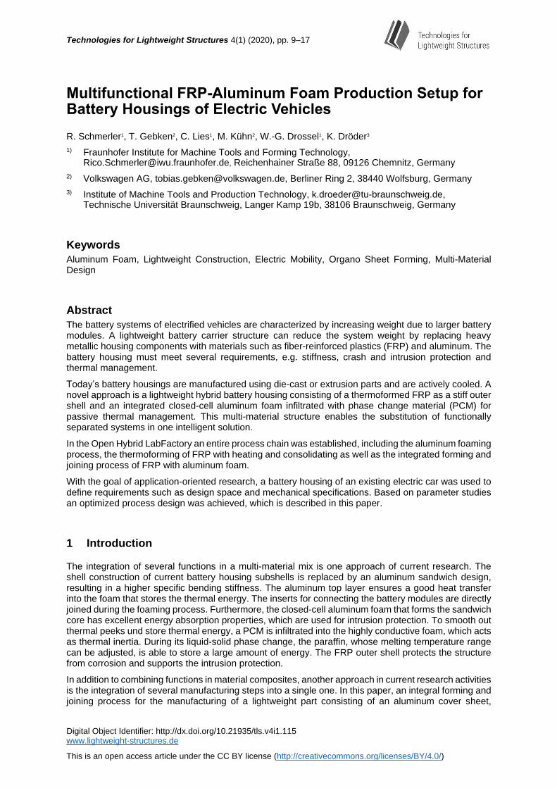
In current experiments, the aluminum foam is heated up to ~250 °C and combined with an infrared heated FRP in an integrated forming and joining process, as illustrated in Figure 1. For better energy efficiency, the residual heat from the foaming process can be used instead. The tempered aluminum is positioned by a vacuum system on the upper forming tool of the hydraulic press, whereas the heated and formable FRP is placed in the lower forming tool. During the forming process, the aluminum foam forms the FRP into its final geometry. The two joining partners, aluminum and FRP, are joined through both adhesive and interlocking mechanisms.
Figure 1: Integrated production process: joining and forming process for the manufacture of a battery subshell
3 Design and manufacture of aluminum foam components
3.1 Materials and process design
The goal of this project regarding aluminum foam is the economical manufacture of a near-net-shaped aluminum foam in one top sheet. Closed-cell aluminum foams can be produced via foaming by blowing gases into molten metal, or via powder metallurgy. While the first method requires an adhesive process to join the metal foam to the cover sheets, in the second method a metallic bond between metal foam and cover sheets is realized during the foaming process. For this reason, the powder metallurgical method was chosen for manufacturing the aluminum foam semi-finished products. For this purpose, a metal powder is mixed with a foaming agent, in this case titanium hydride, and then compressed into a foamable semi-finished product with the required shape. The foamable products are available on the market. One very sustainable approach is the manufacture of metal powder from ground aluminum chips from industrial waste.
The final battery housing provides a design space that allows a 2 mm thick aluminum shell and 9 mm thick foam. The aluminum shell with a weight of 187 g and the foamable products are placed in a foaming tool, often made of graphite due to its heat resistance, thermal conductivity and adhesive properties.
Technologies for Lightweight Structures 4(1) (2020)
11
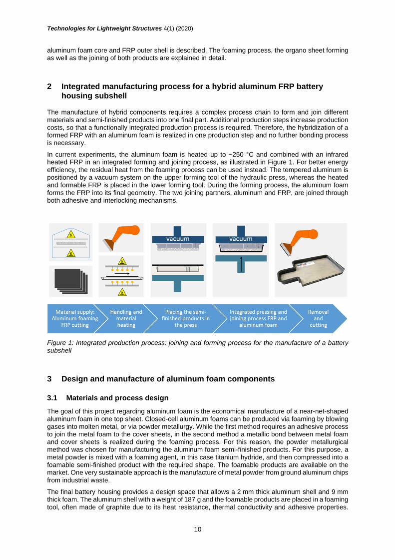
The tool design shown in Figure 2 was used for producing the aluminum foam product with one aluminum cover sheet. Considering the thermal expansion of the materials is very important for the tool construction. Aluminum foam products can be foamed in near-net shape, resulting in a closed aluminum oxide surface, or they are cut out of a semi-finished foam product, resulting in at least partially open porous structures. By varying the amount of foamable material the final density of the product can be adjusted.
Figure 2: Foaming tool for an aluminum foam sandwich using powder metallurgy
For a working process and a high quality of the final product, the melting temperatures of the aluminum alloys for the lower shell and foamable product require a significant delta.
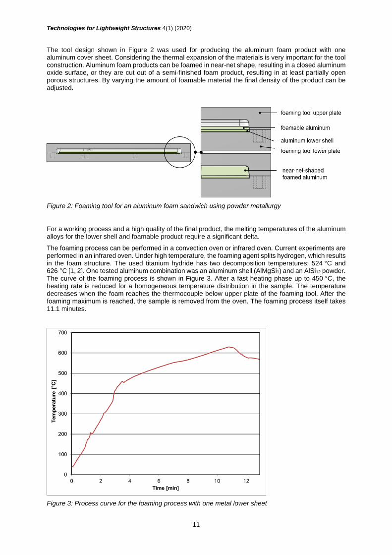
The foaming process can be performed in a convection oven or infrared oven. Current experiments are performed in an infrared oven. Under high temperature, the foaming agent splits hydrogen, which results in the foam structure. The used titanium hydride has two decomposition temperatures: 524 °C and 626 °C [1, 2]. One tested aluminum combination was an aluminum shell (AlMgSi1) and an AlSi12 powder. The curve of the foaming process is shown in Figure 3. After a fast heating phase up to 450 °C, the heating rate is reduced for a homogeneous temperature distribution in the sample. The temperature decreases when the foam reaches the thermocouple below upper plate of the foaming tool. After the foaming maximum is reached, the sample is removed from the oven. The foaming process itself takes 11.1 minutes.
Figure 3: Process curve for the foaming process with one metal lower sheet

Technologies for Lightweight Structures 4(1) (2020)
12
3.2 Results and evaluation
The eight parts manufactured with the same material and process configuration have a weight of
377.5 ±10.8 g. The densities of the foams are 0.51 ±0.03 g
cm³ and consequently 0.85 ±0.02
g
cm³ for the
semi-finished products. The weight of the aluminum shell and the foamed part were measured with a scale. The volume of the part was determined from CAD data and the densities were calculated. Figure 4 shows a semi-finished product.
Fig. 4 Aluminum foam product with one aluminum top shell metallurgically bonded to the foam during the foaming process; top view (left), bottom view (right)
A representative area of 50 mm x 50 mm of the manufactured part was scanned by means of computer tomography (CT). Using a CT program from Volume Graphics, the average pore size and the average cell wall thickness were calculated from the geometric data. The same was done for a 50 mm x 50 mm area of a similar aluminum foam with a specified manufacturing density of 0.5 g/cm³ from havel metal foam GmbH (HMF) for comparison with an reference foam. The results are shown in Table 1. The reference foam shows smaller pore sizes, lower cell wall thicknesses and standard deviations. Consequently, mechanical characterizations for the manufactured foam should be performed in addition to the reference foam.
Table 1 Comparison of properties between manufactured product and a similar foam from HMF
Average pore size
[mm³]
Average cell wall thickness
[mm]
Manufactured product 12.50 ±5.36 0.39 ±0.14
Reference foam (market) 11.78 ±4.82 0.31 ±0.11
Fast cooling during the manufacturing process using powder metallurgy causes micro and macro cracks in the pore walls of the aluminum foam, as shown in Figure 5. This effect enables the infiltration of the by definition closed cell aluminum foam with a low viscosity medium. Liquid paraffin has a dynamic viscosity of 3.9-25 mPas [3]. In vacuum-assisted infiltration tests, the manufactured foam was successfully infiltrated with 84.6 % by volume. The infiltration rate was calculated using the measured weights of the product, reduced by the weight of the aluminium shell, before and after the infiltration process and the material densities.

Technologies for Lightweight Structures 4(1) (2020)
13
Figure 5: CT scan of aluminum foam with cracks in the cell wall of the aluminum marked in red
A CT scan of an infiltrated sample was performed to determine the distribution of PCM inside the foam pores across the sample. The scan shows a varying PCM distribution in the sample. In Figure 6 the scan layer illustrates a very high local infiltration rate of foam with paraffin.
Figure 6: CT scan of closed cell aluminum foam infiltrated with paraffin
In addition to the functional integration of a material like paraffin for temperature control, reinforcements such as stiffening bars or inserts can be integrated during the foaming process. Inserts bonded in this way for the attachment of the battery modules showed significantly higher extraction forces of 7 kN than glued onserts or drilled inserts.
4 Integrated joining and forming process
4.1 Materials and process design
For the experiments, organo sheets with a polyamide 6 matrix and a glass fiber volume content of 47 % were used. The thermoforming experiments were performed with a 2 mm laminate, whereas a stack of four 0.5 mm laminates was used for the temperature measurement.
For the thermoforming of FRP, a temperature measurement study was performed to obtain the formable time range of the material. The FRP blanks were heated in a two-sided infrared radiator system. Ten fast medium-wave heaters with a maximum capacity of 1.4 kW each were used.
An interlayer temperature measurement (see Figure 7) with five thermocouples (evaluation points) was performed. The heating process was set to 95 s to ensure a uniform heating. The heating process finished with a temperature of ~290 °C for layers 2 and 4 and a mid-layer temperature of ~250 °C. During the FRP transfer from the infrared heater system into the hydraulic press, the mid-layer temperature increases through thermal inertia and the outer layer temperature decreases. During the forming and consolidation of the FRP, the FRP temperature decrease to the forming tool temperature of 85 °C. A small temperature increase (peak) of 2-5 °C after 127 seconds was measured in layers 2, 4 and 5. The

Technologies for Lightweight Structures 4(1) (2020)
14
small temperature peak can be explained by a higher mid-layer temperature and a thermal mass gradient through the outer layers into the forming tool.
Figure 7: Temperature measurement of an FRP with 2 mm thickness with 5 evaluation points
The following investigations focused on the consolidation process, especially the forming tool temperature. A forming tool temperature variation between 20 °C and 200 °C with ∆20 °C steps for the upper and lower forming tool was performed. The object of investigation was thermal warping because of different temperature gradients during the consolidation process. Besides the different temperature gradients, the thermal expansion is affected by the fiber orientation. The parts’ warping is mainly controlled by the process design, especially the forming tool temperatures. Therefore, a forming tool temperature study was evaluated to obtain the forming tool temperature for a less warped formed FRP.
4.2 Results and evaluation
For the evaluation of the formed FRP geometry, a 3D scanning system by GOM® ATOS® was used. 3D scanning of the formed geometry allows a comparison between the CAD and experimentally formed geometry is. The main results of the study are presented in Figure 7 using the thermal parameters from Table 2.
Table 2 Process parameters for FRP forming of the battery subshell
Upper forming tool temperature [°C]
(Set / Measured)
Lower forming tool temperature [°C]
(Set / Measured)
Specific surface pressure [N/mm²]
Test 1 20 / 20 20 / 20 13.4
Test 2 80 / 65 160 / 133 13.4
Test 3 100 / 70 180 / 161 13.4
Test 4 180 / 158 160 / 133 13.4
Figure 8 shows a 3D scan of a formed battery subshell with a measured forming tool temperature of 70 °C (upper tool) and 161 °C (lower tool). The color scale shows the difference between the CAD

Technologies for Lightweight Structures 4(1) (2020)
15
geometry and the thermoformed FRP geometry. The results show warped areas in the subshell bottom as well as in the flange area.
Figure 8: 3D scan of the formed battery subshell (Test 3), evaluation points
The warpage degree of each process setting can be evaluated at defined measuring points (MP) by varying the forming tool temperatures. Table 3 includes the main results of the study. Using a forming tool temperature of 20 °C (Test 1), the maximum deflection in the flange area is 7.3 mm (MP 1) and in the bottom area -3.6 mm (MP 3). By increasing the forming tool temperature to 65 °C (upper tool) and 133 °C (lower tool) the deflection reaches 0.8 mm in the flange area (MP 5) and -0.9 mm in the bottom area (MP 3). By increasing the forming tool temperature to 70 °C (upper tool) and 161 °C (lower tool) the deflection can be further reduced. The best results and minimum deflection can be reached with an upper tool temperature of 158 °C and a lower tool temperature of 133 °C.
Table 3 Evaluation of the battery subshell warpage degree by 3D scan (MP: measuring point)
Test 1 Test 2 Test 3 Test 4
MP 1 7.3 mm 0.6 mm 0.6 mm -0.1 mm
MP 2 4.9 mm 0.4 mm 0.4 mm 0.2 mm
MP 3 - 3.6 mm -0.9 mm -0.6 mm 0.0 mm
MP 4 2.5 mm 0.5 mm 0.4 mm 0.6 mm
MP 5 5.1 mm 0.8 mm 0.6 mm 0.3 mm
By using higher upper forming tool temperatures a switching of the warpage deflection could be observed. The flange area gains a high dimensionally stability and the bottom area shows an overall warpage of 0.6 mm. Moreover, a good surface quality of the consolidated organo sheet formed with a solid steel stamp and an open aluminum foam structure was achieved.
The study shows a 3D analysis of a thermoformed FRP including the warping effects due to different thermal gradients. By evaluating the formed geometry, the optimal process parameter settings for a less warped formed FRP subshell can be achieved.
By adapting the process parameters from organo sheet forming to the integral forming and joining process of FRP and aluminum foam, an initial process setting was implemented. The forming tool setup and the material transition manufactured in an integrated manner are shown in Figure 9. By using a vacuum system in the upper forming tool, the aluminum sheet and foam can be positioned and held in place. During the closing process of the press, the aluminum foam and FRP were joined together as one integrated part.
1
2
3
4
5
-1.61
-1.20
-0.80
-0.40
0.00
0.40
0.80
1.20
1.601.86
-1.61
-1.20
-0.80
-0.40
0.00
0.40
0.80
1.20
1.601.86
[mm][mm]

Technologies for Lightweight Structures 4(1) (2020)
16
Figure 9: Forming tool setup for an integrated forming and joining process (left); Hybrid section with open porous structure and closed aluminum film layer (right)
5 Discussion and conclusion
In this paper, investigation results for an integrated manufacturing process of a hybrid aluminum FRP battery housing subshell were shown. The developed process chain with reduced production steps including the organo sheet forming process with an aluminum foam product was illustrated. With this setup the forming process and the joining process can be combined in just one production step.
The near-net-shaped foam product was produced in a graphite form in an infrared oven. The
manufactured closed cell products have a foam density of 0.51 ±0.03 g
cm³ and can be manufactured with
an open porous structure or an aluminum film layer on one side. This density is similar to the aluminum foam products available on the market. However, CT scans showed that there are differences in the pore sizes and cell wall thickness of the foams. Consequently, the thermal and mechanical properties must be investigated with the foams and parts produced.
With the infiltration of the closed cell foam with PCM, an opportunity for the functional integration of temperature control is enabled. Heat can be transferred from the aluminum cover sheet into the aluminum foam und subsequently into the heat storage material paraffin. With a vacuum infusion process samples were infiltrated up to 84.6 %. The infusion capability for closed cell aluminum foam was proven. In terms of a reproducible infiltration of closed cell aluminum foam with PCM, further investigations towards different infiltration processes with distinct parameters are necessary. The melting range, heat capacity and amount of PCM can be adjusted for defined specifications of different applications such as batteries, power electronics or room climate control. The FRP shell acts as a thermal insulation.
Investigations into the heating of organo sheets and their forming behavior formed the basis for integrated forming with the foam product. Here 3D scanning analyses of the formed organo sheet were used to adjust the tool temperatures for minimal thermal warping. Eventually, the results of the integrated forming and joining process were presented. For an upper forming tool temperature of 158 °C, a lower forming tool temperature of 133 °C and a heated aluminum foam product with a specific surface pressure of 13.4 MPa, the best results were achieved for the scaled battery housing subshell. An integrated forming process of thermoplastic FRP and aluminum foam was realized on a small scale. The next challenges are to transfer the results to larger scales and to achieve the high quality demands of the industry, such as a smooth surface finish.
In further investigations, the mechanical performances, such as the intrusion resistance, and thermal properties, such as thermal conductivity, of the FRP-aluminum foam setup will be tested. In addition, several surface treatments and their influences on the bonding strength of the FRP-aluminum foam interface must be studied.

Technologies for Lightweight Structures 4(1) (2020)
17
Acknowledgements
The project was managed by the Fraunhofer IWU and financed by the Ministry of Science and Culture of Lower Saxony. The financial support is gratefully acknowledged.
References
[1] Matijasevic, B.; Banhart, J.; Zizak, I.; Darowski, N.; Schumacher, G.: BESSY Annual Report,
2003, pp. 68–69.
[2] Hipke, T.; Lange, G.; Poss, R.: Taschenbuch für Aluminiumschäume. Düsseldorf: Aluminium-
Verlag, 2007, pp.11–12.
[3] Tobias, K.: Rheologische Eigenschaften von Praffin/Wasser-Dispersionen als Phase Change
Slurry. Bochum: Ruhr-Universität Bochum, 2016, pp. 54, 60, 85–86.