Environmental Degradation Study of FRP Composites ... - CORE
192
Environmental Degradation Study of FRP Composites Through Evaluation of Mechanical Properties Sanghamitra Sethi Department of Metallurgical and Materials Engineering National Institute of Technology Rourkela -769008, odisha INDIA
-
Upload
khangminh22 -
Category
Documents
-
view
2 -
download
0
Transcript of Environmental Degradation Study of FRP Composites ... - CORE
Environmental Degradation Study of FRP Composites
Through Evaluation of Mechanical Properties
Sanghamitra Sethi
Department of Metallurgical and Materials Engineering National Institute of Technology
Rourkela -769008, odisha INDIA
Environmental Degradation Study of FRP Composites Through Evaluation of Mechanical Properties
A Thesis submitted in partial fulfilment of the
requirements for the degree of
DOCTOR OF PHILOSOPHY by
Sanghamitra Sethi (Roll No-510MM101)
Department of Metallurgical and Materials Engineering
National Institute of Technology Rourkela -769008, odisha
INDIA
December 2014
Supervisor
Prof. Bankim Chandra Ray

i
“Dedicated to my family and nation”
i
Department of Metallurgical and Materials Engineering
National Institute of Technology Rourkela-769008
INDIA
CERTIFICATE
This to certify that the thesis entitled “Environmental degradation study of FRP
composites through evaluation of mechanical properties” being submitted by Sanghamitra
Sethi for the award of the degree of Doctor of Philosophy in Metallurgical and Materials
Engineering of NIT Rourkela, is a record of bonafide research work carried out by her under
my supervision and guidance. The candidate has fulfilled all prescribed requirements for the
thesis, which is based on candidate’s own work and has not been submitted elsewhere for a
degree or diploma.
Prof. Bankim Chandra Ray
Supervisior NIT-Rourkela
Place: Rourkela Date:

ii
Acknowledgement
Though only my name appears on the cover of this dissertation, a great many people have
contributed to its production. I owe my gratitude to all those people who have made this
dissertation possible and because of whom my research experience has been one that I will
cherish forever.
My deepest gratitude is to my supervisior, Prof. Bankim Chandra Ray. I have been
amazingly fortunate to have an advisor who gave me the freedom to explore on my own,
and at the same time the guidance to recover when my steps faltered. He taught me how to
question thoughts and express ideas. I am deeply grateful to him for the long discussions
that helped me sort out the technical details of my work. I am also thankful to him for
encouraging the use of correct grammar and consistent notation in my writings and for
carefully reading and commenting on countless revisions of this manuscript.I am grateful
to him for holding me to a high research standard and enforcing strict validations for each
research result, and thus teaching me how to do research.His patience and support helped
me overcome many difficult situations and finish this dissertation. I hope that one day I
would become as good an advisor to my students as Prof. Ray has been to me.
I would like to acknowledge Prof. B.B. Verma, Prof. M.Kumar, Prof. S.Jayanthu my Doctoral
scrutiny committee members for fulfilling their duties of assessing my Ph.D work without
fail.
I am also indebted to our director Prof. Sunil Kumar Sarangi, for all the facilities provided
during the course of my tenure. I would like to thank Head of the Department of
Metallurgical and Materials Engineering department and all the faculty for all their
support through out my research work.
I am greatful to Prof.Addis Kidane, University of South Carolina,USA for all cooperation
during my testing and analyseing the data.
I am like to acknowledge Mr. Rajesh Pattnaik, Subrat Pradhan for their cooperation
during my testing.

iii
Special thanks to all my ex and present lab mates Dinesh, Kishore, Rajesh, Meet, Santosh,
Rajkishore, Pravash for their encouragement and help during my Ph.D work.
I am also thanks to my dear friends Meena, Beauty, Achala, Aparajita and subhashree for
their moral and friendly atomosphere in Rourkela.
Finally I would like to give a big thanks to my beloved husband Managobinda for his kind
support and understanding my each and every problem. His words of suggestion always
show me the right path when I feel disturbed. Thanks to My parents and all my family
members for their mental support and wishes. Lastly I offered my regards and gratitude to
almighty god for kind shower of blessings and support through out my Ph.D work.
22nd December 2014
National Institute of Technology, Rourkela Sanghamitra Sethi
iv
Abstract The performance of fibre-reinforced composites is, to a large extent, controlled by the
properties of fibre-matrix interfaces. The interface chemistry and character is vital to a
composite material. Good interfacial properties are essential to ensure efficient load transfer
from matrix to reinforcement, which helps to reduce stress concentrations and improves
overall sustainability of mechanical properties. The strength of composite materials depends
not only on the substrate but also on the interface strength. The interface here does not have
unique fracture energy unlike homogeneous materials.Consequently, there is a great interest
in developing new concepts for tailoring the strength of fibre-matrix interface. Some of
researchers have been reported the mechanisms responsible for improved fibre-matrix
interface adhesion is removing weak boundary layer, and thereby improving wettability.
However, a high performance composite functions because a weaker interface or
matrix stops a crack running continuously between the strong brittle reinforcements.
Fibre reinforced composite materials do, however, suffer some serious environmental
limitations. Environmental exposures include temperature, moisture, radiations, UV and other
different alkali treatments, which cause deterioration in the mechanical and/or physical
behaviour, adhesion between fibre/matrix interface regions of the composite material over a
period of time. The aim of the current investigation is to present the variation of mechanical
properties of glass fiber/epoxy composite under the synergistic effect of temperature and rate
of loading. In case of temperature we performed 2 types of cases as above and below glass
transition temperature (Tg) and in second case abobe and below-ambient temperature. Glass
fibre reinforced polymer composites (GFRP), carbon fibre reinforced polymer composites
(CFRP) and Kevlar fibre reinforced polymer composites were fabricated by hand-lay up
method followed by compression molding press. The composite specimens were subjected to
elevated and high temperatures as +60°C,+100°C,+150°C and +200°C temperatures. 3-Point
short beam shear test and 4-point short beam shear test were conducted in order to
characterize the mechanical behavior of laminated composite and to determine the influence
of loading rate on interlaminar shear strength. To understand the interactions between various
failure mechanisms in the fiber, matrix and fiber/matrix interface, microscopic analyses were
conducted.
v
In second case we performed in-depth analysis of interlaminar shear test and failure
mechanisms of glass fibre/epoxy, carbon fibre/epoxy and Kevlar fibre/epoxy composites
under +50°C,-50°C,+100°C and-100°C temperatures and different crosshead velocity.
Different high and low temperature conditioning were performed using Instron with
environmental chamber providing additional information regarding in-situ failure of
laminated composites. Following the test, the fracture surfaces of the samples were scanned
under SEM to understand the dominating failure modes. Microstructural assessments can also
reveal the response of each constituent viz. fibre, matrix resin and the interface/interphase;
under temperature and mechanical loading. This section comprehensively presents the
mechanical behaviour and structural changes in fibrous polymeric composite systems during
the mechanical loading under high and low temperature service environment. We specifically
tailored this potential to describe the contradiction and confusion at polymer composite
interface which may not be underestimated by material scientists. Fibre/matrix adhesion
involves very complex physical and chemical mechanisms. One of the most important
physical aspects is the geometry of reinforcing fibres, which influences adhesion between
fibre and matrix, stress transfer and local mechanisms of failure. In addition to chemical
bonding, the fibre/matrix bond strength in shear is largely dependent on the roughness of the
fibre surface and the fibre/matrix contact area.
At cryogenic temperatures, due to difference in coefficient of thermal expansion between the
fibre and the matrix phase, microcracks initiate and propagate through the laminated
composites. Therefore, knowledge of the resistance to different failure modes of woven fabric
composites laminates at cryogenic temperatures is essential to the materials scientist and
design analyst. The aim of this investigation was to study deformation and mechanical
behaviour of glass fibre/epoxy composites subjected to 3-point short beam shear test at low
and ultra-low temperature with different loading speeds. The laminates were tested at
ambient (+27°C) temperature and at (-20°C,-40°C,-60°C) temperatures using liquid nitrogen
in an environmental chamber installed on an Instron testing machine. Testing was carried out
in different loading covering low to high medium speeds. Following the test the fracture
surfaces were scanned under SEM microscope. A need probably exists for an assessment
of mechanical performance of such potentially promising materials under the influence
of changing environment and loading speed. Using fractography study to characterize the
onset and growth of failure modes has become generally accepted method.
vi
During thermal cycling differential coefficient of thermal expansions and residual stresses is a
prime cause in fibre reinforced polymer composites (FRP) material. The behavior of the interfacial
contact between fibre and matrix is strongly influenced by the presence and nature of residual
stresses. GFRP and CFRP composite laminates are used to analyze the thermal cycle effect on the
mechanical behavior with different loading rates. 3-point short beam shear test was performed for
the analyze the mechanical behavior. To study the failure modes which have great impact on
mechanical behavior, Scanning electorn microscope (SEM) was used.
The ensuing research revealed a number of key challenges regarding interface issues in producing
polymer nanocomposites that exhibit a desired behavior. The greatest stumbling block to the large-
scale production and commercialization of nanocomposites is the dearth of cost effective methods
for controlling the dispersion of the nanoparticles in polymeric matrix. Current interest in
alumina/epoxy nanocomposites, Cu nano particle and Multi walled carbon nanotube (MWCNT) has
been generated and maintained because nanoparticles filled polymers exhibit unique combinations of
properties not achievable with conventional composites. In the present study, glass fiber reinforced
composites filled with nanoparticle have been prepared. 3-point short beam shear test was conducted
to analyze the Interlaminar shear strength (ILSS) variation with different loading rate. Alumina
nanoparticle was well dispersed in epoxy polymer matrix to achieved high mechanical performance.
The results show that it is possible to improve the interlaminar shear strength with the loading rate
variations. Clearly, no follow-up work in this area will be commendation for better understanding of
effect of nanoparticle in FRP composites in assessment of loading rate sensitivity. Under these
conditions, fibre reinforced polymer nanocomposites have been shown to exhibit two glass-transition
temperatures, Tg: one associated with polymer chains far from the nanoparticles, and a second, larger
Tg, associated with chains in the vicinity of the particles. To analyze different failure modes SEM
analyses was conducted. Good interfacial properties are essential to ensure efficient load transfer
from matrix to fillers, which helps to reduce stress concentrations and improves overall
mechanical properties. Consequently, there is great interest in developing new concepts for
improving the strength of fibre−matrix interface.
Key Words: Fibre reinforced polymer composites, environmental degradation, fibre/matrix
interface,mechanical behavior, fractography, glass transition temperature, spectroscopy analysis,
Al2O3 nano-filler.
vii
Contents Certificate i
Acknowledgement ii
Abstract iv
List of Figures xii
List of tables xviii
Abbreviations xix
Chapter-1: Introduction
1.1 Fibre reinforcements and polymer matrices 2 1.2 Recent advances of PMCs 3 1.3 Nano-fillers reinforcement 5 1.4 Motivation and relevant case studies 6 1.5 Scope of the investigation 6 1.6 Organisation of thesis 7
References 8
Chapter -2: Literature link 2.1 Introduction 16 2.2 Environmental degradation
2.2.1 Thermal environment 16 2.2.2 Hygrothermalenvironment 19 2.2.3 Effect of temperature on mechanical behavior 21 2.2.4 Other environmental exposures 22 2.2.5 Effects of loading speed 24
2.3 Nano filler in polymer composites 26 2.4 Mechanical behavior of polymer composites
2.4.1 Tensile Failure 27 2.4.2 Stress-strain curve 29
2.5 Microstructural and micro- interfacial characterization 2.5.1 Micro-characterization of interface 31
References 35
Chapter-3: Materials and Methods 3.1 Materials 43
3.2 Experimental Methods 46
3.3 Instrument used 47
viii
Chapter 4 Results and Discussion
4.1. Effect of high temperature on mechanical response of materials: Assisted with viscoelastic nature
Theories and Thoughts 4.1.1. Introduction 50
4.1.2 Materials and experimental set-up
4.1.2.1 Materials and fabrication technique 51
4.1.2.2 In-situ conditioning and characterization 52
4.1.3 Results and Discussion
4.1.3.1 In-situ testing 53
4.1.3.2 Fractography study 60
4.1.3.3 Interfacial chemistry study 72
4.1.3.4 Glass transition study 74
4.1.4 Summary 75
References 76
4.1.1a AFM study of thermally conditioned samples
Theories and Thoughts
4.1.1a. 1 Introduction 78
4.1.1a.2 Materials and experimental set-up
4.1.1a.2.1 Materials 79
4.1.1a.2.2 Fabrications and experimental technique 79
4.1.1a.3 Results and Discussion
4.1.1a.3.1 In-situ testing 80
4.1.1a.3.2 Fractography analysis 82
4.1.1a.4 Conclusion 83
References 83
ix
4.1.1b Effect of above-ambient and below-ambient of FRP composite materials with different loading rates
Theories and Thoughts 4.1.1b.1 Introduction 84
4.1.1b.2 Experimental work
4.1.1b.2.1 Materials 86
4.1.1b.2.2 Temperature conditioning and characterization 86
4.1.1b.3 Results and Discussion
4.1.1b.3.1 Mechanical testing 88
4.1.1b.3.2 Fractography study 93
4.1.1b.3.3 Thermal analysis 103
4.1.1b.4 Summary 104
References 104
4.2 Effect of low temperature on mechanical response of FRP composite materials with different loading rates
Theories and Thoughts 4.2.1 Introduction 106
4.2.2 Experimental work
4.2.2.1 Materials 107
4.2.2.2 Low temperature conditioning and characterization 107
4.2.3 Results and Discussion
4.2.3.1 Mechanical testing 110
4.2.3.2 Fractography study 113
4.2.4 Summary 114
References 114
4.3 An assessment of high and low temerature on prepreg glass fibre/epoxy composites
Theories and Thoughts 4.3.1 Introduction 116
4.3.2 Experimental section
4.3.2.1 Materials and instrument 118
4.3.2.2 Processing of laminates 118
x
4.3.3 Results and Discussions
4.3.3.1 Short beam shear test 120
4.3.3.2 Fractography study 122
4.3.4 Summary 123
References 127
4.4 An effect of thermal cycle on interlaminar shear strength of FRP composites
Theories and Thoughts 4.4.1 Introduction 129
4.4.2 Experimental section
4.4.2.1 Materials and instrument 130
4.4.2.2 Procedure and materials characterization 130
4.4.3 Results and Discussions
4.4.3.1 Short beam shear test 132
4.4.3.2 Fractography study 133
4.4.4 Summary 136
References 136
4.5 Effect of UV treatment on loading rate sensitivity
Theories and Thoughts 4.5.1 Introduction 137
4.5.2 Experimental work
4.5.2.1 Materials 138
4.5.2.2 Conditioning and characterization 138
4.5.3 Results and Discussion 139
4.5.3.1 Mechanical testing 140
4.5.3.2 Fractography analysis by SEM 141
4.5.4 Summary 142
References 142
xi
4.6 Effect of nanoparticle addition to evaluate FRP composites under different environmental conditioning
Theories and Thoughts
4.5.1 Introduction 143
4.5.2 Experimental work
4.5.2.1 Materials 144
4.5.2.2 Materials characterization 144
4.5.2.3 Environmental conditioning 145
4.5.3 Results and Discussion
4.5.3.1 mechanical testing by Instron 146
4.5.3.2 Failure modes study by SEM 148
4.5.4 Summary 149
References 150
4.7 Effect of strain rate and environment on the dynamic flexural behavior of GFRP and CFRP composites
Theories and Thoughts
4.7.1 Introduction 151
4.7.2 Experimental work
4.7.2.1 Materials and frabrication 153
4.7.2.3 Environmental conditioning 153
4.7.3 Results and Discussion
4.7.3.1 Mechanical testing 156
4.7.3.2 Failure modes study by SEM 158
4.7.4 Summary 163
References 164
5. Summary and Conclusions 165
Critical comments and future scope of work 168
xii
List of Figures Figure No.
Figure Description Page No.
Fig.1 Flexural stress–strain curves of control and conditioned neat/nano epoxy specimens.
18
Fig.2 Absorption curves in SFC specimen and iso concentration lines at 10%, 25%,50%, 75%, 90% moisture
20 Fig.3 Short and long term moduli in terms of water concentration 20 Fig.4 Change in snap-through load with exposure to 20°C and
65%RH 22 Fig.5 Load-displacement traces for bistable plate over several days
exposure to 20°C and 65%RH 22 Fig.6 (a) Example of the damage in the treated carbon fibre
composites: (a) XY plane, (b) YZ plane, (c) XZ plane and (d) 3D view, One of the delaminations in the treated E-glass resin composites: (a) XY plane, (b) YZ plane, (c) XZ plane and (d) 3D view
24
Fig.7 ILSS with loading rate of glass fibre/epoxy composites at -50°C temperature 25
Fig.8 Bond strength distributions for Kevlar 49/polyethylene microcomposites and their counterparts aged in water at 88°C for 24 h
26
Fig.9 (a) Interfacial regions as a function of filler particle size. The filler is shown in red, the interfacial region in dark blue and the bulk polymer in pale blue. (b) Large particles produce a low radius of curvature, and relatively less polymer in the ‘interfacial region, (c) the same volume of filler broken into smaller particles creates a higher radius of curvature and more polymers in the interfacial region
27
Fig.10 Geometry and dimensions of composite specimens under tensile loading (b) untested specimen 28
Fig.11 (a) Stress-strain curve at different strain rate (b) Absorbed energy under stress-strain curve 29
Fig.12 Different regions of a typical strain softening curve. The displacement, rather than strain, is used, to avoid implications of violating basic principles
30 Fig.13 FTIR spectra of different sizing agents/epoxy resin before and after
boiling water aging 32 Fig.14 AFM topography images of the same cross-section area of
AS4/VRM34 using Tapping Mode (a) and contact mode (b). The scan size was30*30 µm
33
Fig.15 AFM micrograph shows plastic deformation results in the formation of permanent indentation on the surface of the sample
33
xiii
Fig.16 (A)Variation of ILSS with loading rates of glass fibre/epoxy composites with 3-point short beam shear test at different temperatures (a) Load-displacement curve of glass fibre/epoxy composites at +60°C temperature (b) load-displacement curve of glass fibre/epoxy composites at +100°C temperature (c) load-displacement curve of glass fibre/epoxy composites at +150°C temperature (d) load-displacement curve of glass fibre/epoxy composites at +200°C temperature (e) load-displacement curve of glass fibre/epoxy composites at +250°C temperature.
54
Fig.17 (a,a’) Scanning electron microscopy images of 3-point bend tested glass fibre/epoxy composites at 200mm/min and flexural stress with flexural strain curve at ambient temperature, (b,b’) at +60°C temperature, (c,c’) at +100°C temperature, (d,d’) at +150°C temperature, (e,e’) at +200°C temperature, (f,f ‘) at +250°C temperature
58
Fig.18 Interlaminar shear strength with loading rate of carbon fibre/epoxy composites at +27°C, +60°C, +100°C,+150°C and +200°C.
59
Fig.19 Load-displacement curve of carbon fibre/epoxy composites above and below glass transition temperatures as +60°C,+100°C,+150°C,+200°C.
60
Fig.20 Represents the different failure modes observed at different temperatures and the stress-strain behavior of corresponding temperatures at 200mm/min loading speed (a) at ambient (+27°C) temperature (b) at +60°C temperature (c) +100°C temperature (d) +150°C temperature (e) +200°C temperature
62
Fig.21 (a)Interlaminar shear strength (ILSS) values with loadin rate curve at different temperature of Kevlar fibre/epoxy composites (a’) load-displacement curve of without conditioning samples (+27°C) at different loading rates
64
Fig.22 Load-displacement curves (a) at +60°C temperature(b) at +100°C temperature (c) at+150°C temperature (e) +200°C temperature
64
Fig.23 Different failure modes observed in Kevlar fibre/epoxy composites at high temperature
66 Fig.24 Variation of ILSS with loading rate of glass fibre/epoxy
composites tested with 4-point bend test at different temperatures. (a) Load-displacement curve of glass fibre/epoxy composites at +60°C temperature (b) load-displacement curve of glass fibre/epoxy composites at +100°C temperature (c) load-displacement curve of glass fibre/epoxy composites at +150°C temperature (d) load-displacement curve of glass fibre/epoxy composites at +200°C temperature (e) load-displacement curve of glass fibre/epoxy composites at +250°C temperature.
68
xiv
Fig.25 (A,A’) Scanning electron microscopy images of glass fibre/epoxy composites tested at 4-point short beam shear test at 200mm/min and flexural stress with flexural strain curve at ambient temperature, (B,B’) at +60°C temperature, (C,C’) at +100°C temperature, (D,D’) at +150°C temperature, (E,E’) at +200°C temperature, (F,F’) at +250°C temperature.
68
Fig.26 FTIR-ATR spectroscopy analysis of glass fibre/epoxy and carbon fibre/epoxy composites
73 Fig 27 Curing reaction of epoxy matrix resin. 74 Fig.28 Glass transition temperatures values of glass fibre,carbon fibre
and Kevlar fibre epoxy composite materials.
74
Fig.29 AFM topography images of untreated GFRP composites (a) line analysis of image (b) 3D image analysis 79
Fig.30 AFM topography image of treated GFRP interphase failure after treatment
81 Fig.31 SEM micrograph matrix failure of GFRP composite after treatment 81 Fig.32 AFM topography image of treated GFRP adhesion failure after
thermal conditioning treatment. 82
Fig.33 (a) Schematic representation of 3-point short beam shear test. (b) Experimental set up for 3-point short beam shear test (c) Instron machine used for the test
88
Fig.34 Variation of ILSS with loading rate for glass/epoxy composite system at different temperatures.
90 Fig.35 Interlaminar shear strength of glass/epoxy composite at 1
mm/min for different temperature 91
Fig.36 Scanning electron microscopy (SEM) images of the glass fibre/epoxy composites: (A, A’) at -100˚C temperature (B, B’) at -50˚C temperature (C,C’) at ambient temperature (D,D’) at +50˚C temperature (E,E’) at +100˚C temperature
93
Fig.37 Variation of interlaminar shear strength with different loading rates at different temperatures for carbon fibre/epoxy composite system.
94 Fig.38 Interlaminar shear strength of Carbon/epoxy composite at 1
mm/min for different temperature. 96
Fig.39 Scanning electron microscopy (SEM) images of the carbon fibre/epoxy composites: (A, A’) at -100˚C temperature; (B, B’) at -50˚C temperature; (C,C’) at ambient temperature; (D,D’) at +50˚C temperature; (E,E’) at +100˚C temperature. Variation of ILSS with loading rate for Kevlar/epoxy composite system at various temperatures and loading rates.
97
Fig.40 Interlaminar shear strength of Carbon/epoxy composite at 1 mm/min for different temperature.
98 Fig.41 Scanning electron microscopy (SEM) images of the Kevlar 100
xv
fibre/epoxy composites: (A, A’) at -100˚C temperature (B, B’) at -50˚C temperature (C,C’) at ambient temperature (D,D’) at +50˚C temperature (E,E’) at +100˚C temperature
Fig. 42 Comparison of glass transition temperatures of glass fibre/epoxy composites at different conditioning temperature. (a) Glass fibre/epoxy composites (b) Carbon fibre/epoxy composites (c) Kevlar fibre/epoxy composites
101
Fig. 43 (a)Interlaminar shear strength with different loading rates of glass fibre/epoxy composites at 25°C, -20°C,-40°C and -60°C temperature (b) Flexural stress vs Flexural strain at 1mm/min loading speed.
103
Fig. 44 Fractography analysis of glass fibre/epoxy composites at ambient (27°C) temperature
111 Fig. 45 Fractography analysis of glass fibre/epoxy composites at
ambient (-20°C) temperature 112
Fig. 46 Fractography analysis of glass fibre/epoxy composites at -40°C temperature 113
Fig. 47 Fractography analysis of glass fibre/epoxy composites at -60° temperature
113 Fig. 48 Curing cycle for glass/epoxy composite followed within
autoclave 114
Fig. 49 Instron 5967 with environmental chamber used during the in-situ testing of sample.
119 Fig. 50 (a) Loading rate with ILSS of GFRP samples at different
temperature 120
Fig. 51 (b) Loading speed with ILSS curves of glass/epoxy composite at different temperature
121 Fig. 52 Matrix micro cracking and brittle fracture of fiber at-50 degree
at 1mm/min and 800mm/min 123
Fig. 53 Cleavage marking and fiber/matrix debonding at -50 degree 1000mm/min
125 Fig. 54 Scanning electron micrograph at ambient 1mm/min and
800mm/min shows steps and welts as well as matrix cracking respectively.
126 Fig. 55 Thermal conditioning sample at 1mm/min and 800mm/min
showing fiber/matrix debonding and macromatrix cracking. 126
Fig. 56 Interlaminar shear strength with loading rate at different thermal cycle of glass fibre/epoxy composites
132 Fig. 57 Interlaminar shear strength with loading rate at different
thermal cycle of carbon fibre/epoxy composites. 133
Fig. 58 . Different failure modes were observed in glass fibre/epoxy composites (a) fibre imprint at 0.5 cycle treatment (b) riverline marking at 1cycle treatment (c) fibre/matrix debonding at 1.5 cycles.
134
Fig. 59 Different failure modes are observed in carbon fibre/epoxy composites (a) fibre fracture at 0.5 cycle treatment (b) toughened matrix at 1 cycle treatment (c) fibre/matrix debonding at 1.5 cycle treatment.
135
xvi
Fig. 60 Interlaminar shear strength with loading rate at different time exposure of UV treatment (a) carbon fibre/epoxy composites (b) glass fibre/epoxy composites.
139 Fig. 61 (a) Bunch of fibre fracture (b) resin tearing (c) fibre fracture
sliding failure modes observed in glass fibre/epoxy composites at 30 days, 60 days and 90 days UV treatment of samples.
140 Fig. 62 (a) steps formation on the matrix resin (b) deep riverline
marking (c ) small cusps formation failure modes are observed in carbon fibre/epoxy composites at 30 days, 60 days and 90 days UV treatment of the samples.
141
Fig. 63 (a)Average stress-strain curves for the woven GFRP composite with nanoparticles
146 Fig. 64 (b)Average stress-strain curves for the woven GFRP composite
without nanoparticles 146
Fig. 65 (a),(b) Scanning electron micrograph of epoxy resin and fiber of alumina/epoxy glass fiber reinforced composites. Tilted 20°.
149 Fig. 65 (c),(d) Scanning electron micrograph of epoxy glass fiber
reinforced composites. Tilted 20°. 149
Fig. 66 Configuration of Experimental Apparatus 154 Fig. 67 Loading Fixture, Specimen, and Incident Bar 154 Fig. 68 Loading arrangement and field of the camera system 155 Fig. 69 Typical mid-point deflection a) CFRPAMB at 300/s b) GFRP5_250
at 500 /s 156
Fig. 70 Typical Strain-time plot for GFRP_AMBat different strain rate 158 Fig. 71 Typical Strain-time plot for CFRP_60s at different strain rate 159 Fig. 72 Typical load- time plot for CFRP_AMB at 276 /s 160 Fig. 73 (a) Angles cusps formation on the matrix surface at 5 psi (b)
Cusps formation between the fibres spacing at 10 psi (c) Cusps in very small size at 15 psi.
161
Fig. 74 (a) Tension failure of glass fibre/epoxy at 5psi (b) deadhesion between fibre and matrix at 10psi (c ) bunch of fibre failure at 15psi
162
Fig. 75 Topography change of AS4/VRM34 exposed to 100% RH for different periods of time. The vertical distance between the two selected points decreased from 130.7 nm before treatment to 83.7 nm after 1495 h of hygroscopic treatment at 100% RH.
168
Fig. 76 Unit cell FE model of glass fibre hybrid composites(a)aligned (b)misaligned fibres
168
xvii
List of Tables
Table No. Description Page No. 1 Physical and mechanical properties of glass fibre 42 2 Mechanical Properties of high-modulus carbon fibre 42 3 Mechanical properties of Kevlar-49 fibre. 43 4 Mechanical properties of epoxy resin. 43 5 Temperatures Effect 49 6 UV radiation treatment 49 7 Fibre reinforced epoxy composites with nano-fillers 50 8 Percentage change in ILSS with temperatures at 1 mm/min. 92 9 Percentage change in ILSS with temperatures at 1 mm/min
loading speed 96
10 Percentage change in ILSS with temperatures at 1 mm/min. 100
xviii
Abbreviation
GFRP Glass fibre reinforced polymer composites
CFRP Carbon fibre reinforced polymer composites
KFRP Kevlar fibre reinforced polymer composites
FRP Fibre reinforced polymer composites
ILSS Interlaminar Shear Strength
DSC Differential Scanning Calorimeter
FTIR-ATR Fourier Transform Infrared Spectroscope
SEM Scanning Electron Microscope
AFM Atomic Force Microscope
ASTM Americal Society for Testing of Material
PNC Polymer Matrix Nanocomposites

1
Chapter 1
Introduction
2
1. Introduction Polymer composites demonstrate remarkable electrical, thermal, and mechanical properties,
which allow a number of exciting potential applications. Polymer composites have wide
range of applications in various sectors due to many features including low weight, low cost,
ease of processing and fabrication, environmental stability and corrosion resistance. Fibres
are typically added to enhance chemical and/or physical, mechanical properties of polymer
matrix. Of these properties, optimizing the mechanical properties hasalways been the most
desired objective. Inorganic fibres (glass and carbon fibres) and aromatic organic fibres
(Aramid) are the traditional fillers used to boost the mechanical properties of polymers. With
hundreds of available fibres and thousands of unique polymers , it is costly to determine an
ideal combination for a given application [1]. Further complications arise from the many
additives and fillers which contribute to the final mechanical properties of a given fiber –
matrix system [2]. The dispersion of inorganic additives (at nanometric size and/or
micrometer size) in polymers significantly improves their electrical, mechanical and thermal
properties[3]. These properties involves spatial and orientational distribution of fibres, and
requires information from the nano to the macroscale,which is over 6 orders of magnitude in
length scale [4].One of the most enduring problems in the evolution of science and
technology using nanoscale materials is the characterization of their morphology in
macroscopic systems [5-7]. In a polymer composite, the properties of the polymer region
near the reinforcing agent i.e. interface/interphase, are different from those of the bulk [4].
The strength of composite materials depends not only on the substrate strength but also on the
interface strength. The interface here does not have unique fracture energy unlike
homogeneous materials [8].The adhesive fibres elongate in a stepwise manner as folded
domains are pulled open. The elongation events occur for forces of a few hundred
piconewton. These are smaller than the forces of over a nanonewton, which are required to
break the polymer backbone. When the force rises to a significant fraction of the force
required to break a strong bond and threatens to break the backbone of the molecule,
a domain unfolds. Thus, it could avoid the breaking of a strong bond in the backbone [9]. The
interface between the fibre/polymer plays a defining role in the overall material
properties such as glass transition temperature [10-13], relaxation dynamics [14-16],
thermal aging [17], dielectric behavior (i.e., breakdown strength, voltage endurance, and
dielectric permittivity) [18], mechanical properties (i.e., stiffness, debonding, fracture,
3
internal stress distribution, and toughness) [19,20,21]. The measurement of the interface
volume fraction is, therefore, pivotal for structure property-processing investigation and
modelling of polymer nanocomposites. Tuning the interfaces between fillers and polymer
matrix potentially plays a critical role in composites to enhance their adaptive responses.
1.1 Fibre reinforcement and polymer matrices
Durability of composites depends on the integrity of the interface and the region known as
the interphase between the matrix and the reinforcing material.The fibre/matrix interface has
always been considered as a crucial aspect of polymer composites. It is at the interface where
stress concentration develops because of differences between the reinforcement and matrix
phase thermal expansion coefficients. The interface may also serve as a locus of chemical
reaction [22]. Environmental exposure results in reduced interfacial stress transmissibility
due to matrix plasticization, chemical degradation and mechanical degradation. Matrix
plasticization reduces matrix modulus. Chemical degradation is the result of hydrolysis of the
bonds at the interface [23, 24]. The influence of environmental effects on mechanical
properties of FRP composites and interfacial degradation is well documented in literatures
[25-30].Although thousands of polymer matrix composite components are currently in
service in many applications as well as civil infrastructure repair and rehabilitation,
barrier are still there to further implementation in a more structurally critical and complex
temperature applications. The level of adhesion between matrix and fibre affects the
mechanical behavior in the off-axis and also parallel to the fibre [31].
The fibre and matrix interactions are likely to be greater in woven fabric composites as
compared to composite made up of unidirectional fibres. Localized strains in the matrix may
increase as the fibres straighten under tensile loading or buckle under compression [32].
Differential coefficients of thermal contraction may modify the local stress threshold
required for interfacial debonding. This eventually leads to nucleation of delamination
[33]. The different reinforcements as glass fiber, carbon fibre and Kevlar fibre, whichhas high
elastic constants, gave a significant increase in stiffness of composites over the well-
establishes performance, hence made possible a wide range of applications for composites.
Steel cord reinforced polymer (SCRP) is a new material that can be used as external
reinforcement.SCRP combines the advantages of steel and CFRP. The Young’s modulus is
high, as well as the strength which is comparable to CFRP. The material cost is low and the

4
laminate remains quite flexible. Another advantage is the ductile behaviour of the steel
composite. Therefore, lower material safety factors can be applied in design [34].
In particular, the fibre/matrix interface is highly prone to in-service degradation. In general,
the influence of in-service degradation is reflected in its mechanical performance and fracture
morphology, but analyzing and identifying the reason behind the particular degradation is
problematic. The most common types of environmental conditions to which composite
material was exposed during loading as moisture [35-37], temperature [38-41], hygrothermal
effects [42-50], UV, low earth orbit environment [51-54] and sea water [55-57].
The response of fibre/matrix interface within the composite plays an important role in
determining the gross mechanical performance, because it transmits the load from the matrix
to the fibres, which contribute the greater portion of the composite strength. Better the
interfacial bond better will be the ILSS, de-lamination resistance,fatigue and corrosion
resistance [58]. An interfacial reaction may induce various morphological modifications
to the interphase at the fibre/polymer interface [59, 60]. A need probably exists for an
assessment of mechanical performance of such potentially promising materials under
the influence of changing environment and loading speed. A strong interface displays an
exemplary strength and stiffness, but is very brittle in nature with easy crack propagation
through the interface. A weaker interface reduces the stress transmissibility and consequently
decreased strength and stiffness. A crack here is more likely to deviate and grow at the weak
interface. It results in debonding and/or fiber pull-out and contributes to improved
fracture toughness [61,62].
1.2 Recent advances of PMCs
The Delamination failure mode is known to be the major life-limiting failure process in a
composite laminate. Delamination can induce stiffness loss, local stress concentration and
local instability that can cause buckling failure under compressive loading. The matrix in a
fibre reinforced composites serves to transfer the load between fibres and to integrate the
whole structure to form useful shape. If the incident impact energy exceeds a critical value
(Ec), then the fibre-resin composite will suffer damage in the form of delamination. The
delamination in composites is caused by the interlaminar stresses produced by out-of-plane
loading, eccentricities in load paths, or discontinuities in the structure [63].Prediction of
initiation and growth of delamination is, however, complicated and the success of the
predictions relies on accurate interlaminar toughness data for the material under both static
and fatigue loading and at different environmental conditions.The strain energy release rate
5
threshold values for delamination growth were significantly affected by fatigue loading,
and the fatigue threshold values at 100°C were only about 10% of the critical static
values for all three mode conditions tested [64,65].For review of the problem and various
approaches suggested for the determination of mode mixity in delamination tests has been
reported [66-68].
Z-pinning is an effective reinforcement method for increasing the delamination resistance of
fibre–polymer composites. Z-pins are thin metallic or fibrous rods inserted in the through -
thickness direction of composite materials to increase the interlaminar fracture toughness
properties [69]. Z-pinning has proven a highly effective method for increasing the modes I
and II interlaminar fracture toughness [70-74] and impact damage resistance [75, 76] of
composites. Z-pins also increase the delamination resistance and structural properties of
bonded composite joints [77-80]. These improvements to the toughness properties are reliant
on the z-pins generating bridging traction loads along the delamination crack [81–83]. The
traction loads resist crack opening (under mode I) and crack sliding (under mode II), which
increases the delamination fracture resistance.
1.3 Nano-filler reinforcement The field of polymer nanocomposites has attracted considerable attention as a method of
enhancing polymer properties and extending their utility, by using molecular or nanoscale
reinforcements rather than conventional particulate filled microcomposites. Nanocomposites
are a combination of two or more phases containing different compositions or structures,
where at least one of the phases is in the nanoscale regime [84]. Polymer nanocomposites
exhibit greater resistance to breakdown mechanisms than pure polymers due to their
improved properties. The mechanisms that can lead to polymer nanocomposites failure are
the same as those that lead to pure polymer failure. In recent years, polymer–nanoparticle
composite materials have attracted the interest of a number of researchers, due to their
synergistic and hybrid properties derived from several components. Whether in solution or in
bulk, these materials offer unique mechanical, electrical, optical and thermal properties. Such
enhancements are induced by the physical presence of the nanoparticle and by the interaction
of the polymer with the particle and the state of dispersion [85-88].It is logical to anticipate
that the dispersion of fillers with dimensions in the nanometer level having very large asp ect
ratio and stiffness in a polymer matrix could lead to evenhigher mechanical
performances.Polymer nanocomposites can attain a substantiallygreater stiffness, strength,
6
and thermal stability and barrier properties at very low nano filler content compared to
plastics filled with traditional micrometer-sized particles [89].
However, despite the large volume of literature published on the relationships between the
nano-scale structural variables and macroscale physical and mechanical properties of polymer
nanocomposites over the last 15 years, the understanding of the basic physical origin of these
large property changes remains in its infancy [90-92]. This is partly due to the complexity
of polymer nanocomposites, requiring re-considering the meaning of some basic polymer
physics terms and principles, and partly by the lack of reliable experimental data. In addition
to detailed knowledge of molecular structure of the polymer matrix, the theory also requires a
sufficient description of particle dispersion, self-assembly phenomena, particle chain
interactions and nanocomposites preparation processes [93, 94].
1.4 Motivation and relevant case studies
The main motivation of this research work comes from the large applications of the fibre
reinforced polymer matrix composites. The wide structural applications of fibre reinforced
polymer and polymer nanocomposites are extremely important for the past few decades in
aerospace, spacecraft, marine, sports equipments and many other research fields. During their
service period, the materials are exposed to different environmental conditions. For long
period of exposure, materials leads to ageing of the polymer matrix resin, this tends to quick
degradation of its overall mechanical and thermo-mechanical properties.
1.5 Scope of the investigation
This research is of general interest to study the mechanical and fracture behavior of fibre
reinforced polymer and fibre reinforced polymer nanocomposites in different environmental
conditions at different loading rates. This study will give an idea about the loading rate
sensitivity of FRP’s under different environments. Fractography study reveals different
characteristics of fracture surfaces, failure modes and crack growth behavior. This research
also provides information on changes in glass transition temperature(Tg) of the material. Tg is
an important aspect in obtaining, maintaining mechanical behavior of the composites.
Attenuated total reflection fourier transform infrared spectroscopy is used to obtain
information on the change in chemistry occurring in epoxy resin at different environmental
conditions. Here an attempt is made to correlate the mechanical behavior of the materials
with change in chemistry and change in its glass transition temperature.
7
This research intends to pivot the development of different aspects of fibre/polymer
composites. These are (i) mechanical behavior with environmental instability (ii) response of
stress-strain curve (iii) isolated unprecedented failure (iv) nano filler in polymer composites.
The majority of previous efforts were concentrated on the mechanical and chemical aspects
of fibre/polymer composites. However, from last few decades different research groups have
synthesized and studied the properties and applications of nanofillers on fiber/polymer
nanocomposites.
To date some researchers have also published some reviews as well as book and book
chapters [95,96], mainly highlighting some specific areas and materials as fibre/epoxy
properties and processing [97], mechanics of composites [98], environmental degradation
[99-101], damage modelling [102], mechanical behavior [103,104], failure criteria [105-107],
nanofillers to polymer matrix [108-110] and some applications in different fields. Utilizing
the full potential of this amazing material in different engineering and structural applications,
there is still need of extensive research work with current literature and research perspective
of fibre/epoxy polymer composites.
1.6 Organisation of the thesis
The thesis has been divided in four chapters. Chapter-1, is an introductory section in fibre
reinforced polymer matrix and fibre reinforced polymer nanocomposites. Chapter-2, contains
the present literature survey covering different environmental exposures of these materials,
role of nano-filler in polymer composites, mechanical behavior study, microstructural and
micro-interfacial characterization. Chapter-3 represents the materials used, fabrication
techniques, environmental conditions, experimental methods used during this research work.
Chapter-4 consists of all the results and discussion part which is further divided into seven
sections. Chapter 4.1 related to prior thermal conditioning on FRP compositeswhere an
observation of failure modes with different loading rates has been correlated.Chapter4.2
study the effect of post curing hardening treatment on failure and fracture of FRP composites
at different temperature and loading rates.Chapter-4.3 effect of high temperature on
mechanical response of materials has been studied. Thermal and fractographic analysis are
correlated to the mechanical behavior of these materials. Chapter-4.4 in this section low
temperature effect on mechanical response of materials with different loading rates has been
plotted.Chapter-4.5 is about the effect of thermal cycling on interlaminar shear strength of
FRP composites. In this section different failure modes are observed which are responsible
8
for the degradation of these material. Chapter-4.6 this section dedicated to study the effect of
UV treatment on loading rate sensitivity.Chapter-4.7 presents the effects of nanoparticle
addition to fibre reinforced polymer composites under different environmental conditions and
also at different loading rates. Finally, Chapter-5, represents the summary of the work and
some key point for further study.
Overall, this thesis dedicated to vislualize the different environmental conditions subjected to
these materials in different sections, however, the selection of these materials are on the basis
of their huge applications.
References
1. Jacob,G.C., Energy absorption in polymer composites for automotive crashworthiness, Journal of Composite Material 2002; 36:813–50.
2. Yeung P.,Broutman L.J., The effect of glass-resin interface strength on the impact strength of fiber reinforced plastics. Polymer Engineering Science 1978; 18:62–72.
3. Despoina P., Michael G.D., Interfaces Features in polymer nanocomposites: a review of proposed models, NANO: Brief Reports and Reviews, 2011;6:497–508
4. Mauro Zammarano, Paul H. Maupin, Li-Piin Sung, Jeffrey W. Gilman, Edward D. McCarthy, Yeon S. Kim, Douglas M. Fox, Revealing the Interface in Polymer Nanocomposites, 2011;4; 3391–3399 ’ 2011.
5. Krishnamoorti, R., Strategies for Dispersing Nanoparticles in Polymers. MRS Bull. 2007, 32, 341–346.
6. Dzenis, Y., Structural Nanocomposites. Science 2008; 319: 419–420. 7. Schandler, L., Model Interfaces. Nature Material. 2007; 6:257–258. 8. Ray B.C., Effects of Changing Environment and Loading Speed on Mechanical Behavior of
FRP Composites, Journal of Reinforced Plastics and Composites. 2006; 25: 1227-1240. 9. Smith, B.L., Schaffer, T.E., Viani, M., Thompson, J.B., Frederrick, N.A., Kindt, J.,
Belchers, A., Strucky, G.D., Morse, D.E. and Hansma, P.K., Molecular Mechanistic Origin of the Toughness of Natural Adhesive, Fibres and Composites, Nature, 1999;399:761-763.
10. Sudharsan P., Priya V. Parandekar , Om Prakash , Thomas K. Tsotsis, Nisanth N. Nair , Basu S., Controlling the sub-molecular motions to increase the glass transition temperature of polymers, Chemical Physics Letter.2014; 593:24–27.
11. Awalendra K. Thakur, S.A. Hashmi, Polymer matrix–filler interaction mechanism for modified ion transport and glass transition temperature in the polymer electrolyte composites, Solid State Ionics 2010; 181:1270–1278.
12. Yang,B.,Huang,W.M.,Li,C.,Chor,J. H., Effects of moisture on the glass transition temperature of polyurethane shape memory polymer filled with nano -carbon powder, European Polymer Journal. 2005; 41:1123–1128.
13. Cecen,V., Ismail H. Tavman, Kok,M.,Aydogdu,Y., Epoxy- and Polyester-Based Composites Reinforced With Glass, Carbon and Aramid Fabrics: Measurement of Heat Capacity and
9
Thermal Conductivity of Composites by Differential Scanning Calorimetry, Polymer Composite.2009; 12: 34-37.
14. Christos J. Tsenoglou, Pavlidou,S., Constantine D. Papaspyrides, Evaluation of interfacial relaxation due to water absorption in fiber –polymer composites, Composite Science and Technology,2006; 66: 2855–2864.
15. Jiang,X., Kolstein,H.,Bijlaard, F., Qiang,X., Effects of hygrothermal aging on glass-fibre reinforced polymer laminates and adhesive of FRP composite bridge: Moisture diffusion characteristics, Composites Part A 2014; 57:49–58.
16. Al-Haik,M., Vaghar,M.R., Garmestani,H.,Shahawy, M. Viscoplastic analysis of structural polymer composites using stress relaxation and creep data, Composites Part B 2001; 32 ;165–170
17. Rittigstein, P., Torkelson, J.M., Polymer Nanoparticle Interfacial Interactions in Polymer Nanocomposites: Confinement Effects on Glass Transition Temperature and Suppression of Physical Aging, Jounal of Polymer Science, Part B: Polymer. Physics. 2006; 44:2935–2943.
18. Roy, M., Nelson, J.K., MacCrone, R.K., Schadler, L.S., Polymer Nanocomposite Dielectrics: The Role of the Interface. IEEE Trans. Dielectric Electronic. Insulation. 2005, 12, 629–643.Kim JK, Mai YW. Engineered interfaces in fiber reinforced composites. New York: Elsevier; 1998
19. Zhandarov S., Mäder E., Characterization of fiber/matrix interface strength: applicability of different tests, approaches and parameters. Composite Science and Technology 2005; 65:149–60.
20. Selzer, R., Friedrich,K., Mechanical properties and failure behaviour of carbon fibre-reinforced polymer composites under the influence of moisture, Composite Part-A 1997; 28:595-604.
21. Guedes,R.M., Durability of polymer matrix composites: Viscoelastic effect on static and fatigue loading, Composite. Science and Technology.2007; 67: 2574–2583.
22. Ray B.C., Effect of Thermal Shock on Interlaminar Strength of Thermally Aged Glass Fiber Reinforced Epoxy Composites, Journal of Applied polymer science.2006; 100: 2062-2066.
23. Ray B.C.,Loading Rate Effects on Mechanical Properties of Polymer Composites at Ultra-low Temperatures, Journal of Applied polymer science.2006;100: 2289-2292.
24. Parvatareddy, H., Wang, J.Z.,Dillard,D.A.,Ward,T.C., Environmental aging of high-performance polymeric composites: effects on durability, Composite Science and Technology, 1995; 53:399-409.
25. Jiang,X.,Kolstein,H.,Bijlaard,F.,Qiang, X., Effects of hygrothermal aging on glass-fibre reinforced polymer laminates and adhesive of FRP composite bridge: Moisture diffusion characteristics, Composites Part A 2014; 57:49–58.
26. Jiang,X.,Kolstein,H.,Bijlaard, F.S.K., Moisture diffusion in glass–fiber-reinforced polymer composite bridge under hot/wet environment, Composites Part B 2013; 45: 407–416.
27. Awaja F., Moon J.B., Gilbert M., Zhang S. , Kim C.G., Paul J. Pigram P.J. Surface molecular degradation of selected high performance polymer composites under low earth orbit environmental conditions, Polymer Degradation and Stability 2011;96: 1301-1309.
28. Arun,K.V.,Basavarajappa,S.,Sherigara,B.S., Damage characterisation of glass/textile fabric polymer hybrid composites in sea water environment, Materials and Design 2010; 31:930–939.
10
29. Jiang,X.,Kolstein,H.,Bijlaard, F.S.K., Moisture diffusion and hygrothermal aging in pultruded fibre reinforced polymer composites of bridge decks, Materials and Design 2012; 12; 304–312.
30. Ray B.C., Temperature effect during humid ageing on interfaces of glass and carbon fibers reinforced epoxy composites, Colloid and Interface Science, 2006; 298:111-117.
31. P. J. Herrena-Franco and L. T. Drzal, Composites 1994;23; 2. 32. J. Harding, L. M. Weish, J. Mater. Sci. 1983;18;1810. 33. Ray B.C., Effects of Thermal and Cryogenic Conditionings on Mechanical Behavior of
Thermally Shocked Glass Fiber/Epoxy Composites,Journal of Reinforced Plastics & Composites, 2005.
34. Figeys,W., Schueremans,L., Van Gemert,D.,Brosens,K., A new composite for external reinforcement: Steel cord reinforced polymer, Construction and Building Materials 2008;22:1929–1938
35. Daly, H.B., Brahim, H.B., Hfaied, N., Harchay, M., Boukhili, R., Investigation of water absorption in pultruded composites containing fillers and low profile additives. Polymer Composite 2007; 28:355–64.
36. Shao, Y.X., Kouadi, S., Durability of fiberglass composite sheet piles in water. J Composite Construction 2002; 6:280–7.
37. Muliana, A., Nair, A., Khan, K.A., Wagner, S., Characterization of thermo-mechanical and long-term behaviors of multi-layered composite materials, Composite Science and Technology 2006; 66:2907–24.
38. Zhang,Y.C.,Wang,X., Thermal effects on interfacial stress transfer characteristics of carbon nanotubes/polymer composites, International Journal of Solids and Structures 2005; 42:5399–5412.
39. Adams,R.D., Singh,M.M., Low temperature transitions in fibre reinforced polymers, Composites Part A 2001; 32:797–814.
40. Rupnowski,P.,Gentz,M.,Kumosa,M., Mechanical response of a unidirectional graphite fiber/polyimide composite as a function of temperature, Composites Science and Technology 2006; 66:1045–1055.
41. Bai, Yu.,Valle´e,T.,Keller,T.,Modeling of thermal responses for FRP composites under elevated and high temperatures, Composites Science and Technology 2008; 68:47–56
42. Phifer S.P., Hygrothermal evaluation of pultruded polymer composite laminates experimentation, analysis, and prediction. Blacksburg, VA: Virginia Tech; 2003.
43. Shao, Y.X., Kouadi, S., Durability of fiberglass composite sheet piles in water. J Composite Construction 2002; 6:280–7.
44. Robert, M., Roy, R., Benmokrane, B., Environmental effects on glass fiber reinforced polypropylene thermoplastic composite laminate for structural applications. Polymer Composite 2010; 31:604–11.
45. Shen, C.H., Springer, G.S., Moisture absorption and desorption of composite materials, environmental effects on composite materials. Westport, CT: Technomic Publishing Company; 1981.
46. Doxsee L.E., Janssens, W., Verpoest, I., Demeester, P., Strength of aramid–epoxy composites during moisture absorption. J ReinforcedPlasticandComposite 1991; 10:645–55.
11
47. Arun, K.V., Basavarajappa, S., Sherigara, B.S., Damage characterisation of glass/ textile fabric polymer hybrid composites in sea water environment. Materials and Design 2010; 31:930–9.
48. Hu, R.H., Sun, M.Y., Lim, J.K., Moisture absorption, tensile strength and microstructure evolution of short jute fiber/polylactide composite in hygrothermal environment. MaterialandDesign 2010; 31:3167–73.
49. Ray, B.C., Hygrothermal Effects on the Mechanical Behaviour of Fiber Reinforced Polymeric Composites, J Metals Materials and Process,1991;3:99-108
50. Ray, B.C., Assessment of mechanical behavior of Kevlar/polyester composites after thermal shock conditioning J. of Material Science. 1992;21;1391-1392
51. Fong, H., Vaia, R.A., Sanders, J.H., Lincoln, D., Vreugdenhil, A.J., Liu, W., et al. Self-passivation of polymer-layered silicate nanocomposites. Chemistry of Material 2001; 13:4123-9.
52. Wang, X., Zhao, X., Wang, M., Shen, Z., An experimental study on improving the atomic oxygen resistance of epoxy resin/silica nanocomposites. Polymer Engineering Science 2007; 47:1156-62.
53. Deev, I.S., Nikishin, E.F., Effect of long-term exposure in the space environment on the microstructure of fibre-reinforced polymers. Compos Sci Technol 1997; 57:1391-401.
54. Golub, M.A., Cormia, R.D., ESCA study of poly (vinylidene fluoride),tetra fluoroethylene -ethylene copolymer and polyethylene exposed to atomic oxygen Polymer 1989; 30:1576-81.
55. Abdel-Hamid, I., Mourad, Beckry Mohamed Abdel-Magid, Tamer El-Maaddawy ,Maryam E. Grami, Effect of Seawater and Warm Environment on Glass/Epoxy and Glass/Polyurethane Composites, Appl Compos Mater ,2010,17:557–573.
56. Deniz M.E., Karakuzu R., Seawater effect on impact behavior of glass–epoxy composite pipes, Composites: Part B 2012; 43; 1130–1138.
57. Strait, L.H., Karasek, M.L., Amateau, M.F., Effects of seawater immersion on the impact resistance of glass fiber reinforced epoxy composites. Journal of Composite Material 1992; 26:2118–33.
58. Sethi, S., Ray, B.C., Mechanical behavior of polymer composites at cryogenic temperatures. In: ShusheelKalia, Fu Shao-Yun, editors. Polymers at Cryogenic Temperature. Germany: Springer BerlinHeidelberg; 2013.Springer book.
59. Ray, B.C., Thermal Shock on Interfacial Adhesion of Thermally Conditioned Glass Fiber/epoxy Composites, Materials Letters, 2004;58:2175-2177.
60. Ray, B.C., Effects of Crosshead Velocity and Sub-zero Temperature on Mechanical Behavior of Hygrothermally Conditioned Glass Fiber Reinforced Epoxy Composites, Materials Science and Engineering, A; 2004; 379:39-44.
61. Zafeiropoulos, N.E., Baillie, C.A., Hodgkinson, J.M., Engineering and Characterisation of the Interface in Flax Fiber/Polypropylene Composite Materials. Part II. The Effect of Surface Treatments on the Interface, Composite: Part A, 2002; 33:1185-1190.
62. Ray, B.C., Effects of Thermal and Cryogenic Conditionings on Mechanical Behavior of Thermally Shocked Glass Fiber/Epoxy Composites. Journal of Reinforced Plastics and composites.2005;24;12-14
63. Jang, B.Z., Interfaces and interphases in composites, Advanced Polymer Composites, 1994, ASM International, Materials Park, OH.
12
64. Sjogren,A., Asp, L.E.; Effects of temperature on delamination growth in a carbon/epoxy composite under fatigue loading, International Journal of Fatigue .2002;24; 179–184
65. Asp, L.E.; The effects of moisture and temperature on the interlaminar delamination toughness of a carbon/epoxy composite. Composite Science Technology 1998; 58; 967–77.
66. Pagano, N.J., Schoeppner, G.A., Delamination of polymer matrix composites: problems and assessment. In: Kelly A, Zweben C, editors-in-chief. Comprehensive composite materials, vol. 2. New York: Pergamon; 2000.
67. Tay, T.E., Characterization and analysis of delamination fracture in composites: an overview of developments from 1990 to 2001. Applied Mechanical Review 2003; 56:1–32.
68. Davidson, B.D., Gharibian, S.J., Yu, L., Evaluation of energy release rate-based approaches for predicting delamination growth in laminated composites. International Journal of Fracture 2000; 105:343–65.
69. Mouritz, A.P., Review of z-pinned composite laminates. Composite Part A Application Science Manufacturing 2007; 38A:2383–97.
70. Cartié, D.D.R., Troulis, M., Partridge, I.K., Delamination of z-pinned carbon fibre reinforced laminates. Composite Science Technology 2006; 66:855–61.
71. Grassi, M., Zhang, X., Finite element analyses of mode I interlaminar delamination in z-fibre reinforced composite laminates. Compos Sci Technol 2003; 63:1815–32.
72. Mouritz, A.P., Chang, P., Isa, M.D., Z-pin composites: aerospace structural design considerations. J Aeronautics Engineering 2011; 24:425–32.
73. Rugg, K.L., Cox, B.N., Massabò, R., Mixed mode delamination of polymer composite laminates reinforced through the thickness by z-fibres. Composite Part A Applied Science and Manufacturing 2002; 33:177–90.
74. Yan, W., Liu, H.Y., Mai, Y.W., Mode II delamination toughness of z-pinned laminates. Compos Sci Technol 2004; 64:1937–45.
75. Rezai, A., Cartié, D., Partridge, I., Irving, P., Aston, T., Negre, P., et al. Interlaminar damage resistance of z-fibre TM reinforced structural CFRP. In: Proceedings of the 13th international conference on composite materials, 25–29 June, Beijing; 2001.
76. Isa, M.D., Feih, S., Mouritz, A.P., Compression fatigue properties of z-pinned quasi isotropic carbon/epoxy laminate with barely visible impact damage. Composite Structure 2011; 93:2222–30.
77. Cartié, D.D.R., Dell’ Anno G., Poulin, E., Partridge, I.K., 3D reinforcement of stiffener to-skin T-joints by z-pinning and tufting, Engineering Fracture Mechanics 2006;73:2532-40
78. Koh, T.M., Feih, S., Mouritz, A.P., Experimental determination of the structural properties and strengthening mechanisms of z-pinned composite T-joints. Composite Structure 2011; 93:2269–76.
79. Toral Vazquez J., Castanie, B., Barrau, J.J., Swiergiel, N., Multi-level analysis of low-cost z-pinned composite joints, Part 2: Joint behaviour. Composites: Part A 2011; 42:2082–92.
80. Chang, P., Mouritz, A.P., Cox, B.N., Tensile properties and failure mechanisms of z- pinned composite lap joints. Composite Science and Technology 2006; 66:2163–76.
81. Cartié, D.D.R., Cox, B.N., Fleck, B.N., Mechanisms of crack bridging by composite and metallic rods. Composite Part A: Applied Science and Technology 2004; 35:1325–36.
82. Dai, S.C., Yan, W., Liu, H.Y., Mai, Y.W., Experimental study on z-pin bridging law by pullout test. Composite Science and Technology 2004; 64:2451–7.
13
83. Zhang, A.Y., Liu, H.Y., Mouritz, A.P., Mai, Y.W., Experimental study and computer simulation of z-pin reinforcement under cycle fatigue. Composite PartA Applied Science and Technology 2008; 39A:406–14.
84. Schmidt,G.,Malwitz,M.M., Properties of polymer–nanoparticle composites, Current Opinion in Colloid and Interface Science,2003; 8; 103–108
85. Kim, J.K., et al. Interfacial debonding and fiber pull -out stresses: Part I. A critical comparison of existing theories with experiments. J Material Science 1992; 27:3143–54.
86. Zhou, L.M., et al., Interfacial debonding and fiber pull -out stresses: Part II. A new model based on the fracture mechanics approach. J Material Science 1992; 27:3155–66.
87. Gupta, V., et al., Calculation, measurement and control of interface strength in composites. J America Ceramic Society 1993; 76:305–15.
88. Kelly, A., Tyson, W.R., Tensile properties of fiber -reinforced metals: copper/ tungsten and copper/molybdenum, Journal of Mechanical Physics Solids 1965; 13:329–50.
89. Hsueh, C.H., Interfacial debonding and fiber pull -out stresses of fiber-reinforced composites. Material Science and Engineering A 1990; 123:1–11.
90. Chua, P.S., Piggott, M.R., The glass fiber -polymer interface. II-work of fracture and shear stresses. Composite Science and Technology 1985; 22:107–19.
91. Sitterle, V.B., A modified lap test to more accurately estimate interf acial shear strength of bonded tissues. J Biomechanical 2008; 41:3260–4.
92. Tsai, M.Y., Morton,J., An experimental investigation of non-linear deformations in single-lap joints. Mechanical Material 1995; 20:183–94.
93. Kafkaldis, M.S., Thouless, M.D., The effects of geometry and material properties on the fracture of single lap-shear joints. International J Solids Structure 2002; 39:4367–83.
94. Ferreira, J.M., et al., Stress analysis of lap joints involving natural fibre reinforced interface layers. Journal Composite Part B 2005; 36:1–7.
95. Yu,A.,Gupta,V., Measurement of in situ fiber/matrix interface strength in graphite/epoxy composites, Composites Science and Technology, 1998;58; 1827–1837.
96. Weitsman, Y., Moisture in composites: sorption and damage. In: Reifsnider KL, editor. Fatigue of Composite Materials 1991; 385.
97. Xie,Y.,Hill,C.A.S.,Xiao,Z.,Militz,H.,Mai,C., Silane coupling agents used for natural fiber/polymer composites: A review, Composites: Part A 2010; 41; 806–819.
98. Mouritzas, A.P., Leongb,K.H.,Herszberg C, A review of the effect of stitching on the in-plane mechanical properties of fibre-reinforced polymer composites, Composites Part A 1997;28A; 979-99.
99. Böer,P., Holliday,L.,Kang,T.H.K., Interaction of environmental factors on fiber -reinforced polymer composites and their inspection and maintenance: A review, Construction and Building Materials, 2014; 50; 209–218.
100. Jiang,X.,Kolstein,H.,Bijlaard,F.,Qiang, X., Effects of hygrothermal aging on glass-fibre reinforced polymer laminates and adhesive of FRP composite bridge: Moisture diffusion characteristics.
101. Azwa, Z.N., Yousif, B.F., Manalo, A.C., Karunasena, W.,A review on the degradability of polymeric composites based on natural fibres, Materials and Design; 2013; 47; 424–442.
14
102. Hany El Kadi, Modeling the mechanical behavior of fiber -reinforced polymeric composite materials using artificial neural networks—A review.
103. Mouritz, A.P., Feih, S., Kandare, E., Mathys, Z., Gibson, A.G., P.E. Des Jardin S.W. Case, B.Y. Lattimer, Review of fire structural m odelling of polymer composites, Composites: Part A,2009;40; 1800–1814.
104. Mohammed H. Al-Saleh, Sundararaj, U., Review of the mechanical properties of carbon nanofiber/polymer composites, Composites: Part A, 2011; 42; 2126–2142.
105. Bárány, T., Czigán, T., Karger-Kocsis, J., Application of the essential work of fracture (EWF) concept for polymers, related blends and composites: A review, Progress in Polymer Science; 2010; 35; 1257–1287.
106. Mouritz, A.P., Review of z-pinned composite laminates, Composites: Part A; 2007;38; 2383–2397.
107. Echaabi, J., Troche, F., Gauvin, R., Review of Failure Criteria of Fibrous Composite Materials, Polymer Composites, 2009; 17; 32-37.
108. Lau, K., Gu, C., Hui, D., A critical review on nanotube and nanotube/nanoclay related polymer composite materials, Composites: Part B 2006;37 ;425–436.
109. Breuer, O., Sundararaj, U., Big Returns From Small Fibers: A Review of Polymer/Carbon Nanotube Composites, Polymer Composites, December 2004; 25,7-82.
110. Bokobza, L., Multiwall carbon nanotube elastomeric composites: A review, Polymer; 2007; 48; 4907e4920.

15
Chapter 2
Literature Link
16
2. Literature Link 2.1 Introduction
Fibre reinforced polymer (FRP) composites are the most promising and elegant materials of
present century. Their durability and integrity in various service environments can be altered
by the response of its constituents i.e. fibre, polymer matrix, and the existing
interface/interphase between the fibre and polymer matrix, in that particular
environment. Their susceptibilities to degradation are dependent on the nature of environment
and the different and unique response of each of the constituents. All these structures and
components are exposed to some environment during their service life. The
environmental conditions can be high and low temperatures, high humidity, UV light
exposure, alkaline environment and may be more severe if there is cyclic variation of
temperature, hygrothermal environment and low earth orbit space environment
[1].Widespread application spectrum of FRP’s covers almost every type of advanced
engineering structures. Their usage includes various components in aircraft, helicopters,
spacecraft, boats, ships, offshore platforms and also in automobiles, chemical
processing equipment, sports goods, and civil infrastructure such as buildings and
bridges [2]. The behaviour and performance of advanced structural FRP composites cannot
be explained only in terms of specific properties of its constituent fibre and matrix
but the existing interface/interphase between fibre and matrix has great significance as
well [3, 4]. The presence of moisture at the interface can modify the interfacial
adhesion thereby affecting the mechanical performance of the FRP composites. The
energy associated with the UV radiation is capable of dissociating the molecule bonds in
polymer matrix and may lead to the degradation of the materials. The border surface between
the fiber and the matrix is a result of the linking of constituents; it has its own morphology
and chemistry and represents the critical area in fiber-reinforced composites [3].
2.2 Environmental Degradation
2.2.1 Thermal environment
Fibre reinforced polymer composites are now very popular to structural applications,
aerospace spacecraft and other military fields. Due to its high strength to weight ratio,
corrosion and damping vibration resistance these material are very well-known. During its
service period they are very sensitive to different environmental conditions mostly moisture
17
and temperature. However, these materials are anisotropic and heterogeneous in nature which
results in the formation of hygrothermoelastic stresses within their mesostructure [5]. The
strength and integrity of the materials totally depends upon the strength of the
interface/interphase and/or matrix especially at high temperature and moisture concentration
[6-11]. The structural and physical changes in the matrix resin occurred during hygrothermal
treatment and temperature effect which ultimately have a great significance effects on
mechanical behavior of fibre reinforced polymer composite materials. During moisture
ingression a new-phase formed between fibre and matrix region, at low temperature this
phase has its own glass transition temperature different from its bulk matrix phase [12-14].
Epoxy polymer matrix usually behaves in ductile manner below its glass transition
temperature whereas shows viscoelastic in nature above glass transition temperature. Below
glass transition temperature the mobility of the polymer chain becomes restricted. Last few
decades fibre reinforced polymer composites have numerous applications in low and
cryogenic temperature. At cryogenic temperature the molecules are rearranged due to its
relaxation behavior [15].
Residual stresses have great impact on the fibre matrix interface region of fibre reinforced
polymer composites [16]. Because of these crack initiation and propagation occurs and some
other failure modes are formed [17]. Thermal stresses present in the laminates and differential
coefficients of thermal expansion at interface region may be the reason for creation of
residual stresses in the laminates. Some disadvantages also observed as it weakens the
interface and the interfacial region in the laminates, which leads to debonding. At this
situation different types of failure modes are observed as micro and macro cracks, osmotic
cracks, fibre/matrix debonding, and strain in matrix which lower the glass transition
temperature of the laminates [20]. Wang et al. investigated environmental ageing on carbon
fibre with cyanate ester resin and thermoplastic resin composites where 40-60% decrease in
ultimate failure strain were observed. However, modulus values increases up-to 20% during
6 month of ageing [17]. Sookay et al. studied environmental effect on two different epoxy
resins with woven glass reinforcement [18]. Hosur et al. investigated durability of
montmorillonite clay filled epoxy composites under different environmental conditions. They
considered 2 different conditions as hot environment (elevated temperature: dry, wet at 60
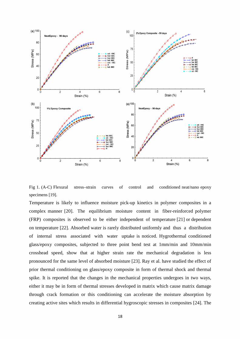
and 80°C) and cold (sub-zero: dry, wet, − 18°C) conditions for different durations. In cold
conditions epoxy matrix shows environmental sensitivity. Fig. 1 represents the stress-strain
curve of cold conditioned samples where discolorations of the materials are observed [19].
18
Fig 1. (A-C) Flexural stress–strain curves of control and conditioned neat/nano epoxy
specimens [19].
Temperature is likely to influence moisture pick-up kinetics in polymer composites in a
complex manner [20]. The equilibrium moisture content in fiber-reinforced polymer
(FRP) composites is observed to be either independent of temperature [21] or dependent
on temperature [22]. Absorbed water is rarely distributed uniformly and thus a distribution
of internal stress associated with water uptake is noticed. Hygrothermal conditioned
glass/epoxy composites, subjected to three point bend test at 1mm/min and 10mm/min
crosshead speed, show that at higher strain rate the mechanical degradation is less
pronounced for the same level of absorbed moisture [23]. Ray et al. have studied the effect of
prior thermal conditioning on glass/epoxy composite in form of thermal shock and thermal
spike. It is reported that the changes in the mechanical properties undergoes in two ways,
either it may be in form of thermal stresses developed in matrix which cause matrix damage
through crack formation or this conditioning can accelerate the moisture absorption by
creating active sites which results in differential hygroscopic stresses in composites [24]. The
19
deterioration effect of hygrothermal shock on interfacial bonding of varied weight fraction
constituents in the composite is also reported in some literatures. When glass/polyester matrix
is treated in 50°C temperature water bath for 30 minutes and then immediately immersed in
100°C temperature water bath for the same duration, various failure modes are observed.
Matrix as well as interface damages possibly contribute to the weakening phenomena of
glass/polyester composite by the hygrothermal shock cycles [25].
2.2.2 Hygrothermal environment
The environmental actions, such as high moisture and high temperature can limit the
usefulness of polymer composites by deteriorating their mechanical properties during
service. One of the key features of this material class is their damage initiation and
propagation behaviour which is spatially distributed in nature and comprises of a variety of
mutually interacting damage modes. The most common damage modes are matrix cracking,
delamination growth and fibre fracture. There has been a pressing need to quantify the degree
of environmental degradation on the deviation of mechanical properties of fibre/polymer
composites. Humid ageing is recognized as one of the main causes of long-term
failure of organic matrix composite. There are several modes of humid ageing,
such as, plasticization of matrix, differential swelling, embrittlement of macromolecular
skeleton by hydrolysis, osmotic cracking, hygrothermal shock, and localized damage at the
fibre/matrix interface [26] etc. Thermal expansion coefficients of polymers are
considerably greater, thus failure of the bond between fibre and resin may occur under
extreme temperature [15]. Moisture diffusion in the laminates is now very critical to justify
the moisture ingression kinetic and degradation of mechanical properties during hygrothermal
treatment as it predicts the life cycle of fibre reinforced polymer composites materials.
Differential coefficients of thermal expansion between fiber and polymer further develop
residual stresses at the interface. These different natures of stresses may weaken the brittle
thermoset epoxy resin and/or the interfacial region of the laminate. Moisture is introduced
into the composite via diffusion flow along the fiber/matrix interface or transport via
microcracks and voids, which leads to diffusion in to the surrounding matrix [27,28]. The
effects of moisture on the matrix include reversible processes, such as hygroelasticity and
swelling that can relieve tensile residual stresses which develop in the resin after cure and,
thus enhance its performance.
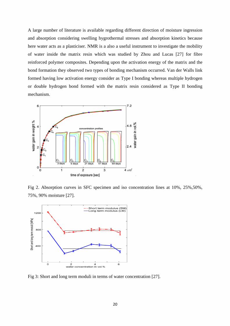
20
A large number of literature is available regarding different direction of moisture ingression
and absorption considering swelling hygrothermal stresses and absorption kinetics because
here water acts as a plasticiser. NMR is a also a useful instrument to investigate the mobility
of water inside the matrix resin which was studied by Zhou and Lucas [27] for fibre
reinforced polymer composites. Depending upon the activation energy of the matrix and the
bond formation they observed two types of bonding mechanism occurred. Van der Walls link
formed having low activation energy consider as Type I bonding whereas multiple hydrogen
or double hydrogen bond formed with the matrix resin considered as Type II bonding
mechanism.
Fig 2. Absorption curves in SFC specimen and iso concentration lines at 10%, 25%,50%,
75%, 90% moisture [27].
Fig 3: Short and long term moduli in terms of water concentration [27].
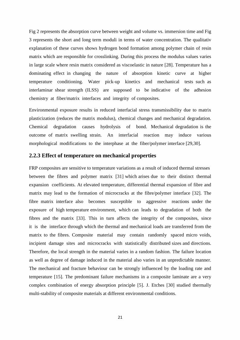
21
Fig 2 represents the absorption curve between weight and volume vs. immersion time and Fig
3 represents the short and long term moduli in terms of water concentration. The qualitativ
explanation of these curves shows hydrogen bond formation among polymer chain of resin
matrix which are responsible for crosslinking. During this process the modulus values varies
in large scale where resin matrix considered as viscoelastic in nature [28]. Temperature has a
dominating effect in changing the nature of absorption kinetic curve at higher
temperature conditioning. Water pick-up kinetics and mechanical tests such as
interlaminar shear strength (ILSS) are supposed to be indicative of the adhesion
chemistry at fiber/matrix interfaces and integrity of composites.
Environmental exposure results in reduced interfacial stress transmissibility due to matrix
plasticization (reduces the matrix modulus), chemical changes and mechanical degradation.
Chemical degradation causes hydrolysis of bond. Mechanical degradation is the
outcome of matrix swelling strain. An interfacial reaction may induce various
morphological modifications to the interphase at the fiber/polymer interface [29,30].
2.2.3 Effect of temperature on mechanical properties
FRP composites are sensitive to temperature variations as a result of induced thermal stresses
between the fibres and polymer matrix [31] which arises due to their distinct thermal
expansion coefficients. At elevated temperature, differential thermal expansion of fibre and
matrix may lead to the formation of microcracks at the fibre/polymer interface [32]. The
fibre matrix interface also becomes susceptible to aggressive reactions under the
exposure of high temperature environment, which can leads to degradation of both the
fibres and the matrix [33]. This in turn affects the integrity of the composites, since
it is the interface through which the thermal and mechanical loads are transferred from the
matrix to the fibres. Composite material may contain randomly spaced micro voids,
incipient damage sites and microcracks with statistically distributed sizes and directions.
Therefore, the local strength in the material varies in a random fashion. The failure location
as well as degree of damage induced in the material also varies in an unpredictable manner.
The mechanical and fracture behaviour can be strongly influenced by the loading rate and
temperature [15]. The predominant failure mechanisms in a composite laminate are a very
complex combination of energy absorption principle [5]. J. Etches [30] studied thermally
multi-stability of composite materials at different environmental conditions.

22
Fig.4 represents the height changes occurred during the testing of load required to moisture
absorption of the materials.
Fig 4. Change in snap-through load with exposure to 20°C and 65%RH [30]
Fig 5. Load-displacement traces for bistable plate over several days exposure to 20°C and 65%RH
[30].
The load–displacement of bistable plate can be seen in Fig. 5 and it is observed that the load
value increases after the plateau region and before the bifurcation of the plate. In this case
presence of moisture in the surrounding also considered which are responsible for thermal
stresses of the material.
2.2.4 Effect of radiations and other external environments on FRPs
Fibre-reinforced composite materials such as glass, carbon and Kevlar fibre-reinforced
plastics are finding numerous applications in structural engineering, because of its higher
specific stiffness and strength, fatigue and corrosion resistance than the conventional
engineering materials. Composite materials do, however, suffer from some serious
environmental limitations. Environmental exposures include temperature, moisture,
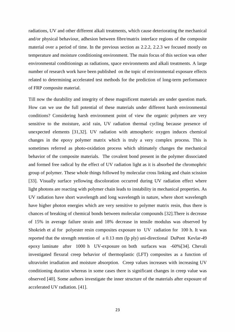
23
radiations, UV and other different alkali treatments, which cause deteriorating the mechanical
and/or physical behaviour, adhesion between fibre/matrix interface regions of the composite
material over a period of time. In the previous section as 2.2.2, 2.2.3 we focused mostly on
temperature and moisture conditioning environment. The main focus of this section was other
environmental conditionings as radiations, space environments and alkali treatments. A large
number of research work have been published on the topic of environmental exposure effects
related to determining accelerated test methods for the prediction of long-term performance
of FRP composite material.
Till now the durability and integrity of these magnificent materials are under question mark.
How can we use the full potential of these materials under different harsh environmental
conditions? Considering harsh environment point of view the organic polymers are very
sensitive to the moisture, acid rain, UV radiation thermal cycling because presence of
unexpected elements [31,32]. UV radiation with atmospheric oxygen induces chemical
changes in the epoxy polymer matrix which is truly a very complex process. This is
sometimes referred as photo-oxidation process which ultimately changes the mechanical
behavior of the composite materials. The covalent bond present in the polymer dissociated
and formed free radical by the effect of UV radiation light as it is absorbed the chromophric
group of polymer. These whole things followed by molecular cross linking and chain scission
[33]. Visually surface yellowing discoloration occurred during UV radiation effect where
light photons are reacting with polymer chain leads to instability in mechanical properties. As
UV radiation have short wavelength and long wavelength in nature, where short wavelength
have higher photon energies which are very sensitive to polymer matrix resin, thus there is
chances of breaking of chemical bonds between molecular compounds [32].There is decrease
of 15% in average failure strain and 18% decrease in tensile modulus was observed by
Shokrieh et al for polyester resin composites exposure to UV radiation for 100 h. It was
reported that the strength retention of a 0.13 mm (lp ply) uni-directional DuPont Kevlar-49
epoxy laminate after 1000 h UV-exposure on both surfaces was -60%[34]. Chevali
investigated flexural creep behavior of thermoplastic (LFT) composites as a function of
ultraviolet irradiation and moisture absorption. Creep values increases with increasing UV
conditioning duration whereas in some cases there is significant changes in creep value was
observed [40]. Some authors investigate the inner structure of the materials after exposure of
accelerated UV radiation. [41].

24
(a) (b)
Fig6: (a) Example of the damage in the treated carbon fibre composites: (a) XY plane, (b) YZ
plane, (c) XZ plane and (d) 3D view, One of the delaminations in the treated E-glass resin
composites: (a) XY plane, (b) YZ plane, (c) XZ plane and (d) 3D view[41].
They reported the carbon fibre composite are less prone to damage than E -glass/resin
composites after exposure to both UV irradiation and high temperature which sown in Fig. 6.
Delamination failure modes are very natural failure modes observed in case of carbon
fibre/epoxy composites. Various literatures are reported on damage and degradation effects of
carbon fibre/epoxy composites under UV radiation [42,43]. In case of nano-filler addition
some polymeric composites shows increase in flexural strength [44].
2.2.5 Effects of loading speed on conditioned composites Sethi et.al studied the failure of glass fibre/epoxy composites in thermal and cryogenic
environments. They observed the percentage of ILSS value decreases during above-ambient
temperature testing in every mode of loading rate ranges because of thermal conditioning
effect which leads to spreading of process zone in the matrix resin which impart high
fiber/matrix debonding which shown in Fig.7. [45].
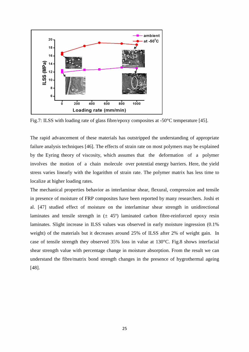
25
Fig.7: ILSS with loading rate of glass fibre/epoxy composites at -50°C temperature [45].
The rapid advancement of these materials has outstripped the understanding of appropriate
failure analysis techniques [46]. The effects of strain rate on most polymers may be explained
by the Eyring theory of viscosity, which assumes that the deformation of a polymer
involves the motion of a chain molecule over potential energy barriers. Here, the yield
stress varies linearly with the logarithm of strain rate. The polymer matrix has less time to
localize at higher loading rates.
The mechanical properties behavior as interlaminar shear, flexural, compression and tensile
in presence of moisture of FRP composites have been reported by many researchers. Joshi et
al. [47] studied effect of moisture on the interlaminar shear strength in unidirectional
laminates and tensile strength in (± 45º) laminated carbon fibre-reinforced epoxy resin
laminates. Slight increase in ILSS values was observed in early moisture ingression (0.1%
weight) of the materials but it decreases around 25% of ILSS after 2% of weight gain. In
case of tensile strength they observed 35% loss in value at 130°C. Fig.8 shows interfacial
shear strength value with percentage change in moisture absorption. From the result we can
understand the fibre/matrix bond strength changes in the presence of hygrothermal ageing
[48].
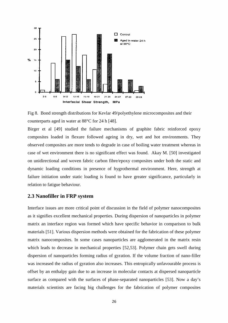
26
Fig 8. Bond strength distributions for Kevlar 49/polyethylene microcomposites and their
counterparts aged in water at 88°C for 24 h [48].
Birger et al [49] studied the failure mechanisms of graphite fabric reinforced epoxy
composites loaded in flexure followed ageing in dry, wet and hot environments. They
observed composites are more tends to degrade in case of boiling water treatment whereas in
case of wet environment there is no significant effect was found. Akay M. [50] investigated
on unidirectional and woven fabric carbon fibre/epoxy composites under both the static and
dynamic loading conditions in presence of hygrothermal environment. Here, strength at
failure initiation under static loading is found to have greater significance, particularly in
relation to fatigue behaviour.
2.3 Nanofiller in FRP system
Interface issues are more critical point of discussion in the field of polymer nanocomposites
as it signifies excellent mechanical properties. During dispersion of nanoparticles in polymer
matrix an interface region was formed which have specific behavior in comparison to bulk
materials [51]. Various dispersion methods were obtained for the fabrication of these polymer
matrix nanocomposites. In some cases nanoparticles are agglomerated in the matrix resin
which leads to decrease in mechanical properties [52,53]. Polymer chain gets swell during
dispersion of nanoparticles forming radius of gyration. If the volume fraction of nano-filler
was increased the radius of gyration also increases. This entropically unfavourable process is
offset by an enthalpy gain due to an increase in molecular contacts at dispersed nanoparticle
surface as compared with the surfaces of phase-separated nanoparticles [53]. Now a day’s
materials scientists are facing big challenges for the fabrication of polymer composites

27
keeping in mind for the proper interfacial behavior [54]. In nanocomposites this interfacial
polymer constitutes a significant volume fraction of the composite even at low filler
concentrations as shown in Fig 9. The degree of interaction between polymer and the nano-
filler can decide the size of the interfacial region (250nm) [55].
(a) (b) (c)
Fig 9: (a) Interfacial regions as a function of filler particle size. The filler is shown in red, the
interfacial region in dark blue and the bulk polymer in pale blue. (b) Large particles produce
a low radius of curvature, and relatively less polymer in the ‘interfacial region, (c) the same
volume of filler broken into smaller particles creates a higher radius of curvature and more
polymers in the interfacial region [55].
Thus the size of interfacial region profoundly influences the glass transition temperature of
the polymer and the relaxation behavior of the materials. If the enthalpy reaction was high
enough then there is a sign of permanent sign of good adhesion between nano-filler and
polymer chain. Considering this stage, polymer nanocomposites exhibits low and high glass
transition temperature on the basis of distance of nano-filler to the polymer chain. [56,57].
2.4 Mechanical behaviour of polymer composites
2.4.1 Tensile failure
The mechanical behavior of fibre -reinforced polymeric composites is sensitive to the
environmental conditioning and the loading fixture [61]. Very few literatures are dedicated
for the fibre reinforced polymer composites on the basis of strain rate and environmental
conditioning compared to conventional materials. Some literatures are performed on tensile
and compression behavior of these materials. Proper understanding was needed for these
materials for its long life performance and durability.
Shokrieh et al [62] studied on tensile behavior of glass/epoxy composites at different strain
rate shown in Fig.10. They found strain to failure, tensile modulus, tensile strength increases
with increasing strain rate.
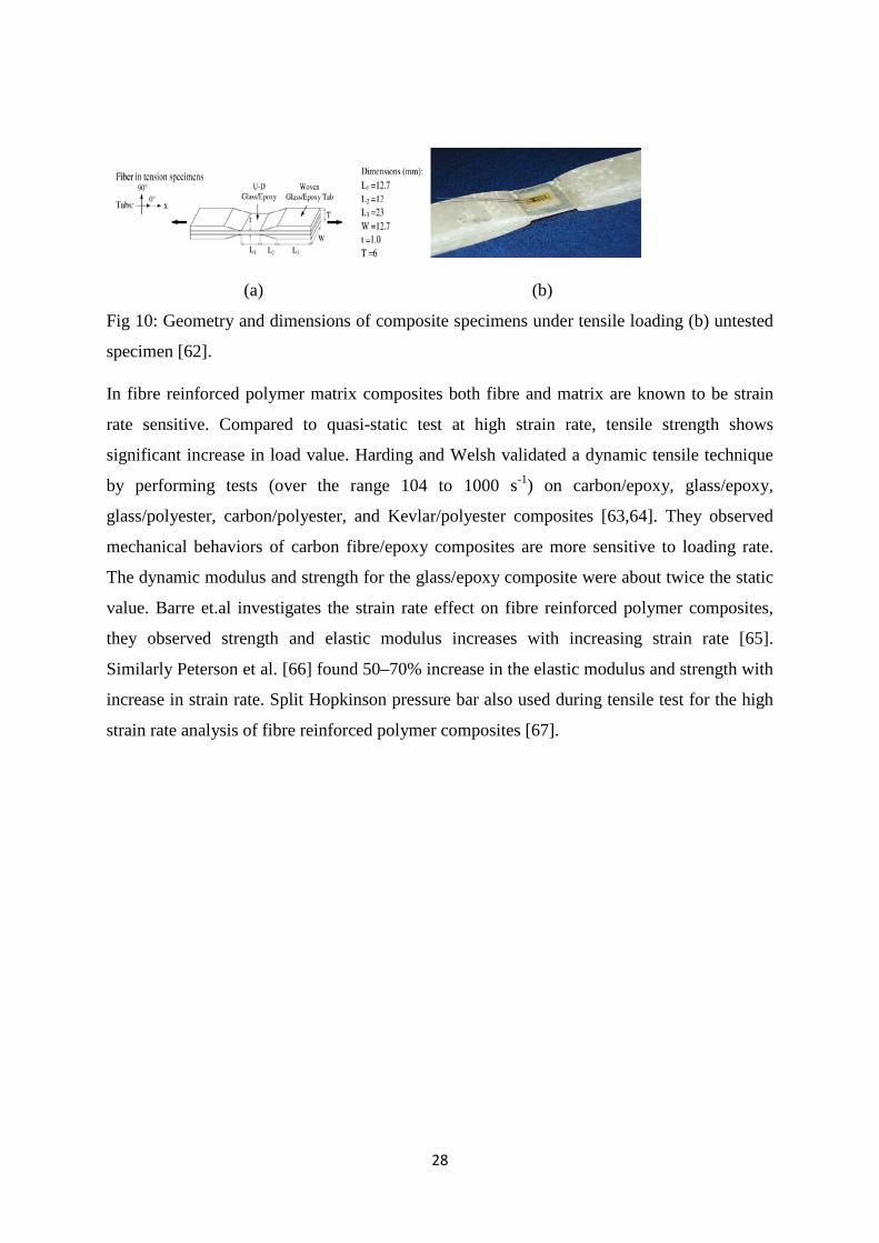
28
(a) (b)
Fig 10: Geometry and dimensions of composite specimens under tensile loading (b) untested
specimen [62].
In fibre reinforced polymer matrix composites both fibre and matrix are known to be strain
rate sensitive. Compared to quasi-static test at high strain rate, tensile strength shows
significant increase in load value. Harding and Welsh validated a dynamic tensile technique
by performing tests (over the range 104 to 1000 s-1) on carbon/epoxy, glass/epoxy,
glass/polyester, carbon/polyester, and Kevlar/polyester composites [63,64]. They observed
mechanical behaviors of carbon fibre/epoxy composites are more sensitive to loading rate.
The dynamic modulus and strength for the glass/epoxy composite were about twice the static
value. Barre et.al investigates the strain rate effect on fibre reinforced polymer composites,
they observed strength and elastic modulus increases with increasing strain rate [65].
Similarly Peterson et al. [66] found 50–70% increase in the elastic modulus and strength with
increase in strain rate. Split Hopkinson pressure bar also used during tensile test for the high
strain rate analysis of fibre reinforced polymer composites [67].
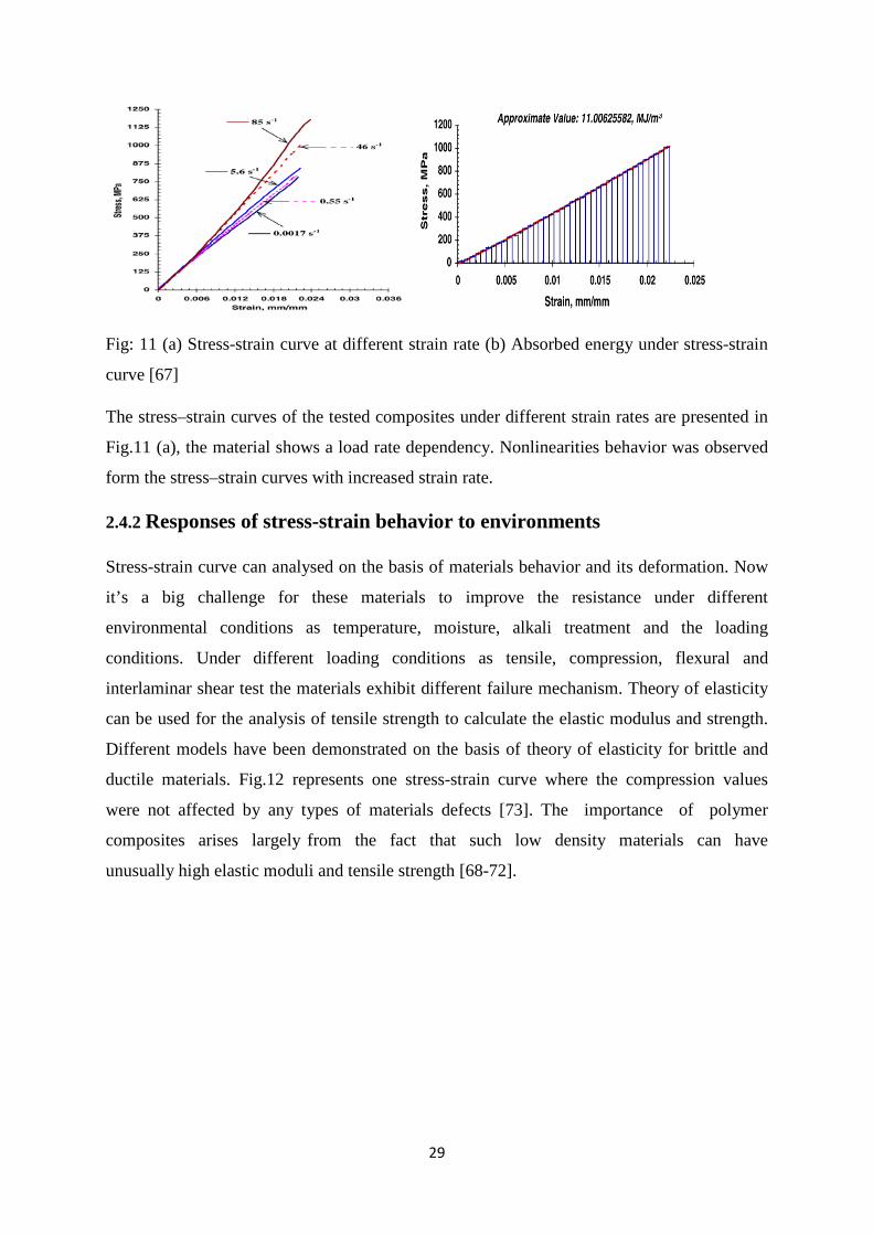
29
Fig: 11 (a) Stress-strain curve at different strain rate (b) Absorbed energy under stress-strain
curve [67]
The stress–strain curves of the tested composites under different strain rates are presented in
Fig.11 (a), the material shows a load rate dependency. Nonlinearities behavior was observed
form the stress–strain curves with increased strain rate.
2.4.2 Responses of stress-strain behavior to environments
Stress-strain curve can analysed on the basis of materials behavior and its deformation. Now
it’s a big challenge for these materials to improve the resistance under different
environmental conditions as temperature, moisture, alkali treatment and the loading
conditions. Under different loading conditions as tensile, compression, flexural and
interlaminar shear test the materials exhibit different failure mechanism. Theory of elasticity
can be used for the analysis of tensile strength to calculate the elastic modulus and strength.
Different models have been demonstrated on the basis of theory of elasticity for brittle and
ductile materials. Fig.12 represents one stress-strain curve where the compression values
were not affected by any types of materials defects [73]. The importance of polymer
composites arises largely from the fact that such low density materials can have
unusually high elastic moduli and tensile strength [68-72].
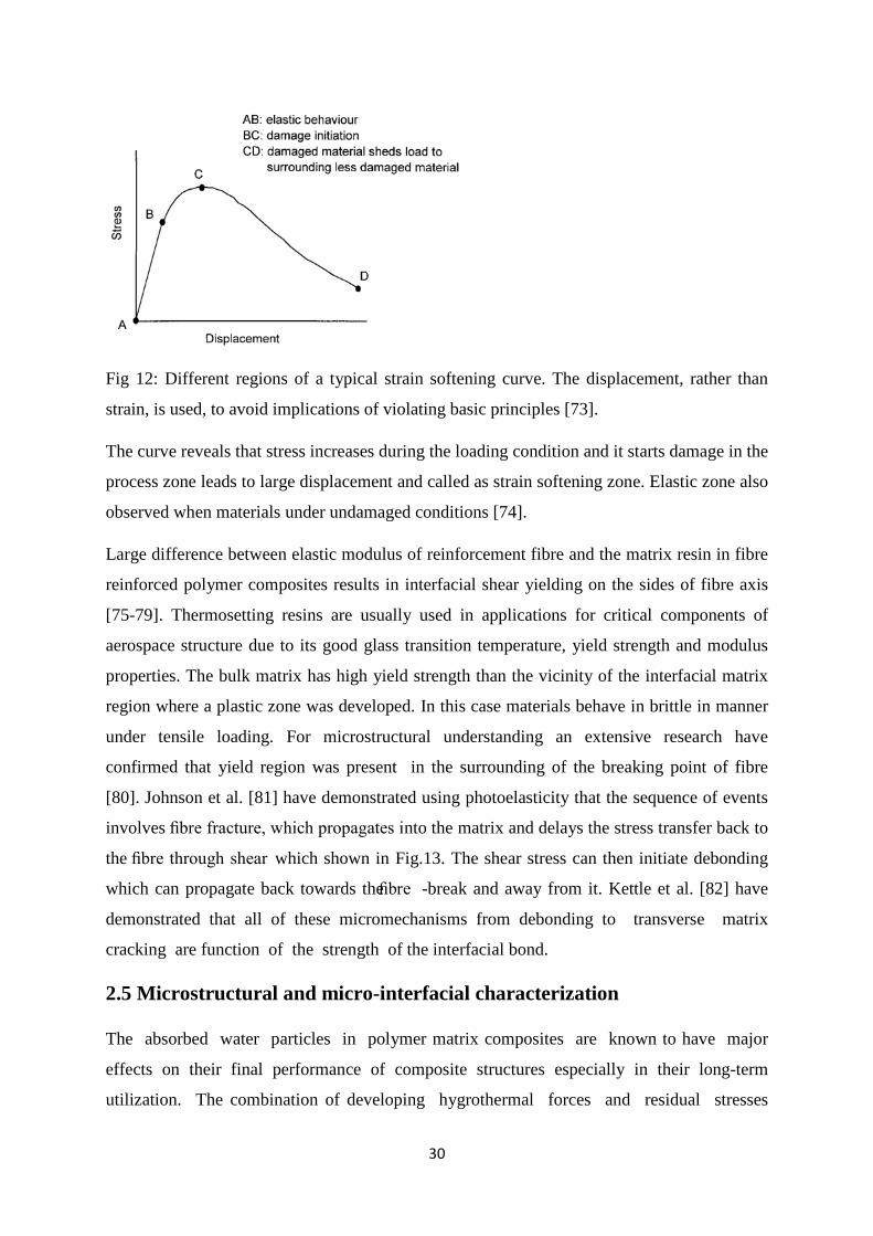
30
Fig 12: Different regions of a typical strain softening curve. The displacement, rather than
strain, is used, to avoid implications of violating basic principles [73].
The curve reveals that stress increases during the loading condition and it starts damage in the
process zone leads to large displacement and called as strain softening zone. Elastic zone also
observed when materials under undamaged conditions [74].
Large difference between elastic modulus of reinforcement fibre and the matrix resin in fibre
reinforced polymer composites results in interfacial shear yielding on the sides of fibre axis
[75-79]. Thermosetting resins are usually used in applications for critical components of
aerospace structure due to its good glass transition temperature, yield strength and modulus
properties. The bulk matrix has high yield strength than the vicinity of the interfacial matrix
region where a plastic zone was developed. In this case materials behave in brittle in manner
under tensile loading. For microstructural understanding an extensive research have
confirmed that yield region was present in the surrounding of the breaking point of fibre
[80]. Johnson et al. [81] have demonstrated using photoelasticity that the sequence of events
involves fibre fracture, which propagates into the matrix and delays the stress transfer back to
the fibre through shear which shown in Fig.13. The shear stress can then initiate debonding
which can propagate back towards the fibre -break and away from it. Kettle et al. [82] have
demonstrated that all of these micromechanisms from debonding to transverse matrix
cracking are function of the strength of the interfacial bond.
2.5 Microstructural and micro-interfacial characterization
The absorbed water particles in polymer matrix composites are known to have major
effects on their final performance of composite structures especially in their long-term
utilization. The combination of developing hygrothermal forces and residual stresses

31
with each other may be sufficiently large enough to influence the failure of laminated
composite and thus, should not be neglected in modern design analysis and lifetime
estimation. Fiber reinforced polymer composite structures are expected to experience a
range of hygrothermal environmental conditions during service life. Since absorbed
moisture can change the stress state and deteriorate the interface, understanding of
hygrothermal behavior is critical for predicting structural performance.
It is necessary to obtain a stable interface region in glass fibre/epoxy composites to optimised
its specific valuable properties under different environmental conditions.. Other
reinforcements are also subjected to different sizing treatment during its working periods. To
understand the basic principle behind this various characterization processes are employed
now a days [84]. These instruments are very sensitive in nature which are included as near-
infrared fourier transform infrared spectroscopy (NIR-FTIR), attenuated total reflection
fourier transform infrared spectroscopy (ATR-FTIR), ultraviolet (UV) reflection, solid-state
nuclear magnetic resonance (NMR), dielectric relaxation measurements, positron annihilation
lifetime spectroscopy (PALS), electrochemical impendence spectroscopy (EIS),
fluorescence, and molecular simulations [85] etc. Fourier transform infrared spectrometry
(FTIR) and atomic force microscopy are particularly useful methods for the study of silane
coupling agents adsorbed or bounded to glass surfaces [86]. However, very small amount of
coupling agent is normally applied to the glass surface and the presence of strong bands from
the substrate often makes the IR detection of the silane characteristic bands difficult.
2.5.1 Micro-characterization of interfaces
As it’s a difficult task for obtaining the clear picture of interfacial characterization in the fibre
reinforced polymer composites various macroscopic approaches are reported. These includes
flexural test, fibre pull-out test, fragmentation test, transverse tensile test which are the main
focusing study on fibre /matrix interface region. During environmental exposures it’s very
difficult to identify the clear reasons for failure of these materials. Matrix properties are very
sensitive to environmental conditions which control the overall mechanical response.
Characterizations of the laminates are influenced by matrix properties and fibre/matrix
interfacial bonding. As fibre reinforced undergoes various sizing treatment on the surface,
the bonding between fibre and matrix plays crucial role. The FTIR measurement is employed
to the sample.

32
Fig 13. FTIR spectra of different sizing agents/epoxy resin before and after boiling water aging [87].
Fig 13 represents the FTIR spectra of T300 sizing/5228, CF-1 sizing/5228 and CF-2
sizing/5228 undergoing boiling water. There is no chemical transformation observed in the
composite in the FTIR spectra under these conditions. It can only be reveals that chemical
reaction does not have any effect on these samples during boiling water treatment [87].
The mechanical behavior of composites depends on the ability of interface to transfer stress
from the matrix to the reinforcement fiber. The physical properties of polymer materials
depend decisively on frequencies of molecular excitation through the relaxation time
that depends on temperature [88]. The durability and integrity of these materials are totally
depends upon the several failure modes observed during fractography testing. Scanning
electron microscopy is very useful technique to understand the failure modes and the reason
behind the materials failure. Hahn et. al [89] conducted a study to describe CFRP composites
to study their interfacial properties and the effect of hygrothermal analysis using Atomic
Force Microscope (AFM). Hygroscopic treatment is found to progressively reduce the height
variation in between fiber and matrix showing the swelling of matrix by absorption of
moisture. The fiber/matrix interface is susceptible to mechanical strength and thermal
behaviour as revealed by the debonding. This debonding can be easily detected by AFM
which is shown in Fig 14.
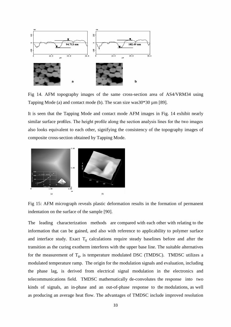
33
Fig 14. AFM topography images of the same cross-section area of AS4/VRM34 using
Tapping Mode (a) and contact mode (b). The scan size was30*30 µm [89].
It is seen that the Tapping Mode and contact mode AFM images in Fig. 14 exhibit nearly
similar surface profiles. The height profile along the section analysis lines for the two images
also looks equivalent to each other, signifying the consistency of the topography images of
composite cross-section obtained by Tapping Mode.
Fig 15: AFM micrograph reveals plastic deformation results in the formation of permanent
indentation on the surface of the sample [90].
The leading characterization methods are compared with each other with relating to the
information that can be gained, and also with reference to applicability to polymer surface
and interface study. Exact Tg calculations require steady baselines before and after the
transition as the curing exotherm interferes with the upper base line. The suitable alternatives
for the measurement of Tg, is temperature modulated DSC (TMDSC). TMDSC utilizes a
modulated temperature ramp. The origin for the modulation signals and evaluation, including
the phase lag, is derived from electrical signal modulation in the electronics and
telecommunications field. TMDSC mathematically de-convolutes the response into two
kinds of signals, an in-phase and an out-of-phase response to the modulations, as well
as producing an average heat flow. The advantages of TMDSC include improved resolution
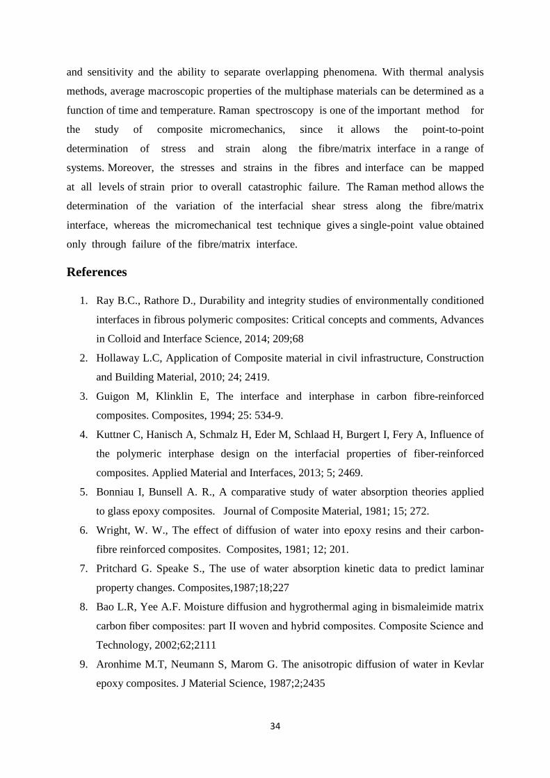
34
and sensitivity and the ability to separate overlapping phenomena. With thermal analysis
methods, average macroscopic properties of the multiphase materials can be determined as a
function of time and temperature. Raman spectroscopy is one of the important method for
the study of composite micromechanics, since it allows the point-to-point
determination of stress and strain along the fibre/matrix interface in a range of
systems. Moreover, the stresses and strains in the fibres and interface can be mapped
at all levels of strain prior to overall catastrophic failure. The Raman method allows the
determination of the variation of the interfacial shear stress along the fibre/matrix
interface, whereas the micromechanical test technique gives a single-point value obtained
only through failure of the fibre/matrix interface.
References
1. Ray B.C., Rathore D., Durability and integrity studies of environmentally conditioned
interfaces in fibrous polymeric composites: Critical concepts and comments, Advances
in Colloid and Interface Science, 2014; 209;68
2. Hollaway L.C, Application of Composite material in civil infrastructure, Construction
and Building Material, 2010; 24; 2419.
3. Guigon M, Klinklin E, The interface and interphase in carbon fibre-reinforced
composites. Composites, 1994; 25: 534-9.
4. Kuttner C, Hanisch A, Schmalz H, Eder M, Schlaad H, Burgert I, Fery A, Influence of
the polymeric interphase design on the interfacial properties of fiber-reinforced
composites. Applied Material and Interfaces, 2013; 5; 2469.
5. Bonniau I, Bunsell A. R., A comparative study of water absorption theories applied
to glass epoxy composites. Journal of Composite Material, 1981; 15; 272.
6. Wright, W. W., The effect of diffusion of water into epoxy resins and their carbon-
fibre reinforced composites. Composites, 1981; 12; 201.
7. Pritchard G. Speake S., The use of water absorption kinetic data to predict laminar
property changes. Composites,1987;18;227
8. Bao L.R, Yee A.F. Moisture diffusion and hygrothermal aging in bismaleimide matrix
carbon fiber composites: part II woven and hybrid composites. Composite Science and
Technology, 2002;62;2111
9. Aronhime M.T, Neumann S, Marom G. The anisotropic diffusion of water in Kevlar
epoxy composites. J Material Science, 1987;2;2435
35
10. Benkhedda A. Tounsi E.A, Addabedia, Effect of temperature and humidity on transient
hygrothermal stresses during moisture desorption in laminated composite plates,
Composite Structures, 2008; 82; 629
11. Sereir Z, Addabedia E, Tounsi A. Effect of temperature on the hygrothermal
behaviour of unidirectional laminated plates with asymmetrical environmental
conditions. Composite Structure, 2006;72:383
12. Sereir Z, Addabedia E, Tounsi A. Effect of the accelerated moisture diffusivity on the
hygrothermal behaviour of laminated plate with symmetrical environmental
conditions. Journal of Thermal Stresses, 2005;28;889
13. Tounsi A, Amara K. Stiffness degradation in hygrothermal aged cross-ply laminates
with transverse cracks. AIAA Journal 2005;43;1836
14. Tounsi A, Amara K.H, Adda-Bedia E. Analysis of transverse cracking and stiffness
loss in cross-ply laminates with hygrothermal conditions. Computational Material
Science 2005;32;167.
15. Tounsi A, Amara K.H, Megueni A, Benzair A. On the transverse cracking and stiffness
degradation of aged angle-ply laminates. Material Letter 2006;60;2561.
16. Springer G.S. Environmental effects on composite materials, 4th Ed. Dayton, OH,
1988.
17. Wang J.Z, Parvatareddy H, Dillard D.A., Ward T.C.,, Composites Science and
Technology 1995; 53; 399
18. Sookay N.K., Klemperer,C.J, Verijenko,V.E., Environmental testing of advanced
epoxy composites, Composite Structures 2003; 62;429
19. M.V. Hosur, S. Zainuddina, Y. Zhoua, Ashok Kumar, S. Jeelani, Durability studies of
montmorillonite clay filled epoxy composites under different environmental
conditions, Materials Science and Engineering A, 2009;507;117
20. Ray B.C., Rathore, D., Environmental damage and degradation of FRP composites: A
review report, Polymer Composites, 2014, DOI- 10.1002/PC.22967
21. Ray B.C, Biswas A., Sinha P.K., Hygrothermal effects on mechanical behaviour of
FRP composites, Metals Materials and Processes 1991;3;99
22. Ray B. C., Mula S., Bera T, Ray P. K., Prior Thermal Spikes and Thermal Shocks on
Mechanical Behavior of Glass Fiber-epoxy Composites, Journal of Reinforced
Plastics and Composites 2006;2;216
36
23. Ray, B. C. Hydrothermal Shock Cycles on Shear Strength of Glass Fiber-Polyester
Composites. Journal of Reinforced Plastics and composites 2005;24;12
24. Ray B.C, Freeze-thaw Response of Glass-polyester Composites at Different Loading
Rates , Journal of Reinforced Plastics and Composites 2005;11;321
25. Ray. B.C, Thermal Shock and Thermal Fatigue on Delamination of Glass Fiber
Reinforced Polymeric Composites. Journal of Reinforced Plastics and Composites
2005;24;461
26. Ray B.C, Effects of Thermal and Cryogenic Conditionings on Mechanical Behavior
of Thermally Shocked Glass Fiber/Epoxy Composites. Journal of Reinforced Plastics
and composites 2005;24;432
27. Zhou J, Lucas J.P. Hygrothermal effects of epoxy resin. Part I: the nature of water in
epoxy. Polymer 1999; 40; 5505.
28. Herrera-Franco P.J., Drzal L.T., Comparison of Methods for the Measurement of
Fiber/Matrix Adhesion in Composites, Composites 1992; 23;3
29. Lai M, Botsis J, Cugnoni J.,Coric D., An experimental–numerical study of moisture
absorption in an epoxy, Composites Part A:Applied Science and Manufacturing
2012;43;1053
30. Etches J., Potter K., Paul Weaver, Ian Bond, Environmental effects on thermally
induced multi stability in unsymmetric composite laminates, Composites Part A :
Applied Science and Manufacturing 2009;40;1240
31. Drzal, L.T., Rich, M.J., Lloyd, P.F. Adhesion of Graphite fiber to epoxy Matrices. I.
The Role of Fiber Surface Treatment, Adhesion 1982;16;1
32. Bockenheimer C., Fata D. Possart W. New Aspects of aging in Epoxy Networks. II.
Hydrothermal Aging, Journal of Applied Polymer Science 2004;91;369
33. Yano O. Yamaoka H. Cryogenic Properties of Polymers, Progresses in Polymer
Science 1995; 20;585
34. Shokrieh, M.M.,A. Bayat, Effects of ultraviolet radiation on mechanical properties of
glass/polyester composites. Journal of composite Materials, 2007;41;2443
35. Andrady, A., et al., Effects of increased solar ultraviolet radiation on materials.
Journal of Photochemistry and Photobiology B: Biology, 1998;46; 96
36. Feldman, D., Polymer weathering: photo-oxidation. Journal of Polymers and the
Environment, 2002;10;163.
37
37. Awaja, F., et al., The investigation of inner structural damage of UV and heat
degraded polymer composites using X-ray micro CT. Composites Part A: Applied
Science and Manufacturing, 2011;42;408
38. Jacques, L.F.E., Accelerated and outdoor/natural exposure testing of coatings.
Progress in Polymer Science, 2000;25;1337
39. Liau, W. and F. Tseng, The effect of long‐term ultraviolet light irradiation on
polymer matrix composites. Polymer composites, 1998;19;440
40. Chevali, V.S., D.R. Dean, and G.M. Janowski, Effect of environmental weathering
on flexural creep behavior of long fiber-reinforced thermoplastic composites.
Polymer Degradation and Stability, 2010;95;2628
41. Lixiang, J., A study of damage effects of CF/EP under vacuum ultraviolet
radiation.Applied laser-shanghai-, 2002;22;409
42. Jiang, L. and L. Sheng, Research on effects of electronic irradiation of epoxy resin
648 and TDE-85. Journal of Space Environment, 2004;21;49
43. Liu, Y., G.-h. Li, and L.-x. Jiang, A study on the resistance performance of epoxy
nano-composites under the vacuum ultraviolet irradiation. Acta Astronautica,
2008;63;1343
44. Paillous, A. and C. Pailler, Degradation of multiply polymer-matrix composites
induced by space environment. Composites, 1994;25;287
45. Sethi.S,Ray B.C., An assessment of mechanical behavior and fractography studyof
glass/epoxy composites at different temperatures and loading speeds, Materials and
Design, 2014;64;160
46. Hull D, Clyne T.W, An introduction to composite materials, Cambridge University
Press, Cambridge, 1996.
47. Om.K. Joshi, The effect of moisture on the shear properties of carbon fiber,
Composites 1983; 14; 196.
48. Gaur U, Chou C.T.,Miller B., Effects of hygrothermal ageing on bond strength,
Composites 1993; 25; 609.
49. Birger S., Moshonov A., Keing S., The effects of thermal and hygrothermal ageing
on the failure mechanisms of graphite-fabric epoxy composites subjected to flexural
loading. Composites 1989; 20;4
38
50. Akay M, Mun S.K.A, Stanley A. Influence of moisture on the thermal and
mechanical properties of autoclaved and oven-cured Kevlar-49/epoxy
laminates. Composite Science and Technology 1997; 57; 565.
51. Fischer H., Polymer nanocomposites: from fundamental research to specific
applications, Materials Science and Engineering C 2003; 23;763
52. Ajayan P.M., Schadler L.S., Braun P.V, Nanocomposite Science and Technology
Wiley VCH, Weinheim, 2003
53. Balazs A.C., Emrick T.,Russell T.P., Nanoparticle Polymer Composites: Where Two
Small Worlds Meet, Science 2006;314; 1107
54. Michael E. Mackay, Anish Tuteja1, Phillip M. Duxbury, Craig J. Hawker, Brooke
Van Horn, Zhibin Guan, Guanghui Chen, R. S. Krishnan, General strategies for
nanoparticle dispersion, Science; 2006;311;1740
55. Rittigstein P. Priestley R.D, Broadbelt L.J., Torkelson J.M, Model polymer
nanocomposites provide an understanding of confinement effects in real
nanocomposites, Nature Materials, 2007; 6;278
56. Schadler L., Model interfaces, Nature Materials,2007;6;257
57. Tsagaropoulos, G.Eisenburg, A. Direct observation of two glass transitions in silica-
filled polymers. Implications to the morphology of random ionomers.
Macromolecules 1995;28;396
58. Reis J.M.L., Coelho J.L.V., Monteiro A.H, Costa Mattos H.S, Tensile behavior of
glass/epoxy laminates at varying strain rates and temperatures, Composites: Part B,
2012;43:2041-2046
59. Mahmood M. S., Omidi M.J., Tension behavior of unidirectional glass/epoxy
composites under different strain rates, Composite Structures, 2009;88 :595–601
60. Harding J, Welsh LM. A tensile testing technique for fibre -reinforced
composites at impact rates of stain. J Material Science 1983; 18:1810–26.
61. Welsh LM, Harding J. Effect of strain rate on the tensile failure of woven reinforced
polyester resin composites. J Physics 1985; 46:405–14.
62. Barré S, Chotard T, Benzeggagh ML. Comparative study of strain rate effects on
mechanical properties of glass fibre -reinforced thermoset matrix composites.
Composites Part A 1996; 27:1169–81.
63. Peterson B.L, Pangborn R.N, Pantano C.G. Static and high strain rate response of a
glass fiber reinforced thermoplastic. J of Composite Material 1991; 25:887–906.
39
64. Gilat A, Goldberg R.K, Roberts G.D. Experimental study of strain-rate-
dependent behavior of carbon/epoxy composite. Composite Science and Technology
2002; 62:1469–76.
65. Chow T.S., Prediction of stress-strain relationships in polymer composites,
Polymer, 1991; 32: 12-15
66. Kongshavn I., Poursartip A., Experimental investigation of a strain-softening
approach to predicting failure in notched fibre -reinforced composite laminates,
Composites Science and Technology,1999; 59:29–40
67. Zweben C. Failure analysis of unidirectional fibre composites under combined axial
tension and shear. J Mechanical Physics Solids 1974; 22:193–215.
68. Iremonger MJ, Wood WG. Effects of geometry on stresses in discontinuous
composite materials. J Strain Analysis. 1969; 4:121–6.
69. Agarwal B.D, Bansal R.K. Plastic analysis of fibre interactions in discontinuous fibre
composites. Fibre Science and Technology. 1977; 10: 281–97.
70. De Morais A.B. Stress distribution along broken fibres in polymer -matrix
composites. Composite Science and Technology. 2001; 61:1571–80.
71. Gulino R, Schwartz P, Phoenix SL. Experiments on shear deformation, debonding
and local transfer in a model graphite/glass/epoxy microcomposite. J of Material
Science, 1991; 26: 6655–72.
72. Nath R.B, Fenner D.N, Galiotis C. Finite element modelling of interfacial failure in
model carbon fibre–epoxy composites. J Material Science 1996; 31:2879–83.
73. Tripathi D, Chen F, Jones FR. The effect of matrix plasticity on the stress fields in a
single filament composite and the value of interfacial shear strength obtained
from the fragmentation test. Proceedings Royal Society London A
1996; 452:621–53.
74. Heuvel PWJ, Peijs T, Young R.J. Failure phenomena in two-dimensional multifibre
microcomposites: 2. A Raman spectroscopic study of the influence of inter -fibre
spacing on stress concentrations. Composite Science and Technol 1997;
57:899–911.
75. DiBenedetto AT, Jones K.D. The role of interphase debonding on cumulative fibre
fractures in a continuous fibre -reinforced composite. Composite Part A 1996;
27A:869–79.
76. Accorsi M.L, Pegoretti A, DiBenedetto A.T. Dynamic analysis of fibre breakage in
single- and multiple-fibre composites. J of Material Science. 1996; 31:4181–7.
40
77. Jacobs E, Verpoest I. Finite element modelling of damage development during
longitudinal tensile loading of coated fibre composites. Composite Part A 1998;
29A:1007–12.
78. Johnson AC, Zhao FM, Hayes SA, Jones FR. Influence of a matrix crack on stress
transfer to an alumina fibre in epoxy resin using FEA and photoelasticity. Composite
Science and Technol 2006; 66:2023–9.
79. Kettle A.P, Beck A.J, OToole L, Jones F.R, Short R.D. Plasma polymerisation for
molecular engineering of carbon-fibre surfaces for optimised composites. Composite
Science and Technol 1997; 57; 1023–32.
80. Totry E. , Jon M. Molina-Aldareguía , González C. , LLorca J., Effect of fiber, matrix
and interface properties on the in-plane shear deformation of carbon-fiber reinforced
composites, Composites Science and Technology, 2010; 70; 970–980
81. Omiya, M., Kishimoto, K, Yang, W. Interface Debonding Model and its Application
to the Mixed Mode Interface Fracture Toughness, International Journal of Damage
Mechanics 2002;11;263
82. Asp L.E., The effects of moisture and temperature on the interlaminar delamination
toughness of a carbon/epoxy composite. Composite Science and Technology 1998;
58;967
41
Chapter 3 Materials and Method
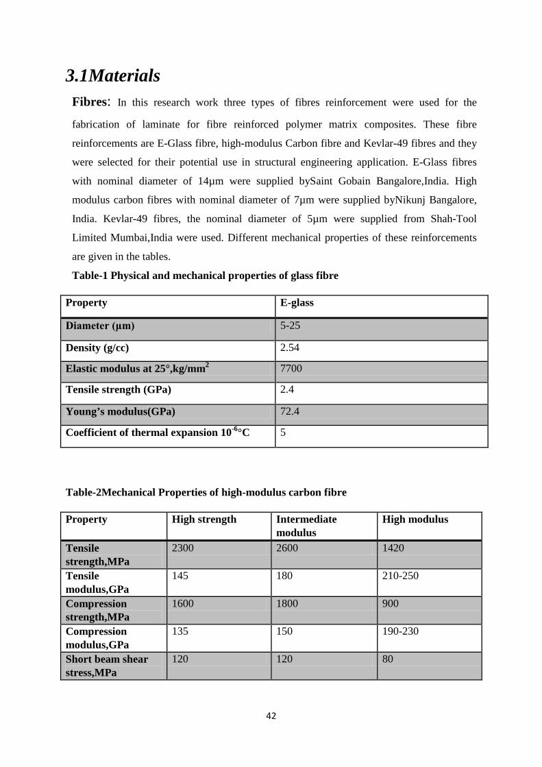
42
3.1Materials Fibres: In this research work three types of fibres reinforcement were used for the
fabrication of laminate for fibre reinforced polymer matrix composites. These fibre
reinforcements are E-Glass fibre, high-modulus Carbon fibre and Kevlar-49 fibres and they
were selected for their potential use in structural engineering application. E-Glass fibres
with nominal diameter of 14µm were supplied bySaint Gobain Bangalore,India. High
modulus carbon fibres with nominal diameter of 7µm were supplied byNikunj Bangalore,
India. Kevlar-49 fibres, the nominal diameter of 5µm were supplied from Shah-Tool
Limited Mumbai,India were used. Different mechanical properties of these reinforcements
are given in the tables.
Table-1 Physical and mechanical properties of glass fibre
Property E-glass
Diameter (μm) 5-25
Density (g/cc) 2.54
Elastic modulus at 25°,kg/mm2 7700
Tensile strength (GPa) 2.4
Young’s modulus(GPa) 72.4
Coefficient of thermal expansion 10-6°C 5
Table-2Mechanical Properties of high-modulus carbon fibre
Property High strength Intermediate modulus
High modulus
Tensile strength,MPa
2300 2600 1420
Tensile modulus,GPa
145 180 210-250
Compression strength,MPa
1600 1800 900
Compression modulus,GPa
135 150 190-230
Short beam shear stress,MPa
120 120 80
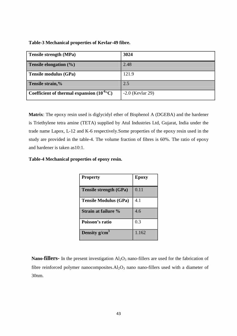
43
Table-3 Mechanical properties of Kevlar-49 fibre.
Tensile strength (MPa) 3024
Tensile elongation (%) 2.48
Tensile modulus (GPa) 121.9
Tensile strain,% 2.5
Coefficient of thermal expansion (10-6°C) -2.0 (Kevlar 29)
Matrix: The epoxy resin used is diglycidyl ether of Bisphenol A (DGEBA) and the hardener
is Triethylene tetra amine (TETA) supplied by Atul Industries Ltd, Gujarat, India under the
trade name Lapox, L-12 and K-6 respectively.Some properties of the epoxy resin used in the
study are provided in the table-4. The volume fraction of fibres is 60%. The ratio of epoxy
and hardener is taken as10:1.
Table-4 Mechanical properties of epoxy resin.
Nano-fillers- In the present investigation Al2O3 nano-fillers are used for the fabrication of
fibre reinforced polymer nanocomposites.Al2O3 nano nano-fillers used with a diameter of
30nm.
Property Epoxy
Tensile strength (GPa) 0.11
Tensile Modulus (GPa) 4.1
Strain at failure % 4.6
Poisson’s ratio 0.3
Density g/cm3 1.162
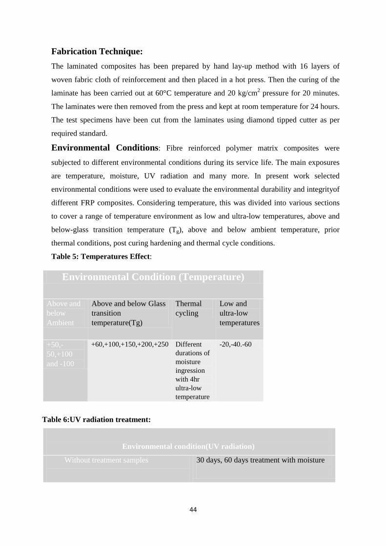
44
Fabrication Technique: The laminated composites has been prepared by hand lay-up method with 16 layers of
woven fabric cloth of reinforcement and then placed in a hot press. Then the curing of the
laminate has been carried out at 60°C temperature and 20 kg/cm2 pressure for 20 minutes.
The laminates were then removed from the press and kept at room temperature for 24 hours.
The test specimens have been cut from the laminates using diamond tipped cutter as per
required standard.
Environmental Conditions: Fibre reinforced polymer matrix composites were
subjected to different environmental conditions during its service life. The main exposures
are temperature, moisture, UV radiation and many more. In present work selected
environmental conditions were used to evaluate the environmental durability and integrityof
different FRP composites. Considering temperature, this was divided into various sections
to cover a range of temperature environment as low and ultra-low temperatures, above and
below-glass transition temperature (Tg), above and below ambient temperature, prior
thermal conditions, post curing hardening and thermal cycle conditions.
Table 5: Temperatures Effect:
Environmental Condition (Temperature)
Above and below Ambient
Above and below Glass transition temperature(Tg)
Thermal cycling
Low and ultra-low temperatures
+50,-50,+100 and -100
+60,+100,+150,+200,+250 Different durations of moisture ingression with 4hr ultra-low temperature
-20,-40.-60
Table 6:UV radiation treatment:
Environmental condition(UV radiation)
Without treatment samples
30 days, 60 days treatment with moisture
45
Table 7-Fibre reinforced epoxy composites with nano-fillers
Fibre reinforced polymer matrix composites(addition of nanofillers)
Al2O3(nano particle)
3.2Experimental Methods 3.2.1Flexural Test(Short beam shear test) Instron 5967 is a servo hydraulic-control and signal conditioning electronics instrument for
material testing applications. It has fine position adjustment thumbwheel with 0.004mm
resolution for precise positioning of crosshead while testing. Specimen protect also applied to
the specimen outside a set threshold-protecting to overcome unwanted damage. Bluehill 3
software helps to get the data from the attached computer.
The test coupons of different sizes were cut from the laminates for physical and mechanical
characterization. ILSS testing were conducted on an Instron 5967 test apparatus using three-
point bend jig according to ASTM: D2344-13.
The flexural methods are applicable to polymeric composite materials. A testing machine
with controllable crosshead speed is used in conjunction with a loading fixture. It is a three
point flexural test on a specimen with a small span, which promotes failure by inter-laminar
shear.The shear stress induced in a beam subjected to a bending load, is directly proportional
to the magnitude of the applied load and independent of the span length. Thus the support
span of the short beam shear specimen is kept short so that an inter-laminar shear failure
occurs before a bending failure.
This test method is defined by ASTM D 2344, which specifies a span length to specimen
thickness ratio of five for low stiffness composites and four for higher stiffness composite.
This test has an inherent problem associated with the stress concentration and the non-linear
plastic deformation induced by the loading nose of small diameter.
With these variations the result signifies that the parabolic distribution of shear stress across
the thickness of the specimen predicted by simple beam theory could be very well in the
regions between the loading andsupport cylinder and the specimen fail in a shear mode. With

46
these modifications ASTM D 2344 may yet become a technically acceptable as well as
popular shear test method.
3.2.2 Scanning Electron Microscope (SEM)
The scanning electron microscope (SEM) has been a well accepted tool for many years in the
examination of fracture surfaces. For analysis of composite fractography, SEM by JEOL-
JSM 6480 LV with the acceleration voltage of 15 kV was used. Cleaned, small in size and
conductive samples are used during testing in SEM. The top surface of the specimens was
coated with platinum using a sputter coater. The coating is used to make the surface
conductive for scanning and prevents the accumulation of static electric charge for clear
images during the microscopy. During the test samples are little tilt around 15-20° to drawn
attractive and clear images of different failure modes.
The prominent imaging advantages are the great depth of field and high spatial resolution and
the image is relatively easy to interpret visually.
Principle: A finely focused electron beam scanned across the surface of the sample generates
secondary electrons, backscattered electrons, and characteristic X-rays. These signals are
collected by detectors to form images of the sample displayed on a cathode ray tube screen.
Features seen in the SEM image may then be immediately analyzed for elemental
composition using EDS or WDS. The electrons that are emitted from the specimen surface
have a spectrum of energies. Secondary and backscattered electrons are conventionally
separated according to their energies. When the energy of the emitted electron is less than
about 50eV, it is referred as a secondary electron and backscattered electrons are considered
to be the electrons that exit the specimen with energy greater than 50eV. A critical point in
understanding the formation of SEM images of fracture surfaces, and their interpretation, is
an appreciation of the factors that affect this excited volume of electrons in the specimen. To
understand the different failure mechanisms in FRP composites, photomicrographs were
taken using a SEM. There is a dramatic change in the structure and properties of the
composite when exposed to high and lowtemperatures.
3.2.3 Differential Scanning Calorimetry (DSC)
The DSC measurements were performed on a Mettler-Toledo 821 with intra cooler, using the
STAR software with Temperature Modulated DSC (TMDSC) module. The temperature
calibration and the determination of the time constant of the instrument were performed by
standards of In and Zn, and the heat flow calibration by In. The underlying heating rate of
47
10°Cmin-1 was used. In order to calibrate the heat flow signal, a blank run with an empty pan
on the reference side and an empty pan plus a lid at the sample side was performed before the
sample measurements. Standard aluminum pans were used. The experiments were performed
in the temperature range from 25°C to 150°C.
Principle: Differential scanning calorimetry (DSC) is a thermoanalytical technique in which
the amount of heat required to increase the temperature of a sample and reference is
measured as a function of temperature and time. Both the sample and reference are
maintained at nearly the same temperature throughout the experiment.
3.2.4 FTIR-ATR Spectroscopy analysis
FTIR analysis was performed in FTIR spectrophotometer interfaced with IR microscope
operated in reflectance mode. The microscope is equipped with a video camera, a liquid
nitrogen-cooled mercury cadmium telluride (MCT) detector and a computer controlled
translation stage, programmable in the x and y directions. The spectra were collected in the
4000cm-1 to 550 cm-1 region with 8 cm-1 resolution, 60 scans and beam spot size of 10µm-
100µm. The spectral point-by-point mapping of the interface of the epoxy cured composites
was performed in a grid pattern with the use of computer controlled microscope stage. Since
the surface of the film was not perfectly smooth and its thickness was not uniform care
should be taken to mount the sample such that a major portion of the plane was in the same
focal plane. The FTIR imaging was performed in AIM-800 Automatic Infra red Microscope
(SHIMADZU). There are certain limitations of refraction and reflection at the fibre surface in
the spectroscopy that will finally affect the FTIR spectra of glass/epoxy composites. Due to
this only a small percent of light reaches the detector. It is difficult to separate these optical
effects from the samples.
Principle: In infrared spectroscopy, Infrared radiation is passed through a sample. Some of
the infrared radiation is absorbed by the sample and some of it is passed through
(transmitted). The resulting spectrum represents the molecular absorption and transmission,
creating a molecular fingerprint of the sample. Like a fingerprint no two unique molecular
structures produce thesame infrared spectrum. This makes infrared spectroscopy useful for
several types of analysis. Infrared spectroscopy is useful in the region to get structural
information for organic compounds. This region is divided into two parts i.e. the functional
group region 4000-1300 cm-1 and 1300- 650 cm-1 finger print region. Most of the functional
groups give absorption bands in the high frequency part of the spectrum, which give small
48
number of bands. The FTIR image analysis suggests that there is a variation in the chemical
structure of the matrix from the fiber to the bulk polymer.
3.2.5 Atomic force Microscopy (AFM)
The surface polished specimens of glass/epoxy and carbon/epoxy composites were exposed
in a thermal conditioning environment at 50˚C f or different time period. After thermal
conditioning the specimens were put in desiccators to protect them from moisture and dust.
The specimens were taken out of the desiccators periodically and then scanned by
VeecoDinnova atomic force microscope.
Principle: The AFM consists of a cantilever with a sharp tip (probe) at its end that is used to
scan the specimen surface. The cantilever is typically silicon or silicon nitride with a tip
radius of curvature on the order of nanometers. When the tip is brought into proximity of a
sample surface, forces between the tip and the sample lead to a deflection of the cantilever
according to Hooke’s law. AFM has become a useful tool for characterizing the topography
and properties of solid materials since its advent. Besides topography information, the phase
lag of the cantilever oscillation, relative to the signal sent to the cantilever’s piezo driver, is
simultaneously monitored giving information about the local mechanical properties such as
adhesion and viscoelasticity. Phase imaging is a powerful tool that provides nanometer-scale
information often not revealed by other microscopy techniques.

49
Chapter- 4
Results and Discussion

50
4.1Effect of high temperature on mechanical response of materials:
Assisted with viscoelastic nature
Theories and thoughts
A judicial selection associated with fiber reinforcement, polymer resin matrix, and the
interface/interphase offer unique physical and mechanical properties. However, a proper and
uniform load transfer across the interface region between fiber and matrix is also animportant
concern in composite material. High temperature has the unwilling effect on the valuable
properties, leading to premature failure and fracture of the material. A number of potential
solutions have been proposed to conquer these limitations.Polymer matrix compositesbehave
in ductile manner at room temperature may become brittle at low temperature and show
viscoelastic behavior at elevated temperature. The thermal aging behavior of epoxy resin is of
unique importance due to their expanding use in structural application where elevated
temperature is a common environmental condition. The location of failure and mode of
failure dependent on the thermal and mechanical stresses present in the materials as well as
the threshold load factor of the matrix to failure. It’s a big challenge to give a conclusive
statement on the effect of temperature on the fibre reinforced polymer composite material.
The present investigation outline the fabrications and characterization of glass fibre/epoxy,
carbon fibre/epoxy and Kevlar fibre/epoxy composites subjected to above glass transition
temperature(Tg) and below glass transition temperatures(Tg). Moreover, interlaminar shear
strength, fractography, thermal and chemical analysis of the composite samples are
determined. The loading rate sensitivity of fibre reinforced polymer composites at different
temperatures has been also studied.
4.1.1 Introduction
With ever increasing advances in science and technology, FRP composite materials have
shown great potential for various high performance structural applications. Their outstanding
strength to weight ratio, fatigue resistance, corrosion resistance and lower manufacturing
costs makes them superior than the conventional metals. Today aircraft, automotive, marine,
chemical, construction and electrical industries are manufacturing most of their components
with fibre composites [1-2]. Glass fibres and carbon fibres are primarily used as
reinforcement in polymer matrix.There are previous investigations available about the
degradation of FRP under high and low temperatures [3], high and low strain rates [4-6],
51
humidity [7], UV radiations [8], alkaline and high pH environments [9]. During the service
period the combined effect of these harsh environmental conditionings is more deleterious on
FRP composites. Most of the FRP components are subjected to different temperature and
different rate of loading simultaneously. But there is a lack of literature in synergistic effect
of temperature and loading rate on FRP composites. The impact response and mechanical
properties of glass fibre/epoxy composite is significantly altered by temperature excursion.
Differential thermal expansion of fibre and matrix at elevated temperature can degrade the
interface which leads to the lower interlaminar shear strength of the composite [10]. At low
temperature most polymer matrix behaves in brittle manner and do not allow the relaxation of
residual stresses or stress concentration [11]. These residual stresses at cryogenic temperature
may result in larger debonded interfaces. Interlaminar shear behaviour can be used to
characterize FRP composite materials. Loading rate has a significant effect on the
interlaminar shear strength of polymer composite and rate of loading can possibly change the
failure mode [12]. Nardone et al [10] studied the effect of temperature on mechanical
properties of GFRP and CFRP composite. The aim of the current investigation is to present
the variation of mechanical properties of glass fiber/epoxy composite under the synergistic
effect of temperature and rate of loading. GFRP composites were fabricated by compression
molding press. The composite specimens were subjected to different temperatures. 3-Point
bend test and 4-point bend test were conducted in order to characterize the mechanical
behavior of laminated composite and to determine the influence of loading rate on
interlaminar shear strength.To understand the interactions between various failure
mechanisms in the fiber, matrix and fiber/matrix interface, microscopic analyses were
conducted.
4.3.2 Experimental section
4.3.2.1 Material selection and fabrication technique
The required E-glass, carbon and Kevlar fibres and epoxy polymer matrix purchased from the
following sources: Saint Gobin Limited Bangalore, India, Nikunj Bangalore India, Shah-
Tools Industries, Mumbai, India and ATUL India Private Limited respectively.
Processing of the laminates After curing, the laminate was cut into the required size for 3-point bend (Short- Beam Shear)
test by diamond cutter. All the specimens were then dried in oven to remove moisture and
other volatile entities. The specimens were then exposed to different
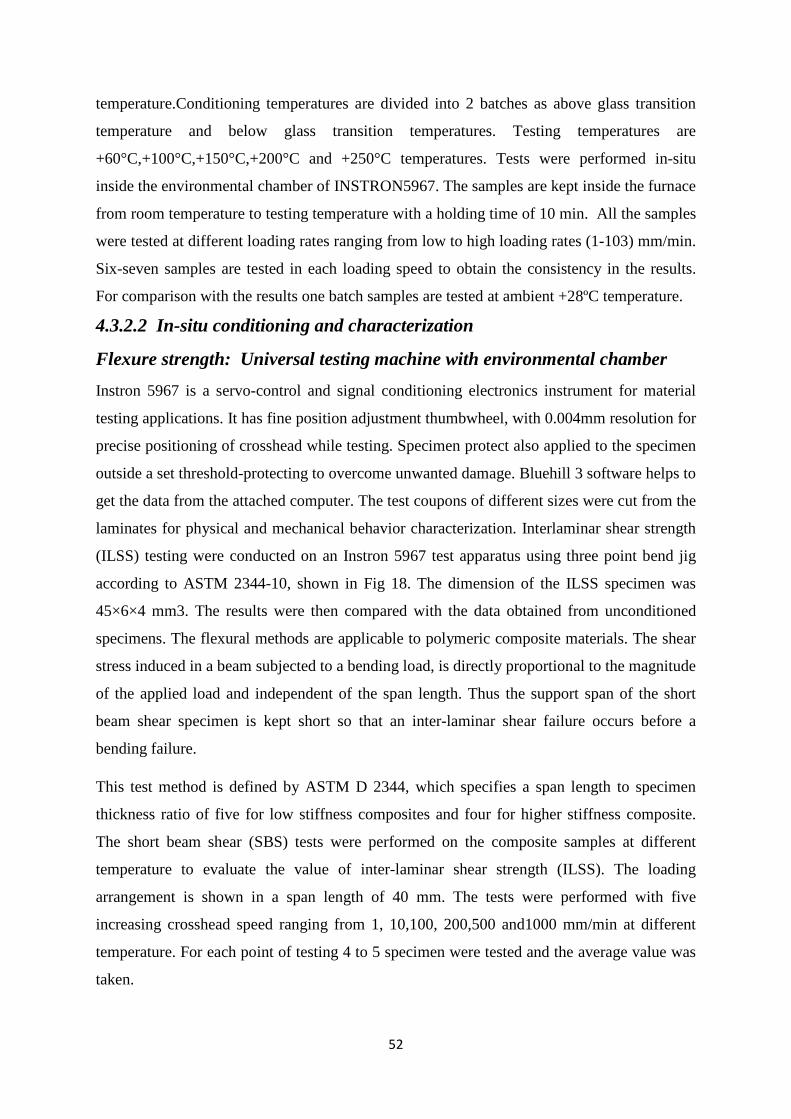
52
temperature.Conditioning temperatures are divided into 2 batches as above glass transition
temperature and below glass transition temperatures. Testing temperatures are
+60°C,+100°C,+150°C,+200°C and +250°C temperatures. Tests were performed in-situ
inside the environmental chamber of INSTRON5967. The samples are kept inside the furnace
from room temperature to testing temperature with a holding time of 10 min. All the samples
were tested at different loading rates ranging from low to high loading rates (1-103) mm/min.
Six-seven samples are tested in each loading speed to obtain the consistency in the results.
For comparison with the results one batch samples are tested at ambient +28ºC temperature.
4.3.2.2 In-situ conditioning and characterization
Flexure strength: Universal testing machine with environmental chamber Instron 5967 is a servo-control and signal conditioning electronics instrument for material
testing applications. It has fine position adjustment thumbwheel, with 0.004mm resolution for
precise positioning of crosshead while testing. Specimen protect also applied to the specimen
outside a set threshold-protecting to overcome unwanted damage. Bluehill 3 software helps to
get the data from the attached computer. The test coupons of different sizes were cut from the
laminates for physical and mechanical behavior characterization. Interlaminar shear strength
(ILSS) testing were conducted on an Instron 5967 test apparatus using three point bend jig
according to ASTM 2344-10, shown in Fig 18. The dimension of the ILSS specimen was
45×6×4 mm3. The results were then compared with the data obtained from unconditioned
specimens. The flexural methods are applicable to polymeric composite materials. The shear
stress induced in a beam subjected to a bending load, is directly proportional to the magnitude
of the applied load and independent of the span length. Thus the support span of the short
beam shear specimen is kept short so that an inter-laminar shear failure occurs before a
bending failure.
This test method is defined by ASTM D 2344, which specifies a span length to specimen
thickness ratio of five for low stiffness composites and four for higher stiffness composite.
The short beam shear (SBS) tests were performed on the composite samples at different
temperature to evaluate the value of inter-laminar shear strength (ILSS). The loading
arrangement is shown in a span length of 40 mm. The tests were performed with five
increasing crosshead speed ranging from 1, 10,100, 200,500 and1000 mm/min at different
temperature. For each point of testing 4 to 5 specimen were tested and the average value was
taken.
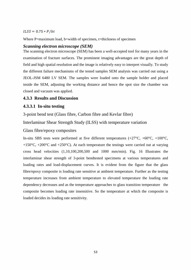
53
Where P=maximum load, b=width of specimen, t=thickness of specimen
Scanning electron microscope (SEM) The scanning electron microscope (SEM) has been a well-accepted tool for many years in the
examination of fracture surfaces. The prominent imaging advantages are the great depth of
field and high spatial resolution and the image is relatively easy to interpret visually. To study
the different failure mechanisms of the tested samples SEM analysis was carried out using a
JEOL-JSM 6480 LV SEM. The samples were loaded onto the sample holder and placed
inside the SEM, adjusting the working distance and hence the spot size the chamber was
closed and vacuum was applied.
4.3.3 Results and Discussion
4.3.3.1 In-situ testing
3-point bend test (Glass fibre, Carbon fibre and Kevlar fibre)
Interlaminar Shear Strength Study (ILSS) with temperature variation
Glass fibre/epoxy composites
In-situ SBS tests were performed at five different temperatures (+27°C, +60°C, +100°C,
+150°C, +200°C and +250°C). At each temperature the testings were carried out at varying
cross head velocities (1,10,100,200,500 and 1000 mm/min). Fig. 16 Illustrates the
interlaminar shear strength of 3-point bendtested specimens at various temperatures and
loading rates and load-displacement curves. It is evident from the figure that the glass
fibre/epoxy composite is loading rate sensitive at ambient temperature. Further as the testing
temperature increases from ambient temperature to elevated temperature the loading rate
dependency decreases and as the temperature approaches to glass transition temperature the
composite becomes loading rate insensitive. So the temperature at which the composite is
loaded decides its loading rate sensitivity.
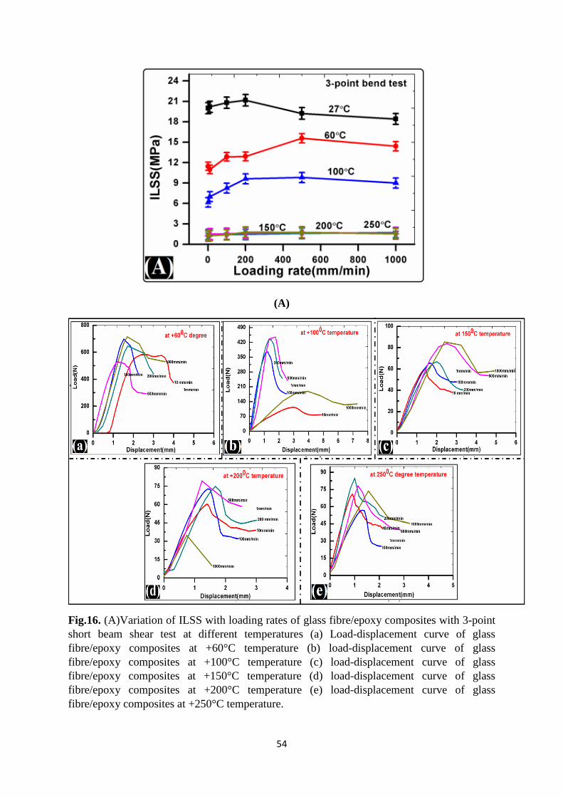
54
(A)
Fig.16. (A)Variation of ILSS with loading rates of glass fibre/epoxy composites with 3-point short beam shear test at different temperatures (a) Load-displacement curve of glass fibre/epoxy composites at +60°C temperature (b) load-displacement curve of glass fibre/epoxy composites at +100°C temperature (c) load-displacement curve of glass fibre/epoxy composites at +150°C temperature (d) load-displacement curve of glass fibre/epoxy composites at +200°C temperature (e) load-displacement curve of glass fibre/epoxy composites at +250°C temperature.
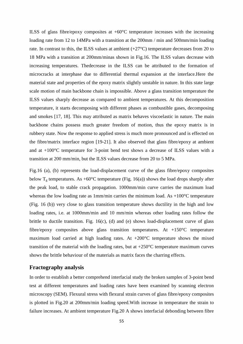
55
ILSS of glass fibre/epoxy composites at +60°C temperature increases with the increasing
loading rate from 12 to 14MPa with a transition at the 200mm / min and 500mm/min loading
rate. In contrast to this, the ILSS values at ambient (+27°C) temperature decreases from 20 to
18 MPa with a transition at 200mm/minas shown in Fig.16. The ILSS values decrease with
increasing temperatures. Thedecrease in the ILSS can be attributed to the formation of
microcracks at interphase due to differential thermal expansion at the interface.Here the
material state and properties of the epoxy matrix slightly unstable in nature. In this state large
scale motion of main backbone chain is impossible. Above a glass transition temperature the
ILSS values sharply decrease as compared to ambient temperatures. At this decomposition
temperature, it starts decomposing with different phases as combustible gases, decomposing
and smokes [17, 18]. This may attributed as matrix behaves viscoelastic in nature. The main
backbone chains possess much greater freedom of motion, thus the epoxy matrix is in
rubbery state. Now the response to applied stress is much more pronounced and is effected on
the fibre/matrix interface region [19-21]. It also observed that glass fibre/epoxy at ambient
and at +100°C temperature for 3-point bend test shows a decrease of ILSS values with a
transition at 200 mm/min, but the ILSS values decrease from 20 to 5 MPa.
Fig.16 (a), (b) represents the load-displacement curve of the glass fibre/epoxy composites
below Tg temperatures. As +60°C temperature (Fig. 16(a)) shows the load drops sharply after
the peak load, to stable crack propagation. 1000mm/min curve carries the maximum load
whereas the low loading rate as 1mm/min carries the minimum load. As +100°C temperature
(Fig. 16 (b)) very close to glass transition temperature shows ductility in the high and low
loading rates, i.e. at 1000mm/min and 10 mm/min whereas other loading rates follow the
brittle to ductile transition. Fig. 16(c), (d) and (e) shows load-displacement curve of glass
fibre/epoxy composites above glass transition temperatures. At +150°C temperature
maximum load carried at high loading rates. At +200°C temperature shows the mixed
transition of the material with the loading rates, but at +250°C temperature maximum curves
shows the brittle behaviour of the materials as matrix faces the charring effects.
Fractography analysis
In order to establish a better comprehend interfacial study the broken samples of 3-point bend
test at different temperatures and loading rates have been examined by scanning electron
microscopy (SEM). Flexural stress with flexural strain curves of glass fibre/epoxy composites
is plotted in Fig.20 at 200mm/min loading speed.With increase in temperature the strain to
failure increases. At ambient temperature Fig.20 A shows interfacial debonding between fibre
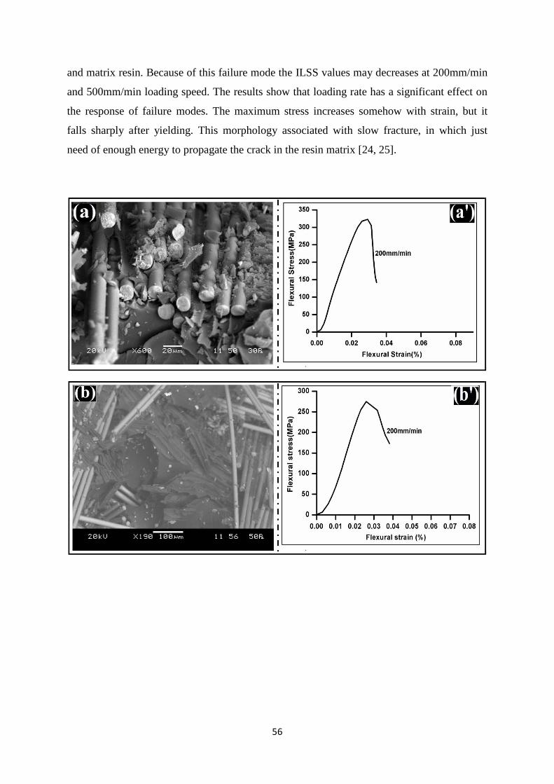
56
and matrix resin. Because of this failure mode the ILSS values may decreases at 200mm/min
and 500mm/min loading speed. The results show that loading rate has a significant effect on
the response of failure modes. The maximum stress increases somehow with strain, but it
falls sharply after yielding. This morphology associated with slow fracture, in which just
need of enough energy to propagate the crack in the resin matrix [24, 25].
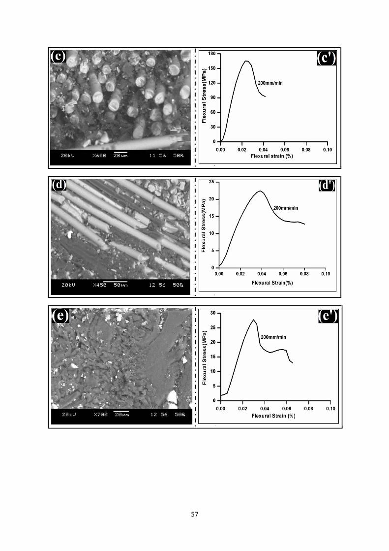
57
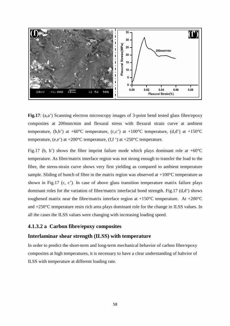
58
Fig.17: (a,a’) Scanning electron microscopy images of 3-point bend tested glass fibre/epoxy
composites at 200mm/min and flexural stress with flexural strain curve at ambient
temperature, (b,b’) at +60°C temperature, (c,c’) at +100°C temperature, (d,d’) at +150°C
temperature, (e,e’) at +200°C temperature, (f,f ‘) at +250°C temperature.
Fig.17 (b, b’) shows the fibre imprint failure mode which plays dominant role at +60°C
temperature. As fibre/matrix interface region was not strong enough to transfer the load to the
fibre, the stress-strain curve shows very first yielding as compared to ambient temperature
sample. Sliding of bunch of fibre in the matrix region was observed at +100°C temperature as
shown in Fig.17 (c, c’). In case of above glass transition temperature matrix failure plays
dominant roles for the variation of fibre/matrix interfacial bond strength. Fig.17 (d,d’) shows
toughened matrix near the fibre/matrix interface region at +150°C temperature. At +200°C
and +250°C temperature resin rich area plays dominant role for the change in ILSS values. In
all the cases the ILSS values were changing with increasing loading speed.
4.1.3.2 a Carbon fibre/epoxy composites
Interlaminar shear strength (ILSS) with temperature
In order to predict the short-term and long-term mechanical behavior of carbon fibre/epoxy
composites at high temperatures, it is necessary to have a clear understanding of bahvior of
ILSS with temperature at different loading rate.
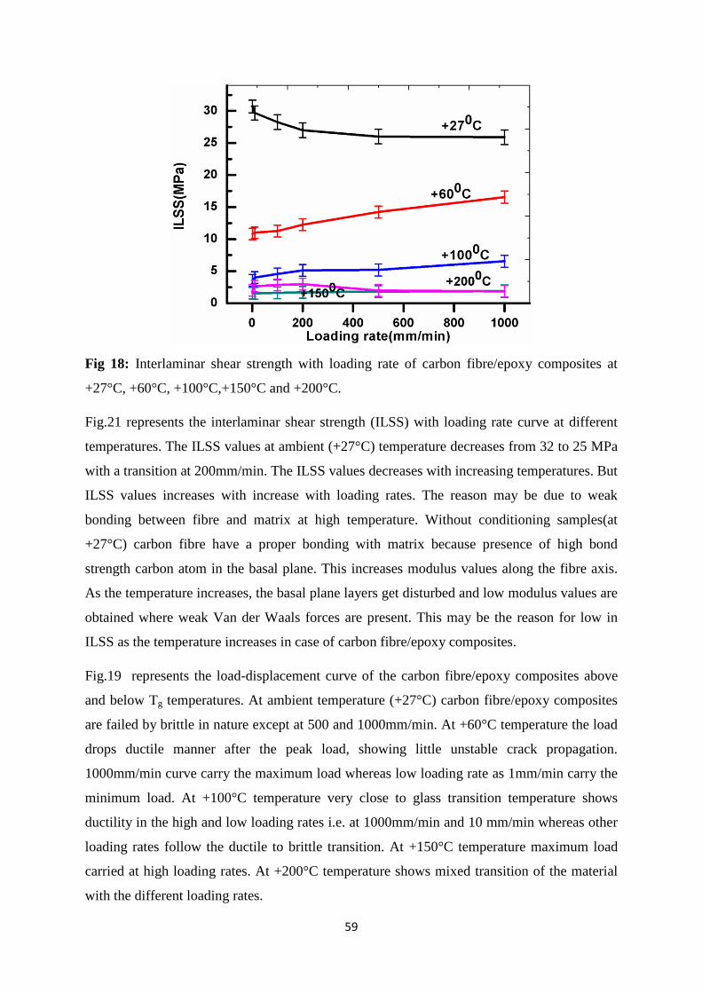
59
Fig 18: Interlaminar shear strength with loading rate of carbon fibre/epoxy composites at
+27°C, +60°C, +100°C,+150°C and +200°C.
Fig.21 represents the interlaminar shear strength (ILSS) with loading rate curve at different
temperatures. The ILSS values at ambient (+27°C) temperature decreases from 32 to 25 MPa
with a transition at 200mm/min. The ILSS values decreases with increasing temperatures. But
ILSS values increases with increase with loading rates. The reason may be due to weak
bonding between fibre and matrix at high temperature. Without conditioning samples(at
+27°C) carbon fibre have a proper bonding with matrix because presence of high bond
strength carbon atom in the basal plane. This increases modulus values along the fibre axis.
As the temperature increases, the basal plane layers get disturbed and low modulus values are
obtained where weak Van der Waals forces are present. This may be the reason for low in
ILSS as the temperature increases in case of carbon fibre/epoxy composites.
Fig.19 represents the load-displacement curve of the carbon fibre/epoxy composites above
and below Tg temperatures. At ambient temperature (+27°C) carbon fibre/epoxy composites
are failed by brittle in nature except at 500 and 1000mm/min. At +60°C temperature the load
drops ductile manner after the peak load, showing little unstable crack propagation.
1000mm/min curve carry the maximum load whereas low loading rate as 1mm/min carry the
minimum load. At +100°C temperature very close to glass transition temperature shows
ductility in the high and low loading rates i.e. at 1000mm/min and 10 mm/min whereas other
loading rates follow the ductile to brittle transition. At +150°C temperature maximum load
carried at high loading rates. At +200°C temperature shows mixed transition of the material
with the different loading rates.
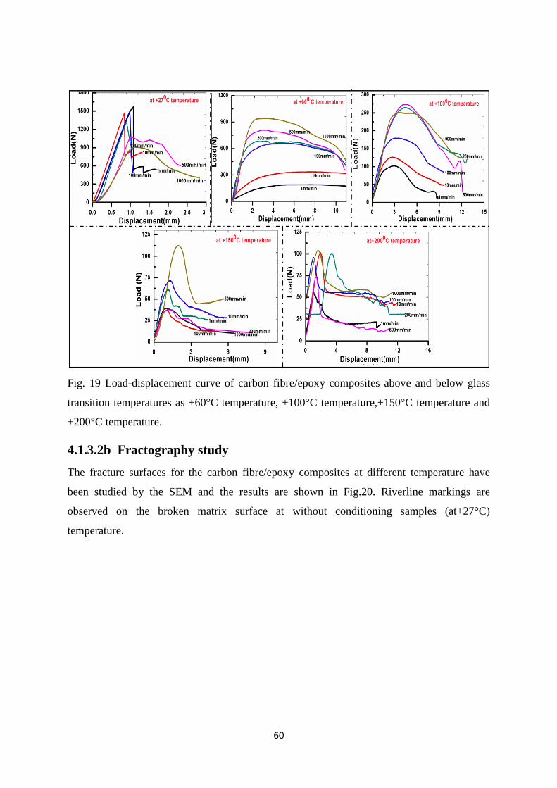
60
Fig. 19 Load-displacement curve of carbon fibre/epoxy composites above and below glass
transition temperatures as +60°C temperature, +100°C temperature,+150°C temperature and
+200°C temperature.
4.1.3.2b Fractography study
The fracture surfaces for the carbon fibre/epoxy composites at different temperature have
been studied by the SEM and the results are shown in Fig.20. Riverline markings are
observed on the broken matrix surface at without conditioning samples (at+27°C)
temperature.
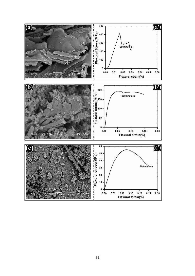
61
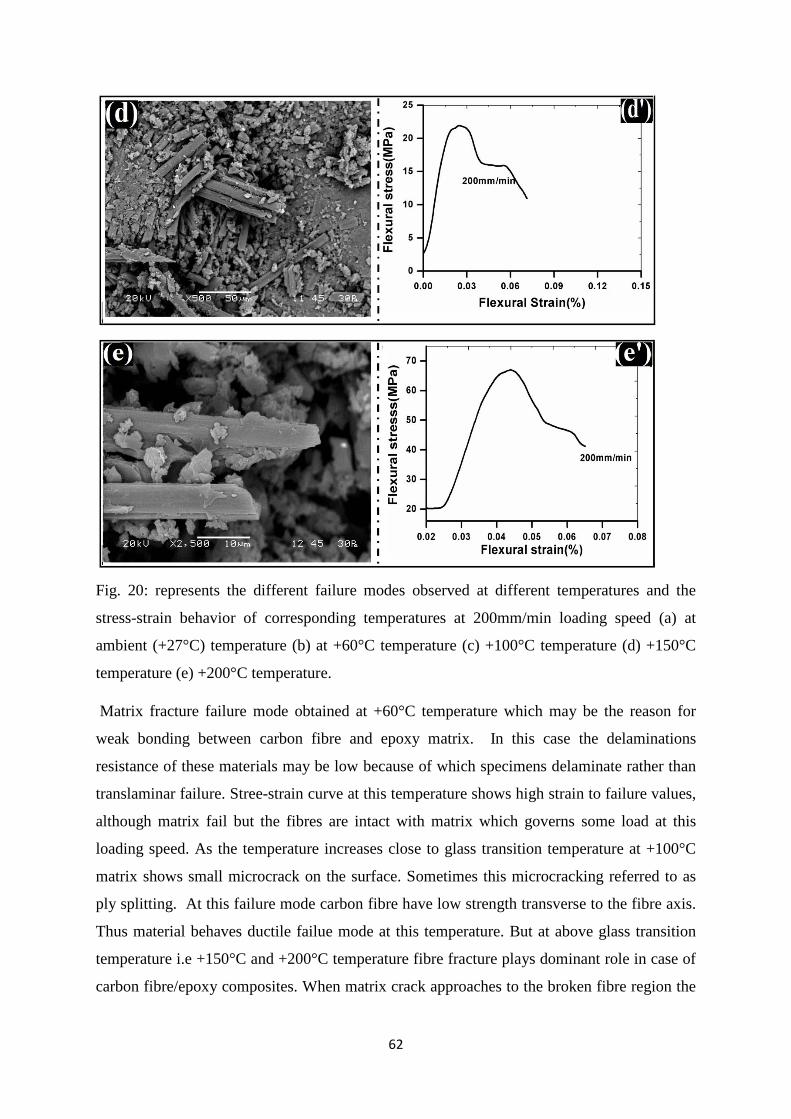
62
Fig. 20: represents the different failure modes observed at different temperatures and the
stress-strain behavior of corresponding temperatures at 200mm/min loading speed (a) at
ambient (+27°C) temperature (b) at +60°C temperature (c) +100°C temperature (d) +150°C
temperature (e) +200°C temperature.
Matrix fracture failure mode obtained at +60°C temperature which may be the reason for
weak bonding between carbon fibre and epoxy matrix. In this case the delaminations
resistance of these materials may be low because of which specimens delaminate rather than
translaminar failure. Stree-strain curve at this temperature shows high strain to failure values,
although matrix fail but the fibres are intact with matrix which governs some load at this
loading speed. As the temperature increases close to glass transition temperature at +100°C
matrix shows small microcrack on the surface. Sometimes this microcracking referred to as
ply splitting. At this failure mode carbon fibre have low strength transverse to the fibre axis.
Thus material behaves ductile failue mode at this temperature. But at above glass transition
temperature i.e +150°C and +200°C temperature fibre fracture plays dominant role in case of
carbon fibre/epoxy composites. When matrix crack approaches to the broken fibre region the
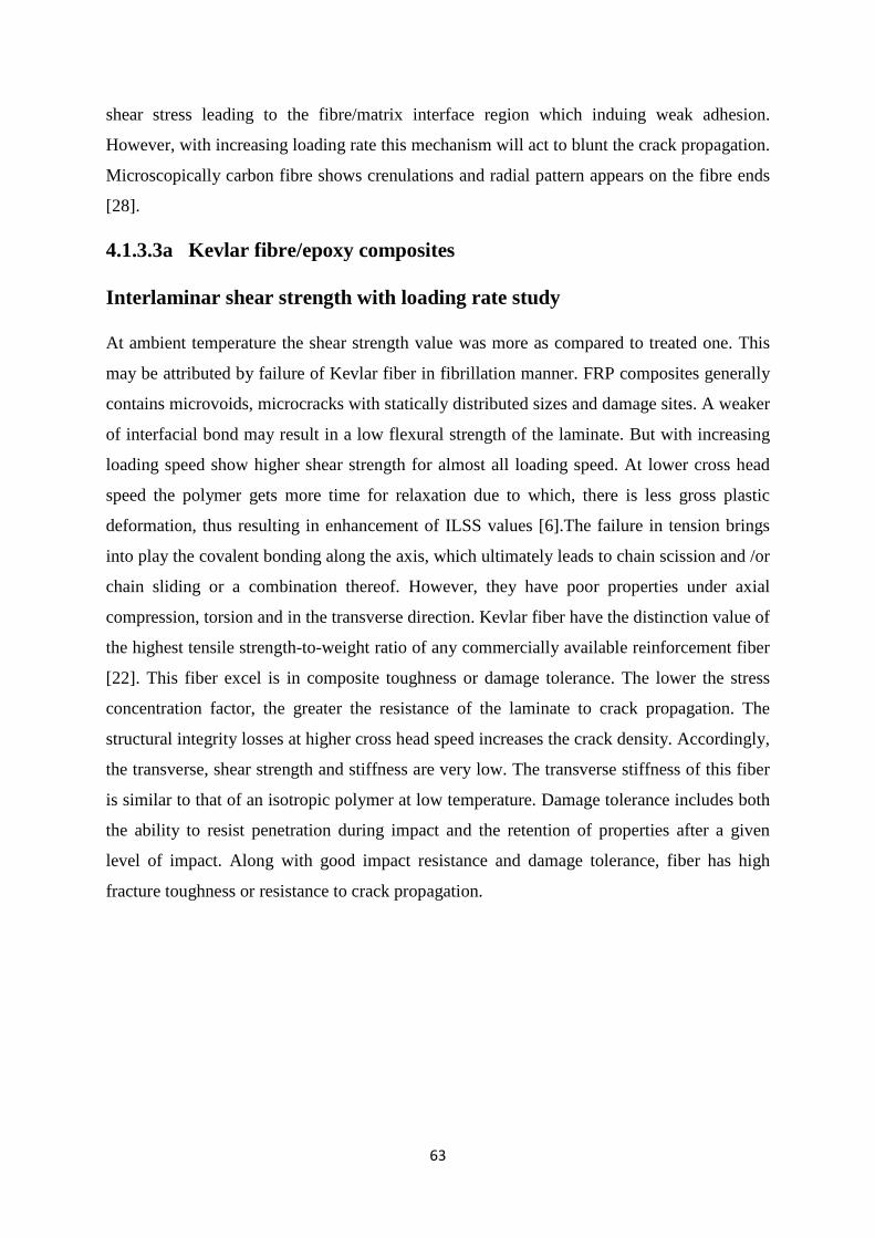
63
shear stress leading to the fibre/matrix interface region which induing weak adhesion.
However, with increasing loading rate this mechanism will act to blunt the crack propagation.
Microscopically carbon fibre shows crenulations and radial pattern appears on the fibre ends
[28].
4.1.3.3a Kevlar fibre/epoxy composites Interlaminar shear strength with loading rate study At ambient temperature the shear strength value was more as compared to treated one. This
may be attributed by failure of Kevlar fiber in fibrillation manner. FRP composites generally
contains microvoids, microcracks with statically distributed sizes and damage sites. A weaker
of interfacial bond may result in a low flexural strength of the laminate. But with increasing
loading speed show higher shear strength for almost all loading speed. At lower cross head
speed the polymer gets more time for relaxation due to which, there is less gross plastic
deformation, thus resulting in enhancement of ILSS values [6].The failure in tension brings
into play the covalent bonding along the axis, which ultimately leads to chain scission and /or
chain sliding or a combination thereof. However, they have poor properties under axial
compression, torsion and in the transverse direction. Kevlar fiber have the distinction value of
the highest tensile strength-to-weight ratio of any commercially available reinforcement fiber
[22]. This fiber excel is in composite toughness or damage tolerance. The lower the stress
concentration factor, the greater the resistance of the laminate to crack propagation. The
structural integrity losses at higher cross head speed increases the crack density. Accordingly,
the transverse, shear strength and stiffness are very low. The transverse stiffness of this fiber
is similar to that of an isotropic polymer at low temperature. Damage tolerance includes both
the ability to resist penetration during impact and the retention of properties after a given
level of impact. Along with good impact resistance and damage tolerance, fiber has high
fracture toughness or resistance to crack propagation.
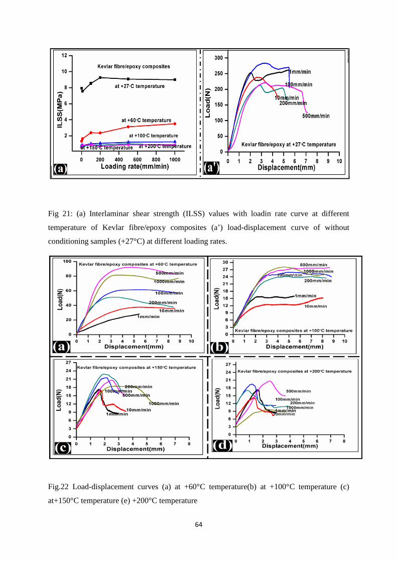
64
Fig 21: (a) Interlaminar shear strength (ILSS) values with loadin rate curve at different
temperature of Kevlar fibre/epoxy composites (a’) load-displacement curve of without
conditioning samples (+27°C) at different loading rates.
Fig.22 Load-displacement curves (a) at +60°C temperature(b) at +100°C temperature (c)
at+150°C temperature (e) +200°C temperature
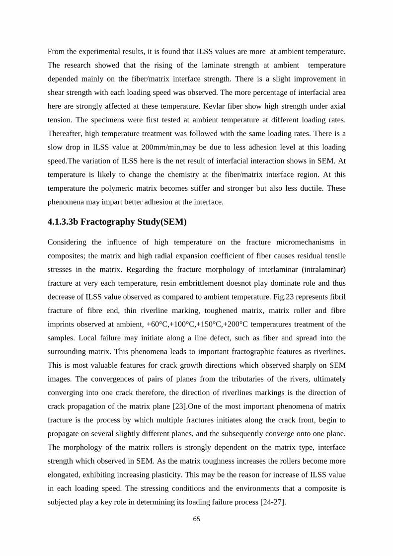
65
From the experimental results, it is found that ILSS values are more at ambient temperature.
The research showed that the rising of the laminate strength at ambient temperature
depended mainly on the fiber/matrix interface strength. There is a slight improvement in
shear strength with each loading speed was observed. The more percentage of interfacial area
here are strongly affected at these temperature. Kevlar fiber show high strength under axial
tension. The specimens were first tested at ambient temperature at different loading rates.
Thereafter, high temperature treatment was followed with the same loading rates. There is a
slow drop in ILSS value at 200mm/min,may be due to less adhesion level at this loading
speed.The variation of ILSS here is the net result of interfacial interaction shows in SEM. At
temperature is likely to change the chemistry at the fiber/matrix interface region. At this
temperature the polymeric matrix becomes stiffer and stronger but also less ductile. These
phenomena may impart better adhesion at the interface.
4.1.3.3b Fractography Study(SEM)
Considering the influence of high temperature on the fracture micromechanisms in
composites; the matrix and high radial expansion coefficient of fiber causes residual tensile
stresses in the matrix. Regarding the fracture morphology of interlaminar (intralaminar)
fracture at very each temperature, resin embrittlement doesnot play dominate role and thus
decrease of ILSS value observed as compared to ambient temperature. Fig.23 represents fibril
fracture of fibre end, thin riverline marking, toughened matrix, matrix roller and fibre
imprints observed at ambient, +60°C,+100°C,+150°C,+200°C temperatures treatment of the
samples. Local failure may initiate along a line defect, such as fiber and spread into the
surrounding matrix. This phenomena leads to important fractographic features as riverlines.
This is most valuable features for crack growth directions which observed sharply on SEM
images. The convergences of pairs of planes from the tributaries of the rivers, ultimately
converging into one crack therefore, the direction of riverlines markings is the direction of
crack propagation of the matrix plane [23].One of the most important phenomena of matrix
fracture is the process by which multiple fractures initiates along the crack front, begin to
propagate on several slightly different planes, and the subsequently converge onto one plane.
The morphology of the matrix rollers is strongly dependent on the matrix type, interface
strength which observed in SEM. As the matrix toughness increases the rollers become more
elongated, exhibiting increasing plasticity. This may be the reason for increase of ILSS value
in each loading speed. The stressing conditions and the environments that a composite is
subjected play a key role in determining its loading failure process [24-27].
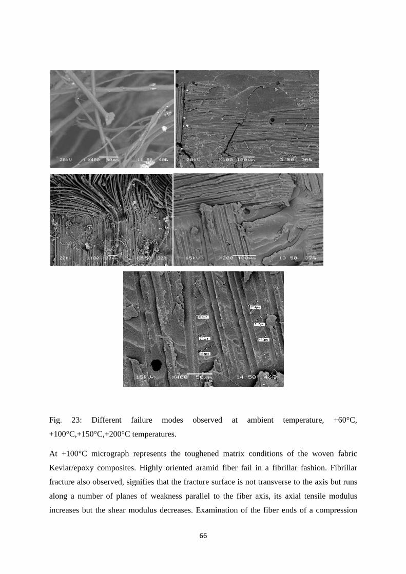
66
Fig. 23: Different failure modes observed at ambient temperature, +60°C,
+100°C,+150°C,+200°C temperatures.
At +100°C micrograph represents the toughened matrix conditions of the woven fabric
Kevlar/epoxy composites. Highly oriented aramid fiber fail in a fibrillar fashion. Fibrillar
fracture also observed, signifies that the fracture surface is not transverse to the axis but runs
along a number of planes of weakness parallel to the fiber axis, its axial tensile modulus
increases but the shear modulus decreases. Examination of the fiber ends of a compression
67
fracture shows further evidence of the microbucklingshown failure mechanisms. The
fractographic features shown on the fiber ends exhibit the morphology particular to laminate
compression failure. Across each individual fiber end is a line, which represents the neutral
axis of the fiber as it undergoes bending. Microbuckling may occur on several planes giving
rise to series of steps on the fracture surface, each step being a multiple of half the buckling
wavelength.During failure involving compressive stresses, fibrillation occurs, which results
in a large degree of new surface area. This fibrillation process results in high-energy
absorption during the process of failure.
4.1.3.4a 4-point bend test(Glass fibre/epoxy composites)
Interlamianr shear strength with Loading rate study
Fig. 24 represents the glass fibre/epoxy composites at different temperatures with different
loading rates subjected to 4-point fixture bend test. Fig. 24(A) illustrates ILSS verse loading
rates at different temperatures compared with ambient samples. It can be seen that ILSS value
changes significantly with temperatures and loading rates.
Curve shows for 4-point bend test very less percentage of change in ILSS values. However,
the values obtained in above Tg shows significantly high percentage of change in ILSS
values. The reason may be due to increase in crack density in the epoxy matrix. As increase
in crack density more number of cracks overlaps into each other, forming larger cracks [22,
23].In case of 4-point bend test, at +60°C temperature the ILSS values increases from 1 to 2
MPa with increasing loading speed and for ambient samples it follows a similar trend as ILSS
increases from 13 to 14 MPa with increasing loading rates. When the specimen subjected to
+150°C temperature, 200°C temperature and +250°C temperatures.
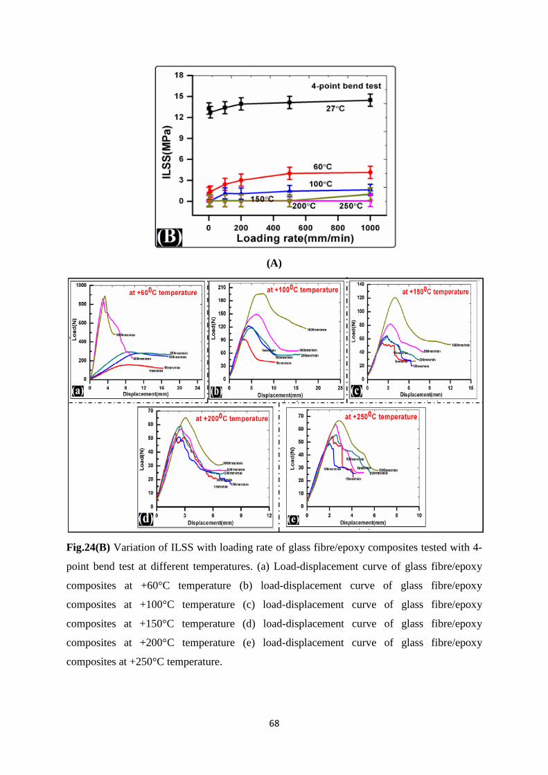
68
(A)
Fig.24(B) Variation of ILSS with loading rate of glass fibre/epoxy composites tested with 4-
point bend test at different temperatures. (a) Load-displacement curve of glass fibre/epoxy
composites at +60°C temperature (b) load-displacement curve of glass fibre/epoxy
composites at +100°C temperature (c) load-displacement curve of glass fibre/epoxy
composites at +150°C temperature (d) load-displacement curve of glass fibre/epoxy
composites at +200°C temperature (e) load-displacement curve of glass fibre/epoxy
composites at +250°C temperature.
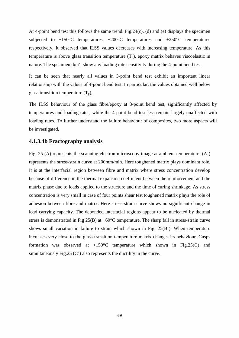
69
At 4-point bend test this follows the same trend. Fig.24(c), (d) and (e) displays the specimen
subjected to +150°C temperatures, +200°C temperatures and +250°C temperatures
respectively. It observed that ILSS values decreases with increasing temperature. As this
temperature is above glass transition temperature (Tg), epoxy matrix behaves viscoelastic in
nature. The specimen don’t show any loading rate sensitivity during the 4-point bend test
It can be seen that nearly all values in 3-point bend test exhibit an important linear
relationship with the values of 4-point bend test. In particular, the values obtained well below
glass transition temperature (Tg),
The ILSS behaviour of the glass fibre/epoxy at 3-point bend test, significantly affected by
temperatures and loading rates, while the 4-point bend test less remain largely unaffected with
loading rates. To further understand the failure behaviour of composites, two more aspects will
be investigated.
4.1.3.4b Fractography analysis
Fig. 25 (A) represents the scanning electron microscopy image at ambient temperature. (A’)
represents the stress-strain curve at 200mm/min. Here toughened matrix plays dominant role.
It is at the interfacial region between fibre and matrix where stress concentration develop
because of difference in the thermal expansion coefficient between the reinforcement and the
matrix phase due to loads applied to the structure and the time of curing shrinkage. As stress
concentration is very small in case of four points shear test toughened matrix plays the role of
adhesion between fibre and matrix. Here stress-strain curve shows no significant change in
load carrying capacity. The debonded interfacial regions appear to be nucleated by thermal
stress is demonstrated in Fig 25(B) at +60°C temperature. The sharp fall in stress-strain curve
shows small variation in failure to strain which shown in Fig. 25(B’). When temperature
increases very close to the glass transition temperature matrix changes its behaviour. Cusps
formation was observed at +150°C temperature which shown in Fig.25(C) and
simultaneously Fig.25 (C’) also represents the ductility in the curve.
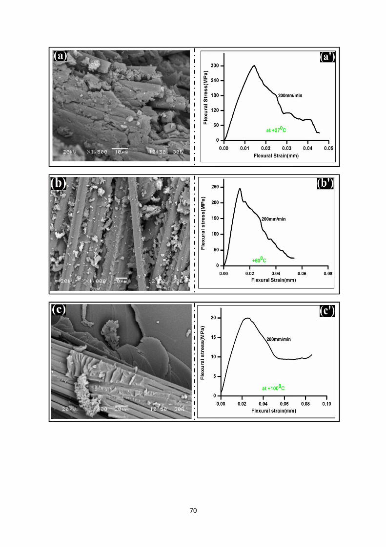
70
71
Fig.25: (A,A’) Scanning electron microscopy images of glass fibre/epoxy composites tested
at 4-point short beam shear test at 200mm/min and flexural stress with flexural strain curve at
ambient temperature, (B,B’) at +60°C temperature, (C,C’) at +100°C temperature, (D,D’) at
+150°C temperature, (E,E’) at +200°C temperature, (F,F’) at +250°C temperature.
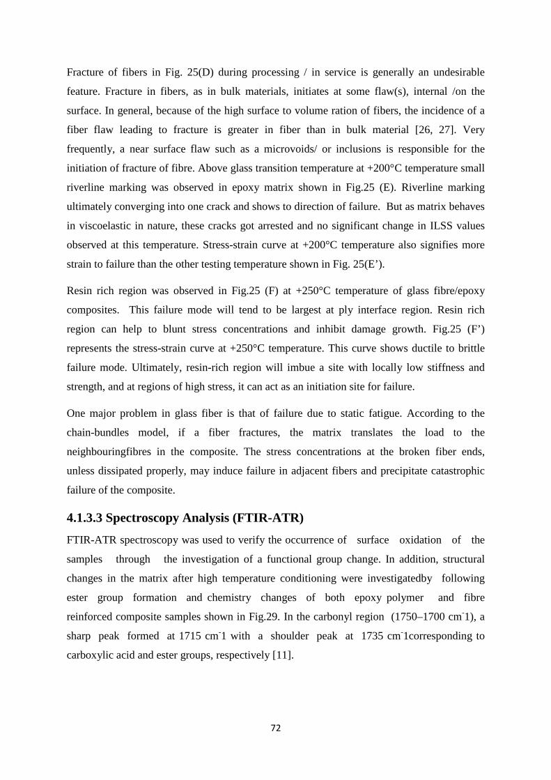
72
Fracture of fibers in Fig. 25(D) during processing / in service is generally an undesirable
feature. Fracture in fibers, as in bulk materials, initiates at some flaw(s), internal /on the
surface. In general, because of the high surface to volume ration of fibers, the incidence of a
fiber flaw leading to fracture is greater in fiber than in bulk material [26, 27]. Very
frequently, a near surface flaw such as a microvoids/ or inclusions is responsible for the
initiation of fracture of fibre. Above glass transition temperature at +200°C temperature small
riverline marking was observed in epoxy matrix shown in Fig.25 (E). Riverline marking
ultimately converging into one crack and shows to direction of failure. But as matrix behaves
in viscoelastic in nature, these cracks got arrested and no significant change in ILSS values
observed at this temperature. Stress-strain curve at +200°C temperature also signifies more
strain to failure than the other testing temperature shown in Fig. 25(E’).
Resin rich region was observed in Fig.25 (F) at +250°C temperature of glass fibre/epoxy
composites. This failure mode will tend to be largest at ply interface region. Resin rich
region can help to blunt stress concentrations and inhibit damage growth. Fig.25 (F’)
represents the stress-strain curve at +250°C temperature. This curve shows ductile to brittle
failure mode. Ultimately, resin-rich region will imbue a site with locally low stiffness and
strength, and at regions of high stress, it can act as an initiation site for failure.
One major problem in glass fiber is that of failure due to static fatigue. According to the
chain-bundles model, if a fiber fractures, the matrix translates the load to the
neighbouringfibres in the composite. The stress concentrations at the broken fiber ends,
unless dissipated properly, may induce failure in adjacent fibers and precipitate catastrophic
failure of the composite.
4.1.3.3 Spectroscopy Analysis (FTIR-ATR) FTIR-ATR spectroscopy was used to verify the occurrence of surface oxidation of the
samples through the investigation of a functional group change. In addition, structural
changes in the matrix after high temperature conditioning were investigatedby following
ester group formation and chemistry changes of both epoxy polymer and fibre
reinforced composite samples shown in Fig.29. In the carbonyl region (1750–1700 cm-1), a
sharp peak formed at 1715 cm-1 with a shoulder peak at 1735 cm-1corresponding to
carboxylic acid and ester groups, respectively [11].
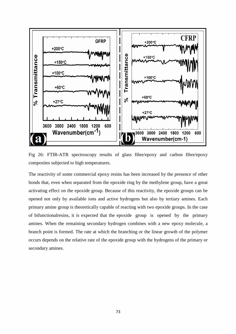
73
Fig 26: FTIR-ATR spectroscopy results of glass fibre/epoxy and carbon fibre/epoxy
composites subjected to high temperatures.
The reactivity of some commercial epoxy resins has been increased by the presence of ether
bonds that, even when separated from the epoxide ring by the methylene group, have a great
activating effect on the epoxide group. Because of this reactivity, the epoxide groups can be
opened not only by available ions and active hydrogens but also by tertiary amines. Each
primary amine group is theoretically capable of reacting with two epoxide groups. In the case
of bifunctionalresins, it is expected that the epoxide group is opened by the primary
amines. When the remaining secondary hydrogen combines with a new epoxy molecule, a
branch point is formed. The rate at which the branching or the linear growth of the polymer
occurs depends on the relative rate of the epoxide group with the hydrogens of the primary or
secondary amines.
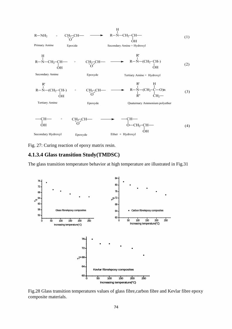
74
Fig. 27: Curing reaction of epoxy matrix resin.
4.1.3.4 Glass transition Study(TMDSC) The glass transition temperature behavior at high temperature are illustrated in Fig.31
0 50 100 150 200 250
52
56
60
64
68
72
76
Glass fibre/epoxy composites
T g
Increasing temperature(°C) 0 50 100 150 200 250
60
64
68
72
76
80
84
Carbon fibre/epoxy composites
T g
Increasing temperature(°C)
0 50 100 150 200 25060
64
68
72
76
Kevlar fibre/epoxy composites
T g
Increasing temperature(°C)
Fig.28 Glass transition temperatures values of glass fibre,carbon fibre and Kevlar fibre epoxy composite materials.
75
The physical cause of glass transitions of polymer are place change of molecular groups.
Since the glass transition temperature (Tg) corresponds to a mobility change in a polymer and
has a definite free volume associated with it, the jumping frequency of a segment is same
magnitude for nearly all polymers. The Tg value usually decreases at high temperature. But
the changes are not very significant. This is may be increase of cross-link density of matrix
which decreases the molecular mobility of the polymer. Another reason behind this, it may be
due to presence of thermal stresses in the epoxy resin matrix which going to degradae the
bonding at the interface region. The covalent bond is going to replace by weakest bond. Glass
fibre/epoxy composites are very weak in nature as compared to carbon fibre/epoxy
composites. During the increase in Tg value matrix undergoes viscoelastic in
behavior.Molecules are likely to unstable in nature at this stage. Because of this interfacial
bond strength getting weak leads to change in Tg values. In the TMDSC measurement, the
structure through the Tg region is nearly in the quasi-equilibrium state.
Summary and Conclusions
The loading rate sensitivity of glass fibre/epoxy composites at low and high temperatures at
different fixture modesare reported here to deconvolute stress concentration and thermal
factors. Four-point bend tests showed that the interlaminar shear strength is not affected by
loading rate while epoxy matrix was affected by temperatures as it goes through its glass
transition temperature. These observations are crucial for explaining the loading rate
sensitivity of glass fibre/epoxy at high temperatures.Considering interlaminar shear strength
and delamination behavior, the tested laminate characterized by SEM to reveal various failure
modes. The present study may possibly reveal the following conclusions:
During 3-point short beam shear test the ILSS values at ambient (+27°C) temperature
decreases from 20 to 18 MPa with a transition at 200mm/min. The ILSS values decreases
with increasing temperatures due to the presence of curing stress between the fibre/matrix
interface regions. In case of 4-point short beam shear test ILSS value changes significantly
with temperatures and loading rates.
Above glass transition temperature the ILSS values sharply decreases as compared to ambient
temperatures. At this decomposition temperature, epoxy starts decomposing with different
phases as combustible gases, decomposing and smokes. This may attributed as matrix
76
behaves viscoelastic in nature as the main backbone chains of polymer possess much greater
freedom of motion.
From fractographic point of view various fibre failures plays dominant role in below glass
transition temperatures whereas matrix failure plays above glass transition role. One general
point observed from flexural stress- flexural strain curve was strain to failure in 3-point bend
tested samples was smaller as compared to 4-point bend tested samples.
References
1. Gudes R.M.(2007).,Durability of polymer matrix composites:Viscoelastic effect on static and fatigue loading, Composite Science and Technology, Vol-67, 2574
2. Naik,N.K., Venkateswara.R.K., Ravikumar,G.,Vearraju,Ch.(2010).,Stress-strain behavior of composites under high strain rate compression along thickness direction: Effect of loading condition,, Materials and Design.,Vol-31, 396
3. Ray, B.C.(2006),Temperature effect during humid ageing on interfaces of glass and carbon Fibers reinforced epoxy compositesJ of Colloid and Interface Science. ,Vol-298, 111
4. Ray B.C. (2004), Effects of crosshead velocity and sub-zero temperature on mechanical behaviour of hygrothermally conditioned glass fibre reinforced epoxy composites. Material Science and Engineering, Vol- 379:39.
5. S. Sethi, Ray B.C(2014), An assessment of mechanical behaviour and fractography studyof glass/epoxy composites at different temperatures and loading speeds, Materials and Design, Vol-64:160
6. S. Sethi, Rathore D, Ray B.C(2014), Effects of temperature and loading speed on interface-dominatedstrength in fibre/polymer composites: An evaluation for in-situenvironment, Materials and Design, Vol-65: 617
7. Tanoglu M.,Mcknight,S.H.,Palmese,G.R.,Gillespie,J.W.Jr,(2000),A new technique to characterize the fiber/matrix interphase properties under high strain rates, Composites Part A, Vol-31,1127
8. C, Dong, Ian J. Davies (2014), Flexural and tensile strengths of unidirectional hybrid epoxy composites reinforced by S-2 glass and T700Scarbon fibres. Materials Design., Vol-54: 955
9. Soutis,C.,Turkmen,D.(1997), Moisture and temperature effects on the compressive failure of CFRP unidirectional laminates, J. Composite. Material,Vol-31, 832
10. Rapnowski,P., Gentz, M.,Kumosa,M.,(2006). Mechanical response of a unidirectional graphite fiber/polyimide composite as a function of temperature, Composite. Science and. Technology., Vol-66, 1045
11. Ray, B.C. (2004),Loading Rate effects on Mechanical Properties of Polymer Composites at Ultralow TemperaturesJ of Applied. Polymer. Science,Vol-100, 2062
12. Fabio Nardone, Marco Di Ludovico, Francisco J. De Caso y Basalo, Andrea Prota , Antonio Nanni, Tensile behavior of epoxy based FRP composites under extreme service conditions, Composites: Part B 43 (2012) 1468–1474.

77
13. Piyush K. Dutta, David Hui, Low temperature and freeze thaw durability of thick composoites, Composites:Part B 27B (1996) 371-379.
14. M.Z. Shah Khan, G. Simpson, E.P. Gellert, Resistance of glass-fibre reinforced polymer composites to increasing compressive strain rates and loading rates, Composites: Part A 31 (2000) 57–67.
15. Okenwa I. Okoli, The effects of strain rate and failure modes on the failure energy of fiber reinforced composites, composite structures 54 (2001) 299-303.
16. Ray B.C.,(2006).Effects of Thermal and Cryogenic Conditionings on Mechanical Behavior of Thermally Shocked Glass Fiber/Epoxy Composites,J of Reinforced Plastic and Composite ,Vol-25, 1227
17. Fereshteh-Saniee, F., Majzoobi,G.H., Bahrami,M.,(2005),An experimental study on the behavior of glass/epoxy composites at low strain rates,J of Materials Processing Technology,Vol-162, 39
18. Jang B Z., Advanced Polymer Composites: Principle and Applications. ASM International, Materials Park, OH, 1994
19. Hartwig,G.,Polymer properties at room and cryogenic temperatures. New York, Plenum Press, 1994
20. Ray B.C. (2006). Adhesion of glass/epoxy composites influenced by thermal and cryogenic environments. J of Applied Polymer Science, Vol-102:1943.
21. Kim K, Mai Y W., Engineered Interfaces in Fiber Reinforced Composites. Kidlington, Oxford ,U.K, Elsevier Publication, 1998
22. Greenhalgh E S. Failure analysis and fractography of polymer composites, Cambridge,UK ,CRC Publication, Woodhead Publishing, 2009
23. Ray B C.(2004).Thermal shock on interfacial adhesion of thermally conditioned glass fiber/epoxy composites rates, Material. Letter.,Vol- 58, 2175
24. Parvatareddy H, Wang J.Z, Dillard D.A., Ward T.C.(1995), Environmental aging of high-performance polymeric composites: effects on durability, Composites Science and Technology, Vol-53,399
25. Sookay N.K., Klemperer,C.J, Verijenko,V.E., (2003) Environmental testing of advanced epoxy composites, Composite Structures, Vol-62;429
26. Karbhari V.M (2004), E-glass/vinyl ester composites in aqueous environments: effects on short-beam shear strength. J Composite Construction, Vol-8, 148
27. Myer M.W, Herakovich C.T, Milkovich SM, Short J.S, (1983), Temperature dependence of mechanical and thermal expansion properties of T-300/5208 graphite epoxy, Composites, Vol-14; 276.
78
4.1.1a AFM Study of thermally conditioned samples
Theories and Thoughts
The characterization of fractographic features associated with fibers, matrix and also
interface/interphase has been emphasized here to analyze the surface topographical
contoursacross the glass fiber and epoxy matrix. Atomic force microscope (AFM) and
Scanning electron microscope (SEM) were performed to characterize the micro-failure
features (like micro-voids, small matrix and interfacial cracks ) and structural
homogeneity/integrity of composites. AFM study showed that thermal conditioning has
resulted non-homogeneous degree of cross-linkingreflected by the height-scan images. The
uneven post-curing may adversely affect the stress transmissibility integrity of interphase
region, which may eventually lead to changes in thermophysical, mechanical and chemical
characteristic of fibrous composite. Scanning micrograph indicates the increase in cusp
thickness due to increase in plasticity of resin matrix.
4.1.1a.1 Introduction
Polymer composite technology is based on taking advantage of the stiffness and strength of
high performance fibers by dispersing them in a matrix, which acts as a binder and transfers
forces to the fibers across the fiber/matrix interface. Severe environmental exposure affects
physical and mechanical properties of polymer composite materials resulting in an
undesirable degradation (1). An interfacial reaction may impart various morphological
modifications to the matrix microstructural in proximity to the fiber surface (2).The
interfacial adhesion and mechanical properties can be improved by increasing the fiber
surface roughness particularly on the nanometer scale (3).As a result, extensive research has
been devoted to the study of microstructural assessment of GFRP composite.The work
represented here has identified both surface and interphase properties interms of topography,
fractography,adhesion and stiffness characterized by AFM,SEM the nanometer scale,which
are essentially for the understanding of the macromechanical response to fracture. Special
emphasis is placed on the local characterization of the fiber surface topography, interphase
mechanical properties and adhesion features. The nanoscale crosslinking process of the epoxy
resins near fiber surface influenced by the thermally conditioning treatment is analyzed by
AFM and SEM.
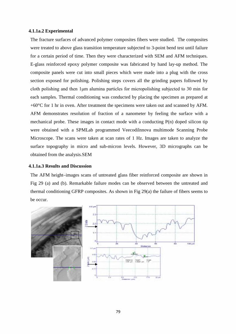
79
4.1.1a.2 Experimental
The fracture surfaces of advanced polymer composites fibers were studied. The composites
were treated to above glass transition temperature subjected to 3-point bend test until failure
for a certain period of time. Then they were characterized with SEM and AFM techniques.
E-glass reinforced epoxy polymer composite was fabricated by hand lay-up method. The
composite panels were cut into small pieces which were made into a plug with the cross
section exposed for polishing. Polishing steps covers all the grinding papers followed by
cloth polishing and then 1μm alumina particles for micropolishing subjected to 30 min for
each samples. Thermal conditioning was conducted by placing the specimen as prepared at
+60°C for 1 hr in oven. After treatment the specimens were taken out and scanned by AFM.
AFM demonstrates resolution of fraction of a nanometer by feeling the surface with a
mechanical probe. These images in contact mode with a conducting P(n) doped silicon tip
were obtained with a SPMLab programmed Veecodilnnova multimode Scanning Probe
Microscope. The scans were taken at scan rates of 1 Hz. Images are taken to analyze the
surface topography in micro and sub-micron levels. However, 3D micrographs can be
obtained from the analysis.SEM
4.1.1a.3 Results and Discussion
The AFM height–images scans of untreated glass fiber reinforced composite are shown in
Fig 29 (a) and (b). Remarkable failure modes can be observed between the untreated and
thermal conditioning GFRP composites. As shown in Fig 29(a) the failure of fibers seems to
be occur.
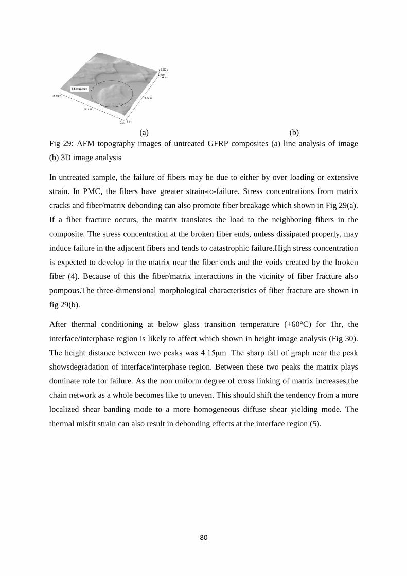
80
(a) (b)
Fig 29: AFM topography images of untreated GFRP composites (a) line analysis of image
(b) 3D image analysis
In untreated sample, the failure of fibers may be due to either by over loading or extensive
strain. In PMC, the fibers have greater strain-to-failure. Stress concentrations from matrix
cracks and fiber/matrix debonding can also promote fiber breakage which shown in Fig 29(a).
If a fiber fracture occurs, the matrix translates the load to the neighboring fibers in the
composite. The stress concentration at the broken fiber ends, unless dissipated properly, may
induce failure in the adjacent fibers and tends to catastrophic failure.High stress concentration
is expected to develop in the matrix near the fiber ends and the voids created by the broken
fiber (4). Because of this the fiber/matrix interactions in the vicinity of fiber fracture also
pompous.The three-dimensional morphological characteristics of fiber fracture are shown in
fig 29(b).
After thermal conditioning at below glass transition temperature (+60°C) for 1hr, the
interface/interphase region is likely to affect which shown in height image analysis (Fig 30).
The height distance between two peaks was 4.15μm. The sharp fall of graph near the peak
showsdegradation of interface/interphase region. Between these two peaks the matrix plays
dominate role for failure. As the non uniform degree of cross linking of matrix increases,the
chain network as a whole becomes like to uneven. This should shift the tendency from a more
localized shear banding mode to a more homogeneous diffuse shear yielding mode. The
thermal misfit strain can also result in debonding effects at the interface region (5).
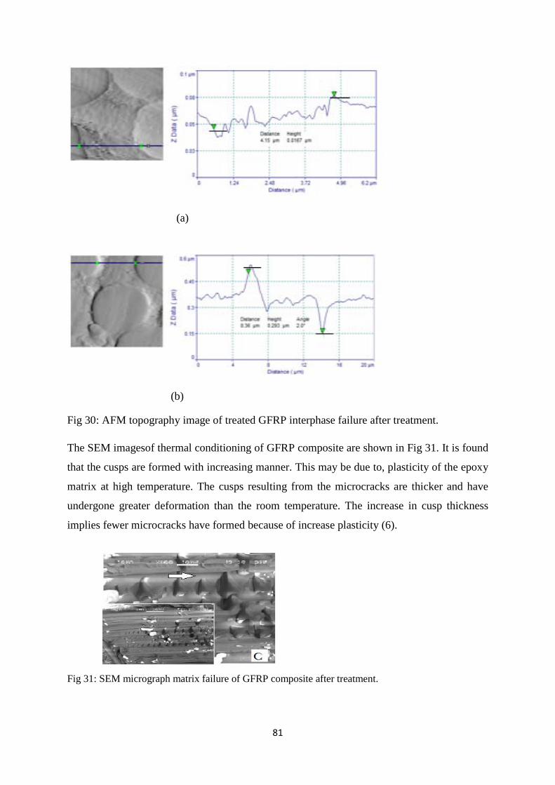
81
(a)
(b)
Fig 30: AFM topography image of treated GFRP interphase failure after treatment.
The SEM imagesof thermal conditioning of GFRP composite are shown in Fig 31. It is found
that the cusps are formed with increasing manner. This may be due to, plasticity of the epoxy
matrix at high temperature. The cusps resulting from the microcracks are thicker and have
undergone greater deformation than the room temperature. The increase in cusp thickness
implies fewer microcracks have formed because of increase plasticity (6).
Fig 31: SEM micrograph matrix failure of GFRP composite after treatment.
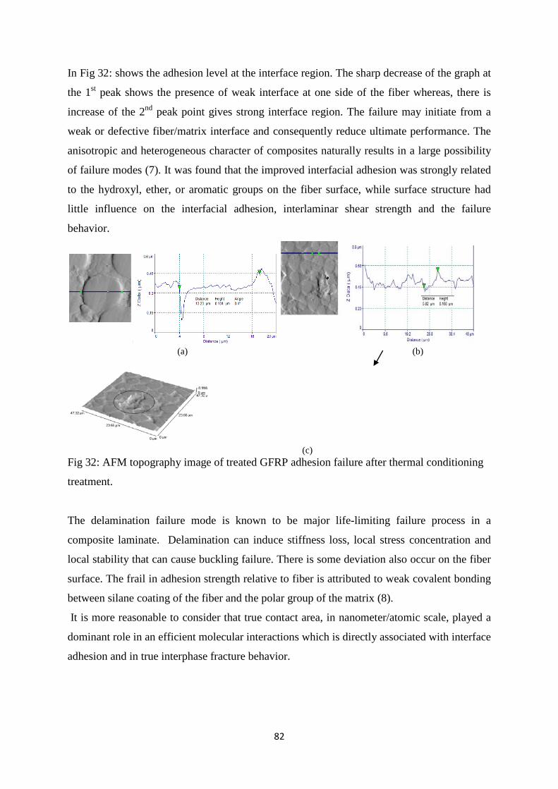
82
In Fig 32: shows the adhesion level at the interface region. The sharp decrease of the graph at
the 1st peak shows the presence of weak interface at one side of the fiber whereas, there is
increase of the 2nd peak point gives strong interface region. The failure may initiate from a
weak or defective fiber/matrix interface and consequently reduce ultimate performance. The
anisotropic and heterogeneous character of composites naturally results in a large possibility
of failure modes (7). It was found that the improved interfacial adhesion was strongly related
to the hydroxyl, ether, or aromatic groups on the fiber surface, while surface structure had
little influence on the interfacial adhesion, interlaminar shear strength and the failure
behavior.
(a) (b)
(c) Fig 32: AFM topography image of treated GFRP adhesion failure after thermal conditioning
treatment.
The delamination failure mode is known to be major life-limiting failure process in a
composite laminate. Delamination can induce stiffness loss, local stress concentration and
local stability that can cause buckling failure. There is some deviation also occur on the fiber
surface. The frail in adhesion strength relative to fiber is attributed to weak covalent bonding
between silane coating of the fiber and the polar group of the matrix (8).
It is more reasonable to consider that true contact area, in nanometer/atomic scale, played a
dominant role in an efficient molecular interactions which is directly associated with interface
adhesion and in true interphase fracture behavior.
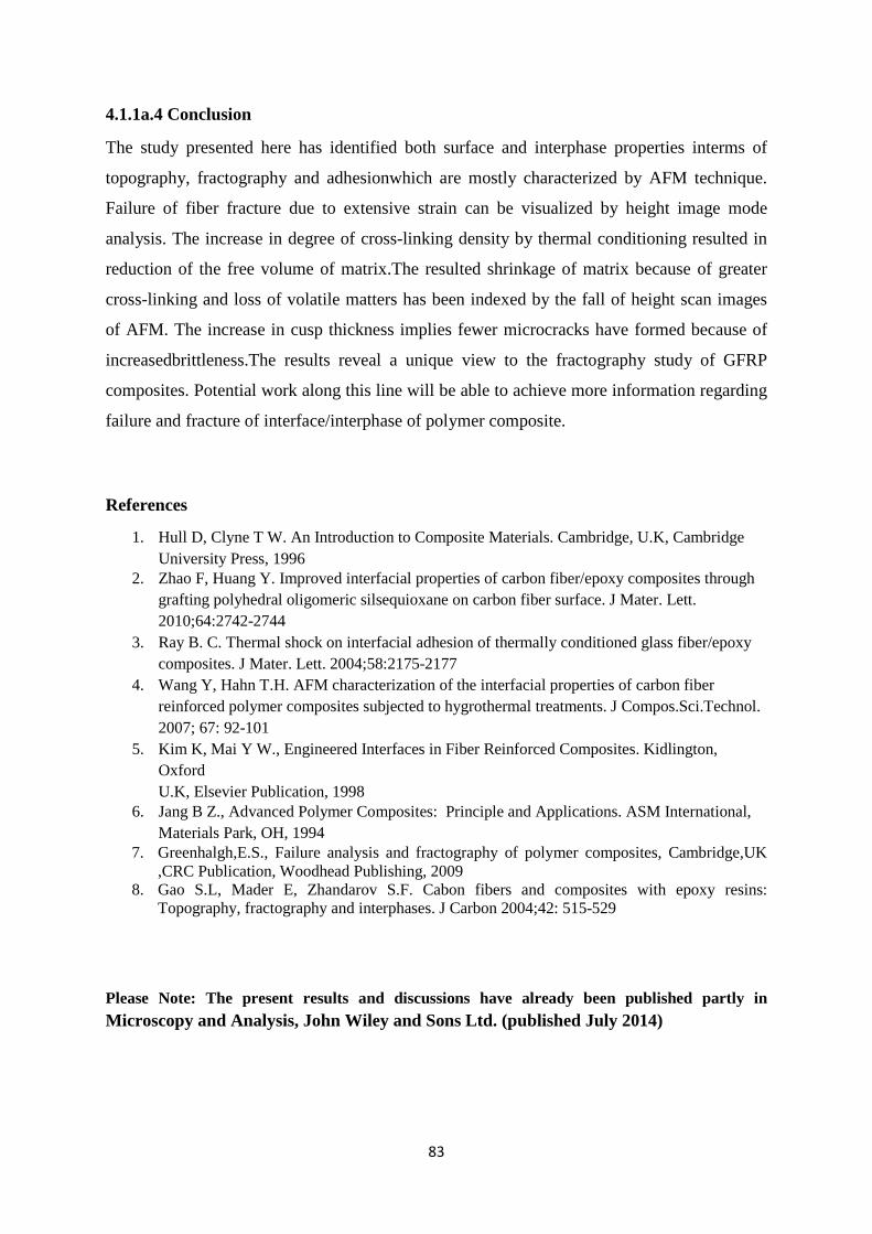
83
4.1.1a.4 Conclusion
The study presented here has identified both surface and interphase properties interms of
topography, fractography and adhesionwhich are mostly characterized by AFM technique.
Failure of fiber fracture due to extensive strain can be visualized by height image mode
analysis. The increase in degree of cross-linking density by thermal conditioning resulted in
reduction of the free volume of matrix.The resulted shrinkage of matrix because of greater
cross-linking and loss of volatile matters has been indexed by the fall of height scan images
of AFM. The increase in cusp thickness implies fewer microcracks have formed because of
increasedbrittleness.The results reveal a unique view to the fractography study of GFRP
composites. Potential work along this line will be able to achieve more information regarding
failure and fracture of interface/interphase of polymer composite.
References
1. Hull D, Clyne T W. An Introduction to Composite Materials. Cambridge, U.K, Cambridge University Press, 1996
2. Zhao F, Huang Y. Improved interfacial properties of carbon fiber/epoxy composites through grafting polyhedral oligomeric silsequioxane on carbon fiber surface. J Mater. Lett. 2010;64:2742-2744
3. Ray B. C. Thermal shock on interfacial adhesion of thermally conditioned glass fiber/epoxy composites. J Mater. Lett. 2004;58:2175-2177
4. Wang Y, Hahn T.H. AFM characterization of the interfacial properties of carbon fiber reinforced polymer composites subjected to hygrothermal treatments. J Compos.Sci.Technol. 2007; 67: 92-101
5. Kim K, Mai Y W., Engineered Interfaces in Fiber Reinforced Composites. Kidlington, Oxford U.K, Elsevier Publication, 1998
6. Jang B Z., Advanced Polymer Composites: Principle and Applications. ASM International, Materials Park, OH, 1994
7. Greenhalgh,E.S., Failure analysis and fractography of polymer composites, Cambridge,UK ,CRC Publication, Woodhead Publishing, 2009
8. Gao S.L, Mader E, Zhandarov S.F. Cabon fibers and composites with epoxy resins: Topography, fractography and interphases. J Carbon 2004;42: 515-529
Please Note: The present results and discussions have already been published partly in Microscopy and Analysis, John Wiley and Sons Ltd. (published July 2014)
84
4.1.1b Effect of above ambient and below-ambient temperature on FRP composite materials with different loading rates.
Theories and Thoughts The present investigation intends to study the influence of crosshead velocity and in-situ
environmental conditioning i.e. high temperature and cryogenic temperature on
micromechanical performance of glass fiber/epoxy, carbon fiber/epoxy and Kevlar
fiber/epoxy polymer composites. 3-point short beam shear tests were conducted on the
conditioned specimens to evaluate the interfacial properties and failure modes which are
related to mechanical properties of the composites. The effect of crosshead velocity (within
the range 1-103 mm/min) on the interlaminar shear strength (ILSS) of all the three composite
systems at different temperatures was studied. The glass transition temperature (Tg) of
conditioned samples were measured by differential scanning calorimetry (DSC) in the
temperature range of 25°C to 150°C temperature. At 1 mm/min loading rate, for both
glass/epoxy and carbon/epoxy composites maximum increase in ILSS value was about
85.72% with respect to ambient, while for kevlar/epoxy composite 31.77% reduction in ILSS
was observed at -100°C temperature.
4.1.1b.1 Introduction
In present century, fibre-polymer composites are the promising and reliable materials in
different high performance and structural applications. Their superlative properties such as
high specific strength and stiffness, high fatigue endurance, good corrosion and abrasion
resistance, make them prime choice material in various industries such as aerospace, marine
and automotive[1]. During their manufacturing and service periods the materials are exposed
to various environments and loading conditions. The performance of these materials is
governed by the response of their constituents i.e. fibre, matrix and the existing
interface/interphase, in that particular environment. The sizing of fibres generally influences
the chemistry and character of the interface/interphase and might generate structural gradient
in the polymer matrix. Their susceptibilities to degradation are dependent on nature of
environments and each of the constituent’s responses differently and uniquely. Among the
three constituents, the interface/interphase has very critical role to play on the performance
and reliability of fibre reinforced polymer (FRP) composites [2].Under low temperature
environment or cycling from room temperature to low temperature with applying loads
microcracks may generate and propagate in the polymer matrix and/or at the fibre/matrix
interface [3].Various structural damages such as fiber/matrix int erfacial debonding and
85
potholing or delamination result in degradation of mechanical properties of FRP composites
[4]. Cryogenic conditioning stimulates the formation of rows of cups due to coalesce of
transverse microcracks that originate longitudinal cracks along the fibre. Potholing or
localized surface degradation, micro cracking and delamination, are some of the more
dramatic phenomena that can occur as a result of cryogenic cycling. At elevated temperature
differential thermal expansion of fibre and matrix may leads to the formation of microcracks
at the fibre/polymer interface [5].The fibre matrix interface also becomes susceptible to
aggressive reactions under the exposure of high temperature environment, which can leads
to degradation of both the fibres and the matrix.
Interlaminar shear strength is one of the most important mechanical properties of laminated
composite which is also an indicative of fibre/matrix interfacial bond strength if all the other
parameters are remains constant. Three point short beam shear test can be used to
qualitatively evaluate apparent interlaminar shear strength of the laminated composites [6].
For short beam shear test, it is assumed that the specimen is subjected to pure shear loading
but the effects of stress concentration cannot be eliminated completely. In a short-beam test,
the low span-to-thickness ratio (typically, L / h = 4 or 5) minimizes bending stresses, allowing
through-thickness shear stresses to dominate, and promoting interlaminar shear failure at the
neutral plane [7].For a valid short beam shear test the specimen should fail under
delamination mode through mid-plane, but due to the effects of stress concentration and
material constraints, the origin of delamination may shift from the mid-plane to either upper
or lower interlaminar planes. Further the variation of loading rate makes the stress
distribution more complex and the failure of the composite includes various damage modes
separately and/or interactively. Since the fibres are usually much stronger than the
matrix, one may postulate fibre/matrix debonding and matrix failure as the two primary
mechanisms of failure initiation [8]. Delamination and matrix cracks are intrinsically
associated in the composite materials primarily under bending loads. Further, the interaction
between these two damage modes constitutes a complex damage mechanism that has not
been addressed at a realistic level [9]. One of the most frequent damage mechanisms is the
delamination between the adjacent plies of the laminate. Many FRP composite components
have tapered thickness, curved shapes, and plies with different orientations, which will also
make the delamination grow with a mode mix that depends on the extent of the crack. Thus,
delaminations generally grow in mixed-mode [10]. The toughest challenge faced by material
scientists is to assess and ascertain its behavioural log in a range of loading rates. The
86
heterogeneity and responses of multiple distinct phases to varying loading conditions are
most often complex and far away from comprehensive conclusion. The less substantial
durability data related to the loading rate sensitivity of FRPs in conjunction with
environmental exposures has created more confusion in using high factors of safety, and thus
led to increased cost and weight of the composites [11, 12]. The endurance on durability and
tailorability is most often underrated. Continuous crack growth usually occurs at low
temperature and high strain rates, which promotes the brittle failure of the polymeric
composite materials.
The rapid advancement of these fibre-polymer composites outstripped the understanding of
appropriate failure analysis techniques. Researchers have investigated the interlaminar shear
strength response of fibre-polymer composites at different environmental conditionings.
Interlaminar shear strength of unidirectional graphite composites were decreased by 30 %
under the exposure of elevated temperature [13]. Investigations on CFRP and GFRP sheets,
which are exposed to 600 °C reported, that the residual tensile strength and stiffness severely
degraded when the composite is exposed to a temperature, higher than the decomposition
temperature of polymer resin and further increase in environmental temperature would not
lead any further reduction in the aforesaid properties [14,15]. Effect of thermal environment
on the residual mechanical performance of graphite-fabric epoxy composite was evaluated
for constant 170°C temperature for 120, 240 and 626 h prior to flexural testing [16].
Unidirectional CFRP composite that had been aged at -196 ˚C for 555 h with half of the
failure load undergone about 20% degradation in tensile strength compared to that at room
temperature [17]. Some studies on strain rate sensitivity of glass/epoxy, carbon/epoxy, and
kevlar/epoxy composite systems have been shown that the mechanical behaviour of these
systems is strain rate sensitive [18-23]. Shokrieh et al. studied the in-plane shear failure
properties of unidirectional glass/epoxy composites at various stroke rates from 0.0216 to
1270 mm/s [24]. The dynamic shear strength response showed an increase of approximately
37% over the measured quasi-static value. Al-Salehi et al. obtained the lamina in-plane shear
properties at various rates of strain on glass/epoxy and Kevlar/epoxy filament wound tubes
with winding angles ±55° and ±65°, under internal hoop loading [25]. The results obtained
from ±55° specimens indicated that with increasing strain rate from 1 to 400s-1, the shear
strength is increased by 70% for glass/epoxy, and 115% for Kevlar/epoxy materials. There is
significant amount of literature available on the effects of temperature on mechanical
properties of FRP composites but according to author’s knowledge scarcely information
87
regarding the effects of temperatures on interfacial behavior (ILSS) in polymeric composites
at different loading rates and temperature has been published to date.
The aim of the present study is to provide in-depth analysis of interlaminar shear test and
failure mechanisms of glass fibre/epoxy, carbon fibre/epoxy and Kevlar fibre/epoxy
composites under different temperatures and crosshead velocity. Different high and low
temperature conditioning were performed using Instron with environmental chamber
providing additional information regarding in-situ failure of laminate composites. Following
the test, the fracture surfaces of the samples were scanned under SEM to understand the
dominating failure modes. Microstructural assessments can also reveal the response of each
constituent viz. fibre, matrix resin and the interface/interphase; under temperature and
mechanical loading. This paper comprehensively presents the mechanical behaviour and
structural changes in fibrous polymeric composite systems during the mechanical loading
under high and low temperature service environment.
4.1.1b.2 Materials and Experimental Methods
4.1.1b.2.1 Materials
Present investigation includes three types of woven fabric reinforcement in epoxy resin i.e.
glass fibres, carbon fibres and, kevlar fibres. The epoxy resin used is diglycidyl ether of
Bisphenol A (DGEBA) and the hardener is Triethylene tetra amine (TETA) supplied by Atul
Industries Ltd, Gujarat, India under the trade name Lapox, L-12 and K-6 respectively.Some
properties of these reinforcements and epoxy resin used in the study are provided in the table-
1. The volume fraction of fibres is 60%. The ratio of epoxy and hardener is taken as10:1. The
laminated composites has been prepared by hand lay-up method with 16 layers of woven
fabric cloth of reinforcement and then placed in a hot press. Then the curing of the laminate
has been carried out at 60°C temperature and 20 kg/cm2 pressure for 20 minutes. The
laminates were then removed from the press and kept at room temperature for 24 hours. The
test specimens have been cut from the laminates using diamond tipped cutter as per standard.
4.1.1b.2.2 Experimental methods
3-point Short-beam shear test The Short-beam shear tests are frequently applied to polymeric composite materials to
evaluate the apparent interlaminar shear strength of the composite system. A testing machine
with controllable crosshead speed is used in conjunction with a three-point loading fixture.
The shear stress induced in a beam subjected to a bending load, is directly proportional to the
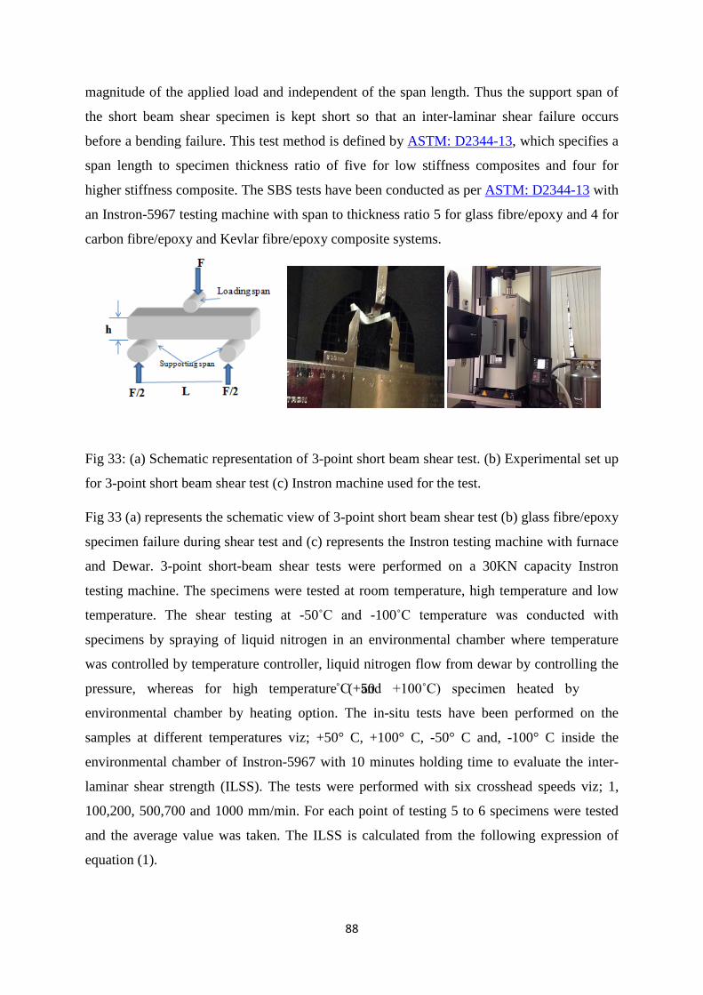
88
magnitude of the applied load and independent of the span length. Thus the support span of
the short beam shear specimen is kept short so that an inter-laminar shear failure occurs
before a bending failure. This test method is defined by ASTM: D2344-13, which specifies a
span length to specimen thickness ratio of five for low stiffness composites and four for
higher stiffness composite. The SBS tests have been conducted as per ASTM: D2344-13 with
an Instron-5967 testing machine with span to thickness ratio 5 for glass fibre/epoxy and 4 for
carbon fibre/epoxy and Kevlar fibre/epoxy composite systems.
Fig 33: (a) Schematic representation of 3-point short beam shear test. (b) Experimental set up
for 3-point short beam shear test (c) Instron machine used for the test.
Fig 33 (a) represents the schematic view of 3-point short beam shear test (b) glass fibre/epoxy
specimen failure during shear test and (c) represents the Instron testing machine with furnace
and Dewar. 3-point short-beam shear tests were performed on a 30KN capacity Instron
testing machine. The specimens were tested at room temperature, high temperature and low
temperature. The shear testing at -50˚C and -100˚C temperature was conducted with
specimens by spraying of liquid nitrogen in an environmental chamber where temperature
was controlled by temperature controller, liquid nitrogen flow from dewar by controlling the
pressure, whereas for high temperature (+50˚C and +100˚C) specimen heated by
environmental chamber by heating option. The in-situ tests have been performed on the
samples at different temperatures viz; +50° C, +100° C, -50° C and, -100° C inside the
environmental chamber of Instron-5967 with 10 minutes holding time to evaluate the inter-
laminar shear strength (ILSS). The tests were performed with six crosshead speeds viz; 1,
100,200, 500,700 and 1000 mm/min. For each point of testing 5 to 6 specimens were tested
and the average value was taken. The ILSS is calculated from the following expression of
equation (1).
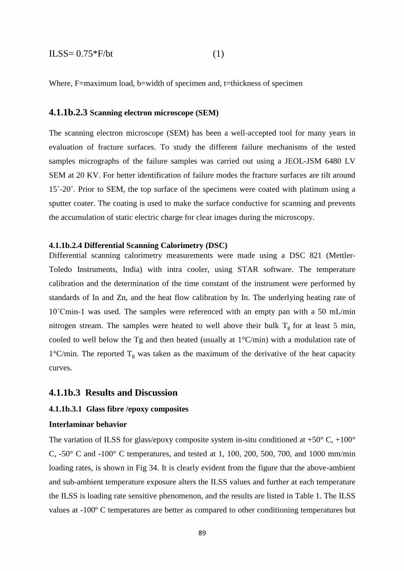
89
ILSS= 0.75*F/bt (1)
Where, F=maximum load, b=width of specimen and, t=thickness of specimen
4.1.1b.2.3 Scanning electron microscope (SEM) The scanning electron microscope (SEM) has been a well-accepted tool for many years in
evaluation of fracture surfaces. To study the different failure mechanisms of the tested
samples micrographs of the failure samples was carried out using a JEOL-JSM 6480 LV
SEM at 20 KV. For better identification of failure modes the fracture surfaces are tilt around
15˚-20˚. Prior to SEM, the top surface of the specimens were coated with platinum using a
sputter coater. The coating is used to make the surface conductive for scanning and prevents
the accumulation of static electric charge for clear images during the microscopy.
4.1.1b.2.4 Differential Scanning Calorimetry (DSC) Differential scanning calorimetry measurements were made using a DSC 821 (Mettler-
Toledo Instruments, India) with intra cooler, using STAR software. The temperature
calibration and the determination of the time constant of the instrument were performed by
standards of In and Zn, and the heat flow calibration by In. The underlying heating rate of
10˚Cmin-1 was used. The samples were referenced with an empty pan with a 50 mL/min
nitrogen stream. The samples were heated to well above their bulk Tg for at least 5 min,
cooled to well below the Tg and then heated (usually at 1°C/min) with a modulation rate of
1°C/min. The reported Tg was taken as the maximum of the derivative of the heat capacity
curves.
4.1.1b.3 Results and Discussion
4.1.1b.3.1 Glass fibre /epoxy composites
Interlaminar behavior
The variation of ILSS for glass/epoxy composite system in-situ conditioned at +50° C, +100°
C, -50° C and -100° C temperatures, and tested at 1, 100, 200, 500, 700, and 1000 mm/min
loading rates, is shown in Fig 34. It is clearly evident from the figure that the above-ambient
and sub-ambient temperature exposure alters the ILSS values and further at each temperature
the ILSS is loading rate sensitive phenomenon, and the results are listed in Table 1. The ILSS
values at -100º C temperatures are better as compared to other conditioning temperatures but
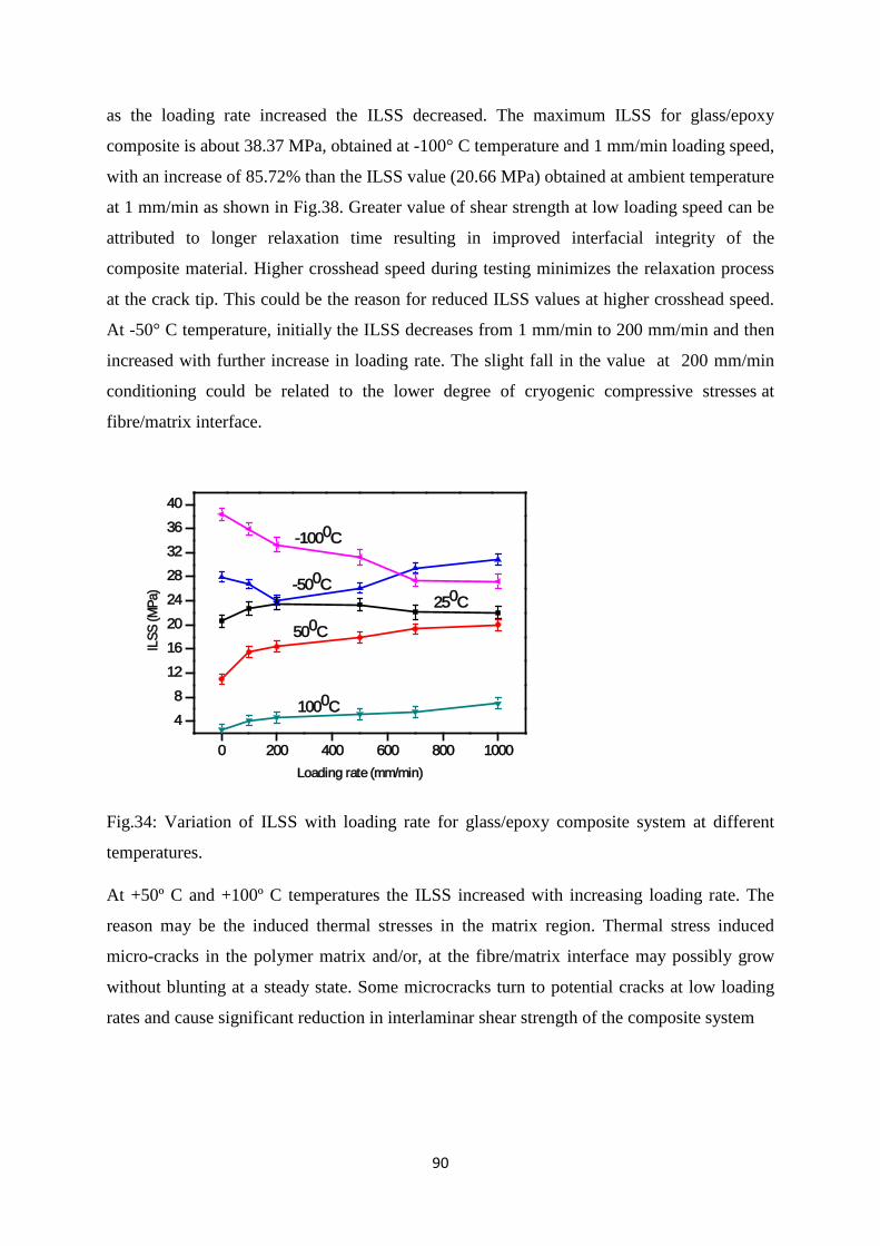
90
as the loading rate increased the ILSS decreased. The maximum ILSS for glass/epoxy
composite is about 38.37 MPa, obtained at -100° C temperature and 1 mm/min loading speed,
with an increase of 85.72% than the ILSS value (20.66 MPa) obtained at ambient temperature
at 1 mm/min as shown in Fig.38. Greater value of shear strength at low loading speed can be
attributed to longer relaxation time resulting in improved interfacial integrity of the
composite material. Higher crosshead speed during testing minimizes the relaxation process
at the crack tip. This could be the reason for reduced ILSS values at higher crosshead speed.
At -50° C temperature, initially the ILSS decreases from 1 mm/min to 200 mm/min and then
increased with further increase in loading rate. The slight fall in the value at 200 mm/min
conditioning could be related to the lower degree of cryogenic compressive stresses at
fibre/matrix interface.
0 200 400 600 800 1000
4
8
12
16
20
24
28
32
36
40
ILSS
(MPa
)
Loading rate (mm/min)
250C
500C
-500C
1000C
-1000C
Fig.34: Variation of ILSS with loading rate for glass/epoxy composite system at different
temperatures.
At +50º C and +100º C temperatures the ILSS increased with increasing loading rate. The
reason may be the induced thermal stresses in the matrix region. Thermal stress induced
micro-cracks in the polymer matrix and/or, at the fibre/matrix interface may possibly grow
without blunting at a steady state. Some microcracks turn to potential cracks at low loading
rates and cause significant reduction in interlaminar shear strength of the composite system
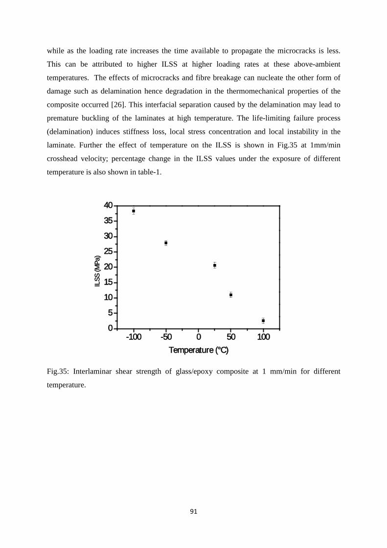
91
while as the loading rate increases the time available to propagate the microcracks is less.
This can be attributed to higher ILSS at higher loading rates at these above-ambient
temperatures. The effects of microcracks and fibre breakage can nucleate the other form of
damage such as delamination hence degradation in the thermomechanical properties of the
composite occurred [26]. This interfacial separation caused by the delamination may lead to
premature buckling of the laminates at high temperature. The life-limiting failure process
(delamination) induces stiffness loss, local stress concentration and local instability in the
laminate. Further the effect of temperature on the ILSS is shown in Fig.35 at 1mm/min
crosshead velocity; percentage change in the ILSS values under the exposure of different
temperature is also shown in table-1.
-100 -50 0 50 1000
5
10
15
20
25
30
35
40
ILSS
(MPa
)
Temperature (°C)
Fig.35: Interlaminar shear strength of glass/epoxy composite at 1 mm/min for different
temperature.
92
Table-1: Percentage change in ILSS with temperatures at 1 mm/min.
Failure fractography
To better comprehend the interfacial behavior and failure mechanisms of above ambient and
sub ambient conditioned glass fibre/epoxy composites, the fracture surfaces after short beam
shear tests have been examined by scanning electron microscopy (SEM). SEM micrographs
of fracture surfaces are shown in Fig 36. The fracture surface of matrix at -100° C (Fig. 36 A,
A’) includes extensive riverline markings and fibre imprints. The convergence of pairs of
planes from the tributaries of the rivers into one crack, form a trace markings known as river
lines. Therefore the direction of crack growth is the direction in which riverlines converge.
As multiple crack initiation and growth of riverlines shown in Fig 36 A. In Fig. 36A’ fibre
imprint refers to fibre matrix debonding. Here we also observed delamination failure modes
on the laminate. At -50° C a significant difference in interfacial microstructure is observed
which is shown in Fig. 36B, B’. The appearance of the cusps at relatively high magnification;
cusps size is similar to that of the fibre spacing. However, the size of cusps is larger than
particularly those which develop with in resin rich regions. These failures do not display a
complete fibre matrix debonding from the fibre surface [27]. At high temperature, the resin
exhibits greater plasticity, and cusps resulting from the microcracks are thicker and
undergone greater deformation than at room temperature as shown in fig.36C, C’ and Fig.36
Material Loading speed
Testing temperature(°C)
ILSS (MPa)
Change in (%)
Glass fibre reinforced polymer composites
(GFRP)
1mm/min
25 20.66
+50 11.0 46.75( )
+100 2.63 87.27 ( )
-50 27.94 35.23 ( )
-100 38.37 85.72 ( )
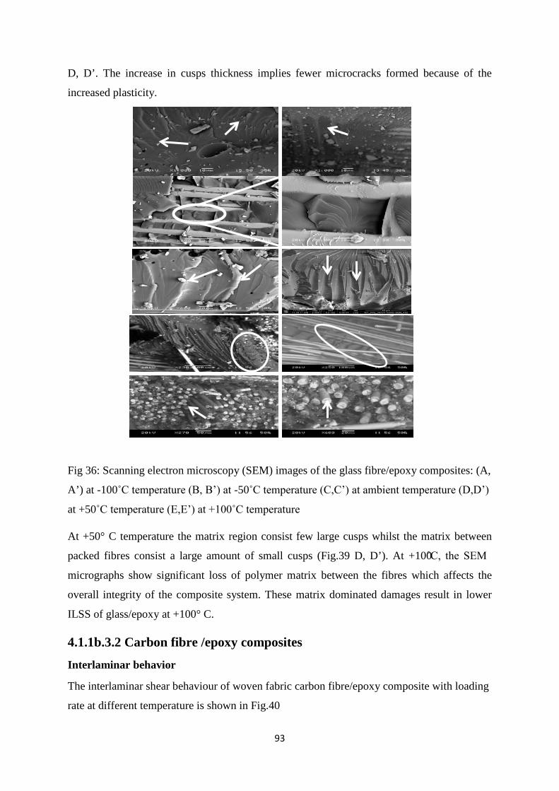
93
D, D’. The increase in cusps thickness implies fewer microcracks formed because of the
increased plasticity.
Fig 36: Scanning electron microscopy (SEM) images of the glass fibre/epoxy composites: (A,
A’) at -100˚C temperature (B, B’) at -50˚C temperature (C,C’) at ambient temperature (D,D’)
at +50˚C temperature (E,E’) at +100˚C temperature
At +50° C temperature the matrix region consist few large cusps whilst the matrix between
packed fibres consist a large amount of small cusps (Fig.39 D, D’). At +100̊C, the SEM
micrographs show significant loss of polymer matrix between the fibres which affects the
overall integrity of the composite system. These matrix dominated damages result in lower
ILSS of glass/epoxy at +100° C.
4.1.1b.3.2 Carbon fibre /epoxy composites
Interlaminar behavior The interlaminar shear behaviour of woven fabric carbon fibre/epoxy composite with loading
rate at different temperature is shown in Fig.40
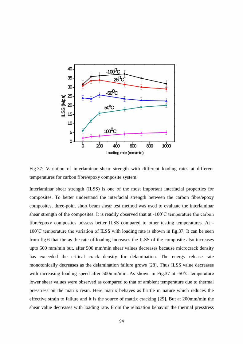
94
0 200 400 600 800 10000
5
10
15
20
25
30
35
40IL
SS (M
pa)
Loading rate (mm/min)
-1000C250C
500C
-500C
1000C
Fig.37: Variation of interlaminar shear strength with different loading rates at different
temperatures for carbon fibre/epoxy composite system.
Interlaminar shear strength (ILSS) is one of the most important interfacial properties for
composites. To better understand the interfacial strength between the carbon fibre/epoxy
composites, three-point short beam shear test method was used to evaluate the interlaminar
shear strength of the composites. It is readily observed that at -100˚C temperature the carbon
fibre/epoxy composites possess better ILSS compared to other testing temperatures. At -
100˚C temperature the variation of ILSS with loading rate is shown in fig.37. It can be seen
from fig.6 that the as the rate of loading increases the ILSS of the composite also increases
upto 500 mm/min but, after 500 mm/min shear values decreases because microcrack density
has exceeded the critical crack density for delamination. The energy release rate
monotonically decreases as the delamination failure grows [28]. Thus ILSS value decreases
with increasing loading speed after 500mm/min. As shown in Fig.37 at -50˚C temperature
lower shear values were observed as compared to that of ambient temperature due to thermal
presstress on the matrix resin. Here matrix behaves as brittle in nature which reduces the
effective strain to failure and it is the source of matrix cracking [29]. But at 200mm/min the
shear value decreases with loading rate. From the relaxation behavior the thermal presstress
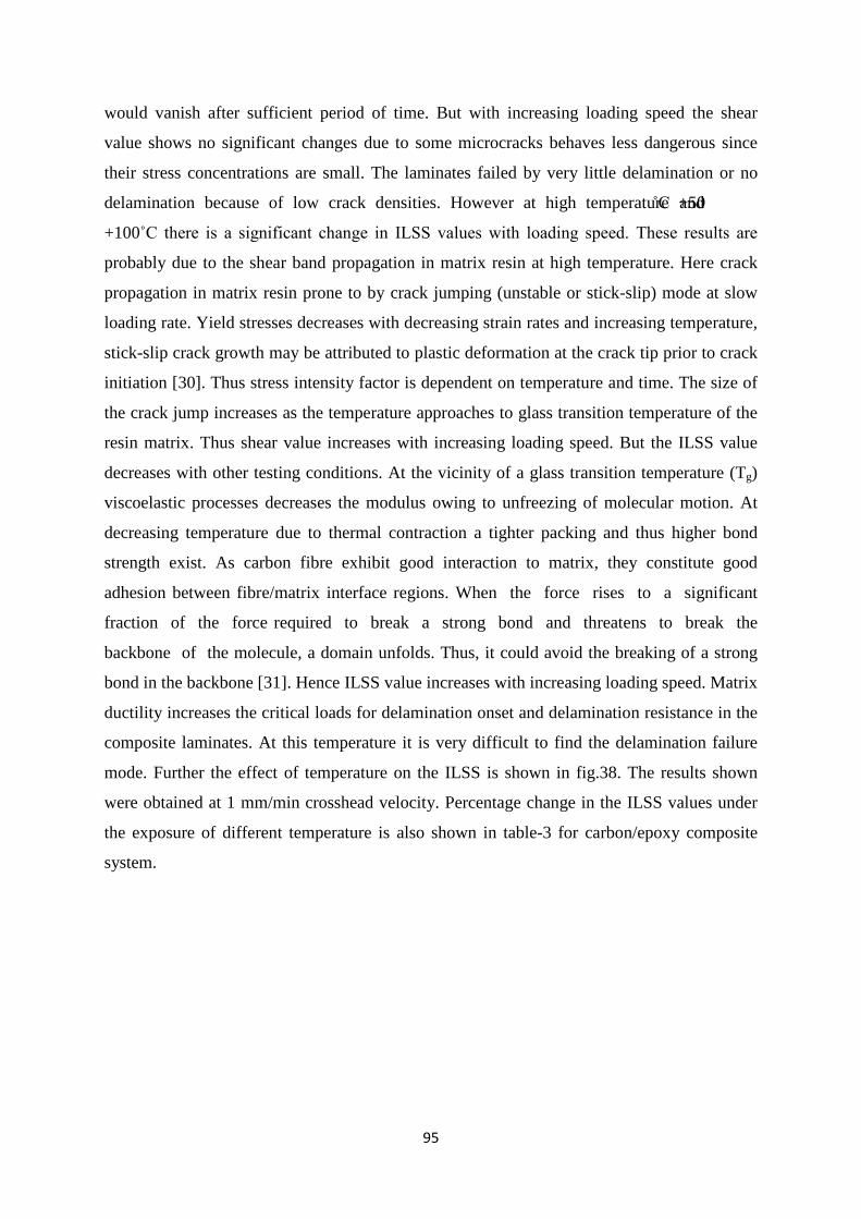
95
would vanish after sufficient period of time. But with increasing loading speed the shear
value shows no significant changes due to some microcracks behaves less dangerous since
their stress concentrations are small. The laminates failed by very little delamination or no
delamination because of low crack densities. However at high temperature +50˚C and
+100˚C there is a significant change in ILSS values with loading speed. These results are
probably due to the shear band propagation in matrix resin at high temperature. Here crack
propagation in matrix resin prone to by crack jumping (unstable or stick-slip) mode at slow
loading rate. Yield stresses decreases with decreasing strain rates and increasing temperature,
stick-slip crack growth may be attributed to plastic deformation at the crack tip prior to crack
initiation [30]. Thus stress intensity factor is dependent on temperature and time. The size of
the crack jump increases as the temperature approaches to glass transition temperature of the
resin matrix. Thus shear value increases with increasing loading speed. But the ILSS value
decreases with other testing conditions. At the vicinity of a glass transition temperature (Tg)
viscoelastic processes decreases the modulus owing to unfreezing of molecular motion. At
decreasing temperature due to thermal contraction a tighter packing and thus higher bond
strength exist. As carbon fibre exhibit good interaction to matrix, they constitute good
adhesion between fibre/matrix interface regions. When the force rises to a significant
fraction of the force required to break a strong bond and threatens to break the
backbone of the molecule, a domain unfolds. Thus, it could avoid the breaking of a strong
bond in the backbone [31]. Hence ILSS value increases with increasing loading speed. Matrix
ductility increases the critical loads for delamination onset and delamination resistance in the
composite laminates. At this temperature it is very difficult to find the delamination failure
mode. Further the effect of temperature on the ILSS is shown in fig.38. The results shown
were obtained at 1 mm/min crosshead velocity. Percentage change in the ILSS values under
the exposure of different temperature is also shown in table-3 for carbon/epoxy composite
system.
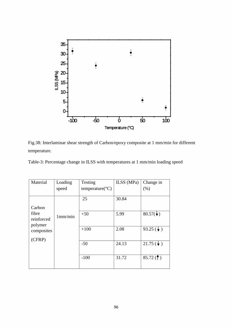
96
-100 -50 0 50 100
0
5
10
15
20
25
30
35
ILSS
(MPa
)
Temperature (°C)
Fig.38: Interlaminar shear strength of Carbon/epoxy composite at 1 mm/min for different
temperature.
Table-3: Percentage change in ILSS with temperatures at 1 mm/min loading speed
Material Loading speed
Testing temperature(°C)
ILSS (MPa) Change in (%)
Carbon fibre reinforced polymer composites
(CFRP)
1mm/min
25 30.84
+50 5.99 80.57( )
+100 2.08 93.25 ( )
-50 24.13 21.75 ( )
-100 31.72 85.72 ( )
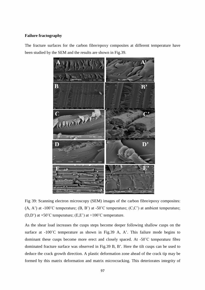
97
Failure fractography
The fracture surfaces for the carbon fibre/epoxy composites at different temperature have
been studied by the SEM and the results are shown in Fig.39.
Fig 39: Scanning electron microscopy (SEM) images of the carbon fibre/epoxy composites:
(A, A’) at -100˚C temperature; (B, B’) at -50˚C temperature; (C,C’) at ambient temperature;
(D,D’) at +50˚C temperature; (E,E’) at +100˚C temperature.
As the shear load increases the cusps steps become deeper following shallow cusps on the
surface at -100˚C temperature as shown in Fig.39 A, A’. This failure mode begins to
dominant these cusps become more erect and closely spaced. At -50˚C temperature fibre
dominated fracture surface was observed in Fig.39 B, B’. Here the tilt cusps can be used to
deduce the crack growth direction. A plastic deformation zone ahead of the crack tip may be
formed by this matrix deformation and matrix microcracking. This deteriorates integrity of
B’
A A’
B
C C’
D D’
E E’
B’
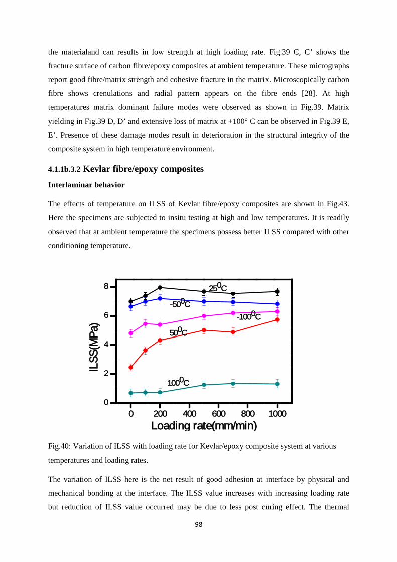
98
the materialand can results in low strength at high loading rate. Fig.39 C, C’ shows the
fracture surface of carbon fibre/epoxy composites at ambient temperature. These micrographs
report good fibre/matrix strength and cohesive fracture in the matrix. Microscopically carbon
fibre shows crenulations and radial pattern appears on the fibre ends [28]. At high
temperatures matrix dominant failure modes were observed as shown in Fig.39. Matrix
yielding in Fig.39 D, D’ and extensive loss of matrix at +100° C can be observed in Fig.39 E,
E’. Presence of these damage modes result in deterioration in the structural integrity of the
composite system in high temperature environment.
4.1.1b.3.2 Kevlar fibre/epoxy composites
Interlaminar behavior
The effects of temperature on ILSS of Kevlar fibre/epoxy composites are shown in Fig.43.
Here the specimens are subjected to insitu testing at high and low temperatures. It is readily
observed that at ambient temperature the specimens possess better ILSS compared with other
conditioning temperature.
0 200 400 600 800 10000
2
4
6
8
ILSS
(MPa
)
Loading rate(mm/min)
250C
500C
-500C-1000C
1000C
Fig.40: Variation of ILSS with loading rate for Kevlar/epoxy composite system at various
temperatures and loading rates.
The variation of ILSS here is the net result of good adhesion at interface by physical and
mechanical bonding at the interface. The ILSS value increases with increasing loading rate
but reduction of ILSS value occurred may be due to less post curing effect. The thermal
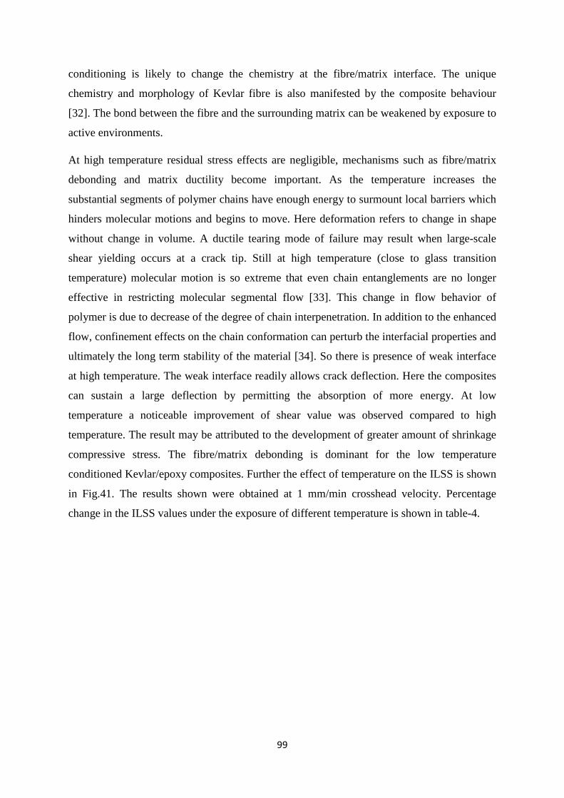
99
conditioning is likely to change the chemistry at the fibre/matrix interface. The unique
chemistry and morphology of Kevlar fibre is also manifested by the composite behaviour
[32]. The bond between the fibre and the surrounding matrix can be weakened by exposure to
active environments.
At high temperature residual stress effects are negligible, mechanisms such as fibre/matrix
debonding and matrix ductility become important. As the temperature increases the
substantial segments of polymer chains have enough energy to surmount local barriers which
hinders molecular motions and begins to move. Here deformation refers to change in shape
without change in volume. A ductile tearing mode of failure may result when large-scale
shear yielding occurs at a crack tip. Still at high temperature (close to glass transition
temperature) molecular motion is so extreme that even chain entanglements are no longer
effective in restricting molecular segmental flow [33]. This change in flow behavior of
polymer is due to decrease of the degree of chain interpenetration. In addition to the enhanced
flow, confinement effects on the chain conformation can perturb the interfacial properties and
ultimately the long term stability of the material [34]. So there is presence of weak interface
at high temperature. The weak interface readily allows crack deflection. Here the composites
can sustain a large deflection by permitting the absorption of more energy. At low
temperature a noticeable improvement of shear value was observed compared to high
temperature. The result may be attributed to the development of greater amount of shrinkage
compressive stress. The fibre/matrix debonding is dominant for the low temperature
conditioned Kevlar/epoxy composites. Further the effect of temperature on the ILSS is shown
in Fig.41. The results shown were obtained at 1 mm/min crosshead velocity. Percentage
change in the ILSS values under the exposure of different temperature is shown in table-4.
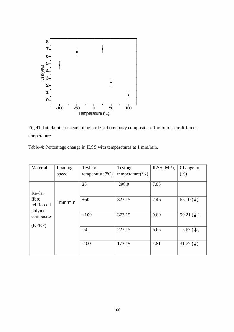
100
-100 -50 0 50 100
0
1
2
3
4
5
6
7
8IL
SS (M
Pa)
Temperature (oC)
Fig.41: Interlaminar shear strength of Carbon/epoxy composite at 1 mm/min for different
temperature.
Table-4: Percentage change in ILSS with temperatures at 1 mm/min.
Material Loading speed
Testing temperature(°C)
Testing temperature(°K)
ILSS (MPa) Change in (%)
Kevlar fibre reinforced polymer composites
(KFRP)
1mm/min
25 298.0 7.05
+50 323.15 2.46 65.10 ( )
+100 373.15 0.69 90.21 ( )
-50 223.15 6.65 5.67 ( )
-100 173.15 4.81 31.77 ( )
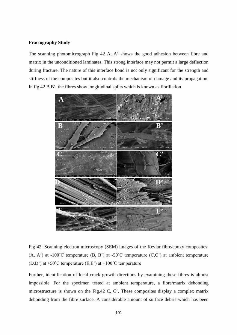
101
Fractography Study
The scanning photomicrograph Fig 42 A, A’ shows the good adhesion between fibre and
matrix in the unconditioned laminates. This strong interface may not permit a large deflection
during fracture. The nature of this interface bond is not only significant for the strength and
stiffness of the composites but it also controls the mechanism of damage and its propagation.
In fig 42 B.B’, the fibres show longitudinal splits which is known as fibrillation.
Fig 42: Scanning electron microscopy (SEM) images of the Kevlar fibre/epoxy composites:
(A, A’) at -100˚C temperature (B, B’) at -50˚C temperature (C,C’) at ambient temperature
(D,D’) at +50˚C temperature (E,E’) at +100˚C temperature
Further, identification of local crack growth directions by examining these fibres is almost
impossible. For the specimen tested at ambient temperature, a fibre/matrix debonding
microstructure is shown on the Fig.42 C, C’. These composites display a complex matrix
debonding from the fibre surface. A considerable amount of surface debris which has been
A A’
B B’
C C’
D D’
E E’
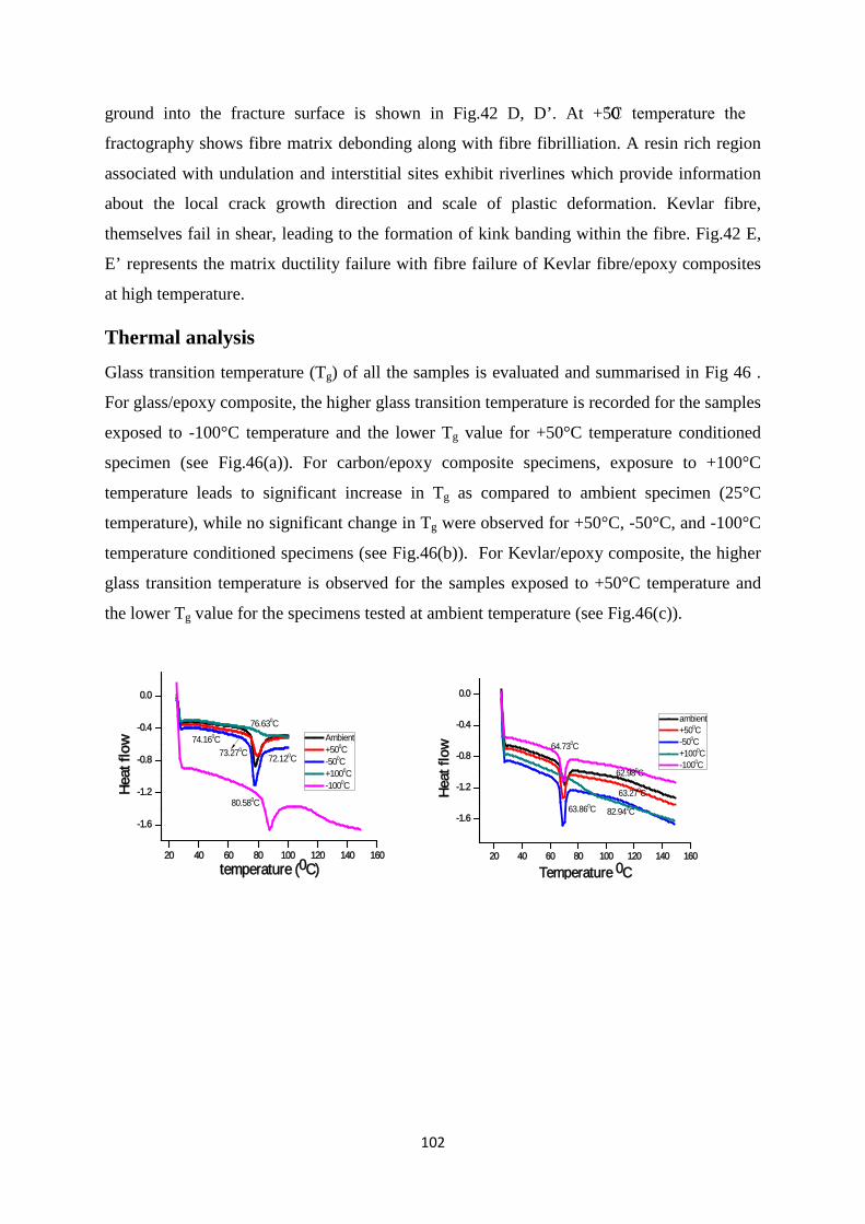
102
ground into the fracture surface is shown in Fig.42 D, D’. At +50˚C temperature the
fractography shows fibre matrix debonding along with fibre fibrilliation. A resin rich region
associated with undulation and interstitial sites exhibit riverlines which provide information
about the local crack growth direction and scale of plastic deformation. Kevlar fibre,
themselves fail in shear, leading to the formation of kink banding within the fibre. Fig.42 E,
E’ represents the matrix ductility failure with fibre failure of Kevlar fibre/epoxy composites
at high temperature.
Thermal analysis
Glass transition temperature (Tg) of all the samples is evaluated and summarised in Fig 46 .
For glass/epoxy composite, the higher glass transition temperature is recorded for the samples
exposed to -100°C temperature and the lower Tg value for +50°C temperature conditioned
specimen (see Fig.46(a)). For carbon/epoxy composite specimens, exposure to +100°C
temperature leads to significant increase in Tg as compared to ambient specimen (25°C
temperature), while no significant change in Tg were observed for +50°C, -50°C, and -100°C
temperature conditioned specimens (see Fig.46(b)). For Kevlar/epoxy composite, the higher
glass transition temperature is observed for the samples exposed to +50°C temperature and
the lower Tg value for the specimens tested at ambient temperature (see Fig.46(c)).
20 40 60 80 100 120 140 160
-1.6
-1.2
-0.8
-0.4
0.0
Hea
t flo
w
temperature (0C)
Ambient +500C -500C +1000C -1000C
80.580C
76.630C
72.120C
74.160C73.270C
20 40 60 80 100 120 140 160
-1.6
-1.2
-0.8
-0.4
0.0
Hea
t flo
w
Temperature 0C
ambient +500C -500C +1000C -1000C
64.730C
62.980C
63.860C
63.270C
82.940C
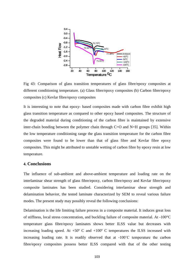
103
20 40 60 80 100 120 140 160
-2.8
-2.4
-2.0
-1.6
-1.2
-0.8
-0.4
0.0
0.4
Heat
Flo
w
Temperature 0C
Ambient +500C -500C +1000C -1000C
77.480C
70.730C
71.230C72.420C
71.010C
Fig 43: Comparison of glass transition temperatures of glass fibre/epoxy composites at
different conditioning temperature. (a) Glass fibre/epoxy composites (b) Carbon fibre/epoxy
composites (c) Kevlar fibre/epoxy composites
It is interesting to note that epoxy- based composites made with carbon fibre exhibit high
glass transition temperature as compared to other epoxy based composites. The structure of
the degraded material during conditioning of the carbon fibre is maintained by extensive
inter-chain bonding between the polymer chain through C=O and N=H groups [35]. Within
the low temperature conditioning range the glass transition temperature for the carbon fibre
composites were found to be lower than that of glass fibre and Kevlar fibre epoxy
composites. This might be attributed to unstable wetting of carbon fibre by epoxy resin at low
temperature.
4. Conclusions
The influence of sub-ambient and above-ambient temperature and loading rate on the
interlaminar shear strength of glass fibre/epoxy, carbon fibre/epoxy and Kevlar fibre/epoxy
composite laminates has been studied. Considering interlaminar shear strength and
delamination behavior, the tested laminate characterized by SEM to reveal various failure
modes. The present study may possibly reveal the following conclusions:
Delamination is the life limiting failure process in a composite material. It induces great loss
of stiffness, local stress concentration, and buckling failure of composite material. At -100°C
temperature glass fibre/epoxy laminates shows better ILSS value but decreases with
increasing loading speed. At +50º C and +100º C temperatures the ILSS increased with
increasing loading rate. It is readily observed that at -100˚C temperature the carbon
fibre/epoxy composites possess better ILSS compared with that of the other testing
104
temperature. But after 500 mm/min shear values decreases because microcrack density has
exceeded the critical crack density for delamination.
Furthermore, for Kevlar fibre/epoxy composites at ambient temperature the specimen possess
better ILSS compared with other conditioning temperature. The variation of ILSS here is the
net result of good adhesion at interface by physical and mechanical bonding at the interface.
Different failure modes such as different types of cusps on the matrix region, riverline
marking, fibre/matrix interfacial debonding, plastic deformation of matrix and fibre fracture
were observed for the composite specimens failed after the exposure to different above-
ambient and sub-ambient temperature.
It is found that the type of fibres and matrix present in the composites influences the amount
of heat required and the glass transition temperature. This brings out that the microstructure
of the fibre/matrix within the composites found to be influencing the amount of thermal
energy absorbed by the materials and consequently affect the mechanical properties.
References
1. B.C. Ray, D. Rathore. Durability and integrity studies of environmentally conditioned interfaces in fibrous polymeric composites: Critical concepts and comments. Adv. Colloid Interface Sci. 2014; 209: 68
2. B.C. Ray. Temperature effect during humid ageing on interfaces of glass and carbon fibres reinforced epoxy composites. J Colloid Interface Sci. 2006; 298: 111.
3. B.C. Ray, S. Sethi. Mechanical Behavior of Polymer Composites at Cryogenic Temperatures. In: Polymers at Cryogenic Temperature, edited by Shusheel Kalia, Shao-Yun Fu, Springer Berlin Heidelberg, Germany 2013
4. B.C. Ray. Effects of crosshead velocity and sub-zero temperature on mechanical behavior of hygrothermally conditioned glass fibre reinforced epoxy composites. Mater. Sci. Eng. A, 2004; 379:39.
5. B.C. Ray. Thermal shock on interfacial adhesion of thermally conditioned glass fibre/epoxy composites. Mater. Lett. 2004; 58:2175.
6. D.F. Adams, L.A. Carlsson, R.B. Pipes, Experimental Characterization of Advanced Composite Materials, (third Ed.) CRC Press, Boca Raton 2003.
7. Y He, A. Makeev. Nonlinear shear behavior and interlaminar shear strength of unidirectional polymer matrix composites: A numerical study. Int. J Solids Struct. 2014; 51:1263.
8. L.E. Asp, L.A. Berglund, R. Talreja. Effects of fibre and interphase on matrix initiated transverse failure in polymer composites. Compos Sci. Technol, 1996; 56:651.
105
9. M F S F de Moura, Interaction of matrix cracking and delamination, In: Delamination of composites, edited by S. Sridharan, Woodhead publishing ltd 2008 341-342.
10. N. Blanco, E.K. Gamstedt, L.E. Asp, J. Costa. Mixed-mode delamination growth in carbon-fibre composite laminates under cyclic loading. Int. J Solids Struct.2004; 41:4219.
11. B.C. Ray, Effects of changing environment and loading speed on mechanical behavior of FRP composites. J. Reinf. Plast. Comp., 2006; 25:1227.
12. C.E. Lundahl, J.H. Kreiner. Effect of composite properties on interlaminar shear strength. 31st International SAMPE Symposium, 1986: 1499.
13. S. Sethi., B.C Ray., An assessment of mechanical behaviour and fractography study of glass/epoxy composites at different temperatures and loading speeds. Mater. Des.,2014;64:160
14. S.K. Foster, L.A. Bisby. High Temperature Residual Properties of Externally Bonded FRP Systems, In: 7th International Symposium on Fibre-Reinforced (FRP) Polymer Reinforcement for Concrete Structures (FRPRCS-7), 2005, New Orleans, USA, 1235–1252.
15. C, Dong, Ian J. Davies, Flexural and tensile strengths of unidirectional hybrid epoxy composites reinforced by S-2 glass and T700Scarbon fibres. Mater. Des., 2014;54: 955
16. S. Birger, A. Moshonov, S. Kenig. The effects of thermal and hygrothermal ageing on the failure mechanisms of graphite-fabric epoxy composites subjected to flexural loading. Composites, 1989; 20:341.
17. V.T. Bechel, J.D. Camping, R.Y. Kim. Cryogenic/elevated temperature cycling induced leakage paths in PMCs. Compos Part B- Eng.2005; 36:171.
18. M.Z. Shah Khan, G. Simpson, E.P. Gellert. Resistance of glass fibre reinforced polymer composites to increasing compressive strain rates and loading rates. Compos: Part A-Appl. 2000; 31:57.
19. A. Gilat, R.K. Goldberg, G.D. Roberts. Experimental study of strain-rate-dependent behavior of carbon/epoxy composites, Compos Sci Technol 2002; 62:1469.
20. N.K. Naik, V.R. Kavala. High strain rate behavior of woven fabric composites under compressive loading. Mater Sci Eng A 2008; 474:301.
21. M.M. Shokrieh, M.J. Omidi. Compressive response of glass-fibre reinforced polymeric composites to increasing compressive strain rates. Compos Struct 2009; 89:517.
22. I.M. Daniel, B.T. Werner, J.S. Fenner Strain-rate-dependent failure criteria for composites. Compos Sci Technol 2011; 71:357.
106
23. Sung-Choong Woo, Tae-Won. Kim, High-strain-rate impact in Kevlar-woven composites and fracture analysis using acoustic emission. Compos Part B-Eng.2014;60:125
24. F.A.R. Al-Salehi, S.T.C. Al-Hassani, N.M. Bastaki, M.J. Hinton, Derived dynamic ply properties from test data on angle ply laminates. Appl Compos Mater, 1997;4:157
25. M.M. Shokrieh, M.J. Omidi. Investigation of strain rate effects on in-plane shear properties of glass/epoxy composites. Compos Struct 2009; 91:95.
26. A. Kelly, C. Zweben: Comprehensive Composite Materials. Oxford U.K, Elsevier Science Publication, 2000.
27. E.S. Greenlagh: Failure analysis and fractography of polymer composites, Woodhead publishing, 2009.
28. J.A. Nairn, S. Hu. The initiation and growth of delamination induced by matrix microcracks in laminated composites. Int. J Fracture, 1992; 57:1.
29. G. Hartwig, Polymer properties at room and cryogenic temperatures. New Work, Plenum Press, 1994.
30. S. Bandyopadhyay. Review of the microscopic and macroscopic aspects of fracture of unmodified and modified epoxy resins, Mat Sci Eng A, 1990;125:157.
31. B.L. Smith, T.E. Schaffer, M. Viani, J.B.Thompson, N.A. Frederrick, J Kindt, A. Belchers, G.D. Strucky, D.E. Morse, P.K. Hansma. Molecular mechanistic origin of the toughness of natural adhesives, fibres and composites. Nature, 1999; 399:761.
32. B.C. Ray. Adhesion of glass/epoxy composites influenced by thermal and cryogenic environments. J Appl Polym Sci, 2006; 102:1943.
33. J.J. Aklonis. Mechanical properties of polymer, J Chem Educ, 1981; 58:892.
34. K. Shin, S. Obukhov, J.T. Chen, J. Huh, Y. Hwang, S. Mok, P Dobriyal, P. Thiyagarajan, T.P. Russell. Enhanced mobility of confined polymers. Nature Materials, 2007; 6:961.
35. Jang B Z., Advanced Polymer Composites: Principle and Applications. ASM International, Materials Park, OH, 1994
Please Note: The present section has already been published partly inMaterials and Design, 2015, 65,617-626.

107
4.2 Effect of low temperature on mechanical response of materials with different loading rates
Theories and Thoughts At low temperatures, there is little thermal energy available and molecular motion is inhibited
in the polymer matrix. Thus fibre/matrix interface degrades the interfacial bond strength,
resulting in loss of microstructural integrity. Consequently, the relaxation and creep rates of
polymers are highly sensitive to temperature. The interaction of a fibre with matrix materials
depends strongly on the chemical/molecular features and atomic composition of the fibre
surface layers as well as its topographical nature. The present study contains the low
temperature effects on glass fibre/epoxy polymer composites at different loading rates.
4.2.1 Introduction The cryogenic applications of polymer composites are recently drawing attention in various
fields as new development in aerospace applications where storage and transportation of
cryogenic liquids are required, transport vessels and components in spacecraft where low
thermal contraction is necessary [1-3].Glass fiber reinforced polymer (GF RP) woven
laminates are usually used for the insulation of superconducting magnet coils operating at
cryogenic temperatures [4,5].Exposure to these cryogenic temperatures may cause
delamination, microcracks and strain in matrix which may significantly reduce the stiffness
and integrity of the material [6-8]. At cryogenic temperatures, due to difference in coefficient
of thermal expansion between the fibre and the matrix phase, microcracks initiate and
propagate through the laminates composites [9, 10]. Therefore, knowledge of the resistance
to different failure modes of woven fabric composites laminates at cryogenic temperatures is
essential to the materials scientist and designer analyst.To achieve the often-promise
capabilities of polymer composites, the properties of the interfacial region between fibre and
matrix must be controlled. The variation in interlaminar shear strength with loading rates
is an important issue in the design of classes of polymer composite materials used in
different structures subjected to suddenly applied loads at low temperatures.Interlaminar
loading rate sensitivity is an importance concern, as it related to the loss of integrity of the
material at low temperatures. The effect of varying loading rate on mechanical properties of
fibre- reinforced polymer composites has been investigated and reported a variety of
contradictory observations and conclusions [11-15].Mechanical properties of polymers are
strongly sensitiveto temperature and strain rate [16,17].At low temperature the matrix
material behaves as brittle in manner and do not allow relaxation of residual stresses or stress
108
concentration to take place [18, 19].The generic behaviour of polymers must arise from the
chainlike structure of the polymer molecules, but detailed insights into the underlying
processes have beenhard to come by [20]. Delamination failure mode is known to be the
major life-limiting failure process in a composite laminate [21].The fibber/matrix interface
has always been considered as a crucial aspect of polymer composites as well as polymer
nanocomposites [22].The response of fibre/matrix interface within the composite plays an
important role in determining the gross mechanical performance, because it transmitting the
load from the matrix to the fibres, which contribute the greater portion of the composite
strength. Better the interfacial bond better will be the ILSS, de-lamination resistance,fatigue
and corrosion resistance.
The aim of this investigation was to study deformation and mechanical behaviour of glass
fibre/epoxy composites subjected to 3-point short beam shear test at low and ultra-low
temperature with different loading speeds. The laminates were tested at ambient (+27°C)
temperature and at (-20°C,-40°C,-60°C) temperatures using liquid nitrogen gas in an
environmental chamber installed on an Instron testing machine. Testing was carried out in
different loading covering low to high medium speeds. Following the test the fracture
surfaces were scanned under SEM microscope.A need probably exists for an assessment
of mechanical performance of such potentially promising materials under the influence
of changing environment and loading speed. Using fractography study to characterize the
onset and growth of failure modes has become generally accepted method.
4.2.2 ExperimentalWork
4.2.2.1 Materials
The material system selected for this work was E-glass fibre/epoxy polymer composites
fabricated by hand lay-up method followed by compression moulding process.Diglycidyl
ether of Bisphenol A (DGEBA) as epoxy and Triethylene tetra amine (TETA) as hardener
supplied by Atul Industries Ltd, Gujarat, India under the trade name Lapox, L-12 and K-6
respectively.The volume fraction of fibres is 60%. The ratio of epoxy and hardener is taken
as10:1. The laminated composites has been prepared by hand lay-up method with 16 layers of
woven fabric cloth of reinforcement and then placed in a compression moulding process.
Then the curing of the laminate has been carried out at 60°C temperature and 15 kg/cm2
pressure for 20 minutes. The laminates were then removed from the press and kept at room
temperature for 24 hours. The test specimens have been cut from the laminates using
diamond tipped cutter as per ASTM D2344-13 standard.
109
4.2.2.2 Low temperature conditioning and characterization techniques
3-point short-beam shear tests were performed on a 30KN capacity Instron testing machine.
The shear testing at –low and ultra-low temperature was conducted with specimens by
spraying of liquid nitrogen in an environmental chamber attached with Instron 5967 where
temperature was controlled by temperature controller, liquid nitrogen flow from dewar by
controlling the pressure. The in-situ tests have been performed on the samples at different
temperatures viz; 25° C, -20° C, -40° C and, -60° C temperature inside the environmental
chamber of Instron-5967 with 10 minutes holding time to evaluate the inter-laminar shear
strength (ILSS). The tests were performed with six crosshead speeds viz; (1, 10, 100,300,
600, and 1000) mm/min. For each point of testing 5 to 6 specimens were tested and the
average value was taken. The broken parts were observed under Scanning Electron
Microscope (SEM) for the fractographic analysis.
For analysis of composite fractography, SEM by JEOL-JSM 6480 LV with the acceleration
voltage of 15 kV was used. Cleaned, small in size and conductive samples are used during
testing in SEM. the top surface of the specimens were coated with platinum using a sputter
coater. The coating is used to make the surface conductive for scanning and prevents the
accumulation of static electric charge for clear images during the microscopy. During the test
samples are little tilt around 15-20° to drawn attractive and clear images of different failure
modes.
4.2.3 Results and discussion
4.2.3.1 Mechanical Study
Interlaminar shear strength with temperatures
Variation of ILSS with different loading speeds at different temperatures of glass fibre/epoxy
composites are shown in Fig 44(a). In thecurrent study, glass fibre/epoxy composites
subjected to low and ultra-low (27°C, -20°C,-40°C,-60°C) temperatures at different loading
speeds. It can be illustrated that, at low temperature the glass fibre/epoxy composites shows
loading rate sensitivity. At -60°C temperature maximum ILSS value was obtained and it
increases with increasing loading speed with a transition 10mm/min. At low loading speed (1
to 100)mm/min it increases 2.48% (max), at medium loading speed (100-600)mm/min it
increases 1.96% (max) whereas, at high loading speed (600-1000)mm/min it increases 3.24%
(max). At -40°C temperatures low ILSS values obtained as compared to -60°C temperature
but it increases with increasing loading speed with the transition at 100 mm/min. At low
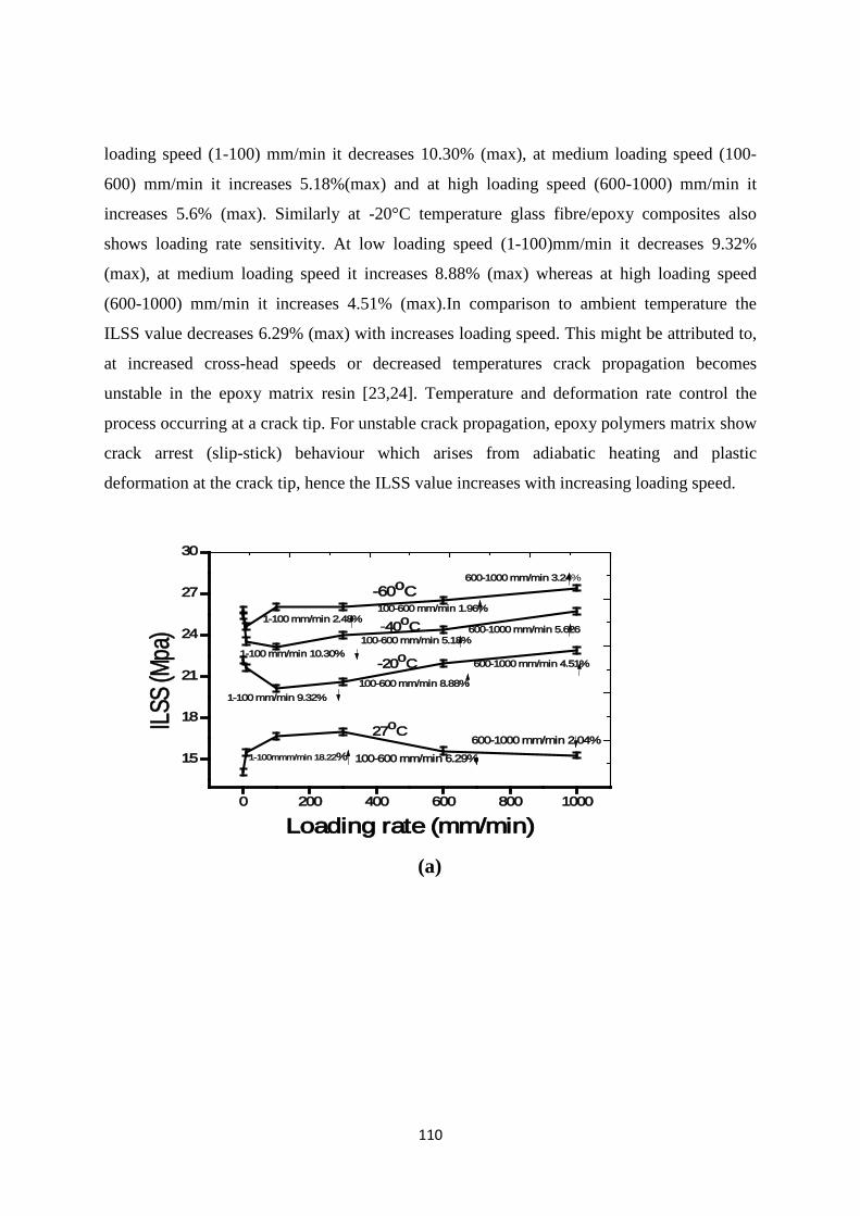
110
loading speed (1-100) mm/min it decreases 10.30% (max), at medium loading speed (100-
600) mm/min it increases 5.18%(max) and at high loading speed (600-1000) mm/min it
increases 5.6% (max). Similarly at -20°C temperature glass fibre/epoxy composites also
shows loading rate sensitivity. At low loading speed (1-100)mm/min it decreases 9.32%
(max), at medium loading speed it increases 8.88% (max) whereas at high loading speed
(600-1000) mm/min it increases 4.51% (max).In comparison to ambient temperature the
ILSS value decreases 6.29% (max) with increases loading speed. This might be attributed to,
at increased cross-head speeds or decreased temperatures crack propagation becomes
unstable in the epoxy matrix resin [23,24]. Temperature and deformation rate control the
process occurring at a crack tip. For unstable crack propagation, epoxy polymers matrix show
crack arrest (slip-stick) behaviour which arises from adiabatic heating and plastic
deformation at the crack tip, hence the ILSS value increases with increasing loading speed.
0 200 400 600 800 1000
15
18
21
24
27
30
ILSS
(Mpa
)
Loading rate (mm/min)
27oC
-20oC
-40oC
-60oC
1-100mmm/min 18.22% 100-600 mm/min 6.29%
600-1000 mm/min 2.04%
1-100 mm/min 9.32%100-600 mm/min 8.88%
600-1000 mm/min 4.51% 1-100 mm/min 10.30%
100-600 mm/min 5.18%600-1000 mm/min 5.626
1-100 mm/min 2.48%100-600 mm/min 1.96%
600-1000 mm/min 3.24%
(a)
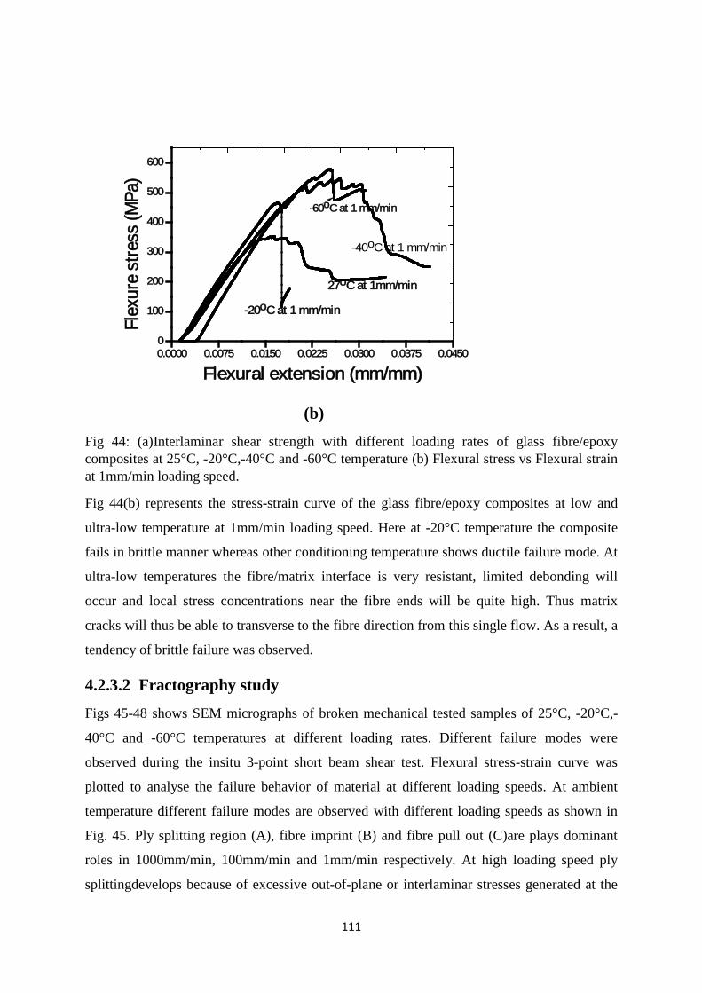
111
(b) Fig 44: (a)Interlaminar shear strength with different loading rates of glass fibre/epoxy composites at 25°C, -20°C,-40°C and -60°C temperature (b) Flexural stress vs Flexural strain at 1mm/min loading speed.
Fig 44(b) represents the stress-strain curve of the glass fibre/epoxy composites at low and
ultra-low temperature at 1mm/min loading speed. Here at -20°C temperature the composite
fails in brittle manner whereas other conditioning temperature shows ductile failure mode. At
ultra-low temperatures the fibre/matrix interface is very resistant, limited debonding will
occur and local stress concentrations near the fibre ends will be quite high. Thus matrix
cracks will thus be able to transverse to the fibre direction from this single flow. As a result, a
tendency of brittle failure was observed.
4.2.3.2 Fractography study
Figs 45-48 shows SEM micrographs of broken mechanical tested samples of 25°C, -20°C,-
40°C and -60°C temperatures at different loading rates. Different failure modes were
observed during the insitu 3-point short beam shear test. Flexural stress-strain curve was
plotted to analyse the failure behavior of material at different loading speeds. At ambient
temperature different failure modes are observed with different loading speeds as shown in
Fig. 45. Ply splitting region (A), fibre imprint (B) and fibre pull out (C)are plays dominant
roles in 1000mm/min, 100mm/min and 1mm/min respectively. At high loading speed ply
splittingdevelops because of excessive out-of-plane or interlaminar stresses generated at the
0.0000 0.0075 0.0150 0.0225 0.0300 0.0375 0.04500
100
200
300
400
500
600
Flex
ure
stre
ss (M
Pa)
Flexural extension (mm/mm)
27oC at 1mm/min
-20oC at 1 mm/min
-60oC at 1 mm/min
-40oC at 1 mm/min

112
fibre/matrix interface. Here matrix failure occurred in some extent ductile manner. In contrast
to this, at low and medium loading speed, matrix has sufficient time to transfer the stress to
fibre and interface region and laminate fails in little brittle manner.
At ultra-low(-20°C) temperature the failure modes are delamination (A), debonding (B) and
brittle fibre fracture (C) at 1mm/min, 100mm/min and 1000mm/min respectively shown in
Fig. 46. Here the stress strain curve shows brittle to ductile transition with increasing loading
speeds.Brittle failure or catastrophic crack growth in matrix starts when a critical stress field
at the crack tip is exceeded. This is due to small specific heat at low temperatures, small
deposition of inelastic deformation energy leads to an appreciable temperature rise. Under
certain conditions adiabatic heating is high enough to reach a secondary dispersion region of
a polymer where enhanced plastification occurs [25]. The fracture energy is increased by
these processes.
Fig 47 represents SEM micrographs of glass fibre/epoxy composites subjected to -40°C
temperature. Different failure modes are observed such as cusps (A), matrix tearing (B) and
fibre/matrix interface failure (C) at 1mm/min, 100mm/min and 1000mm/min respectively.
Here stress-strain curve shows ductile failure mode with increasing loading speeds. Cusps are
usually generated from microcracks which are plays dominant role at low temperature.The
occurrence of an adiabatic transition depends on the crack velocity and on the thermal
diffusivity. In an adiabatic state, however, the heat transfer from the thermally active zone
(i.e. plastification zone at a crack tip) to the passive zone (elastic bulk material) is negligible.
Fig 45: Fractography analysis of glass fibre/epoxy composites at ambient (27°C) temperature
0.0000 0.0175 0.0350 0.0525 0.0700 0.08750
100
200
300
400
500
Flex
ure
stre
ss (M
Pa)
Flexural strain(mm/mm)
1 mm/min
1000 mm/min
100 mm/min
at +270C temperature
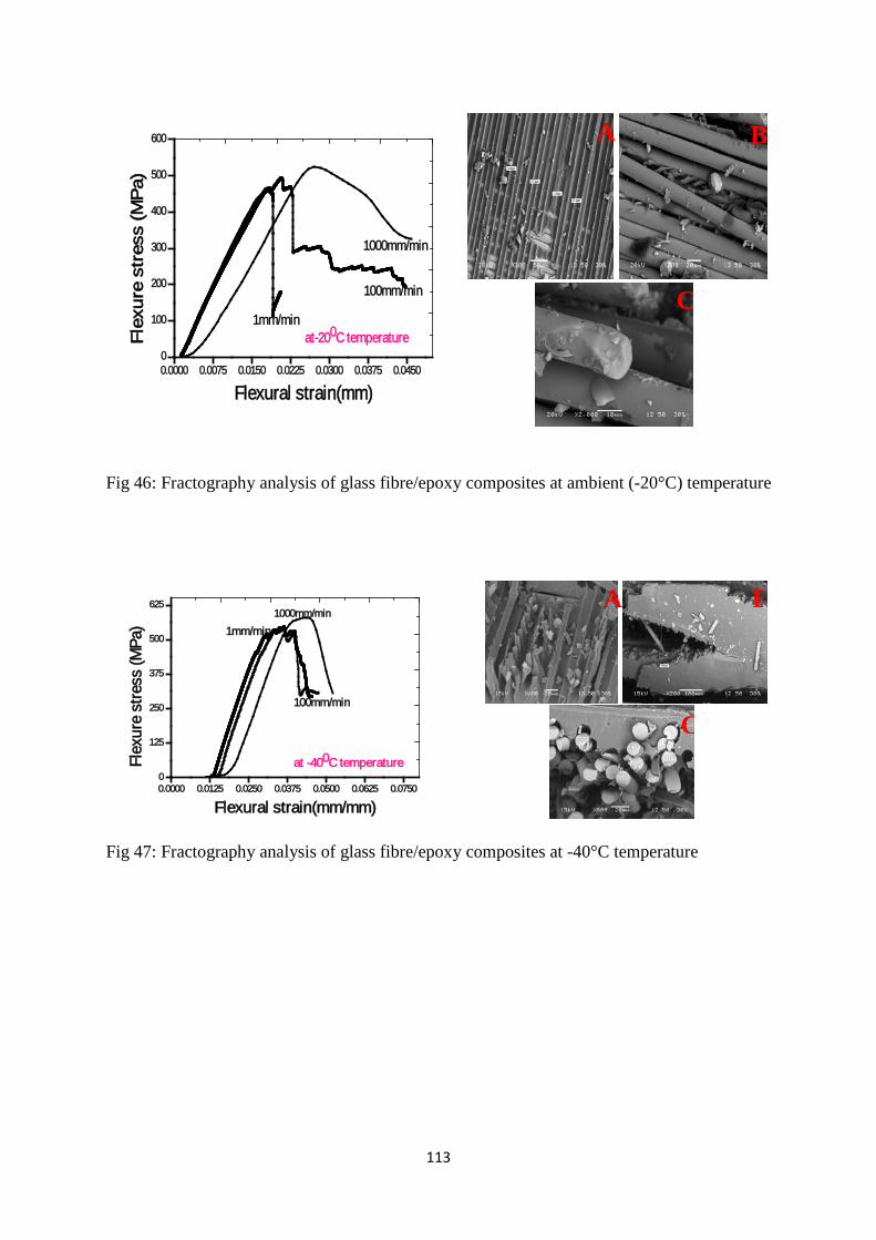
113
0.0000 0.0075 0.0150 0.0225 0.0300 0.0375 0.04500
100
200
300
400
500
600Fl
exur
e st
ress
(MP
a)
Flexural strain(mm)
1000mm/min
100mm/min
1mm/minat-200C temperature
Fig 46: Fractography analysis of glass fibre/epoxy composites at ambient (-20°C) temperature
0.0000 0.0125 0.0250 0.0375 0.0500 0.0625 0.07500
125
250
375
500
625
Flex
ure
stre
ss (M
Pa)
Flexural strain(mm/mm)
1000mm/min
1mm/min
100mm/min
at -400C temperature
Fig 47: Fractography analysis of glass fibre/epoxy composites at -40°C temperature
A B
C
A B
C
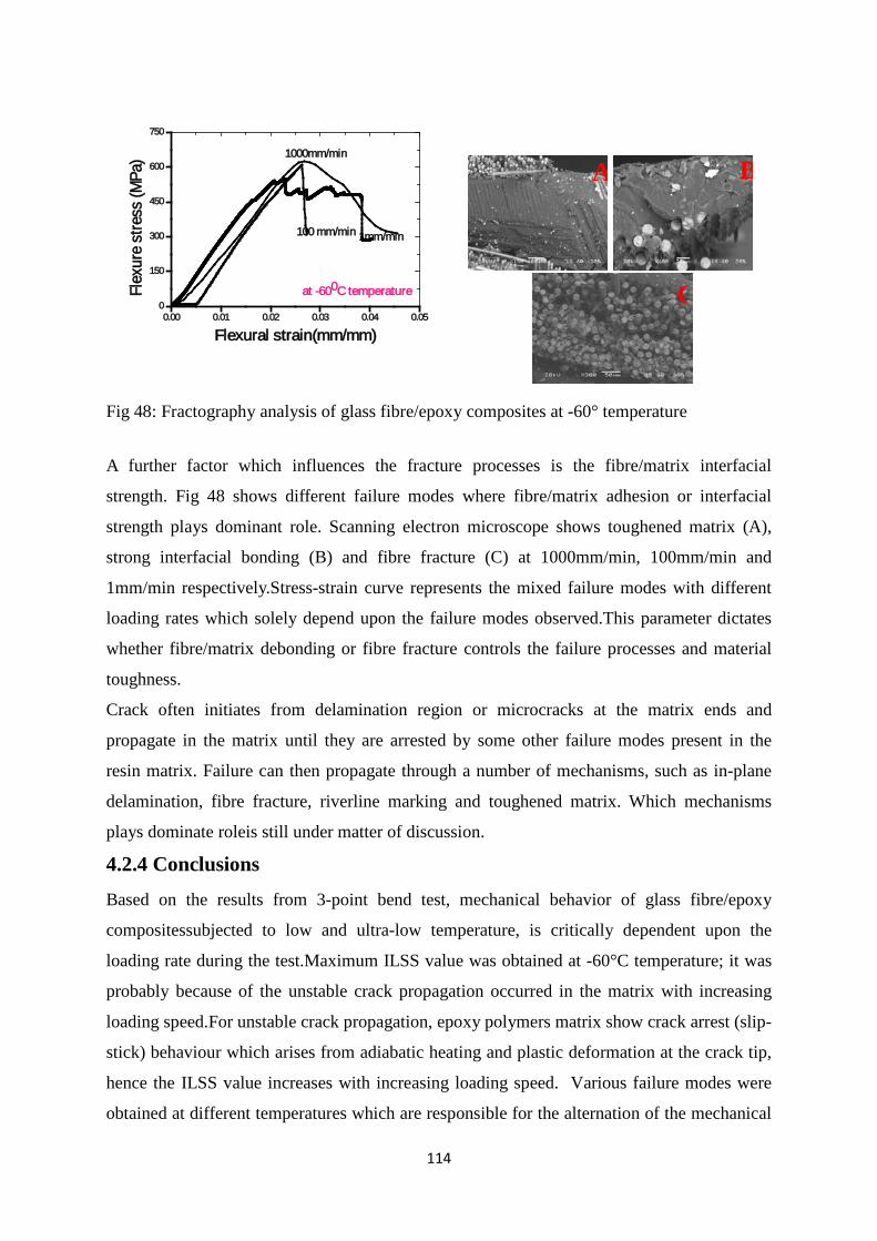
114
0.00 0.01 0.02 0.03 0.04 0.050
150
300
450
600
750Fl
exur
e st
ress
(MPa
)
Flexural strain(mm/mm)
1000mm/min
1mm/min100 mm/min
at -600C temperature
Fig 48: Fractography analysis of glass fibre/epoxy composites at -60° temperature
A further factor which influences the fracture processes is the fibre/matrix interfacial
strength. Fig 48 shows different failure modes where fibre/matrix adhesion or interfacial
strength plays dominant role. Scanning electron microscope shows toughened matrix (A),
strong interfacial bonding (B) and fibre fracture (C) at 1000mm/min, 100mm/min and
1mm/min respectively.Stress-strain curve represents the mixed failure modes with different
loading rates which solely depend upon the failure modes observed.This parameter dictates
whether fibre/matrix debonding or fibre fracture controls the failure processes and material
toughness.
Crack often initiates from delamination region or microcracks at the matrix ends and
propagate in the matrix until they are arrested by some other failure modes present in the
resin matrix. Failure can then propagate through a number of mechanisms, such as in-plane
delamination, fibre fracture, riverline marking and toughened matrix. Which mechanisms
plays dominate roleis still under matter of discussion.
4.2.4 Conclusions
Based on the results from 3-point bend test, mechanical behavior of glass fibre/epoxy
compositessubjected to low and ultra-low temperature, is critically dependent upon the
loading rate during the test.Maximum ILSS value was obtained at -60°C temperature; it was
probably because of the unstable crack propagation occurred in the matrix with increasing
loading speed.For unstable crack propagation, epoxy polymers matrix show crack arrest (slip-
stick) behaviour which arises from adiabatic heating and plastic deformation at the crack tip,
hence the ILSS value increases with increasing loading speed. Various failure modes were
obtained at different temperatures which are responsible for the alternation of the mechanical
A B
C
115
properties. Stress-strain curve and various failure modes observed during testing at different
loading rates solely depend upon the temperatures. This parameter dictates whether
fibre/matrix debonding or fibre fracture controls the failure processes and material toughness.
References
28. Gudes R.M.(2007).,Durability of polymer matrix composites:Viscoelastic effect on static and fatigue loading, Composite Science and Technology, Vol-67, 2574
29. Naik,N.K., Venkateswara.R.K., Ravikumar,G., Vearraju,Ch.(2010).,Stress-strain behavior of composites under high strain rate compression along thickness direction: Effect of loading condition,, Materials and Design.,Vol-31, 396
30. Ray, B.C.(2006),Temperature effect during humid ageing on interfaces of glass and carbon Fibers reinforced epoxy compositesJ of Colloid and Interface Science. ,Vol-298, 111
31. Ray B.C. (2004), Effects of crosshead velocity and sub-zero temperature on mechanical behaviour of hygrothermally conditioned glass fibre reinforced epoxy composites. Material Science and Engineering, Vol- 379:39.
32. S. Sethi, Ray B.C(2014), An assessment of mechanical behaviour and fractography studyof glass/epoxy composites at different temperatures and loading speeds, Materials and Design, Vol-64:160
33. S. Sethi, Rathore D, Ray B.C(2014), Effects of temperature and loading speed on interface-dominatedstrength in fibre/polymer composites: An evaluation for in-situenvironment, Materials and Design, Vol-65: 617
34. Tanoglu M.,Mcknight,S.H.,Palmese,G.R.,Gillespie,J.W.Jr,(2000),A new technique to characterize the fiber/matrix interphase properties under high strain rates, Composites Part A, Vol-31,1127
35. C, Dong, Ian J. Davies (2014), Flexural and tensile strengths of unidirectional hybrid epoxy composites reinforced by S-2 glass and T700Scarbon fibres. Materials Design., Vol-54: 955
36. Soutis, C., Turkmen, D.(1997), Moisture and temperature effects on the compressive failure of CFRP unidirectional laminates, J. Composite. Material, Vol-31, 832
37. Rapnowski, P., Gentz, M., Kumosa, M.,(2006). Mechanical response of a unidirectional graphite fiber/polyimide composite as a function of temperature, Composite. Science and. Technology., Vol-66, 1045
38. Ray, B.C. (2004),Loading Rate effects on Mechanical Properties of Polymer Composites at Ultralow TemperaturesJ of Applied. Polymer. Science,Vol-100, 2062
39. Fabio Nardone, Marco Di Ludovico, Francisco J. De Caso y Basalo, Andrea Prota , Antonio Nanni, Tensile behavior of epoxy based FRP composites under extreme service conditions, Composites: Part B 43 (2012) 1468–1474.
40. Piyush K. Dutta, David Hui, Low temperature and freeze thaw durability of thick composoites, Composites:Part B 27B (1996) 371-379.
116
41. M.Z. Shah Khan, G. Simpson, E.P. Gellert, Resistance of glass-fibre reinforced polymer composites to increasing compressive strain rates and loading rates, Composites: Part A 31 (2000) 57–67.
42. Okenwa I. Okoli, The effects of strain rate and failure modes on the failure energy of fiber reinforced composites, composite structures 54 (2001) 299-303.
4.3 An assessment of high and low temperature on prepreg glass fibre/epoxy composite materials Theories and Thoughts
As with any engineering materials, polymer composites can be exposed to diverse range of
environmental conditionings. Weather and radiation factors that contribute to degradation in
plastics include temperature variations, moisture ingression, sunlight exposure, oxidation,
microbiologic attack, and other environmental elements. At high temperatures, there is
sufficient thermal energy available to the molecules of polymer to allow easy rotation,
movement, and disentanglements. Aim of this present investigation related to study the
effects of high and low temperature on prepreg glass fibre/epoxy composites. 4.3.1 Introduction Over the past years, prepreg glass/epoxy composites have been successfully used as
precursors in the manufacture of high-performance composites such as airplane components,
fishing rods, motor vehicles, sporting goods and water skies [1-3]. The epithet prepreg refers
to a preimpregnated lamina (viscoelastic material) comprised of aligned fibers embedded in
an uncured or partially cured resin.The development and experimental characterization of
these marvelous materials, held together primarily through Vander Walls interactions and
entanglements, have been the focus of significant research over the past decades. Despite the
challenges and expenses inherent in polymer composite processing, applications remains a
major topic of interest due to their potential for high strength to weight ratio, specific strength
and structural integrity. These properties are translatable to the macroscale through the
incorporation of glass fibre reinforcement into epoxy matrix resin and composites. However,
these materials while subjected to certain environmental conditions that may prove damaging
to installed wraps. These include moisture, UV radiation, thermal effects, alkalinity, humidity
and underwater [4, 5]. At high and low temperature exposure plays a dominant role during its
117
short term and long term service life.The interface between the fibre reinforcement and
matrix resins can increase resistance to fracture, join materials of different character, make
them deform more easily and provide motility. While they represent only a tiny fraction of
the overall volume, interfaces are essential for the integrity and durability of the overall
composite material [6].
During their service period it comes across many type of loading rates as static to dynamic
with wide range of loading rates (striking rates).Few literatures have addressed the
mechanical behavior and fractography at different temperatures [7, 8, 9]. Regarding
chemistry of this composite materialHuang et al [10] present the degree of impregnation of
prepreg through NIR spectra, describing the flow of resin matrix through fiber tows.
Grunenfelder et al [11] addressed the effect of voids on both autoclave and VOB precede
laminates they observed that the high pressures during autoclave processing were sufficient to
restrain the void formation. Boey et al [12]studied use of high pressure of up to 7000KPa by
means of isostatic presswithout vacuum application the reduction of void levels as
3%.Considering all the research works we followed autoclave curing cycle for the fabrication
of composites materials which was discussed in experimental part. On the other hand we
knowsevere environmental exposure affects physical and mechanical properties of polymeric
composite materials resulting in an undesirable degradation. As the material is heterogeneous
and anisotropic in nature, damage and degradation of material often be strongly influenced by
local processes. The anisotropy contributes to more complexity in the assessment of the
damage mechanisms and in their impact on the composite responses.An aggressive progress
isneeded, specifically in the aerospace industry to tailor thermal expansion together with the
low material density.Optimization of structural component through improving the prepreg
composite material the resin and the fiber is a challenge for the material scientist as well as
the process engineer. Therefore, scaling concepts need to be applied in the development of
new products to aid the formulation and processing of these heterogeneous, anisotropic and
viscoelastic material.Okoli [13] studied the 3-point bend test of glass/epoxy laminates with
increasing strain rates to find a relationship between energy to failure and strain rate. They
reported a change in failure modes observed as strain rate increased. Shah Khan [14] studied
the resistance of glass fiber reinforced polymer composites with increasing loading rates(2 to
1000 KN/sec) and compressive strain rates (10-3/sec to 102/sec).They found that in-plane
elastic modulus and strength increases with strain rate and then decreased at higher strain
rates. In the present study 3-point bend tests were conducted on glass/epoxy laminates at
118
increasing loading rates to ascertain the relationship between ILSS and loading rate. Very
limited work has been devoted related to ILSS with loading rate, which is the fundamental
knowledge to understand the reliability and structural applications of GFRP composites.To
meet this challenge, researchers and designers must give way to new paradigms, guided by
microstructural characterization of complex phenomena that are discovered and then reported
in a timely way.
4.3.2 Experimental procedure and processing 4.3.2.1 Experimental details Glass/epoxy (GFRP) prepreg composites which contain the reinforcement as E-glass fiber
and matrix as epoxy were prepared. After synthesis of GFRP prepreg composites it was
planned to cure with autoclave following the cure cycle shown in Figure 1. GFRP prepreg
consists of 60 wt% E-glass fiber and 40 wt% matrix epoxy with a 0/90º weave. The prepreg
material used in the testing was the epoxy prepreg made by HEXCEL, supplied by Hindustan
Aeronautics Limited (HAL) having specification Hexply 913-37%-7781-1270, containing a
proprietary curative and glass cloth filter with a 0/90º weave. This prepreg is unique as it can
be stored at room temperature for 24 days.
4.3.2.2Processing of the laminates
Glass/epoxy composite laminates were cured by autoclave method following 5 steps of the
cure cycle which shown in Fig 49. Here first dwell time at 75ºC for 45 minutes. Whereas
second time at 135ºC for 65 minutes. Here pressure is 2.5 bar and vacuum is 0.8 bar. After
curing, the laminate was cut into the required size for 3-point bend (Short- Beam Shear) test
by diamond cutter. Then stability test was done for the composite laminates. Here the
laminates were weighed. One batch of sample was treated with +50 ºC temperature for
thermal conditioning whereas another batch for -50ºC for cryogenic treatment tests. For
comparison one batch for ambient +28 ºC temperature testes sample. The samples were kept
inside the furnace at +50ºC temperature and allowed to stay at that temperature for 10 min as
soaking period. Similarly for cryogenic temperature the samples were kept at -50º C
temperatures and allowed to stay at that temperature for 10 min as soaking period with help
of blowing liquid nitrogen gas.
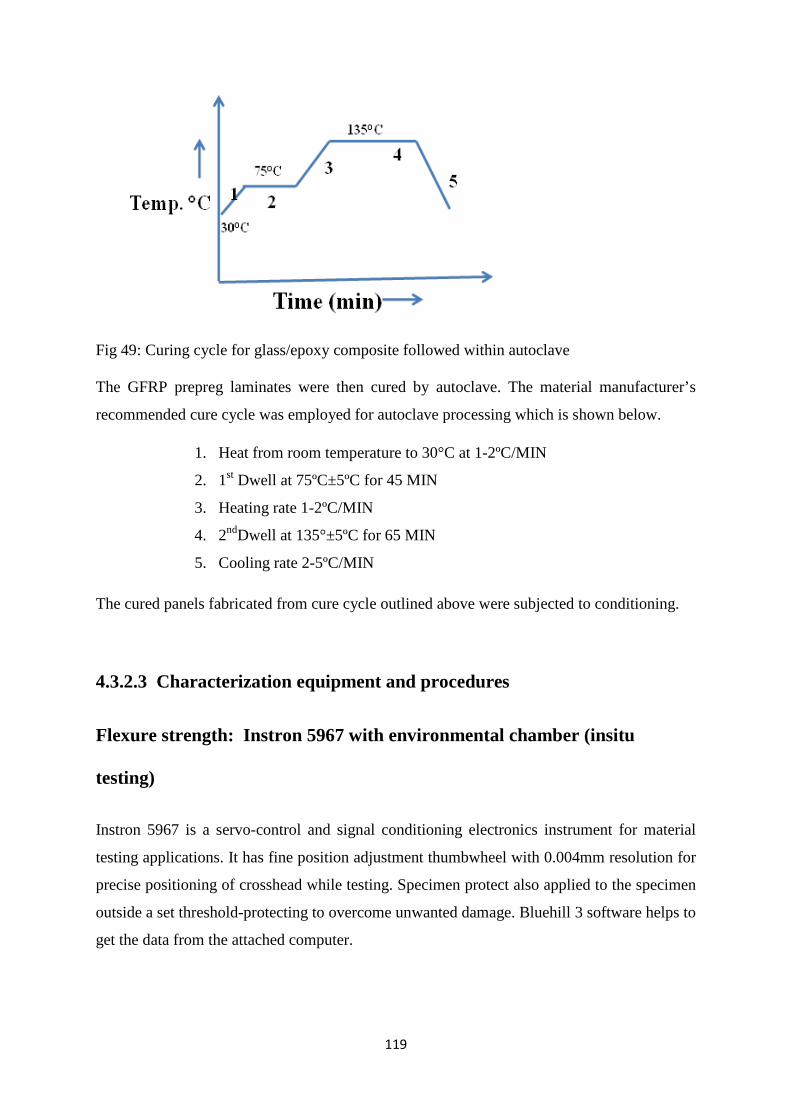
119
Fig 49: Curing cycle for glass/epoxy composite followed within autoclave
The GFRP prepreg laminates were then cured by autoclave. The material manufacturer’s
recommended cure cycle was employed for autoclave processing which is shown below.
1. Heat from room temperature to 30°C at 1-2ºC/MIN
2. 1st Dwell at 75ºC±5ºC for 45 MIN
3. Heating rate 1-2ºC/MIN
4. 2ndDwell at 135°±5ºC for 65 MIN
5. Cooling rate 2-5ºC/MIN
The cured panels fabricated from cure cycle outlined above were subjected to conditioning.
4.3.2.3 Characterization equipment and procedures
Flexure strength: Instron 5967 with environmental chamber (insitu
testing)
Instron 5967 is a servo-control and signal conditioning electronics instrument for material
testing applications. It has fine position adjustment thumbwheel with 0.004mm resolution for
precise positioning of crosshead while testing. Specimen protect also applied to the specimen
outside a set threshold-protecting to overcome unwanted damage. Bluehill 3 software helps to
get the data from the attached computer.
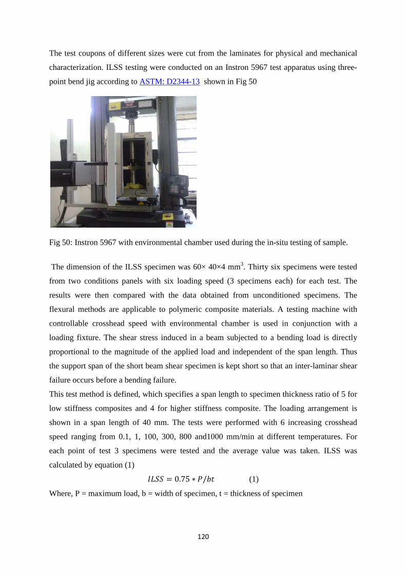
120
The test coupons of different sizes were cut from the laminates for physical and mechanical
characterization. ILSS testing were conducted on an Instron 5967 test apparatus using three-
point bend jig according to ASTM: D2344-13 shown in Fig 50
Fig 50: Instron 5967 with environmental chamber used during the in-situ testing of sample.
The dimension of the ILSS specimen was 60× 40×4 mm3. Thirty six specimens were tested
from two conditions panels with six loading speed (3 specimens each) for each test. The
results were then compared with the data obtained from unconditioned specimens. The
flexural methods are applicable to polymeric composite materials. A testing machine with
controllable crosshead speed with environmental chamber is used in conjunction with a
loading fixture. The shear stress induced in a beam subjected to a bending load is directly
proportional to the magnitude of the applied load and independent of the span length. Thus
the support span of the short beam shear specimen is kept short so that an inter-laminar shear
failure occurs before a bending failure.
This test method is defined, which specifies a span length to specimen thickness ratio of 5 for
low stiffness composites and 4 for higher stiffness composite. The loading arrangement is
shown in a span length of 40 mm. The tests were performed with 6 increasing crosshead
speed ranging from 0.1, 1, 100, 300, 800 and1000 mm/min at different temperatures. For
each point of test 3 specimens were tested and the average value was taken. ILSS was
calculated by equation (1)
𝐼𝐿𝑆𝑆 = 0.75 ∗ 𝑃/𝑏𝑡 (1)
Where, P = maximum load, b = width of specimen, t = thickness of specimen
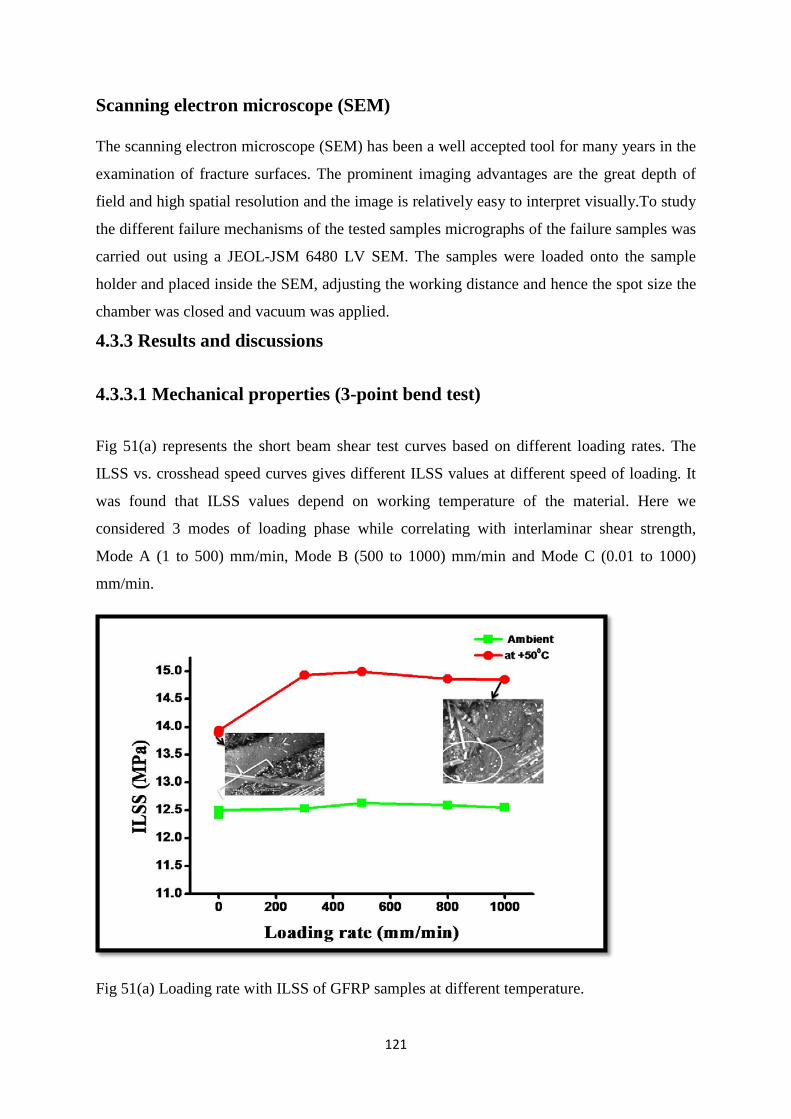
121
Scanning electron microscope (SEM)
The scanning electron microscope (SEM) has been a well accepted tool for many years in the
examination of fracture surfaces. The prominent imaging advantages are the great depth of
field and high spatial resolution and the image is relatively easy to interpret visually.To study
the different failure mechanisms of the tested samples micrographs of the failure samples was
carried out using a JEOL-JSM 6480 LV SEM. The samples were loaded onto the sample
holder and placed inside the SEM, adjusting the working distance and hence the spot size the
chamber was closed and vacuum was applied.
4.3.3 Results and discussions
4.3.3.1 Mechanical properties (3-point bend test)
Fig 51(a) represents the short beam shear test curves based on different loading rates. The
ILSS vs. crosshead speed curves gives different ILSS values at different speed of loading. It
was found that ILSS values depend on working temperature of the material. Here we
considered 3 modes of loading phase while correlating with interlaminar shear strength,
Mode A (1 to 500) mm/min, Mode B (500 to 1000) mm/min and Mode C (0.01 to 1000)
mm/min.
Fig 51(a) Loading rate with ILSS of GFRP samples at different temperature.
122
When the specimen at ambient subjected to 3-point bend test the ILSS values increases with
increasing with loading rate in each loading phase. In contrast to this, when the specimen
treated with +50°C temperature, the strength had decreases in each modes of loading speed
but the ILSS value is more than ambient temperature. In Mode A, it decreases by 16.14%
(Max.), Mode B 9.75% (Max) and Mode C 6.05%(Max) was observed. This may be due to
spreading of process zone (PZ) in large depth (softer resin) in epoxy resin matrix resin which
leads to increase in degree of fiber bridging. In this condition, fiber/matrix debonding is
critical and also exhibit increased deformation which shown in Fig 51 at low and high
loading rates. When sample is loaded there is widespread microscopic damage arises
throughout the laminate. Large damage can be sustained to a critical value at which failure
occurs by the propagation of cracks. These cracks are much more complex in nature than
cracks in homogeneous materials. The failure of a composite involves the fractures of the
load-bearing fibers and the matrix as well as a complex combination of cracks propagated
along the interfaces [15]. Thus ILSS values decreases in every mode of loading.
While at -50°C temperature, the ILSS values increases by 51.09% (max.) inMode A, in Mode
B it decreases by 18.12% (max) again in Mode C it decreases by 3.72% (max). There is a
noticeable decrease of ILSS values in higher cross head speed. In contrast to above, at
ambient temperature ILSS value is increased by 27.07% (Max.) in Mode A, in Mode B it
decreases by 16.42% again in Mode C it is increased by 8.37%.
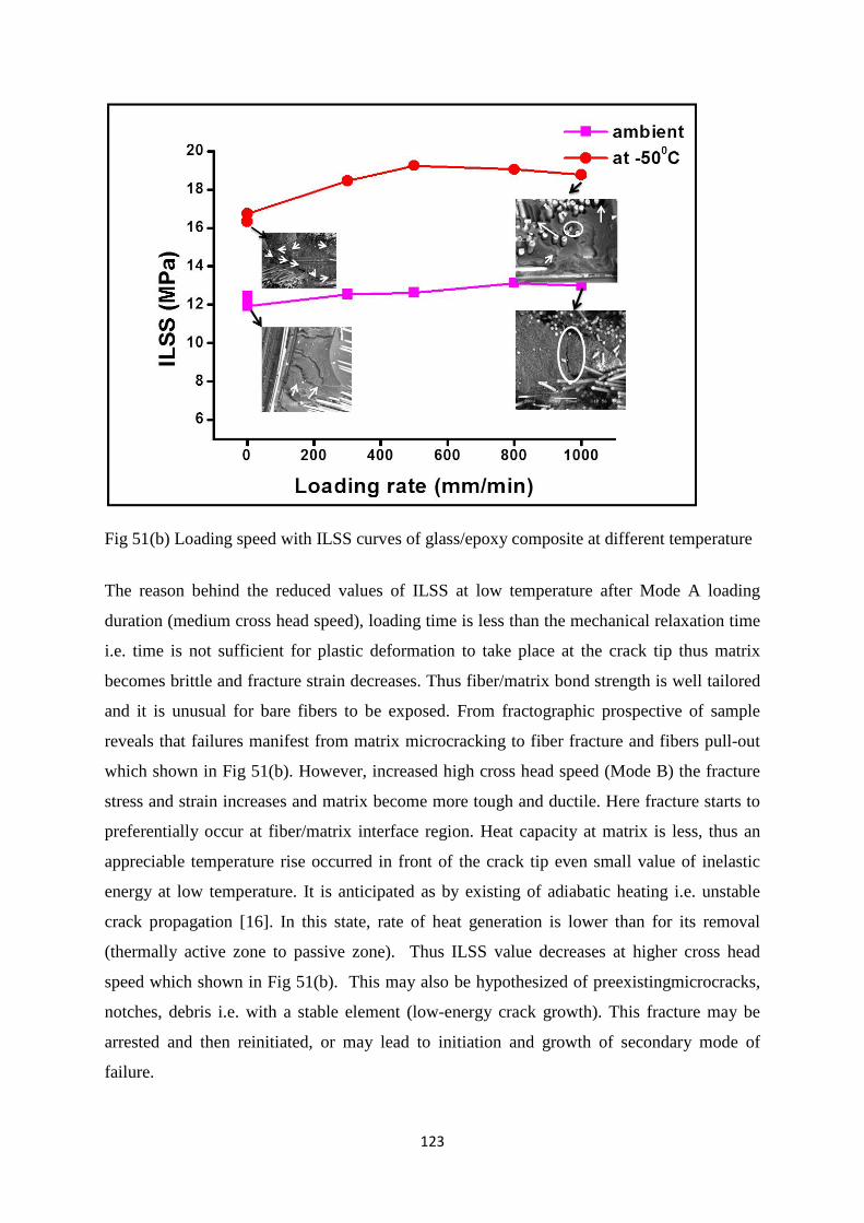
123
Fig 51(b) Loading speed with ILSS curves of glass/epoxy composite at different temperature
The reason behind the reduced values of ILSS at low temperature after Mode A loading
duration (medium cross head speed), loading time is less than the mechanical relaxation time
i.e. time is not sufficient for plastic deformation to take place at the crack tip thus matrix
becomes brittle and fracture strain decreases. Thus fiber/matrix bond strength is well tailored
and it is unusual for bare fibers to be exposed. From fractographic prospective of sample
reveals that failures manifest from matrix microcracking to fiber fracture and fibers pull-out
which shown in Fig 51(b). However, increased high cross head speed (Mode B) the fracture
stress and strain increases and matrix become more tough and ductile. Here fracture starts to
preferentially occur at fiber/matrix interface region. Heat capacity at matrix is less, thus an
appreciable temperature rise occurred in front of the crack tip even small value of inelastic
energy at low temperature. It is anticipated as by existing of adiabatic heating i.e. unstable
crack propagation [16]. In this state, rate of heat generation is lower than for its removal
(thermally active zone to passive zone). Thus ILSS value decreases at higher cross head
speed which shown in Fig 51(b). This may also be hypothesized of preexistingmicrocracks,
notches, debris i.e. with a stable element (low-energy crack growth). This fracture may be
arrested and then reinitiated, or may lead to initiation and growth of secondary mode of
failure.
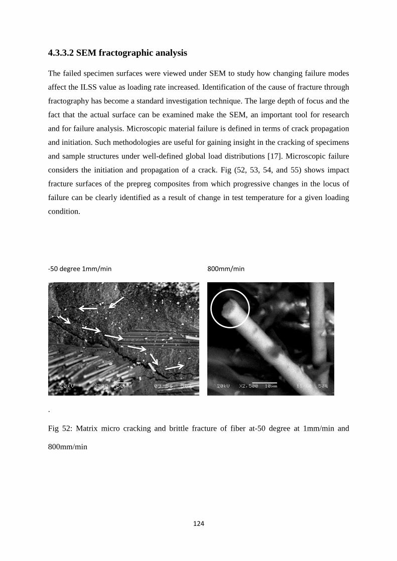
124
4.3.3.2 SEM fractographic analysis
The failed specimen surfaces were viewed under SEM to study how changing failure modes
affect the ILSS value as loading rate increased. Identification of the cause of fracture through
fractography has become a standard investigation technique. The large depth of focus and the
fact that the actual surface can be examined make the SEM, an important tool for research
and for failure analysis. Microscopic material failure is defined in terms of crack propagation
and initiation. Such methodologies are useful for gaining insight in the cracking of specimens
and sample structures under well-defined global load distributions [17]. Microscopic failure
considers the initiation and propagation of a crack. Fig (52, 53, 54, and 55) shows impact
fracture surfaces of the prepreg composites from which progressive changes in the locus of
failure can be clearly identified as a result of change in test temperature for a given loading
condition.
.
Fig 52: Matrix micro cracking and brittle fracture of fiber at-50 degree at 1mm/min and
800mm/min
‐50 degree 1mm/min 800mm/min
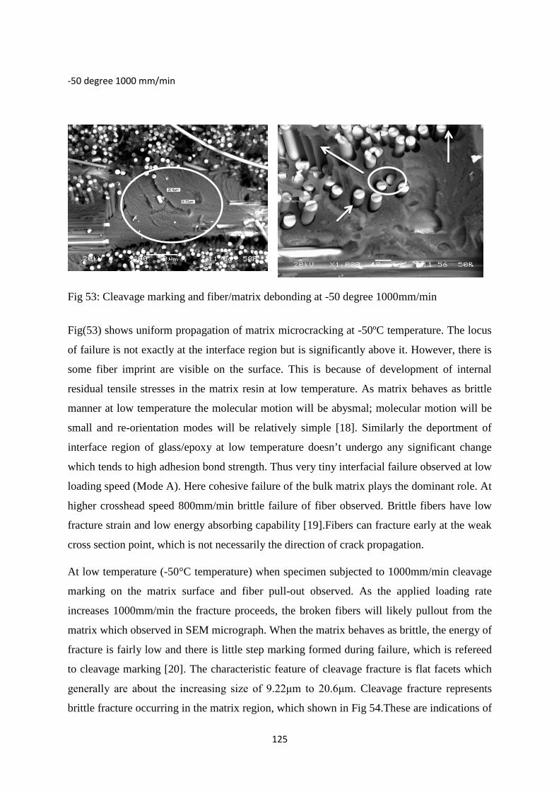
125
Fig 53: Cleavage marking and fiber/matrix debonding at -50 degree 1000mm/min
Fig(53) shows uniform propagation of matrix microcracking at -50ºC temperature. The locus
of failure is not exactly at the interface region but is significantly above it. However, there is
some fiber imprint are visible on the surface. This is because of development of internal
residual tensile stresses in the matrix resin at low temperature. As matrix behaves as brittle
manner at low temperature the molecular motion will be abysmal; molecular motion will be
small and re-orientation modes will be relatively simple [18]. Similarly the deportment of
interface region of glass/epoxy at low temperature doesn’t undergo any significant change
which tends to high adhesion bond strength. Thus very tiny interfacial failure observed at low
loading speed (Mode A). Here cohesive failure of the bulk matrix plays the dominant role. At
higher crosshead speed 800mm/min brittle failure of fiber observed. Brittle fibers have low
fracture strain and low energy absorbing capability [19].Fibers can fracture early at the weak
cross section point, which is not necessarily the direction of crack propagation.
At low temperature (-50°C temperature) when specimen subjected to 1000mm/min cleavage
marking on the matrix surface and fiber pull-out observed. As the applied loading rate
increases 1000mm/min the fracture proceeds, the broken fibers will likely pullout from the
matrix which observed in SEM micrograph. When the matrix behaves as brittle, the energy of
fracture is fairly low and there is little step marking formed during failure, which is refereed
to cleavage marking [20]. The characteristic feature of cleavage fracture is flat facets which
generally are about the increasing size of 9.22μm to 20.6μm. Cleavage fracture represents
brittle fracture occurring in the matrix region, which shown in Fig 54.These are indications of
‐50 degree 1000 mm/min
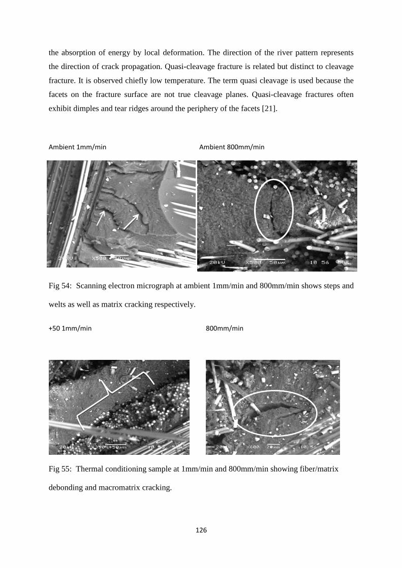
126
the absorption of energy by local deformation. The direction of the river pattern represents
the direction of crack propagation. Quasi-cleavage fracture is related but distinct to cleavage
fracture. It is observed chiefly low temperature. The term quasi cleavage is used because the
facets on the fracture surface are not true cleavage planes. Quasi-cleavage fractures often
exhibit dimples and tear ridges around the periphery of the facets [21].
Ambient 1mm/min Ambient 800mm/min
Fig 54: Scanning electron micrograph at ambient 1mm/min and 800mm/min shows steps and
welts as well as matrix cracking respectively.
+50 1mm/min
800mm/min
Fig 55: Thermal conditioning sample at 1mm/min and 800mm/min showing fiber/matrix
debonding and macromatrix cracking.

127
In contrast to the foregoing phenomena, fracture surface of ambient samples subjected to
1mm/min, 800mm/min and 1000mm/min was shown in Fig (54) display fiber pull-out, steps
and welts, tiny nodules on the matrix surface, matrix cracking, and progressive interfacial
debonding. In addition, there are significant changes in the morphology of the matrix
fracture. Besides that, other important matrix fracture is scraps and ribbons. When multiple
microcracks are formed and begin to propagate in several planes, and they subsequently
converge onto one plane. Ambient temperature signifies the beginning of the steps and welts
as well as macromatrix cracking. Both the things are parallel to the fracture propagation
direction. This failure mode was observed at low loading speed. The steps are identified by
toughened matrix or smooth region, while welts are identified by ribbons. If the crack planes
overlap before they coalesce to form scarp [22]. When the loading rate increases 800 mm/min
density of crack plane increases and macomatrix cracking plays the dominant role.
Above discussions associated with matrix failure modes at high as well as low temperature,
which are responsible for integrity and durability of polymer matrix composites.
Fig (55) shows fiber/matrix debonding as well as cohesive failure of matrix at low and high
loading rate respectively at +50º C temperatures. Damage initiation for cohesive failure
observed at the matrix resin where severity of stress state occurred.
4.3.4 Conclusions
In this investigation, an experimental study was carried out on the failure of GFRP
composites in thermal and cryogenic environment. Parameters such as temperature and
loading rate were considered to assess and evaluate mechanical behavior. The present study
may possibly reveal the following conclusions:
The percentage of ILSS value decreases during above-ambient temperature testing in every
mode of loading rate ranges because of thermal conditioning effect which leads to spreading
of process zone in the matrix resin which impart high fiber/matrix debonding.
In contrast to, at sub-ambient temperature the percentage of ILSS value increases in Mode A,
phase and decreases in Mode B and C due to unstable crack propagation (adiabatic heating)
at the crack tip. This yield matrix microcracking to fiber fracture and then fiber pull-out.
In comparison when a virginal sample is tested the percentage of ILSS value increases in
each mode of loading speed which may be due to preexisting stable element (low-energy
crack) which divulge steps and welts along with matrix cracking in the matrix region.
128
The load carrying capacity and the strain at yield increases with increasing the loading rate in
each environmental conditioning treatment.
References
1. Saponara V.L. Environmental and chemical degradation of carbon/epoxy and
structural adhesive for aerospace applications: Fickian and anomalous diffusion,
Arrhenius kinetics; Compos. Struct. 2001; 93: 2180-2195
2. Collings T.A., Mead D.L. Effect of high temperature spikes on a carbon fibre-
reinforced epoxy laminate, Composites; 1988;19: 61-66
3. Takeda T., Takano S., Shindo Y.,Narita F. Deformation and progressive failure
behavior of woven-fabric-reinforced glass/epoxy composite laminates under tensile
loading at cryogenic temperatures, Compos. Sci. Technol.; 2005;65: 1691-1702
4. Haddad H., Kobaisi M.A, Influence of moisture content on the thermal and
mechanical properties and curing behavior of polymeric matrix and polymer concrete
composite, Mater. Des.;2013;49:850–856
5. Moyeenuddin Ahmad S., Abdullah A. M., Holdsworth P.G., Long term durability of
pultruded polymer composite rebar inconcrete environment, Mater. Des.;2014;
57:616–624
6. Sjogren B.A., Berglund L.A., The effects of matrix and interface on damage in GRP
cross-ply laminates, Compos. Sci. Technol, 2000; 60: 9-21
7. Kim R.Y, Steve L. D. Experimental and analytical studies on the damage initiation in
composite laminates at cryogenic temperatures. Compos. Struct. 2006;76:62-66
8. Choi S, Sankar B V; Fracture toughness of transverse cracks in graphite/epoxy
laminates at cryogenic conditions; Compos part B- ENG 2007;38;193-200
9. Fiedler B, Hojo M., Ochiai S., Schulte K., Ando M., Failure behavior of an epoxy
matrix under different kinds of static loading, Compos. Sci Tech 2001;61; 1615-1624
10. Jiang B, Huang YD; Investigation of the impregnation degree of the prepreg by near
infrared spectroscopy; Composites Part B; 2011;41:946-948
11. Grunenfelder L K, Nutt S R; Void formation in composite prepregs – Effect of
dissolved moisture Compos. Sci. Technol. 2010;70:2304-230
12. Boey F Y C, Lye S.W; Void reduction in autoclave processing of thermoset
composites Part 1: High pressure on void reduction. Composites; 1992;23:261-265
129
13. Okoli, O.I, Smith, G.F. The Effect of Strain Rate and Fiber Content on the Poisson’s
ration of Glass/epoxy Composites, Compos. Struct. 2000; 48:157-161.
14. M.Z. Shah Khan, G. Simpson, E.P. Gellert, Resistance of glass-fibre reinforced
polymer composites to increasing compressive strain rates and loading rates,
Composite Part A ; 2000;31:57–67
15. Shim S B, Seferis J.C, Eom S Y, Shim Y.T; Thermal characterization and comparison
of structural prepregs with different cure temperature. Thermochim. Acta 1997;
291:73-79
16. Ray B. C.; Temperature effect during humid ageing on interfaces of glass and carbon
Fibers reinforced epoxy composites. J. Colloid Interf.Sci. 2006; 298:111-117
17. Sethi S. Panda P., Nayak R., Ray B.C., Experimental studies on mechanical behavior
and microstructural assessment of glass/epoxy composites at low temperature, J.
Reinf. Plast. Compos. 2011;31:77-84
18. Gilat, A., Goldberg, R.K., Roberts, G.D; Experimental Study of Strain-rate-dependent
Behavior of Carbon/epoxy Composite. Compos. Sci. Technol. 2002; 62: 1469-1476.
19. Saatkamp T., Hartwig G.; Fracture energy of polymer at low temperatures.
Cryogenics 1991; 31: 234-237.
20. Hartwig G., Polymer properties at room and cryogenic temperatures. New Work,
Plenum Press.1994
21. Kim K, Mai Y W, Engineered Interfaces in Fiber Reinforced Composites. Kidlington
Oxford U.K, Elsevier Publication. 1998
22. Greenhalgh E S. Failure analysis and fractography of polymer composites
Cambridge,UK CRC Publication, Woodhead Publishing, 2009
Please Note: The present results and discussions have already been published partly in Materials and Design, 2014, 64,160-165
130
4.4 Thermal cycle on interlaminar shear strength of FRP composites.
Theories and Thoughts Polymer composite materials are ultra-light anisotropic and heterogeneous infrastructural
materials, a popularly introduced in the last few years in wide range of applications.
However, their exceptional durability and integrity of mechanical performances, they are
vulnerable to aggressive natural environmental conditioning factors such as harsh
temperature variations, moisture, UV radiation and some cyclic exposure. It is widely
accepted that special caution needs to be observed when using these materials to manufacture
mechanically critical airframe components inside a full-scale structure. Carbon fibre
reinforced plastics (CFRP) are currently the most used composites in the aeronautical
industry (for example in the Boeing 787 and the currently in development Airbus 350 XWB).
4.4.1 Introduction Widespread application spectrum of FRP’s covers almost every type of advanced
engineering structures. Their usage includes various components in aircraft, helicopters,
spacecraft, boats, ships, offshore platforms and also in automobiles, chemical
processing equipment, sports goods, and civil infrastructure such as buildings and
bridges [1]. The behaviour and performance of advanced structural FRP composites cannot
be explained only in terms of specific properties of its constituent fibre and matrix
but the existing interface/interphase between fibre and matrix has great significance as
well [2, 3]. The presence of moisture at the interface can modify the interfacial
adhesion thereby affecting the mechanical performance of the FRP composites. During
thermal cycling differential coefficient of thermal expansions and residual stresses is a main
cause in FRP composite material. The behavior of the interfacial contact between fibre and
matrix is strongly influenced by the presence and nature of residual stresses[4].A very large
thermal expansion mismatch may result in debonding at the fiber/matrix interface and/or a
possible matrix cracking due to thermal stress [5-7].The fiber/matrix interface is likely to
affect the overall mechanical behavior of fiber-reinforced composites. The present
investigation related to study the thermal cycle effects on glass fibre and carbon fibre/epoxy
composites laminates.
131
4.4.2Materials and Methods
4.4.2.1 Materials
The material system selected for this work was E-glass fibre/epoxy and carbon fibre/epoxy
polymer composites fabricated by hand lay-up method followed by compression moulding
process. Diglycidyl ether of Bisphenol A (DGEBA) as epoxy and Triethylene tetra amine
(TETA) as hardener supplied by Atul Industries Ltd, Gujarat, India under the trade name
Lapox, L-12 and K-6 respectively.The volume fraction of fibres is 60%. The ratio of epoxy
and hardener is taken as10:1. The laminated composites has been prepared by hand lay-up
method with 16 layers of woven fabric cloth of reinforcement and then placed in a
compression moulding process. Then the curing of the laminate has been carried out at 60°C
temperature and 15 kg/cm2 pressure for 20 minutes. The laminates were then removed from
the press and kept at room temperature for 24 hours. The test specimens have been cut from
the laminates using diamond tipped cutter as per ASTM D2344-13 standard.
4.4.2.2 Methods and characterization techniques
Universal Testing machine
3-point short-beam shear tests were performed on a 30KN capacity Instron testing machine.
The thermal cycling testing in presence of moisture and low temperature was conducted with
specimens with an ultra-low environmental chamber. Moisture absorption was conducted in a
multifunctional chamber of humidity. The thermal cycle divided into 3 cycle as half-cycle,
full-cycle and one and half-cycle. In half cycle we only consider samples exposed to moisture
for 24 hr and then suddenly transferred to ultra-low chamber at -20°C for 4 hr. In case of full-
cycle specimens again exposed to moisture for 48 hr and then immediate transfer to at -20°C
temperature. Again in one and half cycle anain the half cycle treatment was repeated for the
test. The tests were performed with six crosshead speeds viz; (1, 10, 100,200, 500, and 1000)
mm/min. For each point of testing 5 to 6 specimens were tested and the average value was
taken. The broken parts were observed under Scanning Electron Microscope (SEM) for the
fractographic analysis.
Scanning electron microscope(SEM) For analysis of composite fractography, SEM by JEOL-JSM 6480 LV with the acceleration
voltage of 15 kV was used. Cleaned, small in size and conductive samples are used during
testing in SEM. the top surface of the specimens were coated with platinum using a sputter
coater. The coating is used to make the surface conductive for scanning and prevents the
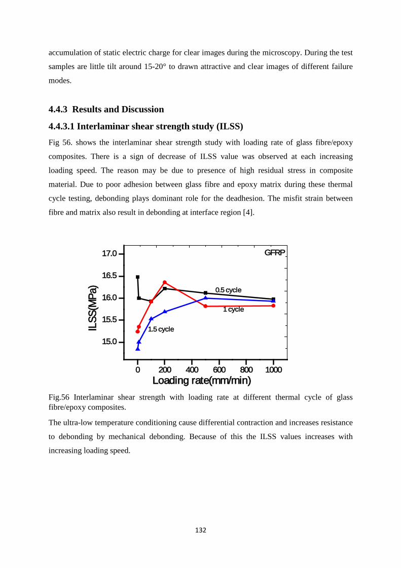
132
accumulation of static electric charge for clear images during the microscopy. During the test
samples are little tilt around 15-20° to drawn attractive and clear images of different failure
modes.
4.4.3 Results and Discussion
4.4.3.1 Interlaminar shear strength study (ILSS) Fig 56. shows the interlaminar shear strength study with loading rate of glass fibre/epoxy
composites. There is a sign of decrease of ILSS value was observed at each increasing
loading speed. The reason may be due to presence of high residual stress in composite
material. Due to poor adhesion between glass fibre and epoxy matrix during these thermal
cycle testing, debonding plays dominant role for the deadhesion. The misfit strain between
fibre and matrix also result in debonding at interface region [4].
0 200 400 600 800 1000
15.0
15.5
16.0
16.5
17.0
ILSS
(MPa
)
Loading rate(mm/min)
0.5 cycle
1 cycle
1.5 cycle
GFRP
Fig.56 Interlaminar shear strength with loading rate at different thermal cycle of glass fibre/epoxy composites.
The ultra-low temperature conditioning cause differential contraction and increases resistance
to debonding by mechanical debonding. Because of this the ILSS values increases with
increasing loading speed.
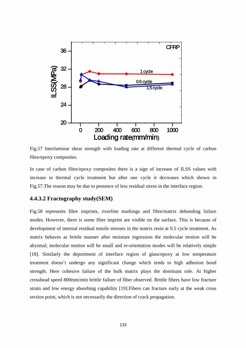
133
0 200 400 600 800 100020
24
28
32
36IL
SS(M
Pa)
Loading rate(mm/min)
0.5 cycle
1 cycle
1.5 cycle
CFRP
Fig.57 Interlaminar shear strength with loading rate at different thermal cycle of carbon
fibre/epoxy composites.
In case of carbon fibre/epoxy composites there is a sign of increase of ILSS values with
increase in thermal cycle treatment but after one cycle it decreases which shown in
Fig.57.The reason may be due to presence of less residual stress in the interface region.
4.4.3.2 Fractography study(SEM)
Fig.58 represents fibre imprints, riverline markings and fibre/matrix debonding failure
modes. However, there is some fiber imprint are visible on the surface. This is because of
development of internal residual tensile stresses in the matrix resin at 0.5 cycle treatment. As
matrix behaves as brittle manner after moisture ingression the molecular motion will be
abysmal; molecular motion will be small and re-orientation modes will be relatively simple
[18]. Similarly the deportment of interface region of glass/epoxy at low temperature
treatment doesn’t undergo any significant change which tends to high adhesion bond
strength. Here cohesive failure of the bulk matrix plays the dominant role. At higher
crosshead speed 800mm/min brittle failure of fiber observed. Brittle fibers have low fracture
strain and low energy absorbing capability [19].Fibers can fracture early at the weak cross
section point, which is not necessarily the direction of crack propagation.
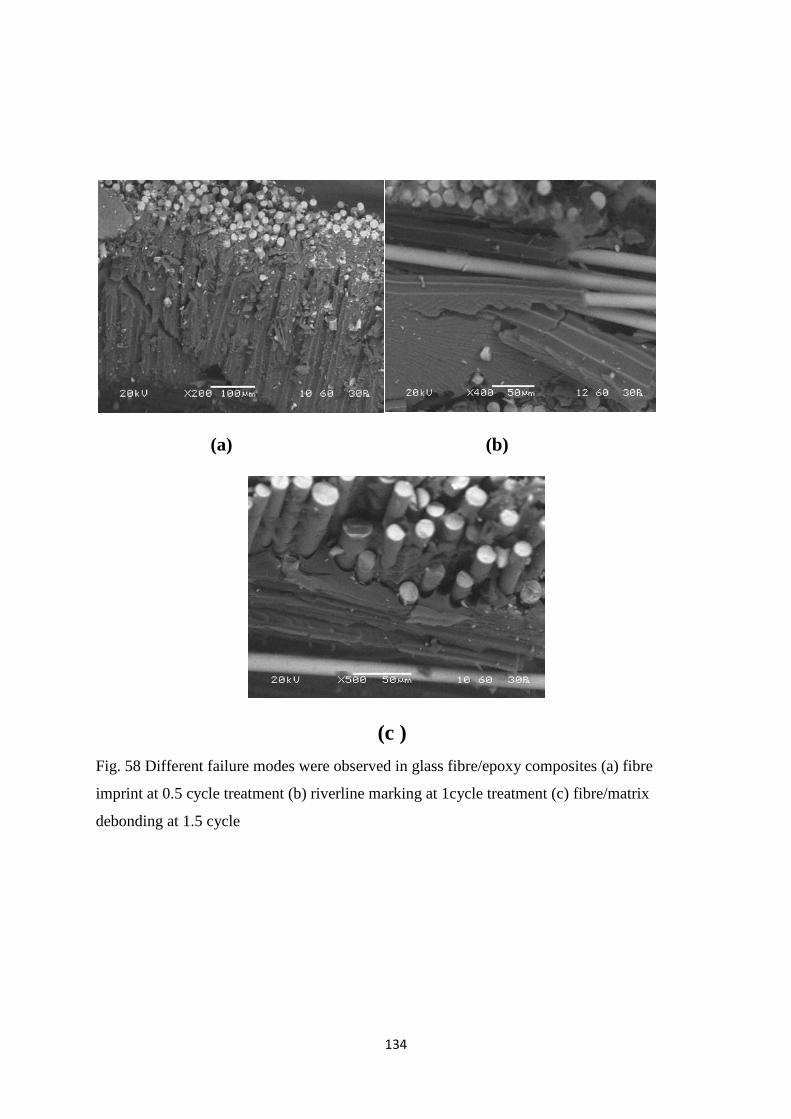
134
(a) (b)
(c ) Fig. 58 Different failure modes were observed in glass fibre/epoxy composites (a) fibre
imprint at 0.5 cycle treatment (b) riverline marking at 1cycle treatment (c) fibre/matrix
debonding at 1.5 cycle
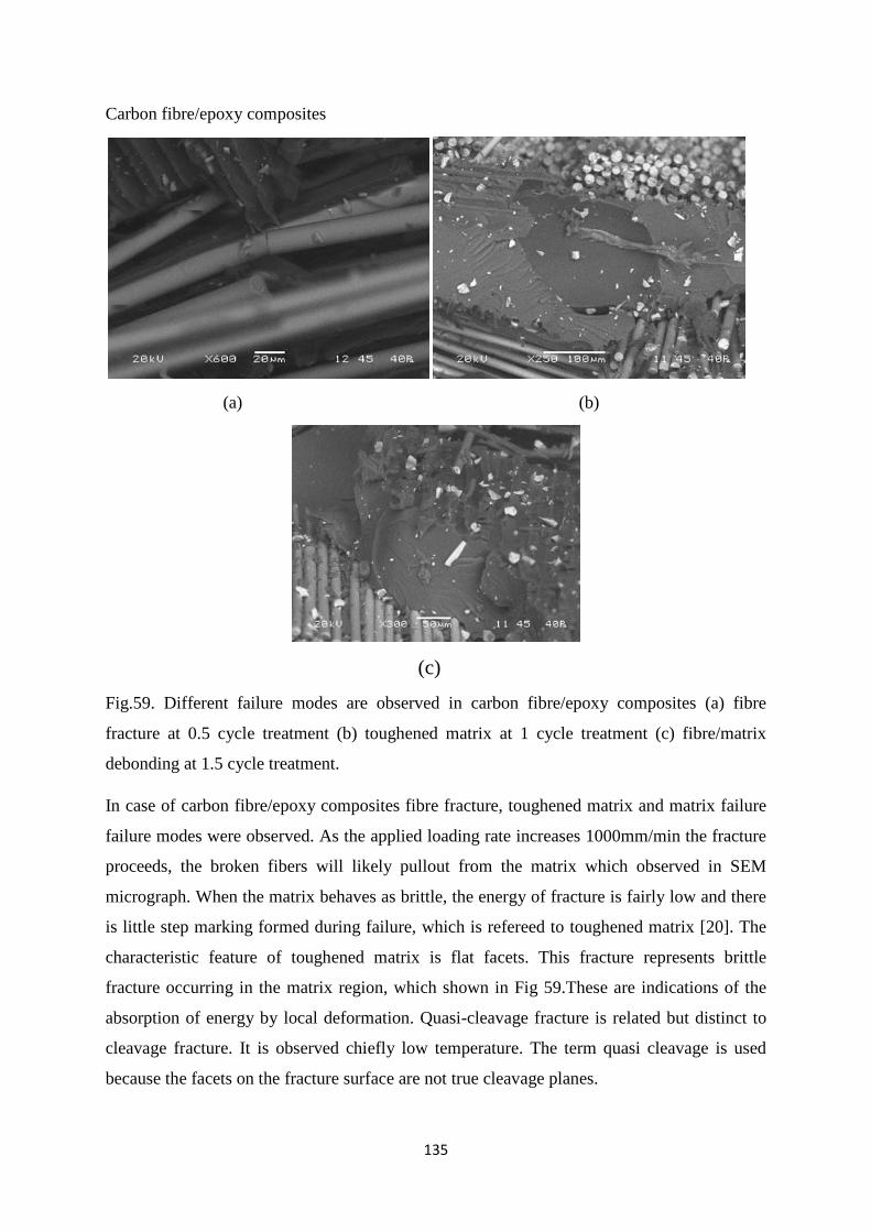
135
Carbon fibre/epoxy composites
(a) (b)
(c)
Fig.59. Different failure modes are observed in carbon fibre/epoxy composites (a) fibre
fracture at 0.5 cycle treatment (b) toughened matrix at 1 cycle treatment (c) fibre/matrix
debonding at 1.5 cycle treatment.
In case of carbon fibre/epoxy composites fibre fracture, toughened matrix and matrix failure
failure modes were observed. As the applied loading rate increases 1000mm/min the fracture
proceeds, the broken fibers will likely pullout from the matrix which observed in SEM
micrograph. When the matrix behaves as brittle, the energy of fracture is fairly low and there
is little step marking formed during failure, which is refereed to toughened matrix [20]. The
characteristic feature of toughened matrix is flat facets. This fracture represents brittle
fracture occurring in the matrix region, which shown in Fig 59.These are indications of the
absorption of energy by local deformation. Quasi-cleavage fracture is related but distinct to
cleavage fracture. It is observed chiefly low temperature. The term quasi cleavage is used
because the facets on the fracture surface are not true cleavage planes.
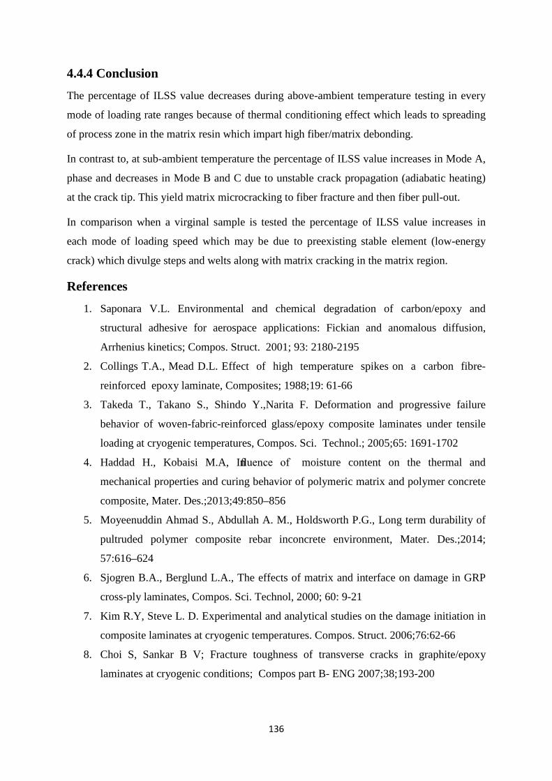
136
4.4.4 Conclusion
The percentage of ILSS value decreases during above-ambient temperature testing in every
mode of loading rate ranges because of thermal conditioning effect which leads to spreading
of process zone in the matrix resin which impart high fiber/matrix debonding.
In contrast to, at sub-ambient temperature the percentage of ILSS value increases in Mode A,
phase and decreases in Mode B and C due to unstable crack propagation (adiabatic heating)
at the crack tip. This yield matrix microcracking to fiber fracture and then fiber pull-out.
In comparison when a virginal sample is tested the percentage of ILSS value increases in
each mode of loading speed which may be due to preexisting stable element (low-energy
crack) which divulge steps and welts along with matrix cracking in the matrix region.
References
1. Saponara V.L. Environmental and chemical degradation of carbon/epoxy and
structural adhesive for aerospace applications: Fickian and anomalous diffusion,
Arrhenius kinetics; Compos. Struct. 2001; 93: 2180-2195
2. Collings T.A., Mead D.L. Effect of high temperature spikes on a carbon fibre-
reinforced epoxy laminate, Composites; 1988;19: 61-66
3. Takeda T., Takano S., Shindo Y.,Narita F. Deformation and progressive failure
behavior of woven-fabric-reinforced glass/epoxy composite laminates under tensile
loading at cryogenic temperatures, Compos. Sci. Technol.; 2005;65: 1691-1702
4. Haddad H., Kobaisi M.A, Influence of moisture content on the thermal and
mechanical properties and curing behavior of polymeric matrix and polymer concrete
composite, Mater. Des.;2013;49:850–856
5. Moyeenuddin Ahmad S., Abdullah A. M., Holdsworth P.G., Long term durability of
pultruded polymer composite rebar inconcrete environment, Mater. Des.;2014;
57:616–624
6. Sjogren B.A., Berglund L.A., The effects of matrix and interface on damage in GRP
cross-ply laminates, Compos. Sci. Technol, 2000; 60: 9-21
7. Kim R.Y, Steve L. D. Experimental and analytical studies on the damage initiation in
composite laminates at cryogenic temperatures. Compos. Struct. 2006;76:62-66
8. Choi S, Sankar B V; Fracture toughness of transverse cracks in graphite/epoxy
laminates at cryogenic conditions; Compos part B- ENG 2007;38;193-200
137
9. Fiedler B, Hojo M., Ochiai S., Schulte K., Ando M., Failure behavior of an epoxy
matrix under different kinds of static loading, Compos. Sci Tech 2001;61; 1615-1624
10. Jiang B, Huang YD; Investigation of the impregnation degree of the prepreg by near
infrared spectroscopy; Composites Part B; 2011;41:946-948
11. Grunenfelder L K, Nutt S R; Void formation in composite prepregs – Effect of
dissolved moisture Compos. Sci. Technol. 2010;70:2304-230
12. Boey F Y C, Lye S.W; Void reduction in autoclave processing of thermoset
composites Part 1: High pressure on void reduction. Composites; 1992;23:261-265
13. Okoli, O.I, Smith, G.F. The Effect of Strain Rate and Fiber Content on the Poisson’s
ration of Glass/epoxy Composites, Compos. Struct. 2000; 48:157-161.
4.5 Effect of UV treatment on loading rate sensitivity
Theories and Thoughts The many concurrent chemical processes taking place in polymers exposed to UV radiation
result in several different modes of damage, each progressing at a different rate. It is usually
the critical first-observed damage process that determines the useful service life of the Fibre
reinforced polymer composite material. The basic mechanism for photo-initiated degradation
is the same for all polymer materials. Damage occurs when lightphotons interact with the
molecular chains that make up the polymer structures.The shorter wavelengths
possessing higher photon energies are more strongly absorbed inmost polymeric materials,
and have a greater potential to break chemical bonds in thatmaterial. The objective of this
study is toinvestigate the above properties of glass fibre/epoxy laminated composites,
subjected to UVradiation attacks.
4.5.1 Introduction
Glass and carbon fibre -reinforced epoxy resin composites have received considerable
attention and are widely used as structural materials in the construction, automotive, and
aerospace industries [1–3]. These composites offer a variety of distinct advantages, including
high specific strength and stiffness, corrosion and fatigue resistance and ease of handling and
fabrication. However, there are concerns with their long-term durability and performance
during their service life under harsh and changing environmental conditions. Ultraviolet
(UV) light from the solar spectrum combined with atmospheric oxygen is potentially
amongst the most damaging weathering conditions which affect polymers deleteriously, re
138
ferred to as photo-oxidation [4–6]. UV light can be absorbed by the chromophoric groups
present in the polymers and the energy absorbed can cause the dissociation of the polymer
covalent bonds (mostly C–C and C–H) to produce free radicals, followed by molecular chain
scission and/or cross-linking. Chain cross-linking during photo-oxidation reactions reduces
molecular mobility and in turn results in excessive embrittlement of the polymer matrix,
which is mainly responsible for the formation of microcracks [7,8]. Photo-oxidation also
induces the formation of the UV-absorbing chromophores which impart discoloration to the
polymer if theyabsorb visible wavelengths. Furthermore, they can decompose tonew free
radicals, activating the auto-oxidative degradation process [8]. At an elevated temperature,
the oxidative reactions areaccelerated, which in turn results in rapid degradation. The aim of
this investigation related to study the loading rate sensitivity of glass fibre/epoxy and carbon
fibre/epoxy composites when subjected to UV radiation effects.
4.5.2 Materials and Methods
4.5.2.1 Materials
The material system selected for this work was E-glass fibre/epoxy and carbon fibre/epoxy
polymer composites fabricated by hand lay-up method followed by compression moulding
process. Diglycidyl ether of Bisphenol A (DGEBA) as epoxy and Triethylene tetra amine
(TETA) as hardener supplied by Atul Industries Ltd, Gujarat, India under the trade name
Lapox, L-12 and K-6 respectively.The volume fraction of fibres is 60%. The ratio of epoxy
and hardener is taken as10:1. The laminated composites has been prepared by hand lay-up
method with 16 layers of woven fabric cloth of reinforcement and then placed in a
compression moulding process. Then the curing of the laminate has been carried out at 60°C
temperature and 15 kg/cm2 pressure for 20 minutes. The laminates were then removed from
the press and kept at room temperature for 24 hours. The test specimens have been cut from
the laminates using diamond tipped cutter as per ASTM D2344-13 standard.
4.5.2.2 Methods and characterization techniques
Universal Testing machine
3-point short-beam shear tests were performed on a 30KN capacity Instron testing machine.
The thermal cycling testing in presence of moisture and low temperature was conducted with
specimens with an ultra-low environmental chamber. Moisture absorption was conducted in a
multifunctional chamber of humidity. The thermal cycle divided into 3 cycle as half-cycle,
full-cycle and one and half-cycle. In half cycle we only consider samples exposed to moisture

139
for 24 hr and then suddenly transferred to ultra-low chamber at -20°C for 4 hr. In case of full-
cycle specimens again exposed to moisture for 48 hr and then immediate transfer to at -20°C
temperature. Again in one and half cycle again the half cycle treatment was repeated for the
test. The tests were performed with six crosshead speeds viz; (1, 10, 100,200, 500, and 1000)
mm/min. For each point of testing 5 to 6 specimens were tested and the average value was
taken. The broken parts were observed under Scanning Electron Microscope (SEM) for the
fractographic analysis.
Scanning electron microscope (SEM)
For analysis of composite fractography, SEM by JEOL-JSM 6480 LV with the acceleration
voltage of 15 kV was used. Cleaned, small in size and conductive samples are used during
testing in SEM. the top surface of the specimens were coated with platinum using a sputter
coater. The coating is used to make the surface conductive for scanning and prevents the
accumulation of static electric charge for clear images during the microscopy. During the test
samples are little tilt around 15-20° to drawn attractive and clear images of different failure
modes.
4.5.3 Results and Discussion
Interlaminar shear strength with loading rate study Fig.60 represents the variation of interlaminar shear strength with loading rate of glass fibre/epoxy and carbon fibre/epoxy composites subjected to UV treatment in different time duration.
Fig.60 Interlaminar shear strength with loading rate at different time exposure of UV
treatment (a) carbon fibre/epoxy composites (b) glass fibre/epoxy composites.
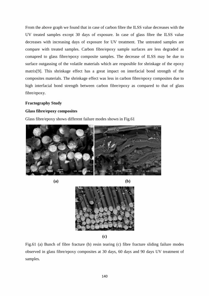
140
From the above graph we found that in case of carbon fibre the ILSS value decreases with the
UV treated samples except 30 days of exposure. In case of glass fibre the ILSS value
decreases with increasing days of exposure for UV treatment. The untreated samples are
compare with treated samples. Carbon fibre/epoxy sample surfaces are less degraded as
comapred to glass fibre/epoxy composite samples. The decrease of ILSS may be due to
surface outgassing of the volatile materials which are resposible for shrinkage of the epoxy
matrix[9]. This shrinkage effect has a great impact on interfacial bond strength of the
composites materials. The shrinkage effect was less in carbon fibre/epoxy composites due to
high interfacial bond strength between carbon fibre/epoxy as compared to that of glass
fibre/epoxy.
Fractography Study
Glass fibre/epoxy composites
Glass fibre/epoxy shows different failure modes shown in Fig.61
(a) (b)
(c)
Fig.61 (a) Bunch of fibre fracture (b) resin tearing (c) fibre fracture sliding failure modes
observed in glass fibre/epoxy composites at 30 days, 60 days and 90 days UV treatment of
samples.
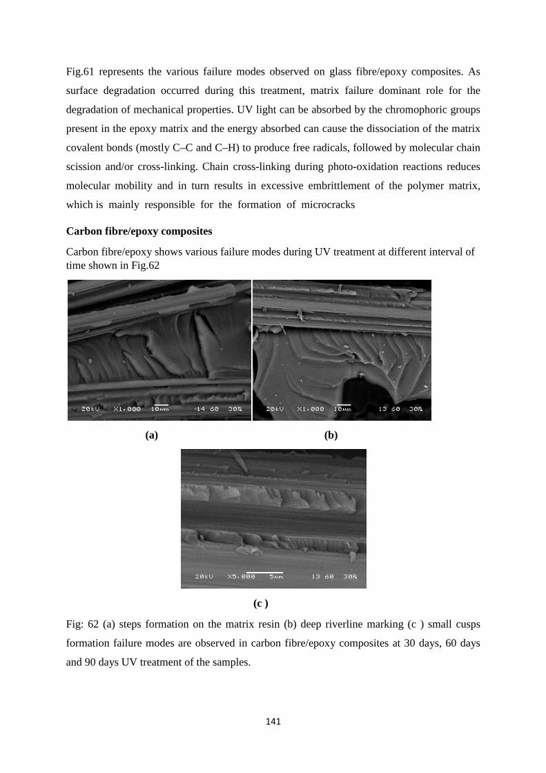
141
Fig.61 represents the various failure modes observed on glass fibre/epoxy composites. As
surface degradation occurred during this treatment, matrix failure dominant role for the
degradation of mechanical properties. UV light can be absorbed by the chromophoric groups
present in the epoxy matrix and the energy absorbed can cause the dissociation of the matrix
covalent bonds (mostly C–C and C–H) to produce free radicals, followed by molecular chain
scission and/or cross-linking. Chain cross-linking during photo-oxidation reactions reduces
molecular mobility and in turn results in excessive embrittlement of the polymer matrix,
which is mainly responsible for the formation of microcracks
Carbon fibre/epoxy composites
Carbon fibre/epoxy shows various failure modes during UV treatment at different interval of time shown in Fig.62
(a) (b)
(c )
Fig: 62 (a) steps formation on the matrix resin (b) deep riverline marking (c ) small cusps
formation failure modes are observed in carbon fibre/epoxy composites at 30 days, 60 days
and 90 days UV treatment of the samples.
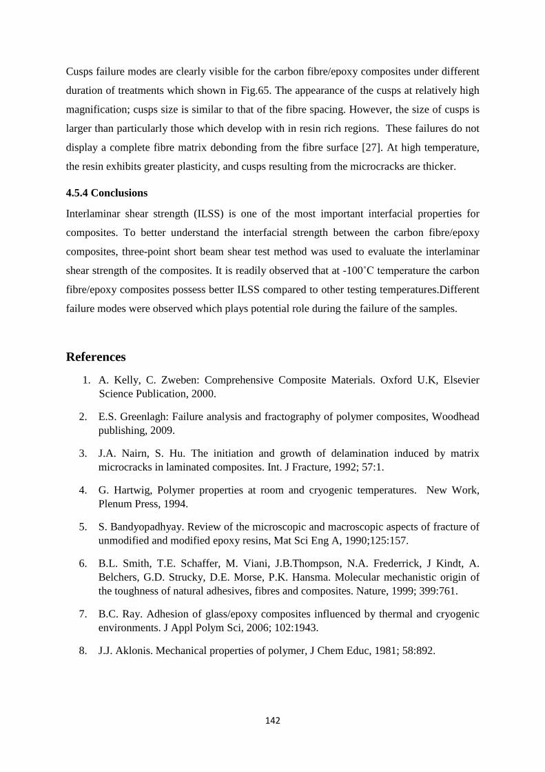
142
Cusps failure modes are clearly visible for the carbon fibre/epoxy composites under different
duration of treatments which shown in Fig.65. The appearance of the cusps at relatively high
magnification; cusps size is similar to that of the fibre spacing. However, the size of cusps is
larger than particularly those which develop with in resin rich regions. These failures do not
display a complete fibre matrix debonding from the fibre surface [27]. At high temperature,
the resin exhibits greater plasticity, and cusps resulting from the microcracks are thicker.
4.5.4 Conclusions
Interlaminar shear strength (ILSS) is one of the most important interfacial properties for
composites. To better understand the interfacial strength between the carbon fibre/epoxy
composites, three-point short beam shear test method was used to evaluate the interlaminar
shear strength of the composites. It is readily observed that at -100˚C temperature the carbon
fibre/epoxy composites possess better ILSS compared to other testing temperatures.Different
failure modes were observed which plays potential role during the failure of the samples.
References
1. A. Kelly, C. Zweben: Comprehensive Composite Materials. Oxford U.K, Elsevier Science Publication, 2000.
2. E.S. Greenlagh: Failure analysis and fractography of polymer composites, Woodhead publishing, 2009.
3. J.A. Nairn, S. Hu. The initiation and growth of delamination induced by matrix microcracks in laminated composites. Int. J Fracture, 1992; 57:1.
4. G. Hartwig, Polymer properties at room and cryogenic temperatures. New Work, Plenum Press, 1994.
5. S. Bandyopadhyay. Review of the microscopic and macroscopic aspects of fracture of unmodified and modified epoxy resins, Mat Sci Eng A, 1990;125:157.
6. B.L. Smith, T.E. Schaffer, M. Viani, J.B.Thompson, N.A. Frederrick, J Kindt, A. Belchers, G.D. Strucky, D.E. Morse, P.K. Hansma. Molecular mechanistic origin of the toughness of natural adhesives, fibres and composites. Nature, 1999; 399:761.
7. B.C. Ray. Adhesion of glass/epoxy composites influenced by thermal and cryogenic environments. J Appl Polym Sci, 2006; 102:1943.
8. J.J. Aklonis. Mechanical properties of polymer, J Chem Educ, 1981; 58:892.
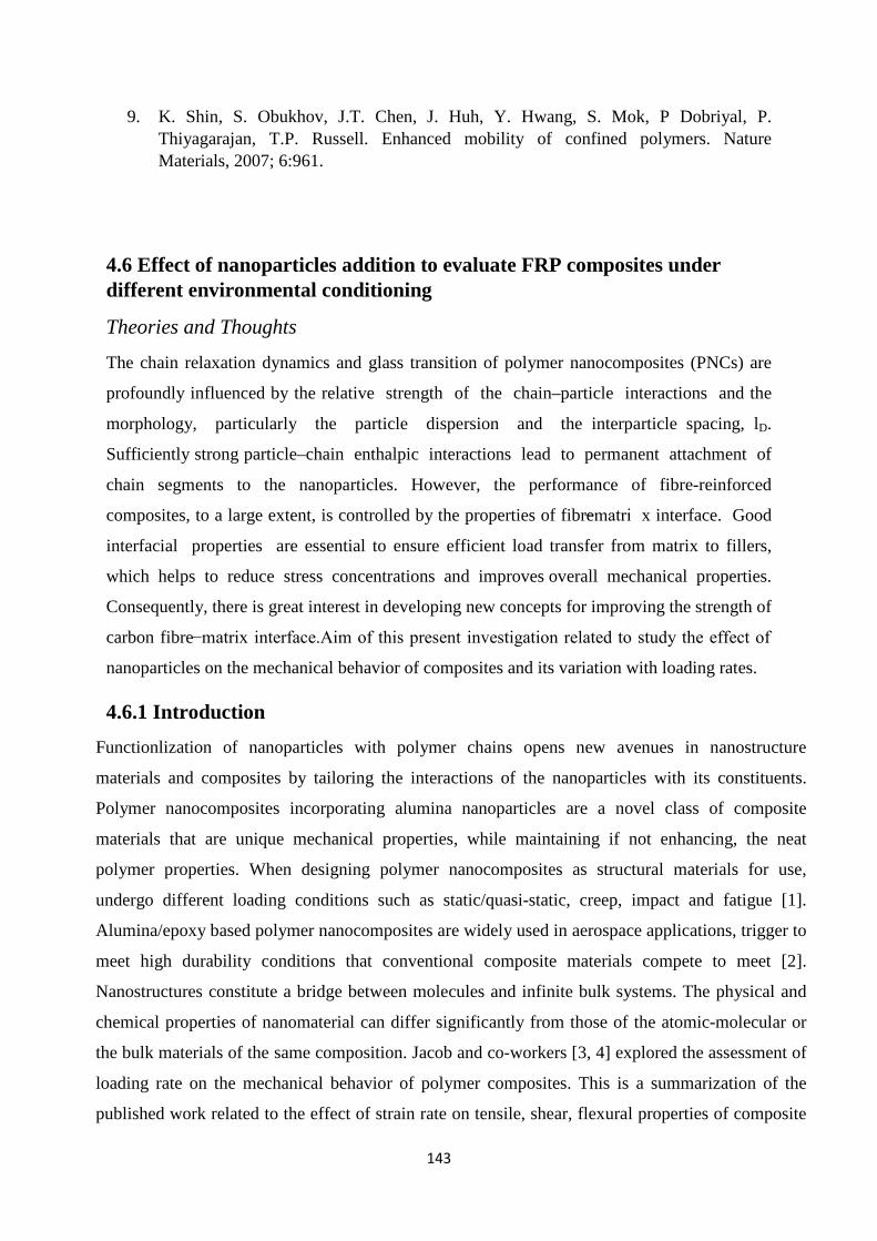
143
9. K. Shin, S. Obukhov, J.T. Chen, J. Huh, Y. Hwang, S. Mok, P Dobriyal, P. Thiyagarajan, T.P. Russell. Enhanced mobility of confined polymers. Nature Materials, 2007; 6:961.
4.6 Effect of nanoparticles addition to evaluate FRP composites under different environmental conditioning
Theories and Thoughts
The chain relaxation dynamics and glass transition of polymer nanocomposites (PNCs) are
profoundly influenced by the relative strength of the chain–particle interactions and the
morphology, particularly the particle dispersion and the interparticle spacing, lD.
Sufficiently strong particle–chain enthalpic interactions lead to permanent attachment of
chain segments to the nanoparticles. However, the performance of fibre-reinforced
composites, to a large extent, is controlled by the properties of fibre−matri x interface. Good
interfacial properties are essential to ensure efficient load transfer from matrix to fillers,
which helps to reduce stress concentrations and improves overall mechanical properties.
Consequently, there is great interest in developing new concepts for improving the strength of
carbon fibre−matrix interface.Aim of this present investigation related to study the effect of
nanoparticles on the mechanical behavior of composites and its variation with loading rates.
4.6.1 Introduction Functionlization of nanoparticles with polymer chains opens new avenues in nanostructure
materials and composites by tailoring the interactions of the nanoparticles with its constituents.
Polymer nanocomposites incorporating alumina nanoparticles are a novel class of composite
materials that are unique mechanical properties, while maintaining if not enhancing, the neat
polymer properties. When designing polymer nanocomposites as structural materials for use,
undergo different loading conditions such as static/quasi-static, creep, impact and fatigue [1].
Alumina/epoxy based polymer nanocomposites are widely used in aerospace applications, trigger to
meet high durability conditions that conventional composite materials compete to meet [2].
Nanostructures constitute a bridge between molecules and infinite bulk systems. The physical and
chemical properties of nanomaterial can differ significantly from those of the atomic-molecular or
the bulk materials of the same composition. Jacob and co-workers [3, 4] explored the assessment of
loading rate on the mechanical behavior of polymer composites. This is a summarization of the
published work related to the effect of strain rate on tensile, shear, flexural properties of composite
144
materials. The strain-rate sensitivity is less pronounced at higher conditioning time. It may be
assumed that the failure mechanisms are loading rate sensitivity phenomenon [5]. Hence, in recent
years introducing rigid nanofillers as alumina into epoxy resin to form polymer-matrix
nanocomposites has become a popular method for improving mechanical properties of epoxy-based
composites materials [6-10]. Zhao.Su. et al reported APTES-Al2O3/epoxy nanocomposites exhibits
increase in fracture energy at 10-15 phr due because of good adhesion level. Debonding, plastic
void growth and plastic deformation of matrix are the key reason of increase of fracture energy
[11].
Current interest in alumina/epoxy nanocomposites has been generated and maintained because
nanoparticles filled polymers exhibit unique combinations of properties not achievable with
conventional composites. In the present study, glass fiber reinforced composites filled with alumina
nanoparticle have been prepared. Alumina nanoparticle was well dispersed in epoxy polymer matrix
to achieved high mechanical performance. The results show that it is possible to improve the
interlaminar shear strength with the loading rate variations. Clearly, no follow-up work in this area
will be commendation for better understanding of effect of nanoparticle in FRP composites in
assessment of loading rate sensitivity.
4.6.2 Methods and experiments Experiments were performed using alumina nanoparticles-epoxy based glass reinforced polymer
nanocomposites. Alumina particles with an average size of 10μm and < 50 nm were purchased from
Sigma Aldrich of was selected as the reinforcement materials. Experiments were performed using
samples that had fabricated as per ASTM standard 2344-10 having dimensions 60× 40×4 mm3.
Epoxy-alumina nanocomposites were prepared via magnetic stirrer and sonicatior methods. 1hpr of
alumina nanoparticles was added to epoxy at 70°C to reduce resin viscosity and then thoroughly
stirred on a magnetic stirrer for 10 min followed by sonicating with sonicater to break any
aggregates. The directionality of woven roving in GFRP composites was 0°/90°, and the fabric had
plain weave architecture. After curing, the laminate was cut into the required size for 3-point bend
(Short- Beam Shear) test by diamond cutter. Specimens were tested from two conditions panels
with six loading speed (3 specimens each) for each test in INSTRON (Model 5967). The results
were then compared with the data obtained from unconditioned specimens. The shear stress induced
in a beam subjected to a bending load, is directly proportional to the magnitude of the applied load
and independent of the span length. Flexure strain expression in BLUE-Hill software for 3-point
bend test is
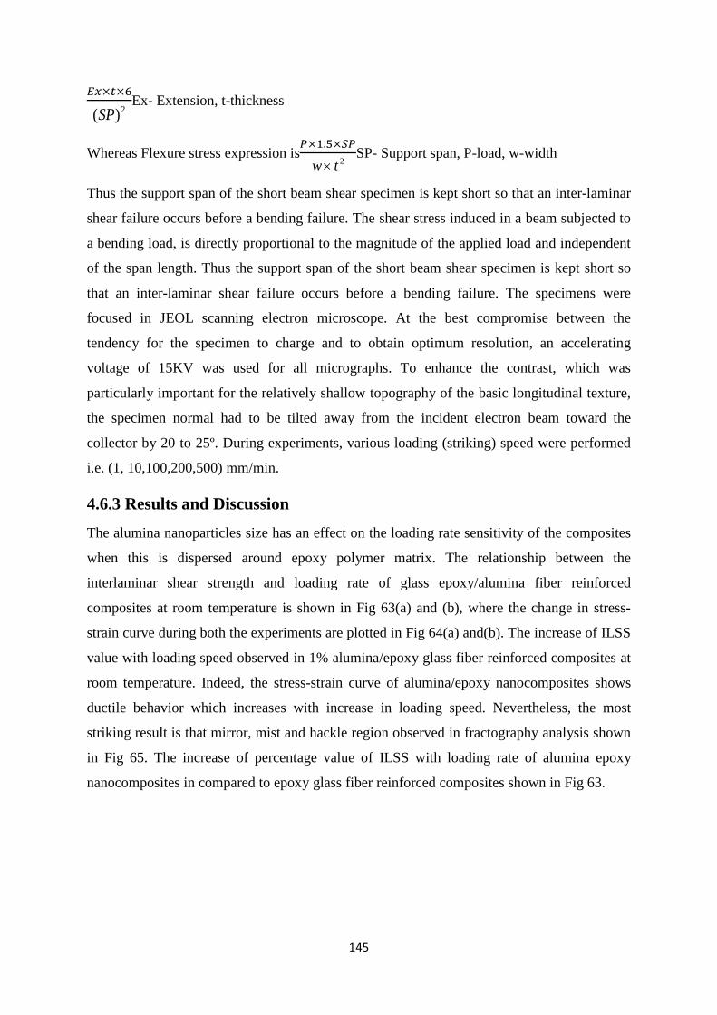
145
𝐸𝑥×𝑡×62)(SP
Ex- Extension, t-thickness
Whereas Flexure stress expression is𝑃×1.5×𝑆𝑃
2tw×SP- Support span, P-load, w-width
Thus the support span of the short beam shear specimen is kept short so that an inter-laminar
shear failure occurs before a bending failure. The shear stress induced in a beam subjected to
a bending load, is directly proportional to the magnitude of the applied load and independent
of the span length. Thus the support span of the short beam shear specimen is kept short so
that an inter-laminar shear failure occurs before a bending failure. The specimens were
focused in JEOL scanning electron microscope. At the best compromise between the
tendency for the specimen to charge and to obtain optimum resolution, an accelerating
voltage of 15KV was used for all micrographs. To enhance the contrast, which was
particularly important for the relatively shallow topography of the basic longitudinal texture,
the specimen normal had to be tilted away from the incident electron beam toward the
collector by 20 to 25º. During experiments, various loading (striking) speed were performed
i.e. (1, 10,100,200,500) mm/min.
4.6.3 Results and Discussion
The alumina nanoparticles size has an effect on the loading rate sensitivity of the composites
when this is dispersed around epoxy polymer matrix. The relationship between the
interlaminar shear strength and loading rate of glass epoxy/alumina fiber reinforced
composites at room temperature is shown in Fig 63(a) and (b), where the change in stress-
strain curve during both the experiments are plotted in Fig 64(a) and(b). The increase of ILSS
value with loading speed observed in 1% alumina/epoxy glass fiber reinforced composites at
room temperature. Indeed, the stress-strain curve of alumina/epoxy nanocomposites shows
ductile behavior which increases with increase in loading speed. Nevertheless, the most
striking result is that mirror, mist and hackle region observed in fractography analysis shown
in Fig 65. The increase of percentage value of ILSS with loading rate of alumina epoxy
nanocomposites in compared to epoxy glass fiber reinforced composites shown in Fig 63.
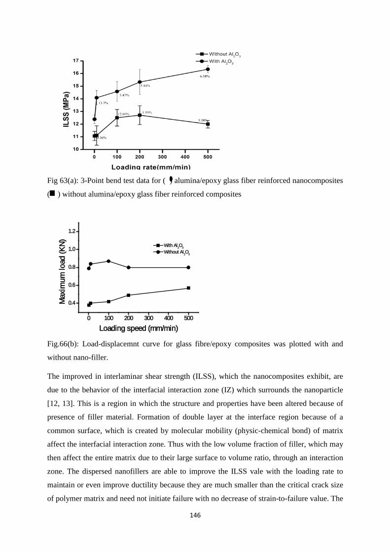
146
Fig 63(a): 3-Point bend test data for ( ) alumina/epoxy glass fiber reinforced nanocomposites
( ) without alumina/epoxy glass fiber reinforced composites
0 100 200 300 400 500
0.4
0.6
0.8
1.0
1.2
Max
imum
load
(KN)
Loading speed (mm/min)
With Al2O3
Without Al2O3
Fig.66(b): Load-displacemnt curve for glass fibre/epoxy composites was plotted with and
without nano-filler.
The improved in interlaminar shear strength (ILSS), which the nanocomposites exhibit, are
due to the behavior of the interfacial interaction zone (IZ) which surrounds the nanoparticle
[12, 13]. This is a region in which the structure and properties have been altered because of
presence of filler material. Formation of double layer at the interface region because of a
common surface, which is created by molecular mobility (physic-chemical bond) of matrix
affect the interfacial interaction zone. Thus with the low volume fraction of filler, which may
then affect the entire matrix due to their large surface to volume ratio, through an interaction
zone. The dispersed nanofillers are able to improve the ILSS vale with the loading rate to
maintain or even improve ductility because they are much smaller than the critical crack size
of polymer matrix and need not initiate failure with no decrease of strain-to-failure value. The
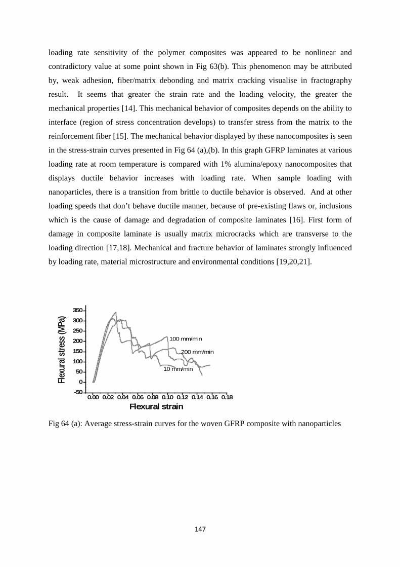
147
loading rate sensitivity of the polymer composites was appeared to be nonlinear and
contradictory value at some point shown in Fig 63(b). This phenomenon may be attributed
by, weak adhesion, fiber/matrix debonding and matrix cracking visualise in fractography
result. It seems that greater the strain rate and the loading velocity, the greater the
mechanical properties [14]. This mechanical behavior of composites depends on the ability to
interface (region of stress concentration develops) to transfer stress from the matrix to the
reinforcement fiber [15]. The mechanical behavior displayed by these nanocomposites is seen
in the stress-strain curves presented in Fig 64 (a),(b). In this graph GFRP laminates at various
loading rate at room temperature is compared with 1% alumina/epoxy nanocomposites that
displays ductile behavior increases with loading rate. When sample loading with
nanoparticles, there is a transition from brittle to ductile behavior is observed. And at other
loading speeds that don’t behave ductile manner, because of pre-existing flaws or, inclusions
which is the cause of damage and degradation of composite laminates [16]. First form of
damage in composite laminate is usually matrix microcracks which are transverse to the
loading direction [17,18]. Mechanical and fracture behavior of laminates strongly influenced
by loading rate, material microstructure and environmental conditions [19,20,21].
0.00 0.02 0.04 0.06 0.08 0.10 0.12 0.14 0.16 0.18-50
0
50
100
150
200
250
300
350
Flexu
ral s
tress
(MPa
)
Flexural strain
10 mm/min
100 mm/min
200 mm/min
Fig 64 (a): Average stress-strain curves for the woven GFRP composite with nanoparticles
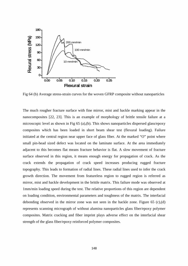
148
0.00 0.05 0.10 0.15 0.20 0.25
0
30
60
90
120
150
180Fl
exur
al st
ress
(MPa
)
Flexural strain
10 mm/min
100 mm/min
200 mm/min
Fig 64 (b) Average stress-strain curves for the woven GFRP composite without nanoparticles
The much rougher fracture surface with fine mirror, mist and hackle marking appear in the
nanocomposites [22, 23]. This is an example of morphology of brittle tensile failure at a
microscopic level as shown in Fig 65 (a),(b). This shows nanoparticles dispersed glass/epoxy
composites which has been loaded in short beam shear test (flexural loading). Failure
initiated at the central region near upper face of glass fiber. At the marked “O” point where
small pin-head sized defect was located on the laminate surface. At the area immediately
adjacent to this becomes flat means fracture behavior is flat. A slow movement of fracture
surface observed in this region, it means enough energy for propagation of crack. As the
crack extends the propagation of crack speed increases producing rugged fracture
topography. This leads to formation of radial lines. These radial lines used to infer the crack
growth direction. The movement from featureless region to rugged region is referred as
mirror, mist and hackle development in the brittle matrix. This failure mode was observed at
1mm/min loading speed during the test. The relative proportions of this region are dependent
on loading condition, environmental parameters and toughness of the matrix. The interfacial
debonding observed in the mirror zone was not seen in the hackle zone. Figure 65 (c),(d)
represents scanning micrograph of without alumina nanoparticles glass fiber/epoxy polymer
composites. Matrix cracking and fiber imprint plays adverse effect on the interfacial shear
strength of the glass fiber/epoxy reinforced polymer composites.
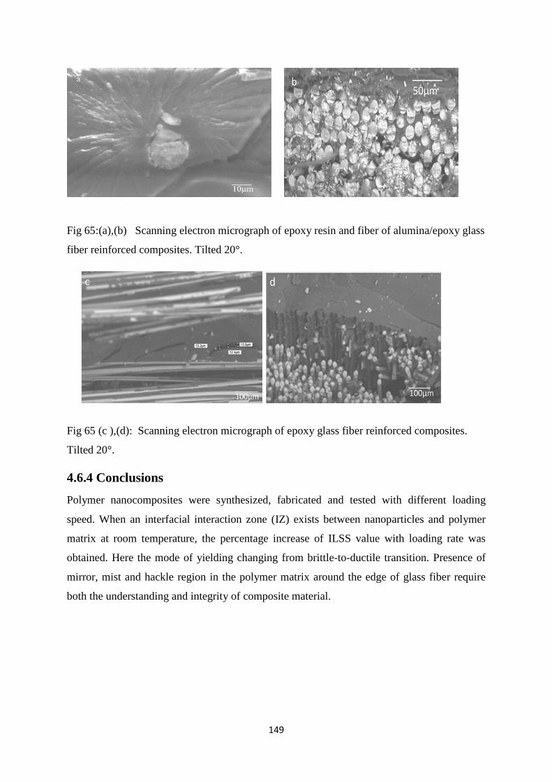
149
Fig 65:(a),(b) Scanning electron micrograph of epoxy resin and fiber of alumina/epoxy glass
fiber reinforced composites. Tilted 20°.
Fig 65 (c ),(d): Scanning electron micrograph of epoxy glass fiber reinforced composites.
Tilted 20°.
4.6.4 Conclusions
Polymer nanocomposites were synthesized, fabricated and tested with different loading
speed. When an interfacial interaction zone (IZ) exists between nanoparticles and polymer
matrix at room temperature, the percentage increase of ILSS value with loading rate was
obtained. Here the mode of yielding changing from brittle-to-ductile transition. Presence of
mirror, mist and hackle region in the polymer matrix around the edge of glass fiber require
both the understanding and integrity of composite material.

150
References
1. Naik N.K.: Mater Design, 2010, Vol.31, pp. 396-401. 2. Njuguna.J. and Pielichouski. K: Adv Eng Mater, 2003, Vol.5, pp. 769-778. 3. Jacob G.C., Starbuck J.M. Fellers. J.F., Simunovic. S., Boeman. R.G.: J.Appl.
Polym.Sci, 2005, Vol.96, pp. 899-904 4. Jacob G.C., Starbuck J.M. Fellers. J.F., Simunovic. S., Boeman. R.G., J.Appl.
Polym.Sci., 2004, Vol.94, pp. 296-301 5. Ray B.C.: Mater.Sci.Eng.A., 2004, Vol.379, pp. 39-44 6. Omrani. A., Simon. L.C., Rostami. A.A.:Mater.Chem.Phys, 2009, Vol.114, pp145-
150. 7. Zeng.K.Y, Lim.S.H, He.C.B: Mater.Sci. Eng.A, 2010, Vol.527, pp. 5670-5676 8. Wetzel. B., Rosso.P, Friedrich.K: Eng. Fract. Mech., 2006,Vol.73,pp.2375-2398 9. Wetzel.B., Haupert. F., Zhang.Q.M: Compos. Sci.Technol., 2003,Vol.63,pp.2055-
2067 10. Quaresimin.M.,Salviato., M.,Zappalorto.M.: Composites Part
B.,2012,Vol.43,pp.2290-2297 11. Van Vliet.K.J., Schmidt. D.J.,Cebeci.,F.C.,Kalcioglu.L.,Wyman.S.G.,Ortiz.C.,
ACSNano, 2009, Vol.3 ,pp.2207-2216 12. Gamby.D. Nguyen.T.H.: Compos. Sci. Technol.,2007,Vol.67,pp.438-452 13. Khan.M.Z.S.,Simpson.G.,Gellert.E.P.:Composites Part A.,2000,Vol.31,pp.57-67 14. Wong.C.P., Sun.Y., Zhang.Z.,Moon.K.S.:J. Polym. Sci.Part B:Polym.Phys.
2004.Vol.42.,pp.3849-3858 15. Tjong.S.C.: Mater. Sci. Eng. R, 2006, Vol.53, pp.73-197 16. Singh.R.P.:Material letters,2004. Vol.58,pp.408-412 17. Ray. B.C.: J. Reinf.Plast. Compos.,2005, Vol.24, pp.1771-1776 18. Ray.B.C.: J. Reinf. Plast. Compos., 2006, Vol.25, pp.1227-1240 19. Ray.B.C.,: J. Colloid Interface. Sci, 2006., Vol.298, pp.111-117 20. Ray.B.C.:J. Reinf. Plast. Compos., 2006, Vol.25, pp.329-333 21. Ray.B.C.: J.Appl.Polym. Sci., 2006,Vol.100,pp.2289-2292 22. Vaia.R.A.,Maguire.J.F.: Chem. Mater., 2007. Vol.19, pp.2736-2751 23. Pitsa.D. and Danikas. M.G: Nano: Brief report and reviews. 2011,vol.6, pp. 497-508
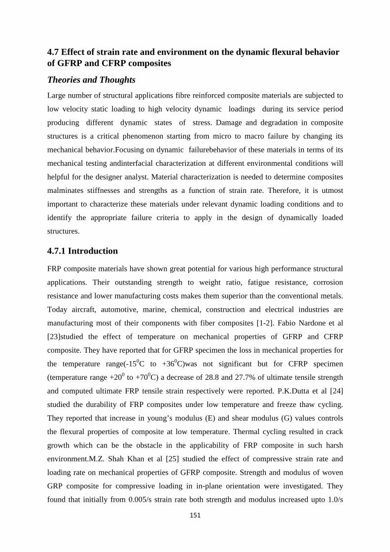
151
4.7 Effect of strain rate and environment on the dynamic flexural behavior of GFRP and CFRP composites
Theories and Thoughts Large number of structural applications fibre reinforced composite materials are subjected to
low velocity static loading to high velocity dynamic loadings during its service period
producing different dynamic states of stress. Damage and degradation in composite
structures is a critical phenomenon starting from micro to macro failure by changing its
mechanical behavior.Focusing on dynamic failurebehavior of these materials in terms of its
mechanical testing andinterfacial characterization at different environmental conditions will
helpful for the designer analyst. Material characterization is needed to determine composites
malminates stiffnesses and strengths as a function of strain rate. Therefore, it is utmost
important to characterize these materials under relevant dynamic loading conditions and to
identify the appropriate failure criteria to apply in the design of dynamically loaded
structures.
4.7.1 Introduction
FRP composite materials have shown great potential for various high performance structural
applications. Their outstanding strength to weight ratio, fatigue resistance, corrosion
resistance and lower manufacturing costs makes them superior than the conventional metals.
Today aircraft, automotive, marine, chemical, construction and electrical industries are
manufacturing most of their components with fiber composites [1-2]. Fabio Nardone et al
[23]studied the effect of temperature on mechanical properties of GFRP and CFRP
composite. They have reported that for GFRP specimen the loss in mechanical properties for
the temperature range(-150C to +360C)was not significant but for CFRP specimen
(temperature range +200 to +700C) a decrease of 28.8 and 27.7% of ultimate tensile strength
and computed ultimate FRP tensile strain respectively were reported. P.K.Dutta et al [24]
studied the durability of FRP composites under low temperature and freeze thaw cycling.
They reported that increase in young’s modulus (E) and shear modulus (G) values controls
the flexural properties of composite at low temperature. Thermal cycling resulted in crack
growth which can be the obstacle in the applicability of FRP composite in such harsh
environment.M.Z. Shah Khan et al [25] studied the effect of compressive strain rate and
loading rate on mechanical properties of GFRP composite. Strength and modulus of woven
GRP composite for compressive loading in in-plane orientation were investigated. They
found that initially from 0.005/s strain rate both strength and modulus increased upto 1.0/s
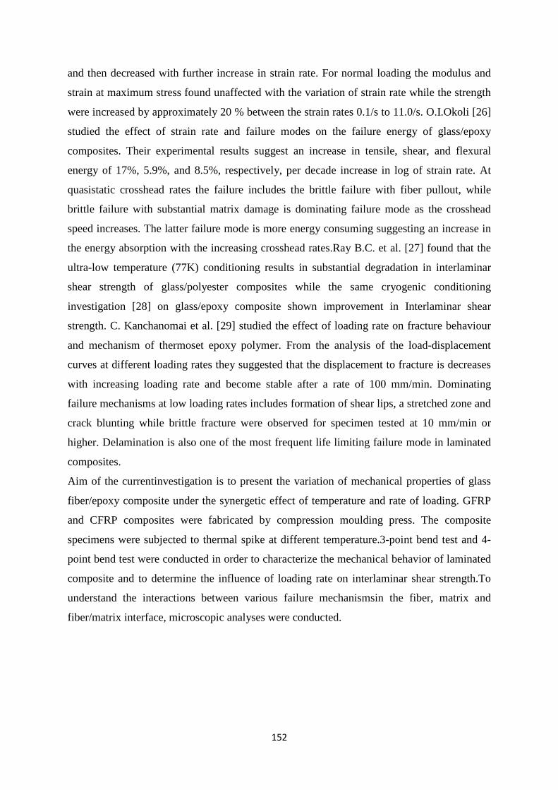
152
and then decreased with further increase in strain rate. For normal loading the modulus and
strain at maximum stress found unaffected with the variation of strain rate while the strength
were increased by approximately 20 % between the strain rates 0.1/s to 11.0/s. O.I.Okoli [26]
studied the effect of strain rate and failure modes on the failure energy of glass/epoxy
composites. Their experimental results suggest an increase in tensile, shear, and flexural
energy of 17%, 5.9%, and 8.5%, respectively, per decade increase in log of strain rate. At
quasistatic crosshead rates the failure includes the brittle failure with fiber pullout, while
brittle failure with substantial matrix damage is dominating failure mode as the crosshead
speed increases. The latter failure mode is more energy consuming suggesting an increase in
the energy absorption with the increasing crosshead rates.Ray B.C. et al. [27] found that the
ultra-low temperature (77K) conditioning results in substantial degradation in interlaminar
shear strength of glass/polyester composites while the same cryogenic conditioning
investigation [28] on glass/epoxy composite shown improvement in Interlaminar shear
strength. C. Kanchanomai et al. [29] studied the effect of loading rate on fracture behaviour
and mechanism of thermoset epoxy polymer. From the analysis of the load-displacement
curves at different loading rates they suggested that the displacement to fracture is decreases
with increasing loading rate and become stable after a rate of 100 mm/min. Dominating
failure mechanisms at low loading rates includes formation of shear lips, a stretched zone and
crack blunting while brittle fracture were observed for specimen tested at 10 mm/min or
higher. Delamination is also one of the most frequent life limiting failure mode in laminated
composites.
Aim of the currentinvestigation is to present the variation of mechanical properties of glass
fiber/epoxy composite under the synergetic effect of temperature and rate of loading. GFRP
and CFRP composites were fabricated by compression moulding press. The composite
specimens were subjected to thermal spike at different temperature.3-point bend test and 4-
point bend test were conducted in order to characterize the mechanical behavior of laminated
composite and to determine the influence of loading rate on interlaminar shear strength.To
understand the interactions between various failure mechanismsin the fiber, matrix and
fiber/matrix interface, microscopic analyses were conducted.
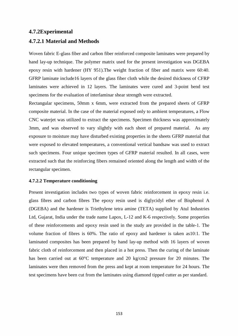
153
4.7.2Experimental
4.7.2.1 Material and Methods
Woven fabric E-glass fiber and carbon fiber reinforced composite laminates were prepared by
hand lay-up technique. The polymer matrix used for the present investigation was DGEBA
epoxy resin with hardener (HY 951).The weight fraction of fiber and matrix were 60:40.
GFRP laminate include16 layers of the glass fiber cloth while the desired thickness of CFRP
laminates were achieved in 12 layers. The laminates were cured and 3-point bend test
specimens for the evaluation of interlaminar shear strength were extracted.
Rectangular specimens, 50mm x 6mm, were extracted from the prepared sheets of GFRP
composite material. In the case of the material exposed only to ambient temperatures, a Flow
CNC waterjet was utilized to extract the specimens. Specimen thickness was approximately
3mm, and was observed to vary slightly with each sheet of prepared material. As any
exposure to moisture may have disturbed existing properties in the sheets GFRP material that
were exposed to elevated temperatures, a conventional vertical bandsaw was used to extract
such specimens. Four unique specimen types of GFRP material resulted. In all cases, were
extracted such that the reinforcing fibers remained oriented along the length and width of the
rectangular specimen.
4.7.2.2 Temperature conditioning
Present investigation includes two types of woven fabric reinforcement in epoxy resin i.e.
glass fibres and carbon fibres The epoxy resin used is diglycidyl ether of Bisphenol A
(DGEBA) and the hardener is Triethylene tetra amine (TETA) supplied by Atul Industries
Ltd, Gujarat, India under the trade name Lapox, L-12 and K-6 respectively. Some properties
of these reinforcements and epoxy resin used in the study are provided in the table-1. The
volume fraction of fibres is 60%. The ratio of epoxy and hardener is taken as10:1. The
laminated composites has been prepared by hand lay-up method with 16 layers of woven
fabric cloth of reinforcement and then placed in a hot press. Then the curing of the laminate
has been carried out at 60°C temperature and 20 kg/cm2 pressure for 20 minutes. The
laminates were then removed from the press and kept at room temperature for 24 hours. The
test specimens have been cut from the laminates using diamond tipped cutter as per standard.
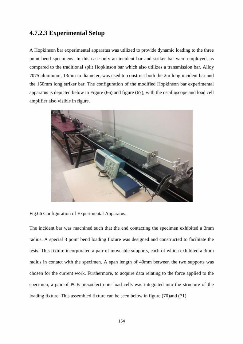
154
4.7.2.3 Experimental Setup
A Hopkinson bar experimental apparatus was utilized to provide dynamic loading to the three
point bend specimens. In this case only an incident bar and striker bar were employed, as
compared to the traditional split Hopkinson bar which also utilizes a transmission bar. Alloy
7075 aluminum, 13mm in diameter, was used to construct both the 2m long incident bar and
the 150mm long striker bar. The configuration of the modified Hopkinson bar experimental
apparatus is depicted below in Figure (66) and figure (67), with the oscilloscope and load cell
amplifier also visible in figure.
Fig.66 Configuration of Experimental Apparatus.
The incident bar was machined such that the end contacting the specimen exhibited a 3mm
radius. A special 3 point bend loading fixture was designed and constructed to facilitate the
tests. This fixture incorporated a pair of moveable supports, each of which exhibited a 3mm
radius in contact with the specimen. A span length of 40mm between the two supports was
chosen for the current work. Furthermore, to acquire data relating to the force applied to the
specimen, a pair of PCB piezoelectronic load cells was integrated into the structure of the
loading fixture. This assembled fixture can be seen below in figure (70)and (71).
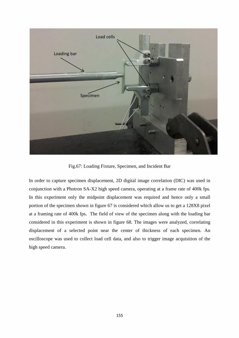
155
Fig.67: Loading Fixture, Specimen, and Incident Bar
In order to capture specimen displacement, 2D digital image correlation (DIC) was used in
conjunction with a Photron SA-X2 high speed camera, operating at a frame rate of 400k fps.
In this experiment only the midpoint displacement was required and hence only a small
portion of the specimen shown in figure 67 is considered which allow us to get a 128X8 pixel
at a framing rate of 400k fps. The field of view of the specimen along with the loading bar
considered in this experiment is shown in figure 68. The images were analyzed, correlating
displacement of a selected point near the center of thickness of each specimen. An
oscilloscope was used to collect load cell data, and also to trigger image acquisition of the
high speed camera.
Load cells
Specimen
Loading bar
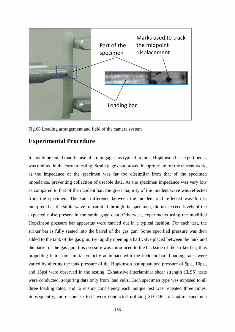
156
Fig.68 Loading arrangement and field of the camera system
Experimental Procedure
It should be noted that the use of strain gages, as typical in most Hopkinson bar experiments,
was omitted in the current testing. Strain gage data proved inappropriate for the current work,
as the impedance of the specimen was far too dissimilar from that of the specimen
impedance, preventing collection of useable data. As the specimen impedance was very low
as compared to that of the incident bar, the great majority of the incident wave was reflected
from the specimen. The sum difference between the incident and reflected waveforms,
interpreted as the strain wave transmitted through the specimen, did not exceed levels of the
expected noise present in the strain gage data. Otherwise, experiments using the modified
Hopkinson pressure bar apparatus were carried out in a typical fashion. For each test, the
striker bar is fully seated into the barrel of the gas gun. Some specified pressure was then
added to the tank of the gas gun. By rapidly opening a ball valve placed between the tank and
the barrel of the gas gun, this pressure was introduced to the backside of the striker bar, thus
propelling it to some initial velocity at impact with the incident bar. Loading rates were
varied by altering the tank pressure of the Hopkinson bar apparatus; pressure of 5psi, 10psi,
and 15psi were observed in the testing. Exhaustive interlaminar shear strength (ILSS) tests
were conducted, acquiring data only from load cells. Each specimen type was exposed to all
three loading rates, and to ensure consistency each unique test was repeated three times.
Subsequently, more concise tests were conducted utilizing 2D DIC to capture specimen
Marks used to track the midpoint displacement
Loading bar
Part of the specimen

157
displacement. Using load data acquired from the load cells in conjunction with displacement
observed using DIC, stress-strain relationships could be plotted. Such testing was done for
each specimen type, exposed to each of the three loading rates described.
Data analysis
Maximum flexural stress
The stress for three-point bend spacemen can be calculated for any point on the load-deflection curve by the following equation.
223bhPL
=σ (1)
Where; σ = stress at the outer surface at mid-spam (MPa) p = applied force (N) L = support span (mm) b= width of beam (mm) h = thickness of beam (mm)
According to the ASTM standard D7264, the maximum flexural stress for the specimen can
be obtained from load data and should be valid up to 2% strain. In our experiment the strain
before fracture are lower than2 %, hence calculating the maximum flexural stress using the
ASTM standard D7264 is valid.
Similarly the maximum strain at the outer surface also occurs at mid-span, and it may be calculated as follows,
2
6L
hδε = (2)
Where: ε= maximum strain at the outer surface (mm/mm) δ = mid-span deflection (mm) L = support span (mm) h = thickness of beam (mm)
Finally, theinteerlaminar shear strength is calculated from the maximum shear stress. Using
elementary beam theory the maximum shear stress can be given as
WtP
43
=τ (3)
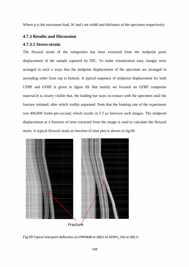
158
Where p is the maximum load, W and t are width and thickness of the specimen respectively.
4.7.3 Results and Discussion
4.7.3.1 Stress-strain The flexural strain of the composites has been extracted from the midpoint point
displacement of the sample captured by DIC. To make visualization easy, images were
arranged in such a ways that the midpoint displacement of the specimen are arranged in
ascending order from top to bottom. A typical sequence of midpoint displacement for both
CFRP and GFRP is given in figure 69. But mainly we focused on GFRP composite
material.It is clearly visible that, the loading bar stays in-contact with the specimen until the
fracture initiated, after which visibly separated. Note that the framing rate of the experiment
was 400,000 frame per-second, which results in 2.5 μs between each images. The midpoint
displacement as a function of time extracted from the image is used to calculate the flexural
strain. A typical flexural strain as function of time plot is shown in fig 69.
Fig 69 Typical mid‐point deflection a) CFRPAMB at 300/s b) GFRP5_250 at 500 /s
Fracture
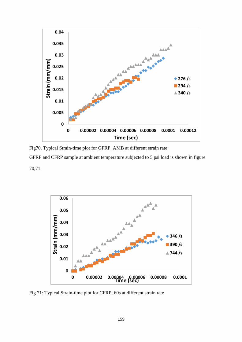
159
Fig70. Typical Strain-time plot for GFRP_AMB at different strain rate
GFRP and CFRP sample at ambient temperature subjected to 5 psi load is shown in figure
70,71.
Fig 71: Typical Strain-time plot for CFRP_60s at different strain rate
0
0.005
0.01
0.015
0.02
0.025
0.03
0.035
0.04
0 0.00002 0.00004 0.00006 0.00008 0.0001 0.00012
Stra
in (m
m/m
m)
Time (sec)
276 /s 294 /s 340 /s
0
0.01
0.02
0.03
0.04
0.05
0.06
0 0.00002 0.00004 0.00006 0.00008 0.0001
Stra
in (m
m/m
m)
Time (sec)
346 /s
390 /s
744 /s
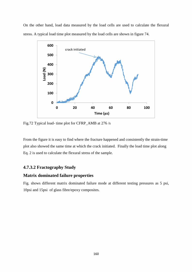
160
On the other hand, load data measured by the load cells are used to calculate the flexural
stress. A typical load time plot measured by the load cells are shown in figure 74.
Fig.72 Typical load- time plot for CFRP_AMB at 276 /s
From the figure it is easy to find where the fracture happened and consistently the strain-time
plot also showed the same time at which the crack initiated. Finally the load time plot along
Eq. 2 is used to calculate the flexural stress of the sample.
4.7.3.2 Fractography Study
Matrix dominated failure properties
Fig. shows different matrix dominated failure mode at different testing pressures as 5 psi,
10psi and 15psi of glass fibre/epoxy composites.
0
100
200
300
400
500
600
0 20 40 60 80 100
Load
(N)
Time (μs)
crack initiated

161
(a) (b)
(c )
Fig:73 (a) Angles cusps formation on the matrix surface at 5 psi (b) Cusps formation
between the fibres spacing at 10 psi (c) Cusps in very small size at 15 psi.
From the above micrographs shows Fig.73. different failure modes which are responsible for
the initiation and propagation of crack. As delaminations failure modes are always driven by
fibre directions and interfiber spacing, cusps are usually generated between the fibres. We
can observed that the size of the cusps are the size of the spacing between the fibres. In case
of 5psi, the cusps are formed only on the matrix region and not have any uniform
size.However at 10psi cusps orientation becomes more alignment with the fibre axis as
compared to 5 and 15psi which leads to more local failure of the glass fibre/epoxy composite
material. During thermal spike treatment the samples are leads to development of thermal
stresses. Thus the presence of these thermal stresses could be the reason for the formation of
cusps in the matrix resin. This induces the addition of extra stresses between fibre and matrix
interface which weakening the interfacial region.
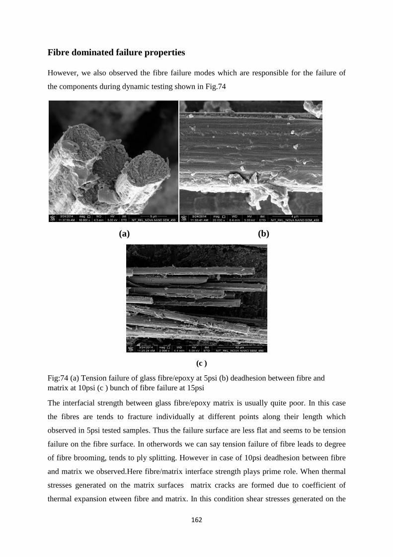
162
Fibre dominated failure properties
However, we also observed the fibre failure modes which are responsible for the failure of
the components during dynamic testing shown in Fig.74
(a) (b)
(c )
Fig:74 (a) Tension failure of glass fibre/epoxy at 5psi (b) deadhesion between fibre and matrix at 10psi (c ) bunch of fibre failure at 15psi
The interfacial strength between glass fibre/epoxy matrix is usually quite poor. In this case
the fibres are tends to fracture individually at different points along their length which
observed in 5psi tested samples. Thus the failure surface are less flat and seems to be tension
failure on the fibre surface. In otherwords we can say tension failure of fibre leads to degree
of fibre brooming, tends to ply splitting. However in case of 10psi deadhesion between fibre
and matrix we observed.Here fibre/matrix interface strength plays prime role. When thermal
stresses generated on the matrix surfaces matrix cracks are formed due to coefficient of
thermal expansion etween fibre and matrix. In this condition shear stresses generated on the

163
matrix surface which then parallel to the fibre axis and ultimately shear stress generated at the
interface region. This could be the reason for the deadhesion between fibre and matrix at
10psi. The bunch of fibre failure observed in 15psi tested samples.
4.7.4 Conclusions
A glass fibre/epoxy composite material was characterized over a wide range of strain rates,
from 104 to over 400 s-1 , at dynamic testing machine. Stress–strain curves to failure, mid-
point deflection were observed. It was found that, for the range of strain rates investigated,
time was linearly varies with strain rate. In case of load-time curve we can observed the
crack intiation time with the strain rate. Various failure modes were also observed which are
responsible for the failure of these materials. Different types of cusps are formed in the
matrix region with different strain rate whereas different fibre fracture also observed in the
conditioned samples.
References 1. White, S. R.; Sottos, N.; Geubelle, P.; Moore, J.; Kessler, M. R.; Sriram, S.; Brown, E.; Viswanathan, S., Autonomic Healing of Polymer Composites. Nature2001, 409, 794-797.
2. Katerelos, D.; Kashtalyan, M.; Soutis, C.; Galiotis, C., Matrix Cracking in Polymeric Composites Laminates: Modelling and Experiments. Composites Science and Technology2008, 68, 2310-2317.
3. Gamstedt, E.; Talreja, R., Fatigue Damage Mechanisms in Unidirectional Carbon-Fibre-Reinforced Plastics. Journal of Materials Science1999, 34, 2535-2546.
4. Ray, B.C., Temperature Effect During Humid Ageing on Interfaces of Glass and Carbon Fibers Reinforced Epoxy Composites. Journal of Colloid and Interface Science2006, 298, 111-117.
5. Ray, B.C., Thermal Shock on Interfacial Adhesion of Thermally Conditioned Glass Fiber/Epoxy Composites. Materials Letters2004, 58, 2175-2177.
6. Bandyopadhyay, A.; Valavala, P. K.; Clancy, T. C.; Wise, K. E.; Odegard, G. M., Molecular Modeling of Crosslinked Epoxy Polymers: The Effect of Crosslink Density on Thermomechanical Properties. Polymer2011, 52, 2445-2452.
7. Polanský, R.; Mentlík, V.; Prosr, P.; Sušír, J., Influence of Thermal Treatment on the Glass Transition Temperature of Thermosetting Epoxy Laminate. Polymer Testing2009, 28, 428-436.
8. Sun, P.; Zhao, Y.; Luo, Y.; Sun, L., Effect of Temperature and Cyclic Hygrothermal Aging on the Interlaminar Shear Strength of Carbon Fiber/Bismaleimide (Bmi) Composite. Materials & Design2011, 32, 4341-4347.
164
9. Takeda, T.; Miura, M.; Shindo, Y.; Narita, F., Fatigue Delamination Growth in Woven Glass/Epoxy Composite Laminates under Mixed-Mode Ii/Iii Loading Conditions at Cryogenic Temperatures. Cryogenics2013, 58, 55-61.
10. Jakobsen, J.; Jensen, M.; Andreasen, J. H., Thermo-Mechanical Characterisation of in-Plane Properties for Csm E-Glass Epoxy Polymer Composite Materials–Part 2: Young's Modulus. Polymer Testing2013, 32, 1417-1422.
11. Sethi, S.; Ray, B. C., An Assessment of Mechanical Behavior and Fractography Study of Glass/Epoxy Composites at Different Temperatures and Loading Speeds. Materials & Design2014, 64, 160-165.
12. Shah Khan, M.; Simpson, G.; Gellert, E., Resistance of Glass-Fibre Reinforced Polymer Composites to Increasing Compressive Strain Rates and Loading Rates. Composites Part A: Applied Science and Manufacturing2000, 31, 57-67.
13. Birger, S.; Moshonov, A.; Kenig, S., The Effects of Thermal and Hygrothermal Ageing on the Failure Mechanisms of Graphite-Fabric Epoxy Composites Subjected to Flexural Loading. Composites1989, 20, 341-348.
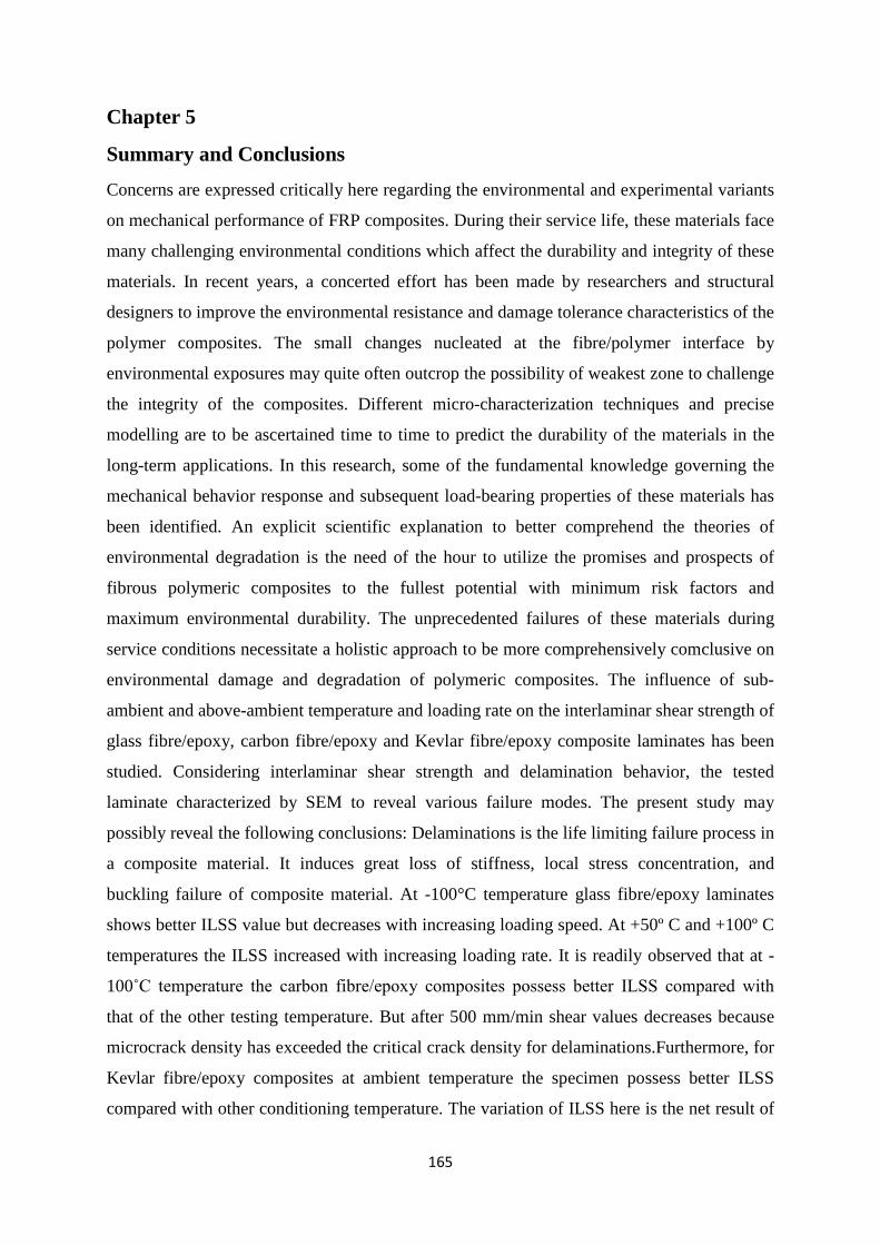
165
Chapter 5
Summary and Conclusions
Concerns are expressed critically here regarding the environmental and experimental variants
on mechanical performance of FRP composites. During their service life, these materials face
many challenging environmental conditions which affect the durability and integrity of these
materials. In recent years, a concerted effort has been made by researchers and structural
designers to improve the environmental resistance and damage tolerance characteristics of the
polymer composites. The small changes nucleated at the fibre/polymer interface by
environmental exposures may quite often outcrop the possibility of weakest zone to challenge
the integrity of the composites. Different micro-characterization techniques and precise
modelling are to be ascertained time to time to predict the durability of the materials in the
long-term applications. In this research, some of the fundamental knowledge governing the
mechanical behavior response and subsequent load-bearing properties of these materials has
been identified. An explicit scientific explanation to better comprehend the theories of
environmental degradation is the need of the hour to utilize the promises and prospects of
fibrous polymeric composites to the fullest potential with minimum risk factors and
maximum environmental durability. The unprecedented failures of these materials during
service conditions necessitate a holistic approach to be more comprehensively comclusive on
environmental damage and degradation of polymeric composites. The influence of sub-
ambient and above-ambient temperature and loading rate on the interlaminar shear strength of
glass fibre/epoxy, carbon fibre/epoxy and Kevlar fibre/epoxy composite laminates has been
studied. Considering interlaminar shear strength and delamination behavior, the tested
laminate characterized by SEM to reveal various failure modes. The present study may
possibly reveal the following conclusions: Delaminations is the life limiting failure process in
a composite material. It induces great loss of stiffness, local stress concentration, and
buckling failure of composite material. At -100°C temperature glass fibre/epoxy laminates
shows better ILSS value but decreases with increasing loading speed. At +50º C and +100º C
temperatures the ILSS increased with increasing loading rate. It is readily observed that at -
100˚C temperature the carbon fibre/epoxy composites possess better ILSS compared with
that of the other testing temperature. But after 500 mm/min shear values decreases because
microcrack density has exceeded the critical crack density for delaminations.Furthermore, for
Kevlar fibre/epoxy composites at ambient temperature the specimen possess better ILSS
compared with other conditioning temperature. The variation of ILSS here is the net result of
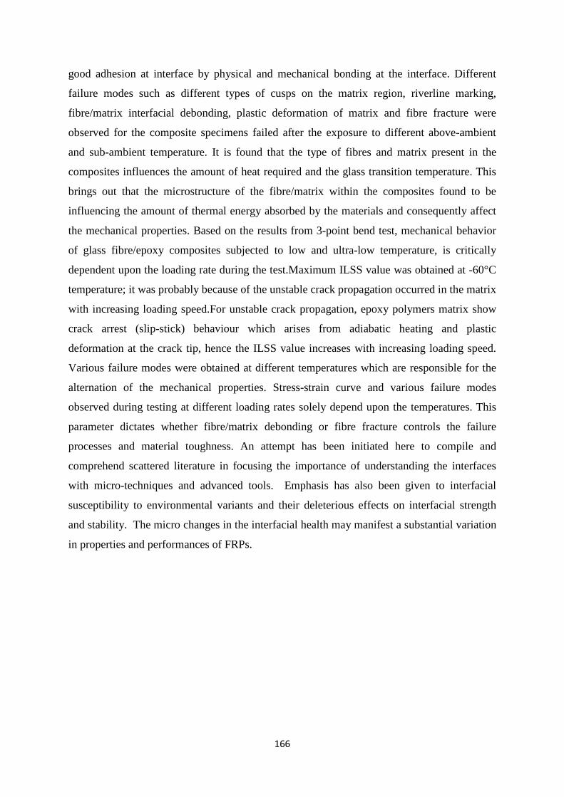
166
good adhesion at interface by physical and mechanical bonding at the interface. Different
failure modes such as different types of cusps on the matrix region, riverline marking,
fibre/matrix interfacial debonding, plastic deformation of matrix and fibre fracture were
observed for the composite specimens failed after the exposure to different above-ambient
and sub-ambient temperature. It is found that the type of fibres and matrix present in the
composites influences the amount of heat required and the glass transition temperature. This
brings out that the microstructure of the fibre/matrix within the composites found to be
influencing the amount of thermal energy absorbed by the materials and consequently affect
the mechanical properties. Based on the results from 3-point bend test, mechanical behavior
of glass fibre/epoxy composites subjected to low and ultra-low temperature, is critically
dependent upon the loading rate during the test.Maximum ILSS value was obtained at -60°C
temperature; it was probably because of the unstable crack propagation occurred in the matrix
with increasing loading speed.For unstable crack propagation, epoxy polymers matrix show
crack arrest (slip-stick) behaviour which arises from adiabatic heating and plastic
deformation at the crack tip, hence the ILSS value increases with increasing loading speed.
Various failure modes were obtained at different temperatures which are responsible for the
alternation of the mechanical properties. Stress-strain curve and various failure modes
observed during testing at different loading rates solely depend upon the temperatures. This
parameter dictates whether fibre/matrix debonding or fibre fracture controls the failure
processes and material toughness. An attempt has been initiated here to compile and
comprehend scattered literature in focusing the importance of understanding the interfaces
with micro-techniques and advanced tools. Emphasis has also been given to interfacial
susceptibility to environmental variants and their deleterious effects on interfacial strength
and stability. The micro changes in the interfacial health may manifest a substantial variation
in properties and performances of FRPs.
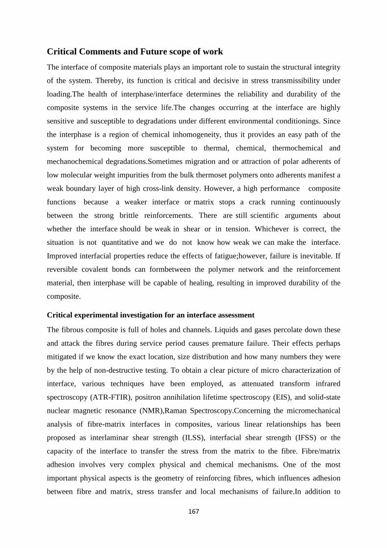
167
Critical Comments and Future scope of work
The interface of composite materials plays an important role to sustain the structural integrity
of the system. Thereby, its function is critical and decisive in stress transmissibility under
loading.The health of interphase/interface determines the reliability and durability of the
composite systems in the service life.The changes occurring at the interface are highly
sensitive and susceptible to degradations under different environmental conditionings. Since
the interphase is a region of chemical inhomogeneity, thus it provides an easy path of the
system for becoming more susceptible to thermal, chemical, thermochemical and
mechanochemical degradations.Sometimes migration and or attraction of polar adherents of
low molecular weight impurities from the bulk thermoset polymers onto adherents manifest a
weak boundary layer of high cross-link density. However, a high performance composite
functions because a weaker interface or matrix stops a crack running continuously
between the strong brittle reinforcements. There are still scientific arguments about
whether the interface should be weak in shear or in tension. Whichever is correct, the
situation is not quantitative and we do not know how weak we can make the interface.
Improved interfacial properties reduce the effects of fatigue;however, failure is inevitable. If
reversible covalent bonds can formbetween the polymer network and the reinforcement
material, then interphase will be capable of healing, resulting in improved durability of the
composite.
Critical experimental investigation for an interface assessment
The fibrous composite is full of holes and channels. Liquids and gases percolate down these
and attack the fibres during service period causes premature failure. Their effects perhaps
mitigated if we know the exact location, size distribution and how many numbers they were
by the help of non-destructive testing. To obtain a clear picture of micro characterization of
interface, various techniques have been employed, as attenuated transform infrared
spectroscopy (ATR-FTIR), positron annihilation lifetime spectroscopy (EIS), and solid-state
nuclear magnetic resonance (NMR),Raman Spectroscopy.Concerning the micromechanical
analysis of fibre-matrix interfaces in composites, various linear relationships has been
proposed as interlaminar shear strength (ILSS), interfacial shear strength (IFSS) or the
capacity of the interface to transfer the stress from the matrix to the fibre. Fibre/matrix
adhesion involves very complex physical and chemical mechanisms. One of the most
important physical aspects is the geometry of reinforcing fibres, which influences adhesion
between fibre and matrix, stress transfer and local mechanisms of failure.In addition to
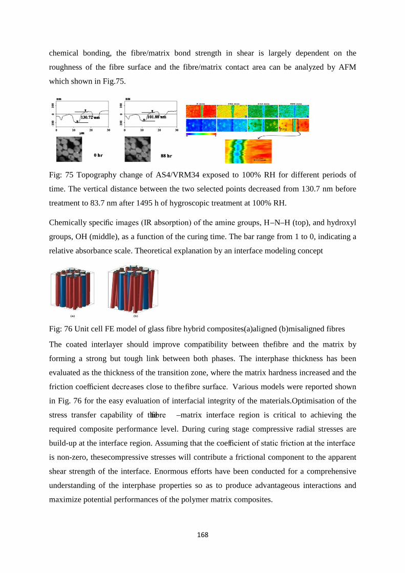
168
chemical bonding, the fibre/matrix bond strength in shear is largely dependent on the
roughness of the fibre surface and the fibre/matrix contact area can be analyzed by AFM
which shown in Fig.75.
Fig: 75 Topography change of AS4/VRM34 exposed to 100% RH for different periods of
time. The vertical distance between the two selected points decreased from 130.7 nm before
treatment to 83.7 nm after 1495 h of hygroscopic treatment at 100% RH.
Chemically specific images (IR absorption) of the amine groups, H–N–H (top), and hydroxyl
groups, OH (middle), as a function of the curing time. The bar range from 1 to 0, indicating a
relative absorbance scale. Theoretical explanation by an interface modeling concept
Fig: 76 Unit cell FE model of glass fibre hybrid composites(a)aligned (b)misaligned fibres
The coated interlayer should improve compatibility between thefibre and the matrix by
forming a strong but tough link between both phases. The interphase thickness has been
evaluated as the thickness of the transition zone, where the matrix hardness increased and the
friction coefficient decreases close to the fibre surface. Various models were reported shown
in Fig. 76 for the easy evaluation of interfacial integrity of the materials.Optimisation of the
stress transfer capability of the fibre –matrix interface region is critical to achieving the
required composite performance level. During curing stage compressive radial stresses are
build-up at the interface region. Assuming that the coefficient of static friction at the interface
is non-zero, thesecompressive stresses will contribute a frictional component to the apparent
shear strength of the interface. Enormous efforts have been conducted for a comprehensive
understanding of the interphase properties so as to produce advantageous interactions and
maximize potential performances of the polymer matrix composites.
169
List of Publications based on the thesis
• S.Sethi, B.C.Ray, Environmetnal effects on fibre reinforced polymeric composites: Evolving reasons and remarks on interfacial strength and stability, Advances in Colloid and Interface Science, DOI No- 10.1016/j.cis.2014.12.005, Impact Factor-9.4
• S.Sethi, D.K Rathore, B.C.Ray, Effects of temperature and loading speed on interface dominated strength in fibre/polymer composites: An evaluation for in-situ environment. Materials and Design, 2015,65 ,617-626, Impact Factor-3.2
• S.Sethi, B.C.Ray, An assessment of mechanical behavior and Fractography study of Glass/Epoxy prepreg composites at different temperatures and loading speeds. Material and Design. 2014, 64,160-165, Impact Factor-3.2
• S.Sethi, B.C.Ray, Experimental study on mechanical behavior and microstructural assessment of Kevlar/epoxy composites at low temperature., Journal of Mechanical Behavior of Materials, DE Gruyter Publication, 2014,Vol-23/3-4, 2014
• S.Sethi, B.C.Ray, A study on fibre/matrix contour and interface/interphase integrity by SEM and AFM techniques. Microscopy and Analysis, John Wiley and Sons Ltd. (published July 2014)
• S.Sethi, B.C.Ray, An assessment of interfacial chemistry and character of fiber/polymer micro-composites., Journal of Polymer and Composites, 2013,1, 1-5
• S.Sethi, B.C.Ray, Effects of nanoparticle in FRP composites on evaluation of loading rate sensitivity. International Journal of Composite Materials,2013,3,1-6
• S.Sethi, B.C.Ray, P.K.Panda, R.K.Nayak , Experimental studies on mechanical behavior and microstructural assessment of glass/epoxy composites at low temperatures., Journal of Reinforced Plastics and Composites January 2012, 31, 77-84, Impact Factor-1.1
• S.Sethi, B.C.Ray, Evaluation of structural integrity and mechanical behavior of advanced FRP composites. International Journal of Structural Intrigity.2011,2, 214-222.
BOOKS& BOOKS CHAPTERS • Sanghamitra Sethi and Bankim Chandra Ray, Assessment of interfacial and
mechanical behavior of FRP composites: Progress and degradation of Polymer composites. LAP LAMBERT Academic Publishing (August 10, 2012) ISBN-13: 978-3659170409.
• Sanghamitra Sethi and Bankim Chandra Ray, Mechanical behavior of polymer composites at cryogenic temperatures (Chapter 4), Edited by SusheelKalia and Shao-yun Fu. Polymers at Cryogenic Temperature, Springer-Verlag, Germany. ISBN – 978-3-642-35334-5, April- 2013

170
CONFERENCE PROCEEDINGS
• Interface assessment in composite materials - International conference on Recent Trends in materials and characterization (RETMAC-2010),NIT Surathkal,Karnataka, INDIA from 14th FEB – 15th FEB’ 2010.
• Assessment of interfacial chemistry and integrity in advanced FRP composites by FTIR-Imaging and Temperature modulated DSC techniques.3rd National Symposium for Materials Research Scholars - MR - 10, at IIT Bombay, Mumbai (Maharashtra),INDIA from 7th May – 8th May 2010.
• Evaluation of environmental damage and degradation study of fiber/polymer composites -The international congress of environmental research ICER-10, MAURITIUS from 16th Sep -18th Sep 2010.
• A microscopic study of failure in fibrous composite material - National metallurgical day-Annual Technical Meeting(NMD-ATM) IISC - Bangalore, INDIA from 14thNov-16th Nov 2010.
• Failure and fracture studies of fibrous composites: Thermal conditioning effects- National metallurgical day-Annual Technical Meeting (NMD-ATM) Hyderabad, INDIA from 13thNov-16th Nov 2011.
• Loading rate sensitivity of FRP composites; an overview- International symposium for research scholars on Metallurgy,Materials science and Engineering(ISRS),IIT Madras from 20thDec-22nd Dec 2012.
• Environmental and Experimental stability of FRP composites. International Conference on Composite materials, International Centre of Goa, 13th -16th Febarury,2013
• An evaluation of the failure behavior with changing loading rate in E-glass fiber/epoxy composites at low temperatures. Designing composite materials: Avoiding large structural failures, An International Conference: DFC12/SI6, Queen’s College,Cambridge, England from 8th-11th April 2013