Model-based Requirements Engineering for Multifunctional ...
175
Andreas Vogelsang Model-based Requirements Engineering for Multifunctional Systems
-
Upload
khangminh22 -
Category
Documents
-
view
1 -
download
0
Transcript of Model-based Requirements Engineering for Multifunctional ...

Andreas Vogelsang
Model-based Requirements Engineering for Multifunctional Systems


Institut für Informatikder Technischen Universität München
Model-based Requirements Engineering forMultifunctional Systems
Andreas Vogelsang
Vollständiger Abdruck der von der Fakultät für Informatik der TechnischenUniversität München zur Erlangung des akademischen Grades eines
Doktors der Naturwissenschaften (Dr. rer. nat.)
genehmigten Dissertation.
Vorsitzender: Univ.-Prof. Dr. Florian Matthes
Prüfer der Dissertation:
1. Univ.-Prof. Dr. Dr. h.c. Manfred Broy
2. Univ.-Prof. Dr. Sven Apel,
Universität Passau
Die Dissertation wurde am 15.12.2014 bei der Technischen Universität Müncheneingereicht und durch die Fakultät für Informatik am 20.03.2015 angenommen.


AbstractMany technical systems that were initially designed for serving one purpose nowoffer a number of functions integrated side-by-side into one application or device. Atypical example for such a multifunctional system is the software system of an auto-mobile, which provides functions ranging from multimedia applications over driverassistance functions to diagnosis functions. Other examples are telecommunicationor avionic systems.
Specifications of multifunctional systems can grow large and therefore need to bestructured to support its development and evolution. Structuring large specifica-tions into functions in a compositional way is highly desirable since functionalitycan be specified independently from each other. Unfortunately, different functionswithin a specification of a multifunctional system are often interconnected or influ-ence each other, which makes it hard to describe them independently in a compo-sitional way. Formal and model-based specification techniques have been proposedby the research community to facilitate the specification of multifunctional systems.However, these techniques are rarely applied in industry. In our experience, thereason for this is a missing integration of the proposed formal specification tech-niques for multifunctional systems into a comprehensive requirements engineering(RE) methodology that describes the stepwise creation and analysis of specificationsbased on the formal specification technique.
This thesis provides supporting evidence and solutions for the stated problem. First,we present an empirical analysis of function dependencies in productive multifunc-tional systems. The analysis reveals that functions are highly interdependent andcurrent engineering approaches address this issue only insufficiently. Furthermore,the study reveals that developers are not aware of these dependencies in most cases.
Second, we present the integration of a formal specification model for multifunc-tional systems into a comprehensive requirements engineering methodology. In theformal specification model, a multifunctional system consists of functions, which canhave dependencies that are described by modes. We integrate these formal conceptsinto a requirements engineering methodology by providing an artifact model thatrelates the concepts to model types that we use to describe them. The semantic rela-tions between the concepts are reflected and expressed by the model types. Further-more, we describe the role of the resulting artifacts in a development process. Ourmain contribution is the definition of this methodology that allows a stepwise devel-opment of a formal and model-based specification for multifunctional systems. Weinstantiate the methodology (1) in a scenario-driven RE context and (2) in a property-driven RE context and demonstrate its effectiveness through two case studies, wherethe methodology increased artifact consistency and detection of specification flaws.
Finally, we highlight two central artifacts, namely the function documentation and themode model, and provide detailed instructions on how to elicit and structure these ar-tifacts. The proposed structure for function documentation is empirically groundedby an exploratory qualitative study in the context of automotive systems. The elici-tation of a mode model is demonstrated through an industrial case study, showingits feasibility and discussing different elicitation approaches.


Acknowledgements
This thesis would not exist without the tremendous support of a number of peoplewhom I am deeply thankful. I want to expresses my gratitude for Prof. Dr. Dr. h.c.Manfred Broy who gave me the opportunity to work as a researcher in his stimulat-ing, supportive, and exceptional research group. His guidance and advice alwaysbroadened my horizon and his commitment to create opportunities in many ways isoutstanding.
I want to thank Prof. Dr. Sven Apel for co-supervising my thesis. His comments andinsights, especially in the field of feature-oriented software development, helped mea lot.
Important parts of this thesis could not have been realized without the support ofindustrial partners. My thanks go to Stefan Teuchert, Christian Winkler, and Jean-François Girard, who are with MAN Truck & Bus AG, to Jochen Quante and An-dreas Thums, who are with Robert Bosch GmbH, to Steffen Fuhrmann who is withBMW Group, and to Ralf Pinger, who is with Siemens AG.
I count myself lucky to work with colleagues who already were or became friends.I am especially thankful to the members of the “Zwiebel” group: Veronika Bauer,Jonas Eckhardt, Sebastian Eder, Henning Femmer, Benedikt Hauptmann, Maxim-ilian Junker, and Daniela Steidl. Additionally, I want to thank Mario Gleirscher,Georg Hackenberg, Lars Heinemann, Thomas Kofler, Daniel Méndez Fernández,Silke Müller, Jakob Mund, and Sabine Teufl for their assistance and contributionsto a warm and supportive working environment.
During my time as a research assistant, I learnt a lot about research in general, busi-ness, personal development, and professional work. I want to thank Wolfgang Böhm,Martin Feilkas, Elmar Jürgens, Andreas Koller, and Bernhard Schätz for sharing theirprofessional and personal experiences with me.
Last but not least, I want to thank all the people around me who supported me inany possible way. I am deeply grateful to my family, my friends and, above all, mywife Lisa.


"The structure of system functionality is more like colour separationthan it is like an assembly of parts."
– Michael Jackson


Contents
1 Introduction 11.1 Context: Multifunctional Systems . . . . . . . . . . . . . . . . . . . . . . 11.2 Problem Statement . . . . . . . . . . . . . . . . . . . . . . . . . . . . . . 21.3 Contributions of this Thesis . . . . . . . . . . . . . . . . . . . . . . . . . 31.4 Approach: Model-based RE for Multifunctional Systems based on
Functions and Modes . . . . . . . . . . . . . . . . . . . . . . . . . . . . . 51.5 Outline . . . . . . . . . . . . . . . . . . . . . . . . . . . . . . . . . . . . . 5
2 Background and Formal Foundations 92.1 Terminology: What is a Function? . . . . . . . . . . . . . . . . . . . . . 92.2 Formal Foundation . . . . . . . . . . . . . . . . . . . . . . . . . . . . . . 132.3 Scope of this Thesis . . . . . . . . . . . . . . . . . . . . . . . . . . . . . . 192.4 Modeling vs. Formalization . . . . . . . . . . . . . . . . . . . . . . . . . 20
3 State of the Art 213.1 Extent, Characteristics, and Impact of Function Dependencies . . . . . 223.2 Specification Techniques for Multifunctional Systems . . . . . . . . . . 253.3 Function Documentations . . . . . . . . . . . . . . . . . . . . . . . . . . 353.4 Elicitation of Mode Models . . . . . . . . . . . . . . . . . . . . . . . . . 37
4 Empirical Study on Function Dependencies in Multifunctional Systems 414.1 Research Objective . . . . . . . . . . . . . . . . . . . . . . . . . . . . . . 414.2 Study Design . . . . . . . . . . . . . . . . . . . . . . . . . . . . . . . . . 424.3 Study Results . . . . . . . . . . . . . . . . . . . . . . . . . . . . . . . . . 484.4 Threats to Validity . . . . . . . . . . . . . . . . . . . . . . . . . . . . . . . 514.5 Discussion . . . . . . . . . . . . . . . . . . . . . . . . . . . . . . . . . . . 514.6 Summary . . . . . . . . . . . . . . . . . . . . . . . . . . . . . . . . . . . . 52
5 Integrating Functions and Modes into a Model-based RE Methodology 535.1 Artifact Model . . . . . . . . . . . . . . . . . . . . . . . . . . . . . . . . . 535.2 Process Integration . . . . . . . . . . . . . . . . . . . . . . . . . . . . . . 745.3 Case Study: Scenario-driven Requirements Engineering . . . . . . . . . 805.4 Case Study: Property-driven Requirements Engineering . . . . . . . . 935.5 Tool Support . . . . . . . . . . . . . . . . . . . . . . . . . . . . . . . . . . 1065.6 Discussion . . . . . . . . . . . . . . . . . . . . . . . . . . . . . . . . . . . 106
ix

5.7 Summary . . . . . . . . . . . . . . . . . . . . . . . . . . . . . . . . . . . . 107
6 Function Documentations for Multifunctional Systems 1096.1 Study Context: Function Documentations for Automotive Systems . . 1106.2 Research Objective . . . . . . . . . . . . . . . . . . . . . . . . . . . . . . 1126.3 Study Design . . . . . . . . . . . . . . . . . . . . . . . . . . . . . . . . . 1126.4 Study Results . . . . . . . . . . . . . . . . . . . . . . . . . . . . . . . . . 1166.5 Threats to Validity . . . . . . . . . . . . . . . . . . . . . . . . . . . . . . . 1226.6 Discussion and Implications . . . . . . . . . . . . . . . . . . . . . . . . . 1226.7 Methodical Guidance for Function Documentations . . . . . . . . . . . 1236.8 Summary . . . . . . . . . . . . . . . . . . . . . . . . . . . . . . . . . . . . 130
7 Systematic Elicitation of Mode Models for Multifunctional Systems 1317.1 Mode Models and Elicitation Approaches . . . . . . . . . . . . . . . . . 1317.2 Case Study: A Mode Model for an Automotive System . . . . . . . . . 1347.3 Threats to Validity . . . . . . . . . . . . . . . . . . . . . . . . . . . . . . . 1387.4 Study Results . . . . . . . . . . . . . . . . . . . . . . . . . . . . . . . . . 1387.5 Discussion . . . . . . . . . . . . . . . . . . . . . . . . . . . . . . . . . . . 1427.6 Summary . . . . . . . . . . . . . . . . . . . . . . . . . . . . . . . . . . . . 145
8 Conclusions and Outlook 1478.1 Conclusions . . . . . . . . . . . . . . . . . . . . . . . . . . . . . . . . . . 1478.2 Outlook . . . . . . . . . . . . . . . . . . . . . . . . . . . . . . . . . . . . . 150
Bibliography 155

Chapter 1Introduction
The topic of this thesis is a model-based requirements engineering and specificationmethodology for multifunctional systems. In this chapter, we introduce and moti-vate this topic by characterizing multifunctional systems (Section 1.1) and stating theproblems related to the specification of their functional requirements (Section 1.2). InSection 1.3, we summarize the major contributions of this thesis. In Section 1.4, webriefly present our basic approach to model-based specifications of multifunctionalsystems, before we finally provide an outline of this thesis in Section 1.5.
1.1 Context: Multifunctional Systems
Systems that offer a variety of different functions to their environment are called mul-tifunctional systems [Broy, 2010b]. A function describes the intent to use a systemfor a specific purpose. Many technical systems that were initially designed for serv-ing one purpose now have a number of functions integrated side-by-side into oneapplication or device serving a number of purposes. A typical example for a mul-tifunctional system is the software system of an automobile, which provides func-tions ranging from multimedia applications, driver assistance functions, to diagnosisfunctions. Other examples are telecommunication or avionic systems. Within thesesystems, the desired functions are realized by a set of (implementation) componentsarranged in an architecture.
Different functions of a system serve different purposes and can be described andrealized independently to some extent. Therefore, function-oriented development,where functions are mirrored by implementation components that are developed in-dependently by different teams and even by different departments, is prevalent incompanies that build multifunctional systems [Broy et al., 2007a].
However, the functions of a multifunctional system can have subtle dependenciesand may affect each other in certain situations. For example in a car, the central lock-ing function and the crash sensing function behave independently to a large extent,however, in case of an accident, the crash sensing function forces the central lockingfunction to unlock all doors of the car. We call this a function dependency. Function
1

1.2. Problem Statement
dependencies can be considered as one form of feature interaction [Calder et al., 2003;Zave, 2001]: “A feature interaction is some way in which a feature or features modify orinfluence another feature in defining overall system behavior.1” [Zave, 1999]. Feature in-teraction may result in desired or undesired behavior. This thesis focuses on thespecification of multifunctional systems and not on their implementation. Therefore,the term function dependency, as used in this thesis, refers to interaction betweenfunctions used to specify the desired behavior of a multifunctional system. Unde-sired feature interaction often arises from function implementations that are integratedinto one system and then interact in an undesired way. This is another interpretationof the term feature interaction, which we do not address with the term function de-pendency. Moreover, the implementation of a system in terms of components mayfollow a completely different structure than induced by the functions (cf. tyrannyof the dominant decomposition [Tarr et al., 1999]). This is especially true if the imple-mentation contains shared components that contribute to the realization of severalfunctions (e.g., a sensor fusion component).
Specifications of multifunctional systems can grow large and therefore need to bestructured to support their development and evolution. Structuring large specifi-cations into functions in a compositional way is highly desirable because the systemspecification is then given by the composition of modular function specifications thatencapsulate behavior serving one purpose. The mentioned function dependenciesneed to be considered in a compositional specification. The characteristics of multi-functional systems challenge their specification due to the following reasons:
• Functions of a multifunctional system cannot be specified in isolation. They ex-hibit subtle dependencies that need to be considered within their specification.
• Without the decomposition into functions, specifications of multifunctionalsystems become over-complex, hard to maintain, and impossible to validatemodularly.
• The implementation of a multifunctional system may follow a completely dif-ferent structuring paradigm than a structuring according to functions.
As a consequence, specifications for multifunctional systems are often structured intofunctions. However, these functions are generally developed in isolation and theirbehavior is often specified on an architectural/implementation level (e.g., by linkingfunction names to code artifacts). This leads to integration errors and unwantedbehavior due to function dependencies, and blurs the distinction between functionaland architectural dependencies.
1.2 Problem Statement
Due to these characteristics, different groups in the software and systems engineer-ing community have recognized the importance of function-oriented specificationand development, and investigated its benefits and limitations. In the correspond-ing work, dependencies between functions have been considered as a major factorleading to integration failures in multifunctional systems [Benz, 2010; Cataldo and
1In this context, the term feature is a synonym for the term function.
2

1.3. Contributions of this Thesis
Herbsleb, 2011]. In an automotive context, Broy [2006] states, “So far, the understand-ing of these interactions between the different functions in the car is insufficient.”
Formal and model-based specification techniques have been proposed by the re-search community to facilitate the specification of multifunctional systems (e.g., Broy[2010b]; Heitmeyer et al. [1997]; Jackson and Zave [1998]; Schätz [2008]). Most ofthem aim at a modular specification for multifunctional systems. The system is bro-ken down into functions, which are described separately. Dependencies betweenfunctions are modeled by different extensions to their interfaces.
Despite the stated challenges resulting from function dependencies and the pro-posed specification techniques to address these, function specifications in industrycurrently do not consider function dependencies. In our experience, the reason forthis is a missing integration of the proposed formal specification techniques for mul-tifunctional systems into a comprehensive requirements engineering methodology.
Formal and model-based specification techniques for multifunctional systems needto be integrated into a comprehensive requirements engineering methodology to beapplicable in industry. This includes the extension and adaption of RE artifacts andanalysis techniques applied to them. However, for the existing specification tech-niques such an integration is missing. For the few techniques that come with toolsupport, it is not clear how the tools can be integrated into an existing RE process,and how the existing RE artifacts relate to those added by the specification technique.Approaches that abstain from extending or adapting existing artifacts, such as UMLdiagrams, lack of precision and are not expressive enough to describe the subtletiesof function dependencies. Thus, an integration of formal specification techniques formultifunctional systems into a comprehensive requirements engineering methodol-ogy is required, including the description of artifact types, their relations, associatedanalysis procedures, and their role in a development process.
Problem Statement:We need a comprehensive requirements engineering methodology for multi-functional systems that integrates and supports the specification of functiondependencies.
1.3 Contributions of this Thesis
In this thesis, we provide supporting evidence and solutions for the stated problem.
Significance of Function Dependencies in Multifunctional Systems We presentan empirical study on two productive automotive systems with the goal to assess theextent and characteristics of function dependencies as well as the developer’s aware-ness of those. In the examined systems, the function dependencies were not part ofthe function specifications. Therefore, we developed an approach to extract functiondependencies from a given component architecture (i.e., an implementation).
Through the analysis of the component architecture, we found function dependen-cies for more than 69% of all functions. Single functions had dependencies to more
3

1.3. Contributions of this Thesis
than half of all functions of their system. As a follow up, we investigated the foundfunction dependencies in detail and discussed them with the developers. We as-sessed that almost 50% of our findings were considered as plausible, although thedevelopers were unaware of them prior to the study. The study reveals that functionsin productive multifunctional systems are highly interdependent and that currentspecification techniques address this issue only insufficiently. The study was carriedout with MAN Truck & Bus AG and the BMW Group.
Requirements Engineering for Multifunctional Systems We present a compre-hensive requirements engineering (RE) methodology that is based on a formal mod-eling theory for multifunctional systems.
We base our methodology on an artifact model that relates the semantic conceptsof the modeling theory to model types that we use to describe them. The seman-tic relations between the concepts are reflected and expressed by the model types.The artifact model supports the stepwise modeling and formalization of functionalrequirements up to a system specification, which finally can be linked to the architec-ture of a system. We illustrate the role of the artifacts in a development process andthe activities they enable and support. The methodology ensures the consistency ofartifacts and allows for a comprehensive requirements tracing from informal require-ments to architectures on different levels of abstraction especially with respect to thespecification of function dependencies. Our main contribution is the definition ofthis methodology that allows a stepwise development of a formal and model-basedspecification for multifunctional systems. The methodology is evaluated in two casestudies in which it is instantiated (1) in a scenario-driven RE context and (2) in aproperty-driven RE context. The first case study was conducted as part of a practicalmaster’s course at TU München and the second was carried out with Siemens in anindustrial setting.
Finally, we highlight two central artifacts of the methodology, namely the functiondocumentation and the mode model, and provide detailed instructions on how to sys-tematically derive and structure these artifacts.
The proposed structure for function documentations is empirically grounded by anexploratory qualitative study in the context of automotive systems conducted atRobert Bosch GmbH. The conclusions of the study particularly address how func-tion documentations should be structured and which information they should pro-vide. We suggest documenting a function based on three levels of abstraction thatare structured by a set of modes. The resulting function documentation templateprovides methodical guidance for the creation of a function documentation based onour proposed RE methodology.
The central role of modes in function specifications and in our methodology ingeneral poses the question, how modes can be elicited systematically, and howlarge these mode models can get. In this thesis, we introduce three elicitation ap-proaches for mode models, which we examine in an industrial case study conductedat MAN Truck & Bus AG, showing their feasibility and discussing differences be-tween the elicited modes.
In the literature, approaches for a wide range of aspects and facets of multifunctionalsystem specifications are proposed, including the specification of functional, safety,
4

1.4. Approach: Model-based RE for Multifunctional Systems based on Functions and Modes
security, reliability, or timing requirements. This set of all types of requirements tobe considered in a specification is large—beyond what can be covered in depth ina dissertation. In this work, we thus focus on functional requirements of a systemas described by Sommerville [2011]: “These are statements of services the system shouldprovide, how the system should react to particular inputs and how the system should behavein particular situations.” Although the relevance of extra-functional requirements isoften stressed, functional requirements are a premise for a valid system specifica-tion. Even more, most of the extra-functional requirements get a functional characteronce they are sufficiently broken down and refined (e.g., timing requirements addconstraints to the functional requirements).
1.4 Approach: Model-based RE for MultifunctionalSystems based on Functions and Modes
In this thesis, we follow a specific view onto specifications for multifunctional sys-tems that is supported by a formal modeling theory proposed by Broy [2010b].
The application of the RE methodology introduced in this thesis results in a speci-fication of a multifunctional system by following an iterative process along the twodimensions modeling and formalization. While modeling adds structure and providesa specific way of thinking about a specification, formalization adds precision andincreases the potential for automation of development steps.
From a modeling point of view, requirements, in our approach, reflect a desired prop-erty of the system as observable at the interface between the system and its environ-ment. Requirements are related to functions, which capture a set of requirementswith a common purpose from a user’s2 point of view. The functions of a system arecomposed to composite functions and finally to a system specification. We call thisthe function architecture of a system. Functions may behave differently depending onthe current state of a system. We model the state of a system in a mode model, whichcontains a (structured) set of modes. These modes can be referenced in the specifica-tion of functions as inputs or outputs. By this, function dependencies are modeled asinteractions between functions via channels that transmit system modes.
From a formalization point of view, we embed the models used in the approach into aformal system modeling theory that represents a system as a stream processing func-tion, which maps streams of input values to streams of output values. A specificationis represented by a predicate over the set of stream processing functions.
1.5 Outline
Figure 1.1 gives an overview over the major contributions and structure of this thesis.Each box in the figure represents a contribution except for the formal system modeldescribed in Chapter 2, which is not a contribution of this thesis but serves as foun-dation. The contributions are structured with respect to their role in this thesis and
2A user can also be an external system (cf. the notion of an actor in UML [Fowler and Scott, 2000]).
5

1.5. Outline
Chapter 6: Function Documentations for Multifunctional Systems
Chapter 1:Introduction
Foundations Motivation Approach Validation
Chapter 3: State of the Art
Chapter 8: Conclusions & Outlook
Chapter 4: Empirical Study on Function Dependencies
Extent, Characteristics & Awareness
Chapter 2: Background & Formal Foundations
Formal System Model
Chapter 5: Integrating Functions and Modes into a Model-based RE Methodology
Artifact Model & Process
Integration
Case Study:Scenario-driven RE
Case Study:Property-driven RE
Chapter 7: Systematic Elicitation of Mode Models
Structure for Function
Documentation
Case Study:Function Documentation for Automotive Systems
Elicitation Approaches for Mode Models
Case Study:Mode Model for an Automotive System
Chapter
Role in the thesis
Main Contribution
Used Foundation
Figure 1.1: Overview over the main contributions and structure of this thesis.
related to chapters in which they are described. The solid lines between the contri-butions indicate how the contributions are related to each other. For example, theinvestigation of extent, characteristics, and awareness of function dependencies inChapter 4 uses the formal system model as foundation to show the motivation for theapproaches of Chapters 5 to 7, which are validated in the corresponding case studies.
Chapter 2 (Background and Formal Foundations) discusses the used terminology ofthis thesis and defines it with respect to a formal system model. Based on this systemmodel, the scope of this thesis is defined in detail.
Chapter 3 (State of the Art) describes the current state of the art structured alongthe contributions of this thesis considering empirical work on function dependen-cies, specification techniques for multifunctional systems, approaches for functiondocumentation, and elicitation approaches for mode models.
Chapter 4 (Empirical Study on Function Dependencies in Multifunctional Systems)presents an empirical study on the extent, characteristics, and awareness of functiondependencies in existing multifunctional systems. It illustrates the challenges andmotivates the approach of this thesis.
Chapter 5 (Integrating Functions and Modes into a Model-based RE Methodology)introduces our model-based requirements engineering methodology for the specifi-
6

1.5. Outline
cation of multifunctional systems. It is based on an artifact model that defines theartifacts and modeling concepts used in the methodology. Furthermore, the method-ology is instantiated and discussed in two case studies.
Chapter 6 (Function Documentations for Multifunctional Systems) introduces a doc-umentation structure for functions that is based on modes and abstraction levels. Thespecific structure is grounded by a qualitative empirical study.
Chapter 7 (Systematic Elicitation of Mode Models for Multifunctional Systems) de-scribes three approaches to elicit a mode model for a multifunctional system anddiscusses the approaches in the context of an industrial case study.
Chapter 8 (Conclusions and Outlook) summarizes this thesis by presenting its con-tributions, limitations and directions for future work.
Previously Published Material
Parts of the contributions presented in this thesis are based on previous publications:
[Vogelsang et al., 2012] Vogelsang, A., Teuchert, S., and Girard, J.: Extent and charac-teristics of dependencies between vehicle functions in automotive software systems.In: Proceedings of the 4th International Workshop on Modeling in Software Engineering(MISE’12@ICSE), 2012.
[Vogelsang and Fuhrmann, 2013] Vogelsang, A. and Fuhrmann, S.: Why feature de-pendencies challenge the requirements engineering of automotive systems: An em-pirical study. In: Proceedings of the 21st IEEE International Requirements EngineeringConference (RE’13), 2013.
[Vogelsang et al., 2014] Vogelsang, A., Eder, S., Hackenberg, G., Junker, M., and Teufl,S.: Supporting concurrent development of requirements and architecture: A model-based approach. In: Proceedings of the 2nd International Conference on Model-DrivenEngineering and Software Development (MODELSWARD’14), 2014.
[Vogelsang, 2014] Vogelsang, A.: An exploratory study on improving automotivefunction specifications. In: Proceedings of the 2nd International Workshop on ConductingEmpirical Studies in Industry (CESI’14@ICSE), 2014.
[Böhm et al., 2014] Böhm, W., Junker, M., Vogelsang, A., Teufl, S., Pinger, R., andRahn, K.: A formal systems engineering approach in practice: An experience report.In: Proceedings of the 1st International Workshop on Software Engineering Research andIndustrial Practices (SER&IPs’14@ICSE), 2014.
[Vogelsang et al., 2015] Vogelsang, A., Femmer, H., and Winkler, C.: Systematic elic-itation of mode models for multifunctional systems. In: Proceedings of the 23rd IEEEInternational Requirements Engineering Conference (RE’15), 2015
7


Chapter 2Background and FormalFoundations
In this chapter, we introduce and explain the basic notions that are necessary to com-prehend the content of this thesis. We especially discuss the notion of a function,which is essential for this thesis, and embed this notion into the context of multifunc-tional systems. For a precise definition of the terminology, we introduce a formalmodeling theory and an architectural framework that is defined on top of that.
2.1 Terminology: What is a Function?
A central notion we use in this thesis is the notion of a function. The term functionis associated with a great variety of meanings and interpretations in academia andindustry. Additional terms that are often mentioned in this context are the termsfeature and service. In the following, we informally describe a selection of differentinterpretations associated with these terms. In the remainder of this chapter, we willintroduce a formal system modeling theory that we use to give a precise definition ofthe different interpretations and the interpretation we are going to use in this thesis.
As a major distinction between different definitions, we consider their focus on ex-pressing requirements, functional specifications, or design/implementation. We list someof the common definitions categorized by their focus (cf. [Classen et al., 2008]).
Focus on Requirements: Kang et al. [1990] define a feature as “a prominent or dis-tinctive user-visible aspect, quality, or characteristic of a software system or systems”.This interpretation is prevalent in product line engineering approaches, whererequirements (of a product line) are expressed by feature diagrams [Chen et al.,2005]. This definition also considers properties like color, a specific algorithmused, or special technical devices as features of a system. In these approaches,functions or features are generally not formalized any further and mainly servethe purpose of characterizing a certain product within a family of products.
Focus on Functional Specifications: Some definitions focus on functional charac-teristics of a system. Schätz [2008] defines, “functions are capsules of behavior,
9

2.1. Terminology: What is a Function?
defined by their (external) interface in terms of data and control flow [. . . ]” and Kanget al. [1998] refine their former definition of a feature to “a distinctively identi-fiable functional abstraction that must be implemented, tested, delivered, and main-tained”. Similarly, Shaker et al. [2012] define a feature as “a coherent and identifi-able bundle of system functionality”. These definitions aim at the use of the termsfunction or feature to be used as elements of a functional specification for asystem. Broy [2010b] uses the term service for “structuring of the functionality ofmultifunctional systems, with the emphasis on the specification phase of requirementsengineering”. All of these definitions are associated with a (partial) black-boxview onto the system. These approaches agree on structuring a specificationof a system into sub parts that contain extracts of the functionality, as it is per-ceived by the user or any other environmental system.
Focus on Design/Implementation: Many definitions consider functions, features,or services as elements of the design or implementation of a system. Liu et al.[2006] define a feature as “an increment in program functionality” and Apel et al.[2010a] define a feature as “a structure that extends and modifies the structure of agiven program in order to satisfy a stakeholder’s requirement, to implement and encap-sulate a design decision, and to offer a configuration option”. Both definitions refer toelements of the implementing program. Some definitions specifically focus onthe design/architecture of the implementing system. Jackson and Zave [1998]define a feature as “an incremental unit of functionality in a DFC [Distributed Fea-ture Composition] network”. This definition is strongly influenced by the idea ofdecomposing a function into sub-functions, which may be arranged in a dataflow or control flow network. This idea originates from classical functionaldecomposition approaches and structured analysis [DeMarco, 1979]. Decom-position is mainly influenced by steps of computation taken to fulfill desiredfunctionality. Thus, this notion describes a white-box view onto a system bybreaking it down into a network of functions (also known as function net orfunctional flow diagram).
As these examples show, it is important to have a precise definition of what is consid-ered as a function. In the remainder of this thesis, we will associate the term functionwith an element that describes a black-box view onto a system to serve as (part of a)functional system specification. That means, a function describes the intent to use asystem for a specific purpose, specified by a behavior that is observable at the bound-ary between the system and its operational context. Table 2.1 gives an overview overthe most important terms used in this thesis and provides an informal description ofthem. Additionally, we associate related terms used in other publications with them.
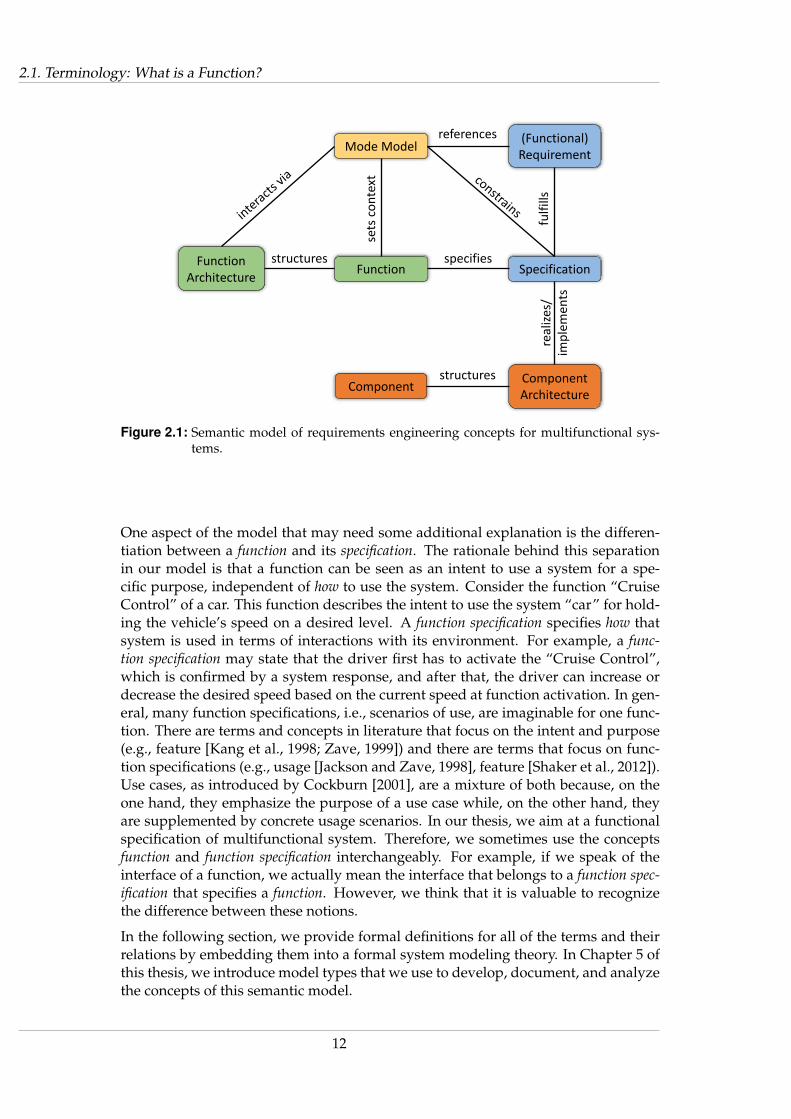
By relating the central terms to each other, we draw a big picture of our semantic modelof requirements engineering concepts for multifunctional systems, illustrated in Fig-ure 2.1. The elements of the semantic model do not refer to any specific descriptiontechnique. Instead, we use this semantic model to understand and relate the contentthat is expressed by different description techniques.1
1The differentiation between the semantics (content), the syntax (description technique), and the rep-resentation of an artifact may sound hairsplitting or trivial. However, in the context of artifact orien-tation, it is a relevant research topic [Böhm and Vogelsang, 2013; Méndez Fernández et al., 2010].
10

2.1. Terminology: What is a Function?
Table 2.1: Central terms of this thesis.
Term Description Related terms
Multifunctionalsystem
A system that offers a variety of differ-ent functions to its environment.
Multifeatured system[Batory et al., 2004]
(Functional)Requirement
A (behavioral) property a multifunctionalsystem must fulfill.
Feature [Kang et al., 1990]
Function An intent of using a multifunctional sys-tem in a specific usage context for a cer-tain purpose.
Use case [Cockburn, 2001],Feature [Kang et al., 1998;Zave, 1999]
Functionspecification
A (set of) interaction patterns specifyinga function’s behavior.
Use case [Cockburn, 2001],Feature [Shaker et al., 2012],Usage[Jackson and Zave, 1998],Service [Broy, 2010b]
Functionarchitecture
A (structured) set of (dependent) func-tions specifying the behavior of a multi-functional system.
Feature model[Kang et al., 1998],Service hierarchy[Broy, 2010b],Service [Bouma and Velthui-jsen, 1994],Use case diagram[OMG, 2011]
Functiondependency
Behavioral interaction between functionsspecifying desired behavior of a multi-functional system.
Feature interaction[Zave, 1999],Lifter [Prehofer, 1997],Derivative [Liu et al., 2006]
Mode An operational state of a multifunctionalsystem or its environment. Function de-pendencies are modeled via modes.
Mode[Dietrich and Atlee, 2013]
Mode model A (structured) set of modes specifyingthe possible dependency interactions ina function architecture.
Statechart[OMG, 2011]
Component Part of a solution structure that realizes/implements functions of a multifunctionalsystem.
Feature box[Jackson and Zave, 1998],Feature module[Batory et al., 2004],Feature [Apel et al., 2010a]
Componentarchitecture
A (structured) set of (communicat-ing) components describing the solutionstructure of a multifunctional system.
Implementation model[Kästner et al., 2009],DFC network[Jackson and Zave, 1998]
11
2.1. Terminology: What is a Function?
Function Architecture
Mode Model
Function
(Functional) Requirement
Specification
references
fulf
ills
structures
sets
co
nte
xt
specifies
ComponentComponent Architecture
real
izes
/im
ple
men
ts
structures
Figure 2.1: Semantic model of requirements engineering concepts for multifunctional sys-tems.
One aspect of the model that may need some additional explanation is the differen-tiation between a function and its specification. The rationale behind this separationin our model is that a function can be seen as an intent to use a system for a spe-cific purpose, independent of how to use the system. Consider the function “CruiseControl” of a car. This function describes the intent to use the system “car” for hold-ing the vehicle’s speed on a desired level. A function specification specifies how thatsystem is used in terms of interactions with its environment. For example, a func-tion specification may state that the driver first has to activate the “Cruise Control”,which is confirmed by a system response, and after that, the driver can increase ordecrease the desired speed based on the current speed at function activation. In gen-eral, many function specifications, i.e., scenarios of use, are imaginable for one func-tion. There are terms and concepts in literature that focus on the intent and purpose(e.g., feature [Kang et al., 1998; Zave, 1999]) and there are terms that focus on func-tion specifications (e.g., usage [Jackson and Zave, 1998], feature [Shaker et al., 2012]).Use cases, as introduced by Cockburn [2001], are a mixture of both because, on theone hand, they emphasize the purpose of a use case while, on the other hand, theyare supplemented by concrete usage scenarios. In our thesis, we aim at a functionalspecification of multifunctional system. Therefore, we sometimes use the conceptsfunction and function specification interchangeably. For example, if we speak of theinterface of a function, we actually mean the interface that belongs to a function spec-ification that specifies a function. However, we think that it is valuable to recognizethe difference between these notions.
In the following section, we provide formal definitions for all of the terms and theirrelations by embedding them into a formal system modeling theory. In Chapter 5 ofthis thesis, we introduce model types that we use to develop, document, and analyzethe concepts of this semantic model.
12

2.2. Formal Foundation
2.2 Formal Foundation
For the purpose of precise definitions, we ground the semantic concepts of this thesison the formal system modeling theory FOCUS [Broy and Stølen, 2001], which pro-vides formal concepts to describe a system, and an architectural framework [Broyet al., 2012], which defines viewpoints that describe a system in different phases ofa development process. In the following, we briefly introduce the system modelingtheory and the architectural framework. For more information on the modeling the-ory, please refer to Broy’s earlier work [Broy, 2007, 2010a,b; Broy and Stølen, 2001].
2.2.1 System Modeling Theory
In the formal system modeling theory FOCUS, a system is described by its interface.An interface description contains syntactic and behavioral information that charac-terize a system. The theory provides formal notions of interface description, interfacecomposition, and interface specification.
Messages and Streams
To describe the interface of a system, we first need to introduce messages andstreams. A stream is an infinite sequence of elements of a given set. In interactivesystems, streams are built over sets of messages or actions. Streams are used thatway to represent communication histories. Let X be a given set of messages. X∞ de-notes the set of infinite sequences over X (represented by the total mappings N→ X).A stream s is an element of this set: s ∈ X∞.
Interface Description
Types are useful concepts to describe system interfaces. We work with a simple no-tion of types where each type is a set of data elements. These data elements are usedas messages. Let a set T of types be given. Then, the universal set of messages X isgiven by the union of all types:
X =⋃t∈T
t
In FOCUS, a typed channel is an identifier for a sequential directed communication linkfor messages of that type. By C, we denote a set of typed channel names. We assumethat a type assignment for the channels in the set C is given as follows:
type : C → T
Given a set C of typed channels, a channel valuation is an element of the set ~C that isdefined as follows:
~C = {x : C → X∞ : ∀c ∈ C : x(c) ∈ (type(c))∞}
A channel valuation x ∈ ~C associates a stream of elements of type type(c) with eachchannel c ∈ C. This way the channel valuation x defines a channel history for the
13

2.2. Formal Foundation
channels in the set C. If we are only interested in the channel valuation of a subsetC ′ ⊆ C of channels, we use the restriction operator x|C ′ with:
x|C ′ = y such that ∀c ∈ C ′ : y(c) = x(c)
In our system modeling theory a (discrete) system consists of
A syntactic interface: The syntactic interface defines the input and output informa-tion that the system is able to sense and produce, and structures them into a setof (typed) input channels I and a set of (typed) output channels O. We denotethe syntactic interface of a system by the term (I I O).
An interface behavior: The behavior of a system is described by means of relationsbetween streams associated to the syntactic interface. The interface behavior F ofa system is then represented by a mapping
F : ~I → ℘( ~O)
where ℘( ~O) denotes the power set of all output channel histories. This de-scribes the (nondeterministic) behavior of a system by relating streams of inputmessages to streams of output messages.
Interface Composition
A fundamental operation in the system model is the composition of interfaces (e.g.,to describe the composition of systems). Given two interfaces with disjoint sets ofoutput channels (O1 ∩O2 = ∅) and interface behaviors
F1 : ~I1 → ℘( ~O1), F2 : ~I2 → ℘( ~O2)
we define the parallel composition with feedback by the interface behavior
F1 ⊗ F2 : ~I → ℘( ~O)
where the syntactic interface is specified by the equations
I = (I1 ∪ I2) \ (O1 ∪O2), O = O1 ∪O2
In this definition of interface composition, the internal channels are also part of thecomposite interface, i.e., no channel hiding2.
The composite interface behavior is specified by the following equation (y ∈ ~C,where the set of channels C is given by C = I1 ∪ I2 ∪O1 ∪O2):
(F1 ⊗ F2)(x) = {y|O : y|I = x ∧ y|O1 ∈ F1(y|I1) ∧ y|O2 ∈ F2(y|I2)}
Here, y denotes a valuation of all the channels in C of F1 and F2. The formula essen-tially says that all the streams on the output channels of the composite system F1⊗F2
are feasible output streams of the systems F1 and F2.
2A definition of interface composition with channel hiding can easily be derived by restricting the com-posite output stream to the external channels O′ = O \ (I1 ∪ I2) [Broy, 2010a].
14

2.2. Formal Foundation
Interface Specification
There are several ways and techniques of specifying interfaces. We relate the dif-ferent specification techniques to three basic views onto a system, which all containinformation about the syntactic interface as well as the interface behavior of a system.
Interface view: Specification techniques of the interface view describe the system bya set of input/output channels and a logic formula defined over these channels.Specification techniques of this view resemble the basic system model most di-rectly. Examples for specifications of this view are temporal logic specificationssuch as LTL or CTL.
Architecture view: Specification techniques of the architecture view describe thesystem by a network of communicating subsystems, which again are consid-ered as systems themselves. The syntactic interface of a system as well as itsinterface behavior in this view is derived from the composition of the subsys-tems. Examples for specifications of this view are dataflow diagrams or processalgebras.
State view: Specification techniques of the state view describe the system by a setof states and transitions between them. Transitions are triggered by events andmay produce actions. The syntactic interface of the system in this view is de-termined by the events and actions of the transitions. The interface behavioris defined by the set of possible event/action traces that result from traversingthe states by the transitions. An example for a specification of this view is astate machine.
2.2.2 Architectural Framework
The formal system modeling theory can be used in different phases of the devel-opment process to describe a system from different points of view, addressing dif-ferent concerns. This follows the idea of separating concerns into different view-points [ISO/IEC/IEEE, 2011a]. In the publicly funded research project SPES, wedeveloped an architectural framework that structures the system development intofour basic viewpoints: requirements, functional, logical, and technical [Broy et al.,2012]. Each viewpoint contains a set of concepts, which are customized towards theconcerns of the different viewpoints. All concepts rely on the system modeling the-ory and have the purpose to describe and specify system interfaces from a specificpoint of view. In the context of this architectural framework, we can give precisedefinitions of the different concepts we use in our semantic model (see Figure 2.1).
Requirements Viewpoint
The requirements viewpoint contains concepts that are used to model and formalizesingle requirements. A requirement is a property the system must fulfill. With re-spect to the system modeling theory, a requirement describes desired observationsof behavior between a system and its environment. Therefore, the specification of
15

2.2. Formal Foundation
a requirement is expressed as a predicate p defined over the channel histories of asystem:
p : ~I × ~O → B
While most requirements are initially expressed in natural language, the model typesof the requirements viewpoint allow a stepwise modeling and formalization of cer-tain types of requirements to a point, where the requirement is expressed as formalpredicate. This provides a formal and model-based representation of requirements.
Functional Viewpoint
In the functional viewpoint, we perform the step from a formal and model-basedrepresentation of requirements to a system specification. The functional viewpointis concerned with a purely functional view onto the system. In this viewpoint, (for-malized) requirements are related to functions of a system, which group the require-ments according to functional concerns.
Function and Function Specification A function describes the intent to use a sys-tem in a specific usage context for a certain purpose. We distinguish functions by givingthem a unique name. The interactions that occur between a system and its environ-ment during the usage of a function are specified by a function specification. A func-tion specification describes a pattern or a set of patterns of using a system for a certainpurpose. These interaction patterns refer to events of sending and receiving mes-sages. Thus, we can formally specify functions by their interfaces (see Section 2.2.1):A function has a unique name f and is specified by a syntactic interface (If I Of )and an interface behavior:
Ff = ~If → ℘( ~Of )
This interface behavior is, in general, a partial mapping. Partiality here means that afunction is specified only for a subset of its input histories, according to its syntacticinterface. This subset is called the function domain [Broy, 2010b; Broy et al., 2007b]. Weaim at a functional specification of multifunctional system (cf. Section 2.1). Therefore,we sometimes use the concepts function and function specification interchangeably. Forexample, if we speak of the interface of a function, we actually mean the interface thatbelongs to a function specification that specifies a function. A similar view is also takenin the approaches of Shaker et al. [2012], Schätz [2008], and Broy [2010b].
Function Architecture In the functional viewpoint, functions of a (multifunc-tional) system are arranged in a function architecture, in which atomic functions arecomposed to function groups and finally to the functional specification of the systemunder development.
A function architecture is represented by a finite set of functions Fun , a mapping sub :Fun → ℘(Fun) that represents a sub-function relation, and a mapping dep : Fun →℘(Fun) that represents a dependency relation. For a function f ∈ Fun the set sub(f)is called its sub-function family. The functions f in a function architecture withoutsub-functions (i.e., sub(f) = ∅) are called atomic functions of the architecture. Allother functions are composite functions. A dependency relation between functions
16

2.2. Formal Foundation
is only allowed for functions that are not in an ancestral relation, i.e., ∀f, g ∈ Fun :g ∈ sub∗(f)⇒ g 6∈ dep(f), where sub∗ is the transitive-reflexive closure of sub.
We apply the interface composition operator (see Section 2.2.1) to define the syntac-tic interface and the interface behavior of a composite function. Thus, the interfacebehavior of a composite function f with sub-function family sub(f) is defined by
Ff =⊗
g∈sub(f)
Fg
The syntactic interface and the interface behavior of the entire function architectureare defined by the root function fr, i.e., the function that is not contained in the sub-function family of any function in the function architecture (∀f ∈ Fun : fr 6∈ sub(f)).
The dependency relation dep represents functional dependencies. In the formal sys-tem modeling theory, functional dependencies are specified by communication chan-nels between interfaces. Therefore, the following must hold for functions f, g ∈ Funwith interfaces (If I Of ) and (Ig I Og):
g ∈ dep(f)⇒ Of ∩ Ig 6= ∅
The dependency relation is interpreted by communication channels between func-tions. We call these internal communication channels mode channels, while we callthe other channels of a function interface primary channels.
Modes and Mode Model Internal channels between functions of a function archi-tecture have a special role. They are called mode channels because the type that definesthe messages transmitted over these channels is called a mode. A mode describes (apart of) the operational state of a multifunctional system or its environment. The mo-tor of a car, for example, may be characterized by a mode Operation that has modevalues Off , Starting , and Running . A multifunctional system may be characterizedby a whole set of modes. The usage context of a function is characterized by modes(e.g., “While driving, I want the vehicle to hold its speed on a desired level”). Modesare structured in a mode model. We describe a mode model formally by adopting theformal description of statecharts [Harel, 1987] as described by Eshuis [2009]:
A mode model is represented by a pair MM = (M,T ), where M is a set of modesand T ⊆M ×M is a set of mode transitions. Function children : M → ℘(M) definesfor each mode m its immediate submodes. There are several kinds of modes. If mhas no children, so children(m) = ∅, then m is a BASIC mode. Otherwise, m iscomposite. A composite mode is either an OR mode or an AND mode. Functionkind : M → {AND ,OR,BASIC} assigns to each mode its kind. Function default :M → M identifies for each OR mode m one of its children as the default mode:default(m) ∈ children(m).
Semantically, a mode model specifies sequences of mode configurations. A modeconfiguration Cfg is a set of modes Cfg ⊆ M that represents a valid global state ofthe mode model. If, for example, an OR mode is part of a mode configuration, thenexactly one of its children is also part of the configuration. Whereas, for each ANDmode in a mode configuration, all of its children are also part of the configuration.The mode transitions specify the valid transitions between mode configurations. A
17

2.2. Formal Foundation
detailed definition of mode configurations and transitions between those is givenby Eshuis [2009]. We describe the set of (infinite) sequences of mode configurationsspecified by a mode model by Cfg∞.
The valid sequences of mode configurations defined by a mode model constrain thepossible mode channel histories in a function architecture. To describe this formally,we need to define the set of mode types MT for a given mode model by MT ={children(m) : kind(m) = OR}. The set of mode types is equivalent to a set of (data)types as used for input/output channels of functions in a function architecture.
Let f be a function in a function architecture with a syntactic interface (I I O) thatconsists of primary and mode channels, i.e.,
I = Ip ∪ Im, O = Op ∪Om
and an associated interface behavior Ff : ~I → ℘( ~O). Let MM be a mode model thatspecifies a set of mode types MT and sequences of valid mode configurations Cfg∞.Function f is called consistent with mode model MM if the following holds:
1. All mode channels of f have a mode type: ∀m ∈ Im ∪Om : type(m) ∈ MT .
2. The interface behavior of f does not violate the valid mode configurations spec-ified by MM :
∀x ∈ ~I : Ff (x)|Om ∈ Cfg∞|Om
Note that the composition of two function interfaces that are consistent with a modemodel does not necessarily result in a composite interface that is also consistent withthe mode model. That is, however, not surprising because the purpose of the modemodel is exactly to constrain the possible behavior that results from integrating func-tions into one system. Therefore, a function architecture is consistent with a modemodel if its root function is consistent with the mode model.3
Function, function architecture, and mode model as concepts of the functional view-point together serve as a functional specification for a system.
Logical Viewpoint
The concepts of the logical viewpoint describe a system with a focus on the logicalrealization structure by means of communicating logical components. In contrastto the function architecture, the component architecture that is defined in the logicalviewpoint is not solely structured with respect to functionality but in terms of archi-tectural design. Here, also aspects like the organizational structure, dependability,maintainability, and reusability play an important role.
With respect to the formal system modeling theory, logical components are describedsimilarly to functions. A logical component is described by a syntactic interface(Ic I Oc) and an associated interface behavior Fc = ~Ic → ℘( ~Oc). A network oflogical components forms the component architecture of a system. The componentarchitecture itself forms a logical component with a syntactic interface and an inter-face behavior that reflects the interface of the system to its environment. The interface
3This definition relies on the composition without channel hiding as introduced in Section 2.2.1.
18

2.3. Scope of this Thesis
and behavior of the component architecture results from the composition of its logi-cal components as described in Section 2.2.1.
The difference between a function architecture and a component architecture ispurely methodological, i.e., we use the same formal concepts to describe functionsand components. The description of this methodological difference and how it isreflected in a development process is part of this thesis and is described in Chapter 5.
The composition of the logical components must refine the functionality specified bythe composition of the functions from the function architecture. Let Ff : ~If → ℘( ~Of )be the interface behavior of a function architecture composed of functions f1, . . . , fnand Fc : ~Ic → ℘( ~Oc) be the interface behavior of a component architecture composedof logical components c1, . . . , cm, then the following proposition must hold:
∀x ∈ ~If : Fc(x) ⊆ Ff (x)
The formula states that the component architecture is a refinement of the behaviorspecified by the function architecture. In the remainder of this thesis, we will seethat, in some cases, it is necessary to “translate” the stream of a function to a streamof a component due to different levels of abstraction for example (cf. interaction re-finement [Broy, 2010a]).
The notions of the terms function or feature that focus on design/implementation(cf. Section 2.1) can be defined and formalized in the context of the component archi-tecture of a system. For example, what Jackson and Zave [1998] described as featurebox can be seen as an atomic logical component, i.e., a logical component that is notfurther decomposed. A network of feature boxes (atomic logical components) maydescribe the functional decomposition of a black-box function into processing steps.In the course of architectural design, atomic logical components may be grouped oreven merged into more comprehensive logical components that finally build the ar-chitecture of a system. Such a comprehensive logical component can be seen as “anincremental unit of functionality”, which is the definition of feature as given by Zave[2003].
Technical Viewpoint
The purpose of the technical viewpoint is to provide concepts of the system with afocus on the target execution platform. In a deployment mapping, the logical compo-nents of the component architecture are assigned to technical execution units, whichexecute the specified behavior of the logical component.
The concepts of this viewpoint are not in the scope of this thesis, although also in thecontext of technical execution platforms the term function is commonly used. Forexample, when a technical component is used for one specific purpose, some peoplegive the function the name of the technical component.
2.3 Scope of this Thesis
The scope of this thesis is a methodology for the creation and analysis of modelsresiding in the requirements and functional viewpoint as well as its relation to the
19

2.4. Modeling vs. Formalization
models of the component architecture (logical viewpoint). The thesis provides modeltypes to be used in the requirements and functional viewpoint along with analysistechniques. The resulting models serve as functional specification of a multifunc-tional system. How the functionality is realized in an implementation is not partof this thesis. We focus on functional requirements and aim at the specification ofmultifunctional systems.
2.4 Modeling vs. Formalization
The approach taken in this thesis utilizes modeling and formalization as means toreduce complexity and increase precision in the specification of multifunctional sys-tems. However, it is important to notice that these two dimensions are independentfrom each other in general. While modeling structures the development artifacts andapplies a common terminology, formalization adds precision and reduces the roomfor interpretation.
Although the methodology described in this thesis exploits both dimensions, it ispossible to apply the methodology by focusing only on one dimension. For example,in an industrial context it might be interesting to follow only the modeling dimen-sion of the methodology by structuring artifacts according to the model types of themethodology but still describing the specific elements by natural language text.
20

Chapter 3State of the Art
This chapter summarizes existing work in the research area of specifications for (mul-tifunctional) systems. More specifically, it summarizes work on extent and character-istics of function dependencies and on approaches for the specification of multifunc-tional systems. Each section summarizes existing work, outlines open issues, andpoints to the chapters in this thesis that contribute to their resolution. The structureof this chapter reflects the organization of this thesis.
Section 3.1 outlines work on the extent, characteristics, and impact of function de-pendencies. The presented work provides evidence that function dependencies (alsocalled feature interactions) are numerous in existing systems and that they are a ma-jor source of failures. The contributions of our thesis presented in Chapter 4 supportthis evidence and additionally indicates that developers are unaware of function de-pendencies in most cases.
Section 3.2 outlines work on specification techniques for multifunctional systemsand, if existent, their integration in requirements engineering approaches. We showthat existing specification approaches lack an explicit specification of function de-pendencies (especially with respect to behavior), do not rely on a seamless modelingtheory, or focus on implementation rather than on specification. In Chapter 5, wepresent an approach that employs (behavioral) function dependencies as explicit el-ements of a specification that is based on a formal modeling theory.
Section 3.3 outlines work on creating a comprehensive function documentation in-cluding proposed artifact structures and templates. We show that existing work rec-ognizes the need for structure and abstraction in function documentations, which isalso reflected by our study presented in Chapter 6. However, currently proposedtemplates and approaches do not consider both aspects at the same time.
Section 3.4 outlines work on the specification of systems based on states/modes. Weshow that these approaches do not provide any guidance on how to elicit states/modes. In Chapter 7, we present three systematic approaches to elicit a mode modelas a prerequisite for mode-based function specifications.
21

3.1. Extent, Characteristics, and Impact of Function Dependencies
3.1 Extent, Characteristics, and Impact of FunctionDependencies
In the following, we report on work related to the extent and characteristics of func-tion dependencies and their impact on the development process. The contribution ofChapter 4 builds up on and extends this state of the art.
3.1.1 Extent and Characteristics of Function Dependencies
Function dependencies have been extensively investigated in the telecommunicationdomain [Calder and Magill, 2000]. In this context, a function dependency is calledfeature interaction and is defined by Zave [1999] as “some way in which a feature orfeatures modify or influence another feature in defining overall system behavior.” A feature,here, is “an increment of functionality, usually with a coherent purpose.” [Zave, 1999]
Apel et al. [2013b] explored feature interactions in real-world systems and charac-terized them by two dimensions: order and visibility. The order of a feature in-teraction is defined as the minimum number of features (minus one) that need tobe activated to trigger the interaction. For the visibility, the authors distinguish be-tween external and internal feature interactions. External feature interactions mayappear at the level of the externally-visible behavior. They are subdivided into func-tional interactions, which address interactions violating the functional specificationof a system and non-functional interactions, which address interactions influencingnon-functional properties (e.g., performance, memory consumptions, or energy con-sumption). Internal feature interactions, on the other hand, may appear at the levelof the internal properties of a system. They are subdivided into structural interac-tions, which can be detected by static analysis of the syntactic program structure andoperational interactions, which can only be detected by more sophisticated analyses(e.g., control or data flow analysis). In their article, Apel et al. [2013b] give prelim-inary results considering the detection and classification of feature interactions infour real-world systems: LINUX, BUSYBOX, GCC, and APACHE. Feature interactionsoccurred in all systems, and the authors found interactions of all kinds, includingstructural, operational, functional, and non-functional interactions. The internal fea-ture interactions outnumbered the external feature interactions found.
Kästner et al. [2009] examined the extent of the optional feature problem in two casestudies from the domain of embedded database systems. The optional feature prob-lem describes a common mismatch between variability intended in the domain anddependencies in the implementation. The optional feature problem occurs if two (ormore) optional features are independent in a domain, but are not independent intheir implementation. For a closer analysis, the authors first distinguish between afeature model and an implementation model in software product line development.A feature model (also known as domain model or product line variability model) de-scribes the features of a domain or software product line and their relationships. Animplementation model (also known as software variability model or family model)describes implementation modules (such as components, plug-ins, aspects, or fea-ture modules) and their relationships. Feature model and implementation model arelinked, so that for a given feature selection the according implementation modules
22

3.1. Extent, Characteristics, and Impact of Function Dependencies
can be composed. In both case studies, the authors found significantly more depen-dencies in the implementation models than in the feature models. For the first casestudy, they extracted 38 features with 16 domain dependencies but with 53 imple-mentation dependencies. In the second case study, they extracted 24 features withonly 8 domain dependencies but with 78 implementation dependencies. These re-sults show that there is a considerable difference in handling function dependencieson an implementation/architectural level and on a level of functions.
Relation to our thesis In this thesis, we focus on external functional feature inter-actions [Apel et al., 2013b] and call them function dependencies. The approach wepresent in Chapter 5 aims at explicitly modeling these function dependencies as partof a system specification. In Chapter 4, we will report on a study, in which we inves-tigate structural (i.e., internal) interactions in an automotive system to derive functiondependencies. The results support the presumption of Apel et al. [2013b], who as-sume a relation between internal and external feature interactions: “We [the authors]believe that there may be systematic correlations between externally-visible and internally-visible interactions, which is a major motivation for our endeavor to explore and understandthe nature of feature interactions.”
One conclusion of the study on the optional feature problem [Kästner et al., 2009]is that dependencies on an implementation/architectural level should be separatedand handled differently from dependencies on a level of functions. We support thisconclusion from a different angle by the results of the study presented in Chapter 4.In this study, we show that specifying dependencies solely on an implementation/architectural level leads to a high chance of missing dependencies on the level offunctions.
3.1.2 Impact of Function Dependencies on Integration Failures
Cataldo and Herbsleb [2011] present a study on factors leading to integration fail-ures in global feature-oriented development. They analyzed a large-scale project thatimplemented 1195 features in a software system. Their analyses revealed that cross-feature interactions, measured as the number of architectural dependencies betweentwo product features, are a major driver of integration failures (detected by failingintegration tests).
Figure 3.1 illustrates the relation between the number of cross-feature dependenciesand the probability of having integration failures. The figure additionally opposesthis relation for geographically distributed and collocated teams (GSD is a dichoto-mous variable where 1 indicates that the feature team members were located in dif-ferent development sites; otherwise, it is set to 0). As the number of cross-featuredependencies increases (x-axis), we observe that there is a point (values > 4 in thelog-transformed measure on the x-axis) at which the probability of integration fail-ures (y-axis) increases significantly faster when the teams that worked on a pair offeatures are collocated than when feature teams are geographically distributed. Itis important to point out that for levels of the cross-feature dependencies measurebelow 5.5, the probability of having integration failures is more than double for theGSD case than for the collocated case. However, when features are highly interre-
23

3.1. Extent, Characteristics, and Impact of Function Dependencies
this result is that the work practices developed by collocated teams might allow them to handle certain levels of interdependence be-tween features very well. For example, dependencies might be han-dled more informally because the interdependent engineers are physically collocated. However, beyond a certain point (e.g. in our analysis values > 4), those work practices failed to adequately iden-tify and manage the interdependencies between features. On the other hand, distributed teams are always at a disadvantage and rec-ognizing such condition they might develop different work practices to manage dependencies that help them cope better with high levels of interdependence.
Figure 2. The Interplay between the Geographic Distribution
of the Feature Teams and Cross-Feature Dependencies.
5.3.4 Assessing the Robustness of the Results We performed one final analysis to assess the robustness of the results reported in table 2. Our large dataset is characterized by having a low proportion of 1s in the outcome variable (an integra-tion failure associated with a pair of features), which is known as rare events data [21]. A traditional logistic regression run against a rare events dataset tends to underestimate the probability of the outcome [21]. Given that potential problem, we used a strategy to overcome it as suggested by Hahn and colleagues [18] and, in the process, evaluate the robustness of our results. The approach is known as choice-based sampling and consists in strategically constructing samples from the original dataset based on the values of the outcome variable. We followed this procedure. First, we constructed two dataset with a random sample of 50% of the pairs of features that had integration failures. We then match those pairs with 5 pairs in one dataset and 10 pairs in the other that had the outcome variable 0. These pairs were created using features inte-grated within a week of the matched pair and involved one of the features in the match pair. We ran the same analyses reported on table 2 on these two additional datasets. The results were all con-sistent with the ones reported in table 2, providing additional con-fidence in our results.
6. DISCUSSION Feature-driven development is a promising approach. In this pa-per, we set out to empirically study how technical and organiza-tional factors impact outcomes in projects that use a feature-driven development approach in order to further our understand-ing of its potential. Specifically, we examined the impact that technical attributes of product features and attributes of the feature teams that developed such feature have on one particular dimen-
sion of software quality, integration failures. Our results showed the amount of architectural dependencies contained within a fea-ture as well as how those dependencies are distributed across components have an important effect on failures. Specifically, higher levels of technical coupling and higher concentration of such coupling in a small set of architectural components signifi-cantly increase the probability of failures at the time of integrating a product feature. Most importantly, our analyses revealed that cross-feature interactions, measured as the number of architectural dependencies between two product features, are a major driver of integration failures. We also found that several attributes of the feature teams impacted quality. The number of engineers involved in the development of a feature and their geographic dispersion were detrimental to quality. However, our analyses showed also that selecting a feature owner that is involved with a highly cou-pled architectural component that is part of a product feature helps overcome the detrimental effects that other technical and organi-zational factors have on the likelihood of integration failures to occur.
The work reported in this paper has four important contributions to the software engineering literature, in particular, to the work on feature-oriented development. First, our results provide one of the very first empirical evaluations of a feature-oriented development setting and its implications for software quality. Second, our analyses explored how the technical and the organizational di-mensions of feature-oriented development impacted integration failures as well as how the interplay between both dimensions impacted such failures. Third, we evaluated an approach to assess the impact of cross-feature interactions and the results showed that our measure based on architectural dependency information was a major driver of integration failures accounting for almost 18% of the deviance in our model. Finally, our results provide concrete guidance to the practice of feature-oriented development. We discuss in detail the pragmatic implications in section 6.3.
6.1 Limitations Our study has several limitations worth highlighting. First, our work examined a single development organization and a single system developed by that organization, which raises concerns regarding external validity. However, the characteristics of the system (e.g. embedded system developed in a combination of C++, C and as-sembly programming languages) as well as the processes and work practices used by the studied organization are similar to those found in the telecommunication, healthcare, infotainment and automotive industries. Therefore, we think that our findings are applicable across a wide spectrum of corporate settings that develop embedded systems using feature-oriented development approaches.
As discussed in the literature (e.g. [6]), cross-feature interactions could stem from multiple sources including architectural depend-encies, logical or semantic dependencies not adequately repre-sented in architectural descriptions or even from unknown de-pendencies among different parts of a software system. Our meas-ure of cross-feature interaction is based on architectural depend-ency information and captures only a fraction of the possible cross-feature interactions that might exist in a system representing a limitation of our analysis. However, the strong impact that our measure had on the probability of integration failures raises a pair of interesting questions: how much additional impact might other types of cross-feature interactions have on failures? And how can we measure such interactions? We elaborate on these issues fur-ther in the implications for future research section.
168
Figure 3.1: The interplay between the geographic distribution of the feature teams and cross-feature dependencies [Cataldo and Herbsleb, 2011].
Figure 3.2: Faults resulting from feature interaction [Benz, 2010].
lated (value > 6), the results show that the impact of cross feature dependencies islower when feature teams are geographically distributed. One possible explanationthe authors give for this result is that the work practices developed by collocatedteams might allow them to handle certain levels of interdependence between fea-tures very well. For example, dependencies might be handled more informally be-cause the engineers are physically collocated. However, beyond a certain point, thosework practices fail to adequately identify and manage the dependencies between fea-tures. On the other hand, distributed teams are always at a disadvantage and, byrecognizing such condition, they might develop different work practices to managedependencies that help them cope better with high levels of interdependence.
Benz [2010] reports on feature interactions in infotainment systems of automobiles.During the development of an infotainment system, he reports that a large fractionof the faults resulted from feature interactions. Figure 3.2 shows the distribution ofsevere faults that occurred during development with respect to whether they werefeature specific or the result of feature interactions. The figure shows that more than40% of all severe faults occurred in feature interaction scenarios. The study has beenperformed as part of a diploma thesis at BMW. During the study, the examined sys-tem was divided into its different features. All faults that result from the interactionbetween different features have been classified as feature interaction faults.
24

3.2. Specification Techniques for Multifunctional Systems
Relation to our thesis The extraction of cross-feature dependencies as presentedby Cataldo and Herbsleb [2011] is comparable to our extraction of function depen-dencies used in Chapter 4. In their study, they could show with statistical signifi-cance that the higher the number of function dependencies a pair of functions have,the higher is the likelihood of integration failures to occur. In our study, we have notinvestigated the relation between function dependencies and integration failures butwe observed a high number of function dependencies in productive multifunctionalsystems and showed that developers are, in most cases, not aware of them. Togetherwith the results from the study of Cataldo and Herbsleb [2011], this leads to the con-clusion that many severe faults are due to function dependencies. This correspondsto the observations presented by Benz [2010].
3.2 Specification Techniques for Multifunctional Systems
In the following, we outline work on specification techniques for multifunctionalsystems and, if existent, their integration into requirements engineering approaches.The contributions of Chapter 5 build up on and extend this state of the art.
3.2.1 Requirements Modeling
Many requirements modeling approaches are based on the RE reference model pre-sented by Jackson and Zave [1995] and Gunter et al. [2000]. Their model is a frame-work for talking about key artifacts, their attributes, and relationships at a generallevel. The model is based on five artifacts broadly classified into groups that pertainmostly to the system versus those that pertain mostly to the environment. The arti-facts are characterized by the phenomena they are talking about. The phenomena of aspecific artifact are called designations. Designations identify classes of phenomena,typically states, events, and individuals, in the system and the environment and as-sign formal terms (names) to them. Gunter et al. [2000] illustrate the framework bya small example of a warning system that notifies a nurse if the patient’s heartbeatstops. The system has a sensor to detect sound in the patient’s chest and an actuatorthat can be programmed to sound a buzzer based on data received from its sensor.Additionally, we assume that there is always a nurse close enough to the nurse’s sta-tion to hear the buzzer, and that if the patient’s heart has stopped, the sound fromthe patient’s chest falls below a threshold for a certain time.
Designations are structured into the following categories:
eh: Phenomena that are hidden from the system and controlled by the environment(e.g., the nurse and the heartbeat of a patient)
ev: Phenomena that are visible to the system and controlled by the environment(e.g., sounds from the patient’s chest)
sv: Phenomena that are visible to the environment and controlled by the system(e.g., the buzzer at the nurse’s station)
sh: Phenomena that are hidden from the environment and controlled by the system(e.g., internal representation of data from the sensor)
25

3.2. Specification Techniques for Multifunctional Systems
These classes of phenomena characterize the five artifacts employed by the referencemodel. The artifacts are:
World (W): Describes domain knowledge that provides presumed environmentfacts. The world model describes domain assumptions that are indicative, i.e.,they indicate facts. The world model is exclusively described by designationsthat are visible to the environment (eh, ev, sv). For example, a world model maystate that there is always a nurse close enough to the nurse’s station to hear abuzzer.
Requirements (R): Indicate what the customer needs from the system, described interms of its effect on the environment. They are optative descriptions, i.e., theyexpress how the world should be once the system is deployed. Requirementsare exclusively described by designations that are visible to the environment(eh, ev, sv). For example, a requirement may demand a warning system tonotify a nurse if the patient’s heartbeat stops.
Specification (S): Provides enough information for a programmer to build a systemthat satisfies the requirements. The specification is exclusively described bydesignations that are visible to the system and the environment (ev, sv). Forexample, a specification may state that if the sound, the sensor detects, fallsbelow the appropriate threshold, then the system should sound the buzzer.
Program (P): Implements the specification using the programming platform. A pro-gram is exclusively described by designations that are visible to the system (ev,sv, sh). For example, a program may implement to sound a buzzer based ondata received from its sensor.
Machine (M): Provides the basis for programming a system that satisfies the require-ments and specifications. A machine is exclusively described by designationsthat are visible to the system (ev, sv, sh). For example, a machine may have asensor to detect sound in the patient’s chest and an actuator capable of sound-ing a buzzer.
Figure 3.3 illustrates the five artifacts of the model and their corresponding designa-tions. A central proof obligation of the reference model is the following relationship:
W,S ` R
This means that the system satisfies the requirements if S combined with W entails R.The specification S in this case is to stand proxy for the program with respect to therequirements. If S properly takes W into account in saying what is needed to obtainR, and P is an implementation of S for M, then P implements R as desired.
Relation to our thesis The approach presented in this thesis and its formal foun-dations can be related to the RE reference model: Functions, function architectureand mode model as introduced in Chapter 2 are parts of the specification artifact astheir purpose is to specify the relation between environmental stimuli and systemreactions. A function is specified by relating phenomena ev and sv. Both types ofphenomena may refer to a mode from the mode model. That means the mode modelcaptures phenomena that are visible to the system and the environment and may becontrolled by both.
26

3.2. Specification Techniques for Multifunctional Systems
Environment System
SW R P M
eh ev sv sh
Visibility Control
Figure 3.3: Five software artifacts with visibility and control for designated terms [Gunteret al., 2000].
Besides the approach presented in this thesis, there are other requirements model-ing approaches that follow the Jackson and Zave RE reference model. For example,KAOS [van Lamsweerde, 2009] is a requirements engineering methodology that cov-ers identification of the business requirements, of the requirements, of the responsibleagents and, if needed, of the behaviors they need to conform to satisfy the require-ments. KAOS proposes four related artifacts to model the requirements for a system(see Figure 3.4). The goal model is a directed graph of goals that are decomposed intosubgoals that enumerate all the cases that must be covered to fulfill the parent goal.Goals that are not further refined into subgoals (i.e., leafs of the goal model) must beplaced under the responsibility of an agent, which is part of the environment or thesystem. The leaf goals represent either an expectation (when placed under respon-sibility of an environment agent), a requirement (when placed under responsibilityof a system agent), or a domain property (descriptive assertion about objects in theenvironment). Goal modeling is a common technique also used in other contexts tojustify requirements by linking them to higher-level goals. Besides the goal modelingtechnique used in KAOS, there are also other goal modeling notations (e.g., iStar [Yuet al., 2011] or GSN [Kelly and Weaver, 2004]). In KAOS, the agents that are linkedto goals are modeled in the responsibility model. The operation model describes all thebehaviors that agents need, in order to fulfill their requirements. Behaviors are ex-pressed in terms of operations performed by agents. Operations work on objects(defined in the object model): they can create objects, trigger object state transitions,and activate other operations (by sending an event). Concerned objects are connectedto the operations by means of input and output links. Events can be external or pro-duced by operations. They may start (cause) or stop operations. The notion of an op-eration in KAOS comes closest to the notion of a function in our approach. However,KAOS does not support specification or analysis of function (operation) dependen-
27

3.2. Specification Techniques for Multifunctional Systems
Figure 3.4: Overview over the KAOS meta-model.1AN OVERVIEW OF FEATURE-ORIENTED SOFTWARE DEVELOPMENT
Transmission
Automatic Manual
Pulls Trailer Engine
ElectricGasoline
Car
mandatory
optional
OR
XOR
Body
Figure 3: A feature model of a simple car.
1 class List {
2 Node first;
3 void push(Node n) {
4 n.next = first; first = n;
5 }
6 }
7 class Node {
8 Node next;
9 }
Figure 4: A singly linked list.
1 class List {
2 Node last;
3 void shup(Node n) {
4 n.prev = last; last = n;
5 }
6 }
7 class Node {
8 Node prev;
9 }
Figure 5: A reversely linked list.
in modeling variability in product line engineering, and further work on FOSD willbuild on this success. Since the introduction of feature models, several refinementsand extensions have been proposed, some of which we will discuss in Section 4.1.
3.2 Feature Interaction
In a different line, researchers and practitioners – mainly from the telecommunica-tions industry – have developed the notion of feature interaction [36,39]. Althoughlargely developed independently of the work of Kang et al., they use features in asimilar sense but with focus on their run time interaction. A feature interaction is asituation in which two or more features exhibit unexpected behavior that does notoccur when the features are used in isolation. The standard example is a phone with– beside basic functionality – two features call waiting and call forwarding : whenused in isolation, both features work fine, but when used in combination, it is un-clear what to do with an incoming call on a busy line. The call is either forwardedor announced; in either case, the expected behavior of one of the two features iscompromised.
Let us illustrate the problem of feature interaction further by means of a simplecode example, which we learned about from Wolfgang Scholz in personal commu-nication. Suppose we have a straightforward implementation of a singly linked list,as shown in Figure 4 (feature Single). Further suppose an implementation of a re-versely linked list, as shown in Figure 5, which is also implemented straightforwardly(feature Reverse). Both features, Single and Reverse, work without problemsas long as they are isolated. But having both features in a single implementation,henceforth called a doubly linked list, leads to an unexpected behavior. In Figure 6,we show the list implementation including both features. In this case, the code of
56 JOURNAL OF OBJECT TECHNOLOGY VOL 8, NO. 5
Figure 3.5: A feature model of a simple car [Apel and Kästner, 2009].
cies. Our main extension to the KAOS approach is to make function behavior andtheir dependencies explicit.
3.2.2 Feature Modeling
Making functions and their dependencies explicit has also been considered in thescope of product line engineering [Kang et al., 2002; Pohl et al., 2005]. In this con-text, most authors speak of features and feature interaction. Kang et al. [1990] in-troduce Feature-Oriented Domain Analysis (FODA) as a method to identify functionalcommonalities and differences of applications in a domain. FODA is best known forintroducing feature models but it also proposes describing requirements of a soft-ware product line using a combination of an ER model and an integrated behavioralmodel parameterized by features. Functional features are organized in a hierarchi-cal model that distinguishes between optional, mandatory, and alternative featuresand allows annotating features with a set of dependencies such as excludes or requires.Figure 3.5 shows an example of a feature model. FODA does not prescribe a partic-ular behavioral modeling language, but Kang et al. [1990] give an example that usesstatecharts. However, the statechart and ER models in the mentioned work are not
1http://www.objectiver.com/fileadmin/download/documents/KaosTutorial.pdf
28

3.2. Specification Techniques for Multifunctional Systems
interrelated. The focus of feature modeling approaches is on reasoning about config-urations of features for different products rather than on specifying feature behavioror interaction. Extended feature modeling approaches, such as FORM [Kang et al.,1998] or FeatureRSEB [Griss et al., 1998], relate features with implementation artifactsto synthesize products from a selection of features.
Relation to our thesis In contrast to feature modeling approaches, we do not fo-cus on variability aspects or product families but on a precise model of functions andespecially their functional dependencies within a specification of a single multifunc-tional system. Our approach is able to model more complex function dependenciesthan just excludes or requires. Especially, we focus on describing dynamic functiondependencies, i.e., behavioral dependencies, and not just static dependencies. Addi-tionally, we associate each function with a behavior specification to be able to reasonabout the resulting functional specification of a system.
3.2.3 Feature-oriented Requirements Modeling
Feature-oriented requirements modeling is a requirements engineering paradigmthat advocates (functional) features as first class entities of requirements specificationand analysis. The approach we present in this thesis can be seen as a feature-orientedrequirements modeling approach. The notion of a feature has also been consideredin the context of the Jackson and Zave [1995] reference model. Classen et al. [2008]define the notion of feature as a subset of correlated elements from the RE referencemodel artifacts W (world), S (specification) and R (requirements). “A feature is a triplet,f = (R,W,S), where R represents the requirements the feature satisfies, W the assumptionsthe feature takes about its environment and S its specification.” Based on this definition, aset of features are said to interact, if
1. they satisfy their individual requirements in isolation,
2. they do not satisfy the conjunction of these requirements when put together,
3. removing any feature from the set of features results in a set of features that donot interact.
This definition relies on a very implicit notion of feature interactions. It is, for ex-ample, unclear how intended interactions between features are represented (e.g., inthe requirements of one (or more) features?). Our approach relies on a much moreexplicit notion of feature interaction. In fact, functions in our approach interact if andonly if an explicit interaction link, called a mode channel, is specified.
In the context of software product line (SPL) engineering, the feature-oriented re-quirements modeling language (FORML) was introduced by Shaker et al. [2012] formodeling the behavioral requirements of a software product line. A FORML modelfor an SPL is decomposed into two requirement views: A world model, which is an on-tology of concepts that describes the problem world of the SPL; and a behavior model,which is an extended finite state machine model that describes the (behavioral) re-quirements for the SPL. The inputs of the behavior model are events and conditionsabout world phenomena and its outputs are actions over world phenomena. A be-havior model is decomposed into feature modules, which describe the requirements
29

3.2. Specification Techniques for Multifunctional Systems
BDS
«inputs»
IgniteOn()
IgniteOff()
Steer(value: Angle)
Accelerate(value: Int)
Decelerate(value: Int)
CC
cruiseSpeed: Int
goalAccel: Int
«inputs»
SetCruiseSpeed()
EnableCC()
DisableCC()
Accelerate(value: Int)
Decelerate(value: Int)
HC
headway: Int
«inputs»
SetHeadway(value: Int)
Lane
AutoSoftCar
ignition: {on, off}
steerDirection: Angle
AutoSoft
RoadObject
velocity: Vector
acceleration: Int
MapObject
position: Coord
shape: Shape
RoadSegment
speedLimit: Int
1..*
DriverDrives
BDS
CC
AutoSoft
HC
feature model
Figure 2. The AutoSoft world model
an association represents a type of relationship that can existamong the instances of other concepts (e.g., automobilescan have drivers), and compositions and aggregations arespecial binary associations that represent strong and weakwhole-part relationships, respectively. The above constructsare expressed as a UML class diagram. Looking again atFigure 2, the AutoSoft world model includes RoadSegments,which consist of one or more Lanes, and RoadObjects. Aspecial type of road object is an AutoSoftCar, which is avehicle (with a Driver) that incorporates AutoSoft products.
What distinguishes a FORML world model from existingapproaches is that it includes the following:
SPL and feature concepts: A SPL concept, distinguishedby a dashed border and a grey background (AutoSoft inFigure 2), represents a SPL’s set of possible products. A SPLinstance is a product with a particular feature configuration(i.e., set of features) represented by instances of the featureconcepts. A SPL concept has one or more associations,which scope the world phenomena relevant to the SPL’sproducts. For example, the scope of an AutoSoft product isthe containing AutoSoftCar and its surroundings. A featureconcept, distinguished by a dashed border (BDS, CC, andHC in Figure 2), specifies feature phenomena that is intro-duced by the SPL but is visible and possibly controllable bythe world. Feature phenomena are either communications toor from a SPL product, or data shared between the productand the world. Communications are modelled as messagesthat are listed inside of relevant feature concepts (e.g.,IgniteOn() is relevant to BDS). Feature data are modelledas attributes or associations of the feature concept that firstintroduces the data (e.g., cruiseSpeed is introduced by CC).Feature phenomena are organized by feature to improvetraceability between features and their respective featurephenomena. This organization eases the task of updating theworld model when a feature is removed from the SPL.
Feature model: A FORML world model includes a featuremodel that constrains the valid feature configurations of aSPL. FORML uses the original feature-model notation [20].A feature model is depicted as a tree whose root is a SPLconcept and every other tree node is a feature concept.A feature topped with a filled circle denotes a mandatoryfeature, and a feature topped with an empty circle denotesan optional feature. An optional feature can be present in aproduct only if its parent feature is present in the product.Hence, the AutoSoft feature model shown in the top-rightof Figure 2 specifies that an AutoSoft product must includeBDS, can optionally include CC, and if it has CC, it canoptionally include HC.
A. World States and World-State Constraints
A world model identifies a space of world states, eachrepresenting a possible state of a SPL’s problem world. Aworld state consists of a set of objects, their attribute values,their associations, etc. Additional domain knowledge andassumptions about the problem world may be specified asconstraints on the world model. A world-state constraintrestricts the space of possible world states defined by theworld model. A world-state transition constraint specifiesrestrictions on consecutive world states; that is, it restrictshow the world state can change. Such constraints are writtenas predicates in FORML’s language for expressions overworld states, described in Section II-B.
B. World-State Expressions
General world-state expressions: FORML has a languagefor writing expressions over the objects, attribute values,association links, etc. in a world state. This expressionlanguage is based on Alloy [21] and OCL [22], whichprovide widely-used operations over object models (e.g.,navigation, filtering, queries). The grammar of Figure 3shows the different types of FORML expressions. An ex-pression is a parenthesized expression, set, predicate, integer,or unspecified function or predicate (rule 1); the latter isintroduced to represent data logic or a constant value that isleft unspecified in a FORML model (rule 17). A set (rule2) can be empty (‘none’) or it can be a collection of objects(or values) in a world state (ID). A navigation expressionstarts from a set of objects and derives a set of relatedobjects, links, or attribute values (rule 4). A set-selectionexpression defines a subset in terms of members that satisfysome predicate (rule 5). An if-then-else expression returns aset based on the value of a predicate (rule 6). There areoperations on sets (e.g., union, cardinality, membership),integers (addition, subtraction), booleans (e.g., negation,conjunction, implication), and comparison operators (e.g.,=, <). One can express predicates about the cardinality of aset (i.e., that a set contains zero, zero or one, one, or someelements) (rule 10). There are quantifiers for asserting thatsome number of a set’s members satisfy a predicate (i.e.,
153
Figure 3.6: Example of a FORML world model [Shaker et al., 2012].
for features of the SPL. The world model contains a feature model defining the setof possible feature configurations in an SPL. The feature model is described in theoriginal feature model notation FODA as introduced by Kang et al. [1990]. The fea-ture model references feature concepts that describe the interactions of the SPL with itscontext implied by the feature. Figure 3.6 gives an example of a FORML world modelfor the SPL AutoSoft. The behavioral requirements of an SPL with a specific featureconfiguration are defined as the composition of the feature modules belonging to thefeatures present in the feature configuration. A feature module can either add, re-move, or replace behaviors in existing features. In all three cases, such requirementscan be modeled as state machine fragments that extend existing feature modules atspecified locations (cf. [Prehofer, 2013]).
Relation to our thesis The notion of a feature and its specification by a featuremodule in FORML is very close to the notion of a function used in this thesis. Thefunction architecture presented in this thesis is similar to the behavior model inFORML but also supports to structure feature modules (called function specifica-tions in our approach) in an architecture. In contrast to the FORML compositionmechanism that is based on the addition of state machine fragments to an existingstate machine, our approach is based on the parallel composition of interfaces. Thishas the advantage that the composition is defined by exactly one composition op-erator, whereas for the addition of a state machine fragment several cases have tobe distinguished (e.g., transition priorities, transition overrides, strengthening andweakening clauses, additional regions or transitions). The introduction of a modechannel for a function can be compared to the addition of a weakening or strength-ening clause fragment in FORML. The messages transmitted over a mode channelcan be used to weaken or strengthen the conditions of a state machine transition.
30

3.2. Specification Techniques for Multifunctional Systems
Base
F1
F2
BaseClass1 BaseClass2 BaseClass3
Class1F2
Class2F1 Class3F1
Class3F2
classes
feat
ure
s
Feature-oriented class refinement
Object-oriented inheritance
Figure 3.7: Feature-oriented class refinement (dashed arrows) and object-oriented inher-itance (solid arrows) are concepts for reuse that are orthogonal to eachother [Thüm et al., 2012].
3.2.4 Feature Implementation
Features have also been utilized to structure implementations on a programing lan-guage level. Following Dijkstra’s separation of concerns, Prehofer [1997] proposed tostructure code fragments with respect to features and calls that feature-oriented pro-gramming (FOP). The implementation fragment that is associated with a feature iscalled a feature module [Batory et al., 2004]. Prehofer [1997] advocates a shift fromthe class hierarchy oriented view onto object-oriented programs to a feature repos-itory oriented view. In classical object-oriented programs, specific functionality isadded by inheriting from a base class and adding or overwriting methods of thebase class. The result is a predefined hierarchy of classes exhibiting specific behav-ior. Prehofer [1997] generalizes this mechanism to independent features that can beadded to any object. The concept of overwriting methods for changing an object’sbehavior in the presence of a specific feature is replaced by the definition of an ad-ditional module called a lifter. A lifter depends on two features and is a separateentity used for composition. The lifter contains the code that need to be changed inone feature implementation in the presence of another feature. In a program withn features, there is only a quadratic number of lifters but an exponential numberof possible feature combinations [Prehofer, 1997]. Batory et al. [2004] describe theintroduction of implementation modules for adding features to a program by a step-wise refinement process (see Figure 3.7). Later, Liu et al. [2006] formalize this idea ofimplementation modules that refine some base modules in the presence of a featureand call them derivative modules. All mentioned approaches rely on an object-orientedprogramming paradigm.
Relation to our thesis Especially in the approaches that originate from a focus onfeature implementation, a feature is not necessarily declaratively complete and a de-veloper may have to combine it with a base program or with other features. Thatmeans features are often increments in program functionality [Batory et al., 2004]. Inthe context of this thesis, a lifter/derivative can be seen as a specification incrementto a function that has a mode dependency to another function. Prehofer’s “A lifterlifts an object to a feature” [Prehofer, 1997] can be translated to “A lifter lifts a func-tion to a mode” in the context of this thesis. However, the concept of lifters or any
31

3.2. Specification Techniques for Multifunctional Systems
Feature Modeling, Domain Scoping,
Automated Reasoning, …
Domain Analysis
Modeling/UML, Formal Specification,
Model-Driven Development, …
Domain Design and Specification
Feature Modules, Aspects, Annotations, Preprocessors,
Lifters/Derivatives, …
Domain Implementation
Feature Selection, Optimization
Composition, TransformationType Checking, Testing,
…
Product Configuration and Generation
GenVoca, AHEAD, Feature Algebra, FOMDD, …
FOSD Theory
Figure 3.8: Phases of the FOSD process [Apel et al., 2013a].
equivalent does not explicitly exist in our approach since we leave it open how torealize a function in an implementation. Additionally, in our approach, functions ofa system must not be composed in a specific order because they do not refine eachother. Function specifications are self-contained (modular) and their interaction issolely coordinated via the mode model.
3.2.5 Feature-oriented Software Development
Feature-oriented software development (FOSD) is a paradigm for the construction,customization, and synthesis of large-scale software systems [Apel et al., 2013a; Apeland Kästner, 2009]. FOSD converged from work done in the fields of feature model-ing, feature interaction, and feature implementation and aims at three properties: struc-ture, reuse, and variation. FOSD integrates work from the mentioned fields into afeature-oriented specification and design process. The phases of this process and thecorresponding methods and modeling languages are illustrated in Figure 3.8.
The FOSD process is, to some extent, backed up by different theories. Most theo-retical work originates from the field of feature implementation and formalizes thecomposition of features. GenVoca [Batory et al., 2004] formalizes feature compositionby a structural composition of code artifacts related to the features. In this theory,programs are described algebraically. Initial programs are constants and refinementsare functions that add features to programs. A multifeatured (multifunctional) sys-tem is represented by an equation that is a named expression (e.g., system = i(j(f))means system has features i, j, and f ). In GenVoca, a function represents both afeature and its implementation. A GenVoca constant represents a base program andis a set of classes. A GenVoca function is a set of classes and class refinements. Aclass refinement can introduce new data members, methods, and constructors to atarget class, as well as extend or override existing methods and constructors of thatclass. The successor of GenVoca is called AHEAD [Batory et al., 2004] and generalizesthe composition mechanism from the code level to arbitrary artifacts by representingprograms as nested sets of equations. Base artifacts are constants and artifact refine-ments are functions. An artifact that results from a refinement chain is modeled asa series of functions (refinements) applied to a constant (base artifact). A similar al-gebraic formalization of feature-based program synthesis is described by Apel et al.[2010a]. In this foundation, a program p (which can itself be viewed as a feature) iscomposed of a series of features p = fn • (fn−1 • (· · · • (f2 • f1))). The composition of
32

3.2. Specification Techniques for Multifunctional Systems
features is defined by superimposition of their implementations [Apel and Lengauer,2008].
Relation to our thesis The approach presented in this thesis focuses partly on thedomain analysis but especially on the domain design and specification phase. However,we do not consider variability in either of the phases. The scope of this thesis doesnot include methods or techniques for the implementation of a multifunctional sys-tem. The focus is on its specification. However, we provide a mechanism to relatethe specification with its abstract implementation, called its logical component archi-tecture, based on the underlying modeling theory. The contributions made in thisthesis provide guidance on how to work out and derive the different artifacts of thespecific phases. On the other hand, the presented FOSD process could be applied asa process model to the artifact model presented in Chapter 5.
In all of the mentioned theories for FOSD, the order of feature composition is relevantsince the composition mechanism relies on the idea that one feature extends another.In the modeling theory that is used in our thesis, the composition of functions iscommutative due to the parallel composition operator [Broy, 2010b].
While the FOSD theories focus on the characterization of features by its implementa-tions, it is an open issue, whether they can be extended to the other phases of theFOSD process. More generally, a unified theory that describes all structures andmechanisms used in the FOSD process is missing [Apel and Kästner, 2009]. Theapproach described in this thesis builds upon a unified modeling theory that is thebasis for all employed modeling artifacts starting from requirements to design andimplementation [Broy, 2010a,b].
3.2.6 Specification Notation Techniques
A specification model that comes very close to ours is the Software Cost ReductionMethod (SCR) introduced by Heitmeyer [1998]; Heitmeyer et al. [2005, 1997]. Basedon the four variable model of Parnas et al. [1994], SCR structures a specification intoa set of tabular descriptions of input/output relations. Similar to our approach, thereis also the notion of a mode, which can be used in the tabular descriptions to cut theconditions of specific specifications short. The modes themselves and their transi-tions are specified separately in mode transition tables. Similar to the table functionsin SCR, mode transitions are triggered by inputs to the system (monitored variables)and their events. The SCR method has two drawbacks, which we try to overcomewith our approach. First, we consider it a major limitation of SCR that mode transi-tions can only be triggered by conditions or events of the monitored variables. In ourapproach, mode transition can also be triggered by an output of a system function.This supports the definition of modes that reflect states of the controlling system it-self. For example, a cruise control function in a vehicle may trigger a mode transitionfrom normal to follow-up. This would be difficult to express as a function of moni-tored variables. Second, SCR provides no elaborated structuring or decompositionmechanism for specifications. In SCR, each dependent variable (i.e., controlled vari-able, term, or mode) is described by a separate table function. The composition ofall table functions yields the specification of the entire system. Thus, the structure of
33

3.2. Specification Techniques for Multifunctional Systems
a specification is determined by the dependent variables of the system. This makesit hard to modularize specifications, which is essential for multifunctional systems.Our approach structures the specification according to system functions, which is apowerful instrument to specify different parts of the specification independently.
Jackson and Zave [1998] introduced Distributed Feature Composition (DFC) as a modu-lar, service-oriented architecture for applications in the telecommunication domain.DFC relies on the notion that a user service request can be composed of a set ofsmaller features, which are arranged in a pipes-and-filters architectural style. Thisarchitecture is especially designed for modeling interactions between different func-tions. The filters in this architecture are called feature boxes that can, if active, generate,absorb, or propagate signals as well processing or transmitting media streams [Zaveet al., 2004]. Every service request is realized by a certain chain of feature boxes thatare connected by internal calls. This chain, called a usage, describes the realizationof a user function in a process-like, sequential manner. As a consequence, the or-der of feature composition in DFC plays an important role, in that the location of afeature in a composition determines what features it overrides (cf. [Apel et al., 2008;Shaker et al., 2012]). Feature interaction is an integral part of this architecture sinceit describes control and data flow between functions. In contrast, our approach aimsat covering only functions that are directly observable by the environment and thuscompletely abstracts from realization details. These functions are provided concur-rently by the system and function dependencies are only used to steer the behaviorof a function. Therefore, the notion of a function used in this thesis is closer to thenotion of a usage in DFC. Feature boxes in DFC are already considered as a logicaldescription of a realization design (an architecture) in the context of this thesis.
UML [OMG, 2011] and SysML [OMG, 2012] are commonly used languages to de-scribe software and system designs. These languages are often also used to describethe requirements of a system, for example by providing state charts, sequence chartsor even block or class diagrams for expressing some kind of structure within therequirements. However, using UML or SysML has two major drawbacks in compar-ison to our specification technique. First, UML and SysML are designed to describesoftware and system architectures and not requirements or behavioral specifications.This becomes obvious when considering the weak expressiveness of use case dia-grams or requirements diagrams, which are supposed to cover the requirements andthe behavior specification in UML/SysML. A second drawback is that UML/SysMLis often used in practice without any fixed semantics and even widely used tools al-low using the languages in any (probably incorrect) way. Our notion of a functioncan roughly be related to the notion of a use case in UML [Booch and Rumbaugh,1997]. Use Case Diagrams summarize and relate use cases to another, thus describ-ing the family of functions of a multifunctional system. In contrast to Use Case Di-agrams, our approach is more flexible and expressive, since Use Case Diagrams donot support hierarchical structuring, and relations can only describe import or extendrelations between use cases. Additionally, behavior specifications for use cases inUML are rather informal.
In the context of feature implementation, specification techniques have been pro-posed that augment the elements of the implementation modules. Thüm et al. [2012]applied design by contract [Meyer, 1992] to feature-oriented programming [Batoryet al., 2004; Prehofer, 1997] by introducing five approaches to define contracts for
34

3.3. Function Documentations
methods and their refinements in feature-oriented programming. They found thatfeature-oriented method refinement often requires the refinement of contracts suchthat the program specification depends on the actual selection of features. Insteadof annotating implementation modules of a feature with specifications, Apel et al.[2010b] propose to first develop a feature-oriented design from a feature model, whichdefines valid feature combinations in a product family. The feature-oriented designserves as an analyzable specification for the feature implementation. The authorsexpress this specification by an extension to the declarative specification languageAlloy [Jackson, 2002] called FeatureAlloy. An Alloy specification model is composedof several different kinds of statements: signatures, which define the vocabulary ofa model by creating new sets, facts which are constraints that are assumed to al-ways hold, predicates, which are parameterized constraints that can be used to rep-resent operations, functions, which are expressions that return results, and assertions,which are assumptions about the model. In FeatureAlloy, a feature is representedas a containment hierarchy, which encapsulates a collaboration of model elements(signatures, facts, etc.) that belong to a feature. Furthermore, FeatureAlloy supportsthe refinement of existing Alloy modules, signatures, facts, and so on by subsequentfeatures without the need to modify existing model elements. The resulting specifi-cation can be checked for semantic dependencies and interactions between features.Both specification notations of Thüm et al. [2012] and Apel et al. [2010b] have a closeconnection to the implementation of a feature and target an object-oriented program-ming paradigm by specifying properties of objects or classes. In contrast, our formalsystem modeling theory specifies functions by system interface observations.
Relation to our thesis Despite the (sometimes only small) differences between thementioned specification notation techniques and the specification technique used inthis thesis, the main contribution of this thesis is not the introduction of a superiorspecification notation technique but rather the integration of a formal specificationtechnique into a requirements engineering methodology. That means we provide acomprehensive description of model types and their relations that reach from generalrequirements to a precise functional system specification. This methodology aimsat a specification that does not rely on any implementation paradigm but preciselydefines a system’s behavior.
3.3 Function Documentations
Function documentations summarize and document all relevant information for afunction and thus serve as central artifacts in the specification, development, testing,and implementation of a function in an industrial context. In the following, we out-line work related to the creation, structuring, and use of function documentations.The contribution of Chapter 6 builds up on and extends this state of the art.
3.3.1 Empirical Investigations of Function Documentations
Considering empirical data and evidences with respect to the use of function docu-mentations in industry, we have found only little related work. Adam et al. [2009] re-
35

3.3. Function Documentations
port on lessons learned from several RE process improvement case studies with smalland medium sized enterprises applying the Fraunhofer IESE ReqMan approach. Intheir paper, they experienced that 80% of their case study companies are challengedwith writing requirements for the developers in an appropriate manner. They ad-ditionally define four hot topics, where the companies plan to make improvement,which are “elicit functional requirements”, “elicit non-functional requirements”, “re-view requirements”, and “document developer requirements”.
Relation to our thesis The results of the study on function documentations pre-sented in Chapter 6 contribute to the exploration of the hot topics of Adam et al. [2009]by providing causes and explanations for the stated problems. More specifically, weidentified two major problems in the current documentation of functions, namely theseparation of the basic principle of operation from the technical implementation andthe inadequate specification of logical conditions, states, and phases of a function.By addressing these challenges, we expect an improvement in the challenges facedin the study of Adam et al. [2009].
3.3.2 Structuring Function Documentations
Gross and Doerr [2012] describe the vision and advantages of view-based require-ments documentations. They argue that in order to create high-quality requirementsdocumentations that fit the specific demands of successive document stakeholders,the research community needs to better understand the particular information needsof downstream development roles.
Waldmann and Jones [2009] report on a beneficial implementation of a feature-oriented requirements engineering approach in the context of a Swiss hearing aidmanufacturer. They chose to segment requirements by features, with each feature de-scribed in a separate, independently reviewed document, which typically containedmultiple use cases, business rules, and nonfunctional requirements. As lessonslearned from the process, they claim that a requirements meta-model is essentialto consistently maintain document content. They additionally report on competingneeds of developers for detailed design input information, and business stakehold-ers to limit the amount of time needed to review these documents. In this context,a strict separation of problem-space information from solution-space informationproved unsuccessful because reviewers were not willing to spend time reviewingproblem-space information alone. This corresponds to our experiences when dis-cussing possible levels of abstraction with different roles.
Ferrari et al. [2013] state that the quality of a natural language requirements doc-ument strongly depends on its structure. A proper document structure improvesthe understandability of the requirements, and eases the modifiability of the overallrequirements specification. In their work, they provide an automatic approach toevaluate the relatedness of requirements in a document by means of clustering algo-rithms.
Relation to our thesis The contributions presented in Chapter 6 provide answersto the information needs mentioned by Gross and Doerr [2012]. Our study reveals
36

3.4. Elicitation of Mode Models
that for downstream development roles, a high-level description of a function is im-portant specifying the basic principle of operation and abstracting from implemen-tation details. Our results additionally show that, depending on the task to fulfill,some information within the document is more relevant than others. This supportsthe idea of view-based documentations that is suggested by Gross and Doerr [2012].Similar to the claims of Ferrari et al. [2013], our study also revealed that a properdocument structuring was considered crucial for the quality of function documenta-tions. Our study results suggest structuring a function documentation with respectto modes of a function.
3.3.3 Standards and Templates
Besides academic approaches, there exist a number of standards and templates forthe documentation of functions.
The IEEE has released standard 29148 for software requirements specifications (SRS)and system requirements specifications (SyRS). The standard recommends specify-ing system modes or states. “Some systems behave quite differently depending on the modeof operation. For example, a control system may have different sets of functions dependingon its mode: training, normal, or emergency.” [ISO/IEC/IEEE, 2011b]. The SRS annexcontains an alternative documentation structure for systems with modes.
Another well-known template for requirements documentation is the Volere Require-ments Specification Template2. System states or modes are not explicitly covered inthis template. Robertson and Robertson [1999] suggest to group functional require-ments by use cases. “The advantage achieved by doing so is that it becomes easy to discoverrelated groups of requirements to test the completeness of the functionality.” Grouping re-quirements according to use cases corresponds to grouping them according to func-tions as performed in our approach. However, our study shows that solely applyingthis criterion is too coarse-grained and a structuring according to modes should beapplied for each function/use case.
Relation to our thesis The function documentation structure provided byIEEE 29148 is similar to the one we describe in Chapter 6. However, the standarddoes not consider describing requirements on different levels of abstraction. Ourstudy reveals that a high-level description and structuring of function requirementsis demanded by the stakeholders of function documentations for multifunctional sys-tems as well as their refinement to more technical and fine-grained requirements. InChapter 6, we provide a function documentation template that integrates a structureaccording to states with a description on different levels of abstraction.
3.4 Elicitation of Mode Models
In the following, we list work related to the specification of systems based on states/modes and approaches to elicit mode models. The contribution of Chapter 7 buildsup on and extends this state of the art.
2http://www.volere.co.uk/template.htm
37

3.4. Elicitation of Mode Models
3.4.1 State-based Specifications
The idea of modeling requirements by means of states is described in many ap-proaches (e.g., [Broy, 2010b; Dietrich and Atlee, 2013; Heitmeyer et al., 1997]).
Broy [2010b] provides the formal basis for the methodology we present in this the-sis. He proposes to capture the requirements for a multifunctional system as servicesand structure them in a service hierarchy.3 He specifies the services based on a for-mal system model, in which a service is described as an input processing and out-put producing function. Functional dependencies between services are described byinter-service communication, which the author calls mode channels. The hypothesisbehind this is that inter-service communication can always be described by a mode(e.g., “If the car is driving faster than 20 km/h, the video player should be switchedoff.”). However, a systematic elicitation approach for these modes is missing.
The situation is similar for the Software Cost Reduction Method (SCR) [Heitmeyeret al., 1997]. In SCR, mode classes, whose values are called modes, are used as auxil-iary variables for the concise specification of required system behavior. A systematicapproach for eliciting these mode classes is also not given for SCR.
Dietrich and Atlee [2013] provide a generic structure for a function, which they callfeature, into the three high-level states Inactive, Active, and Failed. In real examples,this basic structure is too general in most cases. Almost all states need to be defined inmore detail to provide an expressive model of the general solution concept. Duringan Active state, for example, a function may run through a number of additionalstates or phases. Additionally, a function might have a number of different degradedbehaviors depending on the failure detected. The elicitation approaches presented inChapter 7 result in much more fine-grained models of system modes.
Relation to our thesis The major research deficit in all of the stated work is a miss-ing systematic elicitation approach for modes of a system. This is critical becausean incomplete, inconsistent, or imprecise mode model may invalidate the results ofa state-based specification or analysis approach. Moreover, the stated specificationtechniques refer to modes only as auxiliary means to provide a concise specification.In our thesis, we will show that a mode model by itself is a valuable entity for under-standing and specifying a system.
3.4.2 Requirements Formalization
Filipovikj et al. [2014] mention the use of high-level concepts, such as shutdown orstart-up, in textual requirements as an impediment to their formalization. In theirstudy, they report on the difficulties inherent to the process of transforming systemrequirements from their traditional written form into semi-formal notations by ap-plying specification patterns [Dwyer et al., 1999]. They observed two problems re-lated to the mentioned high-level concepts. First, none of the predefined scopes ofthe specification patterns capture the moment when the system is “in” some specificstate (e.g., start-up), and secondly, such states belong to a higher abstraction level and
3In other publications, Broy uses the same terminology as we do in this thesis (i.e., function instead ofservice, and function architecture instead of service hierarchy).
38

3.4. Elicitation of Mode Models
are not properly specified, so their meaning is ambiguous. The authors conclude thatsuch high-level concepts need to be disambiguated by an engineer. Post et al. [2012]performed a similar study. The examples of requirements they present as difficult/impossible to formalize also contain references to states (e.g., “The drag torque andthe activation torque depend on the operating state”).
Relation to our thesis In the approach of this thesis, states or high-level conceptsas described by Filipovikj et al. [2014] are modeled in a mode model. This modemodel enables a precise definition of operational states of a system that can be ref-erenced in requirements and specifications. Thus, the specification of a mode modelmay contribute to the formalization of requirements by providing high-level con-cepts with a precise meaning.
3.4.3 Safety Analysis Approaches
Well-known safety analyses also rely on the notion of system states. For example,Fault-Tree Analysis (FTA) is a top-down deductive safety analysis technique. It isprimarily a means for analyzing causes of hazards [Leveson, 1995]. In an FTA, ananalyst assumes a particular system state and a top event and then writes down thecausal events related to the top event and the logical relations between them, usinglogic symbols. The leafs of the tree often correspond to states of components of thesystem. Thus, an FTA also results in a state model, however, only containing statescausing a hazard. Failure Modes and Effect Analysis (FMEA) is an inductive analysismethod, which allows studying the causes of components faults, their effects, andmeans to cope with these faults systematically. FMEA is used to assess the effects ofeach failure mode of a component on various functions of the system and to identifythe failure modes significantly affecting dependability of the system. FMEA suppliesinformation about failure modes of the individual components into the FTA. FTA andFMEA are often conducted together to complement each other [Troubitsyna, 2008].
Relation to our thesis FTA and FMEA do not provide any systematic approachfor identifying failure modes [Leveson, 1995]. The elicitation approaches introducedin Chapter 7 may support an FMEA by specifying a set of possible system states.
39


Chapter 4Empirical Study on FunctionDependencies in MultifunctionalSystems
In the problem statement of this thesis, we claimed that we need a comprehensive re-quirements engineering methodology that integrates and supports the specificationof function dependencies. In this chapter, we present an empirical study conductedin industry that provides supporting evidence for this claim. In the study, we an-alyzed the component architecture of two productive automotive software systemswith the aim to assess the extent and characteristics of dependencies between func-tions of the systems. Afterwards, we assessed whether the function developers wereaware of these dependencies.
Our results show that within the component architecture, a large ratio of the ana-lyzed vehicle functions depend on each other. These dependencies stretch all overthe system and single functions have dependencies to half of all vehicle functions.We furthermore examined that the developers are not aware of a large number ofthese dependencies when they are modeled solely on an architectural level. There-fore, the developers mention the need for a more precise specification of functiondependencies as part of functions specifications. These results challenge the currentdevelopment methods and emphasize the need for a comprehensive requirementsengineering methodology that integrates and supports the specification of functiondependencies.
This chapter is partly based on previous publications [Vogelsang and Fuhrmann,2013; Vogelsang et al., 2012].
4.1 Research Objective
The purpose of our two-phase, sequential mixed methods study is to obtain quan-titative results from a sample and then follow up with a few individuals to explorethose results in depth. In the first phase, a quantitative research question will address
41

4.2. Study Design
the extent, distribution, and characteristics of function dependencies in modern au-tomotive software systems. In the second phase, qualitative interviews will be usedto assess how aware the function developers are of the found function dependencies.
4.2 Study Design
In this section, we formulate the research questions, characterize the study object,and describe the data collection procedures. We then define the analysis proceduresbefore we conclude with a description of how we ensure the validity.
4.2.1 Research Questions
The study examines the amount of function dependencies in automotive softwaresystems and how dependencies are handled in the development process. We assessthe awareness of existing function dependencies to justify the need for function spec-ifications that consider function dependencies explicitly. We structured our study byfour research questions.
RQ1: To what extent do dependencies between vehicle functions exist? Wefocus on dependencies in the sense that the behavior of a vehicle function is notsolely dependent on its primary inputs but also on the state or data of another vehiclefunction.
RQ2: How are dependencies distributed over all vehicle functions? We areinterested in the question whether dependencies are equally distributed over all ve-hicle functions and whether there are vehicle functions that are more central withrespect to the dependencies.
RQ3: What categories of information characterize the dependencies? To de-velop and assess suitable modeling techniques and theories we have to understandthe characteristics of the information that describes the dependencies. In this study,we aim at extracting different semantic concepts that stand behind these dependen-cies. That means we want to find out what the concepts and notions are that charac-terize a dependency.
RQ4: To what extent are developers aware of function dependencies? Devel-opers of automotive systems are not necessarily aware of existing dependencies andinteractions. We want to identify existing function dependencies that are unknownto developers as well as known dependencies that are not represented within thecomponent architecture and assess them with regard to their plausibility.
42

4.2. Study Design
Table 4.1: Overview of the study objects.
MAN System BMW System
Type: Compact Truck SUV
Number of vehicle functions: 55 94
Number of logical components: 462 325
4.2.2 Study Object
In our study, we analyzed two automotive software systems of modern vehicles andespecially their component architectures. The first system we analyzed was a vehiclesystem from MAN Truck & Bus AG, which describes the entire software architectureof a compact truck. The system comprised 55 fully specified1 vehicle functions thatare realized by an overall of 462 logical components. Logical components may beused for the realization of more than one vehicle function. The second system wasa vehicle system from the BMW Group. Within the component architecture, we fo-cused on the driving dynamics and driver assistance domain. The system comprised94 vehicle functions and 325 logical components. Table 4.1 summarizes the charac-teristics of the two examined systems. Please note, MAN Truck & Bus AG, BMW, andmany other automotive companies denote logical components as (virtual) functions.Since the term (virtual) function can easily be mixed up with the term vehicle func-tion, which describes a different concept, we use the term logical component instead(cf. [Broy, 2007]).
Logical components describe the realization/implementation of a vehicle function ina purely logical fashion, i.e., without any information about the hardware the systemruns on. A network of logical components describes the steps that are necessary totransform the input data into the desired output data. An example for a system thatconsists of 3 vehicle functions, which are realized by a network of 6 logical compo-nents, is illustrated in Figure 4.1. The logical components are afterwards assignedto specific software components, which execute the behavior of the logical compo-nents. As a final step, these software components are deployed to a set of electroniccomputing units.
The relation between a vehicle function and a logical component in the context ofthis study is the following: A vehicle function is realized by a set of logical compo-nents that are arranged in a dataflow network. A logical component can contributeto the realization of a set of vehicle functions. Thus, there is an n : m relation be-tween vehicle functions and logical components. The set of all logical componentsand their connections form a logical component architecture of the entire system (seeSection 2.2.2). The vehicle functions crosscut this architecture by the set of logicalcomponents that contribute to their realization (see Figure 4.1).
1The overall vehicle system comprises 142 vehicle functions. However, at the time of the analysis thesystem was not yet fully specified. Incompletely specified vehicle functions were excluded from thestudy.
43

4.2. Study Design
LC2 LC3
LC5 LC6
LC1
LC4
VF1
VF3
VF2
Figure 4.1: The logical components (rectangles) are connected by data channels (black ar-rows) and form a logical component architecture of the system (outer rectangle).Vehicle functions crosscut this architecture by the set of logical components thatcontribute to their realization (dashed forms).
4.2.3 Data Collection Procedures
For the reliable acquisition of data, we need a precise definition of what we consideras a dependency between vehicle functions. Our initial informal definition statesthat a vehicle function VF1 depends on another vehicle function VF2 if its behav-ior is influenced not only by its primary inputs but also by the state or data of VF2 .Therefore, the vehicle functions have to communicate with each other. In our study,we distinguish between two different ways of communication between vehicle func-tions.
1. A logical component that is part of one vehicle function has a communicationchannel to a logical component that is part of another vehicle function (seeFigure 4.2).
2. A logical component is part of two vehicle functions, i.e., the vehicle functionsshare a logical component (see Figure 4.3).
A dependency between vehicle functions in the second case, however, cannot beensured definitely without further knowledge about the behavior of the logical com-ponents. In the example of Figure 4.3, the influence of the data transmitted overthe channel LF1 → LF3 on the data transmitted over the channel LF3 → LF5 canonly be assessed with further knowledge about the behavior of LF3 . As we had noinformation about the precise behavior of logical components in the context of ourstudy, we focused on dependencies of the first type, where a logical component ofone vehicle function has a communication channel to a logical component of anothervehicle function. This, at least gives a lower bound for the dependencies. Our analy-ses eventually showed that this restriction does not adulterate the results excessively.Considering all dependencies of the second type as actually being dependencies, thenumber of the dependencies in the system just increased by around 10%.
44

4.2. Study Design
LC1 LC2
LC3 LC4
VF1
VF2
Figure 4.2: The vehicle function VF2 depends on the vehicle function VF1 , since the logicalcomponent LC1 (part of VF1 ) sends values to the logical component LC4 (partof VF2 ). Thus, the behavior of VF2 depends on data of VF1 .
LC1 LC2
LC4 LC5
VF1
VF2
LC3
Figure 4.3: Vehicle functions VF1 and VF2 share the logical component LC3 . This mightindicate a dependency between the vehicle functions. However, this cannot beverified without further knowledge about the behavior of LC3 .
45

4.2. Study Design
VF1
VF3
VF2
Figure 4.4: The vehicle function graph extracted from the logical component architecture ofFigure 4.1.
Based on this definition of a dependency between vehicle functions, we extracted avehicle function graph from the logical component architecture, where each node isa vehicle function and a directed edge indicates a dependency between two vehiclefunctions. The resulting vehicle function graph for the example of Figure 4.1 is illus-trated in Figure 4.4. In our study, we extracted the vehicle function graph by meansof a simple tool, written in Java. The tool parses an exported data set from the com-pany’s data backbone containing a list of vehicle functions associated with a set oflogical components. The tool transforms the data into a graph structure, extracts thefunction dependencies according to the definition given in this section, and finallyoutputs a .csv file with the found dependencies. The extraction was performedfully automated and the complexity of the algorithm is quadratic in the number ofvehicle functions and logical components. For the observed system, the extractiontook around 3 seconds on a standard laptop.
The second part of our study is based on four interviews with function experts fromthe BMW Group, who are involved in the design of the logical component architec-ture. For RQ 4, we confronted the experts with a sample of function dependenciesfrom their area of responsibility found by our analysis. We let the experts classifythese dependencies into the following categories:
• plausible/implausible: A dependency is considered as plausible if the expertfinds a functional or physical explanation for this dependency. If the expert hasno functional or physical explanation for this dependency, it is considered asimplausible.
• known/unknown: A dependency is considered as known if the expert wasaware of this dependency prior to the interview. If the expert was not aware ofthis dependency prior to the interview, it is considered as unknown.
Overall, we discussed 100 function dependencies in depth.
4.2.4 Analysis Procedures
To answer the research questions, we collected the following measures from thestudy object:
46

4.2. Study Design
For RQ 1, we analyzed the vehicle function graph to assess the ratio of vehicle func-tions that dependent on another vehicle function and to count the number of incom-ing and outgoing dependencies between vehicle functions. This gives an impressionof the extent of function dependencies in realistic systems.
For RQ 2, we measured the dependency fan-in and fan-out as well as the PageR-ank [Brin and Page, 1998] for all vehicle functions of the vehicle function graph tosee whether dependencies are distributed equally or if certain vehicle functions aremore central than others are. Thus, we obtain information about the distribution offunction dependencies in real automotive software systems.
For RQ 3, we classified the function dependencies of the MAN system by the type ofdata that realize the dependencies. For this purpose, we examined the communica-tion channels between two logical components that cause the corresponding vehiclefunctions to be dependent and classify the data that is transmitted over the channels.We group the data channels by their data type into three categories:
Value: A data type that expresses a value on a continuous scale (a physical unit inmost cases)
Enum: A data type that expresses a value on a discrete finite scale with more thantwo values
Bool: A data type that expresses a value on a scale with two possible values
This categorization should provide additional information about the semantic con-cepts that characterize the dependencies. We expect to get a better understanding ofthe nature of such dependencies from this categorization.
For RQ 4, we counted the number and ratio of function dependencies in the BMWsystem for each combination of category values, leading to a 2x2 matrix with thetwo categories as dimensions. We especially investigated the ratio of plausible func-tion dependencies as an indicator for the validity of our quantitative study and theratio of known function dependencies as an indicator for the awareness of functiondependencies in general.
4.2.5 Validity Procedures
To ensure internal validity for the MAN system, we analyzed the system under in-vestigation at a stage where it was already subject to an architectural review. Thisway, design flaws and misconceptions within the analyzed model should be reduced.Additionally, we presented and discussed the results with the developers and the re-sponsible persons at MAN, who ensured that our results are valid and reasonable.
For the BMW system, we analyzed the system under investigation at a final stage ofthe development process where it was already subject to several architectural reviewsand testing procedures. Therefore, errors and misconceptions in the logical compo-nent architecture can nearly be ruled out. However, our analyses show that vehiclefunctions might differ in the way they are modeled within the logical component ar-chitecture. To ensure validity we presented and discussed the results with functionexperts at the BMW Group, who assessed the found dependencies concerning theirplausibility.
47

4.3. Study Results
Table 4.2: Extent of dependencies in the vehicle function graph.
MAN System(n = 55 =̂ 100%)
BMW System(n = 94 =̂ 100%)
Vehicle functions. . . Number Ratio Number Ratio
with incoming dependencies 36 65.5% 81 86.2%
with outgoing dependencies 29 52.7% 72 76.6%
with incoming and outgoingdependencies
27 49.1% 68 72.3%
without dependencies 17 31.0% 9 9.6%
The evaluation of RQ 4 is based on interviews with function experts from the BMWGroup. In order to get representative results from the interview partners we selectedone expert from each area within the domain of driving dynamics and driver assis-tance. These areas are lateral, longitudinal, and vertical dynamics as well as driverassistance features. The experts were responsible for a number of 12–46 vehicle func-tions.
4.3 Study Results
In this section, the results of the study are presented. They are structured accordingto the defined research questions.
4.3.1 Extent of Dependencies (RQ 1)
Table 4.2 summarizes the results of the analysis on the extent of dependencies in thetwo analyzed systems. Analyzing the vehicle function graph of the MAN system, wefound 133 dependencies between the 55 vehicle functions. 17 out of the 55 vehiclefunctions were completely independent from any other vehicle function and did nothave any influence on other vehicle functions. 36 vehicle functions were dependenton another vehicle function (i.e., they had incoming dependencies) and 29 vehiclefunctions had an influence on another vehicle function (i.e., they had outgoing de-pendencies). 135 different data channels caused the dependencies.
Analyzing the vehicle function graph of the BMW system, we found 1,451 depen-dencies between the 94 vehicle functions. Only 9 out of the 94 vehicle functions werecompletely independent from any other vehicle function. 81 vehicle functions weredependent on another vehicle function and 72 vehicle functions had an influence onanother vehicle function. 234 different data channels caused the dependencies.
48

4.3. Study Results
Table 4.3: Distribution of dependencies in the vehicle function graph.
MAN System (n=55) BMW System (n=94)
Incoming Outgoing PageRank Incoming Outgoing PageRank
Maximum 10 23 6.47% 48 53 5.81%
Median 1 1 1.26% 3 11 0.72%
Minimum 0 0 0.72% 0 0 0.28%
Figure 4.5: Vehicle Functions and dependencies of the MAN system (left) and the BMW sys-tem (right) visualized as an Edge Bundle View. The outer ring represents the hi-erarchy of vehicle functions. Each dot on the inside of the outer ring is an atomicvehicle function. The lines indicate a dependency between two functions.
4.3.2 Distribution of Dependencies (RQ 2)
The extent of the dependencies shows that dependencies between vehicle functionsare distributed all over the system. However, some vehicle functions are more cen-tral in the sense that they have a number of dependencies to other vehicle functions.Table 4.3 illustrates this result. The table shows that for the MAN system vehiclefunctions have a maximum of 23 other vehicle functions that they influence, whereasone vehicle function depends on up to 10 other vehicle functions at maximum. Forthe BMW system, these numbers are even higher. A vehicle function depends on upto 48 other vehicle functions, whereas on the other side vehicle functions have a max-imum of 53 other vehicle functions that they influence, which accounts for 56% of thevehicle functions. Most of the functions have at least 3 functions they depend on andhave at least 11 functions they influence. The computation of the PageRank [Brin andPage, 1998] gives an idea about the “importance” of single vehicle functions and de-viates by a factor of almost 9 for the MAN system and an even higher factor of almost20 for the BMW system. This intermeshed structure of the functions becomes particu-larly visible when illustrating the dependencies in an Edge Bundle View [Holten, 2006](see Figure 4.5).
49

4.3. Study Results
Table 4.4: Categorization of dependency channels in the MAN system according to theirdata type.
Overall Unique
Number Ratio Number Ratio
Value 122 26% 35 25.9%
Enum 314 66.8% 85 63%
Bool 34 7.2% 15 11.1%
Σ 470 100% 135 100%
Table 4.5: Plausibility and awareness of the analyzed function dependencies in the BMWsystem (n=100).
known unknown Σ
plausible 41.0% 48.0% 89.0%
implausible 1.0% 10.0% 11.0%
Σ 42.0% 58.0% 100%
4.3.3 Categories of Dependencies (RQ 3)
As mentioned before, 135 different data types were involved in one or more depen-dencies between vehicle functions within the MAN system. To get a better idea ofthe characteristics of these data, we categorized, for the MAN system, the data chan-nels that modeled a dependency according to their data type and grouped them intothe three categories: Value, Enum, and Bool. The goal of this categorization is to getinformation about the kinds of data that is associated with the dependency in orderto get a better understanding how to characterize the dependencies. Table 4.4 showsthe results of this categorization. On the left side of the table, multiple occurrences ofa data type are counted separately, whereas on the right side of the table every datatype that contributes to any dependency is counted exactly once, independent fromhow often this data type contributes to any dependency. As the results show, thisdistinction has no influence on the distribution to the three categories. We addition-ally found that the channels of type Enum had 16 possible values at maximum. Ourresults show that more than 74% of the channels had a discrete and finite data type.One possibility to interpret these numbers is that a majority of the dependenciesrepresent a propagation of state information or control commands from one vehiclefunction to another.
4.3.4 Awareness of Dependencies (RQ 4)
Table 4.5 summarizes the results of the expert interviews that we conducted for theBMW system in order to assess the plausibility and awareness of the analyzed func-tion dependencies. The results indicate that our analysis produced reasonable resultsas only 11% of the examined function dependencies were considered as implausible,i.e., the dependencies were a result of our analysis but the experts considered them
50

4.4. Threats to Validity
as not correct or at least they were not able to give account of them. Of the 100function dependencies that we examined in the interviews, 42% were known to theexperts and 58% were unknown. Most of the function dependencies that we exam-ined were considered as unknown but plausible, i.e., the experts were not aware ofthe dependency between the functions but when examining the affected signals andlogical components they found reasonable explanations for them. One examined de-pendency was considered as known and implausible as the expert was aware of itbut had no explanation why this dependency exists.
4.4 Threats to Validity
Despite the applied validity procedures, the study design poses some further threatsto the validity of the results. A threat to the internal validity is the fact that the an-alyzed model is already a realization/implementation of the vehicle functions. De-pendencies might thus be a consequence of a design decision made by a developerand not an integral part of the system function itself. This effect can be seen as aninstance of the optional feature problem [Kästner et al., 2009], which addresses thatthe implementation of features may be dependent, although the actual features areindependent in the problem domain. Another threat pertains to the definition of de-pendency as given in this study. Besides the explicitly modeled dependencies thatare in the focus of this study, there may also be dependencies between vehicle func-tions that occur when functions are implicitly connected by a feedback loop throughthe environment. Considering also such dependencies may additionally increase thenumber of detected function dependencies. The specification and detection of thesedependencies would even require considering a system together with a precise spec-ification of its context.
4.5 Discussion
The conclusions we draw point at a number of problems that occur in today’s de-velopment of automotive software systems. Current development processes handlevehicle functions more or less as isolated units of functionality. To some extent, thishas historical reasons as the automotive industry managed to make their differentfunctionality as independent as possible such that vehicles could be developed andproduced in a modular way. With the coming up of software-based functions in thevehicle this independence disappeared [Broy, 2006]. This is especially true for test-ing activities, where each vehicle function is tested separately. Behavior that arisesfrom the complex interplay of vehicle functions due to its dependencies is not in thefocus of these testing activities [Benz, 2010]. The extent and distribution of complexdependencies between vehicle functions also challenge the process and methods forspecifying the requirements of a system. Each dependency between vehicle functionscorresponds to a certain behavior that, in most cases, is observable by the user of asystem and thus should reflect a functional user requirement. Therefore, a methodfor specifying system requirements should also account for dependencies betweenvehicle functions. Some vehicle functions have a large number of dependencies toother vehicle functions. They capture functionality that has an impact on many parts
51

4.6. Summary
of the system, e.g., start-stop systems or energy management. Other vehicle func-tions have dependencies only to a certain group of vehicle functions.
Furthermore, in our interviews, function developers considered the knowledgeabout function dependencies as important. Reasoning about these dependencies onan architectural level is hard because function dependencies and design decisions areintermingled, which leads to the large number of unknown function dependenciesas reported in the last section. An interesting point is that the reasons for functiondependencies that were considered as implausible can also be related to architecturalconcerns. Logical components are architectural elements, which are subject to reuseand thus relate to a number of functions. Developers use and manipulate logicalcomponents without considering other vehicle functions that might also affect or beaffected by this logical component. The emerging function dependencies were, inmost cases, considered as implausible. Therefore, we argue that these dependenciesneed to be modeled precisely on the level of vehicle functions, still independent fromany architectural design decisions (cf. [Broy, 2010b]).
Our results back up the challenges mentioned by Broy [2006]; Pretschner et al. [2007],where the authors state that “functions [of a vehicle] do not stand alone, but exhibit a highdependency on each other, so that a vehicle becomes a complex system where all functions acttogether”. The fact that most dependencies are represented by channels that have adiscrete finite data type supports approaches, which model vehicle function depen-dencies by states of the vehicle (e.g., Broy [2010b]; Dietrich and Atlee [2013]).
4.6 Summary
The results of this study show that dependencies between vehicle functions pose agreat challenge for the development of automotive software systems. Not only thatalmost every vehicle function depends on and/or influences another vehicle func-tion, we have also seen that modeling the dependencies on an architectural level isinsufficient for analyzing them, leading to a 50% chance that a developer is not awareof a specific dependency. In our study, this was particularly striking when the func-tion dependencies arose from architectural decisions. Considering these conclusions,it becomes obvious that it is necessary to integrate the modeling of function depen-dencies on the level of vehicle functions into a comprehensive specification approachfor such systems. In such an approach, functions have to be specified more precisely,for example by annotating them with inputs and outputs, and function dependencieshave to be defined based on this notion of a vehicle functions (cf. [Broy, 2010b]). Insuch a structured specification approach, function dependencies are modeled inde-pendent from architectural decisions and thus the approach facilitates the modelingof feature interactions in requirements engineering.
52

Chapter 5Integrating Functions and Modesinto a Model-based RE Methodology
Model-based requirements engineering methodologies employ models to elicit, spec-ify and analyze requirements. In this chapter, we introduce a model-based require-ments engineering methodology that integrates the formal specification concepts formultifunctional systems described in Section 2.2 into model types and descriptiontechniques, which are created in an iterative process. By this contribution, we claimto enable an explicit and precise handling and specification of function dependenciesduring the different stages of requirements engineering and system development.
This chapter defines the RE methodology by introducing a set of model types anddescription techniques and their relations (Section 5.1), the role of these artifacts in adevelopment process (Section 5.2), and two case studies, for which we instantiatedthe methodology and assesses its applicability, benefits and limitations (Sections 5.3and 5.4). At the end of this chapter, we discuss the RE methodology by the lessonswe learnt from the application in the case studies.
This chapter is partly based on previous publications [Böhm et al., 2014; Vogelsanget al., 2014].
5.1 Artifact Model
In Section 2.2, we described a system modeling theory that provides a formal charac-terization of semantic concepts, suitable for specifying multifunctional systems. Theartifact model, as part of our RE methodology, relates these semantic concepts tomodel types that we use to describe them. The relations between the semantic con-cepts, as shown in Figure 2.1 of Chapter 2, must be reflected and expressed by themodel types. We define these model types to systematically develop, capture, andanalyze the semantic content of the system modeling theory.
Figure 5.1 gives an overview over the artifact model. The larger rounded boxes inthe figure relate to the requirements engineering concepts of our semantic model(see Figure 2.1 in Chapter 2). Within the boxes, we depict the model types that we
53

5.1. Artifact Model
Function Architecture
Mode Model
Function
(Functional) Requirement
Specification
Function List
Function Hierarchy
stru
ctu
res
&
form
aliz
es
Use Case Table
State Machine
Textual Property Description
Interface Assertion
Message Sequence Chart
Scenario Description
form
aliz
es
form
aliz
es
Mode List
Mode Chart
stru
ctu
res
&
form
aliz
es
fulf
ills
references
sets
co
nte
xtstructures specified by
Component Component Architecture
State Machine
Component Diagram
Refinement Specification
structures
real
izes
/im
ple
men
ts
Functional White-Box Diagram
projection
Figure 5.1: The artifact model of our model-based RE methodology associates the conceptsof the semantic model with model types that we use to describe them.
use to describe the respective content. For some semantic concepts, there are modeltypes that describe the semantic concepts in a more formal or structured way thananother model type (indicated by dashed arrows). Table 5.1 provides a short descrip-tion of the model types used in the artifact model. In the remainder of this section,we describe the model types in detail and especially focus on how they reflect therelations between the semantic concepts.
Our artifact model provides a set of model types and relations between them thatspecify the functionality of a system with regard to different views and on differentlevels of formalization. In a concrete development project, this artifact model needsto be instantiated. In the instantiation process, a project manager decides, whichmodel types should be created and in which order. This decision depends on thespecifics of the development context (e.g., a certain level of formalization is neededfor certification). In the case studies we present in Sections 5.3 and 5.4, we describetwo examples of instantiating this artifact model in a concrete development scenarioand discuss the implications.
In the following subsections, the constituents of the artifact model are described indetail. Section 5.1.1 describes the model types used to list and structure the functionsof a system (function modeling), Section 5.1.2 describes the artifacts used to list andstructure the operational modes of a system (mode modeling), Section 5.1.3 describesthe artifacts used to specify desired behavior of the system (behavior modeling), andSection 5.1.4 describes the artifacts used to relate the resulting system specification toa logical description of the system implementation.
54

5.1. Artifact Model
Table 5.1: Overview and short description of the model types used in the artifact model.
Activity SemanticConcept
Model Type Description
Functionmodeling(Section 5.1.1)
Function Use case table Informal description of a function includ-ing its name, purpose, actor(s), and us-age context.
Functionarchitecture
Function list A list of textual elements, each describ-ing a function of the system by its name,a description, and its purpose.
Function hierarchy A hierarchical structure of functionnames with dependencies to each otherrepresenting the function architecture.
Modemodeling(Section 5.1.2)
Mode model
Mode list A list of variables that represent themode types of the mode model.
Mode chart A hierarchical structure of mode nameswith transitions describing valid modeconfigurations of the mode model.
(Functional)Requirement
Scenario description Sequence of informally described inter-action steps between the system and itsenvironment.
Message sequencechart
Formalization of a scenario expressed bya trace language based on message inter-change.
Behaviormodeling(Section 5.1.3)
Textual propertydescription
Textual statement about desired behav-ior, typically expressed in natural lan-guage.
Interface assertion Formalization of a textual property by asyntactic interface and an interface be-havior expressed by a logic formula.
Functionspecification
State machine Specifies the behavior of a function by astate transition relation defining a syn-tactic interface and an interface behavior.
Architecturemodeling(Section 5.1.4)
Componentarchitecture
Component diagram A hierarchical structure of componentnames connected via channels represent-ing the component architecture.
Functional white-boxdiagram
A projection of the component architectureshowing only components relevant for therealization of one function specification.
Component State machine Specifies a syntactic interface and an in-terface behavior of a component by a statetransition relation.
55

5.1. Artifact Model
Name Identifying name
Description Brief description of the function
Purpose Rationale and relation to general goals
Actors Names of the involved actors
Trigger An event/mode that starts the function
Precondition Any prerequisites before the function can be started
Guarantee Minimal What is considered an end to the function under all exits
Success What is considered a successful end to the function
Usa
ge c
on
text
Pu
rpo
se
Figure 5.2: Schematic representation of the model type use case table describing the semanticconcept function with its purpose and usage context.
5.1.1 Function Modeling
As described in Section 2.2.2, a function is the intent to use a system in a specific usagecontext for a certain purpose. We represent these characteristics of a function by a usecase table. A multifunctional system is a composition of such functions. We summa-rize the functions of a multifunctional system in a function list that is structured andformalized by a function hierarchy. Both model types are description techniques forrepresenting the function architecture of a multifunctional system.
Use Case Table
Use cases tables informally describe a function with its purpose and usage contextfrom a user’s perspective (cf. [Cockburn, 2001]). A use case table consists of a name, adescription, a purpose, a set of actors, a trigger, a precondition, success and minimal guar-antees. Figure 5.2 shows a schematic representation of a use case table. The entries ofa use case table are described in natural language.
The name entry specifies the identifying name of the function that we also use asreference in other model types if we refer to that function.
The purpose entry specifies the intent of a user to use the system and originates froma user’s goals. A more formal representation of the purpose of a function and itsrelation to intent and goals of stakeholders is not part of our methodology.
The actor entry specifies entities of the operational context of the system that arerelevant for the use of the function. In general, this means that, while using thefunction it is necessary to get information from or provide information to the contextentity. Context entities may be users or external systems. Usually, there is one mainactor that has the intent to use the system for a certain purpose.
The trigger, precondition, success, and minimal guarantee entries of the use case tablespecify the usage context of a function. These entries characterize the intent of themain actor in more detail by providing information about situations, in which themain actor intents to use the system, or which situations the user intents to achieve.
56

5.1. Artifact Model
Function Name Description Purpose
Identifying name
Brief description of what happens
Rationale and relation to general goals
F1 … …
F2 … …
… … …
Figure 5.3: Schematic representation of the model type function list.
The specification of the usage context is closely related to the mode model, which wedescribe later in more detail.
Function List
A function architecture as semantic concept is the composition of all functions of amultifunctional system. A function list represents the function architecture withoutinformation about the subfunction and dependency relation between functions (cf.Section 2.2.2). It provides a brief overview over the functions of a multifunctionalsystem and can be used, for example, in an early stage of the development process.
A function list is an enumeration of distinct elements, each representing a functionthe system should provide. An item in this list refers to a function by its name and ex-hibits a short description, and the purpose of the function. Figure 5.3 shows a schematicrepresentation of a function list.
A function list is comparable to a list of User Stories, as applied in agile developmentmethodologies, such as SCRUM [Schwaber and Beedle, 2001], where a user storycaptures desired functionality by templates (e.g., “As an <actor>, I want <function>so that <goal>”).
The elements of the function list may reference a corresponding use case table by theidentifying name of the function. In that case, the description and purpose entries areidentical in both model types.
Function Hierarchy
A more complete and formal representation of the function architecture is given by afunction hierarchy. In our methodology, a function hierarchy structures and formal-izes the content of a function list. In a concrete development process, structuringand formalizing may be carried out in different stages of the process. Structuring thefunctions of a function list in a function hierarchy may be possible at an early stage,while the formalization may only be possible at a later stage when more informationabout the precise behavior of functions is present.
Structuring the function list: In a function hierarchy, the functions contained inthe function list are structured in a hierarchy, where the root node represents thefunctionality of the whole system and the inner nodes represent a functional decom-position of this functionality into functions. Figure 5.4 shows a schematic represen-
57

5.1. Artifact Model
FS
F3F2F1
F31 F32F11 F12
Function Name Description Purpose
F1 … …
F11 … …
F12 … …
F2 … …
F3 … …
F31 … …
F32 … …
Function List
Figure 5.4: Schematic representation of the model type function hierarchy and the corre-sponding function list. Solid lines in the function hierarchy indicate the subfunc-tion relation (e.g., F1 is a subfunction of FS) and dashed arrows indicate functiondependencies (e.g., F2 is influenced by F1).
tation of a function hierarchy. In the figure, the system functionality (FS) is brokendown into subfunctions F1, F2, and F3, of which F1 and F3 are further broken downto two subfunctions each. Each node in the function hierarchy (except for the rootnode) corresponds to one item of the function list.
Structuring the functions into a function hierarchy is a design decision that is basedon a set of decomposition criteria, such as functional cohesion or organizational di-vision. It is important to note that the decomposition of a function into subfunctionsdoes not aim at providing a “solution” for this function (e.g., by a decompositioninto sequential subfunctions). The decomposition rather aims at separating different“projections” of the system interface (e.g., by only considering a subset of the input/output channels). Penzenstadler [2011] gives a list of additional decomposition cri-teria. This list suggests, as one criterion, to summarize functions that a user of thesystem considers as associated (e.g., speed limiter and speed control as subfunctions ofdriving assistance in a vehicle). Still, this decomposition is a creative design process,which is not uniquely defined for a given system.
The figure also shows annotated dependencies between the functions F1 and F2, andbetween F31 and F32 (dashed arrows). These dependencies have a direction and indi-cate that the behavior of one function “influences” the behavior of the other function.Later, we will give this “influence” a precise meaning.
58

5.1. Artifact Model
According to Penzenstadler [2011], function dependencies should also be consideredwhen structuring the function list in a function hierarchy. On the one hand, functiondependencies should be kept to a minimum; on the other hand, dependencies be-tween functions that a user perceives as distinct should be made explicit (cf. couplingvs. cohesion).
In summary, the function hierarchy provides a structured view onto the function listby defining a subfunction relation and a dependency relation between the functionsof the function list. Aside from that, the semantic concept of a function architecture asintroduced in Section 2.2.2 also incorporates a formal interpretation of these relations,which is subject to the next paragraph.
Formalizing the function list: A function hierarchy can also be interpreted moreformally, i.e., the structure that is established by the subfunction and the dependencyrelation between functions is equipped with semantics and thus becomes a precisespecification.
For this purpose, we relate a function node in the function hierarchy to a functionspecification. Function specifications and their mode types, as introduced later in Sec-tion 5.1.3 in more detail, define an input/output behavior that is associated withthe function in the function hierarchy. This input/output behavior is defined over asyntactic interface (cf. Section 2.2.1). The dependency relation between functions ofa function hierarchy is interpreted as an exchange of messages via typed channels.The behavior of a function in the function hierarchy results from the parallel compo-sition of all its subfunctions, as defined in Section 2.2.1. The behavior specificationof an entire system results from the parallel composition of all its functions along thefunction hierarchy.
Figure 5.5 shows the function hierarchy from the previous example and addsschematic representations of function specifications for the functions F1, F2, and F3.By this interpretation, we derive the system specification FS by parallel composition:
FS = F1 ⊗ F2 ⊗ F3
Note, that from the point of view of the modeling theory, there is no difference be-tween a leaf function, a function cluster (inner node), or the system specification(root node). The specification of each of these is a result of the parallel compositionof specifications of their children in the function hierarchy.
5.1.2 Mode Modeling
A mode model as semantic concept is the model of operational states of a multifunc-tional system, which are called modes. We summarize the modes of a multifunctionalsystem in a mode list that is structured and formalized in a mode chart. Both modeltypes are description techniques for representing the mode model of a multifunctionalsystem.
59

5.1. Artifact Model
FS
F3F2F1
F31 F32F11 F12
F1
i1i2 m1
o1
F2m1 o3
o2
F3 o4
i2i3
FS
i1
i2 o2
o1
i3o3o4
Figure 5.5: A function hierarchy is interpreted formally by relating the functions of the func-tion hierarchy to formal function specifications. The formal behavior specificationof the entire system results from the parallel composition of the function specifi-cations related to the functions in the function hierarchy.
Mode Name Description Mode Values
Identifying name
Brief description of the mode
A set of possible values of the mode
M1 … mv1, mv2, …
M2 … …
… … …
Figure 5.6: Schematic representation of the model type mode list.
Mode List
A mode list is an enumeration of variables that characterize the state space of the sys-tem and its operational context. An item in this list refers to a mode and is describedby a name, a short description, and a set of mode values that characterizes possible val-ues of the mode.
A mode list represents only the modes of a mode model that are also mode types, i.e., onlymodes with kind = OR (see Section 2.2.2), without information about the submoderelation and transitions between modes. Therefore, the mode list provides a briefoverview over the modes of a multifunctional system that can be used to characterizethe interaction between functions of a multifunctional system.
Figure 5.6 shows a schematic representation of a mode list. The mode list is moti-vated by the characteristics of the domain in which a system is applied and especiallyby its operational context.
60

5.1. Artifact Model
FS
F3F2F1
F31 F32M2
F11 F12
M1
Figure 5.7: The modes contained in the mode list are referenced by the function dependenciesin the function hierarchy (e.g., F2 depends on the mode M1 that is influence by F1).
Modes play a special role for the description of dependencies between functions inthe function architecture. A dependency between functions is characterized by onefunction that causes a change of a mode value (the mode master) and another that isinfluenced by this change (the mode slave) (cf. [Broy, 2010b]). Figure 5.7 shows howthe mode list is referenced in the function hierarchy, which represents the functionarchitecture by annotating a mode to each function dependency.
In the formal interpretation of the function hierarchy, as described in the previoussection, the dependencies between functions are interpreted as behavior interactionsbetween functions. These interactions are modeled by input/output channels be-tween the functions. Since we annotate these dependencies with modes, we call theresulting channels mode channels (e.g., channel m1 between the functions F1 and F2
in Figure 5.5 is a mode channel).
The mode model does not only play a role for the dependencies between functions ofa function architecture but is also referenced in the description of the usage contextof a function. The usage context of a function describes situations, in which an actorintents to use the system, or situations that the user intents to achieve. We modelthese situations by means of the mode model. Figure 5.8 exemplifies this by therelation between a use case table, the function list, and the mode list.
Mode Chart
A more complete and formal representation of the mode model is given by a mode chart.In our methodology, a mode chart structures and formalizes the content of a modelist.
In a mode chart, the modes of the mode list and their mode values are structuredby defining the children and kind relation described in Section 2.2.2. We transfer amode list to a mode chart by creating a mode with kind = OR for each item of themode list and defining the mode values as children . Additional mode categories thatsummarize a set of modes may be added to the mode chart as modes with kind =AND . Figure 5.9 shows a schematic representation of a mode chart. In the figure, themode chart is structured into two parallel modes M1 and M2. M2 has three modevalues, of which one mode value (M3) is a mode itself with mode values mv6 and
61

5.1. Artifact Model
Mode Name Description Mode Values
M1 … mv1, mv2
M2 … mv3, mv4, M3
M3 … mv6, mv7
Use Case Name F1
Description The system shall…
Purpose …
Actors …
Trigger M2 switches to mv3
Precondition M1 is in mv1
Guarantee Minimal M1 is in mv1
Success M1 is in mv1 and M2 is in mv4
Function Name Description Purpose
F1 The system shall… …
… … …
Function List
Mode List
Use Case Table
Figure 5.8: The functions of a function list are detailed by use case tables. The usage context ofa function is described in the use case table by referencing modes from the modelist.
mv7. The mode model that is represented by the mode chart defines a set of validconfigurations of mode values that characterize the operational state of the system.
As a second step, we extend the mode chart by adding transitions between the modesin the mode chart. These transitions define the possible sequences of mode configu-rations during the execution of a system. Additionally, an initial mode value for eachmode needs to be provided.
Figure 5.10 shows a mode chart with transitions and initial mode values for eachmode.
5.1.3 Behavior Modeling
In our approach, a function is associated with a behavior. Associating a function witha behavior changes the character of the term function. In the former sections, wecharacterized a function by its purpose and usage context. Associating a functionwith behavior specifies a concrete instantiation of using this function in terms of in-teractions between the system and its environment. Consider the function “CruiseControl” of a car. This function describes the intent to use the system “car” for hold-ing the vehicle’s speed on a desired level. An associated behavior may state that thedriver first has to activate the “Cruise Control”, which is confirmed by a system re-sponse, and after that, the driver can increase or decrease the desired speed based onthe current speed at function activation. In general, many behaviors, i.e., scenarios ofuse, are imaginable for one function. In our semantic model, the behavior associated
62

5.1. Artifact Model
Mode Chart[M1]
[M2]
mv1
M3
mv3 mv6
mv7
mv2
mv4
Mode Name Description Mode Values
M1 … mv1, mv2
M2 … mv3, mv4, M3
M3 … mv6, mv7
Mode List
Figure 5.9: The modes contained in the mode list are structured in a mode chart.
Mode Chart[M1]
[M2]
mv1
M3
mv3 mv6
mv7
mv2
mv4
Figure 5.10: A mode chart with transitions and initial mode values for each mode.
63

5.1. Artifact Model
Use Case Name F1
Description The system shall…
Purpose …
Actors …
Trigger M2 switches to mv3
Precondition M1 is in mv1
Guarantee Minimal M1 is in mv1
Success M1 is in mv1 and M2 is in mv4
Use Case Table
Step Action
1 The user sends a request.
2 The system responds and switches M2 to mv4.
3 The user confirms the response.
Mode Name Description Mode Values
M1 … mv1, mv2
M2 … mv3, mv4, M3
M3 … mv6, mv7
Mode List
Success Scenario DescriptionStep Action
3a The user confirmation is missing.
3a1 The system switches M2 back to mv3.
Alternative Scenario Description
Figure 5.11: A scenario description supplements a use case table by a sequence of interactionsteps that may reference modes from the mode list.
with a function is the function specification (see Section 2.2.2). In our methodology, weintroduce I/O state machines as model type to represent the function specification.
Specifying the behavior of a function is related to desired properties that the functionshould fulfill, i.e., to (functional) requirements. The idea is that a function specificationfulfills a set of properties, which represent (functional) requirements. We introducescenario descriptions, message sequence charts, textual properties, and interface assertionsas model types to represent functional requirements of different character and ondifferent levels of formalization.
Scenario Descriptions
The idea of describing functional requirements by specifying exemplary executionsof the system, called scenarios, has attracted considerable attention in RE [Sutcliffeet al., 1998]. For example, Cockburn [2001], associates a use case with a set of scenar-ios in his RE methodology. In our methodology, a scenario description is a model typethat defines a sequence of interaction steps between the system and its environment.The individual steps are still described in natural language.
Scenario descriptions can be used to advance from a purpose-based function descrip-tion to a function specification by expressing exemplary executions that are associ-ated with a function. The distinct steps in a scenario description are informal state-ments about information that is transmitted from a context entity to the system (i.e.,input), from the system to a context entity (i.e., output), about a current operationalstate (mode condition), or about changes of an operational state (mode switch). Thelatter two types of steps, thereby, reference modes of the mode model.
Figure 5.11 shows a schematic representation of two scenario descriptions (successand alternative) with relations to the corresponding use case table and references tothe mode list.
64

5.1. Artifact Model
Step Action
1 The user sends a request.
2 The system responds and switches M2 to mv4.
3 The user confirms the response.
Scenario Description
MSC
Environment System
req UI
res
ack UI
UO
M2 = mv4
Figure 5.12: Formalization of a scenario description by a message sequence chart (MSC).
Message Sequence Charts (MSCs)
Our formal model characterizes (functional) requirements as properties defined overan interface (see Section 2.2.2). To be able to express scenarios as properties definedover an interface, we need a more formal representation of the steps given in a sce-nario description. A message sequence chart (MSC) represents a formalization of ascenario description by an interaction diagram providing a trace language based onmessage interchange [ITU-T, 2011]. Each scenario description is formalized by ex-actly one MSC. Figure 5.12 shows the formalization of a scenario description by anMSC. In the MSC, single steps of the corresponding scenario description are repre-sented by the exchange of one or more messages between the system and its environ-ment. Those messages, as opposed to the steps of a scenario description expressedin natural language, are already defined in terms of the underlying system model-ing theory. That means a message is defined by a source port, a target port, and avalue that is transmitted between the ports. A message either describes a stimulus(target port belongs to the system) or a reaction (source port belongs to the system).References to modes within the scenario description are expressed as conditions (rep-resented by a hexagon).
An MSC that references a mode as a condition must be consistent with the modemodel. That means, conditions that specify mode configurations that are not part ofany valid configuration of the mode model are not allowed. Similarly, mode switchesspecified in an MSC must be reflected by transitions between valid mode configura-tions in the mode model.
Textual Properties Description
Textual property descriptions are another way of documenting desired behavior for afunction. For some requirements, such as safety requirements, it might be easier tomodel them as statements to be valid in every situation of the system. This is contraryto the idea of a scenario description, where requirements are formulated with respectto a specific usage scenario. For some types of functions, it is even unintuitive todescribe them as a set of scenarios (e.g., the speedometer function of a vehicle).
65

5.1. Artifact Model
If the system is in mv2, the system must never send a response message.
M1 UO𝐴𝐺(𝑀1 = 𝑚𝑣2 ⇒ 𝑈𝑂 ≠ 𝑟𝑒𝑠)Interface Assertion
Textual Property Description
Figure 5.13: Formalization of a textual property description by an interface assertion consistingof a syntactic interface description and an interface behavior expressed as CTLexpression (temporal logic).
Textual property descriptions are natural language statements about desired behav-ior. In the course of the early requirements engineering phases, abstract and vaguetextual property descriptions need to be refined to properties that are more concrete.This helps explaining the origin and rationale of requirements to stakeholders. Fur-thermore, textual property descriptions may reference modes of the mode model.An example for a textual property description that references the mode value mv2 ofmode M1 is “If the system is in mv2, the system must never send a response”.
Interface Assertions
We introduce interface assertions as model type to formalize textual property descriptionsby specifying a syntactic interface and an associated interface behavior expressedby temporal logic formulas. The syntactic interface specifies the stimuli and reac-tions that the textual property description refers to as input and output ports. It isimportant to note that these ports do not need to correspond to actual ports of theimplemented system. Its purpose is rather to capture the events a textual propertydescription speaks about. It is also important to note that it might not be possibleto formalize a textual property description right from the beginning, especially if itis very vague (e.g., the system shall be safe). In such cases, the properties need to beconcretized on the informal level, for example, by means of goal decomposition ap-proaches (cf. [van Lamsweerde, 2001]). A formalization is possible as soon as thetextual property description speaks about observable stimuli and reactions.
The referenced modes from the informal textual property description are formalizedas inputs or outputs of the interface assertion. Figure 5.13 shows the formalizationof a textual property description by specifying the stated events and conditions asinputs and outputs of the interface assertion. The behavior is captured by a CTLexpression (temporal logic).1 The textual property description states a stimulus thatreferences the mode value mv2 of mode M1. This stimulus is modeled as an input ofthe interface assertion. As a reaction, the textual property description states to “neversend a response message”, which is modeled as an output of the interface assertion.
1In the case studies we will show that more user-friendly specification patterns can also be used toformalize the interface behavior.
66

5.1. Artifact Model
F1M1 UO
UI M2
s1 s2
𝑀1 = 𝑚𝑣1?∧ 𝑈𝐼 = 𝑟𝑒𝑞? /𝑈𝑂 = 𝑟𝑒𝑠! ∧ 𝑀2 = 𝑚𝑣4!
𝑀1 = 𝑚𝑣2? ∨ 𝑈𝐼 = 𝑎𝑐𝑘?
Figure 5.14: An I/O state machine describes a function specification with a syntactic interface(top) and an interface behavior (bottom) by a state transition relation.
An interface assertion is additionally constrained by the valid mode configurationsspecified in the mode model. An interface assertion is consistent with the modemodel if its specified behavior only assumes and produces valid configurations of themode model. If, for example, an interface assertion formalizes a property with M2 =mv3 ∧M3 = mv6 as a condition, this interface assertion is not consistent with themode model of Figure 5.10 because the mode model has no valid configuration thatincludes both mv3 and mv6. Interface assertions that also specify or assume modeswitches must additionally conform to the mode transitions defined in the modemodel. Similar constraints must hold if an interface assertion references a mode asan output.
Function Specifications by State Machines
A function specification associates a function with a behavior that includes and ful-fills all desired functional requirements related to that function. We introduce I/O statemachines as model type to represent the full formal characterization of a functionspecification as introduced in Section 2.2.2. That means, a state machine describesa syntactic interface and an associated interface behavior. While functional require-ments and the model types we introduced to represent them only provide extractsof desired behavior, we introduce function specifications to progress towards a morecomplete functional system specification. Figure 5.14 shows a schematic representa-tion of a function specification that is related to the interface assertion of Figure 5.13and the MSC of Figure 5.12.
A function specification defines an interface behavior that needs to fulfill all associ-ated interface assertions and MSCs. For an associated interface assertion this meansthat there is no execution of the function specification behavior that violates the logicproperty stated by the interface assertion. In other words, the state machine specifi-cation is a model for the logic formula. Fulfilling an associated MSC means that theMSC specifies a valid execution trace of the function specification. To match the exe-cution trace defined by an MSC with the function specification, ingoing and outgoingmessages of the system role in the MSC are mapped to input and output messages of
67

5.1. Artifact Model
the function specification. Conditions, expressed in the MSC by a hexagon, referencemodes and are mapped to input or output ports of the function specification depend-ing on whether they are conditions of the environment or the system. The MSC inFigure 5.12, for example, induces a function specification interface with one inputport (UI) and two output ports (UO and M2). Additionally, the function specificationmust specify behavior that is consistent with the mode model, i.e., only relies on andproduces sequences of valid mode configurations. Figure 5.15 provides an overviewover the behavior modeling artifacts and their relations.
Function specifications are also used to interpret a function hierarchy formally. Asdescribed in Section 5.1.1, a function hierarchy is a structure of functions from thefunction list with additional dependencies between them. Function specificationsprovide the possibility to interpret this structure formally by associating a functionspecification to each function of the function hierarchy. The dependency relation inthe function hierarchy is interpreted as communication between functions via modechannels. The subfunction relation in the function hierarchy is interpreted as compo-sition of function specifications (composition as introduced in Section 2.2.1).
5.1.4 Relating RE Artifacts to System Architecture
The function architecture and the associated function specifications serve as systemspecification. The functionality described in the specification must be realized by theimplemented system. An implemented system is a solution for the system specifica-tion. This solution contains an architecture that describes the design of the implemen-tation. We differentiate between a component architecture (see Section 2.2.2), whichdescribes the internal logical structure of a solution and a technical architecture (seeSection 2.2.2), which describes the technical structure of the solution in terms of thetarget execution platform. In the following, we show how the RE model types arerelated the component architecture. The connection between the component archi-tecture and its deployment to a technical execution platform is not in the scope ofthis thesis.2
We represent the component architecture of a system by a component diagram. After-wards, we connect the function specifications to the component architecture by a refine-ment specification, which is introduced later.
Component Diagram We model the component architecture of a system by a hi-erarchy of communicating components. Components have typed ports, which de-scribe the syntactic interface of the component. Ports can be connected by channelsto specify a message transmission between components. We represent a componentarchitecture by a component diagram. Figure 5.16 shows a schematic representationof a component diagram. In the figure, the system architecture consists of compo-nents C1, C2, and C3. For each component in the component diagram, we need toprovide a component specification that, similar to a function specification, describes theinterface behavior of a component by an executable specification technique, such asstate machines, specification tables, or code specifications.
2Details on the relation between component and technical architecture are, for example, givenby Kugele [2012] and Voss and Schätz [2013].
68

5.1. Artifact Model
F1M1 UO
UI M2
s1 s2
𝑀1 = 𝑚𝑣1?∧ 𝑈𝐼 = 𝑟𝑒𝑞? /𝑈𝑂 = 𝑟𝑒𝑠! ∧ 𝑀2 = 𝑚𝑣4!
𝑀1 = 𝑚𝑣2? ∨ 𝑈𝐼 = 𝑎𝑐𝑘?
Step Action
1 The user sends a request.
2 The system responds and switches M2 to mv4.
3 The user confirms the response.
Scenario Description
MSC
Environment System
req UI
res
ack UI
UO
M2 = mv4
Function Specification by State Machine
If the system is in mv2, the system must never send a response message.
Textual Property Description
M1 UO𝐴𝐺(𝑀1 = 𝑚𝑣2 ⇒ 𝑈𝑂 ≠ 𝑟𝑒𝑠)
Interface Assertion
Figure 5.15: Function specifications incorporate the behavior defined by textual propertydescriptions, scenario descriptions, and their formalizations.
69

5.1. Artifact Model
C3
C1 C2
Figure 5.16: Schematic representation of the model type component diagram representing thecomponent architecture.
Side Note: On the Difference between Function and Component
A fact that is sometimes confusing is that we use the same modeling technique todescribe functions and components. Both are described by a syntactic interface andan interface behavior that is modeled, for example, by a state machine. Functions arepart of a function architecture and components are part of a component architecture.Both structures are constructed by parallel composition of function specifications orcomponent specifications respectively. Both structures address the same scope (thecurrent system under development). However, methodically there is a huge differencebetween a function and a component. A function describes distinct behavior froma user’s point of view. That means a function behavior is defined, in general, overinteractions between the system and its environment. A component, on the contrary,is a part of a solution structure that realizes/implements the functions. That meansa component may have a system-internal interface that does not correspond to in-teractions between the system and its environment at all. For example, we considerthe airbag function as a function of a car control system because it describes a set ofinteractions between the control system of the car and its environment. If, for therealization of the airbag function, it is necessary to aggregate a set of computed val-ues at some point, we may model this aggregation as a solution component. Thiscomponent however, has no direct interactions with the environment. It is purelysystem-internal and describes a part of the solution concept. A user would neverconsider this value aggregation component as a function of the system. An extremecase of this differentiation can be observed when considering a multifunctional sys-tem that is implemented by a layered architecture (cf. [Taylor et al., 2009]). In such asystem, each function crosscuts the whole component architecture. Functions andcomponents are in an n:m relation (see Figure 5.17).
Relating Function Specifications and Component Architecture
As both, the components in the component architecture and the function specifica-tions in the function architecture rely on the same modeling techniques it is possible
70

5.1. Artifact Model
FS
F2F1
F11 F12
C3
C1
C2
Function Architecture
Component Diagram
F12Function Specification
Figure 5.17: In a layered architecture, functions crosscut the whole architecture. Functions andcomponents are in an n:m relation.
to relate them to each other by their interface specification. However, since the syn-tactic interface of a function specification and the component architecture may notmatch exactly, for example due to different levels of abstraction, they possibly needto be translated. For this purpose, we create a refinement specification that defines therelation between the interface behavior of the component architecture and that of afunction specification.
Refinement Specification A refinement specification translates between interac-tions of a function specification and interactions of a component architecture. There-fore, the input/output channels of the component architecture are related to input/output channels of a function specification. Typically, beyond simple channel map-pings, a conversion of data types has to be carried out to compensate for differentlevels of abstraction (cf. [Mou and Ratiu, 2012]).
To relate a function specification to the component architecture, we map the inputsof the function specification to the inputs of the component architecture (represen-tation function) and the outputs of the component architecture to the outputs of thefunction specification (interpretation function). Figure 5.18 illustrates this mapping.In model-based testing these refinement functions are also known as abstraction andconcretization functions [Prenninger and Pretschner, 2005].
Relating Modes and Architecture A special case of refinement is the refinementof mode inputs or mode outputs of a function specification. These ports of a func-tion specification do not have a direct counterpart at the interface of the component
71

5.1. Artifact Model
Fi
o2
o1
C
i1
i2o
R I
Figure 5.18: A refinement specification translates inputs of a function specification F to inputsof a component C by a representation function R, and outputs of the componentto outputs of the function specification by an interpretation function I .
architecture because they model the interaction between functions and are thus notpart of the black-box interface of the composed system specification. To be able tomap the mode channels of a function specification to the component architecture, weneed the concept of a functional white-box diagram.
Functional White-Box Diagram A functional white-box diagram is a projection ofthe component diagram to a subset of components that contribute to the realizationof one function. For the creation of a functional white-box diagram, this relationbetween functions and contributing components needs to be defined or computedbeforehand. Figure 5.19 gives an example of a functional white-box diagram. Inthe figure, the channels are arranged in a way that channels of the original black-box interface of the system are denoted on the left and right border of the functionalwhite-box diagram. We call these primary channels. Channels that are internal chan-nels in the original component diagram are denoted on the top and at the bottomof the functional white-box diagram. This notation helps us to explain the mappingbetween a function and its functional white-box diagram in the following.
A functional white-box diagram itself is again a component diagram specifying aninterface and an associated interface behavior. Thus, we can define a refinementrelation between a function specification and its functional white-box diagram bymapping primary inputs and outputs of the function specification to primary inputsand outputs of the functional white-box diagram and mode inputs and outputs ofthe function specification to internal inputs and outputs of the functional white-boxdiagram. Figure 5.20 shows the refinement of modes for the example of Figure 5.19.
It is important to note that the functional white-box diagram of a function specifica-tion is not uniquely determined by the function specification. It is rather a designdecision to determine the logical components that contribute to the realization of afunction.
72
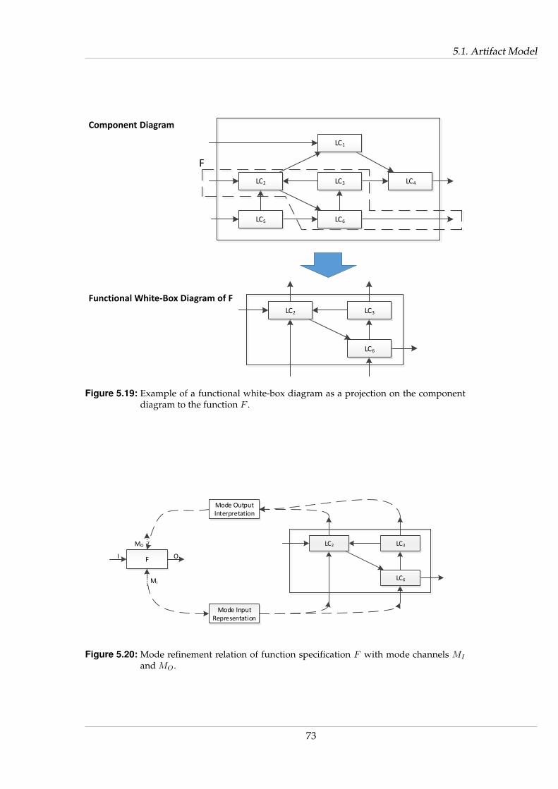
5.1. Artifact Model
Component Diagram
Functional White-Box Diagram of F
LC2 LC3
LC5 LC6
LC1
LC4
F
LC2 LC3
LC6
Figure 5.19: Example of a functional white-box diagram as a projection on the componentdiagram to the function F .
LC2 LC3
LC6
Mode Input Representation
Mode Output Interpretation
FI O
Mi
MO
Figure 5.20: Mode refinement relation of function specification F with mode channels MI
and MO.
73

5.2. Process Integration
5.1.5 Summary: Artifact Model
In this section, we introduced an artifact model that relates the concepts of our se-mantic model to model types that we use to describe them. The relations between thesemantic concepts are reflected and expressed by the model types. We defined thesemodel types to systematically develop, capture, and analyze the semantic content ofthe system modeling theory. This artifact model integrates a formal framework forthe specification of multifunctional systems into model types that are used in ourmodel-based requirements engineering methodology. The artifact model is indepen-dent of the development process by which the models are created. The followingsection of this chapter details the role of these artifacts in a development process.
5.2 Process Integration
In this section, we focus on the role of the presented artifacts in a development pro-cess and the benefits for different development activities. We illustrate the role ofthe artifacts and the activities associated with them by relating them to the V-Modeldevelopment lifecycle. We consider the function architecture with associated func-tion specifications together with the mode model as system specification and call thisthe functional architecture. Figure 5.21 shows a V-Model including this functional ar-chitecture that serves as system specification, and development activities related toit. The presented artifact model supports these activities, for example, by enabling(semi)automated analysis of them. We show how the presented artifacts supportthe validation of the system specification (Section 5.2.1), the assurance of consistencywithin the system specification (Section 5.2.2), the verification of the system architec-ture against the system specification (Section 5.2.3), the verification of the integratedsystem against the system specification (Section 5.2.4), and the possibility of integrat-ing system specification and safety analysis (Section 5.2.5).
5.2.1 System Specification Validation
Validating a system specification means assuring that the specified requirements cor-respond to the actual needs of the stakeholders. The presented artifact model sup-ports this activity by enabling a validation of the system specification by simulation.
The purpose of simulating the system specification is to ensure that the specifiedrequirements are complete and correct with regard to user intentions [Davis, 1982].Specification simulation requires an executable model of requirements (i.e., a pro-totypical representation) and embeds this executable model into a simulation envi-ronment. In the literature, there are two notions of simulation: Simulation and an-imation. Simulation is an execution of the software model, whereas animation is avisualization, in a suggestive form, of the simulated model in its environment [vanLamsweerde, 2009]. Davis [1982] compares a simulation with an interactive termi-nal (or console) that presents some textual output and accepts inputs by the user.However, in some cases, this type of simulation is also referred to as requirementsanimation [Kazmierczak et al., 1998; West and Eaglestone, 1992]. On the other hand,Pohl [2010] presents what the author refers to as requirements animation or prototyp-
74

5.2. Process Integration
Requirements
Functional Architecture
Logical Architecture
TechnicalArchitecture
Unit Testing
Integration Testing
SystemTesting
1 2
4
3
Product
1 Specification Validation
2 Specification Consistency
3 System Architecture Verification
4 System Implementation Verification
5 Safety Analysis Integration
5
Figure 5.21: The role of the functional architecture serving as system specification in thedevelopment process.
ing. This approach is akin to the graphical simulation model presented by Acostaet al. [1994]. Hence, the animation approaches taken by Pohl [2010] and Acosta et al.[1994] mainly describe an approach to visualize the system behavior.
According to Jones, requirements validation by specification simulation is the mosteffective method to reveal errors in specifications [Jones, 1998]. For specification sim-ulation, an executable representation of the system specification and its environmentis required. We therefore need a formal specification of what we want to check foradequacy. This specification must be executable or transformable into an equivalentexecutable form (cf. [van Lamsweerde, 2009]). In our methodology, this means thatthe function specifications have to be defined in terms of an executable descriptiontechnique such as state machines, code specifications, or tabular expressions.
The application of our RE artifact model allows performing specification simulationsunder the stated preconditions. Scenario descriptions and MSCs are used to specifyvalidation scenarios, which can be discussed with the stakeholders. Scenario enact-ment tools can execute these validation scenarios and show the results of interactionsalong timelines in a visual form.
The function specifications of the function hierarchy can be simulated if they are de-scribed by executable specification techniques. Due to the specified composition op-erator for function specifications, it is possible to simulate only parts of the functionhierarchy, showing also the results of the interplay between different functions.
5.2.2 System Specification Consistency
One advantage of the introduced artifact model is that it explicitly defines the rela-tionship between model types and description techniques. In some cases, the con-sistency of these relationships can be assured by precise analysis techniques. Espe-cially, if these analyses can be performed (semi)automated, we expect a great impact
75

5.2. Process Integration
on artifact consistency over the whole development lifecycle. In the following, weintroduce a set of activities to ensure a consistent system specification.
Manual Review of Use Case Tables, Scenario Descriptions, and MSCs As de-scribed in the artifact model, use case tables and scenario descriptions are structuredbut still informal artifacts. That means the ability to check consistency betweenuse case tables, scenarios descriptions, and their transformation to MSCs automat-ically is limited. Therefore, manual reviews are necessary to check the consistency ofthese three artifacts. The properties that need to be assessed in the reviews directlyresult from the artifact relations defined in the artifact model, for example:
Between a use case table and a scenario description:
• Does every scenario description start with the same precondition and triggeras stated in the use case table?
• Does every scenario description end with the minimal guarantee as stated inthe use case table?
• Are the actors of a scenario description step mentioned in the use case table?
Between a scenario description and its MSC:
• Is every step of the scenario description translated to at least one message inthe MSC?
• Are all actors of the scenario description translated to roles in the MSC?
• Is the source of an MSC message the actor of the associated scenario step?
Note that each change in a use case table, a scenario description, or an MSC hasto undergo a (regression) review. The process of deriving formalized requirementsmodels from use cases tables may also be assisted by automated approaches. Sawantet al. [2014], for example, introduce an approach to derive process diagrams and anontology from textual use case descriptions using methods based on computationallinguistics. The derived process diagrams are very close to scenario descriptions andthus may be translated into MSCs. However, these approaches rely on a consistentuse of natural language and may even restrict its use. Therefore, we advise to per-form manual reviews of this step even if (semi)automated approaches are used forderiving formalized requirements models.
Manual Review of Textual Property Descriptions and Interface AssertionsSimilar to the validation of use cases and scenarios against their formalization asMSCs, informal textual property descriptions have to be validated against their for-malization as interface assertions. This process can also only be automated to a lim-ited degree, which is why manual reviews are necessary to check the validity of theformalization. The properties that need to be checked in the reviews directly resultfrom the relations defined in the artifact model, for example:
• Is every predicate (i.e., atomic assertion) of the formalization also mentioned inthe informal textual property description?
76

5.2. Process Integration
• Is every assertion that is mentioned in the textual property description trans-lated to a predicate (i.e., atomic assertion) of the formalization?
• Is every execution sequence implied by the temporal logic formula intended bythe informal textual property description?
• Is every intended execution sequence of the informal textual property descrip-tion implied by the temporal logic formula?
Especially the last two properties are hard to check without a structured procedurethat may be supported by an appropriate tooling. Kof and Penzenstadler [2011], forexample, propose a tool-supported validation of formalizations based on feedback.A tool generates exemplary execution sequences implied by the formalization andan analyst assesses whether these are intended or not.
Automated MSC Feasibility Checks between MSCs and Function SpecificationsAs described in the artifact model, a function specification must fulfill all MSCs re-lated to that function specification. More precisely, an MSC provides a sequence ofmessages that are exchanged between the system and its environment. The functionspecification must reflect this sequence of messages, i.e., it must be a valid executiontrace of the function specification. We automatically check this property by an MSCFeasibility Check. This check transforms the sequence of messages specified by theMSC into a logical proposition and uses a model checker to evaluate whether thefunction specification is a model for the logical proposition. If so, the model checkerprovides an execution of the function specification as evidence. The transformationof MSCs to logical propositions is described, for example, by Broy [2005].
Automated Model Checking between Interface Assertions and Function Speci-fications To check whether a function fulfills all interface assertions related to it, weapply model checking techniques (cf. [Clarke et al., 2005]). This is possible since tem-poral logic formulas are used to describe the behavior of an interface assertion, andfunction specifications can be transformed into a labeled transition system [Keller,1976]. Similar to the MSC feasibility check, the model checker evaluates whether thefunction specification is a model for the temporal logic formula. If this is the case,the function specification is consistent with the interface assertion. If not, either thefunction specification or the interface assertion is incorrect and must be changed.
5.2.3 System Architecture Verification
Given a refinement relation specification between a function specification and thecomponent architecture, we can automatically verify that the behavior of the compo-nent architecture is a refinement of the function specification.
Automated Refinement Test between Function Specification and ComponentArchitecture The function specifications serve as partial specifications for the sys-tem behavior. In Section 5.1.4, we showed how this specification is connected tothe component architecture of the system by a refinement specification. A refinementtest ensures that the system behavior actually refines the specification (cf. [Mou and
77

5.2. Process Integration
Ratiu, 2012]). In a refinement test, test cases are automatically generated from thefunction specification. Each test case provides a valid input/output relation givenby the function specification. The test cases are then automatically translated to testcases for the component architecture by means of the refinement specification as de-scribed in Section 5.1.4. The test cases are executed on the component architectureand the output results are afterwards translated back to the function specificationlevel and compared to the output results of the original test case. If the results of thetest case execution deviate from the function specification, the component architec-ture is not correct with respect to the function specification.
5.2.4 System Implementation Verification
The test cases derived from the function specifications are not only used to testwhether the component architecture is a correct refinement of the system specifica-tion, but they are also used to test the actual implemented system. This resembles theidea of model-based testing, which is to use explicit behavior models to describe theintended behavior. Traces of these models are interpreted as test cases for the imple-mentation: input and expected output. The input part is fed into an implementation(the system under test), and the implementation’s output is compared to that of themodel, as reflected in the output of the test case [Prenninger and Pretschner, 2005].
Our artifact model supports model-based testing in several ways. First of all, we usetest cases derived from function specifications to test the correct implementation ofsingle functions in an integrated system. The test case generation and execution canbe performed completely automated based on the executable function specificationsand a refinement relation to the implemented system.
In addition to those function tests, also function integration and dependency testscan be performed. These tests ensure that the integration of a set of functions in onesystem yields the desired properties and behavior. Due to the explicit modeling offunction dependencies by means of mode channels, the test case inputs trigger alsopossible mode switches that may influence the other functions, which then react ac-cording to the switched mode. The resulting outputs reflect specified behavior thatresults from the integration of a set of functions. The specified function dependen-cies can also be exploited to create test cases, which employ a specific set of modeswitches or affect a large set of different functions.
In our methodology, test cases are derived directly from the specification of require-ments and thus can be traced back to specific properties or use cases. A change inthe requirements accounts for a change in the specifications. In a process, where testcases are derived from the specification models, the test cases can be updated auto-matically. Thus, specification and tests are always consistent. A third point is thattest coverage metrics can be applied to the coverage of specification models. Thus, itis possible to assess the amount of requirements that are assured by a test case.
5.2.5 Safety Analysis Integration
Functional safety assurance is the process of proving that the system under develop-ment can do no harm to its environment. Many embedded systems are safety-critical
78

5.2. Process Integration
as they directly influence physical objects that may exhibit hazardous behavior totheir environment. There are several applicable standards for developing safety-critical electronic systems, such as the IEC 61508-3 [IEC, 1998] or the ISO 26262 forthe automotive sector [ISO, 2011]. They prescribe activities and techniques that haveto be used to build a safety-critical system. By this, the process aims at a clear argu-mentation, why a system cannot harm its environment. A safety case, for example,is a structured line of arguments, which shows that the system under considerationis safe. It addresses the difficulty of combining a large variety of information neededto form this argument [Wagner et al., 2010].
A difficult task during the functional safety assurance procedure is to assess the con-sequences of a failure (both sporadic hardware failures and systematic software fail-ures) to the behavior of the software and the resulting behavior of the system. There-fore, it is necessary to have a clear understanding of system behavior in the presenceof failures.
The model types and artifacts presented in this thesis can be extended by modelingfailures explicitly as part of the behavior. A safety requirements, such as “event a andevent b must never occur simultaneously”, is formalized as an interface assertion andneeds to be fulfilled by a function specification. Thus, function specifications not onlycapture the desired functionality but also describe conditions and constraints thathave to be fulfilled to prove that the overall system is safe. Furthermore, it is possibleto enrich function specifications to also model and specify the behavior under theinfluence of failures as illustrated in the following example: A safety goal describesthe desired behavior of a system in the presence of a failure. This safety goal isspecified by a set of observations between the system and its environment. To specifythis safety goal, it is necessary to extend the interface description of the system byadditional failure stimuli. We get an interface description that expresses relationsbetween operational inputs and outputs as well as information about failures andtheir consequences for the behavior.
The introduction of a mode model supports the specification and elicitation of haz-ardous situations, especially when these arise from the interplay of different func-tions of a system. Based on a mode model, safety goals, such as the mutual exclusionof two modes, can be formulated and it can be checked whether these conditions arefulfilled by the composition of all functions in a system.
Enriching a purely functional specification model with information about failuresleads to the notion of rich specifications [Damm et al., 2005]. In rich specifications,extra-functional aspects, such as failures, timing conditions, or availability informa-tion (cf. [Junker and Neubeck, 2012]), are added to the function specification. Thismakes analyses, such as functional safety assessments, more precise and expressive.
5.2.6 Summary: Process Integration
In this section, we integrated the artifact model that was introduced in Section 5.1into the V-Model development lifecycle. This integration illustrates the role of the ar-tifacts in development activities that profit from the application of the artifact model.More specifically, we showed how the artifacts enable the assurance of a valid andconsistent system specification, the verification of the system architecture against this
79

5.3. Case Study: Scenario-driven Requirements Engineering
specification, and the support for safety analyses. By this contribution, we ensurethat our artifact model has clearly defined relations to subsequent activities in a de-velopment process. In the problem statement of this thesis (see Section 1.2), we statedthis integration as an important property for the adoption of the artifact model in in-dustrial practices. The artifact model and its process integration together form ourRE methodology.
In a concrete development process, the RE methodology needs to be instantiatedbased on the system to be developed and its development context. This instantiationhas an impact on the artifact construction and analysis procedures that are necessaryand possible. In the following, we present two case studies that show and evalu-ate two instantiations of our RE methodology (1) in a scenario-driven requirementsengineering context and (2) in a property-driven requirements engineering context.These case studies explore the possibility to apply our artifact model for differentstyles of eliciting and documenting requirements. We will see that, depending on thestyle, the artifact construction and analysis procedures differ, but for both styles, wewere able to end up with a formal and model-based functional system specification.
5.3 Case Study: Scenario-driven RequirementsEngineering
In a concrete development process, our proposed RE methodology needs to be in-stantiated to fit the characteristics of the system under development and the demandsof the development context. In a first case study, we instantiate our methodology in ascenario-driven RE context and assess its applicability, benefits, and limitations. In ascenario-driven RE approach, requirements are mainly specified by eliciting desiredusage scenarios. We decided to take a scenario-driven RE approach for the studyobject based on the available information about the system.
5.3.1 Study Context: Scenario-driven Requirements Engineering
Scenarios have attracted considerable attention in RE. As discussed by Sutcliffe[2003], scenarios play an important role to stimulate the imagination of the designers.Thus, they help in guiding thoughts, and supporting reasoning in the design process.Scenarios cannot explicitly guide a designer towards a correct model of the desiredsystem. However, they play a key role to start all modeling and design [Misra et al.,2005]. The main purpose of developing scenarios is to stimulate thinking about pos-sible occurrences of these, assumptions relating these occurrences, possible opportu-nities and risks of a scenario, and courses of action [Jarke et al., 1998].
The advantage of a requirements engineering approach based on scenarios lies in theway the scenarios ground argument and reasoning in specific detail or examples, butthe disadvantage is that being specific loses generality. Scenarios in the real worldsense are specific examples. The act of analysis and modeling is to look for patterns inreal world detail, then extract the essence, thereby creating a model [Sutcliffe, 2003].
For a scenario-driven requirements engineering, we instantiate our model-based REmethodology in a way that, starting from functions described by use case tables,
80

5.3. Case Study: Scenario-driven Requirements Engineering
a stepwise formalization of functional requirements via scenario descriptions andMSCs is enabled, which are summarized in function specifications that are finallylinked to the component architecture of the system.
5.3.2 Goal
This case study follows the goal of evaluating the applicability, benefits, and limita-tions of instantiating our model-based RE methodology in a scenario-driven require-ments engineering context.
5.3.3 Study Object
We applied the methodology during two consecutive master-level practical courseson model-based engineering for students at our university. The task of the stu-dents was to develop the control software for a canal monitoring and control sys-tem (CMCS). We took the requirements description of this system from a public casestudy that was used in the 2011 Workshop on Model-Driven Requirements Engineering(MoDRE)3. The only available source of requirements was a requirements specifica-tion document that consisted of a system overview, two descriptions of desired usagescenarios, and a domain model. We classified this as a scenario-driven RE context.
The Canal Monitoring and Control System
The system’s purpose is to control a system of canals on which ships are cruising. Tosurmount a difference in water level, a canal is equipped with a lock. A lock consistsof two lock gates and two valves that are used to balance the water level. A secondcomponent in the canal system is a low bridge. In order for a ship to pass the bridge,it needs to be opened.
The CMCS tracks the ships that cruise on the canals and controls bridges and lockssuch that ships can pass. In the original requirements document, the system wasmeant to handle a flexible canal topology. However, to simplify the developmenttask, we fixed a canal topology with only one lock and one bridge. Furthermore, weincluded only two ships into the case study. The topology is depicted in Figure 5.22.
5.3.4 Study Execution
The overall 15 students that participated in the two courses were divided into twogroups in both courses. The first group took the role of the requirements engineers,while the second group was responsible for the system architecture (the architects).The task of the requirements engineers was to document functional requirements andto formalize them as use case tables with scenarios descriptions, MSCs, and functionspecifications. They additionally created the system specification in terms of a func-tion architecture and a mode model. The architects developed the component archi-tecture and created the refinement specifications between the functions and the com-
3http://cserg0.site.uottawa.ca/modre2011/
81

5.3. Case Study: Scenario-driven Requirements Engineering
Figure 5.22: The topology of the canal system includes a lock with two lock gates (bottom ofthe figure) and a low bridge (top of the figure). The low bridge and the lock areequipped with traffic lights, motors, and valves.
ponent architecture as described in Section 5.2.3. Both groups together performedthe refinement tests and, in case of test failures, decided on the actions to be taken.The created artifacts were continuously reviewed by the course supervisors.
The system was developed incrementally. As two main functions, we identified con-trolling the bridge and controlling the lock. The requirements engineers and thearchitects worked in parallel. While the requirements engineers documented andformalized the requirements, the architects came up with a first rough architecture.
5.3.5 Instantiation of the RE Methodology
To apply the artifact model in a scenario-driven requirements engineering context,we instantiated and tailored the artifact model, and provided a concrete represen-tation. Based on the requirements document given as input for the case study, weused only a subset of model types from the artifact model described in Section 5.1.The process we took in this case study to create and verify artifacts is depicted inFigure 5.23. The figure shows the order in which we created artifacts of the artifactmodel (solid arrows) and checked their consistency (dashed arrows). A detailed de-scription of this study execution process is given in the following.
Step 1: To set the scope of the project, the course supervisors defined a functionlist that contained the functions Pass Bridge and Pass Lock. We extracted those asfunctions because they were stated as “use cases” of the system in the original re-quirements document.
82

5.3. Case Study: Scenario-driven Requirements Engineering
Function Architecture
Mode Model
Function
(Functional) Requirement
Specification
Function List
Function Hierarchy
Use Case Table
State Machine
Message Sequence Chart
Scenario Description
Mode List
Mode Chart
Component Component Architecture
State Machine
Component Diagram
Refinement Specification
Functional White-Box Diagram
Responsibility of Requirements Engineers
Responsibility of System Architects
1.
2.
3.
4.
6.
5.
7.
8.
9.
9.
10.
11.
5.
A: 1. A: 2.
A: 3.
Figure 5.23: Study execution process taken in the scenario-driven case study.
83

5.3. Case Study: Scenario-driven Requirements Engineering
Figure 5.24: Use case table for the function Pass Bridge.
Step 2: The first step that the students performed was to define a mode list from thegiven input document. For this purpose, the students examined the input documentand searched for information that characterize operational states of the system or itsenvironment. They transformed this information to items of the mode list definingmodes and their mode values.
Step 3: As next step, the students transferred the information given in the inputdocument with respect to the two functions into use case tables and documented themin the tool we used. Figure 5.24 shows the use case table for function Pass Bridge.
Step 4: From the use case tables, the students started to define scenario descrip-tions that describe exemplary usage scenarios related to the functions. Usually, thisincluded one success scenario description and a set of alternative scenario descrip-tions. Figure 5.25 shows an example of a success scenario description for the functionPass Bridge.
Step 5: At this point in the process, the students performed a first consistencycheck between the artifacts they created. They compared the use case tables andscenario descriptions with the mode list they created in step 2 to find references be-tween them. For the use case tables, this includes a relation of the statements in thetrigger, precondition, and guarantee fields to the modes of the mode list. In the scenariodescriptions, each step was investigated for conditions or actions related to a modeof the mode list. If necessary, the students extended the mode list and aligned the
84

5.3. Case Study: Scenario-driven Requirements Engineering
Figure 5.25: Success scenario description for the function Pass Bridge.
use case tables and scenario descriptions with the mode list. The tool we used wasable to store and highlight these references in the textual descriptions.
Step 6: As a first step towards a more precise description of the desired systembehavior, the students formalized the informal scenario descriptions by MSCs. Fig-ure 5.26 shows the MSC that formalizes the success scenario description of the func-tion Pass Bridge. In an MSC, the interactions between the system (CMCS) and itsenvironment are modeled by messages. The referenced modes are modeled by con-ditions (hexagons) in the MSC.
Step 7: In addition to the scenario modeling and formalization, the students cre-ated function specifications for each function based on the use case tables. The purposeof the function specifications is to associate the functions with an executable behav-ior that reflects the intended purpose stated in the use case table. The students spec-ified the behavior of functions by executable specification techniques such as statemachines, table specifications, or code specifications. The syntactic interface of thefunction specification is predetermined by the MSCs associated to the original func-tion. That means the students derived the input and output ports of the functionspecification by combining the input and output ports associated with the CMCSsystem in the MSCs. In cases, where it was too difficult or complex to specify the be-havior of an entire function by one state machine, the students had the possibility tobreak the function down to smaller functional units that were then described by statemachines. Figure 5.27 shows the function specification of the Pass Bridge function.
Step 8: To check whether the executable function specification actually fulfills thebehavior of all message sequence charts associated with the function specification,the students applied an MSC feasibility check to verify the consistency between thefunction specification and the MSC. The compatibility of the syntactic interfaces ofMSC and function specification that is necessary to perform the feasibility check wasensured by the construction approach described in the previous step.
85

5.3. Case Study: Scenario-driven Requirements Engineering
Figure 5.26: Formalization of the success scenario description by a message sequence chart(MSC).
86

5.3. Case Study: Scenario-driven Requirements Engineering
Figure 5.27: Example of a function specification with syntactic interface (top) and an associ-ated interface behavior specified by an additional decomposition into subfunc-tions (mid) and finally state machines (bottom).
87

5.3. Case Study: Scenario-driven Requirements Engineering
CMCS
Pass Bridge Pass Lock
Bridge ControlWatercraft
LockTrackingWatercraft1
TrackingLock Control
WC1Pos
Watercraft2Tracking
WC2Pos WC1Pos
WC2Pos
LockProtection
Lock
Figure 5.28: Function hierarchy of the CMCS system.
Step 9: From the function specifications and the mode list, the students createda function hierarchy by associating a function specification with each function of thefunction list. In case a function was broken down to subfunctions during the creationof the function specification, these subfunctions were added to the function hierarchy.The function dependencies between the functions were related to modes of the modelist. The resulting function hierarchy is shown in Figure 5.28.
Step 10: During the construction of the function hierarchy, the students extendedthe model list and then started to structure and formalize the modes of the mode listin a mode chart. This was performed based on the information given in the originalrequirements document and the student’s decisions. The resulting mode chart isshown in Figure 5.29.
Step 11: The mode chart defines a set of valid sequences of mode configurationsthat must not be violated by the function specifications. Otherwise, the function spec-ifications are not consistent with the underlying mode model, i.e., either a functionspecification or the mode model contains an error. To check the consistency, the stu-dents compared the possible execution sequences of the mode channels in the func-tion specification with the valid sequences of mode configurations from the modechart.
Work of the Architects: Concurrent to the specification of requirements and func-tion related artifacts, the architects modeled the component architecture by a compo-nent diagram (step A: 1.) and provided a behavior specification for each component(step A: 2.). The architects started working on the basic design (i.e., a high-level com-ponent diagram) when the first scenarios were specified. As soon as the requirementsengineers had established the first function specifications in step 7, the architects be-gan to define refinement specifications between the function specifications and the com-ponent architecture (step A: 3.). Figure 5.30 provides an extract of the componentdiagram. A continuous comparison between function specifications and componentarchitecture by means of refinement tests was performed from that point on throughall following changes in function specifications or component architecture.
88

5.3. Case Study: Scenario-driven Requirements Engineering
CMCS Mode Chart[WC1Pos]
[WC2Pos]
[Bridge]
[Lock]
hasPassed Bridge wantsTo PassBridge
wantsTo PassLock
isInLock
hasPassed Lock
hasPassed Bridge
wantsTo PassBridge
wantsTo PassLock
isInLock
hasPassed Lock
lowered raised
Changing WaterLevel
Waterlevel Low Waterlevel High
LowerDoor Closed
LowerDoor Opened
UpperDoor Closed
UpperDoor Opened
Figure 5.29: Mode chart of the CMCS system.
89

5.3. Case Study: Scenario-driven Requirements Engineering
Figure 5.30: Extract of the component architecture represented by a component diagram.
5.3.6 Study Results
Reflecting the goal of this study to assess the applicability, benefits, and limitationsof integrating the model-based RE methodology in a scenario-driven RE context, wedescribe our findings structured according to these three subgoals.
Applicability
Overall, the methodology worked well and the system was successfully developedby the students. Due to the high amount of cross checks between the different arti-facts of requirements, specification and architecture, we have high confidence in thecorrectness of the developed system.
Reoccurring Specification Patterns. During the application of the artifact model tothe study object, we observed some general patterns that were applied several timesto specify reoccurring situations.
One specification pattern was applied in situations, in which a set of function specifi-cations influence a common output in a mutually exclusive way. In our case study, forexample, the Lock Control subfunction of function passLock requires the lock door tobe opened when a ship is approaching, whereas the Lock Protection function requiredthe lock doors to be closed if the water level in the lock is currently changing. Thus,the corresponding function specifications influence a common output LockDoorCom-mand. This is a problem since the artifact model and the underlying modeling theoryrequire that the set of outputs are disjoint for each function specification.4 The stu-
4The use of the same output in two different function specification may lead to inconsistent specifi-cations since functions always run in parallel and therefore may produce conflicting values for agiven output (see [Broy, 2010a]). This is a constraint of the modeling theory compared with othertheories that, for example, allow functions to deactivate or interrupt each other (e.g., DFC [Jacksonand Zave, 1998], Activity Diagrams [Fowler and Scott, 2000]).
90

5.3. Case Study: Scenario-driven Requirements Engineering
f1Output=NoVal f2Output=NoVal
Figure 5.31: A specification pattern describing two function specifications influencing acommon output in a mutually exclusive way.
dents modeled these situations using a specification pattern shown in Figure 5.31. Inthis pattern, the set of concurrent function specifications are supplemented by addi-tional Merge function specifications (one for each shared output). Instead of directlyinfluencing the shared output, the single function specifications forward their spec-ified value for output to the Merge function specification (via channels f1Output andf2Output). The Merge function specification is equipped with a formal assumptionthat requires that at most one of the function specifications at a time forward a value,while the others do not specify a value. In the figure, this is expressed by the specialvalue NoVal resulting in the formal assumption depicted in the figure. The func-tions and their interactions have to be specified in a way that this assumption holdsglobally. In general, this requires the introduction of mode channels (e.g., priority-Mode in Figure 5.31). In our case study, the students integrated the mode channelLock between Lock Control and Lock Protection to express a higher priority of the LockProtection function (see Figure 5.28).
The application of this pattern can easily be extended to more than two concurrentfunction specifications and multiple shared outputs. The advantage of this pattern isthat all requirements of a function, including priority over other functions, are cap-tured in that function specification. The Merge functions, for which it is arguablewhether these actually resemble the original idea of a function as introduced in Sec-tion 5.1.3, are reduced to technical entities that carry no functionality that is not al-ready contained in the function specifications themselves. The assumption of theMerge function specification enforces that the concurrent function specifications can-not specify inconsistent behavior with respect to the shared output.
Benefits
Correctness of Requirements. The formalization and modeling of usage scenariosas MSCs provided precision and demanded decisions in an early stage of the devel-opment process. Therefore, the requirement engineers uncovered several misconcep-tions regarding the behavior of the environment very early. For example, among therequirement engineers there was a different understanding what kind of informationthe watercraft sends to the system (current GPS position or current canal segment),which was then decided during the creation of the MSCs.
Concurrent Development of Requirements and Architecture. Due to the precisedefinition of the artifact relations and their continuous assessment, concurrent de-
91

5.3. Case Study: Scenario-driven Requirements Engineering
velopment of requirements and architecture was supported by our RE methodology.Changes and refinements within the requirements or the architecture were immedi-ately checked for consistency with the related artifacts. Requirements and architec-tural elements were linked right from the beginning. The first correctness checks be-tween specification and architecture were applied after one fifth of the project time.In the course of the development, the requirements and the architecture were fur-ther refined and formalized allowing more expressive analyses to ensure the correctrelation between requirements and architecture. All artifacts were continuously up-dated and consistent with each other. A typical situation, where our methodologyproved beneficial compared with simple informal tracing links, occurred, when thearchitects had to change the component architecture due to a change in the require-ments of one function. In many cases, the changed component architecture fulfilledthe altered requirements, however, also introduced bugs with respect to some otherfunction. These bugs were revealed by the refinements tests and led to the revisionof other requirements in many cases, showing that information flows not only fromrequirements to architecture but also in the other direction.
Explicit Design Decisions. Another aspect of the artifact relations is that they ex-plicitly express the design decisions taken during development. Each artifact carriesinformation that originates from information of another artifact. The relation linksbetween the models document the design decisions made at the transition betweenartifacts and make them explicit. For example, the transition from the function spec-ification to the component architecture is captured by the refinement specification.Rather abstract signals like “a ship approaches a bridge” are translated to concretelogical signals like “BridgeSensor sends a signal”. The design decision, to express theevent of the requirement by this specific sensor input, is explicitly documented in therefinement specification between the function specification and the component archi-tecture. This was especially helpful for assessing whether a specific requirement isfulfilled by the chosen architecture. The same applies for the transition of an informalstep in a scenario description to a formalized sequence of messages in an MSC.
Limitations
Scalability. Our approach aims at a modular specification that allows breaking downthe functionality of a system into smaller parts and assessing them individually. It isstill an open question whether analysis procedures and checks can be performed in areasonable amount of time. The previously described system consisted of two func-tions with an overall of 10 scenario descriptions that were refined into MSCs. Ourstudents were able to model all requirements related to the functions in the originalspecification by means of our methodology. We additionally elicited 17 further re-quirements that were first formalized separately by means of temporal logic expres-sions and then mapped to the two functions. 3 out of the 17 additional requirementscould not be formalized as an interface assertion because they were too abstract (i.e.,an additional clarification step with the stakeholder is necessary). The most com-plex function specification of the system had an overall state space of 10,976 states.However, the ability to decompose this function specification to a set of subfunctionsmade it possible to model this function specification by a set of subfunctions withstate machines having a maximum of seven states. The most time consuming auto-
92

5.4. Case Study: Property-driven Requirements Engineering
mated analyses were the MSC Feasibility Checks that lasted up to 100 seconds for anMSC with 36 messages.
Missed Reuse Opportunities. A problem was that the function specifications gotvery complex. Therefore, the requirements engineers started to structure them hi-erarchically, which resulted in the above-mentioned subfunction hierarchies. Thisseemed to be problematic at first, as apparently the work for structuring the func-tionality was done twice, in the function specification and in the component archi-tecture. However, we noticed the rationales behind the structuring were quite differ-ent between requirement engineers and architects. Where the requirement engineersmainly strove for ease of understanding, the architects had goals such as high reuseor an efficient deployment in mind. Whether parts of the function architecture can be(re)used for the component architecture is a question that needs further investigation.
5.3.7 Threats to Validity
A threat to the internal validity is that the notion of correctness in the end was deter-mined by the course supervisors. We had no opportunity to assess the validity of thedeveloped system with the actual stakeholders. We tried to mitigate this threat byfocusing on the given requirements document and trying to be as close to the givenrequirements document as possible. Another threat to the internal validity is thatthe used requirements document was designed to be used as a basis for discussionin an international workshop. It therefore might not describe a real system and thedocument might be created with the goal to facilitate discussion rather than resem-bling real requirements. We have not discussed this threat with the authors of therequirements document; however, we have not found any evidence or suspiciousrequirements that support this threat.
5.4 Case Study: Property-driven RequirementsEngineering
To broaden our experience in applying the proposed RE methodology, we instanti-ated the methodology in a second case study in a property-driven RE context andassessed its applicability, benefits, and limitations. In a property-driven RE context,requirements are mainly specified by independent statements about desired systembehavior. Sometimes, these statements are structured with respect to some criteria.We classified this second case study as having a property-driven RE context due tothe characteristics of the available information about the study object.
5.4.1 Study Context: Property-driven Requirements Engineering
Specifying requirements by independent properties has positive impacts on the REprocess [van Lamsweerde, 2001]:
• Attaining completeness of the requirements. Properties can support the rightcriterion for the sufficiency of the completeness.
93

5.4. Case Study: Property-driven Requirements Engineering
• A property refinement tree can provide links to trace technical requirementsfrom strategic concerns. This helps to explain the requirements to stakeholders.
• At the time of requirement elaboration, requirements engineers are confrontedwith various alternatives to be considered. In such situations, property refine-ments can help in exploring alternative proposals and thereby providing themost appropriate abstraction.
For a property-driven requirements engineering, we instantiate our RE methodol-ogy in a way that, starting from functional properties described by textual propertydescriptions, a stepwise formalization of functional requirements via interface as-sertions is enabled, which are summarized in function specifications. Developinga component architecture and linking the function specifications to this architecturewas not part of this case study.
5.4.2 Goal
This case study follows the goal of evaluating the applicability, benefits, and limita-tions of integrating our model-based RE methodology in a property-driven require-ments engineering context.
5.4.3 Study Object
We applied the RE methodology in a one year industrial collaboration with SiemensRail Automation. The goal of the project was to apply and evaluate a seamlessmodel-based development approach in the context of rail automation. Therefore,we modeled and formalized an extract of a train control system starting from in-formal natural language requirements to implementation code in a stepwise processand assessed the benefits and efforts with Siemens. The Trainguard MT5 is a mod-ern modular automatic train control (ATC) system that offers many features, such astrain supervision and execution and control of the entire range of railway operations.It furthermore supports different levels of train control automation depending on thecharacteristics of the train and the track segment. From this system, we decided todevelop the platform screen doors function.
The Platform Screen Doors Function The Platform Screen Doors Function (PSD)is one feature of the Trainguard MT system. Its purpose is to supervise passengerexchange at platforms. The supervision of train doors is provided by the featureon each level of automation, such that, for example, it is not possible to activatethe propulsion if the train doors are still open. Some platforms are equipped withadditional doors mounted at the platform, which only open if there is a train in thestation. The purpose of the feature is to monitor and control these platform screendoors (PSDs) to synchronize the opening and closing of train and platform screendoors. Figure 5.32 shows a typical scenario, in which a train enters a station and thetrain and platform screen doors open and close simultaneously.
5http://www.siemens.com/press/pool/de/feature/2013/infrastructure-cities/mobility-logistics/2013-02-trainguardmt/broschuere-trainguard-mt-e.pdf
94

5.4. Case Study: Property-driven Requirements Engineering
Architecture Specification IC MOL RA R&D ATC-MT 4 1
OKZ &DCC: SCBA&EEC090 264
System Architecture Specification TGMT 2012-01-24 ID: A6Z08110412169, S of Trainguard MT Released For internal use only 299
Siemens AG 2005 – 2012 Confided to the recipient as a trade secret. All rights reserved SYS_AS.en.doc
Figure 56 Scenario of door control and monitoring in CTC Figure 5.32: Scenario of platform screen door (PSD) control and monitoring. OPD, WMAand OPR are specific data telegrams for communication between train and plat-form. RAUZ is short for run authorization zone. The functionality is executedon four controllers (WCU_ATP and PSDC1–3).
95

5.4. Case Study: Property-driven Requirements Engineering
5.4.4 Study Execution
As an input for the execution of the case study, Siemens provided two documents:A System Requirements Specification (SRS) and a System Architecture Specification (SAS).Both documents contained requirements with the difference that the requirementsin the SAS were already structured according to a set of subsystems and the inter-face descriptions were more concrete and closer to the technical signals used in theimplementation.
We applied our RE methodology to the requirements specified in both documentsand proceeded to a system specification consisting of a function architecture withassociated function specifications and a mode model. The project was conductedover a duration of six months with four researchers working on the model.6 Withinthe six months, we had three extensive full-day workshops with experts of SiemensRail Automation. In the three workshops, we discussed and assessed the quality andcorrectness of the resulting specification.
5.4.5 Instantiation of the RE Methodology
To apply the artifact model in a property-driven requirements engineering context,we instantiated and tailored the artifact model, and provided a concrete representa-tion. Although the study object description contained one scenario for illustration(Figure 5.32), the requirements given in the input documents were primarily for-mulated as functional properties the system shall fulfill. In contrast to the scenario-driven approach taken in the last section, the requirements were not given by use casedescriptions or possible usage scenarios of the system. Instead, the requirementswere structured according to functions the system shall fulfill and stated as indepen-dent assertions that correspond to reactions the system shall show, assuming somesituation and stimuli given by its environment. The requirements are thus indepen-dent from each other to some extent and cannot be connected to a specific usagescenario.7
Based on the requirements documents given as input for the case study, we used onlya subset of model types from the artifact model described in Section 5.1. The processwe took in this case study to create and verify artifacts, is depicted in Figure 5.33.The figure shows the order in which we created artifacts of the artifact model (solidarrows) and checked their consistency (dashed arrows). A detailed description ofthis study execution process is given in the following.
Steps 1 and 2: We started by deriving an initial function list from the input doc-uments that defined the scope of our case study. This initial list contained, for ex-ample, the functions Door Supervision and Control and Train Departure Control. Weextracted all functional requirements related to these functions from the SRS andSAS documents and documented them as textual property descriptions as depicted inFigure 5.34.
6The four researchers were not working full time. The effort spent was roughly 4 PM.7For Siemens, the independence of requirements is a quality criterion.
96

5.4. Case Study: Property-driven Requirements Engineering
Function Architecture
Mode Model
Function
(Functional) Requirement
Specification
Function List
Function Hierarchy
State Machine
Textual Property Description
Interface Assertion
Mode List
Mode Chart
3.
7.2.
8.
1.
5.4.
6.
9.
Figure 5.33: Study execution process taken in the property-driven case study.
Figure 5.34: Example of a textual property description.
97

5.4. Case Study: Property-driven Requirements Engineering
Figure 5.35: Interface assertion with syntactic interface (top) and an associated interface be-havior (bottom) formalizing the textual property description shown in Fig-ure 5.34.
Step 3: As third step, we formalized the textual property descriptions by interfaceassertions (see Figure 5.35). In this case study, we adopted the specification patternsof Dwyer et al. [1999] to specify the behavior related to an interface assertion. Theresult of this process is a set of interface assertions, each having a syntactic interfaceand an associated behavior.
Step 4: We created function specifications by examining the syntactic interfaces of theinterface assertions and composing those in one function specification that referencedthe same or similar outputs. This integration of interface assertions into functionspecifications was a design decision made by us and discussed with Siemens. Forexample, we integrated all interface assertions with outputs related to the opening,closing, and release of train doors to a Train Door Function specification. As alreadydescribed before, a function specification itself is specified by a syntactic interface andan interface behavior. The syntactic interface of the function specification is the resultof the composition of the syntactic interfaces of all interface assertions integrated inthis function specification. Figure 5.36 illustrates this integration of interface asser-tions into one function specification. Some of the syntactic interfaces of the interfaceassertions had inputs that correspond to outputs of other interface assertions. Insuch cases, the models reflected a situation, where the original textual property de-scriptions referred to each other (e.g., “If the door mode is automatic, the doors shallbe opened”). These internal references between interface assertions mapped to onefunction specification represent structural information. We utilized these referencesto structure the function specifications. Interface assertions that were integrated intoone function specification but referenced each other by their syntactic interface, de-fine two separate subfunctions within the function specification. Figure 5.37 showsthe decomposition of the Train Door Function into three subfunctions as a result of theinterface assertions integrated in this function specification. The interface assertions,in this example, reference each other in three cases (doorMode, doorReleaseStatus andreleaseForced). These references represent modes of the function specification. As aconsequence of this construction approach, we are able to trace and relate each in-
98

5.4. Case Study: Property-driven Requirements Engineering
Interface Assertions Function Specification
Figure 5.36: Integration of interface assertions into a function specification by composinginterface assertions with equal or similar outputs.
Interface Assertions
Function Hierarchy
Train Door Function
Door Mode Function
Door Open Function
Door Release Function
doorMode doorReleaseStatusreleaseEnforced
Figure 5.37: Decomposition of the Train Door Function into three subfunctions. The three in-ternal signals doorMode, doorReleaseStatus and releaseForced represent modes ofthe function specification. They originate from the interface assertions (formal-ized textual property descriptions).
99

5.4. Case Study: Property-driven Requirements Engineering
Figure 5.38: Example of a function specification with syntactic interface (top) and an associ-ated interface behavior described by a code specification (bottom).
terface assertion to exactly one (sub)function specification as depicted in Figure 5.37.The behavior of a function specification was, in the end, modeled by an executablespecification technique, such as state machines, table specifications, or code specifi-cations (see Figure 5.38).
Step 5: To check whether the executable function specifications do not violate anyof the interface assertions associated with it, we applied model checking to verifythe consistency between the function specification and the interface assertions. Thecompatibility of the syntactic interfaces of interface assertions and function specifi-cation that is necessary to perform model checking was ensured by the constructionapproach described in the previous step.
Step 6: As described in step 4, the function specifications themselves exhibit a sub-function structure that was induced by the interface assertions associated with thatfunction specification. We integrated this structure in a function hierarchy. We com-pared the function specifications with the initial functions from the function list andcreated a function hierarchy that associated the functions from the function list withthe function specifications (and added functions not considered in the initial creationof the function list).
Steps 7 and 8: We investigated the function dependencies between the functionspecifications associated with the functions of the function hierarchy to derive a
100

5.4. Case Study: Property-driven Requirements Engineering
mode list for the system. That means, we looked at each mode channel between twofunction specifications and defined the type of the channel as a mode. The valuesthat were transmitted over this mode channel served as mode values. The result is amode list. From this list, we created a mode chart in which we structured the modes asAND or OR modes and added transitions for valid mode switches based on commonsense and discussion with the domain experts from Siemens.
Step 9: The mode chart defines a set of valid sequences of mode configurationsthat must not be violated by the function specifications. Otherwise, the functionspecifications are not consistent with the underlying mode model, i.e., either a func-tion specification or the mode model contains an error. To check the consistency,the students compared the possible execution sequences of the mode channels inthe function specification with the valid sequences of mode configurations from themode chart.
Missing Model Types: The creation of a component architecture for the systemwas not in the scope of this case study. Therefore, the model types related to thecomponent architecture are not part of the study execution process. Another inter-esting aspect of this study execution process is that we did not create any artifactsthat describe the purpose and usage context of a function in detail (e.g., by provid-ing a use case table for each function). We did not create these artifacts because theinput documents provided no explicit information on this. This was not crucial forthe execution of this case study; however, in the next chapter of this thesis, we willdiscuss the relevance of such high-level descriptions for a comprehensive functiondocumentation.
5.4.6 Study Results
Reflecting the goal of this study to assess the applicability, benefits, and limitationsof integrating our model-based RE methodology in a property-driven RE context, wedescribe our findings structured according to these three subgoals.
Applicability
System Structure Constraints. The methodology and its instantiation as describedso far is agnostic with respect to a specific scope chosen to specify, i.e., the methodol-ogy is suitable for specifying an entire system (e.g., the whole TGMT system) as wellas for specifying a single subsystem of it (e.g., the control system of a single platformscreen door).
In this case study, we initially planned to apply the methodology to the scope of theplatform screen door function. That means, the scope of the system to be specifiedis defined by the scope of the TGMT system but only the parts relevant to the PSDfunction were modeled. However, during the study execution, a specific architectureconstraint became so prevalent that we integrated this constraint into the methodol-ogy as described in the following.
101

5.4. Case Study: Property-driven Requirements Engineering
The essence of the TGMT system lies in the interaction and coordination betweenthe onboard system of a train and the wayside system of the track. This distinction isso prevalent due to its physical distinction that it can be considered as an architec-tural constraint rather than a design decision. Thus, we started breaking down therequirements with a scope of the TGMT system to requirements with a scope of theonboard or the wayside subsystem. These requirements were formalized by interfaceassertions and two function architectures were created, one for the onboard and onefor the wayside subsystem.
Granularity of Functional Requirements. System level requirements (from the sys-tem requirements specification) and subsystem level requirements (from the systemarchitecture specification) resided on different levels of abstraction. More specifically,they differed in terms of the scope that they address and the granularity in which theywere described.8
With respect to the scope, the system level requirements describe requirements of theentire TGMT system, whereas the subsystem level requirements refine these systemlevel requirements by breaking them down to requirements for the onboard and way-side subsystems. Thus, subsystem level requirements exhibit a different scope andintroduce additional requirements considering the internal communication betweenthe subsystems.
With respect to the granularity, the system level requirements describe events morecoarse grained than the subsystem level requirements. For example, a system levelrequirement may refer to the event Door Open, while on the subsystem requirementslevel, this event is described by two events, Door Release and Door Opening, whichdescribe the abstract event in more detail. This refinement relation can be consideredas interaction refinement [Broy, 2010a].
We were able to apply the artifact model on both levels of granularity.
Formalization of Textual Property Descriptions. For the scope of the project, weextracted 49 relevant textual property descriptions from the documents. From these,we were able to formalize 39. In case we were not able to formalize a textual propertydescription, this was because either the requirement did not describe system behav-ior or the requirement described real-time behavior, which was not in the scope ofthe case study.
Derivation of Function Specifications from Interface Assertions. The 39 interfaceassertions were integrated into 9 function specifications (5 for the onboard and 4for the wayside subsystem). These function specifications were further decomposedinto an overall of 13 subfunctions that were specified by behavior specifications (statemachines and table specifications).
To a large degree, the function hierarchy could be derived from the interface asser-tions in a schematic manner as described in Section 5.4.5 (step 4). By grouping in-terface assertions and identifying internal communication (mode channels), we wereable to easily create the structure of the function hierarchy. The resulting functionhierarchies for the onboard and wayside subsystems are depicted in Figures 5.39and 5.40. The function hierarchy of the onboard subsystem shows seven function de-
8Teufl et al. [2014] provide an interesting discussion about the implications of this gap (scope andgranularity) between requirements.
102

5.4. Case Study: Property-driven Requirements Engineering
Onboard
Train Door Function
Propulsion Function
PSD Door Function
HMI Status Function
Door Supervision
Function
openDoorCommand doorReleaseStatus
authorizePSDOpening doorModedoorReleaseStatus
Door Mode Function
Door Open Function
Door Release Function
doorMode doorReleaseStatusreleaseEnforced
PSD Authorization
Function
PSD Control Function
Supervision Mode
Function
Supervision Control
Function
trainSupervision
Figure 5.39: Function hierarchy of the onboard subsystem.
Wayside
Door Strategy Function
RAUZ Control Function
PSD Control Function
ATS Status Function
currentDoorStrategy
Figure 5.40: Function hierarchy of the wayside subsystem.
pendencies between the functions, whereas the functions of the wayside subsystemonly exhibit one function dependency.
Figure 5.41 shows the mode chart of the onboard subsystem that we derived from thefunction dependencies in the function hierarchy. This representation was well suiteddue to its concepts of hierarchically nested states and orthogonal regions. Hierarchi-cally nested states are used to keep the diagram comprehensible by grouping a setof substates to a more abstract superstate (e.g., in the figure, the superstate OperationModes actually contains five sub states structured in two orthogonal regions ReleaseOptions and Door Mode). Orthogonal regions are used to model independent modes.Independent modes exhibit an AND-semantics, which means that for each region,exactly one state is active at a time (e.g., in the figure, the status of the Train Doors isindependent from the status of the Train Supervision mode).
Formal Verification. Out of the 39 interface assertions, we were able to verify for 31(ca. 80%) that they are not violated by the associated function specification. In cases,in which the verification failed, this was due to incompleteness or inconsistency of
103

5.4. Case Study: Property-driven Requirements Engineering
Onboard Mode Chart[Train Doors]
[PSD Doors]
[Operation Modes]
[Train Supervision]
closed released
opened
opening not authorized
opening authorized
[Release Options]
[Door Mode]
Deactivated Activated
Automatic Release
Enforced Release
ManOpen ManClose
AutOpen ManClose
AutOpen AutClose
Figure 5.41: Mode chart of the onboard subsystem.
104

5.4. Case Study: Property-driven Requirements Engineering
the original requirements provided by Siemens, or due to disability of the tool weused for this case study.9
Benefits
Resolved Inconsistencies. Through the formalization and verification of require-ments, we revealed requirements that, at least, needed further discussion with thedifferent stakeholders. We found that some requirements lacked information or as-sumed certain properties of the context. For example, conflicting requirements of onefunction were revealed when in the verification process either one interface assertionwas fulfilled or the other but never both. In these cases, additional information orconditions must be added to the requirements such that the verification process con-firms that a function fulfills both interface assertions.
Requirements Tracing. As mentioned before, we applied the artifact model to re-quirements on different levels of granularity and scope (system level requirementsvs. subsystem level requirements). The formalization of the requirements as de-scribed in the artifact model enabled defining a (formal) refinement relation betweenthese requirements. Therefore, we were able to verify that the function hierarchies,which were specified on the subsystem level, are consistent with the subsystem levelinterface assertions and afterwards verify that the subsystem level interface asser-tions imply the system level interface assertions.
Limitations
Modeling Efforts. In the context of this case study, we were not able to obtain real-istic effort estimations. This was because in the project the modeling work was doneby the tooling and method experts (academic partner) and not by the domain experts(industrial partner). On the other hand, letting the domain experts do the modelingwould also not have produced realistic assessments about modeling efforts because,in a realistic context, developers would have been trained beforehand in using thetools and methodology.
Missing Guidance for Appropriate Levels of Granularity. As described in Sec-tion 5.4.6, the requirements of the documents provided by Siemens were on differentlevels of granularity. This is often the case in development projects, where there is arequirements specification and a system- or architecture specification. The artifact modelof our methodology does not prescribe any level of granularity on which require-ments or functions should be described. It was, for example, not clear whether weshould specify the syntactic interface and the associated interface behavior of a func-tion specification with very technical input and output messages resembling the ar-chitecture specification (e.g., TCL_O_Door_Release) or on a more abstract and intuitivelevel resembling the requirements specification (e.g., doorReleaseCommand).
9Tool support is discussed separately at the end of this chapter.
105

5.5. Tool Support
5.4.7 Threats to Validity
Since the study object of this case study is a system that is already implemented andintroduced in several markets, the requirements specification provided by Siemensevolved and was influenced by the implementation and its architecture. This posesa threat to the internal validity of this case study since the high applicability of ourmethodology may be based on the requirements documents being already aligned toa specific architecture. Additionally, the modeling of the system was not done by thedomain experts but by the experts of the methodology. This may affect the resultswith respect to the applicability of the methodology. We tried to mitigate this threatby demonstrating and assessing our proceeding with the domain experts in regularworkshops.
As this was a first exploratory feasibility study in the context of a property-driven REcontext applied in the rail automation domain, we cannot guarantee that the resultsare generalizable to other systems from the automation domain or even property-driven RE context in general.
5.5 Tool Support
In both case studies, we used the tool AutoFocus3 (AF3)10 to implement the entiremethodology. Requirements, function hierarchies, mode models, architecture, andeven code generation of both case studies were modeled in AF3. The figures used inSections 5.3 and 5.4 show screenshots from the tool.
AF3 is originally a CASE tool for the model-based development of embedded sys-tems. It supports the creation of hierarchical, component-based software and hard-ware architectures. Components in the architecture hierarchy can be equipped withbehavior specifications, for example, using state machines, I/O tables, or code speci-fications.
Recently, AF3 has been extended by a requirements module called MIRA [Teufl et al.,2013]. With MIRA, requirements engineers can document and formalize require-ments directly in AF3 and link them in various ways to the architecture. One form ofrequirements that is supported by MIRA is use case tables with scenario descriptions.The scenario descriptions can be formalized using MSCs. Furthermore, formal spec-ifications for requirements can be developed using the same modeling techniques asfor the architecture.
Furthermore, AF3 supports all types of analyses mentioned in the case study sectionsout of the box (e.g., MSC feasibility checks, refinement tests, and model checking oftemporal logic assertions).
5.6 Discussion
In the two exploratory case studies, we have seen that the proposed artifact modelis applicable to different RE approaches and application domains. The results in-10http://af3.fortiss.org
106
5.7. Summary
dicate that the application of the artifact model facilitates the revelation of implicitfunction dependencies within the requirements and the explicit documentation ofthem. However, the results also indicate that further work is necessary to addressthe mentioned limitations experienced in the case studies, which are discussed in thefollowing.
One issue that occurred in the case studies was the choice of an appropriate level ofgranularity on which the artifact model should be applied. Actually, in the property-driven RE context, we applied the artifact model on two different levels of granular-ity (see Section 5.4.6). This decision was motivated by the different levels of require-ments granularity handled in the two input documents provided by Siemens. How-ever, it remains an open question whether these two levels are appropriate to sup-port development activities, and what these development activities actually are. Thiscalls for a study on development activities that a function specification should sup-port and the appropriate level(s) of granularity on which the artifact model shouldbe applied.
A second point for discussion is the missing guidance for designing a function, whichincludes the decomposition of functions into subfunctions and the specification oftheir behavior by means of behavior specification techniques (e.g., state machines).The artifact model itself does not give any guidance for that. In the case studies, wedecided case by case whether and how a function is decomposed into subfunctionsand which specification technique to apply. An open question is whether this processcan be guided to a certain extent, assuming that there are reoccurring types of func-tional intent that can be handled in a similar way. This resembles the idea of designpatterns [Gamma et al., 1994] for function specifications.
The two issues mentioned above lead to the question, whether we can provide atemplate for a comprehensive function documentation that integrates all relevant in-formation about a function, and what these information are. In the following chapterof this thesis, we pick up this question and provide a solution.
Another point that needs further examination is the elicitation and derivation of amode model. In the two case studies, the modes were defined in an ad hoc man-ner. That means, in the first case study, we defined modes based on a documentinspection and then added modes, whenever we needed them for the modeling of afunction dependency. In the second case study, we derived the modes by their im-plicit use in the textual requirements of the input documents. These procedures weresufficient for describing the function dependencies in the case studies; however, wethink that a complete and consistent mode model has a positive impact also on thedevelopment of new functions and the evolution of existing ones. Systematic elicita-tion approaches are necessary to reach these goals. In Chapter 7, we introduce andassess three systematic elicitation approaches for mode models.
5.7 Summary
In this chapter, we presented the integration of a formal specification framework formultifunctional systems into a model-based requirements engineering methodology.We defined the methodology by describing an artifact model that relates the semantic
107

5.7. Summary
concepts of the formal specification framework to model types that we use to describethem. The relations between the semantic concepts are reflected and expressed bythe model types. We highlighted the role of the resulting system specification in adevelopment process and showed its potential for automation.
We presented two case studies, where we applied the methodology in a scenario-driven requirements engineering context and in a property-driven requirements en-gineering context. The case studies showed that the methodology is feasible and al-lows detecting inconsistencies in requirements early, especially with respect to func-tion dependencies.
The discussion of the case study results revealed the need for additional methodi-cal guidance especially with respect to the level of granularity on which the artifactmodel should be applied and the decomposition and specification of functions. Ad-ditionally, more work is needed on a systematic elicitation of mode models. Bothissues are subject to the following chapters of this thesis.
108

Chapter 6Function Documentations forMultifunctional Systems
The application of the artifact model as described in the previous chapter revealedmissing methodical guidance when it comes to the selection of an appropriate levelof abstraction for describing functions as well as the design of a proper function spec-ification. In the case studies presented in the last chapter, we decided case by casewhether and how a function is decomposed into subfunctions and which specifi-cation technique to apply. If we want to introduce a comprehensive integration ofour specification approach into the requirements engineering for multifunctional sys-tems, we must provide additional guidance on how to specify and document func-tions. This leads to the question, whether we can provide a template for a compre-hensive function documentation that provides all relevant information about a func-tion, and what these information are.
Giving specific advice on how to create a function documentation calls for an in-depth study on working practices and impediments in a community of people work-ing with function documentations. In this chapter, we present such a study reveal-ing activities performed on the basis of function documentations, challenges facedwhen working with them and relations between these challenges. The conclusions ofthis study particularly address the way in which function documentations should bestructured and which information they should contain. From the results of the study,we develop a new structure for function documentations that describes a function onthree levels of abstraction and structures it by modes of operation. The resulting functiondocumentation template provides methodical guidance for the creation of a functiondocumentation in the context of our RE methodology.
This chapter is partly based on a previous publication [Vogelsang, 2014].
109

6.1. Study Context: Function Documentations for Automotive Systems
6.1 Study Context: Function Documentations forAutomotive Systems
Function documentations are central artifacts in the development of automotive sys-tems. They describe the requirements and the basic design of a function, which sum-marizes a specific part of functionality a vehicle exhibits. Function documentationsare used for several purposes, e.g., documenting requirements, communication be-tween OEM and supplier, calibration of system parameters in a specific product, ortesting and implementing a function. This function documentation artifact in the au-tomotive industry incorporates information that can be linked to several model typesintroduced in the artifact model of our RE methodology (see Section 5.1).
Over the last 25 years, the number of functions (and thus the number of functiondocumentation artifacts) in a vehicle increased and the interaction and logical de-pendencies between functions became more relevant for their specification and doc-umentation [Vogelsang and Fuhrmann, 2013].
As a consequence, developers and testers have difficulties to comprehend the com-plex function documentations, to distinguish between requirements, which need tobe fulfilled and design decisions, which can be altered, and to assess the impact ofchanges [Broy, 2006]. However, it is unclear, what the reasons for these difficul-ties are. What are the challenges the developers and testers face? How are thesechallenges related? How can we improve function documentations and which in-formation must they contain to support development activities in a situation, wherefunction complexity and coupling increases?
In different contexts and companies, function documentation artifacts are called func-tion definition, function specification, functional specification, function requirements docu-mentation, or software and calibration documentation. This artifact is a written docu-mentation of a function’s requirements and its abstract design. In many automotivecompanies, models such as dataflow specifications are used to augment textual de-scriptions (cf. [Robinson-Mallett, 2012]). These dataflow specifications may be eitherused to generate code for the function (e.g., by using Matlab Simulink or ASCETmodels) or the models just serve as an overview and the function is implementedseparately (e.g., as plain C code).
The special role of function documentations in the automotive sector originates fromthe fact that function documentations are not solely a documentation for functiondevelopers. They are the basis for a number of activities and they are read by functiondevelopers, system integrators, functions testers, and calibration engineers.
We conducted the study that we will present in this chapter at Robert Bosch GmbH,a worldwide supplier of hardware and software for automotive systems. At Bosch,function documentation artifacts are textual documents that are structured into fourmain sections described in the following. The structure and content is similar tofunction documentations we have seen in other automotive companies. The namesof the sections are taken from the original documents and their appropriateness maybe subject to discussion. In the context of our study, the actual section names are notimportant.
110

6.1. Study Context: Function Documentations for Automotive Systems
Function
(Functional) Requirement
Specificationfulfills
specifies
Component
Component Architecture
realizes/implements
structures
Function Definition
Function Description
Diagnosis Information
Parameters/Variables/Constants
Sections Content
Figure 6.1: Sections of current function documentations related to the content they describe.
Function Definition: The function definition section contains an abstract descriptionof the task that the function is supposed to realize. This description is oftengiven textually. In addition to this textual high-level description, the sectionalso contains a graphical representation of the black-box interface of the func-tion. This black-box interface contains the input signals that the function usesand the output signals that the function produces without giving any detailson its internal structure.
Function Description: In the function description section, the internal structure andrealization of the function is described by hierarchical dataflow specifica-tions and accompanying textual descriptions. The function description sec-tion is structured according to the hierarchy of the dataflow specification(cf. [Robinson-Mallett, 2012]).
Diagnosis Information: The diagnosis information section contains informationabout the monitoring of erroneous situations within the function. The repre-sentation is similar to that of the function description.
Parameters/Variables/Constants: The Parameters/variables/constants section con-tains tables for parameters, variables, and constants that are used in the func-tion documentation. The section summarizes them and provides additionalinformation such as a detailed description of a signal and its type.
We can classify the information provided in these sections with respect to our seman-tic model introduced in Chapter 2. Figure 6.1 shows the relation between the sectionsand the content they express. We see that a large part of the function documentationis concerned with the realization of the function. Functional requirements do nothave a dedicated (sub)section. They are, if at all, documented as textual explanationsattached to the function specification. The function specification content focuses onthe description of the syntactic interface in terms of input and output signals.
111

6.2. Research Objective
From a series of collaborative projects with a number of automotive companies inthe last years, we made the following observations concerning the current state offunction documentations in practice:
• Function documentations are merely a documentation of the implementationand do not describe the requirements explicitly.
• Function documentations are hard to comprehend for people who are not in-volved in the development of these functions.
• Function documentations are not complete, in the sense that some details thatare necessary to understand the function are only present in the source code.
We are interested in exploring and understanding the reasons for these observations.From this understanding, we expect to get insights that help us to provide methodicalguidance and best practices for structuring function documentations and to under-stand which content may be missing or obsolete.
6.2 Research Objective
The purpose of this study is to analyze function documentations for the purpose ofidentifying and relating challenges with respect to comprehensibility from the point ofview of function developers, system integrators, function testers, and calibration engineersin the context of an automotive software company.
6.3 Study Design
We performed an exploratory study using a grounded theory approach [Adolphet al., 2011] to conduct and analyze semistructured interviews (lasting 1–2 hours)with nine practitioners from Bosch regarding their working practices and experi-ences with function documentations. The study was led by the following researchquestions.
6.3.1 Research Questions
RQ1: Which activities are performed on the basis of function documentations?We are interested in process steps and activities that use the function documentationas input or output artifact. We additionally want to assess, which parts of a func-tion documentation are of special interest for which activities. This research questioncontributes to the goal of exploring the usage and requirements for function docu-mentations.
RQ2: What are the main challenges experienced when working with func-tion documentations? Where are problems and shortcomings when working withfunction documentations? What might be reasons for them? This research questioncontributes to the goal of improving function documentations for different stake-holders.
112

6.3. Study Design
RQ3: How are the challenges related? Can the challenges be related in a waythat they result in a comprehensive problem description? This research questioncontributes to the goal of understanding the reasons for problems in comprehendingand documenting a function.
6.3.2 Research Method
To answer the research questions, we followed a grounded theory (GT) approach, anexploratory research method originating from the social sciences, becoming increas-ingly popular in software engineering research [Adolph et al., 2011]. GT is an induc-tive approach, in which interviews are analyzed in order to derive a theory. It aimsat discovering new perspectives and insights, rather than confirming existing ones.As part of GT, each interview transcript was analyzed through a process of coding:breaking up the interviews into smaller coherent units (sentences or paragraphs), andadding codes (representing key characteristics) to these units. We organized codesinto categories. To develop codes, we applied memoing: the process of writing downnarratives explaining the ideas of the evolving theory. When interviewees progres-sively provided answers similar to earlier ones, a state of saturation was reached, andwe adjusted the interview guidelines to elaborate on other topics (cf. [Greiler et al.,2012]).
We applied this research method at a department of Bosch that is responsible for theresearch and development of software-intensive vehicle systems. The departmenthas longtime experiences in the development of automotive systems and continu-ously improves its development methods and techniques. The development pro-cesses and techniques within Bosch vary depending on the application domain andrange from full-fledged model-based approaches with code generation to conven-tional code-based development. Requirements and specifications for all systems aredocumented in function documentation artifacts. Systems are integrated based on asignal database, which consists of all signals exchanged over a bus system or withinan electronic control unit (ECU). Bosch is responsible for the entire development pro-cess of single systems and functions starting from specifying requirements over sys-tem design, implementation, testing, and calibration for existing vehicles.
6.3.3 Participant Selection
For the interviews, we selected professionals with experience in working with func-tion documentations between 5 and 10 years. We selected the participants based ontheir availability and experience and with the goal to cover as many roles as pos-sible in order to explore the whole spectrum of activities performed with functiondocumentations. Table 6.1 lists the participants and their roles.
System integrators are responsible for the integration of several functions into a sys-tem. Function testers check the correctness of function implementations according tothe function specification. Function developers develop a solution concept for a func-tion based on its high-level requirements and implement this concept. Calibrationengineers configure a function for a specific product by fixing its parameters.
113

6.3. Study Design
Table 6.1: List of roles and corresponding participants.
Role Participants
System integrator P1, P9
Function tester P2, P3
Function developer P4, P5, P7
Calibration engineer P6, P8
Analysis of existing function
specificationsInterviews
Application to function
specifications
Emerging theory
5 iterations
Start Interviews and theory development Evaluation
Interview
Coding & categorization
Theory development
Guideline adaptation
Figure 6.2: Phases of the study [Greiler et al., 2011].
6.3.4 Study Execution
We conducted the study in three phases that are illustrated in Figure 6.2 and de-scribed in the following.
Start To familiarize ourselves with the development process and terminology usedat Bosch, we analyzed two exemplary function documentations from the engine con-trol domain. To discuss relevant aspects in a more concrete way, we additionallyhanded out these examples of function documentations in the conducted interviews.
Interviews and theory development In the second phase of the study we con-ducted five interviews following a rough interview guideline with seven participantsoverall (one of the interviews had three participants). After each interview, the inter-view transcript was subject to a coding and categorization process. The codes wereafterwards integrated and related to an emerging theory describing how developerswork with function documentation and which impediments they experience. If nec-essary, the guideline was adapted for the next interview with respect to the evolvingtheory and possible new insights. In the following, the different steps of this phaseare described in detail.
114

6.3. Study Design
Data collection interview: The interviews followed an interview guideline to coverall relevant aspects. The interview guideline contained open questions aboutactivities performed with function documentations and their role in the devel-opment process, used terminology, importance of specific content for an ac-tivity, related artifacts, missing information, and comprehensibility of functiondocumentations. The interviews lasted between 1 and 2 hours and a writtentranscript was created for each interview.
Coding and Categorization: We broke up the interview transcript into smaller co-herent units (sentences or paragraphs), and added codes (representing key char-acteristics) to these units (open coding). We afterwards grouped the codes intocategories. We created the categories such that they reflect activities that areperformed on the basis of a function documentation.
Theory development: Based on the codes and categories, we started looking forrelationship between them by connecting them (axial coding). A relationshipcan, for example, be a causal condition (what influences a code or category),a strategy (for addressing a code), or a consequence (result from a strategy)(cf. [Corbin and Strauss, 2008]). We annotated these relations with narrativeexplanations (memos), which we discussed and evaluated with the practition-ers in the following interviews. The emerging theory consists of a set of codesgrouped into categories representing activities and relations between the codes.
Guideline adaptation: As the theory emerged during the interviews, we adaptedthe guidelines to explore and validate new insights and hypotheses originatingfrom the theory.
The data analysis process consisted of a constant comparison of text units, codes, andcategories, i.e., data was collected and analyzed simultaneously [Adolph et al., 2011].
Evaluation The theory development process of the second phase resulted in a setof hypotheses and explanations about which content of function documentations isimportant for which activity, where the developers encounter impediments and howthese relate to each other. In the third phase of the study, we focused on the most fre-quent codes and categories and explored them in more detail to refine and evaluaterelated hypotheses and to derive implications for improvements. In the following,the different steps of this phase are described in detail.
Evaluation interviews: In the third phase, we conducted two interviews, where wepresented the theory developed in the second study phase together with thehypotheses concerning the most prevalent codes and categories. We asked theinterviewees to assess the validity of our theory and hypotheses and explain therelations between the core concepts in more detail (selective coding). A writtentranscript was created for each interview.
Application: Besides the qualitative evaluation of the theory in the phase 3 inter-views, we additionally developed an improved function documentation struc-ture based on the results of the developed theory. This improved documenta-tion structure will be introduced later in this chapter. We applied the new doc-umentation structure to the functions explored in the first phase of the study
115

6.4. Study Results
and assessed it with respect to feasibility and improvements. The resulting newdocumentations were also discussed in the interviews of the third phase.
6.3.5 Data Analysis
The result of our study is a theory that is based on a set of codes grouped into cate-gories representing activities and relations between the codes. Codes represent keycharacteristics of one or more coherent units (sentences or paragraphs) of an inter-view transcript. From the codes, we created categories that reflect activities or pro-cess steps, and grouped the codes in these categories. Additionally, we connectedcodes to each other if we found a relationship between them (e.g., one is a causalcondition for, a strategy for, or a consequence of the other).
From this network of codes, categories, and relations, we derive hypotheses by whichwe try to answer the research questions. We answered RQ1 (Which activities are per-formed?) by listing and ordering the created categories by the number of interviewappearances of codes related to them. This shall give an overview and a prioritiza-tion of activities that need to be supported by a function documentation. For RQ2(What are the main challenges?), we list and investigate the five most frequently as-signed codes that appeared in at least half of the interviews. This shall point to thehot spots of challenges that need methodical guidance. For RQ3 (How are the chal-lenges related?), we traverse the three longest paths in our network of related codes.Together with the memos, we added to a connection of two codes, we derive threesequences of related codes and memos that represent conclusive arguments (stories)of the theory. These stories shall serve as rationales for the methodical guidance andimprovements, which we derive from the study results and which we describe at theend of this chapter.
6.4 Study Results
In the seven interviews, we applied 47 different codes in total. From these codes, wecreated eight categories and grouped the codes according to them.
6.4.1 Performed Activities (RQ1)
As mentioned before, we created the categories according to activities or processesthat are performed on the basis of function documentations. Table 6.2 shows theeight categories and ranks them by the total number of appearances of codes relatedto the category. Each code was related to exactly one category.
Comprehending a function According to this ranking, the comprehension of a func-tion was the activity that is addressed most in the interviews. 13 codes are assignedto this category, which were added 46 times to units of the interviews. Especially inthe interviews with function developers and calibration engineers, the comprehen-sion of a function accounted for a large part of the codes applied to the units of theinterviews. P4 states, “I have to comprehend what a function does” and “The demand is to
116

6.4. Study Results
Table 6.2: Categories of the theory ranked by the total number of appearances of codes re-lated to the category. The middle column indicates the number of codes related toa category.
Category # codes # code appearances
Comprehending a function 13 46
Illustrating the principle of operation 6 29
Documenting requirements 4 22
Structuring a function 5 21
Tracing requirements 3 14
Testing a function 7 13
Calibrating a function 4 13
Creating a specification 5 8
describe what a function does and not how”. P7 says, “I first look at the textual descriptionof what the function does, and then at the overview diagram (basic interface, input/output).Then you have to go into details, depending on what you’re looking for.”
Illustrating the principle of operation The second most frequently mentioned ac-tivity is illustrating the principle of operation of a function with 29 appearances of codesrelated to this category. By this activity, the interviewees referred to the necessity toillustrate a function at a high level of abstraction without any details of the imple-mentation. P4 says, “A physical description of a function is more useful in the beginning.”and P6 states, “For an initial understanding, I refer to keywords or names of components.For technical details I might as well just read the code.” Some interviewees also said thatthey try to figure out what the primary physical inputs and outputs of the functionsare and how they are related to each other. P2 proposes, “I want to describe patterns ofbehavior for the primary input and output measures of a function.”
Documenting requirements 22 codes were assigned to the activity documenting re-quirements. This activity shows the importance of the function documentation artifactas a communication means for changing requirements. P5 explains, “Change requestsaddressing the function documentation are the real requirements. If these are incorrectly doc-umented, something wrong gets implemented.” Function documentations are also usedfor clarifying abstract requirements with the customer. P1 says, “In the beginning,requirements are very abstract. The function developer writes a first draft of the functionspecification that is discussed with the customer.”
Structuring a function To support the comprehension of a function, structuring afunction was considered important. In the interviews, two main structuring princi-
117

6.4. Study Results
ples were mentioned for functions: hierarchies and modes. P5 mentions, “Functionspecifications are hierarchically structured and may also be embedded in a system specifica-tion containing also other function specifications.” Modes were mentioned as suitablestructuring principle for functions running through a set of phases. P4 explains, “Ifthere are logically independent parts within a function, a mode-based structure is better thana purely dataflow-oriented model of the function.”
Others Tracing requirements, Testing a function and Calibrating a function are addi-tional activities that are performed on the basis of the function documentation arti-fact. Codes related to the creation of a function documentation were only assigned to 6units in the interviews.
Use of Information in Function Documentations
In addition to the activities that are performed on the basis of the function documen-tation artifact, we were interested in the information that is used to perform theseactivities. Therefore, we asked the participants of the interviews, which parts of thefunction documentation they use to perform the activities.
Figure 6.3 illustrates the mean value that the participants selected on a Likert scalewith five possible values from “I use this section very intensely” to “I don’t use thissection at all”. The sections relate to the structure as introduced in Section 6.1. Theresults show that for all activities the content of the Function Description section isused most intensively. For the comprehension of a function and the illustration ofthe basic principle of operation, the high-level description in the Function Definitionsection is also very important, whereas, when it comes to more concrete tasks, suchas tracing, testing, and calibration, the content from the Diagnosis Information sectionbecomes more important. This section contains detailed information especially aboutexceptional situations and border cases.
As a side question, we additionally assessed the use of textual and graphical repre-sentations within the document. Figure 6.4 illustrates the mean value that the par-ticipants selected on a Likert scale with five possible values from “I use content withthis representation very intensely” to “I do not use content with this representationat all”. The results show that graphical representations are preferred for all activities,especially for the tracing of requirements.
6.4.2 Main Challenges (RQ2)
In order to name the main challenges faced, when working with function documen-tations, we list the five most frequently assigned codes that appeared in at least halfof the interviews. Table 6.3 shows the results of this list.
Highlight the basic principle of operation The most frequently assigned code ishighlight the basic principle of operation. It describes the necessity to understand the(physical) concept that the software function needs to support (P2, P4, P6, P7, P8).
118

6.4. Study Results
not at all very intensely
Calibrating a function
Testing a function
Tracing of requirements
Illustrating the basic principle ofoperation
Comprehending a function
Degree of consideration
Act
ivit
y
Chapter 1: Function Definition
Chapter 2: Function Description
Chapter 3: Diagnosis Information
Chapter 4: Parameters/Variables/Constants
Figure 6.3: Use of document chapters for different activities.
not at all very intensely
Calibrating a function
Testing a function
Tracing of requirements
Illustrating the basicprinciple of operation
Comprehending a function
Degree of consideration
Act
ivit
y
Graphical Representations Textual Representations
Figure 6.4: Use of content representation for different activities.
119

6.4. Study Results
Table 6.3: Top 5 codes with appearances in at least half of the interviews. The second columnindicates the total number of appearances over all interviews.
Code Category #
Highlight the basic principle of operation Illustrating the principle of operation 15
High-level description of a function Comprehending a function 8
Deriving requirements from change requests Documenting requirements 8
Hierarchical structures Structuring a function 6
Structuring modes and phases Structuring a function 5
P4 says, “At first, we focus on the physical aspects of the function and the impact to itsoperational context. States and implementation details of the software come later.”
High-level description of a function A high-level description of a function was men-tioned eight times (P2, P3, P4, P5, P6). This code was applied mainly in the contextof comprehending a function, especially in the context of comprehending a functionsomeone is not familiar with. P2 claims, “It is possible to concisely describe the purposeof any function in five sentences.”
Deriving requirements from change requests Third follows deriving requirementsfrom change requests (P1, P3, P4, P5, P7). This code addresses the fact that most func-tionality is not developed from scratch but is driven by change requests applied toolder versions of a function. P3 explains, “We come from initially assuming that there isalready an existing solution related to this kind of problem. In many cases we then employthe code of the existing version as the specification for the new version.” Additionally, dueto the tight collaboration between car manufacturers and suppliers in the automo-tive industry, the customers (i.e., the car manufacturers) are very familiar with theimplementations of a supplier and vice versa. A consequence of this is that changerequests may be formulated on very different levels of abstraction. P7 says, “Some-times, the requirements are already an exact solution, sometimes they are just a rough idea onsome desired functionality.”
Hierarchical structures Hierarchical structures were mentioned six times in the in-terviews as means to cope with complexity (P1, P5, P6, P7, P9). P6 explains, “Es-pecially, if there are long and complex relations between an input and an output signal, ahierarchical structure facilitates the calibration of a function.”
Structuring modes and phases Another issue that was mentioned in the inter-views (P3, P4, P7, P8, P9) was structuring modes and phases of a function. Describingthe lifecycle of a function in terms of abstract states was considered to have a pos-itive impact on the understandability. P3 says, “In most cases an abstract state-basedview onto a function is sufficient to understand the general purpose of it.” Another aspectmentioned in the interviews was to define dependencies to other functions based on
120

6.4. Study Results
modes. P7 explains, “A state-based representation of dependencies between functions ismore suitable than a description solely based on data exchange.”
6.4.3 Relations between Challenges (RQ3)
We related the codes to each other and annotated the relations with explanations. Wewill present the most relevant results of this process by describing three stories thatsummarize a set of codes and their relations. In the stories, codes are written in boldletters. Each story contains a hypothesis (the heading of the story) that is backed upby the relation of codes within the story that follows the hypothesis.
Story 1: Comprehending a function is supported by documenting the basicprinciple of operation and its logical modes of operation To comprehend afunction, a high-level description of the function is needed. This description shouldhighlight the basic principle of operation. A pure documentation of the code is notsufficient as it hides the underlying physical principles. However, the basic princi-ple of operation describes, in many cases, only the behavior of a function, when allenabling conditions are already fulfilled. The logic that is embedded in the nu-merous enabling conditions is often neglected in the function documentations. Forthe comprehension of a function, these logical conditions must be part of the func-tion documentation. The description of these logical conditions can be supported bystructuring the functionality according to modes of operation.
Story 2: Calibration of a function is supported by a clear description of theblack-box interface of a function For the calibration of a function, the functionparameters have a strong influence on the behavior. The logic and logical condi-tions of a function are also highly parameterized and the logic constitutes a largepart in many functions. Logical conditions hamper the traceability of signal flowthrough a function design. However, tracing signal flow is an important activityfor calibration engineers. Understanding the black box interface of a function is an-other way of tracing signals that are passed through a function. Therefore, the blackbox interface description of a function should contain the most relevant signals forthe physical principle of operation as well as the signals influencing the logical con-ditions of the function.
Story 3: Logical conditions should be integrated into function documentationsThe code of a function contains more details than it is documented in the functiondocumentation. In particular, logical conditions are often only contained in the code.These information about enabling conditions and logical interactions need to be inte-grated into the function documentation because a pure documentation of the codeis not sufficient. The logic constitutes for a large part in many functions and thusit is even more necessary to integrate this part conveniently into function documen-tations.
121

6.5. Threats to Validity
6.5 Threats to Validity
A potential threat to the credibility of our findings is that we misinterpreted the datawe collected and thus derived a theory that does not fit the data. To mitigate thisthreat, we performed data triangulation by reflecting our findings with two of exist-ing function documentations and member checking by presenting and discussing ourfindings and interpretations with the interview participants. We conducted the studyover a period of eight months, in which findings and interpretations were constantlydiscussed and applied to existing data. Another threat is a possible bias of the re-searcher. We tried to mitigate this threat by making the researchers’ intentions clear andco-opting two additional researchers from the automotive company who participatedin the interviews and the discussions of findings [Onwuegbuzie and Leech, 2007]. Weused the frequency of code occurrences as an indicator for importance. This mightbe wrong since “challenge x is not important” might contribute to the importance ofa code related to challenge x. We tried to mitigate this threat by separating negativequotations related to a code into another code (e.g., code documentation is not suffi-cient). The interviews and the coding and categorization process were conducted inGerman and translated only for the presentation in this thesis. To mitigate the threatof incorrect/improper translations by the researchers, the translations were checkedby experts of the domain.
We conducted the interviews only in one company, which poses a threat to the gen-eralizability of our findings. A replication study in other automotive companies hasnot yet been conducted. The relatively small group of only 9 interview participantsmight not be representative. Further participants may add new challenges and as-pects. However, we are confident that our data base is saturated to a certain extent aswe purposely selected participants with different roles and the ratio of codes that firstappeared in one of the two last interviews was below 5%, i.e., not much additionaldata was added in the last interviews. We validated our findings by examining twoexemplary function documentations from the engine control domain. While these, atleast, cover two different types of functions (a feedback control function and a learn-ing adaptation function), the general applicability of the conclusions to all types offunctions cannot be assured.
6.6 Discussion and Implications
From the results of the study, we draw two conclusions:
Conclusion 1: A high-level description of the basic principle of operation of a func-tion is necessary to comprehend a function. This high-level description shouldalso incorporate the logical conditions that influence the function behavior (re-lated codes: Highlight the basic principle of operation, High-level description of afunction).
Conclusion 2: In the past, the complexity of a function was mainly driven by itscontrol engineering part. Nowadays, the logical part of a function, i.e., its en-abling conditions, its modes of operation, etc., accounts for an increasing partof the complexity. There are even functions that are trivial in the controlling
122

6.7. Methodical Guidance for Function Documentations
of some values but highly complex in the situations, in which this controllingshould be applied. This logical complexity should be considered in the functiondocumentations (related code: Structuring modes and phases).
Especially the latter conclusion is well illustrated by an anecdotal example: In auto-mobiles, there is a number of software functions, which, over time, learn an adaptionfactor and apply it to the measured value of a specific sensor to compensate for in-correct measurements for example due to dirt accumulation. Specifying this learningand application process is relatively easy in terms of control engineering theory (e.g.,by giving a differential equation). However, for this function additional complexityis added, when it comes to specifying the conditions that need to be fulfilled beforethe learning process can be started. Furthermore, these conditions may also requireinteractions with other functions (e.g., requesting the permission of a scheduler). Be-fore applying the actual control cycle, the function needs to pass several phases andconditions that account for a large part of the complexity. We speak of the logic of afunction. In many function documentations, this logical part is just somehow addedto the initial control engineering model, which does not really cater for such kinds ofspecifications.1 The phases and states of the function are no longer comprehensiblein the resulting function documentation.
6.7 Methodical Guidance for Function Documentations
The conclusions particularly address the way in which function documentationsshould be structured and which information they should contain. We extracted bestpractices and solutions for the mentioned challenges from the study results and de-veloped a new artifact structure for function documentations. We applied this newfunction documentation structure to two exemplary functions from the engine con-trol domain covering a feedback control function and a learning adaptation function.The resulting new function documentations were used to evaluate the findings andimplications of our study (see the study execution process in Section 6.3.4).
The improved documentation structure introduces two new structuring means thatwere not part of the function documentation before: A function description on threelevels of abstraction and modes of operations that structure the specification according tostates or phases of a function. The structuring means and their integration into animproved documentation template are described in the following.
6.7.1 Three Levels of Abstraction
The idea of abstraction levels addresses the hypothesis of conclusion 1 by describinga function on different levels of abstraction to provide a function description withoutany technical or implementation details. Along these levels, high-level descriptionscan be traced down to lower level requirements. Based on the interviews, we pro-pose to specify requirements of a function according to the following three levels ofabstraction.
1We have seen, for example, how logical conditions are integrated in dataflow models by a sequenceof logical operator blocks like AND, OR, NOT.
123

6.7. Methodical Guidance for Function Documentations
Goals and High-Level Requirements: Describe the purpose of a function withoutany details of its realization. These requirements are the input for a function de-veloper, who designs a general solution concept (basic principle of operation)based on these requirements.
Function Requirements: Requirements that are derived from the general solutionconcept the function developer creates. Function requirements are independentfrom the realization within the software architecture.
Software Implementation Requirements: Requirements that are derived from thefunction requirements. They describe the realization of the function require-ments within the software architecture.
In current documentations, functions were only considered on one (very technical)level of abstraction, which lead to the above-mentioned problems (especially forcomprehending a function).
6.7.2 Modes of Operation
The modes of operation address the hypothesis of conclusion 2. They reflect states orphases of the solution concept. These modes are a structural element that is used tostructure the function requirements and the software implementation requirements.In addition to the modes, mode transitions are defined that specify the conditionsthat account for a mode change (cf. [Broy, 2010b; Dietrich and Atlee, 2013]). Struc-turing a function according to its phases or states is currently not part of the functiondocumentations at Bosch (see Section 6.1). An interesting point for discussion is therelation between these modes of operation of a function and the modes in our artifactmodel (see Section 5.1.2). The modes of operation considered in this study primarilydescribe states or phases of one specific function, while we introduced the modes inour artifact model as modes characterizing a system. However, as also stated by Diet-rich and Atlee [2013], function-specific modes may serve as an interface for describ-ing function dependencies (e.g., “If the electronic brake function is deactivated, thecruise control function should also be deactivated”). In such cases, function-specificmodes become relevant for specifying the behavior of the integrated system and,thus, should be added to the mode model of our RE methodology. In the study thatwe will present in the next chapter of the thesis, we elicited a mode model for a pro-ductive system and discovered that 37% of all elicited modes were function-specific.
6.7.3 Function Documentation Template
Figure 6.5 shows how we integrated the three levels of abstraction and the modesof operation into a function documentation template. We illustrate this integrationby a simplified example of a sensor heating function, i.e., a function that, when ac-tive, heats a sensor device to a constant temperature and maintains this temperatureon the desired level. The template presents the corresponding function documenta-tion with 7 chapters. The content of Chapters 1 and 6–7 is similar to the content ofcurrent function documentations in automotive companies (see Section 6.1). Theycontain basic information such as authoring information (Function Description), thedocumentation of the actual realization (Software Structure Documentation), and a tab-
124

6.7. Methodical Guidance for Function DocumentationsFunction Specification: Lambda Sensor Heating Control (LSU_VDHtrCtl) 1 Function Description
2 Goals and High-Level Requirements
3 Modes of Operation
4 Function Requirements
4.1 Function Interface
4.2 Function Requirements for Mode Inactive
4.3 Function Requirements for Mode Active
4.4 Function Requirements for Mode Failed
5 Software Implementation Requirements
5.1 Software Implementation Interface
5.2 Software Implementation Requirements for Mode Inactive
5.3 Software Implementation Requirements for Mode Active
5.4 Software Implementation Requirements for Mode Failed
6 Software Structure Documentation
7 Constants - Parameters - Variables – Structures
1 Function Description << This section contains a general informal description of the function>>
The heating control of the Lambda sensor regulates the sensor temperature to a constant value. The
intrinsic resistance of the Lambda sensor is used as the equivalent for the actual temperature value
in this case. The correcting variable is the duty cycle for the power stage of the heating resistor.
2 Goals and High-Level Requirements << This section contains goals and high-level requirements, which capture the purpose of the
function without any detail of its realization. These requirements are the input for a function
developer. High-Level requirements can have a Rationale attached to it, which serves as an
explanation of the requirement’s origin. >>
3 Modes of Operation << This section contains the modes of operation. These modes of operation are a structural element
that is used to structure the function requirements and the software implementation requirements.
The modes of operation are determined by the general solution concept, which is created by the
function developer. >>
The function can be structured into the following modes of operation. Figure 1 shows the
corresponding mode automaton.
Levels of A
bstractio
n
Mo
des
Figure 6.5: Table of content of the function documentation template. Chapters 2, 4 and 5represent the function on different levels of abstraction. Chapters 3, 4.2, 4.3, 4.4and 5.2, 5.3, 5.4 structure the levels of abstraction by modes of operations.
ular representation of all signals used (Parameters/Variables/Constants). Chapters 2–5are new and describe the requirements and interfaces of the function on the three dif-ferent levels of abstraction and structured according to the modes of operation. In ourexample, the function has three modes of operation (Inactive, Active, and Failed). Thethree levels of abstraction each account for one chapter in the documentation tem-plate. The modes of operation structure each level in a similar way and thus relatethe different levels of abstraction with each other.
We can classify the information provided in these chapters with respect to our seman-tic model introduced in Chapter 2. Figure 6.6 shows the relation between the chap-ters and the content they express. We see that the improved function documentationemphasizes the requirements of a function on different levels of abstraction explic-itly. Compared to the initial documentation structure, as illustrated in Figure 6.1, weadditionally document content of the mode model that describes the usage contextof a function and structures the requirements. Via the mode model, it is also easierto comprehend the documented function as part of a function architecture becausepossible dependencies to other functions are made explicit by referencing the modemodel in the requirements.
While the additional chapters may give the impression that the size of function doc-umentations strongly increases, we observed only a moderate increase of 18% re-spectively 25% more pages in the improved documentations for two examples weconsidered in our study. Yet, these numbers are only first indicators and additionalwork is necessary to investigate the increase in size and effort, for example, withrespect to the number of modes.
125

6.7. Methodical Guidance for Function Documentations
Function Architecture
Mode Model
Function
(Functional) Requirement
Specification
refe
ren
ces
fulfills
structures
constrains
sets context
spec
ifie
s
2 Goals and High-Level Requirements
4 Function Requirements
5 Software Implementation Requirements
3 Modes of Operation
4.1 Function Interface
5.1 Software Implementation Interface
6 Software Structure Documentation
7 Constants – Parameters – Variables
1 Function Description
Component Architecture
realizes/implements
Component
structures
Sections Content
Figure 6.6: Sections of the improved function documentation template related to the contentthey describe.
Function Specification: Lambda Sensor Heating Control (LSU_VDHtrCtl) 1 Function Description << This section contains a general informal description of the function>>
The heating control of the Lambda sensor regulates the sensor temperature to a constant value. The
intrinsic resistance of the Lambda sensor is used as the equivalent for the actual temperature value
in this case. The correcting variable is the duty cycle for the power stage of the heating resistor.
2 Goals and High-Level Requirements << This section contains goals and high-level requirements, which capture the purpose of the
function without any detail of its realization. These requirements are the input for a function
developer. High-Level requirements can have a Rationale attached to it, which serves as an
explanation of the requirement’s origin. >>
2.1 Regulation of sensor temperature ID: 2.1 Title: Regulation of sensor temperature
Description: The heating control of the sensor regulates the sensor temperature to a constant value.
Rationale: The sensors only work effectively when heated to a specific temperature.
2.2 Extended lifetime of the sensor ID: 2.2 Title: Extended lifetime of the sensor
Description: While the exhaust gas is cold, it may contain condensed water droplets. The sensor must not be heated if there are water droplets in the exhaust gas.
Rationale: If water drops touch a piece of hot sensor ceramic, it may cause damage to the ceramics because of the thermal stress.
2.3 Sensor Protection ID: 2.2 Title: Sensor Protection
Description: The sensors must be protected from damage that is caused by inappropriate heating strategies (e.g., immediate heating with full power leads to the destruction of the sensor)
Rationale: Inappropriate heating may destroy the sensor
3 Function Requirements << This section contains the function requirements. Function requirements document the general
solution concept created by a function developer. They describe the solution concept independent
any hardware specifics and especially independent from the realization within the software
architecture. The section consists of three parts: A model of the modes of operation of a function, a
description of the function’s interface and a set of function requirements that is structured by the
modes of operation and describe the requirements of the different modes of operation.>>
The function requirements are structured with respect to the modes of operation.
Figure 6.7: High-level requirement for a sensor heating function.
Please note, that the documentation structure is not restricted to be used in paper-based documentations. The introduced template could also be used as a schema for amodel repository, a product lifecycle management (PLM) system, or as requirementsstructure in a requirements management system such as DOORS2.
Goals and High-Level Requirements
Goals and high-level requirements capture the purpose of the function. These re-quirements are the input for a function developer. High-level requirements can havea rationale attached to it, which serves as an explanation for the requirement’s origin.The requirements can be documented by a table as shown in Figure 6.7. The exampleshows the requirement’s id, its title, and a description that covers the content of therequirement. The requirement states, as a high-level goal for a function, to regulate
2http://www.ibm.com/software/products/us/en/ratidoor/
126

6.7. Methodical Guidance for Function Documentations
Figure 6.8: Modes of operation for a sensor heating function.
the temperature of a sensor to a constant value. The rationale justifies this goal bygiving a reason for it. A function can have several goals, which might also contradictor influence each other (cf. [van Lamsweerde, 2001]). An alternative/additional de-scription technique that can be used in this section is a use case table, as suggested inSection 5.1.1.
Modes of Operation
The modes of operation are determined by the general solution concept, which iscreated by the function developer. The modes of operation can be represented, forexample, by a state machine that illustrates the modes and the transitions betweenthem. Figure 6.8 shows the modes of operation for the sensor heating function. Inthe example, the function is structured into three modes, which represent differentphases and situations of the function. In this example, we followed the approach tostructure a function into three high-level states Inactive, Active, and Failed as proposedby Dietrich and Atlee [2013]. In real examples, this basic structure was too generalin most cases. Almost all states had to be defined in more detail to provide an ex-pressive model of the general solution concept. During the Active state, for example,a function might run through a number of additional states or phases. Additionally,a function might have a number of different degraded behaviors depending on thefailure detected. However, in the examples we considered in our study, we were ableto describe a function with no more than ten states. The function and software im-plementation requirements are structured according to these modes. The transitionsbetween the modes of operation are described only informally in the figure. Detailson the exact conditions for taking these transitions are specified in the function re-quirements.
Function Requirements
Function requirements document the general solution concept created by a func-tion developer. They describe the solution concept independent from any hardware
127

6.7. Methodical Guidance for Function Documentations
The enabling conditions are satisfied
Mode: M5: Heating up
Refines: Sensor Protection
3.7.2 Heating Ramp
ID: 3.7.2 Title: Heating Ramp
Description: The heating of a sensor must follow a specific ramp-up strategy.
Mode: M5: Heating up
Rationale: The heating of a sensor must be suitable for the specific type of sensor. (LSU 4.9, LSU - ADV).
Refines: Sensor Protection
3.8 Function Requirements for Mode M6: Hold Temperature
3.8.1 Hold Temperature Conditions
3.8.2
3.8.3
3.8.4
3.8.5
3.8.6 Hold Temperature Output
4 Software
Implementation
Requirements << This section
contains the software
implementation
requirements.
Software
implementation
requirements are
derived from the function requirements. They describe the realization of the function requirements
within the software architecture and under the condition of a specific hardware/software design, i.e.,
which specific hardware is used. Each software implementation requirement refines a function
requirement, which is indicated by the Refines attribute of the software implementation
requirement. >>
The software requirements are structured with respect to the modes of operation.
4.1 Software Implementation Interface << The software implementation interface is a refinement of the function interface. It maps the
inputs and outputs of the function interface to inputs and outputs that are used in the software
architecture in order to fulfil the function requirements. >>
ID: 3.8.1 Title: Hold Temperature Conditions
Description: Heater control is active when the enabling conditions are satisfied
Mode: Active
Refines: Regulation of sensor temperature
ID: 3.8.2 Title: 3.8.7
3.8.8
3.8.9
3.8.10 Hold Temperature Output
Description: The current temperature of the sensor should be maintained on a desired constant level.
Mode: Active
Refines: Regulation of sensor temperature
Formalization: ℎ𝑒𝑎𝑡𝑖𝑛𝑔 𝑣𝑎𝑙𝑢𝑒 = 𝑥 𝑠𝑢𝑐ℎ 𝑡ℎ𝑎𝑡 𝑠𝑒𝑛𝑠𝑜𝑟 𝑡𝑒𝑚𝑝𝑒𝑟𝑎𝑡𝑢𝑟𝑒 = 𝑑𝑒𝑠𝑖𝑟𝑒𝑑 𝑡𝑒𝑚𝑝𝑒𝑟𝑎𝑡𝑢𝑟𝑒 +/− 𝜖
The enabling conditions are satisfied
Mode: M5: Heating up
Refines: Sensor Protection
3.7.2 Heating Ramp
ID: 3.7.2 Title: Heating Ramp
Description: The heating of a sensor must follow a specific ramp-up strategy.
Mode: M5: Heating up
Rationale: The heating of a sensor must be suitable for the specific type of sensor. (LSU 4.9, LSU - ADV).
Refines: Sensor Protection
3.8 Function Requirements for Mode M6: Hold Temperature
3.8.1 Hold Temperature Conditions
3.8.2
3.8.3
3.8.4
3.8.5
3.8.6 Hold Temperature Output
4 Software
Implementation
Requirements << This section
contains the software
implementation requirements. Software implementation requirements are derived from the function
requirements. They describe the realization of the function requirements within the software
architecture and under the condition of a specific hardware/software design, i.e., which specific
hardware is used. Each software implementation requirement refines a function requirement, which
is indicated by the Refines attribute of the software implementation requirement. >>
The software requirements are structured with respect to the modes of operation.
4.1 Software Implementation Interface << The software implementation interface is a refinement of the function interface. It maps the
inputs and outputs of the function interface to inputs and outputs that are used in the software
architecture in order to fulfil the function requirements. >>
ID: 3.8.1 Title: Hold Temperature Conditions
Description: Heater control is active when the enabling conditions are satisfied
Mode: Active
Refines: Regulation of sensor temperature
ID: 3.8.2 Title: Hold Temperature Output
Description: The current temperature of the sensor should be maintained on a desired constant level.
Mode: Active
Refines: Regulation of sensor temperature
Formalization: ℎ𝑒𝑎𝑡𝑖𝑛𝑔 𝑣𝑎𝑙𝑢𝑒 = 𝑥 𝑠𝑢𝑐ℎ 𝑡ℎ𝑎𝑡 𝑠𝑒𝑛𝑠𝑜𝑟 𝑡𝑒𝑚𝑝𝑒𝑟𝑎𝑡𝑢𝑟𝑒 = 𝑑𝑒𝑠𝑖𝑟𝑒𝑑 𝑡𝑒𝑚𝑝𝑒𝑟𝑎𝑡𝑢𝑟𝑒 +/− 𝜖
Figure 6.9: Function requirements for a sensor heating function.
Figure 6.10: Function interface of the sensor heating function.
specifics and especially independent from the realization within the software archi-tecture. Each function requirement refines a high-level requirement, which is indi-cated by a Refines attribute of the function requirement. Additionally, a Formaliza-tion attribute may contain a formalization, which relates inputs and outputs of theblack-box interface of the function. In Section 5.1.3, we proposed interface assertionsas a model type for formalizing such textual property descriptions. A function re-quirement may also have a Mode attribute, which indicates that this requirement isonly valid when the function is in a certain mode of operation. Figure 6.9 gives twoexamples for function requirements of the sensor heating function. Both function re-quirements relate to the Active mode and refine the high-level requirement Regulationof sensor temperature.
Function Interface The function interface section is a subsection of the functionrequirements chapter and contains all inputs and outputs of the function that arereferenced in the function requirements. Figure 6.10 shows the function interfacefor the sensor heating function. The main input and output quantities the functionprocesses are denoted to the left and to the right of the function block. On top ofthe function block, the conditions that influence a mode transition of the function aredenoted. Mode transitions of other functions that are affected by this function aredenoted as outputs at the bottom of the function block. The inputs and outputs ofthe function interface can be used to formalize function requirements.
128

6.7. Methodical Guidance for Function Documentations
M4: Heater Ramp enabled
Refines: Heater Ramp Enabled Output
Formalization: LSU_dcycHt = LSU_dcycRmp_CUR(0)
4.6 Software Implementation Requirements for Mode M5: Heating up
4.6.1 Heating up Conditions
ID: 4.6.1 Title: Heating up Conditions
Description: The sensor heating ramp is released if the following conditions hold:
The heater ramp of a sensor is released (LSU_stRmp[%] = TRUE)
The enabling conditions are satisfied (LSU_stRmpEna_mp[%] = TRUE)
The ramp start enable status LSU_stRmpStrtEna is TRUE. LSU_stRmp[%] indicates if the heater ramp is released for the specific sensor
Mode: M5: Heating up
Refines: Heating up Conditions
Formalization: LSU_stRmp[%] = TRUE iff LSU_stRmpEna_mp[%] = TRUE && LSU_stRmpStrtEna = TRUE
4.6.2 Heating Ramp
ID: 4.6.2 Title: Heating Ramp
Description: The duty cycle for heating up the sensor is calculated using a calibratable curve LSU_dcycRmp_CUR that contains the calibration data for the specific LSU sensor (LSU 4.9, LSU - ADV).
Mode: M5: Heating up
Refines: Heating Ramp
Formalization: LSU_dcycHt(t)= LSU_dcycRmp_CUR(t)
4.7 Software Implementation Requirements for Mode M6: Hold Temperature
4.7.1 Hold Temperature Conditions
4.7.2
4.7.3
4.7.4
4.7.5
4.7.6
4.7.7 Duty cycle
ID: 4.7.2 Title: Duty cycle
Description: The value of Sensor_dutyCycle is calculated by a PID governor.
Mode: Active
Refines: Hold Temperature Output
Formalization: 𝑆𝑒𝑛𝑠𝑜𝑟_𝑑𝑢𝑡𝑦𝐶𝑦𝑐𝑙𝑒 = 𝑃𝐼𝐷(|𝑆𝑒𝑛𝑠𝑜𝑟_𝑟𝑒𝑠𝑖𝑠𝑡𝑎𝑛𝑐𝑒 − 𝑆𝐸𝑇𝑃𝑂𝐼𝑁𝑇|)
ID: 4.7.1 Title: Hold Temperature Conditions
Description: Closed loop control of the heater is active when
Heater is enabled (Sensor_htrOff = FALSE) AND
There is no sensor error (Sensor_error = FALSE)
Mode: Active
Refines: Hold Temperature Conditions
Figure 6.11: Software implementation requirements for a sensor heating function.
Software Implementation Requirements
Software implementation requirements are derived from the function requirements.They describe the realization of the function requirements within the software archi-tecture and under the condition of a specific hardware/software design, i.e., whichspecific hardware is used. Each software implementation requirement refines a func-tion requirement, which is indicated by the Refines attribute of the software imple-mentation requirement. Software implementation requirements are also structuredby modes, indicated by the Mode attribute. Figure 6.11 gives two examples for soft-ware implementation requirements of the sensor heating function.
Software Implementation Interface Similar to the function interface, there is alsoa black-box interface description on the software implementation level. The softwareimplementation interface contains inputs and outputs of the function on the level ofthe software architecture, i.e., the names and types of the main quantities and thelogical signals that reflect the mode transitions as they are processed in the softwarearchitecture. Figure 6.10 shows the software implementation interface for the sensorheating function. As shown in the example, the signals of the function interface aremapped to signals of the software implementation interface. These mappings canbe simple 1:1 mappings of abstract signals to concrete signals within the softwarearchitecture, or they can be more complex mappings. In the example shown here, theabstract output signal heating value of the function interface is mapped to the outputvalue SensU_dcycHt, which controls the duty cycle of a heating device. This mappingencodes the decision/constraint that this specific heating device is controlled via apulse-width modulation. If this sensor is replaced by another sensor with a differentcontrolling mechanism, only the software implementation interface and the mappinghas to be adjusted but the function interface and all function requirements are stillvalid.
129

6.8. Summary
Figure 6.12: Software implementation interface of the sensor heating function.
6.8 Summary
In this chapter, we reported on an interview-based study we conducted to exploreand expose challenges and shortcomings in the current documentation of automo-tive functions with the goal to derive methodical guidance and best practices forthe documentation of functions. As a result of this study, we identified two majorproblems in function documentations, namely the separation of the basic principleof operation from the technical implementation and the inadequate specification oflogical conditions, states, and phases of a function. To overcome these problems,we propose an improved documentation structure for functions and exemplify thisstructure by a function documentation template that describes a function on threelevels of abstraction (goals, function requirements, and software implementation re-quirements) and structures its requirements according to modes of operation. Thisdocumentation structure provides guidance for a systematic documentation of func-tions, which are central artifacts of our RE methodology (see Section 5.1).
The central role of the concept of modes in the proposed documentation templateand in our methodology in general poses the question, where these modes comefrom, how they are elicited and even if it is possible to specify them in a systematicmanner. A method is needed to support the elicitation and specification of modesand we need to show that this method is feasible for realistic systems and deliversreasonable and manageable modes and mode models. Such a method and study willbe described in the following chapter.
130

Chapter 7Systematic Elicitation of ModeModels for Multifunctional Systems
The mode model has a central role in our RE methodology. In the presented casestudies, we presented examples of modes and mode models. However, these modeswere mainly defined in an ad hoc manner (e.g., by adding a mode when needed formodeling a function dependency). These procedures were sufficient for describingthe function dependencies in the case studies; however, we think that a completeand consistent mode model has a positive impact also on the development of newfunctions and the evolution of existing ones. Systematic elicitation approaches arenecessary to reach these goals. A second question that arises from the limited size ofthe presented case studies and examples of this thesis is how large a mode model fora realistic system can get. This has an impact on the scalability of our RE method-ology. A third issue that has not been investigated in depth is the question whatcharacterizes a mode and if there is an elicitation approach that is more likely to pro-duce a mode model that fits our RE methodology.
This chapter presents three approaches for a systematic elicitation of mode modelsfor a multifunctional system. The approaches are described in Section 7.1. We ap-plied the three approaches in a case study to a productive automotive system to as-sess the approaches with respect to feasibility and differences between the resultingmode models. The results of this case study are presented and discussed in Sec-tion 7.2.
This chapter is partly based on a previous publication [Vogelsang et al., 2015].
7.1 Mode Models and Elicitation Approaches
The IEEE standard 29148 for software requirements specifications (SRS) notes: “Somesystems behave quite differently depending on the mode of operation. For example, a con-trol system may have different sets of features depending on its mode: training, normal, oremergency.” [ISO/IEC/IEEE, 2011b]. The SRS proposes a specification structure forsystems with modes in its annex. The use of statecharts [Harel, 1987] or other state-
131

7.1. Mode Models and Elicitation Approaches
Engine[Ignition]
[Operation]
Off
Running
Starting
Idle Running
Active
Idle Running
Not Active
On
Off
Figure 7.1: Mode chart representation of an exemplary mode model.
based specification techniques inherently relies on the advantages of structuring asystem or a problem domain according to (observable) states. Use cases or scenariosmay reference states or modes as trigger, pre- or postcondition (see Section 5.1.3).
We call the set of all modes that are used to formulate requirements the mode modelof a system or a problem domain in general. Modes can be used explicitly (e.g.,the mode Engine Off in a statechart) or implicitly (e.g., the term engine is runningin the informal requirement “While the engine is running, the cooling control mustmaintain the motor temperature to a constant level”).
While many specification techniques, including the RE methodology proposed in thisthesis, rely on the notion of modes or states, there are no systematic approaches onhow to elicit a set (a model) of modes/states for a system. Especially multifunctionalsystems may have a large number of states to consider.
As described in Sections 2.2.2 and 5.1.2, we represent a mode by a name and a set ofmode values (e.g., Operation = {Off ,Starting ,Running}). These modes are summa-rized in a mode list. A mode model structures and formalizes the mode list. In a modemodel, the modes of the mode list and their mode values are structured by definingthe children and kind relation described in Section 2.2.2. Figure 7.1 shows an excerptof an exemplary mode model. Note that in a mode model, we do not distinguishbetween modes and mode values anymore because by the hierarchical structure, amode value may be a mode for itself with mode values (e.g., Running is a modevalue of Operation but also a mode for itself with mode values Idle Running active andIdle Running not active). Instead, we call each element of a mode model a mode anddistinguish them by their kind . Modes with kind = AND are called mode categoriesbecause these modes just summarize a set of modes by a specific name/topic (e.g.,Engine is a mode category in the example). Modes with kind = BASIC correspondto mode values of the mode list, while modes with kind = OR correspond to originalmodes of the mode list. These are the mode types defined by a mode model (seeSection 2.2.2).
132

7.1. Mode Models and Elicitation Approaches
We aim at exploring different approaches for eliciting modes of a multifunctionalsystem. In this chapter, we will investigate three approaches: (1) a deductive top-down approach, where modes are defined based on the domain knowledge of ex-perts, (2) an inductive bottom-up approach, where modes are extracted from a givenarchitecture of logical components and an analysis of dependencies between func-tions within this architecture, and (3) an analytical approach, where requirementsare manually inspected for implicit or explicit references to modes.
7.1.1 Elicitation by Interviews with Domain Experts
We assume that domain experts have a good intuition what should be considered asa mode for a system based on their experience in the development of functions of aspecific domain. Therefore, in this first elicitation approach, we obtain a mode modelfrom interviewing domain experts. In the interviews, the interviewees are asked toenumerate what they consider as modes or states of the system under consideration.The result is a mode model that contains all modes mentioned in the interviews.
7.1.2 Elicitation by Function Dependency Analysis
Recent work of Broy [2010b] and Dietrich and Atlee [2013] postulate a relation be-tween function dependencies and modes of a system. Therefore, this second ap-proach is based on the results of a function dependency analysis. In Chapter 4, wepresented the results of a feature dependency analysis performed on a productive au-tomotive system. The analysis is based on a specific architecture of a system. In thisarchitecture, logical components describe the realization/implementation of a func-tion in a purely logical fashion, i.e., without any information about the hardware thesystem runs on. A network of logical components describes the steps that are nec-essary to transform the input data into the desired output data. An example for asystem that consists of 3 functions (VF) that are realized by a network of 6 logicalcomponents is illustrated in Figure 7.2. The logical components are afterwards de-ployed to a set of electronic computing units that execute the behavior of the logicalcomponents.
In the dependency analysis, a function dependency is extracted from the functionarchitecture if there is a logical component associated to one function exchangingdata with a logical component associated to another function (e.g., communicationbetween LC 3 and LC 4). From this dependency analysis, we obtain a list of depen-dencies between functions. Every item in this list contains two functions (source andtarget) and the data signal that is responsible for the dependency.
Now, for this study, we assume all of these dependencies to be candidates for modes:Each data signal represents a mode with the possible values of the data signal asmode values. A mode model is elicited by considering all dependency signals asmodes and structuring them into mode categories.
133

7.2. Case Study: A Mode Model for an Automotive System
LC2 LC3
LC5 LC6
LC1
LC4
VF1
VF3
VF2
Figure 7.2: The logical components (rectangles) are connected by data channels (black ar-rows) and form a component architecture of the system (outer rectangle). Func-tions (VF) crosscut this architecture by the set of logical components that con-tribute to their realization (dashed forms).
7.1.3 Elicitation by Requirements Inspection
The third approach is based on natural language requirements, which are docu-mented in requirements specifications. These specifications often implicitly containstatements about modes or states of a system. For example, the requirement “The airconditioning must maintain the desired temperature if the engine is running”, refersto a mode of the engine, namely that the engine is in mode running. If a requirementrefers to a mode value, we extracted this mode value in this elicitation approach.Afterwards, the extracted mode values are grouped into modes (e.g., mode valuesrunning and off are grouped to mode engine state). For the sake of clarity, the modesare finally structured into mode categories.
7.2 Case Study: A Mode Model for an Automotive System
7.2.1 Research Objective
Our study aims at exploring the different elicitation approaches for mode models ofa multifunctional system and assessing the resulting models in terms of feasibilityand differences to each other in the context of multifunctional systems.
7.2.2 Research Questions
RQ1: Are the introduced elicitation approaches feasible in practice?We are interested whether the proposed elicitation approaches are capable of extract-
134

7.2. Case Study: A Mode Model for an Automotive System
ing modes for multifunctional systems in practice. The results of this research ques-tion have an impact on the process of eliciting modes.
RQ2: Are the resulting mode models manageable?It is an open question, how large a mode model can get for a realistic system. Inthis study, we want to assess the resulting mode models with respect to its size andmanageability. The results of this research question have an impact on the scalabilityof mode-based specification approaches.
RQ3: How do the resulting mode models differ?Different elicitation approaches may result in different modes and mode models. Inthis study, we want to assess the impact of the elicitation approach on the character-istics of the resulting modes. The results of this research question have an impact onthe generalizability of a mode model and the selection of the appropriate elicitationapproach.
7.2.3 Study Object
To answer the research questions, we applied the elicitation approaches in the contextof the development of a truck at MAN Truck & Bus AG. Although the study objectsfor the three elicitation approaches were similar, they were not exactly the same. Forthe elicitation by interviews, we asked for modes relevant to the developer’s dailywork in general and not for a specific vehicle. For the elicitation by function depen-dency analysis, we analyzed a compact truck with a restricted set of 55 functions,while for the elicitation by requirements inspection, we examined requirements of afully equipped heavy truck. This difference in the study objects was due to the avail-ability of data at the time of the study execution. The threats that this poses to thevalidity of the results are discussed later.
7.2.4 Data Collection Procedures
As required for answering RQ1, we elicited a mode model for the analyzed vehiclesystems through the three elicitation approaches described in Section 7.1. Each ofthe elicitation approaches results in a mode model that was afterwards analyzed toanswer RQ2 and RQ3.
Elicitation by Interviews with Domain Experts
We conducted interviews with four developers of MAN Truck & Bus AG from thedomains cabin & lights, base software, energy management, and driver assistance.These interview partners were selected by the head of the company’s architecturegroup with the expectation to provide the maximum number of modes. Each inter-view lasted one hour. The stated modes were simultaneously written down by theinterviewers and afterwards validated with the interviewees. The interviews werenot structured by any questionnaire or guideline. However, we sometimes tried toguide the interviewee by asking open questions regarding specific classes of modes(e.g., “Are there any modes characterizing the vehicle’s surroundings?”). After the
135

7.2. Case Study: A Mode Model for an Automotive System
four interviews, we documented the recorded modes in one integrated mode modelcontaining all modes mentioned in the interviews.
Elicitation by Function Dependency Analysis
In Chapter 4, we already presented the results of a function dependency analysis forthe study object at hand. From this dependency analysis, we extracted an overall of91 different data signals responsible for all function dependencies. Each data signalis additionally characterized by a data type within the company’s data backbone.Based on these data types, we derived a mode model from this list of data signals inthe following way. For each signal, we checked the data type:
Boolean Signals: If the data signal had a Boolean data type, we defined amode with the name of the signal and associated mode values yes and no (e.g.,BrakePedalPressed = {yes,no}).
Enumeration Signals: If the data signal had an enumeration as data type, we defineda mode with the name of the signal and the enumeration members as associatedmode values (e.g., TransmissionMode = {Park ,Neutral ,Drive,Reverse}).
Value Signals: If the data signal had a numeric data type such as km/h, we scannedthe requirements specification of the corresponding vehicle function in order to finda discretization of the data signal. For example, in the requirement specification ofone function, the signal vehicle speed was only used to distinguish between low speedand high speed. This is what we call a discretization. If we found a discretizationof a numerical signal in the requirement specification, we defined a mode with thename of the signal and the extracted discrete values as associated mode values (e.g.,VehicleSpeed = {low , high}).
If we were not able to transform a data signal to a mode by one of the three ways, weexcluded this signal from the study. Similar to the proceeding for the modes of theinterviews, we documented the resulting modes of the function dependency analysisin one mode model.
Elicitation by Requirements Inspection
For eliciting modes from their implicit usage within requirements, we inspected 223requirements from a randomly picked sample of 11 vehicle functions. A requirementin our study is a textual statement consisting of 1–2 sentences in general. Similar tothe proceeding for the modes of the other two elicitation approaches, we documentedthe resulting modes of the requirements inspection in one mode model.
7.2.5 Data Analysis Procedures
To answer the research questions RQ1 and RQ2, we analyzed the resulting modemodels from the three elicitation approaches individually. For each mode model, wecollected three measures: As a first measure, we counted the number of mode types,i.e., modes m with kind(m) = OR. The mode model shown in Figure 7.1, for exam-ple, has three mode types (Ignition, Operation, and Running). As a second measure,
136

7.2. Case Study: A Mode Model for an Automotive System
we determined, for each mode model, the number of mode values per mode typem, i.e., the number of elements in the set children(m) . In the example, the modetypes Ignition and Running each have two mode values, while Operation has three.As a third measure, we determined the nesting depth of each mode type in a modemodel. The nesting depth is determined by the length of the path through the hierar-chical mode model to the mode type. In the example, mode type Ignition has nestingdepth 2 (there is an additional root node in the mode model). These measures serveas indicators for the size and complexity of the resulting mode models. For bothnumber of mode values and nesting depth, we show the distribution by a box plotdiagram including median, maximum, and minimum values.
For the comparison of the resulting mode models (RQ3), we assess the three modemodels with respect to equal mode types. We consider two mode types from differentmode models to be equal if they have a similar name and at least one similar modevalue. If, for example, in one mode model, there is a mode type Ignition = {On,Off }and in another mode model there is a mode IgnitionState = {On, Initializing ,Off },we consider them as one mode type occurring in both mode models. The purposebehind this is that we are interested in classes of modes that are only elicited by aspecific elicitation approach. We report on the number and ratio of modes elicited byjust one elicitation approach and modes that were elicited by more than one elicita-tion approach (or even by all).
7.2.6 Validity Procedures
To ensure the validity of our results, we performed several validity procedures tomitigate mainly threats to the internal validity of the study.
The elicitation of a mode model by interviews poses the threat that the mentionedmodes were incorrectly documented by the researchers. This could be due to im-precise or incorrect interpretation of what was being said or even by a bias of theresearcher in any direction. To mitigate this threat, we took notes in the presenceof the interviewees letting them intervene in case they found something was notedincorrectly or imprecise.
The extraction of a mode model based on a static analysis of function dependenciesposes the threat that this automated analysis delivers incorrect or incomplete resultsthat may then corrupt the resulting mode model. To mitigate this threat we selectedthe same study object that was subject to a former project that especially focused onthis automated dependency analysis. In the context of this former project, the depen-dency analysis results were extensively reviewed and published [Vogelsang et al.,2012]. The extraction of the mode values for the dependency signals as described inSection 7.2.4 were taken from the company’s database and are thus not subject to aresearcher bias or interpretation.
The elicitation of a mode model by requirements inspection poses the threat that theextraction of modes is subject to the researcher’s subjectivity. To mitigate this threat,we inspected a set of 50 requirements independently by two researchers classifyingwhether or not a requirement contains a mode. For this set, we observed an inter-rater agreement in terms of Cohen’s kappa of 0.63 (substantial agreement) [Landis andKoch, 1977]. From this, we conclude that the extracted mode model is fairly reliable
137

7.3. Threats to Validity
considering researcher’s subjectivity. In addition, based on this double classification,we formulated a set of strict criteria that defined what is considered as mode in thisstudy. These criteria were: A mode may change its mode value during runtime ofthe system (this excludes, for example, configurable parameters), a mode has a dis-crete set of mode values (this excludes continuous signals), a mode must be observ-able from outside the system (this excludes internal states), and a mode’s granularitymust maintain a specific notion of importance for the entire system (this excludes,for example, specific failure states that are only relevant to one specific function).
7.3 Threats to Validity
Despite the applied validity procedures, the study design poses some further threatsto the validity of the results: The structure of the mode models, especially the sum-mary of modes in mode categories was determined by the researchers and thus notstrictly determined by the elicitation approach itself. However, this fact may onlyinfluence the measured nesting depth.
The low ratio of common modes for the elicited modes in the four interviews maysuggest that additional interviews might lead to additional modes and thus theelicited mode model might not be complete. However, the interviewees were se-lected externally according to the head of the company’s architecture departmentwith the goal to cover a broad range of modes.
As described before, the study objects used for the elicitation approaches were notexactly the same. A consequence of this is that the absolute numbers of the elicitedmodes are not comparable between the different elicitation approaches. We willtherefore not discuss differences of the elicitation approaches in terms of numberof elicited modes.
For all of the three elicited mode models we cannot guarantee completeness of theelicited mode models because we only conducted four interviews, only inspected re-quirements from 11 functions, and only analyzed fully specified parts of the systems.Future work should investigate the completeness of the created models.
7.4 Study Results
In the first part of this section, we report on the elicited mode models for the threeelicitation approaches (RQ1 and RQ2). In the second part, we will compare the re-sulting models and describe their similarities and differences (RQ3).
7.4.1 Elicited Mode Models
We were able to elicit reasonable mode models by all of the three elicitation ap-proaches, i.e., none of the approaches was a dead end.
138

7.4. Study Results
Table 7.1: Number of modes elicited in the interviews and ratio of modes mentioned in morethan one interview (common modes).
Domain Modes Common Modes
cabin & lights 24 12 (50%)
base software 13 5 (38%)
driver assistance 11 3 (27%)
energy management 7 5 (71%)
Summary 42 12 (28%)
Mode Model from Interviews
Table 7.1 lists the number of elicited modes for each interview and the ratio of modesmentioned in at least one of the other interviews (common modes).
As shown in the table, the number of modes elicited from the interviews range from7 to 24 and the ratio of modes that were also mentioned in another interview rangedfrom 27% to 71%. No single mode was mentioned in all of the interviews. The modeIgnition = {On,Off } was the only mode that was mentioned in three of the four in-terviews. The final mode model that we assembled from all modes of the interviewscontained 42 modes. 12/42 modes (28%) were mentioned in more than one interview.The 42 modes elicited from the interviews have 2 mode values on average (median)with a maximum of 6 mode values for one mode. The average (median) nestingdepth of the modes in the resulting mode model is 2 with a maximum nesting depthof 4.
Mode Model from Function Dependency Analysis
We were able to transform 35/91 (38%) of the dependency signals from the analysisinto an overall of 20 modes. The fact that there are less modes than transformedsignals is due to signals that carried redundant information with respect to the mode(e.g., the signals pedal pressed and pedal position are both determined by the samemode pedal state). The dependency signals that could not be transformed into modeswere numeric data signals for which we have not found any discretization in therequirements documents. The 20 extracted modes from the dependency analysishave 3 mode values on average (median) with a maximum of 15 mode values forone mode. The average (median) nesting depth of the modes in the resulting modemodel is 2 with a maximum nesting depth of 3.
Mode Model from Requirements Inspection
In the inspection of requirements, we observed that 165/223 (74%) of the require-ments contained information regarding at least one mode. From the analyzed re-quirements, we extracted 39 modes.
139

7.4. Study Results
RequirementsInspection
Dependency Analysis
Interviews
8
5 3
4
25
8
24
Figure 7.3: Proportionally correct distribution of modes with respect to the three elicitationapproaches.
The extracted modes from the requirements inspection have 2 mode values on aver-age (median) with a maximum of 7 mode values for one mode. The average (median)nesting depth of the modes in the resulting mode model is 2 with a maximum nestingdepth of 3.
7.4.2 Comparison of Mode Models
The Venn diagram in Figure 7.3 shows the distribution of modes for the differentelicitation approaches. The figure shows that 4 modes (5%) were elicited by all ofthe elicitation approaches. These modes are (1) the operation status of the engine,(2) the information whether the drive train is released, (3) the information whetherthe acceleration pedal is pressed, and (4) the current cruising range. An overall of 57(74%) of all modes were elicited by only one elicitation approach.
The box plots in Figures 7.4 and 7.5 show a comparison of the number of mode val-ues elicited for each mode and its nesting depth in the mode model of the differentelicitation approaches.1 The figure shows that the number of mode values for eachmode is higher for the modes elicited by the dependency analysis, whereas for theother two approaches the number is similar. There is not much difference in the nest-ing depth of the models. There is only a slight tendency for the interview model thatthe nesting depth is 2 at minimum.
1The additional Reference plot can be ignored for now and will be discussed in Section 7.5
140

7.4. Study Results
Reference Interviews Analysis Inspection
24
68
1012
1416
Num
ber
of M
ode
Val
ues
Figure 7.4: Box plot for distribution of mode values.
Reference Interviews Analysis Inspection
12
34
5
Nes
ting
Dep
th
Figure 7.5: Box plot for distribution of nesting depth.
141

7.5. Discussion
7.5 Discussion
In this section, we interpret the study results and discuss them with respect to thecharacteristics of the elicitation approaches, and the size of the mode models. Moti-vated by the diversity of the elicited mode models we also discuss a possible integra-tion of the three mode models in a reference mode model.
7.5.1 Characteristics of the Elicitation Approaches
The goal of the study presented in this paper is to explore and assess different waysof eliciting a mode model for a multifunctional system. Based on the results, wediscuss characteristics of the different approaches with respect to the type of modesthat result from them. Therefore, we focus on the modes elicited by just one of theapproaches and not by the others (see Figure 7.3).
The elicitation of modes based on interviews showed the highest number of modeselicited by just one approach (25). A reason for this may be that, in the interviews,we did not ask for a specific vehicle but for relevant modes in general. These modeswere widely distributed over all kinds of mode categories. Interestingly, modes ofthe electronic infrastructure, such as the state of an electronic control unit or the acti-vation of a bus system, were only elicited in the interviews but not in any of the otherapproaches. Many of the modes specific to the interview elicitation described ratherabstract and general states, e.g., bad weather condition or presence of oncoming vehicle.Such modes seem to be important for the understanding of functionality by humansbut may never appear as signals in the implementation. It might be interesting tomanifest such abstract information also as explicit signals in the final implementa-tion. The slightly higher nesting depth of the mode model elicited from the inter-views compared with the other may indicate that it might be easier in this approachto determine structural relations between modes. This may be due to the fact thatthis approach is the only approach that exploits domain knowledge of experts, whocan also share knowledge about structural relations between modes (e.g., one modeis a submode of another).
The mode model resulting from the dependency analysis is the smallest in terms ofthe number of elicited modes. One reason for this may be that we performed thedependency analysis on a compact truck with a restricted set of functions. Addition-ally, the number of elicited modes is influenced by the fact that, with this approach,only modes are elicited that originate from a dependency between functions of asystem. Modes that are only relevant in one function cannot be elicited with this ap-proach since they are not detected by the dependency analysis. The high number ofdependency signals that could not be transferred into a mode (see Section 7.4.1) arean indicator that a large portion of function dependencies on an implementation/architecture level are due to architectural or technical decisions and do not reflectdependencies on the level of functions, for which we assume that they correspond tomodes. The dependency analysis, for example, also contained priority signals for theorder of computation of functional blocks. This mismatch between dependencies onan implementation and function level is also addressed by the optional feature prob-lem [Kästner et al., 2009]. The mode model resulting from the dependency analysishad the smallest number and portion of modes specific to that approach (8). What is
142

7.5. Discussion
striking for these modes is their detailed character. These modes described, for exam-ple, specific pressing scenarios for a pedal (e.g., long-press vs. short-press). Togetherwith the fact that the number of mode values per mode in this approach is higherthan in the other approaches, we conclude that this elicitation approach results inmore detailed and more fine-grained modes.
The elicitation of modes based on requirements inspection resulted in 24 modes.Some of them described rather abstract and general conditions. This is similar to themodes of the elicitation by interviews and reflects that the requirements are written inthe language of the domain experts. Another interesting aspect of the elicited modesis that they also cover modes specific to a certain function (e.g., ABS active). Thesefunction-oriented modes were not as extensively mentioned in the other approachesas in this approach.
In summary, we were surprised by the diversity of the modes resulting from thedifferent elicitation approaches. Despite the quite different levels of abstraction, allmodes have merit for describing a system’s current state of operation.
7.5.2 Size of the Mode Models
A central aspect that we wanted to answer by this study is the question whether theelicitation of a mode model for an entire productive system results in a model consist-ing of hundreds or even thousands of modes that, in the end, is not understandable,usable, or maintainable anymore. By the results of our study, we are convinced thatthis is not the case. The mode models we elicited had 20 to 42 modes and even a com-bination of all mode models, which will be discussed in the next subsection, does notexceed 75 modes. An interesting question, which we have not addressed yet, wouldbe to investigate the progression of the number of modes with respect to the numberof functions.
An assessment of the elicitation approaches must also consider the necessary effort.Conducting interviews is time and person intensive; however, their analysis and theextraction of a mode model can be performed rather quickly. The extraction of modesfrom requirements is similarly time intensive but can be performed by a single (or asmaller group of) person(s). The extraction of modes by the dependency analysis canbe performed automatically to a large extent.
7.5.3 Reference Mode Model
Motivated by the diversity of the elicited mode models (40–60% of the modes of oneapproach were specific to that approach), we created a reference mode model by merg-ing the modes of all elicitation approaches. In the end, the reference model contained75 modes that we structured into mode categories similar to our proceeding for thethree elicitation approaches. Figures 7.4 and 7.5 show the distribution of mode val-ues and nesting depth for the reference model. The nesting depth tends to be higherthan in the original models. This is not surprising, assuming that a larger numberof modes suggest additional mode categories to maintain the understandability. Thenumber of mode values per mode is similar to those of the original models; however,there are a larger number of outliers with significantly more mode values than in
143

7.5. Discussion
Table 7.2: Categorization of modes from the reference mode model with respect to theirscope and if they relate to a function dependency.
Dependency
yes no Σ %
Scop
e context 0 11 11 14.7
system 8 28 36 48.0
function 9 19 28 37.3
Σ 17 58 75
% 22.7 77.3 100
the original models. We consider this reference model as a comprehensive model ofoperational modes for the development of a truck at MAN Truck & Bus AG since itconsiders and contains all viewpoints addressed by the three elicitation approaches.
7.5.4 Scopes of Modes
While assessing the elicited modes, we also noticed that modes can be classified withrespect to the scope they address. The scope of a mode denotes the object of whicha mode describes a property. To investigate and quantify this characterization inmore detail, we classified the elicited modes of the reference mode model into thefollowing three scopes:
context: Modes with this scope describe states of the operational environment ofthe system under consideration (e.g., AmbientTemperature = {low , high}).
system: Modes with this scope describe states of the system under consideration(e.g., DrivingDirection = {forward , backward}).
function: Modes with this scope describe states of specific functions of the systemunder consideration (e.g., CruiseControl = {Off ,Standby ,Active}).
With this classification, we can assess the quantitative relationship between function-specific modes, as discussed in Chapter 6 as part of the function specification, andsystem-wide modes, as originally introduced in our artifact model (see Section 5.1).More fine-grained or other classifications of mode scopes are also possible (e.g., scopewith respect a domain of a car).
We performed the classification by two researchers. A first round of independentclassification resulted in an inter rater agreement in terms of Cohen’s Kappa of 0.54(moderate agreement) [Landis and Koch, 1977]. Deviations in the classification only ap-peared between the system and the function scope. We resolved these deviations in adiscussion. Table 7.2 shows the resulting distribution of modes of the reference modemodel with respect to their scopes. Additionally, we correlated this distribution withthe property whether the mode describes a function dependency. We assigned thisproperty to the modes that originated from the dependency analysis. As discussedin the threats to validity, the absolute numbers may not be comparable but we candiscuss the distribution with respect to the scope.
144

7.6. Summary
The table shows that system-specific modes account for the largest part of modesin the reference mode model. A slightly smaller number of modes have a function-wide scope. In our study, we elicited most of these modes by the requirements in-spection approach. Only a small, but still considerable, number of modes have acontext scope. When considering the function dependencies, none of the contextmodes relates to a function dependency. However, as we discussed before, this mayresult from the fact that these modes are not (yet) captured by signals within theimplementation and therefore cannot be detected by our dependency analysis. Thedependencies that we found in our analysis were almost equally distributed overmodes with a system or function scope. This, additionally, provides a strong moti-vation for explicitly specifying states or modes of a function in their specification aswe proposed in Chapter 6. These results coincide with the results of Dietrich andAtlee [2013] who also assessed a correlation between function-specific modes andbehavioral function dependencies.
7.6 Summary
In this chapter, we presented three approaches for eliciting a mode model for a mul-tifunctional system. The purpose of a mode model is to describe a system in termsof states. Such a mode model may serve as a basis for the proposed specificationapproach presented in this thesis or any other state-based specification of systemfunctionality.
We applied the three elicitation approaches in the context of the development of atruck at MAN Truck & Bus AG. By application in this context, we answered ourresearch questions in the following way:
RQ1: Are the introduced elicitation approaches feasible in practice?Yes, in our study we were able to elicit modes through all three elicitation approaches.All approaches resulted in a mode model and are thus feasible.
RQ2: Are the resulting mode models manageable?Yes, the size of the elicited mode models ranged from 20 to 42 modes and even acombination of all mode models (reference mode model) did not exceed 75 modes.
RQ3: How do the resulting mode models differ?With all three approaches, we elicited modes that were solely elicited by one ap-proach. We thereby conclude that none of the approaches was superfluous (e.g., ifmost of its modes were also elicited by another approach).
The aim of this study was to explore different elicitation approaches for mode mod-els and assessing the resulting models. The RE methodology presented in this thesisshows how the resulting mode models can be integrated in a requirements engineer-ing process. We see this as a major contribution to the modeling and formalizationof requirements. Filipovikj et al. [2014], for example, mention the use of high-levelconcepts, such as shutdown or start-up, in textual requirements as an impediment totheir formalization because these concepts are too abstract and ambiguous. A modemodel may contribute to this formalization by providing high-level concepts with aprecise meaning.
145

7.6. Summary
The results of this study provide further empirical evidence that explicitly specify-ing the modes of a function, as suggested by our function specification template de-scribed in Chapter 6, supports the specification of function dependencies.
In Section 2.2.2, we introduced mode models including mode transitions, which havenot been tackled so far in our study. Adding mode transitions increases the expres-siveness of a mode model but requires additional information that is not elicited byour approaches. More general, it might also be interesting to state invariants overthe mode model (e.g., a specific mode combination must never occur). Starting therequirements engineering activities with a specification of a mode model for an en-tire multifunctional system may also lead to a completely new way of describing,specifying, and developing functionality.
146

Chapter 8Conclusions and Outlook
In this final chapter, we summarize the contributions of this thesis and describe pos-sible directions for further research.
8.1 Conclusions
This thesis is based on the problem statement “We need a comprehensive requirementsengineering methodology for multifunctional systems that integrates and supports the speci-fication of function dependencies” (see Section 1.2). We claimed that this thesis providessupporting evidence and solutions for the stated problem. In the following, we con-clude that these claims are supported by the contributions provided in this thesis.
8.1.1 Significance of Function Dependencies
From the results presented in Chapter 4, we can answer the stated research questions:
RQ1: To what extent do dependencies between functions exist? Function de-pendencies are numerous and pervade the whole system. Our analysis of the func-tion architecture of two productive automotive systems in industry shows that atleast 69% of the analyzed vehicle functions depend on other vehicle functions or in-fluence other vehicle functions.
RQ2: How are dependencies distributed over all functions? Function depen-dencies are distributed over the whole system. However, some functions are morecentral than others are. In our study, single vehicle functions had dependencies to upto 56% of all vehicle functions.
RQ3: What categories of data characterize the dependencies? The informa-tion that represents a function dependency is, in most cases, a value from a discrete
147

8.1. Conclusions
finite set of possible fixed values. In our analysis, around 74% of the channels thatrepresented a dependency had an enumeration or Boolean data type.
RQ4: To what extent are developers aware of function dependencies? In ourstudy, we have seen that modeling the dependencies on an architectural level is insuf-ficient for analyzing them, leading to a 50% chance that a developer was not aware ofa specific dependency in the analyzed system. In our analysis, this was particularlystriking when the function dependencies arose from architectural decisions.
Conclusion
The results of our study presented in Chapter 4 show that function dependenciespose a great challenge for the development of multifunctional systems. The ex-tent and distribution of them are not reflected by the awareness of the developers.This explains why function dependencies are a major source of unintended and erro-neous behavior and proves their significance for the specification of multifunctionalsystems. Considering these conclusions, it becomes obvious that it is necessary tointegrate the modeling of function dependencies on the level of functions into a com-prehensive specification methodology for such systems.
8.1.2 Requirements Engineering for Multifunctional Systems
Our empirical results show that function dependencies are numerous in productivemultifunctional systems but are not considered in their specification. In Chapters 5to 7, we presented an integration of a formal specification technique for multifunc-tional systems into a comprehensive requirements engineering methodology.
Integrating Functions and Modes into a Model-based RE Methodology
As a first step, we described an artifact model in Chapter 5 that introduces the arti-facts and modeling concepts used in our methodology followed by a description ofthe role of these artifacts in a development process.
We presented two case studies, where the artifact model was instantiated and appliedin a scenario-driven requirements engineering context and in a property-driven re-quirements engineering context. The case studies showed that the methodology isfeasible and allows detecting inconsistencies in requirements early, especially withrespect to function dependencies.
However, the case study evaluation also revealed the need for additional methodi-cal guidance especially with respect to the level of granularity on which the artifactmodel should be applied and the decomposition and documentation of functions.Additionally, methodical guidance is needed for a systematic elicitation of modemodels.
148

8.1. Conclusions
Function Documentations for Multifunctional Systems
Based on the results of the study presented in Chapter 6, we suggest documentingfunctions by applying the artifact model of our methodology on three different lev-els of abstraction: Goals and high-level requirements, which describe the purpose of afunction without any details of its realization, function requirements, which are inde-pendent from the realization within the actual software architecture, and software im-plementation requirements, which describe the realization of the function requirementswithin the software architecture. The requirements within these levels of abstractionare structured with respect to modes of operation, which break a function down to aset of states or phases. These suggestions for documenting functions in a multifunc-tional system are derived from an exploratory qualitative study that revealed (1) alack of separation of the basic principle of operation from the technical implemen-tation of a function, and (2) an inadequate specification of logical conditions, states,and phases of a function in current function documentations.
Elicitation of Mode Models
We presented three approaches for eliciting a mode model for a multifunctional sys-tem. Mode models play an important role in the methodology of this thesis. Theresults presented in Chapter 7 show that we were able to elicit modes for an exist-ing automotive system by means of all elicitation approaches. The resulting modemodels contained 20 to 42 modes and even a combination of all mode models (ref-erence mode model) did not exceed 75 modes. From these results, we conclude thatit is possible to elicit manageable mode models for an entire system. Moreover, theresults of the study provide further empirical evidence that explicitly specifying themodes of a function, as suggested by our function documentation template describedin Chapter 6, supports the specification of function dependencies.
Conclusion
With the presented RE methodology and its evaluation in four case studies, we haveshown that an integration of a formal specification technique into a comprehensiveRE methodology is necessary to handle the challenge of specifying multifunctionalsystems. In the center of this methodology is the specification of functions, theirstructuring in a function architecture, and the explicit specification of function de-pendencies by means of a mode model. The contributions of this thesis provide anartifact model and analysis procedures that operationalize the formal specificationapproach presented by Broy [2010b]. Furthermore, we provide methodical guidancein the application of the artifact model for documenting functions of a multifunc-tional system. Lastly, we provide empirical evidence for the feasibility and useful-ness of explicitly specifying a mode model for a multifunctional system and assessthree elicitation approaches for such a mode model.
149

8.2. Outlook
8.2 Outlook
This section discusses possible improvements of the presented work and illustratesdirections for further research.
8.2.1 Nonfunctional Requirements
While the contributions of this thesis only consider functional requirements, an in-teresting research direction would be to extend the approach to nonfunctional prop-erties of a system, which may influence the behavior of a system.
The basic assumption behind this idea is that so-called nonfunctional requirements,in fact, are always reflected in any kind of system behavior. This misconception ofthe term nonfunctional requirements is, for example, also criticized and discussedby Glinz [2007]. The approach of this thesis may serve as a blueprint for refiningand formalizing also nonfunctional requirements by interpreting them as behavioralproperties. High-level nonfunctional goals as they are stated, for example, in theISO/IEC 9126 [ISO/IEC, 2001] (e.g., usability, reliability, efficiency), are refined toobservations that can be defined in terms of observable system behavior. For someof these properties an extension of the used system modeling theory is necessary.Properties concerning the availability of a system are often defined by the use of sta-tistical measures (e.g., the system must be available 99.9% of the time). Specifyingsuch properties needs an extension of the modeling theory as proposed, for example,by Neubeck [2012]. How such an extended theory can be used to formalize availabil-ity properties is described by Junker and Neubeck [2012].
We think it is promising to examine also other nonfunctional properties and to assesswhether and how they can be specified by means of our formal modeling theory.This way, the approach described in this thesis would also capture the specificationof nonfunctional properties. An interesting, and not yet extensively discussed re-search question is: What is the relation between nonfunctional properties, functions,and function dependencies? It sounds reasonable to specify a nonfunctional prop-erty with respect to a function (e.g., “The airbag function should be available 99.9%of the time”); but how is this availability affected by the availability of other func-tions to which the airbag function has dependencies? In the work of Siegmund et al.[2012], the authors present an approach to predict program performance based onselected features. What is special about this approach is that it also takes the impactof feature interactions into account. The performance of a system is thus determinedby performance measures of the single features and those of their interaction. In theirwork, the authors also provide a feature interaction detection approach that is basedon performance measurements, i.e., nonfunctional behavior might be used to detectinteractions between features. It is an interesting question how such an approachrelates to the mode model that is introduced in this thesis. For example, is it possibleto associate a mode with a performance measurement? Can mode observations beused to detect function dependencies? Such considerations may lead to a notion ofnonfunctional feature interactions.
150

8.2. Outlook
8.2.2 Natural Language Requirements
The approaches presented in this thesis propose to use appropriate models to cap-ture and specify requirements. However, in practice, a large portion of requirementsand system descriptions are captured as natural language text [Luisa et al., 2004].In fact, we have seen in the studies that have been conducted as part of this thesisthat a lot of important information is documented implicitly in natural language ar-tifacts. This bears the risk that ambiguities or incomplete requirements specificationsremain undiscovered because natural language has no formal semantics, and thusthese issues are hard to detect.
An interesting topic for future research is the question how the proposed models ofthis thesis can be related to natural language representations. In the research com-munity, there are different approaches that may contribute to this question. Naturallanguage patterns, as for example proposed by Denger et al. [2003], restrict the useof natural language to a subset that allows a transformation to (semi)formal mod-els. In Chapter 6, we introduced a documentation template for functions. Futureresearch may investigate the use of natural language patterns as part of this functiondocumentation template.
Especially in the presence of legacy systems and its documentation (if existent), it isalso interesting to consider information retrieval techniques to (automatically) extractimplicit knowledge from natural language artifacts and to transform it into modelsproposed in this thesis. In the context of the study presented in Chapter 7, we sawthat natural language requirements were a fertile source of eliciting modes of a sys-tem. Kof and Penzenstadler [2011] propose a semi-automated approach to detectstates in natural language requirements. It would be interesting to investigate thisapproach to extract system modes from natural language requirements.
8.2.3 Variability and Product Families
The focus of this thesis is on the specification of a single system. However, multifunc-tional systems are often part of a whole family of products that consists of a set ofsimilar products. These products of a product family may differ, for example, in theset of functions they offer. A good example for this is a product line of an automotivecompany that contains a set of varying vehicle models (e.g., for different markets andin different luxury classes).
The close relation between function or feature modeling and modeling of variabilityis reflected by many approaches from the field of feature modeling (e.g., [Kang et al.,1990; Pohl et al., 2005; Shaker et al., 2012]). The whole field of feature-oriented soft-ware development considers features as the primary units of reuse, and the variantsof a software system vary in the features they provide [Apel et al., 2013a].
The approach presented in this thesis may contribute to and extend these approachesby considering the variability of features/functions in a more differentiated way. Ourapproach, for example, allows differentiating variability in the set of functions, vari-ability in the behavior of functions, variability in the influence of functions to eachother, and, maybe most interestingly, variability in the set of modes. Variability ofmodes may be worth investigating in more detail in the future. For example, an ad-
151

8.2. Outlook
ditional safety mode that is required when operating a system in a specific countrymay have an influence on all functions of the system. For modeling this variabilityof modes in a mode model it might be interesting to investigate variability extensionmechanisms for statecharts (e.g., as parameterized statechart models [Gomaa, 2005]).Shaker et al. [2012], for example, already use this technique in their feature-orientedrequirements modeling language (FORML) to annotate statechart elements, such asstates, labels, or transitions, with feature dependent parameters.
8.2.4 Software Product Management
Software product management of multifunctional systems is a challenging issue notleast because of the need to handle short iterative lifecycles and families of thesesystems [Ebert and Brinkkemper, 2014]. After collecting experience in control engi-neering from a three-year collaboration in the automotive domain, we conclude thatsoftware product management is only weakly aligned with feature and platform de-velopment. This claim is also supported, for example, by a study of Lucassen et al.[2014], who report that software program managers and software architects collabo-rate in requirements gathering and refinement but do not use any structured modelsfor this purpose. This situation makes it difficult to assure feasibility of innovationsand to identify potentials for innovations.
For innovation management, which is part of product management, we already pro-posed a first step towards the integration of a model-based RE methodology asintroduced in this thesis into the activities of innovation and technology manage-ment [Gleirscher et al., 2014]. We present how function architectures can be extendedto represent also functional evolution over time. Technology roadmaps can be de-rived from this model. A central idea of this approach is to separate functional evo-lution from technological evolution. This separation is described by three models:the function architecture, which describes the evolution of functions offered to thecustomer, the platform service architecture, which describes the capabilities of thetechnology platform, and the platform component model, which describes the con-stituents of the technology platform. In our work, we illustrate how these modelssupport two innovation scenarios (requirements-based and technology-based inno-vation). While we consider this approach promising for the connection of model-based development to earlier development phases from product and innovationmanagement, the approach still needs to be refined and evaluated in more detail.Especially, the relation between evolution (of functions or platform capabilities) andvariation is something that is not properly captured in current working practices.
Tran and Massacci [2014] present an approach for reasoning about feature model evo-lution. In their approach, they present two kinds of models: an evolution possibilitymodel that describes possibilities for a feature model to evolve, and an evolutionaryfeature model that describes the feature model with all changes due to incorporatedevolutions. Based on these models, they present, besides others, a survivability analy-sis that assesses whether a configuration (i.e., a set of features) could survive duringthe expected evolution. However, in their models and analyses, behavioral interac-tions between features are not considered. We are convinced that feature interactionsare as important for the introduction of innovative functionality as the evolution of
152

8.2. Outlook
the isolated features. A large portion of innovative functionality comes from a smartinterplay of existing features.
153


Bibliography
Acosta, R., Burns, C., Rzepka, W., and Sidoran, J. (1994). A case study of applyingrapid prototyping techniques in the requirements engineering environment. InProceedings of the 1st International Conference on Requirements Engineering (RE’94).
Adam, S., Doerr, J., and Eisenbarth, M. (2009). Lessons learned from best practice-oriented process improvement in requirements engineering: A glance into currentindustrial re application. In Proceedings of the 4th International Workshop on Require-ments Engineering Education and Training (REET’09).
Adolph, S., Hall, W., and Kruchten, P. (2011). Using grounded theory to study theexperience of software development. Empirical Software Engineering, 16.
Apel, S., Batory, D. S., Kästner, C., and Saake, G. (2013a). Feature-Oriented SoftwareProduct Lines – Concepts and Implementation. Springer.
Apel, S. and Kästner, C. (2009). Overview of feature-oriented software development.Journal of Object Technology (JOT).
Apel, S., Kästner, C., and Batory, D. (2008). Program refactoring using functionalaspects. In Proceedings of the 7th International Conference on Generative Programmingand Component Engineering (GPCE’08).
Apel, S., Kolesnikov, S., Siegmund, N., Kästner, C., and Garvin, B. (2013b). Exploringfeature interactions in the wild: The new feature-interaction challenge. In Pro-ceedings of the 5th International Workshop on Feature-Oriented Software Development(FOSD’13).
Apel, S. and Lengauer, C. (2008). Superimposition: A language-independent ap-proach to software composition. In Software Composition. Springer Berlin Heidel-berg.
Apel, S., Lengauer, C., Möller, B., and Kästner, C. (2010a). An algebraic foundationfor automatic feature-based program synthesis. Science of Computer Programming,75(11).
Apel, S., Scholz, W., Lengauer, C., and Kästner, C. (2010b). Detecting dependencesand interactions in feature-oriented design. In Proceedings of the 21st InternationalSymposium on Software Reliability Engineering (ISSRE’10).
155

Bibliography Bibliography
Batory, D., Sarvela, J., and Rauschmayer, A. (2004). Scaling step-wise refinement.IEEE Transactions on Software Engineering, 30(6).
Benz, S. (2010). Generating Tests for Feature Interaction. PhD thesis, Technische Univer-sität München.
Böhm, W., Junker, M., Vogelsang, A., Teufl, S., Pinger, R., and Rahn, K. (2014). A for-mal systems engineering approach in practice: An experience report. In Proceed-ings of the 1st International Workshop on Software Engineering Research and IndustrialPractices (SER&IPs’14).
Böhm, W. and Vogelsang, A. (2013). An artifact-oriented framework for the seamlessdevelopment of embedded systems. In Software Engineering 2013 – Workshopband,volume 215 of Lecture Notes in Computer Science. GI.
Booch, G. and Rumbaugh, J. (1997). Unified Method for Object-Oriented Development.Rational Software Corporation, version 1.0 edition.
Bouma, L. and Velthuijsen, H. (1994). Feature interactions in telecommunications sys-tems. IOS press.
Brin, S. and Page, L. (1998). The anatomy of a large-scale hypertextual web searchengine. Computer Networks and ISDN Systems, 30.
Broy, M. (2005). A semantic and methodological essence of message sequence charts.Science of Computer Programming, 54(2–3).
Broy, M. (2006). Challenges in automotive software engineering. In Proceedings of the28th International Conference on Software Engineering (ICSE’06).
Broy, M. (2007). Model-driven architecture-centric engineering of (embedded) soft-ware intensive systems: Modeling theories and architectural milestones. Innova-tions in Systems and Software Engineering, 3(1).
Broy, M. (2010a). A logical basis for component-oriented software and systems engi-neering. The Computer Journal, 53(10).
Broy, M. (2010b). Multifunctional software systems: Structured modeling and speci-fication of functional requirements. Science of Computer Programming, 75(12).
Broy, M., Damm, W., Henkler, S., Pohl, K., Vogelsang, A., and Weyer, T. (2012). Intro-duction to the SPES modeling framework. In Model-Based Engineering of EmbeddedSystems. Springer Berlin Heidelberg.
Broy, M., Krüger, I., Pretschner, A., and Salzmann, C. (2007a). Engineering automo-tive software. Proceedings of the IEEE, 95(2).
Broy, M., Krüger, I. H., and Meisinger, M. (2007b). A formal model of services. ACMTransactions on Software Engineering and Methodology (TOSEM), 16.
Broy, M. and Stølen, K. (2001). Specification and development of interactive systems: Focuson streams, interfaces, and refinement. Springer.
Calder, M., Kolberg, M., Magill, E. H., and Reiff-Marganiec, S. (2003). Feature inter-action: A critical review and considered forecast. Computer Networks, 41(1).
156

Bibliography Bibliography
Calder, M. and Magill, E. H., editors (2000). Feature Interactions in Telecommunicationsand Software Systems VI. IOS Press.
Cataldo, M. and Herbsleb, J. D. (2011). Factors leading to integration failures in globalfeature-oriented development: An empirical analysis. In Proceedings of the 33rdInternational Conference on Software Engineering (ICSE’11).
Chen, K., Zhang, W., Zhao, H., and Mei, H. (2005). An approach to constructingfeature models based on requirements clustering. In Proceedings of the 13th IEEEInternational Conference on Requirements Engineering (RE’05).
Clarke, E., Fehnker, A., Jha, S. K., and Veith, H. (2005). Temporal logic model check-ing. In Handbook of Networked and Embedded Control Systems, Control Engineering.Birkhäuser Boston.
Classen, A., Heymans, P., and Schobbens, P.-Y. (2008). What’s in a feature: A require-ments engineering perspective. In Fundamental Approaches to Software Engineering,volume 4961 of Lecture Notes in Computer Science. Springer Berlin Heidelberg.
Cockburn, A. (2001). Writing Effective Use Cases. Addison-Wesley Professional.
Corbin, J. and Strauss, A. (2008). Basics of qualitative research: Techniques and proceduresfor developing grounded theory. Sage.
Damm, W., Votintseva, A., Metzner, A., Josko, B., Peikenkamp, T., and Böde, E.(2005). Boosting re-use of embedded automotive applications through rich com-ponents. Proceedings of Foundations of Interface Technologies, 2005.
Davis, A. M. (1982). Rapid prototyping using executable requirements specifications.SIGSOFT Software Engineering Notes, 7(5).
DeMarco, T. (1979). Structured analysis and system specification. Yourdon Press.
Denger, C., Berry, D., and Kamsties, E. (2003). Higher quality requirements specifi-cations through natural language patterns. In Proceedings of the IEEE InternationalConference on Software: Science, Technology and Engineering (SwSTE ’03).
Dietrich, D. and Atlee, J. M. (2013). A mode-based pattern for feature requirements,and a generic feature interface. In Proceedings of the 21st IEEE International Require-ments Engineering Conference (RE’13).
Dwyer, M. B., Avrunin, G. S., and Corbett, J. C. (1999). Patterns in property specifi-cations for finite-state verification. In Proceedings of the 21st International Conferenceon Software Engineering (ICSE’99).
Ebert, C. and Brinkkemper, S. (2014). Software product management – An industryevaluation. Journal of Systems and Software, 95(0).
Eshuis, R. (2009). Reconciling statechart semantics. Science of Computer Programming,74(3).
Ferrari, A., Gnesi, S., and Tolomei, G. (2013). Using clustering to improve the struc-ture of natural language requirements documents. In Requirements Engineering:Foundation for Software Quality, volume 7830 of Lecture Notes in Computer Science.Springer Berlin Heidelberg.
157

Bibliography Bibliography
Filipovikj, P., Nyberg, M., and Rodriguez-Navas, G. (2014). Reassessing the pattern-based approach for formalizing requirements in the automotive domain. In Pro-ceedings of the 22nd IEEE International Requirements Engineering Conference (RE’14).
Fowler, M. and Scott, K. (2000). UML distilled – A brief guide to the Standard ObjectModeling Language. Addison-Wesley-Longman, 2nd edition.
Gamma, E., Helm, R., Johnson, R., and Vlissides, J. (1994). Design patterns: Elementsof reusable object-oriented software. Pearson Education.
Gleirscher, M., Vogelsang, A., and Fuhrmann, S. (2014). A model-based approach toinnovation management of automotive control systems. In Proceedings of the 8thInternational Workshop on Software Product Management (IWSPM’14).
Glinz, M. (2007). On non-functional requirements. In Proceedings of the 15th IEEEInternational Requirements Engineering Conference (RE’07).
Gomaa, H. (2005). Designing software product lines with UML. In Proceedings of the35th Annual IEEE Software Engineering Workshop (SEW’05).
Greiler, M., van Deursen, A., and Storey, M. (2012). Test confessions: A study of test-ing practices for plug-in systems. In Proceedings of the 34th International Conferenceon Software Engineering (ICSE’12).
Greiler, M., van Deursen, A., and Storey, M.-A. (2011). What eclipsers think and doabout testing: A grounded theory. Technical Report SERG-2011-010, Delft Univer-sity of Technology.
Griss, M., Favaro, J., and d’Alessandro, M. (1998). Integrating feature modelingwith the RSEB. In Proceedings of the 5th International Conference on Software Reuse(ICSR’98).
Gross, A. and Doerr, J. (2012). What you need is what you get!: The vision of view-based requirements specifications. In Proceedings of the 20th IEEE Requirements En-gineering Conference (RE’12).
Gunter, C. A., Gunter, E. L., Jackson, M., and Zave, P. (2000). A reference model forrequirements and specifications. IEEE Software, 17(3).
Harel, D. (1987). Statecharts: A visual formalism for complex systems. Science ofComputer Programming, 8(3).
Heitmeyer, C. L. (1998). Using the SCR* toolset to specify software requirements.In Proceedings of the 2nd IEEE Workshop on Industrial-Strength Formal SpecificationTechniques (WIFT’98).
Heitmeyer, C. L., Archer, M., Bharadwaj, R., and Jeffords, R. D. (2005). Tools forconstructing requirements specifications: The SCR toolset at the age of ten. Inter-national Journal of Computer Systems Science & Engineering, 20(1).
Heitmeyer, C. L., Kirby, J., and Labaw, B. G. (1997). The SCR method for formallyspecifying, verifying, and validating requirements: Tool support. In Proceedings ofthe 19th International Conference on Software Engineering (ICSE’97).
158

Bibliography Bibliography
Holten, D. (2006). Hierarchical edge bundles: Visualization of adjacency relations inhierarchical data. IEEE Transactions on Visualization and Computer Graphics, 12(5).
IEC (1998). Functional safety of electrical/electronic/programmable electronicsafety-related systems. IEC 61508, International Electrotechnical Commission.
ISO (2011). Road vehicles – Functional safety. ISO 26262, International Organizationfor Standardization, Geneva, Switzerland.
ISO/IEC (2001). Software engineering – Product quality. ISO/IEC 9126, InternationalOrganization for Standardization, Geneva, Switzerland.
ISO/IEC/IEEE (2011a). Systems and software engineering – Architecture descrip-tion. ISO/IEC/IEEE 42010:2011(E), International Organization for Standardiza-tion, Geneva, Switzerland.
ISO/IEC/IEEE (2011b). Systems and software engineering – Life cycle processes –Requirements engineering. ISO/IEC/IEEE 29148:2011(E), International Organiza-tion for Standardization, Geneva, Switzerland.
ITU-T (2011). Formal description techniques – Message sequence chart (MSC). ITUstandard, International Telecommunication Union (Standardization Sector).
Jackson, D. (2002). Alloy: A lightweight object modelling notation. ACM Transactionson Software Engineering and Methodology (TOSEM), 11(2).
Jackson, M. and Zave, P. (1995). Deriving specifications from requirements: An ex-ample. In Proceedings of the 17th International Conference on Software Engineering(ICSE’95).
Jackson, M. and Zave, P. (1998). Distributed feature composition: A virtual archi-tecture for telecommunications services. IEEE Transactions on Software Engineering,24(10).
Jarke, M., Bui, X. T., and Carroll, J. M. (1998). Scenario management: An interdisci-plinary approach. Requirements Engineering, 3(3-4).
Jones, T. C. (1998). Estimating software costs. McGraw-Hill, Inc., Hightstown, NJ, USA.
Junker, M. and Neubeck, P. (2012). A rigorous approach to availability modeling.In Proceedings of the 4th International Workshop on Modeling in Software Engineering(MISE’12).
Kang, K. C., Cohen, S., Hess, J., Novak, W., and Peterson, S. (1990). Feature-orienteddomain analysis (FODA) feasibility study. Technical Report CMU/SEI-90-TR-21,Software Engineering Institute, Carnegie Mellon University.
Kang, K. C., Kim, S., Lee, J., Kim, K., Shin, E., and Huh, M. (1998). FORM: A feature-oriented reuse method with domain-specific reference architectures. Annals of Soft-ware Engineering, 5(1).
Kang, K. C., Lee, J., and Donohoe, P. (2002). Feature-oriented project line engineering.IEEE Software, 19(4).
159

Bibliography Bibliography
Kästner, C., Apel, S., ur Rahman, S. S., Rosenmüller, M., Batory, D., and Saake, G.(2009). On the impact of the optional feature problem: Analysis and case studies.In Proceedings of the 13th International Software Product Line Conference (SPLC’09).
Kazmierczak, E., Winikoff, M., and Dart, P. (1998). Verifying model oriented specifi-cations through animation. In Proceedings of the 5th Asia Pacific Software EngineeringConference (APSEC’98).
Keller, R. M. (1976). Formal verification of parallel programs. Communications of theACM, 19(7).
Kelly, T. and Weaver, R. (2004). The goal structuring notation – A safety argumentnotation. In Proceedings of the 1st Workshop on Assurance Cases.
Kof, L. and Penzenstadler, B. (2011). From requirements to models: Feedback gen-eration as a result of formalization. In Advanced Information Systems Engineering,volume 6741 of Lecture Notes in Computer Science. Springer Berlin Heidelberg.
Kugele, S. (2012). Model-Based Development of Software-intensive Automotive Systems.PhD thesis, Technische Universität München.
Landis, J. R. and Koch, G. G. (1977). The measurement of observer agreement forcategorical data. Biometrics, 33(1).
Leveson, N. G. (1995). Safeware: System Safety and Computers. Addison-Wesley.
Liu, J., Batory, D., and Lengauer, C. (2006). Feature oriented refactoring of legacy ap-plications. In Proceedings of the 28th International Conference on Software Engineering(ICSE’06).
Lucassen, G., van der Werf, J., and Brinkkemper, S. (2014). Alignment of soft-ware product management and software architecture with discussion models.In Proceedings of the 8th International Workshop on Software Product Management(IWSPM’14).
Luisa, M., Mariangela, F., and Pierluigi, I. (2004). Market research for requirementsanalysis using linguistic tools. Requirements Engineering, 9(1).
Méndez Fernández, D., Penzenstadler, B., Kuhrmann, M., and Broy, M. (2010). Ameta model for artefact-orientation: Fundamentals and lessons learned in require-ments engineering. In Model Driven Engineering Languages and Systems, volume6395 of Lecture Notes in Computer Science. Springer Berlin / Heidelberg.
Meyer, B. (1992). Applying "design by contract". IEEE Computer, 25(10).
Misra, S., Kumar, V., and Kumar, U. (2005). Goal-oriented or scenario-based require-ments engineering technique – What should a practitioner select? In Proceedings ofthe 18th Canadian Conference on Electrical and Computer Engineering (CCECE’05).
Mou, D. and Ratiu, D. (2012). Binding requirements and component architecture byusing model-based test-driven development. In Proceedings of the 1st IEEE Interna-tional Workshop on the Twin Peaks of Requirements and Architecture (TwinPeaks’12).
160
Bibliography Bibliography
Neubeck, P. (2012). A Probabilistic Theory of Interactive Systems. PhD thesis, TechnischeUniversität München.
OMG (2011). OMG unified modeling language (OMG UML), superstructure. Version2.4.1, Object Management Group.
OMG (2012). OMG systems modeling language (OMG SysML). Version 1.3, ObjectManagement Group.
Onwuegbuzie, A. and Leech, N. (2007). Validity and qualitative research: An oxy-moron? Quality & Quantity, 41(2).
Parnas, D. L., Madey, J., and Iglewski, M. (1994). Precise documentation of well-structured programs. IEEE Transactions on Software Engineering, 20.
Penzenstadler, B. (2011). DeSyRe – Decomposition of Systems and their Requirements.PhD thesis, Technische Universität München.
Pohl, K. (2010). Requirements Engineering: Fundamentals, Principles, and Techniques.Springer Publishing Company, Incorporated, 1st edition.
Pohl, K., Böckle, G., and van der Linden, F. J. (2005). Software Product Line Engineering:Foundations, Principles and Techniques. Springer-Verlag.
Post, A., Menzel, I., Hoenicke, J., and Podelski, A. (2012). Automotive behavioralrequirements expressed in a specification pattern system: A case study at BOSCH.Requirements Engineering, 17(1).
Prehofer, C. (1997). Feature-oriented programming: A fresh look at objects. InECOOP’97 – Object-Oriented Programming, volume 1241 of Lecture Notes in Com-puter Science. Springer Berlin Heidelberg.
Prehofer, C. (2013). Behavioral refinement and compatibility of statechart extensions.In Proceedings of the 9th International Workshop on Formal Engineering Approaches toSoftware Components and Architectures (FESCA’13).
Prenninger, W. and Pretschner, A. (2005). Abstractions for model-based testing. Elec-tronic Notes in Theoretical Computer Science, 116(0).
Pretschner, A., Broy, M., Krüger, I. H., and Stauner, T. (2007). Software engineeringfor automotive systems: A roadmap. In Proceedings of the International Conferenceon the Future of Software Engineering (FOSE’07).
Robertson, S. and Robertson, J. (1999). Mastering the requirements process. Harlow, UK:Addison Wesley.
Robinson-Mallett, C. (2012). An approach on integrating models and textual specifi-cations. In Proceedings of the 2nd IEEE Model-Driven Requirements Engineering Work-shop (MoDRE’12).
Sawant, K. P., Roy, S., Sripathi, S., Plesse, F., and Sajeev, A. S. M. (2014). Derivingrequirements model from textual use cases. In Proceedings of the 36th InternationalConference on Software Engineering (ICSE’14).
161

Bibliography Bibliography
Schätz, B. (2008). Modular functional descriptions. Electronic Notes in TheoreticalComputer Science, 215.
Schwaber, K. and Beedle, M. (2001). Agile Software Development with Scrum. PrenticeHall PTR, Upper Saddle River, NJ, USA.
Shaker, P., Atlee, J., and Wang, S. (2012). A feature-oriented requirements modellinglanguage. In Proceedings of the 20th IEEE International Requirements Engineering Con-ference (RE’12).
Siegmund, N., Kolesnikov, S. S., Kästner, C., Apel, S., Batory, D., Rosenmüller, M.,and Saake, G. (2012). Predicting performance via automated feature-interactiondetection. In Proceedings of the 34th International Conference on Software Engineering(ICSE ’12).
Sommerville, I. (2011). Software Engineering. Pearson Education, 9th edition.
Sutcliffe, A. (2003). Scenario-based requirements engineering. In Proceedings of the11th IEEE International Requirements Engineering Conference (RE’03).
Sutcliffe, A., Maiden, N. A. M., Minocha, S., and Manuel, D. (1998). Supportingscenario-based requirements engineering. IEEE Transactions on Software Engineer-ing, 24(12).
Tarr, P., Ossher, H., Harrison, W., and Sutton, Jr., S. M. (1999). N degrees of separation:Multi-dimensional separation of concerns. In Proceedings of the 21st InternationalConference on Software Engineering (ICSE’99).
Taylor, R. N., Medvidovic, N., and Dashofy, E. M. (2009). Software architecture: Foun-dations, theory, and practice. Wiley Publishing.
Teufl, S., Böhm, W., and Pinger, R. (2014). Understanding and closing the gap be-tween requirements on system and subsystem level. In Proceedings of the 4th Inter-national Model-Driven Requirements Engineering Workshop (MoDRE’14).
Teufl, S., Mou, D., and Ratiu, D. (2013). MIRA: A tooling-framework to experimentwith model-based requirements engineering. In Proceedings of the 21st IEEE Inter-national Requirements Engineering Conference (RE’13).
Thüm, T., Schaefer, I., Kuhlemann, M., Apel, S., and Saake, G. (2012). Applyingdesign by contract to feature-oriented programming. In Fundamental Approachesto Software Engineering, volume 7212 of Lecture Notes in Computer Science. SpringerBerlin Heidelberg.
Tran, L. M. S. and Massacci, F. (2014). An approach for decision support on theuncertainty in feature model evolution. In Proceedings of the 22nd IEEE InternationalRequirements Engineering Conference (RE’14).
Troubitsyna, E. (2008). Elicitation and specification of safety requirements. In Pro-ceedings of the 3rd International Conference on Systems (ICONS’08).
van Lamsweerde, A. (2001). Goal-oriented requirements engineering: A guided tour.In Proceedings of the 5th IEEE International Symposium on Requirements Engineering(RE’01).
162

Bibliography Bibliography
van Lamsweerde, A. (2009). Requirements Engineering: From system goals to UML mod-els to software specifications. John Wiley & Sons.
Vogelsang, A. (2014). An exploratory study on improving automotive function spec-ifications. In Proceedings of the 2nd International Workshop on Conducting EmpiricalStudies in Industry (CESI’14).
Vogelsang, A., Eder, S., Hackenberg, G., Junker, M., and Teufl, S. (2014). Support-ing concurrent development of requirements and architecture: A model-based ap-proach. In Proceedings of the 2nd International Conference on Model-Driven Engineeringand Software Development (MODELSWARD’14).
Vogelsang, A., Femmer, H., and Winkler, C. (2015). Systematic elicitation of modemodels for multifunctional systems. In Proceedings of the 23rd IEEE InternationalRequirements Engineering Conference (RE’15).
Vogelsang, A. and Fuhrmann, S. (2013). Why feature dependencies challenge the re-quirements engineering of automotive systems: An empirical study. In Proceedingsof the 21st IEEE International Requirements Engineering Conference (RE’13).
Vogelsang, A., Teuchert, S., and Girard, J. (2012). Extent and characteristics of depen-dencies between vehicle functions in automotive software systems. In Proceedingsof the 4th International Workshop on Modeling in Software Engineering (MISE’12).
Voss, S. and Schätz, B. (2013). Deployment and scheduling synthesis for mixed-critical shared-memory applications. In Proceedings of the 20th IEEE InternationalConference and Workshops on Engineering of Computer Based Systems (ECBS’13).
Wagner, S., Schätz, B., Puchner, S., and Kock, P. (2010). A case study on safety casesin the automotive domain: Modules, patterns, and models. In Proceedings of the21st International Symposium on Software Reliability Engineering (ISSRE’10).
Waldmann, B. and Jones, P. (2009). Feature-oriented requirements satisfy needs forreuse and systems view. In Proceedings of the 17th IEEE International RequirementsEngineering Conference (RE’09).
West, M. and Eaglestone, B. (1992). Software development: Two approaches to ani-mation of Z specifications using Prolog. Software Engineering Journal, 7(4).
Yu, E., Giorgini, P., Maiden, N., and Mylopoulos, J. (2011). Social Modeling for Require-ments Engineering. The MIT Press.
Zave, P. (1999). FAQ sheet on feature interaction. http://www.research.att.com/~pamela/faq.html.
Zave, P. (2001). Requirements for evolving systems: A telecommunications perspec-tive. In Proceedings of the 5th IEEE International Symposium on Requirements Engi-neering (RE’01).
Zave, P. (2003). An experiment in feature engineering. In Programming methodology.Springer.
Zave, P., Goguen, H. H., and Smith, T. M. (2004). Component coordination: Atelecommunication case study. Computer Networks, 45(5).
163