Multifunctional Nanocomposites based on Bacterial Cellulose
194
Washington University in St. Louis Washington University in St. Louis Washington University Open Scholarship Washington University Open Scholarship Engineering and Applied Science Theses & Dissertations McKelvey School of Engineering Winter 12-15-2018 Multifunctional Nanocomposites based on Bacterial Cellulose Multifunctional Nanocomposites based on Bacterial Cellulose Qisheng Jiang Washington University in St. Louis Follow this and additional works at: https://openscholarship.wustl.edu/eng_etds Part of the Materials Science and Engineering Commons, and the Mechanics of Materials Commons Recommended Citation Recommended Citation Jiang, Qisheng, "Multifunctional Nanocomposites based on Bacterial Cellulose" (2018). Engineering and Applied Science Theses & Dissertations. 402. https://openscholarship.wustl.edu/eng_etds/402 This Dissertation is brought to you for free and open access by the McKelvey School of Engineering at Washington University Open Scholarship. It has been accepted for inclusion in Engineering and Applied Science Theses & Dissertations by an authorized administrator of Washington University Open Scholarship. For more information, please contact [email protected].
-
Upload
khangminh22 -
Category
Documents
-
view
0 -
download
0
Transcript of Multifunctional Nanocomposites based on Bacterial Cellulose

Washington University in St. Louis Washington University in St. Louis
Washington University Open Scholarship Washington University Open Scholarship
Engineering and Applied Science Theses & Dissertations McKelvey School of Engineering
Winter 12-15-2018
Multifunctional Nanocomposites based on Bacterial Cellulose Multifunctional Nanocomposites based on Bacterial Cellulose
Qisheng Jiang Washington University in St. Louis
Follow this and additional works at: https://openscholarship.wustl.edu/eng_etds
Part of the Materials Science and Engineering Commons, and the Mechanics of Materials Commons
Recommended Citation Recommended Citation Jiang, Qisheng, "Multifunctional Nanocomposites based on Bacterial Cellulose" (2018). Engineering and Applied Science Theses & Dissertations. 402. https://openscholarship.wustl.edu/eng_etds/402
This Dissertation is brought to you for free and open access by the McKelvey School of Engineering at Washington University Open Scholarship. It has been accepted for inclusion in Engineering and Applied Science Theses & Dissertations by an authorized administrator of Washington University Open Scholarship. For more information, please contact [email protected].

WASHINGTON UNIVERSITY IN ST. LOUIS
Institute of Materials Science and Engineering
Dissertation Examination Committee:
Srikanth Singamaneni, Chair
Julio D’Arcy
Guy Genin
Young-Shin Jun
Jeremiah Morrissey
Multifunctional Nanocomposites based on Bacterial Cellulose
by
Qisheng Jiang
A dissertation presented to
The Graduate School
of Washington University in
partial fulfillment of the
requirements for the degree
of Doctor of Philosophy
December 2018 Saint Louis, Missouri

ii
Table of Contents
List of Figures ................................................................................................................................. v List of Abbreviations ................................................................................................................... xiii Acknowledgements ....................................................................................................................... xv Abstract of the Dissertation ........................................................................................................ xvii Chapter 1: Introduction and Motivation ......................................................................................... 1
1.1 Bacterial Nanocellulose......................................................................................................... 1 1.2 Surface Enhanced Raman Scattering (SERS) and Flexible SERS swab .............................. 2 1.3 Novel Materials and Processes for Energy-efficient Water Treatment ................................. 3
1.31 Solar stem generation and processes for energy-efficient water treatment ..................... 3 1.32 Graphene oxide (GO)-based membranes for water purification ..................................... 4 1.33 Photothermal effect as a unique solution for tackling membrane biofouling.................. 4 1.34 Metal and transition metal nanoparticles as a novel and efficient catalyst for dye-contaminated wastewater treatment......................................................................................... 6
1.4 Flexible supercapacitors and paper-based supercapacitors ................................................... 7
1.41 Hybrid materials for high performance supercapacitor (SCs) ......................................... 7 1.42 Flexible paper-based SCs and bacterial nanocellulose-based SCs .................................. 8
1.5 Research Goals and Objectives ............................................................................................. 9 1.6 Overview of the Dissertation............................................................................................... 11
Chapter 2: Bacterial Nanocellulose-based Flexible Surface Enhanced Raman Scattering Substrate....................................................................................................................................................... 13
2.1 Abstract ............................................................................................................................... 13 2.2 Introduction ......................................................................................................................... 13 2.3 Experimental Section .......................................................................................................... 14 2.4 Results and Discussion ........................................................................................................ 17
2.41. Comparison of BNC film and Common Filter Paper ................................................... 17 2.42. Preparation and Characterization of Plasmonic BNC .................................................. 18 2.43. SERS Performance of Plasmonic BNC ........................................................................ 20 2.44. BNC-based SERS Swab for Bacteria Collection and Detection .................................. 23
2.5 Conclusions ......................................................................................................................... 24 2.6 Supporting information ....................................................................................................... 24 2.7 Figures ................................................................................................................................. 25
Chapter 3: Bilayered Biofoam for Highly Efficient Solar Steam Generation .............................. 31
3.1 Abstract ............................................................................................................................... 31 3.2 Introduction ......................................................................................................................... 31 3.3 Experimental Section .......................................................................................................... 33 3.4 Results and Discussion ........................................................................................................ 36

iii
3.41 The Fabrication of the Bilayered Biofoam .................................................................... 36 3.42 Probing the Structure of the Bilayered Biofoam ........................................................... 37 3.43 The Stability of the Bilayered Biofoam ......................................................................... 38 3.44 Probing the Properties of the Bilayered Biofoam .......................................................... 39 3.45 Photothermal and Solar Steam Generation Performance .............................................. 42
3.5 Conclusions ......................................................................................................................... 44 3.6 Supporting Information ....................................................................................................... 45 3.7 Figures ................................................................................................................................. 45
Chapter 4: Polydopamine-filled Bacterial Nanocellulose as Biodegradable Interfacial Photothermal Evaporator .............................................................................................................. 49
4.1 Abstract ............................................................................................................................... 49 4.2 Introduction ......................................................................................................................... 49 4.3 Experimental Section .......................................................................................................... 52 4.4 Results and Discussion ........................................................................................................ 54
4.41 The fabrication of PDA/BNC and Characterizations of PDA particles and PDA/BNC 54 4.42 Optical and Thermal Properties of PDA/BNC .............................................................. 56 4.43 Solar Steam Generation Performance of PDA/BNC ..................................................... 58 4.44 Robustness of PDA/BNC .............................................................................................. 59 4.45 Biodegradability of PDA ............................................................................................... 60
4.5 Conclusions ......................................................................................................................... 61 4.6 Supporting Information ....................................................................................................... 61 4.7 Figures ................................................................................................................................. 62
Chapter 5: Biofouling-resistant, photothermally-active Ultrafiltration Membrane ...................... 68
5.1 Abstract ............................................................................................................................... 68 5.2 Introduction ......................................................................................................................... 68 5.3 Experimental Section .......................................................................................................... 71 5.4 Results and Discussion ........................................................................................................ 75
5.41 The fabrication of RGO/BNC membrane ...................................................................... 75 5.42 Chemical Composition and Ultrastructure of RGO/BNC Membrane ........................... 76 5.43 Stability of RGO/BNC Membrane ................................................................................ 77 5.44 Mass Transport Performance and Water Flux Tests ..................................................... 79 5.45 Photothermal and Bactericidal Performance under Light ............................................. 80
5.5 Conclusions ......................................................................................................................... 82 5.6 Supporting Information ....................................................................................................... 83 5.7 Figures ................................................................................................................................. 84
Chapter 6: Catalytically-active Bacterial Nanocellulose-based Ultrafiltration Membrane .......... 89
6.1 Abstract ............................................................................................................................... 89 6.2 Introduction ......................................................................................................................... 89 6.3 Experimental Section .......................................................................................................... 92
iv
6.4 Results and Discussion ........................................................................................................ 95
6.41 The fabrication of Pd/GO/BNC ..................................................................................... 95 6.42 Micro and Nanostructure and Chemical Composition of Pd/GO/BNC Membrane ...... 96 6.43 Dye Degradation Activity of Pd//GO BNC Membrane ................................................. 98 6.44 Pd/GO/BNC as a Filtration Membrane for Organic-contaminated Water Treatment . 100 6.45 Particle Rejection and Water Flux Tests ..................................................................... 101
6.5 Conclusions ....................................................................................................................... 102 6.6 Supporting Information ..................................................................................................... 103 6.7 Figures ............................................................................................................................... 104
Chapter 7: An In situ Grown Bacterial Nanocellulose/Graphene Oxide Composite for Flexible Supercapacitor............................................................................................................................. 109
7.1 Abstract ............................................................................................................................. 109 7.2 Introduction ....................................................................................................................... 109 7.3 Experimental Section ........................................................................................................ 112 7.4 Results and Discussion ...................................................................................................... 114
7.41 The Fabrication of RGO/PEDOT:PSS/BNC Electrode ............................................... 114 7.42 Characterizations and Optimization of The RGO/PEDOT:PSS/BNC Electrode ........ 116 7.43 Electrochemical Behavior of the RGO/PEDOT:PSS/BNC electrodes........................ 118 7.44 The Performance of All Solid-state Flexible Supercapacitors devices ....................... 120
7.5 Conclusions ....................................................................................................................... 121 7.6 Supporting Information ..................................................................................................... 121 7.7 Figures ............................................................................................................................... 122
Chapter 8: Conclusions ............................................................................................................... 126
8.1 General conclusions .......................................................................................................... 126 8.2 Significance and Outlook .................................................................................................. 128
References ....................................................................................................................................... 1 Appendix ....................................................................................................................................... 19
Appendix 1 ................................................................................................................................ 19 Appendix 2 ................................................................................................................................ 22 Appendix 3 ................................................................................................................................ 25 Appendix 4 ................................................................................................................................ 27 Appendix 5 .............................................................................................................................. 131 Appendix 6 .............................................................................................................................. 138
Curriculum Vitae ........................................................................................................................ 142

v
List of Figures
Figure 1.1. Illustration outlining the objectives of the proposed research project. ....................... 10
Figure 2.1. Surface morphology comparison of BNC and common filter paper. (A) SEM image of naturally dried pristine BNC paper (inset: higher magnification image showing the nanofibers of BNC paper). (B) AFM image of pristine BNC paper (Height scale: 250 nm). (C) SEM image of pristine filter paper (Whatman™ #1) composed of microfibers with a wide range of diameters. (D) AFM image showing the significantly rougher surface of filter paper compared to BNC paper (Height scale: 450 nm). ................................................................................................................. 25
Figure 2.2. Schematic illustration showing the steps involved in the preparation of plasmonic hydrogel from bacterial nanocellulose and photographs showing BNC hydrogel and plasmonic BNC hydrogel. .............................................................................................................................. 26
Figure 2.3. Optical properties and surface morphology of plasmonic BNC film and filter paper. (A) Transmission spectra showing the optical transparency of BNC hydrogel in comparison to the opaque filter paper (Inset photograph shows the filter paper and BNC hydrogel placed on Washington University logo to illustrate the contrast). (B) Extinction spectra of AuNRs solution and BNC hydrogel embedded with AuNRs (Inset photograph shows plasmonic hydrogel placed on Washington University logo). SEM images of (C) naturally dried BNC hydrogel embedded with AuNRs (Inset high resolution SEM image showing AuNRs penetrated into the subsurface layers of cellulose fibers) and (D) filter paper adsorbed with AuNRs. ........................................ 27
Figure 2.4. SERS performance of BNC-based plasmonic hydrogel. (A) SERS spectra obtained from BNC-based plasmonic hydrogel and filter paper after exposure to 10 µM of R6G aqueous solution. (B) SERS spectra obtained from AuNRs adsorbed on BNC after exposure to different concentrations of R6G. (C) Plot of SERS intensity as a function of R6G concentration obtained from AuNRs/BNC substrate. (D) Higher resolution SERS spectra showing the detection limit of R6G compared with AuNRs/BNC control sample. ...................................................................... 28
Figure 2.5. Uniformity of SERS intensity from BNC-based SERS substrate and plasmonic paper. Optical micrographs of (A) AuNRs/BNC and (D) AuNRs/filter paper substrates, and (B, E) corresponding SERS intensity maps of 1590 cm-1 band from the area indicated with dashed lines in the optical images A and D, respectively. Representative SERS spectra of pMBA collected from (C) BNC-based SERS substrate and (F) plasmonic paper substrates from the pixels marked with squares in B and E, respectively. .................................................................................................. 29
Figure 2.6. Flexible BNC-based SERS swab for bacteria collection and detection. (A) Photograph showing a plasmonic BNC SERS substrate being swabbed on a spinach leaf surface intentionally contaminated with E.coli. (B) Bright field and (C) dark field optical micrographs of pristine
vi
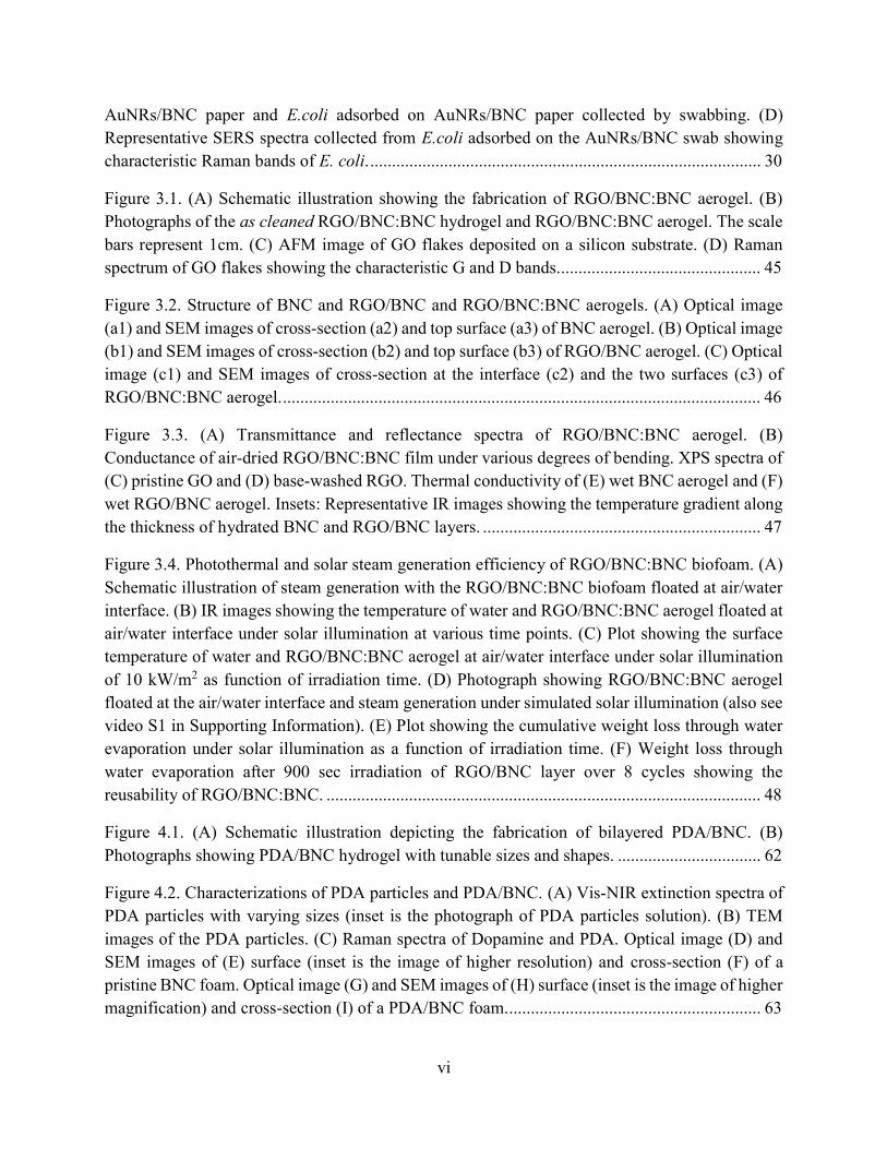
AuNRs/BNC paper and E.coli adsorbed on AuNRs/BNC paper collected by swabbing. (D) Representative SERS spectra collected from E.coli adsorbed on the AuNRs/BNC swab showing characteristic Raman bands of E. coli. .......................................................................................... 30
Figure 3.1. (A) Schematic illustration showing the fabrication of RGO/BNC:BNC aerogel. (B) Photographs of the as cleaned RGO/BNC:BNC hydrogel and RGO/BNC:BNC aerogel. The scale bars represent 1cm. (C) AFM image of GO flakes deposited on a silicon substrate. (D) Raman spectrum of GO flakes showing the characteristic G and D bands. .............................................. 45
Figure 3.2. Structure of BNC and RGO/BNC and RGO/BNC:BNC aerogels. (A) Optical image (a1) and SEM images of cross-section (a2) and top surface (a3) of BNC aerogel. (B) Optical image (b1) and SEM images of cross-section (b2) and top surface (b3) of RGO/BNC aerogel. (C) Optical image (c1) and SEM images of cross-section at the interface (c2) and the two surfaces (c3) of RGO/BNC:BNC aerogel. .............................................................................................................. 46
Figure 3.3. (A) Transmittance and reflectance spectra of RGO/BNC:BNC aerogel. (B) Conductance of air-dried RGO/BNC:BNC film under various degrees of bending. XPS spectra of (C) pristine GO and (D) base-washed RGO. Thermal conductivity of (E) wet BNC aerogel and (F) wet RGO/BNC aerogel. Insets: Representative IR images showing the temperature gradient along the thickness of hydrated BNC and RGO/BNC layers. ................................................................ 47
Figure 3.4. Photothermal and solar steam generation efficiency of RGO/BNC:BNC biofoam. (A) Schematic illustration of steam generation with the RGO/BNC:BNC biofoam floated at air/water interface. (B) IR images showing the temperature of water and RGO/BNC:BNC aerogel floated at air/water interface under solar illumination at various time points. (C) Plot showing the surface temperature of water and RGO/BNC:BNC aerogel at air/water interface under solar illumination of 10 kW/m2 as function of irradiation time. (D) Photograph showing RGO/BNC:BNC aerogel floated at the air/water interface and steam generation under simulated solar illumination (also see video S1 in Supporting Information). (E) Plot showing the cumulative weight loss through water evaporation under solar illumination as a function of irradiation time. (F) Weight loss through water evaporation after 900 sec irradiation of RGO/BNC layer over 8 cycles showing the reusability of RGO/BNC:BNC. .................................................................................................... 48
Figure 4.1. (A) Schematic illustration depicting the fabrication of bilayered PDA/BNC. (B) Photographs showing PDA/BNC hydrogel with tunable sizes and shapes. ................................. 62
Figure 4.2. Characterizations of PDA particles and PDA/BNC. (A) Vis-NIR extinction spectra of PDA particles with varying sizes (inset is the photograph of PDA particles solution). (B) TEM images of the PDA particles. (C) Raman spectra of Dopamine and PDA. Optical image (D) and SEM images of (E) surface (inset is the image of higher resolution) and cross-section (F) of a pristine BNC foam. Optical image (G) and SEM images of (H) surface (inset is the image of higher magnification) and cross-section (I) of a PDA/BNC foam. .......................................................... 63

vii
Figure 4.3. Optical and thermal properties of PDA/BNC. Transmittance and reflectance spectra of (A) BNC hydrogel and (B) PDA/BNC hydrogel. Thermal conductivities of (C) dry BNC/PDA foam and (D) wet PDA/BNC hydrogel. Insets: Representative IR images showing the temperature gradient along the thickness of the samples. ................................................................................. 64
Figure 4.4. Solar steam generation performance of PDA/BNC. (A) IR images of water under 1 kW m-2 solar irradiation, PDA/BNC under 1 kW m-2 and 3 kW m-2 solar irradiation and optical image, showing visible steam generation under 3 kW m-2. (B) Surface temperatures of water and PDA/BNC foam under 1, 3 kW m-2 irradiations. (C) Plot showing the cumulative weight losses through water evaporation of water and PDA/BNC foam under different solar irradiations. (D) Steam generation efficiencies of water and PDA/BNC foam under different solar irradiations. . 65
Figure 4.5. Stability of PDA/BNC. (A) Optical images of PDA/BNC foam achieved via in situ growth and vacuum filtration that have been subjected to sonication and shaking for extended duration. (B) Cycling solar steam generation tests under 7 kW m-2 solar irradiation for 15 min over 20 cycles. (C) High-resolution SEM images of the PDA/BNC surface before and after 20 cycles of solar steam generation depicting the intact structure of the PDA/BNC foam. ......................... 66
Figure 4.6. Biodegradability of PDA. (A) Optical images showing the pristine PDA and laccase-treated PDA solution. (B) Vis-NIR extinction spectra of pristine, laccase-treated PDA solution. SEM images of (C) pristine PDA and (D) laccase-treated PDA solutions. .................................. 67
Figure 5.1. Fabrication of RGO/BNC membrane. Optical images showing (A) GO in bacterial medium and (B) in situ grown RGO/BNC membrane after cleaning and drying. ....................... 84
Figure 5.2. Chemical composition and ultrastructure of RGO/BNC membrane. (A) AFM image of GO flakes deposited on a silicon substrate. X-ray photoelectron spectra of (B) pristine and (C) base-washed GO. Optical image (D) and SEM images of (E) surface and (F) cross-section of a pristine BNC membrane. Optical image (G) and SEM images of (H) surface and (I) cross-section of a RGO/BNC membrane. ........................................................................................................... 85
Figure 5.3. Stability of RGO/BNC membrane. UV-vis absorption spectra of (A RGO/BNC and (D) RGO-coated BNC immersed solutions (at pH 7) before and after ultrasonic agitation for 5 h. The insets show the optical images of a RGO/BNC membrane and a RGO-coated BNC layer after sonication. SEM images of (B) a RGO/BNC and (E) a RGO-coated BNC layer before and after ultrasonic agitation. TGA analyses of (C) a RGO/BNC, (F) a RGO-coated BNC before and after ultrasonic agitation. ....................................................................................................................... 86
Figure 5.4. Mass transport performance and water flux tests. (A) Schematic diagram of a two-cells diffusion setup. (B) Diffusion of model solutes through pristine BNC membrane and RGO/BNC membrane. (C) Schematic diagram of cross-flow flux test setup. RGO/BNC membranes are placed in between the cross-flow cell and tightly sealed. (D) UV-vis extinction spectra indicating the rejection of AuNPs with 5 nm in diameter filtered through RGO/BNC membranes (inset is the

viii
picture showing feed and permeate solutions). (E) Water flux of RGO/BNC membranes (~8 µm thick) and commercial ultrafiltration membranes. 100 psi was applied for the flux tests. .......... 87
Figure 5.5. Photothermal and bactericidal performance under light. (A) Schematic showing antifouling mechanism of RGO/BNC membrane and a possible configuration of spiral wound UF module coupled with LEDs. (B) IR images showing the temperature of the pristine BNC and the RGO/BNC membrane in water under illumination at various time points. (C) Plot showing the temperature of pristine BNC and the RGO/BNC membrane in water under light of 2.9 kW/m2 as a function of irradiation time. Fluorescence images of E. coli on BNC and RGO/BNC membranes (D) before and (E) after irradiation. SEM images of E. coli on RGO/BNC membranes (F) before and (G) after irradiation. ............................................................................................................... 88
Figure 6.1. Schematic illustration and photographs showing the various steps including (A) GO/BNC hydrogel (B) Pd/GO/BNC membrane involved in the fabrication of Pd/GO/BNC membrane. ................................................................................................................................... 104
Figure 6.2. Micro and nanostructure and chemical composition of Pd/GO/BNC membrane. (A) Pristine BNC membrane: Photograph (A1) and SEM images of top surface (A2) and cross-section (A3). (B) Pd/GO/BNC membrane: Photograph (B1), SEM image of top surface (B2), and SEM images of cross-section (B3). (C) TEM image of Pd/GO/BNC membrane and the inset show the size distribution of Pd NPs. (D) HRTEM image of a single Pd NP on the GO/BNC membrane. (E) EDS of the Pd/GO/BNC membrane (strong Cu peaks correspond to the TEM grid made of Cu)...................................................................................................................................................... 105
Figure 6.3. Dye degradation activity of Pd/GO/BNC membrane. (A) UV−vis spectra showing the degradation of MO in the presence of NaBH4 and Pd/GO/BNC membrane. (B) Plot showing the degradation of MO in the presence of NaBH4 over time. (C) Langmuir−Hinshelwood apparent rate constant for MO degradation by Pd/BNC and Pd/GO/BNC as catalysts. (D) The degradation performance of MO solution (25.7 mg L-1) with NaBH4 over 10 cycles for the Pd/GO/BNC membrane and Pd/BNC membrane catalysts. ............................................................................. 106
Figure 6.4. Pd/GO/BNC as a filtration membrane for organic-contaminated water treatment. (A) Schematic view to illustrating the filtration mechanism of the Pd/GO/BNC film. (B) Photograph of the bench-top filtration setup using Pd/GO/BNC film as a membrane. The yellow colored feed solution contains MO and NaBH4. Dye degradation efficiency of Pd/GO/BNC film at different (C) MO concentrations and (D) different pH values. (E) Dye degradation efficiency of Pd/GO/BNC film over multiple cycles of reuse showing recyclability. (F) UV−vis spectra showing the degradation of a cocktail (50 mL) of organic contaminants: 4-nitrophenol (4-NP), rhodamine 6G (R6G) and Methylene blue (MB) (each with a concentration of 10 mg·L-1) in the presence of NaBH4 (140 mg·L-1). (G) Images showing the contaminants cocktail before and after filtration treatment. .................................................................................................................................... 107

ix
Figure 6.5. Particle rejection and water flux tests. (A) Schematic diagram of cross-flow flux test setup. (B) TEM images of gold nanoparticles with a diameter of 5 nm. (C) Image showing Pd/GO/BNC membrane placed in the cross-flow cell. (D) UV-vis extinction spectra indicating the rejection of AuNPs filtered through Pd/RGO/BNC membranes (inset is the picture showing feed and permeate solutions.) (E) Water flux of Pd/GO/BNC membrane, commercial color reduction membrane (58 psi was applied for the flux tests) and commercial nanofiltration membrane (100 psi was applied)........................................................................................................................... 108
Figure 7.1. Fabrication of RGO/PEDOT:PSS/BNC electrode (A) Schematic illustration depicting the various steps involved in the fabrication of RGO/PEDOT:PSS/BNC electrode. Photographs showing (B) bacterial medium with GO and PEDOT:PSS and (C) dried RGO/PEDOT:PSS/BNC electrode. ..................................................................................................................................... 122
Figure 7.2. A) Optical image (A) and SEM images of top surface (A1) and cross-section (A2) of BNC film. (B) Optical image (B) and SEM images of top surface (B1) and cross-section (B2) of RGO/BNC film. C) Optical image (C) and SEM images of top surface (C1) and cross-section (C2) of RGO/PEDOT:PSS/BNC film. (D) Raman spectra of original GO flakes, RGO/PEDOT:PSS/BNC film and PEDOT:PSS/BNC film. (E) XPS spectra of original, base-washed and HPA treated GO. (F) Electrical conductivity and the mass specific capacitance of RGO/PEDOT:PSS/BNC electrodes with different RGO concentrations and fixed PEDOT:PSS concentration (~0.25 wt%) in the bacterial broth. ...................................................................... 123
Figure 7.3. (A) CV curves of RGO/BNC film, PEDOT:PSS/BNC film and RGO/PEDOT:PSS/BNC electrode. (B) CV curves of RGO/PEDOT:PSS/BNC electrode at different scan rates (5 to 100 mV/s). (C) Mass specific capacitance of RGO/PEDOT:PSS/BNC electrode calculated from CV curves as a function of scan rate. (D) Galvanostatic charging/discharging (GCD) curves of RGO/PEDOT:PSS/BNC electrode. (E) Mass specific capacitance of RGO/PEDOT:PSS/BNC calculated from GCD curves as a function of current density. (F) Capacitance retention of RGO/PEDOT:PSS/BNC electrode over 1000 cycles. The inset shows the randomly picked 20 GCD curves. ..................................................................... 124
Figure 7.4. (A) Photographs showing the flexibility of the components (electrode and separator) of device and a schematic showing the structure of the solid-state supercapacitor device based on RGO/PEDOT:PSS/BNC electrodes. (B) CV curves of assembled supercapacitor at different scan rate from 5 to 100 mV/s. (C) GCD curves of assembled supercapacitor at different current densities. (D) CV curves of assembled supercapacitor under different bending angles at a scan rate of 100 mV/s. (E) Cycling stability of assembled supercapacitor over 4500 cycles. The inset shows randomly picked 10 GCD curves. (F) Optical image showing the flexibility of assembled supercapacitor. (G) LED indicator lighted by assembled device. .............................................. 125
x
Figure S1.1. SEM images of (A) top surface and (B) cross section of freeze-dried pristine BNC aerogel (Inset image: high resolution SEM image showing individual BNC fibers of 20-100 nm in diameter). ...................................................................................................................................... 19
Figure S1.2. Representative transmission electron microscopy (TEM) image of gold nanorods employed in this study .................................................................................................................. 20
Figure S1.3. Representative high-resolution SEM image showing AuNRs on the surface and underneath the cellulose fibers...................................................................................................... 20
Figure S1.4. SERS spectra collected from different points of E.coli adsorbed on the AuNRs/BNC swab showing characteristic Raman bands of E. coli. .................................................................. 21
Figure S1.5. Photographs of AuNRs/BNC film before and after (A) swabbing 50 times and (B) 1 hour of sonication. No color change in AuNRs/BNC film confirmed strong adsorption of AuNRs on BNC film. ................................................................................................................................. 21
Figure S2.1. TGA curves for BNC film and air-dried RGO/BNC:BNC film. ............................. 22
Figure S2.2. Cross-sectional SEM image of air- dried (A) RGO/BNC, (B) BNC film. ............. 22
Figure S2.3. Stability of RGO/BNC:BNC as evidenced by the mechanically stable films after ultrasonication for 1 hr in at pH 7 and pH 1.5. .................................................................... 23
Figure S2.4. FTIR spectra of RGO/BNC, GO/BNC and BNC dry film. ..................................... 23
Figure S2.5. Thermal conductivity of dry BNC and RGO/BNC foams. ..................................... 24
Figure S2.6. Solar steam generation of RGO:BNC/BNC upon irradiation with 808nm laser (A) IR images showing the temperature of water and RGO/BNC:BNC aerogel floated at air/water interface under 808 nm laser illumination (510mK/cm2) at various time points. (B) Plot showing the surface temperature of water and RGO/BNC:BNC aerogel at air/water interface as function of irradiation time. (C) Plot showing the cumulative weight loss through water evaporation under solar illumination as a function of irradiation time. ...................................... 24
Figure S3.1 (A) SEM image of PDA particles (B) Hydrodynamic size of PDA particles measured by DLS. ......................................................................................................................................... 25
Figure S3.2 TGA of pristine BNC, pristine PDA and PDA/BNC. ............................................... 25
Figure S3.3 (A) Transmittance and reflectance spectra of PDA coated BNC hydrogel. (B) Solar steam generation performance of PDA coated BNC compared with PDA/BNC via in situ growth method........................................................................................................................................... 26
Figure S4.1. Additional stability tests. (A) RGO/BNC membrane remains intact after 5 h sonication in all pH conditions. (B) RGO coated BNC prepared by vacuum filtration quickly

xi
disintegrated during approximately 1 h sonication in all pH conditions. (C) GO was mixed with BNC dispersion and then vacuum filtrated to form a membrane. The membrane showed good stability in pH 7 solutions but disintegrated during sonication in solutions with different pH (Scale bars: 1 cm). (D) prolonged vortexing employed for membrane washing did not damage the membrane. ..................................................................................................................................... 27
Figure S4.2. (A) TEM image of gold nanoparticles of 5 nm in diameter. (B) Size distribution of AuNPs. (C) UV-vis extinction spectra indicating the rejection of AuNPs with 5 nm in diameter filtered through commercial UF membranes. ............................................................................. 128
Figure S4.3. Nitrogen isotherm of RGO/BNC membrane (A) before and (B) after 24-hour light illumination (2.9 kW/m2). The pore size of RGO/BNC membrane (C) before and (D) after 24-hour light illumination (2.9 kW/m2). ................................................................................................... 128
Figure S4.4. Water flux of RGO/BNC membrane under cyclic illumination. For the first cycle, RGO/BNC membrane was exposed to light (2.9 kW/m2) for 12 hours, and 5 hours exposure time was used for the rest of cyclic tests. ............................................................................................ 129
Figure S4.5. (A) Bacterial cell viability counts during bactericidal performance under illumination for BNC and RGO membranes. (B) Fluorescence images of E. coli on RGO/BNC before and after incubation for 1hour. ................................................................................................................... 129
Figure S4.6. Surface roughness and contact angle of (A) RGO/BNC and (B) BNC membranes...................................................................................................................................................... 130
Figure S5.1. SEM images of the surface of GO/BNC aerogel (A-A1) and GO/BNC membrane (B-B1)............................................................................................................................................... 131
Figure S5.2. TGA curves of BNC, GO/BNC, Pd/BNC, and Pd/GO/BNC. ................................ 132
Figure S5.3. XRD (A) and XPS spectrum of Pd 3d3/2 and Pd 3d5/2 regions (B) of Pd/GO/BNC...................................................................................................................................................... 132
Figure S5.4. XPS spectra of C 1s regions for GO/BNC (A) and Pd/GO/BNC (B), and Raman spectra (C) of GO/BNC and Pd/GO/BNC. ................................................................................. 133
Figure S5.5. SEM images of the surface of Pd/BNC membrane. ............................................... 133
Figure S5.6. TEM images of BNC aerogel (A), Pd/BNC membrane (B), GO/BNC aerogel (C) and Pd/GO/BNC membrane (D), respectively. ................................................................................. 134
Figure S5.7. Leakage of Pd for Pd/BNC membrane and Pd/GO/BNC membrane after 5 days of mechanical agitation. .................................................................................................................. 135

xii
Figure S5.8. UV−vis spectra of MO solution in the presence of NaBH4 and the MO solution filtered through the BNC and GO/BNC membrane. ............................................................................... 135
Figure S5.9. (A) UV−vis spectra of MO solution in the absence of NaBH4 and the MO solution filter through Pd/GO/BNC membrane under 0.8 bar. (B) Image showing the filtration of MO solution through Pd/GO/BNC membrane. .................................................................................. 136
Figure S5.10. (A) MO rejection test of YMGESP3001 membrane. Inset is an image showing the setup. (B) MO rejection test of YMDKSP3001 membrane. UV-vis spectra of permeate solution from MO solution after 3 days. Inset is an image showing the setup. ........................................ 136
Figure S5.11. Stability tests of Pd/GO/BNC and GO membranes. ........................................... 137
Figure S6.1. (A) Picture of a bottle of GO solution. (B) AFM image of GO flakes deposited on a silicon substrate. .......................................................................................................................... 138
Figure S6.2. XPS spectra of pristine GO, base-washed RGO and HPA-treated RGO. .............. 138
Figure S6.3. RGO content in dry film can be tuned by varying GO content in broth. Electrical conductivity of RGO/BNC films with various RGO contents.................................................... 139
Figure S6.4. Effect of solution processes on pristine PEDOT:PSS deposited on a silicon substrate...................................................................................................................................................... 139
Figure S6.5. Specific energy and power densities of the Flexible device. ................................. 140
Figure S6.6. Strain-stress curve of pristine BNC and RGO/PEDOT:PSS/BNC. ....................... 140
Table S6.1: The comparison of recent flexible paper- based and some carbon-based supercapacitors. ........................................................................................................................... 141

xiii
List of Abbreviations
4-NP 4-Nitrophenol
AFM Atomic force microscopy
ATCC American type culture collection
AuNPs Gold nanoparticles
AuNRs Gold nanorods
BET Brunauer-Emmett-Teller
BNC Bacterial nanocellulose
CV Capacitance-voltage
DLS Dynamic light scattering
E. coli Escherichia coli
EDLC Electric double-layer capacitor
FTIR Fourier-transform infrared spectroscopy
GCD Galvanostatic charge/discharge
GO Graphene oxide
HPA Hypophosphrous acid
MB Methylene blue
MO Methyl orange
NIR Near infrared
PBS Phosphate-buffered saline
PDA Polydopamine
PDMS Polydimethylsiloxane

xiv
PdNPs Palladium nanoparticles
PEDOT:PSS Poly(3,4-ethylenedioxythiophene) polystyrene sulfonate
PET Polyethylene terephthalate
pMBA 4- Mercaptobenzoic acid
Psi Pound per square
PVA Polyvinyl alcohol
R6G Rhodamine 6G
RGO Reduced graphene oxide
SCs Supercapacitors
SEM Scanning electron microscopy
SERS Surface enhanced Raman scattering
TGA Thermogravimetric analysis
UV-vis Ultraviolet-visible
XPS X-ray photoelectron spectroscopy
XRD X-ray diffraction

xv
Acknowledgements
First and foremost, I would like to thank my advisor Prof. Srikanth Singamaneni, without
whom none of this would be possible. I was fascinated by the first Softnanomaterials class taught
by him, which led me into this fruitful journey. I have sensed the great passion he has for science
(and cricket), which inspired me tremendously in my PhD study. Besides passion, he also taught
me how to be a researcher: think innovatively and work diligently. After 5 years, there is still a
lot more to learn from him. I would also like to thank my PhD committee Prof. Young-shin Jun,
Prof. Guy Genin, Prof. Jeremiah Morrissey, Prof. Julio D’Arcy for their valuable advice, insightful
comments, and inputs on my research.
I would like to thank all the previous and current members of the soft nanomaterials lab:
Dr. Limei Tian, Dr. Kengku Liu, Dr. Sirimuvva Tadepalli, Dr. Congzhou Wang, Dr. Hongcheng
Sun, Dr. Huzeyfe Yilmaz, Dr. Bo Hu, Dr. Anushree Seth, Ms. Jingyi Luan, Ms. Sisi Cao, Mr.
Zheyu Wang, Mr. Hamed Gholami Derami, Mr. Rohit Gupta, Mr, Prashant Gupta, Ms. Priya Rathi,
Ms. Ting Xu, Ms. Marilee Fisher, Mr. Sang hyun Park, Mr. Max Fei, Mr. Christopher Portz, Ms.
Emily Lu Wang, Mr. Sang hyun Bae, Mr. Abishek Venkatesan Iyer, Mr. Jieun Yim, for being
congenial and selfless, making our lab feel like home (with tears and joy, mostly joy).
Thank all my friends I have met here for their support, kindness and the memories we have
created in STL, a city I had never heard of before and a place I will always remember.
Most of all, I am indebted to my parents for being so understanding and supportive and for
everything they have ever done for me. Thanks for the love, inspiration and drive they have given
me. I will try my best to make them proud!

xvi
Finally, I would like to thank my girlfriend, Yizhong Hu. Meeting her during my time in
STL is one of the luckiest things in my life. Thanks for her love and faith in me. She has made
and still making me a better man!
Qisheng Jiang
Washington University in St. Louis
December 2018

xvii
Dedicated to my parents, who brought me into this world and raised me to be a rebel against our
gene master.
© 2018, Qisheng Jiang

xviii
Abstract of the Dissertation
Multifunctional Nanocomposites based on Bacterial Cellulose
by
Qisheng Jiang
Doctor of Philosophy in Materials Science and Engineering
Washington University in St. Louis, 2018
Professor Srikanth Singamaneni, Chair
Cellulose is biodegradable, renewable, and abundant in nature thus cellulose (or paper)-based
products can be inexpensively produced and recycled. Among cellulosic materials, bacterial
nanocellulose (BNC) draws a special research attention due to the inherent three-dimensional
nanofibrous structure, excellent mechanical flexibility, high purity and well-defined surface
chemistry, and cost-efficient, scalable and environment-friendly synthesis. BNC can be
biosynthesized by Gluconacetobacter xylinus, which is the most characterized BNC producer
among various microorganisms. BNC is composed of highly pure cellulose nanofibrils, produced
from well-defined dextrose through biochemical steps and subsequent self-assembling of the
secreted cellulose fibrils which has the dimension ranges from 25 to 100 nm in diameter from
bacteria in the culture medium. During the biosynthesis of BNC, shape-controlled hydrogels with
well-defined network structure pore diameters below 10 µm can be easily achieved. For all the
above-mentioned reasons, BNC is a highly promising platform material for the fabrication of
functional composites through in situ growth or adsorption of pre-synthesized nanostructures on
the nanoscale cellulose fibers.
In this work, we have designed and demonstrated novel strategies to realize BNC-based functional
nanocomposites with applications in sensing, water purification and energy storage. We have

xix
demonstrated a BNC film-based surface enhanced Raman scattering (SERS) substrate which has
3D porous structure and ultrafine fibers with uniform and dense adsorption of plasmonic
nanostructures, resulting large SERS enhancement and excellent uniformity of SERS activity.
For the first time, we have demonstrated a novel, highly scalable, cost-effective and green strategy
to realize functional BNC-based foams/membranes. Functional materials such as graphene oxide
(GO), polydopamine (PDA) can be efficiently incorporated within BNC matrix during its growth.
Owing to the intercalation of functional materials within the layered BNC matrix, the functional
composites showed excellent mechanical robustness and flexibility, which is crucial for efficient,
large-scale applications, either as a foam or as a membrane.
Specifically, we have designed and developed a bilayered hybrid biofoam comprised of BNC and
RGO and a completely biodegradable bilayered foam based on BNC and PDA for highly efficient
solar steam generation, which can be a sustainable solution to alleviate global water crisis. An
innovative water filtration membrane based on BNC and RGO which harvests sunlight to kill
microorganisms has been developed to provide a novel anti-biofouling approach. We have also
demonstrated a robust filtration membrane based on BNC loaded with GO and PdNPs, which
exhibited excellent dye degradation performance for highly efficient wastewater treatment.
Furthermore, the in situ fabrication approach has been extended to polymeric materials such as
poly(3,4-ethylenedioxythiophene) polystyrene sulfonate (PEDOT:PSS) to realize hybrid flexible
supercapacitor electrodes based on RGO, BNC and PEDOT:PSS.
The fabrication strategies and materials design demonstrated in this work can be easily extended
to realize various BNC-based nanocomposites with applications in water purification, energy
harvesting, sensing, catalysis, and life sciences.

1
Chapter 1: Introduction and Motivation
1.1 Bacterial Nanocellulose
Cellulose is biodegradable, renewable, and abundant in nature thus cellulose (or paper) based
products can be inexpensively produced and recycled.1 Among cellulosic materials, bacterial
nanocellulose (BNC) draws a special research attention due to the inherent three-dimensional
nanofibrous structure, excellent mechanical flexibility, high purity and well-defined surface
chemistry, and cost-efficient, scalable and environment-friendly synthesis.2-6 BNC can be
biosynthesized by Gluconacetobacter xylinus under static culture conditions, which is the most
characterized BNC producer among various microorganisms.7 BNC is composed of highly pure
cellulose nanofibrils, produced from well-defined dextrose through biochemical steps and
subsequent self-assembly of the secreted cellulose fibrils from bacteria in the culture medium.6, 8-
9 In contrast to paper substrates obtained from plant cellulose, which comprise of carbonyl and
carboxyl functional groups along with hydroxyl, BNC possesses only hydroxyl functional
groups.10 The dimensions of BNC nanofibrils range from 25 to 100 nm in diameter and several
micrometers in length. BNC as a biomaterial offers the special benefit of in situ control of cellulose
formation, such as the shape and supramolecular structure of the products.3 During the
biosynthesis of BNC, shape-controlled hydrogels with well-defined network structure pore
diameters below 10 µm can be easily achieved. The as synthesized BNC is harvested and
processed to obtain nanocellulose hydrogel with extremely high-water content (~99% by weight).
For all the above-mentioned reasons, BNC is a highly promising platform material for the
fabrication of functional composites through in situ growth or adsorption of pre-synthesized
nanostructures on the nanoscale cellulose fibers.11-20

2
1.2 Surface Enhanced Raman Scattering (SERS) and Flexible SERS swab
Surface enhanced Raman scattering (SERS) involves the large enhancement (under ideal
conditions up to 1011 times) of Raman scattering signal from molecules adsorbed on or in close
proximity to a nanostructured metal surface.21-27 SERS is a highly promising transduction platform
for the detection of trace levels of known and unknown chemical compounds with applications
spanning from forensics to homeland security.28-33 The advantages of SERS as an analytical tool
include (i) rich and unique molecular fingerprint corresponding to the target analytes; (ii) ultrahigh
sensitivity (single molecule sensitivity under ideal conditions); (iii) absence of interference from
water (making it tolerant to humidity variations); and (iv) ease of sample preparation. Extensive
efforts have focused on the design and fabrication of SERS substrates with high sensitivity and
large-scale uniformity. For many real-world applications, the ease and efficiency of the sample
collection is very important. For example, collection and detection of trace amounts of hazardous
and pathogenic chemical and biological analytes present on solid surfaces is a powerful screening
method. Among various sample collection methods, physical swabbing has been recognized as a
highly efficient and practical method to maximize the sample collection on a solid surface using a
flexible and functional swab. 34-35,36-37 Paper-based SERS swabs developed by our group have been
successfully demonstrated to collect chemical analytes from solid surfaces.38 However, past efforts
have been limited to the use of off-the-shelf filter paper substrates, providing limited control over
the micro/nanoscale roughness, which determines the contact between the SERS swabs and the
surface of interest. Thus, novel methods and materials that offer better control over the
micro/nanoscale structure of these flexible SERS swabs are of great interest.

3
1.3 Novel Materials and Processes for Energy-efficient Water Treatment
Water scarcity is recognized to be one of the most critical global issues of the 21st century as the
demand for clean and safe water, critical for human survival, food production and manufacturing,
continues to rise with increasing world’s population.39-41 Water scarcity is tightly intertwined with
two other global challenges, namely, energy crisis and climate change. Innovative methods for
producing fresh water from sea water (or unpurified water) with significantly reduced energy- and
economic burden are paramount.
1.31 Solar steam generation and processes for energy-efficient water treatment
Solar energy is the most abundant and the cleanest source of energy available on earth that can be
tapped into for addressing the global fresh water shortage. Steam generation through efficient
harvesting of solar energy and thermal concentration is a highly promising technique and has
attracted tremendous attention in the past few years.42-43 Various solar steam generation devices
(also called as interfacial evaporators) have been demonstrated within the past four years.
From the device design standpoint, most of these interfacial thermal evaporators share a few
common features: (i) the top surface is comprised of materials that exhibit broad light absorption
over visible and near infrared wavelengths combined with an efficient photothermal conversion;
(ii) support materials with low thermal conductivity to minimize the heat transfer from the
evaporative surface to the bulk of the water; and (iii) open porous structure and hydrophilic nature
of supporting materials that facilitate a rapid transport of water from bulk to the evaporative surface.
It is highly desirable to utilize materials and processes that are sustainable and energy efficient in
the fabrication of these interfacial thermal evaporators. For example, biodegradability of the
evaporators is an important consideration since the disposal of these devices can quickly pose a

4
significant threat to the environment and marine ecosystems, considering that these evaporators
will be most commonly utilized in aqueous environments.44 Thus, evaporators based on renewable,
biodegradable and scalable materials holds a great potential for ultimate solar steam generation
applications.
1.32 Graphene oxide (GO)-based membranes for water purification
Graphene oxide (GO) has emerged as an excellent membrane material owing to the excellent
mechanical strength, facile synthesis and the ability to be readily dispersed in water and restacked
into membrane using various methods, including vacuum filtration, spin-coating and drop-
casting.45-48 In contrast to graphene flakes, which have a strong tendency to stack and aggregate
in aqueous solutions, GO flakes exhibits excellent water dispersibility and thus aqueous
processability because of the presence of oxygen-containing functional groups (carboxyl, epoxy,
hydroxyl, and carbonyl groups).49
Owing to the excellent mechanical strength, facile synthesis and the ability to be readily dispersed
in water and restacked into membrane using various methods, including vacuum filtration, spin-
coating and drop-casting, GO has emerged as an excellent membrane material.45-48 However, the
stability of current GO-based membranes is compromised under vigorous agitation, pH, and ionic
strength variations that are within the range of feed water.50 Thus, there is a need to develop new
scalable approaches to fabricate stable GO-based membranes.
1.33 Photothermal effect as a unique solution for tackling membrane biofouling
In response to the water scarcity, various membrane technologies have emerged and are being
actively investigated for water purification and reclamation.51-53 However, fouling and consequent
degradation in performance remain to be a ubiquitous problem in most of these membranes.54

5
Specifically, mineral scaling, organic fouling, and biofouling are three major fouling mechanisms,
which lead to either temporary or permanent decline in the water flux.55 Among them, biofouling,
which is ascribed to more than 45% of all membrane fouling, is the “Achilles heel” of the
membrane technologies due to the difficulty associated with the complete removal of
microorganisms.56-58
Various strategies, such as adjusting pH, adding disinfectants and biocides, introducing quorum
sensing molecules to inhibit the formation of biofilm, have been suggested for controlling
biofouling.59-62 However, most of these strategies introduce considerable operational costs and/or
potential hazardous contaminants. Researchers have also investigated the incorporation of
nanomaterials (e.g., silver nanoparticles, titanium dioxide nanoparticles and graphene oxide
nanosheets), polymers (e.g., polyethylene glycol, polyvinyl alcohol, polyvinylpyrrolidone and
zwitterionic polymers), and other materials (e.g., small organic molecules and biomacromolecules)
to engineer fouling-resistant membrane surfaces that can reduce biofilm growth and inactivate
bacteria.55, 63-68 However, most of these methods involve additional thermal or chemical treatment
steps. Furthermore, most of the above techniques are effective only for a short period of time
because biofilm has the ability to gradually adapt to imposed harsh environments.56 Even if 99.9%
of biofilm is removed once, the residual cells are sufficient to grow back and form a new biofilm.
Therefore, there is an immediate need for highly efficient and cost-effective methods that
overcome biofouling on water purification membranes over a long period of time.
Photothermal effect, which involves the conversion of incident light into heat, can offer a unique
solution, obviating the need for harsh chemical treatments to achieve bacterial lysis. In our
previous study, gold nanostars grown on graphene oxide (GO) flakes modified on commercial
membrane were utilized as nanoheaters. Owing to the photothermal properties of gold nanostars,
6
adjacent Escherichia coli were efficiently killed with laser irradiation to prevent the formation of
biofilm.68 While this study provided a promising example of utilizing photothermal effect to
minimize biofouling on membranes, it would be more beneficial if the membrane itself is
comprised of photothermal materials and even more promising, if renewable and sustainable solar
illumination can be harnessed as a light source.
1.34 Metal and transition metal nanoparticles as a novel and efficient catalyst for dye-
contaminated wastewater treatment
Water contamination caused by chemical and biological species released from industrial and
agricultural practices is a formidable environmental challenge.51, 69-70 Among all the contaminants
such as cleaning agents, agricultural chemicals, and noxious microorganisms, organic dyes, which
are widely employed in textile, leather, cosmetic, pharmaceutical industries, pose significant
threats to aquatic life and humans due to their carcinogenic and mutagenic nature.71-73 Due to the
high resistance of organic dyes to traditional biological, physical, and chemical treatment methods,
there is a critical need for the development of highly efficient and cost-effective methods for dye
degradation and removal from contaminated water.74-76
Noble and transition metal nanoparticles, which have been extensively employed in catalysis,
organic synthesis, hydrogen storage, and water treatment, have shown great promise for organic
dye removal.77-80 In particular, palladium nanoparticles (PdNPs) have attracted special attention
for dye degradation owing to their excellent catalytic properties and low environmental impacts.81-
85 To achieve maximum catalytic activity and prevent aggregation of PdNPs, immobilizing PdNPs
on various substrates such as carbon (e.g., carbon microspheres, carbon nanotubes, and graphene
oxide), silica, and metal oxides (e.g., titanium dioxide) has been utilized.86-90 GO is a particular
promising substrate material because of its high mechanical, chemical, thermal stability, and high

7
surface area.91-96 Various self-assembled GO-based composites have been demonstrated for
wastewater treatment.97-102 To the best of our knowledge, a GO-based filtration membrane with
transition metal nanoparticles as catalyst has not been reported since previous developed GO-based
composites have limited aqueous stability and mechanical strength under pressure.
As mentioned in Chapter 1.1, bacterial nanocellulose (BNC) can serve as an ideal material for
realizing functional composites by incorporating functional nanomaterials within BNC matrix
because of its desirable properties such as excellent mechanical strength and toughness, rich
chemical functionality, and high specific surface area in aerogel state. It is highly desirable to
realize a composite based on BNC and GO/PdNPs, which synergizes high catalytic activity and
mechanical robustness.
1.4 Flexible supercapacitors and paper-based supercapacitors
1.41 Hybrid materials for high performance supercapacitor (SCs)
With an explosive development of portable and flexible electronics such as bendable mobile
phones, flexible displays and wearable devices, there is an urgent need for high performance,
flexible energy-storage devices.103-109 Supercapacitors (SCs) have emerged as an important class
of energy storage devices due to their numerous advantages such as high power density, long cycle-
lifetime and low environmental impact.110-112 Owing to various advantages compared to other
energy storage devices such as flexibility, lightweight, reliability, and safe operation over a wide
temperature range, extensive efforts have been devoted to developing flexible all solid-state SCs,
which hold great potential for next generation of flexible energy storage devices.113-119
Generally, active materials used in supercapacitors can be classified into two groups: i)
Electrochemical double layer capacitor (EDLC) materials, which physically store charges via

8
reversible ion adsorption at the electrode-electrolyte interface; ii) Pseudocapacitors materials,
which chemically store charges via redox reaction at the vicinity of the surface. Typically, EDLC
SCs rely on carbon-based materials (including activated carbon, carbon nanotubes, graphene,
reduced graphene oxide (RGO) etc.), while pseudocapacitors typically involve transition metal
oxides (e.g. RuO2, MnO2, CoOx, NiO, Fe2O3, etc.) and conducting polymers (e.g. polypyrrole,
polyaniline, poly(3,4-ethylenedioxythiophene), etc.). EDLC material core and pseudocapacitive
material shell constitutes an attractive combination of core–shell design due to the following merits:
i) EDLC materials as core have better cycle stability due to their electrostatic charge and discharge
storage mechanism (i.e. no phase changes), which makes them robust backbones even for large
number of cycles; ii) EDLC core material also have better electrical conductivity compared to
pseudocapacitive materials, which facilitates efficient transport of electrons; iii) pseudocapacitive
materials as shell can effectively offset the low capacitance contribution from EDLC materials
core as they can introduce Faradaic charge transfer due to reversible redox reactions upon charging
and discharging, which leads to higher capacitance and energy density.120-140
1.42 Flexible paper-based SCs and bacterial nanocellulose-based SCs
Soft and compliant elastomers or plastics such as polydimethylsiloxane (PDMS) and polyethylene
terephthalate (PET) are often used as substrates or packaging materials for the fabrication of
flexible SCs. However these plastics introduce considerable cost and environmental impact after
disposal.141 Cellulose-based paper substrates, on the other hand, are a low cost, highly flexible,
biodegradable option, which possess a fibrous structure, which facilitates interactions with active
materials and also provides pathways for ion transport, making them ideal substrates for flexible
supercapacitors and energy storage devices in general.142-146

9
BNC shows great promise for the fabrication of functional composites through in situ growth or
adsorption of pre-synthesized nanostructures on the nanoscale cellulose fibers due to its excellent
mechanical properties, tunable porosity, chemical functionalizability, ease of synthesis, high
scalability.11, 13, 19, 147-148 Due to these advantages, BNC has been adapted for realizing paper based
flexible supercapacitors.149-153 However, in order to make high performance BNC-based
supercapacitors, the fabrication techniques typically involve vacuum filtration152, 154, pyrolysis
activation150, 155-156, which offer poor prospects in terms of scalability and/or compromise the
mechanical properties of BNC. These considerations highlight the need for a radically different
approach to integrate active materials with BNC that not only preserves the favorable nanofibrous
structure and mechanical properties of BNC but also synergistically enhances the energy storage
performance of the active materials.
1.5 Research Goals and Objectives
The ultimate goal of this research effort is to design and demonstrate novel bacterial nanocellulose
(BNC)-based functional composites with tailored properties for diverse emerging applications,
such as chemical sensing, water treatment and energy storage (Figure 1.1). Towards this goal, we
have pursued the following specific objectives:
Objective 1: Design and demonstrate a flexible surface enhanced Raman scattering (SERS) swab
based on bacterial nanocellulose.
Objective 2: Design and demonstrate novel materials and processes for energy-efficient water
treatment using bacterial nanocellulose-based composites.
Objective 2A: Design and develop a strategy of realizing scalable and efficient reduced
graphene oxide and bacterial nanocellulose interfacial photothermal evaporator for highly
efficient solar steam generation.

10
Objective 2B: Design and demonstrate a completely biodegradable interfacial
photothermal evaporator using polydopamine microparticles and bacterial nanocellulose.
Objective 2C: Design a biofouling-resistant ultrafiltration membrane by harnessing
sunlight.
Objective 2D: Design and demonstrate a novel membrane for organic dye-contaminated
wastewater treatment.
Objective 3: Design and demonstrate a novel bacterial nanocellulose-based flexible
supercapacitor electrode materials.
Figure 1.1. Illustration outlining the objectives of the overall research focus.

11
1.6 Overview of the Dissertation
The current chapter (Chapter 1) provides an overview of the research efforts and provides a brief
background of BNC and functional composites based on BNC for application in sensors, water
and energy.
Chapter 2 describes a BNC film-based SERS substrate fabricated by gravity-assisted filtration
method. Due to the 3D porous structure of BNC and its ultrafine fibers network, the uniform and
dense adsorption of plasmonic nanostructures on the surface and sub-surface regions lead to large
SERS enhancement and excellent uniformity of SERS activity over the entire substrate. The ultra-
smooth BNC-based SERS substrate serves as an ideal platform for the collection, detection and
recognition of microorganisms.
In Chapter 3, we introduce an approach for the fabrication of photothermally-active biofoam that
involves the in situ incorporation of GO flakes into BNC during its growth. We also demonstrate
the versatility of the approach by making a bilayer foam simply achieved by sequential addition
of BNC growth medium. The bilayered GO/BNC composite foam is tailored for high optical
absorption, photothermal conversion, heat localization and water transport, resulting in a highly
efficient solar steam generation.
Chapter 4 describes a complete biodegradable composites foam made of BNC and PDA as a
interfacial photothermal evaporator for solar steam generation. In addition to 2D materials such
as GO, we demonstrate that 0D nanomaterials such as PDA particles can also be incorporated into
BNC during its growth, leading to a complete biodegradable foam with comparable solar steam
generation performance.
In Chapter 5, a novel anti-biofouling ultrafiltration membrane based on BNC and GO is described,
which involves in situ incorporation of GO flakes into BNC during its growth and air-drying. In

12
stark contrast to previously reported GO-based membranes for water treatment, the RGO/BNC
membrane exhibited excellent aqueous stability under environmentally relevant pH conditions,
vigorous mechanical agitation/sonication and even high pressure. Importantly, the membrane
exhibited bactericidal capability enabled by light, due to its excellent photothermal properties,
which lead to efficient bacterial lysis, obviating the need for any treatment of the feed water or
external energy.
Chapter 6 introduces a simple and scalable approach for the fabrication of Pd/GO/BNC membrane
for highly efficient dye degradation. The fabrication of Pd/GO/BNC membrane involves the
incorporation of GO flakes into the BNC matrix during its growth followed by in situ growth of
PdNPs on GO flakes. The layered structure of Pd/GO/BNC, which forms nanocapillaries
throughout the membrane, maximizes the contact between organic dye contaminants and PdNPs
anchored on the GO flakes.
In Chapter 7, we demonstrate that BNC can serve as an ideal layered matrix for incorporation of
active electrochemical active materials to realize flexible and scalable supercapacitor electrode
materials. GO flakes and PEDOT:PSS were incorporated into bacterial nanocellulose (BNC)
matrix during its growth for the fabrication of flexible and light-weight electrodes for high
performance supercapacitors. The fabricated flexible super-capacitor electrode exhibited a high
specific capacitance and stability over 1000 testing cycles. Solid-state supercapacitor formed by
sandwiching a BNC-based separator between RGO/PEDOT:PSS/BNC electrodes exhibited
excellent energy storage performance and mechanical flexibility.

13
Chapter 2: Bacterial Nanocellulose-based Flexible
Surface Enhanced Raman Scattering Substrate
2.1 Abstract
Owing to high purity, simple surface chemistry and three-dimensional (3D) nanofibrous structure,
biosynthesized bacterial nanocellulose (BNC) is a highly attractive biomaterial for a wide range
of applications. Previously, we demonstrated that conventional cellulose-based laboratory filter
paper, adsorbed with plasmonic nanostructures can be employed as a flexible surface enhanced
Raman scattering (SERS) substrate. In this work, we report a BNC film-based SERS substrate
fabricated by gravity-assisted filtration method. The 3D porous structure of BNC facilitates
uniform and dense adsorption of plasmonic nanostructures on the surface and in sub-surface
regions, which results in large SERS enhancement. Furthermore, significantly lower surface
roughness of BNC compared to conventional filter paper resulted in an excellent uniformity of
SERS activity across the entire substrate. Harnessing the smooth surface of BNC, we show that
BNC-based SERS substrate serves as an ideal platform for collection, detection and recognition of
bacteria. The 3D plasmonic BNC composites demonstrated here are highly attractive for a broad
range of applications including sensing, catalysis, and energy harvesting.
2.2 Introduction
Due to the numerous advantages, such as significant reduction in cost, high specific surface area,
excellent wicking properties, and compatibility with conventional printing approaches (enabling
multiplex detection and easy disposability), paper is gaining increased attention as a potential

14
substrate in chemical/biological sensing, tissue engineering, energy harvesting storage and
implementing engineered gene circuits.157-162
Previously, we demonstrated that conventional laboratory filter paper decorated with plasmonic
nanostructures could be employed as a flexible SERS substrate.34, 163-165 Very recently, we
demonstrated 3D plasmonic foam, composed of bacterial nanocellulose aerogel with a high density
of plasmonic nanostructures adsorbed on the cellulose nanofibrils.166 The plasmonic biofoam
provided extraordinarily large plasmonically-active sensing volume (under the laser footprint)
compared to 2D substrates (e.g. filter paper). However, the thickness of plasmonic foams (1-5
mm) fabricated by adsorbing nanostructures on 3D cellulose network using immersion method is
much higher than the light penetration depth (few tens of microns). Thus, there is a need to develop
new fabrication technique to maximally utilized the plasmonic nanostructures.
In this work, to maximally utilize the plasmonic nanostructures, we employ a filtration method to
localize the nanostructures to the top portion of the hydrogel while the bottom portion serves as a
support layer. Furthermore, filtration method makes the processing much faster (30 min)
compared to the immersion approach (typically more than 12 hours). We demonstrate that
naturally-dried plasmonic BNC film with an ultrasmooth surface can serve as a mechanically-
stable and flexible SERS substrate for efficient collection, recognition and detection of pathogenic
bacteria.
2.3 Experimental Section
Synthesis of gold nanorods (AuNRs): Gold nanorods were synthesized using a seed mediated
approach.167-168 Seed solution was prepared by adding 0.6 ml of an ice-cold sodium borohydride
(NaBH4) aqueous solution (10 mM) into a mixture of 9.75 ml of cetyltrimethylammonium bromide
(CTAB, 0.1 M) and 0.25 ml of chloroauric acid (HAuCl4, 10 mM) solution under vigorous stirring

15
at room temperature (1000 rpm). The color of the seed solution immediately changed from yellow
to brown after NaBH4 addition. Growth solution was prepared by mixing 95 ml of CTAB (0.1
M), 1.0 ml of silver nitrate (10 mM), 4.75 ml of HAuCl4 (10 mM), and 0.55 ml of ascorbic acid
(0.1 M) in the same order, followed by gentle shaking to homogenize the solution. To the resulting
colorless solution, 0.12 ml of freshly prepared seed solution was added to the growth solution.
After 24 h of aging, AuNR solution was centrifuged at 10,000 rpm for 15 min to remove excess
reactants and dispersed in nanopure water (18.2 MΩ-cm). The centrifugation was repeated once
more to further remove excess CTAB for AuNRs/BNC film and AuNRs filter paper preparation.
Bacterial nanocellulose (BNC) and AuNRs/BNC substrate preparation: Gluconacetobacter
hansenii (ATCC®53582) was grown in test tubes containing 6 ml of #1765 broth at 30°C under
shaking at 250 rpm. The #1765 broth is composed of 2% (w/v) glucose, 0.5% (w/v) yeast extract,
0.5% (w/v) peptone, 0.27% (w/v) disodium phosphate, and 0.5% (w/v) citric acid. After 3 days
of growth, 1.0 ml of the above solution was inoculated to 6ml of broth in a 6 cm petri dish, followed
by gentle mixing and kept covered at room temperature without disturbance. After 3 days, a thin
film of bacterial nanocellulose (~1.0 mm) formed on the air-liquid interface. To purify the film,
the grown film was washed in a 500 ml of 0.1 M NaOH aqueous solution under boiling for 1 h,
followed by dialysis for 2 days in nanopure water. To prepare AuNRs/BNC substrate, 3 ml of
concentrated AuNRs solution with extinction intensity ~20 was filtered through a hydrated BNC
film, which was placed on a glass filter. Once the infiltration is complete within 30 min,
AuNRs/BNC hydrogel film was stored in hydrated condition for further use. The AuNRs density
in the final SERS substrate can be tuned by varying the concentration of AuNRs in the feed
solution.

16
Spectroscopy measurements: SERS substrates were exposed to R6G or pMBA solutions of
known concentrations for 1 hour followed by thorough rinsing to remove unadsorbed or weakly
bound molecules. Subsequently, SERS substrates were left to naturally dry before measurements.
Raman spectra were obtained using a Renishaw inVia confocal Raman spectrometer mounted on
a Leica microscope equipped with 20X objective (NA = 0.4) and 785 nm wavelength diode laser
(0.7 mW). The spectra were obtained in the range of 600−1800 cm−1 with 10 s exposure time. Five
spectra were collected from different spots across each sample. Shimadzu UV-1800
spectrophotometer was employed for collecting UV-vis extinction spectra from solution and the
AuNRs/BNC substrate.
E.coli swab test: E.coli (ATCC®35218) was cultured in nutrient broth medium for 18 hours at
30°C under shaking at 250 rpm until they reached their stationary growth stage. This corresponded
to a bacteria concentration in the range of 107-108 CFU/ml.169 After washing twice with phosphate
buffer saline (PBS) buffer by centrifugation, 10 µl of the E.coli suspension was spread on a spinach
leaf surface with surface area of 2×2 cm2. Following natural drying of E.coli on the spinach leaf,
plasmonic BNC paper of 1×2 cm2, wetted with PBS buffer, was swabbed on the leaf surface with
pre-spread E. coli. After collecting E.coli with plasmonic BNC paper, the samples were
characterized using optical microscopy and Raman spectroscopy.
Microscopy Characterization: Scanning electron microscope (SEM) images were obtained using
a FEI Nova 2300 Field Emission SEM at accelerating voltage of 10 kV. Plasmonic paper was
gold sputtered for 60 sec prior to SEM imaging. Atomic force microscopy (AFM) images were
obtained using Dimension 3000 (Digital instruments) AFM in light tapping mode.

17
2.4 Results and Discussion
2.41. Comparison of BNC film and Common Filter Paper
Bacterial nanocellulose (BNC) was biosynthesized under static culture conditions using
Gluconacetobacter xylinus, which is the most extensively characterized nanocellulose producing
bacterium among various microorganisms.7 BNC film is composed of highly pure cellulose
nanofibrils, produced from dextrose through a series of biochemical steps followed by the self-
assembly of the secreted cellulose fibrils from bacteria in the culture medium.6, 8-9 Similar to plant-
derived cellulosic materials, BNC possesses surface hydroxyl groups, but does not contain
carbonyl or carboxyl functional groups.6, 10 Owing to pure surface chemistry, nanofibrous and
microporous structure, the properties of BNC are significantly different from those of conventional
filter paper.170-172 After growing the BNC film to a desired thickness (~1 mm), it is harvested and
washed using sodium hydroxide and water to remove bacteria and residual growth medium (see
Experimental Section for details). The resulting hydrogel is comprised of a highly swollen
network of nanoscale cellulose fibers with up to 99 wt% water.
BNC exhibits strikingly different 3D structure and surface morphology compared conventional
filter paper. Freeze-dried BNC aerogel exhibits large surface area, composed of nanofibrils of
20-100 nm in diameter (see appendix 1, Figure S1.1).166 Considering that bacteria form the
cellulose fibers at the air/liquid interface, the cellulose nanofibrils are preferentially oriented
parallel to the surface (i.e. normal to the thickness) of the aerogel structure, which results in denser
physical entanglements of the cellulose nanofibrils parallel to the surface compared to that along
the thickness.3, 6 A representative cross-section SEM image of BNC aerogel reveals dense layers
of cellulose fibers separated by a layer of sparse “tie” fibers resulting in a layered structure (Figure
S1). BNC film of ~20 µm thickness, obtained by naturally drying ~1 mm thick BNC hydrogel,

18
exhibited a smooth surface morphology over a large scale due to the irreversible collapse of
cellulose nanofibril network during dehydration (Figure 2.1A). AFM images revealed the RMS
surface roughness of dry BNC film to be 25.6 nm over 3 × 3 µm2 area (Figure 2.1B). In contrast,
conventional filter paper exhibited an extremely rough, hierarchical fibrous morphology (Figure
2.1C). The filter paper largely consisted of micro scale (up to 20 µm) cellulose fibrous strands
interwoven together. Smaller microfibers made part of the large fibrous structure with nanofibers
braided in between. In a relatively smooth area, the RMS surface roughness of the paper was
measured to be 59.6 nm over 3 × 3 µm2, which is still much higher compared to the naturally-dried
BNC film.
2.42. Preparation and Characterization of Plasmonic BNC
We employed gold nanorods (AuNRs) as plasmonic nanostructures to fabricate a 3D SERS
substrate based on BNC. Owing to their tunable localized surface plasmon resonance (LSPR) and
strong electromagnetic field at the edges, AuNRs have been widely used for sensing
applications.173-175 We employed simple filtration method to realize 3D plasmonic hydrogel,
which enables the uniform adsorption and maximal utilization of plasmonic nanostructures on
porous cellulose nanofibrils (Figure 2.2). Simple filtration not only facilitates the transport and
adsorption of AuNRs into porous BNC hydrogel, but also makes the processing much faster (30
min) than immersion approach (typically more than 12 hours).
One of the distinct advantages of nanocellulose-based materials compared to conventional filter
paper is the optical transparency. Transparent cellulose-based materials have gained significant
interest in recent years as substrates for various electronic and optoelectronic devices.162, 176 The
optical transmittance of BNC hydrogel was measured to be ~80% at 600 nm, which is significantly
higher compared to that of the opaque filter paper (Figure 2.3A). The AuNRs employed in
19
plasmonic hydrogel were 51±3 nm long and 14±1 nm in diameter, making the aspect ratio
approximately 3.6 (see appendix 1, Figure S1.2). UV-Vis extinction spectra of the AuNRs solution
showed the two characteristic peaks at ~513 nm and 768 nm corresponding to the transverse and
longitudinal plasmon resonances of AuNRs, respectively (Figure 2.3B).177 After filtration of the
AuNR solution through the BNC hydrogel, the AuNRs were either adsorbed or trapped within the
first few microns of the BNC hydrogel. The colorless filtrate contained no AuNRs as confirmed
by the absence of characteristic LSPR bands of AuNR in the UV-vis extinction spectra. Extinction
spectrum obtained from plasmonic hydrogel fabricated with filtration method showed a red shift
in longitudinal plasmon resonance wavelength with a slight broadening of the LSPR band,
compared to the gold nanorod solution (Figure 2.3B). The observed red shift and LSPR band
broadening can be attributed to plasmonic coupling between closely packed AuNRs and an
effective increase in the refractive index of the surrounding medium (from water to
water+cellulose). Due to the higher refractive index sensitivity of the longitudinal plasmon
resonance compared to the transverse band, the longitudinal plasmon band exhibited a larger red
shift (~25 nm) compared to the transverse band (< 5 nm).178
We further examined the distribution of AuNRs incorporated in the plasmonic hydrogel. SEM
images revealed uniform and dense adsorption of the AuNRs on the cellulose nanofibrils surface
without any signs of large scale aggregation (Figure 2.3C). Furthermore, the presence of AuNRs
in the subsurface regions (embedded under the cellulose fibrils at the surface) of the porous
hydrogel is revealed by SEM images (inset of Figure 2.3C and Figure S1.3 in appendix 1). From
a number of SEM images, the number density of AuNR monolayer on the BNC film surface was
found to be ~100/μm2 (Figure 2.3C). Based on the amount of AuNRs in the feed solution and
the surface coverage of AuNR on the BNC, we estimate that approximately first 10 layers of
20
cellulose fibers in the BNC hydrogel are decorated with AuNRs. Gravity-assisted infiltration of
AuNRs into the highly swollen BNC hydrogel enables the incorporation of AuNRs into the
subsurface layers of BNC. Following the infiltration, the BNC hydrogel is naturally dried, thus
collapsing the fiber network and trapping the nanostructures within the network. The overall
distribution of AuNRs in the plasmonic hydrogel can be tuned by varying the concentration of
AuNRs and the volume of the feed solution. Following the incorporation of AuNR into the BNC,
even vigorous rinsing with water or alcohol did not result in noticeable desorption of the AuNRs
from BNC, suggesting the stability of the BNC-based SERS substrate for deployment in liquid
environments. Cellulose has a large number of hydroxyl groups, which facilitates the adsorption
of positively charged species.179-180 The uniform, irreversible, and high density adsorption of the
AuNRs is possibly due to the electrostatic and van der Waals interactions between the positively
charged AuNRs and the hydroxyl-rich cellulose surface.181 In case of filter paper, AuNRs were
found to form a monolayer on the surface of the microfibers of the paper surface. The number of
AuNR bound on the surface of the filter paper substrate was found to be in agreement with the
amount of AuNRs absent in the solution after incubation of the paper substrate, which confirms
the absence of AuNR in subsurface regions (Figure 2.3D). Owing to ability to load AuNRs in the
subsurface regions, the amount of AuNRs loaded in the BNC-based plasmonic hydrogel was found
to be 10X higher than that adsorbed on the filter paper. Such higher loading of plasmonic
nanostructures is expected to result in higher SERS activity of BNC compared to plasmonic paper.
2.43. SERS Performance of Plasmonic BNC
Now we turn our attention to the SERS performance of plasmonic hydrogel in comparison to the
2D plasmonic paper we developed previously. We exposed plasmonic hydrogel and plasmonic
paper with similar surface coverage of AuNRs to the same concentration of rhodamine (R6G), a

21
model analyte with a strong affinity to gold. SERS spectrum of R6G adsorbed on AuNRs exhibited
strong Raman bands at 612, 1311, and 1363/1509 cm-1, which correspond to C-C-C ring in-plane
vibration, C-O-C stretching, and aromatic C-C stretching vibration, respectively (Figure 2.4A).182-
183 The intensity of the SERS spectra obtained from plasmonic hydrogel was found to be nearly
10X higher than that from plasmonic paper.181 The significantly superior SERS performance of
plasmonic hydrogel can be ascribed to the large plasmonically-active surface area of 3D BNC with
higher number of AuNRs within the excitation laser footprint. While the porous nature of BNC
hydrogel facilitates the diffusion and adsorption of the analytes on subsurface AuNR, the optical
transparency of BNC ensures the excitation of the subsurface AuNR. Figure 2.4B shows the SERS
spectra obtained from plasmonic hydrogel after exposure to different concentrations of R6G. The
SERS intensity of the characteristic Raman bands of R6G increased with increasing concentration
of the model analyte. The most intense Raman band at 1363 cm-1 was used to analyze the trace
detection ability of plasmonic hydrogel. The plot of SERS intensity at Raman band 1363 cm-1 vs.
concentration of R6G obtained from plasmonic hydrogel shows a monotonic increase of the SERS
intensity with increasing concentrations of R6G (Figure 2.4C). From the higher resolution spectra,
the Raman bands corresponding to R6G are clearly distinguishable (signal to noise ratio (SNR) >
3) down to a concentration of 1 nM (Figure 2.4D).
Apart from high SERS intensity, uniformity of SERS signals across the substrate is extremely
important for quantitative detection of the analytes of interest.184 The homogeneity of SERS
signals determines the noise floor of the spectral intensity, which in turn determines the limit of
detection. We set out to investigate the SERS uniformity of plasmonic hydrogel compared to
plasmonic paper. To demonstrate that the plasmonic hydrogel can be used in other common
solvents (i.e. not limited to water), we chose p-mercaptobenzoic acid (pMBA) as a model molecule

22
to investigate SERS uniformity. The SERS measurement was performed after exposing the
plasmonic hydrogel to 1 mM of pMBA in ethanol, followed by thorough rinsing with ethanol.
Bright-field optical images revealed the smooth surface morphology of BNC after natural drying
(Figure 2.5A). This smooth surface morphology of BNC film, which in agreement with the SEM
images described above, results from the irreversible collapse of BNC nanofibrous structure. A
SERS map was collected over a 26×34 µm2 area (indicated in the bright-field optical image) of
plasmonic hydrogel after exposure to pMBA and naturally drying (Figure 2.5B). The SERS
intensity map corresponding to the Raman band at 1590 cm-1 (aromatic ring mode of pMBA)
exhibited remarkable uniformity with a relative standard deviation of ~4%, calculated from 221
pixels in the map. Three representative spectra from different regions of the SERS map (indicated
in the SERS map) further confirm the small variation in the SERS activity over the mapped region
(Figure 2.5C). In contrast to BNC-based SERS substrate, the optical micrograph of plasmonic
paper reveals the microfibrous structure and rough surface morphology as evidenced by the focus
variations within the field-of-view (Figure 2.5D). The SERS map obtained from plasmonic paper
over a 30 × 30 µm2 area revealed much larger variation in the intensity compared to that from the
BNC substrate (Figure 2.5E). The spatial variation in the SERS intensity largely stems from the
rough surface morphology of the paper, which results in focus variations within the mapped region.
Representative SERS spectra from different regions of the SERS map confirm the larger variations
in the intensity of SERS signals compared to that from BNC-based SERS substrate (Figure 2.5F).
The relative standard deviation of the SERS intensity from the plasmonic paper substrates was
found to be ~25%, calculated from 225 pixels in the map, which is significantly higher compared
to the BNC substrate.

23
2.44. BNC-based SERS Swab for Bacteria Collection and Detection
Owing to the extremely high sensitivity and strain-specific spectroscopic signature, SERS is
considered to be a powerful tool to detect pathogens for food safety and healthcare applications.185-
188 Typical SERS substrates are based on rigid substrates, such as silicon and glass, which are not
suitable for sample collection through physical swabbing. BNC-based SERS substrate developed
here can be employed as a flexible SERS swab to collect pathogens present on various surfaces.
More importantly, the smooth surface morphology of BNC facilitates the easy recognition of
bacteria for obtaining strain-specific fingerprint. As a proof-of-concept, we chose Escherichia coli
(E. coli) as a model pathogen to demonstrate the efficient collection, recognition and detection of
pathogens using a BNC-based SERS swab. To demonstrate the unique sample collection ability,
we swabbed a slightly wet (in buffer) plasmonic BNC substrate on the surface of a spinach leaf
with ~105 E.coli spread over 2×2 cm2 area (Figure 2.6A). As expected, owing to the low surface
roughness of BNC substrate, the collected bacteria could be clearly visualized using optical
microscope under both bright field and dark field illumination for further SERS spectroscopic
analysis (Figure 2.6B, 2.6C). SERS spectra obtained from individual E. coli collected on the SERS
swab showed the characteristic Raman bands of E. coli, which can be easily analyzed considering
the minimal interference from the BNC-based SERS substrate (Figure 2.6D). Four prominent
Raman bands attributed to E. coli were observed: 1070 cm-1 corresponding to O=P-O- stretching
in DNA, 1379 cm-1 corresponding to COO- stretching, 1583 cm-1 corresponding to guanine and
adenine of DNA, and 1618 cm-1 corresponding to tyrosine, phenylalanine and amine I of E. coli.187,
189 Using additional data processing methods such as principal component analysis, it has been
demonstrated that SERS can be employed to distinguish between different species and to classify
different bacteria strains.190 Considering the highly efficient sample collection, excellent

24
sensitivity and ease of fabrication, the flexible SERS substrate demonstrated here can serve as a
promising platform for rapid collection and identification of microorganisms.
2.5 Conclusions
In conclusion, we have demonstrated a flexible SERS substrate based on BNC uniformly adsorbed
with AuNRs through simple filtration method. Apart from the highly dense adsorption on the
surface, the AuNRs are trapped within the subsurface layers (about 10 layers) of BNC, which result
in nearly an order of magnitude higher SERS intensity compared to the SERS substrate based on
filter paper with similar surface coverage of plasmonic nanostructures. The smooth surface
morphology of plasmonic BNC film, stemming from the irreversible collapse of nanoscale fiber
network, renders optical transparency and excellent uniformity in SERS activity compared to
plasmonic paper. The plasmonic BNC film with large and uniform SERS activity combined with
low surface roughness is employed as a flexible swab to demonstrate the collection, identification
and detection of model pathogens on real-world surfaces. The approach demonstrated here can be
easily extended to other functional nanostructures to realize biotic/abiotic composites with tailored
optical, electrical, magnetic and catalytic properties for a broad range of applications.
2.6 Supporting information
Supporting Information for chapter 2 is provided in appendix 1.

25
2.7 Figures
Figure 2.1. Surface morphology comparison of BNC and common filter paper. (A) SEM image of naturally
dried pristine BNC paper (inset: higher magnification image showing the nanofibers of BNC paper). (B)
AFM image of pristine BNC paper (Height scale: 250 nm). (C) SEM image of pristine filter paper
(Whatman™ #1) composed of microfibers with a wide range of diameters. (D) AFM image showing the
significantly rougher surface of filter paper compared to BNC paper (Height scale: 450 nm).
A
C
B
D

26
Figure 2.2. Schematic illustration showing the steps involved in the preparation of plasmonic hydrogel from
bacterial nanocellulose and photographs showing BNC hydrogel and plasmonic BNC hydrogel.

27
Figure 2.3. Optical properties and surface morphology of plasmonic BNC film and filter paper. (A)
Transmission spectra showing the optical transparency of BNC hydrogel in comparison to the opaque filter
paper (Inset photograph shows the filter paper and BNC hydrogel placed on Washington University logo
to illustrate the contrast). (B) Extinction spectra of AuNRs solution and BNC hydrogel embedded with
AuNRs (Inset photograph shows plasmonic hydrogel placed on Washington University logo). SEM images
of (C) naturally dried BNC hydrogel embedded with AuNRs (Inset high resolution SEM image showing
AuNRs penetrated into the subsurface layers of cellulose fibers) and (D) filter paper adsorbed with AuNRs.
A
C
B
D
400 500 600 700 800 900 10001100
0
20
40
60
80
100
Filter paper
T
ran
smitt
ance
(%
)
Wavelength (nm)
BNC hydrogel
400 500 600 700 800 900 10001100
0.00.2
0.4
0.60.8
1.0
1.2
1.41.6
1.8
AuNR BNC hydrogel
Ext
inct
ion
inte
nsi
ty (
a.u
.)
Wavelength (nm)
AuNR solution

28
Figure 2.4. SERS performance of BNC-based plasmonic hydrogel. (A) SERS spectra obtained from BNC-
based plasmonic hydrogel and filter paper after exposure to 10 µM of R6G aqueous solution. (B) SERS
spectra obtained from AuNRs adsorbed on BNC after exposure to different concentrations of R6G. (C) Plot
of SERS intensity as a function of R6G concentration obtained from AuNRs/BNC substrate. (D) Higher
resolution SERS spectra showing the detection limit of R6G compared with AuNRs/BNC control sample.
A
C
B
D
600 800 1000 1200 1400 1600
15111363
1311
1183
612
10 M R6G
AuNR filter paper
2000 cps
AuNR BNCSE
RS
inte
nsi
ty
Raman shift (cm-1)600 800 1000 1200 1400 1600
5000 cps
SE
RS
inte
nsi
ty
Raman shift (cm-1)
0 nM
1 nM10 nM
100 nM
1 M
10 M
800 900 1000 1100 1200 1300 1400
1363
1183
100 cpsS
ER
S in
tens
ity
Raman shift (cm-1)
1 nM
0 nM
1 10 100 1000 10000
0
2000
4000
6000
8000
10000
12000
14000
16000
SE
RS
inte
nsi
ty a
t 13
63 c
m-1 (
cps)
Concentration of R6G (nM)

29
Figure 2.5. Uniformity of SERS intensity from BNC-based SERS substrate and plasmonic paper. Optical
micrographs of (A) AuNRs/BNC and (D) AuNRs/filter paper substrates, and (B, E) corresponding SERS
intensity maps of 1590 cm-1 band from the area indicated with dashed lines in the optical images A and D,
respectively. Representative SERS spectra of pMBA collected from (C) BNC-based SERS substrate and
(F) plasmonic paper substrates from the pixels marked with squares in B and E, respectively.
A C
F
1400 1500 1600 1700 1800
1590
a
b
c
1 mM pMBA
6000 cps
SE
RS
inte
nsity
Raman shift (cm-1)
B
D
1400 1500 1600 1700 1800
1 mM pMBA
2000 cps c
b
a
SE
RS
inte
nsi
tyRaman shift (cm-1)
BNC paper
Filter paper E

30
Figure 2.6. Flexible BNC-based SERS swab for bacteria collection and detection. (A) Photograph showing
a plasmonic BNC SERS substrate being swabbed on a spinach leaf surface intentionally contaminated with
E.coli. (B) Bright field and (C) dark field optical micrographs of pristine AuNRs/BNC paper and E. coli
adsorbed on AuNRs/BNC paper collected by swabbing. (D) Representative SERS spectra collected from
E.coli adsorbed on the AuNRs/BNC swab showing characteristic Raman bands of E. coli.
A B
D C
600 800 1000 1200 1400 1600 1800
250cps
SE
RS
inte
nsi
ty (
a.u
.)
Raman shift (cm-1)
760
E. coli
AuNR/BNC with PBS
760
10701330
1450 1618
1379 1583
1448

31
Chapter 3: Bilayered Biofoam for Highly Efficient
Solar Steam Generation
3.1 Abstract
Solar steam generation by heat localization is highly promising for large-scale desalination and
water purification, can alleviate water shortage and their consequences, especially in resource-
limited regions. However, most of the interfacial evaporators demonstrated so far involve either
expensive materials such as noble metal nanostructures or complex fabrication methods with poor
prospects in terms of scalability. Here, a novel bilayered biofoam is realized using bacteria-
mediated fabrication which brings bacterial nanocellulose and reduced graphene oxide together
for highly efficient solar steam generation. The biofoam exhibits a solar thermal efficiency of
~83% under simulated solar illumination (10 kW/m2). The facile fabrication of this novel
bilayered biofoam is highly scalable and cost-efficient.
3.2 Introduction
Steam generation (distillation) through efficient harvesting of solar energy is highly promising for
large scale power generation, desalination and water purification. Most of the existing solar steam
generation systems, which involve heating water using optical concentrators, suffer from poor
efficiency due to losses associated with heating the bulk water. Confining heat to air/water
interface (i.e. the evaporating surface) is a highly promising approach to improve the efficiency of
evaporation and steam generation process. Over the past three years, various heat localization
layers have been demonstrated to significantly improve the steam generation efficiency compared
to conventional bulk heating methods. However, most of these designs involve either expensive

32
materials such as noble metal nanostructures or complex fabrication methods with poor prospects
in terms of scalability. Thus, there is an immediate need for cost-effective novel materials and
processes for highly-efficient solar distillation.
Graphene oxide (GO) exhibits a broad optical absorption over visible and near infrared (NIR) parts
of the electromagnetic spectrum and excellent photothermal transduction.191-195 Unlike graphene
flakes, which tend to stack and aggregate in aqueous solutions, GO exhibits excellent water
solubility. GO is essentially sheets of graphene with carboxylic functional groups at the edges and
phenol hydroxyl and epoxide groups on the basal planes.49 So, the hydrophilicity of GO is
attributed to the hydroxyl and epoxide groups on the basal planes and carboxyl functionalities at
the edges. Crumpled graphene oxide and crumpled reduced graphene oxide produced by aerosol
synthesis methods also exhibit excellent stability and hydrophilicity.196-197 Graphene-based
materials have been extensively investigated for various optoelectronic applications including
transparent electrodes, photodetectors, and as electron and hole transport layers in photovoltaic
devices.198-200 While being electrically conductive, a single layer of graphene exhibits only small
optical absorbance (~3%), making it an excellent candidate for transparent electrodes. However,
the cumulative optical absorbance of a few graphene monolayers in tandem can quickly add up,
making graphene materials an excellent choice for applications demanding high optical absorption.
We hypothesize that a novel composite material that can stabilize the tandem configuration of
RGO layers at the surface of the water and facilitate the facile transport of water to the
photothermally-active interstitial space (between RGO layers) will be an excellent candidate for a
solar steam generation.
In this work, we introduce a bilayered hybrid biofoam comprised of bacterial nanocellulose (BNC)
and RGO for solar steam generation through heat localization at the evaporation surface. BNC is

33
composed of highly pure cellulose nanofibrils, produced from dextrose through a series of
biochemical steps followed by the self-assembly of the secreted cellulose fibrils from bacteria in
the culture medium.3, 201 BNC is a highly attractive material for the fabrication of functional foams
due to its large specific surface area, open microporous structure, excellent mechanical properties,
and facile and scalable synthesis.11 So far, most of the functional foams based on BNC rely on
either in situ growth or adsorption of functional nanostructures or infiltration of polymers in the
porous cellulose network after harvesting the BNC from the culture.13-19 Here, we demonstrate a
novel approach for the fabrication of photothermally-active biofoam that involves the in situ
incorporation of GO flakes into BNC during its growth. The bilayer structure of the functional
foam is tailored for high optical absorption, photothermal conversion, heat localization, and water
transport to the evaporation surface resulting in a highly efficient solar steam generation. The
bilayer structure exhibited excellent stability even under vigorous mechanical agitation and harsh
chemical conditions, which is quite remarkable considering the simplicity of the two-step
fabrication approach demonstrated here.
3.3 Experimental Section
Preparation of RGO/BNC aerogel: Gluconacetobacter hansenii (ATCC®53582) was cultured in
test tubes containing 16 ml of #1765 medium at 30°C under shaking at 250 rpm. The #1765
medium is composed of 2% (w/v) glucose, 0.5% (w/v) yeast extract, 0.5% (w/v) peptone, 0.27%
(w/v) disodium phosphate, and 0.5% (w/v) citric acid. Graphene oxide was synthesized using an
improved method reported by Tour and coworkers.202 Graphene oxide solution (28 mL of 0.1
wt%) was centrifuged and redispersed in #1765 medium and then centrifuged again to leave a wet
mixture of GO and medium after decanting supernatant. Bacterial culture solution (incubated 3
days) was added to the GO/medium wet mixture to make it to a total 7 ml (with GO concentration

34
of 0.4 wt %). The solution was subsequently transferred to petridish (diameter: 6 cm) and
incubated at room temperature without disturbance. After 5 days, a thin film of GO/BNC was
formed at the liquid/air interface. Subsequently, 7ml of bacterial growth solution was added on
top of the GO/BNC film. After another 5 days, a bilayer of BNC and GO/BNC film was formed.
For purification, the film was harvested from the petri dish and washed in a 500ml of 0.1 M NaOH
aqueous solution under boiling condition for 2 h. The obtained RGO/BNC:BNC hydrogel was
then dialyzed in nanopure water for 2 days. The purified RGO/BNC:BNC hydrogel was then cut
into desired dimensions, typically 1 cm x 1 cm with a thickness of 21 mm, and then freeze-dried
for 12 hours.
Microstructure characterization and properties measurement: Scanning electron microscope
(SEM) images were obtained using a FEI Nova 2300 Field Emission SEM at accelerating voltage
of 10kV. Atomic force microscopy (AFM) images were obtained using Dimension 3000 (Bruker
Inc.) in light tapping mode. Shimadzu UV-1800 spectrophotometer was employed for collecting
UV-vis extinction spectra in transmission mode. Raman spectra were obtained using a Renisha
inVia confocal Raman spectrometer mounted on a Leica microscope with 20x objective and
514nm wavelength diode laser as an illumination source. Fourier transform infrared spectrometer
(FTIR) spectra were recorded using a Nicolette Nexus 470 spectrometer. XPS analysis was
performed using Physical Electronics® 5000 VersaProbe II Scanning ESCA (XPS) Microprobe.
The specific surface areas of GO/BNC bilayer aerogel were measured by the Brunauer-Emmett-
Teller (BET) method using an Autosorb-1C (AX1C-MP-LP) at 298 K.
Thermo- gravimetric analysis (TGA) to measure RGO loading in RGO/BNC:BNC: TGA was
used to measure the mass loading of RGO in RGO/BNC:BNC. Both BNC film and air- dried
RGO/BNC:BNC bilayer film are tested (see appendix 2, Figure S2.1). BNC film showed an initial

35
mass loss which has been attributed to absorbed water, a mass loss (~70 %) at ~280 °C is due to
the degradation of cellulose and a mass loss (~25 %) at ~390 °C is due to the decomposition of
cellulose residual which will generate CO2 and H2O.203 As for RGO/BNC:BNC, the first mass
loss (~2 %) of at ~100 °C is still due to the loss of absorbed water. The second mass loss (~3 %)
at ~200 °C is due to the decomposition of functional groups of GO. The third mass loss (~52 %)
of at 280 °C is due to the degradation of cellulose. The fourth mass loss (~40 %) at 390 °C is due
to the decomposition of cellulose residual and sublimation or burning of the damaged graphitic
regions.204 Based on TGA results, the mass loading of RGO in RGO/BNC:BNC is calculated to
be 27 wt%.
Stability of RGO/BNC:BNC: As the RGO/BNC:BNC hydrogel was base washed during cleaning,
it proved its stability in strongly basic environments. For the stability in an acidic environment,
we put one RGO/BNC:BNC hydrogel in a petridish filled with pH 1.5 solution and sonicated for
one hour and the hydrogel was still intact (see appendix 2, Figure S2.3).
Thermal conductivity measurement of wet/dry RGO/BNC aerogel and bare BNC: The
thermal conductivity of wet/dry RGO/BNC aerogel and BNC aerogel is measured by sandwiching
the material between two glass microscope slides. The sandwich is placed between a hot plate and
a glass slide with ice on top. The temperature distribution along the thickness was monitored by
an IR camera (ICI 7320 USB camera). We assume the emissivity coefficient of glass slide and
sample to be 0.9 to obtain the temperature distribution.Emissivity Coefficients of some common
Materials,(Febrary,2016) Retrieved from http://www.engineeringtoolbox.com/emissivity-
coefficients-d_447.html Fourier equation was used to calculate the thermal conductivity of each
sample:205
𝑞 = 𝐾∆𝑇
∆𝑋

36
Since the thermal conductivity (K) is known for glass slides (1.05 W m-1 K-1 was used), the heat
flux q’ per unit area, was calculated. Assuming the samples and the glass slides were experiencing
same heat flux, the thermal conductivity of the samples was calculated.
Solar steam generation experiment: A 1 cm x 1 cm bilayer RGO/BNC:BNC aerogel with a
thickness of around 21 mm was floating on water in a plastic cuvette with dimensions of 12.5 mm
(W) × 12.5 mm (D) × 49 mm (H). The solar beam from a solar simulator (Newport AM1.5) was
concentrated using a magnifying lens and illuminated onto the floating aerogel. The power density
of the solar beam at the sample surface was controlled to be 10 kW/m2. Each sample was
illuminated for 15 min and the weight loss over the entire duration was recorded. The temperature
was measured using an IR camera and the weight change from evaporation was measured using
an electronic mass balance with an accuracy of 0.1 mg. We assume that the steam is generated at
100°C under 10 kW/m2 illumination. The evaporation efficiency (𝜂) is given by 205:
𝜂 =�̇�ℎ
𝐼
Where 𝜂 is evaporation efficiency, �̇� is the evaporation rate, ℎ is the total enthalpy of sensible
heat (294 J/g, from 30 °C to 100 °C with specific heat 4.2 J/gK) and phase change of liquid to
water (2256 J/g), and 𝐼 is the incident laser power density.
3.4 Results and Discussion
3.41 The Fabrication of the Bilayered Biofoam
The fabrication of the bilayer structure involves growing Gluconacetobacter hansenii bacteria in
the presence of GO flakes under aerobic and static growth conditions (Figure 3.1A). GO flakes
were obtained using a method recently reported by Tour and co-workers.202 It is known that the
thickness of a monolayer of GO is ~0.72 nm and the higher thickness of GO compared to a

37
monolayer of graphene (0.34 nm) is ascribed to the presence of epoxy and hydroxyl groups on the
basal plane.206 Atomic force microscope (AFM) images revealed the average thickness of GO
flakes deposited on a silicon substrate to be ~1±0.2 nm, which corresponds to a bilayer of GO.
Raman spectrum of graphene oxide showed characteristic graphitic band (G-band) at (1580-1600
cm-1) assigned to the E2g phonons at the Brillouin zone center and a defect band (D-band) at (1330-
1340 cm-1) associated with the defect-activated breathing modes of six-membered carbon rings
(Figure 3.1D).207 GO flakes were dispersed in the broth solution with bacteria at a predetermined
concentration to achieve a desired BNC growth rate (see experimental section for details). The
mixture is homogenized and left under the static condition to obtain a BNC layer with desired
thickness and uniformly embedded with GO flakes. Subsequently, additional broth with bacteria
was added on the surface of the GO filled BNC hydrogel to form an additional layer of pristine
BNC. The GO filled BNC/BNC bilayer film (called GO/BNC:BNC henceforth) was washed using
NaOH solution (0.1 M) under high temperature to remove bacteria and residual growth medium.
GO was found to be partially reduced during the washing process, which results in a color change
of the hydrogel from brown to black (discussed in detail below). The as cleaned RGO/BNC:BNC
hydrogel was freeze-dried to obtain highly porous bilayered aerogel (Figure 3.1A,B). The
RGO/BNC:BNC has ~27 wt% of RGO loading based on TGA study (see appendix 2, Figure S2.1
and experimental section).
3.42 Probing the Structure of the Bilayered Biofoam
Pristine BNC aerogel obtained by freeze drying BNC hydrogel exhibited ~98% porosity, ultralow
density (~20 kg m-3) and extremely large specific surface area (~75 m2 g-1) (Figure 3.2A). BNC
aerogel is comprised of a highly open microporous non-woven 3D network of cellulose nanofibrils
(diameter of 20-100 nm). The cellulose fibers are first formed by the bacteria at the air/medium

38
interface and fibers entangle to form a “layer” at the surface.3, 201 As the oxygen diffuses deeper
into the medium, the first layer guides the formation of the subsequent BNC layers, which stack
together to form a 3D BNC network. Considering that bacteria form the cellulose fibers at the
air/liquid interface, the cellulose nanofibrils are preferentially oriented parallel to the surface (i.e.
normal to the thickness) of the aerogel structure, which results in denser physical entanglements
of the cellulose nanofibrils parallel to the surface compared to that along the thickness. A
representative cross-section SEM image of BNC aerogel reveals dense layers of cellulose fibers
separated by a layer of sparse “tie” fibers resulting in a layered structure (Figure 3.2A). Addition
of the GO to the bacterial broth and base wash led to the formation of BNC hydrogel loaded with
RGO (Figure 3.2B, b1). The “layered” formation of BNC starting from the liquid/air interface
facilitated the layered arrangement of RGO flakes within the BNC (Figure 3.2B, b2 and b3). The
layered incorporation of the RGO into the layered structure of BNC was clearly evident in the
cross-sectional SEM images of the naturally dried RGO/BNC film (see appendix 2, Figure S2.2).
SEM images of the aerogel also reveal the uniform incorporation of the RGO flakes into the
cellulose fiber network. It is worth noting that most of the RGO flakes are arranged parallel to
BNC layers (see SEM image of the cross-section in Figure 3.2B, b2).
3.43 The Stability of the Bilayered Biofoam
As briefly mentioned above, bilayered biofoam comprised of RGO/BNC and BNC layers was
obtained by adding fresh broth containing bacteria following the formation of GO/BNC layer. The
bilayered hydrogel subjected to rigorous mechanical agitation and strong basic solution during
cleaning procedure to remove the bacterial and culture medium residue did not exhibit any signs
of delamination. To further test the stability of the bilayer structure, we subjected the bilayer to a
strong acidic environment (pH 1.5) and ultrasonication for 1 hr. The bilayered hydrogel subjected

39
to these extreme conditions remained mechanically stable and the RGO flakes remained embedded
within the nanocellulose layers of BNC (see appendix 2, Figure S2.3). These findings suggest that
the RGO/BNC:BNC has excellent mechanical and chemical stability even under extreme
environments. Such strong interfacial interaction between the two layers formed in a sequential
manner indicates that the nanoscale fibrils generated by the newly added bacteria entangled
seamlessly with the existing BNC network. The bilayer exhibited a sharp interface in terms of
RGO content between the RGO doped BNC and pristine BNC (Figure 3.2C; c1 and c2). The
structures of the pristine and RGO filled regions of the bilayer were found to be identical to the
corresponding monolayer films described above (Figure 3.2C; c3).
3.44 Probing the Properties of the Bilayered Biofoam
The RGO/BNC:BNC aerogel (with thickness of 2.1 mm) exhibited extremely small optical
transmittance (~1.5%) and reflectance (~2.5%) in the visible and near infrared regions, indicating
the large optical extinction (~96%) of the bilayer (Figure 3.3A). The large extinction of the bilayer
owes to the optical absorption of the RGO flakes and the light scattering from the nanoscale
cellulose fibers that increase the optical path length within the bilayer. Such large optical
extinction of the bilayer structures combined with the excellent photothermal activity of RGO
makes RGO/BNC:BNC an excellent candidate for a solar steam generation. Natural drying of
RGO/BNC hydrogel (as opposed to freeze drying described above) resulted in the collapse of the
3D BNC structure into a flexible thin film (inset of Figure 3.3B). This bilayer thin film appeared
light grey in color and exhibited a metallic luster, indicating the partial reduction of GO.208 We
measured the electrical conductivity of the thin film on both sides (i.e. RGO/BNC and pristine
BNC) under different bending angles (Figure 3.3B). As expected, the pristine BNC exhibited
extremely small electrical conductivity (~2.4×10⁻⁶ S·m-1). On the other hand, RGO/BNC exhibited

40
significantly higher electrical conductivity (~14.5 S·m-1), which was found to be insensitive to the
bending angle of the flexible film (inset of Figure 3.3B). The electrical conductivity of RGO/BNC
film without any special reduction procedure was higher compared to BNC/silk/MWCNT
composite membrane (0.2 S·m-1)209 and BNC/PANI nanocomposite membrane (5 S·m-1)210 and
comparable to previous BNC/RGO nanocomposite (23.8 S·m-1)211.
The high electrical conductivity and metallic luster of RGO/BNC film suggests the possible
chemical reduction of GO during the BNC cleaning process. We investigated the effect of the
high-temperature base wash (conditions employed in BNC cleaning process) on the GO flakes to
further understand the chemical reduction of GO. When subjected to high-temperature base wash,
the initially clear brown GO suspension turned into a black aggregate, which indicates the partial
reduction and restacking of the RGO. We employed X-ray photoelectron spectroscopy (XPS) to
confirm the chemical modification of GO upon base wash (Figure 3.3C, 3.3D). The 1s spectra of
carbon can be deconvoluted into three peaks corresponding to sp2 domains (C=C with a binding
energy of 284 eV) and oxidized sp3 domains (C–O with a binding energy of 286 eV and C=O with
a binding energy of 288 eV).212 For as synthesized GO, the C/O ratio (1.74) obtained from the
ratio of the area under the peaks suggests ~57% of the surface of GO is oxidized (Figure 3.3C).
After extensive base wash, the C/O ratio increased to 4.95 indicating that only ~20% of the surface
of GO is oxidized (Figure 3.3D). FTIR absorption spectrum of GO/BNC before base wash showed
bands at 1743 cm-1, 1620 cm-1 corresponding to C=O and COOH groups, respectively.213 On the
other hand, in the case of RGO/BNC, a dramatic decrease in the intensities of these peaks was
observed, indicating the partial reduction of GO flakes (see appendix 2, Figure S2.4). These
findings confirm that the base wash can remove the oxidative debris from the GO flakes.204, 214
While such large degree of reduction of GO can compromise their stability in aqueous solutions,

41
the RGO flakes embedded within the swollen network of nanocellulose fibers of BNC are locked
in their tandem and layered configuration.
We then investigated the thermal conductivity of individual layers of RGO/BNC:BNC according
to different conditions during steam generation. Since BNC layer is in a hydrated state during
solar steam generation, it is important to understand the thermal conductivity of this layer in the
wet state. We measured the thermal conductivity of BNC layer in the wet state using an infrared
camera (see experimental section for details). The IR images of the BNC layer sandwiched
between two glass slides maintained at different temperatures reveal a gradient in the temperature
along the thickness of the BNC layer (insets of Figure 3.3E). The thermal conductivity of BNC
layer was found to be 0.46 W m-1 K-1, which is lower than that of water (0.6 W m-1 K-1 at room
temperature).215 The thermal conductivity of wet BNC layer is comparable to the heat insulating
layers employed in recently demonstrated gold nanoparticle film and double layer carbon foam for
solar steam generation in wet state.205, 216 As for RGO/BNC layer, it is important to measure its
thermal conductivity in both dry and wet state because this layer is semi-wet during the steam
generation. Despite the high electrical conductivity of the air-dried RGO/BNC film, the thermal
conductivity of wet RGO/BNC (0.816 W m-1 K-1) was found to be only slightly higher than water
(see Figure 3.3F). It is worth noting that the thermal conductivity of wet RGO/BNC is lower than
that of exfoliated graphite in the wet state (0.959 W m-1 K-1)205, which has been employed as light-
to-heat conversion layer for a solar steam generation. The lower thermal conductivity of wet
RGO/BNC is due to the presence of the nanocellulose layers separating the RGO layers, which
serve as thermal insulators. As for dry RGO/BNC, the thermal conductivity (0.069 W m -1 K-1) is
just slightly higher than air (see appendix 2, Figure S2.5). Due to high porosity, most of the dry
RGO/BNC layer is comprised of air pockets with a thermal conductivity of 0.024 W m-1 K-1 (at

42
room temperature). Thus, the semi-wet RGO/BNC layer can greatly reduce the heat transferred
from the evaporative surface to the following wet BNC layer. Overall, the low thermal
conductivity of RGO/BNC:BNC results in the confinement of heat to the evaporative surface by
minimizing the heat transfer (loss) to bulk water and improves the overall efficiency of the solar
steam generation.
3.45 Photothermal and Solar Steam Generation Performance
Now we turn our attention to the photothermal and solar steam generation ability of
RGO/BNC:BNC. We investigated the steam generation ability of RGO/BNC: BNC under near-
infrared (NIR) laser (808 nm) and simulated solar illumination (Figure 3.4 and appendix 2, Figure
S2.6). RGO exhibits large and broad optical absorption over visible and NIR regions and has been
employed as a photothermal contrast agent for locoregional photothermal therapy.193-195 IR
imaging was employed to monitor the temperature rise in the RGO/BNC:BNC floated at air/water
interface upon irradiation with a simulated solar beam (power density of 10 KW/m2) or NIR laser
(power density of 5 KW/m2). Upon irradiation, the temperature of the RGO/BNC rapidly
increased from room temperature (30°C) to ~78°C in the case of the solar beam and to ~60°C in
the case of 808 nm laser beam (Figure 3.4B, C and appendix 2, Figure S2.6). The temperature
rapidly increased within tens of seconds after the irradiation and remained constant over the entire
duration (900 sec) of the irradiation. On the other hand, the temperature rise of water in the absence
of RGO/BNC layer was found to be significantly smaller (2-4°C). As briefly discussed above, the
large rise in temperature owes to the high optical absorption of RGO combined with the multiple
scattering of incident light from the nanoscale cellulose fibers resulting in an effective increase of
the optical path length and maximizing the light absorption within the hydrated aerogel. The large

43
rise in temperature of RGO/BNC film illumination resulted in the appearance of steam above the
cuvette, evidencing the rapid evaporation of water (Figure 3.4D).
The steam generation efficiency of the RGO/BNC:BNC was quantified by measuring the weight
loss (due to water evaporation) as a function of irradiation time. The cumulative weight loss was
found to increase linearly with irradiation time (Figure 3.4E). Under solar beam irradiation (10
KW/m2), the weight loss over the duration of 900 sec was found to be 0.4 g over 1 cm2. The steady
state evaporation rate, achieved after ~300 sec of irradiation, was calculated to be 11.8 kg/m2/hr.
On other hand, in the absence of the RGO/BNC:BNC, the evaporation rate of water under identical
irradiation condition was found to be 4.8 kg/m2/hr, which is nearly 2.5 times lower compared to
that with the bilayer structure. Similarly, the steady state evaporation rate under NIR laser
irradiation of RGO/BNC bilayer was found to be 6.1 kg/m2/hr, which is nearly 13 times higher
compared to the evaporation rate in the absence of RGO/BNC layer under identical irradiation
condition (0.46 kg/m2/hr). The RGO/BNC:BNC were highly stable and could be reused multiple
times without any noticeable degradation of the structure or steam generation ability. Over 8
cycles of reuse, the steady state evaporation rate and cumulative weight loss for 900 sec irradiation
were found to exhibit less than 3% variation (Figure 3.4F).
Without considering the losses involved in the test facility, such as reflection and surface radiation,
the evaporation efficiency of RGO/BNC:BNC aerogel was calculated to be 83% at a power density
of 10 kW/m2 (see experimental section for details). Replacing the RGO/BNC:BNC with
RGO/BNC layer alone led to a drop in the evaporation efficiency by about 30%. This observation
highlights the importance of bilayer structure in which the RGO/BNC layer at the top acts as a
light-to-heat conversion layer and the pristine BNC layer at the bottom minimizes the heat loss to
the bulk of by serving as a heat insulation layer. It is important to note that the BNC layer exhibited

44
lower thermal conductivity (0.46 W m-1 K-1) compared to that of water (0.6 W m-1 K-1). We
suggest that the excellent steam generation efficiency of RGO/BNC:BNC aerogel owes its origin
to the following four factors: (i) broad light absorption RGO flakes over visible and near infrared
wavelengths combined with excellent photothermal conversion efficiency; (ii) high density of
RGO flakes in the aerogel combined with the multiple light scattering enabled by nanocellulose
fibers, which greatly increase the optical path length and light absorption; (iii) low thermal
conductivity of RGO/BNC layer due to BNC matrix as well as low thermal conductivity of wet
BNC supporting layer, which minimize the heat transfer from the evaporation surface to the bulk
water; and (iv) open porous structure and hydrophilic nature of BNC aerogel enabling the rapid
transport of water from bulk to the evaporative surface.
3.5 Conclusions
In summary, we have demonstrated the facile fabrication of a bilayered hybrid biofoam comprised
of BNC and RGO for highly efficient solar steam generation. In stark contrast to conventional
approaches, the functional biofoam is fabricated by incorporating GO flakes within the
nanocellulose fiber layers during the bacteria-mediated growth of the BNC hydrogel. The bilayer
structure exhibited excellent stability even under vigorous mechanical agitation and harsh
chemical conditions. Owing to the large light absorption, excellent photothermal conversion, heat
localization and efficient transport of water from bulk to evaporative surface, the novel bilayered
structure exhibited a remarkably high solar thermal efficiency. The fabrication approach
demonstrated here can be extended to other functional nanomaterials to realize biofoams with
applications in energy harvesting, sensing, catalysis and life sciences.

45
3.6 Supporting Information
Supporting Information for chapter 3 is provided in appendix 2.
3.7 Figures
Figure 3.1. (A) Schematic illustration showing the fabrication of RGO/BNC:BNC aerogel. (B) Photographs
of the as cleaned RGO/BNC:BNC hydrogel and RGO/BNC:BNC aerogel. The scale bars represent 1cm.
B A
C D
RGO/BNC:BNC hydrogel
RGO/BNC:BNC aerogel
1050 1200 1350 1500 1650 1800 1950
Inte
nsi
ty (
a.u
.)
Raman shift (cm-1)

46
(C) AFM image of GO flakes deposited on a silicon substrate. (D) Raman spectrum of GO flakes showing
the characteristic G and D bands.
Figure 3.2. Structure of BNC and RGO/BNC and RGO/BNC:BNC aerogels. (A) Optical image (a1) and
SEM images of cross-section (a2) and top surface (a3) of BNC aerogel. (B) Optical image (b1) and SEM
images of cross-section (b2) and top surface (b3) of RGO/BNC aerogel. (C) Optical image (c1) and SEM
images of cross-section at the interface (c2) and the two surfaces (c3) of RGO/BNC:BNC aerogel.
B
C
A
100µm
50µm
10µm
50µm
100µm
RGO/BNC
0.5cm
RGO/BNC:BNC
0.5cm
BNC
0.5cm 10µm
a1 a2 a3
b1 b2 b3
c1 c2 c3

47
Figure 3.3. (A) Transmittance and reflectance spectra of RGO/BNC:BNC aerogel. (B) Conductance of air-dried
RGO/BNC:BNC film under various degrees of bending. XPS spectra of (C) pristine GO and (D) base-washed
RGO. Thermal conductivity of (E) wet BNC aerogel and (F) wet RGO/BNC aerogel. Insets: Representative IR
images showing the temperature gradient along the thickness of hydrated BNC and RGO/BNC layers.
400 500 600 700 800 900 1000 1100
0
10
20
30
40
50
60
70
80
90
100T
ran
smit
tan
ce (
%)
Wavelength (nm)
2 3 4 5 6 7 8 9 10 110.5
1.0
1.5
2.0
2.5
3.0
3.5
4.0
4.5
5.0
5.5
q' (
kW m
-2)
dT/dx (103 K m-1)
K= 0.466 W m-1 K-1
B
2 3 4 5 60.5
1.0
1.5
2.0
2.5
3.0
3.5
4.0
4.5
5.0
5.5
K= 0.833 W m-1 K-1
q' (
kW m
-2)
dT/dx (103 K m-1)
BNC RGO/BNC
400 600 800 1000
0
20
40
60
80
100
RGO/BNC: BNC aerogelRef
lect
ance
(%
)
A
E F
282 284 286 288 290
Co
un
ts (
a.u
.)
Binding Energy (eV)
C=C
C-O
C=O
282 284 286 288 290
C=O
C-OCo
un
ts (
a.u
.)
Binding Energy (eV)
C=CC D
0 30 60 90 120 180
0
2
4
6
8
10
12
14
16
18
BNC
Co
nd
uct
ance
(S
/m)
Bending angle ()
RGO/BNC

48
Figure 3.4. Photothermal and solar steam generation efficiency of RGO/BNC:BNC biofoam. (A) Schematic illustration of
steam generation with the RGO/BNC:BNC biofoam floated at air/water interface. (B) IR images showing the temperature
of water and RGO/BNC:BNC aerogel floated at air/water interface under solar illumination at various time points. (C) Plot
showing the surface temperature of water and RGO/BNC:BNC aerogel at air/water interface under solar illumination of 10
kW/m2 as function of irradiation time. (D) Photograph showing RGO/BNC:BNC aerogel floated at the air/water interface
and steam generation under simulated solar illumination (also see video S1 in Supporting Information). (E) Plot showing
the cumulative weight loss through water evaporation under solar illumination as a function of irradiation time. (F) Weight
loss through water evaporation after 900 sec irradiation of RGO/BNC layer over 8 cycles showing the reusability of
RGO/BNC:BNC.
C
D E F
0 200 400 600 800 1000
-0.4
-0.3
-0.2
-0.1
0.0
RGO/BNC:BNC
RGO/BNC aerogel
Water
Cu
mu
lati
ve W
eig
ht
Lo
ss (
g)
Time (s)
A
Without
light
With light
B
1 2 3 4 5 6 7 80.0
0.1
0.2
0.3
0.4
0.5
0.6
Wei
gh
t L
oss
(g
)
Cycle number
0 200 400 600 800 1000
30
40
50
60
70
80
90
Water + RGO/BNC:BNC aerogel
WaterTem
per
atu
re (C
)
Time (s)
49
Chapter 4: Polydopamine-filled Bacterial
Nanocellulose as Biodegradable Interfacial
Photothermal Evaporator
4.1 Abstract
Solar steam generation by heat localization is considered to be a highly efficient, sustainable way
to alleviate water shortage in resource-limited regions. However, most of the interfacial
photothermal evaporators demonstrated so far involve non-biodegradable nanoscale materials,
which can quickly pose a significant threat to environment and ecosystems, especially marine
ecosystems, after their disposal. For the first time, a flexible, scalable and, more importantly,
completely biodegradable photothermal evaporator for highly efficient solar steam generation is
introduced. The bilayered evaporator is comprised of bacterial nanocellulose densely loaded with
polydopamine (PDA) particles during its growth. The biodegradable foam introduced here exhibits
large light absorption and photothermal conversion, heat localization, and efficient water
transportation, leading to excellent solar steam generation performance under one sun (efficiency
of ~78%). The novel material and scalable process introduced here can be a sustainable solution
to alleviate global water crisis.
4.2 Introduction
Water scarcity is one of the most critical global issues of the 21st century.39-41 Increasing world
population, unprecedented socioeconomic development, and significant depletion of traditional
water sources call for more sustainable ways to secure clean and safe water. Steam generation

50
(distillation) through efficient harvesting of solar energy is highly promising for large-scale
desalination and water purification, can alleviate water shortage and their consequences, especially
in resource-limited regions.217-223 In stark contrast to conventional solar steam generation systems
which suffer from poor efficiencies due to losses associated with heating the entire water (bulk
heating), recently introduced interfacial evaporation systems can convert incident sunlight to
localized heat at the air-water interface, greatly improving the efficiency of steam generation
process.205, 224 These evaporation systems are comprised of materials that have excellent
photothermal, heat insulating, and water transport properties.
Over the last several years, various interfacial evaporator materials with tailored design and
excellent performance have been demonstrated.216, 225-237 However, most of them involve non-
biodegradable photothermal materials (graphite, reduced graphene oxide, carbon nanotubes, gold,
aluminum, titanium oxide, polypyrrole, etc.) or support materials (aluminum, polystyrene thermal
foam, stainless steel mesh, polyethyleneimine, etc.) leading to negative or unknown impacts on
the environment. It should also be noted that most of these materials have a finite lifetime owing
to pore clogging, degradation of the photothermal properties, and alteration of the surface
properties of the water transport layer. Disposal of these materials can quickly pose a significant
threat to the environment and ecosystems. In particular, degradation and leaching of nanoscale
photothermal materials into marine ecosystems, where these materials are most likely deployed,
can have lasting negative consequences.238-242 These considerations clearly highlight the need for
a scalable material platform that is environmentally benign and easy to produce, utilize, and
dispose.
Polydopamine (PDA), formed by the oxidation of dopamine, is an important eumelanin-like
biopolymer known for its versatile adhesion properties and universal surface modification.243 Due

51
to the structural similarity to eumelanin, PDA possesses many striking properties of naturally
occurring eumelanin. For example, it can absorb 99% incident photon energy over a broad solar
spectrum and rapidly convert it into heat within tens of picoseconds, thus offering the protection
to living organisms against ultraviolet injury.244-246 Owing to its superb photothermal ability and
biodegradability, extensive efforts have been dedicated to utilizing PDA nanostructures as contrast
agents for photothermal therapy.247-249
Bacterial nanocellulose (BNC) is a highly pure form of cellulose that is produced from dextrose
through a series of biochemical steps followed by the self-assembly of secreted cellulose fibrils
from bacteria in the culture medium.3 BNC exhibits outstanding mechanical properties, high
porosity, chemical functionalizability, ease of synthesis, high scalability, and more importantly,
low environmental impact.250 Hence BNC is a highly versatile material platform for fabricating
functional composites through in situ growth or adsorption of pre-synthesized nanostructures on
the nanoscale cellulose fibers.11-20, 147 In addition, the hydrophilicity and low thermal conductivity
of BNC provide effective water transport and heat management, making it a highly promising
supporting material for interfacial solar steam generation.147
In this work, we introduce a completely biodegradable, scalable, and flexible bilayered interfacial
solar steam generator comprised of BNC and PDA impregnated BNC layers. The bilayered
interfacial evaporator has outstanding optical absorption, photothermal conversion, heat insulation,
and stability, leading to highly efficient solar generation under one sun condition (i.e., 1 kW m-2).
The highly scalable and cost-effective materials and processing combined with the highly
biocompatible and biodegradable nature of the materials makes this interfacial evaporator a great
candidate for solar steam generation, water distillation in resource-limited regions around the
world.

52
4.3 Experimental Section
Preparation of PDA/BNC: Gluconacetobacter hansenii (ATCC®53582) was cultured in test
tubes containing 16 ml of #1765 medium at 30 °C under shaking at 250 rpm. The #1765 medium
is composed of 2% (w/v) glucose, 0.5% (w/v) yeast extract, 0.5% (w/v) peptone, 0.27% (w/v)
disodium phosphate, and 0.5% (w/v) citric acid. Polydopamine (PDA) particles were prepared
using a method reported by Lu and co-workers.251 To synthesize PDA particles with the size of 1
µm, ammonia solution (NH4OH, 0.14 ml, 28-30%) was mixed with 31.5 ml of nanopure water (18
MΩ·cm) and 14 ml of ethanol and the above mixture was shaken for 30 minutes. Dopamine
hydrochloride solution (3.5 ml, 0.05 g ml-1) was added into the above solution and then transferred
to a petridish. After 30 hours of mild shaking at room temperature, the PDA particles were
collected by centrifugation (7000 rpm, 20 min) and washed with water for three times and
dispersed in nanopure water (40 ml). Bacterial culture solution (3 ml, incubated 3 days) was added
to #1765 medium (15 ml) to make a total 18 ml bacterial growth solution. The solution was
subsequently transferred to a petridish (diameter: 6 cm) and incubated at room temperature without
disturbance. After 5 days, a thick BNC hydrogel (~ 4 mm) was obtained. PDA particle solution
described above (40 ml) was centrifuged and dispersed in bacterial growth medium (7 ml) and was
then added on top of the thick BNC hydrogel. After 12h, PDA particles precipitated on the BNC
hydrogel and excess medium was removed. After another 12 h, a thin layer of PDA/BNC (~ 100
µm) was formed on top of the prior thick BNC hydrogel. The bilayered hydrogel was then
harvested and washed in boiling water for 2 hours, then dialyzed in nanopure water for one day.
The purified PDA/BNC bilayer was then freeze-dried overnight. For PDA/BNC with bigger size,
above procedure were simply scaled up and performed in bigger containers.

53
Microstructure Characterization Methods: Scanning electron microscope (SEM) images were
obtained using a FEI Nova 2300 Field Emission SEM. Transmission electron microscope (TEM)
images were obtained using a JEOL JEM-2100F field emission microscopy. Dynamic light
scattering (DLS) measurements were performed using Malvern Zetasizer (Nano ZS). Shimadzu
UV-1800 spectrophotometer was employed for obtaining UV-vis extinction spectra and
transmittance spectra. Reflectance spectra were obtained using a CRAIC micro spectrophotometer
(QDI 302) coupled to a Leica optical microscope (DM 4000M) with 20× objective in the range of
450–800 nm with 10 accumulations and 100 ms exposure time in reflection mode. Raman spectra
were obtained using a Renishaw inVia confocal Raman spectrometer mounted on a Leica
microscope with 20 x objective and 785 nm wavelength diode laser as an illumination source.
Thermogravimetric analysis (TGA) was performed using TA Instruments Q5000 IR
Thermogravimetric Analyzer in air (at rate of 5 °C min-1).
Thermal conductivity measurements of wet/dry PDA/BNC: The thermal conductivities of
wet/dry PDA/BNC were measured by sandwiching the material between two glass microscope
slides. The sandwich was placed between a hot plate and a glass slide with ice on top. The
temperature distribution across the thickness was monitored by an IR camera (ICI 7320 USB
camera). The emissivity coefficient of a glass slide and a sample was assumed to be 0.9 to obtain
the temperature distribution. Fourier equation was used to calculate the thermal conductivity of
each sample: 147
𝑞 = 𝐾∆𝑇
∆𝑋
The heat flux (q´) was calculated by assuming the thermal conductivity (K) of 1.05 W m-1 K-1 for
glass slides. Because the glass slide and samples experience the same heat flux, the heat flux value
obtained for glass slide was used to measure the thermal conductivity for PDA/BNC samples.

54
Solar steam generation experiment: In a typical test, a circular bilayer of PDA/BNC with 3 cm
diameter and 2.1 mm thickness was floated on water in a 100-ml beaker. The solar beam from a
solar simulator (Newport 66921 Arc Lamp) was directly or concentrated using a magnifying lens
illuminated onto the PDA/BNC. The power density of the solar beam on the sample surface was
controlled to be 1 and 3 kW m-2. Each sample was illuminated for 45 min and the weight loss over
the entire duration was recorded. For the cycling experiments, a 1 cm x 1 cm sample with 4 mm
thickness floating on water in a plastic cuvette with dimensions of 12.5 mm (W) × 12.5 mm (D) ×
49 mm (H) was used. The power density of the solar beam at the sample surface for cycling was
controlled to be 7 kW m-2 (7 sun) for 15 min illumination duration. The temperature was measured
using an IR camera and the weight change from evaporation was measured using an electronic
mass balance with an accuracy of 0.1 mg. It is assumed that the steam was generated at 100 °C.
The evaporation efficiency (𝜂) is given by: 205
𝜂 =�̇�ℎ
𝐼
Where 𝜂 is evaporation efficiency, �̇� is the evaporation rate, ℎ is the total enthalpy of sensible
heat (294 J g-1, from 25 °C to 100 °C with specific heat 4.2 J g-1 K-1) and phase change of liquid
to water (2256 J g-1), and 𝐼 is the incident illumination power density.
4.4 Results and Discussion
4.41 The fabrication of PDA/BNC and Characterizations of PDA particles and PDA/BNC
The fabrication of interfacial solar steam generator (called PDA/BNC henceforth) with desired
size and shape involves a two-step BNC growth under aerobic and static growth conditions (Figure
4.1 and see experimental details). PDA particles were obtained using a method reported by Lu
and co-workers through oxidation and self-polymerization of dopamine monomers in a mixture of

55
water, ethanol and ammonia at room temperature.251 The size of PDA particles, which alters the
optical properties, can be easily tuned by varying the ratio of ammonia to dopamine monomers.
The size of the PDA particles was optimized to efficiently trap PDA particles within the BNC fiber
matrix and to ensure significant overlap between the optical absorption of the PDA particles and
the solar spectrum in the visible and near infrared region (Figure 4.2A). Transmission electron
microscopy (TEM) and scanning electron microscopy (SEM) images revealed that the PDA
particles were spherical in shape with a diameter of ~1 µm (Figure 4.2B and appendix 3, Figure
S3.1A). Dynamic light scattering (DLS) also revealed the hydrodynamic size of the PDA particles
to be ~1 µm (see appendix 3, Figure S3.1B). Raman spectrum of dopamine monomers showed
characteristic bands of C-C stretching (724, 948, 1324 and 1422 cm-1), C-O stretching (1290 cm-
1), and C-N stretching (795 cm-1). The Raman spectrum of PDA particles exhibited two broad
bands (1371 and 1578 cm-1), suggesting catechol deformation. This provides an additional
confirmation of successful PDA particles synthesis (Figure 4.2C).252-253
Pristine BNC aerogel exhibited ~ 98% porosity, ultralow density (~20 kg m-3) and extremely large
specific surface area (Figure 4.2D).13, 147 Furthermore, BNC aerogel forms a highly open
microporous non-woven 3D network of cellulose nanofibrils (diameter of 20-100 nm) with highly
abundant hydroxyl groups, promoting high hydrophilicity (Figure 4.2E, F). Thus, the highly
porous and hydrophilic nature of the BNC aerogel facilitates the transport of water to the
evaporative surface, making it as an ideal supporting material for an interfacial solar steam
generator. The bilayered structure of PDA/BNC was achieved by growing a thin BNC layer (~
100 µm) with PDA particles (as a photothermally active layer) on top of a thick pristine BNC
hydrogel (~ 4 mm, as a heat insulation and water transport layer) (Figure 4.2G). As the bacteria
produce a dense entangled layer of cellulose fiber network at the air/bacteria-growth medium

56
interface, the high density of PDA particles can be loaded within the top layer, which is evident in
the surface and cross-sectional SEM images (Figure 4.2H, I). A cross-sectional SEM image also
shows the sharp interface between the PDA-loaded and pristine BNC layers. Thermogravimetric
analysis (TGA) determined that the loading of PDA particles to be around 43 % (appendix 3,
Figure S3.2).
4.42 Optical and Thermal Properties of PDA/BNC
To evaluate the light absorption properties of PDA/BNC, we measured the optical transmittance
and reflectance of BNC and PDA/BNC. Pristine BNC hydrogel (~ 4 mm) showed high
transmittance (~ 80%) and reflectance (~ 4.8%) in the visible region, which translates to relatively
small light extinction (~ 15.2%) (Figure 4.3A). On the other hand, the PDA/BNC hydrogel (with
thickness of ~ 4.1 mm) exhibited extremely small optical transmittance (~ 1.2%) and reflectance
(~ 0.96%) in the visible region, indicating a large optical extinction (~ 98%) of the bilayer (Figure
4.3B). The large light extinction of the PDA/BNC results from the light absorption corresponding
to the densely loaded PDA particles and the light scattering from the nanoscale cellulose fibers,
which increases the optical path length within the bilayer. Such large optical extinction of the
bilayer structures combined with the excellent photothermal activity of PDA particles makes
PDA/BNC a highly promising candidate for the interfacial solar steam generation.
As mentioned above, one of the most intriguing properties of PDA is its strong adhesion to a broad
range of materials with widely different surface chemistries.243 Hence, it is natural to imagine that
PDA coating on BNC via self-polymerization under oxidative condition is a facile strategy for
achieving PDA/BNC interfacial solar evaporator. However, even after five polymerization cycles
(each for over 12 hours), the PDA/BNC hydrogel exhibited significantly lower light extinction (~
87 %) than PDA-filled BNC (~ 98%) described above (appendix 3, Figure S3.3). The coating
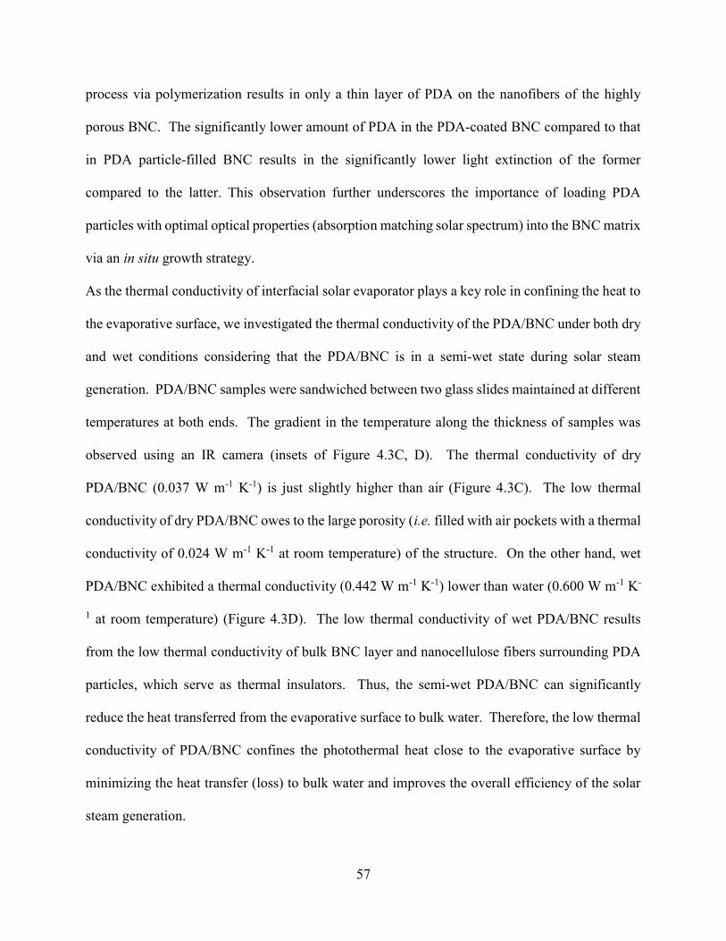
57
process via polymerization results in only a thin layer of PDA on the nanofibers of the highly
porous BNC. The significantly lower amount of PDA in the PDA-coated BNC compared to that
in PDA particle-filled BNC results in the significantly lower light extinction of the former
compared to the latter. This observation further underscores the importance of loading PDA
particles with optimal optical properties (absorption matching solar spectrum) into the BNC matrix
via an in situ growth strategy.
As the thermal conductivity of interfacial solar evaporator plays a key role in confining the heat to
the evaporative surface, we investigated the thermal conductivity of the PDA/BNC under both dry
and wet conditions considering that the PDA/BNC is in a semi-wet state during solar steam
generation. PDA/BNC samples were sandwiched between two glass slides maintained at different
temperatures at both ends. The gradient in the temperature along the thickness of samples was
observed using an IR camera (insets of Figure 4.3C, D). The thermal conductivity of dry
PDA/BNC (0.037 W m-1 K-1) is just slightly higher than air (Figure 4.3C). The low thermal
conductivity of dry PDA/BNC owes to the large porosity (i.e. filled with air pockets with a thermal
conductivity of 0.024 W m-1 K-1 at room temperature) of the structure. On the other hand, wet
PDA/BNC exhibited a thermal conductivity (0.442 W m-1 K-1) lower than water (0.600 W m-1 K-
1 at room temperature) (Figure 4.3D). The low thermal conductivity of wet PDA/BNC results
from the low thermal conductivity of bulk BNC layer and nanocellulose fibers surrounding PDA
particles, which serve as thermal insulators. Thus, the semi-wet PDA/BNC can significantly
reduce the heat transferred from the evaporative surface to bulk water. Therefore, the low thermal
conductivity of PDA/BNC confines the photothermal heat close to the evaporative surface by
minimizing the heat transfer (loss) to bulk water and improves the overall efficiency of the solar
steam generation.

58
4.43 Solar Steam Generation Performance of PDA/BNC
Now we turn our attention to the solar steam generation performance of the PDA/BNC under 1
kW m-2 (~ one sun) and 3 kW m-2 (~ three sun). IR imaging was employed to monitor the
temperature rise in the PDA/BNC floated at air/water interface upon irradiation with a simulated
solar beam (power density of 1 kW m-2 or 3 kW m-2). Upon irradiation (3 kW m-2), the temperature
of the PDA/BNC rapidly increased from room temperature (25 °C) to ~ 43 °C in the case of 1 kW
m-2 irradiation and to ~ 72 °C (Figure 4.4A, B). On the other hand, the temperature rise of water
in the absence of PDA/BNC layer was found to be significantly smaller (2-4 °C). The large rise
in temperature of PDA/BNC film under 3 kW m-2 illumination resulted in the appearance of steam
above the 100-mL beaker, evidencing the rapid evaporation of water (Figure 4.4A).
The efficiency of the PDA/BNC interfacial evaporator was quantified by measuring the weight
loss (due to water evaporation) as a function of irradiation time (all tests were performed for 45
min). The cumulative weight loss was found to increase linearly with irradiation time (Figure
4.4C). Under one sun irradiation, the evaporation rate was found to be 1.13 kg m-2 h-1. On the
other hand, in the absence of the PDA/BNC steam generator, the evaporation rate of water under
identical irradiation was only 0.46 kg m-2 h-1, which is around 2.45 times lower than that of the
PDA/BNC. Similarly, the steady state evaporation rate under 3 kW m-2 with PDA/BNC is 3.47 kg
m-2 h-1, 2.4 times higher than unaided water. Without considering the losses involved in the test
setup, such as reflection and surface radiation, the evaporation efficiency of PDA/BNC was
calculated to be 78% under one sun, which is comparable to other reported evaporators that rely
on potentially toxic carbon nanomaterials.232, 254-255 The evaporation efficiency of unaided water
is only 32% due to the poor photothermal conversion and the large energy loss associated with
bulk water heating. With increasing solar power density, the evaporation efficiency also increased,
59
reaching 82% under 3 kW m-2 (Figure 4.4D). We suggest that the excellent steam generation
efficiency of PDA/BNC owes to the following four factors: (i) tailored absorption of PDA particles,
which matches with solar spectrum combined with outstanding photothermal conversion
efficiency; (ii) high density of PDA particles loaded in the top layer of PDA/BNC combined with
the efficient light scattering enabled by nanocellulose fibers, which greatly increase the optical
path length and light absorption; (iii) low thermal conductivity of PDA/BNC layer due to BNC
matrix, which minimizes the heat transfer from the evaporation surface to the bulk water; and (iv)
open porous structure and hydrophilic nature of BNC aerogel enabling the rapid transport of water
from bulk to the evaporative surface.
4.44 Robustness of PDA/BNC
We then evaluated the robustness of the PDA/BNC foam. The PDA/BNC is subjected to rigorous
mechanical agitation and boiling for 2 hours during cleaning procedure to remove the bacteria and
culture medium residue. Despite the strong mechanical agitation, PDA/BNC did not exhibit any
signs of disintegration or loss of PDA particles. To further test its stability, we subjected
PDA/BNC to ultrasonic agitation (483 W) for 5 hours and vigorous shaking for 30 days. Even
after the vigorous mechanical agitation, the membrane did not exhibit any signs of disintegration
or loss of PDA particles (Figure 4.5A, left part). For comparison, we have prepared a PDA/BNC
composite by depositing PDA particles onto BNC via vacuum filtration method. After only 15
min of ultrasonic agitation or shaking, most of the PDA particles detached from BNC, which
indicates poor stability, highlighting the advantage of using in situ growth strategy to load PDA
particles (Figure 4.5A, right part). The robustness of PDA/BNC solar steam generator enables us
to reuse it multiple times without any noticeable degradation of the structure or steam generation
ability. Over 20 cycles of reuse, the steady-state evaporation rate and cumulative weight loss over

60
15 min irradiations (even under a higher power density, 7 kW m-2) was found to exhibit less than
6% variation (Figure 4.5B). The structure of PDA/BNC evaporator remained unaltered after
cycling tests (involving around 5 h high temperature solar exposure), which is evident from SEM
images of the PDA/BNC surface before and after cycling (Figure 4.5C). TGA results also
suggested the excellent thermal stability of BNC (up to 280 °C) and PDA (with 58% left up to 800
°C) (appendix 3, Figure S3.2).
4.45 Biodegradability of PDA
Finally, we turn our attention to the biodegradability of the solar steam generator. As mentioned
above, both BNC and PDA are well-known biocompatible and biodegradable materials.
Numerous reports in the past have demonstrated the enzymatic degradation of BNC.256-262
However, very limited amount of work has addressed the enzymatic degradation of PDA and PDA
microparticles.244 It has been shown that natural occurring melanin can be degraded by microbial
species due to the presence of melanin-degrading enzymes, such as manganese peroxidase, lignin
peroxidase and laccase.263-266 Considering the structural similarity between eumelanin and PDA,
we employed laccase to demonstrate the enzymatic degradation of PDA particles. After subjecting
PDA particles to an extremely high enzymatic concentration (50 mg/mL, 0.5 U/mg) for 48 hours
(accelerated testing), the colour of the PDA solution faded, indicating the enzymatic degradation
of PDA (Figure 4.6A). UV-vis spectra of pristine PDA particles showed a strong absorbance band
around 700 nm. On the other hand, laccase-treated PDA solution exhibited a broad and
significantly weaker absorbance band around 550 nm (Figure 4.6B). The weak absorbance band
corresponds to the residue PDA particles with significantly smaller size. The biodegradation of
the PDA particles is also evident from SEM images obtained before and after exposing them to
the enzyme (Figure 4.6C, D). It should be noted that the biodegradation tests demonstrated above

61
are highly accelerated by using high enzyme concentration. In reality, degradation timescales are
expected to be much longer than the life-time of the photothermal evaporator. Furthermore, the
high temperature at the surface of the solar steam generator can kill microorganisms, which will
prolong the biodegradation time.
4.5 Conclusions
In summary, we have demonstrated a flexible, scalable and, more importantly, completely
biodegradable photothermal evaporator for highly efficient solar steam generation. The
PDA/BNC bilayered evaporator was achieved by high density loading PDA particles within a BNC
hydrogel during its growth. The size of the PDA particles could be independently tailored to
achieve light absorption properties matching the solar spectrum. Owing to its large light
absorption, outstanding photothermal conversion, heat localization, and efficient water
transportation, the PDA/BNC bilayer foams exhibited excellent solar steam generation
performance under one sun (efficiency of ~78%). The material platform introduced here is
completely biodegradable and highly environmentally-friendly, while not compromising the solar
steam generation efficiency. Ultimately, the novel material and process introduced here can be a
sustainable solution to alleviate global water crisis.
4.6 Supporting Information
Supporting Information for chapter 4 is provided in appendix 3.

62
4.7 Figures
Figure 4.1. (A) Schematic illustration depicting the fabrication of bilayered PDA/BNC. (B) Photographs
showing PDA/BNC hydrogel with tunable sizes and shapes.
A
B

63
Figure 4.2. Characterizations of PDA particles and PDA/BNC. (A) Vis-NIR extinction spectra of PDA
particles with varying sizes (inset is the photograph of PDA particles solution). (B) TEM images of the
PDA particles. (C) Raman spectra of Dopamine and PDA. Optical image (D) and SEM images of (E)
surface (inset is the image of higher resolution) and cross-section (F) of a pristine BNC foam. Optical image
(G) and SEM images of (H) surface (inset is the image of higher magnification) and cross-section (I) of a
PDA/BNC foam.
B
E F D
A C
I H G
600 900 1200 1500 1800
PDA
1371
1578
Inte
nsi
ty (
a.u
.)
Raman shift (cm-1)
Dopamine

64
Figure 4.3. Optical and thermal properties of PDA/BNC. Transmittance and reflectance spectra of (A) BNC
hydrogel and (B) PDA/BNC hydrogel. Thermal conductivities of (C) dry BNC/PDA foam and (D) wet
PDA/BNC hydrogel. Insets: Representative IR images showing the temperature gradient along the
thickness of the samples.
B A
C D

65
Figure 4.4. Solar steam generation performance of PDA/BNC. (A) IR images of water under 1 kW m-2 solar
irradiation, PDA/BNC under 1 kW m-2 and 3 kW m-2 solar irradiation and optical image, showing visible
steam generation under 3 kW m-2. (B) Surface temperatures of water and PDA/BNC foam under 1, 3 kW
m-2 irradiations. (C) Plot showing the cumulative weight losses through water evaporation of water and
PDA/BNC foam under different solar irradiations. (D) Steam generation efficiencies of water and
PDA/BNC foam under different solar irradiations.
B A
C D

66
Figure 4.5. Stability of PDA/BNC. (A) Optical images of PDA/BNC foam achieved via in situ growth and
vacuum filtration that have been subjected to sonication and shaking for extended duration. (B) Cycling
solar steam generation tests under 7 kW m-2 solar irradiation for 15 min over 20 cycles. (C) High-resolution
SEM images of the PDA/BNC surface before and after 20 cycles of solar steam generation depicting the
intact structure of the PDA/BNC foam.
B
A
C

67
Figure 4.6. Biodegradability of PDA. (A) Optical images showing the pristine PDA and laccase-treated
PDA solution. (B) Vis-NIR extinction spectra of pristine, laccase-treated PDA solution. SEM images of
(C) pristine PDA and (D) laccase-treated PDA solutions.
C
A
D
B
68
Chapter 5: Biofouling-resistant, photothermally-active
Ultrafiltration Membrane
5.1 Abstract
By severely decreasing water flux and driving up operational costs, biofouling poses one of the
most serious challenges to membrane technologies. Here, we introduce a novel anti-biofouling
ultrafiltration membrane based on reduced graphene oxide (RGO) and bacterial nanocellulose
(BNC), which incorporates GO flakes into BNC in situ during its growth. In contrast to previously
reported GO-based membranes for water treatment, the RGO/BNC membrane exhibited excellent
aqueous stability under environmentally relevant pH conditions, vigorous mechanical
agitation/sonication, and even high pressure. Importantly, due to its excellent photothermal
properties, under light illumination, the membrane exhibited effective bactericidal activity,
obviating the need for any treatment of the feed water or external energy. The novel design and
in situ incorporation of the membranes developed in this study present a proof-of-concept for
realizing new highly efficient and environmental-friendly anti-biofouling membranes for water
purification.
5.2 Introduction
Water scarcity is recognized as one of the most critical global challenges in the 21st century.39-41
In response to this dire need, various membrane technologies are being actively investigated for
water purification and reclamation.51-53 However, fouling and consequent degradation of
membranes during performance still remain a ubiquitous problem.54 The three major fouling
mechanisms, mineral scaling, organic fouling, and biofouling, all lead to a decline in water flux.55

69
Among them, biofouling, accounting for more than 45% of all membrane fouling, is the Achilles
heel of the technologies, due to the difficulty of completely removing microorganisms.56-58
To inhibit the formation of biofilm, various biofouling controlling strategies, such as adjusting pH,
adding disinfectants and biocides, and introducing quorum sensing molecules, have been
suggested.59-62 However, most of these strategies introduce considerable operational costs and/or
potential hazardous contaminants.59 Researchers have also investigated the incorporation of
nanomaterials (e.g., silver nanoparticles, TiO2 nanoparticles, and graphene oxide nanosheets),
polymers (e.g., polyethylene glycol, polyvinyl alcohol, polyvinylpyrrolidone, and zwitterionic
polymers), and other materials (e.g., small organic molecules and biomacromolecules) to engineer
fouling-resistant membrane surfaces that can reduce biofilm growth and inactivate bacteria.55, 63-68
However, most of these methods involve additional thermal or chemical treatment steps.
Furthermore, most of the above techniques are effective for only a short period of time, because
biofilm gradually adapts to imposed harsh environments.56 Even if 99.9% of biofilm is removed,
the residual cells are sufficient to grow back and form a new biofilm. Highly efficient and cost-
effective methods that overcome biofouling on water purification membranes over a long period
of time would immediately help meet the grand challenge of providing access to clean water.
The photothermal effect of materials can offer a unique solution to biofouling, obviating the need
for harsh chemical treatments to achieve bacterial lysis. Photothermally-active materials can
effectively absorb light and then convert it into heat. In our recent study, gold nanostars grown on
graphene oxide (GO) flakes coating a commercial membrane were utilized as nanoheaters.68 In the
study, with laser irradiation, the photothermal properties of the gold nanostars and GO were
utilized to quickly kill adjacent Escherichia coli bacteria, inhibiting the formation of biofilm on
reverse osmosis membranes. While this study provided a promising example of utilizing the

70
photothermal effect to minimize biofouling on membranes, it would be even more beneficial if the
membrane itself were comprised of photothermal materials.
GO has been recognized as efficient photothermal material because the closely spaced energy level
from loosely bonded π electrons absorb the broad electromagnetic spectrum.267-269 The absorbed
light energy excites electrons, and its electron relaxes to ground state through non-radiative decay,
releasing the energy by heat.267-269 In addition to having an intriguing photothermal property, GO
has frequently been employed as a membrane component owing to its excellent mechanical
strength, facile synthesis, and ease of attachment by vacuum filtration, spin-coating, and drop-
casting.45-48 In contrast to graphene flakes, which have a strong tendency to stack and aggregate in
aqueous solutions, GO flakes are easily dispersed, making the membrane preparation process
easier in aqueous media.270-271 This dispersibility comes from rich oxygen-containing functional
groups (carboxyl, epoxy, hydroxyl, and carbonyl groups).49 However, the stability of current GO-
based membranes is compromised by vigorous agitation, and pH and ionic strength variations that
are within the typical range of feed waters.50 Thus, there is a need to develop new scalable
approaches to fabricate stable GO-based membranes.
Bacterial nanocellulose (BNC) is a highly pure cellulose produced by bacteria with low-molecular
weight sugar as a food source. Through a series of biochemical steps, the bacteria form exterior
cellulose nanofibers in aqueous cultures, and these fibers become entangled to form a 3D network
hydrogel.3 Similar to other cellulose nanofibers and cellulose nanocrystals (CNC), BNC is highly
attractive for membrane technologies in view of its excellent mechanical properties, tunable
porosity, chemical functionalizability, easy synthesis, high scalability, and most important, low
environmental impact.250 Therefore, BNC is a promising material for fabricating functional

71
composites through in situ growth or by adsorption of pre-synthesized nanostructures on the
nanoscale cellulose fibers.11-20
Here, we demonstrate a novel and facile approach for fabricating an anti-biofouling ultrafiltration
membrane, involving in situ incorporation of GO flakes into BNC during its growth. The reduced
graphene oxide (RGO) incorporated BNC membrane not only exhibited outstanding mechanical
and chemical stability under environmentally-relevant pH conditions and vigorous mechanical
agitation/sonication, but also showed stable water flux under high pressure. Particularly, owing to
its photothermal properties, the membrane exhibited light-enabled bactericidal activity, avoiding
the need for any treatment of the feed water or any external energy. The novel design and
preparation method introduced here are suggested the first steps toward realizing highly efficient,
environmental-friendly, and biofouling-resistant membranes for water purification.
5.3 Experimental Section
Fabrication of RGO/BNC membranes. Gluconacetobacter hansenii (ATCC®53582) was
employed to synthesize the cellulose nanofibers. To produce a dense bacterial suspension, the
bacteria were cultured in test tubes containing 16 ml of #1765 medium at 30 °C for 3 days under
shaking at 250 rpm. The #1765 growth medium is composed of 2% (w/v) glucose, 0.5% (w/v)
yeast extract, 0.5% (w/v) peptone, 0.27% (w/v) disodium phosphate, and 0.5% (w/v) citric acid.
To synthesize GO, we employed an efficient oxidation process, reported by Tour and co-
workers.202 For in situ incorporation of GO sheets in a BNC membrane, GO solution (150 mL of
0.0725wt%) was sonicated (2 hours), centrifuged, re-dispersed in #1765 medium, and then
centrifuged again to concentrate a wet mixture of GO and medium after supernatant was decanted.
Then the densely cultured Gluconacetobacter hansenii suspension was added to the GO/medium
wet mixture, making a total of 150 ml with 0.0725 wt% GO contents. The solution was

72
subsequently transferred to a Pyrex bakeware dish (18 cm × 18 cm) and incubated at room
temperature without disturbance. After 2 days, a thin hydrogel of GO/BNC had formed, and it
was harvested from the bakeware for cleaning. To remove the residual bacteria and growth
medium, the hydrogel was boiled in 2.5 L of 0.1 M NaOH aqueous solution for 2 h. The obtained
RGO/BNC hydrogel was then dialyzed in de-ionized water for 1 day. The purified RGO/BNC
hydrogel was dried to obtain an RGO/BNC membrane.
Microstructure characterization and property measurements. Scanning electron microscopy
(SEM, FEI Nova 2300 Field Emission SEM at an accelerating voltage of 10 kV) provided micron-
scale images of RGO/BNC and pristine BNC. Atomic force microscopy (AFM) images were
obtained for determining the thickness of GO flakes, using a Dimension 3000 (Bruker Inc.)
instrument in light tapping mode. To investigate the relative oxygen and carbon ratio of GO and
RGO flakes, carbon 1s peak was analyzed by X-ray photoelectron spectroscopy (XPS, a Physical
Electronics® 5000 VersaProbe II Scanning ESCA Microprobe). The pore size distribution of
RGO/BNC membranes was measured by the Brunauer-Emmett-Teller (BET) method using an
Autosorb-1C (AX1C-MP-LP) at 298 K.
Stability tests of RGO/BNC membrane. To study the stability of the RGO/BNC membrane, we
placed it in Petri dishes filled with solutions at pH 4, 7, and 9 and sonicated them for 5 hours. The
pH values were chosen because they occur in many natural and engineering aqueous systems.272
Subsequently, the release of RGO from the membrane was quantified from the UV-Vis absorbance
spectra (Shimadzu UV-1800 spectrophotometer, 400 nm to 1000 nm) of the solutions. SEM was
used to monitor the surface morphologies of the RGO/BNC film after sonication. To study the
mass change of RGO/BNC membrane before and after sonication, thermo-gravimetric analysis

73
(TGA) was performed using a TA Instruments Q5000 IR Thermogravimetric Analyzer in air (at
rate of 5 °C/min).
Because the GO membranes were frequently prepared by vacuum filtration, we made two
types of control samples for comparison.46-48 First, a similar amount of base-washed RGO flakes
was deposited on top of a BNC hydrogel, using the vacuum-assisted method, and dried to obtain
a dry film. Second, BNC dispersions were pre-mixed with GO solutions and were then filtered to
make membranes. Both control membranes were subjected to the same aqueous stability tests as
the RGO/BNC membrane (appendix 4, Figure S4.1).
Evaluation of mass transport performance of RGO/BNC membranes. The mass transport
performance of RGO/BNC membranes was evaluated by using a side-by-side diffusion cell system.
An RGO/BNC membrane was first mounted between the two cells (Adams & Chittenden
Scientific Glass, 5 mL volume). Then, ethanol and water were used to rinse the membrane several
times to avoid subsequent air bubble formation. To test diffusion-driven transport through an
RGO/BNC membrane, 0.5 mM of rhodamine 6G (R6G, ~ 1 nm, 479 Da) and lysozyme (3.8–4 nm,
14300 Da) were used. R6G is cationic dye, thus it is positively charged.273 The isoelectric points
for lysozyme are 10.5, and its pH value at 0.5 mM concentration is 3.53, indicating that lysozyme
is positively charged under our experimental condition.274 The solute was introduced on the feed
side, while the dialysate side was just DI water. Solutions in both cells were subjected to vigorous
stirring to minimize concentration polarization effects close to the membrane. The diffusing
concentration of the solute was monitored in the wavelength range of 300−700 nm, using a
Shimadzu UV-1800 spectrometer. For replicates, we utilized the RGO/BNC membranes grown in
independent batches, and diffusion tests were conducted with three replicates.
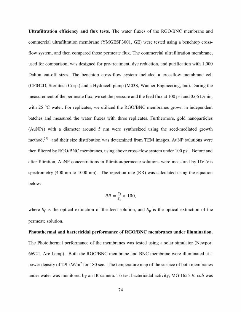
74
Ultrafiltration efficiency and flux tests. The water fluxes of the RGO/BNC membrane and
commercial ultrafiltration membrane (YMGESP3001, GE) were tested using a benchtop cross-
flow system, and then compared those permeate flux. The commercial ultrafiltration membrane,
used for comparison, was designed for pre-treatment, dye reduction, and purification with 1,000
Dalton cut-off sizes. The benchtop cross-flow system included a crossflow membrane cell
(CF042D, Sterlitech Corp.) and a Hydracell pump (M03S, Wanner Engineering, Inc). During the
measurement of the permeate flux, we set the pressure and the feed flux at 100 psi and 0.66 L/min,
with 25 °C water. For replicates, we utilized the RGO/BNC membranes grown in independent
batches and measured the water fluxes with three replicates. Furthermore, gold nanoparticles
(AuNPs) with a diameter around 5 nm were synthesized using the seed-mediated growth
method,275 and their size distribution was determined from TEM images. AuNP solutions were
then filtered by RGO/BNC membranes, using above cross-flow system under 100 psi. Before and
after filtration, AuNP concentrations in filtration/permeate solutions were measured by UV-Vis
spectrometry (400 nm to 1000 nm). The rejection rate (RR) was calculated using the equation
below:
𝑅𝑅 = × 100,
where 𝐸 is the optical extinction of the feed solution, and 𝐸 is the optical extinction of the
permeate solution.
Photothermal and bactericidal performance of RGO/BNC membranes under illumination.
The Photothermal performance of the membranes was tested using a solar simulator (Newport
66921, Arc Lamp). Both the RGO/BNC membrane and BNC membrane were illuminated at a
power density of 2.9 kW/m2 for 180 sec. The temperature map of the surface of both membranes
under water was monitored by an IR camera. To test bactericidal activity, MG 1655 E. coli was
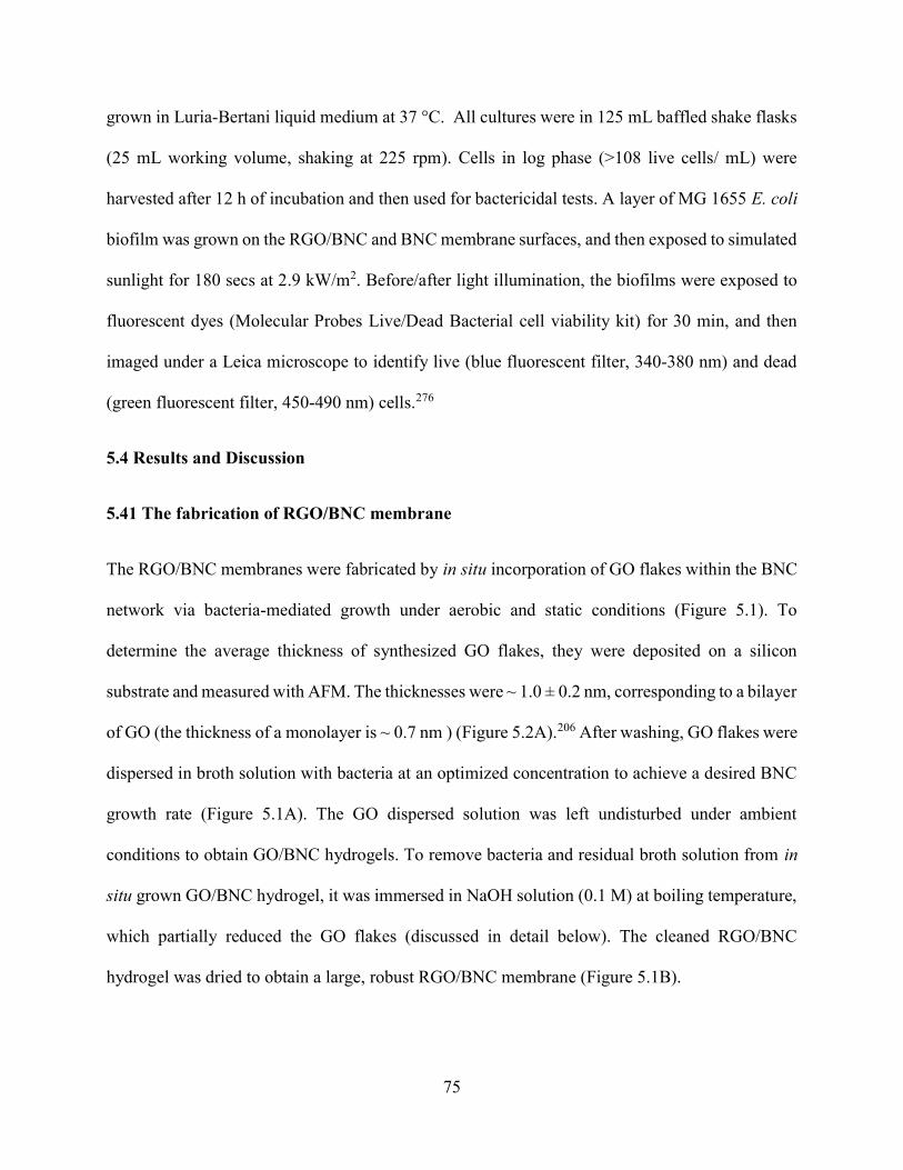
75
grown in Luria-Bertani liquid medium at 37 °C. All cultures were in 125 mL baffled shake flasks
(25 mL working volume, shaking at 225 rpm). Cells in log phase (>108 live cells/ mL) were
harvested after 12 h of incubation and then used for bactericidal tests. A layer of MG 1655 E. coli
biofilm was grown on the RGO/BNC and BNC membrane surfaces, and then exposed to simulated
sunlight for 180 secs at 2.9 kW/m2. Before/after light illumination, the biofilms were exposed to
fluorescent dyes (Molecular Probes Live/Dead Bacterial cell viability kit) for 30 min, and then
imaged under a Leica microscope to identify live (blue fluorescent filter, 340-380 nm) and dead
(green fluorescent filter, 450-490 nm) cells.276
5.4 Results and Discussion
5.41 The fabrication of RGO/BNC membrane
The RGO/BNC membranes were fabricated by in situ incorporation of GO flakes within the BNC
network via bacteria-mediated growth under aerobic and static conditions (Figure 5.1). To
determine the average thickness of synthesized GO flakes, they were deposited on a silicon
substrate and measured with AFM. The thicknesses were ~ 1.0 ± 0.2 nm, corresponding to a bilayer
of GO (the thickness of a monolayer is ~ 0.7 nm ) (Figure 5.2A).206 After washing, GO flakes were
dispersed in broth solution with bacteria at an optimized concentration to achieve a desired BNC
growth rate (Figure 5.1A). The GO dispersed solution was left undisturbed under ambient
conditions to obtain GO/BNC hydrogels. To remove bacteria and residual broth solution from in
situ grown GO/BNC hydrogel, it was immersed in NaOH solution (0.1 M) at boiling temperature,
which partially reduced the GO flakes (discussed in detail below). The cleaned RGO/BNC
hydrogel was dried to obtain a large, robust RGO/BNC membrane (Figure 5.1B).
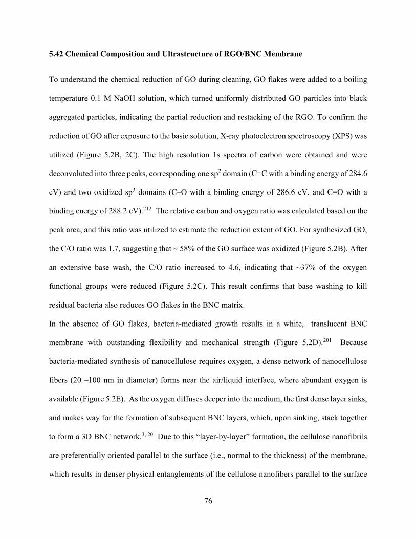
76
5.42 Chemical Composition and Ultrastructure of RGO/BNC Membrane
To understand the chemical reduction of GO during cleaning, GO flakes were added to a boiling
temperature 0.1 M NaOH solution, which turned uniformly distributed GO particles into black
aggregated particles, indicating the partial reduction and restacking of the RGO. To confirm the
reduction of GO after exposure to the basic solution, X-ray photoelectron spectroscopy (XPS) was
utilized (Figure 5.2B, 2C). The high resolution 1s spectra of carbon were obtained and were
deconvoluted into three peaks, corresponding one sp2 domain (C=C with a binding energy of 284.6
eV) and two oxidized sp3 domains (C–O with a binding energy of 286.6 eV, and C=O with a
binding energy of 288.2 eV).212 The relative carbon and oxygen ratio was calculated based on the
peak area, and this ratio was utilized to estimate the reduction extent of GO. For synthesized GO,
the C/O ratio was 1.7, suggesting that ~ 58% of the GO surface was oxidized (Figure 5.2B). After
an extensive base wash, the C/O ratio increased to 4.6, indicating that ~37% of the oxygen
functional groups were reduced (Figure 5.2C). This result confirms that base washing to kill
residual bacteria also reduces GO flakes in the BNC matrix.
In the absence of GO flakes, bacteria-mediated growth results in a white, translucent BNC
membrane with outstanding flexibility and mechanical strength (Figure 5.2D).201 Because
bacteria-mediated synthesis of nanocellulose requires oxygen, a dense network of nanocellulose
fibers (20 –100 nm in diameter) forms near the air/liquid interface, where abundant oxygen is
available (Figure 5.2E). As the oxygen diffuses deeper into the medium, the first dense layer sinks,
and makes way for the formation of subsequent BNC layers, which, upon sinking, stack together
to form a 3D BNC network.3, 20 Due to this “layer-by-layer” formation, the cellulose nanofibrils
are preferentially oriented parallel to the surface (i.e., normal to the thickness) of the membrane,
which results in denser physical entanglements of the cellulose nanofibers parallel to the surface

77
(Figure 5.2F). To form RGO/BNC membranes, GO flakes were added during in situ growth, and
a subsequent base washing process was conducted (Figure 5.2G). Compared to pristine BNC
membrane, the RGO/BNC membrane is smoother and has fewer fibrils protruding from the surface,
due to the presence of 2D RGO sheets (Figure 5.2H). Cross-sectional SEM images showed that
the membrane was ~8 µm thick (Figure 5.2I). The images also show the embedded RGO flakes
between BNC layers due to the “layered” formation of BNC, starting from the liquid/air interface
as described above (Figure 5.2I).
5.43 Stability of RGO/BNC Membrane
To investigate the mechanical and chemical stability of the membrane, we exposed it to ultrasonic
agitation (483 W, 8892, Cole-Parmer) for 5 hours in solutions at pH 4, 7, and 9 (appendix 4, Figure
S4.1). Even after this vigorous mechanical agitation at environmentally-relevant pH conditions,
the membrane did not exhibit any signs of disintegration or loss of RGO flakes (Figure 5.3A and
its inset). This result was further supported by SEM images of the membrane surface, which did
not show a discernable change in the morphology after sonication (Figure 5.3B). Then, to evaluate
the thermal stability of the RGO/BNC membrane, thermogravimetric analysis was conducted. The
membrane showed a first mass loss of ~2 wt.% at ~100 °C, due to the loss of absorbed water. A
second mass loss of ~3 wt.% at ~200 °C was attributed to the decomposition of functional groups
of GO.204 A third mass loss of ~46 wt.% began at 280°C, and was due to the degradation of
cellulose. A fourth mass loss (~49 wt.%) at 390 °C was attributable to the continued decomposition
of cellulose residual and sublimation or burning of damaged graphitic regions.203 Based on the
mass loss profiles of the RGO/BNC membrane, RGO, and pristine BNC membrane, the mass
loading of RGO in RGO/BNC was calculated to be ~45 wt.%, and it suggested excellent thermal
stability of the RGO/BNC membrane up to 200 °C. The RGO/BNC membrane after ultrasonic

78
treatment also showed an identical mass loss profile, implying that the embedded RGO flakes
within the BNC matrix remained intact (Figure 5.3C).
As mentioned above, GO-based membranes have been extensively investigated in the past several
years. Most of these membranes were fabricated by vacuum filtration of GO flakes onto a
supporting membrane, but this coating method always leaves doubt about its long-term aqueous
stability.50 Here, we compared the mechanical stability of in situ embedded RGO/BNC with that
of an RGO/BNC membrane prepared by depositing RGO particles (base-washed) on top of a BNC
membrane using vacuum filtration. After 5 h of ultrasonic agitation in solutions at pH 4, 7, and 9,
the RGO particles had disintegrated completely, and the solution exhibited broad absorbance, a
feature of RGO flakes in solution (Figure 5.3D). This disintegration was further confirmed by
surface SEM images and quantified by TGA. After sonication, the membrane prepared through
vacuum filtration showed an initial mass loss (~5%) at 100 °C, attributed to absorbed water, and
the decomposition of cellulose at ~280 °C (~63%) and at ~340 °C (~32%). All of these findings
indicated the absence of RGO flakes (Figure 5.3F).
Conventional GO-based membranes rely on hydrogen bonding or metal ion incorporation for
mechanical stability. However, mechanical agitation during water filtration or cleaning procedures,
as well as pH variations in the feed water, can compromise the mechanical stability of these
membranes (appendix 4, Figure S4.1). In contrast, in situ RGO/BNC membranes are robust
because during the BNC growth, plate-like GO particles are physically locked into the layered
BNC matrices, which provides its excellent mechanical and chemical stability. Moreover,
intensive vortexing has been employed to wash used in situ RGO/BNC membrane without
damaging it (appendix 4, Figure S4.1D). This finding further suggests the durability of the in situ
RGO/BNC membrane for practical use.

79
5.44 Mass Transport Performance and Water Flux Tests
To probe the diffusive transport capability of small molecules across the RGO/BNC membranes,
we employed a two-cell setup (Figure 5.4A) and tested it with 0.5 mM of two model solute systems,
having different sizes and molecular weights: rhodamine 6G (R6G, ~ 1 nm, 479 Da) and lysozyme
(3.8–4 nm, 14300 Da).277 Because ultrafilters have pore sizes between 1 nm to 100 nm, and thus
remove contaminants via a size exclusion mechanism, these two different solutes helped to
determine the filtration capability of RGO/BNC membranes.278 A UV-vis spectrometer was used
to monitor the concentration of model solutes from the feed side to the permeate side (see
experimental section for details). For pristine BNC membrane, all two solutes rapidly diffused
through because the BNC fiber network is composed of micro-scale pores even if the nanofibers
are densely packed (Figure 5.4B). By contrast, the addition of graphene oxide flakes within the
matrix completely blocked the diffusion of lysozyme (3.8–4 nm), although R6G (~1 nm) passed
through (Figure 5.4B). These results are in accordance with the BET measurements which indicate
the pore size of the RGO/BNC membrane is around 2.2 nm (radius), which falls into the range of
ultrafiltration membranes (appendix 4, Figure S4.3).279
Moreover, the unique mass transport properties of GO-based membranes originate from the
nanocapillary network formed by lamellar stacking of GO, and the mass-transport behavior can be
adjusted by tuning functional groups or inserting external species with desired dimensions. 45,48 In
this work, the presence of bacterial cellulose nanofibers between RGO flakes will lead to an overall
tortuous network of pores in the membrane, even though no visible pores can be seen in a SEM
image of the surface of RGO/BNC membranes.
To further demonstrate the potential of the novel RGO/BNC membrane for an ultrafiltration
system, we performed flux tests and particle rejection tests using size-controlled gold nanoparticles

80
(AuNPs) via a benchtop cross-flow system (setup diagram in Figure 5.4C). For a particle rejection
test, spherical gold nanoparticles with diameters of 5.15 ± 0.4 nm were synthesized using the seed-
mediated method.275 The prepared AuNPs showed a very narrow size distribution (RSD < 8 %),
which made the particle rejection study accurate (appendix 4, Figure S4.2B). The particle rejection
rates were calculated by measuring the UV-vis extinction spectra of solutions before/after filtration
through the RGO/BNC membranes (Figure 5.4D). This result suggested that AuNP of 5 nm
diameter were ~100% rejected (inset of Figure 5.4D). In the same way, the rejection test was also
performed for a commercial ultrafiltration membrane (pore size of around 1.66 nm), which also
showed ~ 100% rejection for 5 nm gold nanoparticles (appendix 4, Figure S4.2C).
Under 100 psi, the RGO/BNC membranes showed higher water fluxes than a commercial
ultrafiltration (UF) membrane. Because the pore size for both membrane types belongs to the range
between UF and nanofiltration (NF), we intentionally tested water flux at a higher operating
pressure than the usual operating pressure for UF (7.3 – 73 psi). Over a five-hour-long flux test
after stabilization, the water flux of the RGO/BNC membrane was found to be 52.6 ± 2.5 L/m2 h,
and that of the commercial ultrafiltration membrane was 21.6 ± 0.8 L/m2 h (Figure 5.4E).
Importantly, the RGO/BNC membrane withstood an operating pressure as high as 100 psi without
any supporting membrane. This performance emphasized the remarkable mechanical strength of
RGO/BNC, considering that most of the GO-based membranes reported in the literature require a
support membrane or a carefully designed apparatus due to their limited mechanical strength.280-
284
5.45 Photothermal and Bactericidal Performance under Light
Next, we examined the photothermal and bactericidal ability of the RGO/BNC membrane using a
Newport 66921 Arc Lamp with a power density of 2.9 kW/m2. We used IR imaging to monitor

81
the temperature profile of the RGO/BNC membrane in an aqueous environment during
illumination (Figure 5.5B). Upon illumination, the temperatures of the RGO/BNC membrane
rapidly increased from room temperature (26 °C) to ~60 °C (Figure 5.5C). Specifically, the
temperature rapidly increased during the first 20 seconds after the onset of irradiation and remained
constant over the entire duration (120 sec). In comparison, the pristine BNC membranes showed
only a small temperature increase (3 °C). The large rise in temperature was caused by the broad
optical absorption of many RGO flakes arranged within the BNC matrix. Once light was absorbed
by the RGO flakes, they immediately generated heat, which then dissipated to the surrounding
water and BNC.20 Due to the decrease of thermal radiation along the distance between IR camera
and surface (~30 cm), the temperature profile obtained from the IR camera underestimated the
actual temperature at the surface of the RGO/BNC membrane. Therefore, biological species were
exposed to temperature higher than ~60 °C. To demonstrate that the heat generated by light
exposure will not damage the mass transport and water flux performance of the RGO/BNC
membrane, we performed BET and water flux tests before and after long duration of light exposure
(2.9 kW/m2). Both the pore size distribution and the water flux performance of RGO/BNC
membrane remained the same after light exposure (appendix 4, Figure S4.3, S4.4).
To test the bactericidal ability, the RGO/BNC membrane was covered with stained E. coli bacteria
from a live/dead cell viability assay, and then light was shined on the membrane surface. Before
irradiation, both RGO/BNC and pristine BNC membranes showed substantial and well distributed
green fluorescence, corresponding to live bacteria, and no sign of red fluorescence, indicating the
absence of dead bacteria (Figure 5.5D). After irradiation (2.9 kW/m2) for 180 secs, the bacteria
on the RGO/BNC membrane exhibited predominantly red fluorescence (dead bacteria) and a
complete visible absence of green fluorescence. However, the E.coli-covered pristine BNC

82
membrane exhibited green fluorescence corresponding to live bacteria, even after irradiation
(Figure 5.5E). The SEM images showed morphology changes and leakage of bacteria, indicating
that the high temperature at the RGO/BNC membrane had disrupted the cell walls and cell
membranes (Figure 5.5F, G). Before light irradiation, live E. coli bacteria on an RGO/BNC
membrane showed a rod-like structure, while after irradiation they were significantly shrunken
and wrinkled. Because the cell walls of E. coli are known to deteriorate near 70 °C,285 this change
implied that upon illumination, the surface of the RGO/BNC membrane had rapidly heated to
above 70 °C and killed bacteria within a short time (180 sec). Live E. coli bacteria on an
RGO/BNC membrane without illumination showed no dead bacteria cells even after 1hour
exposure, indicating the bactericidal activity of RGO/BNC membrane only occur upon light
illumination (appendix 4, Figure S4.5). Here, we demonstrated the excellent bactericidal
performance of the RGO/BNC membrane in harvesting light, and this capability makes the
RGO/BNC membrane highly attractive for energy-saving and environmentally-friendly water
purification applications.
5.5 Conclusions
In this study, we presented an innovative approach that uses the photothermal effect of RGO by
embedding it in BNC structures. This new type of membrane can enhance the stability and
durability of a membrane and inhibit or delay microorganism growth on its surface. While the
most contemporary approaches to resisting biofouling rely on temporary chemical treatments,
combining the photothermal effect with a noble membrane design shows that anti-biofouling can
be achieved with sustainable and abundant sunlight.
We note that fully utilizing the photothermal property of RGO/BNC membranes can be
challenging. A possible implementation involves modifying a spiral-wound module system, as

83
shown in Figure 5A. The inner and outer surfaces of the membrane modules or feed channel
spacers can be equipped with low-energy LEDs for illumination, and can potentially be powered
by renewable energy sources, such as low-cost photovoltaic devices or triboelectric
nanogenerators (TENGs).286 In TENGs, mechanical energy generated through fluid flow in the UF
process can be harnessed to produce light and to heat the membrane surface, reducing the overall
operational expense. In addition to spiral-wound module system, this suggested system can also
be applied to plate sheet membrane module by adding LED-equipped plates between the
membrane modules. This would be an exciting future research direction for realizing photothermal
membrane water filtration.
The novel fabrication method of incorporating RGO during ‘layer-by-layer’ growth of BNC yields
a well stacked the structure, with a pore size in the UF membrane range. In addition, BNC
production is considered eco-friendly because it needs only low-molecular weight sugar and
oxygen as food sources.
Until now, many researchers prepared GO membranes through vacuum filtration or spin coating
without a polymer matrix45-48, but these fabrication methods inevitably raised the mechanical
stability concerns. However, the RGO/BNC membrane, reported here, exhibits stable water flux
under 100 psi loading and maintains chemical stability at solution pH varying from 4 to 9. The
water flux is higher than that of commercial UF membranes under identical pressure. In summary,
RGO/BNC membrane demonstrated here not only provides a novel anti-biofouling approach
powered by solar energy, but also suggests a scalable, eco-friendly, and cost-effective way to
fabricate UF membranes for water purification.
5.6 Supporting Information
Supporting Information for chapter 5 is provided in appendix 4.

84
5.7 Figures
Figure 5.1. Fabrication of RGO/BNC membrane. Optical images showing (A) GO in bacterial medium and
(B) in situ grown RGO/BNC membrane after cleaning and drying.
B A

85
Figure 5.2. Chemical composition and ultrastructure of RGO/BNC membrane. (A) AFM image of GO
flakes deposited on a silicon substrate. X-ray photoelectron spectra of (B) pristine and (C) base-washed GO.
Optical image (D) and SEM images of (E) surface and (F) cross-section of a pristine BNC membrane.
Optical image (G) and SEM images of (H) surface and (I) cross-section of a RGO/BNC membrane.
B A
G
F
C
D
H
E
I
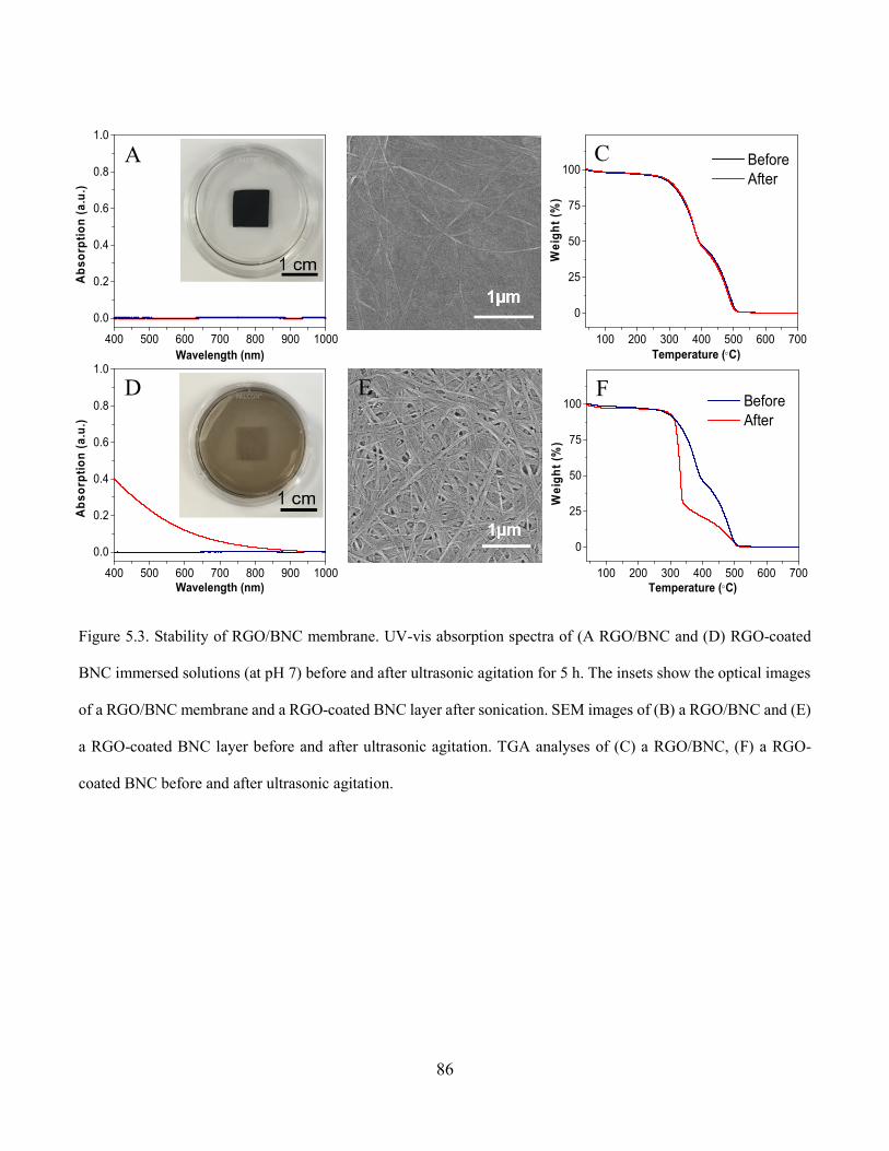
86
Figure 5.3. Stability of RGO/BNC membrane. UV-vis absorption spectra of (A RGO/BNC and (D) RGO-coated
BNC immersed solutions (at pH 7) before and after ultrasonic agitation for 5 h. The insets show the optical images
of a RGO/BNC membrane and a RGO-coated BNC layer after sonication. SEM images of (B) a RGO/BNC and (E)
a RGO-coated BNC layer before and after ultrasonic agitation. TGA analyses of (C) a RGO/BNC, (F) a RGO-
coated BNC before and after ultrasonic agitation.
B A
E F
C
D
400 500 600 700 800 900 1000
0.0
0.2
0.4
0.6
0.8
1.0
Ab
sorp
tio
n (
a.u
.)
Wavelength (nm)
400 500 600 700 800 900 1000
0.0
0.2
0.4
0.6
0.8
1.0
Ab
sorp
tio
n (
a.u
.)
Wavelength (nm)100 200 300 400 500 600 700
0
25
50
75
100
Wei
gh
t (%
)
Temperature (C)
Before After
100 200 300 400 500 600 700
0
25
50
75
100 Before After
Wei
gh
t (%
)
Temperature (C)

87
Figure 5.4. Mass transport performance and water flux tests. (A) Schematic diagram of a two-cells diffusion
setup. (B) Diffusion of model solutes through pristine BNC membrane and RGO/BNC membrane. (C)
Schematic diagram of cross-flow flux test setup. RGO/BNC membranes are placed in between the cross-
flow cell and tightly sealed. (D) UV-vis extinction spectra indicating the rejection of AuNPs with 5 nm in
diameter filtered through RGO/BNC membranes (inset is the picture showing feed and permeate solutions).
(E) Water flux of RGO/BNC membranes (~8 µm thick) and commercial ultrafiltration membranes. 100
psi was applied for the flux tests.

88
Figure 5.5. Photothermal and bactericidal performance under light. (A) Schematic showing antifouling mechanism
of RGO/BNC membrane and a possible configuration of spiral wound UF module coupled with LEDs. (B) IR
images showing the temperature of the pristine BNC and the RGO/BNC membrane in water under illumination at
various time points. (C) Plot showing the temperature of pristine BNC and the RGO/BNC membrane in water under
light of 2.9 kW/m2 as a function of irradiation time. Fluorescence images of E. coli on BNC and RGO/BNC
membranes (D) before and (E) after irradiation. SEM images of E. coli on RGO/BNC membranes (F) before and
(G) after irradiation.
B A
F G E
C
D
89
Chapter 6: Catalytically-active Bacterial
Nanocellulose-based Ultrafiltration Membrane
6.1 Abstract
Large quantities of highly toxic organic dyes in industrial wastewater is a persistent challenge in
wastewater treatment processes. Here, a novel membrane based on bacterial nanocellulose (BNC)
loaded with graphene oxide (GO) and palladium nanoparticles (PdNPs) for highly efficient
wastewater treatment is demonstrated. This Pd/GO/BNC membrane is realized through the in situ
incorporation of GO flakes into BNC matrix during its growth followed by the in situ formation
of palladium nanoparticles. The Pd/GO/BNC membrane exhibits highly efficient methylene
orange (MO) degradation during filtration (up to 99.3% over a wide range of MO concentrations,
pH and multiple cycles of reuse). Multiple contaminants (a cocktail of 4-nitrophenol, methylene
blue and rhodamine 6G) can also be effectively treated by Pd/GO/BNC membrane simultaneously
during filtration. Furthermore, the Pd/GO/BNC membrane demonstrates stable flux (33.1 L/m2·h)
under 58 psi over long duration. The novel and robust membrane demonstrated here is highly
scalable and holds a great promise for wastewater treatment.
6.2 Introduction
Water contamination caused by chemical and biological species released from industrial and
agricultural practices is a formidable environmental challenge.51, 69-70 Among all the contaminants
such as cleaning agents, agricultural chemicals, and noxious microorganisms, organic dyes, which
are widely employed in textile, leather, cosmetic, pharmaceutical industries, pose significant
threats to aquatic life and humans due to their carcinogenic and mutagenic nature.71-73 Due to the

90
high resistance of organic dyes to traditional biological, physical, and chemical treatment methods,
there is a critical need for the development of highly efficient and cost-effective methods for dye
degradation and removal from contaminated water.74-76 Membrane technologies are being
extensively investigated in wastewater treatments owing to its high efficiency, chemical stability,
and low environmental impact.287-289 To achieve nearly complete removal of organic compounds
from wastewater, a promising approach involves the utilization of membranes with specifically
tailored micro- and nano-scale structures and permeation characteristics. These membranes can
be further integrated with emerging technologies such as photocatalytic degradation, chemical
oxidation, physical adsorption.290-292 However, realizing scalable membranes with desired
permeation properties and highly efficient organic dye removal performance remains to be a great
challenge.
Noble and transition metal nanoparticles, which have been extensively employed in catalysis,
organic synthesis, hydrogen storage, and water treatment, have shown great promise for organic
dye removal.77-80 In particular, palladium nanoparticles (PdNPs) have attracted special attention
for dye degradation owing to their excellent catalytic properties and low environmental impacts.81-
85 To achieve maximum catalytic activity and prevent aggregation of PdNPs, immobilizing PdNPs
on various substrates such as carbon (e.g., carbon microspheres, carbon nanotubes, and graphene
oxide), silica, and metal oxides (e.g., titanium dioxide) has been utilized.86-90 Recently, Hu and
coworkers reported a novel mesoporous, three-dimensional (3D) wood which can be used as a
robust substrate for PdNPs to achieve high-performance filtration membrane for efficient waste
water treatment.293
Graphene oxide (GO) is a particular promising substrate material because of its high mechanical,
chemical, thermal stability, and high surface area.91-96 Various self-assembled GO-based

91
composites have been demonstrated for wastewater treatment.97-102 To the best of our knowledge,
a GO-based filtration membrane with transition metal nanoparticles as catalyst has not been
reported since previous developed GO-based composites have limited aqueous stability and
mechanical strength under pressure .
Owing to its desirable properties such as excellent mechanical strength and toughness, rich
chemical functionality, and high specific surface area in aerogel state, bacterial nanocellulose
(BNC) serves as an ideal material for realizing functional composites by incorporating functional
nanomaterials within BNC matrix.11-19, 44, 250 Recently, we have demonstrated a novel, highly
scalable, cost-effective and green strategy to realize functional GO/BNC-based membranes.294-295
GO sheets can be efficiently incorporated within BNC matrix during its growth, which can be
applied to other two-dimensional (2D) materials. Owing to the intercalation of GO flakes within
the layered BNC matrix, the membrane showed mechanical robustness, which is crucial for
efficient, large scale water treatment.
Here, for the first time, we introduce a simple and scalable approach for the fabrication of
Pd/GO/BNC membrane for highly efficient dye degradation. The fabrication of Pd/GO/BNC
membrane involves the incorporation of GO flakes into the BNC matrix during its growth followed
by in situ growth of PdNPs on GO flakes. The layered structure of Pd/GO/BNC, which forms
nanocapillaries through out the membrane, maximizes the contact between organic dye
contaminants and PdNPs anchored on the GO flakes. We demonstrate the novel membrane to
effectively remove organic dyes, showing a great promise for wastewater treatment and separation
applications.

92
6.3 Experimental Section
Preparation of GO/BNC aerogel: Gluconacetobacter hansenii (ATCC®53582) was cultured in
test tubes containing 16 ml of #1765 medium at 30 °C under shaking at 250 rpm. The #1765
medium is composed of 2% (w/v) glucose, 0.5% (w/v) yeast extract, 0.5% (w/v) peptone, 0.27%
(w/v) disodium phosphate, and 0.5% (w/v) citric acid. GO was synthesized using an approach
reported by Tour and co-workers.202 The as synthesized GO (150 mL of 0.0725 wt%) was
centrifuged and redispersed in #1765 medium and then centrifuged again to obtain a wet mixture
of GO and medium after decanting the supernatant. Subsequently, Gluconacetobacter hansenii
culture solution and fresh medium were added into the above mixture to make a solution of total
150 mL (with GO concentration of 0.0725 wt%). The above solution was then transferred to a
Pyrex bakeware (18 × 18 cm) and left without disturbance at room temperature. After 3 days, a
hydrogel was formed, which is washed in boiling NaOH (0.1 M) aqueous solution for 2 h and then
dialyzed in nanopure water for 12 h. The cleaned GO/BNC hydrogel was then cut into desired
dimensions, typically 3×3 cm2, and then freeze-dried for 12 h to obtain GO/ BNC aerogel.
Preparation of Pd/GO/BNC membrane: GO/BNC aerogel (3 × 3 cm2) was immersed in the
PdCl2 solution (2.5 wt% in 5 wt% of HCl) for 8h. The GO/BNC aerogel was transferred into a
petridish and placed in an oven at 60 °C for 1h. The dried GO/BNC membrane was then immersed
into NaBH4 solution (80 mM) for 10 min to achieve in situ formation of Pd nanoparticles. The
obtained Pd/GO/BNC membrane was dried in an oven at 60 °C for 1h.
Microstructure and chemical composition characterization: Scanning electron microscope
(SEM) images were obtained using a FEI Nova 2300 Field Emission SEM at an acceleration
voltage of 10 kV. Transmission electron microscopy (TEM) images were obtained using JEM-
2100F (JEOL) field emission instrument. Raman spectra were obtained using a Renishaw inVia

93
confocal Raman spectrometer mounted on a Leica microscope with 50x objective and 785 nm
wavelength diode laser as an illumination source. X-ray photoelectron spectroscopy (XPS)
analysis was performed using Physical Electronics® 5000 VersaProbe II Scanning ESCA (XPS)
Microprobe. The X-ray diffraction (XRD) measurements of the samples were obtained using a
Bruker D8-Advance X-ray powder diffractometer using Cu Kα radiation (λ = 1.5406 Å).
Thermalgravimetric analysis (TGA) to measure Pd loaing in Pd/GO/BNC:
Thermogravimetric analysis (TGA) was performed in nitrogen using a TA Instruments Q5000 IR
Thermogravimetric Analyzer at a heating rate of 5 ºC min-1. GO/BNC, Pd/GO/BNC (with same
loading of GO as GO/BNC membrane), Pd/BNC and pristine BNC were tested using above condition
(appendix 3, Figure S3.2). For Pd/GO/BNC, the first mass loss (~10 %) can be attributed to absorbed
water. The second mass loss (~13 %) at ~ 160 °C is due to the decomposition of functional groups of
GO. The third mass loss (~26 %) at ~280 °C is due to the degradation of cellulose and a mass loss
(~12.8 %) at ~390 °C is due to the decomposition of cellulose residue, which generates CO2 and H2O
and the sublimation or burning of the damaged graphitic regions.203-204 The remaining mass (~38 %)
is composed of PdNPs and carbon residues. The mass of carbon residues for GO/BNC before the
growth of Pd/GO/BNC is around 25.7 %. Based on the above results, the mass loading of PdNPs in
Pd/GO/BNC is calculated to be 12.3 wt%.
Evaluation of catalytic activity of Pd/GO/BNC membrane: To investigate the catalytic activity
of the Pd/GO/BNC membrane, the catalytic degradation of MO in the presence of NaBH4 was
employed as a model reaction. 40 µL NaBH4 solution (0.02 mg/L) was rapidly added into MO
solution (25.7 mg·L-1, 1.5 mL) under constant stirring. Subsequently, Pd/GO/BNC membrane
(1×0.5 cm) was placed in the above mixture. The concentration of reactant, MO (absorbance at
465 nm), was monitored by acquiring UV–vis absorption spectra using a Shimadzu UV-1800
UV−vis spectrometer. Pseudo-first-order kinetics was employed to evaluate the rate constants.

94
Thus, the rate of the degradation reaction of MO using the Pd/GO/BNC as catalyst can be
calculated the following equation:296
lnC
C = κt
Where, C is the concentration of the reactant, k is the reaction rate constant, t is the reaction time.
In this reaction, the ratio of Ct to C0 is calculated from the relative absorbance intensity of At /A0.
Evaluation of the performance of Pd/GO/BNC filtration membrane for wastewater
treatment: The dye degradation performance was evaluated by filtering dye-contaminated water
through the membrane via a benchtop filtration setup. Feed solutions containing different
concentrations of MO (25.7 to 80 mg·L−1, 10 mL) in the presence of NaBH4 (140 mg·L−1) at
different pH (3, 5, 7, 9) were filtered through a bench-top filtration set-up under 0.8 bar (11.6 psi).
The optical absorption of the solutions before and after the filtration was monitored using a
Shimadzu UV-1800 spectrometer in the wavelength range of 300−700 nm. The dye-contaminated
water treatment efficiency was calculated using the following equation:
MO degradation efficiency (%)= × 100 = × 100
Where A0 is the initial MO optical absorption and At is the MO optical absorption after filtration.
A cocktail of contaminants was prepared by mixing 4-nitrophenol, rhodamine 6G, and methylene
blue (50 mL, each with 10 mgL-1 in 140 mgL-1 NaBH4). The cocktail was then filtered throgh
the Pd/GO/BNC membrane. The optical absorption of the solutions before and after the filtration
was monitored using a Shimadzu UV-1800 spectrometer in the wavelength range of 300−800 nm.
Flux and particle rejection tests: Water flux of Pd/GO/BNC membrane, commercial
ultrafiltration membrane (YMGESP3001, GE, pore size ~ 1000 Da) and commercial nanofiltration
membrane (YMDKSP3001, GE, pore size ~ 150-200 Da) was measured using a benchtop cross-

95
flow system, which includes a crossflow membrane cell (CF042D, Sterlitech Corp.) and a
Hydracell pump (M03S, Wanner Engineering, Inc). Gold nanoparticles (AuNPs) with a diameter
around 5 nm were synthesized using seed-mediated growth method.275 AuNPs solutions were then
filtered by Pd/GO/BNC membranes using above cross-flow system under 58 psi. Before and after
filtration, the optical extinction of filtration/permeate solutions were measured by UV-vis
spectrometer (400 nm to 1000 nm). The rejection rate (RR) is calculated using equation below:
𝑅𝑅 =Ef
𝐸𝑝× 100
Where Ef is the optical extinction of filtration solutions and Ep is the optical extinction of permeate
solutions.
Stability tests: Freestanding GO membranes were prepared by vacuum-filtrating a GO suspension
(0.4 wt%, 10 mL) onto a smooth PVDF membrane. After completely dried, the membranes were
carefully peeled off. GO membranes and Pd/GO/BNC membranes were subjected to sonication,
mechanical agitation and direct negative pressure without any support.
6.4 Results and Discussion
6.41 The fabrication of Pd/GO/BNC
The fabrication of the Pd/GO/BNC membranes involves the culture of Gluconacetobacter hansenii
under static growth conditions with graphene oxide (GO) flakes incorporated into the growth
medium. GO flakes are dispersed in bacteria growth medium at a desired concentration to achieve
a GO/BNC hydrogel with a thickness ~2 mm (Figure 6.1). The presence of epoxy and hydroxyl
groups on the basal plane of GO facilitates the uniform dispersion of GO flakes in the growth
solution without aggregation or restacking into multilayer structures (Figure 6.1A). The uniform
dispersion in turn enables the incorporation and intercalation of GO flakes within BNC matrix in

96
a “layer-by-layer” manner without any covalent crosslinking. The as grown hydrogel was cleaned
in boiling alkaline water (pH 13) and freeze-dried to obtain GO/BNC aerogel. The resulting
GO/BNC aerogels exhibit an open porous structure and large specific surface area (see appendix
5, Figure S5.1A). Subsequently, PdNPs were in situ grown within the matrix to obtain
Pd/GO/BNC membrane (see supporting information for details). After washing and air-drying, a
Pd/GO/BNC membrane was obtained (Figure 6.1B).
6.42 Micro and Nanostructure and Chemical Composition of Pd/GO/BNC Membrane
Pristine BNC film, prepared without GO flakes in the growth solution, is white and translucent as
shown in Figure 6.2A1. Scanning electron microscopy (SEM) image of the top surface of pristine
BNC membrane reveals the entangled network of nanocellulose fibers of 20–100 nm in diameter
(Figure 6.2A2). Considering that bacteria form the densest cellulose fiber network at the air/liquid
interface, the cellulose nanofibrils are preferentially oriented parallel to the surface (i.e. normal to
the thickness) of the film, which results in denser physical entanglements of the cellulose
nanofibrils parallel to the surface compared to that along the thickness. Cross-section image of
the BNC film reveals such layered structure of nanocellulose fibers (Figure 6.2A3). Addition of
GO flakes to the growth solution results in the formation of a GO/BNC composite hydrogel (see
appendix 5, Figure S5.1A). GO/BNC membrane formed by air-drying GO/BNC hydrogel has
smoother surface (less fibrillar) structure compared to pristine BNC membrane due to the presence
of 2D GO sheets (see appendix 5, Figure S5.1B). Pd/GO/BNC membrane is dark and opaque due
to the presence of GO flakes and PdNPs (Figure 6.2B1). As mentioned above, PdNPs were in situ
grown in the GO/BNC composite by exposing the GO/BNC aerogel to Pd precursor solution. The
highly porous nature of GO/BNC allows large uptake of palladium precursor over the entire matrix,
resulting in a large loading of PdNPs in the final membrane (12.3 % from thermogravimetric

97
analysis, see experimental section and appendix 5, Figure S5.2 for details). Similar to GO/BNC,
the surface of the Pd/GO/BNC membrane shows smoother structure compared to the bare BNC
film because of the presence of GO flakes and dense, uniform distribution of PdNPs (Figure 6.2B2).
The cross-sectional SEM image of the Pd/GO/BNC film reveals a laminated structure with a
thickness of ~7 µm, which stems from the packing of GO flakes within the BNC fibers (Figure
6.2B3).
Transmission electron microscopy (TEM) image of Pd/GO/BNC membrane reveals that the in situ
growth method employed here results in a uniform distribution of the Pd nanoparticles on the GO
sheets (Figure 6.2C). The in situ grown PdNPs in GO/BNC matrix appears to be coalesced instead
of individual nanoparticles owing to the absence of a surfactant or capping agent during the
formation of PdNPs. Furthermore, a high density of nucleation sites on GO surface can also result
in the formation of a branched network of PdNPs.297 The size of the PdNPs (estimated from the
width of the PdNPs chains) was found to be 7.3 ± 2.5 nm. High resolution TEM images of the
PdNPs on GO/BNC show lattice fringes with a lattice spacing of 0.23 nm, corresponding to (111)
planes of Pd (Figure 6.2D).298 Energy-dispersive X-ray spectroscopy (EDS) analysis in TEM
further confirm the presence of Pd in the membrane (Figure 6.2E). The strong signal
corresponding to Cu originates from the TEM grid made of copper. The presence of Pd
nanoparticles in the membrane was also verified by XRD measurements. XRD pattern exhibited
three peaks at 40.1, 46.5, and 68.1° corresponding to the (111), (200), and (220) planes of Pd,
respectively (see appendix 5, Figure S5.3A).299
To further understand the chemical composition of Pd/GO/BNC membrane, we have performed
XPS measurements. The binding energy of Pd 3d5/2 and Pd 3d3/2 obtained from the Pd/GO/BNC
at 335.1 and 340.4 eV can be assigned to Pd(0), indicating the metallic form of Pd (PdNPs). The

98
peaks at 336.8 and 342.1 eV correspond to the oxidized form of Pd (Pd2+).300-302 It is calculated
that the Pd(0): Pd(II) ratio is around 9:5, indicating the major species present on GO are Pd(0).303
High resolution spectrum of C1s region was deconvoluted into three peaks corresponding to sp2
domains (C=C with a binding energy of 284.6 eV) and oxidized sp3 domains (C–O with a binding
energy of 286.6 eV and C=O with a binding energy of 288.2 eV) (see appendix 5, Figure S5.4A,
B).212 The C/O ratio obtained from the area under the peaks can be used to evaluate the degree of
reduction of GO. For GO/BNC, the C/O ratio was found to be 0.23 and it was found to increase
to 0.98 after the growth of PdNPs, indicating the partial reduction of GO by NaBH4 during the
growth of PdNPs on the GO/BNC. The Raman scattering spectrum of both the GO/BNC
membrane and the Pd/GO/BNC membrane exhibited Raman bands at 1590-1600 cm−1 and 1320-
1330 cm−1, which correspond to the G band and D band of GO, respectively (see appendix 5,
Figure S5.4C).304 The ratio of the intensity of D/G bands was found to increase from 0.39 to 0.45,
also indicating the reduction of GO.305
6.43 Dye Degradation Activity of Pd//GO BNC Membrane
To evaluate the catalytic activity of Pd/GO/BNC membrane, we selected the degradation of MO
in the presence of NaBH4 as a model catalytic reaction of organic dye molecules. UV-vis
spectroscopy was employed to monitor the reaction kinetics in 20 sec intervals. A strong
absorption peak at 465 nm can be ascribed to the characteristic absorbance of MO and no visible
color change can be observed even after the addition of NaBH4 solution, suggesting that the
degradation reaction of the MO requires the presence of a catalyst. Once the Pd/GO/BNC
membrane was immersed into the solution, the intensity of the absorption peak at 465 nm
decreased rapidly and disappeared completely after 5 min, suggesting the complete degradation of
MO (Figure 6.3A). The degradation is also evident from the color change of the solution, which

99
turned from orange to colorless (inset of Figure 6.3A). For comparison, BNC and GO/BNC
membranes without PdNPs were immersed into the MO solution in the presence of NaBH4. The
intensity of absorption peak at 465 nm remained virtually unchanged within 5 min, suggesting that
the PdNPs are primarily responsible for the catalytic activity of Pd/GO/BNC and MO degradation
in the presence of NaBH4 (Figure 6.3B).
To demonstrate the advantage of utilizing GO as a template for the in situ growth of PdNPs, a
Pd/BNC membrane was prepared via in situ formation of PdNPs on BNC fibers and its catalytic
activity was investigated along with Pd/GO/BNC under identical conditions. The rate of MO
degradation with Pd/BNC membrane was found to be lower compared to Pd/GO/BNC (Figure
6.3B). Langmuir−Hinshelwood apparent first-order kinetics was employed to determine the
reaction rate constants of MO degradation.306 From the first-order kinetics results, the rate constant
with Pd/GO/BNC membrane is found to be 0.0152 s−1, which is higher than that with Pd/BNC
membrane (0.0111 s−1) (Figure 6.3C).
The recovery of catalysts is critical for recycling the catalyst, which can be an important
consideration for dye removal technologies in industrial settings. Both Pd/GO/BNC and Pd/BNC
could be easily withdrawn from the reaction mixture and washed with distilled water/ethanol for
the next reaction cycle. The Pd/GO/BNC retained 94.7% of its catalytic activity even after ten
cycles, which indicates the excellent catalytic stability of the Pd/GO/BNC membrane. In stark
contrast, the MO degradation efficiency of Pd/BNC catalyst dropped to ~67.7% after ten cycles,
due possibly to desorption and leaking of PdNPs from the BNC matrix during multiple cycles of
extensive washing (Figure 6.3D).
Based on the results, Pd/GO/BNC membrane exhibits superior catalytic efficiency and stability
compared to Pd/BNC membrane. We believe that remarkable properties of Pd/GO/BNC largely

100
stem from the following factors: (i) the presence of GO increases the surface area for efficient in
situ growth and anchoring of PdNPs, leading to higher loading of PdNPs; (ii) the distribution of
PdNPs on GO flakes is more uniform compared to that on pristine BNC fibers, which exhibited
severe aggregation (see appendix 5, Figure S5.5, S5.6); and (iii) strong interactions between in situ
formed PdNPs and GO due to abundant chemical functionality on GO flakes and tight packing of
GO flakes, reducing the loss of PdNPs during multiple reaction cycles (see appendix 5, Figure
S5.7).
6.44 Pd/GO/BNC as a Filtration Membrane for Organic-contaminated Water Treatment
Next, we set out to investigate the applicability of Pd/GO/BNC as a filtration membrane for a dye-
contaminated water treatment. The performance was evaluated by filtering dye-contaminated
water through the membrane via a benchtop filtration setup (Figure 6.4B). It can be seen that the
orange-colored MO solution became completely colorless after passing through the membrane and
the filtration only took a few minutes. Noticeably, the Pd/GO/BNC membrane exhibited
outstanding MO degradation performance over a wide range of MO concentrations (Figure 6.4C).
The fact that the Pd/GO/BNC membrane resulted in 99.3% dye degradation efficiency for all MO
concentrations up to 60 mg·L-1 (which is close to the lethal dose to animals, 60 mg·L-1) is
remarkable.307 Even at a concentration of 85 mg·L-1, the degradation efficiency dropped only
slightly (to 90.5%) indicating the excellent catalytic efficiency of the membrane. The dye
degradation of Pd/GO/BNC was found to be insensitive to pH variation of the feed water (Figure
6.4D). The degradation efficiency remained very high (99.3%) across a broad range of
environmentally-relevant pH (pH 3 to 9), which occur in many natural and engineered aqueous
systems.272 The Pd/GO/BNC membrane also exhibited a good cycling stability and its
performance decreased only slightly (to 99.2%) after six cycles of filtration (Figure 6.4E). In

101
contrast, GO/BNC and bare BNC membrane without PdNPs exhibited negligible dye degradation
efficiency, confirming that the dye degradation of Pd/GO/BNC stems from the catalytic efficiency
of Pd rather than the adsorption or rejection of MO (see appendix 5, Figure S5.8).
Besides MO, an anionic dye, we have also evaluated the performance of Pd/GO/BNC membrane
for the treatment of cationic dye and organic contaminant. A cocktail (50 mL) of contaminants
(4-nitrophenol, a toxic organic compound; rhodamine 6G and methylene blue, cationic dyes with
non-overlapping characteristic absorbance band, each with a concentration of 10 mgL-1) was
filtered through the Pd/GO/BNC membrane (Figure 6.4F). It can be seen that all the contaminants
can be effectively treated (4-nitropheneol can be reduced to 4-aminophenol, leading to a new
absorbance peak around 300 nm) simultaneously (Figure 6.4G).
6.45 Particle Rejection and Water Flux Tests
To further demonstrate the potential of Pd/GO/BNC membrane for large-scale water treatment,
we tested the water flux and particle rejection capability of the Pd/GO/BNC membrane using a
benchtop cross-flow system (schematic setup diagram in Figure 6.5A). We examined the particle
rejection capability using gold nanoparticles (AuNPs) with diameters of 5.15 ± 0.4 nm, which were
synthesized by a seed-mediated method.275 The as-synthesized AuNPs exhibited very narrow size
distribution, which is critical for accurate study of particle rejection (Figure 6.5B). The particle
rejection rates were determined by measuring the UV-vis extinction spectra of feed/permeate
solutions containing AuNPs (Figure 6.5D). The Pd/GO/BNC membrane showed ~100% rejection
for particles with a diameter of 5 nm, indicating that the pore size of the Pd/GO/BNC is below 5
nm (inset of Figure 6.5D). Considering that Pd/GO/BNC membrane showed no rejection of MO
(with molecular size of ~1.2 nm) in the absence of NaBH4 during filtration tests, the Pd/GO/BNC
membrane falls into the range of ultrafiltration membrane (see appendix 5, Figure S5.9).279, 308 The

102
nanochannels within GO-based membrane, which determine the mass transport properties can be
altered by introducing exogenous spacers of desired dimensions.45, 48 In this work, the presence of
BNC fibers and PdNPs between GO flakes lead to an overall tortuous network of pores throughout
the membrane even though no visible pores can be observed on the surface of the membrane. The
Pd/GO/BNC membrane showed stable water flux (33.1 L/m2h) over a 6-hour flux test after
stabilization under positive pressure of 58 psi (4 bar), which is 2.3 and 2.8 times higher than the
flux performances of commercial ultrafiltration color reduction membrane (YMGESP3001, pore
size ~ 1000 Da) with MO rejection rate of 95.2% (14.5 L/m2h under 58 psi) commercial
nanofiltration membrane (YMDKSP3001, pore size ~ 150-200 Da) with MO rejection rate of
100% (11.8 L/m2h under 100 psi) (Figure 6.5E and Figure S5.10). The above results demonstrate
that Pd/GO/BNC membrane holds potential for large-scale ultrafiltration process.
It is remarkable that the Pd/GO/BNC membrane can withstand the operation pressure as high as
58 psi without any supporting membrane while most of the GO-based membranes require a porous
support membrane and/or carefully designed setups because of their limited aqueous stability and
poor mechanical stability under pressure.280-283 We performed additional stability tests to
demonstrate the advantage of the in situ fabricated Pd/GO/BNC membrane against pure GO
membrane (see details in supporting infomation). Pd/GO/BNC and GO membranes have been
subjected to sonication, mechanical agitation and direct negative pressure without any support.
Pd/GO/BNC membrane exhibited superior robustness under above testing conditions while GO
membrane disintegrated or broke inevitably (see appendix 5, Figure S5.11).
6.5 Conclusions
In conclusion, we showed a novel membrane based on BNC loaded with GO and PdNPs for highly
efficient wastewater treatment. Three main factors can enable the Pd/GO/BNC membrane to be

103
effective in dye-degradation: i) the excellent catalytic ability of PdNPs with ultrafine size; ii)
uniform and high loading of PdNPs within the entire membrane; and iii) the lamellar structure of
the membrane allowing mass transport through the nanocapillaries between GO flakes, greatly
increasing the path length of organic contaminants, thus maximizing the interaction with the
catalytic PdNPs and the probability of degradation. The bacteria-mediated growth of the BNC
membrane, in situ incorporation of the GO flakes and in situ synthesis of the PdNPs makes the
whole process simple and highly scalable. The excellent dye degradation performance
(degradation of methylene orange (MO) up to 99.3% even at a concentration of 60 mg/L) as well
as the ability for the treatment of multiple contaminants simultaneously, stable flux (33.1 L/m2h
under 58 psi), and the scalable fabrication of the membrane collectively make the approach
suggested here highly attractive for wastewater treatment even at industrial scales. The novel
membrane design suggested here can be easily adapted to realize other GO/BNC-based functional
membranes with potential applications in catalysis, separations, energy storage, and environmental
remediation.
6.6 Supporting Information
Supporting Information for chapter 6 is provided in appendix 5.

104
6.7 Figures
Figure 6.1. Schematic illustration and photographs showing the various steps including (A) GO/BNC
hydrogel (B) Pd/GO/BNC membrane involved in the fabrication of Pd/GO/BNC membrane.
A B

105
Figure 6.2. Micro and nanostructure and chemical composition of Pd/GO/BNC membrane. (A) Pristine
BNC membrane: Photograph (A1) and SEM images of top surface (A2) and cross-section (A3). (B)
Pd/GO/BNC membrane: Photograph (B1), SEM image of top surface (B2), and SEM images of cross-
section (B3). (C) TEM image of Pd/GO/BNC membrane and the inset show the size distribution of Pd NPs.
(D) HRTEM image of a single Pd NP on the GO/BNC membrane. (E) EDS of the Pd/GO/BNC membrane
(strong Cu peaks correspond to the TEM grid made of Cu).

106
Figure 6.3. Dye degradation activity of Pd/GO/BNC membrane. (A) UV−vis spectra showing the
degradation of MO in the presence of NaBH4 and Pd/GO/BNC membrane. (B) Plot showing the degradation
of MO in the presence of NaBH4 over time. (C) Langmuir−Hinshelwood apparent rate constant for MO
degradation by Pd/BNC and Pd/GO/BNC as catalysts. (D) The degradation performance of MO solution
(25.7 mg L-1) with NaBH4 over 10 cycles for the Pd/GO/BNC membrane and Pd/BNC membrane catalysts.

107
Figure 6.4. Pd/GO/BNC as a filtration membrane for organic-contaminated water treatment. (A) Schematic view to
illustrating the filtration mechanism of the Pd/GO/BNC film. (B) Photograph of the bench-top filtration setup using
Pd/GO/BNC film as a membrane. The yellow colored feed solution contains MO and NaBH4. Dye degradation
efficiency of Pd/GO/BNC film at different (C) MO concentrations and (D) different pH values. (E) Dye degradation
efficiency of Pd/GO/BNC film over multiple cycles of reuse showing recyclability. (F) UV−vis spectra showing the
degradation of a cocktail (50 mL) of organic contaminants: 4-nitrophenol (4-NP), rhodamine 6G (R6G) and
Methylene blue (MB) (each with a concentration of 10 mg·L-1) in the presence of NaBH4 (140 mg·L-1). (G) Images
showing the contaminants cocktail before and after filtration treatment.

108
Figure 6.5. Particle rejection and water flux tests. (A) Schematic diagram of cross-flow flux test
setup. (B) TEM images of gold nanoparticles with a diameter of 5 nm. (C) Image showing
Pd/GO/BNC membrane placed in the cross-flow cell. (D) UV-vis extinction spectra indicating the
rejection of AuNPs filtered through Pd/RGO/BNC membranes (inset is the picture showing feed
and permeate solutions.) (E) Water flux of Pd/GO/BNC membrane, commercial color reduction
membrane (58 psi was applied for the flux tests) and commercial nanofiltration membrane (100 psi
was applied).
109
Chapter 7: An In situ Grown Bacterial
Nanocellulose/Graphene Oxide Composite for Flexible
Supercapacitor
7.1 Abstract
Recently, the development of flexible supercapacitors has received significant attention due to
their application in flexible electronics such as bendable mobile phones, flexible displays and
wearable devices. Owing to numerous advantages such as excellent mechanical strength, low cost,
high porosity and natural abundance, bacterial nanocellulose (BNC) is considered to be highly
attractive for the fabrication of flexible supercapacitors. This work demonstrates that BNC can
serve as an ideal layered matrix for incorporation of active two-dimensional (2D) materials. A
novel strategy for the incorporation of graphene oxide (GO) sheets into layered BNC during its
growth is presented. GO flakes can be interlocked within nanocellulose network during BNC
growth, enabling facile chemical reduction of GO sheets, which prevents their restacking and loss
of active area, and leads to excellent energy storage performance as well as mechanical flexibility.
Significantly, the fabrication approach demonstrated here can be extended to other 2D
nanomaterials to realize flexible BNC-based energy storage devices.
7.2 Introduction
With the rapid development of portable and flexible electronics such as bendable mobile phones,
flexible displays and wearable devices, there is a great need for high performance, flexible energy-
storage devices.103-109 Supercapacitors (SCs) have emerged as an important class of energy storage

110
devices due to their high power density, long cycle-lifetime, fast charge-discharge characteristics
and low environmental impact.110-112 Owing to various advantages such as flexibility, light-weight,
reliability, and safe operation over a wide temperature range, extensive efforts have been devoted
to developing flexible all solid-state SCs, which hold great potential for next generation of flexible
energy storage devices.113-119, 309-311
Carbon based materials, such as activated carbon, carbon nanotubes, graphene and its derivative
reduced graphene oxide, are widely used as the active electrode material for flexible
supercapacitors due to their high electrical conductivity, large surface area, chemical stability,
which leads to long cycle life-time, and natural abundance.120-131 Carbon materials are commonly
combined with pseudocapacitive materials including transitional metal oxides (e.g., MnO2, CoO,
NiO) and conducting polymers, such as polyaniline (PANI), poly(3,4-ethylenedioxythiophene)
(PEDOT), polypyrrole (PPy), for preparing flexible supercapacitors, which store charges through
fast and reversible redox (Faradaic) reactions, leading to higher capacitance and energy density.132-
140, 312-313
In order to obtain flexibility while maintaining mechanical strength, soft and bendable plastics
such as polydimethylsiloxane (PDMS) and polyethylene terephthalate (PET) are often used as
substrates or packaging materials, however these plastics introduce considerable cost and
environmental burden after disposal.141 Cellulose-based substrates, on the other hand, are a low
cost, highly flexible, renewable, biodegradable option. Paper substrates possess fibrous structure
that facilitates interactions with active materials and provides pathways for ion transport, which
make them ideal for use as substrates for flexible supercapacitors.142-146 Recently, Hu and co-
workers have reported an all-wood supercapacitor with excellent performance and almost all
components coming from the renewable and biodegradable materials, further signifying the

111
advantages of cellulose-based supercapacitors.314 Among all cellulose materials, bacterial
nanocellulose (BNC), which is a highly pure form of cellulose produced from dextrose through a
series of biochemical steps followed by the self-assembly of secreted cellulose fibrils from bacteria
in the culture medium, shows great promise for the fabrication of functional composites through
in situ growth or adsorption of pre-synthesized nanostructures on the nanoscale cellulose fibers
due to its excellent mechanical properties, tunable porosity, chemical functionalizability, ease of
synthesis, high scalability.11, 13, 19, 147-148 Due to these advantages, BNC has been adapted for
fabricating BNC-based flexible supercapacitors.149-153 However, in order to make high
performance BNC-based supercapacitors, the fabrication techniques usually involve vacuum
filtration152, 154, pyrolysis activation150, 155-156, which either have prospects in terms of scalability
or compromise the mechanical properties of BNC. Thus, there is an immediate need for facile and
scalable methods for the fabrication of BNC-based electrode with high energy storage performance.
In this work, we introduce a novel strategy that involves the in situ incorporation of graphene oxide
(GO) flakes and poly(3,4-ethylenedioxythiophene)-poly(styrfienesulfonate) (PEDOT:PSS) into
BNC matrix during its growth for the fabrication of flexible, light-weight BNC-based electrodes,
which exhibit excellent electrochemical performance (373 F/g at 1 A/g) and cycling stability
(~85% capacitance retention over 1000 cycles). Using a BNC-based separator,
RGO/PEDOT:PSS/BNC electrodes are assembled to obtain all solid-state supercapacitors, which
exhibited excellent energy storage performance, flexibility and robustness. The facile and scalable
fabrication method combined with the low cost of the materials, makes the approach suggested
here highly attractive for all solid-state supercapacitors.

112
7.3 Experimental Section
Materials: Graphite flakes, PEDOT:PSS solution (Orgacon™ HIL-1005, 1 wt% in water, high
conductivity grade), hypophosphorous acid (HPA) and all chemicals for bacterial medium are
purchased from Sigma-Aldrich. Gluconacetobacter hansenii was purchased from ATCC (ATCC®
53582).
Preparation of RGO/PEDOT:PSS/BNC electrodes: Gluconacetobacter hansenii
(ATCC®53582) was cultured in test tubes containing 16 ml of #1765 medium at 30°C under
shaking at 250 rpm. The #1765 medium is composed of 2% (w/v) glucose, 0.5% (w/v) yeast
extract, 0.5% (w/v) peptone, 0.27% (w/v) disodium phosphate, and 0.5% (w/v) citric acid.
Graphene oxide was synthesized using an improved method reported by Tour and coworkers.
Graphene oxide solution (28 mL of 0.1wt%) was centrifuged and redispersed in #1765 medium
and then centrifuged again to leave a wet mixture of GO and medium after decanting supernatant.
Bacterial culture solution (incubated 3 days) and 2 ml of 1 wt% PEDOT:PSS (Sigma Aldrich) was
added to the GO/medium wet mixture to make it to a total 8ml (with GO concentration of 0.35
wt%, PEDOT:PSS concentration of 0.25 wt%). The solution was subsequently transferred to
petridish (diameter: 6 cm) and incubated at room temperature without disturbance for 5 days to
obtain a GO/PEDOT:PSS/BNC semi-dry film. For purification, the film was harvested from the
petri dish and washed in a 500 ml of 0.1 M NaOH aqueous solution under boiling condition for 2
h. The GO/PEDOT:PSS/BNC hydrogel was then dialyzed in nanopure water for 2 days. The as
cleaned hydrogel was then immersed in 5 wt% HPA and then heated to 60 °C for 24 hours, dialyzed
in nanopure water and dried under ambient conditions. To show the scalability of the fabrication
technique, a large electrode was prepared in a Pyrex bakeware (18×18 cm) in the same manner
mentioned above.

113
Preparation of flexible all-solid state supercapacitors: A PVA/H2SO4 gel electrolyte was
prepared by mixing 3 g of PVA powder, 3 g of H2SO4, and 30 mL nanopure water together, and
then heated to 85 °C under vigorous stirring until the solution became clear. After the solution
cooled down to room temperature, two pieces of RGO/PEDOT:PSS/BNC electrodes and a BNC
paper as separator were immersed into the PVA/H2SO4 gel for 10 mins and they were assembled
into a flexible all- solid state device. The device was dried overnight in fume hood to remove
excess water.
Microstructure characterization and properties measurement: Scanning electron microscope
(SEM) images were obtained using a FEI Nova 2300 Field Emission SEM at accelerating voltage
of 10kV. Atomic force microscopy (AFM) images were obtained using Dimension 3000 (Bruker
Inc.) in light tapping mode. Raman spectra were obtained using a Renisha inVia confocal Raman
spectrometer mounted on a Leica microscope with 50x objective and 785 nm wavelength diode
laser as an illumination source. XPS analysis was performed using Physical Electronics® 5000
VersaProbe II Scanning ESCA (XPS) Microprobe.
Electrochemical characterizations: Cyclic voltammetry (CV) and galvanostatic
charge/discharge studies analysis were carried out using CHI 760 bipotentiostat (CH Instruments,
Austin, USA). Chronopotentiometry technique used to run the charge/discharge measurements in
the potential range from 0 to 0.8 V. Electrochemical studies were carried out using three electrode
and two electrode configurations (solid-state device). In three electrode setup,
RGO/PEDOT:PSS/BNC composite served as working electrode, Ag/AgCl as reference, and
platinum wire as counter electrode. The electrolyte solution used here is 1 M H2SO4.
Preparation of PEDOT:PSS/BNC, GO/BNC and rGO/BNC films: PEDOT:PSS/BNC film
was prepared by adding 2ml of 1 wt% PSS:PEDOT solution to 6ml BNC culture solution (overall

114
8ml, the concentration of PSS:PEDOT in solution is 0.25 wt%. After 5 days, the hydrogel was
harvested and cleaned in the manner discussed above. GO/BNC film was prepared by adding a
mixture of BNC culture solution and graphene oxide solution (overall 8ml), the concentration of
GO in solution is 0.3 wt%. After 5 days, the hydrogel was harvested and cleaned in the manner
discussed above. RGO/BNC film was prepared by adding a mixture of BNC culture solution and
graphene oxide solution (overall 8ml, the concentration of GO in solution is 0.3 wt%. After 5 days,
the hydrogel was harvested, cleaned, dried and reduced in the manner mentioned above.
Calculation details: The mass specific capacitances (Cs, CV) of the electrodes and device are all
calculated from CV profile by the equation below:
𝐶 , =𝐼 − 𝐼
𝑚 ∗ (𝑑𝑉/𝑑𝑡)
where Ia, Ic, m, and dv/dt are the anodic current, cathodic current, electrode mass, and scan rate,
respectfully.
The mass specific capacitances (Cs, C-D) of the electrodes and device are all calculated from GCD
profiles by the equation below:
𝐶 , =𝐼∆𝑡
𝑚∆𝑉
Where I, Δt, m, ΔV are the applied current, the elapsed time, the mass of the electrode, and the
voltage range, respectfully.
7.4 Results and Discussion
7.41 The Fabrication of RGO/PEDOT:PSS/BNC Electrode
The fabrication of the RGO/PEDOT:PSS/BNC electrode is achieved by culturing
Gluconacetobacter hansenii bacteria in the presence of GO flakes and PEDOT:PSS under aerobic

115
and static growth conditions (Figure 7.1A). GO flakes were synthesized using a method reported
by Tour and co-workers.202 It is known that the thickness of a monolayer of GO is ~0.72 nm and
the higher thickness of GO compared to a monolayer of graphene (0.34 nm) is ascribed to the
presence of epoxy and hydroxyl groups on the basal plane.206 Atomic force microscope (AFM)
images revealed the average thickness of GO flakes deposited on a silicon substrate to be ~1 ± 0.2
nm, which corresponds to a bilayer of GO (appendix 6, Figure S6.1B). GO flakes were washed
and dispersed in the broth solution with PEDOT:PSS and bacteria at a predetermined concentration
to achieve a desired BNC growth rate (Figure 7.1B and see experimental section for details). The
mixture is homogenized and set aside under static condition for 5 days to obtain a
GO/PEDOT:PSS/BNC semi-dry film with desired thickness and uniformly embedded with GO
flakes and PEDOT:PSS. The GO/PEDOT:PSS/BNC semi-dry film was then washed using boiling
NaOH solution (0.1 M) with mechanical agitation and then nanopure water to remove bacteria and
residual growth medium. The as cleaned film was then treated by 6% hypophosphrous acid (HPA)
at 85 °C overnight to reduce GO flakes and washed in nanopure water for 2 days and then air-dried
to obtain a RGO/PEDOT:PSS/BNC film with thickness of ~8 µm and active materials loading of
0.54 mg/cm2 and overall density of 0.64 mg/cm2 (Figure 7.1C). Note that during the rigorous
aqueous processing mentioned above, the film remained intact and the mechanical robustness can
be attributed to the mechanical interlocking of the loaded RGO flakes and PEDOT:PSS within the
nanofiber network during the BNC growth. The entangled network of highly crystalline BNC
nanofibers and imbedded active materials resulted in the excellent tensile strength of the electrode
(σs= ~240 MPa, see appendix 6, Figure S6.6)

116
7.42 Characterizations and Optimization of The RGO/PEDOT:PSS/BNC Electrode
Pristine BNC film (produced in the absence of GO flakes and PEDOT:PSS in the broth) is white
and translucent and shows excellent flexibility and mechanical strength (Figure 7.2A).201 The
bacteria first form an entangled layer of cellulose fibers (20-100 nm in diameter) at the air/medium
interface (Figure 7.2A1). As the oxygen diffuses deeper into the medium, the subsequent BNC
layers are formed below the surface layer, which stack together to form a 3D BNC network.3, 20
This “layer-by-layer” formation leads to network of cellulose nanofibrils that are preferentially
oriented parallel to the surface (i.e. normal to the thickness) of the film. The cellulose nanofibril
network exhibits denser physical entanglements parallel to the surface compared to that along the
thickness (Figure 7.2A2). Addition of GO flakes to the bacterial broth followed by base wash and
HPA treatment led to the formation of RGO/BNC film which appeared light grey in color and
exhibited a metallic luster, indicating the reduction of GO (Figure 7.2B).208 The surface of the
RGO/BNC film is smoother and less fibrillar compared to the pristine BNC film due to the
incorporation of GO flakes (Figure 7.2B1). The “layered” formation of BNC starting from the
liquid/air interface facilitated the layered arrangement of RGO flakes between the BNC layers as
evidenced by the cross-sectional SEM images of the RGO/BNC film (Figure 7.2B2). Addition of
PEDOT:PSS in GO/BNC broth and subsequent treatment resulted in a dark blue
RGO/PEDOT:PSS/BNC film (Figure 7.2C). Compared to RGO/BNC film, the surface of
RGO/PEDOT:PSS/BNC film exhibited granular surface morphology, possibly due to the
formation of polymer aggregates.315 The PEDOT:PSS fills the interstices within the RGO/BNC
layered structure as evidenced by the cross-sectional SEM images of the RGO/PEDOT:PSS/BNC
film (Figure 7.2C2). Raman scattering spectrum of the prisitine GO showed the characteristic
graphitic band (G-band) at 1580–1600 cm−1 and defect band (D-band) at 1330–1340 cm−1.207

117
Pristine PEDOT:PSS exhibited characteristic bands of symmetric stretching mode of the aromatic
C=C (1425 cm-1), antisymmetric C-C and C-C stretching deformations (1530 cm-1, 1374 cm-1 and
1261 cm-1) and also oxyethylene ring deformation (989 cm-1,577 cm-1).316 The Raman spectrum
of the RGO/PEDOT:PSS/BNC film also exhibited these characteristic bands, although with a
weaker intensity (Figure 7.2D).
To understand the reduction state of GO flakes during the fabrication, we subjected as-synthesized
GO flakes to high-temperature base wash and/or HPA treatment. X-ray photoelectron
spectroscopy (XPS) was employed to probe the degree of reduction of GO upon base wash and/or
HPA treatment. The 1s spectra of carbon can be deconvoluted into three peaks corresponding to
sp2 domains (C=C with a binding energy of 284 eV) and oxidized sp3 domains (C–O with a binding
energy of 286 eV and C=O with a binding energy of 288 eV).212 For as synthesized GO, the C/O
ratio (1.7) obtained from the ratio of the area under the peaks indicates ~58% of the surface of GO
is oxidized. After extensive base wash, the C/O ratio increased to 4.6 indicating that only ~21%
of the surface of GO is oxidized. After further HPA treatment, the C/O ratio increased to 7.8,
which indicates that only ~11% of the surface GO is oxidized (Figure 7.2E and appendix 6, Figure
S6.2). The chemical reduction of GO flakes in the BNC matrix lead to an increased electrical
conductivity. With the increase of GO content in the film up to 78 wt%, (corresponding to a
concentration of 0.35 wt% in the broth), the conductivity of the RGO/BNC film increased to 15.6
S.cm-1 (appendix 6, Figure S6.3). With further increase of GO concentration in the broth (i.e.
above ~0.4 wt%), the viscosity of broth becomes too high leading to insufficient oxygen transport
and unsuccessful film growth. The highest GO loading content achieved using the in situ growth
and HPA reduction method is not sufficient to allow fast surface charge transfer, thus leading to
poor capacitance performance (Figure 7.3A). With the addition of PEDOT:PSS into the BNC

118
matrix, the electrical conductivity and capacitance of the hybrid electrode can be greatly enhanced
(Figure 7.2F and Figure 7.3A). However, the amount of PEDOT:PSS added to the bacterial broth
needs to be carefully optimized. The PEDOT:PSS solution is highly acidic (pH 1.2 for 1 %
aqueous solution) and addition of excess PEDOT:PSS solution causes a drop in the pH of the broth
solution below pH 3 (optimal pH for BNC film growth), and also dilutes the nutrients in the broth,
both of which compromise the growth of BNC film. Hence the concentration of PEDOT:PSS in
the broth is a tradeoff between the film growth and conductivity of the composite film. Film with
highest conductivity (274 S cm-1) and highest capacitance was achieved at PEDOT:PSS and GO
concentrations of 0.25 wt% and 0.35 wt% in the broth solution, respectively (which correspond to
22 wt% PEDOT:PSS and 63 wt% RGO in the dried film) (Figure 7.2F). For subsequent studies,
BNC-based electrodes were prepared using broth solution corresponding to the highest
conductivity and capacitance mentioned above.
7.43 Electrochemical Behavior of the RGO/PEDOT:PSS/BNC electrodes
We then investigated the electrochemical behavior of the RGO/PEDOT:PSS/BNC electrodes
using cyclic voltammetry (CV) and galvanostatic charge-discharge (GCD) in a three-electrode
configuration in H2SO4 (1 M) aqueous solution. The advantage of combining RGO and
PEDOT:PSS for electrode preparation is evident from the CV curve of the
RGO/PEDOT:PSS/BNC electrode, which has a larger integral area and rectangular shape than that
of both RGO/BNC and PEDOT:PSS/BNC with same RGO or PEDOT:PSS loading, indicating a
higher capacitance and faster charge transfer rate (Figure 7.3A). With an increase in the scan rate
from 5 to 100 mV/s, the peak current density gradually increased; however, the shape of the CV
curves deviates from the rectangular shape, which represents an ideal capacitance, to a spindle
shape due to charge transfer resistance from the BNC matrix (Figure 7.3B). Specific capacitance

119
(Cs, CV) of the electrodes calculated from the CV curves exhibited a decrease from 376 F/g to 55
F/g as the scan rates increased from 5 mV/s to 100 mV/s (Figure 7.3C).
GCD was performed at various current densities to study the cycling performance and capacitance
retention (Figure 7.3D). It can be seen that the charge-discharge curves retain approximately
symmetrical shape at different current densities from 0.5 to 5 A/g, indicating that the electrodes
can be operated over a wide current range with reversible redox reaction and fast charge-discharge
rate. From the charge-discharge curves, the specific capacitance (Cs,C-D) of
RGO/PEDOT:PSS/BNC electrode was found to decrease from 470 F/g to 194 F/g (corresponds to
41% retained specific capacitance) with an increase in current density from 0.5 to 5 A/g. The Cs,C-
D (470 F/g) at 0.5 A/g and Cs,CV (376 F/g) at 5 mV/s are higher compared to previous RGO/PEDOT
based electrodes at the same current density and scan rate despite the internal resistance of non-
conductive BNC matrix due possibly to the high conductivity PEDOT:PSS (382 ± 7.2 S cm-1)
employed here. More comparison between the presented electrode and other paper-based, carbon-
based supercapacitors can be found in Table S6.1 in appendix 6.
The long-term stability of the electrode was examined using a galvanostatic charge-discharge
method for 1000 cycles in aqueous solution. The capacitance retention of the electrode was
calculated for each cycle based on the charge-discharge curves at a current density of 5 A/g (Figure
7.3F). It can be seen that although the capacity drops slightly in the first 200 cycles, the electrode
retains more than 85% of its capacitance with no discernable changes in the capacitance over the
last 800 cycles. These results indicate RGO/PEDOT:PSS/BNC electrode has excellent cycling
stability, which is also evident from almost identical charge-discharge curves for 20 consecutive
cycles randomly chosen (inset of Figure 7.3F). The high degree of cycling stability makes the
RGO/PEDOT:PSS/BNC electrode promising for use in solid-state flexible supercapacitor devices.

120
7.44 The Performance of All Solid-state Flexible Supercapacitors devices
Now we turn our attention to exploring the advantages of using RGO/PEDOT:PSS/BNC
electrodes and BNC papers for preparing all solid-state flexible supercapacitor devices. The
devices were prepared by sandwiching a H2SO4/PVA/BNC paper as separator between two
RGO/PEDOT:PSS/BNC electrodes without using any additional flexible substrates such as
polyethylene terephthalate (PET) (see experimental section and Figure 7.4A). CV curves of the
solid-state device exhibited rectangular shape up to scan rate of 50 mV/s, indicating good
performance of the device at higher scan rate (Figure 7.4B). GCD was performed at different
current densities ranging from 0.5 A/g to 8.0 A/g and these curves closely match the ideal
symmetrical triangular curve. Even with a discharge at a current density of 4 A/g, the discharge
time was found to be 48 s with no major sign of self-discharging (Figure 7.4C). One of the
advantages of incorporating RGO and PEDOT:PSS in BNC matrix during the growth of the latter
is that the electrode and device can inherit the excellent mechanical properties of BNC, obviating
the need for flexible substrates such as PET. The fabricated devices exhibited excellent
mechanical flexibility and could be bent to almost 180° multiple times without signs of fracture or
delamination of the layers (Figure 7.4F). CV curves (at a scan rate of 50 mV/s) were also found
to be insensitive to the bending angle between 0 to 180°, indicating excellent stability and
flexibility of the device (Figure 7.4D). Subsequently, the cyclic stability of the devices was
evaluated over 4,500 charge-discharge cycles (Figure 7.4E). The capacitance of the electrodes
stabilized after the first 1000 cycles and remained essentially constant for the following 3500
cycles. To further demonstrate the potential application of the RGO/PEDOT:PSS/BNC
electrodes-based flexible all solid-state supercapacitors, three devices were connected in tandem
to power a red LED for a total of 3 minutes (Figure 7.4G).

121
7.5 Conclusions
In conclusion, we have demonstrated a novel and facile fabrication of RGO/PEDOT:PSS/BNC
flexible electrode achieved via incorporation of GO flakes and conducting polymer PEDOT:PSS
within the nanocellulose matrix during bacteria-mediated growth of the BNC hydrogel followed
by aqueous processing for reduction of GO. The obtained electrodes exhibited excellent
electrochemical performance (373 F/g at 1 A/g) and cycling stability (~85% capacitance retention
over 1000 cycles) and they can be easily assembled with a BNC based separator to form a flexible
all solid-state supercapacitor device. The light-weight device showed remarkable mechanical
flexibility, performance stability under extreme mechanical deformation and ~88% capacitance
retention over 4500 cycles, obviating the need for additional substrates such as PET. The
fabrication approach demonstrated here, which is highly scalable and cost-effective, and offers
great promise for energy storage devices in flexible, wearable and portable electronic devices.
7.6 Supporting Information
Supporting Information for chapter 7 is provided in appendix 6.

122
7.7 Figures
Figure 7.1. Fabrication of RGO/PEDOT:PSS/BNC electrode (A) Schematic illustration depicting the
various steps involved in the fabrication of RGO/PEDOT:PSS/BNC electrode. Photographs showing (B)
bacterial medium with GO and PEDOT:PSS and (C) dried RGO/PEDOT:PSS/BNC electrode.
A
C
B
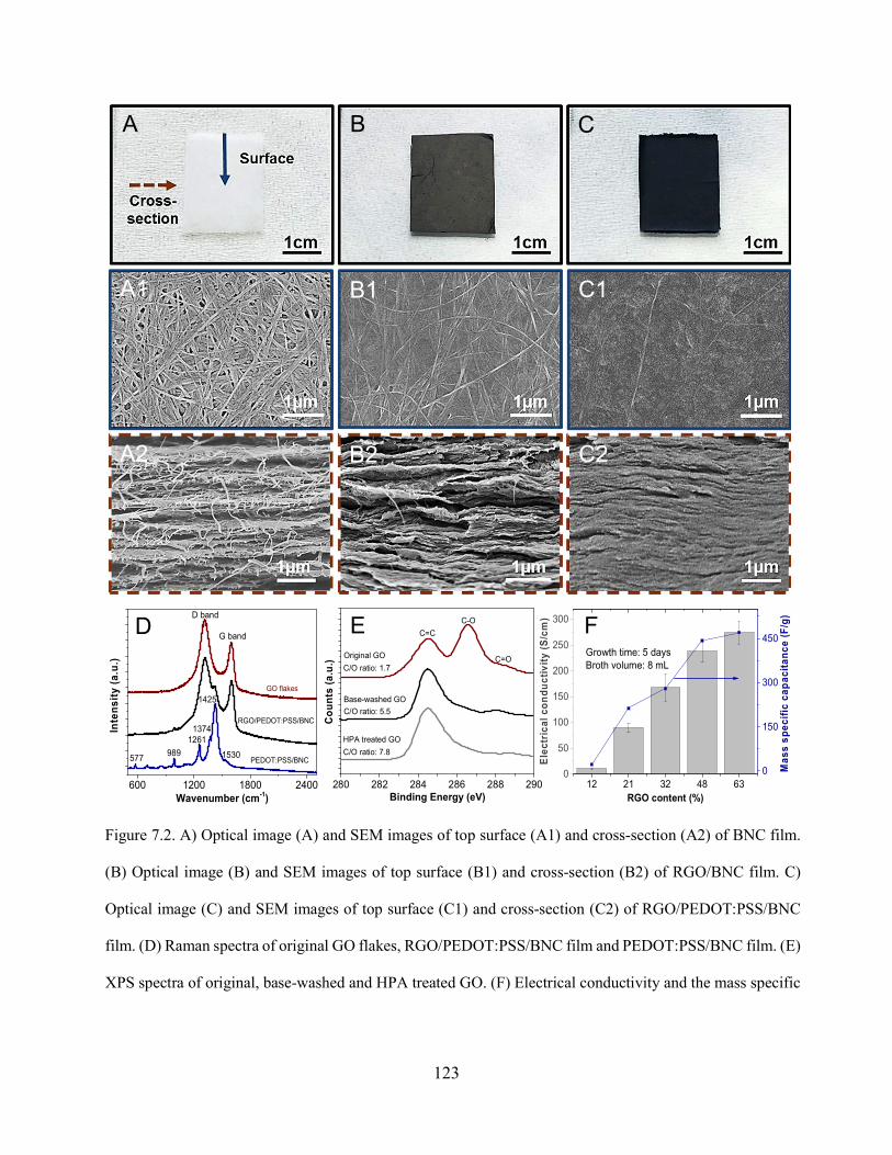
123
Figure 7.2. A) Optical image (A) and SEM images of top surface (A1) and cross-section (A2) of BNC film.
(B) Optical image (B) and SEM images of top surface (B1) and cross-section (B2) of RGO/BNC film. C)
Optical image (C) and SEM images of top surface (C1) and cross-section (C2) of RGO/PEDOT:PSS/BNC
film. (D) Raman spectra of original GO flakes, RGO/PEDOT:PSS/BNC film and PEDOT:PSS/BNC film. (E)
XPS spectra of original, base-washed and HPA treated GO. (F) Electrical conductivity and the mass specific
B
A2
B1
B2
C1
C2
A1
A C
F E D
12 21 32 48 630
50
100
150
200
250
300
RGO content (%)
Ele
ctri
cal
co
nd
uc
tiv
ity
(S/c
m)
Growth time: 5 daysBroth volume: 8 mL
0
150
300
450
Ma
ss s
pe
cifi
c ca
pac
ita
nc
e (F
/g)
600 1200 1800 2400
PEDOT:PSS/BNC
RGO/PEDOT:PSS/BNC
G band
577989
1261
1530
1374Inte
nsi
ty (
a.u
.)
Wavenumber (cm-1)
1425
D band
GO flakes
280 282 284 286 288 290
C/O ratio: 7.8
C/O ratio: 5.5
C/O ratio: 1.7
HPA treated GO
Base-washed GO
Original GO C=O
C-O
Co
un
ts (
a.u
.)
Binding Energy (eV)
C=C

124
capacitance of RGO/PEDOT:PSS/BNC electrodes with different RGO concentrations and fixed PEDOT:PSS
concentration (~0.25 wt%) in the bacterial broth.
Figure 7.3. (A) CV curves of RGO/BNC film, PEDOT:PSS/BNC film and RGO/PEDOT:PSS/BNC electrode. (B)
CV curves of RGO/PEDOT:PSS/BNC electrode at different scan rates (5 to 100 mV/s). (C) Mass specific
capacitance of RGO/PEDOT:PSS/BNC electrode calculated from CV curves as a function of scan rate. (D)
Galvanostatic charging/discharging (GCD) curves of RGO/PEDOT:PSS/BNC electrode. (E) Mass specific
capacitance of RGO/PEDOT:PSS/BNC calculated from GCD curves as a function of current density. (F)
Capacitance retention of RGO/PEDOT:PSS/BNC electrode over 1000 cycles. The inset shows the randomly picked
20 GCD curves.
B A
E F
C
D
0.0 0.2 0.4 0.6 0.8
-1.0
-0.5
0.0
0.5
1.0
Cu
rren
t d
ensi
ty (
A/g
)
Potential (V)
RGO/BNC PEDOT:PSS/BNC RGO/PEDOT:PSS/BNC
0 200 400 600 8000.0
0.2
0.4
0.6
0.8
Po
ten
tia
l (V
)
Time (s)
0.5 A/g 1.0 A/g 2.5 A/g 5.0 A/g
0 200 400 600 800 10000
20
40
60
80
100
Ca
pac
itan
ce r
ete
nti
on
(%
)
Cycle
0 200 400 600 8000.0
0.2
0.4
0.6
0.8
Po
ten
tial (
V)
Time (s)
0 20 40 60 80 1000
50
100
150
200
250
300
350
400
450
Mas
s s
pe
cifi
c c
apac
itan
ce (
F/g
)
Scan rate (mV/s)
0 1 2 3 4 5
200
250
300
350
400
450
500
Ma
ss s
pe
cifi
c ca
pa
cita
nc
e (F
/g)
Current density (A/g)
0.0 0.2 0.4 0.6 0.8
-20
-10
0
10
20
Cu
rre
nt
de
nsi
ty (
A/g
)
Potential (V)
5 mV/s 10 mV/s 25 mV/s 50 mV/s 100 mV/s

125
Figure 7.4. (A) Photographs showing the flexibility of the components (electrode and separator) of device and a schematic showing
the structure of the solid-state supercapacitor device based on RGO/PEDOT:PSS/BNC electrodes. (B) CV curves of assembled
supercapacitor at different scan rate from 5 to 100 mV/s. (C) GCD curves of assembled supercapacitor at different current densities.
(D) CV curves of assembled supercapacitor under different bending angles at a scan rate of 100 mV/s. (E) Cycling stability of
assembled supercapacitor over 4500 cycles. The inset shows randomly picked 10 GCD curves. (F) Optical image showing the
flexibility of assembled supercapacitor. (G) LED indicator lighted by assembled device.
0.0 0.2 0.4 0.6 0.8
-6
-4
-2
0
2
4
6
Cu
rren
t d
ens
ity
(A/g
)
Potential (V)
0 30 60 90 120 180 After 100 repeatly bending to 180
B A
E F
C
D
0 200 400 600 800 1000 1200 14000.0
0.2
0.4
0.6
0.8
Po
ten
tial
(V
)
Time (s)
0.5 A/g 1.0 A/g 2.0 A/g 4.0 A/g 8.0 A/g
G
0 100 200 300 400 5000.0
0.2
0.4
0.6
0.8
Po
ten
tial
(V
)
Time (s)
0.0 0.2 0.4 0.6 0.8
-6
-4
-2
0
2
4
6
Cu
rre
nt
de
ns
ity
(A
/g)
Potential (V)
5 mV/s 10 mV/s 20 mV/s 50 mV/s 100 mV/s
0 1000 2000 3000 40000
20
40
60
80
100
Cap
acit
ance
re
ten
tio
n (
%)
Cycle

126
Chapter 8: Conclusions
8.1 General conclusions
Owing to its desirable properties such as excellent mechanical strength and toughness, rich
chemical functionality, and high specific surface area in aerogel state, bacterial nanocellulose
(BNC) can serve as an ideal matrix for realizing functional composites. Over the last three years,
we have introduced several scalable BNC-based functional composites mainly using a “bacterial
factory” method. By simply introducing functional nanomaterials during the bacteria-mediated
BNC growth, functional nanocomposites can be formed in a scalable, green, and cost-effective
manner. This dissertation demonstrates several examples of BNC-based functional
nanocomposites with applications in sensing, water purification and energy storage.
We have demonstrated a BNC film-based surface enhanced Raman scattering (SERS) substrate,
achieved via gravity-assisted filtration of plasmonic nanostructures. The 3D porous structure and
ultrafine fibers of BNC facilitates uniform and dense adsorption of plasmonic nanostructures on
the surface and in sub-surface regions, which results in large SERS enhancement and excellent
uniformity of SERS activity across the entire substrate. Harnessing the smooth surface of BNC,
we show that BNC-based SERS substrate serves as an ideal platform for collection, detection and
recognition of bacteria.
We have demonstrated a novel, highly scalable, cost-effective and green strategy to realize
functional BNC-based foams/membranes, taking advantage of the bacterial production of BNC.
Functional materials with different dimensions (0D to 3D) such as graphene oxide (GO),
polydopamine (PDA) can be efficiently incorporated within the BNC matrix during its growth.
The functional composites achieved by this approach showed excellent mechanical robustness and

127
flexibility owing to the intercalation of functional materials within the layered BNC matrix, which
is crucial for efficient, large-scale applications, either as a foam or as a membrane.
We have designed and developed a bilayered hybrid biofoam comprised of BNC and RGO for
highly efficient solar steam generation. Owing to the large light absorption, excellent
photothermal conversion, heat localization and efficient transport of water from bulk to
evaporative surface, the novel bilayered structure exhibited a remarkably high solar thermal
efficiency. A flexible, scalable and, more importantly, completely biodegradable photothermal
evaporator for highly efficient solar steam generation has then been demonstrated. The
biodegradable PDA/BNC foam introduced here exhibits large light absorption and photothermal
conversion, heat localization, and efficient water transportation, leading to excellent solar steam
generation performance under one sun. An innovative water filtration membrane based on BNC
and RGO, which harvests sunlight to kill microorganisms has been demonstrated to provide a
novel anti-biofouling approach. The RGO/BNC membrane exhibited outstanding mechanical and
chemical stability and stable water flux under high pressure. Particularly, owing to its
photothermal properties, the membrane exhibited light-enabled bactericidal activity, avoiding the
need for any treatment of the feed water or any external energy.
Additionally, we have demonstrated that the in situ prepared nanocomposites can also serve as a
platform for further uniform modification of other nanomaterials due to the ease of handling and
robustness of the nanocomposites. We have demonstrated a robust filtration membrane based on
BNC loaded with GO and PdNPs which has excellent dye degradation performance for highly
efficient wastewater treatment. The Pd/GO/BNC membrane is realized by post formation of
PdNPs in an in situ prepared GO/BNC membrane. The Pd/GO/BNC membrane exhibited highly
efficient methylene orange (MO) degradation during filtration (over a wide range of MO

128
concentrations, pH and multiple cycles of reuse). Multiple contaminants (a cocktail of 4-
nitrophenol, methylene blue and rhodamine 6G) could also be effectively treated by Pd/GO/BNC
membrane simultaneously during filtration. The Pd/GO/BNC membrane also demonstrated stable
flux under high pressure over long duration.
Furthermore, hybrid functional composites can be realized to achieve optimal performance due to
synergistic effect by introducing multiple functional materials such as GO and poly(3,4-
ehylenedioxythiophene)-poly(styrene sulfonate) (PEDOT:PSS). The obtained RGO-
/PEDOT:PSS/BNC electrodes exhibited excellent electrochemical performance and cycling
stability and they can be easily assembled with a BNC based separator to form a flexible all solid-
state supercapacitor device. The light-weight device showed remarkable mechanical flexibility,
performance stability under extreme mechanical deformation, obviating the need for additional
substrates such as PET.
8.2 Significance and Outlook
In addition to the representative nanocomposites demonstrated in this study, the fabrication
strategies and design principles demonstrated in this work can have far reaching implications to
realize various nanocomposites with applications in water purification, energy harvesting, sensing,
catalysis, and life sciences. Especially with the incorporation of emerging materials (such as GO,
PDA, Mxenes and Metal organic frameworks, etc.), unprecedented multifunctional
nanocomposites can be achieved in a scalable, cost-effective way.
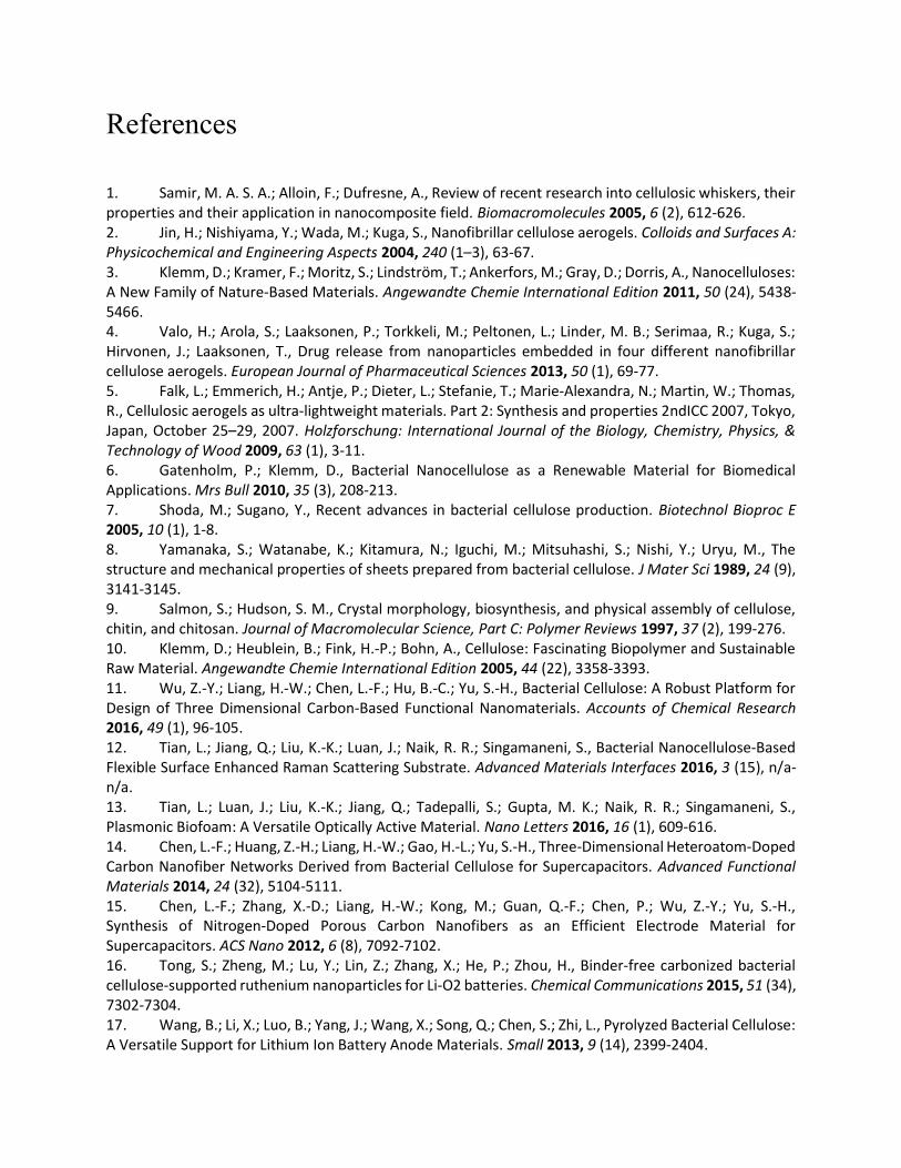
References
1. Samir, M. A. S. A.; Alloin, F.; Dufresne, A., Review of recent research into cellulosic whiskers, their properties and their application in nanocomposite field. Biomacromolecules 2005, 6 (2), 612-626. 2. Jin, H.; Nishiyama, Y.; Wada, M.; Kuga, S., Nanofibrillar cellulose aerogels. Colloids and Surfaces A: Physicochemical and Engineering Aspects 2004, 240 (1–3), 63-67. 3. Klemm, D.; Kramer, F.; Moritz, S.; Lindström, T.; Ankerfors, M.; Gray, D.; Dorris, A., Nanocelluloses: A New Family of Nature-Based Materials. Angewandte Chemie International Edition 2011, 50 (24), 5438-5466. 4. Valo, H.; Arola, S.; Laaksonen, P.; Torkkeli, M.; Peltonen, L.; Linder, M. B.; Serimaa, R.; Kuga, S.; Hirvonen, J.; Laaksonen, T., Drug release from nanoparticles embedded in four different nanofibrillar cellulose aerogels. European Journal of Pharmaceutical Sciences 2013, 50 (1), 69-77. 5. Falk, L.; Emmerich, H.; Antje, P.; Dieter, L.; Stefanie, T.; Marie-Alexandra, N.; Martin, W.; Thomas, R., Cellulosic aerogels as ultra-lightweight materials. Part 2: Synthesis and properties 2ndICC 2007, Tokyo, Japan, October 25–29, 2007. Holzforschung: International Journal of the Biology, Chemistry, Physics, & Technology of Wood 2009, 63 (1), 3-11. 6. Gatenholm, P.; Klemm, D., Bacterial Nanocellulose as a Renewable Material for Biomedical Applications. Mrs Bull 2010, 35 (3), 208-213. 7. Shoda, M.; Sugano, Y., Recent advances in bacterial cellulose production. Biotechnol Bioproc E 2005, 10 (1), 1-8. 8. Yamanaka, S.; Watanabe, K.; Kitamura, N.; Iguchi, M.; Mitsuhashi, S.; Nishi, Y.; Uryu, M., The structure and mechanical properties of sheets prepared from bacterial cellulose. J Mater Sci 1989, 24 (9), 3141-3145. 9. Salmon, S.; Hudson, S. M., Crystal morphology, biosynthesis, and physical assembly of cellulose, chitin, and chitosan. Journal of Macromolecular Science, Part C: Polymer Reviews 1997, 37 (2), 199-276. 10. Klemm, D.; Heublein, B.; Fink, H.-P.; Bohn, A., Cellulose: Fascinating Biopolymer and Sustainable Raw Material. Angewandte Chemie International Edition 2005, 44 (22), 3358-3393. 11. Wu, Z.-Y.; Liang, H.-W.; Chen, L.-F.; Hu, B.-C.; Yu, S.-H., Bacterial Cellulose: A Robust Platform for Design of Three Dimensional Carbon-Based Functional Nanomaterials. Accounts of Chemical Research 2016, 49 (1), 96-105. 12. Tian, L.; Jiang, Q.; Liu, K.-K.; Luan, J.; Naik, R. R.; Singamaneni, S., Bacterial Nanocellulose-Based Flexible Surface Enhanced Raman Scattering Substrate. Advanced Materials Interfaces 2016, 3 (15), n/a-n/a. 13. Tian, L.; Luan, J.; Liu, K.-K.; Jiang, Q.; Tadepalli, S.; Gupta, M. K.; Naik, R. R.; Singamaneni, S., Plasmonic Biofoam: A Versatile Optically Active Material. Nano Letters 2016, 16 (1), 609-616. 14. Chen, L.-F.; Huang, Z.-H.; Liang, H.-W.; Gao, H.-L.; Yu, S.-H., Three-Dimensional Heteroatom-Doped Carbon Nanofiber Networks Derived from Bacterial Cellulose for Supercapacitors. Advanced Functional Materials 2014, 24 (32), 5104-5111. 15. Chen, L.-F.; Zhang, X.-D.; Liang, H.-W.; Kong, M.; Guan, Q.-F.; Chen, P.; Wu, Z.-Y.; Yu, S.-H., Synthesis of Nitrogen-Doped Porous Carbon Nanofibers as an Efficient Electrode Material for Supercapacitors. ACS Nano 2012, 6 (8), 7092-7102. 16. Tong, S.; Zheng, M.; Lu, Y.; Lin, Z.; Zhang, X.; He, P.; Zhou, H., Binder-free carbonized bacterial cellulose-supported ruthenium nanoparticles for Li-O2 batteries. Chemical Communications 2015, 51 (34), 7302-7304. 17. Wang, B.; Li, X.; Luo, B.; Yang, J.; Wang, X.; Song, Q.; Chen, S.; Zhi, L., Pyrolyzed Bacterial Cellulose: A Versatile Support for Lithium Ion Battery Anode Materials. Small 2013, 9 (14), 2399-2404.

2
18. Liang, H.-W.; Guan, Q.-F.; Zhu, Z.; Song, L.-T.; Yao, H.-B.; Lei, X.; Yu, S.-H., Highly conductive and stretchable conductors fabricated from bacterial cellulose. NPG Asia Mater 2012, 4, e19. 19. Olsson, R. T.; Azizi Samir, M. A. S.; Salazar Alvarez, G.; BelovaL; StromV; Berglund, L. A.; IkkalaO; NoguesJ; Gedde, U. W., Making flexible magnetic aerogels and stiff magnetic nanopaper using cellulose nanofibrils as templates. Nat Nano 2010, 5 (8), 584-588. 20. Jiang, Q.; Tian, L.; Liu, K.-K.; Tadepalli, S.; Raliya, R.; Biswas, P.; Naik, R. R.; Singamaneni, S., Bilayered Biofoam for Highly Efficient Solar Steam Generation. Advanced Materials 2016, n/a-n/a. 21. Camden, J. P.; Dieringer, J. A.; Zhao, J.; Van Duyne, R. P., Controlled Plasmonic Nanostructures for Surface-Enhanced Spectroscopy and Sensing. Accounts of Chemical Research 2008, 41 (12), 1653-1661. 22. Ko, H.; Singamaneni, S.; Tsukruk, V. V., Nanostructured Surfaces and Assemblies as SERS Media. Small 2008, 4 (10), 1576-1599. 23. Campion, A.; Kambhampati, P., Surface-enhanced Raman scattering. Chem Soc Rev 1998, 27 (4), 241-250. 24. Li, J. F.; Huang, Y. F.; Ding, Y.; Yang, Z. L.; Li, S. B.; Zhou, X. S.; Fan, F. R.; Zhang, W.; Zhou, Z. Y.; Wu, D. Y.; Ren, B.; Wang, Z. L.; Tian, Z. Q., Shell-isolated nanoparticle-enhanced Raman spectroscopy. Nature 2010, 464 (7287), 392-395. 25. Liu, T. Y.; Tsai, K. T.; Wang, H. H.; Chen, Y.; Chen, Y. H.; Chao, Y. C.; Chang, H. H.; Lin, C. H.; Wang, J. K.; Wang, Y. L., Functionalized arrays of Raman-enhancing nanoparticles for capture and culture-free analysis of bacteria in human blood. Nat Commun 2011, 2. 26. Anker, J. N.; Hall, W. P.; Lyandres, O.; Shah, N. C.; Zhao, J.; Van Duyne, R. P., Biosensing with plasmonic nanosensors. Nat Mater 2008, 7 (6), 442-453. 27. Gandra, N.; Abbas, A.; Tian, L. M.; Singamaneni, S., Plasmonic Planet-Satellite Analogues: Hierarchical Self-Assembly of Gold Nanostructures. Nano Letters 2012, 12 (5), 2645-2651. 28. Moskovits, M., Surface-enhanced Raman spectroscopy: a brief retrospective. Journal of Raman Spectroscopy 2005, 36 (6-7), 485-496. 29. Golightly, R. S.; Doering, W. E.; Natan, M. J., Surface-Enhanced Raman Spectroscopy and Homeland Security: A Perfect Match? ACS Nano 2009, 3 (10), 2859-2869. 30. Homola, J., Surface Plasmon Resonance Sensors for Detection of Chemical and Biological Species. Chemical Reviews 2008, 108 (2), 462-493. 31. Fang, X.; Ahmad, S. R., Detection of explosive vapour using surface-enhanced Raman spectroscopy. Appl. Phys. B 2009, 97 (3), 723-726. 32. Hering, K.; Cialla, D.; Ackermann, K.; Dörfer, T.; Möller, R.; Schneidewind, H.; Mattheis, R.; Fritzsche, W.; Rösch, P.; Popp, J., SERS: a versatile tool in chemical and biochemical diagnostics. Anal Bioanal Chem 2008, 390 (1), 113-124. 33. Stewart, M. E.; Anderton, C. R.; Thompson, L. B.; Maria, J.; Gray, S. K.; Rogers, J. A.; Nuzzo, R. G., Nanostructured Plasmonic Sensors. Chemical Reviews 2008, 108 (2), 494-521. 34. Lee, C. H.; Tian, L. M.; Singamaneni, S., Paper-Based SERS Swab for Rapid Trace Detection on Real-World Surfaces. Acs Appl Mater Inter 2010, 2 (12), 3429-3435. 35. Tian, L.; Morrissey, J. J.; Kattumenu, R.; Gandra, N.; Kharasch, E. D.; Singamaneni, S., Bioplasmonic Paper as a Platform for Detection of Kidney Cancer Biomarkers. Analytical Chemistry 2012, 84 (22), 9928-9934. 36. Martinak, D.; Rudolph, A. In Explosives detection using an ion mobility spectrometer for airport security, Security Technology, 1997. Proceedings. The Institute of Electrical and Electronics Engineers 31st Annual 1997 International Carnahan Conference on, 15-17 Oct 1997; 1997; pp 188-189. 37. Yu, W. W.; White, I. M., Inkjet Printed Surface Enhanced Raman Spectroscopy Array on Cellulose Paper. Analytical Chemistry 2010, 82 (23), 9626-9630. 38. Lee, C. H.; Tian, L.; Singamaneni, S., Paper-Based SERS Swab for Rapid Trace Detection on Real-World Surfaces. ACS Applied Materials & Interfaces 2010, 2 (12), 3429-3435.
3
39. Elimelech, M., The global challenge for adequate and safe water. Journal of Water Supply: Research and Technology - Aqua 2006, 55 (1), 3-10. 40. P-H. Gleick, e. a., The world's Water: The Biennial Report on Freshwater Resources. Island Press: Washington, DC, 2014; Vol. 8. 41. Eliasson, J., The Rising Pressure of Global Water Shortages. Nature 2014, 517 (7532). 42. Shang, W.; Deng, T., Solar steam generation: Steam by thermal concentration. 2016, 1, 16133. 43. Ghasemi, H.; Ni, G.; Marconnet, A. M.; Loomis, J.; Yerci, S.; Miljkovic, N.; Chen, G., Solar steam generation by heat localization. 2014, 5, 4449. 44. Jiang, Q.; Gholami Derami, H.; Ghim, D.; Cao, S.; Jun, Y.-S.; Singamaneni, S., Polydopamine-filled bacterial nanocellulose as a biodegradable interfacial photothermal evaporator for highly efficient solar steam generation. Journal of Materials Chemistry A 2017, 5 (35), 18397-18402. 45. Nair, R. R.; Wu, H. A.; Jayaram, P. N.; Grigorieva, I. V.; Geim, A. K., Unimpeded Permeation of Water Through Helium-Leak–Tight Graphene-Based Membranes. Science 2012, 335 (6067), 442-444. 46. Joshi, R. K.; Alwarappan, S.; Yoshimura, M.; Sahajwalla, V.; Nishina, Y., Graphene oxide: the new membrane material. Applied Materials Today 2015, 1 (1), 1-12. 47. Sun, P.; Wang, K.; Zhu, H., Recent Developments in Graphene-Based Membranes: Structure, Mass-Transport Mechanism and Potential Applications. Advanced Materials 2016, 28 (12), 2287-2310. 48. Mi, B., Graphene Oxide Membranes for Ionic and Molecular Sieving. Science 2014, 343 (6172), 740. 49. Dreyer, D. R.; Park, S.; Bielawski, C. W.; Ruoff, R. S., The chemistry of graphene oxide. Chemical Society Reviews 2010, 39 (1), 228-240. 50. Yeh, C.-N.; Raidongia, K.; Shao, J.; Yang, Q.-H.; Huang, J., On the origin of the stability of graphene oxide membranes in water. Nat Chem 2015, 7 (2), 166-170. 51. Shannon, M. A.; Bohn, P. W.; Elimelech, M.; Georgiadis, J. G.; Marinas, B. J.; Mayes, A. M., Science and technology for water purification in the coming decades. Nature 2008, 452 (7185), 301-310. 52. Singh, R.; Hankins, N., Emerging Membrane Technology for Sustainable Water Treatment. Elsevier 2016. 53. Pendergast, M. M.; Hoek, E. M. V., A review of water treatment membrane nanotechnologies. Energy & Environmental Science 2011, 4 (6), 1946-1971. 54. Le-Clech, P.; Chen, V.; Fane, T. A. G., Fouling in membrane bioreactors used in wastewater treatment. Journal of Membrane Science 2006, 284 (1–2), 17-53. 55. Zhang, R.; Liu, Y.; He, M.; Su, Y.; Zhao, X.; Elimelech, M.; Jiang, Z., Antifouling membranes for sustainable water purification: strategies and mechanisms. Chemical Society Reviews 2016. 56. Flemming, H. C.; Schaule, G.; Griebe, T.; Schmitt, J.; Tamachkiarowa, A., Workshop on Membranes in Drinking Water Production Technical Innovations and Health AspectsBiofouling—the Achilles heel of membrane processes. Desalination 1997, 113 (2), 215-225. 57. Komlenic, R., Rethinking the causes of membrane biofouling. Filtration & separation 2010, 47 (5), 26-28. 58. Baker, J. S.; Dudley, L. Y., Biofouling in membrane systems - A review. Desalination 1998, 118 (1-3), 81-89. 59. Nguyen, T.; Roddick, F. A.; Fan, L., Biofouling of Water Treatment Membranes: A Review of the Underlying Causes, Monitoring Techniques and Control Measures. Membranes 2012, 2 (4), 804-840. 60. Mansouri, J.; Harrisson, S.; Chen, V., Strategies for controlling biofouling in membrane filtration systems: challenges and opportunities. Journal of Materials Chemistry 2010, 20 (22), 4567-4586. 61. Barnes, R. J.; Low, J. H.; Bandi, R. R.; Tay, M.; Chua, F.; Aung, T.; Fane, A. G.; Kjelleberg, S.; Rice, S. A., Nitric Oxide Treatment for the Control of Reverse Osmosis Membrane Biofouling. Applied and Environmental Microbiology 2015, 81 (7), 2515-2524.

4
62. Lade, H.; Paul, D.; Kweon, J. H., Quorum Quenching Mediated Approaches for Control of Membrane Biofouling. International Journal of Biological Sciences 2014, 10 (5), 550-565. 63. Yang, H.-L.; Lin, J. C.-T.; Huang, C., Application of nanosilver surface modification to RO membrane and spacer for mitigating biofouling in seawater desalination. Water Research 2009, 43 (15), 3777-3786. 64. Kumar, A.; Vemula, P. K.; Ajayan, P. M.; John, G., Silver-nanoparticle-embedded antimicrobial paints based on vegetable oil. Nat Mater 2008, 7 (3), 236-241. 65. Perreault, F.; Tousley, M. E.; Elimelech, M., Thin-Film Composite Polyamide Membranes Functionalized with Biocidal Graphene Oxide Nanosheets. Environmental Science & Technology Letters 2014, 1 (1), 71-76. 66. Perreault, F.; Fonseca de Faria, A.; Elimelech, M., Environmental applications of graphene-based nanomaterials. Chemical Society Reviews 2015, 44 (16), 5861-5896. 67. Kochkodan, V.; Hilal, N., A comprehensive review on surface modified polymer membranes for biofouling mitigation. Desalination 2015, 356, 187-207. 68. Ray, J. R.; Tadepalli, S.; Nergiz, S. Z.; Liu, K.-K.; You, L.; Tang, Y.; Singamaneni, S.; Jun, Y.-S., Hydrophilic, Bactericidal Nanoheater-Enabled Reverse Osmosis Membranes to Improve Fouling Resistance. ACS Applied Materials & Interfaces 2015, 7 (21), 11117-11126. 69. Ren, Z. J.; Umble, A. K., Water treatment: Recover wastewater resources locally. Nature 2016, 529 (7584), 25-25. 70. Ahmed, T.; Imdad, S.; Yaldram, K.; Butt, N. M.; Pervez, A., Emerging nanotechnology-based methods for water purification: a review. Desalination and Water Treatment 2014, 52 (22-24), 4089-4101. 71. Khataee, A. R.; Kasiri, M. B., Photocatalytic degradation of organic dyes in the presence of nanostructured titanium dioxide: Influence of the chemical structure of dyes. Journal of Molecular Catalysis A: Chemical 2010, 328 (1), 8-26. 72. Yu, K.; Yang, S.; Liu, C.; Chen, H.; Li, H.; Sun, C.; Boyd, S. A., Degradation of Organic Dyes via Bismuth Silver Oxide Initiated Direct Oxidation Coupled with Sodium Bismuthate Based Visible Light Photocatalysis. Environmental Science & Technology 2012, 46 (13), 7318-7326. 73. Sakkas, V. A.; Islam, M. A.; Stalikas, C.; Albanis, T. A., Photocatalytic degradation using design of experiments: A review and example of the Congo red degradation. Journal of Hazardous Materials 2010, 175 (1), 33-44. 74. Vanhulle, S.; Trovaslet, M.; Enaud, E.; Lucas, M.; Taghavi, S.; van der Lelie, D.; van Aken, B.; Foret, M.; Onderwater, R. C. A.; Wesenberg, D.; Agathos, S. N.; Schneider, Y.-J.; Corbisier, A.-M., Decolorization, Cytotoxicity, and Genotoxicity Reduction During a Combined Ozonation/Fungal Treatment of Dye-Contaminated Wastewater. Environmental Science & Technology 2008, 42 (2), 584-589. 75. Forgacs, E.; Cserháti, T.; Oros, G., Removal of synthetic dyes from wastewaters: a review. Environment International 2004, 30 (7), 953-971. 76. Robinson, T.; McMullan, G.; Marchant, R.; Nigam, P., Remediation of dyes in textile effluent: a critical review on current treatment technologies with a proposed alternative. Bioresource Technology 2001, 77 (3), 247-255. 77. Sun, Y.; Tao, Z.; Chen, J.; Herricks, T.; Xia, Y., Ag Nanowires Coated with Ag/Pd Alloy Sheaths and Their Use as Substrates for Reversible Absorption and Desorption of Hydrogen. Journal of the American Chemical Society 2004, 126 (19), 5940-5941. 78. Deng, Y.; Cai, Y.; Sun, Z.; Liu, J.; Liu, C.; Wei, J.; Li, W.; Liu, C.; Wang, Y.; Zhao, D., Multifunctional Mesoporous Composite Microspheres with Well-Designed Nanostructure: A Highly Integrated Catalyst System. Journal of the American Chemical Society 2010, 132 (24), 8466-8473. 79. Wang, F.; Li, C.; Sun, L.-D.; Xu, C.-H.; Wang, J.; Yu, J. C.; Yan, C.-H., Porous Single-Crystalline Palladium Nanoparticles with High Catalytic Activities. Angewandte Chemie International Edition 2012, 51 (20), 4872-4876.

5
80. Nishihata, Y.; Mizuki, J.; Akao, T.; Tanaka, H.; Uenishi, M.; Kimura, M.; Okamoto, T.; Hamada, N., Self-regeneration of a Pd-perovskite catalyst for automotive emissions control. Nature 2002, 418 (6894), 164-167. 81. Kurt, B. Z.; Durmus, Z.; Durmus, A., Preparation and characterization of platinum (Pt) and palladium (Pd) nanoparticle decorated graphene sheets and their utilization for the elimination of basic fuchsin and indigo carmine dyes. Solid State Sciences 2016, 51, 51-58. 82. Safavi, A.; Momeni, S., Highly efficient degradation of azo dyes by palladium/hydroxyapatite/Fe3O4 nanocatalyst. Journal of Hazardous Materials 2012, 201, 125-131. 83. Jana, N. R.; Wang, Z. L.; Pal, T., Redox Catalytic Properties of Palladium Nanoparticles: Surfactant and Electron Donor−Acceptor Effects. Langmuir 2000, 16 (6), 2457-2463. 84. Rohand, T.; Qin, W.; Boens, N.; Dehaen, W., Palladium-Catalyzed Coupling Reactions for the Functionalization of BODIPY Dyes with Fluorescence Spanning the Visible Spectrum. European Journal of Organic Chemistry 2006, 2006 (20), 4658-4663. 85. Leyva-Pérez, A.; Oliver-Meseguer, J.; Rubio-Marqués, P.; Corma, A., Water-Stabilized Three- and Four-Atom Palladium Clusters as Highly Active Catalytic Species in Ligand-Free CC Cross-Coupling Reactions. Angewandte Chemie International Edition 2013, 52 (44), 11554-11559. 86. Celebi, M.; Yurderi, M.; Bulut, A.; Kaya, M.; Zahmakiran, M., Palladium nanoparticles supported on amine-functionalized SiO 2 for the catalytic hexavalent chromium reduction. Applied Catalysis B: Environmental 2016, 180, 53-64. 87. Adib, M.; Karimi-Nami, R.; Veisi, H., Palladium NPs supported on novel imino-pyridine-functionalized MWCNTs: efficient and highly reusable catalysts for the Suzuki–Miyaura and Sonogashira coupling reactions. New Journal of Chemistry 2016, 40 (6), 4945-4951. 88. Freakley, S. J.; He, Q.; Harrhy, J. H.; Lu, L.; Crole, D. A.; Morgan, D. J.; Ntainjua, E. N.; Edwards, J. K.; Carley, A. F.; Borisevich, A. Y., Palladium-tin catalysts for the direct synthesis of H2O2 with high selectivity. Science 2016, 351 (6276), 965-968. 89. Bhaskar, R.; Joshi, H.; Sharma, A. K.; Singh, A. K., Reusable Catalyst for Transfer Hydrogenation of Aldehydes and Ketones Designed by Anchoring Palladium as Nano-Particles on Graphene Oxide Functionalized with Selenated Amine. ACS Applied Materials & Interfaces 2017. 90. Zhu, W.; Wu, Z.; Foo, G. S.; Gao, X.; Zhou, M.; Liu, B.; Veith, G. M.; Wu, P.; Browning, K. L.; Lee, H. N., Taming interfacial electronic properties of platinum nanoparticles on vacancy-abundant boron nitride nanosheets for enhanced catalysis. Nature communications 2017, 8, 15291. 91. Yang, J.; Tian, C.; Wang, L.; Fu, H., An effective strategy for small-sized and highly-dispersed palladium nanoparticles supported on graphene with excellent performance for formic acid oxidation. Journal of Materials Chemistry 2011, 21 (10), 3384-3390. 92. Wang, Q.; Cui, X.; Chen, J.; Zheng, X.; Liu, C.; Xue, T.; Wang, H.; Jin, Z.; Qiao, L.; Zheng, W., Well-dispersed palladium nanoparticles on graphene oxide as a non-enzymatic glucose sensor. RSC Advances 2012, 2 (15), 6245-6249. 93. Rostamnia, S.; Doustkhah, E.; Karimi, Z.; Amini, S.; Luque, R., Surfactant-Exfoliated Highly Dispersive Pd-Supported Graphene Oxide Nanocomposite as a Catalyst for Aerobic Aqueous Oxidations of Alcohols. ChemCatChem 2015, 7 (11), 1678-1683. 94. Krittayavathananon, A.; Srimuk, P.; Luanwuthi, S.; Sawangphruk, M., Palladium Nanoparticles Decorated on Reduced Graphene Oxide Rotating Disk Electrodes toward Ultrasensitive Hydrazine Detection: Effects of Particle Size and Hydrodynamic Diffusion. Analytical Chemistry 2014, 86 (24), 12272-12278. 95. Huang, Y.-X.; Xie, J.-F.; Zhang, X.; Xiong, L.; Yu, H.-Q., Reduced Graphene Oxide Supported Palladium Nanoparticles via Photoassisted Citrate Reduction for Enhanced Electrocatalytic Activities. ACS Applied Materials & Interfaces 2014, 6 (18), 15795-15801.

6
96. Moussa, S.; Siamaki, A. R.; Gupton, B. F.; El-Shall, M. S., Pd-Partially Reduced Graphene Oxide Catalysts (Pd/PRGO): Laser Synthesis of Pd Nanoparticles Supported on PRGO Nanosheets for Carbon–Carbon Cross Coupling Reactions. ACS Catalysis 2012, 2 (1), 145-154. 97. Jiao, T.; Zhao, H.; Zhou, J.; Zhang, Q.; Luo, X.; Hu, J.; Peng, Q.; Yan, X., Self-Assembly Reduced Graphene Oxide Nanosheet Hydrogel Fabrication by Anchorage of Chitosan/Silver and Its Potential Efficient Application toward Dye Degradation for Wastewater Treatments. ACS Sustainable Chemistry & Engineering 2015, 3 (12), 3130-3139. 98. Zhao, X.; Ma, K.; Jiao, T.; Xing, R.; Ma, X.; Hu, J.; Huang, H.; Zhang, L.; Yan, X., Fabrication of Hierarchical Layer-by-Layer Assembled Diamond-based Core-Shell Nanocomposites as Highly Efficient Dye Absorbents for Wastewater Treatment. Scientific Reports 2017, 7, 44076. 99. Guo, R.; Jiao, T.; Li, R.; Chen, Y.; Guo, W.; Zhang, L.; Zhou, J.; Zhang, Q.; Peng, Q., Sandwiched Fe3O4/Carboxylate Graphene Oxide Nanostructures Constructed by Layer-by-Layer Assembly for Highly Efficient and Magnetically Recyclable Dye Removal. ACS Sustainable Chemistry & Engineering 2018, 6 (1), 1279-1288. 100. Guo, H.; Jiao, T.; Zhang, Q.; Guo, W.; Peng, Q.; Yan, X., Preparation of Graphene Oxide-Based Hydrogels as Efficient Dye Adsorbents for Wastewater Treatment. Nanoscale Research Letters 2015, 10 (1), 272. 101. Sun, T.; Zhang, Z.; Xiao, J.; Chen, C.; Xiao, F.; Wang, S.; Liu, Y., Facile and Green Synthesis of Palladium Nanoparticles-Graphene-Carbon Nanotube Material with High Catalytic Activity. Scientific Reports 2013, 3, 2527. 102. Zhang, Z.; Sun, T.; Chen, C.; Xiao, F.; Gong, Z.; Wang, S., Bifunctional Nanocatalyst Based on Three-Dimensional Carbon Nanotube–Graphene Hydrogel Supported Pd Nanoparticles: One-Pot Synthesis and Its Catalytic Properties. ACS Applied Materials & Interfaces 2014, 6 (23), 21035-21040. 103. Rogers, J. A.; Someya, T.; Huang, Y., Materials and Mechanics for Stretchable Electronics. Science 2010, 327 (5973), 1603-1607. 104. Kim, D.-H.; Song, J.; Choi, W. M.; Kim, H.-S.; Kim, R.-H.; Liu, Z.; Huang, Y. Y.; Hwang, K.-C.; Zhang, Y.-w.; Rogers, J. A., Materials and noncoplanar mesh designs for integrated circuits with linear elastic responses to extreme mechanical deformations. Proceedings of the National Academy of Sciences 2008, 105 (48), 18675-18680. 105. Bae, S.; Kim, H.; Lee, Y.; Xu, X.; Park, J.-S.; Zheng, Y.; Balakrishnan, J.; Lei, T.; Ri Kim, H.; Song, Y. I.; Kim, Y.-J.; Kim, K. S.; Ozyilmaz, B.; Ahn, J.-H.; Hong, B. H.; Iijima, S., Roll-to-roll production of 30-inch graphene films for transparent electrodes. Nat Nano 2010, 5 (8), 574-578. 106. Gelinck, G. H.; Huitema, H. E. A.; van Veenendaal, E.; Cantatore, E.; Schrijnemakers, L.; van der Putten, J. B. P. H.; Geuns, T. C. T.; Beenhakkers, M.; Giesbers, J. B.; Huisman, B.-H.; Meijer, E. J.; Benito, E. M.; Touwslager, F. J.; Marsman, A. W.; van Rens, B. J. E.; de Leeuw, D. M., Flexible active-matrix displays and shift registers based on solution-processed organic transistors. Nat Mater 2004, 3 (2), 106-110. 107. Rogers, J. A.; Bao, Z.; Baldwin, K.; Dodabalapur, A.; Crone, B.; Raju, V. R.; Kuck, V.; Katz, H.; Amundson, K.; Ewing, J.; Drzaic, P., Paper-like electronic displays: Large-area rubber-stamped plastic sheets of electronics and microencapsulated electrophoretic inks. Proceedings of the National Academy of Sciences 2001, 98 (9), 4835-4840. 108. Hammock, M. L.; Chortos, A.; Tee, B. C. K.; Tok, J. B. H.; Bao, Z., 25th Anniversary Article: The Evolution of Electronic Skin (E-Skin): A Brief History, Design Considerations, and Recent Progress. Advanced Materials 2013, 25 (42), 5997-6038. 109. Shao, Y.; El-Kady, M. F.; Wang, L. J.; Zhang, Q.; Li, Y.; Wang, H.; Mousavi, M. F.; Kaner, R. B., Graphene-based materials for flexible supercapacitors. Chemical Society Reviews 2015, 44 (11), 3639-3665. 110. Simon, P.; Gogotsi, Y., Materials for electrochemical capacitors. Nat Mater 2008, 7 (11), 845-854.

7
111. Peng, X.; Peng, L.; Wu, C.; Xie, Y., Two dimensional nanomaterials for flexible supercapacitors. Chemical Society Reviews 2014, 43 (10), 3303-3323. 112. Winter, M.; Brodd, R. J., What Are Batteries, Fuel Cells, and Supercapacitors? (Chem. Rev. 2003, 104, 4245−4269. Published on the Web 09/28/2004.). Chemical Reviews 2005, 105 (3), 1021-1021. 113. Xu, D.; Xu, Q.; Wang, K.; Chen, J.; Chen, Z., Fabrication of Free-Standing Hierarchical Carbon Nanofiber/Graphene Oxide/Polyaniline Films for Supercapacitors. ACS Applied Materials & Interfaces 2014, 6 (1), 200-209. 114. Lu, X.; Wang, G.; Zhai, T.; Yu, M.; Xie, S.; Ling, Y.; Liang, C.; Tong, Y.; Li, Y., Stabilized TiN Nanowire Arrays for High-Performance and Flexible Supercapacitors. Nano Letters 2012, 12 (10), 5376-5381. 115. Lu, X.; Yu, M.; Wang, G.; Zhai, T.; Xie, S.; Ling, Y.; Tong, Y.; Li, Y., H-TiO2@MnO2//H-TiO2@C Core–Shell Nanowires for High Performance and Flexible Asymmetric Supercapacitors. Advanced Materials 2013, 25 (2), 267-272. 116. Wang, G.; Lu, X.; Ling, Y.; Zhai, T.; Wang, H.; Tong, Y.; Li, Y., LiCl/PVA Gel Electrolyte Stabilizes Vanadium Oxide Nanowire Electrodes for Pseudocapacitors. ACS Nano 2012, 6 (11), 10296-10302. 117. Yang, X.; Zhang, F.; Zhang, L.; Zhang, T.; Huang, Y.; Chen, Y., A High-Performance Graphene Oxide-Doped Ion Gel as Gel Polymer Electrolyte for All-Solid-State Supercapacitor Applications. Advanced Functional Materials 2013, 23 (26), 3353-3360. 118. Beidaghi, M.; Gogotsi, Y., Capacitive energy storage in micro-scale devices: recent advances in design and fabrication of micro-supercapacitors. Energy & Environmental Science 2014, 7 (3), 867-884. 119. Yu, D.; Qian, Q.; Wei, L.; Jiang, W.; Goh, K.; Wei, J.; Zhang, J.; Chen, Y., Emergence of fiber supercapacitors. Chemical Society Reviews 2015, 44 (3), 647-662. 120. Zhang, L. L.; Zhao, X. S., Carbon-based materials as supercapacitor electrodes. Chemical Society Reviews 2009, 38 (9), 2520-2531. 121. Jost, K.; Perez, C. R.; McDonough, J. K.; Presser, V.; Heon, M.; Dion, G.; Gogotsi, Y., Carbon coated textiles for flexible energy storage. Energy & Environmental Science 2011, 4 (12), 5060-5067. 122. Hu, L.; Pasta, M.; La Mantia, F.; Cui, L.; Jeong, S.; Deshazer, H. D.; Choi, J. W.; Han, S. M.; Cui, Y., Stretchable, Porous, and Conductive Energy Textiles. Nano Letters 2010, 10 (2), 708-714. 123. Chen, P.-C.; Shen, G.; Shi, Y.; Chen, H.; Zhou, C., Preparation and Characterization of Flexible Asymmetric Supercapacitors Based on Transition-Metal-Oxide Nanowire/Single-Walled Carbon Nanotube Hybrid Thin-Film Electrodes. ACS Nano 2010, 4 (8), 4403-4411. 124. Kaempgen, M.; Chan, C. K.; Ma, J.; Cui, Y.; Gruner, G., Printable Thin Film Supercapacitors Using Single-Walled Carbon Nanotubes. Nano Letters 2009, 9 (5), 1872-1876. 125. El-Kady, M. F.; Strong, V.; Dubin, S.; Kaner, R. B., Laser Scribing of High-Performance and Flexible Graphene-Based Electrochemical Capacitors. Science 2012, 335 (6074), 1326-1330. 126. Zhang, L. L.; Zhao, X.; Stoller, M. D.; Zhu, Y.; Ji, H.; Murali, S.; Wu, Y.; Perales, S.; Clevenger, B.; Ruoff, R. S., Highly Conductive and Porous Activated Reduced Graphene Oxide Films for High-Power Supercapacitors. Nano Letters 2012, 12 (4), 1806-1812. 127. Xu, Y.; Lin, Z.; Huang, X.; Liu, Y.; Huang, Y.; Duan, X., Flexible Solid-State Supercapacitors Based on Three-Dimensional Graphene Hydrogel Films. ACS Nano 2013, 7 (5), 4042-4049. 128. Wu, D.; Zhang, F.; Liang, H.; Feng, X., Nanocomposites and macroscopic materials: assembly of chemically modified graphene sheets. Chemical Society Reviews 2012, 41 (18), 6160-6177. 129. Raccichini, R.; Varzi, A.; Passerini, S.; Scrosati, B., The role of graphene for electrochemical energy storage. Nat Mater 2015, 14 (3), 271-279. 130. Liu, C.; Yu, Z.; Neff, D.; Zhamu, A.; Jang, B. Z., Graphene-Based Supercapacitor with an Ultrahigh Energy Density. Nano Letters 2010, 10 (12), 4863-4868. 131. Yoo, J. J.; Balakrishnan, K.; Huang, J.; Meunier, V.; Sumpter, B. G.; Srivastava, A.; Conway, M.; Mohana Reddy, A. L.; Yu, J.; Vajtai, R.; Ajayan, P. M., Ultrathin Planar Graphene Supercapacitors. Nano Letters 2011, 11 (4), 1423-1427.

8
132. Yu, G.; Hu, L.; Liu, N.; Wang, H.; Vosgueritchian, M.; Yang, Y.; Cui, Y.; Bao, Z., Enhancing the Supercapacitor Performance of Graphene/MnO2 Nanostructured Electrodes by Conductive Wrapping. Nano Letters 2011, 11 (10), 4438-4442. 133. Huang, L.; Chen, D.; Ding, Y.; Feng, S.; Wang, Z. L.; Liu, M., Nickel–Cobalt Hydroxide Nanosheets Coated on NiCo2O4 Nanowires Grown on Carbon Fiber Paper for High-Performance Pseudocapacitors. Nano Letters 2013, 13 (7), 3135-3139. 134. Zhang, J.; Zhao, X. S., Conducting Polymers Directly Coated on Reduced Graphene Oxide Sheets as High-Performance Supercapacitor Electrodes. The Journal of Physical Chemistry C 2012, 116 (9), 5420-5426. 135. Liu, Y.; Weng, B.; Razal, J. M.; Xu, Q.; Zhao, C.; Hou, Y.; Seyedin, S.; Jalili, R.; Wallace, G. G.; Chen, J., High-Performance Flexible All-Solid-State Supercapacitor from Large Free-Standing Graphene-PEDOT/PSS Films. Scientific Reports 2015, 5, 17045. 136. Rauda, I. E.; Augustyn, V.; Dunn, B.; Tolbert, S. H., Enhancing Pseudocapacitive Charge Storage in Polymer Templated Mesoporous Materials. Accounts of Chemical Research 2013, 46 (5), 1113-1124. 137. Wang, D.-W.; Li, F.; Zhao, J.; Ren, W.; Chen, Z.-G.; Tan, J.; Wu, Z.-S.; Gentle, I.; Lu, G. Q.; Cheng, H.-M., Fabrication of Graphene/Polyaniline Composite Paper via In Situ Anodic Electropolymerization for High-Performance Flexible Electrode. ACS Nano 2009, 3 (7), 1745-1752. 138. Cao, X.; Shi, Y.; Shi, W.; Lu, G.; Huang, X.; Yan, Q.; Zhang, Q.; Zhang, H., Preparation of Novel 3D Graphene Networks for Supercapacitor Applications. Small 2011, 7 (22), 3163-3168. 139. Yu, G.; Hu, L.; Vosgueritchian, M.; Wang, H.; Xie, X.; McDonough, J. R.; Cui, X.; Cui, Y.; Bao, Z., Solution-Processed Graphene/MnO2 Nanostructured Textiles for High-Performance Electrochemical Capacitors. Nano Letters 2011, 11 (7), 2905-2911. 140. Wang, Z.; Tammela, P.; Zhang, P.; Huo, J.; Ericson, F.; Stromme, M.; Nyholm, L., Freestanding nanocellulose-composite fibre reinforced 3D polypyrrole electrodes for energy storage applications. Nanoscale 2014, 6 (21), 13068-13075. 141. Zhang, Y.-Z.; Wang, Y.; Cheng, T.; Lai, W.-Y.; Pang, H.; Huang, W., Flexible supercapacitors based on paper substrates: a new paradigm for low-cost energy storage. Chemical Society Reviews 2015, 44 (15), 5181-5199. 142. Gui, Z.; Zhu, H.; Gillette, E.; Han, X.; Rubloff, G. W.; Hu, L.; Lee, S. B., Natural Cellulose Fiber as Substrate for Supercapacitor. ACS Nano 2013, 7 (7), 6037-6046. 143. Hu, L.; Choi, J. W.; Yang, Y.; Jeong, S.; La Mantia, F.; Cui, L.-F.; Cui, Y., Highly conductive paper for energy-storage devices. Proceedings of the National Academy of Sciences 2009, 106 (51), 21490-21494. 144. Hu, L.; Wu, H.; Cui, Y., Printed energy storage devices by integration of electrodes and separators into single sheets of paper. Applied Physics Letters 2010, 96 (18), 183502. 145. Pushparaj, V. L.; Shaijumon, M. M.; Kumar, A.; Murugesan, S.; Ci, L.; Vajtai, R.; Linhardt, R. J.; Nalamasu, O.; Ajayan, P. M., Flexible energy storage devices based on nanocomposite paper. Proceedings of the National Academy of Sciences 2007, 104 (34), 13574-13577. 146. Nishide, H.; Oyaizu, K., Toward Flexible Batteries. Science 2008, 319 (5864), 737-738. 147. Jiang, Q.; Tian, L.; Liu, K.-K.; Tadepalli, S.; Raliya, R.; Biswas, P.; Naik, R. R.; Singamaneni, S., Bilayered Biofoam for Highly Efficient Solar Steam Generation. Advanced Materials 2016, 28 (42), 9400-9407. 148. Tian, L.; Jiang, Q.; Liu, K.-K.; Luan, J.; Naik, R. R.; Singamaneni, S., Bacterial Nanocellulose-Based Flexible Surface Enhanced Raman Scattering Substrate. Advanced Materials Interfaces 2016, 3 (15), 1600214-n/a. 149. Kang, Y. J.; Chun, S.-J.; Lee, S.-S.; Kim, B.-Y.; Kim, J. H.; Chung, H.; Lee, S.-Y.; Kim, W., All-Solid-State Flexible Supercapacitors Fabricated with Bacterial Nanocellulose Papers, Carbon Nanotubes, and Triblock-Copolymer Ion Gels. ACS Nano 2012, 6 (7), 6400-6406.

9
150. Chen, L.-F.; Huang, Z.-H.; Liang, H.-W.; Guan, Q.-F.; Yu, S.-H., Bacterial-Cellulose-Derived Carbon Nanofiber@MnO2 and Nitrogen-Doped Carbon Nanofiber Electrode Materials: An Asymmetric Supercapacitor with High Energy and Power Density. Advanced Materials 2013, 25 (34), 4746-4752. 151. Wang, H.; Zhu, E.; Yang, J.; Zhou, P.; Sun, D.; Tang, W., Bacterial Cellulose Nanofiber-Supported Polyaniline Nanocomposites with Flake-Shaped Morphology as Supercapacitor Electrodes. The Journal of Physical Chemistry C 2012, 116 (24), 13013-13019. 152. Li, S.; Huang, D.; Zhang, B.; Xu, X.; Wang, M.; Yang, G.; Shen, Y., Flexible Supercapacitors Based on Bacterial Cellulose Paper Electrodes. Advanced Energy Materials 2014, 4 (10), 1301655-n/a. 153. Liu, R.; Ma, L.; Huang, S.; Mei, J.; Xu, J.; Yuan, G., A flexible polyaniline/graphene/bacterial cellulose supercapacitor electrode. New Journal of Chemistry 2017, 41 (2), 857-864. 154. Wang, F.; Kim, H.-J.; Park, S.; Kee, C.-D.; Kim, S.-J.; Oh, I.-K., Bendable and flexible supercapacitor based on polypyrrole-coated bacterial cellulose core-shell composite network. Composites Science and Technology 2016, 128, 33-40. 155. Wang, X.; Kong, D.; Zhang, Y.; Wang, B.; Li, X.; Qiu, T.; Song, Q.; Ning, J.; Song, Y.; Zhi, L., All-biomaterial supercapacitor derived from bacterial cellulose. Nanoscale 2016, 8 (17), 9146-9150. 156. Wang, X.; Kong, D.; Wang, B.; Song, Y.; Zhi, L., Activated pyrolysed bacterial cellulose as electrodes for supercapacitors. Science China Chemistry 2016, 59 (6), 713-718. 157. Martinez, A. W.; Phillips, S. T.; Butte, M. J.; Whitesides, G. M., Patterned paper as a platform for inexpensive, low-volume, portable bioassays. Angew Chem Int Edit 2007, 46 (8), 1318-1320. 158. Zhao, W. A.; van den Berg, A., Lab on paper. Lab Chip 2008, 8 (12), 1988-1991. 159. Cheng, C. M.; Martinez, A. W.; Gong, J. L.; Mace, C. R.; Phillips, S. T.; Carrilho, E.; Mirica, K. A.; Whitesides, G. M., Paper-Based ELISA. Angew Chem Int Edit 2010, 49 (28), 4771-4774. 160. Derda, R.; Laromaine, A.; Mammoto, A.; Tang, S. K. Y.; Mammoto, T.; Ingber, D. E.; Whitesides, G. M., Paper-supported 3D cell culture for tissue-based bioassays. P Natl Acad Sci USA 2009, 106 (44), 18457-18462. 161. Pardee, K.; Green, A. A.; Ferrante, T.; Cameron, D. E.; DaleyKeyser, A.; Yin, P.; Collins, J. J., Paper-Based Synthetic Gene Networks. Cell 2014, 159 (4), 940-954. 162. Zhu, H.; Fang, Z.; Preston, C.; Li, Y.; Hu, L., Transparent paper: fabrications, properties, and device applications. Energy & Environmental Science 2014, 7 (1), 269-287. 163. Lee, C. H.; Hankus, M. E.; Tian, L.; Pellegrino, P. M.; Singamaneni, S., Highly Sensitive Surface Enhanced Raman Scattering Substrates Based on Filter Paper Loaded with Plasmonic Nanostructures. Analytical Chemistry 2011, 83 (23), 8953-8958. 164. Abbas, A.; Brimer, A.; Slocik, J. M.; Tian, L.; Naik, R. R.; Singamaneni, S., Multifunctional Analytical Platform on a Paper Strip: Separation, Preconcentration, and Subattomolar Detection. Analytical Chemistry 2013, 85 (8), 3977-3983. 165. Jaiswal, A.; Tian, L. M.; Tadepalli, S.; Liu, K. K.; Fei, M.; Farrell, M. E.; Pellegrino, P. M.; Singamaneni, S., Plasmonic Nanorattles with Intrinsic Electromagnetic Hot-Spots for Surface Enhanced Raman Scattering. Small 2014, 10 (21), 4287-4292. 166. Tian, L.; Luan, J.; Liu, K.-K.; Jiang, Q.; Tadepalli, S.; Gupta, M. K.; Naik, R. R.; Singamaneni, S., Plasmonic Biofoam: A Versatile Optically Active Material. Nano Letters 2015. 167. Orendorff, C. J.; Murphy, C. J., Quantitation of Metal Content in the Silver-Assisted Growth of Gold Nanorods. J. Phys. Chem. B 2006, 110 (9), 3990-3994. 168. Huang, X.; Neretina, S.; El-Sayed, M. A., Gold Nanorods: From Synthesis and Properties to Biological and Biomedical Applications. Adv. Mater. 2009, 21 (48), 4880-4910. 169. Sengupta, A.; Mujacic, M.; Davis, E. J., Detection of bacteria by surface-enhanced Raman spectroscopy. Anal Bioanal Chem 2006, 386 (5), 1379-1386. 170. Cannon, R. E.; Anderson, S. M., Biogenesis of Bacterial Cellulose. Crit Rev Microbiol 1991, 17 (6), 435-447.
10
171. Klemm, D.; Schumann, D.; Udhardt, U.; Marsch, S., Bacterial synthesized cellulose — artificial blood vessels for microsurgery. Progress in Polymer Science 2001, 26 (9), 1561-1603. 172. Jonas, R.; Farah, L. F., Production and application of microbial cellulose. Polym Degrad Stabil 1998, 59 (1-3), 101-106. 173. Huang, X. H.; Neretina, S.; El-Sayed, M. A., Gold Nanorods: From Synthesis and Properties to Biological and Biomedical Applications. Adv Mater 2009, 21 (48), 4880-4910. 174. Tian, L.; Chen, E.; Gandra, N.; Abbas, A.; Singamaneni, S., Gold Nanorods as Plasmonic Nanotransducers: Distance-Dependent Refractive Index Sensitivity. Langmuir 2012, 28 (50), 17435-17442. 175. Abbas, A.; Tian, L.; Morrissey, J. J.; Kharasch, E. D.; Singamaneni, S., Hot Spot-Localized Artificial Antibodies for Label-Free Plasmonic Biosensing. Advanced Functional Materials 2013, 23 (14), 1789-1797. 176. Wang, Y.; Heim, L.-O.; Xu, Y.; Buntkowsky, G.; Zhang, K., Transparent, Stimuli-Responsive Films from Cellulose-Based Organogel Nanoparticles. Advanced Functional Materials 2015, 25 (9), 1434-1441. 177. El-Sayed, M. A., Some Interesting Properties of Metals Confined in Time and Nanometer Space of Different Shapes. Accounts of Chemical Research 2001, 34 (4), 257-264. 178. Jain, P. K.; El-Sayed, M. A., Noble Metal Nanoparticle Pairs: Effect of Medium for Enhanced Nanosensing. Nano Letters 2008, 8 (12), 4347-4352. 179. Martinez, A. W.; Phillips, S. T.; Butte, M. J.; Whitesides, G. M., Patterned Paper as a Platform for Inexpensive, Low-Volume, Portable Bioassays. Angewandte Chemie International Edition 2007, 46 (8), 1318-1320. 180. Habibi, Y.; Lucia, L. A.; Rojas, O. J., Cellulose Nanocrystals: Chemistry, Self-Assembly, and Applications. Chemical Reviews 2010, 110 (6), 3479-3500. 181. Schmucker, A. L.; Tadepalli, S.; Liu, K.-K.; Sullivan, C. J.; Singamaneni, S.; Naik, R. R., Plasmonic paper: a porous and flexible substrate enabling nanoparticle-based combinatorial chemistry. RSC Advances 2016, 6 (5), 4136-4144. 182. Vosgröne, T.; Meixner, A. J., Surface- and Resonance-Enhanced Micro-Raman Spectroscopy of Xanthene Dyes: From the Ensemble to Single Molecules. ChemPhysChem 2005, 6 (1), 154-163. 183. Tian, L.; Tadepalli, S.; Farrell, M. E.; Liu, K.-K.; Gandra, N.; Pellegrino, P. M.; Singamaneni, S., Multiplexed charge-selective surface enhanced Raman scattering based on plasmonic calligraphy. Journal of Materials Chemistry C 2014, 2 (27), 5438-5446. 184. Stiles, P. L.; Dieringer, J. A.; Shah, N. C.; Van Duyne, R. P., Surface-Enhanced Raman Spectroscopy. Annual Review of Analytical Chemistry 2008, 1 (1), 601-626. 185. Fan, C.; Hu, Z.; Mustapha, A.; Lin, M., Rapid detection of food- and waterborne bacteria using surface-enhanced Raman spectroscopy coupled with silver nanosubstrates. Appl Microbiol Biotechnol 2011, 92 (5), 1053-1061. 186. Zhou, Q.; He, Y.; Abell, J.; Zhang, Z.; Zhao, Y., Surface-enhanced Raman scattering from helical silver nanorod arrays. Chemical Communications 2011, 47 (15), 4466-4468. 187. Walter, A.; Marz, A.; Schumacher, W.; Rosch, P.; Popp, J., Towards a fast, high specific and reliable discrimination of bacteria on strain level by means of SERS in a microfluidic device. Lab Chip 2011, 11 (6), 1013-1021. 188. Zhou, H.; Yang, D.; Ivleva, N. P.; Mircescu, N. E.; Niessner, R.; Haisch, C., SERS Detection of Bacteria in Water by in Situ Coating with Ag Nanoparticles. Analytical Chemistry 2014, 86 (3), 1525-1533. 189. Neugebauer, U.; Rösch, P.; Schmitt, M.; Popp, J.; Julien, C.; Rasmussen, A.; Budich, C.; Deckert, V., On the Way to Nanometer-Sized Information of the Bacterial Surface by Tip-Enhanced Raman Spectroscopy. ChemPhysChem 2006, 7 (7), 1428-1430. 190. Chu, H.; Huang, Y.; Zhao, Y., Silver Nanorod Arrays as a Surface-Enhanced Raman Scattering Substrate for Foodborne Pathogenic Bacteria Detection. Appl. Spectrosc. 2008, 62 (8), 922-931. 191. Chung, C.; Kim, Y.-K.; Shin, D.; Ryoo, S.-R.; Hong, B. H.; Min, D.-H., Biomedical Applications of Graphene and Graphene Oxide. Accounts of Chemical Research 2013, 46 (10), 2211-2224.
11
192. Gonçalves, G.; Vila, M.; Portolés, M.-T.; Vallet-Regi, M.; Gracio, J.; Marques, P. A. A. P., Nano-Graphene Oxide: A Potential Multifunctional Platform for Cancer Therapy. Advanced Healthcare Materials 2013, 2 (8), 1072-1090. 193. Nergiz, S. Z.; Gandra, N.; Tadepalli, S.; Singamaneni, S., Multifunctional Hybrid Nanopatches of Graphene Oxide and Gold Nanostars for Ultraefficient Photothermal Cancer Therapy. ACS Applied Materials & Interfaces 2014, 6 (18), 16395-16402. 194. Yang, K.; Zhang, S.; Zhang, G.; Sun, X.; Lee, S.-T.; Liu, Z., Graphene in Mice: Ultrahigh In Vivo Tumor Uptake and Efficient Photothermal Therapy. Nano Letters 2010, 10 (9), 3318-3323. 195. Robinson, J. T.; Tabakman, S. M.; Liang, Y.; Wang, H.; Sanchez Casalongue, H.; Vinh, D.; Dai, H., Ultrasmall Reduced Graphene Oxide with High Near-Infrared Absorbance for Photothermal Therapy. Journal of the American Chemical Society 2011, 133 (17), 6825-6831. 196. Wang, W.-N.; Jiang, Y.; Biswas, P., Evaporation-Induced Crumpling of Graphene Oxide Nanosheets in Aerosolized Droplets: Confinement Force Relationship. The Journal of Physical Chemistry Letters 2012, 3 (21), 3228-3233. 197. Jiang, Y.; Wang, W.-N.; Biswas, P.; Fortner, J. D., Facile Aerosol Synthesis and Characterization of Ternary Crumpled Graphene–TiO2–Magnetite Nanocomposites for Advanced Water Treatment. ACS Applied Materials & Interfaces 2014, 6 (14), 11766-11774. 198. Zhu, Y.; Murali, S.; Cai, W.; Li, X.; Suk, J. W.; Potts, J. R.; Ruoff, R. S., Graphene and Graphene Oxide: Synthesis, Properties, and Applications. Advanced Materials 2010, 22 (35), 3906-3924. 199. Yin, Z.; Sun, S.; Salim, T.; Wu, S.; Huang, X.; He, Q.; Lam, Y. M.; Zhang, H., Organic Photovoltaic Devices Using Highly Flexible Reduced Graphene Oxide Films as Transparent Electrodes. ACS Nano 2010, 4 (9), 5263-5268. 200. Kumar, P. V.; Bardhan, N. M.; Tongay, S.; Wu, J.; Belcher, A. M.; Grossman, J. C., Scalable enhancement of graphene oxide properties by thermally driven phase transformation. Nat Chem 2014, 6 (2), 151-158. 201. Gatenholm, P.; Klemm, D., Bacterial Nanocellulose as a Renewable Material for Biomedical Applications. MRS Bulletin 2010, 35 (03), 208-213. 202. Marcano, D. C.; Kosynkin, D. V.; Berlin, J. M.; Sinitskii, A.; Sun, Z.; Slesarev, A.; Alemany, L. B.; Lu, W.; Tour, J. M., Improved Synthesis of Graphene Oxide. ACS Nano 2010, 4 (8), 4806-4814. 203. Poletto, M.; Pistor, V.; Santana, R. M. C.; Zattera, A. J., Materials produced from plant biomass: part II: evaluation of crystallinity and degradation kinetics of cellulose. Materials Research 2012, 15, 421-427. 204. Rourke, J. P.; Pandey, P. A.; Moore, J. J.; Bates, M.; Kinloch, I. A.; Young, R. J.; Wilson, N. R., The Real Graphene Oxide Revealed: Stripping the Oxidative Debris from the Graphene-like Sheets. Angewandte Chemie International Edition 2011, 50 (14), 3173-3177. 205. Ghasemi, H.; Ni, G.; Marconnet, A. M.; Loomis, J.; Yerci, S.; Miljkovic, N.; Chen, G., Solar steam generation by heat localization. Nat Commun 2014, 5. 206. Kulkarni, D. D.; Choi, I.; Singamaneni, S. S.; Tsukruk, V. V., Graphene Oxide−Polyelectrolyte Nanomembranes. ACS Nano 2010, 4 (8), 4667-4676. 207. Yang, D.; Velamakanni, A.; Bozoklu, G.; Park, S.; Stoller, M.; Piner, R. D.; Stankovich, S.; Jung, I.; Field, D. A.; Ventrice Jr, C. A.; Ruoff, R. S., Chemical analysis of graphene oxide films after heat and chemical treatments by X-ray photoelectron and Micro-Raman spectroscopy. Carbon 2009, 47 (1), 145-152. 208. Hu, K.; Tolentino, L. S.; Kulkarni, D. D.; Ye, C.; Kumar, S.; Tsukruk, V. V., Written-in Conductive Patterns on Robust Graphene Oxide Biopaper by Electrochemical Microstamping. Angewandte Chemie International Edition 2013, 52 (51), 13784-13788. 209. Jung, R.; Kim, H.-S.; Kim, Y.; Kwon, S.-M.; Lee, H. S.; Jin, H.-J., Electrically conductive transparent papers using multiwalled carbon nanotubes. Journal of Polymer Science Part B: Polymer Physics 2008, 46 (12), 1235-1242.

12
210. Hu, W.; Chen, S.; Yang, Z.; Liu, L.; Wang, H., Flexible Electrically Conductive Nanocomposite Membrane Based on Bacterial Cellulose and Polyaniline. The Journal of Physical Chemistry B 2011, 115 (26), 8453-8457. 211. Nandgaonkar, A. G.; Wang, Q.; Fu, K.; Krause, W. E.; Wei, Q.; Gorga, R.; A. Lucia, L., A one-pot biosynthesis of reduced graphene oxide (RGO)/bacterial cellulose (BC) nanocomposites. Green Chemistry 2014, 16 (6), 3195-3201. 212. Kulkarni, D. D.; Kim, S.; Chyasnavichyus, M.; Hu, K.; Fedorov, A. G.; Tsukruk, V. V., Chemical Reduction of Individual Graphene Oxide Sheets as Revealed by Electrostatic Force Microscopy. Journal of the American Chemical Society 2014, 136 (18), 6546-6549. 213. Acik, M.; Lee, G.; Mattevi, C.; Pirkle, A.; Wallace, R. M.; Chhowalla, M.; Cho, K.; Chabal, Y., The Role of Oxygen during Thermal Reduction of Graphene Oxide Studied by Infrared Absorption Spectroscopy. The Journal of Physical Chemistry C 2011, 115 (40), 19761-19781. 214. Thomas, H. R.; Day, S. P.; Woodruff, W. E.; Vallés, C.; Young, R. J.; Kinloch, I. A.; Morley, G. W.; Hanna, J. V.; Wilson, N. R.; Rourke, J. P., Deoxygenation of Graphene Oxide: Reduction or Cleaning? Chemistry of Materials 2013, 25 (18), 3580-3588. 215. Ramires, M. L. V.; Nieto de Castro, C. A.; Nagasaka, Y.; Nagashima, A.; Assael, M. J.; Wakeham, W. A., Standard Reference Data for the Thermal Conductivity of Water. Journal of Physical and Chemical Reference Data 1995, 24 (3), 1377-1381. 216. Liu, Y.; Yu, S.; Feng, R.; Bernard, A.; Liu, Y.; Zhang, Y.; Duan, H.; Shang, W.; Tao, P.; Song, C.; Deng, T., A Bioinspired, Reusable, Paper-Based System for High-Performance Large-Scale Evaporation. Advanced Materials 2015, 27 (17), 2768-2774. 217. Gratzel, M., Photoelectrochemical cells. Nature 2001, 414 (6861), 338-344. 218. Van de Ven, J. D., Mobile hydraulic power supply: Liquid piston Stirling engine pump. Renewable Energy 2009, 34 (11), 2317-2322. 219. Gupta, M. K.; Kaushik, S. C., Exergy analysis and investigation for various feed water heaters of direct steam generation solar–thermal power plant. Renewable Energy 2010, 35 (6), 1228-1235. 220. Zarza, E.; Valenzuela, L.; León, J.; Hennecke, K.; Eck, M.; Weyers, H. D.; Eickhoff, M., Direct steam generation in parabolic troughs: Final results and conclusions of the DISS project. Energy 2004, 29 (5–6), 635-644. 221. Elimelech, M.; Phillip, W. A., The Future of Seawater Desalination: Energy, Technology, and the Environment. Science 2011, 333 (6043), 712-717. 222. Karagiannis, I. C.; Soldatos, P. G., Water desalination cost literature: review and assessment. Desalination 2008, 223 (1–3), 448-456. 223. Neumann, O.; Urban, A. S.; Day, J.; Lal, S.; Nordlander, P.; Halas, N. J., Solar Vapor Generation Enabled by Nanoparticles. ACS Nano 2013, 7 (1), 42-49. 224. Shang, W.; Deng, T., Solar steam generation: Steam by thermal concentration. Nature Energy 2016, 1, 16133. 225. Hu, X.; Xu, W.; Zhou, L.; Tan, Y.; Wang, Y.; Zhu, S.; Zhu, J., Tailoring Graphene Oxide-Based Aerogels for Efficient Solar Steam Generation under One Sun. Advanced Materials 2017, 29 (5), 1604031-n/a. 226. Ito, Y.; Tanabe, Y.; Han, J.; Fujita, T.; Tanigaki, K.; Chen, M., Multifunctional Porous Graphene for High-Efficiency Steam Generation by Heat Localization. Advanced Materials 2015, 27 (29), 4302-4307. 227. Zhou, L.; Tan, Y.; Wang, J.; Xu, W.; Yuan, Y.; Cai, W.; Zhu, S.; Zhu, J., 3D self-assembly of aluminium nanoparticles for plasmon-enhanced solar desalination. Nat Photon 2016, 10 (6), 393-398. 228. Liu, K.-K.; Jiang, Q.; Tadepalli, S.; Raliya, R.; Biswas, P.; Naik, R. R.; Singamaneni, S., Wood–Graphene Oxide Composite for Highly Efficient Solar Steam Generation and Desalination. ACS Applied Materials & Interfaces 2017, 9 (8), 7675-7681. 229. Zhang, P.; Li, J.; Lv, L.; Zhao, Y.; Qu, L., Vertically Aligned Graphene Sheets Membrane for Highly Efficient Solar Thermal Generation of Clean Water. ACS Nano 2017.
13
230. Li, R.; Zhang, L.; Shi, L.; Wang, P., MXene Ti3C2: An Effective 2D Light-to-Heat Conversion Material. ACS Nano 2017, 11 (4), 3752-3759. 231. Li, Y.; Gao, T.; Yang, Z.; Chen, C.; Luo, W.; Song, J.; Hitz, E.; Jia, C.; Zhou, Y.; Liu, B.; Yang, B.; Hu, L., 3D-Printed, All-in-One Evaporator for High-Efficiency Solar Steam Generation under 1 Sun Illumination. Advanced Materials, 1700981-n/a. 232. Li, X.; Xu, W.; Tang, M.; Zhou, L.; Zhu, B.; Zhu, S.; Zhu, J., Graphene oxide-based efficient and scalable solar desalination under one sun with a confined 2D water path. Proceedings of the National Academy of Sciences 2016, 113 (49), 13953-13958. 233. Zhou, L.; Tan, Y.; Ji, D.; Zhu, B.; Zhang, P.; Xu, J.; Gan, Q.; Yu, Z.; Zhu, J., Self-assembly of highly efficient, broadband plasmonic absorbers for solar steam generation. Science Advances 2016, 2 (4). 234. Wang, J.; Li, Y.; Deng, L.; Wei, N.; Weng, Y.; Dong, S.; Qi, D.; Qiu, J.; Chen, X.; Wu, T., High-Performance Photothermal Conversion of Narrow-Bandgap Ti2O3 Nanoparticles. Advanced Materials 2017, 29 (3), 1603730-n/a. 235. Ni, G.; Li, G.; Boriskina, Svetlana V.; Li, H.; Yang, W.; Zhang, T.; Chen, G., Steam generation under one sun enabled by a floating structure with thermal concentration. Nature Energy 2016, 1, 16126. 236. Zhang, L.; Tang, B.; Wu, J.; Li, R.; Wang, P., Hydrophobic Light-to-Heat Conversion Membranes with Self-Healing Ability for Interfacial Solar Heating. Advanced Materials 2015, 27 (33), 4889-4894. 237. Wang, G.; Fu, Y.; Ma, X.; Pi, W.; Liu, D.; Wang, X., Reusable reduced graphene oxide based double-layer system modified by polyethylenimine for solar steam generation. Carbon 2017, 114, 117-124. 238. Klaine, S. J.; Alvarez, P. J. J.; Batley, G. E.; Fernandes, T. F.; Handy, R. D.; Lyon, D. Y.; Mahendra, S.; McLaughlin, M. J.; Lead, J. R., Nanomaterials in the environment: Behavior, fate, bioavailability, and effects. Environmental Toxicology and Chemistry 2008, 27 (9), 1825-1851. 239. Mattsson, K.; Hansson, L. A.; Cedervall, T., Nano-plastics in the aquatic environment. Environmental Science: Processes & Impacts 2015, 17 (10), 1712-1721. 240. Ciglenečki, I.; Svetličić, V., Nanoparticles and Marine Environment: An Overview. In Nanotechnology to Aid Chemical and Biological Defense, Camesano, T. A., Ed. Springer Netherlands: Dordrecht, 2015; pp 95-111. 241. Wu, B.; Torres-Duarte, C.; Cole, B. J.; Cherr, G. N., Copper Oxide and Zinc Oxide Nanomaterials Act as Inhibitors of Multidrug Resistance Transport in Sea Urchin Embryos: Their Role as Chemosensitizers. Environmental Science & Technology 2015, 49 (9), 5760-5770. 242. Wang, Z.; Zhang, L.; Zhao, J.; Xing, B., Environmental processes and toxicity of metallic nanoparticles in aquatic systems as affected by natural organic matter. Environmental Science: Nano 2016, 3 (2), 240-255. 243. Lee, H.; Dellatore, S. M.; Miller, W. M.; Messersmith, P. B., Mussel-Inspired Surface Chemistry for Multifunctional Coatings. Science 2007, 318 (5849), 426. 244. Liu, Y.; Ai, K.; Lu, L., Polydopamine and Its Derivative Materials: Synthesis and Promising Applications in Energy, Environmental, and Biomedical Fields. Chemical Reviews 2014, 114 (9), 5057-5115. 245. Liebscher, J.; Mrówczyński, R.; Scheidt, H. A.; Filip, C.; Hădade, N. D.; Turcu, R.; Bende, A.; Beck, S., Structure of Polydopamine: A Never-Ending Story? Langmuir 2013, 29 (33), 10539-10548. 246. d’Ischia, M.; Napolitano, A.; Ball, V.; Chen, C.-T.; Buehler, M. J., Polydopamine and Eumelanin: From Structure–Property Relationships to a Unified Tailoring Strategy. Accounts of Chemical Research 2014, 47 (12), 3541-3550. 247. Black, K. C. L.; Yi, J.; Rivera, J. G.; Zelasko-Leon, D. C.; Messersmith, P. B., Polydopamine-enabled surface functionalization of gold nanorods for cancer cell-targeted imaging and photothermal therapy. Nanomedicine 2012, 8 (1), 17-28. 248. Liu, Y.; Ai, K.; Liu, J.; Deng, M.; He, Y.; Lu, L., Dopamine-Melanin Colloidal Nanospheres: An Efficient Near-Infrared Photothermal Therapeutic Agent for In Vivo Cancer Therapy. Advanced Materials 2013, 25 (9), 1353-1359.

14
249. Stritzker, J.; Kirscher, L.; Scadeng, M.; Deliolanis, N. C.; Morscher, S.; Symvoulidis, P.; Schaefer, K.; Zhang, Q.; Buckel, L.; Hess, M.; Donat, U.; Bradley, W. G.; Ntziachristos, V.; Szalay, A. A., Vaccinia virus-mediated melanin production allows MR and optoacoustic deep tissue imaging and laser-induced thermotherapy of cancer. Proceedings of the National Academy of Sciences 2013, 110 (9), 3316-3320. 250. Carpenter, A. W.; de Lannoy, C.-F.; Wiesner, M. R., Cellulose Nanomaterials in Water Treatment Technologies. Environmental Science & Technology 2015, 49 (9), 5277-5287. 251. Ai, K.; Liu, Y.; Ruan, C.; Lu, L.; Lu, G., Sp2 C-Dominant N-Doped Carbon Sub-micrometer Spheres with a Tunable Size: A Versatile Platform for Highly Efficient Oxygen-Reduction Catalysts. Advanced Materials 2013, 25 (7), 998-1003. 252. SIDDIQUI, S. A.; DWIVEDI, A.; SINGH, P. K.; HASAN, T.; JAIN, S.; SUNDARAGANESAN, N.; SALEEM, H.; MISRA, N., VIBRATIONAL DYNAMICS AND POTENTIAL ENERGY DISTRIBUTION OF TWO WELL-KNOWN NEUROTRANSMITTER RECEPTORS: TYRAMINE AND DOPAMINE HYDROCHLORIDE. Journal of Theoretical and Computational Chemistry 2009, 08 (03), 433-450. 253. Cheng, G.; Zheng, S.-Y., Construction of a high-performance magnetic enzyme nanosystem for rapid tryptic digestion. Scientific Reports 2014, 4, 6947. 254. Xue, G.; Liu, K.; Chen, Q.; Yang, P.; Li, J.; Ding, T.; Duan, J.; Qi, B.; Zhou, J., Robust and Low-Cost Flame-Treated Wood for High-Performance Solar Steam Generation. ACS Applied Materials & Interfaces 2017, 9 (17), 15052-15057. 255. Xu, N.; Hu, X.; Xu, W.; Li, X.; Zhou, L.; Zhu, S.; Zhu, J., Mushrooms as Efficient Solar Steam-Generation Devices. Advanced Materials, 1606762-n/a. 256. Jozala, A. F.; de Lencastre-Novaes, L. C.; Lopes, A. M.; de Carvalho Santos-Ebinuma, V.; Mazzola, P. G.; Pessoa-Jr, A.; Grotto, D.; Gerenutti, M.; Chaud, M. V., Bacterial nanocellulose production and application: a 10-year overview. Applied Microbiology and Biotechnology 2016, 100 (5), 2063-2072. 257. Torres, F.; Commeaux, S.; Troncoso, O., Biocompatibility of Bacterial Cellulose Based Biomaterials. Journal of Functional Biomaterials 2012, 3 (4), 864. 258. Ruka, D. R.; Sangwan, P.; Garvey, C. J.; Simon, G. P.; Dean, K. M., Biodegradability of Poly-3-hydroxybutyrate/Bacterial Cellulose Composites under Aerobic Conditions, Measured via Evolution of Carbon Dioxide and Spectroscopic and Diffraction Methods. Environmental Science & Technology 2015, 49 (16), 9979-9986. 259. Pérez, J.; Muñoz-Dorado, J.; de la Rubia, T.; Martínez, J., Biodegradation and biological treatments of cellulose, hemicellulose and lignin: an overview. International Microbiology 2002, 5 (2), 53-63. 260. Schröpfer, S. B.; Bottene, M. K.; Bianchin, L.; Robinson, L. C.; Lima, V. d.; Jahno, V. D.; Barud, H. d. S.; Ribeiro, S. J. L., Biodegradation evaluation of bacterial cellulose, vegetable cellulose and poly (3-hydroxybutyrate) in soil. Polímeros 2015, 25, 154-160. 261. Wang, B.; Lv, X.; Chen, S.; Li, Z.; Sun, X.; Feng, C.; Wang, H.; Xu, Y., In vitro biodegradability of bacterial cellulose by cellulase in simulated body fluid and compatibility in vivo. Cellulose 2016, 23 (5), 3187-3198. 262. Wan, Y. Z.; Luo, H.; He, F.; Liang, H.; Huang, Y.; Li, X. L., Mechanical, moisture absorption, and biodegradation behaviours of bacterial cellulose fibre-reinforced starch biocomposites. Composites Science and Technology 2009, 69 (7), 1212-1217. 263. Luther, J. P.; Lipke, H., Degradation of melanin by Aspergillus fumigatus. Applied and Environmental Microbiology 1980, 40 (1), 145-155. 264. Khammuang, S.; Sarnthima, R., Decolorization of synthetic melanins by crude laccases of Lentinus polychrous Lév. Folia Microbiologica 2013, 58 (1), 1-7. 265. Woo, S. H.; Cho, J. S.; Lee, B. S.; Kim, E. K., Decolorization of melanin by lignin peroxidase fromPhanerochaete chrysosporium. Biotechnology and Bioprocess Engineering 2004, 9 (4), 256.

15
266. Kim, B. S.; Blaghen, M.; Hong, H. S.; Lee, K. M., Purification and characterization of a melanin biodegradation enzyme from Geotrichum sp. International Journal of Cosmetic Science 2016, 38 (6), 622-626. 267. Liu, G.; Xu, J.; Wang, K., Solar water evaporation by black photothermal sheets. Nano Energy 2017. 268. Bond, T. C.; Bergstrom, R. W., Light absorption by carbonaceous particles: An investigative review. Aerosol science and technology 2006, 40 (1), 27-67. 269. Wang, P., Emerging investigator series: the rise of nano-enabled photothermal materials for water evaporation and clean water production by sunlight. Environmental Science: Nano 2018, 5 (5), 1078-1089. 270. Konkena, B.; Vasudevan, S., Understanding aqueous dispersibility of graphene oxide and reduced graphene oxide through p K a measurements. The journal of physical chemistry letters 2012, 3 (7), 867-872. 271. Li, D.; Müller, M. B.; Gilje, S.; Kaner, R. B.; Wallace, G. G., Processable aqueous dispersions of graphene nanosheets. Nature nanotechnology 2008, 3 (2), 101. 272. Stumm, W.; Morgan, J. J., Aquatic Chemistry: Chemical Equilibria and Rates in Natrual Waters. 3rd ed. John Wiley & Sons: New York 1996. 273. Kansal, S.; Singh, M.; Sud, D., Studies on photodegradation of two commercial dyes in aqueous phase using different photocatalysts. Journal of hazardous materials 2007, 141 (3), 581-590. 274. Yan, Z.; Xia, M.; Wang, P.; Zhang, P.; Liang, O.; Xie, Y.-H., Selective manipulation of molecules by electrostatic force and detection of single molecules in aqueous solution. The Journal of Physical Chemistry C 2016, 120 (23), 12765-12772. 275. Zheng, Y.; Zhong, X.; Li, Z.; Xia, Y., Successive, Seed-Mediated Growth for the Synthesis of Single-Crystal Gold Nanospheres with Uniform Diameters Controlled in the Range of 5–150 nm. Particle & Particle Systems Characterization 2014, 31 (2), 266-273. 276. Gottenbos, B.; van der Mei, H. C.; Klatter, F.; Nieuwenhuis, P.; Busscher, H. J., In vitro and in vivo antimicrobial activity of covalently coupled quaternary ammonium silane coatings on silicone rubber. Biomaterials 2002, 23 (6), 1417-1423. 277. Kidambi, P. R.; Jang, D.; Idrobo, J.-C.; Boutilier, M. S. H.; Wang, L.; Kong, J.; Karnik, R., Nanoporous Atomically Thin Graphene Membranes for Desalting and Dialysis Applications. Advanced Materials 2017, 29 (33), 1700277-n/a. 278. Wang, L. K.; Chen, J. P.; Hung, Y.-T.; Shammas, N. K., Membrane and desalination technologies. Springer: 2008; Vol. 13. 279. Baker, R. W., Ultrafiltration. In Membrane Technology and Applications, John Wiley & Sons, Ltd: 2004; pp 237-274. 280. Fang, Q.; Zhou, X.; Deng, W.; Zheng, Z.; Liu, Z., Freestanding bacterial cellulose-graphene oxide composite membranes with high mechanical strength for selective ion permeation. Scientific Reports 2016, 6, 33185. 281. Joshi, R. K.; Carbone, P.; Wang, F. C.; Kravets, V. G.; Su, Y.; Grigorieva, I. V.; Wu, H. A.; Geim, A. K.; Nair, R. R., Precise and Ultrafast Molecular Sieving Through Graphene Oxide Membranes. Science 2014, 343 (6172), 752-754. 282. Chen, L.; Shi, G.; Shen, J.; Peng, B.; Zhang, B.; Wang, Y.; Bian, F.; Wang, J.; Li, D.; Qian, Z.; Xu, G.; Liu, G.; Zeng, J.; Zhang, L.; Yang, Y.; Zhou, G.; Wu, M.; Jin, W.; Li, J.; Fang, H., Ion sieving in graphene oxide membranes via cationic control of interlayer spacing. Nature 2017, 550, 380. 283. Abraham, J.; Vasu, K. S.; Williams, C. D.; Gopinadhan, K.; Su, Y.; Cherian, C. T.; Dix, J.; Prestat, E.; Haigh, S. J.; Grigorieva, I. V.; Carbone, P.; Geim, A. K.; Nair, R. R., Tunable sieving of ions using graphene oxide membranes. Nature Nanotechnology 2017, 12, 546. 284. An, D.; Yang, L.; Wang, T.-J.; Liu, B., Separation Performance of Graphene Oxide Membrane in Aqueous Solution. Industrial & Engineering Chemistry Research 2016, 55 (17), 4803-4810.

16
285. Lim, D.-K.; Barhoumi, A.; Wylie, R. G.; Reznor, G.; Langer, R. S.; Kohane, D. S., Enhanced Photothermal Effect of Plasmonic Nanoparticles Coated with Reduced Graphene Oxide. Nano Letters 2013, 13 (9), 4075-4079. 286. Yang, Y.; Zhang, H.; Liu, R.; Wen, X.; Hou, T.-C.; Wang, Z. L., Fully Enclosed Triboelectric Nanogenerators for Applications in Water and Harsh Environments. Adv. Energy Mater. 2013, 3 (12), 1563-1568. 287. Ghasemzadeh, G.; Momenpour, M.; Omidi, F.; Hosseini, M. R.; Ahani, M.; Barzegari, A., Applications of nanomaterials in water treatment and environmental remediation. Frontiers of Environmental Science & Engineering 2014, 8 (4), 471-482. 288. Shawky, H. A.; Chae, S.-R.; Lin, S.; Wiesner, M. R., Synthesis and characterization of a carbon nanotube/polymer nanocomposite membrane for water treatment. Desalination 2011, 272 (1), 46-50. 289. Gehrke, I.; Geiser, A.; Somborn-Schulz, A., Innovations in nanotechnology for water treatment. Nanotechnology, science and applications 2015, 8, 1. 290. Bolisetty, S.; Mezzenga, R., Amyloid–carbon hybrid membranes for universal water purification. Nature nanotechnology 2016, 11 (4), 365-371. 291. Molinari, R.; Pirillo, F.; Falco, M.; Loddo, V.; Palmisano, L., Photocatalytic degradation of dyes by using a membrane reactor. Chemical Engineering and Processing: Process Intensification 2004, 43 (9), 1103-1114. 292. Lv, Y.; Zhang, C.; He, A.; Yang, S.-J.; Wu, G.-P.; Darling, S. B.; Xu, Z.-K., Photocatalytic Nanofiltration Membranes with Self-Cleaning Property for Wastewater Treatment. Advanced Functional Materials 2017, 27 (27), 1700251-n/a. 293. Chen, F.; Gong, A. S.; Zhu, M.; Chen, G.; Lacey, S. D.; Jiang, F.; Li, Y.; Wang, Y.; Dai, J.; Yao, Y.; Song, J.; Liu, B.; Fu, K.; Das, S.; Hu, L., Mesoporous, Three-Dimensional Wood Membrane Decorated with Nanoparticles for Highly Efficient Water Treatment. ACS Nano 2017, 11 (4), 4275-4282. 294. Jiang, Q.; Tian, L.; Liu, K. K.; Tadepalli, S.; Raliya, R.; Biswas, P.; Naik, R. R.; Singamaneni, S., Bilayered Biofoam for Highly Efficient Solar Steam Generation. Advanced Materials 2016, 28 (42), 9400-9407. 295. Jiang, Q.; Kacica, C.; Soundappan, T.; Liu, K.-k.; Tadepalli, S.; Biswas, P.; Singamaneni, S., An in situ grown bacterial nanocellulose/graphene oxide composite for flexible supercapacitors. Journal of Materials Chemistry A 2017, 5 (27), 13976-13982. 296. Vinodgopal, K.; Kamat, P. V., Enhanced Rates of Photocatalytic Degradation of an Azo Dye Using SnO2/TiO2 Coupled Semiconductor Thin Films. Environmental Science & Technology 1995, 29 (3), 841-845. 297. Chen, X.; Wu, G.; Chen, J.; Chen, X.; Xie, Z.; Wang, X., Synthesis of “clean” and well-dispersive Pd nanoparticles with excellent electrocatalytic property on graphene oxide. Journal of the American Chemical Society 2011, 133 (11), 3693-3695. 298. Huang, X.; Tang, S.; Mu, X.; Dai, Y.; Chen, G.; Zhou, Z.; Ruan, F.; Yang, Z.; Zheng, N., Freestanding palladium nanosheets with plasmonic and catalytic properties. Nature nanotechnology 2011, 6 (1), 28-32. 299. Liu, Q.; Xu, Y.-R.; Wang, A.-J.; Feng, J.-J., A single-step route for large-scale synthesis of core–shell palladium@platinum dendritic nanocrystals/reduced graphene oxide with enhanced electrocatalytic properties. Journal of Power Sources 2016, 302, 394-401. 300. Rathi, A. K.; Gawande, M. B.; Pechousek, J.; Tucek, J.; Aparicio, C.; Petr, M.; Tomanec, O.; Krikavova, R.; Travnicek, Z.; Varma, R. S., Maghemite decorated with ultra-small palladium nanoparticles (γ-Fe 2 O 3–Pd): applications in the Heck–Mizoroki olefination, Suzuki reaction and allylic oxidation of alkenes. Green Chemistry 2016, 18 (8), 2363-2373. 301. Wang, B.; Yan, T.; Chang, T.; Wei, J.; Zhou, Q.; Yang, S.; Fang, T., Palladium supported on reduced graphene oxide as a high-performance catalyst for the dehydrogenation of dodecahydro-N-ethylcarbazole. Carbon 2017, 122, 9-18.

17
302. Rahul, R.; Singh, R. K.; Bera, B.; Devivaraprasad, R.; Neergat, M., The role of surface oxygenated-species and adsorbed hydrogen in the oxygen reduction reaction (ORR) mechanism and product selectivity on Pd-based catalysts in acid media. Physical Chemistry Chemical Physics 2015, 17 (23), 15146-15155. 303. Dubey, A. V.; Kumar, A. V., A biomimetic magnetically recoverable palladium nanocatalyst for the Suzuki cross-coupling reaction. RSC Advances 2016, 6 (52), 46864-46870. 304. Qu, K.; Wu, L.; Ren, J.; Qu, X., Natural DNA-modified graphene/Pd nanoparticles as highly active catalyst for formic acid electro-oxidation and for the Suzuki reaction. ACS applied materials & interfaces 2012, 4 (9), 5001-5009. 305. Yang, D.; Velamakanni, A.; Bozoklu, G.; Park, S.; Stoller, M.; Piner, R. D.; Stankovich, S.; Jung, I.; Field, D. A.; Ventrice, C. A.; Ruoff, R. S., Chemical analysis of graphene oxide films after heat and chemical treatments by X-ray photoelectron and Micro-Raman spectroscopy. Carbon 2009, 47 (1), 145-152. 306. Hervés, P.; Pérez-Lorenzo, M.; Liz-Marzán, L. M.; Dzubiella, J.; Lu, Y.; Ballauff, M., Catalysis by metallic nanoparticles in aqueous solution: model reactions. Chemical Society Reviews 2012, 41 (17), 5577-5587. 307. Material Safety Data Sheet of Methyl Orange,(August,2017) Retrieved from http://www.sciencelab.com/msds.php?msdsId=9926081. 308. Wu, Q. Y.; Liang, H. Q.; Li, M.; Liu, B. T.; Xu, Z. K., Hierarchically porous carbon membranes derived from PAN and their selective adsorption of organic dyes. Chin. J. Polym. Sci. 2016, 34 (1), 23-33. 309. Chee, W. K.; Lim, H. N.; Zainal, Z.; Huang, N. M.; Harrison, I.; Andou, Y., Flexible Graphene-Based Supercapacitors: A Review. The Journal of Physical Chemistry C 2016, 120 (8), 4153-4172. 310. Han, X.; Funk, M. R.; Shen, F.; Chen, Y.-C.; Li, Y.; Campbell, C. J.; Dai, J.; Yang, X.; Kim, J.-W.; Liao, Y.; Connell, J. W.; Barone, V.; Chen, Z.; Lin, Y.; Hu, L., Scalable Holey Graphene Synthesis and Dense Electrode Fabrication toward High-Performance Ultracapacitors. ACS Nano 2014, 8 (8), 8255-8265. 311. Li, Y.; Chen, C.; Gao, T.; Zhang, D.; Huang, X.; Pan, Y.; Ye, K.; Cheng, K.; Cao, D.; Wang, G., Synthesis of Hierarchically Porous Sandwich-Like Carbon Materials for High-Performance Supercapacitors. Chemistry – A European Journal 2016, 22 (47), 16863-16871. 312. Ma, Z.; Huang, X.; Dou, S.; Wu, J.; Wang, S., One-Pot Synthesis of Fe2O3 Nanoparticles on Nitrogen-Doped Graphene as Advanced Supercapacitor Electrode Materials. The Journal of Physical Chemistry C 2014, 118 (31), 17231-17239. 313. Wang, S.; Pei, B.; Zhao, X.; Dryfe, R. A. W., Highly porous graphene on carbon cloth as advanced electrodes for flexible all-solid-state supercapacitors. Nano Energy 2013, 2 (4), 530-536. 314. Chen, C.; Zhang, Y.; Li, Y.; Dai, J.; Song, J.; Yao, Y.; Gong, Y.; Kierzewski, I.; Xie, J.; Hu, L., All-wood, low tortuosity, aqueous, biodegradable supercapacitors with ultra-high capacitance. Energy & Environmental Science 2017, 10 (2), 538-545. 315. Timpanaro, S.; Kemerink, M.; Touwslager, F. J.; De Kok, M. M.; Schrader, S., Morphology and conductivity of PEDOT/PSS films studied by scanning–tunneling microscopy. Chemical Physics Letters 2004, 394 (4–6), 339-343. 316. Zhang, X.; Chang, D.; Liu, J.; Luo, Y., Conducting polymer aerogels from supercritical CO2 drying PEDOT-PSS hydrogels. Journal of Materials Chemistry 2010, 20 (24), 5080-5085. 317. Anothumakkool, B.; Soni, R.; Bhange, S. N.; Kurungot, S., Novel scalable synthesis of highly conducting and robust PEDOT paper for a high performance flexible solid supercapacitor. Energy & Environmental Science 2015, 8 (4), 1339-1347. 318. Weng, Z.; Su, Y.; Wang, D.-W.; Li, F.; Du, J.; Cheng, H.-M., Graphene–Cellulose Paper Flexible Supercapacitors. Advanced Energy Materials 2011, 1 (5), 917-922. 319. Yuan, L.; Xiao, X.; Ding, T.; Zhong, J.; Zhang, X.; Shen, Y.; Hu, B.; Huang, Y.; Zhou, J.; Wang, Z. L., Paper-Based Supercapacitors for Self-Powered Nanosystems. Angewandte Chemie International Edition 2012, 51 (20), 4934-4938.

18
320. Feng, J.-X.; Ye, S.-H.; Wang, A.-L.; Lu, X.-F.; Tong, Y.-X.; Li, G.-R., Flexible Cellulose Paper-based Asymmetrical Thin Film Supercapacitors with High-Performance for Electrochemical Energy Storage. Advanced Functional Materials 2014, 24 (45), 7093-7101.

19
Appendix
Appendix 1
Figure S1.1. SEM images of (A) top surface and (B) cross section of freeze-dried pristine BNC aerogel
(Inset image: high resolution SEM image showing individual BNC fibers of 20-100 nm in diameter).
m
500nm
A B

20
Figure S1.2. Representative transmission electron microscopy (TEM) image of gold nanorods employed in
this study
Figure S1.3. Representative high-resolution SEM image showing AuNRs on the surface and underneath
the cellulose fibers.

21
600 800 1000 1200 1400 1600 1800Raman shift (cm-1)
SE
RS
inte
nsity
(a.
u.)
7601070
14501379 1583
1618500cps
Figure S1.4. SERS spectra collected from different points of E.coli adsorbed on the AuNRs/BNC swab
showing characteristic Raman bands of E. coli.
Figure S1.5. Photographs of AuNRs/BNC film before and after (A) swabbing 50 times and (B) 1 hour of
sonication. No color change in AuNRs/BNC film confirmed strong adsorption of AuNRs on BNC film.
A
B

22
Appendix 2
Figure S2.1. TGA curves for BNC film and air-dried RGO/BNC:BNC film.
Figure S2.2. Cross-sectional SEM image of air- dried (A) RGO/BNC, (B) BNC film.

23
Figure S2.3. Stability of RGO/BNC:BNC as evidenced by the mechanically stable
films after ultrasonication for 1 hr in at pH 7 and pH 1.5.
Figure S2.4. FTIR spectra of RGO/BNC, GO/BNC and BNC dry film.

24
Figure S2.5. Thermal conductivity of dry BNC and RGO/BNC foams.
Figure S2.6. Solar steam generation of RGO:BNC/BNC upon irradiation with 808nm laser (A) IR images
showing the temperature of water and RGO/BNC:BNC aerogel floated at air/water interface under 808 nm
laser illumination (510mK/cm2) at various time points. (B) Plot showing the surface temperature of water and
RGO/BNC:BNC aerogel at air/water interface as function of irradiation time. (C) Plot showing the cumulative
weight loss through water evaporation under solar illumination as a function of irradiation time.

25
Appendix 3
Figure S3.1 (A) SEM image of PDA particles (B) Hydrodynamic size of PDA particles measured by DLS.
Figure S3.2 TGA of pristine BNC, pristine PDA and PDA/BNC.
200 400 600 8000
20
40
60
80
100
Wei
gh
t (%
)
Temperature (C)
BNC PDA PDA/BNC
B A
100 1000 10000
0.0
0.2
0.4
0.6
0.8
1.0
No
rmal
ized
In
ten
sity
(a.
u.)
Hydrodynamic Size (nm)
1 µm

26
Figure S3.3 (A) Transmittance and reflectance spectra of PDA coated BNC hydrogel. (B) Solar steam
generation performance of PDA coated BNC compared with PDA/BNC via in situ growth method.
B A
0 10 20 30 40 50-1.2
-1.0
-0.8
-0.6
-0.4
-0.2
0.0
PDA coated BNC (1 sun) ~ 55 % efficiency
Mas
s C
han
ge
(kg
/m2)
Time (min)
PDA/BNC (1 sun) ~78% efficiency
450 500 550 600 650 700 750 8000
20
40
60
80
100
Ref
lect
ance
(%
)
Wavelength (nm)
450 500 550 600 650 700 750 8000
20
40
60
80
100
Tra
nsm
itta
nce
(%
)
Wavelength (nm)
Light absorbed
Light transmitted
Light reflected
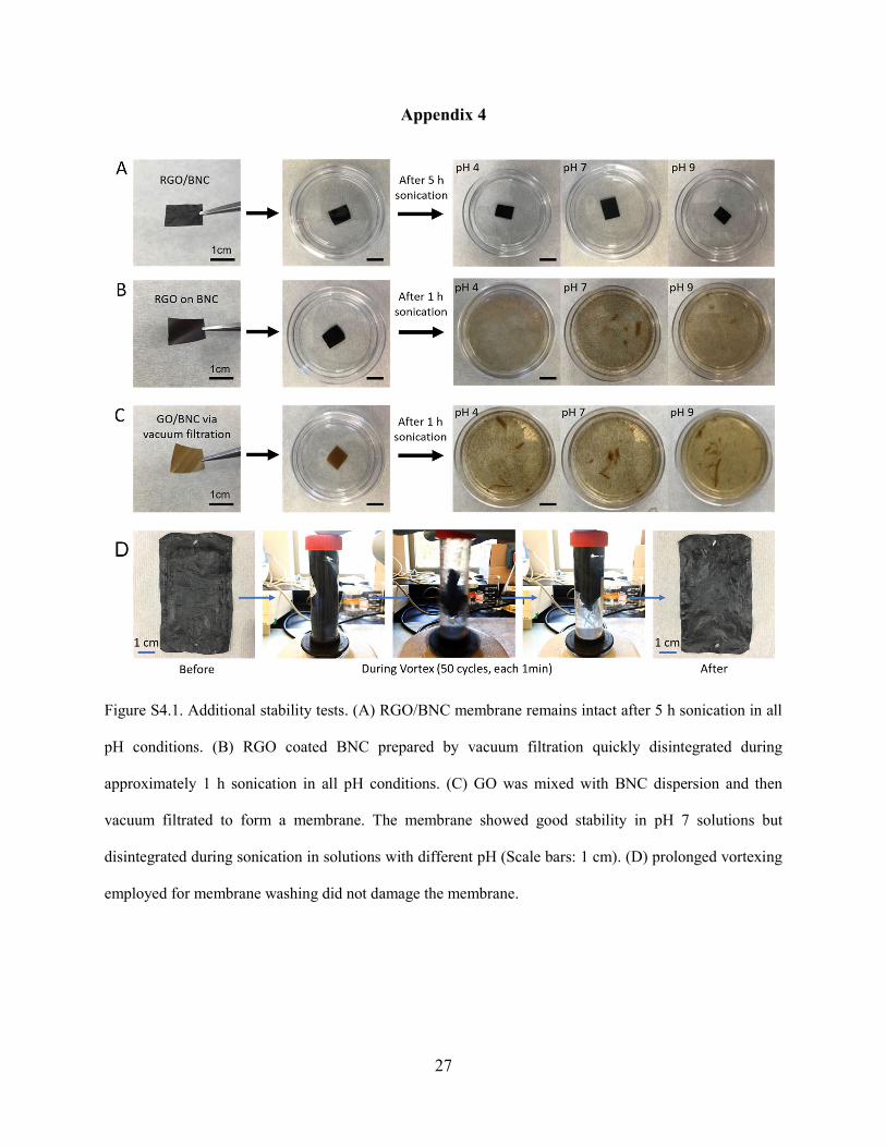
27
Appendix 4
Figure S4.1. Additional stability tests. (A) RGO/BNC membrane remains intact after 5 h sonication in all
pH conditions. (B) RGO coated BNC prepared by vacuum filtration quickly disintegrated during
approximately 1 h sonication in all pH conditions. (C) GO was mixed with BNC dispersion and then
vacuum filtrated to form a membrane. The membrane showed good stability in pH 7 solutions but
disintegrated during sonication in solutions with different pH (Scale bars: 1 cm). (D) prolonged vortexing
employed for membrane washing did not damage the membrane.

128
Figure S4.2. (A) TEM image of gold nanoparticles of 5 nm in diameter. (B) Size distribution of AuNPs. (C) UV-vis
extinction spectra indicating the rejection of AuNPs with 5 nm in diameter filtered through commercial UF
membranes.
Figure S4.3. Nitrogen isotherm of RGO/BNC membrane (A) before and (B) after 24-hour light illumination
(2.9 kW/m2). The pore size of RGO/BNC membrane (C) before and (D) after 24-hour light illumination
(2.9 kW/m2).
B A
C

129
Figure S4.4. Water flux of RGO/BNC membrane under cyclic illumination. For the first cycle, RGO/BNC
membrane was exposed to light (2.9 kW/m2) for 12 hours, and 5 hours exposure time was used for the rest
of cyclic tests.
Figure S4.5. (A) Bacterial cell viability counts during bactericidal performance under illumination for BNC
and RGO membranes. (B) Fluorescence images of E. coli on RGO/BNC before and after incubation for
1hour.

130
Figure S4.6. Surface roughness and contact angle of (A) RGO/BNC and (B) BNC membranes.

131
Appendix 5
Figure S5.1. SEM images of the surface of GO/BNC aerogel (A-A1) and GO/BNC membrane (B-B1).

132
Figure S5.2. TGA curves of BNC, GO/BNC, Pd/BNC, and Pd/GO/BNC.
Figure S5.3. XRD (A) and XPS spectrum of Pd 3d3/2 and Pd 3d5/2 regions (B) of Pd/GO/BNC.
200 400 600 8000
20
40
60
80
100
We
igh
t L
oss
(%
)
Temperature (C)
Pd/GO/BNC GO/BNC Pd/BNC BNC
332 334 336 338 340 342 344 346
Inte
ns
ity(
a.u
.)
Binding Energy(eV)
B
10 20 30 40 50 60 70
Pd/GO/BNC after MO degradation
JCPDS 00¨C005-0681
Inte
nsi
ty(a
.u.)
2 (degree)
Pd/GO/BNC before MO degradation
A
Pd (0): Pd(II)= 9:5

133
Figure S5.4. XPS spectra of C 1s regions for GO/BNC (A) and Pd/GO/BNC (B), and Raman spectra (C) of GO/BNC
and Pd/GO/BNC.
Figure S5.5. SEM images of the surface of Pd/BNC membrane.

134
Figure S5.6. TEM images of BNC aerogel (A), Pd/BNC membrane (B), GO/BNC aerogel (C) and
Pd/GO/BNC membrane (D), respectively.

135
Figure S5.7. Leakage of Pd for Pd/BNC membrane and Pd/GO/BNC membrane after 5 days of mechanical
agitation.
Figure S5.8. UV−vis spectra of MO solution in the presence of NaBH4 and the MO solution filtered through
the BNC and GO/BNC membrane.
0
50
100
150
200
250
300
350
400
450
500
16.56
Pd/GO/BNC
Pd
lea
kag
e(p
pb
)
Pd/BNC
273.65

136
Figure S5.9. (A) UV−vis spectra of MO solution in the absence of NaBH4 and the MO solution filter through
Pd/GO/BNC membrane under 0.8 bar. (B) Image showing the filtration of MO solution through
Pd/GO/BNC membrane.
Figure S5.10. (A) MO rejection test of YMGESP3001 membrane. Inset is an image showing the setup. (B)
MO rejection test of YMDKSP3001 membrane. UV-vis spectra of permeate solution from MO solution
after 3 days. Inset is an image showing the setup.
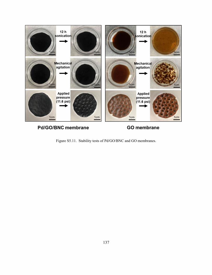
137
Figure S5.11. Stability tests of Pd/GO/BNC and GO membranes.

138
Appendix 6
Figure S6.1. (A) Picture of a bottle of GO solution. (B) AFM image of GO flakes deposited on a silicon
substrate.
Figure S6.2. XPS spectra of pristine GO, base-washed RGO and HPA-treated RGO.
B A
282 284 286 288 290
C=O288.2 eV
C-C286.6 eV
Co
un
ts (
a.u
.)
Binding Energy(eV)
C=C284.6 eV
Pristine GO
282 284 286 288 290
Co
un
ts (
a.u
.)
Binding Energy (eV)
Base-washed RGO C=C284.6 eV
C-C286.6 eV
C=O288.2 eV
282 284 286 288 290
Co
un
ts (
a.u
.)
Binding Energy (eV)
C=C284.6 eV
HPA treated RGO
C-C286.6 eV
C=O288.2 eV

139
Figure S6.3. RGO content in dry film can be tuned by varying GO content in broth. Electrical conductivity
of RGO/BNC films with various RGO contents.
Figure S6.4. Effect of solution processes on pristine PEDOT:PSS deposited on a silicon substrate.
Original After NaOH After HPA0
50
100
150
200
250
300
350
400
Co
nd
uct
ivit
y (S
/cm
)
18 34 53 65 780
2
4
6
8
10
12
14
16
18
Ele
ctr
ical
co
nd
uct
ivit
y (S
/cm
)
RGO content (%)
Growth time: 5 daysBroth volume: 8 mL
0.05 0.125 0.2 0.3 0.40
10
20
30
40
50
60
70
80
RG
O c
on
ten
t in
dry
film
(%
)
GO content in broth (%)
Growh time: 5 daysBroth volume: 8 mL

140
Figure S6.5. Specific energy and power densities of the Flexible device.
Figure S6.6. Strain-stress curve of pristine BNC and RGO/PEDOT:PSS/BNC.
0.0 0.4 0.8 1.2 1.60
50
100
150
200
250
Pristine BNC film RGO/PEDOT:PSS/BNC film
Str
ess
(MP
a)
Strain (%)
0 500 1000
0
5
10
15
En
erg
y d
en
sity
(W
h/k
g)
Power density (W/kg)
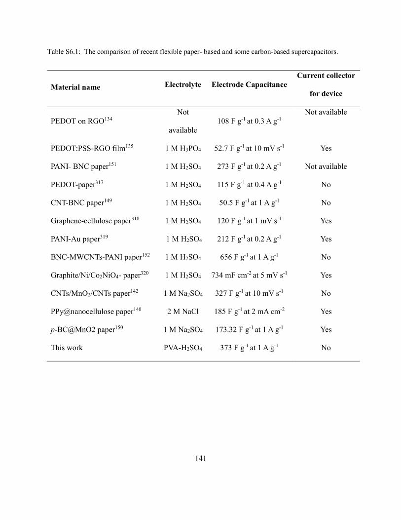
141
Table S6.1: The comparison of recent flexible paper- based and some carbon-based supercapacitors.
Material name Electrolyte Electrode Capacitance Current collector
for device
PEDOT on RGO134 Not
available 108 F g-1 at 0.3 A g-1
Not available
PEDOT:PSS-RGO film135 1 M H3PO4 52.7 F g-1 at 10 mV s-1 Yes
PANI- BNC paper151 1 M H2SO4 273 F g-1 at 0.2 A g-1 Not available
PEDOT-paper317 1 M H2SO4 115 F g-1 at 0.4 A g-1 No
CNT-BNC paper149 1 M H2SO4 50.5 F g-1 at 1 A g-1 No
Graphene-cellulose paper318 1 M H2SO4 120 F g-1 at 1 mV s-1 Yes
PANI-Au paper319 1 M H2SO4 212 F g-1 at 0.2 A g-1 Yes
BNC-MWCNTs-PANI paper152 1 M H2SO4 656 F g-1 at 1 A g-1 No
Graphite/Ni/Co2NiO4- paper320 1 M H2SO4 734 mF cm-2 at 5 mV s-1 Yes
CNTs/MnO2/CNTs paper142 1 M Na2SO4 327 F g-1 at 10 mV s-1 No
PPy@nanocellulose paper140 2 M NaCl 185 F g-1 at 2 mA cm-2 Yes
p-BC@MnO2 paper150 1 M Na2SO4 173.32 F g-1 at 1 A g-1 Yes
This work PVA-H2SO4 373 F g-1 at 1 A g-1 No

142
Curriculum Vitae
Qisheng Jiang
EDUCATION
2018 Ph.D., Materials Science and Engineering, Washington University in St. Louis, St. Louis, USA
Advisor: Professor Srikanth Singamaneni
Dissertation: Multifunctional Nanocomposites based on Bacterial Cellulose (October 2018)
2009 B.S., Materials Processing Engineering, Beijing Institute of Technology, Beijing, China
RESEARCH EXPERIENCE
2014-present Graduate Research Assistant, Washington University in St. Louis, St. Louis, USA
2010-2013 Undergraduate Research Assistant, Beijing Institute of Technology, Beijing, China
PUBLICATIONS
Refereed Journal Publications
1. Jiang, Q.; Tian, L.; Liu, K.-K.; Tadepalli, S.; Raliya, R.; Biswas, P.; Naik, R. R.; Singamaneni, S.,
Bilayered Biofoam for Highly Efficient Solar Steam Generation. Advanced Materials 2016, 28 (42), 9400-
9407.
2. Jiang, Q.; Singamaneni, S., Water from Wood: Pouring through Pores. Joule 2017, 1 (3), 429-430.
3. Jiang, Q.; Gholami Derami, H.; Ghim, D.; Cao, S.; Jun, Y.-S.; Singamaneni, S., Polydopamine-filled
bacterial nanocellulose as a biodegradable interfacial photothermal evaporator for highly efficient solar
steam generation. Journal of Materials Chemistry A 2017, 5 (35), 18397-18402.

143
4. Jiang, Q.; Kacica, C.; Soundappan, T.; Liu, K.-k.; Tadepalli, S.; Biswas, P.; Singamaneni, S., An in situ
grown bacterial nanocellulose/graphene oxide composite for flexible supercapacitors. Journal of Materials
Chemistry A 2017, 5 (27), 13976-13982.
5. Jiang, Q.; Chandar, Y. J.; Cao, S.; Kharasch, E. D.; Singamaneni, S.; Morrissey, J. J., Rapid, Point-of-
Care, Paper-Based Plasmonic Biosensor for Zika Virus Diagnosis. Advanced Biosystems 2017, 1 (9),
1700096.
6. Jiang, Q.; Xu, T; Deoukchen, G; Liu, K,.-K; Sun, H; Derami, H. G.; Wang, Z; Tadepalli, S; Jun, Y.S.;
Zhang, Q.H.; Singamaneni, S, Catalytically-active Bacterial Nanocellulose-based Ultrafiltration Membrane.
Small, 2018. 14(15), 1704006.
7. Jiang, Q.; Deoukchen, G.; Tadepalli, S.; Liu, K,.-K.; Kwon, H.; Luan, J.; Min, Y.; Jun, Y.-S.;
Singamaneni, S., Biofouling-resistante Ultrafiltration Membrane by Harnessing Sunlight. Environmental
Science & Technology 2018. (In press)
8. Liu, K.-K.; Jiang, Q.; Tadepalli, S.; Raliya, R.; Biswas, P.; Naik, R. R.; Singamaneni, S., Wood–
Graphene Oxide Composite for Highly Efficient Solar Steam Generation and Desalination. ACS Applied
Materials & Interfaces 2017, 9 (8), 7675-7681.
9. Tian, L.; Jiang, Q.; Liu, K.-K.; Luan, J.; Naik, R. R.; Singamaneni, S., Bacterial Nanocellulose-Based
Flexible Surface Enhanced Raman Scattering Substrate. Advanced Materials Interfaces 2016, 3 (15),
1600214.
10. Liu, K,.-K; Jiang, Q.; Kacica, C.; Derami, H. G.; Biswas, P.; Singamaneni, S., Flexible Solid-state
Supercapacitor Based on Tin Oxide/Reduced Graphene Oxide/Bacterial Nanocellulose. RSC Advances
2018. (In press)
11. Yuan, M.; Jiang, Q.; Liu, K-K.; Singamaneni, S.; Chakrabartty, S., Towards an Integrated QR Code
Biosensor: Light-Driven Sample Acquisition and Bacterial Cellulose Paper Substrate. IEEE Transactions
on Biomedical Circuits and Systems. 2018, 12(3), 452.

144
12. Derami, H. G.; Jiang, Q.; Deoukchen, G.; Cao, S.; Chandar, Y. J.; Morrissey, J. J.; Jun, Y.S.;
Singamaneni, S., A Robust and Scalable Polydopamine/Bacterial Nanocellulose Hybrid Membrane for
Efficient Wastewater Treatment. ACS Applied Materials & Interfaces. 2018. (In press)
13. Wu, X.H.; Jiang, Q.; Deoukchen, G.; Singamaneni, S.; Jun, Y.S., Localized Heating by a Photothermal
Polydopamine Coating Facilitates a Novel Membrane Distillation Process. Journal of Materials Chemistry
A. 2018, 6, 18799-18807.
14. Deoukchen, G.; Jiang, Q.; Cao, S.; Singamaneni, S.; Jun, Y.S., Mechanically Interlocked 1T/2H Phase
MoS2 Nanosheets for Solar Thermal Water Purification. Nano Energy 2018, 53, 949-957.
15. Li, C-B; Chen, W; Jiang, Q; Wang, L; Luo, D, Corrosion Resistance of Ti-based Metallic Glass Coating
in Concentrated Nitric Acid. Materials Chemistry and Physics 2014, 3, 143, 900-903.
16. Tadepalli, S.; Kuang, Z.; Jiang, Q.; Liu, K.-K.; Fisher, M. A.; Morrissey, J. J.; Kharasch, E. D.; Slocik,
J. M.; Naik, R. R.; Singamaneni, S., Peptide Functionalized Gold Nanorods for the Sensitive Detection of
a Cardiac Biomarker Using Plasmonic Paper Devices. Scientific Reports 2015, 5, 16206.
17. Li, C.; Chen, W.; Jiang, Q.; Wang, L.; Luo, D., Corrosion resistance of Ti-based metallic glass coating
in concentrated nitric acid. Materials Chemistry and Physics 2014, 143 (3), 900-903. 14. Tian, L.; Luan,
J.; Liu, K.-K.; Jiang, Q.; Tadepalli, S.; Gupta, M. K.; Naik, R. R.; Singamaneni, S., Plasmonic Biofoam:
A Versatile Optically Active Material. Nano Letters 2016, 16 (1), 609-616.
18. Kolluru, C.; Gupta, R.; Jiang, Q.; Williams, M.; Noel, R.K.; Singamaneni, S.; Prausnitz, M. R.,
Plasmonic Paper Microneedle Patch for On-patch Detection of Biomarkers in Dermal Interstitial Fluid. (In
preparation)
19. Wang, C.; Sun, H.; Luan, J.; Jiang, Q.; Tadepalli, S.; Morrissey, J. J.; Kharasch, E. D.; Singamaneni,
S., Metal-Organic Framework Encapsulation for Biospecimen Preservation. Chemistry of Materials, 2018,
30 (4), 1291-1300.

145
20. Tadepalli, S.; Wang, Z.; Liu, K.-K.; Jiang, Q.; Slocik, J.; Naik, R. R.; Singamaneni, S., Influence of
Surface Charge of the Nanostructures on the Biocatalytic Activity. Langmuir 2017, 33 (26), 6611-6619.
21. Liu, K.-K.; Tadepalli, S.; Wang, Z.; Jiang, Q.; Singamaneni, S., Structure-dependent SERS activity of
plasmonic nanorattles with built-in electromagnetic hotspots. Analyst 2017, 142 (23), 4536-4543.
22. Luan, J.; Liu, K.-K.; Tadepalli, S.; Jiang, Q.; Morrissey, J. J.; Kharasch, E. D.; Singamaneni, S.,
PEGylated Artificial Antibodies: Plasmonic Biosensors with Improved Selectivity. ACS Applied Materials
& Interfaces 2016, 8 (36), 23509-23516.
23. Wang, C.; Sudlow, G.; Wang, Z.; Cao, S.; Jiang, Q.; Tadepalli, S.; Morrissey, J. J.; Kharasch, E. D.;
Achilefu, S.; Singamaneni, S,. Metal-organic Framework Encapsulation Preserves the Bioactivity of
Protein Therapeutics. Nanoscale, 2017. (In press)
24. Santino, L. M.; Hwang, E.; Diao, Y.; Lu, Y.; Wang, H.; Jiang, Q.; Singamaneni, S.; D’Arcy, J. M.,
Condensing Vapor Phase Polymerization (CVPP) of Electrochemically Capacitive and Stable Polypyrrole
Microtubes. ACS Applied Materials & Interfaces 2017, 9 (47), 41496-41504.
25. Xie, W.; Tadepalli, S.; Park, S.; Kazemi-Moridani, A; Jiang, Q.; Singamaneni, S.; Lee, J., Extreme
Mechanical Behavior of Nacre-Mimetic Graphene-Oxide and Silk Nanocomposites. Nano Letters 2018,
18 (2), 987-993.
26. Luan, J.; Morrissey, J.; Wang, Z.; Derami, H.; Liu, K-K.; Cao, S.; Jiang, Q.; Wang, C.; Kharasch, E.;
Naik, R.; Singamaneni, S., Add-on Plasmonic Patch as a Universal Fluorescence Enhancer. Light Sci. Appl.
2018, 7,29.
Conference Proceeding
1. Jiang, Q.; Tian, L.; Liu, K.-K.; Singamaneni, S., Bacterial Nanocellulose and Reduced Graphene
Oxide Aerogel for Solar Steam Generation. Boston, USA, MRS Fall, Dec. 2015
2. Jiang, Q.; Tian, L.; Liu, K.-K.; Luan, J.; Naik, R.R.; Singamaneni, S., Ultra-Smooth Bacterial
Nanocellulose-Based SERS Swab. Boston, USA, MRS Fall, Dec. 2015

146
3. Tian, L.; Liu, K.-K.; Luan, J.; Jiang, Q.; Tadepalli, S.; Naik, R.R.; Singamaneni, S., Plasmonic
Aerogels from Bacterial Nanocellulose. Boston, USA, MRS Fall, Dec. 2015
PATENTS
1. Photothermally-Active Bilayered Biosystems for Highly Efficient Water Purification Via Solar Steam
Generation. (WU OTM Case No. 016682, filed in August 2016)
2. Rapid Point-of-care Assay for Zika Virus Infection. (WU OTM Case No. 016701, filed in August 2016)
3. Ultrafiltration Membrane based on Bacterial Nanocellulose and Graphene Oxide. (WU OTM Case No.
016792, filed in September 2016)