SIPROTEC Multifunctional Machine Protection 7UM62 - www ...
662
SIPROTEC Multifunctional Machine Protection 7UM62 V4.6 Manual C53000-G1176-C149-5 Preface Introduction 1 Functions 2 Mounting and Commissioning 3 Technical Data 4 Appendix A Literature Glossary Index www . ElectricalPartManuals . com
-
Upload
khangminh22 -
Category
Documents
-
view
1 -
download
0
Transcript of SIPROTEC Multifunctional Machine Protection 7UM62 - www ...

ww
SIPROTEC
Multifunctional Machine Protection7UM62V4.6
Manual
F
M
T
A
L
G
I
. El
ectric
alPar
w
C53000-G1176-C149-5
Preface
Introduction 1unctions 2ounting and Commissioning 3
echnical Data 4ppendix Aiterature
lossary
ndextMan
uals
. com

7UM62 ManualC53000-G1176-C149-5
Disclaimer of liabilityWe have checked the text of this manual against the hardware and software described. However, deviations from the descrip-tion cannot be completely ruled out, so that no liability can be ac-cepted for any errors or omissions contained in the information given.The information given in this document is reviewed regularly and any necessary corrections will be included in subsequent edi-tions. We appreciate any suggestions for improvement.We reserve the right to make technical improvements without notice.
CopyrightCopyright © Siemens AG 2005. All rights reserved.Dissemination or reproduction of this document, or evaluation and communication of its contents, is not authorized except where expressly permitted. Violations are liable for damages. All rights reserved, particularly for the purposes of patent application or trademark registration.
Registered TrademarksSIPROTEC, SINAUT, SICAM and DIGSI are registered trade-marks of Siemens AG. Other designations in this manual might be trademarks whose use by third parties for their own purposes would infringe the rights of the owner.Release V4.61.01
www . El
ectric
alPar
tMan
uals
. com

w
m
Preface
Purpose of this Manual
This manual describes the functions, operation, installation, and commissioning of the 7UM62 devices. In particular, one will find:• Information regarding the configuration of the device and descriptions of device
functions and settings → Chapter 2;• Instruction for mounting and commissioning → Chapter 3,• List of technical data → Chapter 4;• As well as a compilation of the most significant data for experienced users → Ap-
pendix A.
General information about design, configuration, and operation of SIPROTEC 4 devices are laid down in the SIPROTEC 4 System Description /1/.
Target Audience Protection engineers, commissioning engineers, personnel concerned with adjust-ment, checking, and service of selective protective equipment, automatic and control facilities, and personnel of electrical facilities and power plants.
Applicability of this Manual
This manual is valid for: SIPROTEC 4 Multifunctional Machine Protection 7UM62; firmware version V4.6.
Indication of Con-formity
This product is UL-certified according to the Technical Data:
This product complies with the directive of the Council of the European Commu-nities on the approximation of the laws of the Member States relating to electro-magnetic compatibility (EMC Council Directive 89/336/EEC) and concerning elec-trical equipment for use within specified voltage limits (Low-voltage directive 73/23 EEC).This conformity is proved by tests conducted by Siemens AG in accordance with Article 10 of the Council Directive in agreement with the generic standards EN 61000-6-2 and EN 61000-6-4 for the EMC directive, and with the standard EN 61000-6-2 and EN 61000-6-4 for the low-voltage directive. This device was designed and produced for industrial use.The product conforms with the international standard of the series IEC 60255 and the German standard VDE 0435.
Further Standards IEEE Std C37.90-*
ww . El
ectric
alPar
tMan
uals
. co
37UM62 ManualC53000-G1176-C149-5

Preface
om
Additional Support Should further information on the SIPROTEC 4 System be desired or should particular problems arise which are not covered sufficiently for the purchaser's purpose, the matter should be referred to the local Siemens representative.
Training Courses Individual course offerings may be found in our Training Catalogue, or questions may be directed to our training centre in Nuremberg.
WARNING!When operating an electrical device, certain parts of the device inevitably have dan-gerous voltages.
Death, severe personal injury or substantial property damage can result if the device is not handled properly.
Only qualified personnel shall work on and around this equipment. It must be thor-oughly familiar with all warnings and safety notices of this manual as well as with the applicable safety regulations.
The successful and safe operation of this device is dependent on proper handling, in-stallation, operation, and maintenance by qualified personnel under observance of all warnings and hints contained in this manual.
Of particular importance are the general installation and safety regulations for work in a high-voltage environment (for example, ANSI, IEC, EN, DIN, or other national and international regulations). These regulations must be observed.
Instructions and Warnings
The warnings and notes contained in this manual serve for your own safety and for an appropriate lifetime of the device. Please observe them!The following indicators and standard definitions are used:DANGERindicates that death, severe personal injury or substantial property damage will result if proper precautions are not taken.Warningindicates that death, severe personal injury or substantial property damage can result if proper precautions are not taken.Cautionindicates that minor personal injury or property damage can result if proper precau-tions are not taken. This particularly applies to damage on or in the device itself and consequential damage thereof.Noteindicates information about the device or respective part of the instruction manual which is essential to highlight.
ww . El
ectric
alPar
tMan
uals
. c
4 7UM62 ManualC53000-G1176-C149-5
w
Prefacew
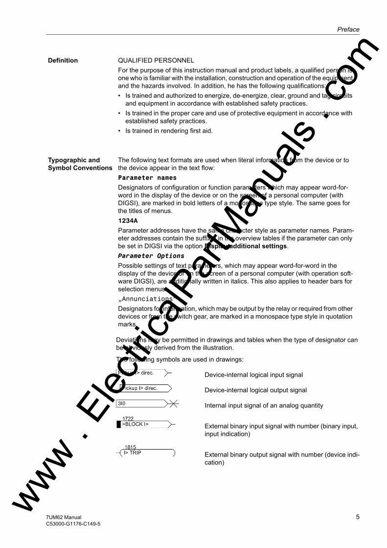
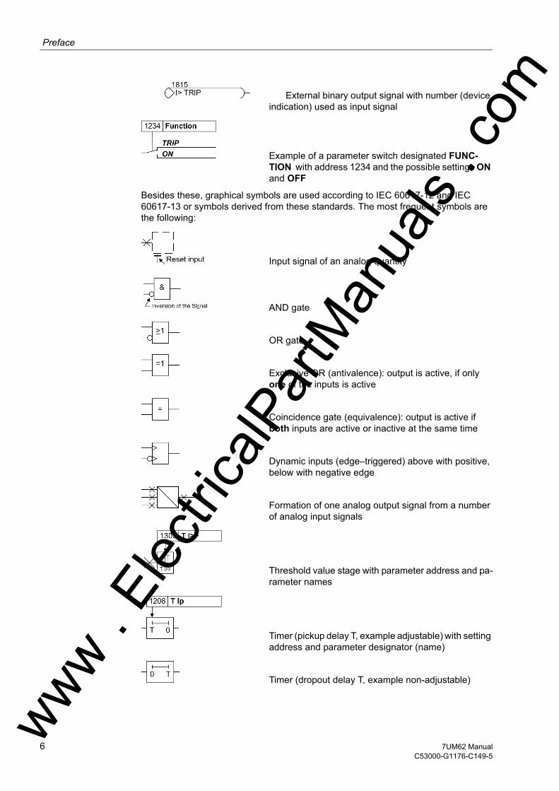
Deviations may be permitted in drawings and tables when the type of designator can be obviously derived from the illustration.
The following symbols are used in drawings:
Device-internal logical input signal
Device-internal logical output signal
Internal input signal of an analog quantity
External binary input signal with number (binary input, input indication)
External binary output signal with number (device indi-cation)
Definition QUALIFIED PERSONNELFor the purpose of this instruction manual and product labels, a qualified person is one who is familiar with the installation, construction and operation of the equipment and the hazards involved. In addition, he has the following qualifications:• Is trained and authorized to energize, de-energize, clear, ground and tag circuits
and equipment in accordance with established safety practices. • Is trained in the proper care and use of protective equipment in accordance with
established safety practices.• Is trained in rendering first aid.
Typographic and Symbol Conventions
The following text formats are used when literal information from the device or to the device appear in the text flow: Parameter names
Designators of configuration or function parameters which may appear word-for-word in the display of the device or on the screen of a personal computer (with DIGSI), are marked in bold letters of a monospace type style. The same goes for the titles of menus.1234A
Parameter addresses have the same character style as parameter names. Param-eter addresses contain the suffix A in the overview tables if the parameter can only be set in DIGSI via the option Display additional settings.Parameter Options
Possible settings of text parameters, which may appear word-for-word in the display of the device or on the screen of a personal computer (with operation soft-ware DIGSI), are additionally written in italics. This also applies to header bars for selection menus.„Annunciations“
Designators for information, which may be output by the relay or required from other devices or from the switch gear, are marked in a monospace type style in quotation marks.
ww . El
ectric
alPar
tMan
uals
. com
57UM62 ManualC53000-G1176-C149-5
Preface
om
External binary output signal with number (device indication) used as input signalExample of a parameter switch designated FUNC-TION with address 1234 and the possible settings ON and OFF
Besides these, graphical symbols are used according to IEC 60617-12 and IEC 60617-13 or symbols derived from these standards. The most frequent symbols are the following:
Input signal of an analog quantity
AND gate
OR gate
Exclusive OR (antivalence): output is active, if only one of the inputs is active
Coincidence gate (equivalence): output is active if both inputs are active or inactive at the same time
Dynamic inputs (edge–triggered) above with positive, below with negative edge
Formation of one analog output signal from a number of analog input signals
Threshold value stage with parameter address and pa-rameter names
Timer (pickup delay T, example adjustable) with setting address and parameter designator (name)
Timer (dropout delay T, example non-adjustable)ww . El
ectric
alPar
tMan
uals
. c
6 7UM62 ManualC53000-G1176-C149-5
w

Prefacew
Dynamic triggered pulse timer T (monoflop)
Static memory (RS-flipflop) with setting input (S), re-setting input (R), output (Q) and inverted output (Q)
ww . El
ectric
alPar
tMan
uals
. com
77UM62 ManualC53000-G1176-C149-5

Preface
om
ww . El
ectric
alPar
tMan
uals
. c
8 7UM62 ManualC53000-G1176-C149-5
w

w
m
Contents
1 Introduction. . . . . . . . . . . . . . . . . . . . . . . . . . . . . . . . . . . . . . . . . . . . . . . . . . . . . . . . . . . . . . . . . . . . 23
1.1 Overall Operation . . . . . . . . . . . . . . . . . . . . . . . . . . . . . . . . . . . . . . . . . . . . . . . . . . . . . . . . 24
1.2 Application Scope . . . . . . . . . . . . . . . . . . . . . . . . . . . . . . . . . . . . . . . . . . . . . . . . . . . . . . . . 27
1.3 Characteristics. . . . . . . . . . . . . . . . . . . . . . . . . . . . . . . . . . . . . . . . . . . . . . . . . . . . . . . . . . . 30
2 Functions. . . . . . . . . . . . . . . . . . . . . . . . . . . . . . . . . . . . . . . . . . . . . . . . . . . . . . . . . . . . . . . . . . . . . . 37
2.1 Introduction, Reference Power System. . . . . . . . . . . . . . . . . . . . . . . . . . . . . . . . . . . . . . . . 392.1.1 Function Description . . . . . . . . . . . . . . . . . . . . . . . . . . . . . . . . . . . . . . . . . . . . . . . . . . . . . . 39
2.2 Device . . . . . . . . . . . . . . . . . . . . . . . . . . . . . . . . . . . . . . . . . . . . . . . . . . . . . . . . . . . . . . . . . 412.2.1 Setting Notes. . . . . . . . . . . . . . . . . . . . . . . . . . . . . . . . . . . . . . . . . . . . . . . . . . . . . . . . . . . . 412.2.2 Settings . . . . . . . . . . . . . . . . . . . . . . . . . . . . . . . . . . . . . . . . . . . . . . . . . . . . . . . . . . . . . . . . 422.2.3 Information List . . . . . . . . . . . . . . . . . . . . . . . . . . . . . . . . . . . . . . . . . . . . . . . . . . . . . . . . . . 42
2.3 Ethernet EN100 Modul . . . . . . . . . . . . . . . . . . . . . . . . . . . . . . . . . . . . . . . . . . . . . . . . . . . . 442.3.1 Function Description . . . . . . . . . . . . . . . . . . . . . . . . . . . . . . . . . . . . . . . . . . . . . . . . . . . . . . 442.3.2 Setting Notes. . . . . . . . . . . . . . . . . . . . . . . . . . . . . . . . . . . . . . . . . . . . . . . . . . . . . . . . . . . . 442.3.3 Information List . . . . . . . . . . . . . . . . . . . . . . . . . . . . . . . . . . . . . . . . . . . . . . . . . . . . . . . . . . 44
2.4 Functional Scope. . . . . . . . . . . . . . . . . . . . . . . . . . . . . . . . . . . . . . . . . . . . . . . . . . . . . . . . . 452.4.1 Functional Description . . . . . . . . . . . . . . . . . . . . . . . . . . . . . . . . . . . . . . . . . . . . . . . . . . . . . 452.4.2 Setting Notes. . . . . . . . . . . . . . . . . . . . . . . . . . . . . . . . . . . . . . . . . . . . . . . . . . . . . . . . . . . . 462.4.3 Settings . . . . . . . . . . . . . . . . . . . . . . . . . . . . . . . . . . . . . . . . . . . . . . . . . . . . . . . . . . . . . . . . 51
2.5 Power System Data 1 . . . . . . . . . . . . . . . . . . . . . . . . . . . . . . . . . . . . . . . . . . . . . . . . . . . . . 562.5.1 Setting Notes. . . . . . . . . . . . . . . . . . . . . . . . . . . . . . . . . . . . . . . . . . . . . . . . . . . . . . . . . . . . 562.5.2 Settings . . . . . . . . . . . . . . . . . . . . . . . . . . . . . . . . . . . . . . . . . . . . . . . . . . . . . . . . . . . . . . . . 632.5.3 Information List . . . . . . . . . . . . . . . . . . . . . . . . . . . . . . . . . . . . . . . . . . . . . . . . . . . . . . . . . . 64
2.6 Change Group. . . . . . . . . . . . . . . . . . . . . . . . . . . . . . . . . . . . . . . . . . . . . . . . . . . . . . . . . . . 652.6.1 Setting Notes. . . . . . . . . . . . . . . . . . . . . . . . . . . . . . . . . . . . . . . . . . . . . . . . . . . . . . . . . . . . 652.6.2 Settings . . . . . . . . . . . . . . . . . . . . . . . . . . . . . . . . . . . . . . . . . . . . . . . . . . . . . . . . . . . . . . . . 652.6.3 Information List . . . . . . . . . . . . . . . . . . . . . . . . . . . . . . . . . . . . . . . . . . . . . . . . . . . . . . . . . . 65
2.7 Power System Data 2 . . . . . . . . . . . . . . . . . . . . . . . . . . . . . . . . . . . . . . . . . . . . . . . . . . . . . 662.7.1 Functional Description . . . . . . . . . . . . . . . . . . . . . . . . . . . . . . . . . . . . . . . . . . . . . . . . . . . . . 662.7.2 Setting Notes. . . . . . . . . . . . . . . . . . . . . . . . . . . . . . . . . . . . . . . . . . . . . . . . . . . . . . . . . . . . 662.7.3 Settings . . . . . . . . . . . . . . . . . . . . . . . . . . . . . . . . . . . . . . . . . . . . . . . . . . . . . . . . . . . . . . . . 672.7.4 Information List . . . . . . . . . . . . . . . . . . . . . . . . . . . . . . . . . . . . . . . . . . . . . . . . . . . . . . . . . . 67ww .
Elec
tricalP
artM
anua
ls . c
o
97UM62 ManualC53000-G1176-C149-5
Contents
om
2.8 Definite-Time Overcurrent Protection (I>, ANSI 50/51) with Undervoltage Seal-In . . . . . . . 682.8.1 Function Description . . . . . . . . . . . . . . . . . . . . . . . . . . . . . . . . . . . . . . . . . . . . . . . . . . . . . . 682.8.2 Setting Notes . . . . . . . . . . . . . . . . . . . . . . . . . . . . . . . . . . . . . . . . . . . . . . . . . . . . . . . . . . . . 692.8.3 Settings . . . . . . . . . . . . . . . . . . . . . . . . . . . . . . . . . . . . . . . . . . . . . . . . . . . . . . . . . . . . . . . . 712.8.4 Information List . . . . . . . . . . . . . . . . . . . . . . . . . . . . . . . . . . . . . . . . . . . . . . . . . . . . . . . . . . 71
2.9 Definite-Time Overcurrent Protection (I>>, ANSI 50, 51, 67) with Direction Detection . . . . 722.9.1 Function Description . . . . . . . . . . . . . . . . . . . . . . . . . . . . . . . . . . . . . . . . . . . . . . . . . . . . . . 722.9.2 Setting Notes . . . . . . . . . . . . . . . . . . . . . . . . . . . . . . . . . . . . . . . . . . . . . . . . . . . . . . . . . . . . 752.9.3 Settings . . . . . . . . . . . . . . . . . . . . . . . . . . . . . . . . . . . . . . . . . . . . . . . . . . . . . . . . . . . . . . . . 772.9.4 Information List . . . . . . . . . . . . . . . . . . . . . . . . . . . . . . . . . . . . . . . . . . . . . . . . . . . . . . . . . . 78
2.10 Inverse-Time Overcurrent Protection (ANSI 51V) . . . . . . . . . . . . . . . . . . . . . . . . . . . . . . . . 792.10.1 Functional Description . . . . . . . . . . . . . . . . . . . . . . . . . . . . . . . . . . . . . . . . . . . . . . . . . . . . . 792.10.2 Setting Notes . . . . . . . . . . . . . . . . . . . . . . . . . . . . . . . . . . . . . . . . . . . . . . . . . . . . . . . . . . . . 832.10.3 Settings . . . . . . . . . . . . . . . . . . . . . . . . . . . . . . . . . . . . . . . . . . . . . . . . . . . . . . . . . . . . . . . . 842.10.4 Information List . . . . . . . . . . . . . . . . . . . . . . . . . . . . . . . . . . . . . . . . . . . . . . . . . . . . . . . . . . 84
2.11 Thermal Overload Protection (ANSI 49) . . . . . . . . . . . . . . . . . . . . . . . . . . . . . . . . . . . . . . . 852.11.1 Functional Description . . . . . . . . . . . . . . . . . . . . . . . . . . . . . . . . . . . . . . . . . . . . . . . . . . . . . 852.11.2 Setting Notes . . . . . . . . . . . . . . . . . . . . . . . . . . . . . . . . . . . . . . . . . . . . . . . . . . . . . . . . . . . . 892.11.3 Settings . . . . . . . . . . . . . . . . . . . . . . . . . . . . . . . . . . . . . . . . . . . . . . . . . . . . . . . . . . . . . . . . 932.11.4 Information List . . . . . . . . . . . . . . . . . . . . . . . . . . . . . . . . . . . . . . . . . . . . . . . . . . . . . . . . . . 94
2.12 Unbalanced Load (Negative Sequence) Protection (ANSI 46) . . . . . . . . . . . . . . . . . . . . . . 952.12.1 Functional Description . . . . . . . . . . . . . . . . . . . . . . . . . . . . . . . . . . . . . . . . . . . . . . . . . . . . . 952.12.2 Setting Notes . . . . . . . . . . . . . . . . . . . . . . . . . . . . . . . . . . . . . . . . . . . . . . . . . . . . . . . . . . . . 982.12.3 Settings . . . . . . . . . . . . . . . . . . . . . . . . . . . . . . . . . . . . . . . . . . . . . . . . . . . . . . . . . . . . . . . 1012.12.4 Information List . . . . . . . . . . . . . . . . . . . . . . . . . . . . . . . . . . . . . . . . . . . . . . . . . . . . . . . . . 101
2.13 Startup Overcurrent Protection (ANSI 51) . . . . . . . . . . . . . . . . . . . . . . . . . . . . . . . . . . . . . 1022.13.1 Function Description . . . . . . . . . . . . . . . . . . . . . . . . . . . . . . . . . . . . . . . . . . . . . . . . . . . . . 1022.13.2 Setting Notes . . . . . . . . . . . . . . . . . . . . . . . . . . . . . . . . . . . . . . . . . . . . . . . . . . . . . . . . . . . 1042.13.3 Settings . . . . . . . . . . . . . . . . . . . . . . . . . . . . . . . . . . . . . . . . . . . . . . . . . . . . . . . . . . . . . . . 1052.13.4 Information List . . . . . . . . . . . . . . . . . . . . . . . . . . . . . . . . . . . . . . . . . . . . . . . . . . . . . . . . . 106
2.14 Differential Protection and Its Protected Objects . . . . . . . . . . . . . . . . . . . . . . . . . . . . . . . . 1072.14.1 Differential Protection (ANSI 87G/87M/87T) . . . . . . . . . . . . . . . . . . . . . . . . . . . . . . . . . . . 1072.14.1.1 Function Description . . . . . . . . . . . . . . . . . . . . . . . . . . . . . . . . . . . . . . . . . . . . . . . . . . . . . 1072.14.1.2 Setting Notes . . . . . . . . . . . . . . . . . . . . . . . . . . . . . . . . . . . . . . . . . . . . . . . . . . . . . . . . . . . 1172.14.1.3 Settings . . . . . . . . . . . . . . . . . . . . . . . . . . . . . . . . . . . . . . . . . . . . . . . . . . . . . . . . . . . . . . . 1182.14.1.4 Information List . . . . . . . . . . . . . . . . . . . . . . . . . . . . . . . . . . . . . . . . . . . . . . . . . . . . . . . . . 1192.14.2 Protected Object Generator or Motor . . . . . . . . . . . . . . . . . . . . . . . . . . . . . . . . . . . . . . . . 1202.14.2.1 Function Description . . . . . . . . . . . . . . . . . . . . . . . . . . . . . . . . . . . . . . . . . . . . . . . . . . . . . 1202.14.2.2 Setting Notes . . . . . . . . . . . . . . . . . . . . . . . . . . . . . . . . . . . . . . . . . . . . . . . . . . . . . . . . . . . 1212.14.3 Protected Object Transformer . . . . . . . . . . . . . . . . . . . . . . . . . . . . . . . . . . . . . . . . . . . . . . 1232.14.3.1 Function Description . . . . . . . . . . . . . . . . . . . . . . . . . . . . . . . . . . . . . . . . . . . . . . . . . . . . . 1232.14.3.2 Setting Notes . . . . . . . . . . . . . . . . . . . . . . . . . . . . . . . . . . . . . . . . . . . . . . . . . . . . . . . . . . . 1272.14.4 Current Transformer Requirements . . . . . . . . . . . . . . . . . . . . . . . . . . . . . . . . . . . . . . . . . . 1312.14.4.1 Function Description . . . . . . . . . . . . . . . . . . . . . . . . . . . . . . . . . . . . . . . . . . . . . . . . . . . . . 131ww .
Elec
tricalP
artM
anua
ls . c
10 7UM62 ManualC53000-G1176-C149-5
w

Contentsw
2.15 Earth Current Differential Protection (ANSI 87GN,TN) . . . . . . . . . . . . . . . . . . . . . . . . . . . 1332.15.1 Function Description . . . . . . . . . . . . . . . . . . . . . . . . . . . . . . . . . . . . . . . . . . . . . . . . . . . . . 1332.15.2 Setting Notes. . . . . . . . . . . . . . . . . . . . . . . . . . . . . . . . . . . . . . . . . . . . . . . . . . . . . . . . . . . 1392.15.3 Settings . . . . . . . . . . . . . . . . . . . . . . . . . . . . . . . . . . . . . . . . . . . . . . . . . . . . . . . . . . . . . . . 1402.15.4 Information List . . . . . . . . . . . . . . . . . . . . . . . . . . . . . . . . . . . . . . . . . . . . . . . . . . . . . . . . . 141
2.16 Underexcitation (Loss-of-Field) Protection (ANSI 40) . . . . . . . . . . . . . . . . . . . . . . . . . . . . 1422.16.1 Function Description . . . . . . . . . . . . . . . . . . . . . . . . . . . . . . . . . . . . . . . . . . . . . . . . . . . . . 1422.16.2 Setting Notes. . . . . . . . . . . . . . . . . . . . . . . . . . . . . . . . . . . . . . . . . . . . . . . . . . . . . . . . . . . 1452.16.3 Settings . . . . . . . . . . . . . . . . . . . . . . . . . . . . . . . . . . . . . . . . . . . . . . . . . . . . . . . . . . . . . . . 1492.16.4 Information List . . . . . . . . . . . . . . . . . . . . . . . . . . . . . . . . . . . . . . . . . . . . . . . . . . . . . . . . . 150
2.17 Reverse Power Protection (ANSI 32R) . . . . . . . . . . . . . . . . . . . . . . . . . . . . . . . . . . . . . . . 1512.17.1 Functional Description . . . . . . . . . . . . . . . . . . . . . . . . . . . . . . . . . . . . . . . . . . . . . . . . . . . . 1512.17.2 Setting Notes. . . . . . . . . . . . . . . . . . . . . . . . . . . . . . . . . . . . . . . . . . . . . . . . . . . . . . . . . . . 1522.17.3 Settings . . . . . . . . . . . . . . . . . . . . . . . . . . . . . . . . . . . . . . . . . . . . . . . . . . . . . . . . . . . . . . . 1542.17.4 Information List . . . . . . . . . . . . . . . . . . . . . . . . . . . . . . . . . . . . . . . . . . . . . . . . . . . . . . . . . 154
2.18 Forward Active Power Supervision (ANSI 32F). . . . . . . . . . . . . . . . . . . . . . . . . . . . . . . . . 1552.18.1 Functional Description . . . . . . . . . . . . . . . . . . . . . . . . . . . . . . . . . . . . . . . . . . . . . . . . . . . . 1552.18.2 Setting Notes. . . . . . . . . . . . . . . . . . . . . . . . . . . . . . . . . . . . . . . . . . . . . . . . . . . . . . . . . . . 1562.18.3 Settings . . . . . . . . . . . . . . . . . . . . . . . . . . . . . . . . . . . . . . . . . . . . . . . . . . . . . . . . . . . . . . . 1572.18.4 Information List . . . . . . . . . . . . . . . . . . . . . . . . . . . . . . . . . . . . . . . . . . . . . . . . . . . . . . . . . 157
2.19 Impedance Protection (ANSI 21). . . . . . . . . . . . . . . . . . . . . . . . . . . . . . . . . . . . . . . . . . . . 1582.19.1 Functional Description . . . . . . . . . . . . . . . . . . . . . . . . . . . . . . . . . . . . . . . . . . . . . . . . . . . . 1582.19.2 Power Swing Blocking . . . . . . . . . . . . . . . . . . . . . . . . . . . . . . . . . . . . . . . . . . . . . . . . . . . 1632.19.3 Setting Notes. . . . . . . . . . . . . . . . . . . . . . . . . . . . . . . . . . . . . . . . . . . . . . . . . . . . . . . . . . . 1652.19.4 Settings . . . . . . . . . . . . . . . . . . . . . . . . . . . . . . . . . . . . . . . . . . . . . . . . . . . . . . . . . . . . . . . 1702.19.5 Information List . . . . . . . . . . . . . . . . . . . . . . . . . . . . . . . . . . . . . . . . . . . . . . . . . . . . . . . . . 171
2.20 Out-of-Step Protection (ANSI 78) . . . . . . . . . . . . . . . . . . . . . . . . . . . . . . . . . . . . . . . . . . . 1722.20.1 Measuring Principle . . . . . . . . . . . . . . . . . . . . . . . . . . . . . . . . . . . . . . . . . . . . . . . . . . . . . . 1722.20.2 Out-of-Step Protection Logic . . . . . . . . . . . . . . . . . . . . . . . . . . . . . . . . . . . . . . . . . . . . . . . 1752.20.3 Setting Notes. . . . . . . . . . . . . . . . . . . . . . . . . . . . . . . . . . . . . . . . . . . . . . . . . . . . . . . . . . . 1772.20.4 Settings . . . . . . . . . . . . . . . . . . . . . . . . . . . . . . . . . . . . . . . . . . . . . . . . . . . . . . . . . . . . . . . 1812.20.5 Information List . . . . . . . . . . . . . . . . . . . . . . . . . . . . . . . . . . . . . . . . . . . . . . . . . . . . . . . . . 182
2.21 Undervoltage Protection (ANSI 27) . . . . . . . . . . . . . . . . . . . . . . . . . . . . . . . . . . . . . . . . . . 1832.21.1 Functional Description . . . . . . . . . . . . . . . . . . . . . . . . . . . . . . . . . . . . . . . . . . . . . . . . . . . . 1832.21.2 Setting Notes. . . . . . . . . . . . . . . . . . . . . . . . . . . . . . . . . . . . . . . . . . . . . . . . . . . . . . . . . . . 1842.21.3 Settings . . . . . . . . . . . . . . . . . . . . . . . . . . . . . . . . . . . . . . . . . . . . . . . . . . . . . . . . . . . . . . . 1852.21.4 Information List . . . . . . . . . . . . . . . . . . . . . . . . . . . . . . . . . . . . . . . . . . . . . . . . . . . . . . . . . 185
2.22 Overvoltage Protection (ANSI 59) . . . . . . . . . . . . . . . . . . . . . . . . . . . . . . . . . . . . . . . . . . . 1862.22.1 Functional Description . . . . . . . . . . . . . . . . . . . . . . . . . . . . . . . . . . . . . . . . . . . . . . . . . . . . 1862.22.2 Setting Notes. . . . . . . . . . . . . . . . . . . . . . . . . . . . . . . . . . . . . . . . . . . . . . . . . . . . . . . . . . . 1872.22.3 Settings . . . . . . . . . . . . . . . . . . . . . . . . . . . . . . . . . . . . . . . . . . . . . . . . . . . . . . . . . . . . . . . 1882.22.4 Information List . . . . . . . . . . . . . . . . . . . . . . . . . . . . . . . . . . . . . . . . . . . . . . . . . . . . . . . . . 188ww .
Elec
tricalP
artM
anua
ls . c
om
117UM62 ManualC53000-G1176-C149-5

Contents
om
2.23 Frequency Protection (ANSI 81) . . . . . . . . . . . . . . . . . . . . . . . . . . . . . . . . . . . . . . . . . . . . 1892.23.1 Functional Description . . . . . . . . . . . . . . . . . . . . . . . . . . . . . . . . . . . . . . . . . . . . . . . . . . . . 1892.23.2 Setting Notes . . . . . . . . . . . . . . . . . . . . . . . . . . . . . . . . . . . . . . . . . . . . . . . . . . . . . . . . . . . 1902.23.3 Settings . . . . . . . . . . . . . . . . . . . . . . . . . . . . . . . . . . . . . . . . . . . . . . . . . . . . . . . . . . . . . . . 1922.23.4 Information List . . . . . . . . . . . . . . . . . . . . . . . . . . . . . . . . . . . . . . . . . . . . . . . . . . . . . . . . . 193
2.24 Overexcitation (Volt/Hertz) Protection (ANSI 24). . . . . . . . . . . . . . . . . . . . . . . . . . . . . . . . 1942.24.1 Functional Description . . . . . . . . . . . . . . . . . . . . . . . . . . . . . . . . . . . . . . . . . . . . . . . . . . . . 1942.24.2 Setting Notes . . . . . . . . . . . . . . . . . . . . . . . . . . . . . . . . . . . . . . . . . . . . . . . . . . . . . . . . . . . 1962.24.3 Settings . . . . . . . . . . . . . . . . . . . . . . . . . . . . . . . . . . . . . . . . . . . . . . . . . . . . . . . . . . . . . . . 1982.24.4 Information List . . . . . . . . . . . . . . . . . . . . . . . . . . . . . . . . . . . . . . . . . . . . . . . . . . . . . . . . . 198
2.25 Inverse-Time Undervoltage Protection (ANSI 27) . . . . . . . . . . . . . . . . . . . . . . . . . . . . . . . 1992.25.1 Function Description . . . . . . . . . . . . . . . . . . . . . . . . . . . . . . . . . . . . . . . . . . . . . . . . . . . . . 1992.25.2 Setting Notes . . . . . . . . . . . . . . . . . . . . . . . . . . . . . . . . . . . . . . . . . . . . . . . . . . . . . . . . . . . 2002.25.3 Settings . . . . . . . . . . . . . . . . . . . . . . . . . . . . . . . . . . . . . . . . . . . . . . . . . . . . . . . . . . . . . . . 2012.25.4 Information List . . . . . . . . . . . . . . . . . . . . . . . . . . . . . . . . . . . . . . . . . . . . . . . . . . . . . . . . . 201
2.26 Rate-of-Frequency-Change Protection df/dt (ANSI 81R) . . . . . . . . . . . . . . . . . . . . . . . . . 2022.26.1 Function Description . . . . . . . . . . . . . . . . . . . . . . . . . . . . . . . . . . . . . . . . . . . . . . . . . . . . . 2022.26.2 Setting Notes . . . . . . . . . . . . . . . . . . . . . . . . . . . . . . . . . . . . . . . . . . . . . . . . . . . . . . . . . . . 2042.26.3 Settings . . . . . . . . . . . . . . . . . . . . . . . . . . . . . . . . . . . . . . . . . . . . . . . . . . . . . . . . . . . . . . . 2062.26.4 Information List . . . . . . . . . . . . . . . . . . . . . . . . . . . . . . . . . . . . . . . . . . . . . . . . . . . . . . . . . 207
2.27 Jump of Voltage Vector . . . . . . . . . . . . . . . . . . . . . . . . . . . . . . . . . . . . . . . . . . . . . . . . . . . 2082.27.1 Functional Description . . . . . . . . . . . . . . . . . . . . . . . . . . . . . . . . . . . . . . . . . . . . . . . . . . . . 2082.27.2 Setting Notes . . . . . . . . . . . . . . . . . . . . . . . . . . . . . . . . . . . . . . . . . . . . . . . . . . . . . . . . . . . 2112.27.3 Settings . . . . . . . . . . . . . . . . . . . . . . . . . . . . . . . . . . . . . . . . . . . . . . . . . . . . . . . . . . . . . . . 2122.27.4 Information List . . . . . . . . . . . . . . . . . . . . . . . . . . . . . . . . . . . . . . . . . . . . . . . . . . . . . . . . . 212
2.28 90-%-Stator Earth Fault Protection (ANSI 59N, 64G, 67G) . . . . . . . . . . . . . . . . . . . . . . . . 2132.28.1 Functional Description . . . . . . . . . . . . . . . . . . . . . . . . . . . . . . . . . . . . . . . . . . . . . . . . . . . . 2132.28.2 Setting Notes . . . . . . . . . . . . . . . . . . . . . . . . . . . . . . . . . . . . . . . . . . . . . . . . . . . . . . . . . . . 2192.28.3 Settings . . . . . . . . . . . . . . . . . . . . . . . . . . . . . . . . . . . . . . . . . . . . . . . . . . . . . . . . . . . . . . . 2212.28.4 Information List . . . . . . . . . . . . . . . . . . . . . . . . . . . . . . . . . . . . . . . . . . . . . . . . . . . . . . . . . 221
2.29 Sensitive Earth Fault Protection (ANSI 51GN, 64R) . . . . . . . . . . . . . . . . . . . . . . . . . . . . . 2222.29.1 Functional Description . . . . . . . . . . . . . . . . . . . . . . . . . . . . . . . . . . . . . . . . . . . . . . . . . . . . 2222.29.2 Setting Notes . . . . . . . . . . . . . . . . . . . . . . . . . . . . . . . . . . . . . . . . . . . . . . . . . . . . . . . . . . . 2242.29.3 Settings . . . . . . . . . . . . . . . . . . . . . . . . . . . . . . . . . . . . . . . . . . . . . . . . . . . . . . . . . . . . . . . 2252.29.4 Information List . . . . . . . . . . . . . . . . . . . . . . . . . . . . . . . . . . . . . . . . . . . . . . . . . . . . . . . . . 225
2.30 100-%-Stator Earth Fault Protection with 3rd Harmonics (ANSI 27/59TN 3rd Harm.). . . . 2262.30.1 Functional Description . . . . . . . . . . . . . . . . . . . . . . . . . . . . . . . . . . . . . . . . . . . . . . . . . . . . 2262.30.2 Setting Notes . . . . . . . . . . . . . . . . . . . . . . . . . . . . . . . . . . . . . . . . . . . . . . . . . . . . . . . . . . . 2302.30.3 Settings . . . . . . . . . . . . . . . . . . . . . . . . . . . . . . . . . . . . . . . . . . . . . . . . . . . . . . . . . . . . . . . 2322.30.4 Information List . . . . . . . . . . . . . . . . . . . . . . . . . . . . . . . . . . . . . . . . . . . . . . . . . . . . . . . . . 232
ww . El
ectric
alPar
tMan
uals
. c
12 7UM62 ManualC53000-G1176-C149-5
w
Contentsw
2.31 100-%-Stator Earth Fault Protection with 20 Hz Voltage Injection (ANSI 64G - 100%). . . 2332.31.1 Function Description . . . . . . . . . . . . . . . . . . . . . . . . . . . . . . . . . . . . . . . . . . . . . . . . . . . . . 2332.31.2 Setting Notes. . . . . . . . . . . . . . . . . . . . . . . . . . . . . . . . . . . . . . . . . . . . . . . . . . . . . . . . . . . 2372.31.3 Settings . . . . . . . . . . . . . . . . . . . . . . . . . . . . . . . . . . . . . . . . . . . . . . . . . . . . . . . . . . . . . . . 2412.31.4 Information List . . . . . . . . . . . . . . . . . . . . . . . . . . . . . . . . . . . . . . . . . . . . . . . . . . . . . . . . . 242
2.32 Sensitive Earth Fault Protection B (ANSI 51GN). . . . . . . . . . . . . . . . . . . . . . . . . . . . . . . . 2432.32.1 Function Description . . . . . . . . . . . . . . . . . . . . . . . . . . . . . . . . . . . . . . . . . . . . . . . . . . . . . 2432.32.2 Setting Notes. . . . . . . . . . . . . . . . . . . . . . . . . . . . . . . . . . . . . . . . . . . . . . . . . . . . . . . . . . . 2472.32.3 Settings . . . . . . . . . . . . . . . . . . . . . . . . . . . . . . . . . . . . . . . . . . . . . . . . . . . . . . . . . . . . . . . 2482.32.4 Information List . . . . . . . . . . . . . . . . . . . . . . . . . . . . . . . . . . . . . . . . . . . . . . . . . . . . . . . . . 248
2.33 Interturn Protection (ANSI 59N (IT)) . . . . . . . . . . . . . . . . . . . . . . . . . . . . . . . . . . . . . . . . . 2492.33.1 Function Description . . . . . . . . . . . . . . . . . . . . . . . . . . . . . . . . . . . . . . . . . . . . . . . . . . . . . 2492.33.2 Setting Notes. . . . . . . . . . . . . . . . . . . . . . . . . . . . . . . . . . . . . . . . . . . . . . . . . . . . . . . . . . . 2512.33.3 Settings . . . . . . . . . . . . . . . . . . . . . . . . . . . . . . . . . . . . . . . . . . . . . . . . . . . . . . . . . . . . . . . 2522.33.4 Information List . . . . . . . . . . . . . . . . . . . . . . . . . . . . . . . . . . . . . . . . . . . . . . . . . . . . . . . . . 252
2.34 Rotor Earth Fault Protection R, fn (ANSI 64R) . . . . . . . . . . . . . . . . . . . . . . . . . . . . . . . . . 2532.34.1 Function Description . . . . . . . . . . . . . . . . . . . . . . . . . . . . . . . . . . . . . . . . . . . . . . . . . . . . . 2532.34.2 Setting Notes. . . . . . . . . . . . . . . . . . . . . . . . . . . . . . . . . . . . . . . . . . . . . . . . . . . . . . . . . . . 2552.34.3 Settings . . . . . . . . . . . . . . . . . . . . . . . . . . . . . . . . . . . . . . . . . . . . . . . . . . . . . . . . . . . . . . . 2572.34.4 Information List . . . . . . . . . . . . . . . . . . . . . . . . . . . . . . . . . . . . . . . . . . . . . . . . . . . . . . . . . 257
2.35 Sensitive Rotor Earth Fault Protection with 1 to 3 Hz Square Wave Voltage Injection (ANSI 64R - 1 to 3 Hz) . . . . . . . . . . . . . . . . . . . . . . . . . . . . . . . . . . . . . . 258
2.35.1 Function Description . . . . . . . . . . . . . . . . . . . . . . . . . . . . . . . . . . . . . . . . . . . . . . . . . . . . . 2582.35.2 Setting Notes. . . . . . . . . . . . . . . . . . . . . . . . . . . . . . . . . . . . . . . . . . . . . . . . . . . . . . . . . . . 2632.35.3 Settings . . . . . . . . . . . . . . . . . . . . . . . . . . . . . . . . . . . . . . . . . . . . . . . . . . . . . . . . . . . . . . . 2642.35.4 Information List . . . . . . . . . . . . . . . . . . . . . . . . . . . . . . . . . . . . . . . . . . . . . . . . . . . . . . . . . 264
2.36 Motor Starting Time Supervision (ANSI 48). . . . . . . . . . . . . . . . . . . . . . . . . . . . . . . . . . . . 2652.36.1 Functional Description . . . . . . . . . . . . . . . . . . . . . . . . . . . . . . . . . . . . . . . . . . . . . . . . . . . . 2652.36.2 Setting Notes. . . . . . . . . . . . . . . . . . . . . . . . . . . . . . . . . . . . . . . . . . . . . . . . . . . . . . . . . . . 2672.36.3 Settings . . . . . . . . . . . . . . . . . . . . . . . . . . . . . . . . . . . . . . . . . . . . . . . . . . . . . . . . . . . . . . . 2692.36.4 Information List . . . . . . . . . . . . . . . . . . . . . . . . . . . . . . . . . . . . . . . . . . . . . . . . . . . . . . . . . 269
2.37 Restart Inhibit for Motors (ANSI 66, 49Rotor) . . . . . . . . . . . . . . . . . . . . . . . . . . . . . . . . . . 2702.37.1 Functional Description . . . . . . . . . . . . . . . . . . . . . . . . . . . . . . . . . . . . . . . . . . . . . . . . . . . . 2702.37.2 Setting Notes. . . . . . . . . . . . . . . . . . . . . . . . . . . . . . . . . . . . . . . . . . . . . . . . . . . . . . . . . . . 2742.37.3 Settings . . . . . . . . . . . . . . . . . . . . . . . . . . . . . . . . . . . . . . . . . . . . . . . . . . . . . . . . . . . . . . . 2772.37.4 Information List . . . . . . . . . . . . . . . . . . . . . . . . . . . . . . . . . . . . . . . . . . . . . . . . . . . . . . . . . 278
2.38 Breaker Failure Protection (ANSI 50BF) . . . . . . . . . . . . . . . . . . . . . . . . . . . . . . . . . . . . . . 2792.38.1 Function Description . . . . . . . . . . . . . . . . . . . . . . . . . . . . . . . . . . . . . . . . . . . . . . . . . . . . . 2792.38.2 Setting Notes. . . . . . . . . . . . . . . . . . . . . . . . . . . . . . . . . . . . . . . . . . . . . . . . . . . . . . . . . . . 2822.38.3 Settings . . . . . . . . . . . . . . . . . . . . . . . . . . . . . . . . . . . . . . . . . . . . . . . . . . . . . . . . . . . . . . . 2832.38.4 Information List . . . . . . . . . . . . . . . . . . . . . . . . . . . . . . . . . . . . . . . . . . . . . . . . . . . . . . . . . 283ww .
Elec
tricalP
artM
anua
ls . c
om
137UM62 ManualC53000-G1176-C149-5

Contents
om
2.39 Inadvertent Energization (ANSI 50, 27) . . . . . . . . . . . . . . . . . . . . . . . . . . . . . . . . . . . . . . . 2842.39.1 Functional Description . . . . . . . . . . . . . . . . . . . . . . . . . . . . . . . . . . . . . . . . . . . . . . . . . . . . 2842.39.2 Setting Notes . . . . . . . . . . . . . . . . . . . . . . . . . . . . . . . . . . . . . . . . . . . . . . . . . . . . . . . . . . . 2852.39.3 Settings . . . . . . . . . . . . . . . . . . . . . . . . . . . . . . . . . . . . . . . . . . . . . . . . . . . . . . . . . . . . . . . 2862.39.4 Information List . . . . . . . . . . . . . . . . . . . . . . . . . . . . . . . . . . . . . . . . . . . . . . . . . . . . . . . . . 287
2.40 DC Voltage/Current Protection (ANSI 59NDC/51NDC) . . . . . . . . . . . . . . . . . . . . . . . . . . . 2882.40.1 Function Description . . . . . . . . . . . . . . . . . . . . . . . . . . . . . . . . . . . . . . . . . . . . . . . . . . . . . 2882.40.2 Setting Notes . . . . . . . . . . . . . . . . . . . . . . . . . . . . . . . . . . . . . . . . . . . . . . . . . . . . . . . . . . . 2902.40.3 Settings . . . . . . . . . . . . . . . . . . . . . . . . . . . . . . . . . . . . . . . . . . . . . . . . . . . . . . . . . . . . . . . 2912.40.4 Information List . . . . . . . . . . . . . . . . . . . . . . . . . . . . . . . . . . . . . . . . . . . . . . . . . . . . . . . . . 292
2.41 Analog Outputs . . . . . . . . . . . . . . . . . . . . . . . . . . . . . . . . . . . . . . . . . . . . . . . . . . . . . . . . . 2932.41.1 Function Description . . . . . . . . . . . . . . . . . . . . . . . . . . . . . . . . . . . . . . . . . . . . . . . . . . . . . 2932.41.2 Setting Notes . . . . . . . . . . . . . . . . . . . . . . . . . . . . . . . . . . . . . . . . . . . . . . . . . . . . . . . . . . . 2942.41.3 Settings . . . . . . . . . . . . . . . . . . . . . . . . . . . . . . . . . . . . . . . . . . . . . . . . . . . . . . . . . . . . . . . 294
2.42 Monitoring Functions . . . . . . . . . . . . . . . . . . . . . . . . . . . . . . . . . . . . . . . . . . . . . . . . . . . . . 2952.42.1 Measurement Supervision. . . . . . . . . . . . . . . . . . . . . . . . . . . . . . . . . . . . . . . . . . . . . . . . . 2952.42.1.1 Hardware Monitoring . . . . . . . . . . . . . . . . . . . . . . . . . . . . . . . . . . . . . . . . . . . . . . . . . . . . . 2952.42.1.2 Software Monitoring. . . . . . . . . . . . . . . . . . . . . . . . . . . . . . . . . . . . . . . . . . . . . . . . . . . . . . 2972.42.1.3 Monitoring External Transformer Circuits . . . . . . . . . . . . . . . . . . . . . . . . . . . . . . . . . . . . 2982.42.1.4 Setting Notes . . . . . . . . . . . . . . . . . . . . . . . . . . . . . . . . . . . . . . . . . . . . . . . . . . . . . . . . . . . 3002.42.1.5 Settings . . . . . . . . . . . . . . . . . . . . . . . . . . . . . . . . . . . . . . . . . . . . . . . . . . . . . . . . . . . . . . . 3012.42.1.6 Information List . . . . . . . . . . . . . . . . . . . . . . . . . . . . . . . . . . . . . . . . . . . . . . . . . . . . . . . . . 3022.42.2 Supervision . . . . . . . . . . . . . . . . . . . . . . . . . . . . . . . . . . . . . . . . . . . . . . . . . . . . . . . . . . . . 3032.42.2.1 Fuse Failure Monitor . . . . . . . . . . . . . . . . . . . . . . . . . . . . . . . . . . . . . . . . . . . . . . . . . . . . . 3032.42.2.2 Malfunction Responses of the Monitoring Functions . . . . . . . . . . . . . . . . . . . . . . . . . . . . . 3062.42.2.3 Setting Notes . . . . . . . . . . . . . . . . . . . . . . . . . . . . . . . . . . . . . . . . . . . . . . . . . . . . . . . . . . . 3082.42.2.4 Settings . . . . . . . . . . . . . . . . . . . . . . . . . . . . . . . . . . . . . . . . . . . . . . . . . . . . . . . . . . . . . . . 3092.42.2.5 Information List . . . . . . . . . . . . . . . . . . . . . . . . . . . . . . . . . . . . . . . . . . . . . . . . . . . . . . . . . 309
2.43 Trip Circuit Supervision . . . . . . . . . . . . . . . . . . . . . . . . . . . . . . . . . . . . . . . . . . . . . . . . . . . 3102.43.1 Functional Description . . . . . . . . . . . . . . . . . . . . . . . . . . . . . . . . . . . . . . . . . . . . . . . . . . . . 3102.43.2 Setting Notes . . . . . . . . . . . . . . . . . . . . . . . . . . . . . . . . . . . . . . . . . . . . . . . . . . . . . . . . . . . 3152.43.3 Settings . . . . . . . . . . . . . . . . . . . . . . . . . . . . . . . . . . . . . . . . . . . . . . . . . . . . . . . . . . . . . . . 3172.43.4 Information List . . . . . . . . . . . . . . . . . . . . . . . . . . . . . . . . . . . . . . . . . . . . . . . . . . . . . . . . . 317
2.44 Threshold supervision . . . . . . . . . . . . . . . . . . . . . . . . . . . . . . . . . . . . . . . . . . . . . . . . . . . . 3182.44.1 Functional Description . . . . . . . . . . . . . . . . . . . . . . . . . . . . . . . . . . . . . . . . . . . . . . . . . . . . 3182.44.2 Setting Notes . . . . . . . . . . . . . . . . . . . . . . . . . . . . . . . . . . . . . . . . . . . . . . . . . . . . . . . . . . . 3222.44.3 Settings . . . . . . . . . . . . . . . . . . . . . . . . . . . . . . . . . . . . . . . . . . . . . . . . . . . . . . . . . . . . . . . 3222.44.4 Information List . . . . . . . . . . . . . . . . . . . . . . . . . . . . . . . . . . . . . . . . . . . . . . . . . . . . . . . . . 328
ww . El
ectric
alPar
tMan
uals
. c
14 7UM62 ManualC53000-G1176-C149-5
w

Contentsw
2.45 External Trip Functions . . . . . . . . . . . . . . . . . . . . . . . . . . . . . . . . . . . . . . . . . . . . . . . . . . . 3292.45.1 Functional Description . . . . . . . . . . . . . . . . . . . . . . . . . . . . . . . . . . . . . . . . . . . . . . . . . . . . 3292.45.2 Setting Notes. . . . . . . . . . . . . . . . . . . . . . . . . . . . . . . . . . . . . . . . . . . . . . . . . . . . . . . . . . . 3292.45.3 Settings . . . . . . . . . . . . . . . . . . . . . . . . . . . . . . . . . . . . . . . . . . . . . . . . . . . . . . . . . . . . . . . 3302.45.4 Information List . . . . . . . . . . . . . . . . . . . . . . . . . . . . . . . . . . . . . . . . . . . . . . . . . . . . . . . . . 331
2.46 Temperature Detection by Thermoboxes . . . . . . . . . . . . . . . . . . . . . . . . . . . . . . . . . . . . . 3322.46.1 Function Description . . . . . . . . . . . . . . . . . . . . . . . . . . . . . . . . . . . . . . . . . . . . . . . . . . . . . 3322.46.2 Setting Notes. . . . . . . . . . . . . . . . . . . . . . . . . . . . . . . . . . . . . . . . . . . . . . . . . . . . . . . . . . . 3342.46.3 Settings . . . . . . . . . . . . . . . . . . . . . . . . . . . . . . . . . . . . . . . . . . . . . . . . . . . . . . . . . . . . . . . 3352.46.4 Information List . . . . . . . . . . . . . . . . . . . . . . . . . . . . . . . . . . . . . . . . . . . . . . . . . . . . . . . . . 340
2.47 Phase Rotation . . . . . . . . . . . . . . . . . . . . . . . . . . . . . . . . . . . . . . . . . . . . . . . . . . . . . . . . . 3412.47.1 Functional Description . . . . . . . . . . . . . . . . . . . . . . . . . . . . . . . . . . . . . . . . . . . . . . . . . . . . 3412.47.2 Setting Notes. . . . . . . . . . . . . . . . . . . . . . . . . . . . . . . . . . . . . . . . . . . . . . . . . . . . . . . . . . . 342
ww . El
ectric
alPar
tMan
uals
. com
157UM62 ManualC53000-G1176-C149-5

Contents
om
2.48 Protection Function Control . . . . . . . . . . . . . . . . . . . . . . . . . . . . . . . . . . . . . . . . . . . . . . . . 3432.48.1 Pickup Logic for the Entire Device. . . . . . . . . . . . . . . . . . . . . . . . . . . . . . . . . . . . . . . . . . . 3432.48.1.1 Functional Description . . . . . . . . . . . . . . . . . . . . . . . . . . . . . . . . . . . . . . . . . . . . . . . . . . . . 3432.48.2 Tripping Logic for the Entire Device. . . . . . . . . . . . . . . . . . . . . . . . . . . . . . . . . . . . . . . . . . 3442.48.2.1 Functional Description . . . . . . . . . . . . . . . . . . . . . . . . . . . . . . . . . . . . . . . . . . . . . . . . . . . . 3442.48.2.2 Setting Notes . . . . . . . . . . . . . . . . . . . . . . . . . . . . . . . . . . . . . . . . . . . . . . . . . . . . . . . . . . . 344
2.49 Ancillary Functions. . . . . . . . . . . . . . . . . . . . . . . . . . . . . . . . . . . . . . . . . . . . . . . . . . . . . . . 3452.49.1 Processing of Annunciation . . . . . . . . . . . . . . . . . . . . . . . . . . . . . . . . . . . . . . . . . . . . . . . . 3452.49.1.1 Functional Description . . . . . . . . . . . . . . . . . . . . . . . . . . . . . . . . . . . . . . . . . . . . . . . . . . . . 3452.49.2 Statistics. . . . . . . . . . . . . . . . . . . . . . . . . . . . . . . . . . . . . . . . . . . . . . . . . . . . . . . . . . . . . . . 3482.49.2.1 Function Description . . . . . . . . . . . . . . . . . . . . . . . . . . . . . . . . . . . . . . . . . . . . . . . . . . . . . 3482.49.2.2 Information List . . . . . . . . . . . . . . . . . . . . . . . . . . . . . . . . . . . . . . . . . . . . . . . . . . . . . . . . . 3492.49.3 Measurement (Secondary/Primary/Percentage Values) . . . . . . . . . . . . . . . . . . . . . . . . . . 3492.49.3.1 Functional Description . . . . . . . . . . . . . . . . . . . . . . . . . . . . . . . . . . . . . . . . . . . . . . . . . . . . 3492.49.3.2 Information List . . . . . . . . . . . . . . . . . . . . . . . . . . . . . . . . . . . . . . . . . . . . . . . . . . . . . . . . . 3542.49.4 Thermal Measurement. . . . . . . . . . . . . . . . . . . . . . . . . . . . . . . . . . . . . . . . . . . . . . . . . . . . 3552.49.4.1 Description. . . . . . . . . . . . . . . . . . . . . . . . . . . . . . . . . . . . . . . . . . . . . . . . . . . . . . . . . . . . . 3552.49.4.2 Information List . . . . . . . . . . . . . . . . . . . . . . . . . . . . . . . . . . . . . . . . . . . . . . . . . . . . . . . . . 3562.49.5 Diff- and Rest. Measurement. . . . . . . . . . . . . . . . . . . . . . . . . . . . . . . . . . . . . . . . . . . . . . . 3562.49.5.1 Information List . . . . . . . . . . . . . . . . . . . . . . . . . . . . . . . . . . . . . . . . . . . . . . . . . . . . . . . . . 3562.49.6 Min/Max Measurement Setup . . . . . . . . . . . . . . . . . . . . . . . . . . . . . . . . . . . . . . . . . . . . . . 3572.49.6.1 Information List . . . . . . . . . . . . . . . . . . . . . . . . . . . . . . . . . . . . . . . . . . . . . . . . . . . . . . . . . 3572.49.7 Energy . . . . . . . . . . . . . . . . . . . . . . . . . . . . . . . . . . . . . . . . . . . . . . . . . . . . . . . . . . . . . . . . 3572.49.7.1 Information List . . . . . . . . . . . . . . . . . . . . . . . . . . . . . . . . . . . . . . . . . . . . . . . . . . . . . . . . . 3582.49.8 Set Points (Measured Values) . . . . . . . . . . . . . . . . . . . . . . . . . . . . . . . . . . . . . . . . . . . . . . 3582.49.8.1 Setting Notes . . . . . . . . . . . . . . . . . . . . . . . . . . . . . . . . . . . . . . . . . . . . . . . . . . . . . . . . . . . 3582.49.8.2 Information List . . . . . . . . . . . . . . . . . . . . . . . . . . . . . . . . . . . . . . . . . . . . . . . . . . . . . . . . . 3592.49.9 Set Points (Statistic). . . . . . . . . . . . . . . . . . . . . . . . . . . . . . . . . . . . . . . . . . . . . . . . . . . . . . 3592.49.9.1 Information List . . . . . . . . . . . . . . . . . . . . . . . . . . . . . . . . . . . . . . . . . . . . . . . . . . . . . . . . . 3592.49.10 Oscillographic Fault Records. . . . . . . . . . . . . . . . . . . . . . . . . . . . . . . . . . . . . . . . . . . . . . . 3602.49.10.1 Function Description . . . . . . . . . . . . . . . . . . . . . . . . . . . . . . . . . . . . . . . . . . . . . . . . . . . . . 3602.49.10.2 Setting Notes . . . . . . . . . . . . . . . . . . . . . . . . . . . . . . . . . . . . . . . . . . . . . . . . . . . . . . . . . . . 3612.49.10.3 Settings . . . . . . . . . . . . . . . . . . . . . . . . . . . . . . . . . . . . . . . . . . . . . . . . . . . . . . . . . . . . . . . 3612.49.10.4 Information List . . . . . . . . . . . . . . . . . . . . . . . . . . . . . . . . . . . . . . . . . . . . . . . . . . . . . . . . . 3622.49.11 Date and Time Stamping . . . . . . . . . . . . . . . . . . . . . . . . . . . . . . . . . . . . . . . . . . . . . . . . . . 3622.49.11.1 Functional Description . . . . . . . . . . . . . . . . . . . . . . . . . . . . . . . . . . . . . . . . . . . . . . . . . . . . 3622.49.12 Commissioning Aids . . . . . . . . . . . . . . . . . . . . . . . . . . . . . . . . . . . . . . . . . . . . . . . . . . . . . 3642.49.12.1 Test Messages to the SCADA Interface during Test Operation . . . . . . . . . . . . . . . . . . . . . 3642.49.12.2 Checking the System Interface . . . . . . . . . . . . . . . . . . . . . . . . . . . . . . . . . . . . . . . . . . . . . 3642.49.12.3 Checking the Binary Inputs and Outputs . . . . . . . . . . . . . . . . . . . . . . . . . . . . . . . . . . . . . . 3652.49.12.4 Creating a Test Fault Record . . . . . . . . . . . . . . . . . . . . . . . . . . . . . . . . . . . . . . . . . . . . . . 365ww .
Elec
tricalP
artM
anua
ls . c
16 7UM62 ManualC53000-G1176-C149-5
w

Contentsw
2.50 Command Processing . . . . . . . . . . . . . . . . . . . . . . . . . . . . . . . . . . . . . . . . . . . . . . . . . . . . 3662.50.1 Control Device. . . . . . . . . . . . . . . . . . . . . . . . . . . . . . . . . . . . . . . . . . . . . . . . . . . . . . . . . . 3662.50.1.1 Description . . . . . . . . . . . . . . . . . . . . . . . . . . . . . . . . . . . . . . . . . . . . . . . . . . . . . . . . . . . . 3662.50.2 Types of Commands . . . . . . . . . . . . . . . . . . . . . . . . . . . . . . . . . . . . . . . . . . . . . . . . . . . . . 3672.50.2.1 Description . . . . . . . . . . . . . . . . . . . . . . . . . . . . . . . . . . . . . . . . . . . . . . . . . . . . . . . . . . . . 3672.50.3 Command Processing . . . . . . . . . . . . . . . . . . . . . . . . . . . . . . . . . . . . . . . . . . . . . . . . . . . . 3682.50.3.1 Description . . . . . . . . . . . . . . . . . . . . . . . . . . . . . . . . . . . . . . . . . . . . . . . . . . . . . . . . . . . . 3682.50.4 Interlocking . . . . . . . . . . . . . . . . . . . . . . . . . . . . . . . . . . . . . . . . . . . . . . . . . . . . . . . . . . . . 3692.50.4.1 Description . . . . . . . . . . . . . . . . . . . . . . . . . . . . . . . . . . . . . . . . . . . . . . . . . . . . . . . . . . . . 3692.50.5 Command Logging . . . . . . . . . . . . . . . . . . . . . . . . . . . . . . . . . . . . . . . . . . . . . . . . . . . . . . 3762.50.5.1 Description . . . . . . . . . . . . . . . . . . . . . . . . . . . . . . . . . . . . . . . . . . . . . . . . . . . . . . . . . . . . 376
ww . El
ectric
alPar
tMan
uals
. com
177UM62 ManualC53000-G1176-C149-5
Contents
om
3 Mounting and Commissioning . . . . . . . . . . . . . . . . . . . . . . . . . . . . . . . . . . . . . . . . . . . . . . . . . . . 379
3.1 Mounting and Connections . . . . . . . . . . . . . . . . . . . . . . . . . . . . . . . . . . . . . . . . . . . . . . . . 3803.1.1 Configuration Information . . . . . . . . . . . . . . . . . . . . . . . . . . . . . . . . . . . . . . . . . . . . . . . . . 3803.1.2 Hardware Modifications . . . . . . . . . . . . . . . . . . . . . . . . . . . . . . . . . . . . . . . . . . . . . . . . . . . 3833.1.2.1 General . . . . . . . . . . . . . . . . . . . . . . . . . . . . . . . . . . . . . . . . . . . . . . . . . . . . . . . . . . . . . . . 3833.1.2.2 Disassembly . . . . . . . . . . . . . . . . . . . . . . . . . . . . . . . . . . . . . . . . . . . . . . . . . . . . . . . . . . . 3853.1.2.3 Switching Elements on the Printed Circuit Boards . . . . . . . . . . . . . . . . . . . . . . . . . 3883.1.2.4 Interface Modules . . . . . . . . . . . . . . . . . . . . . . . . . . . . . . . . . . . . . . . . . . . . . . . . . . . . . . . 4003.1.2.5 Reassembly . . . . . . . . . . . . . . . . . . . . . . . . . . . . . . . . . . . . . . . . . . . . . . . . . . . . . . . . . . . . 4033.1.3 Mounting . . . . . . . . . . . . . . . . . . . . . . . . . . . . . . . . . . . . . . . . . . . . . . . . . . . . . . . . . . . . . . 4043.1.3.1 Panel Flush Mounting . . . . . . . . . . . . . . . . . . . . . . . . . . . . . . . . . . . . . . . . . . . . . . . . . . . . 4043.1.3.2 Rack and Cubicle Mounting. . . . . . . . . . . . . . . . . . . . . . . . . . . . . . . . . . . . . . . . . . . . . . . . 4053.1.3.3 Panel Surface Mounting . . . . . . . . . . . . . . . . . . . . . . . . . . . . . . . . . . . . . . . . . . . . . . . . . . 4073.2 Checking Connections. . . . . . . . . . . . . . . . . . . . . . . . . . . . . . . . . . . . . . . . . . . . . . . . . . . . 4083.2.1 Checking Data Connections of Serial Interfaces . . . . . . . . . . . . . . . . . . . . . . . . . . . . . . . . 4083.2.2 System Interface . . . . . . . . . . . . . . . . . . . . . . . . . . . . . . . . . . . . . . . . . . . . . . . . . . . . . . . . 4093.2.3 Termination . . . . . . . . . . . . . . . . . . . . . . . . . . . . . . . . . . . . . . . . . . . . . . . . . . . . . . . . . . . . 4093.2.4 Analog Output . . . . . . . . . . . . . . . . . . . . . . . . . . . . . . . . . . . . . . . . . . . . . . . . . . . . . . . . . . 4103.2.5 Time Synchronization Interface . . . . . . . . . . . . . . . . . . . . . . . . . . . . . . . . . . . . . . . . . . . . . 4103.2.6 Optical Fibres. . . . . . . . . . . . . . . . . . . . . . . . . . . . . . . . . . . . . . . . . . . . . . . . . . . . . . . . . . . 4113.2.7 Checking Device Connections. . . . . . . . . . . . . . . . . . . . . . . . . . . . . . . . . . . . . . . . . . . . . . 4113.2.8 Checking System Incorporation. . . . . . . . . . . . . . . . . . . . . . . . . . . . . . . . . . . . . . . . . . . . . 4153.3 Commissioning . . . . . . . . . . . . . . . . . . . . . . . . . . . . . . . . . . . . . . . . . . . . . . . . . . . . . . . . . 4183.3.1 Test Mode / Transmission Block . . . . . . . . . . . . . . . . . . . . . . . . . . . . . . . . . . . . . . . . . . . . 4193.3.2 Testing System Interfaces . . . . . . . . . . . . . . . . . . . . . . . . . . . . . . . . . . . . . . . . . . . . . . . . . 4203.3.3 Checking the Binary Inputs and Outputs . . . . . . . . . . . . . . . . . . . . . . . . . . . . . . . . . . . . . . 4223.3.4 Tests for the Circuit Breaker Failure Protection . . . . . . . . . . . . . . . . . . . . . . . . . . . . . . . . . 4253.3.5 Checking Analog Outputs . . . . . . . . . . . . . . . . . . . . . . . . . . . . . . . . . . . . . . . . . . . . . . . . . 4253.3.6 Testing User-defined Functions . . . . . . . . . . . . . . . . . . . . . . . . . . . . . . . . . . . . . . . . . . . . . 4253.3.7 Checking the Rotor Earth Fault Protection at Standstill. . . . . . . . . . . . . . . . . . . . . . . . . . . 4263.3.8 Checking the 100 % Stator Earth Fault Protection . . . . . . . . . . . . . . . . . . . . . . . . . . . . . . 4313.3.9 Checking the DC Voltage / DC Current Circuit . . . . . . . . . . . . . . . . . . . . . . . . . . . . . . . . . 4343.3.10 Trip/Close Tests for the Configured Operating Devices. . . . . . . . . . . . . . . . . . . . . . . . . . . 4343.3.11 Commissioning Test with the Machine. . . . . . . . . . . . . . . . . . . . . . . . . . . . . . . . . . . . . . . . 4353.3.12 Checking the Current Circuits . . . . . . . . . . . . . . . . . . . . . . . . . . . . . . . . . . . . . . . . . . . . . . 4403.3.13 Checking the Differential Protection . . . . . . . . . . . . . . . . . . . . . . . . . . . . . . . . . . . . . . . . . 4423.3.14 Checking the Earth Current Differential Protection . . . . . . . . . . . . . . . . . . . . . . . . . . . . . . 4453.3.15 Checking the Voltage Circuits . . . . . . . . . . . . . . . . . . . . . . . . . . . . . . . . . . . . . . . . . . . . . . 4503.3.16 Checking the Stator Earth Fault Protection . . . . . . . . . . . . . . . . . . . . . . . . . . . . . . . . . . . . 4523.3.17 Checking the 100 % Stator Earth Fault Protection . . . . . . . . . . . . . . . . . . . . . . . . . . . . . . 4603.3.18 Checking the Sensitive Earth Fault Protection
when Used for Rotor Earth Fault Protection . . . . . . . . . . . . . . . . . . . . . . . . . . . . . . . . . . . 462ww . El
ectric
alPar
tMan
uals
. c
18 7UM62 ManualC53000-G1176-C149-5
w
Contentsw
3.3.19 Checking the Rotor Earth Fault Protection During Operation . . . . . . . . . . . . . . . . . . . . . . 4633.3.20 Checking the Interturn Fault Protection . . . . . . . . . . . . . . . . . . . . . . . . . . . . . . . . . . . . . . . 4653.3.21 Tests with the Network. . . . . . . . . . . . . . . . . . . . . . . . . . . . . . . . . . . . . . . . . . . . . . . . . . . . 4673.3.22 Creating a Test Fault Record. . . . . . . . . . . . . . . . . . . . . . . . . . . . . . . . . . . . . . . . . . . . . . . 472
3.4 Final Preparation of the Device . . . . . . . . . . . . . . . . . . . . . . . . . . . . . . . . . . . . . . . . . . . . . 473
4 Technical Data. . . . . . . . . . . . . . . . . . . . . . . . . . . . . . . . . . . . . . . . . . . . . . . . . . . . . . . . . . . . . . . . . 475
4.1 General . . . . . . . . . . . . . . . . . . . . . . . . . . . . . . . . . . . . . . . . . . . . . . . . . . . . . . . . . . . . . . . 4774.1.1 Analog Inputs/Outputs . . . . . . . . . . . . . . . . . . . . . . . . . . . . . . . . . . . . . . . . . . . . . . . . . . . . 4774.1.2 Auxiliary voltage . . . . . . . . . . . . . . . . . . . . . . . . . . . . . . . . . . . . . . . . . . . . . . . . . . . . . . . . 4784.1.3 Binary Inputs and Outputs . . . . . . . . . . . . . . . . . . . . . . . . . . . . . . . . . . . . . . . . . . . . . . . . . 4794.1.4 Communication Interfaces. . . . . . . . . . . . . . . . . . . . . . . . . . . . . . . . . . . . . . . . . . . . . . . . . 4814.1.5 Electrical Tests. . . . . . . . . . . . . . . . . . . . . . . . . . . . . . . . . . . . . . . . . . . . . . . . . . . . . . . . . . 4854.1.6 Mechanical Stress Tests . . . . . . . . . . . . . . . . . . . . . . . . . . . . . . . . . . . . . . . . . . . . . . . . . . 4874.1.7 Climatic Stress Tests . . . . . . . . . . . . . . . . . . . . . . . . . . . . . . . . . . . . . . . . . . . . . . . . . . . . . 4884.1.8 Service Conditions. . . . . . . . . . . . . . . . . . . . . . . . . . . . . . . . . . . . . . . . . . . . . . . . . . . . . . . 4884.1.9 Certifications . . . . . . . . . . . . . . . . . . . . . . . . . . . . . . . . . . . . . . . . . . . . . . . . . . . . . . . . . . . 4884.1.10 Mechanical Design . . . . . . . . . . . . . . . . . . . . . . . . . . . . . . . . . . . . . . . . . . . . . . . . . . . . . . 489
4.2 Definite-Time Overcurrent Protection (I>, I>>) . . . . . . . . . . . . . . . . . . . . . . . . . . . . . . . . . 490
4.3 Inverse-Time Overcurrent Protection (ANSI 51V) . . . . . . . . . . . . . . . . . . . . . . . . . . . . . . . 492
4.4 Thermal Overload Protection (ANSI 49) . . . . . . . . . . . . . . . . . . . . . . . . . . . . . . . . . . . . . . 498
4.5 Unbalanced Load (Negative Sequence) Protection (ANSI 46) . . . . . . . . . . . . . . . . . . . . . 500
4.6 Startup Overcurrent Protection (ANSI 51) . . . . . . . . . . . . . . . . . . . . . . . . . . . . . . . . . . . . . 502
4.7 Differential Protection (ANSI 87G/87M/87T) for Generators and Motors . . . . . . . . . . . . . 503
4.8 Differential Protection (ANSI 87G/87M/87T) for Transformers . . . . . . . . . . . . . . . . . . . . . 506
4.9 Earth Current Differential Protection (ANSI 87GN,TN) . . . . . . . . . . . . . . . . . . . . . . . . . . . 510
4.10 Underexcitation (Loss-of-Field) Protection (ANSI 40) . . . . . . . . . . . . . . . . . . . . . . . . . . . . .511
4.11 Reverse Power Protection (ANSI 32R) . . . . . . . . . . . . . . . . . . . . . . . . . . . . . . . . . . . . . . . 512
4.12 Forward Active Power Supervision (ANSI 32F). . . . . . . . . . . . . . . . . . . . . . . . . . . . . . . . . 513
4.13 Impedance Protection (ANSI 21). . . . . . . . . . . . . . . . . . . . . . . . . . . . . . . . . . . . . . . . . . . . 514
4.14 Out-of-Step Protection (ANSI 78) . . . . . . . . . . . . . . . . . . . . . . . . . . . . . . . . . . . . . . . . . . . 516
4.15 Undervoltage Protection (ANSI 27) . . . . . . . . . . . . . . . . . . . . . . . . . . . . . . . . . . . . . . . . . . 518
4.16 Overvoltage Protection (ANSI 59) . . . . . . . . . . . . . . . . . . . . . . . . . . . . . . . . . . . . . . . . . . . 520
4.17 Frequency Protection (ANSI 81) . . . . . . . . . . . . . . . . . . . . . . . . . . . . . . . . . . . . . . . . . . . . 521
4.18 Overexcitation (Volt/Hertz) Protection (ANSI 24). . . . . . . . . . . . . . . . . . . . . . . . . . . . . . . . 522ww . El
ectric
alPar
tMan
uals
. com
197UM62 ManualC53000-G1176-C149-5

Contents
om
4.19 Rate-of-Frequency-Change Protection df/dt (ANSI 81R) . . . . . . . . . . . . . . . . . . . . . . . . . 524
4.20 Jump of Voltage Vector . . . . . . . . . . . . . . . . . . . . . . . . . . . . . . . . . . . . . . . . . . . . . . . . . . . 525
4.21 90-%-Stator Earth Fault Protection (ANSI 59N, 64G, 67G) . . . . . . . . . . . . . . . . . . . . . . . . 526
4.22 Sensitive Earth Fault Protection (ANSI 51GN, 64R) . . . . . . . . . . . . . . . . . . . . . . . . . . . . . 527
4.23 100-%-Stator Earth Fault Protection with 3rd Harmonics (ANSI 27/59TN 3rd Harm.) . . . . . . . . . . . . . . . . . . . . . . . . . . . . . . . . 528
4.24 100-%-Stator Earth Fault Protection with 20 Hz Voltage Injection (ANSI 64G - 100%). . . . . . . . . . . . . . . . . . . . . . . . . . . . . . . . 529
4.25 Sensitive Earth Fault Protection B (ANSI 51GN). . . . . . . . . . . . . . . . . . . . . . . . . . . . . . . . 530
4.26 Interturn Protection (ANSI 59N (IT)) . . . . . . . . . . . . . . . . . . . . . . . . . . . . . . . . . . . . . . . . 531
4.27 Rotor Earth Fault Protection R, fn (ANSI 64R) . . . . . . . . . . . . . . . . . . . . . . . . . . . . . . . . . 532
4.28 Sensitive Rotor Earth Fault Protection with 1 to 3 Hz Square Wave Voltage Injection (ANSI 64R - 1 to 3 Hz) . . . . . . . . . . . . . . . 534
4.29 Motor Starting Time Supervision (ANSI 48) . . . . . . . . . . . . . . . . . . . . . . . . . . . . . . . . . . . . 535
4.30 Restart Inhibit for Motors (ANSI 66, 49Rotor) . . . . . . . . . . . . . . . . . . . . . . . . . . . . . . . . . . 536
4.31 Breaker Failure Protection (ANSI 50BF) . . . . . . . . . . . . . . . . . . . . . . . . . . . . . . . . . . . . . . 537
4.32 Inadvertent Energization (ANSI 50, 27) . . . . . . . . . . . . . . . . . . . . . . . . . . . . . . . . . . . . . . . 538
4.33 DC Voltage/Current Protection (ANSI 59NDC/51NDC) . . . . . . . . . . . . . . . . . . . . . . . . . . . 539
4.34 Temperature Detection by Thermoboxes. . . . . . . . . . . . . . . . . . . . . . . . . . . . . . . . . . . . . . 540
4.35 Threshold supervision . . . . . . . . . . . . . . . . . . . . . . . . . . . . . . . . . . . . . . . . . . . . . . . . . . . . 541
ww . El
ectric
alPar
tMan
uals
. c
20 7UM62 ManualC53000-G1176-C149-5
w
Contentsw
4.36 Auxiliary Functions . . . . . . . . . . . . . . . . . . . . . . . . . . . . . . . . . . . . . . . . . . . . . . . . . . . . . . 542
4.37 Operating Ranges of the Protection Functions . . . . . . . . . . . . . . . . . . . . . . . . . . . . . . . . . 5484.38 Dimensions . . . . . . . . . . . . . . . . . . . . . . . . . . . . . . . . . . . . . . . . . . . . . . . . . . . . . . . . . . . . 5504.38.1 Housing for Panel Flush Mounting or Cubicle Mounting (Size 1/2) . . . . . . . . . . . . . . . . . . 5504.38.2 Housing for Panel Flush Mounting or Cubicle Mounting (Size 1/1) . . . . . . . . . . . . . . . . . . 5514.38.3 Housing for Panel Surface Mounting (Size 1/2) . . . . . . . . . . . . . . . . . . . . . . . . . . . . . . . . . 5524.38.4 Housing for Panel Surface Mounting (Size 1/1) . . . . . . . . . . . . . . . . . . . . . . . . . . . . . . . . . 5524.38.5 Dimensions of Coupling Unit 7XR6100-0CA0 for Panel Flush Mounting . . . . . . . . . . . . . 5534.38.6 Dimensions of Coupling Unit 7XR6100-0BA0 for Panel Surface Mounting. . . . . . . . . . . . 5544.38.7 Dimensions of the 3PP13 . . . . . . . . . . . . . . . . . . . . . . . . . . . . . . . . . . . . . . . . . . . . . . . . . 5554.38.8 Dimensions of Series Device 7XT7100-0BA00 for Panel Surface Mounting . . . . . . . . . . 5564.38.9 Dimensions of Series Unit 7XT7100-0EA00 for Panel Flash Mounting. . . . . . . . . . . . . . . 5574.38.10 Dimensions of Resistor Unit 7XR6004-0CA00 for Panel Flush
or Cubicle Mounting. . . . . . . . . . . . . . . . . . . . . . . . . . . . . . . . . . . . . . . . . . . . . . . . . . . . . . 5584.38.11 Dimensions of Resistor Unit 7XR6004-0BA00 for Panel Surface Mounting . . . . . . . . . . . 5594.38.12 Dimensions of 20-Hz-Generator 7XT3300-0CA00 for Panel Flush
or Cubicle Mounting. . . . . . . . . . . . . . . . . . . . . . . . . . . . . . . . . . . . . . . . . . . . . . . . . . . . . . 5604.38.13 Dimensions of 20-Hz-Generator 7XT3300-0BA00 for Panel Surface Mounting . . . . . . . . 5614.38.14 Dimensions of 20-Hz-Band-Pass Filter 7XT3400-0CA00 for Panel Flush
or Cubicle Mounting. . . . . . . . . . . . . . . . . . . . . . . . . . . . . . . . . . . . . . . . . . . . . . . . . . . . . . 5624.38.15 Dimensions of 20 Hz Bandpass Filter 7XT3400-0BA00 for Panel Surface Mounting . . . . 563
A Appendix . . . . . . . . . . . . . . . . . . . . . . . . . . . . . . . . . . . . . . . . . . . . . . . . . . . . . . . . . . . . . . . . . . . . . 565
A.1 Ordering Information and Accessories . . . . . . . . . . . . . . . . . . . . . . . . . . . . . . . . . . . . . . . 566A.1.1 Ordering Information . . . . . . . . . . . . . . . . . . . . . . . . . . . . . . . . . . . . . . . . . . . . . . . . . . . . . 566A.1.1.1 Order Key . . . . . . . . . . . . . . . . . . . . . . . . . . . . . . . . . . . . . . . . . . . . . . . . . . . . . . . . . . . . . 566A.1.2 Accessories . . . . . . . . . . . . . . . . . . . . . . . . . . . . . . . . . . . . . . . . . . . . . . . . . . . . . . . . . . . . 570
A.2 Terminal Assignments . . . . . . . . . . . . . . . . . . . . . . . . . . . . . . . . . . . . . . . . . . . . . . . . . . . . 573A.2.1 Panel Flush Mounting or Cubicle Mounting. . . . . . . . . . . . . . . . . . . . . . . . . . . . . . . . . . . . 573A.2.2 Panel Surface Mounting . . . . . . . . . . . . . . . . . . . . . . . . . . . . . . . . . . . . . . . . . . . . . . . . . . 575
A.3 Connection Examples . . . . . . . . . . . . . . . . . . . . . . . . . . . . . . . . . . . . . . . . . . . . . . . . . . . . 577A.3.1 7UM62 - Connection Examples. . . . . . . . . . . . . . . . . . . . . . . . . . . . . . . . . . . . . . . . . . . . . 577A.3.2 Connection Examples for RTD Box. . . . . . . . . . . . . . . . . . . . . . . . . . . . . . . . . . . . . . . . . . 586A.3.3 Schematic Diagram of Accessories. . . . . . . . . . . . . . . . . . . . . . . . . . . . . . . . . . . . . . . . . . 588A.4 Default Settings . . . . . . . . . . . . . . . . . . . . . . . . . . . . . . . . . . . . . . . . . . . . . . . . . . . . . . . . . 591A.4.1 LEDs . . . . . . . . . . . . . . . . . . . . . . . . . . . . . . . . . . . . . . . . . . . . . . . . . . . . . . . . . . . . . . . . . 591A.4.2 Binary Input . . . . . . . . . . . . . . . . . . . . . . . . . . . . . . . . . . . . . . . . . . . . . . . . . . . . . . . . . . . . 592A.4.3 Binary Output . . . . . . . . . . . . . . . . . . . . . . . . . . . . . . . . . . . . . . . . . . . . . . . . . . . . . . . . . . 593A.4.4 Function Keys . . . . . . . . . . . . . . . . . . . . . . . . . . . . . . . . . . . . . . . . . . . . . . . . . . . . . . . . . . 594A.4.5 Default Display . . . . . . . . . . . . . . . . . . . . . . . . . . . . . . . . . . . . . . . . . . . . . . . . . . . . . . . . . 595A.4.6 Pre-defined CFC Charts . . . . . . . . . . . . . . . . . . . . . . . . . . . . . . . . . . . . . . . . . . . . . . . . . . 596ww .
Elec
tricalP
artM
anua
ls . c
om
217UM62 ManualC53000-G1176-C149-5

Contents
om
A.5 Protocol-dependent Functions. . . . . . . . . . . . . . . . . . . . . . . . . . . . . . . . . . . . . . . . . . . . . . 597
A.6 Functional Scope. . . . . . . . . . . . . . . . . . . . . . . . . . . . . . . . . . . . . . . . . . . . . . . . . . . . . . . . 598
A.7 Settings . . . . . . . . . . . . . . . . . . . . . . . . . . . . . . . . . . . . . . . . . . . . . . . . . . . . . . . . . . . . . . . 603
A.8 Information List . . . . . . . . . . . . . . . . . . . . . . . . . . . . . . . . . . . . . . . . . . . . . . . . . . . . . . . . . 620
A.9 Group Alarms. . . . . . . . . . . . . . . . . . . . . . . . . . . . . . . . . . . . . . . . . . . . . . . . . . . . . . . . . . . 642
A.10 Measured Values . . . . . . . . . . . . . . . . . . . . . . . . . . . . . . . . . . . . . . . . . . . . . . . . . . . . . . . . 643
Literature . . . . . . . . . . . . . . . . . . . . . . . . . . . . . . . . . . . . . . . . . . . . . . . . . . . . . . . . . . . . . . . . . . . . . 647
Glossary. . . . . . . . . . . . . . . . . . . . . . . . . . . . . . . . . . . . . . . . . . . . . . . . . . . . . . . . . . . . . . . . . . . . . . 649
Index. . . . . . . . . . . . . . . . . . . . . . . . . . . . . . . . . . . . . . . . . . . . . . . . . . . . . . . . . . . . . . . . . . . . . . . . . 657
ww . El
ectric
alPar
tMan
uals
. c
22 7UM62 ManualC53000-G1176-C149-5
w

w
m
Introduction 1This chapter introduces the SIPROTEC 4 7UM62. It provides an overview of the scopes of application, features and of the functional scope.
1.1 Overall Operation 24
1.2 Application Scope 27
1.3 Characteristics 30
ww . El
ectric
alPar
tMan
uals
. co
237UM62 ManualC53000-G1176-C149-5

1 Introduction
om
1.1 Overall Operation
The digital multifunctional protective relay 7UM62 is equipped with a high performance microprocessor. All tasks such as the acquisition of the measured values and issuing of commands to circuit breakers and other switching equipment are processed digital-ly. Figure 1-1 shows the basic structure of the device.
Analog Inputs The measuring inputs (MI) section consists of current and voltage transformers. They convert the signals from the primary transformers to levels appropriate for the internal processing of the device.
Figure 1-1 Hardware structure of the numerical multi-functional device 7UM62 (Maximum configuration)ww .
Elec
tricalP
artM
anua
ls . c
24 7UM62 ManualC53000-G1176-C149-5
w

1.1 Overall Operationw
The device has 8 current and 4 voltage inputs. Three inputs are used on each side of the protected object for measuring of the phase currents. 2 current inputs are equipped with sensitive input transformers (IEE) and can measure secondary currents in the mA range. 3 voltage inputs acquire the phase-to-earth voltages (connection to phase-to-phase voltages and voltage transformers in V connection is possible as well). The 4th voltage input is for the displacement voltage measurement for the stator and rotor earth fault protection.
The IA input amplifier group allows high impedance connection for analog input values and contains filters optimized for measured value processing bandwidth and speed.
The AD analog digital converter group contains high-resolution Σ∆ digital converters (22 bits) and memory components for data transfer to the microcomputer.
Microcomputer System
The implemented software is processed in the microcomputer system (µC). Major functions are:• Filtering and conditioning of the measured signals,• Continuous monitoring of the measured quantities,• Monitoring of the pickup conditions for the individual protection functions,• Querying of limit values and time sequences,• Controlling signals for logic functions,• Decision for trip commands,• Signalling of protective actions via LEDs, LCD, relays or serial interfaces,• Recording of messages, fault data and fault values for fault analyis,• Management of the operating system and the associated functions such as data re-
cording, real-time clock, communication, interfaces, etc.
Adaptation of Sam-pling Frequency
The frequency of the measured quantities is continuously measured and used for ad-justing of the actual sampling frequency. This ensures that the protection and mea-surement functions produce correct results over a wide frequency range. This ensures measuring accuracy in the frequency range from 11 Hz to 69 Hz.
The sampling frequency adjustment can, however, operate only when at least one a.c. measured quantity is present at one of the analog inputs, with an amplitude of at least 5 % of rated value („operational condition 1“).
If no suitable measured values are present, or if the frequency is below 11 Hz or above 70 Hz, the device operates in „operational condition 0“.
Binary Inputs and Outputs
Binary inputs and outputs from and to the computer system are routed via the I/O modules (inputs and outputs). The computer system obtains the information from the system (e.g remote resetting) or the external equipment (e.g. blocking commands). Outputs are mainly commands that are issued to the switching devices and messages for remote signalling of events and states.
Front Elements Light-emitting diodes (LEDs) and a display (LCD) on the front panel provide informa-tion on the functional status of the device and report events, states and measured values. The integrated control keys and numeric keys in conjunction with the LCD enable local interaction with the device. They allow the user to retrieve any kind of in-formation from the device such as configuration and setting parameters, operational indications and fault messages (see also SIPROTEC 4 System Description /1/) and to change setting parameters. ww . El
ectric
alPar
tMan
uals
. com
257UM62 ManualC53000-G1176-C149-5

1 Introduction
om
Serial Interfaces A personal computer running the DIGSI software can be connected to the serial operator interface (PC port) on the front panel to conviently operate all device func-tions.
The serial service interface can equally be connected to a PC running DIGSI that com-municates with the device. This port is especially well suited to permanently connect the devices to the PC or for remote operation via modem. The service interface can be also used for connecting a RTD box.
All data can be transferred to a central control or monitoring system via the serial system interface. Various protocols and physical arrangements are available for this interface to suit the particular application.
A further interface is provided for time synchronization of the internal clock through ex-ternal synchronization sources.
Further communication protocols can be implemented via additional interface modules.
Analog Outputs / Temperature Input
Depending on the ordering variant and configuration, ports B and D can be equipped with analog output modules for the output of selected measured values (0 to 20 mA). If these ports are equipped with input modules (RS485 or optical) instead, tempera-tures can be fed in from an external temperature sensor.
Power Supply The functional units described are supplied by a power supply PS with the necessary power in the different voltage levels. Voltage dips may occur if the voltage supply system (substation battery) becomes short-circuited. Usually, they are bridged by a capacitor (see also Technical Data).
ww . El
ectric
alPar
tMan
uals
. c
26 7UM62 ManualC53000-G1176-C149-5
w

1.2 Application Scopew
1.2 Application Scope
The SIPROTEC 4 7UM62 is a numerical machine protection unit from the „7UM6 Nu-merical Protection“ series. It provides all functions necessary for protection of gener-ators, motors and transformers. As the scope of functions of the 7UM62 can be cus-tomized, it is suited for small, medium-sized and large generators.
The device fulfills the protection requirements for the two typical basic connections:• Busbar connection• Unit connection
Figure 1-2 Typical Connections
The integrated differential protection function can be used for longitudinal or trans-verse generator differential protection, for protection of the unit transformer or for overall differential protection.
The scalable software allows a wide range of applications, Corresponding function packages can be selected for each particular application. For instance, alone with the 7UM62 device, it is possible to provide comprehensive and reliable protection of gen-erators from small to medium capacity (approx. 5 MW).
Additionally, the device forms the basis for the protection of medium to large size gen-erators. Combined with the 7UM61 (also from the 7UM6 series), all protection require-ments encountered in practice can be met from the smallest to the largest machines. This permits to implement a consistent concept for backup protection.
ww . El
ectric
alPar
tMan
uals
. com
277UM62 ManualC53000-G1176-C149-5
1 Introduction
om
The 7UM62 device is usable for further applications such as• Transformer protection, as the 7UM62 has in addition to differential and overcurrent
protection a large variety of protection functions that allow, for instance, monitoring of the voltage and frequency load.
• Protection of synchronous and asynchronous motors.
Messages and Mea-sured Values; Re-cording of Event and Fault Data
The operational indications provide information about conditions in the power system and the device itself. Measurement quantities and resulting computed values can be displayed locally and communicated via the serial interfaces.
Device messages can be assigned to a number of LEDs on the front panel (allocat-able), can be externally processed via output contacts (allocatable), linked with user-definable logic functions and/or issued via serial interfaces (see Communication below).
During a generator or network fault (fault in the power system), important events and state changes are stored in a fault annunciation buffer. The instantaneous or rms mea-sured values during the fault are also stored in the device and are subsequently avail-able for fault analysis.
Communication Serial interfaces are available for the communication with operating, control and memory systems.
Operator Interface on the Front Panel
A 9-pin DSUB socket on the front panel is used for local communication with a person-al computer. By means of the SIPROTEC 4 operating software DIGSI, all operational and evaluation tasks can be executed via this operator interface, such as specifying and modifying configuration parameters and settings, configuring user-specific logic functions, retrieving operational and fault messages and measured values, readout and display of fault recordings, querying of devices statuses and measured values.
Rear Panel Interfaces
Depending on the ordering version, additional interfaces are located on the rear panel of the device allowing additional digital components to be connected with operating, control and memory functions:
The service interface can be operated through data lines. Also, a modem can be con-nected to this interface. For this reason, remote operation is possible via personal computer and the DIGSI operating software, e.g. to operate several devices via a central PC.
The system interface is used for central communication between the device and a control centre. It can be operated through data cables or optical fibres. Several stan-dard protocols are available for data transmission: • IEC 61850
An EN 100 module allows to integrate the devices into 100 Mbit Ethernet commu-nication networks used by process control and automation systems and running IEC 61850 protocols. In parallel to the process control integration of the device, this interface can also be used for communication with DIGSI and for inter-relay com-munication via GOOSE.
• IEC 60870-5-103 This profile also integrates the devices into the substation automation systems SINAUT LSA and SICAM.
• Profibus DP This protocol of automation technology allows transmission of indications and mea-sured values.ww . El
ectric
alPar
tMan
uals
. c
28 7UM62 ManualC53000-G1176-C149-5
w

1.2 Application Scopew
• Modbus ASCII/RTU This protocol of automation technology allows transmission of indications and mea-sured values.
• DNP 3.0This protocol of automation technology allows transmission of indications and mea-sured values.
• It is also possible to provide an analog output (2 x 20 mA) for output of measured values.
ww . El
ectric
alPar
tMan
uals
. com
297UM62 ManualC53000-G1176-C149-5

1 Introduction
om
1.3 Characteristics
General Features • Powerful 32-bit microprocessor system.
• Complete digital processing of measured values and control, from sampling and digitalization of measured quantities to tripping circuit breakers or other switchgear devices.
• Total electrical separation between the internal processing stages of the device and the external transformer, control and DC supply circuits of the system because of the design of the binary inputs, outputs, and the DC converters.
• Simple device operation using the integrated operator panel or by means of a con-nected personal computer running DIGSI.
• Continuous computation and display of measured quantities.
• Storage of fault messages and instantaneous or rms values for fault recording.
• Continuous monitoring of measured values as well as of the hardware and software of the device.
• Communication with central control and memory storage equipment via serial inter-faces, optionally via data cable, modem, or optic fibre lines.
• Battery-buffered clock that can be synchronized with an IRIG-B (via satellite) or DCF77 signal, binary input signal, or system interface command.
• Statistics: Recording of the number of trip signals instigated by the device and logging of currents switched off last by the device, as well as accumulated short-circuit currents of each pole of the circuit breaker.
• Operating Hours Counter: Tracking of operating hours of the equipment under load being protected.
• Commissioning aids such as connection check, field rotation check, status display of all binary inputs and outputs, and test measurement recording.
Definite-Time Over-current Protection (I>) with Under-voltage Seal-In
• 2 instantaneous (definite-time) stages, I> and I>>, for the 3 phase currents (IL1, IL2, IL3) on side 1 or side 2.
• I> undervoltage seal-in for synchronous machines whose excitation voltage is ob-tained from the machine terminals;
• Additional directional determination with the I>> stage optionally available;
• Blocking capability e.g. for reverse-interlocking busbar protection with any stage.
Inverse Time Over-current Protection (voltage-controlled)
• Selection possible from various characteristics (IEC, ANSI).
• Optionally voltage-controlled or voltage-dependent alteration of current pick-up be-haviour during undervoltage;
• Voltage influencing can be blocked by fuse failure monitor or via voltage transformer protective circuit breaker.
ww . El
ectric
alPar
tMan
uals
. c
30 7UM62 ManualC53000-G1176-C149-5
w

1.3 Characteristicsw
Thermal Overload Protection
• Temperature image of current heat losses (overload protection with full memory ca-pability, single body thermal model).
• Additional adjustable warning levels based on temperature rise and current magni-tude.
• Consideration of coolant and ambient temperatures possible.
Negative Sequence Protection
• Precise evaluation of negative sequence component of the three phase currents.
• Alarm stage when a set unbalanced load is exceeded.
• Thermal characteristic with adjustable negative sequence factor and adjustable cooldown time.
• High-speed trip stage for large unbalanced loads (can be used for short-circuit pro-tection).
Startup Overcur-rent Protection
• I> stage for lower speed ranges (e.g. startup of generators with startup converter).
Differential Protection
• Use for generator, motor or transformer differential protection
• Tripping characteristic with restraining current;
• High sensitivity.
• Insensitivity to DC components and current transformer saturation;
• High degree of stability even with different degrees of CT saturation.
• Restraint feature against high inrush currents with 2nd harmonic;
• Restraint feature against transient and steady-state fault currents with 3rd or 5th harmonics;
• High-speed tripping in case of high-current faults;
• Integrated matching of transformer vector group.
• Integrated matching of transformation ratio with consideration of different c.t. rated currents.
Earth Current Differential Protection
• Tripping characteristic with restraining current;
• Variable selection of measured quantities for all normal system conditions.
• High sensitivity.
• Additional stabilisation measures against overfunction with external faults.
Underexcitation Protection
• Conductance measurement from positive sequence components.
• Multi-step characteristic for steady-state and dynamic stability limits.
• Consideration of the excitation voltage.
ww . El
ectric
alPar
tMan
uals
. com
317UM62 ManualC53000-G1176-C149-5

1 Introduction
om
Reverse Power Protection
• Calculation of power from positive sequence components.
• Highly sensitive and precise active power measurement (detection of small motor-ing powers even with low power factor cos ϕ, angle error compensation).
• Insensitive to power fluctuations.
• Long-time stage and short-time stage (active with closed emergency tripping valve).
Forward Power Supervision
• Calculation of power from positive sequence components.
• Supervision of overvoltage (P>) and/or undervoltage (P<) of active power output with individually adjustable power limits.
• Optionally high-speed or high-accuracy measurement.
Impedance Protection
• Overcurrent pickup with undervoltage seal-in (for synchronous machines which take their excitation voltage from the terminals).
• 2 impedance zones, 1 overreach zone (switchable via binary input), 4 time stages.
• Polygonal tripping characteristics;
• Power Swing Blocking (to be activated)
Out-of-Step Protection
• Based on the well-proven impedance measurement method.
• Measurement enabling by positive sequence current component, and measure-ment blocking by negative sequence component.
• Evaluation of the course of the complex impedance vector;
• Optimum matching to power system conditions by selectable slope of the square wave characteristic.
• Reliable distinction between power swing centre being in the power system network and generator unit area.
Undervoltage Protection
• Two-stage undervoltage measurement of positive sequence component of voltag-es.
• Additional stage with settable, voltage-dependent time characteristic.
Overvoltage Protection
• Two-stage overvoltage measurement of the highest of the three voltages.
• Optionally with phase-to-phase voltages or phase-to-earth voltages.
Frequency Protection
• Monitoring on undershooting (f<) and/or overshooting (f>) with 4 frequency limits and delay times that are independently adjustable.
• Insensitive to harmonics and abrupt phase angle changes.
• Settable undervoltage threshold.
Overexcitation Protection
• Calculation of the U ratio
• Adjustable warning and tripping stage.
• Standard characteristic or arbitrary trip characteristic for calculation of the thermal stress, selectable.ww . El
ectric
alPar
tMan
uals
. c
32 7UM62 ManualC53000-G1176-C149-5
w
1.3 Characteristicsw
Frequency Change Protection
• Monitors whether the frequency overshoots (df/dt>) and/or undershoots (df/dt<) a set limit value, with 4 individually settable limit values or delay times.
• Variable measuring windows
• Coupling to frequency protection pickup.
• Settable undervoltage threshold.
Vector Jump • Sensitive phase jump detection to be used for network disconnection.
90% Stator Earth Fault Protection
• For generators in unit connection and directly connected to busbars.
• Measurement of displacement voltage via the neutral or earthing transformer or by calculation from phase-to-earth voltages.
• Sensitive earth current detection, optionalyl with or without directional determina-tion with zero sequence components (I0, U0).
• Directional characteristic adjustable.
• Determination of the earth-faulted phase.
Sensitive Earth Fault Protection
• Two-stage earth fault current measurement: IEE>> and IEE>.
• High sensitivity (adjustable on the secondary side from 2 mA).
• Can be used for stator earth fault or rotor earth fault detection.
• Measurement circuit monitoring for minimum current flow when used for rotor earth fault protection.
100 % Stator Earth Fault Protection with 3rd Harmonic
• Detection of the 3rd harmonic of the voltage at the starpoint or open delta winding of an earthing transformer.
• Combined with the 90 % stator earth fault protection there is a protection of the entire stator winding (protective range 100 %).
100% Stator Earth Fault Protection with 20 Hz Bias Voltage
• Evaluation of the 20 Hz measurement (7XT33 and 7XT34).
• Warning and trip stage R< and R<<.
• Trip stage with earth current.
• High sensitivity also with large stator earth capacitances.
Earth Current Protection B
• For various applications such as stator current supervision, any kind of earth current supervision and shaft current protection for detecting shaft faults.
• Selection of different measurement methods possible (fundamental component, 3rd harmonics and 1st and 3rd harmonics)
• High sensitivity (above 0.5 mA) by selected FIR filter
Interturn Fault Protection
• Detection of interturn faults in generators by measuring the displacement voltage opposite the generator starpoint
• High sensitivity (above 0.3 V)
• Suppression of disturbances by selected FIR filterww . El
ectric
alPar
tMan
uals
. com
337UM62 ManualC53000-G1176-C149-5

1 Introduction
om
Rotor Earth Fault Protection (R, fn)
• 100 % protection for the entire excitation circuit.
• Symmetrical capacitive coupling of a system-frequency AC voltage into the excita-tion circuit
• with consideration of operational earth impedances and brush resistances
• Calculation of the fault resistance from the total impedance
• Alarm stage and tripping stage directly adjustable in Ohms (rotor-earth resistance)
• Measuring circuit supervision with alarm output.
Sensitive Rotor Earth Fault Protec-tion with 1 to 3 Hz Square Wave Voltage Injection
• Evaluation of the 1 to 3 Hz square-wave voltage injected into the rotor circuit (7XT71).
• Warning and trip stage R< and R<<.
• High sensitivity (max. 80 KΩ).
• Integrated test function.
Motor Starting Time Supervision
• Inverse-time tripping based on an evaluation of the motor starting current
• Definite time delay with blocked rotor.
Restart Inhibit for Motors
• Approximate computation of rotor overtemperature.
• Startup is permitted only if the rotor has sufficient thermal reserves for a complete startup
• Calculation of waiting time until restarting is enabled.
• Different prolongation of cooldown time constants for standstill/operation period is taken into consideration.
• Disabling the start inhibit is possible if an emergency startup is required.
Circuit Breaker Failure Protection
• By checking the current or evaluation of the breaker auxiliary contacts.
• Initiation of each integrated protection function allocated to the circuit breaker.
• Initiation possible through a binary input from an external protective device.
Inadvertent Ener-gizing Protection
• Damage limitation on inadvertent switching on of a stationary generator by fast opening of the generator switch.
• Instantaneous value acquisition of the phase currents.
• Operational state and voltage supervision as well as fuse failure monitor are the enable criteria.
DC Voltage / DC Current Protection
• DC voltage acquisition via integrated isolating amplifier.
• Suited for measurement of small DC currents.
• Can be switched for increase or decrease.
• Suitable also for AC voltage measurement (rms values).
Analog Outputs • Output of up to four analog operational measured values (depending on the variant ordered).ww . El
ectric
alPar
tMan
uals
. c
34 7UM62 ManualC53000-G1176-C149-5
w
1.3 Characteristicsw
Threshold Supervisions
• 10 freely assignable indications for threshold supervision.
• Implementation of fast supervision tasks with CFC.
Temperature Detec-tion Using RTD Boxes
• Acquisition of any ambient temperatures or coolant temperatures using RTD boxes and external temperature sensors.
Phase Rotation • Selectable L1, L2, L3 or L1, L3, L2 via setting (static) or binary input (dynamic).
User Defined Functions
• Internal and external signals can be logically combined to establish user-defined logic functions.
• All common logic functions (AND, OR, NOT, Exclusive OR, etc.).
• Time delays and limit value interrogations.
• Processing of measured values, including zero suppression, adding a knee charac-teristic for a transducer input, and live-zero monitoring.
Breaker Control • Circuit breakers can be opened and closed manually via programmable function keys, via the system interface (e.g. by SICAM or LSA), or via the operating interface (using a PC with DIGSI).
• Feedback information on circuit breakers states via the breaker auxiliary contacts.
• Plausibility monitoring of the circuit breaker position and monitoring of interlocking conditions for switching operations.
Measuring Transducer
• If the 3 measuring transducers present in the unit are not needed by the protection functions, they can be used to connect any type of analog signals (± 10 V, ± 20 mA).
• Threshold processing and logical linking of measurement signals possible.
Measured Values Monitoring
• Increased reliability thanks to monitoring of internal measuring circuits, auxiliary power supply, hardware and software.
• Current transformer and voltage transformer secondary circuits are monitored using symmetry checks.
• Trip circuit monitoring possible via external circuitry.
• Phase sequence check.
ww . El
ectric
alPar
tMan
uals
. com
357UM62 ManualC53000-G1176-C149-5

1 Introduction
om
ww . El
ectric
alPar
tMan
uals
. c
36 7UM62 ManualC53000-G1176-C149-5
w
w
m
Functions 2This chapter describes the individual functions available on the SIPROTEC 4 device 7UM62. It shows the setting possibilities for each function in maximum configuration. Guidelines for establishing setting values and, where required, formulae are given.
Additionally, on the basis of the following information, it may be defined which func-tions are to be used.
2.1 Introduction, Reference Power System 39
2.2 Device 41
2.3 Ethernet EN100 Modul 44
2.4 Functional Scope 45
2.5 Power System Data 1 56
2.6 Change Group 65
2.7 Power System Data 2 66
2.8 Definite-Time Overcurrent Protection (I>, ANSI 50/51) with Undervoltage Seal-In 68
2.9 Definite-Time Overcurrent Protection (I>>, ANSI 50, 51, 67) with Direction Detection 72
2.10 Inverse-Time Overcurrent Protection (ANSI 51V) 79
2.11 Thermal Overload Protection (ANSI 49) 85
2.12 Unbalanced Load (Negative Sequence) Protection (ANSI 46) 95
2.13 Startup Overcurrent Protection (ANSI 51) 102
2.14 Differential Protection and Its Protected Objects 107
2.15 Earth Current Differential Protection (ANSI 87GN,TN) 133
2.16 Underexcitation (Loss-of-Field) Protection (ANSI 40) 142
2.17 Reverse Power Protection (ANSI 32R) 151
2.18 Forward Active Power Supervision (ANSI 32F) 155
2.19 Impedance Protection (ANSI 21) 158
2.20 Out-of-Step Protection (ANSI 78) 172
2.21 Undervoltage Protection (ANSI 27) 183
2.22 Overvoltage Protection (ANSI 59) 186
2.23 Frequency Protection (ANSI 81) 189ww . El
ectric
alPar
tMan
uals
. co
377UM62 ManualC53000-G1176-C149-5
2 Functions
om
2.24 Overexcitation (Volt/Hertz) Protection (ANSI 24) 1942.25 Inverse-Time Undervoltage Protection (ANSI 27) 199
2.26 Rate-of-Frequency-Change Protection df/dt (ANSI 81R) 202
2.27 Jump of Voltage Vector 208
2.28 90-%-Stator Earth Fault Protection (ANSI 59N, 64G, 67G) 213
2.29 Sensitive Earth Fault Protection (ANSI 51GN, 64R) 222
2.30 100-%-Stator Earth Fault Protection with 3rd Harmonics (ANSI 27/59TN 3rd Harm.) 226
2.31 100-%-Stator Earth Fault Protection with 20 Hz Voltage Injection (ANSI 64G - 100%) 233
2.32 Sensitive Earth Fault Protection B (ANSI 51GN) 243
2.33 Interturn Protection (ANSI 59N (IT)) 249
2.34 Rotor Earth Fault Protection R, fn (ANSI 64R) 253
2.35 Sensitive Rotor Earth Fault Protection with 1 to 3 Hz Square Wave Voltage Injection (ANSI 64R - 1 to 3 Hz) 258
2.36 Motor Starting Time Supervision (ANSI 48) 265
2.37 Restart Inhibit for Motors (ANSI 66, 49Rotor) 270
2.38 Breaker Failure Protection (ANSI 50BF) 279
2.39 Inadvertent Energization (ANSI 50, 27) 284
2.40 DC Voltage/Current Protection (ANSI 59NDC/51NDC) 288
2.41 Analog Outputs 293
2.42 Monitoring Functions 295
2.43 Trip Circuit Supervision 310
2.44 Threshold supervision 318
2.45 External Trip Functions 329
2.46 Temperature Detection by Thermoboxes 332
2.47 Phase Rotation 341
2.48 Protection Function Control 343
2.49 Ancillary Functions 345
2.50 Command Processing 366
ww . El
ectric
alPar
tMan
uals
. c
38 7UM62 ManualC53000-G1176-C149-5
w

2.1 Introduction, Reference Power Systemw
2.1 Introduction, Reference Power System
The following chapters explain the individual protective and additional functions and provide information about the setting values.
2.1.1 Function Description
Generator The calculation examples are based on two reference power systems with the two typical basic connections, i.e. the busbar connection and the unit connection. All default settings of the relay are adapted accordingly . The allocation of measured quantities to side 1 and 2 respectively is shown in the following figure.
Figure 2-1 Reference Systems
ww . El
ectric
alPar
tMan
uals
. com
397UM62 ManualC53000-G1176-C149-5

2 Functions
om
Technical Data of the Reference Power Systems
Transformer
Motor
Further technical data is provided within the framework of the functional setting spec-ifications of the individual protective functions.
The calculated setting values are secondary setting values related to the device and can be modified immediately by way of local operation.
The use of the DIGSI operating program is recommended for a complete reparame-terization. In this way, the user can specify primary values in addition to secondary set-tings. Within the framework of the 7UM62 the specification of primary values is per-formed as a setting related to the nominal quantities of the object to be protected (IN, G; UN, G; SN, G). This procedure has the advantage that system-independent, typical settings of the protective functions can be pre-specified. The data of the individual power system are updated in the Power System Data 1 or Power System Data 2 and the conversion to secondary values is executed via a mouse click. All necessary conversion formulas of the individual functions are stored in the operating program.
Generator SN, G = 5,27 MVAUN, G = 6,3 kVIN, G = 483 Acos ϕ = 0.8
Current transformer: IN,prim = 500 A; IN, sec = 1 AToroidal c.t.: IN,prim = 60 A; IN, sec = 1 AVoltage transformer: UN, prim = (6,3/√3) kV UN, sec = (100/√3) V
Uen/3 = (100/3) V
Transformer: SN, T = 5,3 MVAUOS = 20 kVU = 6,3 kVuK = 7 %
Zero point transformer:ü =
Resistor divider: 5 : 1
Motor UN, M = 6600 VIN, M = 126 AISTART = 624 A (Starting current)Imax = 135 A (Permissible continu-
ous stator current)TSTART = 8.5 s (Starting time time at
ISTART)
Current transformer: IN,prim = 200 A; IN, sec = 1 A
ww . El
ectric
alPar
tMan
uals
. c
40 7UM62 ManualC53000-G1176-C149-5
w

2.2 Devicew
2.2 Device
The device can issue a serie of general annunciations about itself and the substation. These annunciations are listed in the following information list. Most annunciations are self-explanatory. The special cases are described below:
Reset: Device is reset on each Power ON.
Initial Start: Initial start occurs after initialization of the device by DIGSI.
Restart: Restart occurs after loading a parameter set or after reset.
The storage of messages masked to local LEDs, and the maintenance of spontaneous messages, can be made dependent on whether the device has issued a trip signal. These messages are not issued if,on a fault, one or more protective functions have only picked up, but a trip signal has not been issued yet by the 7UM62 because the fault was cleared by another device (for instance outside of the own protection range). These messages are then limited to faults in the own protection zone.
2.2.1 Setting Notes
Fault Annuncia-tions
For the last fault, it can be selected whether the stored LED displays and the sponta-neous indications on the display appear upon renewed pickup, or only after a renewed trip signal is issued. In order to select the desired mode of display, select the submenu Device in the SETTINGS menu. At address 610 FltDisp.LED/LCD the two alterna-tives Target on PU and Target on TRIP („No trip - no flag“) are offered.
For devices with graphical display use parameter 611 Spont. FltDisp. to specify whether a spontaneous indication will appear automatically on the display (YES) or not (NO). For devices with text display such indications will appear after a system fault by any means.
Pickup of a new protective function generally turns off any previously set light displays, so that only the latest fault is displayed at any time. At address 615 T MIN LED HOLD you can choose a delay time (e.g. 5 min) during which the LEDs will not be reset. After this delay time has elapsed the LEDs can be reset. All information items pending are OR-combined.
Default display of a 4-line display
After startup of the device featuring a 4-line display, measured values are displayed by default. The arrow keys on the device front allow different displays of the measured values to be selected for the so-called default display. The start page of the default dis-play, which is displayed by default after startup of the device, can be selected via pa-rameter 640 Start image DD. The available representation types for the measured value are listed in the Appendix.
ww . El
ectric
alPar
tMan
uals
. com
417UM62 ManualC53000-G1176-C149-5
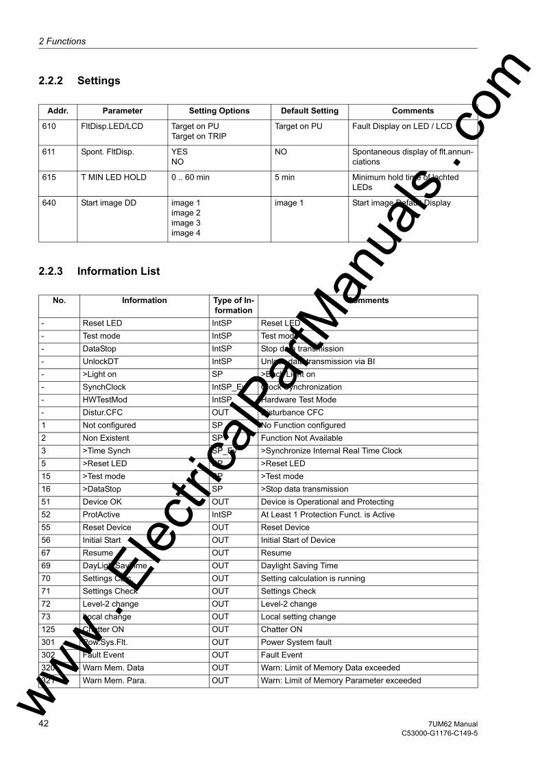
2 Functions
om
2.2.2 Settings
2.2.3 Information List
Addr. Parameter Setting Options Default Setting Comments
610 FltDisp.LED/LCD Target on PUTarget on TRIP
Target on PU Fault Display on LED / LCD
611 Spont. FltDisp. YESNO
NO Spontaneous display of flt.annun-ciations
615 T MIN LED HOLD 0 .. 60 min 5 min Minimum hold time of lachted LEDs
640 Start image DD image 1image 2image 3image 4
image 1 Start image Default Display
No. Information Type of In-formation
Comments
- Reset LED IntSP Reset LED- Test mode IntSP Test mode- DataStop IntSP Stop data transmission- UnlockDT IntSP Unlock data transmission via BI- >Light on SP >Back Light on- SynchClock IntSP_Ev Clock Synchronization- HWTestMod IntSP Hardware Test Mode- Distur.CFC OUT Disturbance CFC1 Not configured SP No Function configured2 Non Existent SP Function Not Available3 >Time Synch SP_Ev >Synchronize Internal Real Time Clock5 >Reset LED SP >Reset LED15 >Test mode SP >Test mode16 >DataStop SP >Stop data transmission51 Device OK OUT Device is Operational and Protecting52 ProtActive IntSP At Least 1 Protection Funct. is Active55 Reset Device OUT Reset Device56 Initial Start OUT Initial Start of Device67 Resume OUT Resume69 DayLightSavTime OUT Daylight Saving Time70 Settings Calc. OUT Setting calculation is running71 Settings Check OUT Settings Check72 Level-2 change OUT Level-2 change73 Local change OUT Local setting change125 Chatter ON OUT Chatter ON301 Pow.Sys.Flt. OUT Power System fault302 Fault Event OUT Fault Event320 Warn Mem. Data OUT Warn: Limit of Memory Data exceeded321 Warn Mem. Para. OUT Warn: Limit of Memory Parameter exceededww .
Elec
tricalP
artM
anua
ls . c
42 7UM62 ManualC53000-G1176-C149-5
w

2.2 Devicew
322 Warn Mem. Oper. OUT Warn: Limit of Memory Operation exceeded323 Warn Mem. New OUT Warn: Limit of Memory New exceeded545 PU Time VI Time from Pickup to drop out546 TRIP Time VI Time from Pickup to TRIP
No. Information Type of In-formation
Comments
ww . El
ectric
alPar
tMan
uals
. com
437UM62 ManualC53000-G1176-C149-5
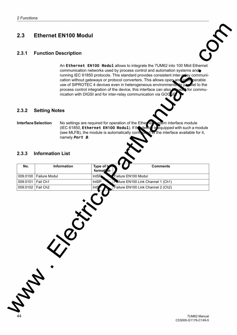
2 Functions
om
2.3 Ethernet EN100 Modul
2.3.1 Function Description
An Ethernet EN100 Modul allows to integrate the 7UM62 into 100 Mbit Ethernet communication networks used by process control and automation systems and running IEC 61850 protocols. This standard provides consistent inter-relay communi-cation without gateways or protocol converters. This allows open and interoperable use of SIPROTEC 4 devices even in heterogeneous environments. In parallel to the process control integration of the device, this interface can also be used for commu-nication with DIGSI and for inter-relay communication via GOOSE.
2.3.2 Setting Notes
Interface Selection No settings are required for operation of the Ethernet system interface module (IEC 61850, Ethernet EN100 Modul). If the device is equipped with such a module (see MLFB), the module is automatically configured to the interface available for it, namely Port B.
2.3.3 Information List
No. Information Type of In-formation
Comments
009.0100 Failure Modul IntSP Failure EN100 Modul009.0101 Fail Ch1 IntSP Failure EN100 Link Channel 1 (Ch1)009.0102 Fail Ch2 IntSP Failure EN100 Link Channel 2 (Ch2)
ww . El
ectric
alPar
tMan
uals
. c
44 7UM62 ManualC53000-G1176-C149-5
w
2.4 Functional Scopew
2.4 Functional Scope
The 7UM62 device incorporates numerous protection and supplementary functions. The hardware and firmware provided is designed for this scope of functions. Never-theless a few restrictions apply to the use of the earth fault current and earth fault voltage inputs IEE and UE respectively. The same input cannot be simultaneously fed with different measured values, e.g. for rotor earth fault protection and stator earth fault protection. Chapter 2.4.2 gives on overview of the particular inputs accessed by the various protection functions.
In addition the command functions can be matched to the system conditions. Also in-dividual functions can be enabled or disabled during configuration. Functions not needed can be thus be deactivated.
The available protection and supplementary functions can be configured as Enabled or Disabled. For some functions a choice between several alternatives is possible, as described below.
Functions that are configured as Disabled are not processed by the 7UM62: There are no indications, and corresponding settings (functions, limit values) are not dis-played during setting.
2.4.1 Functional Description
Configuration of the Functional Scope
Configuration settings can be entered using a PC and the software program DIGSI and transferred via the front serial port or the rear service interface. The procedure is described in detail in the SIPROTEC 4 System Description /1/.
Entry of password No. 7 (for setting modification) is required to modify configuration settings. Without the password, the settings may be read, but may not be modified and transmitted to the device.
The functional scope with the available alternatives is set in the Device Configuration dialog box to match equipment requirements.
Note
Available functions and default settings depend on the ordered device variant (see Ap-pendix A.1 for details). Also, not all combinations of protective functions are possible because of certain restrictions imposed by the hardware (see Section 2.4.2).
ww . El
ectric
alPar
tMan
uals
. com
457UM62 ManualC53000-G1176-C149-5

2 Functions
om
2.4.2 Setting Notes
Peculiarities Most settings are self-explanatory. The special cases are described below.
If the setting group change function has to be used, address 103 Grp Chge OPTION must be set to existing. In this case, it is possible to apply two groups of settings for function parameters (refer also to Section 2.6) allowing convenient and fast switch-over between these setting groups. The setting Disabled implies that only one func-tion parameter setting group can be applied and used.
Parameter 104 FAULT VALUE is used to specify whether the oscillographic fault re-cording should record Instant. values or RMS values. If RMS values is stored, the available recording time increases by the factor 16.
For some protection functions you can also choose the measuring inputs of the device to which they will be allocated (side 1 or side 2); for other functions the allocation is fixed (see table 2-1).
For example, address 112 O/C PROT. I> allows such a choice for the I> stage of the overcurrent protection (= Side 1, Side 2 or Disabled).
For the high-current stage I>> of the overcurrent protection, address 113 O/C PROT. I>> determines whether stage NonDirec. SIDE1 or NonDirec.SIDE 2 or Direc. SIDE1 or Direc. SIDE2 is to be operative. By selecting Disabled, this overcurrent stage can be excluded altogether. For the inverse time overcurrent pro-tection 114 O/C PROT. Ip, different sets of dependent characteristics are available, depending on the version ordered; they are either according to IEC or according to ANSI. This function, too, can be allocated to either side 1 or side 2 (= IEC SIDE 1, ANSI SIDE 1, IEC SIDE 2, ANSI SIDE 2). Inverse time overcurrent protection can be excluded altogether by selecting Disabled.
The following table shows the allocation of device inputs to the protection functions. The interdependencies shown here must be kept in mind when configuring the power system. This concerns the UE input, the two sensitive current inputs Iee1 and Iee2 as well as the 3 measuring transducer inputs (TD). Where the UE input is used e.g. by the stator earth fault protection functions, it is no longer available for rotor earth fault pro-tection (R, fn). The same interdependencies apply for measured value transformer inputs. They can be used only by one protection function in each case. Where the TDs are not used by any protection function, they are available for general processing by the measured value blocks in CFC.
ww . El
ectric
alPar
tMan
uals
. c
46 7UM62 ManualC53000-G1176-C149-5
w
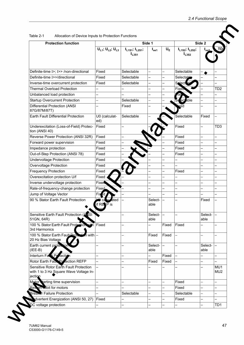
2.4 Functional Scopew
Table 2-1 Allocation of Device Inputs to Protection Functions
Protection function Side 1 Side 2UL1; UL2; UL3 IL1S1; IL2S1;
IL3S1
Iee1 UE IL1S2; IL2S2; IL3S2
Iee2 TD
Definite-time I>; I>> /non-directional Fixed Selectable – – Selectable – –Definite-time I>>/directional Fixed Selectable – – Selectable – –Inverse-time overcurrent protection Fixed Selectable – – Selectable – –Thermal Overload Protection – – – – Fixed – TD2Unbalanced load protection – – – – Fixed – –Startup Overcurrent Protection – Selectable – – Selectable – –Differential Protection (ANSI 87G/87M/87T)
– Fixed – – Fixed – –
Earth Fault Differential Protection U0 (calculat-ed)
Selectable – – Selectable Fixed –
Underexcitation (Loss-of-Field) Protec-tion (ANSI 40)
Fixed – – – Fixed – TD3
Reverse Power Protection (ANSI 32R) Fixed – – – Fixed – –Forward power supervision Fixed – – – Fixed – –Impedance protection Fixed – – – Fixed – –Out-of-Step Protection (ANSI 78) Fixed – – – Fixed – –Undervoltage Protection Fixed – – – – – –Overvoltage Protection Fixed – – – – – –Frequency Protection Fixed – – – Fixed – –Overexcitation protection U/f Fixed – – – – – –Inverse undervoltage protection Fixed – – – – – –Rate-of-frequency-change protection Fixed – – – – – –Jump of Voltage Vector Fixed – – – – – –90 % Stator Earth Fault Protection U0 calculated
if REFP is used
– Select-able
– – Fixed –
Sensitive Earth Fault Protection (ANSI 51GN, 64R)
– – Select-able
– – Select-able
–
100 % Stator Earth Fault Protection with 3rd Harmonics
Fixed – – Fixed Fixed – –
100 % Stator Earth Fault Protection with20 Hz Bias Voltage
– – Fixed Fixed – – –
Earth current protection B(IEE-B)
– – Select-able
– – Select-able
–
Interturn Fault Protection – – – Fixed – – –Rotor Earth Fault Protection REFP – – Fixed Fixed – – –Sensitive Rotor Earth Fault Protection with 1 to 3 Hz Square Wave Voltage In-jection
– – – – – – MU1 MU2
Motor starting time supervision – – – – Fixed – –Restart inibit for motors – – – – Fixed – –Breaker Failure Protection – Selectable – – Selectable – –Inadvertent Energization (ANSI 50, 27) Fixed – – – Fixed – –DC voltage protection – – – – – – TD1ww .
Elec
tricalP
artM
anua
ls . c
om
477UM62 ManualC53000-G1176-C149-5

2 Functions
om
For the differential protection, address 120 DIFF. PROT. allows to specify the type of protected object (Generator/Motor or 3 phase transf.); the function can be excluded altogether by setting Disabled.
Figure 2-2 Use as Generator Differential Protection
Figure 2-3 Use as Block Differential Protection (Overall Protection)
Fuse Failure Monitor Fixed – – – Fixed – –Trip Circuit Monitor (ANSI 74TC) – – – – – – –Threshold Supervision Fixed – – – Fixed – –External Trip Coupling – – – – – – –
Protection function Side 1 Side 2UL1; UL2; UL3 IL1S1; IL2S1;
IL3S1
Iee1 UE IL1S2; IL2S2; IL3S2
Iee2 TD
ww . El
ectric
alPar
tMan
uals
. c
48 7UM62 ManualC53000-G1176-C149-5
w
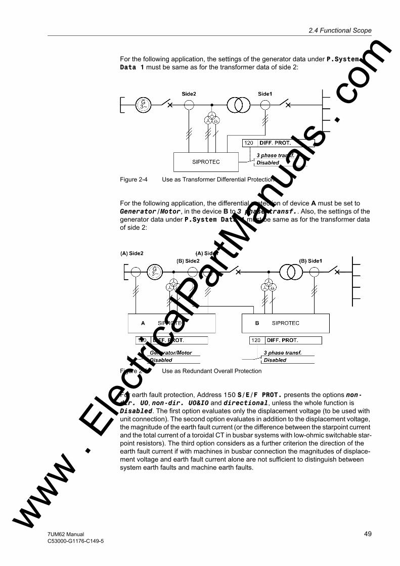
2.4 Functional Scopew
For the following application, the settings of the generator data under P.System Data 1 must be same as for the transformer data of side 2:
Figure 2-4 Use as Transformer Differential Protection
For the following application, the differential protection of device A must be set to Generator/Motor, in the device B to 3 phase transf.. Also, the settings of the generator data under P.System Data 1 must be same as for the transformer data of side 2:
Figure 2-5 Use as Redundant Overall Protection
For earth fault protection, Address 150 S/E/F PROT. presents the options non-dir. U0, non-dir. U0&I0 and directional, unless the whole function is Disabled. The first option evaluates only the displacement voltage (to be used with unit connection). The second option evaluates in addition to the displacement voltage, the magnitude of the earth fault current (or the difference between the starpoint current and the total current of a toroidal CT in busbar systems with low-ohmic switchable star-point resistors). The third option considers as a further criterion the direction of the earth fault current if with machines in busbar connection the magnitudes of displace-ment voltage and earth fault current alone are not sufficient to distinguish between system earth faults and machine earth faults.
ww . El
ectric
alPar
tMan
uals
. com
497UM62 ManualC53000-G1176-C149-5

2 Functions
om
Address 151 O/C PROT. IEE> is used to specify which input will be used for earth fault current measurement (with IEE1 or with IEE2).
Address 170 BREAKER FAILURE specifies whether the circuit breaker failure protec-tion will apply for Side 1 or Side 2.
If the 7UM62 is equipped with analog outputs and you want to use them, the address-es 173, 174, 175 and 176 allow to allocate the available measured values to the analog outputs. All parameters of the analog outputs are accessed under the block address 7301 to 7308.
For trip circuit monitoring, address 182 Trip Cir. Sup. is used to specify whether two binary inputs (2 Binary Inputs) or only one (1 Binary Input) should be utilized, or whether the function is configured as Disabled.
ww . El
ectric
alPar
tMan
uals
. c
50 7UM62 ManualC53000-G1176-C149-5
w
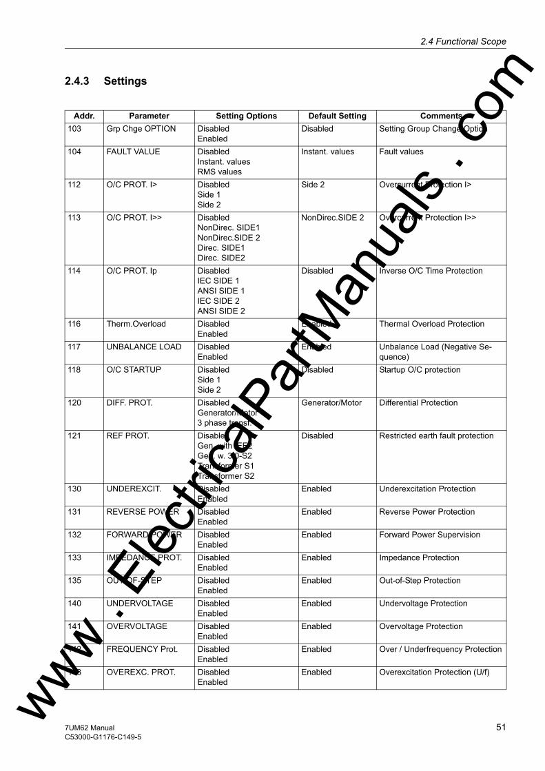
2.4 Functional Scopew
2.4.3 Settings
Addr. Parameter Setting Options Default Setting Comments103 Grp Chge OPTION Disabled
EnabledDisabled Setting Group Change Option
104 FAULT VALUE DisabledInstant. valuesRMS values
Instant. values Fault values
112 O/C PROT. I> DisabledSide 1Side 2
Side 2 Overcurrent Protection I>
113 O/C PROT. I>> DisabledNonDirec. SIDE1NonDirec.SIDE 2Direc. SIDE1Direc. SIDE2
NonDirec.SIDE 2 Overcurrent Protection I>>
114 O/C PROT. Ip DisabledIEC SIDE 1ANSI SIDE 1IEC SIDE 2ANSI SIDE 2
Disabled Inverse O/C Time Protection
116 Therm.Overload DisabledEnabled
Enabled Thermal Overload Protection
117 UNBALANCE LOAD DisabledEnabled
Enabled Unbalance Load (Negative Se-quence)
118 O/C STARTUP DisabledSide 1Side 2
Disabled Startup O/C protection
120 DIFF. PROT. DisabledGenerator/Motor3 phase transf.
Generator/Motor Differential Protection
121 REF PROT. DisabledGen. with IEE2Gen. w. 3I0-S2Transformer S1Transformer S2
Disabled Restricted earth fault protection
130 UNDEREXCIT. DisabledEnabled
Enabled Underexcitation Protection
131 REVERSE POWER DisabledEnabled
Enabled Reverse Power Protection
132 FORWARD POWER DisabledEnabled
Enabled Forward Power Supervision
133 IMPEDANCE PROT. DisabledEnabled
Enabled Impedance Protection
135 OUT-OF-STEP DisabledEnabled
Enabled Out-of-Step Protection
140 UNDERVOLTAGE DisabledEnabled
Enabled Undervoltage Protection
141 OVERVOLTAGE DisabledEnabled
Enabled Overvoltage Protection
142 FREQUENCY Prot. DisabledEnabled
Enabled Over / Underfrequency Protection
143 OVEREXC. PROT. DisabledEnabled
Enabled Overexcitation Protection (U/f)ww . El
ectric
alPar
tMan
uals
. com
517UM62 ManualC53000-G1176-C149-5
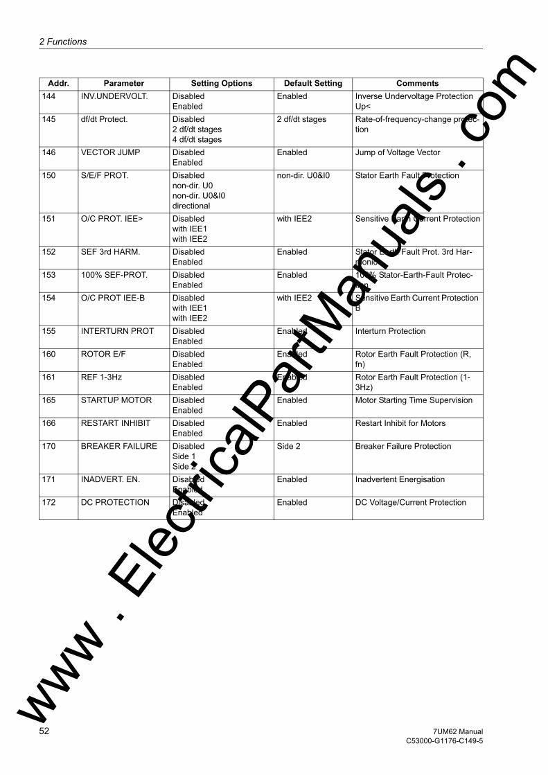
2 Functions
om
144 INV.UNDERVOLT. DisabledEnabledEnabled Inverse Undervoltage Protection Up<
145 df/dt Protect. Disabled2 df/dt stages4 df/dt stages
2 df/dt stages Rate-of-frequency-change protec-tion
146 VECTOR JUMP DisabledEnabled
Enabled Jump of Voltage Vector
150 S/E/F PROT. Disablednon-dir. U0non-dir. U0&I0directional
non-dir. U0&I0 Stator Earth Fault Protection
151 O/C PROT. IEE> Disabledwith IEE1with IEE2
with IEE2 Sensitive Earth Current Protection
152 SEF 3rd HARM. DisabledEnabled
Enabled Stator Earth Fault Prot. 3rd Har-monic
153 100% SEF-PROT. DisabledEnabled
Enabled 100% Stator-Earth-Fault Protec-tion
154 O/C PROT IEE-B Disabledwith IEE1with IEE2
with IEE2 Sensitive Earth Current Protection B
155 INTERTURN PROT DisabledEnabled
Enabled Interturn Protection
160 ROTOR E/F DisabledEnabled
Enabled Rotor Earth Fault Protection (R, fn)
161 REF 1-3Hz DisabledEnabled
Enabled Rotor Earth Fault Protection (1-3Hz)
165 STARTUP MOTOR DisabledEnabled
Enabled Motor Starting Time Supervision
166 RESTART INHIBIT DisabledEnabled
Enabled Restart Inhibit for Motors
170 BREAKER FAILURE DisabledSide 1Side 2
Side 2 Breaker Failure Protection
171 INADVERT. EN. DisabledEnabled
Enabled Inadvertent Energisation
172 DC PROTECTION DisabledEnabled
Enabled DC Voltage/Current Protection
Addr. Parameter Setting Options Default Setting Comments
ww . El
ectric
alPar
tMan
uals
. c
52 7UM62 ManualC53000-G1176-C149-5
w
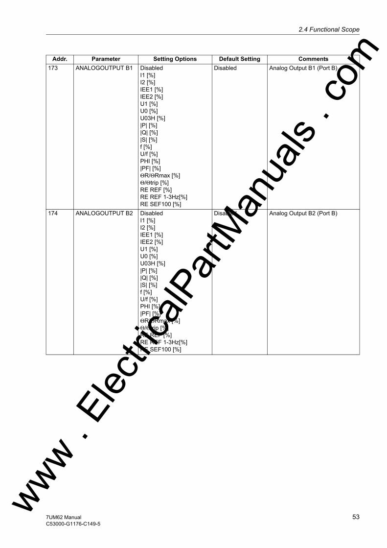
2.4 Functional Scopew
173 ANALOGOUTPUT B1 DisabledI1 [%]I2 [%]IEE1 [%]IEE2 [%]U1 [%]U0 [%]U03H [%]|P| [%]|Q| [%]|S| [%]f [%]U/f [%]PHI [%]|PF| [%]ΘR/ΘRmax [%]Θ/Θtrip [%]RE REF [%]RE REF 1-3Hz[%]RE SEF100 [%]
Disabled Analog Output B1 (Port B)
174 ANALOGOUTPUT B2 DisabledI1 [%]I2 [%]IEE1 [%]IEE2 [%]U1 [%]U0 [%]U03H [%]|P| [%]|Q| [%]|S| [%]f [%]U/f [%]PHI [%]|PF| [%]ΘR/ΘRmax [%]Θ/Θtrip [%]RE REF [%]RE REF 1-3Hz[%]RE SEF100 [%]
Disabled Analog Output B2 (Port B)
Addr. Parameter Setting Options Default Setting Comments
ww . El
ectric
alPar
tMan
uals
. com
537UM62 ManualC53000-G1176-C149-5
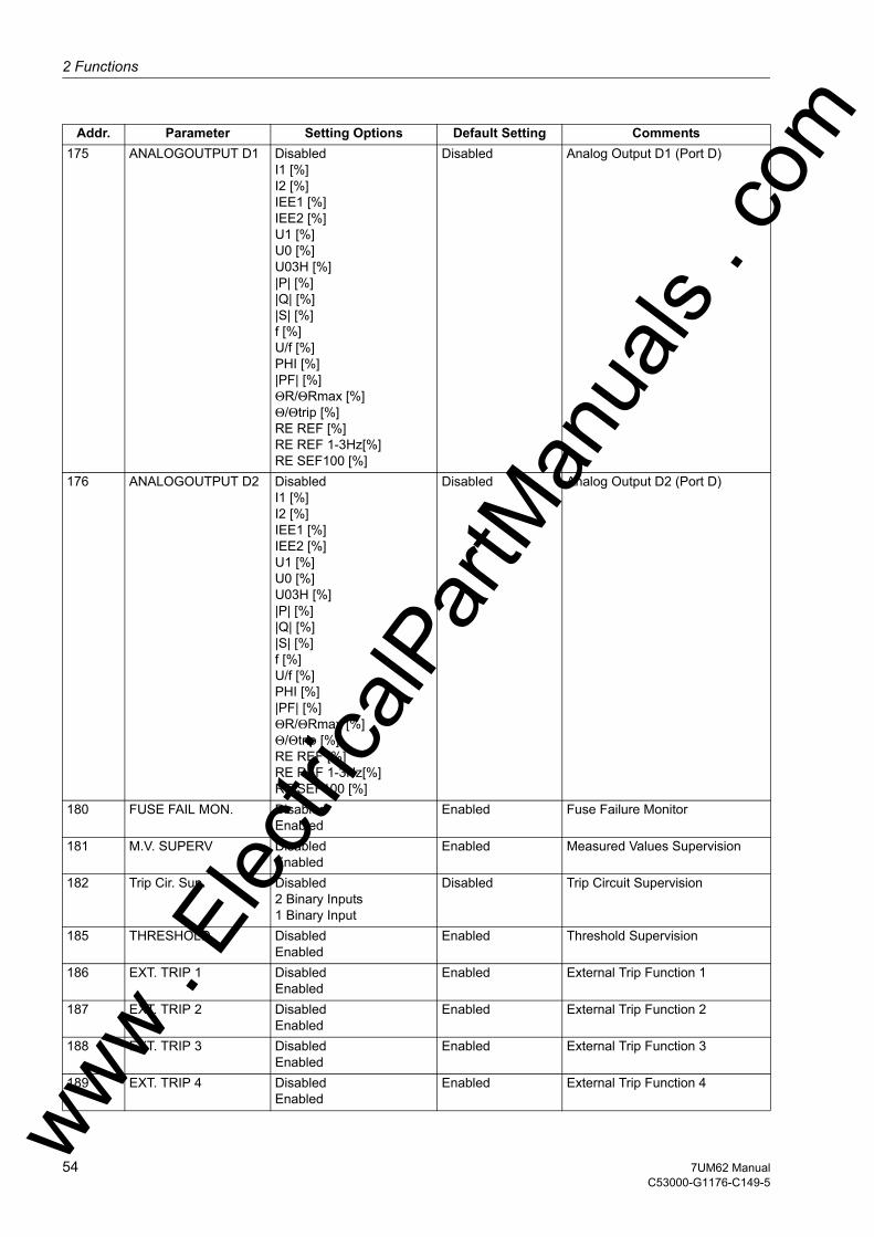
2 Functions
om
175 ANALOGOUTPUT D1 DisabledI1 [%]I2 [%]IEE1 [%]IEE2 [%]U1 [%]U0 [%]U03H [%]|P| [%]|Q| [%]|S| [%]f [%]U/f [%]PHI [%]|PF| [%]ΘR/ΘRmax [%]Θ/Θtrip [%]RE REF [%]RE REF 1-3Hz[%]RE SEF100 [%]Disabled Analog Output D1 (Port D)
176 ANALOGOUTPUT D2 DisabledI1 [%]I2 [%]IEE1 [%]IEE2 [%]U1 [%]U0 [%]U03H [%]|P| [%]|Q| [%]|S| [%]f [%]U/f [%]PHI [%]|PF| [%]ΘR/ΘRmax [%]Θ/Θtrip [%]RE REF [%]RE REF 1-3Hz[%]RE SEF100 [%]
Disabled Analog Output D2 (Port D)
180 FUSE FAIL MON. DisabledEnabled
Enabled Fuse Failure Monitor
181 M.V. SUPERV DisabledEnabled
Enabled Measured Values Supervision
182 Trip Cir. Sup. Disabled2 Binary Inputs1 Binary Input
Disabled Trip Circuit Supervision
185 THRESHOLD DisabledEnabled
Enabled Threshold Supervision
186 EXT. TRIP 1 DisabledEnabled
Enabled External Trip Function 1
187 EXT. TRIP 2 DisabledEnabled
Enabled External Trip Function 2
188 EXT. TRIP 3 DisabledEnabled
Enabled External Trip Function 3
189 EXT. TRIP 4 DisabledEnabled
Enabled External Trip Function 4
Addr. Parameter Setting Options Default Setting Comments
ww . El
ectric
alPar
tMan
uals
. c
54 7UM62 ManualC53000-G1176-C149-5
w

2.4 Functional Scopew
190 RTD-BOX INPUT DisabledPort CPort D
Disabled External Temperature Input
191 RTD CONNECTION 6 RTD simplex6 RTD HDX12 RTD HDX
6 RTD simplex Ext. Temperature Input Connec-tion Type
Addr. Parameter Setting Options Default Setting Comments
ww . El
ectric
alPar
tMan
uals
. com
557UM62 ManualC53000-G1176-C149-5
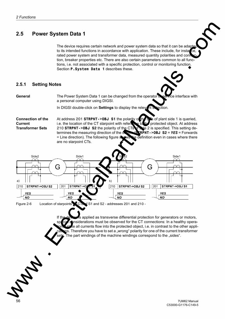
2 Functions
om
2.5 Power System Data 1
The device requires certain network and power system data so that it can be adapted to its intended functions in accordance with application. These include, for instance, rated power system and transformer data, measured quantity polarities and connec-tion, breaker properties etc. There are also certain parameters common to all func-tions, i.e. not associated with a specific protection, control or monitoring function. Section P.System Data 1 describes these.
2.5.1 Setting Notes
General The Power System Data 1 can be changed from the operator or service interface with a personal computer using DIGSI.
In DIGSI double-click on Settings to display the relevant selection.
Connection of the Current Transformer Sets
At address 201 STRPNT->OBJ S1 the polarity of the CTs of plant side 1 is queried, i.e. the location of the CT starpoint with reference to the protected object. At address 210 STRPNT->OBJ S2 the polarity of the CTs of side 2 is specified. This setting de-termines the measuring direction of the device (STRPNT->OBJ S2 = YES = Forwards = Line direction). The following figure shows the definition even in cases where there are no starpoint CTs.
Figure 2-6 Location of starpoints for CTs of S1 and S2 - addresses 201 and 210 -
If the device is applied as transverse differential protection for generators or motors, special considerations must be observed for the CT connections: In a healthy opera-tional state all currents flow into the protected object, i.e. in contrast to the other appli-cations. Therefore you have to set a „wrong“ polarity for one of the current transformer sets. The part windings of the machine windings correspond to the „sides“.
ww . El
ectric
alPar
tMan
uals
. c
56 7UM62 ManualC53000-G1176-C149-5
w

2.5 Power System Data 1w
The following figure shows an example. Although the starpoints of both CT sets are turned towards the protected object, „side 2“ is set to the opposite: STRPNT->OBJ S2 = NO.
Figure 2-7 Current Transformer Starpoints in Transverse Differential Protection - Example
Nominal Values of the Transformers on Side 1
At addresses 202 IN-PRI I-SIDE1 and 203 IN-SEC I-SIDE1 information is entered regarding the primary and secondary nominal currents of the CTs of side 1. It is important to ensure that the rated secondary current of the current transformer matches the rated current of the device, otherwise the device will incorrectly calculate primary amperes.
Nominal Values of the Transformers on Side 2
At addresses 211 IN-PRI I-SIDE2 and 212 IN-SEC I-SIDE2 information is entered regarding the primary and secondary nominal currents of the CTs of side 2. It is important to ensure that the rated secondary current of the current transformer matches the rated current of the device, otherwise the device will incorrectly calculate primary amperes.
W0 Correction Angle
A correction of the angle faults of the current and voltage transformers is particularly important with regard to reverse power protection, as in this case a very low active power is computed from a very high apparent power (for small cos ϕ).
At address 204 CT ANGLE W0 a constant correction angle can be entered for the CTs of side 2.
The angle fault difference ∆ϕ between the current and voltage transformers is partic-ularly important in this context. As a correction the sum of the mean angle errors of the current and voltage transformers is set. The corrective value can be determined during machine commissioning (see Section Installation and Commissioning).
Transformation ratios Iee
For the conversion of the ground currents Iee in primary quantities, the device requires the primary/secondary transformation ratio of the earth CTs. The transformation ratio for input 1 is set at the address 205 FACTOR IEE1, the ratio for input 2 at 213 FACTOR IEE2 .
Nominal Values of Voltage Transform-ers
At addresses 221 Unom PRIMARY and 222 Unom SECONDARY, information is entered regarding the primary nominal voltage and secondary nominal voltages (phase-to-phase) of the connected voltage transformers.ww . El
ectric
alPar
tMan
uals
. com
577UM62 ManualC53000-G1176-C149-5
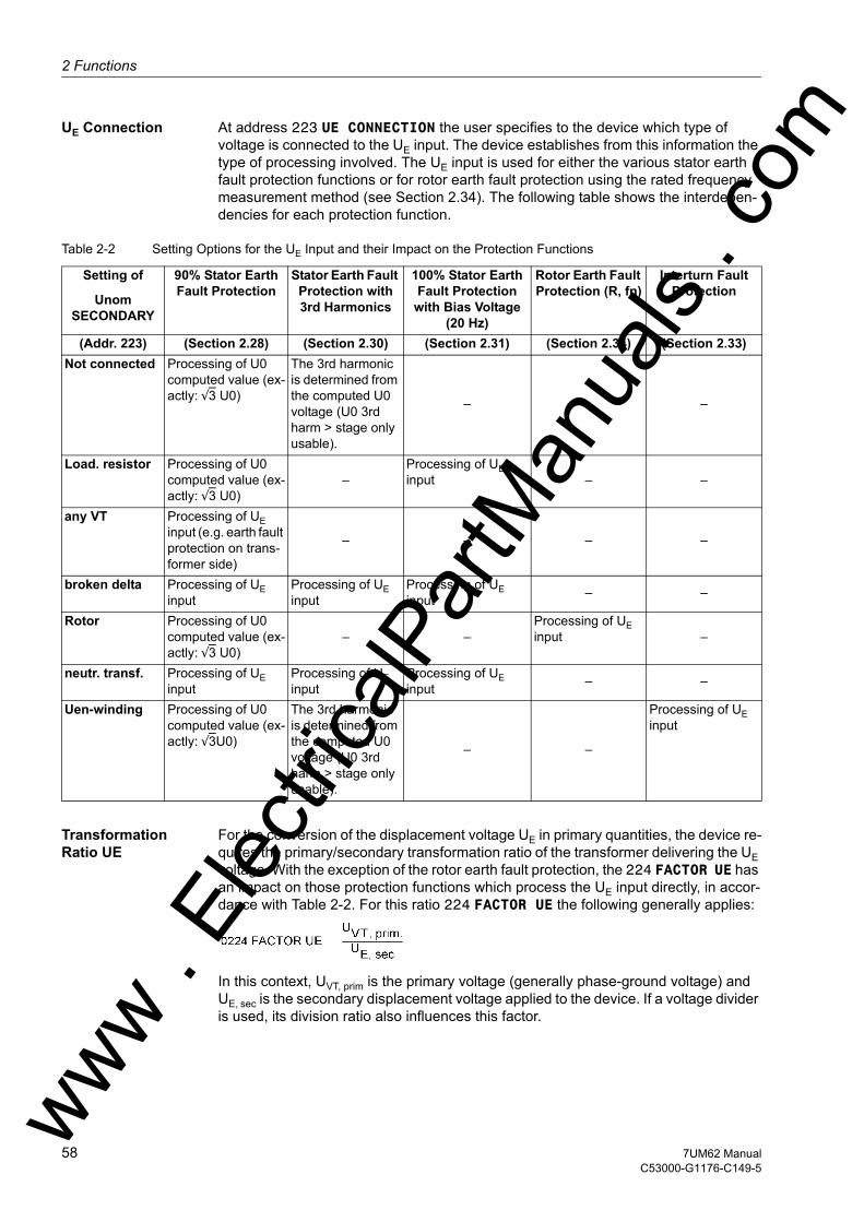
2 Functions
om
UE Connection At address 223 UE CONNECTION the user specifies to the device which type of voltage is connected to the UE input. The device establishes from this information the type of processing involved. The UE input is used for either the various stator earth fault protection functions or for rotor earth fault protection using the rated frequency measurement method (see Section 2.34). The following table shows the interdepen-dencies for each protection function.
Table 2-2 Setting Options for the UE Input and their Impact on the Protection Functions
Transformation Ratio UE
For the conversion of the displacement voltage UE in primary quantities, the device re-quires the primary/secondary transformation ratio of the transformer delivering the UE voltage. With the exception of the rotor earth fault protection, the 224 FACTOR UE has an impact on those protection functions which process the UE input directly, in accor-dance with Table 2-2. For this ratio 224 FACTOR UE the following generally applies:
In this context, UVT, prim is the primary voltage (generally phase-ground voltage) and UE, sec is the secondary displacement voltage applied to the device. If a voltage divider is used, its division ratio also influences this factor.
Setting of
Unom SECONDARY
90% Stator Earth Fault Protection
Stator Earth Fault Protection with 3rd Harmonics
100% Stator Earth Fault Protection
with Bias Voltage (20 Hz)
Rotor Earth Fault Protection (R, fn)
Interturn Fault Protection
(Addr. 223) (Section 2.28) (Section 2.30) (Section 2.31) (Section 2.34) (Section 2.33)Not connected Processing of U0
computed value (ex-actly: √3 U0)
The 3rd harmonic is determined from the computed U0 voltage (U0 3rd harm > stage only usable).
– – –
Load. resistor Processing of U0 computed value (ex-actly: √3 U0)
–Processing of UE input – –
any VT Processing of UE input (e.g. earth fault protection on trans-former side)
– – – –
broken delta Processing of UE input
Processing of UE input
Processing of UE input – –
Rotor Processing of U0 computed value (ex-actly: √3 U0)
– –Processing of UE input –
neutr. transf. Processing of UE input
Processing of UE input
Processing of UE input – –
Uen-winding Processing of U0 computed value (ex-actly: √3U0)
The 3rd harmonic is determined from the computed U0 voltage (U0 3rd harm > stage only usable).
– –
Processing of UE input
ww . El
ectric
alPar
tMan
uals
. c
58 7UM62 ManualC53000-G1176-C149-5
w

2.5 Power System Data 1w
The following equation results for the example in Section 2.1 Figure 2-1 „Unit connec-tion“, with the power system data selected there and an 1:5 voltage divider ratio
Uph/Udelta adaptation factor
The address 225 serves to communicate the adaptation factor between the phase voltage and the displacement voltage to the device. This information is relevant for measured quantity monitoring.
If the voltage transformer set has open delta windings and if these windings are con-nected to the device (UE input), this must be specified accordingly in address 223 (see above). Since the transformation between voltage transformers usually is as follows:
the factor Uph/Udelta (secondary voltage, address 225 Uph / Udelta) in relation to 3/√3 = √3 = 1.73 must be used if the Udelta voltage is connected. For other trans-formation ratios, i.e. the formation of the displacement voltage via an interconnected transformer set, the factor must be corrected accordingly.
Protected Object: Transformer
If a transformer was specified as the protected object during differential protection configuration, the parameter 241 UN-PRI SIDE 1 appears in the Power System Data 1. It specifies the nominal primary voltage of side 1 of the protected object (transform-er).
At address 242 STARPNT SIDE 1 you specify how the starpoint (Solid Earthed; Isolated) of side 1 is treated. This setting has an influence on the measured value monitoring (summation current monitoring); in transformer differential protection it is also important for vector group correction and the treatment of the zero sequence cur-rent.
The setting Isolated can be chosen if the starpoint has no earthing. If the transform-er starpoint is connected to a Petersen coil or a surge voltage arrester, choose the setting Solid Earthed. The same applies to low-ohmic or solid starpoint earthing.
The parameters 243 UN-PRI SIDE 2 and 244 STARPNT SIDE 2 determine respec-tively the rated primary voltage and the starpoint of side 2 of the transformer.
Parameter 246 VECTOR GRP S2 is used to specify the vector group numeral referred to side 1 of the transformer. It is not necessary to specify whether the connection is delta, wye or zigzag.
At address 249 SN TRANSFORMER the rated apparent power is entered. From this the rated currents for sides 1 and 2 are calculated as follows:
These nominal currents are only considered for differential protection and can differ from the generator nominal ratings.
ww . El
ectric
alPar
tMan
uals
. com
597UM62 ManualC53000-G1176-C149-5

2 Functions
om
For the overcurrent protection functions (Sections 2.8, 2.9, and 2.10) and for the breaker failure protection, sides 1 and 2 can be allocated freely. If the differential pro-tection is set to 120 3 phase transf., the following normalizing factors apply for the primary side protection settings in DIGSI.
Setting parameters:
SN, Transf 249 SN TRANSFORMER
UN, S1 241 UN-PRI SIDE 1
SN, Generator 252 SN GEN/MOTOR
UN, Generator 251 UN GEN/MOTOR
These normalizing factors apply for transformer protection and overall protection (see Section2.4.2, Figure 2-3 „Block Differential Protection“ and Figure 2-4 „Transformer Differential Protection“).
Protected Object: Generator/Motor
Regardless of the configuration and intended use of the differential protection, the generator/motor ratings must be specified. Parameter 251 UN GEN/MOTOR specifies the primary rated voltage of the protected generator or motor. At parameter 252 SN GEN/MOTOR the rated apparent power is entered. From these values the nominal gen-erator/motor current for plant side 2 is calculated:
Setting parameters:
SN, Generator 252 SN GEN/MOTOR
UN, Generator 251 UN GEN/MOTOR
The above formula is also used by the DIGSI program to establish the normalizing factors for the primary side protection settings of the overcurrent protection functions (Sections 2.8, 2.9, and 2.10) and of the breaker failure protection, where the sides 1 and 2 can be freely allocated. Normalization is active if the differential protection in the scope of functions is set to 120 Disabled or Generator/Motor. It applies for both side 1 and side 2.
At addresses 242 STARPNT SIDE 1 and 244 STARPNT SIDE 2 you specify the starpoints. For generator protection applications, set Isolated. This is even valid if a loading resistor is connected to the generator starpoint. An exception from this are low-voltage machines with solid starpoint earthing.
Rated System Fre-quency
The nominal frequency of the system is set in Address 270 Rated Frequency. The factory setting of the model variant must only be changed if the device is to be used for a purpose other than intended when ordering.
ww . El
ectric
alPar
tMan
uals
. c
60 7UM62 ManualC53000-G1176-C149-5
w
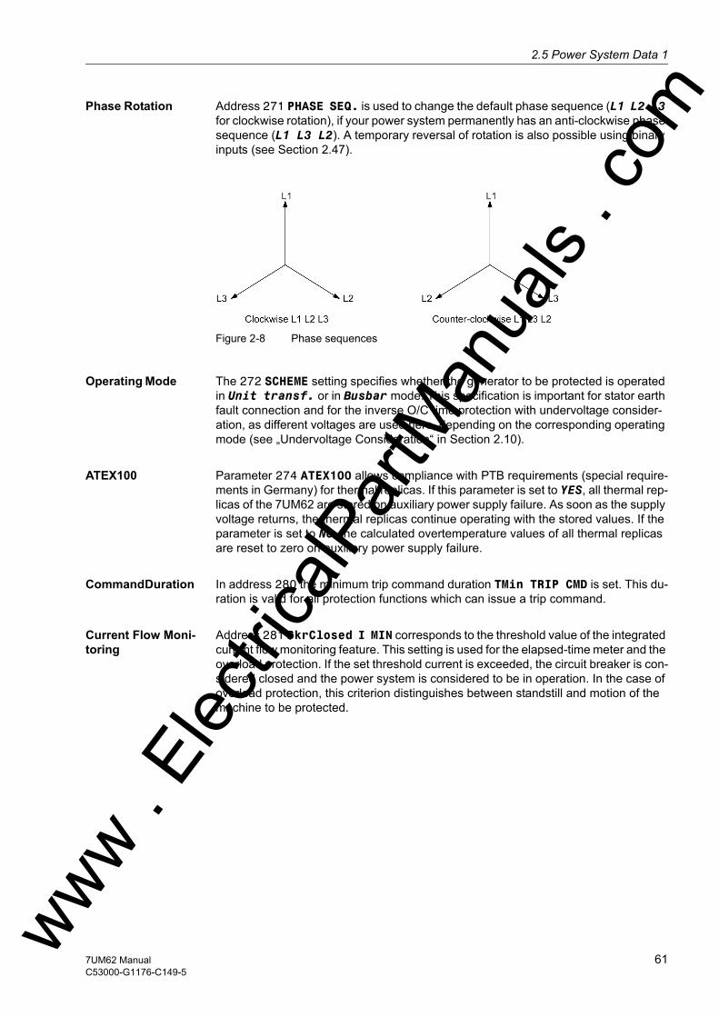
2.5 Power System Data 1w
Phase Rotation Address 271 PHASE SEQ. is used to change the default phase sequence (L1 L2 L3 for clockwise rotation), if your power system permanently has an anti-clockwise phase sequence (L1 L3 L2). A temporary reversal of rotation is also possible using binary inputs (see Section 2.47).
Figure 2-8 Phase sequences
Operating Mode The 272 SCHEME setting specifies whether the generator to be protected is operated in Unit transf. or in Busbar mode. This specification is important for stator earth fault connection and for the inverse O/C time protection with undervoltage consider-ation, as different voltages are used here, depending on the corresponding operating mode (see „Undervoltage Consideration“ in Section 2.10).
ATEX100 Parameter 274 ATEX100 allows compliance with PTB requirements (special require-ments in Germany) for thermal replicas. If this parameter is set to YES, all thermal rep-licas of the 7UM62 are stored on auxiliary power supply failure. As soon as the supply voltage returns, the thermal replicas continue operating with the stored values. If the parameter is set to NO, the calculated overtemperature values of all thermal replicas are reset to zero on auxiliary power supply failure.
Command Duration In address 280 the minimum trip command duration TMin TRIP CMD is set. This du-ration is valid for all protection functions which can issue a trip command.
Current Flow Moni-toring
Address 281 BkrClosed I MIN corresponds to the threshold value of the integrated current flow monitoring feature. This setting is used for the elapsed-time meter and the overload protection. If the set threshold current is exceeded, the circuit breaker is con-sidered closed and the power system is considered to be in operation. In the case of overload protection, this criterion distinguishes between standstill and motion of the machine to be protected.
ww . El
ectric
alPar
tMan
uals
. com
617UM62 ManualC53000-G1176-C149-5
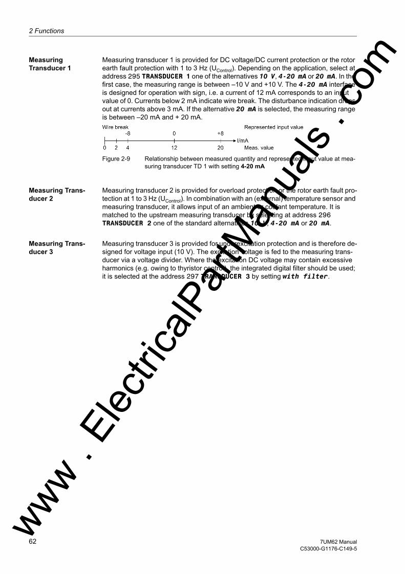
2 Functions
om
Measuring Transducer 1
Measuring transducer 1 is provided for DC voltage/DC current protection or the rotor earth fault protection with 1 to 3 Hz (UControl). Depending on the application, select at address 295 TRANSDUCER 1 one of the alternatives 10 V, 4-20 mA or 20 mA. In the first case, the measuring range is between –10 V and +10 V. The 4-20 mA interface is designed for operation with sign, i.e. a current of 12 mA corresponds to an input value of 0. Currents below 2 mA indicate wire break. The disturbance indication drops out at currents above 3 mA. If the alternative 20 mA is selected, the measuring range is between –20 mA and + 20 mA.
Figure 2-9 Relationship between measured quantity and represented input value at mea-suring transducer TD 1 with setting 4-20 mA
Measuring Trans-ducer 2
Measuring transducer 2 is provided for overload protection or the rotor earth fault pro-tection at 1 to 3 Hz (UControl). In combination with an (external) temperature sensor and measuring transducer, it allows input of an ambient or coolant temperature. It is matched to the upstream measuring transducer by selecting at address 296 TRANSDUCER 2 one of the standard alternatives 10 V, 4-20 mA or 20 mA.
Measuring Trans-ducer 3
Measuring transducer 3 is provided for underexcitation protection and is therefore de-signed for voltage input (10 V). The excitation voltage is fed to the measuring trans-ducer via a voltage divider. Where the excitation DC voltage may contain excessive harmonics (e.g. owing to thyristor control), the integrated digital filter should be used; it is selected at the address 297 TRANSDUCER 3 by setting with filter.
ww . El
ectric
alPar
tMan
uals
. c
62 7UM62 ManualC53000-G1176-C149-5
w
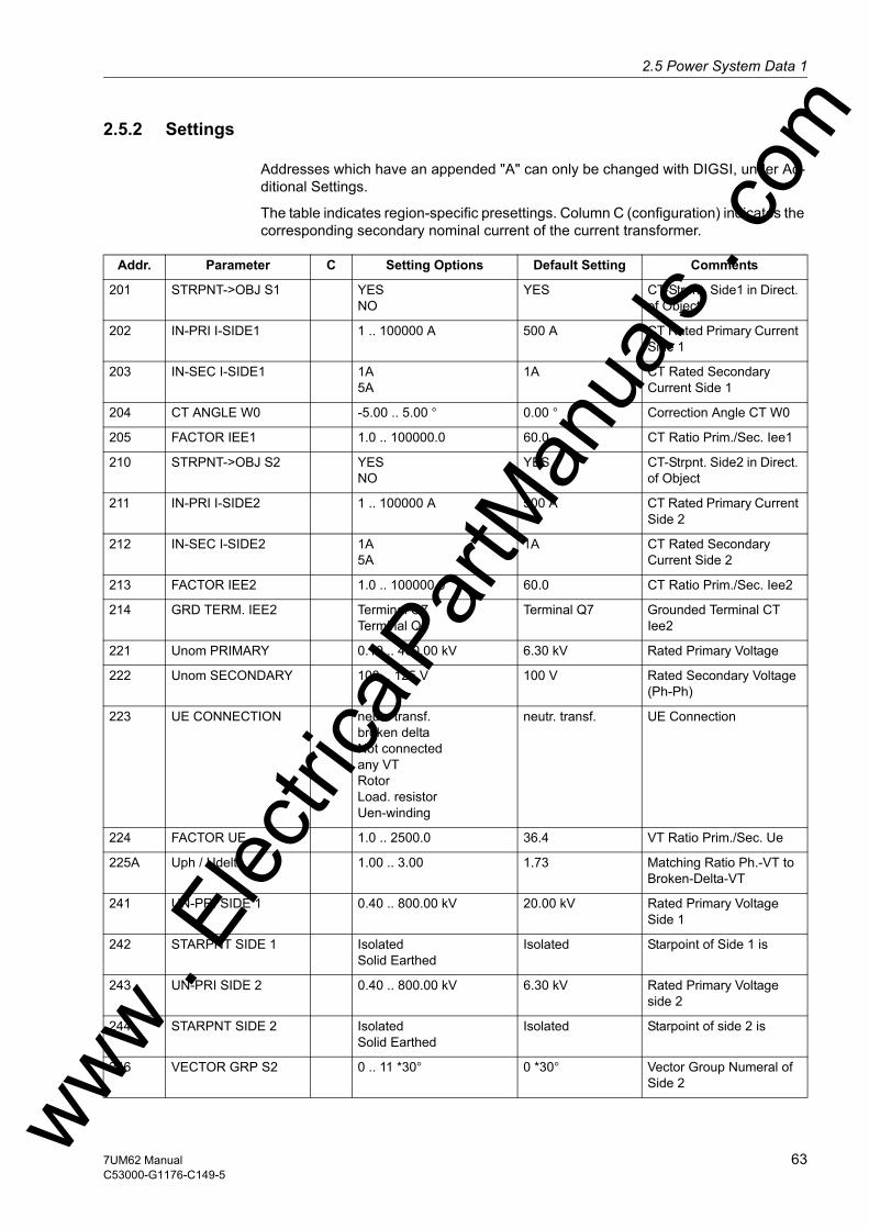
2.5 Power System Data 1w
2.5.2 Settings
Addresses which have an appended "A" can only be changed with DIGSI, under Ad-ditional Settings.
The table indicates region-specific presettings. Column C (configuration) indicates the corresponding secondary nominal current of the current transformer.
Addr. Parameter C Setting Options Default Setting Comments
201 STRPNT->OBJ S1 YESNO
YES CT-Strpnt. Side1 in Direct. of Object
202 IN-PRI I-SIDE1 1 .. 100000 A 500 A CT Rated Primary Current Side 1
203 IN-SEC I-SIDE1 1A5A
1A CT Rated Secondary Current Side 1
204 CT ANGLE W0 -5.00 .. 5.00 ° 0.00 ° Correction Angle CT W0
205 FACTOR IEE1 1.0 .. 100000.0 60.0 CT Ratio Prim./Sec. Iee1
210 STRPNT->OBJ S2 YESNO
YES CT-Strpnt. Side2 in Direct. of Object
211 IN-PRI I-SIDE2 1 .. 100000 A 500 A CT Rated Primary Current Side 2
212 IN-SEC I-SIDE2 1A5A
1A CT Rated Secondary Current Side 2
213 FACTOR IEE2 1.0 .. 100000.0 60.0 CT Ratio Prim./Sec. Iee2
214 GRD TERM. IEE2 Terminal Q7Terminal Q8
Terminal Q7 Grounded Terminal CT Iee2
221 Unom PRIMARY 0.10 .. 400.00 kV 6.30 kV Rated Primary Voltage
222 Unom SECONDARY 100 .. 125 V 100 V Rated Secondary Voltage (Ph-Ph)
223 UE CONNECTION neutr. transf.broken deltaNot connectedany VTRotorLoad. resistorUen-winding
neutr. transf. UE Connection
224 FACTOR UE 1.0 .. 2500.0 36.4 VT Ratio Prim./Sec. Ue
225A Uph / Udelta 1.00 .. 3.00 1.73 Matching Ratio Ph.-VT to Broken-Delta-VT
241 UN-PRI SIDE 1 0.40 .. 800.00 kV 20.00 kV Rated Primary Voltage Side 1
242 STARPNT SIDE 1 IsolatedSolid Earthed
Isolated Starpoint of Side 1 is
243 UN-PRI SIDE 2 0.40 .. 800.00 kV 6.30 kV Rated Primary Voltage side 2
244 STARPNT SIDE 2 IsolatedSolid Earthed
Isolated Starpoint of side 2 is
246 VECTOR GRP S2 0 .. 11 *30° 0 *30° Vector Group Numeral of Side 2ww .
Elec
tricalP
artM
anua
ls . c
om
637UM62 ManualC53000-G1176-C149-5

2 Functions
om
2.5.3 Information List249 SN TRANSFORMER 0.20 .. 5000.00 MVA 5.30 MVA Rated Apparent Power of the Transformer
251 UN GEN/MOTOR 0.40 .. 800.00 kV 6.30 kV Rated Primary Voltage Generator/Motor
252 SN GEN/MOTOR 0.20 .. 5000.00 MVA 5.27 MVA Rated Apparent Power of the Generator
270 Rated Frequency 50 Hz60 Hz
50 Hz Rated Frequency
271 PHASE SEQ. L1 L2 L3L1 L3 L2
L1 L2 L3 Phase Sequence
272 SCHEME BusbarUnit transf.
Busbar Scheme Configuration
274A ATEX100 YESNO
NO Storage of th. Replicas w/o Power Supply
275 FACTOR R SEF 1.0 .. 200.0 37.0 Ratio Prim./Sec. R SEF
276 TEMP. UNIT CelsiusFahrenheit
Celsius Unit of temperature mea-surement
280 TMin TRIP CMD 0.01 .. 32.00 sec 0.15 sec Minimum TRIP Command Duration
281 BkrClosed I MIN 5A 0.20 .. 5.00 A 0.20 A Closed Breaker Min. Current Threshold
1A 0.04 .. 1.00 A 0.04 A
295 TRANSDUCER 1 10 V4-20 mA20 mA
10 V Transducer 1
296 TRANSDUCER 2 10 V4-20 mA20 mA
10 V Transducer 2
297 TRANSDUCER 3 with filterwithout filter
with filter Transducer 3
No. Information Type of In-formation
Comments
361 >FAIL:Feeder VT SP >Failure: Feeder VT (MCB tripped)5002 Operat. Cond. OUT Suitable measured quantities present5145 >Reverse Rot. SP >Reverse Phase Rotation5147 Rotation L1L2L3 OUT Phase Rotation L1L2L35148 Rotation L1L3L2 OUT Phase Rotation L1L3L2
Addr. Parameter C Setting Options Default Setting Comments
ww . El
ectric
alPar
tMan
uals
. c
64 7UM62 ManualC53000-G1176-C149-5
w

2.6 Change Groupw
2.6 Change Group
Two independent groups of parameters can be set for the device functions. During op-eration the user can locally switch between setting groups using the operator panel, binary inputs (if so configured), the operator and service interface per PC, or via the system interface.
A setting group includes the setting values for all functions that have been selected as Enabled during configuration (see Section 2.4). In the 7UM62 device, two indepen-dent setting groups (A and B) are available. Whereas setting values may vary, the se-lected functions of each setting group remain the same.
Where different settings are required for operational reasons, e.g. in pumped storage power stations with a machine operating alternately as a generator and a motor, these settings are made in the setting groups and stored in the device. Depending on the operating mode, the applicable setting group is activated, usually via a binary input.
If multiple setting groups are not required, Group A is the default selection. The rest of this section is not relevant.
2.6.1 Setting Notes
General If the changeover option is desired, on function extent configuration group changeover must be set to Grp Chge OPTION = Enabled (address 103). When setting the func-tion parameters, you configure first setting group A, then setting group B. To find out how to proceed for this, how to copy and to reset setting groups, and how to switch between setting groups during operation, please refer to the SIPROTEC 4 System De-scription /1/.
How to switch between setting groups externally using binary inputs is described in the „Mounting and Connections“ section in Chapter 3.
2.6.2 Settings
2.6.3 Information List
Addr. Parameter Setting Options Default Setting Comments
302 CHANGE Group AGroup BBinary InputProtocol
Group A Change to Another Setting Group
No. Information Type of In-formation
Comments
- Group A IntSP Group A- Group B IntSP Group B7 >Set Group Bit0 SP >Setting Group Select Bit 0
ww . El
ectric
alPar
tMan
uals
. com
657UM62 ManualC53000-G1176-C149-5
2 Functions
om
2.7 Power System Data 2
The general protection data (P.System Data 2) include settings associated with all functions rather than a specific protection or monitoring function. Parameter settings P.System Data 2 can be switched using the setting group.
2.7.1 Functional Description
Setting Groups In the 7UM62 relay, two independent setting groups (A and B) are possible. Whereas setting values may vary, the selected functions of each setting group remain the same.
2.7.2 Setting Notes
General To enter these group-specific general protection data (P.System Data 2), select in the SETTINGS menu theGroup A (Parameter group A), and in it P.System Data 2. The other setting group is accessible under Group B.
Active Power Direc-tion
Address 1108 ACTIVE POWER is used to specify the active power direction in the normal mode (Generator = output or Motor = input) or to adapt it to the power system conditions without device recabling.
ww . El
ectric
alPar
tMan
uals
. c
66 7UM62 ManualC53000-G1176-C149-5
w

2.7 Power System Data 2w
2.7.3 Settings
2.7.4 Information List
Addr. Parameter Setting Options Default Setting Comments
1108 ACTIVE POWER GeneratorMotor
Generator Measurement of Active Power for
No. Information Type of In-formation
Comments
501 Relay PICKUP OUT Relay PICKUP511 Relay TRIP OUT Relay GENERAL TRIP command576 IL1 S1: VI Primary fault current IL1 Side1577 IL2 S1: VI Primary fault current IL2 Side1578 IL3 S1: VI Primary fault current IL3 Side1579 IL1 S2: VI Primary fault current IL1 Side2580 IL2 S2: VI Primary fault current IL2 Side2581 IL3 S2: VI Primary fault current IL3 Side25012 UL1E: VI Voltage UL1E at trip5013 UL2E: VI Voltage UL2E at trip5014 UL3E: VI Voltage UL3E at trip5015 P: VI Active power at trip5016 Q: VI Reactive power at trip5017 f: VI Frequency at trip
ww . El
ectric
alPar
tMan
uals
. com
677UM62 ManualC53000-G1176-C149-5

2 Functions
om
2.8 Definite-Time Overcurrent Protection (I>, ANSI 50/51) with Undervoltage Seal-In
The overcurrent protection is used as backup protection for the short-circuit protection of the protected object. It also provides backup protection for downstream network faults which may be not promptly disconnected thus endangering the protected object.
The 7UM62 relay allows to choose between the input transformers of side 1 and side 2 for allocation of the overcurrent protection function. This choice is made during con-figuration (see Section 2.4).
Initially the currents are numerically filtered so that only the fundamental frequency currents are used for the measurement. This makes the measurement insensitive to transient conditions at the inception of a short-circuit and to asymmetrical short-circuit currents (d.c. component).
In generators where the excitation voltage is taken from the machine terminals, the short-circuit current subsides quickly in the event of adjacent faults (i.e. in the gener-ator or unit transformer region) due to the absence of excitation voltage. Within a few seconds it sinks below the pick-up value of the overcurrent time protection. To avoid that the relay drops out again, the I> stage monitors the positive-sequence component of the voltages and uses it as an additional criterion for detecting a short-circuit. The undervoltage influencing can be disabled off and made ineffective via binary input.
2.8.1 Function Description
I> Stage Each phase current of side 1 or 2 (depending on configuration) is compared individu-ally with the common setting value I> and on overshoot signaled individually. A trip signal is transmitted to the matrix as soon as the corresponding T I> time delay has expired. On delivery the dropout value is set to ± 95 % below the pickup value. For special applications, it is also possible to set a higher value.
Undervoltage Seal-In
The I> stage has a (disconnectable) undervoltage stage. This stage maintains the pick-up signal for a selectable seal-in time if the value falls below a selectable thresh-old of the positive-sequence component of the voltages after an overcurrent pickup - even if the value falls again below the overcurrent value. In this way, the expire of the trip time delay and the tripping of the related breakers is also ensured in these cases. If the voltage recovers before the seal-in time has elapsed or if the undervoltage seal-in is blocked via a binary input, e.g. in case of a tripping of the voltage transformer pro-tective breaker or in case of a machine stopping, the protective relay drops out imme-diately.
The seal-in logic operates separate for each phase. The first pickup starts the timer T-SEAL-IN.
ww . El
ectric
alPar
tMan
uals
. c
68 7UM62 ManualC53000-G1176-C149-5
w
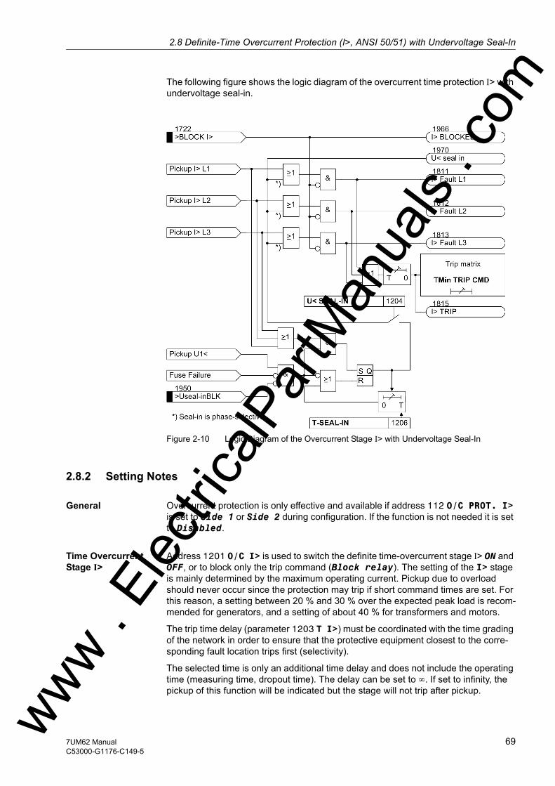
2.8 Definite-Time Overcurrent Protection (I>, ANSI 50/51) with Undervoltage Seal-Inw
The following figure shows the logic diagram of the overcurrent time protection I> with undervoltage seal-in.
Figure 2-10 Logic Diagram of the Overcurrent Stage I> with Undervoltage Seal-In
2.8.2 Setting Notes
General Overcurrent protection is only effective and available if address 112 O/C PROT. I> is set to Side 1 or Side 2 during configuration. If the function is not needed it is set to Disabled.
Time Overcurrent Stage I>
Address 1201 O/C I> is used to switch the definite time-overcurrent stage I> ON and OFF, or to block only the trip command (Block relay). The setting of the I> stage is mainly determined by the maximum operating current. Pickup due to overload should never occur since the protection may trip if short command times are set. For this reason, a setting between 20 % and 30 % over the expected peak load is recom-mended for generators, and a setting of about 40 % for transformers and motors.
The trip time delay (parameter 1203 T I>) must be coordinated with the time grading of the network in order to ensure that the protective equipment closest to the corre-sponding fault location trips first (selectivity).
The selected time is only an additional time delay and does not include the operating time (measuring time, dropout time). The delay can be set to ∞. If set to infinity, the pickup of this function will be indicated but the stage will not trip after pickup. ww . El
ectric
alPar
tMan
uals
. com
697UM62 ManualC53000-G1176-C149-5
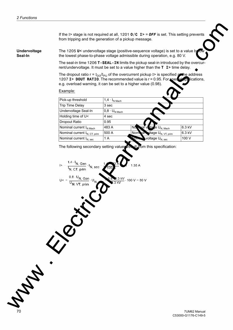
2 Functions
om
If the I> stage is not required at all, 1201 O/C I> = OFF is set. This setting prevents from tripping and the generation of a pickup message.
Undervoltage Seal-In
The 1205 U< undervoltage stage (positive-sequence voltage) is set to a value below the lowest phase-to-phase voltage admissible during operation, e.g. 80 V.
The seal-in time 1206 T-SEAL-IN limits the pickup seal-in introduced by the overcur-rent/undervoltage. It must be set to a value higher than the T I> time delay.
The dropout ratio r = IDO/IPU of the overcurrent pickup I> is specified at the address 1207 I> DOUT RATIO. The recommended value is r = 0.95. For special applications, e.g. overload warning, it can be set to a higher value (0.98).
Example:
The following secondary setting values result from this specification:
Pick-up threshold 1,4 · IN Mach Trip Time Delay 3 secUndervoltage Seal-In 0,8 · UN Mach
Holding time of U< 4 secDropout Ratio 0.95Nominal current IN Mach 483 A Nominal voltage UN, Mach 6.3 kVNominal current IN, CT, prim 500 A Nominal voltage UN, VT, prim 6.3 kVNominal current IN, sec 1 A Nominal voltage UN, sec 100 V
ww . El
ectric
alPar
tMan
uals
. c
70 7UM62 ManualC53000-G1176-C149-5
w
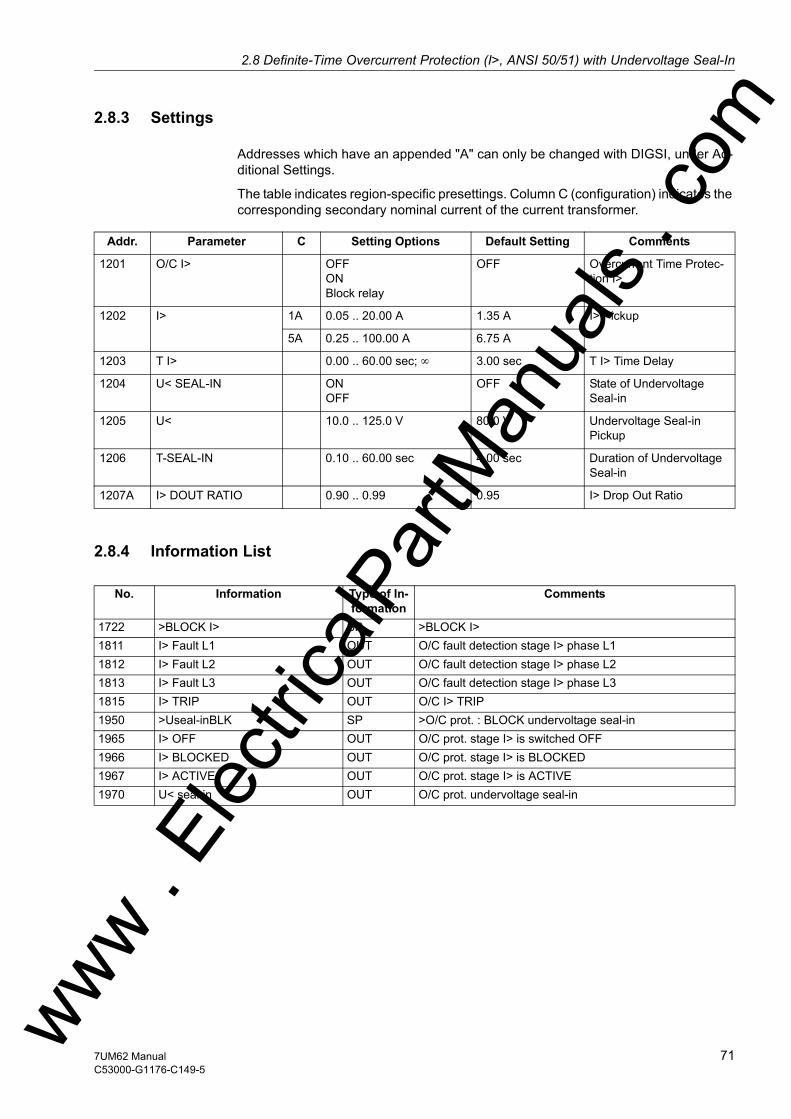
2.8 Definite-Time Overcurrent Protection (I>, ANSI 50/51) with Undervoltage Seal-Inw
2.8.3 Settings
Addresses which have an appended "A" can only be changed with DIGSI, under Ad-ditional Settings.
The table indicates region-specific presettings. Column C (configuration) indicates the corresponding secondary nominal current of the current transformer.
2.8.4 Information List
Addr. Parameter C Setting Options Default Setting Comments
1201 O/C I> OFFONBlock relay
OFF Overcurrent Time Protec-tion I>
1202 I> 1A 0.05 .. 20.00 A 1.35 A I> Pickup
5A 0.25 .. 100.00 A 6.75 A
1203 T I> 0.00 .. 60.00 sec; ∞ 3.00 sec T I> Time Delay
1204 U< SEAL-IN ONOFF
OFF State of Undervoltage Seal-in
1205 U< 10.0 .. 125.0 V 80.0 V Undervoltage Seal-in Pickup
1206 T-SEAL-IN 0.10 .. 60.00 sec 4.00 sec Duration of Undervoltage Seal-in
1207A I> DOUT RATIO 0.90 .. 0.99 0.95 I> Drop Out Ratio
No. Information Type of In-formation
Comments
1722 >BLOCK I> SP >BLOCK I>1811 I> Fault L1 OUT O/C fault detection stage I> phase L11812 I> Fault L2 OUT O/C fault detection stage I> phase L21813 I> Fault L3 OUT O/C fault detection stage I> phase L31815 I> TRIP OUT O/C I> TRIP1950 >Useal-inBLK SP >O/C prot. : BLOCK undervoltage seal-in1965 I> OFF OUT O/C prot. stage I> is switched OFF1966 I> BLOCKED OUT O/C prot. stage I> is BLOCKED1967 I> ACTIVE OUT O/C prot. stage I> is ACTIVE1970 U< seal in OUT O/C prot. undervoltage seal-in
ww . El
ectric
alPar
tMan
uals
. com
717UM62 ManualC53000-G1176-C149-5

2 Functions
om
2.9 Definite-Time Overcurrent Protection (I>>, ANSI 50, 51, 67) with Direction Detection
The overcurrent protection is used as backup protection for the short-circuit protection of the protected object. It also provides backup protection for downstream network faults which may be not promptly disconnected thus endangering the protected object.
The 7UM62 relay allows to choose between the input transformers of side 1 and side 2 for allocation of the overcurrent protection function. This choice is made during con-figuration (see Section 2.4).
In order to ensure that pick-up always occurs even with internal faults, the protection - for generators - is usually connected to the current transformer set in the neutral leads of the machine. If this is not the case for an individual power system, the I>> stage can be combined with a short-circuit direction determination and switch off a generator short circuit by way of an undelayed tripping; the selectivity is not affected by this.
Initially the currents are numerically filtered so that only the fundamental frequency currents are used for the measurement. This makes the measurement insensitive to transient conditions at the inception of a short-circuit and to asymmetrical short-circuit currents (d.c. component).
2.9.1 Function Description
I>> Stage Each phase-current of side 1 or 2 (depending on the configuration) is compared indi-vidually with the common pickup value I>>, and indicated on overshoot. A trip signal is transmitted to the matrix as soon as the corresponding T I>> time delays have ex-pired. The dropout value is ± 95 % below the pick-up value.
Direction Detection If this protection function has been assigned to the input transformers of side 1, the I>> stage is equipped with a (disconnectable) direction element permitting a tripping only for faults in backward (i.e. machine) direction.
For this reason, this stage can be used particularly in applications where no current transformers exist in the generator starpoint and undelayed tripping is nevertheless re-quired on generator faults.
The definition of the current direction in Figure 2-11 applies for the CT of side 1. If the CT of side 2 is used, Forward must be set to determine the current direction.
Figure 2-11 Selectivity via Short-Circuit Direction Detection
ww . El
ectric
alPar
tMan
uals
. c
72 7UM62 ManualC53000-G1176-C149-5
w
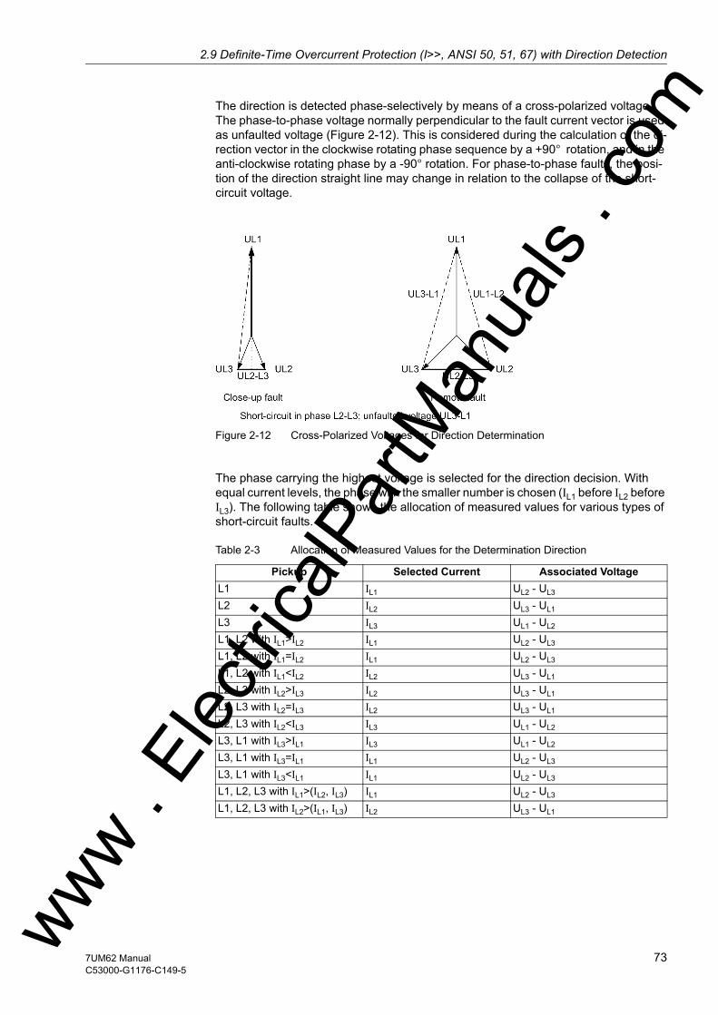
2.9 Definite-Time Overcurrent Protection (I>>, ANSI 50, 51, 67) with Direction Detectionw
The direction is detected phase-selectively by means of a cross-polarized voltage. The phase-to-phase voltage normally perpendicular to the fault current vector is used as unfaulted voltage (Figure 2-12). This is considered during the calculation of the di-rection vector in the clockwise rotating phase sequence by a +90° rotation, and in the anti-clockwise rotating phase by a -90° rotation. For phase-to-phase faults, the posi-tion of the direction straight line may change in relation to the collapse of the short-circuit voltage.
Figure 2-12 Cross-Polarized Voltages for Direction Determination
The phase carrying the highest voltage is selected for the direction decision. With equal current levels, the phase with the smaller number is chosen (IL1 before IL2 before IL3). The following table shows the allocation of measured values for various types of short-circuit faults.
Table 2-3 Allocation of Measured Values for the Determination Direction
Pickup Selected Current Associated VoltageL1 IL1 UL2 - UL3
L2 IL2 UL3 - UL1
L3 IL3 UL1 - UL2
L1, L2 with IL1>IL2 IL1 UL2 - UL3
L1, L2 with IL1=IL2 IL1 UL2 - UL3
L1, L2 with IL1<IL2 IL2 UL3 - UL1
L2, L3 with IL2>IL3 IL2 UL3 - UL1
L2, L3 with IL2=IL3 IL2 UL3 - UL1
L2, L3 with IL2<IL3 IL3 UL1 - UL2
L3, L1 with IL3>IL1 IL3 UL1 - UL2
L3, L1 with IL3=IL1 IL1 UL2 - UL3
L3, L1 with IL3<IL1 IL1 UL2 - UL3
L1, L2, L3 with IL1>(IL2, IL3) IL1 UL2 - UL3
L1, L2, L3 with IL2>(IL1, IL3) IL2 UL3 - UL1
ww . El
ectric
alPar
tMan
uals
. com
737UM62 ManualC53000-G1176-C149-5

2 Functions
om
If the phase-to-phase voltage used for the direction decision is below the minimum value of approx. 7 V, the voltage is taken from a voltage memory. This voltage also allows unambiguous direction determination if the short-circuit voltage has collapsed (short circuit close to generator terminals). After the expiration of the storage time period (2 cycles), the detected direction is saved, as long as no sufficient measuring voltage is available. If a short circuit already exists at generator startup (or for motors or transformers on connection), so that no voltage is present in the memory and no direction can be determined, a trip is issued.
The direction detection can be disabled via binary input.
Figure 2-13 Logic Diagram of I>> Stage with Direction Element
ww . El
ectric
alPar
tMan
uals
. c
74 7UM62 ManualC53000-G1176-C149-5
w
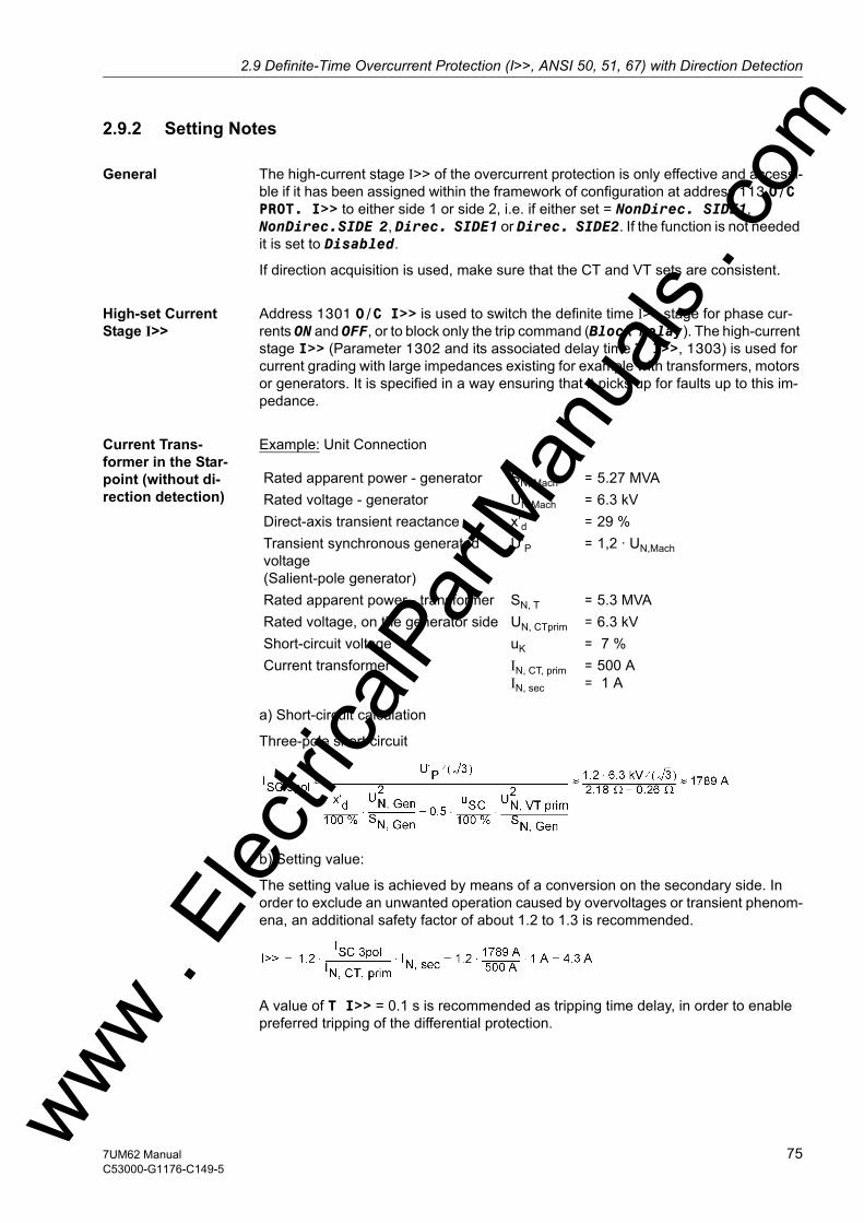
2.9 Definite-Time Overcurrent Protection (I>>, ANSI 50, 51, 67) with Direction Detectionw
2.9.2 Setting Notes
General The high-current stage I>> of the overcurrent protection is only effective and accessi-ble if it has been assigned within the framework of configuration at address 113 O/C PROT. I>> to either side 1 or side 2, i.e. if either set = NonDirec. SIDE1, NonDirec.SIDE 2, Direc. SIDE1 or Direc. SIDE2. If the function is not needed it is set to Disabled.
If direction acquisition is used, make sure that the CT and VT sets are consistent.
High-set Current Stage I>>
Address 1301 O/C I>> is used to switch the definite time I>> stage for phase cur-rents ON and OFF, or to block only the trip command (Block relay). The high-current stage I>> (Parameter 1302 and its associated delay time T I>>, 1303) is used for current grading with large impedances existing for example with transformers, motors or generators. It is specified in a way ensuring that it picks up for faults up to this im-pedance.
Current Trans-former in the Star-point (without di-rection detection)
Example: Unit Connection
a) Short-circuit calculation
Three-pole short circuit
b) Setting value:
The setting value is achieved by means of a conversion on the secondary side. In order to exclude an unwanted operation caused by overvoltages or transient phenom-ena, an additional safety factor of about 1.2 to 1.3 is recommended.
A value of T I>> = 0.1 s is recommended as tripping time delay, in order to enable preferred tripping of the differential protection.
Rated apparent power - generator SN, Mach = 5.27 MVARated voltage - generator UN Mach = 6.3 kVDirect-axis transient reactance x’d = 29 % Transient synchronous generated voltage(Salient-pole generator)
U’P = 1,2 · UN,Mach
Rated apparent power - transformer SN, T = 5.3 MVARated voltage, on the generator side UN, CTprim = 6.3 kVShort-circuit voltage uK = 7 % Current transformer IN, CT, prim
IN, sec
==
500 A 1 A
ww . El
ectric
alPar
tMan
uals
. com
757UM62 ManualC53000-G1176-C149-5

2 Functions
om
Current Trans-former on the Output Side (with direction detection)
If at address 113 O/C PROT. I>> was configured as directional, the addresses 1304 Phase Direction and 1305 LINE ANGLE are accessible. The inclination of the di-rection straight line (see figure 2-14) representing the separating line between the trip-ping and the blocking zone can be adapted to the network conditions by way of the LINE ANGLE parameter. To do this, the line angle of the network is set. The direction straight line is perpendicular to the set direction angle. Together with the parameter 1304 Phase Direction = Forward or Reverse, this parameter covers the entire impedance level. This is thereverse direction, provided that the protective relay has been connected according to Figure 2-11. A small zone is located between the forward and the reverse zone. Due to phase displacement angles of the transformers, a safe direction decision is not possible in this small zone. There is no tripping in the config-ured preferential direction in this zone.
Figure 2-14 Definition of Parameters 1304 Phase Direction and 1305 LINE ANGLE
The setting value of the direction straight line results from the short-circuit angle of the feeding network. As a rule, it will be more than 60°. The current pickup value results from the short-circuit current calculation. Workable pickup values are situated at about (1.5 to 2) · IN, G. A tripping time delay of (TI>> ≈ 0.05 s to 0.1 s). is required to ensure that the effect of the transient phenomena is eliminated.
The corrective value can be determined during machine commissioning (see Section Installation and Commissioning under „Tests with the Network“).
ww . El
ectric
alPar
tMan
uals
. c
76 7UM62 ManualC53000-G1176-C149-5
w
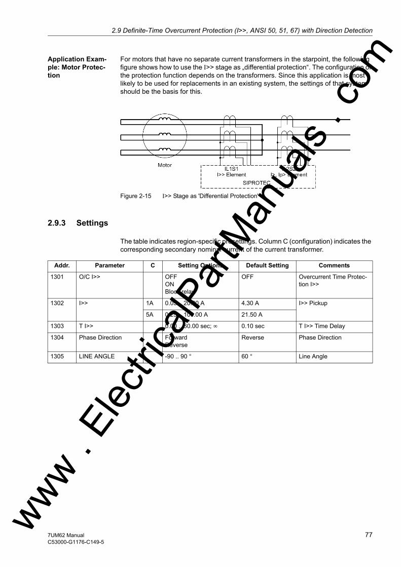
2.9 Definite-Time Overcurrent Protection (I>>, ANSI 50, 51, 67) with Direction Detectionw
Application Exam-ple: Motor Protec-tion
For motors that have no separate current transformers in the starpoint, the following figure shows how to use the I>> stage as „differential protection“. The configuration of the protection function depends on the transformers. Since this application is most likely to be used for replacements in an existing system, the settings of that system should be the basis for this.
Figure 2-15 I>> Stage as 'Differential Protection'
2.9.3 Settings
The table indicates region-specific presettings. Column C (configuration) indicates the corresponding secondary nominal current of the current transformer.
Addr. Parameter C Setting Options Default Setting Comments
1301 O/C I>> OFFONBlock relay
OFF Overcurrent Time Protec-tion I>>
1302 I>> 1A 0.05 .. 20.00 A 4.30 A I>> Pickup
5A 0.25 .. 100.00 A 21.50 A
1303 T I>> 0.00 .. 60.00 sec; ∞ 0.10 sec T I>> Time Delay
1304 Phase Direction ForwardReverse
Reverse Phase Direction
1305 LINE ANGLE -90 .. 90 ° 60 ° Line Angle
ww . El
ectric
alPar
tMan
uals
. com
777UM62 ManualC53000-G1176-C149-5

2 Functions
om
2.9.4 Information List
No. Information Type of In-formation
Comments
1720 >BLOCK dir. SP >BLOCK direction I>> stage1721 >BLOCK I>> SP >BLOCK I>>1801 I>> Fault L1 OUT O/C fault detection stage I>> phase L11802 I>> Fault L2 OUT O/C fault detection stage I>> phase L21803 I>> Fault L3 OUT O/C fault detection stage I>> phase L31806 I>> forward OUT O/C I>> direction forward1807 I>> backward OUT O/C I>> direction backward1808 I>> picked up OUT O/C prot. I>> picked up1809 I>> TRIP OUT O/C I>> TRIP1955 I>> OFF OUT O/C prot. stage I>> is switched OFF1956 I>> BLOCKED OUT O/C prot. stage I>> is BLOCKED1957 I>> ACTIVE OUT O/C prot. stage I>> is ACTIVE
ww . El
ectric
alPar
tMan
uals
. c
78 7UM62 ManualC53000-G1176-C149-5
w
2.10 Inverse-Time Overcurrent Protection (ANSI 51V)w
2.10 Inverse-Time Overcurrent Protection (ANSI 51V)
The overcurrent time protection represents the short-circuit protection for small or low-voltage machines. For larger machines it is used as back-up protection for the machine short-circuit protection (differential protection and/or impedance protection). It provides back-up protection for network faults which may be not promptly discon-nected thus endangering the machine.
The 7UM62 relay allows to choose between the input transformers of side 1 and side 2 for allocation of the inverse-time overcurrent protection function. This choice is made during configuration (see Section 2.4).
In generators where the excitation voltage is taken from the machine terminals, the short-circuit current subsides quickly in the event of adjacent faults (i.e. in the gener-ator or unit transformer region) due to the absence of excitation voltage. Within a few seconds it sinks below the pick-up value of the overcurrent time protection. In order to avoid a dropout of the pickup, the positive-sequence component is monitored addition-ally. This component can influence the overcurrent detection in accordance with two different methods. The undervoltage influencing can be switched off.
The protective function operates, depending on the ordering variant, with an inverse current-tripping characteristic according to the IEC or ANSI standards. The character-istic curves and the corresponding formulas are represented in Technical Data. If one of the inverse characteristics (IEC or ANSI) is configured, the definite-time stages I>> and I> can be additionally effective (see Section 2.8).
2.10.1 Functional Description
Pickup and Tripping
Each phase current is compared individually with the common Ip setting value. If a current exceeds 1.1 times the set value, the stage picks up and is signalled on a per phase basis. The r.m.s. values of the fundamental component are used for the pickup. During the pickup of an Ip stage, the tripping time is calculated from the flowing fault current by means of an integrating measuring procedure, depending on the selected tripping characteristic. After the expiration of this period, a trip command is transmit-ted.
Dropout The dropout of a picked up stage is performed as soon as the value falls below ap-proximately 95 % of the pickup value (i.e. 0.95 to 1.1 = 1.045 to setting value). The timer will start again for all new pickups.
Undervoltage Consideration
The inverse overcurrent time protection is provided with a undervoltage detection that can be disabled. This function can influence overcurrent detection in two different ways:• Voltage controlled:If the value falls below a settable voltage threshold, an overcur-
rent stage with a lower pick-up value is enabled. • Voltage restraint:The pickup threshold of the overcurrent stage depends on the
voltage level. A lower voltage reduces the current pick-up value (see Figure 2-16). A linear, directly proportional dependency is realized in the zone between U/UNom = 1.00 and 0.25.
ww . El
ectric
alPar
tMan
uals
. com
797UM62 ManualC53000-G1176-C149-5
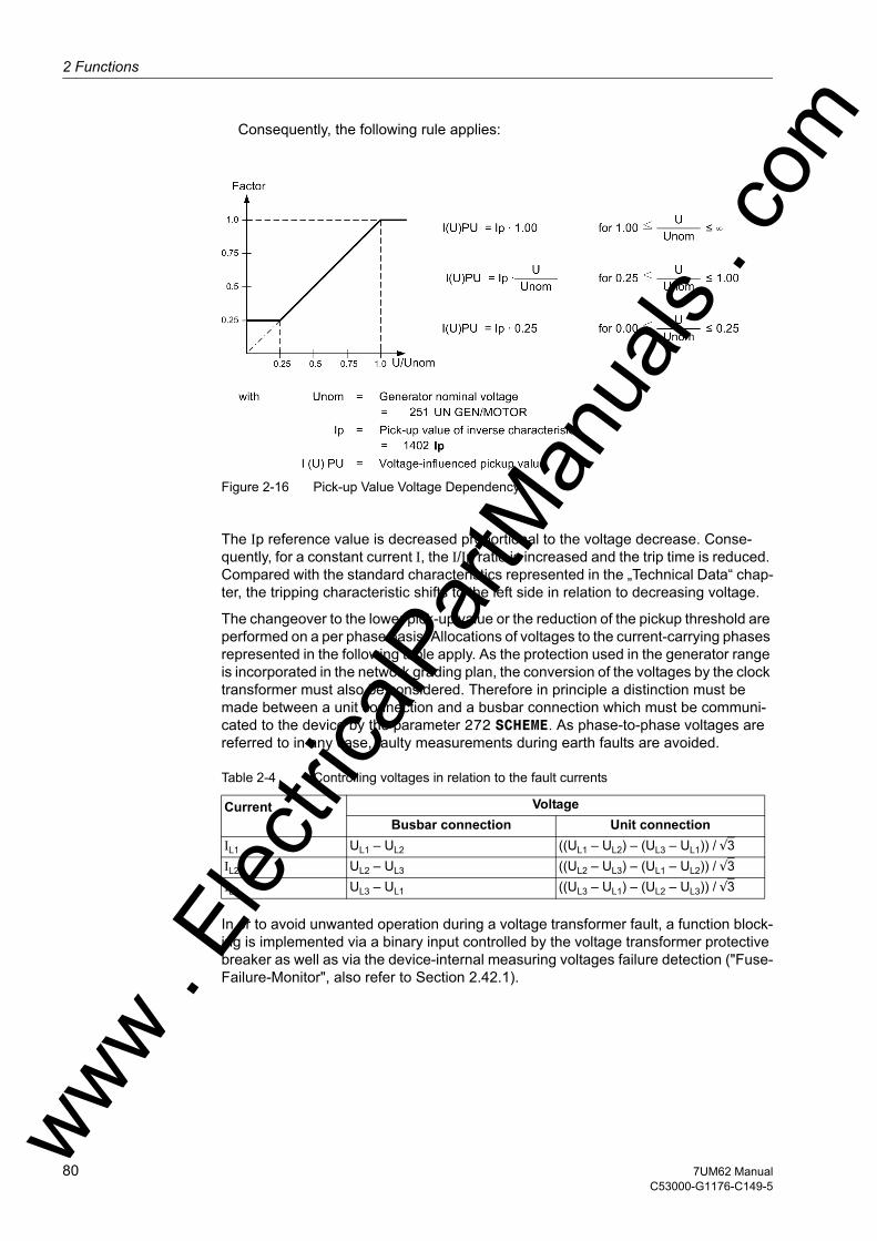
2 Functions
om
Consequently, the following rule applies:
Figure 2-16 Pick-up Value Voltage Dependency
The Ip reference value is decreased proportional to the voltage decrease. Conse-quently, for a constant current I, the I/Ip ratio is increased and the trip time is reduced. Compared with the standard characteristics represented in the „Technical Data“ chap-ter, the tripping characteristic shifts to the left side in relation to decreasing voltage.
The changeover to the lower pick-up value or the reduction of the pickup threshold are performed on a per phase basis. Allocations of voltages to the current-carrying phases represented in the following table apply. As the protection used in the generator range is incorporated in the network grading plan, the conversion of the voltages by the clock transformer must also be considered. Therefore in principle a distinction must be made between a unit connection and a busbar connection which must be communi-cated to the device by the parameter 272 SCHEME. As phase-to-phase voltages are referred to in any case, faulty measurements during earth faults are avoided.
Table 2-4 Controlling voltages in relation to the fault currents
In or to avoid unwanted operation during a voltage transformer fault, a function block-ing is implemented via a binary input controlled by the voltage transformer protective breaker as well as via the device-internal measuring voltages failure detection ("Fuse-Failure-Monitor", also refer to Section 2.42.1).
Current VoltageBusbar connection Unit connection
IL1 UL1 – UL2 ((UL1 – UL2) – (UL3 – UL1)) / √3IL2 UL2 – UL3 ((UL2 – UL3) – (UL1 – UL2)) / √3IL3 UL3 – UL1 ((UL3 – UL1) – (UL2 – UL3)) / √3
ww . El
ectric
alPar
tMan
uals
. c
80 7UM62 ManualC53000-G1176-C149-5
w
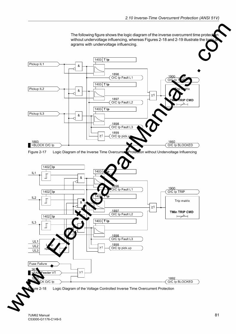
2.10 Inverse-Time Overcurrent Protection (ANSI 51V)w
The following figure shows the logic diagram of the inverse overcurrent time protection without undervoltage influencing, whereas Figures 2-18 and 2-19 illustrate the logic di-agrams with undervoltage influencing.
Figure 2-17 Logic Diagram of the Inverse Time Overcurrent Protection without Undervoltage Influencing
Figure 2-18 Logic Diagram of the Voltage Controlled Inverse Time Overcurrent Protectionww . El
ectric
alPar
tMan
uals
. com
817UM62 ManualC53000-G1176-C149-5
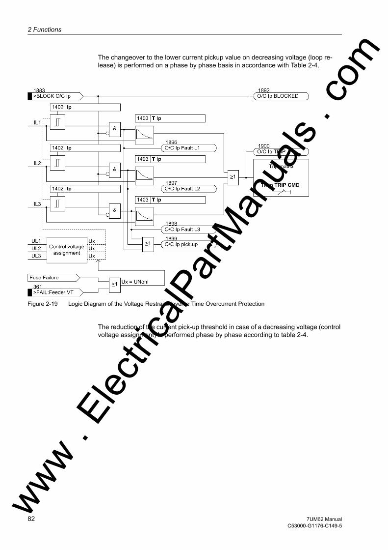
2 Functions
om
The changeover to the lower current pickup value on decreasing voltage (loop re-lease) is performed on a phase by phase basis in accordance with Table 2-4.
Figure 2-19 Logic Diagram of the Voltage Restraint Inverse Time Overcurrent Protection
The reduction of the current pick-up threshold in case of a decreasing voltage (control voltage assignment) is performed phase by phase according to table 2-4.
ww . El
ectric
alPar
tMan
uals
. c
82 7UM62 ManualC53000-G1176-C149-5
w
2.10 Inverse-Time Overcurrent Protection (ANSI 51V)w
2.10.2 Setting Notes
General The inverse overcurrent time protection is only effective and available if this function was allocated to the input CTs of either side 1 or side 2 during configuration (see Section 2.4), i.e. if address 114 O/C PROT. Ip was set to IEC SIDE 1, ANSI SIDE 1, IEC SIDE 2 or ANSI SIDE 2. If the function is not needed it is set to Disabled.
Overcurrent Stage Ip
The address 1401 O/C Ip serves to switch the function ON or OFF or to block only the trip command (Block relay). In this context, it must be considered that, for the inverse O/C time protection, a safety factor of about 1.1 has already been included between the pick-up value and the setting value. This means that a pickup is only per-formed if a current of about 1.1 of the setting value is present. The function will reset as soon as the value falls below 95 % of the pickup value.
The current value is set at address 1402 Ip. The maximum operating current is of primary importance for the setting. A pickup caused by an overload must be excluded, as the device operates in this mode as fault protection with correspondingly short trip-ping times and not as overload protection.
The corresponding time multiplier for configuration of IEC characteristics (address 114 O/C PROT. Ip = IEC Page n) is accessible under address 1403 T Ip. At address 1405 IEC CURVE, 3 IEC characteristics can be selected.
The time multiplier for configuring ANSI characteristics (address 114 O/C PROT. Ip= ANSI Page) can be found at address 1404 TIME DIAL: TD; parameter 1406 ANSI CURVE offers a choice between 5 ANSI characteristics.
The time multipliers must be coordinated with the network grading plan.
The time multipliers can also be set to ∞. If set to infinity, the pickup of this function will be indicated but the stage will not trip after pickup. If the Ip stage is not required, on configuration of the protection function (Section 2.4) address 114 O/C PROT. Ip is set to Disabled or this function switched under 1401 O/C Ip = OFF.
The address 1408 serves to predefine the U< pick-up value for the undervoltage trip of the Ip pickup value for voltage-controlled inverse overcurrent time protection/AMZ (parameter 1407 VOLT. INFLUENCE = Volt. controll.). The parameter is set to a value just below the lowest phase-to-phase voltage admissible during operation, e.g. from 75 to 80 V. In this context, the same rules apply as for the undervoltage seal-in of the definite overcurrent time protection (see also Subsection 2.8.2).
If at address 1407 VOLT. INFLUENCE is set to without or Volt. restraint, the parameter 1408 has no function.
ww . El
ectric
alPar
tMan
uals
. com
837UM62 ManualC53000-G1176-C149-5
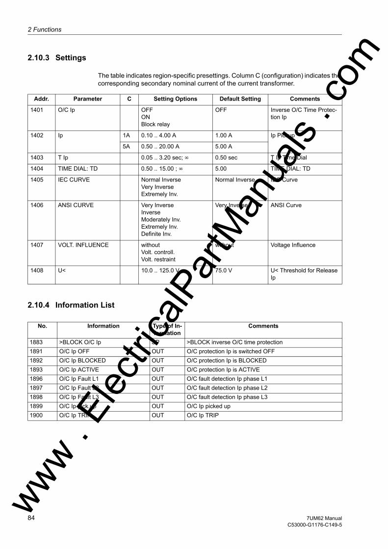
2 Functions
om
2.10.3 Settings
The table indicates region-specific presettings. Column C (configuration) indicates the corresponding secondary nominal current of the current transformer.
2.10.4 Information List
Addr. Parameter C Setting Options Default Setting Comments
1401 O/C Ip OFFONBlock relay
OFF Inverse O/C Time Protec-tion Ip
1402 Ip 1A 0.10 .. 4.00 A 1.00 A Ip Pickup
5A 0.50 .. 20.00 A 5.00 A
1403 T Ip 0.05 .. 3.20 sec; ∞ 0.50 sec T Ip Time Dial
1404 TIME DIAL: TD 0.50 .. 15.00 ; ∞ 5.00 TIME DIAL: TD
1405 IEC CURVE Normal InverseVery InverseExtremely Inv.
Normal Inverse IEC Curve
1406 ANSI CURVE Very InverseInverseModerately Inv.Extremely Inv.Definite Inv.
Very Inverse ANSI Curve
1407 VOLT. INFLUENCE withoutVolt. controll.Volt. restraint
without Voltage Influence
1408 U< 10.0 .. 125.0 V 75.0 V U< Threshold for Release Ip
No. Information Type of In-formation
Comments
1883 >BLOCK O/C Ip SP >BLOCK inverse O/C time protection1891 O/C Ip OFF OUT O/C protection Ip is switched OFF1892 O/C Ip BLOCKED OUT O/C protection Ip is BLOCKED1893 O/C Ip ACTIVE OUT O/C protection Ip is ACTIVE1896 O/C Ip Fault L1 OUT O/C fault detection Ip phase L11897 O/C Ip Fault L2 OUT O/C fault detection Ip phase L21898 O/C Ip Fault L3 OUT O/C fault detection Ip phase L31899 O/C Ip pick.up OUT O/C Ip picked up1900 O/C Ip TRIP OUT O/C Ip TRIP
ww . El
ectric
alPar
tMan
uals
. c
84 7UM62 ManualC53000-G1176-C149-5
w

2.11 Thermal Overload Protection (ANSI 49)w
2.11 Thermal Overload Protection (ANSI 49)
The thermal overload protection prevents thermal overloading of the stator windings of the machine being protected.
2.11.1 Functional Description
Thermal Profile The device calculates the overtemperature in accordance with a single-body thermal model, based on the following differential equation:
with
Θ Actual operating temperature expressed in percent of the operating temperature corresponding to the maximum permissible operating current k·IN
Θ K Coolant temperature or ambient temperature as a difference to the 40 °C reference temperature
τ Thermal time constant for the heating of the equipment being protect-ed
I Operating current expressed in percent of the maximum permissible operating current Imax = k · IN
The protection function models a thermal profile of the equipment being protected (overload protection with memory capability). Both the previous history of an overload and the heat loss to the environment are taken into account.
The solution of this equation is in steady-state operation is an e-function whose as-ymptote represents the final temperature ΘEnd. After an initial settable overtempera-ture threshold is reached, an alarm is issued for e.g. load reduction measures. If the second overtemperature threshold, i.e. final overtemperature = trip temperature, is reached, the protected equipment is disconnected from the network. The overload protection can, however, also be set to Alarm Only. In this case only an indication is issued when the final temperature is reached.
The overtemperature is calculated from the largest of the three phase currents. Since the calculation is based on rms values of currents, harmonics which contribute to a temperature rise of the stator winding are also considered.
The maximum thermally permissible continuous current Imax is described as a multiple of the nominal current IN of the protected object:
Imax = k·IN
In addition to the k factor (parameter K-FACTOR), the TIME CONSTANT τ and the alarm temperature Θ ALARM (in percent of the trip temperature Θ TRIP) must be spec-ified.
Overload protection also has a current alarm feature (I ALARM) in addition to the tem-perature alarm stage. The current warning element may report an overload current prematurely (when Imax is exceeded), even if the calculated operating temperature has not yet attained the warning or tripping levels.ww . El
ectric
alPar
tMan
uals
. com
857UM62 ManualC53000-G1176-C149-5
2 Functions
om
Coolant Tempera-ture (Ambient Tem-perature)
With 7UM62 the thermal model considers an external temperature value. Depending on the application, this temperature can be the coolant or ambient temperature or, in the case of gas turbines, the entry temperature of the cold gas.
The temperature to be considered can be input in one of the following ways:• Via measuring transducer (TD 2)• via Profibus DP interface/Modbus• Via temperature detection unit (Thermobox, RTD 1)
An external temperature sensor measures e.g. the coolant temperature and converts it to a temperature-proportional current or voltage. This output quantity can be fed into the 7UM62 via the integrated measuring transducer TD 2. If a signal level between 4 mA and 20 mA is used, the measuring circuit for temperature input can additionally be monitored for interruptions. If the measured current of the external amplifier drops below 2 mA, the relay outputs a disturbance indication, and switches at the same time to a fictional coolant temperature of 40 °C (the temperature assumed if there is no coolant temperature detection).
The ambient or coolant temperature can also be detected by an external temperature sensor, digitized and fed to the 7UM62 via the Profibus-DP Interface / Modbus .
If a temperature supervision feature is implemented using a thermobox (see Section 2.46) the RTD1 input can be used for temperature inclusion in the overload protection.
With coolant temperature detection in accordance with one of the three methods de-scribed, the maximum permissible current Imax is influenced by the temperature differ-ence of the coolant. If the ambient or coolant temperature is lower, the machine can support a higher current than when the temperatures are high.
Current Limiting In order that overload protection on occurrence of high short-circuit currents (and with small time constants) does not cause extremely short trip times thereby perhaps af-fecting time grading of the short-circuit protection, it is possible to implement current limiting for the overload protection. Currents exceeding the value specified at param-eter 1615 I MAX THERM. are limited to this value. For this reason, they do not further reduce trip time in the thermal memory.
Standstill Time Constant
The above differential equation assumes a constant cooling that is reflected by the time constant τ = Rth · Cth (thermal resistance and thermal capacitance). In a self-ven-tilated machine, however, the thermal time constant at standstill can differ consider-ably from the time constant of a continually running machine, since then the ventilation provides for cooling whereas at standstill only natural convection takes place.
Therefore, two time constants must be considered in such cases for setting.
In this context, machine standstill is detected when the current undershoots the threshold value BkrClosed I MIN (see margin heading "Current Flow Monitoring" in Subsection 2.5).
Blocking The thermal memory may be reset via a binary input („>RM th.rep. O/L“). The current-induced excessive temperature value is reset to zero. The same is achieved by entering a blocking („>BLK ThOverload“); in that case the overload protection is blocked completely, including the current alarm stage.
When machines must be started for emergency reasons, operating temperatures above the maximum permissible operating temperatures are allowed (emergency start). Then exclusively the tripping signal can be blocked via a binary input („>Emer.Start O/L“). Since the thermal profile may have exceeded the tripping ww .
Elec
tricalP
artM
anua
ls . c
86 7UM62 ManualC53000-G1176-C149-5
w

2.11 Thermal Overload Protection (ANSI 49)w
temperature after startup and dropout of the binary input has taken place, the protec-tion function features a programmable run-on time interval (T EMERGENCY) which is started when the binary input drops out and continues suppressing a trip signal. Trip-ping by the overload protection will be defeated until this time interval elapses. This binary input affects only the tripping signal. It has no effect on the fault condition logging nor does it reset the thermal profile.
Behaviour on Power Supply Failure
For overload protection, together with all other thermal protection functions of the 7UM62 in the Power System Data 1 (parameter 274 ATEX100, see Section 2.5) it is possible to choose whether the calculated overtemperature will be stored throughout a power supply failure, or reset to zero. This last option is the default setting.
ww . El
ectric
alPar
tMan
uals
. com
877UM62 ManualC53000-G1176-C149-5

2 Functions
om
The following figure shows the logic diagram for overload protection.
Figure 2-20 Logic of the Overload Protection Functionww . El
ectric
alPar
tMan
uals
. c
88 7UM62 ManualC53000-G1176-C149-5
w

2.11 Thermal Overload Protection (ANSI 49)w
2.11.2 Setting Notes
General Overload protection is only effective and accessible if address 116 Therm.Overload is set to Enabled during configuration. If the function is not required Disabled is set.
Transformers and generators are prone to damage by extended overloads. These overloads cannot and should not be detected by short-circuit protection. Time overcur-rent protection should be set high so that it only detects faults, since fault protection only permits short time delays. Short time delays, however, do not allow measures for unburdening the overloaded equipment nor do they permit advantage to be taken of its (limited) overload capacity.
The 7UM62 protective relay features an overload protective function with thermal trip-ping characteristic adaptable to the overload capability of the equipment being protect-ed.
At address 1601 Ther. OVER LOAD the thermal overload protection ON or OFF can be set, the trip command blocked (Block relay) or the protection function set to Alarm Only . In the latter case no fault record is created should an overload occur. If overload protection is switched ON, tripping is also possible.
K-Factor The overload protection is set with quantities per unit. The nominal current IN, Machine of the object to be protected (generator, motor, transformer) is typically used as base current. The thermally permissible continuous current Imax prim can be used to calculate a factor kprim:
The thermally admissible continuous current for the equipment being protected is gen-erally obtainable from manufacturer's specifications. If no specifications are available, a value of 1.1 times the nominal current rating is assumed.
The K-FACTOR to be set on the device 7UM62 (address 1602) refers to the secondary nominal current (= device current). The following applies for the conversion:
with
Imax prim thermally admissible continuous motor primary current
IN Machine Nominal Current of the Machine
INCT prim Nominal primary CT current
Example: Generator and current transformer with the following data:
Permissible Continuous Current Imax prim= 1.15 · IN, Machine
Generator Nominal Current IN Machine = 483 A
Current Transformer 500 A / 1 A
ww . El
ectric
alPar
tMan
uals
. com
897UM62 ManualC53000-G1176-C149-5
2 Functions
om
Time Constant The overload protection tracks overtemperature progression, employing a thermal dif-ferential equation whose steady state solution is an exponential function. The TIME CONSTANT τ (address 1603) is used in the calculation to determine the operating tem-perature.
If the overload characteristic of the generator to be protected is pre-determined, the user must select the protection trip characteristic so that it largely corresponds the overload characteristic, at least for small overloads.
This is also the case if the admissible power-up time corresponding to a certain over-load value is indicated.
Alarm Stages By setting the thermal warning level Θ ALARM (address 1604), a warning message can be issued before the tripping temperature is reached, thus avoiding tripping by promptly reducing load. This warning level simultaneously represents the dropout level for the tripping signal. The tripping signal is interrupted only when this threshold value is again undershot.
The thermal alarm level is given in % of the tripping overtemperature level.
Note: With the typical value of K-FACTOR = 1.1, on application of nominal machine current and adapted primary transformer current, the following final tripping overtem-perature results
of the tripping temperature. Consequently, the warning stage should be set between the final overtemperature with the nominal current (in this case 83 %) and the tripping overtemperature (100 %).
In the present example, the thermal memory reaches the following value if the nominal current is applied:
A current warning level (parameter 1610 I ALARM) is also available. The level is set in secondary amperes and should be set equal to, or slightly less than, the permissible continuous current K-FACTOR · IN sec . It may be used instead of the thermal warning level by setting the thermal warning level to 100 % and is then practically inactive.
Extension of Time Constants at Machine Standstill
The time constant programmed at address 1603 is valid for the running machine. On slowing down or standstill, the machine may cool down much more slowly. This be-haviour can be modeled by prolonging the time constant by the Kτ-FACTOR (address 1612) on machine standstill. In this context, machine standstill is detected when the current undershoots the threshold value BkrClosed I MIN (see margin heading "Current Flow Monitoring" in Subsection P.System Data 1).
If no distinction between time constants is necessary, the prolongation factor Kτ-FACTOR can be left as 1.0 (default).
Current Limiting The parameter 1615 I MAX THERM. specifies up to which current value the trip times are calculated in accordance with the prescribed formula. In the trip characteristics of Section „Technical Data“, Subsection „Overload Protection“, this limit value deter-mines the transition to the horizontal part of the characteristics, where there is no further trip time reduction despite increasing current values. The limit value must ensure that even for the highest possible short-circuit current, the trip times of the overload protection exceed the trip times of the short-circuit protection devices (differ-ww .
Elec
tricalP
artM
anua
ls . c
90 7UM62 ManualC53000-G1176-C149-5
w

2.11 Thermal Overload Protection (ANSI 49)w
ential protection, impedance protection, time overcurrent protection). As a rule, a lim-itation to a secondary current corresponding to roughly three times the nominal machine current will be sufficient.
Emergency Startup The run-on time to be entered at address 1616 T EMERGENCY must be sufficient to ensure that after an emergency startup and dropout of binary input „>Emer.Start O/L“ the trip command is blocked until the thermal replica is again below the dropout threshold.
Ambient or Coolant Temperature
The specifications given up to now are sufficient for modeling the overtemperature. In addition to this, machine protection can also process the ambient or coolant tempera-ture. This must then be signaled to the device either via the measuring transducer TD2 provided as a temperature-proportional DC current from a measuring transducer with a live zero signal between 4 and 20 mA, linked via the thermobox, or as digitalized measured value via the fieldbus (e.g. Profibus DP). Address 1607 TEMP. INPUT serves to select the temperature input procedure. If there is no coolant temperature detection, address 1607 is set to Disabled. The allocation between the input signal and the temperature can be set at address 1608 (in °C) or 1609 (in °F) TEMP. SCAL.. The temperature value set there is equivalent to 100 % of the Profibus DP/Modbus value, or full-scale deflection (20 mA) of the measuring transducer. In the default setting, 100 % (field bus) or 20 mA (measuring transducer TD2) corresponds to 100 °C.
If under address 1607 TEMP. INPUT the temperature setting of RTD 1 selected, the scaling under address1608 or 1609 is ineffective. The works setting can be left as it is.
If the ambient temperature detection is used, the user must be aware that the K-FACTOR to be set refers to an ambient temperature of 40 °C, i.e. it corresponds to the maximum permissible current at a temperature of 40 °C.
As all calculations are performed with standardized quantities, the ambient tempera-ture must be standardized, too. The temperature at nominal machine current is used as standardization value. If the nominal machine current deviates from the nominal CT current, the temperature must be adapted according to the following formula. At address 1605 or 1606 TEMP. RISE I the temperature adapted to the nominal trans-former current is set. This setting value is used as standardization quantity of the ambient temperature input.
with
ΘNsec Machine Temperature with Secondary Nominal Current = Setting at the 7UM62 (address 1605 or 1606)
ΘNMach Machine Temperature with Nominal Machine Current
INprim Primary nominal current of the current transformer
INMach Nominal current of the machine
If the temperature input is not used, the address 1607 TEMP. INPUT must be set to Disabled. In this case, the settings of the addresses1605 or 1606 and 1608 or 1609 are not considered.
ww . El
ectric
alPar
tMan
uals
. com
917UM62 ManualC53000-G1176-C149-5
2 Functions
om
If the temperature input is used, the trip times change if the coolant temperature devi-ates from the internal reference temperature of 40 °C. The following formula can be used to calculate the trip time:
with
τ TIME CONSTANT (address 1603)
k K-FACTOR (address 1602)
IN Nominal Device Current
I Actually Flowing Secondary Current
IPre Previous Load Current
ΘN Temperature with Nominal Current IN (address 1605 TEMP. RISE I)
ΘK Coolant Temperature Input (Scaling with Address 1608 or 1609)
Example:
Machine:
INMach = 483 A
ImaxMach = 1,15 IN at ΘK = 40 °C
ΘNMach = 93 °C
τth = 600 s (thermal time constant of the machine)
Current transformer: 500 A/1 A
ww . El
ectric
alPar
tMan
uals
. c
92 7UM62 ManualC53000-G1176-C149-5
w
2.11 Thermal Overload Protection (ANSI 49)w
With a supposed load current of I = 1.5 · IN, Device and a preload IPre = 0, for different ambient temperatures ΘK the following trip times result
2.11.3 Settings
Addresses which have an appended "A" can only be changed with DIGSI, under Ad-ditional Settings.
The table indicates region-specific presettings. Column C (configuration) indicates the corresponding secondary nominal current of the current transformer.
Addr. Parameter C Setting Options Default Setting Comments
1601 Ther. OVER LOAD OFFONBlock relayAlarm Only
OFF Thermal Overload Protec-tion
1602 K-FACTOR 0.10 .. 4.00 1.11 K-Factor
1603 TIME CONSTANT 30 .. 32000 sec 600 sec Thermal Time Constant
1604 Θ ALARM 70 .. 100 % 90 % Thermal Alarm Stage
1605 TEMP. RISE I 40 .. 200 °C 100 °C Temperature Rise at Rated Sec. Curr.
1606 TEMP. RISE I 104 .. 392 °F 212 °F Temperature Rise at Rated Sec. Curr.
1607 TEMP. INPUT Disabled4-20 mAFieldbusRTD 1
Disabled Temperature Input
1608 TEMP. SCAL. 40 .. 300 °C 100 °C Temperature for Scaling
1609 TEMP. SCAL. 104 .. 572 °F 212 °F Temperature for Scaling
1610A I ALARM 5A 0.50 .. 20.00 A 5.00 A Current Overload Alarm Setpoint
1A 0.10 .. 4.00 A 1.00 A
1612A Kτ-FACTOR 1.0 .. 10.0 1.0 Kt-Factor when Motor Stopsww .
Elec
tricalP
artM
anua
ls . c
om
937UM62 ManualC53000-G1176-C149-5

2 Functions
om
2.11.4 Information List
1615A I MAX THERM. 5A 2.50 .. 40.00 A 16.50 A Maximum Current for Thermal Replica
1A 0.50 .. 8.00 A 3.30 A
1616A T EMERGENCY 10 .. 15000 sec 100 sec Emergency Time
No. Information Type of In-formation
Comments
1503 >BLK ThOverload SP >BLOCK thermal overload protection1506 >RM th.rep. O/L SP >Reset memory for thermal replica O/L1507 >Emer.Start O/L SP >Emergency start O/L1508 >Fail.Temp.inp SP >Failure temperature input1511 Th.Overload OFF OUT Thermal Overload Protection OFF1512 Th.Overload BLK OUT Thermal Overload Protection BLOCKED1513 Overload ACT OUT Overload Protection ACTIVE1514 Fail.Temp.inp OUT Failure temperature input1515 O/L I Alarm OUT Overload Current Alarm (I alarm)1516 O/L Θ Alarm OUT Thermal Overload Alarm1517 O/L Th. pick.up OUT Thermal Overload picked up1519 RM th.rep. O/L OUT Reset memory for thermal replica O/L1521 ThOverload TRIP OUT Thermal Overload TRIP
Addr. Parameter C Setting Options Default Setting Comments
ww . El
ectric
alPar
tMan
uals
. c
94 7UM62 ManualC53000-G1176-C149-5
w

2.12 Unbalanced Load (Negative Sequence) Protection (ANSI 46)w
2.12 Unbalanced Load (Negative Sequence) Protection (ANSI 46)
Unbalanced load protection detects unbalanced loads of three-phase induction motors. Unbalanced loads create a counter-rotating field which acts on the rotor at double frequency. Eddy currents are induced at the rotor surface leading to local over-heating in rotor end zones and slot wedges. Another effect of unbalanced loads is overheating of the damper winding. In addition, this protection function may be used to detect interruptions, faults, and polarity problems with current transformers. It is also useful in detecting 1-pole and 2-pole faults with magnitudes lower than the load cur-rents.
2.12.1 Functional Description
Unbalanced Load Determination
The unbalanced load protection of 7UM62 uses numerical filters to dissect the phase currents into their symmetrical components. It evaluates the negative-phase se-quence system, the negative phase-sequence current I2. If the negative phase-se-quence current exceeds a parameterized threshold value, the trip time starts. A trip command is transmitted as soon as this trip time has expired.
Warning Stage If the value of the continuously permissible, negative phase-sequence current I2> is exceeded, after expiry of a set time T WARN a warning message „I2> Warn“ is issued (see Figure 2-21).
Thermal Character-istic
The machine manufacturers indicate the permissible unbalanced load by means of the following formula:
The asymmetry factor depends on the machine and represents the time in seconds during which the generator can be loaded with a 100 % unbalanced load. This factor is typically in a range between 5 s and 30 s.
The heating up of the object to be protected is calculated in the device as soon as the permissible unbalanced load I2> is exceeded. In this context, the current-time-area is calculated constantly to ensure a correct consideration of various load cases. As soon as the current-time-area ((I2/IN)2 · t) has reached the K asymmetry factor, the thermal characteristic is tripped.
Limitation To avoid overfunctioning of the thermal tripping stage during asymmetrical short cir-cuits, the input current I2 is restricted. This limit is either 10 · I2perm or the setting value of the I2>> stage (addr. 1701), whichever is smaller. Above this current value the trip-ping time of the thermal function is constant. In addition the thermal memory is limited to 200% of the tripping temperature. This avoids prolonged cooling after a delayed short circuit tripping.
ww . El
ectric
alPar
tMan
uals
. com
957UM62 ManualC53000-G1176-C149-5
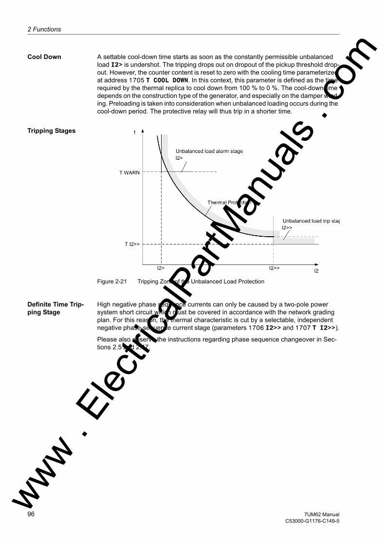
2 Functions
om
Cool Down A settable cool-down time starts as soon as the constantly permissible unbalanced load I2> is undershot. The tripping drops out on dropout of the pickup threshold drop-out. However, the counter content is reset to zero with the cooling time parameterized at address 1705 T COOL DOWN. In this context, this parameter is defined as the time required by the thermal replica to cool down from 100 % to 0 %. The cool-down time depends on the construction type of the generator, and especially on the damper wind-ing. Preloading is taken into consideration when unbalanced loading occurs during the cool-down period. The protective relay will thus trip in a shorter time.
Tripping Stages
Figure 2-21 Tripping Zone of the Unbalanced Load Protection
Definite Time Trip-ping Stage
High negative phase sequence currents can only be caused by a two-pole power system short circuit which must be covered in accordance with the network grading plan. For this reason, the thermal characteristic is cut by a selectable, independent negative phase-sequence current stage (parameters 1706 I2>> and 1707 T I2>>).
Please also observe the instructions regarding phase sequence changeover in Sec-tions 2.5 and 2.47.
ww . El
ectric
alPar
tMan
uals
. c
96 7UM62 ManualC53000-G1176-C149-5
w

2.12 Unbalanced Load (Negative Sequence) Protection (ANSI 46)w
Logic The following figure shows the logic diagram of the unbalanced load protection. The protection may be blocked via a binary input („>BLOCK I2“). Pickups and time stages are reset and the metered values in the thermal replica are cleared. The binary input „>RM th.rep. I2“ only serves to clear metered values of the thermal char-acteristic.
Figure 2-22 Logic diagram of the unbalanced load protection
ww . El
ectric
alPar
tMan
uals
. com
977UM62 ManualC53000-G1176-C149-5

2 Functions
om
2.12.2 Setting Notes
General Negative sequence protection is only in effect and accessible if address 117 UNBALANCE LOAD is set to Enabled during configuration. If the function is not re-quired Disabled is set.
The address 1701 UNBALANCE LOAD serves to switch the unbalanced load protec-tion ON or OFF or to block only the trip command (Block relay).
The maximum permissible, permanent negative phase-sequence current is important for the thermal model. For machines of up to 100 MVA with non-salient pole rotors, this typically amounts to a value in a range from 6 % to 8 % of the nominal machine current, and with salient-pole rotors at least 12 %. For larger machines and in cases of doubt, please refer to the instructions of the machine manufacturer.
It is important to note that the manufacturer's data relate to the primary values of the machine, for example, the maximum permissible permanent inverse current is re-ferred to the nominal machine current. For settings on the protective relay, this data is converted to the secondary inverse current. The following applies
with
I2 max prim Permissible thermal inverse current of the motor
IN Machine Nominal current of the machine
IN CT prim Primary nominal current of the current transformer
Pickup Threshold / Warning Stage
The value for I2> is set at address 1702. It is at the same time the pickup value for a current warning stage whose delay time T WARN is set at address 1703.
Example:
Negative Sequence Factor K
If the machine manufacturer has indicated the loadability duration due to an unbal-anced load by means of the constant K = (I2/IN)2 ·t, it is set immediately at the address 1704 FACTOR K. The constant K is proportional to the admissible energy loss.
Machine IN Machine = 483 AI2 cont. prim / IN Machine = 11 % permanent (salient-pole ma-
chine, see Figure 2-23)Current trans-former
IN CT prim = 500 A
Setting value I2 adm. = 11 % · (483 A/500 A) = 10.6 %
ww . El
ectric
alPar
tMan
uals
. c
98 7UM62 ManualC53000-G1176-C149-5
w

2.12 Unbalanced Load (Negative Sequence) Protection (ANSI 46)w
Conversion to Sec-ondary Values
The factor K can be derived from the unbalanced load characteristic according to the figure below by reading the time corresponding to the FACTOR K at the point II2/IN = 1.
Example:
tperm = 20 s for I2/IN = 1
The constant Kprimary = 20 s determined in this way is valid for the machine side (pri-mary side).
The factor Kprimary can be converted to the secondary side by means of the following formula:
The calculated asymmetry factor Ksec is set as FACTOR K at address 1704.
Example:
IN Machine = 483 A
IN CT prim = 500 A
Factor Kprimary = 20 s
Setting value at address1704:
Figure 2-23 Example of an Unbalanced Load Characteristic Specified by the Machine Man-ufacturer
ww . El
ectric
alPar
tMan
uals
. com
997UM62 ManualC53000-G1176-C149-5

2 Functions
om
Cooldown Time The parameter 1705 T COOL DOWN establishes the time required by the protection object to cool down under admissible unbalanced load I2> to the initial value. If the machine manufacturer does not provide this information, the setting value can be cal-culated by assuming an equal value for cool-down time and heatup time of the object to be protected. The formula below shows the relation between the K asymmetry factor and the cool-down time:
Example:
The following cool-down time results for a K = 20 s and an admissible continual unbal-anced load I2/IN = 11 %.
This value T COOL DOWN is set at address 1705.
Definite-Time Trip-ping Characteristic
Asymmetrical faults also cause high negative phase-sequence currents. A definite-time negative phase-sequence current stage characteristic 1706 I2>> can thus detect asymmetrical power system short circuits. A setting between 60 % and 65 % ensures that tripping always occurs in accordance with the thermal characteristic in case of a phase failure (unbalanced load continually below 100/√3 %, i.e. I2 < 58 %). On the other hand, a two-pole short circuit can be assumed for an unbalanced load of more between 60 % and 65 %. The delay time T I2>> (address 1707) must be co-ordinated with the system grading of phase-to-phase short circuits.
Contrary to time-overcurrent protection, the I2>> stage is able to detect fault currents at nominal current. The following conditions apply:
a two-phase fault with fault current I produces a negative sequence current
a single-phase fault with fault current I produces a negative sequence current
With an isolated starpoint, the I current value is particularly low and can be neglected. With a low-resistance earhting, however, it is determined by the ground resistance.
ww . El
ectric
alPar
tMan
uals
. c
100 7UM62 ManualC53000-G1176-C149-5
w

2.12 Unbalanced Load (Negative Sequence) Protection (ANSI 46)w
2.12.3 Settings
2.12.4 Information List
Addr. Parameter Setting Options Default Setting Comments
1701 UNBALANCE LOAD OFFONBlock relay
OFF Unbalance Load Protection
1702 I2> 3.0 .. 30.0 % 10.6 % Continously Permissible Current I2
1703 T WARN 0.00 .. 60.00 sec; ∞ 20.00 sec Warning Stage Time Delay
1704 FACTOR K 1.0 .. 100.0 sec; ∞ 18.7 sec Negativ Sequence Factor K
1705 T COOL DOWN 0 .. 50000 sec 1650 sec Time for Cooling Down
1706 I2>> 10 .. 200 % 60 % I2>> Pickup
1707 T I2>> 0.00 .. 60.00 sec; ∞ 3.00 sec T I2>> Time Delay
No. Information Type of In-formation
Comments
5143 >BLOCK I2 SP >BLOCK I2 (Unbalance Load)5146 >RM th.rep. I2 SP >Reset memory for thermal replica I25151 I2 OFF OUT I2 is switched OFF5152 I2 BLOCKED OUT I2 is BLOCKED5153 I2 ACTIVE OUT I2 is ACTIVE5156 I2> Warn OUT Unbalanced load: Current warning stage5158 RM th.rep. I2 OUT Reset memory of thermal replica I25159 I2>> picked up OUT I2>> picked up5160 I2>> TRIP OUT Unbalanced load: TRIP of current stage5161 I2 Θ TRIP OUT Unbalanced load: TRIP of thermal stage5165 I2> picked up OUT I2> picked up
ww . El
ectric
alPar
tMan
uals
. com
1017UM62 ManualC53000-G1176-C149-5
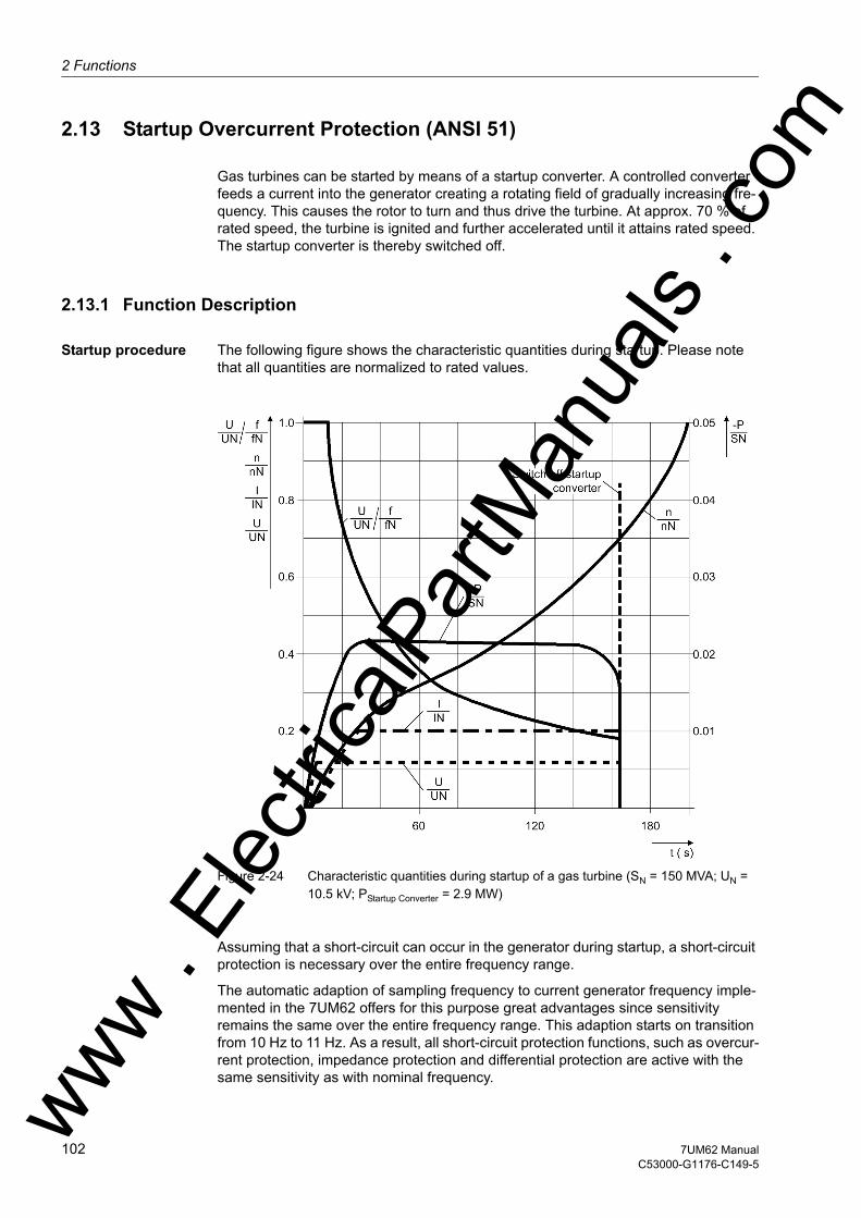
2 Functions
om
2.13 Startup Overcurrent Protection (ANSI 51)
Gas turbines can be started by means of a startup converter. A controlled converter feeds a current into the generator creating a rotating field of gradually increasing fre-quency. This causes the rotor to turn and thus drive the turbine. At approx. 70 % of rated speed, the turbine is ignited and further accelerated until it attains rated speed. The startup converter is thereby switched off.
2.13.1 Function Description
Startup procedure The following figure shows the characteristic quantities during startup. Please note that all quantities are normalized to rated values.
Figure 2-24 Characteristic quantities during startup of a gas turbine (SN = 150 MVA; UN = 10.5 kV; PStartup Converter = 2.9 MW)
Assuming that a short-circuit can occur in the generator during startup, a short-circuit protection is necessary over the entire frequency range.
The automatic adaption of sampling frequency to current generator frequency imple-mented in the 7UM62 offers for this purpose great advantages since sensitivity remains the same over the entire frequency range. This adaption starts on transition from 10 Hz to 11 Hz. As a result, all short-circuit protection functions, such as overcur-rent protection, impedance protection and differential protection are active with the same sensitivity as with nominal frequency. ww .
Elec
tricalP
artM
anua
ls . c
102 7UM62 ManualC53000-G1176-C149-5
w

2.13 Startup Overcurrent Protection (ANSI 51)w
The startup overcurrent protection is a short-circuit protection function that operates below 10 Hz. Its operating range is designed for 2 Hz to approx. 10 Hz (change to op-erational condition 1). Beyond this range the above short-circuit protection functions are active.
The function is also active above 70 Hz with reduced sensitivity, because at that fre-quency the protection is again in operational condition 0.
Measuring Principle
At frequencies below 10 Hz, the protection works in operating condition 0, with the sampling frequency automatically set to nominal conditions (fA = 800 Hz for 50 Hz net-works and 960 Hz for 60 Hz networks). From the sampled phase currents, a special algorithm determines the peak values. These are converted into values proportional to the rms values, and compared with the set threshold value.
The logic is shown in the following picture.
Figure 2-25 Logic diagram of the startup overcurrent protection
ww . El
ectric
alPar
tMan
uals
. com
1037UM62 ManualC53000-G1176-C149-5
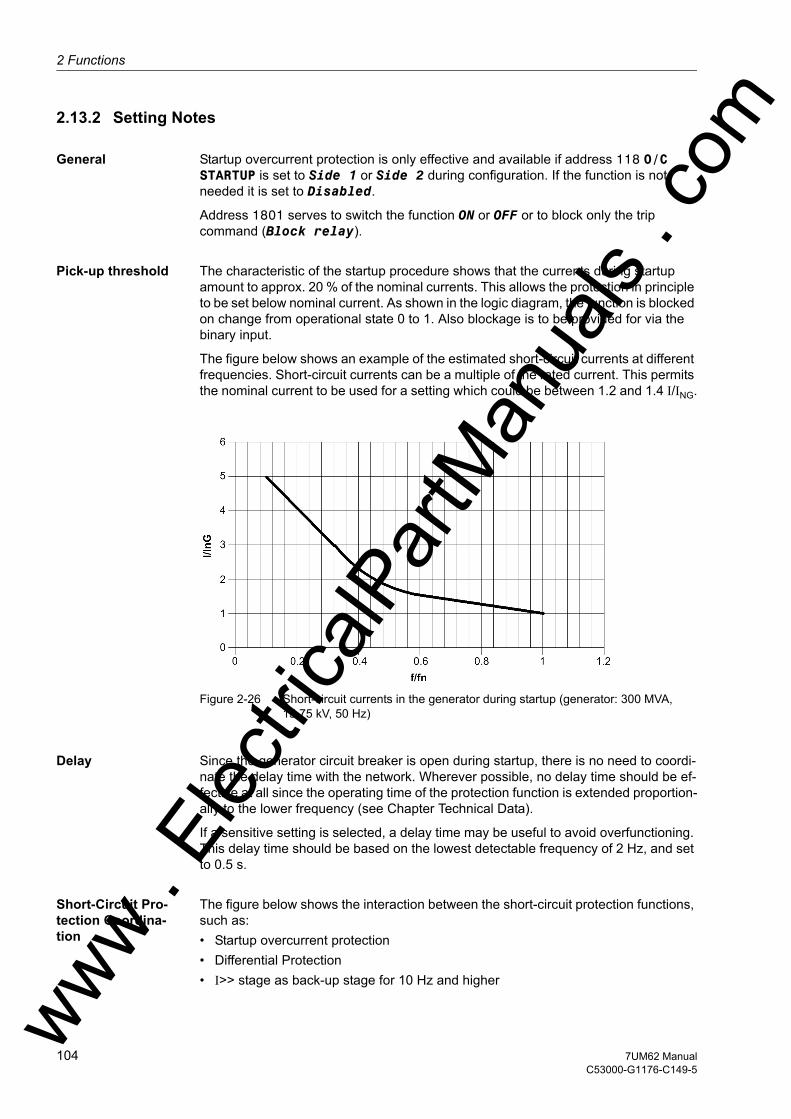
2 Functions
om
2.13.2 Setting Notes
General Startup overcurrent protection is only effective and available if address 118 O/C STARTUP is set to Side 1 or Side 2 during configuration. If the function is not needed it is set to Disabled.
Address 1801 serves to switch the function ON or OFF or to block only the trip command (Block relay).
Pick-up threshold The characteristic of the startup procedure shows that the currents during startup amount to approx. 20 % of the nominal currents. This allows the protection in principle to be set below nominal current. As shown in the logic diagram, the function is blocked on change from operational state 0 to 1. Also blockage is to be provided for via the binary input.
The figure below shows an example of the estimated short-circuit currents at different frequencies. Short-circuit currents can be a multiple of the rated current. This permits the nominal current to be used for a setting which could be between 1.2 and 1.4 I/ING.
Figure 2-26 Short-circuit currents in the generator during startup (generator: 300 MVA, 15.75 kV, 50 Hz)
Delay Since the generator circuit breaker is open during startup, there is no need to coordi-nate the delay time with the network. Wherever possible, no delay time should be ef-fective at all since the operating time of the protection function is extended proportion-ally to the lower frequency (see Chapter Technical Data).
If a sensitive setting is selected, a delay time may be useful to avoid overfunctioning. This delay time should be based on the lowest detectable frequency of 2 Hz, and set to 0.5 s.
Short-Circuit Pro-tection Coordina-tion
The figure below shows the interaction between the short-circuit protection functions, such as:• Startup overcurrent protection• Differential Protection• I>> stage as back-up stage for 10 Hz and higherww .
Elec
tricalP
artM
anua
ls . c
104 7UM62 ManualC53000-G1176-C149-5
w
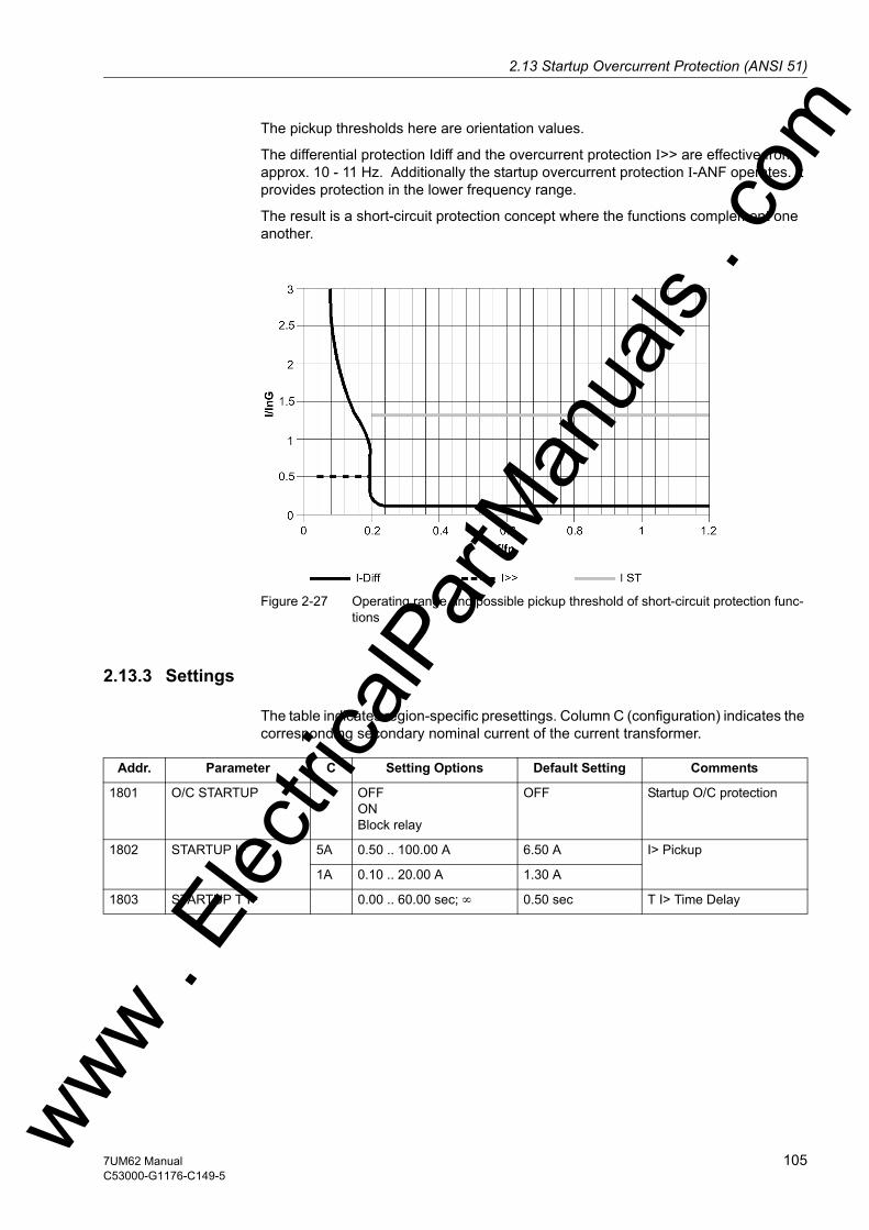
2.13 Startup Overcurrent Protection (ANSI 51)w
The pickup thresholds here are orientation values.
The differential protection Idiff and the overcurrent protection I>> are effective from approx. 10 - 11 Hz. Additionally the startup overcurrent protection I-ANF operates. It provides protection in the lower frequency range.
The result is a short-circuit protection concept where the functions complement one another.
Figure 2-27 Operating range and possible pickup threshold of short-circuit protection func-tions
2.13.3 Settings
The table indicates region-specific presettings. Column C (configuration) indicates the corresponding secondary nominal current of the current transformer.
Addr. Parameter C Setting Options Default Setting Comments
1801 O/C STARTUP OFFONBlock relay
OFF Startup O/C protection
1802 STARTUP I> 5A 0.50 .. 100.00 A 6.50 A I> Pickup
1A 0.10 .. 20.00 A 1.30 A
1803 STARTUP T I> 0.00 .. 60.00 sec; ∞ 0.50 sec T I> Time Delay
ww . El
ectric
alPar
tMan
uals
. com
1057UM62 ManualC53000-G1176-C149-5
2 Functions
om
2.13.4 Information List
No. Information Type of In-formation
Comments
5571 >BLOCK O/C St SP >BLOCK startup O/C protection5572 O/C Start OFF OUT Startup O/C protection is switched OFF5573 O/C Start BLK OUT Startup O/C protection is BLOCKED5574 O/C Start ACT OUT Startup O/C protection is ACTIVE5575 O/C Start L1 PU OUT Startup O/C phase L1 picked up5576 O/C Start L2 PU OUT Startup O/C phase L2 picked up5577 O/C Start L3 PU OUT Startup O/C phase L3 picked up5578 O/C Start TRIP OUT Startup O/C protection TRIP
ww . El
ectric
alPar
tMan
uals
. c
106 7UM62 ManualC53000-G1176-C149-5
w
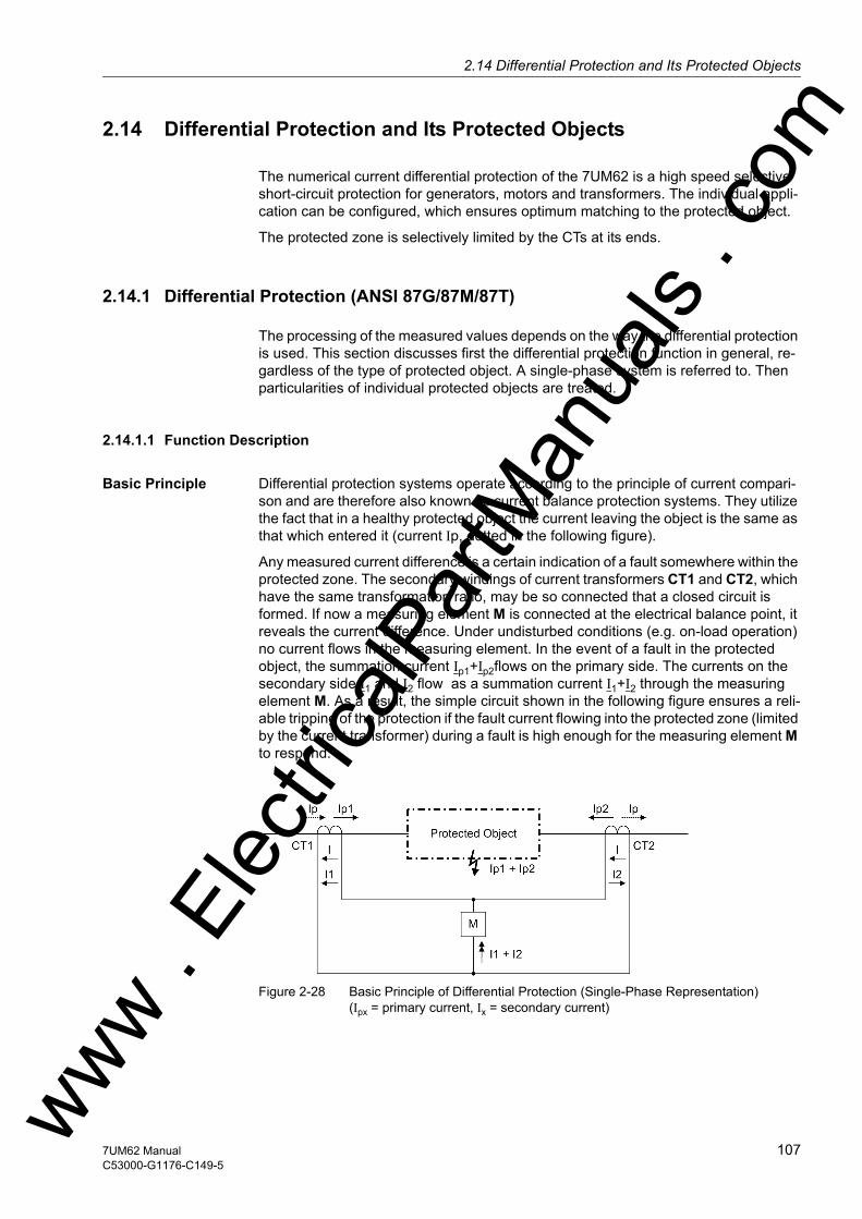
2.14 Differential Protection and Its Protected Objectsw
2.14 Differential Protection and Its Protected Objects
The numerical current differential protection of the 7UM62 is a high speed selective short-circuit protection for generators, motors and transformers. The individual appli-cation can be configured, which ensures optimum matching to the protected object.
The protected zone is selectively limited by the CTs at its ends.
2.14.1 Differential Protection (ANSI 87G/87M/87T)
The processing of the measured values depends on the way the differential protection is used. This section discusses first the differential protection function in general, re-gardless of the type of protected object. A single-phase system is referred to. Then particularities of individual protected objects are treated.
2.14.1.1 Function Description
Basic Principle Differential protection systems operate according to the principle of current compari-son and are therefore also known as current balance protection systems. They utilize the fact that in a healthy protected object the current leaving the object is the same as that which entered it (current Ip, dotted in the following figure).
Any measured current difference is a certain indication of a fault somewhere within the protected zone. The secondary windings of current transformers CT1 and CT2, which have the same transformation ratio, may be so connected that a closed circuit is formed. If now a measuring element M is connected at the electrical balance point, it reveals the current difference. Under undisturbed conditions (e.g. on-load operation) no current flows in the measuring element. In the event of a fault in the protected object, the summation current Ip1+Ip2flows on the primary side. The currents on the secondary side I1 and I2 flow as a summation current I1+I2 through the measuring element M. As a result, the simple circuit shown in the following figure ensures a reli-able tripping of the protection if the fault current flowing into the protected zone (limited by the current transformer) during a fault is high enough for the measuring element M to respond.
Figure 2-28 Basic Principle of Differential Protection (Single-Phase Representation) (Ipx = primary current, Ix = secondary current)
ww . El
ectric
alPar
tMan
uals
. com
1077UM62 ManualC53000-G1176-C149-5
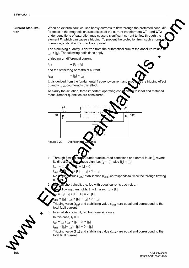
2 Functions
om
Current Stabiliza-tion
When an external fault causes heavy currents to flow through the protected zone, dif-ferences in the magnetic characteristics of the current transformers CT1 and CT2 under conditions of saturation may cause a significant current to flow through the element M, which can cause a tripping. To prevent the protection from such erroneous operation, a stabilising current is imposed.
The stabilising quantity is derived from the arithmetical sum of the absolute values of |I1| + |I2|. The following definitions apply:
a tripping or differential current
Idiff = |I1 + I2|
and the stabilizing or restraint current
Istab = |I1| + |I2|
Idiff is derived from the fundamental frequency current and produces the tripping effect quantity, Istab counteracts this effect.
To clarify the situation, three important operating conditions with ideal and matched measurement quantities are considered:
Figure 2-29 Definitions of Currents
1. Through flowing current under undisturbed conditions or external fault: I2 reverts
its direction, i.e. changes sign, i.e. I2 = –I1; also |I2| = |I1|Idiff = |I1 + I2| = |I1 – I1| = 0Istab = |I1|+ |I2| = |I1| + |I1| = 2 · |I1|No tripping value (Idiff); stabilisation (Istab) corresponds to twice the through flowing current.
2. Internal short-circuit, e.g. fed with equal currents each side:The following then holds: I2 = I1; also: |I2| = |I1|Idiff = |I1+ I2| = |I1 + I1| = 2 · |I1|Istab = |I1|+ |I2| = |I1| + |I1| = 2 · |I1|Tripping value (Idiff) and stabilising value (Istab) are equal and correspond to the total fault current.
3. Internal short-circuit, fed from one side only:In this case, I2 = 0Idiff = |I1 + I2| = |I1 – 0| = |I1|Istab = |I1|+ |I2| = |I1| + 0 = |I1|Tripping value (Idiff) and stabilising value (Istab) are equal and correspond to the total fault current. ww . El
ectric
alPar
tMan
uals
. c
108 7UM62 ManualC53000-G1176-C149-5
w
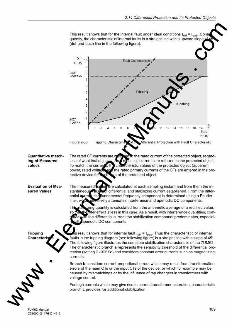
2.14 Differential Protection and Its Protected Objectsw
This result shows that for the internal fault under ideal conditions Idiff = Istab. Conse-quently, the characteristic of internal faults is a straight line with a upward slope of 45° (dot-and-dash line in the following figure).
Figure 2-30 Tripping Characteristic of the Differential Protection with Fault Characteristic
Quantitative match-ing of Measured values
The rated CT currents are matched to the rated current of the protected object, regard-less of what that object is. As a result, all currents are referred to the protected object. To match the currents, the characteristic values of the protected object (apparent power, rated voltage) and the rated primary currents of the CTs are entered in the pro-tective device for each side of the protected object.
Evaluation of Mea-sured Values
The measured values are calculated at each sampling instant and from them the in-stantaneous values of differential and stabilizing current established. From the differ-ential current, the fundamental frequency component is determined using a Fourier filter, which effectively attenuates interference and aperiodic DC components.
The stabilizing quantity is calculated from the arithmetic average of a rectified value, so that the filter effect is less in this case. As a result, with interference quantities, com-pared with the differential current the stabilization component predominates, especial-ly with aperiodic DC components.
Tripping Characteristic
This result shows that for internal fault Idiff = Istab. Thus the characteristic of internal faults in the tripping diagram (see following figure) is a straight line with a slope of 45°. The following figure illustrates the complete stabilization characteristic of the 7UM62. The characteristic branch a represents the sensitivity threshold of the differential pro-tection (setting I-DIFF>) and considers constant error currents such as magnetizing currents.
Branch b considers current-proportional errors which may result from transformation errors of the main CTs or the input CTs of the device, or which for example may be caused by mismatchings or by the influence of tap changers in transformers with voltage control.
For high currents which may give rise to current transformer saturation, characteristic branch c provides for additional stabilization. ww . El
ectric
alPar
tMan
uals
. com
1097UM62 ManualC53000-G1176-C149-5

2 Functions
om
In the presence of differential currents above branch d a trip command is issued re-gardless of stabilizing current and harmonic stabilization. This is the operating range of the „High Speed Trip StageIDiff >>“.
The area of add-on stabilization is determined by the saturation indicator (see margin title "Add-on Stabilization with CT saturation").
The currents IIdiff and Istab are compared by the differential protection with the operat-ing characteristic according to the following figure. If these values result result in a point within the tripping area, a trip signal is issued. If the current conditions Idiff /Istab appear near the fault characteristic (≥ 9 0 % of the slope of the fault characteristic), tripping occurs even when the trip characteristic has been excessively increased due to add-on stabilization, startup or DC current detection.
Figure 2-31 Operating Characteristic of the Differential Protection
High-Speed Trip-ping Stage Idiff>> tripping
The high-speed trip stage IDiff >> clears high-current internal faults instantaneously. As soon as the differential current rises above the threshold IDiff>> (branch d), a trip signal is issued regardless of the magnitude of the stabilizing current.
This stage can operate even when, for example, a considerable second harmonic is present in the differential current caused by current transformer saturation by a DC component in the short-circuit current, and which could be interpreted by the inrush stabilization function as an inrush current.
Fast tripping uses both the fundamental component of the differential current as well as instantaneous values. Instantaneous value processing ensures fast tripping even if the current fundamental component was strongly attenuated by current transformer saturation.
High-current internal faults in the protected transformer may be cleared instanta-neously without regard to the stabilizing currents when the current amplitude excludes an external fault. This is always the case when the short-circuit current is higher than 1/uk · IN Transf.
ww . El
ectric
alPar
tMan
uals
. c
110 7UM62 ManualC53000-G1176-C149-5
w

2.14 Differential Protection and Its Protected Objectsw
Add-On Stabiliza-tion During Current Transformer Satu-ration
During an external fault which produces a high through flowing short-circuit current causing current transformer saturation, a considerable differential current can be sim-ulated, especially when the degree of saturation is different at the two measuring points. If the quantities Idiff/Istab result in an operating point which lies in the trip area of the operating characteristic, a trip signal would be the consequence if no special mea-sures were taken.
Figure 2-32 Operation Characteristic of the Differential Protection with Fault Characteristic
The 7UM62 provides a saturation indicator which detects such phenomena and ini-tiates add-on stabilization measures. The saturation indicator evaluates the dynamic behaviour of the differential and stabilizing current.
The dotted line in Figure 2-32 shows the instantaneous development of currents in case of a external fault with transformer saturation on one side.
Immediately after the fault (A), the short-circuit currents rise strongly, causing a corre-spondingly high stabilizing current (2 x through-flowing current). Saturation occurring on one side (B) now causes a differential current and reduces the stabilizing current, so that the operating point Idiff/Istab may move into the tripping area (C).
In contrast, the operating point moves immediately along the fault characteristic (D) when an internal fault occurs since the stabilization current will barely be higher than the differential current. Therefore, an internal fault is assumed as soon as the ratio Id-
iff/Istab has exceeded an internal threshold for a fixed minimum time.
Current transformer saturation in case of an external fault is thus characterized by a high stabilizing current flowing at the beginning, i.e. by the operating point (diagram see Figure 2-32) moving into an area that is typical for a high-current external fault ("add-on stabilization"). The add-on stabilization area is limited by the parameter I-ADD ON STAB. and the first straight line of the characteristic (with BASE POINT 1 and SLOPE 1) (see following figure). The saturation detector makes its decision within the first quarter of a cycle. When an external fault is detected, the differential protection is blocked for a selectable time. The blocking is cancelled as soon as the operating point Idiff/Istab moves steadily (i.e. over 2 cycles) within the tripping area. This allows consequential faults in the protected area to be quickly recognized even after an ex-ternal fault involving current transformer saturation. ww . El
ectric
alPar
tMan
uals
. com
1117UM62 ManualC53000-G1176-C149-5
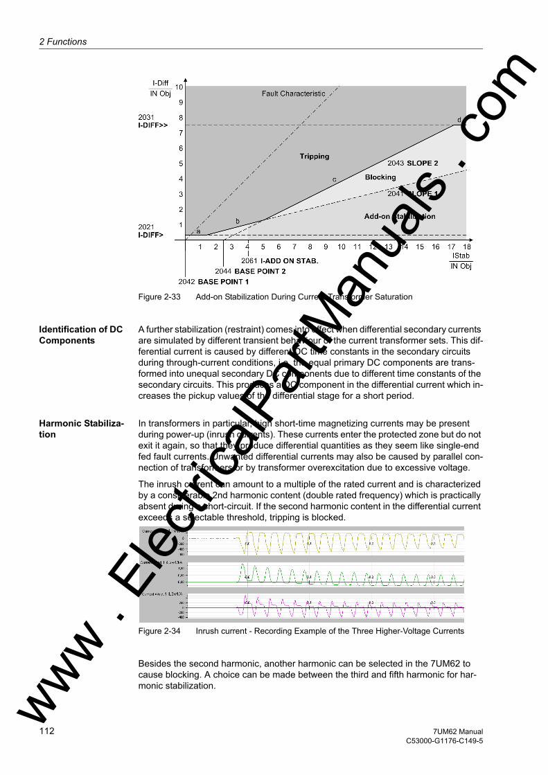
2 Functions
om
Figure 2-33 Add-on Stabilization During Current Transformer Saturation
Identification of DC Components
A further stabilization (restraint) comes into effect when differential secondary currents are simulated by different transient behaviour of the current transformer sets. This dif-ferential current is caused by different DC time constants in the secondary circuits during through-current conditions, i.e. the equal primary DC components are trans-formed into unequal secondary DC components due to different time constants of the secondary circuits. This produces a DC component in the differential current which in-creases the pickup values of the differential stage for a short period.
Harmonic Stabiliza-tion
In transformers in particular, high short-time magnetizing currents may be present during power-up (inrush currents). These currents enter the protected zone but do not exit it again, so that they produce differential quantities as they seem like single-end fed fault currents. Unwanted differential currents may also be caused by parallel con-nection of transformers or by transformer overexcitation due to excessive voltage.
The inrush current can amount to a multiple of the rated current and is characterized by a considerable 2nd harmonic content (double rated frequency) which is practically absent during a short-circuit. If the second harmonic content in the differential current exceeds a selectable threshold, tripping is blocked.
Figure 2-34 Inrush current - Recording Example of the Three Higher-Voltage Currents
Besides the second harmonic, another harmonic can be selected in the 7UM62 to cause blocking. A choice can be made between the third and fifth harmonic for har-monic stabilization. ww .
Elec
tricalP
artM
anua
ls . c
112 7UM62 ManualC53000-G1176-C149-5
w

2.14 Differential Protection and Its Protected Objectsw
Steady-state overexcitation is characterized by odd harmonics. The 3rd or 5th har-monic is suitable to detect overexcitation. Because as the third harmonic is often elim-inated in power transformers (e.g. in a delta winding), the use of the fifth is more common.
Converter transformers also produce odd harmonics which are practically absent in the case of an internal short-circuit.
The differential currents are analysed for harmonic content. For frequency analysis digital filters are used which perform a Fourier analysis of the differential currents. As soon as the harmonics content exceeds the set thresholds, a stabilization of the re-spective phase evaluation is started. The filter algorithms are optimized for transient behaviour such that additional measures for stabilization during dynamic conditions are not necessary.
Harmonic stabilization is maintained for two cycles after decrease of the differential current. This prevents unwanted under-stabilization when external faults are cleared and higher-order harmonics disappear.
Since inrush restraint operates individually for each phase, the protection is fully op-erative even when the transformer is switched onto a single-phase fault, whereby an inrush current may possibly flow through one of the undisturbed phases.
In "modern type" transformers in particular, the 2nd harmonics content may not exceed the threshold value in all three phases on switch-on. To avoid spurious trip-ping, the so-called "crossblock" function must be activated. As soon as an inrush current is detected in one phase, the other phases of the differential protection stage I-DIFF> are blocked.
The "crossblock" function can be limited to a selectable duration. After this cross-block time has elapsed, no further cross-block is possible for as long as a current fault con-dition lasts, i.e. cross-blocking is possible only once after a fault has occurred, and only for the set cross-block time period.
The other harmonic stabilizations operate individually for each phase. However, it is also possible —as it is for inrush stabilization— to set protection such that on over-shooting of the admissible harmonic content in the current of only one phase, the other phases of the differential stage I-DIFF> are blocked. This cross-block feature with 3rd or 5th harmonic works in the same way as with the 2nd harmonic.
Pickup Value In-crease on Startup
An increase of the pickup value on startup provides additional security against over-functioning when a non-energized protection object is switched in. As soon as the sta-bilizing current of one phase has undershot a settable value I-REST. STARTUP, the increase of the pickup value is activated for the I-DIFF> stage. As the stabilizing current is twice the through-flowing current in normal operation, its undershooting of that threshold is a criterion for detecting that the protected object is not energized. The pickup value I-DIFF is now increased by a settable factor (see following figure); the other branches of the Idiff> stage are displaced proportionally.
This is done by dividing the DIFF current of the respective phase by the factor START-FACTOR before the characteristic monitoring. The differential current for fault record-ing, tripping current etc. is not affected by this.
The return of the stabilizing current indicates the startup. After a settable time T START MAX the increase of the characteristic is retracted.
ww . El
ectric
alPar
tMan
uals
. com
1137UM62 ManualC53000-G1176-C149-5

2 Functions
om
Figure 2-35 Increase of Pickup Value for Stage IDIFF> on Startup
Fault Detection, Dropout
The differential protection does not normally use a "pickup", since the detection of a fault is identical with the tripping condition. Like all SIPROTEC 4 devices, however, the differential protection feature of the 7UM62 has a pickup that is the starting point for a number of ulterior activities. The pickup marks the beginning of a fault. This is neces-sary e.g. for creating fault logs and fault records. The pickup also controls internal function sequences for both internal and external faults (such as necessary actions of the saturation detector).
A pickup is detected as soon as the fundamental wave of the differential current has attained 85 % of the setting value or more than 85 % of the stabilizing current are in the add-on stabilization area (see following figure). A pickup signal is also issued when the high-speed trip stage for high-current faults picks up.
Figure 2-36 Pickup of the Differential Protection
If stabilization by higher-order harmonics is activated, the system first performs a har-monic analysis (approx. 1 cycle) to check the stabilization conditions as the case may be. If it is not, the trip command is issued as soon as the tripping conditions are fulfilled (hatched area in Figure 2-31).
For special cases, the trip command can be delayed.ww . El
ectric
alPar
tMan
uals
. c
114 7UM62 ManualC53000-G1176-C149-5
w

2.14 Differential Protection and Its Protected Objectsw
The following figure shows a simplified diagram of the tripping logic.
A dropout is detected when, during 2 cycles, pick-up is no longer recognized in the dif-ferential value, i.e. the differential current has fallen below 70 % of the set value, and the other pickup conditions are no longer fulfilled either.
If a trip command has not been initiated, the fault is considered ended on dropout.
If a trip command had been initiated, it is maintained for the minimum command dura-tion set in the general device data for all protection functions (see also Section P.System Data 1).
Note
The special features of the differential protection for individual protected objects are described in separate chapters.
ww . El
ectric
alPar
tMan
uals
. com
1157UM62 ManualC53000-G1176-C149-5
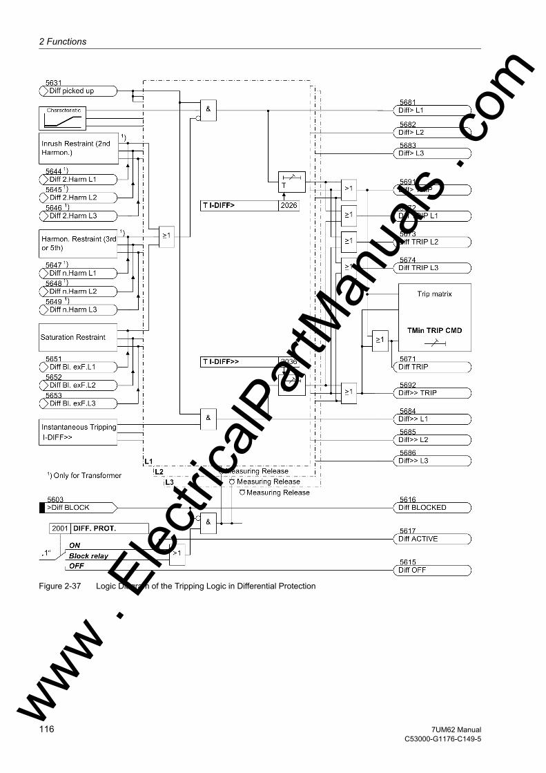
2 Functions
om
Figure 2-37 Logic Diagram of the Tripping Logic in Differential Protectionww . El
ectric
alPar
tMan
uals
. c
116 7UM62 ManualC53000-G1176-C149-5
w
2.14 Differential Protection and Its Protected Objectsw
2.14.1.2 Setting Notes
General Differential protection is only effective and available if the type of protected object for this function was set during protective function configuration (Section 2.4, address 120, DIFF. PROT. = Generator/Motor or 3 phase transf.). Only the relevant parameters for that object are presented, all others are hidden. If the function is not required Disabled is set. The address 2001 DIFF. PROT. serves to enable the function ON and OFF or to block only the trip command (Block relay).
Note
When the device is delivered, the differential protection function is switched OFF. The reason is that the protection must not be in operation unless at least the connection group (of a transformer) and the matching factors have been set before. Without these settings the device react unpredictably (e.g. tripping)!
The primary rated current Ip, ct of the used CTs should normally be higher than the rated current IN, Object of the object to be protected. However, at least the following con-dition should be observed with regard to the upper limit of the linear zone of the 7UM62, which is 20 · IN:
Ip, ct > 0.75 · IN, Object
Additional Settings
Note
Additional parameter settings are given in separate subsections for the respective pro-tected objects.
ww . El
ectric
alPar
tMan
uals
. com
1177UM62 ManualC53000-G1176-C149-5

2 Functions
om
2.14.1.3 Settings
Addresses which have an appended "A" can only be changed with DIGSI, under Ad-ditional Settings.
Addr. Parameter Setting Options Default Setting Comments
2001 DIFF. PROT. OFFONBlock relay
OFF Differential Protection
2005 INC.CHAR.START OFFON
OFF Increase of Trip Char. During Start
2006 INRUSH 2.HARM. OFFON
ON Inrush with 2. Harmonic Restraint
2007 RESTR. n.HARM. OFF3. Harmonic5. Harmonic
OFF n-th Harmonic Restraint
2021 I-DIFF> 0.05 .. 2.00 I/InO 0.20 I/InO Pickup Value of Differential Curr.
2026A T I-DIFF> 0.00 .. 60.00 sec; ∞ 0.00 sec T I-DIFF> Time Delay
2031 I-DIFF>> 0.5 .. 12.0 I/InO; ∞ 7.5 I/InO Pickup Value of High Set Trip
2036A T I-DIFF>> 0.00 .. 60.00 sec; ∞ 0.00 sec T I-DIFF>> Time Delay
2041A SLOPE 1 0.10 .. 0.50 0.25 Slope 1 of Tripping Characteristic
2042A BASE POINT 1 0.00 .. 2.00 I/InO 0.00 I/InO Base Point for Slope 1 of Charac.
2043A SLOPE 2 0.25 .. 0.95 0.50 Slope 2 of Tripping Characteristic
2044A BASE POINT 2 0.00 .. 10.00 I/InO 2.50 I/InO Base Point for Slope 2 of Charac.
2051A I-REST. STARTUP 0.00 .. 2.00 I/InO 0.10 I/InO I-RESTRAINT for Start Detection
2052A START-FACTOR 1.0 .. 2.0 1.0 Factor for Increasing of Char. at Start
2053 T START MAX 0.0 .. 180.0 sec 5.0 sec Maximum Permissible Starting Time
2061A I-ADD ON STAB. 2.00 .. 15.00 I/InO 4.00 I/InO Pickup for Add-on Stabilization
2062A T ADD ON-STAB. 2 .. 250 Cycle; ∞ 15 Cycle Duration of Add-on Stabilization
2063A CROSSB. ADD ON 2 .. 1000 Cycle; 0; ∞ 15 Cycle Time for Cross-blocking Add-on Stabiliz.
2071 2. HARMONIC 10 .. 80 % 15 % 2nd Harmonic Content in I-DIFF
2072A CROSSB. 2. HARM 2 .. 1000 Cycle; 0; ∞ 3 Cycle Time for Cross-blocking 2nd Harm.
2076 n. HARMONIC 10 .. 80 % 30 % n-th Harmonic Content in I-DIFF
2077A CROSSB. n.HARM 2 .. 1000 Cycle; 0; ∞ 0 Cycle Time for Cross-blocking n-th Harm.
2078A IDIFFmax n.HM 0.5 .. 12.0 I/InO 1.5 I/InO Limit IDIFFmax of n-th Harm.Re-straint
ww . El
ectric
alPar
tMan
uals
. c
118 7UM62 ManualC53000-G1176-C149-5
w
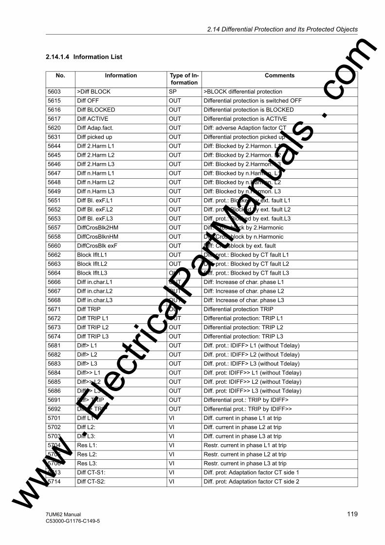
2.14 Differential Protection and Its Protected Objectsw
2.14.1.4 Information List
No. Information Type of In-formation
Comments
5603 >Diff BLOCK SP >BLOCK differential protection5615 Diff OFF OUT Differential protection is switched OFF5616 Diff BLOCKED OUT Differential protection is BLOCKED5617 Diff ACTIVE OUT Differential protection is ACTIVE5620 Diff Adap.fact. OUT Diff: adverse Adaption factor CT5631 Diff picked up OUT Differential protection picked up5644 Diff 2.Harm L1 OUT Diff: Blocked by 2.Harmon. L15645 Diff 2.Harm L2 OUT Diff: Blocked by 2.Harmon. L25646 Diff 2.Harm L3 OUT Diff: Blocked by 2.Harmon. L35647 Diff n.Harm L1 OUT Diff: Blocked by n.Harmon. L15648 Diff n.Harm L2 OUT Diff: Blocked by n.Harmon. L25649 Diff n.Harm L3 OUT Diff: Blocked by n.Harmon. L35651 Diff Bl. exF.L1 OUT Diff. prot.: Blocked by ext. fault L15652 Diff Bl. exF.L2 OUT Diff. prot.: Blocked by ext. fault L25653 Diff Bl. exF.L3 OUT Diff. prot.: Blocked by ext. fault.L35657 DiffCrosBlk2HM OUT Diff: Crossblock by 2.Harmonic5658 DiffCrosBlknHM OUT Diff: Crossblock by n.Harmonic5660 DiffCrosBlk exF OUT Diff: Crossblock by ext. fault5662 Block Iflt.L1 OUT Diff. prot.: Blocked by CT fault L15663 Block Iflt.L2 OUT Diff. prot.: Blocked by CT fault L25664 Block Iflt.L3 OUT Diff. prot.: Blocked by CT fault L35666 Diff in.char.L1 OUT Diff: Increase of char. phase L15667 Diff in.char.L2 OUT Diff: Increase of char. phase L25668 Diff in.char.L3 OUT Diff: Increase of char. phase L35671 Diff TRIP OUT Differential protection TRIP5672 Diff TRIP L1 OUT Differential protection: TRIP L15673 Diff TRIP L2 OUT Differential protection: TRIP L25674 Diff TRIP L3 OUT Differential protection: TRIP L35681 Diff> L1 OUT Diff. prot.: IDIFF> L1 (without Tdelay)5682 Diff> L2 OUT Diff. prot.: IDIFF> L2 (without Tdelay)5683 Diff> L3 OUT Diff. prot.: IDIFF> L3 (without Tdelay)5684 Diff>> L1 OUT Diff. prot: IDIFF>> L1 (without Tdelay)5685 Diff>> L2 OUT Diff. prot: IDIFF>> L2 (without Tdelay)5686 Diff>> L3 OUT Diff. prot: IDIFF>> L3 (without Tdelay)5691 Diff> TRIP OUT Differential prot.: TRIP by IDIFF>5692 Diff>> TRIP OUT Differential prot.: TRIP by IDIFF>>5701 Diff L1: VI Diff. current in phase L1 at trip5702 Diff L2: VI Diff. current in phase L2 at trip5703 Diff L3: VI Diff. current in phase L3 at trip5704 Res L1: VI Restr. current in phase L1 at trip5705 Res L2: VI Restr. current in phase L2 at trip5706 Res L3: VI Restr. current in phase L3 at trip5713 Diff CT-S1: VI Diff. prot: Adaptation factor CT side 15714 Diff CT-S2: VI Diff. prot: Adaptation factor CT side 2ww .
Elec
tricalP
artM
anua
ls . c
om
1197UM62 ManualC53000-G1176-C149-5

2 Functions
om
2.14.2 Protected Object Generator or Motor
The following section describes the special features of the generator and motor pro-tection objects.
2.14.2.1 Function Description
Definition and Matching of Mea-sured Quantities
The differential protection function of the 7UM62 can be used as longitudinal or as transverse differential protection. The operation modes differ from each other only by the definition of the measured currents and the limits of the protected zone.
Since the current direction is normally defined as positive in the direction of the pro-tected object, the definitions as illustrated in the following figure result. The protected zone is limited by the CTs in the neutral point of generator and the CTs at the terminal side. The differential protection feature of the 7UM62 refers all currents to the rated current of the protected object. The characteristic values of the protected object (ap-parent power, rated voltage) and the primary rated currents of the CTs are entered in the protective device for each side of the protected object. Measured value matching is therefore reduced to magnitude factors.
Due to their predominantly inductive component, faults in the proximity of the genera-tor have relatively high DC current time constants that cause magnetisation of the current transformers. The CTs should be designed accordingly (see section 2.14.4).
Figure 2-38 Definition of current direction with longitudinal differential protection
Use as transverse differential protection involves a special point. The definition of the current direction for this application is shown in the figure below.
For transverse differential protection, the phases connected in parallel constitute the border between the protected zone and the network. A differential current appears in this case only, but always, if there is a current difference within the particular parallel phases, so that a fault current in one phase can be assumed.
Since in this case, for normal operation, all currents flow into the protected object, i.e. the opposite of all other applications, the polarity must be reversed for one current transformer set, as described in Section 2.5.1 under "Connection of the Current Trans-former Sets".
5742 Diff DC L1 OUT Diff: DC L15743 Diff DC L2 OUT Diff: DC L25744 Diff DC L3 OUT Diff: DC L35745 Diff DC InCha OUT Diff: Increase of char. phase (DC)
No. Information Type of In-formation
Comments
ww . El
ectric
alPar
tMan
uals
. c
120 7UM62 ManualC53000-G1176-C149-5
w
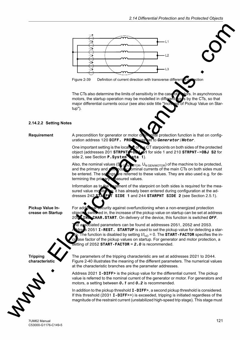
2.14 Differential Protection and Its Protected Objectsw
Figure 2-39 Definition of current direction with transverse differential protection
The CTs also determine the limits of sensitivity in the case of motors. In asynchronous motors, the startup operation may be modelled in different ways by the CTs, so that major differential currents occur (see also side title "Increase of Pickup Value on Star-tup").
2.14.2.2 Setting Notes
Requirement A precondition for generator or motor differential protection function is that on config-uration address 120 DIFF. PROT. was set to Generator/Motor.
One important setting is the location of the CT starpoints on both sides of the protected object (addresses 201 STRPNT->OBJ S1 for side 1 and 210 STRPNT->OBJ S2 for side 2, see Section P.System Data 1).
Also, the nominal values (SN GEN/MOTOR, UN GEN/MOTOR) of the machine to be protected, and the primary and secondary nominal currents of the main CTs on both sides must be entered. The settings are referred to these values. They are also used e.g. for de-termining the primary measured values.
Information as to the treatment of the starpoint on both sides is required for the mea-sured value monitoring; it has already been entered during configuration at the ad-dresses 242 STARPNT SIDE 1 and 244 STARPNT SIDE 2 (see Section 2.5.1).
Pickup Value In-crease on Startup
For additional security against overfunctioning when a non-energized protection object is switched in, the increase of the pickup value on startup can be set at address 2005 INC.CHAR.START. On delivery of the device, this function is switched OFF.
The associated parameters can be found at addresses 2051, 2052 and 2053. Address 2051 I-REST. STARTUP is used to set the pickup value for detecting a star-tup. The function is disabled by setting I/InO = 0. The START-FACTOR specifies the in-crease factor of the pickup values on startup. For generator and motor protection, a setting of 2052 START-FACTOR = 2.0 is recommended.
Tripping characteristic
The parameters of the tripping characteristic are set at addresses 2021 to 2044. Figure 2-40 illustrates the meaning of the different parameters. The numerical values at the characteristic branches are the parameter addresses.
Address 2021 I-DIFF> is the pickup value for the differential current. The pickup value is referred to the nominal current of the generator or motor. For generators and motors, a setting between 0.1 and 0.2 is recommended.
In addition to the pickup threshold I-DIFF>, a second pickup threshold is considered. If this threshold (2031 I-DIFF>>) is exceeded, tripping is initiated regardless of the magnitude of the restraint current (unstabilized high-speed trip stage). This stage must ww . El
ectric
alPar
tMan
uals
. com
1217UM62 ManualC53000-G1176-C149-5
2 Functions
om
be set higher than the I-DIFF> stage. Recommendation: Set a value above the steady-state value of the transient short-circuit current, i.e.:
With values for xd’ between 0.15 and 0.35, the resulting setting values for I-DIFF>> are approx. (3 to 7) IN, Generator.
The tripping characteristic comprises two further branches. Address 2041 SLOPE 1 determines the slope of the first branch, whose starting point is specified in the param-eter 2042 BASE POINT 1. This branch considers current-proportional error currents. These are mainly transformation errors of the main CTs and of the input CTs. If the CTs are identical, the default setting of 0.25 can be reduced to 0.15.
The second branch produces a higher stabilization in the range of high currents which may lead to current transformer saturation. Its base point is set at address 2044 BASE POINT 2. The gradient is set at address 2043 SLOPE 2. The stability during current transformer saturation can be influenced by this parameter branch. A higher gradient results in a higher stability. The default setting of 0.5 has proven to be a good value.
Figure 2-40 Parameters Determining the Shape of the Tripping Characteristic
Add-On Stabiliza-tion During Current Transformer Satu-ration
Where very high currents flow during an external short-circuit, an additional stabiliza-tion takes effect that is set at address 2061 I-ADD ON STAB. (saturation stabiliza-tion). Please note that the stabilizing current is the arithmetical sum of the currents en-tering and leaving the protected zone, i.e. that it is twice the actually flowing current. The default setting of 4.00 I/InO should therefore be kept. The maximum duration of the additional stabilization is set at address 2062 T ADD ON-STAB. in multiples of one cycle. This time is the maximum duration of blocking after leaving the additional stabilization area during heavy current external faults. The setting depends under certain circumstances on the disconnecting time of the upstream contact. The default setting 15 Cycle is a practical value.
ww . El
ectric
alPar
tMan
uals
. c
122 7UM62 ManualC53000-G1176-C149-5
w

2.14 Differential Protection and Its Protected Objectsw
Delay Times In special cases it may be advantageous to delay the trip signal of the differential pro-tection. For this, an additional delay can be set. The timer 2026 T I-DIFF> is started when an internal fault in the generator or the motor has been detected. 2036 T I-DIFF>> is the time delay of tripping stage I-DIFF>>. A separate time stage is pro-vided for each differential protection stage and for each phase. The dropout delay is linked to the minimum trip command duration that is valid for all protection functions.
All setting times are additional time delays which do not include the operating times (measuring time, dropout time) of the protective function.
2.14.3 Protected Object Transformer
Transformers are subject to a number of influences that induce differential currents even during normal operation:
2.14.3.1 Function Description
Mismatching of CTs Differences in the matching of CTs to the transformer rated current are not uncommon. These differences result in an error that leads to a differential current.
Voltage Control by Tap Changers
Voltage control tap changers (usually in-phase regulators) change the transformation ratio and the rated current of the transformer. They cause mismatching of the CTs and thus a differential current.
Inrush Current Transformers may absorb on power-up considerable magnetising currents (inrush currents) that enter the protected zone but do not exit it. They act therefore like fault currents entering on one side.
The inrush current can amount to a multiple of the rated current and is characterized by a considerable 2nd harmonic content (double rated frequency) which is practically absent during a short-circuit.
Overexcitation Where a transformer is operated with an excessive voltage, the non-linear magnetis-ing curve leads to increased magnetising currents, which cause in turn an additional differential current.
Vector Group Depending on their application, transformers have different vector groups, which cause a shift of the phase angles between the primary and the secondary side. Without adequate correction, this phase shift would cause a differential current.
The following paragraphs describe the main functional blocks of the differential protec-tion for managing these influences.
ww . El
ectric
alPar
tMan
uals
. com
1237UM62 ManualC53000-G1176-C149-5

2 Functions
om
Quantitative match-ing of Measured values
The input currents are converted in relation to the power transformer rated current. The nominal values of the transformer, i.e. rated apparent power, rated voltages and primary rated CT currents, are entered in the protective device, and a correction factor kw is calculated according to the following formula:
with
Ip, Ct Primary CT rated current
IN,Obj. Nominal primary current of the protected object
SN Nominal apparent power of protected object
UN Rated voltage
kInterturn Correction factor
This correction is performed for each side of the protected object.
Once the vector group has been entered, the protective device is capable of perform-ing the current comparison according to fixed formulae.
Matching of Vector Group
Unit transformers often have a wye-delta connection, with the delta connection being on the generator side. To allow a maximum of versatility in the use of the 7UM62, all imaginable vector group combinations have been provided for in the software. The basic principle of numerical vector group correction is now explained by way of example for a Y(N)d5 transformer.
The higher voltage side has a wye connection and the lower voltage side a delta con-nection. The phase rotation is n · 30° (i.e. 5 · 30° = 150°). Side 1 (higher voltage side) is the reference system. The vector group correction feature transforms the currents flowing from side 2 to side 1.
ww . El
ectric
alPar
tMan
uals
. c
124 7UM62 ManualC53000-G1176-C149-5
w

2.14 Differential Protection and Its Protected Objectsw
Ungrounded Star-point
The following figure shows the vector group, the vector diagram for symmetrically flowing currents and the transformation rules for a system with an isolated starpoint.
Figure 2-41 Vector group matching for a Y(N) d5 transformer (isolated starpoint)
Deducting on side 2 the currents IL3 – IL1, results in the current IA, which has the same direction as IA on side 1. Multiplying with 1/√3 matches the quantitative values. The matrix describes the conversion for all three phases.
Earthed Transform-er Starpoint
The following figure shows an example of a YNd5 vector group with earthed starpoint on the Y-side.
The zero sequence currents are eliminated in this case. The following figure on the right side, the zero sequence currents are automatically eliminated by the current dif-ference formation, just as in the transformer there can be no zero sequence currents outside the delta winding. On the left-hand side, the elimination of the zero sequence current results from the matrix equation, e.g.1/3 · (2 IL1 – 1 IL2 – 1 IL3) = 1/3 · (3 IL1 – IL1 – IL2 – IL3) = 1/3 · (3 IL1 – 3 I0) = (IL1 – I0).
Because of the zero sequence current elimination, fault currents which flow through the CTs during earth faults in the network if there is an earthing point in the protected zone (transformer starpoint or starpoint earthing transformer) are neutralised without any special measures from outside.
ww . El
ectric
alPar
tMan
uals
. com
1257UM62 ManualC53000-G1176-C149-5

2 Functions
om
Figure 2-42 Vector group matching for Y(N) d5 (with earthed starpoint)
In the following figure on the left-hand side, a zero sequence current will occur in case of e.g. an external fault; on the right-hand side, it will not. If the currents were com-pared without first eliminating the zero sequence current, the result would be wrong (differential current despite external fault). Therefore, the zero sequence current must be eliminated on side 1. The zero sequence current is subtracted from the phase cur-rents. The rule for calculation is shown in the left-hand matrix in Figure 2-42.
Figure 2-43 Example of an earth fault outside the transformer with distribution of currents
ww . El
ectric
alPar
tMan
uals
. c
126 7UM62 ManualC53000-G1176-C149-5
w

2.14 Differential Protection and Its Protected Objectsw
2.14.3.2 Setting Notes
Requirement A precondition for the transformer differential protection function is that on configura-tion address 120 DIFF. PROT. was set to 3 phase transf..
To ensure the correct polarity for the formation of the differential current, the polarity of the sets of CTs must be specified. This was done during configuration by entering the location of the starpoints of the sets of CTs on both sides of the transformer (ad-dresses 201 STRPNT->OBJ S1 for side 1 and 210 STRPNT->OBJ S2 for side 2, see Subsection P.System Data 1).
Also the nominal data (SN TRANSF, UUN WIND S1, UUN WIND S2) of both sides of the trans-former, as well as the primary and secondary rated currents of the main CTs on both sides were queried. The settings are referred to these values. They are also used e.g. for determining the primary measured values.
Information on starpoint handling on both sides is required for elimination of zero se-quence current and for measured value monitoring (summation current monitoring); it has already been entered during configuration at addresses 242 STARPNT SIDE 1 and 244 STARPNT SIDE 2 (see Subsection 2.5.1).
Matching of Abso-lute Values and Vector Groups
When used as transformer protection, the 7UM62 automatically computes from the rated data of the protected transformer the current-matching formulae which are re-quired to match the vector group and the different rated winding currents. The currents are converted such that the sensitivity of the protection always refers to the power rating of the transformer. No circuitry is required in general for vector group matching or for manual conversions for rated currents.
The unit requires the following data for each winding• Rated apparent power SN in MVA (see above), • Rated voltage UUN in kV (see above) • Vector group numeral,• Rated current of the current transformer set in A (see above).
Winding 1 is defined as the reference winding and therefore needs no numeral; the other windings are referred to winding 1.
The reference winding is normally that of the higher voltage. If a reference winding other than the higher voltage one is used, it must be noted that this changes the vector group numeral: E.g. a Dy5 transformer is regarded from the Y side as Yd7.
If a transformer winding is regulated, then the actual rated voltage of the winding is not used as UN, but rather the voltage which corresponds to the average current of the regulated range.
If the setting of the protection should be performed with secondary values only (e.g. because external matching transformers are present), the factory-set parameters of the transformer data can remain unchanged. The presets for transformer data apply for a current matching factor of 1: 1 without phase displacement
ww . El
ectric
alPar
tMan
uals
. com
1277UM62 ManualC53000-G1176-C149-5

2 Functions
om
Zero Sequence Current Treatment
The treatment of the winding starpoints is of no concern if the zero sequence current is eliminated from the phase currents. By this means fault currents which flow through the CTs during earth faults in the network if there is an earthing point in the protected zone (transformer starpoint or starpoint earthing transformer) are neutralized without any special external measures. Elimination is done by setting STARPOINT S* = earthed (see Figure „Vector Group Adaptation with Earthed Starpoint“in the function-al description of this subsection).
In resonant-earthed systems or isolated networks, elimination of zero sequence current may be dispensed with provided that the starpoint of the protected transformer winding has no connection to earth, not even via a Petersen coil or a surge arrester! In this case, each double earth fault with one base point in the protected zone will be cleared by the relay, regardless of any double earth fault priority (see side title „Un-grounded Starpoint“ and Figure „Vector Group Matching for Y(N) d5 (isolated star-point)“).
Pickup Value In-crease on Startup
For additional security against overfunctioning when a non-energized protection object is switched in, the increase of the pickup value on startup can be set at address 2005 INC.CHAR.START. As this option is mainly provided for generator and motor protection, the default setting is initially OFF if a 2-winding transformer is selected as protected object.
The associated parameters can be found at addresses 2051, 2052 and 2053. Address 2051 I-REST. STARTUP is used to set the pickup value for detecting a star-tup. The function is disabled by setting I/InO = 0. The START-FACTOR specifies the in-crease factor of the pickup values on startup. For transformer protection, a setting of 2052 START-FACTOR = 1.0 is recommended. For switching of external loads such as motors or transformers, it should be increased to 2.0. Due to the high time constants, branch b of the characteristic may well be exceeded for a short time with nonmatched CTs.
Harmonic Restraint The inrush restraint of the device can be enabled and disabled at address 2006 INRUSH 2.HARM.. It is based on evaluation of the 2nd harmonic present in the switchon inrush current. When the device is delivered from the factory, a ratio I2fN/IfN of 15 % is set and can normally be taken over unchanged. However the component required for restraint can be parameterized. To provide for more restraint in exception-al cases, where switch-on conditions are particularly unfavourable, a smaller value can be set at address 2071 2. HARMONIC.
Cross Blocking The inrush restraint can be extended by the so-called "crossblock" function. This means that on harmonic content overshoot in only one phase all three phases of the differential stage IDIFF> stage are blocked. The duration for which the cross-block function is to remain operative after differential current overshoot, is set at address 2072 CROSSB. 2. HARM. Setting is in multiple of the AC-cycle. Setting to 0 means that the protection can initiate a tripping when the transformer is switched onto a single-phase fault, even if an inrush current is flowing in another phase. When set to ∞, the cross-block function is always effective. The duration of the blocking is specified during commissioning. The default setting of 3 cycles has proven to be a practical value.
Besides the second harmonic, the 7UM62 can provide restraint with a further harmon-ic. Address 2007 RESTR. n.HARM. is used to disable this harmonics restraint, or to select the harmonic for it. The 3rd or the 5th harmonic are selectable.
ww . El
ectric
alPar
tMan
uals
. c
128 7UM62 ManualC53000-G1176-C149-5
w

2.14 Differential Protection and Its Protected Objectsw
Steady-state overexcitation is characterized by odd harmonics. Here the third or fifth harmonic are suitable for restraint purposes. As the third harmonic is often eliminated in transformers (e.g. in a delta winding), the fifth harmonic is more commonly used.
Converter transformers also produce odd harmonics which are practically absent in the case of an internal short-circuit.
The harmonic content which blocks the differential protection is set at address 2076 n. HARMONIC. If the 5th harmonic is used as overexcitation stabilization, then e.g. 30 % (default setting) are usual.
Harmonic restraint operates individually per phase. However, it is also possible – as it is for the inrush restraint – to set the protection such that not only the phase with har-monics content in excess of the permissible value is stabilized but also the other phases of the differential stage IDIFF> are blocked ("cross-block" function). The dura-tion for which the cross-block function is to remain operative after differential current overshoot, is set at address 2077 CROSSB. n.HARM. Setting is in multiple of the AC-cycle. Setting to 0 Cycle (default setting) allows protection to initiate a tripping when the transformer is switched onto a single-phase fault, even if a higher harmonics content is present in another phase. When set to ∞, the cross-block function is always effective.
If the differential current exceeds a multiple of the rated transformer current specified at address 2078 IDIFFmax n.HM, no nth-harmonic restraint takes place.
Tripping characteristic
The parameters of the tripping characteristic are set in addresses 2021 to 2044. The meaning of the parameters can be seen in the following figure. The numerical values at the characteristic branches are the parameter addresses.
Address 2021 I-DIFF> is the pickup value for the differential current. This is the total fault current flowing in the protection area, regardless of the way it is distributed between the windings of the protected transformer. The pickup value is referred to the rated current corresponding to the rated apparent power of the transformer. For trans-formers, the setting should be between 0.2 and 0.4. It should be checked during com-missioning that the selected pickup value is at least twice the maximum differential current present in steady-state operation.
In addition to the pickup threshold I-DIFF>, a second pickup threshold is introduced. If this threshold (2031 I-DIFF>>) is exceeded, tripping is initiated regardless of the magnitude of the restraint current (unstabilized high-speed trip stage). This stage must be set higher than the I-DIFF> stage. As a guide: above 1/uk of the transformer.
The tripping characteristic forms two more branches (see the following figure). Address 2041 SLOPE 1 determines the slope of the first branch, whose starting point is specified in the parameter 2042 BASE POINT 1. This branch covers current-pro-portional errors. These are mainly transformation errors of the main CTs and, espe-cially, the differential currents which may occur in the final tap changer positions due to a possible transformer regulation range. This branch of the characteristic limits the stabilization area. The preset slope of 0.25 should be sufficient for regulating ranges up to 20 %. If the transformer has a larger regulated range, the slope must be in-creased accordingly.
ww . El
ectric
alPar
tMan
uals
. com
1297UM62 ManualC53000-G1176-C149-5

2 Functions
om
Figure 2-44 Parameters Determining the Shape of the Tripping Characteristic
The second branch produces a higher restraint in the range of high currents which may lead to current transformer saturation. Its base point is set at address 2044 BASE POINT 2 and is referred to the rated power transformer current. The slope is set at address 2043 SLOPE 2. The restraint during current transformer saturation can be influenced by this parameter branch. A higher gradient results in a higher restraint.
Additional Stabili-zation During Current Transform-er Saturation
Where very high currents flow during an external short-circuit, an add-on stabilization takes effect that is set at address 2061 I-ADD ON STAB. (saturation stabilization). Please note that the stabilizing current is the arithmetical sum of the currents through the windings, i.e. it is twice the actually flowing current. The default setting of 4.00 I/InO should be maintained. The maximum duration of the add-on stabilization is set at address 2062 T ADD ON-STAB. in multiples of one cycle. This time is the maximum duration of blocking after leaving the additional stabilization area during heavy current external faults. The setting depends under certain circumstances on the disconnecting time of the upstream contact. The default setting 15 Cycle is a practical value.
Delay Times In special cases it may be advantageous to delay the trip signal of the differential pro-tection. For this, an additional delay can be set. The delay timer 2026 T I-DIFF> is started when an internal fault is detected in the transformer. 2036 T I-DIFF>> is the delay time for the tripping stage 2031 I-DIFF>>. A separate time stage is provided for each differential protection level and for each phase. The dropout delay is linked to the minimum trip command duration that is valid for all protection functions. All setting times are additional time delays which do not include the operating times (measuring time, dropout time) of the protective function.
ww . El
ectric
alPar
tMan
uals
. c
130 7UM62 ManualC53000-G1176-C149-5
w
2.14 Differential Protection and Its Protected Objectsw
2.14.4 Current Transformer Requirements
The differential protection is of decisive importance for the requirements that the current transformers must meet. The high-speed trip stage (IDiff >>) uses instanta-neous values and can therefore reliably trip high-current internal short-circuits. For de-termination of the primary CT rated current, in practice the general usual procedures are used. It must be selected equal to or greater than the rated current of the protected object.
2.14.4.1 Function Description
Design recommen-dations
The external short circuit determines the requirements that the current transformers must meet because of the possible DC current component. In case of a short-circuit flowing through the power transformers, a minimum of 5 ms should elapse before current transformer saturation occurs. The two following tables show the design spec-ifications. The IEC 60044-1 and IEC 60044-6 standards were used in these tables. The equations for calculating the requirements as knee-point voltages are listed in table 2-7.
Table 2-5 Overcurrent Factors
with
Ktd Transient dimensioning factor
IpSC Primary symmetric short circuit current
IpN Primary CT rated current
RBC Connected load
RBN Rated load
RCt Internal load
Table 2-6 Transformer Requirements
Required operational overcurrent factor Resulting rated overcurrent factor
Transformer GeneratorTransient dimensioning factor Ktd
≥ 4 with τN ≤ 100 ms
> (4 to 5), with τN > 100 ms
Symmetrical short circuit current IpSC
ww . El
ectric
alPar
tMan
uals
. com
1317UM62 ManualC53000-G1176-C149-5
2 Functions
om
with
uK Transformer impedance
Xd Direct-axis transient reactance
IsN Secondary CT rated current
τN Power system time constant
Table 2-7 Knee-Point Voltages
with
U Knee-point voltages
n Rated overcurrent factor
IsN Secondary CT rated current
RBN Rated load
RCt Internal load
Example uSC = 0.1 n’ > 40
xd’’ = 0.12 n’ > (34 to 42)
Note: Always use identical trans-formers
Power ≥ 10 or 15 VA Example of network transform-er:10P10 10 or 15 VA(IsN = 1 A or 5 A)
Note internal load! Example: IN, Gapprox. 1000 to 2000 A 5P15 15 VA(IsN = 1 A or 5 A) IN, G > 5000 A5P20 30 VA(IsN = 1 A or 5 A)
Transformer Generator
IEC British Standard ANSI
ww . El
ectric
alPar
tMan
uals
. c
132 7UM62 ManualC53000-G1176-C149-5
w
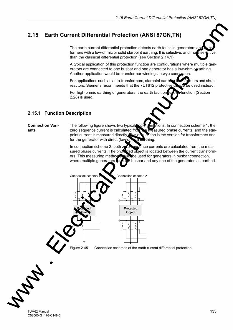
2.15 Earth Current Differential Protection (ANSI 87GN,TN)w
2.15 Earth Current Differential Protection (ANSI 87GN,TN)
The earth current differential protection detects earth faults in generators and trans-formers with a low-ohmic or solid starpoint earthing. It is selective, and more sensitive than the classical differential protection (see Section 2.14.1).
A typical application of this protection function are configurations where multiple gen-erators are connected to one busbar and one generator has a low-ohmic earthing. Another application would be transformer windings in wye connection.
For applications such as auto-transformers, starpoint earthing transformers and shunt reactors, Siemens recommends that the 7UT612 protective device be used instead.
For high-ohmic earthing of generators, the earth fault protection function (Section 2.28) is used.
2.15.1 Function Description
Connection Vari-ants
The following figure shows two typical implementations. In connection scheme 1, the zero sequence current is calculated from the measured phase currents, and the star-point current is measured directly. This application is the version for transformers and for the generator with direct (low-ohmic) earthing.
In connection scheme 2, both zero sequence currents are calculated from the mea-sured phase currents. The protected object is located between the current transform-ers. This measuring method should be used for generators in busbar connection, where multiple generators feed the busbar and any one of the generators is earthed.
Figure 2-45 Connection schemes of the earth current differential protection
ww . El
ectric
alPar
tMan
uals
. com
1337UM62 ManualC53000-G1176-C149-5
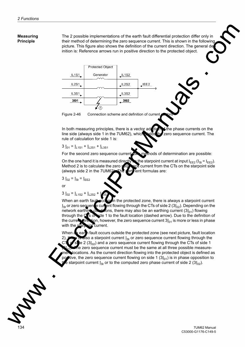
2 Functions
om
Measuring Principle
The 2 possible implementations of the earth fault differential protection differ only in their method of determining the zero sequence current. This is shown in the following picture. This figure also shows the definition of the current direction. The general def-inition is: Reference arrows run in positive direction to the protected object.
Figure 2-46 Connection scheme and definition of current vectors
In both measuring principles, there is a vector addition of the phase currents on the line side (always side 1 in the 7UM62), which yields the zero sequence current. The rule of calculation for side 1 is:
3 I01 = IL1S1 + IL2S1 + IL3S1
For the second zero sequence current, two methods of determination are possible:
On the one hand it is measured directly as the starpoint current at input IEE2 (ISt = IEE2). Method 2 is to calculate the zero sequence current from the CTs on the starpoint side (always side 2 in the 7UM62). The pertinent formulas are:
3 I02 = ISt = IEE2
or
3 I02 = IL1S2 + IL2S2 + IL3S2
When an earth fault occurs in the protected zone, there is always a starpoint current ISt or zero sequence current flowing through the CTs of side 2 (3I02). Depending on the network earthing conditions, there may also be an earthing current (3I01) flowing through the CTs of side 1 to the fault location (dashed arrow). Due to the definition of the current direction, however, the zero sequence current 3I01 is more or less in phase with the starpoint current.
When an earth fault occurs outside the protected zone (see next picture, fault location 2), there is also a starpoint current ISt or zero sequence current flowing through the CTs of side 2 (3I02) and a zero sequence current flowing through the CTs of side 1 (3I01). The zero sequence current must be the same at all three possible measure-ment locations. As the current direction flowing into the protected object is defined as positive, the zero sequence current flowing on side 1 (3I01) is in phase opposition to the starpoint current ISt or to the computed zero phase current of side 2 (3I02).
ww . El
ectric
alPar
tMan
uals
. c
134 7UM62 ManualC53000-G1176-C149-5
w

2.15 Earth Current Differential Protection (ANSI 87GN,TN)w
Figure 2-47 Example of an external fault
When an external non-earthed fault causes heavy currents to flow through the protect-ed zone, differences in the magnetic characteristics of the phase current transformers under conditions of saturation may cause a significant summation current which re-sembles an earth current flowing into the protected zone. Measures must be taken to prevent this current from causing a trip. The same may happen if, for example, signif-icant loads with a high inductive component (and thus large time constants), such as motors or transformers, are switched on.
For these reasons the earth current differential protection provides a number of re-straining features which differ significantly from conventional restraining methods (see margin heading "Restraining Measures").
Evaluation of Mea-sured Values
The earth current differential protection compares the fundamental wave of the zero currents on both sides (3I01 and 3I02) and calculates from them the differential and the restraint (stabilizing) current.
I0-Diff = | 3I01 + 3I02 |
I0-Stab = | 3I01 3I02 |
Depending on the application, current 3I02 may be the calculated zero sequence current of side 2 or the directly measured starpoint current ISt.
Under no-fault conditions, and with ideal CTs, the zero sequence currents would be zero, and consequently the differential and the restraint current zero also. To eliminate the influence of CT errors, the restraint is determined by the characteristic (see follow-ing figure).
In case of an external earth fault, the differential current is zero or minimal, and the restraint current is twice the fault current. The measured quantities are within the re-straint zone. An internal earth fault, on the other hand, causes a fairly equal differential and restraint current. This is now in the trip zone (along the dashed line).
The pickup threshold is set with the I-REF> stage.
ww . El
ectric
alPar
tMan
uals
. com
1357UM62 ManualC53000-G1176-C149-5
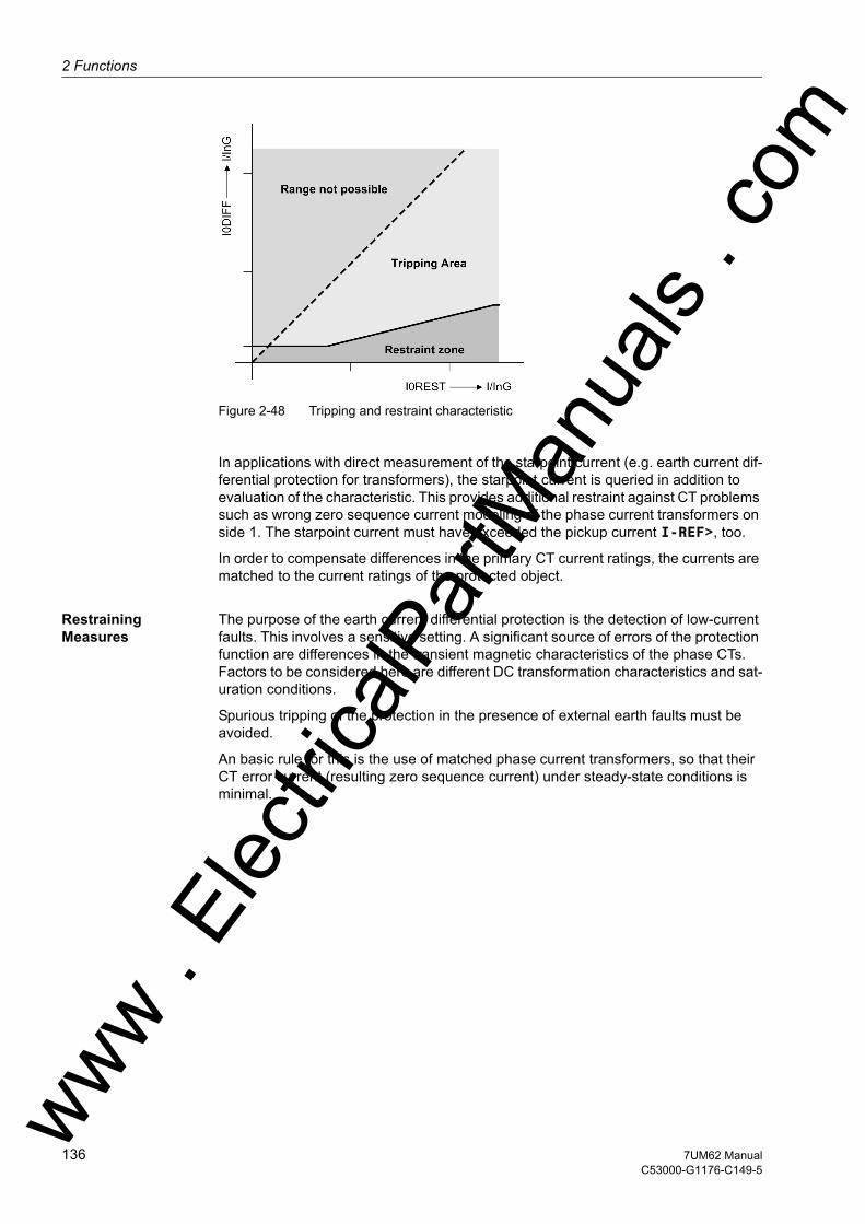
2 Functions
om
Figure 2-48 Tripping and restraint characteristic
In applications with direct measurement of the starpoint current (e.g. earth current dif-ferential protection for transformers), the starpoint current is queried in addition to evaluation of the characteristic. This provides additional restraint against CT problems such as wrong zero sequence current modeling of the phase current transformers on side 1. The starpoint current must have exceeded the pickup current I-REF>, too.
In order to compensate differences in the primary CT current ratings, the currents are matched to the current ratings of the protected object.
Restraining Measures
The purpose of the earth current differential protection is the detection of low-current faults. This involves a sensitive setting. A significant source of errors of the protection function are differences in the transient magnetic characteristics of the phase CTs. Factors to be considered here are different DC transformation characteristics and sat-uration conditions.
Spurious tripping of the protection in the presence of external earth faults must be avoided.
An basic rule for this is the use of matched phase current transformers, so that their CT error current (resulting zero sequence current) under steady-state conditions is minimal.
ww . El
ectric
alPar
tMan
uals
. c
136 7UM62 ManualC53000-G1176-C149-5
w
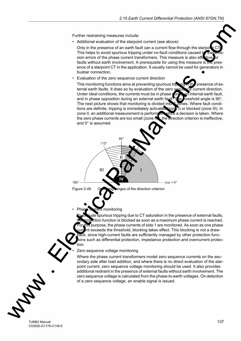
2.15 Earth Current Differential Protection (ANSI 87GN,TN)w
Further restraining measures include:• Additional evaluation of the starpoint current (see above)
Only in the presence of an earth fault can a current flow through the starpoint CTs. This helps to avoid spurious tripping under no-fault conditions caused by transmis-sion errors of the phase current transformers. This measure is also effective for faults without earth involvement. A prerequisite for using this measure is the pres-ence of a starpoint CT in the application. It usually cannot be used for generators in busbar connection.
• Evaluation of the zero sequence current directionThis monitoring functions aims at preventing spurious tripping in the presence of ex-ternal earth faults. It does so by evaluation of the zero sequence current direction. Under ideal conditions, the currents must be in phase during an internal earth fault, and in phase opposition during an external earth fault. The threshold angle is 90°. The next picture shows that monitoring is divided into 2 zones. Where fault condi-tions are definite, tripping is immediately activated (zone I) or blocked (zone III). In zone II, an additional measurement is performed before a decision is taken. Where the zero phase currents are too small (zone IV), the direction criterion is ineffective, and 0° is assumed.
Figure 2-49 Operating ranges of the direction criterion
• Phase current monitoring
To exclude spurious tripping due to CT saturation in the presence of external faults, the protection function is blocked as soon as a maximum phase current is reached. For this purpose, the phase currents of side 1 are monitored. As soon as one phase current exceeds the threshold, blocking takes effect. This blocking is not a draw-back, since high-current faults are sufficiently managed by other protection func-tions such as differential protection, impedance protection and overcurrent protec-tion.
• Zero sequence voltage monitoringWhere the phase current transformers model zero sequence currents on the sec-ondary side after load addition, and where there is no direct evaluation of the star-point current, zero sequence voltage monitoring should be used. It also provides additional restraint in the presence of external faults without earth involvement. The zero sequence voltage is calculated from the phase-to-earth voltages. On detection of a zero sequence voltage, an enable signal is issued.
ww . El
ectric
alPar
tMan
uals
. com
1377UM62 ManualC53000-G1176-C149-5
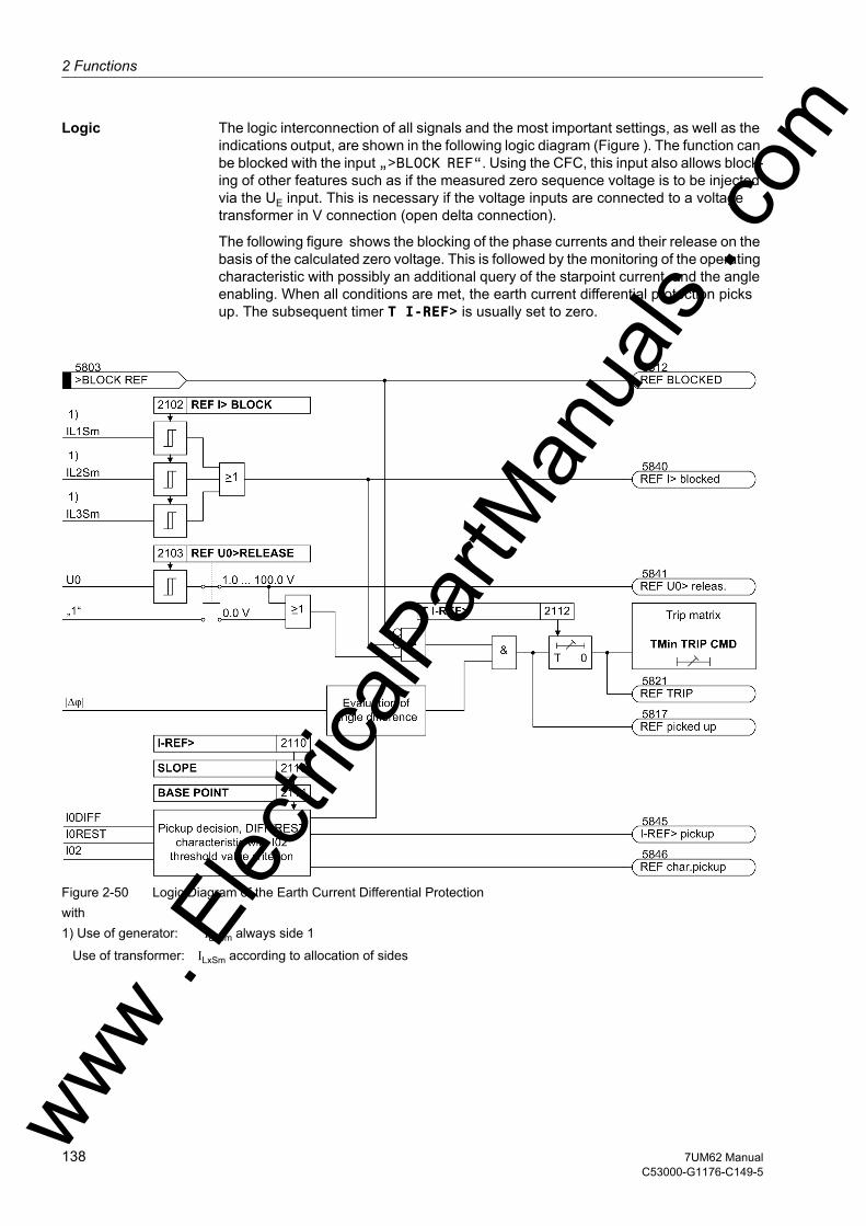
2 Functions
om
Logic The logic interconnection of all signals and the most important settings, as well as the indications output, are shown in the following logic diagram (Figure ). The function can be blocked with the input „>BLOCK REF“. Using the CFC, this input also allows block-ing of other features such as if the measured zero sequence voltage is to be injected via the UE input. This is necessary if the voltage inputs are connected to a voltage transformer in V connection (open delta connection).
The following figure shows the blocking of the phase currents and their release on the basis of the calculated zero voltage. This is followed by the monitoring of the operating characteristic with possibly an additional query of the starpoint current, and the angle enabling. When all conditions are met, the earth current differential protection picks up. The subsequent timer T I-REF> is usually set to zero.
Figure 2-50 Logic Diagram of the Earth Current Differential Protectionwith 1) Use of generator: ILxSm always side 1
Use of transformer: ILxSm according to allocation of sides
ww . El
ectric
alPar
tMan
uals
. c
138 7UM62 ManualC53000-G1176-C149-5
w

2.15 Earth Current Differential Protection (ANSI 87GN,TN)w
2.15.2 Setting Notes
General A precondition for the operation of the earth current differential protection is that during the configuration of the scope of functions (Section 2.4) the correct selection for the application in hand was made at address 121 REF PROT.. If the protected object is a generator, the user can select either direct measurement of the starpoint current via IIEE2 (Gen. with IEE2), or computed current (Gen. w. 3I0-S2). For the trans-former the directly measured zero sequence current is always used. It is however pos-sible to select for the side allocation (Transformer S1 or Transformer S2).
In power system data 1 the required settings must have been made. These are also necessary for normalization and direction definition (see also Section 2.5 or 2.14.1). If the IEE2 input is used, the protection device must be notified of the neutral point trans-former transformation ratio (prim./sec.) and the terminal of the earthing-side CT to which the IEE2 input is connected (see comments in Section 2.5).
Note
When using the IEE2 input, it must be kept in mind that this is a sensitive current input. The current amplitude is limited to approx. √2 1.6 A. A secondary rated current of 1 A is to be used for the starpoint CT. If a 5 A CT is to be used, the transformation ratio must be selected correspondingly larger (optimally factor 5).
Address 2101 REF PROT. serves to switch the function ON or OFF or to block only the trip command (Block relay).
Note
When the device is delivered, the earth current differential protection is set to OFF. The reason is that the protection must not be in operation unless at least the assigned side and CT polarity have been properly set before. Without proper settings, the device may show unexpected reactions (incl. tripping)!
Pickup Values The sensitivity of the protection is determined by I-REF> setting (address 2110). This is the earth fault current flowing in from the starpoint of the protected object (transform-er, generator), and in some cases also from the network. This value should be chosen on the basis of the most unfavourable case, i.e. fault currents entering from one side only. The current set refers to the nominal current of the protected object or the pro-tected side. The sensitivity limit is as a rule set by the CTs. A setting between 0.1 and 0.15 I/InO is quite practical.
For the operating characteristic, the default settings can be used. If necessary, these settings can be changed with the DIGSI communication software. The advanced pa-rameters define the slope (2113 SLOPE) and the base point (2114 BASE POINT) of the characteristic.
To stabilize the protection function, address 2102 can be set to blocking by the phase current (REF I> BLOCK). As a rule of thumb, the pickup value should never be more than twice the nominal current. With low-ohmic starpoint earthing, the general formula is: nominal current + earth current resulting from the starpoint resistance.
ww . El
ectric
alPar
tMan
uals
. com
1397UM62 ManualC53000-G1176-C149-5

2 Functions
om
The zero voltage enabling depends on the operating range of the protection function. 95 % of a generator stator winding is a good value. Therefore, the secondary-side value has been set to 5.0 V (2103 REF U0>RELEASE). Where the zero voltage en-abling is not used, it must be set to 0.0 V.
Note
For the protection function, the zero voltage calculated from the phase-to-earth volt-ages has been multiplied with √3, which corresponds to the voltage present in a broken delta winding.
No settings need to be made for the angle enabling and the additional evaluation of the directly measured starpoint current (where used).
For special applications, it may be advantageous to delay the trip command of the pro-tection. This can be done by setting an additional delay time (address 2112 T I-REF>). Normally, this delay time is set to 0. A minimum command duration was set in common for all protection functions (see Section 2.5.1 under „Command Duration“).
2.15.3 Settings
Addresses which have an appended "A" can only be changed with DIGSI, under Ad-ditional Settings.
Addr. Parameter Setting Options Default Setting Comments
2101 REF PROT. OFFONBlock relay
OFF Restricted Earth Fault Protection
2102 REF I> BLOCK 1.0 .. 2.5 I/InO 1.5 I/InO REF Pickup of Phase Current Blocking
2103 REF U0>RELEASE 1.0 .. 100.0 V; 0 5.0 V REF Pickup of U0> Release
2110 I-REF> 0.05 .. 2.00 I/InO 0.10 I/InO I-REF> Pickup
2112 T I-REF> 0.00 .. 60.00 sec; ∞ 0.00 sec T I-REF> Time Delay
2113A SLOPE 0.00 .. 0.95 0.25 Slope of Charac. I-REF> = f(I0-Rest)
2114A BASE POINT 0.00 .. 2.00 I/InO 0.00 I/InO Base Point for Slope of Charac-teristic
ww . El
ectric
alPar
tMan
uals
. c
140 7UM62 ManualC53000-G1176-C149-5
w

2.15 Earth Current Differential Protection (ANSI 87GN,TN)w
2.15.4 Information List
No. Information Type of In-formation
Comments
5803 >BLOCK REF SP >BLOCK restricted earth fault prot.5811 REF OFF OUT Restricted earth fault is switched OFF5812 REF BLOCKED OUT Restricted earth fault is BLOCKED5813 REF ACTIVE OUT Restricted earth fault is ACTIVE5817 REF picked up OUT REF protection picked up5821 REF TRIP OUT REF protection TRIP5833 REF CTstar: VI REF adaptation factor CT starpnt. wind.5836 REF Adap.fact. OUT REF adverse Adaption factor CT5837 REF CT-S1: VI REF adaptation factor CT side 15838 REF CT-S2: VI REF adaptation factor CT side 25840 REF I> blocked OUT REF is blocked by phase current5841 REF U0> releas. OUT REF release by U0>5845 I-REF> pickup OUT REF pickup of I-REF>5846 REF char.pickup OUT REF characteristic picked up5847 I0-Diff: VI I0-Diff at REF-Trip5848 I0-Res: VI I0-Restraint at REF-Trip
ww . El
ectric
alPar
tMan
uals
. com
1417UM62 ManualC53000-G1176-C149-5

2 Functions
om
2.16 Underexcitation (Loss-of-Field) Protection (ANSI 40)
The underexcitation protection protects a synchronous machine from asynchronous operation in the event of faulty excitation or regulation and from local overheating of the rotor. Furthermore, it avoids endangering network stability by underexcitation of large synchronous machines.
2.16.1 Function Description
Underexcitation Determination
To assess underexcitation the device processes all three terminal phase currents and all three terminal voltages for the stator circuit criterion. It also processes the excitation voltage made available by the measuring transducer TD3, for the rotor circuit criterion.
For the stator circuit criterion the admittance is calculated from the positive sequence currents and voltages. The admittance measurement always produces the physically appropriate stability limit, independently of voltage deviations from rated voltage. Even in such circumstances the protection characteristic can be thus optimally matched to the stability characteristic of the machine. By virtue of the positive sequence system evaluation, protection operates reliably even during asymmetrical current or voltage conditions.
Characteristic Curves
The following figure shows the loading diagram of the synchronous machine in the ad-mittance plane (P/U2; –Q/U2) with the statistic stability limit which crosses the reactive axis near 1/Xd (reciprocal value of the synchronous direct reactance).
Figure 2-51 Admittance Diagram of Turbo Generators
The underexcitation protection in the 7UM62 makes available three independent, freely combinable characteristics. As illustrated in the following figure, it is possible for example to model static machine stability by means of two partial characteristics with the same time delays (T CHAR. 1 = T CHAR 2). The partial characteristics are distin-guished by the corresponding distance from the zero point (1/xd CHAR. 1) and (1/xd CHAR. 2) as well as the corresponding inclination angle α1 and α2.
ww . El
ectric
alPar
tMan
uals
. c
142 7UM62 ManualC53000-G1176-C149-5
w

2.16 Underexcitation (Loss-of-Field) Protection (ANSI 40)w
If the resulting characteristic (1/xd CHAR.1)/α1; (1/xd CHAR.2)/α2 is exceeded (in the following figure on the left), a delayed warning (e.g. by 10 s) or a trip signal is trans-mitted. The delay is necessary to ensure that the voltage regulator is given enough time to increase the excitation voltage.
Figure 2-52 Stator circuit criterion: Pick–Up Characteristic in Admittance Diagram
A further characteristic (1/xd CHAR.3 /α3 can be matched to the dynamic stability characteristic of the synchronous machine. Since stable operation is impossible if this characteristic is exceeded, immediate tripping is then required (time stage T CHAR 3).
Excitation Voltage Query
With a faulty voltage regulator or excitation voltage failure, it is possible to switch off with a short delay (time stage T SHRT Uex<, e.g. 1.5 s). To do so, the device must either be notified via a binary input of the excitation voltage failure, or the excitation voltage must be fed in via measuring transducer TD3 and a voltage divider, provided that at address 3012 EXCIT. VOLT. the excitation voltage query via measuring transducer has been switched ON.
As soon as the excitation voltage undershoots a settable minimum 3013 Uexcit. <, short-time tripping is initiated.
Instead of the excitation voltage acquisition, or also in addition to it, the signal of an external excitation voltage monitoring can be fed in via a binary input. Here also, short-time tripping is initiated as soon as excitation voltage failure is signalled.
Lowpass Filter As the excitation DC voltage may contain significant AC harmonics (e.g. because of thyristor control), an analog lowpass filter is provided on the C-I/O-6 board for connec-tion of excitation voltage, in addition to the integrated digital filter. This particularly at-tenuates multiples of the scanning frequency, which cannot be adequately suppressed by the digital filter. The jumper settings for activating this filter are described in the As-ww . El
ectric
alPar
tMan
uals
. com
1437UM62 ManualC53000-G1176-C149-5
2 Functions
om
sembly and Commissioning section. On delivery from the factory, the filter is enabled. The jumper setting must match the setting of the parameter 297 TRANSDUCER 3 (see Power System Data, Section 2.5.1). If jumper settings and parameters do not match, an alarm is issued and the device is reported faulty and not operative.
Undervoltage Blocking
The admittance calculation requires a minimum measurement voltage. During a severe collapse (short-circuit) or failure of stator voltages, the protection is blocked by an integrated AC voltage monitor whose pickup threshold 3014 Umin is set on deliv-ery to 25 V. The parameter value is based on phase-to-phase voltages.
The following figure shows the logic diagram for underexcitation protection.
Figure 2-53 Logic diagram of the Underexcitation Protection
ww . El
ectric
alPar
tMan
uals
. c
144 7UM62 ManualC53000-G1176-C149-5
w

2.16 Underexcitation (Loss-of-Field) Protection (ANSI 40)w
2.16.2 Setting Notes
General The underexcitation protection is only effective and available if this function was set during protective function configuration (Section 2.4, address 130, UNDEREXCIT. is set to Enabled. If the function is not required Disabled is set. The address 3001 UNDEREXCIT. serves to enable the function ON and OFF or to block only the trip command (Block relay).
The correct power system data input according to Section 2.5 is another prerequisite for the parameterization of the underexcitation protection.
The trip characteristics of the underexcitation protection in the admittance value diagram are composed of straight segments which are respectively defined by their admittance 1/xd (=coordinate distance) and their inclination angle α. The straight seg-ments (1/xd CHAR.1)/α1 (characteristic 1) and (1/xd CHAR.2)/α2 (characteristic 2) form the static underexcitation limit (see the following figure). (1/xd CHAR.1) corre-sponds to the reciprocal value of the related synchronous direct reactance.
If the voltage regulator of the synchronous machine has underexcitation limiting, the static characteristics are set in such a way that the underexcitation limiting of the voltage regulator will intervene before characteristic 1 is reached (see figure 2-56).
Figure 2-54 Underexcitation Protection Characteristics in the Admittance Plane
ww . El
ectric
alPar
tMan
uals
. com
1457UM62 ManualC53000-G1176-C149-5
2 Functions
om
Characteristic Curve Values
If the generator capability diagram (see the following figure) in its preferred represen-tation (abscissa = positive reactive power; ordinate = positive active power) is trans-formed to the admittance plane (division by U2), the tripping characteristic can be matched directly to the stability characteristic of the machine. If the axis sizes are divided by the nominal apparent power, the generator diagram is indicated per unit (the latter diagram corresponds to a per unit representation of the admittance dia-gram).
Figure 2-55 Capability Curve of a Salient-Pole Generator, Indicated per Unit
The primary setting values can be read out directly from the diagram. The related values must be converted for the protection setting. The same conversion formula can be used if the protection setting is performed with the predefined synchronous direct reactance.
with
xdsec related synchronous direct reactance, secondary,
xd mach related synchronous direct reactance of the machine,
INMach Nominal current of the machine
UNMach Nominal Voltage of the Machine
UN, CTprim Primary Nominal Voltage of the voltage transformers
IN, CT prim Nominal primary CT current
ww . El
ectric
alPar
tMan
uals
. c
146 7UM62 ManualC53000-G1176-C149-5
w
2.16 Underexcitation (Loss-of-Field) Protection (ANSI 40)w
Instead of 1/xd Mach the approximate value IK0/IN can be used (with IK0= short-circuit current at no-load excitation).
Setting example:
Multiplied by a safety factor of about 1.05, the setting value 1/xd CHAR. 1 results under address 3002.
For α1, the angle of the underexcitation limiting of the voltage regulator is selected or the inclination angle of the machine stability characteristic is used. The setting value ANGLE 1 is typically situated between 60° and 80°.
In most cases, the machine manufacturer prescribes a minimum excitation value for small active powers. For this purpose, characteristic 1 is cut from characteristic 2 for low active-power load. Consequently, 1/xd CHAR. 2 is set to about 0.9· (1/xd CHAR. 1), the ANGLE 2 to 90°. The kinked tripping limit according to Figure 2-54 (CHAR. 1, CHAR. 2) results in this way, if the corresponding time delays T CHAR. 1 and T CHAR. 2 of both characteristics are set equally.
Characteristic 3 serves to adapt the protection to the dynamic machine stability limits. If there are no precise indications, the user must select a value1/xd CHAR. 3 situ-ated approximately between the synchronous direct reactance xd and the transient re-actance xd'. However, it should be greater than 1.
A value between 80° and 110° is usually selected for the corresponding ANGLE 3, which ensures that only a dynamic instability can lead to a pickup with characteristic 3. The associated time delay is set at address 3010 T CHAR 3 to the value suggested in Table 2-8.
Machine UN Machine = 6.3 kVIN Machine = SN/√3 UN = 5270 kVA/√3 · 6.3 kV = 483 AXd mach = 2.47
(read from machine manufacturer's specifications in Figure 2-55)
Current Trans-former
IN CT prim = 500 A
Voltage trans-former
UN, CTprim = 6.3 kV
ww . El
ectric
alPar
tMan
uals
. com
1477UM62 ManualC53000-G1176-C149-5
2 Functions
om
Figure 2-56 Admittance diagram of a turbogenerator
Delay Times If the static limit curve consisting of the characteristics 1 and 2 is exceeded, the voltage regulator must first have the opportunity of increasing the excitation. For this reason, a warning message due to this criterion is "long-time" delayed (at least 10 s for 3004 T CHAR. 1 and 3007 T CHAR. 2).
If the excitation voltage is missing or too low, the stator criterion picks up as well, pro-vided that the excitation voltage request feature has been enabled at address 3012 EXCIT. VOLT. ON and under address 3013 the parametrized threshold Uexcit. < is undershot or the absence of the excitation voltage has been signalled to the device by binary input. In all these cases tripping is possible with a short delay. This feature is set via parameter 3011 T SHRT Uex<. The following messages and trip commands are typically assigned:
Table 2-8 Setting the Underexcitation Protection
Note
If very short time delays are selected, dynamic balancing procedures may cause un-wanted operations. For this reason, it is recommended to set time values of 0.05 s or higher.
Characteristic 1 and 2 static stability undelayed Annunciation:Exc < Anr
Characteristic 1 and 2 static stability long-time delayedT CHAR. 1 = T CHAR. 2 ≈ 10 s
TrippingsErr<1 TRIP / Err<2 TRIP
Characteristic 1 and 2 Excitation Voltage Failure
short–time delayedT SHRT Uex< ≈ 1.5 s
TrippingErr< UPU < TRIP
Characteristic 3 dynamic stability short–time delayedT CHAR 3 ≈ 0.5 s
TrippingExc<3 TRIP
ww . El
ectric
alPar
tMan
uals
. c
148 7UM62 ManualC53000-G1176-C149-5
w
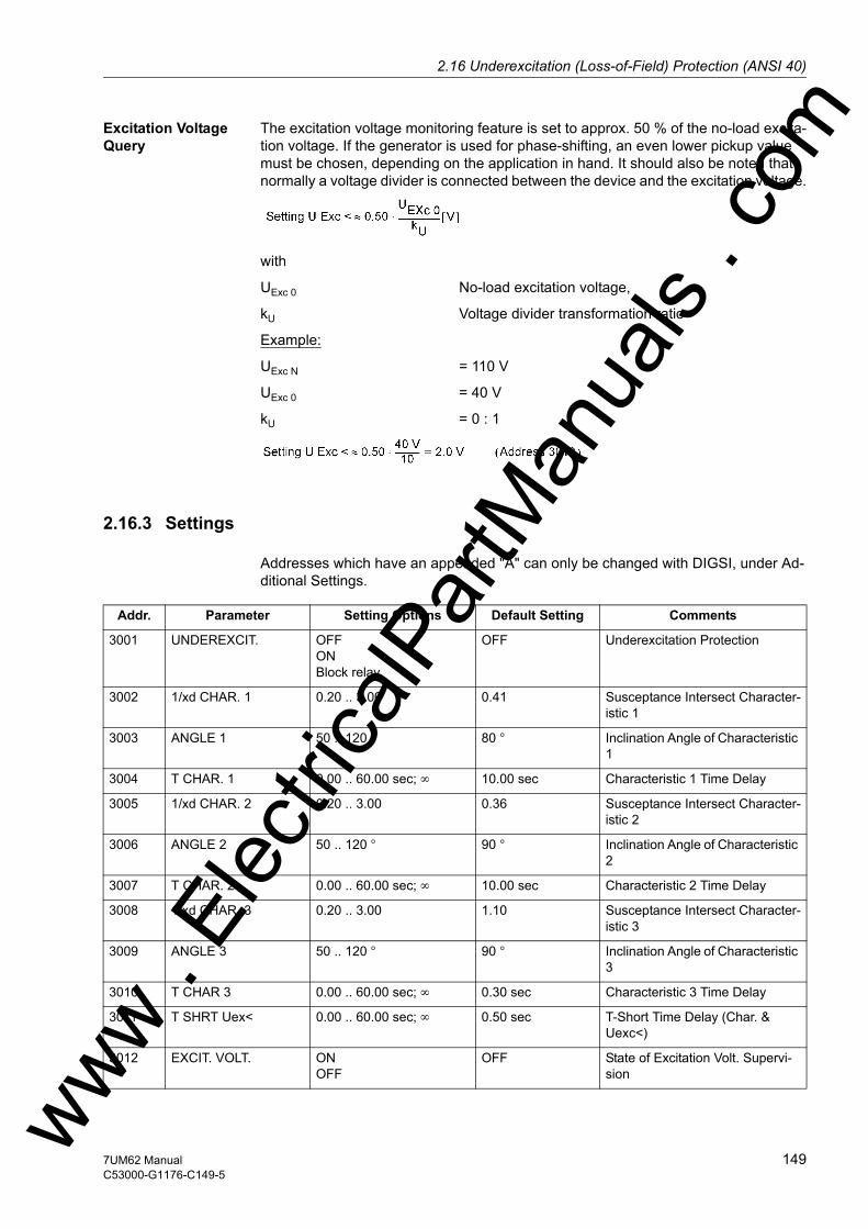
2.16 Underexcitation (Loss-of-Field) Protection (ANSI 40)w
Excitation Voltage Query
The excitation voltage monitoring feature is set to approx. 50 % of the no-load excita-tion voltage. If the generator is used for phase-shifting, an even lower pickup value must be chosen, depending on the application in hand. It should also be noted that normally a voltage divider is connected between the device and the excitation voltage.
with
UExc 0 No-load excitation voltage,
kU Voltage divider transformation ratio
Example:
UExc N = 110 V
UExc 0 = 40 V
kU = 0 : 1
2.16.3 Settings
Addresses which have an appended "A" can only be changed with DIGSI, under Ad-ditional Settings.
Addr. Parameter Setting Options Default Setting Comments
3001 UNDEREXCIT. OFFONBlock relay
OFF Underexcitation Protection
3002 1/xd CHAR. 1 0.20 .. 3.00 0.41 Susceptance Intersect Character-istic 1
3003 ANGLE 1 50 .. 120 ° 80 ° Inclination Angle of Characteristic 1
3004 T CHAR. 1 0.00 .. 60.00 sec; ∞ 10.00 sec Characteristic 1 Time Delay
3005 1/xd CHAR. 2 0.20 .. 3.00 0.36 Susceptance Intersect Character-istic 2
3006 ANGLE 2 50 .. 120 ° 90 ° Inclination Angle of Characteristic 2
3007 T CHAR. 2 0.00 .. 60.00 sec; ∞ 10.00 sec Characteristic 2 Time Delay
3008 1/xd CHAR. 3 0.20 .. 3.00 1.10 Susceptance Intersect Character-istic 3
3009 ANGLE 3 50 .. 120 ° 90 ° Inclination Angle of Characteristic 3
3010 T CHAR 3 0.00 .. 60.00 sec; ∞ 0.30 sec Characteristic 3 Time Delay
3011 T SHRT Uex< 0.00 .. 60.00 sec; ∞ 0.50 sec T-Short Time Delay (Char. & Uexc<)
3012 EXCIT. VOLT. ONOFF
OFF State of Excitation Volt. Supervi-sionww .
Elec
tricalP
artM
anua
ls . c
om
1497UM62 ManualC53000-G1176-C149-5
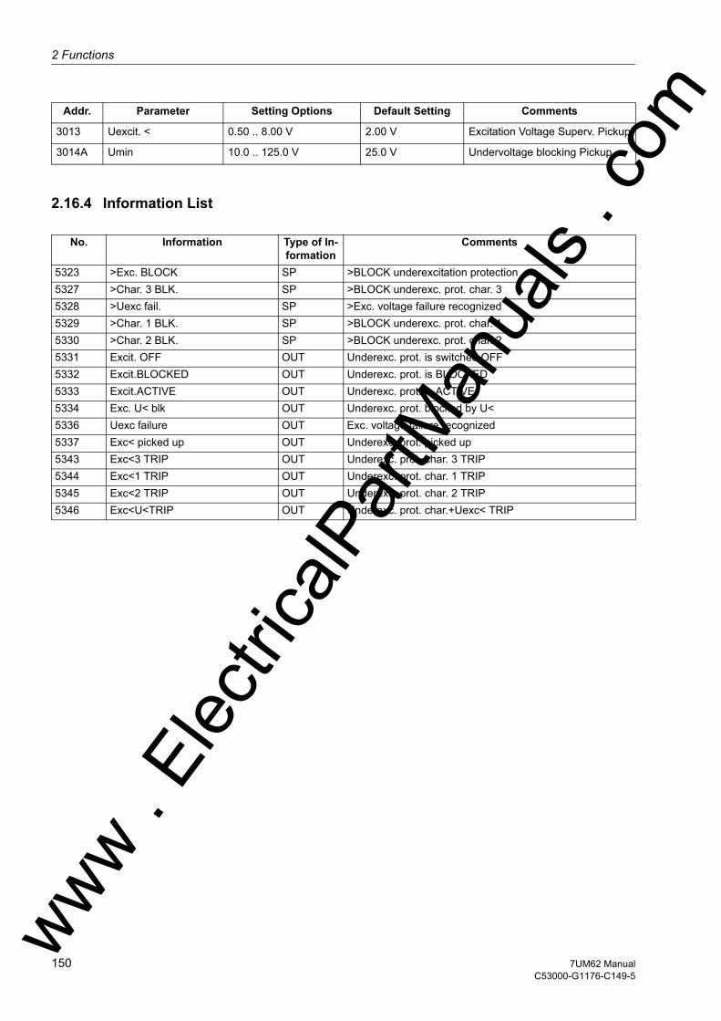
2 Functions
om
2.16.4 Information List
3013 Uexcit. < 0.50 .. 8.00 V 2.00 V Excitation Voltage Superv. Pickup
3014A Umin 10.0 .. 125.0 V 25.0 V Undervoltage blocking Pickup
No. Information Type of In-formation
Comments
5323 >Exc. BLOCK SP >BLOCK underexcitation protection5327 >Char. 3 BLK. SP >BLOCK underexc. prot. char. 35328 >Uexc fail. SP >Exc. voltage failure recognized5329 >Char. 1 BLK. SP >BLOCK underexc. prot. char. 15330 >Char. 2 BLK. SP >BLOCK underexc. prot. char. 25331 Excit. OFF OUT Underexc. prot. is switched OFF5332 Excit.BLOCKED OUT Underexc. prot. is BLOCKED5333 Excit.ACTIVE OUT Underexc. prot. is ACTIVE5334 Exc. U< blk OUT Underexc. prot. blocked by U<5336 Uexc failure OUT Exc. voltage failure recognized5337 Exc< picked up OUT Underexc. prot. picked up5343 Exc<3 TRIP OUT Underexc. prot. char. 3 TRIP5344 Exc<1 TRIP OUT Underexc. prot. char. 1 TRIP5345 Exc<2 TRIP OUT Underexc. prot. char. 2 TRIP5346 Exc<U<TRIP OUT Underexc. prot. char.+Uexc< TRIP
Addr. Parameter Setting Options Default Setting Comments
ww . El
ectric
alPar
tMan
uals
. c
150 7UM62 ManualC53000-G1176-C149-5
w
2.17 Reverse Power Protection (ANSI 32R)w
2.17 Reverse Power Protection (ANSI 32R)
Reverse power protection is used to protect a turbo-generator unit on failure of energy to the prime mover when the synchronous generator runs as a motor and drives the turbine taking motoring energy from the network. This condition leads to overheating of the turbine blades and must be interrupted within a short time by tripping the network circuit-breaker. For the generator, there is the additional risk that, in case of a malfunctioning residual steam pass (defective stop valves) after the switching off of the circuit breakers, the turbine-generator-unit is speeded up, thus reaching an over-speed. For this reason, the system isolation should only be performed after the detec-tion of active power input into the machine.
2.17.1 Functional Description
Reverse Power Determination
The reverse power protection of the 7UM62 precisely calculates the active power from the symmetrical components of the fundamental waves of voltages and currents by averaging the values of the last 16 cycles. The evaluation of only the positive phase-sequence systems makes the reverse power determination independent of current and voltage asymmetries and corresponds to actual loading of the drive end. The cal-culated active power value corresponds to the overall active power. By taking the error angles of the instrument transformers into account, the active power component is exactly calculated even with very high apparent powers and low power factor (cos ϕ. The correction is performed by a W0 constant correction angle determined during commissioning of the protection device in the system. The correction angle is set under Power System Data 1 (see Section 2.5).
Pickup Seal-In Time To ensure that frequently occurring short pickups can cause tripping, it is possible to perform a selectable prolongation of these pickup pulses at parameter 3105 T-HOLD. Each positive edge of the pickup pulses triggers this time stage again. For a sufficient number of pulses, the pickup signals adds up and become longer than the time delay.
Trip Signal For bridging a perhaps short power input during synchronization or during power swings caused by system faults, the trip command is delayed by a selectable time T-SV-OPEN. In case of a closed emergency tripping valve, a short delay is, however, suf-ficient. By means of entering the emergency tripping valve position via a binary input, the short time delay T-SV-CLOSED becomes effective under an emergency tripping condition. The time T-SV-OPEN is still effective as back-up stage.
It is also possible to block tripping via an external signal.
ww . El
ectric
alPar
tMan
uals
. com
1517UM62 ManualC53000-G1176-C149-5

2 Functions
om
The following figure shows the logic diagram for the reverse power protection.
Figure 2-57 Logic Diagram of the Reverse Power Protection
2.17.2 Setting Notes
General Reverse power protection is only effective and available if this function was set during protective function configuration (Section 2.4, address 131, REVERSE POWER is set to Enabled. If the function is not required Disabled is set. The address 3101 REVERSE POWER serves to switch the function ON or OFF or to block only the trip command (Block relay).
In case of a reverse power, the turbine set must be disconnected from the system as the turbine operation is not permissible without a certain minimum steam throughput (cooling effect) or, in case of a gas turbine set, the motor load would be too heavy for the network.
Pickup Values The level of the active power input is determined by the friction losses to be overcome and is in the following ranges, depending on the individual system:• Steam turbines: PReverse/SN ≈ 1 % to 3 %• Gas turbines: PReverse/SN ≈ 3 % to 5 %• Diesel drives: PReverse/SN > 5 %
For the primary test, the reverse power should be measured with the actual protection. The user should select a setting of 0.5 times the value of the measured motoring energy. This value can be found under the percentage operational measured values. The feature to correct angle faults of the current and voltage transformers should be used especially for very large machines with a particularly low motoring energy (see Sections 2.5 and 3.3).
ww . El
ectric
alPar
tMan
uals
. c
152 7UM62 ManualC53000-G1176-C149-5
w
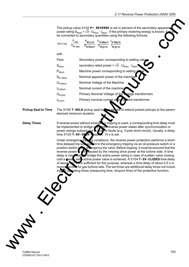
2.17 Reverse Power Protection (ANSI 32R)w
The pickup value 3102 P> REVERSE is set in percent of the secondary apparent power rating SNsek = √3 · UNsec · INsec . If the primary motoring energy is known, it must be converted to secondary quantities using the following formula:
with
Psec Secondary power corresponding to setting value
SNsec secondary rated power = √3 · UNsec · INsec
PMach Machine power corresponding to setting value
SN, Mach Nominal apparent power of the machine
UN Mach Nominal Voltage of the Machine
IN Mach Nominal current of the machine
UN prim Primary Nominal Voltage of the voltage transformers
IN prim Primary nominal current of the current transformer
Pickup Seal-In Time The 3105 T-HOLD pickup seal-in time serves to extend pulsed pickups to the param-eterized minimum duration.
Delay Times If reverse power without emergency tripping is used, a corresponding time delay must be implemented to bridge any short reverse power states after synchronization or power swings subsequent to system faults (e.g. 3-pole short circuit). Usually, a delay time 3103 T-SV-OPEN = approx. 10 s is set.
Under emergency tripping conditions, the reverse power protection performs a short-time delayed trip subsequent to the emergency tripping via an oil-pressure switch or a position switch at the emergency trip valve. Before tripping, it must be ensured that the reverse power is only caused by the missing drive power at the turbine side. A time delay is necessary to bridge the active power swing in case of sudden valve closing, until a steady state active power value is achieved. A 3104 T-SV-CLOSED time delay of about 1 to 3 s is sufficient for this purpose, whereas a time delay of about 0.5 s is recommended for gas turbine sets. The set times are additional delay times not includ-ing the operating times (measuring time, dropout time) of the protective function.
ww . El
ectric
alPar
tMan
uals
. com
1537UM62 ManualC53000-G1176-C149-5

2 Functions
om
2.17.3 Settings
Addresses which have an appended "A" can only be changed with DIGSI, under Ad-ditional Settings.
2.17.4 Information List
Addr. Parameter Setting Options Default Setting Comments
3101 REVERSE POWER OFFONBlock relay
OFF Reverse Power Protection
3102 P> REVERSE -30.00 .. -0.50 % -1.93 % P> Reverse Pickup
3103 T-SV-OPEN 0.00 .. 60.00 sec; ∞ 10.00 sec Time Delay Long (without Stop Valve)
3104 T-SV-CLOSED 0.00 .. 60.00 sec; ∞ 1.00 sec Time Delay Short (with Stop Valve)
3105A T-HOLD 0.00 .. 60.00 sec; ∞ 0.00 sec Pickup Holding Time
No. Information Type of In-formation
Comments
5083 >Pr BLOCK SP >BLOCK reverse power protection5086 >SV tripped SP >Stop valve tripped5091 Pr OFF OUT Reverse power prot. is switched OFF5092 Pr BLOCKED OUT Reverse power protection is BLOCKED5093 Pr ACTIVE OUT Reverse power protection is ACTIVE5096 Pr picked up OUT Reverse power: picked up5097 Pr TRIP OUT Reverse power: TRIP5098 Pr+SV TRIP OUT Reverse power: TRIP with stop valve
ww . El
ectric
alPar
tMan
uals
. c
154 7UM62 ManualC53000-G1176-C149-5
w

2.18 Forward Active Power Supervision (ANSI 32F)w
2.18 Forward Active Power Supervision (ANSI 32F)
The machine protection 7UM62 includes an active power supervision which monitors whether the active power falls below one set value as well as whether a separate second set value is exceeded. Each of these functions can initiate different control functions.
When, for example, with generators operating in parallel, the active power output of one machine becomes so small that other generators could take over this power, then it is often appropriate to shut down the lightly loaded machine. The criterion in this case is that the "forwards" power supplied into the network falls below a certain value.
In many applications it can be desirable to issue a control signal if the active power output rises above a certain value.
When a fault in a utility network is not cleared within a critical time, the utility network and should be split or for example, an industrial network decoupled from it. As criteria for decoupling, in addition to power flow direction, are undervoltage, overcurrent and frequency. As a result, the 7UM62 can also be used for network decoupling.
2.18.1 Functional Description
Active Power Measuring
Depending on the application either slow high-precision measurement (averaging 16 cycles) or high-speed measurement (without averaging) may be selected. High-speed measurement is particularly suitable for network decoupling.
The device calculates the active power from the positive sequence systems of the generator currents and voltages. The computed value is compared with the set values. Each of the forward active power stages can be blocked individually via binary inputs. In addition the entire active power monitoring can be blocked per binary input.
The following figure shows the logic diagram for the forward active power supervision.
Figure 2-58 Logic Diagram of the Forward Active Power Supervisionww . El
ectric
alPar
tMan
uals
. com
1557UM62 ManualC53000-G1176-C149-5

2 Functions
om
2.18.2 Setting Notes
General Forward active power protection is only effective and available if this function was set during protective function configuration (Section 2.4, address 132, FORWARD POWER is set to Enabled). If the function is not required Disabled is set. The address 3201 FORWARD POWER serves to switch the function ON or OFF or to block only the trip command (Block relay).
Pickup Values, Time Delays
The setting of the forward power protection depends strongly on the intended purpose. General setting guidelines are not possible. The pickup values are set in percent of the secondary apparent power rating SNsec = √3 · UNsec · INsec. Consequently, the machine power must be converted to secondary quantities:
with
Psec Secondary power corresponding to setting value
SNsec secondary nominal power = √3 · UNsec · INsec
PMach Machine power corresponding to setting value
SN, Mach Nominal apparent power of the machine
UN Mach Nominal voltage of the machine
IN Mach Nominal current of the machine
UN prim Primary Nominal Voltage of the voltage transformers
IN prim Primary nominal current of the current transformer
Address 3202 serves to set the threshold of the forward power to an undershoot (Pf<) and address 3203 (Pf>) serves to set it to overshoot. Addresses 3204 T-Pf< and 3205 T-Pf> serve to set the associated time delays.
In address 3206 MEAS. METHOD the user can select whether a fast or a precise mea-suring procedure is to be used for the forward power calculation. In most cases, the precise measuring procedure is preferred in the power station sector (as a rule), whereas the fast procedure is applied for use as mains decoupling.
The set times are additional delay times not including the operating times (measuring time, dropout time) of the protective function.
ww . El
ectric
alPar
tMan
uals
. c
156 7UM62 ManualC53000-G1176-C149-5
w

2.18 Forward Active Power Supervision (ANSI 32F)w
2.18.3 Settings
Addresses which have an appended "A" can only be changed with DIGSI, under Ad-ditional Settings.
2.18.4 Information List
Addr. Parameter Setting Options Default Setting Comments
3201 FORWARD POWER OFFONBlock relay
OFF Forward Power Supervision
3202 Pf< 0.5 .. 120.0 % 9.7 % P-forw.< Supervision Pickup
3203 Pf> 1.0 .. 120.0 % 96.6 % P-forw.> Supervision Pickup
3204 T-Pf< 0.00 .. 60.00 sec; ∞ 10.00 sec T-P-forw.< Time Delay
3205 T-Pf> 0.00 .. 60.00 sec; ∞ 10.00 sec T-P-forw.> Time Delay
3206A MEAS. METHOD accuratefast
accurate Method of Operation
No. Information Type of In-formation
Comments
5113 >Pf BLOCK SP >BLOCK forward power supervision5116 >Pf< BLOCK SP >BLOCK forw. power superv. Pf< stage5117 >Pf> BLOCK SP >BLOCK forw. power superv. Pf> stage5121 Pf OFF OUT Forward power supervis. is switched OFF5122 Pf BLOCKED OUT Forward power supervision is BLOCKED5123 Pf ACTIVE OUT Forward power supervision is ACTIVE5126 Pf< picked up OUT Forward power: Pf< stage picked up5127 Pf> picked up OUT Forward power: Pf> stage picked up5128 Pf< TRIP OUT Forward power: Pf< stage TRIP5129 Pf> TRIP OUT Forward power: Pf> stage TRIP
ww . El
ectric
alPar
tMan
uals
. com
1577UM62 ManualC53000-G1176-C149-5
2 Functions
om
2.19 Impedance Protection (ANSI 21)
Machine impedance protection is used as a selective time graded protection to provide shortest possible tripping times for short-circuits in the synchronous machine, on the terminal leads as well as in the unit transformer. It thus also provides backup protection functions to the main protection of a power plant or protection equipment connected in series like generator, transformer differential and system protection de-vices.
The impedance protection feature of the 7UM62 always operates with the currents of side 2 (IL1, 2 ,3; S2).
2.19.1 Functional Description
PICKUP Pickup is required to detect a faulty condition in the power system and to initiate all the necessary procedures for selective clarification of the fault:• Start the time delays for the final stage t3,• Determination of the faulty phase,• Enabling of impedance calculation,• Enabling of tripping command,• Indication/output of the faulty conductor(s).
Pickup is implemented as overcurrent pickup and can be optionally supplemented by an undervoltage seal-in circuit. After numeric filtering, the currents are monitored for over-shooting of a set value. A signal is output for each phase where the set threshold has been exceeded. These pickup signals are considered for choosing the measured values. The pickup is reset when 95% of the pick-up threshold is undershot, unless maintained by the undervoltage seal-in feature.
Undervoltage Seal-In
With excitation systems powered from the network, excitation voltage can drop during a local short circuit, resulting in decreasing short-circuit current which, in spite of the remaining fault, can undershoot the pickup value. In such cases the impedance pro-tection pick-up is maintained for a sufficiently long period by means of an undervoltage controlled seal-in circuit using the positive sequence voltage U1. Pickup drops off when this holding time has expired or when the restored voltage reaches 105% of the set undervoltage seal-in value.
The seal-in logic operates separate for each phase. The first pickup starts the timer T-SEAL-IN.
Figure 2-59 shows the logic diagram of the pickup stage of the impedance protection.
Determination of the Short–Circuit Impedance
For calculating impedance only the currents and voltages of the faulty (shorted) phase loop are decisive. Accordingly the protection, controlled by the pickup, evaluates these measurement values (see also Table 2-9).
ww . El
ectric
alPar
tMan
uals
. c
158 7UM62 ManualC53000-G1176-C149-5
w
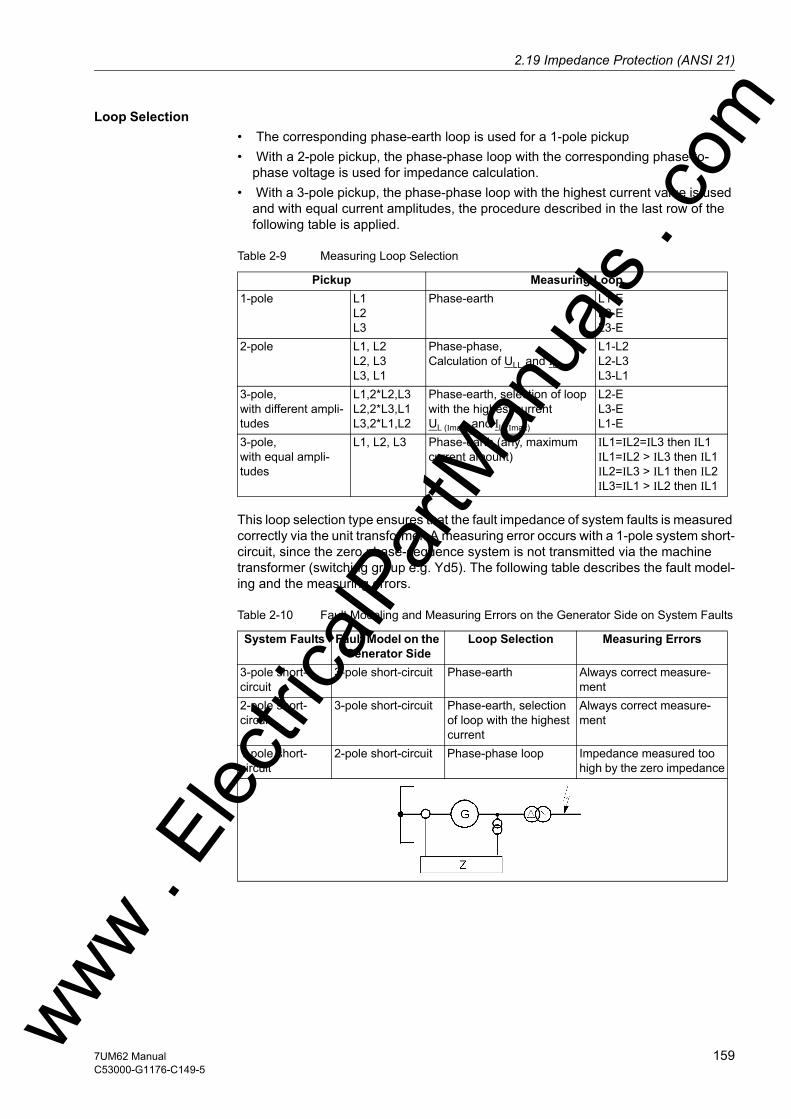
2.19 Impedance Protection (ANSI 21)w
Loop Selection • The corresponding phase-earth loop is used for a 1-pole pickup • With a 2-pole pickup, the phase-phase loop with the corresponding phase-to-
phase voltage is used for impedance calculation. • With a 3-pole pickup, the phase-phase loop with the highest current value is used
and with equal current amplitudes, the procedure described in the last row of the following table is applied.
Table 2-9 Measuring Loop Selection
This loop selection type ensures that the fault impedance of system faults is measured correctly via the unit transformer. A measuring error occurs with a 1-pole system short-circuit, since the zero phase-sequence system is not transmitted via the machine transformer (switching group e.g. Yd5). The following table describes the fault model-ing and the measuring errors.
Table 2-10 Fault Modeling and Measuring Errors on the Generator Side on System Faults
Pickup Measuring Loop1-pole L1
L2 L3
Phase-earth L1-E L2-E L3-E
2-pole L1, L2 L2, L3 L3, L1
Phase-phase,Calculation of ULL and ILL
L1-L2 L2-L3 L3-L1
3-pole,with different ampli-tudes
L1,2*L2,L3 L2,2*L3,L1 L3,2*L1,L2
Phase-earth, selection of loop with the highest currentUL (Imax) and IL (Imax)
L2-E L3-E L1-E
3-pole,with equal ampli-tudes
L1, L2, L3 Phase-earth (any, maximum current amount)
IL1=IL2=IL3 then IL1 IL1=IL2 > IL3 then IL1 IL2=IL3 > IL1 then IL2 IL3=IL1 > IL2 then IL1
System Faults Fault Model on the Generator Side
Loop Selection Measuring Errors
3-pole short-circuit
3-pole short-circuit Phase-earth Always correct measure-ment
2-pole short-circuit
3-pole short-circuit Phase-earth, selection of loop with the highest current
Always correct measure-ment
1-pole short-circuit
2-pole short-circuit Phase-phase loop Impedance measured too high by the zero impedance
ww . El
ectric
alPar
tMan
uals
. com
1597UM62 ManualC53000-G1176-C149-5
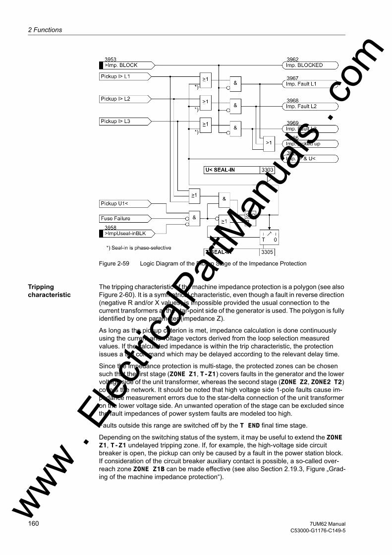
2 Functions
om
Figure 2-59 Logic Diagram of the Pickup Stage of the Impedance Protection
Tripping characteristic
The tripping characteristic of the machine impedance protection is a polygon (see also Figure 2-60). It is a symmetrical characteristic, even though a fault in reverse direction (negative R and/or X values) is impossible provided the usual connection to the current transformers at the star-point side of the generator is used. The polygon is fully identified by one parameter (impedance Z).
As long as the pickup criterion is met, impedance calculation is done continuously using the current and voltage vectors derived from the loop selection measured values. If the calculated impedance is within the trip characteristic, the protection issues a trip command which may be delayed according to the relevant delay time.
Since the impedance protection is multi-stage, the protected zones can be chosen such that the first stage (ZONE Z1, T-Z1) covers faults in the generator and the lower voltage side of the unit transformer, whereas the second stage (ZONE Z2, ZONE2 T2) covers the network. It should be noted that high voltage side 1-pole faults cause im-pedance measurement errors due to the star-delta connection of the unit transformer on the lower voltage side. An unwanted operation of the stage can be excluded since the fault impedances of power system faults are modeled too high.
Faults outside this range are switched off by the T END final time stage.
Depending on the switching status of the system, it may be useful to extend the ZONE Z1, T-Z1 undelayed tripping zone. If, for example, the high-voltage side circuit breaker is open, the pickup can only be caused by a fault in the power station block. If consideration of the circuit breaker auxiliary contact is possible, a so-called over-reach zone ZONE Z1B can be made effective (see also Section 2.19.3, Figure „Grad-ing of the machine impedance protection“).ww .
Elec
tricalP
artM
anua
ls . c
160 7UM62 ManualC53000-G1176-C149-5
w

2.19 Impedance Protection (ANSI 21)w
Figure 2-60 Tripping Characteristics of the Impedance Protection
Tripping Logic The T END time delay is started subsequent to the protection pickup, establishing the fault loop. The loop impedance components are compared with the limit values of the zones previously set. The tripping is executed if the impedance is within its zone during the course of the corresponding time stage.
For the first Z1 zone and also for the Z1B overreach zone, the time delay will in most cases be zero or at least very short. i.e. tripping occurs as soon as it is established that the fault is within this zone.
The Z1B overreach stage can be enabled from outside, via a binary input.
For the Z2 zone which may extend into the network, a time delay is selected over-reaching the first stage of the power system protection.
A drop-out can only be caused by a drop-out of the overcurrent pickup and not by exiting the tripping polygon.
ww . El
ectric
alPar
tMan
uals
. com
1617UM62 ManualC53000-G1176-C149-5

2 Functions
om
Figure 2-61 Logic Diagram of the Impedance Protectionww . El
ectric
alPar
tMan
uals
. c
162 7UM62 ManualC53000-G1176-C149-5
w

2.19 Impedance Protection (ANSI 21)w
2.19.2 Power Swing Blocking
General Dynamic occurrences such as sudden load changes, short circuits, automatic reclo-sure or switching operations within the power system may cause power swings. Therefore impedance protection is complemented by a power swing blocking function to avoid spurious tripping.
Power swings are three-phase symmetrical occurrences. The first prerequisite is therefore effective symmetry of the three phase currents, which is verified by evalua-tion of the negative sequence current. This means that asymmetrical (all single-phase and two-phase) short circuits cannot cause the power swing blocking to pick up. Even if a power swing has been detected, the asymmetrical short-circuits following it quickly deactivate the power swing blocking and make tripping by impedance protection pos-sible. Since a power swing happens much more slowly than a short-circuit, the rate of change of the impedance is a reliable criterion for its identification. Because of its sym-metrical nature, the positive sequence impedance obtained from the positive se-quence components of the currents and voltages is evaluated.
Logic The figure below shows the logic diagram power swing block. The upper section shows the current symmetry monitoring. An enable signal is given if there is a three-pole pickup with no negative sequence system current. For detection of power swings, a power swing polygon (P/SPOL) is used which is greater than the trip polygon (TPOL). The distance between the two polygons can be set (common setting for R and X direction). The user can choose for each setting parameter whether the trip polygon refers only to characteristic Z1 or to characteristics Z1 & Z2. In the latter case, the trip polygon is the maximum impedance value.
Measuring Princi-ple
The criterion for power swing blocking is composed of the power swing polygon, its distance to the trip polygon, the trip polygon itself and the rate of change of the imped-ance. The first impedance value after entering the power swing polygon (instant Tent) is compared with the last value outside the polygon (instant Tent-∆t). The time ∆t is determined by the measuring interval which is one cycle. If the impedance vector rate of change thus determined is less than a set value ∆Z/∆t, a power swing is detected. The impedance stage is not blocked, however, until the impedance vector enters the trip polygon TPOL.
If the first impedance value is both inside the P/SPOL and the TPOL, the protection detects immediately a short-circuit, because there must be at least one impedance value between the P/SPOL and the TPOL. The distance between the power swing polygon P/SPOL and the trip polygon TPOL, and the rate of change ∆Z/∆t are matched to one another in such a way that power swings are reliably detected and the desired impedance zone (Z1 or Z1 & Z2) of the impedance protection is blocked. The blocking remains effective until the measured impedance vector has exited again the trip polygon or power swing polygon, the change rate is exceeded, or asymmetrical power conditions rule out the possibility of a power swing. The power swing blocking time is also limited by a parameter setting (T-ACTION P/S).
ww . El
ectric
alPar
tMan
uals
. com
1637UM62 ManualC53000-G1176-C149-5
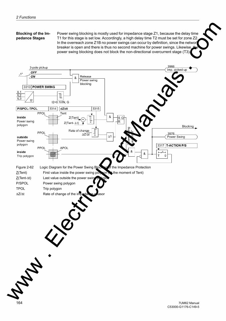
2 Functions
om
Blocking of the Im-pedance Stages
Power swing blocking is mostly used for impedance stage Z1, because the delay time T1 for this stage is set low. Accordingly, a high delay time T2 must be set for zone Z2. In the overreach zone Z1B no power swings can occur by definition, since the network breaker is open and there is thus no second machine for power swings. Likewise, the power swing blocking does not block the non-directional overcurrent stage (T3).
Figure 2-62 Logic Diagram for the Power Swing Blocking of the Impedance ProtectionZ(Tent) First value inside the power swing polygon (at the moment of Tent)Z(Tent-∆t) Last value outside the power swing polygonP/SPOL Power swing polygonTPOL Trip polygon∆Z/∆t Rate of change of the impedance phasor
ww . El
ectric
alPar
tMan
uals
. c
164 7UM62 ManualC53000-G1176-C149-5
w
2.19 Impedance Protection (ANSI 21)w
2.19.3 Setting Notes
General Machine impedance protection is only effective and available if enabled during config-uration (Section 2.4, address 133, IMPEDANCE PROT. = Enabled. If the function is not required Disabled is set. Address 3301 IMPEDANCE PROT. serves to switch the function ON or OFF or to block only the trip command (Block relay).
Pickup The maximum load current during operation is the most important criterion for setting overcurrent pickup. A pickup by an overload must be excluded! For this reason, the 3302 IMP I> pickup value must be set above the maximum (over) load current to be expected. Recommended setting: 1.2 to 1.5 times the nominal machine current. The pickup logic corresponds to the logic of the UMZ I> definite time-overcurrent protec-tion.
If the excitation is derived from the generator terminals with the short circuit current possibly falling below the pickup value (address 3302) due to the collapsing voltage, the undervoltage seal-in feature of the pickup is used, i.e. address 3303 U< SEAL-IN is switched to ON.
The undervoltage seal-in setting U< (address 3304) is set to a value just below the lowest phase-to-phase voltage occurring during operation, e.g. to U< = 75 % to 80 % of the nominal voltage. The seal-in time (address 3305 T-SEAL-IN) must exceed the maximum fault clearance time in a back-up case (recommended setting: address 3312 T END + 1 s).
Impedance Stages The protection has the following characteristics which may be set independently:
1. Zone (fast tripping zone Z1 ) with parameters
ZONE Z1 Reactance = reach,
T-Z1 = 0 or short delay, if required.
Overreach zone Z1B, externally controlled via binary input, with parameters
ZONE Z1B Reactance = reach,
T-Z1B T1B = 0 or short delay, if required.
2. Zone (zone Z2) with parameters
ZONE Z2 Reactance = reach,
ZONE2 T2 The user must select a value for T2 above the grading time of the network protection.
Non-directional final stage with parameter
T END The user must select T END so that the 2nd or 3rd stage of the series-connected power system distance protection is overreached.
As the user may assume that impedance protection measurement extends into the unit transformer, parametrization selection must sufficiently consider the transformer control range.
Therefore ZONE Z1 is normally set to a reach of approx. 70 % of the protected zone (i.e. about 70 % of the transformer reactance), with no or only a small delay (i.e. T-Z1 = 0.00 s to 0.50 s). Protection then switches off faults on this distance after its operat-ing time or with a slight time delay (high speed tripping). A time delay of 0.1 s is pre-ferred. ww . El
ectric
alPar
tMan
uals
. com
1657UM62 ManualC53000-G1176-C149-5

2 Functions
om
For ZONE Z2 the reach could be set to about 100 % of the transformer reactance, or in addition to a network impedance. The corresponding ZONE2 T2 time stage is to be set so that it overreaches the power system protective equipment of the following lines. The T END time is the last back-up time.
The following formula is generally valid for the primary impedance (with limiting to the unit transformer):
with
kR Protection zone reach [%]
uK relative transformer short-circuit voltage [%]
SN Rated transformer power [MVA]
UN Machine-side rated transformer voltage [kV]
The derived primary impedances must be converted for the secondary side of the current and voltage transformers. In general:
The nominal current of the protection device (= secondary nominal current of the current transformer) is automatically considered by the device. You have already com-municated the transformation ratios of the current and voltage transformers to the device by entering the nominal transformer values (see section 2.5).
Example:
Transformer data:
uK = 7 %
SN = 5.3 MVA
UN = 6.3 kV
Transformation ratios:
Current transformer ratio = 500 A / 1 A
This results for a 70 % reach for zone 1 in:
The following secondary side setting value of zone 1 results at address 3306 ZONE Z1:
Note: The following ratio would result from the connection of a 5 A device to a 5 A transformer:
ww . El
ectric
alPar
tMan
uals
. c
166 7UM62 ManualC53000-G1176-C149-5
w

2.19 Impedance Protection (ANSI 21)w
Likewise the following primary reactance results for a 100 % reach for zone 2:
The following secondary side setting value of zone 2 results at address 3310 ZONE Z2:
Figure 2-63 Time Grading for Machine Impedance Protection – Example
Z1B Overreach Zone
The Z1B overreach zone (address 3308 ZONE Z1B) is an externally controlled stage. It does not influence the Z1 zone normal stage. Consequently there is no changeover, but the overreach zone is enabled or disabled depending on the position of the high-voltage side circuit breaker.
The Z1B zone is usually enabled by an opened high-voltage circuit breaker. In this case every impedance protection pickup can only be due to a fault in the protection zone of the block, since the power system is disconnected from the block. Conse-quently the fast tripping zone can be extended to between 100 % and 120 % of the protection zone without any loss of selectivity.
The Z1B zone is activated via a binary input controlled by the circuit breaker auxiliary contact (see Figure 2-63). The overreach zone is allocated an individual 3309 T-Z1B time delay.
Final Stage For short circuits outside the Z1 and Z2 zones, the device functions as a time-delayed overcurrent protection. Its nondirectional final time T END is selected so that its time value overreaches the second or third stage of the series-connected network distance protection.
ww . El
ectric
alPar
tMan
uals
. com
1677UM62 ManualC53000-G1176-C149-5
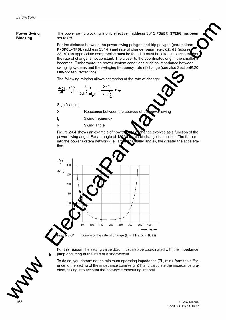
2 Functions
om
Power Swing Blocking
The power swing blocking is only effective if address 3313 POWER SWING has been set to ON.
For the distance between the power swing polygon and trip polygon (parameters: P/SPOL-TPOL (address 3314)) and rate of change (parameter: dZ/dt (address 3315)) an appropriate compromise must be found. It must be taken into account that the rate of change is not constant. The closer to the coordinates origin, the smaller it becomes. Furthermore the power system conditions such as impedance between swinging systems and the swinging frequency, rate of change (see also Section 2.20 Out-of-Step Protection).
The following relation allows estimation of the rate of change:
Significance:
X Reactance between the sources of the power swing
fp Swing frequency
δ Swing angle
Figure 2-64 shows an example of how the rate of change evolves as a function of the power swing angle. For an angle of 180° the rate of change is smallest. The further into the power system network (i.e. larger or smaller angle), the greater the accelera-tion.
Figure 2-64 Course of the rate of change (fp = 1 Hz; X = 10 Ω)
For this reason, the setting value dZ/dt must also be coordinated with the impedance jump occurring at the start of a short-circuit.
To do so, you determine the minimum operating impedance (ZL, min), form the differ-ence to the setting of the impedance zone (e.g. Z1) and calculate the impedance gra-dient, taking into account the one-cycle measuring interval.
ww . El
ectric
alPar
tMan
uals
. c
168 7UM62 ManualC53000-G1176-C149-5
w

2.19 Impedance Protection (ANSI 21)w
Example:
Umin = 0,9 UN, Imax = 1,1 IN, uK = 10 %, ∆ t = 20 ms
UN = 100 V, IN = 1 A
If safety factor 4 is chosen, dZ/dt should never be set higher than 500 Ω/s (or 100 Ω/s for 5 A transformers).
The default setting for dZ/dt is 300 Ω/s, which should be adequate for most applica-tions. This is also the basis for the minimum distance P/SPOL - TPOL, assuming that for detection of a power swing there must be one impedance value between P/SPOL and TPOL.
PPOL - APOL > dZ/dt · ∆t = 300 Ω/s · 0.02 s = 6 Ω (setting selected: 8 Ω)
All other settable parameters are advanced parameters which need not normally be modified.
Whether a power swing can cause an overfunctioning of the impedance protection depends mainly on the time the impedance vector remains inside the trip polygon. This time can only be reliably determined by transient calculations.
If the rate of change in the proximity of 180° is known, it can be the basis for a rough estimation of the time.
T = 2 · Zcharacteristic /dZ/dt (180°)
The above data yield the following value:
Zcharacteristic = Z1 = 4 Ω
dZ/dt (180°) = 20 Ω/s
T = 2 · 4 Ω/20 Ω/s = 0.4 s
This means that for delay times of more than 0.4 s no power swing blocking is needed.
Address Parameters Comments3316 BLOCKING OF The setting is Z1, as there is little or no delay
for this stage. The delay time of Z2 is deter-mined by the power system protection, and is longer. (see also the guidelines below)
3317 T-ACTION P/S The default setting is 3.00 sec. This time depends on the minimum possible power swing frequency.
ww . El
ectric
alPar
tMan
uals
. com
1697UM62 ManualC53000-G1176-C149-5

2 Functions
om
2.19.4 Settings
Addresses which have an appended "A" can only be changed with DIGSI, under Ad-ditional Settings.
The table indicates region-specific presettings. Column C (configuration) indicates the corresponding secondary nominal current of the current transformer.
Addr. Parameter C Setting Options Default Setting Comments
3301 IMPEDANCE PROT. OFFONBlock relay
OFF Impedance Protection
3302 IMP I> 5A 0.50 .. 100.00 A 6.75 A Fault Detection I> Pickup
1A 0.10 .. 20.00 A 1.35 A
3303 U< SEAL-IN ONOFF
OFF State of Undervoltage Seal-in
3304 U< 10.0 .. 125.0 V 80.0 V Undervoltage Seal-in Pickup
3305 T-SEAL-IN 0.10 .. 60.00 sec 4.00 sec Duration of Undervoltage Seal-in
3306 ZONE Z1 5A 0.01 .. 26.00 Ω 0.58 Ω Impedance Zone Z1
1A 0.05 .. 130.00 Ω 2.90 Ω
3307 T-Z1 0.00 .. 60.00 sec; ∞ 0.10 sec Impedance Zone Z1 Time Delay
3308 ZONE Z1B 5A 0.01 .. 13.00 Ω 0.99 Ω Impedance Zone Z1B
1A 0.05 .. 65.00 Ω 4.95 Ω
3309 T-Z1B 0.00 .. 60.00 sec; ∞ 0.10 sec Impedance Zone Z1B Time Delay
3310 ZONE Z2 5A 0.01 .. 13.00 Ω 0.83 Ω Impedanz Zone Z2
1A 0.05 .. 65.00 Ω 4.15 Ω
3311 ZONE2 T2 0.00 .. 60.00 sec; ∞ 0.50 sec Impedance Zone Z2 Time Delay
3312 T END 0.00 .. 60.00 sec; ∞ 3.00 sec T END: Final Time Delay
3313 POWER SWING ONOFF
OFF Power Swing Blocking
3314 P/SPOL-TPOL 5A 0.02 .. 6.00 Ω 1.60 Ω Distance betw. Power Swing - Trip-Pol.
1A 0.10 .. 30.00 Ω 8.00 Ω
3315 dZ/dt 5A 0.2 .. 120.0 Ω/s 60.0 Ω/s Rate of Change of dZ/dt
1A 1.0 .. 600.0 Ω/s 300.0 Ω/s
3316A BLOCKING OF Z1Z2
Z1 Power Swing Blocking locks out
3317A T-ACTION P/S 0.00 .. 60.00 sec; ∞ 3.00 sec Power Swing Action Time
ww . El
ectric
alPar
tMan
uals
. c
170 7UM62 ManualC53000-G1176-C149-5
w

2.19 Impedance Protection (ANSI 21)w
2.19.5 Information List
No. Information Type of In-formation
Comments
3953 >Imp. BLOCK SP >BLOCK impedance protection3956 >Extens. Z1B SP >Zone 1B extension for impedance prot.3958 >ImpUseal-inBLK SP >Imp. prot. : BLOCK undervoltage seal-in3961 Imp. OFF OUT Impedance protection is switched OFF3962 Imp. BLOCKED OUT Impedance protection is BLOCKED3963 Imp. ACTIVE OUT Impedance protection is ACTIVE3966 Imp. picked up OUT Impedance protection picked up3967 Imp. Fault L1 OUT Imp.: Fault detection , phase L13968 Imp. Fault L2 OUT Imp.: Fault detection , phase L23969 Imp. Fault L3 OUT Imp.: Fault detection , phase L33970 Imp. I> & U< OUT Imp.: O/C with undervoltage seal in3976 Power Swing OUT Power swing detection3977 Imp.Z1< TRIP OUT Imp.: Z1< TRIP3978 Imp.Z1B< TRIP OUT Imp.: Z1B< TRIP3979 Imp.Z2< TRIP OUT Imp.: Z2< TRIP3980 Imp.T3> TRIP OUT Imp.: T3> TRIP
ww . El
ectric
alPar
tMan
uals
. com
1717UM62 ManualC53000-G1176-C149-5
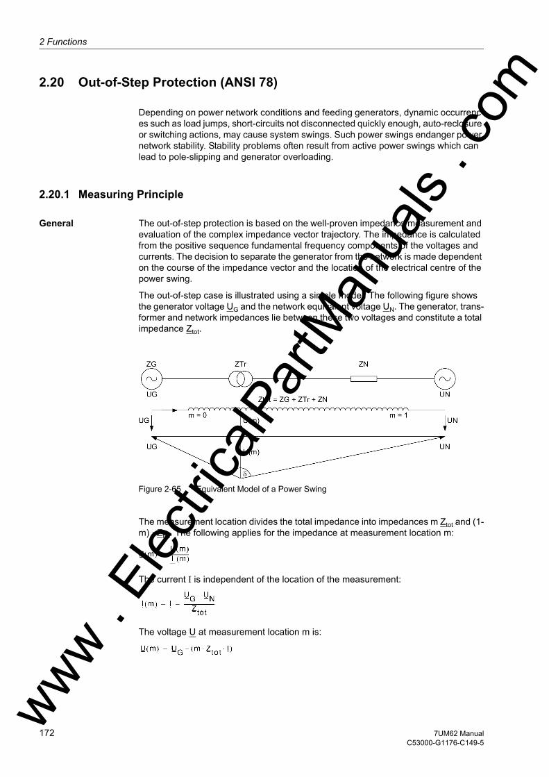
2 Functions
om
2.20 Out-of-Step Protection (ANSI 78)
Depending on power network conditions and feeding generators, dynamic occurrenc-es such as load jumps, short-circuits not disconnected quickly enough, auto-reclosure or switching actions, may cause system swings. Such power swings endanger power network stability. Stability problems often result from active power swings which can lead to pole-slipping and generator overloading.
2.20.1 Measuring Principle
General The out-of-step protection is based on the well-proven impedance measurement and evaluation of the complex impedance vector trajectory. The impedance is calculated from the positive sequence fundamental frequency components of the voltages and currents. The decision to separate the generator from the network is made dependent on the course of the impedance vector and the location of the electrical centre of the power swing.
The out-of-step case is illustrated using a simple model. The following figure shows the generator voltage UG and the network equivalent voltage UN. The generator, trans-former and network impedances lie between these two voltages and constitute a total impedance Ztot.
Figure 2-65 Equivalent Model of a Power Swing
The measurement location divides the total impedance into impedances m Ztot and (1-m) · Ztot. The following applies for the impedance at measurement location m:
The current I is independent of the location of the measurement:
The voltage U at measurement location m is:
ww . El
ectric
alPar
tMan
uals
. c
172 7UM62 ManualC53000-G1176-C149-5
w

2.20 Out-of-Step Protection (ANSI 78)w
Thus results in:
where δ is the phase shift angle between the generator voltage and the network equiv-alent voltage. Under normal conditions, this angle depends on the load situation and is largely constant. In the event of an out-of-step condition on the other hand, the angle fluctuates continually and can vary between 0° and 360°. The following figure shows the impedance vector trajectory at measurement location m in accordance with the above formula. The coordinate system origin corresponds to the measurement loca-tion (voltage transformer set). When the ratio of the voltage magnitudes UN/UG is kept constant and the load angle δ varies, then circular trajectories result. The centre and the radius of the circle are determined by the ratio UN/UG. The centre points of the circles are all on an axis line which is determined by the direction of Ztot. Minimum and maximum of the measured impedance magnitude are at δ = 0° and δ = 180°. If the measurement location is at the electrical system centre, measured voltage and thus measured impedance become zero when δ = 180°.
ww . El
ectric
alPar
tMan
uals
. com
1737UM62 ManualC53000-G1176-C149-5

2 Functions
om
Power Swing Polygon
The measurement characteristic is a power swing polygon adjustable in all four direc-tions and in its inclination angle ϕP. This ensures optimum matching to the conditions in the power system.
Figure 2-66 Impedance Trajectory at Measurement Location m
ww . El
ectric
alPar
tMan
uals
. c
174 7UM62 ManualC53000-G1176-C149-5
w

2.20 Out-of-Step Protection (ANSI 78)w
2.20.2 Out-of-Step Protection Logic
The following figure shows the power swing polygon in greater detail. For transparen-cy purposes the inclination angle ϕP is assumed to be 90°. The setting parameters of impedances Za, Zb, Zc and (Zd–Zc) determine the power swing polygon. The polygon is symmetrical about its vertical axis. Zb is measured in reverse direction into the gen-erator, in the forward direction (Zc) into the unit transformer, and the second stage (Zd) into the power network. The power swing polygon is divided into two parts. Character-istic 1 (i.e. the non-hatched area) represents the lower section of the rectangle. Char-acteristic 2 covers the upper hatched area. Depending on the electrical centre of the power swing, or in the vicinity of the power station, the impedance vector progresses through the range of characteristic 1 or that of characteristic 2. The point of crossing of the symmetry (imaginary) axis is decisive for the characteristic assignment.
Power swings are three-phase symmetrical occurrences. The first prerequisite is therefore the symmetry of the measured currents. A condition for power swing detec-tion is that the positive sequence component of the current exceeds an adjustable limit I2 while the negative sequence current remains below an adjustable value I1.
Figure 2-67 Polygonal Out-of-Step Characteristic with Typical Power Swings
Detection of an out-of-step condition requires, additionally, that the impedance vector enters a power swing characteristic at one side, passes through the imaginary axis or characteristic dividing line, and exits the polygon at the opposite side (loss of synchro-nism, cases (1) and (2)). This is characterized in that the real components of the complex impedances (referred to the coordinate system possibly rotated about ϕP) have changed sign crossing the characteristic. ww . El
ectric
alPar
tMan
uals
. com
1757UM62 ManualC53000-G1176-C149-5

2 Functions
om
On the other hand it is also possible for a power swing vector to enter and exit the power swing polygon on the same side. In this case, the power swing tends to stabilize (cases (3) and (4)).
When an out-of-step condition is recognized, i.e. when the impedance vector has passed through a power swing characteristic, an annunciation is issued which also identifies the crossed characteristic. Additionally, a counter n1 (for characteristic 1) or n2 (for characteristic 2) is incremented.
Out-of-step protection pickup is activated when a counter reaches the value 1. A further out-of-step indication is set for an adjustable indication time period, each time a counter is incremented. After a likewise adjustable holding time pick-up resets to zero. The holding time is started anew each time a counter is incremented.
A trip command is issued when the number of power swing polygon crossings has reached a selectable number. This command is maintained for at least the set time T-HOLDING. The minimum trip command duration T TRIPCOM MIN. does not start until the pickup has reset.
Next comes the logic diagram of the out-of-step protection. The feature has two stages and can be blocked by a binary input.
Figure 2-68 Logic Diagram of the Out-of-Step Protection
ww . El
ectric
alPar
tMan
uals
. c
176 7UM62 ManualC53000-G1176-C149-5
w

2.20 Out-of-Step Protection (ANSI 78)w
2.20.3 Setting Notes
General Out-of-step protection is only effective and available if this function was set during pro-tective function configuration (Section 2.4, address 135, OUT-OF-STEP is set to Enabled. If the function is not required Disabled is set. Address 3501 OUT-OF-STEP serves to switch the function ON or OFF or to block only the trip command (Block relay).
Pickup Measurement is enabled only if the positive sequence component of the currents has exceeded a minimum threshold 3502 I1> RELEASE (overcurrent pickup). Also because of the symmetry condition, a maximum value of negative sequence current 3503 I2< RELEASE must not be exceeded.
Generally the setting value I1> RELEASE should be set over rated current i.e. about 120 % IN to avoid pickup on overload. Depending on network conditions, smaller pickup values are admissible so that the measurement (see logic diagram ) may be released all the time. As out-of-step conditions are symmetrical occurrences, the pickup threshold of the negative sequence component of the current I2< RELEASE should be set to approx. 20 % IN.
Impedance values The measured impedances perceived by the protection device are decisive for the set-tings. For the direction to the machine (as viewed from the location of the voltage transformers), the power swing reactance of the machine must be considered, which is approximately the transient reactance Xd' of the machine. Consequently, you will calculate the secondary transient reactance and use it for Zb ≈ Xd' (see the figure below).
Figure 2-69 Power swing polygonww . El
ectric
alPar
tMan
uals
. com
1777UM62 ManualC53000-G1176-C149-5
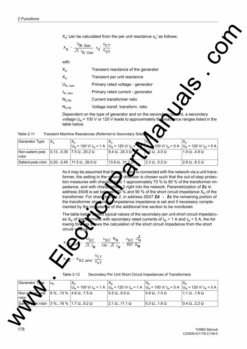
2 Functions
om
Xd' can be calculated from the per unit reactance xd' as follows:
with
Xd Transient reactance of the generator
Xd Transient per unit reactance
UN, Gen Primary rated voltage - generator
IN, Gen Primary rated current - generator
NCTR Current transformer ratio
NVTR Voltage transf. transform. ratio
Dependent on the type of generator and on the secondary current, a secondary voltage UN = 100 V or 120 V leads to approximately the reactance ranges listed in the table below.
Table 2-11 Transient Machine Reactances (Referred to Secondary Side)
As it may be assumed that the generator is connected with the network via a unit trans-former, the setting in the network direction is chosen such that the out-of-step protec-tion measures with characteristic 1 approximately 70 % to 90 % of the transformer im-pedance, and with characteristic 2 right into the network. Parametrization of Zc in address 3506 is set between 70 % and 90 % of the short circuit impedance XK of the transformer. For characteristic 2, in address 3507 Zd - Zc the remaining portion of the transformer short circuit impedance impedance is set and if necessary comple-mented by the impedance of the additional line section to be monitored.
The table below shows typical values of the secondary per unit short circuit impedanc-es XK of transformers with secondary rated currents of IN = 1 A and IN = 5 A, the fol-lowing formula shows the calculation of the short circuit impedance from the short circuit voltage.
Table 2-12 Secondary Per Unit Short Circuit Impedances of Transformers
Generator Type Xd Xd UN = 100 V/ IN = 1 A
Xd UN = 120 V/ IN = 1 A
Xd UN = 100 V/ IN = 5 A
Xd UN = 120 V/ IN = 5 A
Non-salient pole rotor
0,13...0,35 7.5 Ω...20.2 Ω 9.4 Ω...24.3 Ω 1.5 Ω...4.0 Ω 1.9 Ω...4.9 Ω
Salient-pole rotor 0,20...0,45 11.5 Ω...26.0 Ω 13.9 Ω...31.2 Ω 2.3 Ω...5.2 Ω 2.8 Ω...6.2 Ω
Generator Type uK XK UN = 100 V/ IN = 1 A
XK UN = 120 V/ IN = 1 A
XK UN = 100 V/ IN = 5 A
XK UN = 120 V/ IN = 5 A
Non-salient pole rotor
8 %...13 % 4.6 Ω...7.5 Ω 5.5 Ω...9.0 Ω 0.9 Ω...1.5 Ω 1.1 Ω...1.8 Ω
Salient-pole rotor 3 %...16 % 1.7 Ω...9.2 Ω 2.1 Ω...11.1 Ω 0.3 Ω...1.8 Ω 0.4 Ω...2.2 Ωww . El
ectric
alPar
tMan
uals
. c
178 7UM62 ManualC53000-G1176-C149-5
w
2.20 Out-of-Step Protection (ANSI 78)w
The setting Za effects the width of the power swing polygon. This setting value 3504 Za is determined by the total impedance Ztot and can be derived from the equation in the figure below. With this for Ztot alternately the sum of the values Zb and Zd can be used (power swing angle between generator and network) or the sum of Zb and Zc (power swing angle between generator and power station unit transformer). The default setting of address 3504 Za corresponds to the latter case. Usually, a power swing angle δ = 120° is chosen, since the generator voltage UG and the system voltage UN equal the voltage difference:
Figure 2-70 Power swing polygon and impedance vectors with angle δ
Maximum power swing frequency
The polygon width Za determines also the maximum detectable power swing frequen-cy. Considering that even with rapid power swings, at least two impedance values must have been established within the power swing polygon (which in a limit case differ by the width of the polygon), the following approximative formula can be used for the maximum detectable power swing frequency fP:
At a rated frequency of 50 Hz (i.e. T = 20 ms) the above formula gives:
as the maximum power swing frequency.
The inclination angle ϕ of the power swing polygon can be set at address 3508 PHI POLYGON and thereby optimally matched to the particular power system conditions.
ww . El
ectric
alPar
tMan
uals
. com
1797UM62 ManualC53000-G1176-C149-5
2 Functions
om
Example:
Generator data:
Xd = 0,20
UN = 6.3 kV
IN = 483 A
Transformer data:
uK = 7 %
SN = 5.3 MVA
UN = 6.3 kV
Transformation ratios:
Current Transformer üStr = 500 A/1 A
This gives the secondary transient reactance of the generator:
Zb ≈ Xd' thus determines the setting of address 3505 Zb.
The secondary short circuit reactance of the unit transformer is derived by considering the transformation ratios:
If characteristic 1 covers 85 % of the transformer reactance, this results in the setting of Zc ≈ 0.85 · 4.2 Ω ≈ 3.6 Ω.
Assuming that the impedance of the additional line section to be monitored together with the remaining part (0.15 · 4.2 Ω) of the transformer short circuit impedance amounts to about 10 Ω, the result for the setting value is 3507 Zd - Zc = 6.4 Ω.
The width Za of the polygon is determined by the total impedance Ztot . In this calcula-tion example, the total impedance Ztot is that of characteristic 1, i.e. the sum of gener-ator reactance and one portion of the unit transformer reactance; that is the sum of the setting values for Zb and Zc = 12 Ω + 3.6 Ω = 15.6 Ω)):
Za ≈ 0.289 · 15.6 Ω ≈ 4.5 Ω.
ww . El
ectric
alPar
tMan
uals
. c
180 7UM62 ManualC53000-G1176-C149-5
w
2.20 Out-of-Step Protection (ANSI 78)w
Number of Power Swings
Address 3509 REP. CHAR. 1 determines the number of out-of-step cycles which after transgression of characteristic 1 lead to tripping. If no special calculations are available, setting 1 (or 2) is recommended, since power swings within the power station area should not be tolerated too long because the power swing frequency tends to increase causing greater machine stress. On the other hand, for power swings with the electrical centre being in the network itself a higher number of cross-ings can be tolerated, so that address 3510 REP. CHAR. 2 can usually be set to 4.
Each time characteristic 1 or 2 is passed through, a holding time set at address 3511T-HOLDING) is started. After expiry of the hold time a pickup retracted by reset-ting counter n1 or n2 to zero, i.e. a power swing is again "forgotten". This time should be set higher than the longest expected out-of-step cycle period (i.e. for lowest power swing frequency). Settings between 20 s and 30 s are usual.
Each time one of the counters n1 or n2 is incremented, the holding time is restarted, and an annunciation "Out-of-step characteristic 1" or "Out-of-step characteristic 2" is issued. These annunciations disappear after the time set at address 3512 T-SIGNAL. If this time is set higher that the time between two power swings, the annunciation "Out-of-step characteristic 1(2)" begins on the first out-of-step detection and ends after the last out-of-step detection, after the set time T-SIGNAL.
2.20.4 Settings
The table indicates region-specific presettings. Column C (configuration) indicates the corresponding secondary nominal current of the current transformer.
Addr. Parameter C Setting Options Default Setting Comments
3501 OUT-OF-STEP OFFONBlock relay
OFF Out-of-Step Protection
3502 I1> RELEASE 20.0 .. 400.0 % 120.0 % Pickup Current for Mea-suring Release I1>
3503 I2< RELEASE 5.0 .. 100.0 % 20.0 % Pickup Current for Mea-suring Release I2<
3504 Za 5A 0.04 .. 26.00 Ω 0.90 Ω Resistance Za of the Polygon (width)
1A 0.20 .. 130.00 Ω 4.50 Ω
3505 Zb 5A 0.02 .. 26.00 Ω 2.40 Ω Reactance Zb of the Polygon (reverse)
1A 0.10 .. 130.00 Ω 12.00 Ω
3506 Zc 5A 0.02 .. 26.00 Ω 0.72 Ω Reactance Zc of Polygon (forward char.1)
1A 0.10 .. 130.00 Ω 3.60 Ω
3507 Zd - Zc 5A 0.00 .. 26.00 Ω 1.28 Ω Reactance Dif. Char.1 - Char.2 (forward)
1A 0.00 .. 130.00 Ω 6.40 Ω
3508 PHI POLYGON 60.0 .. 90.0 ° 90.0 ° Angle of Inclination of the Polygon
3509 REP. CHAR. 1 1 .. 10 1 Number of Power Swing: Characteristic 1
3510 REP. CHAR. 2 1 .. 20 4 Number of Power Swing: Characteristic 2ww .
Elec
tricalP
artM
anua
ls . c
om
1817UM62 ManualC53000-G1176-C149-5

2 Functions
om
2.20.5 Information List
3511 T-HOLDING 0.20 .. 60.00 sec 20.00 sec Holding Time of Fault De-tection
3512 T-SIGNAL 0.02 .. 0.15 sec 0.05 sec Min. Signal Time for Annun. Char. 1/2
No. Information Type of In-formation
Comments
5053 >BLOCK O/S SP >BLOCK out-of-step protection5061 O/S OFF OUT Out-of-step protection is switched OFF5062 O/S BLOCKED OUT Out-of-step protection is BLOCKED5063 O/S ACTIVE OUT Out-of-step protection is ACTIVE5067 O/S char. 1 OUT Out-of-step pulse of characteristic 15068 O/S char. 2 OUT Out-of-step pulse of characteristic 25069 O/S det. char.1 OUT Out-of-step characteristic 1 picked up5070 O/S det. char.2 OUT Out-of-step characteristic 2 picked up5071 O/S TRIP char.1 OUT Out-of-step TRIP characteristic 15072 O/S TRIP char.2 OUT Out-of-step TRIP characteristic 2
Addr. Parameter C Setting Options Default Setting Comments
ww . El
ectric
alPar
tMan
uals
. c
182 7UM62 ManualC53000-G1176-C149-5
w
2.21 Undervoltage Protection (ANSI 27)w
2.21 Undervoltage Protection (ANSI 27)
Undervoltage protection detects voltage dips in electrical machines and avoids inad-missible operating states and possible loss of stability. Two-pole short circuits or earth faults cause asymmetrical voltage collapse. Compared with three single phase mea-suring systems, the detection of the positive phase-sequence system is not influenced by these procedures and is particularly advantageous for assessing stability problems.
2.21.1 Functional Description
Mode of Operation For the above reasons, the positive sequence system is calculated from the funda-mental waves of the three phase-earth voltages, and fed to the protection function.
Undervoltage protection consists of two stages. A pickup is signalled as soon as se-lectable voltage thresholds are undershot. A trip signal is transmitted if a voltage pickup exists for a selectable time.
In order to ensure that the protection does not accidentally pick up due to a secondary voltage failure, each stage can be blocked individually or both stages together, via binary input(s), e.g. using a voltage transformer mcb. Also the integrated Fuse-Failure Monitor will block the two stage (see Section 2.42.1).
If a pickup occurs as the device changes to operational condition 0 - i.e. no usable measured quantities are present or the admissible frequency range has been exited - this pickup is maintained. This ensures tripping even under such conditions. This seal-in can be retracted only after the measured value has reverted to a value above the drop-off value or by activation of the blocking input.
If no pickup exists before the device is in operating status 0 (thus e.g. on switchon of the device without available measured values), no pickup and no tripping occurs. An immediate tripping may be caused on transition to operating status 1 (i.e. by applica-tion of measured values). For this reason it is recommended that the blocking input of the undervoltage protection is activated via the circuit breaker auxiliary contact, thus for example blocking the protective function after a protection tripping.
ww . El
ectric
alPar
tMan
uals
. com
1837UM62 ManualC53000-G1176-C149-5

2 Functions
om
The following figure shows the logic diagram for undervoltage protection.
Figure 2-71 Logic diagram of the undervoltage protection
2.21.2 Setting Notes
General The undervoltage protection is only effective and available if this function was set during protective function configuration (Section 2.4, address 140, UNDERVOLTAGE is set to Enabled). If the function is not required Disabled is set. Address 4001 UNDERVOLTAGE serves to switch the function ON or OFF or to block only the trip command (Block relay).
Settings It must be noted that the positive phase-sequence voltages and thus also the pickup thresholds are evaluated as phase-to-phase quantities (terminal voltage ·√3). The first undervoltage protection stage is typically set to about 75% of the nominal machine voltage, i.e. address 4002 U< is set to 75 V. The user must select a value for the 4003 T U< time setting that ensures that voltage dips which would affect operating stability are disconnected. On the other hand, the time delay must be large enough to avoid disconnections during admissible short-time voltage dips.
For the second stage, a lower pickup threshold 4004 U<< e.g. = 65 V should be com-bined with a shorter trip time 4005 T U<< e.g. = 0.5 s to achieve an approximate ad-aptation to the stability behaviour of the consumers.
All setting times are additional time delays which do not include the operating times (measuring time, dropout time) of the protective function.
The drop-out ratio can be adapted in small steps to the operating conditions at address 4006 DOUT RATIO.
ww . El
ectric
alPar
tMan
uals
. c
184 7UM62 ManualC53000-G1176-C149-5
w

2.21 Undervoltage Protection (ANSI 27)w
2.21.3 Settings
Addresses which have an appended "A" can only be changed with DIGSI, under Ad-ditional Settings.
2.21.4 Information List
Addr. Parameter Setting Options Default Setting Comments
4001 UNDERVOLTAGE OFFONBlock relay
OFF Undervoltage Protection
4002 U< 10.0 .. 125.0 V 75.0 V U< Pickup
4003 T U< 0.00 .. 60.00 sec; ∞ 3.00 sec T U< Time Delay
4004 U<< 10.0 .. 125.0 V 65.0 V U<< Pickup
4005 T U<< 0.00 .. 60.00 sec; ∞ 0.50 sec T U<< Time Delay
4006A DOUT RATIO 1.01 .. 1.20 1.05 U<, U<< Drop Out Ratio
No. Information Type of In-formation
Comments
6503 >BLOCK U/V SP >BLOCK undervoltage protection6506 >BLOCK U< SP >BLOCK undervoltage protection U<6508 >BLOCK U<< SP >BLOCK undervoltage protection U<<6530 Undervolt. OFF OUT Undervoltage protection switched OFF6531 Undervolt. BLK OUT Undervoltage protection is BLOCKED6532 Undervolt. ACT OUT Undervoltage protection is ACTIVE6533 U< picked up OUT Undervoltage U< picked up6537 U<< picked up OUT Undervoltage U<< picked up6539 U< TRIP OUT Undervoltage U< TRIP6540 U<< TRIP OUT Undervoltage U<< TRIP
ww . El
ectric
alPar
tMan
uals
. com
1857UM62 ManualC53000-G1176-C149-5
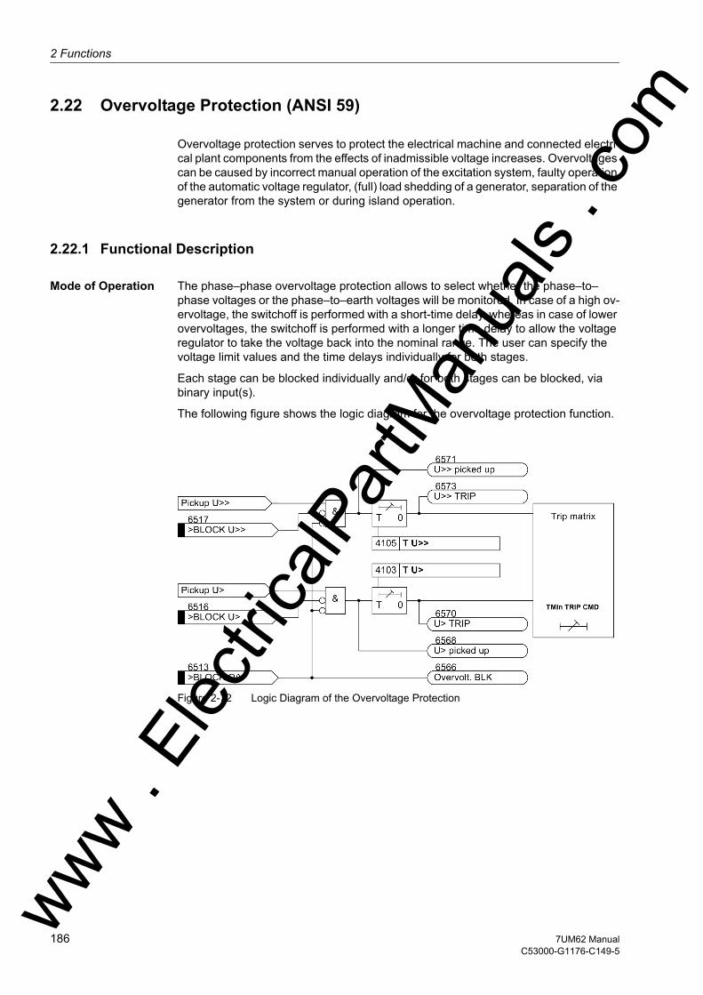
2 Functions
om
2.22 Overvoltage Protection (ANSI 59)
Overvoltage protection serves to protect the electrical machine and connected electri-cal plant components from the effects of inadmissible voltage increases. Overvoltages can be caused by incorrect manual operation of the excitation system, faulty operation of the automatic voltage regulator, (full) load shedding of a generator, separation of the generator from the system or during island operation.
2.22.1 Functional Description
Mode of Operation The phase–phase overvoltage protection allows to select whether the phase–to–phase voltages or the phase–to–earth voltages will be monitored. In case of a high ov-ervoltage, the switchoff is performed with a short-time delay, whereas in case of lower overvoltages, the switchoff is performed with a longer time delay to allow the voltage regulator to take the voltage back into the nominal range. The user can specify the voltage limit values and the time delays individually for both stages.
Each stage can be blocked individually and/or for both stages can be blocked, via binary input(s).
The following figure shows the logic diagram for the overvoltage protection function.
Figure 2-72 Logic Diagram of the Overvoltage Protection
ww . El
ectric
alPar
tMan
uals
. c
186 7UM62 ManualC53000-G1176-C149-5
w

2.22 Overvoltage Protection (ANSI 59)w
2.22.2 Setting Notes
General Overvoltage protection is only effective and available if this function was set during protective function configuration (Section 2.4, address 141, OVERVOLTAGE is set to Enabled. If the function is not required Disabled is set. Address 4101 OVERVOLTAGE serves to switch the function ON or OFF or to block only the trip command (Block relay).
Settings Address 4107 VALUES serves to specify the measured quantities used by the protec-tion feature. The default setting (normal case) is specified for phase-to-phase voltages (= U-ph-ph). The phase-earth voltages should be selected for low-voltage machines with grounded neutral conductor (= U-ph-e). It should be noted that even if phase-earth voltages are selected as measured quantities, the setting values of the protec-tion functions are referred to phase-to-phase voltages.
The setting of limit values and time delays of the overvoltage protection depends on the speed with which the voltage regulator can regulate voltage variations. The pro-tection must not intervene in the regulation process of the faultlessly functioning voltage regulator. For this reason, the two-stage characteristic must always be above the voltage time characteristic of the regulation procedure.
The long-time stage 4102 U> and 4103 T U> must intervene in case of steady-state overvoltages. It is set to approximately 110 % to 115 % UN and, depending on the reg-ulator speed, to a range between 1.5 s and 5 s.
In case of a full-load rejection of the generator, the voltage increases first in relation to the transient voltage. Only then does the voltage regulator reduce it again to its nominal value. The U>> stage is set generally as a short-time stage in a way that the transient procedure for a full-load rejection does not lead to a tripping. For example, for 4104 U>> about 130% UN with a delay 4105 T U>> of zero to 0.5 s are typical values.
All setting times are additional time delays which do not include the operating times (measuring time, dropout time) of the protective function.
The dropout ratio can be adapted at the address 4106 DOUT RATIO in small stages to the operating conditions and used for highly precise signalizations (e.g. network infeed of wind power stations).
ww . El
ectric
alPar
tMan
uals
. com
1877UM62 ManualC53000-G1176-C149-5
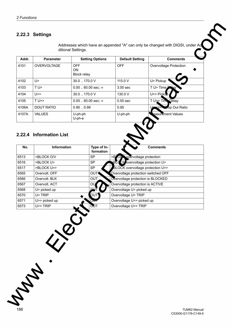
2 Functions
om
2.22.3 Settings
Addresses which have an appended "A" can only be changed with DIGSI, under Ad-ditional Settings.
2.22.4 Information List
Addr. Parameter Setting Options Default Setting Comments
4101 OVERVOLTAGE OFFONBlock relay
OFF Overvoltage Protection
4102 U> 30.0 .. 170.0 V 115.0 V U> Pickup
4103 T U> 0.00 .. 60.00 sec; ∞ 3.00 sec T U> Time Delay
4104 U>> 30.0 .. 170.0 V 130.0 V U>> Pickup
4105 T U>> 0.00 .. 60.00 sec; ∞ 0.50 sec T U>> Time Delay
4106A DOUT RATIO 0.90 .. 0.99 0.95 U>, U>> Drop Out Ratio
4107A VALUES U-ph-phU-ph-e
U-ph-ph Measurement Values
No. Information Type of In-formation
Comments
6513 >BLOCK O/V SP >BLOCK overvoltage protection6516 >BLOCK U> SP >BLOCK overvoltage protection U>6517 >BLOCK U>> SP >BLOCK overvoltage protection U>>6565 Overvolt. OFF OUT Overvoltage protection switched OFF6566 Overvolt. BLK OUT Overvoltage protection is BLOCKED6567 Overvolt. ACT OUT Overvoltage protection is ACTIVE6568 U> picked up OUT Overvoltage U> picked up6570 U> TRIP OUT Overvoltage U> TRIP6571 U>> picked up OUT Overvoltage U>> picked up6573 U>> TRIP OUT Overvoltage U>> TRIP
ww . El
ectric
alPar
tMan
uals
. c
188 7UM62 ManualC53000-G1176-C149-5
w

2.23 Frequency Protection (ANSI 81)w
2.23 Frequency Protection (ANSI 81)
The frequency protection function detects abnormally high and low frequencies of the generator. If the frequency lies outside the admissible range, appropriate actions are initiated, such as separating the generator from the system.
A decrease in system frequency occurs when the system experiences an increase in real power demand, or when a frequency or speed control malfunction occurs. The frequency decrease protection is also used for generators which (for a certain time) function on an island network. This is due to the fact that the reverse power protection cannot operate on drive power failure. The generator can be disconnected from the power system using the frequency decrease protection.
An increase in system frequency occurs e.g. when large loads (island network) are removed from the system, or on frequency control malfunction. This entails risk of self-excitation for generators feeding long lines under no-load conditions.
Through the use of filters measurement is practically independent of harmonic influ-ences and very accurate.
2.23.1 Functional Description
Frequency Increase and Decrease
Frequency protection consists of the four frequency elements f1 to f4. To make protec-tion flexible for different power system conditions, theses stages can be used alterna-tively for frequency decrease or increase separately, and can be independently set to perform different control functions. The setting decides on the purpose of the individ-ual frequency stage. For the f4 frequency stage, the user can specify independently of the parameterized limit value if this stage shall function as decrease or increase stage. For this reason, it can also be used for special applications, if, for example, frequency undershoot below the nominal frequency is to be signaled.
Operating Ranges The frequency can be determined as long as at least one of the phase–to–phase volt-ages is present and of sufficient magnitude. If the measurement voltage drops below a settable value Umin, frequency protection is disabled because precise frequency values can no longer be calculated from the signal.
With overfrequency protection, seal-in of the overfrequency pickup occurs during the transition to the 0 mode, if the last measured frequency was above 66 Hz. The switch-off command drops out by a function blocking or on transition to operational condition 1. A pickup drops out if the frequency measured last before the transition into opera-tional condition 0 is below 66 Hz.
With underfrequency protection, there is no precise frequency calculation on transition to the 0 mode due to a too low frequency. Consequently, the pickup or tripping drop out.
Time Delays/Logic Trippings can be delayed each using an added time stage. When the time delay ex-pires, a trip signal is generated. After pickup dropout the tripping command is imme-diately reset, but not before the minimum command duration has expired.
ww . El
ectric
alPar
tMan
uals
. com
1897UM62 ManualC53000-G1176-C149-5

2 Functions
om
Each of the four frequency stages can be blocked individually by binary inputs.
Figure 2-73 Logic diagram of the frequency protection
2.23.2 Setting Notes
General Frequency protection is only in effect and accessible if address 142 FREQUENCY Prot. is set to Enabled during configuration of protective functions. If the function is not required Disabled is set. Address 4201 O/U FREQUENCY serves to switch the function ON or OFF or to block only the trip command (Block relay).
Pickup Values By configuring the rated frequency of the power system and the frequency threshold for each of the stages f1 PICKUP to f4 PICKUP in each case the function is estab-lished as either overvoltage or undervoltage protection. Set the pickup threshold lower than nominal frequency if the element is to be used for underfrequency protection. Set the pickup threshold higher than nominal frequency if the element is to be used for overfrequency protection.
Note
If the threshold is set equal to the nominal frequency, the element is inactive.
For the f4 frequency stage, the former applies only if the parameter 4214 THRESHOLD f4 is set to automatic (default setting). If desired, this parameter can also be set to f> or f<, in which case the evaluation direction (increase or decrease detection) can be specified independent of the parametrized f4 PICKUP threshold. ww .
Elec
tricalP
artM
anua
ls . c
190 7UM62 ManualC53000-G1176-C149-5
w

2.23 Frequency Protection (ANSI 81)w
If frequency protection is used for network decoupling and load shedding purposes, settings depend on the actual network conditions. Normally a graded load shedding is strived for that takes into account priorities of consumers or consumer groups.
Further application examples are covered under power stations. The frequency values to be set mainly depend, also in these cases, on power system/power station operator specifications. In this context, frequency decrease protection ensures the power sta-tion's own demand by disconnecting it from the power system on time. The turbo reg-ulator regulates the machine set to the nominal speed. Consequently, the station's own demands can be continuously supplied at nominal frequency.
Under the assumption that apparent power is reduced to the same degree, turbine-driven generators can, as a rule, be continuously operated down to 95 % of nominal frequency. However, for inductive consumers, the frequency reduction not only means greater current consumption but also endangers stable operation. For this reason, only a short-time frequency reduction down to about 48 Hz (for fN = 50 Hz) or 58 Hz (for fN = 60 Hz) is permissible.
A frequency increase can, for example, occur due to a load shedding or malfunction of the speed regulation (e.g. in a stand-alone system). In this way, the frequency in-crease protection can, for example, be used as overspeed protection.
Setting example:
Time Delays The delay times T f1 to T f4 entered at addresses 4204, 4207, 4210 and 4213) allow the frequency stages to be graded. The set times are additional delay times not including the operating times (measuring time, dropout time) of the protective function.
Minimum Voltage Address 4215 Umin is used to set the minimum voltage which if undershot, frequency protection is blocked. A value of approx. 65 % UN is recommended. The parameter value is based on phase-to-phase voltages. The minimum voltage threshold can be deactivated by setting this address to 0.
Stage Cause Settingsfor fN = 50 Hz for fN = 60 Hz Delay
f1 Disconnection from the network
48.00 Hz 58.00 Hz 1.00 sec
f2 Shutdown 47.00 Hz 57.00 Hz 6.00 secf3 Warning 49.50 Hz 59.50 Hz 20.00 secf4 Alarm or tripping 52.00 Hz 62.00 Hz 10.00 sec
ww . El
ectric
alPar
tMan
uals
. com
1917UM62 ManualC53000-G1176-C149-5

2 Functions
om
2.23.3 Settings
Addr. Parameter Setting Options Default Setting Comments
4201 O/U FREQUENCY OFFONBlock relay
OFF Over / Under Frequency Protec-tion
4202 f1 PICKUP 40.00 .. 66.00 Hz 48.00 Hz f1 Pickup
4203 f1 PICKUP 40.00 .. 66.00 Hz 58.00 Hz f1 Pickup
4204 T f1 0.00 .. 600.00 sec 1.00 sec T f1 Time Delay
4205 f2 PICKUP 40.00 .. 66.00 Hz 47.00 Hz f2 Pickup
4206 f2 PICKUP 40.00 .. 66.00 Hz 57.00 Hz f2 Pickup
4207 T f2 0.00 .. 100.00 sec 6.00 sec T f2 Time Delay
4208 f3 PICKUP 40.00 .. 66.00 Hz 49.50 Hz f3 Pickup
4209 f3 PICKUP 40.00 .. 66.00 Hz 59.50 Hz f3 Pickup
4210 T f3 0.00 .. 100.00 sec 20.00 sec T f3 Time Delay
4211 f4 PICKUP 40.00 .. 66.00 Hz 52.00 Hz f4 Pickup
4212 f4 PICKUP 40.00 .. 66.00 Hz 62.00 Hz f4 Pickup
4213 T f4 0.00 .. 100.00 sec 10.00 sec T f4 Time Delay
4214 THRESHOLD f4 automaticf>f<
automatic Handling of Threshold Stage f4
4215 Umin 10.0 .. 125.0 V; 0 65.0 V Minimum Required Voltage for Operation
ww . El
ectric
alPar
tMan
uals
. c
192 7UM62 ManualC53000-G1176-C149-5
w

2.23 Frequency Protection (ANSI 81)w
2.23.4 Information List
No. Information Type of In-formation
Comments
5203 >BLOCK Freq. SP >BLOCK frequency protection5206 >BLOCK f1 SP >BLOCK stage f15207 >BLOCK f2 SP >BLOCK stage f25208 >BLOCK f3 SP >BLOCK stage f35209 >BLOCK f4 SP >BLOCK stage f45211 Freq. OFF OUT Frequency protection is OFF5212 Freq. BLOCKED OUT Frequency protection is BLOCKED5213 Freq. ACTIVE OUT Frequency protection is ACTIVE5214 Freq UnderV Blk OUT Frequency protection undervoltage Blk5232 f1 picked up OUT f1 picked up5233 f2 picked up OUT f2 picked up5234 f3 picked up OUT f3 picked up5235 f4 picked up OUT f4 picked up5236 f1 TRIP OUT f1 TRIP5237 f2 TRIP OUT f2 TRIP5238 f3 TRIP OUT f3 TRIP5239 f4 TRIP OUT f4 TRIP
ww . El
ectric
alPar
tMan
uals
. com
1937UM62 ManualC53000-G1176-C149-5

2 Functions
om
2.24 Overexcitation (Volt/Hertz) Protection (ANSI 24)
Overexcitation protection is used to detect inadmissibly high induction in generators and transformers, especially in power station unit transformers. The protection must intervene when the limit value for the protected object (e.g. unit transformer) is ex-ceeded. The transformer is endangered, for example, if the power station block is dis-connected from the system from full-load, and if the voltage regulator either does not operate or does not operate sufficiently fast to control the associated voltage rise. Sim-ilarly a decrease in frequency (speed), e.g. in island systems, can lead to an inadmis-sible increase in induction.
An increase in induction above the rated value very quickly saturates the iron core and causes large eddy current losses.
2.24.1 Functional Description
Measurement Method
The overexcitation protection feature servers to measure the voltageU/frequency ratio f, which is proportional to the B induction and puts it in relation to the BN nominal in-duction. In this context, both voltage and frequency are related to nominal values of the object to be protected (generator, transformer).
The calculation is based on the maximum voltage of the three phase-to-phase voltag-es. The frequency range monitored extends from 10 Hz to 70 Hz.
Voltage Transform-er Adaptation
Any deviation between primary nominal voltage of the voltage transformers and of the object to be protected is compensated by an internal correction factor (UN prim/UN Mach). For this reason pickup values and characteristic do not need to be converted to sec-ondary values. However the system primary nominal transformer voltage and the nominal voltage of the object to be protected must be entered correctly (see Sections 2.5 and 2.7).
Characteristic Curves
Overexcitation protection includes two staged characteristics and one thermal charac-teristic for approximate modeling of the heating of the protection object due to overex-citation. As soon as a first pickup threshold (warning stage 4302 U/f >) has been exceeded, a 4303 T U/f > time stage is started. On its expiry a warning message is transmitted. At the same time a counter switching is activated when the pickup thresh-old is exceeded. This weighted counter is incremented in accordance with the current U/f value resulting in the trip time for the parametrized characteristic. A trip signal is transmitted as soon as the trip counter state has been reached.
The trip signal is retracted as soon as the value falls below the pickup threshold and the counter is decremented in accordance with a parametrizable cool-down time.
The thermal characteristic is specified by 8 value pairs for overexcitation U/f (related to nominal values) and trip time t. In most cases, the specified characteristic for stan-dard transformers provides sufficient protection. If this characteristic does not corre-ww .
Elec
tricalP
artM
anua
ls . c
194 7UM62 ManualC53000-G1176-C149-5
w

2.24 Overexcitation (Volt/Hertz) Protection (ANSI 24)w
spond to the actual thermal behavior of the object to be protected, any desired char-acteristic can be implemented by entering customer-specific trip times for the specified U/f overexcitation values. Intermediate values are determined by a linear interpolation within the device.
Figure 2-74 Tripping Range of the Overexcitation Protection
The characteristic resulting from the device default settings is shown in the Technical Data Section Overexcitation Protection. Figure 2-74 illustrates the behaviour of the protection on the assumption that within the framework of configuration the setting for the pickup threshold (parameter4302 U/f >) was chosen higher or lower than the first setting value of the thermal characteristic.ww . El
ectric
alPar
tMan
uals
. com
1957UM62 ManualC53000-G1176-C149-5
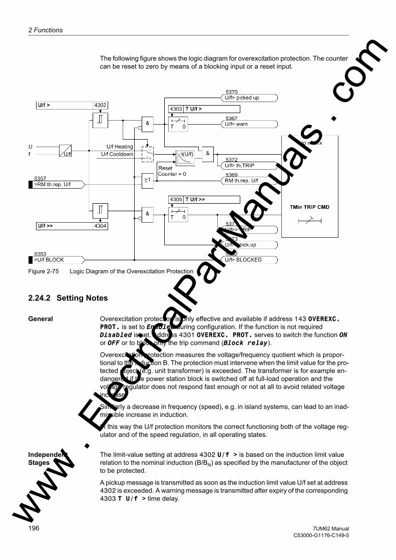
2 Functions
om
The following figure shows the logic diagram for overexcitation protection. The counter can be reset to zero by means of a blocking input or a reset input.
Figure 2-75 Logic Diagram of the Overexcitation Protection
2.24.2 Setting Notes
General Overexcitation protection is only effective and available if address 143 OVEREXC. PROT. is set to Enabled during configuration. If the function is not required Disabled is set. Address 4301 OVEREXC. PROT. serves to switch the function ON or OFF or to block only the trip command (Block relay).
Overexcitation protection measures the voltage/frequency quotient which is propor-tional to the induction B. The protection must intervene when the limit value for the pro-tected object (e.g. unit transformer) is exceeded. The transformer is for example en-dangered if the power station block is switched off at full-load operation and the voltage regulator does not respond fast enough or not at all to avoid related voltage increase.
Similarly a decrease in frequency (speed), e.g. in island systems, can lead to an inad-missible increase in induction.
In this way the U/f protection monitors the correct functioning both of the voltage reg-ulator and of the speed regulation, in all operating states.
Independent Stages
The limit-value setting at address 4302 U/f > is based on the induction limit value relation to the nominal induction (B/BN) as specified by the manufacturer of the object to be protected.
A pickup message is transmitted as soon as the induction limit value U/f set at address 4302 is exceeded. A warning message is transmitted after expiry of the corresponding 4303 T U/f > time delay. ww .
Elec
tricalP
artM
anua
ls . c
196 7UM62 ManualC53000-G1176-C149-5
w

2.24 Overexcitation (Volt/Hertz) Protection (ANSI 24)w
The 4304 U/f >>, 4305 T U/f >> trip stage characteristic serves to rapidly switch off particularly strong overexcitations.
The time set for this purpose is an additional time delay which does not include the operating time (measuring time, drop-out time).
Thermal Character-istic
A thermal characteristic is superimposed on the trip stage characteristic. For this pur-pose, the temperature rise created by the overexcitation is approximately modeled. Not only the already mentioned pickup signal is generated on transgression of the U/f induction limit set at address 4302 but in addition a counter is set additionally which causes the tripping after a length of time corresponding to the set characteristic.
Figure 2-76 Thermal tripping time characteristic (with presettings)
The characteristic of a Siemens standard transformer was selected as a presetting for the parameters 4306 to 4313. If the protection object manufacturer did not provide any information, the preset standard characteristic should be used. Otherwise, any trip characteristic can be specified by point-wise entering of parameters by maximally 7 straight lengths. To do this, the trip times of the overexcitation values U/f = 1.05; 1.10; 1.15; 1.20; 1.25; 1.30; 1.35 and 1.40 are read out from the predefined characteristic and entered at the addresses4306 t(U/f=1.05) to 4313 t(U/f=1.40). The pro-tection device interpolates linearly between the points.
Limitation The heating model of the object to be protected is limited to a 150 % overshoot of the trip temperature.
Cooldown Time Tripping by the thermal image drops out by the time of the pickup threshold dropout. However, the counter content is counted down to zero with the cooldown time param-etrized at address 4314 T COOL DOWN. In this context this parameter is defined as the time required by the thermal image to cool down from 100 % to 0 %.ww . El
ectric
alPar
tMan
uals
. com
1977UM62 ManualC53000-G1176-C149-5

2 Functions
om
Voltage Transform-er Adaptation
Any deviation between primary nominal voltage of the voltage transformers and of the object to be protected is compensated by an internal correction factor (UN prim/UN Mach). For this it is necessary that the relevant parameters 221 Unom PRIMARY and 251 UN GEN/MOTOR were properly entered in accordance with Section 2.5.
2.24.3 Settings
2.24.4 Information List
Addr. Parameter Setting Options Default Setting Comments
4301 OVEREXC. PROT. OFFONBlock relay
OFF Overexcitation Protection (U/f)
4302 U/f > 1.00 .. 1.20 1.10 U/f > Pickup
4303 T U/f > 0.00 .. 60.00 sec; ∞ 10.00 sec T U/f > Time Delay
4304 U/f >> 1.00 .. 1.40 1.40 U/f >> Pickup
4305 T U/f >> 0.00 .. 60.00 sec; ∞ 1.00 sec T U/f >> Time Delay
4306 t(U/f=1.05) 0 .. 20000 sec 20000 sec U/f = 1.05 Time Delay
4307 t(U/f=1.10) 0 .. 20000 sec 6000 sec U/f = 1.10 Time Delay
4308 t(U/f=1.15) 0 .. 20000 sec 240 sec U/f = 1.15 Time Delay
4309 t(U/f=1.20) 0 .. 20000 sec 60 sec U/f = 1.20 Time Delay
4310 t(U/f=1.25) 0 .. 20000 sec 30 sec U/f = 1.25 Time Delay
4311 t(U/f=1.30) 0 .. 20000 sec 19 sec U/f = 1.30 Time Delay
4312 t(U/f=1.35) 0 .. 20000 sec 13 sec U/f = 1.35 Time Delay
4313 t(U/f=1.40) 0 .. 20000 sec 10 sec U/f = 1.40 Time Delay
4314 T COOL DOWN 0 .. 20000 sec 3600 sec Time for Cooling Down
No. Information Type of In-formation
Comments
5353 >U/f BLOCK SP >BLOCK overexcitation protection5357 >RM th.rep. U/f SP >Reset memory of thermal replica U/f5361 U/f> OFF OUT Overexcitation prot. is swiched OFF5362 U/f> BLOCKED OUT Overexcitation prot. is BLOCKED5363 U/f> ACTIVE OUT Overexcitation prot. is ACTIVE5367 U/f> warn OUT Overexc. prot.: U/f warning stage5369 RM th.rep. U/f OUT Reset memory of thermal replica U/f5370 U/f> picked up OUT Overexc. prot.: U/f> picked up5371 U/f>> TRIP OUT Overexc. prot.: TRIP of U/f>> stage5372 U/f> th.TRIP OUT Overexc. prot.: TRIP of th. stage5373 U/f>> pick.up OUT Overexc. prot.: U/f>> picked up
ww . El
ectric
alPar
tMan
uals
. c
198 7UM62 ManualC53000-G1176-C149-5
w
2.25 Inverse-Time Undervoltage Protection (ANSI 27)w
2.25 Inverse-Time Undervoltage Protection (ANSI 27)
The inverse undervoltage protection mainly protects consumers (induction machines) from the consequences of dangerous voltage drops in island networks avoiding inad-missible operating conditions and possible loss of stability. It can also be used as a criterion for load shedding in interconnected networks. Two-pole short circuits or earth faults cause asymmetrical voltage collapse. Compared with single phase measuring systems, the detection of the positive phase-sequence system is not influenced by these procedures and is therefore especially useful for assessing stability problems.
2.25.1 Function Description
Measured Quantity For the above reasons, the positive sequence system is calculated from the funda-mental waves of the three phase-earth voltages, and fed to the protection function. After numerical filtering the fundamental wave is evaluated.
If voltage transformers in open delta connection (V connection) are available on the plant side, protection is applied to the phase-to-phase voltages and the internal star-point is left empty. A virtual starpoint is thus formed so that the (virtual) phase-to-earth voltages can still be detected (see connection example in Appendix A.3).
Tripping character-istic
By means of a voltage-time dependent tripping characteristic protection can be matched exactly to the stability characteristic of motors. If the motor falls below the sta-bility characteristic, it will stall or run at substantially reduced speed, even if full voltage is restored after a short time. Only squirrel-cage machines for which the torque char-acteristic of the driven machine lies below the motor characteristic at all speeds will regain their rated speed. All other machines will be thermally and perhaps mechani-cally overstressed on running down, after return of voltage.
Undervoltage protection consists of one inverse time element. In order to avoid mal-function of the protection in the event of secondary voltage failure, it can be blocked via a binary input, e.g. by the auxiliary contact of a voltage transformer miniature circuit breaker or from the position of the main circuit breaker when the machine is at stand-still. Also the integrated Fuse-Failure Monitor will block the two stage (see section 2.42.2).
If no measured values are available at the device (operation condition 0), no trip signal is issued if there was no pickup. This ensures that the undervoltage protection does not pick up immediately when it is switched on if no measured value is available. Once the protection has been activated, it can only be deactivated again only by blocking.
If a pickup signal is present when the device enters operating condition 0 (i.e. no mea-sured values, or frequency outside the permissible range), it is maintained. The delay time until tripping is calculated in the same way as for a drop to 0V. The sealed-in pickup or tripping signal can only be reset on voltage restoration, or if the blocking input is activated.
The pickup/dropout ratio is 101 % or 0.5 V absolute of the threshold set at address 4402 Up< PICKUP. The integral action of the tripping time determination is „frozen“ between the pickup and the dropout value.
ww . El
ectric
alPar
tMan
uals
. com
1997UM62 ManualC53000-G1176-C149-5

2 Functions
om
The following figure shows the logic diagram of the inverse undervoltage protection.
Figure 2-77 Logic Diagram of the Inverse-Time Undervoltage Protection
2.25.2 Setting Notes
General The inverse-time undervoltage protection is only effective and available if this function was set during protective function configuration (Section 2.4, address 144, INV.UNDERVOLT. is set to Enabled. If the function is not required Disabled is set. Address 4401 INV. UNDERVOLT. serves to switch the function ON or OFF or to block only the trip command (Block relay).
Settings It must be considered that the positive phase-sequence voltages and thus also the pickup thresholds are evaluated as phase-to-phase quantities (terminal voltage · √3).
There are no clear cut procedures on how to set the pickup values. But since the pro-tection is used mainly to protect consumers (induction machines) from the conse-quences of voltage drops, and to prevent loss of stability, the value is normally set to approx. 75 % of the nominal machine voltage, i.e. address 4402 Up< PICKUP is set to 75 V. In exceptional cases, where the voltage drop during startup is too large, it may be necessary to set the protection to lower values. The time multiplier 4403 T MUL must be selected such that voltage drops which would cause unstable operation are reliably disconnected. On the other hand, the time delay must be large enough to avoid disconnections during permissible short-time voltage dips.
If required, the tripping time can also be extended by an additional time stage 4404 T Up<.
All setting times are additional time delays which do not include the operating times (measuring time, drop-out time) of the protective function.
ww . El
ectric
alPar
tMan
uals
. c
200 7UM62 ManualC53000-G1176-C149-5
w

2.25 Inverse-Time Undervoltage Protection (ANSI 27)w
2.25.3 Settings
2.25.4 Information List
Addr. Parameter Setting Options Default Setting Comments
4401 INV. UNDERVOLT. OFFONBlock relay
OFF Inverse Undervoltage Protection Up<
4402 Up< PICKUP 10.0 .. 125.0 V 75.0 V Up< Pickup
4403 T MUL 0.10 .. 5.00 sec; 0 1.00 sec Time Multiplier for Characteristic
4404 T Up< 0.00 .. 60.00 sec; ∞ 0.00 sec T Up< Time Delay
No. Information Type of In-formation
Comments
6520 >BLOCK Up< SP >BLOCK inverse undervoltage protection6522 Up< OFF OUT Inv. Undervoltage prot. is switched OFF6523 Up< BLOCK OUT Inv. Undervoltage protection is BLOCKED6524 Up< ACTIVE OUT Inv. Undervoltage protection is ACTIVE6525 Up< picked up OUT Inverse Undervoltage Up< picked up6526 Up< ch. pick.up OUT Inv. Undervoltage Up<-char. picked up6527 Up< AUS OUT Inverse Undervoltage Up< TRIP
ww . El
ectric
alPar
tMan
uals
. com
2017UM62 ManualC53000-G1176-C149-5
2 Functions
om
2.26 Rate-of-Frequency-Change Protection df/dt (ANSI 81R)
With the rate-of-frequency-change protection, frequency changes can be quickly de-tected. This allows a prompt response to frequency dips or frequency rises. A trip command can be issued even before the pickup threshold of the frequency protection (see Section 2.23) is reached.
Frequency changes occur for instance when there is an imbalance between the gen-erated and the required active power. They call for control measures on one hand and for switching actions on the other hand. These can be unburdening measures, such as network decoupling, or disconnection of loads (load shedding). The sooner these measures are taken after a malfunction appears, the more effective they are.
The two main applications for this protection function are thus network decoupling and load shedding.
2.26.1 Function Description
Measuring Principle
From the positive-sequence voltage, the frequency is determined once per cycle over a measuring window of 3 cycles, and a mean value of two consecutive frequency mea-surements is formed. The frequency difference is then determined over a settable time interval (default setting 5 cycles). The ratio between frequency difference and time dif-ference corresponds to the frequency change; it can be positive or negative. The mea-surement is performed continuously (per cycle). Monitoring functions such as under-voltage monitoring, checks for phase angle jumps etc. help to avoid overfunctioning.
Frequency In-crease/ Decrease
The rate-of-frequency-change protection has four stages, from df1/dt to df4/dt. This allows the function to be adapted variably to all power system conditions. The stages can be set to detect either frequency decreases (-df/dt) or frequency increases (+df/dt). The -df/dt stage is only active for frequencies below the rated frequency, or less if the underfrequency enabling is activated. Likewise, the df/dt stage is active for frequencies above the rated frequency, or higher, if the overfrequency enabling is ac-tivated. The parameter setting decides for what purpose the particular stage will be used.
To avoid a proliferation of setting parameters, the settable measuring window for the frequency difference formation and the dropout difference are each valid for two stages.
Operating Ranges The frequency can be determined as long as there is a sufficiently strong positive se-quence system of voltages. If the measurement voltage drops below a settable value U MIN, frequency protection is disabled because precise frequency values can no longer be calculated from the signal.
ww . El
ectric
alPar
tMan
uals
. c
202 7UM62 ManualC53000-G1176-C149-5
w

2.26 Rate-of-Frequency-Change Protection df/dt (ANSI 81R)w
Time Delays/Logic Tripping can be delayed by a set time delay associated with each applied time stage. This is recommended for monitoring of small gradients. When the time delay expires, a trip signal is generated. After pickup dropout the tripping command is immediately reset, but not before the minimum command duration has expired.
Each of the four frequency change stages can be blocked individually by binary input. The undervoltage blocking acts on all stages simultaneously.
Figure 2-78 Logic Diagram of the Rate-of-Frequency-Change Protection
ww . El
ectric
alPar
tMan
uals
. com
2037UM62 ManualC53000-G1176-C149-5
2 Functions
om
2.26.2 Setting Notes
General The rate-of-frequency-change protection is only effective and accessible if during the configuration address 145 df/dt Protect. has been set accordingly. 2 or 4 stages can be selected. The default setting is 2 df/dt stages.
Address 4501 df/dt Protect. serves to switch the function ON or OFF or to block only the trip command (Block relay).
Pickup Values The setting procedure is the same for all stages. In a first step, it must be determined whether the stage is to monitor a frequency rise at f>fN or a frequency drop at f<fN. For stage 1, for instance, this setting is made at address 4502 df1/dt >/<. The pickup value is set as an absolute value at address 4503 STAGE df1/dt. The setting of address 4502 informs the protection function of the applicable sign.
The pickup value depends on the application and is determined by power system con-ditions. In most cases, a network analysis will be necessary. A sudden disconnection of loads leads to a surplus of active power. The frequency rises and causes a positive frequency change. A failure of generators, on the other hand, leads to a deficit of active power. The frequency drops and leads to a negative frequency change.
The following relations can be used as an example for estimation. They apply for the change rate at the beginning of a frequency change (approx. 1 second).
Significance:
fN Nominal Frequency
∆P Active power change
∆P = PConsumption – PGeneration
SN Nominal apparent power of the machines
H Inertia constant
Example:
fN = 50 Hz
H = 3 s
Case 1: ∆P/SN = 0.12
Case 2: ∆P/SN = 0.48
Case 1: df/dt = -1 Hz/s
Case 2: df/dt = -4 Hz/s
The default settings are based on the above example. The four stages have been set symmetrically.
for hydro-electric generators (salient-pole machines) H = 1.5 s to 6 sfor turbine-driven generators (cylindrical-rotor machines) H = 2 s to 10 sfor industrial turbine-generators H = 3 s to 4 s
ww . El
ectric
alPar
tMan
uals
. c
204 7UM62 ManualC53000-G1176-C149-5
w

2.26 Rate-of-Frequency-Change Protection df/dt (ANSI 81R)w
Time Delays The delay time should be set to zero wherever the protection function is supposed to respond very quickly. This will be the case with high setting values. For the monitoring of small changes (< 1Hz/s), on the other hand, a small delay time can be useful to avoid overfunctioning. The delay time for stage 1 is set at address 4504 T df1/dt, and the time set there is added to the protection operating time.
Release by the Fre-quency Protection
The parameter df1/dt & f1 (Address 4505) is used to set the release of the stage from a certain frequency threshold on. For this the pertinent frequency stage of the fre-quency protection is queried. In the setting example this is stage f1. To exclude cou-pling of the two functions, the parameter can be set to OFF (default setting).
Advanced Parame-ters
The advanced parameters allow setting each for two stages (e.g. df1/dt and df2/dt) the dropout difference and the measuring window. This setting can only be done with the DIGSI communication software.
Setting changes are necessary e.g. to obtain a large dropout difference. For the de-tection of very small frequency changes (< 0.5 Hz/s), the default setting of the mea-suring window should be extended. This is to improve the measuring accuracy.
Minimum Voltage Address 4518 U MIN is used to set the minimum voltage below which the frequency change protection will be blocked. A value of approx. 65 % UN is recommended. The minimum voltage threshold can be deactivated by setting this address to „0“.
Setting value
Stage dfn/dt
df/dt HYSTERES.
(Addr. 4519, 4521)
dfx/dt M-WINDOW
(Addr. 4520, 4522)0.1...0.5 Hz/s ≈ 0.05 25...100.5...1 Hz/s ≈ 0.1 10...51...0.5 Hz/s ≈ 0.2 10...5
5...00.20 Hz/s ≈ 0.5 5...1
ww . El
ectric
alPar
tMan
uals
. com
2057UM62 ManualC53000-G1176-C149-5

2 Functions
om
2.26.3 Settings
Addresses which have an appended "A" can only be changed with DIGSI, under Ad-ditional Settings.
Addr. Parameter Setting Options Default Setting Comments
4501 df/dt Protect. OFFONBlock relay
OFF Rate-of-frequency-change pro-tection
4502 df1/dt >/< -df/dt<+df/dt>
-df/dt< Mode of Threshold (df1/dt >/<)
4503 STAGE df1/dt 0.1 .. 10.0 Hz/s; ∞ 1.0 Hz/s Pickup Value of df1/dt Stage
4504 T df1/dt 0.00 .. 60.00 sec; ∞ 0.50 sec Time Delay of df1/dt Stage
4505 df1/dt & f1 OFFON
OFF AND logic with pickup of stage f1
4506 df2/dt >/< -df/dt<+df/dt>
-df/dt< Mode of Threshold (df2/dt >/<)
4507 STAGE df2/dt 0.1 .. 10.0 Hz/s; ∞ 1.0 Hz/s Pickup Value of df2/dt Stage
4508 T df2/dt 0.00 .. 60.00 sec; ∞ 0.50 sec Time Delay of df2/dt Stage
4509 df2/dt & f2 OFFON
OFF AND logic with pickup of stage f2
4510 df3/dt >/< -df/dt<+df/dt>
-df/dt< Mode of Threshold (df3/dt >/<)
4511 STAGE df3/dt 0.1 .. 10.0 Hz/s; ∞ 4.0 Hz/s Pickup Value of df3/dt Stage
4512 T df3/dt 0.00 .. 60.00 sec; ∞ 0.00 sec Time Delay of df3/dt Stage
4513 df3/dt & f3 OFFON
OFF AND logic with pickup of stage f3
4514 df4/dt >/< -df/dt<+df/dt>
-df/dt< Mode of Threshold (df4/dt >/<)
4515 STAGE df4/dt 0.1 .. 10.0 Hz/s; ∞ 4.0 Hz/s Pickup Value of df4/dt Stage
4516 T df4/dt 0.00 .. 60.00 sec; ∞ 0.00 sec Time Delay of df4/dt Stage
4517 df4/dt & f4 OFFON
OFF AND logic with pickup of stage f4
4518 U MIN 10.0 .. 125.0 V; 0 65.0 V Minimum Operating Voltage Umin
4519A df1/2 HYSTERES. 0.02 .. 0.99 Hz/s 0.10 Hz/s Reset Hysteresis for df1/dt & df2/dt
4520A df1/2 M-WINDOW 1 .. 25 Cycle 5 Cycle Measuring Window for df1/dt & df2/dt
4521A df3/4 HYSTERES. 0.02 .. 0.99 Hz/s 0.40 Hz/s Reset Hysteresis for df3/dt & df4/dt
4522A df3/4 M-WINDOW 1 .. 25 Cycle 5 Cycle Measuring Window for df3/dt & df4/dt
ww . El
ectric
alPar
tMan
uals
. c
206 7UM62 ManualC53000-G1176-C149-5
w

2.26 Rate-of-Frequency-Change Protection df/dt (ANSI 81R)w
2.26.4 Information List
No. Information Type of In-formation
Comments
5503 >df/dt block SP >BLOCK Rate-of-frequency-change prot.5504 >df1/dt block SP >BLOCK df1/dt stage5505 >df2/dt block SP >BLOCK df2/dt stage5506 >df3/dt block SP >BLOCK df3/dt stage5507 >df4/dt block SP >BLOCK df4/dt stage5511 df/dt OFF OUT df/dt is switched OFF5512 df/dt BLOCKED OUT df/dt is BLOCKED5513 df/dt ACTIVE OUT df/dt is ACTIVE5514 df/dt U< block OUT df/dt is blocked by undervoltage5516 df1/dt pickup OUT Stage df1/dt picked up5517 df2/dt pickup OUT Stage df2/dt picked up5518 df3/dt pickup OUT Stage df3/dt picked up5519 df4/dt pickup OUT Stage df4/dt picked up5520 df1/dt TRIP OUT Stage df1/dt TRIP5521 df2/dt TRIP OUT Stage df2/dt TRIP5522 df3/dt TRIP OUT Stage df3/dt TRIP5523 df4/dt TRIP OUT Stage df4/dt TRIP
ww . El
ectric
alPar
tMan
uals
. com
2077UM62 ManualC53000-G1176-C149-5
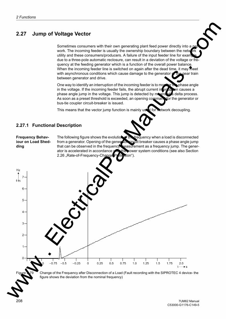
2 Functions
om
2.27 Jump of Voltage Vector
Sometimes consumers with their own generating plant feed power directly into a net-work. The incoming feeder is usually the ownership boundary between the network utility and these consumers/producers. A failure of the input feeder line for example due to a three-pole automatic reclosure, can result in a deviation of the voltage or fre-quency at the feeding generator which is a function of the overall power balance. When the incoming feeder line is switched on again after the dead time, it may meet with asynchronous conditions which cause damage to the generator or the gear train between generator and drive.
One way to identify an interruption of the incoming feeder is to monitor the phase angle in the voltage. If the incoming feeder fails, the abrupt current interruption causes a phase angle jump in the voltage. This jump is detected by means of a delta process. As soon as a preset threshold is exceeded, an opening command for the generator or bus-tie coupler circuit-breaker is issued.
This means that the vector jump function is mainly used for network decoupling.
2.27.1 Functional Description
Frequency Behav-iour on Load Shed-ding
The following figure shows the evolution of the frequency when a load is disconnected from a generator. Opening of the generator circuit breaker causes a phase angle jump that can be observed in the frequency measurement as a frequency jump. The gener-ator is accelerated in accordance with the power system conditions (see also Section 2.26 „Rate-of-Frequency-Change Protection“).
Figure 2-79 Change of the Frequency after Disconnection of a Load (Fault recording with the SIPROTEC 4 device- the figure shows the deviation from the nominal frequency)ww .
Elec
tricalP
artM
anua
ls . c
208 7UM62 ManualC53000-G1176-C149-5
w

2.27 Jump of Voltage Vectorw
Measuring Principle
The vector of the positive sequence system voltage is calculated from the phase-to-earth voltages, and the phase angle change of the voltage vector is determined over a delta interval of 2 cycles. The presence of a phase angle jump indicates an abrupt change of current flow. The basic principle is shown in Figure 2-80. The diagram on the left shows the steady state, and the diagram on the right the vector change follow-ing a load shedding. The vector jump is clearly visible.
Figure 2-80 Voltage Vector Following Load Shedding
The function features a number of additional measures to avoid spurious tripping, such as:• Correction of steady-state deviations from rated frequency• Frequency operating range limited to fN ± 3 Hz• Detection of internal scanning frequency changeover (Scanning frequency adjust-
ment)• Minimum voltage for enabling• Blocking on voltage connection or disconnection
Logic The logic is shown in Figure 2-81. The phase angle comparison determines the angle difference, and compares it with the set value. If this value is exceeded, the vector jump is stored in a RS flip-flop. Trippings can be delayed by the associated time delay.
The stored pickup can be reset via a binary input, or automatically by a timer (address 4604 T RESET).
The vector jump function becomes ineffective on exiting the admissible frequency band. The same applies for the voltage. In such a case the limiting parameters are U MIN and U MAX.
If the frequency or voltage range is not maintained, the logic generates a logical 1, and the reset input is continuously active. The result of the vector jump measurement is suppressed. If, for instance, the voltage is connected, and the frequency range is cor-rect, the logical 1 changes to 0. The timer T BLOCK with reset delay keeps the reset input active for a certain time, thus preventing a pickup caused by the vector jump function.
ww . El
ectric
alPar
tMan
uals
. com
2097UM62 ManualC53000-G1176-C149-5

2 Functions
om
If a short-circuit causes the voltage to drop abruptly to a low value, the reset input is immediately activated to block the function. The vector jump function is thus prevented from causing a trip.
Figure 2-81 Logic Diagram of the Vector Jump Detection
ww . El
ectric
alPar
tMan
uals
. c
210 7UM62 ManualC53000-G1176-C149-5
w
2.27 Jump of Voltage Vectorw
2.27.2 Setting Notes
General The vector jump protection is only effective and available if address 146 VECTOR JUMP is set to Enabled during configuration.
Address 4601 VECTOR JUMP serves to switch the function ON or OFF or to block only the trip command (Block relay).
Pickup Values The value to be set for the vector jump (address 4602 DELTA PHI) depends on the feed and load conditions. Abrupt active power changes cause a jump of the voltage vector. The value to be set must be established in accordance with the particular power system. This can be done on the basis of the simplified equivalent circuit of the diagram „Voltage Vector after a Load Shedding“ in the Functional Description section, or using network calculation software.
If a setting is too sensitive, the protection function is likely to perform a network decou-pling every time loads are connected or disconnected. Therefore the default setting is 10°.
The admissible voltage operating range can be set at addresses 4605 for U MIN and 4606 for U MAX. Setting range limits are to some extent a matter of the utility's policy. The value for U MIN should be below the admissible level of short voltage dips for which network decoupling is desired. The default setting is 80 % of the nominal volt-age. For U MAX the maximum admissible voltage must be selected. This will be in most cases 130 % of the nominal voltage
Time Delays The time delay T DELTA PHI (address 4603) should be left at zero, unless you wish to transmit the trip indication with a delay to a logic (CFC), or to leave enough time for an external blocking to take effect.
After expiry of the timer T RESET (address 4604), the protection function is automat-ically reset. The reset time depends on the decoupling policy. It must have expired before the circuit breaker is reclosed. Where the automatic reset function is not used, the timer is set to ∞. The reset signal must come in this case from the binary input (cir-cuit breaker auxiliary contact).
The timer T BLOCK with reset delay (address 4607) helps to avoid overfunctioning when voltages are connected or disconnected. Normally the default setting need not be changed. Any change can be performed with the DIGSI communication software (advanced parameters). It must be kept in mind that T BLOCK should always be set to more than the measuring window for vector jump measurement (2 cycles).
ww . El
ectric
alPar
tMan
uals
. com
2117UM62 ManualC53000-G1176-C149-5
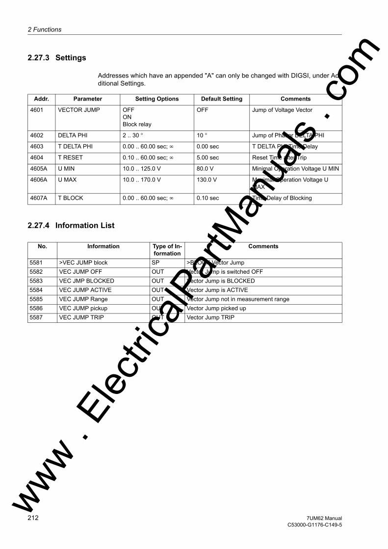
2 Functions
om
2.27.3 Settings
Addresses which have an appended "A" can only be changed with DIGSI, under Ad-ditional Settings.
2.27.4 Information List
Addr. Parameter Setting Options Default Setting Comments
4601 VECTOR JUMP OFFONBlock relay
OFF Jump of Voltage Vector
4602 DELTA PHI 2 .. 30 ° 10 ° Jump of Phasor DELTA PHI
4603 T DELTA PHI 0.00 .. 60.00 sec; ∞ 0.00 sec T DELTA PHI Time Delay
4604 T RESET 0.10 .. 60.00 sec; ∞ 5.00 sec Reset Time after Trip
4605A U MIN 10.0 .. 125.0 V 80.0 V Minimal Operation Voltage U MIN
4606A U MAX 10.0 .. 170.0 V 130.0 V Maximal Operation Voltage U MAX
4607A T BLOCK 0.00 .. 60.00 sec; ∞ 0.10 sec Time Delay of Blocking
No. Information Type of In-formation
Comments
5581 >VEC JUMP block SP >BLOCK Vector Jump5582 VEC JUMP OFF OUT Vector Jump is switched OFF5583 VEC JMP BLOCKED OUT Vector Jump is BLOCKED5584 VEC JUMP ACTIVE OUT Vector Jump is ACTIVE5585 VEC JUMP Range OUT Vector Jump not in measurement range5586 VEC JUMP pickup OUT Vector Jump picked up5587 VEC JUMP TRIP OUT Vector Jump TRIP
ww . El
ectric
alPar
tMan
uals
. c
212 7UM62 ManualC53000-G1176-C149-5
w

2.28 90-%-Stator Earth Fault Protection (ANSI 59N, 64G, 67G)w
2.28 90-%-Stator Earth Fault Protection (ANSI 59N, 64G, 67G)
The stator earth fault protection detects earth faults in the stator windings of three-phase machines. The machine can be operated in busbar connection (directly con-nected to the network) or in unit connection (via unit transformer). The criterion for the occurrence of an earth fault is mainly the emergence of a displacement voltage, or ad-ditionally with busbar connection, of an earth current. This principle makes possible a protected zone of 90 % to 95 % of the stator winding.
2.28.1 Functional Description
Displacement Voltage
The displacement voltage UEcan be measured either at the machine starpoint via voltage transformers or neutral earthing transformers (Figure 2-82) or via the e-n winding (broken delta winding) of a voltage transformer set or the measurement winding of a line connected earthing transformer (Figure 2-83). Since the neutral earthing transformer or the line connected earthing transformer usually supply a dis-placement voltage of 500 V (with full displacement), a voltage divider 500 V/100 V is to be connected in series in such cases.
If the displacement voltage can not be directly applied to the device as a measured value, the device can calculate the displacement voltage from the phase-to-earth volt-ages.
Address 223 UE CONNECTION serves for notifying the device of the way the displace-ment voltage is to be measured or calculated.
In all kinds of displacement voltage formation, the components of the third harmonic in each phase are summed since they are in phase in the three-phase system. In order to obtain reliable measured quantities, only the fundamental of the displacement voltage is evaluated in the stator earth fault protection. Harmonics are filtered out by numerical filter algorithms.
For machines in unit connection the evaluation of the displacement voltage is suffi-cient. The possible sensitivity of the protection is only limited by power frequency in-terference voltages during earth faults in the network. These interference voltages are transferred to the machine side via the coupling capacitances of the unit transformer. If necessary, a loading resistance can be provided to reduce these interference volt-ages. The protection initiates disconnection of the machine when an earth fault in the machine zone has been present for a set time.
ww . El
ectric
alPar
tMan
uals
. com
2137UM62 ManualC53000-G1176-C149-5
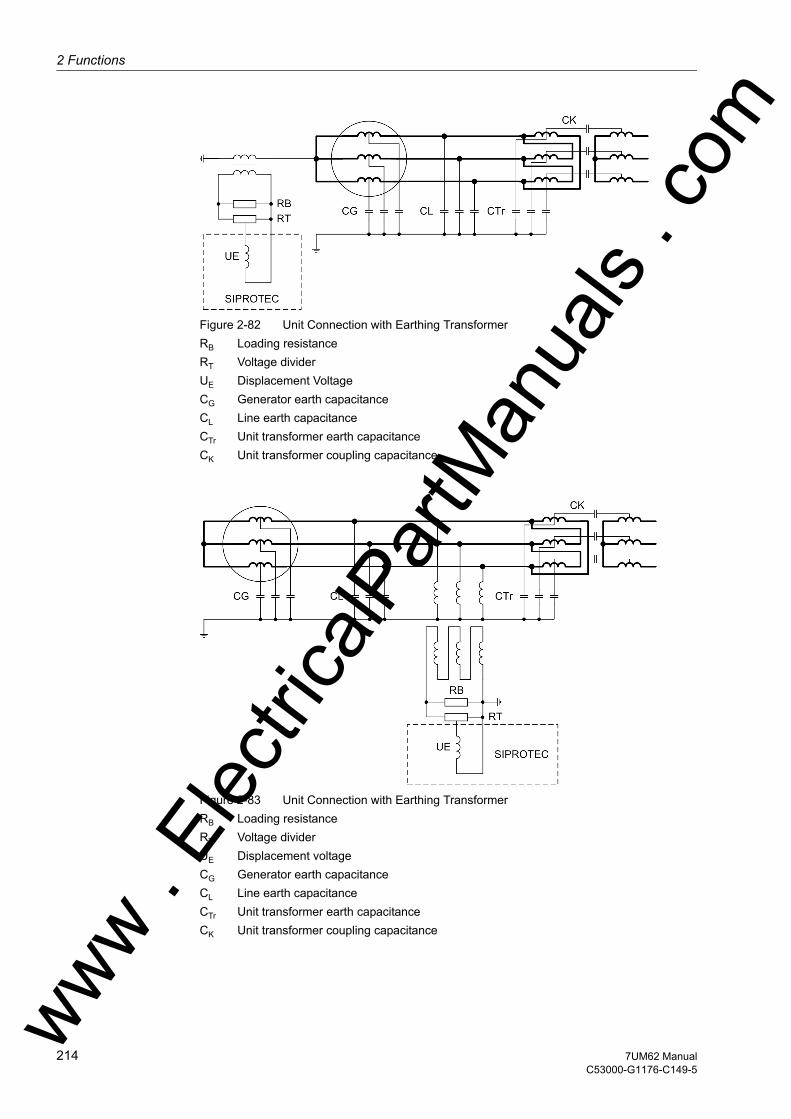
2 Functions
om
Figure 2-82 Unit Connection with Earthing TransformerRB Loading resistanceRT Voltage dividerUE Displacement VoltageCG Generator earth capacitanceCL Line earth capacitanceCTr Unit transformer earth capacitanceCK Unit transformer coupling capacitance
Figure 2-83 Unit Connection with Earthing TransformerRB Loading resistanceRT Voltage dividerUE Displacement voltageCG Generator earth capacitanceCL Line earth capacitanceCTr Unit transformer earth capacitanceCK Unit transformer coupling capacitance
ww . El
ectric
alPar
tMan
uals
. c
214 7UM62 ManualC53000-G1176-C149-5
w
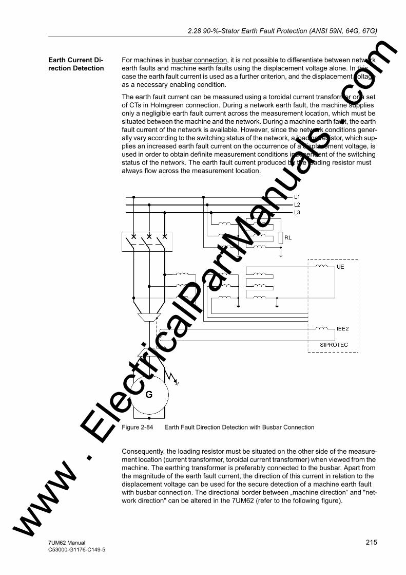
2.28 90-%-Stator Earth Fault Protection (ANSI 59N, 64G, 67G)w
Earth Current Di-rection Detection
For machines in busbar connection, it is not possible to differentiate between network earth faults and machine earth faults using the displacement voltage alone. In this case the earth fault current is used as a further criterion, and the displacement voltage as a necessary enabling condition.
The earth fault current can be measured using a toroidal current transformer or a set of CTs in Holmgreen connection. During a network earth fault, the machine supplies only a negligible earth fault current across the measurement location, which must be situated between the machine and the network. During a machine earth fault, the earth fault current of the network is available. However, since the network conditions gener-ally vary according to the switching status of the network, a loading resistor, which sup-plies an increased earth fault current on the occurrence of a displacement voltage, is used in order to obtain definite measurement conditions independent of the switching status of the network. The earth fault current produced by the loading resistor must always flow across the measurement location.
Figure 2-84 Earth Fault Direction Detection with Busbar Connection
Consequently, the loading resistor must be situated on the other side of the measure-ment location (current transformer, toroidal current transformer) when viewed from the machine. The earthing transformer is preferably connected to the busbar. Apart from the magnitude of the earth fault current, the direction of this current in relation to the displacement voltage can be used for the secure detection of a machine earth fault with busbar connection. The directional border between „machine direction“ and "net-work direction" can be altered in the 7UM62 (refer to the following figure). ww . El
ectric
alPar
tMan
uals
. com
2157UM62 ManualC53000-G1176-C149-5
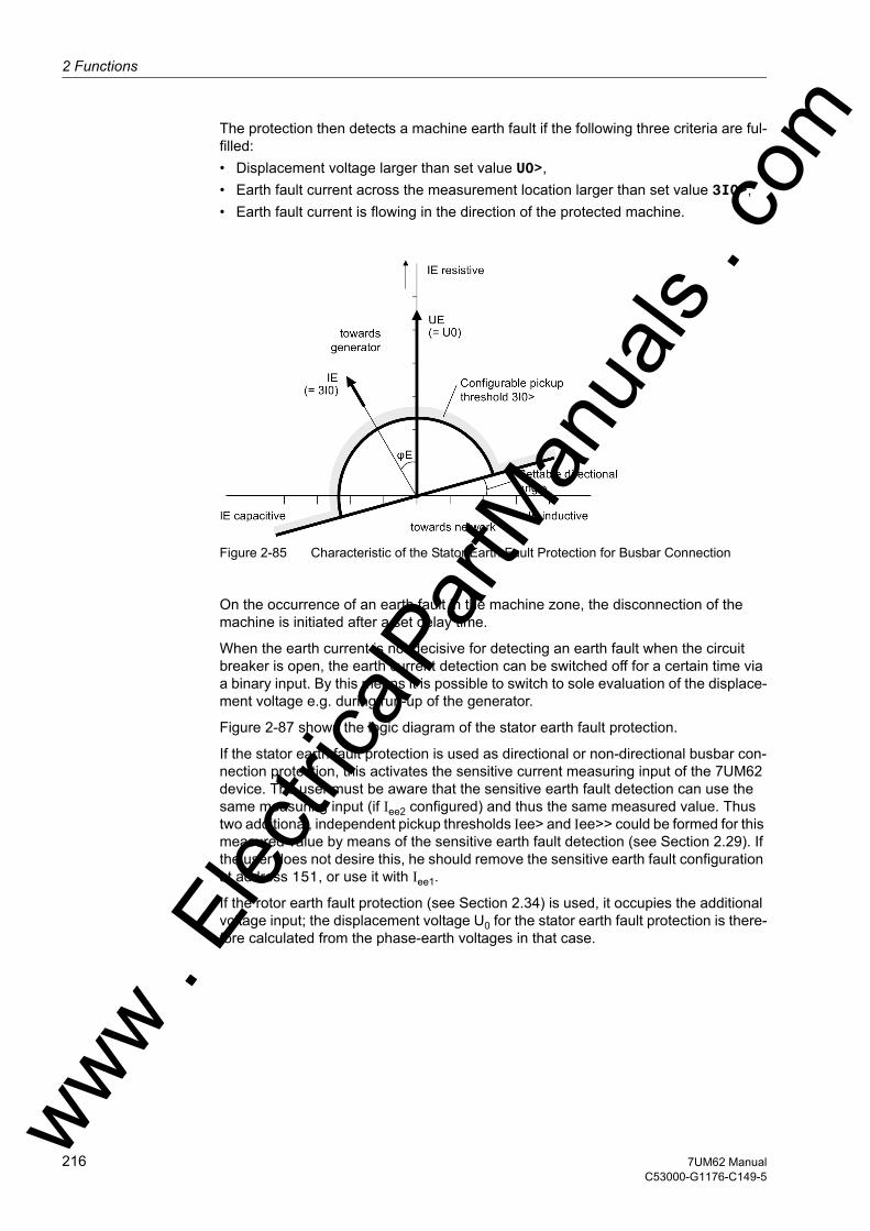
2 Functions
om
The protection then detects a machine earth fault if the following three criteria are ful-filled:• Displacement voltage larger than set value U0>,• Earth fault current across the measurement location larger than set value 3I0>,• Earth fault current is flowing in the direction of the protected machine.
Figure 2-85 Characteristic of the Stator Earth Fault Protection for Busbar Connection
On the occurrence of an earth fault in the machine zone, the disconnection of the machine is initiated after a set delay time.
When the earth current is not decisive for detecting an earth fault when the circuit breaker is open, the earth current detection can be switched off for a certain time via a binary input. By this means it is possible to switch to sole evaluation of the displace-ment voltage e.g. during run-up of the generator.
Figure 2-87 shows the logic diagram of the stator earth fault protection.
If the stator earth fault protection is used as directional or non-directional busbar con-nection protection, this activates the sensitive current measuring input of the 7UM62 device. The user must be aware that the sensitive earth fault detection can use the same measuring input (if Iee2 configured) and thus the same measured value. Thus two additional, independent pickup thresholds Iee> and Iee>> could be formed for this measured value by means of the sensitive earth fault detection (see Section 2.29). If the user does not desire this, he should remove the sensitive earth fault configuration at address 151, or use it with Iee1.
If the rotor earth fault protection (see Section 2.34) is used, it occupies the additional voltage input; the displacement voltage U0 for the stator earth fault protection is there-fore calculated from the phase-earth voltages in that case.
ww . El
ectric
alPar
tMan
uals
. c
216 7UM62 ManualC53000-G1176-C149-5
w

2.28 90-%-Stator Earth Fault Protection (ANSI 59N, 64G, 67G)w
Earth Current De-tection (Earth Dif-ferential Protection with Enabling via Displacement Volt-age)
In the industrial sector, busbar systems are designed with high or low resistance, swit-chable starpoint resistances. For earth-fault detection, the starpoint current and the total current are detected via toroidal current transformers and transmitted to the pro-tective device as current difference. In this way, the earth current portions derived both from the starpoint resistance and from the power system contribute to the total earth current. In order to exclude an unwanted operation due to transformer faults, the dis-placement voltage is used for tripping (see the following figure).
The protection feature detects a machine earth fault if the following two criteria are ful-filled:• Displacement voltage larger than set value U0>,• Earth fault current difference ∆IE larger than setting value 3I0>,
Figure 2-86 Earth Current Differential Protection with Busbar Connection
ww . El
ectric
alPar
tMan
uals
. com
2177UM62 ManualC53000-G1176-C149-5
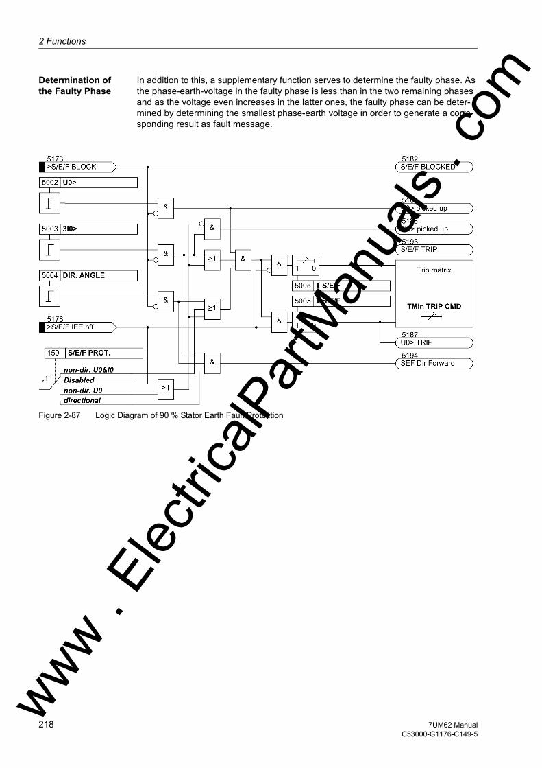
2 Functions
om
Determination of the Faulty Phase
In addition to this, a supplementary function serves to determine the faulty phase. As the phase-earth-voltage in the faulty phase is less than in the two remaining phases and as the voltage even increases in the latter ones, the faulty phase can be deter-mined by determining the smallest phase-earth voltage in order to generate a corre-sponding result as fault message.
Figure 2-87 Logic Diagram of 90 % Stator Earth Fault Protection
ww . El
ectric
alPar
tMan
uals
. c
218 7UM62 ManualC53000-G1176-C149-5
w
2.28 90-%-Stator Earth Fault Protection (ANSI 59N, 64G, 67G)w
2.28.2 Setting Notes
General 90 % stator earth fault protection is only effective and available if address 150 S/E/F PROT. is set to directional; non-dir. U0 or non-dir. U0&I0 during configu-ration. If non-dir. U0 was selected, the parameters affecting the earth current are not displayed. If one of the options directional or non-dir. U0&I0 was selected, the parameters affecting the earth current are accessible. For machines in busbar con-nection, one of the latter options must enabled since differentiation between a power system earth fault and a machine earth fault is only possible by way of the earth cur-rent. If used as „earth differential protection“, address 150 S/E/F PROT. = non-dir. U0&I0 is set. If the function is not required Disabled is set. Address 5001 S/E/F PROT. serves to switch the function ON or OFF or to block only the trip command (Block relay).
Displacement Voltage
The criterion for the occurrence of an earth fault in the stator circuit is the emergence of a neutral displacement voltage. Exceeding the set value 5002 U0> therefore causes pickup for stator earth protection.
The setting must be chosen such that the protection does not pick up because of op-erational asymmetries. This is particularly important for machines in busbar connec-tion since all voltage asymmetries of the network affect the voltage starpoint of the ma-chine. The pickup value should be at least twice the value of operational asymmetry. A value between 5% and 10% of the full displacement value is normal.
For machines in unit connection, the pickup value has to be chosen such that displace-ments during network earth faults which affect the stator circuit via the coupling capac-itances of the unit transformer, do not lead to pickup. The damping effect of the loading resistor must also be considered here. Instructions for dimensioning the loading resis-tor are contained in the publication "Planning Machine Protection Systems" /5/. The setting value is twice the displacement voltage which is coupled in at full network dis-placement. The setting value is finally determined during commissioning with primary values.
Delay The stator earth fault trip is delayed by the time set under address 5005 T S/E/F. For the delay time, the overload capacity of the load equipment must be considered. All set times are additional delay times and do not include operating times (measure-ment time, reset time) of the protection function itself.
Earth Current Addresses 5003 and 5004 are only of importance for machines in busbar connection, where 150 S/E/F PROT. = directional or non-dir. U0&I0 has been set. The following considerations are not applicable for machines in block connection.
The pick-up value 5003 3I0> is set so that for an earth fault in the protected zone, the earth current safely exceeds the setting.
Since the residual earth current in a resonant-earthed network is very small, also to be independent of network conditions in general, an earthing transformer with an ohmic loading resistor is normally provided to increase the residual wattmetric current in the event of an earth fault. Instructions for dimensioning the earth current transformer and loading resistor are contained in the publication „Planning Machine Protection Sys-tems“, /5/.
Since the magnitude of earth fault current in this case is determined mainly by the loading resistor, a small angle is set for 5004 DIR. ANGLE, e.g. 15°. If the network capacitances in an isolated network are also to be considered, then a larger angle (ap-ww . El
ectric
alPar
tMan
uals
. com
2197UM62 ManualC53000-G1176-C149-5
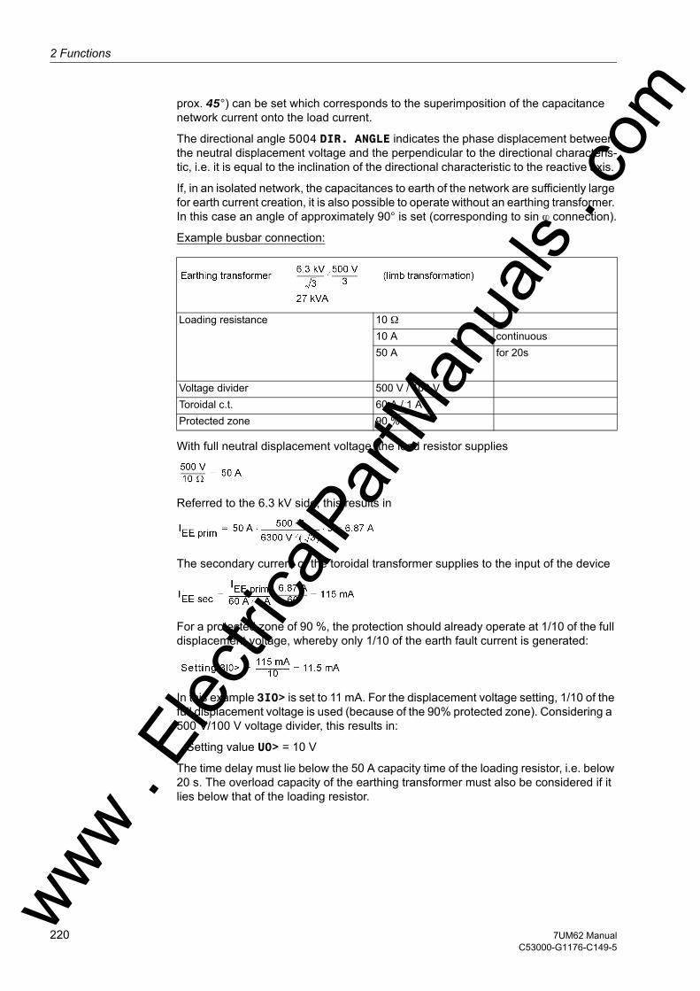
2 Functions
om
prox. 45°) can be set which corresponds to the superimposition of the capacitance network current onto the load current.
The directional angle 5004 DIR. ANGLE indicates the phase displacement between the neutral displacement voltage and the perpendicular to the directional characteris-tic, i.e. it is equal to the inclination of the directional characteristic to the reactive axis.
If, in an isolated network, the capacitances to earth of the network are sufficiently large for earth current creation, it is also possible to operate without an earthing transformer. In this case an angle of approximately 90° is set (corresponding to sin ϕ connection).
Example busbar connection:
With full neutral displacement voltage, the load resistor supplies
Referred to the 6.3 kV side, this results in
The secondary current of the toroidal transformer supplies to the input of the device
For a protected zone of 90 %, the protection should already operate at 1/10 of the full displacement voltage, whereby only 1/10 of the earth fault current is generated:
In this example 3I0> is set to 11 mA. For the displacement voltage setting, 1/10 of the full displacement voltage is used (because of the 90% protected zone). Considering a 500 V/100 V voltage divider, this results in:
Setting value U0> = 10 V
The time delay must lie below the 50 A capacity time of the loading resistor, i.e. below 20 s. The overload capacity of the earthing transformer must also be considered if it lies below that of the loading resistor.
Loading resistance 10 Ω 10 A continuous50 A for 20s
Voltage divider 500 V / 100 VToroidal c.t. 60 A / 1 AProtected zone 90 %
ww . El
ectric
alPar
tMan
uals
. c
220 7UM62 ManualC53000-G1176-C149-5
w
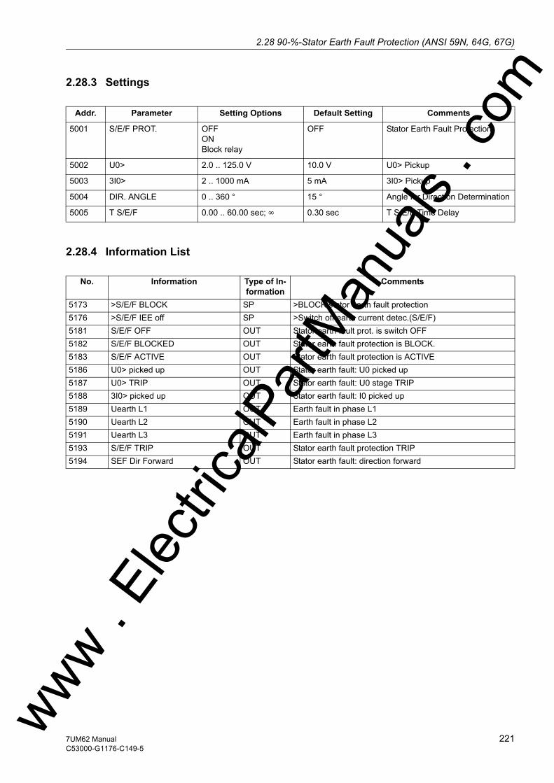
2.28 90-%-Stator Earth Fault Protection (ANSI 59N, 64G, 67G)w
2.28.3 Settings
2.28.4 Information List
Addr. Parameter Setting Options Default Setting Comments
5001 S/E/F PROT. OFFONBlock relay
OFF Stator Earth Fault Protection
5002 U0> 2.0 .. 125.0 V 10.0 V U0> Pickup
5003 3I0> 2 .. 1000 mA 5 mA 3I0> Pickup
5004 DIR. ANGLE 0 .. 360 ° 15 ° Angle for Direction Determination
5005 T S/E/F 0.00 .. 60.00 sec; ∞ 0.30 sec T S/E/F Time Delay
No. Information Type of In-formation
Comments
5173 >S/E/F BLOCK SP >BLOCK stator earth fault protection5176 >S/E/F IEE off SP >Switch off earth current detec.(S/E/F)5181 S/E/F OFF OUT Stator earth fault prot. is switch OFF5182 S/E/F BLOCKED OUT Stator earth fault protection is BLOCK.5183 S/E/F ACTIVE OUT Stator earth fault protection is ACTIVE5186 U0> picked up OUT Stator earth fault: U0 picked up5187 U0> TRIP OUT Stator earth fault: U0 stage TRIP5188 3I0> picked up OUT Stator earth fault: I0 picked up5189 Uearth L1 OUT Earth fault in phase L15190 Uearth L2 OUT Earth fault in phase L25191 Uearth L3 OUT Earth fault in phase L35193 S/E/F TRIP OUT Stator earth fault protection TRIP5194 SEF Dir Forward OUT Stator earth fault: direction forward
ww . El
ectric
alPar
tMan
uals
. com
2217UM62 ManualC53000-G1176-C149-5

2 Functions
om
2.29 Sensitive Earth Fault Protection (ANSI 51GN, 64R)
The highly sensitive earth fault protection detects earth faults in systems with isolated or high-impedance earthed starpoint. This stage operates with the magnitude of the earth current. It is intended for use where the earth current amplitude gives an indica-tion of the earth fault. As an example of this is with electrical machines in busbar con-nection in an isolated power system, where during a machine earth fault of the stator winding, the entire network capacity supplies the earth fault current, but with a network earth fault, the earth fault current is negligible due to the low machine capacitance. The current may be measured using toroidal CTs or CTs in Holmgreen connection.
In the 7UM62, the sensitive earth fault detection feature can be allocated to either input Iee1 or Iee2. This choice is made during configuration (see Section 2.4).
Because of the high sensitivity this protection is not suited for detection of high earth fault currents (above approx. 1 A at the terminals for sensitive earth current connec-tion). If this protection feature nevertheless is to be used for earth fault protection, an additional, external current transformer is required as intermediate transformer.
Note: The sensitive earth current protection may use the same current measuring input (Iee2) used for the directional or non–directional stator earth fault protection with busbar-connection. The sensitive earth fault protection thereby uses the same mea-sured values if address 150 S/E/F PROT. is set to directional or non-dir. U0&I0.
2.29.1 Functional Description
Application as Rotor Earth Fault Protection
Alternatively, this protection can be used as rotor earth fault protection when a system frequency bias voltage is applied to the rotor circuit (see Figure 2-88). In this case, the maximum earth current is determined by the magnitude of the bias voltage UV and the capacitative coupling of the rotor circuit.
A measured value supervision is provided for this application as rotor earth fault pro-tection. The measurement circuit is assumed closed as long as the earth current, even with intact insulation, exceeds a parametrizable minimum value IEE< due to the rotor-earth capacitance. If the value is undershot an alarm is issued after a short delay time of 2 s.
Measurement Method
Initially, the residual current is numerically filtered so that only the fundamental wave of the current is used for the measurement. This makes the measurement insensitive to short-circuit transients and harmonics.
The protection consists of two stages. A pickup is detected as soon as the first param-etrized threshold value IEE> is exceeded. The trip command is transmitted subse-quent to the T IEE> delay time. A pickup is detected as soon as the second param-etrized threshold value IEE>> is exceeded. The trip command is transmitted subsequent to the T IEE>> delay time.
Both stages can be blocked via a binary input.
ww . El
ectric
alPar
tMan
uals
. c
222 7UM62 ManualC53000-G1176-C149-5
w

2.29 Sensitive Earth Fault Protection (ANSI 51GN, 64R)w
Figure 2-88 Application Case as Rotor Earth Fault Protection (7XR61 – Series Device for Rotor Earth Fault Protection; 3PP13 – from Uerr > 150 V, Resistors in 7XR61 are then to be Shorted!)
Figure 2-89 Logic Diagram of the Sensitive Earth Fault Detection1) Parameter and indication are only available if Rotor Earth Fault Protection R,
fn (ANSI 64R) address 160 is set to Disabled.ww . El
ectric
alPar
tMan
uals
. com
2237UM62 ManualC53000-G1176-C149-5

2 Functions
om
2.29.2 Setting Notes
General The sensitive earth fault protection is only effective and available if address 151 O/C PROT. IEE> = with IEE1 or with IEE2 is assigned. If when configuring the 90 % stator earth fault protection (150 S/E/F PROT., see subsection 2.4) one of the options with current value is chosen, this activates the sensitive current measuring input of the device 7UM62 . The user must be aware that the sensitive earth fault de-tection uses the same measuring input (IEE2) and thus the same measuring quantity. If sensitive earth fault detection is not required, Disabled is set. Address 5101 O/C PROT. IEE serves to switch the function ON or OFF or to block only the trip command (Block relay).
Use as Rotor Earth Fault Protection
The sensitive earth current protection can be used to detect earth faults either in the stator or in the rotor winding of the generator. A precondition is that the magnitude of the earth current alone is sufficient as a criterion. In very high-ohmic circuits or those isolated from earth, sufficiently large earth currents must be ensured.
When, for example, used as rotor earth fault protection, a system frequency bias voltage (UV ≈ 42 V must be applied to the rotor circuit by means of the 7XR61 in Figure „ The application case as rotor earth fault protection“ in Section 2.29) must be applied to the rotor circuit . Because of this bias voltage, with proper earth isolation a current flows through the earth capacitance, which can be used as a criterion for a closed measuring circuit (address 5106 IEE<). Approximately 2mA is a typical pickup value. The monitoring stage is ineffective is this value is set to 0. This can become necessary if the earth capacitances are too small.
The earth current pick-up value 5102 IEE> is chosen such that isolation resistances RE between 3 kΩ to 5 kΩ can be detected:
On the other hand, the setting value should be at least twice the interference current caused by the earth capacitances of the rotor circuit.
The 5104 IEE>> trip stage should be dimensioned for a fault resistance of about 1.5 kΩ.
with ZK = Impedance of the series device at nominal frequency.
The 5103 T IEE> and 5105 T IEE>> tripping time delay do not include the operating times.
Use as Stator Earth Fault Protection
Please also refer to section 2.28. For use as stator earth fault protection, the earth current must if necessary be increased by an ohmic load resistor at the earthing trans-former. Instructions for dimensioning the earth current transformer and loading resistor are contained in the publication "Planning Machine Protection Systems" /5/.
Use as Earth Fault Protection
For low-voltage machines with incorporated neutral conductor or machines with low-impedance earthed starpoint, the time-overcurrent protection of the phase branches already is an earth short-circuit protection, since the short-circuit current also flows through the faulty phase . If the sensitive earth current detection nevertheless shall be used as short-circuit to earth protection, an external intermediate transformer must be ww .
Elec
tricalP
artM
anua
ls . c
224 7UM62 ManualC53000-G1176-C149-5
w
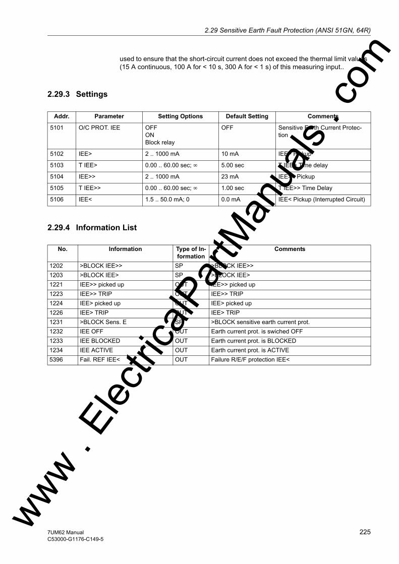
2.29 Sensitive Earth Fault Protection (ANSI 51GN, 64R)w
used to ensure that the short-circuit current does not exceed the thermal limit values (15 A continuous, 100 A for < 10 s, 300 A for < 1 s) of this measuring input..
2.29.3 Settings
2.29.4 Information List
Addr. Parameter Setting Options Default Setting Comments
5101 O/C PROT. IEE OFFONBlock relay
OFF Sensitive Earth Current Protec-tion
5102 IEE> 2 .. 1000 mA 10 mA IEE> Pickup
5103 T IEE> 0.00 .. 60.00 sec; ∞ 5.00 sec T IEE> Time delay
5104 IEE>> 2 .. 1000 mA 23 mA IEE>> Pickup
5105 T IEE>> 0.00 .. 60.00 sec; ∞ 1.00 sec T IEE>> Time Delay
5106 IEE< 1.5 .. 50.0 mA; 0 0.0 mA IEE< Pickup (Interrupted Circuit)
No. Information Type of In-formation
Comments
1202 >BLOCK IEE>> SP >BLOCK IEE>>1203 >BLOCK IEE> SP >BLOCK IEE>1221 IEE>> picked up OUT IEE>> picked up1223 IEE>> TRIP OUT IEE>> TRIP1224 IEE> picked up OUT IEE> picked up1226 IEE> TRIP OUT IEE> TRIP1231 >BLOCK Sens. E SP >BLOCK sensitive earth current prot.1232 IEE OFF OUT Earth current prot. is swiched OFF1233 IEE BLOCKED OUT Earth current prot. is BLOCKED1234 IEE ACTIVE OUT Earth current prot. is ACTIVE5396 Fail. REF IEE< OUT Failure R/E/F protection IEE<
ww . El
ectric
alPar
tMan
uals
. com
2257UM62 ManualC53000-G1176-C149-5
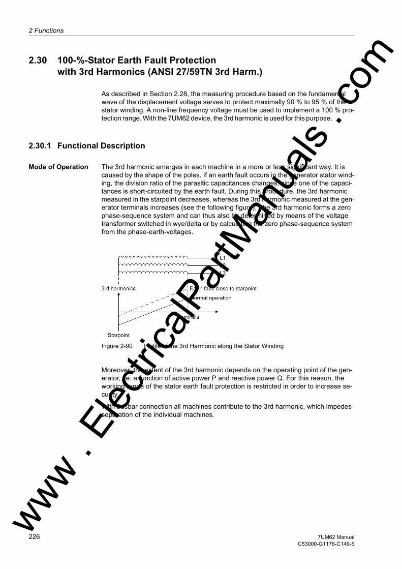
2 Functions
om
2.30 100-%-Stator Earth Fault Protection with 3rd Harmonics (ANSI 27/59TN 3rd Harm.)
As described in Section 2.28, the measuring procedure based on the fundamental wave of the displacement voltage serves to protect maximally 90 % to 95 % of the stator winding. A non-line frequency voltage must be used to implement a 100 % pro-tection range. With the 7UM62 device, the 3rd harmonic is used for this purpose.
2.30.1 Functional Description
Mode of Operation The 3rd harmonic emerges in each machine in a more or less significant way. It is caused by the shape of the poles. If an earth fault occurs in the generator stator wind-ing, the division ratio of the parasitic capacitances changes, since one of the capaci-tances is short-circuited by the earth fault. During this procedure, the 3rd harmonic measured in the starpoint decreases, whereas the 3rd harmonic measured at the gen-erator terminals increases (see the following figure). The 3rd harmonic forms a zero phase-sequence system and can thus also be determined by means of the voltage transformer switched in wye/delta or by calculating the zero phase-sequence system from the phase-earth-voltages.
Figure 2-90 Profile of the 3rd Harmonic along the Stator Winding
Moreover, the extent of the 3rd harmonic depends on the operating point of the gen-erator, i.e. a function of active power P and reactive power Q. For this reason, the working range of the stator earth fault protection is restricted in order to increase se-curity.
With busbar connection all machines contribute to the 3rd harmonic, which impedes separation of the individual machines.
ww . El
ectric
alPar
tMan
uals
. c
226 7UM62 ManualC53000-G1176-C149-5
w
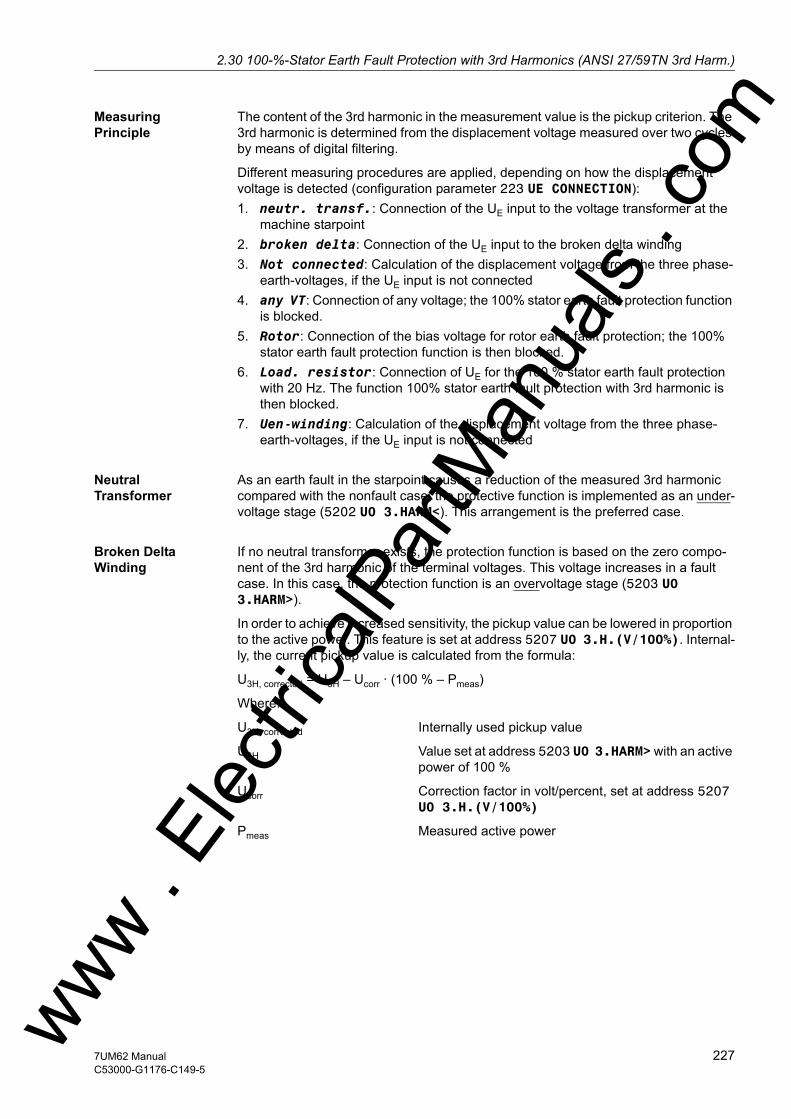
2.30 100-%-Stator Earth Fault Protection with 3rd Harmonics (ANSI 27/59TN 3rd Harm.)w
Measuring Principle
The content of the 3rd harmonic in the measurement value is the pickup criterion. The 3rd harmonic is determined from the displacement voltage measured over two cycles by means of digital filtering.
Different measuring procedures are applied, depending on how the displacement voltage is detected (configuration parameter 223 UE CONNECTION):1. neutr. transf.: Connection of the UE input to the voltage transformer at the
machine starpoint2. broken delta: Connection of the UE input to the broken delta winding3. Not connected: Calculation of the displacement voltage from the three phase-
earth-voltages, if the UE input is not connected4. any VT: Connection of any voltage; the 100% stator earth fault protection function
is blocked.5. Rotor: Connection of the bias voltage for rotor earth fault protection; the 100%
stator earth fault protection function is then blocked.6. Load. resistor: Connection of UE for the 100 % stator earth fault protection
with 20 Hz. The function 100% stator earth fault protection with 3rd harmonic is then blocked.
7. Uen-winding: Calculation of the displacement voltage from the three phase-earth-voltages, if the UE input is not connected
Neutral Transformer
As an earth fault in the starpoint causes a reduction of the measured 3rd harmonic compared with the nonfault case, the protective function is implemented as an under-voltage stage (5202 U0 3.HARM<). This arrangement is the preferred case.
Broken Delta Winding
If no neutral transformer exists, the protection function is based on the zero compo-nent of the 3rd harmonic of the terminal voltages. This voltage increases in a fault case. In this case, the protection function is an overvoltage stage (5203 U0 3.HARM>).
In order to achieve increased sensitivity, the pickup value can be lowered in proportion to the active power. This feature is set at address 5207 U0 3.H.(V/100%). Internal-ly, the current pickup value is calculated from the formula:
U3H, corrected = U3H – Ucorr · (100 % – Pmeas)
Where:
U3H, corrected Internally used pickup value
U3H Value set at address 5203 U0 3.HARM> with an active power of 100 %
Ucorr Correction factor in volt/percent, set at address 5207 U0 3.H.(V/100%)
Pmeas Measured active power
ww . El
ectric
alPar
tMan
uals
. com
2277UM62 ManualC53000-G1176-C149-5

2 Functions
om
Figure 2-91 shows the operating principle.
Figure 2-91 Automatic Lowering of Pickup Value U0 3.HARM>
The trip characteristic is released as soon as the settable minimum active power is reached. As an additional security feature, the following limitation is provided: If due to the power-dependent correction factor the corrected pickup value U3H, corrected drops below the minimum possible setting value (0,2 V), the pickup value will be kept at that setting value.
Not connected/pro-tection interface; calculation of U0
As for the connection to the broken delta winding, an increase of the 3rd harmonic during a fault also results for the calculated voltage. The 5203 U0 3.HARM> param-eter is also relevant.
ww . El
ectric
alPar
tMan
uals
. c
228 7UM62 ManualC53000-G1176-C149-5
w
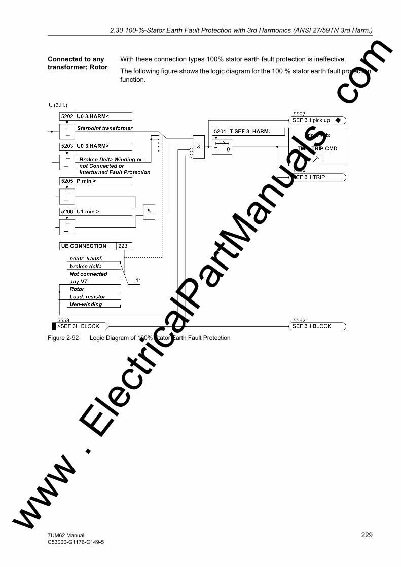
2.30 100-%-Stator Earth Fault Protection with 3rd Harmonics (ANSI 27/59TN 3rd Harm.)w
Connected to any transformer; Rotor
With these connection types 100% stator earth fault protection is ineffective.
The following figure shows the logic diagram for the 100 % stator earth fault protection function.
Figure 2-92 Logic Diagram of 100% Stator Earth Fault Protection
ww . El
ectric
alPar
tMan
uals
. com
2297UM62 ManualC53000-G1176-C149-5
2 Functions
om
2.30.2 Setting Notes
General The 100 % stator earth fault protection is only effective and available if address 152 SEF 3rd HARM. = Enabled is set during configuration. If the function is not required Disabled is set. Address 5201 SEF 3rd HARM. serves to switch the function ON or OFF or to block only the trip command (Block relay).
Connection Type Depending on the system conditions, at address 223 UE CONNECTION the user spec-ified during the project configuration if the displacement voltage Uen is tapped via a neutral transformer (neutr. transf.) or via the broken delta winding of an earthing transformer (broken delta) and fed to the protection device. If it is not possible to make the displacement voltage available to the protection device as a measured quantity, computed quantities are used and Not connected or Uen-winding must be set. The option any VT is selected if the voltage input of the 7UM62 is to be used for measuring any other voltage instead of for earth fault protection. With this setting the 100% stator earth fault protection function is ineffective. The option Rotor is se-lected if the displacement voltage for rotor earth fault connection shall be fed in at this input. In this case, too, the 100% stator earth fault protection function is ineffective.
The option Load. resistor is selected for 100% stator earth fault protection with 20 Hz bias voltage. With this setting the 100% stator earth fault protection function with 3rd harmonic is blocked.
Pickup Value for 3rd Harmonic
Depending on the selection of the connection type, only one of the two setting param-eters 5202 or 5203 is accessible.
The setting values can only be determined within the framework of a primary test. The following applies in general:• The undervoltage stage, address 5202 U0 3.HARM<, is relevant for a connection
to a transformer in the starpoint. The pickup value should be chosen as low as pos-sible.
• The overvoltage stage, address 5203 U0 3.HARM>, is relevant for a connection via the broken delta winding of an earthing transformer and for a not connected, but in-ternally calculated displacement voltage.
As discussed in Section 2.30, margin title „Broken Delta Winding“, the sensitivity of the U0 3.HARM> stage can be increased if a power-dependent correction of the pickup value is made. The relevant parameter for this is set at address 5207 U0 3.H.(V/100%). The default setting of this parameter is 0, which means that the cor-rection is ineffective.
The correction setting is made with the following method: • Measurement of the 3rd harmonic for different active powers using the operational
measured values. For the settings secondary values are recommended. • Interpolation of the measured values by a straight line. Reading of the 3rd harmonic
voltage at 100 % (P1) and 50 % (P2) of the active power. Calculation of the differ-ence based on the following relationship:
ww . El
ectric
alPar
tMan
uals
. c
230 7UM62 ManualC53000-G1176-C149-5
w

2.30 100-%-Stator Earth Fault Protection with 3rd Harmonics (ANSI 27/59TN 3rd Harm.)w
Figure 2-93 shows an example of the measurements made on a generator. The active power dependence of the 3rd harmonic has been determined for operation both in un-derexcitation and in overexcitation conditions.
Figure 2-93 3rd Harmonic of the Secondary Voltage as Function of the Active Power (reac-tive power as parameter)
As Figure 2-93 shows, the rise is almost equal in both cases. The most unfavourable case is operation in underexcitation conditions. When extrapolating the curve to 100 %, the voltage value is approx. 12 V. With 50 % active power, this is approx. 7.5 V. The setting value can now be calculated as follows
At address 5207 U0 3.H.(V/100%) 9 is set. The pickup value in address 5203 U0 3.HARM> must likewise be extrapolated to 100 %. If 14.5 V is selected for this value, the resulting pickup value at 50 % active power is 14.5 V – 4.5 V = 10 V. With cos ϕ = 0.8 and the generator operating at this nominal setting, the resulting pickup value is 14.5 V – 9 V/100 % (100 % – 80 %) = 14.5 V – 1.8 V = 12.7 V.
As described in the „Operating range“, the characteristic must be limited by defining the minimum possible active power. Since measurement of the 3rd harmonic has been performed in Figure 2-93 up to P = 20 %, and the behaviour is still almost linear, a setting of parameter 5205 P min > = 30 % still allows for a certain safety margin.
ww . El
ectric
alPar
tMan
uals
. com
2317UM62 ManualC53000-G1176-C149-5

2 Functions
om
Operating Range Due to the strong dependency of the measurable 3rd harmonic from the correspond-ing working point of the generator, the working area of the 100–%–stator earth fault protection is only tripped above the active-power threshold set via 5205 P min > and on exceeding a minimum positive phase-sequence voltage 5206 U1 min >.
Recommended setting:
Pmin> 40 % P/SN
U1 min> 80 % UN
Time Delay The tripping in case of an earth fault is delayed by the time set at address 5204 T SEF 3. HARM.. The set time is an additional time delay not including the operating time of the protective function.
2.30.3 Settings
2.30.4 Information List
Addr. Parameter Setting Options Default Setting Comments
5201 SEF 3rd HARM. OFFONBlock relay
OFF Stator Earth Fault Protection 3rdHarm.
5202 U0 3.HARM< 0.2 .. 40.0 V 1.0 V U0 3rd Harmonic< Pickup
5203 U0 3.HARM> 0.2 .. 40.0 V 2.0 V U0 3rd Harmonic> Pickup
5204 T SEF 3. HARM. 0.00 .. 60.00 sec; ∞ 0.50 sec T SEF 3rd Harmonic Time Delay
5205 P min > 10 .. 100 %; 0 40 % Release Threshold Pmin>
5206 U1 min > 50.0 .. 125.0 V; 0 80.0 V Release Threshold U1min>
5207 U0 3.H.(V/100%) -40.0 .. 40.0 0.0 Correction Factor for Pickup (V/100%)
No. Information Type of In-formation
Comments
5553 >SEF 3H BLOCK SP >BLOCK SEF with 3.Harmonic5561 SEF 3H OFF OUT SEF with 3.Harm. is switched OFF5562 SEF 3H BLOCK OUT SEF with 3.Harm. is BLOCKED5563 SEF 3H ACTIVE OUT SEF with 3.Harm. is ACTIVE5567 SEF 3H pick.up OUT SEF with 3.Harm. picked up5568 SEF 3H TRIP OUT SEF with 3.Harm. TRIP
ww . El
ectric
alPar
tMan
uals
. c
232 7UM62 ManualC53000-G1176-C149-5
w

2.31 100-%-Stator Earth Fault Protection with 20 Hz Voltage Injection (ANSI 64G - 100%)w
2.31 100-%-Stator Earth Fault Protection with 20 Hz Voltage Injection (ANSI 64G - 100%)
The 100 % stator earth fault protection detects earth faults in the stator windings of generators which are connected with the network via a unit transformer. This protec-tion function, which works with a 20 Hz injected voltage, is independent of the network frequency displacement voltage appearing in earth faults, and detects earth faults in all windings including the machine starpoint. The measuring principle used is not in-fluenced at all by the generator operating mode and allows measurements even with the generator at standstill. The two measuring principles – measurement of the dis-placement voltage and evaluation of the measured quantities at an injected 20 Hz voltage – allow to implement reliable protection concepts that complement one anoth-er.
If an earth fault in the generator starpoint or close to the starpoint is not detected, the generator is operated as "earthed". A subsequent fault (e.g. a second earth fault) causes a single-pole short-circuit that may have an extremely high fault current because the generator zero impedance is very small.
The 100 % stator earth fault protection is for this reason a basic function for large gen-erators.
2.31.1 Function Description
Basic Principle The basic principle is shown in the following figure. An external low frequency alter-nating voltage source (20 Hz) injects into the generator starpoint a voltage of max. 1 % of the rated generator voltage. If an earth fault occurs in the generator starpoint, the 20 Hz voltage drives a current through the fault resistance. From the driving voltage and the fault current, the protective relay determines the fault resistance. The protec-tion principle described here also detects earth faults at the generator terminals, in-cluding connected components such as voltage transformers.
Figure 2-94 Basic Principle of Voltage Injection into the Generator Starpoint
Circuit Design To implement the above concept, some additional equipment is required. The follow-ing picture shows a 20 Hz generator generates a square-wave voltage with an ampli-tude of approx. 25 V. This square-wave voltage is fed via a bandpass into the loading resistor of the earthing or neutral transformer. The bandpass serves for rounding the square-wave voltage and for storing energy. The 20 Hz resistance of the bandpass is approx. 8 Ω. The bandbass assumes also a protection function. If the load resistor carries the full displacement voltage during a terminal-to-earth fault, the higher series resistance of the bandpass protects the 20 Hz generator from excessive feedback cur-rents.ww . El
ectric
alPar
tMan
uals
. com
2337UM62 ManualC53000-G1176-C149-5

2 Functions
om
The driving 20 Hz voltage is taken directly at the loading resistor using a voltage divid-er. In addition the flowing 20 Hz current is measured using a miniature CT. Both values (USEF and ISEF) are fed to the protection device.
The voltage to be injected into the generator starpoint depends on the driving 20 Hz voltage (voltage divider: load resistor and bandpass), and on the transformation ratio of the neutral or earthing transformer.
To prevent the secondary load resistance from becoming too small (it should be below 0.5 Ω where possible), a high secondary rated voltage should be chosen for the earth-ing or neutral transformer. 500 V has proven to be a practical value.
Figure 2-95 Circuit Design of the 100-% Stator Earth Fault Protection with Earthing Transformer or Neutral TransformerR Loading resistanceUSEF Displacement voltage at the protective relayISEF Current measured at the protective relay
The same measuring principle can also be used with a primary loading resistor. The 20 Hz voltage is connected in this case via a voltage transformer, and the starpoint current is directly measured. The setting notes (section 2.31.2) contain the connection scheme and information on the circuit design.
ww . El
ectric
alPar
tMan
uals
. c
234 7UM62 ManualC53000-G1176-C149-5
w
2.31 100-%-Stator Earth Fault Protection with 20 Hz Voltage Injection (ANSI 64G - 100%)w
Measurement method
From the two measured quantities USEF and ISEF in the above picture, the 20 Hz current and voltage vectors are calculated, and from the resulting complex impedance the ohmic fault resistance is determined. This method eliminates disturbances caused by stator earth capacitance and ensures a high sensitivity. The measuring accuracy is further increased by using mean current and voltage values obtained over several cycles for calculating the resistance.
The model takes into account a transfer resistance RPS that may be present at the neu-tral, earthing or voltage transformer. Other error factors are taken into account in the angle error.
In addition to determination of the earth resistance, an earth current stage is provided which processes the current rms value and thus takes into account all frequency com-ponents. It is used as a backup stage and covers approx. 80 to 90 % of the protection zone.
A monitoring circuit checks the coupled fed in 20 Hz voltage and the 20 Hz current and detects by evaluating them any failure of the 20 Hz generator or of the 20 Hz connec-tion. In such a case resistance determination is blocked. The earth current stage remains active.
ww . El
ectric
alPar
tMan
uals
. com
2357UM62 ManualC53000-G1176-C149-5

2 Functions
om
Logic The following figure shows the logic diagram. It comprises:• Monitoring of the 20 Hz connection• Resistance calculation and threshold value decision• Independent current measurement stage
The protection function has an alarm stage and a tripping stage. Both stages can be delayed with a timer. The earth current detection acts only on the tripping stage. Eval-uation of the earth resistance measurement is blocked between 10 Hz and 40 Hz, because in this frequency range a zero voltage can also be generated by generators starting up or slowing down. This would then be superimposed on the connected 20 Hz voltage, causing measurement errors and overfunctioning.
The resistance measurement function is active for frequencies below 10 Hz (i.e. at standstill) and above 40 Hz. The earth current measurement is active over the entire range.
Figure 2-96 Logic Diagram of the 100 % Stator Earth Fault Protection
ww . El
ectric
alPar
tMan
uals
. c
236 7UM62 ManualC53000-G1176-C149-5
w

2.31 100-%-Stator Earth Fault Protection with 20 Hz Voltage Injection (ANSI 64G - 100%)w
2.31.2 Setting Notes
General The 100 % stator earth fault protection is only effective and available if address 153 100% SEF-PROT. is set to Enabled during configuration.
In addition, the function requires the following settings to be made in Power System Data 1:• Address 275: FACTOR R SEF; Sets the resistance transformation ratio (see margin
title "Fault Resistances")• Address 223: UE CONNECTION should be set to Load. resistor for the appli-
cation. The 20 Hz voltage is in this case measured at the UE input, and the displace-ment voltage for the 90 % stator earth fault protection (SEF) is calculated from the phase-to-earth voltages. If the measured voltage is to be used for the 90 % SEF as well, set either neutr. transf. or broken delta.
Address 5301 100% SEF-PROT. serves to switch the function ON or OFF or to block only the trip command (Block relay).
Fault Resistances The final setting values are determined in the primary test as described in Section 3 Subsection „Commissioning“.
Please note that the protection calculates the earth resistance from the secondary values USEF and ISEF which are present at the device terminals. Allocation between this calculated value and the actual (primary) stator earth resistance is determined by the transformation ratio of the earthing and the neutral transformer. For the overall transformation, the following formula applies:
Where:
REsec Earth resistance, converted to the device sideREprim Primary earth resistance of the stator winding (= fault resistance)UTrans Transformation ratio of the earthing or neutral transformer
Earthing transformer (leg transformation divided by 3):
Neutral transformer:
üMinCT Transformation ratio of the miniature CTüDivider Division Ratio of the Voltage Divider
ww . El
ectric
alPar
tMan
uals
. com
2377UM62 ManualC53000-G1176-C149-5

2 Functions
om
The conversion factor of the earth resistance is set as FACTOR R SEF at address 275 in Power System Data 1. The general formula for calculation (REprim / REsec) is:
This formula applies only for almost ideal earthing or neutral transformers. If neces-sary, the measuring result from the primary tests must be set as FACTOR R SEF. For this the inserted fault resistance (trip stage) is related to the measured secondary fault resistance.
The primary fault resistance should be set between 1 and 2 kΩ for the trip stage and to between approx. 3 and 8 kΩ for the alarm stage. The default times have proven to be practical.
Example:
The transformation ratio of the miniature CT 400 A:5 A has been halved to 200A:5 A by passing the primary conductor twice through the transformer window.
For FACTOR R SEF the following value results:
If a generator-side fault resistance of 1000 Ω is selected for the trip stage R<<, a re-sistance value of R<< SEF TRIP = 1000 Ω/8.33 = 120 Ω is set in address 5303. For the warning stage, a primary resistance of 3 kΩ yields a setting value of R< SEF ALARM = 360 Ω.
Earth Current Stage The earth current stage has a backup protection function. It is set to a protected zone of approx. 80 %. Referenced to the maximum secondary fault current, the pickup threshold is at approx. 20 %, and the setting value is calculated as follows:
The delay time T SEF TRIP (address 5305), which is also relevant for the earth current stage, must be less than the tolerable time of the loading transformer (in this example 50 A for 20 s). The overload capability of the earthing or neutral transformer must also be considered if it lies below that of the loading resistor.
Monitoring At addresses 5307 and 5308 the monitoring thresholds are set with U20 MIN and I20 MIN. If the 20 Hz voltage drops below the pickup value without the 20 Hz current rising, there must be a problem with the 20 Hz connection. The default settings will be adequate for most applications. In applications where the loading resistor is less than 1 Ω, the threshold U20 MIN must be reduced to 0.5 V. The current threshold I20 MIN may be left at 10 mA.
Loading resistance RL 10 Ω(10 A continuously, 50 A for 20 s)
Voltage divider üDivider 500 V/200 VMiniature CT üMinCT 200 A/5 A
ww . El
ectric
alPar
tMan
uals
. c
238 7UM62 ManualC53000-G1176-C149-5
w
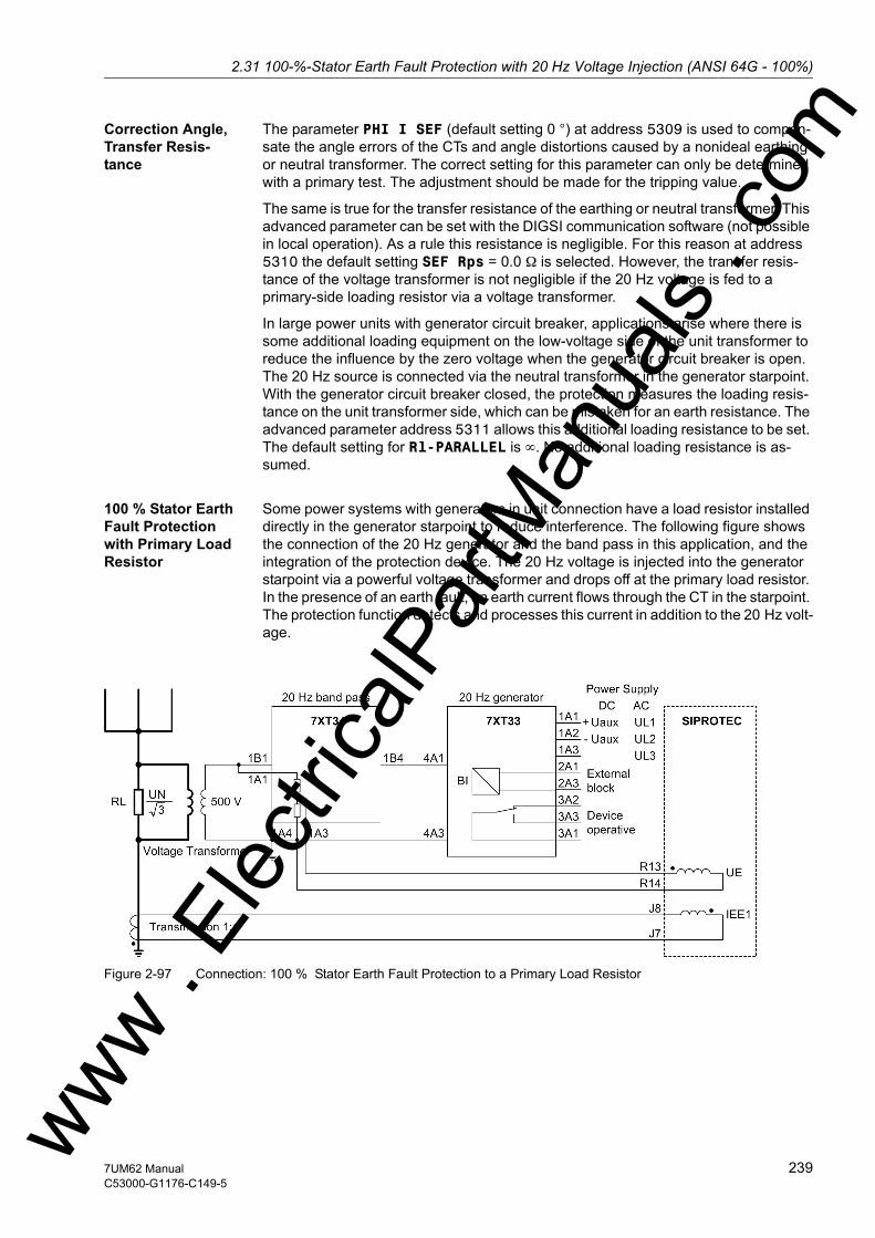
2.31 100-%-Stator Earth Fault Protection with 20 Hz Voltage Injection (ANSI 64G - 100%)w
Correction Angle, Transfer Resis-tance
The parameter PHI I SEF (default setting 0 °) at address 5309 is used to compen-sate the angle errors of the CTs and angle distortions caused by a nonideal earthing or neutral transformer. The correct setting for this parameter can only be determined with a primary test. The adjustment should be made for the tripping value.
The same is true for the transfer resistance of the earthing or neutral transformer. This advanced parameter can be set with the DIGSI communication software (not possible in local operation). As a rule this resistance is negligible. For this reason at address 5310 the default setting SEF Rps = 0.0 Ω is selected. However, the transfer resis-tance of the voltage transformer is not negligible if the 20 Hz voltage is fed to a primary-side loading resistor via a voltage transformer.
In large power units with generator circuit breaker, applications arise where there is some additional loading equipment on the low-voltage side of the unit transformer to reduce the influence by the zero voltage when the generator circuit breaker is open. The 20 Hz source is connected via the neutral transformer in the generator starpoint. With the generator circuit breaker closed, the protection measures the loading resis-tance on the unit transformer side, which can be mistaken for an earth resistance. The advanced parameter address 5311 allows this additional loading resistance to be set. The default setting for Rl-PARALLEL is ∞. No additional loading resistance is as-sumed.
100 % Stator Earth Fault Protection with Primary Load Resistor
Some power systems with generators in unit connection have a load resistor installed directly in the generator starpoint to reduce interference. The following figure shows the connection of the 20 Hz generator and the band pass in this application, and the integration of the protection device. The 20 Hz voltage is injected into the generator starpoint via a powerful voltage transformer and drops off at the primary load resistor. In the presence of an earth fault, an earth current flows through the CT in the starpoint. The protection function detects and processes this current in addition to the 20 Hz volt-age.
Figure 2-97 Connection: 100 % Stator Earth Fault Protection to a Primary Load Resistor
ww . El
ectric
alPar
tMan
uals
. com
2397UM62 ManualC53000-G1176-C149-5
2 Functions
om
A two pole isolated voltage transformer must be used with low primary/secondary impedance. This applies for the 20 Hz frequency.
As the transformation ratio is 1:1, a current transformer with a maximum number of ampere windings must be chosen.
The CT is installed directly in the starpoint on the earth side, downstream of the load resistor.
Type: 5P10 or 5P15 (or 1FS10)
Rated secondary current: 1 A
Transformation Ratio 1 (1A/1A)
During the primary test the correction angle (address 5309 PHI I SEF) and the ohmic transfer resistance of the voltage transformer must be determined and set at address 5310 SEF Rps.
The conversion factor for the resistance (secondary – primary and vice-versa) is:
Example:
Primary Load Resistor: RL = 1250 Ω
Voltage transformer: 10.5 kV/ √3/500 V
Ohmic Divider: 1650 Ω/660 Ω (5:2)
Current transformer: 1 A/1 A
Note
Due to the transfer resistance Rps, an ideal transformation ration of the voltage trans-formers is not to be expected. For this reason major deviations of FACTOR R SEF can occur. It is recommended to measure the transformation ratio with 20 Hz infeed and the machine standing still. This value should then be set.
Primary voltage: UN,Generator / √3 (non-saturated up to UN,Generator)
Secondary voltage: 500 VPower for 20 s(50 Hz or 60 Hz)
3 kVA
Primary-secondary impedance at 20 Hz Zps < RL (but at least < 1000 Ω).
Some manufacturers: Ritz MesswandlerbauSalomon-Heine Weg 72D-20251 Hamburg(Phone +49 (0) 40511123 333)
ww . El
ectric
alPar
tMan
uals
. c
240 7UM62 ManualC53000-G1176-C149-5
w
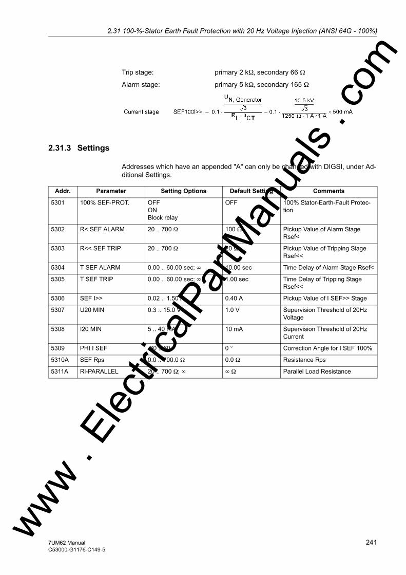
2.31 100-%-Stator Earth Fault Protection with 20 Hz Voltage Injection (ANSI 64G - 100%)w
Trip stage: primary 2 kΩ, secondary 66 Ω
Alarm stage: primary 5 kΩ, secondary 165 Ω
2.31.3 Settings
Addresses which have an appended "A" can only be changed with DIGSI, under Ad-ditional Settings.
Addr. Parameter Setting Options Default Setting Comments
5301 100% SEF-PROT. OFFONBlock relay
OFF 100% Stator-Earth-Fault Protec-tion
5302 R< SEF ALARM 20 .. 700 Ω 100 Ω Pickup Value of Alarm Stage Rsef<
5303 R<< SEF TRIP 20 .. 700 Ω 20 Ω Pickup Value of Tripping Stage Rsef<<
5304 T SEF ALARM 0.00 .. 60.00 sec; ∞ 10.00 sec Time Delay of Alarm Stage Rsef<
5305 T SEF TRIP 0.00 .. 60.00 sec; ∞ 1.00 sec Time Delay of Tripping Stage Rsef<<
5306 SEF I>> 0.02 .. 1.50 A 0.40 A Pickup Value of I SEF>> Stage
5307 U20 MIN 0.3 .. 15.0 V 1.0 V Supervision Threshold of 20Hz Voltage
5308 I20 MIN 5 .. 40 mA 10 mA Supervision Threshold of 20Hz Current
5309 PHI I SEF -60 .. 60 ° 0 ° Correction Angle for I SEF 100%
5310A SEF Rps 0.0 .. 700.0 Ω 0.0 Ω Resistance Rps
5311A Rl-PARALLEL 20 .. 700 Ω; ∞ ∞ Ω Parallel Load Resistance
ww . El
ectric
alPar
tMan
uals
. com
2417UM62 ManualC53000-G1176-C149-5

2 Functions
om
2.31.4 Information List
No. Information Type of In-formation
Comments
5473 >SEF100 BLOCK SP >BLOCK Stator earth fault protection5476 >U20 failure SP >Failure 20Hz bias voltage (S/E/F)5481 SEF100 OFF OUT Stator earth flt. prot. 100% is swit.OFF5482 SEF100 BLOCKED OUT Stator earth flt. prot. 100% is BLOCKED5483 SEF100 ACTIVE OUT Stator earth flt. prot. 100% is ACTIVE5486 SEF100 Failure OUT Stator earth flt. prot. 100% Failure5487 SEF100 Alarm OUT Stator earth flt. prot.100% Alarm stage5488 SEF100 pickup OUT Stator earth flt. prot.100% picked up5489 SEF100 TRIP OUT Stator earth flt. prot.100% TRIP
ww . El
ectric
alPar
tMan
uals
. c
242 7UM62 ManualC53000-G1176-C149-5
w
2.32 Sensitive Earth Fault Protection B (ANSI 51GN)w
2.32 Sensitive Earth Fault Protection B (ANSI 51GN)
The IEE-B sensitive earth current protection feature of 7UM62 provides greater flexi-bility and can be used for the following applications.
Applications • Earth current monitoring to detect earth faults (generator stator, terminal lead, trans-former).
• 3rd harmonics earth current measurement for detection of earth faults near the gen-erator star point. The connection is accomplished in the secondary circuit of the neutral transformer.
• Protection against load resistances by means of single-phase current monitoring.• Shaft current protection in order to detect shaft currents of the generator shaft and
prevent that bearings take damage. The function is mainly used for hydro-electric generators.
2.32.1 Function Description
General The sensitive earth current protection IEE-B uses either the hardware input Iee1 or Iee2. These inputs are designed in a way that allows them to cut off currents greater than 1.6 A (thermal limit, see technical data). This has to be considered for the applications or for the selection of the current transformers.
Application as Shaft Current Pro-tection (Bearing Current Protection)
As most of the applications mentioned above are rather simple, we will focus on the function's application as shaft current protection. This function is of particular interest in conjunction with hydro-electric generators. Due to their construction, the hydro-elec-tric generators have relatively long shafts. The shaft is connected to earth in one point via the turbine wheel and water. In cylindrical-rotor generators the shaft is earthed in one point via the earthing brush. A number of factors such as friction, magnetic fields of the generators and others can build up a voltage across the shaft which then acts as voltage source (electro-motive force - emf). This voltage also contains harmonics with the 3rd harmonic being stronger. This induced voltage is still dependent on the load, the system and the machine. The induced voltage can range between 0.5 and 2 V in cylindrical-rotor generators and between 10 and 30 V in hydro-electric genera-tors. Detection is only possible during operation.
If the oil film covering a bearing is too thin, breakdown can occur. Since the bearing housing is earthed, the electric circuit is now closed. Due to the low resistance (shaft, bearing and earthing), high currents may flow that destroy the bearing. Past experi-ence has shown that currents greater than 1 A are critical for the bearings. As different bearings can be affected, the current is not measured at each bearing, but the current entering the shaft is detected by means of a special transformer. It is a folding trans-former that is mounted around the shaft.
ww . El
ectric
alPar
tMan
uals
. com
2437UM62 ManualC53000-G1176-C149-5

2 Functions
om
The basic connection of the shaft current protection is shown in figure 2-98. The shaft current transformer is then connected to the selected sensitive earth current input (Iee1 or Iee2). If the shaft current exceeds a certain value, the generator should be shut down.
Figure 2-98 Connection of the shaft current transformer (possible current flow in the event of a fault)
The shaft current transformer has to purchased separately from a transformer manu-facturer, or the existing shaft current transformer can be used when replacing the pro-tection. The diameter of the transformer depends on the shaft diameter and can amount up to 2 m. The number of secondary winding turns vary slightly with the diam-eter. These transformer are available with between 400 and 1000 turns. Transformers with less turns (e.g. 600 turns) should be used so as to provide a sufficiently high mea-surement current.
ww . El
ectric
alPar
tMan
uals
. c
244 7UM62 ManualC53000-G1176-C149-5
w

2.32 Sensitive Earth Fault Protection B (ANSI 51GN)w
Shaft current transformers also have a test winding with usually 4 turns. It allows in-jecting a test current to check the entire circuit. Figure 2-99 shows the picture of a shaft current transformer and figure 2-100 the terminals (S1-S2: measurement terminal; A-B: test terminal).
Figure 2-99 Shaft current transformer
Figure 2-100 Terminals of the shaft current transformer
ww . El
ectric
alPar
tMan
uals
. com
2457UM62 ManualC53000-G1176-C149-5
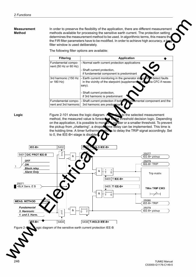
2 Functions
om
Measurement Method
In order to preserve the flexibility of the application, there are different measurement methods available for processing the sensitive earth current. The protection setting determines the measurement method to be used. In algorithmic terms, this means that the FIR filter parameters have to be modified. In order to achieve high accuracy, a long filter window is used deliberately.
The following filter options are available:
Logic Figure 2-101 shows the logic diagram. According to the selected measurement method, the measured value is forwarded to the threshold decision logic. Depending on the application, it is possible to monitor a greater or a smaller threshold. To prevent the pickup from „chattering“, a dropout time delay can be implemented. This time is the holding time. A timer furthermore allows to delay the TRIP signal accordingly. Set to 0, the IEE-B<-stage is disabled.
Figure 2-101 Logic diagram of the sensitive earth current protection IEE-B
Filtering ApplicationFundamental compo-nent (50 Hz or 60 Hz)
- Normal earth current protection applications - Shaft current protection, if fundamental component is predominant
3rd harmonic (150 Hz or 180 Hz)
- Earth current monitoring in the generator starpoint to detect faults in the vicinity of the starpoint (supplementary logic via CFC if neces-
sary). - Shaft current protection, if 3rd harmonic is predominant
Fumdamental compo-nent and 3rd harmonic
- Shaft current protection if both the fundamental component and the 3rd harmonic are predominant
ww . El
ectric
alPar
tMan
uals
. c
246 7UM62 ManualC53000-G1176-C149-5
w

2.32 Sensitive Earth Fault Protection B (ANSI 51GN)w
2.32.2 Setting Notes
General The sensitive earth fault protection IEE-B is only effective and available if configured to with IEE1 or with IEE2 at address .
If the sensitive earth fault detection IEE-B is not required, Disabled is set.
Address serves to switch the function ON or OFF or to block only the trip command (Block relay).
In addition, you can set Alarm Only, i.e. these stages operate and send alarms but do not generate any trip command
Use as shaft current protection
The correct setting of the shaft current protection is only possible during the primary check. A fault record is started with the generator running and the harmonic content is determined using the SIGRA graphic software. Depending on which harmonic content is present, the appropriate measuring method is set in address 5406 MEAS. METHOD. You can select either Fundamental, 3. Harmonic or 1. and 3. Harm.. Once the setting is complete, the respective fault current is read out of the operational mea-sured values with the generator running under load and a setting value is determined on their basis with a safety factor of 1.5 to 2 (see also primary check).
A preliminary setting should be so that it causes the protective function to pick up on fault currents between 0.5 A and 1 A. In case of 600 turns, this yields a pickup value of 1 mA (equivalent to 0.6 A primary).
To ensure that the function also trips in case of intermittent faults, the pickup behaviour has to be set in address 5407 T-HOLD IEE-B> (only possible via the DIGSI soft-ware). A value of 0.5 s is quite practicable. The trip time delay is usually set to 3 s in address 5403 T IEE-B>.
ww . El
ectric
alPar
tMan
uals
. com
2477UM62 ManualC53000-G1176-C149-5

2 Functions
om
2.32.3 Settings
Addresses which have an appended "A" can only be changed with DIGSI, under Ad-ditional Settings.
2.32.4 Information List
Addr. Parameter Setting Options Default Setting Comments
5401 O/C PROT IEE-B OFFONBlock relayAlarm Only
OFF Sensitive O/C Protection B
5402 IEE-B> 0.3 .. 1000.0 mA 5.0 mA IEE-B> Pickup
5403 T IEE-B> 0.00 .. 60.00 sec; ∞ 3.00 sec Time Delay T IEE-B>
5404 IEE-B< 0.3 .. 500.0 mA; 0 0.0 mA IEE-B< Pickup
5405 T IEE-B< 0.00 .. 60.00 sec; ∞ 1.00 sec Time Delay T IEE-B<
5406 MEAS. METHOD Fundamental3. Harmonic1. and 3. Harm.
Fundamental Measurement Method
5407A T-HOLD IEE-B> 0.00 .. 60.00 sec 0.00 sec Pickup Holding Time IEE-B>
5408A T-HOLD IEE-B< 0.00 .. 60.00 sec 0.00 sec Pickup Holding Time IEE-B<
No. Information Type of In-formation
Comments
25071 >BLK Sens. E B SP >BLOCK sensitive earth current prot. B25072 IEE-B OFF OUT Earth current prot. B is switched OFF25073 IEE-B BLOCKED OUT Earth current prot. B is BLOCKED25074 IEE-B ACTIVE OUT Earth current prot. B is ACTIVE25077 IEE-B> pickup OUT IEE-B> picked up25078 IEE-B< pickup OUT IEE-B< picked up25079 IEE-B> TRIP OUT IEE-B> TRIP25080 IEE-B< TRIP OUT IEE-B< TRIP
ww . El
ectric
alPar
tMan
uals
. c
248 7UM62 ManualC53000-G1176-C149-5
w
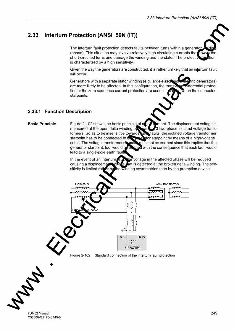
2.33 Interturn Protection (ANSI 59N (IT))w
2.33 Interturn Protection (ANSI 59N (IT))
The interturn fault protection detects faults between turns within a generator winding (phase). This situation may involve relatively high circulating currents that flow in the short-circuited turns and damage the winding and the stator. The protective function is characterized by a high sensitivity.
Given the way the generators are constructed, it is rather unlikely that an interturn fault will occur.
Generators with a separate stator winding (e.g. large-sized hydro-electric generators) are more likely to be affected. In this configuration, the transverse differential protec-tion or the zero sequence current protection are used instead between the connected starpoints.
2.33.1 Function Description
Basic Principle Figure 2-102 shows the basic principle of measurement. The displacement voltage is measured at the open delta winding by means of 3 two-phase isolated voltage trans-formers. So as to be insensitive towards earth faults, the isolated voltage transformer starpoint has to be connected to the generator starpoint by means of a high-voltage cable. The voltage transformer starpoint must not be earthed since this implies that the generator starpoint, too, would be earthed with the consequence that each fault would lead to a single-pole earth fault.
In the event of an interturn fault, the voltage in the affected phase will be reduced causing a displacement voltage that is detected at the broken delta winding. The sen-sitivity is limited rather by the winding asymmetries than by the protection device.
Figure 2-102 Standard connection of the interturn fault protection
ww . El
ectric
alPar
tMan
uals
. com
2497UM62 ManualC53000-G1176-C149-5

2 Functions
om
Figure 2-103 shows an alternative connection example with limited sensitivity. The loading resistor is located at the generator starpoint and the displacement voltage is measured via the voltage transformer. This voltage transformer is equally used for the stator earth fault protection. The voltage transformer on the outgoing side is earthed and has additionally a broken delta winding. The connection example shown in figure 2-103 has the effect that the displacement voltage becomes zero at the measurement input of the interturn fault protection in the event of an earth fault. In the event of an interturn fault, the displacement voltage occurs only at the open-delta winding that is open on the outgoing side.
Figure 2-103 Alternative connection of the interturn fault protection
The wide setting range allows the protective function to be used also as single-stage, single-phase overvoltage protection.
Measurement Method
The UE input of the protection is connected as shown in Figure 2-102 or 2-103. An FIR filter determines the fundamental component of the voltage based on the scanned dis-placement voltage. Selecting an appropriate window function has the effect that the sensitivity towards higher-frequency oscillations is improved and the disturbing influ-ence of the third harmonic is eliminated while achieving the required measurement sensitivity.
ww . El
ectric
alPar
tMan
uals
. c
250 7UM62 ManualC53000-G1176-C149-5
w
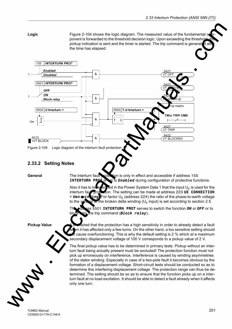
2.33 Interturn Protection (ANSI 59N (IT))w
Logic Figure 2-104 shows the logic diagram. The measured value of the fundamental com-ponent is forwarded to the threshold decision logic. Upon exceeding the threshold, the pickup indication is sent and the timer is started. The trip command is generated after the time has elapsed.
Figure 2-104 Logic diagram of the interturn fault protection
2.33.2 Setting Notes
General The interturn fault protection is only in effect and accessible if address 155 INTERTURN PROT is set to Enabled during configuration of protective functions.
Also it has to be specified in the Power System Data 1 that the input UE is used for the interturn fault protection. The setting can be made at address 223 UE CONNECTION = Uen-winding. For factor UE (address 224) the ratio of the phase-to-earth voltage to the voltage at the broken delta winding (UE input) is set according to section 2.5.
The address 5501 INTERTURN PROT serves to switch the function ON or OFF or to block only the trip command (Block relay).
Pickup Value It is desired that the protection has a high sensitivity in order to already detect a fault when it has affected only a few turns. On the other hand, a too sensitive setting should not cause overfunctioning. This is why the default setting is 2 % which at a maximum secondary displacement voltage of 100 V corresponds to a pickup value of 2 V.
The final pickup value has to be determined in primary tests. Pickup without an inter-turn fault being actually present must be excluded! The protection function must not pick up erroneously on interference. Interference is caused by winding asymmetries of the stator winding. Especially in case of a two-pole fault it becomes obvious by the formation of a displacement voltage. Short-circuit tests should be conducted so as to determine this interfering displacement voltage The protection range can thus be de-termined. The setting should be so as to ensure that the function picks up on a inter-turn fault at no-load excitation. It should be able to detect a fault already when it affects only one turn.ww . El
ectric
alPar
tMan
uals
. com
2517UM62 ManualC53000-G1176-C149-5
2 Functions
om
For the sensitive setting the dropout ratio should equally be reduced slightly. The default setting is 80 % (see address 5504 RESET RATIO).
Delays Delaying the protective function additionally reduces the risk of overfunctioning. But if the delay is too long, there is a risk of the affected stator winding/core taking consid-erable damage. This is why the default value is 0.50 sec (see address 5503 T-U Interturn >).
2.33.3 Settings
2.33.4 Information List
Addr. Parameter Setting Options Default Setting Comments
5501 INTERTURN PROT OFFONBlock relay
OFF Interturn Protection
5502 U Interturn > 0.3 .. 130.0 V 2.0 V Pick up Value U Interturn>
5503 T-U Interturn > 0.00 .. 60.00 sec; ∞ 0.50 sec Time Delay of Trip Command
5504 RESET RATIO 50 .. 95 % 80 % Reset Ratio of U Interturn>
No. Information Type of In-formation
Comments
5413 >I/T BLOCK SP >BLOCK interturn fault protection5421 I/T OFF OUT Interturn fault prot. is switched OFF5422 I/T BLOCKED OUT Interturn fault protection is BLOCKED5423 I/T ACTIVE OUT Interturn fault protection is ACTIVE5426 I/T picked up OUT Interturn fault protection picked up5427 I/T TRIP OUT Interturn fault protection TRIP
ww . El
ectric
alPar
tMan
uals
. c
252 7UM62 ManualC53000-G1176-C149-5
w

2.34 Rotor Earth Fault Protection R, fn (ANSI 64R)w
2.34 Rotor Earth Fault Protection R, fn (ANSI 64R)
Rotor earth fault protection is used to detect earth faults in the excitation circuit of syn-chronous machines. An earth fault in the rotor winding does not cause immediate damage; however, if a second earth fault occurs it constitutes a winding short-circuit of the excitation circuit. The resulting magnetic imbalances can cause extreme me-chanical forces which may destroy the machine.
2.34.1 Function Description
Measurement method
The rotor earth fault protection in the 7UM62 uses an external system frequency aux-iliary voltage of approximately 36 to 45 V AC, which can be taken e.g. from the voltage transformers via a coupling unit 7XR6100-0*A00. This voltage is symmetrically coupled to the excitation circuit and simultaneously connected to the measurement input UE of the device provided for this purpose. The capacitors CK of the 7XR6100 coupling unit are protected by series resistors Rseries and - in case high harmonics content is expected in the excitation circuit (e.g. excitation by thyristor circuits) - by an additional filter choke (for a connection example with terminal assignment see Appen-dix A.3).
The coupled voltage drives a small charging current (normally a few mA) through the coupling unit, as the case may be the brush resistance and the capacitance to earth of the excitation circuit. This current IRE is measured by the device.
Figure 2-105 Establishing the rotor earth resistance RE (7XR61 – series device for rotor earth fault protection; 3PP13 – for excitation voltages above 150 V, resistors in 7XR61 are then to be shorted!)ww .
Elec
tricalP
artM
anua
ls . c
om
2537UM62 ManualC53000-G1176-C149-5
2 Functions
om
The rotor earth fault calculation calculates the complex earth impedance from the aux-iliary AC voltage URE and the current IRE. The earth resistance RE of the excitation circuit is then calculated from the earth impedance. The coupling capacitance of the coupling unit CK, the series resistance Rseries including the brush resistance, and the capacitance to the earth excitation circuit CE are also considered. This method ensures that even relatively high-ohmic earth faults (up to 30 kΩ under ideal condi-tions) can be detected.
In order to eliminate the influence of harmonics - such as occur in semiconductor ex-citation equipment (thyristors or rotating rectifiers) - the measured quantities are fil-tered prior to their evaluation.
The earth resistance supervision has two stages. Usually an alarm is issued if an initial stage (e.g. 5 kΩ to 10 kΩ) is undershot. If the value falls below the second low-resis-tance stage (e.g. 2 kΩ to 5 kΩ), tripping will be initiated after a short time delay. The dropout threshold is defined for both stages as 125 % of the set value.
Note
The rotor earth fault protection uses for the detection of the voltage URE the UE voltage input of the device. In this case, the displacement voltage for the 90 % stator earth fault protection U0 is therefore calculated from the phase-to-earth voltages.
Supervision of the measurement circuit
Since a current flows even during normal operation, i.e. the charging current of the earth capacity CE, the protection can recognize and signal interruptions in the mea-surement circuit, provided the capacitance to earth is at least 0.15 µF.
Stabilization of the Resistance Measurement
If the measuring current IRE exceeds an internal predetermined value (100 mA), a low-resistance earth fault (RE ≈ 0) is detected regardless of the calculated resistance. If this current drops below the internal fixed value of 0.3 mA, RE → ∞ is detected regard-less of the calculated resistance.
ww . El
ectric
alPar
tMan
uals
. c
254 7UM62 ManualC53000-G1176-C149-5
w

2.34 Rotor Earth Fault Protection R, fn (ANSI 64R)w
Figure 2-106 Logic Diagram of the Rotor Earth Fault Protection
2.34.2 Setting Notes
General Rotor earth fault protection protection is only effective and accessible if address 160 ROTOR E/F has been set = to Enabled. If the function is not required Disabled is set. Address 6001 ROTOR E/F serves to switch the function ON or OFF or to block only the trip command (Block relay).
Also, configuration parameter 223 UE CONNECTION must be set to Rotor. If this is not the case, a voltage UURE = 0 is displayed and evaluated, so that the protection remains blocked.
Pickup Values Since the protection calculates the ohmic rotor-earth resistance from the values caused by the applied bias voltage, the thresholds for the warning stage (6002 RE< WARN) and for the trip stage (6003 RE<< TRIP) can be set directly as resistance values. The default settings are sufficient for the majority of cases. These values can be changed depending on the insulation resistance and the coolant. Care must be taken to allow a sufficient margin between the setting value and the actual insulation resistance.
Time Delays The time delay for the warning stage 6004 T-WARN-RE< is usually set to approxi-mately 10 s, and the delay for the trip stage 6005 T-TRIP-RE<< to approximately 0.5 s. The set times are additional delay times not including the operating times (measur-ing time, dropout time) of the protective function.
ww . El
ectric
alPar
tMan
uals
. com
2557UM62 ManualC53000-G1176-C149-5

2 Functions
om
Data for the Cou-pling to the Rotor Circuit
The setting of the coupling reactance 6006 X COUPLING and the series resistance 6007 R SERIES enable the protection to calculate the earth resistance RE from the complex equivalent diagram of the coupling capacitance of the coupling unit, the series (e.g. measuring brush) resistance, the capacitance to earth of the excitation cir-cuit, and the earth resistance of the excitation circuit. The equivalent circuit according to the figure below applies.
Figure 2-107 Equivalent Measuring Circuit for Rotor Earth Fault Protectionwhere: URE Rotor circuit bias voltageIRE Earth currentXCoupling Total series reactance of the coupling circuit, consisting of coupling capaci-
tance and inductance (if applicable)RV Total resistance of the coupling circuit, consisting of brush resistance, protec-
tion resistance (if applicable) and damping resistance (if applicable)CE Rotor earth capacitanceRE Rotor earth resistance
The series resistors Rseries for the protection of the coupling capacitors can be consid-ered with the total series resistance (address 6007) since the brush resistance and the series resistance are connected in series in the measurement circuit. The resultant resistance applies for R SERIES, i.e. the parallel connection in each case of the series resistors Rseries and for the resistance of the two brushes. Similarly, the coupling reac-tance is calculated from the parallel connection of the two coupling capacitors CK.
In some cases, the inductor integrated in the 7XR6100 is included in the coupling circuit to reduce very high harmonics content of the excitation voltage. This forms, to-gether with the coupling capacitance, a band pass for the system frequency. In these cases, it must be considered that the reactance must not become less than –100 Ω (lower threshold of setting 6006 X COUPLING).
Angle Error Correction
Coupling reactance and series resistance can be measured by the protection itself during commissioning (see Subsection 3.3 in the Section „Installation and Commis-sioning“). It may be advantageous to compensate for the angle error of the input CTs of the relay in order to increase accuracy. This can be done at address 6009 PHI I RE. Thus, if the warning stage in particular does not pick up during testing at the ex-pected insulation resistance level, you should check and correct the correction angle and the coupling reactance (see also Subsection 3.3 in the Section „Installation and Commissioning“).
The values calculated and displayed by the relay may become negative due to CT angle errors, wrong settings of the coupling impedance or malfunctions of the excita-tion equipment. In that case, a check is performed whether the current IRE is more than 7 mA, in which case a tripping decision is made. If the current is < 7 mA, the measure-ment is marked as invalid, and the rotor earth resistance Rrotor = ∞ is displayed. This additional consistency check ensures that even if the setting of the correction angle or ww .
Elec
tricalP
artM
anua
ls . c
256 7UM62 ManualC53000-G1176-C149-5
w

2.34 Rotor Earth Fault Protection R, fn (ANSI 64R)w
the coupling impedance is wrong, tripping in case of low-resistance earth faults is ensured although the warning stage may not pick up correctly.
Measuring Circuit Monitoring
If a sufficiently high rotor capacitance (CE ≥ 0.15 µF) is available, an interruption in the measurement circuit can also be recognized. A measurement circuit interruption is assumed when the voltage drops below the threshold set at address 6008 I RE<, and the voltage UV is at the same time above 25 V. The alarm is reset when the current is 0.5 mA or 20 % above the setting value, or when the voltage falls below 20 V. If I RE< is set to 0.0 mA, there is no current monitoring and no alarm.
2.34.3 Settings
2.34.4 Information List
Addr. Parameter Setting Options Default Setting Comments
6001 ROTOR E/F OFFONBlock relay
OFF Rotor Earth Fault Protection (R, fn)
6002 RE< WARN 3.0 .. 30.0 kΩ 10.0 kΩ Pickup Value of Warning Stage Re<
6003 RE<< TRIP 1.0 .. 5.0 kΩ 2.0 kΩ Pickup Value of Tripping Stage Re<<
6004 T-WARN-RE< 0.00 .. 60.00 sec; ∞ 10.00 sec Time Delay of Warning Stage Re<
6005 T-TRIP-RE<< 0.00 .. 60.00 sec; ∞ 0.50 sec Time Delay of Tripping Stage Re<<
6006 X COUPLING -100 .. 800 Ω 398 Ω Coupling Reactance
6007 R SERIES 0 .. 999 Ω 50 Ω Series Resistance (e.g. Meas. Brushes)
6008 I RE< 1.0 .. 50.0 mA; 0 2.0 mA Pickup Value of Failure Detection Ire<
6009 PHI I RE -15.0 .. 15.0 ° 0.0 ° Correction Angle for Ire
No. Information Type of In-formation
Comments
5383 >BLOCK R/E/F SP >BLOCK rotor earth fault prot. (R,fn)5391 R/E/F OFF OUT Rotor earth fault prot. (R,fn) swit. OFF5392 R/E/F BLOCKED OUT Rotor earth fault prot. (R,fn) BLOCKED5393 R/E/F AKTIVE OUT Rotor earth fault prot. (R,fn) is ACTIVE5394 R/E/F U< block OUT Rot. earth flt. prot. (R,fn) block by U<5397 R/E/F warning OUT Rot. earth flt.prot. (R,fn) Re< warning5398 R/E/F picked up OUT Rot. earth flt.prot. (R,fn) Re<< pick.up5399 R/E/F TRIP OUT Rotor earth fault prot. (R,fn) Re<< TRIP5400 Failure R/E/F OUT Failure rotor earth fault prot. (R,fn)
ww . El
ectric
alPar
tMan
uals
. com
2577UM62 ManualC53000-G1176-C149-5
2 Functions
om
2.35 Sensitive Rotor Earth Fault Protection with 1 to 3 Hz Square Wave Voltage Injection (ANSI 64R - 1 to 3 Hz)
The rotor earth fault protection detects high and low resistance earth faults in the ex-citation circuit of synchronous generators. An earth fault in the excitation winding itself causes no direct damage. f however a second earth fault occurs, this results in a winding short-circuit in the excitation circuit The resulting magnetic imbalances can cause extreme mechanical forces which may destroy the machine. The following pro-tection function differs from the function described in Section 2.34 in that it is far more sensitive; it is used for large generators.
2.35.1 Function Description
Basic Principle The rotor earth fault protection works with a direct voltage of approx. 50 V, the polarity of which is reversed between 1 and 4 times per second, depending on the setting. This voltage Ug injected into the rotor circuit is generated in the 7XT71 series device. The voltage passes through a resistor unit 7XR6004 (or 7XR6003) and is symmetrically coupled to the excitation circuit via high-resistance resistors, and at the same time connected to the earthing brush (potential to earth) via a low-resistance measuring shunt RM (see also Appendix). The voltage taken at the measuring shunt and the control voltage are fed into the protection device via measuring transducers. The control voltage is proportional to the injected 50 V voltage Ug in terms of amplitude and frequency. The earth current flowing in the rotor is reflected by the measurement voltage.
Every time the polarity of the direct voltage Ug is reversed, a charging current Ig is driven across the resistor unit into the earth capacitance of the excitation circuit. This current causes a proportional voltage drop UMeas in the measuring shunt. Once the rotor earth capacitance is charged, the charging current drops to zero. If a rotor earth fault is present a continuous earth current is driven. The amplitude depends on the fault resistance.
ww . El
ectric
alPar
tMan
uals
. c
258 7UM62 ManualC53000-G1176-C149-5
w

2.35 Sensitive Rotor Earth Fault Protection with 1 to 3 Hz Square Wave Voltage Injection (ANSI 64R - 1 to 3 Hz)w
The use of a low-frequency square-wave voltage as displacement voltage eliminates the influence of the earth capacitance and ensures at the same time a sufficient margin against interference signals from the excitation system.
Figure 2-108 Connection Schematic of Voltage Injection into the Rotor WindingCE Rotor-earth capacitanceRv Series resistorUg Square-wave voltage from 7XT71Ig Current flowing from the 7XT71 through the rotor into the earthfg Square-wave frquency of the 7XT71
Measurement method
From the control voltage UControl, the function determines the timing for the polarity re-versals and triggers the measurement. At the same time it calculates the voltage am-plitude and converts it to the driving voltage Ug. The actual fault resistance is deter-mined from the voltage UMeas, which is proportional to the current Ig. Every time the polarity of the control voltage is reversed, the DC component of the measurement voltage is determined by a mean value filter. The frequency of the series device must be set low enough to ensure that during the mean-value generation the rotor-earth ca-pacitances are charged, so that only the steady-state portion is evaluated. This allows detection of high-resistance faults (max. approx. 80 kΩ) without being influenced by the earth capacitance.
However, the measurement is distorted by two sources of interference. One of them is a DC voltage component in the measurement circuit which depends on the intensity of the excitation voltage and on the location of the earth fault in the excitation winding, and the other are considerable high-frequency voltage peaks that may be superim-posed on the DC excitation voltage. These peaks are attenuated by a numerical filter.
To eliminate interference from the superimposed DC voltage components, the polarity of the voltage Ug is reversed (square-wave voltage). The measurement voltage calcu-lation described above is performed for both polarities. On formation of the difference between two subsequent measurement results for Ig, namely Ig1 and Ig2, the DC com-ponent originating from the excitation circuit (Ioffset) is eliminated, whereas the DC components originating from the injected voltage Ug accumulate.
ww . El
ectric
alPar
tMan
uals
. com
2597UM62 ManualC53000-G1176-C149-5
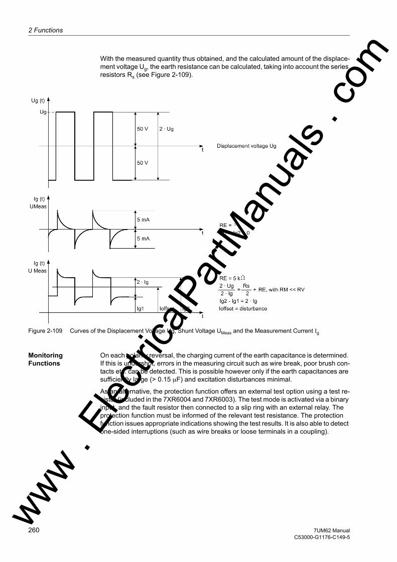
2 Functions
om
With the measured quantity thus obtained, and the calculated amount of the displace-ment voltage Ug, the earth resistance can be calculated, taking into account the series resistors Rs (see Figure 2-109).
Figure 2-109 Curves of the Displacement Voltage Ug, Shunt Voltage UMeas and the Measurement Current Ig
Monitoring Functions
On each polarity reversal, the charging current of the earth capacitance is determined. If this is undershot, errors in the measuring circuit such as wire break, poor brush con-tacts etc. can be detected. This is possible however only if the earth capacitances are sufficiently large (> 0.15 µF) and excitation disturbances minimal.
As an alternative, the protection function offers an external test option using a test re-sistor (included in the 7XR6004 and 7XR6003). The test mode is activated via a binary input, and the fault resistor then connected to a slip ring with an external relay. The protection function must be informed of the relevant test resistance. The protection function issues appropriate indications showing the test results. It is also able to detect one-sided interruptions (such as wire breaks or loose terminals in a coupling).
ww . El
ectric
alPar
tMan
uals
. c
260 7UM62 ManualC53000-G1176-C149-5
w
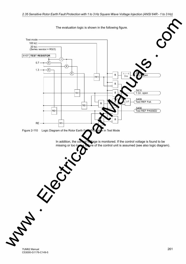
2.35 Sensitive Rotor Earth Fault Protection with 1 to 3 Hz Square Wave Voltage Injection (ANSI 64R - 1 to 3 Hz)w
The evaluation logic is shown in the following figure.
Figure 2-110 Logic Diagram of the Rotor Earth Fault Protection in Test Mode
In addition, the control voltage is monitored. If the control voltage is found to be missing or too low, a failure of the control unit is assumed (see also logic diagram).
ww . El
ectric
alPar
tMan
uals
. com
2617UM62 ManualC53000-G1176-C149-5

2 Functions
om
Logic The logic diagram shows the parts:• Monitoring of the series device• Supervision of the measurement circuit• Two-stage protection function• Effect of the rotor earth fault protection test
If the earth resistance drops below the high-resistance stage RE<, a warning message will normally be issued. If it drops below the second, low-resistance stage RE<<, a trip signal is issued after a short time.
Figure 2-111 Logic Diagram of Sensitive Rotor Earth Fault Protection
ww . El
ectric
alPar
tMan
uals
. c
262 7UM62 ManualC53000-G1176-C149-5
w
2.35 Sensitive Rotor Earth Fault Protection with 1 to 3 Hz Square Wave Voltage Injection (ANSI 64R - 1 to 3 Hz)w
2.35.2 Setting Notes
General Sensitive rotor earth fault protection is only effective and available if configured at address 161 REF 1-3Hz to Enabled.
It must also be ensured that the measuring transducer inputs TD1 and TD2 are not used for any other function.
Address 6101 REF 1-3Hz serves to switch the function ON or OFF or to block only the trip command (Block relay).
Pickup Values Since the protection calculates the ohmic rotor-earth resistance directly from the values of the applied bias voltage, the series resistor and the flowing earth current, the thresholds for the warning stage (6102 RE< WARN) and for the trip stage (6103 RE<< TRIP) can be set directly as resistance values. The default settings (RE< WARN = 40 kΩ and RE<< TRIP = 5 kΩ) are sufficient for the majority of cases. These values can be changed depending on the insulation resistance and the coolant. Care must be taken to allow a sufficient margin between the setting value and the actual insulation resistance.
As interference from the excitation system cannot be excluded, the setting for the warning stage is finally established during primary tests.
Time Delays The time delay for the warning stage 6104 T-WARN-RE< is usually set to approxi-mately 10 s, and the delay for the trip stage 6105 T-TRIP-RE<< to approximately 1 s. The set times are additional time delays not including the operating times (measur-ing time, drop-out time) of the protective function.
Monitoring Functions
The setting value of the measuring circuit monitoring (6106 Qc <) is defined during the primary test. For this purpose the operational measured value (Qc) is read out and half of this value is set. If the charge measured is too low, monitoring cannot be effec-tive. The parameter Qc < should in that case be set to 0 mAs. No fault indication will be issued in this case.
No setting is required if the external test is done using the test resistor 7XR6004 (3.3 kΩ). If a different resistor is to be used, its resistance must be set as an advanced pa-rameter TEST RESISTOR (only via the DIGSI communication software) at address 6107A.
ww . El
ectric
alPar
tMan
uals
. com
2637UM62 ManualC53000-G1176-C149-5
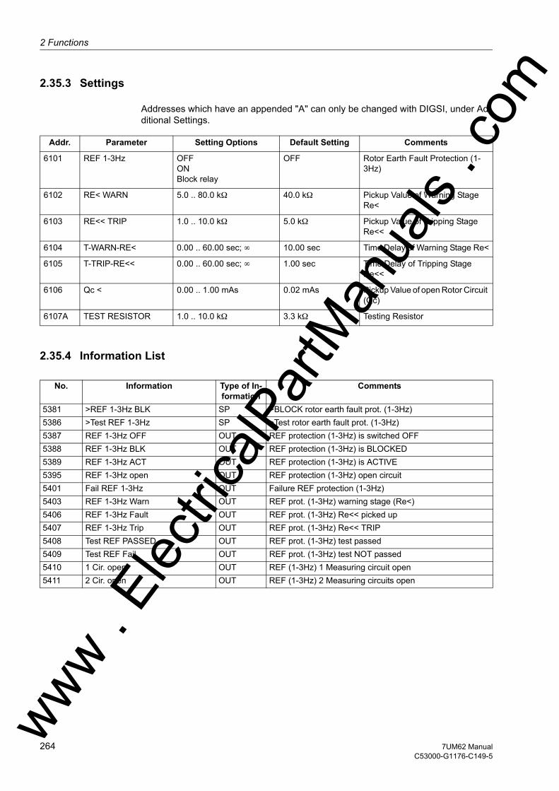
2 Functions
om
2.35.3 Settings
Addresses which have an appended "A" can only be changed with DIGSI, under Ad-ditional Settings.
2.35.4 Information List
Addr. Parameter Setting Options Default Setting Comments
6101 REF 1-3Hz OFFONBlock relay
OFF Rotor Earth Fault Protection (1-3Hz)
6102 RE< WARN 5.0 .. 80.0 kΩ 40.0 kΩ Pickup Value of Warning Stage Re<
6103 RE<< TRIP 1.0 .. 10.0 kΩ 5.0 kΩ Pickup Value of Tripping Stage Re<<
6104 T-WARN-RE< 0.00 .. 60.00 sec; ∞ 10.00 sec Time Delay of Warning Stage Re<
6105 T-TRIP-RE<< 0.00 .. 60.00 sec; ∞ 1.00 sec Time Delay of Tripping Stage Re<<
6106 Qc < 0.00 .. 1.00 mAs 0.02 mAs Pickup Value of open Rotor Circuit (Qc)
6107A TEST RESISTOR 1.0 .. 10.0 kΩ 3.3 kΩ Testing Resistor
No. Information Type of In-formation
Comments
5381 >REF 1-3Hz BLK SP >BLOCK rotor earth fault prot. (1-3Hz)5386 >Test REF 1-3Hz SP >Test rotor earth fault prot. (1-3Hz)5387 REF 1-3Hz OFF OUT REF protection (1-3Hz) is switched OFF5388 REF 1-3Hz BLK OUT REF protection (1-3Hz) is BLOCKED5389 REF 1-3Hz ACT OUT REF protection (1-3Hz) is ACTIVE5395 REF 1-3Hz open OUT REF protection (1-3Hz) open circuit5401 Fail REF 1-3Hz OUT Failure REF protection (1-3Hz)5403 REF 1-3Hz Warn OUT REF prot. (1-3Hz) warning stage (Re<)5406 REF 1-3Hz Fault OUT REF prot. (1-3Hz) Re<< picked up5407 REF 1-3Hz Trip OUT REF prot. (1-3Hz) Re<< TRIP5408 Test REF PASSED OUT REF prot. (1-3Hz) test passed5409 Test REF Fail. OUT REF prot. (1-3Hz) test NOT passed5410 1 Cir. open OUT REF (1-3Hz) 1 Measuring circuit open5411 2 Cir. open OUT REF (1-3Hz) 2 Measuring circuits open
ww . El
ectric
alPar
tMan
uals
. c
264 7UM62 ManualC53000-G1176-C149-5
w
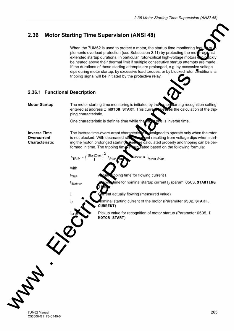
2.36 Motor Starting Time Supervision (ANSI 48)w
2.36 Motor Starting Time Supervision (ANSI 48)
When the 7UM62 is used to protect a motor, the startup time monitoring feature sup-plements overload protection (see Subsection 2.11) by protecting the motor against extended startup durations. In particular, rotor-critical high-voltage motors can quickly be heated above their thermal limit if multiple consecutive startup attempts are made. If the durations of these starting attempts are prolonged, e.g. by excessive voltage dips during motor startup, by excessive load torques, or by blocked rotor conditions, a tripping signal will be initiated by the protective relay.
2.36.1 Functional Description
Motor Startup The motor starting time monitoring is initiated by the motor starting recognition setting entered at address I MOTOR START. This current releases the calculation of the trip-ping characteristic.
One characteristic is definite time while the other one is inverse time.
Inverse Time Overcurrent Characteristic
The inverse time-overcurrent characteristic is designed to operate only when the rotor is not blocked. With decreased startup current resulting from voltage dips when start-ing the motor, prolonged starting times are calculated properly and tripping can be per-formed in time. The tripping time is calculated based on the following formula:
with
tTRIP Actual tripping time for flowing current I
tStartmax Tripping time for nominal startup current IA (param. 6503, STARTING TIME)
I Current actually flowing (measured value)
IA Nominal starting current of the motor (Parameter 6502, START. CURRENT)
IMotorStart Pickup value for recognition of motor startup (Parameter 6505, I MOTOR START)
ww . El
ectric
alPar
tMan
uals
. com
2657UM62 ManualC53000-G1176-C149-5

2 Functions
om
Figure 2-112 Trip Time Depending on Startup Current
Therefore, if the starting current I actually measured is smaller (or larger) than the nominal starting current IA entered at address 6502 (parameter START. CURRENT), the actual tripping time tTrip is lengthened (or shortened) accordingly (see also Figure 2-112).
Definite-Time Over-current Tripping Characteristic (Locked Rotor Time)
If the motor starting time exceeds the maximum allowable blocked rotor time t E, trip-ping must be executed at least with time tE when the rotor is blocked. The device can detect a blocked rotor condition via a binary input („>Rotor locked“) from an ex-ternal rpm-counter. If the current in any of the phases exceeds the already mentioned threshold I MOTOR START, a motor startup is assumed and in addition to the above inverse time delay, a current-independent delay time (locked rotor time) is started. This happens every time the motor is started and is a normal operating condition that is neither entered in the operational annunciations buffer, nor output to a control centre, nor entered in a fault record.
The locked rotor delay time (LOCK ROTOR TIME) is ANDed with the binary input „>Rotor locked“. If the binary input is still activated after the parameterized locked rotor time has expired, tripping is performed immediately, regardless of whether the binary input was activated before or during the delay, or after the delay time had elapsed.
ww . El
ectric
alPar
tMan
uals
. c
266 7UM62 ManualC53000-G1176-C149-5
w
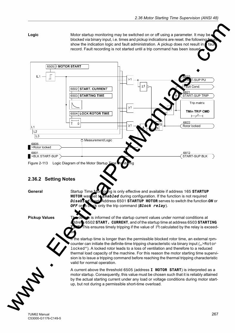
2.36 Motor Starting Time Supervision (ANSI 48)w
Logic Motor startup monitoring may be switched on or off using a parameter. It may be blocked via binary input, i.e. times and pickup indications are reset. the following figure show the indication logic and fault administration. A pickup does not result in a fault record. Fault recording is not started until a trip command has been issued.
Figure 2-113 Logic Diagram of the Motor Startup Time Monitoring
2.36.2 Setting Notes
General Startup Time Monitoring is only effective and available if address 165 STARTUP MOTOR was set to Enabled during configuration. If the function is not required Disabled is set. Address 6501 STARTUP MOTOR serves to switch the function ON or OFF or to block only the trip command (Block relay).
Pickup Values The device is informed of the startup current values under normal conditions at address 6502 START. CURRENT, and of the startup time at address 6503 STARTING TIME. This ensures timely tripping if the value of I2t calculated by the relay is exceed-ed.
If the startup time is longer than the permissible blocked rotor time, an external rpm-counter can initiate the definite-time tripping characteristic via binary input („>Rotor locked“). A locked rotor leads to a loss of ventilation and therefore to a reduced thermal load capacity of the machine. For this reason the motor starting time supervi-sion is to issue a tripping command before reaching the thermal tripping characteristic valid for normal operation.
A current above the threshold 6505 (address I MOTOR START) is interpreted as a motor startup. Consequently, this value must be chosen such that it is reliably attained by the actual starting current under any load or voltage conditions during motor start-up, but not during a permissible short-time overload.ww . El
ectric
alPar
tMan
uals
. com
2677UM62 ManualC53000-G1176-C149-5
2 Functions
om
Example: Motor with the following data:
The setting for address START. CURRENT is calculated as follows:
For reduced voltage, the startup current is also reduced almost linearly. At 80% nominal voltage, the startup current in this example is reduced to 0.8 · ISTART = 2.5 · IN CTsec.
The setting for detection of a motor startup must lie above the maximum load current and below the minimum startup current. If no other influencing factors are present (peak loads), the value for motor startup I MOTOR START set at address 6505 may be set to an average value:
The tripping time of the starting time monitoring is calculated as follows:
Under nominal conditions, the tripping time is the maximum starting time TSTART max. For ratios deviating from nominal conditions, the motor tripping time changes. At 80% of nominal voltage (which corresponds to 80% of nominal starting current), the tripping time is for example:
After the delay time LOCK ROTOR TIME has expired, the binary input becomes effec-tive and initiates a tripping signal. If the blocked rotor time is set to a value that the binary input „>Rotor locked“ (No. 6805) is reliably reset during the delay time LOCK ROTOR TIME, faster tripping will be available during motor starting under locked rotor conditions.
Nominal voltage UN = 6600 V Nominal current IMot.Nom = 126 A Startup current ISTART = 624 A Permissible continuous stator current: Imax = 135 AStarting time at ISTART TSTART max = 8.5 s CT Ratio IN CTprim/IN CTsec 200 A/1 A
ww . El
ectric
alPar
tMan
uals
. c
268 7UM62 ManualC53000-G1176-C149-5
w

2.36 Motor Starting Time Supervision (ANSI 48)w
2.36.3 Settings
The table indicates region-specific presettings. Column C (configuration) indicates the corresponding secondary nominal current of the current transformer.
2.36.4 Information List
Addr. Parameter C Setting Options Default Setting Comments
6501 STARTUP MOTOR OFFONBlock relay
OFF Motor Starting Time Su-pervision
6502 START. CURRENT 5A 0.50 .. 80.00 A 15.60 A Starting Current of Motor
1A 0.10 .. 16.00 A 3.12 A
6503 STARTING TIME 1.0 .. 180.0 sec 8.5 sec Starting Time of Motor
6504 LOCK ROTOR TIME 0.5 .. 120.0 sec; ∞ 6.0 sec Permissible Locked Rotor Time
6505 I MOTOR START 5A 3.00 .. 50.00 A 8.00 A Current Pickup Value of Motor Starting
1A 0.60 .. 10.00 A 1.60 A
No. Information Type of In-formation
Comments
6801 >BLK START-SUP SP >BLOCK Motor Starting Supervision6805 >Rotor locked SP >Rotor is locked6811 START-SUP OFF OUT Starting time supervision switched OFF6812 START-SUP BLK OUT Starting time supervision is BLOCKED6813 START-SUP ACT OUT Starting time supervision is ACTIVE6821 START-SUP TRIP OUT Starting time supervision TRIP6822 Rotor locked OUT Rotor is LOCKED after Locked Rotor Time6823 START-SUP PU OUT Starting time supervision picked up
ww . El
ectric
alPar
tMan
uals
. com
2697UM62 ManualC53000-G1176-C149-5
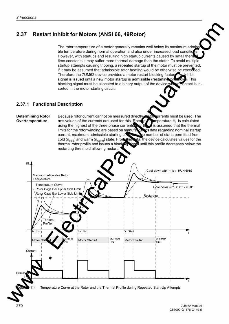
2 Functions
om
2.37 Restart Inhibit for Motors (ANSI 66, 49Rotor)
The rotor temperature of a motor generally remains well below its maximum admissi-ble temperature during normal operation and also under increased load conditions. However, with startups and resulting high startup currents caused by small thermal time constants it may suffer more thermal damage than the stator. To avoid multiple startup attempts causing tripping, a repeated startup of the motor must be prevented, if it may be assumed that admissible rotor heating would be otherwise be exceeded. Therefore the 7UM62 device provides a motor restart blocking feature. An inhibit signal is issued until a new motor startup is admissible (restarting threshold). This blocking signal must be allocated to a binary output of the device whose contact is in-serted in the motor starting circuit.
2.37.1 Functional Description
Determining Rotor Overtemperature
Because rotor current cannot be measured directly, stator currents must be used. The rms values of the currents are used for this. Rotor overtemperature ΘL is calculated using the highest of the three phase currents. For this it is assumed that the thermal limits for the rotor winding are based on manufacturer's data regarding nominal startup current, maximum admissible starting time, and the number of starts permitted from cold (ncold) and warm (nwarm) state. From this data, the device calculates values for the thermal rotor profile and issues a blocking signal until this profile decreases below the restarting threshold allowing restart.
Figure 2-114 Temperature Curve at the Rotor and the Thermal Profile during Repeated Start-Up Attemptsww . El
ectric
alPar
tMan
uals
. c
270 7UM62 ManualC53000-G1176-C149-5
w

2.37 Restart Inhibit for Motors (ANSI 66, 49Rotor)w
Although the heat distribution at the rotor cage bars can range widely during motor startup, the different maximum temperatures in the rotor do not necessarily affect the motor restart inhibit (see Figure 2-114). It is much more important to establish a thermal profile, after a complete motor startup, that is appropriate for protection of the motor's thermal state. The figure shows, as an example, the heating processes during repeated motor starts (three startups from cold operating condition), as well as the thermal replica of the protection device.
Restart Threshold If the rotor temperature has exceeded the restart threshold, the motor cannot be re-started. Only when the rotor temperature goes below the restart threshold, i.e. just when a startup becomes possible without exceeding the rotor overtemperature limit, the blocking signal is retracted. Therefore for the restart threshold ΘRe.Inh., related to maximum admissible rotor overtemperature:
Restart Times The motor manufacturer allows a number of cold (ncold) and warm (nwarm) startups. No subsequent renewed startup is allowed. A corresponding time — the restart time — must expire to allow the rotor to cool down. Thermal behaviour is allowed for as fol-lows: Each time the motor is shutdown, a leveling timer is started (address 6604 T EQUAL). This takes into account the different temperatures of the individual motor components at the moment of shutdown. During the leveling time the thermal profile of the rotor is not updated but maintained constant to replicate the leveling processes in the rotor. Then the thermal model cools down with the corresponding time constant (rotor time constant x extension factor). During the leveling time the motor cannot be restarted. As soon as the restart threshold is undershot, a new restart may be attempt-ed.
The total time that must expire before motor restart equals to the leveling time and the time calculated using the thermal model required for the rotor temperature to decrease below the restart threshold:
with
TLeveling - Rotor temperature leveling time address 6604
kτ – Extension factor for the time constant = Kτ at RUNNING address 6609 or Kτ at STOP address 6608
τR - Rotor time constant, internally calculated:
τL = ta · (ncold – nwarm) · Ion2
where:
tStart = Startup time in s
Ion = Startup current in pu
Θpre - Thermal profile at the moment of motor shutdown (depends on the operating state)
ncold 2 3 4
ΘRe.Inh. [%] 50 % 66.7 % 75 %
ww . El
ectric
alPar
tMan
uals
. com
2717UM62 ManualC53000-G1176-C149-5

2 Functions
om
The operational measured value TRem.= (to be found in the thermal measured values) shows the time remaining until the next restart is allowed.
Extension of the Cooling Time Con-stant
In order to properly account for the reduced heat removal when a self-ventilated motor is stopped, the cooldown time constant can be increased relative to the time constants for a running machine with the factor Kτ at STOP (address 6608). A motor at stand-still is defined by current below an adjustable current threshold BkrClosed I MIN. This assumes that the idle current of the motor is greater than this threshold. The pickup threshold BkrClosed I MIN also affects the thermal overload protection function (see Section 2.11).
While the motor is running, heating of the thermal profile is modeled with the time con-stant τL calculated from the motor ratings, and the cooldown is calculated with the time constant τL · Kτ at RUNNING (address 6609). In this way the requirements for a slow cooldown (slow temperature leveling) are met.
Minimum Inhibit Time
Regardless of thermal profiles, some motor manufacturers require a minimum inhibit time after the maximum number of permissible startup attempts has been exceeded.
The duration of the inhibit signal depends on which of the times, T MIN INHIBIT or TRem., is longer.
Behaviour on Power Supply Failure
Depending on the setting of parameter 274 ATEX100, the value of the thermal profile is either reset to zero on failure of the power supply voltage, or cyclically buffered in a non-volatile memory until the power supply voltage returns. In the latter case when power supply is restored, the thermal profile uses the stored value for calculation and matches it to the operating conditions.
Emergency Startup If, for emergency reasons, motor starting that will exceed the maximum allowable rotor temperature must take place, the motor start blocking signal can be terminated via a binary input („>Emer. Start ΘR“), thus allowing a new starting attempt. The thermal rotor profile continues to function, however, and the maximum admissible rotor temperature can be exceeded. No motor shutdown will be initiated by motor start blocking, but the calculated excessive temperature of the rotor can be observed for risk assessment.
Blocking If the motor start blocking function is blocked or switched off, the thermal profile of the excessive rotor temperature and the equilibrium time T EQUAL as well as the minimum inhibit time T MIN. INHIBIT are reset, and any existing motor start inhibit signal is terminated.
ww . El
ectric
alPar
tMan
uals
. c
272 7UM62 ManualC53000-G1176-C149-5
w
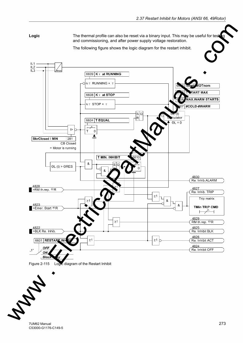
2.37 Restart Inhibit for Motors (ANSI 66, 49Rotor)w
Logic The thermal profile can also be reset via a binary input. This may be useful for testing and commissioning, and after power supply voltage restoration.
The following figure shows the logic diagram for the restart inhibit.
Figure 2-115 Logic diagram of the Restart Inhibit
ww . El
ectric
alPar
tMan
uals
. com
2737UM62 ManualC53000-G1176-C149-5

2 Functions
om
2.37.2 Setting Notes
General Restart inhibit is only effective and available if address 166 RESTART INHIBIT was set to Enabled during configuration. If the function is not required Disabled is set. Address 6601RESTART INHIBIT serves to switch the function ON or OFF or to block only the trip command (Block relay).
Required Charac-teristic Values
Many of the variables needed to calculate the rotor temperature are supplied by the motor manufacturer. Among these variables are the starting current ISTARTUP, the nominal motor current IMOT.NOM, the maximum allowable starting time T START MAX (address 6603), the number of allowable starts from cold conditions (ncold), and the number of allowable starts from warm conditions (nwarm).
The starting current is entered at address 6602, expressed as a multiple of the nominal motor current (IStart/IMOTnom). For a correct interpretation of this param-eter, it is important that in Power System Data 1 the apparent power (address 252 SN GEN/MOTOR) and the rated voltage (address 251 UN GEN/MOTOR) of the motor are correctly set. The number of warm starts allowed is entered at address 6606 (MAX.WARM STARTS) and the difference (#COLD-#WARM) between the number of al-lowable cold and warm starts is entered at address 6607.
For motors without separate ventilation, the reduced cooling at motor standstill can be accounted for by entering at address 6608 the reduced ventilation factor Kτ at STOP. As soon as the current no longer exceeds the setting value entered at address 281 BkrClosed I MIN, motor standstill is detected and the time constant is increased by the extension factor configured.
If no difference between the time constants is to be used (e.g. externally-ventilated motors), then the extension factor Kτ at STOP should be set to 1.
Cooling with running motor is influenced by the extension factor Kτ at RUNNING. This factor considers that a motor running under load and a stopped motor do not cool down at the same speed. It becomes effective as soon as the current exceeds the value set at address 281 BkrClosed I MIN. With Kτ at RUNNING = 1 the heating and the cooling time constant are the same at operating conditions (I > BkrClosed I MIN).
Setting Example: Example: Motor with the following data:
The ratio between startup current and motor nominal current is:
Nominal voltage UN = 6600 V Nominal current IMot.Nom = 126 A Startup current IStart = 624 A Starting time at ISTART TSTART MAX = 8.5 s Permissible number of startups with cold motor
ncold = 3
Permissible number of startups with warm motor
nwarm = 2
Current transformer 200 A / 1 A
ww . El
ectric
alPar
tMan
uals
. c
274 7UM62 ManualC53000-G1176-C149-5
w
2.37 Restart Inhibit for Motors (ANSI 66, 49Rotor)w
The following settings are made:
IStart/IMOTnom = 4.9
T START MAX = 8.5 sec
MAX.WARM STARTS = 2
#COLD-#WARM = 1
For the rotor temperature leveling time, a setting of approx. T EQUAL = 1.0 min has proven to be a practical value. The value for the minimum inhibit time T MIN. INHIBIT depends on the requirements of the motor manufacturer, or on the system conditions. It must in any case exceed T EQUAL. In this example, a value has been chosen that roughly reflects the thermal profile (T MIN. INHIBIT =6.0 min).
The motor manufacturer's or user's requirements determine the extension factor for the time constant during cooldown, especially for motor standstill. Where no other specifications are made, the following settings are recommended: Kτ at STOP = 5.0 and Kτ at RUNNING = 2.0 .
For proper functioning it is also important that the CT values for side 2 (addresses 211 and 212), the power system data (addresses 251, 252) and the current threshold for distinction between stopped and running motor (address 281 BkrClosed I MIN, recommended setting ≈≈ 0,1 · I/IN Motor) were set correctly. An overview of the param-eters and their default settings is given in parameter overviews.
Temperature Be-haviour during Changing Operat-ing States
For better understanding of the above considerations, two of the many possible oper-ating states will be discussed in the following paragraph. The examples use the set-tings indicated above. 3 cold and 2 warm startup attempts have resulted in a restart limit of 66.7 %.
The following figure illustrates the temperature behaviour during 2 warm startup at-tempts. The motor is continuously operated at nominal current. After the first switchoff T EQUAL is effective. 30 s later the motor is restarted and immediately shut down again. After another pause, the 2nd restart attempt is made. The motor is shut down once again. During this 2nd startup attempt, the restart limit is exceeded, so that after shutdown the restart inhibit takes effect. After the temperature leveling time (1 min), the thermal profile cools down with the time constant τL · Kτ at STOP ≈ 5 · 204 s = 1020 s. The restart inhibit is effective for about 7 min.
ww . El
ectric
alPar
tMan
uals
. com
2757UM62 ManualC53000-G1176-C149-5

2 Functions
om
Figure 2-116 Temperature Behaviour during Two Successive Warm Starts
In Figure 2-117, the motor is also restarted twice in warm condition, but the pause between the restart attempts is longer than in the first example. After the second restart attempt, the motor is operated at 90 % nominal current. After the shutdown fol-lowing the first startup attempt, the thermal profile is "frozen". After the temperature leveling time (1 min), the rotor cools down with the time constant τL · Kτ at STOP ≈ 5 · 204 s = 1020 s. During the second restart, the starting current causes a tempera-ture rise, whereas the subsequently flowing on-load current of 0.9 I/IN Motor Kτ at RUNNING reduces the temperature. This time, the time constant L · Kτ at STOP = 2 · 204 s = 408 s is effective.
The fact that the restart limit is exceeded for a short time does not mean a thermal overload. It rather indicates that a thermal overload of the rotor would result if the motor were shut down immediately and restarted.
ww . El
ectric
alPar
tMan
uals
. c
276 7UM62 ManualC53000-G1176-C149-5
w
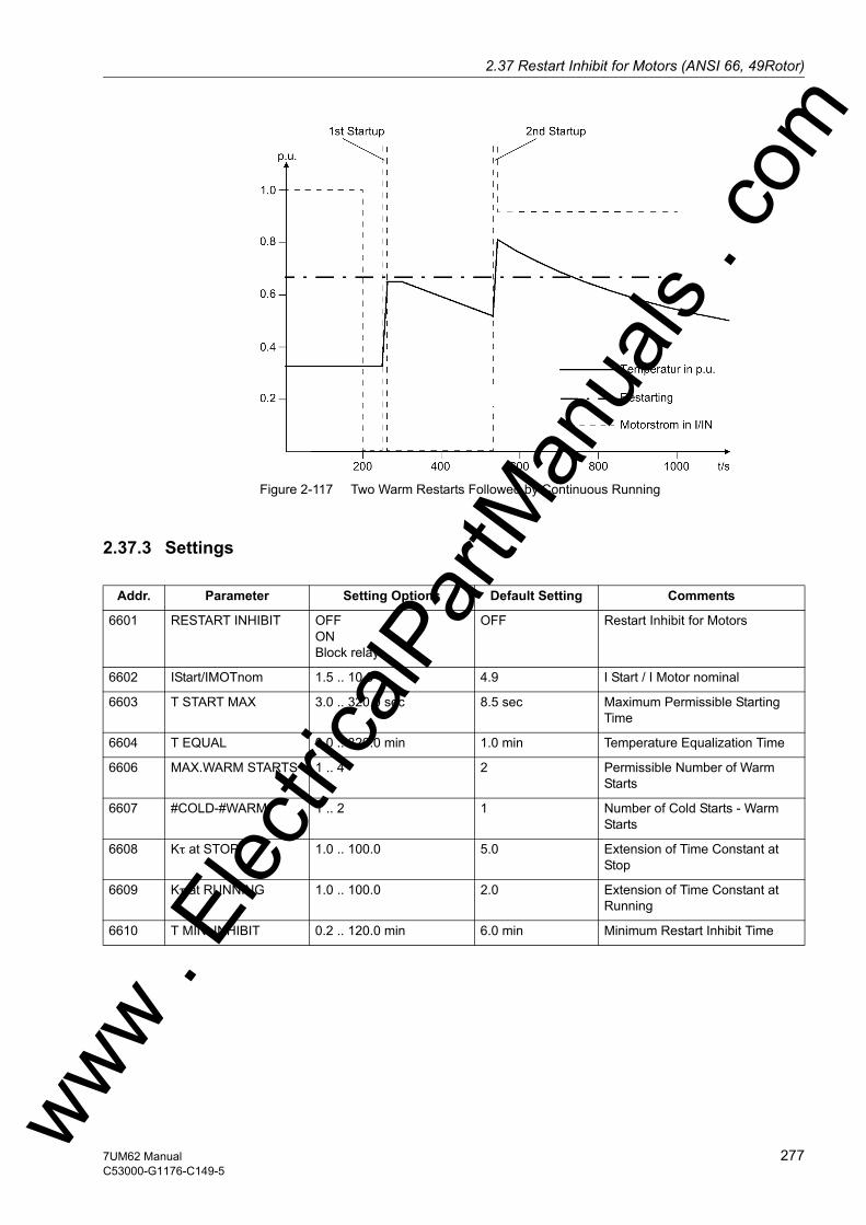
2.37 Restart Inhibit for Motors (ANSI 66, 49Rotor)w
Figure 2-117 Two Warm Restarts Followed by Continuous Running
2.37.3 Settings
Addr. Parameter Setting Options Default Setting Comments
6601 RESTART INHIBIT OFFONBlock relay
OFF Restart Inhibit for Motors
6602 IStart/IMOTnom 1.5 .. 10.0 4.9 I Start / I Motor nominal
6603 T START MAX 3.0 .. 320.0 sec 8.5 sec Maximum Permissible Starting Time
6604 T EQUAL 0.0 .. 320.0 min 1.0 min Temperature Equalization Time
6606 MAX.WARM STARTS 1 .. 4 2 Permissible Number of Warm Starts
6607 #COLD-#WARM 1 .. 2 1 Number of Cold Starts - Warm Starts
6608 Kτ at STOP 1.0 .. 100.0 5.0 Extension of Time Constant at Stop
6609 Kτ at RUNNING 1.0 .. 100.0 2.0 Extension of Time Constant at Running
6610 T MIN. INHIBIT 0.2 .. 120.0 min 6.0 min Minimum Restart Inhibit Time
ww . El
ectric
alPar
tMan
uals
. com
2777UM62 ManualC53000-G1176-C149-5

2 Functions
om
2.37.4 Information List
No. Information Type of In-formation
Comments
4822 >BLK Re. Inhib. SP >BLOCK Restart inhibit motor4823 >Emer. Start ΘR SP >Emergency start rotor4824 Re. Inhibit OFF OUT Restart inhibit motor is switched OFF4825 Re. Inhibit BLK OUT Restart inhibit motor is BLOCKED4826 Re. Inhibit ACT OUT Restart inhibit motor is ACTIVE4827 Re. Inhib. TRIP OUT Restart inhibit motor TRIP4828 >RM th.rep. ΘR SP >Reset thermal memory rotor4829 RM th.rep. ΘR OUT Reset thermal memory rotor4830 Re. Inhib.ALARM OUT Alarm restart inhibit motor
ww . El
ectric
alPar
tMan
uals
. c
278 7UM62 ManualC53000-G1176-C149-5
w
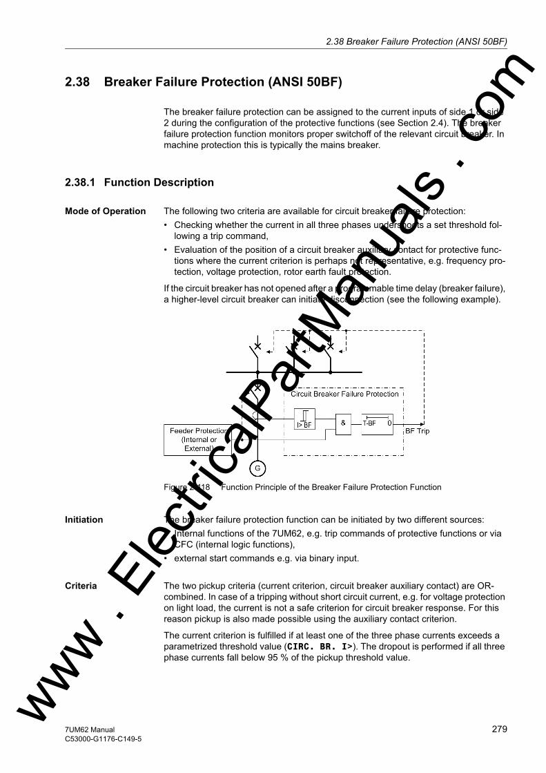
2.38 Breaker Failure Protection (ANSI 50BF)w
2.38 Breaker Failure Protection (ANSI 50BF)
The breaker failure protection can be assigned to the current inputs of side 1 or side 2 during the configuration of the protective functions (see Section 2.4). The breaker failure protection function monitors proper switchoff of the relevant circuit breaker. In machine protection this is typically the mains breaker.
2.38.1 Function Description
Mode of Operation The following two criteria are available for circuit breaker failure protection: • Checking whether the current in all three phases undershoots a set threshold fol-
lowing a trip command,• Evaluation of the position of a circuit breaker auxiliary contact for protective func-
tions where the current criterion is perhaps not representative, e.g. frequency pro-tection, voltage protection, rotor earth fault protection.
If the circuit breaker has not opened after a programmable time delay (breaker failure), a higher-level circuit breaker can initiate disconnection (see the following example).
Figure 2-118 Function Principle of the Breaker Failure Protection Function
Initiation The breaker failure protection function can be initiated by two different sources:• Internal functions of the 7UM62, e.g. trip commands of protective functions or via
CFC (internal logic functions),• external start commands e.g. via binary input.
Criteria The two pickup criteria (current criterion, circuit breaker auxiliary contact) are OR-combined. In case of a tripping without short circuit current, e.g. for voltage protection on light load, the current is not a safe criterion for circuit breaker response. For this reason pickup is also made possible using the auxiliary contact criterion.
The current criterion is fulfilled if at least one of the three phase currents exceeds a parametrized threshold value (CIRC. BR. I>). The dropout is performed if all three phase currents fall below 95 % of the pickup threshold value.
ww . El
ectric
alPar
tMan
uals
. com
2797UM62 ManualC53000-G1176-C149-5
2 Functions
om
If the binary input of the circuit breaker auxiliary contact is inactive, only the current criterion is effective and the breaker failure protection cannot become active with a tripping signal if the current is below the CIRC. BR. I> threshold.
Two-Channel Feature
To increase security and to protect against possible disturbance impulses the binary input for an external trip signal is stabilized. This external signal must be present during the entire period of the delay time. Otherwise, the timer is reset and no tripping signal is issued. A redundant binary input „>ext.start2 B/F“ is linked to further enhance the security against unwanted operation. This means that no initiation is pos-sible unless both binary inputs are activated. The two-channel feature is also effective for an “internal” initiation.
Logic If the breaker failure protection has picked up, a corresponding message is transmit-ted and a parameterized time delay starts. If the pickup criteria are still fulfilled on ex-piration of this time, a redundant source evaluation before fault clearing is initiated via a further AND combination through a higher level circuit breaker.
A pickup drops off and no trip command is produced by the breaker failure protection if• an internal start condition (Output relay BO3 or via CFC) or „>ext.start1 B/F“
or „>ext.start2 B/F“ causing the pickup drop off. • a tripping signal of the protective functions still exists, whereas the current criterion
and the auxiliary contact criterion drop out.
ww . El
ectric
alPar
tMan
uals
. c
280 7UM62 ManualC53000-G1176-C149-5
w

2.38 Breaker Failure Protection (ANSI 50BF)w
The following figure shows the logic diagram for the breaker failure protection function. The overall breaker failure protection can be enabled or disabled via parameters and also blocked dynamically via binary input „>BLOCK BkrFail“ (e.g. during a machine protection check).
Figure 2-119 Logic Diagram of the Breaker Failure Protection
ww . El
ectric
alPar
tMan
uals
. com
2817UM62 ManualC53000-G1176-C149-5
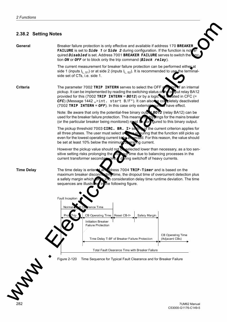
2 Functions
om
2.38.2 Setting Notes
General Breaker failure protection is only effective and available if address 170 BREAKER FAILURE is set to Side 1 or Side 2 during configuration. If the function is not re-quired Disabled is set. Address 7001 BREAKER FAILURE serves to switch the func-tion ON or OFF or to block only the trip command (Block relay).
The current measurement for breaker failure protection can be performed either at side 1 (inputs IL, S1) or at side 2 (inputs IL, S2). It is recommended to use the terminal-side set of CTs, i.e. side 1.
Criteria The parameter 7002 TRIP INTERN serves to select the OFF criterion of an internal pickup. It can be implemented by reading the switching status of the output relay BA12 provided for this (7002 TRIP INTERN = BO12) or by a logic link created in CFC (= CFC) (Message 1442 „>int. start B/F“). It can also be completely deactivated (7002 TRIP INTERN = OFF). In this case only external sources have effect.
Note: Be aware that only the potential-free binary output BO12 (relay BA12) can be used for the breaker failure protection. This means that trippings for the mains breaker (or the particular breaker being monitored) must be configured to this binary output.
The pickup threshold 7003 CIRC. BR. I> setting of the current criterion applies for all three phases. The user must select a value ensuring that the function still picks up even for the lowest operating current to be expected. For this reason, the value should be set at least 10% below the minimum operating current.
However the pickup value should not be selected lower than necessary, as a too sen-sitive setting risks prolonging the drop-out time due to balancing processes in the current transformer secondary circuit during switchoff of heavy currents.
Time Delay The time delay is entered at address 7004 TRIP-Timer and is based on the maximum breaker disconnecting time, the dropout time of overcurrent detection plus a safety margin which takes into consideration delay time runtime deviation. The time sequences are illustrated in the following figure.
Figure 2-120 Time Sequence for Typical Fault Clearance and for Breaker Failure
ww . El
ectric
alPar
tMan
uals
. c
282 7UM62 ManualC53000-G1176-C149-5
w
2.38 Breaker Failure Protection (ANSI 50BF)w
2.38.3 Settings
The table indicates region-specific presettings. Column C (configuration) indicates the corresponding secondary nominal current of the current transformer.
2.38.4 Information List
Addr. Parameter C Setting Options Default Setting Comments
7001 BREAKER FAILURE OFFONBlock relay
OFF Breaker Failure Protection
7002 TRIP INTERN OFFBO12CFC
OFF Start with Internal TRIP Command
7003 CIRC. BR. I> 1A 0.04 .. 2.00 A 0.20 A Supervision Current Pickup
5A 0.20 .. 10.00 A 1.00 A
7004 TRIP-Timer 0.06 .. 60.00 sec; ∞ 0.25 sec TRIP-Timer
No. Information Type of In-formation
Comments
1403 >BLOCK BkrFail SP >BLOCK breaker failure1422 >Break. Contact SP >Breaker contacts1423 >ext.start1 B/F SP >ext. start 1 breaker failure prot.1441 >ext.start2 B/F SP >ext. start 2 breaker failure prot.1442 >int. start B/F SP >int. start breaker failure prot.1443 int. start B/F OUT Breaker fail. started intern1444 B/F I> OUT Breaker failure I>1451 BkrFail OFF OUT Breaker failure is switched OFF1452 BkrFail BLOCK OUT Breaker failure is BLOCKED1453 BkrFail ACTIVE OUT Breaker failure is ACTIVE1455 B/F picked up OUT Breaker failure protection: picked up1471 BrkFailure TRIP OUT Breaker failure TRIP
ww . El
ectric
alPar
tMan
uals
. com
2837UM62 ManualC53000-G1176-C149-5

2 Functions
om
2.39 Inadvertent Energization (ANSI 50, 27)
The inadvertent energizing protection serves to limit damage by accidental connection of the stationary or already started, but not yet synchronized generator, by fast actua-tion of the mains breaker. A connection to a stationary machine is equivalent to con-nection to a low-ohmic resistor. Due to the nominal voltage impressed by the power system, the generator starts up with a high slip as an asynchronous machine. In this context, unpermissibly high currents are induced inside the rotor which may finally destroy it.
2.39.1 Functional Description
Criteria The inadvertent energizing protection only intervenes if measured quantities do not yet exist in the valid frequency working area (operational condition 0, with a stationary machine) or if an undervoltage below the nominal frequency is present (machine already started up, but not yet synchronized). The inadvertent energizing protection is blocked by a voltage criterion on transgression of a minimum voltage, to prevent it picking up during normal operation. This blocking is delayed to avoid protection being blocked immediately in the event of an unintended connection. Another pickup delay is necessary to avoid an unwanted operation during high-current faults with heavy voltage dip. A dropout time delay allows for a measurement limited in time.
As the inadvertent energizing protection must intervene very rapidly, the instanta-neous current values are monitored over a large frequency range already in operation-al condition 0. If valid measured quantities exist (operational condition 1), the positive phase-sequence voltage, the frequency for blocking inadvertent energizing protection as well as the instantaneous current values are evaluated as tripping criterion.
The following figure shows the logic diagram for inadvertent energizing protection. This function can be blocked via a binary input. For example the existence of the ex-citation voltage can be used here as an addition criterion. As the voltage is a neces-sary criterion for enabling the inadvertent energizing protection, the voltage transform-ers must be monitored. This is done by the Fuse-Failure-Monitor (FFM). If it detects a voltage transformer fault, the voltage criterion of the inadvertent energizing protection is deactivated.
ww . El
ectric
alPar
tMan
uals
. c
284 7UM62 ManualC53000-G1176-C149-5
w

2.39 Inadvertent Energization (ANSI 50, 27)w
Figure 2-121 Logic Diagram of the Inadvertent Energizing Protection (Dead Machine Protec-tion)
2.39.2 Setting Notes
General Inadvertent energizing protection is only effective and available if address 171 INADVERT. EN. is set to Enabled during configuration. If the function is not required Disabled is set. Address 7101 INADVERT. EN. serves to switch the function ON or OFF or to block only the trip command (Block relay).
Criteria Parameter 7102 I STAGE serves to specify the current pickup threshold of the inad-vertent energization protection function. As a rule, this threshold value is set more sen-sitively than the threshold value of the time-overcurrent protection. In this case, the in-advertent energizing protection may only be effective if the device is either in operational condition 0 or if no nominal conditions have been reached yet. The param-eter 7103 RELEASE U1< serves to define these nominal conditions. The typical setting is about 50 % to 70 % of the nominal voltage. The parameter value is based on phase-to-phase voltages. A 0 V setting deactivates the voltage tripping. However, this should only be used if 7102 I STAGE shall be used as 3rd time-overcurrent pro-tection stage, at a very high setting.
The parameter 7104 PICK UP T U1< parameter represents the time delay for the release of the tripping condition with undervoltage. The user should select a higher value for this time delay than for the tripping time delay of the time-overcurrent protec-tion.
The delay time to block the tripping conditions when the voltage is above the under-voltage threshold is set at 7105 DROP OUT T U1<. The inadvertent energizing pro-tection is blocked only after this time in order to enable a tripping subsequent to con-nection.
ww . El
ectric
alPar
tMan
uals
. com
2857UM62 ManualC53000-G1176-C149-5

2 Functions
om
The following figure illustrates the course of events during an unwanted connection at machine standstill and, contrast to this, during a voltage collapse on short circuit close to generator terminals.
Figure 2-122 Chronological Sequences of the Inadvertent Energizing Protection
2.39.3 Settings
The table indicates region-specific presettings. Column C (configuration) indicates the corresponding secondary nominal current of the current transformer.
Addr. Parameter C Setting Options Default Setting Comments
7101 INADVERT. EN. OFFONBlock relay
OFF Inadvertent Energisation
7102 I STAGE 5A 0.5 .. 100.0 A; ∞ 1.5 A I Stage Pickup
1A 0.1 .. 20.0 A; ∞ 0.3 A
7103 RELEASE U1< 10.0 .. 125.0 V; 0 50.0 V Release Threshold U1<
7104 PICK UP T U1< 0.00 .. 60.00 sec; ∞ 5.00 sec Pickup Time Delay T U1<
7105 DROP OUT T U1< 0.00 .. 60.00 sec; ∞ 1.00 sec Drop Out Time Delay T U1<
ww . El
ectric
alPar
tMan
uals
. c
286 7UM62 ManualC53000-G1176-C149-5
w
2.39 Inadvertent Energization (ANSI 50, 27)w
2.39.4 Information List
No. Information Type of In-formation
Comments
5533 >BLOCK I.En. SP >BLOCK inadvertent energ. prot.5541 I.En. OFF OUT Inadvert. Energ. prot. is swiched OFF5542 I.En. BLOCKED OUT Inadvert. Energ. prot. is BLOCKED5543 I.En. ACTIVE OUT Inadvert. Energ. prot. is ACTIVE5546 I.En. release OUT Release of the current stage5547 I.En. picked up OUT Inadvert. Energ. prot. picked up5548 I.En. TRIP OUT Inadvert. Energ. prot. TRIP
ww . El
ectric
alPar
tMan
uals
. com
2877UM62 ManualC53000-G1176-C149-5
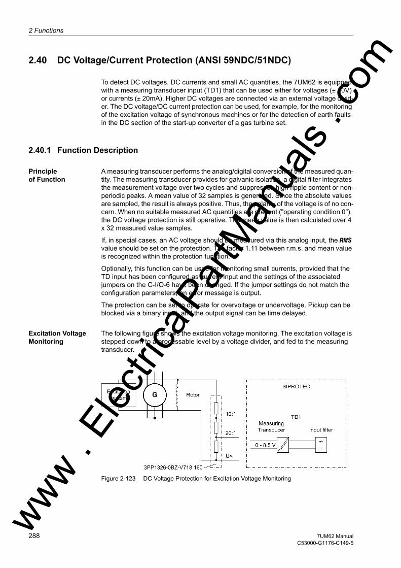
2 Functions
om
2.40 DC Voltage/Current Protection (ANSI 59NDC/51NDC)
To detect DC voltages, DC currents and small AC quantities, the 7UM62 is equipped with a measuring transducer input (TD1) that can be used either for voltages (± 10V) or currents (± 20mA). Higher DC voltages are connected via an external voltage divid-er. The DC voltage/DC current protection can be used, for example, for the monitoring of the excitation voltage of synchronous machines or for the detection of earth faults in the DC section of the start-up converter of a gas turbine set.
2.40.1 Function Description
Principle of Function
A measuring transducer performs the analog/digital conversion of the measured quan-tity. The measuring transducer provides for galvanic isolation, a digital filter integrates the measurement voltage over two cycles and suppresses high ripple content or non-periodic peaks. A mean value of 32 samples is generated. Since the absolute values are sampled, the result is always positive. Thus, the polarity of the voltage is of no con-cern. When no suitable measured AC quantities are present ("operating condition 0"), the DC voltage protection is still operative. The mean value is then calculated over 4 x 32 measured value samples.
If, in special cases, an AC voltage should be measured via this analog input, the RMS value should be set on the protection. The factor 1.11 between r.m.s. and mean value is recognized within the protection function.
Optionally, this function can be used for monitoring small currents, provided that the TD input has been configured as current input and the settings of the associated jumpers on the C-I/O-6 have been changed. If the jumper settings do not match the configuration parameters, an error message is output.
The protection can be set to operate for overvoltage or undervoltage. Pickup can be blocked via a binary input, and the output signal can be time delayed.
Excitation Voltage Monitoring
The following figure shows the excitation voltage monitoring. The excitation voltage is stepped down to a processable level by a voltage divider, and fed to the measuring transducer.
Figure 2-123 DC Voltage Protection for Excitation Voltage Monitoring
ww . El
ectric
alPar
tMan
uals
. c
288 7UM62 ManualC53000-G1176-C149-5
w

2.40 DC Voltage/Current Protection (ANSI 59NDC/51NDC)w
Earth Fault Detec-tion in the Startup Converter
If an earth fault occurs in the startup converter circuit, a current flows through all earthed parts of the system because of the DC voltage. As earthing and neutral trans-formers have a lower ohmic resistance than voltage transformers, the thermal load is the highest on them.
The DC current is converted into a voltage in a shunt, and fed via a shunt converter to the measuring transducer of the device.
Shunt converters can be measuring transducers such as the 7KG6131. For short dis-tances between the shunt converter and the protective device, a voltage input may be used. For longer distances, use the version with current input (-20 to 20 mA or 4 to 20 mA).
Figure 2-124 DC Voltage Protection for Detecting an Earth Fault in the Startup Converter
Figure 2-125 Logic Diagram of the DC Voltage Protection
ww . El
ectric
alPar
tMan
uals
. com
2897UM62 ManualC53000-G1176-C149-5
2 Functions
om
2.40.2 Setting Notes
General The DC voltage protection is only effective and available if set to Enabled at address 172 DC PROTECTION. If the function is not required, Disabled is set. For the asso-ciated measuring transducer 1, address 295 TRANSDUCER 1 was set to one of the alternatives 10 V, 4-20 mA or 20 mA (see section 2.5).
Jumpers X94, X95 and X67 on the C-I/O-6 module are used to set in the hardware whether the measuring transducer input will be a voltage or a current input (see section 3.1.2 in the chapter „Installation and Commissioning“). Their setting must cor-respond to the setting at address 295. If it does not, the device is blocked and issues an annunciation to that effect. When the relay is delivered from the factory, the jumpers and configuration parameters are set to voltage measurement.
Address 7201 DC PROTECTION serves to switch the function ON or OFF or to block only the trip command (Block relay).
Measurement Method
Normally an integrated average value filter is switched on. A high ripple content or non-periodic peaks in the measurement voltage are averaged in this manner. The po-larity of the measured voltages is of no concern since the absolute value is taken.
Alternatively, a sinusoidal AC voltage can be measured (address 7202 MEAS.METHOD = RMS). The protection then multiplies the rectified average value with 1.11. The fre-quency of the AC voltage must match the frequency of other AC quantities, because the latter determine the sampling rate. The maximum AC amplitude must not exceed 10 V, so that for r.m.s. value measurement a maximum setting of 7.0 Vrms is reason-able. The resulting higher secondary voltage can be reduced by means of a voltage divider.
The DC voltage/DC current protection can be set to operate for overvoltage protection at address 7203 DC >/< = DC > or undervoltage protection = DC <.
Pickup Thresholds Depending on whether current or voltage input has been set at address 295 TRANSDUCER 1, one of the following parameters is available, whereas the other is hidden:• Voltage measurement threshold: 7204 U DC ><• Current measurement threshold: 7205 I DC ><
When setting the pickup values (address 7204), the ratio of a voltage divider – if fitted – has to be considered.
Application Examples
When used for excitation voltage monitoring, the DC current protection is configured to operate for undervoltage; the pickup threshold is set to approx. 60 % to 70 % of the no-load excitation voltage. Users should be aware that normally a voltage divider is connected between the protection and the excitation voltage (see above).
Another typical application is the earth fault protection for the startup converter of a gas turbine set. In the case of an earth fault in the DC circuit, half of the DC voltage is present between the transformer starpoint and the earth if the transformer starpoint is not earthed. This voltage can be considered as the voltage feeding the earth current. As the transformer starpoints are earthed, the current flowing is determined by the feeding voltage and the ohmic resistance of all transformers that are galvanically con-nected to the converter set and earthed. This DC current is normally between about 3 and 4 A.ww .
Elec
tricalP
artM
anua
ls . c
290 7UM62 ManualC53000-G1176-C149-5
w
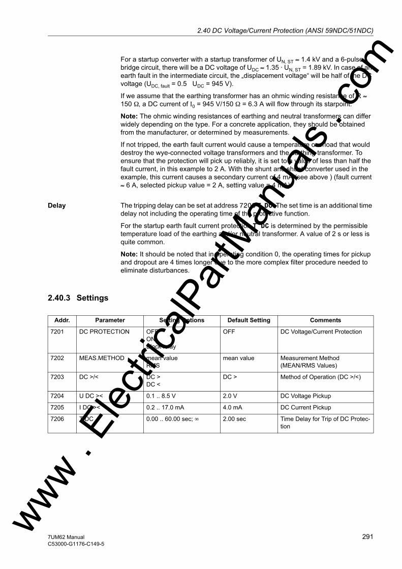
2.40 DC Voltage/Current Protection (ANSI 59NDC/51NDC)w
For a startup converter with a startup transformer of UN, ST ≈ 1.4 kV and a 6-pulse bridge circuit, there will be a DC voltage of UDC ≈ 1.35 · UN, ST = 1.89 kV. In case of an earth fault in the intermediate circuit, the „displacement voltage“ will be half of the DC voltage (UDC, fault = 0.5 UDC = 945 V).
If we assume that the earthing transformer has an ohmic winding resistance of R ≈ 150 Ω, a DC current of I0 = 945 V/150 Ω = 6.3 A will flow through its starpoint.
Note: The ohmic winding resistances of earthing and neutral transformers can differ widely depending on the type. For a concrete application, they should be obtained from the manufacturer, or determined by measurements.
If not tripped, the earth fault current would cause a temperature overload that would destroy the wye-connected voltage transformers and the earthing transformer. To ensure that the protection will pick up reliably, it is set to a value of less than half the fault current, in this example to 2 A. With the shunt and shunt converter used in the example, this current causes a secondary current of 4 mA (see above ) (fault current ≈ 6 A, selected pickup value = 2 A, setting value = 4 mA).
Delay The tripping delay can be set at address 7206 T DC. The set time is an additional time delay not including the operating time of the protective function.
For the startup earth fault current protection T DC is determined by the permissible temperature load of the earthing and/or neutral transformer. A value of 2 s or less is quite common.
Note: It should be noted that in operating condition 0, the operating times for pickup and dropout are 4 times longer due to the more complex filter procedure needed to eliminate disturbances.
2.40.3 Settings
Addr. Parameter Setting Options Default Setting Comments
7201 DC PROTECTION OFFONBlock relay
OFF DC Voltage/Current Protection
7202 MEAS.METHOD mean valueRMS
mean value Measurement Method (MEAN/RMS Values)
7203 DC >/< DC >DC <
DC > Method of Operation (DC >/<)
7204 U DC >< 0.1 .. 8.5 V 2.0 V DC Voltage Pickup
7205 I DC >< 0.2 .. 17.0 mA 4.0 mA DC Current Pickup
7206 T DC 0.00 .. 60.00 sec; ∞ 2.00 sec Time Delay for Trip of DC Protec-tion
ww . El
ectric
alPar
tMan
uals
. com
2917UM62 ManualC53000-G1176-C149-5

2 Functions
om
2.40.4 Information List
No. Information Type of In-formation
Comments
5293 >BLOCK DC Prot. SP >BLOCK DC protection5301 DC Prot. OFF OUT DC protection is switched OFF5302 DC Prot.BLOCKED OUT DC protection is BLOCKED5303 DC Prot. ACTIVE OUT DC protection is ACTIVE5306 DC Prot.pick.up OUT DC protection picked up5307 DC Prot. TRIP OUT DC protection TRIP5308 Failure DC Prot OUT Failure DC protection
ww . El
ectric
alPar
tMan
uals
. c
292 7UM62 ManualC53000-G1176-C149-5
w

2.41 Analog Outputsw
2.41 Analog Outputs
Depending on the variant ordered, the 7UM62 machine protection can have up to four analog outputs (plug-in modules on ports B and D).
2.41.1 Function Description
The values to be transmitted via these interfaces were specified during the configura-tion of the scope of protection functions.
Table 2-13 A maximum of four of the following analog outputs are available:
The operational nominal values are those configured at address 251 UN GEN/MOTOR and 252 SN GEN/MOTOR (see also section 2.5).
For measured values that can be negative (power, power factor), absolute values are formed and output.
Analog values are output as injected currents. The analog outputs have a nominal range between 0 mA and 20 mA, their operating range can be up to 22.5 mA. The con-version factor and the validity range can be set.
Measured value
Description Scaling
I1 Positive sequence current component in % based on IN generator I2 Negative sequence current component in % based on IN generatorIEE1 Sensitive earth current in % based on 100 mA IEE2 Sensitive earth current in % based on 100 mA U1 Positive sequence voltage component in % based on UN generator/√3U0 Zero sequence voltage component in % based on UN generator/√3U03H 3. Harmonic voltage in % based on 0.1 UN generator/√3 (relatively small values)|P| Absolute amount of real power in % based on SN generator |Q| Absolute amount of reactive power in % based on SN generator|S| Apparent power in % based on SN generatorf Frequency in % based on the nominal frequency fNU/f Overexcitation in % based on the nominal values of the protected object PHI Power angle in % based on 90° |cos ϕ| Power factor in % based on 1ΘL/ΘL Trip Rotor temperature in % based on the maximum permissible rotor temperature ΘS/ΘS Trip Stator temperature in % based on the tripping temperatureRE REF Rotor earth resistance (fN measuring method) in % based on 100 kΩRE REF 1-3Hz Rotor earth resistance (1-3 Hz measuring
method)in % based on 100 kΩ
RE SEF "Secondary" stator earth resistance in % based on 100 Ω
ww . El
ectric
alPar
tMan
uals
. com
2937UM62 ManualC53000-G1176-C149-5
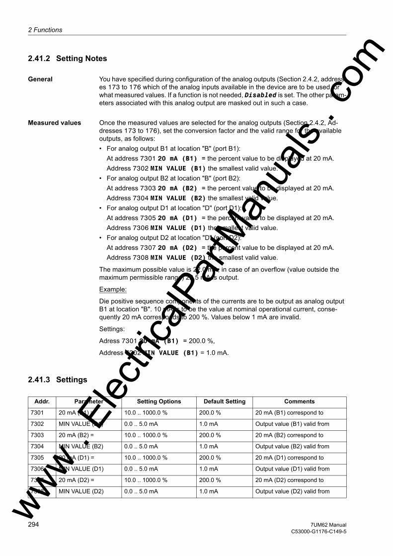
2 Functions
om
2.41.2 Setting Notes
General You have specified during configuration of the analog outputs (Section 2.4.2, address-es 173 to 176 which of the analog inputs available in the device are to be used for what measured values. If a function is not needed, Disabled is set. The other param-eters associated with this analog output are masked out in such a case.
Measured values Once the measured values are selected for the analog outputs (Section 2.4.2, Ad-dresses 173 to 176), set the conversion factor and the valid range for the available outputs, as follows:• For analog output B1 at location "B" (port B1):
At address 7301 20 mA (B1) = the percent value to be displayed at 20 mA. Address 7302 MIN VALUE (B1) the smallest valid value.
• For analog output B2 at location "B" (port B2): At address 7303 20 mA (B2) = the percent value to be displayed at 20 mA. Address 7304 MIN VALUE (B2) the smallest valid value.
• For analog output D1 at location "D" (port D1): At address 7305 20 mA (D1) = the percent value to be displayed at 20 mA. Address 7306 MIN VALUE (D1) the smallest valid value.
• For analog output D2 at location "D" (port D2): At address 7307 20 mA (D2) = the percent value to be displayed at 20 mA. Address 7308 MIN VALUE (D2) the smallest valid value.
The maximum possible value is 22.0 mA; in case of an overflow (value outside the maximum permissible range) 22.5 mA is output.
Example:
Die positive sequence components of the currents are to be output as analog output B1 at location "B". 10 mA is to be the value at nominal operational current, conse-quently 20 mA corresponds to 200 %. Values below 1 mA are invalid.
Settings:
Adress 7301 20 mA (B1) = 200.0 %,
Address 7302 MIN VALUE (B1) = 1.0 mA.
2.41.3 Settings
Addr. Parameter Setting Options Default Setting Comments
7301 20 mA (B1) = 10.0 .. 1000.0 % 200.0 % 20 mA (B1) correspond to
7302 MIN VALUE (B1) 0.0 .. 5.0 mA 1.0 mA Output value (B1) valid from
7303 20 mA (B2) = 10.0 .. 1000.0 % 200.0 % 20 mA (B2) correspond to
7304 MIN VALUE (B2) 0.0 .. 5.0 mA 1.0 mA Output value (B2) valid from
7305 20 mA (D1) = 10.0 .. 1000.0 % 200.0 % 20 mA (D1) correspond to
7306 MIN VALUE (D1) 0.0 .. 5.0 mA 1.0 mA Output value (D1) valid from
7307 20 mA (D2) = 10.0 .. 1000.0 % 200.0 % 20 mA (D2) correspond to
7308 MIN VALUE (D2) 0.0 .. 5.0 mA 1.0 mA Output value (D2) valid fromww . El
ectric
alPar
tMan
uals
. c
294 7UM62 ManualC53000-G1176-C149-5
w

2.42 Monitoring Functionsw
2.42 Monitoring Functions
The device is equipped with extensive monitoring capabilities - both for hardware and software. In addition, the measured values are also constantly monitored for plausibil-ity, therefore, the current transformer and voltage transformer circuits are largely inte-grated into the monitoring.
2.42.1 Measurement Supervision
2.42.1.1 Hardware Monitoring
The device monitoring extends from the measuring inputs to the binary outputs. Mon-itoring circuits and processor check the hardware for malfunctions and inadmissible conditions (see also Table 2-14).
Auxiliary and Refer-ence Voltages
The processor voltage of 5 VDC is monitored by the hardware since if it goes below the minimum value, the processor is no longer functional. In that case the device is put out of operation. When the normal voltage returns, the processor system is restarted.
Failure or switching off the supply voltage removes the device from operation and a message is immediately generated by the "life contact" (an alternatively NO or NC contact). Brief auxiliary voltage interruptions of less than 50 ms do not disturb the op-erational readiness of the device (for nominal auxiliary voltage ≥ 110 VDC).
The processor monitors the reference voltage of the ADC (analog-to-digital converter). In case of inadmissible deviations the protection is blocked; persistent faults are sig-nalled (indication: „Error A/D-conv.“).
Buffer Battery The buffer battery, which ensures operation of the internal clock and storage of counters and messages if the auxiliary voltage fails, is periodically checked for charge status. If the voltage drops below the permissible minimum voltage, the alarm „Fail Battery“ is output.
If the device is isolated from the auxiliary voltage for several hours, the internal back-up battery is switched off automatically, i.e. the time is not registered any more. Mes-sages and fault recordings however are kept stored.
Memory Components
All working memories (RAMs) are checked during start-up. If a fault occurs in this pro-cess, the start is aborted and an LED starts flashing. During operation the memories are checked by means of their checksum.
For the program memory (EPROM), the cross-check sum is cyclically generated and compared to a stored reference program cross-check sum.
For the settings memory, the cross-check sum is formed cyclically and compared to the cross-check sum that is freshly generated each time a setting process takes place.
If a fault occurs the processor system is restarted.
Sampling Frequency
The sampling frequency and the synchronism between the internal buffer modules is continuously monitored. If any deviations cannot be removed by renewed synchroni-sation, then the processor system is restarted. ww . El
ectric
alPar
tMan
uals
. com
2957UM62 ManualC53000-G1176-C149-5
2 Functions
om
Measurement Value Acquisition – Cur-rents
In the current paths there are three input transformers each on side 1 and side 2; the digitized sum of the transformer currents of one side must be almost zero for genera-tors with isolated starpoint during earth-fault-free operation. A current circuit fault is detected if
IF = | IL1 + IL2 + IL3 | > ΣI THRESHOLD S1 · IN + ΣI FACTOR S1 · Imax or
IF = | IL1 + IL2 + IL3 | > ΣI THRESHOLD S2 · IN + ΣI FACTOR S2 · Imax
The component ΣI FACTOR S1 · Imax or ΣI FACTOR S2 · Imax takes into account admissible current-proportional transformation errors in the input transducers which may occur especially during high fault currents (see the following figure). The dropout ratio is about 95 %.
This malfunction is reported as „Fail. Σ I Side1“ or „Fail. Σ I Side2“.
The current sum monitoring is only effective for the side for which the starpoint has been configured (address 242 or 244) as Isolated in the power system data.
Figure 2-126 Current sum monitoring
Measured Value Acquisition – Voltages
Four measuring inputs are available in the voltage path: if three of them are used for phase-earth voltages, and one input for the displacement voltage (e–n voltage from the broken delta winding or neutral transformer) of the same system, a fault in the phase-earth voltage sum is detected if
| UL1 + UL2 + UL3 + kU · UE | > SUM.thres. U + SUM.Fact. U x Umax
SUM.thres. U and SUM.Fact. U are parameter settings, and Umax is the highest of the phase-earth voltages. Factor kU considers the transformation ratio differences between the displacement voltage input and the phase voltage inputs (parameter kU = Uph / Udelta address 225). The SUM.Fact. U x Umax component considers admissible voltage-proportional transformation errors of the input transducers, which can be especially large in the presence of high voltages (see the following figure).
This malfunction is reported as „Fail Σ U Ph-E“.
ww . El
ectric
alPar
tMan
uals
. c
296 7UM62 ManualC53000-G1176-C149-5
w
2.42 Monitoring Functionsw
Note
Voltage sum monitoring is only effective if an external displacement voltage is con-nected at the displacement voltage measuring input and this is also notified via the pa-rameter 223 UE CONNECTION to the device.
Voltage sum monitoring can operate properly only if the adaptation factor Uph / Udelta at address 225 has been correctly configured (see Subsection 2.5.1).
Figure 2-127 Voltage sum monitoring
2.42.1.2 Software Monitoring
Watchdog For continuous monitoring of the program sequences, a watchdog timer is provided in the hardware (hardware watchdog) which will reset and completely restart the proces-sor system in the event of processor failure or if a program falls out of step.
A further software watchdog ensures that any error in the processing of the programs will be recognized. This also initiates a restart of the processor system.
If such a malfunction is not cleared by the restart, an additional restart attempt is begun. After three unsuccessful restarts within a 30 second window of time, the device automatically removes itself from service and the red "Error" LED lights up. The oper-ational readiness relay ("Life contact") opens and issues an alarm (alternatively as NO or NC contact).
ww . El
ectric
alPar
tMan
uals
. com
2977UM62 ManualC53000-G1176-C149-5

2 Functions
om
2.42.1.3 Monitoring External Transformer Circuits
Interruptions or short circuits in the secondary circuits of the current and voltage trans-formers, as well as faults in the connections (important for commissioning!), are de-tected and reported by the device. The measured values are cyclically checked in background routines for this purpose, as long as no system fault is present.
Current Balance The currents fed in at the current inputs of side 1 and side 2 are monitored for symme-try. During normal system operation a certain degree of symmetry of the currents is expected. This symmetry is checked by the device, using an amplitude monitor. The smallest phase current is compared to the largest phase current. Asymmetry is recog-nized if:
| Imin | / | Imax | < BAL. FACT. I S1 as long as Imax / IN > BAL. I LIMIT S1 / IN
| Imin | / | Imax | < BAL. FACT. I S2 as long as Imax / IN > BAL. I LIMIT S2 / IN
where Imax is the largest of the three phase currents and Imin is the smallest. The sym-metry factor BAL. FACT. I S1 or BAL. FACT. I S2 represents the admissible asymmetry of the phase currents whereas the limit value BAL. I LIMIT S1 or BAL. I LIMIT S2 is the lower limit of the operating range of this monitoring (see following figure). The dropout ratio is about 95 %.
This fault is signaled with „Fail. Isym 1“ or „Fail. Isym 2“ separately for side 1 and side 2.
Figure 2-128 Current symmetry monitoring
ww . El
ectric
alPar
tMan
uals
. c
298 7UM62 ManualC53000-G1176-C149-5
w

2.42 Monitoring Functionsw
Voltage Symmetry During normal system operation a certain degree of symmetry among the voltages is expected. With two phase-phase voltages and the displacement voltage UE connected to the device, the third phase-phase voltage is calculated. The rectified mean values are formed from the phase-earth voltages, and checked for the symmetry of their amounts. The smallest phase voltage is compared to the largest. Asymmetry is recog-nized if:
| Umin | / | Umax | < BAL. FACTOR U as long as | Umax | > BALANCE U-LIMIT
Where Umax is the highest of the three voltages and Umin the smallest. The symmetry factor BAL. FACTOR U is the measure for the asymmetry of the conductor voltages; the limit BALANCE U-LIMIT is the lower limit of the operating range of this monitoring (see following figure). Both parameters can be set. The dropout ratio is about 95 %.
This malfunction is reported as „Fail U balance“.
If the 90% stator earth fault protection functions are active, a zero voltage results on voltage asymmetry. If this causes protection pickup, monitoring is relegated to the background and issues no indication.
Figure 2-129 Voltage symmetry monitoring
Current and Voltage Phase Sequence
To detect swapped phase connections in the voltage and current input circuits, the phase sequence of the phase-to-phase measured voltages and the phase currents is checked by monitoring the sequence of same polarity zero transitions of the voltages.
Direction measurement with cross-polarized voltages, path selection for impedance protection, evaluation of positive sequence voltages for undervoltage protection and unbalanced load detection all assume a clockwise phase sequence. The current phase rotation is checked and reported individually for side 1 and side 2.
Phase rotation of measured voltages is checked by verifying the phase sequences of the voltages
UL1 leads UL2 leads UL3
and of the phase currents, in each case
IL1 leads IL2 leads IL3.ww . El
ectric
alPar
tMan
uals
. com
2997UM62 ManualC53000-G1176-C149-5

2 Functions
om
Verification of the voltage phase rotation is performed when each measured voltage is at least
|UL1|, |UL2|, |UL3| > 40 V/√3
Verification of the current phase sequence is performed when each measured current is at least
|IL1|, |IL2|, |IL3| > 0.5 IN.
For abnormal phase sequences (L1, L3, L2), the indications „Fail Ph. Seq. U“, (No. 176) or „FailPh.Seq I S1“, (No. 265) are issued for side 1, or the indication „FailPh.Seq I S2“, (No. 266) for side 2, as well as an OR combination of these indications „Fail Ph. Seq.“, (No. 171)
For applications where a counter-clockwise measured values phase sequence ap-pears, this must be notified to the device via the parameter 271 PHASE SEQ. or an accordingly allocated binary input. If the phase sequence is changed in the relay, phases L2 and L3 internal to the relay are reversed, and the positive and negative se-quence currents are thereby exchanged (see also Subsection 2.47). The phase-related messages, malfunction values, and measured values are not affected by this.
2.42.1.4 Setting Notes
Measured Value Monitoring
Measured value monitoring can be turned ON or OFF at address 8101 MEASURE. SUPERV. In addition the sensitivity of measured value monitorings can be modified. Default values are set at the factory, which are sufficient in most cases. If especially high operating asymmetry in the currents and/or voltages is to be expected for the ap-plication, or if it becomes apparent during operation that certain monitoring functions activate sporadically, then the setting should be less sensitive.
Address 8102 BALANCE U-LIMIT determines the limit voltage (phase-phase), above which voltage symmetry monitoring becomes effective (see also Voltage Symmetry Monitoring figure). Address 8103 BAL. FACTOR U is the associated symmetry factor; that is, the slope of the symmetry characteristic curve.
Address 8104 BAL. I LIMIT S1 determines for side 1, address 8106 BAL. I LIMIT S2 for side 2, the limit current above which current symmetry monitoring becomes effective (see also Current Symmetry Monitoring figure). Address 8105 BAL. FACT. I S1 is the associated symmetry factor for side 1, address 8107 BAL. FACT. I S2 for side 2, i.e. the slope of the symmetry characteristic.
Address 8110 ΣI THRESHOLD S1 establishes for side 1 the limit current above which current sum monitoring (see Current Sum Monitoring figure) is activated (absolute component, referred only to IN). Accordingly address 8112 ΣI THRESHOLD S2 applies for side 2. the relative component (referred to maximum phase current) for trig-gering the sum current monitoring is set for side 1 under address 8111 ΣI FACTOR S1 and for side 2 under 8113 ΣI FACTOR S2
Address 8108 SUM.thres. U determines the limit voltage above which current sum monitoring becomes active (see also Current Sum Monitoring figure) (absolute com-ponent, referred only to UN). The relative component for triggering the sum current monitoring is set under address 8109 SUM.Fact. U.
ww . El
ectric
alPar
tMan
uals
. c
300 7UM62 ManualC53000-G1176-C149-5
w

2.42 Monitoring Functionsw
Note
In power system data 1, the voltage earth path and its matching factor Uph / Udelta were specified. Measured value monitorings will only function properly if the setting there is correct.
2.42.1.5 Settings
The table indicates region-specific presettings. Column C (configuration) indicates the corresponding secondary nominal current of the current transformer.
Addr. Parameter C Setting Options Default Setting Comments
8101 MEASURE. SUPERV OFFON
OFF Measurement Supervision
8102 BALANCE U-LIMIT 10 .. 100 V 50 V Voltage Threshold for Balance Monitoring
8103 BAL. FACTOR U 0.58 .. 0.90 0.75 Balance Factor for Voltage Monitor
8104 BAL. I LIMIT S1 1A 0.10 .. 1.00 A 0.50 A Current Balance Monitor Side 1
5A 0.50 .. 5.00 A 2.50 A
8105 BAL. FACT. I S1 0.10 .. 0.90 0.50 Balance Factor for Current Monitor S1
8106 BAL. I LIMIT S2 5A 0.50 .. 5.00 A 2.50 A Current Balance Monitor Side 2
1A 0.10 .. 1.00 A 0.50 A
8107 BAL. FACT. I S2 0.10 .. 0.90 0.50 Balance Factor for Current Monitor S2
8108 SUM.thres. U 10 .. 200 V 10 V Summation Thres. for Volt. Monitoring
8109 SUM.Fact. U 0.60 .. 0.95 ; 0 0.75 Factor for Volt. Sum. Mon-itoring
8110 ΣI THRESHOLD S1 1A 0.05 .. 2.00 A 0.10 A Summated Cur. Mon. Threshold on Side 1
5A 0.25 .. 10.00 A 0.50 A
8111 ΣI FACTOR S1 0.00 .. 0.95 0.10 Summated Current Mon. Factor on Side 1
8112 ΣI THRESHOLD S2 5A 0.25 .. 10.00 A 0.50 A Summated Cur. Mon. Threshold on Side 2
1A 0.05 .. 2.00 A 0.10 A
8113 ΣI FACTOR S2 0.00 .. 0.95 0.10 Summated Current Mon. Factor on Side 2
ww . El
ectric
alPar
tMan
uals
. com
3017UM62 ManualC53000-G1176-C149-5
2 Functions
om
2.42.1.6 Information List
No. Information Type of In-formation
Comments
161 Fail I Superv. OUT Failure: General Current Supervision164 Fail U Superv. OUT Failure: General Voltage Supervision165 Fail Σ U Ph-E OUT Failure: Voltage Summation Phase-Earth167 Fail U balance OUT Failure: Voltage Balance171 Fail Ph. Seq. OUT Failure: Phase Sequence176 Fail Ph. Seq. U OUT Failure: Phase Sequence Voltage197 MeasSup OFF OUT Measurement Supervision is switched OFF230 Fail. Σ I Side1 OUT Failure: Current Summation on Side 1231 Fail. Σ I Side2 OUT Failure: Current Summation on Side 2265 FailPh.Seq I S1 OUT Failure: Phase Sequence I side 1266 FailPh.Seq I S2 OUT Failure: Phase Sequence I side 2571 Fail. Isym 1 OUT Fail.: Current symm. supervision side 1572 Fail. Isym 2 OUT Fail.: Current symm. supervision side 2
ww . El
ectric
alPar
tMan
uals
. c
302 7UM62 ManualC53000-G1176-C149-5
w
2.42 Monitoring Functionsw
2.42.2 Supervision
2.42.2.1 Fuse Failure Monitor
In the event of a measured voltage failure due to a short circuit fault or a broken con-ductor in the voltage transformer secondary circuit certain measuring loops may mis-takenly see a voltage of zero. The measuring results of the undervoltage protection, the impedance protection and other voltage-dependent protective functions may be falsified in this way, possibly causing an unwanted operation.
If fuses are used instead of a secondary miniature circuit breaker (VT mcb) with con-nected auxiliary contacts, then the fuse failure monitoring can detect problems in the voltage transformer secondary circuit. Of course the miniature circuit breaker and the fuse failure monitor can be used at the same time.
This function uses the current of side 2.
Measuring Princi-ple for 1-Pole and 2-Pole Fuse Failures
The measuring voltage failure detection is based on the fact a significant negative-phase sequence system is formed in the voltage during a 1- or 2-pole voltage failure, without influencing the current. This enables a clear distinction from asymmetries im-pressed by the power system. If the negative-phase sequence system is related to the current positive-phase sequence system, the following rules apply for the fault-free case:
If a fault of the voltage transformers occurs, the following rules apply for a single-pole failure:
If a fault of the voltage transformers occurs, the following rules apply for a two-pole failure:
In case of an outage of one or two phases, the current also shows a negative-phase sequence system of 0.5 or 1. Consequently, the voltage monitoring does not respond since no voltage transformer fault can be present.
In order to avoid - in case of a too small positive-sequence system - an unwanted op-eration by inaccuracies of the measuring voltages failure detection, the function is blocked below a minimum threshold of the positive-sequence systems of voltage (U1 < 10 V) and current (I1 < 0.1 IN).
ww . El
ectric
alPar
tMan
uals
. com
3037UM62 ManualC53000-G1176-C149-5

2 Functions
om
3-pole Fuse Failure A 3–pole fuse failure of the voltage transformer cannot be detected by the positive and negative sequence system as previously described. Here monitoring of the chronolog-ical sequence of current and voltage is required. If a voltage dip of approximately zero occurs (or if the voltage is zero), although the current remains unchanged by the same time, this is probably due to a 3-pole voltage transformer failure. The deviation of the actual current value from the nominal current value is evaluated for this purpose. The measuring voltage failure monitoring is blocked if the deviation exceeds a threshold value. Moreover, this function is blocked if a pickup of an (overcurrent) protective func-tion is already present.
Additional Criteria In addition to this, the function can either be blocked via a binary input or deactivated by an undervoltage protection at a separate voltage transformer set. If an undervolt-age is also detected at a separate transformer set, this is most probably not due to a transformer error and the monitoring switching can be blocked. The separate under-voltage protection must be set non-delayed and should also evaluate the positive-phase sequence system of the voltages (e.g. 7RW600).
Voltage at the UE Input
Depending on how UE is connected, it may be necessary to block the voltage mea-surement of this input. A block can be generated with the CFC tool and combined with the indication „VT Fuse Failure“.
Other Blocks Fuse failure monitores directly blocks functions (see Figure 2-130). If other functions, such as underexcitation protection, need to be blocked, the indication „VT Fuse Failure“ must be used, and combined with the protection fuction via the logic com-ponent (CFC).
ww . El
ectric
alPar
tMan
uals
. c
304 7UM62 ManualC53000-G1176-C149-5
w

2.42 Monitoring Functionsw
Logic When a fuse failure is detected (Figure 2-130 left-hand logic component), this status is stored. This ensures that the fuse failure indication is maintained even in the event of a short circuit. As soon as the fuse failure has been eliminated, and the positive se-quence voltage has risen above 85 % of the nominal voltage, the stored value is can-celled, and the fuse failure indication is reset with a delay of 10 s.
Figure 2-130 Logic Diagram of the Fuse-Failure-Monitor
ww . El
ectric
alPar
tMan
uals
. com
3057UM62 ManualC53000-G1176-C149-5

2 Functions
om
2.42.2.2 Malfunction Responses of the Monitoring Functions
Depending on the type of malfunction detected, an indication is sent, a restart of the processor system initiated, or the device is taken out of service. After three unsuccess-ful restart attempts, the device is also taken out of service. The operational readiness NC contact operates to indicate the device is malfunctioning. Also, the red LED "ERROR" lights up on the front cover, if the internal auxiliary voltage is present, and the green "RUN" LED goes out. If the internal auxiliary voltage fails, then all LEDs are dark. The following table summarises the monitoring functions and the malfunction re-sponses of the device.
ww . El
ectric
alPar
tMan
uals
. c
306 7UM62 ManualC53000-G1176-C149-5
w
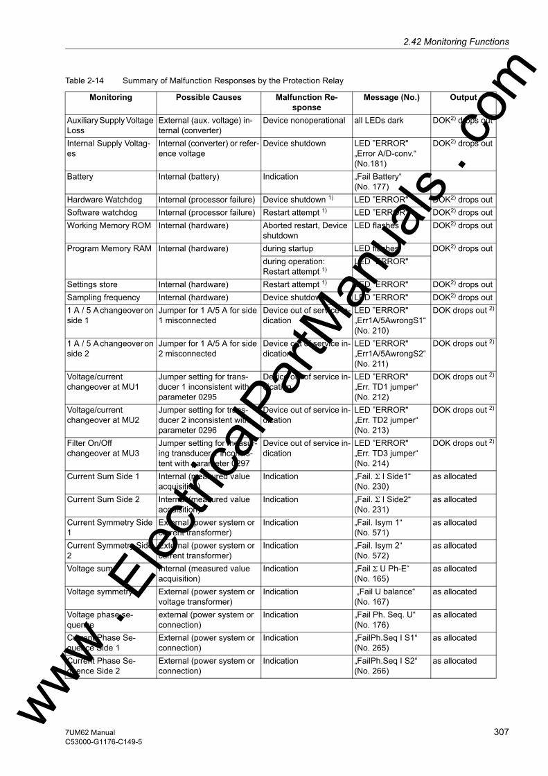
2.42 Monitoring Functionsw
Table 2-14 Summary of Malfunction Responses by the Protection Relay
Monitoring Possible Causes Malfunction Re-sponse
Message (No.) Output
Auxiliary Supply Voltage Loss
External (aux. voltage) in-ternal (converter)
Device nonoperational all LEDs dark DOK2) drops out
Internal Supply Voltag-es
Internal (converter) or refer-ence voltage
Device shutdown LED ”ERROR"„Error A/D-conv.“ (No.181)
DOK2) drops out
Battery Internal (battery) Indication „Fail Battery“ (No. 177)
Hardware Watchdog Internal (processor failure) Device shutdown 1) LED ”ERROR" DOK2) drops outSoftware watchdog Internal (processor failure) Restart attempt 1) LED ”ERROR" DOK2) drops outWorking Memory ROM Internal (hardware) Aborted restart, Device
shutdownLED flashes DOK2) drops out
Program Memory RAM Internal (hardware) during startup LED flashes DOK2) drops outduring operation: Restart attempt 1)
LED ”ERROR"
Settings store Internal (hardware) Restart attempt 1) LED ”ERROR" DOK2) drops outSampling frequency Internal (hardware) Device shutdown LED ”ERROR" DOK2) drops out1 A / 5 A changeover on side 1
Jumper for 1 A/5 A for side 1 misconnected
Device out of service in-dication
LED ”ERROR"„Err1A/5AwrongS1“(No. 210)
DOK drops out 2)
1 A / 5 A changeover on side 2
Jumper for 1 A/5 A for side 2 misconnected
Device out of service in-dication
LED ”ERROR"„Err1A/5AwrongS2“(No. 211)
DOK drops out 2)
Voltage/current changeover at MU1
Jumper setting for trans-ducer 1 inconsistent with parameter 0295
Device out of service in-dication
LED ”ERROR"„Err. TD1 jumper“ (No. 212)
DOK drops out 2)
Voltage/current changeover at MU2
Jumper setting for trans-ducer 2 inconsistent with parameter 0296
Device out of service in-dication
LED ”ERROR"„Err. TD2 jumper“(No. 213)
DOK drops out 2)
Filter On/Off changeover at MU3
Jumper setting for measur-ing transducer 1 inconsis-tent with parameter 0297
Device out of service in-dication
LED ”ERROR"„Err. TD3 jumper“(No. 214)
DOK drops out 2)
Current Sum Side 1 Internal (measured value acquisition)
Indication „Fail. Σ I Side1“(No. 230)
as allocated
Current Sum Side 2 Internal (measured value acquisition)
Indication „Fail. Σ I Side2“ (No. 231)
as allocated
Current Symmetry Side 1
External (power system or current transformer)
Indication „Fail. Isym 1“ (No. 571)
as allocated
Current Symmetry Side 2
External (power system or current transformer)
Indication „Fail. Isym 2“(No. 572)
as allocated
Voltage sum Internal (measured value acquisition)
Indication „Fail Σ U Ph-E“ (No. 165)
as allocated
Voltage symmetry External (power system or voltage transformer)
Indication „Fail U balance“(No. 167)
as allocated
Voltage phase se-quence
external (power system or connection)
Indication „Fail Ph. Seq. U“(No. 176)
as allocated
Current Phase Se-quence Side 1
External (power system or connection)
Indication „FailPh.Seq I S1“(No. 265)
as allocated
Current Phase Se-quence Side 2
External (power system or connection)
Indication „FailPh.Seq I S2“(No. 266)
as allocated
ww . El
ectric
alPar
tMan
uals
. com
3077UM62 ManualC53000-G1176-C149-5

2 Functions
om
1) After three unsuccessful restarts, the device is taken out of service.2) DOK = "Device Okay" = Operational readiness relay drops off, protection and control functions are blocked. Operator
communication is still possible
2.42.2.3 Setting Notes
Fuse Failure Moni-toring
The internal automatic reclosure system will only be effective and accessible if address 180 FUSE FAIL MON. is set Enabled during configuration. If the function is not required Disabled is set. In address 8001 FUSE FAIL MON. the function can be set to ON or OFF.
The thresholds U2/U1 ≥ 40 % and I2/I1 ≤ 20 % for detecting 1-pole and 2-pole voltage failures are fixed. The thresholds for detecting a 3-pole voltage failure (undervoltage threshold = 10 V, below which the failure detection feature responds unless the current changes significantly and the differential current monitoring = 0.5 IN) are likewise fixed and need not be set.
Fuse Failure Monitor External (voltage trans-formers)
Indication „VT Fuse Failure“(No. 6575)
as allocated
Trip Circuit Monitoring External (trip circuit or control voltage)
Indication „FAIL: Trip cir.“(No. 6865)
as allocated
Monitoring Possible Causes Malfunction Re-sponse
Message (No.) Output
ww . El
ectric
alPar
tMan
uals
. c
308 7UM62 ManualC53000-G1176-C149-5
w

2.42 Monitoring Functionsw
2.42.2.4 Settings
2.42.2.5 Information List
Addr. Parameter Setting Options Default Setting Comments
8001 FUSE FAIL MON. OFFON
OFF Fuse Failure Monitor
No. Information Type of In-formation
Comments
68 Clock SyncError OUT Clock Synchronization Error110 Event Lost OUT_Ev Event lost113 Flag Lost OUT Flag Lost140 Error Sum Alarm OUT Error with a summary alarm147 Error PwrSupply OUT Error Power Supply160 Alarm Sum Event OUT Alarm Summary Event177 Fail Battery OUT Failure: Battery empty181 Error A/D-conv. OUT Error: A/D converter185 Error Board 3 OUT Error Board 3187 Error Board 5 OUT Error Board 5188 Error Board 6 OUT Error Board 6190 Error Board 0 OUT Error Board 0191 Error Offset OUT Error: Offset193 Alarm NO calibr OUT Alarm: NO calibration data available194 Error neutralCT OUT Error: Neutral CT different from MLFB210 Err1A/5AwrongS1 OUT Err:1A/5Ajumper different from settingS1211 Err1A/5AwrongS2 OUT Err:1A/5Ajumper different from settingS2212 Err. TD1 jumper OUT Err: TD1 jumper different from setting213 Err. TD2 jumper OUT Err: TD2 jumper different from setting214 Err. TD3 jumper OUT Err: TD3 jumper different from setting264 Fail: RTD-Box 1 OUT Failure: RTD-Box 1267 Fail: RTD-Box 2 OUT Failure: RTD-Box 25010 >FFM BLOCK SP >BLOCK fuse failure monitor5011 >FFM U< extern SP >FFM extern undervoltage6575 VT Fuse Failure OUT Voltage Transformer Fuse Failure
ww . El
ectric
alPar
tMan
uals
. com
3097UM62 ManualC53000-G1176-C149-5

2 Functions
om
2.43 Trip Circuit Supervision
The Multi-Functional Protective Relay 7UM62 is equipped with an integrated trip circuit supervision. Depending on the number of available binary inputs (connected or not to a common potential), monitoring with one or two binary inputs can be selected. If the allocation of the necessary binary inputs does not comply with the selected su-pervision mode, an alarm is given („TripC ProgFail“). When using two binary inputs, malfunctions in the trip circuit can be detected under all circuit breaker condi-tions. When only one binary input is used, malfunctions in the circuit breaker itself cannot be detected.
2.43.1 Functional Description
Monitoring with Two Binary Inputs (not connected to common potential)
When using two binary inputs, these are connected according to the figure below, par-allel to the associated trip contact on one side, and parallel to the circuit breaker aux-iliary contacts on the other.
A precondition for the use of the trip circuit supervision is that the control voltage for the circuit breaker is higher than the total of the minimum voltages drops at the two binary inputs (UCtrl > 2 · UBImin). Since at least 19 V are needed for each binary input, the monitor can only be used with a system control voltage of over 38 V.
Figure 2-131 Principle of trip circuit monitor with two binary inputs (not connected to common potential)
Monitoring with binary inputs not only detects interruptions in the trip circuit and loss of control voltage, it also monitors the response of the circuit breaker using the position of the circuit breaker auxiliary contacts. ww .
Elec
tricalP
artM
anua
ls . c
310 7UM62 ManualC53000-G1176-C149-5
w
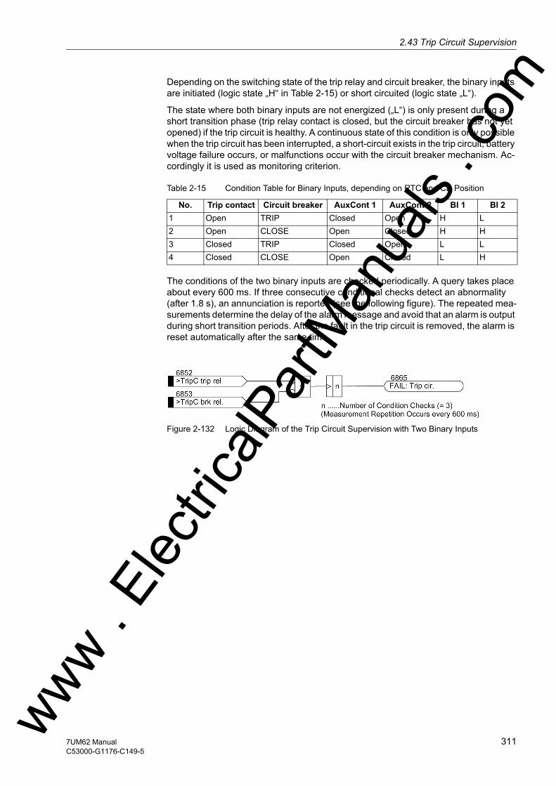
2.43 Trip Circuit Supervisionw
Depending on the switching state of the trip relay and circuit breaker, the binary inputs are initiated (logic state „H“ in Table 2-15) or short circuited (logic state „L“).
The state where both binary inputs are not energized („L“) is only present during a short transition phase (trip relay contact is closed, but the circuit breaker has not yet opened) if the trip circuit is healthy. A continuous state of this condition is only possible when the trip circuit has been interrupted, a short-circuit exists in the trip circuit, battery voltage failure occurs, or malfunctions occur with the circuit breaker mechanism. Ac-cordingly it is used as monitoring criterion.
Table 2-15 Condition Table for Binary Inputs, depending on RTC and CB Position
The conditions of the two binary inputs are checked periodically. A query takes place about every 600 ms. If three consecutive conditional checks detect an abnormality (after 1.8 s), an annunciation is reported (see the following figure). The repeated mea-surements determine the delay of the alarm message and avoid that an alarm is output during short transition periods. After the fault in the trip circuit is removed, the alarm is reset automatically after the same time.
Figure 2-132 Logic Diagram of the Trip Circuit Supervision with Two Binary Inputs
No. Trip contact Circuit breaker AuxCont 1 AuxCont 2 BI 1 BI 21 Open TRIP Closed Open H L2 Open CLOSE Open Closed H H3 Closed TRIP Closed Open L L4 Closed CLOSE Open Closed L H
ww . El
ectric
alPar
tMan
uals
. com
3117UM62 ManualC53000-G1176-C149-5
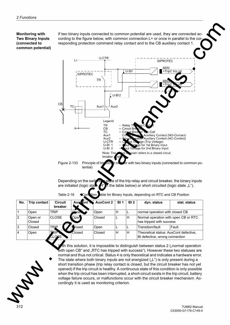
2 Functions
om
Monitoring with Two Binary Inputs (connected to common potential)
If two binary inputs connected to common potential are used, they are connected ac-cording to the figure below, with common connection L+ or once in parallel to the cor-responding protection command relay contact and to the CB auxiliary contact 1.
Figure 2-133 Principle of trip circuit monitor with two binary inputs (connected to common po-tential)
Depending on the switching state of the trip relay and circuit breaker, the binary inputs are initiated (logic state „H“ in the table below) or short circuited (logic state „L“).
Table 2-16 Condition Table for Binary Inputs, depending on RTC and CB Position
With this solution, it is impossible to distinguish between status 2 („normal operation with open CB“ and „RTC has tripped with success“). However these two statuses are normal and thus not critical. Status 4 is only theoretical and indicates a hardware error. The state where both binary inputs are not energized („L“) is only present during a short transition phase (trip relay contact is closed, but the circuit breaker has not yet opened) if the trip circuit is healthy. A continuous state of this condition is only possible when the trip circuit has been interrupted, a short-circuit exists in the trip circuit, battery voltage failure occurs, or malfunctions occur with the circuit breaker mechanism. Ac-cordingly it is used as monitoring criterion.
No. Trip contact Circuit breaker
AuxCont 1 AuxCont 2 BI 1 BI 2 dyn. status stat. status
1 Open TRIP Closed Open H L normal operation with closed CB2 Open or
ClosedCLOSE Open Closed L H Normal operation with open CB or RTC
has tripped with success3 Closed TRIP Closed Open L L Transition/fault Fault4 Open TRIP or
CLOSEClosed Closed H H Theoretical status: AuxCont defective,
BI defective, wrong connection
ww . El
ectric
alPar
tMan
uals
. c
312 7UM62 ManualC53000-G1176-C149-5
w

2.43 Trip Circuit Supervisionw
The conditions of the two binary inputs are scanned periodically. A query takes place about every 600 ms. If three consecutive conditional checks detect an abnormality (after 1.8 s), an annunciation is reported (see Figure 2-132). The repeated measure-ments help to determine the delay of the alarm message and to avoid that an alarm is output during short-time transition periods. After the fault in the trip circuit is removed, the alarm is reset automatically after the same time.
Monitoring with One Binary Input
The binary input is connected in parallel to the respective command relay contact of the protection device according to the following figure. The circuit breaker auxiliary contact is connected in series with a high-ohm resistor R.
The control voltage for the circuit breaker should be at least twice as high as the minimum voltage drop at binary input (UCtrl > 2 · UBImin since approximately the same voltage drop occurs at equivalent resistor R). Since at least 19 V are needed for the binary input, the monitor can be used with a system control voltage of over 38 V.
Figure 2-134 Principle of trip circuit monitoring with one binary input
During normal operation, the binary input is activated (logical condition „H“) when the trip contact is open and the trip circuit is intact, because the supervision circuit is closed either by the circuit breaker auxiliary contact (if the circuit breaker is closed) or through the equivalent resistor R. Only as long as the trip contact is closed is the binary input short-circuited and thereby deactivated (logical condition „L“).
If the binary input is permanently deactivated during operation, an interruption in the trip circuit or a failure of the (trip) control voltage can be assumed.
As the trip circuit supervision is not operative during a system fault condition (picked-up status of the device), the closed trip contact does not lead to an alarm. If, however, tripping contacts from other devices operate in parallel with the trip circuit, then the fault annunciation must be delayed (see also the following figure). The conditions of ww . El
ectric
alPar
tMan
uals
. com
3137UM62 ManualC53000-G1176-C149-5

2 Functions
om
the binary input are therefore checked 500 times before an annunciation is issued. A condition check takes place about every 600 ms, so trip circuit monitoring is only acti-vated during an actual malfunction of the trip circuit (after 300 s). After the fault in the trip circuit is removed, the alarm is reset automatically after the same time.
Note
If the lock-out function is used, the trip circuit monitoring with only one binary input must not be used, as the relay remains permanently picked up after a trip command (longer than 300s).
Figure 2-135 Logic diagram for Trip Circuit Monitoring with one binary input
The following figure shows the logic diagram for the message that can be generated by the trip circuit monitor, depending on the control settings and binary inputs.
Figure 2-136 Message Logic of the Trip Circuit Supervision
ww . El
ectric
alPar
tMan
uals
. c
314 7UM62 ManualC53000-G1176-C149-5
w

2.43 Trip Circuit Supervisionw
2.43.2 Setting Notes
General The function is only in effective and available if address 182 Trip Cir. Sup. (Sec-tion 2.4) was configured to either 2 Binary Inputs or to 1 Binary Input as enabled, and the appropriate number of binary inputs have been allocated for this pur-pose. The function at address 8201 TRIP Cir. SUP. must be set as ON. If the allo-cation of the necessary binary inputs does not comply with the selected supervision mode, an alarm is given („TripC ProgFail“). If the trip circuit monitor is not to be used at all, then at address 182 Disabled is set. Further parameters are not needed. The indication of a trip circuit interruption is delayed by a fixed amount of time. For two binary inputs, the delay is about 2 seconds, and for one binary input, the delay is about 300 s. This ensures that the longest possible duration of a trip signal expires, and an indication occurs only if there is a real malfunction in the trip circuit.
Monitoring with One Binary Input
Note: When using only one binary input (BI) for the trip circuit monitor, some malfunc-tions, such as interruption of the trip circuit or loss of battery voltage, can indeed be detected, but malfunctions with closed trip contacts cannot. Therefore, the measure-ment must take place over a period of time that bridges the longest possible duration of a closed trip contact. This is ensured by the fixed number of measurement repeti-tions and the time between the condition checks.
When using only one binary input, a resistor R is inserted into the circuit on the system side, instead of the missing second binary input. Through appropriate sizing of the re-sistor and depending on the system relationship, a lower control voltage can often be sufficient. The resistor R is inserted into the circuit of the second circuit breaker auxil-iary contact (AuxCont2) to detect a malfunction also when the circuit breaker auxiliary contact (AuxCont1) is open, and the trip contact has dropped out (see Figure „Princi-ple of Trip Circuit Monitoring with One Binary Input“). This resistor must be sized such that the circuit breaker trip coil (CBTC) is no longer energized when the circuit breaker is open (which means AuxCont1 is open and AuxCont2 is closed). Binary input (BI1) should still be picked up when the trip contact is simultaneously opened.
This results in an upper limit for the resistance Rmax, and a lower limit Rmin, from which the optimum value of the arithmetic mean R should be selected:
In order that the minimum voltage for controlling the binary input is ensured, Rmaxis derived as:
ww . El
ectric
alPar
tMan
uals
. com
3157UM62 ManualC53000-G1176-C149-5
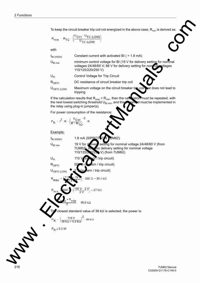
2 Functions
om
To keep the circuit breaker trip coil not energized in the above case, Rmin is derived as:
with
IBI (HIGH) Constant current with activated BI ( = 1.8 mA)
UBI min minimum control voltage for BI (19 V for delivery setting for nominal voltages 24/48/60 V; 88 V for delivery setting for nominal voltages 110/125/220/250 V)
UFt Control Voltage for Trip Circuit
RCBTC DC resistance of circuit breaker trip coil
UCBTC (LOW) Maximum voltage on the circuit breaker trip coil that does not lead to tripping
If the calculation results that Rmax < Rmin, then the calculation must be repeated, with the next lowest switching threshold UBI min, and this threshold must be implemented in the relay using plug-in jumper(s).
For power consumption of the resistance:
Example:
IBI (HIGH) 1.8 mA (SIPROTEC 4 7UM62)
UBI min 19 V for delivery setting for nominal voltage 24/48/60 V (from 7UM62), 88 V for delivery setting for nominal voltage 110/125/220/250 V) (from 7UM62)
UFt 110 V (system / trip circuit)
RCBTC 500 Ω (system / trip circuit)
UCBTC (LOW) 2 V (system / trip circuit)
The closest standard value of 39 kΩ is selected; the power is:
ww . El
ectric
alPar
tMan
uals
. c
316 7UM62 ManualC53000-G1176-C149-5
w
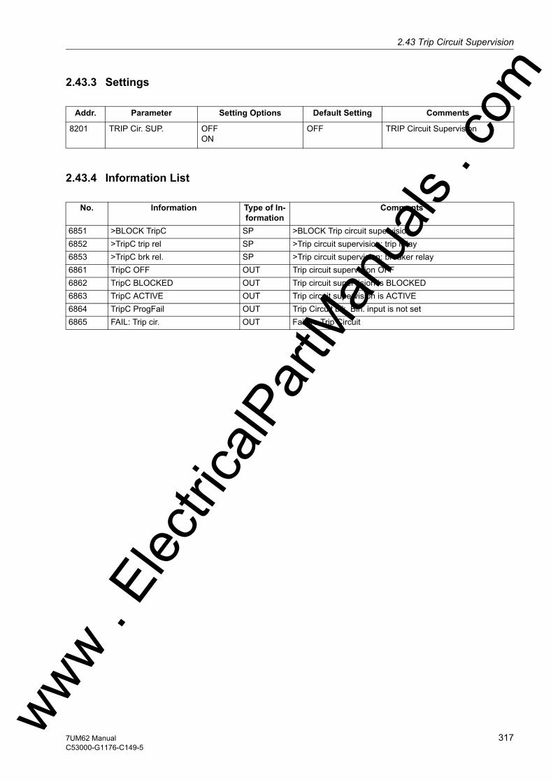
2.43 Trip Circuit Supervisionw
2.43.3 Settings
2.43.4 Information List
Addr. Parameter Setting Options Default Setting Comments
8201 TRIP Cir. SUP. OFFON
OFF TRIP Circuit Supervision
No. Information Type of In-formation
Comments
6851 >BLOCK TripC SP >BLOCK Trip circuit supervision6852 >TripC trip rel SP >Trip circuit supervision: trip relay6853 >TripC brk rel. SP >Trip circuit supervision: breaker relay6861 TripC OFF OUT Trip circuit supervision OFF6862 TripC BLOCKED OUT Trip circuit supervision is BLOCKED6863 TripC ACTIVE OUT Trip circuit supervision is ACTIVE6864 TripC ProgFail OUT Trip Circuit blk. Bin. input is not set6865 FAIL: Trip cir. OUT Failure Trip Circuit
ww . El
ectric
alPar
tMan
uals
. com
3177UM62 ManualC53000-G1176-C149-5
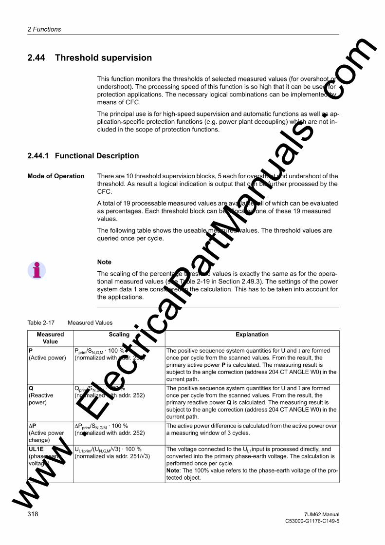
2 Functions
om
2.44 Threshold supervision
This function monitors the thresholds of selected measured values (for overshoot or undershoot). The processing speed of this function is so high that it can be used for protection applications. The necessary logical combinations can be implemented by means of CFC.
The principal use is for high-speed supervision and automatic functions as well as ap-plication-specific protection functions (e.g. power plant decoupling) which are not in-cluded in the scope of protection functions.
2.44.1 Functional Description
Mode of Operation There are 10 threshold supervision blocks, 5 each for overshoot and undershoot of the threshold. As result a logical indication is output that can be further processed by the CFC.
A total of 19 processable measured values are available, all of which can be evaluated as percentages. Each threshold block can be allocated one of these 19 measured values.
The following table shows the useable measured values. The threshold values are queried once per cycle.
Note
The scaling of the percentage threshold values is exactly the same as for the opera-tional measured values (see Table 2-19 in Section 2.49.3). The settings of the power system data 1 are considered in the calculation. This has to be taken into account for the applications.
Table 2-17 Measured Values
Measured Value
Scaling Explanation
P(Active power)
Pprim/SN,G,M · 100 % (normalized with addr. 252)
The positive sequence system quantities for U and I are formed once per cycle from the scanned values. From the result, the primary active power P is calculated. The measuring result is subject to the angle correction (address 204 CT ANGLE W0) in the current path.
Q (Reactive power)
Qprim/SN,G,M · 100 % (normalized with addr. 252)
The positive sequence system quantities for U and I are formed once per cycle from the scanned values. From the result, the primary reactive power Q is calculated. The measuring result is subject to the angle correction (address 204 CT ANGLE W0) in the current path.
∆P (Active power change)
∆Pprim/SN,G,M · 100 % (normalized with addr. 252)
The active power difference is calculated from the active power over a measuring window of 3 cycles.
UL1E (phase-earth voltage)
UL1prim/(UN,G,M/√3) · 100 % (normalized via addr. 251/√3)
The voltage connected to the UL1input is processed directly, and converted into the primary phase-earth voltage. The calculation is performed once per cycle. Note: The 100% value refers to the phase-earth voltage of the pro-tected object. ww .
Elec
tricalP
artM
anua
ls . c
318 7UM62 ManualC53000-G1176-C149-5
w

2.44 Threshold supervisionw
UL2E (phase-earth voltage)
UL2prim/(UN,G,M/√3) · 100 % (normalized via addr. 251/√3)
The voltage connected to the UL2input is processed directly, and converted into the primary phase-earth voltage. The calculation is performed once per cycle. Note: The 100% value refers to the phase-earth voltage of the pro-tected object.
UL3E (phase-earth voltage)
UL3prim/(UN,G,M/√3) · 100 % (normalized via addr. 251/√3)
The voltage connected to the UL3 input is processed directly, and converted into the primary phase-earth voltage. The calculation is performed once per cycle. Note: The 100% value refers to the phase-earth voltage of the pro-tected object.
UE (voltage at the UE input)
UEprim/(UN,G,M/√3) · 100 % (normalized via addr. 251/√3)
The voltage connected to the UE input is converted into a primary voltage via FACTOR UE (addr. 224). The calculation is performed once per cycle. Observe the applications as per Table 2-2. Note: The 100% value refers to the phase-earth voltage of the pro-tected object.
U0 (Zero system voltage)
U0prim/(UN,G,M/√3) · 100 % (normalized via addr. 251/√3)
The zero system voltage is determined from the phase-to-earth volt-ages on the basis of the definition equation for symmetrical compo-nents, and converted into primary values. The calculation is per-formed once per cycle. Note: The 100% value refers to the phase-earth voltage of the pro-tected object.
U1 (Positive se-quence voltage)
U1prim/(UN,G,M/√3) · 100 % (normalized via addr. 251/√3)
The positivev sequence voltage is determined from the phase-to-earth voltages on the basis of the definition equation for symmetrical components, and converted into primary values. The calculation is performed once per cycle. Note: The 100% value refers to the phase-earth voltage of the pro-tected object.
U2 (Negative se-quence voltage)
U2prim/(UN,G,M/√3) · 100 % (normalized via addr. 251/√3)
The negative sequence voltage is determined from the phase-to-earth voltages on the basis of the definition equation for symmetrical components, and converted into primary values. The calculation is performed once per cycle. Note: The 100% value refers to the phase-earth voltage of the pro-tected object.
UE3h (3. harmonic voltage at the UE input)
UE3hprim/(UN,G,M/√3) · 100 % (normalized via addr. 251/√3)
From the voltage connected to the UE input, the 3rd harmonic voltage is computed and converted into a primary voltage via FACTOR UE (addr. 224). The calculation is performed once per cycle. Observe the applications as per Table 2-2. Note: The 100% value refers to the phase-earth voltage of the pro-tected object.
3I0 (Zero sequence current system side 2)
3I0prim/(SN,G,M/(√3 · UN,G,M)) · 100 % (normalized with addr. 251 and 252)
The zero sequence current is determined from the phase currents on the basis of the definition equation for symmetrical components. The calculation is performed once per cycle. Note: The 100% value refers to the nominal current of the protected object.
I1 (Positive se-quence current system side 2)
I1prim/(SN,G,M/(√3 · UN,G,M)) · 100 % (normalized with addr. 251 and 252)
The positive sequence current is determined from the phase cur-rents on the basis of the definition equation for symmetrical compo-nents, and converted into primary values. The calculation is per-formed once per cycle. Note: The 100% value refers to the nominal current of the protected object.
I2 (Negative se-quence current system side 2)
I2prim/(SN,G,M/(√3 · UN,G,M)) · 100 % (normalized with addr. 251 and 252)
The negative sequence current is determined from the phase cur-rents on the basis of the definition equation for symmetrical compo-nents, and converted into primary values. The calculation is per-formed once per cycle. Note: The 100% value refers to the nominal current of the protected object.
Measured Value
Scaling Explanation
ww . El
ectric
alPar
tMan
uals
. com
3197UM62 ManualC53000-G1176-C149-5
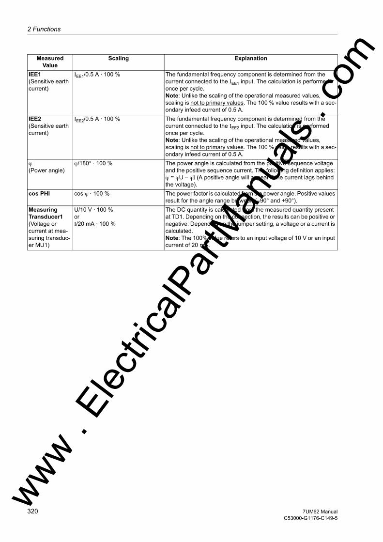
2 Functions
om
IEE1 (Sensitive earth current)IEE1/0.5 A · 100 % The fundamental frequency component is determined from the current connected to the IEE1 input. The calculation is performed once per cycle. Note: Unlike the scaling of the operational measured values, scaling is not to primary values. The 100 % value results with a sec-ondary infeed current of 0.5 A.
IEE2 (Sensitive earth current)
IEE2/0.5 A · 100 % The fundamental frequency component is determined from the current connected to the IEE2 input. The calculation is performed once per cycle. Note: Unlike the scaling of the operational measured values, scaling is not to primary values. The 100 % value results with a sec-ondary infeed current of 0.5 A.
ϕ(Power angle)
ϕ/180° · 100 % The power angle is calculated from the positive sequence voltage and the positive sequence current. The following definition applies: ϕ = ϕU – ϕI (A positive angle will appear if the current lags behind the voltage).
cos PHI cos ϕ · 100 % The power factor is calculated from the power angle. Positive values result for the angle range between (–90° and +90°).
Measuring Transducer1 (Voltage or current at mea-suring transduc-er MU1)
U/10 V · 100 % orI/20 mA · 100 %
The DC quantity is calculated from the measured quantity present at TD1. Depending on the connection, the results can be positive or negative. Depending on the jumper setting, a voltage or a current is calculated. Note: The 100% value refers to an input voltage of 10 V or an input current of 20 mA.
Measured Value
Scaling Explanation
ww . El
ectric
alPar
tMan
uals
. c
320 7UM62 ManualC53000-G1176-C149-5
w

2.44 Threshold supervisionw
The following figure shows an overview of the logic.
Figure 2-137 Logic of the Threshold Supervision
The figure shows that the measured values can be freely allocated to the threshold supervision blocks. The dropout ratio for the MVx> stage is 0.95 or 1 %. Accordingly, it is 1.05 or 1 % for the MVx< stage.
ww . El
ectric
alPar
tMan
uals
. com
3217UM62 ManualC53000-G1176-C149-5

2 Functions
om
2.44.2 Setting Notes
General The threshold supervision function is only effective and accessible if address 185 THRESHOLD has been set to Enabled during the configuration of the protection func-tions.
Pickup Values The pickup values are set as percentages. Note the scaling factors listed in the Mea-sured values table.
The measured values for power P, Q, ∆P and cosϕ as well as the phase angle can be either positive or negative. If a negative threshold value is to be monitored, the number line definition applies (–10 is smaller than –5).
Example:
The measured quantity P (active power) is allocated to MV1> and set to –5 %.
If the actual measured value is higher than –5 % (e.g. –4 % or even +100 %), the in-dication „Meas. Value1>“ is output as a logical „1“, which means a pickup in terms of protection engineering. A dropout signal (indication „Meas. Value1>“ logical "0") is output if the measured value drops to less than –5 % · 1.05 = –5.25 %.
With the measured quantity P is allocated to MV2<, monitoring checks an undershoot.
A pickup signal is output if the measured value becomes less than –5 % (e.g. –8 %). The dropout value is then –5 % · 0.95 = –4.75 %.
Note
The measured values UL1E, UL2E, UL3E, UE, U0, U1, U2, UE3h, IEE1, IEE2 3I0, I1, I2 and measuring transducer 1 are always greater than 0. Care should be taken here to use only positive threshold values which allow the indication to drop out.
With the power angle ϕ it should be kept in mind that this angle is only defined for ± 100 % (equivalent to ± 180°) or less. The threshold value should be chosen accord-ingly, taking into account the dropout ratio.
Further Processing of Indications
The indications of the 10 measured value monitoring blocks (see information over-view) are available in the configuration matrix for further logical processing by the CFC.
2.44.3 Settings
ww . El
ectric
alPar
tMan
uals
. c
322 7UM62 ManualC53000-G1176-C149-5
w

2.44 Threshold supervisionw
Addr. Parameter Setting Options Default Setting Comments
8501 MEAS. VALUE 1> DisabledPQDelta PUL1EUL2EUL3EUEU0U1U2UE3hIEE1IEE23I0I1I2PHIPFTransducer 1
Disabled Measured Value for Threshold MV1>
8502 THRESHOLD MV1> -200 .. 200 % 100 % Pickup Value of Measured Value MV1>
8503 MEAS. VALUE 2< DisabledPQDelta PUL1EUL2EUL3EUEU0U1U2UE3hIEE1IEE23I0I1I2PHIPFTransducer 1
Disabled Measured Value for Threshold MV2<
8504 THRESHOLD MV2< -200 .. 200 % 100 % Pickup Value of Measured Value MV2<
ww . El
ectric
alPar
tMan
uals
. com
3237UM62 ManualC53000-G1176-C149-5

2 Functions
om
8505 MEAS. VALUE 3> DisabledPQDelta PUL1EUL2EUL3EUEU0U1U2UE3hIEE1IEE23I0I1I2PHIPFTransducer 1Disabled Measured Value for Threshold MV3>
8506 THRESHOLD MV3> -200 .. 200 % 100 % Pickup Value of Measured Value MV3>
8507 MEAS. VALUE 4< DisabledPQDelta PUL1EUL2EUL3EUEU0U1U2UE3hIEE1IEE23I0I1I2PHIPFTransducer 1
Disabled Measured Value for Threshold MV4<
8508 THRESHOLD MV4< -200 .. 200 % 100 % Pickup Value of Measured Value MV4<
Addr. Parameter Setting Options Default Setting Comments
ww . El
ectric
alPar
tMan
uals
. c
324 7UM62 ManualC53000-G1176-C149-5
w

2.44 Threshold supervisionw
8509 MEAS. VALUE 5> DisabledPQDelta PUL1EUL2EUL3EUEU0U1U2UE3hIEE1IEE23I0I1I2PHIPFTransducer 1
Disabled Measured Value for Threshold MV5>
8510 THRESHOLD MV5> -200 .. 200 % 100 % Pickup Value of Measured Value MV5>
8511 MEAS. VALUE 6< DisabledPQDelta PUL1EUL2EUL3EUEU0U1U2UE3hIEE1IEE23I0I1I2PHIPFTransducer 1
Disabled Measured Value for Threshold MV6<
8512 THRESHOLD MV6< -200 .. 200 % 100 % Pickup Value of Measured Value MV6<
Addr. Parameter Setting Options Default Setting Comments
ww . El
ectric
alPar
tMan
uals
. com
3257UM62 ManualC53000-G1176-C149-5

2 Functions
om
8513 MEAS. VALUE 7> DisabledPQDelta PUL1EUL2EUL3EUEU0U1U2UE3hIEE1IEE23I0I1I2PHIPFTransducer 1Disabled Measured Value for Threshold MV7>
8514 THRESHOLD MV7> -200 .. 200 % 100 % Threshold of Measured Value MV7>
8515 MEAS. VALUE 8< DisabledPQDelta PUL1EUL2EUL3EUEU0U1U2UE3hIEE1IEE23I0I1I2PHIPFTransducer 1
Disabled Measured Value for Threshold MV8<
8516 THRESHOLD MV8< -200 .. 200 % 100 % Threshold of Measured Value MV8<
Addr. Parameter Setting Options Default Setting Comments
ww . El
ectric
alPar
tMan
uals
. c
326 7UM62 ManualC53000-G1176-C149-5
w
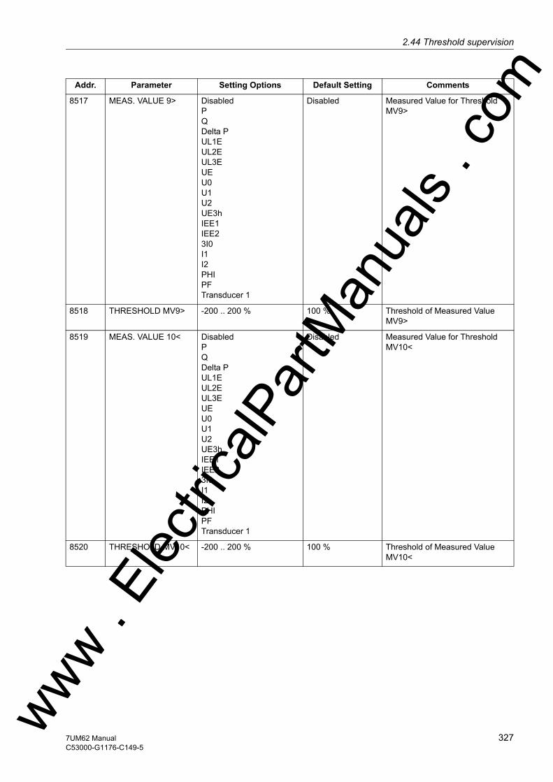
2.44 Threshold supervisionw
8517 MEAS. VALUE 9> DisabledPQDelta PUL1EUL2EUL3EUEU0U1U2UE3hIEE1IEE23I0I1I2PHIPFTransducer 1
Disabled Measured Value for Threshold MV9>
8518 THRESHOLD MV9> -200 .. 200 % 100 % Threshold of Measured Value MV9>
8519 MEAS. VALUE 10< DisabledPQDelta PUL1EUL2EUL3EUEU0U1U2UE3hIEE1IEE23I0I1I2PHIPFTransducer 1
Disabled Measured Value for Threshold MV10<
8520 THRESHOLD MV10< -200 .. 200 % 100 % Threshold of Measured Value MV10<
Addr. Parameter Setting Options Default Setting Comments
ww . El
ectric
alPar
tMan
uals
. com
3277UM62 ManualC53000-G1176-C149-5
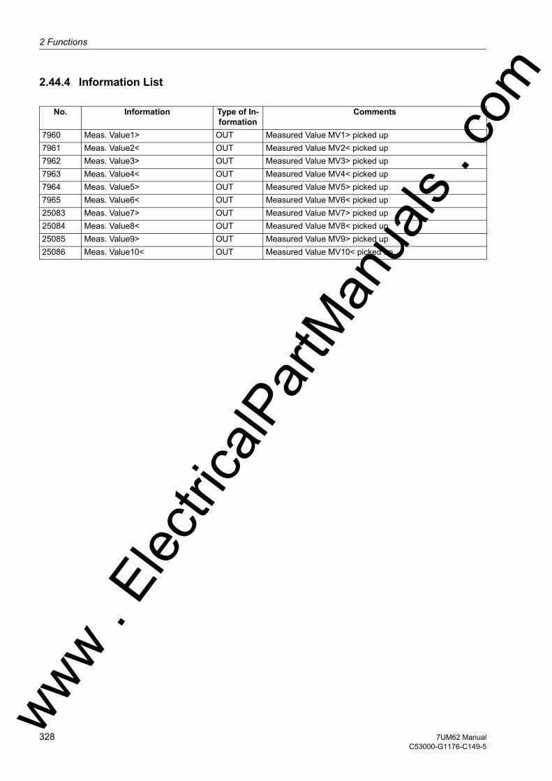
2 Functions
om
2.44.4 Information List
No. Information Type of In-formation
Comments
7960 Meas. Value1> OUT Measured Value MV1> picked up7961 Meas. Value2< OUT Measured Value MV2< picked up7962 Meas. Value3> OUT Measured Value MV3> picked up7963 Meas. Value4< OUT Measured Value MV4< picked up7964 Meas. Value5> OUT Measured Value MV5> picked up7965 Meas. Value6< OUT Measured Value MV6< picked up25083 Meas. Value7> OUT Measured Value MV7> picked up25084 Meas. Value8< OUT Measured Value MV8< picked up25085 Meas. Value9> OUT Measured Value MV9> picked up25086 Meas. Value10< OUT Measured Value MV10< picked up
ww . El
ectric
alPar
tMan
uals
. c
328 7UM62 ManualC53000-G1176-C149-5
w

2.45 External Trip Functionsw
2.45 External Trip Functions
Any signals from external protection or supervision units can be incorporated into the processing of the digital machine protection 7UM62 via binary inputs. Like the internal signals, they can be signaled, time delayed, transmitted to the trip matrix, and also in-dividually blocked. By this means it is possible to include mechanical protection equip-ment, e.g. Buchholz protection, into the processing of indications and trip commands of the digital protection device. Furthermore interaction between protection functions of different numerical machine protection devices of the 7UM6 series is possible.
2.45.1 Functional Description
Mode of Operation The logic status of the corresponding assigned binary inputs is checked at cyclic inter-vals. Change of input status is considered only if at least two consecutive status checks have the same result. An additional time delay 8602 T DELAY is available for the trip command.
The following figure shows the logic diagram for direct input trippings. This logic is im-plemented in all four times in the same manner, the function numbers of the indications are each specified for the first external trip command channel.
Figure 2-138 Logic Diagram of Direct Input Trippings
2.45.2 Setting Notes
General External trip, via binary input is only effective and available if configured at addresses 186 EXT. TRIP 1 to 189 EXT. TRIP 4 = Enabled. Disabled is set if the func-tions are not required. Address 8601 EXTERN TRIP 1 to 8901 EXTERN TRIP 4 is used to switch the function ON or OFF , or to block (Block relay).
Like the internal signals, they can be indicated as external trippings, time delayed and transmitted to the trip matrix. The delay times are set at addresses 8602 T DELAY through 8902 T DELAY. Like for the protective functions, the dropout of the direct input trippings is extended by the parametrized minimum duration TMin TRIP CMD.
ww . El
ectric
alPar
tMan
uals
. com
3297UM62 ManualC53000-G1176-C149-5

2 Functions
om
2.45.3 Settings
Addr. Parameter Setting Options Default Setting Comments
8601 EXTERN TRIP 1 OFFONBlock relay
OFF External Trip Function 1
8602 T DELAY 0.00 .. 60.00 sec; ∞ 1.00 sec Ext. Trip 1 Time Delay
8701 EXTERN TRIP 2 OFFONBlock relay
OFF External Trip Function 2
8702 T DELAY 0.00 .. 60.00 sec; ∞ 1.00 sec Ext. Trip 2 Time Delay
8801 EXTERN TRIP 3 OFFONBlock relay
OFF External Trip Function 3
8802 T DELAY 0.00 .. 60.00 sec; ∞ 1.00 sec Ext. Trip 3 Time Delay
8901 EXTERN TRIP 4 OFFONBlock relay
OFF External Trip Function 4
8902 T DELAY 0.00 .. 60.00 sec; ∞ 1.00 sec Ext. Trip 4 Time Delay
ww . El
ectric
alPar
tMan
uals
. c
330 7UM62 ManualC53000-G1176-C149-5
w

2.45 External Trip Functionsw
2.45.4 Information List
No. Information Type of In-formation
Comments
4523 >BLOCK Ext 1 SP >Block external trip 14526 >Ext trip 1 SP >Trigger external trip 14531 Ext 1 OFF OUT External trip 1 is switched OFF4532 Ext 1 BLOCKED OUT External trip 1 is BLOCKED4533 Ext 1 ACTIVE OUT External trip 1 is ACTIVE4536 Ext 1 picked up OUT External trip 1: General picked up4537 Ext 1 Gen.TRP OUT External trip 1: General TRIP4543 >BLOCK Ext 2 SP >BLOCK external trip 24546 >Ext trip 2 SP >Trigger external trip 24551 Ext 2 OFF OUT External trip 2 is switched OFF4552 Ext 2 BLOCKED OUT External trip 2 is BLOCKED4553 Ext 2 ACTIVE OUT External trip 2 is ACTIVE4556 Ext 2 picked up OUT External trip 2: General picked up4557 Ext 2 Gen.TRP OUT External trip 2: General TRIP4563 >BLOCK Ext 3 SP >BLOCK external trip 34566 >Ext trip 3 SP >Trigger external trip 34571 Ext 3 OFF OUT External trip 3 is switched OFF4572 Ext 3 BLOCKED OUT External trip 3 is BLOCKED4573 Ext 3 ACTIVE OUT External trip 3 is ACTIVE4576 Ext 3 picked up OUT External trip 3: General picked up4577 Ext 3 Gen.TRP OUT External trip 3: General TRIP4583 >BLOCK Ext 4 SP >BLOCK external trip 44586 >Ext trip 4 SP >Trigger external trip 44591 Ext 4 OFF OUT External trip 4 is switched OFF4592 Ext 4 BLOCKED OUT External trip 4 is BLOCKED4593 Ext 4 ACTIVE OUT External trip 4 is ACTIVE4596 Ext 4 picked up OUT External trip 4: General picked up4597 Ext 4 Gen.TRP OUT External trip 4: General TRIP
ww . El
ectric
alPar
tMan
uals
. com
3317UM62 ManualC53000-G1176-C149-5

2 Functions
om
2.46 Temperature Detection by Thermoboxes
Up to 2 RTD boxes with a total of 12 measuring points can be used for temperature detection and evaluated by the protection device. They are particularly useful for mon-itoring the thermal condition of motors, generators and transformers. Rotating ma-chines are additionally monitored for transgression of bearing temperature thresholds. The temperatures are measured in different locations of the protected object by em-ploying temperature sensors (RTD = Resistance Temperature Detector) and are trans-mitted to the device via one or two 7XV566 RTD-boxes.
2.46.1 Function Description
Interaction with the Overload Protection
The ambient or coolant temperature can be fed via the thermobox to the overload pro-tection function of the device. For this purpose the required temperature sensor must be connected to sensor input 1 of the 1st RTD box (corresponds to RTD 1).
RTD-box 7XV56 The 7XV566 RTD box is an external device mounted on a standard DIN rail. It features 6 temperature inputs and one RS 485 interface for communication with the protection device. The RTD box detects the coolant temperature of each measuring point from the resistance value of the temperature detectors (Pt 100, Ni 100 or Ni 120) connected with a two- or three-wire line and converts it to a digital value. The digital values are made available at a serial port.
Communication with the Protection Device
The protection device can communicate with up to 2 RTD boxes via its service port (port C or D).
Up to 12 temperature measuring points are in this way available. For greater distances to the protection device, a fibre optic link is recommended. Possible communication structures are shown in the appendix.
Temperature Evaluation
The transmitted temperature raw data is converted to a temperature in degrees Celsius or Fahrenheit. The conversion depends on the temperature sensor used.
For each measuring point two thresholds decisions can be performed which are avail-able for further processing. The user can allocate the pickup signals in the configura-tion matrix as required.
To each temperature detector is assigned an alarm which is issued in case of a short-circuit or an interruption of the sensor circuit.
ww . El
ectric
alPar
tMan
uals
. c
332 7UM62 ManualC53000-G1176-C149-5
w

2.46 Temperature Detection by Thermoboxesw
The following figure shows the logic diagram for temperature processing.
The manual supplied with the RTD box contains a diagram and dimensioned drawing.
Figure 2-139 Logic Diagram for Temperature Processing
ww . El
ectric
alPar
tMan
uals
. com
3337UM62 ManualC53000-G1176-C149-5
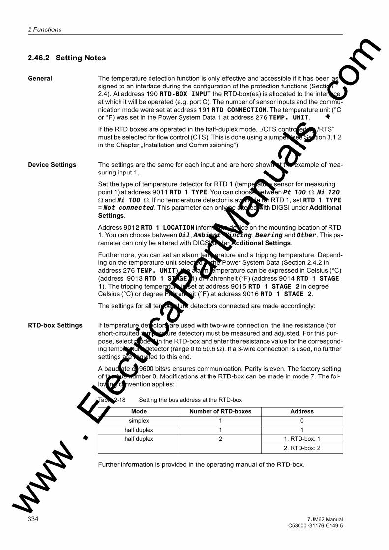
2 Functions
om
2.46.2 Setting Notes
General The temperature detection function is only effective and accessible if it has been as-signed to an interface during the configuration of the protection functions (Section 2.4). At address 190 RTD-BOX INPUT the RTD-box(es) is allocated to the interface at which it will be operated (e.g. port C). The number of sensor inputs and the commu-nication mode were set at address 191 RTD CONNECTION. The temperature unit (°C or °F) was set in the Power System Data 1 at address 276 TEMP. UNIT.
If the RTD boxes are operated in the half-duplex mode, „/CTS controlled by /RTS“ must be selected for flow control (CTS). This is done using a jumper (see Section 3.1.2 in the Chapter „Installation and Commissioning“)
Device Settings The settings are the same for each input and are here shown at the example of mea-suring input 1.
Set the type of temperature detector for RTD 1 (temperature sensor for measuring point 1) at address 9011 RTD 1 TYPE. You can choose between Pt 100 Ω, Ni 120 Ω and Ni 100 Ω. If no temperature detector is available for RTD 1, set RTD 1 TYPE = Not connected. This parameter can only be altered with DIGSI under Additional Settings.
Address 9012 RTD 1 LOCATION informs the device on the mounting location of RTD 1. You can choose between Oil, Ambient, Winding, Bearing and Other. This pa-rameter can only be altered with DIGSI under Additional Settings.
Furthermore, you can set an alarm temperature and a tripping temperature. Depend-ing on the temperature unit selected in the Power System Data (Section 2.4.2 in address 276 TEMP. UNIT), the alarm temperature can be expressed in Celsius (°C) (address 9013 RTD 1 STAGE 1) or Fahrenheit (°F) (address 9014 RTD 1 STAGE 1). The tripping temperature is set at address 9015 RTD 1 STAGE 2 in degree Celsius (°C) or degree Fahrenheit (°F) at address 9016 RTD 1 STAGE 2.
The settings for all temperature detectors connected are made accordingly:
RTD-box Settings If temperature detectors are used with two-wire connection, the line resistance (for short-circuited temperature detector) must be measured and adjusted. For this pur-pose, select mode 6 in the RTD-box and enter the resistance value for the correspond-ing temperature detector (range 0 to 50.6 Ω). If a 3-wire connection is used, no further settings are required to this end.
A baudrate of 9600 bits/s ensures communication. Parity is even. The factory setting of the bus number 0. Modifications at the RTD-box can be made in mode 7. The fol-lowing convention applies:
Table 2-18 Setting the bus address at the RTD-box
Further information is provided in the operating manual of the RTD-box.
Mode Number of RTD-boxes Addresssimplex 1 0
half duplex 1 1half duplex 2 1. RTD-box: 1
2. RTD-box: 2
ww . El
ectric
alPar
tMan
uals
. c
334 7UM62 ManualC53000-G1176-C149-5
w
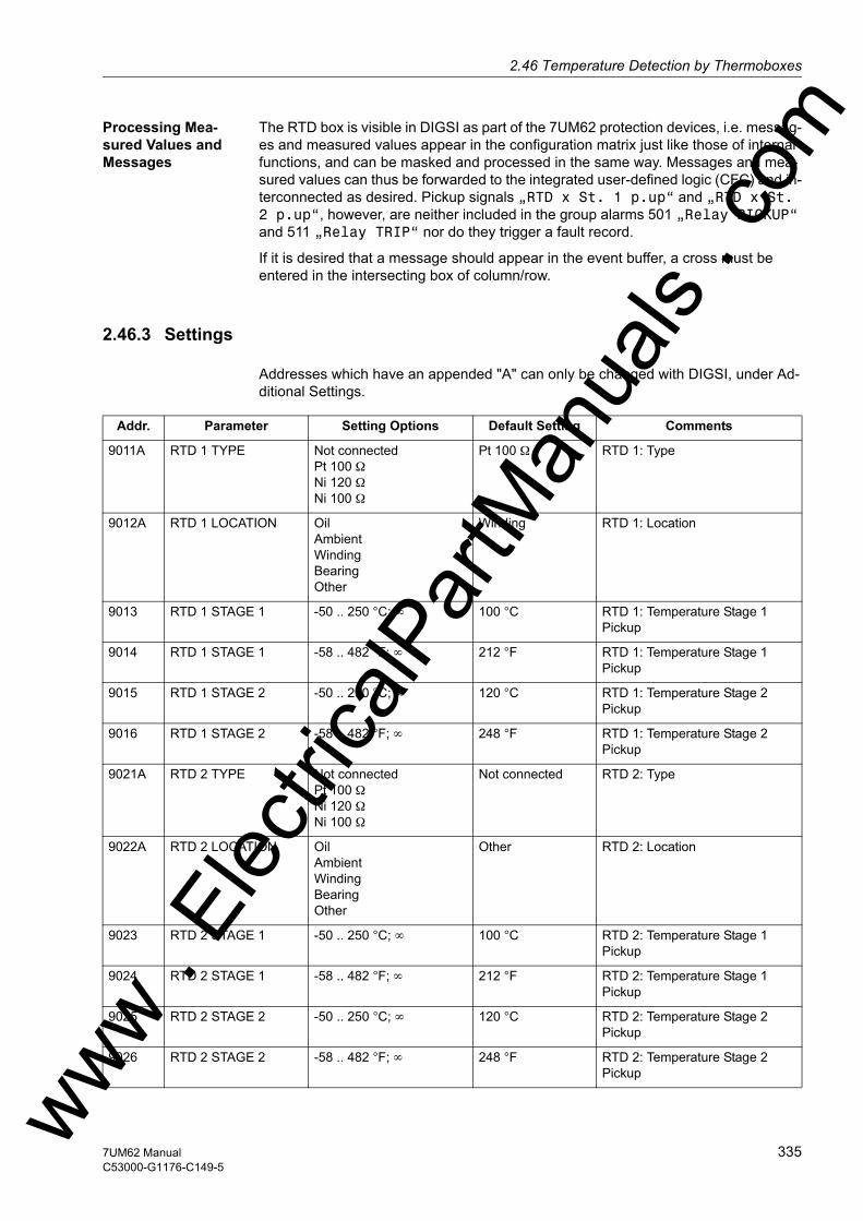
2.46 Temperature Detection by Thermoboxesw
Processing Mea-sured Values and Messages
The RTD box is visible in DIGSI as part of the 7UM62 protection devices, i.e. messag-es and measured values appear in the configuration matrix just like those of internal functions, and can be masked and processed in the same way. Messages and mea-sured values can thus be forwarded to the integrated user-defined logic (CFC) and in-terconnected as desired. Pickup signals „RTD x St. 1 p.up“ and „RTD x St. 2 p.up“, however, are neither included in the group alarms 501 „Relay PICKUP“ and 511 „Relay TRIP“ nor do they trigger a fault record.
If it is desired that a message should appear in the event buffer, a cross must be entered in the intersecting box of column/row.
2.46.3 Settings
Addresses which have an appended "A" can only be changed with DIGSI, under Ad-ditional Settings.
Addr. Parameter Setting Options Default Setting Comments
9011A RTD 1 TYPE Not connectedPt 100 ΩNi 120 ΩNi 100 Ω
Pt 100 Ω RTD 1: Type
9012A RTD 1 LOCATION OilAmbientWindingBearingOther
Winding RTD 1: Location
9013 RTD 1 STAGE 1 -50 .. 250 °C; ∞ 100 °C RTD 1: Temperature Stage 1 Pickup
9014 RTD 1 STAGE 1 -58 .. 482 °F; ∞ 212 °F RTD 1: Temperature Stage 1 Pickup
9015 RTD 1 STAGE 2 -50 .. 250 °C; ∞ 120 °C RTD 1: Temperature Stage 2 Pickup
9016 RTD 1 STAGE 2 -58 .. 482 °F; ∞ 248 °F RTD 1: Temperature Stage 2 Pickup
9021A RTD 2 TYPE Not connectedPt 100 ΩNi 120 ΩNi 100 Ω
Not connected RTD 2: Type
9022A RTD 2 LOCATION OilAmbientWindingBearingOther
Other RTD 2: Location
9023 RTD 2 STAGE 1 -50 .. 250 °C; ∞ 100 °C RTD 2: Temperature Stage 1 Pickup
9024 RTD 2 STAGE 1 -58 .. 482 °F; ∞ 212 °F RTD 2: Temperature Stage 1 Pickup
9025 RTD 2 STAGE 2 -50 .. 250 °C; ∞ 120 °C RTD 2: Temperature Stage 2 Pickup
9026 RTD 2 STAGE 2 -58 .. 482 °F; ∞ 248 °F RTD 2: Temperature Stage 2 Pickupww .
Elec
tricalP
artM
anua
ls . c
om
3357UM62 ManualC53000-G1176-C149-5
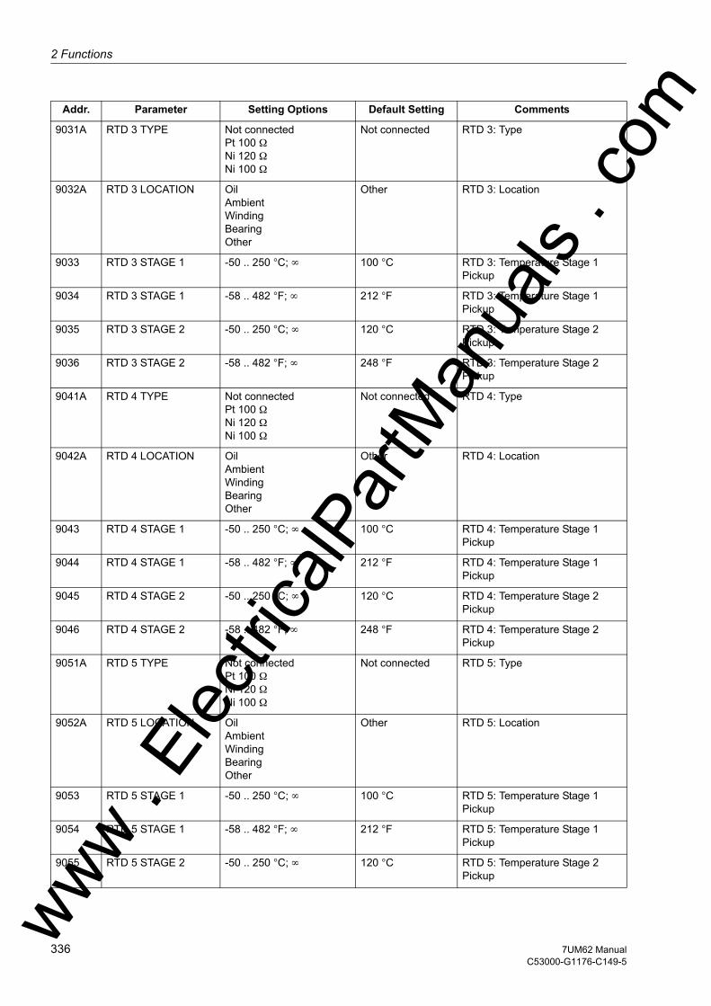
2 Functions
om
9031A RTD 3 TYPE Not connectedPt 100 ΩNi 120 ΩNi 100 ΩNot connected RTD 3: Type
9032A RTD 3 LOCATION OilAmbientWindingBearingOther
Other RTD 3: Location
9033 RTD 3 STAGE 1 -50 .. 250 °C; ∞ 100 °C RTD 3: Temperature Stage 1 Pickup
9034 RTD 3 STAGE 1 -58 .. 482 °F; ∞ 212 °F RTD 3: Temperature Stage 1 Pickup
9035 RTD 3 STAGE 2 -50 .. 250 °C; ∞ 120 °C RTD 3: Temperature Stage 2 Pickup
9036 RTD 3 STAGE 2 -58 .. 482 °F; ∞ 248 °F RTD 3: Temperature Stage 2 Pickup
9041A RTD 4 TYPE Not connectedPt 100 ΩNi 120 ΩNi 100 Ω
Not connected RTD 4: Type
9042A RTD 4 LOCATION OilAmbientWindingBearingOther
Other RTD 4: Location
9043 RTD 4 STAGE 1 -50 .. 250 °C; ∞ 100 °C RTD 4: Temperature Stage 1 Pickup
9044 RTD 4 STAGE 1 -58 .. 482 °F; ∞ 212 °F RTD 4: Temperature Stage 1 Pickup
9045 RTD 4 STAGE 2 -50 .. 250 °C; ∞ 120 °C RTD 4: Temperature Stage 2 Pickup
9046 RTD 4 STAGE 2 -58 .. 482 °F; ∞ 248 °F RTD 4: Temperature Stage 2 Pickup
9051A RTD 5 TYPE Not connectedPt 100 ΩNi 120 ΩNi 100 Ω
Not connected RTD 5: Type
9052A RTD 5 LOCATION OilAmbientWindingBearingOther
Other RTD 5: Location
9053 RTD 5 STAGE 1 -50 .. 250 °C; ∞ 100 °C RTD 5: Temperature Stage 1 Pickup
9054 RTD 5 STAGE 1 -58 .. 482 °F; ∞ 212 °F RTD 5: Temperature Stage 1 Pickup
9055 RTD 5 STAGE 2 -50 .. 250 °C; ∞ 120 °C RTD 5: Temperature Stage 2 Pickup
Addr. Parameter Setting Options Default Setting Comments
ww . El
ectric
alPar
tMan
uals
. c
336 7UM62 ManualC53000-G1176-C149-5
w

2.46 Temperature Detection by Thermoboxesw
9056 RTD 5 STAGE 2 -58 .. 482 °F; ∞ 248 °F RTD 5: Temperature Stage 2 Pickup
9061A RTD 6 TYPE Not connectedPt 100 ΩNi 120 ΩNi 100 Ω
Not connected RTD 6: Type
9062A RTD 6 LOCATION OilAmbientWindingBearingOther
Other RTD 6: Location
9063 RTD 6 STAGE 1 -50 .. 250 °C; ∞ 100 °C RTD 6: Temperature Stage 1 Pickup
9064 RTD 6 STAGE 1 -58 .. 482 °F; ∞ 212 °F RTD 6: Temperature Stage 1 Pickup
9065 RTD 6 STAGE 2 -50 .. 250 °C; ∞ 120 °C RTD 6: Temperature Stage 2 Pickup
9066 RTD 6 STAGE 2 -58 .. 482 °F; ∞ 248 °F RTD 6: Temperature Stage 2 Pickup
9071A RTD 7 TYPE Not connectedPt 100 ΩNi 120 ΩNi 100 Ω
Not connected RTD 7: Type
9072A RTD 7 LOCATION OilAmbientWindingBearingOther
Other RTD 7: Location
9073 RTD 7 STAGE 1 -50 .. 250 °C; ∞ 100 °C RTD 7: Temperature Stage 1 Pickup
9074 RTD 7 STAGE 1 -58 .. 482 °F; ∞ 212 °F RTD 7: Temperature Stage 1 Pickup
9075 RTD 7 STAGE 2 -50 .. 250 °C; ∞ 120 °C RTD 7: Temperature Stage 2 Pickup
9076 RTD 7 STAGE 2 -58 .. 482 °F; ∞ 248 °F RTD 7: Temperature Stage 2 Pickup
9081A RTD 8 TYPE Not connectedPt 100 ΩNi 120 ΩNi 100 Ω
Not connected RTD 8: Type
9082A RTD 8 LOCATION OilAmbientWindingBearingOther
Other RTD 8: Location
9083 RTD 8 STAGE 1 -50 .. 250 °C; ∞ 100 °C RTD 8: Temperature Stage 1 Pickup
9084 RTD 8 STAGE 1 -58 .. 482 °F; ∞ 212 °F RTD 8: Temperature Stage 1 Pickup
Addr. Parameter Setting Options Default Setting Comments
ww . El
ectric
alPar
tMan
uals
. com
3377UM62 ManualC53000-G1176-C149-5

2 Functions
om
9085 RTD 8 STAGE 2 -50 .. 250 °C; ∞ 120 °C RTD 8: Temperature Stage 2 Pickup9086 RTD 8 STAGE 2 -58 .. 482 °F; ∞ 248 °F RTD 8: Temperature Stage 2 Pickup
9091A RTD 9 TYPE Not connectedPt 100 ΩNi 120 ΩNi 100 Ω
Not connected RTD 9: Type
9092A RTD 9 LOCATION OilAmbientWindingBearingOther
Other RTD 9: Location
9093 RTD 9 STAGE 1 -50 .. 250 °C; ∞ 100 °C RTD 9: Temperature Stage 1 Pickup
9094 RTD 9 STAGE 1 -58 .. 482 °F; ∞ 212 °F RTD 9: Temperature Stage 1 Pickup
9095 RTD 9 STAGE 2 -50 .. 250 °C; ∞ 120 °C RTD 9: Temperature Stage 2 Pickup
9096 RTD 9 STAGE 2 -58 .. 482 °F; ∞ 248 °F RTD 9: Temperature Stage 2 Pickup
9101A RTD10 TYPE Not connectedPt 100 ΩNi 120 ΩNi 100 Ω
Not connected RTD10: Type
9102A RTD10 LOCATION OilAmbientWindingBearingOther
Other RTD10: Location
9103 RTD10 STAGE 1 -50 .. 250 °C; ∞ 100 °C RTD10: Temperature Stage 1 Pickup
9104 RTD10 STAGE 1 -58 .. 482 °F; ∞ 212 °F RTD10: Temperature Stage 1 Pickup
9105 RTD10 STAGE 2 -50 .. 250 °C; ∞ 120 °C RTD10: Temperature Stage 2 Pickup
9106 RTD10 STAGE 2 -58 .. 482 °F; ∞ 248 °F RTD10: Temperature Stage 2 Pickup
9111A RTD11 TYPE Not connectedPt 100 ΩNi 120 ΩNi 100 Ω
Not connected RTD11: Type
9112A RTD11 LOCATION OilAmbientWindingBearingOther
Other RTD11: Location
9113 RTD11 STAGE 1 -50 .. 250 °C; ∞ 100 °C RTD11: Temperature Stage 1 Pickup
Addr. Parameter Setting Options Default Setting Comments
ww . El
ectric
alPar
tMan
uals
. c
338 7UM62 ManualC53000-G1176-C149-5
w
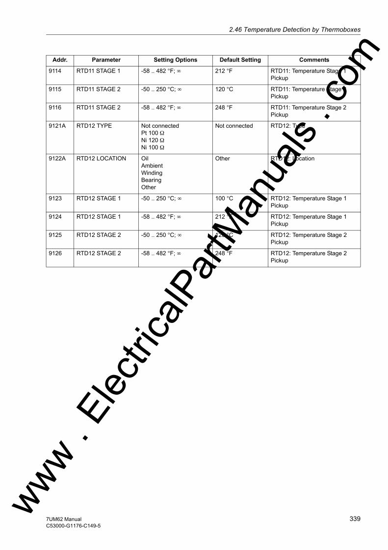
2.46 Temperature Detection by Thermoboxesw
9114 RTD11 STAGE 1 -58 .. 482 °F; ∞ 212 °F RTD11: Temperature Stage 1 Pickup
9115 RTD11 STAGE 2 -50 .. 250 °C; ∞ 120 °C RTD11: Temperature Stage 2 Pickup
9116 RTD11 STAGE 2 -58 .. 482 °F; ∞ 248 °F RTD11: Temperature Stage 2 Pickup
9121A RTD12 TYPE Not connectedPt 100 ΩNi 120 ΩNi 100 Ω
Not connected RTD12: Type
9122A RTD12 LOCATION OilAmbientWindingBearingOther
Other RTD12: Location
9123 RTD12 STAGE 1 -50 .. 250 °C; ∞ 100 °C RTD12: Temperature Stage 1 Pickup
9124 RTD12 STAGE 1 -58 .. 482 °F; ∞ 212 °F RTD12: Temperature Stage 1 Pickup
9125 RTD12 STAGE 2 -50 .. 250 °C; ∞ 120 °C RTD12: Temperature Stage 2 Pickup
9126 RTD12 STAGE 2 -58 .. 482 °F; ∞ 248 °F RTD12: Temperature Stage 2 Pickup
Addr. Parameter Setting Options Default Setting Comments
ww . El
ectric
alPar
tMan
uals
. com
3397UM62 ManualC53000-G1176-C149-5
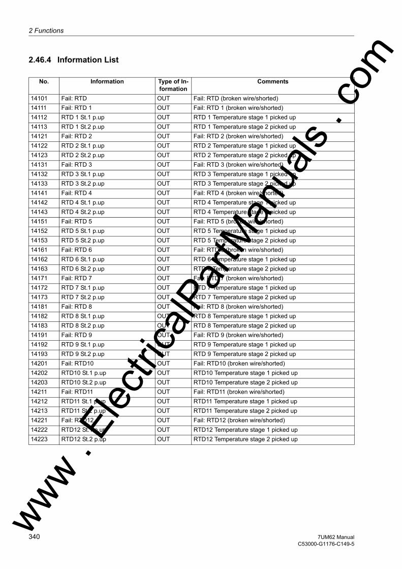
2 Functions
om
2.46.4 Information List
No. Information Type of In-formation
Comments
14101 Fail: RTD OUT Fail: RTD (broken wire/shorted)14111 Fail: RTD 1 OUT Fail: RTD 1 (broken wire/shorted)14112 RTD 1 St.1 p.up OUT RTD 1 Temperature stage 1 picked up14113 RTD 1 St.2 p.up OUT RTD 1 Temperature stage 2 picked up14121 Fail: RTD 2 OUT Fail: RTD 2 (broken wire/shorted)14122 RTD 2 St.1 p.up OUT RTD 2 Temperature stage 1 picked up14123 RTD 2 St.2 p.up OUT RTD 2 Temperature stage 2 picked up14131 Fail: RTD 3 OUT Fail: RTD 3 (broken wire/shorted)14132 RTD 3 St.1 p.up OUT RTD 3 Temperature stage 1 picked up14133 RTD 3 St.2 p.up OUT RTD 3 Temperature stage 2 picked up14141 Fail: RTD 4 OUT Fail: RTD 4 (broken wire/shorted)14142 RTD 4 St.1 p.up OUT RTD 4 Temperature stage 1 picked up14143 RTD 4 St.2 p.up OUT RTD 4 Temperature stage 2 picked up14151 Fail: RTD 5 OUT Fail: RTD 5 (broken wire/shorted)14152 RTD 5 St.1 p.up OUT RTD 5 Temperature stage 1 picked up14153 RTD 5 St.2 p.up OUT RTD 5 Temperature stage 2 picked up14161 Fail: RTD 6 OUT Fail: RTD 6 (broken wire/shorted)14162 RTD 6 St.1 p.up OUT RTD 6 Temperature stage 1 picked up14163 RTD 6 St.2 p.up OUT RTD 6 Temperature stage 2 picked up14171 Fail: RTD 7 OUT Fail: RTD 7 (broken wire/shorted)14172 RTD 7 St.1 p.up OUT RTD 7 Temperature stage 1 picked up14173 RTD 7 St.2 p.up OUT RTD 7 Temperature stage 2 picked up14181 Fail: RTD 8 OUT Fail: RTD 8 (broken wire/shorted)14182 RTD 8 St.1 p.up OUT RTD 8 Temperature stage 1 picked up14183 RTD 8 St.2 p.up OUT RTD 8 Temperature stage 2 picked up14191 Fail: RTD 9 OUT Fail: RTD 9 (broken wire/shorted)14192 RTD 9 St.1 p.up OUT RTD 9 Temperature stage 1 picked up14193 RTD 9 St.2 p.up OUT RTD 9 Temperature stage 2 picked up14201 Fail: RTD10 OUT Fail: RTD10 (broken wire/shorted)14202 RTD10 St.1 p.up OUT RTD10 Temperature stage 1 picked up14203 RTD10 St.2 p.up OUT RTD10 Temperature stage 2 picked up14211 Fail: RTD11 OUT Fail: RTD11 (broken wire/shorted)14212 RTD11 St.1 p.up OUT RTD11 Temperature stage 1 picked up14213 RTD11 St.2 p.up OUT RTD11 Temperature stage 2 picked up14221 Fail: RTD12 OUT Fail: RTD12 (broken wire/shorted)14222 RTD12 St.1 p.up OUT RTD12 Temperature stage 1 picked up14223 RTD12 St.2 p.up OUT RTD12 Temperature stage 2 picked up
ww . El
ectric
alPar
tMan
uals
. c
340 7UM62 ManualC53000-G1176-C149-5
w

2.47 Phase Rotationw
2.47 Phase Rotation
A phase sequence reversal feature via binary input and parameter is implemented in the 7UM62. This permits all protection and monitoring functions to operate correctly even with phase rotation reversal, without the need for two phases to be reversed.
If an anti-clockwise rotating phase sequence permanently exists, this should be entered in the power system data (see Section 2.5).
If phase rotation reverses during operation (e.g. in a pumped storage power station transition from generator to pumping operation is done by changing the phase rota-tion), then a reversal signal at the input allocated is sufficient to inform the protection device of phase-sequence reversal.
2.47.1 Functional Description
Logic The phase rotation is permanently set in a parameter of the power system data at address 271 PHASE SEQ.. Binary input „>Reverse Rot.“ sets the phase rotation to the opposite of the parameter setting.
Figure 2-140 Message logic of the phase-sequence reversal
For safety reasons, the device accepts phase sequence reversal only when no usable measured quantities are current. The binary input is scanned only if operational con-dition 1 is not current. If a reverse command is present for at least 200 ms, the mea-sured quantities of phases L2 and L3 are exchanged.
If operational condition 1 is reached before the minimum control time of 200 ms has expired, phase sequence reversal does not become effective.
As no phase rotation reversal is possible in operational condition 1, the control signal could be retracted in operational condition 1 without a phase rotation reversal occur-ring. For safety reasons, the control signal should be permanently present in order to avoid malfunctions also on device reset (e.g. due to configuration change).
ww . El
ectric
alPar
tMan
uals
. com
3417UM62 ManualC53000-G1176-C149-5

2 Functions
om
Influence on Pro-tective Functions
Swapping phases with a phase sequence reversal affects exclusively calculation of positive and negative sequence quantities, as well as phase-to-phase voltages by subtraction of one phase-to-ground voltage from another, so that phase related indi-cations, fault values, and operating measurement values are not distorted. Thus this function influences almost all protection functions and some of the monitoring func-tions (see Section 2.42.1) which issue an indication if the required and calculated phase rotations do not match.
2.47.2 Setting Notes
Programming Set-tings
The normal phase sequence is set at 271 (see Subsection 2.5). If, on the system side, phase rotation are made temporarily, then these are communicated to the protective device using the binary input „>Reverse Rot.“ (5145).
ww . El
ectric
alPar
tMan
uals
. c
342 7UM62 ManualC53000-G1176-C149-5
w

2.48 Protection Function Controlw
2.48 Protection Function Control
The function logic coordinates the sequence of both the protective and ancillary func-tions, processes the functional decisions, and data received from the system.
2.48.1 Pickup Logic for the Entire Device
This section describes the general pickup and spontaneous messages in the device display.
2.48.1.1 Functional Description
General Device Pickup
The pickup signals for all protection functions in the device are logically OR-combined, and lead to the general device pickup. It is initiated by the first function to pickup and drops out when the last function drops out. In consequence, the following message is reported: „Relay PICKUP“.
The general pickup is the precondition for a number of internal and external conse-quential functions. The following are among the internal functions controlled by general device pickup:• Start of Trip Log: From general device pickup to general device dropout, all fault in-
dications are entered in the trip log.• Initialization of Oscillographic Records: the storage and maintenance of fault values
can also be made dependent on the occurrence of a trip command.• Generation of Spontaneous Messages: Certain fault messages are displayed in the
device display as so-called spontaneous messages (see below „Spontaneous Mes-sages“). This indication can also be made dependent on the general device trip.
Spontaneous Messages
Spontaneous messages are fault messages that appear in the display automatically when general device pickup has occurred. For the 7UM62, these messages include:
„Relay PICKUP“: the protection function that last picked up
„Relay TRIP“: the protection function that last initiated a trip signal;
„PU Time“: running time from general device pickup to dropout of the device, in ms;
„Trip time“: running time from general device pickup to initiation of the first trip signal by the device, with time indicated in ms;
If you use a graphical display, spontaneous messages are only displayed if parameter Spont. FltDisp. is set to YES (see also Section 2.2). On the 4-line display this pa-rameter is hidden.
Note that the thermal overload protection does not have a pickup comparable with the other protection functions. The general device pickup time (PU Time) is started with the trip signal, which starts the trip log. The dropout of the thermal image of the over-load protection ends the fault case and, thereby the running PU Time.
ww . El
ectric
alPar
tMan
uals
. com
3437UM62 ManualC53000-G1176-C149-5

2 Functions
om
2.48.2 Tripping Logic for the Entire Device
This section describes general trip and termination of the trip command.
2.48.2.1 Functional Description
General Trip The tripping signals for all protective functions are connected by ”OR” and generate a message „Relay TRIP“.
This annunciation, like individual trip indications, can be allocated to an LED or an output relay. It can also be used as a sum event.
Controlling the Tripping Signal
For controlling the trip command the following applies:• If a protective function is set to Block. Relay, it is blocked for the activation of
the output relay. The other protective functions are not affected by this.• A trip command once transmitted is stored (see Figure 2-141). At the same time,
the minimum trip command duration T TRIPCOM MIN is started. This trip signal duration timer ensures the trip signal is transmitted to the circuit breaker for a suffi-cient amount of time, even if the function which issued the trip signal drops out quickly. The trip signal is only terminated after all protection Functions drop out AND the minimum trip signal duration expires.
• Finally, it is possible to latch the trip signal until it is manually reset (lockout func-tion). This allows interlocking the circuit breaker against reclosing until the cause of the malfunction has been clarified and the interlock has been manually reset. The reset takes place either by pressing the LED reset key or by activating an appropri-ately masked binary input („>Reset LED“). A precondition, of course, is that the circuit breaker trip coil – as usual – remains blocked as long as the trip signal is present, and the trip coil current is interrupted by the auxiliary contact of the circuit breaker.
Figure 2-141 Terminating the Trip Signal, Example of a Protective Function
2.48.2.2 Setting Notes
Command Duration The minimum trip command duration 280 TMin TRIP CMD was described already in Section 2.5. It is valid for all protection functions which can issue a trip command.
ww . El
ectric
alPar
tMan
uals
. c
344 7UM62 ManualC53000-G1176-C149-5
w

2.49 Ancillary Functionsw
2.49 Ancillary Functions
Chapter Ancillary Functions describes the general device functions.
2.49.1 Processing of Annunciation
After occurrence of a system fault, data on the device response and the measured quantities are significant for analysis purposes. For this purpose, the device provides information processing which operates in a threefold manner:
2.49.1.1 Functional Description
Displays and Binary Outputs (output relays)
Important events and statuses are displayed using front panel LEDs. The relay also contains output relays for remote signaling. Most indications and displays can be con-figured differently to the delivery default settings. The SIPROTEC 4 System Descrip-tion /1/ gives a detailed description of the configuration procedure. The allocation set-tings on delivery are listed in the Appendix of this manual.
The output relays and the LEDs may be operated in a latched or unlatched mode (each may be individually set).
The latched conditions are protected against loss of the auxiliary voltage. They are reset• Locally by pressing the LED key on the relay,• Remotely using a binary input configured for that purpose,• Using one of the serial interfaces,• Automatically at the beginning of a new pickup (please observe the LED minimum
hold time, see Section 2.2)).
Status messages should not be stored. Also, they cannot be reset until the criterion to be reported is remedied. This applies to indications from monitoring functions or sim-ilar.
A green LED displays operational readiness of the relay („RUN“), and cannot be reset. It goes out if the self-check feature of the microprocessor recognizes an abnormal oc-currence, or if the auxiliary voltage fails.
When auxiliary voltage is present, but the relay has an internal malfunction, then the red LED („ERROR“) lights up and the processor blocks the relay.
Information on the Integrated Display (LCD) or to a Per-sonal Computer
Events and states can be obtained from the LCD on the front plate of the device. A personal computer can be connected to the front interface or the service interface for retrieval of information.
In the quiescent condition, as long as no system fault is present, the display panel can display selected operating information (overview of operating measurement values). In the event of a system fault, fault information, so-called spontaneous display indica-tions, appear instead. After the fault indications have been acknowledged, the quies-cent data are shown again. Acknowledgement can be performed by pressing the LED buttons on the front panel (see above).
The device is equipped with several event buffers, for operational messages, circuit breaker statistics, etc., which are protected against loss of the auxiliary voltage by a buffer battery. These messages can be retrieved, at any time, using the operating ww . El
ectric
alPar
tMan
uals
. com
3457UM62 ManualC53000-G1176-C149-5
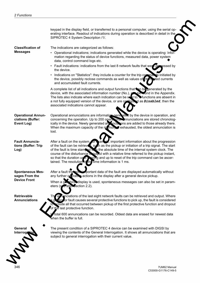
2 Functions
om
keypad in the display field, or transferred to a personal computer, using the serial op-erating interface. Readout of indications during operation is described in detail in the SIPROTEC 4 System Description /1/.
Classification of Messages
The indications are categorized as follows:• Operational indications; indications generated while the device is operating: Infor-
mation regarding the status of device functions, measured data, power system data, control command logs etc.
• Fault indications: indications from the last 8 network faults that were processed by the device.
• Indications on "Statistics": they include a counter for the trip commands initiated by the device, possibly reclose commands as well as values of interrupted currents and accumulated fault currents.
A complete list of all indications and output functions that can be generated by the device, with the associated information number (No.), can be found in the Appendix. The lists also indicate where each indication can be sent to. If functions are absent in a not fully equipped version of the device, or are configured as Disabled, then the associated indications cannot appear.
Operational Annun-ciations (Buffer: Event Log)
Operational annunciations are information generated by the device in operation, and concerning the operation. Up to 200 operational annunciations are stored chronolog-ically in the device. Newly generated annunciations are added to those already there. When the maximum capacity of the memory is exhausted, the oldest annunciation is lost.
Fault Annuncia-tions (Buffer: Trip Log)
After a fault on the system, for example, important information about the progression of the fault can be retrieved, such as the pickup or initiation of a trip signal. The start of the fault is time stamped with the absolute time of the internal system clock. The course of the disturbance is output with a relative time referred to the pickup instant, so that the duration until tripping and up to reset of the trip command can be ascer-tained. The resolution of the time information is 1 ms.
Spontaneous Mes-sages From the Device Front
After a fault the most important data of the fault are displayed automatically without any further operating actions in the display after a general device pickup.
When a graphical display is used, spontaneous messages can also be set in param-eters (see also Section 2.2).
Retrievable Annunciations
The annunciations of the last eight network faults can be retrieved and output. Where a generator fault causes several protective functions to pick up, the fault is considered to include all that occurred between pickup of the first protective function and dropout of the last protective function.
In total 600 annuncations can be recorded. Oldest data are erased for newest data when the buffer is full.
General Interrogation
The present condition of a SIPROTEC 4 device can be examined with DIGSI by viewing the contents of the General Interrogation. It shows all annunciations that are subject to general interrogation with their current value.
ww . El
ectric
alPar
tMan
uals
. c
346 7UM62 ManualC53000-G1176-C149-5
w
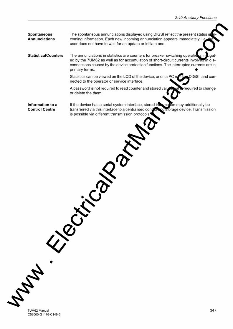
2.49 Ancillary Functionsw
Spontaneous Annunciations
The spontaneous annunciations displayed using DIGSI reflect the present status of in-coming information. Each new incoming annunciation appears immediately, i.e. the user does not have to wait for an update or initiate one.
Statistical Counters The annunciations in statistics are counters for breaker switching operations instigat-ed by the 7UM62 as well as for accumulation of short-circuit currents involved in dis-connections caused by the device protection functions. The interrupted currents are in primary terms.
Statistics can be viewed on the LCD of the device, or on a PC running DIGSI, and con-nected to the operator or service interface.
A password is not required to read counter and stored values but is required to change or delete the them.
Information to a Control Centre
If the device has a serial system interface, stored information may additionally be transferred via this interface to a centralised control and storage device. Transmission is possible via different transmission protocols.
ww . El
ectric
alPar
tMan
uals
. com
3477UM62 ManualC53000-G1176-C149-5

2 Functions
om
2.49.2 Statistics
Tripping commands from the device are counted. Currents of the last disconnections instigated by the device are logged. Disconnected fault currents are accumulated for each breaker pole.
2.49.2.1 Function Description
Number of Trips The number of trips initiated by the 7UM62 is counted, as long as the position of the circuit breaker is monitored via breaker auxiliary contacts and binary inputs. To use this function, the internal pulse counter „#of TRIPs=“ is masked in the matrix to a binary input that is controlled by the circuit breaker OPEN position. The pulse metered value „#of TRIPs=“ can be found in the "Statistics" group if the option "Mea-sured and Metered Values Only" was enabled in the configuration matrix.
Switch-Off Values (at Trip)
Additionally the following switch-off values appear in the fault indications for each trip signal:• If earth differential protection is configured, an indication „I0-Diff:“ and „I0-Stab:“ is issued in I/InO.
• the total of the primary fault currents per phase and side in kA • the primary currents in all three phases in kA, individually for side 1 and side 2• If differential protection is configured, the differential and stabilization (restraint) cur-
rents of all three phases are indicated.• the phase-to-earth voltages in kV• primary active power P in MW (precisely averaged power)• primary reactive power Q in MVAR (precisely averaged power)• Frequency in Hz
Operating Hours The accumulated operating hours under load are also stored (= current value in at least one phase is greater than the limit value BkrClosed I MIN set under address 281).
Accumulated Shut-down Currents
The shutdown currents for each phase, which are indicated at every trip command in-dividually for side 1 and side 2, are accumulated and stored.
The counter and memory levels are secured against loss of auxiliary voltage.
Setting / Resetting Setting or resetting of these statistical counters takes place under the menu item AN-NUNCIATION → STATISTIC by overwriting the counter values displayed.
ww . El
ectric
alPar
tMan
uals
. c
348 7UM62 ManualC53000-G1176-C149-5
w

2.49 Ancillary Functionsw
2.49.2.2 Information List
2.49.3 Measurement (Secondary/Primary/Percentage Values)
A series of measured values and the values derived from them are constantly avail-able for call up on site, or for data transfer (see table 2-19, as well as the following list).
Measured values can be transferred via the interfaces to a central control and storage system.
2.49.3.1 Functional Description
Display of Mea-sured Values
The operational measured values listed in Table 2-19 can be read out as secondary, primary or percent values. A precondition for correctly displaying the primary and per-centage values is complete and correct entry of the nominal values for the current transformers, and protected equipment, in accordance with Subsections 2.5 and 2.7. Table 2-19 lists the formulae for the conversion of secondary into primary or percent-age values.
Depending on the version ordered, the type of device connection and the configured protection functions, only a part of the operational measured values listed in the fol-lowing table may be available. The displacement voltage U0 is calculated from the phase-earth voltages: U0 = 1/3 · |UL1 + UL2 + UL3|. For this the three voltage inputs phase-to-earth must be connected.
No. Information Type of In-formation
Comments
- #of TRIPs= PMV Number of TRIPs409 >BLOCK Op Count SP >BLOCK Op Counter1020 Op.Hours= VI Counter of operating hours30607 ΣIL1 S1: VI Accumulation of interrupted curr. L1 S130608 ΣIL2 S1: VI Accumulation of interrupted curr. L2 S130609 ΣIL3 S1: VI Accumulation of interrupted curr. L3 S130610 ΣIL1 S2: VI Accumulation of interrupted curr. L1 S230611 ΣIL2 S2: VI Accumulation of interrupted curr. L2 S230612 ΣIL3 S2: VI Accumulation of interrupted curr. L3 S2
ww . El
ectric
alPar
tMan
uals
. com
3497UM62 ManualC53000-G1176-C149-5

2 Functions
om
Table 2-19 Conversion formulae between secondary values and primary/percentage values
Measured Values
secondary primary %
IL1 S2, IL2 S2, IL3 S2,I1 S2, I2 S2, 3I0 S2,
Isec S2
IL1 S1, IL2 S1, IL3 S1
Isec S1 Differential Protection for Generators and Motors:
Differential Protection for Three Phase Transformer:
IEE1 IEE1 sec FACTOR IEE1 · IEE1 sec.
IEE2 IEE2 sec. FACTOR IEE2 · IEE1 sec.
IEEB IEE1 sec or IEE2 sec
oror
UL1E, UL2E, UL3E, U0 U1, U2
UL-E sec.
UL1-L2, UL2-L3, UL3-L1
ULL sec.
UE measured: UE sec.
measured: FACTOR UE · UE sec.
calculated: UE sec.= U0 ·√3
calculated:
UI/T UI/T sec FACTOR UE · UI/T sec
ww . El
ectric
alPar
tMan
uals
. c
350 7UM62 ManualC53000-G1176-C149-5
w

2.49 Ancillary Functionsw
Wth the following parameters from the Power System Data 1:
In addition measured values are computed by the protection functions and made avail-able:
P, Q, S Psec Qsec Ssec
Angle PHI ϕ ϕ no display of percentage measured values
Power factor cos ϕ cos ϕ cos ϕ · 100Frequency f f
U/f
R, X Rsec S2Xsec S2
no display of percentage measured values
UE3.H measured:UE3.H,sec
measured:
calculated:UE3.H,sec= U0·√3
calculated:
UDC/IDC (measuring transducer 1)
UDC in V- no primary values
IDC in mA-
Uexc (mea-suring trans-ducer 3)
Uexc no primary value
Measured Values
secondary primary %
Parameter Address Parameter AddressUnom PRIMARY 221 FACTOR IEE1 205Unom SECONDARY 222 FACTOR IEE2 213IN-PRI I-SIDE1 202 FACTOR UE 224IN-SEC I-SIDE1 203 UN GEN/MOTOR 251IN-PRI I-SIDE2 211 SN GEN/MOTOR 252IN-SEC I-SIDE2 212 Uph / Udelta 225UN-PRI SIDE 1 241 SN TRANSFORMER 249
ww . El
ectric
alPar
tMan
uals
. com
3517UM62 ManualC53000-G1176-C149-5
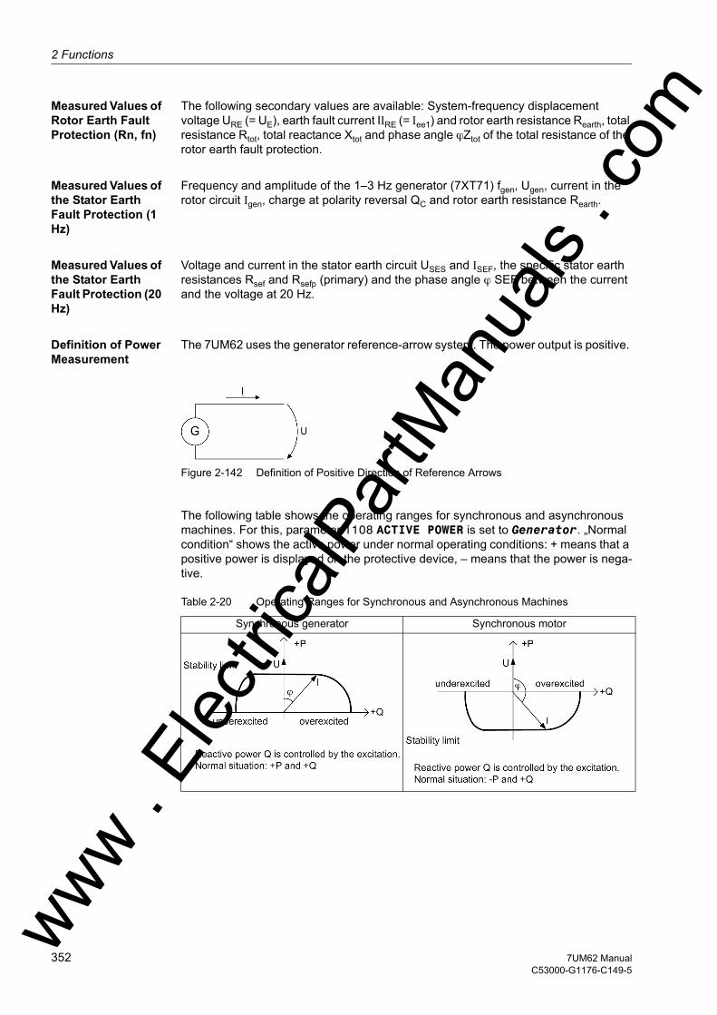
2 Functions
om
Measured Values of Rotor Earth Fault Protection (Rn, fn)
The following secondary values are available: System-frequency displacement voltage URE (= UE), earth fault current IIRE (= Iee1) and rotor earth resistance Rearth, total resistance Rtot, total reactance Xtot and phase angle ϕZtot of the total resistance of the rotor earth fault protection.
Measured Values of the Stator Earth Fault Protection (1 Hz)
Frequency and amplitude of the 1–3 Hz generator (7XT71) fgen, Ugen, current in the rotor circuit Igen, charge at polarity reversal QC and rotor earth resistance Rearth.
Measured Values of the Stator Earth Fault Protection (20 Hz)
Voltage and current in the stator earth circuit USES and ISEF, the specific stator earth resistances Rsef and Rsefp (primary) and the phase angle ϕ SEF between the current and the voltage at 20 Hz.
Definition of Power Measurement
The 7UM62 uses the generator reference-arrow system. The power output is positive.
Figure 2-142 Definition of Positive Direction of Reference Arrows
The following table shows the operating ranges for synchronous and asynchronous machines. For this, parameter 1108 ACTIVE POWER is set to Generator. „Normal condition“ shows the active power under normal operating conditions: + means that a positive power is displayed on the protective device, – means that the power is nega-tive.
Table 2-20 Operating Ranges for Synchronous and Asynchronous Machines
Synchronous generator Synchronous motor
ww . El
ectric
alPar
tMan
uals
. c
352 7UM62 ManualC53000-G1176-C149-5
w

2.49 Ancillary Functionsw
The table shows that the operating ranges in generator and motor operation are mir-rored around the reactive power axis. The measured power values also result from the above definition.
If, for instance, the forward power monitoring or the reverse power protection is to be used in a synchronous motor, parameter 1108 ACTIVE POWER must be set to Motor. This multiplies the actual active power (according to the above definition) with –1. This means that the power diagram is symmetrical around the reactive power axis and the interpretation of active power changes. This effect must be considered when evaluat-ing the metered energy values.
If for instance positive power values are to be obtained with an asynchronous motor, the current direction at the allocated CT set (e.g. parameter 201 STRPNT->OBJ S1) must be reversed. Parameter 1108 ACTIVE POWER remains in the default setting Generator. This means that because of the generator reference-arrow system the earthing of the CTs that must be entered in the device is the opposite of the actual earthing. This leads to results that are comparable to those of a consumer reference-arrow system.
Asynchronous generator Asynchronous motor
ww . El
ectric
alPar
tMan
uals
. com
3537UM62 ManualC53000-G1176-C149-5

2 Functions
om
2.49.3.2 Information List
No. Information Type of In-formation
Comments
605 I1 = MV I1 (positive sequence)606 I2 = MV I2 (negative sequence)621 UL1E= MV U L1-E622 UL2E= MV U L2-E623 UL3E= MV U L3-E624 UL12= MV U L12625 UL23= MV U L23626 UL31= MV U L31627 UE = MV Displacement voltage UE629 U1 = MV U1 (positive sequence)630 U2 = MV U2 (negative sequence)641 P = MV P (active power)642 Q = MV Q (reactive power)644 Freq= MV Frequency645 S = MV S (apparent power)650 UE3h = MV UE 3rd harmonic662 I DC = MV DC Current669 U20= MV SEF 100%: 20 Hz voltage stator circuit670 I20= MV SEF 100%: 20 Hz current stator circuit693 Rtot = MV REF(R,fn): Total Resistance (R total)696 Xtot = MV REF(R,fn): Total Reactance (X total)697 ϕ Ztot= MV REF(R,fn): Phase Angle of Z total700 Re = MV REF(R,fn): Fault Resistance (R earth)721 IL1S1= MV Operat. meas. current L1 side 1 [%] is722 IL2S1= MV Operat. meas. current L2 side 1 [%] is723 IL3S1= MV Operat. meas. current L3 side 1 [%] is724 IL1S2= MV Operat. meas. current L1 side 2 [%] is725 IL2S2= MV Operat. meas. current L2 side 2 [%] is726 IL3S2= MV Operat. meas. current L3 side 2 [%] is755 fgen = MV REF(1-3Hz): Freq. of square-wave gen.757 Ugen = MV REF(1-3Hz): Volt. of square-wave gen.758 Imeas. = MV REF(1-3Hz): Curr. of rotor meas. circuit759 Qc = MV REF(1-3 Hz): Charge at polarity rev.(Qc)760 RSEFp= MV SEF100%: Prim. stator earth resistance761 R earth= MV REF(1-3Hz): Fault Resistance (R earth)762 U SEF= MV SEF100%: Bias volt. for stator circuit763 I SEF= MV SEF100%: Earth curr. in stator circuit764 R SEF= MV SEF100%: Stator earth resistance765 U/f = MV (U/Un) / (f/fn)769 U I/T = MV Displacement voltage U Interturn827 IEE-B= MV Sensitive Current IEE-B828 IEE1= MV Senstive Earth Current 1829 IEE2= MV Senstive Earth Current 2831 3I0 = MV 3I0 (zero sequence)ww .
Elec
tricalP
artM
anua
ls . c
354 7UM62 ManualC53000-G1176-C149-5
w
2.49 Ancillary Functionsw
2.49.4 Thermal Measurement
2.49.4.1 Description
The thermal measured values are as follows:• ΘS/ΘS Trip Overload protection measured value of the stator winding in % of the trip-
ping overtemperature,• ΘS/ΘS TripL1 Normalized overload protection measured value of the stator winding for
phase L1,• ΘS/ΘS TripL2 Normalized overload protection measured value of the stator winding for
phase L2,• ΘS/ΘS TripL3 Normalized overload protection measured value of the stator winding for
phase L3,• ΘL/ΘLmax: Normalized rotor temperature in % of the tripping temperature,• TRem.: Time until the next permissible restart,• INeg th.: Rotor overtemperature due to the negative phase-sequence component of
the current, in % of the tripping overtemperature,• U/f th.: Overtemperature caused by overexcitation, in % of tripping overtempera-
ture,• Coolant temperature• Θ RTD 1 to Θ RTD 12: Temperature at sensors 1 to 12
832 U0 = MV U0 (zero sequence)894 U DC = MV DC voltage896 U RE = MV REF(R,fn): Injected Voltage (U RE)897 I RE = MV REF(R,fn): Curr. in the Circuit (I RE)901 PF = MV Power Factor902 PHI= MV Power angle903 R= MV Resistance904 X= MV Reactance909 Uexcit.= MV Excitation voltage995 ϕ SEF= MV SEF100%: Phase angle in stator circuit996 Td1= MV Transducer 1997 Td2= MV Transducer 2998 Td3= MV Transducer 37740 ϕIL1S1= MV Phase angle in phase IL1 side 17741 ϕIL2S1= MV Phase angle in phase IL2 side 17749 ϕIL3S1= MV Phase angle in phase IL3 side 17750 ϕIL1S2= MV Phase angle in phase IL1 side 27759 ϕIL2S2= MV Phase angle in phase IL2 side 27760 ϕIL3S2= MV Phase angle in phase IL3 side 2
No. Information Type of In-formation
Comments
ww . El
ectric
alPar
tMan
uals
. com
3557UM62 ManualC53000-G1176-C149-5

2 Functions
om
2.49.4.2 Information List
2.49.5 Diff- and Rest. Measurement
Differential and restraint currents (stabilized currents) Idiff L1, Idiff L2, Idiff L3, Istab L1, Istab
L2, Istab L3, I0diff, I0stab, 3I0-1, 3I0-2 in percent of the nominal values of the protected object.
2.49.5.1 Information List
No. Information Type of In-formation
Comments
660 T Rem.= MV Remaining Time for Switch ON661 Θ REST. = MV Threshold of Restart Inhibit766 U/f th. = MV Calculated temperature (U/f)801 Θ/Θtrip = MV Temperat. rise for warning and trip802 Θ/ΘtripL1= MV Temperature rise for phase L1803 Θ/ΘtripL2= MV Temperature rise for phase L2804 Θ/ΘtripL3= MV Temperature rise for phase L3805 ΘR/ΘRmax = MV Temperature of Rotor910 ThermRep.= MV Calculated rotor temp. (unbal. load)911 AMB.TEMP = MV Cooling medium temperature1068 Θ RTD 1 = MV Temperature of RTD 11069 Θ RTD 2 = MV Temperature of RTD 21070 Θ RTD 3 = MV Temperature of RTD 31071 Θ RTD 4 = MV Temperature of RTD 41072 Θ RTD 5 = MV Temperature of RTD 51073 Θ RTD 6 = MV Temperature of RTD 61074 Θ RTD 7 = MV Temperature of RTD 71075 Θ RTD 8 = MV Temperature of RTD 81076 Θ RTD 9 = MV Temperature of RTD 91077 Θ RTD10 = MV Temperature of RTD101078 Θ RTD11 = MV Temperature of RTD111079 Θ RTD12 = MV Temperature of RTD12
No. Information Type of In-formation
Comments
7742 IDiffL1= MV IDiffL1(I/Inominal object [%])7743 IDiffL2= MV IDiffL2(I/Inominal object [%])7744 IDiffL3= MV IDiffL3(I/Inominal object [%])7745 IRestL1= MV IRestL1(I/Inominal object [%])7746 IRestL2= MV IRestL2(I/Inominal object [%])7747 IRestL3= MV IRestL3(I/Inominal object [%])30654 I0-Diff= MV I0-Diff REF (I/Inominal object [%])30655 I0-Rest= MV I0-Rest REF (I/Inominal object [%])30659 3I0-1 = MV 3I0-1 REF (I/Inominal object [%])30660 3I0-2 = MV 3I0-2 REF (I/Inominal object [%])ww .
Elec
tricalP
artM
anua
ls . c
356 7UM62 ManualC53000-G1176-C149-5
w

2.49 Ancillary Functionsw
2.49.6 Min/Max Measurement Setup
Minimum and maximum values for the positive-sequence components I1 and U1, the active power P, reactive power Q, in primary values, of the frequency and of the 3rd harmonic content in the displacement voltage, in secondary values U3.H. Included are the date and time they were last updated. The minimum/maximum values can be reset via binary inputs or, in the delivery status of the device, also via the F4 function key.
Minimum and maximum values: only with version 7UM62**_*****_3***
2.49.6.1 Information List
2.49.7 Energy
Wp, Wq, metered values of the active and reactive energy in kilowatt, megawatt or gi-gawatt hours primary or in kVARh, MVARh or GVARh primary, separately according to the input and output, or capacitive and inductive.
The calculation of the operational measured values is also performed during a fault. The values are updated in intervals of ≥ 0.3 s and ≤ 1 s.
Power metered values: only with version 7UM62**_*****_3***
No. Information Type of In-formation
Comments
- ResMinMax IntSP_Ev Reset Minimum and Maximum counter394 >UE3h MiMa Res. SP >UE 3rd Harm. MIN/MAX Buffer Reset396 >I1 MiMaReset SP >I1 MIN/MAX Buffer Reset399 >U1 MiMa Reset SP >U1 MIN/MAX Buffer Reset400 >P MiMa Reset SP >P MIN/MAX Buffer Reset402 >Q MiMa Reset SP >Q MIN/MAX Buffer Reset407 >Frq MiMa Reset SP >Frq. MIN/MAX Buffer Reset639 UE3h min= MVT UE 3rd Harmonic Voltage Minimum640 UE3h max= MVT UE 3rd Harmonic Voltage Maximum857 I1 Min= MVT Positive Sequence Minimum858 I1 Max= MVT Positive Sequence Maximum874 U1 Min = MVT U1 (positive sequence) Voltage Minimum875 U1 Max = MVT U1 (positive sequence) Voltage Maximum876 PMin= MVT Active Power Minimum877 PMax= MVT Active Power Maximum878 QMin= MVT Reactive Power Minimum879 QMax= MVT Reactive Power Maximum882 fMin= MVT Frequency Minimum883 fMax= MVT Frequency Maximum
ww . El
ectric
alPar
tMan
uals
. com
3577UM62 ManualC53000-G1176-C149-5

2 Functions
om
2.49.7.1 Information List
2.49.8 Set Points (Measured Values)
SIPROTEC 4 device 7UM62 allows to set warning levels for important measured and metered values. If during operation a value reaches or exceeds one of these limits, the device generates an alarm which is displayed as an operational indication. As for all operational annunciations, it is possible to output the information to LED and/or output relay and via the serial interfaces. Unlike real protection functions such as time over-current protection or overload protection, this supervision routine runs in the back-ground, so that in the case of a fault and rapidly changing measured values it may not respond when protection functions pick up. Moreover, since a message is not gener-ated until the set limit value has been exceeded several times, these monitoring func-tions cannot respond immediately before a device trip.
With the 7UM62, only the limit value of the undercurrent protection IL< is configured when the device is delivered from the factory. Further limit values can be configured if their measured and metered values have been set accordingly in CFC (see SIPRO-TEC 4 System Description /1/).
Limit settings are entered under MEASUREMENTS in the sub-menu LIMITS (MV) by overwriting the existing values.
If the phase current drops below the limit „IL<“ is exceeded, the indication „SP. I<“ (No. 284) will be issued.
2.49.8.1 Setting Notes
Limit Values Limit settings are entered under MEASUREMENTS in the sub-menu LIMITS (MV) by overwriting the existing values.
If the phase current drops below the limit „IL<“, the indication „SP. I<“ (No. 284) will be issued.
No. Information Type of In-formation
Comments
- Meter res IntSP_Ev Reset meter888 Wp(puls) PMV Pulsed Energy Wp (active)889 Wq(puls) PMV Pulsed Energy Wq (reactive)916 Wp∆= - Increment of active energy917 Wq∆= - Increment of reactive energy924 WpForward MVMV Wp Forward925 WqForward MVMV Wq Forward928 WpReverse MVMV Wp Reverse929 WqReverse MVMV Wq Reverse
ww . El
ectric
alPar
tMan
uals
. c
358 7UM62 ManualC53000-G1176-C149-5
w
2.49 Ancillary Functionsw
2.49.8.2 Information List
2.49.9 Set Points (Statistic)
SIPROTEC 4 device 7UM62 allows limit levels for important statistic values to be set. If during operation a value reaches or exceeds one of these limits, the device gener-ates an alarm which is displayed as an operational indication.
If the limit „OpHour>“ is exceeded, the indication „SP. Op Hours>“ (No. 272) will be issued.
2.49.9.1 Information List
No. Information Type of In-formation
Comments
- IL< LV IL< under current284 SP. I< OUT Set Point I< alarm
No. Information Type of In-formation
Comments
- OpHour> LV Operating hours greater than272 SP. Op Hours> OUT Set Point Operating Hours
ww . El
ectric
alPar
tMan
uals
. com
3597UM62 ManualC53000-G1176-C149-5
2 Functions
om
2.49.10 Oscillographic Fault Records
The Multi-Functional Protective Relay 7UM62 is equipped with a fault memory which scans either the instantaneous values or the rms values of various measured quanti-ties for storage in a ring buffer.
2.49.10.1Function Description
Mode of Operation The instantaneous values of measured values
iL1 S1, iL2 S1, iL3 S1, iEE1, iL1 S2, iL2 S2, iL3 S2, iEE2 and uL1, uL2, uL3, uE, IdiffL1, IdiffL2, IdiffL3, IstabL1, IstabL2, IstabL3 (referred to the nominal object current) and u= or i= of the three measuring transducers
are sampled at intervals of 1,25 ms (for 50 Hz)and stored in a ring buffer (16 samples per cycle). For a fault, the data are recorded for a set period of time, but not for more than 5 seconds.
The r.m.s. values of the measured quantities
I1, I2, Iee2, Iee1, U1, UE, P, Q, ϕ, f–fN, R and X
can be deposited in a ring buffer, one measured value per half cycle. R and X are the positive sequence impedances. For a fault, the data are recorded for a set period of time, but not for more than 80 seconds.
Up to 8 fault records can be recorded in this buffer. The fault record memory is auto-matically updated with every new fault, so no acknowledgment is required. The fault record buffer can also be started with protection pickup, via binary input, operator in-terface or serial interface.
The data can be retrieved via the serial interfaces by means of a personal computer and evaluated with the protection data processing program DIGSI and the graphic analysis software SIGRA. The latter graphically represents the data recorded during the system fault and calculates additional information such as impedance or rms values from the measured values. Currents and voltages can be presented as desired as primary or secondary values. Binary signal traces (marks) of particular events, e.g. „fault detection“, „tripping“ are also represented.
If the device has a serial system interface, the fault recording data can be passed on to a central device (e.g. SICAM) via this interface. Data are evaluated by appropriate programs in the central device. Currents and voltages are referred to their maximum values, scaled to their rated values and prepared for graphic presentation. Binary signal traces (marks) of particular events, e.g. „fault detection“, „tripping“ are also rep-resented.
In the event of transfer to a central device, the request for data transfer can be exe-cuted automatically and can be selected to take place after each fault detection by the protection, or only after a trip.
ww . El
ectric
alPar
tMan
uals
. c
360 7UM62 ManualC53000-G1176-C149-5
w
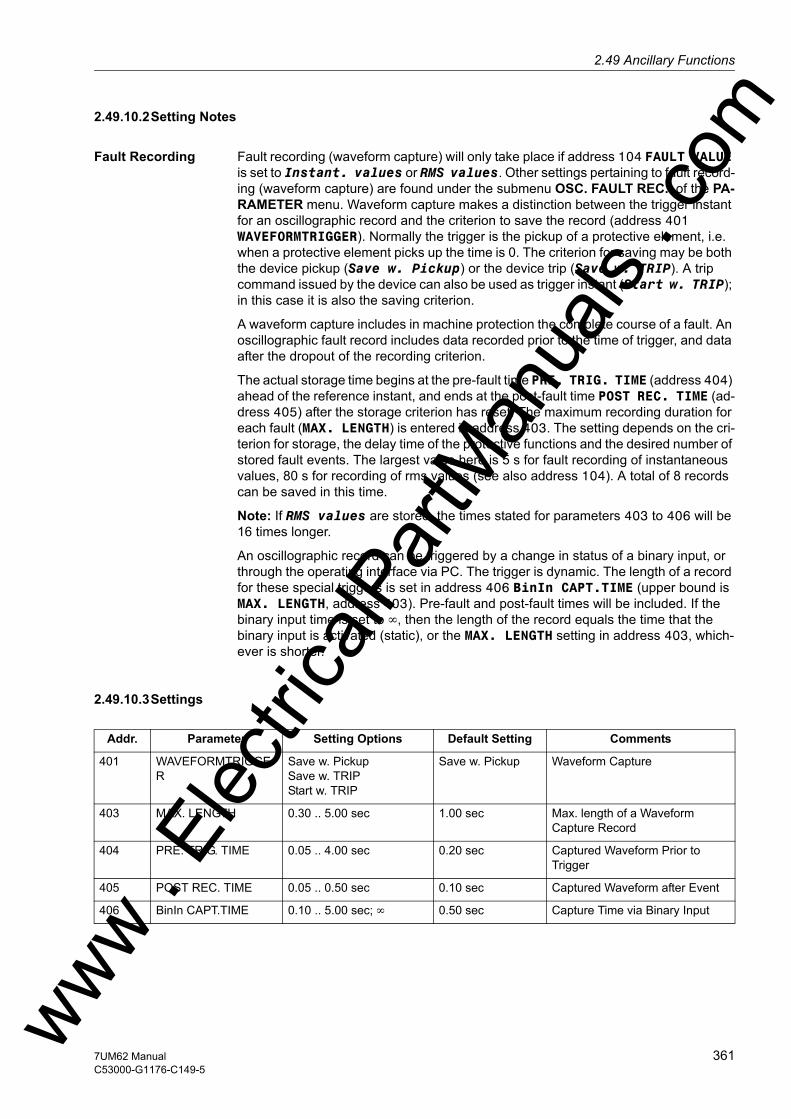
2.49 Ancillary Functionsw
2.49.10.2Setting Notes
Fault Recording Fault recording (waveform capture) will only take place if address 104 FAULT VALUE is set to Instant. values or RMS values. Other settings pertaining to fault record-ing (waveform capture) are found under the submenu OSC. FAULT REC. of the PA-RAMETER menu. Waveform capture makes a distinction between the trigger instant for an oscillographic record and the criterion to save the record (address 401 WAVEFORMTRIGGER). Normally the trigger is the pickup of a protective element, i.e. when a protective element picks up the time is 0. The criterion for saving may be both the device pickup (Save w. Pickup) or the device trip (Save w. TRIP). A trip command issued by the device can also be used as trigger instant (Start w. TRIP); in this case it is also the saving criterion.
A waveform capture includes in machine protection the complete course of a fault. An oscillographic fault record includes data recorded prior to the time of trigger, and data after the dropout of the recording criterion.
The actual storage time begins at the pre-fault time PRE. TRIG. TIME (address 404) ahead of the reference instant, and ends at the post-fault time POST REC. TIME (ad-dress 405) after the storage criterion has reset. The maximum recording duration for each fault (MAX. LENGTH) is entered in address 403. The setting depends on the cri-terion for storage, the delay time of the protective functions and the desired number of stored fault events. The largest value here is 5 s for fault recording of instantaneous values, 80 s for recording of rms values (see also address 104). A total of 8 records can be saved in this time.
Note: If RMS values are stored, the times stated for parameters 403 to 406 will be 16 times longer.
An oscillographic record can be triggered by a change in status of a binary input, or through the operating interface via PC. The trigger is dynamic. The length of a record for these special triggers is set in address 406 BinIn CAPT.TIME (upper bound is MAX. LENGTH, address 403). Pre-fault and post-fault times will be included. If the binary input time is set to ∞, then the length of the record equals the time that the binary input is activated (static), or the MAX. LENGTH setting in address 403, which-ever is shorter.
2.49.10.3Settings
Addr. Parameter Setting Options Default Setting Comments
401 WAVEFORMTRIGGER
Save w. PickupSave w. TRIPStart w. TRIP
Save w. Pickup Waveform Capture
403 MAX. LENGTH 0.30 .. 5.00 sec 1.00 sec Max. length of a Waveform Capture Record
404 PRE. TRIG. TIME 0.05 .. 4.00 sec 0.20 sec Captured Waveform Prior to Trigger
405 POST REC. TIME 0.05 .. 0.50 sec 0.10 sec Captured Waveform after Event
406 BinIn CAPT.TIME 0.10 .. 5.00 sec; ∞ 0.50 sec Capture Time via Binary Input
ww . El
ectric
alPar
tMan
uals
. com
3617UM62 ManualC53000-G1176-C149-5

2 Functions
om
2.49.10.4Information List
2.49.11 Date and Time Stamping
The integrated date/clock management enables the exact timely assignment of events e.g., those in the operational annuncations and fault annunciations or in the lists of the minimum/maximum values.
2.49.11.1 Functional Description
Mode of Operation The time can be influenced by• internal RTC (Real Time Clock), • external synchronization sources (e.g. DCF77, IRIG B),• external minute pulses via binary input.
Note
Upon delivery of the device the internal clock RTC is always set by default as syn-chronization source, regardless of whether the device is equipped with a system inter-face or not. If the time synchronization is to use an external source, it must be select-ed.
The procedure for changing the synchronization source is described in detail in the SIPROTEC 4- System Description.
No. Information Type of In-formation
Comments
- FltRecSta IntSP Fault Recording Start4 >Trig.Wave.Cap. SP >Trigger Waveform Capture203 Wave. deleted OUT_Ev Waveform data deleted30053 Fault rec. run. OUT Fault recording is running
ww . El
ectric
alPar
tMan
uals
. c
362 7UM62 ManualC53000-G1176-C149-5
w
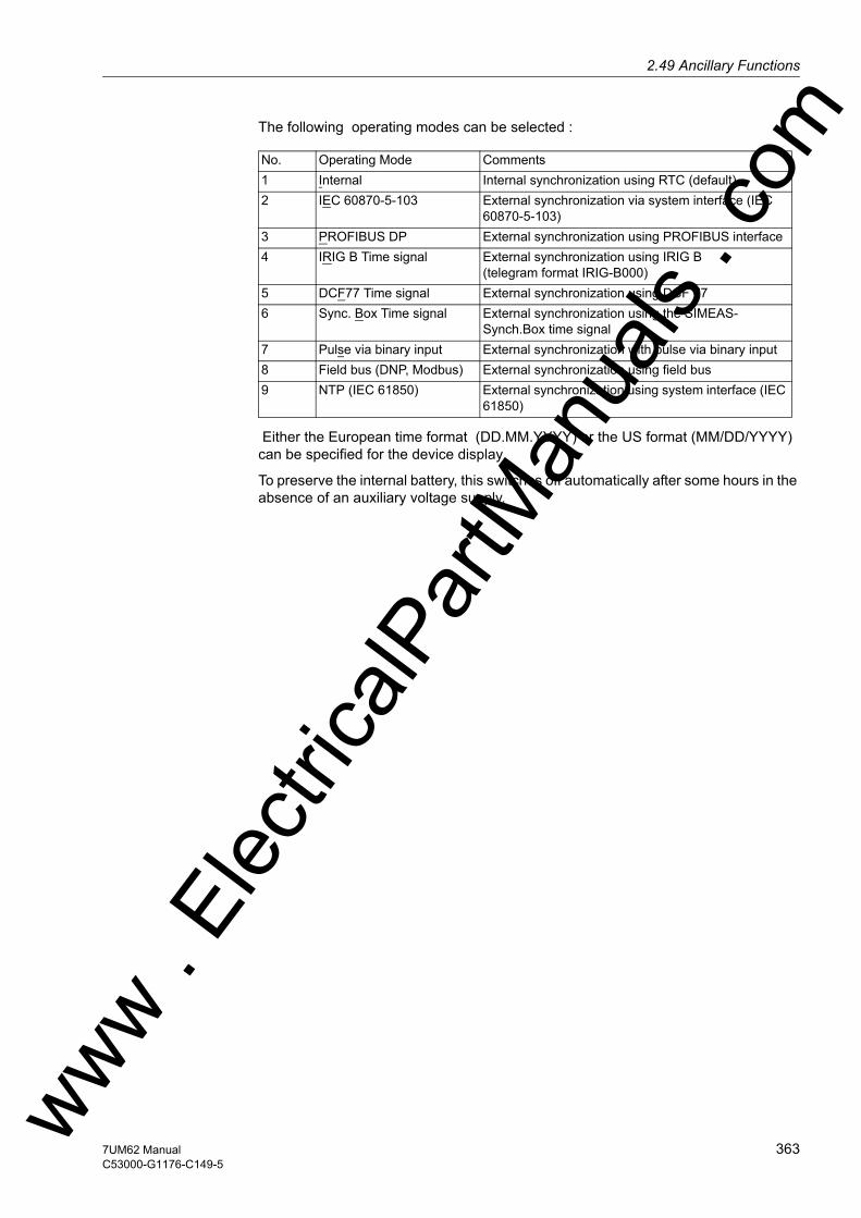
2.49 Ancillary Functionsw
The following operating modes can be selected :
Either the European time format (DD.MM.YYYY) or the US format (MM/DD/YYYY) can be specified for the device display
To preserve the internal battery, this switches off automatically after some hours in the absence of an auxiliary voltage supply.
No. Operating Mode Comments1 Internal Internal synchronization using RTC (default)2 IEC 60870-5-103 External synchronization via system interface (IEC
60870-5-103)3 PROFIBUS DP External synchronization using PROFIBUS interface4 IRIG B Time signal External synchronization using IRIG B
(telegram format IRIG-B000) 5 DCF77 Time signal External synchronization using DCF 77 6 Sync. Box Time signal External synchronization using the SIMEAS-
Synch.Box time signal7 Pulse via binary input External synchronization with pulse via binary input8 Field bus (DNP, Modbus) External synchronization using field bus9 NTP (IEC 61850) External synchronization using system interface (IEC
61850)
ww . El
ectric
alPar
tMan
uals
. com
3637UM62 ManualC53000-G1176-C149-5
2 Functions
om
2.49.12 Commissioning Aids
Device data sent to a central or master computer system during test mode or commis-sioning can be influenced. There are tools for testing the system interface and the binary inputs and outputs of the device.
Applications • Test Mode• Commissioning
Prerequisites To be able to use the commissioning aids described below, the following must apply:
– The device must be equipped with an interface.
– The device has to be connected to a control center.
2.49.12.1Test Messages to the SCADA Interface during Test Operation
If the device is connected to a central or main computer system via the SCADA inter-face, then the information that is transmitted can be influenced.
Depending on the type of protocol, all messages and measured values transferred to the central control system can be identified with an added message "test operation"-bit while the device is being tested on site (test mode). This identification prevents the messages from being incorrectly interpreted as resulting from an actual power system disturbance or event. As another option, all messages and measured values normally transferred via the system interface can be blocked during the testing ("block data transmission").
Data transmission block can be accomplished by controlling binary inputs, by using the operating panel on the device, or with a PC and DIGSI via the operator interface.
The SIPROTEC 4 System Description describes how to activate and deactivate test mode and blocked data transmission.
2.49.12.2Checking the System Interface
If the device features a system interface and uses it to communicate with the control centre, the DIGSI device operation can be used to test if indications are transmitted correctly.
A dialog box displays the texts of all annunciations that have been masked to the system interface in the matrix. In another column of the dialog box you can specify a value for the annunciations that you want to test (e.g. coming/ going)to generate an annunciation as soon as you have entered password no. 6 (for hardware test menus). The annunciation is output and can now be read both in the operational annunciations of the SIPROTEC 4 device and in the station control center.
The procedure is described in detail in Chapter "Mounting and Commissioning".
ww . El
ectric
alPar
tMan
uals
. c
364 7UM62 ManualC53000-G1176-C149-5
w

2.49 Ancillary Functionsw
2.49.12.3Checking the Binary Inputs and Outputs
The binary inputs, outputs, and LEDs of a SIPROTEC 4 device can be individually controlled. This feature can be, for example, to verify control wiring from the device to substation equipment (operational checks), during commissioning.
A dialog box displays all binary inputs and outputs existing in the device, and the LEDs with their current state. It also shows which commands or annunciations are masked to which hardware component. In another column of the dialog box you can switch each item to the opposite state after entering password no. 6 (for hardware test menus). Thus, you can energize every single output relay to check the wiring between protected device and the system without having to create the alarm allocated to it.
The procedure is described in detail in Chapter "Mounting and Commissioning".
2.49.12.4Creating a Test Fault Record
During commissioning energization sequences should be carried out, to check the sta-bility of the protection also during closing operations. Oscillographic event recordings contain the maximum information about the behaviour of the protection.
Along with the capability of storing fault recordings via pickup of the protection func-tion, the 7UM62 also has the capability of initiating a measured value recording using the operator control program DIGSI, via the serial interface and via binary inputs. For the latter, event „>Trig.Wave.Cap.“ must be allocated to a binary input. Triggering of the recording then occurs, for example, via the binary input when the protection object is energized.
An oscillographic recording that is externally triggered (that is, without a protective element pickup or device trip) is processed by the device as a normal oscillographic recording, and has a number for establishing a sequence. However, these recordings are not displayed in the fault log buffer in the display, as they are not network fault events.
The procedure is described in detail in Chapter "Mounting and Commissioning".
ww . El
ectric
alPar
tMan
uals
. com
3657UM62 ManualC53000-G1176-C149-5
2 Functions
om
2.50 Command Processing
The SIPROTEC 4 7UM62 includes a command processing function for initiating switching operations in the system.
Control can originate from four command sources:• Local operation using the keypad on the local user interface of the device• Operation using DIGSI• Remote operation using a substation automation and control system (e.g. SICAM)• Automatic functions (e.g., using a binary input)
Switchgear with single and multiple busbars are supported. The number of switchgear devices to be controlled is limited only by the number of binary inputs and outputs present. Therefore, the variant 7UM622 should be the preferred version. High security against inadvertent device operations can be ensured by interlocking checks. Addi-tionally, there is a large variety of switching device types and operational modes.
2.50.1 Control Device
Switchgear can be controlled via the device operator panel, PC interface and the serial interface as well as a connection to the control system for switchgear with single and double busbars.
The number of switchgear devices to be controlled limited by the number of binary inputs and outputs present.
2.50.1.1 Description
Operation via inte-grated control panel
Using the navigation keys , , , , the control menu can be accessed and the switchgear to be operated selected. After entering a password, a new window is dis-played where multiple control options (ON, OFF, ABORT) are available using the and keys. Then a safety query appears. Only after repeated confirmation using the ENTER key is the command action performed. If this enabling does not occur within one minute, the process is aborted. Cancellation via the ESC key is possible at any time before the control command is issued or during breaker selection.
If the attempted command fails, because an interlocking condition is not met, an error message appears in the display. The message indicates why the control command was not accepted (see also SIPROTEC 4 System Description). This annunciation must be acknowledged with ENTER before further operation of the unit is possible.
Operation using DIGSI
Switchgear devices can be controlled via the operator control interface with a PC using the DIGSI operating program. The procedure is described in detail in the SIPRO-TEC 4 System Description (Control of Switchgear).
Operation using the System Interface
Control commands for switchgear can also be entered through the serial SCADA in-terface communicating with the substation control and protection system. A prerequi-site for this is that the required peripherals physically exist in the device and the sub-station. Also, specific settings to the serial interface must be made in the device (see SIPROTEC 4 System Description ).ww .
Elec
tricalP
artM
anua
ls . c
366 7UM62 ManualC53000-G1176-C149-5
w

2.50 Command Processingw
2.50.2 Types of Commands
In conjunction with the power system control the following command types can be dis-tinguished for the device:
2.50.2.1 Description
Commands to the System
These are all commands that are directly output to the switchgear to change their process state:• Switching commands for the control of circuit breakers (not synchronized), discon-
nectors and ground electrode,• Step Commands, e.g. raising and lowering transformer LTCs• Set-point commands with configurable time settings, e.g. to control Petersen coils
Internal / Pseudo Commands
They do not directly operate binary outputs. They serve to initiate internal functions, simulate changes of state or to acknowledge changes of state.• Manual overriding commands to manually update information on process-depen-
dent objects such as indications and switching states, e.g. if the communication with the process is interrupted. Manually overridden objects are flagged as such in the information status and can be displayed accordingly.
• Tagging commands (for "Setting") for internal object information values, e.g. delet-ing / presetting switching authority (remote vs. local), parameter set changeovers, data transmission blockage and metered values.
• Acknowledgment and resetting commands for setting and resetting internal buffers or data states.
• Information status command to set/reset the additional "information status" of a process object, such as:– Input blocking
– Output Blocking
ww . El
ectric
alPar
tMan
uals
. com
3677UM62 ManualC53000-G1176-C149-5

2 Functions
om
2.50.3 Command Processing
Security mechanisms in the command path ensure that a switch command can be carried out only if the test of previously established criteria has been successfully com-pleted. In addition to general fixed prescribed tests, for each resource separately further interlocks can be configured. The actual execution of the command job also is then monitored. The entire sequence of a command job is described briefly in the fol-lowing:
2.50.3.1 Description
Checking a Command Job
Please observe the following:• Command entry, e.g. using the integrated operator interface
– Check password → access rights
– Check Switching Mode (interlocking activated/deactivated) → Selection of Deac-tivated Interlocking Recognition.
• User-Configurable Command Checks– Switching authority
– Device position check (set vs. actual comparison)
– Interlocking, Zone Controlled (logic using CFC)
– Interlocking, System Interlocking (centrally, using SICAM)
– Double Operation Locking (interlocking against parallel switching operations)
– Protection Blocking (blocking of switching operations by protective functions)
• fixed command checks– Internal process time (software watch dog which checks the time for processing
the control action between initiation of the control and final close of the relay con-tact)
– Configuration in Process (if configuration is in process, commands are denied or delayed)
– Operating equipment enabled as output (if an operating equipment component was configured, but not configured to a binary input, the command is denied)
– Output Block (if an output block has been programmed for the circuit breaker, and is active at the moment the command is processed, then the command is denied)
– Module Hardware Malfunction
– Command in Progress (only one command can be processed at a time for one operating equipment, object-related Double Operation Block)
– 1–of–n Check (for multiple allocations such as common contact relays it is checked if a command procedure was already initiated for the output relays con-cerned).
Command execu-tion monitoring
The following is monitored:• Interruption of a command procedure because of a Cancel Command• Run Time Monitor (feedback indication monitoring time)ww .
Elec
tricalP
artM
anua
ls . c
368 7UM62 ManualC53000-G1176-C149-5
w
2.50 Command Processingw
2.50.4 Interlocking
Interlocking can be executed by the user-defined logic (CFC).
2.50.4.1 Description
Switchgear interlocking checks in a SICAM/SIPROTEC 4 system are normally divided in the following groups:• System interlocking, using the system database in the central control system• Bay interlocking, based on the object database (feedbacks) in the bay unit.• Cross-bay interlocking via GOOSE messages directly between bay controllers and
protection relays (with rollout of IEC 61850; inter-relay communication by GOOSE is performed via the EN100 module)
The extent of the interlocking checks is determined by the configuration of the relay. For more information on GOOSE please refer to the SIPROTEC System Description /1/.
Switching objects that require system interlocking in a central control system are as-signed to a specific parameter inside the bay unit (via configuration matrix).
For all commands, operation with interlocking (normal mode) or without interlocking (Interlocking OFF) can be selected:• For local commands by reprogramming the settings with password check,• for automatic commands via command processing with CFC, by deactivated inter-
locking status,• For local / remote commands, using an additional interlocking disable command via
PROFIBUS.
Interlocked/Non-in-terlocked Switch-ing
The configurable command checks in the SIPROTEC 4 devices are also called "stan-dard interlocking". These checks can be activated via DIGSI (interlocked switch-ing/tagging) or deactivated (non-interlocked).
De-interlocked or non-interlocked switching means that the configured interlock con-ditions are not tested.
Interlocked switching means that all configured interlocking conditions are checked within the command processing. If a condition could not be fulfilled, the command will be rejected by a message with a minus added to it, e.g. CO–, followed by an operation response information.
The following table shows the possible types of commands to a breaker and associat-ed indications. For the device the messages designated with *) are displayed in the event logs, for DIGSI 4 they appear in spontaneous messages.
Type of Command Control Cause MessageControl issued Switching CO CO+/–Manual tagging (positive / nega-tive)
Manual tagging MT MT+/–
Information state command, Input blocking
Input blocking ST ST+/– *)
Output Blocking Output blocking ST ST+/– *)Cancel command Cancel CA CA+/–ww . El
ectric
alPar
tMan
uals
. com
3697UM62 ManualC53000-G1176-C149-5

2 Functions
om
The "plus" appearing in the message is a confirmation of the command execution. The command execution was as expected, in other words positive. A minus sign means a negative, i.e. an unexpected result; the command was rejected. Possible command feedbacks and their causes are dealt with in the SIPROTEC 4 System Description. The following figure shows operational indications relating to command execution and operation response information for successful switching of the circuit breaker.
The check of interlockings can be configured separately for all switching devices and taggings. Other internal commands such as overriding or abort are not tested, i.e. are executed independently of the interlockings.
Figure 2-143 Example of an operational indication for switching circuit breaker 52
Standard Interlock-ing Defaults
The following is a list of Standard Interlocking Conditions that can be selected for each controllable device. All of these are enabled as a default.• Device Position (scheduled vs. actual comparison): The switching command is re-
jected, and an error indication is displayed if the circuit breaker is already in the scheduled (desired) position. (If this check is enabled, then it works whether inter-locking, e.g. zone controlled, is activated or deactivated.)
• System Interlocking: The system interlocking is checked by transmitting a local command to the central controller with the switching authority set to = Local. Switch-gear that is subject to system interlocking cannot be switched by DIGSI.
• Bay Interlocking: Logic combinations deposited in the device using CFC are scanned and taken into consideration for interlocked switching.
• Blocked by Protection: A CLOSE-command is rejected as soon as one of the pro-tective elements in the relay picks up. The OPEN-command, in contrast, can always be executed. Please be aware, activation of thermal overload protection elements or sensitive ground fault detection can create and maintain a fault condition status, and can therefore block CLOSE commands. If the interlocking is removed, consider that, on the other hand, the restart inhibit for motors will not automatically reject a CLOSE command to the motor. Restarting would then have to be interlocked in some other way. One method would be to use a specific interlocking in the CFC logic.
• Double Operation: parallel switching operations are interlocked against one anoth-er; while one command is processed, a second cannot be carried out.
• Switching Authority LOCAL: A switching command of the local control (command with command source LOCAL) is only allowed if a LOCAL control is allowed at the device (by configuration).
ww . El
ectric
alPar
tMan
uals
. c
370 7UM62 ManualC53000-G1176-C149-5
w

2.50 Command Processingw
• Switching Authority DIGSI: Switching commands that are issued locally or remotely via DIGSI (command with command source DIGSI) are only allowed if remote control is admissible for the device (by configuration). When a DIGSI-computer logs on to the device, it enters its Virtual Device Number (VD). Only commands with this VD (when Switching Authority = REMOTE) will be accepted by the device. Remote switching commands will be rejected.
• Switching Authority REMOTE: A switching control command (command with source of command REMOTE) is only allowed if REMOTE control is admissible at the device (by configuration).
Figure 2-144 Standard interlockings
ww . El
ectric
alPar
tMan
uals
. com
3717UM62 ManualC53000-G1176-C149-5
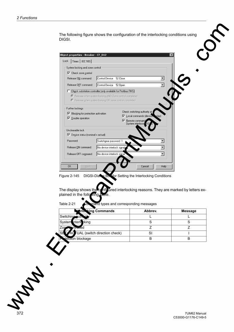
2 Functions
om
The following figure shows the configuration of the interlocking conditions using DIGSI.
Figure 2-145 DIGSI-Dialog Box for Setting the Interlocking Conditions
The display shows the configured interlocking reasons. They are marked by letters ex-plained in the following table.
Table 2-21 Command types and corresponding messages
Interlocking Commands Abbrev. MessageSwitching authority L LSystem interlocking S SZone controlled Z ZSET= ACTUAL (switch direction check) SI IProtection blockage B B
ww . El
ectric
alPar
tMan
uals
. c
372 7UM62 ManualC53000-G1176-C149-5
w

2.50 Command Processingw
The following figure shows all interlocking conditions (which usually appear in the display of the device) for three switchgear items with the relevant abbreviations ex-plained in the previous table. All parameterized interlocking conditions are indicated.
Figure 2-146 Example of configured interlocking conditions
Enabling Logic via CFC
For bay interlocking, an enabling logic can be structured using the CFC. Via specific release conditions the information „released“ or „bay interlocked“ are available, e.g. object „52 Close“ and „52 Open“ with the data values: ON / OFF).
Switching Authority
The interlocking condition "Switching Authority" serves to determine the switching au-thorization. It enables the user to select the authorized switching source. The following switching authority zones are defined in consecutive priority sequence:• LOCAL• DIGSI• REMOTE
The DIGSI object "Switching authority" serves to interlock or enable LOCAL control, but not remote or DIGSI commands. For the 7UM621 and 7UM622 the switching au-thority can be changed between "REMOTE" and "LOCAL" in the operator panel by password or by means of CFC also via binary input and function key. For the 7UM623 the switching authority can be changed by means of the keyswitch.
The object "Switching authority DIGSI" is used for interlocking and enabling of com-mands to be initiated using DIGSI. Commands are allowed for both a remote and a local DIGSI connection. When a (local or remote) DIGSI PC logs on to the device, it enters its Virtual Device Number (VD). The device only accepts commands having that VD (with switching authority = OFF or REMOTE). When the DIGSI PC logs off, the VD is cancelled.
Commands are checked for their source SC and the device settings, and compared to the information set in the objects "Switching authority" and "Switching authority DIGSI".
Configuration
Switching authority available y/n (create appropriate object)Switching authority available DIGSI y/n (create appropriate object)Specific Device (e.g. switching device)
Switching authority LOCAL (check for Local status): y/n
Specific Device (e.g. switching device)
Switching authority REMOTE (check for LOCAL, REMOTE, or DIGSI status): y/n
ww . El
ectric
alPar
tMan
uals
. com
3737UM62 ManualC53000-G1176-C149-5

2 Functions
om
Table 2-22 Interlocking logic
1) also "Enabled" for: ”Switching authority LOCAL (check for Local status): n"2) also "Enabled" for: ”Switching authority REMOTE (check for LOCAL, REMOTE, or DIGSI status): n"3) SC = Source of command
SC = Auto:
Commands that are derived internally (command processing in the CFC) are not subject to switching authority and are therefore always "enabled".
Switching Mode The switching mode determines whether selected interlocking conditions will be acti-vated or deactivated at the time of the switching operation.
The following switching modes (local) are defined:• Local commands (SC=LOCAL)
– interlocked (normal), or
– non-interlocked switching.
For the 7UM621 and 7UM622 the switching authority can be changed between "Inter-locked" and "Non-interlocked" in the operator panel by password or by means of CFC also via binary input and function key. For the 7UM623 this is done by means of a key-switch.
The following switching modes (remote) are defined:• Remote or DIGSI commands (SC = LOCAL, REMOTE, or DIGSI)
– interlocked, or
– non-interlocked switching. Here, deactivation of interlocking is accomplished via a separate command.
– For commands from CFC (SC = Auto), please observe the guidelines in the CFC manual (component: BOOL to command).
Current switching authority status
Switching authority DIGSI Command with
SC3) = DIGSI
Command issued from SC=LOCAL or REMOTE
Command issued from SC=DIGSI
LOCAL Not logged on Enabled Interlocked 2) "interlocked because of LOCAL control"
Interlocked "DIGSI not registered"
LOCAL Logged on Enabled Interlocked 2) "interlocked because of LOCAL control"
Interlocked 2) "inter-locked because of LOCAL control"
REMOTE Not logged on Interlocked 1) "inter-locked because of REMOTE control"
Enabled Interlocked "DIGSI not registered"
REMOTE Logged on Interlocked 1) "inter-locked because of DIGSI control"
Interlocked 2) "interlocked because of DIGSI control"
Enabled
ww . El
ectric
alPar
tMan
uals
. c
374 7UM62 ManualC53000-G1176-C149-5
w

2.50 Command Processingw
Zone Controlled / Field Interlocking
Zone Controlled (field interlocking) includes the verification that predetermined switch-gear position conditions are satisfied to prevent switching errors as well as verification of the state of other mechanical interlocking such as High Voltage compartment doors etc.
Interlocking conditions can be configured separately for each switching device, for MAKE and/or TRIP switching.
Processing of the status of the release condition for an operation switching device can be based on information acquired:• directly, using a single point or double point indication, key-switch, or internal indi-
cation (tagging), or• by means of a control logic via CFC.
When a switching command is initiated, the actual status is scanned cyclically. The as-signment is done via Release object CLOSE/OPEN command.
System Interlocking
Substation Controller (System interlocking) involves switchgear conditions of other bays evaluated by a central control system.
Double Activation Blockage
Parallel switching operations are interlocked. When a control command is received, all objects that are subject to double operation inhibit are checked for control commands in progress. While the command is being executed, the block is in turn active for all other commands.
Blocking by Protection
With this function, switching operations are blocked by the pickup of protective ele-ments. Blocking is configurable separately for both closing and tripping commands.
When configured, "Block CLOSE commands" blocks CLOSE commands, whereas "Block TRIP commands" blocks TRIP signals. Operations in progress will also be aborted by the pickup of a protective element.
Device Status Check (set = actual)
For switching commands, a check takes place whether the selected switching device is already in the scheduled/desired position (scheduled/actual comparison). This means, if a circuit breaker is already in the CLOSED position and an attempt is made to issue a closing command, the command will be refused, with the operating message "scheduled condition equals actual condition". If the circuit breaker/switch-gear device is in the intermediate position, then this check is not performed.
ww . El
ectric
alPar
tMan
uals
. com
3757UM62 ManualC53000-G1176-C149-5

2 Functions
om
Bypassing Interlocks
Interlockings can be bypassed to perform switching operations. This is either done in-ternally by adding a bypass code to the command, or globally by so-called switching modes.• SC=LOCAL
– The switching modes "interlocked" or "non-interlocked" (de-interlocked) can be switched over for the 7UM621 and 7UM62 in the operator control panel after password entry; for the 7UM623 this is done by means of a keyswitch.
• REMOTE and DIGSI– Commands issued by SICAM or DIGSI are unlocked via a global switching mode
REMOTE. A separate job order must be sent for the unlocking. The unlocking applies only for one switching operation and for commands caused by the same source.
– Job order: command to object "Switching mode REMOTE", ON
– Job order: switching command to "switching device"
• Derived commands from CFC (automatic command, SC=Auto):– Behaviour configured in the CFC block ("BOOL to command").
2.50.5 Command Logging
During the processing of the commands, independent of the further message routing and processing, command and process feedback information are sent to the message processing centre. These messages contain information on the cause. With the cor-responding allocation (configuration) these messages are entered in the event list, thus serving as a report.
Prerequisites A listing of possible operating messages and their meaning as well as the command types needed for tripping and closing of the switchgear or for raising and lowering of transformer taps are described in the SIPROTEC 4 System Description.
2.50.5.1 Description
Acknowledgement of Commands to the Device Front
All messages with the source of command LOCAL are transformed into a correspond-ing response and shown in the display of the device.
Acknowledgement of Commands to Local / Remote / Digsi
The acknowledgement of messages with source of command Local/ Remote/DIGSI are sent back to the initiating point independent of the routing (configuration on the serial digital interface).
The acknowledgement of commands is therefore not executed by a response indica-tion as it is done with the local command but by ordinary command and feedback in-formation recording.
ww . El
ectric
alPar
tMan
uals
. c
376 7UM62 ManualC53000-G1176-C149-5
w

2.50 Command Processingw
Monitoring of Feed-back Information
The processing of commands monitors the command execution and timing of feed-back information for all commands. At the same time the command is sent, the moni-toring time is started (monitoring of the command execution). This time controls whether the device achieves the required final result within the monitoring time. The monitoring time is stopped as soon as the feedback information arrives. If no feedback information arrives, a response "Timeout command monitoring time" appears and the process is terminated.
Commands and information feedback are also recorded in the event list. Normally the execution of a command is terminated as soon as the feedback information (FB+) of the relevant switchgear arrives or, in case of commands without process feedback in-formation, the command output resets.
The “plus” appearing in a feedback information confirms that the command was suc-cessful, the command was as expected, in other words positive. The "minus" is a neg-ative confirmation and means that the command was not executed as expected.
Command Output and Switching Relays
The command types needed for tripping and closing of the switchgear or for raising and lowering of transformer taps are described under configuration in /1/.
ww . El
ectric
alPar
tMan
uals
. com
3777UM62 ManualC53000-G1176-C149-5

2 Functions
om
ww . El
ectric
alPar
tMan
uals
. c
378 7UM62 ManualC53000-G1176-C149-5
w

w
m
Mounting and Commissioning 3This chapter is intended for experienced commissioning staff. They should be familiar with the commissioning of protection and control equipment, with operation of the power system network and with the safety rules and regulations. Certain adaptations of the hardware to the power system specifications may be necessary. For primary testing, the object to be protected (generator, motor, transformer) must be started up and in put into service.
3.1 Mounting and Connections 380
3.2 Checking Connections 408
3.3 Commissioning 418
3.4 Final Preparation of the Device 473
ww . El
ectric
alPar
tMan
uals
. co
3797UM62 ManualC53000-G1176-C149-5
3 Mounting and Commissioning
om
3.1 Mounting and Connections
WARNING!Warning of improper transport, storage, installation, and application of the device.
Non-observance can result in death, personal injury or substantial property damage.
Trouble free and safe use of this device depends on proper transport, storage, instal-lation, and application of the device according to the warnings in this instruction manual.
Of particular importance are the general installation and safety regulations for work in a high-voltage environment (for example, ANSI, IEC, EN, DIN, or other national and international regulations). These regulations must be observed.
3.1.1 Configuration Information
Prerequisites For mounting and connection the following requirements and conditions must be met:
The rated device data has been tested as recommended in the SIPROTEC 4 System Description /1/ and their compliance with these data is verified with the Power System Data.
Connection Variants
Overview diagrams are shown in Appendix A.2. Connection examples for current and voltage transformer circuits are given in Appendix A.3. It must be checked that the setting configuration of the Power System Data 1, Section 2.5, corresponds with the connections.
Currents/Voltages Connection diagrams are shown in the Appendix. Examples show connection options for current and voltage transformers with busbar connection (address 272 SCHEME = Busbar) and unit connection (address 272 = Unit transf.) can be found in Ap-pendix A.3. In all examples the CT starpoints point towards the protection object so that addresses 201 STRPNT->OBJ S1 and 210 STRPNT->OBJ S2 must be set to YES.
In the connection examples the UE input of the device is always connected to the open delta winding of a voltage transformer set. Accordingly address 223 UE CONNECTION must be set to broken delta.
A standard connection where one busbar is fed by several generators can be found in the Appendix, A.3. The earth fault current can be increased by an earthing transformer connected to the busbar (approx. 10 A max.), allowing a protection range of up to 90 % to be achieved. The earth current is measured using the toroidal current transformer to achieve the necessary sensitivity. During startup of the machine, the displacement voltage can be used as a criterion for detecting an earth fault until synchronization is completed. ww .
Elec
tricalP
artM
anua
ls . c
380 7UM62 ManualC53000-G1176-C149-5
w

3.1 Mounting and Connectionsw
Factor 213 FACTOR IEE2 considers the transformation ratio between the primary and the secondary side of the summation current transformer when the sensitive current input of side 2 in the corresponding connection example is used. Accordingly, when the input of side 1, is used 205 FACTOR IEE1 applies.
Example:
Summation current transformer 60 A / 1 A
Matching factor for sensitive earth fault current detection: FACTOR IEE2 = 60 (if the input on side 2 is used)
If the sensitive current input of side 1 is used for rotor earth fault current detection (see Appendix A.3), FACTOR IEE1 = 1 is selected.
In Figure „Busbar System“ in the Appendix A.3 the generator starpoint has a low-re-sistance earthing. To avoid circulating currents (3rd harmonic) in multi-generator con-nections, the resistor should be connected to only one generator. For selective earth fault detection, the sensitive earth fault current input IEE2 is looped into the common return line of the two sets of CTs (current differential measurement). The current trans-formers are earthed in one place only. FACTOR IEE2 is set to 1. Balanced DE current transformers (winding balance) are recommended for this type of circuit.
In Figure „Block Connection“ with isolated starpoint in Appendix A.3earth fault detec-tion uses the displacement voltage. A load resistor is provided on the broken delta winding to avoid spurious tripping during earth faults in the power system. The UUE input of the device is connected via a voltage divider to the broken delta winding of an earthing transformer (address 223 UE CONNECTION = broken delta). Factor 225 Uph / Udelta is determined by the transformation ratio of the secondary-side volt-ages:
The resulting factor between the secondary windings is 3/√3 = 1.73. For other trans-formation ratios e.g. where the displacement voltage is measured using an inserted CT set, the factor must be modified accordingly.
The factor 224 FACTOR UE considers the transformation full ratio between the primary voltage and the voltage fed to the device terminals, i.e. it includes the voltage divider that is connected upstream. For a primary nominal transformer voltage of 6.3 kV, a secondary voltage of 500 V with full displacement and a voltage divider ratio of 1:5, this factor would be for example
In Figure „Block Connection with neutral transformer“ in Appendix A.3 a load resistor connected to the generator starpoint reduces the interference voltage from network-side earth faults. The maximum earth fault current is limited to approx. 10A. The resis-tor can be a primary or secondary resistor with neutral transformer. The neutral trans-former should have a low transformation ratio to avoid a small secondary resistance. The higher secondary voltage thereby resulting can be reduced by a voltage divider. Address 223 UE CONNECTION is set to neutr. transf..
The Figure „Startup Earth Fault Protection“ in Appendix A.3 shows the connection of the DC voltage protection for systems with startup converter. The amplifier 7KG6 am-plifies the signal measured at the shunt to a maximum of 10 V or 20 mA, depending on the equipment. Input TD1 can be adapted to the type of signal (voltage or current) by means of wire jumpers (see also 3.1.2 "Switching Elements on Printed Circuit Boards"). ww . El
ectric
alPar
tMan
uals
. com
3817UM62 ManualC53000-G1176-C149-5
3 Mounting and Commissioning
om
Figure „Rotor Earth Fault Protection“ in Appendix A.3 shows in an exemplary way how the rotor earth fault protection is connected to a generator with static excitation. The earthing must be connected to the earthing brush. The coupling device 7XR61 must be extended by the external resistors 3PP1336 if the circulating current can exceed 0.2 A due to the 6th harmonic component in the excitation voltage. This can be the cause with excitation voltages UUExc above 150 V. The IEE 1 input evaluates the earth fault current flowing between the rotor and the ground as a result of injecting a voltage into the rotor circuit. The matching factor FACTOR IEE1 is set to 1.
Figure „Voltage Transformer Connections for Two Voltage Transformers in Open Delta Connection (V Connection)“ in Appendix A.3 shows how a connection is made with only two system-side voltage transformers in open delta connection (V connection).
Figure „Asynchronous Motor“ in Appendix A.3 shows a typical connection of the pro-tection relay to a large asynchronous motor. The voltages for voltage and zero voltage monitoring are usually taken at the busbar. Where several motors are connected to the busbar, the directional earth fault protection detects single-pole earth faults and can thus open breakers selectively. A toroidal transformer is used for detection of the earth fault current.
Factor 213 FACTOR IEE2 considers the transformation ratio between the primary and the secondary side of the summation current transformer IEE2.
Binary Inputs and Outputs
Allocation possibilities of binary inputs and outputs, i.e. the individual matching to the system are described in the SIPROTEC 4 System Description /1/. The presettings of the device are listed in Appendix A, Section A.4. Check also whether the labelling cor-responds to the allocated message functions.
Changing Setting Groups
If binary inputs are used to change setting groups, please observe the following: • If the configuration is performed from the operator panel or using DIGSI, the option
via Binary Input must be selected at address 302CHANGE.• One binary input is sufficient for controlling 2 setting groups, „>Param. Selec.1“.• If the binary input is configured as a make circuit, i.e. as active when voltage is
applied (H active), the significance is as follows: - not activated: Parameter set A - activated: Parameter set B
• The control signal must be continuously present or absent in order that the selected setting group remains active.
Trip Circuit Supervision
A circuit with two binary inputs (see Section 2.43) is recommended for trip circuit mon-itoring. The binary inputs must have no common potential, and their operating point must well below half the rating of the DC control voltage.
Alternately when using only one binary input, a resistor R is inserted (see Section 2.43). Please note that the response times are as long as approx. 300 s. Section 2.43.2 shows how the resistance is calculated.
ww . El
ectric
alPar
tMan
uals
. c
382 7UM62 ManualC53000-G1176-C149-5
w
3.1 Mounting and Connectionsw
3.1.2 Hardware Modifications
3.1.2.1 General
General Subsequent adaptation of hardware to the power system conditions may be neces-sary for example with regard to the control voltage for binary inputs or termination of bus-capable interfaces. The hints given in this section should be observed in all cases whenever hardware modifications are made.
Power Supply Voltage
There are different power supply voltage ranges for the auxiliary voltage (refer to the Ordering Information in the Appendix). The power supplies with the ratings 60/110/125 VDC and 110/125/220/250 VDC / 115/230 VAC are interconvertible. Jumper settings determine the rating. Jumper setting allocation to the rated voltage ranges, and their location on the PCB are described in this Section under the margin title „Processor Board C-CPU-2“. When the device is delivered, these jumpers are set according to the name-plate sticker. Generally, they need not be altered.
Life Contact The life contact of the device is a changeover contact, from which either the opener or closer can be connected to the device terminals F3 and F4 via a jumper (X40). Assign-ments of the jumpers to the contact type and the spatial layout of the jumpers are de-scribed in Section at margin heading „Processor Board C-CPU-2“.
Nominal Currents The input transformers of the devices are set to a rated current of 1 A or 5 A by burden switching. Jumpers are set according to the name-plate sticker. Location layout of these jumpers and their current rating allocation are described in this Section under „C-I/O-2 Input/Output Board“ for side 2 and „ C-I/O-6 Input/Output Board“ for side 1. All the relevant jumpers of one side must be set uniformly for a rated current, i.e. one jumper each (X61 through X63) for each of the input transformers and additionally the common jumper X60.
If nominal current ratings are to be changed exceptionally, then the new change must be notified to the device at addresses 203 IN-SEC I-SIDE1 or 212 IN-SEC I-SIDE2 in the Power System Data (see Section 2.5).
Note
The jumper settings must correspond to the secondary device currents configured at addresses 203, 212. Otherwise the device is blocked and outputs an alarm.
Pickup Voltage for Binary Inputs
When the device is delivered the binary inputs are set to operate with a voltage that corresponds to the rated voltage of the power supply. If the rated values differ from the power system control voltage, it may be necessary to change the switching threshold of the binary inputs.
To change the switching threshold of a binary input, one jumper must be changed for each input. The allocation of the plug-in jumpers to the binary inputs and their actual positioning are described in this Section.
ww . El
ectric
alPar
tMan
uals
. com
3837UM62 ManualC53000-G1176-C149-5

3 Mounting and Commissioning
om
Note
If binary inputs are used for trip circuit monitoring, note that two binary inputs (or one binary input and an equivalent resistor) are connected in series. The switching thresh-old must be significantly less than one half of the rated control voltage.
Contact Mode for Binary Outputs
Input/output modules can have relays that are equipped with changeover contacts. For this it is necessary to rearrange a jumper. For which relay on which board this applies is described in this Section under „Input/Output Board C–I/O -2“ and „In-put/Output Board C–I/O -6“.
Measuring Transducer
The measuring transducers TD 1 (e.g. for DC voltage/DC current protection) and TD 2 (e.g. for input of temperature for overload protection) can process either voltage or current values. To change the default setting (measured values to be voltages) jumpers must be changed. Tables in this Section give an overview under „Input/Output Board C–I/O-6“.
Caution!False connection for „Current“ jumper setting!
If with "Current" jumper setting an input voltage is applied, this may destroy the board.
For an input voltage the "Voltage" jumper must set.
For measuring transducer TD 3 (detects e.g. excitation voltage for underexcitation pro-tection) an analog low-pass can be activated or deactivated by jumpers. Tables in this Section give an overview under „Input/Output Board C–I/O-6“.
Note
The jumper settings must correspond to the mode set at addresses 295, 296 (voltage or current input) and 297 (with/without filter). Otherwise the device is blocked and outputs an alarm.
Replacing Interfaces
The serial interfaces can only be exchanged in the versions for panel flush mounting and cubicle mounting. Which interfaces can be exchanged, and how this is done, is described in this Section under the margin title „Replacing Interface Modules“.
Terminating Resis-tors for RS485 and Profibus DP (Electrical)
For reliable data transmission the RS485 bus or the electrical Profibus DP must be ter-minated with resistors at the respective last device on the bus. For this purpose termi-nation resistors are provided on the PCB of the C-CPU-2 processor board and on the RS485 or PROFIBUS interface module which can be connected via jumpers. Only one of the three options may be used. The physical location of the jumpers on the PCB is described in this Section under the margin title „Processor Board C–CPU-2“, and under the margin title „Bus-Capable Serial Interfaces“ for the interface modules. Both jumpers must always be plugged in the same way.
The terminating resistors are disabled on unit delivery.ww . El
ectric
alPar
tMan
uals
. c
384 7UM62 ManualC53000-G1176-C149-5
w

3.1 Mounting and Connectionsw
Spare Parts Spare parts may be the backup battery that maintains the data in the battery-buffered RAM when the voltage supply fails, and the miniature fuse of the internal power supply. Their physical location is shown in Figure 3-3. The ratings of the fuse are printed on the board next to the fuse itself. When replacing the fuse, please observe the guidelines given in the SIPROTEC 4 System Manual /1/ in the chapter „Mainte-nance“ and „Corrective Action / Repairs“.
3.1.2.2 Disassembly
Disassembly of the Device
Note
It is assumed for the following steps that the device is not in operation.
Caution!Caution when changing jumper settings that affect nominal values of the device
As a consequence, the ordering number (MLFB) and the ratings that are stated on the nameplate do no longer match the actual device properties.
If such changes are necessary, the changes should be clearly and fully noted on the device. Self adhesive stickers are available that can be used as replacement name-plates.
To perform work on the printed circuit boards, such as checking or moving switching elements or exchanging modules, proceed as follows:• Prepare area of work: Preparing a surface appropriate to electrostatic sensitive
devices (EGB). In addition to this, the following tools are required: – screwdriver with a 5 to 6 mm wide tip,
– a Philips screwdriver size 1,
– 5 mm socket or nut driver.
• Unfasten the screw-posts of the D-subminiature connectors on the back panel at location „A“ and „C“. This activity does not apply if the device is for surface mount-ing.
• If the device has additional communication interfaces at locations „A“, „C“ and/or „B“ „D“ on the rear, the screws located diagonally to the interfaces must be removed. This activity does not apply if the device is for surface mounting.
• Remove the caps on the front cover and loosen the screws that become accessible. • Remove the front panel and tilt it to the side.
ww . El
ectric
alPar
tMan
uals
. com
3857UM62 ManualC53000-G1176-C149-5

3 Mounting and Commissioning
om
Work on the Plug Connectors
Caution!Mind electrostatic discharges
Non–observance can result in minor personal injury or material damage.
When handling with plug connectors, electrostatic discharges may emerge by previ-ously touching an earthed metal surface must be avoided.
Do not plug or withdraw interface connections under power!
The following must be observed:• Disconnect the ribbon cable between the front cover and the C-CPU-2 board (No.
1 in Figures 3-1 and 3-2) at the front cover side. To disconnect the cable, push up the top latch of the plug connector and push down the bottom latch of the plug con-nector. Carefully set aside the front cover.
• Disconnect the ribbon cables between the C-CPU-2 board (1) and the I/O boards (2) to (4), depending on the variant ordered).
• Remove the boards and set them on the grounded mat to protect them from ESD damage. In the case of the device variant for panel surface mounting, please be aware of the fact a certain amount of force is required in order to remove the C-CPU-2 module due to the existing plug connectors.
• Check the jumpers in accordance with Figures 3-3 to 3-8and the following informa-tion, and as the case may be change or remove them.
The allocation of the boards for housing size 1/2 is shown in Figure 3-1 and for housing size 1/1 in Figure 3-2.
Figure 3-1 Front View of a 7UM621/623 (Housing Size 1/2) after Removal of the Front Cover (Simplified and Scaled Down)ww .
Elec
tricalP
artM
anua
ls . c
386 7UM62 ManualC53000-G1176-C149-5
w
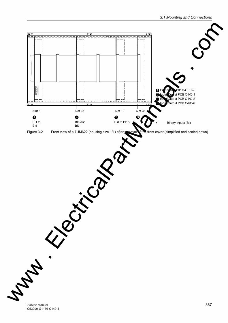
3.1 Mounting and Connectionsw
Figure 3-2 Front view of a 7UM622 (housing size 1/1) after removal of the front cover (simplified and scaled down)
ww . El
ectric
alPar
tMan
uals
. com
3877UM62 ManualC53000-G1176-C149-5
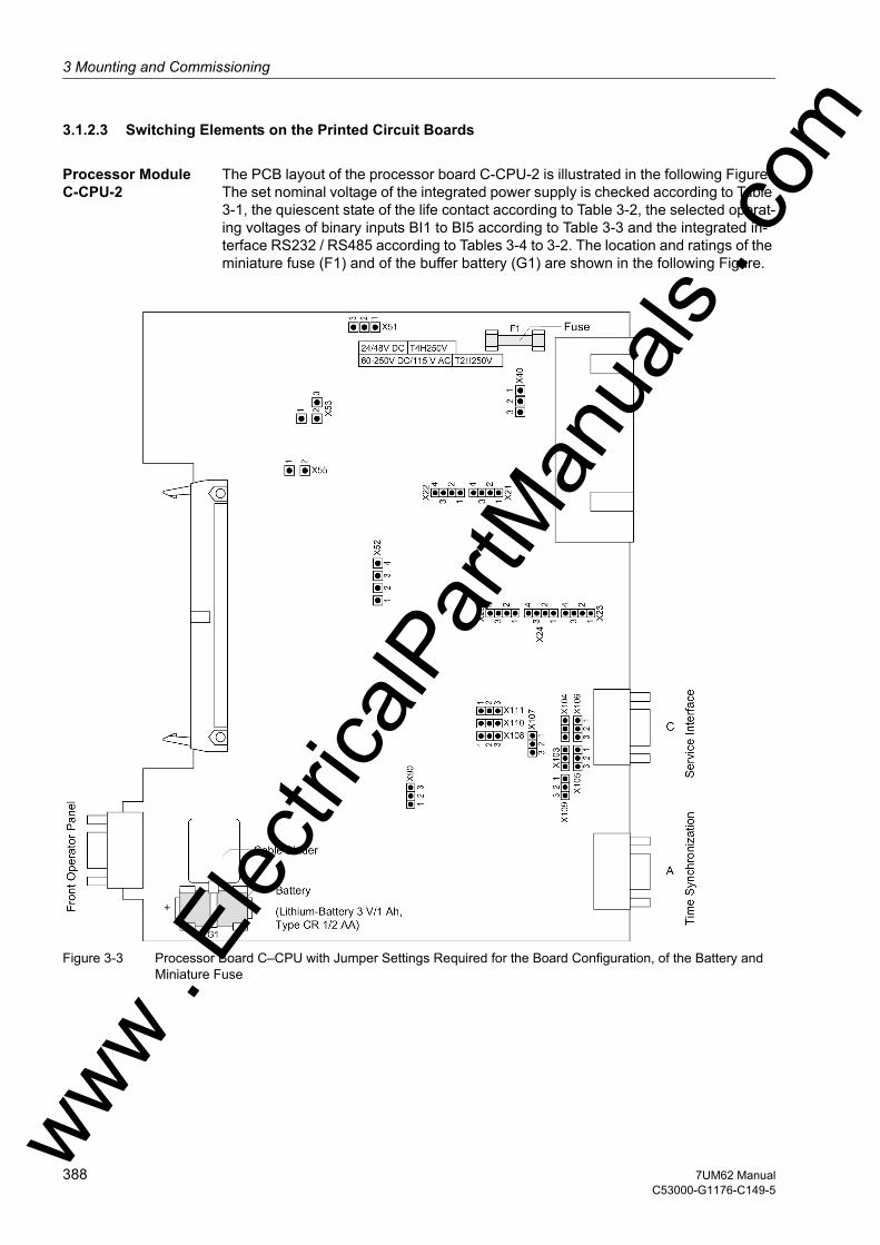
3 Mounting and Commissioning
om
3.1.2.3 Switching Elements on the Printed Circuit Boards
Processor Module C-CPU-2
The PCB layout of the processor board C-CPU-2 is illustrated in the following Figure. The set nominal voltage of the integrated power supply is checked according to Table 3-1, the quiescent state of the life contact according to Table 3-2, the selected operat-ing voltages of binary inputs BI1 to BI5 according to Table 3-3 and the integrated in-terface RS232 / RS485 according to Tables 3-4 to 3-2. The location and ratings of the miniature fuse (F1) and of the buffer battery (G1) are shown in the following Figure.
Figure 3-3 Processor Board C–CPU with Jumper Settings Required for the Board Configuration, of the Battery and Miniature Fuse
ww . El
ectric
alPar
tMan
uals
. c
388 7UM62 ManualC53000-G1176-C149-5
w

3.1 Mounting and Connectionsw
Table 3-1 Jumper setting of the rated voltage of the integrated Power Supply on the C-CPU-2 processor module
Table 3-2 Jumper position of the quiescent state of the Life contact on the C–CPU-2 pro-cessor module
Table 3-3 Jumper setting of the control voltages of binary inputs BI1 to BI5 on the C–CPU-2 processor module
1) Factory settings for devices with rated power supply voltages of 24 VDC to 125 VDC2) Factory settings for devices with power supply voltages of 110 VDC to 250 VDC and 115/230
VAC3) Use only with pickup voltages 220 or 250 VDC
The R485 interface can be converted into an RS232 interface by modifying the jump-ers.
Jumpers X105 to X110 must be set to the same position !
Table 3-4 Jumper Settings of the Integrated RS232/RS485 Interface on the C–CPU-2 Board
The jumpers are preset at the factory according to the configuration ordered.
With interface RS232 jumper X111 is needed to activate CTS which enables the com-munication with the modem.
Jumper Nominal Voltage24 to 48 VDC 60 to 125 VDC 110 to 250 VDC
115/230 VACX51 not used 1-2 2-3X52 not used 1-2 and 3-4 2-3X53 not used 1-2 2-3X55 not used not used 1-2
cannot be changed
interchangeable
Jumper Open in the quiescent state(NO contact)
Closed in the quiescent state(NC contact)
Presetting
X40 1-2 2-3 2-3
Binary inputs Jumper 19 V Threshold 1) 88 V Threshold 2) 176 V Threshold 3)
BI1 X21 1-2 2-3 3-4BI2 X22 1-2 2-3 3-4BI3 X23 1-2 2-3 3-4BI4 X24 1-2 2-3 3-4BI5 X25 1-2 2-3 3-4
Jumper RS232 RS485X103 and X104 1-2 1-2X105 to X110 1-2 2-3
ww . El
ectric
alPar
tMan
uals
. com
3897UM62 ManualC53000-G1176-C149-5
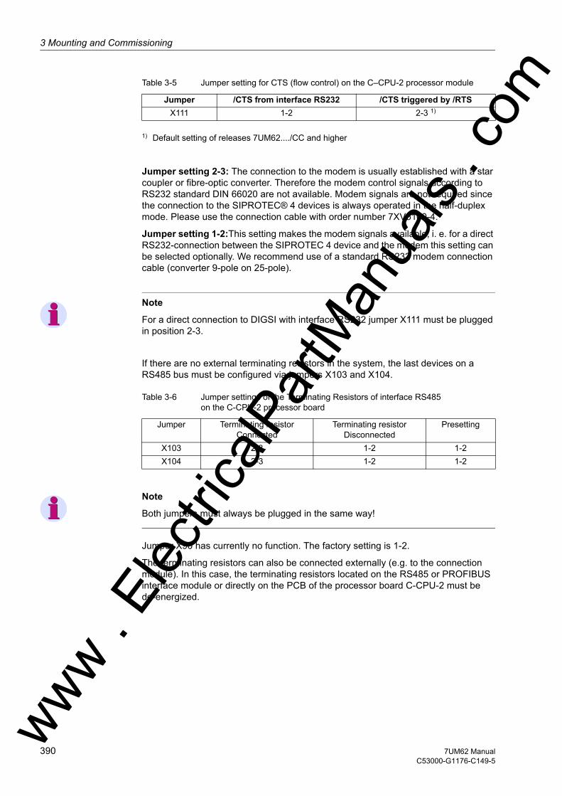
3 Mounting and Commissioning
om
Table 3-5 Jumper setting for CTS (flow control) on the C–CPU-2 processor module
1) Default setting of releases 7UM62..../CC and higher
Jumper setting 2-3: The connection to the modem is usually established with a star coupler or fibre-optic converter. Therefore the modem control signals according to RS232 standard DIN 66020 are not available. Modem signals are not required since the connection to the SIPROTEC® 4 devices is always operated in the half-duplex mode. Please use the connection cable with order number 7XV5100-4.
Jumper setting 1-2:This setting makes the modem signals available, i. e. for a direct RS232-connection between the SIPROTEC 4 device and the modem this setting can be selected optionally. We recommend use of a standard RS232 modem connection cable (converter 9-pole on 25-pole).
Note
For a direct connection to DIGSI with interface RS232 jumper X111 must be plugged in position 2-3.
If there are no external terminating resistors in the system, the last devices on a RS485 bus must be configured via jumpers X103 and X104.
Table 3-6 Jumper settings of the Terminating Resistors of interface RS485 on the C-CPU-2 processor board
Note
Both jumpers must always be plugged in the same way!
Jumper X90 has currently no function. The factory setting is 1-2.
The terminating resistors can also be connected externally (e.g. to the connection module). In this case, the terminating resistors located on the RS485 or PROFIBUS interface module or directly on the PCB of the processor board C-CPU-2 must be de-energized.
Jumper /CTS from interface RS232 /CTS triggered by /RTSX111 1-2 2-3 1)
Jumper Terminating resistorConnected
Terminating resistorDisconnected
Presetting
X103 2-3 1-2 1-2X10⁴ 2-3 1-2 1-2
ww . El
ectric
alPar
tMan
uals
. c
390 7UM62 ManualC53000-G1176-C149-5
w

3.1 Mounting and Connectionsw
Figure 3-4 Termination of the RS485 interface (external)
Input/output board C-I/O-1
Figure 3-5 Input/output board C-I/O-1 with representation of the jumper settings required for the board configuration
In the version 7UM622, binary output BO 13 on the Input/Output module C–I/O-1 can be configured as normally open or normally closed (see also overview diagrams in Ap-pendix A.2).ww . El
ectric
alPar
tMan
uals
. com
3917UM62 ManualC53000-G1176-C149-5

3 Mounting and Commissioning
om
Table 3-7 Jumper position for the contact type of the relay for BO13
Table 3-8 Jumper setting of pickup voltages of binary inputs BI8 to BI15 on Input/Output module module C– I/O–1 in the 7UM622
1) Factory settings for devices with rated power supply voltages of 24 VDC to 125 VDC2) Factory settings for devices with power supply voltages of 110 VDC to 250 VDC and 115/230
VAC3) Use only with control voltages 220 to 250 VDC
Jumpers X71, X72 and X73 on the input/output module C-I/O-1 are used to set the bus address and must not be changed. The following table lists the jumper presettings.
Mounting locations of modules are shown in Figures 3-1 to 3-2.
Table 3-9 Module address jumper setting of input/output module C-I/O-1 for 7UM622
Jumper Open in quiescent state (NO)
Closed in quiescent state (NC)
Presetting
X40 1-2 2-3 1-2
Binary inputs Jumper 19 V Threshold 1) 88 V Threshold 2) 176 V Threshold 3)
BI8 X21/X22 L M HBI9 X23/X24 L M HBI10 X25/X26 L M HBI11 X27/X28 L M HBI12 X29/X30 L M HBI13 X31/X32 L M HBI14 X33/X34 L M HBI15 X35/X36 L M H
Jumper PresettingX71 LX72 HX73 H
ww . El
ectric
alPar
tMan
uals
. c
392 7UM62 ManualC53000-G1176-C149-5
w
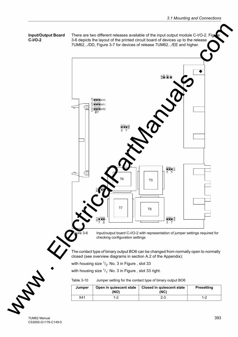
3.1 Mounting and Connectionsw
Input/Output Board C-I/O-2
There are two different releases available of the input output module C-I/O-2. Figure 3-6 depicts the layout of the printed circuit board of devices up to the release 7UM62.../DD, Figure 3-7 for devices of release 7UM62.../EE and higher.
Figure 3-6 Input/output board C-I/O-2 with representation of jumper settings required for checking configuration settings
The contact type of binary output BO6 can be changed from normally open to normally closed (see overview diagrams in section A.2 of the Appendix):
with housing size 1/2: No. 3 in Figure , slot 33
with housing size 1/1: No. 3 in Figure , slot 33 right.
Table 3-10 Jumper setting for the contact type of binary output BO6
Jumper Open in quiescent state (NO)
Closed in quiescent state (NC)
Presetting
X41 1-2 2-3 1-2ww . El
ectric
alPar
tMan
uals
. com
3937UM62 ManualC53000-G1176-C149-5
3 Mounting and Commissioning
om
The set nominal currents of the current input transformers are to be checked on the input/output board C-I/O-2. All jumpers must be set for one nominal current, i.e. re-spectively one jumper (X61 to X63) for each input transformer and additionally the common jumper X60. There is no jumper X64 because all versions of the 7UM62 have a sensitive earth fault current input (input transformer T8).
Jumpers X71, X72 and X73 on the input/output board C-I/O-2 are used to set the bus address and must not be changed. The following Table lists the jumper presettings.
Mounting location:
with housing size 1/2: No. 3 in Figure , slot 33
with housing size 1/1: No. 3 in Figure , slot 33 right.
Table 3-11 Jumper settings of PCB Address of the input/output board C-I/O-2
Jumper PresettingX71 1-2(H)X72 1-2(H)X73 2-3(L)
ww . El
ectric
alPar
tMan
uals
. c
394 7UM62 ManualC53000-G1176-C149-5
w
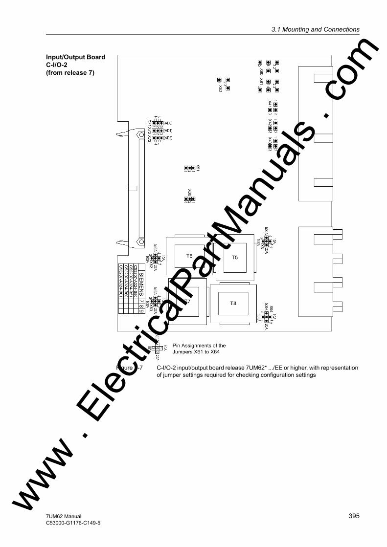
3.1 Mounting and Connectionsw
Input/Output Board C-I/O-2 (from release 7)
Figure 3-7 C-I/O-2 input/output board release 7UM62* .../EE or higher, with representation of jumper settings required for checking configuration settings
ww . El
ectric
alPar
tMan
uals
. com
3957UM62 ManualC53000-G1176-C149-5
3 Mounting and Commissioning
om
Table 3-12 Jumper setting for nominal current or measuring range
1) Not for variant with sensitive earth fault detection
Contacts of relays for binary outputs BO6, BO7 and BO8 can be configured as nor-mally open or normally closed (see also General Diagrams in the Appendix).
Table 3-13 Jumper setting for the contact type of the relays for BO6, BO7 and BO8
1) Factory setting
The relays for binary outputs BO1 through BO5 can be connected to common poten-tial, or configured individually for BO1, BO4 and BO5 (BO2 and BO3 are without func-tion in this context) (see also General Diagrams in the Appendix).
Table 3-14 Jumper settings for the configuration of the common potential of BO1 through BO5 or for configuration of BO1, BO4 and BO5 as single relays
1) Factory setting
The jumpers X71, X72 through X73 serve for setting the bus address. Their position may not be changed. The following table shows the preset jumper positions.
Table 3-15 Jumper settings of module addresses of the input/output module C-I/O-2
Jumper Nominal current 1 A
Measuring range 20 A
Nominal current 5 A
Measuring range 100 AX51 1-2 1-2X60 1-2 2-3X61 2-5 3-5X62 2-5 3-5X63 2-5 3-5
X641) 2-5 3-5
For Jumper Open in quiescent state (NO) 1)
Closed in quiescent state (NC)
BO6 X41 1-2 2-3BO7 X42 1-2 2-3BO8 X43 1-2 2-3
Jumper BO1 through BO5 connected to
common potential 1)
BO1, BO4, BO5 configured as single relays (BO2, BO3 without function)
X80 1-2, 3-4 2-3, 4-5X81 1-2, 3-4 2-3, 4-5X82 2-3 1-2
Jumper Factory settingX71 1-2 (H)X72 1-2 (H)X73 2-3 (L)ww . El
ectric
alPar
tMan
uals
. c
396 7UM62 ManualC53000-G1176-C149-5
w

3.1 Mounting and Connectionsw
Input/Output Board C-I/O-6
PCB layout for the Input/Output C-I/O-6 board is shown in the following Figure.
Figure 3-8 C-I/O-6 Input/Output Board with Representation of Jumper Settings Required for Checking Configuration Settings
Table 3-16 Jumper Setting for activation Voltages of Binary Inputs BI6 and BI7 on the In-put/Output C–I/O-6 board
1) Factory settings for devices with rated power supply voltages of 24 VDC to 125 VDC2) Factory settings for devices with power supply voltages of 110 VDC to 250 VDC and 115/230
VAC3) Use only with pickup voltages 220 or 250 VDC
Binary Inputs Jumper 19 V Threshold 1) 88 V Threshold 2) 176 V Threshold 3)
BI6 X21 L M HBI7 X22 L M H
ww . El
ectric
alPar
tMan
uals
. com
3977UM62 ManualC53000-G1176-C149-5
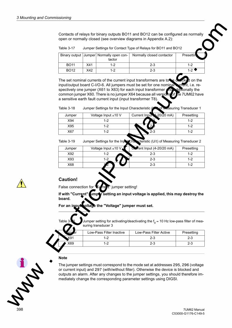
3 Mounting and Commissioning
om
Contacts of relays for binary outputs BO11 and BO12 can be configured as normally open or normally closed (see overview diagrams in Appendix A.2):
Table 3-17 Jumper Settings for Contact Type of Relays for BO11 and BO12
The set nominal currents of the current input transformers are to be checked on the input/output board C-I/O-6. All jumpers must be set for one nominal current, i.e. re-spectively one jumper (X61 to X63) for each input transformer and additionally the common jumper X60. There is no jumper X64 because all versions of the 7UM62 have a sensitive earth fault current input (input transformer T8).
Table 3-18 Jumper Settings for the Input Characteristic (U/I) of Measuring Transducer 1
Table 3-19 Jumper Settings for the Input Characteristic (U/I) of Measuring Transducer 2
Caution!False connection for "Current" jumper setting!
If with "Current" jumper setting an input voltage is applied, this may destroy the board.
For an input voltage the "Voltage" jumper must set.
Table 3-20 Jumper setting for activating/deactivating the fg ≈ 10 Hz low-pass filter of mea-suring transducer 3
Note
The jumper settings must correspond to the mode set at addresses 295, 296 (voltage or current input) and 297 (with/without filter). Otherwise the device is blocked and outputs an alarm. After any changes to the jumper settings, you should therefore im-mediately change the corresponding parameter settings using DIGSI.
Binary output Jumper Normally open con-tactor
Normally closed contactor Presetting
BO11 X41 1-2 2-3 1-2BO12 X42 1-2 2-3 1-2
Jumper Voltage Input ±10 V Current Input (4-20/20 mA) PresettingX94 1-2 2-3 1-2X95 1-2 2-3 1-2X67 1-2 2-3 1-2
Jumper Voltage Input ±10 V Current Input (4-20/20 mA) PresettingX92 1-2 2-3 1-2X93 1-2 2-3 1-2X68 1-2 2-3 1-2
Jumper Low-Pass Filter Inactive Low-Pass Filter Active PresettingX91 1-2 2-3 2-3X69 1-2 2-3 2-3
ww . El
ectric
alPar
tMan
uals
. c
398 7UM62 ManualC53000-G1176-C149-5
w

3.1 Mounting and Connectionsw
Note
Unused measuring transducers should be shorted at the input terminals!
Jumpers X71, X72 and X73 on the input/output module C-I/O-6 are used to set the bus address and must not be changed. The following table lists the jumper presettings.
Table 3-21 Module address jumper settings of input/output module C-I/O-6
Jumper Factory SettingX71 (AD0) 1-2 (H)X72 (AD1) 2-3 (L)X73 (AD2) 1-2 (H)
ww . El
ectric
alPar
tMan
uals
. com
3997UM62 ManualC53000-G1176-C149-5
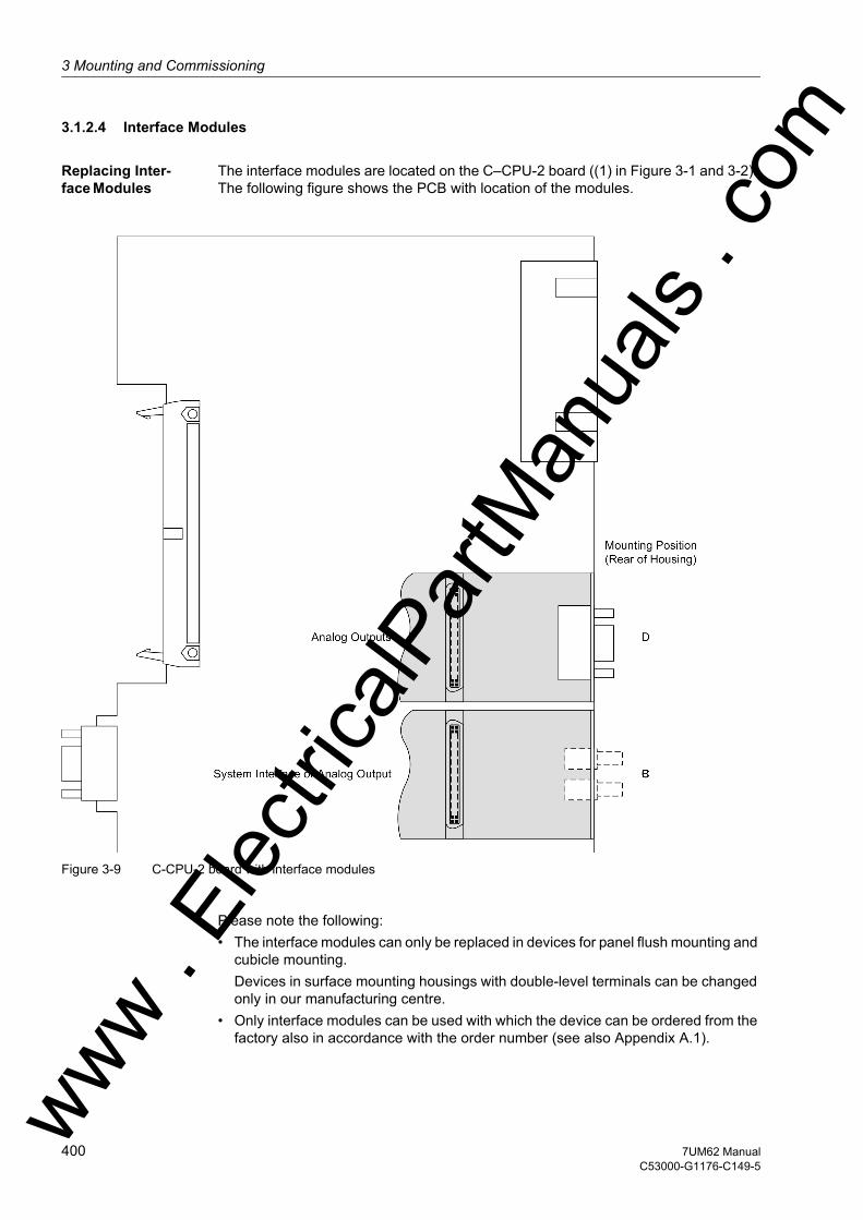
3 Mounting and Commissioning
om
3.1.2.4 Interface Modules
Replacing Inter-face Modules
The interface modules are located on the C–CPU-2 board ((1) in Figure 3-1 and 3-2). The following figure shows the PCB with location of the modules.
Figure 3-9 C-CPU-2 board with interface modules
Please note the following:• The interface modules can only be replaced in devices for panel flush mounting and
cubicle mounting.Devices in surface mounting housings with double-level terminals can be changed only in our manufacturing centre.
• Only interface modules can be used with which the device can be ordered from the factory also in accordance with the order number (see also Appendix A.1).
ww . El
ectric
alPar
tMan
uals
. c
400 7UM62 ManualC53000-G1176-C149-5
w

3.1 Mounting and Connectionsw
Table 3-22 Replacing interface modules
The order numbers of the replacement modules can be found in the Appendix in Section A.1.
EN100 Ethernet Module (IEC 61850)
The Ethernet interface module has no jumpers. No hardware modifications are re-quired to use it.
Interface Termination
For bus-capable interfaces a termination is necessary at the bus for each last device, i.e. terminating resistors must be connected. With the 7UM62 device, this concerns the variants with RS485 or PROFIBUS interfaces.
The terminating resistors are located on the RS485 or Profibus interface module, which is on the C–CPU-2 board ((1) in Figures 3-1 and 3-2), or directly on the PCB of the C-CPU-2 board (see margin title „C-CPU-2 Processor Board“, Table 3-2).
Figure 3-9 shows the PCB of the C-CPU-2 with the layout of the boards.
The module for the RS485 interface is shown in Figure 3-10, the module for the Profi-bus interface in Figure 3-11.
On delivery the jumpers are set so that the terminating resistor are disconnected. Both jumpers of a module must always be plugged in the same way.
Figure 3-10 Position of Terminating Resistors and the Plug-in Jumpers for Configuration of the RS485 Interface
Interface Mounting Location / Inter-face
Replacement module
System interfaceB
Only interface modules that can be ordered in our facilities via the order key (see Appendix, Section A.1).
Analog Output 2 x 0 to 20 mAAnalog Output
D2 x 0 to 20 mA
RTD-box RS485FO
ww . El
ectric
alPar
tMan
uals
. com
4017UM62 ManualC53000-G1176-C149-5

3 Mounting and Commissioning
om
Figure 3-11 Position of the Plug-in Jumpers for the Configuration of the Terminating Resistors at the Profibus (FMS and DP), DNP 3.0 and Modbus Interfaces
The terminating resistors can also be connected externally (e.g. to the terminal block), see Figure 3-4. In this case, the matching resistors located on the RS485 or PROFI-BUS interface module or directly on the PCB of the C-CPU-2 board of must be dis-abled.
It is possible to convert the R485 interface to a RS232 interface by changing the jumper positions and vice-versa.
The jumper positions for the alternatives RS232 or RS485 (as in Figure 3-10) are derived from the following Table.
Table 3-23 Configuration for RS232 or RS485 on the interface module
The jumpers X5 to X10 must be plugged in the same way!
The jumpers are preset at the factory according to the configuration ordered.
Jumper X5 X6 X7 X8 X10 X11 X12 X13RS232 1-2 1-2 1-2 1-2 1-2 2-3 1-2 1-2RS 485 2-3 2-3 2-3 2-3 2-3 2-3 1-2 1-2
ww . El
ectric
alPar
tMan
uals
. c
402 7UM62 ManualC53000-G1176-C149-5
w

3.1 Mounting and Connectionsw
Analog Output The AN20 analog output interface module (see Figure 3-12) has 2 floating channels with a current range of 0 to 20 mA (unipolar, max. 350 Ω).
The location on the C–CPU-2 board is „B“ or/and „D“ depending on the variant ordered (see Figure 3-9).
Figure 3-12 AN20 analog output interface board
3.1.2.5 Reassembly
The device is assembled in the following steps: • Insert the boards carefully in the housing. The mounting locations are shown in
Figures 3-1 to 3-2. For the model of the device designed for surface mounting, use the metal lever to insert the C-CPU-2 board. The installation is easier with the lever.
• Plug in the plug connectors of the ribbon cable onto the input/output modules I/O and then onto the processor module C-CPU-2. Be careful not to bend any connec-tor pins! Do not apply force!
• Connect the plug connectors of the ribbon cable between the C-CPU-2 board and the front panel to the front panel plug connector.
• Press the plug connector interlocks together.• Replace the front panel and screw it tightly to the housing. • Replace the covers again.• Screw the interfaces on the rear panel of the device tight again.
This activity does not apply if the device is for surface mounting.
ww . El
ectric
alPar
tMan
uals
. com
4037UM62 ManualC53000-G1176-C149-5
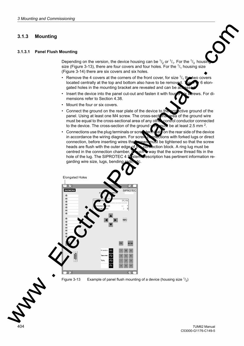
3 Mounting and Commissioning
om
3.1.3 Mounting
3.1.3.1 Panel Flush Mounting
Depending on the version, the device housing can be 1/2 or 1/1. For the 1/3 housing size (Figure 3-13), there are four covers and four holes. For the 1/1 housing size (Figure 3-14) there are six covers and six holes. • Remove the 4 covers at the corners of the front cover, for size 1/1 the two covers
located centrally at the top and bottom also have to be removed. The 4 or 6 elon-gated holes in the mounting bracket are revealed and can be accessed.
• Insert the device into the panel cut-out and fasten it with four or six screws. For di-mensions refer to Section 4.38.
• Mount the four or six covers.• Connect the ground on the rear plate of the device to the protective ground of the
panel. Using at least one M4 screw. The cross-sectional area of the ground wire must be equal to the cross-sectional area of any other control conductor connected to the device. The cross-section of the ground wire must be at least 2.5 mm 2.
• Connections use the plug terminals or screw terminals on the rear side of the device in accordance the wiring diagram. For screw connections with forked lugs or direct connection, before inserting wires the screws must be tightened so that the screw heads are flush with the outer edge of the connection block. A ring lug must be centred in the connection chamber, in such a way that the screw thread fits in the hole of the lug. The SIPROTEC 4 System Description has pertinent information re-garding wire size, lugs, bending radii, etc.
Figure 3-13 Example of panel flush mounting of a device (housing size 1/2)
ww . El
ectric
alPar
tMan
uals
. c
404 7UM62 ManualC53000-G1176-C149-5
w

3.1 Mounting and Connectionsw
Figure 3-14 Example of panel flush mounting of a device (housing size 1/1)
3.1.3.2 Rack and Cubicle Mounting
For the 1/2 housing size (Figure 3-15), there are four covers and four holes. For the 1/1 housing size (Figure 3-16) there are six covers and six holes.
To install the device in a frame or cubicle, two mounting brackets are required. The ordering codes are stated in Appendix, Section A.1.• Loosely screw the two mounting brackets in the rack or cubicle with four screws.• Remove the 4 covers at the corners of the front cover, for size 1/1 the two covers
located centrally at the top and bottom also have to be removed. Thus the 4 respec-tively 6 slots in the mounting flange are revealed and can be accessed.
• Fasten the device to the mounting brackets with four or six screws.• Mount the four or six covers.• Tighten fast the eight screws of the angle brackets in the rack or cubicle.• Connect the ground on the rear plate of the device to the protective ground of the
panel. Using at least one M4 screw. The cross-sectional area of the ground wire must be equal to the cross-sectional area of any other control conductor connected to the device. The cross-section of the ground wire must be at least 2.5 mm 2.
• Connections use the plug terminals or screw terminals on the rear side of the device in accordance the wiring diagram. For screw connections with forked lugs or direct connection, before inserting wires the screws must be tightened so that the screw heads are flush with the outer edge of the connection block. A ring lug must be centred in the connection chamber, in such a way that the screw thread fits in the hole of the lug. The SIPROTEC 4 System Description /1/ has pertinent information regarding wire size, lugs, bending radii, etc.
ww . El
ectric
alPar
tMan
uals
. com
4057UM62 ManualC53000-G1176-C149-5
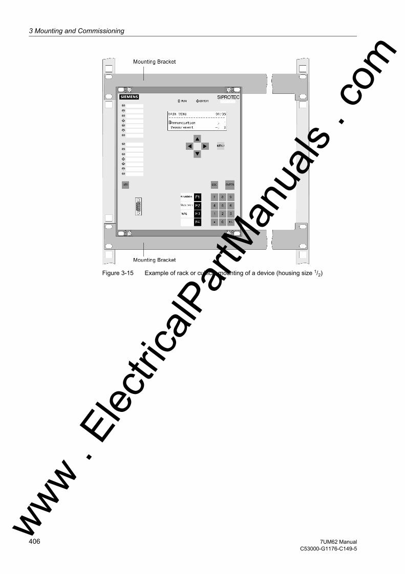
3 Mounting and Commissioning
om
Figure 3-15 Example of rack or cubicle mounting of a device (housing size 1/2)
ww . El
ectric
alPar
tMan
uals
. c
406 7UM62 ManualC53000-G1176-C149-5
w
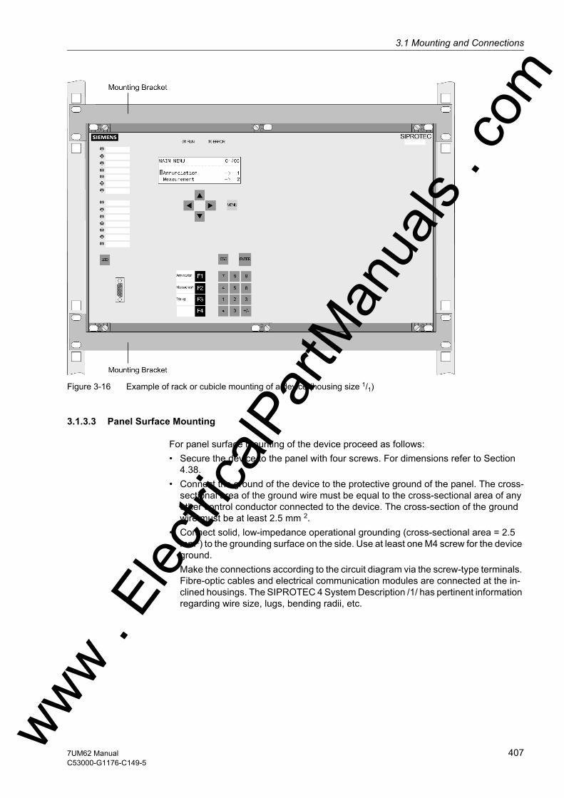
3.1 Mounting and Connectionsw
Figure 3-16 Example of rack or cubicle mounting of a device (housing size 1/1)
3.1.3.3 Panel Surface Mounting
For panel surface mounting of the device proceed as follows:• Secure the device to the panel with four screws. For dimensions refer to Section
4.38.• Connect the ground of the device to the protective ground of the panel. The cross-
sectional area of the ground wire must be equal to the cross-sectional area of any other control conductor connected to the device. The cross-section of the ground wire must be at least 2.5 mm 2.
• Connect solid, low-impedance operational grounding (cross-sectional area = 2.5 mm2) to the grounding surface on the side. Use at least one M4 screw for the device ground.
• Make the connections according to the circuit diagram via the screw-type terminals. Fibre-optic cables and electrical communication modules are connected at the in-clined housings. The SIPROTEC 4 System Description /1/ has pertinent information regarding wire size, lugs, bending radii, etc.
ww . El
ectric
alPar
tMan
uals
. com
4077UM62 ManualC53000-G1176-C149-5
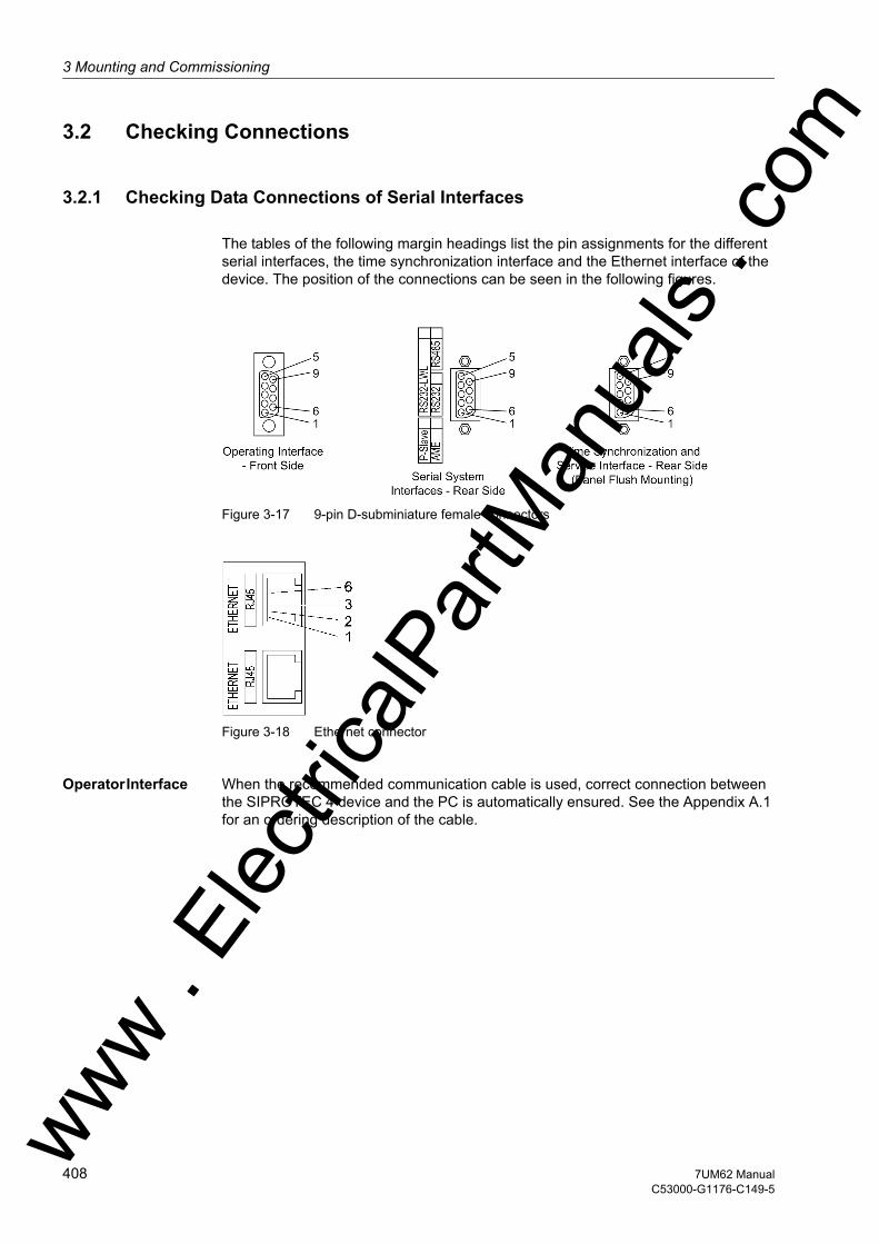
3 Mounting and Commissioning
om
3.2 Checking Connections
3.2.1 Checking Data Connections of Serial Interfaces
The tables of the following margin headings list the pin assignments for the different serial interfaces, the time synchronization interface and the Ethernet interface of the device. The position of the connections can be seen in the following figures.
Figure 3-17 9-pin D-subminiature female connectors
Figure 3-18 Ethernet connector
Operator Interface When the recommended communication cable is used, correct connection between the SIPROTEC 4 device and the PC is automatically ensured. See the Appendix A.1 for an ordering description of the cable.
ww . El
ectric
alPar
tMan
uals
. c
408 7UM62 ManualC53000-G1176-C149-5
w
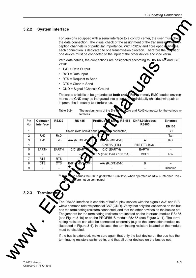
3.2 Checking Connectionsw
3.2.2 System Interface
For versions equipped with a serial interface to a control center, the user must check the data connection. The visual check of the assignment of the transmission and re-ception channels is of particular importance. With RS232 and fibre optic interfaces, each connection is dedicated to one transmission direction. Therefore the output of one device must be connected to the input of the other device and vice versa.
With data cables, the connections are designated according to DIN 66020 and ISO 2110:• TxD = Data Output• RxD = Data Input• RTS = Request to Send• CTS = Clear to Send• GND = Signal / Chassis Ground
The cable shield is to be grounded at both ends. For extremely EMC-loaded environ-ments the GND may be integrated into a separate individually shielded wire pair to improve the immunity to interference.
Table 3-24 The assignments of the D-subminiature and RJ45 connector for the various in-terfaces
1) Pin 7 also carries the RTS signal with RS232 level when operated as RS485 Interface. Pin 7 may therefore not be connected!
3.2.3 Termination
The RS485 interface is capable of half-duplex service with the signals A/A' and B/B' with a common relative potential C/C' (GND). Verify that only the last device on the bus has the terminating resistors connected, and that the other devices on the bus do not. The jumpers for the terminating resistors are located on the interface module RS485 (see Figure 3-10) or on the PROFIBUS module RS485 (see Figure 3-11). The termi-nating resistors can also be connected externally (e.g. to the connection module as illustrated in Figure 3-4). In this case, the terminating resistors located on the module must be disabled.
If the bus is extended, make sure again that only the last device on the bus has the terminating resistors switched-in, and that all other devices on the bus do not.
Pin No.
Operator interface
RS232 RS 485 Profibus DP Slave, RS 485 DNP3.0 Modbus, RS485
Ethernet
EN1001 Shield (with shield ends electrically connected) Tx+2 RxD RxD – – – Tx-3 TxD TxD A/A’ (RxD/TxD-N) B/B’ (RxD/TxD-P) A Rx+4 – – – CNTRA-(TTL) RTS (TTL level) –5 EARTH EARTH C/C' (EARTH) C/C' (EARTH) EARTH1 –6 – – – +5 V (max. load < 100 mA) VCC1 Rx-7 RTS RTS – 1) – – –8 CTS CTS B/B’ (RxD/TxD-P) A/A’ (RxD/TxD-N) B –9 – – – – – Disabled
ww . El
ectric
alPar
tMan
uals
. com
4097UM62 ManualC53000-G1176-C149-5
3 Mounting and Commissioning
om
3.2.4 Analog Output
The two analog values are output as currents on a 9-pin DSUB socket. The outputs are isolated.
Table 3-25 Pin assignment of DSUB socket for analog output
3.2.5 Time Synchronization Interface
Either 5 VDC, 12 VDC or 24 VDC time synchronization signals can be processed if the connections are made as indicated in the table below.
Table 3-26 D-subminiature connector assignment of the time synchronization interface
1) assigned, but not used
For pin assignment of the time synchronization interface in panel surface-mounted de-vices, see Appendix (Figures A-22 and A-23).
Pin No. Code1 Channel 1 positive2 –3 –4 –5 Channel 2 positive6 Channel 1 negative7 –8 –9 Channel 2 negative
Pin No. Designation Signal Meaning1 P24_TSIG Input 24 V2 P5_TSIG Input 5 V3 M_TSIG Return Line4 M_TSYNC 1) Return Line 1)
5 Shield Shield Potential6 – –7 P12_TSIG Input 12 V8 P_TSYNC 1) Input 24 V 1)
9 SHIELD Shield Potential
ww . El
ectric
alPar
tMan
uals
. c
410 7UM62 ManualC53000-G1176-C149-5
w

3.2 Checking Connectionsw
3.2.6 Optical Fibres
WARNING!Laser injection!
Do not look directly into the fibre-optic elements!
The transmission via fibre optics is particularly insensitive to electromagnetic interfer-ence and thus ensures galvanic isolation of the connection. Transmit and receive con-nections are shown with the symbols for transmit and for receive.
The character idle state for the optical fibre interface is „Light off“. If the character idle state is to be changed, use the operating program DIGSI, as described in the SIPRO-TEC 4 System Description.
3.2.7 Checking Device Connections
General By checking the device connections the correct installation of the protection device e.g. in the cubicle must be tested and ensured. This includes wiring check and func-tionality as per drawings, visual assessment of the protection system, and a simplified functional check of the protection device.
Auxiliary Voltage Supply
Before the device is connected for the first time to voltage, it should be have been at least 2 hours in its operating room, in order to attain temperature equilibrium and to avoid dampness and condensation.
Note
If a redundant supply is used, there must be a permanent, i.e. uninterruptible connec-tion between the minus polarity connectors of system 1 and system 2 of the DC voltage supply (no switching device, no fuse), because otherwise there is a risk of voltage doubling in case of a double earth fault.
Switch on the auxiliary voltage circuit breaker (supply protection), check voltage polar-ity and amplitude at the device terminals or at the connection modules.
Visual Check Check the cubicle and the devices for damage, condition of the connections etc., and device earthing.
ww . El
ectric
alPar
tMan
uals
. com
4117UM62 ManualC53000-G1176-C149-5

3 Mounting and Commissioning
om
Secondary Check This test does not undertake to check the individual protection functions for the accu-racy of their pick-up values and characteristic curves. Unlike analog electronic or elec-tromechanical protective devices, no protection function test is required within the framework of the device test, since this is ensured by the factory tests. Protection func-tions are only used to check the device connections.
A plausibility check of the analog-digital converter with the operational measured values is sufficient since the subsequent processing of the measured values is numer-ical and thus internal failures of protection functions can be ruled out.
Where secondary tests are to be performed, a three-phase test equipment providing test currents and voltages is recommended (e.g. Omicron CMC 56 for manual and au-tomatic testing). The phase angle between currents and voltages should be continu-ously controllable.
The accuracy which can be achieved during testing depends on the accuracy of the testing equipment. The accuracy values specified in the Technical data can only be reproduced under the reference conditions set down in IEC 60 255 resp. VDE 0435/part 303 and with the use of precision measuring instruments.
Tests can be performed using the currently set values or the default values.
If unsymmetrical currents and voltages occur during the tests it is likely that the asym-metry monitoring will frequently pickup. This is of no concern because the condition of steady-state measured values is monitored which, under normal operating conditions, are symmetrical; under short circuit conditions these monitorings are not effective.
Note
If during dynamic testing, measured values are connected from or reduced to zero, a sufficiently high value should be present at least one other measuring circuit (in general a voltage), to permit frequency adaptation.
Measured values in earth paths of voltage or current (IEE, UE) can not adapt the scan-ning frequency. To check them a sufficiently high value measured value should be present in one of the phases.
Secondary Test of the Differential Protection
A test set with 6 current outputs is recommended for secondary testing. The following section gives hints how to proceed for testing with fewer current sources. The test current can be injected individually for each winding, thus simulating each time a transformer fault with single-ended infeed.
For three or two-phase testing the parameter (address 2021) set for I-DIFF> is valid as the pickup value on presetting. The pickup value for single-phase testing depends on how the zero sequence current is treated:
If the zero sequence current is eliminated, the pickup value increases to 1.5 times the set value; this corresponds to conventional circuitry when current is fed in via matching transformers.
If the zero sequence current is not eliminated (isolated starpoint), the pickup current corresponds to the setting value I-DIFF> even during single-phase testing.
Checking the pickup value is performed by slowly increasing the test current for each winding with the secondary test set. Tripping is initiated when the converted pickup value is reached. When the test current falls reaches 0.7 times the pickup value, the tripping command drops off. ww .
Elec
tricalP
artM
anua
ls . c
412 7UM62 ManualC53000-G1176-C149-5
w

3.2 Checking Connectionsw
In the method described above, the pickup values for single-ended infeed are tested in each case. It is also possible to check the entire characteristic. Since trip current and restraint current cannot be fed in separately (they can, however, be read out sep-arately in the test measurements), a separate test current has to be applied to each of the two windings.
When testing with the operational parameters, it should be noted that the setting value I-DIFF> refers to the rated current of the transformer, i.e. current which results from
with
SN, Transf Nominal apparent power of the transformer
UN Wndg Rated voltage of the respective winding; for a winding with regulated voltage, the voltage computed in accor-dance with Section 2.14.1.2 applies
Furthermore, the pickup values can change with single and two-phase testing depend-ing on the vector group of the protected transformer; this corresponds to conventional circuitry, when currents are applied via matching current transformers. Table 3-27 shows these changes as a factor kVG depending on the vector group and the type of fault, for three-phase transformers.
In order to obtain the pickup value, the setting value I-DIFF> (parameter address 2021) must be multiplied by the factor
Table 3-27 Correction Factor kVG Depending on Vector Group and Fault Type
The pickup values are checked for each winding by slowly increasing the test current with the secondary test set. Tripping is initiated when the converted pickup value is reached.
Example (Application as „mere transformer protection“):
Three-phase transformer SN = 57 MVA, vector group Yd5
High Voltage 110 kV
Current Transformer 300 A / 1 A
Undervoltage 25 kV
Current Transformer 1500 A / 1 A
Type of Fault Reference winding (High Voltage)
Even VG Numeral(0, 2, 4, 6, 8, 10)
Odd VG Numeral(1, 3, 5, 7, 9, 11)
Three-phase 1 1 1Two-Phase 1 1 √3/2 = 0.866single-phase with I0 elimination 3/2 = 1.5 3/2 = 1.5 √3 = 1.73single-phase without I0 elimina-tion
1 1 √3 = 1.73
ww . El
ectric
alPar
tMan
uals
. com
4137UM62 ManualC53000-G1176-C149-5
3 Mounting and Commissioning
om
The following applies for the high voltage winding:
In this case the rated current of the winding is practically equal to the current trans-former rated current. Thus, the pickup value (referred to the rated relay current) com-plies with the setting value I DIFF> of the relay when three or two-phase testing is per-formed (kVG = 1 for reference winding). For single-phase testing with zero sequence current elimination, a pickup value 1.5 times higher must be expected.
The following applies for the secondary winding:
When testing this winding, the pickup value (referred to the rated device current) will amount to
Because of the odd vector group numeral, the following pickup values apply
Wiring It is particularly important to check the correct wiring and allocation of all device inter-faces. The margin heading titled„Test function for checking the binary inputs and out-puts“ provides additional information to this end.
For analog inputs a plausibility check can be controlled as described above under the margin title „Secondary Testing“
Function Check The only functional test required for protective relays is a plausibility check of the op-erational measured values by means of some secondary test equipment; this is to ensure that no damage has occurred during transit (see also side title „Secondary Testing“).
ww . El
ectric
alPar
tMan
uals
. c
414 7UM62 ManualC53000-G1176-C149-5
w
3.2 Checking Connectionsw
Undervoltage Protection
Note
If in the device undervoltage protection function is configured and activated, the fol-lowing must be considered: Special measures have been taken to ensure that the device does not pick up immediately after applying the auxiliary power supply, as a result of the absent measured voltage. However, the device does pick up as soon as operating state 1 (measured values exist) has been attained.
LEDs After tests where the displays appear on the LEDs, these should be reset in order that they present information only on the currently executed test. This should be done at least once each using the reset button on the front panel and via the binary input for remote reset (if allocated). Observe that an independent reset occurs also on the arrival of a new fault and that setting of new indications can be optionally made depen-dent on the pickup or a trip command (parameter 610 FltDisp.LED/LCD).
Test Switch Check the functions of all test switches that are installed for the purposes of secondary testing and isolation of the device. Of particular importance are „test switches “ in current transformer circuits. Be sure these switches short-circuit the current transform-ers when they are in the test mode.
3.2.8 Checking System Incorporation
General Informa-tion
WARNING!Warning of dangerous voltages
Non-observance of the following measures can result in death, personal injury or sub-stantial property damage.
Therefore, only qualified people who are familiar with and adhere to the safety proce-dures and precautionary measures shall perform the inspection steps.
With this check of the protection, the correct incorporation of the device into the power system is tested and ensured.
Checking of protection parametrization (allocations and settings) in accordance with the power system requirements, is an important test step here.
The interface-wide incorporation check in the power system results on the one hand in testing of cubicle wiring and drawing record in accordance with functionality, and on the other hand the correctness of cabling between transducer or transformer and pro-tection device.
ww . El
ectric
alPar
tMan
uals
. com
4157UM62 ManualC53000-G1176-C149-5

3 Mounting and Commissioning
om
Auxiliary Voltage Supply
Check the voltage magnitude and polarity at the input terminals.
Note
If a redundant supply is used, there must be a permanent, i.e. uninterruptible connec-tion between the minus polarity connectors of system 1 and system 2 of the DC voltage supply (no switching device, no fuse), because otherwise there is a risk of voltage doubling in case of a double earth fault.
Caution!Be careful when operating the device on a battery charger without a battery
Non-observance of the following measure can lead to unusually high voltages and consequently, the destruction of the device.
Do not operate the device on a battery charger without a connected battery. (Limit values can be found in the technical data).
Visual Check During the visual check the following must be considered:• Check of the cubicle and the devices for damage;• Check of earthing of the cabinet and the device;• Check the external cabling for condition and completeness.
Acquisition of Technical Power System Data
For checking protection parameterization (allocation and settings) in accordance with power system requirements, recording of technical data of the individual components is necessary in the primary system. This includes, among others, the generator or motor, the unit transformer and the voltage and current transformers.
Where deviations from the planning data are found, the settings of the protection must be modified accordingly.
Analog Inputs The check of the current and voltage transformer circuits includes:• Acquisition of technical data• Visual check of transformers, e.g. for damage, assembly position, connections• Check of transformer earthing, especially earthing of the broken delta winding in
only one phase• Check cabling in accordance with circuit diagram• Check of the short circuiters of the plug connectors for current circuits
Further tests are under certain circumstances necessary in accordance with contract: • Insulation measurement of cable• Measurement of transformation ratio and polarity• Burden measurement• Checking the functions of test switches, if used for secondary testing.• Measuring transducers/ Measuring transducer connectionww .
Elec
tricalP
artM
anua
ls . c
416 7UM62 ManualC53000-G1176-C149-5
w
3.2 Checking Connectionsw
Binary Inputs and Outputs
For more information see also Section 3.3.• Setting of binary inputs:
– Check and match jumper allocation for pickup thresholds (see Section 3.1)
– Check the pickup threshold – if possible – with a variable DC voltage source
• Check the tripping circuits from the command relays and the tripping lines down to the various components (circuit breakers, excitation circuit, emergency tripping, switchover devices etc.)
• Check the signal processing from the signal relays and the signal lines down to the station control and protection system; to do so, energize the signal contacts of the protective device and check the texts in the station control and protection system
• Check the control circuits from the output relays and the control lines down to the circuit breakers and disconnectors etc.
• Check the binary input signals from the signal lines down to the protective device by activating the external contacts
Voltage Trans-former Miniature Circuit Breaker (VT mcb)
Since it is very important for the undervoltage protection, impedance protection, out-of-step protection and the voltage-controlled definite time and inverse time overcurrent protection that these functions are blocked automatically if the circuit breaker for the voltage transformers has tripped, the blocking should be checked along with the voltage circuits. Switch off voltage transformer protection switches.
One should check in the operational annunciations that the VT mcb trip was detected (annunciation „>FAIL:Feeder VT“ „ON“). A requirement for this is that the auxiliary contact of the VT mcb is connected and correspondingly allocated.
Close the VT mcb again: The above annunciations appear under the „going“ opera-tional annunciations, i.e. with the comment „OFF“ (e.g. „>FAIL:Feeder VT“ „OFF“).
Note
The definite time overcurrent with undervoltage seal-in blocking must be realised with the binary input „>Useal-inBLK“ (1950)
If one of the indications does not appear, check the connection and allocation of these signals.
If the „ON“ and „OFF“ messages are exchanged, then the breaker auxiliary contact type should be checked and corrected if necessary.
ww . El
ectric
alPar
tMan
uals
. com
4177UM62 ManualC53000-G1176-C149-5

3 Mounting and Commissioning
om
3.3 Commissioning
WARNING!Warning of dangerous voltages when operating an electrical device
Non-observance of the following measures can result in death, personal injury or sub-stantial property damage.
Only qualified people shall work on and around this device. They must be thoroughly familiar with all warnings and safety notices in this instruction manual as well as with the applicable safety steps, safety regulations, and precautionary measures.
The device is to be grounded to the substation ground before any other connections are made.
Hazardous voltages can exist in the power supply and at the connections to current transformers, voltage transformers, and test circuits.
Hazardous voltages can be present in the device even after the power supply voltage has been removed (capacitors can still be charged).
After removing voltage from the power supply, wait a minimum of 10 seconds before re-energizing the power supply. This wait allows the initial conditions to be firmly es-tablished before the device is re-energized.
The limit values given in Technical Data (Chapter 10) must not be exceeded, neither during testing nor during commissioning.
When testing the device with secondary test equipment, make sure that no other mea-surement quantities are connected and that the TRIP command lines and possibly the CLOSE command lines to the circuit breakers are interrupted, unless otherwise spec-ified.
DANGER!Hazardous voltages during interruptions in secondary circuits of current trans-formers
Non-observance of the following measure will result in death, severe personal injury or substantial property damage.
Short-circuit the current transformer secondary circuits before current connections to the device are opened.
For the commissioning switching operations have to be carried out. A prerequisite for the prescribed tests is that these switching operations can be executed without danger. They are accordingly not meant for operational checks.
ww . El
ectric
alPar
tMan
uals
. c
418 7UM62 ManualC53000-G1176-C149-5
w
3.3 Commissioningw
WARNING!Warning of dangers evolving from improper primary tests
Non-observance of the following measures can result in death, personal injury or sub-stantial property damage.
Primary test may only be carried out by qualified personnel, who are familiar with the commissioning of protection systems, the operation of the plant and the safety rules and regulations (switching, earthing, etc.).
3.3.1 Test Mode / Transmission Block
If the device is connected to a central or main computer system via the SCADA inter-face, then the information that is transmitted can be influenced. This is only possible with some of the protocols available (see Table „Protocol-dependent functions“ in the Appendix A.5).
If Test mode is set ON, then a message sent by a SIPROTEC 4 device to the main system has an additional test bit. This bit allows the message to be recognized as re-sulting from testing and not an actual fault or power system event. Furthermore it can be determined by activating the Transmission block that no indications at all are transmitted via the system interface during test mode.
The SIPROTEC 4 System Description /1/ describes how to activate and deactivate test mode and blocked data transmission. Note that when DIGSI is being used, the program must be in the Online operating mode for the test features to be used.
ww . El
ectric
alPar
tMan
uals
. com
4197UM62 ManualC53000-G1176-C149-5
3 Mounting and Commissioning
om
3.3.2 Testing System Interfaces
Prefacing Remarks If the device features a system interface and uses it to communicate with the control centre, the DIGSI device operation can be used to test if messages are transmitted correctly. This test option should however definitely „not“ be used while the device is in service on a live system.
DANGER!Danger evolving from operating the equipment (e.g. circuit breakers, discon-nectors) by means of the test function
Non-observance of the following measure will result in death, severe personal injury or substantial property damage.
Equipment used to allow switching such as circuit breakers or disconnectors is to be checked only during commissioning. Do not under any circumstances check them by means of the testing mode during „real“ operation performing transmission and recep-tion of messages via the system interface.
Note
After termination of the hardware test, the device will reboot. Thereby, all annunciation buffers are erased. If required, these buffers should be extracted with DIGSI prior to the test.
The interface test is carried out using DIGSI in the Online operating mode:• Open the Online directory by double-clicking; the operating functions for the device
appear.• Click on Test; the function selection appears in the right half of the screen.• Double-click on Testing Messages for System Interface shown in the list view.
The dialog box Generate Annunciations opens (refer to the following figure).
ww . El
ectric
alPar
tMan
uals
. c
420 7UM62 ManualC53000-G1176-C149-5
w

3.3 Commissioningw
Structure of the Test Dialogue Box
In the column Indication the display texts of all indications are displayed which were allocated to the system interface in the matrix. In the column Status SCHEDULED the user has to define the value for the messages to be tested. Depending on the indica-tion type, several input fields are offered (e.g. „ON“/ „OFF“). By double-clicking onto one of the fields the required value can be selected from the list.
Figure 3-19 System interface test with dialog box: Generate indications — example
Changing the Operating State
On clicking one of the buttons in the column Action you will be prompted for the pass-word No. 6 (for hardware test menus). After correct entry of the password, individual annunciations can be initiated. To do so, click on the button Send in the corresponding line. The corresponding annunciation is issued and can be read out either from the event log of the SIPROTEC 4 device or from the substation control center.
As long as the window is open, further tests can be performed.
Test in Message Direction
For all information that is transmitted to the central station test in Status Scheduled the desired options in the list which appears:• Make sure that each checking process is carried out carefully without causing any
danger (see above and refer to DANGER!)• Click on Send in the function to be tested and check whether the transmitted infor-
mation reaches the central station and shows the desired reaction. Data which are normally linked via binary inputs (first character „>“) are likewise indicated to the central station with this procedure. The function of the binary inputs itself is tested separately.
Exiting the Test Mode
To end the System Interface Test, click on Close. The device is briefly out of service while the start-up routine is executed. The dialogue box closes.
ww . El
ectric
alPar
tMan
uals
. com
4217UM62 ManualC53000-G1176-C149-5

3 Mounting and Commissioning
om
3.3.3 Checking the Binary Inputs and Outputs
Prefacing Remarks The binary inputs, outputs, and LEDs of a SIPROTEC 4 device can be individually and precisely controlled in DIGSI. This feature is used to verify control wiring from the device to plant equipment (operational checks) during commissioning. This test option should however definitely „not“ be used while the device is in service on a live system.
DANGER!Danger evolving from operating the equipment (e.g. circuit breakers, discon-nectors) by means of the test function
Non-observance of the following measure will result in death, severe personal injury or substantial property damage.
Equipment used to allow switching such as circuit breakers or disconnectors is to be checked only during commissioning. Do not under any circumstances check them by means of the testing mode during „real“ operation performing transmission and recep-tion of messages via the system interface.
Note
After termination of the hardware test, the device will reboot. Thereby, all annunciation buffers are erased. If required, these buffers should be extracted with DIGSI prior to the test.
The hardware test can be carried out using DIGSI in the Online operating mode:• Open the Online directory by double-clicking; the operating functions for the device
appear.• Click on Test; the function selection appears in the right half of the screen.• Double-click in the list view on Hardware Test. The dialog box of the same name
opens (see the following figure).
ww . El
ectric
alPar
tMan
uals
. c
422 7UM62 ManualC53000-G1176-C149-5
w

3.3 Commissioningw
Structure of the Test Dialogue Box
The dialog box is divided into three groups: BI for binary inputs, REL for output relays, and LED for light-emitting diodes. On the left of each group is an accordingly labelled button. By double-clicking these buttons you can show or hide the individual informa-tion of the selected group.
In the column Status the current status of the particular hardware component is dis-played. It is displayed symbolically. The actual states of the binary inputs and outputs are displayed by the symbol of opened and closed switch contacts, those of the LEDs by a symbol of a lit or extinguished LED.
The opposite state of each element is displayed in the column Scheduled. The display is made in plain text.
The right-most column indicates the commands or messages that are configured (masked) to the hardware components.
Figure 3-20 Testing of the binary inputs and outputs — example
Changing the Operating State
To change the condition of a hardware component, click on the associated switching field in the Scheduled column.
Password No. 6 (if activated during configuration) will be requested before the first hardware modification is allowed. After entry of the correct password a condition change will be executed. Further condition changes remain possible while the dialog box is open.
ww . El
ectric
alPar
tMan
uals
. com
4237UM62 ManualC53000-G1176-C149-5

3 Mounting and Commissioning
om
Test of the Binary Outputs
Each individual output relay can be energized allowing a check of the wiring between the output relay of the 7UM62 and the system, without having to generate the message that is assigned to the relay. As soon as the first change of state for any of the output relays is initiated, all output relays are separated from the internal device functions, and can only be operated by the hardware test function. This means, that e.g. a TRIP command coming from a control command from the operator panel to an output relay cannot be executed.
Proceed as follows in order to check the output relay :• Ensure that the switching of the output relay can be executed without danger (see
above under DANGER!).• Each output relay must be tested via the corresponding Scheduled-cell in the
dialog box.• The test sequence must be terminated (refer to margin heading „Exiting the Proce-
dure“), to avoid the initiation of inadvertent switching operations by further tests.
Test of the Binary Inputs
To test the wiring between the plant and the binary inputs of the 7UM62 the condition in the system which initiates the binary input must be generated and the response of the device checked.
To do this, the dialog box Hardware Test must again be opened to view the physical state of the binary inputs. The password is not yet required.
Proceed as follows in order to check the binary inputs:• Activate in the system each of the functions which cause the binary inputs.• The response of the device must be checked in the Status column of the dialog box.
To do this, the dialog box must be updated. The options may be found below under the margin heading „Updating the Display“.
• Terminate the test sequence (see below under the margin heading „Exiting the Pro-cedure“).
If however the effect of a binary input must be checked without carrying out any switch-ing in the plant, it is possible to trigger individual binary inputs with the hardware test function. As soon as the first state change of any binary input is triggered and the pass-word no. 6 has been entered, all binary inputs are separated from the plant and can only be activated via the hardware test function.
Test of the LEDs The LEDs may be tested in a similar manner to the other input/output components. As soon as you have initiated the first state change for any LED, all LEDs are disconnect-ed from the functionality of the device and can only be operated by the hardware test function. This means e.g. that no LED is illuminated anymore by a device function or by pressing the LED reset button.
Updating the Display
During the opening of the dialog box Hardware Test the operating states of the hard-ware components which are current at this time are read in and displayed.
An update occurs:• for each hardware component, if a command to change the condition is successfully
performed,• for all hardware components if the Updatebutton is clicked,• for all hardware components with cyclical updating (cycle time is 20 seconds) if the
Automatic Update (20sec) field is marked.
ww . El
ectric
alPar
tMan
uals
. c
424 7UM62 ManualC53000-G1176-C149-5
w
3.3 Commissioningw
Exiting the Test Mode
To end the hardware test, click on Close. The dialog box closes. The device becomes unavailable for a brief start-up period immediately after this. Then all hardware com-ponents are returned to the operating conditions determined by the plant settings.
3.3.4 Tests for the Circuit Breaker Failure Protection
General If the device is equipped with the breaker failure protection and this function is used, its interaction with the breakers of the power plant must be tested in practice.
Especially important for checking the system is the correct distribution of the trip com-mands to the adjacent circuit breakers in the event of breaker failure.
Adjacent circuit breakers are those which must trip in the event of a breaker failure in order to cut off the short-circuit current. Therefore these are the circuit breakers that feed the faulted line.
It is not possible to define a generally applicable, detailed test specification since the definition of adjacent circuit breakers depends to a large extent of the plant layout.
3.3.5 Checking Analog Outputs
The SIPROTEC devices 7UM62 can be equipped with up to 2x2 analog outputs. Where analog outputs are provided and used, their functioning should be tested.
Since various types of measured values or events can be output, the test to be per-formed depends on the values involved. These values must be generated (e.g. with secondary test equipment).
Make sure that the proper values are correctly output at their destination.
3.3.6 Testing User-defined Functions
CFC Logic The device has a vast capability for allowing functions to be defined by the user, es-pecially with the CFC logic. Any special function or logic added to the device must be checked.
Naturally, general test procedures cannot be given. Rather, the configuration of these user defined functions and the necessary associated conditions must be known and verified. Of particular importance are possible interlocking conditions of the switchgear (circuit breakers, isolators, etc.).
ww . El
ectric
alPar
tMan
uals
. com
4257UM62 ManualC53000-G1176-C149-5

3 Mounting and Commissioning
om
3.3.7 Checking the Rotor Earth Fault Protection at Standstill
Rotor Earth Fault Protection (R, fn)
The rotor earth fault protection can be checked with the machine at standstill. For this the coupling device must be fed an external AC voltage. This may be 100 V to 125 V or 230 V (see also connection example in Section 2.34).
Switch rotor earth fault protection (address 6001 ROTOR E/F) to Block relay.
In the case of machines with rotating rectifier excitation (Figure 3-19 left), a dead earth fault is applied between the two measurement slip rings with measurement brushes in place, for machines with excitation via slip rings (following Figure, right) between one slip ring and earth. The device now measures as earth impedance only the reactance of the coupling unit and the brush resistance (as the case may be in series with a pro-tection resistor for the coupling capacitors and a current-limiting resistor with induc-tive/capacitive coupling).
These values can be read out with the phase angle of this complex resistance under the earth fault measured values:
Rtot = x.xx kΩ
Xtot = y.yy kΩ
ϕZtot = z.z °
Rtot. corresponds to the series resistance (brushes plus protection and limiting resistor) and Xtot. to the coupling reactance. If both for Rtot. as well as for Xtot. values are indi-cated as 0, then the connections of URE or IRE have wrong polarity. Change the polarity of one of the connections and repeat the measurement.
It must then be checked/remedied that the setting values
R SERIES = xxx Ω (address 6007)
X COUPLING = yyy Ω (address 6006)
correspond to the above values. Remove earth fault bridge.
Now using a resistor of the size of the warning resistance (RE< WARN, address 6002, 10 kΩ on delivery) an earth fault is simulated as above. The earth resistance calculat-ed by the unit can be read out under the Operational Measured Values as Rearth. If sub-stantial deviation occurs between the actual and the indicated earth resistances, the matching improvement can be attempted by correcting the preset angle error forIRE PHI I RE at address 6009. This angle error correction is only effective for the rotor earth fault protection function.
An earth fault is now simulated as above using a resistor approximately 90% of the trip resistance (RE<< TRIP, address 6003, 2 kΩ on delivery). The rotor earth fault pro-tection initiates a pickup signal and after 6005 T-TRIP-RE<< (0.5 s on delivery) a trip indication (LED 1 and output relay 2), in both cases as a group indication device trip).
For machines with excitation via slip rings, the last test is repeated for the other slip ring.
Remove earth fault resistor.
ww . El
ectric
alPar
tMan
uals
. c
426 7UM62 ManualC53000-G1176-C149-5
w
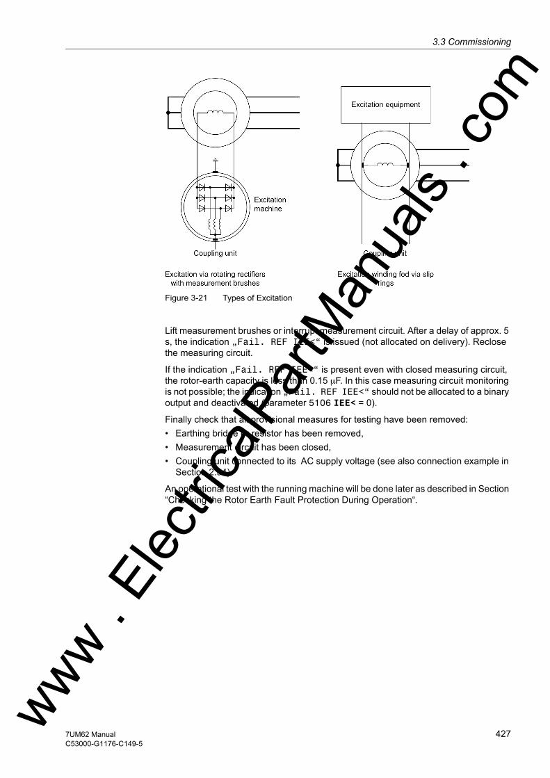
3.3 Commissioningw
Figure 3-21 Types of Excitation
Lift measurement brushes or interrupt measurement circuit. After a delay of approx. 5 s, the indication „Fail. REF IEE<“ is issued (not allocated on delivery). Reclose the measuring circuit.
If the indication „Fail. REF IEE<“ is present even with closed measuring circuit, the rotor-earth capacity is less than 0.15 µF. In this case measuring circuit monitoring is not possible; the indication „Fail. REF IEE<“ should not be allocated to a binary output and deactivated (parameter 5106 IEE< = 0).
Finally check that all provisional measures for testing have been removed:• Earthing bridge or resistor has been removed,• Measurement circuit has been closed,• Coupling unit connected to its AC supply voltage (see also connection example in
Section 2.34).
An operational test with the running machine will be done later as described in Section “Checking the Rotor Earth Fault Protection During Operation“.
ww . El
ectric
alPar
tMan
uals
. com
4277UM62 ManualC53000-G1176-C149-5

3 Mounting and Commissioning
om
Rotor Earth Fault Protection (1 to 3 Hz)
The rotor earth fault protection can be checked with the machine at standstill. For this the series device 7XT71 must be fed an external AC voltage. This is 100 V to 125 V AC (see also connection example in Appendix A.3).
Switch rotor earth fault protection (address 6101 REF 1-3Hz) to Block relay.
The following operational measured values are read out and evaluated under fault-free conditions (see Table 3-28). The operational measured values are under earth fault measured values (in DIGSI see tab „Earth Fault Measured Values“).
Table 3-28 Operational Measured Values of the Rotor Earth Fault Protection
Measured Value Explanationfgen = xx.x Hz Shows the frequency of the injected square-wave voltage. The
frequency can be set by a jumper in the 7XT71. The default setting is approx. 1.5 Hz (tolerance approx. ± 10 %).
Ugen = xx.x V This measured value indicates the present amplitude of the inject-ed square-wave voltage. The measured value amounts to approx. 50 V (tolerance of the 7XT71 can be up to ± 4 V).
Igen = X.xx mA This measured value is nearly zero in fault-free conditions. If a fault resistor is installed between rotor and earth, the current to be expected can be estimated as follows:
RE: Fault resistance RItot: Coupling resisitance (20 kΩ + 720 Ω = 20.720 kΩ)
Qc = x.xxx mAs This measured value indicates the charge which is a function of the rotor earth capacitance. Half of the measured value must be set at address 6106 as Qc <. If the capacitance is very small, it may be necessary to deactivate the measuring circuit monitoring (setting value 0).
Rearth = xxx.x kΩ This measured value indicates the rotor earth resistance. In fault-free condition, the upper limit value 999.9 kΩ is displayed. If it is not, there must be some additional capacitances in the excitation system. The square-wave voltage frequency in the 7XT71 must be reduced by a jumper. No polarity reversal may occur in the measuring current Igen for at least 3 cycles. To visualise what is going on, a test fault record (instantaneous values record) should be started and track TD2, which traces Igen, should be checked (see following Figure).
ww . El
ectric
alPar
tMan
uals
. c
428 7UM62 ManualC53000-G1176-C149-5
w

3.3 Commissioningw
Figure 3-22 Test fault recording
After this the fault resistors for the warning and the trip stage are installed, and the op-erational measured value Rearth is read out. The two measured values are the basis for the setting values of the warning stage (address 6102 RE< WARN) and the trip stage (address 6103 RE<< TRIP).
Finally, the warning and the trip stage are checked. The test resistance for this is approx. 90 % of the set value. On machines with slipring excitation, the test is per-formed for both sliprings.
Remove the earth fault resistor and lift the measuring brushes or interrupt the measur-ing circuit. After a delay of approx. 10 s, the indication „REF 1-3Hz open“ is issued (not allocated on delivery). Reclose the measuring circuit.
If you want to perform an automatic test by means of a test resistor, this mechanism needs to be tested as well. For this connect the test resistor at the slipring to the earth, and activate the test via binary input („>Test REF 1-3Hz“).
Next check the indications for the four test steps to be performed.
1. Measurement circuit has been closed, Indications „Test REF PASSED“
2. Open connection at 1st coupling resistor Indication „1 Cir. open“
3. Open connection at 2nd coupling resistor Indication „2 Cir. open“
4. Reestablish connections Indication „Test REF PASSED“ww . El
ectric
alPar
tMan
uals
. com
4297UM62 ManualC53000-G1176-C149-5

3 Mounting and Commissioning
om
Stop the automatic test and check again the operational measured value Rearth. It must display 999.9 kΩ.
Finally switch the AC voltage source of the 7XT71 off. After about 5 s the protection device issues the indication „Fail REF 1-3Hz“ (not allocated on delivery).
To eliminate interference which might originate from the running machine, in particular from the excitation system, it is recommended to perform an additional operational check.
ww . El
ectric
alPar
tMan
uals
. c
430 7UM62 ManualC53000-G1176-C149-5
w

3.3 Commissioningw
3.3.8 Checking the 100 % Stator Earth Fault Protection
100 % Stator Earth Fault Protection
The 100-% stator earth fault protection can be checked with the machine at standstill, because the measuring principle for the earth resistance calculation is independent of whether the machine is at standstill, rotating or excited. A prerequisite is, however, that the 20 Hz generator 7XT33 must be supplied with a DC voltage or an external voltage source (3 x 100 V, 50/60 Hz), depending on the project, (see also the connection ex-amples in Section 2.31).
Switch the 100-% stator earth fault protection (address 5301 100% SEF-PROT.) to Block relay).
For the following parameters default settings must be maintained for a first commis-sioning.
5309 PHI I SEF = 0 °
5310 SEF Rps = 0.0 Ω
5311 Rl-PARALLEL = ∞ Ω
The measured quantities USEF and ISEF fed to the device can now be read out in the earth fault measured values (in DIGSI under Earth fault measured values):
„U SEF=“ xx.x V
„U20=“ xx.x V
„I SEF=“ xx.x mA
„I20=“ xx.x mA
Please note that these measurements U SEF and I SEF are pure rms values which only correspond to the 20 Hz quantities (U20 and I20) if the generator is at standstill. The voltage measured is influenced by the loading resistor RL, the 20 Hz resistance of the bandpass (RBP approx. 8 Ω), the voltage divider (üVlt.Divider, usually 5/2) and, in the final analysis, by the 20 Hz supply voltage (U20Hz-Generator, approx. 25 V). The value can be estimated as follows:
The flowing current ISEF is determined by the stator earth capacitance and is very small.
The device calculates from these values the earth resistance SES referred to the pro-tection device side. The primary earth resistance SEFpon the machine side is obtained by multiplying the secondary value with the conversion factor set in the Power System Data 1 (address 275 FACTOR R SEF). Both resistance values, including the phase angle between the 20 Hz voltage and the 20 Hz current (ϕSEF = ϕU - ϕI) can be read out in the operational measured values:
„R SEF=“ xxxx Ω
„RSEFp=“ xxx.xx kΩ
„ϕ SEF=“ xx.x°
ww . El
ectric
alPar
tMan
uals
. com
4317UM62 ManualC53000-G1176-C149-5

3 Mounting and Commissioning
om
DANGER!At the generator in standstill also voltages hazardous to the stator winding can be caused by the external 20 Hz bias voltage.Non-observance of the following procedures could result in fatality, serious injury or extensive material damage, since 1% to 3% of the primary rated voltage of the gener-ator being protected may be present.
The external 20 Hz bias voltage of the stator winding must be disconnected before doing work on the generator at standstill.
Proceed as follows:• Under fault-free conditions (RE infinite) the measured current must be negative due
to the capacitive current. If it is not, the connection at the current input must be ro-tated. The phase angle „ϕ SEF=“ should be about –90° due to the existing stator capacitances. If it is not, the value to complement it to –90° must be determined and set as PHI I SEF = –90° – ϕ SEF. For a display value of e.g. „ϕ SEF=“ –75°under address 5309 PHI I SEF = –15° is set. This will change the measured value to approx. –90°. The value displayed for R SEF must be in fault-free condition the maximum possible value of 9999 Ω. The maximum value for the primary earth resistance R SEFp depends on the selected conversion factor (FACTOR R SEF address 275).
• A short-circuit (RE = 0 Ω) is created in the generator starpoint, and the measured fault resistance (address „R SEF=“) read out from the operational measured values. This resistance is set at address 5310 SEF Rps.
• Insert now on the primary side a resistance which corresponds to the tripping value (e.g. 2 kΩ). Check the measured fault resistance („R SEF=“). If this resistance differs very much from the value expected, modify SEF Rps accordingly and, if nec-essary, make a fine adjustment with the correction angle (PHI I SEF). Read out finally the fault resistance, and set this value as the tripping threshold at address 5303 R<< SEF TRIP.Next, insert a fault resistance for the alarm stage (e.g. 5 kΩ) on the primary side, and read out the fault resistance („R SEF=“) from the operational measured values. This value is set at address 5302 as R< SEF ALARM.
• Switch off the voltage supply for the 20 Hz generator, or block the binary input. The indication „SEF100 Failure“ will appear (not allocated on delivery). This ensures that a failure of the 20 Hz generator is reliably detected. If this indication occurs already with the 20 Hz generator in operation, the monitoring threshold (ad-dress 5307 U20 MIN) should be reduced. This can be the case if the loading resis-tances are very small (< 1 Ω).
ww . El
ectric
alPar
tMan
uals
. c
432 7UM62 ManualC53000-G1176-C149-5
w
3.3 Commissioningw
• Finally, a series of measurements is performed, starting with 0 kΩ and proceeding in steps of 1 kΩ. If changes are made to the correction angle (PHI I SEF address 5309) or to the contact resistance (SEF Rps, address 5310), the settings for the trip stage (R<< SEF TRIP) and the alarm stage (R< SEF ALARM) must be matched as required.
• Now the earth resistance is reduced to about 90 % of the resistance for the alarm stage (address 5302 R< SEF ALARM). After the delay time T SEF ALARM (10.00 s on delivery), set at address 5303, the stator earth fault protection issues an alarm „SEF100 Alarm“ (not allocated on delivery). Further reduce the earth resistance to 90 % of what the trip stage pickup value would be for the protection device side (R< SEF ALARM, address 5303). The pro-tection issues a pickup indication and after T SEF TRIP address 5305 (1.00 sec on delivery), a trip indication.Remove the test resistor.
Note
For the settings only secondary values should be used. If you find during the conver-sion from secondary to primary values that the theoretical conversion factor is not quite correct, FACTOR R SEF should be modified to match the measuring results (for conversion formulae refer to Section 2.31.2).
If the indication „20 Hz voltage missing“ to be received from the 20 Hz generator is al-located to one of the binary inputs, and the delivery setting of this input has been changed for this purpose, the binary input can be checked as well.
Switch off the supply voltages of the 20 Hz generator.
Feedback „>U20 failure“ (not allocated on delivery).
Indication „SEF100 Failure“ (not allocated on delivery).
Reconnect the supply voltages of the 20 Hz generator.
If you make use of the possibility to block the 100% stator earth fault protection by binary input, the functioning of the input should be checked.
Activate binary input „>SEF100 BLOCK“.
Feedback „SEF100 BLOCKED“.
Further tests are performed with the machine running.
Note
If within the framework of routine tests the band pass 7XT34 is to be checked as well, short-circuit the earthing or neutral transformer on the secondary side with the machine standing still, and switch the 20 Hz generator on. Multiply the operational measured value I SEF with the transformation ratio of the miniature CT (e.g. 400 A/ 5 A). The flowing current must exceed 3 A. If the current is significantly less, the reso-nance frequency of the bandpass has changed. It can be better matched by adding or removing capacitors (see also operating instructions for the 7XT33, Order No. C53000–B1174–C129).
Finally, remove the shorting link and check the galvanic isolation with the operational measured value U SEF . ww . El
ectric
alPar
tMan
uals
. com
4337UM62 ManualC53000-G1176-C149-5

3 Mounting and Commissioning
om
3.3.9 Checking the DC Voltage / DC Current Circuit
Preparation Set the DC voltage/DC current protection (address 7201 DC PROTECTION) to Block relay.
You can now modify the plant voltage to match the conditions of the intended applica-tion, and verify the response of the 7UM62. Overshoot or undershoot (selected at address 7203) of the threshold voltage (address 7204) is followed by indication „DC Prot.pick.up“ (not allocated on delivery), and after a time T DC = (Adresse 7206) indication „DC Prot. TRIP“ (not allocated on delivery).
The DC voltage protection is then enabled (address 7201 DC PROTECTION = ON) or – if it will not be used – disabled (DC PROTECTION = OFF).
3.3.10 Trip/Close Tests for the Configured Operating Devices
Control by Local Command
If the configured operating devices were not switched sufficiently in the hardware test already described, all configured switching devices must be switched on and off from the device via the integrated control element. The feedback information of the circuit breaker position injected via binary inputs is read out at the device and compared with the actual breaker position. For devices with graphic display this is easy to do with the control display.
The switching procedure is described in the SIPROTEC 4 System Description. The switching authority must be set in correspondence with the source of commands used. With the switching mode, you can choose between locked and unlocked switching. In this case, you must be aware that unlocked switching is a safety risk.
Switching from a Remote Control Centre
If the device is connected to a control centre via a system interface, the corresponding switching tests may also be checked from the control centre. Please also take into consideration that the switching authority is set in accordance with the source of com-mands used.
ww . El
ectric
alPar
tMan
uals
. c
434 7UM62 ManualC53000-G1176-C149-5
w
3.3 Commissioningw
3.3.11 Commissioning Test with the Machine
General Information
WARNING!Warning of hazardous voltages when operating electrical devices
Nonobservance of the following measure will result in fatality, severe personal injury or substantial material damage.
Only qualified people shall work on and around this device. They must be thoroughly familiar with all warnings and safety notices in this instruction manual as well as with the applicable safety steps, safety regulations, and precautionary measures.
For the commissioning switching operations have to be carried out. A prerequisite for the prescribed tests is that these switching operations can be executed without danger. They are accordingly not meant for operational checks.
WARNING!Warning of dangers evolving from improper primary tests
Non-observance of the following measures can result in death, personal injury or sub-stantial property damage.
Primary test may only be carried out by qualified personnel, who are familiar with the commissioning of protection systems, the operation of the plant and the safety rules and regulations (switching, earthing, etc.).
Safety Instructions All relevant safety rules and regulations (e.g. VDE 105, VBG4 or comparable national regulations) must be complied with.
Before undertaking any work, observe the following „5 safety rules“:• Enable• Secure against reswitching on• Establish absence of voltage• Earth and short circuit• Cover or fence in live parts in the vicinity
In addition the following must be observed:• Before making any connections, the device must be earthed at the protective con-
ductor terminal.• Hazardous voltages can exist in all switchgear components connected to the power
supply and to measurement and test circuits.• Hazardous voltages can be present in the device even after the power supply
voltage has been removed (capacitors can still be charged).
ww . El
ectric
alPar
tMan
uals
. com
4357UM62 ManualC53000-G1176-C149-5

3 Mounting and Commissioning
om
• After removing voltage from the power supply, wait a minimum of 10 seconds before reenergizing the power supply. This allows defined initial conditions when the device is re-energized.
• The limit values specified in the Technical Specifications (section 4.1) must not be exceeded, also not during testing and during commissioning.
DANGER!Hazardous voltages during interruptions in secondary circuits of current trans-formers
Nonobservance of the following measure will result in fatality, severe personal injury or substantial material damage.
Short-circuit the current transformer secondary circuits before current connections to the device are opened.
If test switches are installed that automatically short-circuit the current transformer secondary circuits it is sufficient to place them into the „Test“ position provided the short-circuit functions has been previously tested.
All secondary test equipment should be removed and the measurement voltages con-nected. The operational preparations must be completed. Primary tests are performed with the generator.
Testing Sequence Primary testing is usually performed in the following order:• Short circuit tests• Voltage tests• Earth fault tests• Synchronization• Load tests at the network
The following instructions are arranged in this sequence. All protection functions should be initially switched off (condition as delivered from factory) so that they do not influence one another. With the primary tests they then be activated one after the other. If a protection function is not required at all, it should be set in the configuration as Disabled (see Section 2.4.2). It is then ignored in the 7UM62device.
The effective switching of a protection function configured as existing can occur in two ways. The setting addresses concerned are shown in the respective sections.• Protection function Block. Relay : The protection function is operative and
outputs indications (also tripping indications) and measured values. However the trip commands are blocked and not transmitted to the trip matrix.
• Protection function On: The protection function operates and issues indications. The trip command activates the trip relay allocated for the protection function. If the protection command is not allocated to any trip relay, tripping does not occur.
ww . El
ectric
alPar
tMan
uals
. c
436 7UM62 ManualC53000-G1176-C149-5
w
3.3 Commissioningw
Preparation Please perform the following preparatory commissioning steps:• Install an EMERGENCY OFF button for direct trip of the excitation• Block all protection functions (= Block. Relay) • Set the instantaneous overcurrent protection function roughly to the nominal gener-
ator current, with tripping for excitation• Set the instantaneous overvoltage protection function roughly to 30 % of the
nominal generator voltage for the short-circuit test, and to roughly 110 % of the nominal voltage for the voltage tests, with tripping for excitation
Sampling Frequency Adap-tion
The device contains integrated frequency correction; this ensures that the protection functions always operate with algorithms matched to the actual frequency. This ex-plains the wide frequency range and the small frequency influence (refer to Section 4.34, Technical Data). However this requires that measurement values be present before a dynamic test can take place, so that the frequency correction can operate. If a measurement value is switched from 0 to the device without a different measure-ment value having been present beforehand, an additional time delay of approximate-ly 120 ms is incurred since the device must firstly calculate the frequency from the measurement value. Likewise no output signal is possible if no measurement value is connected. A trip signal, once issued, of course, is maintained for at least the duration of the parameterized reset time (TMin TRIP CMD) (refer also to Section 2.5)
Factory Setting When the protection device is delivered from the factory, all protective functions have been switched off. This has the advantage that each function can be separately tested without being influenced by other functions. The required functions must be activated for testing and commissioning.
Operating Ranges of the Protection Functions
For commissioning tests with the generator, care should be taken that the operating range of the protection functions as specified in section 4 is not exceeded and that the measuring quantities applied are high enough. Where tests are performed with reduced pickup values, the pickup value may appear to deviate from the setting value (e.g. in the unbalance load stage or the earth fault protection) if the protection function is blocked because of too small measured values, i.e. if operating state 1 (= protection function active) is not yet attained.
However, this effect will not interfere with commissioning since no checks of the pickup values are performed that involve the machine.
Commissioning Tool Using a WEB Browser
The 7UM62 features a web-based commissioning tool to assist during commissioning, and to perform routine tests. With this tool all indications and measured values can be easily read out. For testing purposes vector diagrams and selected characteristics can be visualized.
If you want to use the „commissioning tool“, please refer to the „help files“ provided on the subject. You will find the Web Monitor in the Internet (www.siprotec.de) at the download area → Programs.
ww . El
ectric
alPar
tMan
uals
. com
4377UM62 ManualC53000-G1176-C149-5

3 Mounting and Commissioning
om
The IP address required for the browser depends on the port used for connecting the PC. The following IP addresses are preset:• Connection to the front operator interface:
– IP address 141.141.255.160 for 7UM62 V4.0 to V4.1
– IP address 192.168.2.1 for 7UM62 V4.6
• Connection to the rear service interface (port C):– IP address 141,143,255,160 for 7UM62 V4.0 to V4.1
– IP address 192.168.2.1 for 7UM62 V4.6
• Connection to the rear system interface if Ethernet is used (port C): – IP address 0.0.0.0 (7UM62 V4.6 or better)
The procedure is described in detail in the SIPROTEC 4 System Description /1/ under „Setting Interface Settings for a SIPROTEC 4 Device“.
To give you a first idea of the possibilities available, the figures below present a selec-tion of displays.
The following Figure shows the vectors of flowing currents. As the current direction towards the protected object is defined as positive, the angle of the phase currents is rotated by 180°. The magnitudes are the same, and the phase rotation is the same as well. This means that the current connection on side 1 and side 2 is OK. A similar display is available for the voltage and current vectors of side 2.
Figure 3-23 Phasor Diagram of the Secondary Measured Values — Example
ww . El
ectric
alPar
tMan
uals
. c
438 7UM62 ManualC53000-G1176-C149-5
w
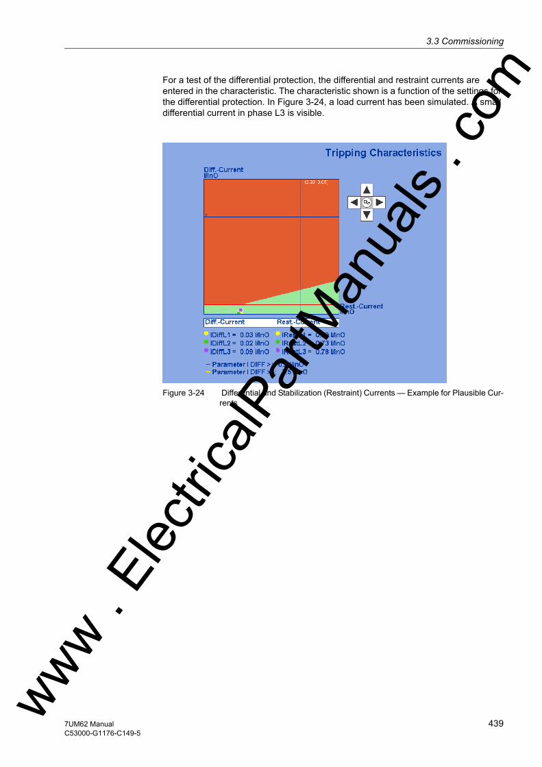
3.3 Commissioningw
For a test of the differential protection, the differential and restraint currents are entered in the characteristic. The characteristic shown is a function of the settings for the differential protection. In Figure 3-24, a load current has been simulated. A small differential current in phase L3 is visible.
Figure 3-24 Differential and Stabilization (Restraint) Currents — Example for Plausible Cur-rents
ww . El
ectric
alPar
tMan
uals
. com
4397UM62 ManualC53000-G1176-C149-5

3 Mounting and Commissioning
om
3.3.12 Checking the Current Circuits
General The checks of the current circuits are performed with the generator to ensure correct CT circuit connections with regard to cabling, polarity, phase sequence, CT ratio etc., not in order to verify individual protection functions in the device.
Preparation Switch unbalanced load protection (address 1701) and overload protection (address 1601) to Block. Relay. With the primary system voltage-free and earthed, install a three-pole short-circuit bridge which is capable of carrying rated current (e.g. earthing isolator) to the generator line-side terminals.
DANGER!Primary measurements may only be carried out with the generator at stand–still on disconnected and grounded equipment of the power system.
After the preparatory measures all current transformer circuits (protection, measuring, metering etc.) can be checked with the remanent excitation.
Test Instruction Then the checks of the current transformer circuits are carried out with max. 20 % of the rated transformer current. Tests with generator currents of more than 20 % are not normally required for digital protection. Operation of the generator at rated current during commissioning may only be necessary when the short-circuit characteristic is measured for the first time.
Amplitude Values The currents can be read out from the device front panel or from the PC via the oper-ator interface under operational measured values and compared with the actual mea-sured values. If significant deviations are found, the CT connections are not correct.
Phase Rotation The phase rotation must conform with the configured phase sequence (address 271 under Power System Data 1); otherwise an indication „Fail Ph. Seq.“ will be output. The allocation of measured values to phases must be checked and corrected, if necessary. The negative sequence component I2 of the currents can be read out under the operational measured values. It must be approximately zero. If this is not the case, check for crossed current transformer leads:
If the unbalanced load amounts to about 1/3 of the phase currents then current is flowing in only one or in only two of the phases.
If the unbalanced load amounts to about 2/3 of the phase currents, then one current transformer has wrong polarity.
If the unbalanced load is about the same as the phase currents, then two phases have been crossed.
After correcting the wrong connection, the test must be repeated.
Remove short circuit bridges.
ww . El
ectric
alPar
tMan
uals
. c
440 7UM62 ManualC53000-G1176-C149-5
w

3.3 Commissioningw
Calibrate the Im-pedance Protection
Switch impedance protection (address 3301) to IMPEDANCE PROT. = Block relay.
With the primary system voltage-free and earthed, install a three-pole short-circuit bridge which is capable of carrying rated current (e.g. earthing isolator) to the primary side of the unit transformer.
DANGER!Primary measurements may only be carried out with the generator at stand–still on disconnected and grounded equipment of the power system.
Start up machine slowly and excite to 20 % of rated machine current.
Test Instruction A test with about 20 % of the rated generator current is sufficient for checking the transformer connections and the operational measured values. If the relative short-circuit voltage of the transformer is small, the voltage values measured are very low, so that it may be necessary to increase the generator current somewhat. A test with the full rated generator current is only required for the quantitative calibration of the impedance protection (e.g. for calibrating the transformer uSC).
The protection device calculates from the currents and voltages the impedance between the point of installation of the voltage transformer set and the short-circuit po-sition, which is mainly established by the short-circuit impedance of the unit transform-er. Reactance and resistance values can be read out under operational measured values. For this the protection device automatically considers the rated device current 1 A or 5 A. In the present case for transformer impedance, the following results:
Primary transformer impedance:
with
uK - relative transformer short-circuit voltage
UN - Rated transformer voltage
SN - Rated transformer power
In secondary values:
with
NCTR - Current transformer ratio
NVTR - Voltage transf. transform. ratio
If substantial deviations or wrong sign occur, then the voltage transformer connections are incorrect. After shutdown and de-excitation of the generator, and removal of the short-circuit bridge, the short-circuit tests are completed. No further tests are re-quired for unbalanced load protection, overcurrent time protection, thermal overload protection, impedance protection and out-of-step protection. ww . El
ectric
alPar
tMan
uals
. com
4417UM62 ManualC53000-G1176-C149-5

3 Mounting and Commissioning
om
After shutdown and de-excitation of the generator, and removal of the short-circuit bridge, the short-circuit tests are completed. No further tests are required for unbal-anced load protection, overcurrent time protection, thermal overload protec-tion, impedance protection and out-of-step protection.
Activate the overcurrent time protection and the impedance protection (address 1201: O/C I> = ON or address 1401 O/C Ip = ON, address 3301: IMPEDANCE PROT. = ON) and it works immediately as a short-circuit protection for all subsequent tests. If used, address 1301 O/C I>> = ON, the thermal overload protection (address 1601: Ther. OVER LOAD = ON), the unbalanced load protection (address1701: UNBALANCE LOAD = ON) and the out-of-step protection (address 3501: OUT-OF-STEP = ON) can be activated. Otherwise, they are set to Off.
3.3.13 Checking the Differential Protection
Preparation Before commencing any primary tests, make sure that the configured object is actually the one you want to protect, and that the amplitude matching for the current ratings of the protected object and the main primary CTs, and the vector group matching are cor-rectly set.
Switch differential protection (address 2001) to Block relay or interrupt the tripping commands.
The test arrangement varies with the application.
On network power transformers and asynchronous machines a low-voltage test equip-ment is preferably used. A low-voltage current source is used to energize the protect-ed object, which is completely disconnected from the network (Figure 3-25). A short-circuit bridge, which is capable of carrying the test current, is installed outside the pro-tected zone and allows the symmetrical test current to flow.
For power station unit transformers and synchronous machines, the tests are per-formed during the current tests, with the generator itself supplying the test current (Figure 3-26). The current is produced by a short-circuit bridge which is installed outside the protected zone and is capable of carrying generator rated current for a short time. In such a case after the machine is started but not yet excited a check is made using remanence currents that no current transformer circuit is open or short-circuited. In order to achieve this, read out the operational measured values and check all operational currents one by one. Even if the currents and the measurement accu-racy are very small, the such errors can actually be detected.
The current for commissioning tests must be at least 2 % of the rated device current.
Figure 3-25 Current check with low-voltage current sourceww . El
ectric
alPar
tMan
uals
. c
442 7UM62 ManualC53000-G1176-C149-5
w

3.3 Commissioningw
Figure 3-26 Current Test in the Power Station
Symmetrical Current Test
The operational measured values supplied by the 7UM62 device allow a fast commis-sioning without external instruments. The indices of the measured currents are as fol-lows:
The symbol for current I is followed by the phase identifier Lx and by the index of the side of the protected object (e.g. the transformer winding). Example:
IL1S1 Current in phase L1 on side 1.
Absolute Value Measurement
Compare the current magnitudes under Measurement → Secondary Values → Op-erational values secondary with the actually flowing values:
IL1S1 =
IL2S1 =
IL3S1 =
IL1S2 =
IL2S2 =
IL3S2 =
If deviations occur that cannot be explained by measuring tolerances, either a connec-tion or the test setup is wrong: • Disconnect the protected object (shut down generator), and earth it,• Re-check the plant connections to the device and the test arrangement and correct
them.• Repeat measurement and recheck measured values.
Angle Measurement
If the current magnitudes are consistent, the next step is to check the phase angle re-lations between the currents (ϕIL1S1, ϕIL2S1, ϕIL3S1, ϕIL1S2, ϕIL2S2, ϕIL3S2). The angle differences are in each case referred to winding L1 of side 1.
Check the phase angle under Measurement → Secondary Values → Phase angles of side 1 of the protected object. All angles are referred to IL1S1.
Consequently, a clockwise phase rotation should produce roughly the following re-sults:
ϕL1S1 = 0°
ϕL2S1 = 240°
ϕL3S1 = 120°ww . El
ectric
alPar
tMan
uals
. com
4437UM62 ManualC53000-G1176-C149-5
3 Mounting and Commissioning
om
If the angles are not correct, wrong polarity or connection phase interchange at side 1 is the cause.• Disconnect the protected object (shut down generator), and earth it,• Re-check the plant connections to the device and the test arrangement and correct
them.• Repeat measurement and recheck measured values.
Check the phase angle under Measurement → Secondary Values → Phase angles of side 2 of the device. All angles are referred to IL1S1. If the angles are not correct, wrong polarity or line phase interchange at side 2 is the cause; proceed as for side 1.
The angles of the through-flowing currents between the different sides of the protec-tion object are defined such that a current of equal phase flowing through the protect-ed object, provided that the connections are correct, produces the angle difference at the two measuring points of 180° between currents of the same phase. Exception: With transverse differential protection, the currents of the corresponding phase must have equal phase!
The theoretical angles depend on the protected object and – in the case of transform-ers – on the vector group. They are listed in Table 3-29 for clockwise phase rotation.
The polarity of the CT connections and the parameterized polarity are taken into con-sideration for the angles displayed. Thus, if all three angles differ by 180° from the the-oretical value, the polarity of one complete transformer set is wrong.
This can be corrected by checking and changing the corresponding system parame-ters:
Address 201 STRPNT->OBJ S1 for primary winding,
Address 210 STRPNT->OBJ S2 for secondary winding
Table 3-29 Displayed phase angle dependent on the protected object (three phase)
1) Angles are valid if the high voltage side is defined as side 1, Otherwise read 360° minus the stated angle
Differential and Restraint Currents
Before the tests with symmetrical currents are terminated, the differential and restraint currents are examined. Even though the symmetrical tests which have been carried out so far should have revealed more or less all possible connection errors, matching errors or wrong vector group allocations cannot be ruled out.
Switch to the operational measured values to read out the calculated values. Note that differential and restraint values are referred to the rated current of the protected object. This must be considered when they are compared with the test currents.
If considerable differential currents occur, recheck the following parameters:
For transformer protection:
Addresses 241, 249 and 202 (matching winding 1), 243, 249 and 211 (matching and vector group winding 2);
Protected object → Generator/
motor
Transformer with Vector Group Numeral 1)
→ Power Angle 0 1 2 3 4 5 6 7 8 9 10 11
ϕL1S2 180° 180° 150° 120° 90° 60° 30° 0° 330° 300° 270° 240° 210°ϕL2S2 60° 60° 30° 0° 330° 300° 270° 240° 210° 180° 150° 120° 90°ϕL3S2 300° 300° 270° 240° 210° 180° 150° 120° 90° 60° 30° 0° 330°
ww . El
ectric
alPar
tMan
uals
. c
444 7UM62 ManualC53000-G1176-C149-5
w

3.3 Commissioningw
For generator or motor protection:
Addresses 251 and 252 (matching of machine ratings);
The symmetrical current tests are now completed. Disconnect the protected object (shut down generator) and earth it, remove the test setup.
Switch the differential protection to active (address 2001: DIFF. PROT. = ON) and it works immediately as a short-circuit protection for all subsequent tests.
3.3.14 Checking the Earth Current Differential Protection
Preparation The primary test checks correct integration into the system, especially the CT connec-tion. Before commencing any primary tests, make sure that the configured object is actually the one you want to protect. To do so, verify the settings used in the configu-ration of the protection function, Power System Data 1 and in the protection function itself.
Before test commencement set the earth current differential protection (address2101 REF PROT.) to Block relay, or interrupt the trip command lines.
Primary tests of power units are performed with the generator itself. On transformers, a low-voltage test source is used.
Before the test, the CT connections have to be visually checked for correctness.
Note
When performing the short-circuit test (3-phase short-circuit) for the earth current dif-ferential protection, check that the three current transformers (side 1 or side 2 – which-ever side is used for the earth current differential protection) are identical in design. To do so, read out the percentages of the operational measured values 3I0-1 and 3I0-2 (in DIGSI under Differential Protection Measured Values). If the CTs are well matched, the values must be zero. Values that are not zero must be taken into account for the protection settings.
ww . El
ectric
alPar
tMan
uals
. com
4457UM62 ManualC53000-G1176-C149-5

3 Mounting and Commissioning
om
Primary Test with Generator
This test is performed in addition to the current test. For this the protection must be set to maximum sensitivity. Zero voltage enabling must be blocked (address 2103 REF U0>RELEASE = 0).
For the test, one phase is earthed and the generator is excited (see the following Fig-ure). The test current may not exceed the admissible negative-sequence current. If this current amounts e.g. to I2adm. = 10 % IN,G, the test current must be less than 30 % I IN,G. On the other hand, the current is determined by the low-resistance starpoint earthing. 10 % of the rated generator current is sufficient for testing.
Figure 3-27 Testing the Earth Current Differential Protection on the Generator
For the external fault, the percentages of the operational measured values are (on the device: Measurement → I-Diff, I-Stab) to be read out:
3I0-1 Calculated zero sequence current of side 1
3I0-2 calculated zero sequence current of side 2 or mea-sured earth current IEE2 (depending on configuration)
I0-Diff calculated differential current
I0-Stab calculated restraint (stabilizing) current
Both zero component currents 3I0-1 and 3I0-2 must be equal and correspond to the injected current. The differential current I0-Diff is almost zero. The restraint (stabi-lising) current I0-Stab is twice the flowing current. If the differential and the restraint current are equal, the polarity of one CT must be wrong. Minor deviations are caused by CT errors.
If there are deviations, a connection error can be normally assumed. If necessary modify the wiring, or in Power System Data 1, the allocation of the CT starpoint for the phase CTs or the earth CT IEE2. For the phase CTs, keep in mind that they are also used by other protection functions, such as the differential current protection. Feed-back effects should be examined. If the differential current protection has already been checked, and the CTs of side 1 and 2 are used for the earth current differential protec-tion, the above errors can be excluded. If the IEE2 input is used, a wrong polarity of the connections is not uncommon. Check the connection and/or the starpoint allocation in Power System Data 1 (address 214 GRD TERM. IEE2). The default setting assumes that terminal 7 is looking towards the protected object. If there are deviations in the measured values, the measured quantities are probably not properly matched. Check the parameter settings of the protected object and of the CTs in Power System Data 1. The default setting assumes that terminal 7 is looking towards the protected object.
If there are deviations in the measured values, the measured quantities are probably not properly matched. Check the parameter settings of the protected object and of the CTs in Power System Data 1. ww .
Elec
tricalP
artM
anua
ls . c
446 7UM62 ManualC53000-G1176-C149-5
w

3.3 Commissioningw
Proceed as follows:• Shut down and earth generator• Check and correct connections, if necessary, or modify settings in Power System
Data 1• Repeat measurement
If the earth current differential protection is used on a transformer, a comparative test is performed (see Figure 3-26). The measured value 3I0-1 is allocated to side 1 and 3I0-2 to the earth currrent IEE2. The test method is similar to the one described above. For the test current, it is essential to ensure that on the generator side the continuously admissible unbalanced load current is not exceeded. With a wye-delta connection, the single-phase fault is modeled on the generator side as a phase to phase fault.
Figure 3-28 Testing the Earth Current Differential Protection on the Transformer
Test with Second-ary Test Equipment
Measurements are always performed from the side with the earthed starpoint. In trans-formers, there must be a delta winding (d-winding or compensating winding). The side which is not included in the tests remains open as the delta winding ensures low-ohmic termination of the current path.
The test setup varies dependent of the application. Figures 3-29 to 3-32 show sche-matically examples of the test setup, with Figure 3-29 mainly for generator protection applications.
DANGER!Primary measurements must only be carried out on disconnected and earthed equip-ment of the power system! Perilous voltages may occur even on voltage-free plant sections due to capacitive influence caused by other live sections.
ww . El
ectric
alPar
tMan
uals
. com
4477UM62 ManualC53000-G1176-C149-5

3 Mounting and Commissioning
om
Figure 3-29 Zero Sequence Current Measurement on a Star-Delta Transformer
Figure 3-30 Zero Sequence Current Measurement on a Star-Star Transformer with Com-pensation Winding
Figure 3-31 Zero Sequence Current Measurement on a Zig-Zag-Winding
ww . El
ectric
alPar
tMan
uals
. c
448 7UM62 ManualC53000-G1176-C149-5
w

3.3 Commissioningw
Figure 3-32 Zero Sequence Current Measurement on a Delta Winding with Artificial Star-point
A zero sequence current of at least 2 % the rated generator current is required for tests per phase, i.e. the test current is at least 6 %.
In the protection function, the sensitive pickup threshold must be set, and the zero voltage release disabled.• Switch on test current• Amplitude measurement with switched on test current
In the device at: Measurement → I-Diff, I-Stab) read out the measured values:
3I0-1 calculated zero sequence current of side 1 or side 2 (depending on configuration)
3I0-2 measured earth current IEE2
I0-Diff calculated differential current
I0-Rest calculated restraint (stabilizing) current
Both zero component currents 3I0-1 and 3I0-2 must be equal and correspond to the injected current. The differential current I0-Diff is almost zero. The restraint (stabi-lising) current I0-Stab is twice the flowing current. If the differential and the restraint current are equal, the polarity of one CT must be wrong. Minor deviations are caused by CT errors.
When checking the phase CTs of the allocated side, the measured values correspond (device: Measurement → Operational values, secondary) per phase will each be 1/3 of the injected zero sequence current. The phase angle is the same in all 3 phases due to the zero sequence current.
If there are deviations, a connection errors can be normally assumed (see margin title „Primary test with generator“)• Disconnect test source and protected object• Check and correct connections and test setup• Repeat measurement
ww . El
ectric
alPar
tMan
uals
. com
4497UM62 ManualC53000-G1176-C149-5

3 Mounting and Commissioning
om
Checking the Zero Voltage Enabling
If the zero voltage enabling is used, it must be checked during the test of the stator earth fault protection. In the presence of an earth fault, the indication 5841 „REF U0> releas.“ must appear. When performing the test, keep in mind that the zero voltage is calculated from the three phase voltages and converted on the secondary side to the phase-to-phase voltage (equivalent to √3 U0). The value thus obtained is the same as for a broken delta winding.
Blocking by Overcurrent
If the above measurement have been successfully performed, and the measured phase currents were plausible, it can be assumed that the current measurement works correctly. You only need to check the correct setting in the protection function (address 2102 = REF I> BLOCK).
The pickup values are checked by injecting a current using secondary test equipment (CTs need not be disconnected).• After completion of the tests, disconnect the test source and the protected object
(shut down generator)• If parameter settings have been changed for the tests, reset them to the values nec-
essary for operation. • After completion of the earth fault protection tests, activate the earth current differ-
ential protection.
3.3.15 Checking the Voltage Circuits
General The voltage circuits of the machine are checked to ensure the correct cabling, polarity, phase sequence, transformer ratio etc. of the voltage transformers - not to check indi-vidual protection functions of the device.
Earthing of the Voltage Transform-ers
When checking the voltage transformers, particular attention should be paid to the broken delta windings because these windings may only be earthed in one phase.
Preparation Set the overvoltage protection function to about 110 % of the rated generator voltage with trip on excitation.
Switch frequency protection (address 4201) and overexcitation protection (address 4301) to Block relay.
Check in the unexcited condition of the machine with the help of remanent voltages, that all short-circuit bridges are removed.
Test Instruction The checks of all voltage transformer circuits (protection, measuring, metering etc.) are carried out with about 30 % of the rated transformer voltage. Tests with generator voltages of more than 30 % rated voltage are only required when the idle characteristic is measured for the first time.
The measuring circuit supervision of the rotor earth fault protection (see below) can be checked when testing the voltage circuits, or after the synchronization.
Amplitudes Read out voltages in all three phases in the operational measured values and compare with the actual voltages. The voltage of the positive sequence system U1 must be approximately the same as the indicated phase voltages. If there are signifi-cant deviations, the voltage transformer connections are incorrect.ww .
Elec
tricalP
artM
anua
ls . c
450 7UM62 ManualC53000-G1176-C149-5
w

3.3 Commissioningw
Phase Rotation The phase rotation must conform with the configured phase sequence (address 271 PHASE SEQ. under Power System Data 1); otherwise an indication „Fail Ph. Seq.“ will be output. The allocation of measured values to phases must be checked and corrected, if necessary. If significant deviations are found, check, and if necessary correct, the voltage transformer circuits and repeat the test. It is also possible to use for this check the operational measured value of positive-sequence component U1 of the voltages: With U1 ≠ UL-E a wiring error is indicated.
Measuring Circuit Supervision of the Rotor Earth Fault Protection
If the sensitive earth fault protection is used for rotor earth fault protection, the mea-suring circuit supervision of that protection function can be checked with the generator under voltage:• Start up the generator and excite it to rated voltage. Apply measurement brushes if
necessary. Inject a test voltage between the rotor circuit and the earth by interpos-ing the additional source device 7XR61. The earth current IEE that is flowing now can be read out on the device under the earth fault measured values. The value ob-tained is the capacitive spill current flowing in fault-free operation.
• IEE< (address 5106) should be set to about 50 % of this capacitive spill current. It should also be checked that the set value IEE> (address 5102) is at least twice this measured spill current. Correct the set value if necessary.
Frequency The frequency protection function is verified by a plausibility check of the instanta-neous machine speed and the operational measured value indicated.
Overexcitation The frequency protection function is verified by a plausibility check of the instanta-neous machine speed and the operational measured value indicated.
The voltage tests are completed after the generator has been shut down. The required voltage and frequency protection functions are activated (address 4001: UNDERVOLTAGE = ON or OFF, address 4101: OVERVOLTAGE = ON or OFF, address 4201: O/U FREQUENCY = ON or OFF, address 4301: OVEREXC. PROT. = ON or OFF). Partial functions can be disabled by appropriate limit value settings (e.g. frequency f* set to f Nom).
ww . El
ectric
alPar
tMan
uals
. com
4517UM62 ManualC53000-G1176-C149-5

3 Mounting and Commissioning
om
3.3.16 Checking the Stator Earth Fault Protection
General The procedure for checking the stator earth fault protection depends mainly on whether the generator is connected to the network in unit connection or in busbar con-nection. In both cases correct functioning and protected zone must be checked.
In order to check interference suppression of the loading resistor, and in order to verify the protected zone of the earth fault protection, it is appropriate to test once with an earth fault at the machine terminals (e.g. with 20 % of the rated transformer voltage) and once with a network earth fault.
Unit Connection In the event of an external (high-voltage side) short-circuit, an interference voltage is transmitted via the coupling capacitance CK which induces a displacement voltage on the generator side. To ensure that this voltage is not interpreted by the protection as an earth fault within the generator, it is reduced by a suitable loading resistor RL to a value which corresponds to approximately one half the pick-up voltage U0> (address 5002). On the other hand, the earth fault current resulting from the loading resistor in the event of an earth fault at the generator terminals should not exceed 10 A, if possi-ble.
Figure 3-33 Unit Connection with Earthing Transformer
Calculation of Protected Zone
Coupling capacitance CC and loading resistor RB represent a voltage divider, whereby RB is the resistance RB referred to the machine terminal circuit.
Figure 3-34 Equivalent Diagram and Vector Diagramww . El
ectric
alPar
tMan
uals
. c
452 7UM62 ManualC53000-G1176-C149-5
w
3.3 Commissioningw
Since the reactance of the coupling capacitance is much larger than the referred re-sistance of the loading resistor RB', UC can be assumed to be UNO/√3 (compare also vector diagram Figure 3-34), where UNO/√3 is the neutral displacement voltage with a full displacement of the network (upper-voltage) neutral. The following applies:
With the voltage transformation ratio TR of the earthing transformer:
we obtain:
Together with the voltage divider RT 500 V/100 V this corresponds to a displacement voltage at the input of the device of:
The pickup value U0> for the neutral displacement voltage should amount to at least twice the value of this interference voltage.
Example:
10 V has been chosen as the setting value for 5002 in address U0> which corre-sponds to a protective zone of 90% (see the following Figure).
Note
For use as a neutral transformer the voltage transformation ratio TR instead of TR/3 should be used. As this has only one winding, the result is the same.
Network UNO = 110 kVfNom = 50 HzCC = 0.01 µF
Voltage transform-er
10 kV / 0.1 kV
Earthing transform-er
TR = 36
Loading resistance RB = 10 Ω
ww . El
ectric
alPar
tMan
uals
. com
4537UM62 ManualC53000-G1176-C149-5

3 Mounting and Commissioning
om
Figure 3-35 Displacement voltage during earth faults
Checking for Generator Earth Fault
Switch rotor earth fault protection S/E/F PROT. (address 5001) to Block relay. If the sensitive earth fault detection is used for stator earth fault protection, switch it to Block relay also under address 5101.
With the primary equipment disconnected and earthed, insert a single-pole earth fault bridge in the generator terminal circuit.
DANGER!Primary measurements may only be carried out with the generator at stand–still on disconnected and grounded equipment of the power system.
Start generator and slowly excite to about 20 % UN.
Read out UE from the operational measured values and check for plausibility.
If the plant has more voltage transformers with broken delta windings, the voltage UE must be measured on them as well.
For protection zone Z the following applies:
Example:
Machine voltage at pick-up 0.1 x Usec N
Measured value UE = 10 V
Setting value U0> = 10 V
Protected zone Z = 90 %
When reading the fault log buffer „U Earth Lx“ „Lx“ indicates the faulted phase pro-vided voltages are connected to the voltage protection inputs of the device.
Shut down generator. Remove earth fault bridge.
Check in Case of a Network Earth Fault
With the primary plant voltage-free and earthed, install a single-pole earth fault bridge on the high voltage side of the unit transformer.ww .
Elec
tricalP
artM
anua
ls . c
454 7UM62 ManualC53000-G1176-C149-5
w
3.3 Commissioningw
DANGER!Primary measurements may only be carried out with the generator at stand–still on disconnected and grounded equipment of the power system.
Caution!Possible starpoint earthing at transformer with simultaneous earthing on high voltage side during test!
Nonobservance of the following procedures can result in minor injury or material damage.
The starpoints of the unit transformer must be disconnected from earth during this test!
Start up machine and slowly excite to 30 % of rated machine voltage.
Read out under operational measured values: UE This value is extrapolated to rated machine voltage (Figure 3-35). The fault value thus calculated should correspond, at the most, to half the pickup value U0> (address 5002), in order to achieve the desired safety margin.
Shut down and de-excite the generator. Remove earth fault bridge.
If the starpoint of the high-voltage side of the unit transformer is to be earthed during normal operation, re-establish starpoint earthing.
Activate the stator earth fault protection: set address 5001 S/E/F PROT. to ON. If the sensitive earth fault detection is used for stator earth fault protection, activate it as well: set address 5101 O/C PROT. IEE to ON.
Busbar Connection Firstly, the correct functioning and data of the loading equipment must be checked: se-quencing, time limit, etc., as well as the plant data: Earthing transformer and the value of the load resistor (tapping).
Switch rotor earth fault protection (address 5001) to Block relay. If the sensitive earth fault detection is used for stator earth fault protection, switch it to Block relay also under address 5101.
With the primary plant earthed and voltage-free, install a single pole earth fault bridge between generator terminals and toroidal current transformer (see the following Fig-ure).
DANGER!Primary measurements may only be carried out with the generator at stand–still on disconnected and grounded equipment of the power system.
ww . El
ectric
alPar
tMan
uals
. com
4557UM62 ManualC53000-G1176-C149-5

3 Mounting and Commissioning
om
Figure 3-36 Earth Fault with Busbar Connection
For this test connections must be such that the generator is galvanically connected with the load equipment. If the plant conditions do not allow this, the hints given over-leaf under the side title „Directional check without Loading Resistor“ must be ob-served.
Start up generator and slowly excite until the stator earth fault protection picks up: In-dication „U0> picked up“ (not allocated when delivered from factory). At the same time the indication „3I0> picked up“ should appear (not allocated when delivered from factory).
Read out operational measured values UE and IEE2. If the connections are correct, this value corresponds to the machine terminal voltage percentage, referred to rated machine voltage (if applicable, deviating rated primary voltage of earthing transformer or neutral earthing transformer must be taken into account). This value also corre-sponds to the setting value U0> in address 5002.
The measured value IEE2 should be approximately equal to or slightly higher than the setting value 3I0> under address 5003. This is to ensure that the protection zone that is determined by the setting value U0> is not reduced by a too slow pick-up.
For protection zone Z the following applies:
ww . El
ectric
alPar
tMan
uals
. c
456 7UM62 ManualC53000-G1176-C149-5
w

3.3 Commissioningw
Example:
Machine voltage at pick-up 0.1 x UN
Measured value UE = 10 V
Setting value U0> = 10 V
Protected zone Z = 90 %
With Directional Determination
The earth fault directional determination requires a check of the current and voltage connections for correctness and correct polarity. The machine is excited to a voltage that corresponds to a displacement voltage above the pickup value. If the polarity is correct, the trip indication „S/E/F TRIP“ is output (LED 6 when delivered from fac-tory).
A cross check is then performed. After the generator has been de-excited and shut down, the earth fault bridge is installed on the other side of the current transformers (as viewed from the machine).
DANGER!Primary measurements may only be carried out with the generator at stand–still on disconnected and grounded equipment of the power system.
After restarting and exciting the generator above the pickup value of the displacement voltage, „U0> picked up“ picks up (LED 2 for group indication of a device pickup when delivered from factory), however the „3I0> picked up“ indication does not appear and tripping does not occur. The measured value IEE should be negligible and on no account at nominal excitation should it be larger then half the setting value 3I0>.
Shut down and de-excite the generator. Remove earth fault bridge.
ww . El
ectric
alPar
tMan
uals
. com
4577UM62 ManualC53000-G1176-C149-5
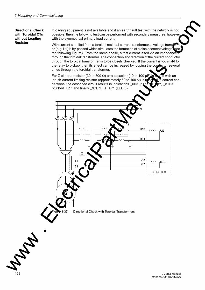
3 Mounting and Commissioning
om
Directional Check with Toroidal CTs without Loading Resistor
If loading equipment is not available and if an earth fault test with the network is not possible, then the following test can be performed with secondary measures, however with the symmetrical primary load current:
With current supplied from a toroidal residual current transformer, a voltage transform-er (e.g. L1) is by-passed which simulates the formation of a displacement voltage (see the following Figure). From the same phase, a test current is fed via an impedance Z through the toroidal transformer. The connection and direction of the current conductor through the toroidal transformer is to be closely checked. If the current is too small for the relay to pickup, then its effect can be increased by looping the conductor several times through the toroidal transformer.
For Z either a resistor (30 to 500 Ω) or a capacitor (10 to 100 µF) in series with an inrush-current-limiting resistor (approximately 50 to 100 Ω) is used. With correct con-nections, the described circuit results in indications „U0> picked up“, „3I0> picked up“ and finally „S/E/F TRIP“ (LED 6).
Figure 3-37 Directional Check with Toroidal Transformers
ww . El
ectric
alPar
tMan
uals
. c
458 7UM62 ManualC53000-G1176-C149-5
w
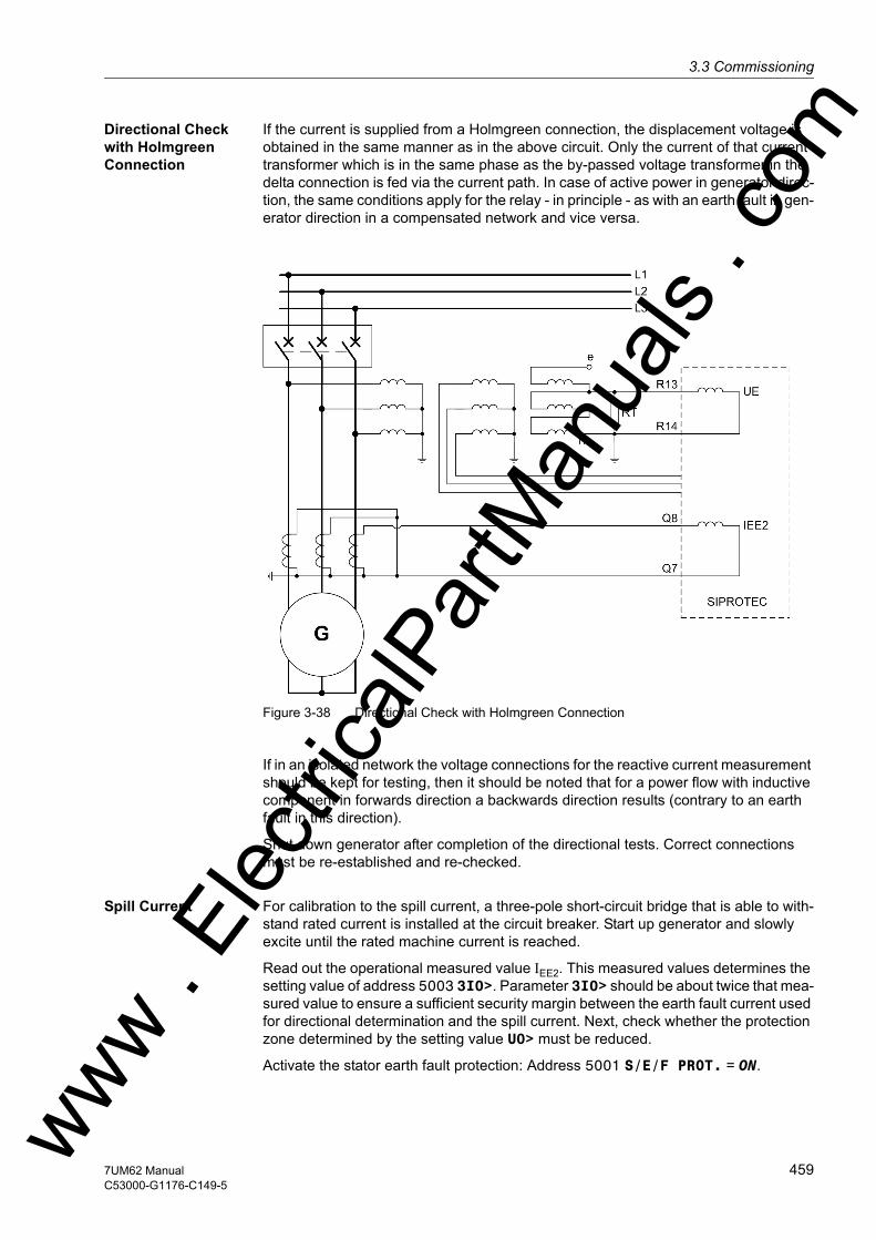
3.3 Commissioningw
Directional Check with Holmgreen Connection
If the current is supplied from a Holmgreen connection, the displacement voltage is obtained in the same manner as in the above circuit. Only the current of that current transformer which is in the same phase as the by-passed voltage transformer in the delta connection is fed via the current path. In case of active power in generator direc-tion, the same conditions apply for the relay - in principle - as with an earth fault in gen-erator direction in a compensated network and vice versa.
Figure 3-38 Directional Check with Holmgreen Connection
If in an isolated network the voltage connections for the reactive current measurement should be kept for testing, then it should be noted that for a power flow with inductive component in forwards direction a backwards direction results (contrary to an earth fault in this direction).
Shut down generator after completion of the directional tests. Correct connections must be re-established and re-checked.
Spill Current For calibration to the spill current, a three-pole short-circuit bridge that is able to with-stand rated current is installed at the circuit breaker. Start up generator and slowly excite until the rated machine current is reached.
Read out the operational measured value IEE2. This measured values determines the setting value of address 5003 3I0>. Parameter 3I0> should be about twice that mea-sured value to ensure a sufficient security margin between the earth fault current used for directional determination and the spill current. Next, check whether the protection zone determined by the setting value U0> must be reduced.
Activate the stator earth fault protection: Address 5001 S/E/F PROT. = ON. ww . El
ectric
alPar
tMan
uals
. com
4597UM62 ManualC53000-G1176-C149-5

3 Mounting and Commissioning
om
3.3.17 Checking the 100 % Stator Earth Fault Protection
General The 100% stator earth fault connection is tested together with the 90% stator earth fault protection.
Set the 100% stator earth fault protection (address 5301 100% SEF-PROT.) to Block relay (if not done so already). Also, the accessories of the protection device must be operational.
The tests to be performed are described in more detail below.
Check without Earth Fault
Start up the generator and excite it to maximum generator voltage. The protection does not pick up.
The operational measured values need to be checked as well. Read out the rms current I SEF. The fault value thus calculated should correspond at most to half the pickup value SEF I>> (address 5306), in order to achieve the desired safety margin.
Shut down generator.
Check Performed with an Earth Fault in the Machine Zone
Connect the 20 Hz generator 7XT33 to the DC voltage or to an external three-phase voltage source.
With the primary equipment disconnected and earthed, insert a single-pole earth fault bridge in the generator terminal circuit.
DANGER!Primary measurements may only be carried out with the generator at stand–still on disconnected and grounded equipment of the power system.
Start up the generator and excite it slowly (but under UN/√3) until the 90% earth fault protection (Pickup threshold U0>) has picked up.
With the earth fault bridge in place, the resistance stages of the 100% protection (warning and trip stage) must pick up immediately on switching in the supply voltage of the 20 Hz generator.
To check the pickup behaviour of the current stage SEF I>>, read out the measured value I SEF from the operational measured values at approx. 10 % to 20 % of the displacement voltage. The value thus obtained should be about the same as the pickup value SEF I>> selected at address 5306. This ensures that the current stage of the 100% stator earth fault protection covers a protection zone of about 80 % to 90 % of the winding in addition to the 100 % resistance calculation.
ww . El
ectric
alPar
tMan
uals
. c
460 7UM62 ManualC53000-G1176-C149-5
w

3.3 Commissioningw
Check in Case of a Network Earth Fault
With the primary plant voltage-free and earthed, install a single-pole earth fault bridge on the high voltage side of the unit transformer.
DANGER!Primary measurements may only be carried out with the generator at stand–still on disconnected and grounded equipment of the power system.
Caution!Possible starpoint earthing at transformer with simultaneous earthing on high voltage side during test!
Nonobservance of the following procedures can result in minor injury or material damage.
The starpoints of the unit transformer must be disconnected from earth during this test!
Start up the generator and slowly excite to 30 % of rated machine voltage (max. 60 %).
The 100 % and 90 % stator earth fault protection does not pick up.
The checks to be performed for the 90% stator earth fault protection are described under margin title „Check Using Network Earth Fault“ in the previous section.
For the 100-% stator earth fault protection, read out the operational measured value I SEF. This value is extrapolated to approx. 1.3 times the rated machine voltage. The current thus extrapolated should not exceed half the pickup value SEF I>> (address 5306) in order to achieve the desired safety margin of the current stage of the 100% stator earth fault protection.
Shut down and de-excite the generator. Remove earth fault bridge.
If the starpoint of the high-voltage side of the unit transformer is to be earthed during normal operation, now reestablish starpoint earthing.
If the 20 Hz generator is to be fed by the voltage transformers of the machine termi-nals, this or a different type of supply connection (e.g. DC voltage supply from a bat-tery) must permanently be established.
If no more special tests are to be made, activate the 100% stator earth fault protection: set address 5301 100% SEF-PROT. to ON.
ww . El
ectric
alPar
tMan
uals
. com
4617UM62 ManualC53000-G1176-C149-5
3 Mounting and Commissioning
om
3.3.18 Checking the Sensitive Earth Fault Protection when Used for Rotor Earth Fault Protection
If the sensitive earth fault protection is used for rotor earth fault protection, it must first be set to 5101 under address O/C PROT. IEE Block relay.
Caution!A rotor circuit not isolated from earth can result in a double fault in conjunction with an earth resistor inserted for checking purposes!
Nonobservance of the following procedures can result in minor injury or material damage.
Make sure that the checked rotor circuit is completed isolated from the earth, to avoid that the earthing resistor that is interposed for test purposes causes a double earth fault!
An earth fault is simulated via a resistor which is roughly equivalent to the desired trip resistance. In generators with rotating rectifier excitation, the resistor is placed between the two measurement slip rings; in generators with excitation via slip rings between one slip ring and earth.
Start up generator and excite to rated voltage. If applicable place measurement brushes into operation. It is irrelevant in this context whether the sensitive earth fault protection picks up or not. The earth current IEE that is flowing now can be read out on the device under the operational measured values.
Check that this measured earth fault current is roughly equal to the pickup value 5102 for sensitive earth fault detection that has been set in address IEE>. However it must not be set to less than double the value of the spill current that has been determined for healthy insulation.
For generators with excitation via slip rings, the test is repeated for the other slip ring.
Shut down generator. Remove earth fault resistor.
The sensitive earth fault detection used for rotor earth fault protection is then activat-ed: O/C PROT. IEE = ON in address 5101.
ww . El
ectric
alPar
tMan
uals
. c
462 7UM62 ManualC53000-G1176-C149-5
w

3.3 Commissioningw
3.3.19 Checking the Rotor Earth Fault Protection During Operation
Rotor Earth Fault Protection (R, fn)
In Section 3.3, the rotor earth fault protection with earth resistance measurement was checked with the machine at standstill. In order to exclude possible interference on the measurement circuit by the running generator, an additional test during operation is recommended.
Caution!A rotor circuit not isolated from earth can result in a double fault in conjunction with an earth resistor inserted for checking purposes!
Nonobservance of the following procedures can result in minor injury or material damage.
Make sure that the checked rotor circuit is completed isolated from the earth, to avoid that the earthing resistor that is interposed for test purposes causes a double earth fault!
An earth fault is simulated via a resistor of approximately 90% of the trip resistance (RE<< TRIP, address 6003). In machines with rotating rectifier excitation, the resistor is placed between the measurement slip rings; in machines with excitation via slip rings between one slip ring and earth.
Start up generator and excite to rated voltage. If applicable place measurement brushes into operation.
The rotor earth fault protection initiates pickup and, after T-TRIP-RE<< (10 s when delivered from factory), trip indication (LED 2 and LED 1 as group indications for device pickup and device trip).
The earth resistance calculated by the device can be read out in the earth fault annun-ciations as „Re =“.
For generators with excitation via slip rings, the test is repeated for the other slip ring.
Shut down generator. Remove earth fault resistor.
Activate the rotor earth fault protection: ROTOR E/F = ON in address 6001.
Rotor Earth Fault Protection (1 to 3 Hz)
In Section 3.3, the rotor earth fault protection was checked with the machine at stand-still. In order to exclude possible interference on the measurement circuit by the running generator, and specifically by the excitation system, an additional test during operation is recommended.
Caution!A rotor circuit not isolated from earth can result in a double fault in conjunction with an earth resistor inserted for checking purposes!
Nonobservance of the following procedures can result in minor injury or material damage.
Make sure that the checked rotor circuit is completed isolated from the earth, to avoid that the earthing resistor that is interposed for test purposes causes a double earth fault! ww . El
ectric
alPar
tMan
uals
. com
4637UM62 ManualC53000-G1176-C149-5
3 Mounting and Commissioning
om
An earth fault is simulated via a resistor of approximately 90% of the trip resistance (6103, address RE<< TRIP). In machines with rotating rectifier excitation, the resistor is placed between the measurement slip rings; in machines with excitation via slip rings between one slip ring and earth.
Start up the generator and excite to the rated voltage. If applicable place measurement brushes into operation.
Check the operational measured value Rearth and the pickup indication („REF 1-3Hz Fault“) and, after T-TRIP-RE<< (10 s on delivery) has expired, check the trip indication („REF 1-3Hz Trip“).
Set the resistance to approx. 90 % of the warning stage (address 6102 RE< WARN), read out the operational measured value „Re =“, and check the warning message („REF 1-3Hz Warn“). If there is heavy interference from the excitation system, it may be necessary to reduce the resistance set for the warning threshold.
Remove the earthing resistor and check the operational measured values as well as the measuring circuit supervision „REF 1-3Hz open“ under fault-free conditions. If spontaneous indications are issued by the measuring circuit monitoring, reduce the pickup value (address 6106 Qc <) or deactivate the monitoring.
For generators with excitation via slip rings, the test is repeated for the other slip ring.
Shut down generator. Remove earth fault resistor.
Activate the rotor earth fault protection: REF 1-3Hz = ON in address 6101.
ww . El
ectric
alPar
tMan
uals
. c
464 7UM62 ManualC53000-G1176-C149-5
w
3.3 Commissioningw
3.3.20 Checking the Interturn Fault Protection
Switch the interturn fault protection (address 5501) to Block relay.
Asymmetries in the stator windings impair the sensitivity of the protection. The two-pole fault is particularly critical in this context.
Caution!Even fault currents which are significantly smaller than the nominal current can ther-mally endanger the generator due to the unbalanced load (negative sequence cur-rent)!
First, the maximum fault current has to be determined.
If the generator is excited using nominal current, the following negative sequence cur-rents are obtained as a result:
Single-phase short-circuit Two-phase short-circuit
100/3 = 33,3 % 100/√3 = 57,7 %
If, for instance, the permanently admissible unbalanced load current is 11 %, the fol-lowing generator currents must not be exceeded:
Single-phase short circuit Two-phase short-circuit
11 %/33,3 % · ING = 0.33 ING 11 %/57,7 % · ING = 0.19 ING
selected 0.3 ING selected 0.17 ING
The same percentages apply to the excitation current.
Install a two-phase short-circuit bridge, which is capable of carrying the applicable short-circuit, at the generator terminals.
DANGER!Primary measurements may only be carried out with the generator at standstill on dis-connected and grounded equipment of the power system.
Run up machine until it has reached permissible excitation and measure the excitation current and the displacement voltage at the device under the operational measured values.
Shut down the generator. Remove short-circuit bridge.
The measured displacement voltage has to be extrapolated to the nominal excitation current to make sure that the function does not pick up erroneously on external short-circuits. The function is then set to at least twice the fault value at nominal excitation.
If the field forcing current is known, the fault voltage has to be extrapolated to this value. The protection is then set to 1.5 times the fault value.
To find out how sensitive the protection is, determine the content of the protected phase winding at no-load excitation. Insert a single-pole short-circuit between a con-ductor and the starpoint to this end.ww . El
ectric
alPar
tMan
uals
. com
4657UM62 ManualC53000-G1176-C149-5
3 Mounting and Commissioning
om
DANGER!Primary measurements may only be carried out with the generator at standstill on dis-connected and earthed equipment of the power system.Adjust the excitation to „manual“ mode.
Run up the generator, but not higher than the excitation at which the above calculated unbalanced load (for single-pole fault) is not exceeded. Read the measured displace-ment voltage out of the operational measured values.
Shut down the generator. Remove short-circuit bridge.
Extrapolate the measured voltage to the value at no-load excitation. The percentage of the protected winding area can be derived from this value.
We assume that Uinterturn voltage increases linearly with the number of short-circuited turns. Actually, the voltage increase of an interturn fault with only a few turns is rather high, i.e. the protection is more sensitive than calculated. To simplify matters, the linear approach was used.
After the test is completed, activate the interturn fault protection by setting address 5501 to INTERTURN PROT = ON.
ww . El
ectric
alPar
tMan
uals
. c
466 7UM62 ManualC53000-G1176-C149-5
w

3.3 Commissioningw
3.3.21 Tests with the Network
Note
Since the protective function adjusts the scanning frequency, the test requires that a nominal-frequency phase-to-earth voltage (e.g. UL1) is injected at least at one voltage input.
Checking the Correct Connection Polarity
The following test instructions apply to a synchronous generator.
Start up generator and synchronize with network. Slowly increase driving power input (up to approximately 5%).
The active power is read out under the operational measured values (percent values) as a positive active power P in percent of the rated apparent power SN.
If a negative power value is to be displayed, direction allocation between the CT set of side 2 and the voltage transformer set does not correspond with the configuration under address 210 (STRPNT->OBJ S2: YES/NO), or configuration of address 1108 ACTIVE POWER = Generator or Motor) is not properly selected. Address 210 is to be reconfigured, as the case may be.
If the power continues being incorrect, there must be an error in the transformer wiring (e.g. cyclical phase swap): • Remedy faults of the transformer lines (current and/or voltage transformers); ob-
serving for this the safety rules,• Repeat test.
Measurement of Motoring Power and Angle Error Correction
Leave the reverse power protection (address 3101) and the forward active power su-pervision (address 3201) switched to Off. For motors this and the following measure-ments are not required.
Independent of the excitation current of the generator, i.e. of the reactive power Q, the motoring power is – as an active power – practically constant. However, the protection device may detect and display different motoring power values because of possible angle errors of the current and voltage transformers. The motoring power/reactive power curve then would not be a straight line parallel with the real power axis of the machine power diagram. Therefore, the angle deviations should be measured at three measuring points and the correction parameter W0 established. The angle errors caused by the device internal input transformers have already been compensated in the factory. This check is recommended if the reverse power protection is set to sen-sitive.
Reduce driving power to zero by closing the regulating valves. The generator now takes motoring energy from the network.
ww . El
ectric
alPar
tMan
uals
. com
4677UM62 ManualC53000-G1176-C149-5

3 Mounting and Commissioning
om
Caution!Overheating on input of reverse power by the generatorOperating the turbine without a minimum steam throughput (cooling effect) can cause the turbine blades to overheat!
Input of reverse power is admissible with a turboset only for a short period.
Caution!Under-excitation may cause the generator to fall out of step!
Nonobservance of the following procedures can result in minor injury or material damage.
Operation with underexcitation is admissible only for a short period
Proceed as follows:1. Adjust excitation until the reactive power amounts to approximately Q = 0. To
check this, read out the active power with sign (negative) in the operational mea-sured values and note it down as P0 (see table below). Read out the reactive power with sign in the operational measured values and note it down as Q0 (see table below).
2. Slowly increase excitation to 30% of rated apparent power of generator (overex-cited). – Read out the motoring power with polarity (negative sign) in the operational
measured values and note it down as P1 (see table below).
– Read out the reactive power Q1 with polarity (positive sign) and write it down.
3. Reduce excitation slowly to approximately 30% rated apparent power of generator (underexcited).– Read out the motoring power P2 with polarity (negative sign) in the operational
measured values under and write it down (see table below).
– Read out the reactive power Q2 with polarity (negative sign) in the operational measured values and write it down (see table below).
4. Adjust generator to no-load excitation and shut it down or select the desired oper-ational state.
Figure 3-39 Determination of the Correction Angle W0
ww . El
ectric
alPar
tMan
uals
. c
468 7UM62 ManualC53000-G1176-C149-5
w

3.3 Commissioningw
The read-out measured values P1, and P2 are now used to carry out CT angle error correction. First calculate a correction angle from the measured value pairs according to the following formula:
The power values must be inserted with their correct polarity as read out! Oth-erwise faulty result!
This angle ϕcorr is entered with reversed sign as the new correction angle under address 204 CT ANGLE W0:
Setting value CT ANGLE W0 = – ϕ corr
A quarter of the sum of the measured values P1 + P2 is set as pickup value of the reverse power protection P> REVERSE under address 3102.
Calibrating the Reverse Power Protection
If a generator is connected with the network, reverse power can be caused by• closing of the regulating valves,• closing of the trip valve
Because of possible leakages in the valves, the reverse power test should – if possible – be performed for both cases.
In order to confirm the correct settings, repeat the reverse power measurement again. For this, the reverse power protection (address 3101) is set to Block relay in order to check its effectiveness (using the indications).
Start up generator and synchronize with network. Close regulating valves.
From the operational measured value for the active power, the motoring power mea-sured with the protection device can be derived. 50% of that value should be taken as the setting for the reverse power protection.
Increase driving power.
On a further test check the stop valve criterion . It is assumed that the binary input „>SV tripped“ is allocated correctly and is controlled by the stop valve criterion (by a pressure switch or a limit switch at the stop valve).
Close stop valve.
From the operational measured value for the active power, the motoring power mea-sured with the protection device can be derived.
If that value should be found to be unexpectedly less than the reverse power with the stop valves closed, 50% of that value should be taken as the setting for the reverse power protection.
Shut down the generator by activating the reverse power protection.
Switch ON the reverse power protection (address 3101) and - if used - the forward power supervision (address 3201).
ww . El
ectric
alPar
tMan
uals
. com
4697UM62 ManualC53000-G1176-C149-5

3 Mounting and Commissioning
om
Checking the Underexcitation Protection
The angle error correction value W0 determined and configured with regard to reverse power protection under address 204 applies also for the underexcitation protection.
In this section the measured values of the reactive power have been read out, and thus a plausibility check of that measured value with directional check has been carried out. No further checks are required.
If nevertheless by an additional load level measurement a directional check is to be performed, proceed as described in the following.
Caution!Under-excitation may cause the generator to fall out of step, in particular with in-creased active power!
Nonobservance of the following procedures can result in minor injury or material damage.
Operation with underexcitation is admissible only for a short period
For checking under load set the underexcitation protection (address 3001) to Block relay.
The proper functioning is checked by approaching freely selected load levels under overexcited and then underexcited conditions. The plausibility check is carried out by reading out the relevant operational measured values from the protection device and comparing them with the measured values obtained from the control and instrumen-tation system.
Set the underexcitation protection to 3001 (address ON).
Note
If operation with capacitive load is not possible, then load points in the underexcited range can be achieved by changing the polarity of the current transformer connections (address 210). Thereby the characteristics of the underexcitation protection are mir-rored around the zero point. It must be noted that the reverse power protection must be set to OFF (address 3101) as its characteristic is also mirrored from the motor into the generator range.
Since the protective device shows each load level through the operational measured values, it is not necessary to approach the underexcitation limit line.
ww . El
ectric
alPar
tMan
uals
. c
470 7UM62 ManualC53000-G1176-C149-5
w

3.3 Commissioningw
Checking the Direc-tional Function of the Overcurrent Time Protection
When the polarity of the connections is checked, the direction of the protection func-tion I>> (Section 2.9) is unambiguously determined by the definition of the reference arrow in the protection device. When the generator produces an active power (opera-tional measured value P is positive), and address 1108 ACTIVE POWER is set to Generator, the network is in the forwards direction.
In order to exclude accidental misconnections, it is recommended to carry out a check with a low load current. Proceed as follows: • Set the directional high current stage 1301 O/C I>>to Block relay and the
pickup value I>> (parameter 1302) to the most sensitive value (= 0.05A with a rated current of 1A and 0.25 A with a rated current of 5 A).
• Increase the load current (ohmic, or ohmic inductive) above the pickup value, and as soon as the pickup indication (No. 1801 to 1803) appear, query the indications 1806 „I>> forward“ and 1807 „I>> backward“.
• Compare the indicated direction with the setpoint (setting value and address 1304 Phase Direction). In the standard application with terminal-side current trans-formers, address 1304 Phase Direction must be set to reverse and indication „I>> forward“ (No. 1806).
• Reset the pickup value in address 1302 back to the original value and the protec-tion function in address 1301 O/C I>> to ON.
Checking the Earth Current Protection IEE-B
Set the sensitive earth current protection IEE-B to Block relay at address .
With the generator at standstill, a current (determined by the number of test turns among others) has to be injected over the test winding of the shaft current transformer and pickup of the protective function has to be checked using the default value (test current should be twice the value). This is primarily a wiring check and an additional check of the function's pickup behaviour and the correct allocation (signalling).
The subsequent primary tests have to be conducted after commissioning the „syn-chronization“.
Proceed as follows:• Synchronise the generator with the power grid and run it under load.• Trigger a fault record in DIGSI and determine the predominant frequency compo-
nent using SIGRA. Depending on the connection, evaluate the fault record track of input Iee1 or Iee2. Depending on the outcome, select the appropriate measurement method at address 5406. It is possible to check all 3 variants (Fundamental, 3. Harmonic and 1. and 3. Harm.) and subsequently select the method that has yielded the best result.
• After setting the measurement method, read the fault current out of the operational measured values.
• Calculate the pickup value of the function by multiplying the fault current with a safety factor (min. 1.5) and then enter it in address .
• Make sure that the protective function does not pick up on this current. It may be necessary to use different excitation states.
• With the generator running, connect a test resistor (0 - 30 Ω) between generator shaft and earth using a slipring in the vicinity of the bearing. Reduce the resistance value until the protection picks up. If the pickup condition „chatters“, increase the holding time slightly at address 5407. This time should not be longer than one second.
After the test is completed, activate the sensitive earth current protection by setting address to = ON.ww . El
ectric
alPar
tMan
uals
. com
4717UM62 ManualC53000-G1176-C149-5
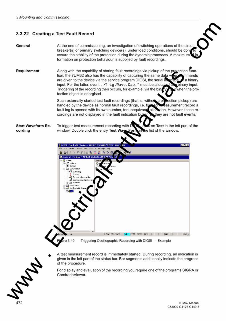
3 Mounting and Commissioning
om
3.3.22 Creating a Test Fault Record
General At the end of commissioning, an investigation of switching operations of the circuit breaker(s) or primary switching device(s), under load conditions, should be done to assure the stability of the protection during the dynamic processes. A maximum of in-formation on protection behaviour is supplied by fault recordings.
Requirement Along with the capability of storing fault recordings via pickup of the protection func-tion, the 7UM62 also has the capability of capturing the same data when commands are given to the device via the service program DIGSI, the serial interface, or a binary input. For the latter, event „>Trig.Wave.Cap.“ must be allocated to a binary input. Triggering of the recording then occurs, for example, via the binary input when the pro-tection object is energised.
Such externally started test fault recordings (that is, without a protection pickup) are handled by the device as normal fault recordings, i.e. for each measurement record a fault log is opened with its own number, for unequivocal allocation. However, these re-cordings are not displayed in the fault indication buffer, as they are not fault events.
Start Waveform Re-cording
To trigger test measurement recording with DIGSI, click on Test in the left part of the window. Double click the entry Test Wave Form in the list of the window.
Figure 3-40 Triggering Oscillographic Recording with DIGSI — Example
A test measurement record is immediately started. During recording, an indication is given in the left part of the status bar. Bar segments additionally indicate the progress of the procedure.
For display and evaluation of the recording you require one of the programs SIGRA or ComtradeViewer. ww .
Elec
tricalP
artM
anua
ls . c
472 7UM62 ManualC53000-G1176-C149-5
w

3.4 Final Preparation of the Devicew
3.4 Final Preparation of the Device
Firmly tighten all screws. Tighten all terminal screws, including those that are not used.
Caution!Inadmissable tightening torques
Non–observance of the following measure can result in minor personal injury or prop-erty damage.
The tightening torques must not be exceeded as the threads and terminal chambers may otherwise be damaged!
In case service settings were changed, check if they are correct. Check if power system data, control and auxiliary functions to be found with the configuration param-eters are set correctly (Section 2). All desired elements and functions must be set ON. Keep a copy of all of the in-service settings on a PC.
Check the internal clock of the device. If necessary, set the clock or synchronize the clock if the element is not automatically synchronized. For assistance, refer to the SIPROTEC 4 System Description /1/.
The indication buffers are deleted under MAIN MENU → Annunciation → Set/Reset, so that in the future they only contain information on actual events and states (see also /1/). The counters in the switching statistics should be reset to the values that were existing prior to the testing (see also SIPROTEC 4 System Description /1/).
The counters of the operational measured values (e.g. operation counter, if available) are reset under Main Menu → Measurement → Reset.
Press the ESC key, several times if necessary, to return to the default display. The default display appears in the display (e.g. display of operation measured values).
Clear the LEDs on the front panel by pressing the LED key, so that they only show real events and states. In this context, also output relays probably memorized are reset. Pressing the LED key also serves as a test for the LEDs on the front panel because they should all light when the button is pushed. Any LEDs that are lit after the clearing attempt are displaying actual conditions.
The green „RUN“ LED must be on. The red „ERROR“ LED must not be lit.
Close the protective switches. If test switches are available, then these must be in the operating position.
The device is now ready for operation.
ww . El
ectric
alPar
tMan
uals
. com
4737UM62 ManualC53000-G1176-C149-5

3 Mounting and Commissioning
om
ww . El
ectric
alPar
tMan
uals
. c
474 7UM62 ManualC53000-G1176-C149-5
w
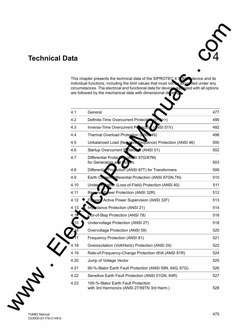
w
m
Technical Data 4This chapter presents the technical data of the SIPROTEC 4 7UM62 device and its individual functions, including the limit values that must not be exceeded under any circumstances. The electrical and functional data for devices equipped with all options are followed by the mechanical data with dimensional drawings.
4.1 General 477
4.2 Definite-Time Overcurrent Protection (I>, I>>) 490
4.3 Inverse-Time Overcurrent Protection (ANSI 51V) 492
4.4 Thermal Overload Protection (ANSI 49) 498
4.5 Unbalanced Load (Negative Sequence) Protection (ANSI 46) 500
4.6 Startup Overcurrent Protection (ANSI 51) 502
4.7 Differential Protection (ANSI 87G/87M) for Generators and Motors 503
4.8 Differential Protection (ANSI 87T) for Transformers 506
4.9 Earth Current Differential Protection (ANSI 87GN,TN) 510
4.10 Underexcitation (Loss-of-Field) Protection (ANSI 40) 511
4.11 Reverse Power Protection (ANSI 32R) 512
4.12 Forward Active Power Supervision (ANSI 32F) 513
4.13 Impedance Protection (ANSI 21) 514
4.14 Out-of-Step Protection (ANSI 78) 516
4.15 Undervoltage Protection (ANSI 27) 518
4.16 Overvoltage Protection (ANSI 59) 520
4.17 Frequency Protection (ANSI 81) 521
4.18 Overexcitation (Volt/Hertz) Protection (ANSI 24) 522
4.19 Rate-of-Frequency-Change Protection df/dt (ANSI 81R) 524
4.20 Jump of Voltage Vector 525
4.21 90-%-Stator Earth Fault Protection (ANSI 59N, 64G, 67G) 526
4.22 Sensitive Earth Fault Protection (ANSI 51GN, 64R) 527
4.23 100-%-Stator Earth Fault Protection with 3rd Harmonics (ANSI 27/59TN 3rd Harm.) 528ww .
Elec
tricalP
artM
anua
ls . c
o
4757UM62 ManualC53000-G1176-C149-5
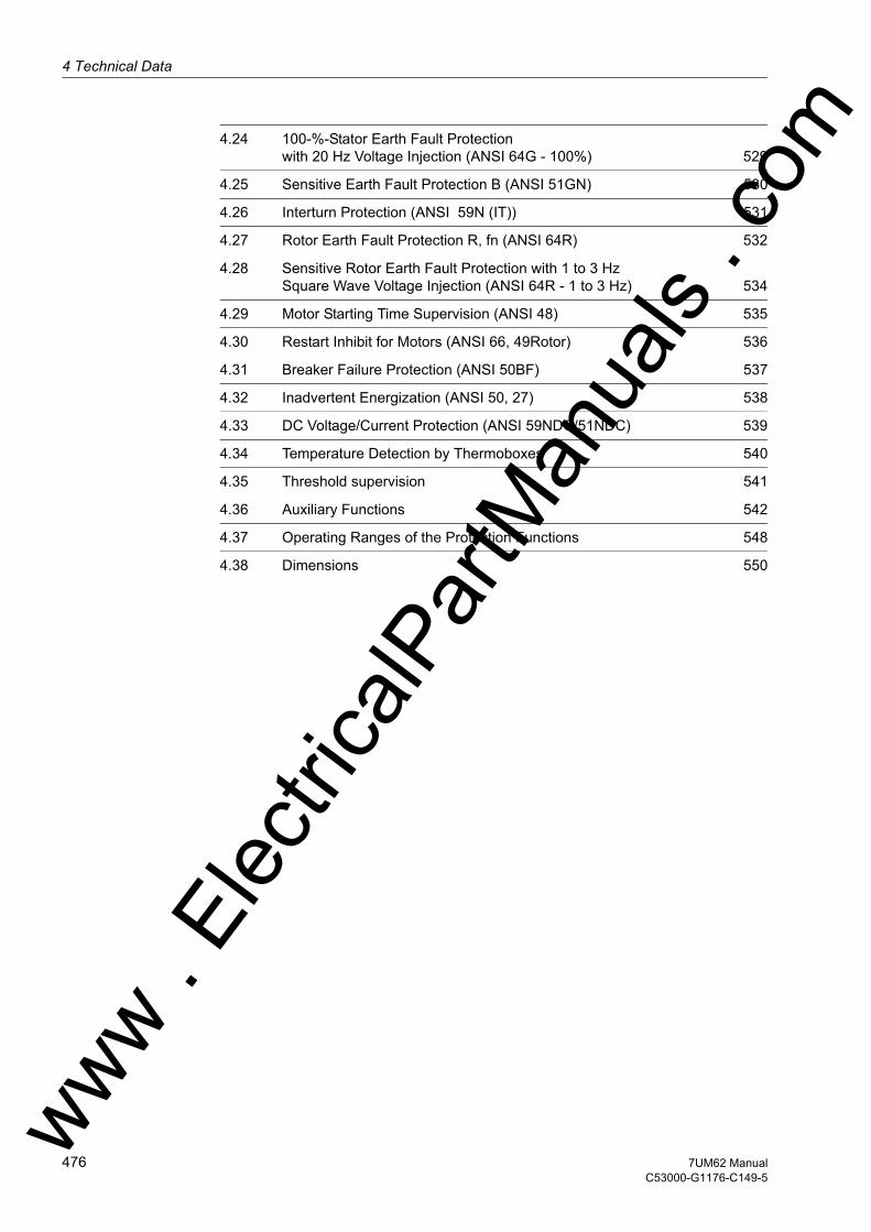
4 Technical Data
om
4.24 100-%-Stator Earth Fault Protection with 20 Hz Voltage Injection (ANSI 64G - 100%) 5294.25 Sensitive Earth Fault Protection B (ANSI 51GN) 530
4.26 Interturn Protection (ANSI 59N (IT)) 531
4.27 Rotor Earth Fault Protection R, fn (ANSI 64R) 532
4.28 Sensitive Rotor Earth Fault Protection with 1 to 3 Hz Square Wave Voltage Injection (ANSI 64R - 1 to 3 Hz) 534
4.29 Motor Starting Time Supervision (ANSI 48) 535
4.30 Restart Inhibit for Motors (ANSI 66, 49Rotor) 536
4.31 Breaker Failure Protection (ANSI 50BF) 537
4.32 Inadvertent Energization (ANSI 50, 27) 538
4.33 DC Voltage/Current Protection (ANSI 59NDC/51NDC) 539
4.34 Temperature Detection by Thermoboxes 540
4.35 Threshold supervision 541
4.36 Auxiliary Functions 542
4.37 Operating Ranges of the Protection Functions 548
4.38 Dimensions 550
ww . El
ectric
alPar
tMan
uals
. c
476 7UM62 ManualC53000-G1176-C149-5
w

4.1 Generalw
4.1 General
4.1.1 Analog Inputs/Outputs
Current Inputs
Voltage Inputs
Measuring Transducer Inputs
Rated system frequency fN 50 Hz or 60 Hz (adjustable)Rated current IN 1 A or 5 AEarth Current, Sensitive IEE Linear range ≤ 1.6 ABurden per Phase and Earth Path- at IN = 1 A Approx. 0.05 VA- at IN = 5 A Approx. 0.3 VA- for Sensitive Earth Fault Detection at 1 A Approx. 0.05 VACurrent Path Loadability
- Thermal (rms) 100· IN for 1 s30· IN for 10 s4· I N continuous
- Dynamic (peak value) 250· I N (half-cycle)Current overload capability for high-sensitivity input IEE
- Thermal (rms) 300 A for 1 s100 A for 10 s15 A continuous
- Dynamic (peak value) 750 A (Half-cycle)
Secondary nominal voltage 100 V to 125 VMeasuring range 0 V to 200 VBurden at 100 V Approx. 0.3 VAVoltage path overload capacity- Thermal (rms) 230 V continuous
Measuring range –10 V to +10 V or-20 mA to +20 mA
Input resistance for DC voltage approx. 1 MΩ
Input resistance for DC voltage Approx. 10 ΩVoltage Input Overload Capacity 60 V– continuousCurrent Input Overload Capacity 100 mA– continuous
ww . El
ectric
alPar
tMan
uals
. com
4777UM62 ManualC53000-G1176-C149-5

4 Technical Data
om
Analog Output (for Operational Measured Values)
4.1.2 Auxiliary voltage
DC Voltage
Nominal Range 0 to 20 mA–Operating Range 0 to 22.5 mA–Connection for flush-mounted case Rear panel, mounting location "B"
or/and "D"9-pin DSUB female connector
For Panel Surface-Mounted Case At the terminal on the case bottom or/and at the housing top
Max. Burden 350 Ω
Voltage Supply via Integrated Converter Nominal auxiliary voltage UAux– 24/48 V DC 60/110/125 V DCAdmissible voltage ranges 19 to 58 V DC 48 to 150 V DCNominal auxiliary voltage UAux– 110/125/220/250 V DCPermissible voltage ranges 88 to 300 V DCadmissible AC ripple voltage,Peak to Peak, IEC 60255-11 ≤15 % of the Auxiliary Voltage
Power input7UM621 Quiescent Approx. 5.3 W7UM622 Approx. 5.5 W7UM623 approx. 5.3 W7UM621 Energized Approx. 12 W7UM622 Approx. 15 W7UM623 approx. 12 WBridging time in the event of power fail-ure/short circuit
≥ 50 ms at U ≥ 48 VDC (UAux,N = 24/48 V)≥ 50 ms at U ≥ 110 VDC (UAux,N = 60...125 V)≥ 20 ms at U ≥ 24 VDC (UAux,N = 24/48 V)≥ 20 ms at U ≥ 60 VDC (UAux,N = 60...125 V)
ww . El
ectric
alPar
tMan
uals
. c
478 7UM62 ManualC53000-G1176-C149-5
w

4.1 Generalw
AC Voltage
4.1.3 Binary Inputs and Outputs
Binary Inputs
Voltage supply via integrated converterNominal auxiliary voltage AC UAux115 VAC (50/60 Hz)
230 VAC (50/60 Hz)
Admissible voltage ranges92 to 132 VAC
184 to 265 VAC
Power input7UM621 Quiescent Approx. 5.5 VA7UM622 Approx. 5.5 VA7UM623 approx. 5.5 VA7UM621 Energized Approx. 13 VA7UM622 Approx. 15 VA7UM623 approx. 13 VABridging time in the event of power failure/short circuit ≥ 200 ms
Variant Number7UM621*- 7 (configurable)7UM623*-7UM622*- 15 (configurable)
Rated Voltage Range 24 VDC to 250 VDC, bipolarCurrent Consumption, Energized Approx. 1.8 mA, independent of the control
voltage
Switching Thresholds adjustable with jumpersfor rated voltages 24/48/
60/110/125 V DCUhigh ≥ 19 VDCUlow ≤ 10 VDC
for rated voltages 110/125/220/250 VDC and 115/230 VAC
Uhigh ≥ 88 VDCUlow ≤ 44 VDC
For nominal voltages 220/250 VDC and 115/230 VAC
Uhigh ≥ 176 VDCUlow ≤ 88 VDC
Maximum permissible voltage 300 V DCInput impulse filtering 220 nF coupling capacity at 220 V with recovery
time > 60 ms
ww . El
ectric
alPar
tMan
uals
. com
4797UM62 ManualC53000-G1176-C149-5

4 Technical Data
om
Output Relays
LEDs
Signalling/trip relays 1) (see also terminal assignments in Appendix A.2))Number: According to the order variant (allocatable)
7UM621*- 12 (1 NO contact each, 3 option-ally as NC contacts)7UM623*-
7UM622*- 20 (1 NO contact each, 4 option-ally as NC contacts)1 Life contact (NC contact or NO contact, selectable)
Make/break capacity CLOSE 1000 W/VABREAK 30 VA
40 W resistive25 W/VA at L/R ≤ 50 ms
Switching voltage 250 VPermissible current per contact (continuous)
5 A
Permissible current per contact (close and hold)
30 A for 0.5 S (NO contact)
Permissible total current on common path
5 A continuous30 A for 0.5 s
1) UL-listed with the following rated data:120 VAC Pilot duty, B300240 VAC Pilot duty, B300240 VAC 5 A General Purpose24 VDC 5 A General Purpose48 VDC 0.8 A General Purpose240 VDC 0.1 A General Purpose120 VAC 1/6 hp (4.4 FLA)240 VAC 1/2 hp (4.9 FLA)
NumberRUN (green) 1ERROR (red) 1allocatable LEDs (red) 14
ww . El
ectric
alPar
tMan
uals
. c
480 7UM62 ManualC53000-G1176-C149-5
w

4.1 Generalw
4.1.4 Communication Interfaces
Operator Interface
Service / Modem Interface
System Interface
Connection Front side, non-isolated, RS232,9-pin DSUB port for connection of a PC
Operation With DIGSITransmission Speed min. 4 800 Baud; max. 115 200 Baud
Factory setting: 38,400 BaudParity: 8E1
bridgeable distance 15 m
Connection isolated interface for data transferOperation With DIGSITransmission Speed min. 4,800 Baud to 115,200 Baud
Factory setting: 38,400 BaudParity: 8E1
RS232/RS485 RS232/RS485 according to the order-ing variant
Connection for flush-mounted case
Rear panel, mounting location "C"9-pole DSUB port
Surface-mounting case At the console housing mounted case on the case bottom;Shielded data cable
Test voltage 500 VAC, 50 HzRS232
bridgeable distance 15 m
RS485bridgeable distance 1,000 m
IEC 60870-5-103RS232/RS485Acc. to ordered variant
Isolated interface for data transfer to a master terminal
RS232Connection for flush mounted case
Rear panel, mounting location "B"9-pole DSUB port
For panel surface-mounted case
in console housing at case bottom side
Test voltage 500 V; 50 HzTransmission speed min. 4,800 Bd,
max. 115,200 BdFactory setting 38,400 Bd
Bridgeable distance 15 m / 50 feet
ww . El
ectric
alPar
tMan
uals
. com
4817UM62 ManualC53000-G1176-C149-5
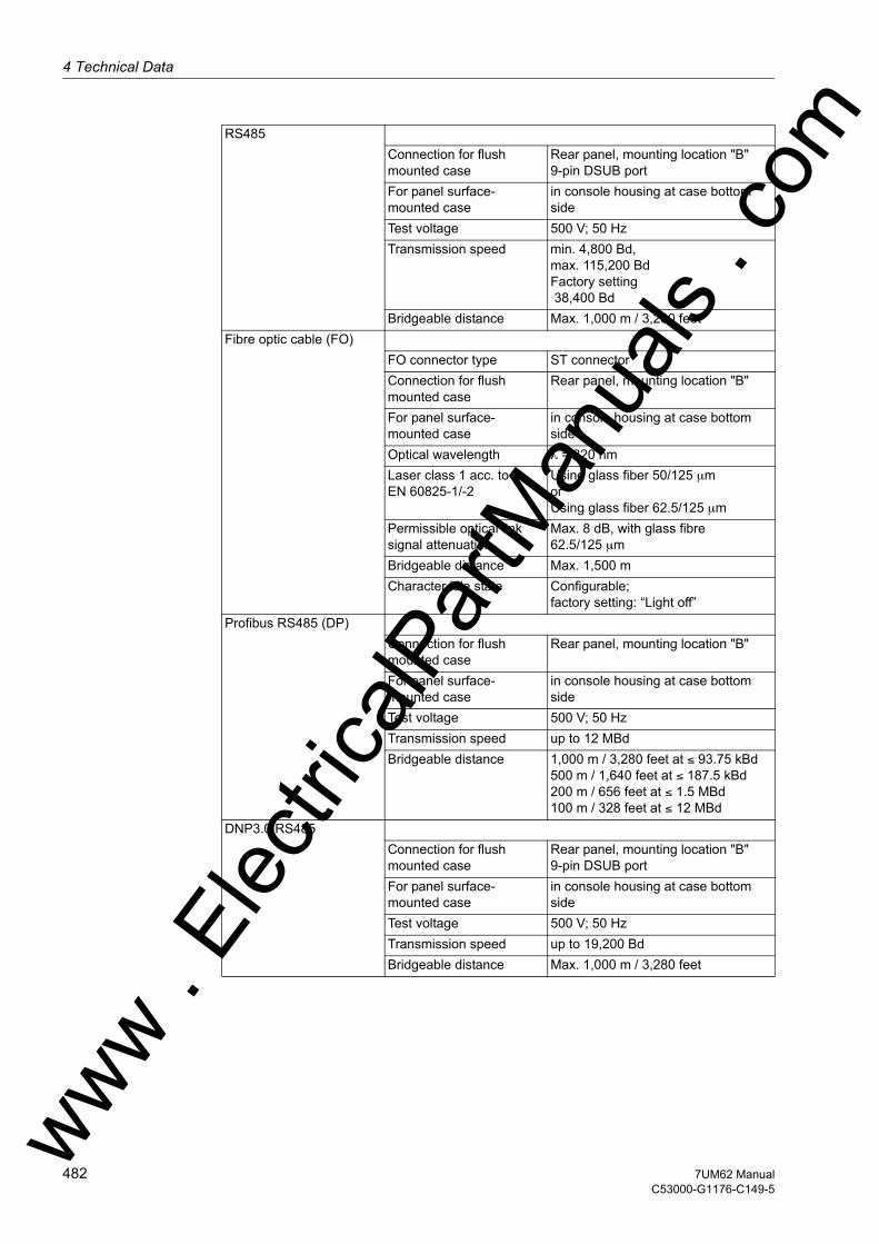
4 Technical Data
om
RS485Connection for flush mounted case
Rear panel, mounting location "B"9-pin DSUB port
For panel surface-mounted case
in console housing at case bottom side
Test voltage 500 V; 50 HzTransmission speed min. 4,800 Bd,
max. 115,200 BdFactory setting 38,400 Bd
Bridgeable distance Max. 1,000 m / 3,280 feetFibre optic cable (FO)
FO connector type ST connectorConnection for flush mounted case
Rear panel, mounting location "B"
For panel surface-mounted case
in console housing at case bottom side
Optical wavelength λ = 820 nmLaser class 1 acc. toEN 60825-1/-2
Using glass fiber 50/125 µmorUsing glass fiber 62.5/125 µm
Permissible optical link signal attenuation
Max. 8 dB, with glass fibre 62.5/125 µm
Bridgeable distance Max. 1,500 mCharacter idle state Configurable;
factory setting: “Light off”Profibus RS485 (DP)
Connection for flush mounted case
Rear panel, mounting location "B"
For panel surface-mounted case
in console housing at case bottom side
Test voltage 500 V; 50 HzTransmission speed up to 12 MBdBridgeable distance 1,000 m / 3,280 feet at ≤ 93.75 kBd
500 m / 1,640 feet at ≤ 187.5 kBd200 m / 656 feet at ≤ 1.5 MBd100 m / 328 feet at ≤ 12 MBd
DNP3.0 RS485Connection for flush mounted case
Rear panel, mounting location "B"9-pin DSUB port
For panel surface-mounted case
in console housing at case bottom side
Test voltage 500 V; 50 HzTransmission speed up to 19,200 BdBridgeable distance Max. 1,000 m / 3,280 feet
ww . El
ectric
alPar
tMan
uals
. c
482 7UM62 ManualC53000-G1176-C149-5
w

4.1 Generalw
MODBUS RS485Connection for flush mounted case
Rear panel, mounting location "B"9-pin DSUB port
for surface-mounting case in console housing at case bottom side
Test voltage 500 V; 50 HzTransmission speed up to 19,200 BdBridgeable distance Max. 1,000 m / 3,280 feet
Profibus Fibre Optical Link (DP) FO connector type ST-connector: single ring / double ring
according to the order for FMS; for DP only double ring available
Connection for flush mounted case
Rear panel, mounting location "B"
For panel surface-mounted case
Please use version with Profibus RS485 in the console housing as well as separate electrical/optical convert-er.
Transmission speed up to 1.5 MBdRecommended > 500 kBdOptical wavelength λ = 820 nmLaser class 1 acc. toEN 60825-1/-2
Using glass fiber 50/125 µmorUsing glass fiber 62.5/125 µm
Permissible optical link signal attenuation
Max. 8 dB, with glass fibre 62.5/125 µm
Bridgeable distance Max. 1,500 m / 0.93 milesDNP3.0 Fibre Optical Link
FO connector type ST connector receiver/transmitterConnection for flush mounted case
Rear panel, mounting location "B"
For panel surface-mounted case
Please use version with DNP3.0 RS485 in the console housing as well as separate electrical/optical converter.
Transmission speed up to 19,200 BdOptical wavelength λ = 820 nmLaser class 1 acc. toEN 60825-1/-2
Using glass fiber 50/125 µmorUsing glass fiber 62.5/125 µm
Permissible optical link signal attenuation
Max. 8 dB, with glass fibre 62.5/125 µm
Bridgeable distance Max. 1,500 m / 0.93 miles
ww . El
ectric
alPar
tMan
uals
. com
4837UM62 ManualC53000-G1176-C149-5
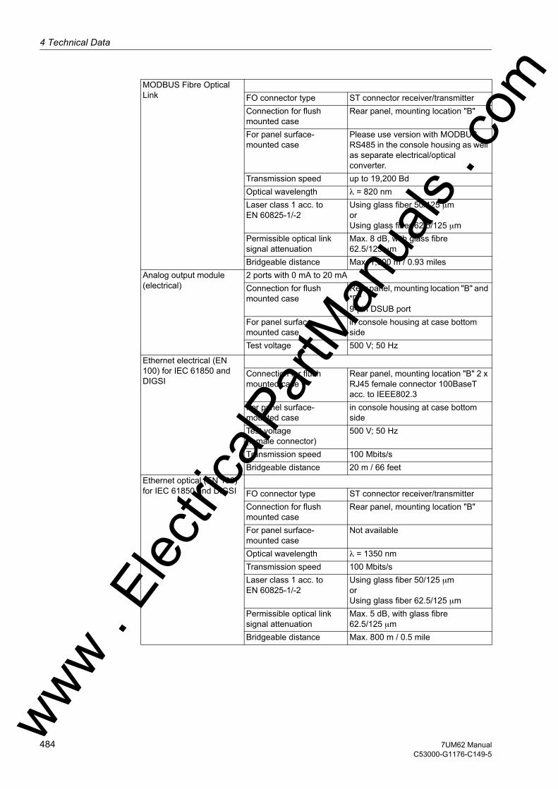
4 Technical Data
om
MODBUS Fibre Optical Link FO connector type ST connector receiver/transmitter
Connection for flush mounted case
Rear panel, mounting location "B"
For panel surface-mounted case
Please use version with MODBUS RS485 in the console housing as well as separate electrical/optical converter.
Transmission speed up to 19,200 BdOptical wavelength λ = 820 nmLaser class 1 acc. toEN 60825-1/-2
Using glass fiber 50/125 µmorUsing glass fiber 62.5/125 µm
Permissible optical link signal attenuation
Max. 8 dB, with glass fibre 62.5/125 µm
Bridgeable distance Max. 1,500 m / 0.93 milesAnalog output module (electrical)
2 ports with 0 mA to 20 mAConnection for flush mounted case
Rear panel, mounting location "B" and "D"9-pin DSUB port
For panel surface-mounted case
in console housing at case bottom side
Test voltage 500 V; 50 Hz
Ethernet electrical (EN 100) for IEC 61850 and DIGSI
Connection for flush mounted case
Rear panel, mounting location "B" 2 x RJ45 female connector 100BaseT acc. to IEEE802.3
For panel surface-mounted case
in console housing at case bottom side
Test voltage (female connector)
500 V; 50 Hz
Transmission speed 100 Mbits/sBridgeable distance 20 m / 66 feet
Ethernet optical (EN 100) for IEC 61850 and DIGSI FO connector type ST connector receiver/transmitter
Connection for flush mounted case
Rear panel, mounting location "B"
For panel surface-mounted case
Not available
Optical wavelength λ = 1350 nmTransmission speed 100 Mbits/sLaser class 1 acc. toEN 60825-1/-2
Using glass fiber 50/125 µmorUsing glass fiber 62.5/125 µm
Permissible optical link signal attenuation
Max. 5 dB, with glass fibre 62.5/125 µm
Bridgeable distance Max. 800 m / 0.5 mile
ww . El
ectric
alPar
tMan
uals
. c
484 7UM62 ManualC53000-G1176-C149-5
w
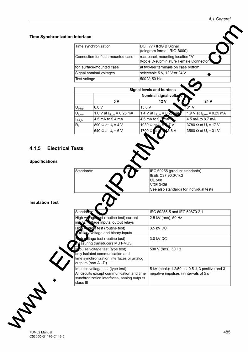
4.1 Generalw
Time Synchronization Interface
4.1.5 Electrical Tests
Specifications
Insulation Test
Time synchronization DCF 77 / IRIG B Signal(telegram format IRIG-B000)
Connection for flush-mounted case rear panel, mounting location "A";9-pole D-subminiature Female Connector
for surface-mounted case at two-tier terminals on case bottomSignal nominal voltages selectable 5 V, 12 V or 24 VTest voltage 500 V; 50 Hz
Signal levels and burdensNominal signal voltage
5 V 12 V 24 VUIHigh 6.0 V 15.8 V 31 VUILow 1.0 V at IILow = 0.25 mA 1.4 V at IILow = 0.25 mA 1.9 V at IILow = 0.25 mAIIHigh 4.5 mA to 9.4 mA 4.5 mA to 9.3 mA 4.5 mA to 8.7 mARI 890 Ω at UI = 4 V 1930 Ω at UI = 8.7 V 3780 Ω at UI = 17 V
640 Ω at UI = 6 V 1700 Ω at UI = 15.8 V 3560 Ω at UI = 31 V
Standards: IEC 60255 (product standards)IEEE C37.90.0/.1/.2UL 508VDE 0435See also standards for individual tests
Standards: IEC 60255-5 and IEC 60870-2-1High voltage test (routine test) current inputs, voltage inputs, output relays
2.5 kV (rms), 50 Hz
High voltage test (routine test)Auxiliary voltage and binary inputs
3.5 kV DC
High voltage test (routine test)Measuring transducers MU1-MU3
3.0 kV DC
Impulse voltage test (type test)only isolated communication andtime synchronization interfaces or analog outputs (port A –D)
500 V (rms), 50 Hz
Impulse voltage test (type test)All circuits except communication and time synchronization interfaces, analog outputs class III
5 kV (peak): 1.2/50 µs: 0.5 J, 3 positive and 3 negative impulses in intervals of 5 s
ww . El
ectric
alPar
tMan
uals
. com
4857UM62 ManualC53000-G1176-C149-5

4 Technical Data
om
EMC Tests for Interference Immunity (type tests)
EMC Tests; Interference Emission (Type Test)
Standards: IEC 60 255-6 and -22 (product standards)EN 61000-6-2 (generic standard)VDE 0435 Part 301DIN VDE 0435-110
High frequency test IEC 60255-22-1, Class III and VDE 0435 Part 303, Class III
2.5 kV (peak); 1 MHz; τ = 15 µs; 400 surges per s; test duration 2 s; Ri = 200 Ω
Electrostatic dischargeIEC 60 55-22-2, Class IVand IEC 61000-4-2, Class IV
8 kV contact discharge; 15 kV air discharge, both polarities; 150 pF; Ri = 330 Ω
Irradiation with HF field, frequency sweepIEC 60255-22-3, Class IIIIEC 61000-4-3, Class III
10 V/m; 80 MHz to 1000 MHz;10 V/m; 800 MHz to 960 MHz;20 V/m; 1.4 GHz to 2.0 GHz;80 % AM; 1 kHz
Irradiation with HF field, single frequenciesIEC 60255-22-3,IEC 61000-4-3,amplitude-modulated
Class III: 10 V/m80/160/450/900 MHz 80 % AM 1 kHz; duty cycle > 10 s
Fast transient disturbance/burstIEC 60255-22-4 andIEC 61000-4-4, Class IV
4 kV; 5/50 ns; 5 kHz; burst length = 15 ms; repe-tition rate 300 ms; both polarities: Ri = 50 Ω; test duration 1 min
High energy surge voltages (SURGE),IEC 61000-4-5 Installation Class 3
Pulse: 1.2/50 µs
Auxiliary voltage Common mode: 2 kV; 12 Ω; 9 µFDiff. mode: 1 kV; 2 Ω; 18 µF
Measuring Inputs, Binary Inputs, Relay Outputs
Common mode: 2 kV; 42 Ω; 0.5 µFDiff. mode: 1 kV; 42 Ω; 0.5 µF
Line conducted HF, amplitude modulated IEC 61000-4-6, Class III
10 V; 150 kHz to 80 MHz; 80 % AM; 1 kHz
Power System Frequency Magnetic FieldIEC 61000-4-8, Class IVIEC 60255-6
30 A/m; continuous; 300 A/m for 3 s; 50 Hz0.5 mT; 50 Hz
Oscillatory Surge Withstand CapabilityIEEE Std C37.90.1
2.5 kV (peak value); 1 MHz; τ = 15 µs;400 pulses per s; test duration 2 s; Ri = 200 Ω
Fast transient surge withstand cap. IEEE Std C37.90.1
4 kV; 5/50 ns; 5 kHz; burst length = 15 ms; repe-tition rate 300 ms; both polarities: R i = 50 Ω; test duration 1 min
Radiated electromagnetic interferenceIEEE Std C37.90.2
35 V/m; 25 MHz to 1000 MHz
Damped oscillationsIEC 60694, IEC 61000-4-12
2.5 kV (peak value), polarity alternating 100 kHz, 1 MHz, 10 MHz and 50 MHz,RL = 200 Ω
Standard: EN 61000-6-3 (generic standard)Radio Noise Voltage to Lines, Only Power Supply Voltage IEC-CISPR 22
150 kHz to 30 MHzLimit Class B
Radio Noise Field Strength IEC-CISPR 11 30 MHz to 1000 MHz Limit Class A
ww . El
ectric
alPar
tMan
uals
. c
486 7UM62 ManualC53000-G1176-C149-5
w

4.1 Generalw
4.1.6 Mechanical Stress Tests
Vibration and Shock Stress During Steady State Operation
Vibration and Shock Stress During Transport
Standards: IEC 60255-21 and IEC 60068OscillationIEC 60255-21-1, Class 2IEC 60068-2-6
sinusoidal10 Hz to 60 Hz: ±0.075 mm amplitude;60 Hz to 150 Hz: 1g accelerationFrequency Sweep Rate 1 octave/min,20 Cycles in 3 Orthogonal Axes
ShockIEC 60255-21-2, Class 1IEC 60068-2-27
Semi-sinusoidal5 g acceleration, duration 11 ms,each 3 shocks (in both directions of the 3 axes)
Seismic VibrationIEC 60255-21-3, Class 1IEC 60068-3-3
sinusoidal1 Hz to 8 Hz: ±3.5 mm amplitude;(Horizontal axis)1 Hz to 8 Hz: ±1.5 mm amplitude;(vertical axis)8 Hz to 35 Hz: 1 g acceleration(horizontal axis); 8 Hz to 35 Hz: 0.5 g accelera-tion(vertical axis)Frequency Sweep 1 octave/min1 Cycle in 3 Orthogonal Axes
Standards: IEC 60255-21 and IEC 60068OscillationIEC 60255-21-1, Class 2IEC 60068-2-6
sinusoidal 5 Hz to 8 Hz: ±7.5 mm amplitude;8 Hz to 15 Hz: 2 g AccelerationFrequency Sweep 1 octave/min20 Cycles in 3 Orthogonal Axes
ShockIEC 60255-21-2, Class 1IEC 60068-2-27
Semi-sinusoidal15 g acceleration, duration 11 ms,each 3 shocks (in both directions of the 3 axes)
Continuous ShockIEC 60255-21-2, Class 1IEC 60068-2-29
Semi-sinusoidal10 g acceleration, duration 16 ms,1000 shocks in each direction of 3 orthogonal axes
ww . El
ectric
alPar
tMan
uals
. com
4877UM62 ManualC53000-G1176-C149-5

4 Technical Data
om
4.1.7 Climatic Stress Tests
Ambient Temperatures
Humidity
4.1.8 Service Conditions
4.1.9 Certifications
Type test(acc. to IEC 60068-2-1 and -2,Test Bd for 16 h)
-25 °C to +85 °C
Limiting temporary (transient) operating tem-perature (tested for 96 h)
–20 °C to +70 °C or –4 °F to +158 °F (Visibility of display may be impaired above +55 °C or 130 °F)
recommended for continuous operation (acc. to IEC 60255-6)
23 °F to +131 °F or –5 °C to +55 °C
Limit temperatures for longterm storage -25 °C to +131 °F or –5 °C to +55 °CLimit temperatures during transport -25 °C to +70 °C or –5 °C to +55 °CStorage and transport of the device with factory packaging!
admissible humidity yearly average ≤ 75 % relative humidity; On 56 days of the year up to 93% relative humid-ity. Condensation must be avoided in operation!
Siemens recommends that all devices be installed so that they are not exposed to direct sun-light nor subject to large fluctuations in temperature that may cause condensation to occur.
The protection device is designed for installation in normal relay rooms and plants, so that elec-tromagnetic compatibility (EMC) is ensured if installation is done properly.
In addition the following is recommended: • Contactors and relays operating within the same cubicle or on the same relay board with
digital protection equipment should always be provided with suitable quenching equipment.• For substations with operating voltages of 100 kV and above, all external cables should be
shielded with a conductive shield grounded at both ends. For substations with lower oper-ating voltages, no special measures are normally required.
• Do not withdraw or insert individual modules or boards while the protective device is ener-gized. When handling the modules or the boards outside of the case, standards for compo-nents sensitive to electrostatic discharge (Electrostatic Sensitive Devices) must be ob-served. They are not endangered when inserted into the case.
UL Listing UL recognition7UM62**-*B***-**** Models with screw ter-
minals7UM62**-*D***-**** Models with plug–in
terminals7UM62**-*E***-****
ww . El
ectric
alPar
tMan
uals
. c
488 7UM62 ManualC53000-G1176-C149-5
w

4.1 Generalw
4.1.10 Mechanical Design
Case 7XP20Dimensions See dimensional drawings, Section 4.38
Weight approx.in flush mounted case7UM621* (case size 1/2) Approx. 7.5 kg (16.5 pounds)7UM623* (case size 1/2)7UM622* (case size 1/1) Approx. 9.5 kg (22 pounds)in surface mounted case7UM621* (case size 1/2) Approx. 12 kg (26.5 pounds)7UM623* (case size 1/2)7UM622* (case size 1/1) Approx. 15 kg (33 pounds)
Degree of protection acc. to IEC 60529for surface mounting case equipment IP 51in flush mounted case
Front IP 51Rear IP 50
For personal protection IP 2x with cover in place
ww . El
ectric
alPar
tMan
uals
. com
4897UM62 ManualC53000-G1176-C149-5

4 Technical Data
om
4.2 Definite-Time Overcurrent Protection (I>, I>>)
Setting Ranges / Increments
Times
Dropout Ratio
Tolerances
Pickup current I> for IN = 1 A 0.05 A to 20.00 A Increments 0.01 Afor IN = 5 A 0.25 A to 100.00 A Increments 0.01 A
Pickup current I>> for IN = 1 A 0.05 A to 20.00 A Increments 0.01 Afor IN = 5 A 0.25 A to 100.00 A Increments 0.01 A
Delay times T 0.00 s to 60.00 sor ∞ (ineffective)
Increments 0.01 s
Undervoltage seal-in U< (phase-to-phase) 10.0 V to 125.0 V Increments 0.1 VHolding Time of Undervoltage Seal-In 0.10 s to 60.00 s Increments 0.01 sDirectional limit line angle tolerance I>> –90° el. to +90° el. Increments 1°The set times are pure delay times.
Pickup times (without inrush restraint, with restraint add 10 ms)I >, I>> Current = 2 × Pickup Value Current = 10 × Pickup Value
approx. 35 msapprox. 25 ms
Dropout Times I >, I>>
approx. 50 ms
Dropout ratio overcurrent I> Approx. 0.95 for I/IN ≥ 0.3Dropout ratio overcurrent I>>(Increments 0.01)
0.90 to 0.99
Dropout ratio undervoltage approx. 1.05Dropout difference ∆ϕ 2° electrical
Pickup currentI >, I>>
for IN = 1 A 1 % of setting value or 10 mAfor IN = 5 A 1 % of setting value or 50 mA
Undervoltage seal–in U< 1 % of setting value or 0.5 VDelay times T 1 % or 10 msDirectional limit lines angle 1° electrical
ww . El
ectric
alPar
tMan
uals
. c
490 7UM62 ManualC53000-G1176-C149-5
w

4.2 Definite-Time Overcurrent Protection (I>, I>>)w
Influencing Variables for Pickup Values
Power supply direct voltage in range0,8 ≤ U/UAux,N ≤ 1.15
≤ 1 %
Temperature in Range23.00 °F (–5 °C) ≤ Θ amb ≤ 131.00 °F (55 °C)
≤ 0.5 % / 10 K
Frequency in range 0.95 ≤ f/fN ≤ 1.05 ≤ 1 %Harmonics – Up to 10 % 3rd harmonic – Up to 10 % 5th harmonic
≤ 1 %≤ 1 %
ww . El
ectric
alPar
tMan
uals
. com
4917UM62 ManualC53000-G1176-C149-5
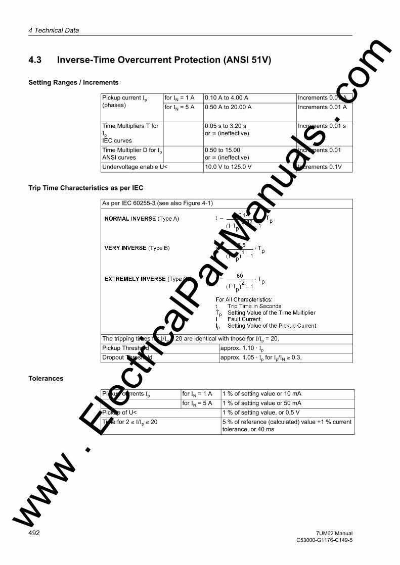
4 Technical Data
om
4.3 Inverse-Time Overcurrent Protection (ANSI 51V)
Setting Ranges / Increments
Trip Time Characteristics as per IEC
Tolerances
Pickup current Ip (phases)
for IN = 1 A 0.10 A to 4.00 A Increments 0.01 Afor IN = 5 A 0.50 A to 20.00 A Increments 0.01 A
Time Multipliers T for IpIEC curves
0.05 s to 3.20 sor ∞ (ineffective)
Increments 0.01 s
Time Multiplier D for IpANSI curves
0.50 to 15.00or ∞ (ineffective)
Increments 0.01
Undervoltage enable U< 10.0 V to 125.0 V Increments 0.1V
As per IEC 60255-3 (see also Figure 4-1)
The tripping times for I/Ip ≥ 20 are identical with those for I/Ip = 20.Pickup Threshold approx. 1.10 · Ip
Dropout Threshold approx. 1.05 · Ip for Ip/IN ≥ 0.3,
Pickup currents Ip for IN = 1 A 1 % of setting value or 10 mAfor IN = 5 A 1 % of setting value or 50 mA
Pickup of U< 1 % of setting value, or 0.5 VTime for 2 ≤ I/Ip ≤ 20 5 % of reference (calculated) value +1 % current
tolerance, or 40 ms
ww . El
ectric
alPar
tMan
uals
. c
492 7UM62 ManualC53000-G1176-C149-5
w

4.3 Inverse-Time Overcurrent Protection (ANSI 51V)w
Influencing Variables for Pickup Values
Power supply direct voltage in range0,8 ≤ UAux/UAux,N ≤ 1.15
≤ 1 %
Temperature in Range23.00 °F (–5 °C) ≤ Θ amb ≤ 131.00 °F (55 °C)
≤ 0.5 % / 10 K
Frequency in range 0.95 ≤ f/fN ≤ 1.05 ≤ 1 %Harmonics – Up to 10 % 3rd harmonic – Up to 10 % 5th harmonic
≤ 1 %≤ 1 %
ww . El
ectric
alPar
tMan
uals
. com
4937UM62 ManualC53000-G1176-C149-5
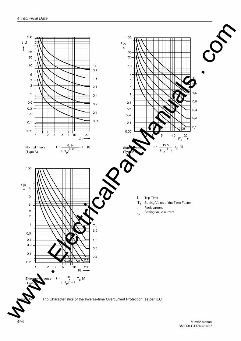
4 Technical Data
om
Figure 4-1 Trip Characteristics of the Inverse-time Overcurrent Protection, as per IECww . El
ectric
alPar
tMan
uals
. c
494 7UM62 ManualC53000-G1176-C149-5
w
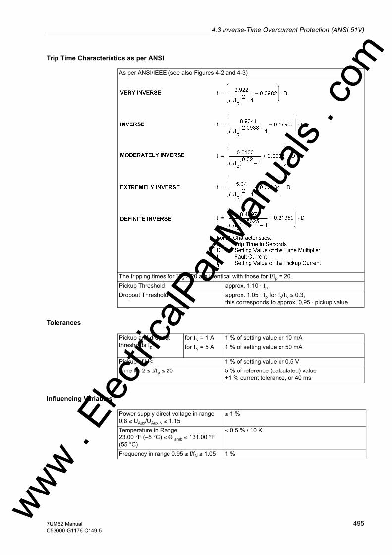
4.3 Inverse-Time Overcurrent Protection (ANSI 51V)w
Trip Time Characteristics as per ANSI
Tolerances
Influencing Variables
As per ANSI/IEEE (see also Figures 4-2 and 4-3)
The tripping times for I/Ip ≥ 20 are identical with those for I/Ip = 20.Pickup Threshold approx. 1.10 · Ip
Dropout Threshold approx. 1.05 · Ip for Ip/IN ≥ 0.3,this corresponds to approx. 0,95 · pickup value
Pickup and dropout thresholds Ip
for IN = 1 A 1 % of setting value or 10 mAfor IN = 5 A 1 % of setting value or 50 mA
Pickup of U< 1 % of setting value or 0.5 VTime for 2 ≤ I/Ip ≤ 20 5 % of reference (calculated) value
+1 % current tolerance, or 40 ms
Power supply direct voltage in range0,8 ≤ UAux/UAux,N ≤ 1.15
≤ 1 %
Temperature in Range23.00 °F (–5 °C) ≤ Θ amb ≤ 131.00 °F (55 °C)
≤ 0.5 % / 10 K
Frequency in range 0.95 ≤ f/fN ≤ 1.05 1 %
ww . El
ectric
alPar
tMan
uals
. com
4957UM62 ManualC53000-G1176-C149-5

4 Technical Data
om
Figure 4-2 Trip Time Characteristics of the Inverse-time Overcurrent Protection, acc. to ANSI/IEEEww . El
ectric
alPar
tMan
uals
. c
496 7UM62 ManualC53000-G1176-C149-5
w
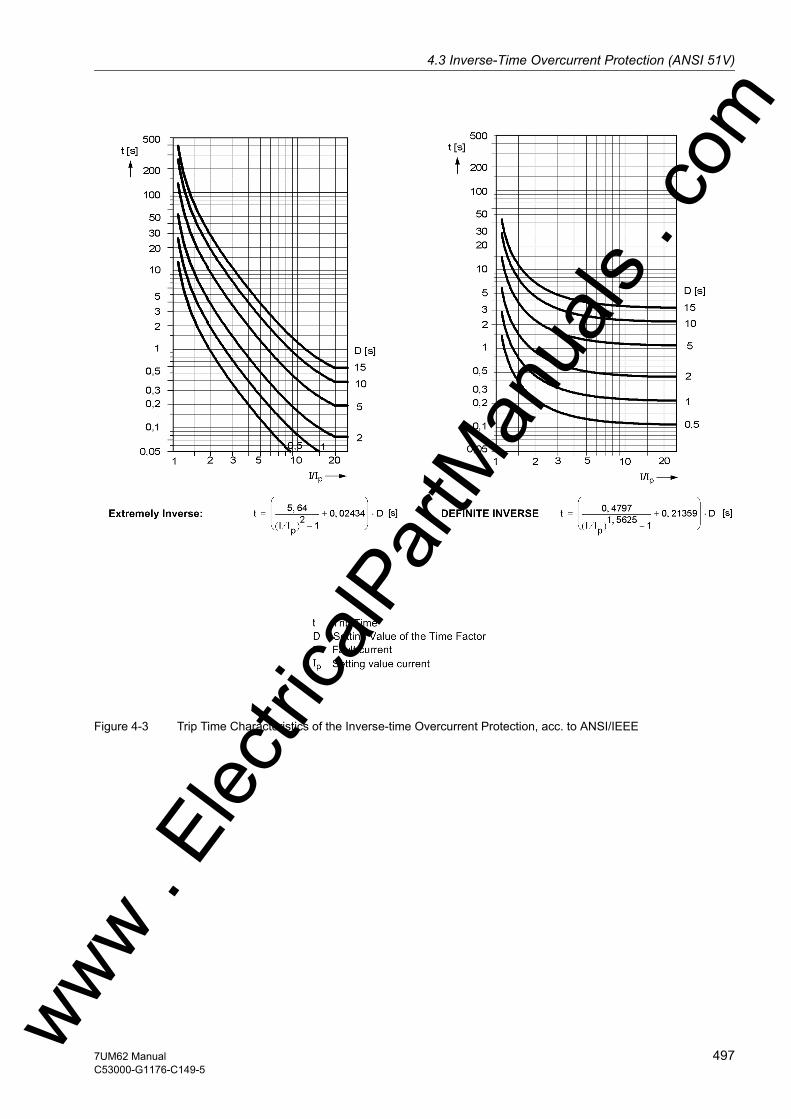
4.3 Inverse-Time Overcurrent Protection (ANSI 51V)w
Figure 4-3 Trip Time Characteristics of the Inverse-time Overcurrent Protection, acc. to ANSI/IEEE
ww . El
ectric
alPar
tMan
uals
. com
4977UM62 ManualC53000-G1176-C149-5

4 Technical Data
om
4.4 Thermal Overload Protection (ANSI 49)
Setting Ranges / Increments
Tripping Characteristic
Dropout ratios
Tolerances
Factor k according to IEC 60255-8 0.10 to 4.00 Increments 0.01Time constant τ 30 s to 32000 s Increments 1 sExtension of Time Constant at Standstill
1.0 to 10.0 Increments 0.1
Thermal alarm ΘAlarm/ΘTrip referred to the tripping temperature
70 % to 100 % Increments 1 %
Current Overload IAlarm for IN = 1 A 0.10 A to 4.00 A Increments 0.01 Afor IN = 1 A 0.50 A to 20.00 A Increments 0.01 A
Nominal Overtemperature (for IN) 40 °C to 200 °C Increments 1 °CCoolant Temperature for Scaling 40 °C to 300 °C Increments 1 °CLimit current ILimit for IN = 1 A 0.50 A to 8.00 A Increments 0.01 A
for IN = 5 A 2.00 A to 40.00 A Increments 0.01 AEmergency timeTEmergency Start
10 s to 15000 s Increments 1 s
see also Figure 4-4
Θ/ΘOff Dropout with ΘAlarm
Θ/ΘAlarm approx. 0.99I/IAlarm approx. 0.95
Referring to k · IN for IN = 1 A 2 % or 10 mA ; class 2 % acc. toIEC 60255-8
for IN = 5 A 2 % or 50 mA ; class 2 % acc. toIEC 60255-8
referred to Trip Time 3 % or 1 mA ; class 3 % acc. toIEC 60255-8 for I/(k ·IN) > 1.25ww .
Elec
tricalP
artM
anua
ls . c
498 7UM62 ManualC53000-G1176-C149-5
w
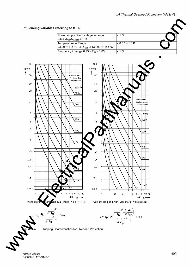
4.4 Thermal Overload Protection (ANSI 49)w
Influencing variables referring to k · IN
Figure 4-4 Tripping Characteristics for Overload Protection
Power supply direct voltage in range0,8 ≤ UAux/UAux,N ≤ 1.15
≤ 1 %
Temperature in Range23.00 °F (–5 °C) ≤ Θ amb ≤ 131.00 °F (55 °C)
≤ 0.5 % / 10 K
Frequency in range 0.95 ≤ f/fN ≤ 1.05 ≤ 1 %
ww . El
ectric
alPar
tMan
uals
. com
4997UM62 ManualC53000-G1176-C149-5
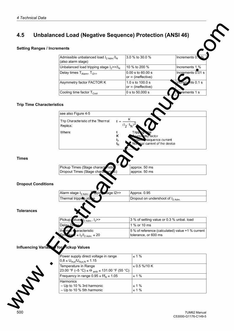
4 Technical Data
om
4.5 Unbalanced Load (Negative Sequence) Protection (ANSI 46)
Setting Ranges / Increments
Trip Time Characteristics
Times
Dropout Conditions
Tolerances
Influencing Variables for Pickup Values
Admissible unbalanced load I2 Adm./IN(also alarm stage)
3.0 % to 30.0 % Increments 0.1 %
Unbalanced load tripping stage I2>>/IN 10 % to 200 % Increments 1 %Delay times TAlarm, TI2>> 0.00 s to 60.00 s
or ∞ (ineffective)Increments 0.01 s
Asymmetry factor FACTOR K 1.0 s to 100.0 sor ∞ (ineffective)
Increments 0.1 s
Cooling time factor TCool 0 s to 50,000 s Increments 1 s
see also Figure 4-5
Pickup Times (Stage characteristic)Dropout Times (Stage characteristic)
approx. 50 msapprox. 50 ms
Alarm stage I2 Adm., Tripping stage I2>> Approx. 0.95Thermal tripping stage Dropout on undershoot of I2 Adm.
Pickup values I2 Adm., I2>> 3 % of setting value or 0.3 % unbal. loadDelay Times 1 % or 10 msthermal characteristicTime for 2 ≤ I2/I2 Adm. ≤ 20
5 % of reference (calculated) value +1 % current tolerance, or 600 ms
Power supply direct voltage in range0,8 ≤ UAux/UAux,N ≤ 1.15
≤ 1 %
Temperature in Range23.00 °F (–5 °C) ≤ Θ amb ≤ 131.00 °F (55 °C)
≤ 0.5 %/10 K
Frequency in range 0.95 ≤ f/fN ≤ 1.05 ≤ 1 %Harmonics – Up to 10 % 3rd harmonic – Up to 10 % 5th harmonic
≤ 1 %≤ 1 %ww .
Elec
tricalP
artM
anua
ls . c
500 7UM62 ManualC53000-G1176-C149-5
w
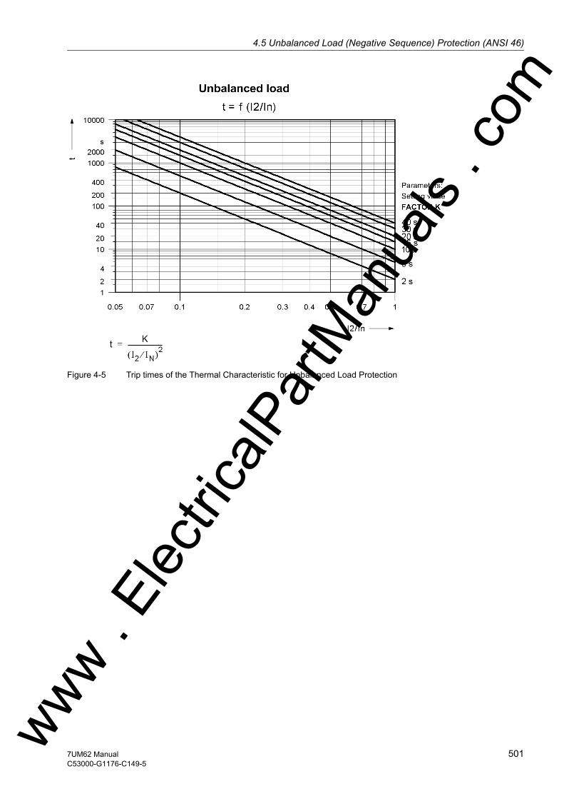
4.5 Unbalanced Load (Negative Sequence) Protection (ANSI 46)w
Figure 4-5 Trip times of the Thermal Characteristic for Unbalanced Load Protection
ww . El
ectric
alPar
tMan
uals
. com
5017UM62 ManualC53000-G1176-C149-5

4 Technical Data
om
4.6 Startup Overcurrent Protection (ANSI 51)
Setting Ranges / Increments
Times
Dropout Conditions
Tolerances
Influencing Variables for Pickup Values
Pickup current I> for IN = 1 A 0.10 A to 20.00 A Increments 0.01 Afor IN = 5 A 0.50 A to 100.00 A Increments 0.01 A
Delay times T 0.00 s to 60.00 sor ineffective
Increments 0.01 s
Pickup Times I> 120 ms or higher (dep. on signal frequency)Dropout times I> 120 ms or higher (dep. on signal frequency)
Current threshold I> 80 % or 0.05 I/In
Current threshold I>f ≥ 3 Hz, I/IN < 5
≤ 10 %
Delay times T 1 % or 10 ms
Power supply direct voltage in range0,8 ≤ UAux/UAux,N ≤ 1.15
≤ 1 %
Temperature in Range23.00 °F (–5 °C) ≤ Θ amb ≤ 131.00 °F (55 °C)
≤ 0.5 % / 10 K
Frequency in range 2 Hz ≤ f ≤ 10 Hz ≤ 10 %Harmonics- Up to 10 % 3rd harmonic- Up to 10 % 5th harmonic
≤ 100 % (considered in calculation)≤ 100 % (considered in calculation)
ww . El
ectric
alPar
tMan
uals
. c
502 7UM62 ManualC53000-G1176-C149-5
w

4.7 Differential Protection (ANSI 87G/87M) for Generators and Motorsw
4.7 Differential Protection (ANSI 87G/87M) for Generators and Motors
Setting Ranges / Increments
Pickup Characteristic
Pickup Times
Tolerances
Differential current IDIFF>/IN Gen 0.05 to 2.00 Increments 0.01High-current stage IDIFF>/IN Gen 0.5 to 12.0
or ∞ (ineffective)Increments 0.1
see also Figure 4-6Slope 1 0.10 to 0.50 Increments 0.01Base point 1 I/IN Gen 0.00 to 2.00 Increments 0.01Slope 2 0.25 to 0.95 Increments 0.01Base point 2 I/IN Gen 0.00 to 10.00 Increments 0.01
Startup recognition I/IN Gen 0.00 to 2.00 Increments 0.01Pickup Value Increase on Startup 1.0 to 2.0 Increments 0.1Max. Starting Time 0.0 s to 180.0 s Increments 0.1 s
Add-on stabilization I/IN Gen 2.00 to 15.00 Increments 0.01Duration of Add-on stabilization (2 to 250) · Cycle duration
(Network frequency)or ∞ (ineffective)
Tripping delay time for IDIFF> and IDIFF>> 0.00 s to 60.00 sor ∞ (ineffective)
Increments 0.01 s
with single side feed (without parallel operation of other protection functions)
Dropout Ratio approx. 0.7
With preset parameters- Pickup Characteristic ± 3 % of setpoint (for I < 5 · IN)- Additional Delay Times ± 1 % of setting value or 10 ms
ww . El
ectric
alPar
tMan
uals
. com
5037UM62 ManualC53000-G1176-C149-5

4 Technical Data
om
Influencing Variables for Pickup Values
Figure 4-6 Pickup Characteristic for Generator or Motor Differential Protection Use
Power supply direct voltage in range0,8 ≤ U/UAux,N ≤ 1.15
≤ 1 %
Temperature in Range23.00 °F (–5 °C) ≤ Θ amb ≤ 131.00 °F (55 °C)
≤ 0.5 % / 10 K
Frequency in range 0.95 ≤ f/fN ≤ 1.05 ≤ 1 % (see also Figure 4-7)
ww . El
ectric
alPar
tMan
uals
. c
504 7UM62 ManualC53000-G1176-C149-5
w
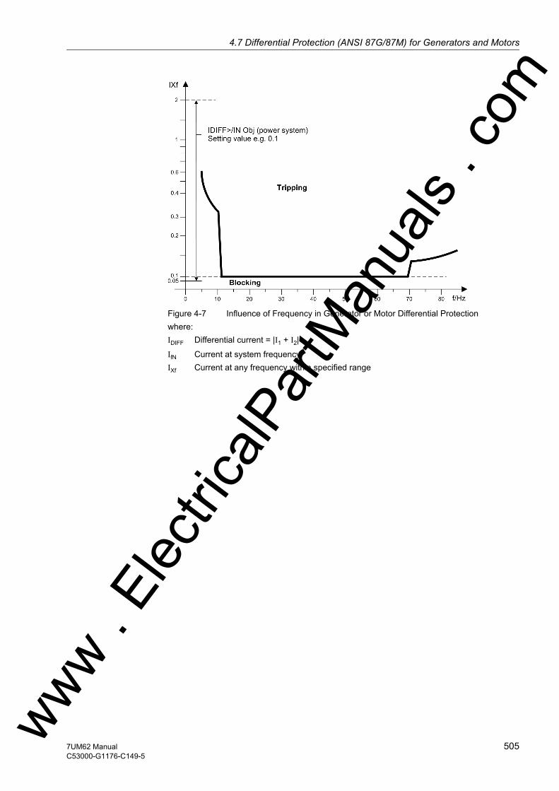
4.7 Differential Protection (ANSI 87G/87M) for Generators and Motorsw
Figure 4-7 Influence of Frequency in Generator or Motor Differential Protectionwhere: IDIFF Differential current = |I1 + I2|
IfN Current at system frequencyIXf Current at any frequency within specified range
ww . El
ectric
alPar
tMan
uals
. com
5057UM62 ManualC53000-G1176-C149-5
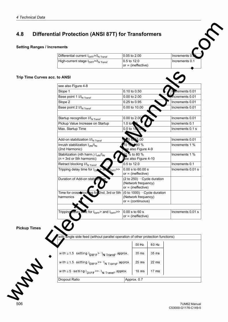
4 Technical Data
om
4.8 Differential Protection (ANSI 87T) for Transformers
Setting Ranges / Increments
Trip Time Curves acc. to ANSI
Pickup Times
Differential current IDIFF>/IN Transf 0.05 to 2.00 Increments 0.01High-current stage IDIFF>/IN Transf 0.5 to 12.0
or ∞ (ineffective)Increments 0.1
see also Figure 4-8Slope 1 0.10 to 0.50 Increments 0.01Base point 1 I/IN Transf 0.00 to 2.00 Increments 0.01Slope 2 0.25 to 0.95 Increments 0.01Base point 2 I/IN Transf 0.00 to 10.00 Increments 0.01
Startup recognition I/IN Transf 0.00 to 2.00 Increments 0.01Pickup Value Increase on Startup 1.0 to 2.0 Increments 0.1Max. Startup Time 0.0 to 180.0 s Increments 0.1 s
Add-on stabilization I/IN Transf 2.00 to 15.00 Increments 0.01Inrush stabilization I2fN/IfN (2nd Harmonic)
10 % to 80 %see also Figure 4-9
Increments 1 %
Stabilization (nth harm.) InfN/IfN(n = 3rd or 5th harmonic)
10 % to 80 %see also Figure 4-10
Increments 1 %
Retract blocking I/IN Transf 0.5 to 12.0 Increments 0.1Tripping delay time for IDIFF> and IDIFF>> 0.00 s to 60.00 s
or ∞ (ineffective)Increments 0.01 s
Duration of Add-on stabilization (2 to 250) · Cycle duration (Network frequency)or ∞ (ineffective)
Time for cross blocking for 2nd, 3rd or 5th harmonics
(0 to 1000) · Cycle duration (Network frequency)or ∞ (continuous)
Tripping delay time for IDIFF> and IDIFF>> 0.00 s to 60 sor ∞ (ineffective)
Increments 0.01 s
with single side feed (without parallel operation of other protection functions)
Dropout Ratio Approx. 0.7ww . El
ectric
alPar
tMan
uals
. c
506 7UM62 ManualC53000-G1176-C149-5
w

4.8 Differential Protection (ANSI 87T) for Transformersw
Tolerances
Influencing Variables for Pickup Values
Figure 4-8 Pickup Characteristic of the Transformer Differential Protection
With Preset Transformer Parameters- Pickup Characteristic ± 3 % of setpoint (for I < 5 · IN)- Inrush Restraint ± 3 % of setting value (for I2fN/IfN ≥ 15 %)- Additional Delay Times ± 1 % of setting value or 10 ms
Power supply direct voltage in range0,8 ≤ UAux/UAux,N ≤ 1.15
≤ 1 %
Temperature in Range23.00 °F (–5 °C) ≤ Θ amb ≤ 131.00 °F (55 °C)
≤ 0.5 % / 10 K
Frequency in range 0.95 ≤ f/fN ≤ 1.05 ≤ 1 % (see also Figure 4-11)
ww . El
ectric
alPar
tMan
uals
. com
5077UM62 ManualC53000-G1176-C149-5

4 Technical Data
om
Figure 4-9 Restraining Influence of 2nd Harmonic in Transformer Differential Protection
Figure 4-10 Restraining Influence of Higher-Order Harmonics
ww . El
ectric
alPar
tMan
uals
. c
508 7UM62 ManualC53000-G1176-C149-5
w

4.8 Differential Protection (ANSI 87T) for Transformersw
Figure 4-11 Influence of Frequency in Transformer Differential Protectionwhere: IDIFF Differential current = |I1 + I2|
IfN Current at nominal frequencyIXf Current at any frequency within specified range
ww . El
ectric
alPar
tMan
uals
. com
5097UM62 ManualC53000-G1176-C149-5

4 Technical Data
om
4.9 Earth Current Differential Protection (ANSI 87GN,TN)
Setting Ranges / Increments
Times
Dropout Ratios
Tolerances
Influencing Variables for Pickup Values
Differential current I-REF> I/InO 0.05 to 2.00 Increments 0.01Characteristic: basepoint I/InO 0.00 to 2.00 Increments 0.01Characteristic: Slope 0.00 to 0.95 Increments 0.01Delay times T 0.00 s to 60.00 s
or ∞ (ineffective)Increments 0.01 s
Phase current blocking I> I/InO 1.0 to 2.5 Increments 0.1Zero Voltage Enable U0 1.0 V to 100.0 V
or 0 (ineffective)Increments 0.1V
Pickup TimesDropout Times
approx. 25 ms to 55 msapprox. 60 ms
Trip Characteristic approx. 0.90Dropout Ratio approx. 0.95ms
Trip Characteristic 5 % of setpoint value or 0.02 I/InOPhase Current Blocking I> 1 % of setting value or 0.01 I/InOZero Voltage Enable U0> 1 % of setting value or 0.5 VDelay times T 1 % of setting value or 10 ms
Power supply direct voltage in range0,8 ≤ UH/U ≤ 1.15
≤ 1 %
Temperature in Range23.00 °F (–5 °C) ≤ Θ amb ≤ 131.00 °F (55 °C)
≤ 0.5 % / 10 K
Frequency in range 0.95 ≤ f/fN ≤ 1.05 ≤ 1 %Harmonics- Up to 10 % 3rd harmonic - Up to 10 % 5th harmonic
≤ 1 %≤ 1 %
ww . El
ectric
alPar
tMan
uals
. c
510 7UM62 ManualC53000-G1176-C149-5
w

4.10 Underexcitation (Loss-of-Field) Protection (ANSI 40)w
4.10 Underexcitation (Loss-of-Field) Protection (ANSI 40)
Setting Ranges / Increments
Times
Dropout Ratios
Tolerances
Influencing Variables for Pickup Values
Conductance Sections 1/xd Char. 0.20 to 3.00 Increments 0.01Slope angle α1, α2, α3 50° to 120° Increments 1°Delay times T 0.00 s to 60.00 s
or ∞ (ineffective)Increments 0.01 s
Undervoltage Blocking 10.0 V to 125.0 V Increments 0.1VExcitation DC voltage Uexc <(via external upstream voltage divider)
0.50 V to 8.00 V Increments 0.01V
Pickup TimesConductance Sections 1/xd Char. approx. 60 msRotor circuit criterion Uexc approx. 60 msUndervoltage Blocking approx. 50 ms
Conductance Sections 1/xd Char., α approx. 0.95Rotor circuit criterion Uexc approx. 1.05 or pickup value + 0.5 VUndervoltage Blocking approx. 1.1
Conductance Sections 1/xd Char. 3 % of setting valueStator Criterion α 1° electricalRotor circuit criterion Uexc 1° or 0.1 VUndervoltage Blocking 1 % of setting value or 0.5 VDelay times T 1 % or 10 ms
Power supply direct voltage in range0,8 ≤ UAux/UAux,N ≤ 1.15
≤ 1 %
Temperature in Range23.00 °F (–5 °C) ≤ Θ amb ≤ 131.00 °F (55 °C)
≤ 0.5 % / 10 K
Frequency in range 0.95 ≤ f/fN ≤ 1.05 ≤ 1 %Harmonics- Up to 10 % 3rd harmonic - Up to 10 % 5th harmonic
≤ 1 %≤ 1 %
ww . El
ectric
alPar
tMan
uals
. com
5117UM62 ManualC53000-G1176-C149-5

4 Technical Data
om
4.11 Reverse Power Protection (ANSI 32R)
Setting Ranges / Increments
Times
Dropout Ratios
Tolerances
Influencing Variables for Pickup Values
Reverse power Preverse>/SN –0.50 % to –30.00 % Increments 0.01 %Delay times T 0.00 s to 60.00 s
or ∞ (ineffective)Increments 0.01 s
Pickup Times – Reverse power Preverse>
approx. 360 ms at f = 50 Hzapprox. 300 ms at f = 60 Hz
Dropout Times – Reverse power Preverse>
approx. 360 ms at f = 50 Hzapprox. 300 ms at f = 60 Hz
– Reverse power Preverse> approx. 0.6
– Reverse power Preverse> 0.25 % SN ± 3 % of setting value for Q < 0.5 SN(SN: Rated apparent power,Q: Reactive power
– Delay times T 1 % or 10 ms
Power supply direct voltage in range0,8 ≤ U/UAux,N ≤ 1.15
≤ 1 %
Temperature in Range23.00 °F (–5 °C) ≤ Θ amb ≤ 131.00 °F (55 °C)
≤ 0.5 % / 10 K
Frequency in range 0.95 ≤ f/fN ≤ 1.05 ≤ 1 %Harmonics – Up to 10 % 3rd harmonic – Up to 10 % 5th harmonic
≤ 1 %≤ 1 %
ww . El
ectric
alPar
tMan
uals
. c
512 7UM62 ManualC53000-G1176-C149-5
w

4.12 Forward Active Power Supervision (ANSI 32F)w
4.12 Forward Active Power Supervision (ANSI 32F)
Setting Ranges / Increments
Times
Dropout ratios
Tolerances
Influencing Variables for Pickup Values
Reverse power Preverse>/SN 0.5 % to 120.0 % Increments 0.1 %Reverse power Preverse>/SN 1.0 % to 120.0 % Increments 0.1 %Delay times T 0.00 s to 60.00 s
or ∞ (ineffective)Increments 0.01 s
Pickup Times – Active power P<, P>
with high–accuracy measurement:approx. 360 ms at f = 50 Hzapprox. 300 ms at f = 60 Hzwith high–speed measurement:approx. 60 ms at f = 50 Hzapprox. 50 ms at f = 60 Hz
Dropout Times – Active power P<, P>
with high–accuracy measurement:approx. 360 ms at f = 50 Hzapprox. 300 ms at f = 60 Hzwith high–speed measurement:approx. 60 ms at f = 50 Hzapprox. 50 ms at f = 60 Hz
Active power PAct< approx. 1.10 or 0.5 % of SN
Active power PAct> approx. 0.90 or -0.5 % of SN
Active power P<, P> 0.25 % SN ± 3 % of set value with high-accuracy measurement0.5 % SN ± 3 % of set value with high-speed measurement(SN: Rated apparent power)
Delay times T 1 % or 10 ms
Power supply direct voltage in range0,8 ≤ UAux/UAux,N ≤ 1.15
≤ 1 %
Temperature in Range23.00 °F (–5 °C) ≤ Θ amb ≤ 131.00 °F (55 °C)
≤ 0.5 % / 10 K
Frequency in range 0.95 ≤ f/fN ≤ 1.05 ≤ 1 %Harmonics – Up to 10 % 3rd harmonic – Up to 10 % 5th harmonic
≤ 1 %≤ 1 %
ww . El
ectric
alPar
tMan
uals
. com
5137UM62 ManualC53000-G1176-C149-5
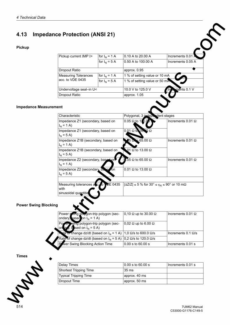
4 Technical Data
om
4.13 Impedance Protection (ANSI 21)
Pickup
Impedance Measurement
Power Swing Blocking
Times
Pickup current IMP I> for IN = 1 A 0.10 A to 20.00 A Increments 0.01 Afor IN = 5 A 0.50 A to 100.00 A Increments 0.05 A
Dropout Ratio approx. 0.95Measuring Tolerances acc. to VDE 0435
for IN = 1 A 1 % of setting value or 10 mAfor IN = 5 A 1 % of setting value or 50 mA
Undervoltage seal–in U< 10.0 V to 125.0 V Increments 0.1 VDropout Ratio approx. 1.05
Characteristic Polygonal, 3 independent stagesImpedance Z1 (secondary, based onIN = 1 A)
0.05 Ω to 130.00 Ω Increments 0.01 Ω
Impedance Z1 (secondary, based onIN = 5 A)
0.01 Ω to 26.00 Ω
Impedance Z1B (secondary, based onIN = 1 A)
0.05 Ω to 65.00 Ω Increments 0.01 Ω
Impedance Z1B (secondary, based onIN = 5 A)
0.01 Ω to 13.00 Ω
Impedance Z2 (secondary, based onIN = 1 A)
0.05 Ω to 65.00 Ω Increments 0.01 Ω
Impedance Z2 (secondary, based onIN = 5 A)
0.01 Ω to 13.00 Ω
Measuring tolerances acc. to VDE 0435 withsinusoidal quantities
|∆Z/Z| ≤ 5 % for 30° ≤ ϕK ≤ 90° or 10 mΩ
Power swing polygon-trip polygon (sec-ondary, based on IN = 1 A)
0,10 Ω up to 30.00 Ω Increments 0.01 Ω
Power swing polygon-trip polygon (sec-ondary, based on IN = 5 A)
0,02 Ω up to 6.00 Ω
Rate of change dz/dt (based on IN = 1 A) 1,0 Ω/s to 600.0 Ω/s Increments 0.1 Ω/sRate of change dz/dt (based on IN = 5 A) 0,2 Ω/s to 120.0 Ω/sPower Swing Blocking Action Time 0.00 s to 60.00 s Increments 0.01 s
Delay Times 0.00 s to 60.00 s Increments 0.01 sShortest Tripping Time 35 msTypical Tripping Time approx. 40 msDropout Time approx. 50 msww .
Elec
tricalP
artM
anua
ls . c
514 7UM62 ManualC53000-G1176-C149-5
w

4.13 Impedance Protection (ANSI 21)w
Influencing Variables for Pickup Values
Holding Time of Undervoltage Seal-In 0.10 s to 60.00 s Increments 0.01 sDelay Time Tolerances 1 % of setting value or 10 ms
Power supply direct voltage in range0,8 ≤ UAux/UAux,N ≤ 1.15
≤ 1 %
Temperature in Range23.00 °F (–5 °C) ≤ Θ amb ≤ 131.00 °F (55 °C)
≤ 0.5 % / 10 K
Frequency in range 0.95 ≤ f/fN ≤ 1.05 ≤ 1 %Harmonics- Up to 10 % 3rd harmonic - Up to 10 % 5th harmonic
≤ 1 %≤ 1 %
ww . El
ectric
alPar
tMan
uals
. com
5157UM62 ManualC53000-G1176-C149-5
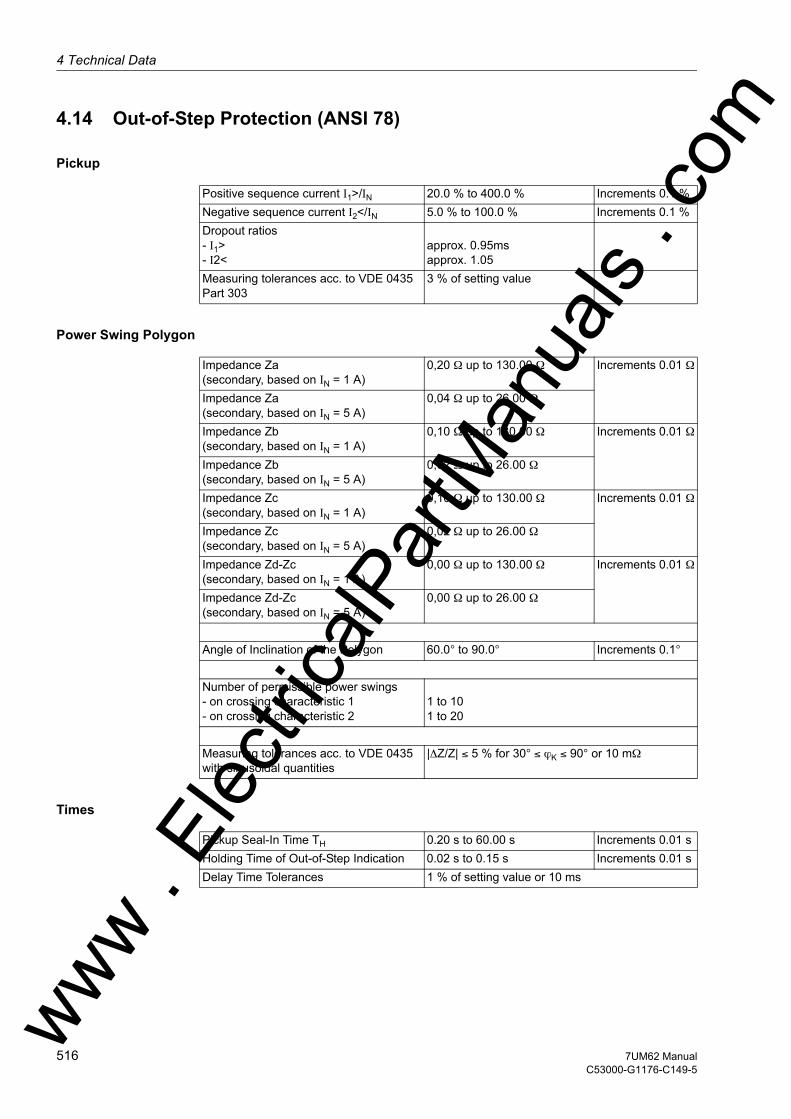
4 Technical Data
om
4.14 Out-of-Step Protection (ANSI 78)
Pickup
Power Swing Polygon
Times
Positive sequence current I1>/IN 20.0 % to 400.0 % Increments 0.1 %Negative sequence current I2</IN 5.0 % to 100.0 % Increments 0.1 %Dropout ratios- I1>- I2<
approx. 0.95msapprox. 1.05
Measuring tolerances acc. to VDE 0435Part 303
3 % of setting value
Impedance Za (secondary, based on IN = 1 A)
0,20 Ω up to 130.00 Ω Increments 0.01 Ω
Impedance Za(secondary, based on IN = 5 A)
0,04 Ω up to 26.00 Ω
Impedance Zb (secondary, based on IN = 1 A)
0,10 Ω up to 130.00 Ω Increments 0.01 Ω
Impedance Zb(secondary, based on IN = 5 A)
0,02 Ω up to 26.00 Ω
Impedance Zc (secondary, based on IN = 1 A)
0,10 Ω up to 130.00 Ω Increments 0.01 Ω
Impedance Zc(secondary, based on IN = 5 A)
0,02 Ω up to 26.00 Ω
Impedance Zd-Zc(secondary, based on IN = 1 A)
0,00 Ω up to 130.00 Ω Increments 0.01 Ω
Impedance Zd-Zc(secondary, based on IN = 5 A)
0,00 Ω up to 26.00 Ω
Angle of Inclination of the Polygon 60.0° to 90.0° Increments 0.1°
Number of permissible power swings- on crossing characteristic 1- on crossing characteristic 2
1 to 101 to 20
Measuring tolerances acc. to VDE 0435with sinusoidal quantities
|∆Z/Z| ≤ 5 % for 30° ≤ ϕK ≤ 90° or 10 mΩ
Pickup Seal-In Time TH 0.20 s to 60.00 s Increments 0.01 sHolding Time of Out-of-Step Indication 0.02 s to 0.15 s Increments 0.01 sDelay Time Tolerances 1 % of setting value or 10 ms
ww . El
ectric
alPar
tMan
uals
. c
516 7UM62 ManualC53000-G1176-C149-5
w

4.14 Out-of-Step Protection (ANSI 78)w
Influencing Variables for Pickup Values
Power supply direct voltage in range0,8 ≤ UAux/UAux,N ≤ 1.15
≤ 1 %
Temperature in Range23.00 °F (–5 °C) ≤ Θ amb ≤ 131.00 °F (55 °C)
≤ 0.5 % / 10 K
Frequency in range 0.95 ≤ f/fN ≤ 1.05 ≤ 1 %Harmonics- Up to 10 % 3rd harmonic - Up to 10 % 5th harmonic
≤ 1 %≤ 1 %
ww . El
ectric
alPar
tMan
uals
. com
5177UM62 ManualC53000-G1176-C149-5

4 Technical Data
om
4.15 Undervoltage Protection (ANSI 27)
Setting Ranges / Increments
Operating Times
Dropout Ratio
Tripping Characteristic
Tolerances
Measured Quantity Positive Sequence phase-to-earth voltages as phase-to-phase Values
Pickup voltages U<, U<<, Up< 10.0 V to 125.0 V Increments 0.1 VDropout ratio RV U< (only stages U<, U<<)
1.01 to 1.20 Increments 0.01
Time delays T U<, T U<< 0.00 s to 60.0 sor ∞ (ineffective)
Increments 0.01 s
Time multiplication factorTMUL for Inverse Characteristic
0.10 s to 5.00 s Increments 0.01 s
Additional time delay TUp< for Inverse Characteristic
0.00 s to 60.00 sor ∞ (ineffective)
Increments 0.01 s
The set times are pure delay times.
Pickup Times approx. 50 msDropout Times approx. 50 ms
from the pickup value of the inverse charac-teristic
1.01 or 0.5 V absolute
see also Figure 4-12
Pickup voltages U<, U<<, Up< 1 % of setting value or 0.5 VTime delays T, TUp< 1 % of setting value or 10 msVoltage-Time Characteristic 1 % based on U, or 30 ms
ww . El
ectric
alPar
tMan
uals
. c
518 7UM62 ManualC53000-G1176-C149-5
w
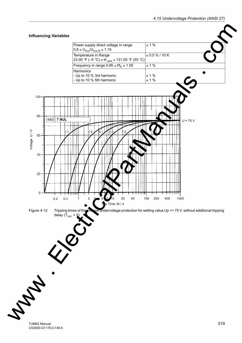
4.15 Undervoltage Protection (ANSI 27)w
Influencing Variables
Figure 4-12 Tripping times of the inverse undervoltage protection for setting value Up <= 75 V, without additional tripping delay (TUp< = 0)
Power supply direct voltage in range0,8 ≤ UAux/UAux,N ≤ 1.15
≤ 1 %
Temperature in Range23.00 °F (–5 °C) ≤ Θ amb ≤ 131.00 °F (55 °C)
≤ 0.5 % / 10 K
Frequency in range 0.95 ≤ f/fN ≤ 1.05 ≤ 1 %Harmonics- Up to 10 % 3rd harmonic - Up to 10 % 5th harmonic
≤ 1 %≤ 1 %
ww . El
ectric
alPar
tMan
uals
. com
5197UM62 ManualC53000-G1176-C149-5
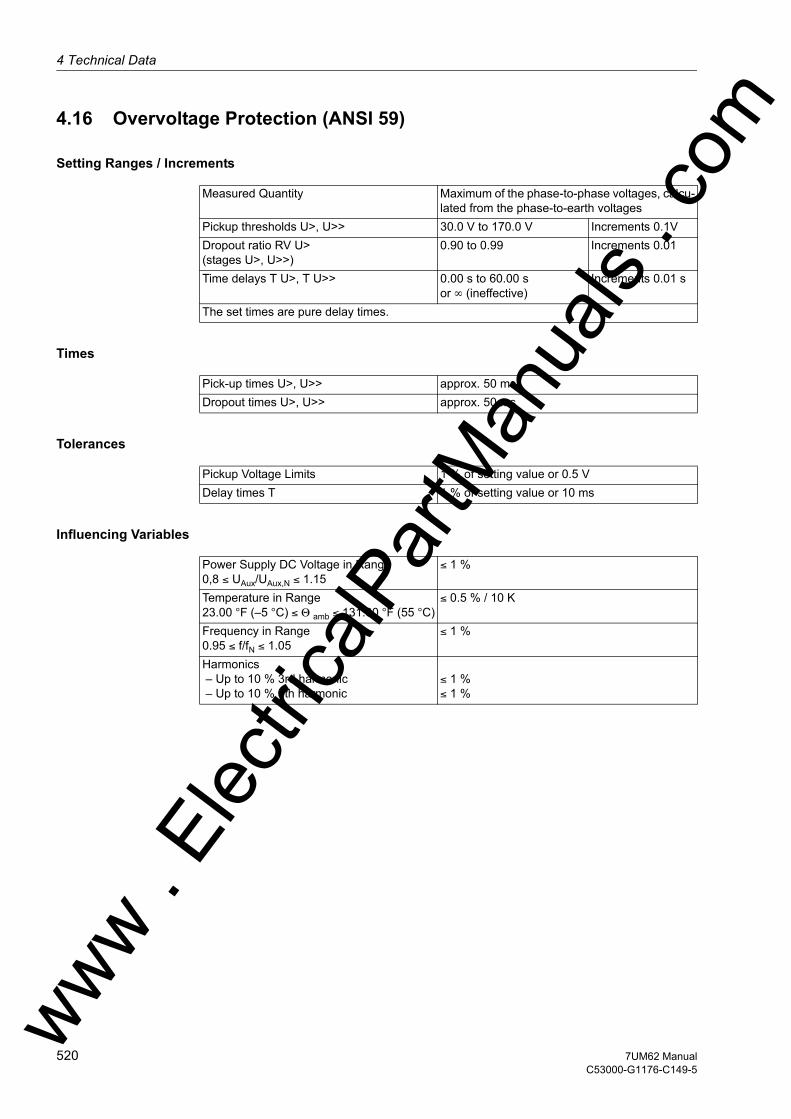
4 Technical Data
om
4.16 Overvoltage Protection (ANSI 59)
Setting Ranges / Increments
Times
Tolerances
Influencing Variables
Measured Quantity Maximum of the phase-to-phase voltages, calcu-lated from the phase-to-earth voltages
Pickup thresholds U>, U>> 30.0 V to 170.0 V Increments 0.1VDropout ratio RV U>(stages U>, U>>)
0.90 to 0.99 Increments 0.01
Time delays T U>, T U>> 0.00 s to 60.00 sor ∞ (ineffective)
Increments 0.01 s
The set times are pure delay times.
Pick-up times U>, U>> approx. 50 msDropout times U>, U>> approx. 50 ms
Pickup Voltage Limits 1 % of setting value or 0.5 VDelay times T 1 % of setting value or 10 ms
Power Supply DC Voltage in Range0,8 ≤ UAux/UAux,N ≤ 1.15
≤ 1 %
Temperature in Range23.00 °F (–5 °C) ≤ Θ amb ≤ 131.00 °F (55 °C)
≤ 0.5 % / 10 K
Frequency in Range0.95 ≤ f/fN ≤ 1.05
≤ 1 %
Harmonics – Up to 10 % 3rd harmonic – Up to 10 % 5th harmonic
≤ 1 %≤ 1 %
ww . El
ectric
alPar
tMan
uals
. c
520 7UM62 ManualC53000-G1176-C149-5
w

4.17 Frequency Protection (ANSI 81)w
4.17 Frequency Protection (ANSI 81)
Setting Ranges / Increments
Times
Dropout Difference
Dropout Ratio
Tolerances
Influencing Variables
Number of Frequency Elements 4; can be set to f> or f< Pickup Frequency f> or f< 40 Hz to 66.00 Hz Increments 0.01 HzDelay TimesT f1T f2 to T f4
0.00 s to 600.00 s0.00 s to 100.00 s
Increments 0.01 sIncrements 0.01 s
Undervoltage Blocking(positive sequence component U1)
10.0 V to 125.0 V and0 V (no blocking)
Increments 0.1V
The set times are pure delay times.
Pickup times f>, f<Dropout Times f>, f<
approx. 100 msapprox. 100 ms
∆f = | Pickup Value – Dropout Value | approx. 20 mHz
Dropout ratiofor undervoltage blocking
approx. 1.05
Frequencies f>, f<Undervoltage BlockingTime Delays T(f<, f<)
10 mHz (at U = UN, f = fN)1 % of setting value or 0.5 V1 % of setting value or 10 ms
Power Supply DC Voltage in Range0,8 ≤ UAux/UAux,N ≤ 1.15
1 %
Temperature in Range23.00 °F (–5 °C) ≤ Θ amb ≤ 131.00 °F (55 °C)
0.5 %/10 K
Harmonics- Up to 10 % 3rd harmonic - Up to 10 % 5th harmonic
1 %1 %
ww . El
ectric
alPar
tMan
uals
. com
5217UM62 ManualC53000-G1176-C149-5
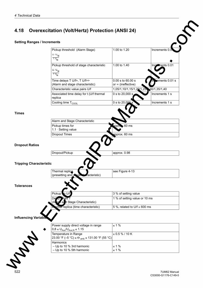
4 Technical Data
om
4.18 Overexcitation (Volt/Hertz) Protection (ANSI 24)
Setting Ranges / Increments
Times
Dropout Ratios
Tripping Characteristic
Tolerances
Influencing Variables
Pickup threshold (Alarm Stage) 1.00 to 1.20 Increments 0.01
Pickup threshold of stage characteristic 1.00 to 1.40 Increments 0.01
Time delays T U/f>, T U/f>> (Alarm and stage characteristic)
0.00 s to 60.00 sor ∞ (ineffective)
Increments 0.01 s
Characteristic value pairs U/f 1,05/1,10/1,15/1,20/1,25/1,30/1,35/1,40Associated time delay for t (U/f thermal replica
0 s to 20,000 s Increments 1 s
Cooling time TCOOL 0 s to 20,000 s Increments 1 s
Alarm and Stage CharacteristicPickup times for 1.1 · Setting value
approx. 60 ms
Dropout Times approx. 60 ms
Dropout/Pickup approx. 0.98
Thermal replica(presetting and stage characteristic)
see Figure 4-13
Pickup on U/f 3 % of setting valueDelay times T(Alarm and Stage Characteristic)
1 % of setting value or 10 ms
thermal replica (time characteristic) 5 %, related to U/f ± 600 ms
Power supply direct voltage in range0,8 ≤ UAux/UAux,N ≤ 1.15
≤ 1 %
Temperature in Range23.00 °F (–5 °C) ≤ Θ amb ≤ 131.00 °F (55 °C)
≤ 0.5 % / 10 K
Harmonics – Up to 10 % 3rd harmonic – Up to 10 % 5th harmonic
≤ 1 %≤ 1 %ww .
Elec
tricalP
artM
anua
ls . c
522 7UM62 ManualC53000-G1176-C149-5
w
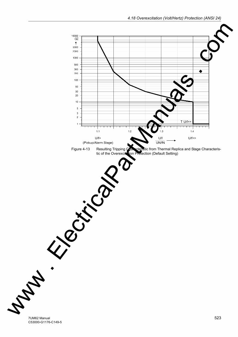
4.18 Overexcitation (Volt/Hertz) Protection (ANSI 24)w
Figure 4-13 Resulting Tripping Characteristic from Thermal Replica and Stage Characteris-tic of the Overexcitation Protection (Default Setting)
ww . El
ectric
alPar
tMan
uals
. com
5237UM62 ManualC53000-G1176-C149-5
4 Technical Data
om
4.19 Rate-of-Frequency-Change Protection df/dt (ANSI 81R)
Setting Ranges / Increments
Times
Dropout Ratios
Tolerances
Influencing Variables for Pickup Values
Stages, can be +df/dt> or –df/dt 4Pickup values df/dt 0.1 Hz/s to 10.0 Hz/s Increments 0.1
Hz/sDelay times T 0.00 s to 60.00 s
or ∞ (ineffective)Increments 0.01 s
Undervoltage blocking U1> 10.0 V to 125.0 V Increments 0.1 VWindow Length 1 to 25 cycles
Pickup Times df/dt Approx. 150 ms to 500 ms(dep. on window length)
Dropout Times df/dt approx. 150 ms to 500 ms(dep. on window length)
Dropout Difference ∆f/dt 0.02 Hz/s to 0.99 Hz/s (adjustable)Dropout Ratio approx. 1.05
Frequency Rise –Measuring Window < 5 Approx. 5 % or 0.15 Hz/s at U > 0,5 UN
– Measuring Window ≥ 5 Approx. 3 % or 0.1 Hz/s at U > 0,5 UN
Undervoltage Blocking 1 % of setting value or 0.5 VDelay Times 1 % or 10 ms
Power Supply DC Voltage in Range0,8 ≤ UAux/UAux,N ≤ 1.15
≤ 1 %
Temperature in Range23.00 °F (–5 °C) ≤ Θ amb ≤ 131.00 °F (55 °C)
≤ 0.5 % / 10 K
Harmonics- Up to 10 % 3rd harmonic - Up to 10 % 5th harmonic
≤ 1 %≤ 1 %
ww . El
ectric
alPar
tMan
uals
. c
524 7UM62 ManualC53000-G1176-C149-5
w
4.20 Jump of Voltage Vectorw
4.20 Jump of Voltage Vector
Setting Ranges / Increments
Times
Dropout Ratios
Tolerances
Influencing Variables
Stage ∆ϕ 2° to 30° Increments 1°Delay Time T 0.00 to 60.00 s
or ∞ (ineffective)Increments 0.01 s
Reset Time TReset 0.00 to 60.00 sor ∞ (ineffective)
Increments 0.00 s
Undervoltage Blocking U1> 10.0 to 125.0 V Increments 0.1 V
Pickup Times ∆ϕ approx. 75 msDropout Times ∆ϕ approx. 75 ms
– –
Angle Jump 0.5° at U > 0.5 UN
Undervoltage Blocking 1 % of setting value or 0.5 VDelay times T 1 % or 10 ms
Power Supply DC Voltage in Range0,8 ≤ UAux/UAux,N ≤ 1.15
≤ 1 %
Temperature in Range23.00 °F (–5 °C) ≤ Θ amb ≤ 131.00 °F (55 °C)
≤ 0.5 % / 10 K
Frequency in Range0.95 ≤ f/fN ≤ 1.05
≤ 1 %
Harmonics- Up to 10 % 3rd harmonic - Up to 10 % 5th harmonic
≤ 1 %≤ 1 %
ww . El
ectric
alPar
tMan
uals
. com
5257UM62 ManualC53000-G1176-C149-5

4 Technical Data
om
4.21 90-%-Stator Earth Fault Protection (ANSI 59N, 64G, 67G)
Setting Ranges / Increments
Times
Dropout Ratio / Dropout Difference
Tolerances
Influencing Variables
Displacement voltage U0> 2.0 V to 125.0 V Increments 0.1 VEarth current 3I0> 2 mA to 1000 mA Increments 1 mAEarth current angle criterion 0° to 360° Increments 1°Delay Time TSEF 0.00 s to 60.00 s
or ∞ (ineffective)Increments 0.01 s
The set times are pure delay times.
Pickup TimesU03I0directional
approx. 50 msapprox. 50 msapprox. 70 ms
Dropout TimesU03I0directional
approx. 50 msapprox. 50 msapprox. 70 ms
Displacement voltage U0 approx. 0.70Earth current 3I0 approx. 0.70Angle criterion (dropout difference) 10° towards network
Displacement Voltage 1 % of setting value or 0.5 VEarth current 1 % of setting value or 0.5 mADelay times T 1 % of setting value or 10 ms
Power Supply DC Voltage in Range0,8 ≤ UAux/UAux,N ≤ 1.15
≤ 1 %
Temperature in Range23.00 °F (–5 °C) ≤ Θ amb ≤ 131.00 °F (55 °C)
≤ 0.5 % / 10 K
Frequency in Range0.95 ≤ f/fN ≤ 1.05
≤ 1 %
Harmonics – Up to 10 % 3rd harmonic – Up to 10 % 5th harmonic
≤ 1 %≤ 1 %
ww . El
ectric
alPar
tMan
uals
. c
526 7UM62 ManualC53000-G1176-C149-5
w

4.22 Sensitive Earth Fault Protection (ANSI 51GN, 64R)w
4.22 Sensitive Earth Fault Protection (ANSI 51GN, 64R)
Setting Ranges / Increments
Times
Dropout Ratios
Tolerances
Influencing Variables
Pickup current IEE> 2 mA to 1000 mA Increments 1 mADelay Time TIEE> 0.00 s to 60.00 s
or ∞ (ineffective)Increments 0.01 s
Pickup current IEE>> 2 mA to 1000 mA Increments 1 mADelay time TIEE>> 0.00 s to 60.00 s
or ∞ (ineffective)Increments 0.01 s
Measuring circuit supervision when used as rotor earth fault protection IEE<
1.5 mA to 50.0 mAor 0.0 mA (ineffective)
Increments 0.1 mA
Pickup Times approx. 50 msDropout Times approx. 50 msMeasuring Circuit Supervision (Delay) approx. 2 s
Pickup current IEE>, IEE>> approx. 0.95 or 1 mAMeasuring circuit supervision IEE< approx. 1.10 or 1 mA
Pickup current 1 % of setting value or 0.5 mATime Delay 1 % of setting value or 10 ms
Power Supply DC Voltage in Range0,8 ≤ UAux/UAux,N ≤ 1.15
≤ 1 %
Temperature in Range23.00 °F (–5 °C) ≤ Θ amb ≤ 131.00 °F (55 °C)
≤ 0.5 % / 10 K
Frequency in Range0.95 ≤ f/fN ≤ 1.05
≤ 1 %
Harmonics- Up to 10 % 3rd harmonic - Up to 10 % 5th harmonic
≤ 1 %≤ 1 %
Note: For the purpose of high sensitivity, the linear range of the measuring input for the sensi-tive ground fault acquisition is from 2 mA to 1600 mA.
ww . El
ectric
alPar
tMan
uals
. com
5277UM62 ManualC53000-G1176-C149-5

4 Technical Data
om
4.23 100-%-Stator Earth Fault Protection with 3rd Harmonics (ANSI 27/59TN 3rd Harm.)
Setting Ranges / Increments
Times
Dropout Ratios
Tolerances
Influencing Variables
Pickup value for 3rd harmonic in undervolt-age stage U0 (3rd harmon.)<
0.2 V to 40.0 V Increments 0.1 V
Pickup value for 3rd harmonic in undervolt-age stage U0 (3rd harmon.)>
0.2 V to 40.0 V Increments 0.1 V
Delay Time TSEF (3rd HARM) 0.00 s to 60.00 sor ∞ (ineffective)
Increments 0.01 s
Enabling conditionsP/Pmin > 10 % to 100 %
or (ineffective)Increments 1 %
U/U1 min> 50.0 V to 125.0 Vor (ineffective)
Increments 0.1 V
Correction factor U03h(V/100%) for stage U0(3rd harmon.)>
–40.0 to +40.0 Increments 0.1
Pickup Times approx. 80 msDropout Times approx. 80 ms
Undervoltage stage U0 (3rd harmon.)< approx. 1.10 or 0.1 mAUndervoltage stage U0 (3rd harmon.)> approx. 0.90 or -0.1 VEnabling conditionsP/Pmin > approx. 0.90U/U1 min> approx. 0.95
Displacement Voltage 3 % of setting value or 0.1 VDelay Time TSEF (3rd HARM) 1 % of setting value or 10 ms
Power Supply DC Voltage in Range0,8 ≤ UAux/UAux,N ≤ 1.15
≤ 1 %
Temperature in Range23.00 °F (–5 °C) ≤ Θ amb ≤ 131.00 °F (55 °C)
≤ 0.5 % / 10 K
Frequency in Range0.95 ≤ f/fN ≤ 1.05
≤ 1 %
ww . El
ectric
alPar
tMan
uals
. c
528 7UM62 ManualC53000-G1176-C149-5
w
4.24 100-%-Stator Earth Fault Protection with 20 Hz Voltage Injection (ANSI 64G - 100%)w
4.24 100-%-Stator Earth Fault Protection with 20 Hz Voltage Injection (ANSI 64G - 100%)
Setting Ranges / Increments
Times
Dropout Ratios
Tolerances
Influencing Variables for Pickup Values
Alarm Stage RSEF< 20 Ω to 700 Ω Increments 1 ΩTripping Stage RSEF<< 20 Ω to 700 Ω Increments 1 ΩEarth currrent stage ISEF> 0.02 A to 1.50 A Increments 0.01 ATime Delay 0.00 s to 60.00 s
or ∞ (ineffective)Increments 0.01 s
Failure Monitoring 20 HZ GeneratorU20 0.3 V to 15 V Increments 0.1VI20 5 mA to 40 mA Increments 1 mACorrection Angle -60° to +60° Increments 1°
Pickup Time RSEF<, RSEF<< ≤ 1.3 sPickup Time ISES> ≤ 250 msDropout Times RSEF<, RSEF<< ≤ 0.8 sDropout Times ISEF> ≤ 120 ms
Dropout Ratio Approx. 1.2 to 1.7
Resistance approx. 5 % or 2 Ω
Current 3 % or 3 mATime Delay 1 % or 10 ms
Power Supply DC Voltage in Range0,8 ≤ UAux/UAux,N ≤ 1.15
≤ 1 %
Temperature in Range23.00 °F (–5 °C) ≤ Θ amb ≤ 131.00 °F (55 °C)
≤ 0.5 %/10 K
Frequency in range0.95 ≤ f/fN ≤ 1.05
≤ 1 %
Harmonics- Up to 10 % 3rd harmonic - Up to 10 % 5th harmonic
≤ 1 %≤ 1 %
ww . El
ectric
alPar
tMan
uals
. com
5297UM62 ManualC53000-G1176-C149-5

4 Technical Data
om
4.25 Sensitive Earth Fault Protection B (ANSI 51GN)
Setting Ranges / Increments
Times
Drop-off to pick-up ratio
Tolerances
Influencing Variables
Pickup Current IEE-B> 0.3 mA to 1000.0 mA Increments 0.1 mADelay Time TIEE-B> 0.00 s to 60.00 s
or ∞ (ineffective)Increments 0.01 s
Pickup Current IEE-B< 0.3 mA to 500.0 mAor 0 (ineffective)
Increments 0.1 mA
Delay Time TIEE-B> 0.00 s to 60.00 sor ∞ (ineffective)
Increments 0.01 s
Pickup Seal-In Time IeeB> 0.00 s to 60.00 s Increments 0.01 sPickup Seal-In Time IeeB< 0.00 s to 60.00 s Increments 0.01 sMeasurement Method when Used as Rotor Earth Fault Protection
- Fundamental- 3. Harmonics- 1. and 3rd harmonic
Pick-up times approx. 50 msDropout times approx. 50 ms
Pickup Current IEE-B> approx. 0.90 or 0.15 mAIEE-B< approx. 1.10 or 0.15 mA
Pickup current 1 % of setting value or 0.1 mATime delay 1 % of set value or 10 ms
Power supply direct voltage in range0,8 ≤ UAux/UAux,N ≤ 1.15
≤ 1 %
Temperature in range23.00 °F (–5 °C) ≤ Θ amb ≤ 131.00 °F (55 °C)
≤ 0.5 %/10 K
Frequency in range0.95 ≤ f/fN ≤ 1.05
≤ 1 %
Harmonics- Up to 10 % 3rd harmonic- Up to 10 % 5th harmonic
≤ 1 %≤ 1 %
ww . El
ectric
alPar
tMan
uals
. c
530 7UM62 ManualC53000-G1176-C149-5
w

4.26 Interturn Protection (ANSI 59N (IT))w
4.26 Interturn Protection (ANSI 59N (IT))
Setting Ranges / Increments
Times
Drop-off to pick-up ratio
Tolerances
Influencing Variables
Pickup thresholds of displacement voltage Uw>
0.3 V to 130.0 V Increments 0.1 V
TUInterturn> 0.00 s to 60.00 sor ∞ (ineffective)
Increments 0.01 s
Pick-up times approx. 60 msDropout times approx. 60 ms
Pickup stage UInterturn> approx. 0.5 to 0.95 s (adjustable)
Displacement voltage 1 % of setting value or 0.1 VTime delay 1 % of set value or 10 ms
Power supply direct voltage in range0,8 ≤ UAux/UAux,N ≤ 1.15
≤ 1 %
Temperature in range23.00 °F (–5 °C) ≤ Θ amb ≤ 131.00 °F (55 °C)
≤ 0.5 %/10 K
Frequency in range0.95 ≤ f/fN ≤ 1.05
≤ 1 %
Harmonics- Up to 10 % 3rd harmonic- Up to 10 % 5th harmonic
≤ 1 %≤ 1 %
ww . El
ectric
alPar
tMan
uals
. com
5317UM62 ManualC53000-G1176-C149-5
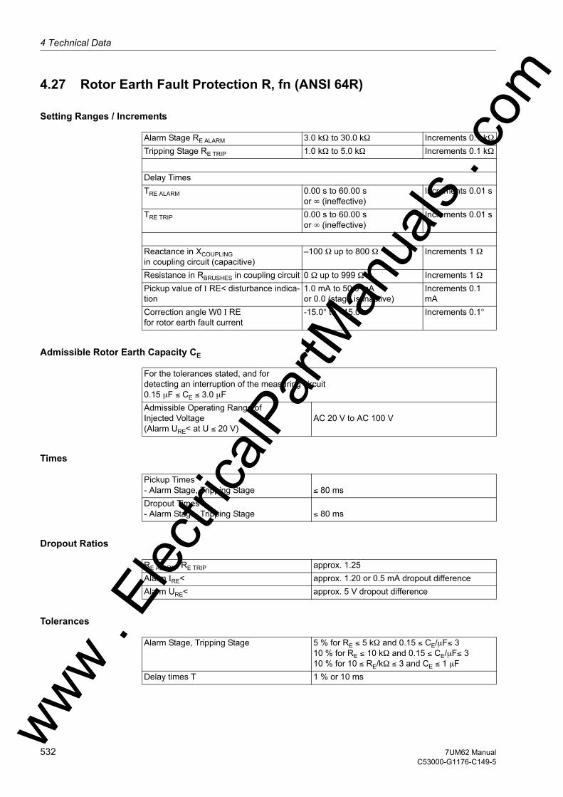
4 Technical Data
om
4.27 Rotor Earth Fault Protection R, fn (ANSI 64R)
Setting Ranges / Increments
Admissible Rotor Earth Capacity CE
Times
Dropout Ratios
Tolerances
Alarm Stage RE ALARM 3.0 kΩ to 30.0 kΩ Increments 0.1 kΩTripping Stage RE TRIP 1.0 kΩ to 5.0 kΩ Increments 0.1 kΩ Delay TimesTRE ALARM 0.00 s to 60.00 s
or ∞ (ineffective)Increments 0.01 s
TRE TRIP 0.00 s to 60.00 sor ∞ (ineffective)
Increments 0.01 s
Reactance in XCOUPLING in coupling circuit (capacitive)
–100 Ω up to 800 Ω Increments 1 Ω
Resistance in RBRUSHES in coupling circuit 0 Ω up to 999 Ω Increments 1 ΩPickup value of I RE< disturbance indica-tion
1.0 mA to 50.0 mAor 0.0 (stage is inactive)
Increments 0.1 mA
Correction angle W0 I RE for rotor earth fault current
-15.0° to +15.0° Increments 0.1°
For the tolerances stated, and for detecting an interruption of the measuring circuit0.15 µF ≤ CE ≤ 3.0 µF Admissible Operating Range ofInjected Voltage(Alarm URE< at U ≤ 20 V)
AC 20 V to AC 100 V
Pickup Times- Alarm Stage, Tripping Stage
≤ 80 ms
Dropout Times- Alarm Stage, Tripping Stage
≤ 80 ms
RE ALARM, RE TRIP approx. 1.25Alarm IRE< approx. 1.20 or 0.5 mA dropout differenceAlarm URE< approx. 5 V dropout difference
Alarm Stage, Tripping Stage 5 % for RE ≤ 5 kΩ and 0.15 ≤ CE/µF≤ 310 % for RE ≤ 10 kΩ and 0.15 ≤ CE/µF≤ 310 % for 10 ≤ RE/kΩ ≤ 3 and CE ≤ 1 µF
Delay times T 1 % or 10 ms
ww . El
ectric
alPar
tMan
uals
. c
532 7UM62 ManualC53000-G1176-C149-5
w

4.27 Rotor Earth Fault Protection R, fn (ANSI 64R)w
Influencing Variables for Pickup Values
Power supply direct voltage in range0,8 ≤ UAux/UAux,N ≤ 1.15
≤ 1 %
Temperature in Range23.00 °F (–5 °C) ≤ Θ amb ≤ 131.00 °F (55 °C)
≤ 0.5 % / 10 K
Frequency in range 0.95 ≤ f/fN ≤ 1.05 ≤ 1 %
ww . El
ectric
alPar
tMan
uals
. com
5337UM62 ManualC53000-G1176-C149-5
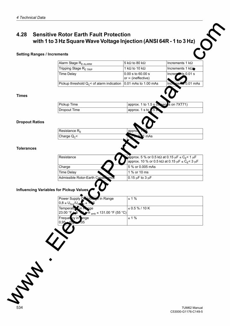
4 Technical Data
om
4.28 Sensitive Rotor Earth Fault Protection with 1 to 3 Hz Square Wave Voltage Injection (ANSI 64R - 1 to 3 Hz)
Setting Ranges / Increments
Times
Dropout Ratios
Tolerances
Influencing Variables for Pickup Values
Alarm Stage RE ALARM 5 kΩ to 80 kΩ Increments 1 kΩTripping Stage RE TRIP 1 kΩ to 10 kΩ Increments 1 kΩTime Delay 0.00 s to 60.00 s
or ∞ (ineffective)Increments 0.01 s
Pickup threshold QC< of alarm indication 0.01 mAs to 1.00 mAs Increments 0.01 mAs
Pickup Time approx. 1 to 1.5 s (depends on 7XT71)Dropout Time approx. 1 s to 1.5 s
Resistance RE approx. 1.25Charge QC< 1.2 or 0.01 mAs
Resistance approx. 5 % or 0.5 kΩ at 0.15 µF ≤ CE< 1 µFapprox. 10 % or 0.5 kΩ at 0.15 µF ≤ CE< 3 µF
Charge 5 % or 0.005 mAsTime Delay 1 % or 10 msAdmissible Rotor-Earth Capacitance 0.15 µF to 3 µF
Power Supply DC Voltage in Range0,8 ≤ UAux/UAux,N ≤ 1.15
≤ 1 %
Temperature in Range23.00 °F (–5 °C) ≤ Θ amb ≤ 131.00 °F (55 °C)
≤ 0.5 % / 10 K
Frequency in range0,95 ≤ f/fN ≤ 1.05
≤ 1 %
ww . El
ectric
alPar
tMan
uals
. c
534 7UM62 ManualC53000-G1176-C149-5
w

4.29 Motor Starting Time Supervision (ANSI 48)w
4.29 Motor Starting Time Supervision (ANSI 48)
Setting Ranges / Increments
Tripping Characteristic
Dropout Ratio
Tolerances
Influencing Variables for Pickup Values
Motor Startup CurrentISTARTUP
for IN = 1 A 0.10 A to 16.00 A Increments 0.01 Afor IN = 5 A 0.50 A to 80.00 A Increments 0.01 A
Pickup Threshold for Startup DetectionISTARTUP DETECT.
for IN = 1 A 0.60 A to 10.0 A Increments 0.01 Afor IN = 5 A 3.00 A to 50.00 A Increments 0.01 A
Maximum Startup TimeTMax. STARTUP
1.0 s to 180.0 s Increments 0.1 s
Admissible Locked Rotor TimeTLOCKED-ROTOR
0.5 s to 120.0 sor ∞ (ineffective)
Increments 0.1 s
Irms/ISTARTUP DETECT. approx. 0.95
Pickup Threshold for IN = 1 A 1 % of setting value or 10 mAfor IN = 5 A 1 % of setting value or 50 mA
Time Delay 5 % or 30 ms
Power Supply DC Voltage in Range0,8 ≤ UAux/UAux,N ≤ 1.15
≤ 1 %
Temperature in Range23.00 °F (–5 °C) ≤ Θ amb ≤ 131.00 °F (55 °C)
≤ 0.5 % / 10 K
Frequency in Range0.95 ≤ f/fN ≤ 1.05
≤ 1 %
Harmonics- Up to 10 % 3rd harmonic - Up to 10 % 5th harmonic
≤ 1 %≤ 1 %
ww . El
ectric
alPar
tMan
uals
. com
5357UM62 ManualC53000-G1176-C149-5

4 Technical Data
om
4.30 Restart Inhibit for Motors (ANSI 66, 49Rotor)
Setting Ranges / Increments
Restart Threshold
Restarting Times
Motor starting current relative to Nominal Motor CurrentISTART/IMotor Nom
1.5 to 10.0 Increments 0.1
Max. admissible Startup TimeTStart Max
3.0 s to 120.0 s Increments 0.1 s
Leveling TimeTLEVEL
0.0 min to 60.0 min Increments 0.1 min
Maximum admissible Number of Warm Starts nWARM
1 to 4 Increments 1
Difference between Cold and Warm StartsnCold – nWarm
1 to 2 Increments 1
Extension Factor at Standstillkτ STANDSTILL
1.0 to 100.0 Increments 0.1
Extension of Time Constant at Motor Runningkτ OPERATION
1.0 to 100.0 Increments 0.1
Minimum Restart Inhibit Time 0.2 min to 120.0 min Increments 0.1 min
Significance:ΘRe.Inh. Temperature limit below which a restart is possibleΘL max adm Maximum admissible rotor overtemperature (= 100 % of operational
value ΘL/ΘL Trip)ncold number of admissible starts from coldTRem. Time after which motor may be reswitched onTLeveling Leveling time during which the thermal replica is "frozen"TRe.Inh. Time until the thermal replica is again below the restart threshold
depends on:ΘHist Rotor temperature past historyτ Rotor time constant, internally calculatedkτ Extension factor for the time constant kτ OPERATION or kτ STANDSTILL
ww . El
ectric
alPar
tMan
uals
. c
536 7UM62 ManualC53000-G1176-C149-5
w
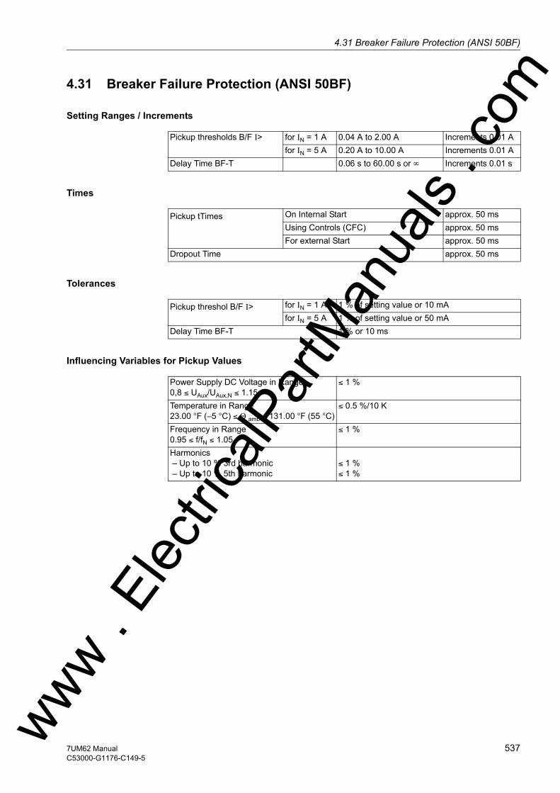
4.31 Breaker Failure Protection (ANSI 50BF)w
4.31 Breaker Failure Protection (ANSI 50BF)
Setting Ranges / Increments
Times
Tolerances
Influencing Variables for Pickup Values
Pickup thresholds B/F I> for IN = 1 A 0.04 A to 2.00 A Increments 0.01 Afor IN = 5 A 0.20 A to 10.00 A Increments 0.01 A
Delay Time BF-T 0.06 s to 60.00 s or ∞ Increments 0.01 s
Pickup tTimes On Internal Start approx. 50 msUsing Controls (CFC) approx. 50 msFor external Start approx. 50 ms
Dropout Time approx. 50 ms
Pickup threshol B/F I> for IN = 1 A 1 % of setting value or 10 mAfor IN = 5 A 1 % of setting value or 50 mA
Delay Time BF-T 1 % or 10 ms
Power Supply DC Voltage in Range0,8 ≤ UAux/UAux,N ≤ 1.15
≤ 1 %
Temperature in Range23.00 °F (–5 °C) ≤ Θ amb ≤ 131.00 °F (55 °C)
≤ 0.5 %/10 K
Frequency in Range0.95 ≤ f/fN ≤ 1.05
≤ 1 %
Harmonics – Up to 10 % 3rd harmonic – Up to 10 % 5th harmonic
≤ 1 %≤ 1 %
ww . El
ectric
alPar
tMan
uals
. com
5377UM62 ManualC53000-G1176-C149-5
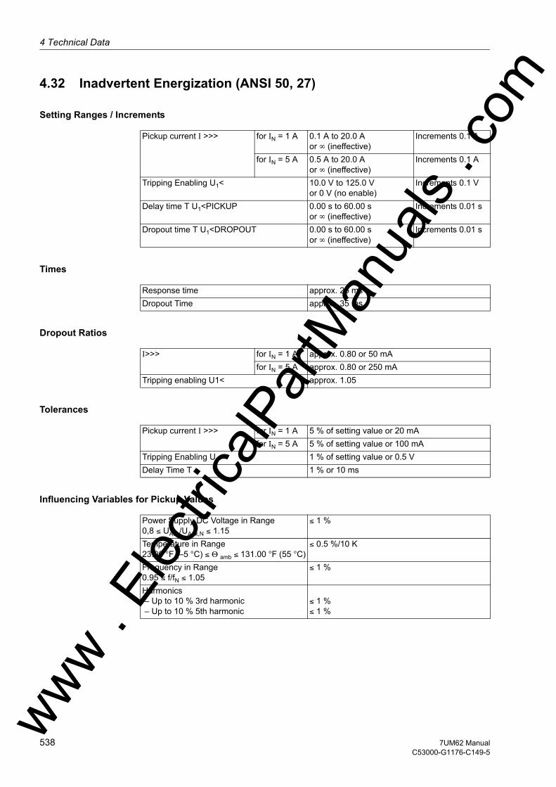
4 Technical Data
om
4.32 Inadvertent Energization (ANSI 50, 27)
Setting Ranges / Increments
Times
Dropout Ratios
Tolerances
Influencing Variables for Pickup Values
Pickup current I >>> for IN = 1 A 0.1 A to 20.0 Aor ∞ (ineffective)
Increments 0.1 A
for IN = 5 A 0.5 A to 20.0 Aor ∞ (ineffective)
Increments 0.1 A
Tripping Enabling U1< 10.0 V to 125.0 Vor 0 V (no enable)
Increments 0.1 V
Delay time T U1<PICKUP 0.00 s to 60.00 sor ∞ (ineffective)
Increments 0.01 s
Dropout time T U1<DROPOUT 0.00 s to 60.00 sor ∞ (ineffective)
Increments 0.01 s
Response time approx. 25 msDropout Time approx. 35 ms
I>>> for IN = 1 A approx. 0.80 or 50 mAfor IN = 5 A approx. 0.80 or 250 mA
Tripping enabling U1< approx. 1.05
Pickup current I >>> for IN = 1 A 5 % of setting value or 20 mAfor IN = 5 A 5 % of setting value or 100 mA
Tripping Enabling U1< 1 % of setting value or 0.5 VDelay Time T 1 % or 10 ms
Power Supply DC Voltage in Range0,8 ≤ UAux/UAux,N ≤ 1.15
≤ 1 %
Temperature in Range23.00 °F (–5 °C) ≤ Θ amb ≤ 131.00 °F (55 °C)
≤ 0.5 %/10 K
Frequency in Range0.95 ≤ f/fN ≤ 1.05
≤ 1 %
Harmonics – Up to 10 % 3rd harmonic – Up to 10 % 5th harmonic
≤ 1 %≤ 1 %
ww . El
ectric
alPar
tMan
uals
. c
538 7UM62 ManualC53000-G1176-C149-5
w

4.33 DC Voltage/Current Protection (ANSI 59NDC/51NDC)w
4.33 DC Voltage/Current Protection (ANSI 59NDC/51NDC)
Setting Ranges / Increments
Times
Dropout Ratios
Tolerances
Influencing Variables for Pickup Values
Voltage increase U≥ 0.1 V to 8.5 V Increments 0.1VVoltage Decrease U≤ 0.1 V to 8.5 V Increments 0.1VCurrent Increase I≥ 0.2 mA to 17.0 mA Increments 0.1 mACurrent Decrease I≤ 0.2 mA to 17.0 mA Increments 0.1 mAFor Measurement of Sinusoidal Voltages 0.1 Vrms to 7.0 Vrms Increments 0.1 Vrms
For Measurement of Sinusoidal Currents 0.2 mA to 14.0 mA Increments 0.1 mADelay Time TGSS 0.00 s to 60.00 s
or ∞ (ineffective)Increments 0.01 s
The set times are pure delay times.
Pickup TimesIncrease U>, I>in Operating State 1in Operating State 0
≤ 60 ms≤ 200 ms
at f = fN
Decrease U<, I<in Operating State 1in Operating State 0
≤ 60 ms≤ 200 ms
at f = fN
Dropout Times Same as pickup times
Voltage Increase U≥ approx. 0.95 or -0.05 VVoltage Decrease U≤ approx. 1.05 or +0.05 VCurrent Increase I≥ approx. 0.95 or -0.1 mACurrent Decrease I≤ approx. 1.05 or +0.1 mA
Voltage Limits 1 % of setting value or 0.1 VCurrent Thresholds 1 % of setting value or 0.1 mADelay Time T 1 % of setting value or 10 ms
Power Supply DC Voltage in Range0,8 ≤ UAux/UAux,N ≤ 1.15
≤ 1 %
Temperature in Range23.00 °F (–5 °C) ≤ Θ amb ≤ 131.00 °F (55 °C)
≤ 0.5 % / 10 K
Frequency in Range0.95 ≤ f/fN ≤ 1.05
≤ 1 %
ww . El
ectric
alPar
tMan
uals
. com
5397UM62 ManualC53000-G1176-C149-5

4 Technical Data
om
4.34 Temperature Detection by Thermoboxes
Temperature Detectors
Thresholds for Indications
connectable thermoboxes 1 or 2Number of temperature detectors per ther-mobox
Max. 6
Measuring Method Pt 100 Ω or Ni 100 Ω or Ni 120 Ω
Mounting Identification „Oil“ or „Ambient“ or „Winding“ or „Bearing“ or „Other“
for each measuring point:Stage 1 –5 °C to 250 °C (+23 °F
to +131 °F)–58 °F to 482 °For ∞ (no indication)
Increments 1 °CIncrements 1 °F
Stage 2 –5 °C to 250 °C (+23 °F to +131 °F)–58 °F to 482 °For ∞ (no indication)
Increments 1 °CIncrements 1 °F
ww . El
ectric
alPar
tMan
uals
. c
540 7UM62 ManualC53000-G1176-C149-5
w
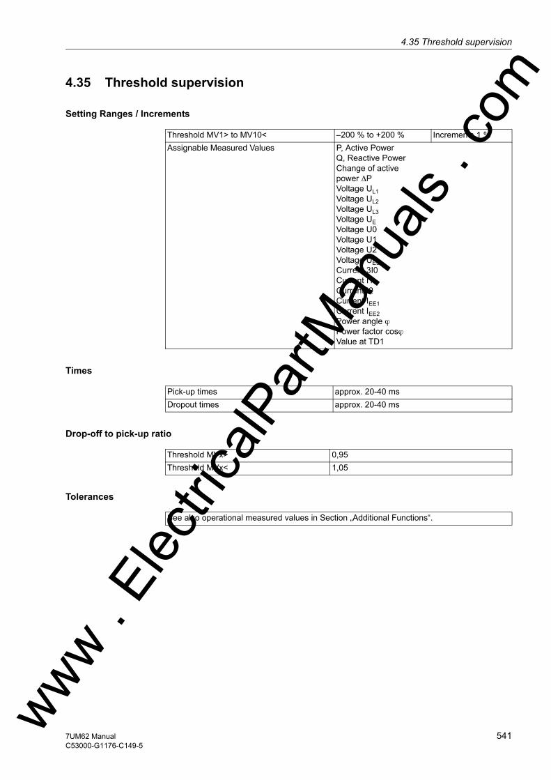
4.35 Threshold supervisionw
4.35 Threshold supervision
Setting Ranges / Increments
Times
Drop-off to pick-up ratio
Tolerances
Threshold MV1> to MV10< –200 % to +200 % Increments 1 %Assignable Measured Values P, Active Power
Q, Reactive PowerChange of activepower ∆PVoltage UL1Voltage UL2Voltage UL3Voltage UEVoltage U0Voltage U1Voltage U2Voltage UE3hCurrent 3I0 Current I1Current I2Current IEE1Current IEE2Power angle ϕPower factor cosϕValue at TD1
Pick-up times approx. 20-40 msDropout times approx. 20-40 ms
Threshold MVx> 0,95Threshold MVx< 1,05
See also operational measured values in Section „Additional Functions“.
ww . El
ectric
alPar
tMan
uals
. com
5417UM62 ManualC53000-G1176-C149-5

4 Technical Data
om
4.36 Auxiliary Functions
Operational Measured Values
Operational Measured Values for Currents
IL1, S1, IL2, S1, IL3, S1, IL1, S2, IL2, S2, IL3, S2in A (kA) primary and in A secondary or in % IN
Range 10 % to 200 % IN
Tolerance 0.2 % of measured value, or ±10 mA ±1 digit
3I0in A (kA) primary and in A secondaryIEE1, IEE2
Range 0 mA to 1600 mATolerance 0.2 % of measured value, or ±10
mA ±1 digitPositive sequence component I1 in A (kA) primary and in A secondary or in % IN
Negative sequence component I2 in A (kA) primary and in A secondary or in % IN
Differential Protection Cur-rents
IDiffL1, IDiffL2, IDiffL3, IRestL1, IRestL2, IRestL3 in I/INO
Range 10 % to 200 % IN
Tolerance 3 % of measured value, or ±10 mA ±1 digit
Operational Measured Values for Voltages (Phase-Ground)
UL1-E, UL2-E, UL3-Ein kV primary, in V secondary or in % UN
Range 10 % to 120 % UN
Tolerance 0.2 % of measured value, or ±0.2 mA ±1 digit
Operating Measured Values for Voltages (Phase-Phase)
UL1-L2, UL2-L3, UL3-L1in kV primary, in V secondary or in % UN
Range 10 % to 120 % UN
Tolerance 0.2 % of measured value, or ±0.2 mA ±1 digit
UE or 3U0 in kV primary, in V secondary or in % UN
Positive sequence component U1 and negative sequence com-ponent U2 in kV primary, in V secondary or in % UN
Operating Measured Values for Impedances
R, Xin Ω primary and secondaryTolerance 1 %
ww . El
ectric
alPar
tMan
uals
. c
542 7UM62 ManualC53000-G1176-C149-5
w
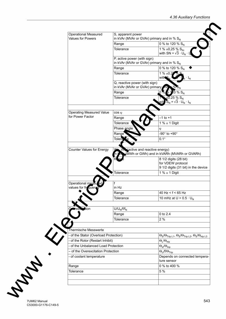
4.36 Auxiliary Functionsw
Operational Measured Values for Powers
S, apparent powerin kVAr (MVAr or GVAr) primary and in % SN
Range 0 % to 120 % SN
Tolerance 1 % ±0,25 % SN, with SN = √3 · UN · IN
P, active power (with sign)in kVAr (MVAr or GVAr) primary and in % SN
Range 0 % to 120 % SN
Tolerance 1 % ±0.25 % SN with SN = √3 · UN · IN
Q, reactive power (with sign)in kVAr (MVAr or GVAr) primary and in % SN
Range 0 % to 120 % SN
Tolerance 1 % ±0.25 % SN with SN = √3 · UN · IN
Operating Measured Value for Power Factor
cos ϕRange –1 to +1Tolerance 1 % ± 1 DigitPhase angle ϕ
Range -90° to +90°Tolerance 0.1°
Counter Values for Energy Wp, Wq (active and reactive energy)in kWh (MWh or GWh) and in kVARh (MVARh or GVARh)Range 8 1/2 digits (28 bit)
for VDEW protocol9 1/2 digits (31 bit) in the device
Tolerance 1 % ± 1 Digit
Operational measured values for frequency
fin HzRange 40 Hz < f < 65 HzTolerance 10 mHz at U > 0.5 · UN
Overexcitation U/UN/f/fNRange 0 to 2.4Tolerance 2 %
Thermische Messwerte- of the Stator (Overload Protection) ΘS/ΘTrip L1, ΘS/ΘTrip L2, ΘS/Θtrip L3
- of the Rotor (Restart Inhibit) ΘL/Θtrip
- of the Unbalanced Load Protection Θi2/Θtrip
– of the Overexcitation Protection ΘU/f/ΘTrip
- of coolant temperature Depends on connected tempera-ture sensor
Range 0 % to 400 %Tolerance 5 %
ww . El
ectric
alPar
tMan
uals
. com
5437UM62 ManualC53000-G1176-C149-5

4 Technical Data
om
Operational Measured Values for Rotor Earth Fault Protection (1-3 Hz)Range 0.5 Hz to 4.0 HzTolerance 0.1 Hz
Amplitude of Rotor Voltage Injection
Ugen in VRange 0.0 V to 60.0 VTolerance 0.5 V
Rotor Circuit Current IN, Gen in mARange 0.00 mA to 20.00 mATolerance 0.05 mA
Charge at Polarity Reversal QC in mAsRange 0.00 mAs to 1.00 mAsTolerance 0.01 mAs
Rotor Earth Resistance REarth in kΩ Range 0.0 kΩ to 9999.9 kΩTolerance < 5 % or 0.5 kΩ
for Rearth < 100 kΩ and for Ce< 1µF < 10 % or 0.5 kΩfor Rearth < 100 kΩ and for Ce< 4µF
Operational measured values of 100-%-Stator Earth Fault Protection (20 Hz)Stator circuit bias voltage USEF
in VRange 0.0 V to 200.0 VTolerance 0.2 % of measured value,
or ± 0.2 V ± 1 digitEarth Current of Stator Circuit ISEF
in ARange 0.0 mA to 1600.0 mATolerance 0.2 % of measured value,
or ± 0.2 V ± 1 digit20 Hz Phase Angle ϕSEF
in °Range – 180.0° to +180.0°Tolerance 1.0 %
Stator Earth Resistance (sec.)
RSEF in Ω Range 0 Ω up to 9999 ΩTolerance 5 % or 2 Ω
Stator Earth Resistance (prim.)
RSEFP in Ω Range 0 Ω up to 9999.99 ΩTolerance 5 % or (5 Ω · conversion factor)ww .
Elec
tricalP
artM
anua
ls . c
544 7UM62 ManualC53000-G1176-C149-5
w

4.36 Auxiliary Functionsw
Min / Max Report
Analog Outputs (optional)
Local Measured Values Monitoring
Fault Logging
Time Allocation
Report of Measured Values with date and timeReset manual using binary input
using keypadusing communication
Min/Max Values for Current Positive Se-quence Components
I1
Min/Max Values for Voltage Positive Se-quence Components
U1
Min/Max Values for 3rd Harmonics in Dis-placement Voltage
UE3H
Min/Max Values for Power P, QMin/Max Values for Frequency f f
Number max. 4 (depending on variant)possible measured values I1, I2, IEE1, IEE2, U1, U0, U03h, |P|, |Q|, S, |cos
ϕ|, f, U/f, ϕ, ΘS/ΘS Trip, ΘL/ΘL Trip, RE LES, RE LES 1-3 Hz, RE SEF in %
Range 0.0 mA to 22.5 mAMinimum threshold (limit of validity:) 0.0 mA to 5.0 mA (increments 0.1 mA)Maximum Threshold 22.0 mA (fixed)Configurable Reference Value 20 mA 10.0 % to 1.000.0 % (0.1 % increments)
Current Asymmetry Imax/Imin > balance factor, for I > Ibalance limit
Voltage Asymmetry Umax/Umin > balance factor, for U > Ulim
Current Sum | iL1 + iL2 + iL3 | > limitVoltage sum | UL1 + UL2 + UL3 + kU · UE | > limit,
with kU = Uph/Uen CTCurrent Phase Sequence Clockwise/ counter-clockwise phase sequenceVoltage Phase Sequence Clockwise/ counter-clockwise phase sequenceLimit Value Monitoring IL< limit value IL<,
configurable using CFC
Indications memory for the last 8 fault cases (max. 600 indications)
Resolution for Event Log (Operational Indi-cations)
1 ms
Resolution for Fault Log (Fault Indications) 1 msMaximum Time Deviation (Internal Clock) 0.01 %Battery Lithium battery 3 V/1 Ah, type CR 1/2 AA
"Flt. Battery" on lowbattery chargeww .
Elec
tricalP
artM
anua
ls . c
om
5457UM62 ManualC53000-G1176-C149-5

4 Technical Data
om
Fault Recording
Energy Meter
Statistical Counters
Operating Hours Counter
Trip Circuit Supervision
Commissioning Aids
Maximum 8 fault records saved by buffer battery also through auxiliary voltage failureInstantaneous Values:Recording Time total 5 s
Pre-event and post-event recording and memory time adjustable
Sampling grid for 50 HzSampling grid for 60 Hz
1 sample/1.25 ms1 sample/1.04 ms
Channels uL1, uL2, uL3, uE, iL1, S1, iL2,S1, iL3,S1, iEE1, iL1, S2, iL2,S2, iL3,S2, iEE, IDiff-L1, IDiff-L2, IDiff-L3, IStab-L1, IStab-L2, IStab-L3, u= or i= of the three measuring transducers TD
rms values:Recording Time total 80 s
Pre-event and post-event recording and memory time adjustable
grid for 50 Hzgrid for 60 Hz
1 sample/20 ms1 sample/16.67 ms
Channels U1, UE, I1, I2, IEE1, IEE2, P, Q, ϕ, R, X, f-fN
Four-Quadrant Meter WP+, WP–, WQ+, WQ–
Tolerance 1 %
Stored Number of Trips up to 9 digitsaccumulated Interrupted Current Up to 4 digits (kA) per pole
Display Range up to 6 digitsCriterion Overshoot of an adjustable current threshold
(CB I>)
Number of monitorable circuits 1with one or two binary inputs
Phase Rotation Field CheckOperational measured valuesSwitching device testCreation of a Test Measurement Report
ww . El
ectric
alPar
tMan
uals
. c
546 7UM62 ManualC53000-G1176-C149-5
w

4.36 Auxiliary Functionsw
Clock
Group Switchover of the Function Parameters
Time synchronization DCF 77 / IRIG B Signal(telegram format IRIG-B000)Binary InputCommunication
Number of Available Setting Groups 2 (parameter group A and B)Switchover can be performed using the keypad
DIGSI using the operating interfacewith protocol via system interfaceBinary Input
ww . El
ectric
alPar
tMan
uals
. com
5477UM62 ManualC53000-G1176-C149-5

4 Technical Data
om
4.37 Operating Ranges of the Protection Functions
Table 4-1 Operating ranges of the protection functions
Operational state 0
Operational state 1 Operational state 0
Protective Elements f ≤ 0 Hz 11 Hz < f/Hz ≤ 40 40 Hz ≤ f/Hz ≤ 69 f ≥ 70 HzDefinite-Time Overcurrent Protection (I>/I>>)
active active active active
Inverse-Time Overcurrent Protection (ANSI 51V)
inactive active active inactive
Thermal Overload Protection (ANSI 49) inactive 1) active active inactive 1)
Unbalanced Load (Negative Sequence) Protection (ANSI 46)
inactive 1) active active inactive 1)
Startup Overcurrent Protection (ANSI 51) active inactive inactive activeDifferential Protection (ANSI 87G/87M/87T)
active active active active
Earth Current Differential Protection (ANSI 87GN,TN)
inactive active active inactive
Underexcitation (Loss-of-Field) Protection (ANSI 40)
inactive active active inactive
Reverse Power Protection (ANSI 32R) inactive active active inactiveForward Active Power Supervision (ANSI 32F)
inactive active active inactive
Impedance Protection (ANSI 21) inactive active active inactiveOut-of-Step Protection (ANSI 78) inactive active active inactiveUndervoltage Protection (ANSI 27) inactive 2) active active inactive 2)
Overvoltage Protection (ANSI 59) active active active activeFrequency increase protection inactive active active inactive 3)
Underfrequency protection inactive active active inactiveOverexcitation (Volt/Hertz) Protection (ANSI 24)
inactive 1) active active inactive 1)
Inverse-Time Undervoltage Protection (ANSI 27)
inactive 2) active active inactive 2)
Rate-of-Frequency-Change Protection df/dt (ANSI 81R)
inactive active 4) active inactive
Jump of Voltage Vector inactive active 5) active 5) inactive90-%-Stator Earth Fault Protection (ANSI 59N, 64G, 67G)
active active active active
Sensitive Earth Fault Protection (ANSI 51GN, 64R)
inactive active active inactive
100-%-Stator Earth Fault Protection with 3rd Harmonics (ANSI 27/59TN 3rd Harm.)
inactive active active inactive
100-%-Stator Earth Fault Protection with 20 Hz Voltage Injection (ANSI 64G - 100%)
active active active active
Rotor Earth Fault Protection R, fn (ANSI 64R)
active active active active
Sensitive Rotor Earth Fault Protection with 1 to 3 Hz Square Wave Voltage Injection (ANSI 64R - 1 to 3 Hz)
active active active active
ww . El
ectric
alPar
tMan
uals
. c
548 7UM62 ManualC53000-G1176-C149-5
w

4.37 Operating Ranges of the Protection Functionsw
1) The thermal replica registers cooling-down2) a pickup – if already present – is maintained3) a pick -up – if already present – is maintained, if the measured voltage is not too small4) 25 Hz < f/Hz ≤ 40 Hz5) The function is only active at rated frequency ± 3 Hz6) If using the measured value of measuring transducer1
Motor Starting Time Supervision (ANSI 48)
inactive active active inactive
Restart Inhibit for Motors (ANSI 66, 49Rotor)
active active active active
Breaker Failure Protection (ANSI 50BF) inactive active active inactiveInadvertent Energization (ANSI 50, 27) active active active activeDC Voltage/Current Protection (ANSI 59NDC/51NDC)
active active active active
Threshold supervision inactive 6) active active inactive 6)
External Trip Functions active active active activeTemperature Detection by Thermoboxes active active active activeFuse Failure Monitor inactive active active inactiveSensitive Earth Fault Protection B (ANSI 51GN)
inactive active active inactive
Interturn Protection (ANSI 59N (IT)) inactive active active inactive
Operational Condition 1: At at least one of the measuring inputs (IL1, S2, IL2, S2, IL3, S2, UL1, UL2 UL3) of the device, at least 5% of the nominal value is present, so that the scanning fre-quency for measurement acquisition can be adjusted.
Operational Condition 0: If no suitable measured values are present, or if the frequency is below 11 Hz or above 69 Hz, the device cannot operate (operational condition 0) and no measured value processing occurs.
Operational state 0
Operational state 1 Operational state 0
Protective Elements f ≤ 0 Hz 11 Hz < f/Hz ≤ 40 40 Hz ≤ f/Hz ≤ 69 f ≥ 70 Hz
ww . El
ectric
alPar
tMan
uals
. com
5497UM62 ManualC53000-G1176-C149-5

4 Technical Data
om
4.38 Dimensions
4.38.1 Housing for Panel Flush Mounting or Cubicle Mounting (Size 1/2)
Figure 4-14 Dimensions of a 7UM621 or a 7UM623 for Panel Flush Mounting or Cubicle Installation (size 1/2)
ww . El
ectric
alPar
tMan
uals
. c
550 7UM62 ManualC53000-G1176-C149-5
w

4.38 Dimensionsw
4.38.2 Housing for Panel Flush Mounting or Cubicle Mounting (Size 1/1)
Figure 4-15 Dimensions of a 7UM622 for panel flush mounting or cubicle installation (size 1/1)
ww . El
ectric
alPar
tMan
uals
. com
5517UM62 ManualC53000-G1176-C149-5

4 Technical Data
om
4.38.3 Housing for Panel Surface Mounting (Size 1/2)
Figure 4-16 Dimensions of a 7UM621 for Panel Surface Mounting (housing size 1/2)
4.38.4 Housing for Panel Surface Mounting (Size 1/1)
Figure 4-17 Dimensions of a 7UM622 for panel surface mounting (housing size 1/1)
ww . El
ectric
alPar
tMan
uals
. c
552 7UM62 ManualC53000-G1176-C149-5
w

4.38 Dimensionsw
4.38.5 Dimensions of Coupling Unit 7XR6100-0CA0 for Panel Flush Mounting
Figure 4-18 Dimensions of Coupling Unit 7XR6100-0CA0 for Panel Flush Mounting
ww . El
ectric
alPar
tMan
uals
. com
5537UM62 ManualC53000-G1176-C149-5

4 Technical Data
om
4.38.6 Dimensions of Coupling Unit 7XR6100-0BA0 for Panel Surface Mounting
Figure 4-19 Dimensions of Coupling Unit 7XR6100-0BA0 for Panel Surface Mounting
ww . El
ectric
alPar
tMan
uals
. c
554 7UM62 ManualC53000-G1176-C149-5
w
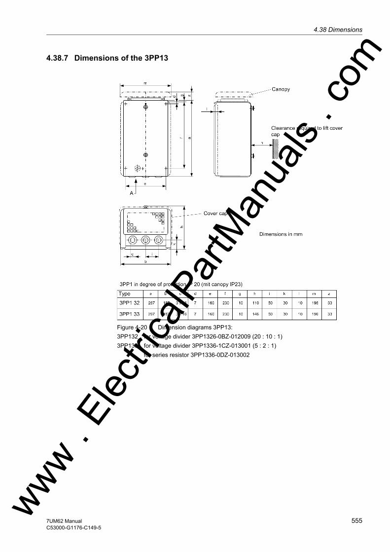
4.38 Dimensionsw
4.38.7 Dimensions of the 3PP13
Figure 4-20 Dimension diagrams 3PP13:3PP132 for voltage divider 3PP1326-0BZ-012009 (20 : 10 : 1)3PP133 for voltage divider 3PP1336-1CZ-013001 (5 : 2 : 1) for series resistor 3PP1336-0DZ-013002
ww . El
ectric
alPar
tMan
uals
. com
5557UM62 ManualC53000-G1176-C149-5
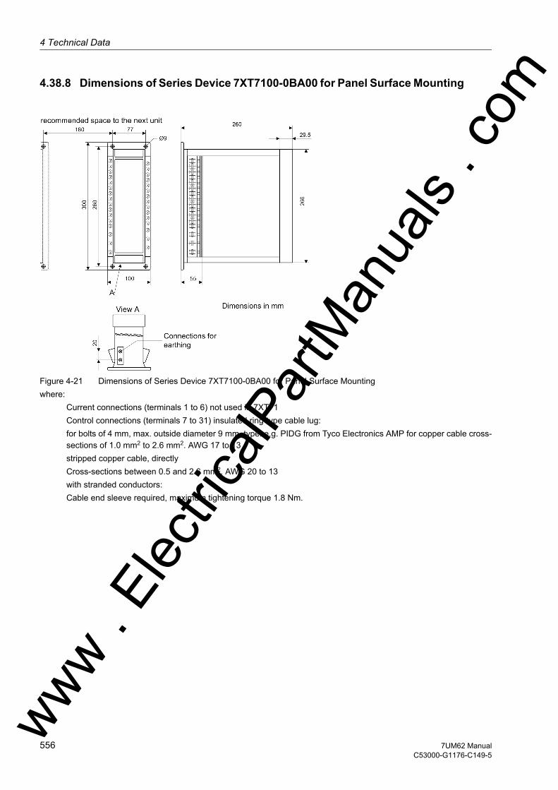
4 Technical Data
om
4.38.8 Dimensions of Series Device 7XT7100-0BA00 for Panel Surface Mounting
Figure 4-21 Dimensions of Series Device 7XT7100-0BA00 for Panel Surface Mountingwhere: Current connections (terminals 1 to 6) not used in 7XT71 Control connections (terminals 7 to 31) insulated ring-type cable lug: for bolts of 4 mm, max. outside diameter 9 mm, type: e.g. PIDG from Tyco Electronics AMP for copper cable cross-
sections of 1.0 mm2 to 2.6 mm2. AWG 17 to 13 stripped copper cable, directly Cross-sections between 0.5 and 2.6 mm2. AWG 20 to 13 with stranded conductors: Cable end sleeve required, maximum tightening torque 1.8 Nm.
ww . El
ectric
alPar
tMan
uals
. c
556 7UM62 ManualC53000-G1176-C149-5
w

4.38 Dimensionsw
4.38.9 Dimensions of Series Unit 7XT7100-0EA00 for Panel Flash Mounting
Figure 4-22 Dimensions of Series Unit 7XT7100-0EA00 for Panel Flash Mountingwhere: Current connections (terminals 1 to 6) not used in 7XT71 Control connections (terminals 7 to 31) Screw terminals (ring-type cable lug): for bolts of 4 mm, max. outside diameter 9 mm Type: e.g. PIDG of Messrs. Tyco Electronics AMP for copper cable cross-sections between 1.0 mm2 and 2.6 mm2
AWG 17 to 13 in parallel double leaf-spring-crimp contact: for copper cable cross-sections between 0.5 mm2 and 2.5 mm2
AWG 20 to 13 Maximum tightening torque 1.8 Nm.
ww . El
ectric
alPar
tMan
uals
. com
5577UM62 ManualC53000-G1176-C149-5
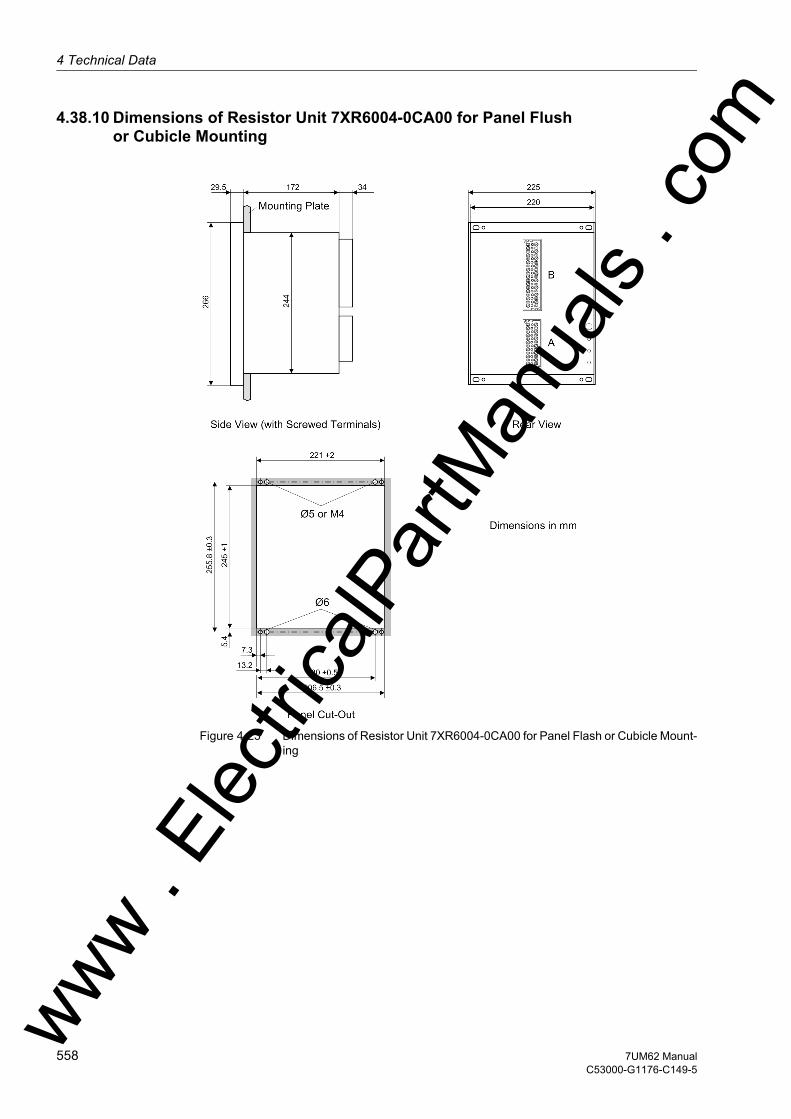
4 Technical Data
om
4.38.10 Dimensions of Resistor Unit 7XR6004-0CA00 for Panel Flush or Cubicle Mounting
Figure 4-23 Dimensions of Resistor Unit 7XR6004-0CA00 for Panel Flash or Cubicle Mount-ing
ww . El
ectric
alPar
tMan
uals
. c
558 7UM62 ManualC53000-G1176-C149-5
w
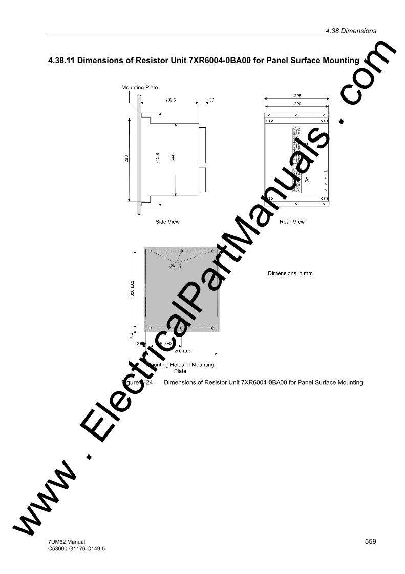
4.38 Dimensionsw
4.38.11 Dimensions of Resistor Unit 7XR6004-0BA00 for Panel Surface Mounting
Figure 4-24 Dimensions of Resistor Unit 7XR6004-0BA00 for Panel Surface Mounting
ww . El
ectric
alPar
tMan
uals
. com
5597UM62 ManualC53000-G1176-C149-5

4 Technical Data
om
4.38.12 Dimensions of 20-Hz-Generator 7XT3300-0CA00 for Panel Flush or Cubicle Mounting
Figure 4-25 Dimensions of 20 Hz Generator 7XT3300-0CA00 for Panel Flash or Cubicle Mounting
ww . El
ectric
alPar
tMan
uals
. c
560 7UM62 ManualC53000-G1176-C149-5
w

4.38 Dimensionsw
4.38.13 Dimensions of 20-Hz-Generator 7XT3300-0BA00 for Panel Surface Mounting
Figure 4-26 Dimensions of 20 Hz Generator 7XT3300-0BA00 for Panel Surface Mounting
ww . El
ectric
alPar
tMan
uals
. com
5617UM62 ManualC53000-G1176-C149-5

4 Technical Data
om
4.38.14 Dimensions of 20-Hz-Band-Pass Filter 7XT3400-0CA00 for Panel Flush or Cubicle Mounting
Figure 4-27 Dimensions of 20-Hz-Band-Pass Filter 7XT3400-0CA00 for Panel Flush or Cubicle Mounting
*) For panel flush mounting, 2 set squares C73165- A63-C201-1 are necessary since the mounting rails of the device housing are not sufficient for the high weight of the 7XT34 device.
Fix the set squares to the panel, using screws size M6, according to the draw-ing.
Mount the 7XT34 device to the set squares using screws size M4 (no hexagon screws).
If the device is mounted in switchgear cabinets, the set squares can be omitted provided the cabinet posesses adequate solid mounting rails.
If not, use 2 set squares C73165-A63-C200-3 (size 28 SEP = 19 inches).
ww . El
ectric
alPar
tMan
uals
. c
562 7UM62 ManualC53000-G1176-C149-5
w
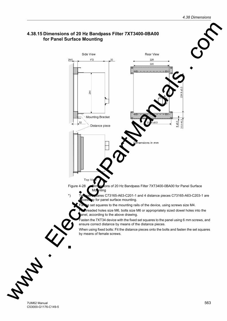
4.38 Dimensionsw
4.38.15 Dimensions of 20 Hz Bandpass Filter 7XT3400-0BA00 for Panel Surface Mounting
Figure 4-28 Dimensions of 20 Hz Bandpass Filter 7XT3400-0BA00 for Panel Surface Mounting
*) Two set squares C73165-A63-C201-1 and 4 distance pieces C73165-A63-C203-1 are necessary for panel surface mounting.
Fix the set squares to the mounting rails of the device, using screws size M4. Fit threaded holes size M6, bolts size M6 or appropriately sized dowel holes into the
panel, according to the above drawing. Fasten the 7XT34 device with the fixed set squares to the panel using 6 mm screws, and
ensure correct distance by means of the distance pieces. When using fixed bolts: Fit the distance pieces onto the bolts and fasten the set squares
by means of female screws.
ww . El
ectric
alPar
tMan
uals
. com
5637UM62 ManualC53000-G1176-C149-5

4 Technical Data
om
ww . El
ectric
alPar
tMan
uals
. c
564 7UM62 ManualC53000-G1176-C149-5
w

w
m
Appendix AThis appendix is primarily a reference for the experienced user. This section provides ordering information for the models of this device. Connection diagrams for indicating the terminal connections of the models of this device are included. Following the general diagrams are diagrams that show the proper connections of the devices to primary equipment in many typical power system configurations. Tables with all set-tings and all information available in this device equipped with all options are provided. Default settings are also given.
A.1 Ordering Information and Accessories 566
A.2 Terminal Assignments 573
A.3 Connection Examples 577
A.4 Default Settings 591
A.5 Protocol-dependent Functions 597
A.6 Functional Scope 598
A.7 Settings 603
A.8 Information List 620
A.9 Group Alarms 642
A.10 Measured Values 643
ww . El
ectric
alPar
tMan
uals
. co
5657UM62 ManualC53000-G1176-C149-5
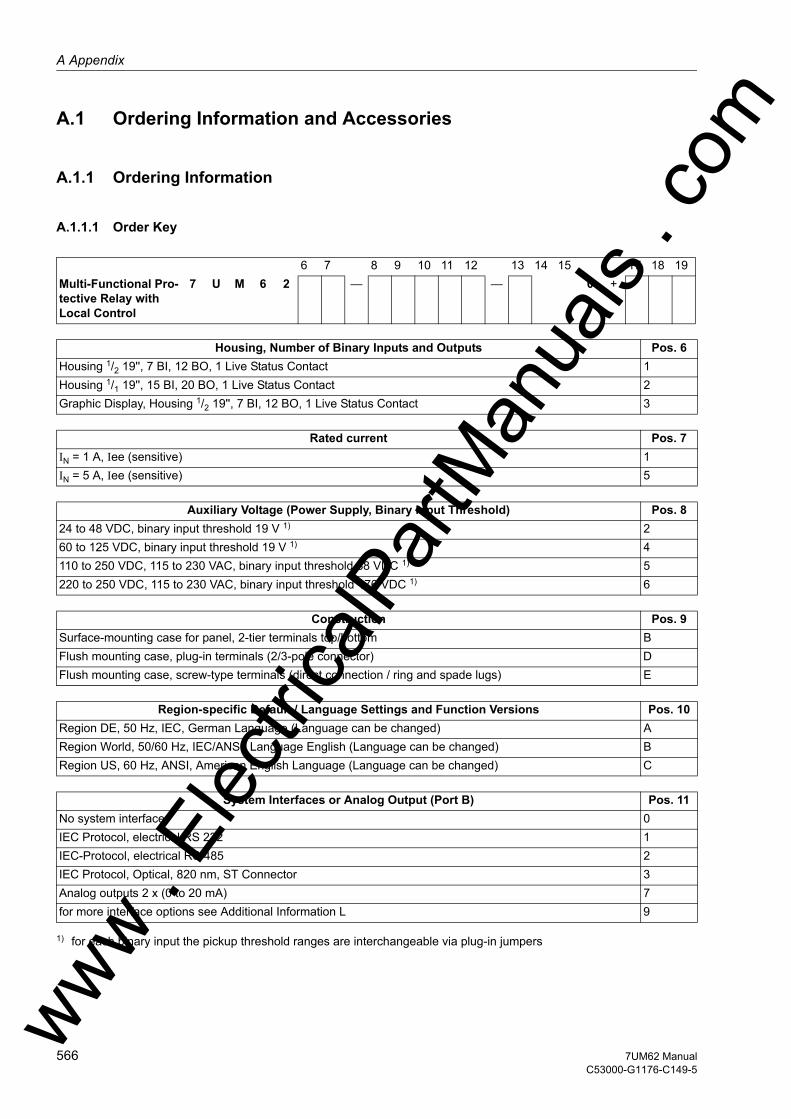
A Appendix
om
A.1 Ordering Information and Accessories
A.1.1 Ordering Information
A.1.1.1 Order Key
1) for each binary input the pickup threshold ranges are interchangeable via plug-in jumpers
6 7 8 9 10 11 12 13 14 15 17 18 19Multi-Functional Pro-tective Relay with Local Control
7 U M 6 2 — — 0 +
Housing, Number of Binary Inputs and Outputs Pos. 6Housing 1/2 19'', 7 BI, 12 BO, 1 Live Status Contact 1Housing 1/1 19'', 15 BI, 20 BO, 1 Live Status Contact 2Graphic Display, Housing 1/2 19'', 7 BI, 12 BO, 1 Live Status Contact 3
Rated current Pos. 7IN = 1 A, Iee (sensitive) 1IN = 5 A, Iee (sensitive) 5
Auxiliary Voltage (Power Supply, Binary Input Threshold) Pos. 824 to 48 VDC, binary input threshold 19 V 1) 260 to 125 VDC, binary input threshold 19 V 1) 4110 to 250 VDC, 115 to 230 VAC, binary input threshold 88 VDC 1) 5220 to 250 VDC, 115 to 230 VAC, binary input threshold 176 VDC 1) 6
Construction Pos. 9Surface-mounting case for panel, 2-tier terminals top/bottom BFlush mounting case, plug-in terminals (2/3-pole connector) DFlush mounting case, screw-type terminals (direct connection / ring and spade lugs) E
Region-specific Default / Language Settings and Function Versions Pos. 10Region DE, 50 Hz, IEC, German Language (Language can be changed) ARegion World, 50/60 Hz, IEC/ANSI, Language English (Language can be changed) BRegion US, 60 Hz, ANSI, American English Language (Language can be changed) C
System Interfaces or Analog Output (Port B) Pos. 11No system interface 0IEC Protocol, electrical RS 232 1IEC-Protocol, electrical RS 485 2IEC Protocol, Optical, 820 nm, ST Connector 3Analog outputs 2 x (0 to 20 mA) 7for more interface options see Additional Information L 9
ww . El
ectric
alPar
tMan
uals
. c
566 7UM62 ManualC53000-G1176-C149-5
w
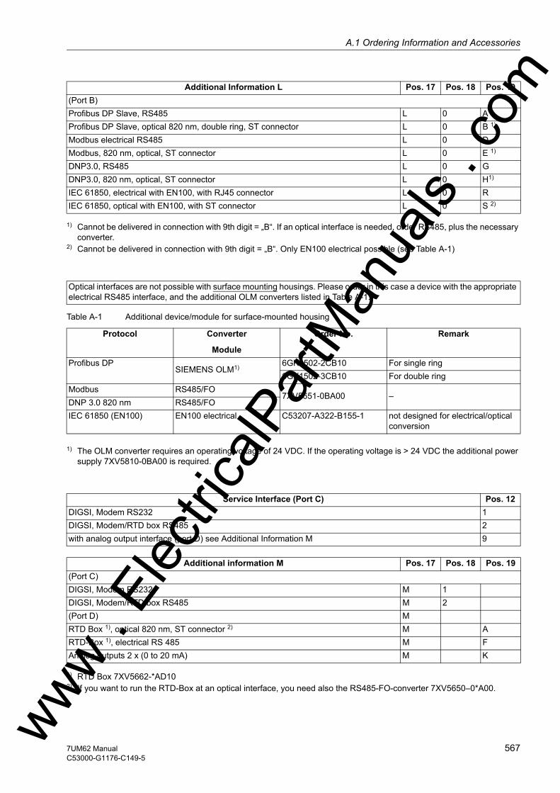
A.1 Ordering Information and Accessoriesw
1) Cannot be delivered in connection with 9th digit = „B“. If an optical interface is needed, order RS485, plus the necessary converter.
2) Cannot be delivered in connection with 9th digit = „B“. Only EN100 electrical possible (see Table A-1)
Table A-1 Additional device/module for surface-mounted housing
1) The OLM converter requires an operating voltage of 24 VDC. If the operating voltage is > 24 VDC the additional power supply 7XV5810-0BA00 is required.
1) RTD Box 7XV5662-*AD102) If you want to run the RTD-Box at an optical interface, you need also the RS485-FO-converter 7XV5650–0*A00.
Additional Information L Pos. 17 Pos. 18 Pos. 19(Port B)Profibus DP Slave, RS485 L 0 AProfibus DP Slave, optical 820 nm, double ring, ST connector L 0 B 1)
Modbus electrical RS485 L 0 DModbus, 820 nm, optical, ST connector L 0 E 1)
DNP3.0, RS485 L 0 GDNP3.0, 820 nm, optical, ST connector L 0 H1)
IEC 61850, electrical with EN100, with RJ45 connector L 0 RIEC 61850, optical with EN100, with ST connector L 0 S 2)
Optical interfaces are not possible with surface mounting housings. Please order in this case a device with the appropriate electrical RS485 interface, and the additional OLM converters listed in Table A-1.
Protocol Converter
Module
Order No. Remark
Profibus DPSIEMENS OLM1) 6GK1502-2CB10 For single ring
6GK1502-3CB10 For double ringModbus RS485/FO
7XV5651-0BA00 –DNP 3.0 820 nm RS485/FOIEC 61850 (EN100) EN100 electrical C53207-A322-B155-1 not designed for electrical/optical
conversion
Service Interface (Port C) Pos. 12DIGSI, Modem RS232 1DIGSI, Modem/RTD box RS485 2with analog output interface (port D) see Additional Information M 9
Additional information M Pos. 17 Pos. 18 Pos. 19(Port C)DIGSI, Modem RS232 M 1DIGSI, Modem/RTD box RS485 M 2(Port D) MRTD Box 1), optical 820 nm, ST connector 2) M ARTD-Box 1), electrical RS 485 M FAnalog outputs 2 x (0 to 20 mA) M K
ww . El
ectric
alPar
tMan
uals
. com
5677UM62 ManualC53000-G1176-C149-5

A Appendix
om
Measuring functions Pos. 13without extended measuring functionality 0Min/Max Values, Energy Metering 3
Functionality Pos. 14Generator Basis, comprising: ANSI No. AOvercurrent protection with Undervoltage Seal-In I> +U< 51Overcurrent protection, directed I>>, dir. 50/51/67Inverse Time Overcurrent Protection t=f(I) +U< 51VOverload Protection I2t 49Unbalanced load protection I2>, t=f(I2) 46Differential Protection ∆I 87G/87M/87TUnderexcitation protection 1/xd 40Reverse Power Protection –P 32RForward power supervision P>, P< 32FUndervoltage Protection U<, t=f(U) 27Overvoltage Protection U> 59Frequency Protection f<, f> 81Overexcitation protection U/f 24Stator Earth Fault Protection, undirected, directed U0>, 3I0>, ∠U0, 3I0 59N, 64G, 67GSensitive earth fault detection (also as rotor earth fault protec-tion
IEE> 50/51GN,( 64R)
Sensitive earth fault protection IEE-B (as shaft current protection) IEE-B>, IEE-B< 50/51GNRotor earth fault protection (fn, R measurement) RE< 64R (fN)Motor startup time supervision IStart
2t 48Breaker Failure Protection Imin> 50BFPhase sequence supervision L1; L2; L3 474 external trip commands Ext. tr. —Trip Circuit Supervision TC mon 74TCFuse Failure Monitor U2/U1; I1/I2 60FLThreshold SupervisionRestart Inhibit I2t 66, 49 Rotor
Generator Standard, comprising: ANSI No. BBasic Generator and in addition:Impedance protection Z< 21Stator Earth Fault Protection with 3rd Harmonic U0 (3rd harm.) 59TN 27TN3.HInterturn Fault Protection UInterturn> 64S (Interturn)Inadvertent Energizing Protection I>, U< 50/27
Generator Full, comprising: ANSI No. CStandard Generator and in addition:Out-of-Step Protection ∆Z/∆t 78DC Voltage/DC Current Protection Udc>/Idc> 59N (DC)/51N (DC)Startup overcurrent protection I> 51Earth current differential protection ∆I0 87Nww .
Elec
tricalP
artM
anua
ls . c
568 7UM62 ManualC53000-G1176-C149-5
w

A.1 Ordering Information and Accessoriesw
Asynchronous Motor, comprising: ANSI No. FBasic Generator but without underexcitation protection, overexcitation protection and rotor earth fault protection (fn, R measurement)
Transformer, comprising: ANSI No. HBasic Generator but without underexcitation protection, unbalanced load protection, motor starting time supervision and rotor earth fault protection (fn, R measurement)
Functionality/Additional Functions ANSI No. Pos. 15Without ASensitive Rotor Earth Fault Protectionwith square-wave voltage injection of 1-3 Hz, Re<80 kΩ and 100% Stator Earth Fault Protectionwith principle of 20 Hz voltage injection
64R(1 Hz to 3 Hz)
64G (100 %)
B
Earth current differential protection 87N CNetwork Decoupling (df/dt and vector jump) 81R Eall additional functions GSample order:7UM6211-4EA99-0BA0 + L0A + M1Khere: Pos. 11 = 9 stands for L0A, i.e. version with Profibus DP Slave system port on the rear, RS485here: Pos. 12 = 9 stands for M1K, i.e. version with rear service port DIGSI, modem RS232 andAnalog outputs 2 x (0 to 20 mA)
Functionality Pos. 14
ww . El
ectric
alPar
tMan
uals
. com
5697UM62 ManualC53000-G1176-C149-5
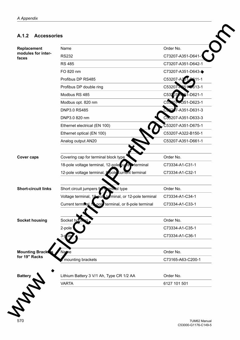
A Appendix
om
A.1.2 Accessories
Replacement modules for inter-faces
Name Order No.
RS232 C73207-A351-D641-1
RS 485 C73207-A351-D642-1
FO 820 nm C73207-A351-D643-1
Profibus DP RS485 C53207-A351-D611-1
Profibus DP double ring C53207-A351-D613-1
Modbus RS 485 C53207-A351-D621-1
Modbus opt. 820 nm C53207-A351-D623-1
DNP3.0 RS485 C53207-A351-D631-3
DNP3.0 820 nm C53207-A351-D633-3
Ethernet electrical (EN 100) C53207-A351-D675-1
Ethernet optical (EN 100) C53207-A322-B150-1
Analog output AN20 C53207-A351-D661-1
Cover caps Covering cap for terminal block type Order No.
18-pole voltage terminal, 12-pole current terminal C73334-A1-C31-1
12-pole voltage terminal, 8-pole current terminal C73334-A1-C32-1
Short-circuit links Short circuit jumpers for terminal type Order No.
Voltage terminal, 18-pole terminal, or 12-pole terminal C73334-A1-C34-1
Current terminal,12-pole terminal, or 8-pole terminal C73334-A1-C33-1
Socket housing Socket housing Order No.
2-pole C73334-A1-C35-1
3-pole C73334-A1-C36-1
Mounting Brackets for 19" Racks
Name Order No.
2 mounting brackets C73165-A63-C200-1
Battery Lithium Battery 3 V/1 Ah, Type CR 1/2 AA Order No.
VARTA 6127 101 501
ww . El
ectric
alPar
tMan
uals
. c
570 7UM62 ManualC53000-G1176-C149-5
w

A.1 Ordering Information and Accessoriesw
Coupling unit Coupling unit for rotor earth fault protection (R, fN) Order No.
Coupling device for panel surface mounting 7XR6100-0CA00
Coupling device for panel flush mounting 7XR6100-0BA00
Series Resistor Series resistor for rotor earth fault protection (R, fN) Order No.
Series resistor (2 x 10⁵ Ω ) 3PP1336-0DZ-K2Y
Voltage divider Voltage divider Order No.
Voltage divider 5:1; 5:2 3PP1336-1CZ-K2Y
Voltage divider 10:1; 20:1 3PP1326-0BZ-K2Y
Series device Series device for rotor earth fault protection (1-3 Hz) Order No.
Surface-mounted housing with terminals at both sides 7XT7100-0BA00
In housing with rear terminals 7XT7100-0EA00
Resistor Unit Resistor device for rotor earth fault protection (1-3 Hz) Order No.
Surface-mounted housing with screw terminals 7XR6004-0BA00
In housing with screw terminals 7XR6004-0CA00
20 Hz Generator 20 Hz Generator Order No.
Surface-mounted housing with screw terminals 7XT3300-0BA00
In housing with screw terminals 7XR3300-0CA00
20 Hz Bandpass Filter
20 Hz Bandpass Filter Order No.
Surface-mounted housing with screw terminals 7XT3400-0BA00
In housing with screw terminals 7XR3400-0CA00
Interface Cable Interface cable between PC and SIPROTEC device Order Number
Cable with 9-pole male / female connector 7XV5100-4
DIGSI operating software
DIGSI protection operation and configuration software Order Number
DIGSI, basic version with licenses for 10 computers 7XS5400-0AA00
DIGSI, complete version with all option packages 7XS5402–0AA00
ww . El
ectric
alPar
tMan
uals
. com
5717UM62 ManualC53000-G1176-C149-5

A Appendix
om
Graphical analysis program SIGRA
Graphical analysis program SIGRA Order No.
Full version with license for 10 computers 7XS5410-0AA00
Graphic Tools Graphical software to aid in the setting of characteristic curves (option package of the full version of DIGSI) Order Number
Graphic Tools 4; Full version with license for 10 PCs 7XS5430-0AA00
DIGSI REMOTE 4 Software for remotely operating protective devices via a modem (and possibly a star connector) using DIGSI (option package of the complete version of DIGSI) Order No.
DIGSI REMOTE 4; Full version with license for 10 PCs; Language: German 7XS5440-1AA00
SIMATIC CFC 4 Graphical software for setting interlocking (latching) control conditions and creating additional functions (option package of the complete version of DIGSI) Order No.
SIMATIC CFC 4; Full version with license for 10 PCs 7XS5450-0AA00
ww . El
ectric
alPar
tMan
uals
. c
572 7UM62 ManualC53000-G1176-C149-5
w

A.2 Terminal Assignmentsw
A.2 Terminal Assignments
A.2.1 Panel Flush Mounting or Cubicle Mounting
7UM621/623*-*D/E
Figure A-1 General Diagram for 7UM621/623*-*D/E (panel flush mounting or cubicle mounting)
ww . El
ectric
alPar
tMan
uals
. com
5737UM62 ManualC53000-G1176-C149-5
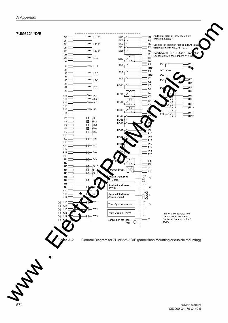
A Appendix
om
7UM622*-*D/E
Figure A-2 General Diagram for 7UM622*–*D/E (panel flush mounting or cubicle mounting)
ww . El
ectric
alPar
tMan
uals
. c
574 7UM62 ManualC53000-G1176-C149-5
w
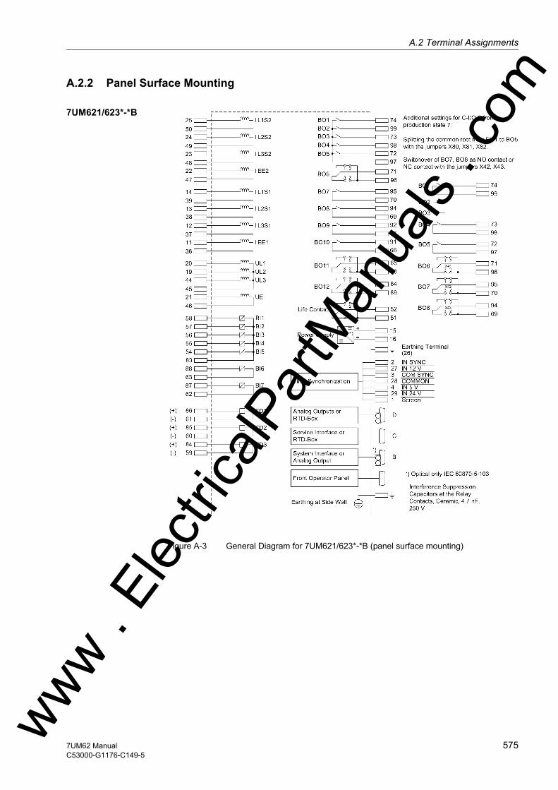
A.2 Terminal Assignmentsw
A.2.2 Panel Surface Mounting
7UM621/623*-*B
Figure A-3 General Diagram for 7UM621/623*-*B (panel surface mounting)
ww . El
ectric
alPar
tMan
uals
. com
5757UM62 ManualC53000-G1176-C149-5

A Appendix
om
7UM622*-*B
Figure A-4 General Diagram for 7UM622*-*B (panel surface mounting)
ww . El
ectric
alPar
tMan
uals
. c
576 7UM62 ManualC53000-G1176-C149-5
w

A.3 Connection Examplesw
A.3 Connection Examples
A.3.1 7UM62 - Connection Examples
Figure A-5 Busbar Connection Current and voltage connections to three transformers (phase-to-ground voltages), and in each case three CTs, earth current from an additional summation current transformer for sensitive earth fault detection; measurement of displacement voltage at broken delta winding (da–dn).. E
lectric
alPar
tMan
uals
. com
5777UM62 ManualC53000-G1176-C149-5
ww

A Appendix
om
Figure A-6 Busbar System with Low-resistance Earthing Transformer connections tothree voltage transformers (phase-to-earth voltages) and in each case three CTs - earth fault detection as differential current measuring by two CT sets; de-tection of displacement voltage at broken delta winding (da–dn) as additional criterion.
ww . El
ectric
alPar
tMan
uals
. c
578 7UM62 ManualC53000-G1176-C149-5
w
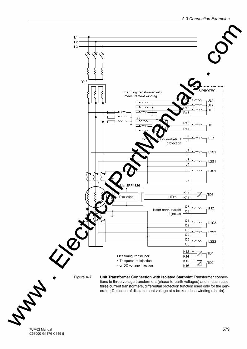
A.3 Connection Examplesw
Figure A-7 Unit Transformer Connection with Isolated Starpoint Transformer connec-tions to three voltage transformers (phase-to-earth voltages) and in each case three current transformers, differential protection function used only for the gen-erator; Detection of displacement voltage at a broken delta winding (da–dn).
ww . El
ectric
alPar
tMan
uals
. com
5797UM62 ManualC53000-G1176-C149-5

A Appendix
om
Figure A-8 Unit connection with neutral earthing transformer Connections to three voltage transformers (phase-to-earth voltages) and in each case three current transformers, differential protection function connected via generator and unit transformer; Loading resistor connected either directly to starpoint circuit or via matching transformers.ww .
Elec
tricalP
artM
anua
ls . c
580 7UM62 ManualC53000-G1176-C149-5
w

A.3 Connection Examplesw
Figure A-9 Startup Earth Fault Protection Connection of DC Voltage Input TD1 with Series-Connected Amplifier 7KG6 for Systems with Startup Converter
Figure A-10 Rotor Earth Fault Protection – with additional unit 7XR61 for injecting nominal-frequency voltage in the rotor circuit using series resistor 3PP1336
Figure A-11 Rotor earth fault protection – with series device 7XR61 for injection of a rated-frequency voltage into the rotor circuit if the sensitive earth current input is used.
ww . El
ectric
alPar
tMan
uals
. com
5817UM62 ManualC53000-G1176-C149-5
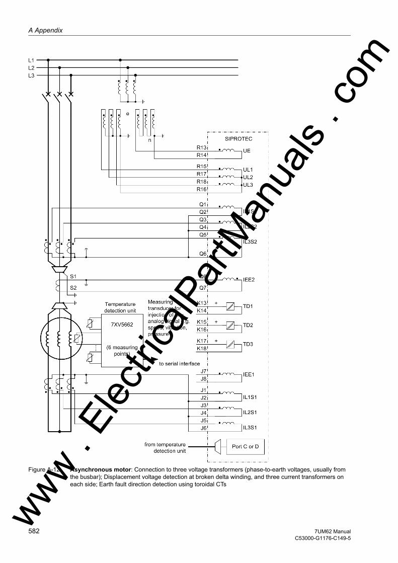
A Appendix
om
Figure A-12 Asynchronous motor: Connection to three voltage transformers (phase-to-earth voltages, usually from the busbar); Displacement voltage detection at broken delta winding, and three current transformers on each side; Earth fault direction detection using toroidal CTsww .
Elec
tricalP
artM
anua
ls . c
582 7UM62 ManualC53000-G1176-C149-5
w
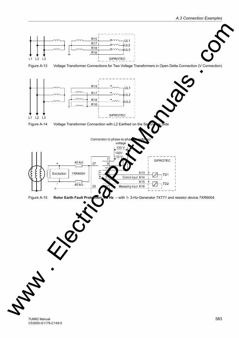
A.3 Connection Examplesw
Figure A-13 Voltage Transformer Connections for Two Voltage Transformers in Open Delta Connection (V Connection)
Figure A-14 Voltage Transformer Connection with L2 Earthed on the Secondary Side
Figure A-15 Rotor Earth Fault Protection 1-3 Hz – with 1- 3-Hz-Generator 7XT71 and resistor device 7XR6004.
ww . El
ectric
alPar
tMan
uals
. com
5837UM62 ManualC53000-G1176-C149-5
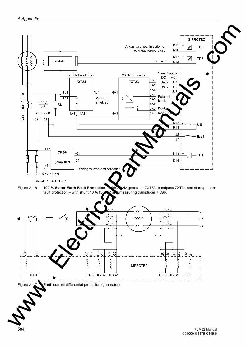
A Appendix
om
Figure A-16 100 % Stator Earth Fault Protection – with 20 Hz generator 7XT33, bandpass 7XT34 and startup earth fault protection – with shunt 10 A/150 mV and measuring transducer 7KG6.
Figure A-17 Earth current differential protection (generator)
ww . El
ectric
alPar
tMan
uals
. c
584 7UM62 ManualC53000-G1176-C149-5
w

A.3 Connection Examplesw
Figure A-18 Earth current differential protection (generator)
ww . El
ectric
alPar
tMan
uals
. com
5857UM62 ManualC53000-G1176-C149-5
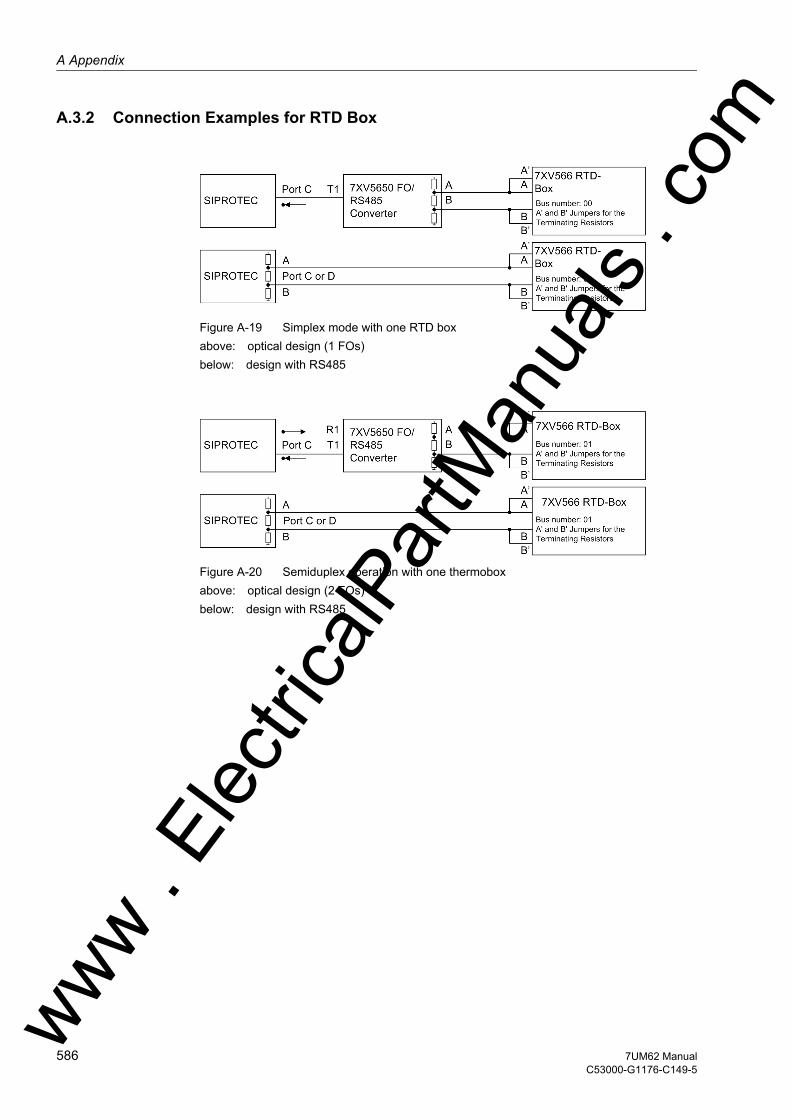
A Appendix
om
A.3.2 Connection Examples for RTD Box
Figure A-19 Simplex mode with one RTD boxabove: optical design (1 FOs)below: design with RS485
Figure A-20 Semiduplex operation with one thermoboxabove: optical design (2 FOs)below: design with RS485
ww . El
ectric
alPar
tMan
uals
. c
586 7UM62 ManualC53000-G1176-C149-5
w
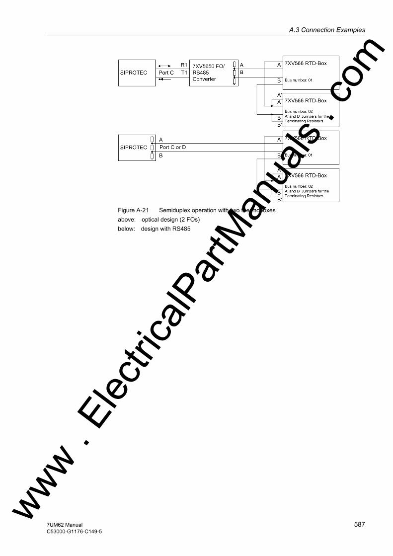
A.3 Connection Examplesw
Figure A-21 Semiduplex operation with two thermoboxesabove: optical design (2 FOs)below: design with RS485
ww . El
ectric
alPar
tMan
uals
. com
5877UM62 ManualC53000-G1176-C149-5

A Appendix
om
A.3.3 Schematic Diagram of Accessories
Figure A-22 Schematic Diagram of Coupling Unit 7XR6100-0*A00 for Rotor Earth Fault Pro-tection
Figure A-23 Schematic Diagram of Series Resistor 3PP1336-0DZ-K2Y
Figure A-24 Schematic Diagram of Voltage Divider 5:1; 5:2; 3PP1336-1CZ-K2Y
Figure A-25 Schematic Diagram of Voltage Divider 10:1; 20:1; 3PP1326-0BZ-K2Y
ww . El
ectric
alPar
tMan
uals
. c
588 7UM62 ManualC53000-G1176-C149-5
w
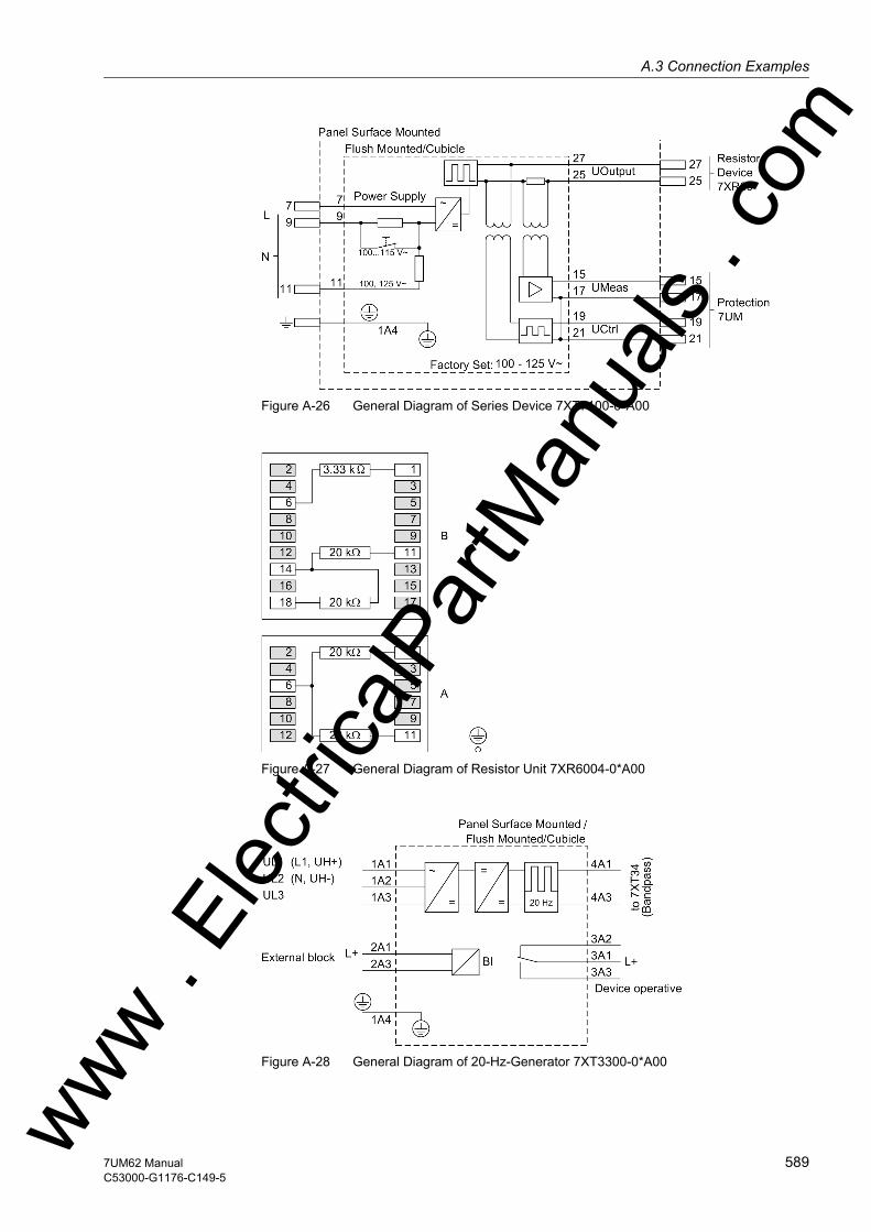
A.3 Connection Examplesw
Figure A-26 General Diagram of Series Device 7XT7100-0*A00
Figure A-27 General Diagram of Resistor Unit 7XR6004-0*A00
Figure A-28 General Diagram of 20-Hz-Generator 7XT3300-0*A00ww . El
ectric
alPar
tMan
uals
. com
5897UM62 ManualC53000-G1176-C149-5
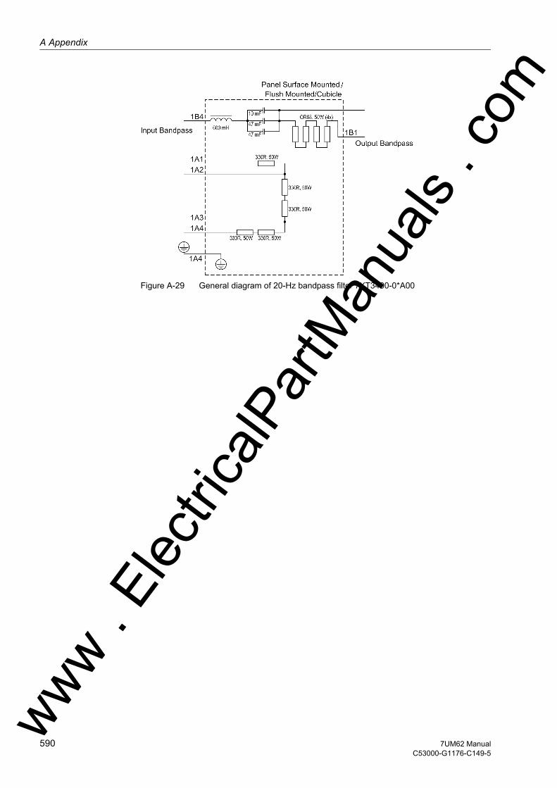
A Appendix
om
Figure A-29 General diagram of 20-Hz bandpass filter 7XT3400-0*A00
ww . El
ectric
alPar
tMan
uals
. c
590 7UM62 ManualC53000-G1176-C149-5
w

A.4 Default Settingsw
A.4 Default Settings
When the device leaves the factory, a large number of LED indicators, binary inputs and outputs as well as function keys are already preset. They are summarized in the following table.
A.4.1 LEDs
Table A-2 LED Indication Presettings
LEDs Allocated Func-tion
Function No. Description
LED1 Relay TRIP 511 Relay GENERAL TRIP commandLED2 Relay PICKUP 501 Relay PICKUPLED3 I> Fault L1 1811 O/C fault detection stage I> phase L1LED4 I> Fault L2 1812 O/C fault detection stage I> phase L2LED5 I> Fault L3 1813 O/C fault detection stage I> phase L3LED6 IEE> TRIP 1226 IEE> TRIP
U0> TRIP 5187 Stator earth fault: U0 stage TRIPS/E/F TRIP 5193 Stator earth fault protection TRIP
LED7 Error PwrSupply 147 Error Power SupplyFail Battery 177 Failure: Battery empty
LED8 Diff TRIP 5671 Differential protection TRIPLED9 Pr TRIP 5097 Reverse power: TRIP
Pr+SV TRIP 5098 Reverse power: TRIP with stop valveLED10 Exc<3 TRIP 5343 Underexc. prot. char. 3 TRIP
Exc<1 TRIP 5344 Underexc. prot. char. 1 TRIPExc<2 TRIP 5345 Underexc. prot. char. 2 TRIPExc<U<TRIP 5346 Underexc. prot. char.+Uexc< TRIP
LED11 I2>> TRIP 5160 Unbalanced load: TRIP of current stage
I2 Θ TRIP 5161 Unbalanced load: TRIP of thermal stage
LED12 f1 TRIP 5236 f1 TRIPf2 TRIP 5237 f2 TRIPf3 TRIP 5238 f3 TRIP
LED13 f4 TRIP 5239 f4 TRIPLED14 U> TRIP 6570 Overvoltage U> TRIP
U>> TRIP 6573 Overvoltage U>> TRIP
ww . El
ectric
alPar
tMan
uals
. com
5917UM62 ManualC53000-G1176-C149-5
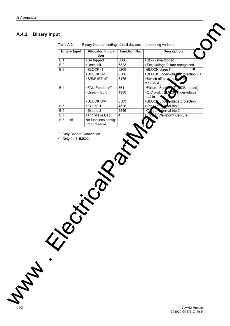
A Appendix
om
A.4.2 Binary Input
Table A-3 Binary input presettings for all devices and ordering variants
1) Only Busbar Connection2) Only for 7UM622
Binary Input Allocated Func-tion
Function No. Description
BI1 >SV tripped 5086 >Stop valve trippedBI2 >Uexc fail. 5328 >Exc. voltage failure recognizedBI3 >BLOCK f1 5206 >BLOCK stage f1
>BLOCK U< 6506 >BLOCK undervoltage protection U<>S/E/F IEE off 5176 >Switch off earth current de-
tec.(S/E/F)1)
BI4 >FAIL:Feeder VT 361 >Failure: Feeder VT (MCB tripped)>Useal-inBLK 1950 >O/C prot. : BLOCK undervoltage
seal-in>BLOCK U/V 6503 >BLOCK undervoltage protection
BI5 >Ext trip 1 4526 >Trigger external trip 1BI6 >Ext trip 2 4546 >Trigger external trip 2BI7 >Trig.Wave.Cap. 4 >Trigger Waveform CaptureBI8 ... 15 No functions config-
ured (reserve)- -2)
ww . El
ectric
alPar
tMan
uals
. c
592 7UM62 ManualC53000-G1176-C149-5
w

A.4 Default Settingsw
A.4.3 Binary Output
Table A-4 Output relay presettings for all devices and ordering variants
Binary Output Allocated Func-tion
Function No. Description
BO1 Error PwrSupply 147 Error Power SupplyFail Battery 177 Failure: Battery empty
BO2 Relay TRIP 511 Relay GENERAL TRIP commandBO3 I> TRIP 1815 O/C I> TRIP
Diff TRIP 5671 Differential protection TRIPImp.Z1< TRIP 3977 Imp.: Z1< TRIPImp.Z1B< TRIP 3978 Imp.: Z1B< TRIPImp.Z2< TRIP 3979 Imp.: Z2< TRIPImp.T3> TRIP 3980 Imp.: T3> TRIPI>> TRIP 1809 O/C I>> TRIPO/C Ip TRIP 1900 O/C Ip TRIP
BO4 IEE>> TRIP 1223 IEE>> TRIPU0> TRIP 5187 Stator earth fault: U0 stage TRIPS/E/F TRIP 5193 Stator earth fault protection TRIP
BO5 U< TRIP 6539 Undervoltage U< TRIPU> TRIP 6570 Overvoltage U> TRIPU>> TRIP 6573 Overvoltage U>> TRIP
BO6 f1 TRIP 5236 f1 TRIPf2 TRIP 5237 f2 TRIP
BO7 Exc<3 TRIP 5343 Underexc. prot. char. 3 TRIPExc<U<TRIP 5346 Underexc. prot. char.+Uexc< TRIP
BO8 I> TRIP 1815 O/C I> TRIP1)
S/E/F TRIP 5193 Stator earth fault protection TRIP1)
U>> TRIP 6573 Overvoltage U>> TRIP1)
f1 TRIP 5236 f1 TRIP1)
f2 TRIP 5237 f2 TRIP1)
Exc<3 TRIP 5343 Underexc. prot. char. 3 TRIP1)
Exc<U<TRIP 5346 Underexc. prot. char.+Uexc< TRIP1)
Pr TRIP 5097 Reverse power: TRIP1)
Pr+SV TRIP 5098 Reverse power: TRIP with stop valve1)
I2 Θ TRIP 5161 Unbalanced load: TRIP of thermal stage1)
Diff TRIP 5671 Differential protection TRIP1)
BO9 I> TRIP 1815 O/C I> TRIP2)
S/E/F TRIP 5193 Stator earth fault protection TRIP2)
U>> TRIP 6573 Overvoltage U>> TRIP2)
f2 TRIP 5237 f2 TRIP2)
Exc<3 TRIP 5343 Underexc. prot. char. 3 TRIP2)
Exc<U<TRIP 5346 Underexc. prot. char.+Uexc< TRIP2)
Pr+SV TRIP 5098 Reverse power: TRIP with stop valve2)
I2 Θ TRIP 5161 Unbalanced load: TRIP of thermal stage2)
Diff TRIP 5671 Differential protection TRIP2)
ww . El
ectric
alPar
tMan
uals
. com
5937UM62 ManualC53000-G1176-C149-5

A Appendix
om
1) Generator Circuit Breaker2) De-excitation3) Emergency Tripping4) Only for 7UM622
A.4.4 Function Keys
Table A-5 Applies to all devices and ordered variants
BO10 I> TRIP 1815 O/C I> TRIP3)
S/E/F TRIP 5193 Stator earth fault protection TRIP3)
f2 TRIP 5237 f2 TRIP3)
I2 Θ TRIP 5161 Unbalanced load: TRIP of thermal stage3)
Diff TRIP 5671 Differential protection TRIP3)
BO11 No functions config-ured (reserve)
- -
BO12 reserved for Breaker failure pro-tection
- -
BO13 ... 20 No functions config-ured (reserve)
- -4)
Binary Output Allocated Func-tion
Function No. Description
Function Keys Allocated FunctionF1 Display of Operational AnnunciationsF2 Display of Primary Operational ValuesF3 Jumping to heading for last eight fault annunciationsF4 Jumping to the reset menu of the min/max values
ww . El
ectric
alPar
tMan
uals
. c
594 7UM62 ManualC53000-G1176-C149-5
w
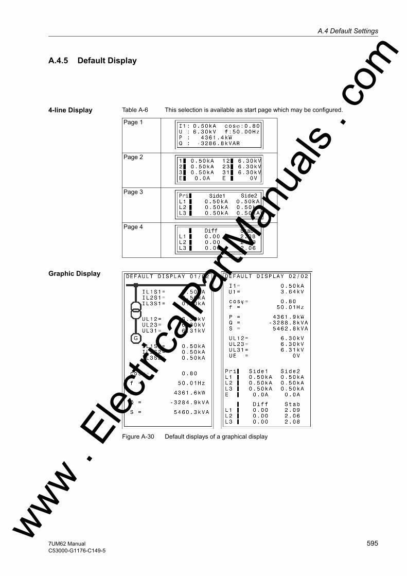
A.4 Default Settingsw
A.4.5 Default Display
4-line Display Table A-6 This selection is available as start page which may be configured.
Graphic Display
Figure A-30 Default displays of a graphical display
Page 1
Page 2
Page 3
Page 4
ww . El
ectric
alPar
tMan
uals
. com
5957UM62 ManualC53000-G1176-C149-5
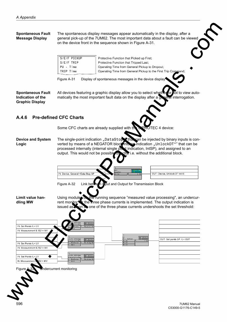
A Appendix
om
Spontaneous Fault Message Display
The spontaneous display messages appear automatically in the display, after a general pick-up of the 7UM62. The most important data about a fault can be viewed on the device front in the sequence shown in Figure A-31.
Figure A-31 Display of spontaneous messages in the device display
Spontaneous Fault Indication of the Graphic Display
All devices featuring a graphic display allow you to select whether or not to view auto-matically the most important fault data on the display after a general interrogation.
A.4.6 Pre-defined CFC Charts
Some CFC charts are already supplied with the SIPROTEC 4 device:
Device and System Logic
The single-point indication „DataStop“” that can be injected by binary inputs is con-verted by means of a NEGATOR block into an indication „UnlockDT“” that can be processed internally (internal single point indication, IntSP), and assigned to an output. This would not be possible directly, i.e. without the additional block.
Figure A-32 Link between Input and Output for Transmission Block
Limit value han-dling MW
Using modules on the running sequence ”measured value processing", an undercur-rent monitor for the three phase currents is implemented. The output indication is issued as soon as one of the three phase currents undershoots the set threshold:
Figure A-33 Undercurrent monitoring
ww . El
ectric
alPar
tMan
uals
. c
596 7UM62 ManualC53000-G1176-C149-5
w

A.5 Protocol-dependent Functionsw
A.5 Protocol-dependent Functions
Protocol → IEC 60870-5-103
IEC 61850 Eth-ernet (EN-100)
Profibus DP DNP3.0 Modbus ASCII/RTU
Additional Service Inter-face (optional)
Function ↓
Operational mea-sured values
Yes (fixed values)
Yes Yes Yes Yes Yes
Metered values Yes Yes Yes Yes Yes YesFault Recording Yes Yes No. Only via
additional service inter-face
No. Only via additional service inter-face
No. Only via additional service inter-face
Yes
Remote protection setting
No. Only via additional service inter-face
No. Only via additional service inter-face
No. Only via additional service inter-face
No. Only via additional service inter-face
No. Only via additional service inter-face
Yes
User-defined indica-tions and switching objects
Yes Yes Yes Yes Yes Yes
Time synchroniza-tion
Via Protocol; DCF77/IRIG B; Interface;Binary Input
Via Protocol (NTP);DCF77/IRIG B;Interface; Binary Input
Via DCF77/IRIG B; Interface; Binary InputProtocol
Via Protocol; DCF77/IRIG B; Interface; Binary Input
Via DCF77/IRIG B; Interface; Binary InputProtocol
—
Indications with time stamp
Yes Yes No Yes No Yes
Commissioning toolsMeasured value in-dication blocking
Yes Yes No No No Yes
Test Mode Yes Yes No No No Yes
Physical mode Asynchronous Synchron Asynchronous Asynchronous Asynchronous —Transmission Mode Cyclical-
ly/EventCyclical-ly/Event
Cyclically Cyclical-ly/Event
Cyclically —
Baudrate 4800 to 38400 Up tp 100 MBaud
Up to 1.5 MBaud
4800 to 19200 2400 to 19200 4800 to 115200
Type RS232 RS485Optical Fiber
Ethernet TP RS485 Optical Fiber; Double ring
RS485Optical Fiber
RS485 Optical Fiber
RS232 RS485
ww . El
ectric
alPar
tMan
uals
. com
5977UM62 ManualC53000-G1176-C149-5
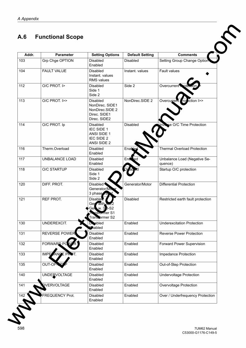
A Appendix
om
A.6 Functional Scope
Addr. Parameter Setting Options Default Setting Comments103 Grp Chge OPTION Disabled
EnabledDisabled Setting Group Change Option
104 FAULT VALUE DisabledInstant. valuesRMS values
Instant. values Fault values
112 O/C PROT. I> DisabledSide 1Side 2
Side 2 Overcurrent Protection I>
113 O/C PROT. I>> DisabledNonDirec. SIDE1NonDirec.SIDE 2Direc. SIDE1Direc. SIDE2
NonDirec.SIDE 2 Overcurrent Protection I>>
114 O/C PROT. Ip DisabledIEC SIDE 1ANSI SIDE 1IEC SIDE 2ANSI SIDE 2
Disabled Inverse O/C Time Protection
116 Therm.Overload DisabledEnabled
Enabled Thermal Overload Protection
117 UNBALANCE LOAD DisabledEnabled
Enabled Unbalance Load (Negative Se-quence)
118 O/C STARTUP DisabledSide 1Side 2
Disabled Startup O/C protection
120 DIFF. PROT. DisabledGenerator/Motor3 phase transf.
Generator/Motor Differential Protection
121 REF PROT. DisabledGen. with IEE2Gen. w. 3I0-S2Transformer S1Transformer S2
Disabled Restricted earth fault protection
130 UNDEREXCIT. DisabledEnabled
Enabled Underexcitation Protection
131 REVERSE POWER DisabledEnabled
Enabled Reverse Power Protection
132 FORWARD POWER DisabledEnabled
Enabled Forward Power Supervision
133 IMPEDANCE PROT. DisabledEnabled
Enabled Impedance Protection
135 OUT-OF-STEP DisabledEnabled
Enabled Out-of-Step Protection
140 UNDERVOLTAGE DisabledEnabled
Enabled Undervoltage Protection
141 OVERVOLTAGE DisabledEnabled
Enabled Overvoltage Protection
142 FREQUENCY Prot. DisabledEnabled
Enabled Over / Underfrequency Protection
ww . El
ectric
alPar
tMan
uals
. c
598 7UM62 ManualC53000-G1176-C149-5
w

A.6 Functional Scopew
143 OVEREXC. PROT. DisabledEnabled
Enabled Overexcitation Protection (U/f)
144 INV.UNDERVOLT. DisabledEnabled
Enabled Inverse Undervoltage Protection Up<
145 df/dt Protect. Disabled2 df/dt stages4 df/dt stages
2 df/dt stages Rate-of-frequency-change protec-tion
146 VECTOR JUMP DisabledEnabled
Enabled Jump of Voltage Vector
150 S/E/F PROT. Disablednon-dir. U0non-dir. U0&I0directional
non-dir. U0&I0 Stator Earth Fault Protection
151 O/C PROT. IEE> Disabledwith IEE1with IEE2
with IEE2 Sensitive Earth Current Protection
152 SEF 3rd HARM. DisabledEnabled
Enabled Stator Earth Fault Prot. 3rd Har-monic
153 100% SEF-PROT. DisabledEnabled
Enabled 100% Stator-Earth-Fault Protec-tion
154 O/C PROT IEE-B Disabledwith IEE1with IEE2
with IEE2 Sensitive Earth Current Protection B
155 INTERTURN PROT DisabledEnabled
Enabled Interturn Protection
160 ROTOR E/F DisabledEnabled
Enabled Rotor Earth Fault Protection (R, fn)
161 REF 1-3Hz DisabledEnabled
Enabled Rotor Earth Fault Protection (1-3Hz)
165 STARTUP MOTOR DisabledEnabled
Enabled Motor Starting Time Supervision
166 RESTART INHIBIT DisabledEnabled
Enabled Restart Inhibit for Motors
170 BREAKER FAILURE DisabledSide 1Side 2
Side 2 Breaker Failure Protection
171 INADVERT. EN. DisabledEnabled
Enabled Inadvertent Energisation
172 DC PROTECTION DisabledEnabled
Enabled DC Voltage/Current Protection
Addr. Parameter Setting Options Default Setting Comments
ww . El
ectric
alPar
tMan
uals
. com
5997UM62 ManualC53000-G1176-C149-5

A Appendix
om
173 ANALOGOUTPUT B1 DisabledI1 [%]I2 [%]IEE1 [%]IEE2 [%]U1 [%]U0 [%]U03H [%]|P| [%]|Q| [%]|S| [%]f [%]U/f [%]PHI [%]|PF| [%]ΘR/ΘRmax [%]Θ/Θtrip [%]RE REF [%]RE REF 1-3Hz[%]RE SEF100 [%]Disabled Analog Output B1 (Port B)
174 ANALOGOUTPUT B2 DisabledI1 [%]I2 [%]IEE1 [%]IEE2 [%]U1 [%]U0 [%]U03H [%]|P| [%]|Q| [%]|S| [%]f [%]U/f [%]PHI [%]|PF| [%]ΘR/ΘRmax [%]Θ/Θtrip [%]RE REF [%]RE REF 1-3Hz[%]RE SEF100 [%]
Disabled Analog Output B2 (Port B)
Addr. Parameter Setting Options Default Setting Comments
ww . El
ectric
alPar
tMan
uals
. c
600 7UM62 ManualC53000-G1176-C149-5
w
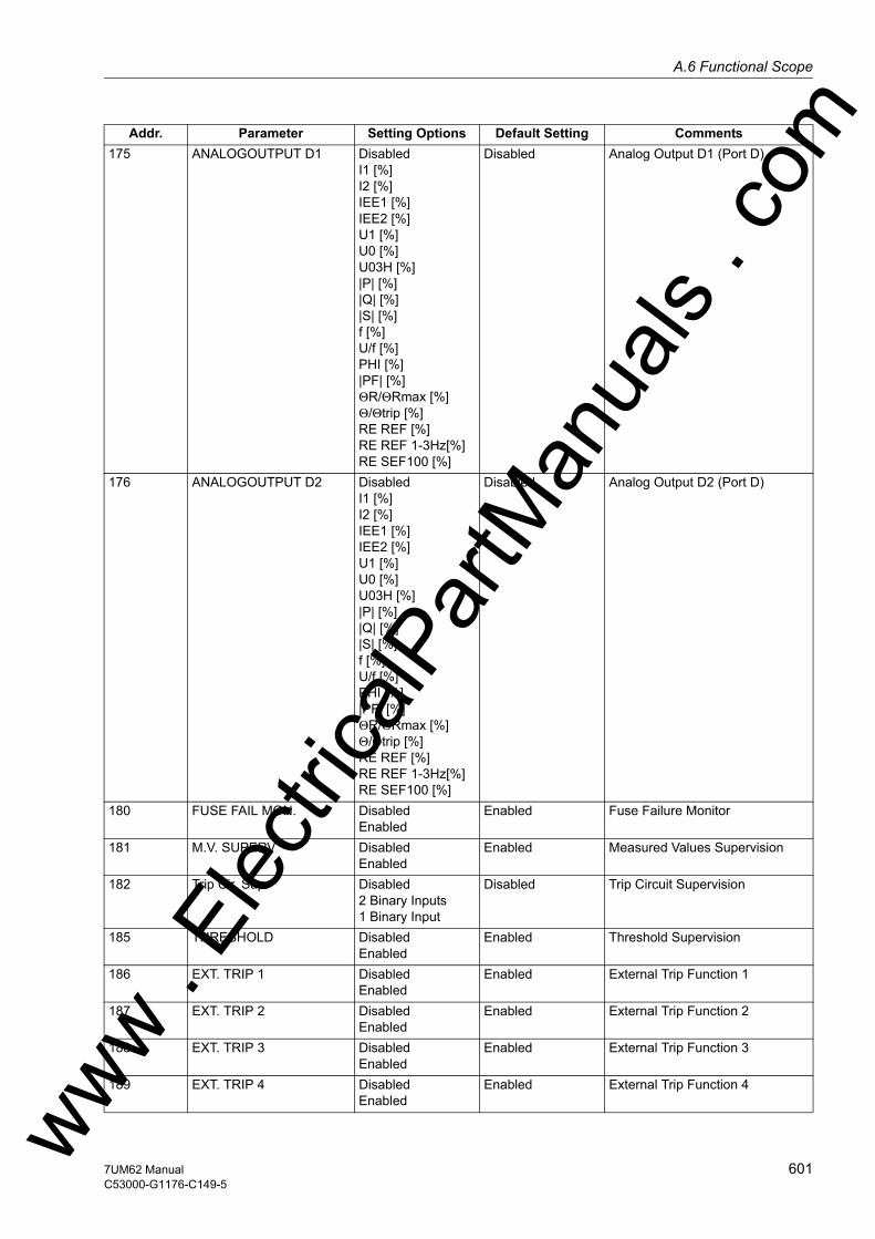
A.6 Functional Scopew
175 ANALOGOUTPUT D1 DisabledI1 [%]I2 [%]IEE1 [%]IEE2 [%]U1 [%]U0 [%]U03H [%]|P| [%]|Q| [%]|S| [%]f [%]U/f [%]PHI [%]|PF| [%]ΘR/ΘRmax [%]Θ/Θtrip [%]RE REF [%]RE REF 1-3Hz[%]RE SEF100 [%]
Disabled Analog Output D1 (Port D)
176 ANALOGOUTPUT D2 DisabledI1 [%]I2 [%]IEE1 [%]IEE2 [%]U1 [%]U0 [%]U03H [%]|P| [%]|Q| [%]|S| [%]f [%]U/f [%]PHI [%]|PF| [%]ΘR/ΘRmax [%]Θ/Θtrip [%]RE REF [%]RE REF 1-3Hz[%]RE SEF100 [%]
Disabled Analog Output D2 (Port D)
180 FUSE FAIL MON. DisabledEnabled
Enabled Fuse Failure Monitor
181 M.V. SUPERV DisabledEnabled
Enabled Measured Values Supervision
182 Trip Cir. Sup. Disabled2 Binary Inputs1 Binary Input
Disabled Trip Circuit Supervision
185 THRESHOLD DisabledEnabled
Enabled Threshold Supervision
186 EXT. TRIP 1 DisabledEnabled
Enabled External Trip Function 1
187 EXT. TRIP 2 DisabledEnabled
Enabled External Trip Function 2
188 EXT. TRIP 3 DisabledEnabled
Enabled External Trip Function 3
189 EXT. TRIP 4 DisabledEnabled
Enabled External Trip Function 4
Addr. Parameter Setting Options Default Setting Comments
ww . El
ectric
alPar
tMan
uals
. com
6017UM62 ManualC53000-G1176-C149-5
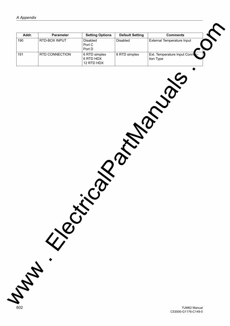
A Appendix
om
190 RTD-BOX INPUT DisabledPort CPort DDisabled External Temperature Input
191 RTD CONNECTION 6 RTD simplex6 RTD HDX12 RTD HDX
6 RTD simplex Ext. Temperature Input Connec-tion Type
Addr. Parameter Setting Options Default Setting Comments
ww . El
ectric
alPar
tMan
uals
. c
602 7UM62 ManualC53000-G1176-C149-5
w

A.7 Settingsw
A.7 Settings
Addresses which have an appended "A" can only be changed with DIGSI, under Ad-ditional Settings.
The table indicates region-specific presettings. Column C (configuration) indicates the corresponding secondary nominal current of the current transformer.
Addr. Parameter Function C Setting Options Default Setting Comments201 STRPNT->OBJ S1 P.System Data 1 YES
NOYES CT-Strpnt. Side1 in Direct. of
Object
202 IN-PRI I-SIDE1 P.System Data 1 1 .. 100000 A 500 A CT Rated Primary Current Side 1
203 IN-SEC I-SIDE1 P.System Data 1 1A5A
1A CT Rated Secondary Current Side 1
204 CT ANGLE W0 P.System Data 1 -5.00 .. 5.00 ° 0.00 ° Correction Angle CT W0
205 FACTOR IEE1 P.System Data 1 1.0 .. 100000.0 60.0 CT Ratio Prim./Sec. Iee1
210 STRPNT->OBJ S2 P.System Data 1 YESNO
YES CT-Strpnt. Side2 in Direct. of Object
211 IN-PRI I-SIDE2 P.System Data 1 1 .. 100000 A 500 A CT Rated Primary Current Side 2
212 IN-SEC I-SIDE2 P.System Data 1 1A5A
1A CT Rated Secondary Current Side 2
213 FACTOR IEE2 P.System Data 1 1.0 .. 100000.0 60.0 CT Ratio Prim./Sec. Iee2
214 GRD TERM. IEE2 P.System Data 1 Terminal Q7Terminal Q8
Terminal Q7 Grounded Terminal CT Iee2
221 Unom PRIMARY P.System Data 1 0.10 .. 400.00 kV 6.30 kV Rated Primary Voltage
222 Unom SECONDARY P.System Data 1 100 .. 125 V 100 V Rated Secondary Voltage (Ph-Ph)
223 UE CONNECTION P.System Data 1 neutr. transf.broken deltaNot connectedany VTRotorLoad. resistorUen-winding
neutr. transf. UE Connection
224 FACTOR UE P.System Data 1 1.0 .. 2500.0 36.4 VT Ratio Prim./Sec. Ue
225A Uph / Udelta P.System Data 1 1.00 .. 3.00 1.73 Matching Ratio Ph.-VT to Broken-Delta-VT
241 UN-PRI SIDE 1 P.System Data 1 0.40 .. 800.00 kV 20.00 kV Rated Primary Voltage Side 1
242 STARPNT SIDE 1 P.System Data 1 IsolatedSolid Earthed
Isolated Starpoint of Side 1 is
243 UN-PRI SIDE 2 P.System Data 1 0.40 .. 800.00 kV 6.30 kV Rated Primary Voltage side 2
244 STARPNT SIDE 2 P.System Data 1 IsolatedSolid Earthed
Isolated Starpoint of side 2 is
246 VECTOR GRP S2 P.System Data 1 0 .. 11 *30° 0 *30° Vector Group Numeral of Side 2
249 SN TRANSFORMER P.System Data 1 0.20 .. 5000.00 MVA 5.30 MVA Rated Apparent Power of the Transformer
251 UN GEN/MOTOR P.System Data 1 0.40 .. 800.00 kV 6.30 kV Rated Primary Voltage Genera-tor/Motor
252 SN GEN/MOTOR P.System Data 1 0.20 .. 5000.00 MVA 5.27 MVA Rated Apparent Power of the Generator
270 Rated Frequency P.System Data 1 50 Hz60 Hz
50 Hz Rated Frequency
271 PHASE SEQ. P.System Data 1 L1 L2 L3L1 L3 L2
L1 L2 L3 Phase Sequence
272 SCHEME P.System Data 1 BusbarUnit transf.
Busbar Scheme Configuration
274A ATEX100 P.System Data 1 YESNO
NO Storage of th. Replicas w/o Power Supply
275 FACTOR R SEF P.System Data 1 1.0 .. 200.0 37.0 Ratio Prim./Sec. R SEF
276 TEMP. UNIT P.System Data 1 CelsiusFahrenheit
Celsius Unit of temperature measure-ment
280 TMin TRIP CMD P.System Data 1 0.01 .. 32.00 sec 0.15 sec Minimum TRIP Command Dura-tionww .
Elec
tricalP
artM
anua
ls . c
om
6037UM62 ManualC53000-G1176-C149-5
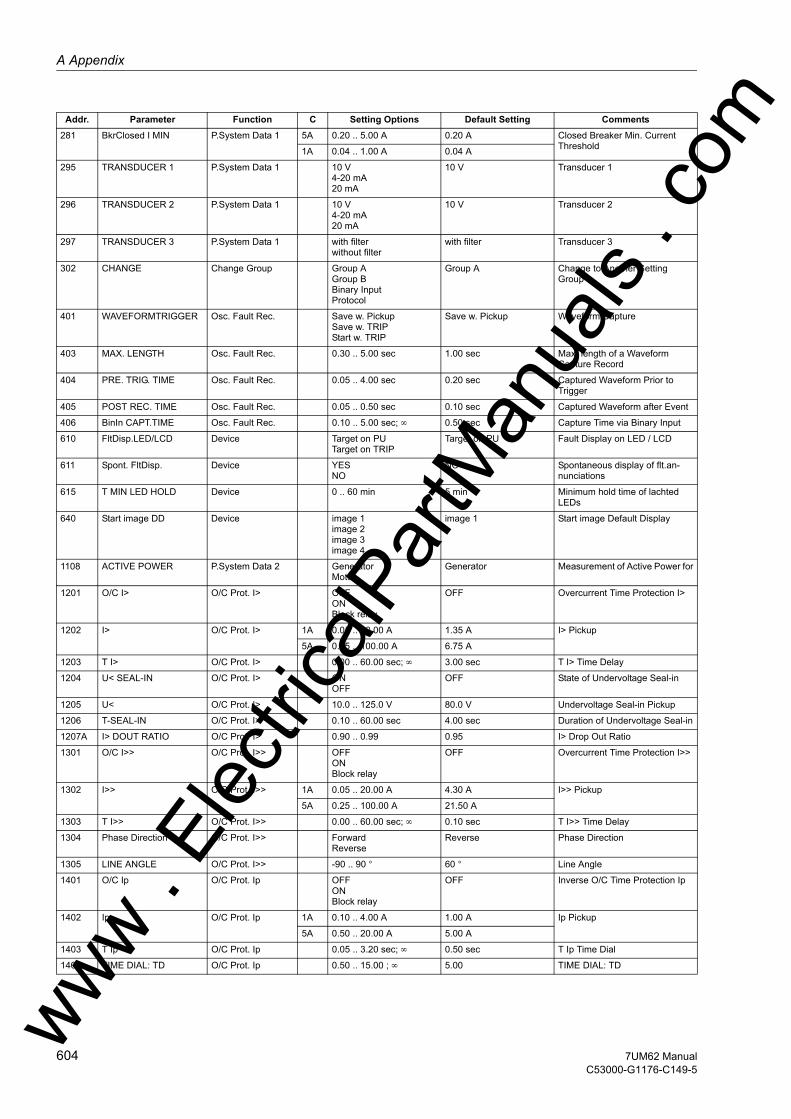
A Appendix
om
281 BkrClosed I MIN P.System Data 1 5A 0.20 .. 5.00 A 0.20 A Closed Breaker Min. Current Threshold1A 0.04 .. 1.00 A 0.04 A295 TRANSDUCER 1 P.System Data 1 10 V4-20 mA20 mA
10 V Transducer 1
296 TRANSDUCER 2 P.System Data 1 10 V4-20 mA20 mA
10 V Transducer 2
297 TRANSDUCER 3 P.System Data 1 with filterwithout filter
with filter Transducer 3
302 CHANGE Change Group Group AGroup BBinary InputProtocol
Group A Change to Another Setting Group
401 WAVEFORMTRIGGER Osc. Fault Rec. Save w. PickupSave w. TRIPStart w. TRIP
Save w. Pickup Waveform Capture
403 MAX. LENGTH Osc. Fault Rec. 0.30 .. 5.00 sec 1.00 sec Max. length of a Waveform Capture Record
404 PRE. TRIG. TIME Osc. Fault Rec. 0.05 .. 4.00 sec 0.20 sec Captured Waveform Prior to Trigger
405 POST REC. TIME Osc. Fault Rec. 0.05 .. 0.50 sec 0.10 sec Captured Waveform after Event
406 BinIn CAPT.TIME Osc. Fault Rec. 0.10 .. 5.00 sec; ∞ 0.50 sec Capture Time via Binary Input
610 FltDisp.LED/LCD Device Target on PUTarget on TRIP
Target on PU Fault Display on LED / LCD
611 Spont. FltDisp. Device YESNO
NO Spontaneous display of flt.an-nunciations
615 T MIN LED HOLD Device 0 .. 60 min 5 min Minimum hold time of lachted LEDs
640 Start image DD Device image 1image 2image 3image 4
image 1 Start image Default Display
1108 ACTIVE POWER P.System Data 2 GeneratorMotor
Generator Measurement of Active Power for
1201 O/C I> O/C Prot. I> OFFONBlock relay
OFF Overcurrent Time Protection I>
1202 I> O/C Prot. I> 1A 0.05 .. 20.00 A 1.35 A I> Pickup
5A 0.25 .. 100.00 A 6.75 A
1203 T I> O/C Prot. I> 0.00 .. 60.00 sec; ∞ 3.00 sec T I> Time Delay
1204 U< SEAL-IN O/C Prot. I> ONOFF
OFF State of Undervoltage Seal-in
1205 U< O/C Prot. I> 10.0 .. 125.0 V 80.0 V Undervoltage Seal-in Pickup
1206 T-SEAL-IN O/C Prot. I> 0.10 .. 60.00 sec 4.00 sec Duration of Undervoltage Seal-in
1207A I> DOUT RATIO O/C Prot. I> 0.90 .. 0.99 0.95 I> Drop Out Ratio
1301 O/C I>> O/C Prot. I>> OFFONBlock relay
OFF Overcurrent Time Protection I>>
1302 I>> O/C Prot. I>> 1A 0.05 .. 20.00 A 4.30 A I>> Pickup
5A 0.25 .. 100.00 A 21.50 A
1303 T I>> O/C Prot. I>> 0.00 .. 60.00 sec; ∞ 0.10 sec T I>> Time Delay
1304 Phase Direction O/C Prot. I>> ForwardReverse
Reverse Phase Direction
1305 LINE ANGLE O/C Prot. I>> -90 .. 90 ° 60 ° Line Angle
1401 O/C Ip O/C Prot. Ip OFFONBlock relay
OFF Inverse O/C Time Protection Ip
1402 Ip O/C Prot. Ip 1A 0.10 .. 4.00 A 1.00 A Ip Pickup
5A 0.50 .. 20.00 A 5.00 A
1403 T Ip O/C Prot. Ip 0.05 .. 3.20 sec; ∞ 0.50 sec T Ip Time Dial
1404 TIME DIAL: TD O/C Prot. Ip 0.50 .. 15.00 ; ∞ 5.00 TIME DIAL: TD
Addr. Parameter Function C Setting Options Default Setting Comments
ww . El
ectric
alPar
tMan
uals
. c
604 7UM62 ManualC53000-G1176-C149-5
w
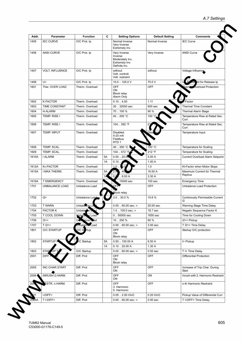
A.7 Settingsw
1405 IEC CURVE O/C Prot. Ip Normal InverseVery InverseExtremely Inv.
Normal Inverse IEC Curve
1406 ANSI CURVE O/C Prot. Ip Very InverseInverseModerately Inv.Extremely Inv.Definite Inv.
Very Inverse ANSI Curve
1407 VOLT. INFLUENCE O/C Prot. Ip withoutVolt. controll.Volt. restraint
without Voltage Influence
1408 U< O/C Prot. Ip 10.0 .. 125.0 V 75.0 V U< Threshold for Release Ip
1601 Ther. OVER LOAD Therm. Overload OFFONBlock relayAlarm Only
OFF Thermal Overload Protection
1602 K-FACTOR Therm. Overload 0.10 .. 4.00 1.11 K-Factor
1603 TIME CONSTANT Therm. Overload 30 .. 32000 sec 600 sec Thermal Time Constant
1604 Θ ALARM Therm. Overload 70 .. 100 % 90 % Thermal Alarm Stage
1605 TEMP. RISE I Therm. Overload 40 .. 200 °C 100 °C Temperature Rise at Rated Sec. Curr.
1606 TEMP. RISE I Therm. Overload 104 .. 392 °F 212 °F Temperature Rise at Rated Sec. Curr.
1607 TEMP. INPUT Therm. Overload Disabled4-20 mAFieldbusRTD 1
Disabled Temperature Input
1608 TEMP. SCAL. Therm. Overload 40 .. 300 °C 100 °C Temperature for Scaling
1609 TEMP. SCAL. Therm. Overload 104 .. 572 °F 212 °F Temperature for Scaling
1610A I ALARM Therm. Overload 5A 0.50 .. 20.00 A 5.00 A Current Overload Alarm Setpoint
1A 0.10 .. 4.00 A 1.00 A
1612A Kτ-FACTOR Therm. Overload 1.0 .. 10.0 1.0 Kt-Factor when Motor Stops
1615A I MAX THERM. Therm. Overload 5A 2.50 .. 40.00 A 16.50 A Maximum Current for Thermal Replica1A 0.50 .. 8.00 A 3.30 A
1616A T EMERGENCY Therm. Overload 10 .. 15000 sec 100 sec Emergency Time
1701 UNBALANCE LOAD Unbalance Load OFFONBlock relay
OFF Unbalance Load Protection
1702 I2> Unbalance Load 3.0 .. 30.0 % 10.6 % Continously Permissible Current I2
1703 T WARN Unbalance Load 0.00 .. 60.00 sec; ∞ 20.00 sec Warning Stage Time Delay
1704 FACTOR K Unbalance Load 1.0 .. 100.0 sec; ∞ 18.7 sec Negativ Sequence Factor K
1705 T COOL DOWN Unbalance Load 0 .. 50000 sec 1650 sec Time for Cooling Down
1706 I2>> Unbalance Load 10 .. 200 % 60 % I2>> Pickup
1707 T I2>> Unbalance Load 0.00 .. 60.00 sec; ∞ 3.00 sec T I2>> Time Delay
1801 O/C STARTUP O/C Startup OFFONBlock relay
OFF Startup O/C protection
1802 STARTUP I> O/C Startup 5A 0.50 .. 100.00 A 6.50 A I> Pickup
1A 0.10 .. 20.00 A 1.30 A
1803 STARTUP T I> O/C Startup 0.00 .. 60.00 sec; ∞ 0.50 sec T I> Time Delay
2001 DIFF. PROT. Diff. Prot OFFONBlock relay
OFF Differential Protection
2005 INC.CHAR.START Diff. Prot OFFON
OFF Increase of Trip Char. During Start
2006 INRUSH 2.HARM. Diff. Prot OFFON
ON Inrush with 2. Harmonic Restraint
2007 RESTR. n.HARM. Diff. Prot OFF3. Harmonic5. Harmonic
OFF n-th Harmonic Restraint
2021 I-DIFF> Diff. Prot 0.05 .. 2.00 I/InO 0.20 I/InO Pickup Value of Differential Curr.
2026A T I-DIFF> Diff. Prot 0.00 .. 60.00 sec; ∞ 0.00 sec T I-DIFF> Time Delay
Addr. Parameter Function C Setting Options Default Setting Comments
ww . El
ectric
alPar
tMan
uals
. com
6057UM62 ManualC53000-G1176-C149-5
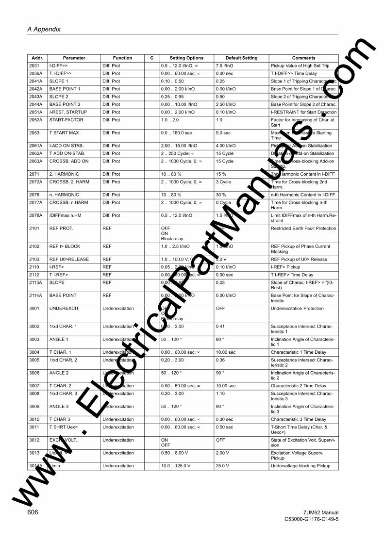
A Appendix
om
2031 I-DIFF>> Diff. Prot 0.5 .. 12.0 I/InO; ∞ 7.5 I/InO Pickup Value of High Set Trip2036A T I-DIFF>> Diff. Prot 0.00 .. 60.00 sec; ∞ 0.00 sec T I-DIFF>> Time Delay
2041A SLOPE 1 Diff. Prot 0.10 .. 0.50 0.25 Slope 1 of Tripping Characteristic
2042A BASE POINT 1 Diff. Prot 0.00 .. 2.00 I/InO 0.00 I/InO Base Point for Slope 1 of Charac.
2043A SLOPE 2 Diff. Prot 0.25 .. 0.95 0.50 Slope 2 of Tripping Characteristic
2044A BASE POINT 2 Diff. Prot 0.00 .. 10.00 I/InO 2.50 I/InO Base Point for Slope 2 of Charac.
2051A I-REST. STARTUP Diff. Prot 0.00 .. 2.00 I/InO 0.10 I/InO I-RESTRAINT for Start Detection
2052A START-FACTOR Diff. Prot 1.0 .. 2.0 1.0 Factor for Increasing of Char. at Start
2053 T START MAX Diff. Prot 0.0 .. 180.0 sec 5.0 sec Maximum Permissible Starting Time
2061A I-ADD ON STAB. Diff. Prot 2.00 .. 15.00 I/InO 4.00 I/InO Pickup for Add-on Stabilization
2062A T ADD ON-STAB. Diff. Prot 2 .. 250 Cycle; ∞ 15 Cycle Duration of Add-on Stabilization
2063A CROSSB. ADD ON Diff. Prot 2 .. 1000 Cycle; 0; ∞ 15 Cycle Time for Cross-blocking Add-on Stabiliz.
2071 2. HARMONIC Diff. Prot 10 .. 80 % 15 % 2nd Harmonic Content in I-DIFF
2072A CROSSB. 2. HARM Diff. Prot 2 .. 1000 Cycle; 0; ∞ 3 Cycle Time for Cross-blocking 2nd Harm.
2076 n. HARMONIC Diff. Prot 10 .. 80 % 30 % n-th Harmonic Content in I-DIFF
2077A CROSSB. n.HARM Diff. Prot 2 .. 1000 Cycle; 0; ∞ 0 Cycle Time for Cross-blocking n-th Harm.
2078A IDIFFmax n.HM Diff. Prot 0.5 .. 12.0 I/InO 1.5 I/InO Limit IDIFFmax of n-th Harm.Re-straint
2101 REF PROT. REF OFFONBlock relay
OFF Restricted Earth Fault Protection
2102 REF I> BLOCK REF 1.0 .. 2.5 I/InO 1.5 I/InO REF Pickup of Phase Current Blocking
2103 REF U0>RELEASE REF 1.0 .. 100.0 V; 0 5.0 V REF Pickup of U0> Release
2110 I-REF> REF 0.05 .. 2.00 I/InO 0.10 I/InO I-REF> Pickup
2112 T I-REF> REF 0.00 .. 60.00 sec; ∞ 0.00 sec T I-REF> Time Delay
2113A SLOPE REF 0.00 .. 0.95 0.25 Slope of Charac. I-REF> = f(I0-Rest)
2114A BASE POINT REF 0.00 .. 2.00 I/InO 0.00 I/InO Base Point for Slope of Charac-teristic
3001 UNDEREXCIT. Underexcitation OFFONBlock relay
OFF Underexcitation Protection
3002 1/xd CHAR. 1 Underexcitation 0.20 .. 3.00 0.41 Susceptance Intersect Charac-teristic 1
3003 ANGLE 1 Underexcitation 50 .. 120 ° 80 ° Inclination Angle of Characteris-tic 1
3004 T CHAR. 1 Underexcitation 0.00 .. 60.00 sec; ∞ 10.00 sec Characteristic 1 Time Delay
3005 1/xd CHAR. 2 Underexcitation 0.20 .. 3.00 0.36 Susceptance Intersect Charac-teristic 2
3006 ANGLE 2 Underexcitation 50 .. 120 ° 90 ° Inclination Angle of Characteris-tic 2
3007 T CHAR. 2 Underexcitation 0.00 .. 60.00 sec; ∞ 10.00 sec Characteristic 2 Time Delay
3008 1/xd CHAR. 3 Underexcitation 0.20 .. 3.00 1.10 Susceptance Intersect Charac-teristic 3
3009 ANGLE 3 Underexcitation 50 .. 120 ° 90 ° Inclination Angle of Characteris-tic 3
3010 T CHAR 3 Underexcitation 0.00 .. 60.00 sec; ∞ 0.30 sec Characteristic 3 Time Delay
3011 T SHRT Uex< Underexcitation 0.00 .. 60.00 sec; ∞ 0.50 sec T-Short Time Delay (Char. & Uexc<)
3012 EXCIT. VOLT. Underexcitation ONOFF
OFF State of Excitation Volt. Supervi-sion
3013 Uexcit. < Underexcitation 0.50 .. 8.00 V 2.00 V Excitation Voltage Superv. Pickup
3014A Umin Underexcitation 10.0 .. 125.0 V 25.0 V Undervoltage blocking Pickup
Addr. Parameter Function C Setting Options Default Setting Comments
ww . El
ectric
alPar
tMan
uals
. c
606 7UM62 ManualC53000-G1176-C149-5
w

A.7 Settingsw
3101 REVERSE POWER Reverse Power OFFONBlock relay
OFF Reverse Power Protection
3102 P> REVERSE Reverse Power -30.00 .. -0.50 % -1.93 % P> Reverse Pickup
3103 T-SV-OPEN Reverse Power 0.00 .. 60.00 sec; ∞ 10.00 sec Time Delay Long (without Stop Valve)
3104 T-SV-CLOSED Reverse Power 0.00 .. 60.00 sec; ∞ 1.00 sec Time Delay Short (with Stop Valve)
3105A T-HOLD Reverse Power 0.00 .. 60.00 sec; ∞ 0.00 sec Pickup Holding Time
3201 FORWARD POWER Forward Power OFFONBlock relay
OFF Forward Power Supervision
3202 Pf< Forward Power 0.5 .. 120.0 % 9.7 % P-forw.< Supervision Pickup
3203 Pf> Forward Power 1.0 .. 120.0 % 96.6 % P-forw.> Supervision Pickup
3204 T-Pf< Forward Power 0.00 .. 60.00 sec; ∞ 10.00 sec T-P-forw.< Time Delay
3205 T-Pf> Forward Power 0.00 .. 60.00 sec; ∞ 10.00 sec T-P-forw.> Time Delay
3206A MEAS. METHOD Forward Power accuratefast
accurate Method of Operation
3301 IMPEDANCE PROT. Impedance OFFONBlock relay
OFF Impedance Protection
3302 IMP I> Impedance 5A 0.50 .. 100.00 A 6.75 A Fault Detection I> Pickup
1A 0.10 .. 20.00 A 1.35 A
3303 U< SEAL-IN Impedance ONOFF
OFF State of Undervoltage Seal-in
3304 U< Impedance 10.0 .. 125.0 V 80.0 V Undervoltage Seal-in Pickup
3305 T-SEAL-IN Impedance 0.10 .. 60.00 sec 4.00 sec Duration of Undervoltage Seal-in
3306 ZONE Z1 Impedance 5A 0.01 .. 26.00 Ω 0.58 Ω Impedance Zone Z1
1A 0.05 .. 130.00 Ω 2.90 Ω
3307 T-Z1 Impedance 0.00 .. 60.00 sec; ∞ 0.10 sec Impedance Zone Z1 Time Delay
3308 ZONE Z1B Impedance 5A 0.01 .. 13.00 Ω 0.99 Ω Impedance Zone Z1B
1A 0.05 .. 65.00 Ω 4.95 Ω
3309 T-Z1B Impedance 0.00 .. 60.00 sec; ∞ 0.10 sec Impedance Zone Z1B Time Delay
3310 ZONE Z2 Impedance 5A 0.01 .. 13.00 Ω 0.83 Ω Impedanz Zone Z2
1A 0.05 .. 65.00 Ω 4.15 Ω
3311 ZONE2 T2 Impedance 0.00 .. 60.00 sec; ∞ 0.50 sec Impedance Zone Z2 Time Delay
3312 T END Impedance 0.00 .. 60.00 sec; ∞ 3.00 sec T END: Final Time Delay
3313 POWER SWING Impedance ONOFF
OFF Power Swing Blocking
3314 P/SPOL-TPOL Impedance 5A 0.02 .. 6.00 Ω 1.60 Ω Distance betw. Power Swing - Trip-Pol.1A 0.10 .. 30.00 Ω 8.00 Ω
3315 dZ/dt Impedance 5A 0.2 .. 120.0 Ω/s 60.0 Ω/s Rate of Change of dZ/dt
1A 1.0 .. 600.0 Ω/s 300.0 Ω/s
3316A BLOCKING OF Impedance Z1Z2
Z1 Power Swing Blocking locks out
3317A T-ACTION P/S Impedance 0.00 .. 60.00 sec; ∞ 3.00 sec Power Swing Action Time
3501 OUT-OF-STEP Out-of-Step OFFONBlock relay
OFF Out-of-Step Protection
3502 I1> RELEASE Out-of-Step 20.0 .. 400.0 % 120.0 % Pickup Current for Measuring Release I1>
3503 I2< RELEASE Out-of-Step 5.0 .. 100.0 % 20.0 % Pickup Current for Measuring Release I2<
3504 Za Out-of-Step 5A 0.04 .. 26.00 Ω 0.90 Ω Resistance Za of the Polygon (width)1A 0.20 .. 130.00 Ω 4.50 Ω
3505 Zb Out-of-Step 5A 0.02 .. 26.00 Ω 2.40 Ω Reactance Zb of the Polygon (re-verse)1A 0.10 .. 130.00 Ω 12.00 Ω
3506 Zc Out-of-Step 5A 0.02 .. 26.00 Ω 0.72 Ω Reactance Zc of Polygon (for-ward char.1)1A 0.10 .. 130.00 Ω 3.60 Ω
Addr. Parameter Function C Setting Options Default Setting Comments
ww . El
ectric
alPar
tMan
uals
. com
6077UM62 ManualC53000-G1176-C149-5

A Appendix
om
3507 Zd - Zc Out-of-Step 5A 0.00 .. 26.00 Ω 1.28 Ω Reactance Dif. Char.1 - Char.2 (forward)1A 0.00 .. 130.00 Ω 6.40 Ω3508 PHI POLYGON Out-of-Step 60.0 .. 90.0 ° 90.0 ° Angle of Inclination of the Polygon
3509 REP. CHAR. 1 Out-of-Step 1 .. 10 1 Number of Power Swing: Char-acteristic 1
3510 REP. CHAR. 2 Out-of-Step 1 .. 20 4 Number of Power Swing: Char-acteristic 2
3511 T-HOLDING Out-of-Step 0.20 .. 60.00 sec 20.00 sec Holding Time of Fault Detection
3512 T-SIGNAL Out-of-Step 0.02 .. 0.15 sec 0.05 sec Min. Signal Time for Annun. Char. 1/2
4001 UNDERVOLTAGE Undervoltage OFFONBlock relay
OFF Undervoltage Protection
4002 U< Undervoltage 10.0 .. 125.0 V 75.0 V U< Pickup
4003 T U< Undervoltage 0.00 .. 60.00 sec; ∞ 3.00 sec T U< Time Delay
4004 U<< Undervoltage 10.0 .. 125.0 V 65.0 V U<< Pickup
4005 T U<< Undervoltage 0.00 .. 60.00 sec; ∞ 0.50 sec T U<< Time Delay
4006A DOUT RATIO Undervoltage 1.01 .. 1.20 1.05 U<, U<< Drop Out Ratio
4101 OVERVOLTAGE Overvoltage OFFONBlock relay
OFF Overvoltage Protection
4102 U> Overvoltage 30.0 .. 170.0 V 115.0 V U> Pickup
4103 T U> Overvoltage 0.00 .. 60.00 sec; ∞ 3.00 sec T U> Time Delay
4104 U>> Overvoltage 30.0 .. 170.0 V 130.0 V U>> Pickup
4105 T U>> Overvoltage 0.00 .. 60.00 sec; ∞ 0.50 sec T U>> Time Delay
4106A DOUT RATIO Overvoltage 0.90 .. 0.99 0.95 U>, U>> Drop Out Ratio
4107A VALUES Overvoltage U-ph-phU-ph-e
U-ph-ph Measurement Values
4201 O/U FREQUENCY Frequency Prot. OFFONBlock relay
OFF Over / Under Frequency Protec-tion
4202 f1 PICKUP Frequency Prot. 40.00 .. 66.00 Hz 48.00 Hz f1 Pickup
4203 f1 PICKUP Frequency Prot. 40.00 .. 66.00 Hz 58.00 Hz f1 Pickup
4204 T f1 Frequency Prot. 0.00 .. 600.00 sec 1.00 sec T f1 Time Delay
4205 f2 PICKUP Frequency Prot. 40.00 .. 66.00 Hz 47.00 Hz f2 Pickup
4206 f2 PICKUP Frequency Prot. 40.00 .. 66.00 Hz 57.00 Hz f2 Pickup
4207 T f2 Frequency Prot. 0.00 .. 100.00 sec 6.00 sec T f2 Time Delay
4208 f3 PICKUP Frequency Prot. 40.00 .. 66.00 Hz 49.50 Hz f3 Pickup
4209 f3 PICKUP Frequency Prot. 40.00 .. 66.00 Hz 59.50 Hz f3 Pickup
4210 T f3 Frequency Prot. 0.00 .. 100.00 sec 20.00 sec T f3 Time Delay
4211 f4 PICKUP Frequency Prot. 40.00 .. 66.00 Hz 52.00 Hz f4 Pickup
4212 f4 PICKUP Frequency Prot. 40.00 .. 66.00 Hz 62.00 Hz f4 Pickup
4213 T f4 Frequency Prot. 0.00 .. 100.00 sec 10.00 sec T f4 Time Delay
4214 THRESHOLD f4 Frequency Prot. automaticf>f<
automatic Handling of Threshold Stage f4
4215 Umin Frequency Prot. 10.0 .. 125.0 V; 0 65.0 V Minimum Required Voltage for Operation
4301 OVEREXC. PROT. Overexcitation OFFONBlock relay
OFF Overexcitation Protection (U/f)
4302 U/f > Overexcitation 1.00 .. 1.20 1.10 U/f > Pickup
4303 T U/f > Overexcitation 0.00 .. 60.00 sec; ∞ 10.00 sec T U/f > Time Delay
4304 U/f >> Overexcitation 1.00 .. 1.40 1.40 U/f >> Pickup
4305 T U/f >> Overexcitation 0.00 .. 60.00 sec; ∞ 1.00 sec T U/f >> Time Delay
4306 t(U/f=1.05) Overexcitation 0 .. 20000 sec 20000 sec U/f = 1.05 Time Delay
4307 t(U/f=1.10) Overexcitation 0 .. 20000 sec 6000 sec U/f = 1.10 Time Delay
4308 t(U/f=1.15) Overexcitation 0 .. 20000 sec 240 sec U/f = 1.15 Time Delay
4309 t(U/f=1.20) Overexcitation 0 .. 20000 sec 60 sec U/f = 1.20 Time Delay
Addr. Parameter Function C Setting Options Default Setting Comments
ww . El
ectric
alPar
tMan
uals
. c
608 7UM62 ManualC53000-G1176-C149-5
w
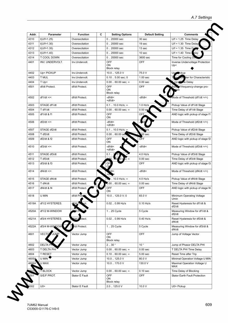
A.7 Settingsw
4310 t(U/f=1.25) Overexcitation 0 .. 20000 sec 30 sec U/f = 1.25 Time Delay
4311 t(U/f=1.30) Overexcitation 0 .. 20000 sec 19 sec U/f = 1.30 Time Delay
4312 t(U/f=1.35) Overexcitation 0 .. 20000 sec 13 sec U/f = 1.35 Time Delay
4313 t(U/f=1.40) Overexcitation 0 .. 20000 sec 10 sec U/f = 1.40 Time Delay
4314 T COOL DOWN Overexcitation 0 .. 20000 sec 3600 sec Time for Cooling Down
4401 INV. UNDERVOLT. Inv.Undervolt. OFFONBlock relay
OFF Inverse Undervoltage Protection Up<
4402 Up< PICKUP Inv.Undervolt. 10.0 .. 125.0 V 75.0 V Up< Pickup
4403 T MUL Inv.Undervolt. 0.10 .. 5.00 sec; 0 1.00 sec Time Multiplier for Characteristic
4404 T Up< Inv.Undervolt. 0.00 .. 60.00 sec; ∞ 0.00 sec T Up< Time Delay
4501 df/dt Protect. df/dt Protect. OFFONBlock relay
OFF Rate-of-frequency-change pro-tection
4502 df1/dt >/< df/dt Protect. -df/dt<+df/dt>
-df/dt< Mode of Threshold (df1/dt >/<)
4503 STAGE df1/dt df/dt Protect. 0.1 .. 10.0 Hz/s; ∞ 1.0 Hz/s Pickup Value of df1/dt Stage
4504 T df1/dt df/dt Protect. 0.00 .. 60.00 sec; ∞ 0.50 sec Time Delay of df1/dt Stage
4505 df1/dt & f1 df/dt Protect. OFFON
OFF AND logic with pickup of stage f1
4506 df2/dt >/< df/dt Protect. -df/dt<+df/dt>
-df/dt< Mode of Threshold (df2/dt >/<)
4507 STAGE df2/dt df/dt Protect. 0.1 .. 10.0 Hz/s; ∞ 1.0 Hz/s Pickup Value of df2/dt Stage
4508 T df2/dt df/dt Protect. 0.00 .. 60.00 sec; ∞ 0.50 sec Time Delay of df2/dt Stage
4509 df2/dt & f2 df/dt Protect. OFFON
OFF AND logic with pickup of stage f2
4510 df3/dt >/< df/dt Protect. -df/dt<+df/dt>
-df/dt< Mode of Threshold (df3/dt >/<)
4511 STAGE df3/dt df/dt Protect. 0.1 .. 10.0 Hz/s; ∞ 4.0 Hz/s Pickup Value of df3/dt Stage
4512 T df3/dt df/dt Protect. 0.00 .. 60.00 sec; ∞ 0.00 sec Time Delay of df3/dt Stage
4513 df3/dt & f3 df/dt Protect. OFFON
OFF AND logic with pickup of stage f3
4514 df4/dt >/< df/dt Protect. -df/dt<+df/dt>
-df/dt< Mode of Threshold (df4/dt >/<)
4515 STAGE df4/dt df/dt Protect. 0.1 .. 10.0 Hz/s; ∞ 4.0 Hz/s Pickup Value of df4/dt Stage
4516 T df4/dt df/dt Protect. 0.00 .. 60.00 sec; ∞ 0.00 sec Time Delay of df4/dt Stage
4517 df4/dt & f4 df/dt Protect. OFFON
OFF AND logic with pickup of stage f4
4518 U MIN df/dt Protect. 10.0 .. 125.0 V; 0 65.0 V Minimum Operating Voltage Umin
4519A df1/2 HYSTERES. df/dt Protect. 0.02 .. 0.99 Hz/s 0.10 Hz/s Reset Hysteresis for df1/dt & df2/dt
4520A df1/2 M-WINDOW df/dt Protect. 1 .. 25 Cycle 5 Cycle Measuring Window for df1/dt & df2/dt
4521A df3/4 HYSTERES. df/dt Protect. 0.02 .. 0.99 Hz/s 0.40 Hz/s Reset Hysteresis for df3/dt & df4/dt
4522A df3/4 M-WINDOW df/dt Protect. 1 .. 25 Cycle 5 Cycle Measuring Window for df3/dt & df4/dt
4601 VECTOR JUMP Vector Jump OFFONBlock relay
OFF Jump of Voltage Vector
4602 DELTA PHI Vector Jump 2 .. 30 ° 10 ° Jump of Phasor DELTA PHI
4603 T DELTA PHI Vector Jump 0.00 .. 60.00 sec; ∞ 0.00 sec T DELTA PHI Time Delay
4604 T RESET Vector Jump 0.10 .. 60.00 sec; ∞ 5.00 sec Reset Time after Trip
4605A U MIN Vector Jump 10.0 .. 125.0 V 80.0 V Minimal Operation Voltage U MIN
4606A U MAX Vector Jump 10.0 .. 170.0 V 130.0 V Maximal Operation Voltage U MAX
4607A T BLOCK Vector Jump 0.00 .. 60.00 sec; ∞ 0.10 sec Time Delay of Blocking
5001 S/E/F PROT. Stator E Fault OFFONBlock relay
OFF Stator Earth Fault Protection
5002 U0> Stator E Fault 2.0 .. 125.0 V 10.0 V U0> Pickup
Addr. Parameter Function C Setting Options Default Setting Comments
ww . El
ectric
alPar
tMan
uals
. com
6097UM62 ManualC53000-G1176-C149-5

A Appendix
om
5003 3I0> Stator E Fault 2 .. 1000 mA 5 mA 3I0> Pickup5004 DIR. ANGLE Stator E Fault 0 .. 360 ° 15 ° Angle for Direction Determination
5005 T S/E/F Stator E Fault 0.00 .. 60.00 sec; ∞ 0.30 sec T S/E/F Time Delay
5101 O/C PROT. IEE Sens. E Fault OFFONBlock relay
OFF Sensitive Earth Current Protec-tion
5102 IEE> Sens. E Fault 2 .. 1000 mA 10 mA IEE> Pickup
5103 T IEE> Sens. E Fault 0.00 .. 60.00 sec; ∞ 5.00 sec T IEE> Time delay
5104 IEE>> Sens. E Fault 2 .. 1000 mA 23 mA IEE>> Pickup
5105 T IEE>> Sens. E Fault 0.00 .. 60.00 sec; ∞ 1.00 sec T IEE>> Time Delay
5106 IEE< Sens. E Fault 1.5 .. 50.0 mA; 0 0.0 mA IEE< Pickup (Interrupted Circuit)
5201 SEF 3rd HARM. SEF 3.Harm. OFFONBlock relay
OFF Stator Earth Fault Protection 3rdHarm.
5202 U0 3.HARM< SEF 3.Harm. 0.2 .. 40.0 V 1.0 V U0 3rd Harmonic< Pickup
5203 U0 3.HARM> SEF 3.Harm. 0.2 .. 40.0 V 2.0 V U0 3rd Harmonic> Pickup
5204 T SEF 3. HARM. SEF 3.Harm. 0.00 .. 60.00 sec; ∞ 0.50 sec T SEF 3rd Harmonic Time Delay
5205 P min > SEF 3.Harm. 10 .. 100 %; 0 40 % Release Threshold Pmin>
5206 U1 min > SEF 3.Harm. 50.0 .. 125.0 V; 0 80.0 V Release Threshold U1min>
5207 U0 3.H.(V/100%) SEF 3.Harm. -40.0 .. 40.0 0.0 Correction Factor for Pickup (V/100%)
5301 100% SEF-PROT. 100% SEF-PROT. OFFONBlock relay
OFF 100% Stator-Earth-Fault Protec-tion
5302 R< SEF ALARM 100% SEF-PROT. 20 .. 700 Ω 100 Ω Pickup Value of Alarm Stage Rsef<
5303 R<< SEF TRIP 100% SEF-PROT. 20 .. 700 Ω 20 Ω Pickup Value of Tripping Stage Rsef<<
5304 T SEF ALARM 100% SEF-PROT. 0.00 .. 60.00 sec; ∞ 10.00 sec Time Delay of Alarm Stage Rsef<
5305 T SEF TRIP 100% SEF-PROT. 0.00 .. 60.00 sec; ∞ 1.00 sec Time Delay of Tripping Stage Rsef<<
5306 SEF I>> 100% SEF-PROT. 0.02 .. 1.50 A 0.40 A Pickup Value of I SEF>> Stage
5307 U20 MIN 100% SEF-PROT. 0.3 .. 15.0 V 1.0 V Supervision Threshold of 20Hz Voltage
5308 I20 MIN 100% SEF-PROT. 5 .. 40 mA 10 mA Supervision Threshold of 20Hz Current
5309 PHI I SEF 100% SEF-PROT. -60 .. 60 ° 0 ° Correction Angle for I SEF 100%
5310A SEF Rps 100% SEF-PROT. 0.0 .. 700.0 Ω 0.0 Ω Resistance Rps
5311A Rl-PARALLEL 100% SEF-PROT. 20 .. 700 Ω; ∞ ∞ Ω Parallel Load Resistance
5401 O/C PROT IEE-B Sens. E Fault B OFFONBlock relayAlarm Only
OFF Sensitive O/C Protection B
5402 IEE-B> Sens. E Fault B 0.3 .. 1000.0 mA 5.0 mA IEE-B> Pickup
5403 T IEE-B> Sens. E Fault B 0.00 .. 60.00 sec; ∞ 3.00 sec Time Delay T IEE-B>
5404 IEE-B< Sens. E Fault B 0.3 .. 500.0 mA; 0 0.0 mA IEE-B< Pickup
5405 T IEE-B< Sens. E Fault B 0.00 .. 60.00 sec; ∞ 1.00 sec Time Delay T IEE-B<
5406 MEAS. METHOD Sens. E Fault B Fundamental3. Harmonic1. and 3. Harm.
Fundamental Measurement Method
5407A T-HOLD IEE-B> Sens. E Fault B 0.00 .. 60.00 sec 0.00 sec Pickup Holding Time IEE-B>
5408A T-HOLD IEE-B< Sens. E Fault B 0.00 .. 60.00 sec 0.00 sec Pickup Holding Time IEE-B<
5501 INTERTURN PROT Interturn Prot. OFFONBlock relay
OFF Interturn Protection
5502 U Interturn > Interturn Prot. 0.3 .. 130.0 V 2.0 V Pick up Value U Interturn>
5503 T-U Interturn > Interturn Prot. 0.00 .. 60.00 sec; ∞ 0.50 sec Time Delay of Trip Command
5504 RESET RATIO Interturn Prot. 50 .. 95 % 80 % Reset Ratio of U Interturn>
6001 ROTOR E/F Rotor E/F OFFONBlock relay
OFF Rotor Earth Fault Protection (R, fn)
Addr. Parameter Function C Setting Options Default Setting Comments
ww . El
ectric
alPar
tMan
uals
. c
610 7UM62 ManualC53000-G1176-C149-5
w

A.7 Settingsw
6002 RE< WARN Rotor E/F 3.0 .. 30.0 kΩ 10.0 kΩ Pickup Value of Warning Stage Re<
6003 RE<< TRIP Rotor E/F 1.0 .. 5.0 kΩ 2.0 kΩ Pickup Value of Tripping Stage Re<<
6004 T-WARN-RE< Rotor E/F 0.00 .. 60.00 sec; ∞ 10.00 sec Time Delay of Warning Stage Re<
6005 T-TRIP-RE<< Rotor E/F 0.00 .. 60.00 sec; ∞ 0.50 sec Time Delay of Tripping Stage Re<<
6006 X COUPLING Rotor E/F -100 .. 800 Ω 398 Ω Coupling Reactance
6007 R SERIES Rotor E/F 0 .. 999 Ω 50 Ω Series Resistance (e.g. Meas. Brushes)
6008 I RE< Rotor E/F 1.0 .. 50.0 mA; 0 2.0 mA Pickup Value of Failure Detection Ire<
6009 PHI I RE Rotor E/F -15.0 .. 15.0 ° 0.0 ° Correction Angle for Ire
6101 REF 1-3Hz REF 1-3Hz OFFONBlock relay
OFF Rotor Earth Fault Protection (1-3Hz)
6102 RE< WARN REF 1-3Hz 5.0 .. 80.0 kΩ 40.0 kΩ Pickup Value of Warning Stage Re<
6103 RE<< TRIP REF 1-3Hz 1.0 .. 10.0 kΩ 5.0 kΩ Pickup Value of Tripping Stage Re<<
6104 T-WARN-RE< REF 1-3Hz 0.00 .. 60.00 sec; ∞ 10.00 sec Time Delay of Warning Stage Re<
6105 T-TRIP-RE<< REF 1-3Hz 0.00 .. 60.00 sec; ∞ 1.00 sec Time Delay of Tripping Stage Re<<
6106 Qc < REF 1-3Hz 0.00 .. 1.00 mAs 0.02 mAs Pickup Value of open Rotor Circuit (Qc)
6107A TEST RESISTOR REF 1-3Hz 1.0 .. 10.0 kΩ 3.3 kΩ Testing Resistor
6501 STARTUP MOTOR Start Motor OFFONBlock relay
OFF Motor Starting Time Supervision
6502 START. CURRENT Start Motor 5A 0.50 .. 80.00 A 15.60 A Starting Current of Motor
1A 0.10 .. 16.00 A 3.12 A
6503 STARTING TIME Start Motor 1.0 .. 180.0 sec 8.5 sec Starting Time of Motor
6504 LOCK ROTOR TIME Start Motor 0.5 .. 120.0 sec; ∞ 6.0 sec Permissible Locked Rotor Time
6505 I MOTOR START Start Motor 5A 3.00 .. 50.00 A 8.00 A Current Pickup Value of Motor Starting1A 0.60 .. 10.00 A 1.60 A
6601 RESTART INHIBIT Restart Motor OFFONBlock relay
OFF Restart Inhibit for Motors
6602 IStart/IMOTnom Restart Motor 1.5 .. 10.0 4.9 I Start / I Motor nominal
6603 T START MAX Restart Motor 3.0 .. 320.0 sec 8.5 sec Maximum Permissible Starting Time
6604 T EQUAL Restart Motor 0.0 .. 320.0 min 1.0 min Temperature Equalization Time
6606 MAX.WARM STARTS Restart Motor 1 .. 4 2 Permissible Number of Warm Starts
6607 #COLD-#WARM Restart Motor 1 .. 2 1 Number of Cold Starts - Warm Starts
6608 Kτ at STOP Restart Motor 1.0 .. 100.0 5.0 Extension of Time Constant at Stop
6609 Kτ at RUNNING Restart Motor 1.0 .. 100.0 2.0 Extension of Time Constant at Running
6610 T MIN. INHIBIT Restart Motor 0.2 .. 120.0 min 6.0 min Minimum Restart Inhibit Time
7001 BREAKER FAILURE Breaker Failure OFFONBlock relay
OFF Breaker Failure Protection
7002 TRIP INTERN Breaker Failure OFFBO12CFC
OFF Start with Internal TRIP Command
7003 CIRC. BR. I> Breaker Failure 1A 0.04 .. 2.00 A 0.20 A Supervision Current Pickup
5A 0.20 .. 10.00 A 1.00 A
7004 TRIP-Timer Breaker Failure 0.06 .. 60.00 sec; ∞ 0.25 sec TRIP-Timer
Addr. Parameter Function C Setting Options Default Setting Comments
ww . El
ectric
alPar
tMan
uals
. com
6117UM62 ManualC53000-G1176-C149-5

A Appendix
om
7101 INADVERT. EN. Inadvert. En. OFFONBlock relayOFF Inadvertent Energisation
7102 I STAGE Inadvert. En. 5A 0.5 .. 100.0 A; ∞ 1.5 A I Stage Pickup
1A 0.1 .. 20.0 A; ∞ 0.3 A
7103 RELEASE U1< Inadvert. En. 10.0 .. 125.0 V; 0 50.0 V Release Threshold U1<
7104 PICK UP T U1< Inadvert. En. 0.00 .. 60.00 sec; ∞ 5.00 sec Pickup Time Delay T U1<
7105 DROP OUT T U1< Inadvert. En. 0.00 .. 60.00 sec; ∞ 1.00 sec Drop Out Time Delay T U1<
7201 DC PROTECTION DC Protection OFFONBlock relay
OFF DC Voltage/Current Protection
7202 MEAS.METHOD DC Protection mean valueRMS
mean value Measurement Method (MEAN/RMS Values)
7203 DC >/< DC Protection DC >DC <
DC > Method of Operation (DC >/<)
7204 U DC >< DC Protection 0.1 .. 8.5 V 2.0 V DC Voltage Pickup
7205 I DC >< DC Protection 0.2 .. 17.0 mA 4.0 mA DC Current Pickup
7206 T DC DC Protection 0.00 .. 60.00 sec; ∞ 2.00 sec Time Delay for Trip of DC Protec-tion
7301 20 mA (B1) = Analog Outputs 10.0 .. 1000.0 % 200.0 % 20 mA (B1) correspond to
7302 MIN VALUE (B1) Analog Outputs 0.0 .. 5.0 mA 1.0 mA Output value (B1) valid from
7303 20 mA (B2) = Analog Outputs 10.0 .. 1000.0 % 200.0 % 20 mA (B2) correspond to
7304 MIN VALUE (B2) Analog Outputs 0.0 .. 5.0 mA 1.0 mA Output value (B2) valid from
7305 20 mA (D1) = Analog Outputs 10.0 .. 1000.0 % 200.0 % 20 mA (D1) correspond to
7306 MIN VALUE (D1) Analog Outputs 0.0 .. 5.0 mA 1.0 mA Output value (D1) valid from
7307 20 mA (D2) = Analog Outputs 10.0 .. 1000.0 % 200.0 % 20 mA (D2) correspond to
7308 MIN VALUE (D2) Analog Outputs 0.0 .. 5.0 mA 1.0 mA Output value (D2) valid from
8001 FUSE FAIL MON. Supervision OFFON
OFF Fuse Failure Monitor
8101 MEASURE. SUPERV Measurem.Superv OFFON
OFF Measurement Supervision
8102 BALANCE U-LIMIT Measurem.Superv 10 .. 100 V 50 V Voltage Threshold for Balance Monitoring
8103 BAL. FACTOR U Measurem.Superv 0.58 .. 0.90 0.75 Balance Factor for Voltage Monitor
8104 BAL. I LIMIT S1 Measurem.Superv 1A 0.10 .. 1.00 A 0.50 A Current Balance Monitor Side 1
5A 0.50 .. 5.00 A 2.50 A
8105 BAL. FACT. I S1 Measurem.Superv 0.10 .. 0.90 0.50 Balance Factor for Current Monitor S1
8106 BAL. I LIMIT S2 Measurem.Superv 5A 0.50 .. 5.00 A 2.50 A Current Balance Monitor Side 2
1A 0.10 .. 1.00 A 0.50 A
8107 BAL. FACT. I S2 Measurem.Superv 0.10 .. 0.90 0.50 Balance Factor for Current Monitor S2
8108 SUM.thres. U Measurem.Superv 10 .. 200 V 10 V Summation Thres. for Volt. Moni-toring
8109 SUM.Fact. U Measurem.Superv 0.60 .. 0.95 ; 0 0.75 Factor for Volt. Sum. Monitoring
8110 ΣI THRESHOLD S1 Measurem.Superv 1A 0.05 .. 2.00 A 0.10 A Summated Cur. Mon. Threshold on Side 15A 0.25 .. 10.00 A 0.50 A
8111 ΣI FACTOR S1 Measurem.Superv 0.00 .. 0.95 0.10 Summated Current Mon. Factor on Side 1
8112 ΣI THRESHOLD S2 Measurem.Superv 5A 0.25 .. 10.00 A 0.50 A Summated Cur. Mon. Threshold on Side 21A 0.05 .. 2.00 A 0.10 A
8113 ΣI FACTOR S2 Measurem.Superv 0.00 .. 0.95 0.10 Summated Current Mon. Factor on Side 2
8201 TRIP Cir. SUP. TripCirc.Superv OFFON
OFF TRIP Circuit Supervision
Addr. Parameter Function C Setting Options Default Setting Comments
ww . El
ectric
alPar
tMan
uals
. c
612 7UM62 ManualC53000-G1176-C149-5
w

A.7 Settingsw
8501 MEAS. VALUE 1> Threshold DisabledPQDelta PUL1EUL2EUL3EUEU0U1U2UE3hIEE1IEE23I0I1I2PHIPFTransducer 1
Disabled Measured Value for Threshold MV1>
8502 THRESHOLD MV1> Threshold -200 .. 200 % 100 % Pickup Value of Measured Value MV1>
8503 MEAS. VALUE 2< Threshold DisabledPQDelta PUL1EUL2EUL3EUEU0U1U2UE3hIEE1IEE23I0I1I2PHIPFTransducer 1
Disabled Measured Value for Threshold MV2<
8504 THRESHOLD MV2< Threshold -200 .. 200 % 100 % Pickup Value of Measured Value MV2<
8505 MEAS. VALUE 3> Threshold DisabledPQDelta PUL1EUL2EUL3EUEU0U1U2UE3hIEE1IEE23I0I1I2PHIPFTransducer 1
Disabled Measured Value for Threshold MV3>
8506 THRESHOLD MV3> Threshold -200 .. 200 % 100 % Pickup Value of Measured Value MV3>
Addr. Parameter Function C Setting Options Default Setting Comments
ww . El
ectric
alPar
tMan
uals
. com
6137UM62 ManualC53000-G1176-C149-5

A Appendix
om
8507 MEAS. VALUE 4< Threshold DisabledPQDelta PUL1EUL2EUL3EUEU0U1U2UE3hIEE1IEE23I0I1I2PHIPFTransducer 1Disabled Measured Value for Threshold MV4<
8508 THRESHOLD MV4< Threshold -200 .. 200 % 100 % Pickup Value of Measured Value MV4<
8509 MEAS. VALUE 5> Threshold DisabledPQDelta PUL1EUL2EUL3EUEU0U1U2UE3hIEE1IEE23I0I1I2PHIPFTransducer 1
Disabled Measured Value for Threshold MV5>
8510 THRESHOLD MV5> Threshold -200 .. 200 % 100 % Pickup Value of Measured Value MV5>
8511 MEAS. VALUE 6< Threshold DisabledPQDelta PUL1EUL2EUL3EUEU0U1U2UE3hIEE1IEE23I0I1I2PHIPFTransducer 1
Disabled Measured Value for Threshold MV6<
8512 THRESHOLD MV6< Threshold -200 .. 200 % 100 % Pickup Value of Measured Value MV6<
Addr. Parameter Function C Setting Options Default Setting Comments
ww . El
ectric
alPar
tMan
uals
. c
614 7UM62 ManualC53000-G1176-C149-5
w
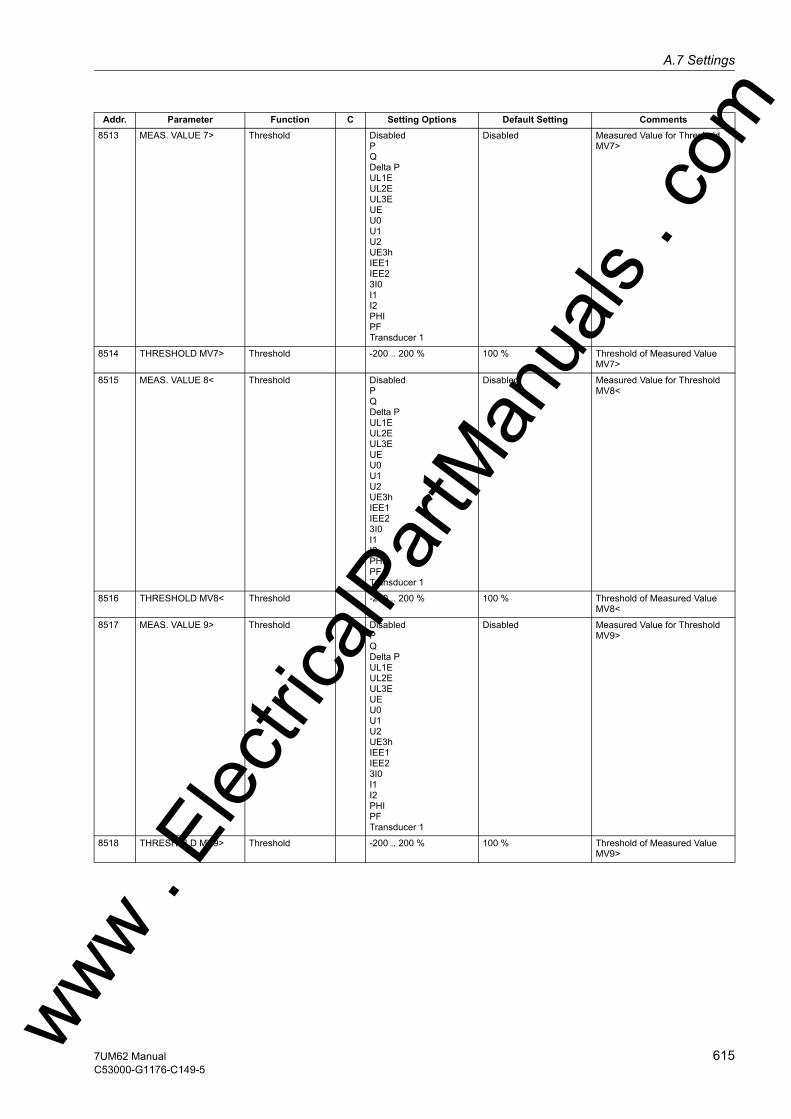
A.7 Settingsw
8513 MEAS. VALUE 7> Threshold DisabledPQDelta PUL1EUL2EUL3EUEU0U1U2UE3hIEE1IEE23I0I1I2PHIPFTransducer 1
Disabled Measured Value for Threshold MV7>
8514 THRESHOLD MV7> Threshold -200 .. 200 % 100 % Threshold of Measured Value MV7>
8515 MEAS. VALUE 8< Threshold DisabledPQDelta PUL1EUL2EUL3EUEU0U1U2UE3hIEE1IEE23I0I1I2PHIPFTransducer 1
Disabled Measured Value for Threshold MV8<
8516 THRESHOLD MV8< Threshold -200 .. 200 % 100 % Threshold of Measured Value MV8<
8517 MEAS. VALUE 9> Threshold DisabledPQDelta PUL1EUL2EUL3EUEU0U1U2UE3hIEE1IEE23I0I1I2PHIPFTransducer 1
Disabled Measured Value for Threshold MV9>
8518 THRESHOLD MV9> Threshold -200 .. 200 % 100 % Threshold of Measured Value MV9>
Addr. Parameter Function C Setting Options Default Setting Comments
ww . El
ectric
alPar
tMan
uals
. com
6157UM62 ManualC53000-G1176-C149-5

A Appendix
om
8519 MEAS. VALUE 10< Threshold DisabledPQDelta PUL1EUL2EUL3EUEU0U1U2UE3hIEE1IEE23I0I1I2PHIPFTransducer 1Disabled Measured Value for Threshold MV10<
8520 THRESHOLD MV10< Threshold -200 .. 200 % 100 % Threshold of Measured Value MV10<
8601 EXTERN TRIP 1 External Trips OFFONBlock relay
OFF External Trip Function 1
8602 T DELAY External Trips 0.00 .. 60.00 sec; ∞ 1.00 sec Ext. Trip 1 Time Delay
8701 EXTERN TRIP 2 External Trips OFFONBlock relay
OFF External Trip Function 2
8702 T DELAY External Trips 0.00 .. 60.00 sec; ∞ 1.00 sec Ext. Trip 2 Time Delay
8801 EXTERN TRIP 3 External Trips OFFONBlock relay
OFF External Trip Function 3
8802 T DELAY External Trips 0.00 .. 60.00 sec; ∞ 1.00 sec Ext. Trip 3 Time Delay
8901 EXTERN TRIP 4 External Trips OFFONBlock relay
OFF External Trip Function 4
8902 T DELAY External Trips 0.00 .. 60.00 sec; ∞ 1.00 sec Ext. Trip 4 Time Delay
9011A RTD 1 TYPE RTD-Box Not connectedPt 100 ΩNi 120 ΩNi 100 Ω
Pt 100 Ω RTD 1: Type
9012A RTD 1 LOCATION RTD-Box OilAmbientWindingBearingOther
Winding RTD 1: Location
9013 RTD 1 STAGE 1 RTD-Box -50 .. 250 °C; ∞ 100 °C RTD 1: Temperature Stage 1 Pickup
9014 RTD 1 STAGE 1 RTD-Box -58 .. 482 °F; ∞ 212 °F RTD 1: Temperature Stage 1 Pickup
9015 RTD 1 STAGE 2 RTD-Box -50 .. 250 °C; ∞ 120 °C RTD 1: Temperature Stage 2 Pickup
9016 RTD 1 STAGE 2 RTD-Box -58 .. 482 °F; ∞ 248 °F RTD 1: Temperature Stage 2 Pickup
9021A RTD 2 TYPE RTD-Box Not connectedPt 100 ΩNi 120 ΩNi 100 Ω
Not connected RTD 2: Type
9022A RTD 2 LOCATION RTD-Box OilAmbientWindingBearingOther
Other RTD 2: Location
9023 RTD 2 STAGE 1 RTD-Box -50 .. 250 °C; ∞ 100 °C RTD 2: Temperature Stage 1 Pickup
9024 RTD 2 STAGE 1 RTD-Box -58 .. 482 °F; ∞ 212 °F RTD 2: Temperature Stage 1 Pickup
9025 RTD 2 STAGE 2 RTD-Box -50 .. 250 °C; ∞ 120 °C RTD 2: Temperature Stage 2 Pickup
Addr. Parameter Function C Setting Options Default Setting Comments
ww . El
ectric
alPar
tMan
uals
. c
616 7UM62 ManualC53000-G1176-C149-5
w
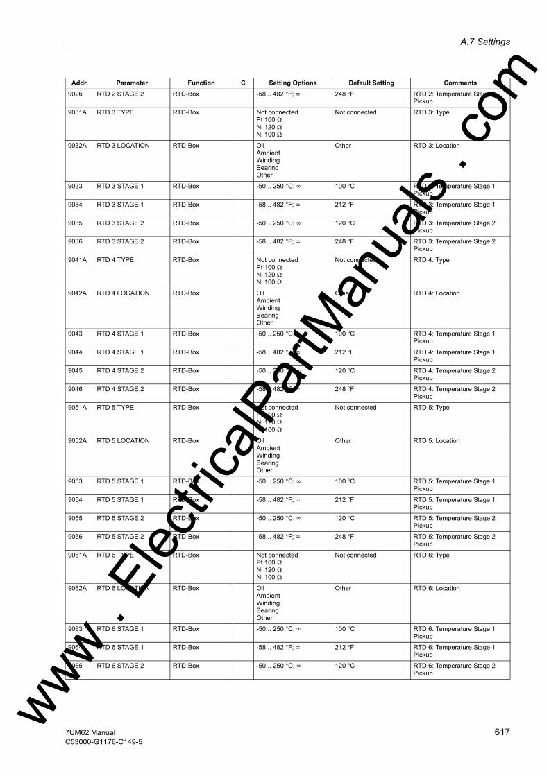
A.7 Settingsw
9026 RTD 2 STAGE 2 RTD-Box -58 .. 482 °F; ∞ 248 °F RTD 2: Temperature Stage 2 Pickup
9031A RTD 3 TYPE RTD-Box Not connectedPt 100 ΩNi 120 ΩNi 100 Ω
Not connected RTD 3: Type
9032A RTD 3 LOCATION RTD-Box OilAmbientWindingBearingOther
Other RTD 3: Location
9033 RTD 3 STAGE 1 RTD-Box -50 .. 250 °C; ∞ 100 °C RTD 3: Temperature Stage 1 Pickup
9034 RTD 3 STAGE 1 RTD-Box -58 .. 482 °F; ∞ 212 °F RTD 3: Temperature Stage 1 Pickup
9035 RTD 3 STAGE 2 RTD-Box -50 .. 250 °C; ∞ 120 °C RTD 3: Temperature Stage 2 Pickup
9036 RTD 3 STAGE 2 RTD-Box -58 .. 482 °F; ∞ 248 °F RTD 3: Temperature Stage 2 Pickup
9041A RTD 4 TYPE RTD-Box Not connectedPt 100 ΩNi 120 ΩNi 100 Ω
Not connected RTD 4: Type
9042A RTD 4 LOCATION RTD-Box OilAmbientWindingBearingOther
Other RTD 4: Location
9043 RTD 4 STAGE 1 RTD-Box -50 .. 250 °C; ∞ 100 °C RTD 4: Temperature Stage 1 Pickup
9044 RTD 4 STAGE 1 RTD-Box -58 .. 482 °F; ∞ 212 °F RTD 4: Temperature Stage 1 Pickup
9045 RTD 4 STAGE 2 RTD-Box -50 .. 250 °C; ∞ 120 °C RTD 4: Temperature Stage 2 Pickup
9046 RTD 4 STAGE 2 RTD-Box -58 .. 482 °F; ∞ 248 °F RTD 4: Temperature Stage 2 Pickup
9051A RTD 5 TYPE RTD-Box Not connectedPt 100 ΩNi 120 ΩNi 100 Ω
Not connected RTD 5: Type
9052A RTD 5 LOCATION RTD-Box OilAmbientWindingBearingOther
Other RTD 5: Location
9053 RTD 5 STAGE 1 RTD-Box -50 .. 250 °C; ∞ 100 °C RTD 5: Temperature Stage 1 Pickup
9054 RTD 5 STAGE 1 RTD-Box -58 .. 482 °F; ∞ 212 °F RTD 5: Temperature Stage 1 Pickup
9055 RTD 5 STAGE 2 RTD-Box -50 .. 250 °C; ∞ 120 °C RTD 5: Temperature Stage 2 Pickup
9056 RTD 5 STAGE 2 RTD-Box -58 .. 482 °F; ∞ 248 °F RTD 5: Temperature Stage 2 Pickup
9061A RTD 6 TYPE RTD-Box Not connectedPt 100 ΩNi 120 ΩNi 100 Ω
Not connected RTD 6: Type
9062A RTD 6 LOCATION RTD-Box OilAmbientWindingBearingOther
Other RTD 6: Location
9063 RTD 6 STAGE 1 RTD-Box -50 .. 250 °C; ∞ 100 °C RTD 6: Temperature Stage 1 Pickup
9064 RTD 6 STAGE 1 RTD-Box -58 .. 482 °F; ∞ 212 °F RTD 6: Temperature Stage 1 Pickup
9065 RTD 6 STAGE 2 RTD-Box -50 .. 250 °C; ∞ 120 °C RTD 6: Temperature Stage 2 Pickup
Addr. Parameter Function C Setting Options Default Setting Comments
ww . El
ectric
alPar
tMan
uals
. com
6177UM62 ManualC53000-G1176-C149-5

A Appendix
om
9066 RTD 6 STAGE 2 RTD-Box -58 .. 482 °F; ∞ 248 °F RTD 6: Temperature Stage 2 Pickup9071A RTD 7 TYPE RTD-Box Not connectedPt 100 ΩNi 120 ΩNi 100 Ω
Not connected RTD 7: Type
9072A RTD 7 LOCATION RTD-Box OilAmbientWindingBearingOther
Other RTD 7: Location
9073 RTD 7 STAGE 1 RTD-Box -50 .. 250 °C; ∞ 100 °C RTD 7: Temperature Stage 1 Pickup
9074 RTD 7 STAGE 1 RTD-Box -58 .. 482 °F; ∞ 212 °F RTD 7: Temperature Stage 1 Pickup
9075 RTD 7 STAGE 2 RTD-Box -50 .. 250 °C; ∞ 120 °C RTD 7: Temperature Stage 2 Pickup
9076 RTD 7 STAGE 2 RTD-Box -58 .. 482 °F; ∞ 248 °F RTD 7: Temperature Stage 2 Pickup
9081A RTD 8 TYPE RTD-Box Not connectedPt 100 ΩNi 120 ΩNi 100 Ω
Not connected RTD 8: Type
9082A RTD 8 LOCATION RTD-Box OilAmbientWindingBearingOther
Other RTD 8: Location
9083 RTD 8 STAGE 1 RTD-Box -50 .. 250 °C; ∞ 100 °C RTD 8: Temperature Stage 1 Pickup
9084 RTD 8 STAGE 1 RTD-Box -58 .. 482 °F; ∞ 212 °F RTD 8: Temperature Stage 1 Pickup
9085 RTD 8 STAGE 2 RTD-Box -50 .. 250 °C; ∞ 120 °C RTD 8: Temperature Stage 2 Pickup
9086 RTD 8 STAGE 2 RTD-Box -58 .. 482 °F; ∞ 248 °F RTD 8: Temperature Stage 2 Pickup
9091A RTD 9 TYPE RTD-Box Not connectedPt 100 ΩNi 120 ΩNi 100 Ω
Not connected RTD 9: Type
9092A RTD 9 LOCATION RTD-Box OilAmbientWindingBearingOther
Other RTD 9: Location
9093 RTD 9 STAGE 1 RTD-Box -50 .. 250 °C; ∞ 100 °C RTD 9: Temperature Stage 1 Pickup
9094 RTD 9 STAGE 1 RTD-Box -58 .. 482 °F; ∞ 212 °F RTD 9: Temperature Stage 1 Pickup
9095 RTD 9 STAGE 2 RTD-Box -50 .. 250 °C; ∞ 120 °C RTD 9: Temperature Stage 2 Pickup
9096 RTD 9 STAGE 2 RTD-Box -58 .. 482 °F; ∞ 248 °F RTD 9: Temperature Stage 2 Pickup
9101A RTD10 TYPE RTD-Box Not connectedPt 100 ΩNi 120 ΩNi 100 Ω
Not connected RTD10: Type
9102A RTD10 LOCATION RTD-Box OilAmbientWindingBearingOther
Other RTD10: Location
9103 RTD10 STAGE 1 RTD-Box -50 .. 250 °C; ∞ 100 °C RTD10: Temperature Stage 1 Pickup
9104 RTD10 STAGE 1 RTD-Box -58 .. 482 °F; ∞ 212 °F RTD10: Temperature Stage 1 Pickup
9105 RTD10 STAGE 2 RTD-Box -50 .. 250 °C; ∞ 120 °C RTD10: Temperature Stage 2 Pickup
Addr. Parameter Function C Setting Options Default Setting Comments
ww . El
ectric
alPar
tMan
uals
. c
618 7UM62 ManualC53000-G1176-C149-5
w

A.7 Settingsw
9106 RTD10 STAGE 2 RTD-Box -58 .. 482 °F; ∞ 248 °F RTD10: Temperature Stage 2 Pickup
9111A RTD11 TYPE RTD-Box Not connectedPt 100 ΩNi 120 ΩNi 100 Ω
Not connected RTD11: Type
9112A RTD11 LOCATION RTD-Box OilAmbientWindingBearingOther
Other RTD11: Location
9113 RTD11 STAGE 1 RTD-Box -50 .. 250 °C; ∞ 100 °C RTD11: Temperature Stage 1 Pickup
9114 RTD11 STAGE 1 RTD-Box -58 .. 482 °F; ∞ 212 °F RTD11: Temperature Stage 1 Pickup
9115 RTD11 STAGE 2 RTD-Box -50 .. 250 °C; ∞ 120 °C RTD11: Temperature Stage 2 Pickup
9116 RTD11 STAGE 2 RTD-Box -58 .. 482 °F; ∞ 248 °F RTD11: Temperature Stage 2 Pickup
9121A RTD12 TYPE RTD-Box Not connectedPt 100 ΩNi 120 ΩNi 100 Ω
Not connected RTD12: Type
9122A RTD12 LOCATION RTD-Box OilAmbientWindingBearingOther
Other RTD12: Location
9123 RTD12 STAGE 1 RTD-Box -50 .. 250 °C; ∞ 100 °C RTD12: Temperature Stage 1 Pickup
9124 RTD12 STAGE 1 RTD-Box -58 .. 482 °F; ∞ 212 °F RTD12: Temperature Stage 1 Pickup
9125 RTD12 STAGE 2 RTD-Box -50 .. 250 °C; ∞ 120 °C RTD12: Temperature Stage 2 Pickup
9126 RTD12 STAGE 2 RTD-Box -58 .. 482 °F; ∞ 248 °F RTD12: Temperature Stage 2 Pickup
Addr. Parameter Function C Setting Options Default Setting Comments
ww . El
ectric
alPar
tMan
uals
. com
6197UM62 ManualC53000-G1176-C149-5
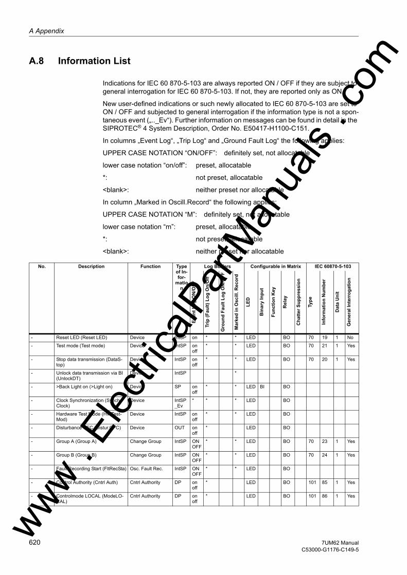
A Appendix
om
A.8 Information List
Indications for IEC 60 870-5-103 are always reported ON / OFF if they are subject to general interrogation for IEC 60 870-5-103. If not, they are reported only as ON.
New user-defined indications or such newly allocated to IEC 60 870-5-103 are set to ON / OFF and subjected to general interrogation if the information type is not a spon-taneous event („.._Ev“). Further information on messages can be found in detail in the SIPROTEC® 4 System Description, Order No. E50417-H1100-C151.
In columns „Event Log“, „Trip Log“ and „Ground Fault Log“ the following applies:
UPPER CASE NOTATION “ON/OFF”: definitely set, not allocatable
lower case notation “on/off”: preset, allocatable
*: not preset, allocatable
<blank>: neither preset nor allocatable
In column „Marked in Oscill.Record“ the following applies:
UPPER CASE NOTATION “M”: definitely set, not allocatable
lower case notation “m”: preset, allocatable
*: not preset, allocatable
<blank>: neither preset nor allocatable
No. Description Function Type of In-for-
mation
Log Buffers Configurable in Matrix IEC 60870-5-103
Even
t Log
ON
/OFF
Trip
(Fau
lt) L
og O
n/O
ff
Gro
und
Faul
t Log
ON
/OFF
Mar
ked
in O
scill
. Rec
ord
LED
Bin
ary
Inpu
t
Func
tion
Key
Rel
ay
Cha
tter S
uppr
essi
on
Type
Info
rmat
ion
Num
ber
Dat
a U
nit
Gen
eral
Inte
rrog
atio
n
- Reset LED (Reset LED) Device IntSP on * * LED BO 70 19 1 No
- Test mode (Test mode) Device IntSP on off
* * LED BO 70 21 1 Yes
- Stop data transmission (DataS-top)
Device IntSP on off
* * LED BO 70 20 1 Yes
- Unlock data transmission via BI (UnlockDT)
Device IntSP *
- >Back Light on (>Light on) Device SP on off
* * LED BI BO
- Clock Synchronization (Synch-Clock)
Device IntSP_Ev
* * * LED BO
- Hardware Test Mode (HWTest-Mod)
Device IntSP on off
* * LED BO
- Disturbance CFC (Distur.CFC) Device OUT on off
* LED BO
- Group A (Group A) Change Group IntSP ON OFF
* * LED BO 70 23 1 Yes
- Group B (Group B) Change Group IntSP ON OFF
* * LED BO 70 24 1 Yes
- Fault Recording Start (FltRecSta) Osc. Fault Rec. IntSP ON OFF
* * LED BO
- Control Authority (Cntrl Auth) Cntrl Authority DP on off
* LED BO 101 85 1 Yes
- Controlmode LOCAL (ModeLO-CAL)
Cntrl Authority DP on off
* LED BO 101 86 1 Yesww . El
ectric
alPar
tMan
uals
. c
620 7UM62 ManualC53000-G1176-C149-5
w
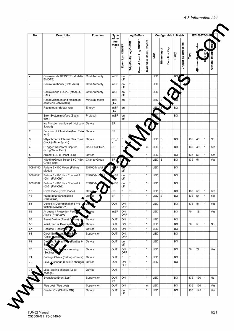
A.8 Information Listw
- Controlmode REMOTE (ModeR-EMOTE)
Cntrl Authority IntSP on off
* LED BO
- Control Authority (Cntrl Auth) Cntrl Authority IntSP on off
* LED BO
- Controlmode LOCAL (ModeLO-CAL)
Cntrl Authority IntSP on off
* LED BO
- Reset Minimum and Maximum counter (ResMinMax)
Min/Max meter IntSP_Ev
on * LED BI BO
- Reset meter (Meter res) Energy IntSP_Ev
on * LED BI BO
- Error Systeminterface (SysIn-tErr.)
Protocol IntSP on off
* LED BO
1 No Function configured (Not con-figured)
Device SP
2 Function Not Available (Non Exis-tent)
Device SP
3 >Synchronize Internal Real Time Clock (>Time Synch)
Device SP_Ev
* * * LED BI BO 135 48 1 No
4 >Trigger Waveform Capture (>Trig.Wave.Cap.)
Osc. Fault Rec. SP * * m LED BI BO 135 49 1 Yes
5 >Reset LED (>Reset LED) Device SP * * * LED BI BO 135 50 1 Yes
7 >Setting Group Select Bit 0 (>Set Group Bit0)
Change Group SP * * * LED BI BO 135 51 1 Yes
009.0100 Failure EN100 Modul (Failure Modul)
EN100-Modul 1 IntSP on off
* * LED BO
009.0101 Failure EN100 Link Channel 1 (Ch1) (Fail Ch1)
EN100-Modul 1 IntSP on off
* * LED BO
009.0102 Failure EN100 Link Channel 2 (Ch2) (Fail Ch2)
EN100-Modul 1 IntSP on off
* * LED BO
15 >Test mode (>Test mode) Device SP * * * LED BI BO 135 53 1 Yes
16 >Stop data transmission (>DataStop)
Device SP * * * LED BI BO 135 54 1 Yes
51 Device is Operational and Pro-tecting (Device OK)
Device OUT ON OFF
* * LED BO 135 81 1 Yes
52 At Least 1 Protection Funct. is Active (ProtActive)
Device IntSP ON OFF
* * LED BO 70 18 1 Yes
55 Reset Device (Reset Device) Device OUT ON * * LED BO
56 Initial Start of Device (Initial Start) Device OUT ON * * LED BO 70 5 1 No
67 Resume (Resume) Device OUT ON * * LED BO
68 Clock Synchronization Error (Clock SyncError)
Supervision OUT ON OFF
* * LED BO
69 Daylight Saving Time (DayLight-SavTime)
Device OUT on off
* * LED BO
70 Setting calculation is running (Settings Calc.)
Device OUT ON OFF
* * LED BO 70 22 1 Yes
71 Settings Check (Settings Check) Device OUT * * * LED BO
72 Level-2 change (Level-2 change) Device OUT ON OFF
* * LED BO
73 Local setting change (Local change)
Device OUT * * *
110 Event lost (Event Lost) Supervision OUT_Ev
ON * * LED BO 135 130 1 No
113 Flag Lost (Flag Lost) Supervision OUT ON * m LED BO 135 136 1 Yes
125 Chatter ON (Chatter ON) Device OUT on off
* * LED BO 135 145 1 Yes
No. Description Function Type of In-for-
mation
Log Buffers Configurable in Matrix IEC 60870-5-103
Even
t Log
ON
/OFF
Trip
(Fau
lt) L
og O
n/O
ff
Gro
und
Faul
t Log
ON
/OFF
Mar
ked
in O
scill
. Rec
ord
LED
Bin
ary
Inpu
t
Func
tion
Key
Rel
ay
Cha
tter S
uppr
essi
on
Type
Info
rmat
ion
Num
ber
Dat
a U
nit
Gen
eral
Inte
rrog
atio
n
ww . El
ectric
alPar
tMan
uals
. com
6217UM62 ManualC53000-G1176-C149-5

A Appendix
om
140 Error with a summary alarm (Error Sum Alarm)
Supervision OUT * * * LED BO
147 Error Power Supply (Error Pwr-Supply)
Supervision OUT ON OFF
* * LED BO
160 Alarm Summary Event (Alarm Sum Event)
Supervision OUT * * * LED BO 70 46 1 Yes
161 Failure: General Current Supervi-sion (Fail I Superv.)
Measurem.Superv OUT on off
* * LED BO 70 32 1 Yes
164 Failure: General Voltage Supervi-sion (Fail U Superv.)
Measurem.Superv OUT on off
* * LED BO 70 33 1 Yes
165 Failure: Voltage Summation Phase-Earth (Fail Σ U Ph-E)
Measurem.Superv OUT on off
* * LED BO 135 184 1 Yes
167 Failure: Voltage Balance (Fail U balance)
Measurem.Superv OUT on off
* * LED BO 135 186 1 Yes
171 Failure: Phase Sequence (Fail Ph. Seq.)
Measurem.Superv OUT on off
* * LED BO 70 35 1 Yes
176 Failure: Phase Sequence Voltage (Fail Ph. Seq. U)
Measurem.Superv OUT on off
* * LED BO 135 192 1 Yes
177 Failure: Battery empty (Fail Bat-tery)
Supervision OUT ON OFF
* * LED BO
181 Error: A/D converter (Error A/D-conv.)
Supervision OUT ON OFF
* * LED BO
185 Error Board 3 (Error Board 3) Supervision OUT ON OFF
187 Error Board 5 (Error Board 5) Supervision OUT ON OFF
188 Error Board 6 (Error Board 6) Supervision OUT ON OFF
190 Error Board 0 (Error Board 0) Supervision OUT ON OFF
191 Error: Offset (Error Offset) Supervision OUT ON OFF
* * LED BO
193 Alarm: NO calibration data avail-able (Alarm NO calibr)
Supervision OUT ON OFF
* * LED BO
194 Error: Neutral CT different from MLFB (Error neutralCT)
Supervision OUT ON OFF
* * LED BO
197 Measurement Supervision is switched OFF (MeasSup OFF)
Measurem.Superv OUT on off
* * LED BO 135 197 1 Yes
203 Waveform data deleted (Wave. deleted)
Osc. Fault Rec. OUT_Ev
ON * * LED BO 135 203 1 No
210 Err:1A/5Ajumper different from settingS1 (Err1A/5AwrongS1)
Supervision OUT ON OFF
* * LED BO
211 Err:1A/5Ajumper different from settingS2 (Err1A/5AwrongS2)
Supervision OUT ON OFF
* * LED BO
212 Err: TD1 jumper different from setting (Err. TD1 jumper)
Supervision OUT ON OFF
* * LED BO
213 Err: TD2 jumper different from setting (Err. TD2 jumper)
Supervision OUT ON OFF
* * LED BO
214 Err: TD3 jumper different from setting (Err. TD3 jumper)
Supervision OUT ON OFF
* * LED BO
230 Failure: Current Summation on Side 1 (Fail. Σ I Side1)
Measurem.Superv OUT on off
* * LED BO 135 155 1 Yes
231 Failure: Current Summation on Side 2 (Fail. Σ I Side2)
Measurem.Superv OUT on off
* * LED BO 135 158 1 Yes
264 Failure: RTD-Box 1 (Fail: RTD-Box 1)
Supervision OUT ON OFF
* * LED BO 135 208 1 Yes
No. Description Function Type of In-for-
mation
Log Buffers Configurable in Matrix IEC 60870-5-103
Even
t Log
ON
/OFF
Trip
(Fau
lt) L
og O
n/O
ff
Gro
und
Faul
t Log
ON
/OFF
Mar
ked
in O
scill
. Rec
ord
LED
Bin
ary
Inpu
t
Func
tion
Key
Rel
ay
Cha
tter S
uppr
essi
on
Type
Info
rmat
ion
Num
ber
Dat
a U
nit
Gen
eral
Inte
rrog
atio
n
ww . El
ectric
alPar
tMan
uals
. c
622 7UM62 ManualC53000-G1176-C149-5
w
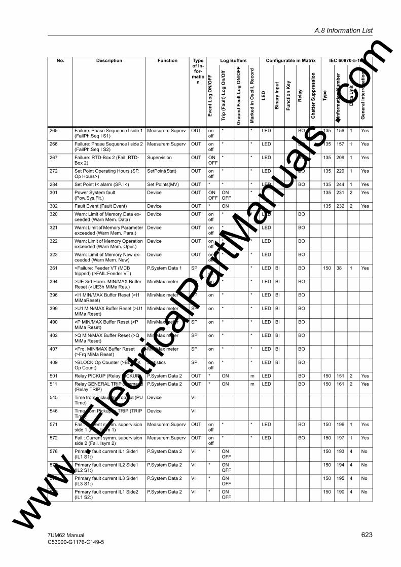
A.8 Information Listw
265 Failure: Phase Sequence I side 1 (FailPh.Seq I S1)
Measurem.Superv OUT on off
* * LED BO 135 156 1 Yes
266 Failure: Phase Sequence I side 2 (FailPh.Seq I S2)
Measurem.Superv OUT on off
* * LED BO 135 157 1 Yes
267 Failure: RTD-Box 2 (Fail: RTD-Box 2)
Supervision OUT ON OFF
* * LED BO 135 209 1 Yes
272 Set Point Operating Hours (SP. Op Hours>)
SetPoint(Stat) OUT on off
* * LED BO 135 229 1 Yes
284 Set Point I< alarm (SP. I<) Set Points(MV) OUT * * * LED BO 135 244 1 Yes
301 Power System fault (Pow.Sys.Flt.)
Device OUT ON OFF
ON OFF
* 135 231 2 Yes
302 Fault Event (Fault Event) Device OUT * ON * 135 232 2 Yes
320 Warn: Limit of Memory Data ex-ceeded (Warn Mem. Data)
Device OUT on off
* * LED BO
321 Warn: Limit of Memory Parameter exceeded (Warn Mem. Para.)
Device OUT on off
* * LED BO
322 Warn: Limit of Memory Operation exceeded (Warn Mem. Oper.)
Device OUT on off
* * LED BO
323 Warn: Limit of Memory New ex-ceeded (Warn Mem. New)
Device OUT on off
* * LED BO
361 >Failure: Feeder VT (MCB tripped) (>FAIL:Feeder VT)
P.System Data 1 SP on off
* * LED BI BO 150 38 1 Yes
394 >UE 3rd Harm. MIN/MAX Buffer Reset (>UE3h MiMa Res.)
Min/Max meter SP on * * LED BI BO
396 >I1 MIN/MAX Buffer Reset (>I1 MiMaReset)
Min/Max meter SP on * * LED BI BO
399 >U1 MIN/MAX Buffer Reset (>U1 MiMa Reset)
Min/Max meter SP on * * LED BI BO
400 >P MIN/MAX Buffer Reset (>P MiMa Reset)
Min/Max meter SP on * * LED BI BO
402 >Q MIN/MAX Buffer Reset (>Q MiMa Reset)
Min/Max meter SP on * * LED BI BO
407 >Frq. MIN/MAX Buffer Reset (>Frq MiMa Reset)
Min/Max meter SP on * * LED BI BO
409 >BLOCK Op Counter (>BLOCK Op Count)
Statistics SP on off
* * LED BI BO
501 Relay PICKUP (Relay PICKUP) P.System Data 2 OUT * ON m LED BO 150 151 2 Yes
511 Relay GENERAL TRIP command (Relay TRIP)
P.System Data 2 OUT * ON m LED BO 150 161 2 Yes
545 Time from Pickup to drop out (PU Time)
Device VI
546 Time from Pickup to TRIP (TRIP Time)
Device VI
571 Fail.: Current symm. supervision side 1 (Fail. Isym 1)
Measurem.Superv OUT on off
* * LED BO 150 196 1 Yes
572 Fail.: Current symm. supervision side 2 (Fail. Isym 2)
Measurem.Superv OUT on off
* * LED BO 150 197 1 Yes
576 Primary fault current IL1 Side1 (IL1 S1:)
P.System Data 2 VI * ON OFF
150 193 4 No
577 Primary fault current IL2 Side1 (IL2 S1:)
P.System Data 2 VI * ON OFF
150 194 4 No
578 Primary fault current IL3 Side1 (IL3 S1:)
P.System Data 2 VI * ON OFF
150 195 4 No
579 Primary fault current IL1 Side2 (IL1 S2:)
P.System Data 2 VI * ON OFF
150 190 4 No
No. Description Function Type of In-for-
mation
Log Buffers Configurable in Matrix IEC 60870-5-103
Even
t Log
ON
/OFF
Trip
(Fau
lt) L
og O
n/O
ff
Gro
und
Faul
t Log
ON
/OFF
Mar
ked
in O
scill
. Rec
ord
LED
Bin
ary
Inpu
t
Func
tion
Key
Rel
ay
Cha
tter S
uppr
essi
on
Type
Info
rmat
ion
Num
ber
Dat
a U
nit
Gen
eral
Inte
rrog
atio
n
ww . El
ectric
alPar
tMan
uals
. com
6237UM62 ManualC53000-G1176-C149-5
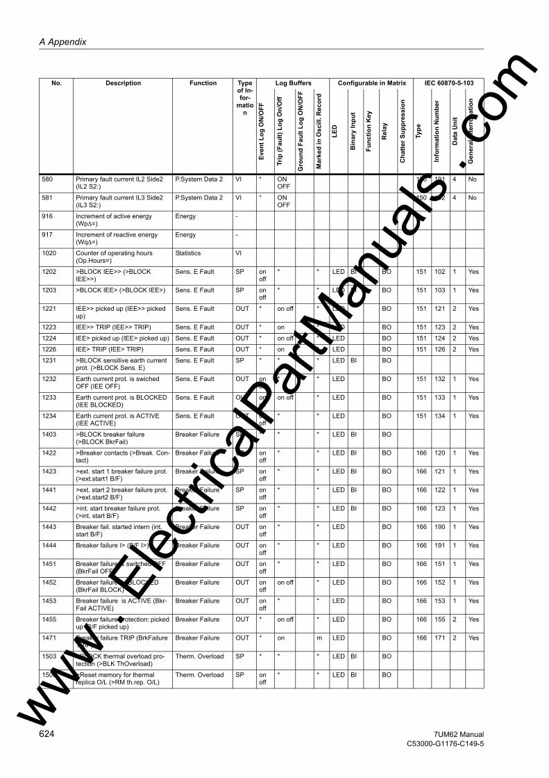
A Appendix
om
580 Primary fault current IL2 Side2 (IL2 S2:)
P.System Data 2 VI * ON OFF
150 191 4 No
581 Primary fault current IL3 Side2 (IL3 S2:)
P.System Data 2 VI * ON OFF
150 192 4 No
916 Increment of active energy (Wp∆=)
Energy -
917 Increment of reactive energy (Wq∆=)
Energy -
1020 Counter of operating hours (Op.Hours=)
Statistics VI
1202 >BLOCK IEE>> (>BLOCK IEE>>)
Sens. E Fault SP on off
* * LED BI BO 151 102 1 Yes
1203 >BLOCK IEE> (>BLOCK IEE>) Sens. E Fault SP on off
* * LED BI BO 151 103 1 Yes
1221 IEE>> picked up (IEE>> picked up)
Sens. E Fault OUT * on off * LED BO 151 121 2 Yes
1223 IEE>> TRIP (IEE>> TRIP) Sens. E Fault OUT * on * LED BO 151 123 2 Yes
1224 IEE> picked up (IEE> picked up) Sens. E Fault OUT * on off * LED BO 151 124 2 Yes
1226 IEE> TRIP (IEE> TRIP) Sens. E Fault OUT * on * LED BO 151 126 2 Yes
1231 >BLOCK sensitive earth current prot. (>BLOCK Sens. E)
Sens. E Fault SP * * * LED BI BO
1232 Earth current prot. is swiched OFF (IEE OFF)
Sens. E Fault OUT on off
* * LED BO 151 132 1 Yes
1233 Earth current prot. is BLOCKED (IEE BLOCKED)
Sens. E Fault OUT on off
on off * LED BO 151 133 1 Yes
1234 Earth current prot. is ACTIVE (IEE ACTIVE)
Sens. E Fault OUT on off
* * LED BO 151 134 1 Yes
1403 >BLOCK breaker failure (>BLOCK BkrFail)
Breaker Failure SP * * * LED BI BO
1422 >Breaker contacts (>Break. Con-tact)
Breaker Failure SP on off
* * LED BI BO 166 120 1 Yes
1423 >ext. start 1 breaker failure prot. (>ext.start1 B/F)
Breaker Failure SP on off
* * LED BI BO 166 121 1 Yes
1441 >ext. start 2 breaker failure prot. (>ext.start2 B/F)
Breaker Failure SP on off
* * LED BI BO 166 122 1 Yes
1442 >int. start breaker failure prot. (>int. start B/F)
Breaker Failure SP on off
* * LED BI BO 166 123 1 Yes
1443 Breaker fail. started intern (int. start B/F)
Breaker Failure OUT on off
* * LED BO 166 190 1 Yes
1444 Breaker failure I> (B/F I>) Breaker Failure OUT on off
* * LED BO 166 191 1 Yes
1451 Breaker failure is switched OFF (BkrFail OFF)
Breaker Failure OUT on off
* * LED BO 166 151 1 Yes
1452 Breaker failure is BLOCKED (BkrFail BLOCK)
Breaker Failure OUT on off
on off * LED BO 166 152 1 Yes
1453 Breaker failure is ACTIVE (Bkr-Fail ACTIVE)
Breaker Failure OUT on off
* * LED BO 166 153 1 Yes
1455 Breaker failure protection: picked up (B/F picked up)
Breaker Failure OUT * on off * LED BO 166 155 2 Yes
1471 Breaker failure TRIP (BrkFailure TRIP)
Breaker Failure OUT * on m LED BO 166 171 2 Yes
1503 >BLOCK thermal overload pro-tection (>BLK ThOverload)
Therm. Overload SP * * * LED BI BO
1506 >Reset memory for thermal replica O/L (>RM th.rep. O/L)
Therm. Overload SP on off
* * LED BI BO
No. Description Function Type of In-for-
mation
Log Buffers Configurable in Matrix IEC 60870-5-103
Even
t Log
ON
/OFF
Trip
(Fau
lt) L
og O
n/O
ff
Gro
und
Faul
t Log
ON
/OFF
Mar
ked
in O
scill
. Rec
ord
LED
Bin
ary
Inpu
t
Func
tion
Key
Rel
ay
Cha
tter S
uppr
essi
on
Type
Info
rmat
ion
Num
ber
Dat
a U
nit
Gen
eral
Inte
rrog
atio
n
ww . El
ectric
alPar
tMan
uals
. c
624 7UM62 ManualC53000-G1176-C149-5
w
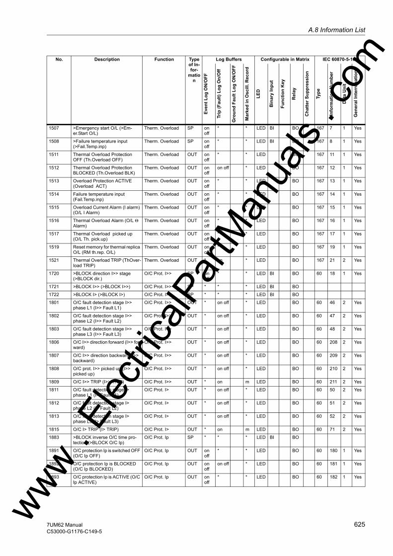
A.8 Information Listw
1507 >Emergency start O/L (>Em-er.Start O/L)
Therm. Overload SP on off
* * LED BI BO 167 7 1 Yes
1508 >Failure temperature input (>Fail.Temp.inp)
Therm. Overload SP on off
* * LED BI BO 167 8 1 Yes
1511 Thermal Overload Protection OFF (Th.Overload OFF)
Therm. Overload OUT on off
* * LED BO 167 11 1 Yes
1512 Thermal Overload Protection BLOCKED (Th.Overload BLK)
Therm. Overload OUT on off
on off * LED BO 167 12 1 Yes
1513 Overload Protection ACTIVE (Overload ACT)
Therm. Overload OUT on off
* * LED BO 167 13 1 Yes
1514 Failure temperature input (Fail.Temp.inp)
Therm. Overload OUT on off
* * LED BO 167 14 1 Yes
1515 Overload Current Alarm (I alarm) (O/L I Alarm)
Therm. Overload OUT on off
* * LED BO 167 15 1 Yes
1516 Thermal Overload Alarm (O/L Θ Alarm)
Therm. Overload OUT on off
* * LED BO 167 16 1 Yes
1517 Thermal Overload picked up (O/L Th. pick.up)
Therm. Overload OUT on off
* * LED BO 167 17 1 Yes
1519 Reset memory for thermal replica O/L (RM th.rep. O/L)
Therm. Overload OUT on off
* * LED BO 167 19 1 Yes
1521 Thermal Overload TRIP (ThOver-load TRIP)
Therm. Overload OUT * on * LED BO 167 21 2 Yes
1720 >BLOCK direction I>> stage (>BLOCK dir.)
O/C Prot. I>> SP on off
* * LED BI BO 60 18 1 Yes
1721 >BLOCK I>> (>BLOCK I>>) O/C Prot. I>> SP * * * LED BI BO
1722 >BLOCK I> (>BLOCK I>) O/C Prot. I> SP * * * LED BI BO
1801 O/C fault detection stage I>> phase L1 (I>> Fault L1)
O/C Prot. I>> OUT * on off * LED BO 60 46 2 Yes
1802 O/C fault detection stage I>> phase L2 (I>> Fault L2)
O/C Prot. I>> OUT * on off * LED BO 60 47 2 Yes
1803 O/C fault detection stage I>> phase L3 (I>> Fault L3)
O/C Prot. I>> OUT * on off * LED BO 60 48 2 Yes
1806 O/C I>> direction forward (I>> for-ward)
O/C Prot. I>> OUT * on off * LED BO 60 208 2 Yes
1807 O/C I>> direction backward (I>> backward)
O/C Prot. I>> OUT * on off * LED BO 60 209 2 Yes
1808 O/C prot. I>> picked up (I>> picked up)
O/C Prot. I>> OUT * on off * LED BO 60 210 2 Yes
1809 O/C I>> TRIP (I>> TRIP) O/C Prot. I>> OUT * on m LED BO 60 211 2 Yes
1811 O/C fault detection stage I> phase L1 (I> Fault L1)
O/C Prot. I> OUT * on off * LED BO 60 50 2 Yes
1812 O/C fault detection stage I> phase L2 (I> Fault L2)
O/C Prot. I> OUT * on off * LED BO 60 51 2 Yes
1813 O/C fault detection stage I> phase L3 (I> Fault L3)
O/C Prot. I> OUT * on off * LED BO 60 52 2 Yes
1815 O/C I> TRIP (I> TRIP) O/C Prot. I> OUT * on m LED BO 60 71 2 Yes
1883 >BLOCK inverse O/C time pro-tection (>BLOCK O/C Ip)
O/C Prot. Ip SP * * * LED BI BO
1891 O/C protection Ip is switched OFF (O/C Ip OFF)
O/C Prot. Ip OUT on off
* * LED BO 60 180 1 Yes
1892 O/C protection Ip is BLOCKED (O/C Ip BLOCKED)
O/C Prot. Ip OUT on off
on off * LED BO 60 181 1 Yes
1893 O/C protection Ip is ACTIVE (O/C Ip ACTIVE)
O/C Prot. Ip OUT on off
* * LED BO 60 182 1 Yes
No. Description Function Type of In-for-
mation
Log Buffers Configurable in Matrix IEC 60870-5-103
Even
t Log
ON
/OFF
Trip
(Fau
lt) L
og O
n/O
ff
Gro
und
Faul
t Log
ON
/OFF
Mar
ked
in O
scill
. Rec
ord
LED
Bin
ary
Inpu
t
Func
tion
Key
Rel
ay
Cha
tter S
uppr
essi
on
Type
Info
rmat
ion
Num
ber
Dat
a U
nit
Gen
eral
Inte
rrog
atio
n
ww . El
ectric
alPar
tMan
uals
. com
6257UM62 ManualC53000-G1176-C149-5

A Appendix
om
1896 O/C fault detection Ip phase L1 (O/C Ip Fault L1)
O/C Prot. Ip OUT * on off * LED BO 60 184 2 Yes
1897 O/C fault detection Ip phase L2 (O/C Ip Fault L2)
O/C Prot. Ip OUT * on off * LED BO 60 185 2 Yes
1898 O/C fault detection Ip phase L3 (O/C Ip Fault L3)
O/C Prot. Ip OUT * on off * LED BO 60 186 2 Yes
1899 O/C Ip picked up (O/C Ip pick.up) O/C Prot. Ip OUT * on off * LED BO 60 183 2 Yes
1900 O/C Ip TRIP (O/C Ip TRIP) O/C Prot. Ip OUT * on m LED BO 60 187 2 Yes
1950 >O/C prot. : BLOCK undervoltage seal-in (>Useal-inBLK)
O/C Prot. I> SP on off
* * LED BI BO 60 200 1 Yes
1955 O/C prot. stage I>> is switched OFF (I>> OFF)
O/C Prot. I>> OUT on off
* * LED BO 60 205 1 Yes
1956 O/C prot. stage I>> is BLOCKED (I>> BLOCKED)
O/C Prot. I>> OUT on off
on off * LED BO 60 206 1 Yes
1957 O/C prot. stage I>> is ACTIVE (I>> ACTIVE)
O/C Prot. I>> OUT on off
* * LED BO 60 207 1 Yes
1965 O/C prot. stage I> is switched OFF (I> OFF)
O/C Prot. I> OUT on off
* * LED BO 60 215 1 Yes
1966 O/C prot. stage I> is BLOCKED (I> BLOCKED)
O/C Prot. I> OUT on off
on off * LED BO 60 216 1 Yes
1967 O/C prot. stage I> is ACTIVE (I> ACTIVE)
O/C Prot. I> OUT on off
* * LED BO 60 217 1 Yes
1970 O/C prot. undervoltage seal-in (U< seal in)
O/C Prot. I> OUT * on off * LED BO 60 220 2 Yes
3953 >BLOCK impedance protection (>Imp. BLOCK)
Impedance SP * * * LED BI BO
3956 >Zone 1B extension for imped-ance prot. (>Extens. Z1B)
Impedance SP on off
* * LED BI BO 28 222 1 Yes
3958 >Imp. prot. : BLOCK undervolt-age seal-in (>ImpUseal-inBLK)
Impedance SP on off
* * LED BI BO 28 30 1 Yes
3961 Impedance protection is switched OFF (Imp. OFF)
Impedance OUT on off
* * LED BO 28 226 1 Yes
3962 Impedance protection is BLOCKED (Imp. BLOCKED)
Impedance OUT on off
on off * LED BO 28 227 1 Yes
3963 Impedance protection is ACTIVE (Imp. ACTIVE)
Impedance OUT on off
* * LED BO 28 228 1 Yes
3966 Impedance protection picked up (Imp. picked up)
Impedance OUT * on off * LED BO 28 229 2 Yes
3967 Imp.: Fault detection , phase L1 (Imp. Fault L1)
Impedance OUT * on off * LED BO 28 230 2 Yes
3968 Imp.: Fault detection , phase L2 (Imp. Fault L2)
Impedance OUT * on off * LED BO 28 231 2 Yes
3969 Imp.: Fault detection , phase L3 (Imp. Fault L3)
Impedance OUT * on off * LED BO 28 232 2 Yes
3970 Imp.: O/C with undervoltage seal in (Imp. I> & U<)
Impedance OUT * on off * LED BO 28 233 2 Yes
3976 Power swing detection (Power Swing)
Impedance OUT * on off * LED BO 28 239 2 Yes
3977 Imp.: Z1< TRIP (Imp.Z1< TRIP) Impedance OUT * on m LED BO 28 240 2 Yes
3978 Imp.: Z1B< TRIP (Imp.Z1B< TRIP)
Impedance OUT * on m LED BO 28 241 2 Yes
3979 Imp.: Z2< TRIP (Imp.Z2< TRIP) Impedance OUT * on m LED BO 28 242 2 Yes
3980 Imp.: T3> TRIP (Imp.T3> TRIP) Impedance OUT * on m LED BO 28 243 2 Yes
4523 >Block external trip 1 (>BLOCK Ext 1)
External Trips SP * * * LED BI BO
No. Description Function Type of In-for-
mation
Log Buffers Configurable in Matrix IEC 60870-5-103
Even
t Log
ON
/OFF
Trip
(Fau
lt) L
og O
n/O
ff
Gro
und
Faul
t Log
ON
/OFF
Mar
ked
in O
scill
. Rec
ord
LED
Bin
ary
Inpu
t
Func
tion
Key
Rel
ay
Cha
tter S
uppr
essi
on
Type
Info
rmat
ion
Num
ber
Dat
a U
nit
Gen
eral
Inte
rrog
atio
n
ww . El
ectric
alPar
tMan
uals
. c
626 7UM62 ManualC53000-G1176-C149-5
w

A.8 Information Listw
4526 >Trigger external trip 1 (>Ext trip 1)
External Trips SP on off
* * LED BI BO 51 126 1 Yes
4531 External trip 1 is switched OFF (Ext 1 OFF)
External Trips OUT on off
* * LED BO 51 131 1 Yes
4532 External trip 1 is BLOCKED (Ext 1 BLOCKED)
External Trips OUT on off
on off * LED BO 51 132 1 Yes
4533 External trip 1 is ACTIVE (Ext 1 ACTIVE)
External Trips OUT on off
* * LED BO 51 133 1 Yes
4536 External trip 1: General picked up (Ext 1 picked up)
External Trips OUT * on off * LED BO 51 136 2 Yes
4537 External trip 1: General TRIP (Ext 1 Gen.TRP)
External Trips OUT * on * LED BO 51 137 2 Yes
4543 >BLOCK external trip 2 (>BLOCK Ext 2)
External Trips SP * * * LED BI BO
4546 >Trigger external trip 2 (>Ext trip 2)
External Trips SP on off
* * LED BI BO 51 146 1 Yes
4551 External trip 2 is switched OFF (Ext 2 OFF)
External Trips OUT on off
* * LED BO 51 151 1 Yes
4552 External trip 2 is BLOCKED (Ext 2 BLOCKED)
External Trips OUT on off
on off * LED BO 51 152 1 Yes
4553 External trip 2 is ACTIVE (Ext 2 ACTIVE)
External Trips OUT on off
* * LED BO 51 153 1 Yes
4556 External trip 2: General picked up (Ext 2 picked up)
External Trips OUT * on off * LED BO 51 156 2 Yes
4557 External trip 2: General TRIP (Ext 2 Gen.TRP)
External Trips OUT * on * LED BO 51 157 2 Yes
4563 >BLOCK external trip 3 (>BLOCK Ext 3)
External Trips SP * * * LED BI BO
4566 >Trigger external trip 3 (>Ext trip 3)
External Trips SP on off
* * LED BI BO 51 166 1 Yes
4571 External trip 3 is switched OFF (Ext 3 OFF)
External Trips OUT on off
* * LED BO 51 171 1 Yes
4572 External trip 3 is BLOCKED (Ext 3 BLOCKED)
External Trips OUT on off
on off * LED BO 51 172 1 Yes
4573 External trip 3 is ACTIVE (Ext 3 ACTIVE)
External Trips OUT on off
* * LED BO 51 173 1 Yes
4576 External trip 3: General picked up (Ext 3 picked up)
External Trips OUT * on off * LED BO 51 176 2 Yes
4577 External trip 3: General TRIP (Ext 3 Gen.TRP)
External Trips OUT * on * LED BO 51 177 2 Yes
4583 >BLOCK external trip 4 (>BLOCK Ext 4)
External Trips SP * * * LED BI BO
4586 >Trigger external trip 4 (>Ext trip 4)
External Trips SP on off
* * LED BI BO 51 186 1 Yes
4591 External trip 4 is switched OFF (Ext 4 OFF)
External Trips OUT on off
* * LED BO 51 191 1 Yes
4592 External trip 4 is BLOCKED (Ext 4 BLOCKED)
External Trips OUT on off
on off * LED BO 51 192 1 Yes
4593 External trip 4 is ACTIVE (Ext 4 ACTIVE)
External Trips OUT on off
* * LED BO 51 193 1 Yes
4596 External trip 4: General picked up (Ext 4 picked up)
External Trips OUT * on off * LED BO 51 196 2 Yes
4597 External trip 4: General TRIP (Ext 4 Gen.TRP)
External Trips OUT * on * LED BO 51 197 2 Yes
4822 >BLOCK Restart inhibit motor (>BLK Re. Inhib.)
Restart Motor SP * * * LED BI BO
No. Description Function Type of In-for-
mation
Log Buffers Configurable in Matrix IEC 60870-5-103
Even
t Log
ON
/OFF
Trip
(Fau
lt) L
og O
n/O
ff
Gro
und
Faul
t Log
ON
/OFF
Mar
ked
in O
scill
. Rec
ord
LED
Bin
ary
Inpu
t
Func
tion
Key
Rel
ay
Cha
tter S
uppr
essi
on
Type
Info
rmat
ion
Num
ber
Dat
a U
nit
Gen
eral
Inte
rrog
atio
n
ww . El
ectric
alPar
tMan
uals
. com
6277UM62 ManualC53000-G1176-C149-5

A Appendix
om
4823 >Emergency start rotor (>Emer. Start ΘR)
Restart Motor SP on off
* * LED BI BO 168 51 1 Yes
4824 Restart inhibit motor is switched OFF (Re. Inhibit OFF)
Restart Motor OUT on off
* * LED BO 168 52 1 Yes
4825 Restart inhibit motor is BLOCKED (Re. Inhibit BLK)
Restart Motor OUT on off
* * LED BO 168 53 1 Yes
4826 Restart inhibit motor is ACTIVE (Re. Inhibit ACT)
Restart Motor OUT on off
* * LED BO 168 54 1 Yes
4827 Restart inhibit motor TRIP (Re. Inhib. TRIP)
Restart Motor OUT on * * LED BO 168 55 1 Yes
4828 >Reset thermal memory rotor (>RM th.rep. ΘR)
Restart Motor SP on off
* * LED BI BO
4829 Reset thermal memory rotor (RM th.rep. ΘR)
Restart Motor OUT on off
* * LED BO 168 50 1 Yes
4830 Alarm restart inhibit motor (Re. In-hib.ALARM)
Restart Motor OUT on off
* * LED BO
5002 Suitable measured quantities present (Operat. Cond.)
P.System Data 1 OUT on off
* * LED BO 71 2 1 Yes
5010 >BLOCK fuse failure monitor (>FFM BLOCK)
Supervision SP on off
on off * LED BI BO 71 7 1 Yes
5011 >FFM extern undervoltage (>FFM U< extern)
Supervision SP on off
* * LED BI BO 71 8 1 Yes
5012 Voltage UL1E at trip (UL1E:) P.System Data 2 VI * ON OFF
71 38 4 No
5013 Voltage UL2E at trip (UL2E:) P.System Data 2 VI * ON OFF
71 39 4 No
5014 Voltage UL3E at trip (UL3E:) P.System Data 2 VI * ON OFF
71 40 4 No
5015 Active power at trip (P:) P.System Data 2 VI * ON OFF
71 41 4 No
5016 Reactive power at trip (Q:) P.System Data 2 VI * ON OFF
71 42 4 No
5017 Frequency at trip (f:) P.System Data 2 VI * ON OFF
71 43 4 No
5053 >BLOCK out-of-step protection (>BLOCK O/S)
Out-of-Step SP * * * LED BI BO
5061 Out-of-step protection is switched OFF (O/S OFF)
Out-of-Step OUT on off
* * LED BI BO 70 56 1 Yes
5062 Out-of-step protection is BLOCKED (O/S BLOCKED)
Out-of-Step OUT on off
on off * LED BO 70 57 1 Yes
5063 Out-of-step protection is ACTIVE (O/S ACTIVE)
Out-of-Step OUT on off
* * LED BO 70 58 1 Yes
5067 Out-of-step pulse of characteris-tic 1 (O/S char. 1)
Out-of-Step OUT * on off * LED BO 70 60 2 Yes
5068 Out-of-step pulse of characteris-tic 2 (O/S char. 2)
Out-of-Step OUT * on off * LED BO 70 61 2 Yes
5069 Out-of-step characteristic 1 picked up (O/S det. char.1)
Out-of-Step OUT * on off * LED BO 70 62 2 Yes
5070 Out-of-step characteristic 2 picked up (O/S det. char.2)
Out-of-Step OUT * on off * LED BO 70 63 2 Yes
5071 Out-of-step TRIP characteristic 1 (O/S TRIP char.1)
Out-of-Step OUT * on m LED BO 70 64 2 Yes
5072 Out-of-step TRIP characteristic 2 (O/S TRIP char.2)
Out-of-Step OUT * on m LED BO 70 65 2 Yes
5083 >BLOCK reverse power protec-tion (>Pr BLOCK)
Reverse Power SP * * * LED BI BO
No. Description Function Type of In-for-
mation
Log Buffers Configurable in Matrix IEC 60870-5-103
Even
t Log
ON
/OFF
Trip
(Fau
lt) L
og O
n/O
ff
Gro
und
Faul
t Log
ON
/OFF
Mar
ked
in O
scill
. Rec
ord
LED
Bin
ary
Inpu
t
Func
tion
Key
Rel
ay
Cha
tter S
uppr
essi
on
Type
Info
rmat
ion
Num
ber
Dat
a U
nit
Gen
eral
Inte
rrog
atio
n
ww . El
ectric
alPar
tMan
uals
. c
628 7UM62 ManualC53000-G1176-C149-5
w

A.8 Information Listw
5086 >Stop valve tripped (>SV tripped) Reverse Power SP on off
* * LED BI BO 70 77 1 Yes
5091 Reverse power prot. is switched OFF (Pr OFF)
Reverse Power OUT on off
* * LED BO 70 81 1 Yes
5092 Reverse power protection is BLOCKED (Pr BLOCKED)
Reverse Power OUT on off
on off * LED BO 70 82 1 Yes
5093 Reverse power protection is ACTIVE (Pr ACTIVE)
Reverse Power OUT on off
* * LED BO 70 83 1 Yes
5096 Reverse power: picked up (Pr picked up)
Reverse Power OUT * on off * LED BO 70 84 2 Yes
5097 Reverse power: TRIP (Pr TRIP) Reverse Power OUT * on m LED BO 70 85 2 Yes
5098 Reverse power: TRIP with stop valve (Pr+SV TRIP)
Reverse Power OUT * on m LED BO 70 86 2 Yes
5113 >BLOCK forward power supervi-sion (>Pf BLOCK)
Forward Power SP * * * LED BI BO
5116 >BLOCK forw. power superv. Pf< stage (>Pf< BLOCK)
Forward Power SP on off
* * LED BI BO 70 102 1 Yes
5117 >BLOCK forw. power superv. Pf> stage (>Pf> BLOCK)
Forward Power SP on off
* * LED BI BO 70 103 1 Yes
5121 Forward power supervis. is switched OFF (Pf OFF)
Forward Power OUT on off
* * LED BO 70 106 1 Yes
5122 Forward power supervision is BLOCKED (Pf BLOCKED)
Forward Power OUT on off
on off * LED BO 70 107 1 Yes
5123 Forward power supervision is ACTIVE (Pf ACTIVE)
Forward Power OUT on off
* * LED BO 70 108 1 Yes
5126 Forward power: Pf< stage picked up (Pf< picked up)
Forward Power OUT * on off * LED BO 70 109 2 Yes
5127 Forward power: Pf> stage picked up (Pf> picked up)
Forward Power OUT * on off * LED BO 70 110 2 Yes
5128 Forward power: Pf< stage TRIP (Pf< TRIP)
Forward Power OUT * on m LED BO 70 111 2 Yes
5129 Forward power: Pf> stage TRIP (Pf> TRIP)
Forward Power OUT * on m LED BO 70 112 2 Yes
5143 >BLOCK I2 (Unbalance Load) (>BLOCK I2)
Unbalance Load SP * * * LED BI BO
5145 >Reverse Phase Rotation (>Re-verse Rot.)
P.System Data 1 SP on off
* * LED BI BO 71 34 1 Yes
5146 >Reset memory for thermal replica I2 (>RM th.rep. I2)
Unbalance Load SP on off
* * LED BI BO
5147 Phase Rotation L1L2L3 (Rotation L1L2L3)
P.System Data 1 OUT on off
* * LED BO 70 128 1 Yes
5148 Phase Rotation L1L3L2 (Rotation L1L3L2)
P.System Data 1 OUT on off
* * LED BO 70 129 1 Yes
5151 I2 is switched OFF (I2 OFF) Unbalance Load OUT on off
* * LED BO 70 131 1 Yes
5152 I2 is BLOCKED (I2 BLOCKED) Unbalance Load OUT on off
on off * LED BO 70 132 1 Yes
5153 I2 is ACTIVE (I2 ACTIVE) Unbalance Load OUT on off
* * LED BO 70 133 1 Yes
5156 Unbalanced load: Current warning stage (I2> Warn)
Unbalance Load OUT on off
* * LED BO 70 134 1 Yes
5158 Reset memory of thermal replica I2 (RM th.rep. I2)
Unbalance Load OUT on off
* * LED BO 70 137 1 Yes
5159 I2>> picked up (I2>> picked up) Unbalance Load OUT * on off * LED BO 70 138 2 Yes
5160 Unbalanced load: TRIP of current stage (I2>> TRIP)
Unbalance Load OUT * on m LED BO 70 139 2 Yes
No. Description Function Type of In-for-
mation
Log Buffers Configurable in Matrix IEC 60870-5-103
Even
t Log
ON
/OFF
Trip
(Fau
lt) L
og O
n/O
ff
Gro
und
Faul
t Log
ON
/OFF
Mar
ked
in O
scill
. Rec
ord
LED
Bin
ary
Inpu
t
Func
tion
Key
Rel
ay
Cha
tter S
uppr
essi
on
Type
Info
rmat
ion
Num
ber
Dat
a U
nit
Gen
eral
Inte
rrog
atio
n
ww . El
ectric
alPar
tMan
uals
. com
6297UM62 ManualC53000-G1176-C149-5

A Appendix
om
5161 Unbalanced load: TRIP of thermal stage (I2 Θ TRIP)
Unbalance Load OUT * on * LED BO 70 140 2 Yes
5165 I2> picked up (I2> picked up) Unbalance Load OUT * on off * LED BO 70 150 2 Yes
5173 >BLOCK stator earth fault protec-tion (>S/E/F BLOCK)
Stator E Fault SP * * * LED BI BO
5176 >Switch off earth current de-tec.(S/E/F) (>S/E/F IEE off)
Stator E Fault SP on off
* * LED BI BO 70 152 1 Yes
5181 Stator earth fault prot. is switch OFF (S/E/F OFF)
Stator E Fault OUT on off
* * LED BO 70 156 1 Yes
5182 Stator earth fault protection is BLOCK. (S/E/F BLOCKED)
Stator E Fault OUT on off
on off * LED BO 70 157 1 Yes
5183 Stator earth fault protection is ACTIVE (S/E/F ACTIVE)
Stator E Fault OUT on off
* * LED BO 70 158 1 Yes
5186 Stator earth fault: U0 picked up (U0> picked up)
Stator E Fault OUT * on off * LED BO 70 159 2 Yes
5187 Stator earth fault: U0 stage TRIP (U0> TRIP)
Stator E Fault OUT * on m LED BO 70 160 2 Yes
5188 Stator earth fault: I0 picked up (3I0> picked up)
Stator E Fault OUT * on off * LED BO 70 168 2 Yes
5189 Earth fault in phase L1 (Uearth L1)
Stator E Fault OUT * on off * LED BO 70 169 2 Yes
5190 Earth fault in phase L2 (Uearth L2)
Stator E Fault OUT * on off * LED BO 70 170 2 Yes
5191 Earth fault in phase L3 (Uearth L3)
Stator E Fault OUT * on off * LED BO 70 171 2 Yes
5193 Stator earth fault protection TRIP (S/E/F TRIP)
Stator E Fault OUT * on m LED BO 70 173 2 Yes
5194 Stator earth fault: direction forward (SEF Dir Forward)
Stator E Fault OUT on off
* * LED BO 70 174 1 Yes
5203 >BLOCK frequency protection (>BLOCK Freq.)
Frequency Prot. SP * * * LED BI BO
5206 >BLOCK stage f1 (>BLOCK f1) Frequency Prot. SP on off
* * LED BI BO 70 177 1 Yes
5207 >BLOCK stage f2 (>BLOCK f2) Frequency Prot. SP on off
* * LED BI BO 70 178 1 Yes
5208 >BLOCK stage f3 (>BLOCK f3) Frequency Prot. SP on off
* * LED BI BO 70 179 1 Yes
5209 >BLOCK stage f4 (>BLOCK f4) Frequency Prot. SP on off
* * LED BI BO 70 180 1 Yes
5211 Frequency protection is OFF (Freq. OFF)
Frequency Prot. OUT on off
* * LED BO 70 181 1 Yes
5212 Frequency protection is BLOCKED (Freq. BLOCKED)
Frequency Prot. OUT on off
on off * LED BO 70 182 1 Yes
5213 Frequency protection is ACTIVE (Freq. ACTIVE)
Frequency Prot. OUT on off
* * LED BO 70 183 1 Yes
5214 Frequency protection undervolt-age Blk (Freq UnderV Blk)
Frequency Prot. OUT on off
on off * LED BO 70 184 1 Yes
5232 f1 picked up (f1 picked up) Frequency Prot. OUT * on off * LED BO 70 230 2 Yes
5233 f2 picked up (f2 picked up) Frequency Prot. OUT * on off * LED BO 70 231 2 Yes
5234 f3 picked up (f3 picked up) Frequency Prot. OUT * on off * LED BO 70 232 2 Yes
5235 f4 picked up (f4 picked up) Frequency Prot. OUT * on off * LED BO 70 233 2 Yes
5236 f1 TRIP (f1 TRIP) Frequency Prot. OUT * on m LED BO 70 234 2 Yes
5237 f2 TRIP (f2 TRIP) Frequency Prot. OUT * on m LED BO 70 235 2 Yes
5238 f3 TRIP (f3 TRIP) Frequency Prot. OUT * on m LED BO 70 236 2 Yes
No. Description Function Type of In-for-
mation
Log Buffers Configurable in Matrix IEC 60870-5-103
Even
t Log
ON
/OFF
Trip
(Fau
lt) L
og O
n/O
ff
Gro
und
Faul
t Log
ON
/OFF
Mar
ked
in O
scill
. Rec
ord
LED
Bin
ary
Inpu
t
Func
tion
Key
Rel
ay
Cha
tter S
uppr
essi
on
Type
Info
rmat
ion
Num
ber
Dat
a U
nit
Gen
eral
Inte
rrog
atio
n
ww . El
ectric
alPar
tMan
uals
. c
630 7UM62 ManualC53000-G1176-C149-5
w

A.8 Information Listw
5239 f4 TRIP (f4 TRIP) Frequency Prot. OUT * on m LED BO 70 237 2 Yes
5293 >BLOCK DC protection (>BLOCK DC Prot.)
DC Protection SP * * * LED BI BO
5301 DC protection is switched OFF (DC Prot. OFF)
DC Protection OUT on off
* * LED BO 71 181 1 Yes
5302 DC protection is BLOCKED (DC Prot.BLOCKED)
DC Protection OUT on off
on off * LED BO 71 182 1 Yes
5303 DC protection is ACTIVE (DC Prot. ACTIVE)
DC Protection OUT on off
* * LED BO 71 183 1 Yes
5306 DC protection picked up (DC Prot.pick.up)
DC Protection OUT * on off * LED BO 71 186 2 Yes
5307 DC protection TRIP (DC Prot. TRIP)
DC Protection OUT * on * LED BO 71 187 2 Yes
5308 Failure DC protection (Failure DC Prot)
DC Protection OUT on off
* * LED BO 71 184 1 Yes
5323 >BLOCK underexcitation protec-tion (>Exc. BLOCK)
Underexcitation SP * * * LED BI BO
5327 >BLOCK underexc. prot. char. 3 (>Char. 3 BLK.)
Underexcitation SP on off
* * LED BI BO 71 53 1 Yes
5328 >Exc. voltage failure recognized (>Uexc fail.)
Underexcitation SP on off
* * LED BI BO 71 54 1 Yes
5329 >BLOCK underexc. prot. char. 1 (>Char. 1 BLK.)
Underexcitation SP on off
* * LED BI BO 71 64 1 Yes
5330 >BLOCK underexc. prot. char. 2 (>Char. 2 BLK.)
Underexcitation SP on off
* * LED BI BO 71 65 1 Yes
5331 Underexc. prot. is switched OFF (Excit. OFF)
Underexcitation OUT on off
* * LED BO 71 55 1 Yes
5332 Underexc. prot. is BLOCKED (Excit.BLOCKED)
Underexcitation OUT on off
on off * LED BO 71 56 1 Yes
5333 Underexc. prot. is ACTIVE (Ex-cit.ACTIVE)
Underexcitation OUT on off
* * LED BO 71 57 1 Yes
5334 Underexc. prot. blocked by U< (Exc. U< blk)
Underexcitation OUT on off
on off * LED BO 71 58 1 Yes
5336 Exc. voltage failure recognized (Uexc failure)
Underexcitation OUT * on off * LED BO 71 59 2 Yes
5337 Underexc. prot. picked up (Exc< picked up)
Underexcitation OUT * on off * LED BO 71 60 2 Yes
5343 Underexc. prot. char. 3 TRIP (Exc<3 TRIP)
Underexcitation OUT * on m LED BO 71 63 2 Yes
5344 Underexc. prot. char. 1 TRIP (Exc<1 TRIP)
Underexcitation OUT * on m LED BO 71 66 2 Yes
5345 Underexc. prot. char. 2 TRIP (Exc<2 TRIP)
Underexcitation OUT * on m LED BO 71 67 2 Yes
5346 Underexc. prot. char.+Uexc< TRIP (Exc<U<TRIP)
Underexcitation OUT * on m LED BO 71 68 2 Yes
5353 >BLOCK overexcitation protec-tion (>U/f BLOCK)
Overexcitation SP * * * LED BI BO
5357 >Reset memory of thermal replica U/f (>RM th.rep. U/f)
Overexcitation SP on off
* * LED BI BO
5361 Overexcitation prot. is swiched OFF (U/f> OFF)
Overexcitation OUT on off
* * LED BO 71 83 1 Yes
5362 Overexcitation prot. is BLOCKED (U/f> BLOCKED)
Overexcitation OUT on off
on off * LED BO 71 84 1 Yes
5363 Overexcitation prot. is ACTIVE (U/f> ACTIVE)
Overexcitation OUT on off
* * LED BO 71 85 1 Yes
No. Description Function Type of In-for-
mation
Log Buffers Configurable in Matrix IEC 60870-5-103
Even
t Log
ON
/OFF
Trip
(Fau
lt) L
og O
n/O
ff
Gro
und
Faul
t Log
ON
/OFF
Mar
ked
in O
scill
. Rec
ord
LED
Bin
ary
Inpu
t
Func
tion
Key
Rel
ay
Cha
tter S
uppr
essi
on
Type
Info
rmat
ion
Num
ber
Dat
a U
nit
Gen
eral
Inte
rrog
atio
n
ww . El
ectric
alPar
tMan
uals
. com
6317UM62 ManualC53000-G1176-C149-5

A Appendix
om
5367 Overexc. prot.: U/f warning stage (U/f> warn)
Overexcitation OUT on off
* * LED BO 71 86 1 Yes
5369 Reset memory of thermal replica U/f (RM th.rep. U/f)
Overexcitation OUT on off
* * LED BO 71 88 1 Yes
5370 Overexc. prot.: U/f> picked up (U/f> picked up)
Overexcitation OUT * on off * LED BO 71 89 2 Yes
5371 Overexc. prot.: TRIP of U/f>> stage (U/f>> TRIP)
Overexcitation OUT * on m LED BO 71 90 2 Yes
5372 Overexc. prot.: TRIP of th. stage (U/f> th.TRIP)
Overexcitation OUT * on * LED BO 71 91 2 Yes
5373 Overexc. prot.: U/f>> picked up (U/f>> pick.up)
Overexcitation OUT * on off * LED BO 71 92 2 Yes
5381 >BLOCK rotor earth fault prot. (1-3Hz) (>REF 1-3Hz BLK)
REF 1-3Hz SP * * * LED BI BO
5383 >BLOCK rotor earth fault prot. (R,fn) (>BLOCK R/E/F)
Rotor E/F SP * * * LED BI BO
5386 >Test rotor earth fault prot. (1-3Hz) (>Test REF 1-3Hz)
REF 1-3Hz SP on off
* * LED BI BO 71 116 1 Yes
5387 REF protection (1-3Hz) is switched OFF (REF 1-3Hz OFF)
REF 1-3Hz OUT on off
* * LED BO 71 117 1 Yes
5388 REF protection (1-3Hz) is BLOCKED (REF 1-3Hz BLK)
REF 1-3Hz OUT on off
on off * LED BO 71 118 1 Yes
5389 REF protection (1-3Hz) is ACTIVE (REF 1-3Hz ACT)
REF 1-3Hz OUT on off
* * LED BO 71 119 1 Yes
5391 Rotor earth fault prot. (R,fn) swit. OFF (R/E/F OFF)
Rotor E/F OUT on off
* * LED BO 71 121 1 Yes
5392 Rotor earth fault prot. (R,fn) BLOCKED (R/E/F BLOCKED)
Rotor E/F OUT on off
on off * LED BO 71 122 1 Yes
5393 Rotor earth fault prot. (R,fn) is ACTIVE (R/E/F AKTIVE)
Rotor E/F OUT on off
* * LED BO 71 123 1 Yes
5394 Rot. earth flt. prot. (R,fn) block by U< (R/E/F U< block)
Rotor E/F OUT on off
* * LED BO 71 124 1 Yes
5395 REF protection (1-3Hz) open circuit (REF 1-3Hz open)
REF 1-3Hz OUT on off
* * LED BO 71 125 1 Yes
5396 Failure R/E/F protection IEE< (Fail. REF IEE<)
Sens. E Fault OUT on off
* * LED BO 71 126 1 Yes
5397 Rot. earth flt.prot. (R,fn) Re< warning (R/E/F warning)
Rotor E/F OUT on off
* * LED BO 71 127 1 Yes
5398 Rot. earth flt.prot. (R,fn) Re<< pick.up (R/E/F picked up)
Rotor E/F OUT * on off * LED BO 71 128 2 Yes
5399 Rotor earth fault prot. (R,fn) Re<< TRIP (R/E/F TRIP)
Rotor E/F OUT * on m LED BO 71 129 2 Yes
5400 Failure rotor earth fault prot. (R,fn) (Failure R/E/F)
Rotor E/F OUT on off
* * LED BO 71 130 1 Yes
5401 Failure REF protection (1-3Hz) (Fail REF 1-3Hz)
REF 1-3Hz OUT on off
* * LED BO 71 131 1 Yes
5403 REF prot. (1-3Hz) warning stage (Re<) (REF 1-3Hz Warn)
REF 1-3Hz OUT on off
* * LED BO 71 133 1 Yes
5406 REF prot. (1-3Hz) Re<< picked up (REF 1-3Hz Fault)
REF 1-3Hz OUT * on off * LED BO 71 136 2 Yes
5407 REF prot. (1-3Hz) Re<< TRIP (REF 1-3Hz Trip)
REF 1-3Hz OUT * on * LED BO 71 137 2 Yes
5408 REF prot. (1-3Hz) test passed (Test REF PASSED)
REF 1-3Hz OUT on off
* * LED BO 71 138 1 Yes
5409 REF prot. (1-3Hz) test NOT passed (Test REF Fail.)
REF 1-3Hz OUT on off
* * LED BO 71 139 1 Yes
No. Description Function Type of In-for-
mation
Log Buffers Configurable in Matrix IEC 60870-5-103
Even
t Log
ON
/OFF
Trip
(Fau
lt) L
og O
n/O
ff
Gro
und
Faul
t Log
ON
/OFF
Mar
ked
in O
scill
. Rec
ord
LED
Bin
ary
Inpu
t
Func
tion
Key
Rel
ay
Cha
tter S
uppr
essi
on
Type
Info
rmat
ion
Num
ber
Dat
a U
nit
Gen
eral
Inte
rrog
atio
n
ww . El
ectric
alPar
tMan
uals
. c
632 7UM62 ManualC53000-G1176-C149-5
w

A.8 Information Listw
5410 REF (1-3Hz) 1 Measuring circuit open (1 Cir. open)
REF 1-3Hz OUT on off
* * LED BO
5411 REF (1-3Hz) 2 Measuring circuits open (2 Cir. open)
REF 1-3Hz OUT on off
* * LED BO
5413 >BLOCK interturn fault protection (>I/T BLOCK)
Interturn Prot. SP * * * LED BI BO
5421 Interturn fault prot. is switched OFF (I/T OFF)
Interturn Prot. OUT on off
* * LED BO 71 142 1 Yes
5422 Interturn fault protection is BLOCKED (I/T BLOCKED)
Interturn Prot. OUT on off
on off * LED BO 71 143 1 Yes
5423 Interturn fault protection is ACTIVE (I/T ACTIVE)
Interturn Prot. OUT on off
* * LED BO 71 144 1 Yes
5426 Interturn fault protection picked up (I/T picked up)
Interturn Prot. OUT * on off * LED BO 71 145 2 Yes
5427 Interturn fault protection TRIP (I/T TRIP)
Interturn Prot. OUT * on * LED BO 71 146 2 Yes
5473 >BLOCK Stator earth fault protec-tion (>SEF100 BLOCK)
100% SEF-PROT. SP * * * LED BI BO
5476 >Failure 20Hz bias voltage (S/E/F) (>U20 failure)
100% SEF-PROT. SP on off
* * LED BI BO 71 227 1 Yes
5481 Stator earth flt. prot. 100% is swit.OFF (SEF100 OFF)
100% SEF-PROT. OUT on off
* * LED BO 71 228 1 Yes
5482 Stator earth flt. prot. 100% is BLOCKED (SEF100 BLOCKED)
100% SEF-PROT. OUT on off
on off * LED BO 71 229 1 Yes
5483 Stator earth flt. prot. 100% is ACTIVE (SEF100 ACTIVE)
100% SEF-PROT. OUT on off
* * LED BO 71 230 1 Yes
5486 Stator earth flt. prot. 100% Failure (SEF100 Failure)
100% SEF-PROT. OUT on off
* * LED BO 71 231 1 Yes
5487 Stator earth flt. prot.100% Alarm stage (SEF100 Alarm)
100% SEF-PROT. OUT on off
* * LED BO 71 232 1 Yes
5488 Stator earth flt. prot.100% picked up (SEF100 pickup)
100% SEF-PROT. OUT * on off * LED BO 71 233 2 Yes
5489 Stator earth flt. prot.100% TRIP (SEF100 TRIP)
100% SEF-PROT. OUT * on * LED BO 71 234 2 Yes
5503 >BLOCK Rate-of-frequency-change prot. (>df/dt block)
df/dt Protect. SP * * * LED BI BO
5504 >BLOCK df1/dt stage (>df1/dt block)
df/dt Protect. SP on off
* * LED BI BO 72 1 1 Yes
5505 >BLOCK df2/dt stage (>df2/dt block)
df/dt Protect. SP on off
* * LED BI BO 72 2 1 Yes
5506 >BLOCK df3/dt stage (>df3/dt block)
df/dt Protect. SP on off
* * LED BI BO 72 3 1 Yes
5507 >BLOCK df4/dt stage (>df4/dt block)
df/dt Protect. SP on off
* * LED BI BO 72 4 1 Yes
5511 df/dt is switched OFF (df/dt OFF) df/dt Protect. OUT on off
* * LED BO 72 5 1 Yes
5512 df/dt is BLOCKED (df/dt BLOCKED)
df/dt Protect. OUT on off
on off * LED BO 72 6 1 Yes
5513 df/dt is ACTIVE (df/dt ACTIVE) df/dt Protect. OUT on off
* * LED BO 72 7 1 Yes
5514 df/dt is blocked by undervoltage (df/dt U< block)
df/dt Protect. OUT on off
on off * LED BO 72 8 1 Yes
5516 Stage df1/dt picked up (df1/dt pickup)
df/dt Protect. OUT * on off * LED BO 72 9 2 Yes
5517 Stage df2/dt picked up (df2/dt pickup)
df/dt Protect. OUT * on off * LED BO 72 10 2 Yes
No. Description Function Type of In-for-
mation
Log Buffers Configurable in Matrix IEC 60870-5-103
Even
t Log
ON
/OFF
Trip
(Fau
lt) L
og O
n/O
ff
Gro
und
Faul
t Log
ON
/OFF
Mar
ked
in O
scill
. Rec
ord
LED
Bin
ary
Inpu
t
Func
tion
Key
Rel
ay
Cha
tter S
uppr
essi
on
Type
Info
rmat
ion
Num
ber
Dat
a U
nit
Gen
eral
Inte
rrog
atio
n
ww . El
ectric
alPar
tMan
uals
. com
6337UM62 ManualC53000-G1176-C149-5

A Appendix
om
5518 Stage df3/dt picked up (df3/dt pickup)
df/dt Protect. OUT * on off * LED BO 72 11 2 Yes
5519 Stage df4/dt picked up (df4/dt pickup)
df/dt Protect. OUT * on off * LED BO 72 12 2 Yes
5520 Stage df1/dt TRIP (df1/dt TRIP) df/dt Protect. OUT * on * LED BO 72 13 2 Yes
5521 Stage df2/dt TRIP (df2/dt TRIP) df/dt Protect. OUT * on * LED BO 72 14 2 Yes
5522 Stage df3/dt TRIP (df3/dt TRIP) df/dt Protect. OUT * on * LED BO 72 15 2 Yes
5523 Stage df4/dt TRIP (df4/dt TRIP) df/dt Protect. OUT * on * LED BO 72 16 2 Yes
5533 >BLOCK inadvertent energ. prot. (>BLOCK I.En.)
Inadvert. En. SP * * * LED BI BO
5541 Inadvert. Energ. prot. is swiched OFF (I.En. OFF)
Inadvert. En. OUT on off
* * LED BO 72 31 1 Yes
5542 Inadvert. Energ. prot. is BLOCKED (I.En. BLOCKED)
Inadvert. En. OUT on off
on off * LED BO 72 32 1 Yes
5543 Inadvert. Energ. prot. is ACTIVE (I.En. ACTIVE)
Inadvert. En. OUT on off
* * LED BO 72 33 1 Yes
5546 Release of the current stage (I.En. release)
Inadvert. En. OUT on off
* * LED BO 72 34 1 Yes
5547 Inadvert. Energ. prot. picked up (I.En. picked up)
Inadvert. En. OUT * on off * LED BO 72 35 2 Yes
5548 Inadvert. Energ. prot. TRIP (I.En. TRIP)
Inadvert. En. OUT * on m LED BO 72 36 2 Yes
5553 >BLOCK SEF with 3.Harmonic (>SEF 3H BLOCK)
SEF 3.Harm. SP * * * LED BI BO
5561 SEF with 3.Harm. is switched OFF (SEF 3H OFF)
SEF 3.Harm. OUT on off
* * LED BO 72 51 1 Yes
5562 SEF with 3.Harm. is BLOCKED (SEF 3H BLOCK)
SEF 3.Harm. OUT on off
on off * LED BO 72 52 1 Yes
5563 SEF with 3.Harm. is ACTIVE (SEF 3H ACTIVE)
SEF 3.Harm. OUT on off
* * LED BO 72 53 1 Yes
5567 SEF with 3.Harm. picked up (SEF 3H pick.up)
SEF 3.Harm. OUT * on off * LED BO 72 54 2 Yes
5568 SEF with 3.Harm. TRIP (SEF 3H TRIP)
SEF 3.Harm. OUT * on m LED BO 72 55 2 Yes
5571 >BLOCK startup O/C protection (>BLOCK O/C St)
O/C Startup SP * * * LED BI BO
5572 Startup O/C protection is switched OFF (O/C Start OFF)
O/C Startup OUT on off
* * LED BO 72 62 1 Yes
5573 Startup O/C protection is BLOCKED (O/C Start BLK)
O/C Startup OUT on off
on off * LED BO 72 63 1 Yes
5574 Startup O/C protection is ACTIVE (O/C Start ACT)
O/C Startup OUT on off
* * LED BO 72 64 1 Yes
5575 Startup O/C phase L1 picked up (O/C Start L1 PU)
O/C Startup OUT * on off * LED BO 72 65 2 Yes
5576 Startup O/C phase L2 picked up (O/C Start L2 PU)
O/C Startup OUT * on off * LED BO 72 66 2 Yes
5577 Startup O/C phase L3 picked up (O/C Start L3 PU)
O/C Startup OUT * on off * LED BO 72 67 2 Yes
5578 Startup O/C protection TRIP (O/C Start TRIP)
O/C Startup OUT * on * LED BO 72 68 2 Yes
5581 >BLOCK Vector Jump (>VEC JUMP block)
Vector Jump SP * * * LED BI BO
5582 Vector Jump is switched OFF (VEC JUMP OFF)
Vector Jump OUT on off
* * LED BO 72 72 1 Yes
No. Description Function Type of In-for-
mation
Log Buffers Configurable in Matrix IEC 60870-5-103
Even
t Log
ON
/OFF
Trip
(Fau
lt) L
og O
n/O
ff
Gro
und
Faul
t Log
ON
/OFF
Mar
ked
in O
scill
. Rec
ord
LED
Bin
ary
Inpu
t
Func
tion
Key
Rel
ay
Cha
tter S
uppr
essi
on
Type
Info
rmat
ion
Num
ber
Dat
a U
nit
Gen
eral
Inte
rrog
atio
n
ww . El
ectric
alPar
tMan
uals
. c
634 7UM62 ManualC53000-G1176-C149-5
w
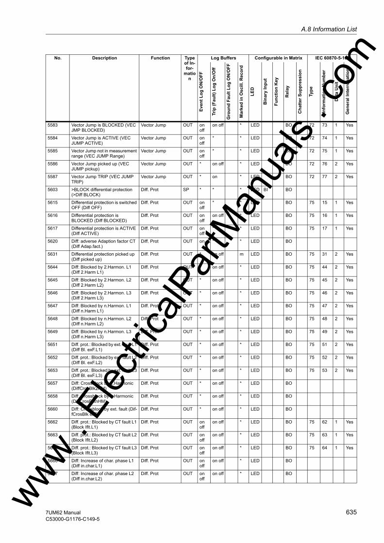
A.8 Information Listw
5583 Vector Jump is BLOCKED (VEC JMP BLOCKED)
Vector Jump OUT on off
on off * LED BO 72 73 1 Yes
5584 Vector Jump is ACTIVE (VEC JUMP ACTIVE)
Vector Jump OUT on off
* * LED BO 72 74 1 Yes
5585 Vector Jump not in measurement range (VEC JUMP Range)
Vector Jump OUT on off
* * LED BO 72 75 1 Yes
5586 Vector Jump picked up (VEC JUMP pickup)
Vector Jump OUT * on off * LED BO 72 76 2 Yes
5587 Vector Jump TRIP (VEC JUMP TRIP)
Vector Jump OUT * on * LED BO 72 77 2 Yes
5603 >BLOCK differential protection (>Diff BLOCK)
Diff. Prot SP * * * LED BI BO
5615 Differential protection is switched OFF (Diff OFF)
Diff. Prot OUT on off
* * LED BO 75 15 1 Yes
5616 Differential protection is BLOCKED (Diff BLOCKED)
Diff. Prot OUT on off
on off * LED BO 75 16 1 Yes
5617 Differential protection is ACTIVE (Diff ACTIVE)
Diff. Prot OUT on off
* * LED BO 75 17 1 Yes
5620 Diff: adverse Adaption factor CT (Diff Adap.fact.)
Diff. Prot OUT on * * LED BO
5631 Differential protection picked up (Diff picked up)
Diff. Prot OUT * on off m LED BO 75 31 2 Yes
5644 Diff: Blocked by 2.Harmon. L1 (Diff 2.Harm L1)
Diff. Prot OUT * on off * LED BO 75 44 2 Yes
5645 Diff: Blocked by 2.Harmon. L2 (Diff 2.Harm L2)
Diff. Prot OUT * on off * LED BO 75 45 2 Yes
5646 Diff: Blocked by 2.Harmon. L3 (Diff 2.Harm L3)
Diff. Prot OUT * on off * LED BO 75 46 2 Yes
5647 Diff: Blocked by n.Harmon. L1 (Diff n.Harm L1)
Diff. Prot OUT * on off * LED BO 75 47 2 Yes
5648 Diff: Blocked by n.Harmon. L2 (Diff n.Harm L2)
Diff. Prot OUT * on off * LED BO 75 48 2 Yes
5649 Diff: Blocked by n.Harmon. L3 (Diff n.Harm L3)
Diff. Prot OUT * on off * LED BO 75 49 2 Yes
5651 Diff. prot.: Blocked by ext. fault L1 (Diff Bl. exF.L1)
Diff. Prot OUT * on off * LED BO 75 51 2 Yes
5652 Diff. prot.: Blocked by ext. fault L2 (Diff Bl. exF.L2)
Diff. Prot OUT * on off * LED BO 75 52 2 Yes
5653 Diff. prot.: Blocked by ext. fault.L3 (Diff Bl. exF.L3)
Diff. Prot OUT * on off * LED BO 75 53 2 Yes
5657 Diff: Crossblock by 2.Harmonic (DiffCrosBlk2HM)
Diff. Prot OUT * on off * LED BO
5658 Diff: Crossblock by n.Harmonic (DiffCrosBlknHM)
Diff. Prot OUT * on off * LED BO
5660 Diff: Crossblock by ext. fault (Dif-fCrosBlk exF)
Diff. Prot OUT * on off * LED BO
5662 Diff. prot.: Blocked by CT fault L1 (Block Iflt.L1)
Diff. Prot OUT on off
on off * LED BO 75 62 1 Yes
5663 Diff. prot.: Blocked by CT fault L2 (Block Iflt.L2)
Diff. Prot OUT on off
on off * LED BO 75 63 1 Yes
5664 Diff. prot.: Blocked by CT fault L3 (Block Iflt.L3)
Diff. Prot OUT on off
on off * LED BO 75 64 1 Yes
5666 Diff: Increase of char. phase L1 (Diff in.char.L1)
Diff. Prot OUT on off
on off * LED BO
5667 Diff: Increase of char. phase L2 (Diff in.char.L2)
Diff. Prot OUT on off
on off * LED BO
No. Description Function Type of In-for-
mation
Log Buffers Configurable in Matrix IEC 60870-5-103
Even
t Log
ON
/OFF
Trip
(Fau
lt) L
og O
n/O
ff
Gro
und
Faul
t Log
ON
/OFF
Mar
ked
in O
scill
. Rec
ord
LED
Bin
ary
Inpu
t
Func
tion
Key
Rel
ay
Cha
tter S
uppr
essi
on
Type
Info
rmat
ion
Num
ber
Dat
a U
nit
Gen
eral
Inte
rrog
atio
n
ww . El
ectric
alPar
tMan
uals
. com
6357UM62 ManualC53000-G1176-C149-5
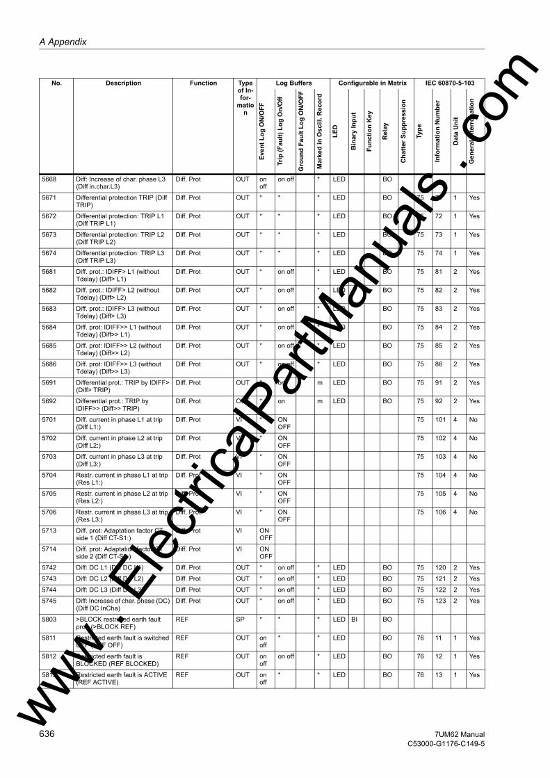
A Appendix
om
5668 Diff: Increase of char. phase L3 (Diff in.char.L3)
Diff. Prot OUT on off
on off * LED BO
5671 Differential protection TRIP (Diff TRIP)
Diff. Prot OUT * * * LED BO 75 71 1 Yes
5672 Differential protection: TRIP L1 (Diff TRIP L1)
Diff. Prot OUT * * * LED BO 75 72 1 Yes
5673 Differential protection: TRIP L2 (Diff TRIP L2)
Diff. Prot OUT * * * LED BO 75 73 1 Yes
5674 Differential protection: TRIP L3 (Diff TRIP L3)
Diff. Prot OUT * * * LED BO 75 74 1 Yes
5681 Diff. prot.: IDIFF> L1 (without Tdelay) (Diff> L1)
Diff. Prot OUT * on off * LED BO 75 81 2 Yes
5682 Diff. prot.: IDIFF> L2 (without Tdelay) (Diff> L2)
Diff. Prot OUT * on off * LED BO 75 82 2 Yes
5683 Diff. prot.: IDIFF> L3 (without Tdelay) (Diff> L3)
Diff. Prot OUT * on off * LED BO 75 83 2 Yes
5684 Diff. prot: IDIFF>> L1 (without Tdelay) (Diff>> L1)
Diff. Prot OUT * on off * LED BO 75 84 2 Yes
5685 Diff. prot: IDIFF>> L2 (without Tdelay) (Diff>> L2)
Diff. Prot OUT * on off * LED BO 75 85 2 Yes
5686 Diff. prot: IDIFF>> L3 (without Tdelay) (Diff>> L3)
Diff. Prot OUT * on off * LED BO 75 86 2 Yes
5691 Differential prot.: TRIP by IDIFF> (Diff> TRIP)
Diff. Prot OUT * on m LED BO 75 91 2 Yes
5692 Differential prot.: TRIP by IDIFF>> (Diff>> TRIP)
Diff. Prot OUT * on m LED BO 75 92 2 Yes
5701 Diff. current in phase L1 at trip (Diff L1:)
Diff. Prot VI * ON OFF
75 101 4 No
5702 Diff. current in phase L2 at trip (Diff L2:)
Diff. Prot VI * ON OFF
75 102 4 No
5703 Diff. current in phase L3 at trip (Diff L3:)
Diff. Prot VI * ON OFF
75 103 4 No
5704 Restr. current in phase L1 at trip (Res L1:)
Diff. Prot VI * ON OFF
75 104 4 No
5705 Restr. current in phase L2 at trip (Res L2:)
Diff. Prot VI * ON OFF
75 105 4 No
5706 Restr. current in phase L3 at trip (Res L3:)
Diff. Prot VI * ON OFF
75 106 4 No
5713 Diff. prot: Adaptation factor CT side 1 (Diff CT-S1:)
Diff. Prot VI ON OFF
5714 Diff. prot: Adaptation factor CT side 2 (Diff CT-S2:)
Diff. Prot VI ON OFF
5742 Diff: DC L1 (Diff DC L1) Diff. Prot OUT * on off * LED BO 75 120 2 Yes
5743 Diff: DC L2 (Diff DC L2) Diff. Prot OUT * on off * LED BO 75 121 2 Yes
5744 Diff: DC L3 (Diff DC L3) Diff. Prot OUT * on off * LED BO 75 122 2 Yes
5745 Diff: Increase of char. phase (DC) (Diff DC InCha)
Diff. Prot OUT * on off * LED BO 75 123 2 Yes
5803 >BLOCK restricted earth fault prot. (>BLOCK REF)
REF SP * * * LED BI BO
5811 Restricted earth fault is switched OFF (REF OFF)
REF OUT on off
* * LED BO 76 11 1 Yes
5812 Restricted earth fault is BLOCKED (REF BLOCKED)
REF OUT on off
on off * LED BO 76 12 1 Yes
5813 Restricted earth fault is ACTIVE (REF ACTIVE)
REF OUT on off
* * LED BO 76 13 1 Yes
No. Description Function Type of In-for-
mation
Log Buffers Configurable in Matrix IEC 60870-5-103
Even
t Log
ON
/OFF
Trip
(Fau
lt) L
og O
n/O
ff
Gro
und
Faul
t Log
ON
/OFF
Mar
ked
in O
scill
. Rec
ord
LED
Bin
ary
Inpu
t
Func
tion
Key
Rel
ay
Cha
tter S
uppr
essi
on
Type
Info
rmat
ion
Num
ber
Dat
a U
nit
Gen
eral
Inte
rrog
atio
n
ww . El
ectric
alPar
tMan
uals
. c
636 7UM62 ManualC53000-G1176-C149-5
w
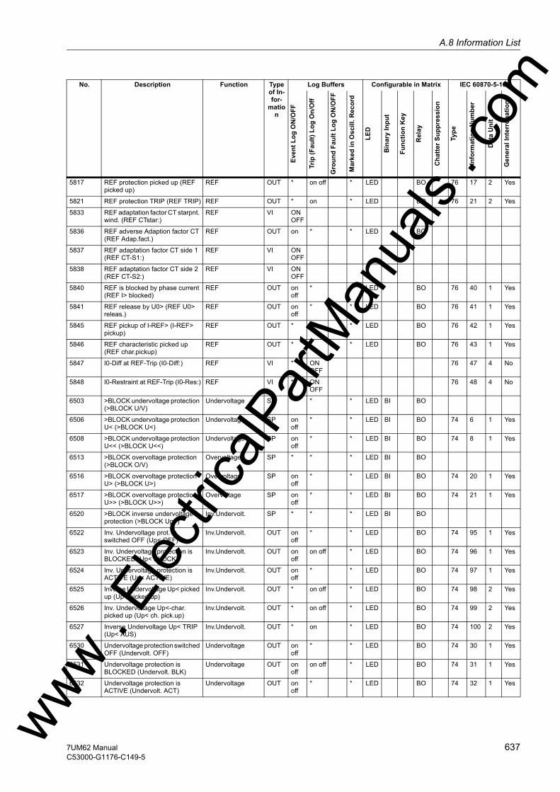
A.8 Information Listw
5817 REF protection picked up (REF picked up)
REF OUT * on off * LED BO 76 17 2 Yes
5821 REF protection TRIP (REF TRIP) REF OUT * on * LED BO 76 21 2 Yes
5833 REF adaptation factor CT starpnt. wind. (REF CTstar:)
REF VI ON OFF
5836 REF adverse Adaption factor CT (REF Adap.fact.)
REF OUT on * * LED BO
5837 REF adaptation factor CT side 1 (REF CT-S1:)
REF VI ON OFF
5838 REF adaptation factor CT side 2 (REF CT-S2:)
REF VI ON OFF
5840 REF is blocked by phase current (REF I> blocked)
REF OUT on off
* * LED BO 76 40 1 Yes
5841 REF release by U0> (REF U0> releas.)
REF OUT on off
* * LED BO 76 41 1 Yes
5845 REF pickup of I-REF> (I-REF> pickup)
REF OUT * * * LED BO 76 42 1 Yes
5846 REF characteristic picked up (REF char.pickup)
REF OUT * * * LED BO 76 43 1 Yes
5847 I0-Diff at REF-Trip (I0-Diff:) REF VI * ON OFF
76 47 4 No
5848 I0-Restraint at REF-Trip (I0-Res:) REF VI * ON OFF
76 48 4 No
6503 >BLOCK undervoltage protection (>BLOCK U/V)
Undervoltage SP * * * LED BI BO
6506 >BLOCK undervoltage protection U< (>BLOCK U<)
Undervoltage SP on off
* * LED BI BO 74 6 1 Yes
6508 >BLOCK undervoltage protection U<< (>BLOCK U<<)
Undervoltage SP on off
* * LED BI BO 74 8 1 Yes
6513 >BLOCK overvoltage protection (>BLOCK O/V)
Overvoltage SP * * * LED BI BO
6516 >BLOCK overvoltage protection U> (>BLOCK U>)
Overvoltage SP on off
* * LED BI BO 74 20 1 Yes
6517 >BLOCK overvoltage protection U>> (>BLOCK U>>)
Overvoltage SP on off
* * LED BI BO 74 21 1 Yes
6520 >BLOCK inverse undervoltage protection (>BLOCK Up<)
Inv.Undervolt. SP * * * LED BI BO
6522 Inv. Undervoltage prot. is switched OFF (Up< OFF)
Inv.Undervolt. OUT on off
* * LED BO 74 95 1 Yes
6523 Inv. Undervoltage protection is BLOCKED (Up< BLOCK)
Inv.Undervolt. OUT on off
on off * LED BO 74 96 1 Yes
6524 Inv. Undervoltage protection is ACTIVE (Up< ACTIVE)
Inv.Undervolt. OUT on off
* * LED BO 74 97 1 Yes
6525 Inverse Undervoltage Up< picked up (Up< picked up)
Inv.Undervolt. OUT * on off * LED BO 74 98 2 Yes
6526 Inv. Undervoltage Up<-char. picked up (Up< ch. pick.up)
Inv.Undervolt. OUT * on off * LED BO 74 99 2 Yes
6527 Inverse Undervoltage Up< TRIP (Up< AUS)
Inv.Undervolt. OUT * on * LED BO 74 100 2 Yes
6530 Undervoltage protection switched OFF (Undervolt. OFF)
Undervoltage OUT on off
* * LED BO 74 30 1 Yes
6531 Undervoltage protection is BLOCKED (Undervolt. BLK)
Undervoltage OUT on off
on off * LED BO 74 31 1 Yes
6532 Undervoltage protection is ACTIVE (Undervolt. ACT)
Undervoltage OUT on off
* * LED BO 74 32 1 Yes
No. Description Function Type of In-for-
mation
Log Buffers Configurable in Matrix IEC 60870-5-103
Even
t Log
ON
/OFF
Trip
(Fau
lt) L
og O
n/O
ff
Gro
und
Faul
t Log
ON
/OFF
Mar
ked
in O
scill
. Rec
ord
LED
Bin
ary
Inpu
t
Func
tion
Key
Rel
ay
Cha
tter S
uppr
essi
on
Type
Info
rmat
ion
Num
ber
Dat
a U
nit
Gen
eral
Inte
rrog
atio
n
ww . El
ectric
alPar
tMan
uals
. com
6377UM62 ManualC53000-G1176-C149-5

A Appendix
om
6533 Undervoltage U< picked up (U< picked up)
Undervoltage OUT * on off * LED BO 74 33 2 Yes
6537 Undervoltage U<< picked up (U<< picked up)
Undervoltage OUT * on off * LED BO 74 37 2 Yes
6539 Undervoltage U< TRIP (U< TRIP) Undervoltage OUT * on m LED BO 74 39 2 Yes
6540 Undervoltage U<< TRIP (U<< TRIP)
Undervoltage OUT * on m LED BO 74 40 2 Yes
6565 Overvoltage protection switched OFF (Overvolt. OFF)
Overvoltage OUT on off
* * LED BO 74 65 1 Yes
6566 Overvoltage protection is BLOCKED (Overvolt. BLK)
Overvoltage OUT on off
on off * LED BO 74 66 1 Yes
6567 Overvoltage protection is ACTIVE (Overvolt. ACT)
Overvoltage OUT on off
* * LED BO 74 67 1 Yes
6568 Overvoltage U> picked up (U> picked up)
Overvoltage OUT * on off * LED BO 74 68 2 Yes
6570 Overvoltage U> TRIP (U> TRIP) Overvoltage OUT * on m LED BO 74 70 2 Yes
6571 Overvoltage U>> picked up (U>> picked up)
Overvoltage OUT * on off * LED BO 74 71 2 Yes
6573 Overvoltage U>> TRIP (U>> TRIP)
Overvoltage OUT * on m LED BO 74 73 2 Yes
6575 Voltage Transformer Fuse Failure (VT Fuse Failure)
Supervision OUT on off
* * LED BO 74 74 1 Yes
6801 >BLOCK Motor Starting Supervi-sion (>BLK START-SUP)
Start Motor SP * * * LED BI BO
6805 >Rotor is locked (>Rotor locked) Start Motor SP on off
* * LED BI BO
6811 Starting time supervision switched OFF (START-SUP OFF)
Start Motor OUT on off
* * LED BO 169 51 1 Yes
6812 Starting time supervision is BLOCKED (START-SUP BLK)
Start Motor OUT on off
on off * LED BO 169 52 1 Yes
6813 Starting time supervision is ACTIVE (START-SUP ACT)
Start Motor OUT on off
* * LED BO 169 53 1 Yes
6821 Starting time supervision TRIP (START-SUP TRIP)
Start Motor OUT * on * LED BO 169 54 2 Yes
6822 Rotor is LOCKED after Locked Rotor Time (Rotor locked)
Start Motor OUT * on * LED BO 169 55 2 Yes
6823 Starting time supervision picked up (START-SUP PU)
Start Motor OUT on off
* * LED BO 169 56 1 Yes
6851 >BLOCK Trip circuit supervision (>BLOCK TripC)
TripCirc.Superv SP * * * LED BI BO
6852 >Trip circuit supervision: trip relay (>TripC trip rel)
TripCirc.Superv SP on off
* * LED BI BO 170 51 1 Yes
6853 >Trip circuit supervision: breaker relay (>TripC brk rel.)
TripCirc.Superv SP on off
* * LED BI BO 170 52 1 Yes
6861 Trip circuit supervision OFF (TripC OFF)
TripCirc.Superv OUT on off
* * LED BO 170 53 1 Yes
6862 Trip circuit supervision is BLOCKED (TripC BLOCKED)
TripCirc.Superv OUT on off
on off * LED BO 153 16 1 Yes
6863 Trip circuit supervision is ACTIVE (TripC ACTIVE)
TripCirc.Superv OUT on off
* * LED BO 153 17 1 Yes
6864 Trip Circuit blk. Bin. input is not set (TripC ProgFail)
TripCirc.Superv OUT on off
* * LED BO 170 54 1 Yes
6865 Failure Trip Circuit (FAIL: Trip cir.) TripCirc.Superv OUT on off
* * LED BO 170 55 1 Yes
No. Description Function Type of In-for-
mation
Log Buffers Configurable in Matrix IEC 60870-5-103
Even
t Log
ON
/OFF
Trip
(Fau
lt) L
og O
n/O
ff
Gro
und
Faul
t Log
ON
/OFF
Mar
ked
in O
scill
. Rec
ord
LED
Bin
ary
Inpu
t
Func
tion
Key
Rel
ay
Cha
tter S
uppr
essi
on
Type
Info
rmat
ion
Num
ber
Dat
a U
nit
Gen
eral
Inte
rrog
atio
n
ww . El
ectric
alPar
tMan
uals
. c
638 7UM62 ManualC53000-G1176-C149-5
w
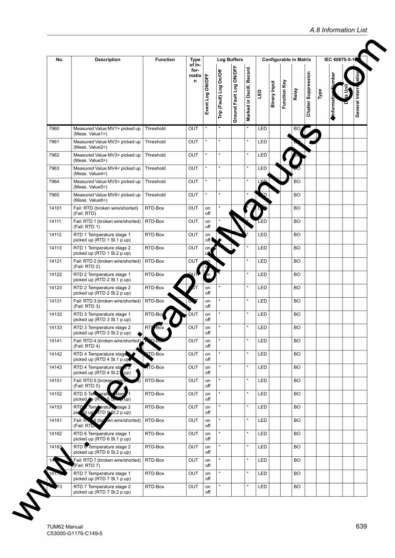
A.8 Information Listw
7960 Measured Value MV1> picked up (Meas. Value1>)
Threshold OUT * * * LED BO
7961 Measured Value MV2< picked up (Meas. Value2<)
Threshold OUT * * * LED BO
7962 Measured Value MV3> picked up (Meas. Value3>)
Threshold OUT * * * LED BO
7963 Measured Value MV4< picked up (Meas. Value4<)
Threshold OUT * * * LED BO
7964 Measured Value MV5> picked up (Meas. Value5>)
Threshold OUT * * * LED BO
7965 Measured Value MV6< picked up (Meas. Value6<)
Threshold OUT * * * LED BO
14101 Fail: RTD (broken wire/shorted) (Fail: RTD)
RTD-Box OUT on off
* * LED BO
14111 Fail: RTD 1 (broken wire/shorted) (Fail: RTD 1)
RTD-Box OUT on off
* * LED BO
14112 RTD 1 Temperature stage 1 picked up (RTD 1 St.1 p.up)
RTD-Box OUT on off
* * LED BO
14113 RTD 1 Temperature stage 2 picked up (RTD 1 St.2 p.up)
RTD-Box OUT on off
* * LED BO
14121 Fail: RTD 2 (broken wire/shorted) (Fail: RTD 2)
RTD-Box OUT on off
* * LED BO
14122 RTD 2 Temperature stage 1 picked up (RTD 2 St.1 p.up)
RTD-Box OUT on off
* * LED BO
14123 RTD 2 Temperature stage 2 picked up (RTD 2 St.2 p.up)
RTD-Box OUT on off
* * LED BO
14131 Fail: RTD 3 (broken wire/shorted) (Fail: RTD 3)
RTD-Box OUT on off
* * LED BO
14132 RTD 3 Temperature stage 1 picked up (RTD 3 St.1 p.up)
RTD-Box OUT on off
* * LED BO
14133 RTD 3 Temperature stage 2 picked up (RTD 3 St.2 p.up)
RTD-Box OUT on off
* * LED BO
14141 Fail: RTD 4 (broken wire/shorted) (Fail: RTD 4)
RTD-Box OUT on off
* * LED BO
14142 RTD 4 Temperature stage 1 picked up (RTD 4 St.1 p.up)
RTD-Box OUT on off
* * LED BO
14143 RTD 4 Temperature stage 2 picked up (RTD 4 St.2 p.up)
RTD-Box OUT on off
* * LED BO
14151 Fail: RTD 5 (broken wire/shorted) (Fail: RTD 5)
RTD-Box OUT on off
* * LED BO
14152 RTD 5 Temperature stage 1 picked up (RTD 5 St.1 p.up)
RTD-Box OUT on off
* * LED BO
14153 RTD 5 Temperature stage 2 picked up (RTD 5 St.2 p.up)
RTD-Box OUT on off
* * LED BO
14161 Fail: RTD 6 (broken wire/shorted) (Fail: RTD 6)
RTD-Box OUT on off
* * LED BO
14162 RTD 6 Temperature stage 1 picked up (RTD 6 St.1 p.up)
RTD-Box OUT on off
* * LED BO
14163 RTD 6 Temperature stage 2 picked up (RTD 6 St.2 p.up)
RTD-Box OUT on off
* * LED BO
14171 Fail: RTD 7 (broken wire/shorted) (Fail: RTD 7)
RTD-Box OUT on off
* * LED BO
14172 RTD 7 Temperature stage 1 picked up (RTD 7 St.1 p.up)
RTD-Box OUT on off
* * LED BO
14173 RTD 7 Temperature stage 2 picked up (RTD 7 St.2 p.up)
RTD-Box OUT on off
* * LED BO
No. Description Function Type of In-for-
mation
Log Buffers Configurable in Matrix IEC 60870-5-103
Even
t Log
ON
/OFF
Trip
(Fau
lt) L
og O
n/O
ff
Gro
und
Faul
t Log
ON
/OFF
Mar
ked
in O
scill
. Rec
ord
LED
Bin
ary
Inpu
t
Func
tion
Key
Rel
ay
Cha
tter S
uppr
essi
on
Type
Info
rmat
ion
Num
ber
Dat
a U
nit
Gen
eral
Inte
rrog
atio
n
ww . El
ectric
alPar
tMan
uals
. com
6397UM62 ManualC53000-G1176-C149-5

A Appendix
om
14181 Fail: RTD 8 (broken wire/shorted) (Fail: RTD 8)
RTD-Box OUT on off
* * LED BO
14182 RTD 8 Temperature stage 1 picked up (RTD 8 St.1 p.up)
RTD-Box OUT on off
* * LED BO
14183 RTD 8 Temperature stage 2 picked up (RTD 8 St.2 p.up)
RTD-Box OUT on off
* * LED BO
14191 Fail: RTD 9 (broken wire/shorted) (Fail: RTD 9)
RTD-Box OUT on off
* * LED BO
14192 RTD 9 Temperature stage 1 picked up (RTD 9 St.1 p.up)
RTD-Box OUT on off
* * LED BO
14193 RTD 9 Temperature stage 2 picked up (RTD 9 St.2 p.up)
RTD-Box OUT on off
* * LED BO
14201 Fail: RTD10 (broken wire/short-ed) (Fail: RTD10)
RTD-Box OUT on off
* * LED BO
14202 RTD10 Temperature stage 1 picked up (RTD10 St.1 p.up)
RTD-Box OUT on off
* * LED BO
14203 RTD10 Temperature stage 2 picked up (RTD10 St.2 p.up)
RTD-Box OUT on off
* * LED BO
14211 Fail: RTD11 (broken wire/short-ed) (Fail: RTD11)
RTD-Box OUT on off
* * LED BO
14212 RTD11 Temperature stage 1 picked up (RTD11 St.1 p.up)
RTD-Box OUT on off
* * LED BO
14213 RTD11 Temperature stage 2 picked up (RTD11 St.2 p.up)
RTD-Box OUT on off
* * LED BO
14221 Fail: RTD12 (broken wire/short-ed) (Fail: RTD12)
RTD-Box OUT on off
* * LED BO
14222 RTD12 Temperature stage 1 picked up (RTD12 St.1 p.up)
RTD-Box OUT on off
* * LED BO
14223 RTD12 Temperature stage 2 picked up (RTD12 St.2 p.up)
RTD-Box OUT on off
* * LED BO
25071 >BLOCK sensitive earth current prot. B (>BLK Sens. E B)
Sens. E Fault B SP * * * LED BI BO
25072 Earth current prot. B is switched OFF (IEE-B OFF)
Sens. E Fault B OUT on off
* * LED BO 151 182 1 Yes
25073 Earth current prot. B is BLOCKED (IEE-B BLOCKED)
Sens. E Fault B OUT on off
on off * LED BO 151 183 1 Yes
25074 Earth current prot. B is ACTIVE (IEE-B ACTIVE)
Sens. E Fault B OUT on off
* * LED BO 151 184 1 Yes
25077 IEE-B> picked up (IEE-B> pickup)
Sens. E Fault B OUT * on off * LED BO 151 185 2 Yes
25078 IEE-B< picked up (IEE-B< pickup)
Sens. E Fault B OUT * on off * LED BO 151 186 2 Yes
25079 IEE-B> TRIP (IEE-B> TRIP) Sens. E Fault B OUT * on * LED BO 151 187 2 Yes
25080 IEE-B< TRIP (IEE-B< TRIP) Sens. E Fault B OUT * on * LED BO 151 188 2 Yes
25083 Measured Value MV7> picked up (Meas. Value7>)
Threshold OUT * * * LED BO
25084 Measured Value MV8< picked up (Meas. Value8<)
Threshold OUT * * * LED BO
25085 Measured Value MV9> picked up (Meas. Value9>)
Threshold OUT * * * LED BO
25086 Measured Value MV10< picked up (Meas. Value10<)
Threshold OUT * * * LED BO
30053 Fault recording is running (Fault rec. run.)
Osc. Fault Rec. OUT * * * LED BO
30607 Accumulation of interrupted curr. L1 S1 (ΣIL1 S1:)
Statistics VI
No. Description Function Type of In-for-
mation
Log Buffers Configurable in Matrix IEC 60870-5-103
Even
t Log
ON
/OFF
Trip
(Fau
lt) L
og O
n/O
ff
Gro
und
Faul
t Log
ON
/OFF
Mar
ked
in O
scill
. Rec
ord
LED
Bin
ary
Inpu
t
Func
tion
Key
Rel
ay
Cha
tter S
uppr
essi
on
Type
Info
rmat
ion
Num
ber
Dat
a U
nit
Gen
eral
Inte
rrog
atio
n
ww . El
ectric
alPar
tMan
uals
. c
640 7UM62 ManualC53000-G1176-C149-5
w
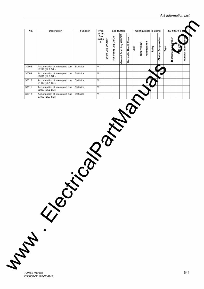
A.8 Information Listw
30608 Accumulation of interrupted curr. L2 S1 (ΣIL2 S1:)
Statistics VI
30609 Accumulation of interrupted curr. L3 S1 (ΣIL3 S1:)
Statistics VI
30610 Accumulation of interrupted curr. L1 S2 (ΣIL1 S2:)
Statistics VI
30611 Accumulation of interrupted curr. L2 S2 (ΣIL2 S2:)
Statistics VI
30612 Accumulation of interrupted curr. L3 S2 (ΣIL3 S2:)
Statistics VI
No. Description Function Type of In-for-
mation
Log Buffers Configurable in Matrix IEC 60870-5-103
Even
t Log
ON
/OFF
Trip
(Fau
lt) L
og O
n/O
ff
Gro
und
Faul
t Log
ON
/OFF
Mar
ked
in O
scill
. Rec
ord
LED
Bin
ary
Inpu
t
Func
tion
Key
Rel
ay
Cha
tter S
uppr
essi
on
Type
Info
rmat
ion
Num
ber
Dat
a U
nit
Gen
eral
Inte
rrog
atio
n
ww . El
ectric
alPar
tMan
uals
. com
6417UM62 ManualC53000-G1176-C149-5

A Appendix
om
A.9 Group Alarms
No. Description Function No. Description140 Error Sum Alarm 181
191264267
Error A/D-conv.Error OffsetFail: RTD-Box 1Fail: RTD-Box 2
160 Alarm Sum Event 1611641711476575193177
Fail I Superv.Fail U Superv.Fail Ph. Seq.Error PwrSupplyVT Fuse FailureAlarm NO calibrFail Battery
161 Fail I Superv. 230231571572
Fail. Σ I Side1Fail. Σ I Side2Fail. Isym 1Fail. Isym 2
164 Fail U Superv. 165167
Fail Σ U Ph-EFail U balance
171 Fail Ph. Seq. 265266176
FailPh.Seq I S1FailPh.Seq I S2Fail Ph. Seq. U
181 Error A/D-conv. 210211194212213214190185187188
Err1A/5AwrongS1Err1A/5AwrongS2Error neutralCTErr. TD1 jumperErr. TD2 jumperErr. TD3 jumperError Board 0Error Board 3Error Board 5Error Board 6
ww . El
ectric
alPar
tMan
uals
. c
642 7UM62 ManualC53000-G1176-C149-5
w
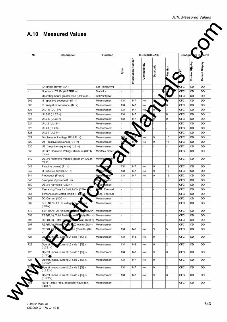
A.10 Measured Valuesw
A.10 Measured Values
No. Description Function IEC 60870-5-103 Configurable in Matrix
Type
Info
rmat
ion
Num
ber
Com
patib
ility
Dat
a U
nit
Posi
tion
CFC
Con
trol
Dis
play
Def
ault
Dis
play
- IL< under current (IL<) Set Points(MV) - - - - - CFC CD DD
- Number of TRIPs (#of TRIPs=) Statistics - - - - - CFC CD DD
- Operating hours greater than (OpHour>) SetPoint(Stat) - - - - - CFC CD DD
605 I1 (positive sequence) (I1 =) Measurement 134 147 No 9 5 CFC CD DD
606 I2 (negative sequence) (I2 =) Measurement 134 147 No 9 6 CFC CD DD
621 U L1-E (UL1E=) Measurement 134 147 No 9 7 CFC CD DD
622 U L2-E (UL2E=) Measurement 134 147 No 9 8 CFC CD DD
623 U L3-E (UL3E=) Measurement 134 147 No 9 9 CFC CD DD
624 U L12 (UL12=) Measurement - - - - - CFC CD DD
625 U L23 (UL23=) Measurement - - - - - CFC CD DD
626 U L31 (UL31=) Measurement - - - - - CFC CD DD
627 Displacement voltage UE (UE =) Measurement 134 147 No 9 10 CFC CD DD
629 U1 (positive sequence) (U1 =) Measurement 134 147 No 9 11 CFC CD DD
630 U2 (negative sequence) (U2 =) Measurement - - - - - CFC CD DD
639 UE 3rd Harmonic Voltage Minimum (UE3h min=)
Min/Max meter - - - - - CFC CD DD
640 UE 3rd Harmonic Voltage Maximum (UE3h max=)
Min/Max meter - - - - - CFC CD DD
641 P (active power) (P =) Measurement 134 147 No 9 12 CFC CD DD
642 Q (reactive power) (Q =) Measurement 134 147 No 9 13 CFC CD DD
644 Frequency (Freq=) Measurement 134 147 No 9 15 CFC CD DD
645 S (apparent power) (S =) Measurement - - - - - CFC CD DD
650 UE 3rd harmonic (UE3h =) Measurement - - - - - CFC CD DD
660 Remaining Time for Switch ON (T Rem.=) Meas. Thermal - - - - - CFC CD DD
661 Threshold of Restart Inhibit (Θ REST. =) Meas. Thermal - - - - - CFC CD DD
662 DC Current (I DC =) Measurement - - - - - CFC CD DD
669 SEF 100%: 20 Hz voltage stator circuit (U20=)
Measurement - - - - - CFC CD DD
670 SEF 100%: 20 Hz current stator circuit (I20=) Measurement - - - - - CFC CD DD
693 REF(R,fn): Total Resistance (R total) (Rtot =) Measurement - - - - - CFC CD DD
696 REF(R,fn): Total Reactance (X total) (Xtot =) Measurement - - - - - CFC CD DD
697 REF(R,fn): Phase Angle of Z total (ϕ Ztot=) Measurement - - - - - CFC CD DD
700 REF(R,fn): Fault Resistance (R earth) (Re =)
Measurement 134 148 No 9 5 CFC CD DD
721 Operat. meas. current L1 side 1 [%] is (IL1S1=)
Measurement 134 148 No 9 1 CFC CD DD
722 Operat. meas. current L2 side 1 [%] is (IL2S1=)
Measurement 134 148 No 9 2 CFC CD DD
723 Operat. meas. current L3 side 1 [%] is (IL3S1=)
Measurement 134 148 No 9 3 CFC CD DD
724 Operat. meas. current L1 side 2 [%] is (IL1S2=)
Measurement 134 147 No 9 1 CFC CD DD
725 Operat. meas. current L2 side 2 [%] is (IL2S2=)
Measurement 134 147 No 9 2 CFC CD DD
726 Operat. meas. current L3 side 2 [%] is (IL3S2=)
Measurement 134 147 No 9 3 CFC CD DD
755 REF(1-3Hz): Freq. of square-wave gen. (fgen =)
Measurement - - - - - CFC CD DDww . El
ectric
alPar
tMan
uals
. com
6437UM62 ManualC53000-G1176-C149-5

A Appendix
om
757 REF(1-3Hz): Volt. of square-wave gen. (Ugen =)
Measurement - - - - - CFC CD DD
758 REF(1-3Hz): Curr. of rotor meas. circuit (Imeas. =)
Measurement - - - - - CFC CD DD
759 REF(1-3 Hz): Charge at polarity rev.(Qc) (Qc =)
Measurement - - - - - CFC CD DD
760 SEF100%: Prim. stator earth resistance (RSEFp=)
Measurement - - - - - CFC CD DD
761 REF(1-3Hz): Fault Resistance (R earth) (R earth=)
Measurement 134 148 No 9 6 CFC CD DD
762 SEF100%: Bias volt. for stator circuit (U SEF=)
Measurement - - - - - CFC CD DD
763 SEF100%: Earth curr. in stator circuit (I SEF=)
Measurement - - - - - CFC CD DD
764 SEF100%: Stator earth resistance (R SEF=) Measurement 134 148 No 9 7 CFC CD DD
765 (U/Un) / (f/fn) (U/f =) Measurement 134 147 No 9 16 CFC CD DD
766 Calculated temperature (U/f) (U/f th. =) Meas. Thermal - - - - - CFC CD DD
769 Displacement voltage U Interturn (U I/T =) Measurement - - - - - CFC CD DD
801 Temperat. rise for warning and trip (Θ/Θtrip =)
Meas. Thermal - - - - - CFC CD DD
802 Temperature rise for phase L1 (Θ/ΘtripL1=) Meas. Thermal - - - - - CFC CD DD
803 Temperature rise for phase L2 (Θ/ΘtripL2=) Meas. Thermal - - - - - CFC CD DD
804 Temperature rise for phase L3 (Θ/ΘtripL3=) Meas. Thermal - - - - - CFC CD DD
805 Temperature of Rotor (ΘR/ΘRmax =) Meas. Thermal - - - - - CFC CD DD
827 Sensitive Current IEE-B (IEE-B=) Measurement - - - - - CFC CD DD
828 Senstive Earth Current 1 (IEE1=) Measurement 134 148 No 9 4 CFC CD DD
829 Senstive Earth Current 2 (IEE2=) Measurement 134 147 No 9 4 CFC CD DD
831 3I0 (zero sequence) (3I0 =) Measurement - - - - - CFC CD DD
832 U0 (zero sequence) (U0 =) Measurement - - - - - CFC CD DD
857 Positive Sequence Minimum (I1 Min=) Min/Max meter - - - - - CFC CD DD
858 Positive Sequence Maximum (I1 Max=) Min/Max meter - - - - - CFC CD DD
874 U1 (positive sequence) Voltage Minimum (U1 Min =)
Min/Max meter - - - - - CFC CD DD
875 U1 (positive sequence) Voltage Maximum (U1 Max =)
Min/Max meter - - - - - CFC CD DD
876 Active Power Minimum (PMin=) Min/Max meter - - - - - CFC CD DD
877 Active Power Maximum (PMax=) Min/Max meter - - - - - CFC CD DD
878 Reactive Power Minimum (QMin=) Min/Max meter - - - - - CFC CD DD
879 Reactive Power Maximum (QMax=) Min/Max meter - - - - - CFC CD DD
882 Frequency Minimum (fMin=) Min/Max meter - - - - - CFC CD DD
883 Frequency Maximum (fMax=) Min/Max meter - - - - - CFC CD DD
888 Pulsed Energy Wp (active) (Wp(puls)) Energy 133 55 No 205 - CFC CD DD
889 Pulsed Energy Wq (reactive) (Wq(puls)) Energy 133 56 No 205 - CFC CD DD
894 DC voltage (U DC =) Measurement - - - - - CFC CD DD
896 REF(R,fn): Injected Voltage (U RE) (U RE =) Measurement - - - - - CFC CD DD
897 REF(R,fn): Curr. in the Circuit (I RE) (I RE =) Measurement - - - - - CFC CD DD
901 Power Factor (PF =) Measurement 134 147 No 9 14 CFC CD DD
902 Power angle (PHI=) Measurement - - - - - CFC CD DD
903 Resistance (R=) Measurement - - - - - CFC CD DD
904 Reactance (X=) Measurement - - - - - CFC CD DD
909 Excitation voltage (Uexcit.=) Measurement - - - - - CFC CD DD
No. Description Function IEC 60870-5-103 Configurable in Matrix
Type
Info
rmat
ion
Num
ber
Com
patib
ility
Dat
a U
nit
Posi
tion
CFC
Con
trol
Dis
play
Def
ault
Dis
play
ww . El
ectric
alPar
tMan
uals
. c
644 7UM62 ManualC53000-G1176-C149-5
w
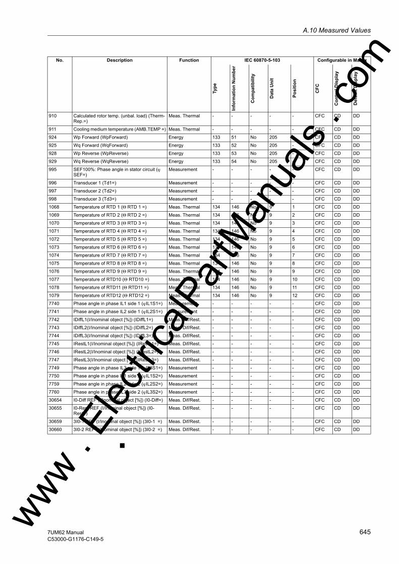
A.10 Measured Valuesw
910 Calculated rotor temp. (unbal. load) (Therm-Rep.=)
Meas. Thermal - - - - - CFC CD DD
911 Cooling medium temperature (AMB.TEMP =) Meas. Thermal - - - - - CFC CD DD
924 Wp Forward (WpForward) Energy 133 51 No 205 - CFC CD DD
925 Wq Forward (WqForward) Energy 133 52 No 205 - CFC CD DD
928 Wp Reverse (WpReverse) Energy 133 53 No 205 - CFC CD DD
929 Wq Reverse (WqReverse) Energy 133 54 No 205 - CFC CD DD
995 SEF100%: Phase angle in stator circuit (ϕ SEF=)
Measurement - - - - - CFC CD DD
996 Transducer 1 (Td1=) Measurement - - - - - CFC CD DD
997 Transducer 2 (Td2=) Measurement - - - - - CFC CD DD
998 Transducer 3 (Td3=) Measurement - - - - - CFC CD DD
1068 Temperature of RTD 1 (Θ RTD 1 =) Meas. Thermal 134 146 No 9 1 CFC CD DD
1069 Temperature of RTD 2 (Θ RTD 2 =) Meas. Thermal 134 146 No 9 2 CFC CD DD
1070 Temperature of RTD 3 (Θ RTD 3 =) Meas. Thermal 134 146 No 9 3 CFC CD DD
1071 Temperature of RTD 4 (Θ RTD 4 =) Meas. Thermal 134 146 No 9 4 CFC CD DD
1072 Temperature of RTD 5 (Θ RTD 5 =) Meas. Thermal 134 146 No 9 5 CFC CD DD
1073 Temperature of RTD 6 (Θ RTD 6 =) Meas. Thermal 134 146 No 9 6 CFC CD DD
1074 Temperature of RTD 7 (Θ RTD 7 =) Meas. Thermal 134 146 No 9 7 CFC CD DD
1075 Temperature of RTD 8 (Θ RTD 8 =) Meas. Thermal 134 146 No 9 8 CFC CD DD
1076 Temperature of RTD 9 (Θ RTD 9 =) Meas. Thermal 134 146 No 9 9 CFC CD DD
1077 Temperature of RTD10 (Θ RTD10 =) Meas. Thermal 134 146 No 9 10 CFC CD DD
1078 Temperature of RTD11 (Θ RTD11 =) Meas. Thermal 134 146 No 9 11 CFC CD DD
1079 Temperature of RTD12 (Θ RTD12 =) Meas. Thermal 134 146 No 9 12 CFC CD DD
7740 Phase angle in phase IL1 side 1 (ϕIL1S1=) Measurement - - - - - CFC CD DD
7741 Phase angle in phase IL2 side 1 (ϕIL2S1=) Measurement - - - - - CFC CD DD
7742 IDiffL1(I/Inominal object [%]) (IDiffL1=) Meas. Dif/Rest. - - - - - CFC CD DD
7743 IDiffL2(I/Inominal object [%]) (IDiffL2=) Meas. Dif/Rest. - - - - - CFC CD DD
7744 IDiffL3(I/Inominal object [%]) (IDiffL3=) Meas. Dif/Rest. - - - - - CFC CD DD
7745 IRestL1(I/Inominal object [%]) (IRestL1=) Meas. Dif/Rest. - - - - - CFC CD DD
7746 IRestL2(I/Inominal object [%]) (IRestL2=) Meas. Dif/Rest. - - - - - CFC CD DD
7747 IRestL3(I/Inominal object [%]) (IRestL3=) Meas. Dif/Rest. - - - - - CFC CD DD
7749 Phase angle in phase IL3 side 1 (ϕIL3S1=) Measurement - - - - - CFC CD DD
7750 Phase angle in phase IL1 side 2 (ϕIL1S2=) Measurement - - - - - CFC CD DD
7759 Phase angle in phase IL2 side 2 (ϕIL2S2=) Measurement - - - - - CFC CD DD
7760 Phase angle in phase IL3 side 2 (ϕIL3S2=) Measurement - - - - - CFC CD DD
30654 I0-Diff REF (I/Inominal object [%]) (I0-Diff=) Meas. Dif/Rest. - - - - - CFC CD DD
30655 I0-Rest REF (I/Inominal object [%]) (I0-Rest=)
Meas. Dif/Rest. - - - - - CFC CD DD
30659 3I0-1 REF (I/Inominal object [%]) (3I0-1 =) Meas. Dif/Rest. - - - - - CFC CD DD
30660 3I0-2 REF (I/Inominal object [%]) (3I0-2 =) Meas. Dif/Rest. - - - - - CFC CD DD
No. Description Function IEC 60870-5-103 Configurable in Matrix
Type
Info
rmat
ion
Num
ber
Com
patib
ility
Dat
a U
nit
Posi
tion
CFC
Con
trol
Dis
play
Def
ault
Dis
play
ww . El
ectric
alPar
tMan
uals
. com
6457UM62 ManualC53000-G1176-C149-5

A Appendix
om
ww . El
ectric
alPar
tMan
uals
. c
646 7UM62 ManualC53000-G1176-C149-5
w
w
m
Literature
/1/ SIPROTEC 4 System Description; E50417-H1176-C151-A5
/2/ SIPROTEC DIGSI, Start UP; E50417-G1176-C152-A2
/3/ DIGSI CFC, Manual; E50417-H1176-C098-A5
/4/ SIPROTEC SIGRA 4, Manual; E50417-H1176-C070-A3
/5/ Pamphlet „ Planning Machine Protection Systems“; E86010-K4500-A111-A1
ww . El
ectric
alPar
tMan
uals
. co
6477UM62 ManualC53000-G1176-C149-5

Literature
om
ww . El
ectric
alPar
tMan
uals
. c
648 7UM62 ManualC53000-G1176-C149-5
w

w
m
Glossary
Battery The buffer battery ensures that specified data areas, flags, timers and counters are re-tained retentively.
Bay controllers Bay controllers are devices with control and monitoring functions without protective functions.
Bit pattern indica-tion
Bit pattern indication is a processing function by means of which items of digital process information applying across several inputs can be detected together in paral-lel and processed further. The bit pattern length can be specified as 1, 2, 3 or 4 bytes.
BP_xx → Bit pattern indication (Bitstring Of x Bit), x designates the length in bits (8, 16, 24 or 32 bits).
C_xx Command without feedback
CF_xx Command with feedback
CFC Continuous Function Chart. CFC is a graphical editor with which a program can be created and configured by using ready-made blocks.
CFC blocks Blocks are parts of the user program delimited by their function, their structure or their purpose.
Chatter blocking A rapidly intermittent input (for example, due to a relay contact fault) is switched off after a configurable monitoring time and can thus not generate any further signal changes. The function prevents overloading of the system when a fault arises.
Combination devices
Combination devices are bay devices with protection functions and a control display.
Combination matrix From DIGSI V4.6 onward, up to 32 compatible SIPROTEC 4 devices can communi-cate with one another in an Inter Relay Communication combination (IRC combina-tion). Which device exchanges which information is defined with the help of the com-bination matrix.
Communication branch
A communications branch corresponds to the configuration of 1 to n users that com-municate by means of a common bus.
Communication reference CR
The communication reference describes the type and version of a station in commu-nication by PROFIBUS.ww . El
ectric
alPar
tMan
uals
. co
6497UM62 ManualC53000-G1176-C149-5
Glossary
om
Component view In addition to a topological view, SIMATIC Manager offers you a component view. The component view does not offer any overview of the hierarchy of a project. It does, how-ever, provide an overview of all the SIPROTEC 4 devices within a project.
COMTRADE Common Format for Transient Data Exchange, format for fault records.
Container If an object can contain other objects, it is called a container. The object Folder is an example of such a container.
Control display The display which is displayed on devices with a large (graphic) display after you have pressed the control key is called the control display. It contains the switchgear that can be controlled in the feeder with status display. It is used to perform switching opera-tions. Defining this display is part of the configuration.
Data pane → The right-hand area of the project window displays the contents of the area selected in the → navigation window, for example indications, measured values, etc. of the in-formation lists or the function selection for the device configuration.
DCF77 The extremely precise official time is determined in Germany by the "Physikalisch-Technische-Bundesanstalt PTB" in Braunschweig. The atomic clock station of the PTB transmits this time via the long-wave time-signal transmitter in Mainflingen near Frank-furt/Main. The emitted time signal can be received within a radius of approx. 1,500 km from Frankfurt/Main.
Device container In the Component View, all SIPROTEC 4 devices are assigned to an object of type Device container. This object is a special object of DIGSI Manager. However, since there is no component view in DIGSI Manager, this object only becomes visible in con-junction with STEP 7.
Double command Double commands are process outputs which indicate 4 process states at 2 outputs: 2 defined (for example ON/OFF) and 2 undefined states (for example intermediate po-sitions)
Double-point indi-cation
Double-point indications are items of process information which indicate 4 process states at 2 inputs: 2 defined (for example ON/OFF) and 2 undefined states (for example intermediate positions).
DP → Double-point indication
DP_I → Double point indication, intermediate position 00
Drag and drop Copying, moving and linking function, used at graphics user interfaces. Objects are selected with the mouse, held and moved from one data area to another.
Earth The conductive earth whose electric potential can be set equal to zero at every point. In the area of earth electrodes the earth can have a potential deviating from zero. The term "Earth reference plane" is often used for this state.
ww . El
ectric
alPar
tMan
uals
. c
650 7UM62 ManualC53000-G1176-C149-5
w

Glossaryw
Earth (verb) This term means that a conductive part is connected via an earthing system to the → earth.
Earthing Earthing is the total of all means and measures used for earthing.
Electromagnetic compatibility
Electromagnetic compatibility (EMC) is the ability of an electrical apparatus to function fault-free in a specified environment without influencing the environment unduly.
EMC → Electromagnetic compatibility
ESD protection ESD protection is the total of all the means and measures used to protect electrostatic sensitive devices.
ExBPxx External bit pattern indication via an ETHERNET connection, device-specific → Bit pattern indication
ExC External command without feedback via an ETHERNET connection, device-specific
ExCF External command with feedback via an ETHERNET connection, device-specific
ExDP External double point indication via an ETHERNET connection, device-specific → Double point indication
ExDP_I External double point indication via an ETHERNET connection, intermediate position 00, device-specific → Double point indication
ExMV External metered value via an ETHERNET connection, device-specific
ExSI External single point indication via an ETHERNET connection, device-specific → Single point indication
ExSI_F External single point indication via an ETHERNET connection, device-specific → Transient information, → Single point indication
Field devices Generic term for all devices assigned to the field level: Protection devices, combina-tion devices, bay controllers.
Floating → Without electrical connection to the → Earth.
FMS communica-tion branch
Within an FMS communication branch, the users communicate on the basis of the PROFIBUS FMS protocol via a PROFIBUS FMS network.
Folder This object type is used to create the hierarchical structure of a project.
ww . El
ectric
alPar
tMan
uals
. com
6517UM62 ManualC53000-G1176-C149-5

Glossary
om
General interroga-tion (GI)
During the system start-up the state of all the process inputs, of the status and of the fault image is sampled. This information is used to update the system-end process image. The current process state can also be sampled after a data loss by means of a GI.
GOOSE message GOOSE messages (Generic Object Oriented Substation Event) are data pakets which are transferred event-controlled via the Ethernet communication system. They serve for direct information exchange among the relays. This mechanism implements cross-communication between bay units.
GPS Global Positioning System. Satellites with atomic clocks on board orbit the earth twice a day on different paths in approx. 20,000 km. They transmit signals which also contain the GPS universal time. The GPS receiver determines its own position from the signals received. From its position it can derive the delay time of a satellite signal and thus correct the transmitted GPS universal time.
Hierarchy level Within a structure with higher-level and lower-level objects a hierarchy level is a con-tainer of equivalent objects.
HV field description The HV project description file contains details of fields which exist in a ModPara-project. The actual field information of each field is stored in a HV field description file. Within the HV project description file, each field is allocated such a HV field description file by a reference to the file name.
HV project descrip-tion
All the data is exported once the configuration and parameterization of PCUs and sub-modules using ModPara has been completed. This data is split up into several files. One file contains details about the fundamental project structure. This also includes, for example, information detailing which fields exist in this project. This file is called a HV project description file.
ID Internal double point indication → Double point indication
ID_S Internal double point indication, intermediate position 00 → Double point indication
IEC International Electrotechnical Commission, international standardisation body
IEC address Within an IEC bus a unique IEC address has to be assigned to each SIPROTEC 4 device. A total of 254 IEC addresses are available for each IEC bus.
IEC communication branch
Within an IEC communication branch the users communicate on the basis of the IEC60-870-5-103 protocol via an IEC bus.
IEC61850 International communication standard for communication in substations. The objective of this standard is the interoperability of devices from different manufacturers on the station bus. An Ethernet network is used for data transfer.
Initialization string An initialization string comprises a range of modem-specific commands. These are transmitted to the modem within the framework of modem initialization. The com-mands can, for example, force specific settings for the modem.ww .
Elec
tricalP
artM
anua
ls . c
652 7UM62 ManualC53000-G1176-C149-5
w

Glossaryw
Inter relay commu-nication
→ IRC combination
IRC combination Inter Relay Communication, IRC, is used for directly exchanging process information between SIPROTEC 4 devices. You require an object of type IRC combination to con-figure an inter relay communication. Each user of the combination and all the neces-sary communication parameters are defined in this object. The type and scope of the information exchanged between the users is also stored in this object.
IRIG-B Time signal code of the Inter-Range Instrumentation Group
IS Internal single point indication → Single point indication
IS_F Internal indication transient → Transient information, → Single point indication
ISO 9001 The ISO 9000 ff range of standards defines measures used to assure the quality of a product from the development stage to the manufacturing stage.
Link address The link address gives the address of a V3/V2 device.
List view The right pane of the project window displays the names and icons of objects which represent the contents of a container selected in the tree view. Because they are dis-played in the form of a list, this area is called the list view.
LV Limit value
LVU Limit value, user-defined
Master Masters may send data to other users and request data from other users. DIGSI op-erates as a master.
Metered value Metered values are a processing function with which the total number of discrete similar events (counting pulses) is determined for a period, usually as an integrated value. In power supply companies the electrical work is usually recorded as a metered value (energy purchase/supply, energy transportation).
MLFB MLFB is the abbreviation for "MaschinenLesbare FabrikateBezeichnung" (machine-readable product designation). This is the equivalent of an order number. The type and version of a SIPROTEC 4 device are coded in the order number.
Modem connection This object type contains information on both partners of a modem connection, the local modem and the remote modem.
Modem profile A modem profile consists of the name of the profile, a modem driver and may also comprise several initialization commands and a user address. You can create several modem profiles for one physical modem. To do so you need to link various initialization commands or user addresses to a modem driver and its properties and save them under different names.ww . El
ectric
alPar
tMan
uals
. com
6537UM62 ManualC53000-G1176-C149-5

Glossary
om
Modems Modem profiles for a modem connection are stored in this object type.
MV Measured value
MVMV Metered value which is formed from the measured value
MVT Measured value with time
MVU Measured value, user-defined
Navigation pane The left pane of the project window displays the names and symbols of all containers of a project in the form of a folder tree.
Object Each element of a project structure is called an object in DIGSI.
Object properties Each object has properties. These might be general properties that are common to several objects. An object can also have specific properties.
Off-line In offline mode a connection to a SIPROTEC 4 device is not required. You work with data which are stored in files.
OI_F Output Indication Transient → Transient information
On-line When working in online mode, there is a physical connection to a SIPROTEC 4 device. This connection can be implemented as a direct connection, as a modem connection or as a PROFIBUS FMS connection.
OUT Output indication
Parameter set The parameter set is the set of all parameters that can be set for a SIPROTEC 4 device.
Phone book User addresses for a modem connection are saved in this object type.
PMV Pulse metered value
Process bus Devices with a process bus interface allow direct communication with SICAM HV mod-ules. The process bus interface is equipped with an Ethernet module.
PROFIBUS PROcess FIeld BUS, the German process and field bus standard, as specified in the standard EN 50170, Volume 2, PROFIBUS. It defines the functional, electrical, and mechanical properties for a bit-serial field bus.
PROFIBUS address Within a PROFIBUS network a unique PROFIBUS address has to be assigned to each SIPROTEC 4 device. A total of 254 PROFIBUS addresses are available for each PROFIBUS network.ww .
Elec
tricalP
artM
anua
ls . c
654 7UM62 ManualC53000-G1176-C149-5
w

Glossaryw
Project Content-wise, a project is the image of a real power supply system. Graphically, a project is represented as a number of objects which are integrated in a hierarchical structure. Physically, a project consists of a number of directories and files containing project data.
Protection devices All devices with a protective function and no control display.
Reorganizing Frequent addition and deletion of objects results in memory areas that can no longer be used. By reorganizing projects, you can release these memory areas again. How-ever, a cleanup also reassigns the VD addresses. The consequence is that all SIPRO-TEC 4 devices have to be reinitialized.
RIO file Relay data Interchange format by Omicron.
RSxxx-interface Serial interfaces RS232, RS422/485
SCADA Interface Rear serial interface on the devices for connecting to a control system via IEC or PROFIBUS.
Service port Rear serial interface on the devices for connecting DIGSI (for example, via modem).
Setting parameters General term for all adjustments made to the device. Parameterization jobs are exe-cuted by means of DIGSI or, in some cases, directly on the device.
SI → Single point indication
SI_F → Single point indication transient → Transient information, → Single point indication
SICAM SAS Modularly structured station control system, based on the substation controller → SICAM SC and the SICAM WinCC operator control and monitoring system.
SICAM SC Substation Controller. Modularly structured substation control system, based on the SIMATIC M7 automation system.
SICAM WinCC The SICAM WinCC operator control and monitoring system displays the state of your network graphically, visualizes alarms, interrupts and indications, archives the network data, offers the possibility of intervening manually in the process and manages the system rights of the individual employee.
Single command Single commands are process outputs which indicate 2 process states (for example, ON/OFF) at one output.
Single point indica-tion
Single indications are items of process information which indicate 2 process states (for example, ON/OFF) at one output.
SIPROTEC The registered trademark SIPROTEC is used for devices implemented on system base V4.ww . El
ectric
alPar
tMan
uals
. com
6557UM62 ManualC53000-G1176-C149-5

Glossary
om
SIPROTEC 4 device This object type represents a real SIPROTEC 4 device with all the setting values and process data it contains.
SIPROTEC 4 variant
This object type represents a variant of an object of type SIPROTEC 4 device. The device data of this variant may well differ from the device data of the original object. However, all variants derived from the original object have the same VD address as the original object. For this reason they always correspond to the same real SIPRO-TEC 4 device as the original object. Objects of type SIPROTEC 4 variant have a variety of uses, such as documenting different operating states when entering param-eter settings of a SIPROTEC 4 device.
Slave A slave may only exchange data with a master after being prompted to do so by the master. SIPROTEC 4 devices operate as slaves.
Time stamp Time stamp is the assignment of the real time to a process event.
Topological view DIGSI Manager always displays a project in the topological view. This shows the hier-archical structure of a project with all available objects.
Transformer Tap In-dication
Transformer tap indication is a processing function on the DI by means of which the tap of the transformer tap changer can be detected together in parallel and processed further.
Transient informa-tion
A transient information is a brief transient → single-point indication at which only the coming of the process signal is detected and processed immediately.
Tree view The left pane of the project window displays the names and symbols of all containers of a project in the form of a folder tree. This area is called the tree view.
TxTap → Transformer Tap Indication
User address A user address comprises the name of the user, the national code, the area code and the user-specific phone number.
Users From DIGSI V4.6 onward , up to 32 compatible SIPROTEC 4 devices can communi-cate with one another in an Inter Relay Communication combination. The individual participating devices are called users.
VD A VD (Virtual Device) includes all communication objects and their properties and states that are used by a communication user through services. A VD can be a phys-ical device, a module of a device or a software module.
VD address The VD address is assigned automatically by DIGSI Manager. It exists only once in the entire project and thus serves to identify unambiguously a real SIPROTEC 4 device. The VD address assigned by DIGSI Manager must be transferred to the SIPROTEC 4 device in order to allow communication with DIGSI Device Editor.
VFD A VFD (Virtual Field Device) includes all communication objects and their properties and states that are used by a communication user through services.ww .
Elec
tricalP
artM
anua
ls . c
656 7UM62 ManualC53000-G1176-C149-5
w

w
m
Index
AAC voltage 479Adaptation of hardware 383Adaptation of the sampling frequency 25Add-on stabilization during current transformer sat-
uration 111Ambient temperatures 488Analog inputs 24, 477Analog output 403, 410Analog outputs 34Analog outputs / temperature input 26Angle error correction 57Assembling the device 403Assignment 409Auxiliary functions 542Auxiliary voltage 478Auxiliary voltage supply 411, 416Auxiliary voltage supply system 26Auxiliary voltages 295
BBattery 295Binary inputs 479Binary inputs and outputs 25Binary outputs 479Breaker control 35Buffer battery 295Busbar Connection 39
CCalibrate the impedance protection 441Calibrating the reverse power protection 469Certifications 488Changeover 382Changing setting groups 382Check:
100 % stator earth fault protection 460Connection polarity 467Directional Function of the Overcurrent Time
Protection 471Earth current protection IEE-B 471Interturn fault protection 465
Operator interface 408Overexcitation 451Rotor Earth Fault Protection (Current Measure-
ment) 462Rotor Earth Fault Protection During Operation
463Stator earth fault protection 452Underexcitation protection 470
Check: Analog outputs 425Check: Differential protection 442Check: Phase rotation 440Check: Switching states of binary inputs and
outputs 422Check: User-defined functions 425Check: Voltage circuits 450Checking analog outputs 425Checking the DC voltage / DC current circuit 434Circuit breaker failure protection 34, 279Climatic stress tests 488Clock 547Command duration 61Commissioning aids 546Commissioning Test with the Machine 435Communication 28Communication interfaces 481Connection variants 380Contact mode for binary outputs 384Controlling the tripping signal 344Coolant temperature 91Cooldown time 100, 197Correction angle 239Coupling unit 553Cubicle mounting 405Current balance 298Current flow monitoring 61Current inputs 477Current limiting 86, 90
DD-subminiature socket
RJ45 socket 409Date and time management 362DC current protection 539DC voltage 478ww .
Elec
tricalP
artM
anua
ls . c
o
6577UM62 ManualC53000-G1176-C149-5
Index
om
DC voltage / DC current protection 34DC voltage/DC current protection 539DCF77 363De-interlocked switching 369Definite time overcurrent protection 490Definite-time overcurrent protection (I>) 68Definite-time overcurrent protection (I>>) 72Determining the motoring power 467Device connections 411Device starts up 41Differential currents 444Differential protection 31, 107Differential Protection for Generators and Motors
120Differential protection for generators and motors
503Differential protection for transformers 506Dimensions of 20 Hz bandpass filter 562Dimensions of 20 Hz generator 560Dimensions of the 3PP13 555Direction detection 72Directional check with Holmgreen connection 459Directional check: without loading resistor 458Disassembly of the device 385Displacement voltage 213
EEarth current differential protection 31Earth current direction detection 215Earth current protection B 33Earth current protection IEE-B 530Earth differential protection 217Earth Fault Protection 224Earth fault protection 526Einführung, Referenzanlagen 39Electrical tests 485EMC tests for interference emission (type test) 486EMC tests for interference immunity (type
tests) 486Emergency startup 91EN100 module
Interface selection 44Energy meter 546Excitation voltage query 143Extension of time constants 272External current transformer circuits 298External trip commands 329
FFault display 41Fault indications 41
Fault logging 545Fault recording 360Fibre-optic cable 482Final preparation of the device 473Forward power supervision 32Frequency change protection 33, 202Frequency protection 32, 189, 521Front elements 25Functional scope 45Fuse failure monitor 303
GGeneral device pickup 343General trip 344Generator 39
HHardware monitoring 295Harmonic Stabilization 110High-set current stage I>> 75High-speed instantaneous trip in case of high-
current transformer faults 110Humidity 488
IIEC 61850 28IEC 60870-5-103 28Impedance protection 32Impedance stages
Blocking 164Inadvertent energizing protection 34, 284Indications (messages, annunciations) 346Information processing 345Initial Start 41Input/output board C-I/O-1 391Input/output board C-I/O-2 393Input/output board C-I/O-6 397Instantaneous values 360Insulation test 485Interface modules 400Interface termination 401Interlocked switching 369Interturn fault protection 33Introduction 23Inverse time overcurrent protection 79IRIG B 363
ww . El
ectric
alPar
tMan
uals
. c
658 7UM62 ManualC53000-G1176-C149-5
w
Indexw
LLEDs 415Life contact 383Limit values 358Local measured values monitoring 545Logic functions 35Loop selection 159Lowpass filter 143
MMalfunction responses 306Matching factor Uph/Udelta 59Measured value acquisition 296Measurement during operation 349Measurement method
Interturn fault protection 250Measuring transducer 35, 384
1 622 623 62
Measuring transducer inputs 477Mechanical design 489Mechanical stress tests 487Memory components 295Messages 346Microcomputer system 25Min / max report 545Minimum and maximum values 357Modbus ASCII/RTU 29MODBUS FO 484Monitoring functions 35Motor protection 77Motor Starting Time Supervision 265Motor starting time supervision 535Motors
Restart inhibit 34Starting time supervision 34
NNegative sequence factor K 98Negative sequence protection 31Nennfrequenz 61Nominal currents 383Nominal values of CTs and VTs 57
OOperating hours counter 348Operating mode 61Operating ranges of the protection functions 437
Operational measured values 542Operator interface 28
Check 408Operator interface on the front panel 28Ordering information 566Out-of-step protection 32, 516Output relays binary outputs 480Overexcitation protection 32, 194, 522Overload protection 85, 498Overvoltage protection 32, 186
PPanel flush mounting 404Panel flush mounting and cubicle mounting 550Panel surface mounting 407, 552Phase rotation 61, 451Phase Rotation Changeover 35Phase sequence 299Phase sequence reversal 341Pickup logic 343Pickup value increase on startup 113Pickup voltage for binary inputs 383Polarity of current transformers 56Power supply 26, 383Power swing blocking 163Power System Data 1 56Power system data 2 66Processor Module C-CPU-2 388Profibus DP 28Profibus fibre optical link 483Profibus RS485 482Protected object
Generator/motor 60Transformer 59
Protected Object: Transformer 123
RRack mounting 405Rear panel interfaces 28Reference voltages 295Replacing interfaces 384, 400Resistor unit 558Restart 41Restart inhibit for motors 270Restart threshold 271Restraint currents 444Reverse power protection 32, 512rms values 360Rotor Earth Fault Detection
(R, fn) 34Rotor Earth Fault Protection 224ww .
Elec
tricalP
artM
anua
ls . c
om
6597UM62 ManualC53000-G1176-C149-5
Index
om
Rotor earth fault protection 532Rotor earth fault protection at standstill 426Rotor earth fault protection: Measuring circuit
supervision 451Rotor overtemperature 270RTD 332RTD boxes for temperature detection 540
SSampling frequency 295Sampling frequency adaption 437Secondary check 412Sensitive earth fault protection 33, 222Sensitive rotor earth fault protection
1 to 3 Hz square wave voltage injection 34Sensitive rotor earth fault protection with 1 to 3
Hz 534Serial interfaces 26Series device 556Service conditions 488Service interface 28Service/modem interface 481Setting groups 65Shaft current protection 247Software monitoring 297Specifications 485Spill current 459Spontaneous annunciations 347Spontaneous messages 343Standard interlocking 370Startup Overcurrent Protection 102Startup overcurrent protection 31Statistical counters 347, 348Stator Earth Fault Protection 224Stator earth fault protection (100 %) with 20 Hz bias
voltage 33Stator earth fault protection (100 %) with 3rd
harmonic 33Stator earth fault protection (90 %) 33, 213Stator earth fault protection with 3rd harmonic 226Stator overload protection 85, 498Switching authority 373Switching elements on printed circuit boards 388Switching mode 374System interface 28
TTemperature detection using RTD boxes 35, 332Terminating resistors 384Termination 409Test fault record 472
Test mode 419Test switch 415Test: Circuit breaker failure protection 425Test: System interface 420Test: Tripping/Closing of the configured operating
equipment 434Tests with the network 467Thermal measured values 357Thermal overload protection 31, 85Threshold supervision 318Threshold supervisions 35Time allocation 545Time constant 90Time synchronization 547Time synchronization interface 410, 485Transformation ratio Iee 57Transformation ratio UE 58Transmission block 419Trip circuit supervision 310, 382Trip counter 348Trip time characteristics: ANSI 495Trip time characteristics: IEC 492Trip/close tests for the configured operating
devices 434, 434Tripping logic 344Tripping test with circuit breaker 434
UUnbalanced load (negative sequence) protection
95Unbalanced load protection (negative sequence
protection) 500Underexcitation protection 31, 142Undervoltage blocking 144Undervoltage consideration 79Undervoltage protection 32, 183, 415Undervoltage seal–in 68, 158Unit Connection 39
VValues of the differential protection 356Vector jump 33, 208, 525Vibration and shock stress during steady state oper-
ation 487Vibration and shock stress during transport 487Voltage controlled 79Voltage inputs 477Voltage restraint 80Voltage symmetry 299Voltage transformer miniature circuit breaker (VT
mcb) 417ww . El
ectric
alPar
tMan
uals
. c
660 7UM62 ManualC53000-G1176-C149-5
w

Indexw
WWatchdog 297
ZZ1B overreach zone 167
ww . El
ectric
alPar
tMan
uals
. com
6617UM62 ManualC53000-G1176-C149-5

Index
om
ww . El
ectric
alPar
tMan
uals
. c
662 7UM62 ManualC53000-G1176-C149-5
w