
ACOPOS User's Manual - www ...
171
Visit us on the web: www.servo-repair.com www.servorepair.ca www.ferrocontrol.com www.sandvikrepair.com www.accuelectric.com For 24/7 repair services : USA: 1 (888) 932 - 9183 Canada: 1 (905) 829 -2505 Emergency After hours: 1 (416) 624 0386 Servicing USA and Canada Scroll down to view your document! Over 100 years cumulative experience 24 hour rush turnaround / technical support service Established in 1993 The leading independent repairer of servo motors and drives in North America.
-
Upload
khangminh22 -
Category
Documents
-
view
0 -
download
0
Transcript of ACOPOS User's Manual - www ...

Visit us on the web:
www.servo-repair.com www.servorepair.ca
www.ferrocontrol.com www.sandvikrepair.com
www.accuelectric.com
For 24/7 repair services :
USA: 1 (888) 932 - 9183 Canada: 1 (905) 829 -2505
Emergency After hours: 1 (416) 624 0386
Servicing USA and Canada
Scroll down to view your document!
Over 100 years cumulative experience
24 hour rush turnaround / technical support service
Established in 1993
The leading independent repairer of servo motors and drives in North America.


ACOPOS
USER'S MANUAL(V1)
Version: 1.0 (February 2002)Mod. No.: MAACP1-E
We reserve the right to change the contents of this manual without warning. The informationcontained herein is believed to be accurate as of the date of publication, however, Bernecker +Rainer Industrie-Elektronik Ges.m.b.H. makes no warranty, expressed or implied, with regardsto the products or the documentation contained within this book. Bernecker + Rainer Industrie-Elektronik Ges.m.b.H. shall not be liable in the event of incidental or consequential damages inconnection with or arising from the furnishing, performance or use of these products. Thesoftware names, hardware names and trademarks used in this document are registered by therespective companies.
ACOPOS User's Manual (V1) 1

2 ACOPOS User's Manual (V1)

CHAPTER 1: GENERAL INFORMATION
CHAPTER 2: TECHNICAL DATA
CHAPTER 3: INSTALLATION
CHAPTER 4: DIMENSIONING
CHAPTER 5: WIRING
CHAPTER 6: GETTING STARTED
ACOPOS User's Manual (V1) 3

4 ACOPOS User's Manual (V1)

CHAPTER 7: STANDARDS AND CERTIFICATIONS
INDEX
ACOPOS User's Manual (V1) 5

6 ACOPOS User's Manual (V1)

Table of Contents
Chapter 1: General Information ..................................................... 131. ACOPOS Servo Family ...................................................................................................... 13
1.1 Secure Operation .......................................................................................................... 131.2 Taking it to the Limit ...................................................................................................... 141.3 Individual I/O Configurations ......................................................................................... 141.4 Configuring Instead of Programming ............................................................................. 151.5 Easy Service ................................................................................................................. 151.6 Software and Hardware as a Unit ................................................................................. 161.7 Plain Text for Functions ................................................................................................. 161.8 Simple Function Test ..................................................................................................... 171.9 Control Trigger .............................................................................................................. 181.10 Cam Profiles for Everyone .......................................................................................... 19
2. ACOPOS Configurations .................................................................................................... 202.1 CAN ............................................................................................................................... 20
2.1.1 Configuration 1 ........................................................................................................ 202.1.2 Configuration 2 ........................................................................................................ 21
3. Safety Guidelines ................................................................................................................ 223.1 General Information ....................................................................................................... 223.2 Intended Use ................................................................................................................. 223.3 Transport and Storage .................................................................................................. 223.4 Installation ..................................................................................................................... 233.5 Operating ....................................................................................................................... 23
3.5.1 Protection against Touching Electrical Parts .......................................................... 233.5.2 Protection from Dangerous Movements ................................................................. 24
3.6 Safety Notices ............................................................................................................... 25
Chapter 2: Technical Data .............................................................. 271. ACOPOS Servo Family ...................................................................................................... 27
1.1 Modular Servo Drive Concept ....................................................................................... 271.2 General Description ....................................................................................................... 281.3 Status LEDs .................................................................................................................. 29
1.3.1 LED Status .............................................................................................................. 301.4 ACOPOS 1022, 1045 and 1090 .................................................................................... 31
1.4.1 Order Data ............................................................................................................. 311.4.2 Technical Data ........................................................................................................ 31
1.5 ACOPOS 1640, 128M ................................................................................................... 331.5.1 Order Data .............................................................................................................. 331.5.2 Technical Data ........................................................................................................ 33
2. ACOPOS plug-in modules .................................................................................................. 352.1 General Information ....................................................................................................... 352.2 Module Overview ........................................................................................................... 352.3 AC110 - CAN Interface .................................................................................................. 36
2.3.1 General Description ................................................................................................ 362.3.2 Order Data .............................................................................................................. 36
ACOPOS User’s Manual (V1) 7

Table of Contents
2.3.3 Technical Data ........................................................................................................ 362.3.4 CAN Node Number Settings ................................................................................... 372.3.5 Indications ............................................................................................................... 37
2.4 AC120 - EnDat Encoder Interface ................................................................................. 382.4.1 General Description ................................................................................................ 382.4.2 Order Data .............................................................................................................. 392.4.3 Technical Data ........................................................................................................ 40
2.5 AC122 - Resolver Interface ........................................................................................... 412.5.1 General Description ................................................................................................ 412.5.2 Order Data .............................................................................................................. 422.5.3 Technical Data ........................................................................................................ 42
2.6 AC123 - Incremental Encoder and SSI Absolute Encoder Interface ............................. 442.6.1 General Description ................................................................................................ 442.6.2 Order Data .............................................................................................................. 442.6.3 Technical Data ........................................................................................................ 45
2.7 AC130 - Digital Mixed Module ....................................................................................... 472.7.1 General Description ................................................................................................ 472.7.2 Order Data .............................................................................................................. 472.7.3 Technical Data ........................................................................................................ 47
3. Cables ................................................................................................................................. 513.1 General Information ....................................................................................................... 51
3.1.1 Manufactured Cable ................................................................................................ 513.2 Motor Cables ................................................................................................................. 52
3.2.1 Order Data ............................................................................................................. 523.2.2 Cable Specification ............................................................................................... 54
3.3 EnDat Cable .................................................................................................................. 573.3.1 Order Data ............................................................................................................. 573.3.2 Cable Specification ................................................................................................. 57
3.4 Resolver Cable .............................................................................................................. 593.4.1 Order Data ............................................................................................................. 593.4.2 Cable Specification ................................................................................................. 60
4. Connectors ......................................................................................................................... 614.1 General Information ....................................................................................................... 614.2 Motor Connectors .......................................................................................................... 62
4.2.1 Order Data ............................................................................................................. 624.2.2 Specifications for 8PM001.00-1 and 8PM002.00-1 ............................................... 634.2.3 Specifications for 8PM003.00-1 ............................................................................. 64
4.3 Encoder Connector ....................................................................................................... 654.3.1 Order Data .............................................................................................................. 654.3.2 Specifications for EnDat Connector 8PE001.00-1 .................................................. 664.3.3 Specifications for Resolver Connector 8PR001.00-1 ............................................. 67
8 ACOPOS User’s Manual (V1)

Table of Contents
Chapter 3: Installation .................................................................... 691. General Information ............................................................................................................ 692. Dimensional Diagram and Installation Dimensions ............................................................ 71
2.1 ACOPOS 1022, 1045, 1090 ........................................................................................ 712.2 ACOPOS 1640 ............................................................................................................. 722.3 ACOPOS 128M ............................................................................................................ 73
3. Installation and Removal of Plug-in Modules ...................................................................... 743.1 General Information ....................................................................................................... 74
3.1.1 Installation ............................................................................................................... 743.1.2 Removal .................................................................................................................. 75
4. Installing Various ACOPOS Series Devices Directly Next to Each Other .......................... 765. Using Cooling Aggregates in Switching Cabinets ............................................................... 78
Chapter 4: Dimensioning ............................................................... 811. Power Mains Connection .................................................................................................... 81
1.1 General Information ....................................................................................................... 811.1.1 System Configuration .............................................................................................. 811.1.2 Supply Voltage Range ............................................................................................ 811.1.3 Protective Ground Connection (PE) ........................................................................ 82
1.2 Dimensioning ................................................................................................................. 831.2.1 Individual ACOPOS Power Mains Connections ...................................................... 831.2.2 Implementing ACOPOS Power Mains Connections for Drive Groups .................... 86
1.3 Fault Current Protection ................................................................................................ 871.3.1 Rated Fault Current ................................................................................................ 871.3.2 Estimating the Discharge Current ........................................................................... 881.3.3 Manufacturer Used ................................................................................................. 88
2. DC Bus ............................................................................................................................... 892.1 General Information ....................................................................................................... 892.2 Wiring ............................................................................................................................ 902.3 Equal Distribution of the Applied Power via the Power Rectifiers ................................. 912.4 Equal Distribution of the Brake Power on the Braking Resistors .................................. 91
3. Motor Connection ............................................................................................................... 924. Braking Resistor ................................................................................................................. 94
4.1 General Information ....................................................................................................... 944.2 Braking Resistor Connection ......................................................................................... 954.3 Dimensioning the Brake Resistor .................................................................................. 964.4 Setting Brake Resistor Parameters ............................................................................... 99
5. Current Consumption of ACOPOS Plug-in Modules ........................................................ 1006. Formula Variables Used .................................................................................................. 101
ACOPOS User’s Manual (V1) 9

Table of Contents
Chapter 5: Wiring .......................................................................... 1031. General Information .......................................................................................................... 103
1.1 Electromagnetic Compatibility of the Installation ......................................................... 1031.1.1 General Information .............................................................................................. 1031.1.2 Installation Notes .................................................................................................. 104
1.2 Overview of the Terminal Cross Sections ................................................................. 1072. Connections ACOPOS 1022, 1045, 1090 ...................................................................... 108
2.1 Pin Assignments for Plug X1 ....................................................................................... 1092.2 Pin Assignments for Plug X2 ....................................................................................... 1092.3 Pin Assignments for Plug X3 ....................................................................................... 1102.4 Pin Assignments for Plug X4 ....................................................................................... 1102.5 Pin Assignments for Plug X5 ....................................................................................... 1102.6 Protective Ground Connection (PE) ............................................................................ 111
3. Connections ACOPOS 1640, 128M ............................................................................... 1123.1 Pin Assignments for Plug X1 ...................................................................................... 1133.2 Pin Assignments for X2 ............................................................................................. 1133.3 Pin Assignments for X3 ............................................................................................. 1143.4 Pin Assignments for Plug X4 ....................................................................................... 1143.5 Pin assignments for X5 ............................................................................................. 1153.6 Pin Assignments for X6 ............................................................................................. 115
4. Plug-in Module Connections ............................................................................................. 1164.1 AC110 - CAN Interface ................................................................................................ 116
4.1.1 Pin Assignments ................................................................................................... 1164.2 AC120 - EnDat Encoder Interface ............................................................................... 117
4.2.1 Pin Assignments ................................................................................................... 1174.3 AC122 - Resolver Interface ......................................................................................... 118
4.3.1 Pin Assignments ................................................................................................... 1184.4 AC123 - Incremental Encoder and SSI Absolute Encoder Interface ........................... 119
4.4.1 Pin Assignments .................................................................................................. 1194.5 AC130 - Digital Mixed Module ..................................................................................... 120
4.5.1 Pin Assignments ................................................................................................... 1204.6 Connecting Cables to Plug-in Modules ....................................................................... 121
5. Cables ............................................................................................................................... 1225.1 Motor Cable ................................................................................................................. 122
5.1.1 Motor Cable Construction .................................................................................... 1225.1.2 Pin Assignments 8CMxxx.12-1, 8CMxxx.12-3 ................................................... 1235.1.3 Cable Schematic for 8CMxxx.12-1, 8CMxxx.12-3 .............................................. 1235.1.4 Pin Assignments for 8CMxxx.12-5 ..................................................................... 1245.1.5 Cable Schematic for 8CMxxx.12-5 ..................................................................... 124
5.2 EnDat Encoder Cables ................................................................................................ 1255.2.1 EnDat Encoder Cable Construction ..................................................................... 1255.2.2 Pin Assignments ................................................................................................... 1255.2.3 Cable Schematic ................................................................................................... 126
5.3 Resolver Cables .......................................................................................................... 1275.3.1 Resolver Cable Construction ................................................................................ 1275.3.2 Pin Assignments ................................................................................................... 1275.3.3 Cable Schematic ................................................................................................... 128
10 ACOPOS User’s Manual (V1)

Table of Contents
Chapter 6: Getting Started ........................................................... 1291. Preparation ....................................................................................................................... 129
1.1 Unpacking the ACOPOS Servo Drive ......................................................................... 1291.2 Installing and Connecting the ACOPOS Servo Drive .................................................. 1291.3 Connecting the ACOPOS Servo Drive with a B&R PLC ............................................. 129
2. Starting Up an ACOPOS Servo Drive ............................................................................... 1302.1 General Information ..................................................................................................... 130
2.1.1 Sample Project ...................................................................................................... 1312.1.2 Preparing the Hardware for Sample Project acp10.gdm ...................................... 131
2.2 Start-up ........................................................................................................................ 1312.2.1 Load Sample Project ............................................................................................. 1312.2.2 Preset Values for the Sample Project ................................................................... 1342.2.3 Preset Values Concerning Wiring ......................................................................... 1402.2.4 Downloading the Project ....................................................................................... 1462.2.5 Test Function ........................................................................................................ 1482.2.6 Starting the Motor Movement .............................................................................. 150
Chapter 7: Standards and Certifications .................................... 1591. Valid European Guidelines for ACOPOS Servo Drives .................................................... 1592. Valid Standards for ACOPOS Servo Drives ..................................................................... 1593. Electrical Limit Values for Immunity Tests according to IEC 61800-3 .............................. 1604. Electrical Limit Values for Emission Tests according to IEC 61800-3 .............................. 1615. Environmental Limit Values according to IEC 61800-2 .................................................... 1626. International Certifications ................................................................................................ 163
ACOPOS User’s Manual (V1) 11

Table of Contents
12 ACOPOS User’s Manual (V1)

Cha
pter
1G
ener
al In
form
atio
n
General Information • ACOPOS Servo Family
CHAPTER 1 • GENERAL INFORMATION
1. ACOPOS Servo Family
With the introduction of the ACOPOS product line - consisting of servo drive and motor components - B&R has provided the basis for complete and uniform automation solutions. Branch specific functions and intuitive tools allow for short development times and create more room for innovation.
1.1 Secure Operation
The embedded parameter chip on the motor is one factor used to guarantee maximum security. It contains all mechanical and electronic data relevant to the functionality of the motor. Parameters no longer have to be set manually and start-up times are substantially reduced. Secure operation also means that relevant data can be requested during service and the cause of the problem can be determined.
EMC was given special attention in order to guarantee proper operation in an industrial environment. Field tests have been carried out under difficult conditions in addition to the tests defined in the standard. The results confirm the excellent values measured by the testing laboratory and during operation. The filter required to meet the CE guidelines is also integrated in the device. This simplifies installation considerably.
ACOPOS User's Manual (V1) 13

General Information • ACOPOS Servo Family
1.2 Taking it to the Limit
Operational security is also improved by monitoring high temperature components (IGBT modules, brake resistor, motor windings). Models with computer support allow component temperatures which cannot be measured directly to be calculated. One example is the junction temperature. This is a decisive value for the maximum load of a semiconductor. Using these models, a sufficiently precise value can be determined for each IGBT. Hot spots can be ruled out and the full dynamic properties of the device can be used at low rpm values and when stalled. The brake resistor and motor windings are monitored in the same way.
This form of monitoring allows better use of absolute limits on the drive and provides the user with the advantages of higher performance at lower costs.
Figure 1: Secure Operation
14 ACOPOS User's Manual (V1)

Cha
pter
1G
ener
al In
form
atio
n
General Information • ACOPOS Servo Family
1.3 Individual I/O Configurations
The I/O points needed to operate a servo axis are part of the standard equipment for ACOPOS drives. The user is provided two trigger inputs for tasks requiring precise measurements or print mark control. Sensor and actuator configurations are made using modular plug-in modules. This modular concept allows the optimum configuration to be selected to meet the requirements of the application.
1.4 Configuring Instead of Programming
Long-term cooperation with our customers has provided us with fundamental knowledge in many positioning application areas. This knowledge can be passed on to our customers in the form of clear and easy to use function blocks. Industry specific functionality can be quickly and easily implemented in an application program.
1.5 Easy Service
All necessary data is placed in application memory on the controller so that service is limited to simply exchanging the device. The program does not have to be changed. After the system is started again, the controller automatically (or when requested by the user) installs the operating system used on the system. After this procedure is complete, the parameters are sent to the servo drive again. Problems resulting from different software versions or parameters can be ruled out.
Figure 2: Individual I/O Configurations
ACOPOS User's Manual (V1) 15

General Information • ACOPOS Servo Family
1.6 Software and Hardware as a Unit
B&R integrates all relevant technologies in one tool - B&R Automation Studio™.
Adding a B&R ACOPOS servo drive is done in a Windows Look & Feel environment which becomes routine after using the program a few times. Wizards and selection boxes ease configuration of servo axis parameters. The target system is shown in a clear tree structure. Detailed information concerning the target system, with integrated hardware documentation ranging from software to terminal assignments, reduces project development times considerably.
1.7 Plain Text for Functions
NC Objects that can be accessed by the application program are also stored on the CPU (like the application program).
Creating NC Objects (for axes, a CNC system or a cam profile) takes place using dialog boxes and special data module editors. The individual hardware and software channels are assigned symbolic names. This eases use and increases clarity. The initial parameters are set in a separate editor in plain text.
Figure 3: Software and Hardware as a Unit
16 ACOPOS User's Manual (V1)

Cha
pter
1G
ener
al In
form
atio
n
General Information • ACOPOS Servo Family
1.8 Simple Function Test
The built-in NC test allows an axis to be used without a line of program code being written. As seen in the picture, several editors are grouped together as a single window. All movements, ranging from point-to-point movements to gear functions, can be carried out using an NC Action. The reaction of the axis can be seen online in the monitor window. If the trace function is turned on, relevant data - from position to motor temperature - is recorded on the drive. The multiple curve display in the trace window allows simple evaluation of the movement results.
Figure 4: Simple Function Test
ACOPOS User's Manual (V1) 17

General Information • ACOPOS Servo Family
1.9 Control Trigger
The oscilloscope in the drive allows movements to be monitored in real time. Many trigger possibilities allow data required for analysis to be easily obtained. The graphic display of diagnosis data supports the user when making fine adjustments and when optimizing the movement. Measurement cursor and reference points allow µs precision.
Figure 5: Control Trigger
18 ACOPOS User's Manual (V1)

Cha
pter
1G
ener
al In
form
atio
n
General Information • ACOPOS Servo Family
1.10 Cam Profiles for Everyone
Modular technology plug-ins allow homogenous integration of high performance tools such as the Cam Editor.
The mouse is used to define fixed points, synchronous sections or interpolations. Effects of positioning behavior on speed, acceleration and jolt for the slaves axes connected can be monitored directly.
Figure 6: Cam Profiles for Everyone
ACOPOS User's Manual (V1) 19

General Information • ACOPOS Configurations
2. ACOPOS Configurations
2.1 CAN
2.1.1 Configuration 1
Functionality
The following ACOPOS functions are possible with this configuration:
• Point-to-Point
• Electronic Gears
• Electronic Compensation Gears
• Cross Cutter
• Electronic Cam Profiles
• Flying Saw
• Line Shaft
Figure 7: CAN Configuration 1
20 ACOPOS User's Manual (V1)

Cha
pter
1G
ener
al In
form
atio
n
General Information • ACOPOS Configurations
2.1.2 Configuration 2
Functionality
The following ACOPOS functions are possible with this configuration:
• Point-to-Point
• Electronic Gears
• Electronic Compensation Gears
• Cross Cutter
• Electronic Cam Profiles
• Flying Saw
• Line Shaft
• CNC
Figure 8: CAN Configuration 2
ACOPOS User's Manual (V1) 21

General Information • Safety Guidelines
3. Safety Guidelines
3.1 General Information
All tasks, such as transport, installation, commissioning and service, are only allowed to be carried out by qualified personnel. Qualified personnel are persons familiar with transport, mounting, installation, commissioning and operation of the product and have the respective qualifications (e.g. IEC 60364). Be sure to follow national accident prevention guidelines.
The safety guidelines, connection descriptions (type plate and documentation) and limit values listed in the technical data are to be read carefully before installation and commissioning and must be observed.
3.2 Intended Use
Servo drives are components designed to be installed in electrical systems or machines. They are not being used as intended unless the machine meets EG regulation 98/37/EG (machine regulation) as well as regulation 89/336/EWG (EMC regulation).
The servo drives are only allowed to be operated directly on grounded, three-phase industrial mains (TN, TT power mains). When using the servo drives in living areas, shops and small businesses, additional filtering measures must be implemented by the user.
The technical data as well as the values for connection and environmental guidelines can be found on the type plate and in the documentation. The connection and environmental guidelines must be met.
Electronic devices are generally not fail-safe. If the servo drive fails, the user is responsible for making sure that the motor is placed in a secure state.
Danger!Servo drives and servo motors can have bare parts with voltages applied (e.g. terminals) or hot surfaces. Additional sources of danger result from moving machine parts. Improperly removing the required covers, inappropriate use, incorrect installation or incorrect operation can result in severe personal injury or damage to property.
Danger!Handling servo drives incorrectly can cause severe personal injury or damage to property!
22 ACOPOS User's Manual (V1)

Cha
pter
1G
ener
al In
form
atio
n
General Information • Safety Guidelines
3.3 Transport and Storage
During transport and storage, the devices must be protected from excessive stress (mechanical load, temperature, humidity, aggressive atmosphere).
Servo drives contain components sensitive to electrostatic charges which can be damaged by inappropriate handling. During installation/removal of servo drives, provide the necessary safety precautions against electrostatic discharges.
3.4 Installation
The installation must take place according to the documentation using suitable equipment and tools.
The devices are only allowed to be installed without voltage applied and by qualified personnel. Voltage to the switching cabinet should be switched off and prevented from being switched on again.
The general safety regulations and national accident prevention guidelines (e.g. VBG 4) must be observed when working with high voltage systems.
The electrical installation must be carried out according to the relevant guidelines (e.g. line cross section, fuse, protective ground connection, also see chapter 4 "Dimensioning").
3.5 Operation
3.5.1 Protection against Touching Electrical Parts
Before turning on the servo drive, make sure that the housing is properly connected to protective ground (PE rail). The ground connection must be made, even when testing the servo drive or when operating it for a short time!
Before turning the device on, make sure that all voltage carrying parts are securely covered. During operation, all covers and switching cabinet doors must remain closed.
Control and high power contacts can have voltage applied, even when the motor is not turning. Touching the contacts when the device is switched on is not permitted.
Danger!To operate servo drives, it is necessary that certain parts are carrying voltages over 42 VDC. A life-threatening electrical shock could occur if you touch these parts. This could result in death, severe injury or material damage.
ACOPOS User's Manual (V1) 23
General Information • Safety Guidelines
Before working on servo drives, they must be disconnected from the power mains and prevented from being switched on again.
The connections for the signal voltages (5 to 30 V) found on the servo drives are isolated circuits. Therefore, the signal voltage connections and interfaces are only allowed to be connected to devices or electrical components with sufficient isolation according to IEC 60364-4-41 or EN 50178.
Never remove the electrical connections from the servo drive with voltage applied. In unfavorable conditions, arcs can occur causing personal injury and damage to contacts.
3.5.2 Protection from Dangerous Movements
Some of these causes can be recognized and prevented by the servo drive using internal monitoring. However, it is generally possible for the motor shaft to move every time the device is switched on! Therefore protection of personnel and the machine can only be guaranteed using higher level safety precautions.
The movement area of machines is must be protected to prevent accidental access. This type of protection can be obtained by using stabile mechanical protection such as protective covers, protective fences, protective gates or photocells.
Removing, bridging or bypassing these safety features and entering the movement area is prohibited.
A sufficient number of emergency stop switches are to be installed directly next to the machine. The emergency stop equipment must be checked before commissioning the machine.
Danger!After switching off the device, wait until the DC bus discharge time of at least five minutes has passed. The voltage currently on the DC bus must be measured with a suitable measuring device before beginning work. This voltage must be less than 42 V DC to rule out danger. The Run LED going out does not indicate that voltage is not present on the device!
Danger!Incorrect control of motors can cause unwanted and dangerous movements! Such incorrect behavior can have various causes:
• Incorrect installation or an error when handling the components
• Incorrect or incomplete wiring
• Defective devices (servo drive, motor, position encoder, cable, brake)
• Incorrect control (e.g. caused by software error)
24 ACOPOS User's Manual (V1)

Cha
pter
1G
ener
al In
form
atio
n
General Information • Safety Guidelines
Remove shaft keys on free running motors or prevent them from being catapulted.
The holding brake built into the motors cannot prevent hoists from allowing the load to sink.
3.6 Safety Notices
Safety notices are organized as follows:
Safety Notice Description
Danger! Disregarding the safety regulations and guidelines can be life-threatening.
Warning! Disregarding the safety regulations and guidelines can result in severe injury or heavy damage to material.
Caution! Disregarding the safety regulations and guidelines can result in injury or damage to material.
Information: Important information used to prevent errors.
Table 1: Description of the safety notices used in this manual
ACOPOS User's Manual (V1) 25

General Information • Safety Guidelines
26 ACOPOS User's Manual (V1)

Cha
pter
2T
echn
ical
Dat
a
Technical Data • ACOPOS Servo Family
CHAPTER 2 • TECHNICAL DATA
1. ACOPOS Servo Family
1.1 Modular Servo Drive Concept
Controlling your power transmission system with the new B&R ACOPOS servo drives allows you to fully use the advantages of an optimized system architecture. Applications that require additional positioning tasks such as torque limitation or torque control can be created quickly and elegantly.
The flexible system concept for B&R servo drives is achieved using matched hardware and software components. You can select the optimal system configuration for your application and increase your competitiveness.
• Perfect integration in the B&R 2000 product family
• Object-oriented axis programming minimizes development time and increases reusability
• Integrated technology functions for branch specific tasks
• Operation of synchronous and asynchronous motors possible
• Input voltage range from 400 - 480 VAC (±10 %) for use worldwide
• Four slots for plug-in modules
• Connection possibilities for all standard encoder systems
• Reduced commissioning and service times using “embedded motor parameter chip”
• Current regulator scan time up to 50 µs
• CAN fieldbus connection
ACOPOS User's Manual (V1) 27

Technical Data • ACOPOS Servo Family
1.2 General Description
The ACOPOS servo drive series covers a current range from 2.2 - 128 A and a power range from 1 - 64 kW with 5 devices in 2 groups. The devices in a group are designed using the same basic concept.
The integrated power supply concept starting with the ACOPOS 1640 allows the 24 VDC voltage supply on the servo drive and the connected encoders and sensors (which can also be supplied via the 24 VDC output) to remain for the entire stopping procedure if there is a power failure. In may cases, it is not necessary to use a 24 VDC UPS which is otherwise needed.
In addition to connection possibilities for all standard encoder systems, the ACOPOS servo drives also provide a modular fieldbus interface.
ACOPOS servo drives are suitable for both synchronous and asynchronous servo motors and have a built-in line filter which meets the limit values for CISPR11, Group 2, Class A.
Group 8V1022.00-18V1045.00-18V1090.00-1
8V1640.00-18V128M.00-1
Power Connections Plug connection Fixed
Integrated Power Filter Yes --- 1)
1) Integrated line filter in preparation.
Mains Failure Monitoring In preparation Yes
DC Bus Connection Yes Yes
24 VDC Supply External External or internal via DC bus
24 VDC Output No 24 V / 0.5 A
Integrated Brake Chopper Yes Yes
Internal Braking Resistor Yes Yes 2)
2) The braking resistor integrated in the ACOPOS servo drives 1640 and 128M is dimensioned so that it is possible to brake to a stop (in a typical drive situation).
Connection of External Braking Resistor Possible
No Yes
Monitored Output for Motor Holding Brake
Yes Yes
Monitored Input for Motor Temperature Sensor
Yes Yes
Table 2: General description of the ACOPOS servo drive series
Caution!ACOPOS servo drives are suitable for use on a circuit capable of delivering not more than 10000 RMS Symmetrical Amperes, 528 Volts maximum.
28 ACOPOS User's Manual (V1)

Cha
pter
2T
echn
ical
Dat
a
Technical Data • ACOPOS Servo Family
1.3 Status LEDs
The ACOPOS servo drives are equipped with three LEDs for direct diagnosis:
If no LEDs are lit, the ACOPOS servo drive is not being supplied with 24 VDC.
LED Designation Color
1 Ready green
2 Run orange
3 Error red
Table 3: Status LEDs ACOPOS servo drives
Danger!After switching off the device, wait until the DC bus discharge time of at least five minutes has passed. The voltage currently on the DC bus must be measured with a suitable measuring device before beginning work. This voltage must be less than 42 VDC to rule out danger. The Run LED going out does not indicate that voltage is not present on the device!
Signal LED Description
Ready green Lit when the ACOPOS servo drive is ready for operation and the power level can be enabled (operating system present and booted, no permanent or temporary errors).
Run orange Lit as soon as the power level is enabled for the ACOPOS servo drive.
Error red Lit when an error occurs on the ACOPOS servo drive. After correcting the error, the LED is automatically switched off.
Examples of permanent errors:• Motor feedback not connected or defective• Low level on the enable input• Motor temperature sensor not connected or defective• Internal error on the device (e.g. IGBT heat sink temperature sensor defective)
Examples of temporary errors:• 24 VDC supply voltage exceeds the tolerance range• DC bus voltage exceeds the tolerance range• Internal 15 VDC control voltage exceeds the tolerance range• IGBT current limit reached• Over-temperature on the motor (temperature sensor)• Over-temperature on the servo drive (IGBT junction, heat sink, conductive tracks)• Over-temperature on the braking resistor• CAN network faulty
Table 4: LED Status
ACOPOS User's Manual (V1) 29

Technical Data • ACOPOS Servo Family
1.3.1 LED Status
The following timing is used for the indication diagrams:
Block size: 125 ms
Repeats after: 2500 ms
Status changes when booting the operating system loader
Error status with reference to the CAN plug-in module AC110
Status LED Indication
1. Boot procedure for basic hardware active
green
orange
red
2. Configuration of CAN plug-in module active
green
orange
red
3. Waiting for CAN telegram
green
orange
red
4. CAN communication active
green
orange
red
Table 5: Status changes when booting the operating system loader
Status LED Indication
Boot error on CAN basic hardware
green
orange
red
Bus Off
green
orange
red
CAN node number is 0
green
orange
red
Table 6: Error status with reference to the CAN plug-in module AC110
30 ACOPOS User's Manual (V1)

Cha
pter
2T
echn
ical
Dat
a
Technical Data • ACOPOS Servo Family
1.4 ACOPOS 1022, 1045 and 1090
1.4.1 Order Data
1.4.2 Technical Data
Model Number Short Description Image
Servo Drives
8V1022.00-1 Servo drive 3 x 400-480V 2.2A 1kW, line filter and braking resistor integrated
8V1045.00-1 Servo drive 3 x 400-480V 4.4A 2kW, line filter and braking resistor integrated
8V1090.00-1 Servo drive 3 x 400-480V 8.8A 4kW, line filter and braking resistor integrated
Accessories
8AC110.60-2 ACOPOS plug-in module, CAN interface
8AC120.60-1 ACOPOS plug-in module, EnDat encoder interface
8AC122.60-1 ACOPOS plug-in module, resolver interface
8AC123.60-1 ACOPOS plug-in module, incremental encoder and SSI absolute encoder interface
8AC130.60-1 ACOPOS plug-in module, 8 digital I/O configurable in pairs as 24V input or as output 400/100mA, 2 digital outputs 2A, Order TB712 terminal block separately
Table 7: Order data ACOPOS 1022, 1045 and 1090
Product ID 8V1022.00-1 8V1045.00-1 8V1090.00-1
General Information
C-UL-US Listed Yes
Power Mains Connection
Mains Input Voltage 3 x 400 VAC to 480 VAC ±10 %Power filter according to IEC 61800-3-A11 second environment
(Limits from CISPR11, Group 2, Class A)
Frequency 48 Hz to 62 Hz
Installed Load Max. 3 kVA Max. 5 kVA Max. 10 kVA
Starting Current 13 A 13 A 20 A
Switch-on Interval >1 min
Power Loss at Max. Device Power without Brake Resistor
120 W 180 W 200 W
Table 8: Technical data ACOPOS 1022, 1045 and 1090
ACOPOS User's Manual (V1) 31

Technical Data • ACOPOS Servo Family
24 VDC Supply
Input Voltagewith motor holding brakewithout motor holding brake
24 VDC +6 % / -2 %24 VDC +30 % / -20 %
Current Requirements Max. 2.5 A + current for motor holding brake
Motor Connection
Maximum Switching Frequency 20 kHz 20 kHz 10 kHz
Continuous Current at 400 V 2.2 Aeff 4.4 Aeff 8.8 Aeff
Continuous Current at 480 V 1.7 Aeff 3.3 Aeff 6.6 Aeff
Peak Current 14 Aeff 24 Aeff 24 Aeff
Maximum Motor Line Length 25 m
Protective Measures Short circuit and ground fault protection
Motor Holding Brake Connection
Maximum Output Current 1 A
Protective Measures Short circuit and ground fault protection
Braking Resistance
Peak Power Output 3.5 kW 7 kW 7 kW
Continuous Power Output 130 W 200 W 200 W
Operational Conditions
Environmental Temperature during Operation
0 to 45 °C
Relative Humidity during Operation 5 to 95 %, non-condensing
Power Reduction in Relation to Installation Altitude
10 % per 1000 m installation altitudeMax. 2,000 m above sea level
Degree of Pollution according to IEC 60664-1
2 (non-conductive material)
Overvoltage Category according toIEC 60364-4-443:1999
II
Protection according to IEC 60529 IP20
Storage and Transport Conditions
Storage Temperature -25 to +55 °C
Relative Humidity for Storage 5 to 95 %, non-condensing
Transport Temperature -25 to +70 °C
Relative Humidity for Transport 95 % at 40 °C, non-condensing
Mechanical Characteristics
DimensionsWidthHeightDepth
70.5 mm 375 mm
235.5 mm
Weight 4.0 kg 4.1 kg 4.4 kg
Product ID 8V1022.00-1 8V1045.00-1 8V1090.00-1
Table 8: Technical data ACOPOS 1022, 1045 and 1090 (cont.)
32 ACOPOS User's Manual (V1)

Cha
pter
2T
echn
ical
Dat
a
Technical Data • ACOPOS Servo Family
PRELIMINARY
1.5 ACOPOS 1640, 128M
1.5.1 Order Data
1.5.2 Technical Data
Model Number Short Description Image
Servo Drives
8V1640.00-1 Servo drive 3 x 400-480V 64A 32kW, line filter and braking resistor integrated 1)
1) Integrated line filter in preparation.
8V128M.00-1 Servo drive 3 x 400-480V 128A 64kW, line filter and braking resistor integrated 1)
Accessories
8AC110.60-2 ACOPOS plug-in module, CAN interface
8AC120.60-1 ACOPOS plug-in module, EnDat encoder interface
8AC122.60-1 ACOPOS plug-in module, resolver interface
8AC123.60-1 ACOPOS plug-in module, incremental encoder and SSI absolute encoder interface
8AC130.60-1 ACOPOS plug-in module, 8 digital I/O configurable in pairs as 24V input or as output 400/100mA, 2 digital outputs 2A, Order TB712 terminal block separately
Table 9: Order data ACOPOS 1640, 128M
Product ID 8V1640.00-1 8V128M.00-1
General Information
C-UL-US Listed Yes
Power Mains Connection
Mains Input Voltage 3 x 400 VAC to 480 VAC ±10 %Power filter according to IEC 61800-3-A11 second environment
(Limits from CISPR11, Group 2, Class A) 1)
Frequency 48 Hz to 62 Hz
Installed Load Max. 54 kVA Max. 98 kVA
Starting Current 26 A (at 400 VAC)
Switch-on Interval Anywhere
Power Loss at Max. Device Power without Brake Resistor
~1600 W ~3200 W
24 VDC Supply
Input Voltage 24 VDC +25 % / -25 %
Current Requirements Max. 6 A + 1.4 x current for motor holding brake
Table 10: Technical data ACOPOS 1640, 128M
ACOPOS User's Manual (V1) 33

Technical Data • ACOPOS Servo Family
PRELIMINARY
PRELIMINARY
Motor Connection
Maximum Switching Frequency 10 kHz 5 kHz
Continuous Current at 400 V 64 Aeff 128 Aeff
Continuous Current at 480 V 48 Aeff 96 Aeff
Peak Current 200 Aeff (283 Apk) 300 Aeff (425 Apk)
Maximum Motor Line Length 25 m
Protective Measures Short circuit and ground fault protection
Motor Holding Brake Connection
Maximum Output Current 3 A
Protective Measures Short circuit and ground fault protection
Braking Resistance
Peak Power Int. / Ext. 7 / 250 kW 8.5 / 250 kW
Continuous Power Int. / Ext. 0.2 / 24 kW 0.24 / 24 kW
Operational Conditions
Environmental Temperature during Operation
0 to 40 °C
Relative Humidity during Operation 5 to 95 %, non-condensing
Power Reduction in Relation to Installation Altitude
10 % per 1000 m installation altitudeMax. 2,000 m above sea level
Degree of Pollution according to IEC 60664-1
2 (non-conductive material)
Overvoltage Category according toIEC 60364-4-443:1999
II
Protection according to IEC 60529 IP20
Storage and Transport Conditions
Storage Temperature -25 to +55 °C
Relative Humidity for Storage 5 to 95 %, non-condensing
Transport Temperature -25 to +70 °C
Relative Humidity for Transport 95 % at 40 °C, non-condensing
Mechanical Characteristics
DimensionsWidthHeightDepth
276 mm460 mm295 mm
402 mm460 mm295 mm
Weight 24.1 kg 33.8 kg
1) Integrated line filter in preparation.
Product ID 8V1640.00-1 8V128M.00-1
Table 10: Technical data ACOPOS 1640, 128M (cont.)
34 ACOPOS User's Manual (V1)

Cha
pter
2T
echn
ical
Dat
a
Technical Data • ACOPOS Plug-in Modules
2. ACOPOS Plug-in Modules
2.1 General Information
The ACOPOS drives are equipped with four plug-in module slots. You can select the plug-in modules required for your application and insert them into the ACOPOS servo drive.
2.2 Module Overview
Model Number Short Description
8AC110.60-2 ACOPOS plug-in module, CAN interface
8AC120.60-1 ACOPOS plug-in module, EnDat encoder interface
8AC122.60-1 ACOPOS plug-in module, resolver interface
8AC123.60-1 ACOPOS plug-in module, incremental encoder and SSI absolute encoder interface
8AC130.60-1 ACOPOS plug-in module, 8 digital I/O configurable in pairs as 24V input or as output 400/100mA, 2 digital outputs 2A, Order TB712 terminal block separately
Table 11: Module overview for plug-in modules
ACOPOS User's Manual (V1) 35

Technical Data • ACOPOS Plug-in Modules
2.3 AC110 - CAN Interface
2.3.1 General Description
The AC110 plug-in module can be used in an ACOPOS slot. The module is equipped with a CAN interface. This fieldbus interface is used for communication and setting parameters on the ACOPOS servo drive for standard applications.
2.3.2 Order Data
2.3.3 Technical Data
Model Number Short Description Image
Plug-in Module
8AC110.60-2 ACOPOS plug-in module, CAN interface
Accessories
7AC911.9 Bus Connector, CAN
0AC912.9 Bus Adapter, CAN, 1 CAN interface
0AC913.92 Bus Adapter, CAN, 2 CAN interfaces, including 30 cm connection cable
Table 12: Order Data AC110
Product ID 8AC110.60-2
General Information
C-UL-US Listed Yes
Module Type ACOPOS plug-in module
Slot Currently limited to slot 1
Power Consumption Max. 0.7 W
CAN Interface
Connection, Module Side 9 pin DSUB plug
Indications RXD/TXD LEDs
Electrical IsolationCAN - ACOPOS
Yes
Table 13: Technical Data AC110
36 ACOPOS User's Manual (V1)

Cha
pter
2T
echn
ical
Dat
a
Technical Data • ACOPOS Plug-in Modules
2.3.4 CAN Node Number Settings
The CAN node number can be set using two HEX code switches: 1)
Changing the node number becomes active the next time the ACOPOS servo drive is switched on.
There must be a terminating resistor (120 Ω, 0.25 W) between CAN_H and CAN_L at the beginning and end of the CAN bus.
2.3.5 Indications
The status LEDs show if data is being received (RXD) or sent (TXD).
Maximum Distance 60 m
Baud Rate 500 kBit/s
Network Capable Yes
Bus Termination Resistor Externally wired
Operational Conditions
Environmental Temperature during Operation
0 to 50 °C
Relative Humidity during Operation 5 to 95 %, non-condensing
Storage and Transport Conditions
Storage Temperature -25 to +55 °C
Relative Humidity for Storage 5 to 95 %, non-condensing
Transport Temperature -25 to +70 °C
Relative Humidity for Transport 95 % at 40 °C, non-condensing
1) Changing the node number using software is not possible (Basis CAN ID can be changed). The ACOPOS Manager only supports node numbers from 1 - 32. When using the NC157 positioning module, only node numbers from 1 - 8 are possible.
Code Switch CAN Node Number
Top 16s position (high)
Bottom 1s position (low)
Table 14: Setting the CAN node number with the two HEX code switches
Product ID 8AC110.60-2
Table 13: Technical Data AC110 (cont.)
ACOPOS User's Manual (V1) 37

Technical Data • ACOPOS Plug-in Modules
2.4 AC120 - EnDat Encoder Interface
2.4.1 General Description
The AC120 plug-in module can be used in an ACOPOS slot. The module is equipped with an EnDat encoder interface.
The module handles the output from EnDat encoders which are built into B&R servo motors or used as an encoder for external axes. The encoder input signals are monitored. In this way, broken connections, shorted lines and encoder supply failure can be recognized.
EnDat is a standard developed by Johanes Heidenhain GmbH (www.heidenhain.de), incorporating the advantages of absolute and incremental position measurement and also offers a read/write parameter memory in the encoder. With absolute position measurement (absolute position is read in serially) the search home procedure is usually not required. Where necessary a multi-turn encoder (4096 revolutions) should be installed. To save costs, a single turn encoder and a reference switch can also be used. In this case, a search home procedure must be carried out.
The incremental process allows the short delay times necessary for position measurement on drives with exceptional dynamic properties. With the sinusoidal incremental signal and the fine resolution in the EnDat module, a very high positioning resolution is achieved in spite of the moderate signal frequencies used.
The parameter memory in the encoder is used by B&R to store motor data (among other things). In this way, the ACOPOS servo drives are always automatically provided the correct motor parameters and limit values.
During start-up, the AC120 module is automatically identified, configured and its parameters set by the ACOPOS operating system. You only have to make sure that the maximum cable length is not exceeded. When using a B&R EnDat cable, even this source of problems is avoided.
38 ACOPOS User's Manual (V1)

Cha
pter
2T
echn
ical
Dat
a
Technical Data • ACOPOS Plug-in Modules
2.4.2 Order Data
Model Number Short Description Image
Plug-in Module
8AC120.60-1 ACOPOS plug-in module, EnDat encoder interface
Accessories
8CE005.12-1 EnDat cable, length 5m, 10 x 0.14mm² + 2 x 0.5mm², EnDat connector 17 pin Intercontec socket, servo connector 15 pin DSUB plug, can be used in cable drag chains, UL/CSA listed
8CE007.12-1 EnDat cable, length 7m, 10 x 0.14mm² + 2 x 0.5mm², EnDat connector 17 pin Intercontec socket, servo connector 15 pin DSUB plug, can be used in cable drag chains, UL/CSA listed
8CE010.12-1 EnDat cable, length 10m, 10 x 0.14mm² + 2 x 0.5mm², EnDat connector 17 pin Intercontec socket, servo connector 15 pin DSUB plug, can be used in cable drag chains, UL/CSA listed
8CE015.12-1 EnDat cable, length 15m, 10 x 0.14mm² + 2 x 0.5mm², EnDat connector 17 pin Intercontec socket, servo connector 15 pin DSUB plug, can be used in cable drag chains, UL/CSA listed
8CE020.12-1 EnDat cable, length 20m, 10 x 0.14mm² + 2 x 0.5mm², EnDat connector 17 pin Intercontec socket, servo connector 15 pin DSUB plug, can be used in cable drag chains, UL/CSA listed
8CE025.12-1 EnDat cable, length 25m, 10 x 0.14mm² + 2 x 0.5mm², EnDat connector 17 pin Intercontec socket, servo connector 15 pin DSUB plug, can be used in cable drag chains, UL/CSA listed
Table 15: Order Data AC120
ACOPOS User's Manual (V1) 39

Technical Data • ACOPOS Plug-in Modules
2.4.3 Technical Data
Product ID 8AC120.60-1
General Information
C-UL-US Listed Yes
Module Type ACOPOS plug-in module
Slot 1)
1) Two EnDat modules can also be inserted. In this case, the module in slot 2 is automatically used for motor feedback.
Currently limited to slots 2 and 3
Power ConsumptionE0 ... EnDat single-turn, 512 linesE1 ... EnDat multi-turn, 512 linesE2 ... EnDat single-turn, 32 lines (inductive)E3 ... EnDat multi-turn, 32 lines (inductive)
Max. 1.7 WMax. 2.3 W
In preparationIn preparation
Encoder Input
Connection, Module Side 15 pin DSUB socket
Indications UP/DN LEDs
Electrical IsolationEnDat Encoder - ACOPOS
No
Encoder Monitoring Yes
Resolution 2)
2) Noise on the encoder signal reduces the resolution that can be used by approx. 3 bits (factor of 8).
8000 * number of encoder linese.g. 4 million incr/rev for 512 line encoders
Precision 3)
3) The precision is actually limited by the encoder.
---
Sine Cosine InputsSignal TransferSignal Frequency
Differential SignalsDC...400 kHz
Serial InterfaceSignal TransferBaud RateElectrical Isolation Encoder-ACOPOSSense Lines
RS485625 kBaud
No, common-mode voltage max. ±7 V2, compensation of max. 1 V
Immunity 4)
IEC 61000-4-2 (ESD)IEC 61000-4-4 (Burst)
4) With B&R EnDat cable. Both screws on the module must be tightened!
15 kV4 kV
Operational Conditions
Environmental Temperature during Operation 0 to 50 °C
Relative Humidity during Operation 5 to 95 %, non-condensing
Storage and Transport Conditions
Storage Temperature -25 to +55 °C
Relative Humidity for Storage 5 to 95 %, non-condensing
Transport Temperature -25 to +70 °C
Relative Humidity for Transport 95 % at 40 °C, non-condensing
Table 16: Technical Data AC120
40 ACOPOS User's Manual (V1)

Cha
pter
2T
echn
ical
Dat
a
Technical Data • ACOPOS Plug-in Modules
2.5 AC122 - Resolver Interface
2.5.1 General Description
The AC122 plug-in module can be used in an ACOPOS slot. The module is equipped with a resolver interface.
The plug-in module handles the output from resolvers which are built into B&R servo motors or used as an encoder for external axes. This resolver delivers the absolute position over one revolution. Normally, the movement path is longer than one revolution. In this case, a reference switch must be used and a search home procedure carried out.
The encoder input signals are monitored. In this way, broken connections, shorted lines and encoder supply failure can be recognized. 1)
The module is designed for the evaluation of BRX resolvers. These resolvers are fed with a single sinusoidal signal (reference signal) and deliver two sinusoidal signals as the result. The amplitude of these signals change with the angular position (sine or cosine form).
Unlike BRX resolvers, BRT resolvers can be fed with two sine signals which are offset by 90°. A single sine signal with constant amplitude is returned. The phase position of this signal depends on the angular position.
During start-up, the AC122 module is automatically identified by the ACOPOS operating system. Making automatic adjustments to the motor (resolution parameter) and reading the motor parameters and limit values is not possible because the resolver does not have parameter memory like the EnDat encoder.
If the precision, resolution, bandwidth or ease of setting parameters is not sufficient with the resolver, the EnDat system should be used (see Section 2.4 "AC120 - EnDat Encoder Interface").
1) In preparation.
ACOPOS User's Manual (V1) 41

Technical Data • ACOPOS Plug-in Modules
2.5.2 Order Data
2.5.3 Technical Data
Model Number Short Description Image
8AC122.60-1 ACOPOS plug-in module, resolver interface
Accessories
8CR005.12-1 Resolver cable, length 5m, 3 x 2 x 24 AWG/19, resolver connector 12 pin Intercontec socket, servo connector 9 pin DSUB plug, can be used in cable drag chains, UL/CSA listed
8CR007.12-1 Resolver cable, length 7m, 3 x 2 x 24 AWG/19, resolver connector 12 pin Intercontec socket, servo connector 9 pin DSUB plug, can be used in cable drag chains, UL/CSA listed
8CR010.12-1 Resolver cable, length 10m, 3 x 2 x 24 AWG/19, resolver connector 12 pin Intercontec socket, servo connector 9 pin DSUB plug, can be used in cable drag chains, UL/CSA listed
8CR015.12-1 Resolver cable, length 15m, 3 x 2 x 24 AWG/19, resolver connector 12 pin Intercontec socket, servo connector 9 pin DSUB plug, can be used in cable drag chains, UL/CSA listed
8CR020.12-1 Resolver cable, length 20m, 3 x 2 x 24 AWG/19, resolver connector 12 pin Intercontec socket, servo connector 9 pin DSUB plug, can be used in cable drag chains, UL/CSA listed
8CR025.12-1 Resolver cable, length 25m, 3 x 2 x 24 AWG/19, resolver connector 12 pin Intercontec socket, servo connector 9 pin DSUB plug, can be used in cable drag chains, UL/CSA listed
Table 17: Order Data AC122
Product ID 8AC122.60-1
General Information
C-UL-US Listed Yes
Module Type ACOPOS plug-in module
Slot 1) Currently limited to slots 2 and 3
Power Consumption Max. 1.2 W
Resolver Input
Resolver Type BRX 2)
Connection, Module Side 9 pin DSUB socket
Indications UP/DN LEDs
Electrical IsolationResolver - ACOPOS
No
Encoder Monitoring Yes 3)
Table 18: Technical Data AC122
42 ACOPOS User's Manual (V1)

Cha
pter
2T
echn
ical
Dat
a
Technical Data • ACOPOS Plug-in Modules
Resolution Depends on the maximum speed14 bits/rev for n<3900 min-1
12 bits/rev for n<15600 min-1
Bandwidth 1.7 kHz for n<3900 min-1
2.5 kHz for n<15600 min-1
Precision ±8 angular minutes
Reference OutputSignal TransferDifferential VoltageOutput CurrentFrequency
Differential SignalsTypically 3.4 Veff
Max. 50 mAeff10 kHz
Sine Cosine InputsSignal TransferDifferential VoltagePossible Phase Shift to Ref.Input Impedance at 10 kHz (per pin)Electrical Isolation Encoder-ACOPOS
Differential SignalsNom. 1.7 Veff max. 1.9 Veff
±10°10.4 kΩ - j 11.1 kΩ
No, common-mode voltage on the sine cosine inputs max ±20 V
Immunity 4)
IEC 61000-4-2 (ESD)IEC 61000-4-4 (Burst)
15 kV4 kV
Operational Conditions
Environmental Temperature during Operation
0 to 50 °C
Relative Humidity during Operation 5 to 95 %, non-condensing
Storage and Transport Conditions
Storage Temperature -25 to +55 °C
Relative Humidity for Storage 5 to 95 %, non-condensing
Transport Temperature -25 to +70 °C
Relative Humidity for Transport 95 % at 40 °C, non-condensing
1) Two resolver modules can also be inserted. In this case, the module in slot 2 is automatically used for motor feedback.2) BRX resolvers have 1 primary winding and 2 secondary windings. The primary winding is supplied with the reference output. Sinusoidal
voltages are induced into the secondary windings with amplitudes corresponding to the sine or cosine of the angle of rotation.3) In preparation.4) With B&R resolver cable. Both screws on the module must be tightened!
Product ID 8AC122.60-1
Table 18: Technical Data AC122 (cont.)
ACOPOS User's Manual (V1) 43

Technical Data • ACOPOS Plug-in Modules
2.6 AC123 - Incremental Encoder and SSI Absolute Encoder Interface
2.6.1 General Description
The ACOPOS plug-in module AC123 is used to connect standard industrial incremental or absolute encoders with a synchronous serial interface (SSI) to ACOPOS servo drives. For example, this allows electronic gears to be configured which read master movements using external encoders. If the encoder resolution is high enough, motor feedback for asynchronous motors is also possible.
With incremental encoders, the maximum counter frequency is 200 kHz. Single and multi-turn encoders with a maximum of 31 bits at 200 kBaud can be read as absolute SSI encoders.
The position is determined cyclically (initiated by the module) and is exactly synchronized with the ACOPOS controller clock. The input signals are monitored for both encoder types. In this way, broken connections, shorted lines and encoder supply failure can be recognized.
With incremental encoders the count frequency and distance between edges is also monitored. With absolute encoders, the parity bit is evaluated and a plausibility check carried out.
2.6.2 Order Data
Model Number Short Description Image
8AC123.60-1 ACOPOS plug-in module, incremental encoder and SSI absolute encoder interface
Table 19: Order Data AC123
44 ACOPOS User's Manual (V1)
Cha
pter
2T
echn
ical
Dat
a
Technical Data • ACOPOS Plug-in Modules
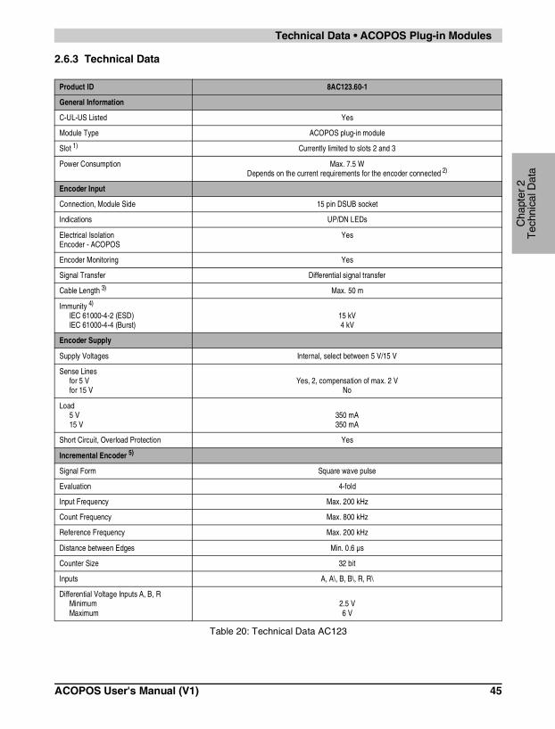
2.6.3 Technical Data
Product ID 8AC123.60-1
General Information
C-UL-US Listed Yes
Module Type ACOPOS plug-in module
Slot 1) Currently limited to slots 2 and 3
Power Consumption Max. 7.5 WDepends on the current requirements for the encoder connected 2)
Encoder Input
Connection, Module Side 15 pin DSUB socket
Indications UP/DN LEDs
Electrical IsolationEncoder - ACOPOS
Yes
Encoder Monitoring Yes
Signal Transfer Differential signal transfer
Cable Length 3) Max. 50 m
Immunity 4)
IEC 61000-4-2 (ESD)IEC 61000-4-4 (Burst)
15 kV4 kV
Encoder Supply
Supply Voltages Internal, select between 5 V/15 V
Sense Linesfor 5 Vfor 15 V
Yes, 2, compensation of max. 2 VNo
Load5 V15 V
350 mA 350 mA
Short Circuit, Overload Protection Yes
Incremental Encoder 5)
Signal Form Square wave pulse
Evaluation 4-fold
Input Frequency Max. 200 kHz
Count Frequency Max. 800 kHz
Reference Frequency Max. 200 kHz
Distance between Edges Min. 0.6 µs
Counter Size 32 bit
Inputs A, A\, B, B\, R, R\
Differential Voltage Inputs A, B, RMinimumMaximum
2.5 V6 V
Table 20: Technical Data AC123
ACOPOS User's Manual (V1) 45

Technical Data • ACOPOS Plug-in Modules
SSI Absolute Encoder
Baud Rate 200 kBaud
Word Size Max. 31 bit
Differential Voltage Clock Output - 120 ΩMinimumMaximum
2.5 V5 V
Differential Voltage Data InputMinimumMaximum
2.5 V6 V
Operational Conditions
Environmental Temperature during Operation
0 to 50 °C
Relative Humidity during Operation 5 to 95 %, non-condensing
Storage and Transport Conditions
Storage Temperature -25 to +55 °C
Relative Humidity for Storage 5 to 95 %, non-condensing
Transport Temperature -25 to +70 °C
Relative Humidity for Transport 95 % at 40 °C, non-condensing
1) Two modules can also be inserted. In this case, the module in slot 2 is automatically used for motor feedback.
2) The power consumption of the plug-in module can be approximated using the following formula:
PModule [W] = PEncoder [W] * k + 0.6 W
The power consumed by the encoder PEncoder is calculated from the selected encoder supply voltage (5 V/15 V) and the currentrequired:
PEncoder [W] = UEncoder [V] * IEncoder [A]
The following values must be used for k:
k = 1.2 (for 15 V encoder supply)k = 1.75 (for 5 V encoder supply)
3) A cable with at least 4 x 2 x 0.14 mm² + 2 x 0.5 mm² is required for the maximum cable length. The sense lines must be used.
4) With shielded cable (single shield) and twisted pair signal lines (e.g. 4 x 2 x 0.14 mm² + 2 x 0.5 mm²). Both screws on the module mustbe tightened!
5) Incremental encoders can be used as motor feedback only for asynchronous motors, but can only provide limited control quality forthis purpose. An encoder with at least 1000 lines must be used for motor feedback.
Product ID 8AC123.60-1
Table 20: Technical Data AC123 (cont.)
46 ACOPOS User's Manual (V1)
Cha
pter
2T
echn
ical
Dat
a
Technical Data • ACOPOS Plug-in Modules
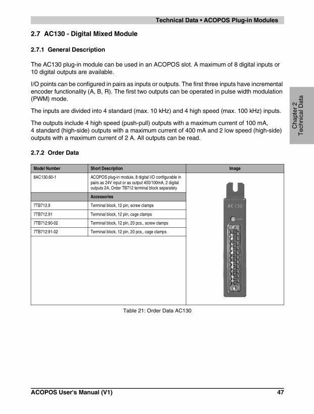
2.7 AC130 - Digital Mixed Module
2.7.1 General Description
The AC130 plug-in module can be used in an ACOPOS slot. A maximum of 8 digital inputs or 10 digital outputs are available.
I/O points can be configured in pairs as inputs or outputs. The first three inputs have incremental encoder functionality (A, B, R). The first two outputs can be operated in pulse width modulation (PWM) mode.
The inputs are divided into 4 standard (max. 10 kHz) and 4 high speed (max. 100 kHz) inputs.
The outputs include 4 high speed (push-pull) outputs with a maximum current of 100 mA, 4 standard (high-side) outputs with a maximum current of 400 mA and 2 low speed (high-side) outputs with a maximum current of 2 A. All outputs can be read.
2.7.2 Order Data
Model Number Short Description Image
8AC130.60-1 ACOPOS plug-in module, 8 digital I/O configurable in pairs as 24V input or as output 400/100mA, 2 digital outputs 2A, Order TB712 terminal block separately
Accessories
7TB712.9 Terminal block, 12 pin, screw clamps
7TB712.91 Terminal block, 12 pin, cage clamps
7TB712:90-02 Terminal block, 12 pin, 20 pcs., screw clamps
7TB712:91-02 Terminal block, 12 pin, 20 pcs., cage clamps
Table 21: Order Data AC130
ACOPOS User's Manual (V1) 47

Technical Data • ACOPOS Plug-in Modules
2.7.3 Technical Data
Product ID 8AC130.60-1
General Information
C-UL-US Listed Yes
Module Type ACOPOS plug-in module
Slot Currently limited to slots 3 and 4
Power Consumption Max. 0.8 W
Inputs/Outputs
Connection, Module Side 12 conductor pin-connector
Configuration of the Inputs/Outputs Configured in pairs as input or output
Indication 24 V - LED
Immunity 1)
IEC 61000-4-2 (ESD)IEC 61000-4-4 (Burst)
15 kV2 kV
Power Supply
Power SupplyMinimumNominalMaximum
18 VDC24 VDC30 VDC
Reverse Polarity Protection Yes
Voltage Monitoring (24 V - LED) Yes, supply voltage >18 V
Inputs
Number of Inputs max. 8
Wiring Sink
Electrical IsolationInput - ACOPOSInput - Input
YesNo
Input VoltageMinimumNominalMaximum
18 VDC24 VDC30 VDC
Switching ThresholdLOWHIGH
< 5 V> 15 V
Input Current at Nominal VoltageInputs 1 - 4Inputs 5 - 8
Approx. 10 mAApprox. 5.5 mA
Switching DelayInputs 1 - 4Inputs 5 - 8
Max. 5 µs Max. 35 µs
Event Counter
Signal Form Square wave pulse
Input Frequency Max. 100 kHz
Table 22: Technical Data AC130
48 ACOPOS User's Manual (V1)

Cha
pter
2T
echn
ical
Dat
a
Technical Data • ACOPOS Plug-in Modules
Counter Size 16 bit
InputsInput 1Input 2
Counter 1Counter 2
Incremental Encoder
Signal Form Square wave pulse
Evaluation 4-fold
Encoder Monitoring No
Input Frequency Max. 62.5 kHz
Count Frequency Max. 250 kHz
Reference Frequency Max. 62.5 kHz
Distance between Edges Min. 2.5 µs
Counter Size 16 bit
InputsInput 1Input 2Input 3
Channel AChannel B
Reference Pulse R
Outputs
Number of Outputs max. 10
TypeOutputs 1 - 4Outputs 5 - 10
Transistor Outputspush-pullhigh-side
Electrical IsolationOutput - ACOPOSOutput - Output
YesNo
Switching VoltageMinimumNominalMaximum
18 VDC24 VDC30 VDC
Continuous CurrentOutputs 1 - 4Outputs 5 - 8Outputs 9 - 10
Max. 100 mA Max. 400 mA
Max. 2 A
Switching DelayOutputs 1 - 4Outputs 5 - 8Outputs 9 - 10
Max. 5 µs Max. 50 µs Max. 500 µs
Switching Frequency (resistive load)Outputs 1 - 2Outputs 3 - 4Outputs 5 - 8Outputs 9 - 10
Max. 10 kHz (max. 20 kHz in PWM mode)Max. 10 kHzMax. 5 kHz
Max. 100 Hz
PWM Outputs 1 - 2Resolution of the Pulse WidthPeriod Duration
13 bit 50 µs - 400 µs
Product ID 8AC130.60-1
Table 22: Technical Data AC130 (cont.)
ACOPOS User's Manual (V1) 49

Technical Data • ACOPOS Plug-in Modules
ProtectionShort Circuit ProtectionOverload Protection
YesYes
Short Circuit Current at 24 V (until cut-off)Outputs 1 - 4Outputs 5 - 8Outputs 9 - 10
Approx. 1 AApprox. 1.2 AApprox. 24 A
Readable Outputs Yes
Operational Conditions
Environmental Temperature during Operation
0 to 50 °C
Relative Humidity during Operation 5 to 95 %, non-condensing
Storage and Transport Conditions
Storage Temperature -25 to +55 °C
Relative Humidity for Storage 5 to 95 %, non-condensing
Transport Temperature -25 to +70 °C
Relative Humidity for Transport 95 % at 40 °C, non-condensing
1) Shielded cables must be used for inputs 1 - 4. Both screws on the module must be tightened!
Product ID 8AC130.60-1
Table 22: Technical Data AC130 (cont.)
50 ACOPOS User's Manual (V1)

Cha
pter
2T
echn
ical
Dat
a
Technical Data • Cables
3. Cables
3.1 General Information
B&R offers the cables for ACOPOS servo drives in six different lengths. All cables can be used for drag chain installations.
To prevent disturbances to encoder signals, the holding brake and temperature sensor wires are in the motor cable and not in the EnDat or resolver cable.
3.1.1 Manufactured Cables
Using the B&R cable guarantees that the EMC limits are not exceeded. The cables are manufactured in the EU and are therefore subject to the strictest quality standards.
Information:
If other cables are used, make sure that they have the same wave parameters. If deviations exist, additional measures are necessary to ensure that EMC guidelines are met.
ACOPOS User's Manual (V1) 51

Technical Data • Cables
3.2 Motor Cables
3.2.1 Order Data
Model Number Short Description Image
Motor Cables 1.5 mm²
8CM005.12-1 Motor cable, length 5m, 4 x 1.5mm² + 2 x 2 x 0.75mm², motor connector 8 pin Intercontec socket, can be used in cable drag chains, UL/CSA listed
8CM007.12-1 Motor cable, length 7m, 4 x 1.5mm² + 2 x 2 x 0.75mm², motor connector 8 pin Intercontec socket, can be used in cable drag chains, UL/CSA listed
8CM010.12-1 Motor cable, length 10m, 4 x 1.5mm² + 2 x 2 x 0.75mm², motor connector 8 pin Intercontec socket, can be used in cable drag chains, UL/CSA listed
8CM015.12-1 Motor cable, length 15m, 4 x 1.5mm² + 2 x 2 x 0.75mm², motor connector 8 pin Intercontec socket, can be used in cable drag chains, UL/CSA listed
8CM020.12-1 Motor cable, length 20m, 4 x 1.5mm² + 2 x 2 x 0.75mm², motor connector 8 pin Intercontec socket, can be used in cable drag chains, UL/CSA listed
8CM025.12-1 Motor cable, length 25m, 4 x 1.5mm² + 2 x 2 x 0.75mm², motor connector 8 pin Intercontec socket, can be used in cable drag chains, UL/CSA listed
Motor Cables 4 mm²
8CM005.12-3 Motor cable, length 5m, 4 x 4mm² + 2 x 2 x 1mm², motor connector 8 pin Intercontec socket, can be used in cable drag chains, UL/CSA listed
8CM007.12-3 Motor cable, length 7m, 4 x 4mm² + 2 x 2 x 1mm², motor connector 8 pin Intercontec socket, can be used in cable drag chains, UL/CSA listed
8CM010.12-3 Motor cable, length 10m, 4 x 4mm² + 2 x 2 x 1mm², motor connector 8 pin Intercontec socket, can be used in cable drag chains, UL/CSA listed
8CM015.12-3 Motor cable, length 15m, 4 x 4mm² + 2 x 2 x 1mm², motor connector 8 pin Intercontec socket, can be used in cable drag chains, UL/CSA listed
8CM020.12-3 Motor cable, length 20m, 4 x 4mm² + 2 x 2 x 1mm², motor connector 8 pin Intercontec socket, can be used in cable drag chains, UL/CSA listed
8CM025.12-3 Motor cable, length 25m, 4 x 4mm² + 2 x 2 x 1mm², motor connector 8 pin Intercontec socket, can be used in cable drag chains, UL/CSA listed
Table 23: Order Data Motor Cables
52 ACOPOS User's Manual (V1)

Cha
pter
2T
echn
ical
Dat
a
Technical Data • Cables
Motor Cables 10 mm²
8CM005.12-5 Motor cable, length 5m, 4 x 10mm² + 2 x 2 x 1.5mm², motor connector 8 pin Intercontec socket, can be used in cable drag chains, UL/CSA listed
8CM007.12-5 Motor cable, length 7m, 4 x 10mm² + 2 x 2 x 1.5mm², motor connector 8 pin Intercontec socket, can be used in cable drag chains, UL/CSA listed
8CM010.12-5 Motor cable, length 10m, 4 x 10mm² + 2 x 2 x 1.5mm², motor connector 8 pin Intercontec socket, can be used in cable drag chains, UL/CSA listed
8CM015.12-5 Motor cable, length 15m, 4 x 10mm² + 2 x 2 x 1.5mm², motor connector 8 pin Intercontec socket, can be used in cable drag chains, UL/CSA listed
8CM020.12-5 Motor cable, length 20m, 4 x 10mm² + 2 x 2 x 1.5mm², motor connector 8 pin Intercontec socket, can be used in cable drag chains, UL/CSA listed
8CM025.12-5 Motor cable, length 25m, 4 x 10mm² + 2 x 2 x 1.5mm², motor connector 8 pin Intercontec socket, can be used in cable drag chains, UL/CSA listed
Motor Cables 35 mm²
8CM005.12-8 Motor cable, length 5m, 4 x 35mm² + 2 x 2 x 1.5mm², can be used in cable drag chains, UL/CSA listed
8CM007.12-8 Motor cable, length 7m, 4 x 35mm² + 2 x 2 x 1.5mm², can be used in cable drag chains, UL/CSA listed
8CM010.12-8 Motor cable, length 10m, 4 x 35mm² + 2 x 2 x 1.5mm², can be used in cable drag chains, UL/CSA listed
8CM015.12-8 Motor cable, length 15m, 4 x 35mm² + 2 x 2 x 1.5mm², can be used in cable drag chains, UL/CSA listed
8CM020.12-8 Motor cable, length 20m, 4 x 35mm² + 2 x 2 x 1.5mm², can be used in cable drag chains, UL/CSA listed
8CM025.12-8 Motor cable, length 25m, 4 x 35mm² + 2 x 2 x 1.5mm², can be used in cable drag chains, UL/CSA listed
Model Number Short Description Image
Table 23: Order Data Motor Cables (cont.)
ACOPOS User's Manual (V1) 53

Technical Data • Cables
3.2.2 Cable Specification
Product ID Motor Cables 1.5 mm² Motor Cables 4 mm²
General Information
Cable Cross Section 4 x 1.5 mm² + 2 x 2 x 0.75 mm² 4 x 4 mm² + 2 x 2 x 1 mm²
Durability Oil resistant according to VDE 0472 part 803, as well as standard hydraulic oil
Certification UL AWM Style 20669, 90 °C, 600 V, E63216 and CSA AWM I/II A/B, 90 °C, 600 V, FT1 LL46064
Conductor
Power Lines 1.5 mm², tinned Cu wire 4 mm², tinned Cu wire
Wire InsulationWire Colors
Special thermoplastic materialBlack, brown, blue, yellow/green
Signal Lines 0.75 mm², tinned Cu wire 1 mm², tinned Cu wire
Wire InsulationWire Colors
Special thermoplastic materialWhite, white/red, white/blue, white/green
Cable Construction
Power LinesStrandingShield
NoNo
Signal LinesStrandingShield
White with white/red and white/blue with white/greenSeparate shielding for pairs, tinned Cu mesh, optical coverage >85 % and foil banding
Cable Stranding With filler elements and foil banding
Cable Shielding Tinned Cu mesh, optical coverage >85 % and wrapped in isolating fabric
Outer SheathingMaterialColor
PUROrange, similar to RAL 2003 flat
Labeling BERNECKER + RAINER 4x1.5+2x2x0.75 FLEX BERNECKER + RAINER 4x4.0+2x2x1.5 FLEX
Electrical Characteristics
Conductor ResistancePower LinesSignal Lines
≤ 14 Ω/km≤ 29 Ω/km
≤ 5.2 Ω/km≤ 14 Ω/km
Insulation Resistance >200 MΩ per km
Isolation VoltageWire/wireWire/shield
3 kV1 kV
Operating Voltage Max. 600 V
Mechanical Characteristics
Temperature RangeMovingStill
-10 °C to 70 °C-20 °C to 90 °C
Outer Diameter 12.8 mm ±0,4 mm 15.8 mm ±0.5 mm
Flex Radius > 96 mm > 118.5 mm
Speed ≤ 4 m/s
Acceleration <60 m/s²
Table 24: Cable specifications for 1.5 and 4 mm² motor cables
54 ACOPOS User's Manual (V1)

Cha
pter
2T
echn
ical
Dat
a
Technical Data • Cables
Flex Cycles ≥3,000,000
Weight 0.26 kg/m 0.45 kg/m
Product ID Motor Cables 10 mm² Motor Cables 35 mm²
General Information
Cable Cross Section 4 x 10 mm² + 2 x 2 x 1.5 mm² 4 x 35 mm² + 2 x 2 x 1.5 mm²
Durability Oil resistant according to VDE 0472 part 803, as well as standard hydraulic oil
Certification UL AWM Style 20669, 90 °C, 600 V, E63216 and CSA AWM I/II A/B, 90 °C, 600 V, FT1 LL46064
Conductor
Power Lines 10 mm², tinned Cu wire 35 mm², tinned Cu wire
Wire InsulationWire Colors
Special thermoplastic materialBlack, brown, blue, yellow/green
Signal LinesWire InsulationWire Colors
1.5 mm², tinned Cu wireSpecial thermoplastic material
White, white/red, white/blue, white/green
Cable Construction
Power LinesStrandingShield
NoNo
Signal LinesStrandingShield
White with white/red and white/blue with white/greenSeparate shielding for pairs, tinned Cu mesh, optical coverage >85 % and foil banding
Cable Stranding With filler elements and foil banding
Cable Shielding Tinned Cu mesh, optical coverage >85 % and wrapped in isolating fabric
Outer SheathingMaterialColor
PUROrange, similar to RAL 2003 flat
Labeling BERNECKER + RAINER 4x10.0+2x2x1.5 FLEX BERNECKER + RAINER 4x35.0+2x2x1.5 FLEX
Electrical Characteristics
Conductor ResistancePower LinesSignal Lines
≤ 2.1 Ω/km≤ 14 Ω/km
≤ 0.6 Ω/km≤ 14 Ω/km
Insulation Resistance >200 MΩ per km
Isolation VoltageWire/wireWire/shield
3 kV1 kV
Operating Voltage Max. 600 V
Table 25: Cable specifications for 10 and 35 mm² motor cables
Product ID Motor Cables 1.5 mm² Motor Cables 4 mm²
Table 24: Cable specifications for 1.5 and 4 mm² motor cables (cont.)
ACOPOS User's Manual (V1) 55

Technical Data • Cables
Mechanical Characteristics
Temperature RangeMovingStill
-10 °C to 70 °C-20 °C to 90 °C
Outer Diameter 20.1 mm ±0.7 mm 32.5 mm ±1 mm
Flex Radius > 150.8 mm > 243.8 mm
Speed ≤ 4 m/s
Acceleration <60 m/s²
Flex Cycles ≥3,000,000
Weight 0.77 kg/m 2.2 kg/m
Product ID Motor Cables 10 mm² Motor Cables 35 mm²
Table 25: Cable specifications for 10 and 35 mm² motor cables (cont.)
56 ACOPOS User's Manual (V1)

Cha
pter
2T
echn
ical
Dat
a
Technical Data • Cables
3.3 EnDat Cables
3.3.1 Order Data
3.3.2 Cable Specification
Model Number Short Description Image
8CE005.12-1 EnDat cable, length 5m, 10 x 0.14mm² + 2 x 0.5mm², EnDat connector 17 pin Intercontec socket, servo connector 15 pin DSUB plug, can be used in cable drag chains, UL/CSA listed
8CE007.12-1 EnDat cable, length 7m, 10 x 0.14mm² + 2 x 0.5mm², EnDat connector 17 pin Intercontec socket, servo connector 15 pin DSUB plug, can be used in cable drag chains, UL/CSA listed
8CE010.12-1 EnDat cable, length 10m, 10 x 0.14mm² + 2 x 0.5mm², EnDat connector 17 pin Intercontec socket, servo connector 15 pin DSUB plug, can be used in cable drag chains, UL/CSA listed
8CE015.12-1 EnDat cable, length 15m, 10 x 0.14mm² + 2 x 0.5mm², EnDat connector 17 pin Intercontec socket, servo connector 15 pin DSUB plug, can be used in cable drag chains, UL/CSA listed
8CE020.12-1 EnDat cable, length 20m, 10 x 0.14mm² + 2 x 0.5mm², EnDat connector 17 pin Intercontec socket, servo connector 15 pin DSUB plug, can be used in cable drag chains, UL/CSA listed
8CE025.12-1 EnDat cable, length 25m, 10 x 0.14mm² + 2 x 0.5mm², EnDat connector 17 pin Intercontec socket, servo connector 15 pin DSUB plug, can be used in cable drag chains, UL/CSA listed
Table 26: Order Data EnDat Cables
Product ID EnDat Cables
General Information
Cable Cross Section 10 x 0.14 mm² + 2 x 0.50 mm²
Durability Oil resistant according to VDE 0472 part 803, as well as standard hydraulic oil
Certification UL AWM Style 20963, 80 °C, 30 V, E63216 and CSA AWM I/II A/B, 90 °C, 30 V, FT1 LL46064
Conductor
Signal LinesWire InsulationWire Colors
0.14 mm², tinned Cu wireSpecial thermoplastic material
Blue, brown, yellow, gray, green, pink, red, black, violet, white
Supply LinesWire InsulationWire Colors
0.5 mm², tinned Cu wireSpecial thermoplastic material
White/green, white/red
Table 27: Cable specifications for EnDat cables
ACOPOS User's Manual (V1) 57

Technical Data • Cables
Cable Construction
Signal LinesStrandingShield
NoNo
Supply LinesStrandingShield
White/red with white/green and filler elementsNo
Cable Stranding with foil banding
Cable Shielding Cu mesh, optical coverage >85 % and wrapped in isolating fabric
Outer SheathingMaterialColorLabeling
PUROrange, similar to RAL 2003 flat
BERNECKER + RAINER 10x0.14+2x0.50 FLEX
Electrical Characteristics
Conductor ResistanceSignal LinesSupply Lines
≤ 140 Ω/km≤ 40 Ω/km
Insulation Resistance >200 MΩ per km
Isolation VoltageWire/wireWire/shield
1.5 kV0.8 kV
Operating Voltage Max. 30 V
Mechanical Characteristics
Temperature RangeMovingStill
-10 °C to 70 °C-20 °C to 90 °C
Outer Diameter 7.3 mm ±0.25 mm
Flex Radius > 55 mm
Speed ≤ 4 m/s
Acceleration <60 m/s²
Flex Cycles ≥3,000,000
Weight 0.08 kg/m
Product ID EnDat Cables
Table 27: Cable specifications for EnDat cables (cont.)
58 ACOPOS User's Manual (V1)

Cha
pter
2T
echn
ical
Dat
a
Technical Data • Cables
3.4 Resolver Cables
3.4.1 Order Data
Model Number Short Description Image
8CR005.12-1 Resolver cable, length 5m, 3 x 2 x 24 AWG/19, resolver connector 12 pin Intercontec socket, servo connector 9 pin DSUB plug, can be used in cable drag chains, UL/CSA listed
8CR007.12-1 Resolver cable, length 7m, 3 x 2 x 24 AWG/19, resolver connector 12 pin Intercontec socket, servo connector 9 pin DSUB plug, can be used in cable drag chains, UL/CSA listed
8CR010.12-1 Resolver cable, length 10m, 3 x 2 x 24 AWG/19, resolver connector 12 pin Intercontec socket, servo connector 9 pin DSUB plug, can be used in cable drag chains, UL/CSA listed
8CR015.12-1 Resolver cable, length 15m, 3 x 2 x 24 AWG/19, resolver connector 12 pin Intercontec socket, servo connector 9 pin DSUB plug, can be used in cable drag chains, UL/CSA listed
8CR020.12-1 Resolver cable, length 20m, 3 x 2 x 24 AWG/19, resolver connector 12 pin Intercontec socket, servo connector 9 pin DSUB plug, can be used in cable drag chains, UL/CSA listed
8CR025.12-1 Resolver cable, length 25m, 3 x 2 x 24 AWG/19, resolver connector 12 pin Intercontec socket, servo connector 9 pin DSUB plug, can be used in cable drag chains, UL/CSA listed
Table 28: Order Data Resolver Cables
ACOPOS User's Manual (V1) 59

Technical Data • Cables
3.4.2 Cable Specification
Product ID Resolver Cables
General Information
Cable Cross Section 3 x 2 x 24 AWG/19
Durability Oil resistant according to VDE 0472 part 803, as well as standard hydraulic oil
Certification UL AWM Style 20671, 90 °C, 30 V, E63216 and CSA AWM, 90 °C, 30 V, I/II A/B FT1 LL46064
Conductor
Signal LinesWire InsulationWire Colors
24 AWG/19, tinned Cu wireSpecial thermoplastic material
White, brown, green, yellow, gray, pink
Cable Construction
Signal LinesStrandingShield
White with brown, green with yellow, gray with pinkNo
Cable Stranding The 3 pairs together covered by foil banding
Cable Shielding Cu mesh, optical coverage ≥90 % and wrapped in isolating fabric
Outer SheathingMaterialColorLabeling
PUROrange, similar to RAL 2003 flat
BERNECKER + RAINER 3x2x24 AWG FLEX
Electrical Characteristics
Conductor Resistance 24 AWG ≤ 86 Ω/km
Insulation Resistance >200 MΩ per km
Isolation VoltageWire/wireWire/shield
1.5 kV0.8 kV
Operating Voltage Max. 30 V
Mechanical Characteristics
Temperature RangeMovingStill
-10 °C to 80 °C-40 °C to 90 °C
Outer Diameter 6.5 mm ±0.2 mm
Flex Radius ≥50 mm
Speed ≤ 4 m/s
Acceleration <60 m/s²
Flex Cycles ≥3,000,000
Weight 0.07 kg/m
Table 29: Cable specifications for resolver cables
60 ACOPOS User's Manual (V1)

Cha
pter
2T
echn
ical
Dat
a
Technical Data • Connectors
4. Connectors
4.1 General Information
B&R offers five different motor/encoder connectors for AC servo motors. All connectors have IP67 protection. The metallic housing provides a protective ground connection on the housing according to VDE 0627. All plastic used in the connector is UL94/V0 listed. High quality, gold plated cage connector contacts guarantee a high level of contact security even when reinserted many times.
Using the B&R connector guarantees that the EMC limits for the connection are not exceeded. Make sure that connectors are put together correctly including a proper shield connection.
ACOPOS User's Manual (V1) 61

Technical Data • Connectors
4.2 Motor Connectors
4.2.1 Order Data
Model Number Short Description Image
Cable Diameter 9 - 17 mm
8PM001.00-1 Motor connector 8 pin Intercontec socket, crimp range 4 x 0.5-2.5mm² + 4 x 0.06-1.0mm², for cable ø 9-14mm, IP67, UL/CSA listed
8PM002.00-1 Motor connector 8 pin Intercontec socket, crimp range 4 x 0.5-4.0mm² + 4 x 0.06-1.0mm², for cable ø 14-17mm, IP67, UL/CSA listed
Cable Diameter 17 - 26 mm
8PM003.00-1 Motor connector 8 pin Intercontec socket, crimp range 4 x 1.5-10mm² + 4 x 0.5-2.5mm², for cable ø 17-26mm, IP67, UL/CSA listed
Table 30: Order data for motor connectors
62 ACOPOS User's Manual (V1)

Cha
pter
2T
echn
ical
Dat
a
Technical Data • Connectors
4.2.2 Specifications for 8PM001.00-1 and 8PM002.00-1
Product ID 8PM001.00-1 8PM002.00-1
General Information
Contacts 8 (4 power and 4 signal contacts)
Degree of Pollution 3
Installation Altitude up to 4,000 m
Insulator PA, UL94/V0 listed
Contacts Gold plated brass
Protective Ground Connection on Housing According to VDE 0627
Protection according to DIN 40050 IP67 when connected
Certifications UL/CSA
Electrical Characteristics
Overvoltage Category 3
Power ContactsNominal CurrentNominal VoltageIsolation Voltage (L-L)Contact Resistance
25 A800 VAC / VDC
6000 V<3 mΩ
Signal ContactsNominal CurrentNominal VoltageIsolation Voltage (L-L)Contact Resistance
9 A250 VAC / VDC
2500 V<5 mΩ
Mechanical Characteristics
Temperature Range -40 °C to 125 °C
Housing Material Zinc casting, nickel plated
Gaskets Viton, H-NBR
Crimp Range 4 x 0.5 - 2.5 mm² + 4 x 0.06 - 1 mm² 4 x 0.5 - 4 mm² + 4 x 0.06 - 1 mm²
Cable ø 9 - 14 mm 14 - 17 mm
Manufacturer Information
ManufacturerInternet Address
INTERCONTEChttp://www.intercontec.com
Manufacturer’s Product ID BSTA 108 FR 19 08 0006 000 BSTA 108 FR 35 16 0006 000
Table 31: Specifications for motor connectors 8PM001.00-1 and 8PM002.00-1
ACOPOS User's Manual (V1) 63

Technical Data • Connectors
4.2.3 Specifications for 8PM003.00-1
Product ID 8PM003.00-1
General Information
Contacts 8 (4 power and 4 signal contacts)
Degree of Pollution 3
Installation Altitude up to 4,000 m
Insulator PA, UL94/V0 listed
Contacts Gold plated brass
Protective Ground Connection on Housing According to VDE 0627
Protection according to DIN 40050 IP67 when connected
Certifications UL/CSA
Electrical Characteristics
Overvoltage Category 3
Power ContactsNominal CurrentNominal VoltageIsolation Voltage (L-L)Contact Resistance
75 A630 VAC / VDC
6000 V<1 mΩ
Signal ContactsNominal CurrentNominal VoltageIsolation Voltage (L-L)Contact Resistance
30 A250 VAC / VDC
4000 V<3 mΩ
Mechanical Characteristics
Temperature Range -40 °C to 130 °C
Housing Material Aluminum, nickel plated
Gaskets Viton
Crimp Range 4 x 1.5 - 10 mm² + 4 x 0.5 - 2.5 mm²
Cable ø 17 - 26 mm
Manufacturer Information
ManufacturerInternet Address
INTERCONTEChttp://www.intercontec.com
Manufacturer’s Product ID CSTA 264 FR 48 25 0001 000
Table 32: Specifications for motor connector 8PM003.00-1
64 ACOPOS User's Manual (V1)

Cha
pter
2T
echn
ical
Dat
a
Technical Data • Connectors
4.3 Encoder Connectors
4.3.1 Order Data
Model Number Short Description Image
EnDat Connector
8PE001.00-1 EnDat Connector 17 pin Intercontec socket, crimp range 17 x 0.06-1,0mm², for cable ø 9-12mm, IP67, UL/CSA listed
Resolver Connector
8PR001.00-1 Resolver connector 12 pin Intercontec socket, crimp range 12 x 0.06-1,0mm², for cable ø 5.5-10.5mm, IP67, UL/CSA listed
Table 33: Order data for encoder connectors
ACOPOS User's Manual (V1) 65

Technical Data • Connectors
4.3.2 Specifications for EnDat Connector 8PE001.00-1
Product ID 8PE001.00-1
General Information
Contacts 17 signal contacts
Degree of Pollution 3
Installation Altitude up to 2,000 m
Insulator PBT, UL94/V0 listed
Contacts Gold plated brass
Protective Ground Connection on Housing According to VDE 0627
Protection according to DIN 40050 IP67 when connected
Certifications UL/CSA
Electrical Characteristics
Signal ContactsNominal CurrentNominal VoltageIsolation Voltage (L-L)Contact Resistance
9 A32 V
1500 V<5 mΩ
Mechanical Characteristics
Temperature Range -40 °C to 125 °C
Housing Material Zinc casting, nickel plated
Gaskets Viton, H-NBR
Crimp Range 17 x 0.06 - 1 mm²
Cable ø 9 - 12 mm
Manufacturer Information
ManufacturerInternet Address
INTERCONTEChttp://www.intercontec.com
Manufacturer’s Product ID ASTA 035 FR 11 12 0005 000
Table 34: Specifications for EnDat Connector 8PE001.00-1
66 ACOPOS User's Manual (V1)

Cha
pter
2T
echn
ical
Dat
a
Technical Data • Connectors
4.3.3 Specifications for Resolver Connector 8PR001.00-1
Product ID 8PR001.00-1
General Information
Contacts 12 signal contacts
Degree of Pollution 3
Installation Altitude up to 2,000 m
Insulator PBT, UL94/V0 listed
Contacts Gold plated brass
Protective Ground Connection on Housing According to VDE 0627
Protection according to DIN 40050 IP67 when connected
Certifications UL/CSA
Electrical Characteristics
Signal ContactsNominal CurrentNominal VoltageIsolation Voltage (L-L)Contact Resistance
9 A160 V2500 V<5 mΩ
Mechanical Characteristics
Temperature Range -40 °C to 125 °C
Housing Material Zinc casting, nickel plated
Gaskets Viton, H-NBR
Crimp Range 12 x 0.06 - 1 mm²
Cable ø 5.5 - 10.5 mm
Manufacturer Information
ManufacturerInternet Address
INTERCONTEChttp://www.intercontec.com
Manufacturer’s Product ID ASTA 021 FR 11 10 0005 000
Table 35: Specifications for Resolver Connector 8PR001.00-1
ACOPOS User's Manual (V1) 67

Technical Data • Connectors
68 ACOPOS User's Manual (V1)

Cha
pter
3In
stal
latio
n
Installation • General Information
CHAPTER 3 • INSTALLATION
1. General Information
Make sure that installation takes place on a flat surface which is correctly dimensioned. The dimensional diagram lists the number and type of mounting screws to be used.
The ring screws contained in the delivery can be attached to the device to lift ACOPOS 1640 and ACOPOS 128M drives:
Figure 9: Attaching the ring screws contained in the delivery to ACOPOS 1640 and 128M drives
ACOPOS User's Manual (V1) 69

Installation • General Information
ACOPOS servo drives can only be installed in an environment which corresponds to pollution degree II (non-conductive material). When installing the device, make sure that the maximum operating temperature (40 °C) is not exceeded and IP20 protection is provided as specified in the technical data.
For proper air circulation, at least 80 mm has to be left free above and below the ACOPOS servo drive. ACOPOS servo drives can be mounted directly next to each other; the required distance between devices can be found in the respective dimensional diagram.
70 ACOPOS User's Manual (V1)

Cha
pter
3In
stal
latio
n
Installation • Dimensional Diagram and Installation Dimensions
2. Dimensional Diagram and Installation Dimensions
2.1 ACOPOS 1022, 1045, 1090
1) For proper air circulation, at least 80 mm has to be left free above and below the ACOPOS servo drive.
Figure 10: Dimensional diagram and installation dimensions for ACOPOS 1022, 1045, 1090
ACOPOS User's Manual (V1) 71

Installation • Dimensional Diagram and Installation Dimensions
2.2 ACOPOS 1640
1) For proper air circulation, at least 80 mm has to be left free above and below the ACOPOS servo drive. Approximately 160 mm free space is required under the ACOPOS servo drive to prevent cabling problems.
Figure 11: Dimensional diagram and installation dimensions for ACOPOS 1640
72 ACOPOS User's Manual (V1)

Cha
pter
3In
stal
latio
n
Installation • Dimensional Diagram and Installation Dimensions
2.3 ACOPOS 128M
1) For proper air circulation, at least 80 mm has to be left free above and below the ACOPOS servo drive. Approximately 160 mm free space is required under the ACOPOS servo drive to prevent cabling problems.
Figure 12: Dimensional diagram and installation dimensions for ACOPOS 128M
ACOPOS User's Manual (V1) 73

Installation • Installation and Removal of Plug-in Modules
3. Installation and Removal of Plug-in Modules
3.1 General Information
All ACOPOS servo drives are equipped with four slots for plug-in modules. At present, the following module arrangements must be used:
3.1.1 Installation
1) Disconnect the ACOPOS servo drive from the power mains and prevent reconnection.
2) Switch off 24 VDC supply voltage.
3) Remove screw from the bottom of the slot cover.
4) Loosen screw on the front (don't remove it completely, the screw could fall into the ACOPOS servo drive!).
Plug-in Module Operation Possible in this Slot
1 2 3 4
8AC110.60-2 x x x
8AC120.60-1 x x
8AC122.60-1 x x
8AC123.60-1 x x
8AC130.60-1 x x
Table 36: Slot overview for ACOPOS plug-in modules
Caution!• Keep the plug-in modules in the original packaging and only take them out
immediately before installation.
• Avoid touching the plug-in modules anywhere but on the front cover.
• Take the necessary steps to protect against electrostatic discharges.
74 ACOPOS User's Manual (V1)

Cha
pter
3In
stal
latio
n
Installation • Installation and Removal of Plug-in Modules
5) Remove slot cover.
6) Insert plug-in module in the free slot (see diagram shown above).
7) Fasten the plug-in module with the two screws.
8) Switch on 24 VDC supply voltage.
9) Connect ACOPOS servo drive to the power mains.
3.1.2 Removal
1) Disconnect the ACOPOS servo drive from the power mains and prevent reconnection.
2) Switch off 24 VDC supply voltage.
3) Remove screw from the bottom of the plug-in module.
4) Loosen screw on the front (don't remove it completely, the screw could fall into the ACOPOS servo drive!).
5) Remove plug-in module.
6) Insert slot cover in free slot.
7) Fasten the slot cover with the two screws.
8) Switch on 24 VDC supply voltage.
9) Connect ACOPOS servo drive to the power mains.
Figure 13: Installing ACOPOS plug-in modules
ACOPOS User's Manual (V1) 75

Installation • Installing Various ACOPOS Series Devices Directly Next to Each Other
4. Installing Various ACOPOS Series Devices Directly Next to Each Other
When installing various ACOPOS series devices directly next to each other, we recommend aligning the vertical position so that the LED displays of the respective devices are lined up.
You can see from the image above that the vertical offset of the upper mounting holes is 10 mm. The distances for the lower mounting holes and the number and size of the screws required can be taken from the dimensional diagrams for the respective ACOPOS servo drives.
Figure 14: Installing various ACOPOS series devices directly next to each other
76 ACOPOS User's Manual (V1)

Cha
pter
3In
stal
latio
n
Installation • Installing Various ACOPOS Series Devices Directly Next to Each Other
Overview of the vertical offsets:
Installed next toACOPOS
1022 1045 1090 1640 128M
ACOPOS
1022
No offset 10 mm1045
1090
164010 mm No offset
128M
Table 37: Overview of the vertical offsets (ACOPOS - ACOPOS)
ACOPOS User's Manual (V1) 77

Installation • Using Cooling Aggregates in Switching Cabinets
5. Using Cooling Aggregates in Switching Cabinets
To prevent exceeding the required environmental temperatures, it may be necessary to cool the air inside of a switching cabinet.
Make sure that only well sealed switching cabinets are used (condensation caused by outside air entering the switching cabinet).
During operation with the switching cabinet doors open (e.g. service), the ACOPOS servo drives are not allowed to be cooler than the air in the switching cabinet at any time after the doors are closed.
To keep the temperature of the ACOPOS servo drives and the switching cabinet at the same level, the cooling aggregate must remain in operation even when the system is switched off.
Cooling aggregates must be installed in a way that prevents condensation from dripping into the ACOPOS servo drives. This should be considered when selecting the switching cabinet (special construction for use of cooling aggregates on top of the switching cabinet).
Also make sure that condensed water which forms in the cooling aggregate fan when it is switched off cannot sprinkle into the ACOPOS servo drives.
Make sure the temperature setting of the cooling aggregates is correct!
Caution!
Incorrect installation of cooling aggregates may cause condensation which can damage the ACOPOS servo drives installed there!
Condensation can enter the ACOPOS servo drives with the cooled air stream!
78 ACOPOS User's Manual (V1)

Cha
pter
3In
stal
latio
n
Installation • Using Cooling Aggregates in Switching Cabinets
Cooling aggregate on top of the switching cabinet
Figure 15: Cooling aggregate on top of the switching cabinet
ACOPOS User's Manual (V1) 79

Installation • Using Cooling Aggregates in Switching Cabinets
Cooling aggregate on the front of the switching cabinet
Figure 16: Cooling aggregate on the front of the switching cabinet
80 ACOPOS User's Manual (V1)

Cha
pter
4D
imen
sion
ing
Dimensioning • Power Mains Connection
CHAPTER 4 • DIMENSIONING
1. Power Mains Connection
1.1 General Information
1.1.1 System Configuration
The power mains connection is made using terminals X3 / L1, L2, L3 and PE. The ACOPOS servo drives can be directly connected to TT and TN systems (these are three-phase systems with grounded neutral).
When using ungrounded IT systems (three-phase systems without grounded neutral), isolation transformers must be used. The secondary neutral must be grounded and connected to the ACOPOS protective ground conductor. In this way, it is possible to prevent overvoltages between external conductors and the ACOPOS housing. Three-phase isolation transformers with the corresponding input and output voltages and a vector group with secondary neutral can be used (e.g. 3 x 400 V / 3 x 400 V, Dyn3).
1.1.2 Supply Voltage Range
The permissible supply voltage range for ACOPOS servo drives is 3 x 400 VAC to 3 x 480 VAC ±10 %. Respective intermediate transformers must be used for other supply voltages. With grounded power mains, autotransformers can also be used to adjust the voltage. Neutral does not have to be connected for this type of transformer.
Danger!The ACOPOS servo drives are only allowed to be operated directly on grounded, three-phase industrial mains (TN, TT systems). When using the servo drives in living areas, shops and small businesses, additional filtering measures must be implemented by the user.
ACOPOS User's Manual (V1) 81

Dimensioning • Power Mains Connection
1.1.3 Protective Ground Connection (PE)
The following information concerning the protective ground connection corresponds to IEC 61800-5 (draft), Item 3.2.5.3 "Connection elements for the protective ground conductor" and must be followed.
Wire Cross Section
The wire cross section for the protective ground conductor is oriented to the external conductors and must be selected according to the following table:
Increased Discharge Current
ACOPOS servo drives are devices with increased discharge current (larger than 3.5 mA AC or 10 mA DC). Therefore a fixed (immobile) protective ground connection is required on the servo drives.
The following conditions must be met, depending on the ACOPOS device being used:
Wire Cross Section for External Line A Minimum Wire Cross Section for Protective Ground Connection APE
[mm²] [mm²]
A ≤ 16 A
16 < A ≤ 35 16
35 < A A / 2
Table 38: Selection of the protective ground conductor cross section
ACOPOS Conditions Image
102210451090
In addition to the connection of the first protective ground conductor on terminal X3 / PE, a second protective ground conductor with the same cross section must be connected on the designated terminal (threaded bolt M4).
1640128M
The cross section of the protective ground conductor connected to terminal X3 / PE must be at least 10 mm² Cu.
Table 39: Protective ground conditions according to ACOPOS device
82 ACOPOS User's Manual (V1)

Cha
pter
4D
imen
sion
ing
Dimensioning • Power Mains Connection
1.2 Dimensioning
In general, dimensioning the power mains, the overcurrent protection and the line contactors depend on the structure of the power mains connection. The ACOPOS servo drives can be connected individually (each drive has separate overcurrent protection and, if necessary, a separate line contactor) or together in groups.
1.2.1 Individual ACOPOS Power Mains Connections
The structure of an individual power mains connection with line contactor and circuit breaker can be seen in the following diagram:
Figure 17: Circuit diagram for ACOPOS X3, individual power mains connection
ACOPOS User's Manual (V1) 83

Dimensioning • Power Mains Connection
Dimensioning the Power Mains and Overcurrent Protection
The cross section of the power mains and the rated current for overcurrent protection should be dimensioned for the average current load to be expected.
The power mains are to be equipped with overcurrent protection in the form of a circuit breaker or a fuse. Circuit breakers (time lag) with type C tripping characteristics (according to IEC 60898) or fuses (time lag) with type gM tripping characteristics (according to IEC60269-1) are to be used. 1)
The average current load to be expected can be calculated as follows:
The apparent power S can be calculated as follows:
2)
1) Circuit breakers are available on the market with rated currents from 6 A to 63 A. Outside of this range, fuses must be used.
2) If information concerning load torque, inertia and friction are available, the effective torque is calculated as follows:
If the motor is dimensioned correctly, the nominal torque for the selected motor can also be used here.
ACOPOS k
1022 2.8
1045 2.4
1090 2.4
1640 1.7
128M 1.5
Table 40: Constant k
Imains A[ ] S VA[ ]3 Umains V[ ]⋅
---------------------------------------=
S VA[ ] Meff Nm[ ] k2 π naver min 1–[ ]⋅ ⋅
60--------------------------------------------------⋅ ⋅=
Meff Nm[ ] 1Tcycle s[ ]----------------------- Mi Nm[ ]2 ti s[ ]⋅
i∑=
84 ACOPOS User's Manual (V1)

Cha
pter
4D
imen
sion
ing
Dimensioning • Power Mains Connection
The cross section of the power mains and the rated current of the overcurrent protection used are chosen according to Table 41, "Maximum current load for PVC insulated three-phase cables or individual wires", on page 85 so that the maximum current load for the cable cross section selected is greater than or equal to the calculated mains current.
The rated current of the overcurrent protection must be less than or equal to the maximum current load for the cable cross section selected (see Table 41, "Maximum current load for PVC insulated three-phase cables or individual wires", on page 85).
The following table shows the maximum current load of PVC insulated three-phase cables (or three current-carrying wires) according to IEC60204-1 at 40 °C environmental temperature 1) and 70 °C maximum conductor temperature (maximum current load for installation type F and cross sections greater than 35 mm², IEC60364-5-523 is used for installation types B1 and B2).
1) The maximum current load value in IEC60204-1 is for an environmental temperature of 40 °C. In IEC60364-5-523, this reference temperature is 30 °C. The values in Table 41, "Maximum current load for PVC insulated three-phase cables or individual wires", on page 85 from IEC60364-5-523 are calculated with the factor kTemp = 0.87 given in the standard and also at 40 °C.
Installation Types
Wire Cross Section Three individual wires in insulating conduit or cable
duct
Three-phase cable in insulating
conduit or cable duct
Three-phase cable on walls
Three-phase cable in a cable tray
Three individual wires in a cable tray
B1 B2 C E F
Maximum current load for the cable cross section IZ / rated current for the overcurrent protection IR
[mm²] [A]
1,5 13.5 / 13 12.2 / 10 15.2 / 13 16.1 / 16 ---
2,5 18.3 / 16 16.5 /16 21 / 20 22 / 20 ---
4 25 / 25 23 / 16 28 / 25 30 / 25 ---
6 32 / 32 29 / 25 36 / 32 37 / 32 ---
10 44 / 32 40 / 32 50 / 50 52 / 50 ---
16 60 / 50 53 / 63 66 / 63 70 / 63 ---
25 77 / 63 67 / 63 84 / 80 88 / 80 96 / 80
35 97 / 80 83 / 80 104 / 100 114 / 100 119 / 100
50 117 / 100 103 / 100 123 / 100 123 / 100 145 / 125
70 149 / 125 130 / 125 155 / 125 155 / 125 188 / 160
95 180 / 160 156 / 125 192 / 160 192 / 160 230 / 200
Table 41: Maximum current load for PVC insulated three-phase cables or individual wires
IZ Imains≥
IB IZ≤
ACOPOS User's Manual (V1) 85

Dimensioning • Power Mains Connection
When determining the cross section for the power mains, make sure that the cross section selected is within the range that can be used with power mains terminal X3 (see Chapter 5 "Wiring", Table 48, "Terminal cross sections for ACOPOS servo drives", on page 107).
Dimensioning the Line Contactor
The rated current of the line contactor is oriented to the overcurrent protection for the power mains connection. The line contactor is selected so that the maximum current load is approximately 1.3 times the rated current of the overcurrent protection.
1.2.2 Implementing ACOPOS Power Mains Connections for Drive Groups
The structure of the power mains connection for a drive group with line contactor and circuit breaker can be seen in the following diagram:
Dimensioning the Power Mains and Overcurrent Protection
The cross section of the distribution point and all power mains connections are chosen according to Table 41, "Maximum current load for PVC insulated three-phase cables or individual wires", on page 85 so that the maximum current load for the cable cross section selected 1) is greater than or equal to the sum of the calculated mains current.
The rated current of the overcurrent protection must be less than or equal to the maximum current load for the cable cross section selected (see Table 41, "Maximum current load for PVC insulated three-phase cables or individual wires", on page 85).
Figure 18: Circuit diagram for ACOPOS X3, power mains connection for a drive group
1) When determining a common cross section for several drives (especially with different sized ACOPOS modules), make sure that the cross section selected is within the range that can be used with the power mains terminals (see Chapter 5 "Wiring", Table 48, "Terminal cross sections for ACOPOS servo drives", on page 107).
IZ Imains∑≥
IB IZ≤
86 ACOPOS User's Manual (V1)

Cha
pter
4D
imen
sion
ing
Dimensioning • Power Mains Connection
Dimensioning the Line Contactor
The rated current of a common line contactor is oriented to the overcurrent protection for the power mains connection. The line contactor is selected so that the maximum current load is approximately 1.3 times the rated current of the overcurrent protection.
1.3 Fault Current Protection
Fault current protection (RCD - residual current-operated protective device) can be used with ACOPOS servo drives. However the following points must be noted:
ACOPOS servo drives have a power rectifier. If a short-circuit to the frame occurs, a flat DC fault current can be created which prevents an AC current or pulse current sensitive RCD (Type A or AC) from being activated, therefore canceling the protective function for all connected devices.
1.3.1 Rated Fault Current
On ACOPOS servo drives, fault current protection with a rated fault current 1) of ≥100 mA can be used. However, errors can occur:
• When connecting servo drives to the power mains (short-term single-phase or two-phase operation because of contact chatter on the line contactor).
• Because of high frequency discharge currents occurring during operation when using long motor cables.
• Because of an extreme unbalance factor for the three-phase system.
Danger!If used for protection during direct or indirect contact of the fault current protection (RCD), only a Type B RCD (AC-DC sensitive, according to IEC 60755) can be used for the ACOPOS power mains connection. Otherwise additional protective measures must be used, such as neutralization or isolation from the power mains using an isolation transformer.
1) The rated fault current listed by the manufacturer are maximum values which will definitely trip the protective device. Normally, the protective device is tripped at approximately 60 % of the rated fault current.
ACOPOS User's Manual (V1) 87

Dimensioning • Power Mains Connection
1.3.2 Estimating the Discharge Current
Depending on the connection of the ACOPOS servo drive, different discharge currents flow to ground on the protective ground conductor (PE):
Single-phase or two-phase operation (as intermediate state when switching on the line contactor):
Single-phase operation with neutral (lab or test operation):
1.3.3 Manufacturer Used
For example, the AC-DC sensitive, 4 pin fault current protective device F 804 from ABB (fault current: 300 mA; nominal current: 63 A) can be used. Using this fault current protective device, approximately 5 ACOPOS 1022 (or 1045, 1090) can be connected in parallel.
ACOPOS CD
[nF]
1022, 1045, 1090 660
1640, 128M --- 1)
1) Integrated line filter in preparation.
Table 42: Discharge capacitance CD
IA A[ ]Umains V[ ] 2 π fmains Hz[ ] CD F[ ]⋅⋅ ⋅ ⋅
3-------------------------------------------------------------------------------------------------=
IA A[ ]Umains V[ ] 2 π fmains Hz[ ] CD F[ ]⋅⋅ ⋅ ⋅
2 3⋅-------------------------------------------------------------------------------------------------=
88 ACOPOS User's Manual (V1)

Cha
pter
4D
imen
sion
ing
Dimensioning • DC Bus
2. DC Bus
2.1 General Information
With ACOPOS servo drives, it is possible to connect several servo drives via the DC bus 1) . This connection allows compensation of brake and drive energy of several axes or the distribution of brake energy to several braking resistors.
The connection is made using terminals X2 / +DC and -DC. The structure of the DC bus connections can be seen in the following diagram:
1) The connection of the DC bus for several ACOPOS 1022, 1045 or 1090 modules is only possible within combined groups (also see Section 1.2.2 "Implementing ACOPOS Power Mains Connections for Drive Groups"). With ACOPOS 1640 and 128M modules, it is also possible to connect individual ACOPOS servo drives because of built-in phase and power mains monitoring.
Figure 19: ACOPOS X2 circuit diagram, DC bus connections
Caution!To prevent excessively high discharge currents from flowing over the individual servo drives, make sure that smaller servo drives are not connected between two larger servo drives.
ACOPOS User's Manual (V1) 89
Dimensioning • DC Bus
2.2 Wiring
The DC bus connections on the ACOPOS servo drives do not have short circuit and ground fault protection and are not protected against reverse polarity. Therefore the DC bus connections must be wired correctly.
A suitable measure to ensure that the wiring is secure against short circuits and ground faults 1) is the use of corresponding cabling. Special rubber-insulated wires with increased resistance to heat (90 °C) of types
• NSGAÖU
• NSGAFÖU
• NSGAFCMÖU
with a nominal voltage Uo/U of at least 1.7/3 kV are considered to be secure against short circuits and ground faults in switchgear and distribution systems up to 1000 V 2) .
Caution!The DC bus connections must be wired correctly (no short circuits, ground faults or reverse polarity).
1) Cabling e.g. according to DIN VDE 0100, part 200 "Electrical systems for buildings - terms", item A.7.6.2) See e.g. DIN VDE 0298, part 3 "Use of cables and insulated wires for high-voltage systems", item 9.2.8.
90 ACOPOS User's Manual (V1)

Cha
pter
4D
imen
sion
ing
Dimensioning • DC Bus
2.3 Equal Distribution of the Applied Power via the Power Rectifiers
When creating a DC bus connection between several servo drives, it is possible that the parallel connection of the power rectifiers causes incorrect distribution of the applied power. To prevent this undesired effect, appropriately dimensioned shunt resistors are integrated in the ACOPOS servo drives.
The following rules must be observed so that the effect of these shunt resistors is not cancelled out:
• The length of the DC bus wiring is not allowed to exceed a total length of 3 m and must be within a single switching cabinet.
• Dimensioning the cross section of the ACOPOS servo drive power mains must be done according to Section "Dimensioning the Power Mains and Overcurrent Protection".
• The cross section of the DC bus wiring 1) on the respective ACOPOS servo drives must be less than or equal to the cross section of the servo drive power mains.
• The selected cross section must be within the range possible for the DC bus connection terminal X2 (see chapter 5 "Wiring", Table 48, "Terminal cross sections for ACOPOS servo drives", on page 107).
2.4 Equal Distribution of the Brake Power on the Braking Resistors
The braking resistors integrated in the ACOPOS servo drives as well as braking resistors which can be connected externally are controlled using a specially developed procedure. This guarantees that the brake power is optimally and equally distributed on the braking resistors when a DC bus connection is made between several units.
When using the integrated braking resistors, additional configuration is not required. When using external braking resistors, the corresponding parameters must be defined (see Section 4.4 "Setting Brake Resistor Parameters").
1) The cross section of the individual segments of the DC bus wiring must be dimensioned for the thermal equivalent effective value of the respective compensation current. If information concerning the flow of the compensation current is available, calculate the thermal equivalent effective value of the compensation current using
The cross section of the DC bus wiring should then be selected as described in chapter 5 "Wiring", Table 48, "Terminal cross sections for ACOPOS servo drives", on page 107 so that the maximum current load of the cable cross section is greater than or equal to the thermal equivalent effective value of the compensation current (IZ ≥ Iq).
Iq A[ ] 1Tcycle s[ ]----------------------- I i A[ ]2 ti s[ ]⋅
i∑=
ACOPOS User's Manual (V1) 91

Dimensioning • Motor Connection
3. Motor Connection
On B&R motors, the power connections, the connections for the holding brake and the connections for the motor temperature sensor are all made using the same motor plug. On the servo drive, the motor connection is made using terminals X5 / U, V, W and PE as well as terminals X4 / B+, B-, T+ and T-. The motor connection must be shielded correctly (see chapter 5 "Wiring", Section 1.1 "Electromagnetic Compatibility of the Installation").
The structure of the motor connection can be seen in the following diagram:
The cross section of the motor cable must be dimensioned for the thermal equivalent effective value of the motor current 1) . If the motor is dimensioned correctly, the nominal current for the motor can also be used here.
Figure 20: ACOPOS X4/X5 circuit diagram, motor connection
1) If information concerning load torque, inertia and friction are available, the thermal equivalent effective value for the motor current of the motor used is calculated as follows:
Iq A[ ] 1Tcycle s[ ]----------------------- Ii A[ ]2 ti s[ ]⋅
i∑=
92 ACOPOS User's Manual (V1)

Cha
pter
4D
imen
sion
ing
Dimensioning • Motor Connection
The cross section of the motor cable is chosen for B&R motor cables according to the following table so that the maximum current load for the cable cross section selected is greater than or equal to the thermal equivalent effective value of the motor current.
The following table shows the maximum current load for special insulated three-phase cables according to IEC60364-5-523 at 40 °C environmental temperature 1) and 90 °C maximum cable temperature.
When determining the cross section for the motor cable, make sure that the cross section selected is within the range that can be used with motor connection terminal X5 (see Chapter 5 "Wiring", Table 48, "Terminal cross sections for ACOPOS servo drives", on page 107).
1) The entry for the maximum current load in IEC60364-5-523 is for an environmental temperature of 30 °C. The values in Table 43, "Maximum current load for special insulated three-phase cables", on page 93 are calculated with the factor kTemp = 0.91 given in the standard for use at 40 °C environmental temperature.
Installation Types
Wire Cross Section Three-phase cable in insulating conduit or cable duct
Three-phase cable on walls Three-phase cable in a cable tray
B2 C E
Maximum current load of the cable IZ
[mm²] [A]
1,5 17.8 20 20.9
4 31.9 36.4 38.2
10 54.6 64.6 68.3
35 116.5 133.8 143.8
Table 43: Maximum current load for special insulated three-phase cables
IZ Iq≥
ACOPOS User's Manual (V1) 93
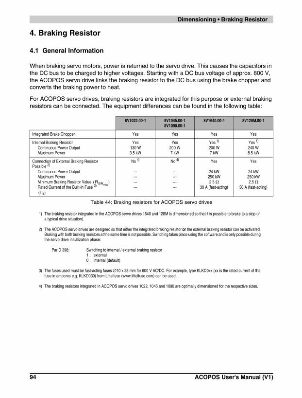
Dimensioning • Braking Resistor
4. Braking Resistor
4.1 General Information
When braking servo motors, power is returned to the servo drive. This causes the capacitors in the DC bus to be charged to higher voltages. Starting with a DC bus voltage of approx. 800 V, the ACOPOS servo drive links the braking resistor to the DC bus using the brake chopper and converts the braking power to heat.
For ACOPOS servo drives, braking resistors are integrated for this purpose or external braking resistors can be connected. The equipment differences can be found in the following table:
8V1022.00-1 8V1045.00-18V1090.00-1
8V1640.00-1 8V128M.00-1
Integrated Brake Chopper Yes Yes Yes Yes
Internal Braking ResistorContinuous Power OutputMaximum Power
Yes130 W3.5 kW
Yes200 W7 kW
Yes 1)
200 W7 kW
1) The braking resistor integrated in the ACOPOS servo drives 1640 and 128M is dimensioned so that it is possible to brake to a stop (in a typical drive situation).
Yes 1)
240 W8.5 kW
Connection of External Braking Resistor Possible 2)
Continuous Power OutputMaximum PowerMinimum Braking Resistor Value Rated Current of the Built-in Fuse 3)
2) The ACOPOS servo drives are designed so that either the integrated braking resistor or the external braking resistor can be activated. Braking with both braking resistors at the same time is not possible. Switching takes place using the software and is only possible during the servo drive initialization phase:
ParID 398: Switching to internal / external braking resistor1 ... external0 ... internal (default)
3) The fuses used must be fast-acting fuses ∅10 x 38 mm for 600 V AC/DC. For example, type KLKD0xx (xx is the rated current of the fuse in amperes e.g. KLKD030) from Littelfuse (www.littelfuse.com) can be used.
No 4)
------------
4) The braking resistors integrated in ACOPOS servo drives 1022, 1045 and 1090 are optimally dimensioned for the respective sizes.
No 4)
------------
Yes
24 kW250 kW2.5 Ω
30 A (fast-acting)
Yes
24 kW250 kW2.5 Ω
30 A (fast-acting)
Table 44: Braking resistors for ACOPOS servo drives
RBRmin( )
IB( )
94 ACOPOS User's Manual (V1)

Cha
pter
4D
imen
sion
ing
Dimensioning • Braking Resistor
4.2 Braking Resistor Connection
The external braking resistors are connected using terminals X6 / RB+, RB- and PE. The structure of the braking resistor connection can be seen in the following diagram:
When determining the cross section 1) for the braking resistor connection, make sure that the cross section selected is within the range that can be used with braking resistor connection terminal X6 (see Chapter 5 "Wiring", Table 48, "Terminal cross sections for ACOPOS servo drives", on page 107).
Figure 21: Circuit diagram for ACOPOS X6, external braking resistor on ACOPOS 1640 and 128M
1) The cross section of the braking resistor cable must be dimensioned for the thermal equivalent effective value of the respective brake current. If information concerning the flow of the brake current is available, calculate the thermal equivalent effective value of the brake current using
The cross section of the braking resistor connection should then be selected as described in Table 41, "Maximum current load for PVC insulated three-phase cables or individual wires", on page 85, so that the maximum current load of the cable cross section is greater than or equal to the thermal equivalent effective value of the brake current (IZ ≥ Iq).
Iq A[ ] 1Tcycle s[ ]----------------------- Ii A[ ]2 ti s[ ]⋅
i∑=
ACOPOS User's Manual (V1) 95

Dimensioning • Braking Resistor
4.3 Dimensioning the Brake Resistor
Like other drive components, the externally connected braking resistors must be dimensioned according to the requirements of the application.
To determine the required braking power (PBr max and PBr aver), the mechanical values M(t), ω(t), Tcycle must be known. The following formulas are used to determine the drive power curve.
Figure 22: Diagram of a typical movement with the brake power curve PBr(t) 1)
1) If - as shown - a typical triangular brake power curve occurs, then the average brake power can be calculated directly with the following formula:
P t( ) W[ ] M t( ) Nm[ ] ω t( ) rad s 1–⋅[ ]⋅=
ω t( ) rad s 1–⋅[ ] 2 π n t( ) min 1–[ ]60 s min 1–⋅[ ]-----------------------------------⋅ ⋅=
PBRaverW[ ] 1
Tcycle s[ ]-----------------------
PBrmaxt⋅Br
2---------------------------⋅=
96 ACOPOS User's Manual (V1)

Cha
pter
4D
imen
sion
ing
Dimensioning • Braking Resistor
The calculation is continued by deriving the brake power curve PBr(t) from the drive power curve. The power must be set to zero in areas where it is positive (P(t) > 0). This results in the following maximum brake power
Then the average brake power is calculated over the given cycle
In order to use an external braking resistor 1) , the following parameters must be calculated:
• the resistance (RBr)
• the maximum power
• the nominal power
Resistance of the Braking Resistor
The resistance of the braking resistor RBr can be calculated as follows:
The selected resistance is not allowed to be less than the minimum resistance for the respective ACOPOS servo drive (see Table 44, "Braking resistors for ACOPOS servo drives", on page 94).
If this condition is not met, the maximum brake power required cannot be reached! Typical resistances are 4 - 50 Ω depending on the size of the ACOPOS device.
1) Reliable braking resistors are available from Danotherm (www.danotherm.com).
Caution!If a resistance less than the minimum resistance is used, the brake chopper built into the ACOPOS device could be destroyed!
PBrmaxW[ ] abs max PBr t( ) W[ ]( )( )=
PBraverW[ ] 1
Tcycle s[ ]------------------------ PBri
t( ) W[ ] ti s[ ]⋅i∑=
PRBrmax
( )
PRBrN( )
RBr Ω[ ]UDC V[ ]2
PBrmaxW[ ]
--------------------------- 800 V[ ]2
PBrmaxW[ ]
---------------------------= =
RBr Ω[ ] RBrminΩ[ ]≥
ACOPOS User's Manual (V1) 97

Dimensioning • Braking Resistor
Then the following calculation
must be made to check if the average continuous power for the brake can be reached with the selected braking resistor on the ACOPOS servo drive. The brake power which can be continually output by the ACOPOS device is limited by the built-in fuse (rated current of the built-in fuse, see Table 44, "Braking resistors for ACOPOS servo drives", on page 94).
Power Data for the Braking Resistor
The maximum power that the braking resistor must be able to dissipate is calculated as follows:
The nominal power (the power which can be continually dissipated) for the braking resistor is calculated using the following formulas:
The second condition depends on ACOPOS internal relationships.
PBraverW[ ] RBr Ω[ ] IB A[ ]2⋅≤
PRBrmaxW[ ] PBrmax
W[ ]≥
PRBrN
W[ ] PBraver≥
PRBrNW[ ] 1
30------ PRBrmax
W[ ]⋅≥
98 ACOPOS User's Manual (V1)

Cha
pter
4D
imen
sion
ing
Dimensioning • Braking Resistor
4.4 Setting Brake Resistor Parameters
The braking resistors integrated in the ACOPOS servo drives as well as braking resistors which can be connected externally are controlled using a specially developed procedure. This guarantees that the brake power is optimally and equally distributed on the braking resistors when a DC bus connection is made between several units.
When using the integrated braking resistors, additional configuration is not required. When using external braking resistors, the following resistor data must be known:
Then the parameters to be set on the ACOPOS servo drive can be determined with the configuration tool RESISTPARAM.XLS.
ParID 10: Ohmic resistance [W]ParID 11: Max. temperature of the resistor. [°C]ParID 12: Thermal resistance [°C/W]ParID 13: Heat capacity of the resistor [Ws/°C]
Resistor Data Term Unit
Continuous power for the resistance [W]
Maximum power for the resistance [W]
Ohmic resistance RBr [Ω]
Maximum switch on time at maximum power [s]
Maximum temperature of the resistor 1)
1) If available.
[°C]
Table 45: Resistor data when using external braking resistors
PRBrN
PRBrmax
ACOPOS User's Manual (V1) 99

Dimensioning • Current Consumption of ACOPOS Plug-in Modules
5. Current Consumption of ACOPOS Plug-in Modules
The plug-in modules for ACOPOS servo drives allow the servo drives to be individually configured according to the requirements of the application. When putting together plug-in module combinations, the power consumption must be checked.
The maximum power output for all 4 slots is 22 W. The total power consumption for all plug-in modules must be less than or equal to the maximum power output.
The power consumption of the individual modules can be found in the technical data for the modules (see chapter 2 "Technical Data").
Pmax 22W Pmodule∑≥=
100 ACOPOS User's Manual (V1)

Cha
pter
4D
imen
sion
ing
Dimensioning • Formula Variables Used
6. Formula Variables Used
Term Unit Product ID
CD F Discharge capacitancefor ACOPOS 1022, 1045, 1090 CD = 660 nFfor ACOPOS 1064, 128M --- 1)
1) Integrated line filter in preparation.
fmains Hz Mains frequency
IA A Discharge current via protective ground conductor (PE)
IB A Rated current for overcurrent protection
Imains A Mains current (phase current)
Iq A Thermal equivalent current effective value
IZ A Maximum current load on a cable
M Nm Torque (general)
Meff Nm Effective load torque
n min-1 Speed (general)
naver min-1 Average speed
ω rad/s Angular speed
P W Power or true power (general)
PBr W Brake power
W Maximum brake power
W Average brake power
W Maximum load on the external braking resistor
W Nominal power of the external braking resistor
Pmax W Maximum power
Pmodule W Power consumption of the plug-in modules
π --- Pi (3.1415)
RBr Ω Braking resistance
Ω Minimum braking resistance
S VA Apparent power
t s Time (general)
tBr s Brake time
Tcycle s Cycle time
UDC V DC bus voltage
Umains V Supply voltage (phase to phase)
Table 46: Formula variables used
PBrmax
PBraver
PRBrmax
PRBrN
RBrmin
ACOPOS User's Manual (V1) 101

Dimensioning • Formula Variables Used
102 ACOPOS User's Manual (V1)

Cha
pter
5W
iring
Wiring • General Information
CHAPTER 5 • WIRING
1. General Information
1.1 Electromagnetic Compatibility of the Installation
1.1.1 General Information
Servo drives are electrical equipment intended for use in industrial and commercial systems. ACOPOS servo drives meet the requirements for adherence to the EMC guideline 89/336/EWG regarding electromagnetic compatibility of the installation. Under the terms of the EMC guidelines, such devices do not require certification because they are intended to be further processed by the competent, machine and equipment manufacturer in compliance with the EMCG components and cannot be operated independently.
Evidence of compliance with the limit values required in the EMC guidelines must be provided by the manufacturer or the machine or system operator.
ACOPOS servo drives fulfill the requirements of IEC 61800-3 (industry – 2nd environment) in regard to disturbance immunity and emitted disturbance.
When using the servo drives in living areas, shops and small businesses, additional filtering measures must be implemented by the user.
ACOPOS User's Manual (V1) 103

Wiring • General Information
1.1.2 Installation Notes
• The switching cabinet or the system must be constructed appropriately.
• In order to avoid disturbances,
- motor cables- encoder cables- control cables- data cables
are to be properly shielded.
• Inductive switching elements such as contactors or relays are to be equipped with corresponding suppressor elements such as varistors, RC elements or damping diodes.
• All electrical connections are to be kept as short as possible.
• Cable shields are to be attached to the designated shield terminals and the plug housing.
• Shielded cables with copper mesh or tinned copper mesh are to be used. Twisting or extending the protective mesh using single conductors is not allowed.
• Unused cable conductors are to be grounded on both sides if possible.
104 ACOPOS User's Manual (V1)

Cha
pter
5W
iring
Wiring • General Information
The ground connections and shield connections have to be made as illustrated in the following diagram.
Figure 23: Connection diagram for ground and shield connections
ACOPOS User's Manual (V1) 105

Wiring • General Information
The protective ground conductor for the power mains (PE) and the protective ground conductor for the motor lines are internally connected with the housing of the ACOPOS servo drive.
The second protective ground conductor connection is required because of the increased discharge current (>3.5 mA) on the ACOPOS servo drives 1022, 1045 and 1090. The same cross section as the protective ground conductor for the power mains must be used.
The two trigger inputs only internally filter disturbances up to approx. 50 µs, therefore proper grounding of the cable shields is important.
The cable shield must be connected to the designated terminal.
On all plug-in modules, the two screws used to fasten the module must be tightened so that the mounting bracket is connected to ground.
Cable connection via DSUB plug:The cable shield must be connected using the designated clamp in the metallic or metal plated plug housing. The plug housing must be fastened to the designated device connector using safety screws.
Cable connection via terminals:The cable shield must be connected to the designated terminal.
The cable shield for the motor line is connected with the ACOPOS housing via the grounding plate using the grounding clamp provided:
On the motor side, the cable shield is connected to the motor housing using the motor plug and connected to ground via the machine.
On the motor side, the encoder cable shield is connected to the motor housing using the encoder plug and connected to ground via the machine.
Shield connection for the motor cable using grounding clamps
1022, 1045, 1090 1640, 128M
Table 47: Grounding the motor cable
106 ACOPOS User's Manual (V1)
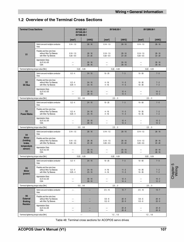
Cha
pter
5W
iring
Wiring • General Information
1.2 Overview of the Terminal Cross Sections
Terminal Cross Sections 8V1022.00-18V1045.00-18V1090.00-1
8V1640.00-1 8V128M.00-1
[mm²] [AWG] [mm²] [AWG] [mm²] [AWG]
X1
Solid core and multiple conductor lines
0.14 - 1.5 28 - 16 0.14 - 1.5 28 - 16 0.14 - 1.5 28 - 16
Flexible and fine wire lineswithout Wire Tip Sleeveswith Wire Tip Sleeves
0.14 - 1.50.25 - 0.5
28 - 1623 - 20
0.14 - 1.50.25 - 0.5
28 - 1623 - 20
0.14 - 1.50.25 - 0.5
28 - 1623 - 20
Approbation DataUL/C-UL-USCSA
------
30 - 1628 - 16
------
30 - 1628 - 16
------
30 - 1628 - 16
Terminal tightening torque value [Nm] 0.22 ... 0.25 0.22 ... 0.25 0.22 ... 0.25
X2DC Bus
Solid core and multiple conductor lines
0.2 - 4 24 - 10 10 - 25 7 - 3 10 - 50 7 - 0
Flexible and fine wire lineswithout Wire Tip Sleeveswith Wire Tip Sleeves
0.2 - 40.25 - 4
24 - 1023 - 10
4 - 164 - 16
11 - 511 - 5
10 - 3510 - 35
7 - 27 - 2
Approbation DataUL/C-UL-USCSA
------
30 - 1028 - 10
------
12 - 414 - 4
------
10 - 212 - 2
Terminal tightening torque value [Nm] 0.5 ... 0.6 2.5 ... 3 2.5 ... 3
X3Power Mains
Solid core and multiple conductor lines
0.2 - 4 24 - 10 10 - 25 7 - 3 10 - 50 7 - 0
Flexible and fine wire lineswithout Wire Tip Sleeveswith Wire Tip Sleeves
0.2 - 40.25 - 4
24 - 1023 - 10
4 - 164 - 16
11 - 511 - 5
10 - 3510 - 35
7 - 27 - 2
Approbation DataUL/C-UL-USCSA
------
30 - 1028 - 10
------
12 - 414 - 4
------
10 - 212 - 2
Terminal tightening torque value [Nm] 0.5 ... 0.6 2.5 ... 3 2.5 ... 3
X4Motor
(holding brake,
temperature sensor)
Solid core and multiple conductor lines
0.14 - 1.5 28 - 16 0.14 - 1.5 28 - 16 0.14 - 1.5 28 - 16
Flexible and fine wire lineswithout Wire Tip Sleeveswith Wire Tip Sleeves
0.14 - 1.50.25 - 0.5
28 - 1623 - 20
0.14 - 1.50.25 - 0.5
28 - 1623 - 20
0.14 - 1.50.25 - 0.5
28 - 1623 - 20
Approbation DataUL/C-UL-USCSA
------
30 - 1428 - 16
------
30 - 1628 - 16
------
30 - 1628 - 16
Terminal tightening torque value [Nm] 0.22 ... 0.25 0.22 ... 0.25 0.22 ... 0.25
X5Motor
(power)
Solid core and multiple conductor lines
0.2 - 4 24 - 10 10 - 25 7 - 3 10 - 50 7 - 0
Flexible and fine wire lineswithout Wire Tip Sleeveswith Wire Tip Sleeves
0.2 - 40.25 - 4
24 - 1023 - 10
4 - 164 - 16
11 - 511 - 5
10 - 3510 - 35
7 - 27 - 2
Approbation DataUL/C-UL-USCSA
------
30 - 1028 - 10
------
12 - 414 - 4
------
10 - 212 - 2
Terminal tightening torque value [Nm] 0.5 ... 0.6 2.5 ... 3 2.5 ... 3
X6External Braking Resistor
Solid core and multiple conductor lines
--- --- 2.5 - 10 13 - 7 2.5 - 10 13 - 7
Flexible and fine wire lineswithout Wire Tip Sleeveswith Wire Tip Sleeves
------
------
0.5 - 60.5 - 6
20 - 920 - 9
0.5 - 60.5 - 6
20 - 920 - 9
Approbation DataUL/C-UL-USCSA
------
------
------
22 - 820 - 8
------
22 - 820 - 8
Terminal tightening torque value [Nm] --- 1.2 ... 1.6 1.2 ... 1.6
Table 48: Terminal cross sections for ACOPOS servo drives
ACOPOS User's Manual (V1) 107

Wiring • Connections ACOPOS 1022, 1045, 1090
2. Connections ACOPOS 1022, 1045, 1090
Figure 24: Connection overview ACOPOS 1022, 1045, 1090
108 ACOPOS User's Manual (V1)

Cha
pter
5W
iring
Wiring • Connections ACOPOS 1022, 1045, 1090
2.1 Pin Assignments for Plug X1
2.2 Pin Assignments for Plug X2
X1 Pin Description Function
1 Trigger1 Trigger 1
2 Quickstop/Trigger2 Quickstop/Trigger 2
3 COM (1, 2) Trigger 1, Quickstop/Trigger 2 - 0 V
4 Shield Shield
5 End+ Positive HW limit
6 End- Negative HW limit
7 Ref Reference switch
8 Enable Controller enable
9 --- ---
10 --- ---
11 +24V Supply +24 V
12 COM (5 -8, 11) Supply 0 V
Terminal Cross Sections see Table 48, "Terminal cross sections for ACOPOS servo drives", on page 107
Table 49: Pin assignments for plug X1 ACOPOS 1022, 1045, 1090
X2 Pin Description Function
1 -DC1 U DC bus -
2 +DC1 U DC bus +
3 +DC2 U DC bus +
4 -DC2 U DC bus -
Terminal Cross Sections see Table 48, "Terminal cross sections for ACOPOS servo drives", on page 107
Table 50: Pin assignments for plug X2 ACOPOS 1022, 1045, 1090
ACOPOS User's Manual (V1) 109

Wiring • Connections ACOPOS 1022, 1045, 1090
2.3 Pin Assignments for Plug X3
2.4 Pin Assignments for Plug X4
2.5 Pin Assignments for Plug X5
X3 Pin Description Function
1 L1 Power Mains Connection L1
2 L2 Power Mains Connection L2
3 L3 Power Mains Connection L3
4 PE Protective Ground Conductor
Terminal Cross Sections see Table 48, "Terminal cross sections for ACOPOS servo drives", on page 107
Table 51: Pin assignments for plug X3 ACOPOS 1022, 1045, 1090
X4 Pin Description Function
1 T- Temperature Sensor -
2 T+ Temperature Sensor +
3 B- Brake -
4 B+ Brake +
Terminal Cross Sections see Table 48, "Terminal cross sections for ACOPOS servo drives", on page 107
Table 52: Pin assignments for plug X4 ACOPOS 1022, 1045, 1090
X5 Pin Description Function
1 PE Protective Ground Conductor
2 W Motor Connection W
3 V Motor Connection V
4 U Motor Connection U
Terminal Cross Sections see Table 48, "Terminal cross sections for ACOPOS servo drives", on page 107
Table 53: Pin assignments for plug X5 ACOPOS 1022, 1045, 1090
110 ACOPOS User's Manual (V1)

Cha
pter
5W
iring
Wiring • Connections ACOPOS 1022, 1045, 1090
2.6 Protective Ground Connection (PE)
The protective ground conductor is connected to the threaded bolt M4 provided using a cable lug. For information concerning dimensioning see Chapter 4 "Dimensioning", Section 1.1.3 "Protective Ground Connection (PE)".
Image Pin Description Function
--- PE Protective Ground Conductor
Terminal Cross Sections [mm²] AWG
Cable lug for threaded bolt M4 0.25 - 6 23 - 9
Table 54: Protective ground conductor (PE) ACOPOS 1022, 1045, 1090
Danger!Before turning on the servo drive, make sure that the housing is properly connected to ground (PE rail). The ground connection must be made, even when testing the servo drive or when operating it for a short time!
ACOPOS User's Manual (V1) 111

Wiring • Connections ACOPOS 1640, 128M
3. Connections ACOPOS 1640, 128M
1) Connections X1 / COM (5 - 8) and X4 / COM (7, 9, 10) are internally connected in the device.
Figure 25: Connection overview ACOPOS 1640, 128M
112 ACOPOS User's Manual (V1)

Cha
pter
5W
iring
Wiring • Connections ACOPOS 1640, 128M
3.1 Pin Assignments for Plug X1
3.2 Pin Assignments for X2
X1 Pin Description Function
1 Trigger1 Trigger 1
2 Quickstop/Trigger2 Quickstop/Trigger 2
3 COM (1, 2) Trigger 1, Quickstop/Trigger 2 - 0 V
4 Shield Shield
5 End+ Positive HW limit
6 End- Negative HW limit
7 Ref Reference switch
8 Enable Controller enable
9 --- ---
10 --- ---
11 --- ---
12 COM (5-8) Supply 0 V
Terminal Cross Sections see Table 48, "Terminal cross sections for ACOPOS servo drives", on page 107
Table 55: Pin assignments for plug X1 ACOPOS 1640, 128M
X2 Pin Description Function
1 +DC2 U DC bus +
2 +DC1 U DC bus +
3 -DC2 U DC bus -
4 -DC1 U DC bus -
Terminal Cross Sections see Table 48, "Terminal cross sections for ACOPOS servo drives", on page 107
Table 56: Pin assignments for X2 ACOPOS 1640, 128M
ACOPOS User's Manual (V1) 113

Wiring • Connections ACOPOS 1640, 128M
3.3 Pin Assignments for X3
3.4 Pin Assignments for Plug X4
X3 Pin Description Function
1 L1 Power Mains Connection L1
2 L2 Power Mains Connection L2
3 L3 Power Mains Connection L3
4 PE Protective Ground Conductor
Terminal Cross Sections see Table 48, "Terminal cross sections for ACOPOS servo drives", on page 107
Table 57: Pin assignments for X3 ACOPOS 1640, 128M
X4 Pin Description Function
1 S1 External activation of the holding brake 1)
1) S1 and S2 can be used to connect an external potential free contact (typically normally closed). This makes it possible to activate the holding brake using an external safety circuit independent of the control integrated in the ACOPOS servo drive. If this function is not used, a jumper must be placed between S1 and S2.
2 S2 External activation of the holding brake 1)
3 B+ Brake +
4 B- Brake -
5 T+ Temperature +
6 T- Temperature -
7 +24V out / 0.5A +24 V output / 0.5 A
8 COM (7, 9, 10) Supply 0 V
9 +24V +24 V
10 +24V +24 V
11 COM (7, 9, 10) Supply 0 V
12 COM (7, 9, 10) Supply 0 V
Terminal Cross Sections see Table 48, "Terminal cross sections for ACOPOS servo drives", on page 107
Table 58: Pin assignments for plug X4 ACOPOS 1640, 128M
114 ACOPOS User's Manual (V1)

Cha
pter
5W
iring
Wiring • Connections ACOPOS 1640, 128M
3.5 Pin Assignments for X5
3.6 Pin Assignments for X6
X5 Pin Description Function
1 PE Protective Ground Conductor
2 W Motor Connection W
3 V Motor Connection V
4 U Motor Connection U
Terminal Cross Sections see Table 48, "Terminal cross sections for ACOPOS servo drives", on page 107
Table 59: Pin assignments for X5 ACOPOS 1640, 128M
X6 Pin Description Function
1 RB+ Brake Resistance +
2 RB- Brake Resistance -
3 PE Protective Ground Conductor
Terminal Cross Sections see Table 48, "Terminal cross sections for ACOPOS servo drives", on page 107
Table 60: Pin assignments for X6 ACOPOS 1640, 128M
ACOPOS User's Manual (V1) 115

Wiring • Plug-in Module Connections
4. Plug-in Module Connections
4.1 AC110 - CAN Interface
4.1.1 Pin Assignments
Image Connection Pin Description Function
1 --- ---
2 CAN_L CAN Low
3 COM (2, 7) CAN 0 V
4 --- ---
5 --- ---
6 --- ---
7 CAN_H CAN High
8 --- ---
9 --- ---
Table 61: Pin assignments for AC110 - CAN Interface
116 ACOPOS User's Manual (V1)

Cha
pter
5W
iring
Wiring • Plug-in Module Connections
4.2 AC120 - EnDat Encoder Interface
4.2.1 Pin Assignments
Image Connection Pin Description Function
1 A Channel A
2 COM (1, 3 - 9,11, 13 - 15) Encoder supply 0 V
3 B Channel B
4 +5V out / 0.25A Encoder supply +5 V
5 D Data input
6 --- ---
7 R\ Reference pulse inverted
8 T Clock output
9 A\ Channel A inverted
10 Sense COM Sense input 0 V
11 B\ Channel B inverted
12 Sense +5V Sense input +5 V
13 D\ Data inverted
14 R Reference pulse
15 T\ Clock output inverted
Table 62: Pin assignments for AC120 - EnDat Encoder Interface
ACOPOS User's Manual (V1) 117

Wiring • Plug-in Module Connections
4.3 AC122 - Resolver Interface
4.3.1 Pin Assignments
Image Connection Pin Description Function
1 --- ---
2 --- ---
3 Cos Cosine input
4 Sin Sine input
5 Ref Reference Output
6 --- ---
7 Cos\ Cosine input inverted
8 Sin\ Sine input inverted
9 Ref \ Reference output inverted
Table 63: Pin assignments for AC122 - Resolver Interface
118 ACOPOS User's Manual (V1)
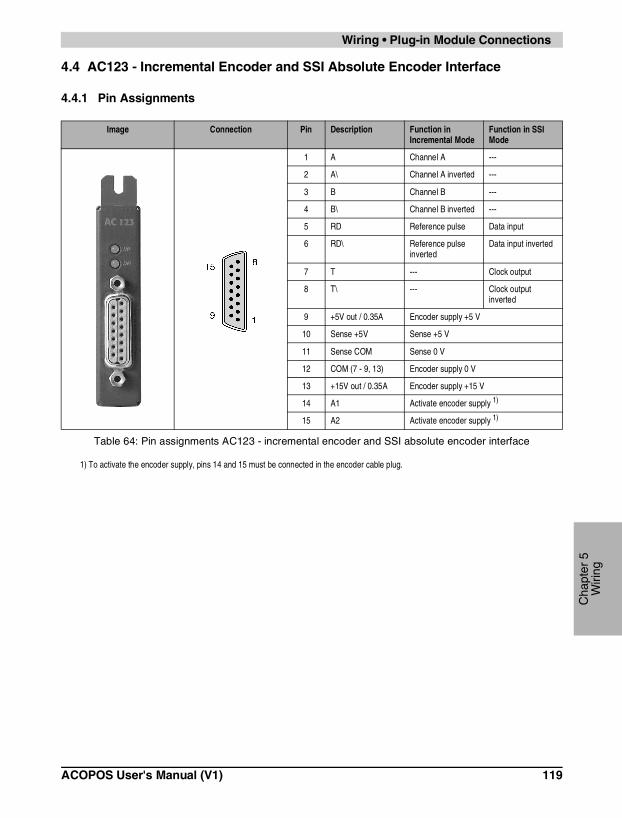
Cha
pter
5W
iring
Wiring • Plug-in Module Connections
4.4 AC123 - Incremental Encoder and SSI Absolute Encoder Interface
4.4.1 Pin Assignments
Image Connection Pin Description Function in Incremental Mode
Function in SSI Mode
1 A Channel A ---
2 A\ Channel A inverted ---
3 B Channel B ---
4 B\ Channel B inverted ---
5 RD Reference pulse Data input
6 RD\ Reference pulse inverted
Data input inverted
7 T --- Clock output
8 T\ --- Clock output inverted
9 +5V out / 0.35A Encoder supply +5 V
10 Sense +5V Sense +5 V
11 Sense COM Sense 0 V
12 COM (7 - 9, 13) Encoder supply 0 V
13 +15V out / 0.35A Encoder supply +15 V
14 A1 Activate encoder supply 1)
1) To activate the encoder supply, pins 14 and 15 must be connected in the encoder cable plug.
15 A2 Activate encoder supply 1)
Table 64: Pin assignments AC123 - incremental encoder and SSI absolute encoder interface
ACOPOS User's Manual (V1) 119

Wiring • Plug-in Module Connections
4.5 AC130 - Digital Mixed Module
4.5.1 Pin Assignments
Image Connection Pin Description Function
1 Dig. I/O 1 Digital input / output 1
2 Dig. I/O 2 Digital input / output 2
3 Dig. I/O 3 Digital input / output 3
4 Dig. I/O 4 Digital input / output 4
5 Dig. I/O 5 Digital input / output 5
6 Dig. I/O 6 Digital input / output 6
7 Dig. I/O 7 Digital input / output 7
8 Dig. I/O 8 Digital input / output 8
9 Dig. O 9 Digital output 9
10 Dig. O 10 Digital output 10
11 +24V Supply +24 V
12 COM (1-11) Supply 0 V
Terminal Cross Sections [mm²] [AWG]
Solid core and multiple conductor lines 0.5 - 1.5 20 - 14
Flexible, multiple wire linewithout Wire Tip Sleeveswith Wire Tip Sleeves
0.5 - 1.50.5 - 1.5
20 - 1420 - 14
Approbation Data (UL/C-UL-US- and CSA)UL/C-UL-USCSA
------
26 - 1426 - 14
Table 65: Pin assignments AC130 - digital mixed module
120 ACOPOS User's Manual (V1)

Cha
pter
5W
iring
Wiring • Plug-in Module Connections
4.6 Connecting Cables to Plug-in Modules
Stress relief for the cable is implemented using a cable tie. The cable tie is to be run through the eye on the bottom of the plug-in module.
Make sure that the ventilation slots on the bottom of the ACOPOS drive are not blocked.
Figure 26: Connecting Cables to Plug-in Modules
ACOPOS User's Manual (V1) 121
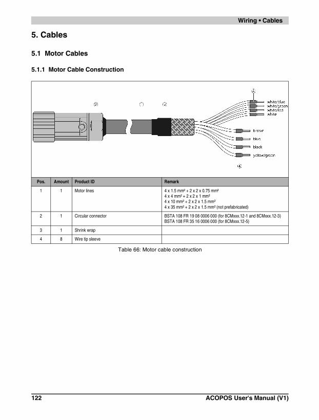
Wiring • Cables
5. Cables
5.1 Motor Cables
5.1.1 Motor Cable Construction
Pos. Amount Product ID Remark
1 1 Motor lines 4 x 1.5 mm² + 2 x 2 x 0.75 mm²4 x 4 mm² + 2 x 2 x 1 mm²4 x 10 mm² + 2 x 2 x 1.5 mm²4 x 35 mm² + 2 x 2 x 1.5 mm² (not prefabricated)
2 1 Circular connector BSTA 108 FR 19 08 0006 000 (for 8CMxxx.12-1 and 8CMxxx.12-3)BSTA 108 FR 35 16 0006 000 (for 8CMxxx.12-5)
3 1 Shrink wrap
4 8 Wire tip sleeve
Table 66: Motor cable construction
122 ACOPOS User's Manual (V1)

Cha
pter
5W
iring
Wiring • Cables
5.1.2 Pin Assignments 8CMxxx.12-1, 8CMxxx.12-3
5.1.3 Cable Schematic for 8CMxxx.12-1, 8CMxxx.12-3
Circular connector Pin Product ID Function
1 U Motor Connection U
2 PE Protective Ground Conductor
3 W Motor Connection W
4 V Motor Connection V
A T+ Temperature +
B T- Temperature -
C B+ Brake +
D B- Brake -
Table 67: Pin assignments for motor cable 8CMxxx.12-1, 8CMxxx.12-3
Figure 27: Cable schematic for motor cable 8CMxxx.12-1, 8CMxxx.12-3
ACOPOS User's Manual (V1) 123

Wiring • Cables
5.1.4 Pin Assignments for 8CMxxx.12-5
5.1.5 Cable Schematic for 8CMxxx.12-5
Circular connector Pin Product ID Function
U U Motor Connection U
PE Protective Ground Conductor
W W Motor Connection W
V V Motor Connection V
1 T+ Temperature +
2 T- Temperature -
+ B+ Brake +
- B- Brake -
Table 68: Pin assignments for motor cables 8CMxxx.12-5
Figure 28: Cable schematic for motor cables 8CMxxx.12-5
124 ACOPOS User's Manual (V1)

Cha
pter
5W
iring
Wiring • Cables
5.2 EnDat Encoder Cables
5.2.1 EnDat Encoder Cable Construction
5.2.2 Pin Assignments
Pos. Amount Product ID Remark
1 1 Encoder cable 10 x 0.14 mm² + 2 x 0.50 mm²
2 1 Circular connector, 17 pin socket ASTA 035 FR 11 12 0005 000
3 1 DSUB housing 45°, metal plated, 15 pin plug
4 1 Shrink wrap
Table 69: EnDat encoder cable construction
Circular connector Pin Product ID Function Pin DSUB plug
15 A Channel A 1
10 COM (1, 3 - 9, 11, 13 - 15) Encoder supply 0 V 2
12 B Channel B 3
7 +5V out / 0.25A Encoder supply +5 V 4
14 D Data input 5
8 T Clock output 8
16 A\ Channel A inverted 9
4 Sense COM Sense input 0 V 10
13 B\ Channel B inverted 11
1 Sense +5V Sense input +5 V 12
17 D\ Data inverted 13
9 T\ Clock output inverted 15
Table 70: Pin assignments for EnDat encoder cables
ACOPOS User's Manual (V1) 125

Wiring • Cables
5.2.3 Cable Schematic
Figure 29: Cable schematic for EnDat encoder cables
126 ACOPOS User's Manual (V1)

Cha
pter
5W
iring
Wiring • Cables
5.3 Resolver Cables
5.3.1 Resolver Cable Construction
5.3.2 Pin Assignments
Pos. Amount Product ID Remark
1 1 Encoder cable 3 x 2 x 24 AWG/19
2 1 Circular connector, 12 pin socket ASTA 021 FR 11 10 0005 000
3 1 DSUB housing 45°, metal plated, 9 pin plug
4 1 Kink protection
Table 71: Resolver cable construction
Circular connector Pin Product ID Function Pin DSUB plug
1 ---
2 ---
3 Cos Cosine input 3
4 Sin Sine input 4
5 Ref Reference Output 5
6 ---
7 Cos\ Cosine input inverted 7
8 Sin\ Sine input inverted 8
9 Ref \ Reference output inverted 9
10 ---
11 ---
12 ---
Table 72: Pin assignments for resolver cables
ACOPOS User's Manual (V1) 127

Wiring • Cables
5.3.3 Cable Schematic
Figure 30: Cable schematic for resolver cables
128 ACOPOS User's Manual (V1)

Cha
pter
6G
ettin
g S
tart
ed
Getting Started • Preparation
CHAPTER 6 • GETTING STARTED
1. Preparation
1.1 Unpacking the ACOPOS Servo Drive
Remove the protective packaging from the ACOPOS servo drive. Check the ACOPOS servo drive for obvious mechanical damage.
1.2 Installing and Connecting the ACOPOS Servo Drive
The guidelines and specifications for installing and wiring the respective ACOPOS servo drive can be found in chapters 3 "Installation", 4 "Dimensioning" and 5 "Wiring".
1.3 Connecting the ACOPOS Servo Drive with a B&R PLC
The ACOPOS servo drives are equipped with a CAN interface which can be used to connect to a B&R PLC. The connection is made using a a CAN cable (pin assignments can be found in chapter 5 "Wiring" and in the User's Manual for the PLC).
Danger!Do not operate the ACOPOS servo drive if it is damaged. This can cause severe personal injury or damage to property!
ACOPOS User's Manual (V1) 129

Getting Started • Starting Up an ACOPOS Servo Drive
2. Starting Up an ACOPOS Servo Drive
The goal of the following example is move the shaft of a motor connected to an ACOPOS servo drive 5000 units. In order to emphasize the important points of starting up the hardware, this will be done using an sample project contained in B&R Automation Studio™.
2.1 General Information
The start-up procedure described here is based on the following configuration: 1)
Danger!Incorrect control of motors or mechanical parts connected to the motor shaft can cause unwanted and dangerous movements!
1) The procedure can change slightly depending on the hardware configuration.
Model Number Short Description
Servo Drives
8V1045.00-1 Servo drive 3 x 400-480V 4.4A 2kW, line filter and braking resistor integrated
Plug-in Modules
8AC110.60-1 ACOPOS plug-in module, CAN interface
8AC120.60-1 ACOPOS plug-in module, EnDat encoder interface
Motor
8MSA4L.E0-B4 Motor MSA4 series with EnDat encoder
Accessories
7AC911.9 Bus connector, CAN (2 pcs.)
8CE005.12-1 EnDat cable, length 5m, 10 x 0.14mm² + 2 x 0.5mm², EnDat connector 17 pin Intercontec socket, servo connector 15 pin DSUB plug, can be used in cable drag chains, UL/CSA listed
8CM005.12-1 Motor cable, length 5m, 4 x 1.5mm² + 2 x 2 x 0.75mm², motor connector 8 pin Intercontec socket, can be used in cable drag chains, UL/CSA listed
0G0001.00-090 Cable PC <--> PLC/PW, RS232, Online cable
PLC CPU
7CP476.60-1 2003 CPU, 750 KB SRAM, 1.5 MB FlashPROM, 24 VDC, 12.5 W supply, 1 RS232 interface, 1 CAN interface, CAN: electrically isolated, network capable, 4 slots for screw-in modules, system bus for expansion modules, max. 272 digital / 80 analog I/O points
B&R Automation Studio™
1A4000.Lx B&R AutomationSoftware™ CD, full version
Table 73: Configuration for the start-up example
130 ACOPOS User's Manual (V1)

Cha
pter
6G
ettin
g S
tart
ed
Getting Started • Starting Up an ACOPOS Servo Drive
The hardware configuration will be called the "target system" in the following sections. A PC with B&R Automation Studio™ installed will also be needed.
2.1.1 Sample Project
Several sample projects are available in B&R Automation Studio™ which can be used to test ACOPOS servo drives. They are found in the directory "...\BRAUTOMATION\SAMPLES\MOTION" in the B&R Automation Studio™ installation directory.
This start-up example is based on the sample project "...\BRAUTOMATION\SAMPLES\MOTION\DEUTSCH\C\ACP10.PGP\ACP10.GDM" starting with ACOPOS operating system version V 0.47.2.
2.1.2 Preparing the Hardware for Sample Project acp10.gdm
• Check the wiring of the ACOPOS servo drive connections (also see chapter 5 "Wiring").
• Set node number 1 on the AC110 plug-in module (see chapter 2 "Technical Data").
• Connect the PC with the PLC using the online cable (see user's manual for the PLC for information concerning the online cable connection to the PLC).
• Apply power to the PLC and the ACOPOS servo drive (24 VDC, 400 VAC). You can make sure the ACOPOS servo drive boots correctly by watching the blink code (see chapter 2 "Technical Data").
Figure 31: Open sample project
Information:During start-up, changes will be made to the sample project. We recommend that you make a copy of the sample project (entire ACP10.PGP directory, see Figure 31 "Open sample project") in a different project directory and use it for the start-up.
ACOPOS User's Manual (V1) 131

Getting Started • Starting Up an ACOPOS Servo Drive
2.2 Start-up
2.2.1 Load Sample Project
Start B&R Automation Studio™:
Figure 32: B&R Automation Studio™ version is shown during the start procedure
Figure 33: B&R Automation Studio™ Start-up Screen
132 ACOPOS User's Manual (V1)

Cha
pter
6G
ettin
g S
tart
ed
Getting Started • Starting Up an ACOPOS Servo Drive
Open the project (recommended: make a copy of sample project ACP10.GDM in the respective project path):
• Click Open Project ... in the File menu.
• Select ...\ACP10.PGP\ACP10.GDM.
• Load the project by clicking on the Open button.
Figure 34: Opening a project
Figure 35: Selecting the project
ACOPOS User's Manual (V1) 133
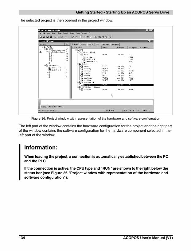
Getting Started • Starting Up an ACOPOS Servo Drive
The selected project is then opened in the project window:
The left part of the window contains the hardware configuration for the project and the right part of the window contains the software configuration for the hardware component selected in the left part of the window.
Figure 36: Project window with representation of the hardware and software configuration
Information:When loading the project, a connection is automatically established between the PC and the PLC.
If the connection is active, the CPU type and "RUN" are shown to the right below the status bar (see Figure 36 "Project window with representation of the hardware and software configuration").
134 ACOPOS User's Manual (V1)

Cha
pter
6G
ettin
g S
tart
ed
Getting Started • Starting Up an ACOPOS Servo Drive
2.2.2 Preset Values for the Sample Project
A few preset values must be defined on the target system before downloading the project.
CPU
The sample project was originally created for a different PLC CPU (7CP474.60-1).
This must be changed to the CPU used on the target system (shown to the right under the status bar):
• In the left part of the window, position the mouse pointer on the CPU (7CP474.60-1).
Figure 37: Select the CPU in the left part of the window
ACOPOS User's Manual (V1) 135

Getting Started • Starting Up an ACOPOS Servo Drive
• Open the shortcut menu with the right mouse button.
• Position the mouse pointer on Replace with 7CP476.60-1.
• Select this menu item with the left mouse button.
• Acknowledge the change of the CPU by clicking on the OK button.
Figure 38: Select the command used to replace the CPU from the shortcut menu
Figure 39: Acknowledge the change of the CPU
136 ACOPOS User's Manual (V1)

Cha
pter
6G
ettin
g S
tart
ed
Getting Started • Starting Up an ACOPOS Servo Drive
User Memory
Before downloading the sample project, we recommend clearing the user memory on the PLC:
• In the Project menu, select Services and then Clear Memory ....
• Activate the checkbox Erase USER ROM.
• Acknowledge the selection by clicking the OK button.
Figure 40: Clearing user memory on the PLC
Figure 41: Selecting the user memory on the PLC
ACOPOS User's Manual (V1) 137

Getting Started • Starting Up an ACOPOS Servo Drive
• The user memory is erased.
After clearing the user memory, the project window will be shown again.
Operating System Download
The first time an ACOPOS servo drive is started up, the ACOPOS operating system ACP10SYS must also be transferred to the target system. In the sample project, transferring ACP10SYS is deactivated (shown in gray in the right part of the window). Transferring ACP10SYS must be activated separately in the sample project:
• Position the mouse pointer on ACP10SYS in the right part of the window.
Figure 42: Erasing the user memory
Figure 43: Place mouse pointer on ACOPOS operating system ACP10SYS
138 ACOPOS User's Manual (V1)

Cha
pter
6G
ettin
g S
tart
ed
Getting Started • Starting Up an ACOPOS Servo Drive
• Open the shortcut menu with the right mouse button.
• Position the mouse pointer on Disable.
• Click on Disable with the left mouse button to cancel deactivation.
Figure 44: Enable transferring the ACOPOS operating system
ACOPOS User's Manual (V1) 139

Getting Started • Starting Up an ACOPOS Servo Drive
ACP10SYS is now enabled (shown in black instead of gray) and is also transferred the next time the project is downloaded.
2.2.3 Preset Values Concerning Wiring
The further procedure depends on the wiring of the digital servo drive control inputs.
End Switch and Quickstop are Wired
If the hardware end switches (normally closed) are wired to X1 / End+ and X1 / End- and a quickstop switch (normally closed) is wired to X1 / Quickstop/Trigger2 according to chapter 5 "Wiring", Section 2 "Connections ACOPOS 1022, 1045, 1090", then start-up can be continued with Section 2.2.4 "Downloading the Project".
Figure 45: The operating system is also transferred the next time the project is downloaded
Information:After successfully downloading the operating system the first time, "Disable" can be set again which shortens the download time for projects.
140 ACOPOS User's Manual (V1)
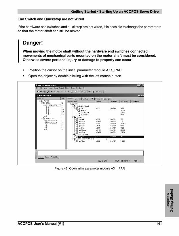
Cha
pter
6G
ettin
g S
tart
ed
Getting Started • Starting Up an ACOPOS Servo Drive
End Switch and Quickstop are not Wired
If the hardware end switches and quickstop are not wired, it is possible to change the parameters so that the motor shaft can still be moved.
• Position the cursor on the initial parameter module AX1_PAR.
• Open the object by double-clicking with the left mouse button.
Danger!When moving the motor shaft without the hardware end switches connected, movements of mechanical parts mounted on the motor shaft must be considered. Otherwise severe personal injury or damage to property can occur!
Figure 46: Open initial parameter module AX1_PAR
ACOPOS User's Manual (V1) 141

Getting Started • Starting Up an ACOPOS Servo Drive
• Position the mouse pointer on "dig_in".
• Expand the view by clicking on "+".
Figure 47: Place the mouse pointer on "dig_in"
Figure 48: Expand the view
142 ACOPOS User's Manual (V1)

Cha
pter
6G
ettin
g S
tart
ed
Getting Started • Starting Up an ACOPOS Servo Drive
• Position the mouse pointer on "level". The parameters are now shown in the right part of the window.
To allow movement of the motor shaft, the following parameters must be changed to the value "ncACTIV_HI":
• pos_hw_end
• neg_hw_end
• trigger2 (quickstop)
"ncACTIV_HI" means that the inputs for both hardware end switches and the quickstop are activated (logical "1"). This allows the motor shaft to be moved without wiring the hardware end switches and a quickstop.
The procedure is shown here in an example for pos_hw_end:
• In the right part of the window, position the mouse pointer on level "ncACTIV_LO" for the shaft parameter pos_hw_end.
Figure 49: Displaying the level parameters
Figure 50: Place mouse pointer on level "ncACTIV_LO"
ACOPOS User's Manual (V1) 143

Getting Started • Starting Up an ACOPOS Servo Drive
• Open the selection list by clicking with the left mouse button.
• Select "ncACTIV_HI" by clicking with the left mouse button.
• Acknowledge the selection by pressing the ENTER key.
Use the same procedure for the other two parameters, neg_hw_end and trigger2 (quickstop).
When all changes are made, the value list looks like this:
Figure 51: Change the level for the positive hardware end switch
Figure 52: Acknowledge level change
Figure 53: Levels after all changes are made
144 ACOPOS User's Manual (V1)
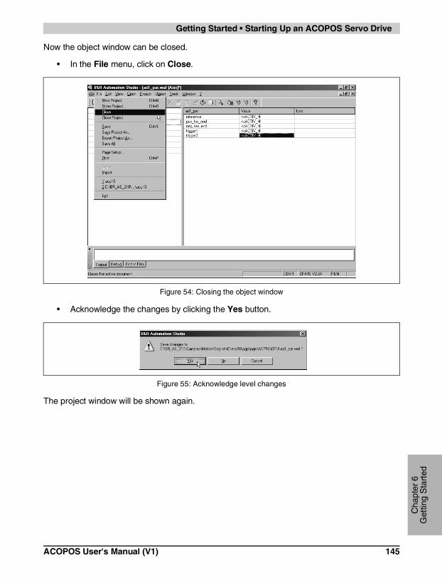
Cha
pter
6G
ettin
g S
tart
ed
Getting Started • Starting Up an ACOPOS Servo Drive
Now the object window can be closed.
• In the File menu, click on Close.
• Acknowledge the changes by clicking the Yes button.
The project window will be shown again.
Figure 54: Closing the object window
Figure 55: Acknowledge level changes
ACOPOS User's Manual (V1) 145

Getting Started • Starting Up an ACOPOS Servo Drive
2.2.4 Downloading the Project
After making the preparations, the project can now be transferred to the target system:
• In the Project menu, click on Transfer To Target.
Figure 56: Click on the command to transfer the project to the target system
146 ACOPOS User's Manual (V1)

Cha
pter
6G
ettin
g S
tart
ed
Getting Started • Starting Up an ACOPOS Servo Drive
If an operating system has already been transferred to the PLC, a version conflict could occur.
In this case, the operating system on the PLC is to be applied to the operating system in the sample project:
• Select option Apply the current version ....
• Acknowledge by clicking the Continue button.
Figure 57: Operating system version conflict
Figure 58: Acknowledge selection of conflict resolution
ACOPOS User's Manual (V1) 147

Getting Started • Starting Up an ACOPOS Servo Drive
• A message will be displayed by B&R Automation Studio™. Acknowledge this message by clicking Yes.
• The project is transferred.
• The following message is given after the project has been successfully transferred:
• Acknowledge the message by clicking the OK button.
Figure 59: Acknowledge message from B&R Automation Studio™ with Yes
Figure 60: The project is transferred
Figure 61: The project was transferred successfully
148 ACOPOS User's Manual (V1)

Cha
pter
6G
ettin
g S
tart
ed
Getting Started • Starting Up an ACOPOS Servo Drive
2.2.5 Test Function
Now control of the motor shaft can be taken over using the test function (ACP10 - real axis):
• Position the cursor on the initial parameter module AX1_PAR.
Figure 62: Select initial parameter module AX1_PAR
ACOPOS User's Manual (V1) 149

Getting Started • Starting Up an ACOPOS Servo Drive
• In the Open menu, click on Test.
The test window is shown:
Figure 63: Command to open the test window
Figure 64: Test window for ACOPOS servo drives
150 ACOPOS User's Manual (V1)

Cha
pter
6G
ettin
g S
tart
ed
Getting Started • Starting Up an ACOPOS Servo Drive
2.2.6 Starting the Motor Movement
If mechanical parts are mounted on the motor, the number of encoder units per motor revolution must be adjusted to the mechanical characteristics (possible traverse path, etc.).
The number of encoder units per motor revolution (units, rev_motor) can be set as follows:
• Position the mouse pointer on "encoder_if"
• Expand the view by clicking on "+"
• Position the mouse pointer on "parameter"
• Expand the view by clicking on "+"
• Position the mouse pointer on "scaling"
• Expand the view by clicking on "+"
• Position the mouse pointer on "load"
The parameters are now shown in the right part of the window:
Now the values can be adjusted to the mechanical parts used and acknowledged by pressing the ENTER key.
Danger!The traverse path must be adjusted for the conditions present (installed mechanical parts, etc.).
Incorrect control of motors or mechanical parts connected to the motor shaft can cause unwanted and dangerous movements. This can cause severe personal injury or damage to property!
Figure 65: Setting the encoder resolution
ACOPOS User's Manual (V1) 151

Getting Started • Starting Up an ACOPOS Servo Drive
For additional safety, the traverse path can be limited using software end switches (pos_sw_end, neg_sw_end).
The software end switches can be defined as follows:
• Position the mouse pointer on "limit"
• Expand the view by clicking on "+"
• Position the mouse pointer on "parameter"
The parameters are now shown in the right part of the window:
Now the values can be adjusted to the mechanical parts used and acknowledged by pressing the ENTER key.
Figure 66: Defining the software end switches
152 ACOPOS User's Manual (V1)
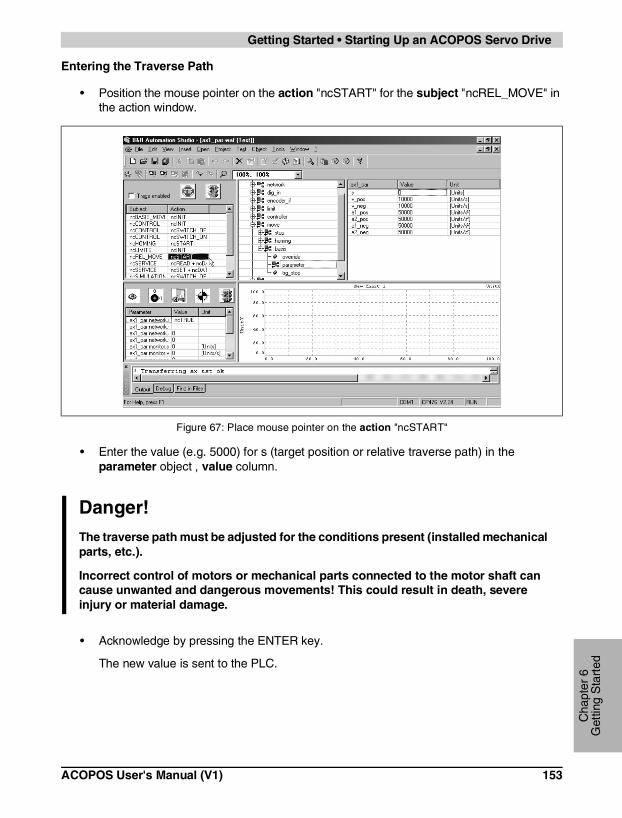
Cha
pter
6G
ettin
g S
tart
ed
Getting Started • Starting Up an ACOPOS Servo Drive
Entering the Traverse Path
• Position the mouse pointer on the action "ncSTART" for the subject "ncREL_MOVE" in the action window.
• Enter the value (e.g. 5000) for s (target position or relative traverse path) in the parameter object , value column.
• Acknowledge by pressing the ENTER key.
The new value is sent to the PLC.
Figure 67: Place mouse pointer on the action "ncSTART"
Danger!The traverse path must be adjusted for the conditions present (installed mechanical parts, etc.).
Incorrect control of motors or mechanical parts connected to the motor shaft can cause unwanted and dangerous movements! This could result in death, severe injury or material damage.
ACOPOS User's Manual (V1) 153

Getting Started • Starting Up an ACOPOS Servo Drive
Enabling the Trace Function
• Position the mouse pointer on the Trace enabled checkbox in the action window.
• Activate the checkbox by clicking on it with the left mouse button.
Figure 68: Enable trace function
154 ACOPOS User's Manual (V1)

Cha
pter
6G
ettin
g S
tart
ed
Getting Started • Starting Up an ACOPOS Servo Drive
Start the Motor Movement
• Position the mouse pointer on the action "ncSTART" for the subject "ncREL_MOVE" in the action window.
• Click on the button on the toolbar:
The motor shaft now moves according to the traverse path (s) defined and the Trace function starts.
Figure 69: Place mouse pointer on the action "ncSTART"
ACOPOS User's Manual (V1) 155

Getting Started • Starting Up an ACOPOS Servo Drive
Display and Evaluation of the Trace Function
Figure 70: During the movement of the shaft, the traverse path already completed is shown in the Watch window
Figure 71: The defined traverse path was completed and the Trace data is loaded
156 ACOPOS User's Manual (V1)

Cha
pter
6G
ettin
g S
tart
ed
Getting Started • Starting Up an ACOPOS Servo Drive
The current position of the motor shaft is shown in the Watch window:
Figure 72: The data recorded is shown in the Trace window
Display of the current position of the motor shaft
Before the shaft movement During the shaft movement After the shaft movement
Table 74: Display of the current position of the motor shaft in the Watch window
ACOPOS User's Manual (V1) 157

Getting Started • Starting Up an ACOPOS Servo Drive
The following data concerning shaft movement is displayed in the Trace window:
Set Speed
The acceleration phase, the constant speed phase and the braking phase of the shaft movement can be evaluated here.
Lag Error
In the acceleration phase for the motor shaft → increasing lag errorAt constant speed → constant lag error
In the braking phase → decreasing lag error
Actual stator current quadrature component
The various movement phases are represented here:
Acceleration of the motor shaft → current increases
Constant speed → current decreasesBraking phase → current becomes negative
Table 75: Output of the recorded data in the Trace window
158 ACOPOS User's Manual (V1)

Cha
pter
7S
tand
ards
and
C
ertif
icat
ions
Standards and Certifications
CHAPTER 7 • STANDARDS AND CERTIFICATIONS
1. Valid European Guidelines for ACOPOS Servo Drives
• EMC guidelines 89/336/EWG
• Low-voltage guidelines 73/23/EWG
• Machine guidelines 98/37/EG
2. Valid Standards for ACOPOS Servo Drives
Standard Description
IEC/EN 61800-2 Adjustable speed electrical power drive systems:
Part 2: General requirements - Rating specifications for low voltage adjustable frequency a.c. power drive systems
IEC/EN 61800-3 Adjustable speed electrical power drive systems:
Part 3: EMC product standard including specific test methods
IEC 61800-5 (draft) Adjustable speed electrical power drive systems:
Part 5: Safety requirements - Electrical and thermal
IEC/EN 61131-2 Programmable controllers:
Part 2: Equipment requirements and tests
IEC 60204-1 Safety of machinery - Electrical equipment of machines:
Part 1: General requirements
EN 1037 Safety of machinery - prevention of unexpected start-up
IEC 61508 Functional safety of electrical / electronic / programmable electronic safety-related systems
IEC 954-1 Safety of machinery - safety-related parts of control systems
Part 1: General principles of design
TÜV: Sample test for secure restart prevention according to category 3 planned
UL 508 C Power Control Equipment
Table 76: Valid Standards for ACOPOS Servo Drives
ACOPOS User's Manual (V1) 159

Standards and Certifications
3. Electrical Limit Values for Immunity Tests according to IEC 61800-3
These immunity tests are valid for industry (2nd environment).
Performance Criteria (simplified)
Criteria A: Test object not influenced during test.
Criteria B: Test object only temporarily influenced during test.
Criteria C: The system does not reboot automatically (reset required).
Tests according to IEC 61000-4-2 Electrostatic Discharge
IEC 61800-3
Contact discharge to powder-coated and bare metal housing parts
4 kV, criteria B
Discharge through the air to plastic housing parts 8 kV, criteria B
Tests according to IEC 61000-4-3 Electromagnetic Fields
IEC 61800-3
Housing, completely wired 80 MHz - 1 GHz, 10 V/m,80 % amplitude modulation with 1 kHz, criteria A
Tests according to IEC 61000-4-4 Burst
IEC 61800-3
Power lines 2 kV, 1 min, criteria B, direct coupling
Lines for measurement and control functions in the process environment
2 kV, 1 min, criteria B
Signal interfaces, other lines 1 kV, 1 min, criteria B
Tests according to IEC 61000-4-5 Surge
IEC 61800-3
Power lines 1 kV (2 Ω), DM, symmetrical, criteria B2 kV (12 Ω), CM, unsymmetrical, criteria B
Tests according to IEC 61000-4-6 HF Coupling
IEC 61800-3
Power lines
0.15 - 80 MHz, 10 V,80 % amplitude modulation with 1 kHz, criteria A
Lines for measurement and control functions in the process environment
Signal interfaces, other lines
Table 77: Electrical Limit Values for Immunity Tests according to IEC61800-3
160 ACOPOS User's Manual (V1)

Cha
pter
7S
tand
ards
and
C
ertif
icat
ions
Standards and Certifications
4. Electrical Limit Values for Emission Tests according to IEC 61800-3
These emission tests are valid for industry (2nd environment).
Tests according to IEC 55011 (conducted emissions)
Continuous Current on Motor Frequency Range [MHz] Quasi-peak Value Average
I ≤ 100 A
0.15 ≤ f < 0.5 100 dB (µV) 90 dB (µV)
0.5 ≤ f < 5 86 dB (µV) 76 dB (µV)
5 ≤ f < 30 90 dB (µV) 80 dB (µV)
100 A < I
0.15 ≤ f < 0.5 130 dB (µV) 120 dB (µV)
0.5 ≤ f < 5 125 dB (µV) 115 dB (µV)
5 ≤ f < 30 115 dB (µV) 105 dB (µV)
Tests according to IEC 55011 (radiated emissions)
Frequency Range [MHz] Quasi-peak Value
30 ≤ f ≤ 230 40 dB (µV/m), measured at distance of 30 m
230 < f ≤ 1000 50 dB (µV/m), measured at distance of 30 m
Table 78: Electrical limit values for emission tests according to IEC 61800-3
ACOPOS User's Manual (V1) 161

Standards and Certifications
5. Environmental Limit Values according to IEC 61800-2
Operational Conditions
IEC 61800-2
Environmental Temperature during Operation 5 to 40 °C
Relative Humidity during Operation 5 -85 %, non-condensing
Power Reduction in Relation to Installation Altitude 1)
1) Unusual operating conditions must be arranged with B&R.
10 % per 1000 m installation altitudeMax. 2,000 m above sea level
Degree of Pollution according to IEC 60664-1 2 (non-conductive material)
Overvoltage Category according to IEC 60364-4-443:1999
II
Protection according to IEC 60529 IP20
Vibration2 ≤ f < 9 Hz9 ≤ f < 200 Hz
0.3 mm amplitude1 m/s² acceleration
Storage and Transport Conditions
Storage Temperature -25 to +55 °C
Relative Humidity for Storage 5 - 95 %, non-condensing
Transport Temperature -25 to +70 °C
Relative Humidity for Transport 95 % at 40 °C, non-condensing
Vibration during Transport2 ≤ f < 8 Hz8 ≤ f < 200 Hz200 ≤ f < 500 Hz
3.5 mm amplitude10 m/s² acceleration15 m/s² acceleration
Table 79: Environmental Limit Values according to IEC 61800-2
162 ACOPOS User's Manual (V1)

Cha
pter
7S
tand
ards
and
C
ertif
icat
ions
Standards and Certifications
6. International Certifications
B&R products and services comply with the applicable standards. These are international standards from organizations such as ISO, IEC and CENELEC, as well as national standards of organizations such as UL, CSA, FCC, VDE, ÖVE, etc. We give special consideration to the reliability of our products in an industrial environment.
Certifications
USA and Canada All important B&R products are tested and listed by Underwriters Laboratories and are checked quarterly by a UL inspector.This mark is valid for the USA and Canada and eases certification of your machines and systems in these areas.
Listing is planned for ACOPOS servo drives.
Europe All harmonized EN standards for the valid guidelines are met.
Russian Federation A GOST-R certification is planned for the export of ACOPOS servo drives in the Russian Federation.
Table 80: International Certifications
ACOPOS User's Manual (V1) 163

Standards and Certifications
164 ACOPOS User's Manual (V1)

Index
Inde
x
Numerics
8AC110.60-2...............................................368AC120.60-1...............................................398AC122.60-1...............................................428AC123.60-1...............................................448AC130.60-1...............................................478CE005.12-1...............................................578CE007.12-1...............................................578CE010.12-1...............................................578CE015.12-1...............................................578CE020.12-1...............................................578CE025.12-1...............................................578CM005.12-1..............................................528CM005.12-3..............................................528CM005.12-5..............................................538CM005.12-8..............................................538CM007.12-1..............................................528CM007.12-3..............................................528CM007.12-5..............................................538CM007.12-8..............................................538CM010.12-1..............................................528CM010.12-3..............................................528CM010.12-5..............................................538CM010.12-8..............................................538CM015.12-1..............................................528CM015.12-3..............................................528CM015.12-5..............................................538CM015.12-8..............................................538CM020.12-1..............................................528CM020.12-3..............................................528CM020.12-5..............................................538CM020.12-8..............................................538CM025.12-1..............................................528CM025.12-3..............................................528CM025.12-5..............................................538CM025.12-8..............................................538CR005.12-1 ..............................................598CR007.12-1 ..............................................598CR010.12-1 ..............................................598CR015.12-1 ..............................................598CR020.12-1 ..............................................598CR025.12-1 ..............................................598PE001.00-1...............................................658PM001.00-1 ..............................................62
8PM002.00-1.............................................. 628PM003.00-1.............................................. 628PR001.00-1 .............................................. 658V1022.00-1............................................... 318V1045.00-1............................................... 318V1090.00-1............................................... 318V128M.00-1.............................................. 338V1640.00-1............................................... 33
A
AC110.................................................36, 116AC120.................................................38, 117AC122.................................................41, 118AC123.................................................44, 119AC130.................................................47, 120ACOPOS
1022 ................................................31, 1081045 ................................................31, 1081090 ................................................31, 108128M ...............................................33, 1121640 ................................................33, 112See Servo Drives
B
Braking resistance...................................... 94
C
CablesEncoder Cables
EnDat...........................................57, 125Resolver.......................................59, 127
General Information ................................ 51Motor Cables...................................52, 122
Cam Editor.................................................. 19CAN Bus Interface AC110..................36, 116Certifications............................................. 163Configurations
CAN......................................................... 20Connections
ACOPOS Servo Drives ......................... 108Cable and Plug......................................122Plug-in Modules ....................................116
ACOPOS User’s Manual (V1) 165

Index
ConnectorEncoder Connector
EnDat .......................................... 65, 125Resolver...................................... 65, 127
General Information.................................61Motor Connectors........................... 62, 123
Correctly installing cooling aggregates .......78Cross Sections..........................................107
D
Danger Warning..........................................22DC Bus .......................................................89Digital Mixed Module AC130 ............. 47, 120Dimensioning
Braking resistance...................................94Current Requirements of Plug-in Modules .100DC Bus ....................................................89Formula Variables .................................101Motor Connection ....................................92Power Mains Connection ........................81
Dimensions .................................................71Drive Oscilloscope ......................................18Drives
See Servo Drives
E
Electromagnetic Compatibility of the Installati-on..............................................................103Embedded Parameter Chip ........................13Encoder Cables
EnDat ............................................. 57, 125Resolver ......................................... 59, 127
Encoder ConnectorEnDat ............................................. 65, 125Resolver ......................................... 65, 127
Encoder Resolution ..................................150Encoder Systems
EnDat Encoder Interface ................ 39, 117Incremental/SSI Encoder IF ........... 44, 119
Resolver interface ...........................42, 118EnDat Cables
Cable Schematic ................................... 126Order Data .............................................. 57Pin Assignments ................................... 125Specifications .......................................... 57Structure................................................125
EnDat ConnectorOrder Data .............................................. 65Pin Assignments ................................... 125Specifications .......................................... 66
EnDat Encoder Interface AC120 ........39, 117
F
Formula Variables ....................................101Function Test......................................17, 155
G
Getting Started .........................................129Guidelines................................................. 159
I
Incremental/SSI Encoder IF AC123 ...44, 119Installation ................................... 23, 69, 103Installation Dimensions............................... 71
L
Limit Values..............................................160
M
Modular Servo Drive Concept .................... 27Motor Cables
Cable Schematic ...........................123, 124Order Data .............................................. 52Pin Assignments ...........................123, 124Specifications .......................................... 54Structure................................................122
166 ACOPOS User’s Manual (V1)
Index
Inde
x
Motor ConnectorsOrder Data...............................................62Pin Assignments........................... 123, 124Specifications ..........................................63
MotorsConfigurations .........................................20Embedded Parameter Chip.....................13General Information.................................13
N
NC Objects .................................................16
P
Plug-in ModulesAC110 ............................................ 36, 116AC120 ............................................ 38, 117AC122 ............................................ 41, 118AC123 ............................................ 44, 119AC130 ............................................ 47, 120Current Requirements ...........................100General Information.......................... 14, 35Installation and Removal .........................74Overview .................................................35
Power Mains Connection............................81Programming ..............................................15Protective Ground Connection (PE) .. 82, 111
R
Resolver CablesCable Schematic ...................................128Order Data...............................................59Pin Assignments....................................127Specifications ..........................................60Structure................................................127
Resolver ConnectorOrder Data...............................................65Pin Assignments....................................127Specifications ..........................................67
Resolver Interface AC122.................. 42, 118
S
Safety Guidelines ....................................... 22Sample Project .........................................130Security.................................................13, 14Service........................................................ 15Servo Drives
ACOPOS 1022, 1045, etc. ..............31, 108Cables
See CableCam Editor .............................................. 19Concept................................................... 27Configurations
CAN ..................................................... 20Connections .......................................... 108Connector
See ConnectorsDanger Warning ...................................... 22Dimensioning .......................................... 81Dimensions ............................................. 71Drive Oscilloscope .................................. 18Function Test ..................................17, 155General Information ..........................13, 27Installation ................................ 23, 69, 103Installation Dimensions ........................... 71NC Objects.............................................. 16Order Data .............................................. 31Plug-in Modules ........ 14, 35, 74, 100, 116Programming........................................... 15Safety Guidelines .................................... 22Sample Project......................................130Service .................................................... 15Software .................................................. 15Start-up ................................................. 129Status LEDs ............................................ 29Storage.................................................... 22Technical Data ........................................ 31Trace ...............................................17, 155Transport................................................. 22Trigger..................................................... 18Wiring .................................................... 103
ACOPOS User’s Manual (V1) 167

Index
Shield Connection.....................................105Software......................................................15Software End Switches.............................151Standards .................................................159Start-up .....................................................129Status LEDs
ACOPOS .................................................29Storage .......................................................22
T
Terminal Cross Sections ..........................107Trace ..................................................17, 155Transport .................................................... 22Trigger ........................................................ 18
W
Wiring .......................................................103
168 ACOPOS User’s Manual (V1)