User's Manual - Pureland Supply
153
Downloaded from Projector.com User's Manual Table of Contents 54-017115-13P Software Version 2.1 (10/02) Roadster/Vista User's Manual iii Section Contents Page 1.1 The Projectors ................................................................................................... 1-1 1.2 Components ...................................................................................................... 1-2 1.3 Purchase Record and Warranty Registration..................................................... 1-2 2.1 Quick Setup....................................................................................................... 2-1 2.2 Installation Considerations ................................................................................ 2-3 2.3 Projector Position and Mounting .................................................................... 2-10 2.4 Source Connections ........................................................................................ 2-15 2.5 Power Connection ........................................................................................... 2-24 2.6 Operating Orientation ..................................................................................... 2-24 2.7 Leveling .......................................................................................................... 2-24 2.8 Zoom, Focus & Lens Offset ............................................................................ 2-25 2.9 Serial Port Connections................................................................................... 2-27 2.10 Keypad Protocols and Conversion .................................................................. 2-34 3.1 Overview........................................................................................................... 3-1 3.2 Projector Basics ................................................................................................ 3-1 3.3 Using the Keypad .............................................................................................. 3-4 3.4 Navigating the Menus ..................................................................................... 3-14 3.5 Using Inputs and Channels.............................................................................. 3-18 3.6 Adjusting the Image ........................................................................................ 3-24 3.7 Configuring System Parameters ...................................................................... 3-41 3.8 Working With the Lamp ................................................................................. 3-47 3.9 Projector Status ............................................................................................... 3-50 3.10 Using Multiple Projectors ............................................................................... 3-51 3.11 Error Conditions ............................................................................................. 3-54 4.1 Warnings and Guidelines .................................................................................. 4-1 4.2 Cleaning ............................................................................................................ 4-3 4.3 Replacing Keypad Batteries .............................................................................. 4-3 4.4 Replacing the Lamp and Filter .......................................................................... 4-4 4.5 Replacing the Lens ............................................................................................ 4-9 4.6 Troubleshooting .............................................................................................. 4-12 5.1 Specifications .................................................................................................... 5-1 A Glossary ........................................................................................................... A-1 B Keypad Reference ........................................................................................... B-1 C Menu Tree ........................................................................................................ C-1 D Serial Communication Cables .......................................................................... D-1 E Throw Distance ................................................................................................ E-1 F Optional Input Modules ................................................................................... F-1 NOTE: Due to continuing research, all information in this manual is subject to change without notice 1 Introduction 2 Installation & Setup 3 Operation 4 Maintenance 5 Specifications 6 Appendices
-
Upload
khangminh22 -
Category
Documents
-
view
4 -
download
0
Transcript of User's Manual - Pureland Supply

Downlo
aded
from
Pro
jecto
r.comUser 's Manual
Table of Contents
54-017115-13P Software Version 2.1 (10/02) Roadster/Vista User's Manual iii
Section Contents Page
1.1 The Projectors...................................................................................................1-11.2 Components ......................................................................................................1-21.3 Purchase Record and Warranty Registration.....................................................1-2
2.1 Quick Setup.......................................................................................................2-12.2 Installation Considerations................................................................................2-32.3 Projector Position and Mounting ....................................................................2-102.4 Source Connections ........................................................................................2-152.5 Power Connection...........................................................................................2-242.6 Operating Orientation .....................................................................................2-242.7 Leveling ..........................................................................................................2-242.8 Zoom, Focus & Lens Offset ............................................................................2-252.9 Serial Port Connections...................................................................................2-272.10 Keypad Protocols and Conversion..................................................................2-34
3.1 Overview...........................................................................................................3-13.2 Projector Basics ................................................................................................3-13.3 Using the Keypad..............................................................................................3-43.4 Navigating the Menus .....................................................................................3-143.5 Using Inputs and Channels..............................................................................3-183.6 Adjusting the Image ........................................................................................3-243.7 Configuring System Parameters ......................................................................3-413.8 Working With the Lamp .................................................................................3-473.9 Projector Status...............................................................................................3-503.10 Using Multiple Projectors ...............................................................................3-513.11 Error Conditions .............................................................................................3-54
4.1 Warnings and Guidelines ..................................................................................4-14.2 Cleaning ............................................................................................................4-34.3 Replacing Keypad Batteries..............................................................................4-34.4 Replacing the Lamp and Filter ..........................................................................4-44.5 Replacing the Lens............................................................................................4-94.6 Troubleshooting ..............................................................................................4-12
5.1 Specifications....................................................................................................5-1
A Glossary ...........................................................................................................A-1B Keypad Reference ...........................................................................................B-1C Menu Tree........................................................................................................ C-1D Serial Communication Cables ..........................................................................D-1E Throw Distance................................................................................................ E-1F Optional Input Modules ................................................................................... F-1
NOTE: Due to continuing research, all information in this manual is subject to change without notice
1 Introduction
2 Installation &Setup
3 Operation
4 Maintenance
5 Specifications
6 Appendices

Downlo
aded
from
Pro
jecto
r.comSect ion 1
Introduction
Roadster/Vista User’s Manual 1-1
The Vista and Roadster projectors are professional quality DMD projectors that useDigital Light Processing (DLP) technology from Texas Instruments to achievehigh-brightness multimedia and video projection. All models are compatible withstandard international video formats and can interface with IBM-compatible PC,Macintosh computers and workstations. Vista models are ideal for mounting in
large audience venues in which there may behigh levels of ambient light, such as incorporate boardrooms, auditoriums, and lecturehalls. The Roadster offers this same high levelof performance but with additional ruggednessenabling frequent transport, changinginstallations and easy stacking of multipleprojectors. This robust projector is well-suitedfor use in outdoor stages and arenas. Vista andRoadster features include:
◊ Native resolution of 1024 x 768 (X models) or 1280 x 1024 (S models), scaleable◊ Brightness (ANSI lumens, ±10%):
• Vista X3/S3 = 3000 • Roadster X4/S4 = 4000 (note: X4/S4 discontinued)• Vista X5/S5 = 5000, Roadster X6/S6 = 6000 (note: Vista S5 discontinued)• Roadster X9/S9 = 8500
◊ Contrast Ratio• Vista X3/X5, Roadster X4/X6 = 300:1 ANSI, 500:1 full on/off• Roadster X9 = 400:1 ANSI, 500:1 full on/off• Roadster S9 = 400:1 ANSI, 800:1 full on/off• “S” models with 700W or 1200W lamp/power supply = 300:1 ANSI, 800:1 full on/off
◊ Smooth and versatile remote control of lens, with Intelligent Lens System (ILS™) for recallof lens settings from source-to-source (standard in Roadster only)
◊ Tandem horizontal and vertical sizing software control◊ Independent vertical stretch for changing aspect ratios◊ Keystone adjustment via menu option (“X” models only)◊ Interchangeable lenses for diagonal screen sizes up to 40 or more feet◊ Display of NTSC, PAL and SECAM video input◊ Display from PCs, VCRs, laser disc players, video cameras, etc.◊ Intuitive on-screen menus or hidden direct control with built-in or remote keypad◊ Memory for up to 99 custom “channels” (source setups) accessible with keypress◊ Controller and switcher compatibility◊ Built-in RS-232 and RS-422 ports for computer control and networked projectors◊ Remote-controlled shutter (optional in Vista models)
◊ Rugged functional design for harsh environments and secure handling (Roadster)◊ Simple hardware option for hoisting and for stacking multiple projectors (Roadster)◊ Modular design for easy servicing. Exterior panels of metal and polymer.
1.1 The Projectors
(Roadster model shown)

Downlo
aded
from
Pro
jecto
r.com
INTRODUCTION
1-2 Roadster/Vista User’s Manual
Vista and Roadster accept data/graphics and video input signals for projection on tofront or rear flat screens. High brightness light is generated by an internal Xenon arclamp, then modulated by three DMD (digital micromirror device) panels that providedigitized red, green or blue color information. Light from the “on” pixels of eachpanel is reflected, converged and then projected to the screen through a single frontlens, where all pixels are perfectly superimposed as a sharp full-color image.
Included with Vista and Roadster is an infrared (IR) remote keypad, a power cord, a9/64” hex socket ball driver, eyebolts (Roadster only) and a Roadster/Vista User’sManual. Make sure that you received everything.
Figure 1.1. Components (SHOWN: Roadster WITH ADDED LENS)
Differences Between Roadster and Vista Models
Motorized Lens Shutter Audio Handles & Slot Covers Stacking Slots Eyebolts
Roadster U U discontinued U U UVista optional optional U not available not available optional
U = Standard
MODELS and AVAILABILITY: The Roadster line and the Vista line both offer modelsdiffering in light output and/or image resolution. All combinations are documented inthis manual, however the following models are no longer manufactured:
Roadster X4 / S4 Vista S5
Whether the projector is under warranty or the warranty has expired, Christie’shighly trained and extensive factory and dealer service network is always available toquickly diagnose and correct projector malfunctions. Complete service manuals andupdates are available to service technicians for all projectors.
Should you encounter a problem with the projector and require assistance, contact yourdealer or Christie. In many cases, any necessary servicing can be performed on site. Ifyou have purchased the projector, fill out the Purchase Record below and keep with yourrecords. In addition, make sure to complete the Warranty Registration at the Christiewebsite—this will ensure that you receive all future product communications promptly.
Purchase Record
Dealer:
Dealer Phone Number:
Projector Serial Number*:
Purchase Date:
Installation Date, if applicable:
* NOTE: The projector serial number is located on the projector's rear identification label
How The Projectors Work '
1.2 Components
1.3 PurchaseRecord andWarrantyRegistration

Downlo
aded
from
Pro
jecto
r.comSect ion 2
Installation & Setup
Roadster/Vista User’s Manual 2-1
This section explains how to install and set up the projector. If you are familiar with the projector and want to quicklyset it up for temporary use, follow the Quick Setup instructions below. For a more complete setup, follow theinstructions and guides covered in the remaining subsections. This section assumes that the video decoder is installed.
NOTE: The lens is not installed for shipping. For instructions on how to install or replace a lens, refer to 4.5,Replacing the Lens.
Follow these steps for quick setup of the projector in a standard floor mount position.
Position the Projector
Set the projector at the expected throw distance (projector-to-screen distance) andvertical position. See 2.3, Projector Position and Mounting and Appendix E. Makesure that the projector is level from side-to-side (see 2.7, Leveling).
Connect a Source
Locate the main input panel at the rear of the projector. The lower left area, labeledINPUT 1, accepts an RGB input via BNC connectors. The upper right area (assuminga video decoder is installed) accepts a composite video at INPUT 3 or S-video input atINPUT 4. Connect your source to the appropriate panel connectors.
Connect the Line Cord to AC Power
Connect the projector’s line cord to the AC receptacle at the lower right rear corner of theprojector and to proper AC. Use the line cord provided with the projector (see Section 5).
Model AC Power Required
X/S3 and X/S4 100-240 VAC, 50-60 Hz, max. 11.5 amps @ 100V
X/S5 and X/S6 200-240 VAC, 50-60 Hz, max. 8.5 amps @ 200V
X9/S9 200-240 VAC, 50-60 Hz, max. 12 amps @ 200V
WARNINGDo not attempt operation if the AC supply and cord are not
within the specified voltage and power range. See Section 5.
Turn the Projector ON
Using either the built-in or remote keypad, press Power* and hold for approximately 1second to turn the projector on (or press Power* ON ). Let the projector warm up forabout five minutes. The POWER LED, located in the lower right corner of the rearinput panel, should glow a steady green.
2.1 Quick Setup
STEP 1 '
STEP 2 '
STEP 3 '
STEP 4 '
Downlo
aded
from
Pro
jecto
r.com
INSTALLATION AND SETUP
2-2 Roadster/Vista User’s Manual
Select a Source
Using either the built-in or remote keypad, press Input1 , Input2 , Input3 , or Input4 to selectand display the image for the source you connected in Step 2. The display will resizeas needed, producing an image as large as possible for the type of source present.
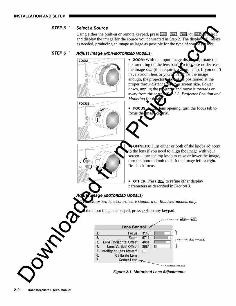
Adjust Image (NON-MOTORIZED MODELS)
• ZOOM: With the input image displayed, rotate thetextured ring on the lens barrel to increase or decreasethe image size (this requires a zoom lens). If you don’thave a zoom lens or you can’t adjust the imageenough, the projector may not be positioned at theproper throw distance for your screen size. Powerdown, unplug the projector and move it towards oraway from the screen. See 2.3, Projector Position andMounting for details.
• FOCUS: At the lens opening, turn the focus tab tofocus the image clearly.
• OFFSETS: Turn either or both of the knobs adjacentto the lens if you need to align the image with yourscreen—turn the top knob to raise or lower the image,turn the bottom knob to shift the image left or right.Re-check focus.
• OTHER: Press Menu to refine other displayparameters as described in Section 3.
Adjust Image (MOTORIZED MODELS)
NOTE: Motorized lens controls are standard on Roadster models only.
With the input image displayed, press Lens on any keypad.
Figure 2.1. Motorized Lens Adjustments
STEP 5 '
STEP 6 '

Downlo
aded
from
Pro
jecto
r.com
INSTALLATION AND SETUP
Roadster/Vista User’s Manual 2-3
If you’ve just installed the lens, select “Calibrate Lens” before making anyadjustments (see Section 3 for details). Then, with the Lens Control menu displayed,use the keypad as shown in Figure 2.1 to focus the image clearly and, if a zoom lensis present, to increase or decrease image size. If desired, adjust horizontal and/orvertical offsets to shift the lens and image location—ranges are shown in 2.3,Projector Position and Mounting.
Press Menu to refine other display parameters, if necessary. See 3.5, Using Inputs andChannels if you want to work with other source inputs or defined channels.
You may want to reduce initial setup time by starting with an “Auto Setup”. Theprojector will automatically optimize a variety of display settings according to theincoming source detected. You can then re-adjust these settings at any time, ifdesired.
Although this projector delivers a high brightness quality output, final display qualitycould be compromised if the projector is not properly installed. This subsectiondiscusses issues you should consider before proceeding with a final installation. Evenif you do not intend to use the projectors in a fixed and permanent installation, thissubsection will help you to better understand what you can do to enhance displayperformance.
For any new installation, you will likelyhave to safely lift or hoist the projector intoplace. Keep in mind the followingguidelines for safety.
Lifting
The Roadster model includes a set of sidehandles for convenient brief hand transport,such as when a single projector is lifted orcarried over short distances by 2 people, orfor the addition of safety straps when hoisting (see Hoisting, below). Note that thesehandles are not intended to support the entire weight of the projector for extendedperiods of time, nor can a set of handles support the weight of more than a singleprojector. In particular, never hoist or suspend the projector from these handles alone.
Vista models do not have handles.
WARNING Do not use the side handles to suspend the projector.
Hoisting
Safely hoisting the projector into place requires hoisting hardware available in aChristie Hoisting/Stacking Kit specially designed for the projector, as well asappropriate nylon webbed safety straps and rigging equipment. Never hoist aprojector by its feet, handles or any other component (Figure 2.3).
IMPORTANT It is recommended that you removethe lens before hoisting a projector.
2.2 InstallationConsiderations
Lifting, Hoisting 'and Stacking

Downlo
aded
from
Pro
jecto
r.com
INSTALLATION AND SETUP
2-4 Roadster/Vista User’s Manual
TO HOIST INVERTED
Roadsters: For one projector,remove the feet, insert 4eyebolts provided and attach ahoisting/rigging frame thatwill enable cables to remainvertical at all times. Addsafety strapping at the sidehandles before hoisting intoplace. Never hoist or suspenda projector if there is any slackin cabling or straps, and keepall cables in place for a“flown” installation. NOTE:Use straps and cabling withload capacity adequate forthe projector weight. SeeSection 5. For a stack of two projectors, remove the small chrome cover near eachcorner of the lid, and install the threaded rods and heavy-duty eyebolt couplingsprovided in the Christie Hoisting/Stacking Kit. NOTE: Follow all instructionsprovided with the kit. Use a minimum of one safety strap per projector–i.e., if you arehoisting a stack of 2 projectors, both projectors must have their own safety strapattached. See Figure 2.5.
Figure 2.3. Do not hoist by handles or feet. Do not angle cables or straps.
TO HOIST NON-INVERTED Roadsters: You must use the hoisting hardware availablein a Christie Hoisting/Stacking Kit specially designed for the projector–follow theinstructions provide with the kit. Hoist with cabling and straps as described forinverted Roadsters, above.
TO HOIST AN INVERTED or NON-INVERTED Vista: Securely wrap hoisting cabling andsafety straps around the whole projector. Attach to the proper Christie ceiling mountonly–never suspend or “fly” this model.
NOTE: Vista models cannot use the Christie Hoisting/Stacking Kit for hoisting intoplace.
Stacking
See Figure 2.4. A maximum of 2 Roadster projectors can be safely secured togetherwith the Christie Hoisting/Stacking Kit hardware–follow all instructions provided inthe kit. For safety, one projector should never “rest” on another without the proper
Figure 2.2. Minimum Hoisting Configuration forOne Projector (Roadster ONLY)

Downlo
aded
from
Pro
jecto
r.com
INSTALLATION AND SETUP
Roadster/Vista User’s Manual 2-5
stacking hardware (available separately) in place, firmly securing the projectorstogether. If you are hoisting a stack, secure a safety strap to at least one handle ofeach projector–keep the strap taut.
NOTE: Vista models cannot be stacked.
WARNING Do not stack projectors without using Christie
Hoisting/Stacking hardware. The top projector couldslide off and cause injury or death.
WARNING Do not carry a stack.
Figure 2.4. Stacking (Roadster only). Requires optional hardware.
WARNING Do not invert only one projector within a stack.
TO HOIST STACKED Roadsters: Securethe projectors together with ChristieHoisting/Stacking Kit hardware,following the instructions provided inthe kit. Hoist with cabling and straps asdescribed in Hoisting, above–makesure to use at least one safety strap oneach projector in the stack. See Figure2.5.
WARNING Use Christie Hoisting/Stacking
hardware only.
Figure 2.5. Hoisting a Stack, MinimumConfiguration (SHOWN INVERTED)

Downlo
aded
from
Pro
jecto
r.com
INSTALLATION AND SETUP
2-6 Roadster/Vista User’s Manual
Choose the installation type which suits your needs: front or rear screen, floor mountor inverted mount.
Front Screen, Floor Mount Installation
ADVANTAGES CONSIDERATIONS
• Easy to set up• Can be moved or changed quickly• Easy to access
• Shares floor space with audience
Front Screen, Inverted Mount (ceiling) Installation
ADVANTAGES CONSIDERATIONS
• Does not take up audience space• Projector is unobtrusive• Projector cannot be accidentally moved
• Installation is more permanent• It is more difficult to access the projector
Rear Screen, Floor Mount Installation
ADVANTAGES CONSIDERATIONS
• Projector is completely hidden• Projector is easily accessed• Usually good ambient light rejection
• Requires separate room
Rear Screen, Inverted Mount (ceiling) Installation
ADVANTAGES CONSIDERATIONS
• Projector is completely hidden• Usually good ambient light rejection
• Requires separate room• Installation cost is usually higher
Rear Screen, Floor Mount with Mirror
ADVANTAGES CONSIDERATIONS
• Projector is completely hidden• Usually good ambient light rejection• Requires less space behind screen than
other rear screen installations
• Requires separate room• Installation cost is usually higher
Front Screen Installations
While there are two basic screen types, flat and curved, generally flat screens arerecommended for this projector. Flat screens offer a gain of about 1 with a viewingangle just less than 180°. Incident light reflects equally in all directions so theaudience can see the display from various angles. Because of the low gain, flatscreens are most effective when ambient lighting is reduced, although this differencemay be negligible given the high brightness output from this projector.
Figure 2.6. Audience Coverage with Flat Screen
Installation Type '
Screen Type '

Downlo
aded
from
Pro
jecto
r.com
INSTALLATION AND SETUP
Roadster/Vista User’s Manual 2-7
NOTE: Lenses for this projector are designed primarily for use with flat screens, butthe projector depth-of-field range allows the lens to be focused on curved screens aswell. While focus remains sharp in the corners, there may be significant pincushiondistortion, primarily at the top of the screen.
Rear Screen Installations
There are two basic types of rear screens: diffused and optical. A diffused screen hasa surface which spreads the light striking it. Purely diffused screens have a gain ofless than 1. The main advantage of the diffused screen is its wide viewing angle,similar to that of a flat screen for front screen projection. Optical screens take lightfrom the projector and redirect it to increase the light intensity at the front of thescreen. This reduces it in other areas. A viewing cone, similar to that of a curvedfront screen installation, is created.
To summarize, optical screens are better suited for brightly lit rooms where theaudience is situated within the viewing cone. Diffused screens may be better suitedwhen a wide viewing angle is required but there is low ambient room lighting.
Screen size may be from 5 to 40 feet diagonal, depending on the lens you are using.For instance, a 1.2:1 lens can produce a 5 to 25 foot image size, whereas a 4-7:1zoom lens produces an 8 to 40 foot image size. Choose a screen size which isappropriate for your lens and application. Keep in mind that if the projector will beused to display text information, the image size must allow the audience to recognizeall text clearly. The eye usually sees a letter clearly if eye-to-text distance is less than150 times the height of the letter. Small text located too far from the eye may beillegible at a distance no matter how sharply and clearly it is displayed.
To fill a screen with an image, the aspect ratio of the screen should be equal to theaspect ratio of the image. The aspect ratio of an image is expressed as the ratio of itswidth to its height. Standard video from a VCR has a 4:3 aspect ratio. For example,to display a VCR output with a 4:3 aspect ratio onto a 10 foot (3m) high screen, thewidth of the screen must be at least 13.3 feet (4m).
Aspect ratio describes the proportion of the screen and is expressed as the ratio ofwidth to height, such as “4:3” or “5:4” (see right). Although image size and imageaspect ratio can both be adjusted quickly through projector software, it is still a goodidea to choose a screen aspect ratio which is most appropriate for your intendedapplications. Ideally, to exactly fill a screen with an image, the aspect ratio of thescreen should correspond to the aspect ratio of the image, which depends on thesource in use. For example, standard video from a VCR has a 4:3 ratio(approximately), whereas a high resolution graphics signal typically has a 5:4 aspectratio. By default, images from your projector will be as large as possible and, withthe exception of graphics sources, will maintain their aspect ratio.
NOTE: With a few exceptions, sources with less than 1280 x 1024 resolution have a4:3 aspect ratio. The normal aspect ratio for 1280 x 1024 sources is 5:4.
Screen Size '
Screen Aspect Ratio '

Downlo
aded
from
Pro
jecto
r.com
INSTALLATION AND SETUP
2-8 Roadster/Vista User’s Manual
Using a 5:4 Screen with “S” Models
With one exception, XGA images will—by default—resize to fill an SXGA screenwith “S” models. The exception(illustrated in Figure 2.7) is that videosignals will retain their aspect ratio—fillthe screen by increasing Vertical Stretchto slightly expand the image to the top andbottom edges of the screen. For details,see 3.6, Adjusting the Image.
Using a 4:3 Screen with “S” Models
If you are using a 4:3 screen with “S” models (which produce 5:4 images), imageswill—by default—slightly overlap the screen vertically. To remedy, reduce VerticalStretch so that the “too tall” 5:4 image no longer spills over the top or bottom of thescreen (Figure 2.8). This control eliminates the need for simply moving the projectorfarther from the screen, which would result in black borders for all sources. See 3.6,Adjusting the Image.
NOTE: The Vertical Stretch adjustment may soften the image slightly, but is notnoticeable in most cases.
Figure 2.8. Using a 4:3 Screen for a mix of 5:4 and 4:3 sources (“S” models)
The high brightness output of this projector is certainly well suited for locationswhere ambient lighting is less than optimum for projection, yet there are still manysimple things you can do to optimize your installation.
Visiting a movie theater can give you an idea of what makes an ideal projectionenvironment. Walls, floors and furnishings are dark and matte finished. A projectionroom should not have white reflective ceilings or non-directional lighting such asfluorescent lights. The white ceiling spreads light, making the room appear brighter.Keep lighting and reflections to a minimum.
If it is not possible to eliminate fluorescent lights, consider using incandescent spotlighting or parabolic reflectors ("egg crates") to direct light down to the floor. Lightdimmers or rheostats allow further control.
Outside windows are undesirable in any projection room. A small crack betweencurtains on a sunny day can wash out a projected image. If you do have windows,make sure that window coverings are opaque and overlapping — some windowcoverings are designed to provide up to 100 percent blockage of outside light.Ideally, the material should have a matte finish.
Figure 2.7. Adjusting a 4:3 VideoImage
Ideal Room Lighting '

Downlo
aded
from
Pro
jecto
r.com
INSTALLATION AND SETUP
Roadster/Vista User’s Manual 2-9
To minimize the effects caused by unwanted light from door and aisle ways,carefully choose the position of your projector and screen. Figure 2.9 shows aninstallation where poor screen placement allows too much unwanted light to enter thescreen. In Figure 2.10, screen and the projector are positioned so that unwanted lightis minimized.
Figure 2.9. Poor Screen Placement
Figure 2.10. Better Screen Placement
Even with all lighting removed it is still possible that room reflections within theroom can slightly degrade the image. Light from the projection screen should beabsorbed by the ceilings, walls and floors so that it will not be reflected back to thescreen. Again, keep reflective surfaces to a minimum.
Here are some other considerations and tips which can help you improve yourinstallation:
• Ventilation is an important factor when preparing a projection room. The ambienttemperature should be kept constant and below 35°C (95°F). Keep the projectoraway from heating and/or air conditioning vents. Changes in temperature cancause drifts in the projector circuitry which may affect performance.
• Keep the projector away from devices which radiate electromagnetic energy suchas motors and transformers. Common sources of these are slide projectors,speakers, power amplifiers, elevators, etc.
Other Considerations '
Downlo
aded
from
Pro
jecto
r.com
INSTALLATION AND SETUP
2-10 Roadster/Vista User’s Manual
• For rear screen applications, less space is required if a mirror is used to fold theoptical path.
• Choose the right screen size for the application:
◊ As screen size increases, magnification increases and reduces brightness.Select a screen size which is appropriate for the venue, but not largerthan that required.
◊ Installing a large screen in a small room is similar to watching televisionclose up; too large a screen can overpower a room. A good rule of thumbis to be no closer than 1.5 times the width of the screen.
◊ Larger screens require greater attention to lighting conditions.
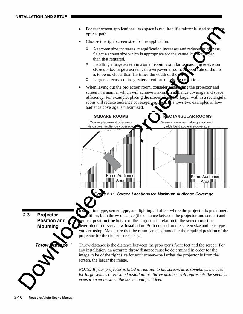
• When laying out the projection room, consider positioning the projector andscreen in a manner which will achieve maximum audience coverage and spaceefficiency. For example, placing the screen along the larger wall in a rectangularroom will reduce audience coverage. Figure 2.11 shows two examples of howaudience coverage is maximized.
Figure 2.11. Screen Locations for Maximum Audience Coverage
Installation type, screen type, and lighting all affect where the projector is positioned.In addition, both throw distance (the distance between the projector and screen) andvertical position (the height of the projector in relation to the screen) must bedetermined for every new installation. Both depend on the screen size and lens typeyou are using. Make sure that the room can accommodate the required position of theprojector for the chosen screen size.
Throw distance is the distance between the projector's front feet and the screen. Forany installation, an accurate throw distance must be determined in order for theimage to be of the right size for your screen–the farther the projector is from thescreen, the larger the image.
NOTE: If your projector is tilted in relation to the screen, as is sometimes the casefor large venues or elevated installations, throw distance still represents the smallestmeasurement between the screen and front feet.
2.3 ProjectorPosition andMounting
Throw Distance '
Downlo
aded
from
Pro
jecto
r.com
INSTALLATION AND SETUP
Roadster/Vista User’s Manual 2-11
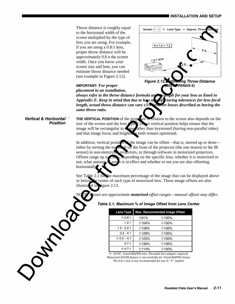
Throw distance is roughly equalto the horizontal width of thescreen multiplied by the type oflens you are using. For example,if you are using a 0.8:1 lens,proper throw distance will beapproximately 0.8 x the screenwidth. Once you know yourscreen size and lens, you canestimate throw distance needed(see example in Figure 2.12).
IMPORTANT: For properplacement in an installation,always refer to the throw distance formula and/or graph for your lens as listed inAppendix E. Keep in mind that due to lens manufacturing tolerances for lens focallength, actual throw distance can vary ±5% between lenses described as having thesame throw ratio.
THE VERTICAL POSITION of the projector in relation to the screen also depends on thesize of the screen and the lens type. Correct vertical position helps ensure that theimage will be rectangular in shape rather than keystoned (having non-parallel sides)and that image focus and brightness both remain optimized.
In addition, vertical position of the image can be offset—that is, moved up or done—either by turning the top knob on the front of the projector (the one nearest to the IRsensor) in non-motorized projectors, or through software in motorized projectors.Offsets range up to 130%, depending on the specific lens, whether it is motorized ornot, what amount of zoom is in effect and whether or not you are also offsettinghorizontally.
See Table 2.1 for the maximum percentage of the image that can be displayed aboveor below the center of each type of motorized lens. These image offsets are alsoillustrated in Figure 2.13.
NOTE: Shown are approximate motorized offset ranges—manual offsets may differ.
Table 2.1. Maximum % of Image Offset from Lens Center
Lens Type Max. Recommended Image Offset
✻ 0.8:1 91% 100%
1.2:1 104% 100%
1.5 - 2.2:1 128% 100%
2.2 - 4:1 128% 100%
✻ 2.5 – 4:1 123% 100%
4-7:1 130% 100%
✻ 4-7:1 114% 100%
✻ NOTE: VistaGRAPHX lens. Threaded lens adapter required.Motorized ZOOM feature is not available for VistaGRAPHX lenses.
The 0.8:1 lens is not recommended for use in “S” models.
Figure 2.12. Estimating Throw Distance(SEE APPENDIX E)
Vertical & Horizontal 'Position

Downlo
aded
from
Pro
jecto
r.com
INSTALLATION AND SETUP
2-12 Roadster/Vista User’s Manual
Figure 2.13. Maximum Vertical Offsets
Continued…

Downlo
aded
from
Pro
jecto
r.com
INSTALLATION AND SETUP
Roadster/Vista User’s Manual 2-13
Figure 2.13. Maximum Vertical Offsets, Continued (ALL LENSES)
NOTES: 1) If you cannot raise orlower the image enough usingmechanical vertical offsets, tryadjusting V-Position in the Sizeand Position menu (see 3.6,Adjusting the Image). 2) If theimage becomes keystoned orexhibits uneven brightness, theprojector may simply be too highor low in relation to the screen. 3) Recommended offset ranges can be exceeded,however this may affect image quality. 4) Simultaneous horizontal and vertical offsetlimits the adjustment range of each.
THE HORIZONTAL POSITION of the image can be offset—that is, shifted left or rightof lens center—either by turning the bottom knob on the front of the projector (theknob farthest from the IR sensor) in non-motorized projectors or through software inmotorized projectors. The maximum horizontal offset for lenses that can be installedin this projector is shown in Figure 2.14. This value expresses the maximumpercentage of the image that can be projected to one side of the lens center (roughly77%, depending on the lens).

Downlo
aded
from
Pro
jecto
r.com
INSTALLATION AND SETUP
2-14 Roadster/Vista User’s Manual
Figure 2.14. Maximum Horizontal Offsets (ALL LENSES)
For typical front or rear floor mounts, mount the projector on asecure table or cart. Take care with a mobile cart—avoidsudden stops, excessive force and uneven surfaces that maycause the projector and cart combination to overturn.
The table or cart should be reasonably level. Fine adjustments to the projector levelcan be made by adjusting the height of the projector legs; refer to 2.7, Leveling fordetails.
Special Mounting
Note that projector can be rotated and mounted at any vertical angle—i.e., you cantilt the face of the projector up or down as much as desired for your installation. Theside-to-side tilt, however, must not exceed 15° (see Figure 2.15). This limit ensuresthat the arc lamp in the projector operates properly and safely. Always make sure thatexhaust air from the projector does not vent towards the lens, otherwise you maydetect heat waves in your projected image.
Figure 2.15. Horizontal and Vertical Tilt Ranges
You must use the proper ceiling mount fixture or stacking kit for your projector. Formore information, contact your dealer.
Mounting '
Downlo
aded
from
Pro
jecto
r.com
INSTALLATION AND SETUP
Roadster/Vista User’s Manual 2-15
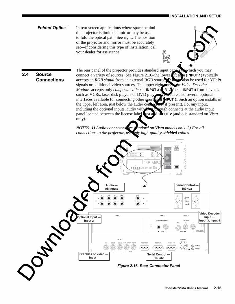
In rear screen applications where space behindthe projector is limited, a mirror may be usedto fold the optical path. See right. The positionof the projector and mirror must be accuratelyset—if considering this type of installation, callyour dealer for assistance.
The rear panel of the projector provides standard input panels to which you mayconnect a variety of sources. See Figure 2.16–the lower left area (INPUT 1) typicallyaccepts an RGB signal from an external RGB source, or it can also be used for YPbPrsignals or additional video sources. The upper right panel–the Video DecoderModule–accepts only composite video at INPUT 3 or S-video at INPUT 4 from devicessuch as VCRs, laser disk players or DVD players. There are also several optionalinterfaces available for connecting other sources at INPUT 2. Such an option installs inthe upper left area, just below the audio connectors (if present). For any input,including the optional inputs, audio with loop through connects at the audio inputpanel located between the license label area and INPUT 2 (audio is standard on Vistaonly).
NOTES: 1) Audio connectors are standard on Vista models only. 2) For allconnections to the projector, use only high-quality shielded cables.
Figure 2.16. Rear Connector Panel
Folded Optics '
2.4 SourceConnections
Downlo
aded
from
Pro
jecto
r.com
INSTALLATION AND SETUP
2-16 Roadster/Vista User’s Manual
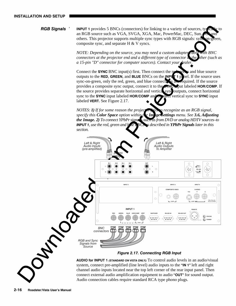
INPUT 1 provides 5 BNCs (connectors) for linking to a variety of sources, typically toan RGB source such as VGA, SVGA, XGA, Mac, PowerMac, DEC, Sun, SGI andothers. This projector supports multiple sync types with RGB signals: sync-on-green,composite sync, and separate H & V syncs.
NOTE: Depending on the source, you may need a custom adapter cable with BNCconnectors at the projector end and a different type of connector at the other (such asa 15-pin "D" connector for computer sources). Contact your dealer.
Connect the SYNC BNC input(s) first. Then connect the red, green and blue sourceoutputs to the RED, GREEN, and BLUE BNCs on the INPUT 1 panel. If the source usessync-on-green, only the red, green, and blue connections are required. If the sourceprovides a composite sync output, connect it to the SYNC input labeled HOR/COMP. Ifthe source provides separate horizontal and vertical sync outputs, connect horizontalsync to the SYNC input labeled HOR/COMP and connect vertical sync to SYNC inputlabeled VERT. See Figure 2.17.
NOTES: 1) If for some reason the projector fails to recognize as an RGB signal,specify this Color Space option within the Image Settings menu. See 3.6, Adjustingthe Image. 2) To connect YPbPr signals–such as from DVD or analog HDTV sources–toINPUT 1, use the red, green and blue BNCs as described in YPbPr Signals later in thissection.
Figure 2.17. Connecting RGB Input
AUDIO for INPUT 1 (STANDARD ON VISTA ONLY): To control audio levels in an audio/visualsystem, connect pre-amplified (line level) audio inputs to the “IN 1” left and rightchannel audio inputs located near the top left corner of the rear input panel. Thenconnect external audio amplification equipment to audio “OUT” for sound output.Audio connection cables require standard RCA type phono plugs.
RGB Signals '

Downlo
aded
from
Pro
jecto
r.com
INSTALLATION AND SETUP
Roadster/Vista User’s Manual 2-17
Connect a YPbPr signal (component video) to INPUT 1 as shown in Figure 2.18.
Figure 2.18. Connecting YPbPr Signal
NOTES: 1) If, for some reason, the projector fails to recognize a YPbPr signal,specify this Color Space option within the Image Settings menu. See 3.6, Adjustingthe Image. 2) Do not connect digital component signals (known as YCbCr) to INPUT
1. Use the appropriate digital interface installed at INPUT 2.
AUDIO for INPUT 1 (STANDARD ON VISTA ONLY): To control audio levels in an audio/visualsystem, connect pre-amplified (line level) audio inputs to the “IN 1” left and rightchannel audio inputs located near the top left corner of the rear input panel. Thenconnect external audio amplification equipment to audio “OUT” for sound output.Audio connection cables require standard RCA type phono plugs.
YPbPr Signal '(COMPONENT VIDEO)

Downlo
aded
from
Pro
jecto
r.com
INSTALLATION AND SETUP
2-18 Roadster/Vista User’s Manual
The video decoder input panel provides simultaneous connection of both a compositevideo source (INPUT 3) and an S-Video source (INPUT 4).
If connecting a composite video source, use the Composite BNC connector or theRCA phono jack at INPUT 3–do not use both as inputs. See Figure 2.19.
AUDIO for INPUT 1 (STANDARD ON VISTA ONLY): To control audio levels in an audio/visualsystem, connect pre-amplified (line level) audio inputs to the “IN 3” left and rightchannel audio inputs located near the top left corner of the rear input panel. Thenconnect external audio amplification equipment to audio “OUT” for sound output.Audio connection cables require standard RCA type phono plugs.
NOTE: If you want to loop a composite signal through to another projector ordisplay device, see Video Loop Through later in this section.
Figure 2.19. Connecting Composite Video
Composite Video '

Downlo
aded
from
Pro
jecto
r.com
INSTALLATION AND SETUP
Roadster/Vista User’s Manual 2-19
The video decoder input panel provides simultaneous connection of both a compositevideo source (INPUT 3) and an S-Video source (INPUT 4).
If connecting an S-Video source, use the 4-pin mini DIN connector or the Y and CBNC connectors (luma and chroma) at INPUT 4–do not use both as inputs. See Figure2.20.
Figure 2.20. Connecting S-Video
AUDIO for INPUT 1 (STANDARD ON VISTA ONLY): To control audio levels in an audio/visualsystem, connect pre-amplified (line level) audio inputs to the “IN 4” left and rightchannel audio inputs located near the top left corner of the rear input panel. Thenconnect external audio amplification equipment to audio “OUT” for sound output.Audio connection cables require standard RCA type phono plugs.
NOTE: If you want to loop an S-video signal through to another projector or displaydevice, see Video Loop Through below.
S-Video '

Downlo
aded
from
Pro
jecto
r.com
INSTALLATION AND SETUP
2-20 Roadster/Vista User’s Manual
To loop a single incoming video signal input (connected at the video decoder)through to another projector or display device, use the empty connector(s) adjacent tothis same input as described below.
Composite Video Loop Through
CONNECTIONS: See Figure 2.21. From your source, connect a composite video signalto INPUT 3 using either the small phono plug or the adjacent BNC. Connect a secondcable from whichever INPUT 3 connector is free to one of the composite video inputsof the next display device or projector. Continue this looping method for eachprojector, using either the phono plug or the adjacent BNC as input into INPUT 3,
then using the other connector as an output (i.e., loop through). Whether you use theBNC or the phono plug as input or output depends on the type of cable you have onhand and what type of connectors are on each end. If desired, connect one audio signalto any projector as usual (audio is standard on Vista models only).
VIDEO TERMINATION: In Image Settings / Video Options control, make sure “VideoTermination” is checked for the final projector only. All other projectors must havethis option unchecked in order for the signal to continue. For other types of displaydevices in the chain, typically a “Hi-Z” switch position is needed.
Figure 2.21. Connections for Composite Video Loop Through
Video Loop Through '

Downlo
aded
from
Pro
jecto
r.com
INSTALLATION AND SETUP
Roadster/Vista User’s Manual 2-21
S-Video Loop Through
CONNECTIONS: See Figure 2.22. From your source, connect an S-video source signalto INPUT 4 using either the 4-pin mini DIN or the 2 adjacent BNCs labeled Y and C.Connect a second cable from whichever INPUT 4 connector is free to one of the S-video inputs of the next display device or projector. Continue this looping method foreach projector, using either 4-pin mini DIN or the 2 adjacent BNCs as input intoINPUT 4, then using the other connector(s) as an output (i.e., loop through). Whetheryou use 4-pin mini DIN or the 2 adjacent BNCs as input or output depends on thetype of cable you have on hand and what type of connectors are on each end. Ifdesired, connect one audio signal to any projector as usual (audio is standard on Vistamodels only).
VIDEO TERMINATION: In the Image Settings / Video Options control, make sure“Video Termination” is checked for only the final projector. All other projectors musthave this option unchecked in order for the signal to continue. For other types ofdisplay devices in the chain, typically a “Hi-Z” switch position is needed.
Figure 2.22. Connections for S-Video Loop Through

Downlo
aded
from
Pro
jecto
r.com
INSTALLATION AND SETUP
2-22 Roadster/Vista User’s Manual
If you want to use an extra video source in addition to the video source(s) connected atINPUT 3 or INPUT 4 connect either a Composite or S-Video source to INPUT 1 as shown inFigure 2.23. Do not connect both types here simultaneously. NOTE: For additional videoinputs, install an optional Composite/S-Video Input Module at INPUT 2.
Figure 2.23. Connecting an Extra Video Source to Input 1
Optional modules from Christie allow you to increase your total number of inputsand/or accommodate different signal types, whether analog or digital. Any one ofthese modules can be installed in the area labeled INPUT 2. They include:
• RGB 500 Input Module• RGB 400 Active Loop Thru Input Module• RGB 400 Buffered Amplifier Input Module• Composite/S-Video Input Module• PC250 Analog Input Module• Serial Digital Input Module• Digital HDTV Input Module• DVI Input Module (originally DVI / DFP Input Module)
Alternatively, the analog interfaces (i.e., non-digital) can be installed in a MarqueeCase/Power Supply or Marquee Switcher, if desired, for use with the projector.
NOTES: 1) Audio ports on optional interfaces are non-functional. Use theprojector’s audio connectors labeled IN 2 (standard on Vista only). 2) Optionaldigital interfaces cannot be used in a Marquee Case/Power Supply or Switcher. 3)Connect analog HDTV signals directly to INPUT 1 or to any “RBG” input moduleinstalled at INPUT 2—the optional HDTV Input Module used in earlier Christieprojector models is not needed or recommended . 4) See Appendix F, Optional InputModules for a brief description of each interface.
Extra Video '– COMPOSITE OR S-VIDEO
Optional Inputs '

Downlo
aded
from
Pro
jecto
r.com
INSTALLATION AND SETUP
Roadster/Vista User’s Manual 2-23
You may wish to use one or more external Marquee Signal Switchers or a third partyswitcher in order to significantly increase the number of sources you can select. Ifyou are using a Marquee Signal Switcher, connect the switcher’s RGB output toINPUT 1 and connect an RS-232 serial communication cable between the switcher andthe projector serial port labeled SWITCHER (see Figure 2.24). The switchercommunication link (permanently set at 9600 baud) enables you to access inputsconnected to the switcher in the same manner as those connected directly to theprojector. For most other third-party switchers, connect and access sources accordingto the documentation provided with that switcher. Use high-quality shielded cables.
NOTE: Make sure any Marquee Signal Switcher connected directly to the projectoris set as “Switcher #1”. If it is not, unplug the switcher and turn the thumbwheel to“1” before plugging back in and connecting to the projector and/or network.
Figure 2.24. Connecting a Marquee Signal Switcher
If you are using more than one Marquee Signal Switcher, daisy-chain the RS-232switcher inputs/outputs together to form a complete network of inputs accessiblefrom the projector (you can network up to 9 switchers), and connect Switcher #1 tothe projector as shown in Figure 2.24. In addition, connect the RGB output from eachswitcher to its matching slot on switcher #1–for example, connect the RGB outputfrom switcher #2 to slot #2 on switcher #1, and the RGB output from switcher #3 toslot #3 on switcher #1. Note that slots used in this manner on switcher #1 are nolonger recognized as inputs to the projector–if you select a slot location that isconnected to another switcher’s RGB output, the projector will display the “no inputsignal” error message.
Connecting a switcher '
Connecting Multiple 'Switchers

Downlo
aded
from
Pro
jecto
r.com
INSTALLATION AND SETUP
2-24 Roadster/Vista User’s Manual
Plug the projector’s high-current line cord into the line input socket located in thelower right corner of the rear panel of the projector, then plug the 3-pronged end ofthe line cord into a grounded AC outlet. Input voltage to X3/X4/S3/S4 models must becapable of 100-240 VAC. For all other models, it must be 200-240 VAC. Use theproper power source and the high-current rated line cord provided. See Section 5,Specifications for all power requirements.
WARNING Do not attempt operation if the AC supply and cord are
not within the specified voltage and power range.
Caution for Shutdowns: Once the projector is turned off ( Power* ), the lampcooling fans will continue to run for approximately five minutes to ensure that theprojector and lamp have sufficiently cooled, at which point the fans willautomatically shut off. To avoid thermal stress that can lead to premature lampfailure, never unplug the line cord while the lamp cooling fans are running, andnever unplug to power down.
The projector is set up at the factory for use in a front screen, floor mount orientation.If your initial installation is ceiling mount or rear screen, displayed images may beupside down and/or reversed. To correct, you must change the image orientationfrom within the MenuPreferences menu (you mayprefer to do this beforephysically installing theprojector in its finalposition/orientation).
In the Menu PreferencesMenu, highlight and selectthe "Image Orientation" pull-down list. Select from Rear,Inverted Rear, Front orInverted Front according toyour intended installation.See Section 3, Operation forfurther information.
For most installations, thelens surface of the projectoris parallel to the screen—thisprevents major keystoning ofthe image (i.e., an imagewith non-parallel sides). Inaddition, the projector mustbe kept level from side-to-side in order for the lamp tofunction safely. To make small corrections to the projector's level, rotate each leg asnecessary to raise or lower. For angled installations, see “Special Mounting” under2.3, Projector Position and Mounting earlier in this section.
2.5 PowerConnection
2.6 OperatingOrientation
2.7 Leveling
Figure 2.25. Adjusting the Feet Height

Downlo
aded
from
Pro
jecto
r.com
INSTALLATION AND SETUP
Roadster/Vista User’s Manual 2-25
Once the projector is properly set up and producing an image, you are ready to makequick lens adjustments. Refer to 3.3, Using the Keypad and 3.4, Navigating theMenus if you are unfamiliar with using the keypad and menu system.
NON-MOTORIZED: If you have a zoom lens installed, turn the textured ring of the lensbarrel to decrease or increase the size of the image at the current throw distance.
MOTORIZED: If you have a zoom lens installed, press Lens to display the Lens Controlmenu. Select the “Zoom” option ( ) and adjust image size as desired with or
. Refer back to Figure 2.1.
WARNING Keep fingers away from the lens opening when
operating the motorized zoom function.
NON-MOTORIZED: Near the lens opening, turn the lens focus tab until the image is assharp as possible.
MOTORIZED: Press Lens to display the Lens Control menu. Adjust image clarity asdesired with or . Refer back to Figure 2.1.
NOTES: 1) Initially, your image may be so blurry you cannot recognize the “Focus”menu option. Remember that Lens activates the “Focus” control (#1)—from here,press or to adjust. 2) If focus is not uniform throughout the image, boresight is likely poor. Contact your dealer for service.
Lens offsets move the lens and image. Try to achieve the desired overall imageposition and best brightness while maintaining a rectangular image. If the brightnesslooks uneven, or the edges do not look perfectly straight, the projector may not be inthe optimal position for your screen. See 2.3, Projector Position and Mounting forfull details. Lens offset ranges are also listed on page 5-1.
NON-MOTORIZED: To relocate the image, turn either or both of the front knobsadjacent to the lens. The top knob “Vertical” will raise or lower the image, thebottom knob “Horizontal” will shift the image left or right.
MOTORIZED: Press Lens to display the Lens Control menu. Select either lens offsetoption ( or ) and move the image as desired with or . Refer back toFigure 2.1.
Other display adjustments are available through keypad commands and on-screenmenus—refer to Section 3, Operation.
NOTE: Requires motorized lens.
Once you’ve defined lens settings for the current display, you can automaticallyrecall these positions whenever you use this channel. This Intelligent Lens SystemTM
(ILSTM) function is particularly useful if you are working with a variety of sourcetypes that may differ in size and/or aspect ratio, since the custom lens settings you’vechosen for any channel will be quickly and accurately applied whenever you use thatchannel.
ENABLING ILS TM : In the Lens Control menu, enable the “Intelligent Lens System”
option (highlight it and press Enter ). This will add the 4 lens positions—focus, zoom,
2.8 Zoom, Focus &Lens Offset
Zoom '
Focus '
Lens Offset '
Intelligent Lens SystemTM '(ILSTM)

Downlo
aded
from
Pro
jecto
r.com
INSTALLATION AND SETUP
2-26 Roadster/Vista User’s Manual
horizontal and vertical offset—to the current channel settings recorded in projectormemory (see 3.5, Using Inputs and Channels if you are unfamiliar with channels).The lens will then automatically reposition itself according to these lens settings eachtime you use this channel. The ILSTM is a global function—any lens settings yousubsequently define for other channels will also be recalled whenever you use thosechannels.
You can still change lens settings as usual when the ILSTM is enabled. Changes will berecalled the next time you use the channel.
DISABLING ILS TM : To use consistent zoom, focus, and offset settings for all channels,
delete the “Intelligent Lens System” checkmark (highlight the option and press Enter ).The lens will not move until you adjust one of its settings.
Operating Tips for Lens Settings and ILSTM
NOTE: Accurate ILSTM performance requires a calibrated lens mount. Calibrate afterinstallation of a lens, and repeat if the lens is moved or bumped. See Section 3.
When defining the focus, zoom, horizontal offset and vertical offset slidebar settingsfor a given channel, keep in mind the following considerations for optimized ILSTM
performance:
• The lens mount must be calibrated.
• When decreasing ( ), values are always even (1004-1002-1000-etc.).
• When increasing ( ), values are always odd (1001-1003-1005-etc.).
• Lens movements begin slowly and subtly before reaching full speed—changesmay not be evident on screen until after a second or two of or .
• When holding or , lens movement gradually accelerates.
• As with any setting, you can directly enter a value using the numbers on thekeypad, if desired. Press Enter before and after.
• Because of how gears function, movement to an even value is alwaysapproached from a higher value, even if the direction of lens movement mustreverse to do this. Likewise, an odd value is approached from a lower value.This protocol helps ensure ILSTM accuracy. In general:
◊ If decreasing to an odd value, movement will reverse its approach.◊ If increasing to an even value, movement will reverse its approach.
• To make small adjustments for ILSTM recall, always maintain the current odd oreven status for the new value—this will prevent the lens from reversing at apoint very near to the requested setting and settling in the area of extra travelknown as the “backlash” zone, an area which is not recognized by the ILSTM .For accurate tweaking of an odd setting, press . If even, press .
FOR EXAMPLE: If the current setting is 1001 and you enter 1002, the lens mustmove slightly beyond the requested setting before quickly reversing backdown to 1002. Although 1002 will appear in the menu, the physical location ofthe lens will not be accurately recalled by the ILSTM.
Instead, if you need to slightly increase a current odd setting (such as 1001),either press as often as necessary or go to a nearby odd setting (1003,1005, etc.) rather than switching to an even setting (1002, 1004, etc.). Thistechnique will prevent the lens from reversing and settling in the backlashzone.

Downlo
aded
from
Pro
jecto
r.com
INSTALLATION AND SETUP
Roadster/Vista User’s Manual 2-27
• Try to release the or key before reaching a desired lens setting, thencontinue as necessary with small incremental adjustments in the samedirection. If you “overshoot” slightly, do not reverse and “tweak” into placeunless you have overshot beyond the backlash zone (which can vary from 10to 600 increments, depending on the function). Otherwise, the ILSTM functionwill not recognize the final “tweaked” value when you return to this channel,and lens performance will appear inaccurate. In general, use small“incremental” fine-tuning only if the direction of lens movement has notchanged during an adjustment. See Figure 2.26.
Alternatively, simply enter a new position to reverse direction. For example, ifthe current setting is 2000, enter 2001 to start moving up—then press . Ifcurrent setting is 2001, enter 2000 to start moving down—then press .
Figure 2.26. Lens Settings and the ILSTM
• When adjusting lens offsets, slidebar values will not reach extremes of 0 or9999. This is normal and does not mean that corresponding lens mountmovements failed to reach their physical extremes.
NOTE: Communication software is required for serial control. Contact your dealerfor details.
You may wish to use equipment other than the keypad for controlling the projector orfor performing other special functions. Such equipment—such as most personalcomputers—requires a serial interface for sending and receiving communicationsthrough the serial ports on the projector. Note that there are two different types ofserial communication ports on this projector as described below.
RS-232 Ports
From most computers, connect an RS-232 serial communication cable between thecomputer and the projector serial port labeled RS-232 IN—this 9-pin D connector portis located near the bottom center of the projector's rear control panel (see Figure2.27). Then set the projector baud rate to match that of the computer (changing thebaud rate is described in 3.7, Configuring System Parameters.
NOTE: Refer to Appendix D for complete cable wiring details.
2.9 Serial PortConnections
If using a computer '

Downlo
aded
from
Pro
jecto
r.com
INSTALLATION AND SETUP
2-28 Roadster/Vista User’s Manual
Figure 2.27. RS-232 Serial Connection to a Computer
RS-422 Ports
Some computers can provide RS-422 serial communications (often through a plug-inadapter or external converter) rather than the more common RS-232. RS-422communication has differential “transmits-and-receives” and is generally bettersuited for long distances than is RS-232 communication. RS-422 is not compatiblewith RS-232—connecting one to the other could damage the equipment at either end.
If you wish to control the projector with a computer and/or other controlling device(such as the Two-Way Controller) having RS-422 capability, connect RS-422 serialcommunication cables between the computer (or other device) and either (or both) ofthe projector serial ports labeled RS-422—these 6-pin XLR connector ports arelocated near the upper right corner of the projector's rear control panel (see Figure2.28). Use an RS-422 port only if your equipment has RS-422 capability—alwaysfirst consult the documentation supplied with your equipment.

Downlo
aded
from
Pro
jecto
r.com
INSTALLATION AND SETUP
Roadster/Vista User’s Manual 2-29
Figure 2.28. RS-422 Serial Connection to a Computer
WARNING Do not use an RS-422 port unless you are using a
computer with RS-422 capability. The voltage levels ofthis signal can damage incompatible equipment.
You may wish to use one or more external Marquee Signal Switchers or a third partyswitcher in order to significantly increase the number of sources you can select. Ifyou are using a Marquee Signal Switcher, connect the switcher’s RGB output toINPUT 1 and connect an RS-232 serial communication cable between the switcher andthe projector serial port labeled SWITCHER (refer back to Figure 2.24). The switchercommunication link (permanently set at 9600 baud) enables you to access inputsconnected to the switcher in the same manner as those connected directly to theprojector. For most other third-party switchers, connect and access sources accordingto the documentation provided with that switcher.
NOTE: See 2.4, Source Connections, “Connecting a Switcher” for complete details.
Serial Communications
RS-232 NETWORK: To control multiple projectors with a computer/controller havingan RS-232 interface, first set them all to the same baud rate needed, then chain theprojectors together by connecting the RS-232 OUT connector of the first projector(already connected to the computer/controller) to the RS-232 IN connector of the nextprojector in the chain.
If using a switcher '
If using multiple projectors '
Downlo
aded
from
Pro
jecto
r.com
INSTALLATION AND SETUP
2-30 Roadster/Vista User’s Manual
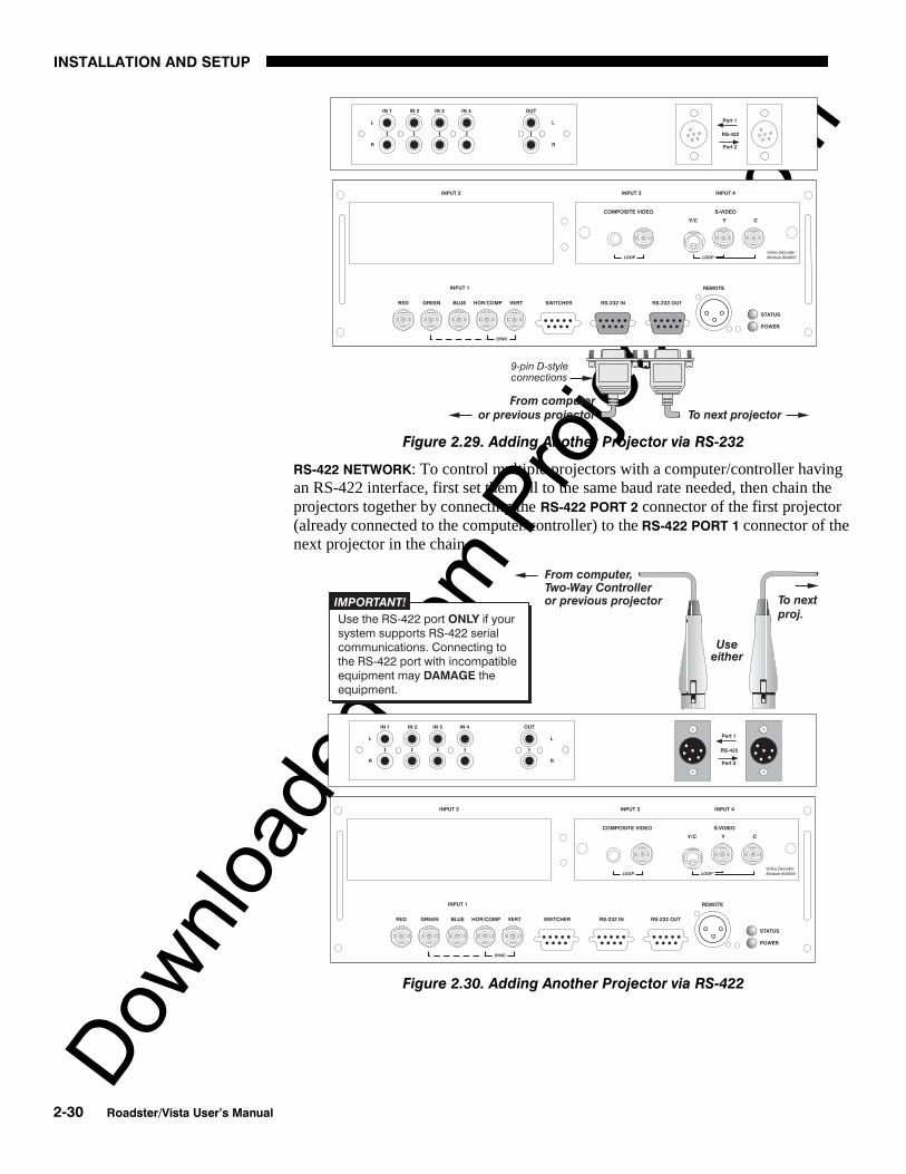
Figure 2.29. Adding Another Projector via RS-232
RS-422 NETWORK: To control multiple projectors with a computer/controller havingan RS-422 interface, first set them all to the same baud rate needed, then chain theprojectors together by connecting the RS-422 PORT 2 connector of the first projector(already connected to the computer/controller) to the RS-422 PORT 1 connector of thenext projector in the chain.
Figure 2.30. Adding Another Projector via RS-422

Downlo
aded
from
Pro
jecto
r.com
INSTALLATION AND SETUP
Roadster/Vista User’s Manual 2-31
For either type of network, continue connecting projectors in this manner untilyou’ve reached the last projector in the chain, so that only the last projector has anempty RS-232 OUT (or RS-422 PORT, if applicable). See examples below.
Figure 2.31. Assorted Networks (NOT split)
Note that communication parameters such as baud rate must be set to match theparticular controlling device before connecting as a network—refer to thedocumentation that came with your controlling device in order to determine theproper baud rate. See 3.7, Configuring System Parameters if you need help changing theprojector baud rate from its default of 19200.
NOTES: 1) To avoid damage, connect only properly wired serial communicationcables. See Appendix D for details. 2) It is recommended that each RS-232communication cable be no more than 25 feet in length. Use high quality cables.

Downlo
aded
from
Pro
jecto
r.com
INSTALLATION AND SETUP
2-32 Roadster/Vista User’s Manual
In a typical network, broadcast serial communications or messages destined for aspecific projector travel through all serial ports in each projector regardless ofwhether the messages originate from an RS-232 or RS-422 source (refer back toFigure 2.31, bottom example). The communication path depends on the serial cablingconnected at each projector.
You may prefer the option of two separate communication paths—RS-232 or RS-422—in your network, essentially creating a redundant “back-up” communicationpath that can take over should a failed projector (or controller) preventcommunications via the other path. For this setup, connect each projector to the nextusing both RS-232 and RS-422 ports.
Then enable the “SplitNetwork” setting in theCommunications menu foreach projector present so thatRS-232 communicationsremain on RS-232 paths onlyand RS-422 communicationsremain on RS-422 paths only(Figure 2.32). Each projectorcan then receive and sendeither type of message depending on which controller initiates the commands—should one path fail, the second “back-up” network path can be used. Only onenetwork should be active at a given time, as determined by the controller (whether itis RS-232 or RS-422). Note that the “Broadcast Key” option is OFF.
IMPORTANT Whenever downloading new projector software to networks, use a
single-route network only. DISCONNECT any redundant serial cablingand UNCHECK the “Split Network” checkbox for each projector.
Two Different “Splits”
There are two different split network configurations possible (Figure 2.33). Set upwhichever option best suits your application needs:
A. SPLIT NETWORK WITH ONE CONTROLLER– If you have a single controller andwant a back-up serial link, connect one controller standard (e.g., RS-232) toone physical end of the network and the other controller standard (e.g., RS-422) at the other physical end of the network. Make sure the “Split Network”option is enabled in the Communications menu. If a projector should then failanywhere in the network, communication with the remaining projectors can beresumed in the opposite direction using the other standard. NOTE: Thisconfiguration requires that both standards be available from a singlecontroller, or that you use an RS-232/RS-422 adapter.
B. SPLIT NETWORK WITH TWO CONTROLLERS– If you have two controllers (oneRS-232 and one RS-422) and want one to be a back-up, connect eachcontroller to the appropriate serial port on the first projector in the network.Then connect projectors together using both RS-232 and RS-422 ports asshown. Make sure the “Split Network” option is enabled in theCommunications menu. Now, if either controller fails, you can simply switchto the other controller and communicate via the other standard.
Back-up or “Split” Networks'
Figure 2.32. Enable “Split Network”

Downlo
aded
from
Pro
jecto
r.com
INSTALLATION AND SETUP
Roadster/Vista User’s Manual 2-33
Figure 2.33. Two Types of Split Networks
Each projector can be assigned a unique 3-digit projector number (for example, 001).These numbers are necessary when you are working with multiple linked projectors,enabling you to direct commands to a certain projector rather than alwaysbroadcasting to the entire network. For complete information on how to assignprojector numbers, see 3.7, Configuring System Parameters.
NOTE: To loop a single incoming video source through to another projector ordisplay device on a network, see Video Loop Through in 2.4, Source Connections.
Projector Numbers '

Downlo
aded
from
Pro
jecto
r.com
INSTALLATION AND SETUP
2-34 Roadster/Vista User’s Manual
At manufacture every keypad is assigned “A” as its default protocol, which is simplya collection of settings that determine how the keypad operates. Once assigned, thisprotocol remains in effect until it is changed—that is, the keypad will operate as itcurrently does until you change its protocol.
Protocols are most useful for multiple-projector applications. For example, you mightwant to change a keypad protocol if you are working with two projectors and tworemote keypads in the same room and need to control each projector independently(Figure 2.34). When Keypad A has a different protocol than Keypad B, each keypadcommunicates only with the projector having a matching protocol. Or, if you have anetwork of two or more projectors connected together via RS-232 serial ports, youmay want only certain projectors to respond to a wired keypad, thus you can usedifferent protocols to limit responses.
NOTE: Matching the protocol on the projector to that of a keypad is done through asetting in the Communications submenu. See 3.7, Configuring System Parametersfor further information on how to change the projector's infrared sensor (rear andfront) protocol.
A protocol for either type of remote keypad — IR or wired — can be changedthrough software commands entered on the keypad. A new protocol set throughsoftware commands remains in effect until the keypad batteries are removed andreplaced (if an IR remote), or until the keypad is unplugged (if a wired remote). Aremote can also be changed manually —you can "hard-wire" new jumper settingsinside the keypad so that they remain in effect until you change the hard-wiring. Notethat a hard-wired protocol can be temporarily overridden by the software protocolchange, effective until the keypad is unplugged and plugged in again (if a wiredremote) or until a battery is removed (if an IR remote).
Figure 2.34. Independent Keypads and Projectors
The standard IR remote keypad or the optional wired remote can be set to one of twodifferent protocols — “A” or “B”. To hard-wire a protocol to “A” or “B” in eitherremote, follow Steps 1 through 5:
2.10 KeypadProtocols andConversion
Remote Keypad 'Protocol
— IR OR WIRED KEYPAD —

Downlo
aded
from
Pro
jecto
r.com
INSTALLATION AND SETUP
Roadster/Vista User’s Manual 2-35
Step 1
Unplug the keypad from the projector (applies to wired remote only).
Step 2
Unlatch and open the empty battery compartment on the back of the keypad as shownin Figure 2.35.
NOTE: A wired keypad opens as shown, but a cable passes through the batterycompartment cover.
Figure 2.35. Opening the Keypad
Step 3
Find the 4 jumpers located along the latching side of the battery compartment. Thesejumpers set the keypad protocol and other settings so that the keypad functions in acertain manner.
Step 4: Set the Jumpers
Set the jumpers as shown in Figure 2.36. Take care to refer to the correct part of thedrawing — IR or wired (optional). Use tweezers or needle-nose pliers to remove andreplace each jumper as necessary.
• J1 jumper: For either remote, set between pins 1 and 2 to set as Protocol “A”.Set between pins 2 and 3 to set as Protocol “B”.
• J2 jumper: For either remote, set between pins 2 and 3 as shown; otherwise, theprojector will not respond correctly to keypad commands.
• J3 jumper: For the IR remote, make sure that the jumper is set between pins 2and 3 as shown. For the wired remote, make sure that the jumper is set betweenpins 1 and 2 as shown.
• J4 jumper: For the IR remote, make sure that the jumper is set between pins 1and 2 as shown. For the wired remote, make sure that the jumper is set betweenpins 2 and 3 as shown.
Step 5
Replace battery compartment cover. Plug into projector (wired keypad only) and test.
Downlo
aded
from
Pro
jecto
r.com
INSTALLATION AND SETUP
2-36 Roadster/Vista User’s Manual
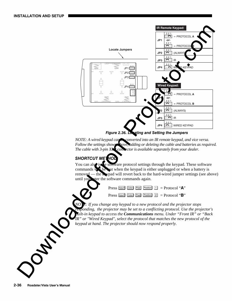
Figure 2.36. Locating and Setting the Jumpers
NOTE: A wired keypad can be converted into an IR remote keypad, and vice versa.Follow the settings shown above, adding or deleting the cable and batteries as required.The cable with 3-pin XLR connector is available separately from your dealer.
SHORTCUT METHOD:
You can also issue software protocol settings through the keypad. These softwarecommands will be lost when the keypad is either unplugged or when a battery isremoved — the keypad will revert back to the hard-wired jumper settings (see above)until you enter the software commands again.
Press Input1 Color Pixel Position = Protocol “A”
Press Input1 Color Pixel Position = Protocol “B”
NOTE: If you change any keypad to a new protocol and the projector stopsresponding, the projector may be set to a conflicting protocol. Use the projector'sbuilt-in keypad to access the Communications menu. Under “Front IR” or “BackIR” or "Wired Keypad", select the protocol that matches the new protocol of thekeypad at hand. The projector should now respond properly.

Downlo
aded
from
Pro
jecto
r.com
INSTALLATION AND SETUP
Roadster/Vista User’s Manual 2-37
If desired, you can convert an IR remote keypad into a wired remote keypad and viceversa (available February 2000).
TO CHANGE FROM INFRARED TO WIRED:
• Remove battery compartment cover from back of keypad.• Remove batteries.• Wait 1-2 minutes.• Plug the keypad cable (available separately) into the empty battery
compartment. Make sure that the battery cover is notched smoothly toaccommodate the cable.
• Set keypad protocol as desired, using “wired” jumper settings.• Replace battery compartment cover.• Plug into the 3-pin XLR port at the rear panel of the projector.
TO CHANGE FROM WIRED TO INFRARED:
• Unplug the keypad from the projector.• Open the keypad back and unplug the keypad cable.• Wait 1-2 minutes.• Install batteries (see Section 4).• Set keypad protocol as desired, using “IR” jumper settings.• Replace battery compartment cover.
Converting a Keypad '

Downlo
aded
from
Pro
jecto
r.com

Downlo
aded
from
Pro
jecto
r.comSect ion 3
Operation
Roadster/Vista User’s Manual 3-1
This section explains how to use the projector once it has been installed. Please readthrough these pages before using the projector for the first time. An understanding ofprojector features and how to access them will help you to take full advantage of thecapabilities of the projector within minutes.
NOTE: Installation involves locating the projector and adjusting it for use at thatlocation. If you have not yet installed the projector, refer to Section 2, Installationand Setup.
Most projector functions and adjustments are initiated via keypad commands thateither control the projector directly or activate a system of intuitive menus.Collections of settings can be defined and retained in the projector's internal memoryas a custom channel, with up to 99 different channels possible.
Projector components and functions are illustrated below. Refer back to the chart onpage 1-2 to determine what is available on each of the various models.
Figure 3.1. Basic Projector Components
3.1 Overview
3.2 ProjectorBasics

Downlo
aded
from
Pro
jecto
r.com
OPERATION
3-2 Roadster/Vista User’s Manual
ZOOM - Accessed manually in some models or with the keypad if a motorized zoomlens is present, the lens barrel of a zoom lens (optional) rotates to adjust the size ofthe image without moving the projector. Minimum and maximum image sizesdepend on which zoom lens is installed — see Section 5, Specifications.
FOCUS - Accessed manually in some models (via 2 “tabs” on the lens) or with akeypad if a motorized lens is present, focus adjusts the sharpness of the image at thecurrent throw distance.
LENS OFFSET – Operated manually in some models or with the keypad if a motorizedlens is present, vertical and horizontal offsets shift the lens and move the image up ordown and left or right. See Section 2, Installation and Setup for the offset ranges forany given lens. These are also listed on page 5-1.
SHUTTER - Closing the shutter blocks the lens internally and turns the image to off.The shutter is controlled with the keypad. (NOTE: OPTIONAL IN SOME MODELS)
EYEBOLTS (Roadster ) – Insert in feet holes for suspending a single inverted Roadsteronly.
SIDE HANDLES (Roadster ) - For safety straps or for brief hand transport. Roadstermodels only.
STACKING SLOTS (Roadster ) - For stacking of Roadster models. NOTE: Stackingrequires a separate hardware accessory kit. See Section 2.
WARNING When stacking projectors you must use Christie
stacking hardware (available separately) in the slots.
LAMP SIDE PANEL - For accessing the interior lamp door and replacing the lampmodule. NOTE: Lamp replacement requires a qualified service technician.
FILTER SIDE PANEL - Louvered grille for air intake. Remove to replace air filter.
AUDIO IN/OUT (Vista) – For connecting pre-amplified (line level) audio. Standard onVista models only.
Components / Features '

Downlo
aded
from
Pro
jecto
r.com
OPERATION
Roadster/Vista User’s Manual 3-3
COMPOSITE/S-VIDEO INPUT - Accepts a composite video and S-Video signal fromdevices such as VCRs.
RGB INPUT - Accepts RGB and sync signals from devices such as computers, as wellas composite video, S-Video or YPbPr component signals.
RS-232 SERIAL INTERFACE (WITH LOOP THROUGH) - Allows one or more projectors tobe remotely controlled by a computer or controller, and provides a communicationsconnection for Christie’s Marquee Signal Switchers.
RS-422 SERIAL INTERFACE (WITH LOOP THROUGH) - Allows one or more projectors tobe remotely controlled by an RS-422 compatible computer or controller (such as theTwo-Way Controller accessory). RS-422 communications can travel greater distancesthan can RS-232 communications, but require RS-422 compatible equipment.
AC LINE CORD INPUT – Use the AC supply specified, and always use the line cordprovided with the projector. See Section 5. Never unplug while the fans are running.
Model AC Power Specifications
X/S3 and X/S4 100-240 VAC, 50-60 Hz, max. 11.5 amps @ 100V
X/S5 and X/S6 200-240 VAC, 50-60 Hz, max. 8.5 amps @ 200V
X9/S9 200-240 VAC, 50-60 Hz, max. 12 amps @ 200V
WARNING Do not attempt operation if the AC supply is not within the
specified voltage and power range. Use the specified line cord.
STATUS/POWER LEDS - Two LEDs (light emitting diodes) located in the lower rightcorner of the rear connector panel indicate projector "Status" (top) and "Power"(bottom). During normal operation, the "Power" light is steady green and the "Status"

Downlo
aded
from
Pro
jecto
r.com
OPERATION
3-4 Roadster/Vista User’s Manual
light flashes green each time a key is pressed or when the projector receives a serialcommand. Use the following as a guide:
Figure 3.2. Reading the Status LEDs
NOTE: A steady red power light accompanied by a coded pattern of red and yellowflashes from the status light indicates an internal system error. Consult the rear LCDdisplay for an explanation, and see 3.11, Error Conditions. Should the problempersist, contact a qualified service technician available through your dealer.
REMOTE WIRED KEYPAD CONNECTOR (3-pin XLR) - For optional tethered remotecontrol of the projector.
BUILT-IN KEYPAD - Alternative location for entering commands. NOTE: The keypadcan be inverted by a qualified service technician. Contact your dealer.
LCD STATUS DISPLAY – Visual feedback for monitoring projector activities and status.
INFRARED SENSORS - The infrared (IR) sensors on the front and rear of the projectorreceive infrared signals from the IR keypad for remote control of projector functions.For proper operation make sure that these sensors are not blocked.
HARD RESET - Emergency access for powering down the projector in the event of asystem failure. Insert a pen point or small screwdriver.
The keypad appears in three locations:
• Built-in to the rear of the projector
• Infrared (IR) Remote for tetherless control up to 100 feet away
• Wired Remote (optional) tethered to the rear of the projector
3.3 Using theKeypad

Downlo
aded
from
Pro
jecto
r.com
OPERATION
Roadster/Vista User’s Manual 3-5
While each keypad is identical in layout and provides complete control of theprojector, you may find one keypad more convenient than another for your specificinstallation and application.
The built-in keypad is located at the rear of the projector. An LCD window abovethis keypad provides feedback regarding current status and activities of the projector.
Figure 3.3. Keypad
The IR Remote Keypad controls the projector by way of wireless communicationsfrom a battery-powered infrared (IR) transmitter. Use the IR remote keypad the sameway you would use a remote keypad supplied with a TV or VCR. When making keypresses, point the keypad either toward the screen or toward the front or rear of the
Built-in '
IR Remote '
Downlo
aded
from
Pro
jecto
r.com
OPERATION
3-6 Roadster/Vista User’s Manual
projector. One of two sensors on the projector will detect the signals and relay thecommands for internal processing.
The wired remote keypad connects to the 3-pin XLR jack via a 50 ft. cable. It isrecommended when:
• the rear of the projector is inaccessible• the lighting conditions are unsuitable for proper IR transmission• you want to use a separate keypad for each projector in a group
NOTES: 1) For extra long distances and/or harsh environments, you may prefer touse an optional remote Two-Way Controller to control the projector. For operatingdetails, please see the Two-Way Controller User’s Manual included with thisaccessory. 2) Old VistaGRAPHX “Roadie style” keypads can be used with thisprojector, but the Func key codes listed on the back are different and do not apply.
Keep in mind the following guidelines:
1) Press keys one-at-a-time; there are no simultaneous key presses required.2) For any key having an “*” ( Power* , for example), hold the key for approximately 1
second in order to toggle the function with a single key press. For other keys (orto use a “*” key in conjunction with ON or OFF ), a momentary press similar toa mouse click is sufficient.
3) Press the “lightbulb key” to temporarily illuminate the backlight for the keyswithout sending any other command.
4) , , ON , and OFF repeat their “arrow” actions when held down. Forother keys, release and press again to repeat an action. In a network, pausebetween adjustments to ensure that the last projector can “keep up” with thecommands.
5) If you press a key while the projector is busy with another action, such as duringa power-up, the key press may not take effect.
When you turn on the projector it begins operating at presentation level, such as animage from the most recently used source signal. The projector temporarily leavespresentation level whenever you use the keypad to work with control settings, displaymenus, or on-line help. For example, pressing Menu after startup displays the mainmenu — presentation level is no longer active, although the image still appears in thebackground. Press Menu again (or Exit ) to return or leave the menu system and returnto presentation level.
Specific keypad commands are explained below:
Power ON/OFF
Press and hold for approximately 1 second to turn the projector on or off with asingle key press. Or press Power* followed immediately by ON or OFF if you want toguarantee the correct toggle (useful if you are unsure of the present status).. Withmultiple projectors, use with to direct the power-up or power-down commandto a specific projector or to broadcast as desired.
NOTES: 1) Whenever the projector is turned off, the lamp cooling fans remain on forabout five minutes to cool the lamp. Never unplug the projector during this time, oras a shut down, as it can lead to premature lamp failure. 2) Avoid turning a projectorback on until it has been off for a few minutes—hot re-strikes of the lamp may reducelamp life.
Wired Remote '—OPTIONAL—
Guide to Keypads '
Keypad Commands '
Power*

Downlo
aded
from
Pro
jecto
r.com
OPERATION
Roadster/Vista User’s Manual 3-7
Input 1
Press Input1 to select the source connected to INPUT 1 on the projector (data input).This is the same as entering Input .
Input 2
Press Input2 to select the source connected to INPUT 2 on the projector (an optionalinterface). This is the same as entering Input .
Input 3
Press Input3 to select the source connected to INPUT 3 on the projector (compositevideo). This is the same as entering Input .
Input 4
Press Input4 to select the source connected to INPUT 4 on the projector (S-Video). Thisis the same as entering Input .
Input
Press Input when you want to display from a specific source location, such as aswitcher connected serially to the projector’s switcher port. The first digit representsthe number you have assigned to your switcher (usually 1-9, or “0” for one of thefour inputs on the projector). The second digit represents the switcher’s slot number(1-9). For example:
Input = display data from switcher 1, slot 2.
NOTES: 1) Although you don’t need to use the input key unless a switcher isconnected to the projector, you can also use Input to access the four input “slots” onthe projector itself: use as the first digit (representing the projector as theswitcher), then , , , or as the second digit (the desired input slot number).
in combination with higher numbers is an invalid entry. 2) See 3.5, UsingChannels and Inputs for a detailed explanation of inputs.
NOTE: Input key behavior during a presentation depends on whether or not theDisplay Channel List option is selected in the Menu Preferences menu. You canchoose to have on-screen feedback when you press Input , or you may prefer to enterthe desired source location “blind”, i.e., without on-screen feedback. SeePreferences later in this section.
Channel
Press Chan to select a specific source setup (channel) defined and stored in projectormemory. Once you enter a 2-digit channel number (or, if there is a list displayed,highlight it and press Enter ), the display will automatically change and updateaccording to the numerous setup parameters defined for that channel.
NOTE: Chan key behavior during a presentation depends on whether or not theDisplay Channel List option is selected in the Menu Preferences menu. You canchoose to use a scrollable list of channels when you press Chan , or you may prefer toenter the desired channel number “blind”, i.e., without on-screen feedback. SeeMenu Preferences later in this section.
Input1
Input2
Input3
Input4
Input
Chan

Downlo
aded
from
Pro
jecto
r.com
OPERATION
3-8 Roadster/Vista User’s Manual
Standby
Press Stby* and hold for approximately 1 second to blank all display and mute theaudio output (if connected) while keeping the projector in a warmed-up and readystate. Or quickly press and release Stby* and follow immediately by ON or OFF ifyou want to guarantee the correct toggle (useful if you are unsure of the presentstatus). Note that the lamp and electronics remain ON in standby mode, even thoughthe image turns to black and most functions are disabled. To leave standby press andhold Stby* again (or use Stby* OFF ). Or simply press Exit or Menu .
Menu
Press Menu to display the Main menu. A list of several options appears for access tospecific functions, such as Channel Setup or Image Settings. Press Menu again toremove all menus and return to presentation level.
Enter
Press Enter to select a highlighted item, to toggle a checkbox (checked vs. unchecked),or to accept a parameter adjustment and return to the previous menu or image.
Exit
Press Exit to return to the previous level, such as the previous menu.
NOTE: Exit does not save changes within text editing boxes (including numberediting of a slidebars) or within pull-down lists. It acts as a “cancel” in these cases.
Arrow Keys
The arrow keys have a variety of functions depending on the situation. Some typicaluses are described below. See also Editing Text later in Section 3.
• Use or to change a slidebar value—hold as desired for continuousadjustment (note the adjustment increments and range depend on theparameter being adjusted).
• Use or to change to a different option within a pull-down listwithout having to display the list first
• Use or to jump between “pages”, such as in Help or lengthy pull-down lists.
Use the ON or OFF keys to navigate within a menu, pull-down list or text box, or toincrease or decrease the value in the second (bottom) slidebar of a double slidebar.
You can also use ON or OFF in conjunction with certain toggle keys—i.e., thoseincluding an asterisk symbol—to ensure a toggle only in the desired direction. Whenturning the projector on, for instance, you may be too far from the projector to knowwhether it is really off or if the shutter is merely closed. If you press Power* and hold itfor approximately 1 second in hopes of turning the projector on, the projector willactually turn off if the projector was already on. Instead, to avoid the risk of togglingin the wrong direction, quickly press and release normally the function key you wishto toggle (in this case Power* ). Then immediately (within 2 seconds) press either ON
or OFF as desired. The specific toggle will occur.
Toggle keys are labeled with an asterisk on the keypad. They are listed below:
Stby*
Menu
Enter
Exit
ON
or OFF

Downlo
aded
from
Pro
jecto
r.com
OPERATION
Roadster/Vista User’s Manual 3-9
• Shutter* + ON = close the shutter (NOT PRESENT IN ALL MODELS)Shutter* + OFF = open the shutter (NOT PRESENT IN ALL MODELS)
• Stby* + ON = put the projector in standby modeStby* + OFF = leave standby
• Power* + ON = turn the projector onPower* + OFF = turn the projector off
• Mute* + ON = turn the audio (if connected) and menu display onMute* + OFF = turn the audio (if connected) and menu display off
• OSD* + ON = turn the menu system onOSD* + OFF = turn the menu system off
Color
Press Color to adjust the color saturation level, i.e. the amount of color in a videoimage. Lower settings produce less saturated colors — a setting of “0” produces ablack and white image, for example. If the color level is too high, colors will beoverpowering and unrealistic. Use and until the desired color saturationlevel is displayed. The Color key has no effect when the ADP option is installed.
Tint
Press Tint to adjust the red/green color hue for true color reproduction of NTSC videosignals or HDTV signals. For best results, adjust tint while displaying a properexternal test pattern from the source — otherwise, it is recommended that tint remainat its default setting. Use and until the desired tint is displayed.
Detail
Press Detail to adjust the sharpness of a video image (it is of limited use for non-video). Use and until the display is as sharp as desired, keeping in mindthat any level of detail above 3 will also introduce a certain degree of noise in theimage. Set below 3 to filter the signal and remove noise from a noisy source.
Contrast
Press Cont to change the amount of white in your images. Use and until youreach the desired level of contrast—for best results, start low and increase so thatwhites remain bright but are not distorted or tinted, and that light areas do notbecome white (i.e., are “crushed”). Conversely, low contrast causes dim images. See3.6, Adjusting the Image (Image Settings subsection).
Brightness
Press Bright to increase or decrease the amount of black in the image. Use and until you reach the desired level of contrast—for best results, start high and
decrease so that dark areas do not become black (i.e., are “crushed”). Conversely,high brightness changes black to dark gray, causing washed-out images. See 3.6,Adjusting the Image (Image Settings subsection).
Volume
Press Vol to control the audio level (if connected). Use and until you reachthe desired volume.
NOTE: Audio control is standard on Vista models only. In other models, the keydoes nothing.
Color
Tint
Detail
Cont
Bright
Vol

Downlo
aded
from
Pro
jecto
r.com
OPERATION
3-10 Roadster/Vista User’s Manual
Projector
Press Proj when you want to access a specific projector within a network or if yousimply need to see if the local projector is listening. The number appearing in the“Enter Number” window indicates which projector is currently listening tocommands, and will match the projector number that has been defined in itsCommunications menu.
The “Projector” checkbox (read-only) shows whether or not the projector physicallyconnected to a keypad is listening to commands from that keypad. A checkmarkmeans that connected projector is listening; if there is no checkmark, you arecommunicating with a different projector.
To use a specific projector, enter the 3-digit number assigned to the projector youwant to use. Press Enter to select, press Exit to cancel. If you switch to a projectorother than the one you are currently using, the checkmark will disappear. Keypadcommands (even Power* ) will then affect this projector.
To broadcast to multiple projectors, press Proj Proj without entering a projectornumber. Keypad commands (even Power* ) will then affect all projectors present.
NOTES: 1) The "Broadcast Keys" option in the Communications menu must beselected for only one (any) projector in a serial network. The keypad in use must beOFF (disabled) for the remaining projectors. See 2.10. Keypad Protocols andConversion, and 3.7, Configuring System Parameters.
Pixel
Press Pixel to access the pixel tracking and pixel phase double slidebar. Adjust pixeltracking first: use and to increase or decrease the frequency of the pixelsampling clock to correct consistency of the image. For proper phase, use ON and
OFF to increase or decrease pixel phase so that any shimmer disappears and theimage is stable throughout. See 3.6, Adjusting the Image (Size and Positionsubsection) for a complete explanation of tracking and phase.
Position
Press Position to move the image using the double slidebar. At the slidebar, use and to move the image left or right, use ON and OFF to move the image up ordown.
Lens (STANDARD IN ROADSTER ONLY)
NOTES: 1) Requires a motorized lens. In non-motorized projectors, adjust the lensmanually for proper focus, zoom and offsets as described on page 2-2. 2) For fulldetails regarding motorized lens functions, refer to 2.8, Zoom, Focus and LensOffset.
Proj
Pixel
Position
Lens

Downlo
aded
from
Pro
jecto
r.com
OPERATION
Roadster/Vista User’s Manual 3-11
Press Lens to access remotemotorized control ofhorizontal/vertical offsets, focusand zoom, and other relatedfunctions in the Lens Controlmenu. All slidebars can beadjusted with and , orset with a specific value enteredfrom the keypad.
NOTE: Since the direction of lenstravel affects the final true position of the lens, setting a lens position (focus, zoom oran offset) to a specific value may cause the lens to reverse its direction of travel,depending on its starting point, so that it approaches the setting from the necessarydirection. Any even-numbered setting is approached from above (the slidebar valueswill decrease), any odd-numbered setting is approached from below (the slidebarvalue will increase).
FOCUS: Adjust the image clarity. If focus is not uniform throughout the image, boresight is likely poor. Contact your dealer for service.
ZOOM: Enlarge or shrink the image (note: requires a Roadster/Vista zoom lens).
HORIZONTAL OFFSET: Shift the lens and image left or right. Note that slidebar valueswill not reach extremes of 0 or 9999. This is normal.
VERTICAL OFFSET: Shift the lens and image up or down. Note that slidebar valueswill not reach extremes of 0 or 9999. This is normal.
INTELLIGENT LENS SYSTEM: Enable “Intelligent Lens System” (ILSTM) to add the 4lens positions—focus, zoom, horizontal and vertical offset—to the current channelsettings recorded in projector memory (see 3.5, Using Inputs and Channels if you areunfamiliar with channels). This feature is particularly useful if you are using sourceswith differing aspect ratios, such as anamorphic vs. 5:4. When switching to and fromsuch displays, thelens willautomaticallymove to the lastdefined positionfor each channel,quicklyoptimizing thedisplay for focus,zoom and offsets.
ILSTM is a globalfunction—anylens settings you subsequently define for other channels will be recalled wheneveryou use those channels. Delete the checkmark if you want to use consistent zoom,focus and offset settings for all channels—the lens will not move unless you re-adjusta lens setting.
For full details regarding optimization of ILSTM performance, refer to 2.8, Zoom,Focus and Lens Offset.
CALIBRATE LENS: Select “Calibrate Lens” to ensure that the physical mid-point foreach of the four lens functions is defined as such in software, and that lens mount
Figure 3.4. Lens Control Menu ( Lens )
Figure 3.5. Lens Settings and the ILSTM

Downlo
aded
from
Pro
jecto
r.com
OPERATION
3-12 Roadster/Vista User’s Manual
movements remain accurate to this reference. Regular calibration can correct forslight eventual mechanical “drifting” of movements over time. It is particularlyrecommended whenever the projector is bumped or subjected to vibration, and it isrequired whenever a new lens is installed and after certain service procedures.
During calibration, the lens mount will move in various directions for approximately30 seconds, detecting the center of focus and offset ranges and the extremes forzoom. A small “Lens Calibrating” message appears on screen during calibration.Calibration is complete when lens mount movement stops (and the menureappears)—note that the lens returns to the previous settings.
NOTES: 1) Calibration with a fixed lens installed causes the zoom calibration totime-out, possibly delaying the completion of calibration by a few seconds. This isnormal. 2) If calibration with zoom lens installed takes longer than about 30 secondsto complete, make sure the focus motor is engaged as described in 4.5, Replacing theLens.
CENTER LENS: This option removes most vertical and horizontal offset and returnsthe lens to the approximate center of the lens opening—the image will be fairly well-centered on this axis. Note that if centering remains significantly “off”, lens mountbore sight is likely poor. Contact your dealer for service.
Shutter (OPTIONAL IN SOME MODELS)
If your projector has a mechanical lens shutter (a.k.a. douser) installed, press andhold Shutter* for approximately 1 second to toggle the shutter closed or open with asingle key press (this also blanks the image electronically). Or quickly press andrelease Shutter* and follow immediately with ON or OFF if you want to guarantee thecorrect toggle (useful if you are unsure of the present status). Close the shutterwhenever you want to mute all display yet maintain access to projector functions.Open the shutter to regain the display. With no shutter installed, Shutter* still blanks theimage electronically, but the blanking is not quite as black.
NOTES: 1) The status of the shutter is shown in the LCD window on the rear panel ofthe projector. 2) Upon power-up, the shutter is open. 3) The lamp remains on.
Mute
Use Mute* to mute audio (if connected) and/or hide the current menu. Press and holdMute* for approximately 1 second to toggle on or off with a single key press. Orquickly press and release Mute* and follow immediately with ON or OFF if you wantto guarantee the correct toggle (useful if you are unsure of the present status). Ineither case, a small message appears on screen to signify mute status.
NOTE: After early October 2000, audio control is standard on Vista models only. Inmodels without audio, Mute* temporarily turns the current menu on/off.
Function Key
From presentation level, press Func followed by a 2-digit number to enable a specificcolor or colors in the display. For example, Func will display only red and greendata, Func will display all color data. The list of available color combinations isshown below and also appears on the back of the IR remote keypad. Color enablingcan also be accessed through the menu system rather than these shortcuts.
Shutter*
Mute*
Func

Downlo
aded
from
Pro
jecto
r.com
OPERATION
Roadster/Vista User’s Manual 3-13
Func = RedFunc = GreenFunc = BlueFunc = Red and GreenFunc = Green and BlueFunc = Red and BlueFunc = All colors ( Exit does the same thing)
NOTE: When Func is pressed in presentation level, the projector will not respond tonon-numeric entry until 2 digits have been entered or until 5 seconds of inactivityhave elapsed.
Use of the Func key within the menu system is noted with the appropriate topicelsewhere in Section 3. For example, press Func in the Channel Setup menu to enabledeletion or copying of a channel.
OSD (On-screen display)
Press and hold OSD* for approximately 1 second to toggle menus on or off (i.e.,visible or invisible). Or press OSD* followed immediately by ON or OFF toguarantee the correct toggle direction (useful if you are unsure of the present status).Note that invisible menus are fully functional.
NOTES: 1) With OSD on, you can still mute menus, error messages, slidebars, etc.with the appropriate setting in the Menu Preferences Menu. 2) The status of the OSD*
key is displayed in the LCD window on the rear panel of the projector.
Help
Press Help for detailed information about any current menu and highlight. Press Help
again to exit. From presentation level, press Help to access the General Help menuconsisting of Using Help, Setup, Keys, Source (Input) Selection, Stat/Pwr LEDs andUsing 3D. Press Exit to leave General Help and return to presentation level.
Test
Press Test to display one of the available test patterns. Press Test again to display thenext available pattern in the sequence. Test will exit after the last pattern, or press Exit
at any time to remove the current test pattern from the screen and return topresentation level.
NOTE: For a complete list of all test patterns, see the Geometry menu descriptionlater in Section 3.
Keypad operating settings (protocols)
The remote keypad and the optional wired keypad both store keypad operatingsettings (called protocols) in memory. In some advanced applications, such as whenyou want to use two separate keypads to control two projectors independently, youmay want to override the original protocol set at manufacture (which is "A or B") forone of the keypads. See section 2.10, Keypad Protocols and Conversion for completeinstructions.
OSD*
Help
Test

Downlo
aded
from
Pro
jecto
r.com
OPERATION
3-14 Roadster/Vista User’s Manual
Most of the controls for the projector areaccessed from within the projector’s menusystem. There are several groups of relatedfunctions, with each group selectable from theMain menu as shown at right. Press Menu at anytime to display the Main menu.
On the keypad, either enter the numbercorresponding to the function menu you wish toaccess, such as for the Image Settings menu,or use the keys to highlight the desired option and press Enter . The functionmenu you selected will then appear. If you select “Auto Setup”, this will not activatea separate function menu but rather begin an automated process of optimizing criticaldisplay parameters such as size, position, pixel tracking, etc.
Once you have a function menu displayed, navigate in a similar manner—enter amenu option number for any numbered option, or use to move the highlightand press Enter at the desired option. Extra long menus have a scroll bar on the right–use the arrow keys to see the remainder of the menu. Items that are locked out or donot pertain to the current action appear dimmed and cannot be selected.
NOTES: 1) If there is no signal present, all source-dependent adjustments aredisabled. 2) After 15 minutes of inactivity, the projector leaves the menu system andreturns to the presentation. 3) The Status menu is read-only.
When finished with a function menu, do one of the following:
• Press Exit to return to the previous screen
• Press Menu to leave the menu system and return to the presentation
If at any time you are uncertain what to do next, press Help to display detailedinformation about the current menu or highlighted option. A scroll bar appears on theright-hand side of a help window if there is additional text–use the arrow keys toscroll. Press Help again to exit.
From presentation level, press Help to access general Help Topics. Scroll as necessarywithin a topic. Press Exit to return to your presentation. At the bottom of somemenus, a line of hint text also appears.
3.4 Navigating theMenus
Figure 3.6. Main Menu
On-line Help '

Downlo
aded
from
Pro
jecto
r.com
OPERATION
Roadster/Vista User’s Manual 3-15
Figure 3.7. Accessing General Help Topics
Whenever the projector is not at presentation level, such as when there is a slidebar,menu, message or test pattern displayed, you have limited time in which to make akeypad entry before the projector returns to presentation level and the graphicdisappears. These time-outs vary depending on the current display, as shown in thefollowing chart:
TIME-OUTS
Slidebar (from pres.) 5 seconds
Slidebar (from menu) 15 minutes
Lamp Timer Msg. 30 seconds
Channel entry 5 seconds
Other 15 minutes
If a menu option includes this icon, settings for the option apply universally to anyincoming signal.
Most of the function menus allow you to change settings by using slidebars,checkboxes, and pull-down lists. To select a slidebar, toggle a checkbox status, orview a pull-down list, do one of the following within the function menu:
• Enter the menu option number corresponding to the setting you wish tochange (for example, press for Vertical Stretch in Size & Position menu).
• Or move the highlight to the desired parameter and press Enter .
• Or move the highlight to the option desired and press or .
• Or bypass menus entirely and use a single key to immediately access anadjustment (note: applies only to options having their own key, such as Color,Tint, Detail, Contrast, Brightness, Volume, Pixel and Position).
Once selected, change the setting as desired (see below) and press Enter to save andreturn to the current function menu.
Slidebars in menus - The current value for a given option,such as size or vertical stretch, appears to the left of its slidebaricon. This number may express a percentage or specific units (such as pixels, degreesKelvin, etc.), depending on the option. Press or to gradually adjust thesetting up or down—both the number and the length of the bar change accordingly(for continuous adjustment, hold down the desired arrow key). Or press Enter toactivate a slidebar text box for specific number entry via the keypad, then press or and Enter to save (or press Exit to cancel).
Time-outs '
The Global Icon '
Using Slidebars and 'Other Controls

Downlo
aded
from
Pro
jecto
r.com
OPERATION
3-16 Roadster/Vista User’s Manual
Double slidebars - In doubleslidebars, such as the pixeltracking/pixel phase doubleslidebar, adjust the top slidebarwith or as desired.When you have finished with thetop slidebar (whether changed ornot), adjust the bottom slidebarwith ON or OFF . When you are done, press Exit to return to your presentation. Forfast continuous adjustments, hold down the desired arrow key.
“Direct” slidebars - For quick access, you can often use a slidebar (or doubleslidebar) without traveling through the menu system. For example, simply press Cont
to immediately display the same contrast slidebar accessed with the Contrast optionin the Image Settings menu. Direct slidebars are listed below.
LIST OF DIRECT SLIDEBARS
H-Position or V-Position Position
Pixel Tracking or Phase Pixel
Volume
Contrast Cont
Brightness Bright
Color Color
Tint Tint
Detail Detail
Use the arrow keys to adjust a direct slidebar, or press Enter and enter a specificnumber from the keypad , then Enter or or to save ( or Exit to cancel).When you are done, press Exit to save and return to your presentation.
NOTES: 1) You can still adjust a direct slidebar as usual if the menu display isturned off (see OSD* or Menu Preferences menu) — the slidebar just won’t be visible.2) A direct slidebar disappears if it is not used within 5 seconds.
Checkboxes - Conditions are present if its adjacent checkbox contains a checkmark.To toggle the checkbox, simply highlight and press Enter , or highlight and use to
check and to uncheck. For a checkbox that isnumbered, simply enter the number of the option to togglethe checkbox.
Pull-down lists – To see a pull-down list of options available for a given parameterlabeled with a ▼, you can:
• Highlight it and press Enter
• Or enter the menu option number.

Downlo
aded
from
Pro
jecto
r.com
OPERATION
Roadster/Vista User’s Manual 3-17
Figure 3.8. Example of Pull-Down List
Use ON or OFF keys to navigate up and down within the list (the current choice isnoted with a small '). Press Enter to choose an option from the list, if desired.
Or, of you prefer to quickly scroll through a list without first pulling it down,highlight the option and use or . Press Enter when the desired choice appears.
NOTES: 1) Press or to jump between “pages” in an extra long pull-downlist. 2) Press Exit while in a pull-down list to cancel any change.
ACTIVATE THE EDIT WINDOW: To enter or edit text, highlight the desired parameter(such as a channel name) and press Enter to activate its adjacent edit window. Anypreviously entered text is displayed with its first character highlighted in a squarecursor, signifying that this character is ready for editing.
NAVIGATE WITHIN THE EDIT WINDOW: Press to move the cursor forward or to move the cursor backwards as desired.
EDIT A CHARACTER: To edit a highlightedcharacter, use and to scroll throughthe alphabet, numbers, spaces andpunctuation available. When the characteryou need appears, press to select it—the cursor will move to the next character ofcurrent text, if present. Note that you canalso enter a number directly from thekeypad—it will be accepted and the cursorwill move on.
ADD OR DELETE A CHARACTER OR SPACE: To insert a space at the cursor location,press Func . To delete a highlighted character (or space), press Func .
Editing Text '
Figure 3.9. Entering Text

Downlo
aded
from
Pro
jecto
r.com
OPERATION
3-18 Roadster/Vista User’s Manual
PRESS Enter WHEN FINISHED: To accept the edits and move out of the edit window,press Enter .
NOTE: Press Exit at any time to cancel changes and return to the previously-definedtext.
Enter numbers directly from the keypad in order to specify numbers representingprojectors, channels (source setups), switchers, or slots. As each digit is entered, it isdisplayed and the cursor moves on. Note that channel numbers are defined with 2digits—for example, if you enter only a single digit (like “7”) for a channel number,the channel will automatically be defined as “07”. Use “07” to utilize this channel.
NOTES: 1) Once you enter the first digit, this digit replaces all old digits. 2) If youpress any non-numbered key, the number entered up to that point is accepted andupdated as the new value. 3) Press Exit to cancel editing of numerical values.
NOTE: See Section 2, Installation and Setup, for a full explanation of how toconnect a variety of sources to the projector.
The projector stores and automatically recalls up to 99 different channels (sourcesetups) for a variety of inputs. This memory feature allows you to define andconveniently use a wide variety of customized setups rather than having to repeatedlyre-configure the projector for different presentations. Each physical source (i.e.,input) can have several different channels associated with it.
INPUT - An input simply describes a physical location for an incoming signalconnection. These connections are always either on the projector itself (one of thefour inputs at the rear of the projector) or on any switcher connected to theprojector’s switcher port. Input describes the source signal according to two specificcriteria only—to which switcher it is connected and to which slot it is connected—and is identified by a 2-digit number entered on the keypad. The first digit specifiesthe switcher (0-9), the second specifies the slot (1-9). Note that the projector isalways considered “switcher #0”.
EXAMPLES:
Input = use source connected to switcher #1, slot #3Input = use source connected to the projector, slot #1 (i.e., Input1 )
You can switch to an input in either one of two ways. Pressing the appropriate directkey — Input1 , Input2 , Input3 , or Input4 — is a quick and seamless way to display from oneof the four inputs connected at the rear of the projector. Or, if your projector has aswitcher connected to it at the SWITCHER port, press the general Input key and enter
Editing Numerical Values '
3.5 Using Inputsand Channels
Do I Select an Input 'Or a Channel?

Downlo
aded
from
Pro
jecto
r.com
OPERATION
Roadster/Vista User’s Manual 3-19
the 2-digit number representing the switcher and slot location for the desired signal(note there is no on-screen feedback for entering the numbers).
Regardless of which method you use to select a source/input, the image will bedisplayed according to the following:
If it is the first time you have used the source/input (or if you used the input but didnot define a channel by adjusting anything ), the projector will recognize the newinput signal based on its frequencies and polarities, and will automatically display animage according to default settings for such a signal. Note that a graphic source willresize into a full-screen image, whereas video or HDTV sources will resize only asmuch as possible while maintaining their aspect ratio.
If you used the source once before and changed a display parameter such ascontrast, V-Position etc., then a channel was automatically created and still exists inprojector memory (see below). Using an Input key will automatically recall thischannel—and all its setup parameters—and update the display accordingly.
If more than one channel exists for the input, the image will be displayed accordingto the setup parameters for the first channel with matching characteristics.
CHANNEL - A channel is a collection of measurements, locations and settings thattailor a display to your specific needs. Since source types and applications can varygreatly, you will likely want to adjust and define a wide variety of parameters, suchas brightness, contrast, tint, size, etc., in order to customize and optimize the displaycoming from a particular source. For example, the display settings you choose for aVCR source may be very different from those you choose for a high resolutioncomputer source, or one signal may simply vary from another signal used earlierthrough the same input location. Once you have adjusted a display parameter, such aspixel tracking or contrast, all current settings are collectively stored in the projector'smemory as a unique 2-digit channel, such as . You can have numerous distinctchannels available for the same input, any of which can be selected by using the Chan
key on the keypad followed by the 2-digit channel number.
NOTE: The Chan key may display a channellist or not, depending on what you havedefined within the Menu Preferences menu(see Menu Preferences later in this section).Shown at right is a sample channel listavailable from Chan .
In order to use channels ( Chan on the keypad),you must first create them. See below.
To use a new source with the projector, a newchannel must be added to projector memoryso that the projector will respond properly to an input signal from that source in thefuture. A new channel can be created automatically, as described here, or it can becopied from an existing channel and then edited as necessary (see Copying orDeleting Channels later in this section).
When you select a direct input (press Input or Input1 , Input2 , Input3 or Input4 ), the existingchannels in the projector are searched for matching input and signal parameters. If nomatch to the incoming input signal is found in the currently defined channels, a new
Channel List ( Chan )Creating a New '
Channel— AUTOMATIC —

Downlo
aded
from
Pro
jecto
r.com
OPERATION
3-20 Roadster/Vista User’s Manual
channel is temporarily created based on factory-defined defaults for this signal. Thechannel number assigned to this channel is the lowest available number from 01-99.
NOTES: 1) An automatic channel will be discarded unless one or more of itsparameters are changed, and will not appear in the Channel List (see below). 2) Iftwo channels have the same distinguishing source characteristics except for thereversal of sync connectors (i.e., H-sync and V-sync, are switched), they are stilldefined as distinct channels. 3) You cannot define a new channel without a signalpresent.
If the incoming signal does match an existing channel, the image will be set up anddisplayed as usual according to the parameters currently defined for that channel.
USING A CHANNEL: You can normally select a channel at any time by pressing Chan
(see right). If you want to prevent a channel from appearing in this list, you must editthe channel as describedin Channel Edit later inthis section. Such achannel can still beselected as shown at right.
NOTES: 1) The currentchannel is highlightedupon entering theChannel List, or, if thischannel is not displayed in the list, the first channel in the list is highlighted. 2)Channels created automatically do not appear in the Channel List unless aparameter has been changed.
All available channels are listed in the Channel Setup menu, which describes howeach channel can be accessed and which serves as the gateway for editing, copyingand deleting channels.
From the presentationlevel press Menu todisplay the Main menu.To display the ChannelSetup menu, press , ormove the highlight to theChannel Setup option andpress Enter . The ChannelSetup menu will appear(see sample at right),with the active channelhighlighted.
WHAT APPEARS IN THE CHANNEL SETUP MENU? As shown in Figure 3.10, this menulists all channels defined so far and indicates how they are connected to the projector.The far left column contains current channel numbers defined. The values in the farright columns indicate horizontal and vertical frequencies—if a name has beendefined for this channel, it appears here instead. Other columns contain detailspertaining to each channel setup, such as its switcher number, slot location, a varietyof icons indicating access to the channel, and an abbreviated description of eachsignal type. See Editing a Channel Setup for details.
What Channels 'Are Defined So Far?
Figure 3.10. All Channels Appear in theChannel Setup Menu

Downlo
aded
from
Pro
jecto
r.com
OPERATION
Roadster/Vista User’s Manual 3-21
SIGNAL TYPE — Either channel list, whether the Chan key list or the Channel Setupmenu, identifies signal types in a shortened form as defined below. These descriptorsindicate what signal information the projector used to identify a match for a givenchannel, and are preceded by either an “i” (interlaced signal) or “p” (progressivesignal). See Table 3.1.
Table 3.1. Abbreviations for Signal Type
Abbrev. Signal Type
4WH Composite (4 wire) on HC input
4WV Composite (4 wire) on V input
SG Sync-on-green
SR Sync-on-red
5W Separate H,V
5WR Separate H,V swapped
SVid S-Vid
CVid Composite Video
3LH Tri-Level on HC input
3LV Tri-Level on V input
3LG Tri-Level on green
E3LH European Tri-Level on HC input
E3LV European Tri-Level on V input
E3G European Tri-Level on green
Dig Digital
If you have more than a handful of channels, use and to see the remainingchannels not visible in this initial display.
To copy, delete or edit any of the channels listed in the Channel Setup menu,highlight the desired channel and do one of two things:
• Press Func if you want to copy the selected channel or delete this or otherchannels. See Copying or Deleting a Channel below.
• Press Enter if you want to edit channel setups (i.e., non-image relatedparameters) for the selected channel. See Editing a Channel Setup,below.
TO COPY A CHANNEL, highlight the desired channel in the Channel Setup menu, thenpress Func to go to the Channel Copy/Delete submenu. Select “Copy” and pressEnter —a new channel will be created. It is identical to original, which still remains,but it is identified with the next available number from 01-99. If you change yourmind and do not want to copy the current channel, press Exit to cancel and return tothe previous menu. Copying channels is a quick method for creating numerouschannels, each of which can then be edited and adjusted for a variety of presentationsin the future.
Copying or ' Deleting Channels

Downlo
aded
from
Pro
jecto
r.com
OPERATION
3-22 Roadster/Vista User’s Manual
Figure 3.11. Copying A Channel
TO DELETE A CHANNEL, highlight the desired channel in the Channel Setup menu,then press Func to activate the Channel Copy/Delete submenu. Select “Delete” andpress Enter —a confirmation window will appear to make sure that you really want todelete this channel.
Figure 3.12. Deleting a Channel
TO DELETE MULTIPLE CHANNELS, highlight any channel in the Channel Setup menuand press Func to go to the Channel Copy/Delete submenu. Select “Delete UnlockedOnly” and press Enter to delete all unlocked channels. Or select “Delete All Channels”to delete all channels, even those that are locked. In either case, the current channelwill remain but will be redefined from projector defaults.
NOTE: For any deletion, a confirmation box appears to make sure that you reallywant to delete. Select “Cancel” (default) if you don’t want to delete after all.
The basic setups that describe how and where a channel can be accessed are listed inthe Channel Setup menu. These channel setups can be edited at any time in theChannel Edit submenu.
From the presentation level press Menu to display the main menu. To display theChannel Setup menu, press , or move the highlight to the Channel Setup optionand press Enter . The Channel Setup menu will appear.
To edit parameters shown in the Channel Setup menu, select the relevant channel and pressEnter . The Channel Edit menu will appear similar to the sample shown in Figure 3.13.
Editing a Channel Setup '
CHANNEL EDIT — STEP 1
CHANNEL EDIT — STEP 2

Downlo
aded
from
Pro
jecto
r.com
OPERATION
Roadster/Vista User’s Manual 3-23
Figure 3.13. Channel Edit Menu (SAMPLE)
If desired, edit the following channel setups in the Channel Edit menu:
• CHANNEL NAME: An alpha-numeric label can be defined and/or changedhere. Channel names can be up to 12 characters in length.
• CHANNEL NUMBER: A channel number from 01 to 99 can be changedhere. NOTE: If you enter a channel number that already exists, a dialogmessage appears indicating that this number is already in use–assign adifferent channel number.
• SWITCHER NUMBER: “0” represents the projector itself. Or, if the inputsource is connected to a switcher, the default will be the lowest switchernumber available (from 1-9)–change here as desired.
• SLOT: 1 ( Input1 ), 2 ( Input2 ), 3 ( Input3 ), or 4 ( Input4 ) for projector inputs, orcurrent slot number (1-9) if the source is connected to a switcher.
• LOCKED: If checked, all of the image settings for this channel are disabled.If unchecked (default), all available image settings can be adjusted asdesired. You cannot use Auto Setup with a locked channel.
• IN MENU: If checked (default, except for automatically defined channelswith unchanged parameters), this defined channel will then appear in thelist available when Chan key is pressed. If unchecked, the channel must beaccessed via Chan on the keypad or via the Auto Source function. NOTE:On-screen display of the channel list is an option that must be set in theMenu Preferences menu.
• AUTO SOURCE: If checked, (default), the projector can automaticallylocate this channel when an incoming input signal matches. If notchecked, the projector can locate the selected channel only when it isdirectly selected via Chan on the keypad—and a change in input signal willnot result in a channel change.
• PREVIOUS CHANNEL: Select this option to see or change Channel Editsettings for the previous channel in the Channel Setup list.
• NEXT CHANNEL: Select this option to see or change Channel Edit settingsfor the next channel in the Channel Setup list.
CHANNEL EDIT — STEP 3

Downlo
aded
from
Pro
jecto
r.com
OPERATION
3-24 Roadster/Vista User’s Manual
Most options for source-specific image adjustments can be accessed through twomenus: Size and Position ( Menu ) and Image Settings ( Menu ), both of which arelisted in the Main menu. While in either of these two menus, you can change settingsaffecting the image from the current channel by working with the appropriateslidebars, checkboxes and pull-down lists. Exit will always return to the previousmenu (or to the presentation, if from the Main menu) and accept any changes youmay have made. Or you may prefer to begin with an automated setup in which theprojector quickly defines certain parameters for you—select Auto Setup from theMain menu. These settings can then be fine-tuned in Size and Position and ImageSettings at any time.
From your presentation, access any of the individual options in these menus bypressing Menu followed by the appropriate two-digit number representing theirlocation in the menu system. For example, press Menu to quickly access the“Color Setup” option in the Image Settings menu.
For certain options, you may prefer to use a “direct key” from presentation level togo directly to a particular option rather than traveling through the menu system at all(note: this is not available for all display parameters). For example, press Cont toaccess the “contrast” slidebar immediately. Press Exit to return to your presentation.
NOTE: 1) To hide the “direct” slidebars only, make sure the Display Slidebarsoption in the Menu Preferences menu is unchecked. 2) To hide the entire menusystem from view, toggle the on-screen display OFF: press and hold the OSD* key.
If you want the projector to quickly set up the image for you, select “Auto Setup”from the Main menu. A confirmation box will ask if you really want to continue, inwhich case display parameters listed in the Table below will be set for you. An “AutoSetup” can save time in setting up an image, and you can also make furtheradjustments as desired. You must have an unlocked channel present to use Auto Setup.
Table 3.2. Auto Setup Parameters
What an “Auto Setup” Does
OPTIMIZES: SETS TO DEFAULT:
Pixel Tracking Contrast & Brightness
Pixel Phase Auto Input Level (off)
Size Blanking
Vertical Stretch Detail (if video source)
Position Filter
Input Levels (if analog source) Luma Delay
3.6 Adjusting theImage
Auto Setup '
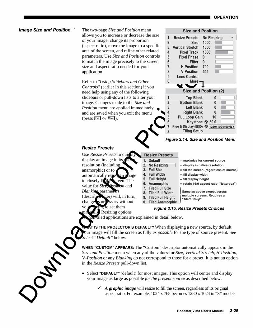
Downlo
aded
from
Pro
jecto
r.com
OPERATION
Roadster/Vista User’s Manual 3-25
The two-page Size and Position menuallows you to increase or decrease the sizeof your image, change its proportion(aspect ratio), move the image to a specificarea of the screen, and refine other relatedparameters. Use Size and Position controlsto match the image precisely to the screensize and aspect ratio needed for yourapplication.
Refer to "Using Slidebars and OtherControls" (earlier in this section) if youneed help using any of the followingslidebars or pull-down lists to alter yourimage. Changes made to the Size andPosition menu are applied immediatelyand are saved when you exit the menu(press Exit or Menu ).
Resize Presets
Use Resize Presets to quicklydisplay an image in its nativeresolution (includinganamorphic) or toautomatically resize an imageto closely fit the screen. Thevalue for Size, Position andBlanking parameters(described later) will, in turn,change as necessary withoutyour having to set themmanually. Resizing optionsfor non-tiled applications are explained in detail below.
WHAT IS THE PROJECTOR’S DEFAULT? When displaying a new source, by defaultyour image will fill the screen as fully as possible for the type of source present. SeeSelect “Default” below.
WHEN “CUSTOM” APPEARS: The “Custom” descriptor automatically appears in theSize and Position menu when any of the values for Size, Vertical Stretch, H-Position,V-Position or any Blanking do not correspond to those for a preset. It is not an optionin the Resize Presets pull-down list.
• Select “DEFAULT” (default) for most images. This option will center and displayyour image as large as possible for the present source as described below:
A graphic image will resize to fill the screen, regardless of its originalaspect ratio. For example, 1024 x 768 becomes 1280 x 1024 in “S” models.
Image Size and Position '
Figure 3.14. Size and Position Menu
Figure 3.15. Resize Presets Choices

Downlo
aded
from
Pro
jecto
r.com
OPERATION
3-26 Roadster/Vista User’s Manual
A video image will resize to fill the screen while still maintaining itsaspect ratio (assumed to be 5:4).
An HDTV wide-screen (16:9) image will resize to fill the screenhorizontally while maintaining its 16:9 aspect ratio—i.e., there will beblack borders at top and bottom, commonly called “letterboxed”.
A non-HDTV anamorphic (16:9) image, typical of DVDs, will bestretched vertically.
So with the exception of HDTV (16:9), the “Default” setting produces an aspectratio that is either almost or exactly 5:4 (if “S” model) or 4:3 (if “X” model). Seeexamples below.
NOTE: Shown with “S” model resolution (1280 x 1024). “X” models are 1024 x 768.
• Select “NO RESIZING” to display the image in its native resolution, which may besmaller or larger than the native resolution of the projector. All Size, VerticalStretch, H-Position, V-Position or Blanking values will change accordingly. Forexample, for a source with a native resolution of 800 x 600, “No Resizing” willcenter a small image within a black border. Conversely, an HDTV image is widerthan both 1024 and 1280 and will be cropped on the sides—or, in the case of“1080i” HDTV, cropped at top and bottom too. With “No Resizing”, signals withnon-square pixels, such as video connected to INPUT 3 or INPUT 4, producedistorted images that are too tall or too wide. See below.
• Select “FULL SCREEN” to use all pixels (1024 x 768in“X” models, 1280 x 1024 in “S” models) fordisplaying the image, regardless of source or originalaspect ratio. See right. NOTE: SXGA resolution shown.
• Select “FULL WIDTH” to fill the display from left-to-right. Depending on the source, this may create topand bottom borders.

Downlo
aded
from
Pro
jecto
r.com
OPERATION
Roadster/Vista User’s Manual 3-27
• Select “FULL HEIGHT” to fill the display from top-to-bottom. Depending on the source, this may createside borders.
• Select “ANAMORPHIC” to display an entire non-HDTV “wide screen” (anamorphic) image in its native16:9 aspect ratio. Known as letterbox, the image will fillthe screen from left-to-right, but will not use all verticalpixels available (top and bottom will be black). If youdo not choose “Anamorphic” when a non-HDTVanamorphic image is present, the default image will bestretched vertically, characterized by obvious distortionand “thin people”.
NOTE: 1) SXGA resolution shown. 2)Use “Anamorphic” for regaining a 16:9display of non-HDTV anamorphic sources only (typically found on some DVDs,for example). For HDTV, the “Default” setting will produce the same result.
• All TILED resizing choices are selectable only if you have defined a tiled group ofprojectors in the Tiling Setup submenu. See 3.10, Using Multiple Projectors.
Size
Size controls both the image width and height in tandem, maintaining the originalaspect ratio (proportion) of data from the incoming signal. Under some conditions in“X” models, adjusting Size also adjusts Keystone.
NOTE: If Size $1000 (1000 = No Resizing) and Size x Vertical Stretch value$1,000,000, adjusting Size also adjusts keystone simultaneously. Requires “X”model.
Vertical Stretch
Vertical stretch adjusts the height the image while keeping the width constant. UseVertical Stretch to display data from the incoming signal in a different aspect ratio.Under some conditions in “X” models, adjusting Vertical Stretch also adjustsKeystone.
NOTE: If Size $1000 (1000 = No Resizing) and Size x Vertical Stretch value$1,000,000, adjusting Vertical Stretch also adjusts keystone simultaneously.Requires “X” model.
Pixel Track
(SHORT CUT: Press Pixel and adjust the top slidebar.)
Pixel tracking adjusts the frequency of the pixel sampling clock, indicated by the numberof pixels per line, so that all pixels generated by a particular source are sampled. Properpixel tracking ensures that the image quality–whether good or poor– is consistent acrossthe screen, that aspect ratio is correct, and that pixel phase can be optimized (below).
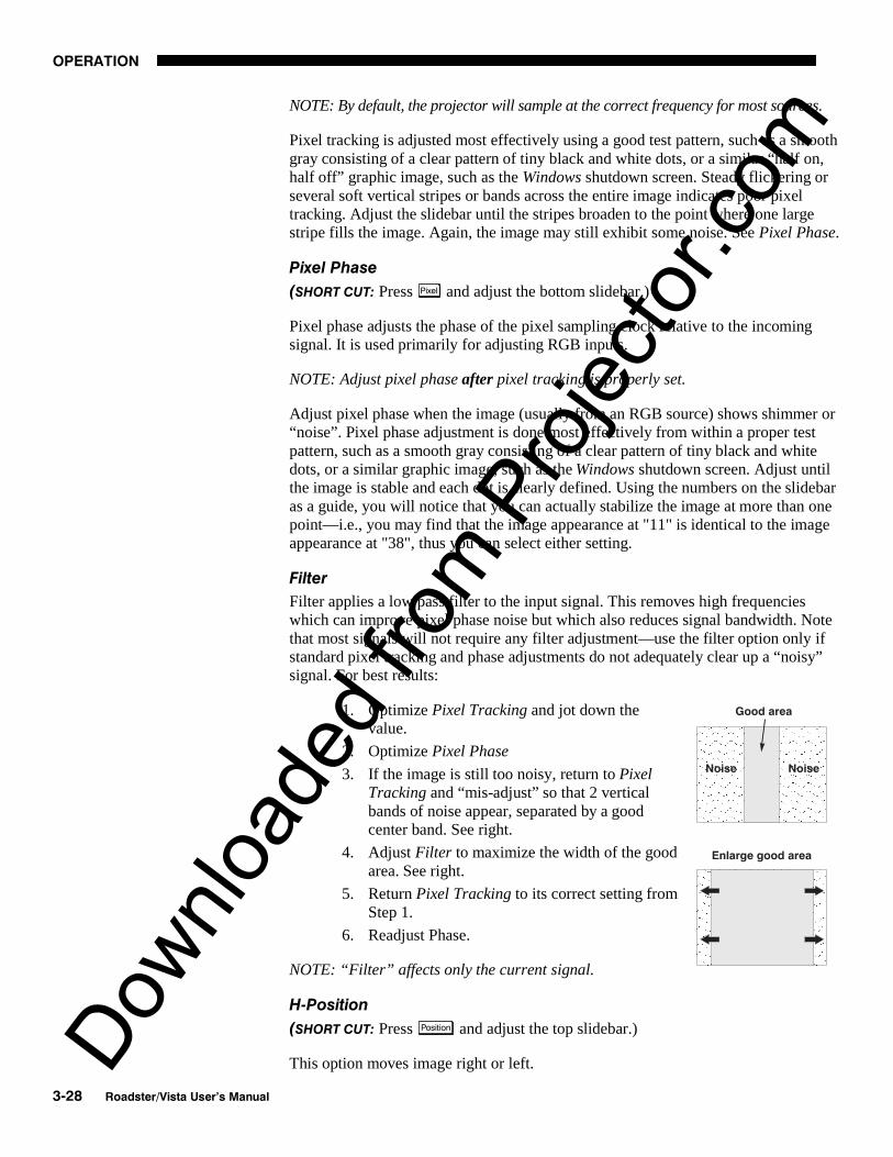
Downlo
aded
from
Pro
jecto
r.com
OPERATION
3-28 Roadster/Vista User’s Manual
NOTE: By default, the projector will sample at the correct frequency for most sources.
Pixel tracking is adjusted most effectively using a good test pattern, such as a smoothgray consisting of a clear pattern of tiny black and white dots, or a similar “half on,half off” graphic image, such as the Windows shutdown screen. Steady flickering orseveral soft vertical stripes or bands across the entire image indicates poor pixeltracking. Adjust the slidebar until the stripes broaden to the point where one largestripe fills the image. Again, the image may still exhibit some noise. See Pixel Phase.
Pixel Phase
(SHORT CUT: Press Pixel and adjust the bottom slidebar.)
Pixel phase adjusts the phase of the pixel sampling clock relative to the incomingsignal. It is used primarily for adjusting RGB inputs.
NOTE: Adjust pixel phase after pixel tracking is properly set.
Adjust pixel phase when the image (usually from an RGB source) shows shimmer or“noise”. Pixel phase adjustment is done most effectively from within a proper testpattern, such as a smooth gray consisting of a clear pattern of tiny black and whitedots, or a similar graphic image, such as the Windows shutdown screen. Adjust untilthe image is stable and each dot is clearly defined. Using the numbers on the slidebaras a guide, you will notice that you can actually stabilize the image at more than onepoint—i.e., you may find that the image appearance at "11" is identical to the imageappearance at "38", thus you can select either setting.
Filter
Filter applies a low pass filter to the input signal. This removes high frequencieswhich can improve pixel phase noise but which also reduces signal bandwidth. Notethat most signals will not require any filter adjustment—use the filter option only ifstandard pixel tracking and phase adjustments do not adequately clear up a “noisy”signal. For best results:
1. Optimize Pixel Tracking and jot down thevalue.
2. Optimize Pixel Phase
3. If the image is still too noisy, return to PixelTracking and “mis-adjust” so that 2 verticalbands of noise appear, separated by a goodcenter band. See right.
4. Adjust Filter to maximize the width of the goodarea. See right.
5. Return Pixel Tracking to its correct setting fromStep 1.
6. Readjust Phase.
NOTE: “Filter” affects only the current signal.
H-Position
(SHORT CUT: Press Position and adjust the top slidebar.)
This option moves image right or left.

Downlo
aded
from
Pro
jecto
r.com
OPERATION
Roadster/Vista User’s Manual 3-29
NOTE: The value shown represents where the approximate center of the image lies inrelation to the total number of pixels available horizontally. This varies widelyaccording to the signal—watch the image while adjusting.
V-Position
(SHORT CUT: Press Position and adjust the bottom slidebar.)
This option moves the image up or down.
NOTE: The value shown represents where the approximate center of the image lies inrelation to the total number of pixels available vertically. This varies widelyaccording to the signal—watch the image while adjusting.
Lens Control (STANDARD IN ROADSTER ONLY)
(SHORT CUT: Press Lens to activate the Lens Control submenu.)
For a full description of the Lens Control submenu, see 3.3, Using the Keypad ( Lens
key) and 2.8, Zoom, Focus and Lens Offset.
Blank: Top, Bottom, Left or Right
These slidebars blank (turn to black) the top, bottom,left, or right edge of the image so that any unwantedinformation is cropped from view. For example, whendisplaying native size video you may want to blankout a few of the top lines. Do not use in combinationwith Keystone control.
PLL Loop Gain
This control changes the relative offset to the default gain. The default PLL (PhaseLock Loop) Loop Gain setting of 10 is set automatically with a Pixel Trackingadjustment and is correct in most cases. In rare instances, such as if your imageexhibits tearing or “flag-waving”, increase the PLL loop gain setting as necessary.Or, if your image is unstable and “breaks up”, this may indicate that the PLL loopgain setting is either too high or too low. PLL Loop Gain affects the current channelonly.
Keystone
NOTE: This function is not available in “S” models.
Adjust the keystone control if images appears non-rectangular or keystoned in shape—thatis, smaller at either the top or bottom edge. The effect of keystone adjustment is similar tophysically tilting the projector forward or backward in relation to the screen, and it affectsall sources.
NOTES: 1) Keystone is enabled for a source only if Size is $1000 and Size xVertical Stretch is $1,000,000. 2) Keystone adjustment is not available in “S”models. 3) Avoid using Keystone with Blanking.

Downlo
aded
from
Pro
jecto
r.com
OPERATION
3-30 Roadster/Vista User’s Manual
Generally, set at 50 (default) to apply nokeystone—if your projector is positionedwith its lens surface parallel to thescreen, images will be rectangular. Ifimages are too narrow at the bottom,increase keystone. If images are toonarrow at the top, reduce keystone.
The keystone control may be limitedwhen Size is just slightly greater than1000. In general, work with image size,stretch and keystone controls as necessary for your application.
Plug & Display (EDID)
NOTE: Requires optional DVI Input Module. Disabled for all other inputs.
By default, the Plug & Display option detects an incoming digital flat panel videosignal and displays it in the native resolution of yourprojector. If you have additional daisy-chained projectors,they will display in this resolution as well. If you want touse a different resolution (for example, your graphics cardmay not support the current resolution), select a differentPlug & Play setting from the list.
Tiling Setup
See 3.10, Using Multiple Projectors (Tiling Setup section).
Use options in the two-page ImageSettings menu to alter your image inways that do not affect its size orposition. Changes made to the ImageSettings menu are appliedimmediately and are saved when youexit the menu (press Exit or Menu ).Options not available for yourprojector model appear dimmed andare disabled.
Contrast
(SHORT CUT: Press Cont and adjust theslidebar.)
“Contrast” increases or decreases theperceived difference between lightand dark areas of your image (0-100).If contrast is set too high, the lightparts of the image lose detail andclarity. If set too low, the light areaswill not be as bright as they could beand the image will be dim. Start low and increase so that whites remain bright but arenot distorted or tinted, and that light areas do not become white (i.e., are “crushed”).For best results, keep close to 50.
Image Settings '
Figure 3.16. Image Settings Menu

Downlo
aded
from
Pro
jecto
r.com
OPERATION
Roadster/Vista User’s Manual 3-31
Brightness
(SHORT CUT: Press Bright and adjust the slidebar.)
“Brightness” increases or decreases the amount of black in the image (0-100). Starthigh and decrease so that dark areas do not become black (i.e., are “crushed”).Conversely, high brightness changes black to dark gray, causing washed-out images.For best results, keep close to 50.
Pixel Phase
(SHORT CUT: Press Pixel and adjust the slidebar.)
See description in Size and Position section, above.
Detail
(SHORT CUT: Press and adjust the slidebar.)
”Detail” adjusts the sharpness of a video image. Use and until the displayis as sharp as desired, keeping in mind that any increase in detail above 3 (default)will also introduce a certain degree of noise in the image. Set below 3 to filter thesignal and remove noise from a noisy source. Keep at 3 to apply no detail.
Color Space
This option determines how the color components of an inputsignal are decoded for accurate color in the display. Selecting acolor space option is useful only for analog signals connected toINPUT 1 or INPUT 2. Although the color space for such a signalis automatically determined by the projector, in some circumstances you may wish tooverride this and manually set a different color space.
NOTE: For digital signals or for signals connected to INPUT 3 or INPUT 4, the colorspace function is entirely automatic and the pull-down list disabled.
• Select RGB unless you are using component video at INPUT 1 or 2.
• Select YPbPr (Video) with a standard definition televised signal (SDTV)• Select YPbPr (HDTV) with a high definition televised signal (HDTV).
NOTE: When certain RGB signals are first connected, the projector may not initiallyrecognize them as RGB and will incorrectly decode their color information as YPbPr(video). These signals can include:
• RGB signals in NTSC, PAL, SECAM frequency ranges• Scan-doubled sync-on-green• Scan-quadrupled sync-on-green
For these signals, change the Color Space to RGB, which will define a new channelfor future use.

Downlo
aded
from
Pro
jecto
r.com
OPERATION
3-32 Roadster/Vista User’s Manual
Color Setup
Select this submenu to work withaspects of color—adjust forsaturation and overall hue in videosignals, or adjust gamma ortemperature in any signal.
COLOR — “Color” adjusts thecolor saturation level or theamount of color in a video image. When set to “0’ the image appears black andwhite, and when set too high the colors appear overpowering and unrealistic. Use
and to adjust “Color” until the desired saturation level is displayed. For ashortcut to “Color” slidebar, press Color at any time.
TINT — “Tint” adjusts color hue to obtain true color reproduction of NTSC videosignals or HDTV signals. Use and until the desired balance or red-to-greenis displayed in your image. It is best to adjust tint while displaying an external testpattern—otherwise, it is recommended that tint remain at its default setting. For ashortcut to “Tint” slidebar, press Tint at any time.
SELECT COLOR TEMP — “Select Color Temp” applies either apreset color temperature (3200K, 5400K, 6500K or 9300K) orany previously “User” defined color temperature. Colortemperatures are measured in degrees Kelvin and represent the“coloration” (reddish or bluish) of the whites displayed by theprojector—the lower the temperature, the more reddish thewhites; the higher the temperature, the more bluish the whites.
NOTE: The custom temperatures “User” or “InterpolatedColor” can be defined in the Color Temperature Setup menu.Until defined, these custom choices all default to 6500K. See 3.8, ConfiguringSystem Parameters.
INTERPOLATED COLOR — Use this option if you need a specific color temperaturethat lies somewhere between one preset color temperature and another. Adjust theslidebar to define a new temperature which will be interpolated from the neighboringpresets (for example, 7841 is interpolated from 6500 and 9300). This slidebar isdisabled unless you have a source connected and have selected “Interpolated Color”in the “Select Color Temp” pull-down list.
GAMMA — NOTE: Gamma does not normally require adjustment and is intended forexperienced users only.
The "Gamma" option affects the shape of the curve determiningwhat gray shades are available for a given amount of signalinput between minimum (black) and maximum (white).Different curves can improve performance for certain kinds ofsource input and applications. Generally the best gamma curveis one that produces maximum contrast, brightness and colorperformance for the current signal and ambient lightingconditions.

Downlo
aded
from
Pro
jecto
r.com
OPERATION
Roadster/Vista User’s Manual 3-33
DEFAULT (default) – This setting provides good black levels and high contrastunder optimum viewing conditions for virtually all types of images, includingvideo, HDTV and computer graphics.
ENHANCED – This setting elevates middle gray levels compared to “Default”, andprovides a more gradual rolled-off transition to maximum white. Together, thesedifferences can improve the appearance of many kinds of images.
HIGH AMBIENT – This setting elevates low gray levels compared to the “Default”and “Enhanced” settings. In high ambient light conditions, details can be seen inthe dark parts of an image that would otherwise be difficult to perceive.
PAL/SECAM – This setting results in a darker image with higher contrast. Thegamma curve more closely matches the official standard for PAL and SECAMvideo signals.
LINEAR – This setting is a straight, linear transition from black to white. Fornormal source signals, it results in a picture of low contrast with highly elevatedlow- and mid- level grays. It should be used only with sources that have theirown pre-applied gamma control.
COLOR TEMPERATURE SETUP — Use the Color Temperature Setup submenu toapply, alter, add, or copy a color temperature, or if you want to use an unalteredfactory default color temperature.. This menu is duplicated in other locations.
By default, the projector can utilize any of four calibrated factory-set colortemperatures: 3200, 5400, 6500 or 9300 (expressed in degrees Kelvin). For mostapplications, these temperatures will display accurate and realistic colors from avariety of sources. They can be selected at any time from the “Select Color Temp”list in the Color Setup submenu.
However, if you require extra color temperatures, you can also add up to five customcolor temperatures—four “User” and one “Interpolated Color”—by defining themwithin the Color Temperature Setup menu (each defaults to 6500K until then). Any“User” or “Interpolated Color” temperature created here is immediately applied, or itcan be selected at any time from the Color Setup menu as usual, regardless of yoursource or channel. Use of the Color Temperature Setup menu is described below.
NOTE: For best results, use an internal grayscale test pattern when working withcolor temperature.
Figure 3.17. Color Temperature Setup Menu

Downlo
aded
from
Pro
jecto
r.com
OPERATION
3-34 Roadster/Vista User’s Manual
SELECT COLOR TEMP – See Figure 3.17. Upon opening the Color TemperatureSetup menu, the current temperature appears as the top option. You can change toa different color temperature here as desired, just as in the Image Settings menu.Note that selecting a “User” color temperature, enables the “White Level”options in the Color Temperature Setup—you can adjust them as desired todefine or change a “User” color temperature (see “White Levels”, below).Likewise, selecting “Interpolated Color” here activates the “Interpolated Color”slidebar for defining or changing an interpolated color temperature for aconnected source.
INTERPOLATED COLOR – Select this option if you need a specific colortemperature that lies somewhere between one preset color temperature andanother. Adjust the slidebar to define a new temperature which will beinterpolated from the neighboring presets (for example, 7841 is interpolated from6500 and 9300). It can be used any time and appears as a 4-digit temperaturewhen in use. NOTE: This option is disabled unless you have a source connectedand have selected “Interpolated Color” in the “Select Color Temp” pull-downlist.
WHITE LEVELS –These 3 controls are adjustable only if a “User” choice isselected (in which case “User 1, 2, 3 or 4” appears at the top of the ColorTemperature Setup menu). Their current values are shown for the active colortemperature. Changing a white level here changes the drive (contrast) for thatcolor, essentially creating a new color temperature that is “warmer” or “cooler”etc. For maximum overall brightness, always keep at least one white level at100. When you are satisfied with the new “User” temperature, it can be usedimmediately upon exit or it can be selected from either the Image Settings menuor the Color Temperature Setup menu as usual. You can re-define a “User” colortemperature at any time using the Color Temperature Setup menu.
COLOR ENABLE – Select which color or colors you want to see, useful whileworking with color temperature white levels.
COPY FROM – Use this option to replace the currently selected “User” colortemperature setup with that of another. This function can be particularly useful asa starting point for a new “User” color, or for accessing an unaltered factorydefault. It is disabled for all color temperatures except “User”. See Figure 3.18.
Figure 3.18. “Copy From”

Downlo
aded
from
Pro
jecto
r.com
OPERATION
Roadster/Vista User’s Manual 3-35
To create a starting point: To set a starting point for a new custom user colortemperature, select a user temperature, then highlight “Copy From” and select atemperature that is similar to what you want. Adjust white levels from there asdesired.
To use a factory default: The preset color temperature setups (3200K, 5400K,6500K and 9300K) can be altered from within the password-protected Servicemenu only—note that although such analteration changes the setup andappearance for a preset, it does notchange its name. If you suspect that youare using a preset temperature that hasbeen altered and you want instead to usethe original factory-calibrated colortemperature without clearing the entireprojector memory, you can use the“Copy From” option in the ColorTemperature Setup menu to set up a“User” temperature with settings from apermanent factory preset:
1. Select the “User” color temperatureyou wish to update at the top of the Color Temperature Setup menu, such as“User 2”.
2. From the “Copy From” list, select the matching temperature labeled “Factory”(such as “Factory 5400K”). These are the calibrated color temperatures set atmanufacture—they remain intact for the life of the projector.
3. The setups for the “User” color temperature you selected at the top of theColor Temperature Setup menu will now be updated/replaced by those for thepermanent factory calibrated temperature you selected in the “Copy From”list. Again, a “User” temperature can be altered at any time, if desired.
Video Options
Not applicable to graphics sources.
VIDEO STANDARD — The projectorautomatically detects the video standardpresent and displays the name of thisstandard here. Press to view orselect a different video standard from acomplete list available to the projector(some will appear disabled, depending on the current incoming signal). Selecting aspecific standard forces the projector to process the signal according to this standard.
NOTE: This option should remain set at “Auto” for all instances EXCEPT: 1) a poorquality input signal or 2) a black-and-white video signal. In order to detect anddisplay such signals, select the relevant standard.
INPUT VIDEO BLACK — This control compensates for incoming elevated black levels–called “setup”–that are present in certain video signals, and ensures that blacks onscreen are neither crushed (i.e., with dark gray appearing black) nor excessivelyelevated (i.e., with black appearing dark gray). By default, the projector automaticallydetermines the correct setting according to the type of incoming video signal:
Figure 3.19. Presets and“Factory” Presets

Downlo
aded
from
Pro
jecto
r.com
OPERATION
3-36 Roadster/Vista User’s Manual
• 0 IRE – For DVD output with “enhanced black”, SECAM, most PALstandards, and Japanese NTSC.
• 7.5 IRE – For most NTSC video signals.
For some types of video, you can override the setting. The control is disabled for othertypes of video (and all graphics sources). Generally, if black appears crushed whenbrightness = 50, choose “0 IRE”. If black appears excessively elevated, use “7.5 IRE”.
VCR – This control determines to what degree the projector tolerates signaldisturbances. The correct setting is automatically determined and set according to thetype of incoming source signal–for instance, there should be a checkmark for allVCR sources. The VCR option may require a change from its auto setting in veryrare circumstances only, such as if you are having difficulty switching between twounusual and almost identical VGA computer sources. Otherwise, it is not necessaryto change this option.
VIDEO TERMINATION — Enter a checkmarkto terminate the video inputs 3 and 4 (75S). The input should be terminated unlessthe signal loops through (continues) toanother projector or display device, inwhich case only the last projector in thechain should be terminated.
ENABLE DECODER AGC – The “automatic gain control” affects decoded video imagesonly. Enter a checkmark (default) for most decoded video sources—this activates theAGC circuit to ensure properly bright images. Delete the checkmark if a decodedvideo image exhibits strange color artifacts such as stripes in highly saturated colors,indicating an incompatibility between this source and the AGC.
DECODER LUMA DELAY – This control affects any incoming composite or S-videosignal, delaying the luma signal (intensity) in relation to the chroma (color). In theimage, increasing the luma delay will move luma (seen as a shadow where colorsoverlap) to the right slightly, with colors remaining in place. Decreasing this delaywill move the shadow slightly to the left. If necessary for your current source, adjustso that no shadows occur with adjacent colors.
Input Levels
NOTES: 1) It is recommended that only experienced users use the Input Levelssubmenu—the projector automatically optimizes input levels for all but the mostunusual of sources. 2) Before attempting an input level adjustment, check that overallcontrast and brightness settings are near 50 and that color temperature is properlyset up on an internal grayscale test pattern. 3) There must be at least one white pixelpresent in the image for proper “Auto Input Level” function. Leave this control off.

Downlo
aded
from
Pro
jecto
r.com
OPERATION
Roadster/Vista User’s Manual 3-37
Good RGB or inputlevels—that is, thedrives and blacklevelsfor each of the threecolors, red, green andblue—ensure thatimages from analogsources other thandecoded video havemaximum contrastwithout crushing blackor white. By default(and in an “Auto Setup”from the Main menu), the projector automatically determines the best input levels bymonitoring image content and adjusting the controls appropriately—furtheradjustment is typically not required to obtain proper blacks or whites. NOTE: Thisautomatic adjustment requires at least 1 white pixel in the image. Without a whitepixel, input levels may produce skewed colors, particularly in non-video images.
However, for a very unusual source exhibiting overly high blacklevels (most oftencaused by a noisy source that causes blacklevel spikes), an experienced user mayprefer to use the Input Levels menu (see Figure 3.20). These adjustments, which areactually a calibration process to compensate for differences in sources and cabling,enables an experienced user to perfect the source image input levels. Note that InputLevels are of limited use with digital signals, but offer some ability to tweak poorlymastered source materials.
AUTO INPUT LEVEL – Keep off for virtually all sources (default). Temporarily enter acheckmark only if you are an experienced user and you have an unusual source thatyou feel needs further color temperature and/or input level adjustment. After enteringa checkmark, wait for the six values to stabilize, then delete the checkmark and exit.
BLACKLEVELS AND DRIVES - To check your image and adjust these controls:
1. Make sure overall Contrast and Brightness are both set to near 50.NOTE: Not required for “Auto” adjustment.
• Cont = 50 (approx.)
• = 50 (approx.)
2. Check the color temperature setup using an internal grayscale testpattern, adjusting as desired to obtain a neutral grayscale. NOTE: Notrequired for “Auto” adjustment.
3. Make sure you are using an analog source not connected to INPUT 3 orINPUT 4, as Input Levels are not applicable for digital sources or sourcesgoing through the decoder. A grayscale is recommended.
4. If the blacks and/or whites appear OK, input levels do not needadjustment. If black levels are too high (and/or whites are too low, whichis rare), you likely have a noisy source that is producing skewed inputlevels. Continue with Step 5.
5. Temporarily enable “Auto” in the Input Levels submenu. Wait for all 6values to stabilize. Alternatively, do not use “Auto”—reduce blacklevelsmanually instead. Judge by eye and change one or more of the six levelsas necessary to obtain proper blacks and whites. You may want to see
Figure 3.20. Input Levels Submenu

Downlo
aded
from
Pro
jecto
r.com
OPERATION
3-38 Roadster/Vista User’s Manual
only a certain color while adjusting—use the “Color Enable” option(described below).
6. Delete the “Auto” checkmark and leave the Input Levels menu.
IMPORTANT: Do not use Input Levels to adjust color temperature. This willdistort Contrast and Brightness functions as well as color temperature.
CLAMP TIP – This option (full name sync tip clamping) can brighten the imageproduced from certain high resolution, high frequency graphic sources. Enter acheckmark if the image appears unusually dim, if there are horizontal streaks across theimage, or if there is significant color drift. Delete the checkmark if the image is eithersufficiently bright or overly bright.
NOTE: The sync tip clamping option is not used for video sources or any RGB sourcewith sync information on the video (e.g., sync-on-green).
COLOR ENABLE – Select which color or colors you want to see, useful while workingwith color temperature white levels or input levels.
NOTES: 1) Input levels apply for the current source only, but for any colortemperature used. 2) Assuming that color temperature has been set up based on theinternal test patterns, you can then set up input levels for a given source so that itmatches the color temperature of the internal test patterns.
PEAK DETECTOR – The Peak Detector is fast method of defining individual inputlevels, and may improve the accuracy of input levels set by the Auto Input levelfunction. Enabling the Peak Detector activates a special operating mode that detectsonly pixels that are considered black or white—all other levels are displayed as amid-level gray. When used with a 16-step grayscale pattern, where the black andwhite bands are known to be at the edges of the image, you can watch these isolatedareas while adjusting individual blacklevels and input drives as necessary. Imagesfrom this source will then display correct blacks and whites without crushing.
See Figure 3.21.
1) Display a 16 level grayscale test pattern from the desired external source, andenter a checkmark in the Peak Detector checkbox. NOTE: The “Peak Detector”will initially render the grayscale as a uniform gray field before adjustment.
2) Display one primary color (use Color Enable to select).
3) For the current color, adjust its corresponding “Blacklevel” slidebar just until asingle band of black appears at one edge of the screen. This band represents thefirst band of the grayscale pattern, which should be 100% black. Do not adjusttoo far.
4) With the same color still active, adjust its corresponding “Input Drive” slidebarjust until a single band of white appears at the opposite edge of the screen. Thisband represents the last band of the grayscale pattern, which should be 100%white. Do not adjust too far.
5) Go back and check the black band—adjust the blacklevel slidebar if necessary.Adjustments are related, so you may have to go back and forth until both bandsare just optimized.
6) Repeat Steps 2-5 with the other two remaining primary colors. When eachprimary color shows one optimized black band and white band, the input levels

Downlo
aded
from
Pro
jecto
r.com
OPERATION
Roadster/Vista User’s Manual 3-39
for this source are correctly set. Upon exiting the Input Levels menu, the PeakDetector checkbox will clear.
Figure 3.21. Adjusting Input Levels Using the Peak Detector(RED EXAMPLE SHOWN)
Processing Mode
This control determines theprojector’s processing route forthe incoming signal.
1. AUTO (default): Theprojector willautomatically selectthe correct processing mode according to what input signal it detects.Use “Auto” unless you want or need to override its performance andapply a specific mode instead.
2. VIDEO: Performs 15 kHz NTSC/PAL video de-interlacing, regardless ofsignal type. Note that this option utilizes 8-bit processing.
3. GRAPHICS / HDTV: Performs basic de-interlacing and scaling, regardlessof signal type. Note that this option utilizes 8-bit processing.
4. MINIMUM DELAY: Not used in this projector.5. ADVANCED 10-BIT (ADP): Uses 10-bit processing instead of the standard
8-bit processing provided in the projector, resulting in smoother andclearer details in video images. This feature requires installation ofoptional internal hardware—the Advanced Digital Processing Module—and is disabled unless this module is present. It activates full source-to-screen 10-bit processing for a digital video source, typically connectedvia the optional Serial Digital Input Module or the Digital HDTV InputModule (INPUT 2). Images from analog signals (INPUT 1, 3 or 4) will alsobe noticeably improved, however these signals are first converted with 8-bit processing before routing through the ADP module.
Motion Filter
This control is most useful for smoothing out movingimages from interlaced sources. In most cases theproper Motion Filter setting is automaticallydetermined according to the type of incoming sourcesignal. However, if your source is noisy and/orinconsistent you may wish to “force” a setting to ensurestable processing for this source—if desired, override

Downlo
aded
from
Pro
jecto
r.com
OPERATION
3-40 Roadster/Vista User’s Manual
the default “Auto” setting by selecting the appropriate motion filter:
1) AUTO: The projector will automatically use the correct motion filter according tothe incoming signal. Note that the “Still Video” filter will be applied for RGBnon-HDTV interlaced signals, and the “Motion” filter will be applied for RGBHDTV interlaced sources.
2) STILL VIDEO: For static images with no motion, such as graphics from a CD.Note: Applied for RGB non-HDTV interlaced signals.
3) VIDEO: For video images that did not originate from film, or for movingcomputer-generated images. NOTE: Applied for RGB HDTV interlaced signals.
4) FILM: For video images that originated from film. This will optimize imagequality and stability.
5) NOTES: 1) For 60 Hz video standards: NTSC, PAL M, PAL 60. 2) Alsorecommend for PAL video standard if the ADP module is present—note that youmust select film mode manually in this case. 3) Signals can be from RGB video,composite video or S-video sources.
6) GRAPHICS: For graphic images.
7) MOTION: For video images that did not originate from film, or for movingcomputer-generated images. NOTE: Applied for RGB HDTV interlaced signals.
Dark Interval
Not available in this projector.
Invert Stereo3D
Not available in this projector.
White Boost
Not available in this projector.
PLL Loop Gain – See description in Size and Position.
Noise Reduction – requires optional ADP Module
Select the amount of image noise reduction desired, with “0” applying no noisereduction (default) and “10” applying maximum noise reduction. The higher thevalue, the softer the image.
Horizontal Filter – requires optional ADP Module
Select the amount of horizontal filtering desired for the current source. Note that thedefault setting of “0” allows the projector to optimize the amount of horizontalfiltering according to the current source, and is the recommended setting for mostsituations. You can override this by selecting a value from 1-10, with “1” applying nofiltering and “10” applying maximum filtering. High filtering levels will soften theimage slightly, particularly evident along vertical edges.
Vertical Filter - requires optional ADP Module
Select the amount of vertical filtering desired for the current source. Note that thedefault setting of “0” allows the projector to optimize the amount of vertical filteringaccording to the current source, and is the recommended setting for most situations.You can override this by selecting a value from 1-10, with “1” applying no filteringand “10” applying maximum filtering. High filtering levels will soften the imageslightly, particularly evident along horizontal edges.
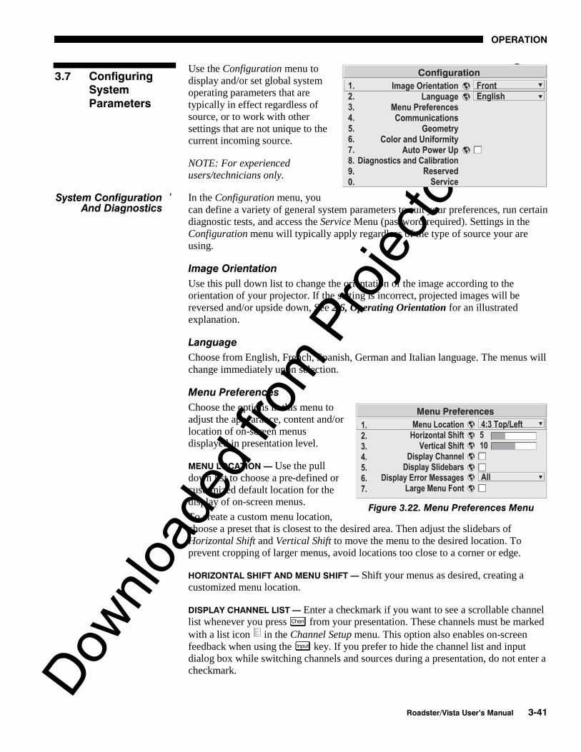
Downlo
aded
from
Pro
jecto
r.com
OPERATION
Roadster/Vista User’s Manual 3-41
Use the Configuration menu todisplay and/or set global systemoperating parameters that aretypically in effect regardless ofsource, or to work with othersettings that are not unique to thecurrent incoming source.
NOTE: For experiencedusers/technicians only.
In the Configuration menu, youcan define a variety of general system parameters to suit your preferences, run certaindiagnostic tests, and access the Service Menu (password required). Settings in theConfiguration menu will typically apply regardless of the type of source your areusing.
Image Orientation
Use this pull down list to change the orientation of the image according to theorientation of your projector. If the setting is incorrect, projected images will bereversed and/or upside down, See 2.6, Operating Orientation for an illustratedexplanation.
Language
Choose from English, French, Spanish, German and Italian language. The menus willchange immediately upon selection.
Menu Preferences
Choose the options in this menu toadjust the appearance, content and/orlocation of on-screen menusdisplayed in presentation level.
MENU LOCATION — Use the pulldown list to choose a pre-defined orcustomized default location for thedisplay of on-screen menus.
To create a custom menu location,choose a preset that is closest to the desired area. Then adjust the slidebars ofHorizontal Shift and Vertical Shift to move the menu to the desired location. Toprevent cropping of larger menus, avoid locations too close to a corner or edge.
HORIZONTAL SHIFT AND MENU SHIFT — Shift your menus as desired, creating acustomized menu location.
DISPLAY CHANNEL LIST — Enter a checkmark if you want to see a scrollable channellist whenever you press Chan from your presentation. These channels must be markedwith a list icon in the Channel Setup menu. This option also enables on-screenfeedback when using the Input key. If you prefer to hide the channel list and inputdialog box while switching channels and sources during a presentation, do not enter acheckmark.
3.7 ConfiguringSystemParameters
System Configuration 'And Diagnostics
Figure 3.22. Menu Preferences Menu

Downlo
aded
from
Pro
jecto
r.com
OPERATION
3-42 Roadster/Vista User’s Manual
NOTE: The Channel List and input dialog box cannot be hidden when a menu isdisplayed.
DISPLAY SLIDEBARS — Enter a checkmark to superimpose a small slidebar over thecurrent image whenever an adjustable parameter is selected directly with a key (theoption does not affect slidebars in menus) such as Pixel , Position , , or Bright . If“Display slidebars” is unchecked, these slidebars can still be accessed, but will behidden during adjustment.
DISPLAY ERROR MESSAGES — Choose in what way you want to be notified of errorsdetected in either the incoming signal or projector. Select “Screen” or “All” to see abrief on-screen messages or select “RS232” to be see messages via RS232 and RS-422 serial communication only. To disable error message display, select “Off”.
LARGE MENU FONT — Enter a checkmark to enlarge menus and their text. You mayhave to adjust “Menu Location” to accommodate the increased menu area.
Communications
This submenu of the Configuration menu is fully described in a separate SystemCommunications subsection later in Section 3.
Geometry
From the Configuration submenu, select theGeometry submenu to adjust your display shape,work with the lens, define a multi-screen mappingof incoming source material, or to work with testpatterns. The “Reserved” option has no function.
KEYSTONE and TILING SETUP — Refer todescriptions under Size and Position earlier in thissection. Controls are duplicated here for convenience during setup.
LENS CONTROL — For a full description of the Lens Control submenu, see 3.3, Usingthe Keypad ( Lens key) and 2.8, Zoom, Focus and Lens Offset.
TEST PATTERN — Use the pull-down list to select and display aninternal test pattern. Select OFF to turn off the display of a testpattern.
(SHORTCUT: Use Test key.)
Color and Uniformity
Use the options in the Color and Uniformity submenuto define color temperature, primary color hues and/orto achieve consistent brightness throughout all displayareas. This submenu is typically used in multiple-projector applications that require precise matching
Figure 3.23. Geometry Menu

Downlo
aded
from
Pro
jecto
r.com
OPERATION
Roadster/Vista User’s Manual 3-43
between adjacent displays—for Roadster/Vista models, only Color Temp Setup isavailable.
COLOR TEMP SETUP — See Image Settings. This function is offered in multiple menulocations for convenient access.
Auto Power Up
Enter a check mark to enable the projector to automatically power up after losingpower due to a power failure or due to unplugging the projector during operation.Note that unsaved display adjustments may be lost.
Diagnostics and Calibration
From the Diagnostics andCalibration submenu you canaccess several options for testingand setup of images. You canwork with test patterns andspecific colors, freeze an imagefor inspection, and/or access theOdd Pixel Adjustment menu forprecision settings of offset and gain.
TEST PATTERN — Refer to description under Geometry submenu.
COLOR ENABLE — Refer to description under Image Settings.
FREEZE IMAGE — Enter a check mark to freeze (stop) an image at a single frame.This diagnostic tool is useful if you need to examine in detail a still version of theincoming image that cannot be “frozen” at the source. For example, in movingimages it is sometimes difficult to observe artifacts such as externaldeinterlacing/resizing and signal noise. Remove the checkmark to return back tonormal.
ODD PIXEL ADJUSTMENT – Forsources with Color Space set toRGB only.
When using certain RGB sourceswith still images, you may need toadjust the normal gain or offset ofodd pixels in relation to even pixels.This will smooth out very narrow(1-pixel wide) “checks” or verticalstripes that indicate adjacent “on”and “off” pixels. You can remove these patterns as follows:
1) Use an external grayscale test pattern with both dark and light gray areas.
2) Display the image in its native resolution – select “No Resizing” by accessingResize Preset in Size and Position menu.
3) Display a single color—choose from a “Color Enable” list or use the Func keyshortcuts indicated on the back of the keypad.

Downlo
aded
from
Pro
jecto
r.com
OPERATION
3-44 Roadster/Vista User’s Manual
4) Examine an area of darkest gray (but not black). If there is a 1-pixel wide patternpresent, adjust “Odd Pixel Adjustment” offset for the current color. Stop when thepattern disappears and the area is smooth.
5) Examine an area of lightest gray (not white). If there is a 1-pixel wide patternpresent, adjust “Odd Pixel Adjustment” gain for the current color. Stop when thepattern disappears and the area is smooth.
6) Repeat for each color, adjusting offset then gain for each.
NOTES: 1) Adjust offset before gain, since offset affects gain. 2) A value of 128represents no change in normal odd pixel offset or gain. 3) Odd Pixel Adjustmenteliminates “1 pixel on, 1 pixel off” patterns only, not any type of larger patterns.
Reserved
No function for these options.
Service
The Service submenu offers the ability to enable or disable service passwords, and towork with factory-defined color temperatures and other functions. This submenu ispassword-protected and intended for use by qualified service technicians only.
Use the checkboxes and pull-downlists in the Communicationssubmenu to alter the methods ortypes of communication to andfrom one or more projectors.NOTE: Changes made to theCommunications submenu will besaved upon exit of the menu.
Baud Rate
The baud rate setting determines the speed of communication to andfrom the projector. By default, the projector baud rate is set to 19200.Setting the correct speed is important when you are controlling theprojector with an external device such as a computer or anotherprojector via an RS-232 or RS-422 port. You must set the projectorbaud rate at these ports to match the baud rate of the controllingdevice. If you are unsure about what baud rate to choose, refer to thedocumentation for the controlling device. In an existing network, ifyou discover that a projector has the wrong baud rate, make sure to use the pull-downlist and select the correct baud rate with the Enter key—do not just scroll this controlwith and keys.
NOTE: 1) The baud rate setting does not affect the switcher port, which is always9600 baud. 2) See Serial Port Connections and Appendix D for more informationabout cable connections between devices. 3) On early models, the 2 highest baudrates are unavailable for downloading projector MAIN software.
System Communications '
Figure 3.24. Communications Menu

Downlo
aded
from
Pro
jecto
r.com
OPERATION
Roadster/Vista User’s Manual 3-45
Front IR / Back IR
As described in Section 2, the standard IR remote keypad is capable ofsending data to the projector in either one of two protocols called A orB. Likewise, the front and rear IR sensors on the projector can be set toaccept IR data accordingly, responding to A, B or both. The projector’sA or B default is adequate for most single-projector installations. Selecta specific protocol to prevent interference when you are controlling
two protectors in the same area and want to work with one projector at a time.
Note that the front and rear IR sensors cannot respond to different protocols–if youchange a protocol for either sensor to anything other than OFF, the protocol for theother sensor also changes. For example, setting Front IR to B also changes the BackIR to B. If you want only one sensor to respond to a particular protocol—A, B, or A or
B—disable the other sensor by setting its protocol to OFF.
If you want to disable both IR sensors, you cannot use the IR remote keypad to selectthe second OFF setting. This safeguard prevents accidentally disabling a keypadwhile you are using it. Instead, use either the built-in keypad or the wired remote toset the remaining active sensor to OFF. The projector will no longer respond to an IRremote keypad.
IMPORTANTKeep at “A OR B” unless you are sure of
the current IR keypad protocol.
NOTES: 1) The IR remote keypad for this projector is set at manufacture to"Protocol A". See 2.10, Keypad Protocols and Conversion for information aboutchanging the keypad protocol. 2) A key press from a conflicting protocol will cause asingle yellow flash on the Status LED located in the lower right corner of the rearprojector panel.
Wired Keypad
Like the IR remote keypad, the optional wired keypad is either a "Protocol A" keypad(default) or a "Protocol B" keypad. Likewise, the projector can be set to accept wiredkeypad data accordingly, responding to A or B. If desired, you can prohibit theprojector from responding to a particular wired keypad protocol, or you can ensurethat the projector responds to either protocol (default). You can also prevent theprojector from responding to the keypad entirely. In the pull-down list, select thedesired protocol.
NOTE: The wired keypad for this projector is set at manufacture to "Protocol A". See2.10, Keypad Protocols and Conversion for information about changing the keypadprotocol.
ADDING A WIRED KEYPAD PROTOCOL: To add a protocol, select the A or B option.
CHANGING A WIRED KEYPAD PROTOCOL: As a safeguard, you cannot accidentallyselect an option in the “Wired Keypad” list that would disable the wired keypadduring use, since such options are automatically disabled in the list. In other words,you cannot switch to the opposite protocol or select OFF using the wired keypad.Instead, if you want to quickly change to the other protocol, you may find it moreconvenient to use one of the other keypads (the built-in keypad or the IR remote) toexecute the protocol change for the wired keypad. The projector will now recognize

Downlo
aded
from
Pro
jecto
r.com
OPERATION
3-46 Roadster/Vista User’s Manual
only the opposing wired keypad protocol. Or, if you prefer, use the wired keypad tosafely change its own protocol:
1. Select the A or B option. This will ensure that once your keypad is manuallychanged (see Step 2), it will still be recognized by the projector.
2. Unplug the keypad and change the protocol in the keypad as desired. Do thiseither by entering the short-cut software command or by hard-wiring thekeypad as described in 2.10, Keypad Protocols and Conversion.
3. Plug the keypad back into the projector. Return to the Communications menuand select the new protocol you have just set up in the wired keypad.
TURNING OFF THE WIRED KEYPAD: If you want to disable the wired keypad entirely,you cannot use it to select the OFF option. This safeguard prevents you fromaccidentally disabling the wired keypad during use. Instead, use either the built-inkeypad or the IR remote keypad to select OFF. The projector will no longer respondto the wired keypad.
Broadcast Key
Enter a checkmark if you want keypad commands sent to one projector to be relayedto all projectors in a network. Note the key will temporarily “override” theeffect of a broadcast setting and allow you to control a specific projector whennecessary. Make sure to remove the checkmark if using the split network feature.
Projector
Enter a three-digit number (such as "001") to assign or change a number to theprojector currently in use – if the current projector already has a number assigned,that number will appear here (see right).Numerical identity for projectors isrequired whenever you want tocommunicate with a single projectorwithin a multiple-projector application(see key description in 3.3, Using theKeypad). If you make a mistake inassigning or changing the projectornumber, press Exit to cancel.
For complete information aboutcontrolling multiple projectors, see 3.10,Using Multiple Projectors.
Split Network
Enter a checkmark if you have a network in which each projector is connected viaboth its RS-232 and RS-422 serial ports (Figure 3.25A). At each projector, serialcommunications will then remain on either its RS-232 or RS-422 path (depending onthe controller) rather than being broadcast to all 3 remaining serial ports. Should aprojector or path ever fail, the other path will be available as a back-up.
The Split Network feature is unnecessary when only a single serial link is connectedbetween any two projectors (Figure 3.25B), and will cause communication errors ifthese single links vary from RS-232 to RS-422 anywhere in the network. Likewise, ifyou have two serial links connected between any two projectors, failure to use theSplit Network checkbox can also cause a communication error.

Downlo
aded
from
Pro
jecto
r.com
OPERATION
Roadster/Vista User’s Manual 3-47
NOTES: 1) Requires double serial links—RS-232 and RS-422—between allprojectors in a network. 2) Set each projector’s Broadcast Key OFF. 3) Keypadscannot broadcast in a split network—use controller(s) instead. 4) Do not use a splitnetwork when downloading new projector software to a network.
Figure 3.25. Split Network Checkbox — ON vs. OFF
Whenever you install a new lamp in theprojector you must access the Lamp submenu(available from Main) and record the lampserial number in the projector’s memory. Youcan also choose the lamp operation mode youprefer, such as maintaining a specific intensity(light output) or power level, and define theexpected lamp life. Read-only informationincludes the lamp serial number and age.
NOTE: See 4.4, Replacing the Lamp and Filterfor complete instructions on installing a newlamp in the projector.
LAMP HOURS shows the number of hours logged on the current lamp. Whenever yourecord a new lamp serial number, this read-only value automatically resets to “0”,where it begins to log time for the new lamp. “Lamp Hours” also appears in theStatus menu.
LAMP S/N is the serial number recorded for the current lamp. When you install a newlamp and enter its serial number, the number will appear here. NOTE: Read-only.
LAMP MESSAGE — Enter a checkmark if you want to enable a warning message uponpower-up that the lamp has reached the specified lamp limit and should be replaced.Delete the checkmark if you do not want to see this warning—instead, when your
3.8 Working withthe Lamp
Figure 3.26. Lamp Menu

Downlo
aded
from
Pro
jecto
r.com
OPERATION
3-48 Roadster/Vista User’s Manual
lamp expires, only the status information on the back of the projector will provide thewarning to replace the lamp.
NOTES: 1) It is recommended that the Lamp Message checkbox remain enabled. 2)When a lamp warning message appears, press to temporarily cancel themessage. The message will continued to appear upon power-up until you install anew lamp.
Set LAMP LIMIT to the number of hours you expect to log on the current lamp beforereplacing it. This limit typically will match you lamp warranty, but consider also thatactual lamp life depends on what lamp mode(s) you use over the life of the lamp andhow much light output is desired for your application. In any case, when the lampapproaches your chosen lamp limit, the Lamp Message (if it has been enabled) willappear upon power-up.
NOTES: 1) If you change modes over the life of a lamp, the lamp limit you originallyexpected may no longer apply. 2) Turning the lamp on and off can reduce lamp lifesignificantly, as will other factors. Limit lamp strikes to what is necessary.
Set which LAMP MODE you want to use in order to control thelight output in your application. Although there can beexceptions, in most lamps the higher the light output or powersetting, the shorter the life span of the lamp.
Use the lamp mode that best suits your need for brightness. For example, you maysimply need as much brightness as possible, which will apply maximum power to thelamp—choose Max Brightness. Alternatively, in a tiled application you may want toclosely match and maintain brightness levels between adjacent images—chooseIntensity for each projector, then judge by eye and set each individual intensity settingas necessary (see “Intensity”, below). Or you may simply want to apply a reducedpower level to the lamp at all times—choose a specific Power wattage.
Lamp modes are described below:
• Max Brightness: The lamp will always burn as brightly as possible, driven bymaximum power of 700W in the X3/S3/X4/S4, 1200W in the X5/S5/X6/S6 andup to 1700W (self-adjusting1) in the X9/S9. Keep in mind that the “maximumbrightness” for any lamp gradually diminishes with age—images will becomedimmer over time. The current light output level (stated as an arbitrary value,i.e. unrelated to lumens) appears in the “Intensity” box.
• Intensity: Brightness will remain close to a specified level for as long aspossible. Once you select this option, enter a number representing the intensitylevel (brightness) you wish to maintain—the projector will automaticallyadjust power as needed to closely maintain this intensity over time. Note thatan intensity value is simply an arbitrary value from 0-9999 unrelated tolumens levels in your model. See “Intensity” below.
• Power: The power (watts) supplied to the lamp will remain at a desired levelthroughout the life of the lamp. Once you select this option, enter the number ofwatts representing the power level you wish to maintain. See “Power” below.
1 In X9/S9, a new lamp needs less than full power to achieve maximum brightness and will, in fact, limit incoming power as requiredto run at 75A. During the first few hundred hours of life, the lamp arc gradually changes and voltage automatically increases until thelamp is utilizing the full 1700W. This self-adjusting behavior results in less “lamp drop-off” over time---images are brighter for alarger percentage of overall lamp life.
Figure 3.27.

Downlo
aded
from
Pro
jecto
r.com
OPERATION
Roadster/Vista User’s Manual 3-49
POWER – The number shown here indicates how many watts are applied to the lamp.In the X3/X4/S3/S4, set from 450-700 watts as desired. In the X5/X6/S5/S6, set from800-1200 watts as desired. In the X9/S9, set from 1200-1700 watts as desired. Forany model, keep in mind that lower power levels produce dimmer images. When in“Power” or Max Brightness modes, the power level remains constant2. When in“Intensity” mode, the power level will change as necessary3. Specifying themaximum power level in Power mode is the same as operating in Max Brightness
mode.
NOTES: 1) Power level can be set only if the lamp is in “power” mode. 2) If you arein “Intensity” mode, the power level value will automatically increase over time asnecessary to maintain the desired brightness as closely as possible, until powerreaches its maximum. 3) After approximately 500 hours of use, all models using a700W lamp require lamp power of 550W or higher. If set too low, the aging lamp cancause a projector shutdown. Upon your next power up, lamp power willautomatically maximize and a message box relates “Unexpected lamp off. Power setto max.”. Use 550W or more to ensure normal operation and prevent similarshutdowns, or install a new lamp in order to reliably use lower lamp power levels.
INTENSITY – This number represents the current brightness of your lamp, decreasingover time when you are operating at Max Brightness or at a specific Power level.However, when you are operating in “Intensity” mode, this value remains at yourchosen “Intensity” setting.
NOTE: The number shown for “intensity” is not the actual lumen output, but ratheran arbitrary value unrelated to lumens.
To use “Intensity” mode, judge by eye and set the level as desired for yourapplication, remembering that higher settings can significantly shorten lamp life.Over time, the projector will automatically increase the power supplied to the lamp asneeded to maintain the chosen intensity as closely as possible. This is called“Brightness Tracking” or “LiteLoc”.
Keep in mind that once power reaches its maximum (see “Power”, above), thistracking is no longer possible. At this point, the lamp will gradually begin to dim asusual, even though your original “Intensity” value will still appear in the menu. Toresume accurate tracking, reduce the intensity setting so that the resulting “Power”value is less than its maximum—the lower the intensity, the longer it can bemaintained.
Do not lower the “Intensity” so much that the corresponding “Power” value reachesits minimum (450 watts in the X3/S3/X4/S4, 800 in the X5/S5/X6/S6, and 1200W inthe X9/S9) — the intensity settings will be inaccurate and cannot be maintained. Notealso that lamp power of 550W (or higher) is required for any 700W lamp havingmore than 500 hours on it. Make sure your “Intensity” setting is high enough to keepthe corresponding lamp power at 550W or higher. For best results in matchingintensity over in tiled images, choose an intensity setting that enables all lamps tooperate at less than the maximum number of watts available in your projector, butabove 550W. See “Power”, above.
2 Precise behavior with newly-installed lamps in X9/S9 is described in footnote 1 on the previous page.
3 Because a new lamp in X9/S9 can emit maximum brightness without initially requiring maximum power, adjusting Power orIntensity slidebars beyond this point produces no additional light output. This is normal for these models.

Downlo
aded
from
Pro
jecto
r.com
OPERATION
3-50 Roadster/Vista User’s Manual
NOTES: 1) Lamps become more stable over time, thus a specific intensity is moreeasily maintained as the lamp ages. 2) Intensity can be set only if the lamp is in"Intensity" mode 3) Intensity cannot exceed the output of Max Brightness mode.
LAMP HISTORY - This read-only option lists the most lamps mostrecently installed and recorded in the projector. Lamp Historyautomatically updates whenever you record a new lamp serialnumber—the new lamp is added to the bottom of the list.
Use CHANGE LAMP
to record the serialnumber for a newlyinstalled lamp.
In the Lamp S/Nwindow, use thenumber text entrykeys to record thenew lamp serialnumber, and press
again to acceptthe change. SeeUsing Slidebars and Other Controls if you need help entering the number. Onceentered, the new lamp serial number will be added to the Lamp History menu and theLamp Hours timer will reset to “0”. Lamp Mode and Lamp Limit remain as they werefor the previous lamp, and can be changed at any time.
NOTE: Enter a serial number only if you have just installed a new lamp. This willhelp ensure that lamp timer is not reset on an old lamp and that the number of hourslogged on the lamp will be accurate.
IMPORTANT Always DO record the serial number of a NEW lamp.
This read-only menu lists a variety of details about the standard and optionalcomponents currently in use on the projector. Refer to the Status menu for versions ofhardware (left side) and software (right side) installed, the number of lamp hourslogged in total and for a specific period (such as a rental period), and for yourprojector model name and serial number. In addition, the Status menu identifies thecurrent channel, switcher, slot and frequencies.
Use ON , OFF , or to see additional Status information.
Figure 3.28. Recording the New Lamp Serial Number
3.9 ProjectorStatus

Downlo
aded
from
Pro
jecto
r.com
OPERATION
Roadster/Vista User’s Manual 3-51
Figure 3.29. Status Menu (SAMPLE)
When working with multiple projectors, you may want to use the RS-232 or RS-422serial ports to chain the projectors together in a network that you control from either akeypad or a computer/controller (see 2.9, Serial Port Connections). Or you may preferthat each projector stands alone, but is controlled with a common IR remote keypad.You can also tile a single incoming image among multiple displays in a videowall,with each display making up a portion of the total image. In such cases, you canswitch back and forth between broadcasting to all projectors or controlling eachprojector individually.
Make sure you have assigned a unique projector number to each projector present —this number will be required in order get the exclusive attention of an individualprojector. To assign a projector number:
Press Menu and select the Configuration menu, then the Communications submenu.Scroll down to "Projector#" and enter a valid three-digit number (000 to 999) foridentifying the current projector. Press Enter to accept the entry, or Exit to cancel.
Repeat for each projector, using a unique three-digit number for each. Once everyprojector has its own number, you can begin to control the network.
First make certain that only one (any) networked projector has its "Broadcast Keys"option selected (checked) and IR sensors enabled — the remaining projectors musthave the “Broadcast Keys” option unchecked and their keypads disabled (do this inthe Configuration / Communications menu). The "Broadcast Keys" projector willthen relay keypad commands to the other projectors. If using a wired remote, make
3.10 Using MultipleProjectors
Assigning a '"Projector#"
Controlling One Projector '

Downlo
aded
from
Pro
jecto
r.com
OPERATION
3-52 Roadster/Vista User’s Manual
sure to select the “Broadcast Keys” option for the projector to which the wiredremote is connected.
To work with a single projector, press to display an editable window from eachprojector. Enter the three-digit number you have assigned to the projector you wish tocontrol. All keypad commands will then affect this projector exclusively until you press
again and enter a different number, or until you switch to broadcast mode (below).
NOTES: 1) If you are using a computer or controller to issue commands, use thecorrect RS-232 software command to gain control of a single projector.
First make certain that only one (any) networked projector has its "Broadcast Keys"option selected (checked) — the remaining projectors must have the optionunchecked and their keypads disabled (do this in Configuration / Communicationmenu). The "Broadcast Keys" projector will then relay keypad commands to theothers. If using a wired remote, make sure to select the “Broadcast Keys” option forthe projector to which the wired remote is connected.
On either the IR remote or wired keypad, press to display the projector box.Press again without entering a number — the keypad commands will now affectall projectors.
NOTE: 1) If you are using a computer or controller to issue commands, use thecorrect RS-232 software command to broadcast.
Tiling an image means that multiple adjacentdisplays work together to form a single image,like a tiles in a mosaic. This videowall conceptcontrasts with other multiple-projectorapplications in which each display is acomplete and independent image. Use theTiling Setup menu as described below(accessed via the Size and Position menu orConfiguration/Geometry menu) to configure a maximum of 16 displays (4 x 4) intoone single-image videowall or tiling array.
Defining the Videowall
NUMBER OF ROWS – Use the slidebar to define the number of rows (1-4) present inyour videowall. Each projector must have the same setting.
NUMBER OF COLUMNS – Use the slidebar to define the number of columns (1-4)present in your videowall. Each projector must have the same setting.
PROJECTOR ROW AND PROJECTOR COLUMN – For each projector, use these twoslidebars to define the projector’s unique row-and-column location within thevideowall. Any videowall begins with the top left corner display as Row 1, Column1. See Figure 3.30.
Broadcasting to 'All Projectors
Tiling An Image 'Across Multiple Displays

Downlo
aded
from
Pro
jecto
r.com
OPERATION
Roadster/Vista User’s Manual 3-53
Figure 3.30. Tiling Setup (Example of 4x4 Array)
Resizing the Videowall Image
RESIZE PRESETS – When your multiple-projector tiled array has been defined asdescribed above, select a desired tiled resizing method. Sections of incoming datawill then automatically map to the appropriate “row,column” address in yourvideowall, filling the wall with a complete image that is scaled as you have specified.
NOTES: 1) Tiled resizing options are enabled only if you have defined an array oftwo or more projectors as described above. 2) Use the same tiled resizing option foreach projector in your array, regardless of the number of rows and columns in thearray. 3) Whether the wall produces a black border or a cropped image depends onthe aspect ratio and resolution of the incoming source.
• For each projector, select “Tiled Full Size” tofully fill all screens in the wall. Each sectionof incoming data will be scaled horizontallyand vertically to fill the screen to which itautomatically maps. See right. Note thisoption does not necessarily maintain aspectratio.
• For each projector, select “Tiled Full Width”to fill the videowall from left-to-right whilemaintaining aspect ratio. This typicallycreates a top and bottom black border on thewall, and is best suited for HDTV signals. Seeright.
NOTE FOR LARGE ARRAYS: 1) In largearrays having 3 or 4 rows, the center row(s)will automatically fill. 2) Screens with verylittle or no image will be blanked (cropped).

Downlo
aded
from
Pro
jecto
r.com
OPERATION
3-54 Roadster/Vista User’s Manual
• For each projector, select “Tiled Full Height” tofill the videowall from top-to-bottom whilemaintaining the incoming aspect ratio. Thistypically creates a black border on the left andright edges of the wall. See right.
NOTE FOR LARGE ARRAYS: 1) In largearrays having 3 or 4 columns/rows, the centerscreen(s) will automatically fill. 2) Screenshaving very little or no image will be blanked(cropped).
• For each projector, select “Tiled Anamorphic”to fill the videowall from left-to-right whilemaintaining the incoming “widescreen”(anamorphic) aspect ratio of 16:9. Thistypically creates a black border at the top andbottom edges of the wall. See right.
NOTE FOR LARGE ARRAYS: 1) In largearrays having 3 or 4 columns/rows, the centerscreen(s) will automatically fill. 2) Screenshaving very little or no image will be blanked(cropped).
Large Displays and 10-bit Processing
When processing sources throughthe optional ADP module, youmay have to crop the extreme topand bottom edges of the imageOR map to fewer screens (seeright).
Occasionally the projector may encounter an error condition that interrupts normaloperation. Such a condition can be caused by an invalid user entry, an input signalerror (most common) or other system error.
If you would like to be notified on-screen of such errors, select the “Screen” optionfrom the “Display Error Messages” pull-down list (in Menu Preferences Menu). Ifyou would like to be notified via a serial communication only, select the “RS-232”option instead. To receive both notifications, select “All”. To disable error messages(except for invalid user entries), select “Off”.
NOTE: Error messages also always appear at the rear LCD next to the keypad.
3.11 ErrorConditions

Downlo
aded
from
Pro
jecto
r.com
OPERATION
Roadster/Vista User’s Manual 3-55
Invalid User Entry
Any keypad entry not recognized by the projector will trigger an on-screen errormessage describing the problem. For example, if you specify a channel number thathas not been defined, the message “Invalid Channel will appear. Or if you try to enterthe wrong password, you’ll see “Invalid Password”. Press Enter or Exit to confirm themessage and eliminate the message box.
NOTE: Displaying of “Invalid User Entry” messages cannot be disabled, even ifDisplay Error Messages has been set to “Off”.
Input signal errors messages appear when you are in presentation level (i.e., whenthere are no menus present) and have selected an input on which the projector detectsa problem. While menus remain operational and pressing any key will temporarilyremove the message from the screen, you must resolve the signal problem in order topermanently eliminate the message.
NOTE: Input signal messages appear on-screen only if Display Error Messages hasbeen set to “Screen” or “All”.
No Signal
The message "No signal" appears when there is no signal detected at the selectedinput. Both HSYNC and VSYNC are inactive and the screen background is black.Connect or correct the signal, or select another input.
Bad Sync
The message "Bad Sync" is displayed when HSYNC or VSYNC are active but thesignal cannot be displayed. Such a condition occurs when only one of the two signalsis present, or when either signal is unstable or of the wrong frequency. Correct thesignal or select another input.
Other Signal Error Messages
In addition to the common "Bad Sync" and “No Signal” errors, you may encounter asignal error message indicating that Hsync and/or Vsync are either too fast or tooslow. When such a message appears, check the frequencies shown in the Statusmenu. If they are correct, then the signal is not recognized by the projector. On somePCs you may be able to change the settings to generate a compatible signal. If thefrequencies shown in the Status menu are incorrect, check the cabling to see wherethe problem is.
When the projector encounters a system malfunction, either a System Warningmessage or a System Error message may appear. Both types of messages areaccompanied by a steady red “Power” LED and a flashing red-and-yellow error codeon the “Status” LED. This condition indicates the need for service by a qualifiedservice technician.
NOTE: System messages appear on-screen only if Display Error Messages has beenset to “Screen” or “All”.
System Warnings
A system warning message indicates that a system malfunction has been detected(see Status LED Codes, below). A system warning message replaces any input signalmessage and disappears when the input signal status changes. While the projector
User Errors '
Input Signal Errors '
System Warnings / Errors '

Downlo
aded
from
Pro
jecto
r.com
OPERATION
3-56 Roadster/Vista User’s Manual
will remain operational, the message indicates the presence of a serious problem thatshould be reported to the manufacturer. You can press to remove the message,but for best results you should reset the projector—power the projector down and upagain with the key.
System Errors
A system error message indicates that a serious malfunction has been detected andmust be reported to the manufacturer (see Status LED Codes, below). The projectorwill no longer operate and must be reset—power the projector down and up againwith the key.
The Status LED Codes
If the "Status" LED on the back of the projector repeatedly flashes a pattern of yellowand red light while the "Power" LED glows a continuous red, you have encountered alikely system error requiring the attention of a qualified service technician (seeSystem Warnings and System Errors, above). Try resetting the projector by poweringit off and on again, cooling when necessary. Consult Table 3.3 and contact yourdealer if the problem persists.
The specific pattern of flashing indicates the 2-digit code identifying the type ofproblem encountered—the number of yellow flashes represents the first digit and thenumber of red flashes indicates the second digit. For example, a pattern of “yellow-yellow-red-red-red” is “Code 23”, meaning the lamp ballast (power supply) isoverheated. These codes are listed in Table 3.3.

Downlo
aded
from
Pro
jecto
r.com
OPERATION
Roadster/Vista User’s Manual 3-57
Table 3.3. System Error Codes
Code Description
GENERAL12 Software bug. Contact dealer/factory.
13 CRC error in flash ROM. Download new software.
14 Replace IPM
15 Attempting to download code without being in boot mode
16 Invalid interrupt. Power off/on. If persists, contact dealer/factory.
LAMP / BALLAST
21 Unable to turn the lamp on
22 Lamp is overheated
23 Lamp ballast (power supply) is overheated
24 One or more of the lamp interlocks are open
25 Lamp may be on before being turned on
26 Cannot read valid lamp ballast ID
27 Unexpected lamp shut-off
28 Lamp not installed
IMAGE PROCESSOR MODULE
31 Boot code CRC failed
32 Unable to program the Sync Xilinx part
33 Unable to program a device on Altera programming bus
34 Unable to program a device on JTAG programming bus
35 Unrecognized ROM type
36 Write to flash ROM failed
37 General IPM failure
38 Code being downloaded will not fit in ROMs
PANEL DRIVER MODULE / LIGHT ENGINE ELECTRONICS
41 Unrecognized Panel Driver Module (PDM)
42 Unable to program a device on Panel Driver programming bus
43 Panel Driver/optical system communication problem
44 Red Formatter/flex cable problem
45 Green Formatter/flex cable problem
46 Blue Formatter/flex cable problem
47 Mixed Formatters
48 Download failure in display engine
POWER & COOLING
51 Fan #1 failed (part of Cooling Module)
52 Fan #2 failed (part of Cooling Module)
53 Fan #3 failed (side fan, bottom—connects to J38 on ICM)
54 Fan #4 failed (side fan, top—connects to J39 on ICM)
55 Low voltage power supply failed to turn on
MOTOR CONTROL MODULE (not in all projectors)
61 Problem communicating with MCM
62 Unable to program the MCM field-programmable gate array
INTERCONNECT OR CHASSIS I.D.
71 Unable to access EEPROM on the ICM
72 EEPROM memory has re-initialized
VIDEO DECODER MODULE (INPUT 3 OR 4)
81 Unable to program the video decoder (VDM)
OPTIONAL INTERFACE MODULE
91 Unable to program the option card
If you encounter a system error, try resetting the projector by powering it off and on again(cooling if necessary). Contact dealer/factory if error persists.

Downlo
aded
from
Pro
jecto
r.com

Downlo
aded
from
Pro
jecto
r.comSect ion 4
Maintenance
Roadster/Vista User’s Manual 4-1
This projector is CSA approved and is designed for safe and reliable operation.However, safe operation cannot be assured by design alone; installers, maintainers,and users must maintain a safe operating environment for the system. Please readthrough and understand the following warnings and guidelines promoting safe usageof the projector.
WARNING Always REMOVE the lens when shipping a projector.
WARNING Never look directly into the projector lens. The extremely highbrightness of this projector can cause permanent eye damage.
WARNING For protection from ultraviolet radiation,
keep all projector shielding intact during operation.
Observe and follow all warnings and instructions marked on the projector.
The exclamation point within the equilateral triangle alerts the userto important operating and maintenance (servicing) instructions inthe literature accompanying the projector.
The lightning flash and arrowhead symbol within the equilateraltriangle alerts the user to non-insulated "dangerous voltage" withinthe projector's enclosure that may be of sufficient magnitude toconstitute a risk of electric shock.
Operate the projector in an environment which meets the operating rangespecifications in Section 5, Specifications. Do not operate the projector close towater, such as near a swimming pool.
Do not place the projector on an unstable cart, stand or table. If theprojector is to be ceiling mounted, only use a Christie-approvedceiling mount fixture.
A projector and cart combination should be used with care. Suddenstops, excessive force, and uneven surfaces may cause theprojector and cart combination to overturn.
4.1 Warnings andGuidelines
Labels and Markings '
Projector Location '

Downlo
aded
from
Pro
jecto
r.com
MAINTENANCE
4-2 Roadster/Vista User’s Manual
LAMP: Do not operate the Xenon lamp for more than 1000 hours; risk of the lampshattering increases as a result of changes in the quartz glass. Also, operation beyond1000 hours significantly reduces brightness output.
WARNING Never attempt to remove the lamp housing directly after use.The lamp is under great pressure when hot and may explode,causing personal injury and/or property damage. Allow to cool
completely.
The arc lamp operates at a very high temperature and pressure.Failure to allow the lamp to sufficiently cool prior to handling couldresult in an explosion causing personal injury and/or propertydamage. After turning the projector off it is important that you waitat least five minutes before unplugging it. This provides enough timefor the internal lamp cooling fans to cool the lamp and to automatically shut off. Coolcompletely before handling.
WARNING Use only lamps supplied by Christie.
FILTER: Replace the side filter every 1000 hours or sooner. If this filter is notreplaced, air flow may become restricted and cause the projector to overheat.
See 4.4, Replacing the Lamp and Filter for the complete replacement procedure.
WARNING Use only filters supplied by Christie.
Only use attachments or accessories recommended by Christie, such as the specificpower cord supplied. Use of other attachments or accessories with this projector mayresult in the risk of fire, shock or personal injury.
WARNING Use only the AC power cord supplied. Do not attempt operationif the AC supply and cord are not within the specified voltage
and power range. See Section 5.
Do not allow anything to rest on the power cord. Locate the projector where the cordcannot be abused by persons walking on it or objects rolling over it.
Operate the projector at the specified voltage only. Do not overload power outletsand extension cords as this can result in fire or shock hazards.
The projector is equipped with a three wire plug having a third (grounding) pin. Thisis a safety feature. If you are unable to insert the plug into the outlet, contact anelectrician to have the outlet replaced. Do not defeat the safety purpose of thegrounding-type plug.
Before unplugging the power cord, make sure the internal lampcooling fans have shut off. The fans automatically shut off when theprojector has adequately cooled down.
Slots and openings in the projector provide ventilation. To ensure
Lamp and Filter 'Replacement
Power Cord 'and Attachments
Ventilation '
Downlo
aded
from
Pro
jecto
r.com
MAINTENANCE
Roadster/Vista User’s Manual 4-3
reliable operation of the projector and to prevent overheating, these openings mustnever be blocked or covered. The projector should never be placed near or over aradiator or heat register. The projector should not be placed in an enclosure unlessproper ventilation is provided. For best results, ensure that the projector bottom isabove any “lip” that may be present on a cart—extend projector feet as necessary.
Do not push objects of any kind into the projector through the ventilation openings.They may touch dangerous voltages or short-out components resulting in a fire orshock hazard. Do not spill liquids of any kind into the projector. Should an accidentalspill occur, immediately unplug the projector and have it serviced by a qualifiedservice technician.
If any of the following conditions exist, immediately unplug the projector from thepower outlet and refer service to qualified service personnel.
• The power cord has been damaged.
• The internal cooling fans do not come on when the projector is first turned on.
• Liquid has been spilled into the projector.
• The projector has been exposed to excessive moisture.
• The projector does not operate normally.
• The projector has been dropped or the case has been damaged.
• Projector performance has deteriorated.
Do not attempt to service the projector yourself. All servicing must be performed bya qualified Christie service technician only. If replacement parts are required, it isimportant that only Christie-approved parts are used. Other parts may result in fire,electric shock or risk of personal injury.
Clean the projector when required. Before cleaning, always unplug the projector fromthe power outlet.
To avoid the risk of scratching the lens, clean the lens only if absolutely required. Asmall amount of dust on the lens will have very little effect on picture quality. If thelens must be cleaned, use a DRY soft cotton cloth. Clean gently in a circular motion.
It is important to never touch the glass surface of the lamp, as the oil imprint willseriously degrade lamp performance. Should you accidentally touch the surface ofthe lamp, clean carefully with a lint-free cloth moistened with isopropyl alcohol.
Clean the case with a soft dampened cloth. Use a mild commercial cleaner. Do notuse liquid or aerosol cleaners.
The optional IR Remote Keypad uses four AA size, 1.5V batteries (preferablyalkaline). To install new batteries, open the battery compartment at the back side ofthe keypad by pulling on the raised portion of the cover as shown (Figure 4.1).
Servicing '
4.2 Cleaning
Lens '
Lamp '
Case '
4.3 ReplacingKeypadBatteries
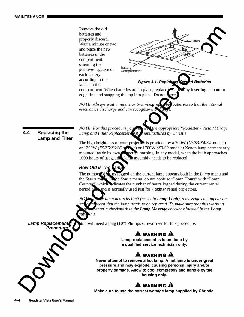
Downlo
aded
from
Pro
jecto
r.com
MAINTENANCE
4-4 Roadster/Vista User’s Manual
Remove the oldbatteries andproperly discard.Wait a minute or twoand place the newbatteries in thecompartment,orienting thepositive/negative ofeach batteryaccording to thelabels in thecompartment. When batteries are in place, replace the cover by inserting its bottomedge first and snapping the top into place. Do not force.
NOTE: Always wait a minute or two when replacing batteries so that the internalelectronics discharge and can recognize the change.
NOTE: For this procedure you will need the appropriate “Roadster / Vista / MirageLamp and Filter Replacement Kit” manufactured by Christie.
The high brightness of your projector is provided by a 700W (X3/S3/X4/S4 models)or 1200W (X5/S5/X6/S6 models) or 1700W (X9/S9 models) Xenon lamp permanentlymounted inside its own protective housing. In any model, when the bulb approaches1000 hours of usage, this lamp assembly needs to be replaced.
How Old is The Lamp?
The number of hours logged on the current lamp appears both in the Lamp menu andthe Status menu. In the Status menu, do not confuse “Lamp Hours” with “LampCounter”, which indicates the number of hours logged during the current rentalperiod only and is normally used just for Roadster rental projectors.
NOTE: As the lamp nears its limit (as set in Lamp Limit), a message can appear onscreen to warn that the lamp needs to be replaced. To make sure that this warningappears, enter a checkmark in the Lamp Message checkbox located in the Lampsubmenu.
You will need a long (10”) Phillips screwdriver for this procedure.
WARNING Lamp replacement is to be done bya qualified service technician only.
WARNING Never attempt to remove a hot lamp. A hot lamp is under great
pressure and may explode, causing personal injury and/orproperty damage. Allow to cool completely and handle by the
housing only.
WARNING Make sure to use the correct wattage lamp supplied by Christie.
Figure 4.1. Replacing Keypad Batteries
4.4 Replacing theLamp and Filter
Lamp Replacement 'Procedure

Downlo
aded
from
Pro
jecto
r.com
MAINTENANCE
Roadster/Vista User’s Manual 4-5
NOTE: All illustrations for this procedure assume a non-inverted projector.
Turn off the projector
Turn the projector off and allow the cooling fans to stop automatically beforeproceeding with Step 2.
Unplug the projector
When the cooling fans have stopped, unplug the projector.
Remove the left side panel
• See Figure 4.2. Remove the 5screws securing the projector’sleft side panel.
• Lower the panel slightly to cleartwo pins at the bottom edge of theprojector.
• Pull the panel off to expose thelamp door near the front corner.
Open the lamp door
• See Figure 4.3. Loosen the 2 screws fasteningthe lamp door shut.
• Lift the door fully open (it will stay up on mostmodels).
Not shown: Air deflector on underside of X9/S9lamp door. Do not remove.
STEP 1 '
STEP 2 '
STEP 3 '
Figure 4.2. Remove the left side panel
STEP 4 '
Figure 4.3.Open the lamp door

Downlo
aded
from
Pro
jecto
r.com
MAINTENANCE
4-6 Roadster/Vista User’s Manual
Loosen the spring-loaded T-bolts
The lamp module is secured to its alignment plate with 3 large spring-loaded T-boltsthat lock in-and-out with a 90° turn (they are the largest heads visible on thealignment plate). To unlock each T-bolt, use a Phillips screwdriver to push and turneach bolt 90°. The pin behind each bolt will align with its slot and pop the bolt free.See below.
Figure 4.4. Loosen the spring-loaded T-bolts
NOTES: 1) In older models, if access to the bottom screw is blocked, reduce verticaloffset of the lens. 2) In X9/S9, you may want to remove the side-mount air deflector.
Remove lamp and detach from terminal block
• Pull the lamp module out slightly.Note that it is still attached to a“terminal block” which connects tothe lamp power supply via anodeand cathode cables–the lampmodule cannot be fully removedyet.
• Remove the single screw securingthe lamp module to the terminalblock. See Figure 4.5 (top view).The lamp should now be fully free–refer to the recycling/disposalinstructions provided with the newlamp.
IMPORTANT Detach the lamp from the terminal block only.
Do not disconnect cables.
STEP 5 '
STEP 6 '
Figure 4.5. Detach lamp from terminalblock (TOP VIEW)

Downlo
aded
from
Pro
jecto
r.com
MAINTENANCE
Roadster/Vista User’s Manual 4-7
Reattach terminal block and insert lamp
• Secure the new lamp module to theterminal block with the single screw.
• Insert the new lamp module into thelamp compartment as shown in Figure4.6.
For 700W or 1200W models: Lookinginto the lamp compartment, theterminal block should be located atapproximately “3 o’clock”, i.e.,roughly centered and on the side of thelamp facing the projector front. Seeright, top example. Make sure themain lamp cables travel over thelamp, i.e. NOT along the lampcompartment floor.
For X9/S9: Looking into the lampcompartment, the terminal blockshould be located at approximately “9o’clock”, i.e., roughly centered and onthe side of the lamp facing theprojector rear. See right, bottomexample. Make sure the interlockwires travel between the lamp and the igniter and remain secured in clip asshown. Do not allow contact with igniter.
WARNING Check lead dressing in lamp compartment!
Secure the new lamp to the alignment plate
• Roughly align the 3 T-bolts on the lamp to the 3 slots in the alignment plate atthe rear of the lamp compartment.
• Push the lamp all the way back and make sure the pin on each T-bolt alignswith its slot on the alignment plate–slowly turn each until the clearance slot islocated. Then push and turn each T-bolt 90° to lock. See Figure 4.7.
Figure 4.7. Using the T-bolts(INVERT ILLUSTRATION FOR X9/S9)
• Replace the side-mount air deflector if you had to remove it (X9/S9 only).
STEP 7 '
Figure 4.6. Lamp Orientation forDifferent Models
STEP 8 '

Downlo
aded
from
Pro
jecto
r.com
MAINTENANCE
4-8 Roadster/Vista User’s Manual
Close the lamp door
• Swing the door down and secure the 2 screws. If necessary, push the X9/S9 airdeflector on the lamp door slightly to the left when closing—it must clear doorframe and internal components.
Replace the left side panel
• Align the bottom of the left side panel with two pins at the bottom edge of theprojector and swing up into place. Secure with 5 screws.
NOTE: The lamp module is calibrated for maximum performance and brightness inthis projector. Do not attempt to re-align or adjust an installed lamp module.
Power up the projector and reset the lamp timer
In the Main menu, select the Lamp option. In the Lamp menu, select the “ChangeLamp” option–enter the new serial number in the S/N text box (see Section 3,Operation if you need help entering the number). When the new number is recorded,the lamp timer will automatically reset to “0” hours and begin to log time.
IMPORTANTIf you neglect to enter a serial number, the lamp timer
will not reset to “0” and will therefore be inaccurate. Thelamp life limit may then expire prematurely.
NOTES: 1) Once entered, the new lamp serial number is also automatically added to the“Lamp History” submenu (read-only). 2) Lamp life data is required for warranty claims.
It is a good idea to replace the air filter whenever the lamp module is replaced (ormore frequently if operating the projector in a dusty environment). The filter islocated behind the right side panel.
Turn off the projector, cool, and unplug.
Before removing or installing a filter, turn off the projector and allow to cool for fiveminutes before unplugging. Make sure that the lens cap is on.
WARNING Unplug the projector.
Remove the right side panel
• See Figure 4.8. Remove the 5screws securing the projector’sright side panel.
• Lower the panel slightly to cleartwo pins at the bottom edge of theprojector.
• Pull the panel off to expose thefilter near the front corner.
STEP 9 '
STEP 10 '
STEP 11 '
Filter Replacement 'Procedure
STEP 1 '
STEP 2 '
Figure 4.8. Remove the right side panel

Downlo
aded
from
Pro
jecto
r.com
MAINTENANCE
Roadster/Vista User’s Manual 4-9
Replace the filter
Slide the used filter out from under the toptab and replace. Make sure the wire sidefaces IN. See Figure 4.9.
Replace the right side panel
Align the bottom of the panel with 2 pins atthe bottom edge of the projector and swingup into place. Secure with 5 screws.
WARNING Use only Christie filters. Never operatethe projector without the filter installed.
A variety of lenses can accommodate different throw distances and specific types ofinstallations. See page 5-1 for details. To change a lens, follow the steps below.
NOTES: 1) You will need a 9/64”(3mm or 3.5mm) hex socket ball driver (suppliedwith projector) or allen key for this procedure. For motorized zoom lenses, you mayalso need a remote keypad and flashlight. 2) “Top” or “bottom” references assume anon-inverted projector, as illustrated. 3) If you are installing a VistaGRAPHX lens,first make sure its “VistaGRAPHX Lens Adapter” is present on the lens. Such anadapter/flange secures to the projector in the same manner as the flange describedbelow, but accommodates a screw-mount lens.
Before removing a motorized zoom lens, you must adjust “zoom” in order to reachlens mount screws accessible through holes in the zoom gear:
1. POWER UP AND CALIBRATE THE LENS MOUNT (if not already done).
2. ADJUST ZOOM GEAR TO 1000 (FOR ACCESSING SCREWS): Press Lens (zoom adjust). Set to 1000.
Turn off the projector, cool, and unplug.
Before removing or installing any lens, turn off the projector and allow fans to stopbefore unplugging. Make sure that the lens cap is on.
WARNING Unplug the projector.
Figure 4.10. Install lens cap
Loosen the 3 lens mount screws
NOTE: If there is no lens installed, skip to Step 4.
STEP 3 '
Figure 4.9. Install wire side IN
STEP 4 '
4.5 Replacing theLens
Before You Begin '(MOTORIZED ZOOM LENS ONLY)
STEP 1 '
STEP 2 '

Downlo
aded
from
Pro
jecto
r.com
MAINTENANCE
4-10 Roadster/Vista User’s Manual
Use the hex socket ball driver provided with the projector to loosen the 3 lens mountscrews securing the lens flange to the mount–loosen these screws only, do notremove. Accessibility is illustrated in Figure 4.11.
• IF MANUAL ZOOM LENS: Access to the 3 lens mount screws is likely blockedby the toothed zoom ring. Manually rotate the zoom ring until its access holesalign with the screws beyond, then insert the hex socket ball driver as shown.See Figure 4.11.
• IF MOTORIZED ZOOM LENS: As shown in Figure 4.11, the 3 access holes onthe zoom gear will be “skewed” away from the lens mount screws (see BeforeYou Begin instructions). Insert the hex socket ball driver through the holes atapproximately 30° to access each screw. Aim down for 4 o’clock screw, aimup for 8 o’clock screw.
Figure 4.11. Accessing the Lens Mount Screws
Rotate Lens and Remove (Figure 4.12)
1. ROTATE THE LENS SLIGHTLY: See below. Using both hands, rotate the lensbarrel counterclockwise until the screw heads align with the larger end of theirslots on the lens flange.
2. PULL LENS OUT: Carefully pull the lens assembly straight out of the projectorand set aside.
STEP 3 '

Downlo
aded
from
Pro
jecto
r.com
MAINTENANCE
Roadster/Vista User’s Manual 4-11
Figure 4.12. Rotate Lens and Remove (FIXED LENS SHOWN)
Rotate zoom gear clockwise fully
Face the front of the new motorized zoom lens (stillout of the projector), with cut-out at bottom. Manuallyrotate the zoom gear fully clockwise. See Figure 4.13.The access holes will be aligned with the flange slots.
IMPORTANT: Before continuing, make sure focustabs cannot move—this indicates that the focus gear isproperly engaged with its motor. If the tabs do movefreely, the focus motor (visible just inside the lensopening, at the bottom) has likely popped forwardduring rough transit and is no longer engaged with thegear. The motor must be as far into the projector aspossible—move focus tabs slightly while pushing themotor back fully (maximum movement isapproximately ¼”).
Insert New Lens
NOTE: Remove small rear cap. Keep front cap ON.
• CUT-OUT AT BOTTOM: Orient the lens flangecut-out to the bottom of the lens opening.
• INSERT LENS: The 3 slots on the lens flangealign with the 3 lens mount screws—insert thelens so that screw heads slip through the largeends of the flange holes. See Figure 4.14.
• ROTATE LENS: Rotate the lens barrelclockwise until the screw heads lock into thesmall ends of the lens assembly slots. SeeFigure 4.14.
NOTE: For a motorized zoom lens, the rotation will skew the access holesaway from the lens mount screws. Screws will still be accessible, however.
STEP 4 '(MOTORIZED ZOOM ONLY)
Figure 4.13. Gear rotated fully
clockwise
STEP 5 '

Downlo
aded
from
Pro
jecto
r.com
MAINTENANCE
4-12 Roadster/Vista User’s Manual
Figure 4.14. Insert Lens and Rotate (FIXED LENS SHOWN)
Secure new lens assembly
Secure the 3 lens mount screws. Refer back to Figure 4.11. Accessing the LensMount Screws—note 30° angle of hex driver required to secure a motorized zoomlens.
Power Up and Calibrate the Lens
Remove the lens cap and power up the projector. Press Lens to focus, then selectthe “Calibrate Lens” option in the Lens Control menu.
Reposition the projector for new lens
Reposition the projector closer or further from the screen as necessary for the screenand the new lens type—refer to lens descriptions in Section 2 and Section 5 andAppendix E, Throw Distance. In a permanent installation, always use the appropriatethrow distance formula.
IMPORTANT Always calibrate a newly installed lens.
If the projector appears not to be operating properly, note the symptoms present anduse the following guide to assist you. If you cannot resolve the problems yourself,contact your dealer for assistance.
NOTE: Always check the LCD status window at the rear of the projector for initialinformation about a problem.
The projector will not turn on when Power* is pressed…
1. Make sure to hold Power* for approximately one second. Or press Power* quicklyand release, and follow with ON .
2. Do both LEDs come on at the rear of the projector? Check that the power cord isproperly connected at the wall outlet and that you are using the original high-current cable provided with your projector.
3. Does the green "Status" LED flash with each key press? If not, the projector isnot receiving the keypad's IR signals. Ensure the keypad is directed at either thefront or rear of the projector, or at the screen. Also make sure that these paths arenot blocked. Try the built-in keypad.
STEP 6 '
STEP 7 '
STEP 8 '
4.6 Troubleshooting
Symptom '
CAUSE / REMEDY:

Downlo
aded
from
Pro
jecto
r.com
MAINTENANCE
Roadster/Vista User’s Manual 4-13
4. The batteries in the IR remote keypad may be weak. Refer to 4.3, ReplacingKeypad Batteries for instructions.
5. The IR keypad may have been disabled by a change in protocol. See 2.10,Keypad Protocols and Conversion and 3.7, Configuring System Parameters.
6. Use the Power* key on the built-in keypad to turn the projector on.
The projector is on but I can’t see display of source input...
1. Was the lens cover accidentally left on? Remove lens cover.
2. Is the correct AC power source connected? See Section 5 for specifications.
3. Is the shutter closed? Is the projector in standby? Press Exit to clear.
4. Is an active source connected properly? Check the cable connections. And is thecorrect source selected? Press Input1 , Input2 , Input3 , or Input4 to select. See 2.4,Source Connections and 3.5, Working with Inputs and Channels for details.
5. Are there test patterns or menus present? If so, check your source connectionsagain.
6. The room lighting may be too bright. Lower the intensity of the room lighting.Reduce light reflections as much as possible.
7. Increase contrast and/or brightness of image.
8. The projector may be too far from the screen. Move the projector closer.
9. Is the "Status" LED flashing a pattern of yellow and red lights while the "Power"LED is steady red? This indicates an internal system error that may prevent theprojector from operating. If the problem persists contact a qualified Christieservice technician.
The projector does not respond to the infrared remote keypad...
1. Does the built-in keypad work? If so, check that the keypads are enabled.
2. Does the green "Status" LED flash each time a key is pressed? If not, theprojector is not receiving the keypad's IR signals. Ensure the keypad is directedto either the front or rear of the projector, or towards the screen.
3. The viewing path between the IR keypad and the projector (or screen) may beblocked. Ensure there is a clear line-of-sight between the keypad and theprojector (or screen).
4. The batteries in the IR remote keypad may be weak. Refer to 4.3, ReplacingKeypad Batteries for instructions on how to replace the batteries.
5. There may be unusual lighting conditions in the room affecting IR keypadoperation. Determine if such conditions exist and correct.
6. When broadcasting in a network, enter numbers directly on the keypad ratherthan holding or to change slidebar settings. Numeric entry eliminatesthe time delay to distant projectors, ensuring all projectors receive the command.
7. The IR keypad may have been disabled for use with this projector(s). Press to enable broadcasting to all projectors. See 2.10, Keypad Protocols and
Conversion and 3.7, Configuring System Parameters for additional information.
The power is on but the lamp is not…
1. Does the LCD status window say “warming up”?
2. The projector probably became overheated (there is likely an error code flashingand a message in the LCD status window). Allow to cool and make sure thatnothing blocks projector vents. Do not operate in environments warmer than35°C (95°F).
Symptom '
CAUSE / REMEDY:
Symptom '
CAUSE / REMEDY:
Symptom '
CAUSE / REMEDY:

Downlo
aded
from
Pro
jecto
r.com
MAINTENANCE
4-14 Roadster/Vista User’s Manual
3. The lamp may have reached the end of its life. Check the “Lamp Hours” via RS-232 request lph?.
Motorized FOCUS does not work…
1. Remote lens functions are standard with Roadster models only.
2. If Lens focus does nothing and the focus tabs move freely by hand, the focusmotor (located just below the lens opening) has likely been bumped forwardduring rough transit of the projector, disengaging from its gear. Remove the lensand push the motor into the projector as far as possible (¼”)—if necessary,wiggle the focus tabs slightly so that the motor engages with its gear internally.
Motorized ZOOM does not work, or is limited…
1. Remote lens functions are standard with Roadster models only.
2. Motorized zoom function is not available for VistaGRAPHX zoom lenses 2.5-4:1or 4-7:1, neither of which have a zoom gear, or fixed (non-zoom) lenses.
3. Calibrate the lens immediately after installation, and again if the lens is bumpedor moved. This will re-establish correct ranges for all lens functions.
ILSTM performance seems inaccurate…
1. Refer to Operating Tips for Lens Settings and ILSTM in Section 2 for a fullunderstanding of how to optimize ILSTM performance.
2. A 20 minute warm-up of the projector is always recommended.
The display is jittery or unstable…
1. If the display is jittery or if it disappears and reappears erratically, check that thesource is properly connected and that its signal is of adequate quality fordetection. For example, it the projector scans the default input Input1 for a signal todisplay, and a poor quality or improperly connected source is connected, theprojector will briefly and repeatedly attempt to display an image. If no source isconnected, the "No signal present" error message appears over a blank display.Correct the source connection.
2. The horizontal or vertical scan frequency of the input signal may be out of rangeof the projector. Refer to Section 5, Specifications for scan frequency ranges.
3. The sync signal may be inadequate. Correct the source problem.
4. The input signal type may conflict with the input module. Install/use the correctmodule for the source.
5. Pixel tracking, phase, filter, etc. may need more adjustment.
The display is faint…
1. Check Input Levels option–turn Auto input Level to “off”, then “on” again.
2. Brightness and/or contrast may be set too low. Adjust as necessary.
3. Gamma may be poor. Recommended setting for most signals is “Default”.
4. The projection room may be too bright. Lower the intensity of projection roomlighting and reduce light reflections as much as possible.
5. The projector may be too far from the screen. Move the projector closer.
6. The location of the audience with respect to the screen may not be ideal. Makesure the audience is within the viewing angle set by the projector and screenposition, and the screen type.
7. The source may be double terminated. Ensure the source is terminated only once.
Symptom '
CAUSE / REMEDY:
Symptom '
CAUSE / REMEDY:
Symptom '
CAUSE / REMEDY:
Symptom '
CAUSE / REMEDY:
Symptom '
CAUSE / REMEDY:

Downlo
aded
from
Pro
jecto
r.com
MAINTENANCE
Roadster/Vista User’s Manual 4-15
8. The source (if non-video) may need sync tip clamping. Enter a check in the"Clamp Tip" box found in the Input Levels submenu.
The display is reversed and/or upside-down…
1. The projector's image orientation is not set correctly for the current installation.Refer to 2.6, Operating Orientation to set the projector's image orientation tomatch your installation.
The upper portion of the display is waving, tearing or jittering…
1. This can sometimes occur with video or VCR sources. If you are using a VCR,make sure that the "VCR" option is checked (in Image Settings / Video Options).
Portions of the display are cut off or wrap to the opposite edge…
1. Reduce top, bottom, left or right blanking from within the Size and Positionmenu. Check size and position adjustments.
2. Resizing may need adjustment. Adjust until entire image is visible and centered.
The display appears compressed or stretched…
1. The frequency of the pixel sampling clock is incorrect for the current source.
2. The Size and Position options may be adjusted poorly for the incoming sourcesignal. See 3.6, Adjusting the Image.
Display quality appears to drift from good to bad, bad to good…
1. The operating temperature of the projector may be fluctuating. Watch that theprojector is not located too close to heating/air conditioning vents.
2. The source input signal may be of low quality.
3. The horizontal or vertical frequency of the input may have changed at the sourceend.
The display has suddenly frozen, or an unknown menu has appeared…
1. You may have accidentally entered a special engineering code using the Func keyin combination with certain numbers, or you may have selected the “FreezeImage” option. Press Exit as necessary to cancel the function and return topresentation level.
2. If the screen blacks out inexplicably, it is possible that excessive voltage noise onthe AC or ground input has interrupted the projector’s ability to lock on to asignal. Turn the projector off, wait for the lamp fans to stop, and unplug. Plug inagain and power up as usual.
The display is not sharp or “clean”…
1. More display adjustment may be required–focus, brightness, contrast, pixeltracking, pixel phase, and detail.
2. If you are using a BNC T-connector, try using a distribution amplifier to boostsignal levels.
3. Is the video input signal properly terminated? Set in Video Options menu.
4. The screen size may be too large. As screen size increases, magnificationincreases, reducing brightness and clarity. See lens specifications in Section 5.
5. The source input signal may be of low quality. Try another source.
Symptom '
CAUSE / REMEDY:
Symptom '
CAUSE / REMEDY:
Symptom '
CAUSE / REMEDY:
Symptom '
CAUSE / REMEDY:
Symptom '
CAUSE / REMEDY:
Symptom '
CAUSE / REMEDY:
Symptom '
CAUSE / REMEDY:

Downlo
aded
from
Pro
jecto
r.com
MAINTENANCE
4-16 Roadster/Vista User’s Manual
Colors in the display are inaccurate…
1. The color, tint, gamma, color space and/or color temperature settings may requireadjustment. Review all settings, and refer to 3.6, Adjusting the Image and 3.7,Configuring System Parameters.
The display is not rectangular…
1. Check leveling of the projector. If necessary, try relocating the projector orscreen so that the lens surface and screen are approximately parallel
2. Is the vertical offset set correctly ? Adjust as necessary using the vertical offsetknob on the front of the projector.
3. The “Vertical Stretch” option may need adjustment. Also check pixel tracking.
The display is “noisy”…
1. Display adjustment may be required. Adjust pixel tracking, phase and filter.Noise is particularly common on YPbPr signals from a DVD player.
2. The video input may not be terminated. Make sure the video input is terminated(75 S). If it is the last connection in a loop-through chain, the video input shouldbe terminated at the last projector only.
3. The signal cables carrying the input signal may be of poor quality. Use only goodquality signal cables.
4. The distance between the input source device and the projector may be too great.If the distance between the input source device and the projector is greater than25 feet, signal amplification/conditioning may be required.
5. The input signal may be of poor quality.
6. If the source is a VCR or off-air broadcast, detail may be set too high. Keep near4 for most sources.
I cannot access the bottom lamp screw in order to remove the lamp
1. The vertical offset is too substantial, causing the moveable internal component toblock access to the screw. Decrease the vertical offset to move the component upand out of the way. NOTE: If your projector has a motorized lens mount andcannot power-up due to an expired lamp or power supply problem, the motorizedfunctions must be disabled and then vertical offset adjusted manually. Contactyour dealer or the manufacturer.
Symptom '
CAUSE / REMEDY:
Symptom '
CAUSE / REMEDY:
Symptom '
CAUSE / REMEDY:
Symptom '
CAUSE/REMEDY:

Downlo
aded
from
Pro
jecto
r.comSect ion 5
Specifications
Roadster/Vista User’s Manual 5-1
NOTES: 1) Due to continuing research, specifications are subject to change without notice. 2)Specifications apply to all models unless otherwise noted. 3) Roadster X4/ S4 and Vista S5are no longer manufactured.
Panel Resolution and Refresh Rate
Pixel format (H x V) on 3 DMD panels 1280 x 1024 (SXGA) or 1080 x 768 (XGA)Refresh rate (panel) 23.97 – 78 Hz
Brightness in maximum output conditions
Vista X3/S3 = 3000 ANSI lumens Roadster X4/S4 = 4000 ANSI lumensVista X5/S5 = 5000 ANSI lumens Roadster X6/S6 = 6000 ANSI lumensRoadster X9/S9 = 8500 ANSI lumens
Contrast Ratio in maximum contrast conditions
Vista X3/X5, Roadster X4/X6 300:1 ANSI 500:1 full on / full offAll 700W or 1200W “S” models 300:1 ANSI 800:1 full on / full offRoadster X9 400:1 ANSI 500:1 full on / full offRoadster S9 400:1 ANSI 800:1 full on / full off
Color Gamut and Gray Scale
Gamut of displayable colors > 1 billionGray scale resolution (standard) 8 bitGray scale resolution (with ADP installed) 10 bitGamma processing 13 bit
Color Temperature
Default 6500KRange of Adjustment 3200K to 9300K
Lens Type / Throw Ratio Diagonal Screen Size (ft.) Max. % of Image Offset from Lens Center
0.8:1 ( VistaGRAPHX) 5-25 91% 100% ø 77%
1.2:1 5-30 104% 100% ø 77%
1.5 - 2.2:1 5-40 128% 100% ø 77%
2.2 - 4:1 5-40 128% 100% ø 77%
2.5 – 4:1 ( VistaGRAPHX) 5-40 123% 100% ø 77%
4 - 7:1 8-40 130% 100% ø 77%
4 - 7:1 ( VistaGRAPHX) 10-40 114% 100% ø 77%
NOTES: 1) VistaGRAPHX lenses (noted above) require a threaded adapter/flange for installation in this projector.2) VistaGRAPHX zoom lenses (noted above) do not offer motorized zoom function. Manual only.3) VistaGRAPHX 0.8:1 lens is not recommended for use in “S” models.4) Maximum offsets are reduced when simultaneously offsetting horizontally and vertically.5) Offsets shown are for motorized lens mounts. Manual offset ranges may differ.
5.1 SpecificationsAll RoadsterAll Vista
Display '
Lenses '

Downlo
aded
from
Pro
jecto
r.com
SPECIFICATIONS
5-2 Roadster/Vista User’s Manual
Number of inputs 2 RGBHV (second input via plug-in module)
2 video, 4 stereo (audio standard on Vista only))
Analog RGB and YPbPr (INTERLACED OR PROGRESSIVE SCAN FORMAT)
Horizontal frequency range * 15 – 120 kHz *Vertical frequency range 23.97 – 120 HzPixel clock rate 10 – 160 MHzActive pixels per scan line (H) 640 – 2048Active lines per frame/field (V) 200 – 2000Signal format Analog RGB or YPbPr
Input levelsR,B,G,Y — with syncR,G,B — without syncPb,Pr
1.0Vp-p ±2 dB0.7Vp-p ±2 dB0.7Vp-p ±2 dB
DC offset ± 5VNominal impedance 75 ohmsMaximum return loss (VSWR) 1.2:1 dB @ 200 MHz
* Input frequencies higher than the maximum panel refresh rate will be displayed at a lower rate.
Analog Video
Signal formats Composite (CVBS), S-Video (Y/C)Video standards NTSC, NTSC 4.43, PAL, PAL-M,
PAL-N, PAL-60 & SECAMInput level, Composite 1.0 Vp-p ± 3db (including sync tip)Input level, S-Video, Luma (Y) 1.0 Vp-p ± 3db (including sync tip)Input level, S-Video, Chroma (C) 630 mVp-p nominal (burst)DC offset ± 5VNominal impedance 75 ohmsMaximum return loss (VSWR) 1.2:1 dB @ 6 mHz
Sync (INTERLACED OR PROGRESSIVE SCAN FORMAT)
Input level ** 0.5Vp-p – 5.0Vp-p
DC operating range ** 0V – 5VImpedance (for composite or separate H & V) 75 ohmsSync type • Separate H and V
• Bi-level or tri-level sync-on-green• Bi-level or tri-level composite
Polarity ** Positive or negative** Not applicable for sync-on-green
Audio (NOTE: STANDARD ON VISTA MODELS ONLY)
Number & type of inputs 4 pairs of phono plugNominal input and output level 1.0 Vp-p
DC offset ± 2VImpedance 30k ohms ± 10k ohmVolume control range -60 dB to +20 dBBandwidth (± 3 dB) 30 Hz to 20 kHz
RS-232 Serial Input
Number of connectors 3 (1 network in, 1 network out, 1 forswitcher control)
Connector type 9 pin D
Inputs '

Downlo
aded
from
Pro
jecto
r.com
SPECIFICATIONS
Roadster/Vista User’s Manual 5-3
RS-422 Serial Input
Number of connectors 2Connector type 6-pin XLR
Wired Control Input
Optional wired keypad 3-pin XLR connectorInput level High 2.0V min., Low 0.7V max.
General
Voltage range (auto switching) for X3/S3 and X4/S4Voltage range (auto switching) for X5/S5, X6/S6 and X9/S9
100 to 240 VAC ±10%200 to 240 VAC ±10%
Line frequency, all 50 – 60 Hz nominalMax. inrush current X3/S3, X4/S4, X5/S5, and X6/S6 60 ampsMax. inrush current X9/S9 85 ampsMax. current rating for X3/S3 and X4/S4 11.5 amps @ 100VMax. current rating for X5/S5 and X6/S6 8.5 amps @ 200VMax. current rating for X9/S9 12 amps @ 200VMax. power consumption for X3/S3 and X4/S4Max. power consumption for X5/S5 and X6/S6Max. power consumption for X9/S9
1150 watts1700 watts2400 watts
Line Cords
X3/S3 and X4/S4 10’ heavy-duty, high currentX5/S5, X6/S6, and X9/S9 12’ heavy-duty, high current
Length Rating Gauge
10’ 250V 16 AWG15’ 250V 14 AWG20’ 250V 12 AWG
Plugs
X3/S3 and X4/S4 NEMA 5-15P, 15A, 125/250VX5/S5, X6/S6, and X9/S9 NEMA 6-15P, 15A, 250V
Type (X3/S3, X4/S4)Type (X5/S5, X6/S6)Type (X9/S9)
700 watt Xenon short arc, open1200 watt Xenon short arc, open1700 watt Xenon short arc, open
Adjustment range for X3/S3 and X4/S4Adjustment range for X5/S5 and X6/S6Adjustment range for X9/S9
450-700 watts800-1200 watts1200-1700 watts
Operating angle any vertical angle, ±15° horizontalWarm up period to full brightness 5 minutesRated life 1000 hours to half intensity
Power Requirements '
Lamp '

Downlo
aded
from
Pro
jecto
r.com
SPECIFICATIONS
5-4 Roadster/Vista User’s Manual
Typical range 100’, line-of-sightIR carrier frequency (subcarrier modulated) 336 kHzBattery type (4 required) AA 1.5 V (Alkaline cells)Battery life 1 yr. Shelf, 1 mo. continuous use
RoadsterSize (W x L x H of product only, no lens) 27.3 (69.3 cm) x 30.3” (77 cm) x
11.9” (30.2 cm)Max. weight of product, no lens 114 lb. (51.7 kg)Max. shipping weight 176 lb. (79.9 kg)
VistaSize (W x L x H of product only, no lens) 22.3” (56.6 cm) x 30.3” (77 cm) x
11.9” (30.2 cm)Weight of product, no lens 88 lb. (39.9 kg)Shipping weight 147 lb. (66.7 kg)
Figure 5.1. Projector Dimensions (Roadster shown)
C.S.A. C22.2. No. 950 (M94), U.L. 1950 and EN60950
• FCC Part 15 Class A Conducted and Radiated Emissions• CISPR 22 Class A Conducted and Radiated Emissions
• EN55024 (all parts)
Temperature 0°C to 35°C (32°F to 95°F)Humidity (non-condensing) 20% to 80%Altitude 0 – 3000 meters
Temperature -25°C to 55°C (-22°F to 120°F)Humidity (non-condensing) 0% to 95%
IR (infrared) Remote Keypad — includes batteriesHigh current AC line cordUser’s Manual9/64” hex socket ball driver4 Eyebolts (Roadster only)
IR Control '
Size & Weight '
Safety '
EMC Emissions '
EMC Immunity '
Operating Environment '
Non-operating Environment'
Standard Components '

Downlo
aded
from
Pro
jecto
r.com
SPECIFICATIONS
Roadster/Vista User’s Manual 5-5
Accessories
Wired Remote Keypad2-Way Controller (NOTE: v1.2 or higher TWC required for CoRE v1.4 or higher)
IR Remote SensorAlternate Throw Lenses (see page 5-1)
Roadster Hoisting/Stacking KitUniversal Ceiling Mount (includes Roadster / Vista adapter)CoRE Librarian for downloading new softwareThreaded lens adapter/flange for installing VistaGRAPHX lensesShutter kit (for Vista)
Input Modules (“Interfaces”)
RGB500 Input ModuleRGB400 Active Loop-Through Input ModuleRGB400 Buffered Amplifier Input ModuleComposite/S-Video Input ModulePC250 Analog Input ModuleSerial Digital Input ModuleDigital HDTV Input ModuleDVI Input Module
Other
Advanced Digital Processing (ADP) Module
Options '

Downlo
aded
from
Pro
jecto
r.com

Downlo
aded
from
Pro
jecto
r.comAppendix A
Glossary
Roadster/Vista User’s Manual A-1
This appendix defines the specific terms used in this manual as they apply to this projector. Also included are othergeneral terms commonly used in the projection industry.
The time, inside one horizontal scan line, during which video is generated.
The ability of a screen to reflect ambient light in a direction away from the "line ofbest viewing". Curved screens usually have good ambient light rejection. Flat screensusually have less ambient light rejection.
The video output of most computers and video tape machines. Analog video cangenerate a large number of colors.
The ratio of the width of an image to its height, such as the 4:3 aspect ratio commonin video output.
The ability of the projector to automatically recognize and synchronize to thehorizontal and vertical scan frequencies of an input signal for proper display.
The extra travel distance required for accurate lens mount positions in a Roadster,Vista or Mirage projector having a motorized lens mount.
The frequency range of the projector's video amplifier.
The speed at which serial communications travel from their origin. In this projector,the RS-232 or RS-422 default baud rate of 19200 can be changed to match acontrolling device. The switcher baud rate of 9600 cannot be changed.
The time inside one scan line during which video is not generated. The blanking timeof the input signal must be equal to or greater than the retrace time of the projector.
In projection, brightness usually describes the amount of light emitted from a surfacesuch as a screen. It is measured in foot-lamberts or candelas per square meter.
Unit of measure for measuring intensity of light.
A collection of measurements stored by the projector for a given input source,including frequencies, pulse width, polarity, syncs, channel number and location,user-adjustable display settings, etc. Use channels to switch between a variety ofsetups quickly, automatically recalling previously defined display parameters.
A list/menu of previously-defined channels available in projector memory.
Active Line Time '
Ambient Light Rejection '
Analog Video '
Aspect Ratio '
Auto Source '
Backlash Zone '
Bandwidth '
Baud Rate '
Blanking Time '
Brightness '
Candela or Candle '
Channel '
Channel List '

Downlo
aded
from
Pro
jecto
r.com
GLOSSARY
A-2 Roadster/Vista User’s Manual
A number that uniquely identifies a specific channel retained in projector memory.The projector can retain up to 99 channels.
A menu item that indicates whether an option is currently in effect (checked) or not(unchecked).
A change in the tint of a white field across an image.
The coloration (reddish, white, bluish, greenish, etc.) of white in an image, measuredusing the Kelvin (degrees K) temperature scale. Higher temperatures output morelight.
See YCbCr or YPbPr.
The output of video tape players and some computers, characterized bysynchronization, luminance and color signals combined on one output cable.
The degree of difference between the lightest and darkest areas of the image.
The alignment of the red, green, and blue elements of a projected image.
A projection screen which is slightly concave for improved screen gain. Curvedscreens usually have screen gains which are greater than 1 but viewing angles muchless than 180°. Curved screens are not recommended for use with this projector.
A “direct digital interface” signal can be supplied to the projector via an optionaldigital input module installed in INPUT 2. For example, you can input an SMPTE-259M signal using a Serial Digital Input Module or input an SMPTE-272M signalfrom a Digital HDTV Serial Input Module.
Digital Micromirror Devices used in this projector for processing red, green, andblue color data.
Located at INPUT 3 and INPUT 4, this device converts NTSC 3.58, NTSC 4.4, PAL,PAL-N, PAL-M, or SECAM to RGB video.
The sharpness of a display from a video source.
A type of rear-projection screen which spreads the light striking it. Screen gain is lessthan 1 but audience viewing angles are increased.
An adjustment that affects the display of an image. Such display settings includecontrast, brightness, tint, blanking, size, offsets, and others.
A very rapid variation in image brightness caused by a frame rate that is too slow.(See Interlace.)
The frequency at which complete images are generated. For non-interlaced signals,the frame rate is identical to the vertical frequency. For interlaced signals, the framerate (also known as field rate) is one half of vertical frequency.
The intensity of visible light per square foot.
The luminance (brightness) which results from one foot-candle of illumination fallingon a perfectly diffuse surface.
Channel Number '
Checkbox '
Color Shift '
Color Temperature '
Component Video '
Composite Video '
Contrast (ratio) '
Convergence '
Curved Screen '
DDI '
DMD '
Decoder '
Detail '
Diffused Screen '
Display Setting '
Flicker '
Frame Rate '
Foot-candle '
Foot-lambert '

Downlo
aded
from
Pro
jecto
r.com
GLOSSARY
Roadster/Vista User’s Manual A-3
The ability of a screen to direct incident light to an audience. A flat matte white wallhas a gain of approximately 1. Screens with gain less than 1 attenuate incident light;screens with gain more than 1 direct more incident light to the audience but have anarrow viewing angle. For example: An image reflecting off a 10 gain screen appears10 times brighter than it would if reflected off a matte white wall. Curved screensusually have larger gain than flat screens.
A display of help information regarding the current task or presentation.
The frequency at which scan lines are generated, which varies amongst sources. Alsocalled horizontal scan rate or line rate.
The difference between the center of the projected image and the center of theprojector lens. For this projector, this value is expressed as the maximum percentageof the image that can be projected to one side of the lens center without degrading theimage quality. Horizontal offset ranges can be affected by the type of lens in use, andwhether or not the image is offset vertically at the same time.
A circular area of a screen where the image appears brighter than elsewhere on thescreen. A hot spot appears along the line of sight and "moves" with the line of sight.High gain screens and rear screens designed for slide or movie projection usuallyhave a hot spot.
The Intelligent Lens System™ describes the ability of projectors having a motorizedlens mount to automatically return to lens settings previously defined for a particularchannel.
A physical connection route for a source signal, described by a 2-digit numberrepresenting 1) its switcher/projector location and 2) its slot in the switcher/projector.
Signal sent from a source device to the projector.
A device, such as the Serial Digital Input Module, that accepts an input signal fordisplay by the projector.
A method used by video tape players and some computers to double the verticalresolution without increasing the horizontal line rate. If the resulting frame/field rateis too low, the image may flicker depending on the image content.
A small push-button device for controlling most projector settings and operation. Formore information, refer to 3.3, Using the Keypad.
A distortion of the image which occurs when the top and bottom borders of the imageare unequal in length. Side borders both slant in or out, producing a “keyhole” shapedimage. It is caused when the screen and lens surface are not parallel, or (in “X”models) by poor Keystone adjustment.
The reproduction of the horizontal and vertical size of characters and/or shapes overthe entire screen.
When light from a projector is incident on a screen, the light reflects from the screensuch that the angle of reflection equals the angle of incidence. The Line of BestViewing is along the line of reflection.
Gain or Screen Gain '
Help Screen '
Horizontal Frequency '
Horizontal Offset '
Hot Spot '
ILSTM '
Input '
Input Signal '
Interface '
Interlace '
Keypad '
Keystone '
Linearity '
Line of Best Viewing '
Downlo
aded
from
Pro
jecto
r.com
GLOSSARY
A-4 Roadster/Vista User’s Manual
The method of feeding a series of high impedance inputs from a single video sourcewith a coaxial transmission line in such a manner that the line is terminated with itscharacteristic impedance at the last input on the line.
The unit of measure for the amount of visible light emitted by a light source.
The amount of visible light per square meter incident on a surface.1 lux = 1 lumen/square meter = 0.093 foot-candles
A list of selectable options displayed on the screen.
A video output format of some video tape and disk players. There are two types ofNTSC (National Television Standards Committee) video: NTSC 3.58 and NTSC4.43. NTSC 3.58 is used primarily in North America and Japan. NTSC 4.43 is lesscommonly used.
A type of rear-projection screen which re-directs light through the screen to increaseimage brightness in front of the screen. Screen gain is usually greater than 1 butaudience viewing angles are reduced.
PAL (Phase Alternating Line) video is a 50 Hz standard with 768 x 576 resolution. Itis found on some video tape and disk players (used primarily in Europe, China andsome South American and African countries).
A distortion of the image shape characterized by concave or convex borders.
The smallest discernible element of data from a computer-generated image.
The phase of the pixel sampling clock relative to incoming data.
The frequency of the pixel sampling clock, indicated by the number of pixels perline.
The projector is at presentation level when an image from a source is displayedwithout the presence of a slidebar, menu, pull-down list, or error message.
The distance between the projector's front feet centers and the screen. Also called"Throw Distance”.
The type of code format called “A” or “B” utilized by the remote keypad(s). Thedefault protocol set at manufacture is Protocol “A”. By using two different keypadprotocols, adjacent projectors can be controlled independently with their remote IRkeypads.
A selectable menu item that unfolds into a list of options pertaining to it.
A translucent panel for screen projection. Incident light travels through the incidentsurface of a rear screen and forms an image on the other surface.
The ability to manipulate through software commands the physical size, placementand/or aspect ratio of an image.
The maximum number of alternate white and black horizontal lines that can bedistinguished on a screen when a photographic target is placed between the lens and alight source and illuminated by that source.
Loopthrough '(Loopthru)
Lumen '
Lux '
Menu '
NTSC Video '
Optical Screen '
PAL Video '
Pincushion '
Pixel (picture element) '
Pixel Phase '
Pixel Tracking '
Presentation Level '
Projector-to-Screen 'Distance
Protocol '
Pull-down List '
Rear Screen '
Resizing '
Resolution (lens) '

Downlo
aded
from
Pro
jecto
r.com
GLOSSARY
Roadster/Vista User’s Manual A-5
The maximum number of pixels that the projector can display horizontally andvertically across an image, such as 1024 x 768 (called XGA).
The minimum time required for a CRT projector to move the position of the scanningspot from the right edge to the left edge.
The time required by the video amplifier of the projector to increase its output from10% to 90% of the maximum value.
The video output (analog or digital) of most computers. Analog RGB video can have3, 4, or 5 wires — one each for red, green, and blue, and either none, one or two forsync. For three-wire RGB, the green wire usually provides sync. (See TTL Video).
A common asynchronous data transmission standard recommended by theElectronics Industries Association (EIA). Also called serial communication.
A less common asynchronous data transmission standard in which balanceddifferential voltage is specified. RS-422 is especially suited to long distances.
The output from certain video tape players and video equipment. S-Video separatessync and luminance from color information, typically producing a higher qualitydisplay than composite video.
The horizontal or vertical frequency at which images are generated.
One horizontal line on the display.
A video output format of some video tape and disk players (used primarily inFrance). SECAM (Sequential Couleur á Mémoire) signals are similar in resolutionand frequency to PAL signals. The primary difference between the two standards isin the way color information is encoded.
A slidebar is a graphical display of an adjustable setting. The numerical setting oftenrepresents a percentage but can be a specific unit such as degrees Kelvin.
The device, such as a computer or VCR, connected to the projector for display. Asource is identified at the projector as Input1 , Input2 , Input3 or Input4 , or as other user-defined numbers. A source may have numerous corresponding channels defined andrecognized by the projector. See Input.
See Channel.
The diameter of the smallest dot that can be generated by a CRT projector. Thisprojector has a fixed spot (pixel) size.
A signal selector, such as the Christie Marquee Signal Switcher, that can beconnected to a projector for the purpose of adding more sources.
This term refers to the part of the video signal that is used to stabilize the picture.Sync can occur in three forms:
1) "Composite sync": the horizontal and vertical components are together on onecable.
2) "Sync-on-green": the sync is part of the green video.
Resolution (projector) '
Retrace Time '(Horizontal)
Rise Time '
RGB Video '
RS-232 '
RS-422 '
S-Video '
Scan Frequency '
Scan Line '
SECAM '
Slidebar '
Source '
Source Setup '
Spot Size '
Switcher '
Sync '

Downlo
aded
from
Pro
jecto
r.com
GLOSSARY
A-6 Roadster/Vista User’s Manual
3) "Separate sync" or "H.SYNC and V.SYNC": the horizontal and verticalcomponents of the sync are on two separate cables.
The duration of each sync pulse generated by a computer. The sync width is part ofthe blanking time.
A type of RGB video with digital characteristics.
A wire connecting a single video source to a display device, such as a projector, mustbe terminated by a resistance (usually 75S for video).
The distance between the front feet of the projector and the screen. Also called"Projector-to-Screen Distance”. Always use the correct Christie throw distanceformula to calculate the proper throw distance (±5%) required for your lens.
Balance of red-to-green necessary for realistic representation of NTSC signals.
The ability of a projector to synchronize to inputs with frequencies within a specifiedrange.
The frequency at which images are generated. Vertical frequencies vary amongstsources. Also called vertical scan rate.
The difference between the center of the projected image and the center of theprojector lens. For this projector, this value is expressed as the maximum percentageof the image that can be projected above or below the lens center without degradingthe image quality. Vertical offset ranges depend on the type of lens in use, andwhether or not the image is offset horizontally at the same time.
The signal that is used by display devices (such as projectors) to generate an image.This term also refers to the output of video tape/disk players and computers.
An optional device that converts NTSC 3.58, NTSC 4.4, PAL, PAL-N, PAL-M orSECAM to RGB video.
A specific type of video signal, such as NTSC, PAL, SECAM. This projector canautomatically recognize and interpret the incoming standard and display accordingly.
Screens do not reflect equally in all directions. Most light is reflected in a conicalvolume centered around the "line of best viewing". Maximum brightness is perceivedif you are within the viewing cone defined by the horizontal and vertical viewingangles.
The color temperature of white used by the projector.
The area of an image that is white only. For example, a full white field is an imagethat is white everywhere. A 10% white field is a white area (usually rectangular) thatoccupies 10% of the image; the remaining 90% is black.
A high-end digital component video signal.
A high-end analog component video signal. Sometimes called YUV, Component, orY, R-Y, B-Y, the YPbPr signal by-passes the video decoder in this projector.
See YPbPr.
The adjustment of image size by means of a zoom lens.
Sync Width '
TTL Video '
Terminated '
Throw Distance '
Tint '
Variable Scan '
Vertical Frequency '
Vertical Offset '
Video '
Video Decoder '
Video Standard '
Viewing Angle '
White Balance '
White Field '
YCbCr '
YPbPr '
YUV '
Zoom '

Downlo
aded
from
Pro
jecto
r.comAppendix B
Keypad Reference
Roadster/Vista User’s Manual B-1
Figure B-1. Keypad

Downlo
aded
from
Pro
jecto
r.com

Downlo
aded
from
Pro
jecto
r.comAppendix C
Menu Tree
Roadster/Vista User’s Manual C-1

Downlo
aded
from
Pro
jecto
r.com
MENU TREE
C-2 Roadster/Vista User’s Manual

Downlo
aded
from
Pro
jecto
r.comAppendix D
Serial Communication Cables
Roadster/Vista User’s Manual D-1
When connecting a Roadster and/or Vista projector to a computer, another projector, or a Marquee Signal Switcher,use the appropriate serial communication shielded cabling as illustrated.

Downlo
aded
from
Pro
jecto
r.com
SERIAL COMMUNICATION CABLES
D-2 Roadster/Vista User’s Manual

Downlo
aded
from
Pro
jecto
r.com
SERIAL COMMUNICATION CABLES
Roadster/Vista User’s Manual D-3

Downlo
aded
from
Pro
jecto
r.com
SERIAL COMMUNICATION CABLES
D-4 Roadster/Vista User’s Manual

Downlo
aded
from
Pro
jecto
r.comAppendix E
Throw Distance
Roadster/Vista User’s Manual E-1
Always consult this Appendix when planning a projector installation. See also 2.3, Projector Position and Mounting.
Calculating Throw Distance
Correct throw distance depends on the screen size and lens present—the larger the imageneeded, the greater the distance you must allow between the lens and screen. Once youknow the screen size and lens type present, you can calculate the precise throw distance you
require by using theappropriate formula asfound in this appendix.
Throw distance is thedistance between theprojector front feet and thescreen. This measurementis not necessarily parallel tothe floor—i.e., the projectorand screen may be inclined.
NOTE: If your projectoris tilted up or down inrelation to the screen, as
is sometimes the case for large venues or elevated installations, throw distance stillrepresents the smallest measurement between the screen and front feet center axes.
Pre-calculated throw distances for the complete range of lens types and screen sizesappear in the charts and graphs on the following pages. Refer to these examples toquickly determine the proper throw distance (±5%) for your installation and lens.NOTE: Variable operating ranges for zoom lenses appear in graphs only.
Table E-1. Throw Distance Formulas
Lens Throw Ratio Throw Distance Formula (ft.) ±5% Diagonal Screen Size ➹ (ft.)
0.8:1 (VistaGRAPHX) .79 x screen width (↔ ft.) + .81 5-25
1.2:1 1.24 x screen width (↔ ft.) + .82 5-30
1.5-2.2:1 zoom Min: 1.52 x screen width (↔ ft.) + .57
Max: 2.26 x screen width (↔ ft.) + .44
5-40
2.2-4:1 zoom Min: 2.23 x screen width (↔ ft.) + .61
Max: 4.09 x screen width (↔ ft.) + .36
5-40
2.5-4:1 zoom(VistaGRAPHX)
Min: 2.44 x screen width (↔ ft.) + .90
Max: 3.92 x screen width (↔ ft.) + .72
5-40
4-7:1 zoom Min: 4.03 x screen width (↔ ft.) + .57
Max: 7.13 x screen width (↔ ft.) + .27
8-40
4-7: zoom (VistaGRAPHX) Min: 3.93 x screen width (↔ ft.) + .66
Max: 6.85 x screen width (↔ ft.) + .51
10-40
NOTES: 1) Make sure to use HORIZONTAL screen size in all formulas. 2) The 0.8:1 lens is not recommended for use in “S” models.
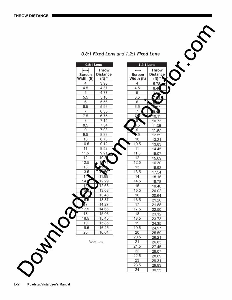
Downlo
aded
from
Pro
jecto
r.com
THROW DISTANCE
E-2 Roadster/Vista User’s Manual

Downlo
aded
from
Pro
jecto
r.com
THROW DISTANCE
Roadster/Vista User’s Manual E-3

Downlo
aded
from
Pro
jecto
r.com
THROW DISTANCE
E-4 Roadster/Vista User’s Manual

Downlo
aded
from
Pro
jecto
r.com
THROW DISTANCE
Roadster/Vista User’s Manual E-5

Downlo
aded
from
Pro
jecto
r.com
THROW DISTANCE
E-6 Roadster/Vista User’s Manual
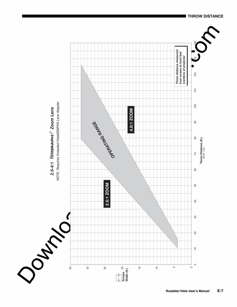
Downlo
aded
from
Pro
jecto
r.com
THROW DISTANCE
Roadster/Vista User’s Manual E-7

Downlo
aded
from
Pro
jecto
r.com
THROW DISTANCE
E-8 Roadster/Vista User’s Manual

Downlo
aded
from
Pro
jecto
r.comAppendix F
Optional Input Modules
Roadster/Vista User’s Manual F-1
There are many optional input modules and accessories currently available for this projector. Contact your dealer for acomplete and up-to-date listing.
The Marquee Signal Switcher is a rack-mountable signal selector which can greatlyincrease the number of analog sources (inputs) available to the projector. Connectedto INPUT 1, a single switcher provides up to 9 more sources to the projector.Additional Marquee Signal Switchers can be connected to the first, with their inputlocations (switcher#,slot#) selectable through the Input key on the keypad. Switcherinputs can also be selected at the switcher by pressing the appropriate front panelpush-button, or through serial communications. See Section 2.
Marquee Signal Switcher Features
◊ simple connection and push-button control◊ easy to see, illuminated indicators◊ 9 slots for analog interface modules◊ RS-232 serial interface◊ input for a wired remote keypad◊ universal power input◊ up to 9 switchers can be daisy-chained together with a projector
The RGB500 Input Module may be installed in this projector, a Marquee SignalSwitcher, or a Marquee Case/Power Supply. The module receives analog RGB inputsignals from computers or other RGB source devices.
Marquee 'Signal Switcher
38-801050-xx
RGB500 Input Module '38-804606-xx

Downlo
aded
from
Pro
jecto
r.com
OPTIONAL INPUT MODULES
F-2 Roadster/Vista User’s Manual
RGB500 Features
◊ accepts 3, 4, or 5 wire RGB video (sync-on-green, composite sync, orseparate horizontal and vertical sync), up to 500 MHz bandwidth
◊ BNC connectors for RGB signal inputs
NOTE: The audio connectors are not functional. Connect audio to the projector’s IN2 audio port, if available (standard on Vista models only).
The RGB400 Buffered Amplifier Input Module may be installed in this projector, in aMarquee Signal Switcher or in a Marquee Case/Power Supply. Connect three-, four-, orfive-wire RGB video signals of up to 400 MHz bandwidth, signals typically produced byhigh-resolution computer or workstations. The buffering capability of the module enablesthe incoming signal to be sent to a remote destination. Inputs are 75S terminated.
RGB400BA Features
◊ accepts 3, 4, or 5 wire RGB video (sync-on-green, composite sync, orseparate horizontal and vertical sync)
◊ BNC connectors for RGB signal inputs◊ Buffered signals to a remote destination
NOTE: The audio connectors are not functional. Connect audio to the projector’s IN2 audio port, if available (standard on Vista models only).
The RGB400 ALT Input Module may be installed in this projector, a Marquee SignalSwitcher, or a Marquee Case/Power Supply. The module receives analog RGB inputsignals from computers or other RGB source devices. Video inputs are 75Sterminated. Video outputs provide buffered loop-through to another display device.
RGB400ALT Features
◊ accepts 3, 4, or 5 wire RGB video (sync-on-green, composite sync, orseparate horizontal and vertical sync)
◊ BNC connectors for RGB signal inputs◊ buffered loop-through video outputs
NOTE: The audio connectors are not functional. Connect audio to the projector’s IN2 audio port, if available (standard on Vista models only).
RGB400BA Input Module '38-804610-xx
RGB400 Active Loop-Thru 'Input Module38-804607-xx

Downlo
aded
from
Pro
jecto
r.com
OPTIONAL INPUT MODULES
Roadster/Vista User’s Manual F-3
The Composite/S-Video Input Module may be installed in this projector, a MarqueeSignal Switcher or a Marquee Case/Power Supply. The module receives eithercomposite video or S-video input signals from tape or disk players (do not connectboth types of signals simultaneously). Video inputs are 75S terminated. Videooutputs are provided for buffered loop-through to another display device.
Composite/S-video Features
◊ BNC connectors for composite RGB signals◊ 4-pin mini-DIN connectors for S-Video signals◊ buffered loop-through video outputs
NOTES: 1) This interface is not a decoder. NTSC, PAL, or SECAM signals mustconnect to the video decoder installed at INPUT 3 / INPUT 4. 2) The audio connectorsare not functional. Connect audio to the projector’s IN 2 audio port, if available(standard on Vista models only). 3) For use with this projector, do not connect bothcomposite video and S-video signals to the Composite / S-Video Input Module–connect one or the other, even when plugged into a switcher.
The PC250 Analog Input Module may be installed in this projector, a MarqueeSignal Switcher or a Marquee Case/Power Supply. The module receives analog RGBinput signals from IBM PC compatibles or Macintosh computers. Video inputs are75S terminated. Video outputs are provided for buffered loop-through to anotherdisplay device.
PC250 Analog Features
◊ accepts VGA or MAC RGB video◊ 15 pin D connectors for video◊ active loop-through video outputs
NOTES: 1) This interface does not accept VGA and MAC signals simultaneously. 2)The audio connectors are not functional. Connect audio to the projector’s IN 2 audioport, if available (standard on Vista models only). 3) Trademarks are the rights oftheir respective owners.
Composite / S-Video 'Input Module38-804608-xx
PC250 Analog 'Input Module38-804609-xx

Downlo
aded
from
Pro
jecto
r.com
OPTIONAL INPUT MODULES
F-4 Roadster/Vista User’s Manual
The DVI Input Module can be installed in the projector at INPUT 2 to display digitalvideo input signals conforming to the DVI (Digital Visual Interface) single-channelstandard.
Features
◊ Supports Digital Visual Interface (DVI) single-channel◊ Supports VESA Extended Display Identification Data (EDID)◊ Provides an active-loop-through using a DVI connector (conforming to
the DVI Specification)
The Digital HDTV Input Module can be installed in the projector at INPUT 2, where itaccepts a digital 4:2:2 component HDTV signal (YCbCr) via a single SERIAL IN BNCconnector. The signal can loop through the SERIAL OUT BNC out to another device(such as another projector). Inputs are 75S terminated.
Features
◊ accepts a variety of digital HDTV 4:2:2 component signals (YCbCr), and de-serializes into a parallel 20-bit 4:2:2 component signal (10 bits each for Yand CbCr)
◊ SMPTE 292M compatible◊ Two data rates: 1.485 Gb/sec or 1.485/1.001 Gb/sec.◊ provides both a SERIAL IN and a SERIAL OUT BNC connector◊ includes 4 status LEDs
DVI Input Module '38-804635-xx
Digital HDTV Input Module '38-804611-xx

Downlo
aded
from
Pro
jecto
r.com
OPTIONAL INPUT MODULES
Roadster/Vista User’s Manual F-5
The Serial Digital Input Module (SDI) can be installed in the projector at INPUT 2,where it accepts a serial digital 4:2:2 component video signal (YCbCr) via a singleSERIAL IN BNC connector. The signal can loop through the SERIAL OUT BNC out toanother device (such as another projector). Inputs are 75S terminated.
SDI Features
◊ accepts serial digital 4:2:2 component video (YCbCr)◊ provides both a SERIAL IN and a SERIAL OUT BNC connector◊ includes status LEDs for signal and error
NOTE: Connect audio to the projector’s IN 2 audio port, if available (standard onVista models only)..
The Marquee Case/Power Supply enables you to use an analog input module as astand-alone interface. Two supplies are available: one for use with 120 volt linevoltage (38-801023-XX), and the other for use with 220 volt line voltage(38-801026-XX). Both models include a 15 VDC, 500 mA AC adapter.
Marquee Case/Power Supply Features
◊ easy installation — no tools required◊ the Marquee Case/Power Supply accepts the following input modules for
use with this projector: RBG500, RGB400 Active Loop-Thru, RGB400Buffered Amplifier, Composite/S-Video, and PC Analog. Digital inputscannot be used.
◊ retaining clip to secure AC adapter◊ non-slip feet◊ supplied with 110 or 220 volt AC adapter
Serial Digital Input Module '38-804602-xx
Marquee 'Case/Power Supply
38-801023-xx38-801026-xx

Downlo
aded
from
Pro
jecto
r.com

Downlo
aded
from
Pro
jecto
r.com
Index
Roadster/Vista User’s Manual INDEX-1
AAC Requirements, 2-1Advanced 10-bit (ADP), 3-39
Noise and Filtering, 3-40Anamorphic, 3-27
And Tiled Image, 3-54Arrow Keys, 3-8Aspect Ratio, 2-7, 3-25Audio, 5-2
Input 1, 2-16Input 2, 2-22Input 3, 2-18Input 4, 2-19
Auto Gain Control. See Enable Decoder AGCAuto Input Level, 3-37Auto Power Up, 3-43Auto Setup, 3-24AutoSource Checkbox, 3-23
BBack IR Keypad, 3-45Bad Sync, 3-55Baud Rate, 2-31, 3-44Blacklevels and Drives, 3-37Blanking, 3-29Brightness, 3-31, 5-1Brightness Key, 3-9, 3-31Broadcast Key, 3-46Broadcasting, 3-10, 3-52
CCalibrate Lens, 3-11Ceiling Mounting, 2-14Center Lens, 3-12Channel
Locked, 3-23Name, 3-23Number, 3-20, 3-23
Channel Copy/Delete, 3-21Channel Edit Menu, 3-22Channel Key, 3-7, 3-19Channel Selection, 3-20Channel Setup Menu, 3-20
And Enter Key, 3-21
And Function Key, 3-21Channels
Creating automatically, 3-19Creating in Channel Setup Menu, 3-21, 3-22Definition of, 3-19Deleting in Channel Setup Menu, 3-22Maximum Number, 3-18
Checkbox Toggles, 3-16Clamp Tip, 3-38Color (Adj.), 3-32Color and Uniformity Menu, 3-42Color Enable, 3-34, 3-38Color Key, 3-9Color Setup Menu, 3-32Color Space, 3-31Color Temperature, 5-1
How to Copy, 3-34Interpolated, 3-34Modifying a Setup, 3-34Presets and Factory Presets, 3-35User, 3-34
Color Temperature Setup, 3-33Communications Menu, 3-42, 3-44Component Video, 2-17Components, 1-2
Location and Use, 3-1Composite Video
Connecting, 2-18Extra, 2-22Loop-Through, 2-20
Configuration Menu, 3-41Contrast, 3-30Contrast Key, 3-9, 3-30Contrast Ratio, 5-1Custom Sizing, 3-26
DDark Interval, 3-40Decoder Luma Delay, 3-36Detail, 3-31Detail Key, 3-9, 3-31Diagnostics and Calibration, 3-43Display Channel List, 3-41Display Error Messages, 3-42Display Slidebars, 3-42DVI / DFP Input Module, 3-30

Downlo
aded
from
Pro
jecto
r.com
INDEX
INDEX-2 Roadster/Vista User’s Manual
EEnable Decoder AGC, 3-36Enter Key, 3-8Error Messages, 3-54
Bad Sync, 3-55H-Sync or V-Sync, 3-55Input Signal Errors, 3-55Invalid User Entry, 3-55No Signal, 3-55System Warnings/Errors, 3-55
Errors, 3-54Exit Key, 3-8
FFeatures, 1-1Filter (Air) Replacement, 4-8Filter (Air) Warning, 4-2Filter (Image Adjustment), 3-28Filter (Motion), 3-39Flat Panel Sources, 3-30Flying the Projector, 2-3Focus, 2-2, 2-7, 2-25, 3-2
Troubleshooting for Motorized, 4-14Folded Optics, 2-15Formats
Video, 5-2Freeze Image, 3-43Front IR Keypad, 3-45Full Height, 3-27Full Screen, 3-26Full Width, 3-26Function Key, 3-12
GGamma, 3-32Geometry Menu, 3-42Global Icon, 3-15
HHandles, 2-3, 3-2HDTV Connection, 2-22Help
Context-sensitive, 3-14Help Key, 3-13
Hoisting, 2-3Stacked Projectors, 2-5
Horizontal Filter, 3-40Horizontal Position, 3-29
IILS, 2-25, 3-11
Operating Tips, 2-26Troubleshooting, 4-14
Image Adjustments, 3-24Image Orientation, 2-24, 3-41Image Settings, 3-30InMenu Checkbox, 3-23Input
Connection, 2-1, 2-15
Definition of, 3-18Selecting/Switching, 3-18Selection, 2-2
Input 1, 2-16Extra Video Sources, 2-22
Input 2, 2-22Input 3
Connection, 2-18Input 4
Connection, 2-18, 2-19Input Key, 3-7, 3-19Input Levels, 3-36Input Video Black, 3-35Installation
Front Screen, 2-6General Considerations, 2-3Horizontal Position, 2-13Leveling, 2-14Quick Setup, 2-1Rear Screen, 2-7, 2-15Room Lighting, 2-8Types, 2-6Vertical Position, 2-11
Intelligent Lens SystemDescription and Use, 2-25, 3-11Operating Tips, 2-26Troubleshooting, 4-14
Intensity (Lamp Mode), 3-49Interfaces,Optional, 2-22Interpolated, 3-34Interpolated Color, 3-32, 3-34Invalid Channel, 3-55Invert Stereo3D, 3-40IR Sensors, 3-4, 3-45
KKeypad
Guidelines, 3-6Types, 3-5
Keypad Batteries, 4-3Keypad Protocol, 2-34, 3-13, 3-45, 4-13
Changing in Keypad, 2-34Conflicts, 2-36Default, 2-34, 3-13Hard-wired, 2-34Software Method, 2-36
Keypad, Built-in, 3-5Keypad, IR Remote, 4-3
Description and Use, 3-5Specifications, 5-4
Keypad, Wired, 3-6, 3-45Keystone, 2-11, 3-29
LLamp
Cleaning, 4-3Mode, 3-48Recording Serial Number, 3-50Specifications, 5-3
Lamp Counter, 4-4Lamp History, 3-50Lamp Hours, 3-47

Downlo
aded
from
Pro
jecto
r.com
INDEX
Roadster/Vista User’s Manual INDEX-3
Lamp Limit, 3-48Lamp Menu, 3-47Lamp Message, 3-47Lamp Modes
Intensity, 3-48Max Brightness, 3-48Power, 3-48
Lamp ReplacementWarning, 4-2
Lamp Replacement Procedure, 4-4Lamp Serial Number, 3-47, 4-8Language, 3-41LCD Status Display, 3-4LEDs, Status, 3-4, 3-56Lens
Calibration, 3-11Centering, 3-12Cleaning, 4-3Motorized Functions, 3-10Offset Adjustment, 2-25Types Available and Specs, 5-1
Lens Control Menu, 3-11Lens Installation/Replacement, 4-9Lens Key, 3-11Leveling, 2-1, 2-14, 2-24
Special Mounting, 2-14Lifting, 2-3Locked Channel Checkbox, 3-23Luma Delay, 3-36
MMain Menu, 3-14Menu
Channel Edit, 3-22Channel Setup, 3-20Color and Uniformity, 3-42Color Setup, 3-32Color Temperature Setup, 3-33Communications, 3-42, 3-44Configuration, 3-41Diagnostics and Calibration, 3-43Geometry, 3-42Image Settings, 3-30Input Levels, 3-36Lamp, 3-47Lens Control, 3-11Main, 3-14Menu Preferences, 3-41Odd Pixel Adjustment, 3-43Service, 3-44Size and Position, 3-25Status, 3-50Tiling Setup, 3-52Video Options, 3-35
Menu Font Size, 3-42Menu Key, 3-8Menu Location on Screen, 3-41Menu Navigation, 3-14Menu Preferences Menu, 3-41Menu System, Navigation, 3-24Minimum Delay, 3-39Motion Filter, 3-39Motorized Lens Functions, 2-25, 3-10
Disabling, 4-16Mounting, 2-14Moving the Projector, 2-3Multiple Projectors, 2-34, 3-51
And Tiling an Image, 3-52Mute Key, 3-12
NNetwork, Split. See Split NetworkNetworks, 2-31
Providing a Back-up, 2-32RS-232 and/or RS-422, 2-29
No Resizing, 3-26No Signal, 3-55Noise Reduction, 3-40Numerical Entry, 3-18
OOdd Pixel Adjustment, 3-43Offset Knobs, 2-2Offsets, 2-25, 3-2
Horizontal, 2-13Removing, 3-12Vertical, 2-11
Optional Modules, 2-22Options, 5-5OSD Key (On-Screen Display), 3-13
PPeak Detector, 3-38Phase Lock Loop, 3-29Pixel Key, 3-10Pixel Phase, 3-28, 3-31Pixel Tracking, 3-27, 4-16PLL Loop Gain, 3-29Plug & Display, 3-30Position Key, 3-10Power
Loss, 3-43Requirements, 2-24, 5-3Setting for Lamp, 3-49Warning, 4-2
Power Key, 3-6Presentation Level
Definition, 3-6Processing Mode, 3-39Proj Key, 3-10Projector
Angles of Operation, 2-14Cleaning/Maintenance, 4-3Components, 1-2, 3-1, 5-4Dimensions, 5-4Hoisting, 3-2Number, 3-18, 3-46, 3-51Position and Mounting, 2-24Resetting, 3-4, 3-56Service, 4-3Ventilation, 2-9, 4-2
Protocols, 2-34, 3-45Changing, 2-34Changing in Projector, 3-45

Downlo
aded
from
Pro
jecto
r.com
INDEX
INDEX-4 Roadster/Vista User’s Manual
Pull-Down Lists, Use of, 3-16
RResizing, 3-25
A Tiled Image, 3-53Default, 2-2
Resolution, 5-1RGB
Connection, 3-3Frequencies, 5-2
RS-232, 2-23, 2-27, 2-29, 2-34, 3-44, 3-51, 3-52, 5-2
RS-232 and/or RS-422, 2-32RS-422, 2-28, 3-44, 3-51, 5-3
SScreen Size, 2-7, 2-10, 2-11, 4-15Select Color Temp, 3-32, 3-34Serial Ports
Communication Cables, 3-44Service Menu, 3-44Service Requirements, 4-3Shutter, 3-2Shutter Key, 3-12Signal Types, 3-21Size. See SizingSize and Position, 3-25Sizing, 3-25, 3-27Slidebars
Using, 3-15Slidebars,"Direct", 3-24Slot, 3-23Source
Connection, 2-1Specifying a Location, 3-7
Source Setup. See ChannelSplit Network, 3-46
And Downloads, 2-32Options for Setup, 2-32When to Use, 3-46
Stacking, 2-3, 2-4Standby Key, 3-8Status LEDs, 3-3Status Menu, 3-50S-Video
Connecting, 2-19Extra, 2-22Loop Through, 2-21
Switcher, 3-23, 3-44Switcher Connection, 2-23Sync
Def. and types, 5
TTest Key, 3-13Test Patterns, 3-42Text
Editing, 3-17Throw Distance, 2-1, 4-16
Definition, 2-10Sample, 2-11
Tiling Setup, 3-52Resizing, 3-53
Time-outs, 3-15Tint Key, 3-9, 3-32Toggle Keys, 3-8Troubleshooting, 4-12Two-Way Controller, 3-6
UUser Color Temperatures, 3-34
VVCR Checkbox, 3-36Vertical Offset
How to Adjust, 3-2Vertical Position, 3-29Vertical Stretch, 3-27Video, 3-3
Formats, 5-2Video Options, 3-35Video Standard, 3-35Video Termination, 2-20, 2-21, 3-36Volume Key, 3-9
WWhite Boost, 3-40White Levels, 3-34Wired Keypad, 3-45
YYPbPr, 3-31
Connecting, 2-17
ZZoom, 2-2, 2-25, 3-2
Troubleshooting for Motorized, 4-14