User's Manual - Insatech
266
User's Manual IM 01R04B04-00E-E Rota Yokogawa GmbH & Co. KG Rheinstr. 8 D-79664 Wehr Germany IM 01R04B04-00E-E ©Copyright July 2003 (Rü) 10th edition, January 2014 (Rü) 3 Series Coriolis Mass Flow and Density Meter Integral Type RCCT3 Remote Type RCCF31 + RCCS3 Remote Type RCCR31 + RCCS3
-
Upload
khangminh22 -
Category
Documents
-
view
0 -
download
0
Transcript of User's Manual - Insatech
User'sManual
IM 01R04B04-00E-E
Rota Yokogawa GmbH & Co. KGRheinstr. 8D-79664 WehrGermany
IM 01R04B04-00E-E©Copyright July 2003 (Rü)
10th edition, January 2014 (Rü)
3 SeriesCoriolis Mass Flow and Density MeterIntegral Type RCCT3Remote Type RCCF31 + RCCS3Remote Type RCCR31 + RCCS3

Blank Page
yef02606
Rechteck

CONTENTS
i IM 01R04B04-00E-E 10th edition October 01, 2013 -00All Rights Reserved. Copyright © 2003, Rota Yokogawa
Contents
1. INTRODUCTION ...................................................................................1-1
1.1 Using the Coriolis Flowmeter Safely .............................................................1-2
1.2 Warranty ...........................................................................................................1-3
1.3 Instruction according EMC ............................................................................1-3
1.4 ATEX Documentation ......................................................................................1-4
1.5 Confirmation of accessories ..........................................................................1-5
2. TRANSPORTATION AND STORAGE ...................................................2-1
3. PRODUCT DESCRIPTION ...................................................................3-1
3.1 The functional principle .................................................................................3-1
3.2 The Integral Type RCCT34 to 39/IR ...............................................................3-2
3.3 The Remote Field-Mount Converter RCCF31 ...............................................3-2
3.4 The Remote Rack-Mount Converter RCCR31 ..............................................3-3
3.5 The Remote Detector RCCS30LR to 33 ........................................................3-4
3.6 The Remote Detector RCCS30LR to 33 /T .................................................3-4
3.7 The Remote Detector RCCS34 to 39/IR ........................................................3-5
3.8 The Remote Detector RCCS34 to 39/IR /T .................................................3-6
3.9 The Remote and Integral Type RCC39/XR .................................................3-7
3.10 Measurement system and applications ......................................................3-8
3.11 Name Plates ...................................................................................................3-9

CONTENTS
iiIM 01R04B04-00E-E 10th edition October 01, 2013 -00 All Rights Reserved. Copyright © 2003, Rota Yokogawa
4. INSTALLATION .....................................................................................4-1
4.1 General .......................................................................................................................................... 4-1
4.2 Mounting of detector RCCS30LR to 33 option /PD ......................................................4-2
4.3 Piping ...............................................................................................................4-2
4.4 Customer insulation .......................................................................................4-6
4.5 Mounting of converter RCCF31 to 2-inch pipe .............................................. 4-6
4.6 Mounting of converter RCCR31 in a subrack ................................................ 4-7
4.7 Alteration of display (RCCT3 / RCCF31) ......................................................4-7
4.8 Wiring ...............................................................................................................4-8
4.8.1 General items ....................................................................................................... 4-8
4.8.2 Ground (earth) connections ............................................................................. 4-10
4.8.3 Wiring technique ..................................................................................................4-11
4.8.4 Assembling and connecting the Remote Cable RCCY03 .............................. 4-12
4.8.5 Power supply wiring .......................................................................................... 4-17
4.8.6 Connecting to external instruments ................................................................ 4-20
4.8.7 Connecting HART- Communication ................................................................. 4-24
4.8.8 Flowmeters with intrinsic safe outputs ........................................................... 4-24
5. BASIC OPERATING PROCEDURES ...................................................5-1
5.1 Liquid crystal display .....................................................................................5-1
5.2 Display modes.................................................................................................5-3
5.3 Setting via keys ...............................................................................................5-4
5.4 Examples of parameter settings via keys ....................................................5-5
5.4.1 Display configuration, set volume flow to line 1 .............................................. 5-5
5.4.2 Setting Temperature 20-120°C to Analog Output 2 ......................................... 5-6
5.5 Setting parameters in converter with option /NC ........................................5-8
5.6 Zero adjustment (Autozero) ...........................................................................5-9

CONTENTS
iii IM 01R04B04-00E-E 10th edition October 01, 2013 -00All Rights Reserved. Copyright © 2003, Rota Yokogawa
6. OPERATION VIA HART .......................................................................6-1
6.1 Conditions of communication line ................................................................6-1
6.2 Communication via FieldMate .......................................................................6-2
6.3 Communication via HART Communicator ...................................................6-5
6.4 Unique functions of HART Communicator ..................................................6-6
6.5 Transmitting device variables via HART .......................................................6-7
6.6 Hardware Write Protect ...................................................................................6-8
7. PARAMETER DESCRIPTION ...............................................................7-1
7.1 Overview ...........................................................................................................7-1
7.2 Parameter list ...................................................................................................7-2
7.3 Parameter tree, Display menu ......................................................................7-21
7.4 Parameter tree, HART menu .........................................................................7-52
7.5 Mass flow functions (Basic or Detailed Setup) ..........................................7-84
7.6 Volume flow functions (Basic or Detailed Setup) ......................................7-85
7.7 Density functions (Basic or Detailed Setup) ..............................................7-86
7.8 Temperature functions (Basic or Detailed Setup) ......................................7-88
7.9 Velocity functions (Detailed Setup) .............................................................7-88
7.10 Analog 1 functions (Basic or Detailed Setup) ..........................................7-89
7.11 Analog 2 functions (Basic or Detailed Setup) ..........................................7-90
7.12 Pulse/Status output 1 functions (Basic or Detailed Setup) ....................7-91
7.13 Pulse/Status output 2 functions (Basic or Detailed Setup) .....................7-95
7.14 Status input functions (Basic or Detailed Setup) ....................................7-96
7.15 HART output (Detailed Setup) ....................................................................7-97
7.16 Totalizer functions (Basic or Detailed Setup) ...........................................7-98
7.17 Flow direction function (Detailed Setup) ..................................................7-99
7.18 Concentration measurement (Detailed Setup) .......................................7-100
7.19 Net flow (Detailed Setup) .......................................................................... 7-101
7.20 Slug detection (Detailed Setup) ............................................................... 7-102
7.21 Empty pipe detection (Detailed Setup) ................................................... 7-103

CONTENTS
ivIM 01R04B04-00E-E 10th edition October 01, 2013 -00 All Rights Reserved. Copyright © 2003, Rota Yokogawa
7.22 Corrosion detection (Detailed Setup) ...................................................... 7-104
7.23 Detector data (Detailed Setup) ................................................................. 7-104
7.24 Autozero (Diag/Service) ............................................................................ 7-105
7.25 Reading maximum fluid temperature (Detailed Setup) ......................... 7-106
7.26 Option /GA for Gas Measurement ........................................................... 7-106
8. SELF-DIAGNOSTIC AND TROUBLESHOOTING ................................8-1
8.1 Error descriptions and countermeasures .....................................................8-1
8.2 Reading Event + Error History (Diag/Service, Self test/Status) .................8-3
8.3 Self test (Diag/Service) ...................................................................................8-3
8.4 Signal- and I/O-Test (Diag/Service) ...............................................................8-3
8.5 Output trim ......................................................................................................8-4
8.6 Detector cleaning ............................................................................................8-4
8.7 Troubleshooting ..............................................................................................8-5
8.7.1 No indication ......................................................................................................... 8-5
8.7.2 No key-setting possible ....................................................................................... 8-6
8.7.3 No HART communication .................................................................................... 8-6
8.7.4 Unstable zero ........................................................................................................ 8-7
8.7.5 Disagreement of indication with actual flow rate ............................................. 8-8
8.7.6 Disagreement of indication with actual density ............................................... 8-9
8.7.7 Disagreement of indication with actual temperature ..................................... 8-10
8.7.8 Discrepancy of output signals to the assigned measurand ..........................8-11
8.7.9 Setting "Burn-out" mode ................................................................................... 8-12
8.8 Detection of metering tube failure ..............................................................8-13
8.9 Customer Maintenance Part List .................................................................8-14
8.10 Disposal, Cleaning and Return ...................................................................8-18

CONTENTS
v IM 01R04B04-00E-E 10th edition October 01, 2013 -00All Rights Reserved. Copyright © 2003, Rota Yokogawa
9. EXPLOSION PROTECTED TYPE INSTRUMENTS ................................ 9-1
9.1 ATEX .................................................................................................................9-1
9.1.1 Technical Data ...................................................................................................... 9-1
9.1.2 Installation ............................................................................................................ 9-5
9.1.3 Operation .............................................................................................................. 9-8
9.1.4 Maintenance and repair ....................................................................................... 9-8
9.1.5 Ex-relevant marking on name plates (refer to chapter 3.11) ............................ 9-8
9.2 FM (USA + Canada) .....................................................................................9-10
9.2.1 Technical Data .................................................................................................... 9-10
9.2.2 Installation .......................................................................................................... 9-12
9.2.3 General warnings ............................................................................................... 9-13
9.2.4 Ex-relevant marking on name plates (refer to chapter 3.11) ......................... 9-14
9.2.5 Control drawings ............................................................................................... 9-15
9.3 IECEx ..............................................................................................................9-20
9.3.1 Technical Data .................................................................................................... 9-20
9.3.2 Installation .......................................................................................................... 9-24
9.3.3 Operation ............................................................................................................ 9-26
9.3.4 Maintenance and repair .................................................................................... 9-26
9.3.5 Ex-relevant marking on name plates (refer to chapter 3.11) ......................... 9-27
9.4 INMETRO (Brazil) ..........................................................................................9-28
9.5 NEPSI (China) ................................................................................................9-28
9.6 Gost approval ................................................................................................9-28
10. PED (PRESSURE EQUIPMENT DIRECTIVE) .......................................................10-1
11. Technical Data ....................................................................................................11-1
APPENDIX 1. SOFTWARE CHANGE HISTORY ................................. A1-1

CONTENTS
viIM 01R04B04-00E-E 10th edition October 01, 2013 -00 All Rights Reserved. Copyright © 2003, Rota Yokogawa
APPENDIX 2. Safety Instrumented Systems Installation .................A2-1
A2.1 Scope and Purpose ...................................................................................A2-1
A2.2 Using Rotamass 3 for a SIS Application ................................................A2-1
A2.2.1 Safety Function ...............................................................................................A2-1
A2.2.2 Safety Accuracy ..............................................................................................A2-2
A2.2.3 Diagnostic Response Time ............................................................................A2-2
A2.2.4 Setup ................................................................................................................A2-2
A2.2.5 Proof Testing ....................................................................................................A2-2
A2.2.6 Repair and Replacement ................................................................................A2-3
A2.2.7 Startup Time ....................................................................................................A2-3
A2.2.8 Firmware Update .............................................................................................A2-3
A2.2.9 Reliability Data ................................................................................................A2-3
A2.2.10 Lifetime Limits ...............................................................................................A2-3
A2.2.11 Required Parameter Settings .......................................................................A2-3
A2.2.12 Environmental Limits ....................................................................................A2-4
A2.2.13 Application Limits .........................................................................................A2-4
A2.3 Definitions and Abbreviations .................................................................A2-4
A2.3.1 Definitions ........................................................................................................A2-4
A2.3.2 Abbreviations ...................................................................................................A2-4
1. INTRODUCTION
1-1All Rights Reserved. Copyright © 2003, Rota Yokogawa IM 01R04B04-00E-E 10th edition October 01, 2013 -00
1. INTRODUCTION
This instrument has been adjusted at the factory before shipment.
To ensure correct use of the instrument, please read this manual thoroughly and fully understand how to operate the instrument before operating it.
NOTE
This manual describes the hardware and soft-ware configurations of the ROTAMASS Coriolis Massflowmeter.
Regarding This User's Manual
•This manual should be provided to the end user.•Beforeuse,readthismanualthoroughlytocom-
prehend its contents.•Thecontentsofthismanualmaybechanged
without prior notice.•Allrightsarereserved.Nopartofthismanual
may be reproduced in any form without Yokoga-wa's written permission.
•Yokogawamakesnowarrantyofanykindwithregard to this material, including, but not limited to, implied warranties of merchantability and suitability for a particular purpose.
•Allreasonableefforthasbeenmadetoensurethe accuracy of the contents of this manual. However, if any errors or omissions are found, please inform Yokogawa.
•Yokogawaassumesnoresponsibilitiesforthisproduct except as stated in the warranty.
•Pleasenotethatthisuser'smanualmaynotberevised for any specification changes, construction changes or operating part changes that are not considered to affect function or performance.
•Ifthecustomeroranythirdpartyisharmedbythe use of this product, Yokogawa assumes no responsibility for any such harm owing to any defects in the product which were not predict-able, or for any indirect damages.
Safety and Modification Precautions
•Thefollowinggeneralsafetyprecautionsmustbe observed during all phases of operation, service, and repair of this instrument. Failure to comply with these precautions or with specific WARNINGSgivenelsewhereinthismanual
violates safety standards of design, manufacture, and intended use of the instrument. Yokogawa assumes no liability for the customer's failure to comply with these requirements. If this instrument is used in a manner not specified in this manual, the protection provided by this instrument may be impaired.
•Thefollowingsafetysymbolmarksareusedinthis user's manual and instrument.
WARNING
AWARNINGsigndenotesahazard.Itcallsattention to procedure, practice, condition or the like, which, if not correctly performed or adhered to, could result in injury or death of personnel.
CAUTION
ACAUTIONsigndenotesahazard.Itcallsattention to procedure, practice, condition or the like, which, if not correctly performed or adhered to, could result in damage to or destruction of part or all of the product.
IMPORTANT
AnIMPORTANTsigndenotesthatattentionisrequired to avoid damage to the instrument or system failure.
NOTE
ANOTEsigndenotesinformationnecessaryforessential understanding of operation and features.
This sign on the instrument denotes information in the instruction manual.

1. INTRODUCTION
1-2 All Rights Reserved. Copyright © 2003, Rota YokogawaIM 01R04B04-00E-E 10th edition October 01, 2013 -00
Protective grounding terminal
Functional grounding terminal (This terminal should not be used as a pro-tective grounding terminal.)
Alternating current
Direct current
1.1 Using the Coriolis Flowmeter Safely
WARNING
(0) General•Avoidworkingwithbareskin.•Avoidtouchingthedevicewithwethands(1) Installation•InstallationoftheCoriolisflowmetermustbe
performed by expert engineer or skilled personnel. Nooperator shall be permitted to perform procedures relating to installation.
•TheCoriolisflowmeterisaheavyinstrument.Be careful that no damage is caused to personnel through accidentally dropping it, or by exerting
excessive force on the Coriolis flowmeter. When moving the Coriolis flowmeter, always use a trolley and have at least two people carry it (see also chapter 2).
•All procedures relating to installation must comply with the electrical code of the country where it is used.
(2) Wiring•ThewiringoftheCoriolisflowmetermustbe
performed by expert engineer or skilled personnel. Nooperatorshallbepermittedtoperform
procedures relating to wiring.•Whenconnectingthewiring,checkthatthe
supply voltage is within the range of the voltage specified for this instrument before connecting the power cable. In addition, check that no voltage is applied to the power cable before connecting the wiring.
•Theprotectivegroundingmustbeconnectedsecurely at the terminal with the mark to avoid danger to personnel.
(3) Operation•Donotopenthecoveruntilthepowerhasbeen
off for at least 10 minutes because of electric shock and hot temperatures inside. Only expert engineer or skilled personnel are permitted to open the cover.
•WhentheCoriolisflowmeterisprocessinghot fluids, the instrument itself may become extremely hot. Take sufficient care not to get burnt.
If the fluid temperature is above 65°C it has to be made sure, that an easy touch by humans is prohibited (e.g. by installation, by a barrier, by a warning).
•Wherethefluidbeingprocessedisatoxicsub-stance, avoid contact with the fluid and avoid inhaling any residual gas, even after the instru-ment has been taken off the line for
maintenance and so forth.(4) Maintenance•MaintenanceontheCoriolisflowmetershould
be performed by expert engineer or skilled personnel.Nooperatorshallbepermittedtoperform any operations relating to maintenance.
•Alwaysconformtomaintenanceproceduresoutlined in this manual. If necessary, contact Yokogawa.
•Careshouldbetakentopreventthebuildupof dirt, dust or other substances on the display panel glass or data plate. If these surfaces do get dirty, wipe them clean with a soft dry cloth.
•Don’topenthecoverintherain.•Don’topenthecoverduringpowerisconnected
because of electric shock.•Theamplifierassemblycontainssensitiveparts.
Take care so as not to directly touch the elec-tronic parts or circuit patterns on the board, and by preventing static electrification using ground-ed wrist straps when handing the assembly.
•Whileremovingtheinstrumentshouldbefixedor hung (see also chapter 2 "Transportation").
(5) European Pressure Equipment Directive (PED)
•WhenusingtheinstrumentasaPED-compliant product, be sure to read Chapter 10 before use.(6)HazardousDutyTypeInstruments•Forexplosionprooftypeinstrumentsthe
description in chapter 9 "EXPLOSIONPRO-
TECTEDTYPEINSTRUMENT" has priority to the other descriptions in this instruction manual. •AllinstructionmanualsforATEXExrelatedproducts are available in English, German and French. Should you require Ex related instruc-tions in your local language, you should contact your nearest Yokogawa office or representative. •Onlytrainedpersonalshouldinstalland maintaininstrumentsinhazardousareas.

1. INTRODUCTION
1-3All Rights Reserved. Copyright © 2003, Rota Yokogawa IM 01R04B04-00E-E 10th edition October 01, 2013 -00
•Theprotectivegroundingterminal must be connected to a suitable IS grounding system. •Avoidmechanicalgeneratedsparkswhile working on the equipment and peripheral devicesinhazardousareas.
1.2 Warranty•Thewarrantytermsofthisinstrumentthatare
guaranteed are described in the quotation. We will make any repairs that may become neces-sary during the guaranteed term free of charge.
•Pleasecontactoursalesofficeifthisinstrumentrequires repair.
•Iftheinstrumentisfaulty,contactuswithcom-plete details about the problem and the length of time it has been faulty, and state the model and serial number. We would appreciate the inclusion of drawings or additional information.
•Theresultsofourexaminationwilldeterminewhether the meter will be repaired free of charge or on an at-cost basis.
The guarantee will not apply in the following cases:
•Damageduetonegligenceorinsufficientmain-tenance on the part of the customer.
•Problemsordamageresultingfromhandling,operation or storage that violates the intended use and specifications.
•Problemsthatresultfromusingorperformingmaintenance on the instrument in a location that does not comply with the installation location specified by Yokogawa.
•Problemsordamageresultingfromrepairsormodifications not performed by Yokogawa or someoneauthorizedbyYokogawa.
•Problemsordamageresultingfrominappropri-ate installation after delivery.
•Problemsordamageresultingfromdisasterssuch as fires, earthquakes, storms, floods, or lightning strikes and external causes.
Installation
The function ground terminal or the PE- terminal have to be connected to protective ground to ensure electro-magnetic interference protection.To ensure the EMC specifications the following
measures must be carried out :
1. Put the power cables through the ferrite core
clamp before connecting to the terminals as shown
in chapter "Installation" (Power supply wiring).
2. Put the I/O- cables through the ferrite core
clamp before connecting to the terminals as shown
in chapter "Installation" (Power supply wiring).
3. Connect protective ground conductor of power
supply to PE- terminal in the terminal box (see
chapter "Installation" (Power supply wiring).
4. In case of Explosion proof type instrument, fur-
ther requirements are described in chapter 9
“EXPLOSIONPROTECTEDTYPEINSTRUMENTS”.
The description in this chapter is prior to other de-
scriptions in this instruction manual.
1.3 Instruction according EMC
The ROTAMASS Coriolis flowmeter is conform to the European EMC Guideline and fulfills the following standards:
EN61326-1:2006;
EN61326-2-3:2006;
EN61000-3-2:2006;
EN61000-3-3:1995+A1+A2
ROTAMASS is a class A product and should be used and installed properly according to the EMC Class A requirements
Restriction on Use of Radio Transceiver:
IMPORTANT
Although the products has been designed to resist high frequency electrical noise, if a radio transceiver is used near the flowmeter or its external wiring, the transmitter may be affected by high frequency noise pickup. To test for such effects, bring the transceiver in use slowly from a distance of several meters from the flowmeter, and observe the measurement loop for noise effects. Thereafter, always use the transceiver outside the area affected by noise.
CAUTION

1. INTRODUCTION
1-4 All Rights Reserved. Copyright © 2003, Rota YokogawaIM 01R04B04-00E-E 10th edition October 01, 2013 -00
1.4 ATEX DocumentationThis is only applicable to the countries in European Union.
GB
DK
I
E
NL
SF
P
F
D
S
LT
LV
PL
EST
SLO
H
BG
RO
M
CZ
SK
GR

1. INTRODUCTION
1-5All Rights Reserved. Copyright © 2003, Rota Yokogawa IM 01R04B04-00E-E 10th edition October 01, 2013 -00
1.5 Confirmation of accessoriesWhen you received the instrument, please check the following accessories. RCCF31 remote type converter - 1x ferrite cores for power line - 1x ferrite core for I/O lines - 1x band for fixing the ferrite cores on power line - 1x 2-inch pipe mounting bracket set - 1x bracket - 1x U-bracket - 2x nuts - 2x washers - 4x bolts with hexagon socket - 1x terminal wiring auxiliary tool - 1x cable gland for wiring port detector signal - M20 cable gland (metal) (for RCCF31-M...) -NPT1/2´´cablegland(metal)(forRCCF31-A...) - 2x cable gland for power supply and I/O signal wiring port - M20 cable gland (plastic) (for RCCF31-M...) -NPT1/2´´(forRCCF31-A...) cable glands for power supply and I/O signal wiring port are not attached.
Remote type detector RCCS3 - 1x cable gland for wiring port detector signal - 1x M20 cable gland (for RCCS3-M) -1xNPT1/2´´cablegland+1xadapterM20toNPT(forRCCS3-A)
Integral RCCT3 - 1x ferrite cores for power line - 1x ferrite core for I/O lines - 1x band for fixing the ferrite cores on power line- 1x terminal wiring auxiliary tool - 2x cable gland for power supply and I/O signal wiring port - M20 Cable gland (plastic) (for RCCT3-M) -1xNPT1/2´´cablegland+1xadapterM20toNPT(forRCCS3-A)

1. INTRODUCTION
1-6 All Rights Reserved. Copyright © 2003, Rota YokogawaIM 01R04B04-00E-E 10th edition October 01, 2013 -00
Blank Page

2. TRANSPORTATION AND STORAGE
2-1All Rights Reserved. Copyright © 2003, Rota Yokogawa IM 01R04B04-00E-E 10th edition October 01, 2013 -00
Transport instructions
ROTAMASS is a heavy instrument. Please be careful to prevent persons from injuring when it is handled.
When transporting the instrument, you must observe the following safety instructions in order to avoid lethal
injury, damage to the instrument and other material damage.
The steps involved in transport may only be carried out by qualified persons taking into account the safety
instructions.
• Observe the transport instructions on the packaging.
• Observe the below mentioned storage conditions.
• Use only the original packaging.
• The packaging material must be disposed of in accordance with the regulations.
• The transport braces must not be removed until installation.
• Read chapter 1.1. "Using the Coriolis Flowmeter safety".
• To avoid any damages, unpack the flowmeter only at the installation site.
• Mechanical shocks are to be avoided.
• Using a sling to lift and carry the meter. The instruments must be hanged by a lift at the tubes between
the detector housing and the process connections.
Center of gravity of the instrument is higher than the suspension points of the sling. Risk of injury if the
instruments slips.
The lift must fulfill the local safety instructions.
Do not lift the instrument
-using the flange bolt holes.
-on the converter housing
-on the detector neck.
2. TRANSPORTATION AND STORAGE
WARNING
WARNING

2. TRANSPORTATION AND STORAGE
2-2 All Rights Reserved. Copyright © 2003, Rota YokogawaIM 01R04B04-00E-E 10th edition October 01, 2013 -00
Storage conditions
Please note the following for storage purposes :
The detector and converter should be stored in its transport packaging.
Choose a storage place that meets the following requirements:
• Protectionfromrainandhumidity• Freeofmechanicalvibrationandshocks• Ambienttemperaturebetween -40°Cto55°C(RCCT3/RCCF31/RCCR31) -50°C to 80°C (RCCS3)
• Atmospherichumidity ranging from 0 to 100%. Operation above 95% for longer times is not recommended.
Before storing a used flowmeter remove any fluid from the flowmeter line completely.
Properties of the instrument can change when stored outdoors.

3. Product description
3-1All Rights Reserved. Copyright © 2003, Rota Yokogawa IM 01R04B04-00E-E 10th edition October 01, 2013 -00
3. PRODUCT DESCRIPTION
3.1 The functional principleThe ROTAMASS instrument measures the mass flow with the help of the so-called Coriolis force. This force
occurs, when the medium being measured is flowing at velocity ν through a tube that is rotating around an
axis perpendicular to the direction of flow at angular velocity ϖ.
When the medium moves away from the axis of rotation it must be accelerated to an
increasingly high peripheral velocity. The force required for this is called Coriolis force, after its discoverer.
The Coriolis force reduces the rotation. The opposite effect occurs, when the medium flows towards the axis
of rotation. Then the Coriolis force amplifies the rotation.
The formula for the Coriolis force is as follows:
Fc = - 2 m (ϖ x ν )
The entire measurement tube is deformed slightly by the Coriolis forces, in the way shown. This deformation
is registered by movement sensors at points S1 and S2 .
For practical exploitation of this physical principle, it is sufficient for the tube to perform sympathetic
oscillations on a small section of a circular path. This is achieved by exciting the measurement tube at point
E by means of an electromagnetic exciter.
The general construction of a Coriolis mass flowmeter looks as followed:
3. Product description
3-2 All Rights Reserved. Copyright © 2003, Rota YokogawaIM 01R04B04-00E-E 10th edition October 01, 2013 -00
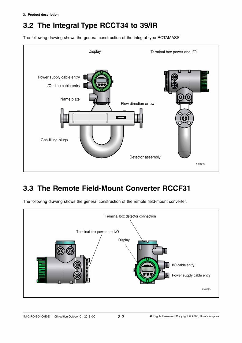
3.3 The Remote Field-Mount Converter RCCF31
The following drawing shows the general construction of the remote field-mount converter.
F32.EPS
Display
Terminal box power and I/O
Terminal box detector connection
Power supply cable entry
I/O cable entry
3.2 The Integral Type RCCT34 to 39/IR
The following drawing shows the general construction of the integral type ROTAMASS
F31.EPS
Terminal box power and I/ODisplay
Name plate
Detector assembly
Flow direction arrow
Power supply cable entry
I/O - line cable entry
Gas-filling-plugs

3. Product description
3-3All Rights Reserved. Copyright © 2003, Rota Yokogawa IM 01R04B04-00E-E 10th edition October 01, 2013 -00
3.4 The Remote Rack-Mount Converter RCCR31
The following drawing shows the general construction of the remote rack-mount converter.
Terminal board
F35.EPS
19-inch cassette
Display and infrared switches
PE
PE
D+D-S1+S1-S2+S2-TP1TP2TP3COM
Iout1+Iout1-Iout2+Iout2-Pout+Pout-Sin+Sin-Sout+Sout-
L/+
N/-
G
Detector connection terminals
Input /Output terminals
Powerterminals
Groundterminals

3. Product description
3-4 All Rights Reserved. Copyright © 2003, Rota YokogawaIM 01R04B04-00E-E 10th edition October 01, 2013 -00
3.5 The Remote Detector RCCS30LR to 33The following drawing shows the general construction of the remote detector RCCS30LR to 33.
Name plate
Terminal box
Gas-filling-plug
3.6 The Remote Detector RCCS30LR to 33 /TThe following drawing shows the general construction of the remote detector RCCS30LR to 33 /Tx
Dimensions in mmWeight (without process flanges): 12kg
F37.EPS
see table 8
Terminal box
Ventilation option /T3
Factory insulation
Name plate
Process connection
Heating connectionoption /T2 or /T3
3. Product description
3-5All Rights Reserved. Copyright © 2003, Rota Yokogawa IM 01R04B04-00E-E 10th edition October 01, 2013 -00
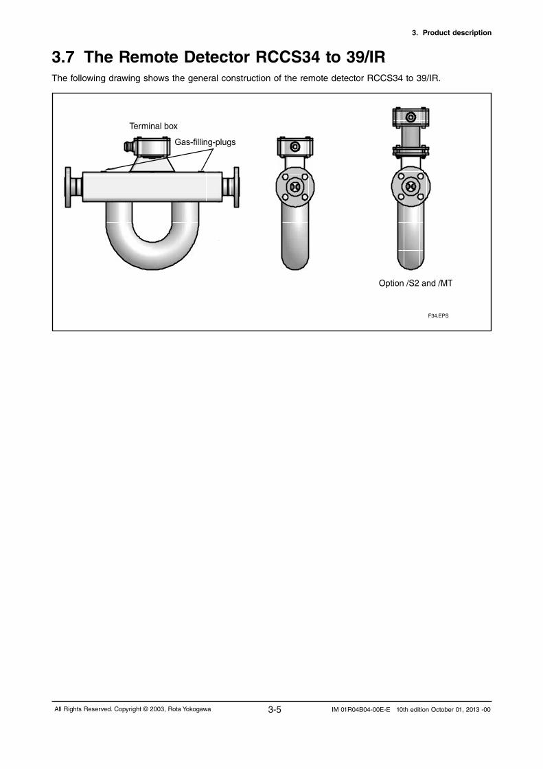
3.7 The Remote Detector RCCS34 to 39/IRThe following drawing shows the general construction of the remote detector RCCS34 to 39/IR.
F34.EPS
Terminal box
Option /S2 and /MT
Gas-filling-plugs

3. Product description
3-6 All Rights Reserved. Copyright © 2003, Rota YokogawaIM 01R04B04-00E-E 10th edition October 01, 2013 -00
3.8 The Remote Detector RCCS34 to 39/IR /TThe following drawing shows the general construction of the remote detector RCCS34 to 39/IR /T.
Process connectionoption /T2 or /T3Heating connection
Terminal box
Factory insulation
Ventilationoption /T3
F36.EPS

3. Product description
3-7All Rights Reserved. Copyright © 2003, Rota Yokogawa IM 01R04B04-00E-E 10th edition October 01, 2013 -00
3.9 The Remote and Integral Type RCC39/XRThe following drawing shows the general construction of the RCC39/XR.
Option /S2 and /MT
F38.EPS
Terminal box
Integral Type RCCT39/XR
Remote Type RCCS39/XR
Gas-filling-plugs

3. Product description
3-8 All Rights Reserved. Copyright © 2003, Rota YokogawaIM 01R04B04-00E-E 10th edition October 01, 2013 -00
3.10 Measurement system and applicationsROTAMASS measures the mass flow of fluids directly.The measurement system uses the Coriolis principle and is suitable for a wide range of continuous flow measurement applications in all branches of process technology.ROTAMASS has two components: the detector and the converter.The detector measures the mass flow directly and converts it into electrical signals.The converter evaluates the electrical signals and outputs the following values: - mass flow, independent from media properties, such as density, temperature, viscosity - fluid density - fluid temperatureThe values are displayed and output as electrical values for use by other systems.The converter is operated by three infra-red keys and a 4- line display and is standard equipped with HART-communication protocol.ROTAMASS is suitable for - measuring liquids, liquids with solid content, multi-phase mixtures - measuring gases (restricted by density and pressure loss) - simultaneous measurement of mass flow, density, temperature, volume flow and cumulated mass and volume - measuring of concentrations of liquid mixtures, solutions and suspensions - connection to controllers and process control systemsROTAMASS provides the following I/O-connections and can be configured for a wide variety of different measurement applications (controlling, checking, monitoring, metering, mixing, filling). - 2 active analog outputs
- 2 passive pulse outputs / status outputs
- 1 status input - optional /AP: - 1 active pulse output / status output -optional/NM: -1pulseoutput/statusoutputaccordingEN60947-5-6(NAMUR) -optional /F2 : - 1 passive analog output Ex ia - 1 passive pulse output / status output Ex ia -optional /F5 : - 2 passive analog outputs Ex ia - 1 passive pulse output / status output Ex ia - optional /FB see IM 01R04B05-00E-E : - 1 Foundation Fieldbus communication line - optional /FB and /F4 see IM 01R04B05-00E-E : - 1 intrinsic safe Ex ia Foundation Fieldbus communication line -optional /MB2 see IM 01R04B08-00E-E : - 1 MODBUS communication line - optional /MB3 see IM 01R04B08-00E-E : - 1 MODBUS communication line - 1 current output - 1 pulse / status output - 1 status inputThese capabilities make ROTAMASS ideal for the increasing demand of requirements for automation and the growing trend towards batch processes.

3. Product description
3-9All Rights Reserved. Copyright © 2003, Rota Yokogawa IM 01R04B04-00E-E 10th edition October 01, 2013 -00
3.11 Name PlatesName plate of Integral type RCCT3:
1 Model code 2 Serial number 3 Ambient temperature range 4 Current output range and load resistance range 5 Power supply range 6 Maximum supply voltage and maximum current for passive pulse- and status- output 7 Calibration constants of detector (see also on calibration certificate) 8 NumberofnotifiedbodyaccordingATEX(onlyforATEXcertifiedflowmeters) 9 NumberofnotifiedbodyaccordingPED(onlyforunitswithprocessconnectionsmorethanDN25) 10 Area for Ex- relevant marking (see chapter 9). The CE-mark is not present for FM-approved units. 11 PS = maximum permissible pressure 12 TS = maximum permissible process temperature 13 Material of metering tubes 14 Year of manufacturing 15 Customer specified tag number if option /BG was ordered
Name plate of Remote Converter RCCF31 / RCCR31:
1 Model code 2 Serial number 3 Year of manufacturing 4 Ambient temperature range 5 Power supply range 6 Current output range and load resistance range 7 Maximum supply voltage and maximum current for passive pulse output 8 Maximum supply voltage and maximum current for passive status output 9 NumberofnotifiedbodyaccordingATEX(onlyforATEXcertifiedflowmeters) 10 Area for Ex- relevant marking (see chapter 9). The CE-mark is not present for FM-approved units. 11 Customer specified tag number if option /BG was ordered

3. Product description
3-10 All Rights Reserved. Copyright © 2003, Rota YokogawaIM 01R04B04-00E-E 10th edition October 01, 2013 -00
Name plate of Remote Detector RCCS3:
1 Model code 2 Serial number 3 Calibration constants of detector (see also on calibration certificate) 4 NumberofnotifiedbodyaccordingATEX(onlyforATEXcertifiedflowmeters) 5 NumberofnotifiedbodyaccordingPED(onlyforunitswithprocessconnectionsgreaterthanDN25) 6 Area for Ex- relevant marking (see chapter 9). The CE-mark is not present for FM-approved units. 7 PS = maximum permissible pressure 8 TS = maximum permissible process temperature 9 Material of metering tubes 10 Year of manufacturing 11 Customer specified tag number if option /BG was ordered
Name plate of RCCT3 and RCCS3 with option /DS (Dual Seal approval):In general the name plates of these units are the same as shown above.The difference is as followed: PS is named as "Working pressure range" TS is named as "Process temperature range" "Dual Seal" is additionally stated on the name plate

4. INSTALLATION
4-1All Rights Reserved. Copyright © 2003, Rota Yokogawa IM 01R04B04-00E-E 10th edition October 01, 2013 -00
4.1 General
This instrument must be installed by an expert engineer or skilled personal. The procedures described in this chapter are not permitted for operators. For the installation of explosionprotectedinstrumentsseechapter9„Explosionprotectedtypeinstruments”. If the detector is not insulated, the surface of detector may be very hot according to the process temperature.
WARNINGNeveropenthecoversduringoperation.
IMPORTANT An exclusive external circuit breaker must be placed near each flowmeter. It must be marked as the disconnectingdeviceofthismeterandmustbeeasilyaccessible.Checktheexternalcircuitbreaker’srate conforms to the requirements specified in the specification of this instrument.
- Keep protection sheet on the flanges attached until the flowmeter is installed to piping.-Don’topentheterminalboxuntilthewiringprocedure.Leavingtheboxopenedcanresultininsulation deterioration.- A newly installed piping-line often contains foreign matters (such as welding scrap and wood chips). Remove them by flushing the piping before installing the flowmeter. This will help to prevent not only damaging the flowmeter, but making erroneous signal generated by foreign matters.- For RCCT3 or RCCF31 at ambient temperature above 50°C a sunshade is recommended. This is particularly important in countries with high ambient temperatures.
About the site
Tostabilizetheinstrument,pleaseconsiderthefollowingitemswheretoplacetheinstrumentforyourlong-termuse. - Ambient Temperature Please avoid installing in a place which has a large temperature gradient and variation as possible. And if the meter is subjected to radiant heat from plant, please use heat insulation measure or please set up so that is well ventilated.- Atmospheric conditions Please avoid to place in a corrosive atmosphere as possible. When used in corrosive atmosphere, allow better ventilation. - Shock and vibration Please install in a place without shock and vibration as possible. - Explosion-proof equipment installations Iftheproductisinstalledinhazardousareaspleasenoticetheinstallationhintsinchapter9.- Space Select locations where there is adequate space to service installing, wiring, overhauling, etc.Sequence of installation:- Mounting of detector RCCS30 to 33 on a 2-inch pipe if option /PD was ordered (see chapter 4.2)- Piping of the detector or integral flowmeter in the line (see chapter 4.3)- Customer insulation of detector if necessary (see chapter 4.4)- Mounting of converter RCCF31 on a 2-inch pipe (see chapter 4.5)- Mounting of converter RCCR31 in a subrack (see chapter 4.6)- Alteration of converter display of converter RCCF31 if necessary (see chapter 4.7)- Wiring of converter (see chapter 4.8)- Afterinstallationanautozeroaccordingchapter5.6mustbeexecuted.Whencarryingoutthezero- adjustment,themeasuringtubeshouldbefilledwiththeliquidat“noflow”.Itisthereforerecommended to have shut-off valves at appropriate points of the upstream (vertical installation) and downstream (horizontalinstallation)oftheflowmeter.
4. INSTALLATION
WARNING
IMPORTANT

4. INSTALLATION
4-2 All Rights Reserved. Copyright © 2003, Rota YokogawaIM 01R04B04-00E-E 10th edition October 01, 2013 -00
4.3 Piping
1. The upstream and downstream piping length has no influence on the functioning of the instrument.
2. Piping requirements for proper operation :
• ACoriolismassflowmetercanbeinstalledvertically,horizontallyoratanyanglefromthehorizontal
position.
• However, the piping must be installed to ensure that the measuring tube is always filled with liquid.
• The position of installation of the detector is arbitrary. A vertical mounting is recommended however.
IMPORTANT When the following notes are not observed, flow measurements may not be correct and can damage the instrument. Please make correct piping design in accordance with the present guidelines.
IMPORTANTPlease be careful to install the flowmeter not too close to motors, transformers, inverters and other power source, induction failure may occur.
IMPORTANT Use bolts and nuts in compliance with the flange ratings. Be sure to choose a gasket with an inner diameter that does not protrude inside the piping. If the inner diameter of the gasket is too large, however, fluid leakage may result.
4.2 Mounting of detector RCCS30LR to 33 option /PDThe detector RCCS30LR to 33 can be mounted on a 2-inch pipe (option /PD) with a bracket and U-bolt
assy.
Improper fixing is subject to cause injury and to damage instrument.
NOTE

4. INSTALLATION
4-3All Rights Reserved. Copyright © 2003, Rota Yokogawa IM 01R04B04-00E-E 10th edition October 01, 2013 -00
Use shut-off valve and bypass line
Tofacilitatezeroadjustmentandmaintenance,providingabypasslineisrecommended.
Supporting the Coriolis flowmeter
- Please prevent the detector from pipeline stretching, vibration or shock. - Please prevent the detector from direct fixing. (See figure below.) - Please fix the pipe at first and support the detector with piping. (See figure below.) -Pleasefixonlyonesideofthedetectorinsteadofbothsidessoastominimizemechanicalstresstothe detector.
Vertical installation (recommended):
Makes pipe easier to empty (in case of maintenance, start-
up, product change). Helps gas bubbles to escape.
Only one shut-off valve is required to ensure“noflow”for
settingAutozero.
Horizontal installation :
For liquids: Measuring tube downwards so that no gas can
collectif“noflow”.Forprocesstemperaturesabove100°C
measuring tubes upwards are recommended.
For gases: Measuring tube upwards so that no liquid can
collectif“noflow”.
Installation at highest point of a piping system:
Avoid it, as this can lead to collection of gas bubbles.
Installation with pressure below 1 bar abs:
Avoid it, as suction can draw air into the measuring tube,
leading to incorrect measurements. Free outlets to contain-
ers or vessels can generate low pressure by earth gravity
acceleration. F41.EPS
Flow
Flow
Flow
Flow
F0301.ai
Bypass valve
Coriolis flowmeter
Shut-off valve
Shut-off valve
WARNING
• Do not stress the detector mechanically. Fix the pipe not on both ends of the detector but only at one
side. Let the other side run free for minimum mechanical stress on the detector.
• Pleaseusethestandardreducersifthepiping’scross-sectiondiffersattheinletoroutletpointofthe
flowmeter.

4. INSTALLATION
4-4 All Rights Reserved. Copyright © 2003, Rota YokogawaIM 01R04B04-00E-E 10th edition October 01, 2013 -00
Check the adjacent pipe
Eccentricity and inclination are dangerous and may cause leakage in the piping. This may cause damage to the pipe flanges.
If the dimensions are not in tolerance or you have incline or eccentric pipes, please correct before installing detectors.
If a new pipeline is provided, it may have other foreign materials such as wood chips and welding trash.Before installing, please remove them by flushing.
Mounting of integral and remote type detector
Please prepare your flange bolts and nuts. Please provide a gasket in the piping. However, if the gasket diameter is too large or too small.
(1) Mounting direction Please note the flow direction according the arrow on the instrument. If flow is opposite to the direction of the arrow change parameter "Flow Direction" (see chapter 7.17).
(2) Mounting Flange Install piping by using bolts, nuts and gaskets. Bolts, nuts and gaskets are not included. Please prepare those according the flanges.
WARNING
F0304.ai
inclination
eccentricity
IMPORTANT
F0302.ai
Please avoid direct fixing at detector. This causes measurement errors.
Please use the piping to support the detector. In addition, to secure the support of only one side of the pipe detector.
(pipe) (pipe)(detector) (pipe) (pipe)(detector)
Whendensitymeasurementisusedandtheinstrumentissetuphorizontally,youwillneedtoseta predetermined correction factor into the converter. Please see chapter 7.7.
IMPORTANT
4. INSTALLATION
4-5All Rights Reserved. Copyright © 2003, Rota Yokogawa IM 01R04B04-00E-E 10th edition October 01, 2013 -00
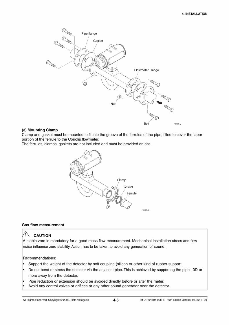
F0305.ai
Pipe flange
Bolt
Nut
Gasket
Flowmeter Flange
(3) Mounting Clamp Clamp and gasket must be mounted to fit into the groove of the ferrules of the pipe, fitted to cover the taper portion of the ferrule to the Coriolis flowmeter. The ferrules, clamps, gaskets are not included and must be provided on site.
F0306.ai
Ferrule
Gasket
Clamp
Gas flow measurement
Astablezeroismandatoryforagoodmassflowmeasurement.Mechanicalinstallationstress and flow
noiseinfluencezerostability.Actionhastobetakentoavoidanygenerationof sound.
Recommendations:
• Support the weight of the detector by soft coupling (silicon or other kind of rubber support.
• Do not bend or stress the detector via the adjacent pipe. This is achieved by supporting the pipe 10D or
more away from the detector.
• Pipe reduction or extension should be avoided directly before or after the meter.• Avoidanycontrolvalvesororificesoranyothersoundgeneratornearthedetector.
CAUTION

4. INSTALLATION
4-6 All Rights Reserved. Copyright © 2003, Rota YokogawaIM 01R04B04-00E-E 10th edition October 01, 2013 -00
4.4 Customer insulationCustomer insulation is only possible for remote detector RCCS3 with option /S2 (terminal box on distance).The upper line of the insulation must be minimum 40 mm below the terminal box.
IMPORTANT For explosion proof types see tables "Temperature classification" in chapter 9.
4.5 Mounting of converter RCCF31 to 2-inch pipeThe field-mount converter RCCF31 can be mounted on a 2-inch pipe. Therefore use the delivered bracket
and U-bolt assy.
F0309.ai
Improper fixing is subject to cause injury and to damage instrument.
NOTE

4. INSTALLATION
4-7All Rights Reserved. Copyright © 2003, Rota Yokogawa IM 01R04B04-00E-E 10th edition October 01, 2013 -00
4.6 Mounting of converter RCCR31 in a subrackIf the remote rack mount converter RCCR31 was not ordered with option /SR1 or /SR2, the customer has
tomountittoanown19´´subrack.Theterminalboardmustbefixedby6screws(M2.5x10)totherear
side of the subrack.
The RCCR31 rack cassette must be inserted into the subrack.
4.7 Alteration of display (RCCT3 / RCCF31)LCD display can be turned its direction with respect to piping configurations.
Removingfourscrews,adjustingdisplay’sorientationandfixingthescrewstightlyagainasshowninfigure
below.
Fixthelockscrewforuseinhazardousarea.After modification the user must ensure that the cover isscrewed down tightly to maintain the IP rating of the housing, failure to do so may allow moisture ingress and failure of electronic components.
F43.EPS
Lock screw for cover (Ex d)
IMPORTANT

4. INSTALLATION
4-8 All Rights Reserved. Copyright © 2003, Rota YokogawaIM 01R04B04-00E-E 10th edition October 01, 2013 -00
4.8.1 General items
Notes concerning the wiringWhen wiring, please observe the following precautions.
- Do not connect cables outdoors in wet weather in order to prevent damage from condensation and to protect the insulation, e.g. inside the terminal box of the flowmeter. - In case of conduit wiring, prevent rainwater from flowing or remain into the wiring pipe byusing a seal tape. - Use the cables which fulfill specification and check before wiring. - Before opening the terminal box, be sure to turn off the power. - Please fully tighten the terminal box cover. - When removing the cover, please unlock the locking screw clockwise. (See figure below). - After mounting the cover, please lock the cover by turning the locking screw counterclockwise. (See figure below). - For explosion proof wiring please see chapter 9. - Once all wiring is complete, check the connections before applying power to the instrument. Improper arrangements or wiring may cause a unit malfunction or damage.
4.8 Wiring
WARNING
F0400 .ai
Cover locking screw
Cover locking screw
Indicator
Indicator
RCCT3 Integral type RCCF31 Remote type converter

4. INSTALLATION
4-9All Rights Reserved. Copyright © 2003, Rota Yokogawa IM 01R04B04-00E-E 10th edition October 01, 2013 -00
Wiring port handling
(1) When waterproof property is unnecessaryFormeterswithNPT1/2´´threadsthewiringportissealedwithacap(notwater-proof)thatmustberemoved before wiring. For the unused wiring port, please prepare plug by the customer. For explosion proof, please refer to Chapter 9.
(2) When waterproof property is necessary (Wiring using waterproof glands)
To prevent water or condensation from entering the converter housing, waterproof glands are recommended. Do not over-tighten the glands or damage to the cables may result. Tightness of the gland can be checked by confirming that the cable is held firmly in place.
(3) Conduit Wiring
When wiring the conduits, utilizethewaterproofglandtopreventwaterfromflowingintowiringconnectionport. Place the conduit pipe on an angle as shown in Figure below. Install a drain valve at the low end of the vertical pipe, and open the valve regularly.
F0401 .ai
Plastic gland
Gasket
IMPORTANT
F0402.ai
Drain valve

4. INSTALLATION
4-10 All Rights Reserved. Copyright © 2003, Rota YokogawaIM 01R04B04-00E-E 10th edition October 01, 2013 -00
4.8.2 Ground (earth) connections
Grounding resistance of 10 Ω or less is necessary. For explosion proof type follow the domestic electrical requirements as regulated in each country.
The following table shows the grounding:
- The location of the protective earth terminal is at the terminal box of converter as shown in figure below.- In case of remote type, the detector is grounded at the converter. (See figure above.) - Use insulated PVC wire for 600 V for grounding wire.
IMPORTANT
• Detector connected to converter via remote cable• Protective earth terminal connected as below
• Protective earth terminal connected as below
Remote type
Detector
Converter
Protective earth
Detector
Converter
Remote cable
F0431.ai
Integral type
Protective earth
Grounding resistance 10 Ohm or less Grounding resistance 10 Ohm or less
F0403 .ai
cover locking screw
cover locking screw
display
display
RCCT3 integral type RCCF31 remote converter
protective earth terminal location
Protective earth terminal (M4 screw)
F0404.ai

4. INSTALLATION
4-11All Rights Reserved. Copyright © 2003, Rota Yokogawa IM 01R04B04-00E-E 10th edition October 01, 2013 -00
4.8.3 Wiring technique
Cable connection on terminal block:For connecting the cables to power-, I/O- and remote cable connection terminals a special tool is attached to the instrument. The terminal looks as follows:
Insert the auxiliary tool from the top into the terminal block.
Tilt the tool until it opens the cable port and insert the cable. Tilt the tool back and the opening is closed and the cable is fixed. Remove the tool. Fix the wires one at a time, please make sure that is secured to the wiring terminal block.
D+
PP
D–
S1+
S1–
S2+
S2–
TP1
TP2
TP3
COM
YOKOGAWA
Cable
Wiring tool slot
Wiring tool slot
Cable connection port
Cable connection port
F0406.ai
F0407.ai
F0408.ai
IMPORTANT-DoexternalelectricalconnectioninconformitywithEN61010-1orequivalentnationalregulations. For
hazardousareainstallationinEurope(ATEX)usestandardEN60079-14 as a guideline.
- Do not switch power supply on before all wiring is finished.
4. INSTALLATION
4-12 All Rights Reserved. Copyright © 2003, Rota YokogawaIM 01R04B04-00E-E 10th edition October 01, 2013 -00
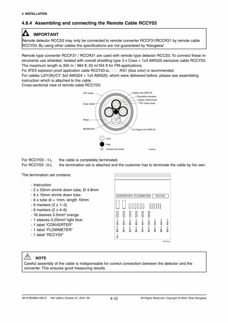
4.8.4 Assembling and connecting the Remote Cable RCCY03
Remote detector RCCS3 may only be connected to remote converter RCCF31/RCCR31 by remote cable RCCY03. By using other cables the specifications are not guaranteed by Yokogawa!
Remote type converter RCCF31 / RCCR31 are used with remote type detector RCCS3. To connect these in-struments use shielded, twisted with overall shielding type 3 x Coax + 1x3 AWG20 exclusive cable RCCY03. Themaximumlengthis300m/984ft;50m/164ftforFM-applications:For ATEX explosion proof application cable RCCY03-xL /KS1 (blue color) is recommended.For cables Li2Y(St)/CY 3x2 AWG24 + 1x3 AWG20, which were delivered before, please see assembling instruction which is attached to the cable.Cross-sectional view of remote cable RCCY03:
For RCCY03-1-L the cable is completely terminated. For RCCY03-0-L the termination set is attached and the customer has to terminate the cable by his own.
The termination set contains:
- Instruction - 2 x 20mm shrink down tube, Ø 4.8mm
- 6 x 10mm shrink down tube - 6 x tube di = 1mm, length 10mm
- 6 markers (2 x 1–3) - 6 markers (2 x 4–6) - 18 sleeves 0.5mm² orange - 1 sleeves 0.25mm² light blue -1label“CONVERTER” -1label“FLOWMETER” -1label“RCCY03”
NOTE Careful assembly of the cable is indispensable for correct connection between the detector and the converter. This ensures good measuring results.
F0410.ai
1
1
2
2
3
3
4
4
5
5
6
6
CONVERTER FLOWMETER RCCY03
PVC sheat
Outer shield
Wrap
Aluminium foil
Core
Filler
Coaxial wire shield F0409.ai
Copper wire AWG 20
Polyolefine insulation
Copper shield tinned
PVC Outer sheat
3 x Copper wire AWG 20
IMPORTANT

4. INSTALLATION
4-13All Rights Reserved. Copyright © 2003, Rota Yokogawa IM 01R04B04-00E-E 10th edition October 01, 2013 -00
Termination procedure:
Termination of cable end detector- Remove PVC outer sheath and outer shielding 100mm from the end.- Remove the clear wrap and the filler material, the foil that is around the isolated wires and drain wire close to the cable jacket.- Termination of the 3 single wires:- Slide a shrink down plastic tube (Ø 4.8mm, l=20mm) over the 3 wires, push it to the cable jacket and heat with hot air.- Strip 8mm of the wire ends.- Crimp the orange terminal sleeves (0.5mm²) to the ends of the 3 wires.- Termination of the 3 Coax cables:- Remove the PVC sheath 25mm from the end.- Unbraid the copper wire mesh and twist it.- Cut the wire 5mm and strip 8mm of the end.- Cut the copper wire mesh to match the wire length and slip a tube (10mm) over it.- Slip a 10mm shrink down tube over wire and shield to the transition to the cable and shrink it (s. photo).- Crimp an orange terminal sleeve (0.5mm²) to the end of the wire and to the drilled wire mesh.- Make a radial cut into the PVC outer sheeting 25mm from the end and cut lengthwise. 1)
Heat shrink tube 20mm, Ø 5mm
25
Terminal sleeves0.5mm (orange)
Cut
Terminal sleeves0.5mm (orange)
Tube10mm
Shrinkage tube 10mm
white insulation + (e.g. D+)black insulation: - (e.g. D-)

4. INSTALLATION
4-14 All Rights Reserved. Copyright © 2003, Rota YokogawaIM 01R04B04-00E-E 10th edition October 01, 2013 -00
Termination of cable end converter- Remove PVC outer sheath and outer shielding 100mm from the end.- Remove the clear wrap and the filler material.- Remove the foil that is around the isolated wires.- Do not clip off the drain wire!- Termination of the 3 single wires:- Slide a shrink down plastic tube (Ø 4.8mm, l=20mm) over the 3 wires, push it to the cable jacket and heat with hot air.- Strip 8mm of the wire ends.- Crimp the orange terminal sleeves (0.5mm²) to the ends of the 3 wires.- Crimp the light blue terminal sleeves (0.25mm2) to the end of the drain wire.- Termination of the 3 Coax cables:- Remove the PVC sheath 25mm from the end.- Unbraid the copper wire mesh and twist it.- Cut the wire 5mm and strip 8mm of the end.- Cut the copper wire mesh to match the wire length and slip a tube (10mm) over it.- Slip a 10mm shrink down tube over wire and shield to the transition to the cable and shrink it (s. photo).- Crimp an orange terminal sleeve (0.5mm²) to the end of the wire and to the drilled wire mesh.- Make a radial cut into the PVC outer sheeting 25mm from the end and cut lengthwise. 1)
Slidetheconductormarkersontothewireendsonbothsides,sothattheCoaxwithprinted“1”getsmarker“1”,theCoaxwithprinted“2”getsmarker“2”andtheCoaxwithprinted“3”getsmarker“3”.The3singlewiresgetthemarkers“4”(white),“5”(brown)and“6”(yellow).Each wire must have the same number on detector and on converter side.
1)
These sections of the outer sheating are removed only when connecting the cable at both cable ends and the outer shielding harness is connected electrically to the detector and converter housings via the metal PU-cable glands.
Heat shrink tube 20mm, Ø 5mm
25
Terminal sleeve on drain wire0.25mm (light blue)
Terminal sleeves0.5mm (orange)
Cut
Terminal sleeves0.5mm (orange)
Tube 10mm
Shrinkage tube 10mm
NOTE
white insulation + (e.g. D+)black insulation: - (e.g. D-)

4. INSTALLATION
4-15All Rights Reserved. Copyright © 2003, Rota Yokogawa IM 01R04B04-00E-E 10th edition October 01, 2013 -00
Fix labels Cable end detector Cable end converter

4. INSTALLATION
4-16 All Rights Reserved. Copyright © 2003, Rota YokogawaIM 01R04B04-00E-E 10th edition October 01, 2013 -00
Cable connection to detector RCCS3 and field-mount converter RCCF31:
1. Remove connection box cover detector and converter (see figure below).
2. Loosen the thread of cable gland and insert the cable into the cap and the clamp part. (See figure below.)3. Remove the PVC outer sheathing 25 mm from the end and fold back outer shield over the clamp part.
(See figure below.)
4. Tighten the cable gland.
5. Connect the numbered leads to the terminals as shown in the figure below.
6. Connect inner shields to terminal COM.
7. Close the connection box covers.
F0413.ai
CapCable
Cable gland
Clamp part
Screw partOuter shieldof cable
Wiring port
F0414.ai
Remote Converter RCCF31
terminal
Remote detector RCCS3
terminal
D+D-
S1+S1-S2+S2-
TP1TP2TP3
D+D-
S1+S1-S2+S2-
TP1TP2TP3
COM
Note:D-, S1-, S2- are connected to shield of coax line.
F0416.ai
RCCS3 RCCY03 RCCF31
D+ 1 1 D+
D- 2 1 D-
S1+ 3 2 S1+S1+ S1+
S1- 4 2 S1-
S2+ 5 3 S2+
S2- 6 3 S2-
TP1 7 4 TP1
TP2 8 5 TP2TP2 TP2
TP3 9 6 TP3drain wires COM
Coax
Coax
Coax

4. INSTALLATION
4-17All Rights Reserved. Copyright © 2003, Rota Yokogawa IM 01R04B04-00E-E 10th edition October 01, 2013 -00
4.8.5 Power supply wiring
The terminals for the power supply and for the I/O ports are in a separate terminal box as shown in the
figures below.
Cable connection to rack-mount converter RCCR31:
1. Loose the cable clamp on terminal board
2. Remove the 25 mm section of PVC outer sheathing from the cable and fix the outer ring of the cable
with the cable clamp on terminal board. (see left figure below).
3. Connect the numbered leads to the terminals as shown in the right figure below.
4. Connect inner shields to terminal COM.
Note:D-, S1-, S2- are connected to shield of coax line.
RCCS3 RCCY03 RCCR31
D+ 1 1 D+
D- 2 1 D-
S1+ 3 2 S1+S1+ S1+
S1- 4 2 S1-
S2+ 5 3 S2+
S2- 6 3 S2-
TP1 7 4 TP1
TP2 8 5 TP2TP2 TP2
TP3 9 6 TP3drain wires COM
Coax
Coax
Coax
F0417 .ai
Cover locking screws
Cover locking screws
Display
Display
RCCT3 Integral type RCCF31 remote converter
Protective earth terminal (M4 screw)
Power terminal block
Input / Output signalterminal block
F0418.ai

4. INSTALLATION
4-18 All Rights Reserved. Copyright © 2003, Rota YokogawaIM 01R04B04-00E-E 10th edition October 01, 2013 -00
CAUTION
1. Before starting the wiring, turn off the source of the supply power and check with the tester that there is
no voltage at the cable.
2. For RCCT3 / RCCF31 the protective ground conductor must be connected to the separate PE terminal
intheterminalboxwithCrimp-onring-typeterminalinordertoavoidpersonalshockhazard.
3. For RCCR31 the protective ground conductor must be connected to the separate PE terminal on the ter-
minalboardinordertoavoidpersonalshockhazard.
4. An exclusive external circuit breaker must be placed near each flowmeter. It must be marked as the dis-
connecting device of this meter and must be easily accessible.
5. Checktheexternalcircuitbreaker’sratingconformstotherequirementsspecifiedinthespecificationof
this instrument.
6. Wire the power supply cable keeping the distance of 1 cm or more from other signal wires.
7. Confirm the operating voltage of the converter before operation.
8. Please lock the cover of the converter with hexagon lock screw before operation (only RCCT3 /RCCF31)
•Cableterminalsshouldnotbenaked.ProperterminalsshouldbeusedforPowerandI/O.
•Connect the power supply cable to the terminals inside of the converter terminal box (RCCT3 /RCCF31)
or on terminal board (RCCR31).
•Confirm two ferrite core sets are attached to the flowmeter.
•Insert the cables into ferrite core before connecting to the terminals. Fix the ferrite core to the cable with
a cable strap.
• Connect the power cables to the terminals according to the figure below.
•For the connection of protective ground conductor to PE terminal of RCCF31 / RCCT3 use a crimp-on
ring type terminal. For RCCR31 connect the protective ground conductor to PE terminal of terminal
board.
RCCT3 / RCCF31 RCCR31

4. INSTALLATION
4-19All Rights Reserved. Copyright © 2003, Rota Yokogawa IM 01R04B04-00E-E 10th edition October 01, 2013 -00
CAUTION Special connections for Ex version :
The converter case must be connected to the potential equalisation facility of the
hazardousarea,e.g.totheU-clampPAterminalontheoutsideattheconverter.Pleaserefertochapter9
“EXPLOSIONPROTECTEDTYPEINSTRUMENTS”.
Power supply cable
Cable : Use cables acc. to VDE 0250, VDE 0281 or equivalents.
Outerdiameter:DINandNPTcablegland:6.5to10.5mmindiameter
Nominalcrosssectionofconductivewire :0.5to2.5mm²
Outer diameter of cores insulation part : < 3.6 mm
Connecting length of conductive wire part : < 9 mm
24V DC connectionsFor the DC power supply type, connect a 24 V DC power supply, following the precautions below.
1. Connecting Power Supply
Please refer to the Figure in right. AC power supplies
can not be connected. Confirm the polarity of DC power supply.
2. Supply voltage rating
The specification for the supply voltage is 20.5 – 28.8 V DC. But because the input voltage of the converter
drops due to cable resistance, it should be used within the following range.
3. Ground connection
Connect ground as shown on page 4-8 due to EMC protection.
L/+ N/- G
+ -20.5 to 28.8 V DC F49.EPS
1000(3300)900(2970)800(2640)700(2310)600(1980)500(1650)400(1320)300(990)200(660)100(330)0
20 22 24 26 28 30
F410.EPS
Allowedcable length m (ft)
Cable crosssection area 1.25mm2
Cable crosssection area 2mm2
voltage V
4. INSTALLATION
4-20 All Rights Reserved. Copyright © 2003, Rota YokogawaIM 01R04B04-00E-E 10th edition October 01, 2013 -00
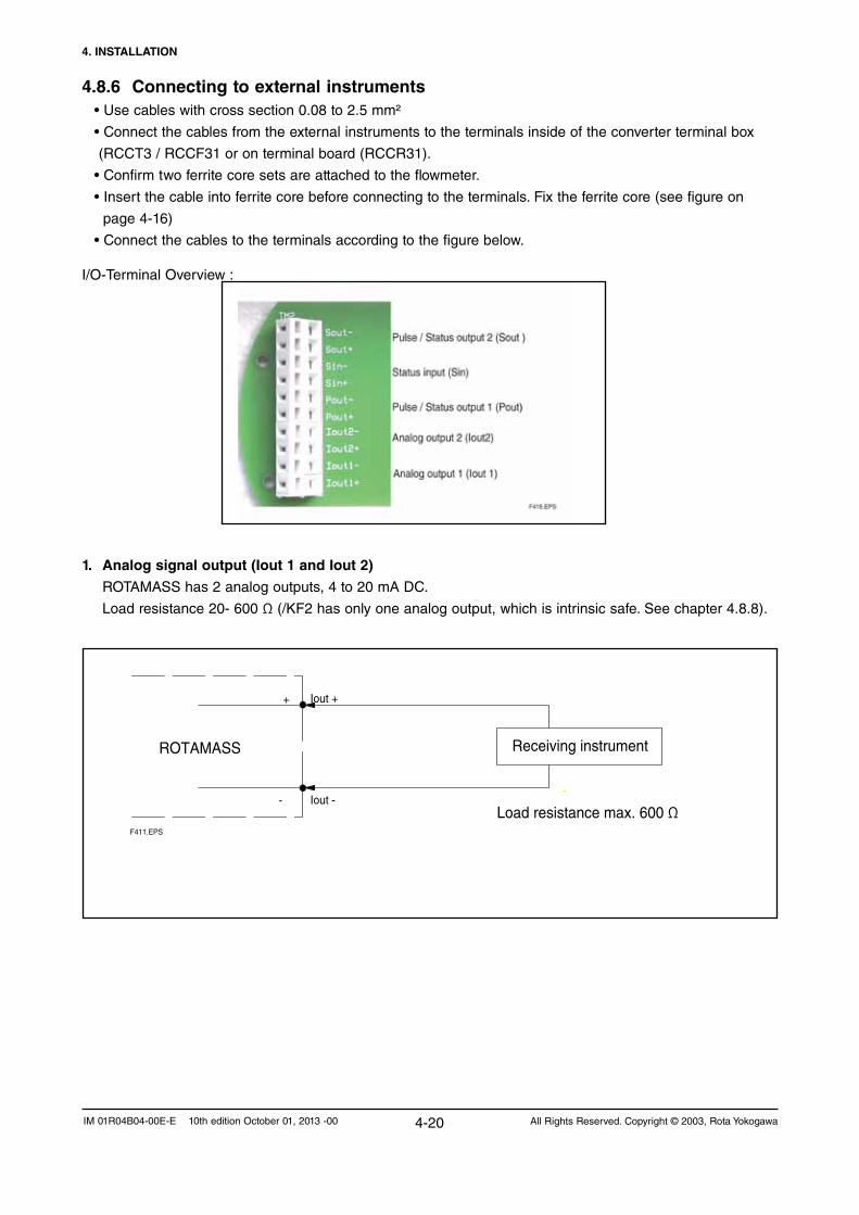
4.8.6 Connecting to external instruments•Usecableswithcrosssection0.08to2.5mm²
•Connect the cables from the external instruments to the terminals inside of the converter terminal box
(RCCT3 / RCCF31 or on terminal board (RCCR31).
•Confirm two ferrite core sets are attached to the flowmeter.
•Insert the cable into ferrite core before connecting to the terminals. Fix the ferrite core (see figure on
page 4-16)
• Connect the cables to the terminals according to the figure below.
I/O-Terminal Overview :
Receiving instrumentROTAMASS
Iout -
Iout ++
--
Load resistance max. 600 ΩF411.EPS
1. Analog signal output (Iout 1 and Iout 2)
ROTAMASS has 2 analog outputs, 4 to 20 mA DC.
Load resistance 20- 600 Ω (/KF2 has only one analog output, which is intrinsic safe. See chapter 4.8.8).

4. INSTALLATION
4-21All Rights Reserved. Copyright © 2003, Rota Yokogawa IM 01R04B04-00E-E 10th edition October 01, 2013 -00
3. Status Output passive (Pout / Sout)
The pulse outputs can be set to status outputs by menu item. Since this is an isolated
transistor contact, attention must be paid to voltage and polarity when wiring. This output cannot switch an
AC load. To switch an AC load, an intermediate relay (see the figure below) is required.
Protective diode
30VDC, 200mA max
ROTAMASSPout +/Sout +
Mechanical counter
ROTAMASS
Pout - /Sout-
Pout + /Sout +
Pulse output
Pulse output Load Electronic counter
Pout - /Sout-
F412.EPS
2. Pulse Output passive (Pout / Sout)
ROTAMASS has 2 pulse outputs (isolated transistor contact). Attention must be paid to voltage and polarity when wiring (/KF2 has one passive pulse output, which is
intrinsic safe. See chapter 4.8.8)
Protective diode
Magnetic valve
ROTAMASSPout + /Sout +
Load
ROTAMASS
Pout - /Sout-
Pout + /Sout +
Pout - /Sout-
F413.EPS
30VDC, 200mA max

4. INSTALLATION
4-22 All Rights Reserved. Copyright © 2003, Rota YokogawaIM 01R04B04-00E-E 10th edition October 01, 2013 -00
Pulse rate: 20~10000 Hz(10 kHz)
Load
* If the load resistance is 10 kΩ, 0 V-12 V voltage pulse is obtained.
ROTAMASS
Pout -
Pout +
F0427ai
Electronic counter
+15 V ±10%
2.3 kΩ
4. Pulse Output active (option /AP)
Pulseoutput1(Pout)canbeorderedasactiveoutput.Notpossiblewithintrinsicsafeoutputsoption/KF2.
5. Status Output active (option /AP)
Statusoutput1(Pout)canbeorderedasactiveoutput.Notpossiblewithintrinsicsafeoutputsoption/KF2.
Magnetic valve
ROTAMASS
Pout +
Load
ROTAMASS
Pout -
Pout +
Pout -
F421.EPS
12V, 6mA max., Load > 10kΩ
12V, 6mA max.
+
+

4. INSTALLATION
4-23All Rights Reserved. Copyright © 2003, Rota Yokogawa IM 01R04B04-00E-E 10th edition October 01, 2013 -00
7. Status input (Sin)
Statusinputisdesignedforusewithvoltage-free(“dry”)contact(activatesourcecurrent to detect the
contact state). Be careful not to connect to any signal source carrying any voltage. Applying voltage may
damage the input circuit.
ROTAMASSSin+
Sin-
Close: 200Ω max
Open: 100kΩ min
Voltage-free
contact input F415.EPS
6. Pulse / Status Output according EN 60947-5-6 (NAMUR) (option /NM)
Pulseoutput1(Pout)canbeorderedasNAMURoutput.
U
Transmitter Relay
-+
~ ~
ROTAMASSPout +
Pulse output
Pout -
1k
10k
F426.EPS

4. INSTALLATION
4-24 All Rights Reserved. Copyright © 2003, Rota YokogawaIM 01R04B04-00E-E 10th edition October 01, 2013 -00
Example of installation :
F418.EPS
Hazardous area
Iout +
Iout -
R barrier
4-20mA
Vin
V out
Ground
Safe area
ROTAMASS/[]F5
R load
4.8.7 Connecting HART- Communication
HART communication is available on analog output 1 and the HART-communicator is connected via load
resistance (230 ... 600 Ω) as shown on the figure below.
HARTCommunicator
HARTCommunicator
HARTCommunicator
Intermediateterminals
4 to 20mA DCsignal trans-mission line
Receivinginstrument
Terminal board
Control room
F417.EPS
ROTAMASS
4.8.8 Flowmeters with intrinsic safe outputs
ROTAMASS with option /F2 (not /FF2) has one intrinsic safe current output and one intrinsic safe pulse /
status output. The Ex-data of this output can be found in chapter 9.
ROTAMASS with option /F5 (not /FF5) has two intrinsic safe current outputs and one intrinsic safe pulse /
status output. The Ex-data of this output can be found in chapter 9.
The second current output (only /F2), pulse, status output and the status input are not available.
The concerning parameters in the menu are not visible.
Current output : The intrinsic safe current output is passive and an external power supply with shunt-diode
type barrier or isolation type barrier should be connected.

4. INSTALLATION
4-25All Rights Reserved. Copyright © 2003, Rota Yokogawa IM 01R04B04-00E-E 10th edition October 01, 2013 -00
Pulse output :
The intrinsic safe pulse output is passive and an external power supply with shunt-diode type barrier or
isolation type barrier should be connected.Maximum voltage : 30 V DC Maximum current : 100 mA
Example of installation :
Hazardous area
Pout 1 +
Pout 1 -
R barrier
R load
Vin
counter
V out
Ground
Safe area
ROTAMASS/[]F5
F420.EPS
Powersupplyrange : 10.5V…30VDC forNot-HARTapplication
Power supply range : 16.75 V … 30 V DC for HART application
Loadresistance : 20…600Ω forNot-HARTapplication
Load resistance : 230 … 600 Ω for HART application
Load resistance vs Power supply voltage :
800700600500400300200100 0
10 12 14 16 18 20 22 24 26 28 30
Loadresistance [ Ω ]
Power supply voltage [V]
HART communication available range
F419.EPS

4. INSTALLATION
4-26 All Rights Reserved. Copyright © 2003, Rota YokogawaIM 01R04B04-00E-E 10th edition October 01, 2013 -00
Blank Page

5. BASIC OPERATING PROCEDURES
5-1All Rights Reserved. Copyright © 2003, Rota Yokogawa IM 01R04B04-00E-E 10th edition October 01, 2013 -00
Data setting can be done by HART-Communication (see chapter 6) or with the 3 keys on the front panel. The following section describes how to use the three panel keys.
Direct sunlight may disturb the functionality of the setting switches.
(1) Always use the setting switches with the cover of the ROTAMASS closed.(2) Use these switches when covered by the glass window.(3) If dirt, dust or other substances surfaces on the display panel glass, wipe them clean with a soft dry cloth.(4) The operation with dirty gloves may cause a switch response error.
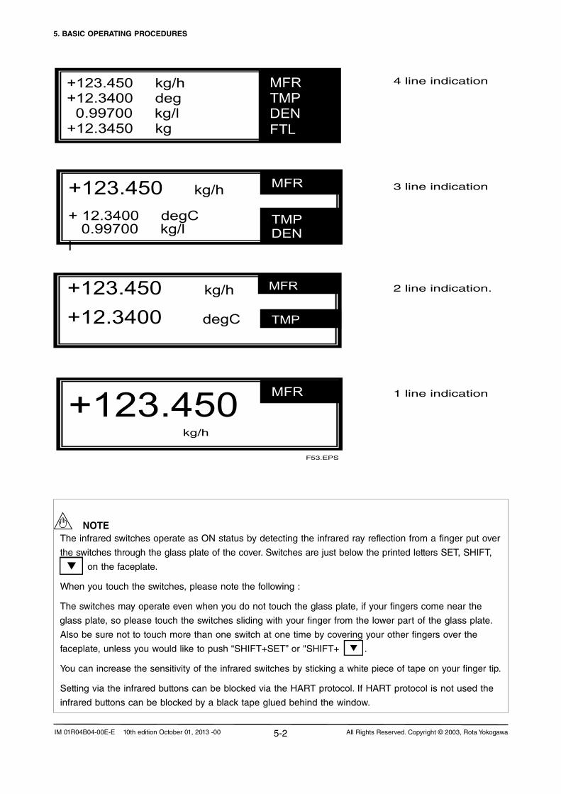
5.1 Liquid crystal displayConstruction of ROTAMASS display :
LCD dot matrix (32 x 132 dots) •1lineindication or •2lineindication or •3lineindication or •4lineindication
3 infrared switches SET , SHIFT ,
5. BASIC OPERATING PROCEDURES
SET : confirm data setting
or entry data setting
or confirm parameter
SHIFT : move cursor right to next position
SET + SHIFT : return to higher menu level : move to lower
parameter or increment value
SHIFT + : move to upper parameter
F51.EPS
SET SHIFTESC
General display indication :
123.450 kg/h
MFR Indication of title
Indication of numeric value
Indication of unit
F52.EPS
Lock symbol for indication of hardware write protect
IMPORTANT
NOTE
5. BASIC OPERATING PROCEDURES
5-2 All Rights Reserved. Copyright © 2003, Rota YokogawaIM 01R04B04-00E-E 10th edition October 01, 2013 -00
4 line indication
3 line indication
2 line indication.
1 line indication
+123.450 kg/h +12.3400 deg 0.99700 kg/l +12.3450 kg
MFR TMP DEN FTL
+123.450 kg/h
MFR
+123.450 kg/h
+12.3400 degC
MFR
TMP
+123.450 kg/h + 12.3400 degC
0.99700 kg/l l
MFR
TMP DEN
F53.EPS
TheinfraredswitchesoperateasONstatusbydetectingtheinfraredrayreflectionfromafingerputover
the switches through the glass plate of the cover. Switches are just below the printed letters SET, SHIFT,
on the faceplate.
When you touch the switches, please note the following :
The switches may operate even when you do not touch the glass plate, if your fingers come near the
glass plate, so please touch the switches sliding with your finger from the lower part of the glass plate.
Also be sure not to touch more than one switch at one time by covering your other fingers over the
faceplate,unlessyouwouldliketopush“SHIFT+SET”or"SHIFT+.
You can increase the sensitivity of the infrared switches by sticking a white piece of tape on your finger tip.
Setting via the infrared buttons can be blocked via the HART protocol. If HART protocol is not used the
infrared buttons can be blocked by a black tape glued behind the window.
NOTE

5. BASIC OPERATING PROCEDURES
5-3All Rights Reserved. Copyright © 2003, Rota Yokogawa IM 01R04B04-00E-E 10th edition October 01, 2013 -00
In the title indication the following abbreviations are used :
MASS FLOW RATE : MFR Additional with option /Cx : VOLUMEFLOWRATE :VFR CONCENTRATION :CON FORWARDTOTALMASS :FTM NETFLOW :NET REVERSETOTALMASS :RTM FORWARDTOTALNET :FTN DIFFERENTIALTOTALMASS :DTM REVERSETOTALNET :RTN FORWARDTOTALVOLUME :FTV DIFFERENTIALTOTALNET :DTN REVERSE TOTAL VOLUME : RTV DIFFERENTIALTOTALVOLUME :DTV DENSITY :DEN TEMPERATURE : TMP FORWARDTOTALENERGY :FTE VELOCITY : VEL FORWARD TOTAL FLEX : FTL REVERSE TOTAL FLEX : RTL DIFFERENTIALTOTALFLEX :DTL DRIVEGAIN : DGN
Numberoffigures:
totalizer≤999999 :1sign+6figures(e.g.+123456) totalizer≤9999999 :1sign+7figures(e.g.+1234567) totalizer>9999999 :Exponentialview(e.g.+1.23E12) measured value : 7 figures + 1 sign (e.g. +1234567) or 6 figures + 1 sign + 1 decimal point (e.g. +123.456) unit : 10 figures title : 3 figures
The contrast of the display can be adjusted with parameter
Detailed setup / Display Config / Disp contrast
The indication period of the display can be adjusted with parameter
Detailed setup / Display Config / Disp period
5.2 Display modesThe display can show the following indication modes :
1 Measuring mode Actual selected measuring values are shown
2 Parameter setting mode
2a Entry mode A confirmation, that setting via the infrared buttons should really happen
2b Parameter search mode Mode to search the parameter, which should be changed
2c Parameter select mode Mode to rewrite data. There are 4 types of data :- Select type (not blinking)-Numericaltype(blinking)-Numericaltypewithsign(blinking)- Character type (blinking)
2d Data confirmation mode Mode to confirm new value of selected parameter
2e Data determination mode Parameter setting is completed
3 Alarm mode Alarm or Error Code is displayed alternating with measuring mode (2s Alarm / 4s Measure). Warnings are not displayed. Access to Warnings via Self Test/Status.
In measuring mode the actual measured values according the display select parameters are indicated as
shown in chapter 5.1. How to set display settings see chapter 5.4.
Parameter setting mode is described in chapter 5.3.
The language of the parameter setting mode can be selected in parameter
Language / or Detailed setup / Display config / language .
English, German, French or Russian can be selected.

5. BASIC OPERATING PROCEDURES
5-4 All Rights Reserved. Copyright © 2003, Rota YokogawaIM 01R04B04-00E-E 10th edition October 01, 2013 -00
5.3 Setting via keys
The three keys SET
, SHIFT
, are used to set parameters via display menu.
The following flowchart shows how to reach the modes by using the keys :
Chapter 7.2 shows the display parameter list and chapter 7.3 shows the parameter tree.
Measuring mode
SET > 2s
Entry mode 1) SHIFT+SET
Indicate "Setting enable?"
SET
Parameter search mode 2)
downwardsSHIFT+SET > 3s
SHIFT + upwardsSET lower layerSHIFT+SET upper layer
SET
Parameter select mode 2))Input data:
SHIFT + SET scroll down or increment numberSHIFT + scroll upSHIFT shift Cursor rightSET set Parameter SHIFT+SET to parameter search
SET
SHIFT + SET Data confirmation mode 2)
Data blinking
SET
after 2s Data determination modeNo blinking
1) Back to measuring mode if no key is pressed within 10s.2) Back to measuring mode if no key is pressed within 120s.
F54.EPS
SHIFT+SET > 3s
SHIFT+SET > 3s
IMPORTANT
IMPORTANT
The infrared keys can be locked via HART by Hot Key / Key Status.
Depending on parameter setting, only relating parameters are visible in the menu. E.g., if Pulse/Stat 1
select is set to Pulse, the parameters concerning status out 1 (SO1) do not appear in the menu.
Such dependences are described later in the related chapters.

5. BASIC OPERATING PROCEDURES
5-5All Rights Reserved. Copyright © 2003, Rota Yokogawa IM 01R04B04-00E-E 10th edition October 01, 2013 -00
5.4 Examples of parameter settings via keys5.4.1 Display configuration, set volume flow to line 1
123.450 kg/h 0.99700 kg/l 12.3400 degC 12.3450 kg
MFR DEN TMP FTL
SET> 2s
Setting Enable?
Main Menu Language Process variables
Diag/Service
Main Menu Basic Setup
Detailed Setup Review device info
SET
SET
Basic Setup Tag Long Tag
Display config
Basic Setup Display Config
Mass flow Density
2x
Display config Display select 1 Display select 2
Display select 3
SET
Display
Mass flow
Display select 1 Mass flow
Volume flow Density
select
2x SET 3x SHIFT + SET or SHIFT + SET > 3s
12.3400 m³/h 0.99700 kg/l 12.3400 degC 12.3450 kg
VFR DEN TEMP FTL
3x
Display select 1 Mass flow
Volume flow
SET
DensityTemperatureF-Total flexR-Total flexD-Total...........
flex
F55.EPS

5. BASIC OPERATING PROCEDURES
5-6 All Rights Reserved. Copyright © 2003, Rota YokogawaIM 01R04B04-00E-E 10th edition October 01, 2013 -00
5.4.2 Setting Temperature 20-120°C to Analog Output 2
MFR DEN TMP FTL
SET > 2s
Setting Enable?
Main Menu Language Process variables
Diag/Service
Main Menu Basic Setup
Detailed Setup Review device info
SET
SET
Basic Setup Tag Long Tag
Display config
Basic Setup Temperature
Analog 1 select Analog 2 select
5x
Temperature Temperature unit Temperature LRV
Temperature URV
SET
Temperature Temperature LRV Temperature URV Temperature damping
SET
Temperature LRV 000.00 degC 000.00 degC
Edit number with SHIFT and
Temperature LRV 000.00 degC 020.00 degC
2x SET
Temperature Temperature URV
Temperature damping
Temperature Temperature LRV Temperature URV Temperature damping
F56.EPS
3x
123.450 kg/h 0.99700 kg/l 12.3400 degC 12.3450 kg
Temperature unit
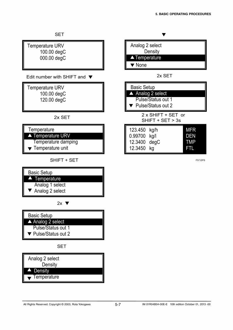
5. BASIC OPERATING PROCEDURES
5-7All Rights Reserved. Copyright © 2003, Rota Yokogawa IM 01R04B04-00E-E 10th edition October 01, 2013 -00
2x SET
2x
SET
Analog 2 select Density
Density Temperature
2x SET
Basic Setup Analog 2 select
Pulse/Status out 1 Pulse/Status out 2
SET
Temperature URV 100.00 degC 000.00 degC
Temperature URV 100.00 degC 120.00 degC
Basic Setup Temperature
Analog 1 select Analog 2 select
Analog 2 select Density
Temperature
Basic Setup Analog 2 select
Pulse/Status out 1 Pulse/Status out 2
2 x SHIFT + SET orSHIFT + SET > 3s
MFR DEN TMP FTL
F57.EPS
Temperature Temperature URV
Temperature damping
SHIFT + SET
123.450 kg/h 0.99700 kg/l 12.3400 degC 12.3450 kg
Edit number with SHIFT and
Temperature unit
None

5. BASIC OPERATING PROCEDURES
5-8 All Rights Reserved. Copyright © 2003, Rota YokogawaIM 01R04B04-00E-E 10th edition October 01, 2013 -00
5.5 Setting parameters in converter with option /NCIfremoteconverterRCCF31/RCCR31wasorderedwithoption/NC(nocombination),thecustomermust
set the parameters of the connected detector by himself.
In parameter Detailed Setup / Sensor model the sensor model must be selected. Then, the sensor model
depending parameters are set automatically to default value :
Qnom,Massflowunit,MassflowLRV,MassflowURV,Volflowunit,VolflowLRV,VolflowURV,Autozero
range,Autozerofluctuationrange.
In parameter Detailed Setup / Sensor constants the sensor constants from calibration certificate must be set.
If material of wetted parts is HC see instruction TI 01R04B04-03E-E attached to the converter.
In Parameter Basic setup / Tag or Basic setup / Long tag the tag number must be set if necessary.

5. BASIC OPERATING PROCEDURES
5-9All Rights Reserved. Copyright © 2003, Rota Yokogawa IM 01R04B04-00E-E 10th edition October 01, 2013 -00
After the flow meter is installed into the process pipe work, set up the parameter corresponding to calibration certificate(generallysetupinthefactory)andperformthepre-operationzeroadjustment.
Zero adjustment is required before beginning operation in order to obtain the output signals are accurately proportional to the flow. Zero adjustment is performed to set the instrument to 0% when the flow rate is 0.
- Stop flow before starting autozero (valve on outputs).-Duringautozerotime -Flowisfixedtozero -Totalizerstopscounting. - Display switches do not work.
Following procedure should be executed after installation but before starting measurement to get best measuring results: - Flush the meter with the fluid under process conditions. - Stop flow, the best way is closing valves upstream and downstream. - Wait2minutesinwhichdensity,temperatureandpressureshouldstabilize. - Density check: •for measurement of liquids control via expected medium density reading that the measuring
tubes are gas free (density not lower than expected. Do not forget to insert the process pressure and pressure unit for the pressure compensation via Detailed Setup / Config Fld vars / Dens).
•for measurement of gases there is no possibility to check the density reading as the density value of gases is lower than 0.3 kg/l and the ROTAMASS switches automatically to 0 kg/l, see chapter 7.7. - PerformAutozero. - StoretheAutozerovalueinAutozeroHistoryifrequired.(Onlyifyouenterthedatethevalueswill be stored). - Flow measurement can start.
ForsettingaproperAutozerotheconditionshavetobewelldefined.Undercertaincircumstancesitis recommendednottoperformAutozerobutusetheAutozerovaluesetduringflowcalibrationinthefactory:-zeroflowconditioncannotbeguarantiedwhilevalvesmaybenottight - two or multi phase medium whether the phases separates under no flow condition - two phase medium whether there is gas contained in the fluid phase or liquid particles in the gas phase
ROTAMASSincorporatestwomeasuringtubeswhichvibratesataresonancefrequencybetween100Hzand200Hz.Undercertaincircumstancesthereisasimilarresonancefrequencyinthepipeworkorfixturewhichmightbeexcited.InthiscasehighzerofluctuationmayoccurandAutozerovaluecan’tbeexecuted properly. Changes in the mechanical support of the detector should be done to decouple the detector from the vibrating structures.
5.6 Zero adjustment (Autozero)
IMPORTANT
IMPORTANT
CAUTION
WARNING

5. BASIC OPERATING PROCEDURES
5-10 All Rights Reserved. Copyright © 2003, Rota YokogawaIM 01R04B04-00E-E 10th edition October 01, 2013 -00
How to perform Autozero via keys :
MFR DEN TMP FTL
SET> 2sSetting Enable?
Main Menu Language Process variables
Diag/Service
Main Menu Diag/Service
Basic Setup Detailed Setup
SET
2x
Diag/Service Autozero check
Autozero Output trim
2x
Diag/Service Autozero
Output trim
SET Diag/Service
F58.EPS
Autozero checkInput/Output testSelftest/Status
SET AutozeroMass flow Zero tuning
Autozero Auto zero exe
Autozero value
SET Auto zero exe Not execute
Execute
2x
SET Autozero tuning
Inhibit Inhibit
Enable
2x SETAutozeroMass flow Zero tuning Auto zero time
Auto zero exe
Autozero tuning
Enable
2x SET
Autozero tuning Enable
Inhibit
123.450 kg/h 0.99700 kg/l 12.3400 degC 12.3450 kg
Self Test / Status
Zero tuning

5. BASIC OPERATING PROCEDURES
5-11All Rights Reserved. Copyright © 2003, Rota Yokogawa IM 01R04B04-00E-E 10th edition October 01, 2013 -00
Reading Autozero history (see also chapter 7.24) :
MFR DEN TMP FTL
SET> 2s Setting Enable?
Main Menu Language Process variables
Diag/Service
Main Menu Diag/Service
Basic Setup Detailed Setup
SET
2x
Diag/Service Autozero check
Autozero Output trim
2x
SET Autozero check Autozero history Autozero initial
Autozero range
Autozero history 05/05/2003
10/06/2003
SET
AZ hist : 05/05/2003+ 0000.00 kg/h+ 00.0000 kg/l+ 0030.00 degC
SET Diag/Service
F59.EPS
Autozero checkInput/Output testSelftest/Status
SET
15/07/2004
SHIFT+ SET
Autozero05/05/2003
10/06/200315/07/2004
123.450 kg/h 0.99700 kg/l 12.3400 degC 12.3450 kg
Autozero
Auto zero Exe XXX.XXkg/h
2x SET
Autozero Autozero exe Doing Autozero 180sec
After 30s /180s
Auto zero Exe Execute
After 3s
Set date with SHIFT+ . Then press 2x SET Autozero data are written in Autozero
history.
Autozero
Date (DD/MM/YYYY)00/00/2000
F58a.EPS
3x SHIFT + SET Measuring mode
Not Execute

5. BASIC OPERATING PROCEDURES
5-12 All Rights Reserved. Copyright © 2003, Rota YokogawaIM 01R04B04-00E-E 10th edition October 01, 2013 -00
Blank Page

6. OPERATION VIA HART
6-1All Rights Reserved. Copyright © 2003, Rota Yokogawa IM 01R04B04-00E-E 10th edition October 01, 2013 -00
6. OPERATION VIA HART
6.1 Conditions of communication lineA HART-communicator can communicate with the ROTAMASS RCC3 from the control room, the RO-
TAMASS site or any other wiring termination point in the loop, provided there is a minimum load
resistance of 230Ω between the connection and the instrument. To communicate, it must be connected in
parallel with the ROTAMASS RCC3,theconnectionsarenotpolarized.Thefigurebelowshowsthewiring
connections for direct interface at the ROTAMASS RCC3.
Specifications of communication line :
Load resistance : 230 to 600 Ω, for multidrop mode see figure below
Minimumcablesize : 24AWG(0.51mmdiameter)
Cable type : single pair shielded or multiple pair with overall shield
Maximum twisted pair length : 6,500 ft (2,000 m)
Maximum multiple twisted pair length : 3,200 ft (1,000 m)
Use the following formula to determine cable length for a specific application :
Where : L = length in feet or meters
R = resistance in ohms, current sense resistance
C = cable capacitance in pF/ft or pF/m
Ci = 50,000 pF
Load resistance and quantity of devices in multidrop mode :
800700600500400300200100 0
1 2 3 4 5 6 7 8 9 10 11 12 13 14 15
Loadresistance [ Ω ]
Quantity of connected field devicesF62.EPS
230
571500
333 307 285 266
400444363
RCCT_F3
HARTCommunicator
HARTCommunicator
HARTCommunicator
Intermediateterminals
4 to 20mA DCsignal trans-mission line
Receivinginstrument
Terminal board
Control room
F61.EPS
L =65x106
(RxC)(C f+10,000)
C

6. OPERATION VIA HART
6-2 All Rights Reserved. Copyright © 2003, Rota YokogawaIM 01R04B04-00E-E 10th edition October 01, 2013 -00
6.2 Communication via FieldMateFieldMate is a PC-based flexible field device management tool from Yokogawa.
Features:
-InstantdevicerecognitionuponconnectionforHART,FF,ProfibusandBRAINdevices
- Support of both FDT/DTM and EDDL technologies
- Database support for offline maintenance
- Full history and audit trail
-SynchronizationwithPRM
The segment viewer will automatically scan the bus and will list your devices.
FieldMate start window
AllYokogawadeviceDTM’scanbedownloadedforfreefromthewebsite:
http://downloads.yokogawa-europe.com

6. OPERATION VIA HART
6-3All Rights Reserved. Copyright © 2003, Rota Yokogawa IM 01R04B04-00E-E 10th edition October 01, 2013 -00
RCC3 DTM: Start window

6. OPERATION VIA HART
6-4 All Rights Reserved. Copyright © 2003, Rota YokogawaIM 01R04B04-00E-E 10th edition October 01, 2013 -00
RCC3 DTM: Process variables
RCC3 DTM: Device information
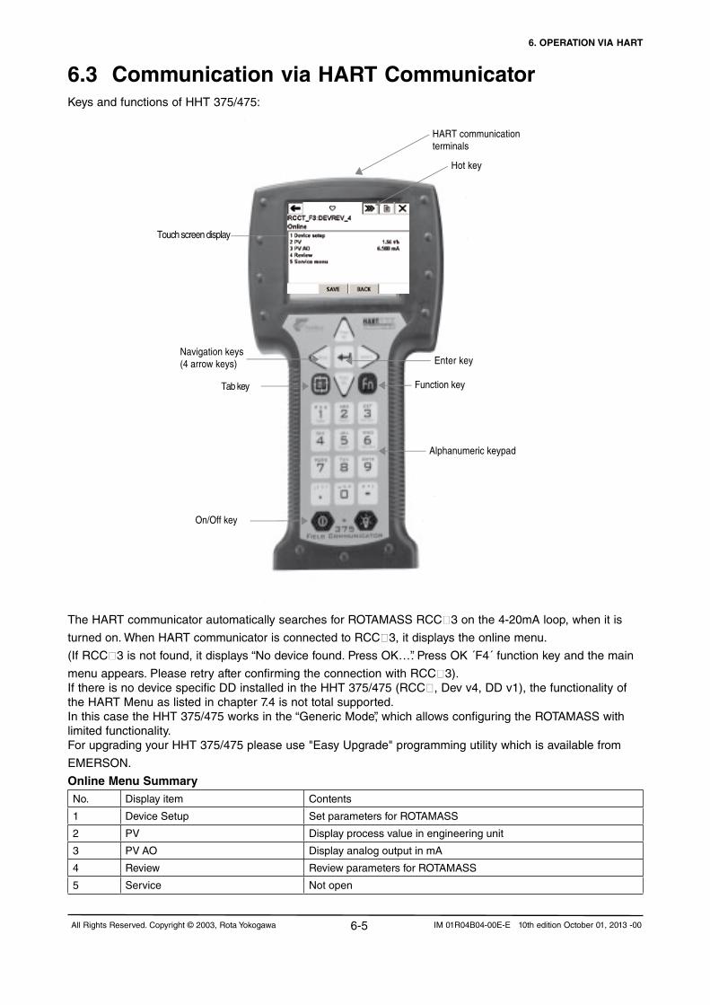
6. OPERATION VIA HART
6-5All Rights Reserved. Copyright © 2003, Rota Yokogawa IM 01R04B04-00E-E 10th edition October 01, 2013 -00
6.3 Communication via HART CommunicatorKeys and functions of HHT 375/475:
Touch screen display
HART communicationterminals
Enter key
Function key
Alphanumeric keypad
On/Off key
Navigation keys(4 arrow keys)
Tab key
Hot key
The HART communicator automatically searches for ROTAMASS RCC3 on the 4-20mA loop, when it is
turned on. When HART communicator is connected to RCC3, it displays the online menu.
(If RCC3isnotfound,itdisplays“Nodevicefound.PressOK…”.PressOK´F4´functionkeyandthemain
menu appears. Please retry after confirming the connection with RCC3).If there is no device specific DD installed in the HHT 375/475 (RCC, Dev v4, DD v1), the functionality of the HART Menu as listed in chapter 7.4 is not total supported.InthiscasetheHHT375/475worksinthe“GenericMode”,whichallowsconfiguringtheROTAMASSwithlimited functionality.For upgrading your HHT 375/475 please use "Easy Upgrade" programming utility which is available from
EMERSON.
Online Menu SummaryNo. Display item Contents
1 Device Setup Set parameters for ROTAMASS
2 PV Display process value in engineering unit
3 PV AO Display analog output in mA
4 Review Review parameters for ROTAMASS
5 Service Notopen
6. OPERATION VIA HART
6-6 All Rights Reserved. Copyright © 2003, Rota YokogawaIM 01R04B04-00E-E 10th edition October 01, 2013 -00
The HART menu in chapter 7.4 shows the configuration of the online menu, which is needed for the opera-
tionwithHARTcommunicator.Select´DeviceSetup´tocallupthedesireditemasfollows:
There are two choices to select the desired menu item:
1. Use the ↓ or ↑ key to select the desired item, and then press the → key.
2. Press the number key displayed for the desired item.
To return to the previous display, press the ← key
Entering, setting and sending data:
The data, which is input with the keys is set in the HART-communicator by pressing ENTER. Then, by press-
ing SEND, the data is sent to RCC3.NotethatthedataisnotsenttoROTAMASSifSEND is not pressed.
All the data set with the HART-communicator is held in memory unless power is turned off, so all data can
be send to RCC3 in one lot.
IMPORTANT Parameter setting on the display with the infrared keys is prohibited during HART communication.
IMPORTANT Do not turn power off just after HART-Communicator settings (sending) have been made. If ROTAMASS
is turned off less than 30 seconds after parameters have been set, the set data will not be stored and the
data returns to previous settings.
6.4 Unique functions of HART CommunicatorCheck on communication error:
When over run error, framing error, parity error or buffer overflow error is detected, the data including the
information of errors is returned, and the error message is indicated on HHT.
Time recording:
Online → Device setup → Detailed setup → Device information → Date
Month and day can be set in a number of 2 figures, Year in 4 figures.
Multi-drop communication:
Field devices in multi-drop mode refer to the connection of several field devices on a
communication single line. Up to 15 field devices can be connected when set in the multi-drop mode.
To activate multi-drop communication, the field device address must be changed to a number from 1 to 15.
This change deactivates the 4 to 20 mA output and turns it to 4 mA.
Online → Device setup→ Detailed setup → HART Communication → Poll address
Write protect:
Write protect function is provided to inhibit parameter change. That becomes active by
enteringapasswordin“Newpassword”.Writeprotectstatusisreleasedfor10minutesbyenteringthe
passwordin“Enablewrt10min”.
Setting the password:
Hotkey →Newpassword
Enter new password to change state of write.
Hotkey → Enable wrt 10 min
“EnableWrite”releasewriteprotectstatusfor10minutes.

6. OPERATION VIA HART
6-7All Rights Reserved. Copyright © 2003, Rota Yokogawa IM 01R04B04-00E-E 10th edition October 01, 2013 -00
Whilewriteprotectstatusisreleased,enteranewpasswordtwice,within30secin“NewPassword”.
It will not be possible to set a new password when 10 minutes have elapsed.
Ifaparameter,whichiswriteenabled,ischangedwhilethedeviceisin“Enablewrt10min”, release time is
extended for further 10 minutes.
NOTE• When the write protect function is active (its menu bar shows “Yes”),datasettingchangesinallparameters
of RCC3 are inhibited and cannot be changed using the HART communicator. Also the setting via the
infrared pushbuttons is prohibited.
•If8charactersareinputas“space”,theWriteprotectfunctionisinreleasestatusirrespectiveoftime.
•IfbothRCC3 and HART Communicator power off and on again within 10 minutes after releasing of
writeprotectstatus,“EnableWrite”becomesunavailable.
Software seal :The“Softwareseal”menuisreservedasevidencesothatuserisabletoconfirmwhethertheJokerpassword is used or not. This evidence is saved.Hotkey → Software seal The first indication in Software seal menu is "keep".After the joker password setting it shows "break".Aftersettinganewpasswordandreleasevia“Enablewrt10min”,theSoftwaresealshows“keep”again.Key Status : Enable: Infrared keys are activated. Inhibit: Infrared keys are deactivated.Master Reset :Default : all parameters set to default except board constants, calibration constants, detector depending parameter and Concentration measuring settings in service menu.
6.5 Transmitting device variables via HARTWhile current output 1 is connected to a HART master it is possible to transmit up to 4 device variables named primary (PV), secondary (SV), tertiary (TV) and quaternary variable (QV). To select which measure-ment value will be transmitted in which place there are basically two ways.•Setting via output configurationThe 4 device variables are linked to the settings of the corresponding output according to the table:
Device variable Corresponding output (not option /KF2) Corresponding output (option /KF2)
PV Current output 1 (Iout 1) Current output 1 (Iout 1)
SV Current output 2 (Iout 2) Notavailable1)
TV Pulse output 1 (Pout) 1) Pulse output 1 (Pout) 1)
QV Pulse output 2 (Sout) 1) NotavailablevThe unit, in which the device variable is transmitted, is taken from the unit of the corresponding measure-ment value as shown on the display. To change the order of the device variables, the output configuration has to be changed.1)Ifoneoftheoutputsisnotavailable(option/KF2)orPulseoutput1/2isconfiguredasStatusoutputorNoFunction, the corresponding device variable can be freely selected via HART output configuration menu (see Chapter 7.15).•Setting via HARTFor setting the device variables there are the two common practice commands #51 (assignment of device variables) and #53 (unit of device variables). These commands are typically used by other HART devices like multiplexers.Since the device variables are linked to the output configuration sending one of this commands will change
the output configuration of ROTAMASS!

6. OPERATION VIA HART
6-8 All Rights Reserved. Copyright © 2003, Rota YokogawaIM 01R04B04-00E-E 10th edition October 01, 2013 -00
6.6 Hardware Write ProtectIf software write protection via password is not suitable to protect the access to the converter, a hardware
write protection can be set:
•Openthecoveroftheconverter.
•Unscrewthe4screwsofthedisplayandmovethedisplayaside.
•SetthejumperonJP1ofCPU-boardto"Protect"asshowninthefollowingpicture.
Additionally the protect switch on display board must be set to "Protect":
The activated hard write protection is indicated on display via a lock symbol in the upper right corner
(see Chapter 5.1 General display indication).
Screw the display and close the cover.
The hardware write protection is prior to any other write protection, and cannot be released by HART or
other software means.
Enable Protect F64.EPS
CPU Board
Cable to display
JP1
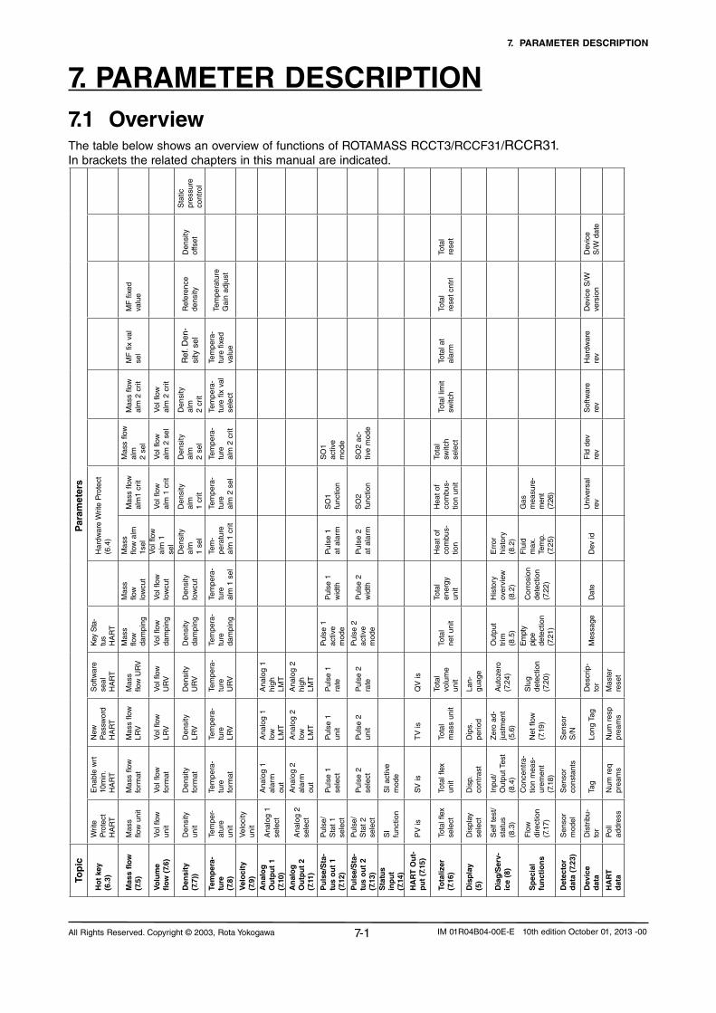
7. PARAMETER DESCRIPTION
7-1All Rights Reserved. Copyright © 2003, Rota Yokogawa IM 01R04B04-00E-E 10th edition October 01, 2013 -00
7. PARAMETER DESCRIPTION7.1 OverviewThe table below shows an overview of functions of ROTAMASS RCCT3/RCCF31/RCCR31. In brackets the related chapters in this manual are indicated.
Par
amet
ers
Sta
tic
pres
sure
cont
rol
Den
sity
offs
et
Tota
l re
set
Dev
ice
S/W
dat
e
MF
fixe
d va
lue
Ref
eren
cede
nsity
Tem
pera
ture
Gai
n ad
just
Tota
l re
set
cntr
l
Dev
ice
S/W
ve
rsio
n
MF
fix
val
sel
Ref
. Den
-si
ty s
el
Tem
pera
-tu
re fi
xed
valu
e
Tota
l at
alar
m
Har
dwar
e re
v
Mas
s flo
w
alm
2 c
rit
Vol
flow
al
m 2
crit
Den
sity
al
m2
crit
Tem
pera
-tu
re fi
x va
l se
lect
Tota
l lim
itsw
itch
Sof
twar
e re
v
Mas
s flo
w
alm
2 se
l
Vol
flow
al
m 2
sel
Den
sity
al
m
2 se
l
Tem
pera
-tu
re
alm
2 c
rit
SO
1 ac
tive
mod
e
SO
2 ac
-tiv
e m
ode
Tota
l sw
itch
sele
ct
Fld
dev
re
v
Har
dwar
e W
rite
Pro
tect
(6.4
)
Mas
s flo
w
alm
1 cr
it
Vol
flow
al
m 1
crit
Den
sity
al
m
1 cr
it
Tem
pera
-tu
re
alm
2 s
el
SO
1 fu
nctio
n
SO
2 fu
nctio
n
Hea
t of
co
mbu
s-tio
n un
it
Gas
m
easu
re-
men
t (7
.26)
Uni
vers
al
rev
Mas
s flo
w a
lm1s
elV
ol fl
ow
alm
1
sel
Den
sity
al
m1
sel
Tem
-pe
ratu
real
m 1
crit
Pul
se 1
at
ala
rm
Pul
se 2
at
ala
rm
Hea
t of
co
mbu
s-tio
n
Err
or
hist
ory
(8.2
)
Flu
id
max
. Te
mp.
(7.2
5)
Dev
id
Mas
s flo
wlo
wcu
t
Vol
flow
lo
wcu
t
Den
sity
lo
wcu
t
Tem
pera
-tu
real
m 1
sel
Pul
se 1
w
idth
Pul
se 2
w
idth
Tota
l en
ergy
un
it
His
tory
ov
ervi
ew(8
.2)
Cor
rosi
on
dete
ctio
n(7
.22)
Dat
e
Key
Sta
-tu
sH
AR
T
Mas
s flo
wda
mpi
ng
Vol
flow
da
mpi
ng
Den
sity
da
mpi
ng
Tem
pera
-tu
re
dam
ping
Pul
se 1
ac
tive
mod
e
Pul
se 2
ac
tive
mod
e
Tota
l ne
t un
it
Out
put
trim
(8.5
)
Em
pty
pipe
de
tect
ion
(7.2
1)
Mes
sage
Sof
twar
e se
alH
AR
T
Mas
s flo
w U
RV
Vol
flow
U
RV
Den
sity
U
RV
Tem
pera
-tu
reU
RV
Ana
log
1 hi
ghLM
T
Ana
log
2 hi
ghLM
T
Pul
se 1
ra
te
Pul
se 2
ra
te
QV
is
Tota
l vo
lum
e un
it
Lan-
guag
e
Autozero
(7.2
4)
Slu
g de
tect
ion
(7.2
0)
Des
crip
-to
r
Mas
ter
rese
t
New
P
assw
ord
HA
RT
Mas
s flo
w
LRV
Vol
flow
LR
V
Den
sity
LR
V
Tem
pera
-tu
reLR
V
Ana
log
1 lo
wLM
T
Ana
log
2 lo
w
LMT
Pul
se 1
un
it
Pul
se 2
un
it
TV
is
Tota
l m
ass
unit
Dip
s.
perio
d
Zer
o ad
-ju
stm
ent
(5.6
)
Netflow
(7.1
9)
Sen
sor
S/N
Long
Tag
Num
resp
prea
ms
Ena
ble
wrt
10m
in.
HA
RT
Mas
s flo
w
form
at
Vol
flow
fo
rmat
Den
sity
fo
rmat
Tem
pera
-tu
refo
rmat
Ana
log
1 al
arm
out
Ana
log
2 al
arm
out
Pul
se 1
se
lect
Pul
se 2
sele
ct
SI
activ
e m
ode
SV
is
Tota
l flex
un
it
Dis
p.
cont
rast
Inpu
t/O
utpu
t Tes
t (8
.4)
Con
cent
ra-
tion
mea
s-ur
emen
t (7
.18)
Sen
sor
cons
tant
s
Tag
Num
req
pr
eam
s
Writ
e P
rote
ctH
AR
T
Mas
s flo
w u
nit
Vol
flow
un
it
Den
sity
un
it
Tem
per-
atur
eun
it
Vel
ocity
un
it
Ana
log
1 se
lect
Ana
log
2 se
lect
Pul
se/
Sta
t 1
sele
ct
Pul
se/
Sta
t 2
sele
ct
SI
func
tion
PV
is
Tota
l flex
se
lect
Dis
play
se
lect
Sel
f te
st/
stat
us(8
.3)
Flo
w
dire
ctio
n(7
.17)
Sen
sor
mod
el
Dis
trib
u-to
r
Pol
l ad
dres
s
Top
ic
Ho
t ke
y(6
.3)
Mas
s flo
w(7
.5)
Volu
me
flow
(7.
6)
Den
sity
(7.7
))
Tem
per
a-tu
re(7
.8)
Vel
oci
ty(7
.9)
An
alo
gO
utp
ut
1 (7
.10)
An
alo
gO
utp
ut
2 (7
.11)
Pu
lse/
Sta
-tu
s o
ut
1 (7
.12)
Pu
lse/
Sta
-tu
s o
ut
2 (7
.13)
Sta
tus
inp
ut
(7.1
4)
HA
RT
Ou
t-p
ut
(7.1
5)
Tota
lizer
(7.1
6)
Dis
pla
y(5
)
Dia
g/S
erv-
ice
(8)
Sp
ecia
lfu
nct
ion
s
Det
ecto
r d
ata
(7.2
3)
Dev
ice
dat
a
HA
RT
dat
a

7. PARAMETER DESCRIPTION
7-2 All Rights Reserved. Copyright © 2003, Rota YokogawaIM 01R04B04-00E-E 10th edition October 01, 2013 -00
Differences between display and HART settingThe ROTAMASS software is continuously improved. This leads to functions, which are different in HART (DD version 0402) and display setting (software version from 1.08.20)
For ROTAMASS with software version 1.08.xx (xx < 20) the parameters marked with "*)" are not available. Parameters marked with "**)" are not available in software version from 1.08.20.
7.2 Parameter listParameter Data form Data range Dec.
pointUnit R : read
W : writeExe : execute
Reset Master
Reset Power on
Default
Write protect Select No - - R/W -
Yes
Enable WRT 10 min Acc. To HART - - R/W X Disable
NewPassword ASCII 8 characters - - R/W X Space
Software Seal Select Break - - R/W -
Keep
Master reset Select NotExecute - - R/W X NotExecute
Execute
Key Status Select Enable - - R/W Enable
Inhibit
Language Select English - - R/W X English
German
French
Russian
Mass Flow Decimal - 0 to 5 Mass flow unit R - -
Volume Flow Decimal - 0 to 5 Vol flow unit R - -
Density Decimal - 0 to 5 Density unit R - -
Temperature Decimal - 0 to 5 Temperature unit R - -
F-Total flex Decimal - Auto Total flex unit R X - -
R-Total flex Decimal - Auto Total flex unit R X - -
D-Total flex Decimal - Auto Total flex unit R X - -
F-Total mass Decimal - Auto Total mass unit R X - -
R-Total mass Decimal - Auto Total mass unit R X - -
D-Total mass Decimal - Auto Total mass unit R X - -
F-Total vol Decimal - Auto Total volume unit R X - -
R-Total vol Decimal - Auto Total volume unit R X - -
D-Total vol Decimal - Auto Total volume unit R X - -
F-Total net Decimal - Auto Total net unit R X - -
R-Total net Decimal - Auto Total net unit R X - -
D-Total net Decimal - Auto Total net unit R X - -
Concentration meas Decimal 0 to 110 0 to 5Concentration meas unit
R - -
Netflow Decimal - 0 to 5 Mass flow unit R - -
F-Total energy Decimal - Auto Total unit energy R X - -
Velocity Decimal - Auto Velocity unit R - -
Drive gain Decimal 0 to 11 (typ.) 3 V R - -
Analog output 1 Decimal -As sel. Var.
As sel. Var. R - -
Analog output 1% Decimal - 2 % R - -
NOTE

7. PARAMETER DESCRIPTION
7-3All Rights Reserved. Copyright © 2003, Rota Yokogawa IM 01R04B04-00E-E 10th edition October 01, 2013 -00
Parameter Data form Data range Dec. point
Unit R : readW : writeExe : execute
Reset Master
Reset Power on
Default
Analog output 1 mA Decimal - 2 mA R - -
Analog output 2 Decimal -as sel. Var.
as sel. Var. R - -
Analog output 2% Decimal - 2 % R - -
Analog output 2 mA Decimal - 2 mA R - -
Pulse output 1 Decimal - 1 Hz R - -
Status output 1 ASCII - - - R - -
Pulse output 2 Decimal - 1 Hz R - -
Status output 2 ASCII - - - R - -
View input ASCII - - - R - -
Self Test Select NotExecute - - R/W X NotExecute
Execute
Status ASCII Results of last self test - - R - -
Hist Overview ord ASCII - - - R - -
Hist Overview abs ASCII - - - R - -
Error History ASCII - - - R - -
Analog output 1 (Test) Decimal 2.0 to 22.0 2 mA W X X 4
Analog output 2 (Test) Decimal 2.0 to 22.0 2 mA W X X 4
Pulse output 1 (Test) Decimal 0 to 10000 1 Hz W X X 1000
Status Output 1 (Test) Select On Active - - W X X On Active
Off Active
Pulse output 2 (Test) Decimal 0 to 2000 1 Hz W X X 1000
Status Output 2 (Test) Select On Active - - W X X On Active
Off Active
Status input (Test) ASCII Open/Short - - R - -
Autozerotuning Select Inhibit - - R/W X X Inhibit
Enable
AutozeroTime Select 3 min - - R/W X X 3 min
30 s
AutozeroExe Select NotExecute - - Exe X X NotExecute
Execute
AutozeroValue Decimal dependsonsize 3 kg/h R X 0
AutozeroHistory ASCII - - - R X - -
Autozeroinitial Decimal dependsonsize 3 kg/h R X - -
Autozerorange Decimal dependsonsize 3 kg/h R - -
Autozerofluctuationrange Decimal dependsonsize 3 kg/h R X - -
Output Trim AO 1 trim 4mA Decimal ACC To HART - - R/W - 0
Output Trim AO 2 trim 4mA Decimal ACC To HART - - R/W - 0
Output Trim AO 1 trim 20mA
Decimal ACC To HART - - R/W - 0
Output Trim AO 2 trim 20mA
Decimal ACC To HART - - R/W - 0
Tag ASCII 8 characters - - R/W Space
Long Tag ASCII 22 characters - - R/W Space
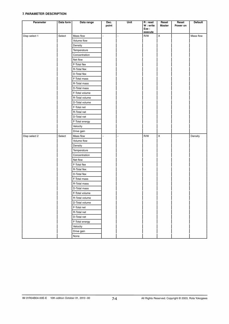
7. PARAMETER DESCRIPTION
7-4 All Rights Reserved. Copyright © 2003, Rota YokogawaIM 01R04B04-00E-E 10th edition October 01, 2013 -00
Parameter Data form Data range Dec. point
Unit R : readW : writeExe : execute
Reset Master
Reset Power on
Default
Disp select 1 Select Mass flow - - R/W X Mass flow
Volume flow
Density
Temperature
Concentration
Netflow
F-Total flex
R-Total flex
D-Total flex
F-Total mass
R-Total mass
D-Total mass
F-Total volume
R-Total volume
D-Total volume
F-Total net
R-Total net
D-Total net
F-Total energy
Velocity
Drive gain
Disp select 2 Select Mass flow - - R/W X Density
Volume flow
Density
Temperature
Concentration
Netflow
F-Total flex
R-Total flex
D-Total flex
F-Total mass
R-Total mass
D-Total mass
F-Total volume
R-Total volume
D-Total volume
F-Total net
R-Total net
D-Total net
F-Total energy
Velocity
Drive gain
None

7. PARAMETER DESCRIPTION
7-5All Rights Reserved. Copyright © 2003, Rota Yokogawa IM 01R04B04-00E-E 10th edition October 01, 2013 -00
Parameter Data form Data range Dec. point
Unit R : readW : writeExe : execute
Reset Master
Reset Power on
Default
Disp select 3 Select Mass flow - - R/W X Temperature
Volume flow
Density
Temperature
Concentration
Netflow
F-Total flex
R-Total flex
D-Total flex
F-Total mass
R-Total mass
D-Total mass
F-Total volume
R-Total volume
D-Total volume
F-Total net
R-Total net
D-Total net
F-Total energy
Velocity
Drive gain
None
Disp select 4 Select Mass flow - - R/W X F-Total mass
Volume flow
Density
Temperature
Concentration
Netflow
F-Total flex
R-Total flex
D-Total flex
F-Total mass
R-Total mass
D-Total mass
F-Total volume
R-Total volume
D-Total volume
F-Total net
R-Total net
D-Total net
F-Total energy
Velocity
Drive gain
None

7. PARAMETER DESCRIPTION
7-6 All Rights Reserved. Copyright © 2003, Rota YokogawaIM 01R04B04-00E-E 10th edition October 01, 2013 -00
Parameter Data form Data range Dec. point
Unit R : readW : writeExe : execute
Reset Master
Reset Power on
Default
Disp contrast Select -5 - - R/W X 0
-4
-3
-2
-1
0
1
2
3
4
5
Disp Period Select 0.5 s - - R/W X 1.0 s
1.0 s
2.0 s
Flow direction Select Forward - - R/W X Forward
Reverse
Mass flow unit Select g/s - - R/W X RCCS30LR…33: l/hg/min
g/hRCCS34…39/XR: m³/h
kg/s
kg/min
kg/h
kg/d
t/min
t/h
t/d
lb/s
lb/min
lb/h
lb/d
Mass flow format Select xxxxxxx - - R/W X xxxx.XX
xxxxx.X
xxxx.XX
xxx.XXX
xx.XXXX
x.XXXXX
Mass flow LRV Decimal -Qmax to Qmax 0 to 5 Mass flow unit R/W X 0
Mass flow URV Decimal -Qmax to Qmax 0 to 5 Mass flow unit R/W X Qnom
Mass flow damping Decimal 0 to 200 1 Sec. R/W X 3
Mass flow lowcut Decimal -Qmax to Qmax 0 to 5 Mass flow unit R/W X 0
Mass flow alm 1 sel Select Nofunction - - R/W X Nofunction
More than
Less than
Mass flow alm 1 crit Decimal -110% to 110% of URV 0 to 5 Mass flow unit R/W X 0
Mass flow alm 2 sel Select Nofunction - - R/W X Nofunction
More than
Less than
Mass flow alm 2 crit Decimal -110% to 110% of URV 0 to 5 Mass flow unit R/W X 10
Mass flow fix val sel Select Inhibit - - R/W X Inhibit
Enable
Mass flow fixed val Decimal 0 to Qnom 0 to 5 Mass flow unit R/W X 0

7. PARAMETER DESCRIPTION
7-7All Rights Reserved. Copyright © 2003, Rota Yokogawa IM 01R04B04-00E-E 10th edition October 01, 2013 -00
Parameter Data form Data range Dec. point
Unit R : readW : writeExe : execute
Reset Master
Reset Power on
Default
Vol flow unit Select cm³/s - - R/W X RCCS30LR…33: l/hcm³/min
cm³/hRCCS34…39/XR: m³/h
l/s
l/min
l/h
l/d
m³/s
m³/min
m³/h
m³/d
gal/s
gal/min
gal/h
gal/d
Cuft/s
Cuft/min
Cuft/h
Cuft/d
bbl/s
bbl/min
bbl/h
bbl/d
lmpgal/s
lmpgal/min
lmpgal/h
Impgal/d
l(N)/s
l(N)/min
l(N)/h
l(N)/d
m³(N)/s
m³(N)/min
m³(N)/h
m³(N)/d
Sl/s
Sl/min
Sl/h
Sl/d
Scuft/s
Scuft/min
Scuft/h
Scuft/d
Sm³/s
Sm³/min
Sm³/h
Sm³/d
Vol flow format Select xxxxxxx - - R/W X xxxx.XX
xxxxx.X
xxxx.XX
xxx.XXX
xx.XXXX
x.XXXXX

7. PARAMETER DESCRIPTION
7-8 All Rights Reserved. Copyright © 2003, Rota YokogawaIM 01R04B04-00E-E 10th edition October 01, 2013 -00
Parameter Data form Data range Dec. point
Unit R : readW : writeExe : execute
Reset Master
Reset Power on
Default
Vol flow LRV Decimal -Qvmax to Qvmax 0 to 5 Vol flow unit R/W X 0
Vol flow URV Decimal -Qvmax to Qvmax 0 to 5 Vol flow unit R/W X Qvnom
Vol flow damping Decimal 0 to 200 1 Sec. R/W X 3
Vol flow lowcut Decimal -Qvmax to Qvmax 0 to 5 Vol flow unit R/W X 0
Vol flow alm 1 sel Select Nofunction - - R/W X Nofunction
More than
Less than
Vol flow alm 1 crit Decimal -110% to 110% of URV 0 to 5 Vol flow unit R/W X 0
Vol flow alm 2 sel Select Nofunction - - R/W X Nofunction
More than
Less than
Vol flow alm 2 crit Decimal -110% to 110% of URV 0 to 5 Vol flow unit R/W X 10
Density unit Select g/ml - - R/W X kg/l
kg/l
kg/m³
lb/gal
lb/Cuft
g/cm³
g/l
°Bé hv
°Bé lt
°API
Density format Select xxxxxxx - - R/W X xx.XXXX
xxxxx.X
xxxx.XX
xxx.XXX
xx.XXXX
x.XXXXX
Density LRV Decimal 0 to 5 kg/l 0 to 5 Density unit R/W X 0.0
Density URV Decimal 0 to 5 kg/l 0 to 5 Density unit R/W X 1.5
Density damping Decimal 0 to 200 1 Sec. R/W X 15.0
Density lowcut Decimal 0 to 5 kg/l 0 to 5 Density unit R/W X 0.0
Density alm 1 sel Select Nofunction - - R/W X Nofunction
More than
Less than
Density alm1 crit Decimal 0 to 5 kg/l 0 to 5 Density unit R/W X LRV
Density alm 2 sel Select Nofunction - - R/W X Nofunction
More than
Less than
Density alm 2 crit Decimal 0 to 5 kg/l 0 to 5 Density unit R/W X URV
Ref. Density sel *) Select Inhibit - - R/W X Inhibit
Fixed
Calculated
Density fix val sel **) Select Inhibit - - R/W X Inhibit
Enable
Reference Density Decimal 0 to 5 kg/l 0 to 5 Density unit R/W X 1.0
Density offset Decimal -9999.99 to +9999.99 2 g/l R/W X 0
Pressure Decimal 0 to 400 2 bar R/W 0
Pressure unit Select bar - - R/W bar
psi
MPa

7. PARAMETER DESCRIPTION
7-9All Rights Reserved. Copyright © 2003, Rota Yokogawa IM 01R04B04-00E-E 10th edition October 01, 2013 -00
Parameter Data form Data range Dec. point
Unit R : readW : writeExe : execute
Reset Master
Reset Power on
Default
Temperature unit Select degC - - R/W X degC
degF
K
Temperature format Select xxxxxxx - - R/W X xxxxxx.X
xxxxx.X
xxxx.XX
xxx.XXX
xx.XXXX
x.XXXXX
Temperature LRV Decimal Standard: -200 to 230°C 0 to 5 Temperature unit R/W X -200
High Temp.: 0 to 400°C
Temperature URV Decimal Standard: -200 to 230°C 0 to 5 Temperature unit R/W X 230
High Temp.: 0 to 400°C
Temperature damping Decimal 0 to 200 1 Sec. R/W X 3
Temp alm 1 sel Select Nofunction - - R/W X Nofunction
More than
Less than
Temp alm 1 crit Decimal Standard: -200 to 200°C 0 to 5 Temperature unit R/W X LRV
Temp alm 2 sel Select Nofunction - - R/W X Nofunction
More than
Less than
Temp alm 2 crit Decimal Standard: -200 to 230°C 0 to 5 Temperature unit R/W X URV
High Temp.: 0 to 400°C
Temp fix val select Select Inhibit - - R/W X X Inhibit
Enable
Temp fixed val Decimal Standard: -200 to 230°C 1 Temperature unit R/W X X 30
High Temp.: 0 to 400°C
Temp gain Decimal 0.8 to 1.2 3 - R/W 1
Velocity unit Select m/s - - R/W X m/s
ft/s
Analog 1 select Select Mass flow - - R/W X Mass flow
Volume flow
Density
Temperature
Concentration meas
Netflow
None
Analog 1 alarm out Select <2.4mA - - R/W X <3.6mA
<3.6mA
4.0mA
>21mA
>21.6mA
Hold
Measured Value
Analog 1 low LMT Decimal 2.4 to 21.6 mA 2 mA R/W X 3.8
Analog 1 high LMT Decimal 2.4 to 21.6 mA 2 mA R/W X 20.5
Analog 2 select Select Mass flow - - R/W X Density
Volume flow
Density
Temperature
Concentration meas
Netflow
None
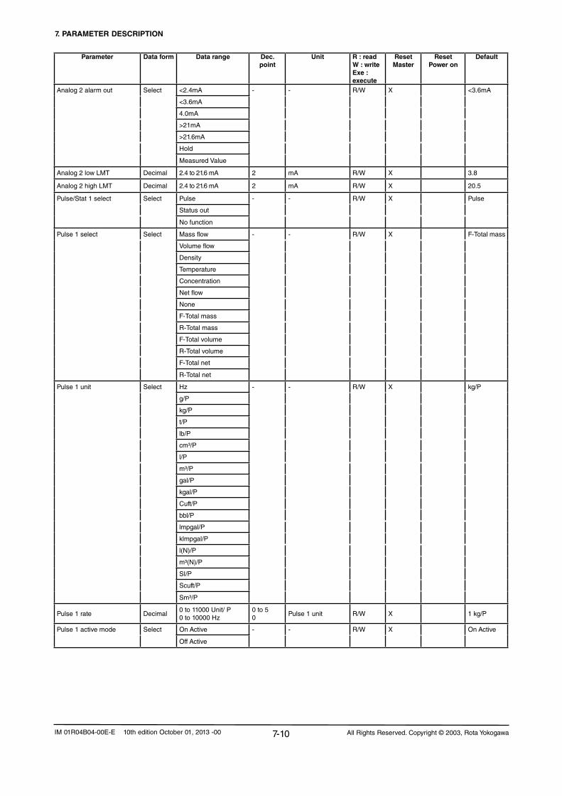
7. PARAMETER DESCRIPTION
7-10 All Rights Reserved. Copyright © 2003, Rota YokogawaIM 01R04B04-00E-E 10th edition October 01, 2013 -00
Parameter Data form Data range Dec. point
Unit R : readW : writeExe : execute
Reset Master
Reset Power on
Default
Analog 2 alarm out Select <2.4mA - - R/W X <3.6mA
<3.6mA
4.0mA
>21mA
>21.6mA
Hold
Measured Value
Analog 2 low LMT Decimal 2.4 to 21.6 mA 2 mA R/W X 3.8
Analog 2 high LMT Decimal 2.4 to 21.6 mA 2 mA R/W X 20.5
Pulse/Stat 1 select Select Pulse - - R/W X Pulse
Status out
Nofunction
Pulse 1 select Select Mass flow - - R/W X F-Total mass
Volume flow
Density
Temperature
Concentration
Netflow
None
F-Total mass
R-Total mass
F-Total volume
R-Total volume
F-Total net
R-Total net
Pulse 1 unit Select Hz - - R/W X kg/P
g/P
kg/P
t/P
lb/P
cm³/P
l/P
m³/P
gal/P
kgal/P
Cuft/P
bbl/P
lmpgal/P
klmpgal/P
l(N)/P
m³(N)/P
SI/P
Scuft/P
Sm³/P
Pulse 1 rate Decimal0 to 11000 Unit/ P0to10000Hz
0 to 50
Pulse 1 unit R/W X 1 kg/P
Pulse 1 active mode Select On Active - - R/W X On Active
Off Active

7. PARAMETER DESCRIPTION
7-11All Rights Reserved. Copyright © 2003, Rota Yokogawa IM 01R04B04-00E-E 10th edition October 01, 2013 -00
Parameter Data form Data range Dec. point
Unit R : readW : writeExe : execute
Reset Master
Reset Power on
Default
Pulse 1 width Select 0.05ms - - R/W X 1ms
0.1ms
0.5ms
1ms
5ms
10ms
50ms
100ms
500ms
1000ms
Pulse 1 at alarm Select 0P/0Hz - - R/W X 0P/Hz
Measured Value
Hold
SO 1 function Select Nofunction - - R/W X Nofunction
Flow-Direction
Total limit switch
Mass flow alm 1
Mass flow alm 2
Mass flow alm 1+2
Vol flow alm 1
Vol flow alm 2
Vol flow alm 1+2
Density alm 1
Density alm 2
Density alm 1+2
Temp alm 1
Temp alm 2
Temp alm 1+2
Concentr. meas alm 1
Concentr. meas alm 2
Concentr. meas alm 1+2
Netflowalm1
Netflowalm2
Netflowalm1+2
Slug alarm
Empty alarm
Corrosion alarm
All alarms
All errors
All alarms & errors
SO 1 active mode Select On Active - - R/W X On Active
Off Active
Pulse/Stat 2 select Select Pulse - - R/W X Status out
Status out
Nofunction

7. PARAMETER DESCRIPTION
7-12 All Rights Reserved. Copyright © 2003, Rota YokogawaIM 01R04B04-00E-E 10th edition October 01, 2013 -00
Parameter Data form Data range Dec. point
Unit R : readW : writeExe : execute
Reset Master
Reset Power on
Default
Pulse 2 select Select Mass flow - - R/W X Temperature
Volume flow
Density
Temperature
Concentration
Netflow
None
F-Total mass
R-Total mass
F-Total volume
R-Total volume
F-Total net
R-Total net
Pulse 2 unit Select Hz - - R/W X Hz
g/P
kg/P
t/P
lb/P
cm³/P
l/P
m³/P
gal/P
kgal/P
Cuft/P
bbl/P
lmpgal/P
klmpgal/P
l(N)/P
m³(N)/P
SI/P
Scuft/P
Sm³/P
Pulse 2 rate Decimal0 to 11000 Unit/P0to2000Hz
0 to 50
Pulse 2 unit R/W X 2000Hz
Pulse 2 active mode Select On Active - - R/W X On Active
Off Active
Pulse 2 width Select 0.05ms - - R/W 1ms
0.1ms
0.5ms
1ms
5ms
10ms
50ms
100ms
500ms
1000ms
Pulse 2 at alarm Select 0P/0Hz - - R/W X 0P/0Hz
Measured Value
Hold

7. PARAMETER DESCRIPTION
7-13All Rights Reserved. Copyright © 2003, Rota Yokogawa IM 01R04B04-00E-E 10th edition October 01, 2013 -00
Parameter Data form Data range Dec. point
Unit R : readW : writeExe : execute
Reset Master
Reset Power on
Default
SO 2 function Select Nofunction - - R/W X NoFunction
Flow-Direction
Total limit switch
Mass flow alm 1
Mass flow alm 2
Mass flow alm 1+2
Vol flow alm 1
Vol flow alm 2
Vol flow alm 1+2
Density alm 1
Density alm 2
Density alm 1+2
Temp alm 1
Temp alm 2
Temp alm 1+2
Concentr. meas alm 1
Concentr. meas alm 2
Concentr. meas alm 1+2
Netflowalm1
Netflowalm2
Netflowalm1+2
Slug alarm
Empty alarm
Corrosion alarm
All alarms
All errors
All alarms & errors
SO 2 active mode Select On active - - R/W X On active
Off active
PV is Select Mass flow - - R/W X Mass flow
Volume flow
Density
Temperature
Concentration meas
Netflow
None

7. PARAMETER DESCRIPTION
7-14 All Rights Reserved. Copyright © 2003, Rota YokogawaIM 01R04B04-00E-E 10th edition October 01, 2013 -00
Parameter Data form Data range Dec. point
Unit R : readW : writeExe : execute
Reset Master
Reset Power on
Default
SV is Select Mass flow - - R/W X Density
Volume flow
Density
Temperature
Concentration meas
Netflow
None
F-Total flex
R-Total flex
D-Total flex
F-Total mass
R-Total mass
D-Total mass
F-Total volume
R-Total volume
D-Total volume
F-Total net
R-Total net
D-Total net
F-Total energy
Velocity
Drive gain
TV is Select Mass flow - - R/W X F-Total mass
Volume flow
Density
Temperature
Concentration meas
Netflow
None
F-Total flex
R-Total flex
D-Total flex
F-Total mass
R-Total mass
D-Total mass
F-Total volume
R-Total volume
D-Total volume
F-Total net
R-Total net
D-Total net
F-Total energy
Velocity
Drive gain
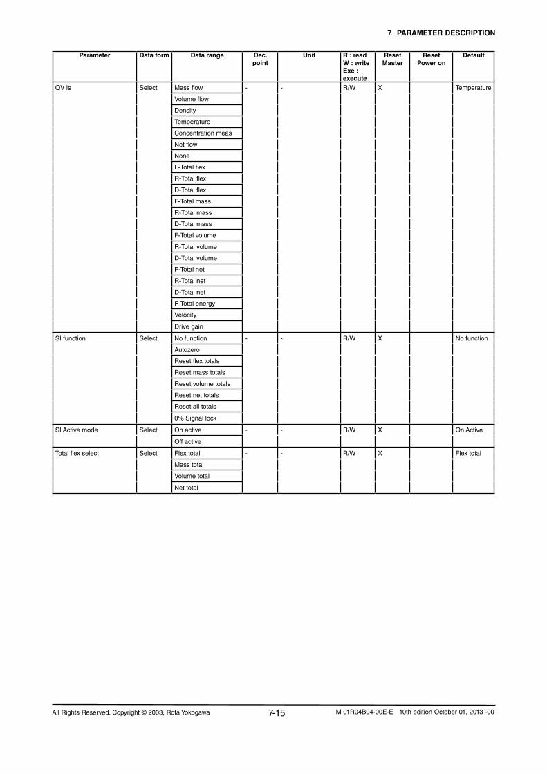
7. PARAMETER DESCRIPTION
7-15All Rights Reserved. Copyright © 2003, Rota Yokogawa IM 01R04B04-00E-E 10th edition October 01, 2013 -00
Parameter Data form Data range Dec. point
Unit R : readW : writeExe : execute
Reset Master
Reset Power on
Default
QV is Select Mass flow - - R/W X Temperature
Volume flow
Density
Temperature
Concentration meas
Netflow
None
F-Total flex
R-Total flex
D-Total flex
F-Total mass
R-Total mass
D-Total mass
F-Total volume
R-Total volume
D-Total volume
F-Total net
R-Total net
D-Total net
F-Total energy
Velocity
Drive gain
SI function Select Nofunction - - R/W X Nofunction
Autozero
Reset flex totals
Reset mass totals
Reset volume totals
Reset net totals
Reset all totals
0% Signal lock
SI Active mode Select On active - - R/W X On Active
Off active
Total flex select Select Flex total - - R/W X Flex total
Mass total
Volume total
Nettotal

7. PARAMETER DESCRIPTION
7-16 All Rights Reserved. Copyright © 2003, Rota YokogawaIM 01R04B04-00E-E 10th edition October 01, 2013 -00
Parameter Data form Data range Dec. point
Unit R : readW : writeExe : execute
Reset Master
Reset Power on
Default
Total flex unit Select g - - R/W X kg
kg
t
lb
cm³
l
m³
gal
kgal
Cuft
bbl
Impgal
klmpgal
I(N)
m³(N)
SI
Scuft
MMscuft
Sm³
Total mass unit Select g - - R/W X kg
kg
t
lb
Total volume unit Select cm³ - - R/W X l
l
m³
gal
kgal
Cuft
bbl
Impgal
klmpgal
I(N)
m³(N)
SI
Scuft
MMscuft
Sm³
Total net unit Select g - - R/W X kg
kg
t
lb
cm³
l
m³
gal
kgal
Cuft
bbl
Impgal
klmpgal
Total switch select Select Mass - - R/W X Mass
Volume
Net

7. PARAMETER DESCRIPTION
7-17All Rights Reserved. Copyright © 2003, Rota Yokogawa IM 01R04B04-00E-E 10th edition October 01, 2013 -00
Parameter Data form Data range Dec. point
Unit R : readW : writeExe : execute
Reset Master
Reset Power on
Default
Total limit switch Decimal 0 to 9999999 0 to 5 Total unit R/W X 0
Total unit energy Select MJ - - R/W X MJ
Btu
Energy factor/ heat of combustion
Decimal 0 to 100000 0 to 5heat of combust unit
R/W 10
Energy factor/ heat of combust unit
Select MJ/kg - - R/W X MJ/kg
Btu/lb
MJ/m³(N)
Btu/Scuft
Total at alarm Select Hold - - R/W X Hold
Continue Total
Total reset cntrl Select Inhibit - - R/W X Inhibit
Enable
Total reset Select NotExecute - - R/W X X NotExecute
Reset flex totals
Reset mass totals
Reset volume totals
Reset net totals
Reset all totals
SK20 Decimal 0 to 5 MHz×kg/h R/W 124
SKT Decimal 0 to 5 E-4×1/K R/W -7,34
SKTK Decimal 0 to 5 E-7×1/K2 R/W 19,6
RV Decimal 0 to 5 %/(kg/l) R/W 0,24
Qnom Decimal auto Mass flow unit R 10
KD Decimal 0 to 5 kg/l R/W 4,4
fl20 Decimal 0 to 5 Hz R/W 177,1
FTC1 Decimal 0 to 5 E-4×1/K R/W -2,179
FTCK Decimal 0 to 5 E-7×1/K2 R/W -0,539
SKP Decimal 0 to 5 E-4×1/bar R/W -0,346
SKPT Decimal 0 to 5 E-7×1/(bar×K) R/W 0
FPC Decimal 0 to 5 E-4×1/bar R/W 0,173
FPTC Decimal 0 to 5 E-7×1/(bar×K) R/W 0,02
FQC1 Decimal 0 to 5 E-10×s/g R/W 0
FQC2 Decimal 0 to 5 E-13×(s/g)2 R/W -40,8
Poll Adress Decimal 0 to 15 0 - R/W 0
Numreqpream Decimal 0 - R 5
Numresppream Decimal 5 to 20 0 - R/W 5
Reference temperature Decimal 1 Temperature unit R/W X 25
Ref. density carrier Decimal 0 to 5 Density unit R/W X 0,997
Temp. coeff. a carrier Decimal 0 to 5 E-3×(1/Tempunit) R/W X -0,261
Temp. coeff. b carrier Decimal 0 to 5 E-5×(1/Tempunit2) R/W X -0,36
Ref. density product Decimal 0 to 5 Density unit R/W X 0
Temp. coeff. a product Decimal 0 to 5 E-3×(1/Tempunit) R/W X 0
Temp. coeff. b product Decimal 0 to 5 E-5×(1/Tempunit2) R/W X 0
Temp. coeff. a *) Decimal 0 to 5 E-3×(1/Tempunit) R/W X 0
Temp. coeff. b *) Decimal 0 to 5 E-5×(1/Tempunit2) R/W X 0
Concentration meas unit Select °Brix - - R/W X Wt-%
Wt -% sol X
Vol % sol X
Wt -% X
Vol % X

7. PARAMETER DESCRIPTION
7-18 All Rights Reserved. Copyright © 2003, Rota YokogawaIM 01R04B04-00E-E 10th edition October 01, 2013 -00
Parameter Data form Data range Dec. point
Unit R : readW : writeExe : execute
Reset Master
Reset Power on
Default
Concentration meas format Select xxxxxxx - - R/W X xxxx.XX
xxxxx.X X
xxxx.XX X
xxx.XXX X
xx.XXXX X
x.XXXXX X
Concentration meas LRV Decimal 0 to 110 0 to 5Concentration meas unit
R/W X 0
Concentration meas URV Decimal 0 to 110 0 to 5Concentration meas unit
R/W X 100
Concentration meas Damp Decimal 0 to 200 1 Sec R/W X 10
Concentration meas lowcut Decimal 0 to 10% 0 to 5Concentration meas unit
R/W 0
Conc meas alm 1 sel Select Nofunction - - R/W X Nofunction
More than
Less than
Conc meas alm 1 crit Decimal 0 to 110% of URV 0 to 5Concentration meas unit
R/W X LRV
Conc meas alm 2 sel Select Nofunction - - R/W X Nofunction
More than
Less than
Conc meas alm 2 crit Decimal 0 to 110% of URV 0 to 5Concentration meas unit
R/W X URV
Netflowselect Select Mass - - R/W X Mass
Volume

7. PARAMETER DESCRIPTION
7-19All Rights Reserved. Copyright © 2003, Rota Yokogawa IM 01R04B04-00E-E 10th edition October 01, 2013 -00
Parameter Data form Data range Dec. point
Unit R : readW : writeExe : execute
Reset Master
Reset Power on
Default
Netflowunit Select g/s - - R/W X RCCS30LR-33:
g/min kg/h
g/hRCCS34-39/XR: t/h
kg/s
kg/min
kg/h
t/min
t/h
lb/s
lb/min
lb/h
cm³/s
cm³/min
cm³/h
l/s
l/min
l/h
l/d
m³/s
m³/min
m³/h
m³/d
gal/s
gal/min
gal/h
gal/d
Cuft/s
Cuft/min
Cuft/h
Cuft/d
bbl/s
bbl/min
bbl/h
bbl/d
lmpgal/s
lmpgal/min
lmpgal/h
Impgal/d
Netflowformat Select xxxxxxx - - R/W X xxxx.XX
xxxxx.X
xxxx.XX
xxx.XXX
xx.XXXX
x.XXXXX
NetflowLRV Decimal -Qmax to Qmax 0 to 5 Netflowunit R/W X 0
NetflowURV Decimal -Qmax to Qmax 0 to 5 Netflowunit R/W X Qnom
Netflowdamping Decimal 0 to 200 1 Sec R/W X 3
Netflowlowcut Decimal -Qmax to Qmax 0 to 5 Netflowunit R/W X 0.0
Netflowalm1sel Select Nofunction - - R/W X Nofunction
More than
Less than
Netflowalm1crit Decimal -110% to 110% of URV 0 to 5 Netflowunit R/W X LRV
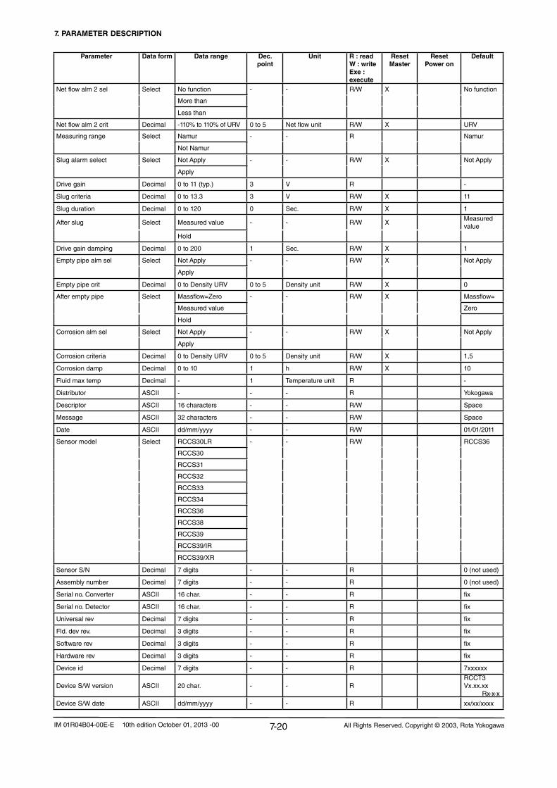
7. PARAMETER DESCRIPTION
7-20 All Rights Reserved. Copyright © 2003, Rota YokogawaIM 01R04B04-00E-E 10th edition October 01, 2013 -00
Parameter Data form Data range Dec. point
Unit R : readW : writeExe : execute
Reset Master
Reset Power on
Default
Netflowalm2sel Select Nofunction - - R/W X Nofunction
More than
Less than
Netflowalm2crit Decimal -110% to 110% of URV 0 to 5 Netflowunit R/W X URV
Measuring range Select Namur - - R Namur
NotNamur
Slug alarm select Select NotApply - - R/W X NotApply
Apply
Drive gain Decimal 0 to 11 (typ.) 3 V R -
Slug criteria Decimal 0 to 13.3 3 V R/W X 11
Slug duration Decimal 0 to 120 0 Sec. R/W X 1
After slug Select Measured value - - R/W XMeasured value
Hold
Drive gain damping Decimal 0 to 200 1 Sec. R/W X 1
Empty pipe alm sel Select NotApply - - R/W X NotApply
Apply
Empty pipe crit Decimal 0 to Density URV 0 to 5 Density unit R/W X 0
After empty pipe Select Massflow=Zero - - R/W X Massflow=
Measured value Zero
Hold
Corrosion alm sel Select NotApply - - R/W X NotApply
Apply
Corrosion criteria Decimal 0 to Density URV 0 to 5 Density unit R/W X 1,5
Corrosion damp Decimal 0 to 10 1 h R/W X 10
Fluid max temp Decimal - 1 Temperature unit R -
Distributor ASCII - - - R Yokogawa
Descriptor ASCII 16 characters - - R/W Space
Message ASCII 32 characters - - R/W Space
Date ASCII dd/mm/yyyy - - R/W 01/01/2011
Sensor model Select RCCS30LR - - R/W RCCS36
RCCS30
RCCS31
RCCS32
RCCS33
RCCS34
RCCS36
RCCS38
RCCS39
RCCS39/IR
RCCS39/XR
SensorS/N Decimal 7 digits - - R 0 (not used)
Assembly number Decimal 7 digits - - R 0 (not used)
Serial no. Converter ASCII 16 char. - - R fix
Serial no. Detector ASCII 16 char. - - R fix
Universal rev Decimal 7 digits - - R fix
Fld. dev rev. Decimal 3 digits - - R fix
Software rev Decimal 3 digits - - R fix
Hardware rev Decimal 3 digits - - R fix
Device id Decimal 7 digits - - R 7xxxxxx
Device S/W version ASCII 20 char. - - RRCCT3 Vx.xx.xx Rx-x-x
Device S/W date ASCII dd/mm/yyyy - - R xx/xx/xxxx
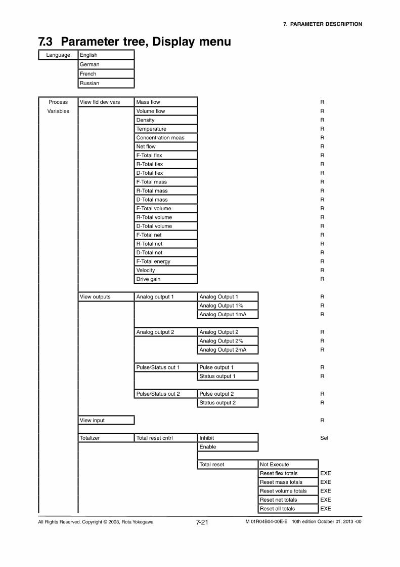
7. PARAMETER DESCRIPTION
7-21All Rights Reserved. Copyright © 2003, Rota Yokogawa IM 01R04B04-00E-E 10th edition October 01, 2013 -00
7.3 Parameter tree, Display menuLanguage English
German
French
Russian
Process View fld dev vars Mass flow R
Variables Volume flow R
Density R
Temperature R
Concentration meas R
Netflow R
F-Total flex R
R-Total flex R
D-Total flex R
F-Total mass R
R-Total mass R
D-Total mass R
F-Total volume R
R-Total volume R
D-Total volume R
F-Total net R
R-Total net R
D-Total net R
F-Total energy R
Velocity R
Drive gain R
View outputs Analog output 1 Analog Output 1 R
Analog Output 1% R
Analog Output 1mA R
Analog output 2 Analog Output 2 R
Analog Output 2% R
Analog Output 2mA R
Pulse/Status out 1 Pulse output 1 R
Status output 1 R
Pulse/Status out 2 Pulse output 2 R
Status output 2 R
View input R
Totalizer Total reset cntrl Inhibit Sel
Enable
Total reset NotExecute
Reset flex totals EXE
Reset mass totals EXE
Reset volume totals EXE
Reset net totals EXE
Reset all totals EXE
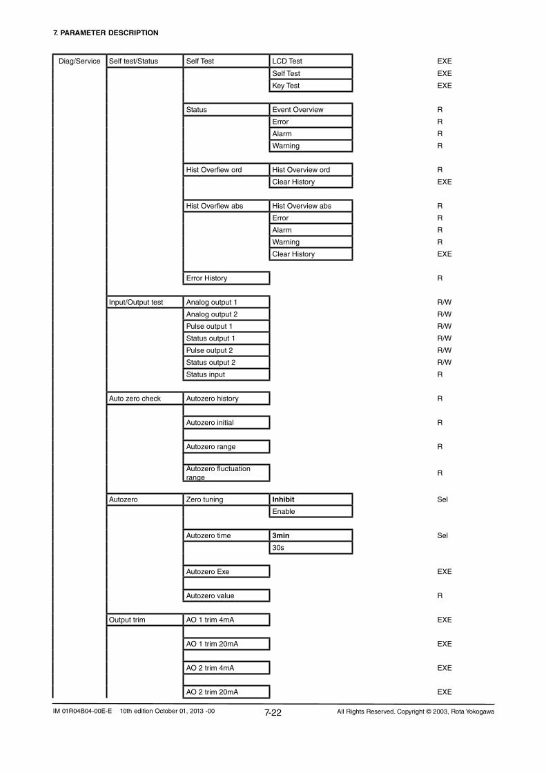
7. PARAMETER DESCRIPTION
7-22 All Rights Reserved. Copyright © 2003, Rota YokogawaIM 01R04B04-00E-E 10th edition October 01, 2013 -00
Diag/Service Self test/Status Self Test LCD Test EXE
Self Test EXE
Key Test EXE
Status Event Overview R
Error R
Alarm R
Warning R
Hist Overfiew ord Hist Overview ord R
Clear History EXE
Hist Overfiew abs Hist Overview abs R
Error R
Alarm R
Warning R
Clear History EXE
Error History R
Input/Output test Analog output 1 R/W
Analog output 2 R/W
Pulse output 1 R/W
Status output 1 R/W
Pulse output 2 R/W
Status output 2 R/W
Status input R
Autozerocheck Autozerohistory R
Autozeroinitial R
Autozerorange R
Autozerofluctuationrange
R
Autozero Zero tuning Inhibit Sel
Enable
Autozerotime 3min Sel
30s
AutozeroExe EXE
Autozerovalue R
Output trim AO 1 trim 4mA EXE
AO 1 trim 20mA EXE
AO 2 trim 4mA EXE
AO 2 trim 20mA EXE

7. PARAMETER DESCRIPTION
7-23All Rights Reserved. Copyright © 2003, Rota Yokogawa IM 01R04B04-00E-E 10th edition October 01, 2013 -00
Basic Setup Tag R/W
Long Tag R/W
Display config Disp select 1 Mass flow Sel
Volume flow
Density
Temperature
Concentration meas
Netflow
F-Total flex
R-Total flex
D-Total flex
F-Total mass
R-Total mass
D-Total mass
F-Total volume
R-Total volume
D-Total volume
F-Total net
R-Total net
D-Total net
F-Total energy
Velocity
Drive gain
Disp select 2 Mass flow Sel
Volume flow
Density
Temperature
Concentration meas
Netflow
F-Total flex
R-Total flex
D-Total flex
F-Total mass
R-Total mass
D-Total mass
F-Total volume
R-Total volume
D-Total volume
F-Total net
R-Total net
D-Total net
F-Total energy
Velocity
Drive gain
None

7. PARAMETER DESCRIPTION
7-24 All Rights Reserved. Copyright © 2003, Rota YokogawaIM 01R04B04-00E-E 10th edition October 01, 2013 -00
Basic Setup Disp select 3 Mass flow Sel
Volume flow
Density
Temperature
Concentration meas
Netflow
F-Total flex
R-Total flex
D-Total flex
F-Total mass
R-Total mass
D-Total mass
F-Total volume
R-Total volume
D-Total volume
F-Total net
R-Total net
D-Total net
F-Total energy
Velocity
Drive gain
None
Disp select 4 Mass flow Sel
Volume flow
Density
Temperature
Concentration meas
Netflow
F-Total flex
R-Total flex
D-Total flex
F-Total mass
R-Total mass
D-Total mass
F-Total volume
R-Total volume
D-Total volume
F-Total net
R-Total net
D-Total net
F-Total energy
Velocity
Drive gain
None

7. PARAMETER DESCRIPTION
7-25All Rights Reserved. Copyright © 2003, Rota Yokogawa IM 01R04B04-00E-E 10th edition October 01, 2013 -00
Basic Setup Display contrast -5 Sel
-4
-3
-2
-1
0
+1
+2
+3
+4
+5
Mass flow Mass flow unit g/s Sel
g/min
g/h
kg/s
kg/min
kg/h
kg/d
t/min
t/h
t/d
lb/s
lb/min
lb/h
lb/d
Mass flow LRV R/W
Mass flow URV R/W
Mass flow damping R/W
Density Density unit g/ml Sel
kg/l
kg/m³
lb/gal
lb/Cuft
g/cm³
g/l
°Bé hv
°Bé lt
°API
Density LRV R/W
Density URV R/W
Density damping R/W
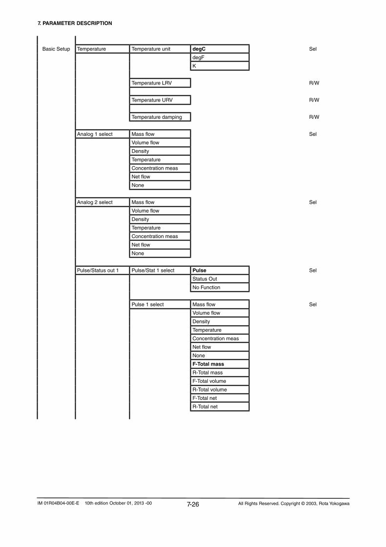
7. PARAMETER DESCRIPTION
7-26 All Rights Reserved. Copyright © 2003, Rota YokogawaIM 01R04B04-00E-E 10th edition October 01, 2013 -00
Basic Setup Temperature Temperature unit degC Sel
degF
K
Temperature LRV R/W
Temperature URV R/W
Temperature damping R/W
Analog 1 select Mass flow Sel
Volume flow
Density
Temperature
Concentration meas
Netflow
None
Analog 2 select Mass flow Sel
Volume flow
Density
Temperature
Concentration meas
Netflow
None
Pulse/Status out 1 Pulse/Stat 1 select Pulse Sel
Status Out
NoFunction
Pulse 1 select Mass flow Sel
Volume flow
Density
Temperature
Concentration meas
Netflow
None
F-Total mass
R-Total mass
F-Total volume
R-Total volume
F-Total net
R-Total net

7. PARAMETER DESCRIPTION
7-27All Rights Reserved. Copyright © 2003, Rota Yokogawa IM 01R04B04-00E-E 10th edition October 01, 2013 -00
Basic Setup Pulse 1 unit Hz Sel
g/P
kg/P
t/P
lb/P
cm³/P
l/P
m³/P
gal/P
kgal/P
Cuft/P
bbl/P
Impgal/P
klmpgal/P
I(N)/P
m³(N)/P
SI/P
Scuft/P
Sm³/P
Pulse 1 rate R/W
SO 1 function No Function Sel
Flow direction
Total limit switch
Mass flow alm 1
Mass flow alm 2
Mass flow alm 1+2
Vol flow alm 1
Vol flow alm 2
Vol flow alm 1+2
Density alm 1
Density alm 2
Density alm 1+2
Temp alm 1
Temp alm 2
Temp alm 1+2
Concentr. meas alm 1
Concentr. meas alm 2Concentr. meas alm 1+2Netflowalm1
Netflowalm2
Netflowalm1+2
Slug Alarm
Empty alarm
Corrosion Alarm
All alarms
All errors
All alarms & errors

7. PARAMETER DESCRIPTION
7-28 All Rights Reserved. Copyright © 2003, Rota YokogawaIM 01R04B04-00E-E 10th edition October 01, 2013 -00
Basic Setup Pulse/Status out 2 Pulse/Stat 2 select Pulse Sel
Status Out
NoFunction
Pulse 2 select Mass flow Sel
Volume flow
Density
Temperature
Concentration meas
Netflow
None
F-Total mass
R-Total mass
F-Total volume
R-Total volume
F-Total net
R-Total net
Pulse 2 unit Hz Sel
g/P
kg/P
t/P
lb/P
cm³/P
l/P
m³/P
gal/P
kgal/P
Cuft/P
bbl/P
Impgal/P
klmpgal/P
I(N)/P
m³(N)/P
SI/P
Scuft/P
Sm³/P
Pulse 2 rate R/W

7. PARAMETER DESCRIPTION
7-29All Rights Reserved. Copyright © 2003, Rota Yokogawa IM 01R04B04-00E-E 10th edition October 01, 2013 -00
Basic Setup SO 2 function No Function Sel
Flow direction
Total limit switch
Mass flow alm 1
Mass flow alm 2
Mass flow alm 1+2
Vol flow alm 1
Vol flow alm 2
Vol flow alm 1+2
Density alm 1
Density alm 2
Density alm 1+2
Temp alm 1
Temp alm 2
Temp alm 1+2
Concentr. meas alm 1
Concentr. meas alm 2Concentr. meas alm 1+2Netflowalm1
Netflowalm2
Netflowalm1+2
Slug Alarm
Empty alarm
Corrosion Alarm
All alarms
All errors
All alarms & errors
SI function No function Sel
Autozero
Reset flex totals
Reset mass totals
Reset volume totals
Reset net totals
Reset all totals
0% signal lock
Totalizer Total flex select Mass Sel
Volume
Net

7. PARAMETER DESCRIPTION
7-30 All Rights Reserved. Copyright © 2003, Rota YokogawaIM 01R04B04-00E-E 10th edition October 01, 2013 -00
Basic Setup Total flex unit g Sel
kg
t
lb
cm³
l
m³
gal
kgal
Cuft
bbl
Impgal
Klmpgal
I(N)
m³(N)
SI
Scuft
MMscuft
Sm³
Total mass unit g Sel
kg
t
lb
Total volume unit cm³ Sel
l
m³
gal
kgal
Cuft
bbl
Impgal
Klmpgal
I(N)
m³(N)
SI
Scuft
MMscuft
Sm³

7. PARAMETER DESCRIPTION
7-31All Rights Reserved. Copyright © 2003, Rota Yokogawa IM 01R04B04-00E-E 10th edition October 01, 2013 -00
Basic Setup Total net unit g
kg
t
lb
cm³
l
m³
gal
kgal
Cuft
bbl
Impgal
Klmpgal
Total switch select Flex total Sel
Mass total
Volume total
Nettotal
Detailed Setup Display config Disp select 1 Mass flow Sel
Volume flow
Density
Temperature
Concentration meas
Netflow
F-Total flex
R-Total flex
D-Total flex
F-Total mass
R-Total mass
D-Total mass
F-Total volume
R-Total volume
D-Total volume
F-Total net
R-Total net
D-Total net
F-Total energy
Velocity
Drive gain

7. PARAMETER DESCRIPTION
7-32 All Rights Reserved. Copyright © 2003, Rota YokogawaIM 01R04B04-00E-E 10th edition October 01, 2013 -00
Detailed Setup Disp select 2 Mass flow Sel
Volume flow
Density
Temperature
Concentration meas
Netflow
F-Total flex
R-Total flex
D-Total flex
F-Total mass
R-Total mass
D-Total mass
F-Total volume
R-Total volume
D-Total volume
F-Total net
R-Total net
D-Total net
F-Total energy
Velocity
Drive gain
None
Disp select 3 Mass flow Sel
Volume flow
Density
Temperature
Concentration meas
Netflow
F-Total flex
R-Total flex
D-Total flex
F-Total mass
R-Total mass
D-Total mass
F-Total volume
R-Total volume
D-Total volume
F-Total net
R-Total net
D-Total net
F-Total energy
Velocity
Drive gain
None

7. PARAMETER DESCRIPTION
7-33All Rights Reserved. Copyright © 2003, Rota Yokogawa IM 01R04B04-00E-E 10th edition October 01, 2013 -00
Detailed Setup Disp select 4 Mass flow Sel
Volume flow
Density
Temperature
Concentration meas
Netflow
F-Total flex
R-Total flex
D-Total flex
F-Total mass
R-Total mass
D-Total mass
F-Total volume
R-Total volume
D-Total volume
F-Total net
R-Total net
D-Total net
F-Total energy
Velocity
Drive gain
None
Display contrast -5 Sel
-4
-3
-2
-1
0
+1
+2
+3
+4
+5
Disp period 0.5s Sel
1.0s
2.0s
Language English Sel
German
French
Russian

7. PARAMETER DESCRIPTION
7-34 All Rights Reserved. Copyright © 2003, Rota YokogawaIM 01R04B04-00E-E 10th edition October 01, 2013 -00
Detailed Setup Sensor model RCCS30LR Sel
RCCS30
RCCS31
RCCS32
RCCS33
RCCS34
RCCS36
RCCS38
RCCS39
RCCS39/IR
RCCS39/XR
Sensor constants Mass flow SK20 R/W
SKT R/W
SKTK R/W
RV R/W
Qnom R
SKP R/W
SKPT R/W
Density KD R/W
fl20 R/W
FTC1 R/W
FTCK R/W
FPC R/W
FPTC R/W
FQC1 R/W
FQC2 R/W
Config fld variables Flow direction Forward Sel
Reverse
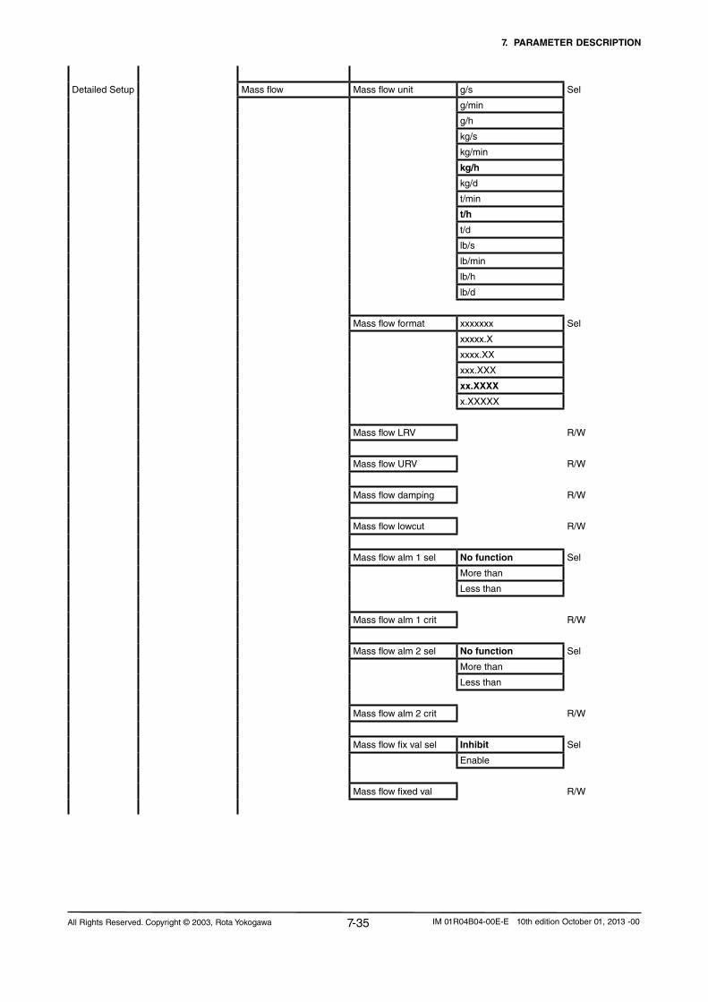
7. PARAMETER DESCRIPTION
7-35All Rights Reserved. Copyright © 2003, Rota Yokogawa IM 01R04B04-00E-E 10th edition October 01, 2013 -00
Detailed Setup Mass flow Mass flow unit g/s Sel
g/min
g/h
kg/s
kg/min
kg/h
kg/d
t/min
t/h
t/d
lb/s
lb/min
lb/h
lb/d
Mass flow format xxxxxxx Sel
xxxxx.X
xxxx.XX
xxx.XXX
xx.XXXX
x.XXXXX
Mass flow LRV R/W
Mass flow URV R/W
Mass flow damping R/W
Mass flow lowcut R/W
Mass flow alm 1 sel No function Sel
More than
Less than
Mass flow alm 1 crit R/W
Mass flow alm 2 sel No function Sel
More than
Less than
Mass flow alm 2 crit R/W
Mass flow fix val sel Inhibit Sel
Enable
Mass flow fixed val R/W

7. PARAMETER DESCRIPTION
7-36 All Rights Reserved. Copyright © 2003, Rota YokogawaIM 01R04B04-00E-E 10th edition October 01, 2013 -00
Detailed Setup Volume flow Vol flow unit cm³/s Sel
cm³/min
cm³/h
l/s
l/min
l/h
l/d
m³/s
m³/min
m³/h
m³/d
gal/s
gal/min
gal/h
gal/d
Cuft/s
Cuft/min
Cuft/h
Cuft/d
bbl/s
bbl/min
bbl/h
bbl/d
Impgal/s
Impgal/min
Impgal/h
Impgal/d
I(N)/s
I(N)/min
I(N)/h
l(N)/d
m³(N)/s
m³(N)/min
m³(N)/h
m³(N)/d
SI/s
SI/min
SI/h
Sl/d
Scuft/s
Scuft/min
Scuft/h
Scuft/d
Sm³/s
Sm³/min
Sm³/h
Sm³/d

7. PARAMETER DESCRIPTION
7-37All Rights Reserved. Copyright © 2003, Rota Yokogawa IM 01R04B04-00E-E 10th edition October 01, 2013 -00
Detailed Setup Vol flow format xxxxxxx Sel
xxxxx.X
xxxx.XX
xxx.XXX
xx.XXXX
x.XXXXX
Vol flow LRV R/W
Vol flow URV R/W
Vol flow damping R/W
Vol flow lowcut R/W
Vol flow alm 1 sel No function Sel
More than
Less than
Vol flow alm 1 crit R/W
Vol flow alm 2 sel No function Sel
More than
Less than
Vol flow alm 2 crit R/W
Density Density unit g/ml Sel
kg/l
kg/m³
lb/gal
lb/Cuft
g/cm³
g/l
°Bé hv
°Bé lt
°API
Density format xxxxxxx Sel
xxxxx.X
xxxx.XX
xxx.XXX
xx.XXXX
x.XXXXX
Density LRV R/W
Density URV R/W
Density damping R/W
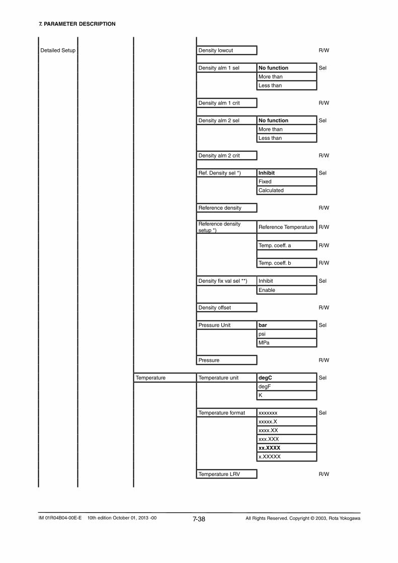
7. PARAMETER DESCRIPTION
7-38 All Rights Reserved. Copyright © 2003, Rota YokogawaIM 01R04B04-00E-E 10th edition October 01, 2013 -00
Detailed Setup Density lowcut R/W
Density alm 1 sel No function Sel
More than
Less than
Density alm 1 crit R/W
Density alm 2 sel No function Sel
More than
Less than
Density alm 2 crit R/W
Ref. Density sel *) Inhibit Sel
Fixed
Calculated
Reference density R/W
Reference density setup *)
Reference Temperature R/W
Temp. coeff. a R/W
Temp. coeff. b R/W
Density fix val sel **) Inhibit Sel
Enable
Density offset R/W
Pressure Unit bar Sel
psi
MPa
Pressure R/W
Temperature Temperature unit degC Sel
degF
K
Temperature format xxxxxxx Sel
xxxxx.X
xxxx.XX
xxx.XXX
xx.XXXX
x.XXXXX
Temperature LRV R/W

7. PARAMETER DESCRIPTION
7-39All Rights Reserved. Copyright © 2003, Rota Yokogawa IM 01R04B04-00E-E 10th edition October 01, 2013 -00
Detailed Setup Temperature URV R/W
Temperature damping R/W
Temp alm 1 sel No function Sel
More than
Less than
Temp alm 1 crit R/W
Temp alm 2 sel No function Sel
More than
Less than
Temp alm 2 crit R/W
Temp fix val select Inhibit Sel
Enable
Temp fixed value R/W
Temp gain R/W
Velocity unit m/s Sel
ft/s
Config Output/Input Analog output 1 Analog 1 select Mass flow Sel
Volume flow
Density
Temperature
Concentration meas
Netflow
None
Analog 1 alarm Out <2.4 mA Sel
<3.6 mA
<4.0 mA
>21.0mA
>21.6mA
Hold
Measured value
Analog 1 low LMT R/W
Analog 1 high LMT R/W

7. PARAMETER DESCRIPTION
7-40 All Rights Reserved. Copyright © 2003, Rota YokogawaIM 01R04B04-00E-E 10th edition October 01, 2013 -00
Detailed Setup Analog output 2 Analog 2 select Mass flow Sel
Volume flow
Density
Temperature
Concentration meas
Netflow
None
Analog 2 alarm Out <2.4 mA Sel
<3.6 mA
<4.0 mA
>21.0mA
>21.6mA
Hold
Measured value
Analog 2 low LMT R/W
Analog 2 high LMT R/W
Pulse/Status out 1 Pulse/Stat 1 select Pulse Sel
Status out
Nofunction
Pulse 1 select Mass flow Sel
Volume flow
Density
Temperature
Concentration meas
Netflow
None
F-Total mass
R-Total mass
F-Total volume
R-Total volume
F-Total net
R-Total net

7. PARAMETER DESCRIPTION
7-41All Rights Reserved. Copyright © 2003, Rota Yokogawa IM 01R04B04-00E-E 10th edition October 01, 2013 -00
Detailed Setup Pulse 1 unit Hz Sel
g/P
kg/P
t/P
lb/P
cm³/P
l/P
m³/P
gal/P
kgal/P
Cuft/P
bbl/P
lmpgal/P
klmpgal/P
I(N)/P
m³(N)/P
SI/P
Scuft/P
Sm³/P
Pulse 1 rate R/W
Pulse 1 active mode On Active Sel
Off Active
Pulse 1 width 0.05ms Sel
0.1ms
0.5ms
1ms
5ms
10ms
50ms
100ms
50ms
1000ms
Pulse 1 at alarm 0P/0Hz Sel
Measured value
Hold

7. PARAMETER DESCRIPTION
7-42 All Rights Reserved. Copyright © 2003, Rota YokogawaIM 01R04B04-00E-E 10th edition October 01, 2013 -00
Detailed Setup SO 1 function No Function Sel
Flow direction
Mass flow alm 1
Mass flow alm 2
Mass flow alm 1+2
Vol flow alm 1
Vol flow alm 2
Vol flow alm 1+2
Density alm 1
Density alm 2
Density alm 1+2
Temp alm 1
Temp alm 2
Temp alm 1+2
Concentr. meas alm 1
Concentr. meas alm 2Concentr. meas alm 1+2Netflowalm1
Netflowalm2
Netflowalm1+2
Slug Alarm
Empty alarm
Corrosion Alarm
All alarms
All errors
All alarms & errors
SO1 active mode On Active Sel
Off Active
Pulse/Status out 2 Pulse/Stat 2 select Pulse Sel
Status out
Nofunction
Pulse 2 select Mass flow Sel
Volume flow
Density
Temperature
Concentration meas
Netflow
None
F-Total mass
R-Total mass
F-Total volume
R-Total volume
F-Total net
R-Total net
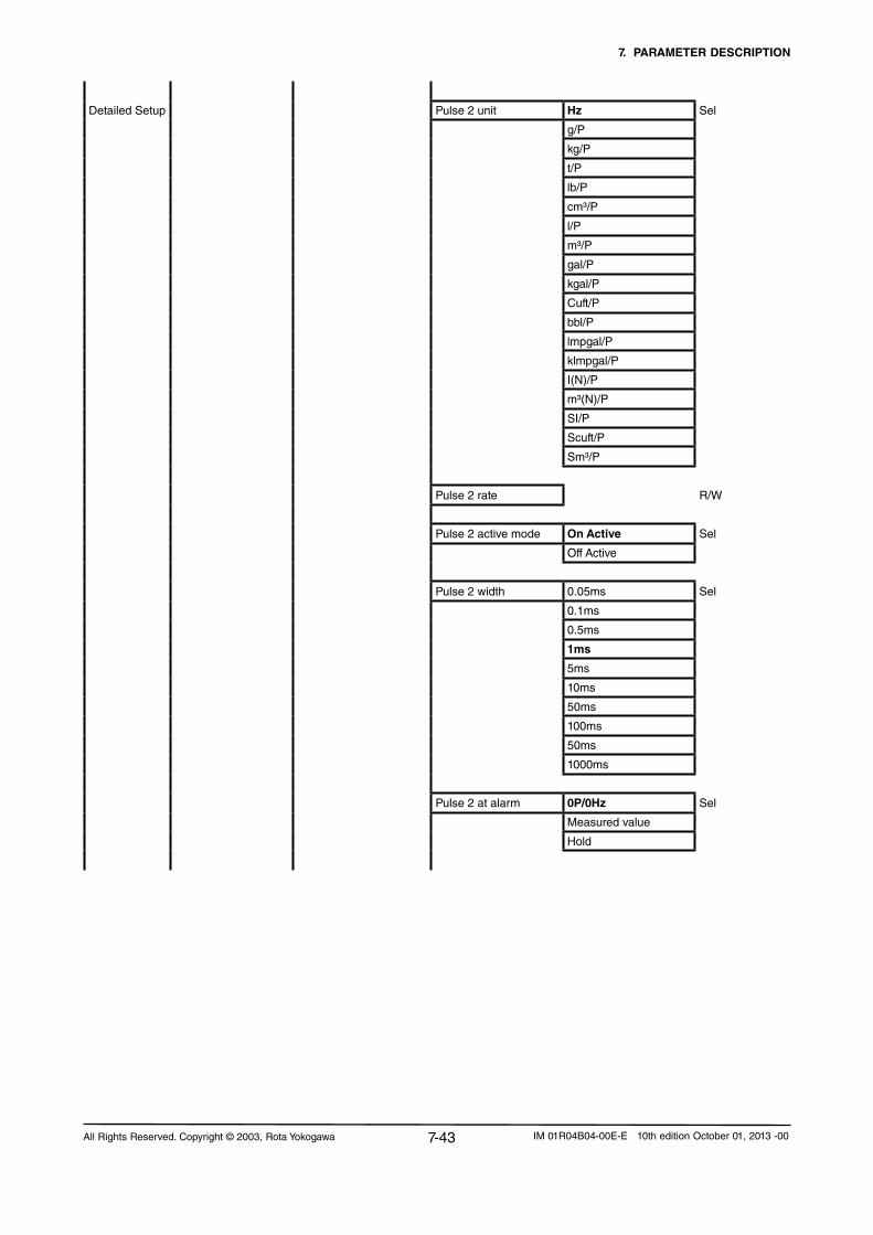
7. PARAMETER DESCRIPTION
7-43All Rights Reserved. Copyright © 2003, Rota Yokogawa IM 01R04B04-00E-E 10th edition October 01, 2013 -00
Detailed Setup Pulse 2 unit Hz Sel
g/P
kg/P
t/P
lb/P
cm³/P
l/P
m³/P
gal/P
kgal/P
Cuft/P
bbl/P
lmpgal/P
klmpgal/P
I(N)/P
m³(N)/P
SI/P
Scuft/P
Sm³/P
Pulse 2 rate R/W
Pulse 2 active mode On Active Sel
Off Active
Pulse 2 width 0.05ms Sel
0.1ms
0.5ms
1ms
5ms
10ms
50ms
100ms
50ms
1000ms
Pulse 2 at alarm 0P/0Hz Sel
Measured value
Hold

7. PARAMETER DESCRIPTION
7-44 All Rights Reserved. Copyright © 2003, Rota YokogawaIM 01R04B04-00E-E 10th edition October 01, 2013 -00
Detailed Setup SO2 function No Function Sel
Flow direction
Total limit switch
Mass flow alm 1
Mass flow alm 2
Mass flow alm 1+2
Vol flow alm 1
Vol flow alm 2
Vol flow alm 1+2
Density alm 1
Density alm 2
Density alm 1+2
Temp alm 1
Temp alm 2
Temp alm 1+2
Concentr. meas alm 1
Concentr. meas alm 2Concentr. meas alm 1+2Netflowalm1
Netflowalm2
Netflowalm1+2
Slug Alarm
Empty alarm
Corrosion Alarm
All alarms
All errors
All alarms & errors
SO2 active mode On Active Sel
Off Active
Status input SI function No function Sel
Autozero
Reset flex totals
Reset mass totals
Reset volume totals
Reset net totals
Reset all totals
0% signal lock
SI active mode On Active Sel
Off Active

7. PARAMETER DESCRIPTION
7-45All Rights Reserved. Copyright © 2003, Rota Yokogawa IM 01R04B04-00E-E 10th edition October 01, 2013 -00
Detailed Setup HART output PV is Mass flow Sel
Volume flow
Density
Temperature
Concentration meas
Netflow
None
SV is Mass flow Sel
Volume flow
Density
Temperature
Concentration meas
Netflow
None
F-Total mass
R-Total mass
F-Total volume
R-Total volume
F-Total net
R-Total net
F-Total flex
R-Total flex
D-Total mass
D-Total volume
D-Total net
D-Total flex
F-Total energy
Velocity
Drive gain
TV is Mass flow Sel
Volume flow
Density
Temperature
Concentration meas
Netflow
None
F-Total mass
R-Total mass
F-Total volume
R-Total volume
F-Total net
R-Total net
F-Total flex
R-Total flex
D-Total mass
D-Total volume
D-Total net
D-Total flex
F-Total energy
Velocity
Drive gain

7. PARAMETER DESCRIPTION
7-46 All Rights Reserved. Copyright © 2003, Rota YokogawaIM 01R04B04-00E-E 10th edition October 01, 2013 -00
Detailed Setup QV is Mass flow Sel
Volume flow
Density
Temperature
Concentration meas
Netflow
None
F-Total mass
R-Total mass
F-Total volume
R-Total volume
F-Total net
R-Total net
F-Total flex
R-Total flex
D-Total mass
D-Total volume
D-Total net
D-Total flex
F-Total energy
Velocity
Drive gain
Totalizer Total flex select Mass Sel
Volume
Net
Total flex unit g Sel
kg
t
lb
cm³
l
m³
gal
kgal
Cuft
bbl
Impgal
Klmpgal
I(N)
m³(N)
SI
Scuft
MMscuft
Sm³
Total mass unit g Sel
kg
t
lb

7. PARAMETER DESCRIPTION
7-47All Rights Reserved. Copyright © 2003, Rota Yokogawa IM 01R04B04-00E-E 10th edition October 01, 2013 -00
Detailed Setup Total volume unit cm³ Sel
l
m³
gal
kgal
Cuft
bbl
Impgal
kimpgal
I(N)
m³(N)
SI
Scuft
MMscuft
Sm³
Total net unit g
kg
t
lb
cm³
l
m³
gal
kgal
Cuft
bbl
Impgal
kimpgal
Total unit energy MJ Sel
Btu
Energy factor Heat of combustion R/W
Heat of combustion unit MJ/kg Sel
Btu/lb
MJ/m³(N)
Btu/Scuft
Total switch select Flex total Sel
Mass total
Volume total
Nettotal
Total limit switch R/W
Total at alarm Hold Sel
Continue total
Total reset cntrl Inhibit Sel
Enable

7. PARAMETER DESCRIPTION
7-48 All Rights Reserved. Copyright © 2003, Rota YokogawaIM 01R04B04-00E-E 10th edition October 01, 2013 -00
Detailed Setup Total reset NotExecute
Reset flex totals Exe
Reset mass totals Exe
Reset volume totals Exe
Reset net totals Exe
Reset all totals Exe
HART communication Poll addr R/W
Numreqpream R/W
Numresppream R/W
Master reset Exe
Concentration setup Reference Temperature R/W
Ref. density carrier R/W
Temp. coeff. a carrier R/W
Temp. coeff. b carrier R/W
Ref. density product R/W
Temp. coeff. a product R/W
Temp. coeff. b product R/W
Concentration meas Concentr. meas unit °Brix Sel
Wt-% sol
Vol% sol
Vol%
Wt-%
Concentr. meas format xxxxxxx Sel
xxxxx.X
xxxx.XX
xxx.XXX
xx.XXXX
x.XXXXX
Concentr.meas LRV R/W
Concentr. meas URV R/W
Concentr. meas Damp R/W
Concentr. meas Lowcut R/W

7. PARAMETER DESCRIPTION
7-49All Rights Reserved. Copyright © 2003, Rota Yokogawa IM 01R04B04-00E-E 10th edition October 01, 2013 -00
Detailed Setup Conc meas alm 1 Sel No function Sel
More than
Less than
Conc meas alm 1 Crit R/W
Conc meas alm 2 Sel No function Sel
More than
Less than
Conc meas alm 2 crit R/W
Netflow Netflowselect Mass Sel
Volume
Netflowunit g/s Sel
g/min
g/h
kg/s
kg/min
kg/h
kg/d
t/min
t/h
t/d
lb/s
lb/min
lb/h
lb/d
cm³/s
cm³/min
cm³/h
l/s
l/min
l/h
l/d
m³/s
m³/min
m³/h
m³/d
gal/s
gal/min
gal/h
gal/d
Cuft/s
Cuft/min
Cuft/h
Cuft/d
bbl/s
bbl/min
bbl/h

7. PARAMETER DESCRIPTION
7-50 All Rights Reserved. Copyright © 2003, Rota YokogawaIM 01R04B04-00E-E 10th edition October 01, 2013 -00
bbl/d
Detailed Setup Impgal/s
Impgal/min
Impgal/h
Impgal/d
Netflowformat xxxxxxx Sel
xxxxx.X
xxxx.XX
xxx.XXX
xx.XXXX
x.XXXXX
NetflowLRV R/W
NetflowURV R/W
Netflowdamping R/W
Netflowlowcut R/W
NetflowAlm1Sel No function Sel
More than
Less than
NetflowAlm1Crit R/W
NetflowAlm2Sel No function Sel
More than
Less than
NetflowAlm2Crit R/W
Measuring range R
Slug detection Slug alarm select Not apply Sel
Apply
Drive gain R
Slug criteria R/W
Slug duration R/W
After slug Measured value Sel
Hold
Drive gain damping

7. PARAMETER DESCRIPTION
7-51All Rights Reserved. Copyright © 2003, Rota Yokogawa IM 01R04B04-00E-E 10th edition October 01, 2013 -00
Detailed Setup Empty pipe detect Empty pipe alm sel Not apply Sel
Apply
Empty pipe crit R/W
After empty pipe Massflow=Zero Sel
Measured Value
Hold
Corrosion detect Corrosion alm sel Not apply Sel
Apply
Corrosion crit R/W
Corrosion damp R/W
Fluid max temp R
Device information Distributor R
Tag R/W
Long Tag R/W
Descriptor R/W
Message R/W
Date R/W
Sensor model R
SensorS/N R
Assembly number R
Serial no. converter R
Serial no. detector R
Device S/W Device S/W version R
Device S/W date R
Device id R
Universal rev R
Fld dev rev R
Software rev R
Hardware rev R

7. PARAMETER DESCRIPTION
7-52 All Rights Reserved. Copyright © 2003, Rota YokogawaIM 01R04B04-00E-E 10th edition October 01, 2013 -00
7.4 Parameter tree, HART menuOnline Device setup Set parameters for Rotamass (see below)
PV Display process value in engineering unitPV AO Display analogue output in mAReview Review parameters for Rotamass (see below)Service Notopen
Device setup
Language English Sel
German
French
Russian
Process View fld dev vars Mass flo R
variables Volume flo R
Dens R
Temp R
Conc meas R
Netflo R
F-Totl flex R
R-Totl flex R
D-Totl flex R
F-Totl mass R
R-Totl mass R
D-Totl mass R
F-Totl vol R
R-Totl vol R
D-Totl vol R
F-Totl net R
R-Totl net R
D-Totl net R
F-Totl energy R
Velocity R
Drive Gain R
View Outputs Analog output 1 Analog 1 select R
PV R
PV AO R
% rnge R
Analog output 2 Analog 2 select R
SV R
SV AO R
% rnge R
Pulse/Status out 1 Pulse 1 select R
TV R
TV Freq R
SO 1 function R
SO 1 mode R
Nofunction R
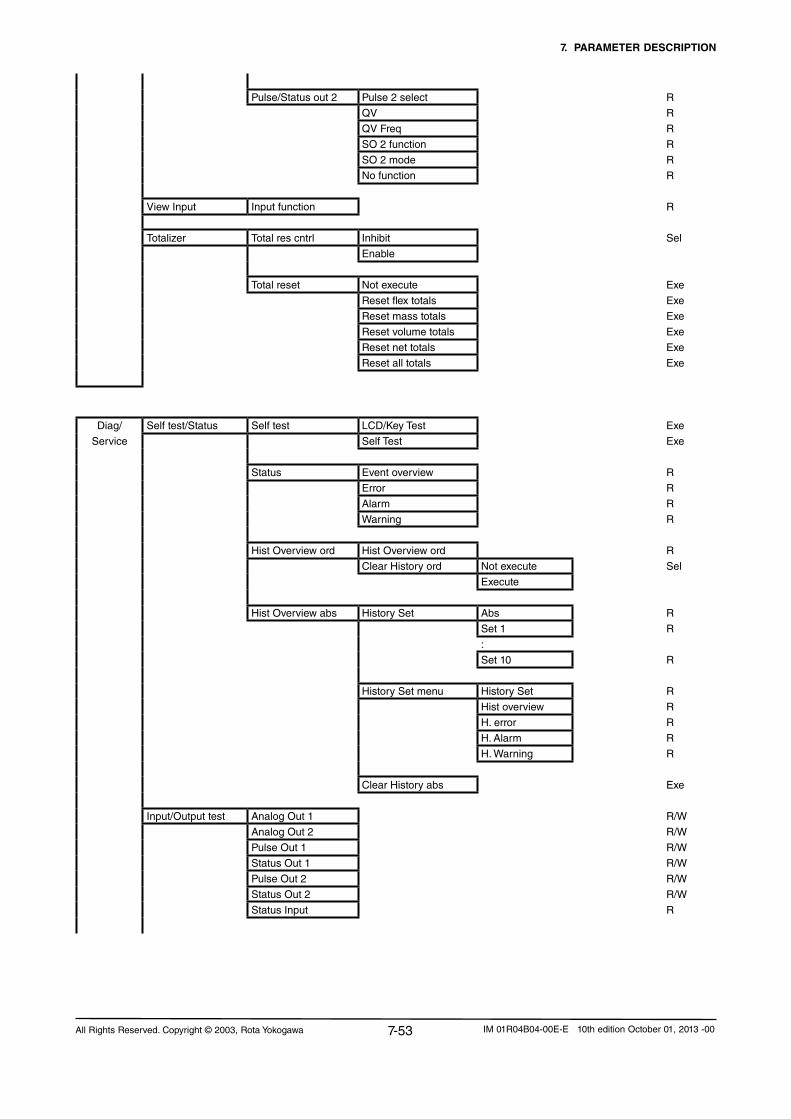
7. PARAMETER DESCRIPTION
7-53All Rights Reserved. Copyright © 2003, Rota Yokogawa IM 01R04B04-00E-E 10th edition October 01, 2013 -00
Pulse/Status out 2 Pulse 2 select R
QV R
QV Freq R
SO 2 function R
SO 2 mode R
Nofunction R
View Input Input function R
Totalizer Total res cntrl Inhibit Sel
Enable
Total reset Notexecute Exe
Reset flex totals Exe
Reset mass totals Exe
Reset volume totals Exe
Reset net totals Exe
Reset all totals Exe
Diag/ Self test/Status Self test LCD/Key Test Exe
Service Self Test Exe
Status Event overview R
Error R
Alarm R
Warning R
Hist Overview ord Hist Overview ord R
Clear History ord Notexecute Sel
Execute
Hist Overview abs History Set Abs R
Set 1 R
:
Set 10 R
History Set menu History Set R
Hist overview R
H. error R
H. Alarm R
H. Warning R
Clear History abs Exe
Input/Output test Analog Out 1 R/W
Analog Out 2 R/W
Pulse Out 1 R/W
Status Out 1 R/W
Pulse Out 2 R/W
Status Out 2 R/W
Status Input R

7. PARAMETER DESCRIPTION
7-54 All Rights Reserved. Copyright © 2003, Rota YokogawaIM 01R04B04-00E-E 10th edition October 01, 2013 -00
Diag/ Autozerocheck Autozerohistory Data Set 1Newest R
Service 2
3
4
5 Oldest
Initial
Date R
Val R
Dens R
Temp R
AZ range R
AZ fluctuation R
Autozero Zero tuning Inhibit Sel
Enable
Autozero Autozeroduration 3min Sel
30s
Performautozero Exe
Autozerovalue R
Loop trim Trim output 1 Exe
Trim output 2 Exe
Tag R/W
Long Tag R/W

7. PARAMETER DESCRIPTION
7-55All Rights Reserved. Copyright © 2003, Rota Yokogawa IM 01R04B04-00E-E 10th edition October 01, 2013 -00
Basic Setup Display config Disp select 1 Mass flo Sel
Vol flo
Dens
Temp
Conc meas
Netflo
F-Totl flex
R-Totl flex
D-Totl flex
F-Totl mass
R-Totl mass
D-Totl mass
F-Totl vol
R-Totl vol
D-Totl vol
F-Totl net
R-Totl net
D-Totl net
F-Totl energy
Velocity
Drive Gain
Disp select 2 Mass flo Sel
Vol flo
Dens
Temp
Conc meas
Netflo
F-Totl flex
R-Totl flex
D-Totl flex
F-Totl mass
R-Totl mass
D-Totl mass
F-Totl vol
R-Totl vol
D-Totl vol
F-Totl net
R-Totl net
D-Totl net
F-Totl energy
Velocity
Drive Gain
None

7. PARAMETER DESCRIPTION
7-56 All Rights Reserved. Copyright © 2003, Rota YokogawaIM 01R04B04-00E-E 10th edition October 01, 2013 -00
Basic Setup Disp select 3 Mass flo Sel
Vol flo
Dens
Temp
Conc meas
Netflo
F-Totl flex
R-Totl flex
D-Totl flex
F-Totl mass
R-Totl mass
D-Totl mass
F-Totl vol
R-Totl vol
D-Totl vol
F-Totl net
R-Totl net
D-Totl net
F-Totl energy
Velocity
Drive Gain
None
Disp select 4 Mass flo Sel
Vol flo
Dens
Temp
Conc meas
Netflo
F-Totl flex
R-Totl flex
D-Totl flex
F-Totl mass
R-Totl mass
D-Totl mass
F-Totl vol
R-Totl vol
D-Totl vol
F-Totl net
R-Totl net
D-Totl net
F-Totl energy
Velocity
Drive Gain
None
Display contrast -5 Sel
-4
-3
-2
-1
0+1
+2
+3
+4
+5
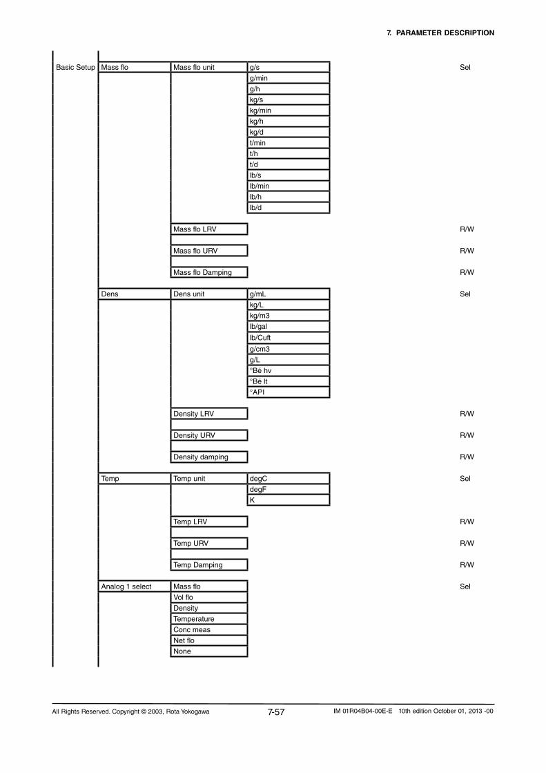
7. PARAMETER DESCRIPTION
7-57All Rights Reserved. Copyright © 2003, Rota Yokogawa IM 01R04B04-00E-E 10th edition October 01, 2013 -00
Basic Setup Mass flo Mass flo unit g/s Sel
g/min
g/h
kg/s
kg/min
kg/h
kg/d
t/min
t/h
t/d
lb/s
lb/min
lb/h
lb/d
Mass flo LRV R/W
Mass flo URV R/W
Mass flo Damping R/W
Dens Dens unit g/mL Sel
kg/L
kg/m3
lb/gal
lb/Cuft
g/cm3
g/L
°Bé hv
°Bé lt
°API
Density LRV R/W
Density URV R/W
Density damping R/W
Temp Temp unit degC Sel
degF
K
Temp LRV R/W
Temp URV R/W
Temp Damping R/W
Analog 1 select Mass flo Sel
Vol flo
Density
Temperature
Conc meas
Netflo
None

7. PARAMETER DESCRIPTION
7-58 All Rights Reserved. Copyright © 2003, Rota YokogawaIM 01R04B04-00E-E 10th edition October 01, 2013 -00
Basic Setup Analog 2 select Mass flo Sel
Vol flo
Density
Temperature
Conc meas
Netflo
None
Pulse/Status out 1 Pulse/Stat 1 select Pulse Sel
Status out
Nofunction
Pulse out 1 Pulse 1 select Mass flo Sel
Vol flo
Dens
Temp
Conc meas
Netflo
None
F-Totl mass
R-Totl mass
F-Totl vol
R-Totl vol
F-Totl net
R-Totl net
TV Pls unit Hz Sel
g/P
kg/p
t/P
lb/P
cm3/P
L/P
m3/P
gal/P
kgal/P
Cuft/P
bbl/P
Impgal/P
klmpgal/P
L(N)/P
m3(N)/P
L(Std)/P
StdCuft/P
m3(Std)/P
TV Pls rate R/W

7. PARAMETER DESCRIPTION
7-59All Rights Reserved. Copyright © 2003, Rota Yokogawa IM 01R04B04-00E-E 10th edition October 01, 2013 -00
Basic Setup Status out 1 SO 1 function NoFunction Sel
Flow direction
Total Switch
Mass flo alm 1
Mass flo alm 2
Mass flo alm 1+2
Vol flo alm 1
Vol flo alm 2
Vol flo alm 1+2
Dens alm 1
Dens alm 2
Dens alm 1+2
Temp alm 1
Temp alm 2
Temp alm 1+2
Conc alm 1
Conc alm 2
Conc alm 1+2
Netfloalm1
Netfloalm2
Netfloalm1+2
Slug Alarm
Empty Alarm
Corrosion Alarm
All Alarms
All ErrorsAll Alarms & Errors
Pulse/Status out 2 Pulse/Stat 2 select Pulse Sel
Status out
Nofunction
Pulse out 2 Pulse 2 select Mass flo Sel
Vol flo
Dens
Temp
Conc meas
Netflo
None
F-Totl mass
R-Totl mass
F-Totl vol
R-Totl vol
F-Totl net
R-Totl net

7. PARAMETER DESCRIPTION
7-60 All Rights Reserved. Copyright © 2003, Rota YokogawaIM 01R04B04-00E-E 10th edition October 01, 2013 -00
Basic Setup QV Pls unit Hz Sel
g/P
kg/p
t/P
lb/P
cm3/P
L/P
m3/P
gal/P
kgal/P
Cuft/P
bbl/P
Impgal/P
klmpgal/P
L(N)/P
m3(N)/P
L(Std)/P
StdCuft/P
m3(Std)/P
QV Pls rate R/W
Status out 2 SO 2 function NoFunction Sel
Flow direction
Total Switch
Mass flo alm 1
Mass flo alm 2
Mass flo alm 1+2
Vol flo alm 1
Vol flo alm 2
Vol flo alm 1+2
Dens alm 1
Dens alm 2
Dens alm 1+2
Temp alm 1
Temp alm 2
Temp alm 1+2
Conc alm 1
Conc alm 2
Conc alm 1+2
Netfloalm1
Netfloalm2
Netfloalm1+2
Slug Alarm
Empty Alarm
Corrosion Alarm
All Alarms
All ErrorsAll Alarms & Errors

7. PARAMETER DESCRIPTION
7-61All Rights Reserved. Copyright © 2003, Rota Yokogawa IM 01R04B04-00E-E 10th edition October 01, 2013 -00
Basic Setup Input function Nofunction Sel
Autozero
Reset flex totals
Reset mass totals
Reset volume totals
Reset net totals
Reset all totals
0% Signal lock
Totalizer Total flex select Mass Sel
Volume
Net
F-Totl flex Unit g
kg
t
lb
cm3
L
m3
gal
kgal
Cuft
bbl
Impgal
klmpgal
L(N)
m3(N)
L(Std)
StdCuft
MMscuft
m3(Std)
F-Totl mass Unit g Sel
kg
t
lb
F-Totl vol Unit cm3 Sel
L
m3
gal
kgal
Cuft
bbl
Impgal
klmpgal
L(N)
m3(N)
L(Std)
StdCuft
MMscuft
m3(Std)

7. PARAMETER DESCRIPTION
7-62 All Rights Reserved. Copyright © 2003, Rota YokogawaIM 01R04B04-00E-E 10th edition October 01, 2013 -00
Basic Setup F-Totl net Unit g Sel
kg
t
lb
cm3
L
m3
gal
kgal
Cuft
bbl
Impgal
klmpgal
L(N)
m3(N)
L(Std)
StdCuft
MMscuft
m3(Std)
Total switch select Flex total Sel
Mass total
Volume total
Nettotal
Detailed Display config Disp Select 1 Mass flo Sel
Setup Vol flo
Dens
Temp
Conc meas
Netflo
F-Totl flex
R-Totl flex
D-Totl flex
F-Totl mass
R-Totl mass
D-Totl mass
F-Totl vol
R-Totl vol
D-Totl vol
F-Totl net
R-Totl net
D-Totl net
F-Totl energy
Velocity
Drive Gain
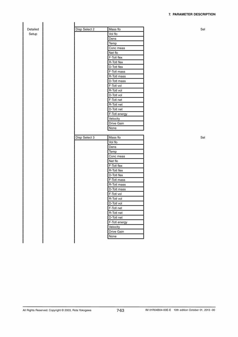
7. PARAMETER DESCRIPTION
7-63All Rights Reserved. Copyright © 2003, Rota Yokogawa IM 01R04B04-00E-E 10th edition October 01, 2013 -00
Detailed Disp Select 2 Mass flo Sel
Setup Vol flo
Dens
Temp
Conc meas
Netflo
F-Totl flex
R-Totl flex
D-Totl flex
F-Totl mass
R-Totl mass
D-Totl mass
F-Totl vol
R-Totl vol
D-Totl vol
F-Totl net
R-Totl net
D-Totl net
F-Totl energy
Velocity
Drive Gain
None
Disp Select 3 Mass flo Sel
Vol flo
Dens
Temp
Conc meas
Netflo
F-Totl flex
R-Totl flex
D-Totl flex
F-Totl mass
R-Totl mass
D-Totl mass
F-Totl vol
R-Totl vol
D-Totl vol
F-Totl net
R-Totl net
D-Totl net
F-Totl energy
Velocity
Drive Gain
None

7. PARAMETER DESCRIPTION
7-64 All Rights Reserved. Copyright © 2003, Rota YokogawaIM 01R04B04-00E-E 10th edition October 01, 2013 -00
Detailed Disp Select 4 Mass flo Sel
Setup Vol flo
Dens
Temp
Conc meas
Netflo
F-Totl flex
R-Totl flex
D-Totl flex
F-Totl mass
R-Totl mass
D-Totl mass
F-Totl vol
R-Totl vol
D-Totl vol
F-Totl net
R-Totl net
D-Totl net
F-Totl energy
Velocity
Drive Gain
None
Display contrast -5 R/W
-4
-3
-2
-1
0+1
+2
+3
+4
+5
Display period 0.5s Sel
1.0s
2.0s
Language English Sel
German
French
Russian
Sensor model RCCS30LR SelRCCS30
RCCS31
RCCS32
RCCS33
RCCS34
RCCS36
RCCS38
RCCS39
RCCS39/IR
RCCS39/XR

7. PARAMETER DESCRIPTION
7-65All Rights Reserved. Copyright © 2003, Rota Yokogawa IM 01R04B04-00E-E 10th edition October 01, 2013 -00
Detailed Sensor constants Mass flo SK20 R/W
Setup
SKT R/W
SKTK R/W
RV R/W
Qnom R
SKP R/W
SKPT R/W
Density KD R/W
Fl20 R/W
FTC1 R/W
FTCK R/W
FPC R/W
FPTC R/W
FQC1 R/W
FQC2 R/W
Config fld var Flow direction Forward Sel
Reverse
Mass flo Mass flo unit g/s Sel
g/min
g/h
kg/s
kg/min
kg/h
kg/d
t/min
t/h
td
lb/s
lb/min
lb/h
lb/d
Mass flo format xxxxxxx Sel
xxxxx.X
xxxx.XX
xxx.XXX
xx.XXXX
x.XXXXX
Mass flo LRV R/W
Mass flo URV R/W

7. PARAMETER DESCRIPTION
7-66 All Rights Reserved. Copyright © 2003, Rota YokogawaIM 01R04B04-00E-E 10th edition October 01, 2013 -00
Detailed Mass flo damping R/W
Setup
Mass flo lowcut R/W
Mass flo alm 1 sel Nofunction Sel
More than
Less than
Mass flo alm 1 crit R/W
Mass flow alm 2 sel Nofunction Sel
More than
Less than
Mass flo alm 2 crit R/W
Mass flo fix sel Inhibit Sel
Enable
Mass flo fix menu Mass flo fixed val R/W
Vol flo Vol flo Unit cm3/s Sel
cm3/min
cm3/h
L/s
L/min
L/h
L/d
m3/s
m3/min
m3/h
m3/d
gal/s
gal/min
gal/h
gal/d
Cuft/s
Cuft/min
Cuft/h
Cuft/d
bbl/s
bbl/min
bbl/h
bbl/d
Impgal/s
Impgal/min
Impgal/h
Impgal/d
L(N)/s
L(N)/min
L(N)/h
L(N)/d
m3(N)/s
m3(N)/min
m3(N)/h
m3(N)/d

7. PARAMETER DESCRIPTION
7-67All Rights Reserved. Copyright © 2003, Rota Yokogawa IM 01R04B04-00E-E 10th edition October 01, 2013 -00
Detailed L(Std)/s
Setup L(Std)/min
L(Std)/h
L(Std)/d
StdCuft/s
StdCuft/min
StdCuft/h
StdCuft/d
m3(Std)/s
m3(Std)/min
m3(Std)/h
m3(Std)/d
Vol flo Format xxxxxxx Sel
xxxxx.X
xxxx.XX
xxx.XXX
xx.XXXX
x.XXXXX
Vol flo LRV R/W
Vol flo URV R/W
Vol flo damping R/W
Vol flo Lowcut R/W
Vol flo alm 1 sel Nofunction Sel
More than
Less than
Vol flo alm 1 crit R/W
Vol flow alm 2 sel Nofunction Sel
More than
Less than
Vol flo alm 2 crit R/W
Dens Dens Unit g/mL Sel
kg/L
kg/m3
lb/gal
lb/Cuft
g/cm3
g/L
°Bé hv
°Bé lt
°API
Dens Format xxxxxxx Sel
xxxxx.X
xxxx.XX
xxx.XXX
xx.XXXX
x.XXXXX

7. PARAMETER DESCRIPTION
7-68 All Rights Reserved. Copyright © 2003, Rota YokogawaIM 01R04B04-00E-E 10th edition October 01, 2013 -00
Detailed Dens LRV R/W
Setup
Dens URV R/W
Dens damping R/W
Dens lowcut R/W
Dens alm 1 sel Nofunction Sel
More than
Less than
Dens alm 1 crit R/W
Dens alm 2 sel Nofunction Sel
More than
Less than
Dens alm 2 crit R/W
Ref. Density sel *) Inhibit Sel
FixedCalculated
Fixed ref dens menu *) Reference density R/W
Ref density setup *) Ref. temperature R/W
Temp. coeff a R/W
Temp. coeff b R/W
Dens fix val sel **) Inhibit Sel
Enable
Dens fix menu **) Reference density R/W
Density offset R/W
Pressure Unit bar Selpsi
MPa
Pressure R/W
Temp Temp Unit degC Sel
degF
K
Temp Format xxxxxxx Sel
xxxxx.X
xxxx.XX
xxx.XXX
xx.XXXX
x.XXXXX
Temp LRV R/W
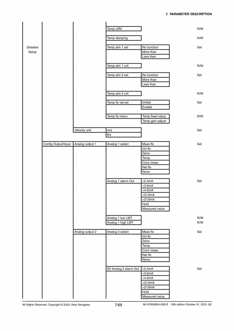
7. PARAMETER DESCRIPTION
7-69All Rights Reserved. Copyright © 2003, Rota Yokogawa IM 01R04B04-00E-E 10th edition October 01, 2013 -00
Temp URV R/W
Temp damping R/W
Detailed Temp alm 1 sel Nofunction Sel
Setup More than
Less than
Temp alm 1 crit R/W
Temp alm 2 sel Nofunction Sel
More than
Less than
Temp alm 2 crit R/W
Temp fix val sel Inhibit Sel
Enable
Temp fix menu Temp fixed value R/W
Temp gain adjust
Velocity unit m/s Sel
ft/s
Config Output/Input Analog output 1 Analog 1 select Mass flo Sel
Vol flo
Dens
Temp
Conc meas
Netflo
None
Analog 1 alarm Out <2.4mA Sel
<3.6mA
<4.0mA
>21.0mA
>21.6mA
Hold
Measured value
Analog 1 low LMT R/W
Analog 1 high LMT R/W
Analog output 2 Analog 2 select Mass flo Sel
Vol flo
Dens
Temp
Conc meas
Netflo
None
SV Analog 2 alarm Out <2.4mA Sel
<3.6mA
<4.0mA
>21.0mA
>21.6mA
Hold
Measured value

7. PARAMETER DESCRIPTION
7-70 All Rights Reserved. Copyright © 2003, Rota YokogawaIM 01R04B04-00E-E 10th edition October 01, 2013 -00
Analog 2 low LMT R/W
Analog 2 high LMT R/W
Detailed Pulse/Status 1 Pulse/Stat 1 sel Pulse Sel
Setup Status out
Nofunction
Pulse/freq out 1 Pulse 1 select Mass flo Sel
Vol flo
Dens
Temp
Conc meas
Netflo
None
F-Totl mass
R-Totl mass
F-Totl vol
R-Totl vol
F-Totl net
R-Totl net
Freq/Pulse out 1 TV Pls unit Sel
Hz
g/P
kg/P
t/P
lb/P
cm3/P
L/P
m3/P
gal/P
kgal/P
Cuft/P
bbl/P
Impgal/P
kImpgal/P
L(N)/P
m3(N)/P
L(Std)/P
StdCuft/P
m3(Std)/P
TV Pls rate R/W
TV Pls mode Sel
On Active
Off Active
TV Pls width Sel
0.05ms
0.1ms
0.5ms
1ms
5ms
10ms
50ms
100ms
500ms
1000ms

7. PARAMETER DESCRIPTION
7-71All Rights Reserved. Copyright © 2003, Rota Yokogawa IM 01R04B04-00E-E 10th edition October 01, 2013 -00
Detailed TV Pls alarm Sel
Setup 0Hz/0Pulses
Hold
Measured value
Status out 1 SO 1 function Nofunction Sel
Flow direction
Total switch
Mass flo alm 1
Mass flo alm 2
Mass flo alm 1+2
Vol flo alm 1
Vol flo alm 2
Vol flo alm 1+2
Dens alm 1
Dens alm 2
Dens alm 1+2
Temp alm 1
Temp alm 2
Temp alm 1+2
Conc alm 1
Conc alm 2
Conc alm 1+2
Netfloalm1
Netfloalm2
Netfloalm1+2
Slug Alarm
Empty Alarm
Corrosion Alarm
All alarms
All errorsAll alarms & errors
SO 1 active mode On Active Sel
Off Active
Pulse/Status 2 Pulse/Stat 2 sel Pulse Sel
Status out
Nofunction
Pulse/freq out 2 Pulse 2 select Mass flo Sel
Vol flo
Dens
Temp
Conc meas
Netflo
None
F-Totl mass
R-Totl mass
F-Totl vol
R-Totl vol
F-Totl net
R-Totl net
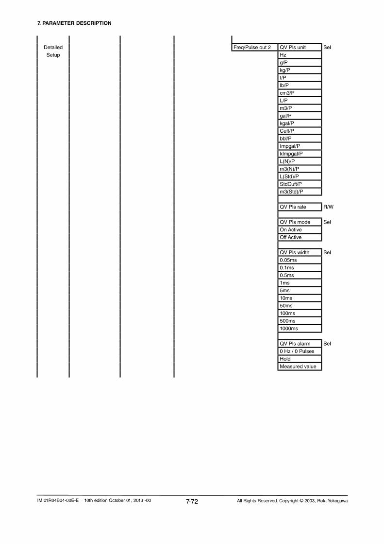
7. PARAMETER DESCRIPTION
7-72 All Rights Reserved. Copyright © 2003, Rota YokogawaIM 01R04B04-00E-E 10th edition October 01, 2013 -00
Detailed Freq/Pulse out 2 QV Pls unit Sel
Setup Hz
g/P
kg/P
t/P
lb/P
cm3/P
L/P
m3/P
gal/P
kgal/P
Cuft/P
bbl/P
Impgal/P
kImpgal/P
L(N)/P
m3(N)/P
L(Std)/P
StdCuft/P
m3(Std)/P
QV Pls rate R/W
QV Pls mode Sel
On Active
Off Active
QV Pls width Sel
0.05ms
0.1ms
0.5ms
1ms
5ms
10ms
50ms
100ms
500ms
1000ms
QV Pls alarm Sel
0Hz/0Pulses
Hold
Measured value

7. PARAMETER DESCRIPTION
7-73All Rights Reserved. Copyright © 2003, Rota Yokogawa IM 01R04B04-00E-E 10th edition October 01, 2013 -00
Detailed Status out 2 SO 2 function Nofunction Sel
Setup Flow direction
Total switch
Mass flo alm 1
Mass flo alm 2
Mass flo alm 1+2
Vol flo alm 1
Vol flo alm 2
Vol flo alm 1+2
Dens alm 1
Dens alm 2
Dens alm 1+2
Temp alm 1
Temp alm 2
Temp alm 1+2
Conc alm 1
Conc alm 2
Conc alm 1+2
Netfloalm1
Netfloalm2
Netfloalm1+2
Slug alarm
Empty alarm
Corrosion alarm
All alarms
All errorsAll alarms & errors
SO 2 active mode On Active Sel
Off Active
Status input Input function NoFunction Sel
Autozero
Reset flex totals
Reset mass totalsReset volume totalsReset net totals
Reset all totals
0% signal lock
SI active mode On Active Sel
Off Active

7. PARAMETER DESCRIPTION
7-74 All Rights Reserved. Copyright © 2003, Rota YokogawaIM 01R04B04-00E-E 10th edition October 01, 2013 -00
Detailed HART Output PV is Mass floSetup Vol flo
Dens
Temp
Conc meas
Netflo
None
SV is Mass flo
Vol flo
Dens
Temp
Conc meas
Netflo
None
F-Totl mass
R-Totl mass
F-Totl vol
R-Totl vol
F-Totl net
R-Totl net
F-Totl flex
R-Totl flex
D-Totl mass
D-Totl vol
D-Totl net
D-Totl flex
F-Totl energy
Velocity
Drive Gain
TV is Mass flo
Vol flo
Dens
Temp
Conc meas
Netflo
None
F-Totl mass
R-Totl mass
F-Totl vol
R-Totl vol
F-Totl net
R-Totl net
F-Totl flex
R-Totl flex
D-Totl mass
D-Totl vol
D-Totl net
D-Totl flex
F-Totl energy
Velocity
Drive Gain
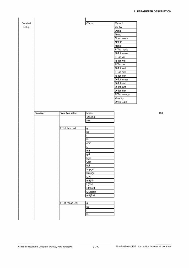
7. PARAMETER DESCRIPTION
7-75All Rights Reserved. Copyright © 2003, Rota Yokogawa IM 01R04B04-00E-E 10th edition October 01, 2013 -00
Detailed QV is Mass flo
Setup Vol flo
Dens
Temp
Conc meas
Netflo
None
F-Totl mass
R-Totl mass
F-Totl vol
R-Totl vol
F-Totl net
R-Totl net
F-Totl flex
R-Totl flex
D-Totl mass
D-Totl vol
D-Totl net
D-Totl flex
F-Totl energy
Velocity
Drive Gain
Totalizer Total flex select Mass Sel
Volume
Net
F-Totl flex Unit g
kg
t
lb
cm3
L
m3
gal
kgal
Cuft
bbl
Impgal
klmpgal
L(N)
m3(N)
L(Std)
StdCuft
MMscuft
m3(Std)
F-Totl mass Unit g
kg
t
lb

7. PARAMETER DESCRIPTION
7-76 All Rights Reserved. Copyright © 2003, Rota YokogawaIM 01R04B04-00E-E 10th edition October 01, 2013 -00
Detailed F-Totl vol Unit cm3 Sel
Setup L
m3
gal
kgal
Cuft
bbl
Impgal
klmpgal
L(N)
m3(N)
L(Std)
StdCuft
MMscuft
m3(Std)
F-Totl net Unit g Sel
kg
t
lb
cm3
L
m3
gal
kgal
Cuft
bbl
Impgal
klmpgal
L(Std)
StdCuft
MMscuft
m3(Std)
F-Totl energy Unit MJ Sel
Btu
Energy factor Heat of combust unit MJ/kg Sel
Btu/lb
MJ/Nm3
Btu/Scuft
Heat of combustion R/W
Total switch select Flex Sel
Mass
Volume
Net
Total limit switch R/W
Total at alarm Hold Sel
continue
Total res cntrl Inhibit Sel
Enable

7. PARAMETER DESCRIPTION
7-77All Rights Reserved. Copyright © 2003, Rota Yokogawa IM 01R04B04-00E-E 10th edition October 01, 2013 -00
Detailed Total reset Notexecute Exe
Setup Reset flex total Exe
Reset mass total Exe
Reset volume total Exe
Reset net total Exe
Reset all totals Exe
HART communication
Poll addr R/W
Numreqpream R/W
Numresppreams R/W
Master reset Exe
Conc meas setup Ref. temperature R/W
Ref. dens. carrier R/W
Coeff. a carrier R/W
Coeff b carrier R/W
Ref. dens. product R/W
Coeff. a product R/W
Coeff. b product R/W
Conc meas Conc meas unit degBrix Sel
% sol-wt
% sol-vol
Wt-%
Vol-%
Conc meas Format xxxxxxx Sel
xxxxx.X
xxxx.XX
xxx.XXX
xx.XXXX
x.XXXXX
Conc meas LRV R/W
Conc meas URV R/W
Conc meas Damp R/W
Conc meas Lowcut R/W
Conc meas alm 1 sel Nofunction Sel
More than
Less than
Conc meas alm 1 crit R/W

7. PARAMETER DESCRIPTION
7-78 All Rights Reserved. Copyright © 2003, Rota YokogawaIM 01R04B04-00E-E 10th edition October 01, 2013 -00
Detailed Conc meas alm 2 sel Nofunction Sel
Setup More than
Less than
Conc meas alm 2 crit R/W
Netflo Netflowselect Mass Sel
Volume
Notapplicable R
NetfloUnit g/s Sel
g/min
g/h
kg/s
kg/min
kg/h
kg/d
t/min
t/h
t/d
lb/s
lb/min
lb/h
lb/d
cm3/s
cm3/min
cm3/h
L/s
L/min
L/h
L/d
m3/s
m3/min
m3/h
m3/d
gal/s
gal/min
gal/h
gal/d
Cuft/s
Cuft/min
Cuft/h
Cuft/d
bbl/s
bbl/min
bbl/h
bbl/d
Impgal/s
Impgal/min
Impgal/h
Impgal/d
NetfloFormat xxxxxxx Sel
xxxxx.X
xxxx.XX
xxx.XXX
xx.XXXX
x.XXXXX

7. PARAMETER DESCRIPTION
7-79All Rights Reserved. Copyright © 2003, Rota Yokogawa IM 01R04B04-00E-E 10th edition October 01, 2013 -00
Detailed NetfloLRV R/W
Setup
NetfloURV R/W
NetfloDamp R/W
Netflolowcut R/W
Netfloalm1sel Nofunction Sel
More than
Less than
Netfloalm1crit R/W
Netfloalm2sel Nofunction Sel
More than
Less than
Netfloalm2crit R/W
Measuring Range R
Slug detection Slug alarm select Notapply Sel
Apply
Slug detection Drive gain R
Slug criteria R/W
Slug duration R/W
After slug Measured value Sel
Hold
Drive gain damping
Empty pipe detect Empty pipe alm sel Notapply Sel
Apply
Empty pipe detect Empty pipe crit R/W
After empty pipe Massflow =Zero Sel
Measured Value
Hold
Corrosion detect Corrosion alm sel Notapply Sel
Apply
Corrosion detect Corrosion crit R/W
Corrosion damp R/W
Fluid max temp R

7. PARAMETER DESCRIPTION
7-80 All Rights Reserved. Copyright © 2003, Rota YokogawaIM 01R04B04-00E-E 10th edition October 01, 2013 -00
Detailed Device information Tag R/W
Setup
Long Tag R/W
Descriptor R/W
Message R/W
Date R/W
Sensor model R
SensorS/N R
Final asmbly num R
S/NConverter R
S/NDetector R
Revision #‘s Universal rev R
Fld dev rev R
Software rev R
Hardware rev R
Device S/W Device S/W version R
Device S/W date R
Review Distributor R
Device info Sensor model R
SensorS/N R
Final asmbly num R
Tag R
Long Tag R
Describtor R
Message R
Date R
Dev id R
Universal rev R
Fld dev rev R
Software rev R
Hardware rev R
Device S/W version R
Device S/W date R
S/NConverter R
S/NDetector R

7. PARAMETER DESCRIPTION
7-81All Rights Reserved. Copyright © 2003, Rota Yokogawa IM 01R04B04-00E-E 10th edition October 01, 2013 -00
Review SK20 R
Sensor SKT R
SKTK R
RV R
Qnom R
SKP R
SKPT R
KD R
fl20 R
FTC1 R
FTCK R
FPC R
FPTC R
FQC1 R
FQC2 R
Autozerovalue R
Rev Fld Dev Flow direction R
vars 1
Mass flo unit R
Mass flo LRV R
Mass flo URV R
Mass flo damp R
Mass flo lowcut R
Mass flo alm 1 sel R
Mass flo alm 1 crit R
Mass flo alm 2 sel R
Mass flo alm 2 crit R
Mass flo fixed value R
Vol flo unit R
Vol flo LRV R
Vol flo URV R
Vol flo damp R
Vol flo lowcut R
Vol flo alm 1 sel R
Vol flo alm 1 crit R
Vol flo alm 2 sel R
Vol flo alm 2 crit R
Dens unit R
Dens LRV R
Dens URV R
Dens damp R
Dens lowcut R
Dens alm 1 sel R
Dens alm 1 crit R
Dens alm 2 sel R
Dens alm 2 crit R
Reference density R
Density offset R
Pressure R
Pressure unit R

7. PARAMETER DESCRIPTION
7-82 All Rights Reserved. Copyright © 2003, Rota YokogawaIM 01R04B04-00E-E 10th edition October 01, 2013 -00
Rev Fld Dev Temperature unit R
vars 1 Temp LRV R
Temp URV R
Temp damp R
Temp range select R
Temp alm 1 select R
Temp alm 1 crit R
Temp alm 2 select R
Temp alm 2 crit R
Temp fixed value R
Velocity unit R
Rev Fld Dev Conc meas Unit R
vars 2 Conc meas LRV R
Conc meas URV R
Conc meas damp R
Conc meas lowcut R
Conc alm 1 select R
Conc alm 1 crit R
Conc alm 2 sel R
Conc alm 2 crit R
Netfloselect R
Netflounit R
NetfloLRV R
NetfloURV R
Netflodamping R
Netflolowcut R
Netfloalm1sel R
Netfloalm1crit R
Netfloalm2sel R
Netfloalm2crit R
Rev Outputs Analog 1 select R
/Input PV Alarm 1 select R
PV Analog 1 low LMT R
PV Analog 1 high LMT R
Analog 2 select R
SV Alarm 2 select R
SV Analog 2 low LMT R
SV Analog 2 high LMT R
Pulse/Stat 1 sel R
Pulse 1 select R
Pls Unit R
Pls Rate R
Pls Mode R
Pls Width R
Pls Alarm R
SO 1 function R
SO 1 active mode R
Pulse/Stat 2 select R
Pulse 2 select R
Pls Unit R
Pls Rate R

7. PARAMETER DESCRIPTION
7-83All Rights Reserved. Copyright © 2003, Rota Yokogawa IM 01R04B04-00E-E 10th edition October 01, 2013 -00
Pls Mode R
Pls Width R
Pls Alarm R
SO 2 function R
SO 2 active mode R
Input function R
SI active mode R
PV is R
SV is R
TV is R
QV is R
Total flex select R
F-Totl flex Unit R
F-Totl mass Unit R
F-Totl vol Unit R
F-Totl net Unit R
F-Totl energy Unit R
Heat of combust unit R
Heat of combustion R
Total switch sel R
Total limit switch R
Total at alarm R
Total res cntrl R
Rev HART Poll addr R
Numreqpream R
Numresppream R

7. PARAMETER DESCRIPTION
7-84 All Rights Reserved. Copyright © 2003, Rota YokogawaIM 01R04B04-00E-E 10th edition October 01, 2013 -00
7.5 Mass flow functions (Basic or Detailed Setup)Mass flow To set the functions of mass flow measurement.
Mass flow unit Select: g/s, g/min, g/h, kg/s, kg/min, kg/h, kg/d, t/min, t/h, t/d, lb/s, lb/min, lb/h, lb/d
Mass flow format Select: xxxxxxx,xxxxx.X, xxxx.XX, xxx.XXX, xx.XXXX, x.XXXXX
Mass flow LRV (low range value)
Setamassflowvaluetothe4mAor0Hz.LRVcanalsobenegativetomeasure reverse flow.
Mass flow URV (upper range value)
Setamassflowvaluetothe20mAorxxxxxHz.Abs(URV-LRV) ≥ 5% of Qnom for liquids and 1% for gases
Mass flow damping Set the damping time in s. Damping time affects outputs and display. After 5 times damping time the given value is displayed (t=63%).
Mass flow lowcut Set the low cut. Low cut affects outputs and display and applies to negative and positive flow. A hysteresis of 0.05% of Qnom is given by the system.
Mass flow alm 1 sel Select: No function, More than, Less than
Mass flow alm 1 crit Select a mass flow alarm level. What happens in case of an alarm has to be defined in Status out (7.12, 7.13).
Mass flow alm 2 sel Select: No function, More than, Less than
Mass flow alm 2 selRestrictions:All alarms have to be in 0-110% of URV-LRV.Alarm criteria 2 must always be larger than alarm criteria 1.
Select a mass flow alarm level. What happens in case of an alarm has to be defined in Status out (7.12, 7.13).
Mass flow fix val sel Select: Inhibit, Enable
Mass flow fixed value Select a fix Mass flow value (only for test purpose or in case of maintenance).The set value is added to the actual value. In case of no flow it will vary withthezerofluctuation.

7. PARAMETER DESCRIPTION
7-85All Rights Reserved. Copyright © 2003, Rota Yokogawa IM 01R04B04-00E-E 10th edition October 01, 2013 -00
7.6 Volume flow functions (Basic or Detailed Setup)Volume flow Tosetthefunctionsofvolumeflowmeasurement.Notice:Volumeflow
is derived density and mass flow measurement.Errors in density measurement (e.g. from gas bubbles) effects the accuracy of volume flow. For liquid it is recommended to use mass flow as original measurement. Density below roh = 0.3 kg/l volume flow is settozero(forliquids)
Vol flow unit Select:cm³/s, cm³/min, cm³/h, l/s, l/min, l/h, l/d, m³/s, m³/min, m³/h, m³/d, gal/s, gal/min, gal/h, gal/d, Cuft/s, Cuft/min, Cuft/h, Cuft/d, bbl/s, bbl/min, bbl/h, bbl/d, Impgal/s, Impgal/min, Impgal/h, Impgal/d, I(N)/s, I(N)/min, I(N)/h, l(N)/d, m³(N)/s, m³(N)/min, m³(N)/h, m³(N)/d, SI/s, SI/min, SI/h, Sl/d, Scuft/s, Scuft/min, Scuft/h, Scuft/d, Sm³/s, Sm³/min, Sm³/h, Sm³/d
I(N)/s, I(N)/min, I(N)/h, l(N)/d, m³(N)/s, m³(N)/min, m³(N)/h, m³(N)/d only for gas application.SI/s, SI/min, SI/h, Sl/d, Scuft/s, Scuft/min, Scuft/h, Scuft/d, Sm³/s, Sm³/min, Sm³/h, Sm³/d only for gas application or if Reference density value is selected.
Vol flow format Select;xxxxxxx, xxxxx.X, xxxx.XX, xxx.XXX, xx.XXXX, x.XXXXX
Vol flow LRV (low range value)
Setavolumeflowvaluetothe4mAor0Hz.LRVcanalsobenegativeto measure reverse flow.
Vol flow URV (upper range value)
Setavolumeflowvaluetothe20mAorxxxxxHz.Abs(URV-LRV) ≥ 5% of Qvnom for liquids.For gas application Abs(URV-LRV) ≥ 1%
Vol flow damping Set the damping time in s. Damping time affects outputs and display. After 5 times damping time the given value is displayed (t=63%)
Vol flow lowcut Set the low cut. Low cut affects outputs and display. Any low cut on mass flow will affect volume flow also. A hysteresis of 0.05% of Qnom on mass flow is given by the system.
Vol flow alm 1 sel Select: No function, More than, Less than
Vol flow alm 1 crit Select a volume flow alarm level. What happens in case of an alarm has to be defined in Status (7.12, 7.13).
Vol flow alm 2 sel Select: No function, More than, Less than
Vol flow alm 2 critRestrictions:All alarms have to be in 0-110% of URV-LRV.Alarm criteria 2 must always be larger than alarm criteria 1.
Select a volume flow alarm level. What happens in case of an alarm has to be defined in Status out (7.12, 7.13).

7. PARAMETER DESCRIPTION
7-86 All Rights Reserved. Copyright © 2003, Rota YokogawaIM 01R04B04-00E-E 10th edition October 01, 2013 -00
7.7 Density functions (Basic or Detailed Setup)Density To set the functions of density measurement.
Notice:Densitymeasurementisonlyreliableifthereisnogasintheliquid. For liquid measurement a density lower 0.3 kg/l is displayed as 0.0 kg/l. For gas measurement set a fixed density value.
Density unit Select:g/ml, kg/l, kg/m³, lb/gal, lb/Cuft, g/cm³, g/l, °Bé hv, °Bé lt, °API
°Bé hv, °Bé lt, °API only with option /CST
Density format Select: xxxxxxx, xxxxx.X, xxxx.XX, xxx.XXX, xx.XXXX, x.XXXXX
Density LRV (low range value)
Setadensityvaluetothe4mAor0Hz.
Density URV (upper range value)
Setadensityvaluetothe20mAorxxxxxHz.Abs(URV-LRV) > 0.05 kg/l
Density damping Set the damping time in s. Damping time affects outputs and display. After 5 times damping time the given value is displayed (t=63%)
Density lowcut Set the low cut. Low cut affects outputs and display.
Density alm 1 sel Select: No function, More than, Less than
Density alm 1 crit Select a density alarm level. What happens in case of an alarm has to be defined in Status out (7.12, 7.13).
Density alm 2 sel Select: No function, More than, Less than
Density alm 2 critRestrictions:All alarms have to be in 0-110% of URV-LRVAlarm criteria 2 must always be larger than alarm criteria 1.
Select a density alarm level. What happens in case of an alarm has to be defined in Status out (7.12, 7.13).
Density Fix val sel(only software revision lower than 1.8.20)
Select: Inhibt, Enable
Ref. Density sel(from software revision 1.8.20)
Select: Inhibit, Fixed, Calculated
If Fixed or Calculated is selected, reference density and corrected vol-ume flow is output. Otherwise measured density and volume flow is output.
Calculated reference density is not available if concentration measure-ment (option /C) or gas measurement (option /GA) is activated.
Reference density Set a fixed reference density value. For gas measurement (option /GA) set here your actual density for output of volume flow. For output of standard or normal volume flow set the standard or normal density of your gas accordingly. For liquid measurement this parameter can also be used to enter the standard density of your liquid for output of standard volume flow or for the actual density in case of density disturbances.

7. PARAMETER DESCRIPTION
7-87All Rights Reserved. Copyright © 2003, Rota Yokogawa IM 01R04B04-00E-E 10th edition October 01, 2013 -00
Reference density setup(from software revision 1.8.20)
To setup the coefficients used for calculating the reference density.
ρref = ρ(1+aΔt+bΔt²);Δt=t-tref
ρref : density at reference temperatureρ : measured densityt : measured temperaturetref : reference temperaturea : linear thermal expansion coefficientb : quadratic thermal expansion coefficient
Reference temperature(from software revision 1.8.20)
Set the reference temperature for the reference density calculation.
Temp. coeff. a(from software revision 1.8.20)
Set the linear thermal expansion coefficient of the liquid for the refer-ence density calculation.
Temp. coeff. b(from software revision 1.8.20)
Set the quadratic thermal expansion coefficient of the liquid for the refer-ence density calculation.
Density offset IftheRotamassdetectorisinstalledhorizontally(benddown)thevaluefrom the following table must be entered according to the concerning sensor model.RCCS30LR 5.25 g/lRCCS30 2.70 g/lRCCS31 1.80 g/lRCCS32 2.00 g/lRCCS33 0.60 g/lRCCx34 0.90 g/lRCCx36 0.35 g/lRCCx38 to 39/XR 0 g/l (default)
ROTAMASS is density-calibrated vertically. If the ROTAMASS detector is installedhorizontalandensityoffset value from the above table has to be entered to the parameter ref-erence density. As positive values if the tubes are down and as negative value if the tubes are up.
Pressure Set the average static line pressure.Static pressure effect on density and mass flow will be corrected auto-matically.
Pressure unit Select: bar, psi, MPa

7. PARAMETER DESCRIPTION
7-88 All Rights Reserved. Copyright © 2003, Rota YokogawaIM 01R04B04-00E-E 10th edition October 01, 2013 -00
7.8 Temperature functions (Basic or Detailed Setup)Temperature To set the functions of temperature measurement.
Notice:Standardrange:-200to230°C High temp. range (/HT): 0 to 400°C
Temperature Unit Select: degC, degF, K
Temperature format Select: xxxxxxx, xxxxx.X, xxxx.XX, xxx.XXX, xx.XXXX, x.XXXXX
Temperature LRV (low range value)
Setatemperaturevaluetothe4mAor0Hz
Temperature URV (upper range value)
Setatemperaturevaluetothe20mAorxxxxxHz.Abs(URV-LRV) ≥ 10K
Temperature damping Set the damping time in s. Damping time affects outputs and display. After 5 times damping time the given value is displayed (t=63%).
Temperature alm 1 sel Select: No function, More than, Less than
Temperature alm 1 crit Select a temperature alarm level.What happens in case of an alarm has to be defined in Status out (7.12, 7.13).
Temperature alm 2 sel Select: No function, More than, Less than
Temperature alm 2 critRestrictions:All alarms have to be in 0-110% of URV-LRV Alarm criteria 2 must always be larger than alarm criteria 1.
Select a temperature alarm level.What happens in case of an alarm has to be defined in Status out (7.12, 7.13).
Temperature fix val select Select: Inhibit, Enable
Temperature fixed value Select a temperature value in case of malfunction of the built in temperature sensor.
Temperature gain Change the gain by setting a factor different from 1.The ROTAMASS temperature sensor is installed outside of the measuring tubes. So at high or low fluid temperature the temperature measurement may show a deviation as a function of the quality of heat insulation. This function allows correcting temperature measurement for better accuracy in mass flow and density.Note:Itisnotrecommendedtousethisfunctionunlesscorrectmeasurement over the complete process temperature range can be confirmed. It is not sufficient to proof correct measurement at one temperature or in a very narrow temperature range unless the process operates exclusively within this range.
7.9 Velocity functions (Detailed Setup)Velocity To set the function of the medium velocity.
Notavailableforgasmeasurement(/GA)Velocity is not calculated if reference density is enabled.
Velocity unit Select: m/s, ft/s

7. PARAMETER DESCRIPTION
7-89All Rights Reserved. Copyright © 2003, Rota Yokogawa IM 01R04B04-00E-E 10th edition October 01, 2013 -00
7.10 Analog 1 functions (Basic or Detailed Setup)
-10
0
10
20
30
40
50
60
70
80
90
100
110
-110 -90 -70 -50 -30 -10 10 30 50 70 90 110Reverse ← Flow [%] → Forward
Out
put c
urre
nt [%
]
2.4
4
5.6
7.2
8.8
10.4
12
13.6
15.2
16.8
18.4
20
21.6O
utpu
t cur
rent
[mA
]
High-LMT 20.5 mA
Low-LMT 3.8 mA0
LRV < 0 (e.g. -100% of flow)
possible Low cut
T76a.EPS
Example for Bi-directional flow (NAMUR):
Analog output 1 To set the current output 1. This output provides HART communication.
Analog 1 select Select: Mass flow (0), Volume flow (1), Density (2), Temperature (3), Concentration meas (4), Net flow (5), None (6)NumbersmaybedisplayedifselectedviaHART.
If None is selected, output is 4 mA, HART communication is available.
Analog 1 alarm out(Detailed setup, configure output/input)
Select: <2.4 mA, <3.6 mA, <4 mA, >21 mA, >21.6 mA
Analog 1 low LMT (low limit)(Detailed setup, configureoutput/ input)The alarm is active if the measured value is lower than the low limit.
Default: 3.8mASetting range: 3.8 - 20.5 mA
Analog 1 high LMT (high limit)(Detailed setup, Configure output/ input)The alarm is active if the measured value is higher than the high limit.
Default: 20.5mASetting range: 3.8 - 20.5 mA

7. PARAMETER DESCRIPTION
7-90 All Rights Reserved. Copyright © 2003, Rota YokogawaIM 01R04B04-00E-E 10th edition October 01, 2013 -00
7.11 Analog 2 functions (Basic or Detailed Setup)Analog output 2 To set the current output 2.
Analog 2 select Select: Mass flow (0), Volume flow (1), Density (2), Temperature (3), Concentration meas (4), Net flow (5), None (6)NumbersmaybedisplayedifselectedviaHART.
If None is selected, output is 4 mA.
Analog 2 alarm out(Detailed setup, configure out-put/input)
Select: <2.4 mA, <3.6 mA, <4 mA, >21 mA, >21.6 mA
Analog 2 low LMT (low limit)(Detailed setup, configure output/ input)The alarm is active if the measured value is lower than the low limit.
Default: 3.8mASetting range: 3.8 - 20.5 mA
Analog 2 high LMT (high limit)(Detailed setup, Configure output/ input)The alarm is active if the measured value is higher than the high limit.
Default: 20.5mASetting range: 3.8 - 20.5 mA

7. PARAMETER DESCRIPTION
7-91All Rights Reserved. Copyright © 2003, Rota Yokogawa IM 01R04B04-00E-E 10th edition October 01, 2013 -00
7.12 Pulse/Status output 1 functions (Basic or Detailed Setup)
Pulse/Status out 1 To set the pulse/status output 1.
Pulse/Stat 1 select Select: Pulse out, Status out, No function
If Pulse is selected, Status out 1 (SO) is not available.If Status out is selected, pulse parameters are not available.
Pulse 1 select Select: Mass flow (0), Volume flow (1), Density (2), Temperature (3), Concentration meas (4), Net flow (5), None (6), F-Total mass (7), R-Total mass (8), F-Total volume (9), R-Total volume (10), F-Total net (11), R-Total net (12)NumbersmaybedisplayedifselectedviaHART.
If F-Total mass, F-Total volume or F-Total net are selected, pulse output only works at forward flow.
If R-Total mass, R-Total volume or R-Total net are selected, pulse output only works at reverse flow.
Pulse 1 unit
To select the pulse output mass or volume has to be selected. If mass flow or volume flow is selected the output delivers only frequency.
Select: Hz, g/P, kg/P, t/P, lb/P, cm³/P, l/P, m³/P, gal/P, kgal/P, Cuft/P, bbl/P, Impgal/P, kImpgal/P, I(N)/P, m³(N)/P, SI/P, Scuft/P, Sm³/P
If Pulse 1 select is Mass flow, Volume flow, Density, Temperature or Concentration meas, only Hz can be selected.
If Pulse 1 select is F-Total mass, R-Total mass, F-Total volume, R-Total volume, F-Total net or R-Total net only unit/P can be selected.
I(N)/P, m³(N)/P only for gas application.SI/P, Scuft/P, Sm³/P only for gas application or if reference density value is selected.
Pulse 1 rate The Pulse rate can be set according to the unit set in Pulse 1 unit.Pulserateis0to10000Hz.Minimumoutput20Hz.
Pulse 1 active mode Select: On Active, Off Active
The output levels depending on this parameter are shown on page 7-91.
Pulse 1 width Select: 0.05ms, 0.1ms, 0.5ms, 1ms, 5ms, 10ms, 50ms, 100ms, 500ms, 1000ms
Pulse 1 at alarm Select: 0P/0Hz, Measured value, HoldIf 0P/0Hz is selected, in case of alarm the pulse output is stopped.If Measured value is selected, the pulse output keeps on measuring.If Hold is selected, the pulse output keeps the value before entering the alarm/error state.
NOTE

7. PARAMETER DESCRIPTION
7-92 All Rights Reserved. Copyright © 2003, Rota YokogawaIM 01R04B04-00E-E 10th edition October 01, 2013 -00
How to set status, pulse or frequencyoutput (using the display keys, equivalent via HART)Status Basic Setup or Detailed Setup Pulse/Status out 1 Pulse/Stat 1 select Select : Status out
Pulse or Frequency Basic Setup or Detailed Setup Pulse/Status out 1 Pulse/Stat 1 select Select : Pulse Pulse 1 select F-Total mass → Pulse R-Total mass → Pulse F-Total volume → Pulse R-Total volume → Pulse F-Total net → Pulse R-Total net → Pulse Mass Flow → Frequency Volume Flow → Frequency Net Flow → Frequency Density → Frequency Temperature → Frequency Concentration meas. → FrequencyNotice:Byselectingavariable(massorvolume)whichcanbetotalizedautomaticallythepulseoutput is selected.
SO 1 function Select: No Function, Flow direction, Total limit switch, Mass flow alm 1, Mass flow alm 2, Mass flow alm 1+2, Vol flow alm 1, Vol flow alm 2, Vol flow alm 1+2, Density alm 1,Density alm 2, Density alm 1+2, Temp alm 1, Temp alm 2, Temp alm 1+2, Concentration meas alm 1, Concentration meas alm 2, Concentration meas alm 1+2, Net flow alm 1, Net flow alm 2, Net flow alm 1+2, Slug alarm, Empty alarm, Corrosion alarm, All alarms, All errors, All alarms & errors
If Flow direction is selected, status output becomes active for forward flow and not active for reverse flow, if parameter flow direction set to forward. It is the other way round, if parameter flow direction is set to reverse (see 7.17).
If Total limit switch is selected, status output becomes active, when thetotalizerreachesthevaluesettoparameterTotal limit switch (see 7.17).
If an alarm function is selected, status output becomes active, if the concerning alarm occurs.If All alarms is selected, status output becomes active, if at least one alarm occurs. The same applies for errors with the setting All errors. For All alarms & errors the status output becomes active, if at least one alarm or one error occurs.
SO1 active mode Select: On Active, Off ActiveThe output levels depending on this parameter are shown on page 7-94.
If Pulse is selected, under Basis Setup the Pulse unit and Pulse ratehave to be defined.Under "Detailed Setup" Pulse unit Pulse rate Pulse active mode and Pulse widthhave to be defined.If the pulse output is set under Basic Setup, the pulse width is the width set under Detailed SetupIf the pulse width is not configured under DetailedSetup menu the pulse width will be set default to 1ms.If "frequency" is selected the frequency generatedat URV (upper range value) has to be defined. DefaultisURV=1000Hz.Differences between Pulse and FrequencyoutputFor pulse output the mass (or volume) is internally totalizedandiftheincrementisreached,onepulse is sent.For a frequency output the measured value is calculated in actual frequency according to the definitionoftheuser(e.g.10000Hz=54321kg/h)with 50% duty cycle. Set as frequency output the pulse length is changing with the change of the measured value.

7. PARAMETER DESCRIPTION
7-93All Rights Reserved. Copyright © 2003, Rota Yokogawa IM 01R04B04-00E-E 10th edition October 01, 2013 -00
If the flow is higher than max.Q pulses will be lost. Therefore it is mandatory to choose the pulse width/rate so, that the calculated max.Q is always 10% higher than the maximum ex-pected flowrate.
10% higher is recommended because the duty cycle is not always exact 50%. For certain pulse widths the duty cycle at max.Q is larger than 50% so fewer pulses can be generated. These pulses are delivered later when the flowrate is again below max.Q minus 10%. To avoid this situation it is recommended to keep the flowrate always 10% below max.Q.Example : Flowrate : 11 t/h Pulse unit : kg Pulse rate : 0.1 kg/P Time factor (related to s) = 3600 P/hCheck : Lowest pulse width = 0.5 s*pulse rate* time factor/ max. flow rate = 0.5 s*0.1 kg/P *3600 P/h /(11000 kg/h) = 16.4 ms → customer should select 10 ms pulse width or lower. Max. Q = 18000 kg/h 11000 kg/h < 18000 kg/h - 10%Result : Pulse width = 10 ms Pulse rate = 0.1 kg/P For a first orientation the max. Q for certain pulse widths and units for a pulse rate of 0.1, 1 and 10 are given in the table 7-1.
Max. flow restriction :
t
flowMax flow from pulse width, unit, rate
this amount willbe lost
t
flowMax flow from pulse width, unit, rate
Grey zone
this amount willbe lost
F3.EPS
Atfrequenciesabove500Hz,frequencyoutput1inserts gaps in the pulse train. Therefore it is required to use a minimum pulse integration time of 10 sec. to get accurate frequency measurements. If shorter pulse integration time is necessary e.g. for batching applications, it is recommended to usefrequencyoutput1uptomax.500Hz.
Set as a pulse output the pulse length is constant but the time between the pulses varies. Even at constant flow the time between the pulses might vary because the microprocessor has to find a suitable gap in its timing to send the pulse.
Typical pattern for frequency output :
Typical pattern for pulse output(50ms;0.1kg/P;2580kg/h):
Setting the pulse outputBecause the duty cycle of pulses is max. 50%, the max. flowrate is restricted by the pulse width, the unit and the pulse rate :Max. flow rate =1s/(pulse width*2) *pulse rate *time factorExample :Max. Q should be calculated in kg/minPulse width = 50 msPulse rate = 0.1 kg/PTime factor (related to s) = 60 P/minMax. Q = 1s/(0.05s *2) *0.1kg/P * 60P/min = 60kg/min
NOTE
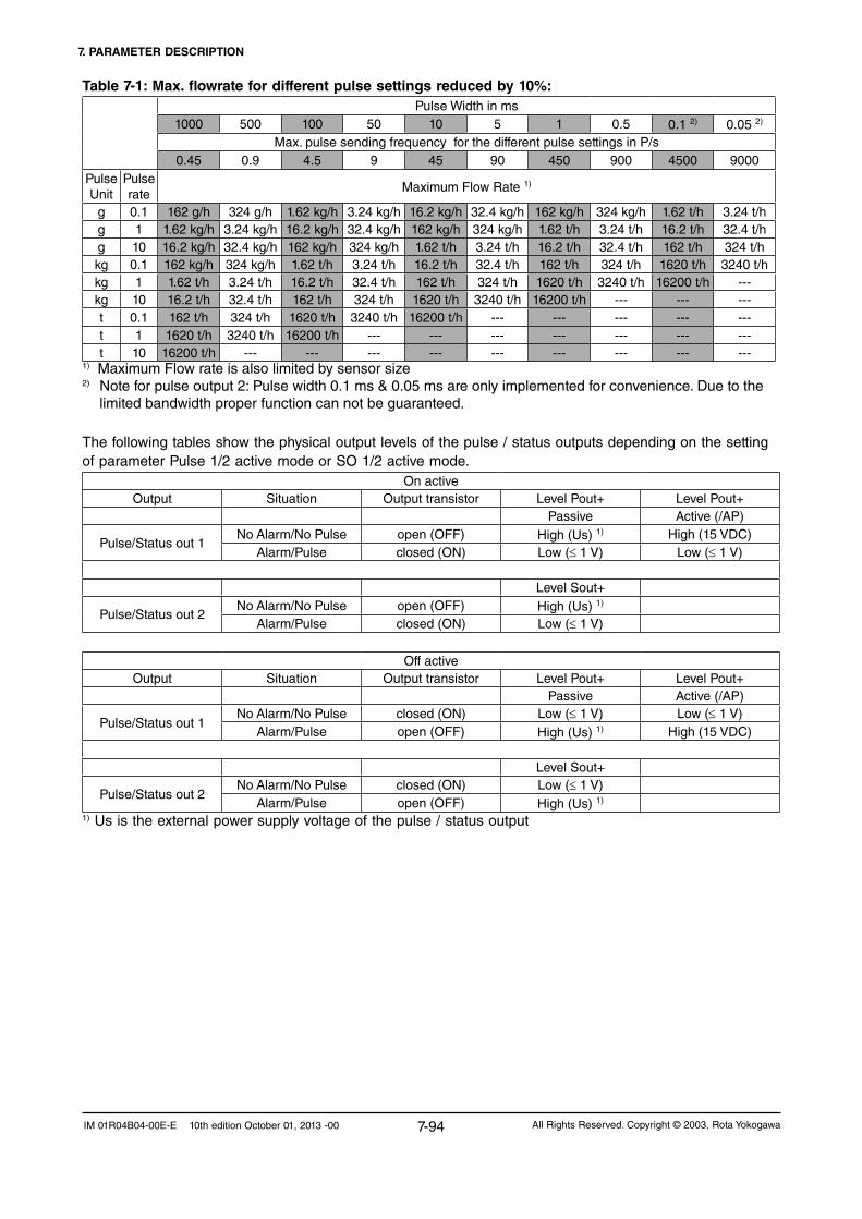
7. PARAMETER DESCRIPTION
7-94 All Rights Reserved. Copyright © 2003, Rota YokogawaIM 01R04B04-00E-E 10th edition October 01, 2013 -00
Table 7-1: Max. flowrate for different pulse settings reduced by 10%:Pulse Width in ms
1000 500 100 50 10 5 1 0.5 0.1 2) 0.05 2) Max. pulse sending frequency for the different pulse settings in P/s
0.45 0.9 4.5 9 45 90 450 900 4500 9000Pulse Unit
Pulse rate Maximum Flow Rate 1)
g 0.1 162 g/h 324 g/h 1.62 kg/h 3.24 kg/h 16.2 kg/h 32.4 kg/h 162 kg/h 324 kg/h 1.62 t/h 3.24 t/hg 1 1.62 kg/h 3.24 kg/h 16.2 kg/h 32.4 kg/h 162 kg/h 324 kg/h 1.62 t/h 3.24 t/h 16.2 t/h 32.4 t/hg 10 16.2 kg/h 32.4 kg/h 162 kg/h 324 kg/h 1.62 t/h 3.24 t/h 16.2 t/h 32.4 t/h 162 t/h 324 t/hkg 0.1 162 kg/h 324 kg/h 1.62 t/h 3.24 t/h 16.2 t/h 32.4 t/h 162 t/h 324 t/h 1620 t/h 3240 t/hkg 1 1.62 t/h 3.24 t/h 16.2 t/h 32.4 t/h 162 t/h 324 t/h 1620 t/h 3240 t/h 16200 t/h ---kg 10 16.2 t/h 32.4 t/h 162 t/h 324 t/h 1620 t/h 3240 t/h 16200 t/h --- --- ---t 0.1 162 t/h 324 t/h 1620 t/h 3240 t/h 16200 t/h --- --- --- --- ---t 1 1620 t/h 3240 t/h 16200 t/h --- --- --- --- --- --- ---t 10 16200 t/h --- --- --- --- --- --- --- --- ---
1) Maximum Flow rate is also limited by sensorsize2)Noteforpulseoutput2:Pulsewidth0.1ms&0.05msareonlyimplementedforconvenience.Duetothe limited bandwidth proper function can not be guaranteed.
The following tables show the physical output levels of the pulse / status outputs depending on the setting of parameter Pulse 1/2 active mode or SO 1/2 active mode.
On activeOutput Situation Output transistor Level Pout+ Level Pout+
Passive Active (/AP)
Pulse/Status out 1NoAlarm/NoPulse open (OFF) High (Us) 1) High (15 VDC)
Alarm/Pulse closed(ON) Low (≤ 1 V) Low (≤ 1 V)
Level Sout+
Pulse/Status out 2NoAlarm/NoPulse open (OFF) High (Us) 1)
Alarm/Pulse closed(ON) Low (≤ 1 V)
Off activeOutput Situation Output transistor Level Pout+ Level Pout+
Passive Active (/AP)
Pulse/Status out 1NoAlarm/NoPulse closed(ON) Low (≤ 1 V) Low (≤ 1 V)
Alarm/Pulse open (OFF) High (Us) 1) High (15 VDC)
Level Sout+
Pulse/Status out 2NoAlarm/NoPulse closed(ON) Low (≤ 1 V)
Alarm/Pulse open (OFF) High (Us) 1)
1) Us is the external power supply voltage of the pulse / status output

7. PARAMETER DESCRIPTION
7-95All Rights Reserved. Copyright © 2003, Rota Yokogawa IM 01R04B04-00E-E 10th edition October 01, 2013 -00
7.13 Pulse/Status output 2 functions (Basic or Detailed Setup)
Pulse/Status out 2 To set the pulse/status output 2.
Pulse/Stat 2 select Select: Pulse out, Status out, No function
If Pulse is selected, Status out 2 (SO) is not available.If Status out is selected, pulse parameters are not available.
Pulse 2 select Select: Mass flow (0), Volume flow (1), Density (2), Temperature (3), Concentration meas (4), Net flow (5), None (6), F-Total mass (7), R-Total mass (8), F-Total volume (9), R-Total volume (10), F-Total net (11), R-Total net (12)NumbersmaybedisplayedifselectedviaHART.
If F-Total mass, F-Total volume or F-Total net are selected, pulse output only works at forward flow.
If R-Total mass, R-Total volume or R-Total net are selected, pulse output only works at reverse flow.
Pulse 2 unit
To select the pulse output mass or volume has to be selected. If mass flow or volume flow is selected the output delivers only frequency.
Select: Hz, g/P, kg/P, t/P, lb/P, cm³/P, l/P, m³/P, gal/P, kgal/P, Cuft/P, bbl/P, Impgal/P, kImpgal/P, I(N)/P, m³(N)/P, SI/P, Scuft/P, Sm³/P
If Pulse 2 select is Mass flow, Volume flow, Density, Temperature or Concentration meas, only Hz can be selected.
If Pulse 2 select is F-Total mass, R-Total mass, F-Total volume, R-Total volume, F-Total net or R-Total net only unit/P can be selected.
I(N)/P, m³(N)/P only for gas application.SI/P, Scuft/P, Sm³/P only for gas application or if Reference density value is selected.
Pulse 2 rate The Pulse rate can be set according to the unit set in Pulse 2 unit.Pulserateis0to2000Hz.Minimumoutput20Hz.
Pulse 2 active mode Select: On Active, Off Active
The output levels depending on this parameter are shown on page 7-91.
Pulse 2 width Select: 0.05ms, 0.1ms, 0.5ms, 1ms, 5ms, 10ms, 50ms, 100ms, 500ms, 1000ms
Pulse 2 at alarm Select: 0P/0Hz, Measured value, HoldIf 0P/0Hz is selected, in case of alarm the pulse output is stopped.If Measured value is selected, the pulse output keeps on measuring.If Hold is selected, the pulse output keeps the value before entering the alarm/error state.
NOTE

7. PARAMETER DESCRIPTION
7-96 All Rights Reserved. Copyright © 2003, Rota YokogawaIM 01R04B04-00E-E 10th edition October 01, 2013 -00
Detailed information about using the pulse and status output see chapter 7.12.
SO 2 function Select: No Function, Flow direction, Total limit switch, Mass flow alm 1, Mass flow alm 2, Mass flow alm 1+2, Vol flow alm 1, Vol flow alm 2, Vol flow alm 1+2, Density alm 1,Density alm 2, Density alm 1+2, Temp alm 1, Temp alm 2, Temp alm 1+2, Concentration meas alm 1, Concentration meas alm 2, Concentration meas alm 1+2, Net flow alm 1, Net flow alm 2, Net flow alm 1+2, Slug alarm, Empty alarm, Corrosion alarm, All alarms, All errors, All alarms & errors
If Flow direction is selected, status output becomes active for forward flow and not active for reverse flow, if parameter flow direction set to forward. It is the other way round, if parameter flow direction is set to reverse (see 7.17).
If Total limit switch is selected, status output becomes active, when the totalizerreachesthevaluesettoparameterTotal limit switch (see 7.17).
If an alarm function is selected, status output becomes active, if the concerning alarm occurs.If All alarms is selected, status output becomes active, if at least one alarm occurs. The same applies for errors with the setting All errors. For All alarms & errors the status output becomes active, if at least one alarm or one error occurs.
SO2 active mode Select: On Active, Off ActiveThe output levels depending on this parameter are shown on page 7-94.
7.14 Status input functions (Basic or Detailed Setup)Status input To set the status input.
SI function Select: No function, Autozero, Reset flex totals, Reset mass totals, Reset volume totals, Reset net totals, Reset all totals, 0% signal lock
If Autozeroisselected,activestatusinputstartsautozeroprocedure.
If 0% signal lock is selected, analog outputs 1 and 2 are fixed to 4 mA while status input is active.
If parameter Total reset cntrl is enabled:- If Reset flex totals is selected, active status input sets flex totalizertozero.- If Reset mass totals is selected, active status input sets mass
totalizertozero.- If Reset volume totals is selected, active status input sets volumetotalizertozero.- If Reset net totals is selected, active status input sets nettotalizertozero.- If Reset all totals is selected, active status input sets all totalizertozero.
SI active mode Select: On Active, Off Active
If On Active is selected, the status input is closed active.If Off Active is selected, the status input is open active.

7. PARAMETER DESCRIPTION
7-97All Rights Reserved. Copyright © 2003, Rota Yokogawa IM 01R04B04-00E-E 10th edition October 01, 2013 -00
7.15 HART output (Detailed Setup)HART output To set the assignments of HART device variables which are reported via
HART Universal Command 3.
PV is Set the assignment of Primary variable (PV).PV is linked to Analog output 1. Changing of PV will change the assignment of Analog output 1 and vice versa.
Select: Mass flow, Volume flow, Density, Temperature, Concentration meas, Net flow, None
SV is Set the assignment of Secondary variable (SV).SV is linked to Analog output 2. Changing of SV will change the assignment of Analog output 2 and vice versa.
Select: Mass flow, Volume flow, Density, Temperature, Concentration meas, Net flow, None
If Analog output 2 is not available (option /KF2) an extended selection is available,see“HARTVariablelist”below.
TV is Set the assignment of Tertiary variable (TV).TV is linked to Pulse output 1 if Pulse/Stat 1 sel is set to Pulse. In this case changing of TV will change the assignment of Pulse output 1 and vice versa.
Select: Mass flow, Volume flow, Density, Temperature, Concentration meas, Net flow, None, F-Total mass, R-Total mass, F-Total volume, R-Total volume, F-Total net, R-Total net
If Pulse/Stat 1 sel is set to Status out or No function an extended selectionisavailable,see“HARTVariablelist”below.Thisselectionisstoredseparatelyfromtheselectionfor“Pulse”.
QV is Set the assignment of Quaternary variable (QV).QV is linked to Pulse output 2 if Pulse/Stat 2 sel is set to Pulse. In this case changing of QV will change the assignment of Pulse output 2 and vice versa.
Select: Mass flow, Volume flow, Density, Temperature, Concentration meas, Net flow, None, F-Total mass, R-Total mass, F-Total volume, R-Total volume, F-Total net, R-Total net
If Pulse output 2 is not available (option /KF2 ) or Pulse/Stat 2 sel is set to Status out or No function an extended selection is available, see “HART Variablelist”below.Thisselectionisstoredseparatelyfromtheselectionfor“Pulse”.
HART Variable list
(For HART- communication: Variables which are not allowed will be rejected by "Invalid Selection")
Mass flow, Volume flow, Density, Temperature, Concentration meas, Net flow, None, F-Total mass, R-Total mass, F-Total volume, R-Total volume, F-Total net, R-Total net, F-Total flex, R-Total flex, D-Total mass, D-Total volume, D-Total net, D-Total flex, F-Total energy, Velocity, Drive Gain

7. PARAMETER DESCRIPTION
7-98 All Rights Reserved. Copyright © 2003, Rota YokogawaIM 01R04B04-00E-E 10th edition October 01, 2013 -00
7.16 Totalizer functions (Basic or Detailed Setup)Totalizer Tosettotalizerfunction.
Totalizerincrementstheforwardflowifflowdirectionisforwardorthe reverse flow if flow direction is reverse.
Total flex select Flextotalizerisavailableasasecondarytotalformass,volumeornet.Select: Mass, Volume, NetIfassignmentischangedFlextotalizerwillbesettozero,Total flex unit will be set to default.
Total flex unit When Total flex select is set to Mass or Net, the Total flex unit g, kg, t, lb can be selected.When Total flex select is set to Volume or Net,the Total flex unit cm³, l, m³, gal, kgal, Cuft, bbl, Impgal, kImpgal, l(N), m³(N), Sl, Scuft, MMscuft, Sm³ can be selected.l(N), m³(N) only for gas application.Sl, Scuft, MMscuft, Sm³ only for gas application or if Reference density value is selected.
Total mass unit Select: g, kg, t, lbTotal volume unit For Total volume unit
cm³, l, m³, gal, kgal, Cuft, bbl, Impgal, kImpgal, l(N), m³(N), Sl, Scuft, MMscuft, Sm³ can be selected.l(N), m³(N) only for gas application.Sl, Scuft, MMscuft, Sm³ only for gas application or if Reference density value is selected.
Total net unit For option /CST:When Net flow select is set to Mass,the Total net unit g, kg, t, lb can be selected.
When Net flow select is set to Volume,the Total net unit cm³, l, m³, gal, kgal, Cuft, bbl, Impgal, kImpgal can be selected.
For option /C:Selection depends from concentration unit.
Total energy unit Select: MJ, BtuEnergy factor/Heat of combustion Set the calorific value of the medium with the unit Energy factor/
Heat of combust. unit.ThetotalizedenergyofthemediumcanbeindicatedondisplaybyF-Total energy.Heat of combust. unit MJ/kg, Btu/lb, MJ/m³(N) and Btu/Scuft can be selected.
Total switch select Select: Flex Total, Mass Total, Volume Total, Net TotalTotal limit switch Atotalizerlimitcanbesetonlytotheforward
totalizerselectedin Total select. If status output is set to Total switch,statusoutputissetactive,ifthetotalizerreachesthisvalue.Total switch is not active if set to 0.0.
Total at alarm Select: Hold, Continue TotalCharacteristicoftotalizerselectedinTotal select in case of the Total switch is active.If Hold is selected forward and reverse totalising stops.
Total reset cntrl Select: Inhibit, EnableEnables or inhibits total reset.
7. PARAMETER DESCRIPTION
7-99All Rights Reserved. Copyright © 2003, Rota Yokogawa IM 01R04B04-00E-E 10th edition October 01, 2013 -00
7.17 Flow direction function (Detailed Setup)Flow direction Select: Forward, Reverse
See 7.12 and 7.13 according influence on status output(SO 1/2 function = Flow direction)If Reverse is selected, the flow direction in the other direction of the arrow on the detector is used as positive values of flow.
Total reset Select: Not Execute, Reset flex totals, Reset mass totals, Reset volume totals, Reset net totals, Reset all totalsAfter execution of reset totals, forward and reverse total of the selectedtotalizerwillbesettozero.
If the total value 9999999 is reached, the indication changes to exponential type. During exponential indication the resolution is lower. If full accuracy is needed, total reset must be executed to reach precise indication.

7. PARAMETER DESCRIPTION
7-100 All Rights Reserved. Copyright © 2003, Rota YokogawaIM 01R04B04-00E-E 10th edition October 01, 2013 -00
7.18 Concentration measurement (Detailed Setup)Concentration meas(only for option/CST or /Cxx)
To set the functions of concentration measurement.
For xx=00 to 99 a customer specific or defined table is stored in the converter in factory.For /CST temperature coefficients have to be determined by the customer.
Concentration meas unit(only available for option/CST)
Select: °Brix, Wt-% sol, Vol% sol, Wt-%, Vol%
Concentration meas format Select: xxxxxxx, xxxxx.X, xxxx.XX, xxx.XXX, xx.XXXX, x.XXXXX
Concentration meas LRV (low range value)
Setaconcentrationvaluetothe4mAor0Hz
Concentration meas (upper range value)
Set a concentration valuetothe20mAorxxxxx=Hz.Abs(URV-LRV) ≥ 10%
Concentration meas damping Set the damping time in s. Damping time affects outputs and display. After 5 times damping time the given value is displayed (t=63%).
Concentration meas lowcut Set the low cut. Low cut affects outputs and display.
Concentration meas alm 1 sel Select: No function, More than, Less than
Concentration meas alm 1 crit Select a concentration alarm level. What happens in case of an alarm has to be defined in Status out (7.12, 7.13).
Concentration meas alm 2 sel Select: No function, More than, Less than
Concentration meas alm 2 crit
Restrictions:All alarms have to be in 0-110% of URV-LRV Alarm criteria 2 must always be larger than alarm criteria 1.
Select a concentration alarm level. What happens in case of an alarm has to be defined in Status out (7.12, 7.13).
Concentration meas setup(only for option /CST)
To setup the coefficients used for calculation of concentration using the Standard Concentration Measurement.
Reference temperature Set the temperature where the reference density of both components of the mixture has been determined.
Ref. density carrier Set the density of the carrier liquid determined at the reference temperature.
Temp. coeff. a carrier Set the linear temperature coefficient of the density of the carrier liquid.
Temp. coeff. b carrier Set the squared temperature coefficient of the density of the carrier liquid.
Ref. density product Set the density of the product determined at the reference temperature.
Temp. coeff. a product Set the linear temperature coefficient of the density of the product.
Temp. coeff. b product Set the squared temperature coefficient of the density of the product.
For more information on concentration measurement see TI "Concentration Measurement" TI 01R04B04-04E-E.

7. PARAMETER DESCRIPTION
7-101All Rights Reserved. Copyright © 2003, Rota Yokogawa IM 01R04B04-00E-E 10th edition October 01, 2013 -00
7.19 Net flow (Detailed Setup)Net flow To set the functions of net flow measurement.
Netflowisonlyavailableifconcentrationmeasurementisactivated(option /Cxx or /CST). The actual flow is multiplied with the concentration).
Net flow select(only available for option /CST)
Select: Mass, Volume
Net flow unit When Net flow select is set to Mass:g/s, g/min, g/h, kg/s, kg/min, kg/h, kg/d, t/min, t/h, t/d, lb/s, lb/min, lb/h, lb/d can be selected
When Net flow select is set to Volume:cm³/s, cm³/min, cm³/h, l/s, l/min, l/h, l/d, m³/s, m³/min, m³/h, m³/d, gal/s, gal/min, gal/h, gal/d, Cuft/s, Cuft/min, Cuft/h, Cuft/d, bbl/s, bbl/min, bbl/h, bbl/d, Impgal/s, Impgal/min, Impgal/h, Impgal/d can be selected
Net flow format Select: xxxxxxx, xxxxx.X, xxxx.XX, xxx.XXX, xx.XXXX, x.XXXXX
Net flow LRV (low range value)
Setanetflowvaluetothe4mAor0Hz.
Net flow URV (upper range value)
Setanetflowvaluetothe20mAorxxxxx=Hz.Abs(URV-LRV) ≥ 5% of Qnom.
Net flow damping Set the damping time in s. Damping time effects outputs and display. After 5 times damping time the given value is displayed (t=63%).
Net flow lowcut Set the low cut effects output and display. A hysteresis of 0.05% of Qnom is given by the system.
Net flow alm 1 sel Select: No function, More than, Less than
Net flow alm 1 crit Select a net flow alarm level. What happens in case of an alarm has to be defined in Status out (7.12, 7.13)
Net flow alm 2 sel Select: No function, More than, Less than
Net flow alm 2 crit
Restrictions:All alarms have to be in 0-110% of URV-LRVAlarm criteria 2 must always be larger than alarm criteria 1.
Select a net flow alarm level. What happens in case of an alarm has to be defined in Status out (7.12, 7.13)

7. PARAMETER DESCRIPTION
7-102 All Rights Reserved. Copyright © 2003, Rota YokogawaIM 01R04B04-00E-E 10th edition October 01, 2013 -00
7.20 Slug detection (Detailed Setup)Slug detection
Notavailableifgasmeasurementis ordered.
Detection of bubble flow.
After slug criteria has been reached, slug is supervised during slug duration. If slug is still detected after slug duration has expired, the selected action in After slug is taken.See below table.
Slug alarm select Select: Not apply, Apply
Drive gain To read drive gain.To set a suitable slug criteria the customer must know the drive gain level of normal flow condition and of slug flow condition. This function is suitable to evaluate this level.
Slug criteria Above this drive gain level slug flow is assumed.
Slug duration Duration time is designed to ignore short gas bubbles. Only after Slug duration has expired the setting in After slug will be taken in account. Innormalslugapplicationsetslugdurationtozero.
After slug Select: Measured value, HoldIf Hold is selected mass flow and density keep their value before occurrence of the slug alarm and as long as slug alarm is detected.
Drive gain damping Set drive gain damping time to get a constant drive gain level.
Gas application?
Yes No
Slug detection off
Slug alarm select = Apply?
Yes No
Drivegain>Slugcriteria?
Slug detection off
Yes No
Duration active?
Yes After duration
Function active Alarm off
Measurement continued
Slug detection OnAlarm on
Measurement continued
or value hold
Slug detection offAlarm off
time
mass flow
drive gain
density
single bubble
slug flow
duration time
mass flow, if Hold
mass flow, if Measured value
T88.EPS
Influence of slug on mass flow, density and drive gain :

7. PARAMETER DESCRIPTION
7-103All Rights Reserved. Copyright © 2003, Rota Yokogawa IM 01R04B04-00E-E 10th edition October 01, 2013 -00
7.21 Empty pipe detection (Detailed Setup)Empty pipe detection
Notavailableifgasmeasurement(option /GA) is ordered.Notworkingiffixedreferencedensityisenabled.
Detection of empty pipe
After Empty pipe crit has been reached, alarm output is activated if selected.This function can also be used to detect tube failure (see chapter 8.8).
Empty pipe alm sel Select: Not apply, Apply
Empty pipe crit Set density value as criteria when empty pipe alarm should happen. If Empty pipe crit is smaller than Density URV (or LRV, whichever is higher), alarm appears if density is lower than Empty pipe crit.If Empty pipe crit is equal or greater than Density URV (or LRV, whichever is higher), alarm appears if density is higher than Empty pipe crit.
After empty pipe Select the behaviour of the outputs after empty pipe has happened.
Select: Massflow = Zero, Measured Value, Hold
Withthisfunctiontheoutputscanbesettozeroifthedetector runs empty during maintenance. It is also useful for batching if the batch starts with an empty pipe. In such case please install the detector vertically.
Gas application?
Yes No
Empty pipe alm sel = Apply?
Yes No
Empty pipe crit < Density URV?(or LRV, whichever is higher)
Empty pipe crit ≥ Density URV?(or LRV, whichever is higher)
Yes No Yes No
Empty pipe OFF
Alarm off
Empty pipe ON
Alarm Onif density <
empty pipe crit
Outputs either Measured
Value, Hold or 4mA/0Hz
Empty pipe OFF
Alarm off
Empty pipe ON
Alarm Onif density ≥
empty pipe crit
Outputs either Measured
Value, Hold or 4mA/0Hz
Empty pipe OFF
Alarm off
Empty pipe OFF
Alarm off

7. PARAMETER DESCRIPTION
7-104 All Rights Reserved. Copyright © 2003, Rota YokogawaIM 01R04B04-00E-E 10th edition October 01, 2013 -00
7.22 Corrosion detection (Detailed Setup)
7.23 Detector data (Detailed Setup)The sensor model is defined in Parameter Detailed Setup / Sensor model :
The function Sensor model is only for changing a converter in case of maintenance. Neverchangethesensormodelifthesensorisnotchanged.
The sensor constants for the selected detector are stored in parameters Detailed Setup / Sensor constants.You find the main sensor constants on the name plate. In case of doubt of the measured value please confirm that the proper sensor constants are stored.
Theserialnumberoftheconverterisstoredin´DetailedSetup/DeviceInformation/Serialno.Converter´.Theserialnumberofthedetectorisstoredin´DetailedSetup/DeviceInformation/Serialno.Detector´.For compact version RCCT3 there is only one serial number.
The tag number, if provided by the customer (option /BG), is stored in Basic setup / Tag.
For integral type RCCT3 and remote type RCCF31 / RCCR31 combined ordered with RCCS3 the detector data are factory stored in the concerning parameters. For not combined remote type RCCF31 with option /NCseechapter5.5.
If the parameter Detailed setup / Sensor model is changed to another type, the following parameters are changed to new default values corresponding to the selected model :Qnom, Mass flow unit, Mass flow LRV, Mass flow URV, Vol flow unit, Vol flow LRV, VolflowURV,Autozerorange,Autozerofluctuationrangeandthesensorconstants.In this case the sensor constants, the detector serial number and, if available, the tag number must be set to the values corresponding to the used detector as described above.
WARNING
Corrosion detection
Notavailableifgasmeasurementisordered.Notworkingiffixedreference density is enabled. This function is useful if the max. den-sity of the fluid is known and cor-rosion may happen. As alternative to this function the user can watch density periodically.
Detection of corrosion in pipe.
After density value stored in Corrosion crit has been reached, alarm output is activated if selected.
This function is only good for liquids with relative constant density. Set an upper density level. If this density level is reached permanently, a warning occurs.
Corrosion alm sel Select: Not apply, Apply
Corrosion crit Set density value up to Density URV or Density LRV (whichever is higher)
Corrosion damp Set damping on density for comparison with Corrosion crit, up to 10h.

7. PARAMETER DESCRIPTION
7-105All Rights Reserved. Copyright © 2003, Rota Yokogawa IM 01R04B04-00E-E 10th edition October 01, 2013 -00
7.24 Autozero (Diag/Service)
IMPORTANT
Autozero Mass flow zero setting.
Pleasesetzerounderprocessconditionsafterwarminguptheconverter.
Zero tuning Select: Inhibit, Enable
Autozero time Select: 3 min, 30 sec
Selectthedurationofautozeroperforming.Recommended: 3 min
Autozero Exe Select: Execute, Not Execute
If ExecuteisselectedAutozeroisstarted.Afterautozeroexecutiontheautozerovalueisindicatedfor3secondsandthedateshouldbeentered (format: dd/mm/yyyy).PressingSETstoresvalue,date,temperatureanddensityinautozerohistory.Note:Autozerofunctioncan’tbeterminated.Autozerovaluewillbecalculated and used once the function has been started!
Autozero value Result of Autozero Exe
Autozero check: Autozero history Indicates5latestautozerovalueswithdateofexecution,temperatureand density during execution (only if date has been entered).
Thisfunctionallowscheckingthequalityofautozeroconditionandlongtermzerodrift.
Autozero check: Autozero initial Indicatesthefactoryautozerovalue
Autozero check: Autozero range Indicatesthetypicalmaximumautozerorange.IfthisrangeisexceededduringautozerothewarningW06isgenerated.Checkthedetectorinstallation!
Autozero check: Autozero fluctuation range
Warning: If the sensor model is changedAutozerofluctuationrangeiszero.
IndicatesthefactoryAutozerofluctuationrangedeterminedduringcalibration.IfthisrangeisexceededduringautozerothewarningW07is generated. Check the electrical installation, the plant vibration and the density (is the detector fully filled?).
- Stop flow before starting autozero (valve on output).-Duringautozerotime -Flowisfixedtozero-Totalizerstopscounting - Display keys do not work
Additionalinformationandhowtostartautozeroandhowtoreadautozerohistoryisdescribedinchapter 5.6 "Zero adjustment".

7. PARAMETER DESCRIPTION
7-106 All Rights Reserved. Copyright © 2003, Rota YokogawaIM 01R04B04-00E-E 10th edition October 01, 2013 -00
7.25 Reading maximum fluid temperature (Detailed Setup)
Fluid max. temp The highest measured medium temperature ever reached can be read in this parameter.This parameter can not be reset or changed by the user.
7.26 Option /GA for Gas MeasurementThis option is factory set by order. If this function is selected find the following restrictions: -Densitymeasurementisnotavailable;thereferencedensityvalueisalwaysused and displayed. -Normalvolumeflow: - Set reference density to normal density. - Select normal volume (flow) units for volume, total volume, pulse output. - Standard volume flow (for ROTAMASS with software version 1.08.xx (xx < 20) "Density Fix Val" instead of "reference density" must be set): - Set reference density to standard density. - Select standard volume (flow) units for volume, total volume, pulse output. - Volume flow: - Set reference density to actual density. - Select volume (flow) units for volume, total volume, pulse output. - Corrosion detection is not available. - Empty pipe detection is not available. - Slug detection is not available
The instrument is mass balanced with air at normal pressure. It can be used for liquids with reduced accuracy.
The minimum URV-LRV range for mass flow, volume flow and net flow is 1% of Qnom.
If Heat of Combustion unit is changed between mass related units (MJ/kg, Btu/lb) and volume related units (MJ/m³(N),Btu/Scuft),thereisnoconversionofHeatofCombustionvalue.In this case, Heat of Combustion has to be set manually to the correct value.

8. SELF-DIAGNOSTIC AND TROUBLESHOOTING
8-1All Rights Reserved. Copyright © 2003, Rota Yokogawa IM 01R04B04-00E-E 10th edition October 01, 2013 -00
8.1 Error descriptions and countermeasuresThe self check function displays instrument errors, warnings and alarms.When an alarm or error occurs, the code (e.g. E-01) and the name (e.g. Frequency fault) appear on the display during display mode, alternating with measuring value indication. This does not happen in parameter setting mode.The alarms, errors and warnings are written into history, see chapter 9.2.The following table shows the possible alarms, warnings and error with the concerning influences on outputs and fields variables.Alarm(A);Warning
(W)Error (E)
Name
Flow on Dis-play
Density/Temp. on Display
TotalizeronDisplay
Analogoutputs
Frequ./Pulse-outputs
Status outputs *)
nc = no change, nd = not defined
A-01 MF 1 criteria nc nc nc nc 6) Mass flow alm 1 *)
A-02 MF 2 criteria nc nc nc nc 6) Mass flow alm 2 *)
A-03 VF 1 criteria nc nc nc nc 6) Vol flow alm 1 *)
A-04 VF 2 criteria nc nc nc nc 6) Vol flow alm 2 *)
A-05 Dens. 1 criteria nc nc nc nc 6) Density alm 1 *)
A-06 Dens. 2 criteria nc nc nc nc 6) Density alm 2 *)
A-07 Temp. 1 criteria nc nc nc nc 6) Temp alm 1 *)
A-08 Temp. 2 criteria nc nc nc nc 6) Temp alm 2 *)
A-09 Conc. 1 criteria nc nc nc nc 6) Conc meas alm 1*)
A-10 Conc. 2 criteria nc nc nc nc 6) Conc meas alm 2*)
A-11 Netflow1crit. nc nc nc nc 6) Netflowalm1*)
A-12 Netflow2crit. nc nc nc nc 6) Netflowalm2*)
A-13 Total thr exceed nc nc hold;continue1) nc 6) Total switch *)
A-14 Slug detectionMFL:meas.;
hold 4)
DEN:meas.;hold 4) nc nc 6) Slug alarm *)
A-15 Empty pipe det.MFL:meas.;
hold 2) nc nc nc 6) Empty pipe alm *)
A-16 Corrosion det. nc nc nc nc 6) Corrosion alm *)
W-01 Density low nc DEN:0kg/l5) nc nc nc ncW-02 Fixed dens act. nc DEN:fixvalue nc nc nc ncW-03 Fixed temp act. nc TEMP: fix value nc nc nc nc
W-04 Fixed MF activeMFL: fix
value +act.zero
nc nc nc nc nc
W-05 Autozerorunning nc nc nc nc nc ncW-06 AZ val error nc nc nc nc nc ncW-07 AZ fluct error nc nc nc nc nc ncW-08 Sensor simul. nc nc nc nc nc ncW-09 Fixed Prim Out nc nc nc 4mA nc ncW-10 Prim Out sat. nc nc nc nc nc ncW-11 Sec Out sat. nc nc nc nc nc ncW-12 Tert Out sat. nc nc nc nc nc ncW-13 Quart Out sat. nc nc nc nc nc nc
E-01 Frequency fault ndDens = ndTemp = nc
hold 3,6mA;…3) 6) 7)
E-02 Signal fault nd nc hold 3,6mA;…3) 6) 7)
E-03 EEPROM fault nd nd hold 3,6mA;…3) 6) 7)
E-04 CPU fault nd nd nd 3,6mA… 8) nd ndE-05 DSP fault nd nd hold 3,6mA… 8) 6) 7)
E-06 Sensor 1 fault ndDens = ndTemp = nc
hold 3,6mA;…3) 6) 7)
E-07 Sensor 2 fault nd nc hold 3,6mA;…3) 6) 7)
E-08 Temp sens fault ncDensity = ndTemp = 30°C
hold 3,6mA;…3) 6) 7)
1)Choiceof“Totalatalarm”(DetailedSetup/Totalizer)2)Choiceof“OutputafterEmptypipe”(DetailedSetup/Emptypipedetect)3) Choice of “Analog 1/2 alarmout”(DetailedSetup/ConfigOutput)andNAMUR/NOTNAMUR(Measuringrange)4)Choiceof“AfterSlug”(DetailedSetup/Slugdetection)5)Onlyif“Liquid”isselected(DetailedSetup/Liquid/gasselection)6)Choiceof“Pulse1atalarm”or“Pulse2atalarm”(DetailedSetup/Pulse/Statusout1/2)7)Statusoutputsactiveif“AllErrors”or“AllAlarms&Errors”isselected(DetailedSetup/Pulse/Statusout1/2)8)Choiceofjumper“Burn-out”(Seechapter8.7.9Setting“Burn-out”Mode)*) Status outputs acc. SO 1/2 function and SO 1/2 active mode
8. SELF-DIAGNOSTIC AND TROUBLE-SHOOTING

8. SELF-DIAGNOSTIC AND TROUBLESHOOTING
8-2 All Rights Reserved. Copyright © 2003, Rota YokogawaIM 01R04B04-00E-E 10th edition October 01, 2013 -00
The following table shows possible countermeasures :
Alarm(A);Warning
(W)Error (E)
Name Meaning Description Countermeasure
A-01 MF 1 criteria Mass flow L Alarm Mass flow below MF 1 criteria Increase mass flow / Change settingA-02 MF 2 criteria Mass flow H Alarm Mass flow above MF 2 criteria Reduce mass flow / Change settingA-03 VF 1 criteria Volume flow L Alarm Volume flow below VF 1 criteria Increase volume flow / Change settingA-04 VF 2 criteria Volume flow H Alarm Volume flow above VF 2 criteria Reduce volume flow / Change settingA-05 Dens. 1 criteria Density L Alarm Density below Dens. 1 criteria Increase density / Change settingA-06 Dens. 2 criteria Density H Alarm Density above Dens. 2 criteria Reduce density / Change settingA-07 Temp. 1 criteria Temperature L Alarm Temperature below Temp. 1 criteria Increase temperature / Change settingA-08 Temp. 2 criteria Temperature H Alarm Temperature above Temp. 2 criteria Reduce temperature / Change settingA-09 Conc. 1 criteria Concentration L Alarm Concentration below Conc. 1 criteria Increase concentration / Change settingA-10 Conc. 2 criteria Concentration H Alarm Concentration above Conc. 2 criteria Reduce concentration / Change settingA-11 Netflow1crit. NetflowLAlarm NetflowbelowNetflow1crit. Increase net flow / Change settingA-12 Netflow2crit. NetflowHAlarm NetflowaboveNetflow2crit. Reduce net flow / Change setting
A-13 Total thr exceed Total threshold exceedTotalizervalueexceedstotalthreshold
Resettotalizer/Changesetting
A-14 Slug detection Slug flow detected Slug criterion is reached Reduce gas bubbles in medium
A-15Empty pipe det.
Empty pipe detectd Empty pipe criterion is reached Fill pipe
A-16 Corrosion det. Corrosion detected Corrosion criterion is reached Change detectorW-01 Density low Density lower 0.3 kg/l Density lower than 0.3 kg/l Fill the detector with fluid
W-02 Fixed dens act. Fixed Dens selectedParameter Density fix val sel or Ref. Density sel is set to fixed
Set parameter Density fix val sel or Ref. Density sel to inhibit
W-03 Fixed temp act. Fixed Temp selected Parameter Temp fix val sel is enabledSet parameter Temp fix val sel to inhibit
W-04 Fixed MF active Fixed MF selected Parameter MF fix val sel is enabled Set parameter MF fix val sel to inhibit
W-05 Autozerorunning Autozeroisrunning…Autozeroprocessisperformed,started by user action or status input
Wait until process stops (30sec or 180sec max)
W-06 AZ val errorAutozerovalueoutofrange
Autozerovalueisoutoftheinternaldetector depending range
Stopflowduringautozero.Check detector installation
W-07 AZ fluct errorAutozerofluctuationoutof range
Autozerofluctuationisoutoftheinternal detector depending range
Stopflowduringautozero.Checkelectrical installation, vibrations and density.
W-08 Sensor simul. Sensor simulation activeFixed frequency or fixed phase dif-ference is enabled
Set Sensor simulation to inhibit
W-09 Fixed Prim Out Analog output 1 fixedAnalog output 1 fixed at 4mA for multidrop operation
Set HART polling address to 0 (Multidrop operation stops)
W-10 Prim Out sat. Analog output 1 saturatedAnalog output 1 reaches less than 3.8mA or more than 20.5mA
Increase or decrease current level of output 1
W-11 Sec Out sat. Analog output 2 saturatedAnalog output 2 reaches less than 3.8mA or more than 20.5mA
Increase or decrease current level of output 2
W-12 Tert Out sat.Pulse/Status output 1 saturated
Relation between pulse width and pulse rate of Pulse/Status output 1 is too high
Decrease length of pulse width or increase amount of pulse rate of pulse output 1
W-13 Quart Out sat.Pulse/Status output 2 saturated
Relation between pulse width and pulse rate of Pulse/Status output 2 is too high
Decrease length of pulse width or increase amount of pulse rate of pulse output 2
E-01 Frequency fault Frequency fault detected Driving frequency out of range Check cable (Remote) and detectorE-02 Signal fault Signal fault detected Phase difference out of range Check cable (Remote) and detectorE-03 EEPROM fault EEPROM fault detected CRC-Error Contact Yokogawa serviceE-04 CPU fault CPU fault detected Micro processor is not working Contact Yokogawa serviceE-05 DSP fault DSP fault detected Micro processor is not working Contact Yokogawa service
E-06 Sensor 1 faultSensor 1 Signal fault detected
Sensor 1 signal below 7% for 3 min Check cable (Remote) and detector
E-07 Sensor 2 faultSensor 2 Signal fault detected
Sensor 2 signal below 7% for 3 min Check cable (Remote) and detector
E-08 Temp sens faultTemperature Sensor Fault detected
T<-220°CorT>550°CCheck cable (Remote) and detectorCheck temperature

8. SELF-DIAGNOSTIC AND TROUBLESHOOTING
8-3All Rights Reserved. Copyright © 2003, Rota Yokogawa IM 01R04B04-00E-E 10th edition October 01, 2013 -00
8.2 Reading Event + Error History (Diag/Service, Self test/Status)
Event Overview/ ErrorAlarmWarning
Reads the actual errors, alarms and warnings (EAW). In Event Overview the number of the actual EAWs is shown. In Error, Alarm or Warning the description of the actual events can be found.
Hist Overview in Order Shows the latest 10 EAWs. By comparing this with Hist Overview abs it can be checked if certain EAWs have vanished.
Hist Overview in Order/Clear History
Select: Execute, Non execute
If Execute is selected the latest 10 EAWs are cleared.
Hist Overview abs/ErrorAlarmWarning
In Hist Overview abs the number of EAWs after the last clearance can be viewed. In Error, Alarm or Warning the description of the events after the last clearance can be found.
Hist Overview abs/Clear History
Select: Execute, Not Execute
If Execute is selected the user is asked to fill in a date (mm/dd/yyyy). If a date is set the errors and warnings are stored in the Error history with this date.
Error History In Error History the number of EAWs of the last clearance of the Hist Overview abs can be viewed. In Error or Warning the description of the events can be found. The last 10 entries can be selected by date.
8.3 Self test (Diag/Service)Self test/ Status Select: Self test, Status
If Self test is selected, all error and alarm status are checked.If Status is selected, the existing errors and alarms are indicated in succession.
8.4 Signal- and I/O-Test (Diag/Service)Input/Output test These functions enable you to simulate the I/O signals (loop test).
The outputs can be checked with a multimeter.Refer to the connecting diagrams in chapter 4.8.6. The test can be cancelled by pressing any key.
Analog output 1Analog output 2Pulse output 1Status output 1Pulse output 2Status output 2Status input
Setting range: 2 to 22 mASetting range: 2 to 22 mASettingrange:20to10000HzSetting range: On Active or Off ActiveSettingrange:20to2000HzSetting range: On Active or Off ActiveIndication range: Open or Short

8. SELF-DIAGNOSTIC AND TROUBLESHOOTING
8-4 All Rights Reserved. Copyright © 2003, Rota YokogawaIM 01R04B04-00E-E 10th edition October 01, 2013 -00
8.5 Output trim
8.6 Detector cleaning
CAUTION For integral type : Ambient temperature may not exceed 55°C !
The equipment can be CIP-cleaned. Steam below 230°C is not a problem. However, you should take care that the cleaning operation does not last so long that the converter temperature exceed 55°C. Switch power off during cleaning.
Output trim With this function the 4 mA and the 20 mA can be adjusted if required
AO 1 trim 4mA / AO 1 trim 20mA The analog output 1 is set to the 4 mA or 20 mA. Connect a load resistor between 20 and 600 W and measure the output current.This current value must be entered on request on display. The deviation to 4 mA is corrected by the converter itself.
AO 2 trim 4mA / AO 2 trim 20mA The analog output 2 is set to the internal 4 mA or 20 mA value. Connect a load resistor between 20 and 600 W and measure the output current.This current value must be entered on request on display.

8. SELF-DIAGNOSTIC AND TROUBLESHOOTING
8-5All Rights Reserved. Copyright © 2003, Rota Yokogawa IM 01R04B04-00E-E 10th edition October 01, 2013 -00
8.7 Troubleshooting
IMPORTANT If the indicated countermeasures do not remedy the fault or in case of troubles which can not be remedied by the user, please contact your Yokogawa service centre.
If there is an error, alarm or warning displayed, deal with the error according to 8.1 „Error descriptions and countermeasure”.In the following some problems are listed which may not be indicated as error, alarm or warning. First make sure, that no error, alarm or warning is displayed.
8.7.1 No indication
no yes yes no yes yes
Is the power supply voltage between terminals L/+ and N/- correct ?
Check the power supply connections.
Is display cable connected correct to CPU board ?
Connect the cable in the correct position.
Contact the nearest YOKOGAWA office or service center.
F81.EPS

8. SELF-DIAGNOSTIC AND TROUBLESHOOTING
8-6 All Rights Reserved. Copyright © 2003, Rota YokogawaIM 01R04B04-00E-E 10th edition October 01, 2013 -00
8.7.2 No key-setting possible
8.7.3 No HART communication
no yes no yes
Is parameter Key Status set enable ?
Set parameter Key Status enable .
Is display cable connected correct to CPU board ?
Connect the cable in the correct position.
Contact the nearest YOKOGAWA office or service center.
F82.EPS
no yes no yes
Is HART DD of Rotamass RCCT3 available in HART communicator ?
Store necessary DD in HART communicator.
Is HART communicator connected to Rotamass according chapter 4.8.7 ?
Connect HART communicator according chapter 4.8.7.
Contact the nearest YOKOGAWA office or service center.
F83.EPS

8. SELF-DIAGNOSTIC AND TROUBLESHOOTING
8-7All Rights Reserved. Copyright © 2003, Rota Yokogawa IM 01R04B04-00E-E 10th edition October 01, 2013 -00
8.7.4 Unstable zero
no
yes
yes
no
no
yes
no
Is the tube filled with liquid completely (check the density)?
Fill the detector. May be vertical installation is indicated.
Are bubbles in the liquid ? Check piping and installation.
Is the detector installed free of mechanical stress?
Is electrical grounding correct according chapter 4.8.4; 4.8.5; 9 ?
Make correct grounding.
Is the flowmeter located near motors, transformers or other electric equipments ?
Shield the flowmeter sufficiently. Locate the flowmeter as far as possible from these equipments.
Is the connection box free of dirt and humidity? (only for remote installation)
yes
no
Loose the process connections and make sure that they are in line. Support only one adjacent pipe, let one side of the adjacent pipe be “soft”.
yes
Contact the nearest YOKOGAWA office or service center.
yes
no Clean and dry the connection box. Make sure that humidity cannot penetrate.
F84.EPS

8. SELF-DIAGNOSTIC AND TROUBLESHOOTING
8-8 All Rights Reserved. Copyright © 2003, Rota YokogawaIM 01R04B04-00E-E 10th edition October 01, 2013 -00
8.7.5 Disagreement of indication with actual flow rate no yes no yes no yes no no no
Run autozero according chapter 5.6.
Are mass flow unit, URV, LRV and lowcut set correctly ?
Set correct mass flow parameters.
Contact the nearest YOKOGAWA office or service center.
Is electrical grounding correct according chapter 4.8.4; 4.8.5; 9 ?
Make correct grounding.
Control the piping. Is there a location where air can be sucked in?
Connect remote cable according chapter 9 and 4.8.1.
Is zero point set correctly?
Is gas penetration in the fluid (chek the density)?
yes
Is the control measurement correct and reliable?
For Remote type: Is remote cable connected according chapter 9 and 4.8.1 ?
yes
yes
Check the control measurement.
F85.EPS
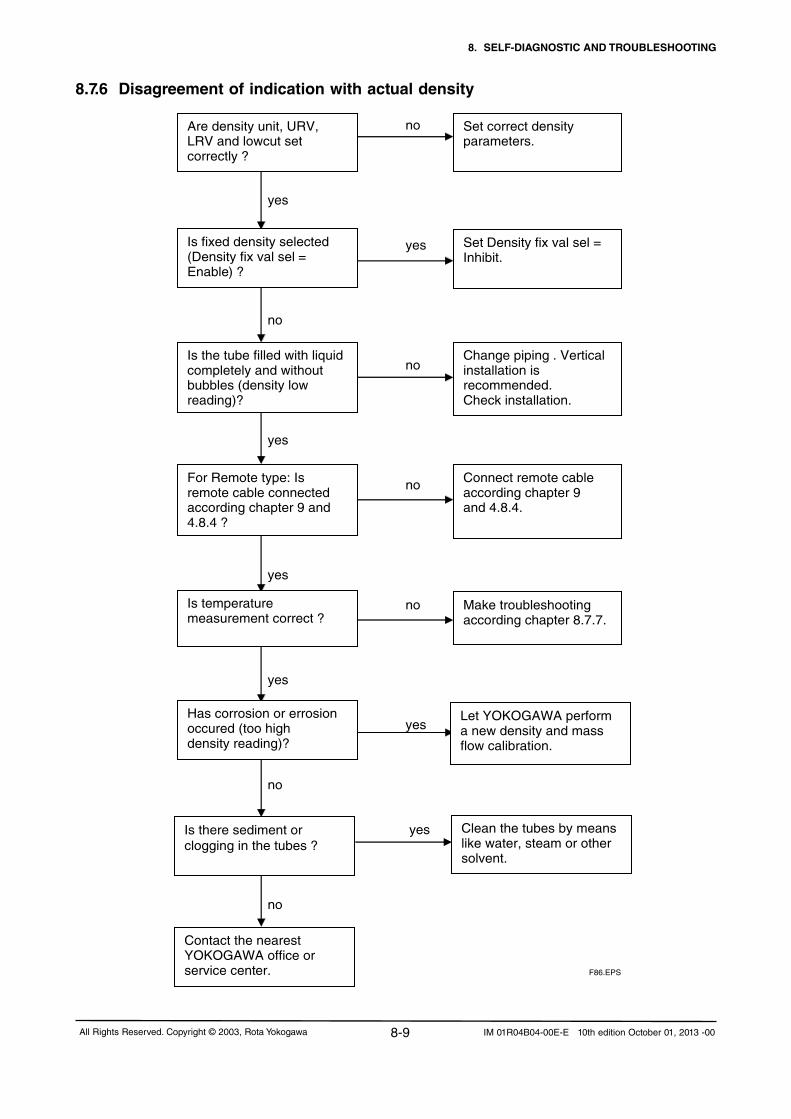
8. SELF-DIAGNOSTIC AND TROUBLESHOOTING
8-9All Rights Reserved. Copyright © 2003, Rota Yokogawa IM 01R04B04-00E-E 10th edition October 01, 2013 -00
8.7.6 Disagreement of indication with actual density no yes yes no no yes no yes no yes yes no yes no
Set correct density parameters.
Change piping . Vertical installation is recommended. Check installation.
Connect remote cable according chapter 9 and 4.8.4.
Make troubleshooting according chapter 8.7.7.
Set Density fix val sel = Inhibit.
Is temperature measurement correct ?
For Remote type: Is remote cable connected according chapter 9 and 4.8.4 ?
Let YOKOGAWA perform a new density and mass flow calibration.
Has corrosion or errosion occured (too high density reading)? Contact the nearest YOKOGAWA office or service center.
Is fixed density selected (Density fix val sel = Enable ) ?
Is the tube filled with liquid completely and without bubbles (density low reading)?
Is there sediment orclogging in the tubes ?
Clean the tubes by means like water, steam or other solvent.
Are density unit, URV, LRV and lowcut set correctly ?
F86.EPS

8. SELF-DIAGNOSTIC AND TROUBLESHOOTING
8-10 All Rights Reserved. Copyright © 2003, Rota YokogawaIM 01R04B04-00E-E 10th edition October 01, 2013 -00
8.7.7 Disagreement of indication with actual temperature
yes
Are temperature unit, URV, LRV and lowcut set correctly ?
Set correct temperature parameters.
PT 100 fault. Simulate the correct temp. by a fixed temp, value or connect an external PT100.
For Remote type: Is remote cable connected according chapter 9 and 4.8.4 ?
Connect remote cable according chapter 9 and 4.8.4
Compact type: disconnect first the converter housing Disconnect the temperature sensor cables 7,8,9 from TP1, TP2, TP3 in detector RCCS3 terminal box. Measure the resistances of detector temperature sensor terminals TP1, TP2, TP3. Resistance between TP1 + TP2 : 50 …200 depending on medium temperature Resistance between TP1 + TP3 : 50 …200 depending on medium temperature Resistance between TP2 + TP3 : <10
Replace remote cable.
Is fixed temperature selected (Tempy fix val sel = Enable ) ?
Set Temp fix val sel = Inhibit.
Resistance values are as stored ?
For remote type: Check remote cable lines 7, 8, 9. Cable OK ?
yes
no
no
no
no
no
yes
yes
yes
yes
F87.EPS

8. SELF-DIAGNOSTIC AND TROUBLESHOOTING
8-11All Rights Reserved. Copyright © 2003, Rota Yokogawa IM 01R04B04-00E-E 10th edition October 01, 2013 -00
8.7.8 Discrepancy of output signals to the assigned measurand
no
yes
Measured temperature values OK ?
Converter fault. Contact the nearest YOKOGAWA office or service center.
Check the electronics: Connect Pt100 simulator to terminals TP1, TP2, TP3 in converter RCCF31 terminal box. TP1 : + power, + sensor TP2 : - sensor TP3 :
Check your reference temperature.
F88.EPS
- power
no
yes
no
yes
Is the setting of the doubtful output signal correct ?
Make correct parameter setting.
Check output according chapter 8.4. Output OK ?
Contact the nearest YOKOGAWA office or service center
Check measurand. F89.EPS

8. SELF-DIAGNOSTIC AND TROUBLESHOOTING
8-12 All Rights Reserved. Copyright © 2003, Rota YokogawaIM 01R04B04-00E-E 10th edition October 01, 2013 -00
8.7.9 Setting "Burn-out" modeThe flowmeter is equipped with a CPU error burn-out function used to set the analog output direction upon CPU error. When factory-shipment the output of CPU error burn-out is set to HIGH. The setting of the direction of analog output from burn-out can be changed.
To change the direction of output arising from burn-out, switch the jumper J2 on the CPU Board (see figure below).
CPU Board
Cable to display
JP2 (Burn out)
High : I ≥ 21.6mA
Low : I ≤ 3.6mA
F810.EPS

8. SELF-DIAGNOSTIC AND TROUBLESHOOTING
8-13All Rights Reserved. Copyright © 2003, Rota Yokogawa IM 01R04B04-00E-E 10th edition October 01, 2013 -00
The ROTAMASS RCC34...39/XRwastestedandFM-approvedaccordingtoANSI/ISA–12.27.01–2003for Canadian Dual Seal Approval. For units with option /DS this is stated on the name plate.
NOTE
If ROTAMASS flowmeter is not used in Canada this functionality can also be used without Dual Seal approval.
The primary seal (metering tube) withstands the maximum test pressures forced for the maximum flange pressure of 12.41 MPas / 1800 psi (Flange A4, ASME 900). However the enclosure do not withstand this pressure. For details see GS 01R04B04-00E-E.
When the metering tube fails, the detector enclosure is filled with process medium and the density reading of ROTAMASS increases rapidly. This can be used for detecting a primary seal failure by the following an-nunciation methods:
A) Via too high density reading, preferable with liquid application- Set “Basic setup / Density / Density URV about 0.3 kg/l above the highest possible process density. - Set an output (current or frequency) to density transmission.- If the URV is reached (e.g. 20 mA ) the primary seal failed.- Set Status output to Density alm 1 and status output will be active in case of tube failure.
B) Via Status output and “Empty pipe detection”Only for liquid (only possible with software version 1.7 or higher):- Check parameter "Basic Setup / Density / Density URV" (Default value is 1.5 kg/l). URV should be about 0.3 kg/l higher than any density the process can provide.- Set parameter "Detailed Setup / Empty pipe detect / Empty pipe alm sel / Apply".- Set parameter "Detailed Setup / Empty pipe detect / Empty pipe crit / ..." to a value which is a little bit higher than Density URV.- For detection with e.g. status output 1: Set "Detailed Setup / Config Output/Input / Pulse/Status out 1 / Pulse/Stat 1 select / Status out". Set "Detailed Setup / Config Output/Input / Pulse/Status out 1 / SO1 function / Empty alarm"- When the metering tube fails, the detector housing is filled with the process medium and the density increases. Alarm A15 "Empty pipe detection" appears, display is blinking and the status output is set active.
C) Via rupture disk (option /RD), preferable with gas application- When the metering tube fails, the installed rupture disk bursts at about 20 bar (290 psi). - For gas application the result will be a whistle by the gas blowing out.- Rupture disk is only for annunciation.
WARNINGIfrupturediskbursts,thehazardousprocessmediumispressedoutofthedetectorhousingtothe environment. Take care that no worker gets contact to the medium.
8.8 Detection of metering tube failure

8. SELF-DIAGNOSTIC AND TROUBLESHOOTING
8-14 All Rights Reserved. Copyright © 2003, Rota YokogawaIM 01R04B04-00E-E 10th edition October 01, 2013 -00
8.9 Customer Maintenance Part List
14a
Converter RCCF31 (RCCT3)
Detector RCCS30 ... 33
14a
Option /PD
Detector
13

8. SELF-DIAGNOSTIC AND TROUBLESHOOTING
8-15All Rights Reserved. Copyright © 2003, Rota Yokogawa IM 01R04B04-00E-E 10th edition October 01, 2013 -00
Detector RCCS34 ... 39/XR
Detector

8. SELF-DIAGNOSTIC AND TROUBLESHOOTING
8-16 All Rights Reserved. Copyright © 2003, Rota YokogawaIM 01R04B04-00E-E 10th edition October 01, 2013 -00
Item Part-No. Descriptions
RC
CT
34..3
9/X
R
RC
CF
31
RC
CS
34..3
9/X
R
RC
CS
30L
R..3
3
1a M3808PA-SP Complete CF-M20 Converter Housing xM3808PC-SP Complete CF-M20 Converter Housing Epoxy xM3808PE-SP CompleteCF-NPTConverterHousing xM3808PG-SP CompleteCF-NPTConverterHousingEpoxy x
1b M3808NL-SP Complete CT-M20 Converter Housing xM3808NN-SP Complete CT-M20 Converter Housing Epoxy xM3808NQ-SP CompleteCT-NPTConverterHousing xM3808NS-SP CompleteCT-NPTConverterHousingEpoxy x
2 M3810DD-SP CF/CT Base Board Set Std x xM3810DE-SP CF/CT Base Board Set /FB x xM3811QF-SP CF/CT Base Board Set /MB1, /MB2, /MB3 x x
3 M3810DF-SP CF/CT Cap Assy Std (/HP) x x4 M3810DS-SP CF/CT Amplifier AC Std x x
M3810DT-SP CF/CTAmplifierACStd/NM x xM3810DW-SP CF/CT Amplifier AC Std /XR x xM3810DX-SP CF/CTAmplifierACStd/XR/NM x xM3810DY-SP CF/CT Amplifier DC Std x xM3810DZ-SP CF/CTAmplifierDCStd/NM x xM3810EA-SP CF/CT Amplifier DC Std /XR x xM3810EB-SP CF/CTAmplifierDCStd/XR/NM x xM3810EC-SP CF/CT_FB Amplifier AC Std x xM3810ED-SP CF/CT_FB Amplifier AC Std /XR x xM3810EE-SP CF/CT_FB Amplifier DC Std x xM3810EF-SP CF/CT_FB Amplifier DC Std /XR x xM3811HP-SP CF/CT Amplifier AC Std /MB1 x xM3811HR-SP CF/CT Amplifier AC Std /XR /MB1 x xM3811HQ-SP CF/CT Amplifier DC Std /MB1 x xM3811HS-SP CF/CT Amplifier DC Std /XR /MB1 x xM3815BN-SP CF/CT Amplifier AC Std /MB2, /MB3 x xM3815BP-SP CF/CT Amplifier AC Std /XR /MB2, /MB3 x xM3815BQ-SP CF/CT Amplifier DC Std /MB2, /MB3 x xM3815BR-SP CF/CT Amplifier DC Std /XR /MB2, /MB3 x x
5 M3808TC-SP CF/CT Display Set x xM3808TD-SP CF/CT Display Set /FB x x
6 M3810DJ-SP CF/CT Cover with Window PU (not Ex) x xM3810DK-SP CF/CT Cover with Window Epoxy (not Ex) x x
7 M3810DL-SP CF/CT Short Cover PU x xM3810DM-SP CF/CT Short Cover Epoxy x x
8 M3810DN-SP CF/CT Small Cover PU xM3810DP-SP CF/CT Small Cover Epoxy x
9 M3808TB-SP CF/CT/CS Complete O-Ring Set Conv./Sens. x x x x9a M3809EF-SP 10pcsO-RingSet109,4x3,1NBR70N7S33-59 x x9b M3809EG-SP 10pcsO-RingSet89,4x3,3NBR70N7S33-59 x9c M3809EH-SP 10pcsO-RingSet84x3NBR70N7S33-59 x x x x9d M3809EJ-SP 10pcsO-RingSet81x4NBR70N7S33-59 x x

8. SELF-DIAGNOSTIC AND TROUBLESHOOTING
8-17All Rights Reserved. Copyright © 2003, Rota Yokogawa IM 01R04B04-00E-E 10th edition October 01, 2013 -00
Item Part-No. Descriptions
RC
CT
34..3
9/X
R
RC
CF
31
RC
CS
34..3
9/X
R
RC
CS
30L
R..3
3
10 M3810EH-SP Cable Gland M20x1,5 Black x xM3810EK-SP CableGlandM20x1,5Nickel-platedBrass x xM3810FB-SP Cable Gland M20x1,5 Stainless Steel x xM3810EJ-SP CableGlandNPT1/2-14Nickel-platedBrass x xM3810FC-SP CSCableGlandSetNPTNickel-platedBrass x xM3810FD-SP CSCableGland-SetNPTStainlessSteel x xM3810EM-SP AdapterNPT½-14=>G1/2 x x
11 M3808SZ_SP CS Connection Housing- 316L Set x x12 M3808TA-SP CS Connection Housing Cover- 316L Set x x13 M3806JA-SP 2“ Pipe Mounting Set (Option /PD) x14a M3810DR-SP CF Mounting Bracket+Bracket Mounting Set x14b M3808TE-SP CF Bracket Mounting Set x
M3810EP-SP CT Wiring Loom xM3806ZZ-SP CF/CT Connection Part-Set x xM3810DQ-SP CY Cable Termination Set for 9 wire cableM3813WJ-SP CY Cable Termination Set for cable with coaxial lines
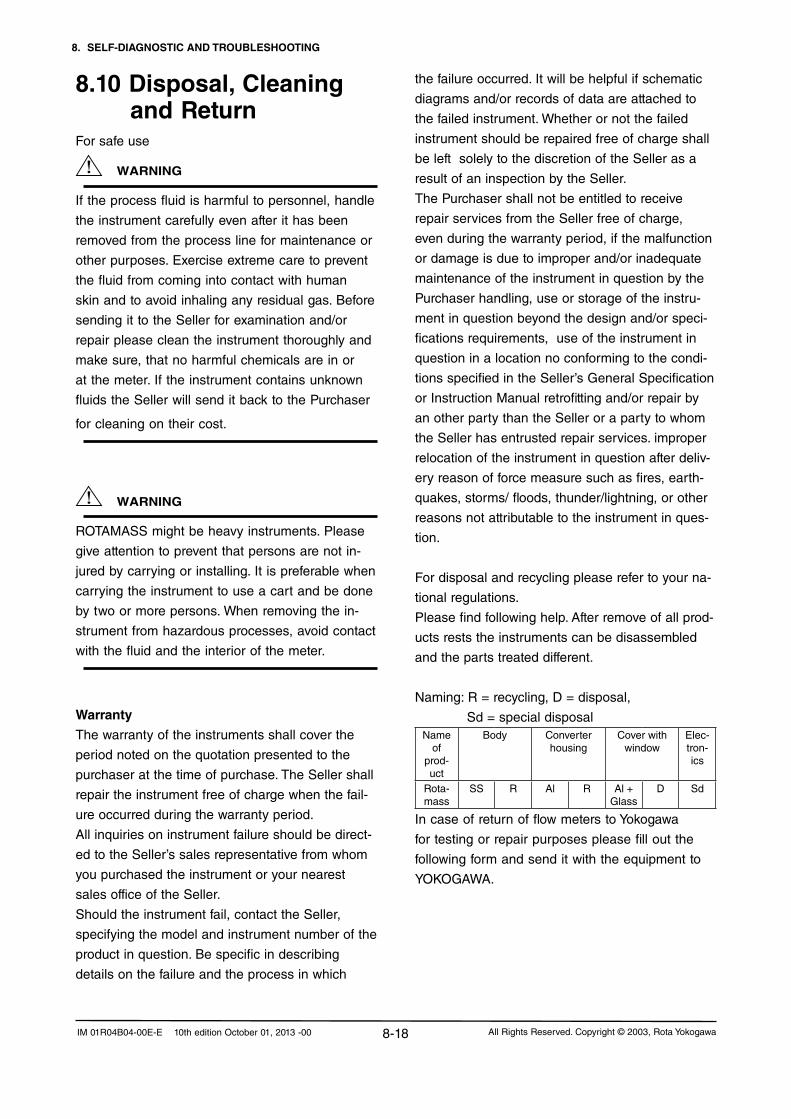
8. SELF-DIAGNOSTIC AND TROUBLESHOOTING
8-18 All Rights Reserved. Copyright © 2003, Rota YokogawaIM 01R04B04-00E-E 10th edition October 01, 2013 -00
8.10 Disposal, Cleaning and Return
For safe use
WARNING
If the process fluid is harmful to personnel, handle
the instrument carefully even after it has been
removed from the process line for maintenance or
other purposes. Exercise extreme care to prevent
the fluid from coming into contact with human
skin and to avoid inhaling any residual gas. Before
sending it to the Seller for examination and/or
repair please clean the instrument thoroughly and
make sure, that no harmful chemicals are in or
at the meter. If the instrument contains unknown
fluids the Seller will send it back to the Purchaser
for cleaning on their cost.
WARNING
ROTAMASS might be heavy instruments. Please
give attention to prevent that persons are not in-
jured by carrying or installing. It is preferable when
carrying the instrument to use a cart and be done
by two or more persons. When removing the in-
strumentfromhazardousprocesses,avoidcontact
with the fluid and the interior of the meter.
the failure occurred. It will be helpful if schematic
diagrams and/or records of data are attached to
the failed instrument. Whether or not the failed
instrument should be repaired free of charge shall
be left solely to the discretion of the Seller as a
result of an inspection by the Seller.
The Purchaser shall not be entitled to receive
repair services from the Seller free of charge,
even during the warranty period, if the malfunction
or damage is due to improper and/or inadequate
maintenance of the instrument in question by the
Purchaser handling, use or storage of the instru-
ment in question beyond the design and/or speci-
fications requirements, use of the instrument in
question in a location no conforming to the condi-
tionsspecifiedintheSeller’sGeneralSpecification
or Instruction Manual retrofitting and/or repair by
an other party than the Seller or a party to whom
the Seller has entrusted repair services. improper
relocation of the instrument in question after deliv-
ery reason of force measure such as fires, earth-
quakes, storms/ floods, thunder/lightning, or other
reasons not attributable to the instrument in ques-
tion.
For disposal and recycling please refer to your na-
tional regulations.
Please find following help. After remove of all prod-
ucts rests the instruments can be disassembled
and the parts treated different.
Naming:R=recycling,D=disposal,
Sd = special disposalName
of prod-uct
Body Converter housing
Cover with window
Elec-tron-ics
Rota-mass
SS R Al R Al + Glass
D Sd
In case of return of flow meters to Yokogawa
for testing or repair purposes please fill out the
following form and send it with the equipment to
YOKOGAWA.
Warranty
The warranty of the instruments shall cover the
period noted on the quotation presented to the
purchaser at the time of purchase. The Seller shall
repair the instrument free of charge when the fail-
ure occurred during the warranty period.
All inquiries on instrument failure should be direct-
edtotheSeller’ssalesrepresentativefromwhom
you purchased the instrument or your nearest
sales office of the Seller.
Should the instrument fail, contact the Seller,
specifying the model and instrument number of the
product in question. Be specific in describing
details on the failure and the process in which

8. SELF-DIAGNOSTIC AND TROUBLESHOOTING
8-19All Rights Reserved. Copyright © 2003, Rota Yokogawa IM 01R04B04-00E-E 10th edition October 01, 2013 -00
ROTA YOKOGAWA GmbH & Co. KG Service & Repair Department Rheinstraße 8; D - 79664 Wehr Phone no.: +49 (0)7761-567-190 Fax no.: +49 (0)7761-567-285 e-Mail: [email protected]
Declaration of Decontamination Legal regulations for the safety of our employees and operating equipment determine that we need the declaration of decontamination before your order can be handled. Please make sure to include it with the shipping documents, attached to the outside of the packaging you use for shipment.
Customer data
Company:
Address:
Contact person: E-Mail:
Phone no.: Fax no.:
Reference/Order no.:
Instrument data*
Type: Serial no.:
Type: Serial no.:
*If not enough, note on separate sheet
Process data
Process medium:
Medium is: [ ] toxic [ ] corrosive [ ] explosive [ ] biological hazardous [ ] unknown if dangerous [ ] non hazardous
Remarks:
Cleaning agent:
Kind of cleaning :
Other remarks / Reason of return:
We hereby confirm that this statement is filled in completely and truthfully. The returned instruments were carefully cleaned and are thus free from product residue and dirt. I agree that if this arrangement does not match with the instruments, they will be sent back to the above mentioned customer address at our expenses. Name Date Signature

8. SELF-DIAGNOSTIC AND TROUBLESHOOTING
8-20 All Rights Reserved. Copyright © 2003, Rota YokogawaIM 01R04B04-00E-E 10th edition October 01, 2013 -00
Blank Page

9. EXPLOSION PROTECTED TYPE INSTRUMENTS
9-1All Rights Reserved. Copyright © 2003, Rota Yokogawa IM 01R04B04-00E-E 10th edition October 01, 2013 -00
9.1 ATEXIn this section, further requirements and differences
for explosion proof type instrument are described.
For explosion proof type instrument, the descrip-
tion in this chapter is prior to other description in
this Instruction Manual.
• Only trained persons may use the instrument in industrial location.•Theinstrumentmodificationorpartsreplace- mentbyotherthananauthorizedRepresentative of Yokogawa is prohibited and will void the certification. •Electrostaticchargemaycauseanexlosion hazard.Avoidanyactionsthatcausethe gerenation of eletrostatic charge, such as rubbing with a dry cloth on coating face of the converter.•Ifitismountedinanareawheretheuseof category 2D apparatus is required, it shall be installed in such a way that the risk from electrostatic discharges and propagating brush discharges caused by rapid flow of dust is avoided.
9. EXPLOSION PROTECTED TYPE INSTRUMENTS
WARNING
ROTAMASS is produced byRota YokogawaRheinstr. 8D-79664 WehrGermany
9.1.1 Technical Data
Applicable standards:RCCS3:EN60079-0:2012;EN60079-11:2012;EN60079-31:2009RCCT3/RCCF31/RCCR31:EN60079-0:2012;EN60079-1:2007;EN60079-7:2007;EN60079-11:2012;EN60079-31:2009
Remote detector RCCS30LR ... 33 (option /KS1):- KEMA 01ATEX 1075 X- Intrinsically safe- II 2G Ex ib IIB/IIC T1 ... T6 Gb- II 2D Ex ib IIIC T Db ( = max. surface temperature see below)- Max. surface temperature : Standard : 150°C /MT : 260°C /MT, not /T : 320°C - Degree of protection: IP67- Ambient humidity : 0 to 95% RH- Ambient temperature range: -50°C to +80°C- Process temperature limits : Standard : -50°C to 150°C /MT : -50°C to 260°C /MT, not /T : -50°C to 320°C- Heat carrier fluid temperature limits : Standard : 0°C to 150°C Option /MT : 0°C to 260°C
Remote detector RCCS34 ... 39/XR (option /KS1):- KEMA 01ATEX 1075 X- Intrinsically safe- II 2G Ex ib IIB/IIC T1 ... T6 Gb- II 2D Ex ib IIIC T Db ( = max. surface temperature see below)-Max. surface temperature : Standard + /LT : 150°C /MT : 220°C /HT : 350°C - Degree of protection: IP67- Ambient humidity : 0 to 95% RH- Ambient temperature range: -50°C to +80°C Option /HT (process temperature < 280°C): -50°C to +65°C Option /HT (process temperature < 350°C): -50°C to +55°C- Process temperature limits : Standard : -50°C to 150°C Option /MT: : -50°C to 220°C Option /HT : 0°C to 350°C Option /LT : -200°C to 150°C- Heat carrier fluid temperature limits : Standard : 0°C to 150°C Option /MT : 0°C to 220°C Option /HT : 0°C to 350°C

9. EXPLOSION PROTECTED TYPE INSTRUMENTS
9-2 All Rights Reserved. Copyright © 2003, Rota YokogawaIM 01R04B04-00E-E 10th edition October 01, 2013 -00
Remote converter RCCF31 (option /KF1):- KEMA 02ATEX 2183 X- Flame proof with intrinsic safe connection to detector (ib)- II 2G Ex d [ib] IIC T6 Gb or Ex d e [ib] IIC T6 Gb- II 2G Ex d [ib] IIB T6 Gb or Ex d e [ib] IIB T6 Gb with option /HP- II 2D Ex tb [ib] IIIC T75°C Db- Max. surface temperature: 75°C- Degree of protection : IP66/67-Powersupply:90to250VAC,50/60Hz 20.5 to 28.8 V DC- Power consumption : max. 25 VA / 10 W- Ambient humidity : 0 to 95% RH- Ambient temperature range: -40°C to +55°CRemote converter RCCF31 (option /KF5):- KEMA 02ATEX 2183 X- Flame proof with intrinsic safe connection to detector (ib)- Additional intrinsic safe outputs (ia).- II 2 (1) G Ex d [ia Ga] [ib] IIC T6 Gb or Ex d e [ia Ga] [ib] IIC T6 Gb- II 2 (1) G Ex d [ia IIC Ga] [ib] IIB T6 Gb or Ex d e [ia IIC Ga] [ib] IIB T6 Gb with option /HP- II 2 (1) D Ex tb [ia Da] [ib] IIIC T75°C Db- Max. surface temperature: 75°C- Degree of protection : IP66/67-Powersupply:90to250VAC,50/60Hz 20.5 to 28.8 V DC- Power consumption : max. 25 VA / 10 W- Ambient humidity : 0 to 95% RH- Ambient temperature range : -40°C to +55°C
Remote converter RCCR31 (option /KS1) :- KEMA 02ATEX 2183 X- Associated apparatus with intrinsic safe connection to detector (ib)- II (2) G [Ex ib Gb] IIC - II (2) G [Ex ib Gb] IIB with option /HP- II (2) D [Ex ib Db] IIIC-Powersupply:90to250VAC,50/60Hz 20.5 to 28.8 V DC- Power consumption : max. 25 VA / 10 W- Ambient humidity: 0 to 95% RH- Ambient temperature range: -40°C to +55°C
WARNING Remote rack mount converter RCCR31 must only be installed in safe area !
Integral type RCCT34 ... 39/XR (option /KF1):- KEMA 02ATEX 2183 X- Flame proof with intrinsic safe connection to detector (ib)- II 2G Ex d ib IIC T6...T3 Gb or Ex d e ib IIC T6...T3 G- II 2G Ex d ib IIB T6...T3 Gb or Ex d e ib IIB T6...T3 Gb with option /HP- II 2G Ex d ib op is IIC T6...T3 Gb - II 2D Ex ib tb IIIC T150°C Db- Max. surface temperature : 150°C- Degree of protection : IP66/67-Powersupply:90to250VAC,50/60Hz 20.5 to 28.8 V DC- Power consumption : max. 25 VA / 10 W- Ambient humidity : 0 to 95% RH- Ambient temperature range : -40°C to +55°C- Process temperature limits : -50°C to 150°C
Integral type RCCT34 ... 39/XR (option /KF5):- KEMA 02ATEX 2183 X- Flame proof with intrinsic safe connection to detector (ib)- Additional intrinsic safe outputs (ia).- II 2 (1) G Ex d ib [ia Ga] IIC T6...T3 Gb or Ex d e ib [ia Ga] IIC T6...T3 Gb- II 2 (1) G Ex d ib [ia IIC Ga] IIB T6...T3 Gb or Ex d e ib [ia IIC Ga] IIB T6...T3 Gb with option /HP- II 2 (1) D Ex ib tb [ia Da] IIIC T150°C Db- Max. surface temperature : 150°C- Degree of protection : IP66/67-Powersupply:90to250VAC,50/60Hz 20.5 to 28.8 V DC- Power consumption : max. 25 VA / 10 W- Ambient humidity : 0 to 95% RH- Ambient temperature range : -40°C to +55°C- Process temperature limits : -50°C to 150°C
The electronics of RCCT3 and RCCF31 are placed in a pressure tight section of the converter housing Ex d. The kind of protection of the terminal enclosure is“e”,butcanbecome“d”byusingEx-dcertifiedcable glands.
Electrical data remote detector RCCS30LR ... 33:- Driving circuit : terminals D+ / D- ExibIIC: Ui=16V;Ii=53mA;Pi=0.212W Li=4.2mH;Ci=negl.small ExibIIB: Ui=16V;Ii=153mA;Pi=0.612W Li=4.2mH;Ci=negl.small- Sensor circuits: terminals S1+/ S1- or S2+ / S2- ExibIIC: Ui=16V;Ii=80mA;Pi=0.32W Li=4.2mH;Ci=negl.small- Temp. sensor circuit : terminals TP1, TP2, TP3 ExibIIC: Ui=16V;Ii=50mA;Pi=0.2W Li = negligible small
Ci = negligible small

9. EXPLOSION PROTECTED TYPE INSTRUMENTS
9-3All Rights Reserved. Copyright © 2003, Rota Yokogawa IM 01R04B04-00E-E 10th edition October 01, 2013 -00
Coherence between temperature class, ambient- and medium temperature/ temperature of heat carrier :RCCS30LR to RCCS33
without insulationRCCS30LR to RCCS33 with factory insulation
Temp. class
Max. ambient temperature
Max. process temperature
Max. ambient temperature
Max. process temperature
T6 50°C / 122°F 60°C / 140°F 60°C / 140°F 60°C / 140°F
T5 50°C / 122°F 80°C / 176°F 80°C / 176°F 90°C / 194°F
T480°C / 176°F 50°C / 122°F
100°C / 212°F120°C / 248°F
80°C / 176°F 130°C / 266°F
T3 80°C / 176°F 180°C / 356°F 80°C / 176°F 180°C / 356°F
T2 80°C / 176°F 260°C / 500°F 80°C / 176°F 260°C / 500°F
T1 80°C / 176°F 260°C / 500°F 80°C / 176°F 260°C / 500°F
RCCS34 to RCCS39/XR without insulation
RCCS34 to RCCS39/XR with factory insulation
RCCT34 to RCCT39/XR
Temp. class
Max. ambient temperature
Max. process temperature
Max. ambient temperature
Max. process temperature
Max. ambient temperature
Max. process temperature
T6 40°C / 104°F 40°C / 104°F 65°C / 149°C 65°C / 149°F +55°C / 131°F 65°C / 149°C
T5 55°C / 131°F 55°C / 131°F 75°C / 167°F 75°C / 167°F +55°C / 131°F 80°C / 176°F
T480°C / 176°F40°C / 104°F
100°C / 212°F120°C / 248°F
70°C / 158°F 115°C / 239°F +55°C / 131°F 115°C / 239°F
T380°C / 176°F40°C / 104°F
160°C / 320°F180°C / 356°F
70°C / 158°F 180°C / 356°F +55°C / 131°F 150°C / 302°F
T2 80°C / 176°F 220°C / 428°F 65°C /149°F 275°C / 527°F +55°C / 131°F 150°C / 302°F
T1 80°C / 176°F 220°C / 428°F 45°C / 113°F 350°C / 662°F +55°C / 131°F 150°C / 302°F
For customer insulation of RCCS30LR to 39/XR the following must be regarded : The table "with factory insulation" is calculated with 80 mm insulation and k-factor = 0.4 W/m2K. If your insulation data are worse than these use table "without insulation" !
NOTE
Electrical data remote detector RCCS34 ... 39/XR :
- Driving circuit : terminals D+ / D
ExibIIC: Ui=16V;Ii=53mA;Pi=0.212W Li=3.2mH;Ci=negligiblesmall
ExibIIB: Ui=16V;Ii=153mA;Pi=0.612W Li=3.2mH;Ci=negligiblesmall
- Sensor circuits: terminals S1+/ S1- or S2+ / S2-
ExibIIC: Ui=16V;Ii=80mA;Pi=0.32W
Li=2.1mH;Ci=negligiblesmall
- Temp. sensor circuit : terminals TP1, TP2, TP3
ExibIIC: Ui=16V;Ii=50mA;Pi=0.2W
Li = negligible small
Ci = negligible small
Electrical data remote converter RCCF31, RCCR31 and converter of Intergral type RCCT3:
- Driving circuit : terminals D+ / D-
Ex ib IIC : Uo=14.5V;Io=47mA;Po=0.171W
Lo=15mH;Co=0.65µF
ExibIIB: Uo=11.7V;Io=124mA;Po=0.363W
Lo=8mH;Co=10.3µF
- Sensor circuits: terminals S1+/ S1- or S2+ / S2-
Ex ib IIC : Uo=14.5V;Io=47mA;Po=0.171W
Lo=15mH;Co=0.65µF
- Temperature sensor circuit : terminals TP1,TP2, TP3
Ex ib IIC : Uo=13.3V;Io=40mA;Po=0.133W
Lo=20mH;Co=0.91µF- Current output (only option /KF2) : ExiaIIC: Ui=30V;Ii=165mA;Pi=1.25W Li=negligiblesmall;Ci=6.9nF- Pulse output (only option /KF2) : Ex ia IIC : Ui=30V;Ii=100mA;Pi=0.75W Li = negligible small;Ci=4.5nF
- Current output (only option /KF5) :
ExiaIIC: Ui=30V;Ii=300mA;Pi=1.25W Li=4µH;Ci=5.5nF
- Pulse output (only option /KF5) :
Ex ia IIC : Ui=30V;Ii=130mA;Pi=1.25W Li=4µH;Ci=13.1nF

9. EXPLOSION PROTECTED TYPE INSTRUMENTS
9-4 All Rights Reserved. Copyright © 2003, Rota YokogawaIM 01R04B04-00E-E 10th edition October 01, 2013 -00
If a Rotamass with option /LT is used without factory insulation option /T1, it must be ensured that the temperature at the O-rings of the terminal box does not decrease below -50°C !
Flame proof (Ex d) relevant threads at converter housing and covers:
No. Position of thread Pitch Thread form + quality of pitch
Threads engaged
Depth of engagement
(1) case Thread on electronic/display side 2 mm medium, 6H 1) ≥ 6 12 mm(1) cover Thread on electronic/display side 2 mm medium, 6g 1) ≥ 6 12 mm(2) case Thread on terminal box side 2 mm medium, 6H 1) ≥ 6 12 mm(2) cover Thread on terminal box side 2 mm medium, 6g 1) ≥ 6 12 mm(3) M Thread for cable glands M20 x 1.5 1.5 mm medium, 6H 1) ≥ 10 17 mm(3) A/F Threadforcableglands1/2´´NPT 1.814 mm 2) 6.5 ± 1 13.605 mm
1) acc. ISO 965-1 and ISO 965-3 2)acc.ANSIB1.20.1
If terminal enclosure is used as Ex e, the threads (2) and (3) in above table must be not be regarded.
Marking of Ex d covers
The cover with glass window is marked inside with an "Ex"- label as shown below:
NOTE
F94.EPS
(1) (2)
(3)

9. EXPLOSION PROTECTED TYPE INSTRUMENTS
9-5All Rights Reserved. Copyright © 2003, Rota Yokogawa IM 01R04B04-00E-E 10th edition October 01, 2013 -00
9.1.2 Installation
Integral type RCCT3
WARNING 1. Ex type of ROTAMASS must be connected to the suitable IS earthing system (see installation diagram).
Converter case must have connection to the potential equalisation facility. If the connecting process tubing is part of the potential equalisation, no additional connection is required .
2. Use the certified cable glands, suitable for the conditions of use. The delivered cable glands are only for Ex e use. For Ex d use d-type cable glands.
3. Please confirm that the ground terminal (inside the terminal enclosure) is firmly connected by means of a clip-on eye-let.4. Ex-e terminals for power supply and I/O-lines are designed for cables with cross section of 0.08 mm²
(AWG 28) to 2.5 mm² (AWG 22). The strip length must be 5 to 6 mm (0.2 to 0.24 in).
Cable glands for power- and I/O-cables :RCCT3-M : Exetypesareenclosed.Thesecableglandscanalsobeusedfor“dustapplication”(D). Use ATEX-certified Ex d cable glands for Ex d condition.RCCT3-A:Nocableglandsareenclosed.UsetheATEX-certifiedcableglands,suitableforthe conditions of use (Ex de or Ex d or dust application).
For“dustapplication”usecableglandswithminimumIP67protection!
Installation diagram (option /KF1):
L/+N/-G
Power supply
I/O control
Hazardous area Safe area
I/O
Rotamass RCCT3
F91.EPS
Ter
min
al B
ox
Detailed information for connection intrinsic safe outputs (option /KF2 and /KF5) see chapter 4.8.8.

9. EXPLOSION PROTECTED TYPE INSTRUMENTS
9-6 All Rights Reserved. Copyright © 2003, Rota YokogawaIM 01R04B04-00E-E 10th edition October 01, 2013 -00
Remote field-mount type RCCF31 with RCCS3
WARNING 1. Ex-type RCCF31 and RCCS3 must be connected to the suitable IS earthing system (see installation diagram). Converter and detector case must have connection to the potential equalisation facility. 2. Use the certified cable glands, suitable for the conditions of use. 3. Please confirm that the ground terminal (inside the terminal enclosure) is firmly connected by means of a clip-on eye-let. 4. Ex-e terminals for power supply and I/O-lines are designed for cables with cross section of 0.08 mm²
(AWG 28) to 2.5 mm² (AWG 22). The strip length must be 5 to 6 mm (0.2 to 0.24 in). 5. For EMC technical reasons the case of the detector is connected to the case of the converter via the shielding of the interconnecting cable.
Cable glands for power- and I/O-cables :RCCF31-M : Exetypesareenclosed.Thesecableglandscanalsobeusedfor“dustapplication”(D). Use ATEX-certified Ex d cable glands for Ex d condition.RCCF31-A : Nocableglandsareenclosed.UsetheATEX-certifiedcableglands,suitableforthe conditions of use (Ex de or Ex d or dust application)
For“dustapplication”(D)usecableglandswithminimumIP67protection!
Cable glands for detector connection terminal :RCCF31-M : Cable glands are fitted in the concerning thread. This cable gland can be used for “dustapplication”(D).RCCF31-A : Cableglandsareenclosed.Thiscableglandcanalsobeusedfor“dustapplication”(D).
Installation diagram (option /KF1) :
L/+N/-G
Power supply
I/O control
Hazardous area Safe area
I/O
RCCF31RCCS3
D+D-
S1+S1-
S2+S2-
TP1TP2TP3
D+D-
S1+S1-
S2+S2-TP1TP2TP3COM
Exclusive remote cable RCCY03
Coax line
Coax line
Coax line
IS earth
The inner shields (shields of the cable pairs) are connected together to COM – terminal on converter side.The outer shield of the cable is connected on both sides to the cases by cable gland.
Detailed information for connection intrinsic safe outputs (option /KF2 and /KF5) see chapter 4.8.8

9. EXPLOSION PROTECTED TYPE INSTRUMENTS
9-7All Rights Reserved. Copyright © 2003, Rota Yokogawa IM 01R04B04-00E-E 10th edition October 01, 2013 -00
Remote rack-mount type RCCR31 with RCCS3
WARNING 1.. Remote rack-mount converter RCCR31 may only be installed in safe area ! 2. Ex-type RCCR31 and RCCS3 must be connected to the suitable IS earthing system (see installation diagram). Converter and detector case must have connection to the potential equalisation facility. 3. Please confirm that the ground terminal on terminal board is firmly connected. 4. For EMC technical reasons the case of the detector is connected to the case of the converter via the shielding of the interconnecting cable.
Installation diagram :
L/+N/-G
Power supply
I/O control
Hazardous area Safe area
I/O
RCCR31RCCS3
D+D-
S1+S1-
S2+S2-
TP1TP2TP3
D+D-
S1+S1-
S2+S2-TP1TP2TP3COM
Exclusive remote cable RCCY03
Coax line
Coax line
Coax line
IS earth
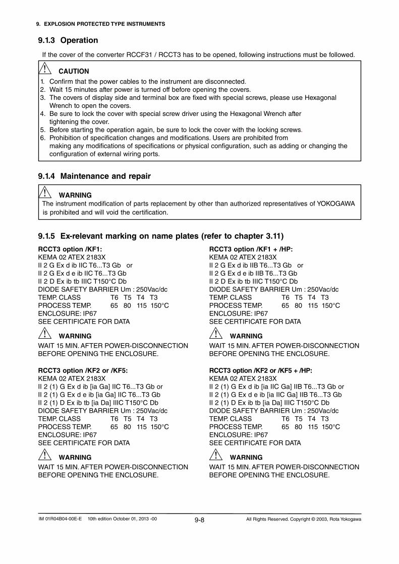
9. EXPLOSION PROTECTED TYPE INSTRUMENTS
9-8 All Rights Reserved. Copyright © 2003, Rota YokogawaIM 01R04B04-00E-E 10th edition October 01, 2013 -00
9.1.3 Operation
If the cover of the converter RCCF31 / RCCT3 has to be opened, following instructions must be followed.
CAUTION 1. Confirm that the power cables to the instrument are disconnected. 2. Wait 15 minutes after power is turned off before opening the covers. 3. The covers of display side and terminal box are fixed with special screws, please use Hexagonal Wrench to open the covers. 4. Be sure to lock the cover with special screw driver using the Hexagonal Wrench after tightening the cover. 5. Before starting the operation again, be sure to lock the cover with the locking screws. 6. Prohibition of specification changes and modifications. Users are prohibited from making any modifications of specifications or physical configuration, such as adding or changing the configuration of external wiring ports.
9.1.4 Maintenance and repair
WARNINGTheinstrumentmodificationofpartsreplacementbyotherthanauthorizedrepresentatives of YOKOGAWA
is prohibited and will void the certification.
9.1.5 Ex-relevant marking on name plates (refer to chapter 3.11)
RCCT3 option /KF1:KEMA 02 ATEX 2183XII 2 G Ex d ib IIC T6...T3 Gb or II 2 G Ex d e ib IIC T6...T3 GbII 2 D Ex ib tb IIIC T150°C DbDIODE SAFETY BARRIER Um : 250Vac/dcTEMP. CLASS T6 T5 T4 T3 PROCESS TEMP. 65 80 115 150°C ENCLOSURE:IP67SEE CERTIFICATE FOR DATA
WARNINGWAIT15MIN.AFTERPOWER-DISCONNECTIONBEFOREOPENINGTHEENCLOSURE.
RCCT3 option /KF2 or /KF5:KEMA 02 ATEX 2183XII 2 (1) G Ex d ib [ia Ga] IIC T6...T3 Gb orII 2 (1) G Ex d e ib [ia Ga] IIC T6...T3 GbII 2 (1) D Ex ib tb [ia Da] IIIC T150°C DbDIODE SAFETY BARRIER Um : 250Vac/dcTEMP. CLASS T6 T5 T4 T3 PROCESS TEMP. 65 80 115 150°C ENCLOSURE:IP67SEE CERTIFICATE FOR DATA
WARNINGWAIT15MIN.AFTERPOWER-DISCONNECTIONBEFOREOPENINGTHEENCLOSURE.
RCCT3 option /KF1 + /HP:KEMA 02 ATEX 2183XII 2 G Ex d ib IIB T6...T3 Gb or II 2 G Ex d e ib IIB T6...T3 GbII 2 D Ex ib tb IIIC T150°C DbDIODE SAFETY BARRIER Um : 250Vac/dcTEMP. CLASS T6 T5 T4 T3 PROCESS TEMP. 65 80 115 150°C ENCLOSURE:IP67SEE CERTIFICATE FOR DATA
WARNINGWAIT15MIN.AFTERPOWER-DISCONNECTIONBEFOREOPENINGTHEENCLOSURE.
RCCT3 option /KF2 or /KF5 + /HP:KEMA 02 ATEX 2183XII 2 (1) G Ex d ib [ia IIC Ga] IIB T6...T3 Gb orII 2 (1) G Ex d e ib [ia IIC Ga] IIB T6...T3 Gb II 2 (1) D Ex ib tb [ia Da] IIIC T150°C DbDIODE SAFETY BARRIER Um : 250Vac/dcTEMP. CLASS T6 T5 T4 T3 PROCESS TEMP. 65 80 115 150°C ENCLOSURE:IP67SEE CERTIFICATE FOR DATA
WARNINGWAIT15MIN.AFTERPOWER-DISCONNECTIONBEFOREOPENINGTHEENCLOSURE.
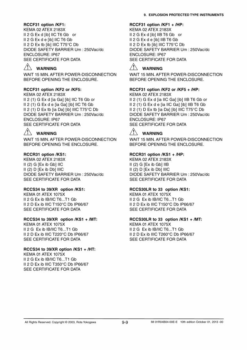
9. EXPLOSION PROTECTED TYPE INSTRUMENTS
9-9All Rights Reserved. Copyright © 2003, Rota Yokogawa IM 01R04B04-00E-E 10th edition October 01, 2013 -00
RCCF31 option /KF1:KEMA 02 ATEX 2183XII 2 G Ex d [ib] IIC T6 Gb or II 2 G Ex d e [ib] IIC T6 GbII 2 D Ex tb [ib] IIIC T75°C DbDIODE SAFETY BARRIER Um : 250Vac/dcENCLOSURE:IP67SEE CERTIFICATE FOR DATA
WARNINGWAIT15MIN.AFTERPOWER-DISCONNECTIONBEFOREOPENINGTHEENCLOSURE.
RCCF31 option /KF2 or /KF5:KEMA 02 ATEX 2183XII 2 (1) G Ex d [ia Ga] [ib] IIC T6 Gb or II 2 (1) G Ex d e [ia Ga] [ib] IIC T6 GbII 2 (1) D Ex tb [ia Da] [ib] IIIC T75°C DbDIODE SAFETY BARRIER Um : 250Vac/dcENCLOSURE:IP67SEE CERTIFICATE FOR DATA
WARNINGWAIT15MIN.AFTERPOWER-DISCONNECTIONBEFOREOPENINGTHEENCLOSURE.
RCCR31 option /KS1:KEMA 02 ATEX 2183XII (2) G [Ex ib Gb] IICII (2) D [Ex ib Db] IIICDIODE SAFETY BARRIER Um : 250Vac/dc SEE CERTIFICATE FOR DATA
RCCS34 to 39/XR option /KS1:KEMA 01 ATEX 1075XII 2 G Ex ib IB/IIC T6...T1 GbII 2 D Ex ib IIIC T150°C Db IP66/67 SEE CERTIFICATE FOR DATA
RCCS34 to 39/XR option /KS1 + /MT:KEMA 01 ATEX 1075XII 2 G Ex ib IB/IIC T6...T1 GbII 2 D Ex ib IIIC T220°C Db IP66/67SEE CERTIFICATE FOR DATA
RCCS34 to 39/XR option /KS1 + /HT:KEMA 01 ATEX 1075XII 2 G Ex ib IB/IIC T6...T1 GbII 2 D Ex ib IIIC T350°C Db IP66/67SEE CERTIFICATE FOR DATA
RCCF31 option /KF1 + /HP:KEMA 02 ATEX 2183XII 2 G Ex d [ib] IIB T6 Gb or II 2 G Ex d e [ib] IIB T6 GbII 2 D Ex tb [ib] IIIC T75°C DbDIODE SAFETY BARRIER Um : 250Vac/dc ENCLOSURE:IP67SEE CERTIFICATE FOR DATA
WARNINGWAIT15MIN.AFTERPOWER-DISCONNECTIONBEFOREOPENINGTHEENCLOSURE.
RCCF31 option /KF2 or /KF5 + /HP:KEMA 02 ATEX 2183XII 2 (1) G Ex d [ia IIC Ga] [ib] IIB T6 Gb or II 2 (1) G Ex d e [ia IIC Ga] [ib] IIB T6 GbII 2 (1) D Ex tb [ia Da] [ib] IIIC T75°C DbDIODE SAFETY BARRIER Um : 250Vac/dc ENCLOSURE:IP67SEE CERTIFICATE FOR DATA
WARNINGWAIT15MIN.AFTERPOWER-DISCONNECTIONBEFOREOPENINGTHEENCLOSURE.
RCCR31 option /KS1 + /HP:KEMA 02 ATEX 2183XII (2) G [Ex ib Gb] IIBII (2) D [Ex ib Db] IIICDIODE SAFETY BARRIER Um : 250Vac/dc SEE CERTIFICATE FOR DATA
RCCS30LR to 33 option /KS1:KEMA 01 ATEX 1075XII 2 G Ex ib IB/IIC T6...T1 GbII 2 D Ex ib IIIC T150°C Db IP66/67 SEE CERTIFICATE FOR DATA
RCCS30LR to 33 option /KS1 + /MT:KEMA 01 ATEX 1075XII 2 G Ex ib IB/IIC T6...T1 GbII 2 D Ex ib IIIC T260°C Db IP66/67 SEE CERTIFICATE FOR DATA

9. EXPLOSION PROTECTED TYPE INSTRUMENTS
9-10 All Rights Reserved. Copyright © 2003, Rota YokogawaIM 01R04B04-00E-E 10th edition October 01, 2013 -00
9.2 FM (USA + Canada)Applicable standards:FM3600:2011,FM3610:2010,FM3615:2006;,FM3810:2005,ANSI/NEMA250:1991,IEC60529:1999,ANSI/ISA60079-0:2009,ANSI/ISA60079-11:2009,CSA-C22.2No.157,:1992CSA-C22.2No.25:1992,CSA-C22.2No.30:1988,CSA-C22.2No.0.5:1982,CSA-C22.2No.142:1987,CSA-C22.2No.0.4:1982,CSA-C22.2No.94:1991
9.2.1 Technical DataRemote detector RCCS30LR ... 39/XR (option /FS1):- Intrinsically safe- AEx ia IIC, Class 1, Zone 0- IS Class I, Division 1, Groups A,B,C,D T6- DIP Class II / III, Division 1, Groups E,F,G-IP67/NEMA4XRemote converter RCCF31 (option /FF1, /FF2 or /FF5:- Housing explosion proof- Provides intrinsically safe detector circuits- AEx [ia] IIC, Class I, Zone 1, T6 - Class I, Division 1, Groups A,B,C,D- Class I, Division 1, Groups C,D with option /HP- Class II / III, Division 1, Groups E,F,G - AIS Class I / II / III, Division 1, Groups A,B,C,D, E,F,G - AIS Class I / II / III, Division 1, Groups C,D,E,F,G with /HPRemote converter RCCR31 (option /FS1):- Intrinsic safe associated apparatus- Provides intrinsically safe detector circuits- [AEx ia] IIC, Class I, Zone 1- AIS Class I, Division 1, Groups A,B,C,D - AIS Class I, Division 1, Groups C,D with option /HPIntegral type RCCT34 .. 39/XR (option /FF1, /FF2 or /FF5):- Housing explosion proof- AEx d [ia] IIC, Class I, Zone 1, T6 - Class I, Division 1, Groups A,B,C,D- Class I, Division 1, Groups C,D with option /HP- Class II / III, Division 1, Groups E,F,G -IP66/67/NEMA4XTemperature classification :The remote converter RCCF31 has a T6 temperature class rating for operation at ambient temperature up to +50°C / +122°F.
Process temperature limits / Heat carrier fluid temperature limits :- Standard : -50°C to 150°C / -58°F to 302°F- with option /LT : -200°C to 150°C / -328°F to 302°F- with option /MT (RCCS30LR...33) : -50°C to 260°C / -58°F to 500°F- with option /MT (RCCx34...39/XR) : -50°C to 220°C / -58°F to 428°F- with option /HT : 0°C to 350°C / 32°F to 662°F
Electrical data remote converter RCCF31, RCCR31 and converter of integral type RCCT3 :
- Driving circuit : terminals D+ / D-
Uo=14.5V;Io=47mA;Po=0.171W
Lo=15mH;Co=0.65µF
- Driving circuit : terminals D+ / D- with option /HP
Uo=11.7V;Io=124mA;Po=0.363W
Lo=8mH;Co=10.3µF
- Sensor circuits: terminals S1+/ S1- or S2+ / S2-
Uo=14.5V;Io=47mA;Po=0.363W
Lo=15mH;Co=0.65µF
- Temperature sensor circuit : terminals TP1,TP2, TP3
Uo=13.3V;Io=40mA;Po=0.133W
Lo=20mH;Co=0.91µF
Electrical data remote detector RCCS30LR ... 33:
- Driving circuit : terminals D+ and D
Ui=16V;Ii=53mA;Pi=0.212W Li=4.2mH;Ci=negligiblesmall
- Driving circuit : terminals D+ / D- with option /HP
Ui=16V;Ii=153mA;Pi=0.612W
Li=4.2mH;Ci=negligiblesmall
- Sensor circuits: terminals S1+ / S1- or S2+ /S2-
Ui=16V;Ii=80mA;Pi=0.32W
Li=4.2mH;Ci=negligiblesmall
- Temperature sensor circuit : terminals TP1, TP2, TP3
Ui=16V;Ii=50mA;Pi=0.2W
Li=negligiblesmall;Ci=negligiblesmall
Electrical data remote detector RCCS34 ... 39/XR :
- Driving circuit : terminals D+ and D
Ui=16V;Ii=53mA;Pi=0.212W
Li=3.2mH;Ci=negligiblesmall
- Driving circuit : terminals D+ / D- with option /HP
Ui=16V;Ii=153mA;Pi=0.612W
Li=3.2mH;Ci=negligiblesmall
- Sensor circuits: terminals S1+ / S1- or S2+ /S2-
Ui=16V;Ii=80mA;Pi=0.32W
Li=2.1mH;Ci=negligiblesmall
- Temperature sensor circuit : terminals TP1, TP2, TP3
Ui=16V;Ii=50mA;Pi=0.2W
Li=negligiblesmall;Ci=negligiblesmall

9. EXPLOSION PROTECTED TYPE INSTRUMENTS
9-11All Rights Reserved. Copyright © 2003, Rota Yokogawa IM 01R04B04-00E-E 10th edition October 01, 2013 -00
For customer insulation of RCCS30LR to 39/XR the following must be regarded : The table "with factory insulation" is calculated with 80 mm insulation and k-factor = 0.4 W/m2K. If your insulation data are worse than these use table "without insulation" !
NOTE
RCCS30LR to RCCS33 without insulation
RCCS30LR to RCCS33 with factory insulation
Temp. class
Max. ambient temperature
Max. process temperature
Max. ambient temperature
Max. process temperature
T6 50°C / 122°F 60°C / 140°F 60°C / 140°F 60°C / 140°F
T5 50°C / 122°F 80°C / 176°F 80°C / 176°F 90°C / 194°F
T480°C / 176°F 50°C / 122°F
100°C / 212°F120°C / 248°F
80°C / 176°F 130°C / 266°F
T3 80°C / 176°F 180°C / 356°F 80°C / 176°F 180°C / 356°F
T2 80°C / 176°F 260°C / 500°F 80°C / 176°F 260°C / 500°F
T1 80°C / 176°F 260°C / 500°F 80°C / 176°F 260°C / 500°F
RCCS34 to RCCS39/XR without insulation
RCCS34 to RCCS39/XR with factory insulation
RCCT34 to RCCT39/XR
Temp. class
Max. ambient temperature
Max. process temperature
Max. ambient temperature
Max. process temperature
Max. ambient temperature
Max. process temperature
T6 40°C / 104°F 40°C / 104°F 65°C / 149°C 65°C / 149°F 50°C / 122°F 65°C / 149°C
T5 55°C / 131°F 55°C / 131°F 75°C / 167°F 75°C / 167°F 50°C / 122°F 80°C / 176°F
T480°C / 176°F40°C / 104°F
100°C / 212°F120°C / 248°F
70°C / 158°F 115°C / 239°F 50°C / 122°F 115°C / 239°F
T380°C / 176°F40°C / 104°F
160°C / 320°F180°C / 356°F
70°C / 158°F 180°C / 356°F 50°C / 122°F 150°C / 302°F
T2 80°C / 176°F 220°C / 428°F 65°C /149°F 275°C / 527°F 50°C / 122°F 150°C / 302°F
T1 80°C / 176°F 220°C / 428°F 45°C / 113°F 350°C / 662°F 50°C / 122°F 150°C / 302°F
If a Rotamass with option /LT is used without factory insulation option /T1, it must be ensured that the temperature at the O-rings of the terminal box does not decrease below -50°C !
Marking of Ex d covers
The cover with glass window is marked inside with an "Ex"- label as shown below:
NOTE

9. EXPLOSION PROTECTED TYPE INSTRUMENTS
9-12 All Rights Reserved. Copyright © 2003, Rota YokogawaIM 01R04B04-00E-E 10th edition October 01, 2013 -00
-Theflowmetermustbeconnectedtothepotentialequalizationsystem.Forremotetypeconverteranddetector case must have connection to the potential equalisation facility.
- For remote type at ambient temperature up to 60°C / 140°F use remote cable RCCY031 or RCCY032. - For remote type at ambient temperature up to 80°C / 176°F use remote cable RCCY033. - Maximum length of remote cable is 50 m/164 ft. - Specified maximum ambient temperature of cables (power supply-, I/O- and remote cable) must be 20°C / 41°F above maximum ambient temperature of flowmeter. - For AC-version maximum power supply is 250 V AC. -InstallaccordingNationalElectricalCode.IntrinsicallysafecircuitsmustbeinstalledaccordingNECANSI/
NPFA70amdISARP12.6. - Use certified XP (explosion proof) cable glands for power supply and I/O. - Please confirm that the ground terminal (inside the terminal enclosure) is firmly connected by means of a
clip-on eye-let. - For EMC technical reasons the case of the detector is connected to the case of the converter via the
shielding of the interconnecting cable.
Installation of separate intrinsic safe ground for remote type RCCS3 with RCCF31 (see Control Drawing 8300027) :- Remove the stopping plug on detector connecting side and replace it by a dust proofed cable gland.- Open the cover on detector connecting side of RCCF31.- Remove the cable between COM- terminal and the ground screw.- Put the intrinsic safe ground cable through the new installed cable gland.- Connect the IS-ground cable to the COM- terminal.- Install the remote cable between detector RCCS3 and converter RCCF31 as shown in this chapter.
9.2.2 InstallationIntegral type RCCT3 :
L/+N/-G
Power supply
I/O control
Hazardous area Safe area
I/O
Rotamass RCCT3
F91.EPSTe
rmin
al B
ox
Remote field-mount type RCCF31 with RCCS3 :
L/+N/-G
Power supply
I/O control
Hazardous area Safe area
I/O
RCCF31RCCS3
D+D-
S1+S1-
S2+S2-
TP1TP2TP3
D+D-
S1+S1-
S2+S2-TP1TP2TP3COM
Exclusive remote cable RCCY03
Coax line
Coax line
Coax line
IS earth
CAUTION

9. EXPLOSION PROTECTED TYPE INSTRUMENTS
9-13All Rights Reserved. Copyright © 2003, Rota Yokogawa IM 01R04B04-00E-E 10th edition October 01, 2013 -00
L/+N/-G
Power supply
I/O control
Hazardous area Safe area
I/O
RCCR31RCCS3
D+D-
S1+S1-
S2+S2-
TP1TP2TP3
D+D-
S1+S1-
S2+S2-TP1TP2TP3COM
Exclusive remote cable RCCY03
Coax line
Coax line
Coax line
IS earth
9.2.3 General warnings
- Substitution of components may impair intrinsic safety ! - Only trained persons may use the instrument in industrial location.-TheinstrumentmodificationofpartsreplacementbyotherthanauthorizedrepresentativesofYOKOGAWA
is prohibited and will void the certification. - If the cover of the converter case has to be opened, following instructions must be followed: - Confirm that the power cables to the instrument are disconnected.
- Wait 15 minutes after power is turned off before opening the covers. - The covers of display side and terminal box are fixed with special screws,
please use Hexagonal Wrench to open the covers. - Be sure to lock the cover with special screw using the Hexagonal Wrench after
tightening the cover (see drawing chapter 4.3). - Prohibition of specification changes and modifications. Users are prohibited from
making any modifications of specifications or physical configuration, such as adding or changing the configuration of external wiring ports.
WARNING
Remote rack-mount type RCCR31 with RCCS3
1. Remote rack-mount converter RCCR31 must only be installed in safe area ! 2. Ex-type RCCR31 and RCCS3 must be connected to the suitable IS earthing system (see installation diagram). Converter and detector case must have connection to he potential equalisation facility. 3. Please confirm that the ground terminal on terminal board is firmly connected. 4. For EMC technical reasons the case of the detector is connected to the case of the converter via the shielding of the interconnecting cable.
Installation diagram :
WARNING

9. EXPLOSION PROTECTED TYPE INSTRUMENTS
9-14 All Rights Reserved. Copyright © 2003, Rota YokogawaIM 01R04B04-00E-E 10th edition October 01, 2013 -00
9.2.4 Ex-relevant marking on name plates (refer to chapter 3.11)RCCT3 option /FF1, /FF2 or /FF5:ControlDrawingNo.8300026ClassI,Division1;GroupA,B,C,DClass II / III, Division 1, Group E, F, GAEx d [ia] IIC, Class I, Zone 1, T6Conduit Seals required within 18 inches.Use Conductors rated 70°CTYPENEMA4X,IP67
WARNINGWAIT15MIN.AFTERPOWER-DISCONNECTIONBEFOREOPENINGTHEENCLOSURE.
RCCF31 option /FF1, /FF2 or /FF5:ControlDrawingNo.8300027ClassI,Division1;GroupA,B,C,DAIS Class I / II / III, Division 1, Group A, B, C, D, E, F, GClass II / III, Division 1, Group E, F, GAEx d [ia] IIC, Class I, Zone 1, T6Conduit Seals required within 18 inches.Use Conductors rated 70°CTYPENEMA4X,IP67
WARNINGWAIT15MIN.AFTERPOWER-DISCONNECTIONBEFOREOPENINGTHEENCLOSURE.
RCCR31 option /FS1:ControlDrawingNo.8300028AIS Class I , Division 1, Group A, B, C, DAEx [ia] IIC, Class I, Zone 1
RCCT3 option /FF1 + /DS:ControlDrawingNo.8300026ClassI,Division1;GroupA,B,C,DClass II / III, Division 1, Group E, F, GAEx d [ia] IIC, Class I, Zone 1, T6Conduit Seals required within 18 inches.Use Conductors rated 70°CTYPENEMA4X,IP67
WARNINGWAIT15MIN.AFTERPOWER-DISCONNECTIONBEFOREOPENINGTHEENCLOSURE.Dual Seal
RCCS3 option /FS1:ControlDrawingNo.8300027ISClassI,Division1;GroupA,B,C,D,T6Class II / III, Division 1, Group E, F, GAEx ia IIC, Class I, Zone 0Use Conductors rated 20°C above max. ambient temperatureTYPENEMA4X,IP67Temperature Class see Control Drawing
RCCT3 option /FF1, /FF2 or /FF5 + /HP:ControlDrawingNo.8300026ClassI,Division1;GroupC,DClass II / III, Division 1, Group E, F, GAEx d [ia] IIB, Class I, Zone 1, T6Conduit Seals required within 18 inches.Use Conductors rated 70°CTYPENEMA4X,IP67
WARNINGWAIT15MIN.AFTERPOWER-DISCONNECTIONBEFOREOPENINGTHEENCLOSURE.
RCCF31 option /FF1, /FF2 or /FF5 + /HP:ControlDrawingNo.8300027ClassI,Division1;GroupC,DAIS Class I / II / III, Division 1, Group C, D, E, F, GClass II / III, Division 1, Group E, F, GAEx d [ia] IIB, Class I, Zone 1, T6Conduit Seals required within 18 inches.Use Conductors rated 70°CTYPENEMA4X,IP67
WARNINGWAIT15MIN.AFTERPOWER-DISCONNECTIONBEFOREOPENINGTHEENCLOSURE.
RCCR31 option /FS1 + /HP:ControlDrawingNo.8300028AIS Class I , Division 1, Group C, DAEx [ia] IIB, Class I, Zone 1
RCCT3 option /FF1 + /HP + /DS:ControlDrawingNo.8300026ClassI,Division1;GroupC,DClass II / III, Division 1, Group E, F, GAEx d [ia] IIB, Class I, Zone 1, T6Conduit Seals required within 18 inches.Use Conductors rated 70°CTYPENEMA4X,IP67
WARNINGWAIT15MIN.AFTERPOWER-DISCONNECTIONBEFOREOPENINGTHEENCLOSURE.Dual Seal
RCCS3 option /FS1 + /DS:ControlDrawingNo.8300027ISClassI,Division1;GroupA,B,C,D,T6Class II / III, Division 1, Group E, F, GAEx ia IIC, Class I, Zone 0Use Conductors rated 20°C above max. ambient temperatureTYPENEMA4X,IP67Temperature Class see Control DrawingDual Seal

9. EXPLOSION PROTECTED TYPE INSTRUMENTS
9-15All Rights Reserved. Copyright © 2003, Rota Yokogawa IM 01R04B04-00E-E 10th edition October 01, 2013 -00
9.2.5 Control drawings
1 18300026
FM/CSA CONTROL DRAWINGROTAMASS RCCT3
Butz09.02.200509.02.2005 Rü
L/+N/-G
CKECKED
DRAWED
UPDATE No.Rev.
aDATE EDITOR CHECKED
TITEL:
79664 WEHR YOKOGAWA
NAMEDATE
DWG. No.:
RCCT34 to RCCT39/XR Temp.class
T6 ≤ 50°C / 122°F ≤ 65°C / 149°F T5 ≤ 50°C / 122°F ≤ 80°C / 176°F T4 ≤ 50°C / 122°F ≤ 115°C / 239°F T3 ≤ 50°C / 122°F ≤ 150°C / 302°F
NPT 1/2"
Hazardous Locations :
Class I Division 1 Groups A,B,C,D or Class I Zone 1 Group IIC Class I Division 1 Groups C,D or Class I Zone 1 Group IIB (option /HP)and Class II and III Division 1 Groups E,F,G
The minimum ambient temperature is -40°C / -40°F
WARNING : Substitution of components may impair intrinsic safety.
Note :- For AC-version maximum power supply is 250V AC.- For DC-version maximum power supply is 28.8V DC. - The installation must be in accordance with the national electrical code, NFPA70, article 504 to 510
and ANSI/ISA RP 12.06.01.- The non intrinsically safe terminals must not be connected to any device that uses or generates more
than 250Vrms or dc unless it has been determined that the voltage was adequately isolated.- Installation must be in accordance with the Canadian Electrical Code, when installed in Canada.
Max.Medium temperature or temperature ofheat carrier
Max.Ambienttemperature
Power supply
I/O control
HAZARDOUS LOCATION NON HAZARDOUS LOCATION
I/O
Rotamass RCCT3
GERMANY
b ---------- 1.9.05 Butz Rü c ---------- 5.3.07 Butz Rü
Temperature classification :
Installation :
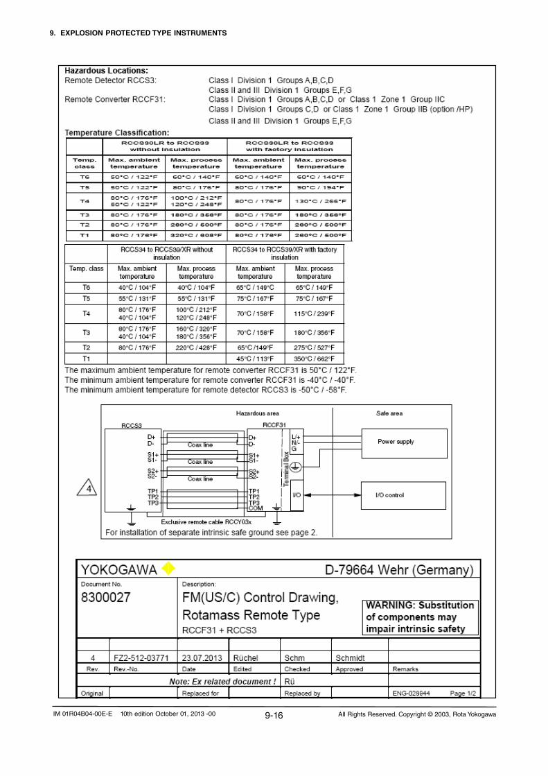
9. EXPLOSION PROTECTED TYPE INSTRUMENTS
9-16 All Rights Reserved. Copyright © 2003, Rota YokogawaIM 01R04B04-00E-E 10th edition October 01, 2013 -00
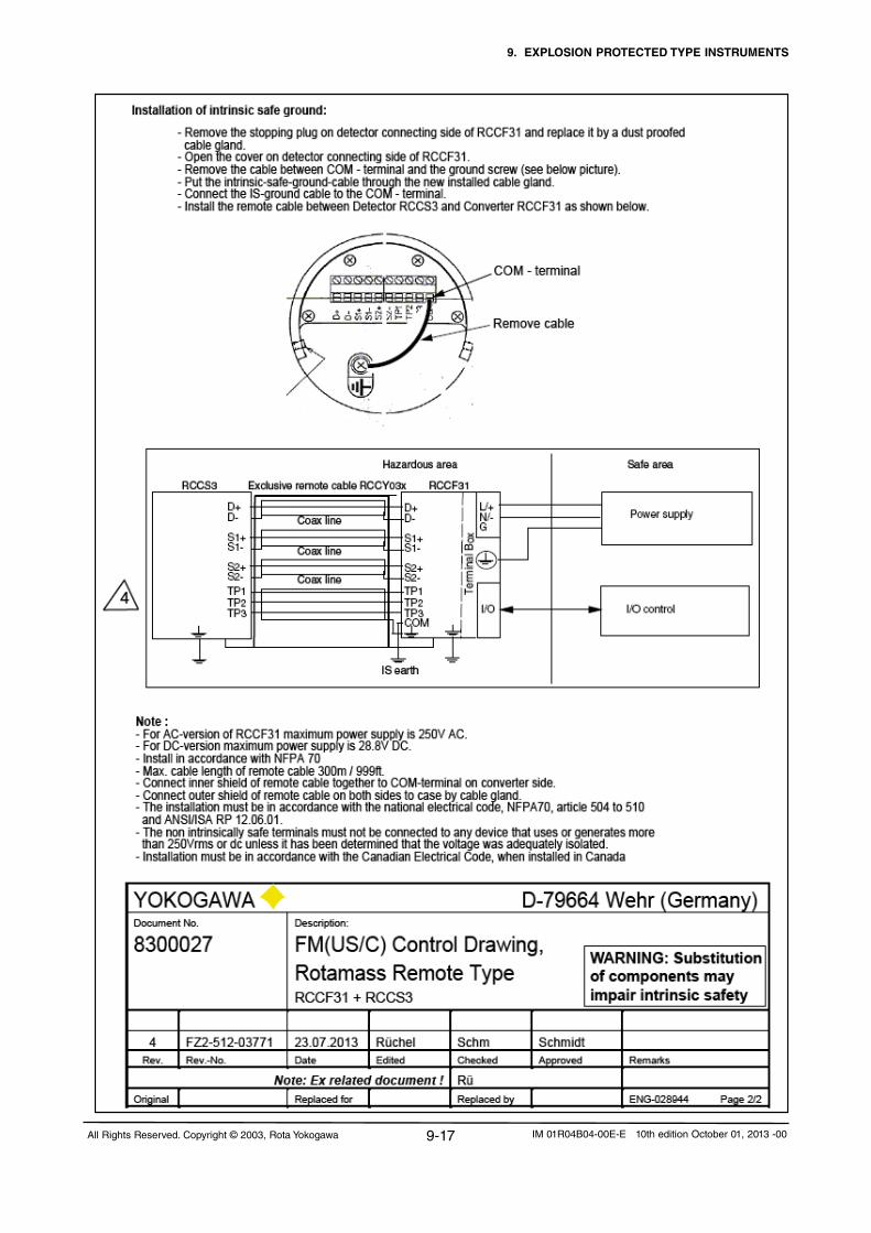
9. EXPLOSION PROTECTED TYPE INSTRUMENTS
9-17All Rights Reserved. Copyright © 2003, Rota Yokogawa IM 01R04B04-00E-E 10th edition October 01, 2013 -00

9. EXPLOSION PROTECTED TYPE INSTRUMENTS
9-18 All Rights Reserved. Copyright © 2003, Rota YokogawaIM 01R04B04-00E-E 10th edition October 01, 2013 -00

9. EXPLOSION PROTECTED TYPE INSTRUMENTS
9-19All Rights Reserved. Copyright © 2003, Rota Yokogawa IM 01R04B04-00E-E 10th edition October 01, 2013 -00

9. EXPLOSION PROTECTED TYPE INSTRUMENTS
9-20 All Rights Reserved. Copyright © 2003, Rota YokogawaIM 01R04B04-00E-E 10th edition October 01, 2013 -00
9.3 IECExIn this section, further requirements and differences
for explosion proof type instrument are described.
For explosion proof type instrument, the descrip-
tion in this chapter is prior to other description in
this Instruction Manual.
WARNING
•Onlytrainedpersonsmayusetheinstrumentin industrial location.•Theinstrumentmodificationorpartsreplace- mentbyotherthananauthorizedRepresentative of Yokogawa is prohibited and will void the certification. •Electrostaticchargemaycauseanexlosion hazard.Avoidanyactionsthatcausethe gerenation of eletrostatic charge, such as rubbing with a dry cloth on coating face of the converter.•Ifitismountedinanareawheretheuseof category 2D apparatus is required, it shall be installed in such a way that the risk from electrostatic discharges and propagating brush discharges caused by rapid flow of dust is avoided.
ROTAMASS is produced byRota YokogawaRheinstr. 8D-79664 WehrGermany
9.3.1 Technical Data
Applicable Standards: IEC60079-0:2011;IEC60079-1:2007, IEC60079-7:2006;IEC60079-11:2011; IEC 60079-31:2008Certificate: IECEx KEM 06.0031X
Remote detector RCCS30LR ... 33 (option /ES1):- Intrinsically safe- Ex ib IIB/IIC T1 ... T6 Gb- Ex ib IIIC T Db ( = max. surface temperature see below)- Max. surface temperature : Standard : 150°C /MT : 260°C /MT, not /T : 320°C - Degree of protection: IP67- Ambient humidity : 0 to 95% RH- Ambient temperature range: -50°C to +80°C- Process temperature limits : Standard : -50°C to 150°C /MT : -50°C to 260°C /MT, not /T : -50°C to 320°C- Heat carrier fluid temperature limits : Standard : 0°C to 150°C Option /MT : 0°C to 260°C
Remote detector RCCS34 ... 39/XR (option /ES1):- Intrinsically safe- Ex ib IIB/IIC T1 ... T6 Gb- Ex ib IIIC T Db ( = max. surface temperature see below)-Max. surface temperature : Standard + /LT : 150°C /MT : 220°C /HT : 350°C - Degree of protection: IP67- Ambient humidity : 0 to 95% RH- Ambient temperature range: -50°C to +80°C Option /HT (process temperature < 280°C): -50°C to +65°C Option /HT (process temperature < 350°C): -50°C to +55°C- Process temperature limits : Standard : -50°C to 150°C Option /MT: : -50°C to 220°C Option /HT : 0°C to 350°C Option /LT : -200°C to 150°C- Heat carrier fluid temperature limits : Standard : 0°C to 150°C Option /MT : 0°C to 220°C Option /HT : 0°C to 350°C

9. EXPLOSION PROTECTED TYPE INSTRUMENTS
9-21All Rights Reserved. Copyright © 2003, Rota Yokogawa IM 01R04B04-00E-E 10th edition October 01, 2013 -00
Remote converter RCCF31 (option /EF1):- Flame proof with intrinsic safe connection to detector (ib)- Ex d [ib] IIC T6 Gb or Ex d e [ib] IIC T6 Gb- Ex d [ib] IIB T6 Gb or Ex d e [ib] IIB T6 Gb with option /HP- Ex tb [ib] IIIC T75°C Db- Max. surface temperature: 75°C- Degree of protection : IP66/67-Powersupply:90to250VAC,50/60Hz 20.5 to 28.8 V DC- Power consumption : max. 25 VA / 10 W- Ambient humidity : 0 to 95% RH- Ambient temperature range: -40°C to +55°C
Remote converter RCCF31 (option /EF5):- Flame proof with intrinsic safe connection to detector (ib)- Additional intrinsic safe outputs (ia).- Ex d [ib] [ia Ga] IIC T6 Gb or Ex d e [ib] [ia Ga] IIC T6 Gb- Ex d [ib] [ia IIC Ga] IIB T6 Gb or Ex d e [ia IIC Ga] [ib] IIB T6 Gb with option /HP- Ex tb [ia Da] [ib] IIIC T75°C Db- Max. surface temperature: 75°C- Degree of protection : IP66/67-Powersupply:90to250VAC,50/60Hz 20.5 to 28.8 V DC- Power consumption : max. 25 VA / 10 W- Ambient humidity : 0 to 95% RH- Ambient temperature range : -40°C to +55°C
Remote converter RCCR31 (option /ES1) :- Associated apparatus with intrinsic safe connection to detector (ib)- [Ex ib Gb] IIC - [Ex ib Gb] IIB with option /HP- [Ex ib Db] IIIC-Powersupply:90to250VAC,50/60Hz 20.5 to 28.8 V DC- Power consumption : max. 25 VA / 10 W- Ambient humidity: 0 to 95% RH- Ambient temperature range: -40°C to +55°C
WARNING Remote rack mount converter RCCR31 must only be installed in safe area !
Integral type RCCT34 ... 39/XR (option /EF1):- Flame proof with intrinsic safe connection to detector (ib)- Ex d ib IIC T6...T3 Gb or Ex d e ib IIC T6...T3 Gb- Ex d ib IIB T6...T3 Gb or Ex d e ib IIB T6...T3 Gb with option /HP- Ex ib tb IIIC T150°C Db- Max. surface temperature : 150°C- Degree of protection : IP66/67-Powersupply:90to250VAC,50/60Hz 20.5 to 28.8 V DC- Power consumption : max. 25 VA / 10 W- Ambient humidity : 0 to 95% RH- Ambient temperature range : -40°C to +55°C- Process temperature limits : -50°C to 150°C
Integral type RCCT34 ... 39/XR (option /EF5):- Flame proof with intrinsic safe connection to detector (ib)- Additional intrinsic safe outputs (ia).- Ex d ib [ia Ga] IIC T6...T3 Gb or Ex d e ib [ia Ga] IIC T6...T3 Gb- Ex d ib [ia IICGa] IIB T6...T3 Gb or Ex d e ib [ia IIC Ga] IIB T6...T3 Gb with option /HP- Ex ib tb [ia Da] IIIC T150°C Db- Max. surface temperature : 150°C- Degree of protection : IP66/67-Powersupply:90to250VAC,50/60Hz 20.5 to 28.8 V DC- Power consumption : max. 25 VA / 10 W- Ambient humidity : 0 to 95% RH- Ambient temperature range : -40°C to +55°C- Process temperature limits : -50°C to 150°C
The electronics of RCCT3 and RCCF31 are placed in a pressure tight section of the converter housing Ex d. The kind of protection of the terminal enclosure is“e”,butcanbecome“d”byusingEx-dcertifiedcable glands.
Electrical data remote detector RCCS30LR ... 33:- Driving circuit : terminals D+ / D- ExibIIC: Ui=16V;Ii=53mA;Pi=0.212W Li=4.2mH;Ci=negl.small ExibIIB: Ui=16V;Ii=153mA;Pi=0.612W Li=4.2mH;Ci=negl.small- Sensor circuits: terminals S1+/ S1- or S2+ / S2- ExibIIC: Ui=16V;Ii=80mA;Pi=0.32W Li=4.2mH;Ci=negl.small- Temp. sensor circuit : terminals TP1, TP2, TP3 ExibIIC: Ui=16V;Ii=50mA;Pi=0.2W Li = negligible small Ci = negligible small

9. EXPLOSION PROTECTED TYPE INSTRUMENTS
9-22 All Rights Reserved. Copyright © 2003, Rota YokogawaIM 01R04B04-00E-E 10th edition October 01, 2013 -00
Coherence between temperature class, ambient- and medium temperature/ temperature of heat carrier :RCCS30LR to RCCS33
without insulationRCCS30LR to RCCS33 with factory insulation
Temp. class
Max. ambient temperature
Max. process temperature
Max. ambient temperature
Max. process temperature
T6 50°C / 122°F 60°C / 140°F 60°C / 140°F 60°C / 140°F
T5 50°C / 122°F 80°C / 176°F 80°C / 176°F 90°C / 194°F
T480°C / 176°F 50°C / 122°F
100°C / 212°F120°C / 248°F
80°C / 176°F 130°C / 266°F
T3 80°C / 176°F 180°C / 356°F 80°C / 176°F 180°C / 356°F
T2 80°C / 176°F 260°C / 500°F 80°C / 176°F 260°C / 500°F
T1 80°C / 176°F 260°C / 500°F 80°C / 176°F 260°C / 500°F
RCCS34 to RCCS39/XR without insulation
RCCS34 to RCCS39/XR with factory insulation
RCCT34 to RCCT39/XR
Temp. class
Max. ambient temperature
Max. process temperature
Max. ambient temperature
Max. process temperature
Max. ambient temperature
Max. process temperature
T6 40°C / 104°F 40°C / 104°F 65°C / 149°C 65°C / 149°F +55°C / 131°F 65°C / 149°C
T5 55°C / 131°F 55°C / 131°F 75°C / 167°F 75°C / 167°F +55°C / 131°F 80°C / 176°F
T480°C / 176°F40°C / 104°F
100°C / 212°F120°C / 248°F
70°C / 158°F 115°C / 239°F +55°C / 131°F 115°C / 239°F
T380°C / 176°F40°C / 104°F
160°C / 320°F180°C / 356°F
70°C / 158°F 180°C / 356°F +55°C / 131°F 150°C / 302°F
T2 80°C / 176°F 220°C / 428°F 65°C /149°F 275°C / 527°F +55°C / 131°F 150°C / 302°F
T1 80°C / 176°F 220°C / 428°F 45°C / 113°F 350°C / 662°F +55°C / 131°F 150°C / 302°F
For customer insulation of RCCS30LR to 39/XR the following must be regarded : The table "with factory insulation" is calculated with 80 mm insulation and k-factor = 0.4 W/m2K. If your insulation data are worse than these use table "without insulation" !
NOTE
Electrical data remote detector RCCS34 ... 39/XR :- Driving circuit : terminals D+ / D ExibIIC: Ui=16V;Ii=53mA;Pi=0.212W Li=3.2mH;Ci=negligiblesmall ExibIIB: Ui=16V;Ii=153mA;Pi=0.612W Li=3.2mH;Ci=negligiblesmall- Sensor circuits: terminals S1+/ S1- or S2+ / S2- ExibIIC: Ui=16V;Ii=80mA;Pi=0.32W Li=2.1mH;Ci=negligiblesmall- Temp. sensor circuit : terminals TP1, TP2, TP3 ExibIIC: Ui=16V;Ii=50mA;Pi=0.2W Li = negligible small Ci = negligible small
Electrical data remote converter RCCF31, RCCR31 and converter of Intergral type RCCT3:- Driving circuit : terminals D+ / D- Ex ib IIC : Uo=14.5V;Io=47mA;Po=0.171W Lo=15mH;Co=0.65µF ExibIIB: Uo=11.7V;Io=124mA;Po=0.363W Lo=8mH;Co=10.3µF
- Sensor circuits: terminals S1+/ S1- or S2+ / S2- Ex ib IIC : Uo=14.5V;Io=47mA;Po=0.171W Lo=15mH;Co=0.65µF- Temperature sensor circuit : terminals TP1,TP2, TP3 Ex ib IIC : Uo=13.3V;Io=40mA;Po=0.133W Lo=20mH;Co=0.91µF- Current output (only option /EF2) : ExiaIIC: Ui=30V;Ii=165mA;Pi=1.25W Li=negligiblesmall;Ci=6.9nF- Pulse output (only option /EF2) : Ex ia IIC : Ui=30V;Ii=100mA;Pi=0.75W Li = negligible small;Ci=4.5nF- Current output (only option /EF5) : ExiaIIC: Ui=30V;Ii=300mA;Pi=1.25W Li=4µH;Ci=5.5nF- Pulse output (only option /EF5) : Ex ia IIC : Uo=30V;Io=130mA;Po=1.25W Lo=4µH;Co=13.1nF
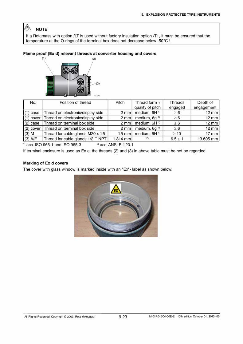
9. EXPLOSION PROTECTED TYPE INSTRUMENTS
9-23All Rights Reserved. Copyright © 2003, Rota Yokogawa IM 01R04B04-00E-E 10th edition October 01, 2013 -00
If a Rotamass with option /LT is used without factory insulation option /T1, it must be ensured that the temperature at the O-rings of the terminal box does not decrease below -50°C !
Flame proof (Ex d) relevant threads at converter housing and covers:
No. Position of thread Pitch Thread form + quality of pitch
Threads engaged
Depth of engagement
(1) case Thread on electronic/display side 2 mm medium, 6H 1) ≥ 6 12 mm(1) cover Thread on electronic/display side 2 mm medium, 6g 1) ≥ 6 12 mm(2) case Thread on terminal box side 2 mm medium, 6H 1) ≥ 6 12 mm(2) cover Thread on terminal box side 2 mm medium, 6g 1) ≥ 6 12 mm(3) M Thread for cable glands M20 x 1.5 1.5 mm medium, 6H 1) ≥ 10 17 mm(3) A/F Threadforcableglands1/2´´NPT 1.814 mm 2) 6.5 ± 1 13.605 mm
1) acc. ISO 965-1 and ISO 965-3 2)acc.ANSIB1.20.1
If terminal enclosure is used as Ex e, the threads (2) and (3) in above table must be not be regarded.
Marking of Ex d covers
The cover with glass window is marked inside with an "Ex"- label as shown below:
F94.EPS
(1) (2)
(3)
NOTE

9. EXPLOSION PROTECTED TYPE INSTRUMENTS
9-24 All Rights Reserved. Copyright © 2003, Rota YokogawaIM 01R04B04-00E-E 10th edition October 01, 2013 -00
Remote field-mount type RCCF31 with RCCS3
WARNING 1. Ex type RCCF31 and RCCS3 must be connected to the suitable IS earthing system (see installation diagram). Converter and detector case must have connection to the potential equalisation facility. 2. Use the certified cable glands, suitable for the conditions of use. 3. Please confirm that the ground terminal (inside the terminal enclosure) is firmly connected by means of a clip-on eye-let. 4. For EMC technical reasons the case of the detector is connected to the case of the converter via the shielding of the interconnecting cable.
Cable glands for power- and I/O-cables :RCCF31-M:Exetypesareenclosed.Thesecableglandscanalsobeusedfor“dustapplication”tD. Use IECEx- certified Ex d cable glands for Ex d condition.RCCF31-A: Nocableglandsareenclosed.UsetheIECEx-certifiedcableglands,suitableforthe conditions of use (Ex de or Ex d or tD)
For“dustapplication”tDusecableglandswithminimumIP67protection!
Cable glands for detector connection terminal :RCCF31-M : Cable glands are fitted in the concerning thread. This cable gland can also be used for “dustapplication”tD.RCCF31-A :Cableglandsareenclosed.Thiscableglandcanalsobeusedfordustapplication”tD.
L/+N/-G
Power supply
I/O control
Hazardous area Safe area
I/O
Rotamass RCCT3
F91.EPS
Term
inal B
ox
Detailed information for connection intrinsic safe outputs (option /EF2 and /EF5 see chapter 4.8.8.
Installation diagram (option /EF1) :
9.3.2 Installation
Integral type RCCT3
WARNING 1. Ex type of ROTAMASS must be connected to the suitable IS earthing system (see installation
diagram). Converter case must have connection to the potential equalisation facility. If the connecting process tubing is part of the potential equalisation, no additional connection is required. 2. Use the certified cable glands, suitable for the conditions of use. The delivered cable glands are only for
Ex e use. For Ex d use certified d-type cable glands. 3. Please confirm that the ground terminal (inside the terminal enclosure) is firmly connected by means of
a clip-on eye-let.4. Ex-e terminals for power supply and I/O-lines are designed for cables with cross section of 0.08 mm²
(AWG 28) to 2.5 mm² (AWG 22). The strip length must be 5 to 6 mm (0.2 to 0.24 in).
Cable glands for power- and I/O-cables :RCCT3-M: Exetypesareenclosed.Thesecableglandscanalsobeusedfor“dustapplication”tD. Use IECEx- certified Ex d cable glands for Ex d condition.RCCT3-A : Nocableglandsareenclosed.UsetheIECEx-certifiedcableglands,suitableforthe conditions of use (Ex de or Ex d or tD).For“dustapplication”usecableglandswithminimumIP67protection!

9. EXPLOSION PROTECTED TYPE INSTRUMENTS
9-25All Rights Reserved. Copyright © 2003, Rota Yokogawa IM 01R04B04-00E-E 10th edition October 01, 2013 -00
Remote rack-mount type RCCR31 with RCCS3
WARNING
1. Remote rack mount converter RCCR31 must only be installed in safe area ! 2. Ex-type RCCR31 and RCCS3 must be connected to the suitable IS earthing system (see installation diagram). Converter and detector case must have connection to the potential equalisation facility. 3. Please confirm that the ground terminal on terminal board is firmly connected. 4. Ex-e terminals for power supply and I/O-lines are designed for cables with cross section of 0.08 mm² (AWG 28) to 2.5 mm² (AWG 22). The strip length must be 5 to 6 mm (0.2 to 0.24 in). 5. For EMC technical reasons the case of the detector is connected to the case of the converter via the shielding of the interconnecting cable.
Installation diagram :
L/+N/-G
Power supply
I/O control
Hazardous area Safe area
I/O
RCCR31RCCS3
D+D-
S1+S1-
S2+S2-
TP1TP2TP3
D+D-
S1+S1-
S2+S2-TP1TP2TP3COM
Exclusive remote cable RCCY03
Coax line
Coax line
Coax line
IS earth
L/+N/-G
Power supply
I/O control
Hazardous area Safe area
I/O
RCCF31RCCS3
D+D-
S1+S1-
S2+S2-
TP1TP2TP3
D+D-
S1+S1-
S2+S2-TP1TP2TP3COM
Exclusive remote cable RCCY03
Coax line
Coax line
Coax line
IS earth
The inner shields (shields of the cable pairs) are connected together to COM –terminal on converter side.
The outer shield of the cable is connected on both sides to the cases by cable gland.
Detailed information for connection intrinsic safe outputs (option /EF2 and /EF5) see chapter 4.8.8.
Installation diagram (option /EF1) :

9. EXPLOSION PROTECTED TYPE INSTRUMENTS
9-26 All Rights Reserved. Copyright © 2003, Rota YokogawaIM 01R04B04-00E-E 10th edition October 01, 2013 -00
9.3.3 Operation
If the cover of the converter RCCF31 / RCCT3 has to be opened, following instructions must be followed.
CAUTION 1. Confirm that the power cables to the instrument are disconnected. 2. Wait 15 minutes after power is turned off before opening the covers. 3. The covers of display side and terminal box are fixed with special screws, please use Hexagonal wrench to open the covers. 4. Be sure to lock the cover with special screw using the Hexagonal Wrench after tightening the cover (see drawing chapter 4.3). 5. Before starting the operation again, be sure to lock the cover with the locking screws. 6. Prohibition of specification changes and modifications. Users are prohibited from making any modifications of specifications or physical configuration, such as adding or changing the configuration of external wiring ports.
9.3.4 Maintenance and repair
WARNING Theinstrumentmodificationofpartsreplacementbyotherthanauthorizedrepresentatives of YOKOGAWA
is prohibited and will void the certification.

9. EXPLOSION PROTECTED TYPE INSTRUMENTS
9-27All Rights Reserved. Copyright © 2003, Rota Yokogawa IM 01R04B04-00E-E 10th edition October 01, 2013 -00
9.3.5 Ex-relevant marking on name plates (refer to chapter 3.11)RCCT3 option /EF1:IECEx KEM 06.0031XEx d ib IIC T6...T3 Gb or Ex d e ib IIC T6...T3 GbEx ib tb IIIC T150°C DbDIODE SAFETY BARRIER Um : 250Vac/dcTEMP. CLASS T6 T5 T4 T3 PROCESS TEMP. 65 80 115 150°C ENCLOSURE:IP67SEE CERTIFICATE FOR DATA
WARNINGWAIT15MIN.AFTERPOWER-DISCONNECTIONBEFOREOPENINGTHEENCLOSURE.
RCCT3 option /EF2 or /EF5:IECEx KEM 06.0031XEx d ib [ia Ga] IIC T6...T3 Gb or Ex d e ib [ia Ga] IIC T6...T3 GbEx ib tb [ia Da] IIIC T150°C DbDIODE SAFETY BARRIER Um : 250Vac/dcTEMP. CLASS T6 T5 T4 T3 PROCESS TEMP. 65 80 115 150°C ENCLOSURE:IP67SEE CERTIFICATE FOR DATA
WARNINGWAIT15MIN.AFTERPOWER-DISCONNECTIONBEFOREOPENINGTHEENCLOSURE.
RCCF31 option /EF1:IECEx KEM 06.0031XEx d [ib] IIC T6 Gb or Ex d e [ib] IIC T6 GbEx tb [ib] IIIC T75°C Db ENCLOSURE:IP67SEE CERTIFICATE FOR DATA
WARNINGWAIT15MIN.AFTERPOWER-DISCONNECTIONBEFOREOPENINGTHEENCLOSURE.
RCCF31 option /EF2 or /EF5:IECEx KEM 06.0031XEx d [ib] [ia Ga] IIC T6 Gb or Ex d e [ib] [ia Ga] IIC T6 GbEx tb [ia Da] [ib] IIIC T75°C DbDIODE SAFETY BARRIER Um : 250Vac/dcENCLOSURE:IP67SEE CERTIFICATE FOR DATA
WARNINGWAIT15MIN.AFTERPOWER-DISCONNECTIONBEFOREOPENINGTHEENCLOSURE.
RCCT3 option /EF1 + /HP:IECEx KEM 06.0031XEx d ib IIB T6...T3 Gb or Ex d e ib IIB T6...T3 GbEx ib tb IIIC T150°C DbDIODE SAFETY BARRIER Um : 250Vac/dcTEMP. CLASS T6 T5 T4 T3 PROCESS TEMP. 65 80 115 150°C ENCLOSURE:IP67SEE CERTIFICATE FOR DATA
WARNINGWAIT15MIN.AFTERPOWER-DISCONNECTIONBEFOREOPENINGTHEENCLOSURE.
RCCT3 option /EF2 or /EF5 + /HP:IECEx KEM 06.0031XEx d ib [ia IIC Ga] IIB T6...T3 Gb or Ex d e ib [ia IIC Ga] IIB T6...T3 GbEx ib tb [ia Da] IIIC T150°C DbDIODE SAFETY BARRIER Um : 250Vac/dcTEMP. CLASS T6 T5 T4 T3 PROCESS TEMP. 65 80 115 150°C ENCLOSURE:IP67SEE CERTIFICATE FOR DATA
WARNINGWAIT15MIN.AFTERPOWER-DISCONNECTIONBEFOREOPENINGTHEENCLOSURE.
RCCF31 option /EF1 + /HP:IECEx KEM 06.0031XEx d i[b[ IIB T6 Gb or Ex d e [ib] IIB T6 GbEx tb [ib] IIIC T75°C DbENCLOSURE:IP67SEE CERTIFICATE FOR DATA
WARNINGWAIT15MIN.AFTERPOWER-DISCONNECTIONBEFOREOPENINGTHEENCLOSURE.
RCCF31 option /EF2 or /EF5 + /HP:IECEx KEM 06.0031XEx d [ib] [ia IIC Ga] IIB T6 Gb or Ex d e [ib] [ia IIC Ga] IIB T6 GbEx tb [ia Da] [ib] IIIC T75°C DbDIODE SAFETY BARRIER Um : 250Vac/dc ENCLOSURE:IP67SEE CERTIFICATE FOR DATA
WARNINGWAIT15MIN.AFTERPOWER-DISCONNECTIONBEFOREOPENINGTHEENCLOSURE.

9. EXPLOSION PROTECTED TYPE INSTRUMENTS
9-28 All Rights Reserved. Copyright © 2003, Rota YokogawaIM 01R04B04-00E-E 10th edition October 01, 2013 -00
9.4 INMETRO (Brazil)RCCS3 with option /US1 same as IECEx /ES1RCCT3 with options /UF1 ... /UF5 same as IECEx EF1 ... /EF5RCCR31 with options /UF1 ... /UF5 same as IECEx EF1 ... /EF5RCCR31 with option /US1 same as IECEx /ES1Same parameters and specifications as IECEx approval. See chapter 9.3.
9.5 NEPSI (China)Certificate GYJ12.1381XRCCS3withoption/NS1,RCCT3withoptions/NF1.../NF5,RCCF31withoptions/NF1.../NF5,RCCR31withoption/NS1SameparametersandspecificationsasIECExapprovalexceptNEPSIhasnodustproofcertification.
9.6 Gost approvalRotaYokogawahasthe“PatternApprovalCertificateofMeasuringInstruments”whichallowstoexporttheinstrumenttoRussia,Kazakhstan,UzbekistanandotherCIScountries.FurthermoreROTAMASSisRTN(GGTN)approvedforinstallationinhazardousareas.FortheexportofROTAMASS to CIS countries please contact your Yokogawa representative.
RCCR31 option /ES1:IECEx KEM 06.0031X[Ex ib Gb] IIC[Ex ib Db] IIICDIODE SAFETY BARRIER Um : 250Vac/dc SEE CERTIFICATE FOR DATA
RCCS34 to 39/XR option /ES1:IECEx KEM 06.0031XEx ib IIC/IIB T6...T1 Gb Ex ib IIIC T150°C Db IP66/67 SEE CERTIFICATE FOR DATA
RCCS34 to 39/XR option /ES1 + /MT:IECEx KEM 06.0031XEx ib IIC/IIB T6...T1 Gb Ex ib IIIC T220°C Db IP66/67SEE CERTIFICATE FOR DATA
RCCS34 to 39/XR option /ES1 + /HT:IECEx KEM 06.0031XEx ib IIC/IIB T6...T1 GbEx ib IIIC T350°C Db IP66/67SEE CERTIFICATE FOR DATA
RCCR31 option /ES1 + /HP:IECEx KEM 06.0031X[Ex ib Gb] IIB[Ex ib Db] IIICDIODE SAFETY BARRIER Um : 250Vac/dc SEE CERTIFICATE FOR DATA
RCCS30LR to 33 option /ES1:IECEx KEM 06.0031XEx ib IIC/IIB T6...T1 Gb Ex ib IIIC T150°C Db IP66/67 SEE CERTIFICATE FOR DATA
RCCS30LR to 33 option /ES1 + /MT:IECEx KEM 06.0031XEx ib IIC/IIB T6...T1 Gb Ex ib IIIC T260°C Db IP66/67 SEE CERTIFICATE FOR DATA
10. PED (PRESSURE EQUIPMENT DIRECTIVE
10-1All Rights Reserved. Copyright © 2003, Rota Yokogawa IM 01R04B04-00E-E 10th edition October 01, 2013 -00
10. PED (PRESSURE EQUIPMENT DIRECTIVE)
All materials containing pressure (process connections, flow divider and tubes) are traced back to the original manufacturer with a material certificate. The PED limits the pressure and temp, which can be found below.
The given temperature /pressure ranges are calculated and approved without corrosion or erosion. The customer is fully responsible to select proper materials to withstand his corrosive or erosive conditions. In case of heavy corrosion and/or erosion the instrument may not withstand the pressure and an incident may happen with human and/or environmental harm. Yokogawa will not take any liability regarding damage caused by corrosion / erosion. If corrosion/erosion may happen, the user has to check periodically if the necessary wall thickness is still in place.
ROTAMASS is produced according the determinations of directive 97/23/EG (Directive for Pressure Equipment
/ PED).The units are classified as pipe according item 3, number 1, 3. letter, a) first dash or according diagram 6 after appendix II :
Classification as pipe
ForFluidGroup1and2(article9chapter(2));For fluid group 2 with a max. partial
pressure of 1.5bar at Tmax..
Medium liquid and gas
The basic safety requests (for design, production and testing) for all units according to category I to III are
generally determined for the requests of category III. The units, which are not included by PED, article 3
paragraph3,arecheckedbyaconformity-valuation–methodeaccordingappendixIII“moduleH”.
The complete quality assurance system according PED appendix III module H was
certified by the notified body :
Lloyd’sRegisterNederlandB.V.Energy;K.P.vanderMandelelaan41a;NL-3062MBRotterdam
ID-No. 0038
Numberisprintedonnameplates(seechapter3.11).
Theriskassessmentwasmadeacc.DINCEN/TS764-6.
WARNING
Do not open the gas-filling-plugs in the drawings in chapter 3.2, 3.5, 3.7, 3.9, filling with protective gas!
For the application the following notes have to be noticed :
Permitted maximum operating temperatures:
The pressure relevant temperature limits of the detector are : -200 to 400°C
These limits are reduced by measuring boundary conditions :
General : -40 to 150°C
Additional reductions for the use of special connections (clamp, pipe screwing ...) have to be noticed ac-
cording the concerning standards.
WARNING
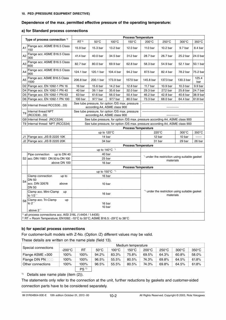
10. PED (PRESSURE EQUIPMENT DIRECTIVE)
10-2 All Rights Reserved. Copyright © 2003, Rota YokogawaIM 01R04B04-00E-E 10th edition October 01, 2013 -00
Dependence of the max. permitted effective pressure of the operating temperature:
a) for Standard process connections
b) for special process connections
Forcustomer-builtmodelswithZ-No.(Option/Z)differentvaluesmaybevalid.
These details are written on the name plate (field 13).
Special connectionsMedium temperature
-200°C RT 50°C 100°C 150°C 200°C 250°C 300°C 350°CFlangeASME>300 100% 100% 94.2% 83.3% 75.8% 69.5% 64.3% 60.8% 58.0%FlangeDINPN 100% 100% 96.5% 55.5% 80.5% 74.3% 69.8% 64.5% 61.8%Other connections 100% 100% 96.5% 55.5% 80.5% 74.3% 69.8% 64.5% 61.8%
PS 1)
1) Details see name plate (item (2)).
The statements only refer to the connection at the unit, further reductions by gaskets and customer-sided
connection parts have to be considered separately.
Type of process connection 1)Process Temperature
RT 2) 50°C 100°C 150°C 200°C 250°C 300°C 350°C
A1Flange acc. ASME B16.5 Class 150
15.9 bar 15.3 bar 13.2 bar 12.0 bar 11.0 bar 10.2 bar 9.7 bar 8.4 bar
A2Flange acc. ASME B16.5 Class 300
41.4 bar 40.0 bar 34.5 bar 31.2 bar 28.7 bar 26.7 bar 25.2 bar 24.0 bar
A3Flange acc. ASME B16.5 Class 600
82.7 bar 80.0 bar 69.9 bar 62.8 bar 58.3 bar 54.9 bar 52.1 bar 50.1 bar
A4Flange acc. ASME B16.5 Class 900
124.1 bar 120.1 bar 104.4 bar 94.2 bar 87.5 bar 82.4 bar 78.2 bar 75.2 bar
A5Flange acc. ASME B16.5 Class 1500
206.8 bar 200.1 bar 173.9 bar 157.0 bar 145.8 bar 137.3 bar 130.3 bar125.4 bar
D2 Flangeacc.EN1092-1PN16 16 bar 15.6 bar 14.2 bar 12.8 bar 11.7 bar 10.9 bar 10.3 bar 9.9 barD4 Flangeacc.EN1092-1PN40 40 bar 39.1 bar 35.6 bar 32.0 bar 29.3 bar 27.2 bar 25.8 bar 24.7 barD5 Flangeacc.EN1092-1PN63 63 bar 61.6 bar 56.0 bar 50.4 bar 46.2 bar 42.8 bar 40.6 bar 38.9 barD6 Flangeacc.EN1092-1PN100 100 bar 97.7 bar 97.7 bar 80.0 bar 73.3 bar 68.0 bar 64.4 bar 61.8 bar
G9 Internal thread RCCS30...33)See tube pressure, for option /DS max. pressure
according A4, ASME class 900------------------------------------------------------------
------------
T9InternalthreadNPT(RCCS30...33)
See tube pressure, for option /DS max. pressure according A4, ASME class 900
------------------------------------------------------------------------
G9 Internal thread (RCCS34) See tube pressure, for option /DS max. pressure according A4, ASME class 900T9 InternalthreadNPT(RCCS34) See tube pressure, for option /DS max. pressure according A4, ASME class 900
Process Temperatureup to 120°C 220°C 300°C 350°C
J1 Flange acc. JIS B 2220 10K 14 bar 12 bar 10 bar ------J2 Flange acc. JIS B 2220 20K 34 bar 31 bar 29 bar 26 bar
Process Temperatureup to 140°C *)
S2PipeconnectionuptoDN40acc.DIN11851DN50toDN100aboveDN100
40 bar*) under the restriction using suitable gasket
materials25 bar16 bar
Process Temperatureup to 150°C **)
S4
Clamp connection up to DN50acc.DIN32676aboveDN50
16 bar
**) under the restriction using suitable gasket materials
10 bar
S8
Clamp acc. Mini-Clamp up to1/2´´
16 bar
Clamp acc. Tri-Clamp up to2´´ above2´´
16 bar10 bar
1) all process connections acc. AISI 316L (1.4404 / 1.4435)2)RT=RoomTemperature;EN1092:-10°Cto50°C;ASMEB16.5:-29°Cto38°C

10. PED (PRESSURE EQUIPMENT DIRECTIVE
10-3All Rights Reserved. Copyright © 2003, Rota Yokogawa IM 01R04B04-00E-E 10th edition October 01, 2013 -00
PED-data on the name plate of RCCT3
1) Year of manufacturing
2) Max. permitted pressure at room temperature, for other temperatures see table
3) Max. permitted temperature range
4) Test pressure, for standard units without value, because in this case generally
PT=1.5 x PS
5) Material of medium wetted parts with pressure load
Operation restriction:
The operator is responsible that no corrosion and/or erosion is caused by the medium, which reduces the
safety of the unit as pressure vessel. Corrosion and erosion can make the unit fail and can lead to the
endangering of persons and facilities. If corrosion and erosion are possible, the integrity of the tubes has to
be checked periodically.The following usages of the instruments are not permitted:
- use as climbing aid (e.g during assembling work on pipe system)
- use as support for external load (e.g. support for piping) or tray surface for heavy tools (e.g. during piping
work)
- Material removal by any kind of machining (e.g. drilling, sawing etc.)
- Painting of the name-plate
- Brazingorweldingofpartstotheinstrument
- Any repair, modification or supplements or the installation of spare-parts is only permitted if it is done in
accordance to this instruction manual. Other work must be agreed by YOKOGAWA beforehand.
YOKOGAWAwillnottakeoveranyliabilityfordamagescausedbyunauthorizedworkontheinstrument
or prohibited usage of the instrument.
Rating of flange connections
The user must dimension bolts and nuts as depending of pressure, temperature, flange material and seal, so
that the flange connection remains tight in the expected operating conditions.
The basic of calculation may be:
-EN1515part1+2(boltsandnuts)
-EN1591part1+2(flangesandseals)
Forcertainsealingmaterialsitmayoccurthatthesheetthicknessoftheflangeatutilizationofthefull
pressurerange(eg,PN)isnolongerofsufficientsize.
The user is responsible to take necessary measures before ordering, for example:- selection of flanges with higher pressure rate- selection of flanges with a flange face which is more thick as according standard

10. PED (PRESSURE EQUIPMENT DIRECTIVE)
10-4 All Rights Reserved. Copyright © 2003, Rota YokogawaIM 01R04B04-00E-E 10th edition October 01, 2013 -00
Information of potential hazardous situations:
Endangering by: Description Remarks Surface temperature
Surface temperature is hot in case of high process temperature. It is the sole responsibility of the user to establish proper means to prevent touching of the detector (see also chapter 11.1).
Max. / Min process temperature See chapter 11.1 Max. process pressure See chapter 11.1
Tightness of the wetted, PED relevant volume
A factory test is done before delivery
Corrosion and erosion effects
It is the sole responsibility of the user to select proper wetted materials for the medium intended to use (see chapter 10).
Life time evaluation
Experience shows that the lifetime of the detector within the allowed operation conditions is more than 10 years.
Without erosion and corrosion.
Temperature shock
Permanent temperature cycles of more than 100°C temp. difference have to be avoided. Tube failure can occur because of material wearing.
Medium
Instable fluids
If instable fluids are transported it is the sole responsibility of the user that in case of decomposition the design limits are not exceeded.
Process pressure/temp. relation See chapter 10 Piping and support forces See chapter 4.3 Choice of gaskets and pre- stress of the
process connections
It is the sole responsibility of the user to select suitable gaskets and to screw the process connections with the necessary torques.
Refer to EN 1591-1
Use of closing and openings
Do not open the ¼ NPT plugs in the body after tube failure before it is ensured that the housing is pressure free and free of hazardous substances.
Pressure shock, water hammer and pressure surges
Dynamical exceeding of the given max. pressure at process temp. has to be avoided.
Water hammer can lead to tube failures.
Filling and emptying of the pipe work
The detector is part of a pipe work. It has to be taken into account that fluid can remain in the measuring tubes.
Disposal, cleaning and return See chapter 1.5 Flow direction of the unit
See chapter 4.1 and marking on the detector.
After installation with wrong flow direction only indication error (wrong sign, can be corrected viasoftware)
Installation position of the unit
See chapter 4.3
A wrong installation position givesonly measuring disturbances
Installation
Pipe stress by weight of the instrument See chapter 4.3 Permitted ambient conditions (temperature, humidity)
See chapter 11.1
External fire
External fire can result in - Rise in pressure by temperature - Damage of gaskets It is in the sole responsibility of the user to implement suitable means to prevent large damage in the case of fire.
The instrument itself does not
contain flammable materials.
Outer influence
Earthquake resistance Damage of the mounting screws Check by user T101.EPS

11. TECHNICAL DATA
11-1All Rights Reserved. Copyright © 2003, Rota Yokogawa IM 01R04B04-00E-E 10th edition October 01, 2013 -00
11. TECHNICAL DATA
Qnom is the water flow rate at about 1 bar pressure drop.The flowmeter has a default low cut of 0.05% of Qnom.
Accuracy mass flow (refer to table 2): Liquid RCCS30LR: ±0.15%offlowrate±zerostability/flowrate*100% Liquid RCCS30 - 39/XR: ±0.1%offlowrate±zerostability/flowrate*100% Gas (option /GA): ±0.5%offlowrate±zerostability/flowrate*100%
Accuracy volume flow : SQRT ( (mass flow error in %)² + (density error in %)²) PleaserefertotheYokogawasizingsoftware.
Accuracy based on the frequency output includes the combined effects of repeatability, linearity and hysteresis.
Repeatability for liquids: ±0.05%±(zerostability/2)/flowrate*100%
Table 2 : Zero stability
Type RCCS30LR RCCS30 RCCS31 RCCS32 RCCS33
kg/h 0.003 0.005 0.0085 0.019 0.048
Type RCC34 RCC36 RCC38 RCC39 RCC39 /IR
RCC39 /XR
kg/h 0.15 0.5 1.6 5 13 25
Pressure DependencyThe stiffness of the ROTAMASS tubes is slightly line pressure dependent. The static pressure effect of mass flow and density can be corrected by setting the static pressure manually via menu.
PERFORMANCE SPECIFICATIONSModel- Remote detector RCCS30LR to 33: 2 tubes, low flow design - Remote detector RCCS34 to 39/XR : 2 tube design - Remote field-mount converter RCCF31- Remote rack-mount converter RCCR31- Integral type RCCT34 to 39/XR: 2 tube integral design
Fluid to be measured : Liquid, gas or slurries
Measurement Items : Mass flow, density, temperature and derived from these values: concentration, volume flow and net flow
Mass Flow MeasurementTable 1: measuring range
TypeRCCS30
LRRCCS30 RCCS31 RCCS32 RCCS33
Qmax t/h 0.04 0.1 0.3 0.6 1.5Qnom t/h 0.021 0.045 0.17 0.37 0.95
Type RCC34 RCC36 RCC38 RCC39RCC39
/IRRCC39
/XRQmax t/h 5 17 50 170 300 600
Qnom t/h 3 10 32 100 250 500
Table 3 : Static pressure effect on mass flow (if not corrected)
Type RCCS30LR RCCS30 RCCS31 RCCS32 RCCS33
% of rate per bar
SH ---- ---- ---- ---- ----
HC 0.00000 0.00000 0.00012 0.00246 0.0035
Type RCC34 RCC36 RCCv38 RCC39 RCC39 /IR
% of rate per bar
SS 0.00081 0.00346 0.00950 0.01058 0.02920
HC 0.00084 0.00336 0.00896 0.00808 0.01780
Type RCC39 /XR
% of rate per bar
SS 0.00740
HC ----
Density MeasurementAdjustment with water and air at calibration temperature.Measuring range: RCCS30LR - 38: 0.3 kg/l to 5 kg/l RCC39 -39/XR : 0.3 kg/l to 2 kg/lNodensitymeasurementforgasapplication.Withoption/K4thermalstabilized.Foroption/K6seealso“Specialcalibrations”onpage11-3.Table 4: Accuracy (at calibration conditions):
Type Standard Option /K4 Option /K6
RCCS30LR 0.02 g/cm³ *) ------ ------
RCCS30 0.008 g/cm³ *) ------ ------
RCCS31 0.004 g/cm³ 0.001 g/cm³ ------
RCCS32 0.004 g/cm³ 0.001 g/cm³ 0.0005 g/cm³
RCCS33 0.004 g/cm³ 0.001 g/cm³ 0.0005 g/cm³
RCC34 0.003 g/cm³ 0.001 g/cm³ 0.0005 g/cm³
RCC36 0.0022 g/cm³ 0.001 g/cm³ 0.0005 g/cm³
RCC38 0.0015 g/cm³ 0.001 g/cm³ 0.0005 g/cm³
RCC39 0.0015 g/cm³ 0.001 g/cm³ 0.0005 g/cm³
RCC39//IR 0.0015 g/cm³ ------ ------
RCC39//XR 0.0015 g/cm³ ------ ------
*) 0.003 g/cm³ on requestRepeatability: RCCS32-33, RCC34-39/XR : ± 0.0005 g/cm³ (Std, /K4)Static pressure effect: Compensated if static pressure is set in the menuSpecification of high performance density measurement option /K6: Density calibration Density range : 0.3 to 2.5 kg/l Ambient temp. range : -10°C to 50°C Fluid temp. range : -50°C to 150°C (Standard) 150°C to 350°C (/HT) Minimum flow rate for specified accuracy: - RCC36 to RCC39 : 700 kg/h - RCC34 : 140 kg/h - RCCS33 : 90 kg/h - RCCS32 : 37 kg/h Maximum flow rate : Qnom Repeatability : ±0.0002 g/cm³ Temperature measurement: ±(0.5°C+0.002*abs(Tmedium-20°C)) (not /HT) ±(0.5°C+0.008*abs(Tmedium-20°C)) (/HT) Density accuracy : only for liquids, one phase Process temperature influence : ±0.000015 g/cm³ * abs(Tmedium-20°C)
-1.0-0.9-0.8-0.7-0.6-0.5-0.4-0.3-0.2-0.1
00.10.20.30.40.50.60.70.80.91.0
0 50 100 150
Flow in % of Qnom
Erro
r in
%
F10.EPS

11. TECHNICAL DATA
11-2 All Rights Reserved. Copyright © 2003, Rota YokogawaIM 01R04B04-00E-E 10th edition October 01, 2013 -00
Temperature Measurement Temperature measuring range of converter :Standard, /LT, /MT : -200°C to 230°C Option /HT : 0°C to 350°C Accuracy:Standard (-70°C to 150°C) : ±(0.5°C+0.005*abs(Tmedium-20°C))Option /LT (-200°C to 150°C): ±(1.0°C+0.008*abs(Tmedium-20°C))Option /MT (-70°C to 260°C) : ±(0.5°C+0.005*abs(Tmedium-20°C))Option /HT (0°C to 350°C) : ±(1.0°C+0.008*abs(Tmedium-20°C))For process temperatures more than 80°C higher/lower than ambient temperature the detector should be insulated to maintain optimum accuracy.
Heat Tracing Heating with heat carrier, insulation and protection housing. Typically the max. surface temperature at the protection housing from inner heating is 40°C (at Tamb = 20°C). Above 150°C process temperature insulation from the manufacturer is recommended. However up to 230°C process temperature the customer can insulate the detector himself. For this case order option /S2.Option /T1 : only insulation and protection Option /T2 : insulation, protection and heating line Option /T3 : like /T2 but with ventilationProcess connection for the heat carrier fluid (see table 10):forD-typeflanges :ENDN15PN40FormB1forA-typeflanges :ANSI½-150lbs.forJ-typeflanges :JISDN1510KMax.pressure :PN40Protection class : IP54, install roof protectedFor fluid temperatures below -70°C select option /LT.
Calibration for Liquids and Gases :The ROTAMASS flowmeters are always factory calibrated with water. Calibration Conditions: - Water : 22.5°C ± 12.5°C- Ambient temperature : 22.5°C ± 12.5°C- Process pressure : 1 to 2 bar abs- Installation: RCCS30LR to RCC38 vertical RCC39 to RCCS39/XRhorizontalAll specifications are based on above mentioned calibration reference conditions, a flow calibration protocol is attached to each instrument.
Special Calibrations - Mass-/Volume flow calibration with factory certificate (option /K2): Calibration with water at customer specified flow values according calibration order sheet.- Mass-/Volume flow calibration with DAkkS certificate EN17025(option/K5): Calibration with water at customer specified flow values according calibration order sheet.- Density calibration with factory certificate (option /K6): Adjustment and check with 3 different fluids, fluid temperature influence adjustment for low ambient temperature influence and thermal treatment for long term density measurement stability, improved temperature measurement accuracy (see also page 12).
Dual Seal Approval (option /DS):-ConformwithANSI/ISA-12.27.01.-TobeorderedifcompliancewithANSI/ISA12.27.01isrequired.- UptoANSIclass900linepressure.- Only with FM approval option.-Forliquidapplicationtheleakagedetectionisrealizedby software in the converter.- For gas application options /GA and /RD (rupture disk) are mandatory. - Rupture disk is only for annunciation.
NORMAL OPERATING CONDITIONSAmbient Temperature Limits - Remote detector RCCS3 : Standard : -50°C to +80°C Option /LT : -50°C to +80°C Option /MT : -50°C to +80°C Option /HT : -50°C to +65°C (up to 280°C medium temperature) -50°C to +55°C (up to 350°C medium temperature) Terminal box temperature should not exceed 100°C - Remote converter RCCF31, RCCR31 and Integral type RCCT3: Display operating range : -20°C to +55°C Electronic operating range : -40°C to +55°C Cold start : above -30°C Where meters are mounted in direct sunlight, it is recom-mended to install a sunshade. This is particularly important in countries with high ambient temperatures.
Ambient Humidity Limits : 0 to 95% RH
Process Temperature Limits
Detector : - RCCS30LR to 33 : -50°C to 150°C - RCCS30LR to 33 /MT : -50°C to 260°C- RCCS34 to 39/XR : -70°C to 150°C - RCCS34 to 39/XR /LT : -200°C to 150°C- RCCS34 to 39/XR /MT : -70°C to 230°C (Range 150°C - 230°C recommended with /Tx option)- RCCS34 to 39/IR /HT : 0°C to 350°C (only with /Tx option or with /S2 and customer insulation)- RCCS39/XR /HT : 0°C to 350°C (only with /S2 and customer insulation)Integral type :- RCCT34 to 39/XR : -50°C to 150°C
Foruseinhazardousareasee“HazardousAreaSpecifications”
Heat Carrier Fluid Temperature Limits(Option /T2 or /T3 only for remote type RCCS30LR to 39/IR)- Standard : 0°C to 150°C- With option /MT (RCCS30LR to 33) : 0°C to 200°C- With option /MT (RCCS34 to 39/IR) : 0°C to 230°C- With option /HT : 0°C to 350°C
Process Pressure LimitIn dependence of the process connections s. table 9.On request following maximum pressure up to 27°C (RT=Room Temp.):
Material wetted parts SH [bar] SL [bar] HC [bar]
RCCS30LR 400 ---- ----
RCCS30 400 ---- ----
RCCS31 350 ---- ----
RCCS32 285 ---- ----
RCCS33 285 ---- ----
RCCS34 / RCCT34 ---- 260 385
RCCS36 / RCCT36 ---- 210 315
RCCS38 / RCCT38 ---- 175 260
RCCS39 / RCCT39 ---- 135 260
RCCS39/IR / RCCT39/IR ---- 110 180
RCCS39/XR / RCCT39/XR ---- 95 ----

11. TECHNICAL DATA
11-3All Rights Reserved. Copyright © 2003, Rota Yokogawa IM 01R04B04-00E-E 10th edition October 01, 2013 -00
For higher medium temperatures maximum tube pressure needs to be derated as follows : up to 50°C : 4% derating 51 to 100°C : 11% derating 101 to 150°C : 20% derating 151 to 230°C : 30% derating 231 to 350°C : 38% deratingHigher pressure on request.The maximum process pressure of a single instrument is given by the lower value either of the process connections (table 9) or tubes. The maximum temperature and process pressure limits of an instrument are marked on the name plate as TS and PS.The given temperature/pressure ranges are calculated and approved without corrosion or erosion effects. The customer is fully responsible to select proper materials to withstand his corrosive or erosive conditions. In case of heavy corrosion and/or erosion the instrument may not withstand the pressure and an incident may happen with human and/or environmental harm. Yokogawa will not take any liability regarding damage caused by corrosion / erosion. If corrosion/erosion may happen, the user has to check periodically if the necessary wall thick-ness is still in place.
Gas Content Limits for Liquid/Gas Mixtures Gas content limit is defined as the amount of gas in a liquid/gas mixture which generates an error in the converter. The gas content limit is dependent on viscosity, surface tension andbubblesizeoftheliquid/gasmixture.Furthermore it is highly flow rate dependent (the higher the flow rate, the lower the gas content limits). The stated values are for a flow of 50% of Qnom and water/air without /HP:
Model Gas fraction
RCCS30LR to RCCS32 no limitation
RCCS33 non-Ex type no limitation
RCCS33 Ex type approx. 35%
RCC34 no limitation
RCC36 approx. 50%
RCC38 approx. 30%
RCC39 approx. 7%
RCC39/IR approx. 3%
RCC39/XR (with /HP) approx. 2%
With option /HP the gas content limits are improved.With liquid/gas mixtures the specified mass flow accuracy will not be achieved.For short time aeration a function can be activated to keep the current outputs constant during the aeration time.
Other 2 Phase Flow, liquid/solid and liquid/liquidTwo phase flow can generate minus span errors. The errors are proportional to the difference in density between the 2 phases and the amount of the second phase. If the particles or droplets are very small no errors will be generated.
Secondary Containment Model Typical rupture
pressureOption /J1
pressure test *)RCCS30LR-33 65 bar ---RCC34-36 120bar 60 barRCC38 120 bar 40 barRCC39 80 bar 10 barRCC39/IR 50 bar ---RCC39/XR on request ---RCC39/XR/HT 50 bar ---
*) Pressure test with safety factor S=1.1If the detector housing is exposed to a pressure close to the rupture pressure it will deform and measurement will be strongly influenced. Therefore the pressure test of the housing (option /J1) can only be done as shown in above table.
MECHANICAL SPECIFICATIONSProtection Class - RCCT3 : IP66/67- RCCF31 : IP66/67- RCCS3 : IP66/67- RCCR31 : IP20
Materials- Detector housing : Stainless steel 304/1.4301- Detector terminal box : 316L/1.4404 - Detector gas filling plug: 1.4305- Detector insulation housing : Stainless steel 304/1.4301- Detector rupture disk (/RD) : 316L - Field- mount converter housing : Aluminium alloy with Polyurethane corrosion-resistant coating or epoxy coating (option /X1) - Field- mount converter mounting bracket: : Stainless steel 304/1.4301- Rack- mount converter housing : Aluminium Coating Color- Field-mount converter case : Mint green
Wetted Parts- RCCS30LR to 33 : Measuringtubes :Ni-AlloyC-22/2.4602 Process connections : 316L/1.4404- RCC34 to 39/IR : Measuring tubes and process connection : 316L/1.4404/1.4435 or Measuring tubes and flange face :Ni-AlloyC-22/2.4602- RCC39/XR : Measuring tubes and process connection : 316L/1.4404/1.4435
Table 5 : Diameter of measuring tubes
TypeRCCS30
LRRCCS30 RCCS31 RCCS32 RCCS33
Inner diameter
mm 0.9 1.2 2.1 3 4.5
Wall thick-ness
mm 0.15 0.2 0.25 0.25 0.4
Type RCC34 RCC36 RCC38 RCC39RCC39
/IRRCC39
/XR
Inner diameter
mm 7.7 13.4 22.1 37.2 54.5 82.50
Wall thick-ness
mm 0.89 1.24 1.65 2.6 2.9 3.2
Pressure Equipment Directive 97/23/ECRCCS30LR- RCCS33 : SEPFluid group 1 : Module H, Category IIIFluid group 2 : RCC34-RCC38: SEP : RCC39-RCC39/XR: Cat.I
For all Process Connections :CRN0F12074.5
Vibration Test : Acc. IEC 60068-2-64

11. TECHNICAL DATA
11-4 All Rights Reserved. Copyright © 2003, Rota YokogawaIM 01R04B04-00E-E 10th edition October 01, 2013 -00
REMOTE CABLE RCCY03 SPECIFICATION3xCoaxial+1x3AWG20,shielded,twisted;overallshielding;flamepropagationacc.IEC60332-1.Table 6 : Cable specifications
Model code Temperature range
Wire gauge Resistance of loop
Capacitance wire/wire
Capacitance wire/shield
Inductance wire/wire
RCCY031 -50 to +105°CCoaxialAWG 20
37 Ω/km 70 Ω/km
120 nF/km145 nF/km
132 nF/km290 nF/km
0.175 mH/km0.70 mH/km
RCCY032 -50 to +105°CCoaxialAWG 20
37 Ω/km 70 Ω/km
120 nF/km145 nF/km
132 nF/km290 nF/km
0.175 mH/km0.70 mH/km
RCCY033 -50 to +105°CCoaxialAWG 20
37 Ω/km 70 Ω/km
120 nF/km145 nF/km
132 nF/km290 nF/km
0.175 mH/km0.70 mH/km
RCCY034 -50 to +105°CCoaxialAWG 20
37 Ω/km 70 Ω/km
120 nF/km145 nF/km
132 nF/km290 nF/km
0.175 mH/km0.70 mH/km
ELECTRICAL SPECIFICATIONSPower Supply - AC- type : 90 V to 264 V AC- AC- Ex-type : 90 V to 250 V AC - DC- type : 20.5 V to 28.8 V DC Power consumption : max. 25 VA / 10 WExternal circuit breaker rating : 5 A, 250 V (In the converter no power switch is installed).
Fuse on Base Board - AC- type : 2 A, T, breaking capacity 1500A- DC- type : 2 A, T, breaking capacity 1500A
I/O Signals- Two active current outputs: Iout1, Iout2 4 to 20 mA DC, galvanic separated from other signals, Load resistance : 20 Ω to 600 Ω FailurecurrentaccordingNAMURNE43 Ambient temperature effect : < 0.05% of span/10°C Linearity : 0.008 mA = 0.05% of span Setting range URV for liquids: 5 to 100% of Qmax Setting range URV for gases: 1 to 100% of Qmax- Two pulse outputs / status outputs : Pout, Sout Passive transistor contact output, 30 V DC, 200 mA Output rate Output 1 : 0 to 10000 pulses/s Output 2 : 0 to 2000 pulses/s Option/NM :passive,accordingEN60947-5-6 Option /AP : active output, 12 V, 6 mA, RL>10kΩ Active pulse output is not isolated from current output 2 As frequency output Output1 : 20Hzto10000Hz Output2 : 20Hzto2000Hz - Status input : Voltage-free contact Closed : < 200 Ω Open :>100kΩ
Option /KF2, /EF2, /UF2, /NF2: 2 intrinsic safe outputs - One passive current output (additional power supply needed) : Iout, 4 to 20 mA DC, galvanic separated from other signals. Supply voltage : 10.5 V to 30 V DC (without HART®), 165 mA Supply voltage : 16.75 V to 30 V DC (with HART®), 165 mA Load resistance : 20 Ω ... 600 Ω Ambient temperature effect : < 0.05% of span/10°C- One pulse output / status output : Pout Passive transistor contact output, 30 V DC, 100 mA Output rate : 0 to 2000 pulses/s Asfrequencyoutput : 20Hzto2000Hz Option/NM :passive,accordingEN60947-5-6- Nostatusinput
Option /FF2: 2 passive outputs - One passive current output (additional power supply needed) : Iout, 4 to 20 mA DC, galvanic separated from other signals. Supply voltage : 10.5 V to 30 V DC (without HART®), 165 mA Supply voltage : 16.75 V to 30 V DC (with HART®), 165 mA Load resistance : 20 Ω ... 600 Ω Ambient temperature effect : < 0.05% of span/10°C- One pulse output / status output : Pout Passive transistor contact output, 30 V DC, 100 mA
Output rate : 0 to 2000 pulses/s Asfrequencyoutput : 20Hzto2000Hz Option/NM :passive,accordingEN60947-5-6- Nostatusinput
Option /KF5, /EF5: 3 intrinsic safe outputs - Two passive current outputs (additional power supply needed) : Iout1, Iout2, 4 to 20 mA DC, galvanically separated from other signals. Supply voltage : 10.5 V to 30 V DC (without HART®), 165 mA Supply voltage : 16.75 V to 30 V DC (with HART®), 165 mA Load resistance : 20 Ω ... 600 Ω Ambient temperature effect : < 0.05% of span/10°C- One pulse output / status output : Pout Passive transistor contact output, 30 V DC, 100 mA Output rate : 0 to 2000 pulses/s Asfrequencyoutput : 20Hzto2000Hz Option/NM :passive,accordingEN60947-5-6- Nostatusinput
Option /FF5 3 passive outputs - Two passive current outputs (additional power supply needed) : Iout1, Iout2, 4 to 20 mA DC, galvanically separated from other signals. Supply voltage : 10.5 V to 30 V DC (without HART®), 165 mA Supply voltage : 16.75 V to 30 V DC (with HART®), 165 mA Load resistance : 20 Ω ... 600 Ω Ambient temperature effect : < 0.05% of span/10°C- One pulse output / status output : Pout Passive transistor contact output, 30 V DC, 100 mA Output rate : 0 to 2000 pulses/s Asfrequencyoutput : 20Hzto2000Hz Option/NM :passive,accordingEN60947-5-6- Nostatusinput
Digital Communication - HART® communication protocol rev. 5, superimposed on 4 -20 mA DC signal (Iout1) - Load resistance : 230 Ω to 600 Ω (including cable) -Powerlinespacing :>15cm,avoidparallelwiring -Cablelength :≤2kmif„CEV”cablesareused- FOUNDATION™ Fieldbus communication (/FB) - see GS 01R04B05-00E- MODBUS® communication (/MB1, /MB2 + /MB3) - Physical interface RS485 as two wire data bus according EIA/TIA-485 - Maximal bus length is depending from bus topology and communication speed. - Addresses: 1 to 247 - Baud rates: 1200, 2400, 4800, 9600, 19200, 38400, 57600, 76800, 115200 -Dataformats:E/1,O/1,N/1,N/2(parity/stopbits) - Modes: RTU, ASCII
Setting Functions Parameter setting is possible by using the infrared switches on the display or with HART® communication. For comfortable setting we recommend to use Yokogawas Fileldmate setting tool (DTM based)./MB2 can be set via Modbus and display./MB3 can be set via Modbus, HART® and display.

11. TECHNICAL DATA
11-5All Rights Reserved. Copyright © 2003, Rota Yokogawa IM 01R04B04-00E-E 10th edition October 01, 2013 -00
- Ambient temperature range Standard , option /LT and option /MT : -50°C to +80°C Option /HT (process temperature < 280°C : -50°C to +65°C Option /HT (process temperature < 350°C : -50°C to +55°C- Process temperature limits : Standard : -50°C to 150°C Option /LT : -200°C to 150°C Option /MT : -50°C to 220°C Option /HT : 0°C to 350°C- Heat carrier fluid temperature limits Standard : 0°C to 150°C Option /MT : 0°C to 220°C Option /HT : 0°C to 350°C
Remote Converter RCCF31 (Option /KF1) :- KEMA 02ATEX 2183 X- Flame proof with intrinsic safe connection to detector (ib)- II 2G Ex d [ib] IIC T6 Gb or Ex d e [ib] IIC T6 Gb- II 2G Ex d [ib] IIB T6 Gb or Ex d e [ib] IIB T6 Gb with option /HP- II 2D Ex tb [ib] IIIC T75°C Db- Max. surface temperature : 75°C- Degree of protection : IP67-Powersupply :90to250VAC,50/60Hzor 20.5 to 28.8 V DC- Power consumption : max. 25 VA / 10 W- Ambient humidity : 0 to 95% RH- Ambient temperature range: -40°C to +55°C
Remote Converter RCCF31 (Option /KF2 and /KF5) :- KEMA 02ATEX 2183 X- Flame proof with intrinsic safe connection to detector (ib)- Additional intrinsic safe outputs.- II 2G Ex d [ib] [ia Ga] IIC T6 Gb or Ex d e [ib] [ia Ga] IIC T6 Gb- II 2G Ex d [ib] [ia Ga] IIB T6 Gb or Ex d e [ib] [ia Ga] IIB T6 Gb with option /HP- II 2D Ex tb [ib] [ia Da] IIIC T75°C Db- Max. surface temperature : 75°C- Degree of protection : IP67-Powersupply :90to250VAC,50/60Hzor 20.5 to 28.8 V DC- Power consumption : max. 25 VA / 10 W- Ambient humidity : 0 to 95% RH- Ambient temperature range: -40°C to +55°C
Remote Converter RCCR31 (Option /KS1) :- KEMA 02ATEX 2183 X- Associated apparatus with intrinsic safe connection to detector (ib)- II (2) G [Ex ib Gb] IIC - II (2) G [Ex ib Gb] IIB with option /HP- II (2) D [Ex ib Db] IIIC-Powersupply :90to250VAC,50/60Hzor 20.5 to 28.8 V DC- Power consumption : max. 25 VA / 10 W- Ambient humidity : 0 to 95% RH- Ambient temperature range: -40°C to +55°C
WARNING Remote rack-mount converter RCCR31 must be installed in safe area !
HAZARDOUS AREA SPECIFICATIONS
ATEX
Remote Detector RCCS30LR ... 33 (Option /KS1):- KEMA 01ATEX 1075 X- Intrinsically safe- II 2G Ex ib IIB/IIC T1 ... T6 Gb- II 2D Ex ib IIIC Txxx Db (xxx = max. surface temperature see below)- Max. surface temperature : Standard : 150°C /MT : 260°C - Degree of protection : IP67- Ambient humidity : 0 to 95% RH- Ambient temperature range : -50°C to +80°C- Process temperature limits : Standard : -50°C to 150°C Option /MT : -50°C to 260°C - Heat carrier fluid temperature limits Standard : 0°C to 150°C Option /MT : 0°C to 200°C Remote Detector RCCS34 ... 39/XR (Option /KS1):- KEMA 01ATEX 1075 X- Intrinsically safe- II 2G Ex ib IIB/IIC T1 ... T6 Gb- II 2D Ex ib IIIC Txxx Db (xxx = max. surface temperature see below)-Max. surface temperature : Standard + /LT : 150°C /MT : 220°C /HT : 350°C- Degree of protection : IP67- Ambient humidity : 0 to 95% RH
Display Function - Up to 4 lines.- 4 languages selectable (English, German, French, Russian)- /MB only English Damping Functions Adjustable from 0 seconds to 200 seconds, effects display and outputs.
Isolation Resistance of ConverterWhen surge arrestors are removed-betweenpowerandgroundterminal:>100MΩ / 500 V DC-betweenpowerandI/Oterminals :>20MΩ / 100 V DC-betweenI/Oterminalsandground :>20MΩ / 100 V DC
Dielectric StrengthWhen surge arrestors are removed- between power and ground terminal : 1,500 V AC for 1 minute
Lightning ProtectionArresters 2000 A are inside of the converter for power supply lines.
Electromagnetic CompatibilityAcc. EN61326-1:2006,Class A, Table 2 EN61326-2-3:2006 EN61000-3-2:2006 EN61000-3-3:2008
Safety Requirement Standards Acc. EN61010-1:2010 EN61010-2-030:2011 Overvoltage category II Pollution degree 2

11. TECHNICAL DATA
11-6 All Rights Reserved. Copyright © 2003, Rota YokogawaIM 01R04B04-00E-E 10th edition October 01, 2013 -00
FM (For USA and Canada)
Remote Detector RCCS30LR ... 39/XR (Option /FS1) :- Intrinsically safe- AEx ia IIC, Class 1, Zone 0- IS Class I, Division 1, Groups A, B, C, D T6- DIP Class II / III, Division 1, Groups E, F, G-IP67/NEMA4X- Ambient temperature range : -50°C to +80°C / -58°F to 176°F
Remote Converter RCCF31 (Option /FF1, /FF2, /FF5) :- Housing explosion proof- Provides intrinsically safe detector circuits- AEx d [ia] IIC, Class I, Zone 1, T6 - AEx d [ia] IIB, Class I, Zone 1, T6 with option /HP- Class I, Division 1, Groups A, B, C, D- Class I, Division 1, Groups C, D with option /HP- Class II / III, Division 1, Groups E, F, G - AIS Class I / II / III, Division 1, Groups A, B, C, D, E, F, G - AIS Class I / II / III, Division 1, Groups C, D, E, F, G with /HP-IP67/NEMA4X- Ambient temperature range : -40°C to +50°C / -40°F to 122°F
Remote Converter RCCR31 (Option /FS1) :- Intrinsic safe associated apparatus- Provides intrinsically safe detector circuits- [AEx ia] IIC, Class I, Zone 1- [AEx ia] IIB, Class I, Zone 1, T6 with option /HP- AIS Class I, Division 1, Groups A, B, C, D - AIS Class I, Division 1, Groups C, D with option /HP- Ambient temperature range : -40°C to +50°C / -40°F to 122°F
Integral Type RCCT34 ... 39/XR (Option /FF1, /FF2, /FF5) :- Housing explosion proof- AEx d [ia] IIC, Class I, Zone 1, T6 - AEx d [ia] IIB, Class I, Zone 1, T6 with option /HP- Class I, Division 1, Groups A, B, C, D- Class I, Division 1, Groups C, D with option /HP- Class II / III, Division 1, Groups E, F, G -IP67/NEMA4X- Ambient temperature range : -40°C to +50°C / -40°F to 122°F
Process Temperature Limits :- Standard : -50°C to 150°C / -58°F to 302°F- with option /LT : -200°C to 150°C / -328°F to 302°F- with option /MT (RCCS30LR...33) : -50°C to 260°C / -58°F to 500°F- with option /MT (RCC34...39/XR) : -50°C to 220°C / -58°F to 428°F- with option /HT : 0°C to 350°C / 32°F to 662°F
Integral Type RCCT34 ... 39/XR (Option /KF1) :- KEMA 02ATEX 2183 X- Flame proof with intrinsic safe connection to detector (ib)- II 2G Ex d ib IIC T6...T3 Gb or Ex d e ib IIC T6...T3 Gb- II 2G Ex d ib IIB T6...T3 Gb or Ex d e ib IIB T6...T3 Gb with option /HP- II 2D Ex tb ib IIIC T150°C Db- Max. surface temperature : 150°C- Degree of protection : IP67-Powersupply :90to250VAC,50/60Hzor 20.5 to 28.8 V DC- Power consumption : max. 25 VA / 10 W- Ambient humidity : 0 to 95% RH- Ambient temperature range: -40°C to +55°C
Integral Type RCCT34 ... 39/XR (option /KF2 and /KF5) :- KEMA 02ATEX 2183 X- Flame proof with intrinsic safe connection to detector (ib)- Additional intrinsic safe outputs.- II 2G Ex d ib [ia Ga] IIC T6...T3 Gb or Ex d e ib [ia Ga] IIC T6...T3 Gb- II 2G Ex d ib [ia Ga] IIB T6...T3 Gb or Ex d e ib [ia Ga] IIB T6...T3 Gb with option /HP- II 2D Ex tb ib [ia Da] IIIC T150°C Db- Max. surface temperature : 150°C- Degree of protection : IP67-Powersupply :90to250VAC,50/60Hzor 20.5 to 28.8 V DC- Power consumption : max. 25 VA / 10 W- Ambient humidity : 0 to 95% RH- Ambient temperature range: -40°C to +55°C- Process temperature limits : -50°C to 150°C
Electrical Data Remote Detector RCCS30LR ... 33 :- Driving circuit : terminals D+ and D ExibIIC: Ui=16V;Ii=53mA;Pi=0.212W Li=4.2mH;Ci=negligiblesmall ExibIIB: Ui=16V;Ii=153mA;Pi=0.612W Li=4.2mH;Ci=negligiblesmall- Sensor circuits: terminals S1+ and S1- or S2+ and S2- ExibIIC: Ui=16V;Ii=80mA;Pi=0.32W Li=4.2mH;Ci=negligiblesmall- Temperature sensor circuit : terminals TP1, TP2, TP3 ExibIIC: Ui=16V;Ii=50mA;Pi=0.2W Li=negligiblesmall;Ci=negligiblesmall
Electrical Data Remote Detector RCCS34 ... 39/XR :- Driving circuit : terminals D+ and D ExibIIC: Ui=16V;Ii=53mA;Pi=0.212W Li=3.2mH;Ci=negligiblesmall ExibIIB: Ui=16V;Ii=153mA;Pi=0.612W Li=3.2mH;Ci=negligiblesmall- Sensor circuits: terminals S1+ and S1- or S2+ and S2- ExibIIC: Ui=16V;Ii=80mA;Pi=0.32W Li=2.1mH;Ci=negligiblesmall- Temperature sensor circuit : terminals TP1, TP2, TP3 ExibIIC: Ui=16V;Ii=50mA;Pi=0.2W Li=negligiblesmall;Ci=negligiblesmall
Electrical Data Remote Converter RCCF31, RCCR31 and Converter of Intergral Type RCCT3 :- Driving circuit : terminals D+ / D- Ex[ib]IIC: Uo=14.5V;Io=47mA;Po=0.171W Lo=15mH;Co=0.65µF Ex[ib]IIB: Uo=11.7V;Io=124mA;Po=0.363W Lo=8mH;Co=10.3µF- Sensor circuits: terminals S1+/ S1- or S2+ / S2- Ex[ib]IIB/IIC: Uo=14.5V;Io=47mA;Po=0.171W Ex[ib]IIC: Lo=15mH;Co=0.65µF Ex[ib]IIB: Lo=60mH;Co=4.07µF- Temperature sensor circuit : terminals TP1, TP2, TP3 Ex[ib]IIB/IIC: Uo=13.3V;Io=40mA;Po=0.133W Ex[ib]IIC: Lo=20mH;Co=0.91µF Ex[ib]IIB: Lo=80mH;Co=5.6µF
- Current output (only option /KF2) :
ExiaIIC: Ui=30V;Ii=165mA;Pi=1.25W Li=negligiblesmall;Ci=6.9nF
- Pulse output (only option /KF2) :
Ex ia IIC : Ui=30V;Ii=100mA;Pi=0.75W Li = negligible small;Ci=4.5nF
- Current outputs (only option /KF5) :
ExiaIIC: Ui=30V;Ii=300mA;Pi=1.25W Li=4µH;Ci=5.5nF
- Pulse output (only option /KF5) :
Ex ia IIC : Ui=30V;Ii=130mA;Pi=1.25W Li=4µH;Ci=13.1nF
Temperature classification see table 7.

11. TECHNICAL DATA
11-7All Rights Reserved. Copyright © 2003, Rota Yokogawa IM 01R04B04-00E-E 10th edition October 01, 2013 -00
IECEx APPROVALCertificate: IECEx KEM 06.0031X
Remote Detector RCCS30LR ... 33 (Option /ES1):- Intrinsically safe- Ex ib IIB/IIC T1 ... T6 Gb- Ex ib IIIC Txxx Db (xxx = max. surface temperature see below)- Max. surface temperature : Standard : 150°C /MT : 260°C - Degree of protection : IP67- Ambient humidity : 0 to 95% RH- Ambient temperature range : -50°C to +80°C- Process temperature limits : Standard : -50°C to 150°C Option /MT: : -50°C to 260°C - Heat carrier fluid temperature limits Standard : 0°C to 150°C Option /MT: : 0°C to 200°C Remote Detector RCCS34 ... 39/XR (Option /ES1):- Intrinsically safe- Ex ib IIB/IIC T1 ... T6 Gb- Ex ib IIIC Txxx Db (xxx = max. surface temperature see below)- Max. surface temperature : Standard + /LT : 150°C /MT : 220°C /HT : 350°C- Degree of protection : IP67- Ambient humidity : 0 to 95% RH- Ambient temperature range Standard , option /LT and option /MT : -50°C to +80°C Option /HT (process temperature < 280°C : -50°C to +65°C Option /HT (process temperature < 350°C : -50°C to +55°C- Process temperature limits : Standard : -50°C to 150°C Option /LT: : -200°C to 150°C Option /MT: : -50°C to 220°C Option /HT : 0°C to 350°C- Heat carrier fluid temperature limits Standard : 0°C to 150°C Option /MT: : 0°C to 220°C Option /HT : 0°C to 350°C
Remote Converter RCCF31 (Option /EF1) :- Flame proof with intrinsic safe connection to detector (ib)- Ex d [ib] IIC T6 Gb or Ex d e [ib] IIC T6 Gb- Ex d [ib] IIB T6 Gb or Ex d e [ib] IIB T6 Gb with option /HP- Ex tb [ib] IIIC T75°C Db- Max. surface temperature : 75°C- Degree of protection : IP67-Powersupply :90to250VAC,50/60Hzor 20.5 to 28.8 V DC- Power consumption : max. 25 VA / 10 W- Ambient humidity : 0 to 95% RH- Ambient temperature range: -40°C to +55°C
Heat Carrier Fluid Temperature Limits :- Standard : 0°C to 150°C / 32°F to 302°F- with option /MT (RCCS30LR...33) : -50°C to 200°C / -58°F to 392°F- with option /MT (RCC34...39/XR) : -50°C to 220°C / -58°F to 428°F- with option /HT : 0°C to 350°C / 32°F to 662°F
Electrical Data Remote Converter RCCF31, RCCR31 and Converter of Intergral Type RCCT3 :- Driving circuit : terminals D+ / D- Uo=14.5V;Io=47mA;Po=0.171W Lo=15mH;Co=0.65µF- Driving circuit : terminals D+ / D- with option /HP Uo=11.7V;Io=124mA;Po=0.363W Lo=8mH;Co=10.3µF- Sensor circuits: terminals S1+/ S1- or S2+ / S2- Uo=14.5V;Io=47mA;Po=0.171 W Lo=15mH;Co=0.65µF- Temperature sensor circuit : terminals TP1, TP2, TP3 Uo=13.3V;Io=40mA;Po=0.133W Lo=20mH;Co=0.91µF
Electrical Data Remote Detector RCCS30LR ... 33 :- Driving circuit : terminals D+ and D GroupsA-D:Ui=16V;Ii=53mA;Pi=0.212W Li=4.2mH;Ci=negligiblesmall GroupsC,D:Ui=16V;Ii=153mA;Pi=0.612W Li=4.2mH;Ci=negligiblesmall- Sensor circuits: terminals S1+ and S1- or S2+ and S2- Ui=16V;Ii=80mA;Pi=0.32W Li=4.2mH;Ci=negligiblesmall- Temperature sensor circuit : terminals TP1, TP2, TP3 Ui=16V;Ii=50mA;Pi=0.2W Li=negligiblesmall;Ci=negligiblesmall
Electrical Data Remote Detector RCCS34 ... 39/XR :- Driving circuit : terminals D+ and D GroupsA-D:Ui=16V;Ii=53mA;Pi=0.212W Li=3.2mH;Ci=negligiblesmall GroupsC,D:Ui=16V;Ii=153mA;Pi=0.612W Li=3.2mH;Ci=negligiblesmall- Sensor circuits: terminals S1+ and S1- or S2+ and S2- Ui=16V;Ii=80mA;Pi=0.32W Li=2.1mH;Ci=negligiblesmall- Temperature sensor circuit : terminals TP1, TP2, TP3 Ui=16V;Ii=50mA;Pi=0.2W Li=negligiblesmall; Ci = negligible small
The remote converter RCCF31 has a T6 temperature class rating for operation at ambient temperature up to +50°C / +122°F.Special conditions :- ROTAMASSwithFMapprovalisonlyavailablewithANSI 1/2”NPTcableconduitconnection“A”.- The flowmeter must be connected to the potential equalizationsystem.- For AC-version maximum power supply is 250V AC.- Use conduit seals within 18 inches for power supply- and IO- cable entries at RCCT3 / RCCF31.
Temperature classification see table 7.

11. TECHNICAL DATA
11-8 All Rights Reserved. Copyright © 2003, Rota YokogawaIM 01R04B04-00E-E 10th edition October 01, 2013 -00
Remote Converter RCCF31 (Option /EF2 and /EF5) :- Flame proof with intrinsic safe connection to detector (ib)- Additional intrinsic safe outputs.- Ex d [ib] [ia Ga] IIC T6 Gb or Ex d e [ib] [ia Ga] IIC T6 Gb- Ex d [ib] [ia Ga] IIB T6 Gb or Ex d e [ib] [ia Ga] IIB T6 Gb with option /HP- Ex tb [ib] [ia Da] IIIC T75°C Db- Max. surface temperature : 75°C- Degree of protection : IP67-Powersupply :90to250VAC,50/60Hzor 20.5 to 28.8 V DC- Power consumption : max. 25 VA / 10 W- Ambient humidity : 0 to 95% RH- Ambient temperature range: -40°C to +55°C
Remote Converter RCCR31 (Option /ES1) :- Associated apparatus with intrinsic safe connection to detector (ib)- [Ex ib Gb] IIC - [Ex ib Gb] IIB with option /HP- [Ex ib Db] IIIC-Powersupply :90to250VAC,50/60Hzor 20.5 to 28.8 V DC- Power consumption : max. 25 VA / 10 W- Ambient humidity : 0 to 95% RH- Ambient temperature range: -40°C to +55°C
WARNING Remote rack-mount converter RCCR31 must be installed in safe area !
Integral Type RCCT34 ... 39/XR (Option /EF1) :- Flame proof with intrinsic safe connection to detector (ib)- Ex d ib IIC T6...T3 Gb or Ex d e ib IIC T6...T3 Gb- Ex d ib IIB T6...T3 Gb or Ex d e ib IIB T6...T3 Gb with option /HP- Ex tb ib IIIC T150°C Db- Max. surface temperature : 150°C- Degree of protection : IP67-Powersupply :90to250VAC,50/60Hzor 20.5 to 28.8 V DC- Power consumption : max. 25 VA / 10 W- Ambient humidity : 0 to 95% RH- Ambient temperature range: -40°C to +55°C- Process temperature limits : -50°C to 150°C
Integral Type RCCT34 ... 39/XR (option /EF2 and /EF5) :- Flame proof with intrinsic safe connection to detector (ib)- Additional intrinsic safe outputs.- Ex d ib [ia Ga] IIC T6...T3 Gb or Ex d e ib [ia Ga] IIC T6...T3 Gb- Ex d ib [ia Ga] IIB T6...T3 Gb or Ex d e ib [ia Ga] IIB T6...T3 Gb with option /HP- Ex tb ib [ia Da] IIIC T150°C Db- Max. surface temperature : 150°C- Degree of protection : IP67-Powersupply :90to250VAC,50/60Hzor 20.5 to 28.8 V DC- Power consumption : max. 25 VA / 10 W- Ambient humidity : 0 to 95% RH- Ambient temperature range: -40°C to +55°C- Process temperature limits : -50°C to 150°C
Electrical Data Remote Detector RCCS30LR ... 33 :- Driving circuit : terminals D+ and D ExibIIC: Ui=16V;Ii=53mA;Pi=0.212W Li=4.2mH;Ci=negligiblesmall ExibIIB: Ui=16V;Ii=153mA;Pi=0.612W Li=4.2mH;Ci=negligiblesmall- Sensor circuits: terminals S1+ and S1- or S2+ and S2- ExibIIC: Ui=16V;Ii=80mA;Pi=0.32W Li=4.2mH;Ci=negligiblesmall- Temperature sensor circuit : terminals TP1, TP2, TP3 ExibIIC: Ui=16V;Ii=50mA;Pi=0.2W Li=negligiblesmall;Ci=negligiblesmall
Electrical Data Remote Detector RCCS34 ... 39/XR :- Driving circuit : terminals D+ and D ExibIIC: Ui=16V;Ii=53mA;Pi=0.212W Li=3.2mH;Ci=negligiblesmall ExibIIB: Ui=16V;Ii=153mA;Pi=0.612W Li=3.2mH;Ci=negligiblesmall- Sensor circuits: terminals S1+ and S1- or S2+ and S2- ExibIIC: Ui=16V;Ii=80mA;Pi=0.32W Li=2.1mH;Ci=negligiblesmall- Temperature sensor circuit : terminals TP1, TP2, TP3 ExibIIC: Ui=16V;Ii=50mA;Pi=0.2W Li=negligiblesmall;Ci=negligiblesmall
Electrical Data Remote Converter RCCF31, RCCR31 and Converter of Intergral Type RCCT3 :- Driving circuit : terminals D+ / D- Ex[ib]IIC: Uo=14.5V;Io=47mA;Po=0.171W Lo=15mH;Co=0.65µF Ex[ib]IIB: Uo=11.7V;Io=124mA;Po=0.363W Lo=8mH;Co=10.3µF- Sensor circuits: terminals S1+/ S1- or S2+ / S2- Ex[ib]IIB/IIC: Uo=14.5V;Io=47mA;Po=0.171W Ex[ib]IIC: Lo=15mH;Co=0.65µF Ex[ib]IIB: Lo=60mH;Co=4.07µF- Temperature sensor circuit : terminals TP1, TP2, TP3 Ex[ib]IIB/IIC: Uo=13.3V;Io=40mA;Po=0.133W Ex[ib]IIC: Lo=20mH;Co=0.91µF Ex[ib]IIB: Lo=80mH;Co=5.6µF
- Current output (only option /EF2) :
ExiaIIC: Ui=30V;Ii=165mA;Pi=1.25W Li=negligiblesmall;Ci=6.9nF
- Pulse output (only option /EF2) :
Ex ia IIC : Ui=30V;Ii=100mA;Pi=0.75W Li = negligible small;Ci=4.5nF
- Current output (only option /EF5) :
ExiaIIC: Ui=30V;Ii=300mA;Pi=1.25W Li=4µH;Ci=5.5nF
- Pulse output (only option /EF5) :
Ex ia IIC : Uo=30V;Io=130mA;Po=1.25W Lo=4µH;Co=13.1nF
Temperature classification see table 7.

11. TECHNICAL DATA
11-9All Rights Reserved. Copyright © 2003, Rota Yokogawa IM 01R04B04-00E-E 10th edition October 01, 2013 -00
For customer insulation of RCCS30LR to 39/XR the following must be regarded :The table "with factory insulation" is calculated with 80 mm insulation and k-factor = 0.4 W/m2K.If your insulation data are worse than these use table "without insulation" !
Table7:TemperatureclassificationforATEX,FM,IECEx,INMETRO,NEPSIandKOSHAcertifiedflowmeter
RCCS30LR to RCCS33 without insulation
RCCS30LR to RCCS33 with factory insulation
Temp. class Max. ambient temperature
Max. process temperature
Max. ambient temperature
Max. process temperature
T6 50°C / 122°F 60°C / 140°F 60°C / 140°F 60°C / 140°F
T5 50°C / 122°F 80°C / 176°F 80°C / 176°F 90°C / 194°F
T480°C / 176°F50°C / 122°F
100°C / 212°F120°C / 248°F
80°C / 176°F 130°C / 266°F
T3 80°C / 176°F 180°C / 356°F 80°C / 176°F 180°C / 356°F
T2 80°C / 176°F 260°C / 500°F 80°C / 176°F 260°C / 500°F
T1 80°C / 176°F 260°C / 608°F 80°C / 176°F 260°C / 500°F
RCCS34 to RCCS39/XRwithout insulation
RCCS34 to RCCS39/XRwith factory insulation
RCCT34 to RCCT39/XR
Temp. class Max. ambient temperature
Max. process temperature
Max. ambient temperature
Max. process temperature
Max. ambient temperature
Max. process temperature
T6 40°C / 104°F 40°C / 104°F 65°C / 149°F 65°C / 149°F 55°C / 122°F 65°C / 149°F
T5 55°C / 131°F 55°C / 131°F 75°C / 167°F 75°C / 167°F 55°C / 122°F 80°C / 176°F
T480°C / 176°F40°C / 104°F
100°C / 212°F120°C / 248°F
70°C / 158°F 115°C / 239°F 55°C / 122°F 115°C / 239°F
T380°C / 176°F40°C / 104°F
160°C / 320°F180°C / 356°F
70°C / 158°F 180°C / 356°F 55°C / 122°F 150°C / 302°F
T2 80°C / 176°F 220°C / 428°F 65°C /149°F 275°C / 527°F 55°C / 122°F 150°C / 302°F
T1 80°C / 176°F 220°C / 428°F 45°C / 113°F 350°C / 662°F 55°C / 122°F 150°C / 302°F
INMETRO APPROVAL (For Brazil)RCCS3 with option /US1.same as IECEx /ES1RCCT3 with options /UF1 ... /UF2 same as IECEx /EF1 ... /EF2RCCF31 with options /UF1 ... /UF2 same as IECEx /EF1 ... /EF2RCCR31 with option /US1 same as IECEx /ES1Same parameters and specifications as IECEx approval.
NEPSI APPROVAL (For China)Certificate GYJ12.1381XRCCS3withoption/NS1,RCCT3withoptions/NF1.../NF2,RCCF31withoptions/NF1.../NF2,RCCR31withoption/NS1Same parameters and specifications as IECEx approval exceptNEPSIhasnodustproofcertification.
KOSHA APPROVAL (For Korea)Same parameters and specifications as IECEx approval.Meter with IECEx option must be ordered.
METROLOGICAL REGULATION IN CIS (GOST)Rotamass has “Pattern Approval Certificate of Measuring Instruments”andisregisteredasameasuringinstrumentinRussia,Kazakhstan,Uzbekistan,BelarusandUkraine.The calibration laboratory of Rota Yokogawa is approved by Federal Agency on Technical Regulating and Metrology in RussiaandotherMetrologicalOrganizationsinCIScountriesto issue primary calibration confirmation for ROTAMASS, option /QR.FurthermoreROTAMASSisRTN(GGTN)approvedforinstallationinhazardousareas.For export to CIS countries please contact your Yokogawa representative.

11. TECHNICAL DATA
11-10 All Rights Reserved. Copyright © 2003, Rota YokogawaIM 01R04B04-00E-E 10th edition October 01, 2013 -00
PLANNING AND INSTALLATION HINTS
Design LimitsIt is the responsibility of the user to use the instrument within the given design limits. Erosion and corrosion influence the accuracy and may restrict the temperature / pressure limits. Therefore corrosion and erosion should be avoided.
Installation Theflowmetercanbeinstalledvertically,horizontallyorin any other position, as long as the measuring tubes are completely filled with the measured liquid during measurement.
Redundant InstallationIftwoflowmetersofthesamesizeareinstalledinseriesmutual interference called cross talk may take place. Cross talk occurs due to the fact that both meters have the same resonance frequency. If serial installation is planned please contact your Yokogawa representative who can ensure that a frequency adjustment is made to one of the meters at the factory.
SizingThe measuring range and accuracy are virtually indepen-dentoffluidconditionsandsizeoftheconnectingpipe.Selectasuitablenominalsizefrompressurelosscalcula-tion. Check whether the measuring range and accuracy at minimal flow fit the application. The calculations of the pressurelossarebasedonNewtonianfluids.Forcorrectcalculation of the pressure drop use the YOKOGAWASizingsoftware.
Sanitary Applications For sanitary applications select process connection S2, S4 orS8.ThewettedsurfacewillbeRa≤1.6µm.However,ifoption /SF is selected the surface roughness will be Ra<0.8µmandwith/SF2acertificatewitha3-pointroughness measurement certificate is delivered. The EHEDG certificate shows that ROTAMASS conforms to the EHEDG criteria regarding the capability to be cleaned by a CIP process. The evaluation does not include the process connections and seals.
CavitationTo avoid cavitation keep the back pressure of the fluid sufficiently above the vapor pressure of the fluid. For low viscous fluids following condition should be fulfilled at the given temperature:pback>pvapor + 0.7*∆pWithΔp=pressureloss(e.g.givenbytheYokogawasizingsoftware)
Long Term StabilityTo get stable deflection of the tubes by the Coriolis forces the stiffness and therefore the wall thickness has to kept con-stant during measuring. With corrosion or erosion the meter factor is drifting with time and recalibration is necessary. Select the suitable resistant tube material for the process!
Recalibration ServiceYokogawa offers via its European Flow Centre (Rota Yokogawa, Germany) full recalibration service, if necessary with a certificate traceable to German national standards. Please contact your Yokogawa affiliate or directly Rota Yokogawa, Germany.
Heat Tracing and InsulationBasically the detector can be insulated by the customer.To be sure not to overheat the connection box choose one of /T options (insulation or heat tracing from Yokogawa) or /S2. For process temperatures between 150°C and 230°C (RCCS34 - 39/XR) or 260°C (RCCS30LR - 33) choose /MT option and remote installation. If Rotamass detector with /MT or /HT is not insulated, the accuracy specification can not be guaranteed.The converter should not be exceeded more than 50°C. Therefore never insulate the converter and keep the neck free from insulation too. Yokogawa will not take any liability regarding customer insulation.
Relations between Options /MT, /HT, /S2 and /T ( /T1, /T2, /T3)The meters with high temperature options (/MT, /HT) can be insulated either by the customer by using option /S2 (prolonged neck) or by the factory through options /T.The /T options already include the option /S2 so that the /S2 option can not be selected in case of the /T options.If the meter is not properly insulated by the customer, the accuracy specification can not be guaranteed.
Installation above 100°C Process TemperatureTo provide enough cooling the instrument should be installedverticallyorhorizontallywiththeconverterdown.ThisisrecommendedforsizeRCC36 and larger without /T option.
Installation below 0°C Process TemperatureThe detector can be insulated to prevent ice capping either by the customer or by the manufacturer. Ask your Yokogawa representative for special insulation. If the cus-tomer wants to insulate by themselves a closed cell foam as insulation material is recommended to avoid water siphon. In this case option /S2 should be selected. For temperatures below -70°C option /LT is recommended (on request).
Installation below 0°C Process TemperatureThe detector can be insulated to prevent ice capping either by the customer or by the manufacturer. Ask your Yokogawa representative for special insulation. If the cus-tomer wants to insulate by themselves a closed cell foam as insulation material is recommended to avoid water siphon. In this case option /S2 should be selected. For temperatures below -70°C option /LT is recommended (on request).
Zero Adjustment FunctionZero point can be adjusted either by setting the switches on display or with the HART® communication or with statusinput when the fluid flow is stopped and the detector filled. To ensure no flow conditions isolation valves should be installed.Toachievethespecifiedaccuracyazeroshouldbe performed at process conditions (temp., pressure).
Pressure / Temperature Dependencies of Process ConnectionsSeealsoprocesspressurelimitsinchapter”Normalopera-tionconditions”.
Rupture DiskThe rupture disk is used as annunciation method in the case of tube rupture (Dual Seal) preferable for high pres-sure gas service. Practically a tube rupture of ROTAMASS is not known to the manufacturer.Forlargesizesitcannotbe expected that the full line pressure can be released via the rupture disk. If this is requested please contact Yokogawa for a special execution.

11. TECHNICAL DATA
11-11All Rights Reserved. Copyright © 2003, Rota Yokogawa IM 01R04B04-00E-E 10th edition October 01, 2013 -00
Explosion Proof Concept The detector is intrinsically safe Ex ib, the converter RCCT and RCCF31 are flame (explosion) proof. The converter RCCR31 is an intrinsically safe associated apparatus. The driving power from converter to detector is limited and protected by an intrinsically safe barrier, which is part of the converter. The barrier is protecting the detector either for gas group IIC or IIB (option /HP).Option /KF2 delivers one passive intrinsic safe current and one pulse output, however the converter is flame (explosion) proof.
Option /HPWith option /HP the detector driving power is higher which is benefitto2phaseflow.Thisisalsotruefornonhazardousapplications.
Gas MeasurementFor gas applications please choose the option /GA.Density reading below 0.3 kg/l is not possible. Volume flow is calculated by using the fix density value stored in „Reference density“. Based on the selection of the gas density, the following volume flowratescanbecalculated;standard,reference,normal.Besides, the corresponding volume flow rate units can be selected. Some functions are unavailable for gas measurement, including concentration measurement, empty pipe, slug or corrosion detection.Good and stress free installation is mandatory for a stable Zero. Attention to resonance phenomenons has to be taken if gas compressors are used in the pipe. Flow noise has to be avoided.
Density Measurement There are 3 levels of density measurement. The standard adjustment and /K4 delivers an accuracy up to 0.001 g/cm³, if the fluid den-sity is around 1 kg/l. However, at elevated temperatures the density error may increase. For option /K4 the instrument is preheated ensuring long term stability. However, if high density stability is needed at high temperatures option /HT is recommended. Option /K6 includes preheating, a full calibration at 3 different densities, increased temperature measurement specification and individual adjustment of the fluid temperature dependency. Multiphase flow can generate higher deviations. The higher the density differences of the single components are the more likely it is that a negative density error is generated. Aeration has to be avoided fully to receive good density measurement. FormoreinformationpleaseseeTI01R04B04-05E”DensityMeasurementwithROTAMASS”.Note:Densityspecificationundercalibrationconditiononlywithflowdirection“forward”accordingthearrowonthemeter.Table 8: Overview density-/volume- flow measurement:
Option Accuracy Certificate Description Typical Application
Standard ± 0.0015 g/cm³ to± 0.02 g/cm³
Standard (mass flow) factory calibration certificate
- Standard adjustment with water and air- Density constants given in mass flow certificate
- Process medium and environment are approximately at room temperature, the density range is 0.9 kg/l to 1.1 kg/l
Option /K4 ± 0.001 g/cm³ Standard (mass flow) factory calibration certificate
- Thermal treatment of the sensor and special hardware design- Standard adjustment with water and air- Density constants given in mass flow certificate
- Improved volume flow accuracy- Process medium up to 150°C, for higher temperature select option /MT or /HT- Density range is 0.9 kg/l to 1.1 kg/l
Option /K6 ± 0.0005 g/cm³ Separate factory density calibration certificate
- Thermal treatment of the sensor and special hardware design - Density calibration with 3 different liquids- Individual adjustment of the fluid temperature dependency
- Density and concentration measurement in addition to the mass flow:- Process medium up to 150°C, for higher temperature select option /HT- Density range 0.3 kg/l to 2.5 kg/l- Best volume flow accuracy
Batch Process The specified mass flow accuracy applies if the batch process is>1minute.Forshorterbatchtime(Dt in s) the accuracy decreases with the square root of 60/Dt.For short batches the opening and closing times of the valves have to be longer than 2 seconds.
Concentration Measurement for LiquidsThe Standard Concentration Measurement (option /CST) is suitable for concentration measurement of emulsions or suspensions, where the density of the solid is assumed to be fix. It can also be used for (mainly low concentration) solutions if the two fluids are not strongly interacting. The density change of the liquid components due to temperature can normally be described with a linear or quadratic function with very high accuracy within the desired measurement range. The coefficients of these function (linear and quadratic thermal expansion coefficients) must be either known or have to be determined prior to using this function. For interacting liquids the Advanced Concentration Measurement options should be used, these options can be ordered using the appropriate /Cxx concentration measurement option. For more information please see TI 01R04B04-04E-E “Concentration Measurement with ROTAMASS”.

11. TECHNICAL DATA
11-12 All Rights Reserved. Copyright © 2003, Rota YokogawaIM 01R04B04-00E-E 10th edition October 01, 2013 -00
Type of process connection 1) Process TemperatureRT 2) 50°C 100°C 150°C 200°C 250°C 300°C 350°C
A1 Flange acc. ASME B16.5 Class 150 15.9 bar 15.3 bar 13.2 bar 12.0 bar 11.0 bar 10.2 bar 9.7 bar 8.4 barA2 Flange acc. ASME B16.5 Class 300 41.4 bar 40.0 bar 34.5 bar 31.2 bar 28.7 bar 26.7 bar 25.2 bar 24.0 barA3 Flange acc. ASME B16.5 Class 600 82.7 bar 80.0 bar 69.9 bar 62.8 bar 58.3 bar 54.9 bar 52.1 bar 50.1 barA4 Flange acc. ASME B16.5 Class 900 124.1 bar 120.1 bar 104.4 bar 94.2 bar 87.5 bar 82.4 bar 78.2 bar 75.2 barA5 Flange acc. ASME B16.5 Class 1500 206.8 bar 200.1 bar 173.9 bar 157.0 bar 145.8 bar 137.3 bar 130.3 bar 125.4 barD2 Flangeacc.EN1092-1PN16 16 bar 15.6 bar 14.2 bar 12.8 bar 11.7 bar 10.9 bar 10.3 bar 9.9 barD4 Flangeacc.EN1092-1PN40 40 bar 39.1 bar 35.6 bar 32.0 bar 29.3 bar 27.2 bar 25.8 bar 24.7 barD5 Flangeacc.EN1092-1PN63 63 bar 61.6 bar 56.0 bar 50.4 bar 46.2 bar 42.8 bar 40.6 bar 38.9 barD6 Flangeacc.EN1092-1PN100 100 bar 97.7 bar 97.7 bar 80.0 bar 73.3 bar 68.0 bar 64.4 bar 61.8 barG9 Internal thread RCCS30LR ... 33 285 bar 271 bar 247 bar 227 bar ------------------------------------------------------------------------T9 InternalthreadNPTRCCS30LR...33 285 bar 271 bar 247 bar 227 bar ------------------------------------------------------------------------
G9 3) Internal thread RCCS34 260 bar 251 bar 231 bar 208 bar 190 bar 178 bar 167 bar 160 barT9 3) InternalthreadNPTRCCS34 260 bar 251 bar 231 bar 208 bar 190 bar 178 bar 167 bar 160 bar
Process Temperatureup to 120°C 220°C 300°C 350°C
J1 Flange acc. JIS B 2220 10K 14 bar 12 bar 10 bar ------
J2 Flange acc. JIS B 2220 20K 34 bar 31 bar 29 bar 26 bar Process Temperature
up to 140°C *)
S2
PipeconnectionuptoDN40
acc.DIN11851DN50toDN100
aboveDN100
40 bar*) under the restriction using suitable gasket materials25 bar
16 bar
Process Temperatureup to 150°C **)
S4ClampconnectionuptoDN50acc.DIN32676aboveDN50
16 bar
**) under the restriction using suitable gasket materials
10 bar
S8Clampacc.Mini-Clampupto1/2´´ 16 bar
Clamp acc. Tri-Clamp® upto2´´above2´´
16 bar 10 bar
1) all process connections are made of material 1.4404 / 1.4435 (equivalent to group 2.3 material AISI 316L acc. ASME B16.5)2)RT=RoomTemperature;EN1092:-10°Cto50°C;ASMEB16.5:-29°Cto38°C3) for option /DS max. pressure according A4. ASME class 900
Type of process connection 1) Process TemperatureRT 2) 120°F 210°F 300°F 390°F 480°F 570°F 660°F
A1 Flange acc. ASME B16.5 Class 150 231 psi 222 psi 191 psi 174 psi 160 psi 148 psi 141 psi 122 psiA2 Flange acc. ASME B16.5 Class 300 600 psi 580 psi 500 psi 452 psi 416 psi 387 psi 365 psi 348 psiA3 Flange acc. ASME B16.5 Class 600 1199 psi 1160 psi 1014 psi 911 psi 845 psi 796 psi 755 psi 726 psiA4 Flange acc. ASME B16.5 Class 900 1799 psi 1741 psi 1514 psi 1366 psi 1269 psi 1195 psi 1134 psi 1090 psiA5 Flange acc. ASME B16.5 Class 1500 2999 psi 2901 psi 2522 psi 2277 psi 2114 psi 1991 psi 1889 psi 1818 psiD2 Flangeacc.EN1092-1PN16 232 psi 226 psi 206 psi 186 psi 170 psi 158 psi 149 psi 144 psiD4 Flangeacc.EN1092-1PN40 580 psi 567 psi 516 psi 464 psi 425 psi 394 psi 374 psi 358 psiD5 Flangeacc.EN1092-1PN63 914 psi 893 psi 812 psi 731 psi 670 psi 621 psi 589 psi 564 psiD6 Flangeacc.EN1092-1PN100 1450 psi 1417 psi 1417 psi 1160 psi 1063 psi 986 psi 934 psi 896 psiG9 Internal thread RCCS30LR ... 33 4133 psi 3930 psi 3582 psi 3292 psi ------------------------------------------------------------------------T9 InternalthreadNPTRCCS30LR...33 4133 psi 3930 psi 3582 psi 3292 psi ------------------------------------------------------------------------
G9 3) Internal thread RCCS34 3770 psi 3640 psi 3350 psi 3016 psi 2755 psi 2581 psi 2422 psi 2320 psiT9 3) InternalthreadNPTRCCS34 3770 psi 3640 psi 3350 psi 3016 psi 2755 psi 2581 psi 2422 psi 2320 psi
Process Temperatureup to 248°F 428°F 572°F 662°F
J1 Flange acc. JIS B 2220 10K 1203 psi 174 psi 145 psi ------
J2 Flange acc. JIS B 2220 20K 493 psi 449 psi 420 psi 377 psiProcess Temperature
up to 284°F) *)
S2
PipeconnectionuptoDN40
acc.DIN11851DN50toDN100
aboveDN100
580 psi*) under the restriction using suitable gasket materials362 psi
232 psi
Process Temperatureup to 302°F **)
S4ClampconnectionuptoDN50acc.DIN32676aboveDN50
232 psi
**) under the restriction using suitable gasket materials
145 psi
S8Clampacc.Mini-Clampupto1/2´´ 232 psi
Clamp acc. Tri-Clamp® upto2´´above2´´
232 psi145 psi
1) all process connections are made of material 1.4404 / 1.4435 (equivalent to group 2.3 material AISI 316L acc. ASME B16.5)2)RT=RoomTemperature;EN1092:-10°Cto50°C;ASMEB16.5:-20°Fto100°F3) for option /DS max. pressure according A4. ASME class 900
Table 9 : Pressure rating

11. TECHNICAL DATA
11-13All Rights Reserved. Copyright © 2003, Rota Yokogawa IM 01R04B04-00E-E 10th edition October 01, 2013 -00
Note:Theflangedimensionsdependonsizeandpressureratingoftheflange.
Model L1 L2 L3 H1 H2 H3 H4 W1 W2 Weight
RCCT34 [mm] see tabel 11 272 212 177 214 279 80 60 80 13-24 kg
RCCT36 [mm] see tabel 11 400 266 230 214 279 80 76 90 17.5-38 kg
RCCT38 [mm] see tabel 11 490 267 269 224 289 100 89 110 35.5-53 kg
RCCT39 [mm] see tabel 11 850 379 370 240 306 135 129 160 63-105 kg
RCCT39/IR [mm] see tabel 11 870 454 452 272 338 200 154 200 61-116 kg
Dimensions in mm. Weights with smallest and biggest flanges
DIMENSIONSIntegral Type RCCT34 39/IR
L2
L3
H1
H3
H4
52
85
(147)
65 H
2
266
32 50 30
49Ø 12
3
W1
L1 ± 5
122 144
W2
With Display
Without Display
(147)
266
32 30 30
49Ø 12
3

11. TECHNICAL DATA
11-14 All Rights Reserved. Copyright © 2003, Rota YokogawaIM 01R04B04-00E-E 10th edition October 01, 2013 -00
Integral Type RCCT39/XR
L1 ± 5 (see table 11)
128
0
269
R300
280
280
230
52
240
380
Weigth 295...375 kg

11. TECHNICAL DATA
11-15All Rights Reserved. Copyright © 2003, Rota Yokogawa IM 01R04B04-00E-E 10th edition October 01, 2013 -00
Remote field-mount Converter RCCF31
Remote rack-mount Converter RCCR31
201
305
75
85
148
6412
017
Ø12
3
91.6
32 2929
Ø102
124 122
122
75
201
305
1712
064
85
(148)
Ø102Ø
123
91.6
32 2949
144 122
122
Weight with bracket: 5.5 kg (depends on type)
With Display
Without Display
228 107 (21TE)
128
(3H
E)
Terminal Board Cassette, side view Cassette front view
Dimensios in mm19-inch rack, acc. IEC / DIN EN 60297-3-101 Weight: 1.5 kg

11. TECHNICAL DATA
11-16 All Rights Reserved. Copyright © 2003, Rota YokogawaIM 01R04B04-00E-E 10th edition October 01, 2013 -00
Remote Detector RCCS30LR - 33
Remote Detector RCCS34 - 39/IR
Note:Theflangedimensionsdependonsizeandpressureratingoftheflange.
Model L1 L2 L3 H1 W1 W2 H4 H5 H6 Weight
RCCS34 [mm] see tabel 11 272 212 177 60 80 80 138 218 10-21 kg
RCCS36 [mm] see tabel 11 400 266 230 76 90 80 138 218 14.5-35 kg
RCCS38 [mm] see tabel 11 490 267 269 89 110 100 148 228 32.5-50 kg
RCCS39 [mm] see tabel 11 850 379 370 129 160 135 166 246 60-102 kg
RCCS39/IR [mm] see tabel 11 870 454 452 154 200 200 198 278 58-113 kg
Dimensions in mm. Weights with smallest and biggest flanges
L1
± 3
s. ta
ble
11
150
110
111 (RCCS30LR)111 (RCCS30)99 (RCCS31)89 (RCCS32)55 (RCCS33)
180
150
210
Ø8,5
25 20 29
126
Ø89
25 57 46
Ø10
2 98
Option /PD Mounting set for DN50 tube
L1 ± 5
L2
L3 W1
H1
H5
Ø102
98
80
H6
W2
Ø102
H4
Option /S2, /MT,Option /LT withHazardous Area Approval

11. TECHNICAL DATA
11-17All Rights Reserved. Copyright © 2003, Rota Yokogawa IM 01R04B04-00E-E 10th edition October 01, 2013 -00
Remote Detector RCCS39/XR
320
Ø102
58
280
280
750
L1 ± 5 (see table 11)
98
230
238
900 90
0
Ø102
1140
Weight 290...370 kg
Remote Detector RCCS39/XR with option /HT
280
178
683
1140
L1 ± 5 (see table 11)
891
317
273
280
58
68
Ø50
Ø102
Weight 290...320 kg

11. TECHNICAL DATA
11-18 All Rights Reserved. Copyright © 2003, Rota YokogawaIM 01R04B04-00E-E 10th edition October 01, 2013 -00
Remote Detector RCCS34 - 39/IR with option /Tx (Insulation / Heating)
Note:Theflangedimensionsdependonsizeandpressureratingoftheflange.
Model L1 L4 L5 D1 D2 H6 H7 H8 H9 W3 Weight
RCCS34 mm see table 11 420 310 200 330 218 411 273 138 240 19-30 kg
RCCS36 mm see table 11 540 439 250 380 218 464 326 138 260 26.5-47 kg
RCCS38 mm see table 11 640 530 250 430 228 524 376 148 260 47.5-65 kg
RCCS39 mm see table 11 1000 894 350 545 245 668 503 165 302 95-137 kg
RCCS39/IR mm see table 11 1040 932 350 570 278 726 528 198 342 95-150 kg
Dimensions in mm. Weights with smallest and biggest flanges including insulation cover and heat tracing. Standard heating connection according table 10.
H7
H8
H9
H6
D1
± 5
D2
± 5
Ø102
L5
L1 ± 5
W3
L4 ± 5 Ventilationoption /T3
Heating connection
option /T2 or /T3
Process connection

11. TECHNICAL DATA
11-19All Rights Reserved. Copyright © 2003, Rota Yokogawa IM 01R04B04-00E-E 10th edition October 01, 2013 -00
Table 10: Heat tracing connection types depending on process connection type
Process connection Standard heating connection *)
Ax ASME½´´-150
Dx ENDN15PN40
Jx JIS10KDN15
S2;S4 ENDN15PN40
S8 ASME½´´-150
G9 ENDN15PN40
T9 ASME½´´-150
*) others on request
Adapter 1/2´´ NPT - G1/2 (option /AD2)
N1 N2 ØD B ØC L1 L2 L Weight (kg)
1/2NPT G1/2 15 27 30 19 23 45 0.07
Unit: mm
Remote Detector RCCS30LR - 33 with option /Tx (Insulation / Heating)
180
270
350
134
299
425
176
160
Ø102
L1 ± 3 s. table 11
heating connectionoption /T2 or /T3
ventilation option /T3

11. TECHNICAL DATA
11-20 All Rights Reserved. Copyright © 2003, Rota YokogawaIM 01R04B04-00E-E 10th edition October 01, 2013 -00
MODEL, SUFFIX AND OPTION CODESIntegral Type RCCT3, Model and Suffix Code Model Suffix Code Description Restrictions
RCCT34RCCT36RCCT38RCCT39RCCT39/IRRCCT39/XR
NominalValue:3t/h=50kg/minNominalValue:10t/h=170kg/minNominalValue:32t/h=533kg/minNominalValue:100t/h=1670kg/minNominalValue:250t/h=4170kg/minNominalValue:500t/h=8340kg/min only with /HP
Power supply -A-D
90 - 264 V AC24 V DC
Indicator direction H1H2V0N0
Detectorinstallationhorizontal,tubesdown,recom.forliquidserviceDetectorinstallationhorizontal,tubesup,recommendedforgasservice/GADetector installation verticalWithout indicator
Cable conduit connection MA
M20 x 1.5, female thread with cable glandsANSI½´´NPT,femalethreadwithoutcableglands
not with /FF1, /FF2, /FF5
Processconnectionsize1) 2301020405060810121520
¾´´DN15,½´´DN25,1´´DN40,1½´´DN50,2´´DN65,2½´´DN80,3´´DN100,4´´DN125,5´´DN150,6´´DN200,8´´
see table 11see table 11see table 11see table 11see table 11see table 11see table 11see table 11see table 11see table 11see table 11
Process connection rating and style 1) A1A2A3A4A5D2D4D5D6J1J2S2S4S8G9T9
ASME flange class 150, process connection dim. + facing acc. ASME B16.5ASME flange class 300, process connection dim. + facing acc. ASME B16.5ASME flange class 600, process connection dim. + facing acc. ASME B16.5ASME flange class 900, process connection dim. + facing acc. ASME B16.5ASME flange class 1500, process connection dim. + facing acc. ASME B16.5ENflangePN16,processconnectiondim.+facingacc.EN1092-1FormB1ENflangePN40,processconnectiondim.+facingacc.EN1092-1FormB1ENflangePN63,processconnectiondim.+facingacc.EN1092-1FormB1ENflangePN100,processconnectiondim.+facingacc.EN1092-1FormB1JIS flange 10K, JIS B 2220JIS flange 20K, JIS B 2220Threadacc.DIN11851Clamp,processconnectiondimensionsacc.DIN32676Clamp,processconnectiondim.acc.Tri-Clover®(Tri-Clamp®)and½´´MiniClampG, female threadNPTfemalethread
see table 11see table 11see table 11see table 11see table 11see table 11see table 11see table 11see table 11see table 11see table 11see table 11see table 11see table 11see table 11see table 11
Material of wetted parts 1) SLHC
Stainless steel 316L (1.4404)Hastelloy C-22 (2.4602) only RCCT34 to 39/IR
1) see selection table „Process connection and materials“ (table 11)
Integral Type RCCT3, Option Code :Options Option
codeDescription Restrictions
HazardousAreaApprovals /KF1/KF2
/KF5
/FF1
/FF2
/FF5
/EF1/EF2
/EF5
/UF1/UF2
/NF1/NF2
ATEX Flame proof converter + Intrinsic safe detectorATEX Flame proof converter + Intrinsic safe detector + Intrinsic safe outputs 1 passive analog output + 1 passive pulse outputATEX Flame proof converter + Intrinsic safe detector + Intrinsic safe outputs 2 passive analog output + 1 passive pulse outputFM approval for USA+Canada, Flame proof converter + Intrinsic safe detector + 2 active analog outputs + 2 passive pulse outputs + 1 status inputFM approval for USA+Canada, Flame proof converter + Intrinsic safe detector + 1 passive analog output + 1 passive pulse outputFM approval for USA+Canada, Flame proof converter + Intrinsic safe detector + 2 passive analog outputs + 1 passive pulse outputIECEx Flame proof converter + Intrinsic safe detectorIECEx Flame proof converter + Intrinsic safe detector + Intrinsic safe outputs 1 passive analog output + 1 passive pulse outputIECEx Flame proof converter + Intrinsic safe detector + Intrinsic safe outputs 2 passive analog output + 1 passive pulse outputINMETROFlameproofconverter+IntrinsicsafedetectorINMETROFlameproofconverter+Intrinsicsafedetector+Intrinsicsafeoutputs1 passive analog output + 1 passive pulse outputNEPSIFlameproofconverter+IntrinsicsafedetectorNEPSIFlameproofconverter+Intrinsicsafedetector+Intrinsicsafeoutputs1 passive analog output + 1 passive pulse output
with /HP for gas group IIBwith /HP for gas group IIB
with /HP for gas group IIB
onlywithcableconduit´A´;with/HPnotforgroupsAand Bonlywithcableconduit´A´;with/HPnotforgroupsAand Bonlywithcableconduit´A´;with/HPnotforgroupsAand Bwith /HP for gas group IIBwith /HP for gas group IIB
with /HP for gas group IIB
with /HP for gas group IIBwith /HP for gas group IIB
with /HP for gas group IIBwith /HP for gas group IIB
Custody Transfer Measurement acc. OIML R 117-1
/Q01/Q20
European MID Approval (fluids other than water) (refer to GS 01R04B07-00E) NTEPapproval12-080A1,Accuracyclass0.3acc.NISTHandbook44(refertoGS 01R04B07-00E)
notwith/NMonlyRCCT34to39;Ex-type only with /FF1, /FF2 or /FF5
GOST /QR1/QR2/QR3
Primary Calibration and Test Confirmation valid in Russia PrimaryCalibrationandTestConfirmationvalidinKazakhstanPrimaryCalibrationandTestConfirmationvalidinUzbekistan
seepage9;notwith/Q20seepage9;notwith/Q20seepage9;notwith/Q20
Dual Seal Approval /DS/RD
DualSealapproval(conformwithANSI/ISA-12.27.01)Rupture disk, rupture pressure 20 bar, nominal diameter 8 mm
onlywith/FF1;notwithprocessconnectionA5;preferable with /GA, mandatory if /DS+/GA is selected

11. TECHNICAL DATA
11-21All Rights Reserved. Copyright © 2003, Rota Yokogawa IM 01R04B04-00E-E 10th edition October 01, 2013 -00
Integral Type RCCT3, Option Code (continued) Options Option
codeDescription Restrictions
High Driving Power /HP HighDrivingPower;recommendedforRCCT36to39,stronglyrecommendedforRCCT39/IR 1) , Pleasesee„HazardousAreaSpecifications“
not for RCCT34, mandatory for RCCT39/XR
Communication /MB1 Modbus communication protocol for selected parameters and values.(Termination Date Feb. 2014. Please select /MB2 or /MB3)
not with /Q01, /Q20, /KF5, /EF5, KF2, /EF2, /FF2, /UF2,/NF2,/KF5,/EF5,/FF5,/MB2,/MB3
/MB2 Modbus communication protocol for all parameters and values notwith/KF2,/EF2,/FF2,/UF2,/NF2,/KF5,/EF5,/FF5,/Q01,/Q20,/AP,/NM,/MB1,/MB3
/MB3 Modbus communication protocol for all parameters and values incl. HART Communication, analogue output, pulse/status output, status input
notwith/KF2,/EF2,/FF2,/UF2,/NF2,/KF5,/EF5,/FF5, /Q01, /Q20, /MB1, /MB2
Active Pulse Output /AP One active pulse output notwith/KF5,/EF5,KF2,/EF2,/FF2,/UF2,/NF2,/NM
NAMURSwitch /NM Onepulseoutputacc.toEN60947-5-6(NAMUR) not with /AP
TagNumber /BG With customer specified tag number on name plate max. 16 digits
HART®TagNumber(SoftwareTag) /BT1 With customer specified tag number for HART® communication in converter 8 digits for tag, 22 digits for long tag
Flange Facing /DN/RJ
Flangewithsafetygroovesacc.toEN1092-1formDRing Type Joint Flanges
onlyforD2toD6;notHConlyforA3,A4,A5;notHC
Gas Measurement /GA Gas measurement, special factory adjustments and settings tobeconformwithANSI/ISA-12.27.01select/RD;notwith /Q20
Special Calibration /K2 2)
/K4 /K5 2)
/K6
Custom 5 pts mass-/volume-flow calibration using water with factory certificate (traceable to German national standards)Densityadjustment+thermaltreatment;(accuracy:0.001g/cm³)
Custom 10 pts mass-/volume-flow calibration using water with DAkkS certificate (accordingEN-17025:2005)Density calibration with 3 different fluids incl. individual temperature compensation with certificate (accuracy: 0.0005 g/cm³)
onlyRCCT34to39;notwith/GA
onlyRCCT34to39;notwith/GA
Certificates /P2/P3/P6/P8/H1/WP
Certificateofcompliancewiththeorderacc.toEN10204:2004-2.1As/P2+Testreportacc.toEN10204:2004-2.2(QIC)Materialcertificateacc.toEN10204:2004-3.1Pressure test report measuring systemOil and fat free for wetted surface acc. to ASTM G93-03 level CWPSacc.DINENISO15609-1(WeldingProcedureSpecification)WPQRacc.DINENISO15614-1(WelderPerformanceQualificationRecord)WQCacc.DINEN287-1(WelderQualificationCertificate)
only for butt weld between process connection and flow divider;notformaterialHC
Sanitary Type /SF1
/SF2/SA/SE
SurfaceroughnessRa=0.8µm
As /SF1 + Test report roughness of wetted partsAs /SF2 + 3A- declaration of conformity and 3A- markAs /SF2 + EHEDG certificate
only RCCT34 to 39;not with RCCT34 /K4 and RCCT34 / K6;onlyprocessconnectionsS2,S4,S8;as /SF1as /SF1, but not with process connection S2as /SF1, but not with process connection S2
Customer Presetting /PS Presetting sheet with customer data has to be issued with the order
Housing Pressure Test /J1 Rupture pressure proof test and certificate (see page 4) not for RCCT39/XR
X-Ray Examination /RT X-ray examination of flange welding RCCT34with/K4or/K6onlyone-sided;notwithHC
PMI Examination /PM6 PAMI test (6 test points: process connection inlet + outlet, measuring tubes, flow divider inlet + outlet) 3)
Dye Penetration Test /PT Dye penetration test of flange welding
Epoxy Coating /X1 Epoxy coating of converter housing
Concentration Measurement 4) /CST/C
Standard concentration measurementAdvanced concentration measurement, details see table „Advanced Concentration Measurement Options“
not with /GAnot with /GA
Delivery to Japan /PJ For meters which are delivered to Japan, with SI-unit preset
Delivery to Korea /KC With KC-mark for Korea
Cable glands /AD2 2 pcsANSI1/2“NPT/G1/2adapter onlywithcableconduit´A´
Instruction Manuals /IE/ID/IF
Quantity of instruction manuals in EnglishQuantity of instruction manuals in GermanQuantity of instruction manuals in French
= 1 to 3 selectable 5)
= 1 to 3 selectable 5)
= 1 to 3 selectable 5)
Quick Delivery /QD Delivery within 24 hours from factory Delivery scope please refer to “Quick Delivery Possibili-ties”orcontactYokogawasalesoffice.
Special order /Z Special design must be specification an extra sheet1) For gas application /GA RCCT39/XR can also be ordered without /HP.2) Calibration order sheet must be delivered with the order. This is available on the Flow Center Page at Coriolis/RCC3/Technical Information.3) Measuring tube PAMI test is performed per delivery batch.4) For detailed information please see TI 01R04B04-04E-E. Concentration measurement is recommended with option /K6.5) If no instruction manual is selected, only a DVD with instruction manuals is shipped with the instrument. More than 3 manuals of one language on request.

11. TECHNICAL DATA
11-22 All Rights Reserved. Copyright © 2003, Rota YokogawaIM 01R04B04-00E-E 10th edition October 01, 2013 -00
Remote Detector RCCS3, Model and Suffix Code Model Suffix Code Description Restrictions
RCCS30LRRCCS30RCCS31RCCS32RCCS33RCCS34RCCS36RCCS38RCCS39RCCS39/IRRCCS39/XR
NominalValue:0.021t/h=0.35kg/minNominalValue:0.045t/h=0.75kg/minNominalValue:0.17t/h=2.8kg/minNominalValue:0.37t/h=6.2kg/minNominalValue:0.95t/h=16kg/minNominalValue:3t/h=50kg/minNominalValue:10t/h=170kg/minNominalValue:32t/h=533kg/minNominalValue:100t/h=1670kg/minNominalValue:250t/h=4170kg/minNominalValue:500t/h=8340kg/min select affiliated RCCF31 or
RCCR31 with /HP
Cable conduit connection -M-A
M20 x 1.5, female thread with cable glandsANSI½´´NPT,femalethreadonlywithcableglandfordetectorconnection
not with /FS1
Processconnectionsize1) 410123020405060810121520
¼´´DN15,½´´¾´´DN25,1´´DN40,1½´´DN50,2´´DN65,2½´´DN80,3´´DN100,4´´DN125,5´´DN150,6´´DN200,8´´
see table 11see table 11see table 11see table 11see table 11see table 11see table 11see table 11see table 11see table 11see table 11see table 11
Process connection rating and style 1) A1A2A3A4A5D2D4D5D6J1J2S2S4S8G9T9
ASME flange class 150, process connection dim. + facing acc. ASME B16.5ASME flange class 300, process connection dim. + facing acc. ASME B16.5ASME flange class 600, process connection dim. + facing acc. ASME B16.5ASME flange class 900, process connection dim. + facing acc. ASME B16.5ASME flange class 1500, process connection dim. + facing acc. ASME B16.5ENflangePN16,processconnectiondim.+facingacc.EN1092-1FormB1ENflangePN40,processconnectiondim.+facingacc.EN1092-1FormB1ENflangePN63,processconnectiondim.+facingacc.EN1092-1FormB1ENflangePN100,processconnectiondim.+facingacc.EN1092-1FormB1JIS flange 10K, JIS B 2220JIS flange 20K, JIS B 2220Threadacc.DIN11851Clamp,processconnectiondimensionsacc.DIN32676Clamp,processconnectiondim.acc.Tri-Clover®(Tri-Clamp®)and½´´MiniClampG female threadNPTfemalethread
see table 11see table 11see table 11see table 11see table 11see table 11see table 11see table 11see table 11see table 11see table 11see table 11see table 11see table 11see table 11see table 11
Material of wetted parts 1) SHSLHC
316L (1.4404) and Hastelloy C-22 (2.4602) for tubeStainless steel 316L (1.4404)Hastelloy C-22 (2.4602)
only RCCS30LR to 33only RCCS34 to 39/XRonly RCCS34 to 39/IR
1) see selection table „Process connection and materials“ (table 11)

11. TECHNICAL DATA
11-23All Rights Reserved. Copyright © 2003, Rota Yokogawa IM 01R04B04-00E-E 10th edition October 01, 2013 -00
Remote Detector RCCS3, Option Code Options Option
codeDescription Restrictions
HazardousAreaApprovals1) /KS1/FS1/ES1/US1/NS1
ATEX intrinsically safe approvalFM intrinsically safe approval for USA + CanadaIECEx intrinsically safe approvalINMETROintrinsicallysafeapprovalforBrazilNEPSIintrinsicallysafeapprovalforChina
onlywithcableconduit´A´
not with /LT
Custody Transfer Measurement acc. OIML R 117-1
/Q01/Q20
European MID Approval (fluids other than water) (refer to GS 01R04B07-00E)NTEPapproval12-080A1,Accuracyclass0.3acc.NISTHandbook44(refertoGS 01R04B07-00E)
onlyRCCS33to39;Extypeonlywith/FS1
GOST 1) /QR1/QR2/QR3
Primary Calibration and Test Confirmation valid in Russia PrimaryCalibrationandTestConfirmationvalidinKazakhstanPrimaryCalibrationandTestConfirmationvalidinUzbekistan
seepage9;notwithRCCS30LR;notwith/Q20seepage9;notwithRCCS30LR;notwith/Q20seepage9;notwithRCCS30LR;notwith/Q20
Dual Seal Approval /DS
/RD
DualSealapproval(conformwithANSI/ISA-12.27.01)
Rupture disk, rupture pressure 20 bar, nominal diameter 8 mm
only RCCS34 to 39/XR;onlywith/FS1;notwithpro-cess connection A5only RCCS34 to 39/XR, preferable with /GA, not with /T1, /T2, /T3, mandatory if /DS + /GA is selected
TagNumber /BG With customer specified tag number on name plate max. 16 digits
Flange Facing /DN
/RJ
Flangewithsafetygroovesacc.toEN1092-1formD
Ring Type Joint Flanges
onlyforD2toD6;notHC,forRCCS30LRonlyfor01D4or 01D6onlyforA3,A4,A5;notHC,forRCCS30LRonlyfor01A3 or 01A5
Gas Measurement /GA Gas measurement, special factory adjustments and settings selectaffiliatedRCCF31orRCCR31with/GA;tobeconformwithANSI/ISA-12.27.01select/RD;notwith /Q20
Low temperature version /LT -200°C < Tmedium < 150°C forRCCS34to39/XR; not with /MT, /HT, /Q01, /T1, /T2,/T3;incombinationwithHazardousAreaApprovalonlywith/S2
Extended temperature range /MT -70°C < Tmedium < 230°C-50°C < Tmedium < 260°C
forRCCS34to39/XR;alwayswith/S2or/T1,/T2,/T3;for RCCS30LR to 33, always with /S2 or /T1, /T2, /T3 notwith/NS1,/US1,/QR1,/QR2,/QR3
High temperature version /HT Tmedium up to 350°C RCCS34to39/IR;onlywith/T1,/T2,/T3or/S2(cus-tomerinsulationrequired);RCCS39/XRonlywith/S2;
Special Calibration /K2 2)
/K4 /K5 2)
/K6
Custom 5 pts mass-/volume-flow calibration using water with factory certificate (traceable to German national standards)Densityadjustment+thermaltreatment;(accuracy:0.001g/cm³)Custom 10 pts mass-/volume-flow calibration using water with DAkkS certificate (accordingEN-17025:2005)Density calibration with 3 different fluids incl. individual temperature compensation with certificate (accuracy: 0.0005 g/cm³)
onlyRCCS31to39;notwith/GA
onlyRCCS32to39;notwith/GA;notwith/LT;notwith/MT;onlyavailableifconverterisalsoordered
Certificates /P2/P3/P6/P8/H1/WP
Certificateofcompliancewiththeorderacc.toEN10204:2004-2.1As/P2+TestreportacctoEN10204:2004-2.2(QIC)MaterialcertificateacctoEN10204:2004-3.1Pressure test report measuring systemOil and fat free for wetted surface acc. to ASTM G93-03 level CWPSacc.DINENISO15609-1(WeldingProcedureSpecification)WPQRacc.DINENISO15614-1(WelderPerformanceQualificationRecord)WQCacc.DINEN287-1(WelderQualificationCertificate)
only for butt weld between process connection and flow divider;notforHC
Sanitary Type /SF1
/SF2/SA/SE
SurfaceroughnessRa=0.8µm
As /SF1 + Test report roughness of wetted partsAs /SF2 + 3A- declaration of conformity and 3A- markAs /SF2 + EHEDG- certificate
only RCCS34 to 39;not with RCCS34 /K4, RCCS34 / K6 andRCCS34/LT;onlyprocessconnectionsS2,S4,S8;as /SF1as /SF1, but not with process connection S2as /SF1, but not with process connection S2
Mounting set /PD 2 inch pipe mounting set, recommended for RCCS30LR and RCCS30 onlyRCCS30LRto33;notwith/Tx
Housing Pressure Test /J1 Rupture pressure proof test and certificate (see page 4) not for RCCS30LR to 33 + RCCS39/XR
Customer insulation / Heating /S2 Terminal box on extension for high or low process temperature not with /T1, /T2, /T3
Factory Insulating / Heating /T1/T2/T3
InsulationInsulation + Heat carrier heatingInsulation + Heat carrier heating with ventilation (purge)
not for RCCS39/XRnot for RCCS39/XRnot for RCCS39/XR
X-Ray Examination /RT X-ray examination of flange welding RCCS30LR to 33 and RCCS34 with /K4, /K6 or /LT only one-sided;notwithHC
PMI Examination /PM4
/PM6
PAMI test (4 test points: process connection inlet + outlet, flow divider inlet + outlet) 3)
PAMI test (6 test points: process connection inlet + outlet, measuring tubes, flow divider inlet + outlet) 3)
only RCCS30LR to 33
not RCCS30LR to 33
Dye Penetration Test /PT Dye penetration test of flange welding
Stainless steel cable gland /BS Cable gland stainless steel
Delivery to Japan /PJ For meters which are delivered to Japan
Delivery to Korea /KC With KC-mark for Korea
Quick Delivery /QD Delivery within 24 hours from factory Delivery scope please refer to “Quick Delivery Possibili-ties”orcontactYokogawasalesoffice.
Special order /Z Special design must be specification an extra sheet1) Select affiliated converter RCCF31/RCCR31 with the same approval type (e.g. ATEX).2) Calibration order sheet must be delivered with the order. This is available on the Flow Center Page at Coriolis/RCC3/Technical Information.3) Measuring tube PAMI test is performed per delivery batch.

11. TECHNICAL DATA
11-24 All Rights Reserved. Copyright © 2003, Rota YokogawaIM 01R04B04-00E-E 10th edition October 01, 2013 -00
Remote field-mount Converter RCCF31, Model, Suffix and Option Code Model Suffix Code Option
CodeDescription Restrictions
RCCF31 Remotefield-mountconvertertobeconnectedtoRCCS3;whenorderedwithoutdetectorcombinationoption/NCmustbeselected
Power supply -A-D
90 - 264 V AC24 V DC
Indicator direction H2N0
With indicatorWithout indicator
Cable conduit connection MA
M20 x 1.5, female thread with cable glandsANSI½´´NPT,femalethread,onlycableglandfordetectorconnection
not with /FF1, /FF2, /FF5
HazardousAreaApprovals1) /KF1/KF2
/KF5
/FF1
/FF2
/FF5
/EF1/EF2
/EF5
/UF1/UF2
/NF1/NF2
ATEX Flame proof converter + Intrinsic safe detector outputATEX Flame proof converter + Intrinsic safe detector output + Intrinsic safe outputs 1 passive analog output + 1 passive pulse outputATEX Flame proof converter + Intrinsic safe detector output + Intrinsic safe outputs 2 passive analog output + 1 passive pulse outputFM approval for USA+Canada, Flame proof converter + Intrinsic safe detector output + 2 active analog outputs + 2 passive pulse outputs + 1 status inputFM approval for USA+Canada, Flame proof converter + Intrinsic safe detector output + 1 passive analog output + 1 passive pulse outputFM approval for USA+Canada, Flame proof converter + Intrinsic safe detector output + 2 passive analog outputs + 1 passive pulse outputIECEx Flame proof converter + Intrinsic safe detector outputIECEx Flame proof converter + Intrinsic safe detector output + Intrinsic safe outputs 1 passive analog output + 1 passive pulse outputIECEx Flame proof converter + Intrinsic safe detector output + Intrinsic safe outputs 2 passive analog output + 1 passive pulse outputINMETROFlameproofconverter+IntrinsicsafedetectoroutputINMETROFlameproofconverter+Intrinsicsafedetectoroutput+Intrinsicsafeoutputs 1 passive analog output + 1 passive pulse outputNEPSIFlameproofconverter+IntrinsicsafedetectoroutputNEPSIFlameproofconverter+Intrinsicsafedetectoroutput+Intrinsicsafeoutputs 1 passive analog output + 1 passive pulse output
with /HP for gas group IIBwith /HP for gas group IIB
with /HP for gas group IIB
onlywithcableconduit´A´;with/HPnotforgroupsA and Bonlywithcableconduit´A´;with/HPnotforgroupsA and Bonlywithcableconduit´A´;with/HPnotforgroupsA and Bwith /HP for gas group IIBwith /HP for gas group IIB
with /HP for gas group IIB
with /HP for gas group IIBwith /HP for gas group IIB
with /HP for gas group IIBwith /HP for gas group IIB
Custody Transfer Measurement acc. OIML R 117-1
/Q01/Q20
European MID Approval (fluids other than water) (refer to GS 01R04B07-00E) NTEPapproval12-080A1,Accuracyclass0.3acc.NISTHandbook44(refertoGS 01R04B07-00E)
notwith/NMEx-type only with /FF1, /FF2 or /FF5
GOST 1) /QR1/QR2/QR3
Primary Calibration and Test Confirmation valid in Russia PrimaryCalibrationandTestConfirmationvalidinKazakhstanPrimaryCalibrationandTestConfirmationvalidinUzbekistan
seepage9;notwith/Q20seepage9;notwith/Q20seepage9;notwith/Q20
High Driving Power /HP High Driving Power, recommended for combination with RCCS36 to 39, strongly recommended for combination with RCCS39/IR, Pleasesee„HazardousAreaSpecifications“
not for combination with RCCS30 to 34, mandatory for combination with RCCS39/XR
Communication /MB1 Modbus communication protocol for selected parameters and values.(Termination Date Feb. 2014. Please select /MB2 or /MB3)
not with /Q01, /Q20, /KF5, /EF5, KF2, /EF2, /FF2, /UF2,/NF2,/KF5,/EF5,/FF5,/MB2,/MB3
/MB2 Modbus communication protocol for all parameters and values notwith/KF2,/EF2,/FF2,/UF2,/NF2,/KF5,/EF5,/FF5,/Q01,/Q20,/AP,/NM,/MB1,/MB3
/MB3 Modbus communication protocol for all parameters and values incl. HART Communication, analogue output, pulse/status output, status input
notwith/KF2,/EF2,/FF2,/UF2,/NF2,/KF5,/EF5,/FF5, /Q01, /Q20, /MB1, /MB2
NAMURSwitch /NM Onepulseoutputacc.EN60947-5-6(NAMUR) not with /AP
Active Pulse Output /AP One active pulse output notwith/KF5,/EF5,KF2,/EF2,/FF2,/UF2,/NF2,/NM
TagNumber /BG With customer specified tag number on name plate max. 16 digits
HART®TagNumber(SoftwareTag) /BT1 With customer specified tag number for HART® communication in converter 8 digits for tag, 22 digits for long tag
Gas Measurement /GA Gas measurement, special factory adjustments and settings selectaffiliatedRCCS3with/GA;notwith/Q20
Combination with RCCS39/XR /XR Special converter adjustment with RCCS39/XR mandatory for combination with RCCS39/XR
NoCombination /NC Nocombinationwithdetector
Customer Presetting /PS Presetting sheet with customer data has to be issued with the order
Epoxy Coating /X1 Epoxy coating of converter housing
Delivery to Japan /PJ For meters which are delivered to Japan with SI-unit preset
Delivery to Korea /KC With KC-mark for Korea
Cable glands /AD2 2pcsANSI1/2“NPT/G1/2adapter onlywithcableconduit´A´
Concentration Measurement 2) /CST/C
Standard concentration measurementAdvanced concentration measurement, details see table „Advanced Concentration Measurement Options“
not with /GAnot with /GA
Certificates /P2/P3
Certificateofcompliancewiththeorderacc.toEN10204:2004-2.1As/P2+TestreportacctoEN10204:2004-2.2(withtestresults)
Instruction Manuals /IE/ID/IF
Quantity of instruction manuals in EnglishQuantity of instruction manuals in GermanQuantity of instruction manuals in French
= 1 to 3 selectable 5)
= 1 to 3 selectable 5)
= 1 to 3 selectable 5)
Quick Delivery /QD Delivery within 24 hours from factory Delivery scope please refer to “Quick Delivery Pos-sibilities”orcontactYokogawasalesoffice.
Special order /Z Special design must be specification an extra sheet
1) Select affiliated RCCS3 with the same approval type (e.g. /KFx with /KS1).2) For detailed information please see TI 01R04B04-04E-E. Option /K6 of RCCS3 is recommended with concentration measurement. 3) If no instruction manual is selected, only a DVD with instruction manuals is shipped with the instrument. More than 3 manuals of one language on request.4) RCCF31 in combination with RCCS39/XR with gas application /GA can also be ordered without /HP.

11. TECHNICAL DATA
11-25All Rights Reserved. Copyright © 2003, Rota Yokogawa IM 01R04B04-00E-E 10th edition October 01, 2013 -00
Remote Cable RCCY03, Model, Suffix and Option Code Model Suffix Code Option
CodeDescription Restrictions
RCCY031RCCY032RCCY033RCCY034
Lengthin´meter´Lengthin´feet´Lengthin´meter´Lengthin´feet´
max.ambienttemperature70°C;with/FFxor/FS1:50°Cmax.ambienttemperature70°C;with/FFxor/FS1:50°Cmax.ambienttemperature105°C;with/FFxor/FS1:85°Cmax.ambienttemperature105°C;with/FFxor/FS1:85°C
Cable ends -0-1
Notermination,withoneterminationkitTerminated
Cable length L Enter the length max. 300m / 999ft,the following lengths can be ordered (e.g. 3m = L003):RCCY031-0: 3m, 5m, 10m, 15m, 30m, 50m, 100m, 150m, 200m, 250m, 300mRCCY031-1: 3m, 5m, 10m, 15m, 30m, 50mRCCY032-0: 10ft, 15ft, 30ft, 50ft, 100ft, 150ft, 300ft, 500ft, 1000ftRCCY032-1: 10ft, 15ft, 30ft, 50ft, 100ft, 150ftRCCY033-0: 3m, 5m, 10m, 15m, 30m, 50m, 100m, 150m, 300mRCCY033-1: 3m, 5m, 10m, 15m, 30m, 50mRCCY034-0: 10ft, 15ft, 30ft, 50ft, 100ft, 150ft, 300ft, 500ft, 1000ftRCCY034-1: 10ft, 15ft, 30ft, 50ft, 100ft, 150ft
Options:Hazardousareainstallation
Termination kitsQuick delivery
/KS1/NS1/TK/QD
Blue cable for Ex-i indicationBlue cable for Ex-i indication (China)Quantity of additional termination kitsDelivery within 24 hours from factory
= 01 to 99only L003, L005, L010
Remote rack-mount Converter RCCR31, Model, Suffix and Option Code Model Suffix Code Option
CodeDescription Restrictions
RCCR31 Remoteconverterfor19´´rackmountingtobeconnectedtoRCCS3
Power supply -A-D
90 - 264 V AC24 V DC
HazardousAreaApprovals1) /KS1/FS1/ES1/US1/NS1
ATEX associated apparatus for intrinsic safe detector connection for gas group IICFM associated apparatus for intrinsic safe detector output IECEx associated apparatus for intrinsic safe detector output for gas group IICINMETROassociatedapparatusforintrinsicsafedetectoroutputforgasgroupIICNEPSIassociatedapparatusforintrinsicsafedetectoroutputforgasgroupIIC
with /HP for gas group IIBwith /HP not for gas groups A and Bwith /HP for gas group IIBwith /HP for gas group IIBwith /HP for gas group IIB
GOST 1) /QR1/QR2
Primary Calibration and Test Confirmation valid in Russia PrimaryCalibrationandTestConfirmationvalidinKazakhstan
see page 9see page 9
High Driving Power /HP High Driving Power, recommended for combination with RCCS36 to 39, strongly recommended for combination with RCCS39/IR, Pleasesee„HazardousAreaSpecifications“
not for combination with RCCS30 to 34, mandatory for combination with RCCS39/XR
Active Pulse Output /AP One active pulse output notwith/NM
NAMURSwitch /NM Onepulseoutputacc.EN60947-5-6(NAMUR) not with /AP
Communication /MB1 Modbus communication protocol for selected parameters and values.(Termination Date Feb. 2014. Please select /MB2 or /MB3)
not with //MB2, /MB3
/MB2 Modbus communication protocol for all parameters and values notwith/AP,/NM,/MB1,/MB3
/MB3 Modbus communication protocol for all parameters and values incl. HART Communication, analogue output, pulse/status output, status input
not with /MB1, /MB2
Gas Measurement /GA Gas measurement, special factory adjustments and settings select affiliated RCCS3 with /GA
Combination with RCCS39/XR /XR Special converter adjustment with RCCS39/XR mandatory for combination with RCCS39/XR
NoCombination /NC Nocombinationwithdetector
Customer Presetting /PS Presetting sheet with customer data has to be issued with the order
Concentration Measurement 2) /CST/C
Standard concentration measurementAdvanced concentration measurement, details see table „Advanced Concentration Measurement Options“
not with /GAnot with /GA
Subrack /SR2/SR4
Subrack for 2 converter RCCR31 with mountingSubrack for 4 converter RCCR31 with mounting
Delivery to Korea /KC With KC-mark for Korea
Certificates /P2/P3
Certificateofcompliancewiththeorderacc.toEN10204:2004-2.1As/P2+TestreportacctoEN10204:2004-2.2(withtestresults)
Instruction Manuals /IE/ID/IF
Quantity of instruction manuals in EnglishQuantity of instruction manuals in GermanQuantity of instruction manuals in French
= 1 to 3 selectable 5)
= 1 to 3 selectable 5)
= 1 to 3 selectable 5)
Special order /Z Special design must be specification an extra sheet1) Select affiliated RCCS3 with the same approval type (e.g. /KS1 with /KS1).2) For detailed information please see TI 01R04B04-04E-E. Option /K6 of RCCS3 is recommended with concentration measurement.3) If no instruction manual is selected, only a DVD with instruction manuals is shipped with the instrument. More than 3 manuals of one language on request.4) RCCR31 in combination with RCCS39/XR with gas application /GA can also be ordered without /HP.

11. TECHNICAL DATA
11-26 All Rights Reserved. Copyright © 2003, Rota YokogawaIM 01R04B04-00E-E 10th edition October 01, 2013 -00
Advanced Concentration Measurement Options (others on request), recommended with Option /K6 Option Display Components Concentration
rangeTemp. range
Source of concentration- / density table
/C01 °Brix Sugar / Water 0 - 85 °Brix 0 - 80°C PTB- Messages 100 5/90:„The density of watery Saccarose solutions after the introduction of the interna-
tional temperature scale of 1990 (ITS1990)“ Table 5
/C02 WT% NaOH/Water 2 - 50 WT% 0 - 100°C D´Ans-Lax,HandbookforchemistsandphysicistsVol.1,3rdedition,1967
/C03 WT% KOH / Water 0 - 60 WT% 54 - 100°C D´Ans-Lax,HandbookforchemistsandphysicistsVol.1,3rdedition,1967
/C04 WT% NH4NO3 / Water 1 - 50 WT% 0 - 80°C Data table on request
/C05 WT% NH4NO3 / Water 20 - 70 WT% 20 - 100°C Data table on request
/C06 1) WT% HCl / Water 22 - 34 WT% 20 - 40°C D´Ans-Lax,HandbookforchemistsandphysicistsVol.1,3rdedition,1967
/C07 WT% HNO3 / Water 50 - 67 WT% 10 - 60°C Data table on request
/C09 WT% H2O2 / Water 30 - 75 WT% 4 - 44°C Data table on request
/C10 WT% Ethylene Glycol / Water
10 - 50 WT% -20 - 40°C Data table on request
/C11 WT% Amylum = starch / Water 33 - 43 WT% 35 - 45°C Data table on request
/C12 WT% Methanol / Water 35 - 60 WT% 0 - 40°C Data table on request
/C20 VOL% Alcohol / Water 55 - 100 VOL% 10 - 40°C Data table on request
/C21 °Brix Sugar / Water 40 - 80 °Brix 75 - 100°C Data table on request
/C30 WT% Alcohol / Water 66 - 100 WT% 15 - 40°C Standard Copersucar 1967
/C37 WT% Alcohol / Water 66 - 100 WT% 10 - 40°C BrazilianStandardABNT
/C38 VOL% Alcohol / Water 73 - 100 VOL% 10 - 40°C BrazilianStandardABNT
1) only with material HC

11. TECHNICAL DATA
11-27All Rights Reserved. Copyright © 2003, Rota Yokogawa IM 01R04B04-00E-E 10th edition October 01, 2013 -00
Table 11 : Selection Table Process Connection and Materials, Installation Length (mm)
RCCS30LR
RCCS30-33
RCCS34RCCT34
RCCS36RCCT36
RCCS38RCCT38
RCCS39RCCT39
RCCS39/IRRCCT39/IR
RCCS39/XRRCCT39/XR
SH SH SL HC SL HC SL HC SL HC SL HC SL HC
Fla
ng
es a
cco
rdin
g to
AS
ME
B16
.5
01A1 ½“-150 240 240 370 ---- ---- ---- ---- ---- ---- ---- ---- ---- ---- ----01A2 ½“-300 240 240 370 ---- ---- ---- ---- ---- ---- ---- ---- ---- ---- ----01A3 ½“-600 250 250 380 ---- ---- ---- ---- ---- ---- ---- ---- ---- ---- ----01A5 ½“-900/1500 270 270 400 ---- ---- ---- ---- ---- ---- ---- ---- ---- ---- ----02A1 1“-150 ---- 240 370 390 500 ---- ---- ---- ---- ---- ---- ---- ---- ----02A2 1“-300 ---- 240 370 390 500 ---- ---- ---- ---- ---- ---- ---- ---- ----02A3 1“-600 ---- 260 390 ---- 520 ---- ---- ---- ---- ---- ---- ---- ---- ----02A5 1“-900/1500 ---- 320 450 ---- 540 ---- ---- ---- ---- ---- ---- ---- ---- ----04A1 1½“-150 ---- 250 380 390 500 520 600 ---- ---- ---- ---- ---- ---- ----04A2 1½“-300 ---- 250 380 390 510 520 600 ---- ---- ---- ---- ---- ---- ----04A3 1½“-600 ---- 270 400 ---- 530 ---- 620 ---- ---- ---- ---- ---- ---- ----04A4 1½“-900 ---- ---- ---- ---- ---- ---- 640 ---- ---- ---- ---- ---- ---- ----04A5 1½“-900/1500 ---- 340 470 ---- 600 ---- ---- ---- ---- ---- ---- ---- ---- ----05A1 2“-150 ---- ---- ---- ---- 510 520 600 620 ---- ---- ---- ---- ---- ----05A2 2“-300 ---- ---- ---- ---- 510 520 600 620 ---- ---- ---- ---- ---- ----05A3 2“-600 ---- ---- ---- ---- 540 ---- 630 ---- ---- ---- ---- ---- ---- ----05A4 2“-900 ---- ---- ---- ---- ---- ---- 720 ---- ---- ---- ---- ---- ---- ----05A5 2“-900/1500 ---- ---- ---- ---- 660 ---- ---- ---- ---- ---- ---- ---- ---- ----06A1 2½“-150 ---- ---- ---- ---- ---- ---- 610 620 ---- ---- ---- ---- ---- ----06A2 2½“-300 ---- ---- ---- ---- ---- ---- 610 620 ---- ---- ---- ---- ---- ----06A3 2½“-600 ---- ---- ---- ---- ---- ---- 640 ---- ---- ---- ---- ---- ---- ----06A4 2½“-900 ---- ---- ---- ---- ---- ---- 760 ---- ---- ---- ---- ---- ---- ----08A1 3“-150 ---- ---- ---- ---- ---- ---- 610 620 1000 1020 ---- ---- ---- ----08A2 3“-300 ---- ---- ---- ---- ---- ---- 620 620 1000 1020 ---- ---- ---- ----08A3 3“-600 ---- ---- ---- ---- ---- ---- 640 ---- 1000 ---- ---- ---- ---- ----08A4 3“-900 ---- ---- ---- ---- ---- ---- 760 ---- ---- ---- ---- ---- ---- ----10A1 4“-150 ---- ---- ---- ---- ---- ---- ---- ---- 1000 1020 1100 ---- ---- ----10A2 4“-300 ---- ---- ---- ---- ---- ---- ---- ---- 1000 1020 1100 ---- ---- ----10A3 4“-600 ---- ---- ---- ---- ---- ---- ---- ---- 1030 ---- 1100 ---- ---- ----12A1 5“-150 ---- ---- ---- ---- ---- ---- ---- ---- 1000 1020 1100 1100 ---- ----12A2 5“-300 ---- ---- ---- ---- ---- ---- ---- ---- 1000 1020 1100 1100 ---- ----12A3 5“-600 ---- ---- ---- ---- ---- ---- ---- ---- 1040 ---- 1160 ---- ---- ----15A1 6“-150 ---- ---- ---- ---- ---- ---- ---- ---- ---- ---- 1100 1100 1350 ----15A2 6“-300 ---- ---- ---- ---- ---- ---- ---- ---- ---- ---- 1100 1100 1350 ----15A3 6“-600 ---- ---- ---- ---- ---- ---- ---- ---- ---- ---- 1200 ---- 1390 ----20A1 8“-150 ---- ---- ---- ---- ---- ---- ---- ---- ---- ---- ---- ---- 1350 ----20A2 8“-300 ---- ---- ---- ---- ---- ---- ---- ---- ---- ---- ---- ---- 1350 ----20A3 8“-600 ---- ---- ---- ---- ---- ---- ---- ---- ---- ---- ---- ---- 1440 ----
Fla
ng
es a
cco
rdin
g to
EN
109
2-1
01D4 DN15PN40 240 240 370 ---- ---- ---- ---- ---- ---- ---- ---- ---- ---- ----01D6 DN15PN100 250 250 380 ---- ---- ---- ---- ---- ---- ---- ---- ---- ---- ----02D4 DN25PN40 ---- 240 370 390 500 520 ---- ---- ---- ---- ---- ---- ---- ----02D6 DN25PN100 ---- 260 390 ---- 520 ---- ---- ---- ---- ---- ---- ---- ---- ----04D4 DN40PN40 ---- 240 370 390 500 520 600 ---- ---- ---- ---- ---- ---- ----04D6 DN40PN100 ---- 320 450 ---- 560 ---- 620 ---- ---- ---- ---- ---- ---- ----05D4 DN50PN40 ---- ---- ---- ---- 500 520 600 620 ---- ---- ---- ---- ---- ----05D5 DN50PN63 ---- ---- ---- ---- 520 ---- 620 620 ---- ---- ---- ---- ---- ----05D6 DN50PN100 ---- ---- ---- ---- 590 ---- 660 ---- ---- ---- ---- ---- ---- ----08D4 DN80PN40 ---- ---- ---- ---- ---- ---- 610 620 1000 1020 ---- ---- ---- ----08D5 DN80PN63 ---- ---- ---- ---- ---- ---- 620 ---- 1000 ---- ---- ---- ---- ----08D6 DN80PN100 ---- ---- ---- ---- ---- ---- 730 ---- 1000 ---- ---- ---- ---- ----10D2 DN100PN16 ---- ---- ---- ---- ---- ---- ---- ---- ---- ---- 1100 ---- ---- ----10D4 DN100PN40 ---- ---- ---- ---- ---- ---- ---- ---- 1000 1020 1100 ---- ---- ----10D5 DN100PN63 ---- ---- ---- ---- ---- ---- ---- ---- 1000 ---- 1100 ---- ---- ----10D6 DN100PN100 ---- ---- ---- ---- ---- ---- ---- ---- 1050 ---- 1100 ---- ---- ----12D2 DN125PN16 ---- ---- ---- ---- ---- ---- ---- ---- ---- ---- 1100 1100 ---- ----12D4 DN125PN40 ---- ---- ---- ---- ---- ---- ---- ---- 1000 1020 1100 1100 ---- ----12D5 DN125PN63 ---- ---- ---- ---- ---- ---- ---- ---- 1000 ---- 1100 ---- ---- ----12D6 DN125PN100 ---- ---- ---- ---- ---- ---- ---- ---- 1100 ---- 1140 ---- ---- ----15D2 DN150PN16 ---- ---- ---- ---- ---- ---- ---- ---- ---- ---- 1100 1100 1350 ----15D4 DN150PN40 ---- ---- ---- ---- ---- ---- ---- ---- ---- ---- 1100 1100 1350 ----15D5 DN150PN63 ---- ---- ---- ---- ---- ---- ---- ---- ---- ---- 1140 ---- 1350 ----15D6 DN150PN100 ---- ---- ---- ---- ---- ---- ---- ---- ---- ---- 1180 ---- ---- ----20D2 DN200PN16 ---- ---- ---- ---- ---- ---- ---- ---- ---- ---- ---- ---- 1350 ----20D4 DN200PN40 ---- ---- ---- ---- ---- ---- ---- ---- ---- ---- ---- ---- 1350 ----20D5 DN200PN63 ---- ---- ---- ---- ---- ---- ---- ---- ---- ---- ---- ---- 1350 ----

11. TECHNICAL DATA
11-28 All Rights Reserved. Copyright © 2003, Rota YokogawaIM 01R04B04-00E-E 10th edition October 01, 2013 -00
RCCS30LR
RCCS30-33
RCCS34RCCT34
RCCS36RCCT36
RCCS38RCCT38
RCCS39RCCT39
RCCS39RCCT39/IR
RCCS39RCCT39/XR
SH SH SL HC SL HC SL HC SL HC SL HC SL HC
Fla
ng
es a
cco
rdin
g to
JIS
B 2
220
01J1 DN1510K 240 240 370 ---- ---- ---- ---- ---- ---- ---- ---- ---- ---- ----01J2 DN1520K 240 240 370 ---- ---- ---- ---- ---- ---- ---- ---- ---- ---- ----02J1 DN2510K ---- 240 370 390 500 ---- ---- ---- ---- ---- ---- ---- ---- ----02J2 DN2520K ---- 240 370 390 500 ---- ---- ---- ---- ---- ---- ---- ---- ----04J1 DN4010K ---- 240 370 390 500 520 600 ---- ---- ---- ---- ---- ---- ----04J2 DN4020K ---- 240 370 390 500 520 600 ---- ---- ---- ---- ---- ---- ----05J1 DN5010K ---- ---- ---- ---- 500 520 600 620 ---- ---- ---- ---- ---- ----05J2 DN5020K ---- ---- ---- ---- 500 520 600 620 ---- ---- ---- ---- ---- ----08J1 DN8010K ---- ---- ---- ---- ---- ---- 600 620 1000 1020 ---- ---- ---- ----08J2 DN8020K ---- ---- ---- ---- ---- ---- 610 620 1000 1020 ---- ---- ---- ----
10J1 DN10010K ---- ---- ---- ---- ---- ---- ---- ---- 1000 1020 1100 ---- ---- ----10J2 DN10020K ---- ---- ---- ---- ---- ---- ---- ---- 1000 1020 1100 ---- ---- ----12J1 DN12510K ---- ---- ---- ---- ---- ---- ---- ---- 1000 1020 1100 1100 ---- ----
12J2 DN12520K ---- ---- ---- ---- ---- ---- ---- ---- 1000 1020 1100 1100 ---- ----15J1 DN15010K ---- ---- ---- ---- ---- ---- ---- ---- ---- ---- 1100 1100 ---- ----15J2 DN15020K ---- ---- ---- ---- ---- ---- ---- ---- ---- ---- 1100 1100 ---- ----
Cla
mp
DIN
01S4 DN15 240 240 ---- ---- ---- ---- ---- ---- ---- ---- ---- ---- ---- ----02S4 DN25 ---- 240 370 ---- ---- ---- ---- ---- ---- ---- ---- ---- ---- ----
04S4 DN40 ---- 240 370 ---- 500 ---- ---- ---- ---- ---- ---- ---- ---- ----
05S4 DN50 ---- ---- ---- ---- 500 ---- 600 ---- ---- ---- ---- ---- ---- ----06S4 DN65 ---- ---- ---- ---- ---- ---- 600 ---- ---- ---- ---- ---- ---- ----10S4 DN100 ---- ---- ---- ---- ---- ---- ---- ---- 1000 ---- ---- ---- ---- ----
Tri-
Cla
mp
01S8 ½“ 240 240 ---- ---- ---- ---- ---- ---- ---- ---- ---- ---- ---- ----02S8 1“ ---- 240 370 ---- ---- ---- ---- ---- ---- ---- ---- ---- ---- ----04S8 1½“ ---- 240 370 ---- 500 ---- ---- ---- ---- ---- ---- ---- ---- ----05S8 2“ ---- ---- ---- ---- 500 ---- 600 ---- ---- ---- ---- ---- ---- ----08S8 3“ ---- ---- ---- ---- ---- ---- 600 ---- ---- ---- ---- ---- ---- ----10S8 4“ ---- ---- ---- ---- ---- ---- ---- ---- 1000 ---- ---- ---- ---- ----
DIN
1185
1 02S2 DN25 ---- 240 370 ---- ---- ---- ---- ---- ---- ---- ---- ---- ---- ----04S2 DN40 ---- ---- ---- ---- 500 ---- ---- ---- ---- ---- ---- ---- ---- ----05S2 DN50 ---- ---- ---- ---- ---- ---- 600 ---- ---- ---- ---- ---- ---- ----10S2 DN100 ---- ---- ---- ---- ---- ---- ---- ---- 1000 ---- ---- ---- ---- ----
Th
read
41G9 G¼“ female 260 260 ---- ---- ---- ---- ---- ---- ---- ---- ---- ---- ---- ----01G9 G½“female 260 260 390 ---- ---- ---- ---- ---- ---- ---- ---- ---- ---- ----23G9 G¾“ female 260 260 390 ---- ---- ---- ---- ---- ---- ---- ---- ---- ---- ----41T9 NPT¼“female 260 260 ---- ---- ---- ---- ---- ---- ---- ---- ---- ---- ---- ----01T9 NPT½“female 260 260 390 ---- ---- ---- ---- ---- ---- ---- ---- ---- ---- ----23T9 NPT¾“female 260 260 390 ---- ---- ---- ---- ---- ---- ---- ---- ---- ---- ----
Table 11 : Selection Table Process Connection and Materials, Installation Length (continued)

A1. SOFTWARE CHANGE HISTORY
A1-1All Rights Reserved. Copyright © 2003, Rota Yokogawa IM 01R04B04-00E-E 10th edition October 01, 2013 -00
APPENDIX 1. SOFTWARE CHANGE HISTORY
Table A1-1 Converter Software Change HistoryRelease date Label SW
RevDevRev
Changes Instruction Manual
14.08.2003 1.02.xx 2
1
HART communication added IM 01R04B04-00E-E ed. 1
06.07.2004 1.03.xx 3 Correction constants introduced IM 01R04B04-00E-E ed. 4
14.12.2005 1.04.xx 4 „All alarms“ for status out introduced, new density unit introduced, negative LRV value allowed
IM 01R04B04-00E-E ed. 5
14.06.2006 1.05.xx 5 Standard and normal volume (flow) units introduced, energytotalizerandflowvelocityintroduced
IM 01R04B04-00E-E ed. 5
20.07.2007 1.06.xx 6 2 7 digits for values, new correction constants introduced, new sensor model 39/XR introduced
IM 01R04B04-00E-E ed. 6
07.02.2008 1.07.xx 7 3 Standard concentration measurement added, temperature offset compensation and sensor correction constants introduced
IM 01R04B04-00E-E ed. 7
24.03.2011 1.08.xx 8 4 Additionaltotalizerwithfreeassignment,newhandlingfornon-SI units, improved scrolling in menu and input of numbers
IM 01R04B04-00E-E ed. 8
01.10.2012 1.08.20 8 4 Additional data for RCCS30LR IM 01R04B04-00E-E ed. 9

A1. SOFTWARE CHANGE HISTORY
A1-2 All Rights Reserved. Copyright © 2003, Rota YokogawaIM 01R04B04-00E-E 10th edition October 01, 2013 -00
Blank Page

A2 SAFETY INSTRUMENTED SYSTEMS INSTALLATION
A2-1All Rights Reserved. Copyright © 2003, Rota Yokogawa IM 01R04B04-00E-E 10th edition October 01, 2013 -00
APPENDIX 2. Safety Instrumented Systems Installation
The contents of this appendix are cited from exida.com safety manual on the Rotamass 3 series Coriolis Mass Flow and Density meter specifically observed for the safety transmitter purpose. When using the Rotamass 3 for Safety Instrumented Systems (SIS) application, the instructions and procedures in this section must be strictly followed in order to preserve the transmitter for that safety level.
A2.1 Scope and PurposeThis document provides an overview of the user responsibilities for installation and operation of the Yokogawa ROTAMASS 3 Series Coriolis Mass Flow and Density Meter in order to maintain the designed safety level. Items that will be addressed are proof testing, repair and replacement of the flowmeter, reliability data, lifetime, environmental and application limits, and parameter settings.
A2.2 Using Rotamass 3 for a SIS ApplicationA2.2.1 Safety Function
This flowmeter is intended for use as a mass flow, fluid density and fluid temperature measurement component in a Safety Instrumented System. It has two 4-20 mA analog outputs, two passive pulse outputs/ status outputs and one status input. The flowmeter may be used with the two 4 – 20 mA outputs to feed signals to a logic solver that is part of the safety instrumented function (SIF) as shown in Figure A2-1. The fault annunciation mechanism is an out of range analog current. In order to take credit for the automatic diagnostics in the flowmeter, this annunciation mechanism must be connected.
Figure A2-1 Example Safety Instrumented Function
WARNING

A2 SAFETY INSTRUMENTED SYSTEMS INSTALLATION
A2-2 All Rights Reserved. Copyright © 2003, Rota YokogawaIM 01R04B04-00E-E 10th edition October 01, 2013 -00
A2.2.2 Safety Accuracy
The flowmeter has a specified safety accuracy of 2%. This means that internal componentfailures are listed in the device failure rate if they will cause an error of 2% or greater.
A2.2.3 Diagnostic Response Time
The flowmeter will report an internal failure within 3 minutes of fault occurrence for amplitude errors and within 1 second of fault occurrence for all other errors (e. g. frequency error, signal fault).
A2.2.4 Setup
During installation the flowmeter must be setup with engineering unit parameters. This is typically done with a handheld device. These parameters must be verified during the installation to insure that the correct parameters are in the flowmeter. Engineering range parameters can be verified by reading these parameters from the optional local display or by checking actual calibration of the flowmeter.Calibration of the flowmeter must be done after parameters are set.
A2.2.5 Proof Testing
The objective of proof testing is to detect failures within the flowmeter that are not detected by the diagnostics of the flowmeter. Of main concern are undetected failures that prevent the safety instrumented function from performing its intended function. The frequency of the proof tests (or the proof test interval) is to be determined in the reliability calculations for the safety instrumented functions for which the flowmeter is applied. The actual proof tests must be performed more frequently or as frequently as specified in the calculation in order to maintain required safety integrity of the safety instrumented function. The following tests need to be specifically executed when a proof test is performed. The results of the proof test need to be documented and this documentation should be part of a plant safety management system. Failures that are detected should be reported to Yokogawa.
Step Action
1. Bypass the safety function and take appropriate action to avoid a false trip
2. Verifycurrentoutputwithflowtubefilledandzeroflowratewithinstatedaccuracy
3. Verify reasonability of current output with flow tube filled at two different flow rates ableto be independently estimated to approximately 10% accuracy
4. Use display or digital communications to retrieve process temperature measurementand verify against independent measurement
5. Use display or digital communications to retrieve any diagnostics and take appropriateaction.
6. Use display or digital communications to send the flowmeter to the high and low alarmlevel output state current and verify that the analog current reaches these values 1.
7. Remove the bypass and otherwise restore normal operation1 This tests low loop voltage and high loop impedance related failures.
When all the tests listed above are executed a proof test coverage of 71.8% can be claimed.This proof test in combination with automatic diagnostics will detect 94% of possible DU failures.The following tools need to be available to perform proof testing.- Flowmeter display or alternatively for digital communication: HART Handheld, PRM or FieldMate- Measurement instrument to verify output current- Reference temperature measurement as close as possible to the meter under test.
The person(s) performing the proof test of the Yokogawa ROTAMASS 3 Series Coriolis Mass Flow and Density Meter should be trained in SIS operations including bypass procedures, flowmeter maintenance and company management of change procedures.

A2 SAFETY INSTRUMENTED SYSTEMS INSTALLATION
A2-1All Rights Reserved. Copyright © 2003, Rota Yokogawa IM 01R04B04-00E-E 10th edition October 01, 2013 -00
A2.2.6 Repair and Replacement
Maintenanceinformationcanbefoundinsection8,Self-diagnosticandTroubleshootingoftheUser’sManual ROTAMASS 3 Series Coriolis Mass Flow and Density Meter Integral Type RCCT3, Remote Type RCCF31 + RCCS3, Remote Type RCCR31 + RCCS3, IM 01R04B04-00E-E.If repair is to be performed with the process online the Yokogawa ROTAMASS 3 Series Coriolis Mass Flow and Density Meter will need to be bypassed during the repair. The user should setup appropriate bypass procedures for that.Contact the Yokogawa sales office if this instrument requires repairThe person(s) performing the repair and / or replacement of the Yokogawa ROTAMASS 3 Series Coriolis Mass Flow and Density Meter should have a sufficient skill level.
A2.2.7 Startup Time
The flowmeter will generate a valid signal within 20 seconds of power-on startup with the default 3 second dampening time. Increasing the configurable dampening time adds to the startup time.
A2.2.8 Firmware Update
In case firmware updates are required they will be performed at factory. The replacement responsibilities are then in place. The user will not be required to perform any firmware updates.
A2.2.9 Reliability Data
A detailed Failure Mode, Effects, and Diagnostics Analysis (FMEDA) report is available from Yokogawa with all failure rates and failure modes. The Yokogawa ROTAMASS 3 Series Coriolis Mass Flow and Density Meter is intended for use in a Low Demand Mode. Low Demand Mode means the average interval between dangerous conditions occurs infrequently.The Yokogawa ROTAMASS 3 Series Coriolis Mass Flow and Density Meter is certified up to SIL2 for use in a simplex (1oo1) configuration, depending on the PFDavg calculation of the entire Safety Instrumented Function. The development process of the Yokogawa ROTAMASS 3 Series Coriolis Mass Flow and Density Meter is certified up to SIL3, allowing redundant use, with hardware fault tolerance of 1, of the flowmeter up to this Safety Integrity Level, depending the PFDavg calculation of the entire Safety Instrumented Function.When using the Yokogawa ROTAMASS 3 Series Coriolis Mass Flow and Density Meter in a redundant configuration, the use of a common cause factor (β-factor) of 2% is suggested.
A2.2.10 Lifetime Limits
The expected lifetime of the Yokogawa ROTAMASS 3 Series Coriolis Mass Flow and Density Meter is 10 years. The reliability data listed in A2.2.9 is only valid for this period. The failure rates of the Yokogawa ROTAMASS 3 Series Coriolis Mass Flow and Density Meter may increase sometime after this period. Reliability calculations based on the data listed in A2.2.9 for Yokogawa ROTAMASS 3 Series Coriolis Mass Flow and Density Meter lifetimes beyond 10 years may yield results that are too optimistic, i.e. the calculated Safety Integrity Level will not be achieved.
A2.2.11 Required Parameter Settings
The following parameters need to be set in order to maintain the designed safety integrity.
High – Low (Burn-out) jumper To specify if the output should go high (≥ 21.6 mA) or low (≤ 3.6 mA) upon detection of an internal failure.
Write Protect (Security) The write function should be disabled.

A2 SAFETY INSTRUMENTED SYSTEMS INSTALLATION
A2-4 All Rights Reserved. Copyright © 2003, Rota YokogawaIM 01R04B04-00E-E 10th edition October 01, 2013 -00
A2.2.12 Environmental Limits
The environmental limits of the Yokogawa ROTAMASS 3 Series Coriolis Mass Flow and Density Meter are specifiedintheUser’sManual,ROTAMASS3SeriesCoriolisMassFlowandDensityMeter,IntegralTypeRCCT3, Remote Type RCCF31 + RCCS3, Remote Type RCCR31 + RCCS3, IM 01R04B04-00E-E.
A2.2.13 Application Limits
The application limits of the Yokogawa ROTAMASS 3 Series Coriolis Mass Flow and Density Meter are specifiedintheUser’sManual,ROTAMASS3SeriesCoriolisMassFlowandDensityMeter,IntegralTypeRCCT3, Remote Type RCCF31 + RCCS3, Remote Type RCCR31 + RCCS3, IM 01R04B04-00E-E. If the flowmeter is used outside of the application limits the reliability data listed in A2.2.9 becomes invalid.
A2.3 Definitions and AbbreviationsA2.3.1 Definitions
Safety Freedom from unacceptable risk of harmFunctional Safety The ability of a system to carry out the actions necessary to achieve or to maintain a defined safe state for the equipment / machinery / plant / apparatus under control of the systemBasic Safety The equipment must be designed and manufactured such that it protects against riskofdamagetopersonsbyelectricalshockaotherhazardsandagainst resulting fire and explosion. The protection must be effective under all conditions of the nominal operation and under single fault conditionVerification The demonstration for each phase of the life-cycle that the (output) deliverables of the phase meet the objectives and requirements specified by the inputs to the phase. The verification is usually executed by analysis and / or testingValidation The demonstration that the safety-related system(s) or the combination of safety- related system(s) and external risk reduction facilities meet, in all respects, the Safety Requirements Specification. The validation is usually executed by testingSafety Assessment The investigation to arrive at a judgment - based on evidence - of the safety achieved by safety-related systems
Further definitions of terms used for safety techniques and measures and the description ofsafety related systems are given in IEC 61508-4.
A2.3.2 Abbreviations
FMEDA Failure Mode, Effects and Diagnostic AnalysisSIF Safety Instrumented FunctionSIL Safety Integrity LevelSIS Safety Instrumented SystemSLC Safety Lifecycle

All Rights Reserved. Copyright © 2003, Rota Yokogawa IM 01R04B04-00E-E 10th edition October 01, 2013 -00

All Rights Reserved. Copyright © 2003, Rota YokogawaIM 01R04B04-00E-E 10th edition October 01, 2013 -00
Yokogawa has an extensive sales and distribution network. Please refer to the European website (www.yokogawa.com/eu) to contact your nearest representative.
Euroweg 23825 HD AMERSFOORTThe Netherlandswww.yokogawa.com/eu
YOKOGAWA ELECTRIC CORPORATIONWorld Headquarters9-32, Nakacho 2-chome, Musashino-shiTokyo 180-8750Japanwww.yokogawa.com
YOKOGAWA CORPORATION OF AMERICA2 Dart RoadNewnan GA 30265USAwww.yokogawa.com/us
YOKOGAWA ELECTRIC ASIA Pte. LTD.5 Bedok South RoadSingapore 469270Singaporewww.yokogawa.com/sg
YOKOGAWA CHINA CO. LTD.3F Tower D Cartelo Crocodile BuildingNo.568 West Tianshan Road Changing DistrictShanghai, Chinawww.yokogawa.com/cn
YOKOGAWA MIDDLE EAST B.S.C.(c)P.O. Box 10070, ManamaBuilding 577, Road 2516, Busaiteen 225Muharraq, Bahrainwww.yokogawa.com/bh
Subject to change without notice
REGISTERED TRADEMARKSHART® : Registered trademark of HART Communication Foundation, Austin, TX, USAMODBUS® :RegisteredtrademarkofMODBUSOrganizationFOUNDATION™Fieldbus :RegisteredtrademarkoftheFieldbusFOUNDATION,Austin,TX,USATRI-CLAMP® : Registered trademark of Ladish & Co., Inc., Kenosha, USA