USER'S MANUAL - Supermicro
112
® X6DHR-X8G X6DHR-XiG USER’S MANUAL Revision 1.0 SUPER
-
Upload
khangminh22 -
Category
Documents
-
view
0 -
download
0
Transcript of USER'S MANUAL - Supermicro

®
X6DHR-X8GX6DHR-XiG
USER’S MANUAL
Revision 1.0
SUPER

The information in this User’s Manual has been carefully reviewed and is believed to beaccurate. The vendor assumes no responsibility for any inaccuracies that may becontained in this document, makes no commitment to update or to keep current theinformation in this manual, or to notify any person or organization of the updates.
Please Note: For the most up-to-date version of this manual, pleasesee our web site at www.supermicro.com.
SUPERMICRO COMPUTER reserves the right to make changes to the product described inthis manual at any time and without notice. This product, including software, if any, anddocumentation may not, in whole or in part, be copied, photocopied, reproduced, translatedor reduced to any medium or machine without prior written consent.
IN NO EVENT WILL SUPERMICRO COMPUTER BE LIABLE FOR DIRECT, INDIRECT,SPECIAL, INCIDENTAL, OR CONSEQUENTIAL DAMAGES ARISING FROM THE USE ORINABILITY TO USE THIS PRODUCT OR DOCUMENTATION, EVEN IF ADVISED OF THEPOSSIBILITY OF SUCH DAMAGES. IN PARTICULAR, THE VENDOR SHALL NOT HAVELIABILITY FOR ANY HARDWARE, SOFTWARE, OR DATA STORED OR USED WITH THEPRODUCT, INCLUDING THE COSTS OF REPAIRING, REPLACING, INTEGRATING,INSTALLING OR RECOVERING SUCH HARDWARE, SOFTWARE, OR DATA.
Any disputes arising between manufacturer and customer shall be governed by the laws ofSanta Clara County in the State of California, USA. The State of California, County ofSanta Clara shall be the exclusive venue for the resolution of any such disputes.Supermicro's total liability for all claims will not exceed the price paid for the hardwareproduct.
Unless you request and receive written permission from SUPER MICRO COMPUTER, youmay not copy any part of this document.
Information in this document is subject to change without notice. Other products andcompanies referred to herein are trademarks or registered trademarks of their respectivecompanies or mark holders.
Copyright © 2004 by SUPER MICRO COMPUTER INC.All rights reserved.Printed in the United States of America

i i i
Preface
PrefaceAbout This Manual
This manual is wri t ten for system integrators, PC technicians andknowledgeable PC users. It provides information for the installation and useof the X6DHR-X8G/X6DHR-XiG motherboard. The X6DHR-X8G/X6DHR-XiG supports single or dual Intel® Xeon 32-bit/wEM64T NoconaTM processors at a 800 MHz front side bus. Based uponIntel's NetBurst microarchitecture with EM64T support, the Nocona proces-sor supports the IA-32 software and includes features found in the XeonTM
processor such as a Rapid Execution Engine, an Execution Trace Cache,and Hyper Pipelined Technology, which includes a multi-stage pipeline, al-lowing the processor to reach much higher core frequencies. The 800 MHzsystem bus is a quad-pumped bus running off a 200 MHz system clockmaking 6.4 GBper second data transfer rates possible. Packaged in a 604-pin Flip Chip Micro Pin Grid Array(FC-mPGA4) platform in a Zero InsertionForce(ZIF) socket (mPGA 604), the Nocona Processor (800 MHz) supportsHyper-Threading Technology and EM67T Extension, is ideal for high per-formance workstation and server environments with up to two processorson one system bus. Please refer to the motherboard specifications pageson our web site (http://www.supermicro.com/Product_page/product-m.htm)for updates on supported processors. This product is intended to be pro-fessionally installed.
Manual OrganizationChapter 1 begins with a checklist of what should be included in yourmainboard box, describes the features, specifications and performance ofthe motherboard and provides detailed information about the chipset.
Chapter 2 begins with instructions on handling static-sensitive devices.Read this chapter when you want to install the processor and DIMM memorymodules and when mounting the mainboard in the chassis. Also refer tothis chapter to connect the floppy and hard disk drives, SCSI drives, the IDEinterfaces, the parallel and serial ports, the keyboard and mouse, the powersupply and various control panel buttons and indicators.
If you encounter any problems, see Chapter 3, which describes trouble-shooting procedures for the video, the memory and the setup configurationstored in CMOS. For quick reference, a general FAQ [Frequently AskedQuestions] section is provided.
Chapter 4 includes an introduction to BIOS and provides detailed informa-tion on running the CMOS Setup utility.
Appendix A gives information on BIOS POST messages.
Appendix B provides BIOS POST codes.

iv
PrefaceAbout This Manual ...................................................................................................... iiiManual Organization ................................................................................................... iii
Chapter 1: Introduction1-1 Overview ......................................................................................................... 1-1
Checklist .................................................................................................... 1-1Contacting Supermicro ............................................................................ 1-2
X6DHR-X8G/X6DHR-XiG Image ............................................ 1-3 X6DHR-X8G/X6DHR-XiG Layout ........................................... 1-4
X6DHR-X8G/X6DHR-XiG Quick Reference .......................... 1-5Motherboard Features ............................................................................. 1-6Intel Lindenhurst-VS Chipset: System Block Diagram ....................... 1-8
1-2 Chipset Overview ........................................................................................... 1-91-3 Special Features ........................................................................................... 1-10
BIOS Recovery ....................................................................................... 1-10Recovery from AC Power Loss ......................................................... 1-10
1-4 PC Health Monitoring .................................................................................... 1-101-5 ACPI Features ............................................................................................... 1-121-6 Power Supply ............................................................................................... 1-131-7 Super I/O ......................................................................................................... 1-14
Chapter 2: Installation2-1 Static-Sensitive Devices ............................................................................... 2-1
Precautions ............................................................................................... 2-1Unpacking .................................................................................................. 2-1
2-2 PGA Processor and Heatsink Installation .................................................. 2-22-3 Installing DIMMs ............................................................................................... 2-62-4 I/O Ports/Control Panel Connectors ............................................................. 2-72-5 Connecting Cables .......................................................................................... 2-9
ATX Power Connector ............................................................................ 2-9Processor Power Connector ................................................................. 2-9NMI Button ................................................................................................ 2-10Power LED ............................................................................................... 2-10HDD LED .................................................................................................. 2-11NIC1/NIC2 LED ........................................................................................ 2-11Overheat LED ......................................................................................... 2-12Power Fail LED ....................................................................................... 2-12
Table of Contents
X6DHR-X8G/X6DHR-XiG User's Manual

Table of Contents
v
Reset Button ........................................................................................... 2-13Power Button ......................................................................................... 2-13Chassis Intrusion ................................................................................... 2-14Universal Serial Bus (USB0/1) ............................................................ 2-14Extra Universal Serial Bus Headers (USB2/3) ................................. 2-15Serial Ports ............................................................................................. 2-15GLAN1/GLAN2 (Ethernet Ports) ........................................................... 2-16Fan Headers ........................................................................................... 2-16SMB .......................................................................................................... 2-17ATX PS/2 Keyboard and Mouse Ports ............................................... 2-17Power LED/Speaker Header (JD1) ..................................................... 2-18Wake-On-Ring ......................................................................................... 2-18Wake-On-LAN ......................................................................................... 2-19Overheat LED (JOH1) ............................................................................ 2-19
2-6 Jumper Settings ............................................................................................ 2-20
Explanation of Jumpers ........................................................................ 2-20CMOS Clear ............................................................................................. 2-20GLAN Enable/Disable ............................................................................. 2-21VGA Enable/Disable .............................................................................. 2-21Watch Dog Enable/Disable .................................................................... 2-22SCSI Enable/Disable ................................................................................ 2-22SCSI Termination Enable/Disable .......................................................... 2-23
2-7 Onboard Indicators ...................................................................................... 2-24GLAN LEDs .............................................................................................. 2-24
2-8 Parallel Port, Floppy/Hard Disk Drive and SCSI Connections ............... 2-25Floppy Connector ................................................................................... 2-25IPMI ........................................................................................................... 2-26IDE Connectors ...................................................................................... 2-26
Chapter 3: Troubleshooting3-1 Troubleshooting Procedures ........................................................................ 3-1
Before Power On .................................................................................... 3-1No Power .................................................................................................. 3-1No Video ................................................................................................... 3-1Memory Errors .......................................................................................... 3-2Losing the System’s Setup Configuration ........................................... 3-2
3-2 Technical Support Procedures .................................................................... 3-23-3 Frequently Asked Questions ........................................................................ 3-33-4 Returning Merchandise for Service ............................................................ 3-4

vi
Chapter 4: BIOS4-1 Introduction ....................................................................................................... 4-14-2 Running Setup .................................................................................................. 4-24-3 Main BIOS Setup .............................................................................................. 4-24-4 Advanced Setup .............................................................................................. 4-74-5 Security Setup ............................................................................................... 4-204-6 Boot Setup ...................................................................................................... 4-224-7 Exit ................................................................................................................... 4-23
Appendices:Appendix A: BIOS POST Messages ..................................................................... A-1Appendix B: BIOS POST Codes ............................................................................. B-1
Appendix C: Installing Software Drivers and Windows Operating System ... C-1
X6DHR-X8G/X6DHR-XiG User's Manual

Chapter 1: Introduction
1-1
Intr
oduc
tion
Chapter 1Introduction
1-1 Overview
Checklist
Congratulations on purchasing your computer motherboard from an ac-knowledged leader in the industry. Supermicro boards are designed withthe utmost attention to detail to provide you with the highest standards inquality and performance.
Check that the following items have all been included with your mother-board. If anything listed here is damaged or missing, contact your retailer.
One (1) Supermicro Mainboard
One (1) ribbon cable for IDE devices
One (1) floppy ribbon cable
One (1) Supermicro CD or diskettes containing drivers and utilities
One (1) User's/BIOS Manual

1-2
Introduction
X6DHR-X8G/X6DHR-XiG User's Manual
Contacting Supermicro
HeadquartersAddress: SuperMicro Computer, Inc.
980 Rock Ave.San Jose, CA 95131 U.S.A.
Tel: +1 (408) 503-8000Fax: +1 (408) 503-8008Email: [email protected] (General Information)
[email protected] (Technical Support)Web Site: www.supermicro.com
EuropeAddress: SuperMicro Computer B.V.
Het Sterrenbeeld 28, 5215 ML's-Hertogenbosch, The Netherlands
Tel: +31 (0) 73-6400390Fax: +31 (0) 73-6416525Email: [email protected] (General Information)
[email protected] (Technical Support)[email protected] (Customer Support)
Asia-PacificAddress: SuperMicro, Taiwan
D5, 4F, No. 16 Chien-Ba RoadChung-Ho 235, Taipei Hsien, Taiwan, R.O.C.
Tel: +886-(2) 8226-3990Fax: +886-(2) 8226-3991Web Site: www.supermicro.com.twTechnical Support:Email: [email protected]: 886-2-8228-1366, ext.132 or 139

Chapter 1: Introduction
1-3
Intr
oduc
tion
Figure 1-1. X6DHR-X8G/X6DHR-XiG Image
1-4
Introduction
X6DHR-X8G/X6DHR-XiG User's Manual
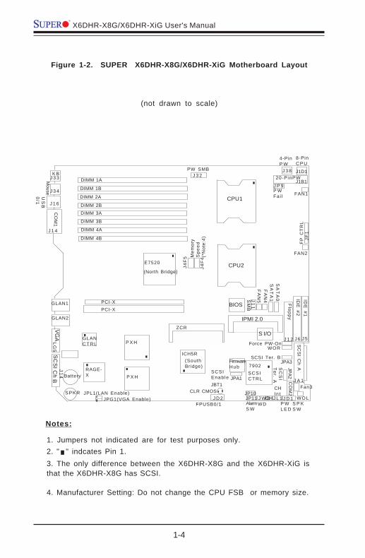
Figure 1-2. SUPER X6DHR-X8G/X6DHR-XiG Motherboard Layout
1. Jumpers not indicated are for test purposes only.
(not drawn to scale)
K B
DIMM 4B
Mouse
US
B0
/1
J 1 4
CO
M1
DIMM 4A
DIMM 3B
DIMM 3ADIMM 2B
DIMM 2A
DIMM 1B
DIMM 1A
GLAN1
GLAN2
VGA
SC
SI C
h B Battery
JPG1(VGA Enable)JPL1(LAN Enable)
RAGE-X
GLANCTRL
P X H
P X H
PCI-XPCI-X
E7520
(North Bridge)
ICH5R(SouthBridge)
ZCR
IPMI 2.0
BIOS
S I/O
7902SCSICTRL
IDE
#1ID
E #2
Floppy
SC
SI C
h A
WOL
CO
M2
Fan3
SCSIEnab le
FPUSB0/1J D 2
J P 9
CLR CMOS
Force PW-OnWOR
S P KS W
SC
SI
Ter. AJPA1
JBT1
SM
B
FA
N5
SA
TA
1S
AT
A0
FP
CT
RL
JF1
FAN2
FAN1
20-PinPW
8-PinC P U
4-PinP W
PW SMB
P WL E D
CHIntJ L 1J W D
WD
CPU1
CPU2
JP11AlarmS W
JPA3
JPA2
SCSI Ter. B
OH
J 3 3
J 3 4
J 1 6
LG5
J14
J D 1
J A 1
J 5J 6J 1 2
FA
N4
FirmwareHub
J1B1
J1D1J 3 8J 3 2
J4F
4
J4F
5 Mem
ory
Spe
ed(*
Not
e:4)
Notes:
2. " " indcates Pin 1.3. The only difference between the X6DHR-X8G and the X6DHR-XiG isthat the X6DHR-X8G has SCSI.
4. Manufacturer Setting: Do not change the CPU FSB or memory size.
J11
P WFai l
JP10S P K R

Chapter 1: Introduction
1-5
Intr
oduc
tion
Jumper Description Default SettingJBT1 CMOS Clear See Chapter 2J4F4/J4F5 Memory Frequency Select (*Manufacturer Setting: Do not chage!)JPL1 GLAN Enable/Disable Pins 1-2 (Enabled)JP10 3rd PWR Supply Fail Detect Open (Disabled)JPA1 SCSI Enable/Disable(*Note) Pins 1-2 (Enabled)JPA2,JPA3 SCSI Term. A/B Enable (*Note) Open (Enabled)JPG1 VGA Enable/Disable Pins 1-2 (Enabled)JWD Watch Dog Pins 1-2 (Reset)Connector DescriptionATX PWR (J1B1) Primary ATX 20-Pin Power Connector12-V PWR (J38) 4-Pin Power Connector (Required)CPU PWR (J1D1) 8-Pin CPU Power Connector( Required)COM(J14)/COM2(J15) COM1/COM2 Serial Port ConnectorsFAN#1-5 Onboard CPU Fan/Chassis Fan HeadersDIMM#1A-DIMM#4B Memory (RAM) SlotsFloppy Drive(J12) Floppy Drive ConnectorFPUSB0/1(JD2) Front Panel USB0/1 HeadersGLAN1/2 G-bit Ethernet PortsIPMI (J9) IPMI 2.0 ConnectorIDE1/2(J5/J6) IDE1/2 Hard Disk Drive ConnectorsKB/Mouse(J33, J34) PS/2 Keyboard (J34)/Mouse (J33)PWR Fail (JP9) Triple Redundant PS Fail Detect HeaderPower SMB(J32) Power System Mangement Bus (See Chapter 2)SCSI Ch.A/B(JA1/JA2) SCSI Ch. A (JA2), SCSI Ch. B (JA1) HeadersSMB(J11) System Management Bus HeaderJD1 PWR LED(Pins1-3), Speaker(Pins4-7) HeaderJF1 Front Control Panel ConnectorJL1 Chassis Intrusion HeaderJP11 Alarm Rest Header (Defult: On)JOH1 Overheat LEDJWOL Wake-on-LAN HeaderJWOR Wake-on-Ring HeaderSATA0(J3)/SATA1(J4) Serial ATA ConnectorsVideo(LG5) Video ConnectorUSB0/1(J16) Universal Serial Bus Ports
(*Note: for X6DHR-X8G only)
Quick Reference (X6DHR-X8G/X6DHR-XiG)(*Please refer to Chapter 2 for pin definitions and detailedinformation.)

1-6
Introduction
X6DHR-X8G/X6DHR-XiG User's Manual
Motherboard Features
CPU• Single or dual Intel® 604-pin Xeon 32-bit/w. EM64T NoconaTM proces-
sors at a 800 MHz front side (system) bus speed.*Notes: The CPU FSB is set at 800 MHz by the Manufacturer. Please donot change the CPU FSB setting. Please refer to the support section ofour web site for a complete listing of supported processors (http://www.supermicro.com/TechSupport.htm.)
Memory• Eight 184-pin DIMM sockets supporting up to 32/16 GB Registered ECC
DDR-333/266 (PC2700/2100) SDRAM (*Manufacturer Setting)Notes: Memory is set via BIOS. Interleaved memory; requires memorymodules to be installed in pairs. See Section 2-3 for details.
Chipset• Intel E7520 (Lindenhurst) chipset
Expansion Slots• Two 64-bit PCI-X 133 slots
BIOS• 4 Mb Phoenix® Flash ROM• APM 1.2, DMI 2.1, PCI 2.2, ACPI 1.0, Plug and Play (PnP), SMBIOS 2.3
PC Health Monitoring• Onboard voltage monitors for CPU cores, chipset voltage, +3.3V,+5V,
+12V, −12V, and +5V standby• Fan status monitor with firmware/software on/off control• CPU/chassis temperature monitors• Environmental temperature monitor and control• CPU fan auto-off in sleep mode• CPU slow-down on temperature overheat• CPU thermal trip support for processor protection, +5V standby alert
LED• Power-up mode control for recovery from AC power loss• Auto-switching voltage regulator for CPU core• System overheat LED and control• Chassis intrusion detection

Chapter 1: Introduction
1-7
Intr
oduc
tion
• System resource alert (via Supero Doctor III)
ACPI Features (optional)• Microsoft OnNow• Slow blinking LED for suspend state indicator• Main switch override mechanism
Onboard I/O• Support for up to two Ultra 320 Channels• 2015S ZCR support (*Note)• One IPMI 2.0• One Intel 82546GB Gigabit Ethernet controllers• 2 EIDE Ultra DMA/100 bus master interfaces• 1 floppy port interface (up to 2.88 MB)• 2 Fast UART 16550A compatible serial ports• PS/2 mouse and PS/2 keyboard ports• Up to 4 USB 2.0 (Universal Serial Bus) ports
Other• Internal/external modem ring-on• Wake-on-LAN (WOL)• Wake-on-Ring (WOR)• Console redirection
CD/Diskette Utilities• BIOS flash upgrade utility and device drivers
Dimensions• ATX Ext. 12" x 13.05" (304.8 x 331.5 mm)
(*Note: If ZCR 2015S is used, please change the SCSI Bus to PCI 66MHzin BIOS. If THE 2025 ZCR is used, the 2025 ZCR Card will be automati-cally detected by the Phoenix BIOS.)

1-8
Introduction
X6DHR-X8G/X6DHR-XiG User's Manual
Figure 1-9. Block Diagram of the E7520 Chipset
Note: This is a general block diagram. Please refer to the MotherboardFeatures for details.
MCH
NOCONA PROCE S SOR#2VRM CL OCK
4 DDR- 266A
DD
R
CT
RL
DA
TA
NOCONA PROCE S SOR#1
AD
DR
CT
RL
DA
TA
DA
TA
AD
DR
CT
RL
DI MMs
I CH5 R
F WHL PC I / O
L PC BUS
HUB
BMC CON.
DDRA- 266
DDRB- 266
PCI BUS ( 32- BI T)
DI MMs4 DDR- 266
US B
0, 1, 2, 3
US B PORT
VGA
KB.S E R. 2S E R. 1 H/ W
MONI TORF DD.
MS .
VRM
0, 1
SATA SATA
UDMA- 100I DE
PRI / S EC
PXH
S CS I
7902
PCI - X BUS ( 100 MHZ)
Gbi t L AN
S OCKE T
ZCR
PXH
PCI - X BUS ( 100 MHZ)
S L OT
PCI - X BUS1_PCI - X133
PCI - X BUS
1_PCI - X133S L OT
266MB/ s
6. 4GB/ s
4. 26GB/ s
DDR- 3335. 33GB/ s
7902
82546GB
PCI - E x p .
PCI - E x p .

Chapter 1: Introduction
1-9
Intr
oduc
tion
1-2 Chipset Overview
Bui l t upon the funct ional i ty and the capabi l i ty of the Intel E7520(Lindenhurst) chipset, The X6DHR-X8G/X6DHR-XiG motherboard providesthe performance and feature set required for dual processor-based serv-ers, with configuration options optimized for communications, presentation,storage, computation or database applications. The Intel E7520 (Lindenhurst)chipset consists of the following components: the E7520 (Lindenhurst)Memory Controller Hub (MCH), the ICH5R Controller Hub (ICH), the Intel PCI-X Hub (PXH).
The E7520 MCH supports single or dual Nocona processors with Front SideBus speeds of 800 MHz. Its memory controller provides direct connection totwo channels of registered DDR266, DDR333 with a marched system busaddress and data bandwidths of up to 6.4GB/s. The E7520 also supportsthe new PCI high speed serial I/O interface for superior I/O bandwidth. TheMCH interfaces with the ICH5R I/O Controller Hub (ICH5R) via a dedicatedHub Interface. The PXH provides connection between a PCI interface andtwo independent PCI bus interfaces that can be configured for standard PCI-X 1.0 protocol.
ICH5R System Features
In addition to providing the I/O subsystem with access to the rest of thesystem, the ICH5R I/O Controller Hub integrates many I/O functions.
The ICH5R I/O Controller Hub integrates: 2-channel Ultra ATA/100 Bus Mas-ter IDE Controller, two Serial ATA (SATA) Host w/RAID0, RAID1 support,SMBus 2.0 Controller, LPC/Flash BIOS Interface, PCI 2.2 Interface and Sys-tem Management Controller.

1-10
Introduction
X6DHR-X8G/X6DHR-XiG User's Manual
1-3 Special Features
BIOS Recovery
The BIOS Recovery function allows you to recover your BIOS image file ifthe BIOS flashing procedure fails (see Section 3-3).
Recovery from AC Power Loss
BIOS provides a setting for you to determine how the system will respondwhen AC power is lost and then restored to the system. You can choosefor the system to remain powered off (in which case you must hit thepower switch to turn it back on) or for it to automatically return to a power-on state. See the Power Lost Control setting in the Advanced BIOS Setupsection (Peripheral Device Configuration) to change this setting. The de-fault setting is Always On.
1-4 PC Health Monitoring
This section describes the PC health monitoring features of the SUPERX6DHR-X8G/X6DHR-XiG. All have an onboard System Hardware Monitorchip that supports PC health monitoring.
Onboard Voltage Monitors for the CPU Cores, ChipsetVoltage, +3.3V, +5V, +12V, -12V and +5V Standby
An onboard voltage monitor will scan these voltages continuously. Once avoltage becomes unstable, a warning is given or an error message is sentto the screen. Users can adjust the voltage thresholds to define thesensitivity of the voltage monitor.
Fan Status Monitor with Firmware/Software On/Off Control
The PC health monitor can check the RPM status of the cooling fans. Theonboard CPU and chassis fans are controlled by the Thermal Managementvia BIOS.

Chapter 1: Introduction
1-11
Intr
oduc
tion
Environmental Temperature Control
The thermal control sensor monitors the CPU temperature in real time andwill turn on the thermal control fan whenever the CPU temperature exceedsa user-defined threshold. The overheat circuitry runs independently fromthe CPU. It can continue to monitor for overheat conditions even when theCPU is in sleep mode. Once it detects that the CPU temperature is too high,it will automatically turn on the thermal control fan to prevent any overheatdamage to the CPU. The onboard chassis thermal circuitry can monitor theoverall system temperature and alert users when the chassis temperatureis too high.
CPU Fan Auto-Off in Sleep Mode
The CPU fan activates when the power is turned on. It continues to operatewhen the system enters Standby mode. When in sleep mode, the CPU willnot run at full power, thereby generating less heat.
CPU Overheat/Fan Fail LED and Control
This feature is available when the user enables the CPU overhea/Fan Failwarning function in the BIOS. This allows the user to define an overheattemperature. When this temperature is exceeded, both the overheat fan andthe warning LED are triggered.
System Resource Alert (*via Supero Doctor III)
This feature is available when used with Intel's LANDesk Client Manager(optional). For example, if the system is running low on virtual memory andthere is insufficient hard drive space for saving the data, you can bealerted of the potential problem.
Auto-Switching Voltage Regulator for the CPU Core
The auto-switching voltage regulator for the CPU core can support up to120A current and auto-sense voltage IDs ranging from 0.83V to 1.63V.This will allow the regulator to run cooler and thus make the system morestable.

1-12
Introduction
X6DHR-X8G/X6DHR-XiG User's Manual
1-5 ACPI Features
ACPI stands for Advanced Configuration and Power Interface. The ACPIspecification defines a flexible and abstract hardware interface that pro-vides a standard way to integrate power management features throughouta PC system, including its hardware, operating system and application soft-ware. This enables the system to automatically turn on and off peripheralssuch as CD-ROMs, network cards, hard disk drives and printers. This alsoincludes consumer devices connected to the PC such as VCRs, TVs, tele-phones and stereos.
In addition to enabling operating system-directed power management, ACPIprovides a generic system event mechanism for Plug and Play and an oper-ating system-independent interface for configuration control. ACPI lever-ages the Plug and Play BIOS data structures while providing a processorarchitecture-independent implementation that is compatible with WindowsOperating Systems.
Microsoft OnNow
The OnNow design initiative is a comprehensive, system-wide approach tosystem and device power control. OnNow is a term for a PC that is alwayson but appears to be off and responds immediately to user or other re-quests.
Slow Blinking LED for Suspend-State Indicator
When the CPU goes into a suspend state, the chassis power LED will startblinking to indicate that the CPU is in suspend mode. When the user pressesany key, the CPU will wake-up and the LED will automatically stop blinkingand remain on.
Main Switch Override Mechanism
When an ATX power supply is used, the power button can function as asystem suspend button to make the system enter a SoftOff state. Themonitor will be suspended and the hard drive will spin down. Depressingthe power button again will cause the whole system to wake-up. Duringthe SoftOff state, the ATX power supply provides power to keep the re-

Chapter 1: Introduction
1-13
Intr
oduc
tion
quired circuitry in the system alive. In case the system malfunctions andyou want to turn off the power, just depress and hold the power button for4 seconds. This option can be set in the Power section of the BIOS Setuproutine.
External Modem Ring-On
Wake-up events can be triggered by a device such as the external modemringing when the system is in the SoftOff state. Note that external modemring-on can only be used with an ATX 2.01 (or above) compliant powersupply.
Wake-On-LAN (WOL)
Wake-On-LAN is defined as the ability of a management application to re-motely power up a computer that is powered off. Remote PC setup, up-dates and asset tracking can occur after hours and on weekends so thatdaily LAN traffic is kept to a minimum and users are not interrupted. Themotherboard has a 3-pin header (WOL) to connect to the 3-pin header on aNetwork Interface Card (NIC) that has WOL capability. Wake-On-LAN mustbe enabled in BIOS. Note that Wake-On-LAN can only be used with an ATX2.01 (or above) compliant power supply.
1-6 Power Supply
As with all computer products, a stable power source is necessary forproper and reliable operation. It is even more important for processors thathave high CPU clock rates.
The SUPER X6DHR-X8G/X6DHR-XiG accommodates ATX power supplies.Although most power supplies generally meet the specifications required bythe system, some are inadequate. You should use one that will supply atleast 400W of power. It is also required that a +12V, 4-pin power connec-tor (J38) be used for heavy loading configurations. An higher wattagepower supply is recommended for high-load configurations. Also yourpower supply must supply 1.5A for the Ethernet ports.
It is strongly recommended that you use a high quality power supply thatmeets ATX power supply Specification 2.02 or above. It must also be SSIcompliant (info at http://www.ssiforum.org/). Additionally, in areas wherenoisy power transmission is present, you may choose to install a line filterto shield the computer from noise. It is recommended that you also install a

1-14
Introduction
X6DHR-X8G/X6DHR-XiG User's Manual
power surge protector to help avoid problems caused by power surges. (*Please refer to the next page for additional information.)
NOTES: 1. Auxiliary 12V power (JID1) is required to support IntelNocona CPUs. Failure to provide this extra power will cause theCPU to become unstable after only a few minutes of operation.See Section 2-5 for details on connecting the power supply cables.
2. Be sure to use the correct type of onboard CMOS battery asspecified by the Manufacturer. Do not install the CMOS battery up-side down to avoid possible explosion.
1-7 Super I/O
The disk drive adapter functions of the Super I/O chip include a floppy diskdrive controller that is compatible with industry standard 82077/765, a dataseparator, write pre-compensation circuitry, decode logic, data rate selec-tion, a clock generator, drive interface control logic and interrupt and DMAlogic. The wide range of functions integrated onto the Super I/O greatlyreduces the number of components required for interfacing with floppy diskdrives. The Super I/O supports 360 K, 720 K, 1.2 M, 1.44 M or 2.88 M diskdrives and data transfer rates of 250 Kb/s, 500 Kb/s or 1 Mb/s. It alsoprovides two high-speed, 16550 compatible serial communication ports(UARTs), one of which supports serial infrared communication. Each UARTincludes a 16-byte send/receive FIFO, a programmable baud rate generator,complete modem control capability and a processor interrupt system. BothUARTs provide legacy speed with baud rate of up to 115.2 Kbps as well asan advanced speed with baud rates of 250 K, 500 K, or 1 Mb/s, whichsupport higher speed modems.
The Super I/O supports one PC-compatible printer port (SPP), Bi-directionalPrinter Port (BPP) , Enhanced Parallel Port (EPP) or Extended CapabilitiesPort (ECP).
The Super I/O provides functions that comply with ACPI (Advanced Con-figuration and Power Interface), which includes support of legacy and ACPIpower management through an SMI or SCI function pin. It also featuresauto power management to reduce power consumption.
The IRQs, DMAs and I/O space resources of the Super I/O can flexiblyadjust to meet ISA PnP requirements, which support ACPI and APM (Ad-vanced Power Management).

Chapter 2: Installation
2-1
Chapter 2Installation
2-1 Static-Sensitive Devices
Electric-Static-Discharge (ESD) can damage electronic components. To pre-vent damage to your system board, it is important to handle it very carefully.The following measures are generally sufficient to protect your equipmentfrom ESD.
Precautions
• Use a grounded wrist strap designed to prevent static discharge.• Touch a grounded metal object before removing the board from the anti-
static bag.• Handle the board by its edges only; do not touch its components, periph-
eral chips, memory modules or gold contacts.• When handling chips or modules, avoid touching their pins.• Put the motherboard and peripherals back into their antistatic bags when
not in use.• For grounding purposes, make sure your computer chassis provides ex-
cellent conductivity between the power supply, the case, the mountingfasteners and the motherboard.
Warning: Please use the correct type of onboard CMOS battery asspecified by the Manufacturer. Do not install the CMOS battery up-side down to avoid possible explosion.
Unpacking
The motherboard is shipped in antistatic packaging to avoid static damage.When unpacking the board, make sure the person handling it is static protected.

2-2
X6DHR-X8G/X6DHR-XiG User's Manual
IMPORTANT: Always connect the power cord last and always remove itbefore adding, removing or changing any hardware components. Makesure that you install the processor into the CPU socket before you installthe CPU heat sink.
2-2 Nocona Processor and Heatsink InstallationWhen handling the processor package, avoid placing directpressure on the label area of the fan. Also, do not place themotherboard on a conductive surface, which can damage theBIOS battery and prevent the system from booting up.
!
Socket lever
CPU Installation
1. Lift the lever on the CPU socket:lift the lever completely as shownon the picture on the right;otherwise, you will damage theCPU socket when power isapplied. (Install CPU1 first.)
1. Place the CPU retention bracketon top of the CPU mounting plate.
CPU RetentionBracket
CPU Socket
Mounting Holesw/Standoffs
Xeon CPU
Heatsink
2. Install the CPU mounting plateand the retention bracket on thereverse side of the motherboard.
3. Insert four standoffs through themounting holes on the chassisback plane and the mounting holeson the CPU sockets(with theretention bracket in between.)
4. Properly place the CPU on top ofthe CPU socket. Align Pin 1 on theCPU with Pin 1 on the CPU socket.
Chassisback plane
Motherboard
CPUSocket
Heatsink
Installing CPU Mounting Plate and Retention Bracket
CPU
Standoffs
MountingHolesChassis
back plane

Chapter 2: Installation
2-3
HeatsinkHeatsink Installation
1. Do not apply any thermal compoundto the heatsink or the CPU die-therequired amount has already beenapplied.
2. Place the heatsink on top of theCPU so that the four mounting holesare aligned with those on the retentionmechanism.
3. Screw in two diagonal screws (iethe #1 and the #2 screws) until justsnug (-do not fully tighten the screwsto avoid possible damage to the CPU.)
4. Finish the installation by fullytightening all four screws.
Screw#1 Screw#2
Pin 1
2. Insert the CPU in the socket,making sure that pin 1 of the CPUaligns with pin 1 of the socket(both corners are marked with atriangle). When using only oneCPU, install it into CPU socket #1(socket #2 is automatically disabledif only one CPU is used).
3. Press the lever down untilyou hear the *click* so youcan be sure that the CPU issecurely installed in the CPUsocket.
Socket lever in thelocking Position
Screw#1

2-4
X6DHR-X8G/X6DHR-XiG User's Manual
Figure 2-1. PGA604 Socket: Empty and with Processor Installed
Lever
Processor(installed)
Triangle
Triangle
Empty socket
Warning! Makesure you lift thelever completelywhen installing theCPU. If the lever isonly partly raised,damage to thesocket or CPU mayresult.
!
1. Unscrew and remove the heatsinkscrews from the motherboard in thesequence as show in the secondpicture on the right.
2. Hold the heatsink as show in thepicture on the right and gently wrigglethe heatsink to loosen it from the CPU.(Do not use excessive force whenwriggling the heatsink!!)
3. Once the CPU is loosened from theheatsink, remove the heatsink from theCPU socket.
4. Clean the surface of the CPU andthe heatsink to get rid of the oldthermal grease. Reapply the properamount of thermal grease on thesurface before you re-install the CPUand the heatsink.
To Un- Install Heatsink

Chapter 2: Installation
2-5
Mounting the Motherboard in the Chassis
All motherboards have standard mounting holes to fit different types ofchassis. Make sure the location of all the mounting holes for both themotherboard and the chassis match. Although a chassis may have bothplastic and metal mounting fasteners, metal ones are highly recommendedbecause they ground the motherboard to the chassis. Make sure the metalstandoffs click in or are screwed in tightly. Then use a screwdriver tosecure the motherboard onto the motherboard tray.

2-6
X6DHR-X8G/X6DHR-XiG User's Manual
Figure 2-2. Installing and Removing DIMMs
To Install:Insert modulevertically andpress downuntil it snapsinto place.Pay attentionto thealignmentnotch at thebottom.
2-3 Installing DIMMs
Note: Check the Supermicro web site for recommended memory modules:
http://www.supermicro.com/TECHSUPPORT/FAQs/Memory_vendors.htm
CAUTIONExercise extreme care when installing or removing DIMM
modules to prevent any possible damage. Also note that thememory is interleaved to improve performance (see step 1).
DIMM Installation (See Figure 2-2)
1. Insert the desired number of DIMMs into the memory slots, starting withDIMM 1A. The memory scheme is interleaved so you must install twomodules at a time, beginning with DIMM 1A, then DIMM 1B, and so on.
2. Insert each DIMM module vertically into its slot. Pay attention to thenotch along the bottom of the module to prevent inserting the DIMMmodule incorrectly.
3. Gently press down on the DIMM module until it snaps into place in theslot. Repeat for all modules (see step 1 above).
Memory SupportThe X6DHR-X8G/X6DHR-XiG supports up to 32/16 GB of Registered DDR-333/266 (PC2700/2100) memory (recommended by the Manufacturer). Allmotherboards were designed to support 2 GB modules in each slot, but hasonly been verified for up to 1.0 GB modules. *Note:If Reg. ECC DDR 333(PC2700) memory modules are used, 4 pieces of double banked memoryand 6 pieces of single banked memory are supported.

Chapter 2: Installation
2-7
To Remove:Use your thumbs to gently push near the edge of both ends ofthe module. This should release it from the slot.
2-4 I/OPorts/Control Panel Connectors
The I/O ports are color coded in conformance with the PC 99 specification.See Figure 2-3 below for the colors and locations of the various I/O ports.
Figure 2-3. I/O Port Locations and Definitions
Mouse (Purple)
K e y b o a r d
(Turquoise)GLAN1COM Port1 GLAN2
USB0/1
Video
SCSI (X6DHR-
X8G) only)

2-8
X6DHR-X8G/X6DHR-XiG User's Manual
Front Control Panel
JF1 contains header pins for various buttons and indicators that are nor-mally located on a control panel at the front of the chassis. These connec-tors are designed specifically for use with Supermicro server chassis. SeeFigure 2-4 for the descriptions of the various control panel buttons and LEDindicators. Refer to the following section for descriptions and pin defini-tions.
Figure 2-4. JF1 Header Pins
Power Button
Overheat LED
1
NIC1 LED
Reset Button
2
Power Fail LED
HDD LED
Power LED
Reset
Pwr
Vcc
Vcc
Vcc
Vcc
Ground
Ground
1920
Vcc
X
Ground NMI
X
NIC2 LED Vcc
Chapter 2: Installation
2-9
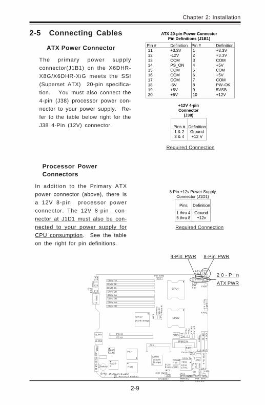
2-5 Connecting Cables
ATX Power Connector
The pr imary power supplyconnector(J1B1) on the X6DHR-X8G/X6DHR-XiG meets the SSI(Superset ATX) 20-pin specifica-tion. You must also connect the4-pin (J38) processor power con-nector to your power supply. Re-fer to the table below right for theJ38 4-Pin (12V) connector.
Pins
1 thru 45 thru 8
Definition
Ground+12v
8-Pin +12v Power SupplyConnector (J1D1)
Processor PowerConnectors
In addition to the Primary ATXpower connector (above), there isa 12V 8-pin processor powerconnector. The 12V 8-pin con-nector at J1D1 must also be con-nected to your power supply forCPU consumption. See the tableon the right for pin definitions.
Pin # Definition 11 +3.3V 12 -12V 13 COM 14 PS_ON 15 COM 16 COM 17 COM 18 -5V 19 +5V 20 +5V
Pin # Definition 1 +3.3V 2 +3.3V 3 COM 4 +5V 5 COM 6 +5V 7 COM 8 PW-OK 9 5VSB 10 +12V
ATX 20-pin Power ConnectorPin Definitions (J1B1)
Pins #1 & 23 & 4
DefinitionGround+12 V
+12V 4-pinConnector
(J38)
Required Connection
Required Connection
8-Pin PWR
2 0 - P i n
ATX PWR
4-Pin PWR
K B
DIMM 4B
Mouse
US
B0
/1
J 1 4
CO
M1
DIMM 4A
DIMM 3B
DIMM 3A
DIMM 2B
DIMM 2A
DIMM 1B
DIMM 1A
GLAN1
GLAN2
VG
AS
CS
I Ch
B Battery
JPG1(VGA Enable)JPL1(LAN Enable)
RAGE-X
GLANCTRL
P X H
P X H
PCI-X
PCI-X
E7520
(North Bridge)
ICH5R(SouthBridge)
ZCR
IPMI 2.0
BIOS
S I/O
7902
SCSICTRL
IDE
#1
IDE
#2
Flo
pp
y
SC
SI C
h A
WOL
CO
M2
Fan3
SCSIEnab le
FPUSB0/1J D 2
J P 9
CLR CMOS
Force PW-OnWOR
S P KS W
SC
SI
Te
r. AJPA1JBT1
SM
B
FA
N5
SA
TA
1S
AT
A0
FP
CT
RL
JF
1
FAN2
FAN1
20-PinPW
8-PinC P U
4-PinP W
PW SMB
P WL E D
CHIntJ L 1J W D
WD
CPU1
CPU2
JP11AlarmS W
JPA3
JPA
2
SCSI Ter. B
OH
J 3 3
J 3 4
J 1 6
LG
5J
14
J D 1
J A 1
J 5J 6J 1 2
FA
N4
FirmwareHub
J1B1
J1D1J 3 8J 3 2
J4
F4
J4
F5 M
em
ory
Sp
ee
d(*
No
te:4
)
J1
1
P WFai l
JP10S P K R

2-10
X6DHR-X8G/X6DHR-XiG User's Manual
K B
DIMM 4B
Mouse
US
B0
/1
J 1 4
CO
M1
DIMM 4A
DIMM 3B
DIMM 3A
DIMM 2B
DIMM 2A
DIMM 1B
DIMM 1A
GLAN1
GLAN2
VG
AS
CS
I Ch
B Battery
JPG1(VGA Enable)JPL1(LAN Enable)
RAGE-X
GLANCTRL
P X H
P X H
PCI-X
PCI-X
E7520
(North Bridge)
ICH5R(SouthBridge)
ZCR
IPMI 2.0
BIOS
S I/O
7902
SCSICTRL
IDE
#1
IDE
#2
Flo
pp
y
SC
SI C
h A
WOL
CO
M2
Fan3
SCSIEnab le
FPUSB0/1J D 2
J P 9
CLR CMOS
Force PW-OnWOR
S P KS W
SC
SI
Te
r. AJPA1JBT1
SM
B
FA
N5
SA
TA
1S
AT
A0
FP
CT
RL
JF
1
FAN2
FAN1
20-PinPW
8-PinC P U
4-PinP W
PW SMB
P WL E D
CHIntJ L 1J W D
WD
CPU1
CPU2
JP11AlarmS W
JPA3
JPA
2
SCSI Ter. B
OH
J 3 3
J 3 4
J 1 6
LG
5J
14
J D 1
J A 1
J 5J 6J 1 2
FA
N4
FirmwareHub
J1B1
J1D1J 3 8J 3 2
J4
F4
J4
F5 M
em
ory
Sp
ee
d(*
No
te:4
)
J1
1
P WFai l
JP10S P K R
Power LED
The Power LED connection is lo-cated on pins 15 and 16 of JF1.Refer to the table on the right forpin definitions.
NMI Button
The non-maskable interrupt buttonheader is located on pins 19 and20 of JF1. Refer to the table onthe right for pin definitions.
PinNumber
1920
DefinitionControlGround
NMI Button PinDefinitions (JF1)
PinNumber
1516
DefinitionVcc
Control
PWR_LED Pin Definitions(JF1)
NMI
PWR LED
Power Button
Overheat LED
1
NIC1 LED
Reset Button
2
Power Fail LED
HDD LED
Power LED
Reset
Pwr
Vcc
Vcc
Vcc
Vcc
Ground
Ground
1920
Vcc
X
Ground NMI
X
NIC2 LED Vcc

Chapter 2: Installation
2-11
K B
DIMM 4B
Mouse
US
B0
/1
J 1 4
CO
M1
DIMM 4A
DIMM 3B
DIMM 3A
DIMM 2B
DIMM 2A
DIMM 1B
DIMM 1A
GLAN1
GLAN2
VG
AS
CS
I Ch
B Battery
JPG1(VGA Enable)JPL1(LAN Enable)
RAGE-X
GLANCTRL
P X H
P X H
PCI-X
PCI-X
E7520
(North Bridge)
ICH5R(SouthBridge)
ZCR
IPMI 2.0
BIOS
S I/O
7902
SCSICTRL
IDE
#1
IDE
#2
Flo
pp
y
SC
SI C
h A
WOL
CO
M2
Fan3
SCSIEnab le
FPUSB0/1J D 2
J P 9
CLR CMOS
Force PW-OnWOR
S P KS W
SC
SI
Te
r. AJPA1JBT1
SM
B
FA
N5
SA
TA
1S
AT
A0
FP
CT
RL
JF
1
FAN2
FAN1
20-PinPW
8-PinC P U
4-PinP W
PW SMB
P WL E D
CHIntJ L 1J W D
WD
CPU1
CPU2
JP11AlarmS W
JPA3
JPA
2
SCSI Ter. B
OH
J 3 3
J 3 4
J 1 6
LG
5J
14
J D 1
J A 1
J 5J 6J 1 2
FA
N4
FirmwareHub
J1B1
J1D1J 3 8J 3 2
J4
F4
J4
F5 M
em
ory
Sp
ee
d(*
No
te:4
)
J1
1
P WFai l
JP10S P K R
NIC1/NIC2 LED Indicators
The NIC (Network Interface Con-troller) LED connection for GLANport1 is located on pins 11 and 12of JF1 and the LED connection forGLAN Port2 is on Pins 9 and 10.Attach the NIC LED cables to dis-play network activity. Refer to thetable on the right for pin defini-tions.
HDD LED
The HDD LED connection is locatedon pins 13 and 14 of JF1. Attachthe hard drive LED cable here todisplay disk activity (for any harddrives on the system, includingSCSI, Serial ATA and IDE). Seethe table on the right for pin defini-tions.
HDD LED PinDefinitions
(JF1)Pin
Number1314
DefinitionVcc
HD Active
NIC1 LED PinDefinitions
(JF1)Pin
Number1112
DefinitionVccGND
NIC2 LED PinDefinitions
(JF1)Pin
Number9
10
DefinitionVccGND
HDD LED
NIC1 LED
NIC2 LED
Power Button
Overheat LED
1
NIC1 LED
Reset Button
2
Power Fail LED
HDD LED
Power LED
Reset
Pwr
Vcc
Vcc
Vcc
Vcc
Ground
Ground
1920
Vcc
X
Ground NMI
X
NIC2 LED Vcc

2-12
X6DHR-X8G/X6DHR-XiG User's Manual
Power Button
Overheat LED
1
NIC1 LED
Reset Button
2
Power Fail LED
HDD LED
Power LED
Reset
Pwr
Vcc
Vcc
Vcc
Vcc
Ground
Ground
1920
Vcc
X
Ground NMI
X
NIC2 LED Vcc
K B
DIMM 4B
Mouse
US
B0
/1
J 1 4
CO
M1
DIMM 4A
DIMM 3B
DIMM 3A
DIMM 2B
DIMM 2A
DIMM 1B
DIMM 1A
GLAN1
GLAN2
VG
AS
CS
I Ch
B Battery
JPG1(VGA Enable)JPL1(LAN Enable)
RAGE-X
GLANCTRL
P X H
P X H
PCI-X
PCI-X
E7520
(North Bridge)
ICH5R(SouthBridge)
ZCR
IPMI 2.0
BIOS
S I/O
7902
SCSICTRL
IDE
#1
IDE
#2
Flo
pp
y
SC
SI C
h A
WOL
CO
M2
Fan3
SCSIEnab le
FPUSB0/1J D 2
J P 9
CLR CMOS
Force PW-OnWOR
S P KS W
SC
SI
Te
r. AJPA1JBT1
SM
B
FA
N5
SA
TA
1S
AT
A0
FP
CT
RL
JF
1
FAN2
FAN1
20-PinPW
8-PinC P U
4-PinP W
PW SMB
P WL E D
CHIntJ L 1J W D
WD
CPU1
CPU2
JP11AlarmS W
JPA3
JPA
2
SCSI Ter. B
OH
J 3 3
J 3 4
J 1 6
LG
5J
14
J D 1
J A 1
J 5J 6J 1 2
FA
N4
FirmwareHub
J1B1
J1D1J 3 8J 3 2
J4
F4
J4
F5 M
em
ory
Sp
ee
d(*
No
te:4
)
J1
1
P WFai l
JP10S P K R
Overheat LED (OH)
Connect an LED to the OH connec-tion on pins 7 and 8 of JF1 to pro-vide advanced warning of chassisoverheating. Refer to the table onthe right for pin definitions.
Power Fail LED
The Power Fail LED connection islocated on pins 5 and 6 of JF1.Refer to the table on the right forpin definitions.
Overheat (OH) LEDPin Definitions
(JF1)Pin
Number78
DefinitionVccGND
Power Fail LED PinDefinitions
(JF1)Pin
Number56
DefinitionVccGND
Overheat LED
PWR Fail LED

Chapter 2: Installation
2-13
K B
DIMM 4B
Mouse
US
B0
/1
J 1 4
CO
M1
DIMM 4A
DIMM 3B
DIMM 3A
DIMM 2B
DIMM 2A
DIMM 1B
DIMM 1A
GLAN1
GLAN2
VG
AS
CS
I Ch
B Battery
JPG1(VGA Enable)JPL1(LAN Enable)
RAGE-X
GLANCTRL
P X H
P X H
PCI-X
PCI-X
E7520
(North Bridge)
ICH5R(SouthBridge)
ZCR
IPMI 2.0
BIOS
S I/O
7902
SCSICTRL
IDE
#1
IDE
#2
Flo
pp
y
SC
SI C
h A
WOL
CO
M2
Fan3
SCSIEnab le
FPUSB0/1J D 2
J P 9
CLR CMOS
Force PW-OnWOR
S P KS W
SC
SI
Te
r. AJPA1JBT1
SM
B
FA
N5
SA
TA
1S
AT
A0
FP
CT
RL
JF
1
FAN2
FAN1
20-PinPW
8-PinC P U
4-PinP W
PW SMB
P WL E D
CHIntJ L 1J W D
WD
CPU1
CPU2
JP11AlarmS W
JPA3
JPA
2
SCSI Ter. B
OH
J 3 3
J 3 4
J 1 6
LG
5J
14
J D 1
J A 1
J 5J 6J 1 2
FA
N4
FirmwareHub
J1B1
J1D1J 3 8J 3 2
J4
F4
J4
F5 M
em
ory
Sp
ee
d(*
No
te:4
)
J1
1
P WFai l
JP10S P K R
Power Button
The Power Button connection islocated on pins 1 and 2 of JF1.Momentarily contacting both pinswill power on/off the system. Thisbutton can also be configured tofunct ion as a suspend button(with a setting in BIOS - see Chap-ter 4). To turn off the powerwhen set to suspend mode, de-press the button for at least 4seconds. Refer to the table on theright for pin definitions.
PinNumber
12
DefinitionPW_ONGround
Power ButtonConnector
Pin Definitions(JF1)
Reset Button
The Reset Button connection is lo-cated on pins 3 and 4 of JF1. At-tach i t to the hardware resetswitch on the computer case.Refer to the table on the right forpin definitions.
PinNumber
34
DefinitionReset
Ground
Reset PinDefinitions
(JF1)
PWR ButtonReset Button
Power Button
Overheat LED
1
NIC1 LED
Reset Button
2
Power Fail LED
HDD LED
Power LED
Reset
Pwr
Vcc
Vcc
Vcc
Vcc
Ground
Ground
1920
Vcc
X
Ground NMI
X
NIC2 LED Vcc

2-14
X6DHR-X8G/X6DHR-XiG User's Manual
ICH5R(SouthBridge) 7902
SCSICTRL
CS
I Ch
A
WOL
CO
M2
Fan3
SCSIEnab le
FPUSB0/1J D 2
CLR CMOS
WOR
S P KS W
SC
SI
Te
r. AJPA1JBT1
P WL E D
CHIntJ L 1J W D
WDJP11AlarmS W
JPA3
JPA
2
SCSI Ter. B
OH J D 1
J A 1
FirmwareHub
JP10
K B
DI
Mouse
US
B0
/1
J 1 4
CO
M1
DI
DI
DI
DI
DI
DI
DIJ 3 3
J 3 4
J 1 6
K B
DIMM 4B
Mouse
US
B0
/1
J 1 4
CO
M1
DIMM 4A
DIMM 3B
DIMM 3A
DIMM 2B
DIMM 2A
DIMM 1B
DIMM 1A
GLAN1
GLAN2
VG
AS
CS
I Ch
B Battery
JPG1(VGA Enable)JPL1(LAN Enable)
RAGE-X
GLANCTRL
P X H
P X H
PCI-X
PCI-X
E7520
(North Bridge)
ICH5R(SouthBridge)
ZCR
IPMI 2.0
BIOS
S I/O
7902
SCSICTRL
IDE
#1
IDE
#2
Flo
pp
y
SC
SI C
h A
WOL
CO
M2
Fan
SCSIEnab le
FPUSB0/1J D 2
J P 9
CLR CMOS
Force PW-OnWOR
S P KS W
SC
SI
Te
r. AJPA1JBT1
SM
B
FA
N5
SA
TA
1S
AT
A0
FP
CT
RL
JF
1
FAN2
FAN1
20-PinPW
8-PinC P U
4-PinP W
PW SMB
P WL E D
CHIntJ L 1J W D
WD
CPU1
CPU2
JP11AlarmS W
JPA3
JPA
2
SCSI Ter. B
OH
J 3 3
J 3 4
J 1 6
LG
5J
14
J D 1
J A 1
J 5J 6J 1 2
FA
N4
FirmwareHub
J1B1
J1D1J 3 8J 3 2
J4
F4
J4
F5 M
em
ory
Sp
ee
d(*
No
te:4
)
J1
1
P WFai l
JP10S P K R
Universal Serial Bus(USB0/1)
Two USB 2.0 ports (J16) are lo-cated beside the Mouse and COM1ports. USB0 is the bottom connec-tor and USB1 is the top connector.See the table on the right for pindefinitions.
Universal Serial Bus Pin Definitions
Pin Number Definition 1 +5V 2 P0- 3 P0+ 4 Ground 5 N/A
Pin Number Definition 1 +5V 2 P0- 3 P0+ 4 Ground 5 Key
USB0 USB1
Chassis Intrusion
A Chassis Intrusion header is lo-cated at JL1. Attach the appropri-ate cable to inform you of a chas-sis intrusion.
C h a s s
Intru
USB
0/1

Chapter 2: Installation
2-15
Front Panel UniversalSerial Bus Headers
An Extra USB header: FPUSB0/FPUSB1(JD2) can be used forfront side USB access. You willneed a USB cable to use the con-nections. Refer to the tables onthe right for pin definitions.
Front Panel Universal Serial Bus PinDefinitions
Pin Number Definition 1 +5V 2 P0- 3 P0+ 4 Ground 5 N/A
FPUSB0/1 (JD2)
Serial Ports
COM Port1(J14) is located besidethe Back Panel USB0/1, and COMPort 2 is located next to ChassisFan3. See the table on the rightfor pin definitions.
Serial Port Pin Definitions(COM2)
Pin Number Definition 1 CD 2 RD 3 TD 4 DTR 5 Ground
Pin Number Definition 6 DSR 7 RTS 8 CTS 9 RI 10 NC
(FP)USB0/1 COM2
K B
DIMM 4B
Mouse
US
B0
/1
J 1 4
CO
M1
DIMM 4A
DIMM 3B
DIMM 3A
DIMM 2B
DIMM 2A
DIMM 1B
DIMM 1A
GLAN1
GLAN2
VG
AS
CS
I Ch
B Battery
JPG1(VGA Enable)JPL1(LAN Enable)
RAGE-X
GLANCTRL
P X H
P X H
PCI-X
PCI-X
E7520
(North Bridge)
ICH5R(SouthBridge)
ZCR
IPMI 2.0
BIOS
S I/O
7902
SCSICTRL
IDE
#1
IDE
#2
Flo
pp
y
SC
SI C
h A
WOL
CO
M2
Fan3
SCSIEnab le
FPUSB0/1J D 2
J P 9
CLR CMOS
Force PW-OnWOR
S P KS W
SC
SI
Te
r. AJPA1JBT1
SM
B
FA
N5
SA
TA
1S
AT
A0
FP
CT
RL
JF
1
FAN2
FAN1
20-PinPW
8-PinC P U
4-PinP W
PW SMB
P WL E D
CHIntJ L 1J W D
WD
CPU1
CPU2
JP11AlarmS W
JPA3
JPA
2
SCSI Ter. B
OH
J 3 3
J 3 4
J 1 6
LG
5J
14
J D 1
J A 1
J 5J 6J 1 2
FA
N4
FirmwareHub
J1B1
J1D1J 3 8J 3 2
J4
F4
J4
F5 M
em
ory
Sp
ee
d(*
No
te:4
)
J1
1
P WFai l
JP10S P K R
COM1
Serial Port Pin Definitions(COM1)
Pin Number Definition 1 CD 2 RD 3 TD 4 DTR 5 Ground
Pin Number Definition 6 DSR 7 RTS 8 CTS 9 RI

2-16
X6DHR-X8G/X6DHR-XiG User's Manual
GLAN1/GLAN2 (Gigabit-Ethernet Ports)
A G-bit Ethernet ports (designatedJLAN1/JLAN2) are located besidethe Video port on the IO backplane.This ports accepts RJ45 typecables.
Fan Headers
There are five fan headers (Fan 1to Fan 5) on the X6DHR-X8G/X6DHR-XiG. See the table on theright for pin definitions. (The fanspeeds are controlled by ThermalManagement via BIOS. Please re-fer to the Hardware MonitoringSection in the "Advanced Setting"in BIOS.)
3-pin Fan Header Pin Definitions(CPU and Chassis Fans )Pin#123
DefinitionGround (black)+12V (red)Tachometer
Caution: These fan headers use DC power.
K B
DIMM 4B
Mouse
US
B0
/1
J 1 4
CO
M1
DIMM 4A
DIMM 3B
DIMM 3A
DIMM 2B
DIMM 2A
DIMM 1B
DIMM 1A
GLAN1
GLAN2
VG
AS
CS
I Ch
B Battery
JPG1(VGA Enable)JPL1(LAN Enable)
RAGE-X
GLANCTRL
P X H
P X H
PCI-X
PCI-X
E7520
(North Bridge)
ICH5R(SouthBridge)
ZCR
IPMI 2.0
BIOS
S I/O
7902
SCSICTRL
IDE
#1
IDE
#2
Flo
pp
y
SC
SI C
h A
WOL
CO
M2
Fan3
SCSIEnab le
FPUSB0/1J D 2
J P 9
CLR CMOS
Force PW-OnWOR
S P KS W
SC
SI
Te
r. AJPA1JBT1
SM
B
FA
N5
SA
TA
1S
AT
A0
FP
CT
RL
JF
1
FAN2
FAN1
20-PinPW
8-PinC P U
4-PinP W
PW SMB
P WL E D
CHIntJ L 1J W D
WD
CPU1
CPU2
JP11AlarmS W
JPA3
JPA
2
SCSI Ter. B
OH
J 3 3
J 3 4
J 1 6
LG
5J
14
J D 1
J A 1
J 5J 6J 1 2
FA
N4
FirmwareHub
J1B1
J1D1J 3 8J 3 2
J4
F4
J4
F5 M
em
ory
Sp
ee
d(*
No
te:4
)
J1
1
P WFai l
JP10S P K R
Fan1
Fan2
Fan3
GLAN1
GLAN2
Fan4
Fan5

Chapter 2: Installation
2-17
SMB
A System Management Busheader is located at J11. Connectthe appropriate cable here to uti-lize SMB on your system.
ATX PS/2 Keyboard andPS/2 Mouse Ports
The ATX PS/2 Keyboard(J34) andPS/2 Mouse(J33) are located be-side the USB0/1 Ports on thebackpanel. See the table at rightfor pin definitions. (See Figure 2-3 for the locations of each.)
PS/2 Keyboardand Mouse PortPin Definitions
(J34, J33)Pin
Number123456
DefinitionDataNC
GroundVCCClock
NC
SMB HeaderPin Definitions (J22)
PinNumber
1234
DefinitionData
GroundClock
No Connection
K B
DIMM 4B
Mouse
US
B0
/1
J 1 4
CO
M1
DIMM 4A
DIMM 3B
DIMM 3A
DIMM 2B
DIMM 2A
DIMM 1B
DIMM 1A
GLAN1
GLAN2
VG
AS
CS
I Ch
B Battery
JPG1(VGA Enable)JPL1(LAN Enable)
RAGE-X
GLANCTRL
P X H
P X H
PCI-X
PCI-X
E7520
(North Bridge)
ICH5R(SouthBridge)
ZCR
IPMI 2.0
BIOS
S I/O
7902
SCSICTRL
IDE
#1
IDE
#2
Flo
pp
y
SC
SI C
h A
WOL
CO
M2
Fan3
SCSIEnab le
FPUSB0/1J D 2
J P 9
CLR CMOS
Force PW-OnWOR
S P KS W
SC
SI
Te
r. AJPA1JBT1
SM
B
FA
N5
SA
TA
1S
AT
A0
FP
CT
RL
JF
1
FAN2
FAN1
20-PinPW
8-PinC P U
4-PinP W
PW SMB
P WL E D
CHIntJ L 1J W D
WD
CPU1
CPU2
JP11AlarmS W
JPA3
JPA
2
SCSI Ter. B
OH
J 3 3
J 3 4
J 1 6
LG
5J
14
J D 1
J A 1
J 5J 6J 1 2
FA
N4
FirmwareHub
J1B1
J1D1J 3 8J 3 2
J4
F4
J4
F5 M
em
ory
Sp
ee
d(*
No
te:4
)
J1
1
P WFai l
JP10S P K R
Keyboard
Mouse
SMB

2-18
X6DHR-X8G/X6DHR-XiG User's Manual
Wake-On-Ring
The Wake-On-Ring header is des-ignated JWOR. This function al-lows your computer to receiveand "wake-up" by an incoming callto the modem when in suspendstate. See the table on the rightfor pin definitions. You must havea Wake-On-Ring card and cable touse this feature.
Wake-on-RingPin Definitions
(JWOR1)
PinNumber
12
DefinitionGround
Wake-up
Power LED/Speaker
On the JDI header, pins 1-3 arefor a power LED and pins 4-7 arefor the speaker. See the table onthe right for speaker pin defini-tions. Note: The speaker connec-tor pins are for use with an exter-nal speaker. If you wish to usethe onboard speaker, you shouldclose pins 6-7 with a jumper.
Speaker Connector PinDefinitions (JD1)
PinNumber
4567
Function+
Key
DefinitionRed wire, Speaker data
No connectionKey
Speaker data
K B
DIMM 4B
Mouse
US
B0
/1
J 1 4
CO
M1
DIMM 4A
DIMM 3B
DIMM 3A
DIMM 2B
DIMM 2A
DIMM 1B
DIMM 1A
GLAN1
GLAN2
VG
AS
CS
I Ch
B Battery
JPG1(VGA Enable)JPL1(LAN Enable)
RAGE-X
GLANCTRL
P X H
P X H
PCI-X
PCI-X
E7520
(North Bridge)
ICH5R(SouthBridge)
ZCR
IPMI 2.0
BIOS
S I/O
7902
SCSICTRL
IDE
#1
IDE
#2
Flo
pp
y
SC
SI C
h A
WOL
CO
M2
Fan3
SCSIEnab le
FPUSB0/1J D 2
J P 9
CLR CMOS
Force PW-OnWOR
S P KS W
SC
SI
Te
r. AJPA1JBT1
SM
B
FA
N5
SA
TA
1S
AT
A0
FP
CT
RL
JF
1
FAN2
FAN1
20-PinPW
8-PinC P U
4-PinP W
PW SMB
P WL E D
CHIntJ L 1J W D
WD
CPU1
CPU2
JP11AlarmS W
JPA3
JPA
2
SCSI Ter. B
OH
J 3 3
J 3 4
J 1 6
LG
5J
14
J D 1
J A 1
J 5J 6J 1 2
FA
N4
FirmwareHub
J1B1
J1D1J 3 8J 3 2
J4
F4
J4
F5 M
em
ory
Sp
ee
d(*
No
te:4
)
J1
1
P WFai l
JP10S P K R
S I/O
7902
SCSICTRL
SC
SI C
h A
WOL
CO
M2
Fan3
Force PW-OnWOR
S P KS W
SC
SI
Te
r. AJPA1
P WL E D
CHIntJ L 1J W D
WDJP11AlarmS W
JPA3
JPA
2
SCSI Ter. B
OH J D 1
J A 1
J 5J 6J 1 2
FirmwareHub
JP10
WOR
PWRLED/
Speaker

Chapter 2: Installation
2-19
PinNumber
123
Definition+5V Standby
GroundW ake-up
Wake-On-LAN PinDefinitions (WOL)
Wake-On-LAN
The Wake-On-LAN header is des-ignated WOL. See the table on theright for pin definitions. You mustenable the LAN Wake-Up setting inBIOS to use this feature. Youmust also have a LAN card with aWake-on-LAN connector andcable.
Overheat LED (JOH1)
Connect an LED to the JOH1header to provide warning ofchassis overheat ing. See thetable on the right for pin defini-tions.
PinNumber
12
Definition+5V
OH Active
Overheat LEDPin Definitions (JOH1)
K B
DIMM 4B
Mouse
US
B0
/1
J 1 4
CO
M1
DIMM 4A
DIMM 3B
DIMM 3A
DIMM 2B
DIMM 2A
DIMM 1B
DIMM 1A
GLAN1
GLAN2
VG
AS
CS
I Ch
B Battery
JPG1(VGA Enable)JPL1(LAN Enable)
RAGE-X
GLANCTRL
P X H
P X H
PCI-X
PCI-X
E7520
(North Bridge)
ICH5R(SouthBridge)
ZCR
IPMI 2.0
BIOS
S I/O
7902
SCSICTRL
IDE
#1
IDE
#2
Flo
pp
y
SC
SI C
h A
WOL
CO
M2
Fan3
SCSIEnab le
FPUSB0/1J D 2
J P 9
CLR CMOS
Force PW-OnWOR
S P KS W
SC
SI
Te
r. AJPA1JBT1
SM
B
FA
N5
SA
TA
1S
AT
A0
FP
CT
RL
JF
1
FAN2
FAN1
20-PinPW
8-PinC P U
4-PinP W
PW SMB
P WL E D
CHIntJ L 1J W D
WD
CPU1
CPU2
JP11AlarmS W
JPA3
JPA
2
SCSI Ter. B
OH
J 3 3
J 3 4
J 1 6
LG
5J
14
J D 1
J A 1
J 5J 6J 1 2
FA
N4
FirmwareHub
J1B1
J1D1J 3 8J 3 2
J4
F4
J4
F5 M
em
ory
Sp
ee
d(*
No
te:4
)
J1
1
P WFai l
JP10S P K R
CTRL
WOL
CO
M2
Fan3
S P KS W
SI
r. AJPA1
P WL E D
CHIntJ L 1J W D
WDJP11AlarmS W
A2
OH J D 1
J A 1
JP10
Overheat
WOL

2-20
X6DHR-X8G/X6DHR-XiG User's Manual
2-6 Jumper Settings
Explanation ofJumpers
To modify the operation of themotherboard, jumpers can beused to choose betweenopt ional sett ings. Jumperscreate shorts between two pinsto change the function of theconnector. Pin 1 is identifiedwith a square solder pad onthe printed circuit board. Seethe motherboard layout pagesfor jumper locations.Note: On two pin jumpers,"Closed" means the jumper ison and "Open" means thejumper is off the pins.
ConnectorPins
JumperCap
Setting
Pin 1-2 short
3 2 13 2 1
CMOS Clear
JBT1 is used to clear CMOS. Instead of pins, this "jumper" consists ofcontact pads to prevent the accidental clearing of CMOS. To clear CMOS,use a metal object such as a small screwdriver to touch both pads at thesame time to short the connection. Always remove the AC power cordfrom the system before clearing CMOS. JBT1 is located near the FPUSB0/1 headers on the motherboard.Note: For an ATX power supply, you must completely shut down the sys-tem, remove the AC power cord and then short JBT1 to clear CMOS. Donot use the PW_ON connector to clear CMOS.
K B
DIMM 4B
Mouse
US
B0
/1
J 1 4
CO
M1
DIMM 4A
DIMM 3B
DIMM 3A
DIMM 2B
DIMM 2A
DIMM 1B
DIMM 1A
GLAN1
GLAN2
VG
AS
CS
I Ch
B Battery
JPG1(VGA Enable)JPL1(LAN Enable)
RAGE-X
GLANCTRL
P X H
P X H
PCI-X
PCI-X
E7520
(North Bridge)
ICH5R(SouthBridge)
ZCR
IPMI 2.0
BIOS
S I/O
7902
SCSICTRL
IDE
#1
IDE
#2
Flo
pp
y
SC
SI C
h A
WOL
CO
M2
Fan3
SCSIEnab le
FPUSB0/1J D 2
J P 9
CLR CMOS
Force PW-OnWOR
S P KS W
SC
SI
Te
r. AJPA1JBT1
SM
B
FA
N5
SA
TA
1S
AT
A0
FP
CT
RL
JF
1
FAN2
FAN1
20-PinPW
8-PinC P U
4-PinP W
PW SMB
P WL E D
CHIntJ L 1J W D
WD
CPU1
CPU2
JP11AlarmS W
JPA3
JPA
2
SCSI Ter. B
OH
J 3 3
J 3 4
J 1 6
LG
5J
14
J D 1
J A 1
J 5J 6J 1 2
FA
N4
FirmwareHub
J1B1
J1D1J 3 8J 3 2
J4
F4
J4
F5 M
em
ory
Sp
ee
d(*
No
te:4
)
J1
1
P WFai l
JP10S P K R
FPUSB0/1J D 2
CLR CMOS
A
JBT1CIJJ W D
WDJP11AlarmS W
OHJP10
CMOS Clear

Chapter 2: Installation
2-21
GLAN Enable/Disable
JPL1 enables or disables theGLAN port(s) on the motherboard.See the table on the r ight forjumper settings. The default set-ting is enabled.
JumperPositionPins 1-2Pins 2-3
DefinitionEnabledDisabled
GLANEnable/Disable
Jumper Settings(JPL1)
VGA Enable/Disable
JPG1 enables or disables the VGAConnector on the motherboard.See the table on the r ight forjumper settings. The default set-ting is enabled.
JumperPositionPins 1-2Pins 2-3
DefinitionEnabledDisabled
VGAEnable/Disable
Jumper Settings(JPG1)
K B
DIMM 4B
Mouse
US
B0
/1
J 1 4
CO
M1
DIMM 4A
DIMM 3B
DIMM 3A
DIMM 2B
DIMM 2A
DIMM 1B
DIMM 1A
GLAN1
GLAN2
VG
AS
CS
I Ch
B Battery
JPG1(VGA Enable)JPL1(LAN Enable)
RAGE-X
GLANCTRL
P X H
P X H
PCI-X
PCI-X
E7520
(North Bridge)
ICH5R(SouthBridge)
ZCR
IPMI 2.0
BIOS
S I/O
7902
SCSICTRL
IDE
#1
IDE
#2
Flo
pp
y
SC
SI C
h A
WOL
CO
M2
Fan3
SCSIEnab le
FPUSB0/1J D 2
J P 9
CLR CMOS
Force PW-OnWOR
S P KS W
SC
SI
Te
r. AJPA1JBT1
SM
B
FA
N5
SA
TA
1S
AT
A0
FP
CT
RL
JF
1FAN2
FAN1
20-PinPW
8-PinC P U
4-PinP W
PW SMB
P WL E D
CHIntJ L 1J W D
WD
CPU1
CPU2
JP11AlarmS W
JPA3
JPA
2
SCSI Ter. B
OH
J 3 3
J 3 4
J 1 6
LG
5J
14
J D 1
J A 1
J 5J 6J 1 2
FA
N4
FirmwareHub
J1B1
J1D1J 3 8J 3 2
J4
F4
J4
F5 M
em
ory
Sp
ee
d(*
No
te:4
)
J1
1
P WFai l
JP10S P K R
VG
AS
CS
I Ch
B Battery
JPG1(VGA Enable)JPL1(LAN Enable)
RAGE-X
GLANCTRL
P X H
P X HLG
5J
14
S P K R GLAN Enable
VGA Enable
2-22
X6DHR-X8G/X6DHR-XiG User's Manual
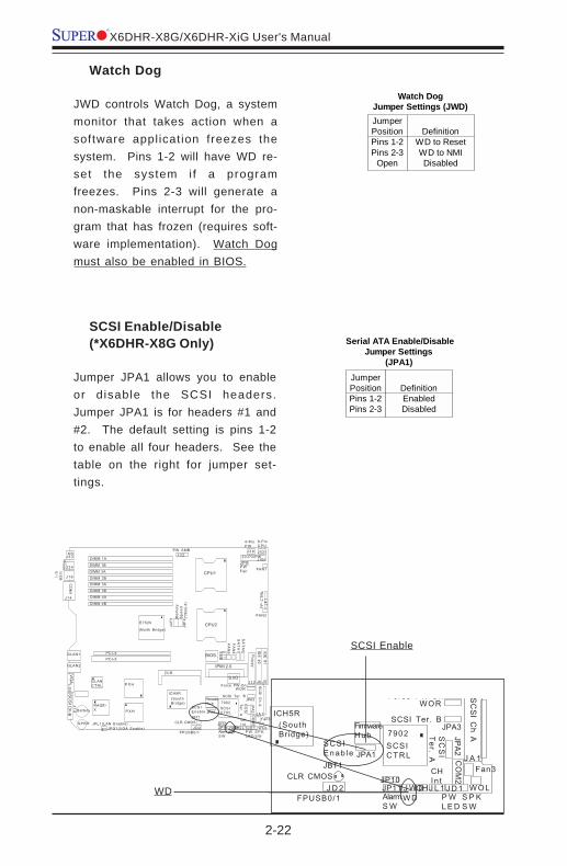
SCSI Enable/Disable(*X6DHR-X8G Only)
Jumper JPA1 allows you to enableor disable the SCSI headers.Jumper JPA1 is for headers #1 and#2. The default setting is pins 1-2to enable all four headers. See thetable on the right for jumper set-tings.
JumperPositionPins 1-2Pins 2-3
DefinitionEnabledDisabled
Serial ATA Enable/DisableJumper Settings
(JPA1)
Watch Dog
JWD controls Watch Dog, a systemmonitor that takes action when asoftware application freezes thesystem. Pins 1-2 will have WD re-set the system i f a programfreezes. Pins 2-3 will generate anon-maskable interrupt for the pro-gram that has frozen (requires soft-ware implementation). Watch Dogmust also be enabled in BIOS.
JumperPositionPins 1-2Pins 2-3
Open
DefinitionWD to ResetWD to NMIDisabled
Watch DogJumper Settings (JWD)
K B
DIMM 4B
Mouse
US
B0
/1
J 1 4
CO
M1
DIMM 4A
DIMM 3B
DIMM 3A
DIMM 2B
DIMM 2A
DIMM 1B
DIMM 1A
GLAN1
GLAN2
VG
AS
CS
I Ch
B Battery
JPG1(VGA Enable)JPL1(LAN Enable)
RAGE-X
GLANCTRL
P X H
P X H
PCI-X
PCI-X
E7520
(North Bridge)
ICH5R(SouthBridge)
ZCR
IPMI 2.0
BIOS
S I/O
7902
SCSICTRL
IDE
#1
IDE
#2
Flo
pp
y
SC
SI C
h A
WOL
CO
M2
Fan3
SCSIEnab le
FPUSB0/1J D 2
J P 9
CLR CMOS
Force PW-OnWOR
S P KS W
SC
SI
Te
r. AJPA1JBT1
SM
B
FA
N5
SA
TA
1S
AT
A0
FP
CT
RL
JF
1
FAN2
FAN1
20-PinPW
8-PinC P U
4-PinP W
PW SMB
P WL E D
CHIntJ L 1J W D
WD
CPU1
CPU2
JP11AlarmS W
JPA3
JPA
2
SCSI Ter. B
OH
J 3 3
J 3 4
J 1 6
LG
5J
14
J D 1
J A 1
J 5J 6J 1 2
FA
N4
FirmwareHub
J1B1
J1D1J 3 8J 3 2
J4
F4
J4
F5 M
em
ory
Sp
ee
d(*
No
te:4
)
J1
1
P WFai l
JP10S P K R
ICH5R(SouthBridge) 7902
SCSICTRL
SC
SI C
h A
WOL
CO
M2
Fan3
SCSIEnab le
FPUSB0/1J D 2
CLR CMOS
Force PW OnWOR
S P KS W
SC
SI
Te
r. AJPA1JBT1
P WL E D
CHIntJ L 1J W D
WDJP11AlarmS W
JPA3
JPA
2
SCSI Ter. B
OH J D 1
J A 1
FirmwareHub
JP10
SCSI Enable
WD

Chapter 2: Installation
2-23
SCSI Termination Enable/Disable
Jumpers JPA2 and JPA3 allow youto enable or disable termination forthe SCSI connectors. Jumper JPA2controls SCSI channel A and JPA3is for SCSI channel B. The defaultsetting is open to enable (terminate)both SCSI channels. (For SCSI tofunction properly, please do notchange the default setting.) See thetable on the right for jumper set-tings.
JumperPosition*OpenClosed
DefinitionEnabledDisabled
SCSI Channel TerminationEnable/Disable
Jumper Settings(JPA2, JPA3)
(*X6DHR-X8G Only)
(*Default: Open. Please do not change
the default setting.)
K B
DIMM 4B
Mouse
US
B0
/1
J 1 4
CO
M1
DIMM 4A
DIMM 3B
DIMM 3A
DIMM 2B
DIMM 2A
DIMM 1B
DIMM 1A
GLAN1
GLAN2
VG
AS
CS
I Ch
B Battery
JPG1(VGA Enable)JPL1(LAN Enable)
RAGE-X
GLANCTRL
P X H
P X H
PCI-X
PCI-X
E7520
(North Bridge)
ICH5R(SouthBridge)
ZCR
IPMI 2.0
BIOS
S I/O
7902
SCSICTRL
IDE
#1
IDE
#2
Flo
pp
y
SC
SI C
h A
WOL
CO
M2
Fan3
SCSIEnab le
FPUSB0/1J D 2
J P 9
CLR CMOS
Force PW-OnWOR
S P KS W
SC
SI
Te
r. AJPA1JBT1
SM
B
FA
N5
SA
TA
1S
AT
A0
FP
CT
RL
JF
1
FAN2
FAN1
20-PinPW
8-PinC P U
4-PinP W
PW SMB
P WL E D
CHIntJ L 1J W D
WD
CPU1
CPU2
JP11AlarmS W
JPA3
JPA
2
SCSI Ter. B
OH
J 3 3
J 3 4
J 1 6
LG
5J
14
J D 1
J A 1
J 5J 6J 1 2
FA
N4
FirmwareHub
J1B1
J1D1J 3 8J 3 2
J4
F4
J4
F5 M
em
ory
Sp
ee
d(*
No
te:4
)
J1
1
P WFai l
JP10S P K R
CH5R(SouthBridge)
R
IPMI 2.0
BIOS
S I/O
7902
SCSICTRL
DE
#1
DE
#2
Flo
pp
y
SC
SI C
h A
WOL
CO
M2
Fan3
SCSIEnab le
FPUSB0/1J D 2
CLR CMOS
Force PW-OnWOR
S P KS W
SC
SI
Te
r. AJPA1JBT1
SM
B
5 1 0
P WL E D
CHIntJ L 1J W D
WDJP11AlarmS W
JPA3
JPA
2
SCSI Ter. B
OH J D 1
J A 1
J 5J 6J 1 2
4
FirmwareHub
J1
1
JP10
SCSI ChA Term.
Enable
SCSI ChBs Term.
Enable

2-24
X6DHR-X8G/X6DHR-XiG User's Manual
2-7 Onboard Indicators
GLAN LEDs
The Gigabit Ethernet LAN ports (lo-cated beside the Video port) hastwo LEDs. The yellow LED indi-cates activity while the other LEDmay be green, orange or off to in-dicate the speed of the connec-tion. See the table at right for thefunctions associated with the sec-ond LED.
LEDColorOff
GreenOrange
DefinitionNo Connection
100 MHz1 GHz
1 Gb LAN Right LEDIndicator
K B
DIMM 4B
Mouse
US
B0
/1
J 1 4
CO
M1
DIMM 4A
DIMM 3B
DIMM 3A
DIMM 2B
DIMM 2A
DIMM 1B
DIMM 1A
GLAN1
GLAN2
VG
AS
CS
I Ch
B Battery
JPG1(VGA Enable)JPL1(LAN Enable)
RAGE-X
GLANCTRL
P X H
P X H
PCI-X
PCI-X
E7520
(North Bridge)
ICH5R(SouthBridge)
ZCR
IPMI 2.0
BIOS
S I/O
7902
SCSICTRL
IDE
#1
IDE
#2
Flo
pp
y
SC
SI C
h A
WOL
CO
M2
Fan3
SCSIEnab le
FPUSB0/1J D 2
J P 9
CLR CMOS
Force PW-OnWOR
S P KS W
SC
SI
Te
r. AJPA1JBT1
SM
B
FA
N5
SA
TA
1S
AT
A0
FP
CT
RL
JF
1
FAN2
FAN1
20-PinPW
8-PinC P U
4-PinP W
PW SMB
P WL E D
CHIntJ L 1J W D
WD
CPU1
CPU2
JP11AlarmS W
JPA3
JPA
2
SCSI Ter. B
OH
J 3 3
J 3 4
J 1 6
LG
5J
14
J D 1
J A 1
J 5J 6J 1 2
FA
N4
FirmwareHub
J1B1
J1D1J 3 8J 3 2
J4
F4
J4
F5 M
em
ory
Sp
ee
d(*
No
te:4
)
J1
1
P WFai l
JP10S P K R
GLAN1/GLAN2

Chapter 2: Installation
2-25
Pin Number Function 1 GND 3 GND 5 Key 7 GND 9 GND 11 GND 13 GND 15 GND 17 GND 19 GND 21 GND 23 GND 25 GND 27 GND 29 GND 31 GND 33 GND
Pin Number Function 2 FDHDIN 4 Reserved 6 FDEDIN 8 Index- 10 Motor Enable 12 Drive Select B- 14 Drive Select A- 16 Motor Enable 18 DIR- 20 STEP- 22 Write Data- 24 Write Gate- 26 Track 00- 28 Write Protect- 30 Read Data- 32 Side 1 Select- 34 Diskette
Floppy Connector Pin Definitions (JP12)Floppy Connector
The floppy connector is locatedon J12. See the table below forpin definitions.
2-8 Floppy/Hard Disk Drive, IPMI, IDE and SCSIConnections
Note the following when connecting the floppy and hard disk drive cables:
• The floppy disk drive cable has seven twisted wires.
• A red mark on a wire typically designates the location of pin 1.
• A single floppy disk drive ribbon cable has 34 wires and two connectors toprovide for two floppy disk drives. The connector with twisted wires alwaysconnects to drive A, and the connector that does not have twisted wiresalways connects to drive B.
K B
DIMM 4B
Mouse
US
B0
/1
J 1 4
CO
M1
DIMM 4A
DIMM 3B
DIMM 3A
DIMM 2B
DIMM 2A
DIMM 1B
DIMM 1A
GLAN1
GLAN2
VG
AS
CS
I Ch
B Battery
JPG1(VGA Enable)JPL1(LAN Enable)
RAGE-X
GLANCTRL
P X H
P X H
PCI-X
PCI-X
E7520
(North Bridge)
ICH5R(SouthBridge)
ZCR
IPMI 2.0
BIOS
S I/O
7902
SCSICTRL
IDE
#1
IDE
#2
Flo
pp
y
SC
SI C
h A
WOL
CO
M2
Fan3
SCSIEnab le
FPUSB0/1J D 2
J P 9
CLR CMOS
Force PW-OnWOR
S P KS W
SC
SI
Te
r. AJPA1JBT1
SM
B
FA
N5
SA
TA
1S
AT
A0
FP
CT
RL
JF
1
FAN2
FAN1
20-PinPW
8-PinC P U
4-PinP W
PW SMB
P WL E D
CHIntJ L 1J W D
WD
CPU1
CPU2
JP11AlarmS W
JPA3
JPA
2
SCSI Ter. B
OH
J 3 3
J 3 4
J 1 6
LG
5J
14
J D 1
J A 1
J 5J 6J 1 2
FA
N4
FirmwareHub
J1B1
J1D1J 3 8J 3 2
J4
F4
J4
F5 M
em
ory
Sp
ee
d(*
No
te:4
)
J1
1
P WFai l
JP10S P K R
IPMI 2.0
BIOS
S I/O
7902
SCSICTRL
IDE
#1
IDE
#2
Flo
pp
y
SC
SI C
h A
WOL
CO
M2
Fan3
e
Force PW-OnWOR
S P KS W
SC
SI
Te
r. AJPA1
SM
B
FA
N5
SA
TA
1S
AT
A0
P WL E D
CHIntJ L 1J W D
WD
CPU2
JP11AlarmS W
JPA3
JPA
2
SCSI Ter. B
OH J D 1
J A 1
J 5J 6J 1 2
FA
N4
FirmwareHub
J1
1
JP10
Floppy

2-26
X6DHR-X8G/X6DHR-XiG User's Manual
IDE Connectors
There are no jumpers toconfigure the onboard IDE#1and #2 connectors (at J5and J6, respectively). Seethe table on the right for pindefinitions.
Pin Number Function 1 Reset IDE 3 Host Data 7 5 Host Data 6 7 Host Data 5 9 Host Data 4 11 Host Data 3 13 Host Data 2 15 Host Data 1 17 Host Data 0 19 GND 21 DRQ3 23 I/O Write- 25 I/O Read- 27 IOCHRDY 29 DACK3- 31 IRQ14 33 Addr 1 35 Addr 0 37 Chip Select 0 39 Activity
Pin Number Function 2 GND 4 Host Data 8 6 Host Data 9 8 Host Data 10 10 Host Data 11 12 Host Data 12 14 Host Data 13 16 Host Data 14 18 Host Data 15 20 Key 22 GND 24 GND 26 GND 28 BALE 30 GND 32 IOCS16- 34 GND 36 Addr 2 38 Chip Select 1- 40 GND
IDE Connector Pin Definitions(J5, J6)
IPMI
J9 is designated as the IPMISocket for the Motherboard.
K B
DIMM 4B
Mouse
US
B0
/1
J 1 4
CO
M1
DIMM 4A
DIMM 3B
DIMM 3A
DIMM 2B
DIMM 2A
DIMM 1B
DIMM 1A
GLAN1
GLAN2
VG
AS
CS
I Ch
B Battery
JPG1(VGA Enable)JPL1(LAN Enable)
RAGE-X
GLANCTRL
P X H
P X H
PCI-X
PCI-X
E7520
(North Bridge)
ICH5R(SouthBridge)
ZCR
IPMI 2.0
BIOS
S I/O
7902
SCSICTRL
IDE
#1
IDE
#2
Flo
pp
y
SC
SI C
h A
WOL
CO
M2
Fan3
SCSIEnab le
FPUSB0/1J D 2
J P 9
CLR CMOS
Force PW-OnWOR
S P KS W
SC
SI
Te
r. AJPA1JBT1
SM
B
FA
N5
SA
TA
1S
AT
A0
FP
CT
RL
JF
1
FAN2
FAN1
20-PinPW
8-PinC P U
4-PinP W
PW SMB
P WL E D
CHIntJ L 1J W D
WD
CPU1
CPU2
JP11AlarmS W
JPA3
JPA
2
SCSI Ter. B
OH
J 3 3
J 3 4
J 1 6
LG
5J
14
J D 1
J A 1
J 5J 6J 1 2
FA
N4
FirmwareHub
J1B1
J1D1J 3 8J 3 2
J4
F4
J4
F5 M
em
ory
Sp
ee
d(*
No
te:4
)
J1
1
P WFai l
JP10S P K R
IPMI 2.0
BIOS
S I/O
7902
SCSICTRL
IDE
#1
IDE
#2
Flo
pp
y
SC
SI C
h A
WOL
CO
M2
Fan3
le
Force PW-OnWOR
S P KS W
SC
SI
Te
r. AJPA1
SM
B
FA
N5
SA
TA
1S
AT
A0
P WL E D
CHIntJ L 1J W D
WD
CPU2
JP11AlarmS W
JPA3
JPA
2
SCSI Ter. B
OH J D 1
J A 1
J 5J 6J 1 2
FA
N4
FirmwareHub
J1
1
JP10
IPMI
IDE1
IDE2

Chapter 2: Installation
2-27
Signal Names
+DB(12)+DB(13)+DB(14)+DB(15)+DB(P1)+DB(0)+DB(1)+DB(2)+DB(3)+DB(4)+DB(5)+DB(6)+DB(7)+DB(P)
GROUNDDIFFSENSTERMPW RTERMPW RRESERVED
GROUND+ATN
GROUND+BSY+ACK+RST+MSG+SEL+C/D+REQ+I/O
+DB(8)+DB(9)
+DB(10)+DB(11)
ConnectorContactNumber
123456789
10111213141516171819202122232425262728293031323334
Signal Names
-DB(12)-DB(13)-DB(14)-DB(15)-DB(P1)-DB(0)-DB(1)-DB(2)-DB(3)-DB(4)-DB(5)-DB(6)-DB(7)-DB(P)
GROUNDGROUND
TERMPW RTERMPW RRESERVED
GROUND-ATN
GROUND-BSY-ACK-RST-MSG-SEL-C/D-REQ-I/O
-DB(8)-DB(9)
-DB(10)-DB(11)
ConnectorContactNumber
35363738394041424344454647484950515253545556575859606162636465666768
68-pin Ultra320 SCSI Connectors (JA1 and JA2)
Ultra320 SCSI Connectors(*X6DHR-X8G Only)
Refer to the table below for the pindefinitions of the Ultra320 SCSIconnectors located at JA1 and JA2.
K B
DIMM 4B
Mouse
US
B0
/1
J 1 4
CO
M1
DIMM 4A
DIMM 3B
DIMM 3A
DIMM 2B
DIMM 2A
DIMM 1B
DIMM 1A
GLAN1
GLAN2
VG
AS
CS
I Ch
B Battery
JPG1(VGA Enable)JPL1(LAN Enable)
RAGE-X
GLANCTRL
P X H
P X H
PCI-X
PCI-X
E7520
(North Bridge)
ICH5R(SouthBridge)
ZCR
IPMI 2.0
BIOS
S I/O
7902
SCSICTRL
IDE
#1
IDE
#2
Flo
pp
y
SC
SI C
h A
WOL
CO
M2
Fan3
SCSIEnab le
FPUSB0/1J D 2
J P 9
CLR CMOS
Force PW-OnWOR
S P KS W
SC
SI
Te
r. AJPA1JBT1
SM
B
FA
N5
SA
TA
1S
AT
A0
FP
CT
RL
JF
1
FAN2
FAN1
20-PinPW
8-PinC P U
4-PinP W
PW SMB
P WL E D
CHIntJ L 1J W D
WD
CPU1
CPU2
JP11AlarmS W
JPA3
JPA
2
SCSI Ter. B
OH
J 3 3
J 3 4
J 1 6
LG
5J
14
J D 1
J A 1
J 5J 6J 1 2
FA
N4
FirmwareHub
J1B1
J1D1J 3 8J 3 2
J4
F4
J4
F5 M
em
ory
Sp
ee
d(*
No
te:4
)
J1
1
P WFai l
JP10S P K R
VG
AS
CS
I Ch B Battery
JPG1(VGA Enable)JPL1(LAN Enable)
RAGE-X
GLANCTRL
P X H
P X H
ICH5R(SouthBridge)
ZCRS I/O
7902
SCSICTRL
SC
SI C
h A
WOL
CO
M2
Fan3
SCSIEnab le
FPUSB0/1J D 2
CLR CMOS
Force PW-OnWOR
S P KS W
SC
SI
Te
r. AJPA1JBT1
P WL E D
CHIntJ L 1J W D
WDJP11AlarmS W
JPA3
JPA
2
SCSI Ter. B
OH
LG
5J
14
J D 1
J A 1
J 5J 6J 1 2
FirmwareHub
JP10S P K R
SCSI Ch A
SCSI Ch B

2-28
X6DHR-X8G/X6DHR-XiG User's Manual
(*Note: For software installation instructions, please refer to Ap-pendix C. For Adaptec's SCSI HostRAID Utility, please refer to theCDs that came with your motherboard.)

3-1
Chapter 3: Troubleshooting
Chapter 3Troubleshooting
3-1 Troubleshooting Procedures
Use the following procedures to troubleshoot your system. If you havefollowed all of the procedures below and still need assistance, refer to the‘Technical Support Procedures’ and/or ‘Returning Merchandise for Service’section(s) in this chapter.Note: Always disconnect the power cord before adding, changingor installing any hardware components.
Before Power On
1. Make sure no short circuits exist between the motherboard and chassis.2. Disconnect all ribbon/wire cables from the motherboard, including those
for the keyboard and mouse.3. Remove all add-on cards.4. Install one CPU (making sure it is fully seated) and connect the chassis
speaker and the power LED to the motherboard. (Check all jumpersettings as well.)
5. Use only the correct type of onboard CMOS battery as recommended bythe Manufacturer. Do not install the onboard battery upside down toavoid possible explosion.
No Power
1. Make sure no short circuits exist between the motherboard and the chas-sis.
2. Verify that all jumpers are set to their default positions.3. Check that the 115V/230V switch on the power supply is properly set.4. Turn the power switch on and off to test the system.5. The battery on your motherboard may be old. Check to verify that it still
supplies ~3VDC. If it does not, replace it with a new one.
No Video
1. If the power is on but you have no video, remove all the add-on cardsand cables.
2. Use the speaker to determine if any beep codes exist. Refer to theAppendix for details on beep codes.

3-2
X6DHR-X8G/X6DHR-XiG User's Manual
Losing the System’s Setup Configuration
1. Ensure that you are using a high quality power supply. A poor qualitypower supply may cause the system to lose the CMOS setup informa-tion. Refer to Section 1-6 for details on recommended power supplies.
2. The battery on your motherboard may be old. Check to verify that it stillsupplies ~3VDC. If it does not, replace it with a new one.
3. If the above steps do not fix the Setup Configuration problem, contactyour vendor for repairs.
3-2 Technical Support Procedures
Before contacting Technical Support, please take the following steps. Also,note that as a motherboard manufacturer, Super Micro does not sell directlyto end-users, so it is best to first check with your distributor or reseller fortroubleshooting services. They should know of any possible problem(s)with the specific system configuration that was sold to you.
NOTEIf you are a system integrator, VAR or OEM, a POST diagnos-
tics card is recommended. For I/O port 80h codes, refer toApp. B.
Memory Errors
1. Make sure the DIMM modules are properly and fully installed.2. Determine if different speeds of DIMMs have been installed and verify
that the BIOS setup is configured for the fastest speed of RAM used.It is recommended to use the same RAM speed for all DIMMs in thesystem.
3. Make sure you are using the correct type of ECC Reg. DDR-333/266(PC2700/2100) SDRAM (*recommended by the manufacturer.)
4. Check for bad DIMM modules or slots by swapping a single module be-tween two slots and noting the results.
5. Make sure all memory modules are fully seated in their slots. As aninterleaved memory scheme is used, you must install two modules at atime, beginning with Bank 1, then Bank 2, and so on (see Section 2-3).
6. Check the position of the 115V/230V switch on the power supply.

3-3
Chapter 3: Troubleshooting
1. Please go through the ‘Troubleshooting Procedures’ and 'FrequentlyAsked Question' (FAQ) sections in this chapter or see the FAQs on ourweb site (http://www.supermicro.com/support/faqs/) before con-tacting Technical Support.
2. BIOS upgrades can be downloaded from our web site at(http://www.supermicro.com/support/bios/).
Note: Not all BIOS can be flashed depending on the modificationsto the boot block code.
3. If you still cannot resolve the problem, include the following infor-mation when contacting Super Micro for technical support:
•Motherboard model and PCB revision number•BIOS release date/version (this can be seen on the initial display whenyour system first boots up)•System configurationAn example of a Technical Support form is on our web site at(http://www.supermicro.com/support/contact.cfm).
4. Distributors: For immediate assistance, please have your account numberready when placing a call to our technical support department. We canbe reached by e-mail at [email protected], by phone at:(408) 503-8000, option 2, or by fax at (408)503-8019.
3-3 Frequently Asked Questions
Question: What are the various types of memory that my mother-board can support?
Answer: The X6DHR-X8G/X6DHR-XiG has four 184-pin DIMM slots thatsupport registered ECC DDR-333/266 (PC2700/2100) SDRAM modules. It isstrongly recommended that you do not mix memory modules of differentspeeds and sizes.
Question: How do I update my BIOS?
Answer: It is recommended that you do not upgrade your BIOS if you areexperiencing no problems with your system. Updated BIOS files are locatedon our web site at http://www.supermicro.com. Please check our BIOSwarning message and the info on how to update your BIOS on our website. Also, check the current BIOS revision and make sure it is newer thanyour BIOS before downloading. Select your motherboard model and down-load the BIOS file to your computer. Unzip the BIOS update file and you willfind the readme.txt (flash instructions), the phlash.exe (BIOS flash utility),the platform.bin (platform file) and the BIOS image (xxxxxx.rom) files. Copythese files onto a bootable floppy and reboot your system. It is not neces

3-4
X6DHR-X8G/X6DHR-XiG User's Manual
sary to set BIOS boot block protection jumpers on the motherboard. At theDOS prompt, enter the command "phlash." This will start the flash utility andgive you an opportunity to save your current BIOS image. Flash the bootblock and enter the name of the update BIOS image file.
Question: After flashing the BIOS my system does not have video.How can I correct this?
Answer: If the system does not have video after flashing your new BIOS,it indicates that the flashing procedure failed. To remedy this, first clearCMOS per the instructions in this manual and retry the BIOS flashing proce-dure. If you still do not have video, please use the following BIOS Recov-ery Procedure. First, make sure the JPWAKE jumper is disabled. Boot upthe system from a Windows boot disk. Type A:\>phlash /B=X6DHR-X8G.Bin/s /x /mode=3 /mfg [BIOS filename.rom] or A:\>phx7505 [BIOS filename.rom].The system will flash BIOS from here and reboot once it finishes.To recover BIOS: a recovery flash requires an update key over the COMport as follows: hardwire Pin4 wires to Pin8 and Pin9, Pin7 wires to Pin6,Pin3 wires to Pin2 and leave Pin 1 and Pin 5 open. Use the Supermicro CDto make a “Phoenix BIOS Crisis Disk for Supermicro Mainboard”. This diskincludes a BIOS file named “bios.rom”. Please note, this BIOS file can bechanged to a different Phoenix BIOS file as long as it’s named “bios.rom”.Connect the serial key to the COM port, insert the recovery disk into floppydrive and power on the system. When the system starts to read the disk,remove the serial key immediately. When the system is done with the BIOSrecovery, it will automatically reboot.
Question: What's on the CD that came with my motherboard?
Answer: The supplied compact disc has quite a few drivers and programsthat will greatly enhance your system. We recommend that you review theCD and install the applications you need. Applications on the CD includechipset drivers for Windows and security and audio drivers.
3-4 Returning Merchandise for ServiceA receipt or copy of your invoice marked with the date of purchase isrequired before any warranty service will be rendered. You can obtainservice by calling your vendor for a Returned Merchandise Authorization(RMA) number. When returning to the manufacturer, the RMA numbershould be prominently displayed on the outside of the shipping carton, andmailed prepaid or hand-carried. Shipping and handling charges will be ap-plied for all orders that must be mailed when service is complete.

3-5
Chapter 3: Troubleshooting
This warranty only covers normal consumer use and does not cover dam-ages incurred in shipping or from failure due to the alternation, misuse,abuse or improper maintenance of products.
During the warranty period, contact your distributor first for any productproblems.

3-6
X6DHR-X8G/X6DHR-XiG User's Manual
Notes

Chapter 4: BIOS
4-1
Chapter 4BIOS
4-1 Introduction
This chapter describes the Phoenix BIOS™ Setup utility for the X6DHR-X8G/X6DHR-XiG. The Phoenix ROM BIOS is stored in a flash chip and can beeasily upgraded using a floppy disk-based program.
Note: Due to periodic changes to the BIOS, some settings may have beenadded or deleted and might not yet be recorded in this manual. Please referto the Manual Download area of the Supermicro web si te<http://www.supermicro.com> for any changes to BIOS that may not bereflected in this manual.
System BIOS
The BIOS is the Basic Input Output System used in all IBM® PC, XT™, AT®,and PS/2® compatible computers. The Phoenix BIOS flash chip stores thesystem parameters, such type of disk drives, video displays, etc. in theCMOS. The CMOS memory requires very little electrical power. When thecomputer is turned off, a back-up battery provides power to the BIOS flashchip, enabling it to retain system parameters. Each time the computer ispowered-on the computer is configured with the values stored in the BIOSROM by the system BIOS, which gains control at boot-up.
How To Change the Configuration Data
The CMOS information that determines the system parameters may bechanged by entering the BIOS Setup utility. This Setup utility can be ac-cessed by pressing the <Delete> key at the appropriate time during systemboot, see below.
Starting the Setup Utility
Normally, the only visible POST (Power On Self Test) routine is the memorytest. As the memory is being tested, press the <Delete> key to enter themain menu of the BIOS Setup utility. From the main menu, you can accessthe other setup screens, such as the Security and Power menus. Begin-ning with Section 4-3, detailed descriptions are given for each parametersetting in the Setup utility.

4-2
X6DHR-X8G/X6DHR-XiG User's Manual
4-2 Running Setup
*Default settings are in bold text unless otherwise noted.
The BIOS setup options described in this section are selected by choos-ing the appropriate text from the main BIOS Setup screen. All displayedtext is described in this section, although the screen display is often allyou need to understand how to set the options (see on next page).
When you first power on the computer, the Phoenix BIOS™ is immediatelyactivated.
While the BIOS is in control, the Setup program can be activated in one of twoways:
1. By pressing <Delete> immediately after turning the system on, or2. When the message shown below appears briefly at the bottom of the
screen during the POST (Power On Self-Test), press the <Delete> key toactivate the main Setup menu:
Press the <Delete> key to enter Setup
4-3 Main BIOS Setup
All main Setup options are described in this section. The main BIOS Setup screenis displayed below.
Use the Up/Down arrow keys to move among the different settings in each menu.Use the Left/Right arrow keys to change the options for each setting.
Press the <Esc> key to exit the CMOS Setup Menu. The next section describesin detail how to navigate through the menus.
Items that use submenus are indicated with the ! icon. With the item highlighted,press the <Enter> key to access the submenu.

Chapter 4: BIOS
4-3
Main BIOS Setup Menu
Main Setup Features
System Time
To set the system date and time, key in the correct information in theappropriate fields. Then press the <Enter> key to save the data.
System Date
Using the arrow keys, highlight the month, day and year fields and enterthe correct data. Press the <Enter> key to save the data.
BIOS Date
This feature allows BIOS to automatically display the BIOS date.

4-4
X6DHR-X8G/X6DHR-XiG User's Manual
Legacy Diskette A
This setting allows the user to set the type of floppy disk drive installed asdiskette A. The options are Disabled, 360Kb 5.25 in, 1.2MB 5.25 in, 720Kb3.5 in, 1.44/1.25MB, 3.5 in and 2.88MB 3.5 in.
Parallel ATA
This setting allows the user to enable or disable the funciton of ParallelATA. The options are Disabled, Channel 0, Channel 1 and Both.
Serial ATA
This setting allows the user to enable or disable the funciton of Serial ATA.The options are Disabled and Enabled.
Serial ATA RAID Enable
Select Enable to enable Serial ATA RAID Functions. (*For the Windows OSenvironment, use the RAID driver if this feature is set to "Enabled". If"disabled", use the "Non-RAID" driver.)
Native Mode Operation
This option allows the user to select the Native Mode for ATA. SomeOperating Systems are not supported by the Native Mode. The options are:Serial ATA, Parallel ATA, Auto, and Both.
!!!!!IDE Channel 0 Master/Slave, IDE Channel 1 Master/Slave, IDEChannel 2 Master, IDE Channel 3 Master
These settings allow the user to set the parameters of IDE Channel 0Master/Slave, IDE Channel 1 Master/Slave, IDE Channel 2 Master, IDEChannel 3 Master slots. Hit <Enter> to activate the following sub-menuscreen for detailed options of these items. Set the correct configurationsaccordingly. The items included in the sub-menu are:

Chapter 4: BIOS
4-5
Type
Selects the type of IDE hard drive. The options are Auto (allows BIOSto automatically determine the hard drive's capacity, number of heads,Sectors, Maximum Capacity, LBA Format, ect.). Enter a number from 1-39 to select a predetermined type of hard drive, CD-ROM and ATAPIRemovable. The option- "User" will allow the user to enter the parametersof the HDD installed at this connection. The option-"Auto" will allow BIOSto automatically configure the parameters of the HDD installed at theconnection. Choose the option"1-39" to select a pre-determined HDDtype. Select CD-ROM if a CD-ROM drive is installed. Select ATAPI if aremovable disk drive is installed.

4-6
X6DHR-X8G/X6DHR-XiG User's Manual
Multi-Sector Transfers
Select the number of transfer sectors. The options are Disabled, 2, 4, 6,8 and 16 Sectors.
LBA Mode Control
This item determines whether Phoenix BIOS will access the IDE PrimaryMaster Device via LBA mode. The options are Disabled and Enabled.
32 Bit I/O
Selects 32 Bit I/O operation. The options are Enabled and Disabled.
Transfer Mode
Selects the transfer mode. The options are Standard, Fast PIO1, FastPIO2, Fast PIO3, Fast PIO4, FPIO3/DMA1 and FPIO4/DMA2.
Ultra DMA Mode
Selects Ultra DMA Mode. The options are Disabled, Mode 0, Mode 1,Mode 2, Mode 3, Mode 4, Mode 5 and Mode 6.
System Memory
This display informs you how much system memory is recognized as beingpresent in the system.
Extended Memory
This display informs you how much extended memory is recognized asbeing present in the system.

Chapter 4: BIOS
4-7
4-4 Advanced Setup
Choose Advanced from the Phoenix BIOS Setup Utility main menu with the arrowkeys. You should see the following display. The items with a triangle besidethem have sub menus that can be accessed by highlighting the item and pressing<Enter>. Options for PIR settings are displayed by highlighting the setting optionusing the arrow keys and pressing <Enter>. All Advanced BIOS Setup optionsare described in this section.
!!!!!Boot Features
Access the submenu to make changes to the following settings.
Quick Boot Mode
If enabled, this feature will speed up the POST (Power On Self Test) routineafter the computer is turned on. The settings are Enabled and Disabled. IfDisabled, the POST routine will run at normal speed.
Quiet Boot
This setting allows you to Enable or Disable the diagnostic screen duringboot-up.

4-8
X6DHR-X8G/X6DHR-XiG User's Manual
Summary Screen
This setting allows you to Enable or Disable the summary screen.
ACPI Mode
Use the sett ing to determine if you want to employ ACPI (AdvancedConfiguration and Power Interface) power management on your system.The options are Yes and No.
Power Button Behavior
If set to Instant-Off, the system will power off immediately as soon as theuser hits the power button. If set to 4-sec, the system will power off whenthe user presses the power button for 4 seconds or longer. The optionsare instant-off and 4-sec override.
Power Loss Control
This setting allows you to choose how the system will react when power
!!!!!Memory Cache
Cache System BIOS Area
This sett ing allows you to designate a reserve area in the systemmemory to be used as a System BIOS buffer to allow the BIOS write(cache) its data into this reserved memory area. Select "Write Protect"to enable this function, and this area will be reserved for BIOS ROMaccess only. Select "Uncached" to disable this function and make thisarea available for other devices.
Cache Video BIOS Area
This sett ing allows you to designate a reserve area in the systemmemory to be used as a Video BIOS buffer to allow the BIOS write(cache) its data into this reserved memory area. Select "Write Protect"to enable the function and this area will be reserved for BIOS ROMaccess only. Select "Uncached" to disable this function and make thisarea available for other devices.

Chapter 4: BIOS
4-9
Cache Base 0-512K
If enabled, this feature will allow the data stored in the base memoryarea: block 0-512K to be cached (written) into a buffer, a storage areain the Static DRM (SDROM) or written into L1, L2, L3 cache inside theCPU to speed up CPU operations . Select "Uncached" to disable thisfunciton. Select "Write Through" to allow data to be cached into thebuffer and written into the system memory at the same time. Select"Write Protect" to prevent data from being written into the base memoryarea of Block 0-512K. Select "Write Back" to allow CPU to write databack directly from the buffer without writing data to the System Memoryfor fast CPU data processing and operat ion. The opt ions are"Uncached", "Write Through", "Write Protect", and "Write Back".
Cache Base 512K-640K
If enabled, this feature will allow the data stored in the memory area:512K-640K to be cached (written) into a buffer, a storage area in theStatic DRM (SDROM) or written into L1, L2, L3 cache inside the CPU tospeed up CPU operations . Select "Uncached" to disable this funciton.Select "Write Through" to allow data to be cached into the buffer andwritten into the system memory at the same time. Select "Write Protect"to prevent data from being written into the base memory area of Block0-512K. Select "Write Back" to allow CPU to write data back directly fromthe buffer without writing data to the System Memory for fast CPU dataprocessing and operation. The options are "Uncached", "Write Through","Write Protect", and "Write Back".
Cache Extended Memory
If enabled, this feature will allow the data stored in the extended memoryarea to be cached (written) into a buffer, a storage area in the StaticDRM (SDROM) or written into L1, L2, L3 cache inside the CPU to speedup CPU operations . Select "Uncached" to disable this funciton. Select"Write Through" to allow data to be cached into the buffer and writteninto the system memory at the same time. Select "Write Protect" toprevent data from being written into the base memory area of Block 0-512K. Select "Write Back" to allow CPU to write data back directly fromthe buffer without writing data to the System Memory for fast CPU dataprocessing and operation. The options are "Uncached", "Write Through","Write Protect", and "Write Back".

4-10
X6DHR-X8G/X6DHR-XiG User's Manual
!!!!!PCI Configuration
Access the submenu to make changes to the following settings for PCIdevices.
Onboard GLAN (Gigabit- LAN) OPROM Configure
Enabling this option provides the capability to boot from GLAN. Theoptions are Disabled and Enabled.
Onboard SCSI OPROM Configure
Enabling this option provides the capability to boot from SCSI HDD. Theoptions are Disabled and Enabled.
Reset Configuration Data
If set to Yes, this setting clears the Extended System Configuration Data-(ESCD) area. The options are Yes and No.
Frequency for RAID-SLOT/SCSI
This option allows the user to change the bus frequency for the devicesinstalled in the slot indicated. The options are Auto, PCI 33 MHz, PCI 66MHz, PCI-X 66 MHz, PCI-X 100 MHz, and PCI-X 133 MHz.
Frequency for G-LAN
This option allows the user to change the bus frequency of the devicesinstalled in the slot indicated. The options are Auto, PCI 33 MHz, PCI 66MHz, PCI-X 66 MHz, PCI-X 100 MHz, and PCI-X 133 MHz.
Frequency for PCI-X #1/Frequency for PCI-X #2
This option allows the user to change the bus frequency of the devicesinstalled in the slot indicated. The options are Auto, PCI 33 MHz, PCI 66MHz, PCI-X 66 MHz, PCI-X 100 MHz, and PCI-X 133 MHz.

Chapter 4: BIOS
4-11
!!!!!PCI-X 133MHz Slot #1/Slot#2
Access the submenu for each of the settings above to make changes tothe following:
Option ROM Scan
When enabled, this setting will initialize the device expansion ROM.The options are Enabled and Disabled.
Enable Master
This setting allows you to enable the selected device as the PCI busmaster. The options are Enabled and Disabled.
Latency Timer
This setting allows you to set the clock rate for Bus Master.A high-prioity, high-throughout device may benefit from a greater Clock rate.The options are Default, 0020h, 0040h, 0060h, 0080h, 00A0h, 00C0h,and 00E0h. For Unix, Novell and other Operating Systems, pleaseselect the option:"other". If a drive fails after the installation of a newsoftware , you might want to change this setti ing and try again.Different OS requires different Bus Master clock rate.
Large Disk Access Mode
This setting determines how large hard drives are to be accessed. Theoptions are DOS or Other (for Unix, Novellle NetWare and other operatingsystems).
!!!!!Advanced Chipset Control
Access the submenu to make changes to the following settings.
Memory RAS Feature Control
Select this option to enable the Memory RAS Feature Control The optionsare Miirroring, Sparing and Standard.

4-12
X6DHR-X8G/X6DHR-XiG User's Manual
DRAM Data Integrity Mode
If enabled, this feature allows the data stored in the DRMA memory tobe integrated for faster data processing. The options are 72-bit ECC,144-bit ECC, Auto, Algorithms and Disabled.
ECC Error Type
This setting lets you select which type of interrupt to be activated as aresult of an ECC error. The options are None, NMI (Non-MaskableInterrupt), SMI (System Management Interrupt) and SCI (System ControlInterrupt.)
SERR Signal Condition
This setting specifies the conditions required to be qualified as an ECCerror. The options are None, Single Bit, Multiple Bit and Both.
USB Function
This setting allows you to Enable or Disable all functions for the USBdevices specified.
Legacy USB Support
This setting allows you to enable support for Legacy USB devices. Thesettings are Enabled and Disabled.
Clock Spectrum Feature
If "Enabled", BIOS will monitor the level of Electromagnetic Interferencecaused by the components and will attempt to decrease the interferencewhenever needed. The options are Enabled and Disabled.

Chapter 4: BIOS
4-13
!!!!!Advanced Processor Options
Access the submenu to make changes to the following settings.
CPU Speed
This is a display that indicates the speed of the installed processor.
Hyper-threading
This setting allows you to Enable or Disable the function of hyper-threading. Enabl ing hyper-threading resul ts in increased CPUperformance. (Applicable for the XP systems.)
Machine Checking
This setting allows you to Enable or Disable Machine Checking.
Adjacent Cache Line Prefetch
The CPU fetches the cache line for 64 bytes if Disabled. The CPU fetchesboth cache lines for 128 bytes as comprised if Enabled.
!!!!!I/O Device Configuration
Access the submenu to make changes to the following settings.

4-14
X6DHR-X8G/X6DHR-XiG User's Manual
KBC Clock Input
This setting allows you to select clock frequency for KBC. The optionsare 6MHz, 8MHz, 12MHz and 16MHz.
On-board COM 1
This setting allows you to assign control of serial port A. The optionsare Enabled (user defined), Disabled and Auto (BIOS controlled).
Base I/O Address
Select the base I/O address for serial port A. The options are 3F8,2F8, 3E8 and 2E8.
Interrupt
Select the IRQ (interrupt request) for serial port A. The options areIRQ3 and IRQ4.
On-board COM 2
This setting allows you to assign control of serial port B. The optionsare Enabled (user defined), Disabled and Auto (BIOS controlled).
Mode
Specify the type of device that will be connected to serial port B. Theoptions are Normal, IR (for an infrared device) and ASK-IR.
Base I/O Address
Select the base I/O address for serial port B. The options are 3F8,2F8, 3E8 and 2E8.
Interrupt
Select the IRQ (interrupt request) for serial port B. The options areIRQ3 and IRQ4.

Chapter 4: BIOS
4-15
Parallel Port
This setting allows you to assign control of the parallel port. The optionsare Enabled (user defined), Disabled and Auto (BIOS controlled).
Base I/O Address
Select the base I/O address for the parallel port. The options are 378,278 and 3BC.
Interrupt
Select the IRQ (interrupt request) for the parallel port. The optionsare IRQ5 and IRQ7.
Mode
Specify the parallel port mode. The options are Output Only, Bi-directional, EPP and ECP.
DMA Channel 1
Specify the DMA channel. The options are DMA1 and DMA3.
Floppy Disk Controller
This setting allows you to assign control of the floppy disk controller.The options are Enabled (user defined), Disabled and Auto (BIOScontrolled).
Base I/O Address
Select the base I/O address for the parallel port. The options arePrimary and Secondary.

4-16
X6DHR-X8G/X6DHR-XiG User's Manual
!!!!!DMI Event Logging
Access the submenu to make changes to the following settings.
Event Log Validity
This is a display, not a setting, informing you of the event log validity.
Event Log Capacity
This is a display, not a setting, informing you of the event log capacity.
View DMI Event Log
Highlight this item and press <Enter> to view the contents of the eventlog.
Event Logging
This setting allows you to Enable or Disable event logging.
ECC Event Logging
This setting allows you to Enable or Disable ECC event logging.
Mark DMI Events as Read
Highlight this item and press <Enter> to mark the DMI events as read.
Clear All DMI Event Logs
Select Yes and press <Enter> to clear all DMI event logs. The options areYes and No.

Chapter 4: BIOS
4-17
BAUD Rate
Select the BAUD rate for console redirection. The options are 300, 1200,2400, 9600, 19.2K, 38.4K, 57.6K and 115.2K.
Console Type
Choose from the available options to select the console type for consoleredirection. The options are VT100, VT100,8bit, PC-ANSI, 7bit, PCANSI,VT100+, VT-UTF8.
Flow Control
Choose from the available options to select the flow control for consoleredirection. The options are: None, XON/XOFF, and CTS/RTS.
Console Connection
Select the console connection: either Direct or Via Modem.
Continue CR after POST
Choose whether to continue with console redirection after the POSTroutine. The options are On and Off.
!!!!!Console Redirection
Access the submenu to make changes to the following settings.
COM Port Address
Specifies to redirect the console to On-board COM A or On-board COMB. This setting can also be Disabled.

4-18
X6DHR-X8G/X6DHR-XiG User's Manual
!!!!!Hardware Monitor Logic
CPU Temperature Threshold
This option allows the user to set a CPU temperature threshold thatwill activate the alarm system when the CPU temperature reaches thispre-set temperature threshold. The options are 85oC, 90oC, 95oC and100oC.
Highlight this and hit <Enter> to see monitor data for the following items:
CPU1 Temperature: This item displays CPU1 Temperature.
CPU2 Temperature: This item displays CPU2 Temperature.
System Temperature: This item displays the system Temperature.
Fan Speed Control Modes [Disable, 3-pin (Server)]
This feature allows the user to decide how the system controls thespeeds of onboard fans. Select "Disable" to disable of the functionof fan speed control and the system will run at the full speed (12V.)Select "3-pin Server" to optimize the fan speed control via BIOSThermal management.
CPU1 Fan
CPU2 Fan
Vcore A
Vcore B
P3V3
P5V
CHS Fan1
CHS Fan2
CHS Fan3

Chapter 4: BIOS
4-19
N12V
P12V
VDD
P5Vsb15

4-20
X6DHR-X8G/X6DHR-XiG User's Manual
4-5 Security
Choose Security from the Phoenix BIOS Setup Utility main menu with the arrowkeys. You should see the following display. Security setting options aredisplayed by highlighting the setting using the arrow keys and pressing <Enter>.All Security BIOS settings are described in this section.
Supervisor Password Is:
This displays whether a supervisor password has been entered for thesystem. Clear means such a password has not been used and Set meansa supervisor password has been entered for the system.
User Password Is:
This displays whether a user password has been entered for the system.Clear means such a password has not been used and Set means a userpassword has been entered for the system.

Chapter 4: BIOS
4-21
Set Supervisor Password
When the item "Set Supervisor Password" is highlighted, hit the <Enter> key.When prompted, type the Supervisor's password in the dialogue box to setor to change supervisor's password, which allows access to BIOS.
Set User Password
When the item "Set User Password" is highlighted, hit the <Enter> key.When prompted, type the user's password in the dialogue box to set or tochange the user's password, which allows access to the system at boot-up.
Fixed Disk Boot Sector
This setting may offer some protection against viruses when set to WriteProtect, which protects the boot sector on the hard drive from having avirus written to it. The other option is Normal.
Password on Boot
This setting allows you to require a password to be entered when thesystem boots up. The options are Enabled (password required) andDisabled (password not required).

4-22
X6DHR-X8G/X6DHR-XiG User's Manual
4-6 Boot
Choose Boot from the Phoenix BIOS Setup Utility main menu with the arrow keys.You should see the following display. Highlighting a setting with a + or - willexpand or collapse that entry. See details on how to change the order and specsof boot devices in the Item Specific Help window. All Boot BIOS settings aredescribed in this section.
+Removable Devices
Highlight and press <Enter> to expand the field. See details on how tochange the order and specs of devices in the Item Specific Help window.
CD-ROM Drive
See details on how to change the order and specs of the CD-ROM drive inthe Item Specific Help window.
+Hard Drive
Highlight and press <Enter> to expand the field. See details on how tochange the order and specs of hard drives in the Item Specif ic Helpwindow.

Chapter 4: BIOS
4-23
4-7 Exit
Choose Exit from the Phoenix BIOS Setup Utility main menu with the arrow keys.You should see the following display. All Exit BIOS settings are described in thissection.
Exit Saving Changes
Highlight this item and hit <Enter> to save any changes you made and toexit the BIOS Setup utility.
Exit Discarding Changes
Highlight this item and hit <Enter> to exit the BIOS Setup utility without savingany changes you may have made.
Load Setup Defaults
Highlight this item and hit <Enter> to load the default settings for all items inthe BIOS Setup. These are the safest settings to use.

4-24
X6DHR-X8G/X6DHR-XiG User's Manual
Discard Changes
Highlight this item and hit <Enter> to discard (cancel) any changes youmade. You will remain in the Setup utility.
Save Changes
Highlight this item and hit <Enter> to save any changes you made. You willremain in the Setup utility.

A-1
Appendix A: BIOS POST Messages
Appendix ABIOS POST Messages
During the Power-On Self-Test (POST), the BIOS will check for problems. If a problemis found, the BIOS will activate an alarm or display a message. The following is a listof such BIOS messages.
Failure Fixed DiskFixed disk is not working or not configured properly. Check to see if fixed disk isattached properly. Run Setup. Find out if the fixed-disk type is correctly identified.
Stuck keyStuck key on keyboard.
Keyboard errorKeyboard not working.
Keyboard Controller FailedKeyboard controller failed test. May require replacing keyboard controller.
Keyboard locked - Unlock key switchUnlock the system to proceed.
Monitor type does not match CMOS - Run SETUPMonitor type not correctly identified in Setup
Shadow Ram Failed at offset: nnnnShadow RAM failed at offset nnnn of the 64k block at which the errorwas detected.
System RAM Failed at offset: nnnnSystem RAM failed at offset nnnn of in the 64k block at which the errorwas detected.
Extended RAM Failed at offset: nnnn Extended memory notworking or not configured properly at offset nnnn.
System battery is dead - Replace and run SETUPThe CMOS clock battery indicator shows the battery is dead. Replace thebattery and run Setup to reconfigure the system.
A-2
X6DHR-X8G/X6DHR-XiG User's Manual
System CMOS checksum bad - Default configuration usedSystem CMOS has been corrupted or modified incorrectly, perhaps by anapplication program that changes data stored in CMOS. The BIOS installed DefaultSetup Values. If you do not want these values, enter Setup and enter your ownvalues. If the error persists, check the system battery or contact your dealer.
System timer errorThe timer test failed. Requires repair of system board.
Real time clock errorReal-Time Clock fails BIOS hardware test. May require board repair.
Check date and time settingsBIOS found date or time out of range and reset the Real-Time Clock. May requiresetting legal date (1991-2099).
Previous boot incomplete - Default configuration usedPrevious POST did not complete successfully. POST loads default values andoffers to run Setup. If the failure was caused by incorrect values and they arenot corrected, the next boot will likely fail. On systems with control of waitstates, improper Setup settings can also terminate POST and cause this error onthe next boot. Run Setup and verify that the waitstate configuration is correct.This error is cleared the next time the system is booted.
Memory Size found by POST differed from CMOSMemory size found by POST differed from CMOS.
Diskette drive A errorDiskette drive B errorDrive A: or B: is present but fails the BIOS POST diskette tests. Check to see thatthe drive is defined with the proper diskette type in Setup and that the diskettedrive is attached correctly.
Incorrect Drive A type - run SETUPType of floppy drive A: not correctly identified in Setup.
Incorrect Drive B type - run SETUPType of floppy drive B: not correctly identified in Setup.

A-3
Appendix A: BIOS POST Messages
System cache error - Cache disabledRAM cache failed and BIOS disabled the cache. On older boards, check thecache jumpers. You may have to replace the cache. See your dealer. A disabledcache slows system performance considerably.
CPU ID:CPU socket number for Multi-Processor error.
EISA CMOS not writeableServerBIOS2 test error: Cannot write to EISA CMOS.
DMA Test FailedServerBIOS2 test error: Cannot write to extended DMA (Direct MemoryAccess) registers.
Software NMI FailedServerBIOS2 test error: Cannot generate software NMI (Non-MaskableInterrupt).
Fail-Safe Timer NMI FailedServerBIOS2 test error: Fail-Safe Timer takes too long.
device Address ConflictAddress conflict for specified device.
Allocation Error for: deviceRun ISA or EISA Configuration Utility to resolve resource conflict for thespecified device.
CD ROM DriveCD ROM Drive identified.
Entering SETUP ...Starting Setup program
Failing Bits: nnnnThe hex number nnnn is a map of the bits at the RAM address which failedthe memory test. Each 1 (one) in the map indicates a failed bit. See errors230, 231, or 232 above for offset address of the failure in System,Extended, or Shadow memory.

A-4
X6DHR-X8G/X6DHR-XiG User's Manual
Fixed Disk nFixed disk n (0-3) identified.
Invalid System Configuration DataProblem with NVRAM (CMOS) data.
I/O device IRQ conflictI/O device IRQ conflict error.
PS/2 Mouse Boot Summary Screen:PS/2 Mouse installed.
nnnn kB Extended RAM PassedWhere nnnn is the amount of RAM in kilobytes successfully tested.
nnnn Cache SRAM PassedWhere nnnn is the amount of system cache in kilobytes successfully tested.
nnnn kB Shadow RAM PassedWhere nnnn is the amount of shadow RAM in kilobytes successfullytested.
nnnn kB System RAM PassedWhere nnnn is the amount of system RAM in kilobytes successfully tested.
One or more I2O Block Storage Devices were excluded from the SetupBoot MenuThere was not enough room in the IPL table to display all installed I2O block-storage devices.
Operating system not foundOperating system cannot be located on either drive A: or drive C:. Enter Setupand see if fixed disk and drive A: are properly identified.
Parity Check 1 nnnnParity error found in the system bus. BIOS attempts to locate the address anddisplay it on the screen. If it cannot locate the address, it displays ????. Parity isa method for checking errors in binary data. A parity error indicates that somedata has been corrupted.

A-5
Appendix A: BIOS POST Messages
Parity Check 2 nnnnParity error found in the I/O bus. BIOS attempts to locate the address and displayit on the screen. If it cannot locate the address, it displays ????.
Press <F1> to resume, <F2> to Setup, <F3> for previousDisplayed after any recoverable error message. Press <F1> to start the bootprocess or <F2> to enter Setup and change the settings. Press <F3> to displaythe previous screen (usually an initialization error of an Option ROM, i.e., anadd-on card). Write down and follow the information shown on the screen.
Press <F2> to enter SetupOptional message displayed during POST. Can be turned off in Setup.
PS/2 Mouse:PS/2 mouse identified.
Run the I2O Configuration UtilityOne or more unclaimed block storage devices have the Configuration Request bitset in the LCT. Run an I2O Configuration Utility (e.g. the SAC utility).
System BIOS shadowedSystem BIOS copied to shadow RAM.
UMB upper limit segment address: nnnnDisplays the address nnnn of the upper limit of Upper Memory Blocks,indicating released segments of the BIOS which can be reclaimed by a virtualmemory manager.
Video BIOS shadowedVideo BIOS successfully copied to shadow RAM.

A-6
X6DHR-X8G/X6DHR-XiG User's Manual
Notes

Appendix B: BIOS POST Codes
B-1
This section lists the POST (Power On Self Test) codes for the PhoenixBIOS. POSTcodes are divided into two categories: recoverable and terminal.
Recoverable POST Errors
When a recoverable type of error occurs during POST, the BIOS will displayan POST code that describes the problem. BIOS may also issue one of thefollowing beep codes:
1 long and two short beeps - video configuration error 1 continuous long beep - no memory detected
Terminal POST Errors
If a terminal type of error occurs, BIOS will shut down the system. Beforedoing so, BIOS will write the error to port 80h, attempt to initialize video andwrite the error in the top left corner of the screen.The following is a list of codes that may be written to port 80h.
Appendix BBIOS POST Codes
POST Code Description02h Verify Real Mode03h Disable Non-Maskable Interrupt (NMI)04h Get CPU type06h Initialize system hardware07h Disable shadow and execute code from the ROM.08h Initialize chipset with initial POST values09h Set IN POST flag0Ah Initialize CPU registers0Bh Enable CPU cache0Ch Initialize caches to initial POST values0Eh Initialize I/O component0Fh Initialize the local bus IDE10h Initialize Power Management11h Load alternate registers with initial POST values12h Restore CPU control word during warm boot13h Initialize PCI Bus Mastering devices14h Initialize keyboard controller16h 1-2-2-3 BIOS ROM checksum17h Initialize cache before memory Auto size

B-2
X6DHR-X8G/X6DHR-XiG User's Manual
POST Code Description18h 8254 timer initialization1Ah 8237 DMA controller initialization1Ch Reset Programmable Interrupt Controller20h 1-3-1-1 Test DRAM refresh22h 1-3-1-3 Test 8742 Keyboard Controller24h Set ES segment register to 4 GB28h Auto size DRAM29h Initialize POST Memory Manager2Ah Clear 512 kB base RAM2Ch 1-3-4-1 RAM failure on address line xxxx*2Eh 1-3-4-3 RAM failure on data bits xxxx* of low byte of
memory bus2Fh Enable cache before system BIOS shadow32h Test CPU bus-clock frequency33h Initialize Phoenix Dispatch Manager36h Warm start shut down38h Shadow system BIOS ROM3Ah Auto size cache3Ch Advanced configuration of chipset registers3Dh Load alternate registers with CMOS values41h Initialize extended memory for RomPilot42h Initialize interrupt vectors45h POST device initialization46h 2-1-2-3 Check ROM copyright notice47h Initialize I20 support48h Check video configuration against CMOS49h Initialize PCI bus and devices4Ah Initialize all video adapters in system4Bh QuietBoot start (optional)4Ch Shadow video BIOS ROM4Eh Display BIOS copyright notice4Fh Initialize MultiBoot50h Display CPU type and speed51h Initialize EISA board52h Test keyboard54h Set key click if enabled55h Enable USB devices58h 2-2-3-1 Test for unexpected interrupts59h Initialize POST display service5Ah Display prompt “Press F2 to enter SETUP”5Bh Disable CPU cache

Appendix B: BIOS POST Codes
B-3
POST Code Description5Ch Test RAM between 512 and 640 kB60h Test extended memory62h Test extended memory address lines64h Jump to UserPatch166h Configure advanced cache registers67h Initialize Multi Processor APIC68h Enable external and CPU caches69h Setup System Management Mode (SMM) area6Ah Display external L2 cache size6Bh Load custom defaults (optional)6Ch Display shadow-area message6Eh Display possible high address for UMB recovery70h Display error messages72h Check for configuration errors76h Check for keyboard errors7Ch Set up hardware interrupt vectors7Dh Initialize Intelligent System Monitoring7Eh Initialize coprocessor if present80h Disable onboard Super I/O ports and IRQs81h Late POST device initialization82h Detect and install external RS232 ports83h Configure non-MCD IDE controllers84h Detect and install external parallel ports85h Initialize PC-compatible PnP ISA devices86h Re-initialize onboard I/O ports.87h Configure Motherboard Configurable Devices
(optional)88h Initialize BIOS Data Area89h Enable Non-Maskable Interrupts (NMIs)8Ah Initialize Extended BIOS Data Area8Bh Test and initialize PS/2 mouse8Ch Initialize floppy controller8Fh Determine number of ATA drives (optional)90h Initialize hard-disk controllers91h Initialize local-bus hard-disk controllers92h Jump to UserPatch293h Build MPTABLE for multi-processor boards95h Install CD ROM for boot96h Clear huge ES segment register97h Fix up Multi Processor table98h 1-2 Search for option ROMs. One long, two short
beeps on checksum failure

B-4
X6DHR-X8G/X6DHR-XiG User's Manual
POST Code Description99h Check for SMART Drive (optional)9Ah Shadow option ROMs9Ch Set up Power Management9Dh Initialize security engine (optional)9Eh Enable hardware interrupts9Fh Determine number of ATA and SCSI drivesA0h Set time of dayA2h Check key lockA4h Initialize typematic rateA8h Erase F2 promptAAh Scan for F2 key strokeACh Enter SETUPAEh Clear Boot flagB0h Check for errorsB1h Inform RomPilot about the end of POST.B2h POST done - prepare to boot operating systemB4h 1 One short beep before bootB5h Terminate QuietBoot (optional)B6h Check password (optional)B7h Initialize ACPI BIOSB9h Prepare BootBAh Initialize SMBIOSBBh Initialize PnP Option ROMsBCh Clear parity checkersBDh Display MultiBoot menuBEh Clear screen (optional)BFh Check virus and backup remindersC0h Try to boot with INT 19C1h Initialize POST Error Manager (PEM)C2h Initialize error loggingC3h Initialize error display functionC4h Initialize system error handlerC5h PnPnd dual CMOS (optional)C6h Initialize note dock (optional)C7h Initialize note dock lateC8h Force check (optional)C9h Extended checksum (optional)CAh Redirect Int 15h to enable remote keyboardCBh Redirect Int 13h to Memory Technologies
Devices such as ROM, RAM, PCMCIA, andserial disk
CCh Redirect Int 10h to enable remote serial video

Appendix B: BIOS POST Codes
B-5
POST Code DescriptionCDh Re-map I/O and memory for PCMCIACEh Initialize digitizer and display messageD2h Unknown interrupt
The following are for boot block in Flash ROM
POST Code DescriptionE0h Initialize the chipsetE1h Initialize the bridgeE2h Initialize the CPUE3h Initialize system timerE4h Initialize system I/OE5h Check force recovery bootE6h Checksum BIOS ROME7h Go to BIOSE8h Set Huge SegmentE9h Initialize Multi ProcessorEAh Initialize OEM special codeEBh Initialize PIC and DMAECh Initialize Memory typeEDh Initialize Memory sizeEEh Shadow Boot BlockEFh System memory testF0h Initialize interrupt vectorsF1h Initialize Run Time ClockF2h Initialize videoF3h Initialize System Management ManagerF4h Output one beepF5h Clear Huge SegmentF6h Boot to Mini DOSF7h Boot to Full DOS
* If the BIOS detects error 2C, 2E, or 30 (base 512K RAM error), it displays an additionalword-bitmap (xxxx) indicating the address line or bits that failed. For example, “2C0002” means address line 1 (bit one set) has failed. “2E 1020" means data bits 12and 5 (bits 12 and 5 set) have failed in the lower 16 bits. The BIOS also sends thebitmap to the port-80 LED display. It first displays the checkpoint code, followed bya delay, the high-order byte, another delay, and then the loworder byte of the error.It repeats this sequence continuously.

B-6
X6DHR-X8G/X6DHR-XiG User's Manual
Notes

Appendix C: Software Installation Instructions
C-1
Appendix C
Installing Software Drivers and WindowsOperating System
After all the hardware has been installed, you must first configure theAdaptec Embedded Serial ATA RAID Driver before you install the Windowsoperating system. The necessary drivers are all included on the Supermicrobootable CDs that came packaged with your motherboard. (*ForAdaptec's SCSI HostRAID Utility, please refer to the CDs that camewith your motherboard.)
C-1 Introduction to the Adaptec Embedded Serial ATARAID Controller Driver
Serial ATA (SATA)Serial ATA(SATA) is a physical storage interface. It uses a single cable witha minimum of four wires to create a point-to-point connection betweendevices. It is a serial link which supports SATA Transfer rates from150MBps. Because the serial cables used in SATA are thinner than thetraditional cables used in Parallel ATA(PATA), SATA systems have betterairflow and can be installed in smaller chassis than Parallel ATA. In addition,the cables used in PATA can only extend to 40cm long, while Serial ATAcables can extend up to one meter. Overall, Serial ATA provides betterfunctionality than Parallel ATA.
Introduction to the Intel ICH5R I/O Controller HubLocated in the South Bridge of the Intel E7520 (Lindenhurst) Chipset, theICH5R I/O Controller Hub provides the I/O subsystem with access to the restof the system. It supports 2-channel Ultra ATA/100 Bus Master IDE controller(PATA) and two Serial ATA (SATA) Host Controllers, which support up to twoSerial ATA ports and up to two RAID drives.

C-2
X6DHR-X8G/X6DHR-XiG User's Manual
Configuring BIOS settings for the SATA RAID Functions
1. Press the <Del> key during system bootup to enter the BIOS SetupUtility.
(*Note: If it is the first time to power on the system, we recommend thatyou load the Optimized Default Settings. If you have already done so,please skip to Step 3.
2. Use the arrow keys to select the "Exit" Menu. Once in the "Exit" Menu,scroll down the menu to select the item- "Load Optimized Default settings"and press the <Enter> key. Select "OK" to confirm the selection. Pressthe <Enter> key to load the default settings to the BIOS.
3. Use the arrow keys to select the "Main" Menu in the BIOS.
4. Scroll down to the next item-"SATA RAID Enable", select "Enabled" andpress <Enter>.
5. Tap the <Esc> key and scroll down to "Exit". Select "Save and Exit"from the "Exit" menu. Press the <Enter> key to save the changes and exitthe BIOS.
6. Once you've exited the BIOS Utility, the system will re-boot.
7. During the system startup, press the <Ctrl> and the <A> keys simulta-neously to run the Adaptec RAID Configuration Utility when prompted bythe following message:
Press <Ctrl><A> for Adaptec RAID Configuration Utility

Appendix C: Software Installation Instructions
C-3
The Adaptec Embedded Serial ATA with HostRAIDController DriverAdaptec's Embedded Serial ATA RAID with HostRAID controller adds RAIDfunctionality to the Serial ATA I/O controller by supporting RAID 0(Striping) or RAID 1 (Mirroring) to enhance the industry's pioneer PCI-to-ehost controller products. RAID striping (RAID 0) can greatly improve harddisk I/O performance because of its capability in striping data acrossmultiple drives. RAID mirroring (RAID 1) allows the data to be simulta-neously written to two drives, so critical data is always available even ifa single hard disk fails. Due to the built-in functionality, the X6DHR-X8G/X6DHR-XiG is specially designed to keep pace with the increasingperformance demands of computer systems by improving disk I/Othroughput and providing data accessibility regardless of a single diskfailure. By incorporating the Adaptec Embedded Serial ATA into themotherboard design, Supermicro's X6DHR-X8G/X6DHR-XiG offers the userwith the benefits of SATARAID without the high costs associated withhardware RAID applications.
(*Note: For Adaptec's RAID Driver Installation Instructions, please refer tothe Adaptec RAID Controller User's Guide: "Emb_SA_RAID_UG.pdf" in theCD that came with this motherboard. You can also download a copy ofAdaptec's User's Guide from our web site at www.supermicro.com.)
Using the Adaptec RAID Configuration Utility (ARC)The Adaptec RAID Configuration Utility is an embedded BIOS Utility,including:
*Array Configuration Utility: Use this utility when you want to create,configure and manage arrays.
* Disk Utilities: Use this option to format or verify disks.
To run the Adaptec RAID Configuration Utility, you will need to enable theRAID function in the system BIOS (refer to Chapter 4 for System BIOSConfigurations), and then, press the <Ctrl> and <A> keys simultaneouslywhen prompted to do so during the system startup. (Refer to the previ-ous page for detailed instructions.)(*Note: To select an option, use the arrow keys to highlight the item andthen press the <Enter> key to select it. To return to the previous menu,press the <ESC> key.)
A. Using the Array Configuration Utility (ACU)
The Array Configuration Utility (ACU) enables you to create, manage, anddelete arrays from the controller’s BIOS, add and delete spare drives, andinitialize drives. During the system startup, press <Ctrl> and <A> keysimultaneously, and the main menu will appear.

C-4
X6DHR-X8G/X6DHR-XiG User's Manual
Managing ArraysSelect this option to view array properties, and delete arrays. Thefollowing sections describe the operations Of "Managing Arrays".
To select this option, use the arrow keys and the <enter> key to select"Managing Arrays" from the main menu (as shown above).

Appendix C: Software Installation Instructions
C-5
Viewing Array Properties
To view the properties of an existing array:1. At the BIOS prompt, press Ctrl+A.2. From the ARC menu, select Array Configuration Utility (ACU).3. From the ACU menu, select Manage Arrays (as shown on theprevious screen.)4. From the List of Arrays dialog box, select the array you want to viewand press Enter.The Array Properties dialog box appears, showing detailedinformation on the array. The physical disks associated with the array aredisplayed here.
5. Press Esc to return to the previous menu.
Deleting Arrays
*Warning: Back up the data on an array before you delete it to preventthe loss of data. Deleted arrays cannot be restored.To delete an existing array:1. Turn on your computer and press Ctrl+A when prompted to accessthe ARC utility.2. From the ARC main menu, select Array Configuration Utility(ACU).3. From the ACU menu, select Manage Arrays.4. Select the array you wish to delete and press Delete.5. In the Array Properties dialog box, select Delete and pressEnter. The following prompt is displayed:
*Warning!! Deleting the array will render array unusable. Do youwant to delete the array?(Yes/No):
RAID 1 only—the following prompt is also displayed:Deleting the partition will result in data loss! Do you also want todelete the partition? (Yes/No):
6. Press Yes to delete the array or partition or No to return to theprevious menu.
7. Press Esc to return to the previous menu.

C-6
X6DHR-X8G/X6DHR-XiG User's Manual
Creating ArraysBefore creating arrays, make sure the disks for the array areconnected and installed in your system. Note that disks with nousable space, or disks that are un-initialized are shown in gray andcannot be used. See Initializing Disk Drives.
To create an array:1 Turn on your computer and press Ctrl+A when prompted toaccess the ARC utility.2 From the ARC menu, select Array Configuration Utility Main Menu(ACU) (as shown on the first screen on page B-5).3 From the ACU menu, select Create Array.4 Select the disks for the new array and press Insert (as the screenshown below).(*Note: To deselect any disk, highlight the disk and press Delete.)
5 Press Enter when both disks for the new array are selected. TheArray Properties menu displays (as the screen shown on the next page).

Appendix C: Software Installation Instructions
C-7
Assigning Array Properties
Once you've create a new array, you are ready to assign the propertiesto the array.
*Caution: Once the array is created and its properties are assigned,you cannot change the array properties using the ACU. You will need touse the Adaptec Storage Manager - Browser Edition. (Refer to Adaptec'sUser's Guide in the enclosed CD.)
To assign properties to the new array:
1. In the Array Properties menu (as shown in the following screen),select an array type and press Enter.Note that only the available array types: RAID 0, and RAID1, are dis-played on the screen. (*RAID 0 or RAID 1 requires two drives.)

C-8
X6DHR-X8G/X6DHR-XiG User's Manual
2. Under the item "Arrays Label", type in an label and press Enter.(*Note: The label shall not be more than 15 characters.)3. For RAID 0, select the desired stripe size. (*Note: Available stripe sizesare 16, 32, and 64 KB-default. It is recommended that you do not changethe default setting.)4. The item: "Create RAID via" allows you to select between thedifferent creating methods for RAID 0 and RAID 1.The following table gives examples of when each is appropriate.
(*Note: If you select Migrate for RAID 0, or Build for RAID 1, you will beasked to select the source drive. The contents of the source drive will bepreserved. However, the data on the new drive will be lost.)
Raid Level Create Via When Appropriate RAID 0 No Init Creating a RAID 0 on new drives RAID 0 Migrate
(*Note) Creating a RAID 0 from one new drive and one drive with data you wish to preserve
RAID 1 Build1 Any time you wish to create a RAID 1, but especially if you have data on one drive that you wish to preserve
RAID 1 Clear Creating a RAID 1 on new drives, or when you want to ensure that the array contains no data after creation.
RAID 1 Quick
RAID 1 Init
Fastest way to create a RAID 1. Appropriate when using new drives

Appendix C: Software Installation Instructions
C-9
Notes:1. Before adding a new drive to an array, back up any data contained onthe new drive. Otherwise, all data will be lost.2. If you stop the Build or Clear process on a RAID 1 from ACU, you canrestart it by pressing Ctrl+R.3. A RAID 1 created using the Quick Init option may return some data mis-compares if you later run a consistency check. This is normal and is nota cause for concern.4. The ACU allows you to use drives of different sizes in aRAID . However, during a build operation, only the smaller drive can beselected as the source or first drive.5. When migrating from single volume to RAID 0, migrating from a largerdrive to a smaller drive is allowed. However, the destination drive mustbe at least half the capacity of the source drive.6. Adaptec does not recommend that you migrate or build an array onWindows dynamic disks (volumes), as it will result in data loss.Warning: Do not interrupt the creation of a RAID 0 using the Migrateoption. If you do, you will not be able to restart, or to recover the datathat was on the source drive.
5. When you are finished, press Done (as the screen shown below).

C-10
X6DHR-X8G/X6DHR-XiG User's Manual
Adding a Bootable Array
To make an array bootable:
1. From the Main menu, select Manage Arrays.
2. From the List of Arrays, select the array you want to makebootable, and press Ctrl+B.
3. Enter Y to create a bootable array when the following message isdisplayed: "This will make all other existing bootable array non-bootable. Doyou want to make this array bootable? (Yes/No):" Then, a bootable arraywill be created. An asterisk will appear next to the bootable array (asshown in the picture below:)
Deleting a Bootable Array
To delete a bootable array:
1. From the Main menu, select Manage Arrays.
2. From the List of Arrays, select the bootable array (*) you want to delete,and press Ctrl+B. (* a bootable array is the array marked with an asterisk(as shown in the picture above.)
3. Enter Y to delete a bootable array when the following message isdisplayed: "The array is already marked bootable. Do you want to make thisarray as not bootable? (Yes/No):" Then, the bootable array will be deletedand the asterisk will disappear.
(*Note: do not use the delete key to delete the bootable array.)

Appendix C: Software Installation Instructions
C-11
Adding/Deleting Hotspares
(*Note: In order to rebuild a RAID (RAID 0 or RAID 1), you would need toadd a new HDD as a hotspare.)
1. Turn on your computer and press Ctrl+A as prompted to access the ARCUtility.
2. From the ARC menu, select Array Configuration Utility (ACU).
3. From the ACU menu, select Add/Delete Hotspares.
4. Use the up and down arrow keys to highlight and select the disk youwant to designate as a hotspare, and press <Insert>, and then, press<Enter>.
5. Press yes when the following prompt is displayed:
"Do you want to create spare?" (Yes/No?)
The spare you have selected will appear in the Select Drive Menu.

C-12
X6DHR-X8G/X6DHR-XiG User's Manual
Initializing Disk DrivesIf an installed disk does not appear in the disk selection list forcreating a new array, or if it appears grayed out, you may have toinitialize it before you can use it as part of an array. Drives attachedto the controller must be initialized before they can be used in anarray.
Caution: Initializing a disk overwrites the partition table on thedisk and makes any data on the disk inaccessible. If the driveis used in an array, you may not be able to use the array again.Do not initialize a disk that is part of a boot array. Todetermine which disks are associated with a particular array,please refer to Viewing Array Properties.
To initialize drives:
1. Turn on your computer and press Ctrl+A when prompted toaccess the ARC utility.2. From the ARC menu, select Array Configuration Utility (ACU) (asshown in the screen below).
3. Select Initialize Drives (as shown in the screen below).

Appendix C: Software Installation Instructions
C-13
4. Use the up and down arrow keys to highlight the disk you wishto initialize and press Insert (as shown in the screen below).

C-14
X6DHR-X8G/X6DHR-XiG User's Manual
5. Repeat Step 4 so that both drives to be initialized are selected (asshown in the screen below).
6. Press Enter.7. Read the warning message as shown in the screen.
8. Make sure that you have selected the correct disk drives to initialize.If correct, type Y to continue.

Appendix C: Software Installation Instructions
C-15
Rebuilding Arrays*Note 1: Rebuilding applies to Fault Tolerant array (RAID 1) only.
If an array Build process (or initialization) is interrupted or critical withone member missing, you must perform a Rebuild to optimized its function-ality. For a critical array Rebuild operation, the optimal drive is the sourcedrive.
*Note 2: If no spare array exists and a hard disk drive fails, you need tocreate a spare before you can rebuild an array.
To Rebuild an array:
1 From the Main Menu, select Manage Arrays (as shown in the screenbelow). From the List of Arrays, select the array you want to Rebuild.
2 Press Ctrl+R to Rebuild.

C-16
X6DHR-X8G/X6DHR-XiG User's Manual
Using the Disk UtilitiesThe Disk Utilities enable you to format or verify the media of your SerialATA hard disks.
To access the disk utilities:
1. Turn on your computer and press Ctrl+A when prompted to accessthe ARC utility (as shown in the screen below.)

Appendix C: Software Installation Instructions
C-17
3 Select the desired disk and press Enter (as shown in the screenbelow.)
2. From the ARC menu, select Disk Utilities as shown in the screenbelow.

C-18
X6DHR-X8G/X6DHR-XiG User's Manual
You can choose from the following options:
1. Format Disk—Simulates a low-level format of the hard drive bywriting zeros to the entire disk. Serial ATA drives are low-level formattedat the factory and do not need to be low-level formatted again.
(*Caution: Formatting destroys all data on the drive. Besure to back up your data before performing this operation.)
2. Verify Disk Media—Scans the media of a disk drive fordefects.
To Exit Adaptec RAID Configuration Utility
1. Once you have completed RAID array configurations, press ESC toexit. The following screen will appear.
2. Press Yes to exit the Utility.
(*For more information regarding Adaptec RAID Utility, pleaserefer to Adaptec's User's Guide in the CD included in yourshipping package. You can also download a copy of AdaptecUser's Guide from our web site at: www. supermicro.com.)

Appendix C: Software Installation Instructions
C-19
m. After Windows OS Installation is completed, the system will automati-cally reboot.
C-2 Installing Intel's ICH5R Driver by Adaptec andWindows Operating System
f. Insert Microsoft Windows OS Setup CD in the CD Driver, and thesystem will start to boot up from CD.
g. Press the <F6> key when the message-"Press F6 if you need to installa third party SCSI or RAID driver" displays.
h. When the Windows OS Setup screen appears, press "S" to specifyadditional device(s).
i. Insert the driver diskette-"Adaptec Embedded Serial ATA Raid ControllerDriver" into Drive A: and press the <Enter> key.
j. Choose Adaptec Embedded Host Serial ATA Raid Controller from the listindicated in the Windows OS Setup Screen, and press the <Enter> key.
k. Press the <Enter> key to continue the installation process. (If you needto specify any additional devices to be installed, do it at this time.) Onceall devices are specified, press the <Enter> key to continue with theinstallation.
l. From the Windows OS Setup screen, press the <Enter> key. The OSSetup will automatically load all device files, and, then, continue theWindows OS installation.
a. Insert Supermicro's bootable CD that came with the package into theCD Drive during the system reboot, and the screen:"Super Micro DriverDiskette Maker" will appear.
b. Choose from the list the item: "Intel ICH5R Driver by 3rd Party(Adaptec)" and press <ENTER>.
c. From the next screen displayed, choose the OS driver you want toinstall and press <Enter>.
d. Insert a formatted diskette into drive A: and press <Enter> asprompted.
e. Exit the program after the process is completed. Then, reboot thesystem.

C-20
X6DHR-X8G/X6DHR-XiG User's Manual
Driver/Tool Installation Display Screen
(*Note: Click the icons showing a hand writing on paper to view the readmefiles for each item. Click the computer icons to the right of these items toinstall each item (from top to the bottom) one at a time. After installingeach item, you must re-boot the system before moving on to thenext item on the list. You should install everything here except for theSUPER Doctor utility, Intel LDCM and the LAN/SCSI driver diskettes, whichare optional. The bottom icon with a CD on it allows you to view the entirecontents of the CD. )
B-3 Installing Other Software Programs and Drivers
A. Installing Drivers other than Adaptec Embedded SerialATA RAID Controller Driver
After you've installed Windows Operating System, a screen as shown be-low will appear. You are ready to install software programs and driversthat have not yet been installed. To install these software programs anddrivers, click the icons to the right of these items.
(*Please refer to the Adaptec User's Guide for the installation ofAdaptec's Serial ATA RAID Controller Driver. Adaptec's User'sGuide is included in the CD. You can also download a copy of theuser's guide from our web site.)

Appendix C: Software Installation Instructions
C-21
Supero Doctor III
The Supero Doctor III program is a Web base management tool thatsupports remote management capability. It includes Remote and LocalManagement tools. The local management is called SD III Client. TheSupero Doctor III program included on the CDROM that came with yourmotherboard allows you to monitor the environment and operations ofyour system. Supero Doctor III displays crucial system information suchas CPU temperature, system voltages and fan status. See the Figurebelow for a display of the Supero Doctor III interface.
Supero Doctor III Interface Display Screen-I (Health Information)

C-22
X6DHR-X8G/X6DHR-XiG User's Manual
Supero Doctor III Interface Display Screen-II (Remote Control)
(*Note: SD III Software Revision 1.0 can be downloaded from our Website at: ftp://ftp.supermicro.com/utility/Supero_Doctor_III/. You can alsodownload SDIII User's Guide at: http://www.supermicro.com/PRODUCT/Manuals/SDIII/UserGuide.pdf. For Linux, we will still recommend SuperoDoctor II.)