User's Manual - Yokogawa
150
User’s Manual UT35A-L Digital Indicating Controller (Limit Control Type) User’s Manual IM 05P04D41-01EN IM 05P04D41-01EN 2nd Edition
-
Upload
khangminh22 -
Category
Documents
-
view
1 -
download
0
Transcript of User's Manual - Yokogawa
User’sManual UT35A-L
Digital Indicating Controller (Limit Control Type)User’s Manual
IM 05P04D41-01EN
IM 05P04D41-01EN2nd Edition

Product RegistrationThank you for purchasing YOKOGAWA products.
YOKOGAWA provides registered users with a variety of information and services.Please allow us to serve you best by completing the product registration form accessible from our homepage.
http://www.yokogawa.com/ns/reg/


iIM 05P04D41-01EN
2nd Edition : Mar. 2016 (YK)All Rights Reserved, Copyright © 2011 Yokogawa Electric Corporation
IntroductionThank you for purchasing the UT35A-L digital indicating controller (hereinafter referred to as UT35A-L).This manual describes how to use UT35A-L functions other than UT35A-L’s communication function. Please read through this user’s manual carefully before using the product.
PrintedmanualManual Name Manual Number Description
UT35A-L Operation Guide IM 05P04D41-11EN This manual describes the basic operation method.
ElectronicmanualsManual Name Manual Number Description
UT35A-L Operation Guide IM 05P04D41-11EN This is identical to the printed manual.
UT35A-L User’s Manual IM 05P04D41-01EN
This manual. It describes the usage of all functions except the communication functions.
UTAdvanced Series Communication Interface (RS-485, Ethernet) User’s Manual
IM 05P07A01-01EN
This manual describes how to use UT35A/UT32A in Ethernet and serial communications. For communication wiring, see the Operation Guide or User’s Manual.
LL50A Parameter Setting Software Installation Manual IM 05P05A01-01EN This manual describes how to install and
uninstall the LL50A.
LL50A Parameter Setting Software User’s Manual IM 05P05A01-02EN
This manual describes how to use the LL50A, ladder sequence function, peer-to-peer communication, and network profile creating function.
* User’s Manual can be downloaded from a website.
http://www.yokogawa.com/ns/ut/im/ GeneralSpecifications
GeneralSpecificationName GSNumber
UT35A-L Digital Indicating Controller (Limit Control Type) GS 05P04D41-01EN
LL50A Parameter Setting Software GS 05P01A01-01EN
* The last two characters of the manual number and general specification number indicate the language in which the manual is written.
Target ReadersThis guide is intended for the following personnel; Engineersresponsibleforinstallation,wiring,andmaintenanceoftheequipment. Personnelresponsiblefornormaldailyoperationoftheequipment.
Notice Thecontentsofthismanualaresubjecttochangewithoutnoticeasaresultof
continuing improvements to the instrument’s performance and functions. Everyefforthasbeenmadetoensureaccuracyinthepreparationofthismanual.
Should any errors or omissions come to your attention, however, please inform YokogawaElectric’ssalesofficeorsalesrepresentative.
Undernocircumstancesmaythecontentsofthismanual,inpartorinwhole,betranscribed or copied without our permission.

ii IM 05P04D41-01EN
Trademarks Ourproductnamesorbrandnamesmentionedinthismanualarethetrademarksor
registered trademarks of Yokogawa Electric Corporation (hereinafter referred to as YOKOGAWA).
Microsoft,MS-DOS,Windows,WindowsXP,WindowsVista,andWindows7areeither registered trademarks or trademarks of Microsoft Corporation in the United States and/or other countries.
Adobe,Acrobat,andPostscriptareeitherregisteredtrademarksortrademarksofAdobe Systems Incorporated.
EthernetisaregisteredtrademarkofXEROXCorporationintheUnitedStates. ModbusisaregisteredtrademarkofSchneiderElectric. WedonotusetheTMor®marktoindicatethesetrademarksorregistered
trademarks in this user’s manual. Allotherproductnamesmentionedinthisuser’smanualaretrademarksorregistered
trademarks of their respective companies.
SafetyPrecautionsThis instrument is a product of Installation Category II of IEC/EN/CSA/UL61010-1, IEC/EN61010-2-201, IEC/EN61010-2-030 Safety Standards and Class A of EN61326-1, EN55011 (EMC Standards).
CAUTIONThis instrument is an EMC class A product. In a domestic environment, this product may cause radio interference in which case the user needs to take adequate measures.
The instrument is a product rated Measurement Category O (other). * Measurement Category O (other) This category applies to electric equipment that measures a circuit connected to a
low-voltage facility and receives power from stationary equipment such as electric switchboards.
To use the instrument properly and safely, observe the safety precautions described in this user’s manual when operating it. Use of the instrument in a manner not prescribed herein may compromise protection features inherent in the device. We assume no liability for or warranty on a fault caused by users’ failure to observe these instructions.This instrument is designed to be used within the scope of Measurement Category O (other) and is dedicated for indoor use.
Notes on the User’s Manual• This user’s manual should be readily accessible to the end users so it can be referred
to easily. It should be kept in a safe place.• Read the information contained in this manual thoroughly before operating the
product.• The purpose of this user’s manual is not to warrant that the product is well suited to
any particular purpose, but rather to describe the functional details of the product.

iiiIM 05P04D41-01EN
Safety,Protection,andModificationoftheProductThe following symbols are used in the product and user’s manuals to indicate safety precautions:
AC
AC/DC
“Handle with Care” (This symbol is attached to the part(s) of the product to indicate that the user’s manual should be referred to in order to protect the operator and the instrument from harm.)
The equipment wholly protected by double insulation or reinforced insulation.
Functional grounding terminal (Do not use this terminal as a protective grounding terminal.)
• In order to protect the system controlled by this product and the product itself, and to ensure safe operation, observe the safety precautions described in this user’s manual. Use of the instrument in a manner not prescribed herein may compromise the product’s functions and the protection features inherent in the device. We assume no liability for safety, or responsibility for the product’s quality, performance or functionality should users fail to observe these instructions when operating the product.
• Installation of protection and/or safety circuits with respect to a lightning protector; protective equipment for the system controlled by the product and the product itself; foolproof or failsafe design of a process or line using the system controlled by the product or the product itself; and/or the design and installation of other protective and safety circuits are to be appropriately implemented as the customer deems necessary.
• Be sure to use the spare parts approved by YOKOGAWA when replacing parts or consumables.• This product is not designed or manufactured to be used in critical applications that
directly affect or threaten human lives. Such applications include nuclear power equipment, devices using radioactivity, railway facilities, aviation equipment, air navigation facilities, aviation facilities, and medical equipment. If so used, it is the user’s responsibility to include in the system additional equipment and devices that ensure personnel safety.
• Modificationoftheproductisstrictlyprohibited.• This product is intended to be handled by skilled/trained personnel for electric devices.• This product is UL Recognized Component. In order to comply with UL standards,
end-products are necessary to be designed by those who have knowledge of the requirements.
WARNING PowerSupply Ensure that the instrument’s supply voltage matches the voltage of the power
supply before turning ON the power. DoNotUseinanExplosiveAtmosphere Do not operate the instrument in locations with combustible or explosive gases
or steam. Operation in such environments constitutes an extreme safety hazard. Use of the instrument in environments with high concentrations of corrosive gas (H2S, SOX, etc.) for extended periods of time may cause a failure.
DoNotRemoveInternalUnit The internal unit should not be removed by anyone other than YOKOGAWA’s
service personnel. There are dangerous high voltage parts inside. Additionally, do not replace the fuse by yourself.
DamagetotheProtectiveConstruction Operation of the instrument in a manner not specified in this user’s manual may
damage its protective construction.

iv IM 05P04D41-01EN
Warning and Disclaimer• YOKOGAWA makes no warranties regarding the product except those stated in the
WARRANTY that is provided separately.• The product is provided on an “as is” basis. YOKOGAWA assumes no liability to any
person or entity for any loss or damage, direct or indirect, arising from the use of the product or from any unpredictable defect of the product.
NotesonSoftware• YOKOGAWA makes no warranties, either expressed or implied, with respect to the
software’smerchantabilityorsuitabilityforanyparticularpurpose,exceptasspecifiedin the terms of the separately provided warranty.
• Thissoftwaremaybeusedononespecificmachineonly.• To use the software on another machine, the software must be purchased again
separately.• It is strictly prohibited to reproduce the product except for backup purposes.• Store the software CD-ROM (the original medium) in a safe place.• All reverse-engineering operations, such as reverse compilation or the reverse
assembly of the product are strictly prohibited.• No part of the product’s software may be transferred, converted, or sublet for use by
any third party, without prior written consent from YOKOGAWA.
HandlingPrecautionsfortheMainUnit• The instrument comprises many plastic components. To clean it, wipe it with a soft,
dry cloth. Do not use organic solvents such as benzene or thinner for cleaning, as discoloration or deformation may result.
• Keepelectricallychargedobjectsawayfromthesignalterminals.Notdoingsomaycause the instrument to fail.
• Do not apply volatile chemicals to the display area, operation keys, etc. Do not leave theinstrumentincontactwithrubberorPVCproductsforextendedperiods.Doingsomay result in failure.
• If the equipment emits smoke or abnormal smells or makes unusual noises, turn OFF the instrument’s power immediately and unplug the device. In such an event, contact your sales representative.
CheckingtheContentsofthePackageUnpack the box and check the contents before using the product. If the product is different from that which you have ordered, if any parts or accessories are missing, or if the product appears to be damaged, contact your sales representative.
UT35A-L Main UnitThe UT35A-L main units have nameplates affixed to the side of the case.Check the model and suffix codes inscribed on the nameplate to confirm that the product received is that which was ordered.
No. (Instrument number)When contacting your sales representative, inform them of this number, too.

vIM 05P04D41-01EN
ModelandSuffixCodesofUT35A-L
Model SuffixcodeOptional suffixcode
Description
UT35A Digital Indicating Controller (provided with retransmission output, 2 DIs, and3DOs)(Powersupply:100-240VAC)
Type 1: Basic control
-L Limit control type
Type 2:Functions
0 Always “0”
Type 3:Open networks
0 None1 RS-485 communication (Max.38.4 kbps, 2-wire/4-wire)2 Ethernet communication (with serial gateway function)
Display language -1 English
Case color0 White (Light gray)1 Black (Light charcoal gray)
Fixed code -00 Always "-00"/DC Powersupply24VAC/DC
AccessoriesThe product is provided with the following accessories according to the model and suffix codes. Check that none of them are missing or damaged.
1 2
4
3
No. Product Name Quantity Remark
1 Brackets 2 Part number: L4502TP (For fixing the upper and lower parts)
2 Unit label 1 Partnumber:L4502VZ
3 Tag label 1 Partnumber:L4502VE(Onlywhenordered.)
4 Operation Guide 1 A3 size, x 5 (Standard model only)

vi IM 05P04D41-01EN
Accessory (sold separately)The following lists an accessory sold separately.
• LL50A Parameter Setting SoftwareModel Suffixcode Description
LL50A -00 Parameter Setting Software
• Terminal cover Model: UTAP001
• Brackets Part number L4502TP (2 pieces for fixing the upper and lower parts)
• User’s Manual (A4 size) * User’s Manual can be downloaded from a website.

viiIM 05P04D41-01EN
SymbolsUsedinThisManual
Thissymbolisusedontheinstrument.Itindicatesthepossibilityofinjurytotheuserordamage to the instrument, and signifies that the user must refer to the user’s manual for special instructions. The same symbol is used in the user’s manual on pages that the user needs to refer to, together with the term “WARNING” or “CAUTION.”
WARNINGCallsattentiontoactionsorconditionsthatcouldcauseseriousorfatalinjurytotheuser,and indicates precautions that should be taken to prevent such occurrences.
CAUTIONCallsattentiontoactionsorconditionsthatcouldcauseinjurytotheuserordamagetothe instrument or property and indicates precautions that should be taken to prevent such occurrences.
NoteIdentifies important information required to operate the instrument.
Indicates related operations or explanations for the user’s reference.
[ ]Indicates a character string displayed on the display.
SettingDisplayIndicates a setting display and describes the keystrokes required to display the relevant setting display.
SettingDetailsProvides the descriptions of settings.
DescriptionDescribes restrictions etc. regarding a relevant operation.

viii IM 05P04D41-01EN
HowtoUseThisManualThis user’s manual is organized into Chapters 1 to 18 as shown below.
Chapter Title and Description
1Introduction to FunctionsDescribes the main functions of the UT35A-L.
2UT35A-L Operating ProceduresDescribes the flow from unpacking to regular operations.
3Part NamesDescribes part names and functions on the front panel.
4Basic OperationDescribes basic operation of the UT35A-L.
5QuickSettingFunctionDescribes the minimum necessary settings for operation.
6MonitoringandControlofRegularOperationsDescribes monitoring displays of regular operations and operation.
7Input (PV) FunctionsDescribesPVinput.
8Function Block DiagramProvides function block diagrams.
9AuxiliaryControlFunctionsDescribes auxiliary control functions
10Retransmission Output FunctionsDescribes output functions.
11Alarm FunctionsDescribes alarm output and status output.
12Contact Input FunctionsDescribes contact input functions.
13Display,Key,andSecurityFunctionsDescribes display, user function key and security functions.
14Parameter InitializationDescribes the initialization to factory default values and to user default values.
15PowerFailureRecoveryProcessing/PowerFrequencySetting/OtherSettingsDescribes operations performed after momentary power interruption and power failures.
16Troubleshooting,Maintenance,andInspectionsDescribes troubleshooting, maintenance, periodic inspections, and disposal.
17Installation and WiringDescribes installation and wiring.
18ParametersProvides parameter maps.
GSSpecificationsProvides the UT35A-L specifications.
ixIM 05P04D41-01EN
1
2
3
4
5
6
7
8
9
10
11
12
13
14
15
16
17
18
App
Index
Contents
Introduction ............................................................................................................................iTarget Readers ......................................................................................................................iNotice ................................................................................................................................iTrademarks .......................................................................................................................... iiSafety Precautions ............................................................................................................... iiHandling Precautions for the Main Unit ............................................................................... ivChecking the Contents of the Package ............................................................................... ivModel and Suffix Codes of UT35A-L ....................................................................................vSymbols Used in This Manual ............................................................................................ viiHow to Use This Manual ................................................................................................... viii
Chapter 1 Introduction to Functions1.1 Quick Setting Function ..................................................................................................... 1-11.2 Input/Output Functions ..................................................................................................... 1-21.3 Limit Control Functions ..................................................................................................... 1-31.4 Display and Key Functions ............................................................................................... 1-51.5 Communication Functions ................................................................................................ 1-61.6 Definition of Main Symbols and Terms ............................................................................. 1-8
Chapter 2 UT35A-L Operating Procedures2.1 UT35A-L Operating Procedures ....................................................................................... 2-1
Chapter 3 Part Names3.1 Names and Functions of Display Parts ............................................................................ 3-13.2 Names and Functions of Keys ......................................................................................... 3-23.3 List of Display Symbols .................................................................................................... 3-43.4 Brief Description of Setting Details (Parameters) ............................................................. 3-6
Chapter 4 Basic Operation4.1 Overview of Display Switch and Operation Keys ............................................................. 4-14.2 How to Set Parameters .................................................................................................... 4-4
Chapter5QuickSettingFunction5.1 Setting Using Quick Setting Function ............................................................................... 5-15.2 Restarting Quick Setting Function .................................................................................... 5-6
Chapter6MonitoringandControlofRegularOperations6.1 Monitoring and Control of Operation Displays .................................................................. 6-1
6.1.1 Operation Display Transitions. ............................................................................ 6-16.2 Setting Target Setpoint ..................................................................................................... 6-46.3 Setting Alarm Setpoint ...................................................................................................... 6-56.4 Releasing On-State (Latch) of Alarm Output .................................................................... 6-6
Chapter 7 Input (PV) Functions7.1 SettingFunctionsofPVInput ........................................................................................... 7-1
7.1.1 Setting Input Type, Unit, Range, Scale, and Decimal Point Position .................. 7-17.1.2 Setting Burnout Detection for Input ..................................................................... 7-37.1.3 Setting Reference Junction Compensation (RJC) or External Reference
Junction Compensation (ERJC) ......................................................................... 7-47.1.4 CorrectingInputValue ........................................................................................ 7-5

x IM 05P04D41-01EN
Chapter 8 Function Block Diagram8.1 Function Block Diagram ................................................................................................... 8-1
Chapter9AuxiliaryControlFunctions9.1 Setting SP Limiter ............................................................................................................. 9-19.2 Setting Controller Action at Power ON
(Restart Mode) ................................................................................................................. 9-2
Chapter 10 Retransmission Output Functions10.1 Setting Retransmission Output Terminal, Type, and Scales ........................................... 10-110.2 Changing Current Output Range .................................................................................... 10-2
Chapter 11 Alarm Functions11.1 Setting Alarm Type ..........................................................................................................11-111.2 Setting Hysteresis to Alarm Operation ............................................................................11-911.3 Delaying Alarm Output (Alarm Delay Timer) .................................................................11-10
Chapter 12 Contact Input Functions12.1 Setting Contact Input Function ....................................................................................... 12-1
12.1.1 Setting Contact Input Function ......................................................................... 12-1
Chapter13Display,Key,andSecurityFunctions13.1 Setting Display Functions ............................................................................................... 13-1
13.1.1 SettingActiveColorPVDisplayFunction ......................................................... 13-113.1.2 MaskingLeastSignificantDigitofPVDisplay .................................................. 13-413.1.3 Setting Economy Mode ..................................................................................... 13-513.1.4 Selecting the Initial Operation Display that Appears at Power ON ................... 13-513.1.5 Setting Message Function ................................................................................ 13-613.1.6 Changing Guide Scroll Speed .......................................................................... 13-713.1.7 Turning Guide Display ON/OFF ........................................................................ 13-713.1.8 Setting Automatic Return to Operation Display ................................................ 13-713.1.9 SettingBrightnessandContrastAdjustmentofLCDandDisplayUpdateCycle ......
13-813.2 Assigning Function to User Function Key ...................................................................... 13-913.3 Setting Security Functions ............................................................................................ 13-10
13.3.1 Setting a Password ......................................................................................... 13-1013.3.2 Setting Parameter Display Level .................................................................... 13-1013.3.3 Locking (Hiding) Parameter Menu Display ......................................................13-1113.3.4 Key Lock ......................................................................................................... 13-1213.3.5 Prohibiting Writing via Communication ........................................................... 13-12
13.4 ConfirmationofKeyandI/OConditionandVersion ..................................................... 13-1313.4.1 Confirmation of Key and I/O Condition ........................................................... 13-1313.4.2 ConfirmationofVersion .................................................................................. 13-15
Chapter 14 Parameter Initialization14.1 InitializingParameterSettingstoFactoryDefaultValues ............................................... 14-114.2 RegisteringandInitializingUserDefaultValues ............................................................. 14-2
14.2.1 RegisteringasUserSetting(Default)Values.................................................... 14-214.2.2 InitializingtoUserSetting(Default)Values ....................................................... 14-2
Contents

xiIM 05P04D41-01EN
1
2
3
4
5
6
7
8
9
10
11
12
13
14
15
16
17
18
App
Index
Chapter15PowerFailureRecoveryProcessing/PowerFrequencySetting / OtherSettings15.1 Remedies if Power Failure Occurs during Operations ................................................... 15-115.2 Power Frequency Setting ............................................................................................... 15-2
Chapter16Troubleshooting,Maintenance,andInspections16.1 Troubleshooting .............................................................................................................. 16-1
16.1.1 Troubleshooting Flowchart ................................................................................ 16-116.1.2 Errors at Power On ........................................................................................... 16-216.1.3 Errors during Operation .................................................................................... 16-3
16.2 Maintenance ................................................................................................................... 16-716.2.1 Cleaning ............................................................................................................ 16-716.2.2 Packaging when Shipping the Product for Repair ............................................ 16-716.2.3 Replacing Parts ................................................................................................ 16-7
16.3 Periodic Maintenance .................................................................................................... 16-816.4 Disposal .......................................................................................................................... 16-9
Chapter 17 Installation and Wiring17.1 Installation Location ........................................................................................................ 17-117.2 Mounting Method ............................................................................................................ 17-317.3 External Dimensions and Panel Cutout Dimensions ...................................................... 17-417.4 Wiring ............................................................................................................................. 17-5
17.4.1 Important Information on Wiring ....................................................................... 17-517.4.2 PVInputWiring ................................................................................................. 17-717.4.3 Limit Control Output (Relay) Wiring .................................................................. 17-817.4.4 Contact Input Wiring ......................................................................................... 17-917.4.5 Contact Output Wiring .................................................................................... 17-1017.4.6 Retransmission Output Wiring ........................................................................17-1117.4.7 RS-485 Communication Interface Wiring ....................................................... 17-1217.4.8 Ethernet Communication Interface Wiring ...................................................... 17-1317.4.9 Power Supply Wiring ...................................................................................... 17-15
17.5 Attaching and Detaching Terminal Cover ..................................................................... 17-16
Chapter 18 Parameters18.1 Parameter Map ............................................................................................................... 18-118.2 List of Parameters .......................................................................................................... 18-6
18.2.1 Operation Parameters ...................................................................................... 18-618.2.2 Setup Parameters ............................................................................................. 18-8
AppendixInputandOutputTable ...............................................................................Appendix 1 Input and Output Table ..........................................................................................App-1
RevisionInformation
Contents

Blank Page

1-1IM 05P04D41-01EN
Introduction to Functions
11.1 QuickSettingFunction
The Quick setting function is a function to easily set the basic function of the controller.
Q: What should I do to perform operate immediately?First, I want to set the input and output.
A: Use the Quick setting function to perform the setup easily. Quick setting function: Chapter 5
Check the contents.
Installation and Wiring: Chapter 17Install and wire a controller, and then turn on the power.
Buy andUnpacking
Installationand Wiring
Setup
Operation
Chapter 1 Introduction to Functions

1-2 IM 05P04D41-01EN
1.2 Input/Output Functions
PVInput(equippedasstandard)PVinputisauniversalinputtoarbitrarilysetthetypeandrangeforthethermocouple(TC),resistance-temperature detector (RTD), and DC voltage/current. Chapter7Input(PV)Functions
Current
Relay contact
TCmVV
mA
RTD
Retransmission OutputRetransmissionoutputoutputsaPVinputvalue(PV),targetsetpoint(SP),andthelikeas an analog signal to, for example, the recorder. Chapter10RetransmissionOutputFunctions
Current
External device such as recorder etc.
UT35A-L
Contact InputTwo contact inputs are incorporated in UT35A-L. Chapter12ContactInputFunctions
Contact OutputThree contact outputs are incorporated in UT35A-L. Contact output can output events such as alarms.For details, see the table of Model and Suffix Codes. Chapter11AlarmFunctions

1-3IM 05P04D41-01EN
Introduction to Functions
11.3 Limit Control Functions
InCaseofHighLimitControlWhenPVexceedsasetpoint(SP),"EXCEEDED"lamplights,and"OUT"lampturnsON(point A). The limit control output relay is de-energized then."EXCEEDED"lampturnsoffwhenPVgoesintonormalcondition,while"OUT"lampstays on as it is (point B). "OUT" lamp turns off when a confirming operation is done by an operator (point C). The way to confirm is pushing the "RST" key (or by an exeternal contact, according to the setting of setup parameter CNF). The confirming operation isnotacceptedduringPVexceedsSP(pointD).Stateofoutputrelayisdeenergizedwhenever "OUT" lamp is on. (NC terminal: CLOSE, NO terminal: OPEN)
SP
PV
(A)
Confirmation(accepted)
Hysteresis
EXCEEDED Lamp
OUT Lamp
Output Relay
Operation(RST key or external contact input)
(B) (C) (A) (D) (B)
Confirmation(not accepted)
lit
lit lit
lit
on on
off
off
off off
off
off off
InCaseofLowLimitControlWhenPVexceedsasetpoint(SP),“EXCEEDED”lamplights,and“OUT”lampturnsON(point A). The limit control output relay is de-energized then.“EXCEEDED”lampturnsoffwhenPVgoesintonormalcondition,while“OUT”lampstays on as it is (point B). “OUT” lamp turns off when a confirming operation is done by an operator (point C). The way to confirm is pushing the “RST” key (or by an exeternal contact, according to the setting of setup parameter CNF). The confirming operation isnotacceptedduringPVexceedsSP(pointD).Stateofoutputrelayisdeenergizedwhenever “OUT” lamp is on. (NC terminal: CLOSE, NO terminal: OPEN)
SP
PV
(A)
Confirmation(accepted)
Hysteresis
EXCEEDED Lamp
OUT Lamp
Output Relay
Operation(RST key or external contact input)
(B) (C) (A) (D) (B)
Confirmation(not accepted)
lit
lit
on
off
off
litoff off
litoff
off on off

1-4 IM 05P04D41-01EN
PoweronStatusThe state of output relay at power-on can be set by a setup parameter restart mode R.MD.Restart mode R.MD:
0: Limit output relay is de-energized at power on.1: Limit output relay is energized at power on.
When parameter R.MD is set to 0.Thelimitoutputrelayisalwaysde-energizedatpoweron,evenifPVdoesn’texceedSP (point A). (NC terminal: CLOSE, NO terminal: OPEN). “OUT” lamp is lit. After the confirmation, state of output relay is energized (NC terminal: OPEN, NO terminal: CLOSE)and“OUT”lampturnsoff,ifthePVdoesn’texceedSP(pointB).
lit
lit lit
on on
off
off off off
off off
SP
PV
Confirmation(accepted)
Hysteresis
EXCEEDED Lamp
OUT Lamp
Output Relay
Operation(RST key or external contact input)
Confirmation(accepted)
Power on
(A) (B)
In Case of High Limit Control
When parameter R.MD is set to 1.The limit output relay is always energized at power on (point A) (NC terminal: OPEN, NO terminal:CLOSE)and“OUT”lampisoff,exceptwhenPVexceedsSPatpoweron.
lit
lit
on on
off
off off
offoff
SP
PV
Hysteresis
EXCEEDED Lamp
OUT Lamp
Output Relay
Operation(RST key or external contact input)
(A)
Confirmation(accepted)
Power on
In Case of High Limit Control
1.3 Limit Control Functions

1-5IM 05P04D41-01EN
Introduction to Functions
11.4 DisplayandKeyFunctions
Employing a 14-segment, active color LCD greatly increases the monitoring and operating capabilities.
Active Color PV Display (display color change)TheactivecolorPVdisplayfunctionchangesthePVdisplaycolor(redorwhite)whenabnormalityoccursinPVetc. 13.1.1SettingActiveColorPVDisplayFunction
Normal Abnormal
GuideDisplayTheguideisdisplayedonPVdisplaywhensettingparameters.Thisguidecanbeturnedon/off with the Fn key.
The scrolling guide is displayed when setting parameters.
Parameter Display LevelTo intended use of the operator, the display level of the parameter can be set. Chapter18Parameters
UserFunctionKeysThe UT35A-L has user function keys (F1, F2, and Fn).Assign a function to a user function key to use it as an exclusive key. 13.2AssigningFunctiontoUserFunctionKey

1-6 IM 05P04D41-01EN
1.5 Communication Functions
The UT35A-L can use RS-485 communication and Ethernet communication specifying the suffix code and optional suffix code for each communication. UTAdvancedSeriesCommunicationInterface(RS-485,Ethernet)User’sManual
RS-485Communication(Modbuscommunication,PClinkcommunication,andLadder communication)
The UT35A-L can communicate with PCs, PLCs, touch panels, and other devices.
Up to 31 connected slaves with a maximum length of 1200m
Model: ML2 of YOKOGAWA is recommended.RS-485/RS-232Cconverter
PC
EthernetCommunication(Modbus/TCP)The UT35A-L can be connected to IEEE802.3-compliant network (10BASE-T/100BASE-TX).Aserialgatewayfunctioncanincreasethenumberofconnectedcontrollers.
Ethernet
Modbus/TCP
Modbus/RTU
Host computer
Hub
LANconnnection
Distance from hub to controller: Within 100 mNumber of cascade connections on hub: Max. 4 stages (10BASE-T) Max. 2 stages (100BASE-TX)
RS-485 communicationSerial gateway function
Up to 31 connected slaves with a maximum length of 1200m

1-7IM 05P04D41-01EN
Introduction to Functions
1Light-loader CommunicationUse the LL50A to set parameters. Attach the adapter to the front of the controller to communicate. Light-loaderfunction:LL50AParameterSettingSoftwareUser’sManual
Dedicated cable
LL50A Parameter Setting Software
To USB terminal
Light-loaderadapter
MaintenancePortCommunication(PowersupplyisnotrequiredfortheUT35A-L)
Maintenance port is used to connect with the dedicated cable when using LL50A Parameter Setting Software (sold separately). The parameters can be set without supplying power to the UT35A-L.
Dedicated cable
LL50A Parameter Setting Software
To USB terminal
CAUTIONWhen using the maintenance port, do not supply power to the controller. Otherwise, the controller does not work normally. If power is supplied to the controller while the cable is connected, or the cable is connected to the controller already turned on, unplug the cable and turn on the controller again. The controller returns to the normal condition.
1.5 Communication Functions

1-8 IM 05P04D41-01EN
1.6 DefinitionofMainSymbolsandTerms
MainSymbolPV:MeasuredinputvalueSP: Target setpointOUT: Limit control output
E3: Terminal areas 17.4Wiring
EngineeringUnitsInputrange(scale):thePVrangelowlimitissetto0%,andthehighlimitissetto100%for conversion.Inputrange(scale)span:thePVrangespanissetto100%forconversion.
In this manual, the parameter setting range is described as the “input range” and “input range span.” This means that engineering units are required to be set. Set a temperature for temperature input.
The following describes a conversion example.WhenthePVinputrangeis100to600°C,0%ofthePVrangeisequivalentto100°C,50%ofthePVrangeisequivalentto350°C,and100%ofthePVrangeisequivalentto600°C.100%ofthePVrangespanisequivalentto500°C.20%ofthePVrangespanisequivalentto100°C.
Minimum value of PV input range Maximum value of PV input range100°C 600°C350°C
50% of PV input range
100% of PV input range span = 500°C
0% of PV input range 100% of PV input range
The above applies to the scale for voltage and current input.

2-1IM 05P04D41-01EN
UT35A
-L Operating Procedures
22.1 UT35A-L Operating Procedures
Install and wire a controller.
Monitoring and control of regular operations
Other setup
Operation
Alarm setup
NO
YES
Set the alarm parameters as necessary.
Set the other parameters as necessary.
Input setup
Installationand Wiring
Power ON
Limit control type setup
Limit control type setup
Input/output setup
UseQuick setting
function?
Chapter 2 UT35A-L Operating Procedures
Chapter17InstallationandWiring
Chapter5QuickSetting Function
6.3SettingAlarmSetpoint
18.2.2SetupParameters
7.1SettingFunctionsofPVInput
Chapter6MonitoringandControlofRegularOperations

Blank Page

3-1IM 05P04D41-01EN
Part Nam
es
3
3.1 NamesandFunctionsofDisplayParts
(1) PV display
(2) Group display
(10) Security indicator
(4) Data display
(2) + (3) + (4) : Setpoint display
(3) Symbol display
(5) EXCEED indicator(6) OUT indicator
(7) Event indicator
(8) Key navigation indicator
(9) Parameter display level indicator
No.infigure Name Description
(1) PV display (whiteorred)
DisplaysPV.Displays an error code if an error occurs.Displays the scrolling guide in the Menu Display and Parameter Setting Display when the guide display ON/OFF is set to ON.
(2) Groupdisplay(green)
Displays terminal area (E3).E3 is displayed in the Parameter Setting Display.
(3) Symboldisplay(orange) Displays a parameter symbol.
(4) Data display (orange) Displays a parameter setpoint and menu symbol.
(5) EXCEEDindicator(red)
LighttoindicatetheexceededstatusofPV.LightswhilePVexceedsSP.
(6) OUT indicator (orange)
Light to indicate the output status.Lights while the relay output is OFF.
(7) Eventindicator(orange)
Lit when the alarms 1 to 3 occur.Event displays other than alarms can be set by the parameter.
(8)Keynavigationindicator (green)
Lit or blinks when the Up/Down or Left/Right arrow key operation is possible.
(9)Parameter display level indicator (green)
Displays the setting conditions of the parameter display level function.
Parameter display level EASY PROEasy setting mode Lit UnlitStandard setting mode Unlit UnlitProfessional setting mode Unlit Lit
(10) Securityindicator(red) Lit if a password is set. The setup parameter settings are locked.
Chapter 3 Part Names

3-2 IM 05P04D41-01EN
3.2 NamesandFunctionsofKeys
(4) Light-loader interface
(5) RST key
(6) User function keys
(1) DISPLAY key
(2) PARAMETER key
(3) SET/ENTER key Up/Down/Left/Right arrow keys
No.infigure Name Description
(1) DISPLAYkey
Used to switch the Operation Displays.Press the key in the Operation Display to switch the provided Operation Displays.Press the key in the Menu Display or Parameter Setting Display to return to the Operation Display.
(2) PARAMETERkey
Hold down the key for 3 seconds to move to the Operation Parameter Setting Display.Hold down the key and the Left arrow key simultaneously for 3 seconds to move to the Setup Parameter Setting Display.Press the key in the Parameter Setting Display to return to the Menu Display. Press the key once to cancel the parameter setting (setpoint is blinking).
(3)SET/ENTERkeyUp/Down/Left/Rightarrowkeys
SET/ENTERkeyPress the key in the Menu Display to move to the Parameter Setting Display of the Menu. Press the key in the Parameter Setting Display to transfer to the parameter setting mode (setpoint is blinking), and the parameter can be changed. Press the key during parameter setting mode to register the setpoint.Up/Down/Left/RightarrowkeysPress the Left/Right arrow keys in the Menu Display to switch the Displays.Press the Up/Down/Left/Right arrow keys in the ParameterSetting Display to switch the Displays.Press the Up/Down arrow keys during parameter setting mode (setpoint is blinking) to change a setpoint.Press the Left/Right arrow keys during parameter setting mode (setpoint is blinking) to move between digits according to the parameter.
(4) Light-loaderinterfaceIt is the communication interface to the adapter cable when setting and storing parameters via PC. The LL50A Parameter Setting Software (sold separately) is required.
(5) RSTkey Usedtoconfirmandresetthelimitoutputandrelatedparameters.
(6) Userfunctionkeys The user can assign a function to the key. The function is set by the parameter.

3-3IM 05P04D41-01EN
Part Nam
es
3
MaintenancePort(PowersupplyisnotrequiredfortheUT35A-L).The maintenance port is used to connect with the dedicated cable when using LL50A Parameter Setting Software (sold separately). The parameters can be set without supplying power to the UT35A-L.
Maintenance port
UT35A-L
Upper surface
CAUTIONWhen using the maintenance port, do not supply power to the controller. Otherwise, the controller does not work normally. If power is supplied to the controller while the cable is connected, or the cable is connected to the controller already turned on, unplug the cable and turn on the controller again. The controller returns to the normal condition.
3.2NamesandFunctionsofKeys

3-4 IM 05P04D41-01EN
3.3 ListofDisplaySymbols
The following shows the parameter symbols, menu symbols, alphanumeric of guide, and symbols which are displayed on the UT35A-L.
Figure (common to all display area)
0 1 2 3 4 5 6 7 8 9
PV display (14 segments): Alphabet
A B C D E F
G H I J K L
M N O P Q R
S T U V W X
Y Z
SymboldisplayandDatadisplay(11segments):Alphabet
c (lower-case)
A B C D E F
G H I J K L
M N O P Q R
S T U V W X
Y Z

3-5IM 05P04D41-01EN
Part Nam
es
3
Groupdisplay(7segments):Alphabet
A B C D E F
G H I J K L
M N O P Q R
S T U V W X
Y Z
None
PVdisplay(14segments):Symbol
Space - / ‘ ,
3.3ListofDisplaySymbols

3-6 IM 05P04D41-01EN
3.4 BriefDescriptionofSettingDetails(Parameters)
This manual describes the Setting Details as follows in addition to the functional Description.
SettingDetails
(DisplayExample)Parameter
symbol Name Display level Settingrange Menu symbol
A1 to A3 Alarm-1 to -3 setpoint EASY
Set a display value of setpoint of PValarm,SPalarm,deviationalarm, or velocity alarm.-19999 to 30000 (Set a value within the input range.)Decimal point position depends on the input type
SP
(1) Parameter symbol: Symbol displayed on Symbol display on the front panel.
(2) Name: Parameter name
(3) Display level: Indicates the parameter display level.
(4) Setting range: Parameter setting range
(5) Menu symbol: Indicates the menu to which the parameter belongs.: Operation parameter: Setup parameter
Parameter Display LevelDisplay level Description
EASY Easy setting mode: The minimum necessary parameters are displayed.
Corresponding parameters are displayed in all modes.
STD
Standard setting mode: The wider range of parameters than those shown in Easy setting mode are displayed.
Corresponding parameters are displayed only in Standard setting mode and Professional setting mode.Parameter display level indicators "EASY" and "PRO" are unlit in Standard setting mode.*: "STD" is the symbol used in this manual only.
PRO Professional setting mode: All parameters are displayed.
Corresponding parameters are displayed only in Professional setting mode.
NoteFor more intelligible display operation of parameters and the references, see Chapter 18, "Parameter Map."
4-1IM 05P04D41-01EN
Basic O
peration
4
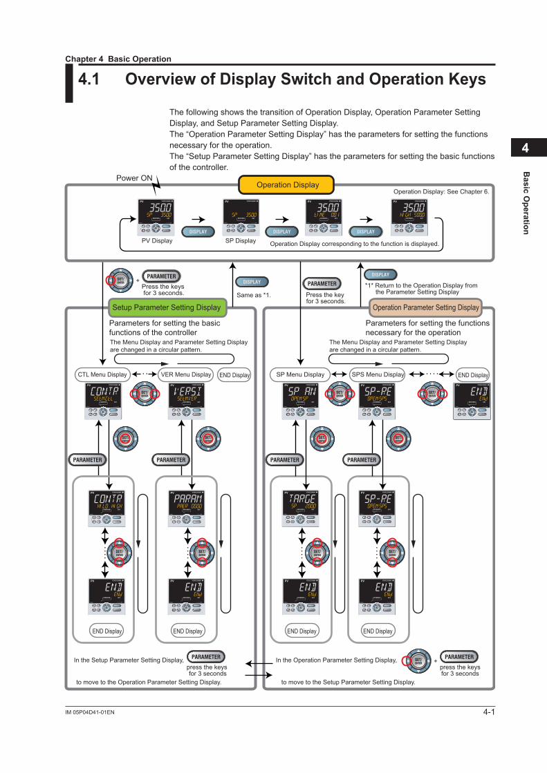
4.1 OverviewofDisplaySwitchandOperationKeys
The following shows the transition of Operation Display, Operation Parameter Setting Display, and Setup Parameter Setting Display.The “Operation Parameter Setting Display” has the parameters for setting the functions necessary for the operation.The “Setup Parameter Setting Display” has the parameters for setting the basic functions of the controller.
SP Menu DisplayVER Menu Display
PV Display
Power ON
SP Display Operation Display corresponding to the function is displayed.
Operation Display: See Chapter 6.
*1* Return to the Operation Display from the Parameter Setting Display
The Menu Display and Parameter Setting Display are changed in a circular pattern.
The Menu Display and Parameter Setting Display are changed in a circular pattern.
Same as *1.
Operation Display
Operation Parameter Setting DisplaySetup Parameter Setting Display
Press the keys for 3 seconds. Press the key
for 3 seconds.
+
CTL Menu Display SPS Menu Display END DisplayEND Display
END Display END Display END DisplayEND Display
press the keysfor 3 seconds
+In the Setup Parameter Setting Display, In the Operation Parameter Setting Display,
to move to the Operation Parameter Setting Display. to move to the Setup Parameter Setting Display.
press the keys for 3 seconds
Parameters for setting the basicfunctions of the controller
Parameters for setting the functionsnecessary for the operation
• •
• •
• • • • • •
• •
• •
• •
• •
• •
• •
Chapter 4 Basic Operation

4-2 IM 05P04D41-01EN
The display pattern of the UT35A-L is as follows; the Menu Display and Parameter Setting Display.For the Operation Display, see Chapter 6, “Monitoring and Control of Regular Operations.”
Display Description
Menu Display
The Menu Display is segmented by the function and optional terminal position.ThescrollingguideforthemenuisdisplayedonPVdisplay.Theguidedisplaycan be turned on/off with the Fn key.
Menu Display of Operation Parameter
OPE.M is displayed. Menu symbol is displayed.
The scrolling guide for the menu is displayed.
Menu Display of Setup Parameter
SET.M is displayed. Menu symbol is displayed.
The scrolling guide for the menu is displayed.
Parameter SettingDisplay
The following is the Display for displaying and setting a parameter.The parameters have three types of display levels; Easy setting mode, Standard setting mode, and Professional setting mode. The parameters to be displayed can be limited according to the setting of the parameter display level.ThescrollingguidefortheparameterisdisplayedonPVdisplay.Theguidedisplay can be turned on/off with the Fn key.
Parameter Setting Display (Example of Operation Parameter Setting Display)
Setpoint is displayed.Parameter symbol is displayed.
The scrolling guide for the parameter is displayed.
4.1OverviewofDisplaySwitchandOperationKeys

4-3IM 05P04D41-01EN
Basic O
peration
4
DisplayShownattheEnd(theLowestLevel)oftheParameterSettingDisplayAs shown in the figure below, the END Display is shown to indicate the end of the Menu Display and Parameter Setting Display. There are no setting items.
END is displayed.
The scrolling guide of END is displayed.
BasicKeyOperationSequence TomovetotheSetupParameterSettingDisplayHold down the PARAMETER (or PARA) key and the Left arrow key simultaneously for 3 seconds.
Hold down the keys for 3 seconds.
+
TomovetotheOperationParameterSettingDisplayHold down the PARAMETER (or PARA) key for 3 seconds.
Hold down the key for 3 seconds.
TomovetotheOperationDisplayPress the DISPLAY (or DISP) key once.
4.1OverviewofDisplaySwitchandOperationKeys
4-4 IM 05P04D41-01EN
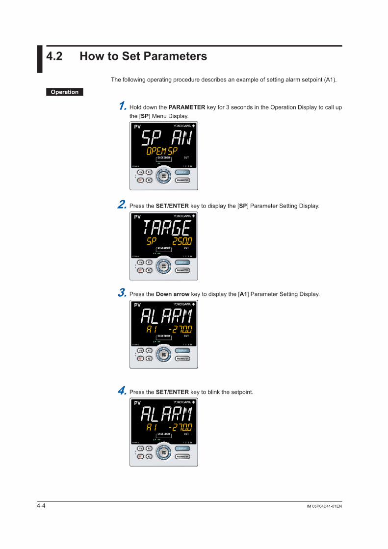
4.2 HowtoSetParameters
The following operating procedure describes an example of setting alarm setpoint (A1).
Operation
1. Hold down the PARAMETER key for 3 seconds in the Operation Display to call up the [SP] Menu Display.
2. Press the SET/ENTER key to display the [SP] Parameter Setting Display.
3. Press the Downarrow key to display the [A1] Parameter Setting Display.
4. Press the SET/ENTER key to blink the setpoint.

4-5IM 05P04D41-01EN
Basic O
peration
4
4.2HowtoSetParameters
5. Press the Up orDownarrow key to change the setpoint. (Change the setpoint using the Up/Down arrow keys to increase and decrease the value and the Left/Right arrow keys to move between digits.)
6. Press the SET/ENTER key to register the setpoint (the setpoint stops blinking).
7. Press the PARAMETER key once to return to the Menu Display. Press the DISPLAY key once to return to the Operation Display.
This completes the setting procedure.
HowtoCancelParameterSettingTo cancel parameter setting when a parameter is being set (setpoint is blinking), press the PARAMETER key once.

4-6 IM 05P04D41-01EN
HowtoSetParameterSetpointNumericValueSetting
1.
2.
3.
4.
5.
Press the Left arrow key to move one digit to the left.(Press the Right arrow key to move one digit to the right.)
Press the Up or Down arrow key to change the setpoint. Press the Up arrow key when 9 is displayed to move one digit to the left.Press the Down arrow key when 0 is displayed to move one digit to the right.
Press the SET/ENTER key to register the setpoint.
Display the Parameter Setting Display.
Press the SET/ENTER key to move to the setting mode (the setpoint blinks).
SelectionDataSetting
1.
2.
3.
4.
Press the Up arrow key to change the setpoint (press the Down arrow key to change the setpoint).
Press the SET/ENTER key to register the setpoint.
Display the Parameter Setting Display.
Press the SET/ENTER key to move to the setting mode (the setpoint blinks).
4.2HowtoSetParameters

4-7IM 05P04D41-01EN
Basic O
peration
4
4.2HowtoSetParameters
Time(minute.second)Setting
1.
2.
3.
4.
5.
Example of 17 minutes 59 seconds
Press the Left arrow key to move one digit to the left.(press the Right arrow key to move one digit to the right.)
Press the SET/ENTER key to register the setpoint.
Display the Parameter Setting Display.
Press the SET/ENTER key to move to the setting mode (the setpoint blinks).
Press the Up or Down arrow key to change the setpoint. Press the Up arrow key when 5 is displayed to move one digit to the left.Press the Down arrow key when 0 is displayed to move one digit to the right.

Blank Page

5-1IM 05P04D41-01EN
Quick Setting Function
5
5.1 SettingUsingQuickSettingFunction
Description
The Quick setting function is a function to easily set the basic function of the controller.The Quick setting function starts when the power is turned on after wiring.
The following lists the items to set using the Quick setting function.(1) Limit control type (High or low)(2) Inputfunction(PVinput,range,scale(atvoltage/currentinput),etc.)
Chapter 5QuickSettingFunction

5-2 IM 05P04D41-01EN
FlowchartofQuickSettingFunction
Decide whether or not to use the Quick setting function.
Press the UP arrow key to select YES.Press the SET/ENTER key to start the Quick setting function.
Press the Down arrow key to select NO.Press the SET/ENTER key not to start the Quick setting function.The Operation Display is displayed.
Select YES.Press the SET/ENTER key.
The Quick setting function is started.
NO
Each parameter is displayed in turn.See described later.
Select NO.Press the SET/ENTER key.
Operation Display
Power ON
The parameter HI.LO (limit control type) is displayed first.
Finally EXIT is displayed. Select YES and press the SET/ENTER key to complete the setup of basic functions.The Operation Display is displayed.Select NO to continue the Quick setting functionn.
Setting Method(1) Press the Up or Down arrow key to
display a parameter to set.(2) Press the SET/ENTER key. (The setpoint blinks).(3) Press the UP or Down arrow key to
change a setpoit.(4) Press the SET/ENTER key to
register the setpoint. (The setpoint stops blinkng.)
Setting Details
* If NO is selected and the parameter IN (PV input type) is set to OFF, the Quick setting function starts when the power is turned on again.
PV is displayed.
SP is displayed.
5.1SettingUsingQuickSettingFunction

5-3IM 05P04D41-01EN
Quick Setting Function
5
SettingExampleSet the following parameters to set to high limit control and thermocouple Type K (range: 0.0 to 500.0ºF). No need to change the parameters other than the following parameters.
Set QSM = YES to enter the quick setting mode.
(1) Set HI.LO = HIGH.(2) Set IN = K1.(3) Set UNIT = F.(4) Set RH = 500.0.(5) Set RL = 0.0.
SetEXIT=YEStoquitthequicksettingmode.The Operation Display is shown.
SettingDetails
Control TypeParameter
symbol Name Display level Settingrange Menu symbol
HI.LO Limit control type EASY LOW: Low limit controlHIGH: High limit control CTL
5.1SettingUsingQuickSettingFunction

5-4 IM 05P04D41-01EN
Input FunctionParameter
symbol Name Display level Settingrange Menu symbol
IN PVinputtype EASY
OFF: DisableK1: -270.0 to 1370.0 ºC / -450.0 to 2500.0 ºFK2: -270.0 to 1000.0 ºC / -450.0 to 2300.0 ºFK3: -200.0 to 500.0 ºC / -200.0 to 1000.0 ºFJ: -200.0 to 1200.0 ºC / -300.0 to 2300.0 ºFT1: -270.0 to 400.0 ºC / -450.0 to 750.0 ºFT2: 0.0 to 400.0 ºC / -200.0 to 750.0 ºFB: 0.0 to 1800.0 ºC / 32 to 3300 ºFS: 0.0 to 1700.0 ºC / 32 to 3100 ºFR: 0.0 to 1700.0 ºC / 32 to 3100 ºFN: -200.0 to 1300.0 ºC / -300.0 to 2400.0 ºFE: -270.0 to 1000.0 ºC / -450.0 to 1800.0 ºFL: -200.0 to 900.0 ºC / -300.0 to 1600.0 ºFU1: -200.0 to 400.0 ºC / -300.0 to 750.0 ºFU2: 0.0 to 400.0 ºC / -200.0 to 1000.0 ºFW: 0.0 to 2300.0 ºC / 32 to 4200 ºFPL2: 0.0 to 1390.0 ºC / 32.0 to 2500.0 ºFP2040: 0.0 to 1900.0 ºC / 32 to 3400 ºFWRE: 0.0 to 2000.0 ºC / 32 to 3600 ºFJPT1: -200.0 to 500.0 ºC / -300.0 to 1000.0 ºFJPT2: -150.0 to 150.0 ºC / -200.0 to 300.0 ºFPT1: -200.0 to 850.0 ºC / -300.0 to 1560.0 ºFPT2: -200.0 to 500.0 ºC / -300.0 to 1000.0 ºFPT3: -150.00 to 150.00 ºC / -200.0 to 300.0 ºF0.4-2V:0.400to2.000V1-5V:1.000to5.000V4-20: 4.00 to 20.00 mA0-2V:0.000to2.000V0-10V:0.00to10.00V0-20 : 0.00 to 20.00 mA-1020:-10.00to20.00mV0-100:0.0to100.0mV
PV
UNIT PVinputunit EASY
-: No unitC: Degree Celsius-: No unit- -: No unit- - -: No unitF: Degree Fahrenheit
RH Maximum value of PVinputrange EASY Depends on the input type.
- For temperature input - Set the temperature range that
is actually controlled. (RL<RH)- For voltage / current input - Set the range of a voltage /
current signal that is applied. The scale across which the
voltage / current signal is actually controlled should be set using the maximum value of input scale (SH) and minimum value of input scale (SL). (Input is always0%whenRL=RH.)
RL Minimum value of PVinputrange EASY
Note1:W:W-5%Re/W-26%Re(HoskinsMfg.Co.).ASTME988 WRE: W97Re3-W75Re25
5.1SettingUsingQuickSettingFunction

5-5IM 05P04D41-01EN
Quick Setting Function
5
5.1SettingUsingQuickSettingFunction
Input Function (Continued)Parameter
symbol Name Display level Settingrange Menu symbol
SDPPVinputscaledecimal point position
EASY
0: No decimal place1: One decimal place2: Two decimal places3: Three decimal places4: Four decimal places PV
SH Maximum value of PVinputscale EASY
-19999 to 30000, (SL<SH),|SH-SL|≤30000SL Minimum value of
PVinputscale EASY
Inputsetting:7.1SettingFunctionsofPVInput

5-6 IM 05P04D41-01EN
5.2 RestartingQuickSettingFunction
Once functions have been built using the Quick setting function, the Quick setting function does not start even when the power is turned on. The following methods can be used to restart the Quick setting function.
SettheparameterQSM(Quicksettingmode)toONandturnonthepoweragain. SettheparameterIN(PVinputtype)toOFFandturnonthepoweragain.
CAUTIONTheparametersrelatedtotherangeorscaleareinitializedifthePVinputtypeischanged.
SettingDetails
Parameter symbol Name Display
level Settingrange Menu symbol
IN PVinputtype EASY OFF: Disable PV
QSM Quick setting mode EASY OFF: DisableON: Enable SYS

6-1IM 05P04D41-01EN
Monitoring and C
ontrol of Regular O
perations
6
6.1 MonitoringandControlofOperationDisplays
6.1.1 Operation Display Transitions.
PV Display (SP can be changed.)
When setup parameter HOME is set to PV.
When setup parameter HOME is set to SP.
PV Display (SP can be changed.)
SP Display (SP can be changed.)
SP Display(SP can be changed.)
Duration Time Display
Maximum Value Display
Minimum Value Display
Chapter 6MonitoringandControlofRegularOperations
6-2 IM 05P04D41-01EN
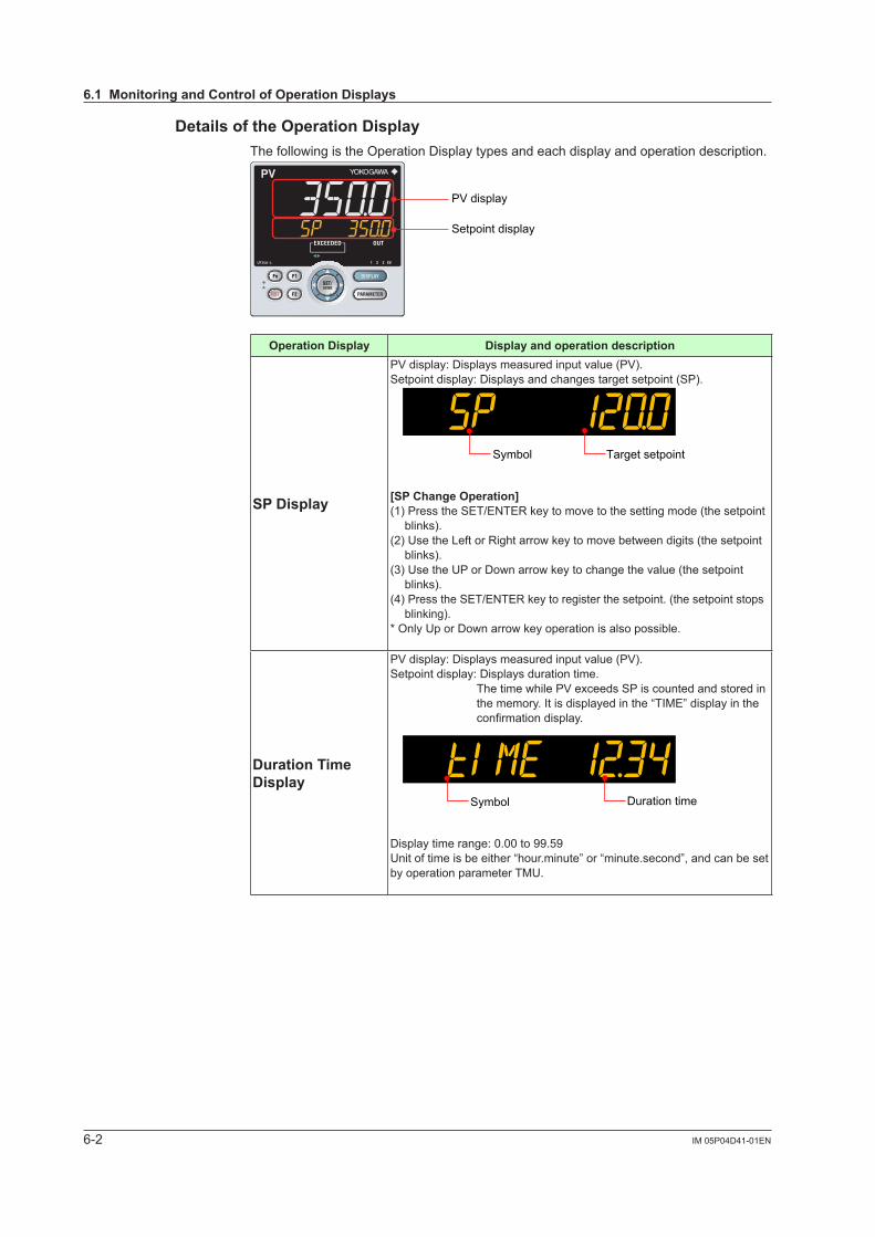
DetailsoftheOperationDisplayThe following is the Operation Display types and each display and operation description.
PV display
Setpoint display
Operation Display Display and operation description
SPDisplay
PVdisplay:Displaysmeasuredinputvalue(PV).Setpoint display: Displays and changes target setpoint (SP).
Symbol Target setpoint
[SPChangeOperation](1) Press the SET/ENTER key to move to the setting mode (the setpoint
blinks).(2) Use the Left or Right arrow key to move between digits (the setpoint
blinks).(3) Use the UP or Down arrow key to change the value (the setpoint
blinks).(4) Press the SET/ENTER key to register the setpoint. (the setpoint stops
blinking).* Only Up or Down arrow key operation is also possible.
Duration Time Display
PVdisplay:Displaysmeasuredinputvalue(PV).Setpoint display: Displays duration time.
ThetimewhilePVexceedsSPiscountedandstoredinthe memory. It is displayed in the “TIME” display in the confirmationdisplay.
Duration timeSymbol
Display time range: 0.00 to 99.59Unit of time is be either “hour.minute” or “minute.second”, and can be set by operation parameter TMU.
6.1MonitoringandControlofOperationDisplays

6-3IM 05P04D41-01EN
Monitoring and C
ontrol of Regular O
perations
6
(Continued)Operation Display Display and operation description
Maximum/Minimum Value Display
PVdisplay:Displaysmeasuredinputvalue(PV).Setpoint display: Displays maximum value or minimum value.
Maximumvalue
Symbol
Minimumvalue
Symbol
ThemaximumvalueorminimumvalueofPVisstoredinthememoryanddisplayinthe“HIGH”or“LOW”displayintheconfirmationdisplay.Whenthecontroltypeisspecifiedashighlimitcontrol,themaximumvalueisdisplayedinthe“HIGH”display,andcontroltypeisspecifiedaslow limit control, the minimum value is displayed in the “LOW” display.WhenthePVexceedsSPandthenreturnstothenormalstatus,Maximum/MinimumValueisretainedasitis,butwhenPVexceedsSP again, it is automatically reset and starts taking new value for its minimum / maximum value.
6.1MonitoringandControlofOperationDisplays
6-4 IM 05P04D41-01EN
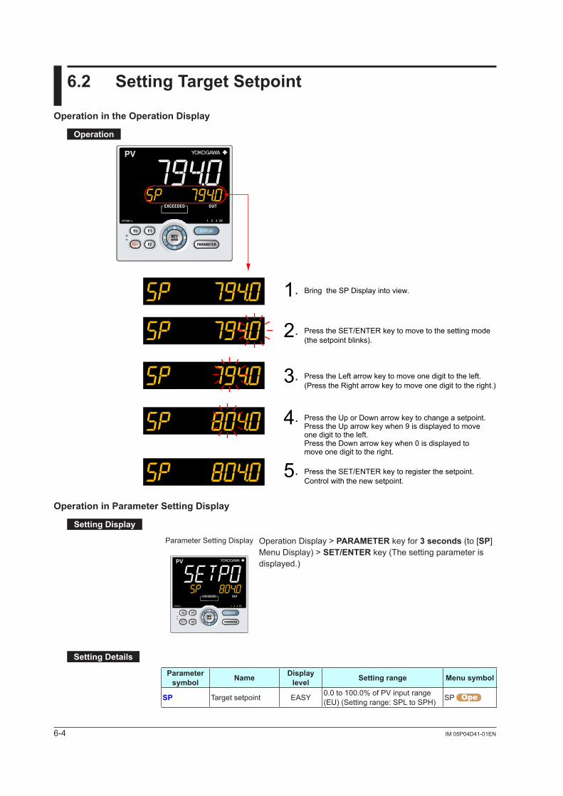
6.2 SettingTargetSetpoint
Operation in the Operation Display
Operation
1.
2.
3.
4.
5.
Press the Left arrow key to move one digit to the left. (Press the Right arrow key to move one digit to the right.)
Press the Up or Down arrow key to change a setpoint.Press the Up arrow key when 9 is displayed to move one digit to the left.Press the Down arrow key when 0 is displayed to move one digit to the right.
Press the SET/ENTER key to register the setpoint. Control with the new setpoint.
Bring the SP Display into view.
Press the SET/ENTER key to move to the setting mode(the setpoint blinks).
OperationinParameterSettingDisplay
SettingDisplay
Parameter Setting Display Operation Display > PARAMETER key for 3 seconds (to [SP] Menu Display) > SET/ENTER key (The setting parameter is displayed.)
SettingDetails
Parameter symbol Name Display
level Settingrange Menu symbol
SP Target setpoint EASY 0.0to100.0%ofPVinputrange(EU) (Setting range: SPL to SPH) SP

6-5IM 05P04D41-01EN
Monitoring and C
ontrol of Regular O
perations
6
6.3 SettingAlarmSetpoint
SettingDisplay
Parameter Setting Display Operation Display > PARAMETER key for 3 seconds (to [SP] Menu Display) > SET/ENTER key (The setting parameter is displayed.) > Downarrow key (The setting parameter is displayed.)
In the setting Display for the alarm parameters, Displays can be arbitrarily switched using the Up, Down, Left or Right arrow key. Pressing the Left or Right arrow key changes the group.(The group number is displayed on Group display.)
SettingDetails
Parameter symbol Name Display
level Settingrange Menu symbol
A1 to A3 Alarm-1 to -3 setpoint EASY
Set a display value of setpoint of PValarm,SPalarm,deviationalarm, or velocity alarm.-19999 to 30000 (Set a value within the input range.)Decimal point position depends on the input type
SP
Description
Each alarm type has three alarm setpoints. Alarm-related parameter Numberofsettings
Alarm type 3 (number of settings)
PVvelocityalarmtimesetpoint 3 (number of settings)
Alarm hysteresis 3 (number of settings)
Alarm delay timer 3 (number of settings)
Alarm setpoint 3 (number of settings)
Alarmtype:Chapter11AlarmFunctions
6-6 IM 05P04D41-01EN
6.4 ReleasingOn-State(Latch)ofAlarmOutput
Description
Alarm latch can be released by any of the following. (1) User function key (2) Communication (3) Contact input For the switching operation by using the above, the last switching operation is performed.
Releasing the alarm latch function releases all of the latched alarm outputs.By factory default, the function is not assigned to the user function key and contact input. Assign and use the function in accordance with the reference sections below.
Releasebyuserfunctionkey:13.2AssigningFunctiontoUserFunctionKey Releasebycontactinput:12.1SettingContactInputFunction Releaseviacommunication:UTAdvancedSeriesCommunicationInterfaceUser’sManual

7-1IM 05P04D41-01EN
Input (PV) Functions
7
7.1 SettingFunctionsofPVInput
7.1.1 SettingInputType,Unit,Range,Scale,andDecimalPointPosition
Description
ThefigurebelowdescribesthecaseofPVinput.
ExampleofTemperatureInputThe figure below is an example of setting Type K thermocouple and a measurement range of 0.0 to 800.0 ºC.
Minimum value of PV input range
Input type
-270.0°C 1370.0°C
RL = 0.0°C RH = 800.0°C
Maximum value of PV input range
Set a range to becontrolled.PV input range
ExampleofVoltageandCurrentInputsThefigurebelowisanexampleofsetting2-4VDCandascaleof0.0to50.0m³/h.
Minimum value of PV input scale
1 V 5 V (input signal)
SL = 0.0 m³/h SH = 50.0 m³/h
Maximum value of PV input scale
2 V 4 V
RL = 2.000
RL = 1.000
RH = 4.000
RH = 5.000
PV input scale
Input type
Set a range to becontrolled.
PV input range
Whenusing1-5VDCsignalasis,setRH=5.000V,RL=1.000V,SDP=1, and SH = 50.0, and SL=0.0.
Chapter 7 Input (PV) Functions

7-2 IM 05P04D41-01EN
SettingDetails
Parameter symbol Name Display
level Settingrange Menu symbol
IN PVinputtype EASY
OFF: DisableK1: -270.0 to 1370.0 ºC / -450.0 to 2500.0 ºFK2: -270.0 to 1000.0 ºC / -450.0 to 2300.0 ºFK3: -200.0 to 500.0 ºC / -200.0 to 1000.0 ºFJ: -200.0 to 1200.0 ºC / -300.0 to 2300.0 ºFT1: -270.0 to 400.0 ºC / -450.0 to 750.0 ºFT2: 0.0 to 400.0 ºC / -200.0 to 750.0 ºFB: 0.0 to 1800.0 ºC / 32 to 3300 ºFS: 0.0 to 1700.0 ºC / 32 to 3100 ºFR: 0.0 to 1700.0 ºC / 32 to 3100 ºFN: -200.0 to 1300.0 ºC / -300.0 to 2400.0 ºFE: -270.0 to 1000.0 ºC / -450.0 to 1800.0 ºFL: -200.0 to 900.0 ºC / -300.0 to 1600.0 ºFU1: -200.0 to 400.0 ºC / -300.0 to 750.0 ºFU2: 0.0 to 400.0 ºC / -200.0 to 1000.0 ºFW: 0.0 to 2300.0 ºC / 32 to 4200 ºF(Note1)PL2: 0.0 to 1390.0 ºC / 32.0 to 2500.0 ºFP2040: 0.0 to 1900.0 ºC / 32 to 3400 ºFWRE: 0.0 to 2000.0 ºC / 32 to 3600 ºFJPT1: -200.0 to 500.0 ºC / -300.0 to 1000.0 ºFJPT2: -150.0 to 150.0 ºC / -200.0 to 300.0 ºFPT1: -200.0 to 850.0 ºC / -300.0 to 1560.0 ºFPT2: -200.0 to 500.0 ºC / -300.0 to 1000.0 ºFPT3: -150.00 to 150.00 ºC / -200.0 to 300.0 ºF0.4-2V:0.400to2.000V1-5V:1.000to5.000V4-20: 4.00 to 20.00 mA0-2V:0.000to2.000V0-10V:0.00to10.00V0-20 : 0.00 to 20.00 mA-1020:-10.00to20.00mV0-100:0.0to100.0mV
PV
UNIT PVinputunit EASY
-: No unitC: Degree Celsius-: No unit- -: No unit- - -: No unitF: Degree Fahrenheit
PV
RH(Physical quantity)
MaximumvalueofPVinput range EASY
Depends on the input type.- For temperature input - Set the temperature range
that is actually controlled. (RL<RH)
- For voltage / current input - Set the range of a voltage
/ current signal that is applied.
The scale across which the voltage / current signal is actually controlled should be set using the maximum value of input scale (SH) and minimum value of input scale (SL). (Input isalways0%whenRL=RH.)
PV
RL(Physical quantity)
MinimumvalueofPVinput range EASY Same as RH PV
Note1:W:W-5%Re/W-26%Re(HoskinsMfg.Co.).ASTME988 WRE: W97Re3-W75Re25
7.1SettingFunctionsofPVInput

7-3IM 05P04D41-01EN
Input (PV) Functions
7
(Continued)Parameter
symbol Name Display level Settingrange Menu symbol
SDP(Scaling)
PVinputscaledecimalpoint position EASY
0: No decimal place1: One decimal place2: Two decimal places3: Three decimal places4: Four decimal places
PV
SH(Scaling)
MaximumvalueofPVinput scale EASY -19999 to 30000, (SL<SH),
|SH-SL|≤30000 PV
SL(Scaling)
MinimumvalueofPVinput scale EASY -19999 to 30000, (SL<SH),
|SH-SL|≤30000 PV
WhenchangingthePVdecimalpointpositionorthedigitoftheindicatedvalue,canbeset by the following parameters.Example:PVinputtype=K1(-270.0to1370.0ºC),thedigitiswithoutdecimalpointfor"0
to 1000ºC". P.UNI=C P.DP=0 P.RH=1000 P.RL=0
Parameter symbol Name Display
level Settingrange Menu symbol
P.UNI ControlPVinputunit
STD
-: No unitC: Degree Celsius-: No unit- -: No unit- - -: No unitF: Degree Fahrenheit
MPVP.DP ControlPVinput
decimal point position
0: No decimal place1: One decimal place2: Two decimal places3: Three decimal places4: Four decimal places
P.RH Maximum value of controlPVinputrange -19999 to 30000, (P.RL<P.RH),
|P.RH-P.RL|≤30000P.RL Minimum value of controlPVinputrange
7.1.2 SettingBurnoutDetectionforInputDescription
The input value when input burnout occurs can be determined.Theinputvalueis105.0%oftheinputrangewhentheupscaleisset,and-5.0%oftheinput range when the downscale is set.BurnoutdetectionisactivatedforTC,RTD,andstandardsignal(0.4–2Vor1–5V).Forstandardsignal,burnoutisdeterminedtohaveoccurredifitis0.1Vorlessfortherangeof0.4–2Vand1–5V,orifitis0.4mAorlessfortherangeof4–20mA.
SettingDetails
Parameter symbol Name Display
level Settingrange Menu symbol
BSL PVinputburnoutaction STDOFF: DisableUP: UpscaleDOWN: Downscale
PV
7.1SettingFunctionsofPVInput

7-4 IM 05P04D41-01EN
7.1.3 SettingReferenceJunctionCompensation(RJC)orExternalReferenceJunctionCompensation(ERJC)
Description
ReferenceJunctionCompensation(RJC)WhenTCinputisselected,presence/absenceofinputreferencejunctioncompensationcan be set.Usually input values are compensated with the RJC function provided for the controller. However, if it is necessary to rigorously compensate the values with a device other than the function of the controller, for example with a zero-compensator, the RJC function of the controller can be turned off.
ExternalReferenceJunctionCompensation(ERJC)For TC input, a temperature compensation value for external device can be set.The external RJC can be used only when RJC = OFF.
Furnace
Furnace
UT35A-L
UT35A-L
Compensating lead wire
Compensating lead wire
Terminal block
Terminal block
TC
TC
Installed in an area where ambient temperature is fixed to 25°C.
Set the temperature in the area using ERJC parameter.
Normal wiring
Example:Setting parametersRJC = OFF,ERJC = 25.0°C
SettingDetails
Parameter symbol Name Display
level Settingrange Menu symbol
RJC PVinputreferencejunctioncompensation PRO OFF: RJC OFF
ON: RJC ON PV
ERJC PVinputexternalRJCsetpoint PRO -10.0to60.0°Cor
14.0to140.0°F PV
7.1SettingFunctionsofPVInput

7-5IM 05P04D41-01EN
Input (PV) Functions
7
7.1.4 Correcting Input Value
SettingBiasandFilter
Description
PV Input BiasThePVinputbiasallowsbiastobesummedwithinputtodevelopameasuredvaluefordisplay and control use inside the controller.Thisfunctioncanalsobeusedforfineadjustmenttocompensateforsmallinter-instrument differences in measurement reading that can occur even if all are within the specified instrument accuracies.PVinputbiasisusedfornormaloperation.
PV input value + =PV input bias PV value inside the controller
Temperature sensed by thermocouple
Compensationvalue
Estimated materialtemperature
PV Input FilterIf input noise or variations cause the low-order display digits to fluctuate so that the displayed value is difficult to read, a digital filter can be inserted to smooth operation. This filter provides a first-order lag calculation, which can remove more noise the larger the time constant becomes. However, an excessively large time constant will distort the waveform.PVinputfilterisusedfornormaloperation.
Actual input With a small time constant With a large time constant
InputFiltering for 2 sec
Filtering for 10 sec
Analog Input BiasAnalog input bias is used to correct sensor-input characteristics, compensating lead wire errors, and so on.
Analog Input FilterThe analog input filter is used to remove noise from an input signal. This filter provides a first-order lag calculation, which can remove more noise the larger the time constant becomes. However, an excessively large time constant will distort the waveform.
7.1SettingFunctionsofPVInput

7-6 IM 05P04D41-01EN
SettingDetails
Parameter symbol Name Display
level Settingrange Menu symbol
BS PVinputbias EASY -100.0to100.0%ofPVinput range span (EUS) PVS
FL PVinputfilter EASY OFF, 1 to 120 s
Parameter symbol Name Display
level Settingrange Menu symbol
A.BS PVanaloginputbias STD -100.0to100.0%ofeachinput range span (EUS) PV
A.FL PVanaloginputfilter STD OFF, 1 to 120 s PV
7.1SettingFunctionsofPVInput

8-1IM 05P04D41-01EN
Function Block D
iagram
Chapter 8 Function Block Diagram
8
8.1 Function Block Diagram
BS
FL
DI2.SCNF
UNIT
IN
RH, RL SDP SH, SL
A.BS
A.FL
RTSRTH RTL
RST
Input type
PV analog input bias
PV analog input filter
Input unit
Input range/scale
PV input bias
PV input filter
Equipped as standard Equipped as standard
RelayCurrent
RET retransmission output Alarm
Limit Control computation
Contact inputs
PV
PV input
Equipped as standardEquipped as standard.
Ala
rm 1
(PV
hig
h lim
it)
Ala
rm 2
(PV
low
lim
it)
Ala
rm 3
(PV
hig
h lim
it)
PV display SP display
Com.
OUT
DI2DI1
RET AL3AL2AL1
RS-485, Ethernet
Terminal Parameter Function
Analog signal Contact signal Front panel keyLegend
Confirmation
Target setpointSP
SP limiter
Latch release, etc
SPH, SPL
HI.LO
HYS

Blank Page

9-1IM 05P04D41-01EN
Auxiliary C
ontrol Functions
9
9.1 SettingSPLimiter
Description
The SP high and low limits can be set to restrict the SP to the range between those limits. They works to the SP of all SP groups.
0.0 100.0(%)
Setting range
SPH
Actu
al S
P
SPL
Setting range of actual SP
Original setting range
0.0
(%)100.0
High limit of SP
Low limit of SP
SettingDetails
Parameter symbol Name Display
level Settingrange Menu symbol
SPH SP high limit STD 0.0to100.0%ofPVinputrange(EU), (SPL<SPH) MPV
SPL SP low limit STD
Chapter 9AuxiliaryControlFunctions

9-2 IM 05P04D41-01EN
9.2 SettingControllerActionatPowerON (Restart Mode)
Description
The state of output relay at power-on can be set by a setup parameter restart mode R.MD.For details, see Chapter 15, “Power Failure Recovery Processing.”
SettingDetails
Parameter symbol Name Display
level Settingrange Menu symbol
R.MD Restart Mode STD
0: Limit output is ON at power on in any cases.
1: Limit output is OFF at power on whenPVdoesn’texceedSP.
SYS

10-1IM 05P04D41-01EN
Retransm
ission Output Functions
10
10.1 SettingRetransmissionOutputTerminal,Type,andScales
Description
The retransmission output can be used when the control output is not assigned to the analog output terminal. Confirm the output type selection (OT) before setting the retransmission output. The range can be changed. Currentoutputrange:10.2ChangingCurrentOutputRange
20 mA (output signal)
0.0°C 200.0°C
4 mA
50.0°C 150.0°CRetransmission scale
PV scale
Output range
Minimum value ofPV input range
Maximum value ofPV input range
To Recorder
SettingDetails
Parameter symbol Name Display
level Settingrange Menu symbol
RTSRetransmission out type of RET
EASYOFF: DisablePV1:PVSP1: SP
OUT
RTH
Maximum value of retransmission output scale of RET
STDWhenRTS=PV1,SP1 RTL + 1 digit to 30000-19999 to RTH - 1 digit
Decimal point position:WhenRTS=PV1orSP1,decimal
pointpositionissameasthatofPVinput.
RTL
Minimum value of retransmission output scale of RET
STD
Parameters and Corresponding TerminalsRTS, RTH, RTL RET terminal
Chapter 10 Retransmission Output Functions

10-2 IM 05P04D41-01EN
10.2 Changing Current Output Range
Description
The analog output type can be selected from among 4 to 20, 0 to 20, 20 to 4, or 20 to 0 mA.
SettingDetails
Parameter symbol Name Display
level Settingrange Menu symbol
RET.A RET current output range STD
4-20: 4 to 20 mA,0-20: 0 to 20 mA,20-4: 20 to 4 mA,20-0: 20 to 0 mA
OUT
Parameters and Corresponding TerminalsRET.A RET terminal

11-1IM 05P04D41-01EN
Alarm
Functions
11
11.1 SettingAlarmType
Description
The alarm-related parameters consist of the alarm type (type, stand-by action, energized/de-energized,andlatchfunction),PVvelocityalarmtimesetpoint,alarmhysteresis,alarm (On-/Off-) delay timer, and alarm setpoint.
Alarm-related parameter Numberofsettings
Alarm type 3 (number of settings)
PVvelocityalarmtimesetpoint 3 (number of settings)
Alarm hysteresis 3 (number of settings)
Alarm (on-/off-) delay timer 3 (number of settings)
Alarm setpoint 3 (number of settings)
Alarmhysteresis:11.2SettingHysteresistoAlarmOperation Alarmdelaytimer:11.3DelayingAlarmOutput(AlarmDelayTimer) Alarmsetpoint:6.3SettingAlarmSetpoint
Factory default: Only three groups of alarm-related parameters are displayed. Terminalfunction:17.4.5ContactOutputWiring
To read the conditions of alarms, outputs, or latches via communication, see Communication Interface User's Manual.
AL3AL2AL1
Alarm 1(PV high limit)
Alarm conditions
Energized/de-energized
Alarm 2(PV low limit)
Alarm 3(PV high limit)
Alarm Function
Chapter 11 Alarm Functions

11-2 IM 05P04D41-01EN
PVHighLimitAlarmandPVLowLimitAlarm
PV
ON OFF
ON
Contact type in the figure above: Energized when an event occurs (factory default).
Alarm hysteresis
Alarm hysteresis
OFF
Time
PV high limitalarm setpoint
PV low limitalarm setpoint
PV high limitalarm output
PV low limitalarm output
11.1SettingAlarmType

11-3IM 05P04D41-01EN
Alarm
Functions
11
DeviationHighLimitAlarmandDeviationLowLimitAlarm
PV
Alarm hysteresis
Alarm hysteresis
Deviation low limitalarm setpoint (negative setpoint)
Time
ON OFFOFF
ON OFFOFF
Deviation high limitalarm output
Deviation low limitalarm output
Target setpoint(SP)
Contact type in the figure above: Energized when an event occurs (factory default).
When a negative setpoint is set for the deviation high limit alarm setpoint, the deviation setpoint will be lower than the SP.Moreover, when a positive setpoint is set for the deviation low limit alarm setpoint, the deviation setpoint will be higher than the SP.
Deviation high limitalarm setpoint (positive setpoint)
DeviationHighandLowLimitsAlarm
PV
Alarm hysteresis
Alarm hysteresis
Deviation high andlow limits alarm setpoint
Time
ON OFFOFF ON OFFDeviationhigh and low limits
alarm output
Target setpoint(SP)
Contact type in the figure above: Energized when an event occurs (factory default).
DeviationwithinHighandLowLimitsAlarm
PV
Alarm hysteresis
Alarm hysteresis
Deviation within highand low limits alarm setpoint
Time
ON ONOFF OFFONDeviation within
high and low limitsalarm output
Target setpoint(SP)
Contact type in the figure above: Energized when an event occurs (factory default).
11.1SettingAlarmType

11-4 IM 05P04D41-01EN
PV Velocity Alarm
PV
VT VT VT VT VT VT
PV velocityalarm output
Time
An alarm occurs if the velocityexceeds this inclination.
OFF OFF OFFON ON
Velocity alarmtime setpointVT1 to VT3
Velocity alarmsetpoint
Velocity alarmsetpoint
Velocity alarmtime setpointVT1 to VT3
Exceeds the velocity
Contact type in the figure above: Energized when an event occurs (factory default).
Monitors the variation of the measured value for 2 points by the time interval set in VT.
ThePVvelocityalarmfunctiondoesnotworkthealarmhysteresis,thestand-byactionand the alarm delay timer functions.
Fault diagnosis AlarmThe function outputs an alarm signal in the following cases.Thecorrespondingevent(EV)lampislitandthecontactoutputturnson(whenthecontact type is energized).• BurnoutofPVinput• ADC failure ofPVinput• Referencejunctioncompensation(RJC)errorofPVinputThe fault diagnosis alarm does not work the stand-by action functions.
FAIL outputWhen the FAIL condition is caused (faulty MCU or system data error), DO (alarm output) turned off regardless of contact type.The FAIL output does not work the alarm latch, the energized/de-energized and the stand-by action functions.
11.1SettingAlarmType

11-5IM 05P04D41-01EN
Alarm
Functions
11
Stand-byActionThe stand-by action is a function for ignoring the alarm condition and keeps the alarm off until the alarm condition is removed. Once the alarm condition is removed, the stand-by action is cancelled.It is effective in the following cases where;• The power is turned on• SP is changed• The alarm type is changed• Forced stand-by via communication
The following shows the behavior of an alarm with the stand-by action at power ON.
Treatedas normal
ºC
Power-on Time
The alarm output does not turn onin this region even if the PV valuleis below PV low limit alarm setpoint.
PV low limit alarm setpoint
Normal Abnormal
The alarm outputturns on.
11.1SettingAlarmType

11-6 IM 05P04D41-01EN
Alarm Latch FunctionThe alarm latch function is a function for keeping the alarm output (keeping the alarm output on) after entering the alarm condition (alarm output is turned on) until an order to release the alarm latch is received.
The alarm latch function has the following four types of action. Latch 1 Cancels the alarm output when an order to release the alarm latch is received. (Alarm
output OFF.) However, an order to release the alarm latch is ignored if the order is received during alarm condition.
Latch 2 Always forces cancelling of the alarm output when an order to release the alarm latch
is received. (Alarm output OFF)Latch 3 Cancels the alarm output when an order to release the alarm latch is received or when
the alarm condition is removed. (Alarm output OFF.)Latch 4 Cancels the alarm output when an order to release the alarm latch is received. (Alarm
output OFF.) However, cancels the alarm output for the duration of the sampling period (control period) if an order to release the alarm latch is received during alarm condition. (Alarm output OFF)
PV
Lit Lit
Contact type in the figure above: Energized when an event occurs (factory default).
Alarm hysteresis
Unlit Unlit
ON
ON ON
ONOFF
OFF
OFF
ON ONOFF OFF
Time
PV high limitalarm setpoint
PV high limitalarm indicator
PV high limit alarm output(no latch action)
PV high limit alarm outputof latch 1 action
PV high limit alarm outputof latch 2 action
ON ONOFF OFFPV high limit alarm outputof latch 3 action
ON ON ON
OFF during the sampling period
OFFPV high limit alarm outputof latch 4 action
Release order Release order
Release order Release order
Release order
Release order
Release order
Release order
11.1SettingAlarmType

11-7IM 05P04D41-01EN
Alarm
Functions
11
ReleaseofAlarmLatchThe alarm latch function can be cancelled by the user function key or by contact input.Cancelling the alarm latch function cancels all latched alarm outputs. Releasebyuserfunctionkey:13.2AssigningFunctiontoUserFunctionKey Releasebycontactinput:12.1.1SettingContactInputFunction Releaseviacommunication:UTAdvancedSeriesCommunicationInterfaceUser’sManual
PV
Lit Lit
Contact type in the figure above: Energized when an event occurs (factory default).
Alarm hysteresis
Alarm hysteresis
Unlit Unlit
Lit LitUnlit Unlit Unlit
ON ONOFF OFF
ON ON ONOFF OFF
Time
PV high limitalarm setpoint
PV low limitalarm setpoint
PV high limit alarm state
PV low limit alarm state
PV high limit alarm outputof latch 1 action
PV low limit alarm outputof latch 2 action
Release order Release order Release order
Release order Release order Release order
OperationofAlarmOutputandDisplayLamp(EV)Thecontactoutputanddisplaylamp(EV)areusuallyoutputanddisplayedaccordingto the setpoint of the alarm type. However, the alarm conditions (operations) of the normal action, and latch action can be assigned to the contact output and display lamp (EV),regardlessofthesetpointofthealarmtype.(Twooperationscanbeassignedsimultaneously.) Displaylampaction:13.1SettingDisplayFunctions
11.1SettingAlarmType

11-8 IM 05P04D41-01EN
SettingDetails
Parameter symbol Name Display
level Settingrange Menu symbol
AL1 to AL3 Alarm-1 to -3 type EASY See the table below.ALRM
VT1 to VT3 PVvelocityalarmtimesetpoint 1 to 3 EASY 00.01 to 99.59
(minute.second)Note1:TheinitialvaluesoftheparmetersAL1toAL3andVT1toVT3are"3".
ThefollowingshowstheexampleofsettingPVhighlimit(01),Withstand-byaction(1),De-energized (1), and Latch 1 action (1).
Alarm typeSymbol
Stand-by actionEnergized/de-energizedLatch
Name Latch action (Note 1)
Energized(0)/de-energized (1)
Stand-byactionWithout(0)/with(1)
Alarm type
Disable - (Note 2) - (Note 2) - (Note 2) 00
PVhighlimit 0 / 1 / 2 / 3 / 4 0 / 1 0 / 1 01
PVlowlimit 0 / 1 / 2 / 3 / 4 0 / 1 0 / 1 02
Deviation high limit 0 / 1 / 2 / 3 / 4 0 / 1 0 / 1 05
Deviation low limit 0 / 1 / 2 / 3 / 4 0 / 1 0 / 1 06
Deviation high and low limits 0 / 1 / 2 / 3 / 4 0 / 1 0 / 1 07Deviation within high and low limits 0 / 1 / 2 / 3 / 4 0 / 1 0 / 1 08
PVvelocity 0 / 1 / 2 / 3 / 4 0 / 1 - (Note 2) 29
Fault diagnosis 0 / 1 / 2 / 3 / 4 0 / 1 - (Note 2) 30
FAIL - (Note 2) - (Note 2) - (Note 2) 31
Note 1: 0: No latch function, 1: Latch 1, 2: Latch 2, 3: Latch 3, 4: Latch 4Note 2: -: Alarm function doesn't work even if any value is set.
11.1SettingAlarmType

11-9IM 05P04D41-01EN
Alarm
Functions
11
11.2 SettingHysteresistoAlarmOperation
Description
If the On/Off switch of the alarm output is too busy, you can alleviate the busyness by increasing the alarm hysteresis.
HysteresisforPVHighLimitAlarm
Point of ON/OFF action(alarm setpoint)
PV
Output
ON
OFF Hysteresis
WhenSettingHysteresisof5ºCand15ºCforPVHighLimitAlarm
Closed (ON)
Open
Time
Alarm-1 setpoint: 100ºC (example)
Closed (ON)
Open
Time
Alarm-1 setpoint: 100ºC (example)
HYS: 15ºC (example)HYS: 5ºC (example)
PV PVAlarm ON
OFF
ONOFF
ON
OFF
Alarm ON
OFF
SettingDetails
Parameter symbol Name Display
level Settingrange Menu symbol
HY1toHY3 Alarm-1 to -3 hysteresis EASY
Sets the hysteresis setpoint as a display value.-19999 to 30000 (set it within the input range)The decimal point position depends on the input type.
ALRM

11-10 IM 05P04D41-01EN
11.3 Delaying Alarm Output (Alarm Delay Timer)
Description
The alarm on-delay timer is a function for turning on the alarm when the alarm condition occurs, and the timer starts and the set time elapses.The timer is reset if the alarm condition is removed while the timer is running. No alarm is generated.The figure below shows the example of the On-delay timer
PV
Elapsed time
On-delay timer time
Lit
Contact type in the figure above: Energized when an event occurs (factory default).
Alarm hysteresis
Unlit
OFF
Time
PV high limitalarm setpoint
PV high limitalarm state
(without delay timer)
PV high limitalarm output
Elapsed time
On-delay timer time
ON
The alarm Off-delay timer is a function for turning off the alarm when the alarm condition is removed (normal condition), and the timer starts and the set time elapses.The timer is reset if the alarm condition occurs again while the timer is running. The alarm is not cancelled.
SettingDetails
Parameter symbol Name Display
level Settingrange Menu symbol
DYN1toDYN3
Alarm-1 to -3 On-delay timer STD
0.00 to 99.59 (minute.second) ALRM DYF1toDYF3
Alarm-1 to -3 Off-delay timer PRO

12-1IM 05P04D41-01EN
Contact Input Functions
12
12.1 SettingContactInputFunction
12.1.1 SettingContactInputFunction
Description
The contact input (DI2) function works by setting the DI2.S parameter to functions such as the operation mode.
Latch Release (LAT)Latch can be released using contact input. (Switch by the rising edge)
Contact status Operation Remark
OFF→ON Releases the latch –
ON→OFF Maintains the current operation status –
Releasing the latch function releases all latched contact (alarm) outputs.
LCDBacklightON/OFFSwitch(LCD)LCD backlight ON/OFF can be switched using contact input. (Switch by the rising edge and the falling edge)
Contact status Operation Remark
OFF→ON Turns off the LCD backlight –
ON→OFF Turns on the LCD backlight –
MessageDisplayInterruption1to4(MG1to4)The message set using LL50A Parameter Setting Software can be interrupt-displayed on PVdisplayusingcontactinput.Themessagesarelimitedto20alphanumericcharacters.A maximum of four displays can be registered. (Switch by the rising edge) Message:LL50AParameterSettingSoftwareUser’sManual
Contact status Operation Remark
OFF→ON Interrupt-displays the message Pressing the DISPLAY key erases the message.
ON→OFF DisplaysthecurrentPV –
Chapter 12 Contact Input Functions
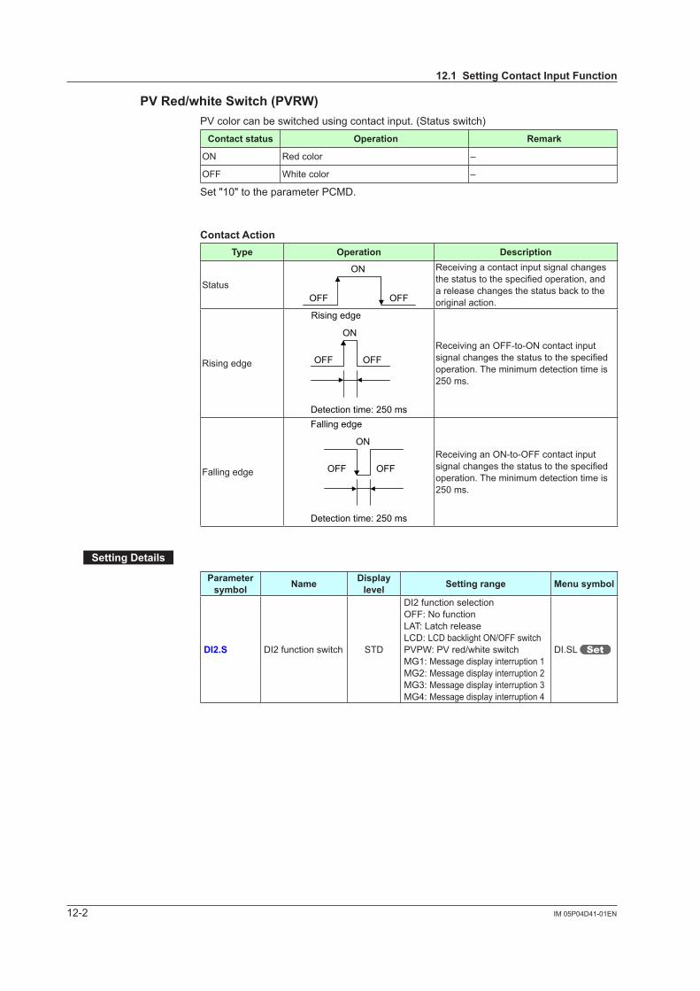
12-2 IM 05P04D41-01EN
PVRed/whiteSwitch(PVRW)PVcolorcanbeswitchedusingcontactinput.(Statusswitch)
Contact status Operation Remark
ON Red color –
OFF White color –
Set "10" to the parameter PCMD.
Contact ActionType Operation Description
Status
ON
OFFOFF
Receiving a contact input signal changes thestatustothespecifiedoperation,anda release changes the status back to the original action.
Rising edge
Rising edge
ON
OFF OFF
Detection time: 250 ms
Receiving an OFF-to-ON contact input signalchangesthestatustothespecifiedoperation. The minimum detection time is 250 ms.
Falling edge
Detection time: 250 ms
Falling edge
ON
OFFOFFReceiving an ON-to-OFF contact input signalchangesthestatustothespecifiedoperation. The minimum detection time is 250 ms.
SettingDetails
Parameter symbol Name Display
level Settingrange Menu symbol
DI2.S DI2 function switch STD
DI2 function selectionOFF: No functionLAT: Latch releaseLCD: LCD backlight ON/OFF switchPVPW:PVred/whiteswitchMG1: Message display interruption 1MG2: Message display interruption 2MG3: Message display interruption 3MG4: Message display interruption 4
DI.SL
12.1SettingContactInputFunction
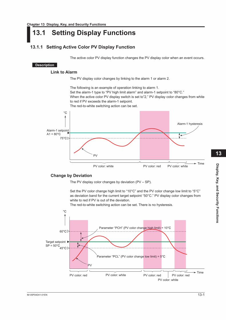
13-1IM 05P04D41-01EN
Display, K
ey, and Security Functions
13
13.1 SettingDisplayFunctions
13.1.1 SettingActiveColorPVDisplayFunction
TheactivecolorPVdisplayfunctionchangesthePVdisplaycolorwhenaneventoccurs.
Description
Link to AlarmThePVdisplaycolorchangesbylinkingtothealarm1oralarm2.
The following is an example of operation linking to alarm 1.Setthealarm-1typeto“PVhighlimitalarm”andalarm-1setpointto“80°C.”WhentheactivecolorPVdisplayswitchissetto”2,”PVdisplaycolorchangesfromwhitetoredifPVexceedsthealarm-1setpoint.The red-to-white switching action can be set.
°C
TimePV color: redPV color: white PV color: white
Alarm-1 setpointA1 = 80°C
PV
75°C
Alarm-1 hysteresis
Change by DeviationThePVdisplaycolorchangesbydeviation(PV–SP).
SetthePVcolorchangehighlimitto“10°C”andthePVcolorchangelowlimitto“5°C”asdeviationbandforthecurrenttargetsetpoint“50°C.”PVdisplaycolorchangesfromwhitetoredifPVisoutofthedeviation.The red-to-white switching action can be set. There is no hysteresis.
°C
Time
Target setpointSP = 50°C
60°C
45°C
PV
PV color: redPV color: red PV color: redPV color: white
PV color: white
Parameter “PCH” (PV color change high limit) = 10°C
Parameter “PCL” (PV color change low limit) = 5°C
Chapter 13Display,Key,andSecurityFunctions

13-2 IM 05P04D41-01EN
Link to PVThePVdisplaycolorchangesbylinkingtoPV.
SetthePVcolorchangehighlimitto“70°C”andthePVcolorchangelowlimitto“20°C.”PVdisplaycolorchangesfromwhitetoredifPVisoutoftherange.The red-to-white switching action can be set. There is no hysteresis.
Time
70°C
20°C
PV
Parameter “PCH” (PV color change high limit) = 70°C
Parameter “PCL” (PV color change low limit) = 20°C
°C
PV color: red PV color: redPV color: white PV color: white
UseinFixedColorPVdisplaycolorcanbefixedinred.Itcanalsobefixedinwhite.
PV color: red
SP color: orange(SP color cannot be changed.)
Link to DIThePVdisplaycolorchangesbylinkingtoDI(ON/OFF).
The following is an example for changing the display color by a state of DI2.SettheparameterPCMD=10,andDI2.S=PVRW.PVdisplaycolorisredwhenDI2=ON,andiswhitewhenDI2=OFF.
PVRW:PVred/whiteswitch(Menu:DI.SL)
13.1SettingDisplayFunctions

13-3IM 05P04D41-01EN
Display, K
ey, and Security Functions
13
SettingDetails
Parameter symbol Name Display
level Settingrange Menu symbol
PCMD ActivecolorPVdisplay switch EASY
0: Fixed in white1: Fixed in red2: Link to alarm 1 (Alarm OFF:
white, Alarm ON: red)3: Link to alarm 1 (Alarm OFF:
red, Alarm ON: white)4: Link to alarm 1 or 2 (Alarm
OFF: white, Alarm ON: red)5: Link to alarm 1 or 2 (Alarm
OFF: red, Alarm ON: white) 6:PVlimit(Withinrange:white,
Out of range: red)7:PVlimit(Withinrange:red,Out
of range: white)8: SP deviation (Within deviation:
white, Out of deviation: red)9: SP deviation (Within deviation:
red, Out of deviation: white)10: Link to DI2 (ON: red, OFF:
white) (*)11:LinktoEXCEEDEDlamp
(Unlit: hite, lit: red)12: Link to OUT lamp
(Unlit: white, lit: red)*: Set the parameter DI2.S =
PVRW
DISP
PCH PVcolorchangehigh limit EASY SetadisplayvaluewheninPV
limit or SP deviation.-19999 to 30000 (Set a value within the input range.)Decimal point position depends on the input type.
PCL PVcolorchangelow limit EASY
13.1SettingDisplayFunctions

13-4 IM 05P04D41-01EN
13.1.2 MaskingLeastSignificantDigitofPVDisplay
Description
WithandwithoutleastsignificantdigitofthePVintheOperationDisplaycanbeset.When without least significant digit is set, the value of the least significant digit is truncated and not displayed.The internal value is not changed depending on whether with or without least significant digit(thevalueisfordisplayonly).ThisparameterdoesnotfunctionforthePVwithoutdecimal point.
Least significant digitis displayed.
Least significant digitis not displayed.
The following shows the example of with and without least significant digitPV display
Withleastsignificantdigit Withoutleastsignificantdigit
1.4999 1.499
1.5000 1.500
1.9999 1.999
2.0000 2.000
3000.0 3000
3000.9 3000
3001.0 3001
SettingDetails
Parameter symbol Name Display
level Settingrange Menu symbol
MLSD LeastsignificantdigitalmaskofPVdisplay STD OFF:Withleastsignificantdigit
ON:Withoutleastsignificantdigit DISP
13.1SettingDisplayFunctions

13-5IM 05P04D41-01EN
Display, K
ey, and Security Functions
13
13.1.3 SettingEconomyMode
Description
The LCD backlight ON/OFF can be set in the following methods.Setting the LCD backlight to OFF saves energy.
UserFunctionKeys The LCD backlight ON/OFF switch can be assigned to the user function key. Userfunctionkey:13.2AssigningFunctiontoUserFunctionKey
Backlight OFF timer The backlight OFF timer sets the economy mode parameter to ON.
If no keys are pressed for 30 minutes, the LCD backlight goes off automatically. The backlight OFF can be set to turn off the backlight for the whole display or a displayotherthanthePVdisplay. To turn on the LCD backlight, press any key.
Contact Input The LCD backlight ON/OFF switch can be assigned to the contact input Contactinput:12.1SettingContactInputFunction
In the following cases, the LCD backlight does not go off. • When an alarm occurs. • When an error at power-on or a hardware malfunction error occurs. •WhenEXCEEDlampandOUTlampturnon.
SettingDetails
Parameter symbol Name Display
level Settingrange Menu symbol
ECO Economy mode STD
OFF: Disable1: Economy mode ON (All
indicationsexceptPVdisplayOFF)
2: Economy mode ON (All indications OFF)
3:Brightness10%(allindications)
DISP
13.1.4 SelectingtheInitialOperationDisplaythatAppearsatPowerON
Description
The initial Operation Display that appears when the power is turned on can be set.
SettingDetails
Parameter symbol Name Display
level Settingrange Menu symbol
HOME Home Operation Display setting PRO PV:PVDisplay
SP: SP Display DISP
13.1SettingDisplayFunctions

13-6 IM 05P04D41-01EN
13.1.5 SettingMessageFunction
Description
Using the message function and turning the contact input on/off, the message registered beforehandcanbedisplayedonPVdisplaybyinterrupt.The message is registered using LL50A Parameter Setting Software.The messages are limited to 20 alphanumeric characters. A maximum of four messages can be registered.If a number of messages occur simultaneously, the priority is as follows:(high) MG1>MG2>MG3>MG4 (low) Messageregistration:LL50AParameterSettingSoftwareUser’sManual Registration of contact input: 12.1.1 Setting Contact Input Function Registration symbols: 3.3 List of Display Symbols
When the contact input is turned on, the scrolling message registered beforehand is displayed on PV Display.
Operation Display
13.1SettingDisplayFunctions

13-7IM 05P04D41-01EN
Display, K
ey, and Security Functions
13.1.6 ChangingGuideScrollSpeed
Description
The scroll speed can be changed when the guide for the parameter or menu is displayed.
SettingDetails
Parameter symbol Name Display
level Settingrange Menu symbol
SPD Scroll speed PRO (Slow) 1 to 8 (Quick) DISP
13.1.7 TurningGuideDisplayON/OFF
Description
The guide display that appears when the parameter or the menu is displayed can be switched.The guide display can be turned on and off by the Fn key in the Menu Display and Parameter Setting Display.
SettingDetails
Parameter symbol Name Display
level Settingrange Menu symbol
GUID Guide display ON/OFF STD OFF: NondisplayON: Display DISP
13.1.8 SettingAutomaticReturntoOperationDisplay
Description
The Display will automatically revert to the Operation Display if no keys are pressed for 5 minutes in Menu Display or Parameter Setting Display.
SettingDetails
Parameter symbol Name Display
level Settingrange Menu symbol
OP.JP Automatic return to Operation Display PRO
ON: Automatically returned to the Operation Display.
OFF: Not automatically returned to the Operation Display.
DISP
13
13.1SettingDisplayFunctions

13-8 IM 05P04D41-01EN
13.1.9 SettingBrightnessandContrastAdjustmentofLCDandDisplayUpdateCycle
Description
Thebrightnessandcontrastcanbeadjusted.The LCD has a characteristic that the display action becomes late at the low temperature.Thiscanbesolvedbyadjustingthedisplayupdatecycle(D.CYC).
SettingDetails
Parameter symbol Name Display
level Settingrange Menu symbol
BRI Brightness EASY (Dark) 1 to 5 (Bright)
DISP
B.PVWWhite brightness adjustmentofPVdisplay
PROAdjuststhewhitebrightnessofPVdisplay.(Dark) -4 to 4 (Bright)
B.PVRRed brightness adjustmentofPVdisplay
PROAdjuststheredbrightnessofPVdisplay.(Dark) -4 to 4 (Bright)
B.SP Brightnessadjustmentof Setpoint display PRO
AdjuststhebrightnessofSPdisplay.(Dark) -4 to 4 (Bright)
B.BAR Brightnessadjustmentof Bar-graph display PRO
AdjuststhebrightnessofEXCEEDlampandOUTlamp.(Dark) -4 to 4 (Bright)
B.STS Brightnessadjustmentof Status indicator PRO
AdjuststhebrightnessofStatus indicator.(Dark) -4 to 4 (Bright)
D.CYC Display update cycle PRO
1: 100 ms2: 200 ms3: 500 ms4: 1 s5: 2 s
13.1SettingDisplayFunctions

13-9IM 05P04D41-01EN
Display, K
ey, and Security Functions
13.2 AssigningFunctiontoUserFunctionKey
Description
The UT35A-L has three user function keys on the front panel.Variousfunctionscanbeassignedtotheuserfunctionkey.Presstheuserfunctionkeyto perform the assigned function.The User function key is available only on the Operation Display.The assigned function does not work on the Parameter Setting Display. However, the Fn key can be used to turn on/off the guide display.
User function keys
SettingDetails
Parameter symbol Name Display
level Settingrange Menu symbol
F1 to Fn User function key action setting EASY See the table below KEY
Setpoint Function Action Availability (Note 1)F1 F2 Fn
OFF Unassigned – √ √ √
LTUP LCD brightness UP The current brightness gradually increases every time the function key is pressed. √ √ √
LTDN LCD brightness DOWN The current brightness gradually decreases every time the function key is pressed. √ √ √
BRI AdjustLCDbrightness
The current brightness gradually increases every time the function key is pressed.Pressing the function key after reaching the maximum brightness changes to the minimum brightness.Thereafter,minimumbrightness→maximumbrightness→maximumbrightnessisrepeated.
√ √ √
LCD LCD Backlight ON/OFF switch The LCD backlight turns on and off every time the user function key is pressed. √ √ √
LAT Latch release Latch 1 to latch 3 are released every time the user function key is pressed. √ √ √
Note1: √indicatesavailable,–indicatesunavailable,and√√indicatesinitialvalue.
StatusofuserfunctionkeyThe status of the user function key can be identified by communication.“1” can be read while the user function key is held down, and “0” can be read when the user function key is released. (Initial value: 0) Readingviacommunication:UTAdvancedSeriesCommunicationInterfaceUser’sManual
FnkeyoperationintheParameterSettingDisplayIntheMenuDisplayandParameterSettingDisplay,theguideisdisplayedonPVdisplay.Atthistime,usetheFnkeytoturnonandofftheguidedisplayonPVdisplay.Ameasuredinputvalue(PV)isdisplayedintheONstate.
13
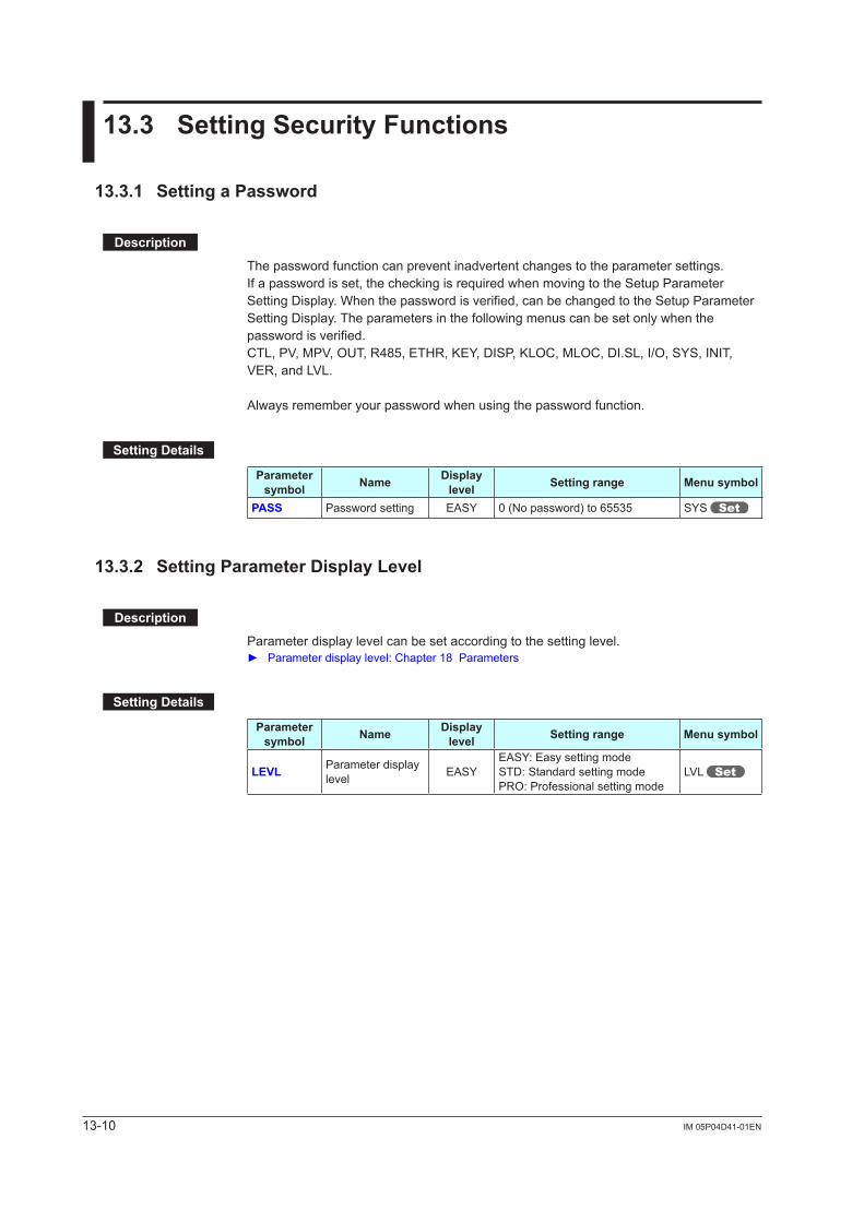
13-10 IM 05P04D41-01EN
13.3 SettingSecurityFunctions
13.3.1 SettingaPassword
Description
The password function can prevent inadvertent changes to the parameter settings.If a password is set, the checking is required when moving to the Setup Parameter Setting Display. When the password is verified, can be changed to the Setup Parameter Setting Display. The parameters in the following menus can be set only when the password is verified.CTL,PV,MPV,OUT,R485,ETHR,KEY,DISP,KLOC,MLOC,DI.SL,I/O,SYS,INIT,VER,andLVL.
Always remember your password when using the password function.
SettingDetails
Parameter symbol Name Display
level Settingrange Menu symbol
PASS Password setting EASY 0 (No password) to 65535 SYS
13.3.2 SettingParameterDisplayLevel
Description
Parameter display level can be set according to the setting level. Parameterdisplaylevel:Chapter18Parameters
SettingDetails
Parameter symbol Name Display
level Settingrange Menu symbol
LEVL Parameter display level EASY
EASY: Easy setting modeSTD: Standard setting modePRO: Professional setting mode
LVL

13-11IM 05P04D41-01EN
Display, K
ey, and Security Functions
13.3.3 Locking (Hiding) Parameter Menu Display
Description
The parameter menu display lock function hides the following Parameter Menu Displays.
SettingDetails
Parameter symbol Name Display
level Settingrange Menu symbol
CTL [CTL] menu lock PRO
OFF: DisplayON: Nondisplay MLOC
PV [PV]menulock PRO
MPV [MPV]menulock PRO
OUT [OUT] menu lock PRO
R485 [R485] menu lock PRO
ETHR [ETHR] menu lock PRO
KEY [KEY] menu lock PRO
DISP [DISP] menu lock PRO
KLOC [KLOC] menu lock PRO
DI.SL [DI.SL] menu lock PRO
I/O [I/O] menu lock PRO
SYS [SYS] menu lock PRO
INIT [INIT] menu lock PRO
VER [VER]menulock PRO
LVL [LVL]menulock PRO
SP [SP] menu lock PRO
SPS [SPS] menu lock PRO
ALRM [ALRM] menu lock PRO
PVS [PVS]menulock PRO
13
13.3SettingSecurityFunctions

13-12 IM 05P04D41-01EN
13.3.4 KeyLock
Description
The key lock function locks the key on the front panel to prohibit key operation.It can prohibit the operation mode switch or parameter setting change.
SettingDetails
Parameter symbol Name Display
level Settingrange Menu symbol
DATA Front panel parameter data key lock STD OFF: Unlock
ON: Lock KLOCK
13.3.5 Prohibiting Writing via Communication
Description
Writing data to each register via all communication methods can be permitted or prohibited. However, writing data via light-loader (front) or maintenance port (upper) is possible using LL50A Parameter Setting Software.
SettingDetails
Parameter symbol Name Display
level Settingrange Menu symbol
COM.W Communication write enable/disable STD OFF: Enable
ON: Disable KLOC
Displayed only in cases where the communication is specified.
13.3SettingSecurityFunctions

13-13IM 05P04D41-01EN
Display, K
ey, and Security Functions
13.4 ConfirmationofKeyandI/OConditionandVersion
13.4.1 ConfirmationofKeyandI/OCondition
Description
Can be confirm the Key and I/O condition.
SettingDetails
Parameter symbol Name Display
level Settingrange Menu symbol
KEY Key status PRO
Read only. I/O X000 DI1-DI2 status (equipped as standard) PRO
Y000 AL1-AL3 status (equipped as standard) PRO
Key confirmation parameters are displayed in hexadecimal.When the error occurs, "1" is set on the bit of corresponding error , and the bit data is displayed in hexadecimal.
Data display
1st digit (hexadecimal)
2nd digit (hexadecimal)3rd digit (hexadecimal)
4th digit (hexadecimal)
Symbol display
13

13-14 IM 05P04D41-01EN
ParameterKEYDisplayed digit bit Description
1st digit
0 PARAMETER (or PARA) key (0: OFF, 1: ON)1 DISPLAY (or DISP) key (0: OFF, 1: ON)2 RIGHT arrow key (0: OFF, 1: ON)3 DOWN arrow key (0: OFF 1: ON)
2nd digit
4 SET/ENTER key (0: OFF, 1: ON)5 UP arrow key (0: OFF, 1: ON)6 LEFT arrow key (0: OFF, 1: ON)7 F2 key (0: OFF, 1: ON)
3rd digit
8 F1 key (0: OFF, 1: ON)9 RST key (0: OFF, 1: ON)10 Fn key (0: OFF, 1: ON)11 –
4th digit
12 –13 –14 –15 –
ParameterX000Displayed digit bit Description
1st digit
0 DI1 status (0: OFF, 1: ON)1 DI2 status (0: OFF, 1: ON)2 –3 –
2nd digit
4 –5 –6 –7 –
3rd digit
8 –9 –10 –11 –
4th digit
12 –13 –14 –15 –
ParameterY000Displayed digit bit Description
1st digit
0 AL1 status (0: OFF, 1: ON)1 AL2 status (0: OFF, 1: ON)2 AL3 status (0: OFF, 1: ON)3 –
2nd digit
4 –5 –6 –7 –
3rd digit
8 –9 –10 –11 –
4th digit
12 –13 –14 –15 –
13.4ConfirmationofKeyandI/OConditionandVersion

13-15IM 05P04D41-01EN
Display, K
ey, and Security Functions
13.4.2 ConfirmationofVersion
Description
Can be confirm the version of the controller.
SettingDetails
Parameter symbol Name Display
level Settingrange Menu symbol
MCU MCU version EASY
Read only. VER
DCU DCU version EASY
ECU3 ECU-3 version EASY
PARA Parameter version EASY
H.VER Product version EASY
SER1 Serial number 1 EASY
SER2 Serial number 2 EASY
MAC1 MAC address 1 EASY
MAC2 MAC address 2 EASY
MAC3 MAC address 3 EASY
13
13.4ConfirmationofKeyandI/OConditionandVersion

Blank Page

14-1IM 05P04D41-01EN
Parameter Initialization
14
14.1 InitializingParameterSettingstoFactoryDefaultValues
Description
Parameter settings can be initialized to the factory default values.Use the key or LL50A Parameter Setting Software to execute it.
NoteThe user setting values (defaults) are not initialized even if the parameter setting values are initialized to the factory default values.
SettingDetails
Parameter symbol Name Display
level Settingrange Menu symbol
F.DEF Initialization to factory default value PRO
-12345: Initialization, automatically returned to "0" after initialization.
INIT
Chapter 14 Parameter Initialization

14-2 IM 05P04D41-01EN
14.2 RegisteringandInitializingUserDefaultValues
14.2.1 RegisteringasUserSetting(Default)Values
Description
The user default values can be registered as parameter default values.Use the LL50A Parameter Setting Software to register user setting (default) values.
CAUTIONBefore registering the user default value, make sure that the user setting value is set to the parameter.
14.2.2 InitializingtoUserSetting(Default)Values
Description
Parameter settings can be initialized to the user setting (default) values.Use the LL50A Parameter Setting Software to execute it.
SettingDetails
Parameter symbol Name Display
level Settingrange Menu symbol
U.DEF Initialization to user default value PRO
12345: Initialization, automatically returned to "0" after initialization.
INIT

15-1IM 05P04D41-01EN
Power Failure Recovery Processing / Setting Power Frequency / Other Settings
15
15.1 RemediesifPowerFailureOccursduringOperations
Description
All functions of the controller cannot be operated for about 10 seconds after recovery. However, the case of instantaneous power failure is excepted.
• 100–240VAC:Instantaneouspowerfailureof20msorless• 24VAC/DC:Instantaneouspowerfailureof1msA power failure is not detected. Normal operation continues.
The following shows effects caused in “settings” and “operation status.”
Alarm action Does not continue. Alarm with stand-by function will enter stand-by status.Alarm latch will be initialized.
Setting parameter Set contents of each parameter are retained.
SettingDetails
Parameter symbol Name Display
level Settingrange Menu symbol
R.MD Restart mode EASY
0: Limit output relay is de-energized at power on.
1: Limit output relay is energized at power on.
SYS
Chapter 15PowerFailureRecoveryProcessing/PowerFrequencySetting/OtherSettings

15-2 IM 05P04D41-01EN
15.2 PowerFrequencySetting
Description
The power frequency can be set by automatic detection or manually.However, when the /DC option is specified, only manual setting is available. Set the range to the commercial frequency of the installation location.
SettingDetails
Parameter symbol Name Display
level Settingrange Menu symbol
FREQ Power frequency EASYAUTO60: 60 Hz50: 50 Hz
SYS

16-1IM 05P04D41-01EN
Troubleshooting, Maintenance, and Inspections
16
16.1 Troubleshooting
16.1.1 TroubleshootingFlowchart
If the Operation Display does not appear after turning on the controller’s power, follow the measures in the procedure below.If a problem appears complicated, contact our sales representative.
Is the controllerdefective?
Contact us for repair. Problem solved.
No communicationcapability
Completelyinactive?
Yes
Yes
Yes
No
No
No
Keyoperationfailure?
Yes
No
Yes
Check wiring on thepower terminals.
Check the key locksetting.
Displayfailure?
*Yes
No
Turn off power, andthen turn it on again.
I/O signalfailure?
Yes
No
Check the I/O specificationsof the controller.
Check the supply voltage.
Check thespecifications and polarity
of connected devices.
Check the communication-related parameters.
Check the specificationsof communication
devices.
Check the communication wiring.
Communicationfailure?
No Withcommuni-
cation?
Yes
Normal?Is the
key locked?
Check the specifications of the controller.
Yes
NoCorrect?
Correct the error(s).
Cancel the setting.
*: The LCD (a liquid crystal display) is used for a display portion of this product. The LCD has a characteristic that the display action becomes late at the low temperature. Additionally, the luminance and contrast degradation are caused due to aged deterioration. However, the control function is not affected.
Chapter 16Troubleshooting,Maintenance,andInspections

16-2IM
05P04D
41-01EN
16.1.2 ErrorsatPowerOn
The errors shown below may occur in the fault diagnosis when the power is turned on.PV display (Operation
Display)
Setpintdisplay(Operation Display)
Statusindicator(Operation Display)
Parameter that displays error details
Errordescription Cause and diagnosis Remedy
Indication off Indication off – – Faulty MCU RAM / MCU ROM MCU RAM / MCU ROM are failed. Faulty.Contact us for repair.
ERR
SYS -----
–
– System data error System data is corrupted. Faulty.Contact us for repair.
PAR 0004(for user default value error only) Setup
parameter (PA.ER)
User (parameter) default value error
User parameter is corrupted.Initialized to factory default value. Checkandreconfiguretheinitialized
parameters.Error indication is erased when the power is turned on again.
PAR 0010 (for setup parameter error only) Setup parameter error Setup parameter data is corrupted.
Initialized to factory default value.PAR 0020 (for operation parameter error only) Operation parameter error Operation parameter data is corrupted.
Initialized to user default value.
SLOT 0004 (0004: Error occurs to all hardware of E3-terminal areas.)
Setup parameter (OP.ER)
Non responding hardware of extended function (E3-terminal areas)
Inconsistence of system data and hardware of extended function.Non responding communication between hardware of extended function (E3-terminal areas).
Faulty.Contact us for repair.
Normal indication Normal indication
Rightmost decimal pointonPVdisplay blinks. Setup
parameter (PA.ER)
Calibration value error Initialized to calibrated default value because of corrupted factory default value.
Faulty.Contact us for repair.Right most
decimal point on Symbol display blinks.
Faulty FRAM Writing (storing) data to FRAM is impossible.
16.1 Troubleshooting

16-3IM
05P04D
41-01EN
Troubleshooting, Maintenance, and Inspections 16
16.1.3 ErrorsduringOperation
The errors shown below may occur during operation.
PV display (Operation
Display)
Setpointdisplay
(Operation Display)
Statusindicator(Operation
Display)
Parameter that displays error details Errordescription Cause and diagnosis Remedy
AD.ERRNormal indication (Note)
– Setup parameter (AD1.E)
Analog input terminal ADC error•PVinput Analog input terminal AD value error Faulty
Contact us for repair.
RJC.E (Displays RJC.E andPValternately.)
Normal indication(Note)
– Setup parameter (AD1.E)
Universal input terminal RJC error•PVinput Universal input terminal RJC error
FaultyContact us for repair.Set the parameter RJC to OFF to erase error indication.
B.OUTNormal indication(Note)
–
Setup parameter (AD1.E)
Analog input terminal burnout error•PVinput
Analog input terminal sensor burnoutCheck wiring and sensor.Error indication is erased in normal operation.
Setup parameter (PV1.E) PVinputburnouterror) BurnoutofanaloginputconnectedtoPV
Check wiring and sensor of connected analog input terminal.Error indication is erased in normal operation.
OVER-OVER
Normal indication – Setup parameter
(PV1.E)
PVinputover-scalePVinputunder-scale(PVvaluesoutof-5to105%)
PVinputisoutof-5to105%. Check analog input value.
Normal indication
0.000 00000(Decimal point on the left of the Symbol display blinks)
– Setup parameter (OP.ER)
Communication error (RS-485 communication)
Framing parity errorBufferoverflowInter-character time-outChecksum error (PC link communication with checksum)CRC check error (Modbus/RTU)LRC check error (Modbus/ASCII)
Check the communication parameters.Recovery at normal receipt.Hold down any key to stop blinking.
Undefined Undefined – – Faulty MCU MCU is corrupted. Faulty Contact us for repair.
Undefined Undefined – – Faulty DCU (ROM/RAM error, corrupted) DCU is corrupted. Faulty
Contact us for repair.Note: When an error occurs in input shown in Analog input display (Operation display). SetpointdisplayshowsthesamesymbolasthePVdisplay.
16.1 Troubleshooting
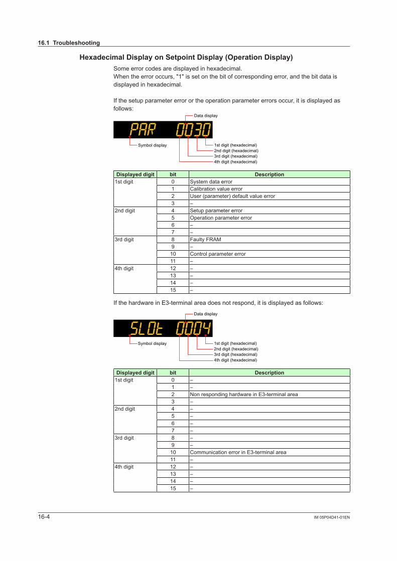
16-4 IM 05P04D41-01EN
HexadecimalDisplayonSetpointDisplay(OperationDisplay)Some error codes are displayed in hexadecimal.When the error occurs, "1" is set on the bit of corresponding error, and the bit data is displayed in hexadecimal.
If the setup parameter error or the operation parameter errors occur, it is displayed as follows:
Data display
1st digit (hexadecimal)2nd digit (hexadecimal)3rd digit (hexadecimal)4th digit (hexadecimal)
Symbol display
Displayed digit bit Description1st digit 0 System data error
1 Calibration value error2 User (parameter) default value error3 –
2nd digit 4 Setup parameter error5 Operation parameter error6 –7 –
3rd digit 8 Faulty FRAM9 –10 Control parameter error11 –
4th digit 12 –13 –14 –15 –
If the hardware in E3-terminal area does not respond, it is displayed as follows:
Data display
1st digit (hexadecimal)2nd digit (hexadecimal)3rd digit (hexadecimal)4th digit (hexadecimal)
Symbol display
Displayed digit bit Description1st digit 0 –
1 –2 Non responding hardware in E3-terminal area3 –
2nd digit 4 –5 –6 –7 –
3rd digit 8 –9 –10 Communication error in E3-terminal area11 –
4th digit 12 –13 –14 –15 –
16.1 Troubleshooting

16-5IM 05P04D41-01EN
Troubleshooting, Maintenance, and Inspections
16
HexadecimalDisplayoftheParameterwhichShowstheErrorDetailsError confirmation parameters are displayed in hexadecimal.When the error occurs, "1" is set on the bit of corresponding error.
Data display
1st digit (hexadecimal)
2nd digit (hexadecimal)3rd digit (hexadecimal)
4th digit (hexadecimal)
Symbol display
ParameterPA.ERDisplayed digit bit Description
1st digit 0 System data error1 Calibration value error2 User (parameter) default value error3 –
2nd digit 4 Setup parameter error5 Operation parameter error6 –7 –
3rd digit 8 Faulty FRAM9 –10 Control parameter error11 –
4th digit 12 –13 –14 –15 –
ParameterOP.ERDisplayed digit bit Description
1st digit 0 –1 –2 Non responding hardware in E3-terminal area3 –
2nd digit 4 –5 –6 –7 –
3rd digit 8 –9 –10 Communication error in E3-terminal area11 –
4th digit 12 –13 –14 –15 –
16.1 Troubleshooting

16-6 IM 05P04D41-01EN
ParameterAD1.EDisplayed digit bit Description
1st digit 0 ADCerrorofPVinput1 –2 –3 –
2nd digit 4 –5 RJCerrorofPVinput6 –7 –
3rd digit 8 PVinputburnouterror9 –10 –11 –
4th digit 12 –13 –14 –15 –
ParameterPV1.EDisplayed digit bit Description
1st digit 0 PVinputburnouterror1 –2 –3 –
2nd digit 4 PVinputover-scale5 PVinputunder-scale6 –7 –
3rd digit 8 –9 –10 –11 –
4th digit 12 –13 –14 –15 –
16.1 Troubleshooting

16-7IM 05P04D41-01EN
Troubleshooting, Maintenance, and Inspections
16
16.2 Maintenance
16.2.1 CleaningThe front panel and operation keys should be gently wiped with a cloth soaked with water and squeezed firmly.
CAUTIONIn order to prevent LCD from static electricity damage, do not wipe with dry cloth. (When LCD is electrified, it returns to normal in several minutes.) Do not use alcohol, benzene, or any other solvents.
16.2.2 PackagingwhenShippingtheProductforRepairShould the instrument break down and need to be shipped to our sales representative for repair, handle it as noted below:
CAUTIONWrite down the settings of parameters for a repair request.
WARNINGPrior to shipping the instrument, put it into an antistatic bag and repackage it using the original internal packaging materials and packaging container.
16.2.3 Replacing PartsDo not replace any parts inside the unit.

16-8 IM 05P04D41-01EN
16.3 Periodic Maintenance
Check the operating condition periodically to use this instrument with good condition.

16-9IM 05P04D41-01EN
Troubleshooting, Maintenance, and Inspections
16
16.4 Disposal
When disposing of this instrument, arrange for appropriate disposal as industrial waste according to the rules of a country, the area, or a local government.

Blank Page

17-1IM 05P04D41-01EN
Installation and Wiring
17
17.1 Installation Location
The instrument should be installed in indoor locations meeting the following conditions:• Instrumented panel This instrument is designed to be mounted in an instrumented panel. Mount the
instrument in a location where its terminals will not inadvertently be touched.• Well ventilated locations Mount the instrument in well ventilated locations to prevent the instrument’s internal
temperature from rising. However, make sure that the terminal portions are not exposed to wind. Exposure to wind may cause the temperature sensor accuracy to deteriorate. To mount multiple indicating controllers, see the external dimensions/panelcutoutdimensionswhichfollow.Ifmountingotherinstrumentsadjacenttotheinstrument, comply with these panel cutout dimensions to provide sufficient clearance between the instruments.
• Locations with little mechanical vibration Installtheinstrumentinalocationsubjecttolittlemechanicalvibration.• Horizontal location Mount the instrument horizontally and ensure that it is level, with no inclination to the
right or left.
Front panelof controller
Keep this anglewithin 30°
Rear ofcontroller
30°
NoteIf the instrument is moved from a location with low temperature and low humidity to a place with high temperature and high humidity, or if the temperature changes rapidly, condensation will result. Moreover, in the case of thermocouple inputs, measurement errors will result. To avoid such a situation, leave the instrument in the new environment under ambient conditions for more than 1 hour prior to using it.
Chapter 17 Installation and Wiring

17-2 IM 05P04D41-01EN
Do not mount the instrument in the following locations:• Outdoors• Locationssubjecttodirectsunlight,ultraredrays,ultravioletrays,orclosetoaheater Install the instrument in a location with stable temperatures that remain close to an
averagetemperatureof23°C.Donotmountitinlocationssubjecttodirectsunlightorclose to a heater. Doing so adversely affects the instrument and LCD.
• Locations with substantial amounts of oily fumes, steam, moisture, dust, or corrosive gases
The presence of oily fumes, steam, moisture, dust, or corrosive gases adversely affectstheinstrument.Donotmounttheinstrumentinlocationssubjecttoanyofthese substances.
• Areas near electromagnetic field generating sources Do not place magnets or tools that generate magnetism near the instrument. If the
instrument is used in locations close to a strong electromagnetic field generating source, the magnetic field may cause measurement errors.
• Locations where the display is difficult to see The instrument uses an LCD for the display unit, and this can be difficult to see from
extremely oblique angles. Mount the instrument in a location where it can be seen as much as possible from the front.
• Areas close to flammable articles Absolutely do not place the instrument directly on flammable surfaces. If such a
circumstance is unavoidable and the instrument must be placed close to a flammable item, provide a shield for it made of 1.43 mm thick plated steel or 1.6 mm thick unplated steel with a space of at least 150 mm between it and the instrument on the top, bottom and sides.
150 mm150 mm
150 mm
150 mm
• Areassubjecttobeingsplashedwithwater
17.1 Installation Location

17-3IM 05P04D41-01EN
Installation and Wiring
17
17.2 Mounting Method
WARNINGBe sure to turn OFF the power supply to the controller before installing it on the panel to avoid an electric shock.
Mounting the Instrument Main UnitProvide an instrumented panel steel sheet of 1 to 10 mm thickness.
After opening the mounting hole on the panel, follow the procedures below to install the controller:1. Insert the controller into the opening from the front of the panel so that the terminal
board on the rear is at the far side.2. Set the brackets in place on the top and bottom of the controller as shown in the
figure below, then tighten the screws of the brackets. Take care not to overtighten them.
Bracket(top mounting hardware)
Terminal board
Bracket(bottom mounting hardware)
Panel
Insert a screwdriver into thebrackets to tighten the screws.
Direction to insert thecontroller
Appropriatetightening torque:0.25 N•m
Insert the controllerinto the opening atthe front of the panel.
To uninstall the controller, perform the procedure in the reverse order.
CAUTION1) Tighten the screws with appropriate tightening torque within 0.25 N•m. Otherwise
it may cause the case deformation or the bracket damage.2) Make sure that foreign materials do not enter the inside of the instrument
through the case's slit holes.

17-4 IM 05P04D41-01EN
17.3 ExternalDimensionsandPanelCutoutDimensions
Unit: mm(approx. inch)
Normal tolerance: ±(value of JIS B 0401-1998 tolerance class IT18)/2(25)
(0.98)
(53) (2.09)
[(N–1)×96+92] +0.80
+0.8092
+0.8092
+0.8092
+0.030(3.62 )
+0.030(3.62 )
+0.030(3.62 )
+0.030([(N-1)×3.78+3.62] )
65 (2.56)20 (0.79)
11(0.43)
UT35A-L
94.6
(3.7
2)91
.6 (3
.61)
105.
2 (4
.14)
96 (3.78)
96 (3
.78)
Bracket
Bracket
Terminal cover
1 to 10 mm (0.04 to 0.39 inch) (panel thickness)General mounting Side-by-side close mounting
“N” stands for the number of controllers to be installed.However, the measured value applies if N≥5.
117 (4.61) min.
145 min.(5.71)

17-5IM 05P04D41-01EN
Installation and Wiring
17
17.4 Wiring
17.4.1 ImportantInformationonWiring
WARNING1) Be sure to turn OFF the power supply to the controller before wiring to avoid an
electric shock. Use a tester or similar device to ensure that no power is being supplied to a cable to be connected.
2) Wiring work must be carried out by a person with basic electrical knowledge and practical experience.
3)Forthewiringcable,thetemperatureratingis75°Cormore.
E3-terminal area
UT35A-L Terminal Block Diagram
101
102
103
104
105
106
107
108
109
110
111
112
407
401
408
409
410
411
412
201
202
203
204
205
206
207
208
210
211
212
101-112
401-412
201-212
Wiring direction Do not use.
CAUTION Whenconnectingtwoormorecrimp-onterminallugstothesingleterminal
block, bend the crimp-on terminal lugs before tightening the screw. Notethatthewiringoftwoormorecrimp-onterminallugstothesinglehigh-
voltage terminal of the power supply and relay, etc. does not comply with the safety standard.

17-6 IM 05P04D41-01EN
CAUTIONDo not use an unassigned terminal as the relay terminal.
Recommended Crimp-on Terminal Lugs
(A)
(F)
(ød)
Recommended tightening torque: 0.6 N·mApplicable wire size: Power supply wiring 1.25 mm2 or more
Applicable terminal lug Applicablewiresizemm2 (AWG#) (ød) (A) (F)
M3 0.25 to 1.65 (22 to 16) 3.3 5.5 4.2
5.5 3.3
CableSpecificationsPurpose Name and Manufacturer
Power supply, relay contact output
600VGradeheat-resistantPVCinsulatedwires,JISC3317(HIV),0.9to 2.0 mm2
Thermocouple Shielded compensating lead wire JISC1610
RTD Shielded wire (three/four conductors) UL2482 (Hitachi Cable)Other signals (other than contact input/output) Shielded wires
Other signals (contact input/output) Non shielded wires
RS485 communication Shielded wires
Ethernet communication 100BASE-TX(CAT-5)/10BASE-T
Recommended tightening torque: 0.5 to 0.6 N·m
NoteCommunication wires of cross-sectional area less than or equal to 0.34 mm2 may not be secured firmly to the terminals.Check that the wire is firmly connected to the terminal by folding the conductor of the wire connected to the climp-on lug.Recommended length of the stripped wire: 7 mm
17.4 Wiring

17-7IM 05P04D41-01EN
Installation and Wiring
17
17.4.2 PV Input Wiring
CAUTION1) Be careful of polarity when wiring inputs. Reversed polarity can damage the UT.2)KeepthePVinputsignallineasfarawayaspossiblefromthepowersupply
circuit and ground circuit.3) For TC input, use shielded compensating lead wires for wiring. For RTD input,
use shielded wires that have low conductor resistance and cause no significant differences in resistance between the three wires.
4) If there is a risk of external lightning surges, use a lightning arrester etc.
UT35A-LTC Input RTDInput(3-wiresystem)
203
202TC
–
+
Compensating lead wire
Class D grounding(grounding resistanceof 100 Ω or less)
Shield
PV
203
202
201RTD
A
B
b
Lead wire resistance per wire of10 Ω or less. Make the resistanceof the three wires equal.
A
bB
Class D grounding(grounding resistanceof 100 Ω or less)
Shield
PV
DCVoltage(mV,V)Input DC Current (mA) Input
203
202
–
++
–DC voltage
Class D grounding(grounding resistance of 100 Ω or less)
Shield
PV204
203–
++
–DC current
Class D grounding(grounding resistance of 100 Ω or less)
Shield
PV
UsePVinputisusedforPVinput.
17.4 Wiring

17-8 IM 05P04D41-01EN
17.4.3 Limit Control Output (Relay) Wiring
CAUTION1) The use of inductance (L) loads such as auxiliary relays, motors and solenoid
valves causes malfunction or relay failure; always insert a CR filter for use with alternating current or a diode for use with direct current, as a spark-removal surge suppression circuit, into the line in parallel with the load.
2) If there is a risk of external lightning surges, use a lightning arrester etc.3) Relays cannot be used for a small load of 10 mA or less.4) Since the insulation provided to each relay output terminal is Functional
insulation, provide Reinforced insulation to the external of the device as necessary. (Refer to the drawing below.)
This product
Functional insulation
A safety voltage circuit
A safety voltage circuit
This product
Reinforced insulation
Reinforced insulation
Functional insulation
A hazardous voltage circuit
A hazardous voltage circuit
A safety voltage circuit
A safety voltage circuit
This product
Reinforced insulation
Reinforced insulation
Functional insulation
A hazardous voltage circuit
A hazardous voltage circuit
A hazardous voltage circuit
A hazardous voltage circuit
DC Relay Wiring
R
External DC power supplyRelay
UT35A-L
UT’s contact
Diode(Mount it directlyto the relay coilterminal (socket).)
Relay(Use one with a relay coil rating
less than the UT’s contact rating.)
AC Relay Wiring
UT35A-L
R
CR filter(Mount it directlyto the relay coilterminal (socket).)
Relay(Use one with a relay coilrating less than the UT’s
contact rating.)
UT’s contact
External AC power supply
17.4 Wiring
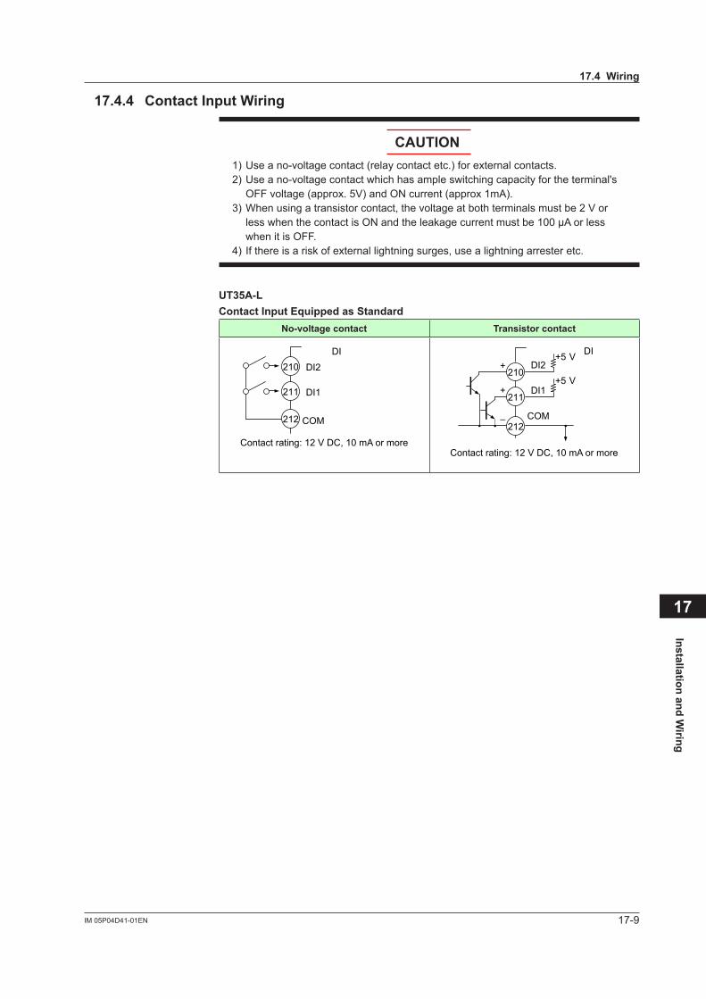
17-9IM 05P04D41-01EN
Installation and Wiring
17
17.4.4 Contact Input Wiring
CAUTION1) Use a no-voltage contact (relay contact etc.) for external contacts.2) Use a no-voltage contact which has ample switching capacity for the terminal's
OFFvoltage(approx.5V)andONcurrent(approx1mA).3)Whenusingatransistorcontact,thevoltageatbothterminalsmustbe2Vor
less when the contact is ON and the leakage current must be 100 µA or less when it is OFF.
4) If there is a risk of external lightning surges, use a lightning arrester etc.
UT35A-LContactInputEquippedasStandard
No-voltage contact Transistor contact
DI2
DI1
COM
210
211
212
DI
Contact rating: 12 V DC, 10 mA or more
DI2
DI1
COM
210
211
212
DI+
+
–
+5 V
+5 V
Contact rating: 12 V DC, 10 mA or more
17.4 Wiring

17-10 IM 05P04D41-01EN
17.4.5 Contact Output Wiring
CAUTION1) Use an auxiliary relay for load-switching if the contact rating is exceeded.2) Connect a bleeder resistor when a small current is used, so that a current
exceeding 1 mA can be supplied.3) The output relay has a limited service life. Be sure to connect a CR filter (for AC)
or diode (for DC) to the load.4) If there is a risk of external lightning surges, use a lightning arrester etc.5) Since the insulation provided to each relay output terminal is Functional
insulation, provide Reinforced insulation to the external of the device as necessary. (Refer to the drawing below.)
This product
Functional insulation
A safety voltage circuit
A safety voltage circuit
This product
Reinforced insulation
Reinforced insulation
Functional insulation
A hazardous voltage circuit
A hazardous voltage circuit
A safety voltage circuit
A safety voltage circuit
This product
Reinforced insulation
Reinforced insulation
Functional insulation
A hazardous voltage circuit
A hazardous voltage circuit
A hazardous voltage circuit
A hazardous voltage circuit
Whenusingauxiliaryrelay:17.4.3LimitControlOutput(Relay)Wiring
UT35A-LContactOutputEquippedasStandard
Relay contact
AL3
AL2
AL1
COM
COM
COM
Contact rating: 240 V AC, 1 A 30 V DC, 1 A (resistance load)
104
105
106
107
108
109
ALM
The following table shows the initial status.AL1 terminal AL2 terminal AL3 terminal
Alarm 1 (PVhighlimit)
Alarm 2 (PVlowlimit)
Alarm 3 (PVhighlimit)
17.4 Wiring

17-11IM 05P04D41-01EN
Installation and Wiring
17
17.4.6 Retransmission Output Wiring The current output range can be changed.
208
207
Class D grounding(grounding resistanceof 100 Ω or less)
RET terminalsShield
–
+
Receiver(Recorder etc.)
Receiving resistor:600 Ω or less
17.4 Wiring

17-12 IM 05P04D41-01EN
17.4.7 RS-485CommunicationInterfaceWiringWire as follows for Modbus communication, PC link communication, or ladder communication.Always connect a terminating resistor to the station at the end of the communication line. Detailsofcommunicationparametersettingsandcommunicationfunctions:UTAdvancedSeries
Communication Interface (RS-485, Ethernet) User's Manual
4-wireWiring
ML2-
SG
SDB (+)
SDA (–)
RDB (+)
RDA (–)
RDB (+)
RDA (–)
SDB (+)
SDA (–)
SG
RDB (+)
RDA (–)
SDB (+)
SDA (–)
SGRS-232CStraight cable
UT
2
1
4
3
5
6
UT
Class D grounding(grounding resistanceof 100 Ω or less)
Communicationcable
Class D grounding(grounding resistanceof 100 Ω or less)
Communicationcable
Class D grounding(grounding resistanceof 100 Ω or less)
PC (External)Terminating resistor
220 Ω 1/4 W
(External)Terminating resistor220 Ω 1/4 W
(External)Terminating resistor220 Ω 1/4 W
2-wireWiringof4-wireTerminal
SG
ML2- UT
B (+)
A (–)
SDB (+)
SDA (–)
RDB (+)
RDA (–)
SG
SDB (+)
SDA (–)
RDB (+)
RDA (–)
SG
RS-232CStraight cable
PC4
3
5
6
Class D grounding(grounding resistanceof 100 Ω or less)
UT
(External)Terminating resistor
220 Ω 1/4 W
(External)Terminating resistor220 Ω 1/4 W
Communicationcable
Class D grounding(grounding resistanceof 100 Ω or less)
Communicationcable
Class D grounding(grounding resistanceof 100 Ω or less)
UT35A-LTerminal symbol above
UT35A-L(ForStandardmodel)Suffixcode:Type
3 = “1”
RDB (+) 410
RDA (–) 411
SDB (+) 407
SDA (–) 408
SG 409
NoteML2-x indicates a converter of YOKOGAWA. Other than this, RS232C/RS485 converters can also be used. If another converter is to be used, check the electrical specifications of the converter before using it.
17.4 Wiring

17-13IM 05P04D41-01EN
Installation and Wiring
17
17.4.8 EthernetCommunicationInterfaceWiring
Ethernet
Straight cable
HUB
UT35A-L UT35A-L
Crossing cable
*Devices that can be connected via Ethernet
*Devices that can be connected via Ethernet
UT35A-L
UppersideLED(baudrate) LowersideLED(linkactivity)
Color Amber Color Green
Lit 100M bps Lit Linked
Unlit 10M bps Blink Active
Unlit Link failure
CAUTIONBesuretoconnectalightningarresterforEthernet(100BASE-TX/10BASE-T)inanenvironment where a surge voltage may be induced by a lightning discharge.
17.4 Wiring

17-14 IM 05P04D41-01EN
RS-485 communication wiring for the serial gateway function is as follows. 2-wireWiringof4-wireTerminal
Serial gateway
SG
RSB (+)
RSA (–)
SDB (+)
SDA (–)
RDB (+)
RDA (–)
SG
SDB (+)
SDA (–)
RDB (+)
RDA (–)
SG
(External)Terminating resistor
220 Ω 1/4 W
(External)Terminating resistor220 Ω 1/4 W
407
408
409
UT UT
Communicationcable
Class D grounding(grounding resistance
of 100 Ω or less)
Communicationcable
Class D grounding(grounding resistance
of 100 Ω or less)
Slaveterminals
Terminal symbol above
UT35A-L(ForStandardmodel)Suffixcode:Type
3 = “1”(ForDetailedmodel)Optionalsuffix
code: /CH3RDB (+) 410
RDA (–) 411
SDB (+) 407
SDA (–) 408
SG 409
2-wireWiring
Serial gateway
SG
RSB (+)
RSA (–)
RSB (+)
RSA (–)
SG
RSB (+)
RSA (–)
SG
(External)Terminating resistor220 Ω 1/4 W
(External)Terminating resistor
220 Ω 1/4 W
UT UT
407
408
409
Communicationcable
Class D grounding(grounding resistance
of 100 Ω or less)
Communicationcable
Class D grounding(grounding resistance
of 100 Ω or less)
17.4 Wiring

17-15IM 05P04D41-01EN
Installation and Wiring
17
17.4.9 PowerSupplyWiring
WARNING1) Wiring work must be carried out by a person with basic electrical knowledge and
practical experience.2) Be sure to turn OFF the power supply to the controller before wiring to avoid an
electric shock. Use a tester or similar device to ensure that no power is being supplied to a cable to be connected.
3) As a safety measure, always install a circuit breaker (an IEC 60947-compatible product,5A,100Vor220VAC)inaneasilyaccessiblelocationneartheinstrument. Moreover, provide indication that the switch is a device for turning off the power to the instrument.
4) Install the power cable keeping a distance of more than 1 cm from other signal wires.
5) The power cable is required to meet the IEC standards concerned or the requirements of the area in which the instrument is being installed.
6) Wiring should be installed to conform to NEC (National Electrical Code: ANSI/NFPA-70) or the wiring construction standards in countries or regions where wiring will be installed.
CAUTION1) Provide electricity from a single-phase power supply. If the power is noisy,
install an isolation transformer on the primary side, and use a line filter on the secondary side. When measures against noise are taken, do not install the primary and secondary power cables close to each other.
2) If there is a risk of external lightning surges, use a lightning arrester etc.
111
110
L
N
CircuitbreakerLine filter
Insulation transformer
Primary side Secondary side
Controllerpower
112
Class D grounding
G
17.4 Wiring

17-16 IM 05P04D41-01EN
17.5 Attaching and Detaching Terminal Cover
After completing the wiring, the terminal cover is recommended to use for the instrument.
Attaching Method
(2) The following figure is a mounting image.(1) Attach the terminal cover to the rear panel of the main unit horizontally.
When Ethernet communication is specified, cut and use a terminal cover as follows.Cut the cover carefully using nippers etc. so that sharp edge does not remain.
Detaching Method(1) Slide the terminal cover to the direction of the printed arrow.
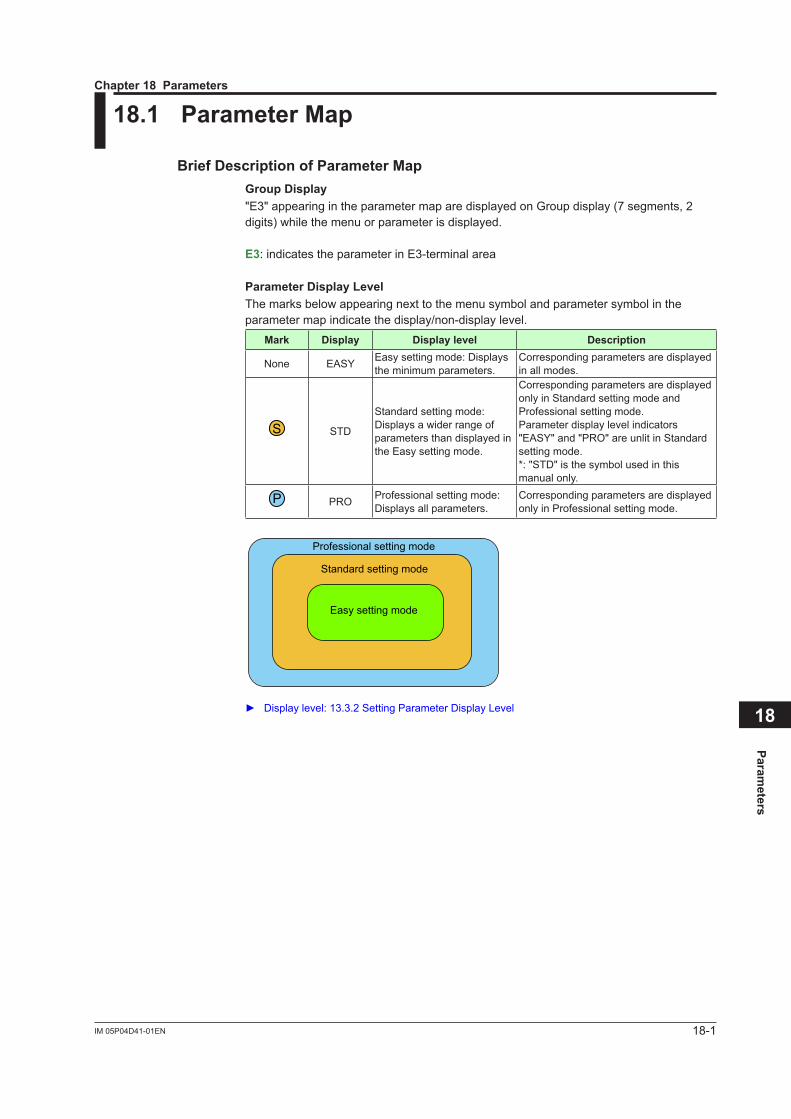
18-1IM 05P04D41-01EN
Parameters
18
18.1 Parameter Map
BriefDescriptionofParameterMapGroupDisplay"E3" appearing in the parameter map are displayed on Group display (7 segments, 2 digits) while the menu or parameter is displayed.
E3: indicates the parameter in E3-terminal area
Parameter Display LevelThe marks below appearing next to the menu symbol and parameter symbol in the parameter map indicate the display/non-display level.
Mark Display Display level Description
None EASY Easy setting mode: Displays the minimum parameters.
Corresponding parameters are displayed in all modes.
S STD
Standard setting mode: Displays a wider range of parameters than displayed in the Easy setting mode.
Corresponding parameters are displayed only in Standard setting mode and Professional setting mode.Parameter display level indicators "EASY" and "PRO" are unlit in Standard setting mode.*: "STD" is the symbol used in this manual only.
P PRO Professional setting mode: Displays all parameters.
Corresponding parameters are displayed only in Professional setting mode.
Professional setting mode
Standard setting mode
Easy setting mode
Displaylevel:13.3.2SettingParameterDisplayLevel
Chapter 18 Parameters

18-2 IM 05P04D41-01EN
FunctionofEachMenu
The parameters in the menu of the following table indicate the parameters to set the functions necessary for operation.
Menu symbol Function
SP SP and alarm setpoint
SPS SP-related function
ALRM Alarm function
PVS PV-relatedfunction
The parameters in the menu of the following table indicate the parameters to set the basic functions of the controller. The symbol in parentheses are shown on Group display.
Menu symbol Functions
PASS Password setting (Displayed only when the password has been sent.)
Menu symbol Functions
CTL Limitcontroltype,thewayofconfirmingoperation
PV PVinputtype,range,scale,etc
MPV Input range, SP limiters
OUT Retransmission output
R485(E3) RS-485 communication (E3-terminal area)
ETHR(E3) Ethernet communication, gateway setting, IP access restriction, etc. (E3-terminal area)
KEY Function of User function key
DISP Display functions
KLOC Key lock
MLOC Parameter menu lock
DI.SL Contact input function
I/O Input / output data display
SYS Action setting when recovering from a power failure, password setting, etc
INIT Initialization of parameter
VER Error status, version, MAC address, etc
LVL Parameter display level
NoteSome parameters are not displayed according to the setting such as input and output.
18.1 Parameter Map

18-3IM 05P04D41-01EN
Parameters
18
SP
A1
A2
A3
END
TMU
END
AL1AL2AL3VT1VT2VT3HY1HY2HY3
DYN1DYN2DYN3DYF1DYF2DYF3END
SP
BS
FL
HYS
END
PVSSPS ALRM ENDEND
PPP
SSS
Operation display
Setting parameters for the functions necessary for operations.
Press the keyfor 3 seconds.
18.1 Parameter Map

18-4 IM 05P04D41-01EN
IN
UNIT
RH
RL
SDP
SH
SL
BSL
RJC
ERJC
A.BS
A.FL
END
HI.LO
CNF
END
HSRBPSPRIIP1IP2IP3IP4
SM1SM2SM3SM4DG1DG2DG3DG4PRTIPAR1.IP11.IP21.IP31.IP42.IP12.IP22.IP32.IP4ESWEND
PSL
BPS
PRI
STP
DLN
ADR
RP.T
END
RTSRTHRTL
RET.AEND
F1
F2
Fn
END
PA.EROP.ERAD1.EPV1.EMCUDCU
ECU3(E3)PARAH.VERSER1SER2
MAC1(E3)MAC2(E3)MAC3(E3)
END
U.DEFF.DEFEND
E3 E3PVCTLPASS ETHRR485OUT KEY
VERINIT
LEVL
LVL END
P
PP
P
P
P
S
S
SS
SS
S
S
P.UNI
P.DP
P.RH
P.RL
SPH
SPL
END
MPV S
+
END
PASS
Displayedwhen
a passwordhas been set.
Setting parameters for the basic functions of the controller
Press the keys for 3 seconds.
Operation display
SALL
DI2.S
END
CTLPV
MPVOUT
R485(E3)ETHR(E3)
KEYDISPKLOCDI.SL
I/OSYSINITVERLVLSP
SPSALRMPVSEND
COM.W
DATA
END
PCMDPCHPCLSPDGUIDHOMEECOBRI
B.PVWB.PVRB.SP
B.BARB.STSD.CYCOP.JPMLSDEND
R.MD
C.GRN
FREQ
QSM
PASS
SMEC
END
KEY
X000
Y000
END
DI.SLMLOCKLOCDISP SYSI/O
P
P
PPPPPP
P
P
S
P
P
P
S
S
S
S
S
S
SS
PALL PALL
PALL
E3: indicates the parameter in E3-terminal area
18.1 Parameter Map

18-5IM 05P04D41-01EN
Parameters
18
IN
UNIT
RH
RL
SDP
SH
SL
BSL
RJC
ERJC
A.BS
A.FL
END
HI.LO
CNF
END
HSRBPSPRIIP1IP2IP3IP4
SM1SM2SM3SM4DG1DG2DG3DG4PRTIPAR1.IP11.IP21.IP31.IP42.IP12.IP22.IP32.IP4ESWEND
PSL
BPS
PRI
STP
DLN
ADR
RP.T
END
RTSRTHRTL
RET.AEND
F1
F2
Fn
END
PA.EROP.ERAD1.EPV1.EMCUDCU
ECU3(E3)PARAH.VERSER1SER2
MAC1(E3)MAC2(E3)MAC3(E3)
END
U.DEFF.DEFEND
E3 E3PVCTLPASS ETHRR485OUT KEY
VERINIT
LEVL
LVL END
P
PP
P
P
P
S
S
SS
SS
S
S
P.UNI
P.DP
P.RH
P.RL
SPH
SPL
END
MPV S
+
END
PASS
Displayedwhen
a passwordhas been set.
Setting parameters for the basic functions of the controller
Press the keys for 3 seconds.
Operation display
SALL
DI2.S
END
CTLPV
MPVOUT
R485(E3)ETHR(E3)
KEYDISPKLOCDI.SL
I/OSYSINITVERLVLSP
SPSALRMPVSEND
COM.W
DATA
END
PCMDPCHPCLSPDGUIDHOMEECOBRI
B.PVWB.PVRB.SP
B.BARB.STSD.CYCOP.JPMLSDEND
R.MD
C.GRN
FREQ
QSM
PASS
SMEC
END
KEY
X000
Y000
END
DI.SLMLOCKLOCDISP SYSI/O
P
P
PPPPPP
P
P
S
P
P
P
S
S
S
S
S
S
SS
PALL PALL
PALL
E3: indicates the parameter in E3-terminal area
18.1 Parameter Map

18-6 IM 05P04D41-01EN
18.2 ListofParameters
18.2.1 Operation Parameters
SPandAlarmSetpointSettingMenu(Menu:SP)Parameter
symbol Name Display level Settingrange Initial value
SP Target setpoint EASY 0.0to100.0%ofPVinputrange(EU) (Setting range: SPL to SPH) SPH
A1 to A3 Alarm-1 to -3 setpoint EASY
Set a display value of setpoint ofPValarm,deviationalarm,orvelocity alarm.-19999 to 30000 (Set a value within the input range.)Decimal point position depends on the input type.
0
SP-relatedSettingMenu(Menu:SPS)Parameter
symbol Name Display level Settingrange Initial value
TMU Time unit for duration time EASY HH.MM: Hour and minute
MM.SS: Minute and second HH.MM

18-7IM 05P04D41-01EN
Parameters
18
18.2ListofParameters
AlarmFunctionSettingMenu(Menu:ALRM)Parameter
symbol Name Display level Settingrange Initial value
AL1 to AL3 Alarm-1 to -3 type EASY
Set a 5-digit value in the following order.[Alarm type: 2 digits (see below)] + [Without (0) or With (1) Stand-by action] + [Energized (0) or De-energized (1)] + [Latch action (0/1/2/3/4)]For latch action, see chapter 11.
Alarm type: 2 digits00: Disable01:PVhighlimit02:PVlowlimit05: Deviation high limit06: Deviation low limit07: Deviation high and low limits08: Deviation within high and low limits29:PVvelocity30: Fault diagnosis31: FAIL
AL1,AL3:PVhigh limit (01)Without Stand-by action (0)Energized (0)Latch action (0)
AL2:PVlowlimit (02)Without Stand-by action (0)Energized (0)Latch action (0)
VT1 to VT3PVvelocityalarm time setpoint 1 to 3
EASY 0.01 to 99.59 (minute.second) 1.00
HY1toHY3 Alarm-1 to -3 hysteresis EASY
Set a display value of setpoint of hysteresis.-19999 to 30000 (Set a value within the input range.)Decimal point position depends on the input type.When the decimal point position for the input type is set to "1", the initial value of the hysteresis is "1.0".
10
DYN1toDYN3
Alarm-1 to -3 On-delay timer STD
0.00 to 99.59 (minute.second)0.00
DYF1toDYF3
Alarm-1 to -3 Off-delay timer PRO 0.00
PV-relatedSettingMenu(Menu:PVS)Parameter
symbol Name Display level Settingrange Initial value
BS PVinputbias EASY -100.0to100.0%ofPVinputrangespan (EUS)
0.0%ofPVinput range span
FL PVinputfilter EASY OFF, 1 to 120 s OFF
HYSLimit control output hysteresis
EASY 0.0to100.0%ofPVinputrangespan(EUS)
0.5%ofPVinput range span

18-8 IM 05P04D41-01EN
18.2.2 SetupParameters
ControlFunctionSettingMenu(Menu:CTL)Parameter
symbol Name Display level Settingrange Initial value
HI.LO Limit control type EASY LOW: Low limit controlHIGH: High limit control HIGH
CNFThe way of confirmingoperation
EASY KEY: By key operationDI: By DI KEY
18.2ListofParameters

18-9IM 05P04D41-01EN
Parameters
18
PVInputSettingMenu(Menu:PV)Parameter
symbol Name Display level Settingrange Initial
value
IN PVinputtype EASY
OFF: DisableK1: -270.0 to 1370.0 (°C) / -450.0 to 2500.0 (°F)K2: -270.0 to 1000.0 (°C) / -450.0 to 2300.0 (°F)K3: -200.0 to 500.0 (°C) / -200.0 to 1000.0 (°F)J: -200.0 to 1200.0 (°C) / -300.0 to 2300.0 (°F)T1: -270.0 to 400.0 (°C) / -450.0 to 750.0 (°F)T2: 0.0 to 400.0 (°C) / -200.0 to 750.0 (°F)B: 0.0 to 1800.0 (°C) / 32 to 3300 (°F)S: 0.0 to 1700.0 (°C) / 32 to 3100 (°F)R: 0.0 to 1700.0 (°C) / 32 to 3100 (°F)N: -200.0 to 1300.0 (°C) / -300.0 to 2400.0 (°F)E: -270.0 to 1000.0 (°C) / -450.0 to 1800.0 (°F)L: -200.0 to 900.0 (°C) / -300.0 to 1600.0 (°F)U1: -200.0 to 400.0 (°C) / -300.0 to 750.0 (°F)U2: 0.0 to 400.0 (°C) / -200.0 to 1000.0 (°F)W: 0.0 to 2300.0 (°C) / 32 to 4200 (°F)PL2: 0.0 to 1390.0 (°C) / 32.0 to 2500.0 (°F)P2040: 0.0 to 1900.0 (°C) / 32 to 3400 (°F)WRE: 0.0 to 2000.0 (°C) / 32 to 3600 (°F)JPT1: -200.0 to 500.0 (°C) / -300.0 to 1000.0 (°F)JPT2: -150.00 to 150.00 (°C) / -200.0 to 300.0 (°F)PT1: -200.0 to 850.0 (°C) / -300.0 to 1560.0 (°F)PT2: -200.0 to 500.0 (°C) / -300.0 to 1000.0 (°F)PT3: -150.00 to 150.00 (°C) / -200.0 to 300.0 (°F)0.4-2V:0.400to2.000V1-5V:1.000to5.000V4-20: 4.00 to 20.00 mA0-2V:0.000to2.000V0-10V:0.00to10.00V0-20: 0.00 to 20.00 mA-1020:-10.00to20.00mV0-100:0.0to100.0mV
Note:W:W-5%Re/W-26%Re(HoskinsMfg.Co.),
ASTM E988WRE: W97Re3-W75Re25
OFF
UNIT PVinputunit EASY
-: No unitC: Degree Celsius-: No unit--: No unit---: No unitF: Degree Fahrenheit
C
RHMaximum valueofPVinput range
EASYDepends on the input type.- For temperature input - Set the temperature range that is actually
controlled. (RL<RH)- For voltage / current input - Set the range of a voltage / current signal
that is applied. The scale across which the voltage / current
signal is actually controlled should be set using the maximum value of input scale (SH) and minimum value of input scale (SL).
(Inputisalways0%whenRL=RH.)
Depends on the input type
RLMinimum valueofPVinput range
EASYDepends on the input type
18.2ListofParameters

18-10 IM 05P04D41-01EN
PVInputSettingMenu(Menu:PV)(Continuedfrompreviouspage)Parameter
symbol Name Display level Settingrange Initial value
SDPPVinputscaledecimal point position
EASY
0: No decimal place1: One decimal place2: Two decimal places3: Three decimal places4: Four decimal places
Depends on the input type
SHMaximum valueofPVinput scale
EASY-19999to30000,(SL<SH),|SH-SL|≤30000
Depends on the input type
SLMinimum value ofPVinputscale
EASY Depends on the input type
BSL PVinputburnout action STD
OFF: DisableUP: UpscaleDOWN: Downscale
Depends on the input type
RJC
PVinputreference junctioncompensation
PRO OFF: RJC OFFON: RJC ON ON
ERJCPVinputexternal RJC setpoint
PRO -10.0to60.0(°C)or14.0to140.0(°F) 0.0
A.BS PVanaloginput bias STD -100.0to100.0%ofPVinputrange
span (EUS)
0.0%ofPVinput range span
A.FL PVanaloginputfilter STD OFF, 1 to 120 s OFF
InputRange/SPLimiterSettingMenu(Menu:MPV)Parameter
symbol Name Display level Settingrange Initial value
P.UNI ControlPVinput unit STD
-: No unitC: Degree Celsius-: No unit--: No unit---: No unitF: Degree Fahrenheit
SameasPVinput unit
P.DPControlPVinput decimal point position
STD
0: No decimal place1: One decimal place2: Two decimal places3: Three decimal places4: Four decimal places
1
P.RHMaximum value ofcontrolPVinput range
STD-19999 to 30000, (P.RL<P.RH), | P.RH - P.RL|≤30000
Depends on the input type
P.RLMinimum value ofcontrolPVinput range
STD Depends on the input type
SPH SP high limit STD0.0to100.0%ofPVinputrange(EU),(SPL<SPH)
100.0%ofPVinput range
SPL SP low limit STD 0.0%ofPVinput range
18.2ListofParameters

18-11IM 05P04D41-01EN
Parameters
18
OutputSettingMenu(Menu:OUT)Parameter
symbol Name Display level Settingrange Initial value
RTS Retransmission output type of RET EASY
OFF: DisablePV1:PVSP1: SP
PV1
RTHMaximum value of retransmission output scale of RET
STDWhenRTS=PV1,SP1RTL + 1 digit to 30000-19999 to RTH - 1 digit
Decimal point position:WhenRTS=PV1orSP1decimal
point position is same as that of PVinput.
WhenRTS=PV,decimalpointpositionissameasthatofPVinput scale.
100%ofPVinput range
RTLMinimum value of retransmission output scale of RET
STD 0%ofPVinput range
RET.A RET current output range STD
4-20: 4 to 20 mA0-20: 0 to 20 mA20-4: 20 to 4 mA20-0: 20 to 0 mA
4-20
18.2ListofParameters

18-12 IM 05P04D41-01EN
RS-485CommunicationSettingMenu(Menu:R485)(E3terminalarea)Parameter
symbol Name Display level Settingrange Initial value
PSL Protocol selection EASY
PCL: PC link communicationPCLSM: PC link communication
(with checksum)LADR: Ladder communicationMBASC: Modbus (ASCII)MBRTU: Modbus (RTU)
MBRTU
BPS Baud rate EASY
600: 600 bps1200: 1200 bps2400: 2400 bps4800: 4800 bps9600: 9600 bps19200: 19.2k bps38400: 38.4k bps
19200
PRI Parity EASYNONE: NoneEVEN:EvenODD: Odd
EVEN
STP Stop bit EASY 1: 1 bit, 2: 2 bits 1
DLN Data length EASY 7: 7 bits, 8: 8 bits 8
ADR Address EASY 1 to 99 1
RP.T Minimum response time PRO 0 to 10 (x10ms) 0
When each parameter is displayed, the terminal area (E3) is displayed on Group display.• Parameter: PSL, BPS, STP, DLN, ADR, RP.T
18.2ListofParameters

18-13IM 05P04D41-01EN
Parameters
18
EthernetCommunicationSettingMenu(Menu:ETHR)(E3terminalarea)Parameter
symbol Name Display level Settingrange Initial value
HSR High-speed response mode EASY OFF, 1 to 8 1
BPS Baud rate EASY9600: 9600 bps19200: 19.2k bps38400: 38.4k bps
38400
PRI Parity EASYNONE: NoneEVEN:EvenODD: Odd
EVEN
IP1 to IP4 IP address 1 to 4 EASY 0 to 255Initial value: 192.168.1.1 See left
SM1toSM4 Subnet mask 1 to 4 EASY 0 to 255Initial value: 255.255.255.0 See left
DG1toDG4 Default gateway 1 to 4 EASY 0 to 255
Initial value: 0.0.0.0 See left
PRT Port number EASY 502, 1024 to 65535 502
IPAR IP access restriction EASY OFF: Disable, ON: Enable OFF1.IP1 to 1.IP4
Permitted IP address 1-1 to 1-4 EASY 0 to 255
Initial value: 255.255.255.255 See left
2.IP1 to 2.IP4
Permitted IP address 2-1 to 2-4 EASY 0 to 255
Initial value: 255.255.255.255 See left
ESW Ethernet setting switch EASY
OFF, ONSetting this parameter to “ON” enables the Ethernet communication parameter settings.* The parameter ESW
automatically returns to “OFF”after “ON” is set.
OFF
When each parameter is displayed, the terminal area (E3) is displayed on Group display.
18.2ListofParameters

18-14 IM 05P04D41-01EN
KeyActionSettingMenu(Menu:KEY)Parameter
symbol Name Display level Settingrange Initial value
F1 to F2 User function key-1, -2 action setting EASY OFF: Disable
LTUP: LCD brightness UPLTDN: LCD brightness DOWNBRI:AdjustLCDbrightnessLCD: LCD backlight ON/OFF
switchLAT: Latch release
OFFFn User function key-n
action setting EASY
DisplayFunctionSettingMenu(Menu:DISP)Parameter
symbol Name Display level Settingrange Initial value
PCMD ActivecolorPVdisplay switch EASY
0: Fixed in white1: Fixed in red2: Link to alarm 1 (Alarm OFF:
white, Alarm ON: red)3: Link to alarm 1 (Alarm OFF: red,
Alarm ON: white)4: Link to alarm 1 or 2 (Alarm OFF:
white, Alarm ON: red)5: Link to alarm 1 or 2 (Alarm OFF:
red, Alarm ON: white)6:PVlimit(Withinrange:white,
Out of range: red)7:PVlimit(Withinrange:red,Out
of range: white)8: SP deviation (Within deviation:
white, Out of deviation: red)9: SP deviation (Within deviation:
red, Out of deviation: white)10: Link to DI2 (ON: red, OFF:
white) (*)11:LinktoEXCEEDEDlamp(Unlit:
white, lit: red)12: Link to OUT lamp (Unlit: white,
lit: red)*:SettheparameterDI2.S=PVRW
0
PCH PVcolorchangehigh limit EASY SetadisplayvaluewheninPV
limit or SP deviation.-19999 to 30000 (Set a value within the input range.)Decimal point position depends on the input type.
0
PCL PVcolorchangelow limit EASY 0
SPD Scroll speed PRO (Slow) 1 to 8 (Quick) 4
18.2ListofParameters
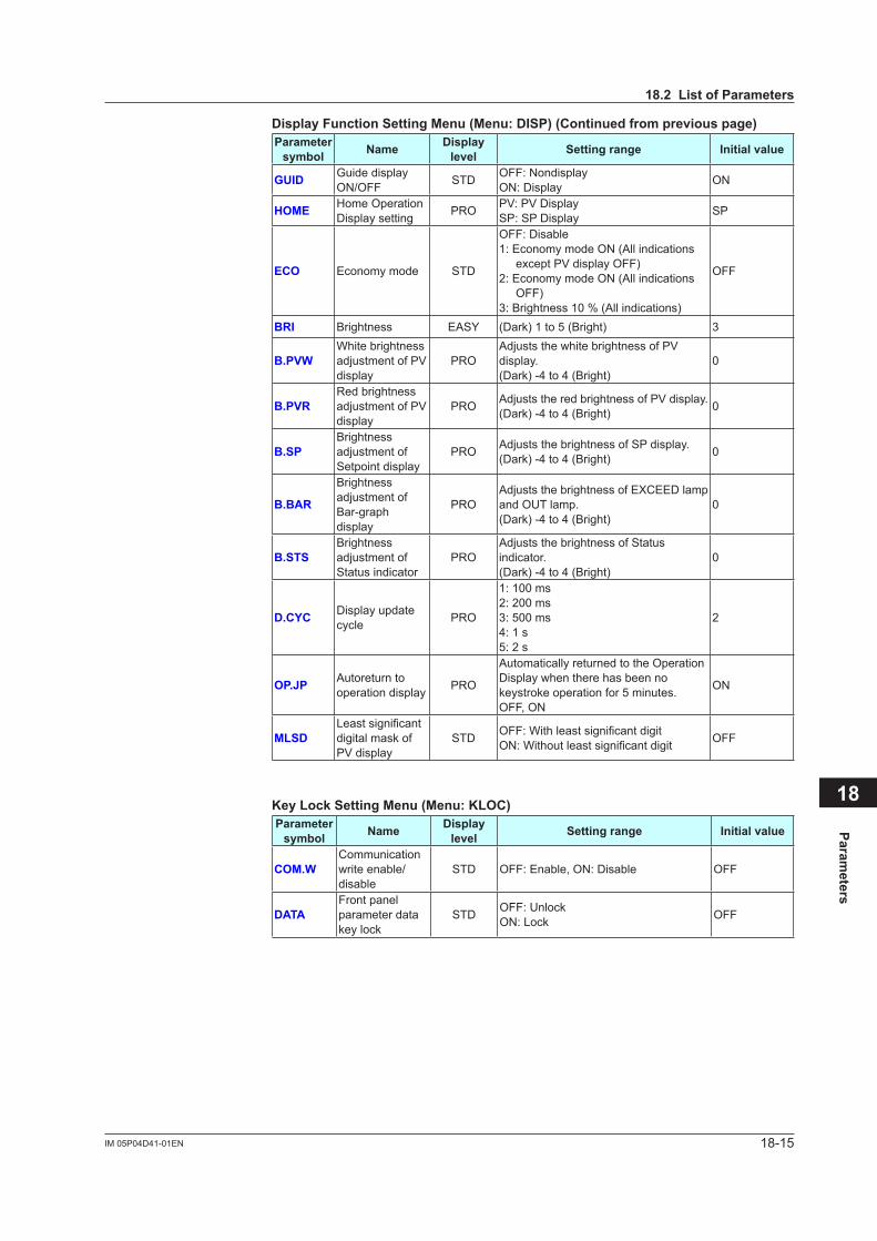
18-15IM 05P04D41-01EN
Parameters
18
DisplayFunctionSettingMenu(Menu:DISP)(Continuedfrompreviouspage)Parameter
symbol Name Display level Settingrange Initial value
GUID Guide display ON/OFF STD OFF: Nondisplay
ON: Display ON
HOME Home Operation Display setting PRO PV:PVDisplay
SP: SP Display SP
ECO Economy mode STD
OFF: Disable1: Economy mode ON (All indications
exceptPVdisplayOFF)2: Economy mode ON (All indications
OFF)3:Brightness10%(Allindications)
OFF
BRI Brightness EASY (Dark) 1 to 5 (Bright) 3
B.PVWWhite brightness adjustmentofPVdisplay
PROAdjuststhewhitebrightnessofPVdisplay.(Dark) -4 to 4 (Bright)
0
B.PVRRed brightness adjustmentofPVdisplay
PRO AdjuststheredbrightnessofPVdisplay.(Dark) -4 to 4 (Bright) 0
B.SPBrightness adjustmentofSetpoint display
PRO AdjuststhebrightnessofSPdisplay.(Dark) -4 to 4 (Bright) 0
B.BAR
Brightness adjustmentofBar-graphdisplay
PROAdjuststhebrightnessofEXCEEDlampand OUT lamp.(Dark) -4 to 4 (Bright)
0
B.STSBrightness adjustmentofStatus indicator
PROAdjuststhebrightnessofStatusindicator.(Dark) -4 to 4 (Bright)
0
D.CYC Display update cycle PRO
1: 100 ms2: 200 ms3: 500 ms4: 1 s5: 2 s
2
OP.JP Autoreturn to operation display PRO
Automatically returned to the Operation Display when there has been no keystroke operation for 5 minutes.OFF, ON
ON
MLSDLeastsignificantdigital mask of PVdisplay
STD OFF:WithleastsignificantdigitON:Withoutleastsignificantdigit OFF
KeyLockSettingMenu(Menu:KLOC)Parameter
symbol Name Display level Settingrange Initial value
COM.WCommunication write enable/disable
STD OFF: Enable, ON: Disable OFF
DATAFront panel parameter data key lock
STD OFF: UnlockON: Lock OFF
18.2ListofParameters

18-16 IM 05P04D41-01EN
MenuLockSettingMenu(Menu:MLOC)Parameter
symbol Name Display level Settingrange Initial value
CTL [CTL] menu lock PRO
OFF: DisplayON: Nondisplay OFF
PV [PV]menulock PRO
MPV [MPV]menulock PRO
OUT [OUT] menu lock PRO
R485 [R485] menu lock PRO
ETHR [ETHR] menu lock PRO
KEY [KEY] menu lock PRO
DISP [DISP] menu lock PRO
KLOC [KLOC] menu lock PRO
DI.SL [DI.SL] menu lock PRO
I/O [I/O] menu lock PRO
SYS [SYS] menu lock PRO
INIT [INIT] menu lock PRO
VER [VER]menulock PRO
LVL [LVL]menulock PRO
MODE [MODE] menu lock PRO
OFF: DisplayON: Nondisplay OFF
SP [SP] menu lock PRO
SPS [SPS] menu lock PRO
ALRM [ALRM] menu lock PRO
PVS [PVS]menulock PRO
When each parameter is displayed, the terminal area (E3) is displayed on Group display.• Parameter: R485, ETHR
18.2ListofParameters

18-17IM 05P04D41-01EN
Parameters
18
DIFunctionRegistrationMenu(Menu:DI.SL)Parameter
symbol Name Display level Settingrange Initial value
DI2.S DI2 function selection STD
OFF: No functionLAT: Latch releaseLCD: LCD backlight ON/OFF switchPVRW:PVred/whiteswitch(*)MG1: Message display interruption 1MG2: Message display interruption 2MG3: Message display interruption 3MG4: Message display interruption 4*: Set the parameter PCMD=10.
OFF
I/O Display Menu (Menu: I/O)Parameter
symbol Name Display level Read only
KEY Key status PROSee 13.4.1ConfirmationofKey and I/O Condition.X000 DI1-DI2 status (equipped as standard) PRO
Y000 AL1-AL3 status (equipped as standard) PRO
SystemSettingMenu(Menu:SYS)Parameter
symbol Name Display level Settingrange Initial value
R.MD Restart mode STD
0: Limit output is ON at power on in any cases.
1: Limit output is OFF at power on whenPVdoesn’texceedSP.
0
C.GRN Response as GREEN Series PRO
OFF: Works as UTAdvanced Series in communication of device information response or broadcasting.
ON: Works as GREEN Series in communication of device information response or broadcasting.
OFF
FREQ Power frequency EASY AUTO, 60: 60 Hz, 50: 50 Hz AUTO
QSM Quick setting mode EASY OFF: DisableON: Enable ON
PASS Password setting EASY 0 (No password) to 65535 0
SMEC Sampling period error counter PRO 0 to 65535 (display only) 0 when power
is turned on.
18.2ListofParameters

18-18 IM 05P04D41-01EN
Initialization Menu (Menu: INIT)Parameter
symbol Name Display level Settingrange Initial value
U.DEF Initialization to user default value PRO 12345: Initialization, automatically
returned to "0" after initialization. 0
F.DEF Initialization to factory default value PRO -12345: Initialization, automatically
returned to "0" after initialization. 0
ErrorandVersionConfirmationMenu(Menu:VER)Parameter
symbol Name Display level Read only
PA.ER Parameter error status EASYSee 16.1 Troubleshooting.AD1.E A/D converter error status 1 EASY
PV1.E PVinputerrorstatus EASY
MCU MCU version EASY
See 13.4.2 ConfirmationofVersion.
DCU DCU version EASY
ECU3 ECU-3 version EASY
PARA Parameter version EASY
H.VER Product version EASY
SER1 Serial number 1 EASY
SER2 Serial number 2 EASY
MAC1 MAC address 1 EASY
MAC2 MAC address 2 EASY
MAC3 MAC address 3 EASY
When the following parameters are displayed, the terminal area (E3) is displayed on Group display.• Parameter: ECU3, MAC1, MAC2 and MAC3
Parameter Display Level Menu (Menu: LVL)Parameter
symbol Name Display level Settingrange Initial value
LEVL Parameter display level EASY
EASY: Easy setting modeSTD: Standard setting modePRO: Professional setting mode
STD
18.2ListofParameters

GeneralSpecifications
<<Contents>> <<Index>>
UT35A-LDigital Indicating Controller(Limit Control Type)
Yokogawa Electric Corporation2-9-32, Nakacho, Musashino-shi, Tokyo, 180-8750 JapanTel.: 81-422-52-7179 Fax.: 81-422-52-6619
GS 05P04D41-01EN
GS 05P04D41-01EN3rd Edition Mar.14, 2016 (YK)
n OverviewThe UT35A-L is a Limit Control Type Digital Indicating Controller that can be configured either as a high limit or as a low limit controller by a user. The UT35A-L complies with FM approval.The UT35A-L features universal input, three alarm out-puts, retransmission output, a timer to count the total time the setpoint is exceeded, and a register to retain the maximum temperature reached. The UT35A-L controller employs an easy-to-read, 14-segment large color LCD display, along with navigation keys, thus greatly increasing the monitoring and operating capa-bilities. The short depth of the controller helps save instrument panel space. The UT35A-L also support RS-485 and Ethernet communication.
n Features• A 14-segment, active (PV display color changing
function) color LCD display is employed. Two five-digit, high-resolution displays are possible.Alphabet letters can be displayed in an easy-to-read manner. The guide display shows parameter names.
• Easy to operate Navigation keys (SET/ENTER and Up/Down/Left/Right arrow keys) are employed to facilitate making settings.
• 65 mm depth The small depth enables the mounting in a thin and small instrumented panel.
• Quick setting function Setting only the minimum necessary parameters for operation is possible.
nFunctionalSpecificationsLimit Control FunctionSetpoint : 1Control type : high limit or low limitLimit action : latching
High Limit ControlWhen PV exceeds a setpoint (SP), "EXCEEDED" lamp lights, and "OUT" lamp turns ON (point A). The limit control output relay is de-energized then.
"EXCEEDED" lamp turns off when PV goes into normal condition, while "OUT" lamp stays on as it is (point B). "OUT" lamp turns off when a confirming operation is done by an operator (point C). The way to confirm is pushing the "RST" key (or by an external contact, according to the setting of setup parameter CNF). The confirming operation is not accepted dur-ing PV exceeds SP (point D). State of output relay is de-energized whenever "OUT" lamp is on. (NC terminal: CLOSE, NO terminal: OPEN)
SP
PV
(A)
Confirmation(accepted)
Hysteresis
EXCEEDEDLamp
OUT Lamp
Output Relay
Operation(RST key or external contact input)
(B) (C) (A) (D) (B)
Confirmation(not accepted)
off lit lit
litlit
off off
off
off off
off
on on

2
All Rights Reserved. Copyright © 2011, Yokogawa Electric Corporation
<<Contents>> <<Index>>
GS 05P04D41-01EN Mar.14, 2016-00
Low Limit ControlWhen PV exceeds a setpoint (SP), “EXCEEDED” lamp lights, and “OUT” lamp turns ON (point A). The limit control output relay is de-energized then.“EXCEEDED” lamp turns off when PV goes into normal condition, while “OUT” lamp stays on as it is (point B). “OUT” lamp turns off when a confirming operation is done by an operator (point C). The way to confirm is pushing the “RST” key (or by an external contact, according to the setting of setup parameter CNF). The confirming operation is not accepted during PV exceeds SP (point D). State of output relay is de-energized whenever “OUT” lamp is on. (NC terminal: CLOSE, NO terminal: OPEN)
SP
PV
(A)
Confirmation(accepted)
Hysteresis
EXCEEDEDLamp
OUT Lamp
Output Relay
Operation(RST key or external contact input)
(B) (C) (A) (D) (B)
Confirmation(not accepted)
lit lit
lit lit
off off
off
off
off
off offon on
n Control Computation Function
Alarm Functions• Types of AlarmMeasured value
alarmDeviation alarmRate-of-change
alarm
PV (measured value) high/low limit alarmDeviation high/low limit alarmDeviation high and low limits alarm Deviation within high and low limits alarm PV rate-of-change alarm
Other alarms Self-diagnosis alarmFAIL
• Alarm Functions
Alarm output action
Alarm stand-by actionAlarm latch (forced reset) functionAlarm hysteresisAlarm ON/OFF delay timer
Number of alarm settings 3
Number of alarm output points 3
Contact I/O FunctionThis function allows for allocating the input error condition, operation condition, alarm condition or other conditions to the contact input and contact output.
Contact input
Limit output confirmation (RESET) (DI1 fixed)Alarm Latch releasePV red/white switchingLCD backlight ON/OFF switchingMessage interrupt displays 1 through 4
Contact output Alarms 1 through 3
Communication Function Function Method Interface Targets Max connection Communication
Data
Modbus/TCP A standard industry protocol allowing communications between the controller and devices such as PCs, PLCs, and DCSs.
Server Ethernet PLC and others 2 connections
PV, SP, ALM, etc
Gateway Ethernet +RS-485
RS-485: UT55A/UT52A/UT35A/UT32A/UP55A/UP35A/
UM33A (*1)
31 units
Modbus (RTU/ASCII) Slave RS-485
PLC and others, UT55A/UT52A/UT35A/UT32A/UP55A/UP35A/
UM33A (*2)
31 units
PC linkThe proprietary Yokogawa protocol allowing communications to PCs, PLCs and touch panels. Slave RS-485
PC and others, UT55A/UT52A /UT35A/UT32A/UP55A/UP35A/
UM33A(*2)
31 units
Ladder A protocol to communicate to PLCs.
*1: UT digital indicating controller, Signal conditioner JUXTA, Power monitor POWERCERT can be connected.*2: UT digital indicating controllers can be connected.
Physical interfaceEthernet Standard : IEEE802.3 (10BASE-T, 100BASE-TX) Max segment length : 100m Max. Connecting Configuration : Cascade Max. 4 level (10BASE-T), Max. 2 level (100BASE-TX)RS-485 Standard : EIA RS-485 Communication method : Two-wire half-duplex or four-wire half-duplex, start-stop synchronization, and non-procedural Baud rate : 600,1200,2400,4800,9600,19200 or 38400 bps Maximum communication distance : 1200 m Terminating resistor : 220Ω (External)

3<<Contents>> <<Index>>
All Rights Reserved. Copyright © 2011, Yokogawa Electric Corporation GS 05P04D41-01EN Mar.14, 2016-00
nHardwareSpecificationsDisplaySpecifications• PV display 5-digit, 14-segment active color LCD (white/red)
Character height: 21.5 mm• Data display 5-digit, 11-segment color LCD (orange)UniversalInputSpecifications• Number of input points: 1• Types of input, instrument range, and measurement
accuracy (see the table below)
Types of input Instrument range Accuracy°C °F
Ther
moc
oupl
e
K-270.0 to 1370.0°C -450.0 to 2500.0°F ±0.1% of instrument
range ±1 digit for 0°C or more±0.2% of instrument range ±1 digit for less than 0°CHowever, ±2% of instrument range ±1 digit for less than -200°C of thermocouple K ±1% of instrument range ±1 digit for less than -200°C of thermo-couple T
-270.0 to 1000.0°C -450.0 to 2300.0°F-200.0 to 500.0°C -200.0 to 1000.0°F
J -200.0 to 1200.0°C -300.0 to 2300.0°F
T
-270.0 to 400.0°C -450.0 to 750.0°F
0.0 to 400.0°C -200.0 to 750.0°F
B 0.0 to 1800.0°C 32 to 3300°F
±0.15% of instrument range ±1 digit for 400°C or more±5% of instrument range ±1 digit for less than 400°C
S 0.0 to 1700.0°C 32 to 3100°F ±0.15% of instrument range ±1 digit R 0.0 to 1700.0°C 32 to 3100°F
N -200.0 to 1300.0°C -300.0 to 2400.0°F
±0.1% of instrument range ±1 digit ±0.25% of instrument range ±1 digit for less than 0°C
E -270.0 to 1000.0°C -450.0 to 1800.0°F ±0.1% of instrument range ±1 digit for 0°C or more±0.2% of instrument range ±1 digit for less than 0°CHowever, ±1.5% of instrument range ±1 digit for less than -200.0°C of thermocouple E
L -200.0 to 900.0°C -300.0 to 1600.0°F
U
-200.0 to 400.0°C -300.0 to 750.0°F
0.0 to 400.0°C -200.0 to 1000.0°F
W (*2) 0.0 to 2300.0°C 32 to 4200°F ±0.2% of instrument range ±1 digit
Platinel 2 0.0 to 1390.0°C 32.0 to 2500.0°F ±0.1% of instrument
range ±1 digit
PR20-40 0.0 to 1900.0°C 32 to 3400°F
±0.5% of instrument range ±1 digit for 800°C or moreAccuracy not guaran-teed for less than 800°C
W97 Re3-W75
Re250.0 to 2000.0°C 32 to 3600°F ±0.2% of instrument
range ±1 digit
Resis
tance
-tem
pera
ture
de
tecto
r (R
TD) 3
-wire JPt100
-200.0 to 500.0°C -300.0 to 1000.0°F ±0.1% of instrument range ±1 digit (*1)
-150.00 to 150.00°C -200.0 to 300.0°F ±0.1% of instrument range ±1 digit
Pt100
-200.0 to 850.0°C -300.0 to 1560.0°F ±0.1% of instrument range ±1 digit (*1)-200.0 to 500.0°C -300.0 to 1000.0°F
-150.00 to 150.00°C -200.0 to 300.0°F ±0.1% of instrument range ±1 digit
Standard signal
0.400 to 2.0000 V
±0.1% of instrument range ±1 digit
1.000 to 5.000 V4.00 to 20.00 mA
DC voltage0.000 to 2.000 V0.00 to 10.00 V-10.00 to 20.00 mV
DC current 0.00 to 20.00 mA
The accuracy is that in the standard operating condi-tions: 23 ±2°C, 55 ±10%RH, and power frequency at 50/60 Hz.
*1: ±0.3°C and ±1 digit in the range between 0 and 100°C ±0.5°C ±1 digit in the range between -100 and 200°C*2: W-5% Re/W-26% Re (Hoskins Mfg.Co.), ASTM E988
• Applicable standards: JIS, IEC and DIN (ITS-90) for ther-mocouples and resistance-temperature detectors (RTD)
• Input sampling period: Synchronized to control period• Burnout detection
Upscale and downscale of function, and OFF can be specified for the standard signal of thermocou-ple and resistance-temperature detector (RTD).For integrated signal input, 0.1 V or 0.4 mA or less is judged as a burnout.
• Input bias current: 0.05 μA (for thermocouple and resistance-temperature detector (RTD))
• Resistance-temperature detector (RTD) measured current: About 0.16 mA
• Input resistance 1 MΩ or more for thermocouple/mV input About 1 MΩ for voltage input About 250 Ω for current input (with built-in shunt resistance)• Allowable signal source resistance 250 Ω or less for thermocouple/mV input Effect of signal source resistance: 0.1 μV/Ω or less 2 kΩ or less for DC voltage input Effect of signal source resistance: about
0.01%/100 Ω• Allowable wiring resistance Up to 150 Ω per line for resistance-temperature
detector (RTD) input (conductor resistance between the three lines shall be equal)
Effect of wiring resistance: ±0.1°C/10 Ω• Allowable input voltage/current ±10 V DC for thermocouple/mV/mA or resistance-
temperature detector (RTD) input ±20 V DC for V input ±40 mA DC for mA input• Noise reduction ratio 40 dB or more (at 50/60 Hz) in normal mode 120 dB or more (at 50/60 Hz) in common mode• Reference junction compensation error ±1.0°C (15 to 35°C) ±1.5°C (-10 to 5°C and 35 to 50°C)RelayContactOutputSpecifications• Types of contact and number of points Limit control relay output: one 1 c-contact point Alarm output: 3 1a-contact points (Common is
separated)• Contact rating 1c-contact: 3 A at 250 V AC or 3 A at 30 V DC
(resistance load) 1a-contact: 1 A at 240 V AC or 1 A at 30 V DC
(resistance load) *: The control output should always be used with a load
of 10 mA or more. The alarm output should always be used with a load of 1 mA or more.
• Application: alarm output, FAIL output, etc.• Time resolution for limit control output: 10 ms or 0.1%
of output value, whichever is largerStepResponseTimeSpecifications1 s(Response time at 63% of transmission output when a change is made stepwise in the range between 10 and 90% of input span)

4
All Rights Reserved. Copyright © 2011, Yokogawa Electric Corporation
<<Contents>> <<Index>>
GS 05P04D41-01EN Mar.14, 2016-00
• Allowable power interruption time: 20 ms (at 100 V AC)• Withstanding voltage 2300 V AC for 1 minute between primary and
secondary terminals (UL, CSA) 3000 V AC for 1 minute between primary and
secondary terminals (CE) 1500 V AC for 1 minute between primary terminals 500 V AC for 1 minute between secondary terminals (Primary terminals = Power (*) and relay output
terminals, Secondary terminals = Analog I/O signal terminals, contact input terminals, communication terminals, and functional grounding terminals.)
*: Power terminals for 24 V AC/DC models are the secondary terminals.
• Insulation resistance Between power supply terminals and a grounding
terminal: 20 MΩ or more at 500 V DC• Isolation specifications
The circuits divided by lines are insulated mutually.
Retransmission (analog) output terminals
PV (universal) input terminals
Control relay (c-contact) output terminals
Alarm-1 relay (a-contact) output terminals
Alarm-2 relay (a-contact) output terminals
Alarm-3 relay (a-contact) output terminals
Internal circuits
Power supply
Contact input terminalsRS485 communication terminals
Ethernet communication terminal
Environmental ConditionsNormal operating conditions• Ambient temperature: -10 to 50°C (-10 to 40°C for
side-by-side mounting of controllers)• Ambient humidity: 20 to 90% RH (no condensation)• Magnetic field: 400 A/m or less• Continuous vibration (at 5 to 9 Hz) Half amplitude of
1.5 mm or less (at 9 to 150 Hz) 4.9 m/s2 or less, 1 oct/min for 90 min-
utes each in the three axis directions• Rapid vibration: 14.7 m/s2, 15 s or less• Impact: 98 m/s2 or less, 11 msec.• Installation altitude: 2,000 m or less above sea level• Warm-up time: 30 minutes or more after the power is
turned on• Start-up time within 10 sTransportation and Storage Conditions• Temperature: -25 to 70°C• Temperature change rate: 20°C per hour or less• Humidity: 5 to 95%RH (no condensation)
Effects of Operating Conditions• Effect of ambient temperature For voltage or TC input:
±1 μ V/°C or ±0.01% of F.S. (instrument range)/°C, whichever is greater
For RTD input:±0.05°C/°C (ambient temperature) or less
For current input: ±0.01% of F.S. (instrument range)/°C For analog output:
±0.02% of F.S./°C or less• Effect of power supply fluctuation: For analog input: ±0.05% of F.S. (instrument range)
or less For analog output: ±0.05% of F.S. or less
(Each within rated voltage range)
RetransmissionOutputSpecifications• Number of points: 1 point• Output function: current output 4 to 20 mA DC or 0 to 20 mA DC/load
resistance 600 Ω or less• Current output accuracy (conversion accuracy from
PV display on the set scale): ±0.1% of span (how-ever, ±5% of span for 1 mA or less)
The accuracy is that in the basic operating conditions: 23 ±2°C, 55 ±10%RH, and power frequency at 50/60 Hz This is not conversion accuracy through input
and output but the performance of transmission output itself.
ContactInputSpecifications• Number of points: 2 points• Input type: no-voltage contact input or transistor con-
tact input• Input contact capacity: 12 V DC, 10 mA or more Be sure to use a contact with a minimum ON current of 1 mA or less• ON/OFF detection No-voltage contact input:
Contact resistance 1 kΩ or less in ON state Contact resistance 50 kΩ or more in OFF state
Transistor contact input: 2 V or less in ON state Leak current 100 μ A or less in OFF state
• Status detection minimum hold time: 250 ms• Application: Confirmation operation, etc.
Safety and EMC Standards• Safety: Compliant with IEC/EN 61010-1 (CE), IEC/EN 61010-
2-201 (CE), IEC/EN 61010-2-030 (CE), approved by CAN/CSA C22.2 No. 61010-1 (CSA), approved by UL 61010-1. Certified for FM-3810 and FM-3545.
Installation category: II Pollution degree: 2 Measurement category: I (CAT I) (UL, CSA) O (Other) (CE) Rated measurement input voltage: Max. 10 V DC Rated transient overvoltage: 1500 V (*)
*: This is a reference safety standard value for measure-ment category I of CSA/UL 61010-1, and for measure-ment category O of IEC/EN 61010-2-030. This value is not necessarily a guarantee of instrument performance.
• EMC standards: Compliant with CE marking EN 61326-1 Class A, Table 2 (For use in industrial locations), EN 61326-2-3
*: The instrument continues to operate at a measurement accuracy of within ±20% of the range during testing.
EN 55011 Class A, Group 1 EN 61000-3-2 Class A EN 61000-3-3 EMC Regulatory Arrangement in Australia and New Zealand EN 55011 Class A, Group 1
PowerSupplySpecificationsandIsolation• Power supply Rated voltage: 100 to 240 V AC (+10%/-15%), 50/60 Hz
24 V AC/DC (+10%/-15%) (When the /DC option is specified)
• Power consumption: 18 VA (For the /DC option. DC: 9 VA, AC: 14 VA)
• Storage: Nonvolatile memory

5<<Contents>> <<Index>>
All Rights Reserved. Copyright © 2011, Yokogawa Electric Corporation GS 05P04D41-01EN Mar.14, 2016-00
n Block Diagram
BS
FL
DI2.SCNF
UNIT
IN
RH, RL SDP SH, SL
A.BS
A.FL
RTSRTH RTL
RST
Input type
PV analog input bias
PV analog input filter
Input unit
Input range/scale
PV input bias
PV input filter
Equipped as standard Equipped as standard
RelayCurrent
RET retransmission output Alarm
Limit Control computation
Contact inputs
PV
PV input
Equipped as standardEquipped as standard.
Ala
rm 1
(PV
hig
h lim
it)
Ala
rm 2
(PV
low
lim
it)
Ala
rm 3
(PV
hig
h lim
it)PV display SP display
Com.
OUT
DI2DI1
RET AL3AL2AL1
RS-485, Ethernet
Terminal Parameter Function
Analog signal Contact signal Front panel keyLegend
Confirmation
Target setpointSP
SP limiter
Latch release, etc
SPH, SPL
HI.LO
HYS
n Terminal Arrangement
E3-terminal area
PVPV inputTC input RTD input
Voltage (mV, V) input
A
+
-
+
-
Current (mA) input
+
-
B
b
(24 V AC/DC power supply: Option code /DC)
(Equippedas standard)
Power supply
101
102
103
104
105
106
107
108
109
110
111
407
401
408
409
410
411
412
201
202
203
204
207
208
205
206
210
211
212
101-112
501-512
401-412
301-306
201-212
ALM (Equipped as standard)Contact output
External contact output (relay)
AL3
AL2
AL1
Relay contact rating: 240 V AC, 1 A 30 V DC, 1 A (resistance load)
Alarm-3 output(PV high limit)
Alarm-2 output( PV low limit)
Alarm-1 output(PV high limit)
Common
Common
Common
UT104
105
106
107
108
109
100-240 V AC power supply
N
L
Allowable range: 100-240 V AC (+10%, -15%) (free voltage) 50/60 Hz shared
110
111
24 V AC/DC power supply
-
+
110
111
202
203
201
202
203
202
203
203
204
Factory default: PV input type is undefined.
(Equipped as standard)OUTLimit control output
101
102
Relay contact output
103
NC
NO
COM
Contact rating: 250 V AC, 3 A 30 V DC, 3 A (resistance load)
RETRetransmission output
4-20 mA DC or0-20 mA DC
+
-
Default: 4-20 mA DC
Default: PV retransmission
Load resistance 600 Ω or less
Retransmission output (Equipped as standard)
207
208
DI (Equipped as standard)Contact input
Contact rating: 12 V DC, 10 mA or more
External contact input
DI2
DI1
COM
Factory default: No function
RESET when DI=ON(However, setup parameter CNF=DI)
Common
DI2
DI1
COM
+5V
+5V
No-voltagecontact
Transistor contactUT UT
210
211
212
210
211
212
Function can be assigned to the terminals with no function.
112
112 112
N
L
Wiring direction
RS-485
SDB(+)
SDA(-)
RDB(+)
RDA(-)
SG
RS-485 communication(Suffix code: Type 3=1)
407
408
409
410
411
RS485
(Suffix code: Type 3=2)
Ethernet communication (with gateway function)
10BASE-T/100BASE-TXRJ45 connector
ColorLitUnlit
Amber100M bps10M bps
Green
LinkedActiveLink failure
Color
LitBlinkUnlit
Upper side LED (baud rate)
Lower side LED (link activity)
RS-485
RSB(+)
RSA(-)
SG
407
408
409
ETHR
401-412
Do not use.
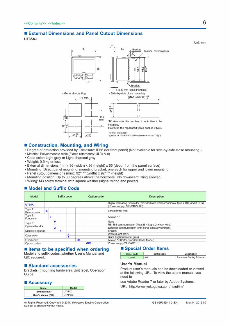
6
All Rights Reserved. Copyright © 2011, Yokogawa Electric Corporation
<<Contents>> <<Index>>
GS 05P04D41-01EN Mar.14, 2016-00Subject to change without notice.
n External Dimensions and Panel Cutout DimensionsUT35A-L
Unit: mm
(25)
(53)
[(N-1)×96+92]117 min.
145min.
+0.80
+0.8 0
92
+0.8092
+0.8092
“N” stands for the number of controllers to beinstalled.However, the measured value applies if N≥5.
6520
11
1 to 10 mm (panel thickness)Bracket
Bracket
94.6
91.6
105.
2
96
96
• General mounting • Side-by-side close mounting
Terminal cover (option)
Normal tolerance: ±(value of JIS B 0401-1998 tolerance class IT18)/2
n Construction, Mounting, and Wiring• Degree of protection provided by Enclosure: IP66 (for front panel) (Not available for side-by-side close mounting.)• Material: Polycarbonate resin (Flame retardancy: UL94 V-0)• Case color: Light gray or Light charcoal gray• Weight: 0.5 kg or less• External dimensions (mm): 96 (width) x 96 (height) x 65 (depth from the panel surface)• Mounting: Direct panel mounting; mounting bracket, one each for upper and lower mounting• Panel cutout dimensions (mm): 92+0.8/0 (width) x 92+0.8/0 (height)• Mounting position: Up to 30 degrees above the horizontal. No downward titling allowed.• Wiring: M3 screw terminal with square washer (signal wiring and power)
nModelandSuffixCodeModel Suffixcode Option code Description
UT35A Digital Indicating Controller (provided with retransmission output, 2 DIs, and 3 DOs) (Power supply: 100-240 V AC)
Type 1: Basic control -L Limit control type
Type 2:Functions 0 Always "0"
Type 3:Open networks
0 None1 RS-485 communication (Max.38.4 kbps, 2-wire/4-wire)2 Ethernet communication (with serial gateway function)
Display language -1 English
Case color 0 White (Light gray)1 Black (Light charcoal gray)
Fixed code -00 Always "-00" (for Standard Code Model)Option codes /DC Power supply 24 V AC/DC
nItemstobespecifiedwhenorderingModel and suffix codes, whether User’s Manual and QIC required.
n Standard accessoriesBrackets (mounting hardware), Unit label, Operation Guide
n AccessoryName Model
Terminal cover UTAP001User’s Manual (CD) UTAP003
n Special Order ItemsModel code Suffixcode Description
LL50A -00 Parameter Setting Software
User’s ManualProduct user’s manuals can be downloaded or viewed at the following URL. To view the user’s manual, you need touse Adobe Reader 7 or later by Adobe Systems.URL: http://www.yokogawa.com/ns/ut/im/

App-1IM 05P04D41-01EN
Input and Output Table
App
AppendixInputandOutputTable
Appendix1 InputandOutputTable
UT35A ModelandSuffixCodes
Model SuffixcodeOptional suffixcode
INPUT OUT DI DO
PV RET DI1 DI2 AL1 AL2 AL3 OUT
UT35A -x x x -xx -00 /x Type 1: Basic control
-L
Type 2: Functions 0
Type3:Opennetworks x
Display language/Case color -xx
Fixedcode -00
Optionalsuffixcodes /x
: Equipped
DescriptionofsymbolPV:MeasuredinputRET: Retransmission outputDI1 to DI2: Contact inputAL1 to AL3: Alarm outputOUT: Limit control output

Blank Page

i
RevisionInformation Title : UT35A-L Digital Indicating Controller (Limit Control Type) User’s Manual Manual No. : IM 05P04D41-01EN
July2011/1stEditionNewly published
Aug.2015/2ndEditionSafety standard IEC/EN 61010-2-201 conformity, Safety and EMC standard (3rd edition) confomity and error correction.
n Written by Yokogawa Electric Corporation n Published by Yokogawa Electric Corporation 2-9-32 Nakacho, Musashino-shi, Tokyo 180-8750, JAPAN

Blank Page

YOKOGAWA ELECTRIC CORPORATIONHeadquarters2-9-32, Nakacho, Musashino-shi, Tokyo, 180-8750 JAPANPhone : 81-422-52-5555
Branch Sales OfficesOsaka, Nagoya, Hiroshima, Kurashiki, Fukuoka, Kitakyusyu
YOKOGAWA CORPORATION OF AMERICAHead Office12530 West Airport Blvd, Sugar Land, Texas 77478, USAPhone : 1-281-340-3800 Fax : 1-281-340-3838
Georgia Office2 Dart Road, Newnan, Georgia 30265, USA Phone : 1-800-888-6400/ 1-770-253-7000 Fax : 1-770-254-0928
YOKOGAWA AMERICA DO SUL LTDA.Praca Acapulco, 31 - Santo Amaro, Sáo Paulo/SP, BRAZIL, CEP-04675-190Phone : 55-11-5681-2400 Fax : 55-11-5681-4434
YOKOGAWA EUROPE B. V.Euroweg 2, 3825 HD Amersfoort, THE NETHERLANDSPhone : 31-88-4641000 Fax : 31-88-4641111
YOKOGAWA ELECTRIC CIS LTD.Grokholskiy per 13 Building 2, 4th Floor 129090, Moscow, RUSSIAPhone : 7-495-737-7868 Fax : 7-495-737-7869
YOKOGAWA CHINA CO., LTD.3F Tower D Cartelo Crocodile Building, No.568 West Tianshan Road, Shanghai 200335, CHINAPhone : 86-21-62396262 Fax : 86-21-62387866
YOKOGAWA ELECTRIC KOREA CO., LTD.(Yokogawa B/D, Yangpyeong-dong 4-Ga), 21, Seonyu-ro 45-gil, Yeongdeungpo-gu,Seoul, 150-866, KOREAPhone : 82-2-2628-6000 Fax : 82-2-2628-6400
YOKOGAWA ENGINEERING ASIA PTE. LTD.5 Bedok South Road, Singapore 469270, SINGAPOREPhone : 65-6241-9933 Fax : 65-6241-2606
YOKOGAWA INDIA LTD.Plot No.96, Electronic City Complex, Hosur Road, Bangalore - 560 100, INDIAPhone : 91-80-4158-6000 Fax : 91-80-2852-1442
YOKOGAWA AUSTRALIA PTY. LTD.Tower A, 112-118 Talavera Road, Macquarie Park NSW 2113, AUSTRALIAPhone : 61-2-8870-1100 Fax : 61-2-8870-1111
YOKOGAWA MIDDLE EAST & AFRICA B.S.C.(C)P.O. Box 10070, Manama, Building 577, Road 2516, Busaiteen 225, Muharraq,Kingdom of BAHRAINPhone : 973-17358100 Fax : 973-17336100 Apr. '15
Printed in Japan