USER'S MANUAL - Katradis
30
O KATRADIS SA ISO 9001:2015 & ISO 14001:2015 LRQA CERTIFIED COMPANY USER’S MANUAL Synthetic Mooring Ropes KATRADIS MARINE ROPES INDUSTRY S.A.
-
Upload
khangminh22 -
Category
Documents
-
view
6 -
download
0
Transcript of USER'S MANUAL - Katradis

O KATRADIS SA
ISO 9001:2015 & ISO 14001:2015 LRQA CERTIFIED COMPANY
USER’S MANUAL Synthetic Mooring Ropes
KATRADIS MARINE ROPES INDUSTRY S.A.

User’s Manual Synthetic Mooring Ropes
Page 1
USER’S MANUAL
Synthetic Mooring Ropes
This manual is intended to accompany the Synthetic Mooring Ropes - manufactured by
KATRADIS SA, used in mooring operations and provide information and guidance regarding their
proper usage, installation, safety issues, inspection & discard criteria.
Synthetic mooring ropes cover a wide range of materials and constructions and can be generally
categorized as Polyolefin, Polyester, Mixed Polyolefin/Polyester and Nylon. More specifically:
Polyolefin (Polypropylene PP / Polyethylene PE)
KATRADIS SA has been producing for many years the special NIKA-Steel® monofilament fibers, a
"melt mixture" of first quality virgin raw materials (Polypropylene, Polyethylene and UV
stabilizers). Ropes made of NIKA-Steel® are floating, very durable and outlast the common
polypropylene ropes.
Polyester
These ropes are made of polyester multifilament fibers and exhibit a lot of advantages such as
very high abrasion resistance, flexibility and capability of maintaining breaking strength even at
high temperatures. Polyester ropes are non-floating.
Mixed Polyolefin/Polyester
Consisting of NIKA-Steel® and polyester fibers twisted on the outer surface of rope yarns, these
ropes combine the high strength and long service life. The proportions of each material can vary
and provide floating or non-floating properties.
Nylon
Nylon ropes are used mostly because of their elasticity and shock-load absorbing properties for
the shipping industry. This is why they are used mostly for mooring tails, but can be also used as
main mooring lines. Nylon ropes (non-floating) tend to lose approx. 15% of their breaking
strength in wet conditions, but this effect is recovered when dried.
All the above rope types can be manufactured in 3/8/12/24/32/64-strand construction.

User’s Manual Synthetic Mooring Ropes
Page 2
Contents
Brief description of manufacturing process……………………………………. 3
Description of Quality Control Arrangement…………………………………… 4
On-Board Installation 5 - 8
Hardware/Deck preparation…………………………………………………………… 5
Installation on a winch……………………………………………………………………. 6 - 8
Mooring Operation 9 - 16
Rope Protection……………………………………………………………………………… 10
Minimum Safety Usage Factors……………………………………………………… 11 - 12
Safety Issues………………………………………………………………………………….. 13 - 16
Rope Care and Maintenance 18
Inspection Practices and Retirement Criteria 19-25
For unjacketed ropes…………………………………………………………………….. 20-21
Jacket Damages…………………………………………………………………………….. 22
Small repairs………………………………………………………………………………….. 24
Extensive repairs……………………………………………………………………………. 25
Annex A………………………………………………………………………………………….. 26-27
Information regarding packaging and traceability…………………………. 28
Storage conditions…………………………………………………………………………. 28
User’s Manual Synthetic Mooring Ropes
Page 3
Brief description of manufacturing process
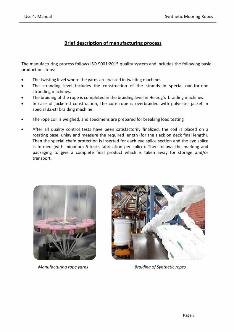
The manufacturing process follows ISO 9001:2015 quality system and includes the following basic
production steps:
• The twisting level where the yarns are twisted in twisting machines
• The stranding level includes the construction of the strands in special one-for-one
stranding machines.
• The braiding of the rope is completed in the braiding level in Herzog’s braiding machines.
• In case of jacketed construction, the core rope is overbraided with polyester jacket in
special 32-str braiding machine.
• The rope coil is weighed, and specimens are prepared for breaking load testing
• After all quality control tests have been satisfactorily finalized, the coil is placed on a
rotating base, unlay and measure the required length (for the slack on deck final length).
Then the special chafe protection is inserted for each eye splice section and the eye splice
is formed (with minimum 5-tucks fabrication per splice). Then follows the marking and
packaging to give a complete final product which is taken away for storage and/or
transport.
Manufacturing rope yarns Braiding of Synthetic ropes

User’s Manual Synthetic Mooring Ropes
Page 4
Description of quality control arrangement
The product quality control involves the following steps/procedures:
• Tenacity testing of the yarns.
• Yarn-To-Yarn abrasion test of the yarns
• UV resistance tests of the yarns
• Breaking strength testing of the rope yarns (twisted yarns)
• Breaking testing of rope specimens as per batch order.
Table 1. Synthetic ropes constituent yarns technical information
Property Nylon Polyester NIKA-Steel®
Density 1,14 kg/dm3 1,38 kg/dm3 0,92 kg/dm3
Tenacity > 9gr/den > 9gr/den 8gr/den
Elongation (at break) 25%-30% 18% 15%-18%
Melting point 218 0C 265 0C 165 0C
UV resistance Excellent Excellent Excellent
Fmax (%)
Elongation at Break (%)
User’s Manual Synthetic Mooring Ropes
Page 5
ON-BOARD INSTALLATION
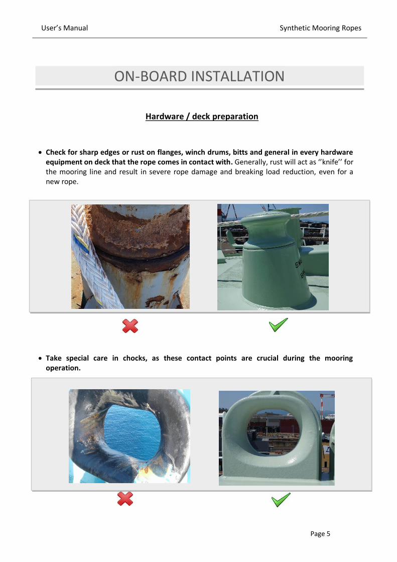
Hardware / deck preparation
• Check for sharp edges or rust on flanges, winch drums, bitts and general in every hardware
equipment on deck that the rope comes in contact with. Generally, rust will act as ‘’knife’’ for
the mooring line and result in severe rope damage and breaking load reduction, even for a
new rope.
• Take special care in chocks, as these contact points are crucial during the mooring
operation.

User’s Manual Synthetic Mooring Ropes
Page 6
Installation on a winch
• Uncoiling the rope from the delivery package must be done carefully and gradually.
• When uncoiling the rope from a reel or a coil, the winding and unwinding must be
performed with care to avoid twisting
• Be careful of the twist that may be introduced to the rope while winding it on the winch.
Studies have proved that loss of strength amounts to 7% per turn per meter.
• Winding of the ropes must be carried out tightly & evenly at clockwise direction, so that no
spaces are created between the wraps.
Second Layer
First Layer
Mooring line
Winch Drum
Mooring rope that has suffered several
twists, which cause considerable strength
reduction. The handling of braided ropes
should be with care to avoid twists as much
as possible.

User’s Manual Synthetic Mooring Ropes
Page 7
Drum Capacity calculation
The following formula has been developed to determine drum capacity under normal tension
and uniform winding conditions.
• In cases of split mooring winch drums, the drum separator should have rounded edges where
the rope passes through.
L = Length of rope (meters)
A = Desired depth of winding (cm)
The depth of the flange is normally
reduced by 40 to 50 mm to allow
ground clearance for the rope
B = Diameter of Barrel (cm)
C = Width between flanges (cm)
d = diameter of the rope (mm)
π= 3,14
These metal surfaces
that come in contact
with mooring lines
must be rounded and
not sharp.

User’s Manual Synthetic Mooring Ropes
Page 8
• On the tension drum, the rope must have at least 4 to 5 wraps to avoid slippage. Also, the
tension drum is operated with only one layer of mooring line.
• On an undivided drum, outer layers of mooring line tend to embed into lower layers when under
tension which can damage the mooring line. The split drum winch has been designed as a
solution to this problem and is preferred by most operators.
• OCIMF recommends that the primary brake should be set to hold 60% of the ship design MBL
on the first layer. The brake holding capacity for this type of winch is always quoted for the first
layer on the tension drum. If more than one layer is wound onto the drum, then significant loss
of brake holding power will result. For undivided drums, it is recommended to ask the winch
manufacturer for guidance on maintaining the value for brake rendering.
(MBLSD) Ship Design Minimum Breaking Load: The MBL of a new, dry mooring line
for which a ship’s mooring system is designed. The MBLSD meets standard environmental criteria restraint requirements.
(LDBF) Line Design Break Force: The minimum break force at which a new, dry, spliced
mooring line will break when tested acc. to CI1500B:2015. This value is declared by the
manufacturer on each mooring line certificate.
LDBF = 100% - 105% of MBLSD

User’s Manual Synthetic Mooring Ropes
Page 9
MOORING OPERATION
Mooring operation is one of the most critical and hazardous tasks carried out on vessels. Mooring
arrangements differ from port to port and careful re-planning of the mooring operation is essential.
Deck crew has to consider various safety precautions and understand working principles of deck
machinery and systems. When it comes to mooring operations, additional precautions need to be
taken to ensure crew members’ safety.
✓ As the ship nears the port the mooring winches are tried out, the breaks are tested, the
mooring ropes are checked and positioned.
✓ Mooring lines must be as symmetrical as possible about the midship line of the vessel.
✓ Two or more lines leading in the same direction should always be of the same material
(also tensile strength, elongation etc.) and construction.
✓ MIXED MOORING MUST BE AVOIDED.

User’s Manual Synthetic Mooring Ropes
Page 10
Rope Protection
Use protective chafe gear. KATRADIS SA has developed high quality protection sleeves against
external abrasion conditions (to be used in areas such as chocks, bitts, etc.). Using chafe
protection will substantially extend the service life of your mooring line.
Protection for the main body of the mooring line
Protection for the rope’s eye
NIKA®-Guard Protector
Flat Polyester webbing pad used for the protection
of ropes against abrasive surfaces (chocks, bitts
etc.). The Velcro scratch tape, firmly stitched on the
sleeve guard, is used for quick & easy installation
and removal.
Polyester Eye splice Protector
Special braided cover designed for extra protection
of the eye splices, made from specially twisted
polyester fibers.
NIKA®-Eye splice Protector
UHMWPE braided sleeve cover highly efficient
against abrasion and wear. It’s low coefficient of friction makes it ideal for the eye protection in
demanding operations.
NIKA®-Guard UltraDouble
It is manufactured using a combination of High
Tenacity polyester and UHMWPE webs in a double-
layer sleeve construction. The polyester layer of the
webbing sleeve is fixed on the outer side while the
UHMWPE layer protects the rope from the inside.

User’s Manual Synthetic Mooring Ropes
Page 11
Minimum safety usage factors
The maximum Working Load Limit (WLL) of synthetic mooring lines must not exceed 50% of
the ship design MBL (MBLsd).
The SWL of the bitts and other deck hardware should be equal or greater than the MBLsd of
the employed mooring line.
Any bending of mooring lines will instantaneously reduce its breaking strength. Repeated
bending will reduce the service life of the line. The D/d ratio (D: diameter of bend, d: diameter
of mooring line) should be as large as possible to maximize mooring line strength and working
life.
The diameter D of bitts, pedestal fairleads, etc. that meet mooring lines should be at least 15
times larger than the diameter of the line.
Mooring line arrangements often require redirection from winches and bending of lines around
pedestal rollers. Users should keep in mind that high bending angles can cause compression of
the inside strands and yarns and also extensive wear when the line is under loading and
unloading conditions.
Rope diameter d
Fitting diameter D
Recommended D/d ≥ 15
Bending Angle θ Larger bending angles cause
longer wear zones of mooring
lines and increased fatigue
due to bending.

User’s Manual Synthetic Mooring Ropes
Page 12
Securing Mooring Lines in figure 8 arrangement
It is recommended by MEG4 that when securing mooring lines to double post mooring bitts, two
turns should be placed around the first post before beginning to belay figure of eights.
If the two full turns of the mooring line around the first post are missing, a higher stress is
induced in each post creating a tendency for the bitts to be pulled together. This method is not
recommended and is illustrated below:
Recommended method of turning up a mooring line on bitts (two full turns around leading post)
Incorrect figure of eight method for attaching a mooring line on mooring bitts

User’s Manual Synthetic Mooring Ropes
Page 13
Safety issues
ALWAYS CONSIDER the high risk areas regarding snap-back effect of mooring ropes, as
indicatively shown in the drawing below, when the line is under tension.
NOTE: MEG4 Guidelines suggest that a snap-back area should not be marked on deck because
such an approach gives a false sense of safety for the crew outside the marked areas. It is
suggested that during mooring operations, all crew and personnel should become aware of the
snap-back dangers and not be in close proximity of the tensioned mooring lines.
Any work that must be performed near to a mooring line under tension must be performed as
quick as possible, but NOT HASTY, and with extreme caution.
It is impossible to work the lines without the crew
standing in such a large and high-risk snap-back
area.
The crew can work the lines without standing in
high-risk snap-back zone.

User’s Manual Synthetic Mooring Ropes
Page 14
Never let two ropes rub one another when they are under tension. There can be excessive
heat build-up that will damage the fibers locally and impose a weak point in the line.
Directing more than one mooring line through fairleads, chocks etc. is a bad mooring
practice because of local compression and abrasion, which can severely affect the
performance of the lines.
All mooring lines must be equally tensioned, otherwise the most tensioned line will be
exposed to overloading.
This line is highly tensioned
compared to the rest mooring
lines.
Mooring lines that come in
contact with each other
create high-risk working
conditions.

User’s Manual Synthetic Mooring Ropes
Page 15
AVOID keeping mooring lines on drum ends. Lines must be kept in storage drums with
appropriate wraps.
MAKE SURE that there are no obstacles on the mooring line’s directions. Parts of the vessel’s construction that come in contact with mooring lines must be removed as they can cause rope
damages that could lead to unexpected premature failure of the mooring line.
Under no circumstances the rope should contain oil/grease material, as it may cause
chemical contamination and foreign particle adhesion (which will create abrasive
conditions).

User’s Manual Synthetic Mooring Ropes
Page 16
Induced Twisting:
As already mentioned, the handling of braided ropes should be with care to avoid twists as
much as possible - twisting of ropes causes a strength reduction up to 7% per twist per meter.
Below there is an example of rope that has suffered several twists.
BEST ACTION: Spread the twisted length of the rope along the deck and align in order to
straighten the rope.
Mooring rope suffering a large number of twists.
Under no circumstances the mooring ropes should work with induced twists, because it highly affects their performance.
After removing the twists that may have been induced, wind it carefully back to the winch.

User’s Manual Synthetic Mooring Ropes
Page 17
ROPE CARE AND MAINTENANCE
Unless otherwise recommended, on an annual basis reverse your mooring line end-for-
end: bring the rear part of the rope in front and vice versa so that the wear is distributed
and get a longer service life.
Avoid making knots at all costs because this can reduce the line's strength by up to 50%.
Also, end-to-end splices will cause significant strength loss up to 20%. Best practice is to
make eye splices instead.
Keep the ropes clean: wash them with tap water on a regular basis (the time frame is to be
decided upon operators' experience) to remove any dirt or sea salt. Such particles will act as
“razors” and damage the fibers when dry.
Conduct regular inspections on the rope and the hardware (see more on the inspection
practices).
For better abrasion performance we recommend the use of the special NIKA-Lube lubricant.
It is polyurethane based and appropriate for application on mooring ropes (for more
information please contact KATRADIS SA).
Spread the mooring line on the deck and after the tap water scouring let it dry normally.
Nylon ropes must be carefully dried as their strength starts to decrease in wet conditions.

User’s Manual Synthetic Mooring Ropes
Page 18
Determination of NORMAL / EXTREME Operating Conditions
Generally, mooring lines operate in various weather conditions, types of ports (sheltered or
exposed – open sea), mooring arrangements and loading conditions. Such factors highly affect
the service life of mooring lines and should be taken into consideration when evaluating their
condition and performance.
Below, there is a table for determining the normal or extreme operating conditions of mooring
ropes.
NORMAL
OPERATING
CONDITIONS
Operating temperatures up to 50oC
Mooring at sheltered port
Low wind forces (1-4 beaufort)
Typical mooring layout
Absence of swell
EXTREME
OPERATING
CONDITIONS
Operating temperatures exceeding 50oC
Mooring at exposed terminal
Ship-to-Ship operations
High wind forces (over 5 beaufort)
Presence of swell
SPM, CBM or Multi Buoy Mooring layout
Typical mooring at sheltered berth

User’s Manual Synthetic Mooring Ropes
Page 19
INSPECTION PRACTICES AND RETIREMENT CRITERIA
The rope should be inspected after each operation. A trained person from the crew, assigned
by the master or by the company, must be charged with the visual inspections and rope
repairs. A diary log must be kept where as much information as possible must be recorded
(mooring line history, hours of mooring operations, temperature exposure data etc.).
Also keep in mind that in order to have an indication of the remaining/current breaking
strength of a line, the originally received coil should have an extra length of about 10 to 12
meters. This way, a breaking test in a specimen could be performed without
limiting/affecting the line's length. For this extra length, the purchaser should make this
notification during the order placement and always consult KATRADIS SA regarding the
recommended mooring line testing.
It is recommended that mooring lines and tails that have reached the 75% of the ship design
MBL (respectively) must be replaced.
The visual inspection must check the following (also useful guidance for complete inspection
can be found in the User’s Checklist Inspection).
User’s Manual Synthetic Mooring Ropes
Page 20
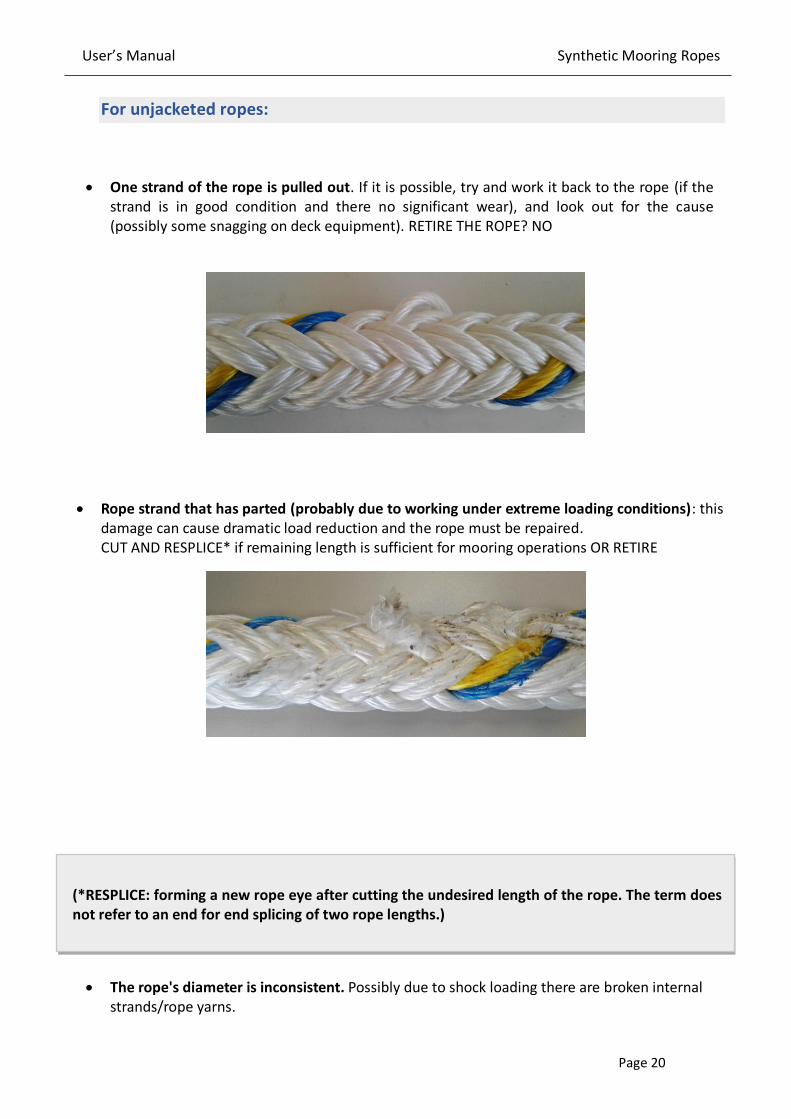
For unjacketed ropes:
• One strand of the rope is pulled out. If it is possible, try and work it back to the rope (if the
strand is in good condition and there no significant wear), and look out for the cause
(possibly some snagging on deck equipment). RETIRE THE ROPE? NO
• Rope strand that has parted (probably due to working under extreme loading conditions): this
damage can cause dramatic load reduction and the rope must be repaired.
CUT AND RESPLICE* if remaining length is sufficient for mooring operations OR RETIRE
(*RESPLICE: forming a new rope eye after cutting the undesired length of the rope. The term does
not refer to an end for end splicing of two rope lengths.)
• The rope's diameter is inconsistent. Possibly due to shock loading there are broken internal
strands/rope yarns.

User’s Manual Synthetic Mooring Ropes
Page 21
REPAIR THE ROPE (CUT AND RESPLICE if remaining length is sufficient for mooring operations)
OR RETIRE
• The rope has extensive wear and/or reduced volume. The percent of the volume decreased
means greater decrease in line's strength.
CUT AND RESPLICE if remaining length is sufficient for mooring operations) OR RETIRE
• The rope's surface is discolored. Most probable cause is chemical contamination (oil/grease
residues from deck or other chemicals). The rope should be cleaned thoroughly with plenty of
water because foreign particles will adhere the rope’s surface and create abrasive conditions. RETIRE THE ROPE? NO
Jacket Damages:

User’s Manual Synthetic Mooring Ropes
Page 22
In case of a worn jacket or a pulled strand, local repair in the jacket could be performed (as
long as it is verified that the load bearing core is in good condition and hasn't suffered any
damage - for details refer to Unjacketed rope inspection instructions). Examples of jacket
damages are given below:
Abraded jacket Cut jacket strands
Glazed (fused) strands on the jacket Discoloration
When the jacket is damaged, we recommend inspection of the inner strength member. If
the inner strength member is damaged, then it may be necessary to downgrade the rope.
The cause of the damage should be determined and if possible, removed.
Depending on the extent of the damage either a small repair or an extensive repair is
recommended (See below sections: Small repairs & Extensive repairs).

User’s Manual Synthetic Mooring Ropes
Page 23
In case of a total jacket partition, the repairing should take place by KATRADIS SA (this
includes removal of the parted jacket and overbraiding a new one as long as the core rope is
in good condition). On-board, only a temporary repair can take place in this case.
Broken internal strands:
A broken internal strand can be recognized from the diameter’s reduction. Specifically, a 12% - 13% loss of the rope’s diameter is expected when an internal strand has parted. Most likely the inside of the rope will become softer in the particular area.
BEST ACTION:
CUT AND RESPLICE IF ALLOWED
and if remaining length is sufficient
for mooring operations
OR RETIRE
A temporary repair can take
place: bring the two jacket
parted sides as close as
possible and use the Repair
Kit (see below instructions:
Extensive repairs).

User’s Manual Synthetic Mooring Ropes
Page 24
Small repairs
The most durable method to make small repairs on the jacket braid requires the use of
whipping twine and polyurethane glue.
Remove all the damaged yarns and coat the free
yarn ends with the glue, in order to prevent
further unraveling of the cover. Start whipping at
least three centimeters away from the damage,
as shown in the drawing. Lay a loop of twine
across the rope, leaving a free tail after the
damage zone of about ten centimeters. This tail
has to be grasped later, so avoid covering it
completely with whipping. With the working
end of the twine, make multiple wraps around
the rope from the tail end toward the apex of
the loop, covering the loop until the whipping is at least three centimeters beyond the
damage.
To finish the whipping, insert the working end of the small twine through the loop. Pull on
the very end or tail of the small twine until the loop slides completely out of sight. Clip the
ends close to the whipping.
If necessary, a temporary cover repair can be made using high quality adhesive tapes such as
vinyl electrical tape, etc. A more permanent repair, as described above, should replace the
tape as soon as possible.
Effective repair by whipping Temporary repair with adhesive tape
User’s Manual Synthetic Mooring Ropes
Page 25
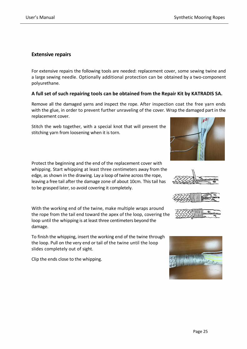
Extensive repairs
For extensive repairs the following tools are needed: replacement cover, some sewing twine and
a large sewing needle. Optionally additional protection can be obtained by a two-component
polyurethane.
A full set of such repairing tools can be obtained from the Repair Kit by KATRADIS SA.
Remove all the damaged yarns and inspect the rope. After inspection coat the free yarn ends
with the glue, in order to prevent further unraveling of the cover. Wrap the damaged part in the
replacement cover.
Stitch the web together, with a special knot that will prevent the
stitching yarn from loosening when it is torn.
Protect the beginning and the end of the replacement cover with
whipping. Start whipping at least three centimeters away from the
edge, as shown in the drawing. Lay a loop of twine across the rope,
leaving a free tail after the damage zone of about 10cm. This tail has
to be grasped later, so avoid covering it completely.
With the working end of the twine, make multiple wraps around
the rope from the tail end toward the apex of the loop, covering the
loop until the whipping is at least three centimeters beyond the
damage.
To finish the whipping, insert the working end of the twine through
the loop. Pull on the very end or tail of the twine until the loop
slides completely out of sight.
Clip the ends close to the whipping.

User’s Manual Synthetic Mooring Ropes
Page 26
ANNEX A: RETIREMENT CRITERIA FOR MOORING ROPES
For unjacketed Ropes
CONDITION Resplice
(if localized) Retire
-Bulk of surface yarns or strands reduced by 50% or more for a linear
distance equal to the rope diameter X X
-Rope suspected of being shock loaded X
-Exposure to excess temperature as specified for type of fibre X
-Burns or melting visible for a length of over four rope diameters X X
- Abrasion on inside of eye, with bulk of surface yarns or strands reduced
by 50% or more X X
-Rust (might indicate chemical damage) X X
-Oil and grease Wash in mild detergent
-Heavy surface fuzz-progressive
X X
Remove source of abrasion
-UV degradation, splinters on yarn surface X

User’s Manual Synthetic Mooring Ropes
Page 27
For jacketed Ropes
CONDITION Repair
(if localized) Retire
-Multiple cut yarns of filaments within distance of one pitch length X X
-Core visible through cover, because of cover damage X X
-Core damage-pulled, cut, abraded, powdered, or melted strands X
-Herniation-core pokes through cover (sheath) X
-5% of yarns cut or badly abraded in score between strands X X
-Cover yarns cut or abraded more than 50% on one
or more crowns of rope X X
-Strand cut to 5% of diameter within one lay length X X
-Powdering between adjacent strand contact surfaces X X
-Hockle or backturn X X
-10% abrasion of one strand within one lay length X X
Thermal damage
- Hard, melted, flattened areas of the rope which can indicate serious damage to the rope
X X
- Short-term exposure to temperature above 65 ˚C X
-Melting or fusing affecting 20% or more of cover rope yarns
--If within one lay length X
--If over more than one lay length X

User’s Manual Synthetic Mooring Ropes
Page 28
Information regarding packaging and traceability
The ropes are packaged in Polyethylene heat shrinking film. On this, there is a glossy label where it
is marked /stated:
a) Product name / type b) Weight of the coil c) Length of the coil d) Construction of the rope (e.g.
12Strands) e) production code number and f) Date of Production
The marking on the product, also involves metal labels (2 metal labels per coil) where the unique
code number of the rope coil is marked permanently for traceability purposes. This marking is
being carried out in a way that it is visible, legible and indelible. This unique product code number
is the reference to the manufacturer's certificate.
Storage conditions
Store the ropes in a clean environment under mild and dry environmental conditions (avoid
storage in high temperatures) and away from direct sunlight.
Store the ropes away from heat generating sources and acid (especially sulfuric acid) and alkaline
environment. Good ventilation of the storage place is also preferable.
Under these specified conditions, the ropes can be stored without loss of properties for 8-10 years
(shelf-life), but the user should keep in mind that once the rope is unpacked and subjected to
operation the shelf-life management stops and the service life begins.

User’s Manual Synthetic Mooring Ropes
Page 29
DISCLAIMER
Katradis Marine Ropes Industry S.A., to the best of its knowledge, uses reasonable efforts to include accurate and
up-to date information on this manual; it does not, however, make any warranties or representations, either
express or implied, as to its accuracy or completeness. All material and information provided on this manual are
provided “as is” without warranty of any kind, either express or implied, including warranties of merchantability, fitness for a particular purpose, commercial viability, title or non – infringement.
Katradis Marine Ropes Industry S.A. and its affiliates assume no liability or responsibility for any errors or
omissions in the content of this manual. It is the responsibility of the user to ensure the proper use, handling,
maintenance and routine inspection of Siri® ropes. Under no circumstances and under no legal theory shall
Katradis Marine Ropes Industry S.A., its affiliates, its suppliers, or any other party involved in creating, producing,
or delivering this manual’s contents be liable to the users for any indirect, direct, special, incidental, or consequential damages arising from any cause whatsoever.
11, Psaron Street, Piraeus 186 48, Greece
Tel.: +30 210 4060300 Fax: +30 210 4626268
Email: [email protected]
www.katradis.com