
ModelSim User's Manual - CiteSeerX
450
ModelSim ® User’s Manual Software Version 6.2g February 2007 © 1991-2007 Mentor Graphics Corporation All rights reserved. This document contains information that is proprietary to Mentor Graphics Corporation. The original recipient of this document may duplicate this document in whole or in part for internal business purposes only, provided that this entire notice appears in all copies. In duplicating any part of this document, the recipient agrees to make every reasonable effort to prevent the unauthorized use and distribution of the proprietary information.
-
Upload
khangminh22 -
Category
Documents
-
view
3 -
download
0
Transcript of ModelSim User's Manual - CiteSeerX
ModelSim® User’s Manual
Software Version 6.2g
February 2007
© 1991-2007 Mentor Graphics CorporationAll rights reserved.
This document contains information that is proprietary to Mentor Graphics Corporation. The original recipient of thisdocument may duplicate this document in whole or in part for internal business purposes only, provided that this entirenotice appears in all copies. In duplicating any part of this document, the recipient agrees to make every reasonableeffort to prevent the unauthorized use and distribution of the proprietary information.

This document is for information and instruction purposes. Mentor Graphics reserves the right to makechanges in specifications and other information contained in this publication without prior notice, and thereader should, in all cases, consult Mentor Graphics to determine whether any changes have beenmade.
The terms and conditions governing the sale and licensing of Mentor Graphics products are set forth inwritten agreements between Mentor Graphics and its customers. No representation or other affirmationof fact contained in this publication shall be deemed to be a warranty or give rise to any liability of MentorGraphics whatsoever.
MENTOR GRAPHICS MAKES NO WARRANTY OF ANY KIND WITH REGARD TO THIS MATERIALINCLUDING, BUT NOT LIMITED TO, THE IMPLIED WARRANTIES OF MERCHANTABILITY ANDFITNESS FOR A PARTICULAR PURPOSE.
MENTOR GRAPHICS SHALL NOT BE LIABLE FOR ANY INCIDENTAL, INDIRECT, SPECIAL, ORCONSEQUENTIAL DAMAGES WHATSOEVER (INCLUDING BUT NOT LIMITED TO LOST PROFITS)ARISING OUT OF OR RELATED TO THIS PUBLICATION OR THE INFORMATION CONTAINED IN IT,EVEN IF MENTOR GRAPHICS CORPORATION HAS BEEN ADVISED OF THE POSSIBILITY OFSUCH DAMAGES.
RESTRICTED RIGHTS LEGEND 03/97
U.S. Government Restricted Rights. The SOFTWARE and documentation have been developed entirelyat private expense and are commercial computer software provided with restricted rights. Use,duplication or disclosure by the U.S. Government or a U.S. Government subcontractor is subject to therestrictions set forth in the license agreement provided with the software pursuant to DFARS 227.7202-3(a) or as set forth in subparagraph (c)(1) and (2) of the Commercial Computer Software - RestrictedRights clause at FAR 52.227-19, as applicable.
Contractor/manufacturer is:Mentor Graphics Corporation
8005 S.W. Boeckman Road, Wilsonville, Oregon 97070-7777.Telephone: 503.685.7000
Toll-Free Telephone: 800.592.2210Website: www.mentor.com
TRADEMARKS: The trademarks, logos and service marks ("Marks") used herein are the property ofMentor Graphics Corporation or other third parties. No one is permitted to use these Marks without theprior written consent of Mentor Graphics or the respective third-party owner. The use herein of a third-party Mark is not an attempt to indicate Mentor Graphics as a source of a product, but is intended toindicate a product from, or associated with, a particular third party. A current list of Mentor Graphics’trademarks may be viewed at: www.mentor.com/terms_conditions/trademarks.cfm.
ModelSim User’s Manual, v6.2g 3February 2007
Table of Contents
Chapter 1Introduction. . . . . . . . . . . . . . . . . . . . . . . . . . . . . . . . . . . . . . . . . . . . . . . . . . . . . . . . . . . . . . . 21
Tool Structure and Flow . . . . . . . . . . . . . . . . . . . . . . . . . . . . . . . . . . . . . . . . . . . . . . . . . . . . 21Simulation Task Overview . . . . . . . . . . . . . . . . . . . . . . . . . . . . . . . . . . . . . . . . . . . . . . . . . . 22Basic Steps for Simulation. . . . . . . . . . . . . . . . . . . . . . . . . . . . . . . . . . . . . . . . . . . . . . . . . . . 23
Step 1 — Collecting Files and Mapping Libraries . . . . . . . . . . . . . . . . . . . . . . . . . . . . . . . 24Step 2 — Compiling the Design (vlog, vcom, sccom) . . . . . . . . . . . . . . . . . . . . . . . . . . . . 25Step 3 — Loading the Design for Simulation. . . . . . . . . . . . . . . . . . . . . . . . . . . . . . . . . . . 26Step 4 — Simulating the Design. . . . . . . . . . . . . . . . . . . . . . . . . . . . . . . . . . . . . . . . . . . . . 26Step 5 — Debugging the Design . . . . . . . . . . . . . . . . . . . . . . . . . . . . . . . . . . . . . . . . . . . . 26
Modes of Operation . . . . . . . . . . . . . . . . . . . . . . . . . . . . . . . . . . . . . . . . . . . . . . . . . . . . . . . . 27Command Line Mode . . . . . . . . . . . . . . . . . . . . . . . . . . . . . . . . . . . . . . . . . . . . . . . . . . . . . 27Batch Mode. . . . . . . . . . . . . . . . . . . . . . . . . . . . . . . . . . . . . . . . . . . . . . . . . . . . . . . . . . . . . 28
Standards Supported . . . . . . . . . . . . . . . . . . . . . . . . . . . . . . . . . . . . . . . . . . . . . . . . . . . . . . . 28Assumptions. . . . . . . . . . . . . . . . . . . . . . . . . . . . . . . . . . . . . . . . . . . . . . . . . . . . . . . . . . . . . . 29Sections In This Document . . . . . . . . . . . . . . . . . . . . . . . . . . . . . . . . . . . . . . . . . . . . . . . . . . 29What is an "Object" . . . . . . . . . . . . . . . . . . . . . . . . . . . . . . . . . . . . . . . . . . . . . . . . . . . . . . . . 30Text Conventions . . . . . . . . . . . . . . . . . . . . . . . . . . . . . . . . . . . . . . . . . . . . . . . . . . . . . . . . . . 31Installation Directory Pathnames. . . . . . . . . . . . . . . . . . . . . . . . . . . . . . . . . . . . . . . . . . . . . . 31
Chapter 2Simulator Windows . . . . . . . . . . . . . . . . . . . . . . . . . . . . . . . . . . . . . . . . . . . . . . . . . . . . . . . . 33
Design Object Icons and Their Meaning . . . . . . . . . . . . . . . . . . . . . . . . . . . . . . . . . . . . . . . . 35Setting Fonts . . . . . . . . . . . . . . . . . . . . . . . . . . . . . . . . . . . . . . . . . . . . . . . . . . . . . . . . . . . . 35
Main Window . . . . . . . . . . . . . . . . . . . . . . . . . . . . . . . . . . . . . . . . . . . . . . . . . . . . . . . . . . . . 36Workspace. . . . . . . . . . . . . . . . . . . . . . . . . . . . . . . . . . . . . . . . . . . . . . . . . . . . . . . . . . . . . . 37Transcript . . . . . . . . . . . . . . . . . . . . . . . . . . . . . . . . . . . . . . . . . . . . . . . . . . . . . . . . . . . . . . 38Message Viewer . . . . . . . . . . . . . . . . . . . . . . . . . . . . . . . . . . . . . . . . . . . . . . . . . . . . . . . . . 40Multiple Document Interface (MDI) Frame . . . . . . . . . . . . . . . . . . . . . . . . . . . . . . . . . . . . 41
Organizing Windows with Tab Groups . . . . . . . . . . . . . . . . . . . . . . . . . . . . . . . . . . . . . . . . . 42Navigating in the Main Window . . . . . . . . . . . . . . . . . . . . . . . . . . . . . . . . . . . . . . . . . . . . . . 43
Main Window Status Bar . . . . . . . . . . . . . . . . . . . . . . . . . . . . . . . . . . . . . . . . . . . . . . . . . . 44Main Window Toolbar . . . . . . . . . . . . . . . . . . . . . . . . . . . . . . . . . . . . . . . . . . . . . . . . . . . . 45
Active Processes Pane . . . . . . . . . . . . . . . . . . . . . . . . . . . . . . . . . . . . . . . . . . . . . . . . . . . . . . 47Process Status . . . . . . . . . . . . . . . . . . . . . . . . . . . . . . . . . . . . . . . . . . . . . . . . . . . . . . . . . . . 48
Call Stack Pane . . . . . . . . . . . . . . . . . . . . . . . . . . . . . . . . . . . . . . . . . . . . . . . . . . . . . . . . . . . 48Dataflow Window . . . . . . . . . . . . . . . . . . . . . . . . . . . . . . . . . . . . . . . . . . . . . . . . . . . . . . . . . 49
Dataflow Window Toolbar . . . . . . . . . . . . . . . . . . . . . . . . . . . . . . . . . . . . . . . . . . . . . . . . . 50List Window. . . . . . . . . . . . . . . . . . . . . . . . . . . . . . . . . . . . . . . . . . . . . . . . . . . . . . . . . . . . . . 53Locals Pane . . . . . . . . . . . . . . . . . . . . . . . . . . . . . . . . . . . . . . . . . . . . . . . . . . . . . . . . . . . . . . 55Memory Panes . . . . . . . . . . . . . . . . . . . . . . . . . . . . . . . . . . . . . . . . . . . . . . . . . . . . . . . . . . . . 56
Associative Arrays in Verilog/SystemVerilog . . . . . . . . . . . . . . . . . . . . . . . . . . . . . . . . . . 57
Table of Contents
4February 2007
ModelSim User’s Manual, v6.2g
Viewing Single and Multidimensional Memories . . . . . . . . . . . . . . . . . . . . . . . . . . . . . . . 57Viewing Packed Arrays . . . . . . . . . . . . . . . . . . . . . . . . . . . . . . . . . . . . . . . . . . . . . . . . . . . 57Viewing Memory Contents. . . . . . . . . . . . . . . . . . . . . . . . . . . . . . . . . . . . . . . . . . . . . . . . . 57Saving Memory Formats in a DO File . . . . . . . . . . . . . . . . . . . . . . . . . . . . . . . . . . . . . . . . 58Direct Address Navigation . . . . . . . . . . . . . . . . . . . . . . . . . . . . . . . . . . . . . . . . . . . . . . . . . 58Splitting the Memory Contents Pane . . . . . . . . . . . . . . . . . . . . . . . . . . . . . . . . . . . . . . . . . 58
Objects Pane. . . . . . . . . . . . . . . . . . . . . . . . . . . . . . . . . . . . . . . . . . . . . . . . . . . . . . . . . . . . . . 60Filtering the Objects List . . . . . . . . . . . . . . . . . . . . . . . . . . . . . . . . . . . . . . . . . . . . . . . . . . 60Filtering by Name . . . . . . . . . . . . . . . . . . . . . . . . . . . . . . . . . . . . . . . . . . . . . . . . . . . . . . . . 60Filtering by Signal Type . . . . . . . . . . . . . . . . . . . . . . . . . . . . . . . . . . . . . . . . . . . . . . . . . . . 61
Source Window . . . . . . . . . . . . . . . . . . . . . . . . . . . . . . . . . . . . . . . . . . . . . . . . . . . . . . . . . . . 62Opening Source Files . . . . . . . . . . . . . . . . . . . . . . . . . . . . . . . . . . . . . . . . . . . . . . . . . . . . . 62Displaying Multiple Source Files . . . . . . . . . . . . . . . . . . . . . . . . . . . . . . . . . . . . . . . . . . . . 63Dragging and Dropping Objects into the Wave and List Windows . . . . . . . . . . . . . . . . . . 63Setting your Context by Navigating Source Files. . . . . . . . . . . . . . . . . . . . . . . . . . . . . . . . 64Language Templates . . . . . . . . . . . . . . . . . . . . . . . . . . . . . . . . . . . . . . . . . . . . . . . . . . . . . . 65Setting File-Line Breakpoints . . . . . . . . . . . . . . . . . . . . . . . . . . . . . . . . . . . . . . . . . . . . . . . 67Checking Object Values and Descriptions . . . . . . . . . . . . . . . . . . . . . . . . . . . . . . . . . . . . . 67Marking Lines with Bookmarks . . . . . . . . . . . . . . . . . . . . . . . . . . . . . . . . . . . . . . . . . . . . . 68Customizing the Source Window . . . . . . . . . . . . . . . . . . . . . . . . . . . . . . . . . . . . . . . . . . . . 68
Watch Pane . . . . . . . . . . . . . . . . . . . . . . . . . . . . . . . . . . . . . . . . . . . . . . . . . . . . . . . . . . . . . . 70Adding Objects to the Pane. . . . . . . . . . . . . . . . . . . . . . . . . . . . . . . . . . . . . . . . . . . . . . . . . 70Expanding Objects to Show Individual Bits. . . . . . . . . . . . . . . . . . . . . . . . . . . . . . . . . . . . 70Grouping and Ungrouping Objects. . . . . . . . . . . . . . . . . . . . . . . . . . . . . . . . . . . . . . . . . . . 71Saving and Reloading Format Files . . . . . . . . . . . . . . . . . . . . . . . . . . . . . . . . . . . . . . . . . . 71
Wave Window . . . . . . . . . . . . . . . . . . . . . . . . . . . . . . . . . . . . . . . . . . . . . . . . . . . . . . . . . . . . 72Wave Window Panes . . . . . . . . . . . . . . . . . . . . . . . . . . . . . . . . . . . . . . . . . . . . . . . . . . . . . 75Wave Window Toolbar. . . . . . . . . . . . . . . . . . . . . . . . . . . . . . . . . . . . . . . . . . . . . . . . . . . . 76
Chapter 3Projects. . . . . . . . . . . . . . . . . . . . . . . . . . . . . . . . . . . . . . . . . . . . . . . . . . . . . . . . . . . . . . . . . . . 81
What are Projects? . . . . . . . . . . . . . . . . . . . . . . . . . . . . . . . . . . . . . . . . . . . . . . . . . . . . . . . . . 81What are the Benefits of Projects? . . . . . . . . . . . . . . . . . . . . . . . . . . . . . . . . . . . . . . . . . . . 81Project Conversion Between Versions . . . . . . . . . . . . . . . . . . . . . . . . . . . . . . . . . . . . . . . . 82
Getting Started with Projects . . . . . . . . . . . . . . . . . . . . . . . . . . . . . . . . . . . . . . . . . . . . . . . . . 82Step 1 — Creating a New Project . . . . . . . . . . . . . . . . . . . . . . . . . . . . . . . . . . . . . . . . . . . . 83Step 2 — Adding Items to the Project . . . . . . . . . . . . . . . . . . . . . . . . . . . . . . . . . . . . . . . . 84Step 3 — Compiling the Files. . . . . . . . . . . . . . . . . . . . . . . . . . . . . . . . . . . . . . . . . . . . . . . 85Step 4 — Simulating a Design . . . . . . . . . . . . . . . . . . . . . . . . . . . . . . . . . . . . . . . . . . . . . . 86Other Basic Project Operations. . . . . . . . . . . . . . . . . . . . . . . . . . . . . . . . . . . . . . . . . . . . . . 88
The Project Tab . . . . . . . . . . . . . . . . . . . . . . . . . . . . . . . . . . . . . . . . . . . . . . . . . . . . . . . . . . . 88Sorting the List . . . . . . . . . . . . . . . . . . . . . . . . . . . . . . . . . . . . . . . . . . . . . . . . . . . . . . . . . . 89
Changing Compile Order. . . . . . . . . . . . . . . . . . . . . . . . . . . . . . . . . . . . . . . . . . . . . . . . . . . . 89Auto-Generating Compile Order . . . . . . . . . . . . . . . . . . . . . . . . . . . . . . . . . . . . . . . . . . . . 90Grouping Files . . . . . . . . . . . . . . . . . . . . . . . . . . . . . . . . . . . . . . . . . . . . . . . . . . . . . . . . . . 90
Creating a Simulation Configuration . . . . . . . . . . . . . . . . . . . . . . . . . . . . . . . . . . . . . . . . . . . 91Organizing Projects with Folders. . . . . . . . . . . . . . . . . . . . . . . . . . . . . . . . . . . . . . . . . . . . . . 92
Adding a Folder . . . . . . . . . . . . . . . . . . . . . . . . . . . . . . . . . . . . . . . . . . . . . . . . . . . . . . . . . 92
Table of Contents
ModelSim User’s Manual, v6.2g 5February 2007
Specifying File Properties and Project Settings. . . . . . . . . . . . . . . . . . . . . . . . . . . . . . . . . . . 94File Compilation Properties . . . . . . . . . . . . . . . . . . . . . . . . . . . . . . . . . . . . . . . . . . . . . . . . 94Project Settings . . . . . . . . . . . . . . . . . . . . . . . . . . . . . . . . . . . . . . . . . . . . . . . . . . . . . . . . . . 96
Accessing Projects from the Command Line. . . . . . . . . . . . . . . . . . . . . . . . . . . . . . . . . . . . . 97
Chapter 4Design Libraries . . . . . . . . . . . . . . . . . . . . . . . . . . . . . . . . . . . . . . . . . . . . . . . . . . . . . . . . . . . 99
Design Library Overview . . . . . . . . . . . . . . . . . . . . . . . . . . . . . . . . . . . . . . . . . . . . . . . . . . . 99Design Unit Information . . . . . . . . . . . . . . . . . . . . . . . . . . . . . . . . . . . . . . . . . . . . . . . . . . . 99Working Library Versus Resource Libraries . . . . . . . . . . . . . . . . . . . . . . . . . . . . . . . . . . . 99Archives . . . . . . . . . . . . . . . . . . . . . . . . . . . . . . . . . . . . . . . . . . . . . . . . . . . . . . . . . . . . . . . 100
Working with Design Libraries . . . . . . . . . . . . . . . . . . . . . . . . . . . . . . . . . . . . . . . . . . . . . . . 100Creating a Library . . . . . . . . . . . . . . . . . . . . . . . . . . . . . . . . . . . . . . . . . . . . . . . . . . . . . . . . 101Managing Library Contents . . . . . . . . . . . . . . . . . . . . . . . . . . . . . . . . . . . . . . . . . . . . . . . . 101Assigning a Logical Name to a Design Library . . . . . . . . . . . . . . . . . . . . . . . . . . . . . . . . . 102Moving a Library . . . . . . . . . . . . . . . . . . . . . . . . . . . . . . . . . . . . . . . . . . . . . . . . . . . . . . . . 104Setting Up Libraries for Group Use . . . . . . . . . . . . . . . . . . . . . . . . . . . . . . . . . . . . . . . . . . 104
Specifying the Resource Libraries . . . . . . . . . . . . . . . . . . . . . . . . . . . . . . . . . . . . . . . . . . . . . 105Verilog Resource Libraries . . . . . . . . . . . . . . . . . . . . . . . . . . . . . . . . . . . . . . . . . . . . . . . . . 105VHDL Resource Libraries . . . . . . . . . . . . . . . . . . . . . . . . . . . . . . . . . . . . . . . . . . . . . . . . . 105Predefined Libraries . . . . . . . . . . . . . . . . . . . . . . . . . . . . . . . . . . . . . . . . . . . . . . . . . . . . . . 105Alternate IEEE Libraries Supplied . . . . . . . . . . . . . . . . . . . . . . . . . . . . . . . . . . . . . . . . . . . 106Regenerating Your Design Libraries . . . . . . . . . . . . . . . . . . . . . . . . . . . . . . . . . . . . . . . . . 106Maintaining 32- and 64-bit Versions in the Same Library . . . . . . . . . . . . . . . . . . . . . . . . . 107
Importing FPGA Libraries. . . . . . . . . . . . . . . . . . . . . . . . . . . . . . . . . . . . . . . . . . . . . . . . . . . 107
Chapter 5VHDL Simulation . . . . . . . . . . . . . . . . . . . . . . . . . . . . . . . . . . . . . . . . . . . . . . . . . . . . . . . . . . 109
Basic VHDL Flow . . . . . . . . . . . . . . . . . . . . . . . . . . . . . . . . . . . . . . . . . . . . . . . . . . . . . . . 109Compiling VHDL Files . . . . . . . . . . . . . . . . . . . . . . . . . . . . . . . . . . . . . . . . . . . . . . . . . . . . . 109
Creating a Design Library for VHDL. . . . . . . . . . . . . . . . . . . . . . . . . . . . . . . . . . . . . . . . . 109Invoking the VHDL Compiler . . . . . . . . . . . . . . . . . . . . . . . . . . . . . . . . . . . . . . . . . . . . . . 110Dependency Checking . . . . . . . . . . . . . . . . . . . . . . . . . . . . . . . . . . . . . . . . . . . . . . . . . . . . 110Range and Index Checking . . . . . . . . . . . . . . . . . . . . . . . . . . . . . . . . . . . . . . . . . . . . . . . . . 110Subprogram Inlining . . . . . . . . . . . . . . . . . . . . . . . . . . . . . . . . . . . . . . . . . . . . . . . . . . . . . . 110Differences Between Language Versions. . . . . . . . . . . . . . . . . . . . . . . . . . . . . . . . . . . . . . 111
Simulating VHDL Designs . . . . . . . . . . . . . . . . . . . . . . . . . . . . . . . . . . . . . . . . . . . . . . . . . . 114Simulator Resolution Limit (VHDL) . . . . . . . . . . . . . . . . . . . . . . . . . . . . . . . . . . . . . . . . . 114Default Binding. . . . . . . . . . . . . . . . . . . . . . . . . . . . . . . . . . . . . . . . . . . . . . . . . . . . . . . . . . 115Delta Delays . . . . . . . . . . . . . . . . . . . . . . . . . . . . . . . . . . . . . . . . . . . . . . . . . . . . . . . . . . . . 116
Using the TextIO Package . . . . . . . . . . . . . . . . . . . . . . . . . . . . . . . . . . . . . . . . . . . . . . . . . . . 118Syntax for File Declaration. . . . . . . . . . . . . . . . . . . . . . . . . . . . . . . . . . . . . . . . . . . . . . . . . 119Using STD_INPUT and STD_OUTPUT Within the Tool . . . . . . . . . . . . . . . . . . . . . . . . . 119
TextIO Implementation Issues. . . . . . . . . . . . . . . . . . . . . . . . . . . . . . . . . . . . . . . . . . . . . . . . 120Writing Strings and Aggregates . . . . . . . . . . . . . . . . . . . . . . . . . . . . . . . . . . . . . . . . . . . . . 120Reading and Writing Hexadecimal Numbers . . . . . . . . . . . . . . . . . . . . . . . . . . . . . . . . . . . 121Dangling Pointers . . . . . . . . . . . . . . . . . . . . . . . . . . . . . . . . . . . . . . . . . . . . . . . . . . . . . . . . 121The ENDLINE Function. . . . . . . . . . . . . . . . . . . . . . . . . . . . . . . . . . . . . . . . . . . . . . . . . . . 121
Table of Contents
6February 2007
ModelSim User’s Manual, v6.2g
The ENDFILE Function . . . . . . . . . . . . . . . . . . . . . . . . . . . . . . . . . . . . . . . . . . . . . . . . . . . 122Using Alternative Input/Output Files . . . . . . . . . . . . . . . . . . . . . . . . . . . . . . . . . . . . . . . . . 122Flushing the TEXTIO Buffer . . . . . . . . . . . . . . . . . . . . . . . . . . . . . . . . . . . . . . . . . . . . . . . 122Providing Stimulus . . . . . . . . . . . . . . . . . . . . . . . . . . . . . . . . . . . . . . . . . . . . . . . . . . . . . . . 122
VITAL Specification and Source Code . . . . . . . . . . . . . . . . . . . . . . . . . . . . . . . . . . . . . . . . . 123VITAL Packages . . . . . . . . . . . . . . . . . . . . . . . . . . . . . . . . . . . . . . . . . . . . . . . . . . . . . . . . . . 123VITAL Compliance . . . . . . . . . . . . . . . . . . . . . . . . . . . . . . . . . . . . . . . . . . . . . . . . . . . . . . . . 124
VITAL Compliance Checking . . . . . . . . . . . . . . . . . . . . . . . . . . . . . . . . . . . . . . . . . . . . . . 124Compiling and Simulating with Accelerated VITAL Packages . . . . . . . . . . . . . . . . . . . . . . 124Util Package . . . . . . . . . . . . . . . . . . . . . . . . . . . . . . . . . . . . . . . . . . . . . . . . . . . . . . . . . . . . . . 124
get_resolution . . . . . . . . . . . . . . . . . . . . . . . . . . . . . . . . . . . . . . . . . . . . . . . . . . . . . . . . . . . 125init_signal_driver() . . . . . . . . . . . . . . . . . . . . . . . . . . . . . . . . . . . . . . . . . . . . . . . . . . . . . . . 125init_signal_spy() . . . . . . . . . . . . . . . . . . . . . . . . . . . . . . . . . . . . . . . . . . . . . . . . . . . . . . . . . 125signal_force() . . . . . . . . . . . . . . . . . . . . . . . . . . . . . . . . . . . . . . . . . . . . . . . . . . . . . . . . . . . 126signal_release() . . . . . . . . . . . . . . . . . . . . . . . . . . . . . . . . . . . . . . . . . . . . . . . . . . . . . . . . . . 126to_real(). . . . . . . . . . . . . . . . . . . . . . . . . . . . . . . . . . . . . . . . . . . . . . . . . . . . . . . . . . . . . . . . 126to_time() . . . . . . . . . . . . . . . . . . . . . . . . . . . . . . . . . . . . . . . . . . . . . . . . . . . . . . . . . . . . . . . 127
Modeling Memory . . . . . . . . . . . . . . . . . . . . . . . . . . . . . . . . . . . . . . . . . . . . . . . . . . . . . . . . . 128VHDL87 and VHDL93 Example . . . . . . . . . . . . . . . . . . . . . . . . . . . . . . . . . . . . . . . . . . . . 129VHDL02 example. . . . . . . . . . . . . . . . . . . . . . . . . . . . . . . . . . . . . . . . . . . . . . . . . . . . . . . . 132
Affecting Performance by Cancelling Scheduled Events . . . . . . . . . . . . . . . . . . . . . . . . . . . 136Converting an Integer Into a bit_vector . . . . . . . . . . . . . . . . . . . . . . . . . . . . . . . . . . . . . . . . . 136
Chapter 6Verilog and SystemVerilog Simulation. . . . . . . . . . . . . . . . . . . . . . . . . . . . . . . . . . . . . . . . . 139
Terminology. . . . . . . . . . . . . . . . . . . . . . . . . . . . . . . . . . . . . . . . . . . . . . . . . . . . . . . . . . . . . . 139Basic Verilog Flow . . . . . . . . . . . . . . . . . . . . . . . . . . . . . . . . . . . . . . . . . . . . . . . . . . . . . . . . 139Compiling Verilog Files . . . . . . . . . . . . . . . . . . . . . . . . . . . . . . . . . . . . . . . . . . . . . . . . . . . . 139
Creating a Working Library . . . . . . . . . . . . . . . . . . . . . . . . . . . . . . . . . . . . . . . . . . . . . . . . 140Invoking the Verilog Compiler. . . . . . . . . . . . . . . . . . . . . . . . . . . . . . . . . . . . . . . . . . . . . . 140Incremental Compilation . . . . . . . . . . . . . . . . . . . . . . . . . . . . . . . . . . . . . . . . . . . . . . . . . . 141Library Usage . . . . . . . . . . . . . . . . . . . . . . . . . . . . . . . . . . . . . . . . . . . . . . . . . . . . . . . . . . . 144SystemVerilog Multi-File Compilation Issues . . . . . . . . . . . . . . . . . . . . . . . . . . . . . . . . . . 145Verilog-XL Compatible Compiler Arguments . . . . . . . . . . . . . . . . . . . . . . . . . . . . . . . . . . 146Verilog-XL uselib Compiler Directive . . . . . . . . . . . . . . . . . . . . . . . . . . . . . . . . . . . . . . . . 147Verilog Configurations . . . . . . . . . . . . . . . . . . . . . . . . . . . . . . . . . . . . . . . . . . . . . . . . . . . . 149Verilog Generate Statements . . . . . . . . . . . . . . . . . . . . . . . . . . . . . . . . . . . . . . . . . . . . . . . 150
Simulating Verilog Designs. . . . . . . . . . . . . . . . . . . . . . . . . . . . . . . . . . . . . . . . . . . . . . . . . . 151Simulator Resolution Limit (Verilog). . . . . . . . . . . . . . . . . . . . . . . . . . . . . . . . . . . . . . . . . 151Event Ordering in Verilog Designs. . . . . . . . . . . . . . . . . . . . . . . . . . . . . . . . . . . . . . . . . . . 154Debugging Event Order Issues . . . . . . . . . . . . . . . . . . . . . . . . . . . . . . . . . . . . . . . . . . . . . . 157Negative Timing Check Limits. . . . . . . . . . . . . . . . . . . . . . . . . . . . . . . . . . . . . . . . . . . . . . 159Verilog-XL Compatible Simulator Arguments . . . . . . . . . . . . . . . . . . . . . . . . . . . . . . . . . 160Using Escaped Identifiers . . . . . . . . . . . . . . . . . . . . . . . . . . . . . . . . . . . . . . . . . . . . . . . . . . 161
Cell Libraries . . . . . . . . . . . . . . . . . . . . . . . . . . . . . . . . . . . . . . . . . . . . . . . . . . . . . . . . . . . . . 162SDF Timing Annotation . . . . . . . . . . . . . . . . . . . . . . . . . . . . . . . . . . . . . . . . . . . . . . . . . . . 162Delay Modes . . . . . . . . . . . . . . . . . . . . . . . . . . . . . . . . . . . . . . . . . . . . . . . . . . . . . . . . . . . . 162
System Tasks and Functions . . . . . . . . . . . . . . . . . . . . . . . . . . . . . . . . . . . . . . . . . . . . . . . . . 163
Table of Contents
ModelSim User’s Manual, v6.2g 7February 2007
IEEE Std 1364 System Tasks and Functions . . . . . . . . . . . . . . . . . . . . . . . . . . . . . . . . . . . 164SystemVerilog System Tasks and Functions . . . . . . . . . . . . . . . . . . . . . . . . . . . . . . . . . . . 166System Tasks and Functions Specific to the Tool . . . . . . . . . . . . . . . . . . . . . . . . . . . . . . . 167Verilog-XL Compatible System Tasks and Functions . . . . . . . . . . . . . . . . . . . . . . . . . . . . 168
Compiler Directives . . . . . . . . . . . . . . . . . . . . . . . . . . . . . . . . . . . . . . . . . . . . . . . . . . . . . . . . 171IEEE Std 1364 Compiler Directives . . . . . . . . . . . . . . . . . . . . . . . . . . . . . . . . . . . . . . . . . . 171Verilog-XL Compatible Compiler Directives . . . . . . . . . . . . . . . . . . . . . . . . . . . . . . . . . . 172
Verilog PLI/VPI and SystemVerilog DPI . . . . . . . . . . . . . . . . . . . . . . . . . . . . . . . . . . . . . . . 173
Chapter 7WLF Files (Datasets) and Virtuals . . . . . . . . . . . . . . . . . . . . . . . . . . . . . . . . . . . . . . . . . . . . 175
Saving a Simulation to a WLF File . . . . . . . . . . . . . . . . . . . . . . . . . . . . . . . . . . . . . . . . . . . . 176WLF File Parameter Overview. . . . . . . . . . . . . . . . . . . . . . . . . . . . . . . . . . . . . . . . . . . . . . 177
Opening Datasets . . . . . . . . . . . . . . . . . . . . . . . . . . . . . . . . . . . . . . . . . . . . . . . . . . . . . . . . . . 178Viewing Dataset Structure . . . . . . . . . . . . . . . . . . . . . . . . . . . . . . . . . . . . . . . . . . . . . . . . . . . 179
Structure Tab Columns . . . . . . . . . . . . . . . . . . . . . . . . . . . . . . . . . . . . . . . . . . . . . . . . . . . . 179Managing Multiple Datasets . . . . . . . . . . . . . . . . . . . . . . . . . . . . . . . . . . . . . . . . . . . . . . . . . 180
GUI . . . . . . . . . . . . . . . . . . . . . . . . . . . . . . . . . . . . . . . . . . . . . . . . . . . . . . . . . . . . . . . . . . . 180Command Line . . . . . . . . . . . . . . . . . . . . . . . . . . . . . . . . . . . . . . . . . . . . . . . . . . . . . . . . . . 180Restricting the Dataset Prefix Display . . . . . . . . . . . . . . . . . . . . . . . . . . . . . . . . . . . . . . . . 181
Saving at Intervals with Dataset Snapshot. . . . . . . . . . . . . . . . . . . . . . . . . . . . . . . . . . . . . . . 182Collapsing Time and Delta Steps. . . . . . . . . . . . . . . . . . . . . . . . . . . . . . . . . . . . . . . . . . . . . . 182Virtual Objects . . . . . . . . . . . . . . . . . . . . . . . . . . . . . . . . . . . . . . . . . . . . . . . . . . . . . . . . . . . . 183
Virtual Signals . . . . . . . . . . . . . . . . . . . . . . . . . . . . . . . . . . . . . . . . . . . . . . . . . . . . . . . . . . 184Virtual Functions . . . . . . . . . . . . . . . . . . . . . . . . . . . . . . . . . . . . . . . . . . . . . . . . . . . . . . . . 185Virtual Regions . . . . . . . . . . . . . . . . . . . . . . . . . . . . . . . . . . . . . . . . . . . . . . . . . . . . . . . . . . 186Virtual Types . . . . . . . . . . . . . . . . . . . . . . . . . . . . . . . . . . . . . . . . . . . . . . . . . . . . . . . . . . . 186
Chapter 8Waveform Analysis. . . . . . . . . . . . . . . . . . . . . . . . . . . . . . . . . . . . . . . . . . . . . . . . . . . . . . . . . 187
Objects You Can View . . . . . . . . . . . . . . . . . . . . . . . . . . . . . . . . . . . . . . . . . . . . . . . . . . . . . 187Wave Window Overview. . . . . . . . . . . . . . . . . . . . . . . . . . . . . . . . . . . . . . . . . . . . . . . . . . . . 187List Window Overview . . . . . . . . . . . . . . . . . . . . . . . . . . . . . . . . . . . . . . . . . . . . . . . . . . . . . 190Adding Objects to the Wave or List Window . . . . . . . . . . . . . . . . . . . . . . . . . . . . . . . . . . . . 191
Adding Objects with Drag and Drop . . . . . . . . . . . . . . . . . . . . . . . . . . . . . . . . . . . . . . . . . 191Adding Objects with a Menu Command . . . . . . . . . . . . . . . . . . . . . . . . . . . . . . . . . . . . . . 191Adding Objects with a Command. . . . . . . . . . . . . . . . . . . . . . . . . . . . . . . . . . . . . . . . . . . . 191Adding Objects with a Window Format File . . . . . . . . . . . . . . . . . . . . . . . . . . . . . . . . . . . 192
Measuring Time with Cursors in the Wave Window . . . . . . . . . . . . . . . . . . . . . . . . . . . . . . 192Working with Cursors. . . . . . . . . . . . . . . . . . . . . . . . . . . . . . . . . . . . . . . . . . . . . . . . . . . . . 193Understanding Cursor Behavior . . . . . . . . . . . . . . . . . . . . . . . . . . . . . . . . . . . . . . . . . . . . . 194Jumping to a Signal Transition . . . . . . . . . . . . . . . . . . . . . . . . . . . . . . . . . . . . . . . . . . . . . . 195
Setting Time Markers in the List Window . . . . . . . . . . . . . . . . . . . . . . . . . . . . . . . . . . . . . . 195Working with Markers . . . . . . . . . . . . . . . . . . . . . . . . . . . . . . . . . . . . . . . . . . . . . . . . . . . . 195
Zooming the Wave Window Display . . . . . . . . . . . . . . . . . . . . . . . . . . . . . . . . . . . . . . . . . . 196Zooming with the Menu, Toolbar and Mouse . . . . . . . . . . . . . . . . . . . . . . . . . . . . . . . . . . 196Saving Zoom Range and Scroll Position with Bookmarks. . . . . . . . . . . . . . . . . . . . . . . . . 197
Searching in the Wave and List Windows. . . . . . . . . . . . . . . . . . . . . . . . . . . . . . . . . . . . . . . 198
Table of Contents
8February 2007
ModelSim User’s Manual, v6.2g
Finding Signal Names. . . . . . . . . . . . . . . . . . . . . . . . . . . . . . . . . . . . . . . . . . . . . . . . . . . . . 198Searching for Values or Transitions . . . . . . . . . . . . . . . . . . . . . . . . . . . . . . . . . . . . . . . . . . 199Using the Expression Builder for Expression Searches . . . . . . . . . . . . . . . . . . . . . . . . . . . 200
Formatting the Wave Window. . . . . . . . . . . . . . . . . . . . . . . . . . . . . . . . . . . . . . . . . . . . . . . . 202Setting Wave Window Display Preferences . . . . . . . . . . . . . . . . . . . . . . . . . . . . . . . . . . . . 202Formatting Objects in the Wave Window . . . . . . . . . . . . . . . . . . . . . . . . . . . . . . . . . . . . . 204Dividing the Wave Window . . . . . . . . . . . . . . . . . . . . . . . . . . . . . . . . . . . . . . . . . . . . . . . . 206Splitting Wave Window Panes . . . . . . . . . . . . . . . . . . . . . . . . . . . . . . . . . . . . . . . . . . . . . . 207
Wave Groups . . . . . . . . . . . . . . . . . . . . . . . . . . . . . . . . . . . . . . . . . . . . . . . . . . . . . . . . . . . . . 208Creating a Wave Group . . . . . . . . . . . . . . . . . . . . . . . . . . . . . . . . . . . . . . . . . . . . . . . . . . . 208Deleting or Ungrouping a Wave Group . . . . . . . . . . . . . . . . . . . . . . . . . . . . . . . . . . . . . . . 210Adding Items to an Existing Wave Group . . . . . . . . . . . . . . . . . . . . . . . . . . . . . . . . . . . . . 210Removing Items from an Existing Wave Group. . . . . . . . . . . . . . . . . . . . . . . . . . . . . . . . . 210Miscellaneous Wave Group Features . . . . . . . . . . . . . . . . . . . . . . . . . . . . . . . . . . . . . . . . . 210
Formatting the List Window . . . . . . . . . . . . . . . . . . . . . . . . . . . . . . . . . . . . . . . . . . . . . . . . . 211Setting List Window Display Properties. . . . . . . . . . . . . . . . . . . . . . . . . . . . . . . . . . . . . . . 211Formatting Objects in the List Window . . . . . . . . . . . . . . . . . . . . . . . . . . . . . . . . . . . . . . . 211
Saving the Window Format . . . . . . . . . . . . . . . . . . . . . . . . . . . . . . . . . . . . . . . . . . . . . . . . . . 213Printing and Saving Waveforms in the Wave window . . . . . . . . . . . . . . . . . . . . . . . . . . . . . 214
Saving a .eps Waveform File and Printing in UNIX . . . . . . . . . . . . . . . . . . . . . . . . . . . . . 214Printing from the Wave Window on Windows Platforms . . . . . . . . . . . . . . . . . . . . . . . . . 214Printer Page Setup. . . . . . . . . . . . . . . . . . . . . . . . . . . . . . . . . . . . . . . . . . . . . . . . . . . . . . . . 214
Saving List Window Data to a File . . . . . . . . . . . . . . . . . . . . . . . . . . . . . . . . . . . . . . . . . . . . 214Combining Objects into Buses . . . . . . . . . . . . . . . . . . . . . . . . . . . . . . . . . . . . . . . . . . . . . . . 215Configuring New Line Triggering in the List Window. . . . . . . . . . . . . . . . . . . . . . . . . . . . . 217
Using Gating Expressions to Control Triggering . . . . . . . . . . . . . . . . . . . . . . . . . . . . . . . . 219Sampling Signals at a Clock Change . . . . . . . . . . . . . . . . . . . . . . . . . . . . . . . . . . . . . . . . . 221
Miscellaneous Tasks . . . . . . . . . . . . . . . . . . . . . . . . . . . . . . . . . . . . . . . . . . . . . . . . . . . . . . . 221Examining Waveform Values. . . . . . . . . . . . . . . . . . . . . . . . . . . . . . . . . . . . . . . . . . . . . . . 221Displaying Drivers of the Selected Waveform . . . . . . . . . . . . . . . . . . . . . . . . . . . . . . . . . . 221Sorting a Group of Objects in the Wave Window . . . . . . . . . . . . . . . . . . . . . . . . . . . . . . . 222
Creating and managing breakpoints. . . . . . . . . . . . . . . . . . . . . . . . . . . . . . . . . . . . . . . . . . . . 222Signal breakpoints. . . . . . . . . . . . . . . . . . . . . . . . . . . . . . . . . . . . . . . . . . . . . . . . . . . . . . . . 222File-line breakpoints . . . . . . . . . . . . . . . . . . . . . . . . . . . . . . . . . . . . . . . . . . . . . . . . . . . . . . 222
Chapter 9Tracing Signals with the Dataflow Window. . . . . . . . . . . . . . . . . . . . . . . . . . . . . . . . . . . . . 225
Dataflow Window Overview . . . . . . . . . . . . . . . . . . . . . . . . . . . . . . . . . . . . . . . . . . . . . . . . . 225Objects You Can View in the Dataflow Window. . . . . . . . . . . . . . . . . . . . . . . . . . . . . . . . 225
Adding Objects to the Window . . . . . . . . . . . . . . . . . . . . . . . . . . . . . . . . . . . . . . . . . . . . . . . 226Links to Other Windows . . . . . . . . . . . . . . . . . . . . . . . . . . . . . . . . . . . . . . . . . . . . . . . . . . . . 226Exploring the Connectivity of the Design . . . . . . . . . . . . . . . . . . . . . . . . . . . . . . . . . . . . . . . 227
Tracking Your Path Through the Design . . . . . . . . . . . . . . . . . . . . . . . . . . . . . . . . . . . . . . 228The Embedded Wave Viewer . . . . . . . . . . . . . . . . . . . . . . . . . . . . . . . . . . . . . . . . . . . . . . . . 228Zooming and Panning . . . . . . . . . . . . . . . . . . . . . . . . . . . . . . . . . . . . . . . . . . . . . . . . . . . . . . 229
Panning with the Mouse . . . . . . . . . . . . . . . . . . . . . . . . . . . . . . . . . . . . . . . . . . . . . . . . . . . 230Tracing Events (Causality) . . . . . . . . . . . . . . . . . . . . . . . . . . . . . . . . . . . . . . . . . . . . . . . . . . 230Tracing the Source of an Unknown State (StX) . . . . . . . . . . . . . . . . . . . . . . . . . . . . . . . . . . 231
Table of Contents
ModelSim User’s Manual, v6.2g 9February 2007
Finding Objects by Name in the Dataflow Window . . . . . . . . . . . . . . . . . . . . . . . . . . . . . . . 232Printing and Saving the Display . . . . . . . . . . . . . . . . . . . . . . . . . . . . . . . . . . . . . . . . . . . . . . 233
Saving a .eps File and Printing the Dataflow Display from UNIX . . . . . . . . . . . . . . . . . . 233Printing from the Dataflow Display on Windows Platforms . . . . . . . . . . . . . . . . . . . . . . . 234
Configuring Page Setup . . . . . . . . . . . . . . . . . . . . . . . . . . . . . . . . . . . . . . . . . . . . . . . . . . . . . 235Symbol Mapping . . . . . . . . . . . . . . . . . . . . . . . . . . . . . . . . . . . . . . . . . . . . . . . . . . . . . . . . . . 235Configuring Window Options . . . . . . . . . . . . . . . . . . . . . . . . . . . . . . . . . . . . . . . . . . . . . . . . 237
Chapter 10Signal Spy . . . . . . . . . . . . . . . . . . . . . . . . . . . . . . . . . . . . . . . . . . . . . . . . . . . . . . . . . . . . . . . . 239
Designed for Testbenches . . . . . . . . . . . . . . . . . . . . . . . . . . . . . . . . . . . . . . . . . . . . . . . . . . 239disable_signal_spy . . . . . . . . . . . . . . . . . . . . . . . . . . . . . . . . . . . . . . . . . . . . . . . . . . . . . . . 241enable_signal_spy . . . . . . . . . . . . . . . . . . . . . . . . . . . . . . . . . . . . . . . . . . . . . . . . . . . . . . . . 242init_signal_driver . . . . . . . . . . . . . . . . . . . . . . . . . . . . . . . . . . . . . . . . . . . . . . . . . . . . . . . . 243init_signal_spy . . . . . . . . . . . . . . . . . . . . . . . . . . . . . . . . . . . . . . . . . . . . . . . . . . . . . . . . . . 245signal_force. . . . . . . . . . . . . . . . . . . . . . . . . . . . . . . . . . . . . . . . . . . . . . . . . . . . . . . . . . . . . 248signal_release . . . . . . . . . . . . . . . . . . . . . . . . . . . . . . . . . . . . . . . . . . . . . . . . . . . . . . . . . . . 250$disable_signal_spy . . . . . . . . . . . . . . . . . . . . . . . . . . . . . . . . . . . . . . . . . . . . . . . . . . . . . . 252$enable_signal_spy . . . . . . . . . . . . . . . . . . . . . . . . . . . . . . . . . . . . . . . . . . . . . . . . . . . . . . . 253$init_signal_driver . . . . . . . . . . . . . . . . . . . . . . . . . . . . . . . . . . . . . . . . . . . . . . . . . . . . . . . 254$init_signal_spy . . . . . . . . . . . . . . . . . . . . . . . . . . . . . . . . . . . . . . . . . . . . . . . . . . . . . . . . . 256$signal_force. . . . . . . . . . . . . . . . . . . . . . . . . . . . . . . . . . . . . . . . . . . . . . . . . . . . . . . . . . . . 258$signal_release . . . . . . . . . . . . . . . . . . . . . . . . . . . . . . . . . . . . . . . . . . . . . . . . . . . . . . . . . . 260
Chapter 11Standard Delay Format (SDF) Timing Annotation. . . . . . . . . . . . . . . . . . . . . . . . . . . . . . . 263
Specifying SDF Files for Simulation. . . . . . . . . . . . . . . . . . . . . . . . . . . . . . . . . . . . . . . . . . . 263Instance Specification . . . . . . . . . . . . . . . . . . . . . . . . . . . . . . . . . . . . . . . . . . . . . . . . . . . . . 263SDF Specification with the GUI . . . . . . . . . . . . . . . . . . . . . . . . . . . . . . . . . . . . . . . . . . . . . 264Errors and Warnings . . . . . . . . . . . . . . . . . . . . . . . . . . . . . . . . . . . . . . . . . . . . . . . . . . . . . . 264
VHDL VITAL SDF . . . . . . . . . . . . . . . . . . . . . . . . . . . . . . . . . . . . . . . . . . . . . . . . . . . . . . . . 265SDF to VHDL Generic Matching . . . . . . . . . . . . . . . . . . . . . . . . . . . . . . . . . . . . . . . . . . . . 265Resolving Errors . . . . . . . . . . . . . . . . . . . . . . . . . . . . . . . . . . . . . . . . . . . . . . . . . . . . . . . . . 265
Verilog SDF. . . . . . . . . . . . . . . . . . . . . . . . . . . . . . . . . . . . . . . . . . . . . . . . . . . . . . . . . . . . . . 266$sdf_annotate . . . . . . . . . . . . . . . . . . . . . . . . . . . . . . . . . . . . . . . . . . . . . . . . . . . . . . . . . . . 267SDF to Verilog Construct Matching . . . . . . . . . . . . . . . . . . . . . . . . . . . . . . . . . . . . . . . . . . 268Optional Edge Specifications . . . . . . . . . . . . . . . . . . . . . . . . . . . . . . . . . . . . . . . . . . . . . . . 271Optional Conditions . . . . . . . . . . . . . . . . . . . . . . . . . . . . . . . . . . . . . . . . . . . . . . . . . . . . . . 272Rounded Timing Values . . . . . . . . . . . . . . . . . . . . . . . . . . . . . . . . . . . . . . . . . . . . . . . . . . . 273
SDF for Mixed VHDL and Verilog Designs . . . . . . . . . . . . . . . . . . . . . . . . . . . . . . . . . . . . . 273Interconnect Delays . . . . . . . . . . . . . . . . . . . . . . . . . . . . . . . . . . . . . . . . . . . . . . . . . . . . . . . . 273Disabling Timing Checks . . . . . . . . . . . . . . . . . . . . . . . . . . . . . . . . . . . . . . . . . . . . . . . . . . . 274Troubleshooting . . . . . . . . . . . . . . . . . . . . . . . . . . . . . . . . . . . . . . . . . . . . . . . . . . . . . . . . . . . 274
Specifying the Wrong Instance. . . . . . . . . . . . . . . . . . . . . . . . . . . . . . . . . . . . . . . . . . . . . . 274Mistaking a Component or Module Name for an Instance Label. . . . . . . . . . . . . . . . . . . . 275Forgetting to Specify the Instance . . . . . . . . . . . . . . . . . . . . . . . . . . . . . . . . . . . . . . . . . . . 275
Table of Contents
10February 2007
ModelSim User’s Manual, v6.2g
Chapter 12Value Change Dump (VCD) Files . . . . . . . . . . . . . . . . . . . . . . . . . . . . . . . . . . . . . . . . . . . . . 277
Creating a VCD File . . . . . . . . . . . . . . . . . . . . . . . . . . . . . . . . . . . . . . . . . . . . . . . . . . . . . . . 277Flow for Four-State VCD File . . . . . . . . . . . . . . . . . . . . . . . . . . . . . . . . . . . . . . . . . . . . . . 277Flow for Extended VCD File . . . . . . . . . . . . . . . . . . . . . . . . . . . . . . . . . . . . . . . . . . . . . . . 278Case Sensitivity. . . . . . . . . . . . . . . . . . . . . . . . . . . . . . . . . . . . . . . . . . . . . . . . . . . . . . . . . . 278
Using Extended VCD as Stimulus. . . . . . . . . . . . . . . . . . . . . . . . . . . . . . . . . . . . . . . . . . . . . 278Simulating with Input Values from a VCD File . . . . . . . . . . . . . . . . . . . . . . . . . . . . . . . . . 278Replacing Instances with Output Values from a VCD File . . . . . . . . . . . . . . . . . . . . . . . . 280
VCD Commands and VCD Tasks . . . . . . . . . . . . . . . . . . . . . . . . . . . . . . . . . . . . . . . . . . . . . 281Compressing Files with VCD Tasks. . . . . . . . . . . . . . . . . . . . . . . . . . . . . . . . . . . . . . . . . . 282
VCD File from Source To Output . . . . . . . . . . . . . . . . . . . . . . . . . . . . . . . . . . . . . . . . . . . . . 282VHDL Source Code . . . . . . . . . . . . . . . . . . . . . . . . . . . . . . . . . . . . . . . . . . . . . . . . . . . . . . 282VCD Simulator Commands . . . . . . . . . . . . . . . . . . . . . . . . . . . . . . . . . . . . . . . . . . . . . . . . 283VCD Output . . . . . . . . . . . . . . . . . . . . . . . . . . . . . . . . . . . . . . . . . . . . . . . . . . . . . . . . . . . . 283
Capturing Port Driver Data . . . . . . . . . . . . . . . . . . . . . . . . . . . . . . . . . . . . . . . . . . . . . . . . . . 286Driver States . . . . . . . . . . . . . . . . . . . . . . . . . . . . . . . . . . . . . . . . . . . . . . . . . . . . . . . . . . . . 286Driver Strength . . . . . . . . . . . . . . . . . . . . . . . . . . . . . . . . . . . . . . . . . . . . . . . . . . . . . . . . . . 287Identifier Code . . . . . . . . . . . . . . . . . . . . . . . . . . . . . . . . . . . . . . . . . . . . . . . . . . . . . . . . . . 288Resolving Values . . . . . . . . . . . . . . . . . . . . . . . . . . . . . . . . . . . . . . . . . . . . . . . . . . . . . . . . 288
Chapter 13Tcl and Macros (DO Files) . . . . . . . . . . . . . . . . . . . . . . . . . . . . . . . . . . . . . . . . . . . . . . . . . . . 293
Tcl Features . . . . . . . . . . . . . . . . . . . . . . . . . . . . . . . . . . . . . . . . . . . . . . . . . . . . . . . . . . . . . . 293Tcl References . . . . . . . . . . . . . . . . . . . . . . . . . . . . . . . . . . . . . . . . . . . . . . . . . . . . . . . . . . 293
Tcl Commands . . . . . . . . . . . . . . . . . . . . . . . . . . . . . . . . . . . . . . . . . . . . . . . . . . . . . . . . . . . . 293Tcl Command Syntax . . . . . . . . . . . . . . . . . . . . . . . . . . . . . . . . . . . . . . . . . . . . . . . . . . . . . . 294
If Command Syntax . . . . . . . . . . . . . . . . . . . . . . . . . . . . . . . . . . . . . . . . . . . . . . . . . . . . . . 297Command Substitution . . . . . . . . . . . . . . . . . . . . . . . . . . . . . . . . . . . . . . . . . . . . . . . . . . . . 297Command Separator . . . . . . . . . . . . . . . . . . . . . . . . . . . . . . . . . . . . . . . . . . . . . . . . . . . . . . 298Multiple-Line Commands. . . . . . . . . . . . . . . . . . . . . . . . . . . . . . . . . . . . . . . . . . . . . . . . . . 298Evaluation Order. . . . . . . . . . . . . . . . . . . . . . . . . . . . . . . . . . . . . . . . . . . . . . . . . . . . . . . . . 298Tcl Relational Expression Evaluation. . . . . . . . . . . . . . . . . . . . . . . . . . . . . . . . . . . . . . . . . 298Variable Substitution . . . . . . . . . . . . . . . . . . . . . . . . . . . . . . . . . . . . . . . . . . . . . . . . . . . . . 299System Commands . . . . . . . . . . . . . . . . . . . . . . . . . . . . . . . . . . . . . . . . . . . . . . . . . . . . . . . 299
List Processing . . . . . . . . . . . . . . . . . . . . . . . . . . . . . . . . . . . . . . . . . . . . . . . . . . . . . . . . . . . . 300Simulator Tcl Commands . . . . . . . . . . . . . . . . . . . . . . . . . . . . . . . . . . . . . . . . . . . . . . . . . . . 300Simulator Tcl Time Commands. . . . . . . . . . . . . . . . . . . . . . . . . . . . . . . . . . . . . . . . . . . . . . . 301
Conversions. . . . . . . . . . . . . . . . . . . . . . . . . . . . . . . . . . . . . . . . . . . . . . . . . . . . . . . . . . . . . 302Relations . . . . . . . . . . . . . . . . . . . . . . . . . . . . . . . . . . . . . . . . . . . . . . . . . . . . . . . . . . . . . . . 302Arithmetic . . . . . . . . . . . . . . . . . . . . . . . . . . . . . . . . . . . . . . . . . . . . . . . . . . . . . . . . . . . . . . 303
Tcl Examples . . . . . . . . . . . . . . . . . . . . . . . . . . . . . . . . . . . . . . . . . . . . . . . . . . . . . . . . . . . . . 303Macros (DO Files) . . . . . . . . . . . . . . . . . . . . . . . . . . . . . . . . . . . . . . . . . . . . . . . . . . . . . . . . . 307
Creating DO Files . . . . . . . . . . . . . . . . . . . . . . . . . . . . . . . . . . . . . . . . . . . . . . . . . . . . . . . . 307Using Parameters with DO Files. . . . . . . . . . . . . . . . . . . . . . . . . . . . . . . . . . . . . . . . . . . . . 308Deleting a File from a .do Script. . . . . . . . . . . . . . . . . . . . . . . . . . . . . . . . . . . . . . . . . . . . . 308Making Macro Parameters Optional. . . . . . . . . . . . . . . . . . . . . . . . . . . . . . . . . . . . . . . . . . 309Useful Commands for Handling Breakpoints and Errors . . . . . . . . . . . . . . . . . . . . . . . . . . 310
Table of Contents
ModelSim User’s Manual, v6.2g 11February 2007
Error Action in DO Files. . . . . . . . . . . . . . . . . . . . . . . . . . . . . . . . . . . . . . . . . . . . . . . . . . . 311
Appendix ASimulator Variables . . . . . . . . . . . . . . . . . . . . . . . . . . . . . . . . . . . . . . . . . . . . . . . . . . . . . . . . 313
Variable Settings Report . . . . . . . . . . . . . . . . . . . . . . . . . . . . . . . . . . . . . . . . . . . . . . . . . . . . 313Environment Variables . . . . . . . . . . . . . . . . . . . . . . . . . . . . . . . . . . . . . . . . . . . . . . . . . . . . . 313
Environment Variable Expansion . . . . . . . . . . . . . . . . . . . . . . . . . . . . . . . . . . . . . . . . . . . . 313Setting Environment Variables . . . . . . . . . . . . . . . . . . . . . . . . . . . . . . . . . . . . . . . . . . . . . . 314Creating Environment Variables in Windows . . . . . . . . . . . . . . . . . . . . . . . . . . . . . . . . . . 317Referencing Environment Variables. . . . . . . . . . . . . . . . . . . . . . . . . . . . . . . . . . . . . . . . . . 318Removing Temp Files (VSOUT) . . . . . . . . . . . . . . . . . . . . . . . . . . . . . . . . . . . . . . . . . . . . 319
Simulator Control Variables . . . . . . . . . . . . . . . . . . . . . . . . . . . . . . . . . . . . . . . . . . . . . . . . . 319Library Path Variables . . . . . . . . . . . . . . . . . . . . . . . . . . . . . . . . . . . . . . . . . . . . . . . . . . . . 319Verilog Compiler Control Variables. . . . . . . . . . . . . . . . . . . . . . . . . . . . . . . . . . . . . . . . . . 321VHDL Compiler Control Variables . . . . . . . . . . . . . . . . . . . . . . . . . . . . . . . . . . . . . . . . . . 324Simulation Control Variables . . . . . . . . . . . . . . . . . . . . . . . . . . . . . . . . . . . . . . . . . . . . . . . 329Setting Simulator Control Variables With The GUI. . . . . . . . . . . . . . . . . . . . . . . . . . . . . . 342Message System Variables . . . . . . . . . . . . . . . . . . . . . . . . . . . . . . . . . . . . . . . . . . . . . . . . . 344Commonly Used INI Variables . . . . . . . . . . . . . . . . . . . . . . . . . . . . . . . . . . . . . . . . . . . . . 346
Variable Precedence. . . . . . . . . . . . . . . . . . . . . . . . . . . . . . . . . . . . . . . . . . . . . . . . . . . . . . . . 349Simulator State Variables . . . . . . . . . . . . . . . . . . . . . . . . . . . . . . . . . . . . . . . . . . . . . . . . . . . 349
Referencing Simulator State Variables. . . . . . . . . . . . . . . . . . . . . . . . . . . . . . . . . . . . . . . . 350Special Considerations for the now Variable . . . . . . . . . . . . . . . . . . . . . . . . . . . . . . . . . . . 350
Appendix BLocation Mapping. . . . . . . . . . . . . . . . . . . . . . . . . . . . . . . . . . . . . . . . . . . . . . . . . . . . . . . . . . 353
Referencing Source Files with Location Maps . . . . . . . . . . . . . . . . . . . . . . . . . . . . . . . . . . . 353Using Location Mapping . . . . . . . . . . . . . . . . . . . . . . . . . . . . . . . . . . . . . . . . . . . . . . . . . . 353Pathname Syntax. . . . . . . . . . . . . . . . . . . . . . . . . . . . . . . . . . . . . . . . . . . . . . . . . . . . . . . . . 354How Location Mapping Works . . . . . . . . . . . . . . . . . . . . . . . . . . . . . . . . . . . . . . . . . . . . . 354Mapping with TCL Variables . . . . . . . . . . . . . . . . . . . . . . . . . . . . . . . . . . . . . . . . . . . . . . . 354
Appendix CError and Warning Messages . . . . . . . . . . . . . . . . . . . . . . . . . . . . . . . . . . . . . . . . . . . . . . . . 355
Message System. . . . . . . . . . . . . . . . . . . . . . . . . . . . . . . . . . . . . . . . . . . . . . . . . . . . . . . . . . . 355Message Format . . . . . . . . . . . . . . . . . . . . . . . . . . . . . . . . . . . . . . . . . . . . . . . . . . . . . . . . . 355Getting More Information. . . . . . . . . . . . . . . . . . . . . . . . . . . . . . . . . . . . . . . . . . . . . . . . . . 355Changing Message Severity Level . . . . . . . . . . . . . . . . . . . . . . . . . . . . . . . . . . . . . . . . . . . 356
Suppressing Warning Messages . . . . . . . . . . . . . . . . . . . . . . . . . . . . . . . . . . . . . . . . . . . . . . 356Suppressing VCOM Warning Messages . . . . . . . . . . . . . . . . . . . . . . . . . . . . . . . . . . . . . . 356Suppressing VLOG Warning Messages . . . . . . . . . . . . . . . . . . . . . . . . . . . . . . . . . . . . . . . 357Suppressing VSIM Warning Messages . . . . . . . . . . . . . . . . . . . . . . . . . . . . . . . . . . . . . . . 357
Exit Codes . . . . . . . . . . . . . . . . . . . . . . . . . . . . . . . . . . . . . . . . . . . . . . . . . . . . . . . . . . . . . . . 357Miscellaneous Messages . . . . . . . . . . . . . . . . . . . . . . . . . . . . . . . . . . . . . . . . . . . . . . . . . . . . 359Enforcing Strict 1076 Compliance. . . . . . . . . . . . . . . . . . . . . . . . . . . . . . . . . . . . . . . . . . . . . 362
Appendix D
Table of Contents
12February 2007
ModelSim User’s Manual, v6.2g
Verilog PLI/VPI/DPI . . . . . . . . . . . . . . . . . . . . . . . . . . . . . . . . . . . . . . . . . . . . . . . . . . . . . . . 365Implementation Information . . . . . . . . . . . . . . . . . . . . . . . . . . . . . . . . . . . . . . . . . . . . . . . . . 365
g++ Compiler Support for use with PLI/VPI/DPI . . . . . . . . . . . . . . . . . . . . . . . . . . . . . . . 365Registering PLI Applications. . . . . . . . . . . . . . . . . . . . . . . . . . . . . . . . . . . . . . . . . . . . . . . . . 366Registering VPI Applications . . . . . . . . . . . . . . . . . . . . . . . . . . . . . . . . . . . . . . . . . . . . . . . . 367Registering DPI Applications . . . . . . . . . . . . . . . . . . . . . . . . . . . . . . . . . . . . . . . . . . . . . . . . 369DPI Use Flow. . . . . . . . . . . . . . . . . . . . . . . . . . . . . . . . . . . . . . . . . . . . . . . . . . . . . . . . . . . . . 370
When Your DPI Export Function is Not Getting Called . . . . . . . . . . . . . . . . . . . . . . . . . . 371Simplified Import of FLI / PLI / C Library Functions . . . . . . . . . . . . . . . . . . . . . . . . . . . . 371Use Model for Read-Only Work Libraries . . . . . . . . . . . . . . . . . . . . . . . . . . . . . . . . . . . . . 372
Compiling and Linking C Applications for PLI/VPI/DPI . . . . . . . . . . . . . . . . . . . . . . . . . . . 373For all UNIX Platforms . . . . . . . . . . . . . . . . . . . . . . . . . . . . . . . . . . . . . . . . . . . . . . . . . . . 374Windows Platforms. . . . . . . . . . . . . . . . . . . . . . . . . . . . . . . . . . . . . . . . . . . . . . . . . . . . . . . 37432-bit Linux Platform . . . . . . . . . . . . . . . . . . . . . . . . . . . . . . . . . . . . . . . . . . . . . . . . . . . . . 37664-bit Linux for IA64 Platform. . . . . . . . . . . . . . . . . . . . . . . . . . . . . . . . . . . . . . . . . . . . . . 37664-bit Linux for Opteron/Athlon 64 and EM64T Platforms. . . . . . . . . . . . . . . . . . . . . . . . 37632-bit Solaris Platform . . . . . . . . . . . . . . . . . . . . . . . . . . . . . . . . . . . . . . . . . . . . . . . . . . . . 37764-bit Solaris Platform . . . . . . . . . . . . . . . . . . . . . . . . . . . . . . . . . . . . . . . . . . . . . . . . . . . . 37732-bit HP700 Platform . . . . . . . . . . . . . . . . . . . . . . . . . . . . . . . . . . . . . . . . . . . . . . . . . . . . 37764-bit HP Platform . . . . . . . . . . . . . . . . . . . . . . . . . . . . . . . . . . . . . . . . . . . . . . . . . . . . . . . 37864-bit HP for IA64 Platform. . . . . . . . . . . . . . . . . . . . . . . . . . . . . . . . . . . . . . . . . . . . . . . . 37832-bit IBM RS/6000 Platform . . . . . . . . . . . . . . . . . . . . . . . . . . . . . . . . . . . . . . . . . . . . . . 37864-bit IBM RS/6000 Platform . . . . . . . . . . . . . . . . . . . . . . . . . . . . . . . . . . . . . . . . . . . . . . 379
Compiling and Linking C++ Applications for PLI/VPI/DPI. . . . . . . . . . . . . . . . . . . . . . . . . 380Windows Platforms. . . . . . . . . . . . . . . . . . . . . . . . . . . . . . . . . . . . . . . . . . . . . . . . . . . . . . . 38132-bit Linux Platform . . . . . . . . . . . . . . . . . . . . . . . . . . . . . . . . . . . . . . . . . . . . . . . . . . . . . 38264-bit Linux for IA64 Platform. . . . . . . . . . . . . . . . . . . . . . . . . . . . . . . . . . . . . . . . . . . . . . 38264-bit Linux for Opteron/Athlon 64 and EM64T Platforms. . . . . . . . . . . . . . . . . . . . . . . . 38232-bit Solaris Platform . . . . . . . . . . . . . . . . . . . . . . . . . . . . . . . . . . . . . . . . . . . . . . . . . . . . 38364-bit Solaris Platform . . . . . . . . . . . . . . . . . . . . . . . . . . . . . . . . . . . . . . . . . . . . . . . . . . . . 38332-bit HP700 Platform . . . . . . . . . . . . . . . . . . . . . . . . . . . . . . . . . . . . . . . . . . . . . . . . . . . . 38364-bit HP Platform . . . . . . . . . . . . . . . . . . . . . . . . . . . . . . . . . . . . . . . . . . . . . . . . . . . . . . . 38464-bit HP for IA64 Platform. . . . . . . . . . . . . . . . . . . . . . . . . . . . . . . . . . . . . . . . . . . . . . . . 38432-bit IBM RS/6000 Platform . . . . . . . . . . . . . . . . . . . . . . . . . . . . . . . . . . . . . . . . . . . . . . 38464-bit IBM RS/6000 Platform . . . . . . . . . . . . . . . . . . . . . . . . . . . . . . . . . . . . . . . . . . . . . . 385
Specifying Application Files to Load . . . . . . . . . . . . . . . . . . . . . . . . . . . . . . . . . . . . . . . . . . 386PLI/VPI file loading . . . . . . . . . . . . . . . . . . . . . . . . . . . . . . . . . . . . . . . . . . . . . . . . . . . . . . 386DPI File Loading. . . . . . . . . . . . . . . . . . . . . . . . . . . . . . . . . . . . . . . . . . . . . . . . . . . . . . . . . 387Loading Shared Objects with Global Symbol Visibility . . . . . . . . . . . . . . . . . . . . . . . . . . 387
PLI Example . . . . . . . . . . . . . . . . . . . . . . . . . . . . . . . . . . . . . . . . . . . . . . . . . . . . . . . . . . . . . 387VPI Example . . . . . . . . . . . . . . . . . . . . . . . . . . . . . . . . . . . . . . . . . . . . . . . . . . . . . . . . . . . . . 388DPI Example . . . . . . . . . . . . . . . . . . . . . . . . . . . . . . . . . . . . . . . . . . . . . . . . . . . . . . . . . . . . . 389The PLI Callback reason Argument . . . . . . . . . . . . . . . . . . . . . . . . . . . . . . . . . . . . . . . . . . . 390The sizetf Callback Function . . . . . . . . . . . . . . . . . . . . . . . . . . . . . . . . . . . . . . . . . . . . . . . . . 391PLI Object Handles . . . . . . . . . . . . . . . . . . . . . . . . . . . . . . . . . . . . . . . . . . . . . . . . . . . . . . . . 392Third Party PLI Applications. . . . . . . . . . . . . . . . . . . . . . . . . . . . . . . . . . . . . . . . . . . . . . . . . 392Support for VHDL Objects . . . . . . . . . . . . . . . . . . . . . . . . . . . . . . . . . . . . . . . . . . . . . . . . . . 393IEEE Std 1364 ACC Routines . . . . . . . . . . . . . . . . . . . . . . . . . . . . . . . . . . . . . . . . . . . . . . . . 395
Table of Contents
ModelSim User’s Manual, v6.2g 13February 2007
IEEE Std 1364 TF Routines. . . . . . . . . . . . . . . . . . . . . . . . . . . . . . . . . . . . . . . . . . . . . . . . . . 397SystemVerilog DPI Access Routines. . . . . . . . . . . . . . . . . . . . . . . . . . . . . . . . . . . . . . . . . . . 397Verilog-XL Compatible Routines . . . . . . . . . . . . . . . . . . . . . . . . . . . . . . . . . . . . . . . . . . . . . 39864-bit Support for PLI . . . . . . . . . . . . . . . . . . . . . . . . . . . . . . . . . . . . . . . . . . . . . . . . . . . . . . 398
Using 64-bit ModelSim with 32-bit Applications . . . . . . . . . . . . . . . . . . . . . . . . . . . . . . . 398PLI/VPI Tracing. . . . . . . . . . . . . . . . . . . . . . . . . . . . . . . . . . . . . . . . . . . . . . . . . . . . . . . . . . . 398
The Purpose of Tracing Files . . . . . . . . . . . . . . . . . . . . . . . . . . . . . . . . . . . . . . . . . . . . . . . 399Invoking a Trace . . . . . . . . . . . . . . . . . . . . . . . . . . . . . . . . . . . . . . . . . . . . . . . . . . . . . . . . . 399
Debugging PLI/VPI/DPI Application Code . . . . . . . . . . . . . . . . . . . . . . . . . . . . . . . . . . . . . 400Troubleshooting a Missing DPI Import Function. . . . . . . . . . . . . . . . . . . . . . . . . . . . . . . . 400HP-UX Specific Warnings . . . . . . . . . . . . . . . . . . . . . . . . . . . . . . . . . . . . . . . . . . . . . . . . . 401
Appendix ECommand and Keyboard Shortcuts . . . . . . . . . . . . . . . . . . . . . . . . . . . . . . . . . . . . . . . . . . . 403
Command Shortcuts. . . . . . . . . . . . . . . . . . . . . . . . . . . . . . . . . . . . . . . . . . . . . . . . . . . . . . . . 403Command History Shortcuts. . . . . . . . . . . . . . . . . . . . . . . . . . . . . . . . . . . . . . . . . . . . . . . . 403
Main and Source Window Mouse and Keyboard Shortcuts . . . . . . . . . . . . . . . . . . . . . . . . . 404List Window Keyboard Shortcuts . . . . . . . . . . . . . . . . . . . . . . . . . . . . . . . . . . . . . . . . . . . . . 407Wave Window Mouse and Keyboard Shortcuts . . . . . . . . . . . . . . . . . . . . . . . . . . . . . . . . . . 408
Appendix FSetting GUI Preferences . . . . . . . . . . . . . . . . . . . . . . . . . . . . . . . . . . . . . . . . . . . . . . . . . . . . . 411
Customizing the Simulator GUI Layout . . . . . . . . . . . . . . . . . . . . . . . . . . . . . . . . . . . . . . . . 411Layouts and Modes of Operation . . . . . . . . . . . . . . . . . . . . . . . . . . . . . . . . . . . . . . . . . . . . 411Custom Layouts . . . . . . . . . . . . . . . . . . . . . . . . . . . . . . . . . . . . . . . . . . . . . . . . . . . . . . . . . 411Automatic Saving of Layouts . . . . . . . . . . . . . . . . . . . . . . . . . . . . . . . . . . . . . . . . . . . . . . . 413Resetting Layouts to Their Defaults . . . . . . . . . . . . . . . . . . . . . . . . . . . . . . . . . . . . . . . . . . 413
Navigating the Graphic User Interface . . . . . . . . . . . . . . . . . . . . . . . . . . . . . . . . . . . . . . . . . 413Manipulating Panes. . . . . . . . . . . . . . . . . . . . . . . . . . . . . . . . . . . . . . . . . . . . . . . . . . . . . . . 413Columnar Information Display . . . . . . . . . . . . . . . . . . . . . . . . . . . . . . . . . . . . . . . . . . . . . . 415Quick Access Toolbars . . . . . . . . . . . . . . . . . . . . . . . . . . . . . . . . . . . . . . . . . . . . . . . . . . . . 415
Simulator GUI Preferences . . . . . . . . . . . . . . . . . . . . . . . . . . . . . . . . . . . . . . . . . . . . . . . . . . 415Setting Preference Variables from the GUI . . . . . . . . . . . . . . . . . . . . . . . . . . . . . . . . . . . . 416Saving GUI Preferences . . . . . . . . . . . . . . . . . . . . . . . . . . . . . . . . . . . . . . . . . . . . . . . . . . . 417The modelsim.tcl File . . . . . . . . . . . . . . . . . . . . . . . . . . . . . . . . . . . . . . . . . . . . . . . . . . . . . 417
Appendix GSystem Initialization . . . . . . . . . . . . . . . . . . . . . . . . . . . . . . . . . . . . . . . . . . . . . . . . . . . . . . . . 419
Files Accessed During Startup. . . . . . . . . . . . . . . . . . . . . . . . . . . . . . . . . . . . . . . . . . . . . . . . 419Environment Variables Accessed During Startup . . . . . . . . . . . . . . . . . . . . . . . . . . . . . . . . . 420Initialization Sequence. . . . . . . . . . . . . . . . . . . . . . . . . . . . . . . . . . . . . . . . . . . . . . . . . . . . . . 421
Index
Third-Party Information
End-User License Agreement
14February 2007
ModelSim User’s Manual, v6.2g
List of Examples
Example 2-1. Wave Window Panes. . . . . . . . . . . . . . . . . . . . . . . . . . . . . . . . . . . . . . . . . . . . 74Example 6-1. Invocation of the Verilog Compiler . . . . . . . . . . . . . . . . . . . . . . . . . . . . . . . . 140Example 6-2. Incremental Compilation Example . . . . . . . . . . . . . . . . . . . . . . . . . . . . . . . . . 142Example 6-3. Sub-Modules with Common Names . . . . . . . . . . . . . . . . . . . . . . . . . . . . . . . . 145Example 6-4. Negative Timing Check. . . . . . . . . . . . . . . . . . . . . . . . . . . . . . . . . . . . . . . . . . 159Example 12-1. Verilog Counter. . . . . . . . . . . . . . . . . . . . . . . . . . . . . . . . . . . . . . . . . . . . . . . 279Example 12-2. VHDL Adder. . . . . . . . . . . . . . . . . . . . . . . . . . . . . . . . . . . . . . . . . . . . . . . . . 279Example 12-3. Mixed-HDL Design. . . . . . . . . . . . . . . . . . . . . . . . . . . . . . . . . . . . . . . . . . . . 279Example 12-4. Replacing Instances. . . . . . . . . . . . . . . . . . . . . . . . . . . . . . . . . . . . . . . . . . . . 280Example 12-5. VCD Output from vcd dumpports. . . . . . . . . . . . . . . . . . . . . . . . . . . . . . . . . 290Example D-1. VPI Application Registration . . . . . . . . . . . . . . . . . . . . . . . . . . . . . . . . . . . . . 368Example F-1. Configure Window Layouts Dialog Box . . . . . . . . . . . . . . . . . . . . . . . . . . . . 412
15February 2007
ModelSim User’s Manual, v6.2g
List of Figures
Figure 1-1. Tool Structure and Flow . . . . . . . . . . . . . . . . . . . . . . . . . . . . . . . . . . . . . . . . . . . 22Figure 2-1. Graphical User Interface . . . . . . . . . . . . . . . . . . . . . . . . . . . . . . . . . . . . . . . . . . . 33Figure 2-2. Main Window . . . . . . . . . . . . . . . . . . . . . . . . . . . . . . . . . . . . . . . . . . . . . . . . . . . 37Figure 2-3. Message Viewer Tab. . . . . . . . . . . . . . . . . . . . . . . . . . . . . . . . . . . . . . . . . . . . . . 41Figure 2-4. Tabs in the MDI Frame. . . . . . . . . . . . . . . . . . . . . . . . . . . . . . . . . . . . . . . . . . . . 42Figure 2-5. Organizing Files in Tab Groups . . . . . . . . . . . . . . . . . . . . . . . . . . . . . . . . . . . . . 43Figure 2-6. Main Window Status Bar . . . . . . . . . . . . . . . . . . . . . . . . . . . . . . . . . . . . . . . . . . 44Figure 2-7. Active Processes Pane. . . . . . . . . . . . . . . . . . . . . . . . . . . . . . . . . . . . . . . . . . . . . 47Figure 2-8. Call Stack Pane . . . . . . . . . . . . . . . . . . . . . . . . . . . . . . . . . . . . . . . . . . . . . . . . . . 48Figure 2-9. Dataflow Window . . . . . . . . . . . . . . . . . . . . . . . . . . . . . . . . . . . . . . . . . . . . . . . . 49Figure 2-10. List Window Docked in Main Window MDI Frame . . . . . . . . . . . . . . . . . . . . 53Figure 2-11. List Window Undocked . . . . . . . . . . . . . . . . . . . . . . . . . . . . . . . . . . . . . . . . . . 54Figure 2-12. Locals Pane . . . . . . . . . . . . . . . . . . . . . . . . . . . . . . . . . . . . . . . . . . . . . . . . . . . . 55Figure 2-13. Memory Panes. . . . . . . . . . . . . . . . . . . . . . . . . . . . . . . . . . . . . . . . . . . . . . . . . . 56Figure 2-14. Viewing Multiple Memories . . . . . . . . . . . . . . . . . . . . . . . . . . . . . . . . . . . . . . . 58Figure 2-15. Split Screen View of Memory Contents . . . . . . . . . . . . . . . . . . . . . . . . . . . . . . 59Figure 2-16. Objects Pane . . . . . . . . . . . . . . . . . . . . . . . . . . . . . . . . . . . . . . . . . . . . . . . . . . . 60Figure 2-17. Objects Filter . . . . . . . . . . . . . . . . . . . . . . . . . . . . . . . . . . . . . . . . . . . . . . . . . . 60Figure 2-18. Filtering the Objects List by Name . . . . . . . . . . . . . . . . . . . . . . . . . . . . . . . . . . 61Figure 2-19. Source Window Showing Language Templates . . . . . . . . . . . . . . . . . . . . . . . . 62Figure 2-20. Displaying Multiple Source Files . . . . . . . . . . . . . . . . . . . . . . . . . . . . . . . . . . . 63Figure 2-21. Setting Context from Source Files . . . . . . . . . . . . . . . . . . . . . . . . . . . . . . . . . . 64Figure 2-22. Language Templates . . . . . . . . . . . . . . . . . . . . . . . . . . . . . . . . . . . . . . . . . . . . . 65Figure 2-23. Create New Design Wizard. . . . . . . . . . . . . . . . . . . . . . . . . . . . . . . . . . . . . . . . 66Figure 2-24. Inserting Module Statement from Verilog Language Template . . . . . . . . . . . . 66Figure 2-25. Language Template Context Menus . . . . . . . . . . . . . . . . . . . . . . . . . . . . . . . . . 67Figure 2-26. Preferences Dialog for Customizing Source Window . . . . . . . . . . . . . . . . . . . 69Figure 2-27. .Watch Pane. . . . . . . . . . . . . . . . . . . . . . . . . . . . . . . . . . . . . . . . . . . . . . . . . . . . 70Figure 2-28. Grouping Objects in the Watch Pane . . . . . . . . . . . . . . . . . . . . . . . . . . . . . . . . 71Figure 2-29. Wave Window Undock Button . . . . . . . . . . . . . . . . . . . . . . . . . . . . . . . . . . . . . 72Figure 2-30. Wave Window Dock Button . . . . . . . . . . . . . . . . . . . . . . . . . . . . . . . . . . . . . . . 73Figure 3-1. Create Project Dialog . . . . . . . . . . . . . . . . . . . . . . . . . . . . . . . . . . . . . . . . . . . . . 83Figure 3-2. Project Tab in Workspace Pane . . . . . . . . . . . . . . . . . . . . . . . . . . . . . . . . . . . . . 83Figure 3-3. Add items to the Project Dialog . . . . . . . . . . . . . . . . . . . . . . . . . . . . . . . . . . . . . 84Figure 3-4. Create Project File Dialog. . . . . . . . . . . . . . . . . . . . . . . . . . . . . . . . . . . . . . . . . . 85Figure 3-5. Add file to Project Dialog . . . . . . . . . . . . . . . . . . . . . . . . . . . . . . . . . . . . . . . . . . 85Figure 3-6. Right-click Compile Menu in Project Tab of Workspace. . . . . . . . . . . . . . . . . . 86Figure 3-7. Click Plus Sign to Show Design Hierarchy . . . . . . . . . . . . . . . . . . . . . . . . . . . . 86Figure 3-8. Start Simulation Dialog. . . . . . . . . . . . . . . . . . . . . . . . . . . . . . . . . . . . . . . . . . . . 87Figure 3-9. Structure Tab of the Workspace . . . . . . . . . . . . . . . . . . . . . . . . . . . . . . . . . . . . . 87
List of Figures
16February 2007
ModelSim User’s Manual, v6.2g
Figure 3-10. Project Displayed in Workspace . . . . . . . . . . . . . . . . . . . . . . . . . . . . . . . . . . . . 88Figure 3-11. Setting Compile Order . . . . . . . . . . . . . . . . . . . . . . . . . . . . . . . . . . . . . . . . . . . 89Figure 3-12. Grouping Files. . . . . . . . . . . . . . . . . . . . . . . . . . . . . . . . . . . . . . . . . . . . . . . . . . 90Figure 3-13. Simulation Configuration Dialog . . . . . . . . . . . . . . . . . . . . . . . . . . . . . . . . . . . 91Figure 3-14. Simulation Configuration in the Project Tab . . . . . . . . . . . . . . . . . . . . . . . . . . 92Figure 3-15. Add Folder Dialog. . . . . . . . . . . . . . . . . . . . . . . . . . . . . . . . . . . . . . . . . . . . . . . 93Figure 3-16. Specifying a Project Folder. . . . . . . . . . . . . . . . . . . . . . . . . . . . . . . . . . . . . . . . 93Figure 3-17. Project Compiler Settings Dialog . . . . . . . . . . . . . . . . . . . . . . . . . . . . . . . . . . . 94Figure 3-18. Specifying File Properties . . . . . . . . . . . . . . . . . . . . . . . . . . . . . . . . . . . . . . . . . 95Figure 3-19. Project Settings Dialog . . . . . . . . . . . . . . . . . . . . . . . . . . . . . . . . . . . . . . . . . . . 96Figure 4-1. Creating a New Library. . . . . . . . . . . . . . . . . . . . . . . . . . . . . . . . . . . . . . . . . . . . 101Figure 4-2. Design Unit Information in the Workspace . . . . . . . . . . . . . . . . . . . . . . . . . . . . 102Figure 4-3. Edit Library Mapping Dialog . . . . . . . . . . . . . . . . . . . . . . . . . . . . . . . . . . . . . . . 103Figure 4-4. Import Library Wizard . . . . . . . . . . . . . . . . . . . . . . . . . . . . . . . . . . . . . . . . . . . . 108Figure 5-1. VHDL Delta Delay Process . . . . . . . . . . . . . . . . . . . . . . . . . . . . . . . . . . . . . . . . 116Figure 6-1. Selecting ‘Use System Verilog’ Compile Option . . . . . . . . . . . . . . . . . . . . . . . . 141Figure 7-1. Displaying Two Datasets in the Wave Window . . . . . . . . . . . . . . . . . . . . . . . . . 176Figure 7-2. Open Dataset Dialog Box . . . . . . . . . . . . . . . . . . . . . . . . . . . . . . . . . . . . . . . . . . 178Figure 7-3. Structure Tabs in Workspace Pane . . . . . . . . . . . . . . . . . . . . . . . . . . . . . . . . . . . 179Figure 7-4. The Dataset Browser . . . . . . . . . . . . . . . . . . . . . . . . . . . . . . . . . . . . . . . . . . . . . . 180Figure 7-5. Dataset Snapshot Dialog . . . . . . . . . . . . . . . . . . . . . . . . . . . . . . . . . . . . . . . . . . . 182Figure 7-6. Virtual Objects Indicated by Orange Diamond. . . . . . . . . . . . . . . . . . . . . . . . . . 184Figure 8-1. Undocking the Wave Window . . . . . . . . . . . . . . . . . . . . . . . . . . . . . . . . . . . . . . 188Figure 8-2. Docking the Wave Window . . . . . . . . . . . . . . . . . . . . . . . . . . . . . . . . . . . . . . . . 189Figure 8-3. Panes in the Wave Window . . . . . . . . . . . . . . . . . . . . . . . . . . . . . . . . . . . . . . . . 190Figure 8-4. Tabular Format of the List Window . . . . . . . . . . . . . . . . . . . . . . . . . . . . . . . . . . 191Figure 8-5. Cursor Names, Values and Time Measurements . . . . . . . . . . . . . . . . . . . . . . . . 193Figure 8-6. Time Markers in the List Window . . . . . . . . . . . . . . . . . . . . . . . . . . . . . . . . . . . 195Figure 8-7. Bookmark Properties Dialog. . . . . . . . . . . . . . . . . . . . . . . . . . . . . . . . . . . . . . . . 198Figure 8-8. Find Signals by Name or Value . . . . . . . . . . . . . . . . . . . . . . . . . . . . . . . . . . . . . 199Figure 8-9. Wave Signal Search Dialog . . . . . . . . . . . . . . . . . . . . . . . . . . . . . . . . . . . . . . . . 200Figure 8-10. Expression Builder Dialog . . . . . . . . . . . . . . . . . . . . . . . . . . . . . . . . . . . . . . . . 201Figure 8-11. Display Tab of the Wave Window Preferences Dialog . . . . . . . . . . . . . . . . . . 203Figure 8-12. Grid & Timeline Tab of Wave Window Preferences Dialog . . . . . . . . . . . . . . 204Figure 8-13. Clock Cycles in Timeline of Wave Window . . . . . . . . . . . . . . . . . . . . . . . . . . 204Figure 8-14. Changing Signal Radix . . . . . . . . . . . . . . . . . . . . . . . . . . . . . . . . . . . . . . . . . . . 205Figure 8-15. Separate Signals with Wave Window Dividers . . . . . . . . . . . . . . . . . . . . . . . . 206Figure 8-16. Splitting Wave Window Panes . . . . . . . . . . . . . . . . . . . . . . . . . . . . . . . . . . . . . 208Figure 8-17. Fill in the name of the group in the Group Name field. . . . . . . . . . . . . . . . . . . 209Figure 8-18. Wave groups denoted by red diamond . . . . . . . . . . . . . . . . . . . . . . . . . . . . . . . 209Figure 8-19. Modifying List Window Display Properties . . . . . . . . . . . . . . . . . . . . . . . . . . . 211Figure 8-20. List Signal Properties Dialog . . . . . . . . . . . . . . . . . . . . . . . . . . . . . . . . . . . . . . 212Figure 8-21. Changing the Radix in the List Window. . . . . . . . . . . . . . . . . . . . . . . . . . . . . . 213Figure 8-22. Signals Combined to Create Virtual Bus . . . . . . . . . . . . . . . . . . . . . . . . . . . . . 216Figure 8-23. Line Triggering in the List Window . . . . . . . . . . . . . . . . . . . . . . . . . . . . . . . . . 217
List of Figures
ModelSim User’s Manual, v6.2g 17February 2007
Figure 8-24. Setting Trigger Properties . . . . . . . . . . . . . . . . . . . . . . . . . . . . . . . . . . . . . . . . . 218Figure 8-25. Trigger Gating Using Expression Builder. . . . . . . . . . . . . . . . . . . . . . . . . . . . . 220Figure 9-1. The Dataflow Window (undocked). . . . . . . . . . . . . . . . . . . . . . . . . . . . . . . . . . . 225Figure 9-2. Green Highlighting Shows Your Path Through the Design . . . . . . . . . . . . . . . . 228Figure 9-3. Wave Viewer Displays Inputs and Outputs of Selected Process . . . . . . . . . . . . 229Figure 9-4. Unknown States Shown as Red Lines in Wave Window . . . . . . . . . . . . . . . . . . 231Figure 9-5. Find in Dataflow Dialog . . . . . . . . . . . . . . . . . . . . . . . . . . . . . . . . . . . . . . . . . . . 233Figure 9-6. The Print Postscript Dialog . . . . . . . . . . . . . . . . . . . . . . . . . . . . . . . . . . . . . . . . . 234Figure 9-7. The Print Dialog . . . . . . . . . . . . . . . . . . . . . . . . . . . . . . . . . . . . . . . . . . . . . . . . . 234Figure 9-8. The Dataflow Page Setup Dialog . . . . . . . . . . . . . . . . . . . . . . . . . . . . . . . . . . . . 235Figure 9-9. Configuring Dataflow Options . . . . . . . . . . . . . . . . . . . . . . . . . . . . . . . . . . . . . . 237Figure 11-1. SDF Tab in Start Simulation Dialog . . . . . . . . . . . . . . . . . . . . . . . . . . . . . . . . . 264Figure A-1. Runtime Options Dialog: Defaults Tab . . . . . . . . . . . . . . . . . . . . . . . . . . . . . . . 342Figure A-2. Runtime Options Dialog Box: Assertions Tab. . . . . . . . . . . . . . . . . . . . . . . . . . 343Figure A-3. Runtime Options Dialog Box, WLF Files Tab . . . . . . . . . . . . . . . . . . . . . . . . . 344Figure D-1. DPI Use Flow Diagram . . . . . . . . . . . . . . . . . . . . . . . . . . . . . . . . . . . . . . . . . . . 370Figure F-1. Save Current Window Layout Dialog Box. . . . . . . . . . . . . . . . . . . . . . . . . . . . . 412Figure F-2. GUI: Window Pane. . . . . . . . . . . . . . . . . . . . . . . . . . . . . . . . . . . . . . . . . . . . . . . 413Figure F-3. GUI: Double Bar. . . . . . . . . . . . . . . . . . . . . . . . . . . . . . . . . . . . . . . . . . . . . . . . . 414Figure F-4. GUI: Undock Button. . . . . . . . . . . . . . . . . . . . . . . . . . . . . . . . . . . . . . . . . . . . . . 414Figure F-5. GUI: Dock Button. . . . . . . . . . . . . . . . . . . . . . . . . . . . . . . . . . . . . . . . . . . . . . . . 414Figure F-6. GUI: Zoom Button . . . . . . . . . . . . . . . . . . . . . . . . . . . . . . . . . . . . . . . . . . . . . . . 414Figure F-7. GUI: Zoom Button . . . . . . . . . . . . . . . . . . . . . . . . . . . . . . . . . . . . . . . . . . . . . . . 415Figure F-8. Toolbar Manipulation . . . . . . . . . . . . . . . . . . . . . . . . . . . . . . . . . . . . . . . . . . . . . 415Figure F-9. Preferences Dialog Box: By Window Tab . . . . . . . . . . . . . . . . . . . . . . . . . . . . . 416Figure F-10. Preferences Dialog Box: By Name Tab . . . . . . . . . . . . . . . . . . . . . . . . . . . . . . 417
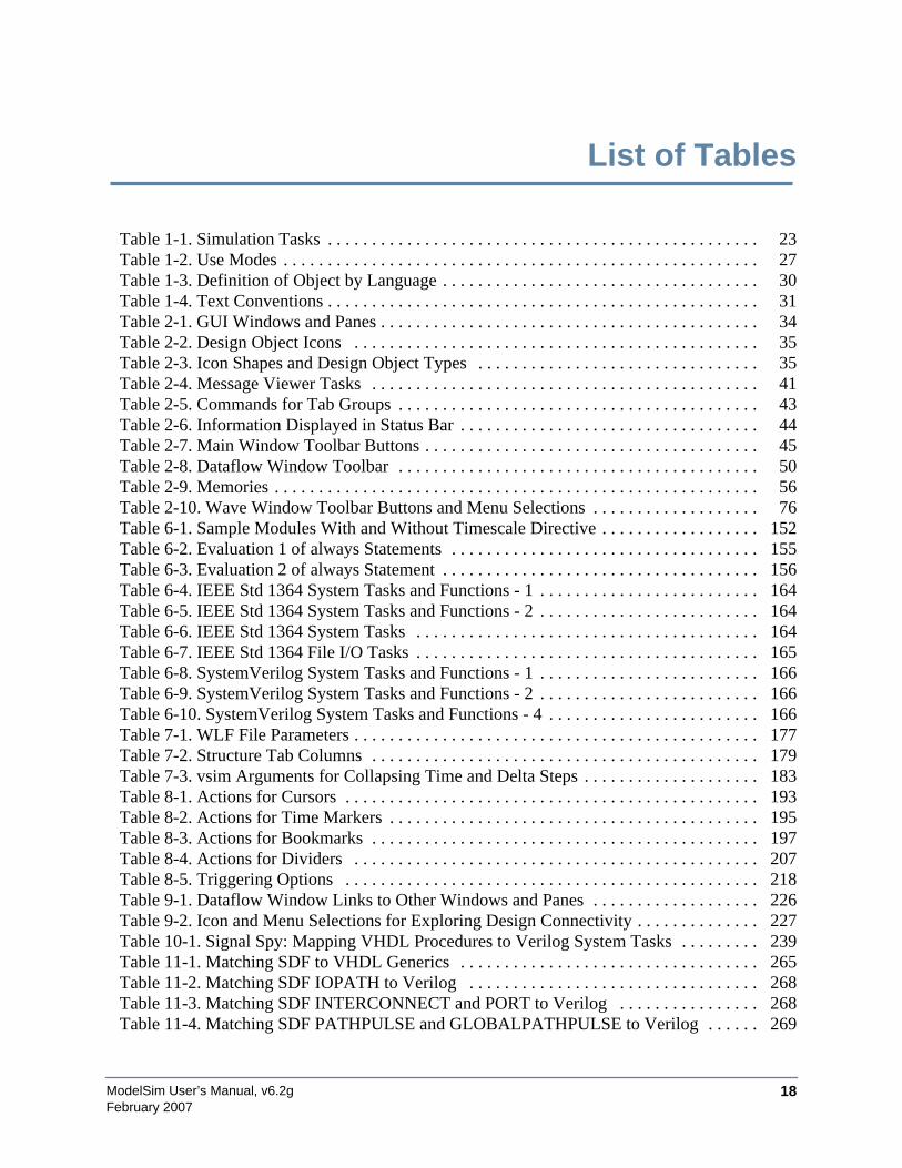
ModelSim User’s Manual, v6.2g 18February 2007
List of Tables
Table 1-1. Simulation Tasks . . . . . . . . . . . . . . . . . . . . . . . . . . . . . . . . . . . . . . . . . . . . . . . . . 23Table 1-2. Use Modes . . . . . . . . . . . . . . . . . . . . . . . . . . . . . . . . . . . . . . . . . . . . . . . . . . . . . . 27Table 1-3. Definition of Object by Language . . . . . . . . . . . . . . . . . . . . . . . . . . . . . . . . . . . . 30Table 1-4. Text Conventions . . . . . . . . . . . . . . . . . . . . . . . . . . . . . . . . . . . . . . . . . . . . . . . . . 31Table 2-1. GUI Windows and Panes . . . . . . . . . . . . . . . . . . . . . . . . . . . . . . . . . . . . . . . . . . . 34Table 2-2. Design Object Icons . . . . . . . . . . . . . . . . . . . . . . . . . . . . . . . . . . . . . . . . . . . . . . 35Table 2-3. Icon Shapes and Design Object Types . . . . . . . . . . . . . . . . . . . . . . . . . . . . . . . . 35Table 2-4. Message Viewer Tasks . . . . . . . . . . . . . . . . . . . . . . . . . . . . . . . . . . . . . . . . . . . . 41Table 2-5. Commands for Tab Groups . . . . . . . . . . . . . . . . . . . . . . . . . . . . . . . . . . . . . . . . . 43Table 2-6. Information Displayed in Status Bar . . . . . . . . . . . . . . . . . . . . . . . . . . . . . . . . . . 44Table 2-7. Main Window Toolbar Buttons . . . . . . . . . . . . . . . . . . . . . . . . . . . . . . . . . . . . . . 45Table 2-8. Dataflow Window Toolbar . . . . . . . . . . . . . . . . . . . . . . . . . . . . . . . . . . . . . . . . . 50Table 2-9. Memories . . . . . . . . . . . . . . . . . . . . . . . . . . . . . . . . . . . . . . . . . . . . . . . . . . . . . . . 56Table 2-10. Wave Window Toolbar Buttons and Menu Selections . . . . . . . . . . . . . . . . . . . 76Table 6-1. Sample Modules With and Without Timescale Directive . . . . . . . . . . . . . . . . . . 152Table 6-2. Evaluation 1 of always Statements . . . . . . . . . . . . . . . . . . . . . . . . . . . . . . . . . . . 155Table 6-3. Evaluation 2 of always Statement . . . . . . . . . . . . . . . . . . . . . . . . . . . . . . . . . . . . 156Table 6-4. IEEE Std 1364 System Tasks and Functions - 1 . . . . . . . . . . . . . . . . . . . . . . . . . 164Table 6-5. IEEE Std 1364 System Tasks and Functions - 2 . . . . . . . . . . . . . . . . . . . . . . . . . 164Table 6-6. IEEE Std 1364 System Tasks . . . . . . . . . . . . . . . . . . . . . . . . . . . . . . . . . . . . . . . 164Table 6-7. IEEE Std 1364 File I/O Tasks . . . . . . . . . . . . . . . . . . . . . . . . . . . . . . . . . . . . . . . 165Table 6-8. SystemVerilog System Tasks and Functions - 1 . . . . . . . . . . . . . . . . . . . . . . . . . 166Table 6-9. SystemVerilog System Tasks and Functions - 2 . . . . . . . . . . . . . . . . . . . . . . . . . 166Table 6-10. SystemVerilog System Tasks and Functions - 4 . . . . . . . . . . . . . . . . . . . . . . . . 166Table 7-1. WLF File Parameters . . . . . . . . . . . . . . . . . . . . . . . . . . . . . . . . . . . . . . . . . . . . . . 177Table 7-2. Structure Tab Columns . . . . . . . . . . . . . . . . . . . . . . . . . . . . . . . . . . . . . . . . . . . . 179Table 7-3. vsim Arguments for Collapsing Time and Delta Steps . . . . . . . . . . . . . . . . . . . . 183Table 8-1. Actions for Cursors . . . . . . . . . . . . . . . . . . . . . . . . . . . . . . . . . . . . . . . . . . . . . . . 193Table 8-2. Actions for Time Markers . . . . . . . . . . . . . . . . . . . . . . . . . . . . . . . . . . . . . . . . . . 195Table 8-3. Actions for Bookmarks . . . . . . . . . . . . . . . . . . . . . . . . . . . . . . . . . . . . . . . . . . . . 197Table 8-4. Actions for Dividers . . . . . . . . . . . . . . . . . . . . . . . . . . . . . . . . . . . . . . . . . . . . . . 207Table 8-5. Triggering Options . . . . . . . . . . . . . . . . . . . . . . . . . . . . . . . . . . . . . . . . . . . . . . . 218Table 9-1. Dataflow Window Links to Other Windows and Panes . . . . . . . . . . . . . . . . . . . 226Table 9-2. Icon and Menu Selections for Exploring Design Connectivity . . . . . . . . . . . . . . 227Table 10-1. Signal Spy: Mapping VHDL Procedures to Verilog System Tasks . . . . . . . . . 239Table 11-1. Matching SDF to VHDL Generics . . . . . . . . . . . . . . . . . . . . . . . . . . . . . . . . . . 265Table 11-2. Matching SDF IOPATH to Verilog . . . . . . . . . . . . . . . . . . . . . . . . . . . . . . . . . 268Table 11-3. Matching SDF INTERCONNECT and PORT to Verilog . . . . . . . . . . . . . . . . 268Table 11-4. Matching SDF PATHPULSE and GLOBALPATHPULSE to Verilog . . . . . . 269
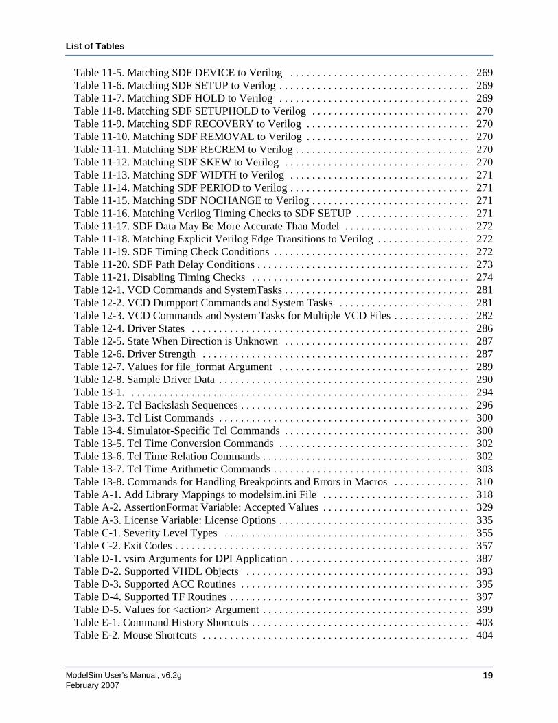
List of Tables
ModelSim User’s Manual, v6.2g 19February 2007
Table 11-5. Matching SDF DEVICE to Verilog . . . . . . . . . . . . . . . . . . . . . . . . . . . . . . . . . 269Table 11-6. Matching SDF SETUP to Verilog . . . . . . . . . . . . . . . . . . . . . . . . . . . . . . . . . . . 269Table 11-7. Matching SDF HOLD to Verilog . . . . . . . . . . . . . . . . . . . . . . . . . . . . . . . . . . . 269Table 11-8. Matching SDF SETUPHOLD to Verilog . . . . . . . . . . . . . . . . . . . . . . . . . . . . . 270Table 11-9. Matching SDF RECOVERY to Verilog . . . . . . . . . . . . . . . . . . . . . . . . . . . . . . 270Table 11-10. Matching SDF REMOVAL to Verilog . . . . . . . . . . . . . . . . . . . . . . . . . . . . . . 270Table 11-11. Matching SDF RECREM to Verilog . . . . . . . . . . . . . . . . . . . . . . . . . . . . . . . . 270Table 11-12. Matching SDF SKEW to Verilog . . . . . . . . . . . . . . . . . . . . . . . . . . . . . . . . . . 270Table 11-13. Matching SDF WIDTH to Verilog . . . . . . . . . . . . . . . . . . . . . . . . . . . . . . . . . 271Table 11-14. Matching SDF PERIOD to Verilog . . . . . . . . . . . . . . . . . . . . . . . . . . . . . . . . . 271Table 11-15. Matching SDF NOCHANGE to Verilog . . . . . . . . . . . . . . . . . . . . . . . . . . . . . 271Table 11-16. Matching Verilog Timing Checks to SDF SETUP . . . . . . . . . . . . . . . . . . . . . 271Table 11-17. SDF Data May Be More Accurate Than Model . . . . . . . . . . . . . . . . . . . . . . . 272Table 11-18. Matching Explicit Verilog Edge Transitions to Verilog . . . . . . . . . . . . . . . . . 272Table 11-19. SDF Timing Check Conditions . . . . . . . . . . . . . . . . . . . . . . . . . . . . . . . . . . . . 272Table 11-20. SDF Path Delay Conditions . . . . . . . . . . . . . . . . . . . . . . . . . . . . . . . . . . . . . . . 273Table 11-21. Disabling Timing Checks . . . . . . . . . . . . . . . . . . . . . . . . . . . . . . . . . . . . . . . . 274Table 12-1. VCD Commands and SystemTasks . . . . . . . . . . . . . . . . . . . . . . . . . . . . . . . . . . 281Table 12-2. VCD Dumpport Commands and System Tasks . . . . . . . . . . . . . . . . . . . . . . . . 281Table 12-3. VCD Commands and System Tasks for Multiple VCD Files . . . . . . . . . . . . . . 282Table 12-4. Driver States . . . . . . . . . . . . . . . . . . . . . . . . . . . . . . . . . . . . . . . . . . . . . . . . . . . 286Table 12-5. State When Direction is Unknown . . . . . . . . . . . . . . . . . . . . . . . . . . . . . . . . . . 287Table 12-6. Driver Strength . . . . . . . . . . . . . . . . . . . . . . . . . . . . . . . . . . . . . . . . . . . . . . . . . 287Table 12-7. Values for file_format Argument . . . . . . . . . . . . . . . . . . . . . . . . . . . . . . . . . . . 289Table 12-8. Sample Driver Data . . . . . . . . . . . . . . . . . . . . . . . . . . . . . . . . . . . . . . . . . . . . . . 290Table 13-1. . . . . . . . . . . . . . . . . . . . . . . . . . . . . . . . . . . . . . . . . . . . . . . . . . . . . . . . . . . . . . . 294Table 13-2. Tcl Backslash Sequences . . . . . . . . . . . . . . . . . . . . . . . . . . . . . . . . . . . . . . . . . . 296Table 13-3. Tcl List Commands . . . . . . . . . . . . . . . . . . . . . . . . . . . . . . . . . . . . . . . . . . . . . . 300Table 13-4. Simulator-Specific Tcl Commands . . . . . . . . . . . . . . . . . . . . . . . . . . . . . . . . . . 300Table 13-5. Tcl Time Conversion Commands . . . . . . . . . . . . . . . . . . . . . . . . . . . . . . . . . . . 302Table 13-6. Tcl Time Relation Commands . . . . . . . . . . . . . . . . . . . . . . . . . . . . . . . . . . . . . . 302Table 13-7. Tcl Time Arithmetic Commands . . . . . . . . . . . . . . . . . . . . . . . . . . . . . . . . . . . . 303Table 13-8. Commands for Handling Breakpoints and Errors in Macros . . . . . . . . . . . . . . 310Table A-1. Add Library Mappings to modelsim.ini File . . . . . . . . . . . . . . . . . . . . . . . . . . . 318Table A-2. AssertionFormat Variable: Accepted Values . . . . . . . . . . . . . . . . . . . . . . . . . . . 329Table A-3. License Variable: License Options . . . . . . . . . . . . . . . . . . . . . . . . . . . . . . . . . . . 335Table C-1. Severity Level Types . . . . . . . . . . . . . . . . . . . . . . . . . . . . . . . . . . . . . . . . . . . . . 355Table C-2. Exit Codes . . . . . . . . . . . . . . . . . . . . . . . . . . . . . . . . . . . . . . . . . . . . . . . . . . . . . . 357Table D-1. vsim Arguments for DPI Application . . . . . . . . . . . . . . . . . . . . . . . . . . . . . . . . . 387Table D-2. Supported VHDL Objects . . . . . . . . . . . . . . . . . . . . . . . . . . . . . . . . . . . . . . . . . 393Table D-3. Supported ACC Routines . . . . . . . . . . . . . . . . . . . . . . . . . . . . . . . . . . . . . . . . . . 395Table D-4. Supported TF Routines . . . . . . . . . . . . . . . . . . . . . . . . . . . . . . . . . . . . . . . . . . . . 397Table D-5. Values for <action> Argument . . . . . . . . . . . . . . . . . . . . . . . . . . . . . . . . . . . . . . 399Table E-1. Command History Shortcuts . . . . . . . . . . . . . . . . . . . . . . . . . . . . . . . . . . . . . . . . 403Table E-2. Mouse Shortcuts . . . . . . . . . . . . . . . . . . . . . . . . . . . . . . . . . . . . . . . . . . . . . . . . . 404
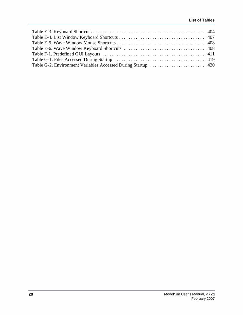
List of Tables
20February 2007
ModelSim User’s Manual, v6.2g
Table E-3. Keyboard Shortcuts . . . . . . . . . . . . . . . . . . . . . . . . . . . . . . . . . . . . . . . . . . . . . . . 404Table E-4. List Window Keyboard Shortcuts . . . . . . . . . . . . . . . . . . . . . . . . . . . . . . . . . . . . 407Table E-5. Wave Window Mouse Shortcuts . . . . . . . . . . . . . . . . . . . . . . . . . . . . . . . . . . . . . 408Table E-6. Wave Window Keyboard Shortcuts . . . . . . . . . . . . . . . . . . . . . . . . . . . . . . . . . . 408Table F-1. Predefined GUI Layouts . . . . . . . . . . . . . . . . . . . . . . . . . . . . . . . . . . . . . . . . . . . 411Table G-1. Files Accessed During Startup . . . . . . . . . . . . . . . . . . . . . . . . . . . . . . . . . . . . . . 419Table G-2. Environment Variables Accessed During Startup . . . . . . . . . . . . . . . . . . . . . . . 420
ModelSim User’s Manual, v6.2g 21February 2007
Chapter 1Introduction
This documentation was written for UNIX, Linux, and Microsoft Windows users. Not allversions of ModelSim are supported on all platforms. Contact your Mentor Graphics salesrepresentative for details.
Tool Structure and FlowThe diagram below illustrates the structure of the ModelSim tool, and the flow of that tool as itis used to verify a design.
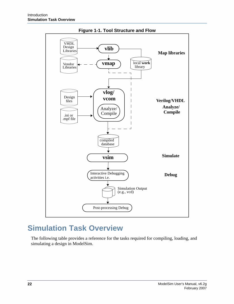
ModelSim User’s Manual, v6.2g22
IntroductionSimulation Task Overview
February 2007
Figure 1-1. Tool Structure and Flow
Simulation Task OverviewThe following table provides a reference for the tasks required for compiling, loading, andsimulating a design in ModelSim.
Simulate
Simulation Output(e.g., vcd)
Debug
.ini or Compile
vlog/
.mpf file
LibrariesVendor
Designfiles
vsim
Interactive Debuggingactivities i.e.
Analyze/
Verilog/VHDL
Compile
compileddatabase
vcom
Analyze/
vmap
VHDLDesignLibraries vlib
local worklibrary
Map libraries
Post-processing Debug
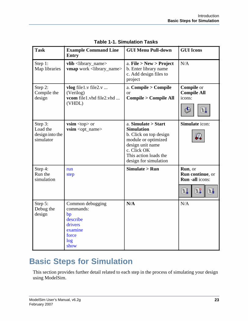
IntroductionBasic Steps for Simulation
ModelSim User’s Manual, v6.2g 23February 2007
Basic Steps for SimulationThis section provides further detail related to each step in the process of simulating your designusing ModelSim.
Table 1-1. Simulation Tasks
Task Example Command LineEntry
GUI Menu Pull-down GUI Icons
Step 1:Map libraries
vlib <library_name>vmap work <library_name>
a. File > New > Projectb. Enter library namec. Add design files toproject
N/A
Step 2:Compile thedesign
vlog file1.v file2.v ...(Verilog)vcom file1.vhd file2.vhd ...(VHDL)
a. Compile > CompileorCompile > Compile All
Compile orCompile Allicons:
Step 3:Load thedesign into thesimulator
vsim <top> orvsim <opt_name>
a. Simulate > StartSimulationb. Click on top designmodule or optimizeddesign unit namec. Click OKThis action loads thedesign for simulation
Simulate icon:
Step 4:Run thesimulation
runstep
Simulate > Run Run, orRun continue, orRun -all icons:
Step 5:Debug thedesign
Common debuggingcommands:bpdescribedriversexamineforcelogshow
N/A N/A
ModelSim User’s Manual, v6.2g24
IntroductionBasic Steps for Simulation
February 2007
Step 1 — Collecting Files and Mapping LibrariesFiles needed to run ModelSim on your design:
• design files (VHDL and/or Verilog ), including stimulus for the design
• libraries, both working and resource
• modelsim.ini (automatically created by the library mapping command
Providing Stimulus to the DesignYou can provide stimulus to your design in several ways:
• Language based testbench
• Tcl-based ModelSim interactive command, force
• VCD files / commands
See Creating a VCD File and Using Extended VCD as Stimulus
• 3rd party testbench generation tools
What is a Library?A library is a location where data to be used for simulation is stored. Libraries are ModelSim’sway of managing the creation of data before it is needed for use in simulation. It also serves as away to streamline simulation invocation. Instead of compiling all design data each and everytime you simulate, ModelSim uses binary pre-compiled data from these libraries. So, if youmake a changes to a single Verilog module, only that module is recompiled, rather than allmodules in the design.
Working and Resource LibrariesDesign libraries can be used in two ways: 1) as a local working library that contains thecompiled version of your design; 2) as a resource library. The contents of your working librarywill change as you update your design and recompile. A resource library is typicallyunchanging, and serves as a parts source for your design. Examples of resource libraries mightbe: shared information within your group, vendor libraries, packages, or previously compiledelements of your own working design. You can create your own resource libraries, or they maybe supplied by another design team or a third party (e.g., a silicon vendor).
For more information on resource libraries and working libraries, see Working Library VersusResource Libraries, Managing Library Contents, Working with Design Libraries, andSpecifying the Resource Libraries.
IntroductionBasic Steps for Simulation
ModelSim User’s Manual, v6.2g 25February 2007
Creating the Logical Library (vlib)Before you can compile your source files, you must create a library in which to store thecompilation results. You can create the logical library using the GUI, using File > New >Library (see Creating a Library), or you can use the vlib command. For example, thecommand:
vlib work
creates a library named work. By default, compilation results are stored in the work library.
Mapping the Logical Work to the Physical Work Directory (vmap)VHDL uses logical library names that can be mapped to ModelSim library directories. Iflibraries are not mapped properly, and you invoke your simulation, necessary components willnot be loaded and simulation will fail. Similarly, compilation can also depend on proper librarymapping.
By default, ModelSim can find libraries in your current directory (assuming they have the rightname), but for it to find libraries located elsewhere, you need to map a logical library name tothe pathname of the library.
You can use the GUI (Library Mappings with the GUI, a command (Library Mapping from theCommand Line), or a project (Getting Started with Projects to assign a logical name to a designlibrary.
The format for command line entry is:
vmap <logical_name> <directory_pathname>
This command sets the mapping between a logical library name and a directory.
Step 2 — Compiling the Design (vlog, vcom, sccom)Designs are compiled with one of the three language compilers.
Compiling Verilog (vlog)ModelSim’s compiler for the Verilog modules in your design is vlog. Verilog files may becompiled in any order, as they are not order dependent. See Compiling Verilog Files for details.
Compiling VHDL (vcom)ModelSim’s compiler for VHDL design units is vcom. VHDL files must be compiled accordingto the design requirements of the design. Projects may assist you in determining the compileorder: for more information, see Auto-Generating Compile Order. See Compiling VHDL Filesfor details. on VHDL compilation.
ModelSim User’s Manual, v6.2g26
IntroductionBasic Steps for Simulation
February 2007
Step 3 — Loading the Design for Simulation
vsim topLevelModuleYour design is ready for simulation after it has been compiled. You may then invoke vsim withthe names of the top-level modules (many designs contain only one top-level module). Forexample, if your top-level modules are "testbench" and "globals", then invoke the simulator asfollows:
vsim testbench globals
After the simulator loads the top-level modules, it iteratively loads the instantiated modules andUDPs in the design hierarchy, linking the design together by connecting the ports and resolvinghierarchical references.
Using SDFYou can incorporate actual delay values to the simulation by applying SDF back-annotationfiles to the design. For more information on how SDF is used in the design, see Specifying SDFFiles for Simulation.
Step 4 — Simulating the DesignOnce the design has been successfully loaded, the simulation time is set to zero, and you mustenter a run command to begin simulation. For more information, see Verilog andSystemVerilog Simulation, and VHDL Simulation.
The basic simulator commands are:
• add wave
• force
• bp
• run
• step
Step 5 — Debugging the DesignNumerous tools and windows useful in debugging your design are available from the ModelSimGUI. In addition, several basic simulation commands are available from the command line toassist you in debugging your design:
• describe
• drivers
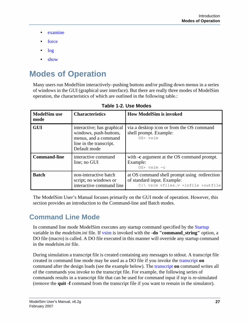
IntroductionModes of Operation
ModelSim User’s Manual, v6.2g 27February 2007
• examine
• force
• log
• show
Modes of OperationMany users run ModelSim interactively–pushing buttons and/or pulling down menus in a seriesof windows in the GUI (graphical user interface). But there are really three modes of ModelSimoperation, the characteristics of which are outlined in the following table.:
The ModelSim User’s Manual focuses primarily on the GUI mode of operation. However, thissection provides an introduction to the Command-line and Batch modes.
Command Line ModeIn command line mode ModelSim executes any startup command specified by the Startupvariable in the modelsim.ini file. If vsim is invoked with the -do "command_string" option, aDO file (macro) is called. A DO file executed in this manner will override any startup commandin the modelsim.ini file.
During simulation a transcript file is created containing any messages to stdout. A transcript filecreated in command line mode may be used as a DO file if you invoke the transcript oncommand after the design loads (see the example below). The transcript on command writes allof the commands you invoke to the transcript file. For example, the following series ofcommands results in a transcript file that can be used for command input if top is re-simulated(remove the quit -f command from the transcript file if you want to remain in the simulator).
Table 1-2. Use Modes
ModelSim usemode
Characteristics How ModelSim is invoked
GUI interactive; has graphicalwindows, push-buttons,menus, and a commandline in the transcript.Default mode
via a desktop icon or from the OS commandshell prompt. Example:
OS> vsim
Command-line interactive commandline; no GUI
with -c argument at the OS command prompt.Example:
OS> vsim -c
Batch non-interactive batchscript; no windows orinteractive command line
at OS command shell prompt using redirectionof standard input. Example:
C:\ vsim vfiles.v <infile >outfile
ModelSim User’s Manual, v6.2g28
IntroductionStandards Supported
February 2007
vsim -c top
library and design loading messages… then execute:
transcript onforce clk 1 50, 0 100 -repeat 100run 500run @5000quit -f
Rename transcript files that you intend to use as DO files. They will be overwritten the nexttime you run vsim if you don’t rename them. Also, simulator messages are already commentedout, but any messages generated from your design (and subsequently written to the transcriptfile) will cause the simulator to pause. A transcript file that contains only valid simulatorcommands will work fine; comment out anything else with a "#".
Stand-alone tools pick up project settings in command line mode if they are invoked in theproject's root directory. If invoked outside the project directory, stand-alone tools pick upproject settings only if you set the MODELSIM environment variable to the path to the projectfile (<Project_Root_Dir>/<Project_Name>.mpf).
Batch ModeBatch mode is an operational mode that provides neither an interactive command line norinteractive windows. In a Windows environment, vsim is run from a Windows commandprompt and standard input and output are redirected from and to files.
Here is an example of a batch mode simulation using redirection of std input and output:
vsim counter < yourfile > outfile
where "yourfile" is a script containing various ModelSim commands.
You can use the CTRL-C keyboard interrupt to break batch simulation in UNIX and Windowsenvironments.
Standards SupportedModelSim VHDL implements the VHDL language as defined by IEEE Standards 1076-1987,1076-1993, and 1076-2002. ModelSim also supports the 1164-1993 Standard Multivalue LogicSystem for VHDL Interoperability, and the 1076.2-1996 Standard VHDL MathematicalPackages standards. Any design developed with ModelSim will be compatible with any otherVHDL system that is compliant with the 1076 specs.
ModelSim Verilog implements the Verilog language as defined by the IEEE Std 1364-1995 and1364-2005. ModelSim Verilog also supports a partial implementation of SystemVerilog P1800-2005 (see /<install_dir>/modeltech/docs/technotes/sysvlog.note for implementation details).
IntroductionAssumptions
ModelSim User’s Manual, v6.2g 29February 2007
Both PLI (Programming Language Interface) and VCD (Value Change Dump) are supportedfor ModelSim users.
In addition, all products support SDF 1.0 through 4.0 (except the NETDELAY statement),VITAL 2.2b, VITAL’95 – IEEE 1076.4-1995, and VITAL 2000 – IEEE 1076.4-2000.
AssumptionsWe assume that you are familiar with the use of your operating system and its graphicalinterface.
We also assume that you have a working knowledge of the design languages. AlthoughModelSim is an excellent tool to use while learning HDL concepts and practices, this documentis not written to support that goal.
Finally, we assume that you have worked the appropriate lessons in the ModelSim Tutorial andare familiar with the basic functionality of ModelSim. The ModelSim Tutorial is available fromthe ModelSim Help menu.
Sections In This DocumentIn addition to this introduction, you will find the following major sections in this document:
Chapter 3, Projects — This chapter discusses ModelSim "projects", a container fordesign files and their associated simulation properties.
Chapter 4, Design Libraries — To simulate an HDL design using ModelSim, you needto know how to create, compile, maintain, and delete design libraries as described in thischapter.
Chapter 5, VHDL Simulation — This chapter is an overview of compilation andsimulation for VHDL within the ModelSim environment.
Chapter 6, Verilog and SystemVerilog Simulation — This chapter is an overview ofcompilation and simulation for Verilog and SystemVerilog within the ModelSimenvironment.
Chapter 7, WLF Files (Datasets) and Virtuals — This chapter describes datasets andvirtuals - both methods for viewing and organizing simulation data in ModelSim.
Chapter 8, Waveform Analysis — This chapter describes how to perform waveformanalysis with the ModelSim Wave and List windows.
Chapter 9, Tracing Signals with the Dataflow Window — This chapter describes how totrace signals and assess causality using the ModelSim Dataflow window.
ModelSim User’s Manual, v6.2g30
IntroductionWhat is an "Object"
February 2007
Chapter 10, Signal Spy — This chapter describes Signal Spy, a set of VHDL proceduresand Verilog system tasks that let you monitor, drive, force, or release a design objectfrom anywhere in the hierarchy of a VHDL or mixed design.
Chapter 11, Standard Delay Format (SDF) Timing Annotation — This chapter discussesModelSim’s implementation of SDF (Standard Delay Format) timing annotation.Included are sections on VITAL SDF and Verilog SDF, plus troubleshooting.
Chapter 12, Value Change Dump (VCD) Files — This chapter explains ModelTechnology’s Verilog VCD implementation for ModelSim. The VCD usage is extendedto include VHDL designs.
Chapter 13, Tcl and Macros (DO Files) — This chapter provides an overview of Tcl(tool command language) as used with ModelSim.
Appendix A, Simulator Variables — This appendix describes environment, system, andpreference variables used in ModelSim.
Appendix C, Error and Warning Messages — This appendix describes ModelSim errorand warning messages.
Appendix D, Verilog PLI/VPI/DPI — This appendix describes the ModelSimimplementation of the Verilog PLI and VPI.
Appendix E, Command and Keyboard Shortcuts — This appendix describes ModelSimkeyboard and mouse shortcuts.
Appendix G, System Initialization — This appendix describes what happens duringModelSim startup.
What is an "Object"Because ModelSim works with so many languages (Verilog, VHDL, SystemVerilog, ), an“object” refers to any valid design element in those languages. The word "object" is usedwhenever a specific language reference is not needed. Depending on the context, “object” canrefer to any of the following:
Table 1-3. Definition of Object by Language
Language An object can be
VHDL block statement, component instantiation, constant,generate statement, generic, package, signal, alias,or variable
Verilog function, module instantiation, named fork, namedbegin, net, task, register, or variable
SystemVerilog In addition to those listed above for Verilog:class, package, program, interface, array, directive,property, or sequence
IntroductionText Conventions
ModelSim User’s Manual, v6.2g 31February 2007
Text ConventionsText conventions used in this manual include:
Installation Directory PathnamesWhen referring to installation paths, this manual uses “modeltech” as a generic representationof the installation directory for all versions of ModelSim. The actual installation directory onyour system may contain version information.
PSL property, sequence, directive, or endpoint
Table 1-4. Text Conventions
Text Type Description
italic text provides emphasis and sets off filenames,pathnames, and design unit names
bold text indicates commands, command options, menuchoices, package and library logical names, aswell as variables, dialog box selections, andlanguage keywords
monospace type monospace type is used for program andcommand examples
The right angle (>) is used to connect menu choices whentraversing menus as in: File > Quit
UPPER CASE denotes file types used by ModelSim (e.g., DO,WLF, INI, MPF, PDF, etc.)
Table 1-3. Definition of Object by Language
Language An object can be

ModelSim User’s Manual, v6.2g32
IntroductionInstallation Directory Pathnames
February 2007
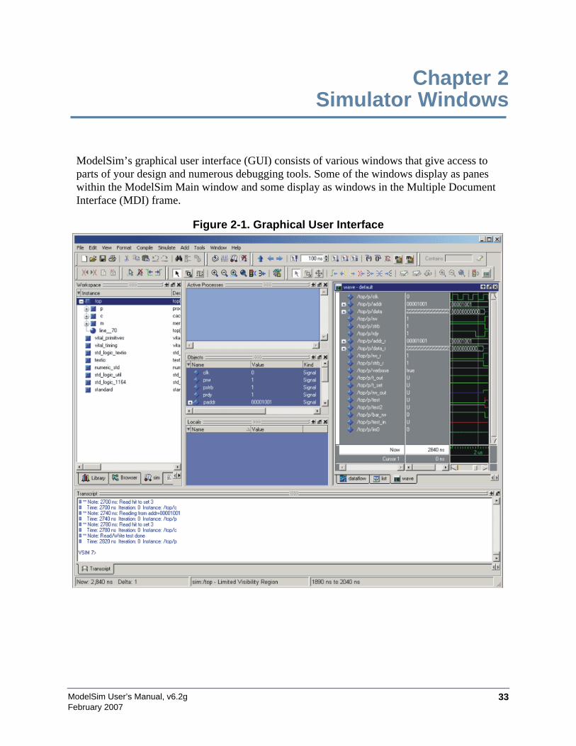
ModelSim User’s Manual, v6.2g 33February 2007
Chapter 2Simulator Windows
ModelSim’s graphical user interface (GUI) consists of various windows that give access toparts of your design and numerous debugging tools. Some of the windows display as paneswithin the ModelSim Main window and some display as windows in the Multiple DocumentInterface (MDI) frame.
Figure 2-1. Graphical User Interface
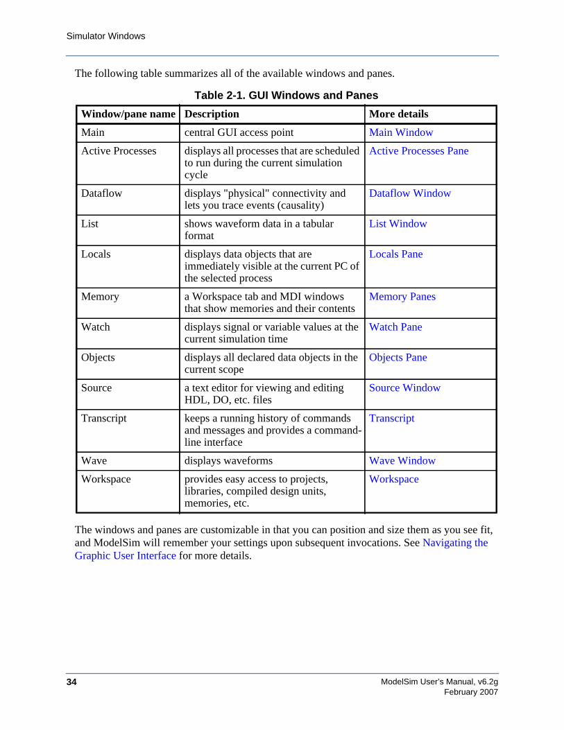
ModelSim User’s Manual, v6.2g34
Simulator Windows
February 2007
The following table summarizes all of the available windows and panes.
The windows and panes are customizable in that you can position and size them as you see fit,and ModelSim will remember your settings upon subsequent invocations. See Navigating theGraphic User Interface for more details.
Table 2-1. GUI Windows and Panes
Window/pane name Description More details
Main central GUI access point Main Window
Active Processes displays all processes that are scheduledto run during the current simulationcycle
Active Processes Pane
Dataflow displays "physical" connectivity andlets you trace events (causality)
Dataflow Window
List shows waveform data in a tabularformat
List Window
Locals displays data objects that areimmediately visible at the current PC ofthe selected process
Locals Pane
Memory a Workspace tab and MDI windowsthat show memories and their contents
Memory Panes
Watch displays signal or variable values at thecurrent simulation time
Watch Pane
Objects displays all declared data objects in thecurrent scope
Objects Pane
Source a text editor for viewing and editingHDL, DO, etc. files
Source Window
Transcript keeps a running history of commandsand messages and provides a command-line interface
Transcript
Wave displays waveforms Wave Window
Workspace provides easy access to projects,libraries, compiled design units,memories, etc.
Workspace

Simulator WindowsDesign Object Icons and Their Meaning
ModelSim User’s Manual, v6.2g 35February 2007
Design Object Icons and Their MeaningThe color and shape of icons convey information about the language and type of a designobject. shows the icon colors and the languages they indicate.
Here is a list of icon shapes and the design object types they indicate:
Setting FontsYou may need to adjust font settings to accommodate the aspect ratios of wide screen anddouble screen displays or to handle launching ModelSim from an X-session.
Font ScalingTo change font scaling, select Tools > Options > Adjust Font Scaling. You’ll need a ruler tocomplete the instructions in the lower right corner of the dialog. When you have entered thepixel and inches information, click OK to close the dialog. Then, restart ModelSim to see thechange. This is a one time setting; you shouldn't have to set it again unless you change display
Table 2-2. Design Object Icons
Icon color Design Language
light blue Verilog or SystemVerilog
dark blue VHDL
orange virtual object
Table 2-3. Icon Shapes and Design Object Types
icon shape example design object type
square any scope (VHDL block, Verilog named block, SCmodule, class, interface, task, function, etc.)
circle process
diamond valued object (signals, nets, registers, etc.)
caution sign comparison object
diamondwith red dot
an editable waveform created with the waveform editor
star transaction; The color of the star for each transactiondepends on the language of the region in which thetransaction stream occurs: dark blue for VHDL, light bluefor Verilog and SystemVerilog, green for SystemC,magenta for PSL.
ModelSim User’s Manual, v6.2g36
Simulator WindowsMain Window
February 2007
resolution or the hardware (monitor or video card). The font scaling applies to Windows andUNIX operating systems. On UNIX systems, the font scaling is stored based on the $DISPLAYenvironment variable.
Controlling Fonts in an X-sessionWhen executed via an X-session (e.g., Exceed, VNC), ModelSim uses font definitions from the.Xdefaults file. To ensure that the fonts look correct, create a .Xdefaults file with the followinglines:
vsim*Font: -adobe-courier-medium-r-normal--*-120-*-*-*-*-*vsim*SystemFont: -adobe-courier-medium-r-normal--*-120-*-*-*-*-*vsim*StandardFont: -adobe-courier-medium-r-normal--*-120-*-*-*-*-*vsim*MenuFont: -adobe-courier-medium-r-normal--*-120-*-*-*-*-*
Alternatively, you can choose a different font. Use the program "xlsfonts" to identify whichfonts are available on your system.
Also, the following command can be used to update the X resources if you make changes to the.Xdefaults and wish to use those changes on a UNIX machine:
xrdb -merge .Xdefaults
Main WindowThe primary access point in the ModelSim GUI is called the Main window. It providesconvenient access to design libraries and objects, source files, debugging commands, simulationstatus messages, etc. When you load a design, or bring up debugging tools, ModelSim addspanes or opens windows appropriate for your debugging environment (Figure 2-2).
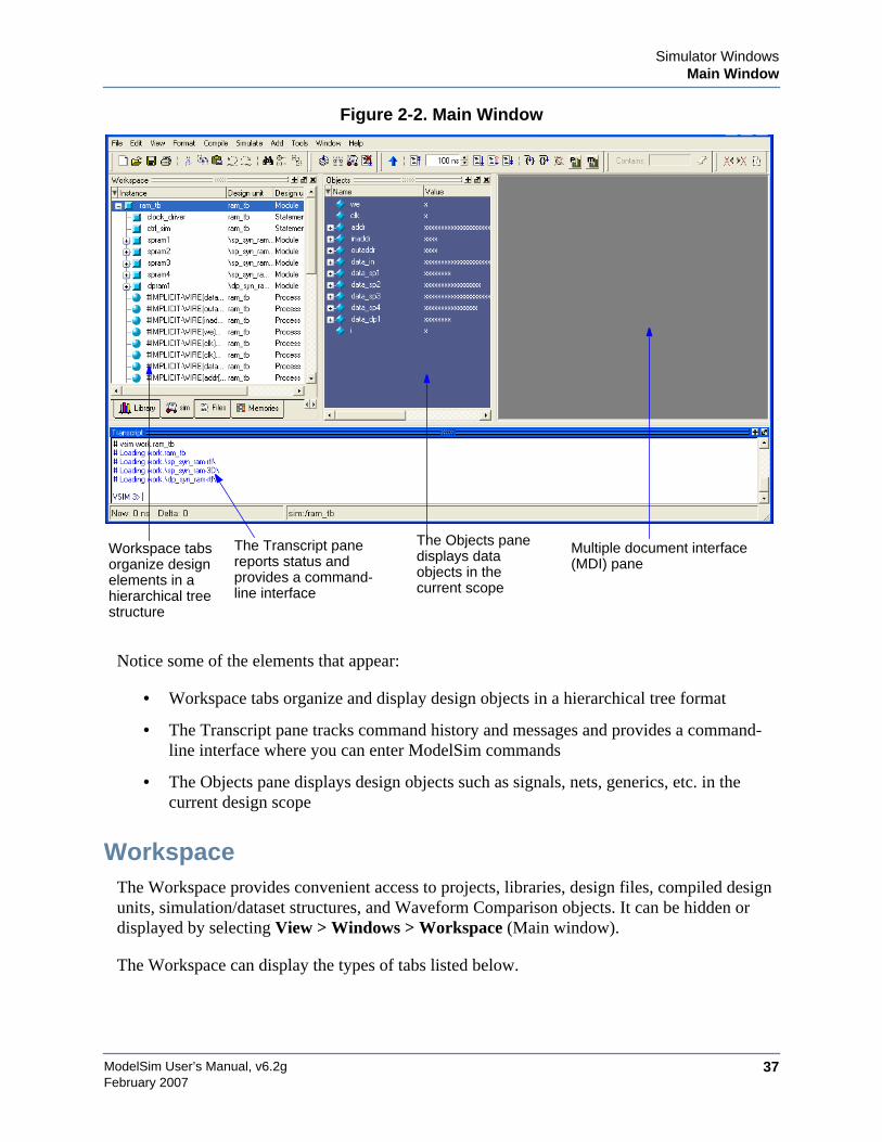
Simulator WindowsMain Window
ModelSim User’s Manual, v6.2g 37February 2007
Figure 2-2. Main Window
Notice some of the elements that appear:
• Workspace tabs organize and display design objects in a hierarchical tree format
• The Transcript pane tracks command history and messages and provides a command-line interface where you can enter ModelSim commands
• The Objects pane displays design objects such as signals, nets, generics, etc. in thecurrent design scope
WorkspaceThe Workspace provides convenient access to projects, libraries, design files, compiled designunits, simulation/dataset structures, and Waveform Comparison objects. It can be hidden ordisplayed by selecting View > Windows > Workspace (Main window).
The Workspace can display the types of tabs listed below.
Workspace tabsorganize designelements in ahierarchical treestructure
The Transcript panereports status andprovides a command-line interface
The Objects panedisplays dataobjects in thecurrent scope
Multiple document interface(MDI) pane
ModelSim User’s Manual, v6.2g38
Simulator WindowsMain Window
February 2007
• Project tab — Shows all files that are included in the open project. Refer to Projects fordetails.
• Library tab — Shows design libraries and compiled design units. To update the currentview of the library, select a library, and then Right click > Update. See ManagingLibrary Contents for details on library management.
• Structure tabs —Shows a hierarchical view of the active simulation and any opendatasets. There is one tab for the current simulation (named "sim") and one tab for eachopen dataset. See Viewing Dataset Structure for details.
An entry is created by each object within the design. When you select a region in astructure tab, it becomes the current region and is highlighted. The Source Window andObjects Pane change dynamically to reflect the information for the current region. Thisfeature provides a useful method for finding the source code for a selected regionbecause the system keeps track of the pathname where the source is located and displaysit automatically, without the need for you to provide the pathname.
Also, when you select a region in the structure pane, the Active Processes Pane isupdated. The Active Processes window will in turn update the Locals Pane.
Objects can be dragged from the structure tabs to the Dataflow, List and Wave windows.
You can toggle the display of processes by clicking in a Structure tab and selectingView > Filter > Processes.
You can also control implicit wire processes using a preference variable. By defaultStructure tabs suppress the display of implicit wire processes. To enable the display ofimplicit wire processes, set PrefMain(HideImplicitWires) to 0 (select Tools > EditPreferences, By Name tab, and expand the Main object).
• Files tab — Shows the source files for the loaded design.
You can disable the display of this tab by setting the PrefMain(ShowFilePane)preference variable to 0. See Simulator GUI Preferences for information on settingpreference variables.
• Memories tab — Shows a hierarchical list of all memories in the design. To display thistab, select View > Windows > Memory. When you select a memory on the tab, amemory contents page opens in the MDI frame. See Memory Panes.
TranscriptThe Transcript portion of the Main window maintains a running history of commands that areinvoked and messages that occur as you work with ModelSim. When a simulation is running,the Transcript displays a VSIM prompt, allowing you to enter command-line commands fromwithin the graphic interface.
Simulator WindowsMain Window
ModelSim User’s Manual, v6.2g 39February 2007
You can scroll backward and forward through the current work history by using the verticalscrollbar. You can also use arrow keys to recall previous commands, or copy and paste usingthe mouse within the window (see Main and Source Window Mouse and Keyboard Shortcutsfor details).
Saving the Transcript FileVariable settings determine the filename used for saving the transcript. If either PrefMain(file)in the .modelsim file or TranscriptFile in the modelsim.ini file is set, then the transcript outputis logged to the specified file. By default the TranscriptFile variable in modelsim.ini is set totranscript. If either variable is set, the transcript contents are always saved and no explicitsaving is necessary.
If you would like to save an additional copy of the transcript with a different filename, click inthe Transcript pane and then select File > Save As, or File > Save. The initial save must bemade with the Save As selection, which stores the filename in the Tcl variablePrefMain(saveFile). Subsequent saves can be made with the Save selection. Since noautomatic saves are performed for this file, it is written only when you invoke a Save command.The file is written to the specified directory and records the contents of the transcript at the timeof the save.
Using the Saved Transcript as a Macro (DO file)Saved transcript files can be used as macros (DO files). Refer to the do command for moreinformation.
Changing the Number of Lines Saved in the Transcript WindowBy default, the Transcript window retains the last 5000 lines of output from the transcript. Youcan change this default by altering the saveLines preference variable. Setting this variable to 0instructs the tool to retain all lines of the transcript. See Simulator GUI Preferences for detailson setting preference variables.
Disabling Creation of the Transcript FileYou can disable the creation of the transcript file by using the following ModelSim commandimmediately after ModelSim starts:
transcript file ""
Automatic Command HelpWhen you start typing a command at the Transcript prompt, a dropdown box appears which liststhe available commands matching what has been typed so far. You may use the Up and Downarrow keys or the mouse to select the desired command. When a unique command has beenentered, the command usage is presented in the drop down box.
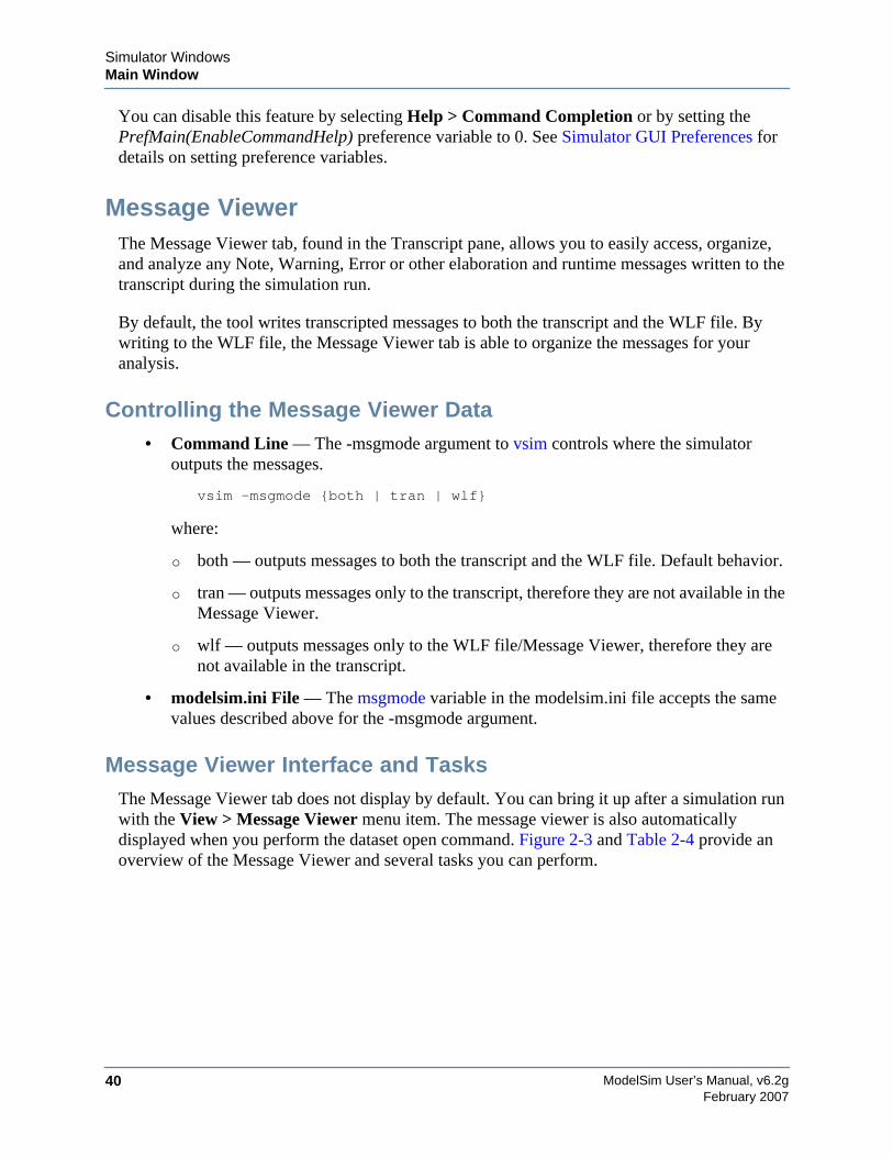
ModelSim User’s Manual, v6.2g40
Simulator WindowsMain Window
February 2007
You can disable this feature by selecting Help > Command Completion or by setting thePrefMain(EnableCommandHelp) preference variable to 0. See Simulator GUI Preferences fordetails on setting preference variables.
Message ViewerThe Message Viewer tab, found in the Transcript pane, allows you to easily access, organize,and analyze any Note, Warning, Error or other elaboration and runtime messages written to thetranscript during the simulation run.
By default, the tool writes transcripted messages to both the transcript and the WLF file. Bywriting to the WLF file, the Message Viewer tab is able to organize the messages for youranalysis.
Controlling the Message Viewer Data• Command Line — The -msgmode argument to vsim controls where the simulator
outputs the messages.
vsim -msgmode {both | tran | wlf}
where:
o both — outputs messages to both the transcript and the WLF file. Default behavior.
o tran — outputs messages only to the transcript, therefore they are not available in theMessage Viewer.
o wlf — outputs messages only to the WLF file/Message Viewer, therefore they arenot available in the transcript.
• modelsim.ini File — The msgmode variable in the modelsim.ini file accepts the samevalues described above for the -msgmode argument.
Message Viewer Interface and TasksThe Message Viewer tab does not display by default. You can bring it up after a simulation runwith the View > Message Viewer menu item. The message viewer is also automaticallydisplayed when you perform the dataset open command. Figure 2-3 and Table 2-4 provide anoverview of the Message Viewer and several tasks you can perform.
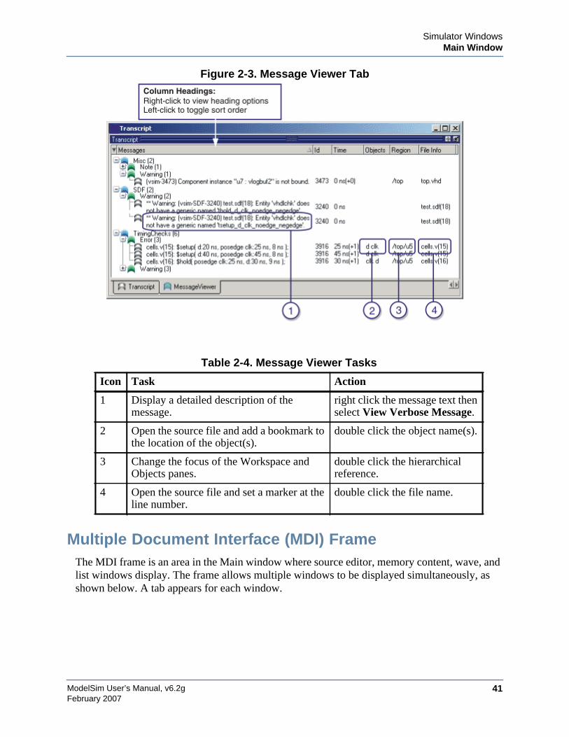
Simulator WindowsMain Window
ModelSim User’s Manual, v6.2g 41February 2007
Figure 2-3. Message Viewer Tab
Multiple Document Interface (MDI) FrameThe MDI frame is an area in the Main window where source editor, memory content, wave, andlist windows display. The frame allows multiple windows to be displayed simultaneously, asshown below. A tab appears for each window.
Table 2-4. Message Viewer Tasks
Icon Task Action
1 Display a detailed description of themessage.
right click the message text thenselect View Verbose Message.
2 Open the source file and add a bookmark tothe location of the object(s).
double click the object name(s).
3 Change the focus of the Workspace andObjects panes.
double click the hierarchicalreference.
4 Open the source file and set a marker at theline number.
double click the file name.
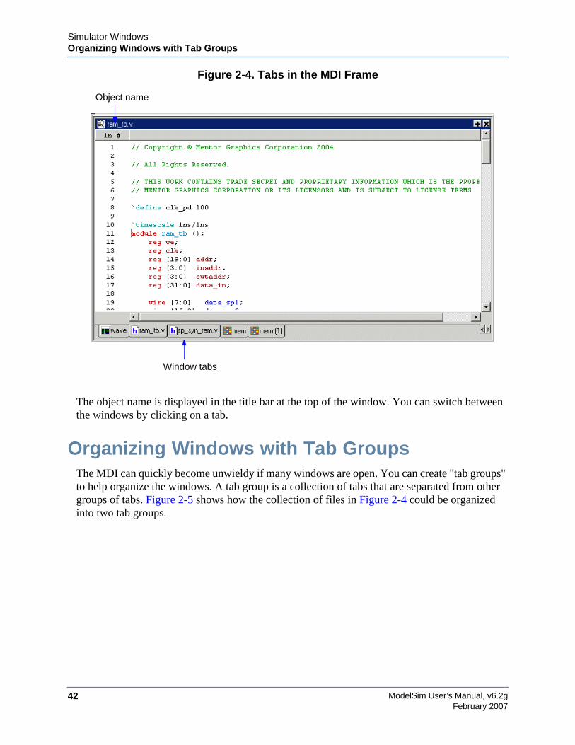
ModelSim User’s Manual, v6.2g42
Simulator WindowsOrganizing Windows with Tab Groups
February 2007
Figure 2-4. Tabs in the MDI Frame
The object name is displayed in the title bar at the top of the window. You can switch betweenthe windows by clicking on a tab.
Organizing Windows with Tab GroupsThe MDI can quickly become unwieldy if many windows are open. You can create "tab groups"to help organize the windows. A tab group is a collection of tabs that are separated from othergroups of tabs. Figure 2-5 shows how the collection of files in Figure 2-4 could be organizedinto two tab groups.
Window tabs
Object name
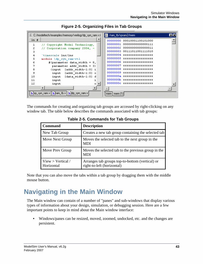
Simulator WindowsNavigating in the Main Window
ModelSim User’s Manual, v6.2g 43February 2007
Figure 2-5. Organizing Files in Tab Groups
The commands for creating and organizing tab groups are accessed by right-clicking on anywindow tab. The table below describes the commands associated with tab groups:
Note that you can also move the tabs within a tab group by dragging them with the middlemouse button.
Navigating in the Main WindowThe Main window can contain of a number of "panes" and sub-windows that display varioustypes of information about your design, simulation, or debugging session. Here are a fewimportant points to keep in mind about the Main window interface:
• Windows/panes can be resized, moved, zoomed, undocked, etc. and the changes arepersistent.
Table 2-5. Commands for Tab Groups
Command Description
New Tab Group Creates a new tab group containing the selected tab
Move Next Group Moves the selected tab to the next group in theMDI
Move Prev Group Moves the selected tab to the previous group in theMDI
View > Vertical /Horizontal
Arranges tab groups top-to-bottom (vertical) orright-to-left (horizontal)
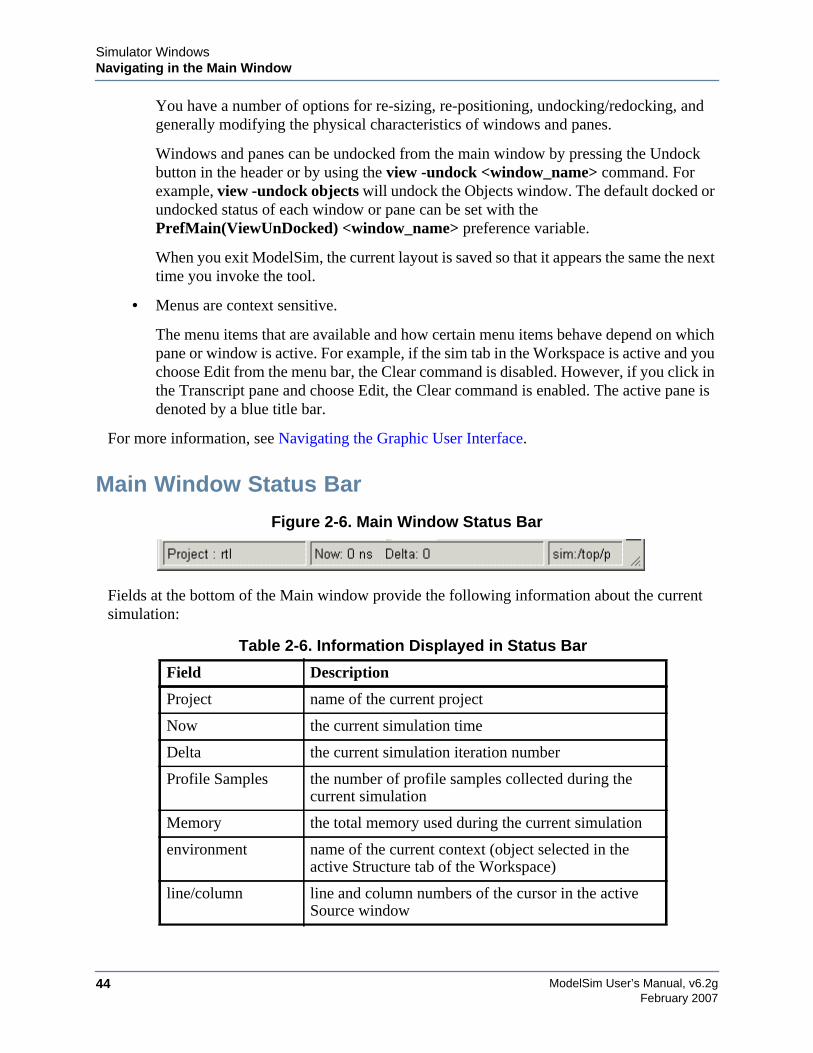
ModelSim User’s Manual, v6.2g44
Simulator WindowsNavigating in the Main Window
February 2007
You have a number of options for re-sizing, re-positioning, undocking/redocking, andgenerally modifying the physical characteristics of windows and panes.
Windows and panes can be undocked from the main window by pressing the Undockbutton in the header or by using the view -undock <window_name> command. Forexample, view -undock objects will undock the Objects window. The default docked orundocked status of each window or pane can be set with thePrefMain(ViewUnDocked) <window_name> preference variable.
When you exit ModelSim, the current layout is saved so that it appears the same the nexttime you invoke the tool.
• Menus are context sensitive.
The menu items that are available and how certain menu items behave depend on whichpane or window is active. For example, if the sim tab in the Workspace is active and youchoose Edit from the menu bar, the Clear command is disabled. However, if you click inthe Transcript pane and choose Edit, the Clear command is enabled. The active pane isdenoted by a blue title bar.
For more information, see Navigating the Graphic User Interface.
Main Window Status Bar
Figure 2-6. Main Window Status Bar
Fields at the bottom of the Main window provide the following information about the currentsimulation:
Table 2-6. Information Displayed in Status Bar
Field Description
Project name of the current project
Now the current simulation time
Delta the current simulation iteration number
Profile Samples the number of profile samples collected during thecurrent simulation
Memory the total memory used during the current simulation
environment name of the current context (object selected in theactive Structure tab of the Workspace)
line/column line and column numbers of the cursor in the activeSource window
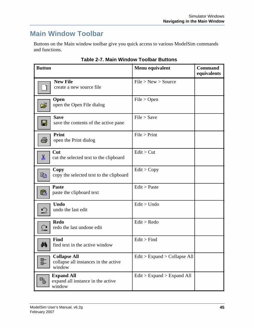
Simulator WindowsNavigating in the Main Window
ModelSim User’s Manual, v6.2g 45February 2007
Main Window ToolbarButtons on the Main window toolbar give you quick access to various ModelSim commandsand functions.
Table 2-7. Main Window Toolbar Buttons
Button Menu equivalent Commandequivalents
New Filecreate a new source file
File > New > Source
Openopen the Open File dialog
File > Open
Savesave the contents of the active pane
File > Save
Printopen the Print dialog
File > Print
Cutcut the selected text to the clipboard
Edit > Cut
Copycopy the selected text to the clipboard
Edit > Copy
Pastepaste the clipboard text
Edit > Paste
Undoundo the last edit
Edit > Undo
Redoredo the last undone edit
Edit > Redo
Findfind text in the active window
Edit > Find
Collapse Allcollapse all instances in the activewindow
Edit > Expand > Collapse All
Expand Allexpand all instance in the activewindow
Edit > Expand > Expand All
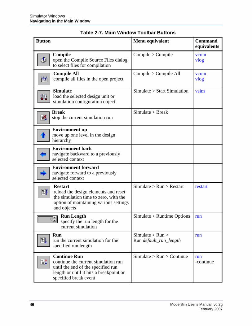
ModelSim User’s Manual, v6.2g46
Simulator WindowsNavigating in the Main Window
February 2007
Compileopen the Compile Source Files dialogto select files for compilation
Compile > Compile vcomvlog
Compile Allcompile all files in the open project
Compile > Compile All vcomvlog
Simulateload the selected design unit orsimulation configuration object
Simulate > Start Simulation vsim
Breakstop the current simulation run
Simulate > Break
Environment upmove up one level in the designhierarchy
Environment backnavigate backward to a previouslyselected context
Environment forwardnavigate forward to a previouslyselected context
Restartreload the design elements and resetthe simulation time to zero, with theoption of maintaining various settingsand objects
Simulate > Run > Restart restart
Run Lengthspecify the run length for thecurrent simulation
Simulate > Runtime Options run
Runrun the current simulation for thespecified run length
Simulate > Run >Run default_run_length
run
Continue Runcontinue the current simulation rununtil the end of the specified runlength or until it hits a breakpoint orspecified break event
Simulate > Run > Continue run-continue
Table 2-7. Main Window Toolbar Buttons
Button Menu equivalent Commandequivalents
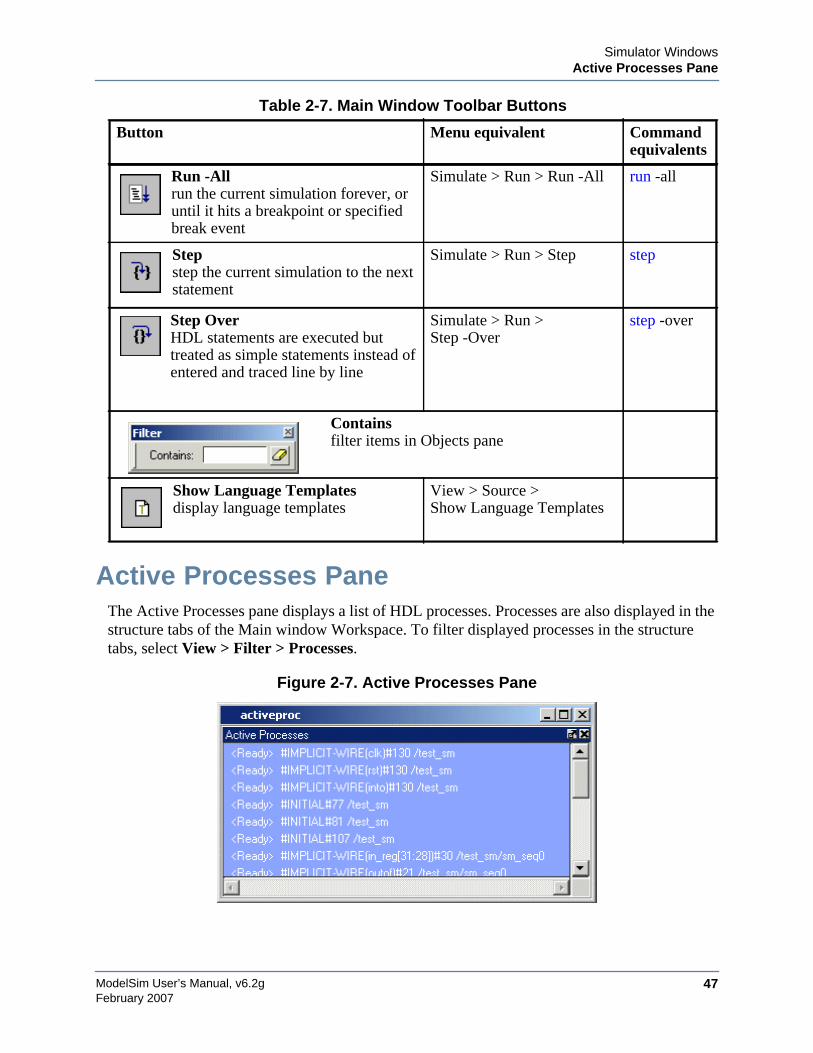
Simulator WindowsActive Processes Pane
ModelSim User’s Manual, v6.2g 47February 2007
Active Processes PaneThe Active Processes pane displays a list of HDL processes. Processes are also displayed in thestructure tabs of the Main window Workspace. To filter displayed processes in the structuretabs, select View > Filter > Processes.
Figure 2-7. Active Processes Pane
Run -Allrun the current simulation forever, oruntil it hits a breakpoint or specifiedbreak event
Simulate > Run > Run -All run -all
Stepstep the current simulation to the nextstatement
Simulate > Run > Step step
Step OverHDL statements are executed buttreated as simple statements instead ofentered and traced line by line
Simulate > Run >Step -Over
step -over
Containsfilter items in Objects pane
Show Language Templatesdisplay language templates
View > Source >Show Language Templates
Table 2-7. Main Window Toolbar Buttons
Button Menu equivalent Commandequivalents
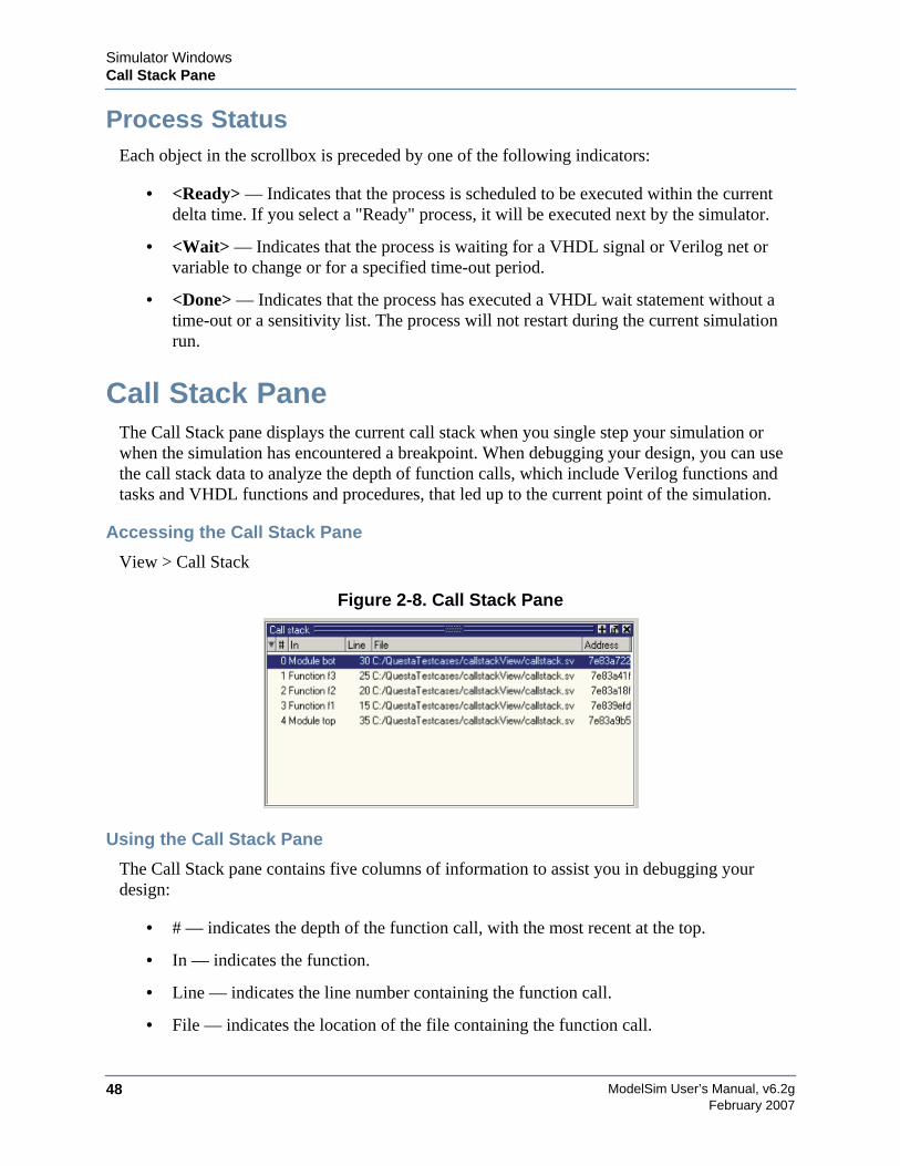
ModelSim User’s Manual, v6.2g48
Simulator WindowsCall Stack Pane
February 2007
Process StatusEach object in the scrollbox is preceded by one of the following indicators:
• <Ready> — Indicates that the process is scheduled to be executed within the currentdelta time. If you select a "Ready" process, it will be executed next by the simulator.
• <Wait> — Indicates that the process is waiting for a VHDL signal or Verilog net orvariable to change or for a specified time-out period.
• <Done> — Indicates that the process has executed a VHDL wait statement without atime-out or a sensitivity list. The process will not restart during the current simulationrun.
Call Stack PaneThe Call Stack pane displays the current call stack when you single step your simulation orwhen the simulation has encountered a breakpoint. When debugging your design, you can usethe call stack data to analyze the depth of function calls, which include Verilog functions andtasks and VHDL functions and procedures, that led up to the current point of the simulation.
Accessing the Call Stack Pane
View > Call Stack
Figure 2-8. Call Stack Pane
Using the Call Stack Pane
The Call Stack pane contains five columns of information to assist you in debugging yourdesign:
• # — indicates the depth of the function call, with the most recent at the top.
• In — indicates the function.
• Line — indicates the line number containing the function call.
• File — indicates the location of the file containing the function call.
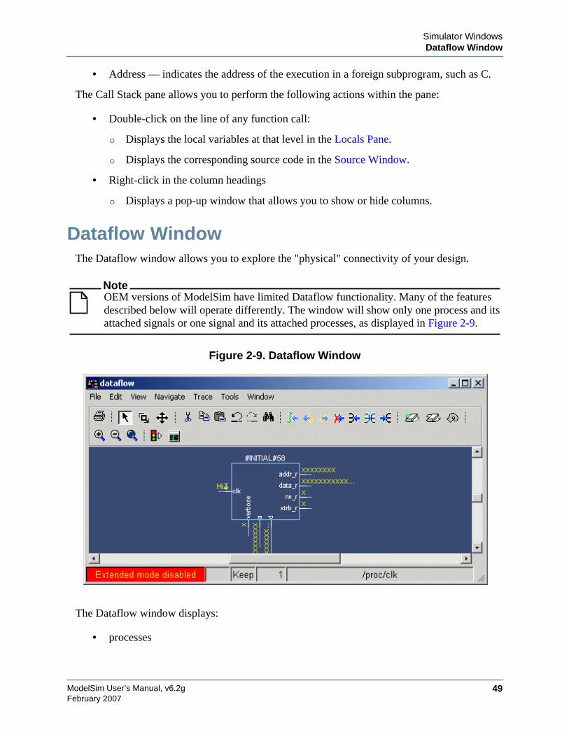
Simulator WindowsDataflow Window
ModelSim User’s Manual, v6.2g 49February 2007
• Address — indicates the address of the execution in a foreign subprogram, such as C.
The Call Stack pane allows you to perform the following actions within the pane:
• Double-click on the line of any function call:
o Displays the local variables at that level in the Locals Pane.
o Displays the corresponding source code in the Source Window.
• Right-click in the column headings
o Displays a pop-up window that allows you to show or hide columns.
Dataflow WindowThe Dataflow window allows you to explore the "physical" connectivity of your design.
NoteOEM versions of ModelSim have limited Dataflow functionality. Many of the featuresdescribed below will operate differently. The window will show only one process and itsattached signals or one signal and its attached processes, as displayed in Figure 2-9.
Figure 2-9. Dataflow Window
The Dataflow window displays:
• processes
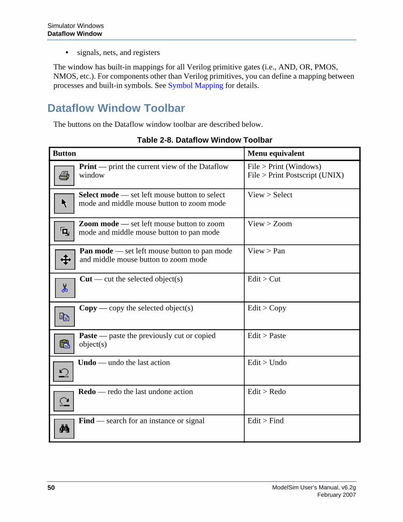
ModelSim User’s Manual, v6.2g50
Simulator WindowsDataflow Window
February 2007
• signals, nets, and registers
The window has built-in mappings for all Verilog primitive gates (i.e., AND, OR, PMOS,NMOS, etc.). For components other than Verilog primitives, you can define a mapping betweenprocesses and built-in symbols. See Symbol Mapping for details.
Dataflow Window ToolbarThe buttons on the Dataflow window toolbar are described below.
Table 2-8. Dataflow Window Toolbar
Button Menu equivalent
Print — print the current view of the Dataflowwindow
File > Print (Windows)File > Print Postscript (UNIX)
Select mode — set left mouse button to selectmode and middle mouse button to zoom mode
View > Select
Zoom mode — set left mouse button to zoommode and middle mouse button to pan mode
View > Zoom
Pan mode — set left mouse button to pan modeand middle mouse button to zoom mode
View > Pan
Cut — cut the selected object(s) Edit > Cut
Copy — copy the selected object(s) Edit > Copy
Paste — paste the previously cut or copiedobject(s)
Edit > Paste
Undo — undo the last action Edit > Undo
Redo — redo the last undone action Edit > Redo
Find — search for an instance or signal Edit > Find
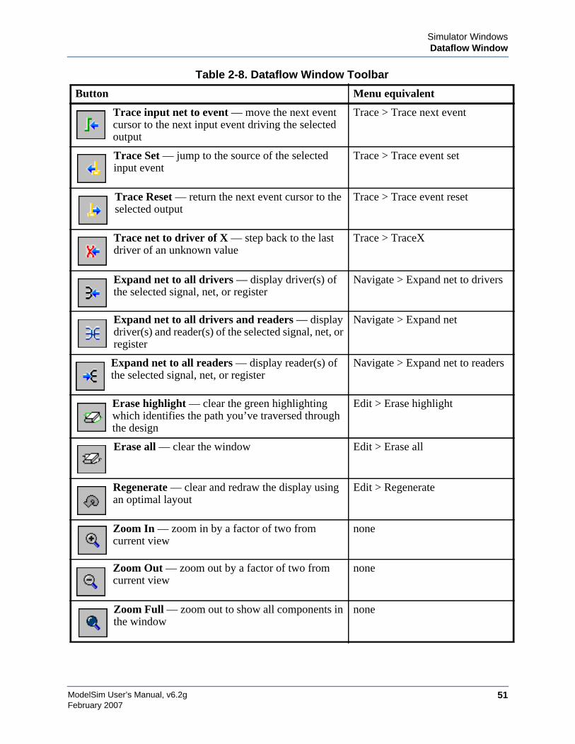
Simulator WindowsDataflow Window
ModelSim User’s Manual, v6.2g 51February 2007
Trace input net to event — move the next eventcursor to the next input event driving the selectedoutput
Trace > Trace next event
Trace Set — jump to the source of the selectedinput event
Trace > Trace event set
Trace Reset — return the next event cursor to theselected output
Trace > Trace event reset
Trace net to driver of X — step back to the lastdriver of an unknown value
Trace > TraceX
Expand net to all drivers — display driver(s) ofthe selected signal, net, or register
Navigate > Expand net to drivers
Expand net to all drivers and readers — displaydriver(s) and reader(s) of the selected signal, net, orregister
Navigate > Expand net
Expand net to all readers — display reader(s) ofthe selected signal, net, or register
Navigate > Expand net to readers
Erase highlight — clear the green highlightingwhich identifies the path you’ve traversed throughthe design
Edit > Erase highlight
Erase all — clear the window Edit > Erase all
Regenerate — clear and redraw the display usingan optimal layout
Edit > Regenerate
Zoom In — zoom in by a factor of two fromcurrent view
none
Zoom Out — zoom out by a factor of two fromcurrent view
none
Zoom Full — zoom out to show all components inthe window
none
Table 2-8. Dataflow Window Toolbar
Button Menu equivalent
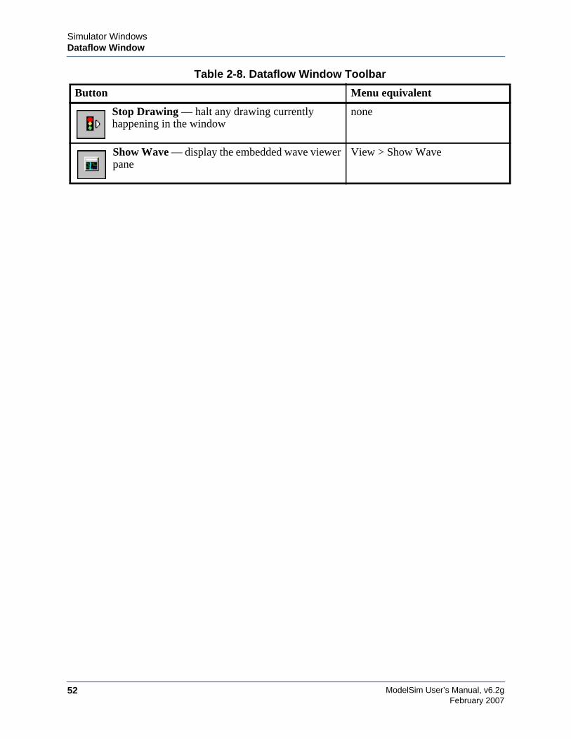
ModelSim User’s Manual, v6.2g52
Simulator WindowsDataflow Window
February 2007
Stop Drawing — halt any drawing currentlyhappening in the window
none
Show Wave — display the embedded wave viewerpane
View > Show Wave
Table 2-8. Dataflow Window Toolbar
Button Menu equivalent
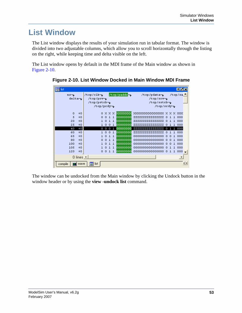
Simulator WindowsList Window
ModelSim User’s Manual, v6.2g 53February 2007
List WindowThe List window displays the results of your simulation run in tabular format. The window isdivided into two adjustable columns, which allow you to scroll horizontally through the listingon the right, while keeping time and delta visible on the left.
The List window opens by default in the MDI frame of the Main window as shown inFigure 2-10.
Figure 2-10. List Window Docked in Main Window MDI Frame
The window can be undocked from the Main window by clicking the Undock button in thewindow header or by using the view -undock list command.
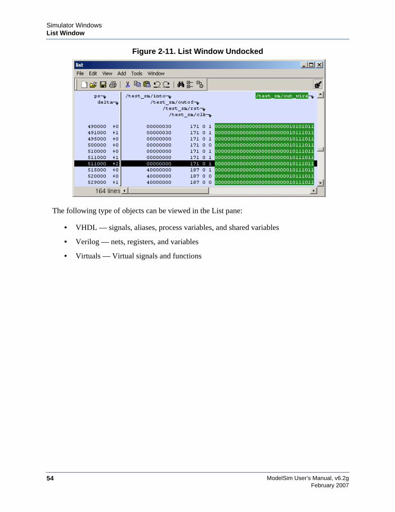
ModelSim User’s Manual, v6.2g54
Simulator WindowsList Window
February 2007
Figure 2-11. List Window Undocked
The following type of objects can be viewed in the List pane:
• VHDL — signals, aliases, process variables, and shared variables
• Verilog — nets, registers, and variables
• Virtuals — Virtual signals and functions
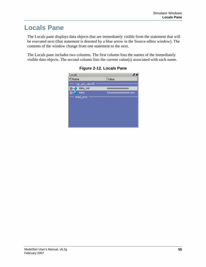
Simulator WindowsLocals Pane
ModelSim User’s Manual, v6.2g 55February 2007
Locals PaneThe Locals pane displays data objects that are immediately visible from the statement that willbe executed next (that statement is denoted by a blue arrow in the Source editor window). Thecontents of the window change from one statement to the next.
The Locals pane includes two columns. The first column lists the names of the immediatelyvisible data objects. The second column lists the current value(s) associated with each name.
Figure 2-12. Locals Pane
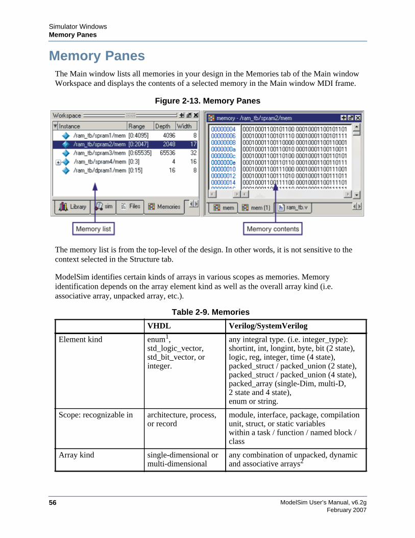
ModelSim User’s Manual, v6.2g56
Simulator WindowsMemory Panes
February 2007
Memory PanesThe Main window lists all memories in your design in the Memories tab of the Main windowWorkspace and displays the contents of a selected memory in the Main window MDI frame.
Figure 2-13. Memory Panes
The memory list is from the top-level of the design. In other words, it is not sensitive to thecontext selected in the Structure tab.
ModelSim identifies certain kinds of arrays in various scopes as memories. Memoryidentification depends on the array element kind as well as the overall array kind (i.e.associative array, unpacked array, etc.).
Table 2-9. Memories
VHDL Verilog/SystemVerilog
Element kind enum1,std_logic_vector,std_bit_vector, orinteger.
any integral type. (i.e. integer_type):shortint, int, longint, byte, bit (2 state),logic, reg, integer, time (4 state),packed_struct / packed_union (2 state),packed_struct / packed_union (4 state),packed_array (single-Dim, multi-D,2 state and 4 state),enum or string.
Scope: recognizable in architecture, process,or record
module, interface, package, compilationunit, struct, or static variableswithin a task / function / named block /class
Array kind single-dimensional ormulti-dimensional
any combination of unpacked, dynamicand associative arrays2
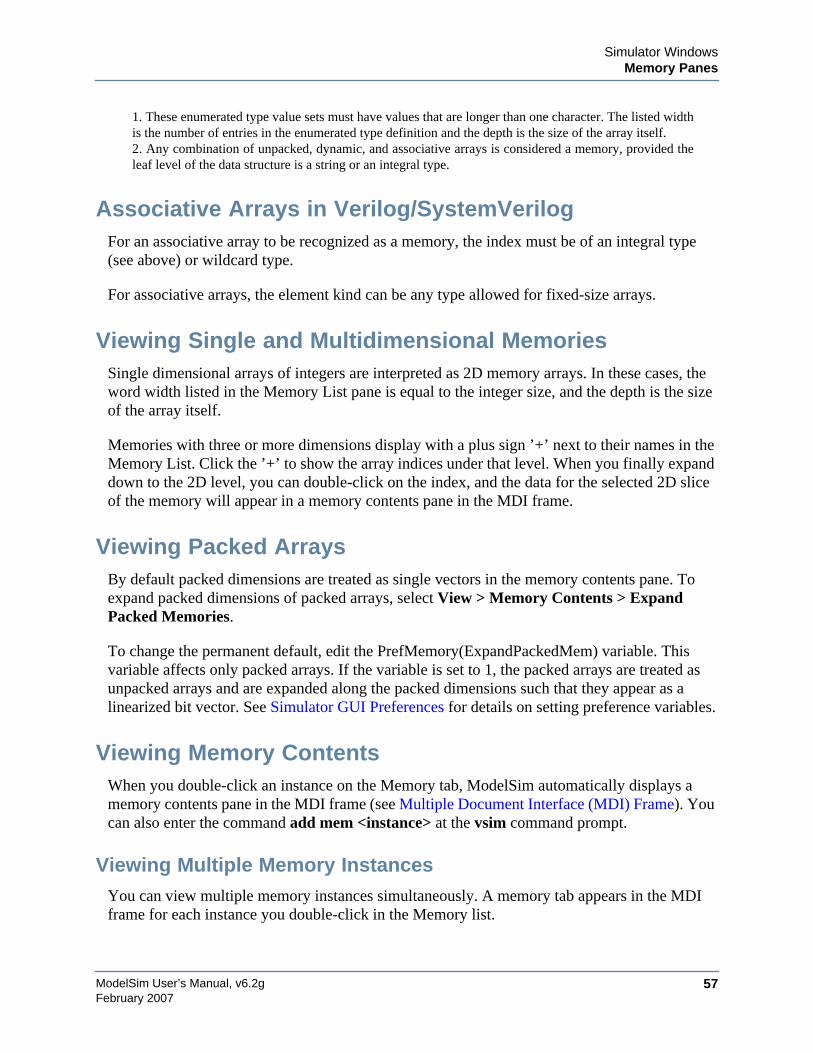
Simulator WindowsMemory Panes
ModelSim User’s Manual, v6.2g 57February 2007
Associative Arrays in Verilog/SystemVerilogFor an associative array to be recognized as a memory, the index must be of an integral type(see above) or wildcard type.
For associative arrays, the element kind can be any type allowed for fixed-size arrays.
Viewing Single and Multidimensional MemoriesSingle dimensional arrays of integers are interpreted as 2D memory arrays. In these cases, theword width listed in the Memory List pane is equal to the integer size, and the depth is the sizeof the array itself.
Memories with three or more dimensions display with a plus sign ’+’ next to their names in theMemory List. Click the ’+’ to show the array indices under that level. When you finally expanddown to the 2D level, you can double-click on the index, and the data for the selected 2D sliceof the memory will appear in a memory contents pane in the MDI frame.
Viewing Packed ArraysBy default packed dimensions are treated as single vectors in the memory contents pane. Toexpand packed dimensions of packed arrays, select View > Memory Contents > ExpandPacked Memories.
To change the permanent default, edit the PrefMemory(ExpandPackedMem) variable. Thisvariable affects only packed arrays. If the variable is set to 1, the packed arrays are treated asunpacked arrays and are expanded along the packed dimensions such that they appear as alinearized bit vector. See Simulator GUI Preferences for details on setting preference variables.
Viewing Memory ContentsWhen you double-click an instance on the Memory tab, ModelSim automatically displays amemory contents pane in the MDI frame (see Multiple Document Interface (MDI) Frame). Youcan also enter the command add mem <instance> at the vsim command prompt.
Viewing Multiple Memory InstancesYou can view multiple memory instances simultaneously. A memory tab appears in the MDIframe for each instance you double-click in the Memory list.
1. These enumerated type value sets must have values that are longer than one character. The listed widthis the number of entries in the enumerated type definition and the depth is the size of the array itself.2. Any combination of unpacked, dynamic, and associative arrays is considered a memory, provided theleaf level of the data structure is a string or an integral type.
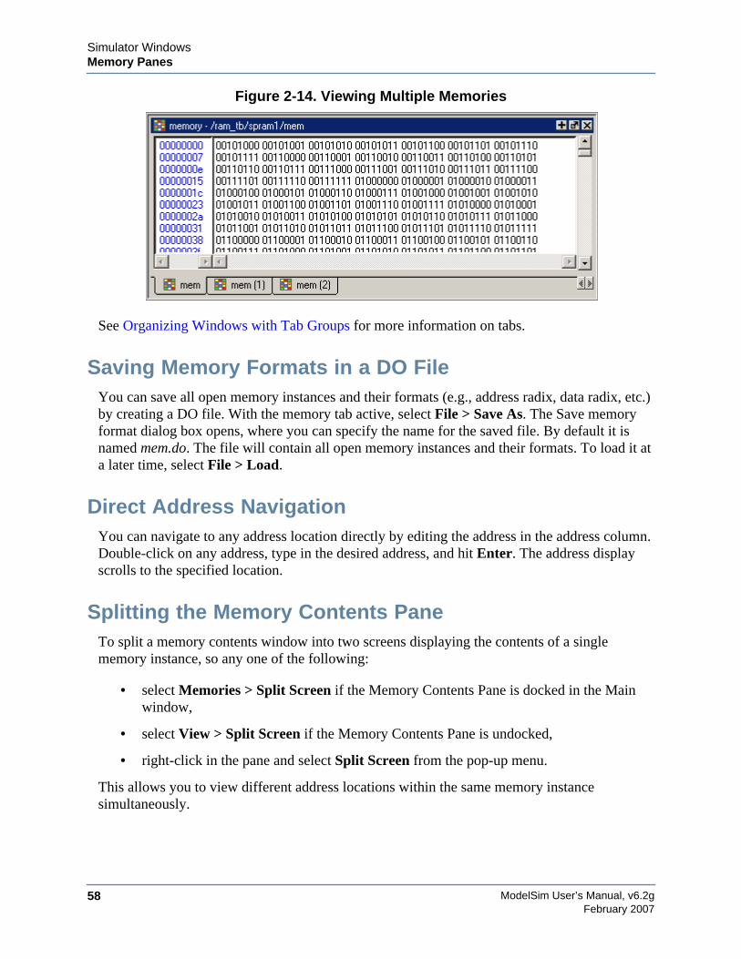
ModelSim User’s Manual, v6.2g58
Simulator WindowsMemory Panes
February 2007
Figure 2-14. Viewing Multiple Memories
See Organizing Windows with Tab Groups for more information on tabs.
Saving Memory Formats in a DO FileYou can save all open memory instances and their formats (e.g., address radix, data radix, etc.)by creating a DO file. With the memory tab active, select File > Save As. The Save memoryformat dialog box opens, where you can specify the name for the saved file. By default it isnamed mem.do. The file will contain all open memory instances and their formats. To load it ata later time, select File > Load.
Direct Address NavigationYou can navigate to any address location directly by editing the address in the address column.Double-click on any address, type in the desired address, and hit Enter. The address displayscrolls to the specified location.
Splitting the Memory Contents PaneTo split a memory contents window into two screens displaying the contents of a singlememory instance, so any one of the following:
• select Memories > Split Screen if the Memory Contents Pane is docked in the Mainwindow,
• select View > Split Screen if the Memory Contents Pane is undocked,
• right-click in the pane and select Split Screen from the pop-up menu.
This allows you to view different address locations within the same memory instancesimultaneously.

Simulator WindowsMemory Panes
ModelSim User’s Manual, v6.2g 59February 2007
Figure 2-15. Split Screen View of Memory Contents
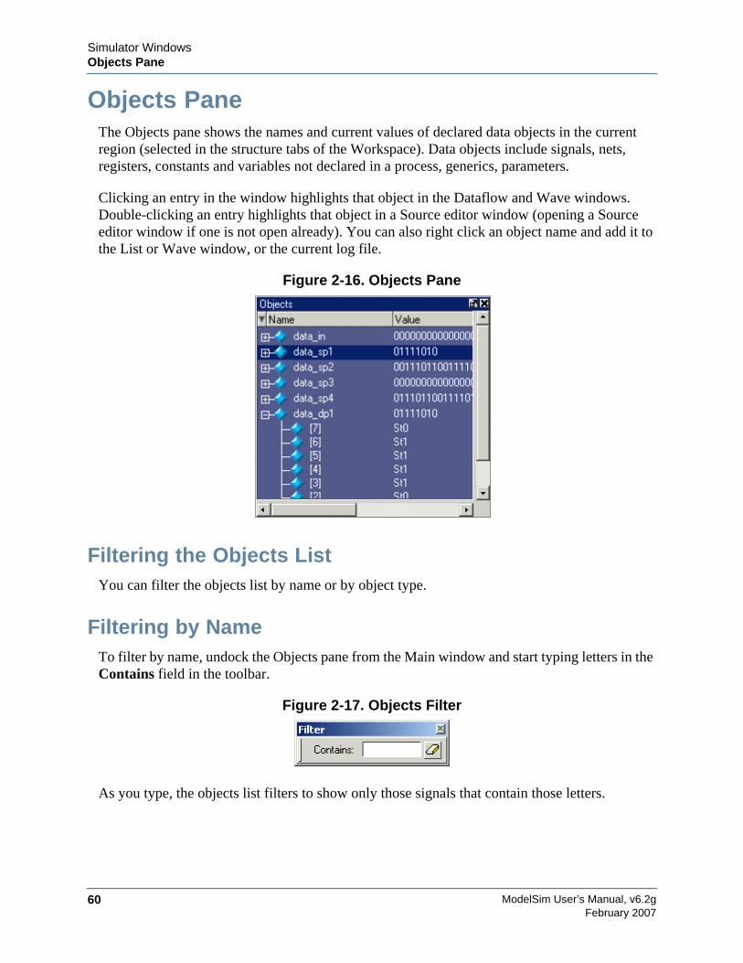
ModelSim User’s Manual, v6.2g60
Simulator WindowsObjects Pane
February 2007
Objects PaneThe Objects pane shows the names and current values of declared data objects in the currentregion (selected in the structure tabs of the Workspace). Data objects include signals, nets,registers, constants and variables not declared in a process, generics, parameters.
Clicking an entry in the window highlights that object in the Dataflow and Wave windows.Double-clicking an entry highlights that object in a Source editor window (opening a Sourceeditor window if one is not open already). You can also right click an object name and add it tothe List or Wave window, or the current log file.
Figure 2-16. Objects Pane
Filtering the Objects ListYou can filter the objects list by name or by object type.
Filtering by NameTo filter by name, undock the Objects pane from the Main window and start typing letters in theContains field in the toolbar.
Figure 2-17. Objects Filter
As you type, the objects list filters to show only those signals that contain those letters.
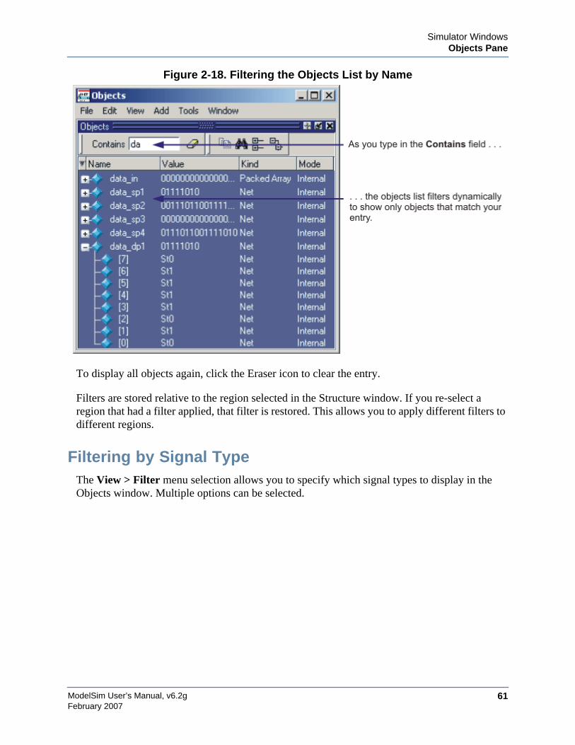
Simulator WindowsObjects Pane
ModelSim User’s Manual, v6.2g 61February 2007
Figure 2-18. Filtering the Objects List by Name
To display all objects again, click the Eraser icon to clear the entry.
Filters are stored relative to the region selected in the Structure window. If you re-select aregion that had a filter applied, that filter is restored. This allows you to apply different filters todifferent regions.
Filtering by Signal TypeThe View > Filter menu selection allows you to specify which signal types to display in theObjects window. Multiple options can be selected.
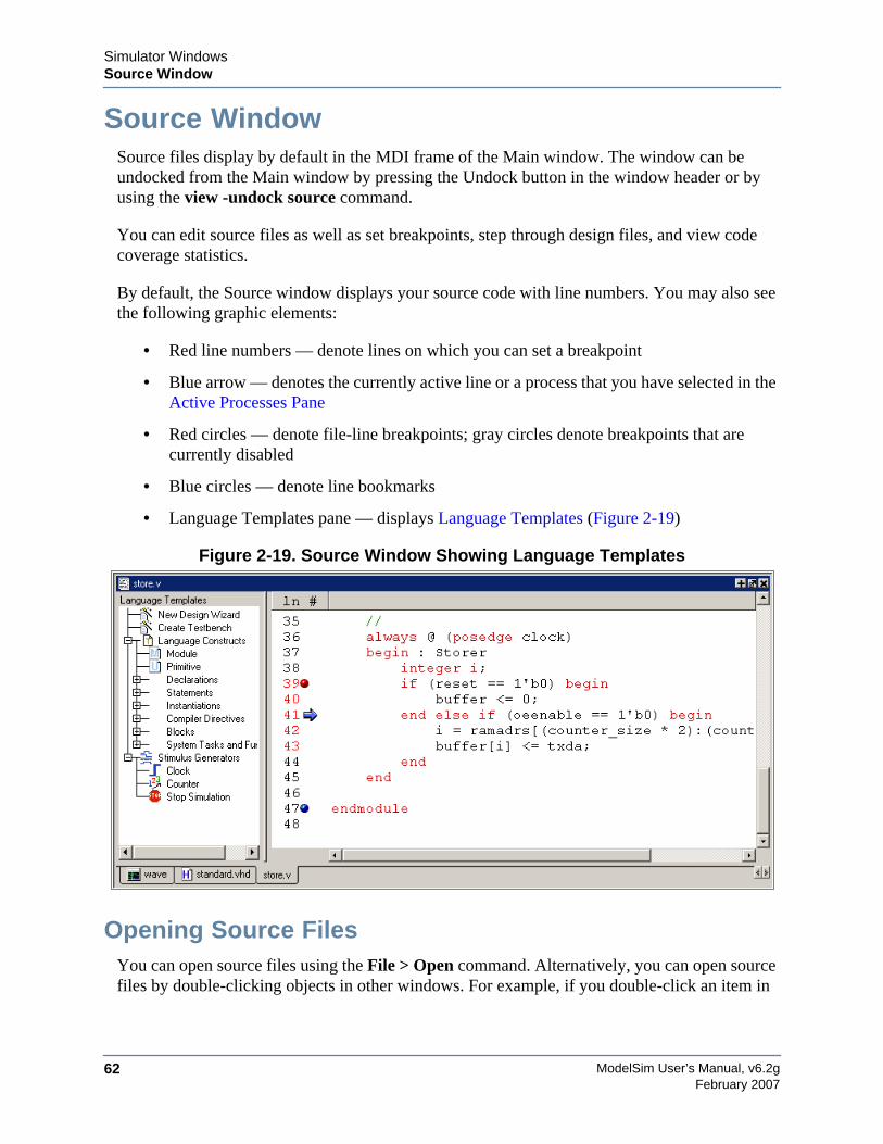
ModelSim User’s Manual, v6.2g62
Simulator WindowsSource Window
February 2007
Source WindowSource files display by default in the MDI frame of the Main window. The window can beundocked from the Main window by pressing the Undock button in the window header or byusing the view -undock source command.
You can edit source files as well as set breakpoints, step through design files, and view codecoverage statistics.
By default, the Source window displays your source code with line numbers. You may also seethe following graphic elements:
• Red line numbers — denote lines on which you can set a breakpoint
• Blue arrow — denotes the currently active line or a process that you have selected in theActive Processes Pane
• Red circles — denote file-line breakpoints; gray circles denote breakpoints that arecurrently disabled
• Blue circles — denote line bookmarks
• Language Templates pane — displays Language Templates (Figure 2-19)
Figure 2-19. Source Window Showing Language Templates
Opening Source FilesYou can open source files using the File > Open command. Alternatively, you can open sourcefiles by double-clicking objects in other windows. For example, if you double-click an item in
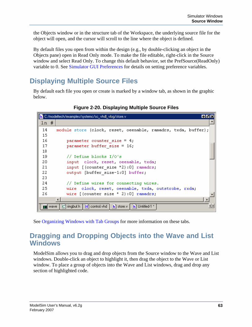
Simulator WindowsSource Window
ModelSim User’s Manual, v6.2g 63February 2007
the Objects window or in the structure tab of the Workspace, the underlying source file for theobject will open, and the cursor will scroll to the line where the object is defined.
By default files you open from within the design (e.g., by double-clicking an object in theObjects pane) open in Read Only mode. To make the file editable, right-click in the Sourcewindow and select Read Only. To change this default behavior, set the PrefSource(ReadOnly)variable to 0. See Simulator GUI Preferences for details on setting preference variables.
Displaying Multiple Source FilesBy default each file you open or create is marked by a window tab, as shown in the graphicbelow.
Figure 2-20. Displaying Multiple Source Files
See Organizing Windows with Tab Groups for more information on these tabs.
Dragging and Dropping Objects into the Wave and ListWindows
ModelSim allows you to drag and drop objects from the Source window to the Wave and Listwindows. Double-click an object to highlight it, then drag the object to the Wave or Listwindow. To place a group of objects into the Wave and List windows, drag and drop anysection of highlighted code.
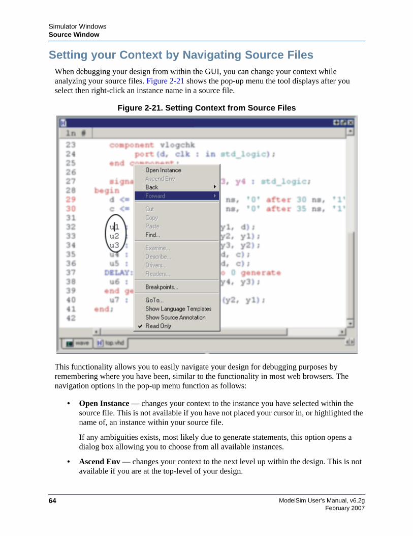
ModelSim User’s Manual, v6.2g64
Simulator WindowsSource Window
February 2007
Setting your Context by Navigating Source FilesWhen debugging your design from within the GUI, you can change your context whileanalyzing your source files. Figure 2-21 shows the pop-up menu the tool displays after youselect then right-click an instance name in a source file.
Figure 2-21. Setting Context from Source Files
This functionality allows you to easily navigate your design for debugging purposes byremembering where you have been, similar to the functionality in most web browsers. Thenavigation options in the pop-up menu function as follows:
• Open Instance — changes your context to the instance you have selected within thesource file. This is not available if you have not placed your cursor in, or highlighted thename of, an instance within your source file.
If any ambiguities exists, most likely due to generate statements, this option opens adialog box allowing you to choose from all available instances.
• Ascend Env — changes your context to the next level up within the design. This is notavailable if you are at the top-level of your design.
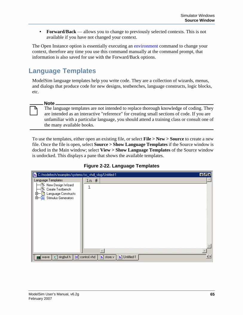
Simulator WindowsSource Window
ModelSim User’s Manual, v6.2g 65February 2007
• Forward/Back — allows you to change to previously selected contexts. This is notavailable if you have not changed your context.
The Open Instance option is essentially executing an environment command to change yourcontext, therefore any time you use this command manually at the command prompt, thatinformation is also saved for use with the Forward/Back options.
Language TemplatesModelSim language templates help you write code. They are a collection of wizards, menus,and dialogs that produce code for new designs, testbenches, language constructs, logic blocks,etc.
NoteThe language templates are not intended to replace thorough knowledge of coding. Theyare intended as an interactive "reference" for creating small sections of code. If you areunfamiliar with a particular language, you should attend a training class or consult one ofthe many available books.
To use the templates, either open an existing file, or select File > New > Source to create a newfile. Once the file is open, select Source > Show Language Templates if the Source window isdocked in the Main window; select View > Show Language Templates of the Source windowis undocked. This displays a pane that shows the available templates.
Figure 2-22. Language Templates
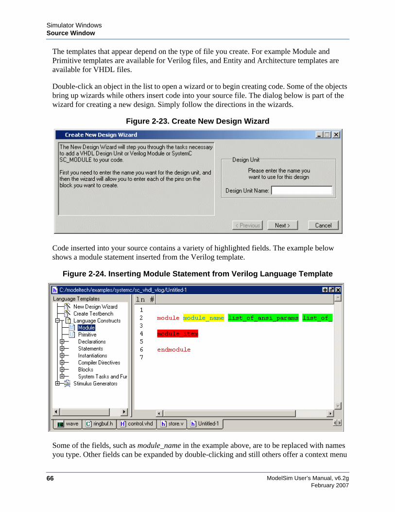
ModelSim User’s Manual, v6.2g66
Simulator WindowsSource Window
February 2007
The templates that appear depend on the type of file you create. For example Module andPrimitive templates are available for Verilog files, and Entity and Architecture templates areavailable for VHDL files.
Double-click an object in the list to open a wizard or to begin creating code. Some of the objectsbring up wizards while others insert code into your source file. The dialog below is part of thewizard for creating a new design. Simply follow the directions in the wizards.
Figure 2-23. Create New Design Wizard
Code inserted into your source contains a variety of highlighted fields. The example belowshows a module statement inserted from the Verilog template.
Figure 2-24. Inserting Module Statement from Verilog Language Template
Some of the fields, such as module_name in the example above, are to be replaced with namesyou type. Other fields can be expanded by double-clicking and still others offer a context menu
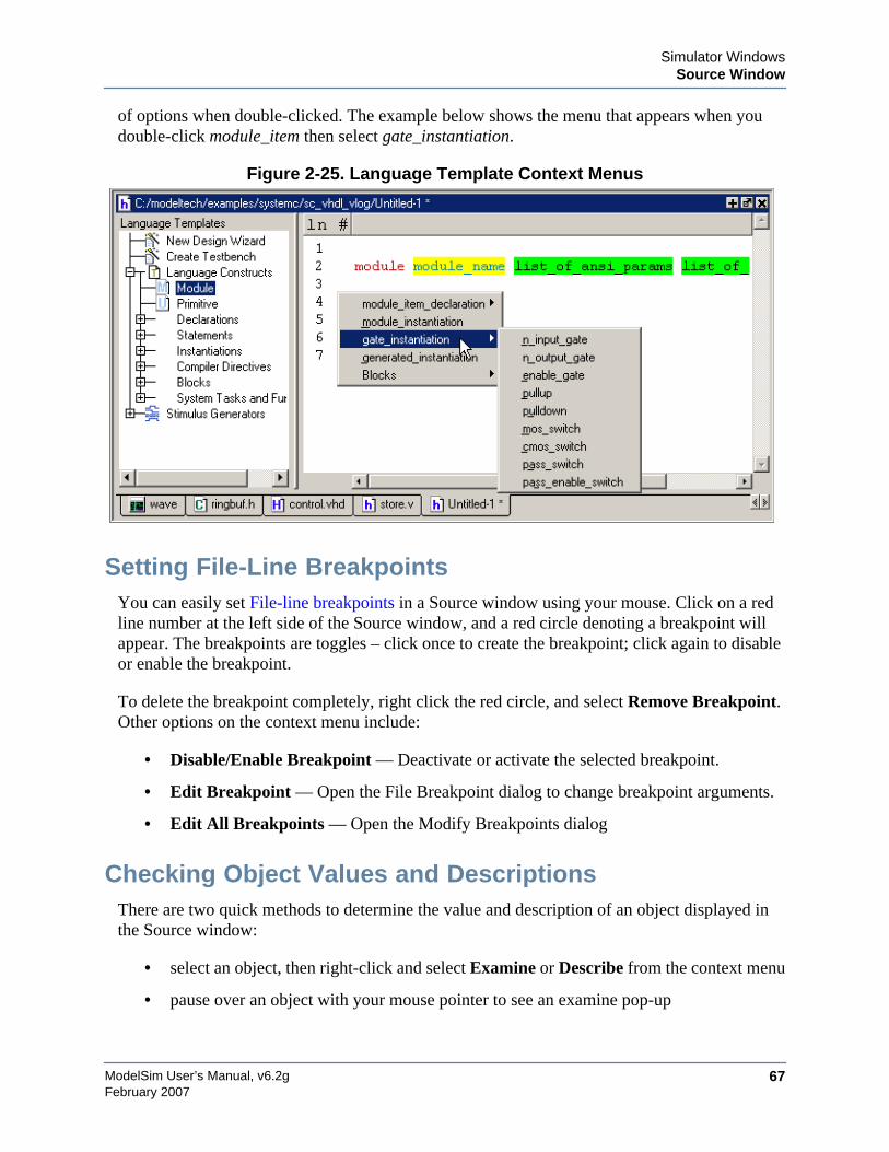
Simulator WindowsSource Window
ModelSim User’s Manual, v6.2g 67February 2007
of options when double-clicked. The example below shows the menu that appears when youdouble-click module_item then select gate_instantiation.
Figure 2-25. Language Template Context Menus
Setting File-Line BreakpointsYou can easily set File-line breakpoints in a Source window using your mouse. Click on a redline number at the left side of the Source window, and a red circle denoting a breakpoint willappear. The breakpoints are toggles – click once to create the breakpoint; click again to disableor enable the breakpoint.
To delete the breakpoint completely, right click the red circle, and select Remove Breakpoint.Other options on the context menu include:
• Disable/Enable Breakpoint — Deactivate or activate the selected breakpoint.
• Edit Breakpoint — Open the File Breakpoint dialog to change breakpoint arguments.
• Edit All Breakpoints — Open the Modify Breakpoints dialog
Checking Object Values and DescriptionsThere are two quick methods to determine the value and description of an object displayed inthe Source window:
• select an object, then right-click and select Examine or Describe from the context menu
• pause over an object with your mouse pointer to see an examine pop-up

ModelSim User’s Manual, v6.2g68
Simulator WindowsSource Window
February 2007
Select Tools > Options > Examine Now or Tools > Options > Examine Current Cursor tochoose at what simulation time the object is examined or described.
You can also invoke the examine and/or describe commands on the command line or in amacro.
Marking Lines with BookmarksSource window bookmarks are blue circles that mark lines in a source file. These graphicalicons may ease navigation through a large source file by "highlighting" certain lines.
As noted above in the discussion about finding text in the Source window, you can insertbookmarks on any line containing the text for which you are searching. The other method forinserting bookmarks is to right-click a line number and select Add/Remove Bookmark. Toremove a bookmark, right-click the line number and select Add/Remove Bookmark again.
Customizing the Source WindowYou can customize a variety of settings for Source windows. For example, you can changefonts, spacing, colors, syntax highlighting, and so forth. To customize Source window settings,select Tools > Edit Preferences. This opens the Preferences dialog. Select Source Windowsfrom the Window List.
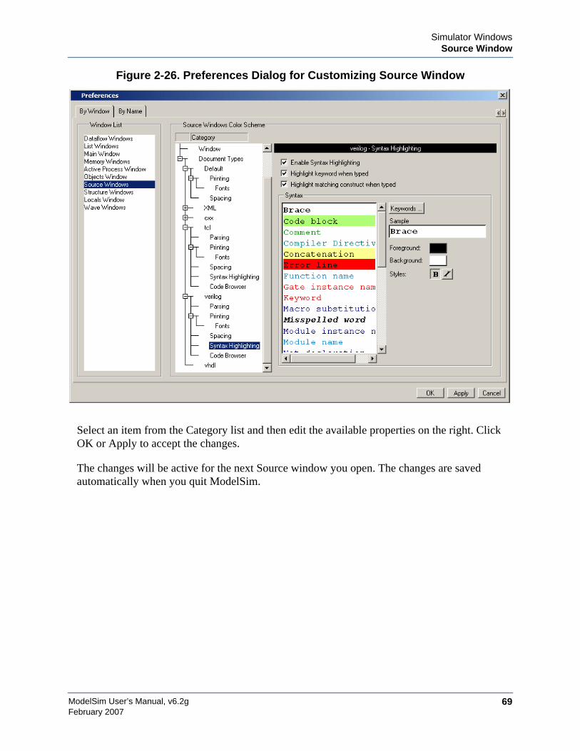
Simulator WindowsSource Window
ModelSim User’s Manual, v6.2g 69February 2007
Figure 2-26. Preferences Dialog for Customizing Source Window
Select an item from the Category list and then edit the available properties on the right. ClickOK or Apply to accept the changes.
The changes will be active for the next Source window you open. The changes are savedautomatically when you quit ModelSim.
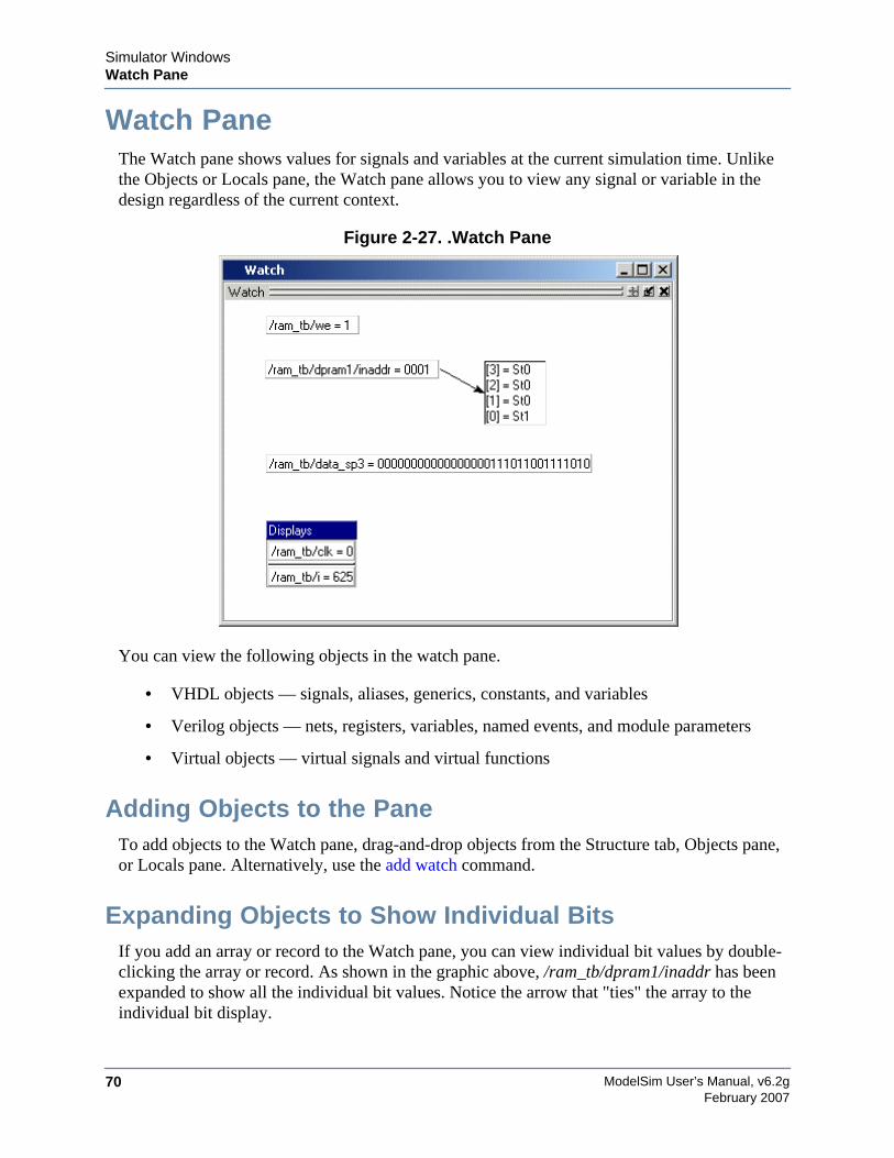
ModelSim User’s Manual, v6.2g70
Simulator WindowsWatch Pane
February 2007
Watch PaneThe Watch pane shows values for signals and variables at the current simulation time. Unlikethe Objects or Locals pane, the Watch pane allows you to view any signal or variable in thedesign regardless of the current context.
Figure 2-27. .Watch Pane
You can view the following objects in the watch pane.
• VHDL objects — signals, aliases, generics, constants, and variables
• Verilog objects — nets, registers, variables, named events, and module parameters
• Virtual objects — virtual signals and virtual functions
Adding Objects to the PaneTo add objects to the Watch pane, drag-and-drop objects from the Structure tab, Objects pane,or Locals pane. Alternatively, use the add watch command.
Expanding Objects to Show Individual BitsIf you add an array or record to the Watch pane, you can view individual bit values by double-clicking the array or record. As shown in the graphic above, /ram_tb/dpram1/inaddr has beenexpanded to show all the individual bit values. Notice the arrow that "ties" the array to theindividual bit display.
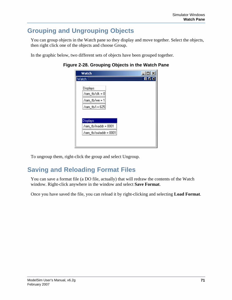
Simulator WindowsWatch Pane
ModelSim User’s Manual, v6.2g 71February 2007
Grouping and Ungrouping ObjectsYou can group objects in the Watch pane so they display and move together. Select the objects,then right click one of the objects and choose Group.
In the graphic below, two different sets of objects have been grouped together.
Figure 2-28. Grouping Objects in the Watch Pane
To ungroup them, right-click the group and select Ungroup.
Saving and Reloading Format FilesYou can save a format file (a DO file, actually) that will redraw the contents of the Watchwindow. Right-click anywhere in the window and select Save Format.
Once you have saved the file, you can reload it by right-clicking and selecting Load Format.
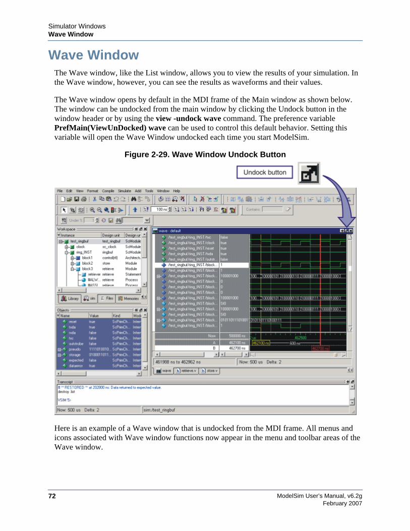
ModelSim User’s Manual, v6.2g72
Simulator WindowsWave Window
February 2007
Wave WindowThe Wave window, like the List window, allows you to view the results of your simulation. Inthe Wave window, however, you can see the results as waveforms and their values.
The Wave window opens by default in the MDI frame of the Main window as shown below.The window can be undocked from the main window by clicking the Undock button in thewindow header or by using the view -undock wave command. The preference variablePrefMain(ViewUnDocked) wave can be used to control this default behavior. Setting thisvariable will open the Wave Window undocked each time you start ModelSim.
Figure 2-29. Wave Window Undock Button
Here is an example of a Wave window that is undocked from the MDI frame. All menus andicons associated with Wave window functions now appear in the menu and toolbar areas of theWave window.
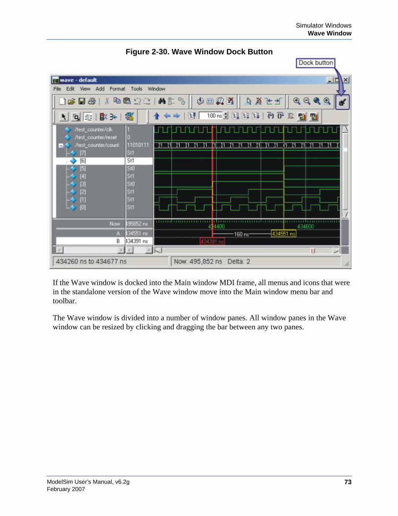
Simulator WindowsWave Window
ModelSim User’s Manual, v6.2g 73February 2007
Figure 2-30. Wave Window Dock Button
If the Wave window is docked into the Main window MDI frame, all menus and icons that werein the standalone version of the Wave window move into the Main window menu bar andtoolbar.
The Wave window is divided into a number of window panes. All window panes in the Wavewindow can be resized by clicking and dragging the bar between any two panes.
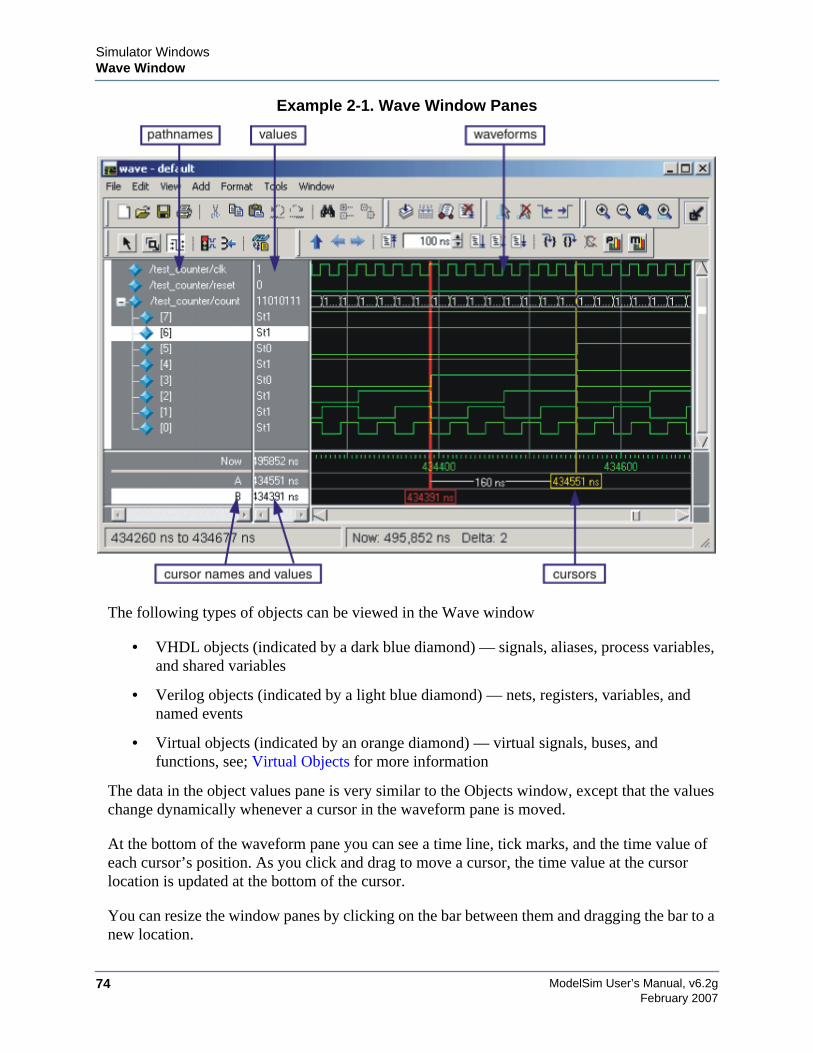
ModelSim User’s Manual, v6.2g74
Simulator WindowsWave Window
February 2007
Example 2-1. Wave Window Panes
The following types of objects can be viewed in the Wave window
• VHDL objects (indicated by a dark blue diamond) — signals, aliases, process variables,and shared variables
• Verilog objects (indicated by a light blue diamond) — nets, registers, variables, andnamed events
• Virtual objects (indicated by an orange diamond) — virtual signals, buses, andfunctions, see; Virtual Objects for more information
The data in the object values pane is very similar to the Objects window, except that the valueschange dynamically whenever a cursor in the waveform pane is moved.
At the bottom of the waveform pane you can see a time line, tick marks, and the time value ofeach cursor’s position. As you click and drag to move a cursor, the time value at the cursorlocation is updated at the bottom of the cursor.
You can resize the window panes by clicking on the bar between them and dragging the bar to anew location.
Simulator WindowsWave Window
ModelSim User’s Manual, v6.2g 75February 2007
Waveform and signal-name formatting are easily changed via the Format menu. You can reuseany formatting changes you make by saving a Wave window format file (see Saving theWindow Format).
Wave Window PanesThe sections below describe the various Wave window panes.
Pathname PaneThe pathname pane displays signal pathnames. Signals can be displayed with full pathnames, asshown here, or with only the leaf element displayed. You can increase the size of the pane byclicking and dragging on the right border. The selected signal is highlighted.
The white bar along the left margin indicates the selected dataset (see Splitting Wave WindowPanes).
Value PaneThe value pane displays the values of the displayed signals.
The radix for each signal can be symbolic, binary, octal, decimal, unsigned, hexadecimal,ASCII, or default. The default radix can be set by selecting Simulate > Runtime Options.
NoteWhen the symbolic radix is chosen for SystemVerilog reg and integer types, the valuesare treated as binary. When the symbolic radix is chosen for SystemVerilog bit and inttypes, the values are considered to be decimal.
The data in this pane is similar to that shown in the Objects Pane, except that the values changedynamically whenever a cursor in the waveform pane is moved.
Waveform PaneThe waveform pane displays the waveforms that correspond to the displayed signal pathnames.It also displays up to 20 cursors. Signal values can be displayed in analog step, analoginterpolated, analog backstep, literal, logic, and event formats. The radix of each signal can beset individually by selecting the signal and then choosing . The default radix is logic.
If you rest your mouse pointer on a signal in the waveform pane, a popup displays withinformation about the signal. You can toggle this popup on and off in the Wave WindowProperties dialog.
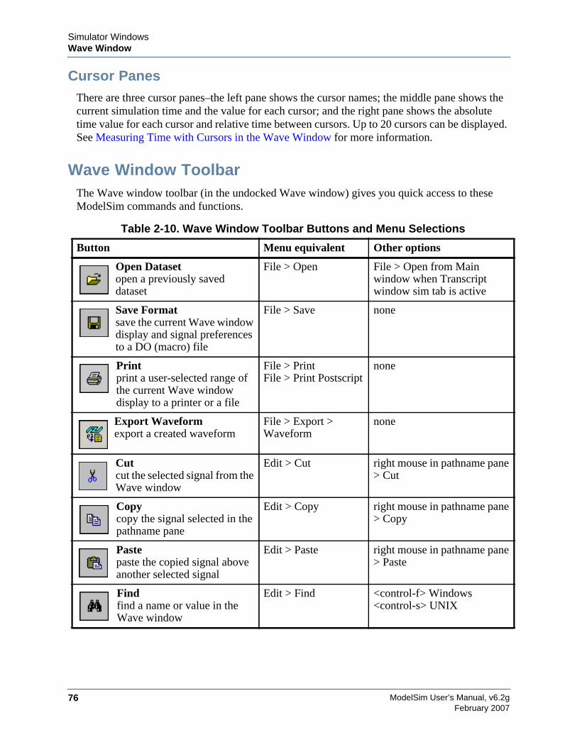
ModelSim User’s Manual, v6.2g76
Simulator WindowsWave Window
February 2007
Cursor PanesThere are three cursor panes–the left pane shows the cursor names; the middle pane shows thecurrent simulation time and the value for each cursor; and the right pane shows the absolutetime value for each cursor and relative time between cursors. Up to 20 cursors can be displayed.See Measuring Time with Cursors in the Wave Window for more information.
Wave Window ToolbarThe Wave window toolbar (in the undocked Wave window) gives you quick access to theseModelSim commands and functions.
Table 2-10. Wave Window Toolbar Buttons and Menu Selections
Button Menu equivalent Other options
Open Datasetopen a previously saveddataset
File > Open File > Open from Mainwindow when Transcriptwindow sim tab is active
Save Formatsave the current Wave windowdisplay and signal preferencesto a DO (macro) file
File > Save none
Printprint a user-selected range ofthe current Wave windowdisplay to a printer or a file
File > PrintFile > Print Postscript
none
Export Waveformexport a created waveform
File > Export >Waveform
none
Cutcut the selected signal from theWave window
Edit > Cut right mouse in pathname pane> Cut
Copycopy the signal selected in thepathname pane
Edit > Copy right mouse in pathname pane> Copy
Pastepaste the copied signal aboveanother selected signal
Edit > Paste right mouse in pathname pane> Paste
Findfind a name or value in theWave window
Edit > Find <control-f> Windows<control-s> UNIX

Simulator WindowsWave Window
ModelSim User’s Manual, v6.2g 77February 2007
Insert Cursoradd a cursor to the waveformpane
Add > Wave > Cursor(Main window)Add > Cursor(undocked Wavewindow)
right click in cursor pane andselect New Cursor
Delete Cursordelete the selected cursor fromthe window
Edit > Delete Cursor right mouse in cursor pane >Delete Cursor n
Find Previous Transitionlocate the previous signalvalue change for the selectedsignal
Edit > Search(Search Reverse)
keyboard: Shift + Tab
Find Next Transitionlocate the next signal valuechange for the selected signal
Edit > Search(Search Forward)
keyboard: Tab
Select Modeset mouse to Select Mode –click left mouse button toselect, drag middle mouse
button to zoom
View > Zoom >Mouse Mode > SelectMode
none
Zoom Modeset mouse to Zoom Mode –drag left mouse button tozoom, click middle mousebutton to select
View > Zoom >Mouse Mode > ZoomMode
none
Zoom In 2xzoom in by a factor of twofrom the current view
View > Zoom > ZoomIn
keyboard: i I or +right mouse in wave pane >Zoom In
Zoom Out 2xzoom out by a factor of twofrom current view
View > Zoom > ZoomOut
keyboard: o O or -right mouse in wave pane >Zoom Out
Zoom in on Active Cursorcenter active cursor in thedisplay and zoom in
View > Zoom > ZoomCursor
keyboard: c or C
Zoom Fullzoom out to view the fullrange of the simulation fromtime 0 to the current time
View > Zoom > ZoomFull
keyboard: f or Fright mouse in wave pane >Zoom Full
Table 2-10. Wave Window Toolbar Buttons and Menu Selections
Button Menu equivalent Other options
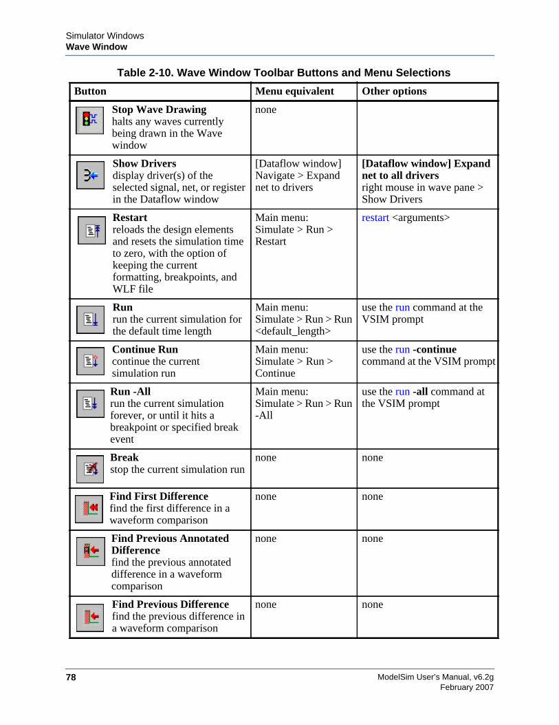
ModelSim User’s Manual, v6.2g78
Simulator WindowsWave Window
February 2007
Stop Wave Drawinghalts any waves currentlybeing drawn in the Wavewindow
none
Show Driversdisplay driver(s) of theselected signal, net, or registerin the Dataflow window
[Dataflow window]Navigate > Expandnet to drivers
[Dataflow window] Expandnet to all driversright mouse in wave pane >Show Drivers
Restartreloads the design elementsand resets the simulation timeto zero, with the option ofkeeping the currentformatting, breakpoints, andWLF file
Main menu:Simulate > Run >Restart
restart <arguments>
Runrun the current simulation forthe default time length
Main menu:Simulate > Run > Run<default_length>
use the run command at theVSIM prompt
Continue Runcontinue the currentsimulation run
Main menu:Simulate > Run >Continue
use the run -continuecommand at the VSIM prompt
Run -Allrun the current simulationforever, or until it hits abreakpoint or specified breakevent
Main menu:Simulate > Run > Run-All
use the run -all command atthe VSIM prompt
Breakstop the current simulation run
none none
Find First Differencefind the first difference in awaveform comparison
none none
Find Previous AnnotatedDifferencefind the previous annotateddifference in a waveformcomparison
none none
Find Previous Differencefind the previous difference ina waveform comparison
none none
Table 2-10. Wave Window Toolbar Buttons and Menu Selections
Button Menu equivalent Other options
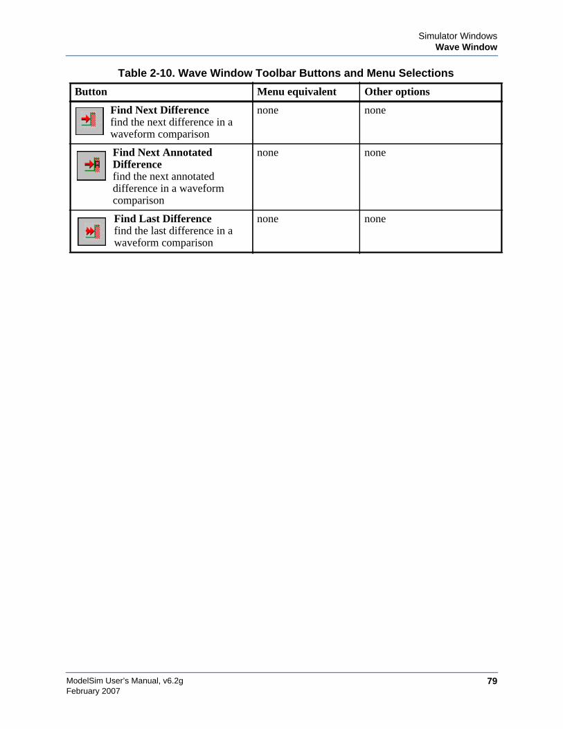
Simulator WindowsWave Window
ModelSim User’s Manual, v6.2g 79February 2007
Find Next Differencefind the next difference in awaveform comparison
none none
Find Next AnnotatedDifferencefind the next annotateddifference in a waveformcomparison
none none
Find Last Differencefind the last difference in awaveform comparison
none none
Table 2-10. Wave Window Toolbar Buttons and Menu Selections
Button Menu equivalent Other options

ModelSim User’s Manual, v6.2g80
Simulator WindowsWave Window
February 2007

ModelSim User’s Manual, v6.2g 81February 2007
Chapter 3Projects
Projects simplify the process of compiling and simulating a design and are a great tool forgetting started with ModelSim.
What are Projects?Projects are collection entities for designs under specification or test. At a minimum, projectshave a root directory, a work library, and "metadata" which are stored in a .mpf file located in aproject's root directory. The metadata include compiler switch settings, compile order, and filemappings. Projects may also include:
• Source files or references to source files
• other files such as READMEs or other project documentation
• local libraries
• references to global libraries
• Simulation Configurations (see Creating a Simulation Configuration)
• Folders (see Organizing Projects with Folders)
NoteProject metadata are updated and stored only for actions taken within the project itself.For example, if you have a file in a project, and you compile that file from the commandline rather than using the project menu commands, the project will not update to reflectany new compile settings.
What are the Benefits of Projects?Projects offer benefits to both new and advanced users. Projects
• simplify interaction with ModelSim; you don’t need to understand the intricacies ofcompiler switches and library mappings
• eliminate the need to remember a conceptual model of the design; the compile order ismaintained for you in the project. Compile order is maintained for HDL-only designs.
• remove the necessity to re-establish compiler switches and settings at each session; theseare stored in the project metadata as are mappings to source files
ModelSim User’s Manual, v6.2g82
ProjectsGetting Started with Projects
February 2007
• allow users to share libraries without copying files to a local directory; you can establishreferences to source files that are stored remotely or locally
• allow you to change individual parameters across multiple files; in previous versionsyou could only set parameters one file at a time
• enable "what-if" analysis; you can copy a project, manipulate the settings, and rerun it toobserve the new results
• reload the initial settings from the project .mpf file every time the project is opened
Project Conversion Between VersionsProjects are generally not backwards compatible for either number or letter releases. When youopen a project created in an earlier version, you will see a message warning that the project willbe converted to the newer version. You have the option of continuing with the conversion orcancelling the operation.
As stated in the warning message, a backup of the original project is created before theconversion occurs. The backup file is named <project name>.mpf.bak and is created in thesame directory in which the original project is located.
Getting Started with ProjectsThis section describes the four basic steps to working with a project.
• Step 1 — Creating a New Project
This creates a .mpf file and a working library.
• Step 2 — Adding Items to the Project
Projects can reference or include source files, folders for organization, simulations, andany other files you want to associate with the project. You can copy files into the projectdirectory or simply create mappings to files in other locations.
• Step 3 — Compiling the Files
This checks syntax and semantics and creates the pseudo machine code ModelSim usesfor simulation.
• Step 4 — Simulating a Design
This specifies the design unit you want to simulate and opens a structure tab in theWorkspace pane.
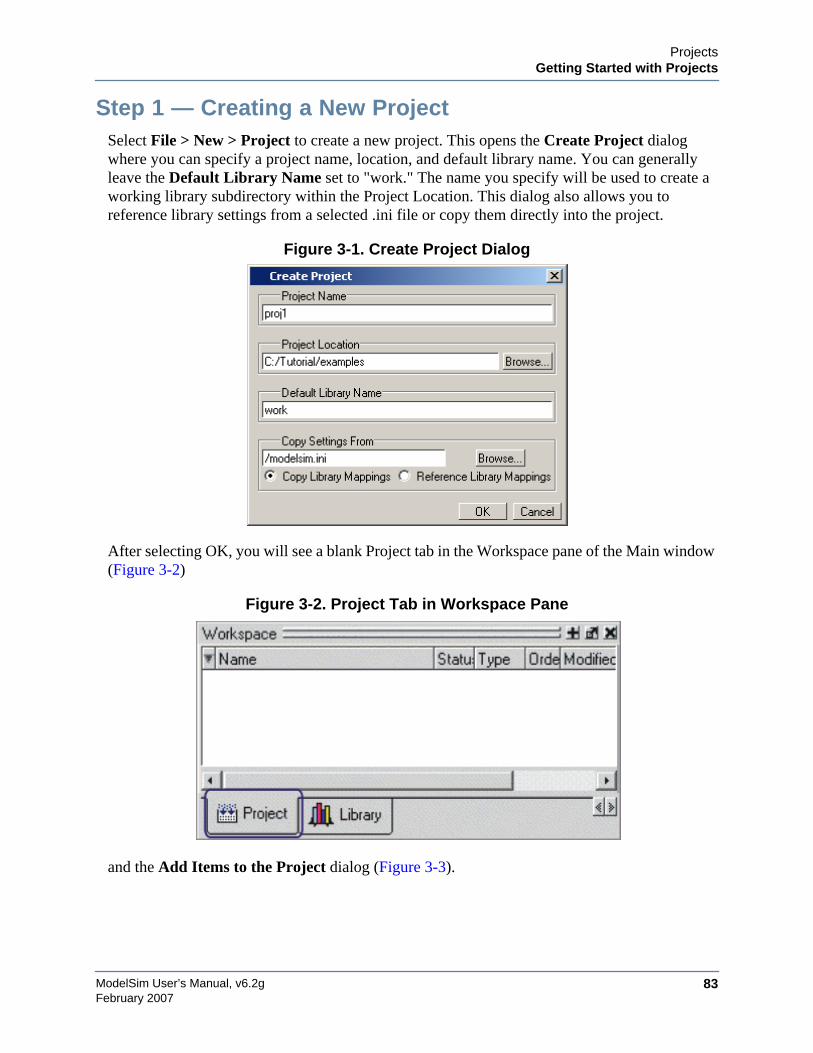
ProjectsGetting Started with Projects
ModelSim User’s Manual, v6.2g 83February 2007
Step 1 — Creating a New ProjectSelect File > New > Project to create a new project. This opens the Create Project dialogwhere you can specify a project name, location, and default library name. You can generallyleave the Default Library Name set to "work." The name you specify will be used to create aworking library subdirectory within the Project Location. This dialog also allows you toreference library settings from a selected .ini file or copy them directly into the project.
Figure 3-1. Create Project Dialog
After selecting OK, you will see a blank Project tab in the Workspace pane of the Main window(Figure 3-2)
Figure 3-2. Project Tab in Workspace Pane
and the Add Items to the Project dialog (Figure 3-3).
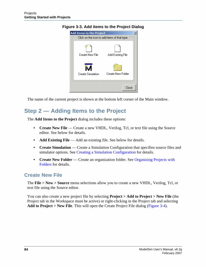
ModelSim User’s Manual, v6.2g84
ProjectsGetting Started with Projects
February 2007
Figure 3-3. Add items to the Project Dialog
The name of the current project is shown at the bottom left corner of the Main window.
Step 2 — Adding Items to the ProjectThe Add Items to the Project dialog includes these options:
• Create New File — Create a new VHDL, Verilog, Tcl, or text file using the Sourceeditor. See below for details.
• Add Existing File — Add an existing file. See below for details.
• Create Simulation — Create a Simulation Configuration that specifies source files andsimulator options. See Creating a Simulation Configuration for details.
• Create New Folder — Create an organization folder. See Organizing Projects withFolders for details.
Create New FileThe File > New > Source menu selections allow you to create a new VHDL, Verilog, Tcl, ortext file using the Source editor.
You can also create a new project file by selecting Project > Add to Project > New File (theProject tab in the Workspace must be active) or right-clicking in the Project tab and selectingAdd to Project > New File. This will open the Create Project File dialog (Figure 3-4).
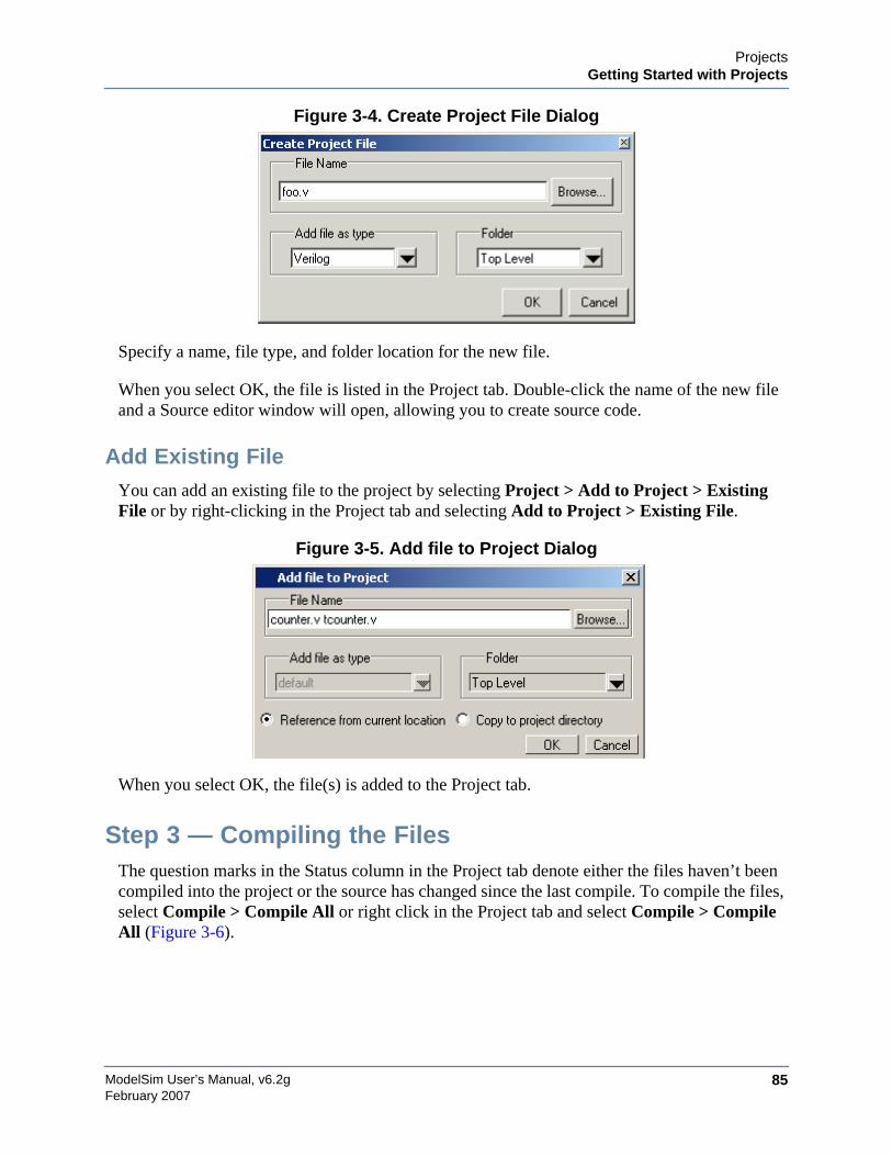
ProjectsGetting Started with Projects
ModelSim User’s Manual, v6.2g 85February 2007
Figure 3-4. Create Project File Dialog
Specify a name, file type, and folder location for the new file.
When you select OK, the file is listed in the Project tab. Double-click the name of the new fileand a Source editor window will open, allowing you to create source code.
Add Existing FileYou can add an existing file to the project by selecting Project > Add to Project > ExistingFile or by right-clicking in the Project tab and selecting Add to Project > Existing File.
Figure 3-5. Add file to Project Dialog
When you select OK, the file(s) is added to the Project tab.
Step 3 — Compiling the FilesThe question marks in the Status column in the Project tab denote either the files haven’t beencompiled into the project or the source has changed since the last compile. To compile the files,select Compile > Compile All or right click in the Project tab and select Compile > CompileAll (Figure 3-6).
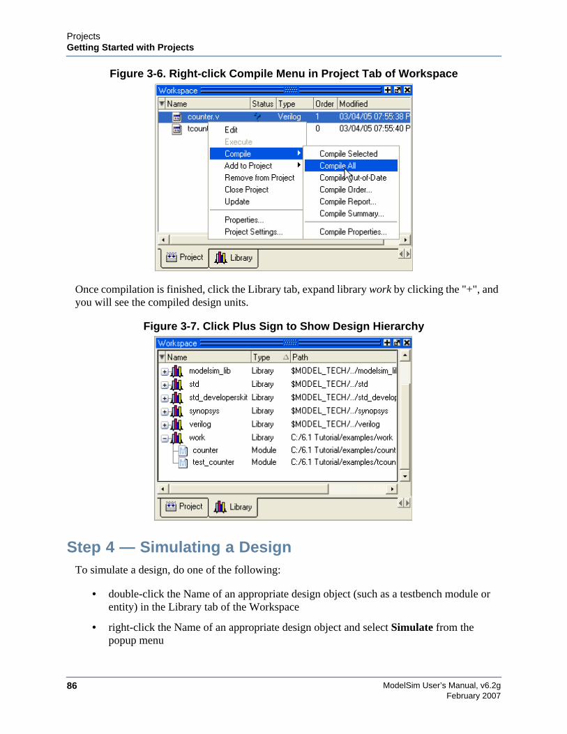
ModelSim User’s Manual, v6.2g86
ProjectsGetting Started with Projects
February 2007
Figure 3-6. Right-click Compile Menu in Project Tab of Workspace
Once compilation is finished, click the Library tab, expand library work by clicking the "+", andyou will see the compiled design units.
Figure 3-7. Click Plus Sign to Show Design Hierarchy
Step 4 — Simulating a DesignTo simulate a design, do one of the following:
• double-click the Name of an appropriate design object (such as a testbench module orentity) in the Library tab of the Workspace
• right-click the Name of an appropriate design object and select Simulate from thepopup menu
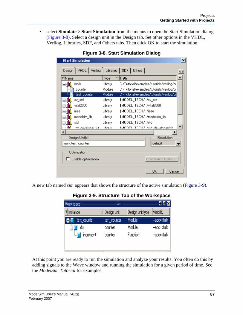
ProjectsGetting Started with Projects
ModelSim User’s Manual, v6.2g 87February 2007
• select Simulate > Start Simulation from the menus to open the Start Simulation dialog(Figure 3-8). Select a design unit in the Design tab. Set other options in the VHDL,Verilog, Libraries, SDF, and Others tabs. Then click OK to start the simulation.
Figure 3-8. Start Simulation Dialog
A new tab named sim appears that shows the structure of the active simulation (Figure 3-9).
Figure 3-9. Structure Tab of the Workspace
At this point you are ready to run the simulation and analyze your results. You often do this byadding signals to the Wave window and running the simulation for a given period of time. Seethe ModelSim Tutorial for examples.
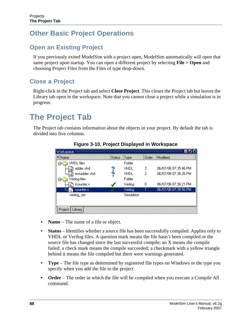
ModelSim User’s Manual, v6.2g88
ProjectsThe Project Tab
February 2007
Other Basic Project Operations
Open an Existing ProjectIf you previously exited ModelSim with a project open, ModelSim automatically will open thatsame project upon startup. You can open a different project by selecting File > Open andchoosing Project Files from the Files of type drop-down.
Close a ProjectRight-click in the Project tab and select Close Project. This closes the Project tab but leaves theLibrary tab open in the workspace. Note that you cannot close a project while a simulation is inprogress.
The Project TabThe Project tab contains information about the objects in your project. By default the tab isdivided into five columns.
Figure 3-10. Project Displayed in Workspace
• Name – The name of a file or object.
• Status – Identifies whether a source file has been successfully compiled. Applies only toVHDL or Verilog files. A question mark means the file hasn’t been compiled or thesource file has changed since the last successful compile; an X means the compilefailed; a check mark means the compile succeeded; a checkmark with a yellow trianglebehind it means the file compiled but there were warnings generated.
• Type – The file type as determined by registered file types on Windows or the type youspecify when you add the file to the project.
• Order – The order in which the file will be compiled when you execute a Compile Allcommand.

ProjectsChanging Compile Order
ModelSim User’s Manual, v6.2g 89February 2007
• Modified – The date and time of the last modification to the file.
You can hide or show columns by right-clicking on a column title and selecting or deselectingentries.
Sorting the ListYou can sort the list by any of the five columns. Click on a column heading to sort by thatcolumn; click the heading again to invert the sort order. An arrow in the column headingindicates which field the list is sorted by and whether the sort order is descending (down arrow)or ascending (up arrow).
Changing Compile OrderThe Compile Order dialog box is functional for HDL-only designs. When you compile all filesin a project, ModelSim by default compiles the files in the order in which they were added to theproject. You have two alternatives for changing the default compile order: 1) select and compileeach file individually; 2) specify a custom compile order.
To specify a custom compile order, follow these steps:
1. Select Compile > Compile Order or select it from the context menu in the Project tab.
Figure 3-11. Setting Compile Order
2. Drag the files into the correct order or use the up and down arrow buttons. Note that youcan select multiple files and drag them simultaneously.
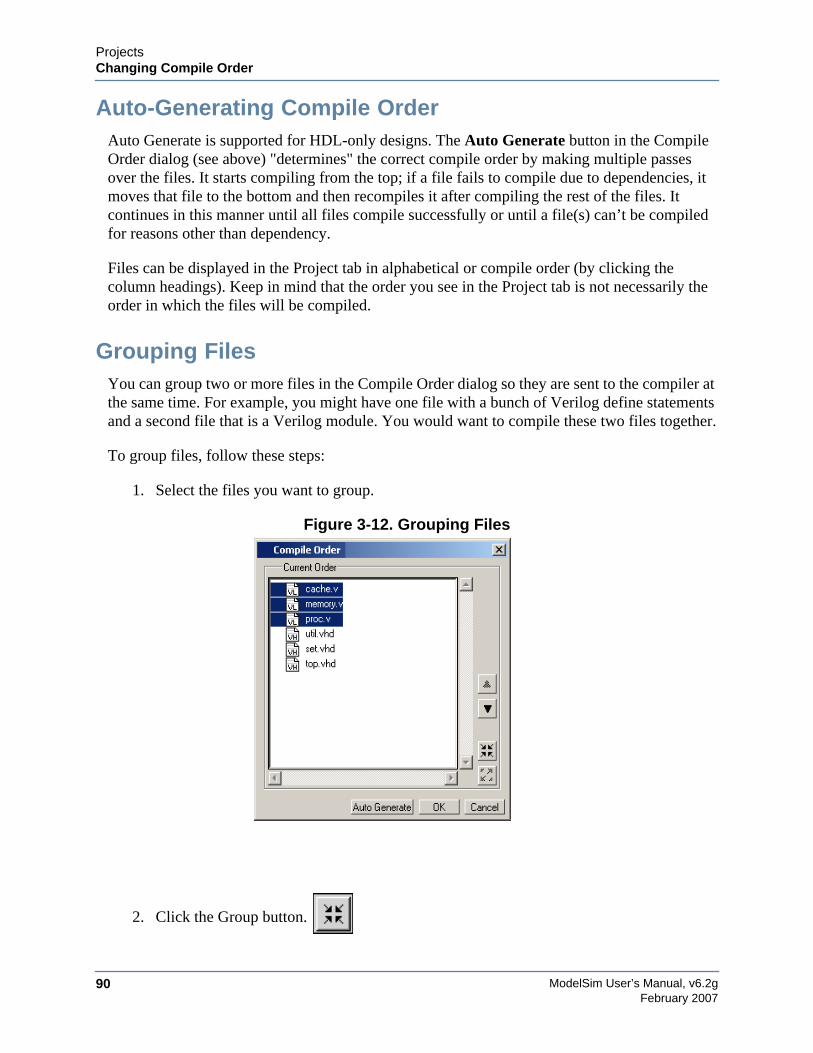
ModelSim User’s Manual, v6.2g90
ProjectsChanging Compile Order
February 2007
Auto-Generating Compile OrderAuto Generate is supported for HDL-only designs. The Auto Generate button in the CompileOrder dialog (see above) "determines" the correct compile order by making multiple passesover the files. It starts compiling from the top; if a file fails to compile due to dependencies, itmoves that file to the bottom and then recompiles it after compiling the rest of the files. Itcontinues in this manner until all files compile successfully or until a file(s) can’t be compiledfor reasons other than dependency.
Files can be displayed in the Project tab in alphabetical or compile order (by clicking thecolumn headings). Keep in mind that the order you see in the Project tab is not necessarily theorder in which the files will be compiled.
Grouping FilesYou can group two or more files in the Compile Order dialog so they are sent to the compiler atthe same time. For example, you might have one file with a bunch of Verilog define statementsand a second file that is a Verilog module. You would want to compile these two files together.
To group files, follow these steps:
1. Select the files you want to group.
Figure 3-12. Grouping Files
2. Click the Group button.
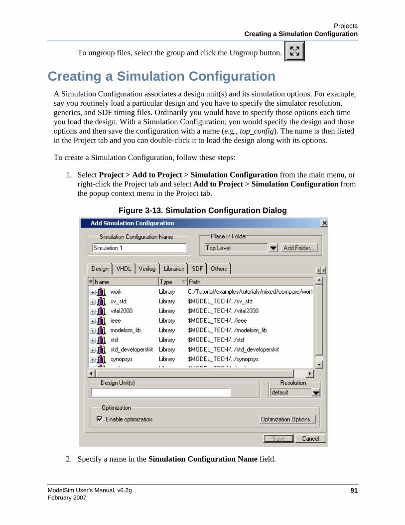
ProjectsCreating a Simulation Configuration
ModelSim User’s Manual, v6.2g 91February 2007
To ungroup files, select the group and click the Ungroup button.
Creating a Simulation ConfigurationA Simulation Configuration associates a design unit(s) and its simulation options. For example,say you routinely load a particular design and you have to specify the simulator resolution,generics, and SDF timing files. Ordinarily you would have to specify those options each timeyou load the design. With a Simulation Configuration, you would specify the design and thoseoptions and then save the configuration with a name (e.g., top_config). The name is then listedin the Project tab and you can double-click it to load the design along with its options.
To create a Simulation Configuration, follow these steps:
1. Select Project > Add to Project > Simulation Configuration from the main menu, orright-click the Project tab and select Add to Project > Simulation Configuration fromthe popup context menu in the Project tab.
Figure 3-13. Simulation Configuration Dialog
2. Specify a name in the Simulation Configuration Name field.
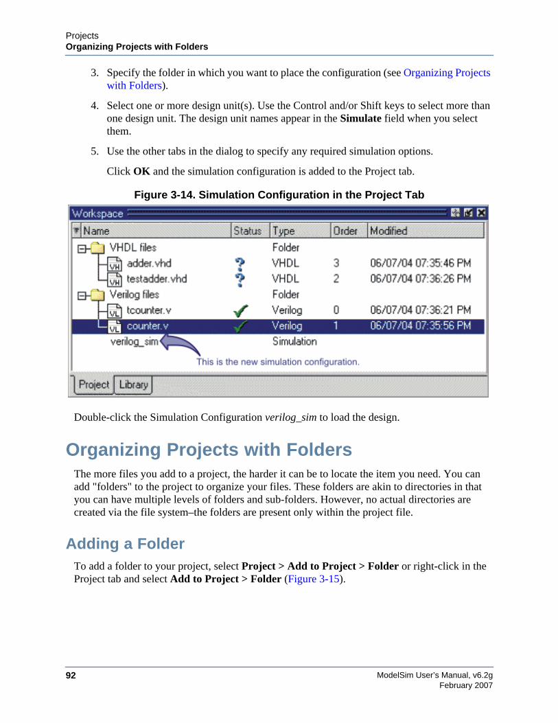
ModelSim User’s Manual, v6.2g92
ProjectsOrganizing Projects with Folders
February 2007
3. Specify the folder in which you want to place the configuration (see Organizing Projectswith Folders).
4. Select one or more design unit(s). Use the Control and/or Shift keys to select more thanone design unit. The design unit names appear in the Simulate field when you selectthem.
5. Use the other tabs in the dialog to specify any required simulation options.
Click OK and the simulation configuration is added to the Project tab.
Figure 3-14. Simulation Configuration in the Project Tab
Double-click the Simulation Configuration verilog_sim to load the design.
Organizing Projects with FoldersThe more files you add to a project, the harder it can be to locate the item you need. You canadd "folders" to the project to organize your files. These folders are akin to directories in thatyou can have multiple levels of folders and sub-folders. However, no actual directories arecreated via the file system–the folders are present only within the project file.
Adding a FolderTo add a folder to your project, select Project > Add to Project > Folder or right-click in theProject tab and select Add to Project > Folder (Figure 3-15).

ProjectsOrganizing Projects with Folders
ModelSim User’s Manual, v6.2g 93February 2007
Figure 3-15. Add Folder Dialog
Specify the Folder Name, the location for the folder, and click OK. The folder will be displayedin the Project tab.
You use the folders when you add new objects to the project. For example, when you add a file,you can select which folder to place it in.
Figure 3-16. Specifying a Project Folder
If you want to move a file into a folder later on, you can do so using the Properties dialog for thefile. Simply right-click on the filename in the Project tab and select Properties from the contextmenu that appears. This will open the Project Compiler Settings Dialog (Figure 3-17). Use thePlace in Folder field to specify a folder.
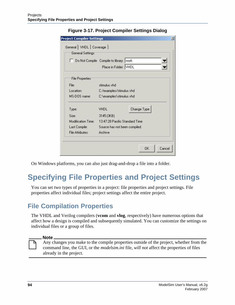
ModelSim User’s Manual, v6.2g94
ProjectsSpecifying File Properties and Project Settings
February 2007
Figure 3-17. Project Compiler Settings Dialog
On Windows platforms, you can also just drag-and-drop a file into a folder.
Specifying File Properties and Project SettingsYou can set two types of properties in a project: file properties and project settings. Fileproperties affect individual files; project settings affect the entire project.
File Compilation PropertiesThe VHDL and Verilog compilers (vcom and vlog, respectively) have numerous options thataffect how a design is compiled and subsequently simulated. You can customize the settings onindividual files or a group of files.
NoteAny changes you make to the compile properties outside of the project, whether from thecommand line, the GUI, or the modelsim.ini file, will not affect the properties of filesalready in the project.
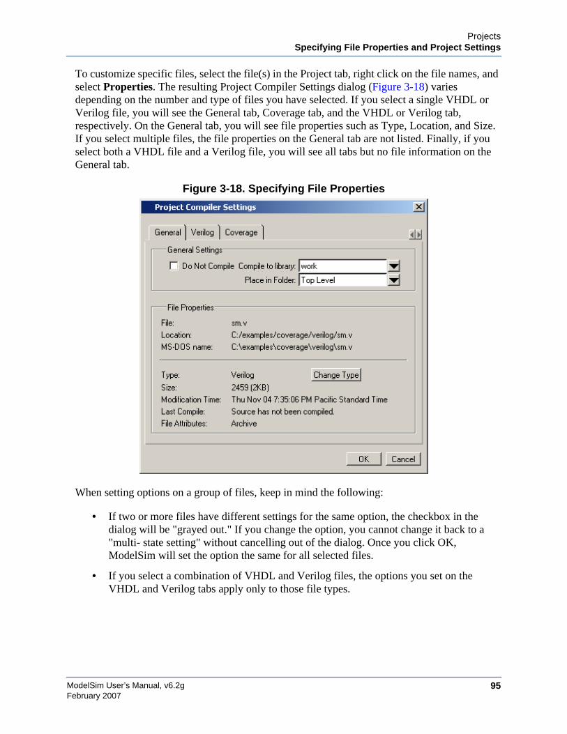
ProjectsSpecifying File Properties and Project Settings
ModelSim User’s Manual, v6.2g 95February 2007
To customize specific files, select the file(s) in the Project tab, right click on the file names, andselect Properties. The resulting Project Compiler Settings dialog (Figure 3-18) variesdepending on the number and type of files you have selected. If you select a single VHDL orVerilog file, you will see the General tab, Coverage tab, and the VHDL or Verilog tab,respectively. On the General tab, you will see file properties such as Type, Location, and Size.If you select multiple files, the file properties on the General tab are not listed. Finally, if youselect both a VHDL file and a Verilog file, you will see all tabs but no file information on theGeneral tab.
Figure 3-18. Specifying File Properties
When setting options on a group of files, keep in mind the following:
• If two or more files have different settings for the same option, the checkbox in thedialog will be "grayed out." If you change the option, you cannot change it back to a"multi- state setting" without cancelling out of the dialog. Once you click OK,ModelSim will set the option the same for all selected files.
• If you select a combination of VHDL and Verilog files, the options you set on theVHDL and Verilog tabs apply only to those file types.
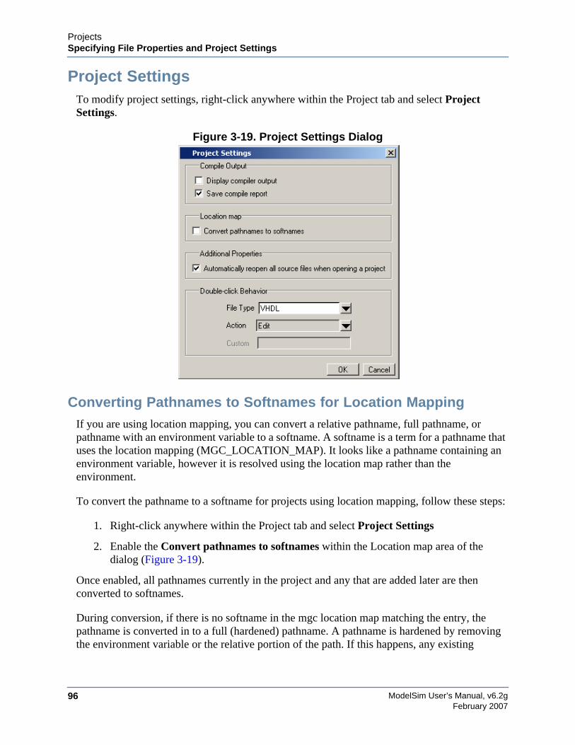
ModelSim User’s Manual, v6.2g96
ProjectsSpecifying File Properties and Project Settings
February 2007
Project SettingsTo modify project settings, right-click anywhere within the Project tab and select ProjectSettings.
Figure 3-19. Project Settings Dialog
Converting Pathnames to Softnames for Location MappingIf you are using location mapping, you can convert a relative pathname, full pathname, orpathname with an environment variable to a softname. A softname is a term for a pathname thatuses the location mapping (MGC_LOCATION_MAP). It looks like a pathname containing anenvironment variable, however it is resolved using the location map rather than theenvironment.
To convert the pathname to a softname for projects using location mapping, follow these steps:
1. Right-click anywhere within the Project tab and select Project Settings
2. Enable the Convert pathnames to softnames within the Location map area of thedialog (Figure 3-19).
Once enabled, all pathnames currently in the project and any that are added later are thenconverted to softnames.
During conversion, if there is no softname in the mgc location map matching the entry, thepathname is converted in to a full (hardened) pathname. A pathname is hardened by removingthe environment variable or the relative portion of the path. If this happens, any existing
ProjectsAccessing Projects from the Command Line
ModelSim User’s Manual, v6.2g 97February 2007
pathnames that are either relative or use environment variables are also changed: either tosoftnames if possible, or to hardened pathnames if not.
For more information on location mapping and pathnames, see Location Mapping.
Accessing Projects from the Command LineGenerally, projects are used from within the ModelSim GUI. However, standalone tools willuse the project file if they are invoked in the project's root directory. If you want to invokeoutside the project directory, set the MODELSIM environment variable with the path to theproject file (<Project_Root_Dir>/<Project_Name>.mpf).
You can also use the project command from the command line to perform common operationson projects.

ModelSim User’s Manual, v6.2g98
ProjectsAccessing Projects from the Command Line
February 2007

ModelSim User’s Manual, v6.2g 99February 2007
Chapter 4Design Libraries
VHDL designs are associated with libraries, which are objects that contain compiled designunits. Verilog and SystemVerilog designs simulated within ModelSim are compiled intolibraries as well.
Design Library OverviewA design library is a directory or archive that serves as a repository for compiled design units.The design units contained in a design library consist of VHDL entities, packages, architectures,and configurations; Verilog modules and UDPs (user-defined primitives). The design units areclassified as follows:
• Primary design units — Consist of entities, package declarations, configurationdeclarations, modulesUDPs. Primary design units within a given library must haveunique names.
• Secondary design units — Consist of architecture bodiespackage bodies. Secondarydesign units are associated with a primary design unit. Architectures by the same namecan exist if they are associated with different entities or modules.
Design Unit InformationThe information stored for each design unit in a design library is:
• retargetable, executable code
• debugging information
• dependency information
Working Library Versus Resource LibrariesDesign libraries can be used in two ways:
1. as a local working library that contains the compiled version of your design;
2. as a resource library.
The contents of your working library will change as you update your design and recompile. Aresource library is typically static and serves as a parts source for your design. You can create
ModelSim User’s Manual, v6.2g100
Design LibrariesWorking with Design Libraries
February 2007
your own resource libraries or they may be supplied by another design team or a third party(e.g., a silicon vendor).
Only one library can be the working library.
Any number of libraries can be resource libraries during a compilation. You specify whichresource libraries will be used when the design is compiled, and there are rules to specify inwhich order they are searched (refer to Specifying the Resource Libraries).
A common example of using both a working library and a resource library is one in which yourgate-level design and testbench are compiled into the working library and the design referencesgate-level models in a separate resource library.
The Library Named "work"The library named "work" has special attributes within ModelSim — it is predefined in thecompiler and need not be declared explicitly (i.e. library work). It is also the library name usedby the compiler as the default destination of compiled design units (i.e., it does not need to bemapped). In other words, the work library is the default working library.
ArchivesBy default, design libraries are stored in a directory structure with a sub-directory for eachdesign unit in the library. Alternatively, you can configure a design library to use archives. Inthis case, each design unit is stored in its own archive file. To create an archive, use the -archiveargument to the vlib command.
Generally you would do this only in the rare case that you hit the reference count limit on I-nodes due to the ".." entries in the lower-level directories (the maximum number of sub-directories on UNIX and Linux is 65533). An example of an error message that is producedwhen this limit is hit is:
mkdir: cannot create directory `65534': Too many links
Archives may also have limited value to customers seeking disk space savings.
NoteGMAKE won’t work with these archives on the IBM platform.
Working with Design LibrariesThe implementation of a design library is not defined within standard VHDL or Verilog. WithinModelSim, design libraries are implemented as directories and can have any legal name allowedby the operating system, with one exception: extended identifiers are not supported for librarynames.
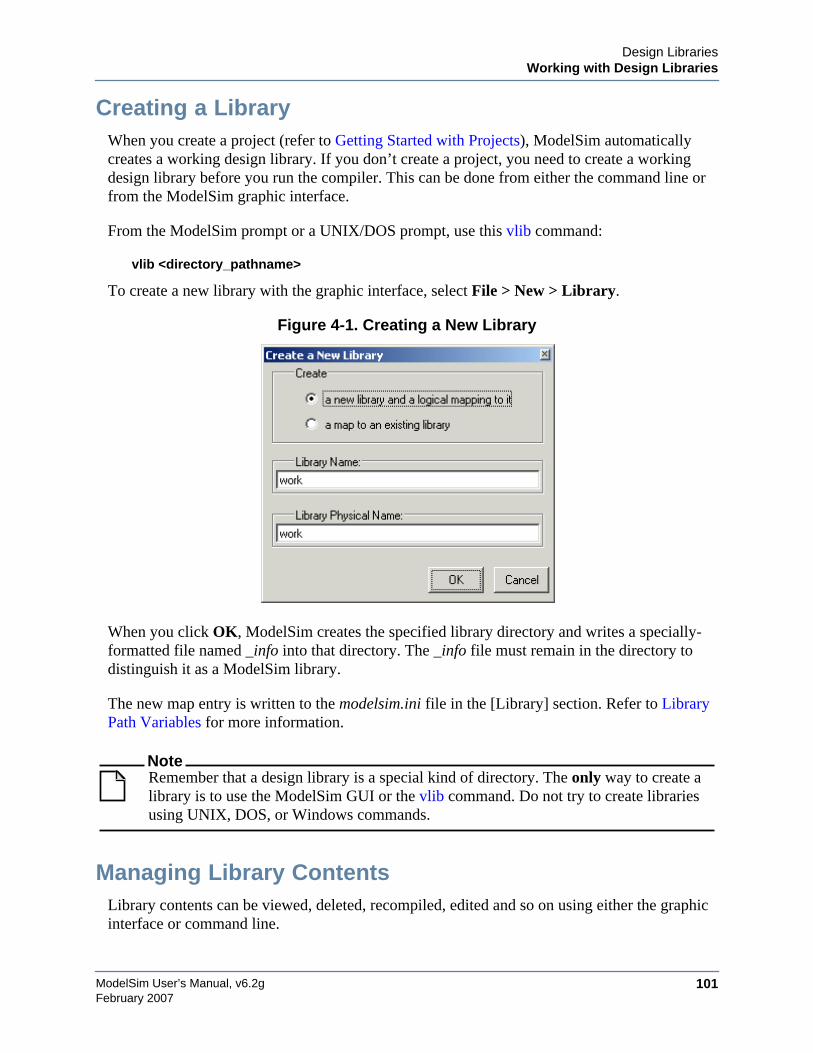
Design LibrariesWorking with Design Libraries
ModelSim User’s Manual, v6.2g 101February 2007
Creating a LibraryWhen you create a project (refer to Getting Started with Projects), ModelSim automaticallycreates a working design library. If you don’t create a project, you need to create a workingdesign library before you run the compiler. This can be done from either the command line orfrom the ModelSim graphic interface.
From the ModelSim prompt or a UNIX/DOS prompt, use this vlib command:
vlib <directory_pathname>
To create a new library with the graphic interface, select File > New > Library.
Figure 4-1. Creating a New Library
When you click OK, ModelSim creates the specified library directory and writes a specially-formatted file named _info into that directory. The _info file must remain in the directory todistinguish it as a ModelSim library.
The new map entry is written to the modelsim.ini file in the [Library] section. Refer to LibraryPath Variables for more information.
NoteRemember that a design library is a special kind of directory. The only way to create alibrary is to use the ModelSim GUI or the vlib command. Do not try to create librariesusing UNIX, DOS, or Windows commands.
Managing Library ContentsLibrary contents can be viewed, deleted, recompiled, edited and so on using either the graphicinterface or command line.
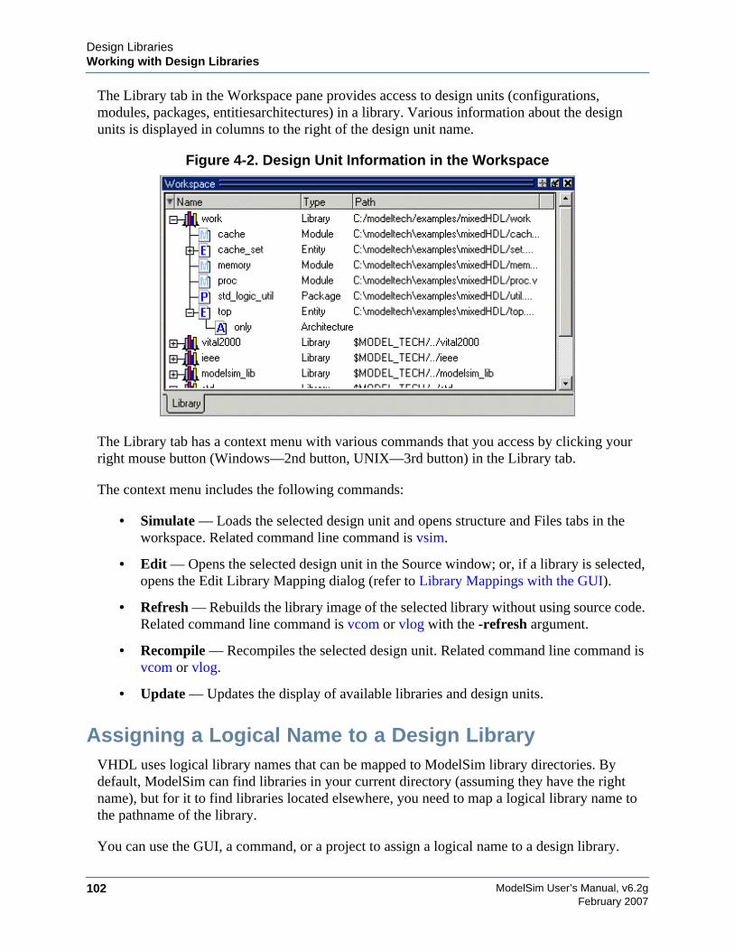
ModelSim User’s Manual, v6.2g102
Design LibrariesWorking with Design Libraries
February 2007
The Library tab in the Workspace pane provides access to design units (configurations,modules, packages, entitiesarchitectures) in a library. Various information about the designunits is displayed in columns to the right of the design unit name.
Figure 4-2. Design Unit Information in the Workspace
The Library tab has a context menu with various commands that you access by clicking yourright mouse button (Windows—2nd button, UNIX—3rd button) in the Library tab.
The context menu includes the following commands:
• Simulate — Loads the selected design unit and opens structure and Files tabs in theworkspace. Related command line command is vsim.
• Edit — Opens the selected design unit in the Source window; or, if a library is selected,opens the Edit Library Mapping dialog (refer to Library Mappings with the GUI).
• Refresh — Rebuilds the library image of the selected library without using source code.Related command line command is vcom or vlog with the -refresh argument.
• Recompile — Recompiles the selected design unit. Related command line command isvcom or vlog.
• Update — Updates the display of available libraries and design units.
Assigning a Logical Name to a Design LibraryVHDL uses logical library names that can be mapped to ModelSim library directories. Bydefault, ModelSim can find libraries in your current directory (assuming they have the rightname), but for it to find libraries located elsewhere, you need to map a logical library name tothe pathname of the library.
You can use the GUI, a command, or a project to assign a logical name to a design library.
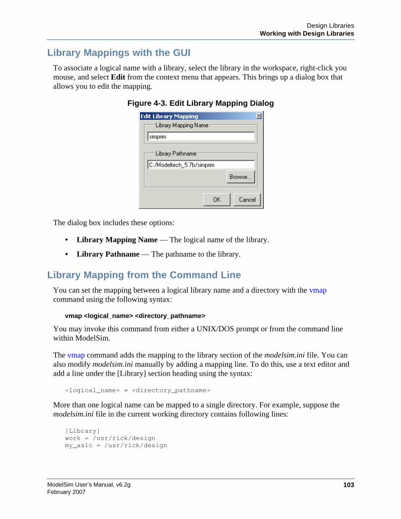
Design LibrariesWorking with Design Libraries
ModelSim User’s Manual, v6.2g 103February 2007
Library Mappings with the GUITo associate a logical name with a library, select the library in the workspace, right-click youmouse, and select Edit from the context menu that appears. This brings up a dialog box thatallows you to edit the mapping.
Figure 4-3. Edit Library Mapping Dialog
The dialog box includes these options:
• Library Mapping Name — The logical name of the library.
• Library Pathname — The pathname to the library.
Library Mapping from the Command LineYou can set the mapping between a logical library name and a directory with the vmapcommand using the following syntax:
vmap <logical_name> <directory_pathname>
You may invoke this command from either a UNIX/DOS prompt or from the command linewithin ModelSim.
The vmap command adds the mapping to the library section of the modelsim.ini file. You canalso modify modelsim.ini manually by adding a mapping line. To do this, use a text editor andadd a line under the [Library] section heading using the syntax:
<logical_name> = <directory_pathname>
More than one logical name can be mapped to a single directory. For example, suppose themodelsim.ini file in the current working directory contains following lines:
[Library]work = /usr/rick/designmy_asic = /usr/rick/design
ModelSim User’s Manual, v6.2g104
Design LibrariesWorking with Design Libraries
February 2007
This would allow you to use either the logical name work or my_asic in a library or use clauseto refer to the same design library.
Unix Symbolic LinksYou can also create a UNIX symbolic link to the library using the host platform command:
ln -s <directory_pathname> <logical_name>
The vmap command can also be used to display the mapping of a logical library name to adirectory. To do this, enter the shortened form of the command:
vmap <logical_name>
Library Search RulesThe system searches for the mapping of a logical name in the following order:
• First the system looks for a modelsim.ini file.
• If the system doesn’t find a modelsim.ini file, or if the specified logical name does notexist in the modelsim.ini file, the system searches the current working directory for asubdirectory that matches the logical name.
An error is generated by the compiler if you specify a logical name that does not resolve to anexisting directory.
Moving a LibraryIndividual design units in a design library cannot be moved. An entire design library can bemoved, however, by using standard operating system commands for moving a directory or anarchive.
Setting Up Libraries for Group UseBy adding an “others” clause to your modelsim.ini file, you can have a hierarchy of librarymappings. If the tool does not find a mapping in the modelsim.ini file, then it will search the[library] section of the initialization file specified by the “others” clause. For example:
[library]asic_lib = /cae/asic_libwork = my_workothers = /usr/modeltech/modelsim.ini
You can specify only one "others" clause in the library section of a given modelsim.ini file.
The others clause only instructs the tool to look in the specified modelsim.ini file for a library, itdoes not load any other part of the specified file.
Design LibrariesSpecifying the Resource Libraries
ModelSim User’s Manual, v6.2g 105February 2007
Specifying the Resource Libraries
Verilog Resource LibrariesModelSim supports separate compilation of distinct portions of a Verilog design. The vlogcompiler is used to compile one or more source files into a specified library. The library thuscontains pre-compiled modules and UDPs that are referenced by the simulator as it loads thedesign.
NoteResource libraries are specified differently for Verilog and VHDL. For Verilog you useeither the -L or -Lf argument to vlog. Refer to Library Usage for more information.
VHDL Resource LibrariesWithin a VHDL source file, you use the VHDL library clause to specify logical names of oneor more resource libraries to be referenced in the subsequent design unit. The scope of a libraryclause includes the text region that starts immediately after the library clause and extends to theend of the declarative region of the associated design unit. It does not extend to the next designunit in the file.
Note that the library clause is not used to specify the working library into which the design unitis placed after compilation. The vcom command adds compiled design units to the currentworking library. By default, this is the library named work. To change the current workinglibrary, you can use vcom -work and specify the name of the desired target library.
Predefined LibrariesCertain resource libraries are predefined in standard VHDL. The library named std contains thepackages standard and textio, which should not be modified. The contents of these packagesand other aspects of the predefined language environment are documented in the IEEE StandardVHDL Language Reference Manual, Std 1076. Refer also to, Using the TextIO Package.
A VHDL use clause can be specified to select particular declarations in a library or package thatare to be visible within a design unit during compilation. A use clause references the compiledversion of the package—not the source.
By default, every VHDL design unit is assumed to contain the following declarations:
LIBRARY std, work;USE std.standard.all
To specify that all declarations in a library or package can be referenced, add the suffix .all tothe library/package name. For example, the use clause above specifies that all declarations inthe package standard, in the design library named std, are to be visible to the VHDL design unit
ModelSim User’s Manual, v6.2g106
Design LibrariesSpecifying the Resource Libraries
February 2007
immediately following the use clause. Other libraries or packages are not visible unless they areexplicitly specified using a library or use clause.
Another predefined library is work, the library where a design unit is stored after it is compiledas described earlier. There is no limit to the number of libraries that can be referenced, but onlyone library is modified during compilation.
Alternate IEEE Libraries SuppliedThe installation directory may contain two or more versions of the IEEE library:
• ieeepure — Contains only IEEE approved packages (accelerated for ModelSim).
• ieee — Contains precompiled Synopsys and IEEE arithmetic packages which have beenaccelerated by Model Technology including math_complex, math_real, numeric_bit,numeric_std, std_logic_1164, std_logic_misc, std_logic_textio, std_logic_arith,std_logic_signed, std_logic_unsigned, vital_primitives, and vital_timing.
You can select which library to use by changing the mapping in the modelsim.ini file. Themodelsim.ini file in the installation directory defaults to the ieee library.
Regenerating Your Design LibrariesDepending on your current ModelSim version, you may need to regenerate your design librariesbefore running a simulation. Check the installation README file to see if your libraries requirean update. You can regenerate your design libraries using the Refresh command from theLibrary tab context menu (refer to Managing Library Contents), or by using the -refreshargument to vcom and vlog.
From the command line, you would use vcom with the -refresh argument to update VHDLdesign units in a library, and vlog with the -refresh argument to update Verilog design units. Bydefault, the work library is updated. Use either vcom or vlog with the -work <library>argument to update a different library. For example, if you have a library named mylib thatcontains both VHDL and Verilog design units:
vcom -work mylib -refresh
vlog -work mylib -refresh
An important feature of -refresh is that it rebuilds the library image without using source code.This means that models delivered as compiled libraries without source code can be rebuilt for aspecific release of ModelSim. In general, this works for moving forwards or backwards on arelease. Moving backwards on a release may not work if the models used compiler switches,directives, language constructs, or features that do not exist in the older release.
Design LibrariesImporting FPGA Libraries
ModelSim User’s Manual, v6.2g 107February 2007
NoteYou don't need to regenerate the std, ieee, vital22b, and verilog libraries. Also, youcannot use the -refresh option to update libraries that were built before the 4.6 release.
Maintaining 32- and 64-bit Versions in the Same LibraryModelSim allows you to maintain 32-bit and 64-bit versions of a design in the same library.
To do this, you must compile the design with the 32-bit version and then "refresh" the designwith the 64-bit version. For example:
Using the 32-bit version of ModelSim:
vlog file1.v file2.v -forcecode -work asic_lib
Next, using the 64-bit version of ModelSim:
vlog -work asic_lib -refresh
This allows you to use either version without having to do a refresh.
Do not compile the design with one version, and then recompile it with the other. If you do this,ModelSim will remove the first module, because it could be "stale."
Importing FPGA LibrariesModelSim includes an import wizard for referencing and using vendor FPGA libraries. Thewizard scans for and enforces dependencies in the libraries and determines the correct mappingsand target directories.
NoteThe FPGA libraries you import must be pre-compiled. Most FPGA vendors supply pre-compiled libraries configured for use with ModelSim.
To import an FPGA library, select File > Import > Library.
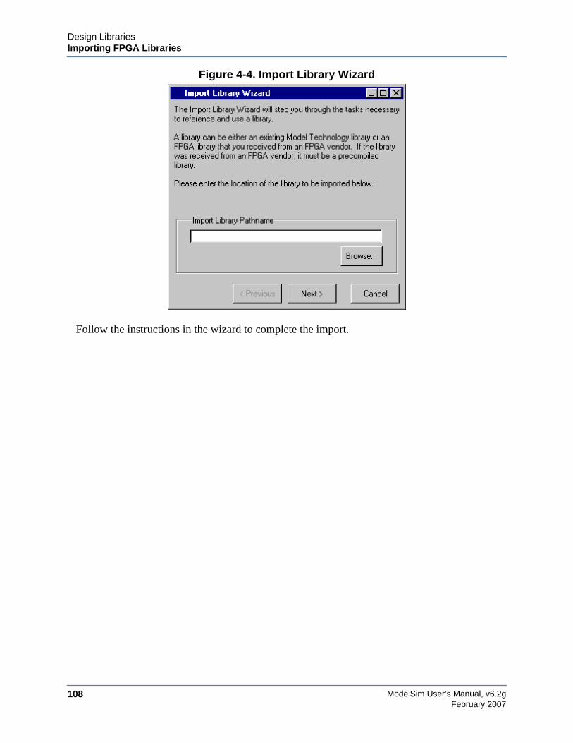
ModelSim User’s Manual, v6.2g108
Design LibrariesImporting FPGA Libraries
February 2007
Figure 4-4. Import Library Wizard
Follow the instructions in the wizard to complete the import.
ModelSim User’s Manual, v6.2g 109February 2007
Chapter 5VHDL Simulation
This chapter describes how to compile, optimize, and simulate VHDL designs in ModelSim. Italso discusses using the TextIO package with ModelSim; ModelSim’s implementation of theVITAL (VHDL Initiative Towards ASIC Libraries) specification for ASIC modeling; andModelSim’s special built-in utilities package.
The TextIO package is defined within the VHDL Language Reference Manual, IEEE Std 1076;it allows human-readable text input from a declared source within a VHDL file duringsimulation.
Basic VHDL FlowSimulating VHDL designs with ModelSim includes four general steps:
1. Compile your VHDL code into one or more libraries using the vcom command. SeeCompiling VHDL Files for details.
2. Load your design with the vsim command. See Simulating VHDL Designs for details.
3. Run and debug your design.
Compiling VHDL Files
Creating a Design Library for VHDLBefore you can compile your source files, you must create a library in which to store thecompilation results. Use vlib to create a new library. For example:
vlib work
This creates a library named work. By default, compilation results are stored in the worklibrary.
The work library is actually a subdirectory named work. This subdirectory contains a specialfile named _info. Do not create libraries using UNIX, MS Windows, or DOS commands –always use the vlib command.
See Design Libraries for additional information on working with libraries.
ModelSim User’s Manual, v6.2g110
VHDL SimulationCompiling VHDL Files
February 2007
Invoking the VHDL CompilerModelSim compiles one or more VHDL design units with a single invocation of vcom, theVHDL compiler. The design units are compiled in the order that they appear on the commandline. For VHDL, the order of compilation is important – you must compile any entities orconfigurations before an architecture that references them.
You can simulate a design containing units written with 1076 -1987, 1076 -1993, and1076-2002 versions of VHDL. To do so you will need to compile units from each VHDLversion separately. The vcom command compiles using 1076 -2002 rules by default; use the -87or -93 argument to vcom to compile units written with version 1076-1987 or 1076 -1993,respectively. You can also change the default by modifying the VHDL93 variable in themodelsim.ini file (see Simulator Control Variables for more information).
Dependency CheckingDependent design units must be reanalyzed when the design units they depend on are changedin the library. vcom determines whether or not the compilation results have changed. Forexample, if you keep an entity and its architectures in the same source file and you modify onlyan architecture and recompile the source file, the entity compilation results will remainunchanged and you will not have to recompile design units that depend on the entity.
Range and Index CheckingA range check verifies that a scalar value defined with a range subtype is always assigned avalue within its range. An index check verifies that whenever an array subscript expression isevaluated, the subscript will be within the array's range.
Range and index checks are performed by default when you compile your design. You candisable range checks (potentially offering a performance advantage) and index checks usingarguments to the vcom command. Or, you can use the NoRangeCheck and NoIndexCheckvariables in the modelsim.ini file to specify whether or not they are performed. See SimulatorControl Variables.
Range checks in ModelSim are slightly more restrictive than those specified by the VHDLLRM. ModelSim requires any assignment to a signal to also be in range whereas the LRMrequires only that range checks be done whenever a signal is updated. Most assignments tosignals update the signal anyway, and the more restrictive requirement allows ModelSim togenerate better error messages.
Subprogram InliningModelSim attempts to inline subprograms at compile time to improve simulation performance.This happens automatically and should be largely transparent. However, you can disableautomatic inlining two ways:
VHDL SimulationCompiling VHDL Files
ModelSim User’s Manual, v6.2g 111February 2007
• Invoke vcom with the -O0 or -O1 argument
• Use the mti_inhibit_inline attribute as described below
Single-stepping through a simulation varies slightly depending on whether inlining occurred.When single-stepping to a subprogram call that has not been inlined, the simulator stops first atthe line of the call, and then proceeds to the line of the first executable statement in the calledsubprogram. If the called subprogram has been inlined, the simulator does not first stop at thesubprogram call, but stops immediately at the line of the first executable statement.
mti_inhibit_inline AttributeYou can disable inlining for individual design units (a package, architecture, or entity) orsubprograms with the mti_inhibit_inline attribute. Follow these rules to use the attribute:
• Declare the attribute within the design unit's scope as follows:
attribute mti_inhibit_inline : boolean;
• Assign the value true to the attribute for the appropriate scope. For example, to inhibitinlining for a particular function (e.g., "foo"), add the following attribute assignment:
attribute mti_inhibit_inline of foo : procedure is true;
To inhibit inlining for a particular package (e.g., "pack"), add the following attributeassignment:
attribute mti_inhibit_inline of pack : package is true;
Do similarly for entities and architectures.
Differences Between Language VersionsThere are three versions of the IEEE VHDL 1076 standard: VHDL-1987, VHDL-1993, andVHDL-2002. The default language version for ModelSim is VHDL-2002. If your code waswritten according to the ’87 or ’93 version, you may need to update your code or instructModelSim to use the earlier versions’ rules.
To select a specific language version, do one of the following:
• Select the appropriate version from the compiler options menu in the GUI
• Invoke vcom using the argument -87, -93, or -2002
• Set the VHDL93 variable in the [vcom] section of the modelsim.ini file. Appropriatevalues for VHDL93 are:
- 0, 87, or 1987 for VHDL-1987
- 1, 93, or 1993 for VHDL-1993
ModelSim User’s Manual, v6.2g112
VHDL SimulationCompiling VHDL Files
February 2007
- 2, 02, or 2002 for VHDL-2002
The following is a list of language incompatibilities that may cause problems when compiling adesign.
• VHDL-93 and VHDL-2002 — The only major problem between VHDL-93 and VHDL-2002 is the addition of the keyword "PROTECTED". VHDL-93 programs which usethis as an identifier should choose a different name.
All other incompatibilities are between VHDL-87 and VHDL-93.
• VITAL and SDF — It is important to use the correct language version for VITAL.VITAL2000 must be compiled with VHDL-93 or VHDL-2002. VITAL95 must becompiled with VHDL-87. A typical error message that indicates the need to compileunder language version VHDL-87 is:
"VITALPathDelay DefaultDelay parameter must be locally static"
• Purity of NOW — In VHDL-93 the function "now" is impure. Consequently, anyfunction that invokes "now" must also be declared to be impure. Such calls to "now"occur in VITAL. A typical error message:
"Cannot call impure function 'now' from inside pure function'<name>'"
• Files — File syntax and usage changed between VHDL-87 and VHDL-93. In manycases vcom issues a warning and continues:
"Using 1076-1987 syntax for file declaration."
In addition, when files are passed as parameters, the following warning message isproduced:
"Subprogram parameter name is declared using VHDL 1987 syntax."
This message often involves calls to endfile(<name>) where <name> is a file parameter.
• Files and packages — Each package header and body should be compiled with the samelanguage version. Common problems in this area involve files as parameters and the sizeof type CHARACTER. For example, consider a package header and body with aprocedure that has a file parameter:
procedure proc1 ( out_file : out std.textio.text) ...
If you compile the package header with VHDL-87 and the body with VHDL-93 orVHDL-2002, you will get an error message such as:
"** Error: mixed_package_b.vhd(4): Parameter kinds do not conformbetween declarations in package header and body: 'out_file'."
• Direction of concatenation — To solve some technical problems, the rules for directionand bounds of concatenation were changed from VHDL-87 to VHDL-93. You won't seeany difference in simple variable/signal assignments such as:

VHDL SimulationCompiling VHDL Files
ModelSim User’s Manual, v6.2g 113February 2007
v1 := a & b;
But if you (1) have a function that takes an unconstrained array as a parameter, (2) passa concatenation expression as a formal argument to this parameter, and (3) the body ofthe function makes assumptions about the direction or bounds of the parameter, then youwill get unexpected results. This may be a problem in environments that assume allarrays have "downto" direction.
• xnor — "xnor" is a reserved word in VHDL-93. If you declare an xnor function inVHDL-87 (without quotes) and compile it under VHDL-2002, you will get an errormessage like the following:
** Error: xnor.vhd(3): near "xnor": expecting: STRING IDENTIFIER
• 'FOREIGN attribute — In VHDL-93 package STANDARD declares an attribute'FOREIGN. If you declare your own attribute with that name in another package, thenModelSim issues a warning such as the following:
-- Compiling package foopack
** Warning: foreign.vhd(9): (vcom-1140) VHDL-1993 added a definitionof the attribute foreign to package std.standard. The attribute isalso defined in package 'standard'. Using the definition frompackage 'standard'.
• Size of CHARACTER type — In VHDL-87 type CHARACTER has 128 values; inVHDL-93 it has 256 values. Code which depends on this size will behave incorrectly.This situation occurs most commonly in test suites that check VHDL functionality. It'sunlikely to occur in practical designs. A typical instance is the replacement of warningmessage:
"range nul downto del is null"
by
"range nul downto 'ÿ' is null" -- range is nul downto y(umlaut)
• bit string literals — In VHDL-87 bit string literals are of type bit_vector. In VHDL-93they can also be of type STRING or STD_LOGIC_VECTOR. This implies that someexpressions that are unambiguous in VHDL-87 now become ambiguous is VHDL-93. Atypical error message is:
** Error: bit_string_literal.vhd(5): Subprogram '=' is ambiguous.Suitable definitions exist in packages 'std_logic_1164' and'standard'.
• Sub-element association — In VHDL-87 when using individual sub-element associationin an association list, associating individual sub-elements with NULL is discouraged. InVHDL-93 such association is forbidden. A typical message is:
"Formal '<name>' must not be associated with OPEN when subelementsare associated individually."
ModelSim User’s Manual, v6.2g114
VHDL SimulationSimulating VHDL Designs
February 2007
Simulating VHDL DesignsA VHDL design is ready for simulation after it has been compiled with vcom . The simulatormay then be invoked with the name of the configuration or entity/architecture pair.
NoteThis section discusses simulation from the UNIX or Windows/DOS command line. Youcan also use a project to simulate (see Getting Started with Projects) or the Simulatedialog box.
This example invokes vsim on the entity my_asic and the architecture structure:
vsim my_asic structure
vsim is capable of annotating a design using VITAL compliant models with timing data from anSDF file. You can specify the min:typ:max delay by invoking vsim with the -sdfmin, -sdftyp,or -sdfmax option. Using the SDF file f1.sdf in the current work directory, the followinginvocation of vsim annotates maximum timing values for the design unit my_asic:
vsim -sdfmax /my_asic=f1.sdf my_asic
By default, the timing checks within VITAL models are enabled. They can be disabled with the+notimingchecks option. For example:
vsim +notimingchecks topmod
Simulator Resolution Limit (VHDL)The simulator internally represents time as a 64-bit integer in units equivalent to the smallestunit of simulation time, also known as the simulator resolution limit. The default resolutionlimit is set to the value specified by the Resolution variable in the modelsim.ini file. You canview the current resolution by invoking the report command with the simulator state option.
Overriding the ResolutionYou can override ModelSim’s default resolution by specifying the -t option on the commandline or by selecting a different Simulator Resolution in the Simulate dialog box. Availableresolutions are: 1x, 10x, or 100x of fs, ps, ns, us, ms, or sec.
For example this command chooses 10 ps resolution:
vsim -t 10ps topmod
Clearly you need to be careful when doing this type of operation. If the resolution set by -t islarger than a delay value in your design, the delay values in that design unit are rounded to theclosest multiple of the resolution. In the example above, a delay of 4 ps would be rounded to 0ps.
VHDL SimulationSimulating VHDL Designs
ModelSim User’s Manual, v6.2g 115February 2007
Choosing the Resolution for VHDLYou should choose the coarsest resolution limit possible that does not result in undesiredrounding of your delays. The time precision should not be unnecessarily small because it willlimit the maximum simulation time limit, and it will degrade performance in some cases.
Default BindingBy default ModelSim performs default binding when you load the design with vsim. Theadvantage of performing default binding at load time is that it provides more flexibility forcompile order. Namely, entities don't necessarily have to be compiled before otherentities/architectures which instantiate them.
However, you can force ModelSim to perform default binding at compile time. This may allowyou to catch design errors (e.g., entities with incorrect port lists) earlier in the flow. Use one ofthese two methods to change when default binding occurs:
• Specify the -bindAtCompile argument to vcom
• Set the BindAtCompile variable in the modelsim.ini to 1 (true)
Default Binding RulesWhen looking for an entity to bind with, ModelSim searches the currently visible libraries foran entity with the same name as the component. ModelSim does this because IEEE 1076-1987contained a flaw that made it almost impossible for an entity to be directly visible if it had thesame name as the component. In short, if a component was declared in an architecture, any like-named entity above that declaration would be hidden because component/entity names cannotbe overloaded. As a result we implemented the following rules for determining default binding:
• If performing default binding at load time, search the libraries specified with the -Lfargument to vsim.
• If a directly visible entity has the same name as the component, use it.
• If an entity would be directly visible in the absence of the component declaration, use it.
• If the component is declared in a package, search the library that contained the packagefor an entity with the same name.
If none of these methods is successful, ModelSim will also do the following:
• Search the work library.
• Search all other libraries that are currently visible by means of the library clause.
• If performing default binding at load time, search the libraries specified with the -Largument to vsim.
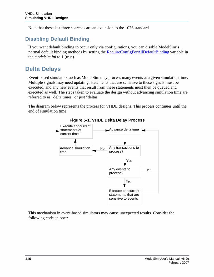
ModelSim User’s Manual, v6.2g116
VHDL SimulationSimulating VHDL Designs
February 2007
Note that these last three searches are an extension to the 1076 standard.
Disabling Default BindingIf you want default binding to occur only via configurations, you can disable ModelSim’snormal default binding methods by setting the RequireConfigForAllDefaultBinding variable inthe modelsim.ini to 1 (true).
Delta DelaysEvent-based simulators such as ModelSim may process many events at a given simulation time.Multiple signals may need updating, statements that are sensitive to these signals must beexecuted, and any new events that result from these statements must then be queued andexecuted as well. The steps taken to evaluate the design without advancing simulation time arereferred to as "delta times" or just "deltas."
The diagram below represents the process for VHDL designs. This process continues until theend of simulation time.
Figure 5-1. VHDL Delta Delay Process
This mechanism in event-based simulators may cause unexpected results. Consider thefollowing code snippet:
Execute concurrentstatements atcurrent time
Advance delta time
Any transactions toprocess?
No
Yes
Any events toprocess?
No
Execute concurrentstatements that aresensitive to events
Advance simulationtime
Yes
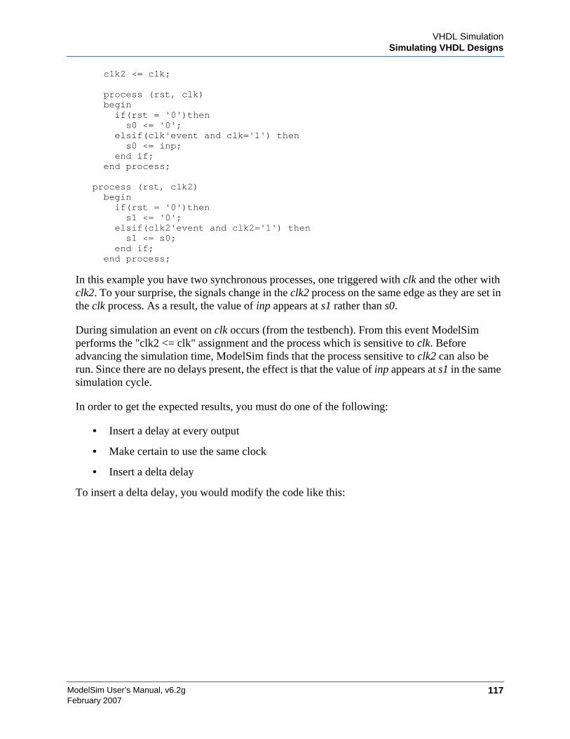
VHDL SimulationSimulating VHDL Designs
ModelSim User’s Manual, v6.2g 117February 2007
clk2 <= clk;
process (rst, clk) begin if(rst = '0')then s0 <= '0'; elsif(clk'event and clk='1') then s0 <= inp;
end if; end process;
process (rst, clk2) begin if(rst = '0')then s1 <= '0'; elsif(clk2'event and clk2='1') then s1 <= s0; end if; end process;
In this example you have two synchronous processes, one triggered with clk and the other withclk2. To your surprise, the signals change in the clk2 process on the same edge as they are set inthe clk process. As a result, the value of inp appears at s1 rather than s0.
During simulation an event on clk occurs (from the testbench). From this event ModelSimperforms the "clk2 <= clk" assignment and the process which is sensitive to clk. Beforeadvancing the simulation time, ModelSim finds that the process sensitive to clk2 can also berun. Since there are no delays present, the effect is that the value of inp appears at s1 in the samesimulation cycle.
In order to get the expected results, you must do one of the following:
• Insert a delay at every output
• Make certain to use the same clock
• Insert a delta delay
To insert a delta delay, you would modify the code like this:
ModelSim User’s Manual, v6.2g118
VHDL SimulationUsing the TextIO Package
February 2007
process (rst, clk) begin if(rst = '0')then s0 <= '0'; elsif(clk'event and clk='1') then s0 <= inp; s0_delayed <= s0; end if; end process;
process (rst, clk2) begin if(rst = '0')then s1 <= '0'; elsif(clk2'event and clk2='1') then s1 <= s0_delayed; end if; end process;
The best way to debug delta delay problems is observe your signals in the List window. Thereyou can see how values change at each delta time.
Detecting Infinite Zero-Delay LoopsIf a large number of deltas occur without advancing time, it is usually a symptom of an infinitezero-delay loop in the design. In order to detect the presence of these loops, ModelSim defines alimit, the “iteration limit", on the number of successive deltas that can occur. When ModelSimreaches the iteration limit, it issues a warning message.
The iteration limit default value is 1000. If you receive an iteration limit warning, first increasethe iteration limit and try to continue simulation. You can set the iteration limit from theSimulate > Runtime Options menu or by modifying the IterationLimit variable in themodelsim.ini. See Simulator Control Variables for more information on modifying themodelsim.ini file.
If the problem persists, look for zero-delay loops. Run the simulation and look at the sourcecode when the error occurs. Use the step button to step through the code and see which signalsor variables are continuously oscillating. Two common causes are a loop that has no exit, or aseries of gates with zero delay where the outputs are connected back to the inputs.
Using the TextIO PackageTo access the routines in TextIO, include the following statement in your VHDL source code:
USE std.textio.all;
VHDL SimulationUsing the TextIO Package
ModelSim User’s Manual, v6.2g 119February 2007
A simple example using the package TextIO is:
USE std.textio.all;ENTITY simple_textio ISEND;
ARCHITECTURE simple_behavior OF simple_textio ISBEGIN
PROCESSVARIABLE i: INTEGER:= 42;VARIABLE LLL: LINE;
BEGINWRITE (LLL, i);WRITELINE (OUTPUT, LLL);WAIT;
END PROCESS;END simple_behavior;
Syntax for File DeclarationThe VHDL’87 syntax for a file declaration is:
file identifier : subtype_indication is [ mode ] file_logical_name ;
where "file_logical_name" must be a string expression.
In newer versions of the 1076 spec, syntax for a file declaration is:
file identifier_list : subtype_indication [ file_open_information ] ;
where "file_open_information" is:
[open file_open_kind_expression] is file_logical_name
You can specify a full or relative path as the file_logical_name; for example (VHDL’87):
Normally if a file is declared within an architecture, process, or package, the file is opened whenyou start the simulator and is closed when you exit from it. If a file is declared in a subprogram,the file is opened when the subprogram is called and closed when execution RETURNs fromthe subprogram. Alternatively, the opening of files can be delayed until the first read or write bysetting the DelayFileOpen variable in the modelsim.ini file. Also, the number of concurrentlyopen files can be controlled by the ConcurrentFileLimit variable. These variables help youmanage a large number of files during simulation. See Simulator Variables for more details.
Using STD_INPUT and STD_OUTPUT Within the ToolThe standard VHDL’87 TextIO package contains the following file declarations:
file input: TEXT is in "STD_INPUT";file output: TEXT is out "STD_OUTPUT";
ModelSim User’s Manual, v6.2g120
VHDL SimulationTextIO Implementation Issues
February 2007
Updated versions of the TextIO package contain these file declarations:
file input: TEXT open read_mode is "STD_INPUT";file output: TEXT open write_mode is "STD_OUTPUT";
STD_INPUT is a file_logical_name that refers to characters that are entered interactively fromthe keyboard, and STD_OUTPUT refers to text that is displayed on the screen.
In ModelSim, reading from the STD_INPUT file allows you to enter text into the current bufferfrom a prompt in the Transcript pane. The lines written to the STD_OUTPUT file appear in theTranscript.
TextIO Implementation Issues
Writing Strings and AggregatesA common error in VHDL source code occurs when a call to a WRITE procedure does notspecify whether the argument is of type STRING or BIT_VECTOR. For example, the VHDLprocedure:
WRITE (L, "hello");
will cause the following error:
ERROR: Subprogram "WRITE" is ambiguous.
In the TextIO package, the WRITE procedure is overloaded for the types STRING andBIT_VECTOR. These lines are reproduced here:
procedure WRITE(L: inout LINE; VALUE: in BIT_VECTOR;JUSTIFIED: in SIDE:= RIGHT; FIELD: in WIDTH := 0);
procedure WRITE(L: inout LINE; VALUE: in STRING;JUSTIFIED: in SIDE:= RIGHT; FIELD: in WIDTH := 0);
The error occurs because the argument "hello" could be interpreted as a string or a bit vector,but the compiler is not allowed to determine the argument type until it knows which function isbeing called.
The following procedure call also generates an error:
WRITE (L, "010101");
This call is even more ambiguous, because the compiler could not determine, even if allowed to,whether the argument "010101" should be interpreted as a string or a bit vector.
There are two possible solutions to this problem:
• Use a qualified expression to specify the type, as in:
VHDL SimulationTextIO Implementation Issues
ModelSim User’s Manual, v6.2g 121February 2007
WRITE (L, string’("hello"));
• Call a procedure that is not overloaded, as in:
WRITE_STRING (L, "hello");
The WRITE_STRING procedure simply defines the value to be a STRING and calls theWRITE procedure, but it serves as a shell around the WRITE procedure that solves theoverloading problem. For further details, refer to the WRITE_STRING procedure in the io_utilspackage, which is located in the file <install_dir>/modeltech/examples/misc/io_utils.vhd.
Reading and Writing Hexadecimal NumbersThe reading and writing of hexadecimal numbers is not specified in standard VHDL. The IssuesScreening and Analysis Committee of the VHDL Analysis and Standardization Group (ISAC-VASG) has specified that the TextIO package reads and writes only decimal numbers.
To expand this functionality, ModelSim supplies hexadecimal routines in the package io_utils,which is located in the file <install_dir>/modeltech/examples/misc/io_utils.vhd. To use theseroutines, compile the io_utils package and then include the following use clauses in your VHDLsource code:
use std.textio.all;use work.io_utils.all;
Dangling PointersDangling pointers are easily created when using the TextIO package, because WRITELINE de-allocates the access type (pointer) that is passed to it. Following are examples of good and badVHDL coding styles:
Bad VHDL (because L1 and L2 both point to the same buffer):
READLINE (infile, L1); -- Read and allocate bufferL2 := L1; -- Copy pointersWRITELINE (outfile, L1); -- Deallocate buffer
Good VHDL (because L1 and L2 point to different buffers):
READLINE (infile, L1); -- Read and allocate bufferL2 := new string’(L1.all); -- Copy contentsWRITELINE (outfile, L1); -- Deallocate buffer
The ENDLINE FunctionThe ENDLINE function described in the IEEE Standard VHDL Language Reference Manual,IEEE Std 1076-1987 contains invalid VHDL syntax and cannot be implemented in VHDL. This
ModelSim User’s Manual, v6.2g122
VHDL SimulationTextIO Implementation Issues
February 2007
is because access values must be passed as variables, but functions do not allow variableparameters.
Based on an ISAC-VASG recommendation the ENDLINE function has been removed from theTextIO package. The following test may be substituted for this function:
(L = NULL) OR (L’LENGTH = 0)
The ENDFILE FunctionIn the VHDL Language Reference Manuals, the ENDFILE function is listed as:
-- function ENDFILE (L: in TEXT) return BOOLEAN;
As you can see, this function is commented out of the standard TextIO package. This is becausethe ENDFILE function is implicitly declared, so it can be used with files of any type, not justfiles of type TEXT.
Using Alternative Input/Output FilesYou can use the TextIO package to read and write to your own files. To do this, just declare aninput or output file of type TEXT. For example, for an input file:
The VHDL’87 declaration is:
file myinput : TEXT is in "pathname.dat";
The VHDL’93 declaration is:
file myinput : TEXT open read_mode is "pathname.dat";
Then include the identifier for this file ("myinput" in this example) in the READLINE orWRITELINE procedure call.
Flushing the TEXTIO BufferFlushing of the TEXTIO buffer is controlled by the UnbufferedOutput variable in themodelsim.ini file.
Providing StimulusYou can stimulate and test a design by reading vectors from a file, using them to drive valuesonto signals, and testing the results. A VHDL test bench has been included with the ModelSiminstall files as an example. Check for this file:
<install_dir>/modeltech/examples/misc/stimulus.vhd
VHDL SimulationVITAL Specification and Source Code
ModelSim User’s Manual, v6.2g 123February 2007
VITAL Specification and Source CodeVITAL ASIC Modeling Specification
The IEEE 1076.4 VITAL ASIC Modeling Specification is available from the Institute ofElectrical and Electronics Engineers, Inc.:
IEEE Customer Service445 Hoes LanePiscataway, NJ 08854-1331
Tel: (732) 981-0060Fax: (732) 981-1721home page: http://www.ieee.org
VITAL source code
The source code for VITAL packages is provided in the directories:
/<install_dir>/vhdl_src/vital22b/vital95/vital2000
VITAL PackagesVITAL 1995 accelerated packages are pre-compiled into the ieee library in the installationdirectory. VITAL 2000 accelerated packages are pre-compiled into the vital2000 library. If youneed to use the newer library, you either need to change the ieee library mapping or add a useclause to your VHDL code to access the VITAL 2000 packages.
To change the ieee library mapping, issue the following command:
vmap ieee <modeltech>/vital2000
Or, alternatively, add use clauses to your code:
LIBRARY vital2000;USE vital2000.vital_primitives.all;USE vital2000.vital_timing.all;USE vital2000.vital_memory.all;
Note that if your design uses two libraries -one that depends on vital95 and one that depends onvital2000 - then you will have to change the references in the source code to vital2000.Changing the library mapping will not work.
ModelSim User’s Manual, v6.2g124
VHDL SimulationVITAL Compliance
February 2007
VITAL ComplianceA simulator is VITAL compliant if it implements the SDF mapping and if it correctly simulatesdesigns using the VITAL packages, as outlined in the VITAL Model DevelopmentSpecification. ModelSim is compliant with the IEEE 1076.4 VITAL ASIC ModelingSpecification. In addition, ModelSim accelerates the VITAL_Timing, VITAL_Primitives, andVITAL_memory packages. The optimized procedures are functionally equivalent to the IEEE1076.4 VITAL ASIC Modeling Specification (VITAL 1995 and 2000).
VITAL Compliance CheckingIf you are using VITAL 2.2b, you must turn off the compliance checking either by not settingthe attributes, or by invoking vcom with the option -novitalcheck.
Compiling and Simulating with AcceleratedVITAL Packages
vcom automatically recognizes that a VITAL function is being referenced from the ieee libraryand generates code to call the optimized built-in routines.
Invoke with the -novital option if you do not want to use the built-in VITAL routines (whendebugging for instance). To exclude all VITAL functions, use -novital all:
vcom -novital all design.vhd
To exclude selected VITAL functions, use one or more -novital <fname> options:
vcom -novital VitalTimingCheck -novital VitalAND design.vhd
The -novital switch only affects calls to VITAL functions from the design units currently beingcompiled. Pre-compiled design units referenced from the current design units will still call thebuilt-in functions unless they too are compiled with the -novital option.
ModelSim VITAL built-ins will be updated in step with new releases of the VITAL packages.
Util PackageThe util package serves as a container for various VHDL utilities. The package is part of themodelsim_lib library which is located in the modeltech tree and is mapped in the defaultmodelsim.ini file.
To access the utilities in the package, you would add lines like the following to your VHDLcode:
library modelsim_lib;use modelsim_lib.util.all;

VHDL SimulationUtil Package
ModelSim User’s Manual, v6.2g 125February 2007
get_resolutionget_resolution returns the current simulator resolution as a real number. For example, 1femtosecond corresponds to 1e-15.
Syntax
resval := get_resolution;
Returns
Arguments
None
Related functions
• to_real()
• to_time()
Example
If the simulator resolution is set to 10ps, and you invoke the command:
resval := get_resolution;
the value returned to resval would be 1e-11.
init_signal_driver()The init_signal_driver() procedure drives the value of a VHDL signal or Verilog net onto anexisting VHDL signal or Verilog net. This allows you to drive signals or nets at any level of thedesign hierarchy from within a VHDL architecture (e.g., a testbench).
See init_signal_driver for complete details.
init_signal_spy()The init_signal_spy() utility mirrors the value of a VHDL signal or Verilog register/net onto anexisting VHDL signal or Verilog register. This allows you to reference signals, registers, or netsat any level of hierarchy from within a VHDL architecture (e.g., a testbench).
See init_signal_spy for complete details.
Name Type Description
resval real The simulator resolution represented as areal
ModelSim User’s Manual, v6.2g126
VHDL SimulationUtil Package
February 2007
signal_force()The signal_force() procedure forces the value specified onto an existing VHDL signal orVerilog register or net. This allows you to force signals, registers, or nets at any level of thedesign hierarchy from within a VHDL architecture (e.g., a testbench). A signal_force works thesame as the force command with the exception that you cannot issue a repeating force.
See signal_force for complete details.
signal_release()The signal_release() procedure releases any force that was applied to an existing VHDL signalor Verilog register or net. This allows you to release signals, registers, or nets at any level of thedesign hierarchy from within a VHDL architecture (e.g., a testbench). A signal_release worksthe same as the noforce command.
See signal_release for complete details.
to_real()to_real() converts the physical type time value into a real value with respect to the currentsimulator resolution. The precision of the converted value is determined by the simulatorresolution. For example, if you were converting 1900 fs to a real and the simulator resolutionwas ps, then the real value would be 2.0 (i.e., 2 ps).
Syntax
realval := to_real(timeval);
Returns
Arguments
Related functions
• get_resolution
• to_time()
Example
If the simulator resolution is set to ps, and you enter the following function:
Name Type Description
realval real The time value represented as a real withrespect to the simulator resolution
Name Type Description
timeval time The value of the physical type time
VHDL SimulationUtil Package
ModelSim User’s Manual, v6.2g 127February 2007
realval := to_real(12.99 ns);
then the value returned to realval would be 12990.0. If you wanted the returned value to be inunits of nanoseconds (ns) instead, you would use the get_resolution function to recalculate thevalue:
realval := 1e+9 * (to_real(12.99 ns)) * get_resolution();
If you wanted the returned value to be in units of femtoseconds (fs), you would enter thefunction this way:
realval := 1e+15 * (to_real(12.99 ns)) * get_resolution();
to_time()to_time() converts a real value into a time value with respect to the current simulator resolution.The precision of the converted value is determined by the simulator resolution. For example, ifyou were converting 5.9 to a time and the simulator resolution was ps, then the time valuewould be 6 ps.
Syntax
timeval := to_time(realval);
Returns
Arguments
Related functions
• get_resolution
• to_real()
Example
If the simulator resolution is set to ps, and you enter the following function:
timeval := to_time(72.49);
then the value returned to timeval would be 72 ps.
Name Type Description
timeval time The real value represented as a physicaltype time with respect to the simulatorresolution
Name Type Description
realval real The value of the type real
ModelSim User’s Manual, v6.2g128
VHDL SimulationModeling Memory
February 2007
Modeling MemoryAs a VHDL user, you might be tempted to model a memory using signals. Two commonsimulator problems are the likely result:
• You may get a "memory allocation error" message, which typically means the simulatorran out of memory and failed to allocate enough storage.
• Or, you may get very long load, elaboration, or run times.
These problems are usually explained by the fact that signals consume a substantial amount ofmemory (many dozens of bytes per bit), all of which needs to be loaded or initialized beforeyour simulation starts.
Modeling memory with variables or protected types instead provides some excellentperformance benefits:
• storage required to model the memory can be reduced by 1-2 orders of magnitude
• startup and run times are reduced
• associated memory allocation errors are eliminated
In the VHDL example below, we illustrate three alternative architectures for entity memory:
• Architecture bad_style_87 uses a vhdl signal to store the ram data.
• Architecture style_87 uses variables in the memory process
• Architecture style_93 uses variables in the architecture.
For large memories, architecture bad_style_87 runs many times longer than the other two, anduses much more memory. This style should be avoided.
Architectures style_87 and style_93 work with equal efficiently. However, VHDL 1993 offersadditional flexibility because the ram storage can be shared between multiple processes. Forexample, a second process is shown that initializes the memory; you could add other processesto create a multi-ported memory.
To implement this model, you will need functions that convert vectors to integers. To use it youwill probably need to convert integers to vectors.
Example functions are provided below in package "conversions".
For completeness sake we also show an example using VHDL 2002 protected types, though inthis example, protected types offer no advantage over shared variables.
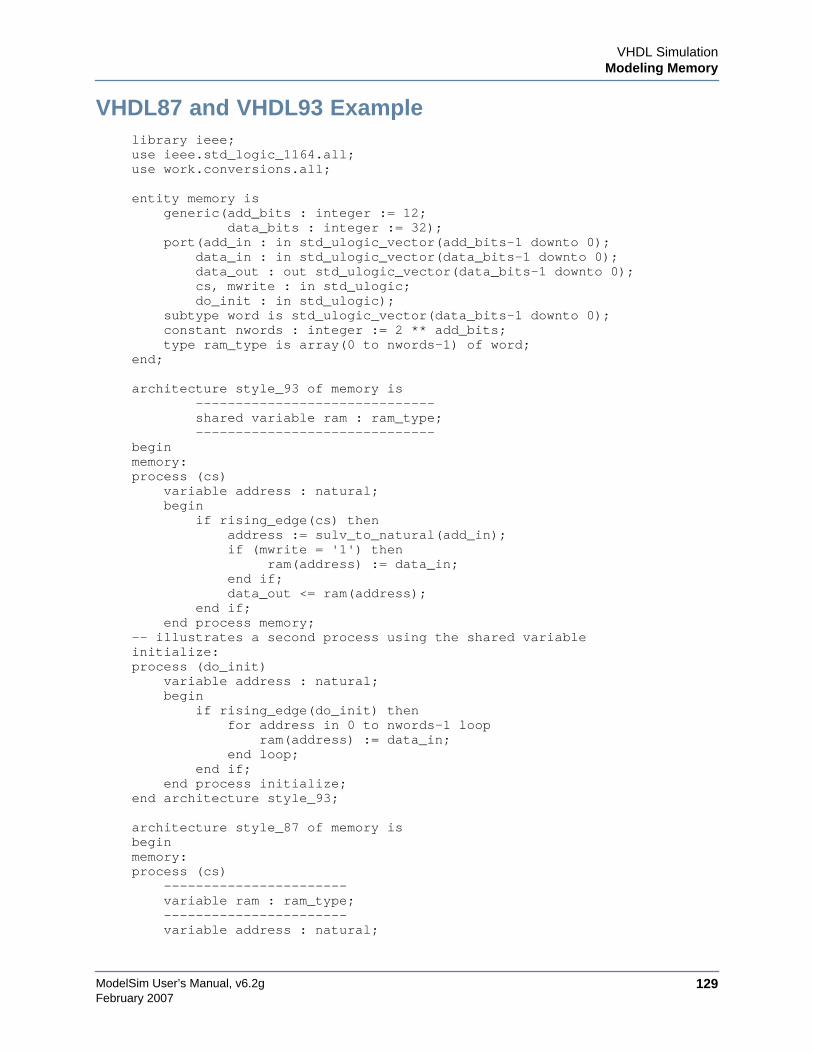
VHDL SimulationModeling Memory
ModelSim User’s Manual, v6.2g 129February 2007
VHDL87 and VHDL93 Examplelibrary ieee;use ieee.std_logic_1164.all;use work.conversions.all;
entity memory isgeneric(add_bits : integer := 12;
data_bits : integer := 32);port(add_in : in std_ulogic_vector(add_bits-1 downto 0);
data_in : in std_ulogic_vector(data_bits-1 downto 0);data_out : out std_ulogic_vector(data_bits-1 downto 0);cs, mwrite : in std_ulogic;do_init : in std_ulogic);
subtype word is std_ulogic_vector(data_bits-1 downto 0);constant nwords : integer := 2 ** add_bits;type ram_type is array(0 to nwords-1) of word;
end;
architecture style_93 of memory is------------------------------shared variable ram : ram_type;------------------------------
beginmemory:process (cs)
variable address : natural;begin
if rising_edge(cs) thenaddress := sulv_to_natural(add_in);if (mwrite = '1') then
ram(address) := data_in;end if;data_out <= ram(address);
end if;end process memory;
-- illustrates a second process using the shared variableinitialize:process (do_init)
variable address : natural;begin
if rising_edge(do_init) thenfor address in 0 to nwords-1 loop
ram(address) := data_in;end loop;
end if;end process initialize;
end architecture style_93;
architecture style_87 of memory isbeginmemory:process (cs)
-----------------------variable ram : ram_type;-----------------------variable address : natural;
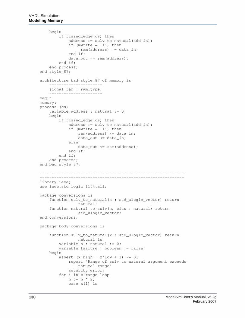
ModelSim User’s Manual, v6.2g130
VHDL SimulationModeling Memory
February 2007
beginif rising_edge(cs) then
address := sulv_to_natural(add_in);if (mwrite = '1') then
ram(address) := data_in;end if;data_out <= ram(address);
end if;end process;
end style_87;
architecture bad_style_87 of memory is----------------------signal ram : ram_type;----------------------
beginmemory:process (cs)
variable address : natural := 0;begin
if rising_edge(cs) thenaddress := sulv_to_natural(add_in);if (mwrite = '1') then
ram(address) <= data_in;data_out <= data_in;
elsedata_out <= ram(address);
end if;end if;
end process;end bad_style_87;
------------------------------------------------------------------------------------------------------------------------library ieee;use ieee.std_logic_1164.all;
package conversions isfunction sulv_to_natural(x : std_ulogic_vector) return
natural;function natural_to_sulv(n, bits : natural) return
std_ulogic_vector;end conversions;
package body conversions is
function sulv_to_natural(x : std_ulogic_vector) returnnatural is
variable n : natural := 0;variable failure : boolean := false;
beginassert (x'high - x'low + 1) <= 31
report "Range of sulv_to_natural argument exceedsnatural range"
severity error;for i in x'range loop
n := n * 2;case x(i) is
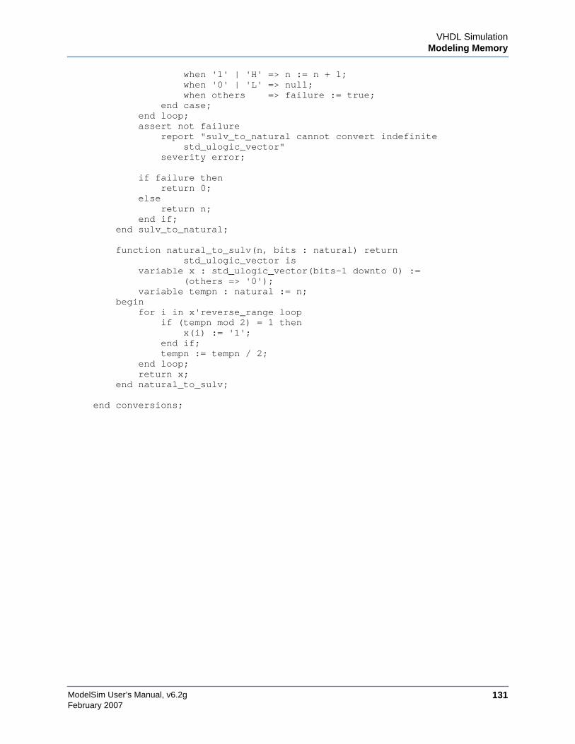
VHDL SimulationModeling Memory
ModelSim User’s Manual, v6.2g 131February 2007
when '1' | 'H' => n := n + 1;when '0' | 'L' => null;when others => failure := true;
end case;end loop;assert not failure
report "sulv_to_natural cannot convert indefinitestd_ulogic_vector"
severity error;
if failure thenreturn 0;
elsereturn n;
end if;end sulv_to_natural;
function natural_to_sulv(n, bits : natural) returnstd_ulogic_vector is
variable x : std_ulogic_vector(bits-1 downto 0) :=(others => '0');
variable tempn : natural := n;begin
for i in x'reverse_range loopif (tempn mod 2) = 1 then
x(i) := '1';end if;tempn := tempn / 2;
end loop;return x;
end natural_to_sulv;
end conversions;
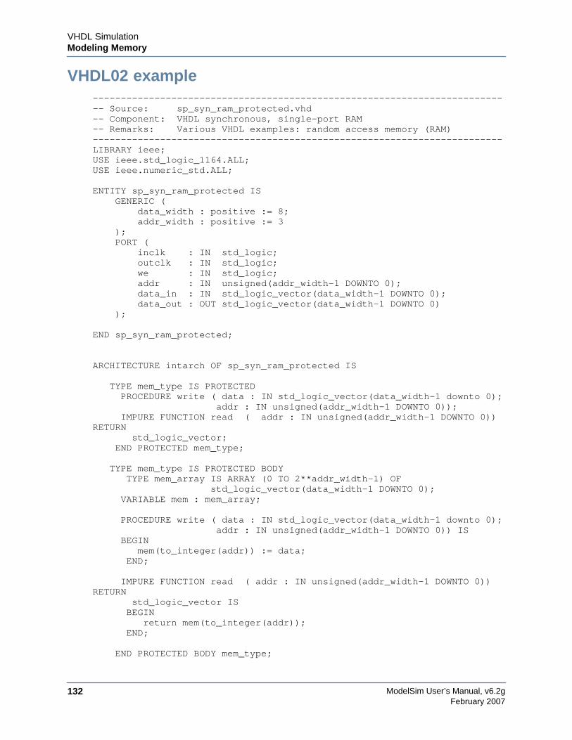
ModelSim User’s Manual, v6.2g132
VHDL SimulationModeling Memory
February 2007
VHDL02 example--------------------------------------------------------------------------- Source: sp_syn_ram_protected.vhd-- Component: VHDL synchronous, single-port RAM-- Remarks: Various VHDL examples: random access memory (RAM)-------------------------------------------------------------------------LIBRARY ieee;USE ieee.std_logic_1164.ALL;USE ieee.numeric_std.ALL;
ENTITY sp_syn_ram_protected IS GENERIC ( data_width : positive := 8; addr_width : positive := 3 ); PORT ( inclk : IN std_logic; outclk : IN std_logic; we : IN std_logic; addr : IN unsigned(addr_width-1 DOWNTO 0); data_in : IN std_logic_vector(data_width-1 DOWNTO 0); data_out : OUT std_logic_vector(data_width-1 DOWNTO 0) );
END sp_syn_ram_protected;
ARCHITECTURE intarch OF sp_syn_ram_protected IS
TYPE mem_type IS PROTECTED PROCEDURE write ( data : IN std_logic_vector(data_width-1 downto 0);
addr : IN unsigned(addr_width-1 DOWNTO 0)); IMPURE FUNCTION read ( addr : IN unsigned(addr_width-1 DOWNTO 0))
RETURN std_logic_vector;
END PROTECTED mem_type;
TYPE mem_type IS PROTECTED BODY TYPE mem_array IS ARRAY (0 TO 2**addr_width-1) OF
std_logic_vector(data_width-1 DOWNTO 0); VARIABLE mem : mem_array;
PROCEDURE write ( data : IN std_logic_vector(data_width-1 downto 0); addr : IN unsigned(addr_width-1 DOWNTO 0)) IS
BEGIN mem(to_integer(addr)) := data;
END;
IMPURE FUNCTION read ( addr : IN unsigned(addr_width-1 DOWNTO 0))RETURN
std_logic_vector IS BEGIN return mem(to_integer(addr)); END;
END PROTECTED BODY mem_type;
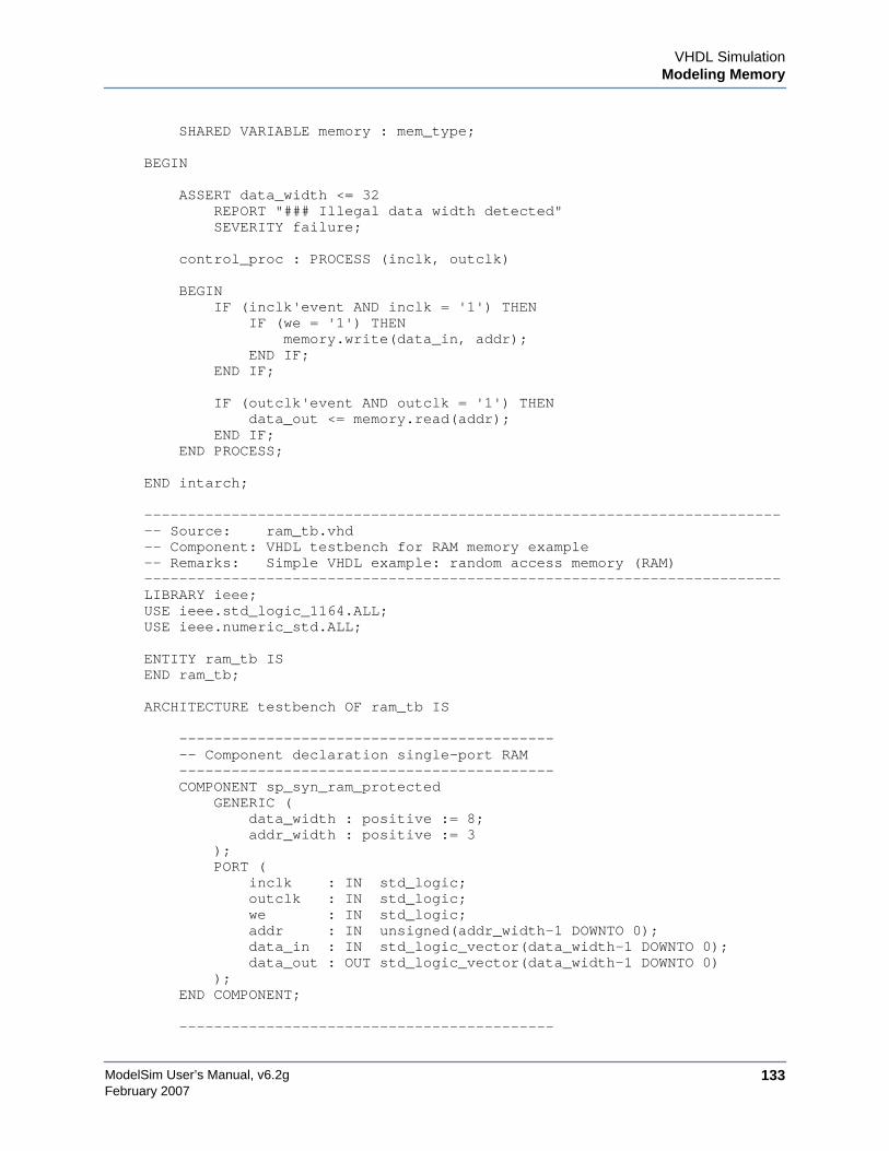
VHDL SimulationModeling Memory
ModelSim User’s Manual, v6.2g 133February 2007
SHARED VARIABLE memory : mem_type;
BEGIN
ASSERT data_width <= 32 REPORT "### Illegal data width detected" SEVERITY failure;
control_proc : PROCESS (inclk, outclk)
BEGIN IF (inclk'event AND inclk = '1') THEN IF (we = '1') THEN memory.write(data_in, addr); END IF; END IF;
IF (outclk'event AND outclk = '1') THEN data_out <= memory.read(addr); END IF; END PROCESS;
END intarch;
--------------------------------------------------------------------------- Source: ram_tb.vhd-- Component: VHDL testbench for RAM memory example-- Remarks: Simple VHDL example: random access memory (RAM)-------------------------------------------------------------------------LIBRARY ieee;USE ieee.std_logic_1164.ALL;USE ieee.numeric_std.ALL;
ENTITY ram_tb ISEND ram_tb;
ARCHITECTURE testbench OF ram_tb IS
------------------------------------------- -- Component declaration single-port RAM ------------------------------------------- COMPONENT sp_syn_ram_protected GENERIC ( data_width : positive := 8; addr_width : positive := 3 ); PORT ( inclk : IN std_logic; outclk : IN std_logic; we : IN std_logic; addr : IN unsigned(addr_width-1 DOWNTO 0); data_in : IN std_logic_vector(data_width-1 DOWNTO 0); data_out : OUT std_logic_vector(data_width-1 DOWNTO 0) ); END COMPONENT;
-------------------------------------------
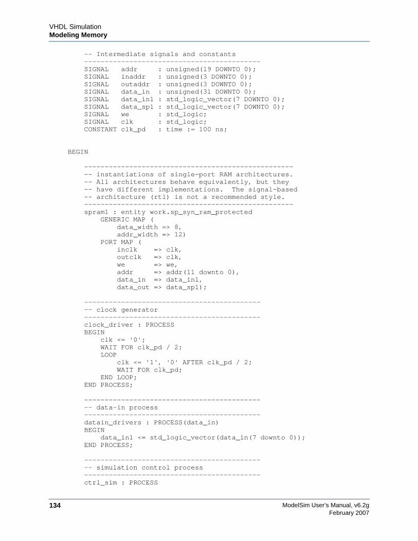
ModelSim User’s Manual, v6.2g134
VHDL SimulationModeling Memory
February 2007
-- Intermediate signals and constants ------------------------------------------- SIGNAL addr : unsigned(19 DOWNTO 0); SIGNAL inaddr : unsigned(3 DOWNTO 0); SIGNAL outaddr : unsigned(3 DOWNTO 0); SIGNAL data_in : unsigned(31 DOWNTO 0); SIGNAL data_in1 : std_logic_vector(7 DOWNTO 0); SIGNAL data_sp1 : std_logic_vector(7 DOWNTO 0); SIGNAL we : std_logic; SIGNAL clk : std_logic; CONSTANT clk_pd : time := 100 ns;
BEGIN
--------------------------------------------------- -- instantiations of single-port RAM architectures. -- All architectures behave equivalently, but they -- have different implementations. The signal-based -- architecture (rtl) is not a recommended style. --------------------------------------------------- spram1 : entity work.sp_syn_ram_protected GENERIC MAP ( data_width => 8, addr_width => 12) PORT MAP ( inclk => clk, outclk => clk, we => we, addr => addr(11 downto 0), data_in => data_in1, data_out => data_sp1);
------------------------------------------- -- clock generator ------------------------------------------- clock_driver : PROCESS BEGIN clk <= '0'; WAIT FOR clk_pd / 2; LOOP clk <= '1', '0' AFTER clk_pd / 2; WAIT FOR clk_pd; END LOOP; END PROCESS;
------------------------------------------- -- data-in process ------------------------------------------- datain_drivers : PROCESS(data_in) BEGIN data_in1 <= std_logic_vector(data_in(7 downto 0)); END PROCESS;
------------------------------------------- -- simulation control process ------------------------------------------- ctrl_sim : PROCESS
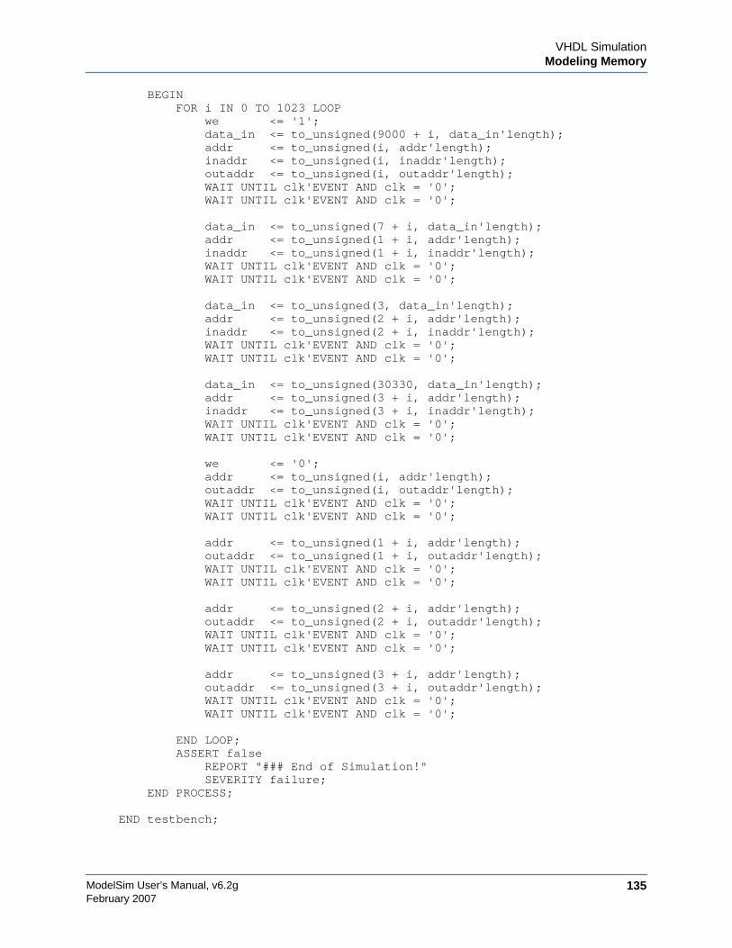
VHDL SimulationModeling Memory
ModelSim User’s Manual, v6.2g 135February 2007
BEGIN FOR i IN 0 TO 1023 LOOP we <= '1'; data_in <= to_unsigned(9000 + i, data_in'length); addr <= to_unsigned(i, addr'length); inaddr <= to_unsigned(i, inaddr'length); outaddr <= to_unsigned(i, outaddr'length); WAIT UNTIL clk'EVENT AND clk = '0'; WAIT UNTIL clk'EVENT AND clk = '0';
data_in <= to_unsigned(7 + i, data_in'length); addr <= to_unsigned(1 + i, addr'length); inaddr <= to_unsigned(1 + i, inaddr'length); WAIT UNTIL clk'EVENT AND clk = '0'; WAIT UNTIL clk'EVENT AND clk = '0';
data_in <= to_unsigned(3, data_in'length); addr <= to_unsigned(2 + i, addr'length); inaddr <= to_unsigned(2 + i, inaddr'length); WAIT UNTIL clk'EVENT AND clk = '0'; WAIT UNTIL clk'EVENT AND clk = '0';
data_in <= to_unsigned(30330, data_in'length); addr <= to_unsigned(3 + i, addr'length); inaddr <= to_unsigned(3 + i, inaddr'length); WAIT UNTIL clk'EVENT AND clk = '0'; WAIT UNTIL clk'EVENT AND clk = '0';
we <= '0'; addr <= to_unsigned(i, addr'length); outaddr <= to_unsigned(i, outaddr'length); WAIT UNTIL clk'EVENT AND clk = '0'; WAIT UNTIL clk'EVENT AND clk = '0';
addr <= to_unsigned(1 + i, addr'length); outaddr <= to_unsigned(1 + i, outaddr'length); WAIT UNTIL clk'EVENT AND clk = '0'; WAIT UNTIL clk'EVENT AND clk = '0';
addr <= to_unsigned(2 + i, addr'length); outaddr <= to_unsigned(2 + i, outaddr'length); WAIT UNTIL clk'EVENT AND clk = '0'; WAIT UNTIL clk'EVENT AND clk = '0';
addr <= to_unsigned(3 + i, addr'length); outaddr <= to_unsigned(3 + i, outaddr'length); WAIT UNTIL clk'EVENT AND clk = '0'; WAIT UNTIL clk'EVENT AND clk = '0';
END LOOP; ASSERT false REPORT "### End of Simulation!" SEVERITY failure; END PROCESS;
END testbench;
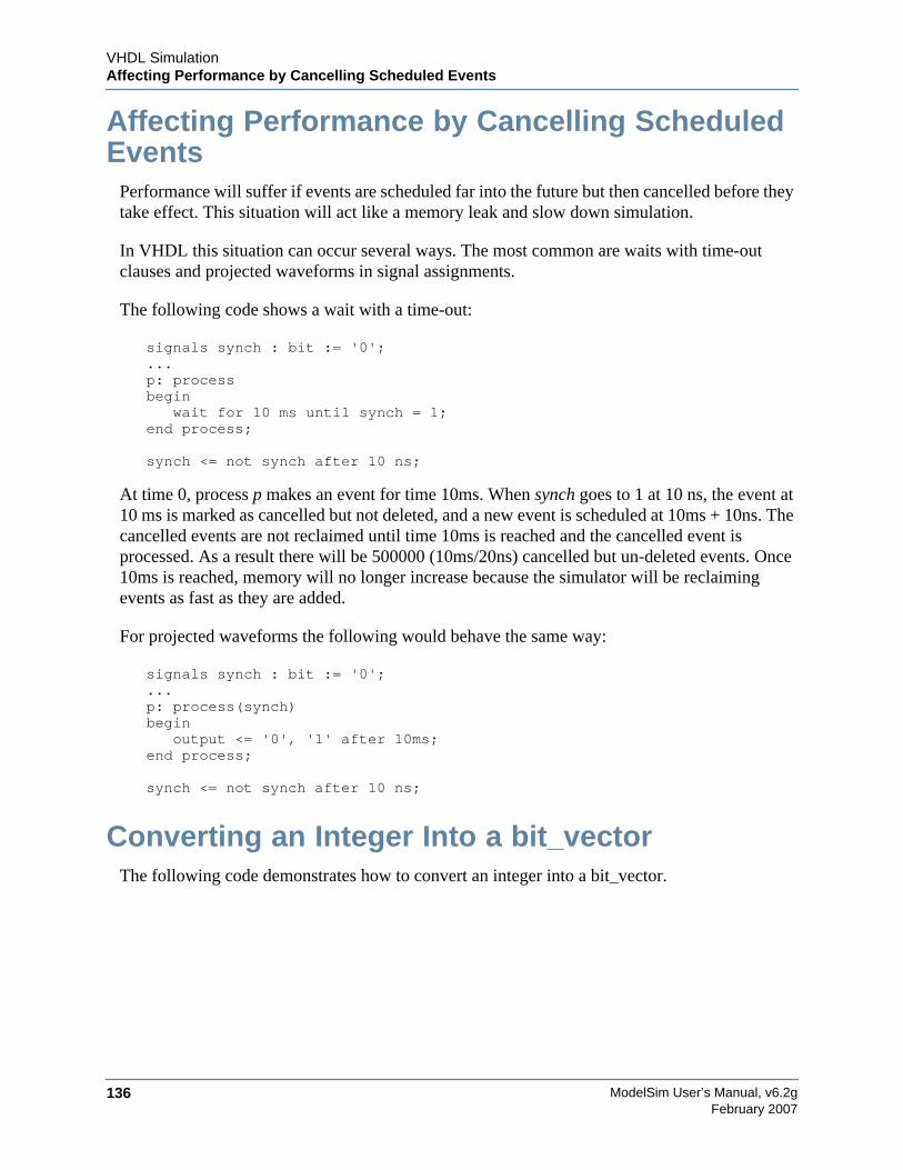
ModelSim User’s Manual, v6.2g136
VHDL SimulationAffecting Performance by Cancelling Scheduled Events
February 2007
Affecting Performance by Cancelling ScheduledEvents
Performance will suffer if events are scheduled far into the future but then cancelled before theytake effect. This situation will act like a memory leak and slow down simulation.
In VHDL this situation can occur several ways. The most common are waits with time-outclauses and projected waveforms in signal assignments.
The following code shows a wait with a time-out:
signals synch : bit := '0';...p: processbegin
wait for 10 ms until synch = 1;end process;
synch <= not synch after 10 ns;
At time 0, process p makes an event for time 10ms. When synch goes to 1 at 10 ns, the event at10 ms is marked as cancelled but not deleted, and a new event is scheduled at 10ms + 10ns. Thecancelled events are not reclaimed until time 10ms is reached and the cancelled event isprocessed. As a result there will be 500000 (10ms/20ns) cancelled but un-deleted events. Once10ms is reached, memory will no longer increase because the simulator will be reclaimingevents as fast as they are added.
For projected waveforms the following would behave the same way:
signals synch : bit := '0';...p: process(synch)begin output <= '0', '1' after 10ms;end process;
synch <= not synch after 10 ns;
Converting an Integer Into a bit_vectorThe following code demonstrates how to convert an integer into a bit_vector.
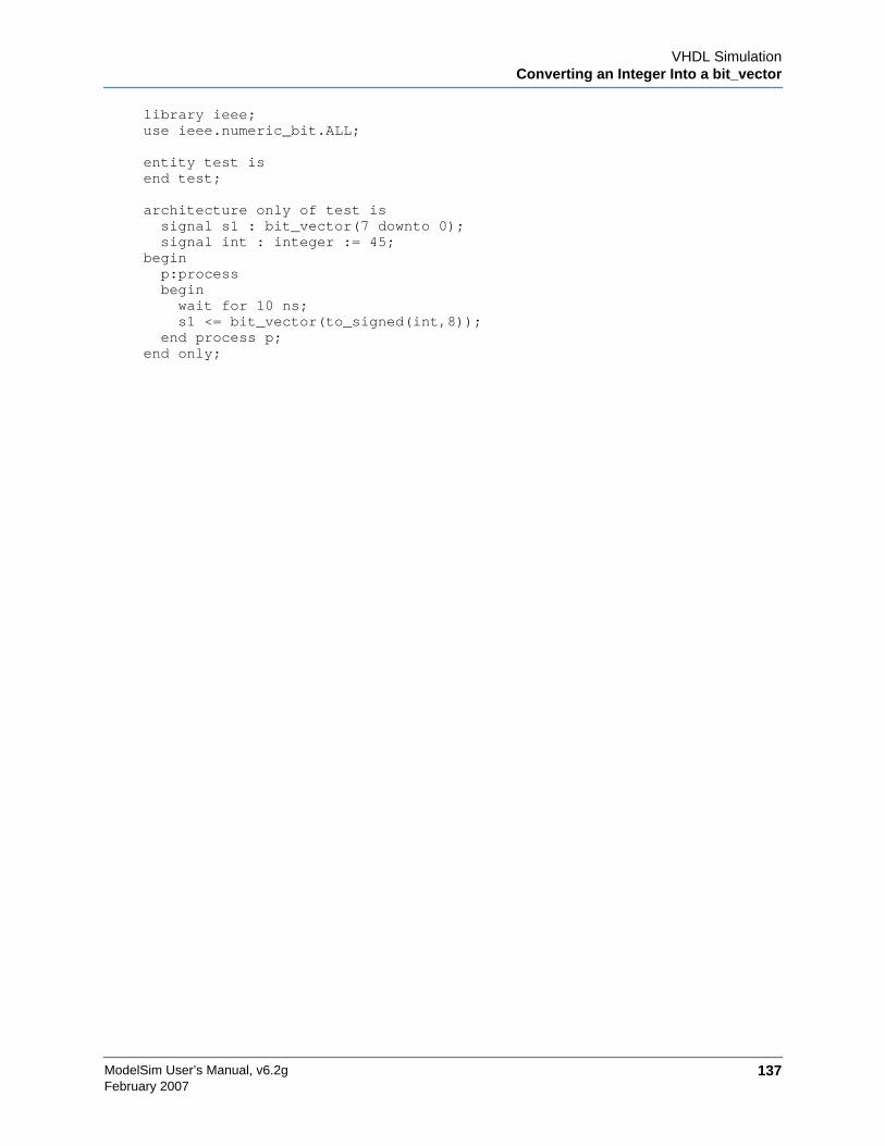
VHDL SimulationConverting an Integer Into a bit_vector
ModelSim User’s Manual, v6.2g 137February 2007
library ieee;use ieee.numeric_bit.ALL;
entity test isend test;
architecture only of test issignal s1 : bit_vector(7 downto 0);signal int : integer := 45;
beginp:processbeginwait for 10 ns;s1 <= bit_vector(to_signed(int,8));
end process p;end only;

ModelSim User’s Manual, v6.2g138
VHDL SimulationConverting an Integer Into a bit_vector
February 2007

ModelSim User’s Manual, v6.2g 139February 2007
Chapter 6Verilog and SystemVerilog Simulation
This chapter describes how to compile and simulate Verilog and SystemVerilog designs withModelSim. ModelSim implements the Verilog language as defined by the IEEE Standards1364-1995 and 1364-2005. We recommend that you obtain these specifications for reference.
The following functionality is partially implemented in ModelSim:
• Verilog Procedural Interface (VPI) (see/<install_dir>/modeltech/docs/technotes/Verilog_VPI.note for details)
• IEEE Std P1800-2005 SystemVerilog (see/<install_dir>/modeltech/docs/technotes/sysvlog.note for implementation details)
TerminologyThis chapter uses the term “Verilog” to represent both Verilog and SystemVerilog, unlessotherwise noted.
Basic Verilog FlowSimulating Verilog designs with ModelSim includes four general steps:
1. Compile your Verilog code into one or more libraries using the vlog command. SeeCompiling Verilog Files for details.
2. Load your design with the vsim command. See Simulating Verilog Designs for details.
3. Run and debug your design.
Compiling Verilog FilesThe first time you compile a design there is a two-step process:
1. Create a working library with vlib or select File > New > Library.
2. Compile the design using vlog or select Compile > Compile.

ModelSim User’s Manual, v6.2g140
Verilog and SystemVerilog SimulationCompiling Verilog Files
February 2007
Creating a Working LibraryBefore you can compile your design, you must create a library in which to store the compilationresults. Use the vlib command or select File > New > Library to create a new library. Forexample:
vlib work
This creates a library named work. By default compilation results are stored in the worklibrary.
The work library is actually a subdirectory named work. This subdirectory contains a specialfile named _info. Do not create libraries using UNIX commands – always use the vlib.
See Design Libraries for additional information on working with libraries.
Invoking the Verilog CompilerThe Verilog compiler, vlog, compiles Verilog source code into retargetable, executable code.The library format is compatible across all supported platforms, and you can simulate yourdesign on any platform without having to recompile your design.
As the design compiles, the resulting object code for modules and UDPs is generated into alibrary. As noted above, the compiler places results into the work library by default. You canspecify an alternate library with the -work argument.
Example 6-1. Invocation of the Verilog Compiler
Here is a sample invocation of vlog:
vlog top.v +libext+.v+.u -y vlog_lib
After compiling top.v, vlog will scan the vlog_lib library for files with modules with the samename as primitives referenced, but undefined in top.v. The use of +libext+.v+.u impliesfilenames with a .v or .u suffix (any combination of suffixes may be used). Only referenceddefinitions will be compiled.
Parsing SystemVerilog KeywordsWith standard Verilog files (<filename>.v), vlog will not automatically parse SystemVerilogkeywords. SystemVerilog keywords are parsed when any of the following situations exists:
• any file within the design contains the .sv file extension,
• the -sv argument is used with the vlog command,
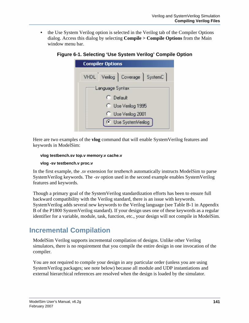
Verilog and SystemVerilog SimulationCompiling Verilog Files
ModelSim User’s Manual, v6.2g 141February 2007
• the Use System Verilog option is selected in the Verilog tab of the Compiler Optionsdialog. Access this dialog by selecting Compile > Compile Options from the Mainwindow menu bar.
Figure 6-1. Selecting ‘Use System Verilog’ Compile Option
Here are two examples of the vlog command that will enable SystemVerilog features andkeywords in ModelSim:
vlog testbench.sv top.v memory.v cache.v
vlog -sv testbench.v proc.v
In the first example, the .sv extension for testbench automatically instructs ModelSim to parseSystemVerilog keywords. The -sv option used in the second example enables SystemVerilogfeatures and keywords.
Though a primary goal of the SystemVerilog standardization efforts has been to ensure fullbackward compatibility with the Verilog standard, there is an issue with keywords.SystemVerilog adds several new keywords to the Verilog language (see Table B-1 in AppendixB of the P1800 SystemVerilog standard). If your design uses one of these keywords as a regularidentifier for a variable, module, task, function, etc., your design will not compile in ModelSim.
Incremental CompilationModelSim Verilog supports incremental compilation of designs. Unlike other Verilogsimulators, there is no requirement that you compile the entire design in one invocation of thecompiler.
You are not required to compile your design in any particular order (unless you are usingSystemVerilog packages; see note below) because all module and UDP instantiations andexternal hierarchical references are resolved when the design is loaded by the simulator.
ModelSim User’s Manual, v6.2g142
Verilog and SystemVerilog SimulationCompiling Verilog Files
February 2007
NoteCompilation order may matter when using SystemVerilog packages. As stated in theIEEE std p1800-2005 LRM, section entitled Referencing data in packages, which states:"Packages must exist in order for the items they define to be recognized by the scopes inwhich they are imported.”
Incremental compilation is made possible by deferring these bindings, and as a result someerrors cannot be detected during compilation. Commonly, these errors include: modules thatwere referenced but not compiled, incorrect port connections, and incorrect hierarchicalreferences.
Example 6-2. Incremental Compilation Example
Contents of testbench.sv
module testbench;timeunit 1ns;timeprecision 10ps;bit d=1, clk = 0;wire q;initial
for (int cycles=0; cycles < 100; cycles++)#100 clk = !clk;
design dut(q, d, clk);endmodule
Contents of design.v:
module design(output bit q, input bit d, clk);timeunit 1ns;timeprecision 10ps;always @(posedge clk)
q = d;endmodule
Compile the design incrementally as follows:
ModelSim> vlog testbench.sv.# Top level modules:# testbenchModelSim> vlog -sv test1.v.# Top level modules:# dut
Note that the compiler lists each module as a top-level module, although, ultimately, onlytestbench is a top-level module. If a module is not referenced by another module compiled inthe same invocation of the compiler, then it is listed as a top-level module. This is just aninformative message and can be ignored during incremental compilation.
Verilog and SystemVerilog SimulationCompiling Verilog Files
ModelSim User’s Manual, v6.2g 143February 2007
The message is more useful when you compile an entire design in one invocation of thecompiler and need to know the top-level module names for the simulator. For example,
% vlog top.v and2.v or2.v-- Compiling module top-- Compiling module and2-- Compiling module or2Top level modules:
top
Automatic Incremental Compilation with -incrThe most efficient method of incremental compilation is to manually compile only the modulesthat have changed. However, this is not always convenient, especially if your source files havecompiler directive interdependencies (such as macros). In this case, you may prefer to compileyour entire design along with the -incr argument. This causes the compiler to automaticallydetermine which modules have changed and generate code only for those modules.
The following is an example of how to compile a design with automatic incrementalcompilation:
% vlog -incr top.v and2.v or2.v-- Compiling module top-- Compiling module and2-- Compiling module or2Top level modules:
top
Now, suppose that you modify the functionality of the or2 module:
% vlog -incr top.v and2.v or2.v-- Skipping module top-- Skipping module and2-- Compiling module or2Top level modules:
top
The compiler informs you that it skipped the modules top and and2, and compiled or2.
Automatic incremental compilation is intelligent about when to compile a module. Forexample, changing a comment in your source code does not result in a recompile; however,changing the compiler command line arguments results in a recompile of all modules.
NoteChanges to your source code that do not change functionality but that do affect sourcecode line numbers (such as adding a comment line) will cause all affected modules to berecompiled. This happens because debug information must be kept current so thatModelSim can trace back to the correct areas of the source code.

ModelSim User’s Manual, v6.2g144
Verilog and SystemVerilog SimulationCompiling Verilog Files
February 2007
Library UsageAll modules and UDPs in a Verilog design must be compiled into one or more libraries. Onelibrary is usually sufficient for a simple design, but you may want to organize your modules intovarious libraries for a complex design. If your design uses different modules having the samename, then you are required to put those modules in different libraries because design unitnames must be unique within a library.
The following is an example of how you may organize your ASIC cells into one library and therest of your design into another:
% vlib work% vlib asiclib% vlog -work asiclib and2.v or2.v-- Compiling module and2-- Compiling module or2
Top level modules:and2or2
% vlog top.v-- Compiling module topTop level modules:
top
Note that the first compilation uses the -work asiclib argument to instruct the compiler to placethe results in the asiclib library rather than the default work library.
Library Search Rules for vlogSince instantiation bindings are not determined at compile time, you must instruct the simulatorto search your libraries when loading the design. The top-level modules are loaded from thelibrary named work unless you prefix the modules with the <library>. option. All otherVerilog instantiations are resolved in the following order:
• Search libraries specified with -Lf arguments in the order they appear on the commandline.
• Search the library specified in the Verilog-XL uselib Compiler Directive section.
• Search libraries specified with -L arguments in the order they appear on the commandline.
• Search the work library.
• Search the library explicitly named in the special escaped identifier instance name.
Handling Sub-Modules with Common NamesSometimes in one design you need to reference two different modules that have the same name.This situation can occur if you have hierarchical modules organized into separate libraries, and
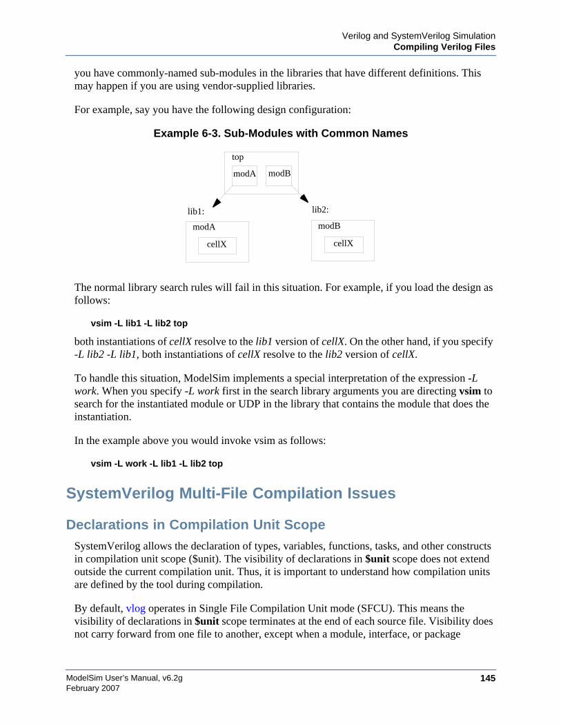
Verilog and SystemVerilog SimulationCompiling Verilog Files
ModelSim User’s Manual, v6.2g 145February 2007
you have commonly-named sub-modules in the libraries that have different definitions. Thismay happen if you are using vendor-supplied libraries.
For example, say you have the following design configuration:
Example 6-3. Sub-Modules with Common Names
The normal library search rules will fail in this situation. For example, if you load the design asfollows:
vsim -L lib1 -L lib2 top
both instantiations of cellX resolve to the lib1 version of cellX. On the other hand, if you specify-L lib2 -L lib1, both instantiations of cellX resolve to the lib2 version of cellX.
To handle this situation, ModelSim implements a special interpretation of the expression -Lwork. When you specify -L work first in the search library arguments you are directing vsim tosearch for the instantiated module or UDP in the library that contains the module that does theinstantiation.
In the example above you would invoke vsim as follows:
vsim -L work -L lib1 -L lib2 top
SystemVerilog Multi-File Compilation Issues
Declarations in Compilation Unit ScopeSystemVerilog allows the declaration of types, variables, functions, tasks, and other constructsin compilation unit scope ($unit). The visibility of declarations in $unit scope does not extendoutside the current compilation unit. Thus, it is important to understand how compilation unitsare defined by the tool during compilation.
By default, vlog operates in Single File Compilation Unit mode (SFCU). This means thevisibility of declarations in $unit scope terminates at the end of each source file. Visibility doesnot carry forward from one file to another, except when a module, interface, or package
top
modA modB
modA modB
cellX cellX
lib1: lib2:
ModelSim User’s Manual, v6.2g146
Verilog and SystemVerilog SimulationCompiling Verilog Files
February 2007
declaration begins in one file and ends in another file. In that case, the compilation unit spansfrom the file containing the beginning of the declaration to the file containing the end of thedeclaration.
vlog also supports a non-default behavior called Multi File Compilation Unit mode (MFCU). InMFCU mode, vlog compiles all files given on the command line into one compilation unit. Youcan invoke vlog in MFCU mode as follows:
• For a specific compilation -- with the -mfcu argument to vlog.
• For all compilations -- by setting the variable MultiFileCompilationUnit = 1 in themodelsim.ini file.
By using either of these methods, you allow declarations in $unit scope to remain in effectthroughout the compilation of all files.
In case you have made MFCU the default behavior by setting MultiFileCompilationUnit = 1in your modelsim.ini file, it is possible to override the default behavior on specific compilationsby using the -sfcu argument to vlog.
Macro Definitions and Compiler Directives in Compilation UnitScope
According to the SystemVerilog IEEE Std p1800-2005 LRM, the visibility of macro definitionsand compiler directives span the lifetime of a single compilation unit. By default, this means thedefinitions of macros and settings of compiler directives terminate at the end of each source file.They do not carry forward from one file to another, except when a module, interface, or packagedeclaration begins in one file and ends in another file. In that case, the compilation unit spansfrom the file containing the beginning of the definition to the file containing the end of thedefinition.
See Declarations in Compilation Unit Scope for instructions on how to control vlog's handlingof compilation units.
NoteCompiler directives revert to their default values at the end of a compilation unit.
If a compiler directive is specified as an option to the compiler, this setting is used for allcompilation units present in the current compilation.
Verilog-XL Compatible Compiler ArgumentsThe compiler arguments listed below are equivalent to Verilog-XL arguments and may ease theporting of a design to ModelSim. See the vlog command for a description of each argument.
Verilog and SystemVerilog SimulationCompiling Verilog Files
ModelSim User’s Manual, v6.2g 147February 2007
+define+<macro_name>[=<macro_text>]+delay_mode_distributed+delay_mode_path+delay_mode_unit+delay_mode_zero-f <filename>+incdir+<directory>+mindelays+maxdelays+nowarn<mnemonic>+typdelays-u
Arguments Supporting Source LibrariesThe compiler arguments listed below support source libraries in the same manner as Verilog-XL. See the vlog command for a description of each argument.
Note that these source libraries are very different from the libraries that the ModelSim compileruses to store compilation results. You may find it convenient to use these arguments if you areporting a design to ModelSim or if you are familiar with these arguments and prefer to usethem.
Source libraries are searched after the source files on the command line are compiled. If thereare any unresolved references to modules or UDPs, then the compiler searches the sourcelibraries to satisfy them. The modules compiled from source libraries may in turn haveadditional unresolved references that cause the source libraries to be searched again. Thisprocess is repeated until all references are resolved or until no new unresolved references arefound. Source libraries are searched in the order they appear on the command line.
-v <filename>-y <directory>+libext+<suffix>+librescan+nolibcell-R [<simargs>]
Verilog-XL uselib Compiler DirectiveThe `uselib compiler directive is an alternative source library management scheme to the -v, -y,and +libext compiler arguments. It has the advantage that a design may reference differentmodules having the same name. You compile designs that contain `uselib directive statementsusing the -compile_uselibs argument (described below) to vlog.
The syntax for the `uselib directive is:
`uselib <library_reference>...
where <library_reference> can be one or more of the following:

ModelSim User’s Manual, v6.2g148
Verilog and SystemVerilog SimulationCompiling Verilog Files
February 2007
• dir=<library_directory>, which is equivalent to the command line argument:
-y <library_directory>
• file=<library_file>, which is equivalent to the command line argument:
-v <library_file>
• libext=<file_extension>, which is equivalent to the command line argument:
+libext+<file_extension>
• lib=<library_name>, which references a library for instantiated objects. This behavessimilarly to a LIBRARY/USE clause in VHDL. You must ensure the correct mappingsare set up if the library does not exist in the current working directory. The-compile_uselibs argument does not affect this usage of `uselib.
For example, the following directive
`uselib dir=/h/vendorA libext=.v
is equivalent to the following command line arguments:
-y /h/vendorA +libext+.v
Since the `uselib directives are embedded in the Verilog source code, there is more flexibility indefining the source libraries for the instantiations in the design. The appearance of a `uselibdirective in the source code explicitly defines how instantiations that follow it are resolved,completely overriding any previous `uselib directives.
-compile_uselibs ArgumentUse the -compile_uselibs argument to vlog to reference `uselib directives. The argument findsthe source files referenced in the directive, compiles them into automatically created objectlibraries, and updates the modelsim.ini file with the logical mappings to the libraries.
When using -compile_uselibs, ModelSim determines into which directory to compile the objectlibraries by choosing, in order, from the following three values:
• The directory name specified by the -compile_uselibs argument. For example,
-compile_uselibs=./mydir
• The directory specified by the MTI_USELIB_DIR environment variable (seeEnvironment Variables)
• A directory named mti_uselibs that is created in the current working directory
The following code fragment and compiler invocation show how two different modules thathave the same name can be instantiated within the same design:
Verilog and SystemVerilog SimulationCompiling Verilog Files
ModelSim User’s Manual, v6.2g 149February 2007
module top;`uselib dir=/h/vendorA libext=.vNAND2 u1(n1, n2, n3);`uselib dir=/h/vendorB libext=.vNAND2 u2(n4, n5, n6);
endmodule
vlog -compile_uselibs top
This allows the NAND2 module to have different definitions in the vendorA and vendorBlibraries.
uselib is PersistentAs mentioned above, the appearance of a `uselib directive in the source code explicitly defineshow instantiations that follow it are resolved. This may result in unexpected consequences. Forexample, consider the following compile command:
vlog -compile_uselibs dut.v srtr.v
Assume that dut.v contains a `uselib directive. Since srtr.v is compiled after dut.v, the `uselibdirective is still in effect. When srtr is loaded it is using the `uselib directive from dut.v todecide where to locate modules. If this is not what you intend, then you need to put an empty`uselib at the end of dut.v to "close" the previous `uselib statement.
Verilog ConfigurationsThe Verilog 2001 specification added configurations. Configurations specify how a design is"assembled" during the elaboration phase of simulation. Configurations actually consist of twopieces: the library mapping and the configuration itself. The library mapping is used at compiletime to determine into which libraries the source files are to be compiled. Here is an example ofa simple library map file:
library work ../top.v;library rtlLib lrm_ex_top.v;library gateLib lrm_ex_adder.vg;library aLib lrm_ex_adder.v;
Here is an example of a library map file that uses -incdir:
library lib1 src_dir/*.v -incdir ../include_dir2, ../, my_incdir;
The name of the library map file is arbitrary. You specify the library map file using the -libmapargument to the vlog command. Alternatively, you can specify the file name as the first item onthe vlog command line, and the compiler will read it as a library map file.
The library map file must be compiled along with the Verilog source files. Multiple map filesare allowed but each must be preceded by the -libmap argument.
ModelSim User’s Manual, v6.2g150
Verilog and SystemVerilog SimulationCompiling Verilog Files
February 2007
The library map file and the configuration can exist in the same or different files. If they areseparate, only the map file needs the -libmap argument. The configuration is treated as anyother Verilog source file.
Configurations and the Library Named workThe library named “work” is treated specially by ModelSim (see The Library Named "work" fordetails) for Verilog configurations. Consider the following code example:
config cfg;design top;instance top.u1 use work.u1;
endconfig
In this case, work.u1 indicates to load u1 from the current library.
Verilog Generate StatementsThe Verilog 2001 rules for generate statements had numerous inconsistencies and ambiguities.As a result, ModelSim implements the rules that have been adopted for Verilog 2005. Most ofthe rules are backwards compatible, but there is one key difference related to name visibility.
Name Visibility in Generate StatementsConsider the following code example:
module m;parameter p = 1;
generateif (p)
integer x = 1;else
real x = 2.0;endgenerate
initial $display(x);endmodule
This code sample is legal under 2001 rules. However, it is illegal under the 2005 rules and willcause an error in ModelSim. Under the new rules, you cannot hierarchically reference a name inan anonymous scope from outside that scope. In the example above, x does not propagate itsvisibility upwards, and each condition alternative is considered to be an anonymous scope.
To fix the code such that it will simulate properly in ModelSim, write it like this instead:
Verilog and SystemVerilog SimulationSimulating Verilog Designs
ModelSim User’s Manual, v6.2g 151February 2007
module m;parameter p = 1;
if (p) begin:sinteger x = 1;
endelse begin:s
real x = 2.0;end
initial $display(s.x);endmodule
Since the scope is named in this example, normal hierarchical resolution rules apply and thecode is fine.
Note too that the keywords generate - endgenerate are optional under the 2005 rules and areexcluded in the second example.
Simulating Verilog DesignsA Verilog design is ready for simulation after it has been compiled with vlog. The simulatormay then be invoked with the names of the top-level modules (many designs contain only onetop-level module). For example, if your top-level modules are "testbench" and "globals", theninvoke the simulator as follows:
vsim testbench globals
After the simulator loads the top-level modules, it iteratively loads the instantiated modules andUDPs in the design hierarchy, linking the design together by connecting the ports and resolvinghierarchical references. By default all modules and UDPs are loaded from the library namedwork. Modules and UDPs from other libraries can be specified using the -L or -Lf arguments tovsim (see Library Usage for details).
On successful loading of the design, the simulation time is set to zero, and you must enter a runcommand to begin simulation. Commonly, you enter run -all to run until there are no moresimulation events or until $finish is executed in the Verilog code. You can also run for specifictime periods (e.g., run 100 ns). Enter the quit command to exit the simulator.
Simulator Resolution Limit (Verilog)The simulator internally represents time as a 64-bit integer in units equivalent to the smallestunit of simulation time, also known as the simulator resolution limit. The resolution limitdefaults to the smallest time precision found among all of the `timescale compiler directives inthe design. Here is an example of a `timescale directive:
`timescale 1 ns / 100 ps
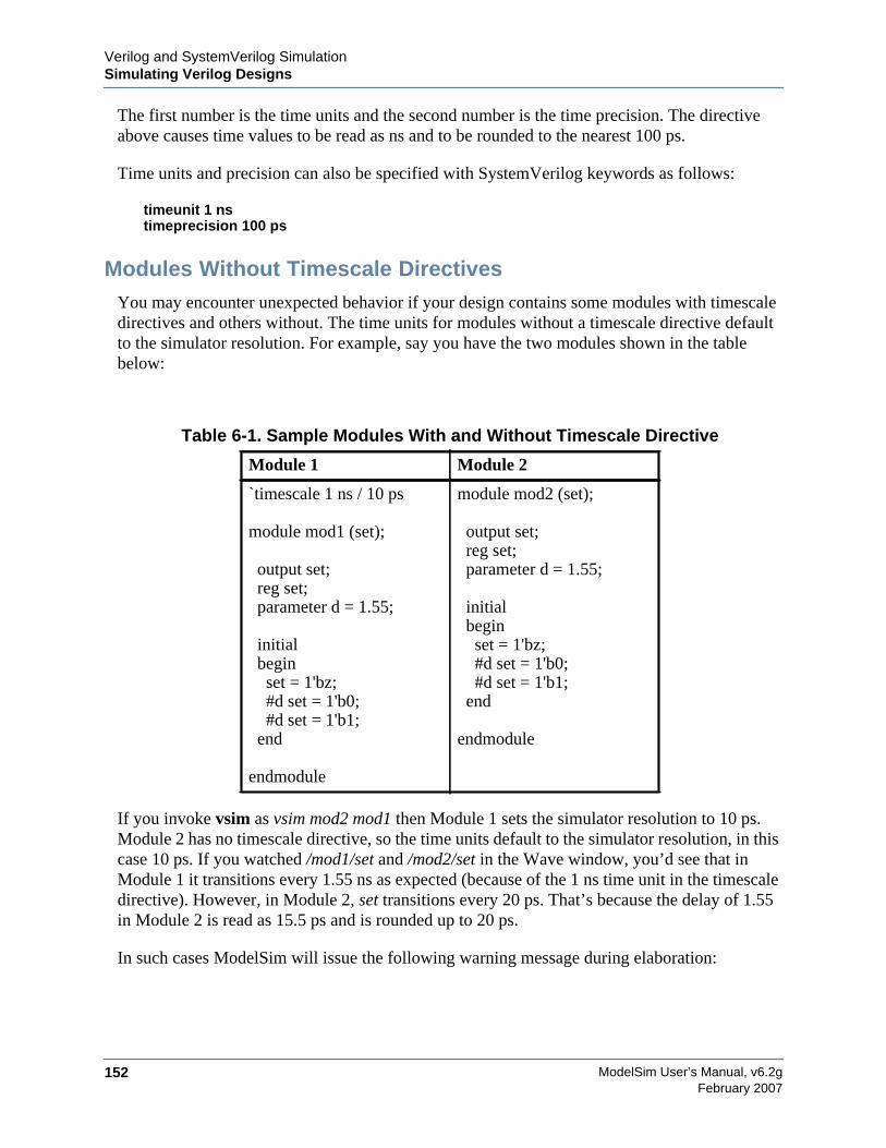
ModelSim User’s Manual, v6.2g152
Verilog and SystemVerilog SimulationSimulating Verilog Designs
February 2007
The first number is the time units and the second number is the time precision. The directiveabove causes time values to be read as ns and to be rounded to the nearest 100 ps.
Time units and precision can also be specified with SystemVerilog keywords as follows:
timeunit 1 nstimeprecision 100 ps
Modules Without Timescale DirectivesYou may encounter unexpected behavior if your design contains some modules with timescaledirectives and others without. The time units for modules without a timescale directive defaultto the simulator resolution. For example, say you have the two modules shown in the tablebelow:
If you invoke vsim as vsim mod2 mod1 then Module 1 sets the simulator resolution to 10 ps.Module 2 has no timescale directive, so the time units default to the simulator resolution, in thiscase 10 ps. If you watched /mod1/set and /mod2/set in the Wave window, you’d see that inModule 1 it transitions every 1.55 ns as expected (because of the 1 ns time unit in the timescaledirective). However, in Module 2, set transitions every 20 ps. That’s because the delay of 1.55in Module 2 is read as 15.5 ps and is rounded up to 20 ps.
In such cases ModelSim will issue the following warning message during elaboration:
Table 6-1. Sample Modules With and Without Timescale Directive
Module 1 Module 2
`timescale 1 ns / 10 ps
module mod1 (set);
output set;reg set;parameter d = 1.55;
initialbeginset = 1'bz;#d set = 1'b0;#d set = 1'b1;
end
endmodule
module mod2 (set);
output set;reg set;parameter d = 1.55;
initialbeginset = 1'bz;#d set = 1'b0;#d set = 1'b1;
end
endmodule
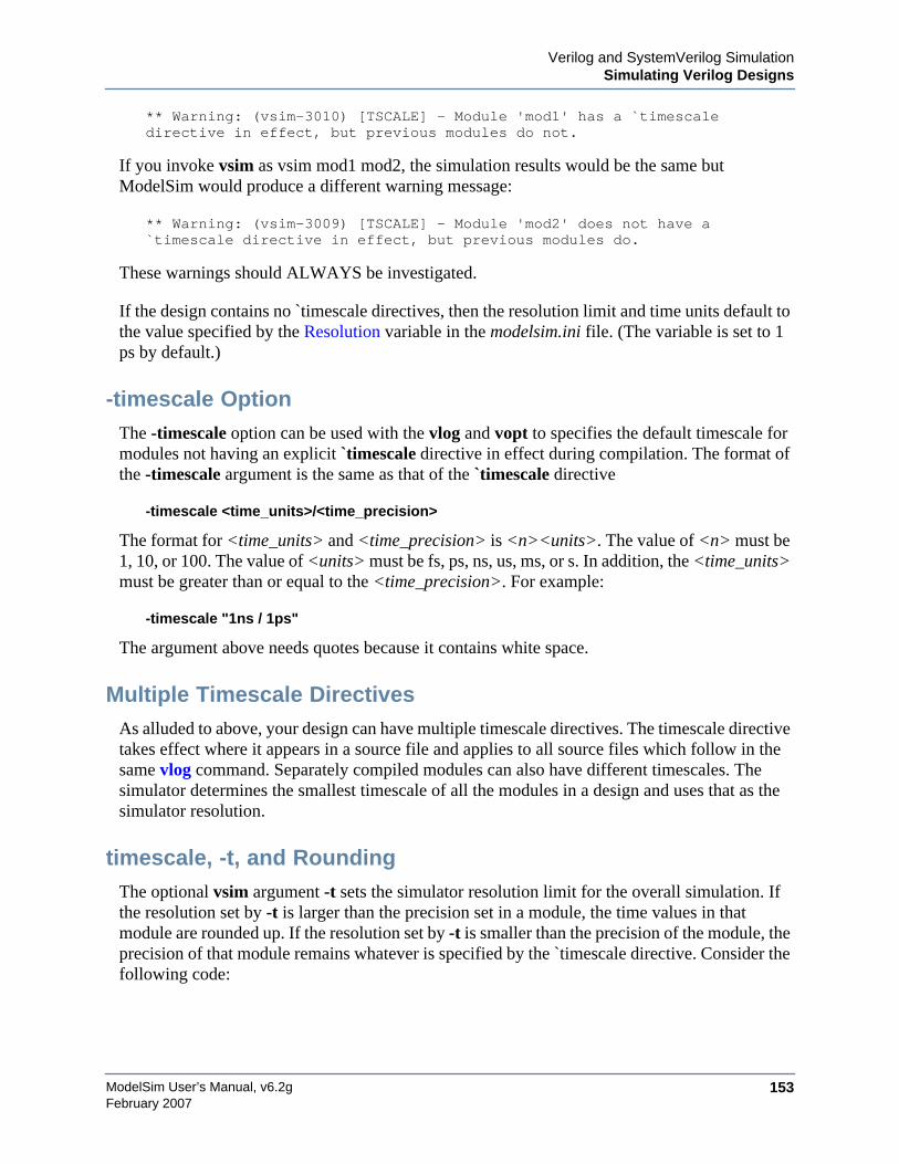
Verilog and SystemVerilog SimulationSimulating Verilog Designs
ModelSim User’s Manual, v6.2g 153February 2007
** Warning: (vsim-3010) [TSCALE] - Module 'mod1' has a `timescaledirective in effect, but previous modules do not.
If you invoke vsim as vsim mod1 mod2, the simulation results would be the same butModelSim would produce a different warning message:
** Warning: (vsim-3009) [TSCALE] - Module 'mod2' does not have a`timescale directive in effect, but previous modules do.
These warnings should ALWAYS be investigated.
If the design contains no `timescale directives, then the resolution limit and time units default tothe value specified by the Resolution variable in the modelsim.ini file. (The variable is set to 1ps by default.)
-timescale OptionThe -timescale option can be used with the vlog and vopt to specifies the default timescale formodules not having an explicit `timescale directive in effect during compilation. The format ofthe -timescale argument is the same as that of the `timescale directive
-timescale <time_units>/<time_precision>
The format for <time_units> and <time_precision> is <n><units>. The value of <n> must be1, 10, or 100. The value of <units> must be fs, ps, ns, us, ms, or s. In addition, the <time_units>must be greater than or equal to the <time_precision>. For example:
-timescale "1ns / 1ps"
The argument above needs quotes because it contains white space.
Multiple Timescale DirectivesAs alluded to above, your design can have multiple timescale directives. The timescale directivetakes effect where it appears in a source file and applies to all source files which follow in thesame vlog command. Separately compiled modules can also have different timescales. Thesimulator determines the smallest timescale of all the modules in a design and uses that as thesimulator resolution.
timescale, -t, and RoundingThe optional vsim argument -t sets the simulator resolution limit for the overall simulation. Ifthe resolution set by -t is larger than the precision set in a module, the time values in thatmodule are rounded up. If the resolution set by -t is smaller than the precision of the module, theprecision of that module remains whatever is specified by the `timescale directive. Consider thefollowing code:

ModelSim User’s Manual, v6.2g154
Verilog and SystemVerilog SimulationSimulating Verilog Designs
February 2007
`timescale 1 ns / 100 ps
module foo;
initial#12.536 $display
The list below shows three possibilities for -t and how the delays in the module would behandled in each case:
• -t not set
The delay will be rounded to 12.5 as directed by the module’s ‘timescale directive.
• -t is set to 1 fs
The delay will be rounded to 12.5. Again, the module’s precision is determined by the‘timescale directive. ModelSim does not override the module’s precision.
• -t is set to 1 ns
The delay will be rounded to 12. The module’s precision is determined by the -t setting.ModelSim has no choice but to round the module’s time values because the entiresimulation is operating at 1 ns.
Choosing the Resolution for VerilogYou should choose the coarsest resolution limit possible that does not result in undesiredrounding of your delays. The time precision should not be unnecessarily small because it willlimit the maximum simulation time limit, and it will degrade performance in some cases.
Event Ordering in Verilog DesignsEvent-based simulators such as ModelSim may process multiple events at a given simulationtime. The Verilog language is defined such that you cannot explicitly control the order in whichsimultaneous events are processed. Unfortunately, some designs rely on a particular eventorder, and these designs may behave differently than you expect.
Event QueuesSection 5 of the IEEE Std 1364-1995 LRM defines several event queues that determine theorder in which events are evaluated. At the current simulation time, the simulator has thefollowing pending events:
• active events
• inactive events
• non-blocking assignment update events
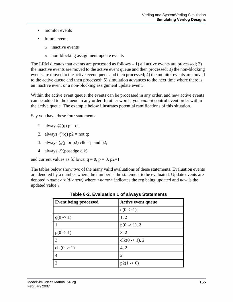
Verilog and SystemVerilog SimulationSimulating Verilog Designs
ModelSim User’s Manual, v6.2g 155February 2007
• monitor events
• future events
o inactive events
o non-blocking assignment update events
The LRM dictates that events are processed as follows – 1) all active events are processed; 2)the inactive events are moved to the active event queue and then processed; 3) the non-blockingevents are moved to the active event queue and then processed; 4) the monitor events are movedto the active queue and then processed; 5) simulation advances to the next time where there isan inactive event or a non-blocking assignment update event.
Within the active event queue, the events can be processed in any order, and new active eventscan be added to the queue in any order. In other words, you cannot control event order withinthe active queue. The example below illustrates potential ramifications of this situation.
Say you have these four statements:
1. always@(q) p = q;
2. always @(q) p2 = not q;
3. always @(p or p2) clk = p and p2;
4. always @(posedge clk)
and current values as follows: q = 0, p = 0, p2=1
The tables below show two of the many valid evaluations of these statements. Evaluation eventsare denoted by a number where the number is the statement to be evaluated. Update events aredenoted <name>(old->new) where <name> indicates the reg being updated and new is theupdated value.\
Table 6-2. Evaluation 1 of always Statements
Event being processed Active event queue
q(0 -> 1)
q(0 -> 1) 1, 2
1 p(0 -> 1), 2
p(0 -> 1) 3, 2
3 clk(0 -> 1), 2
clk(0 -> 1) 4, 2
4 2
2 p2(1 -> 0)
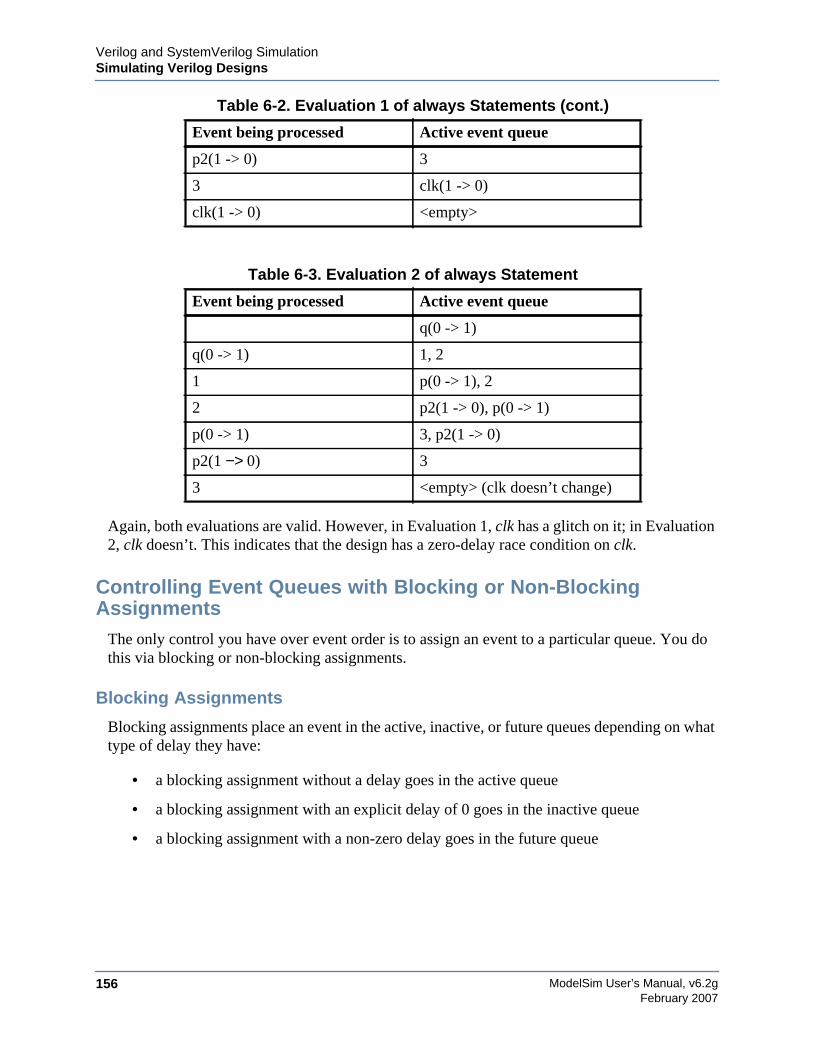
ModelSim User’s Manual, v6.2g156
Verilog and SystemVerilog SimulationSimulating Verilog Designs
February 2007
Again, both evaluations are valid. However, in Evaluation 1, clk has a glitch on it; in Evaluation2, clk doesn’t. This indicates that the design has a zero-delay race condition on clk.
Controlling Event Queues with Blocking or Non-BlockingAssignments
The only control you have over event order is to assign an event to a particular queue. You dothis via blocking or non-blocking assignments.
Blocking Assignments
Blocking assignments place an event in the active, inactive, or future queues depending on whattype of delay they have:
• a blocking assignment without a delay goes in the active queue
• a blocking assignment with an explicit delay of 0 goes in the inactive queue
• a blocking assignment with a non-zero delay goes in the future queue
p2(1 -> 0) 3
3 clk(1 -> 0)
clk(1 -> 0) <empty>
Table 6-3. Evaluation 2 of always Statement
Event being processed Active event queue
q(0 -> 1)
q(0 -> 1) 1, 2
1 p(0 -> 1), 2
2 p2(1 -> 0), p(0 -> 1)
p(0 -> 1) 3, p2(1 -> 0)
p2(1 −> 0) 3
3 <empty> (clk doesn’t change)
Table 6-2. Evaluation 1 of always Statements (cont.)
Event being processed Active event queue
Verilog and SystemVerilog SimulationSimulating Verilog Designs
ModelSim User’s Manual, v6.2g 157February 2007
Non-Blocking Assignments
A non-blocking assignment goes into either the non-blocking assignment update event queue orthe future non-blocking assignment update event queue. (Non-blocking assignments with nodelays and those with explicit zero delays are treated the same.)
Non-blocking assignments should be used only for outputs of flip-flops. This insures that alloutputs of flip-flops do not change until after all flip-flops have been evaluated. Attempting touse non-blocking assignments in combinational logic paths to remove race conditions may onlycause more problems. (In the preceding example, changing all statements to non-blockingassignments would not remove the race condition.) This includes using non-blockingassignments in the generation of gated clocks.
The following is an example of how to properly use non-blocking assignments.
gen1: always @(master)clk1 = master;
gen2: always @(clk1)clk2 = clk1;
f1 : always @(posedge clk1)beginq1 <= d1;
end
f2: always @(posedge clk2)beginq2 <= q1;
end
If written this way, a value on d1 always takes two clock cycles to get from d1 to q2.If you change clk1 = master and clk2 = clk1 to non-blocking assignments or q2 <= q1 and q1<= d1 to blocking assignments, then d1 may get to q2 is less than two clock cycles.
Debugging Event Order IssuesSince many models have been developed on Verilog-XL, ModelSim tries to duplicate Verilog-XL event ordering to ease the porting of those models to ModelSim. However, ModelSim doesnot match Verilog-XL event ordering in all cases, and if a model ported to ModelSim does notbehave as expected, then you should suspect that there are event order dependencies.
ModelSim helps you track down event order dependencies with the following compilerarguments: -compat, -hazards, and -keep_delta.
See the vlog command for descriptions of -compat and -hazards.
ModelSim User’s Manual, v6.2g158
Verilog and SystemVerilog SimulationSimulating Verilog Designs
February 2007
Hazard DetectionThe -hazard argument to vsim detects event order hazards involving simultaneous reading andwriting of the same register in concurrently executing processes. vsim detects the followingkinds of hazards:
• WRITE/WRITE — Two processes writing to the same variable at the same time.
• READ/WRITE — One process reading a variable at the same time it is being written toby another process. ModelSim calls this a READ/WRITE hazard if it executed the readfirst.
• WRITE/READ — Same as a READ/WRITE hazard except that ModelSim executed thewrite first.
vsim issues an error message when it detects a hazard. The message pinpoints the variable andthe two processes involved. You can have the simulator break on the statement where thehazard is detected by setting the break on assertion level to Error.
To enable hazard detection you must invoke vlog with the -hazards argument when youcompile your source code and you must also invoke vsim with the -hazards argument whenyou simulate.
NoteEnabling -hazards implicitly enables the -compat argument. As a result, using thisargument may affect your simulation results.
Hazard Detection and Optimization LevelsIn certain cases hazard detection results are affected by the optimization level used in thesimulation. Some optimizations change the read/write operations performed on a variable if thetransformation is determined to yield equivalent results. Since the hazard detection algorithmdoesn’t know whether or not the read/write operations can affect the simulation results, theoptimizations can result in different hazard detection results. Generally, the optimizationsreduce the number of false hazards by eliminating unnecessary reads and writes, but there arealso optimizations that can produce additional false hazards.
Limitations of Hazard Detection• Reads and writes involving bit and part selects of vectors are not considered for hazard
detection. The overhead of tracking the overlap between the bit and part selects is toohigh.
• A WRITE/WRITE hazard is flagged even if the same value is written by both processes.
• A WRITE/READ or READ/WRITE hazard is flagged even if the write does not modifythe variable's value.
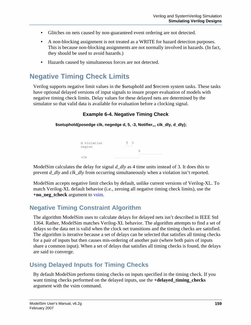
Verilog and SystemVerilog SimulationSimulating Verilog Designs
ModelSim User’s Manual, v6.2g 159February 2007
• Glitches on nets caused by non-guaranteed event ordering are not detected.
• A non-blocking assignment is not treated as a WRITE for hazard detection purposes.This is because non-blocking assignments are not normally involved in hazards. (In fact,they should be used to avoid hazards.)
• Hazards caused by simultaneous forces are not detected.
Negative Timing Check LimitsVerilog supports negative limit values in the $setuphold and $recrem system tasks. These taskshave optional delayed versions of input signals to insure proper evaluation of models withnegative timing check limits. Delay values for these delayed nets are determined by thesimulator so that valid data is available for evaluation before a clocking signal.
Example 6-4. Negative Timing Check
$setuphold(posedge clk, negedge d, 5, -3, Notifier,,, clk_dly, d_dly);
ModelSim calculates the delay for signal d_dly as 4 time units instead of 3. It does this toprevent d_dly and clk_dly from occurring simultaneously when a violation isn’t reported.
ModelSim accepts negative limit checks by default, unlike current versions of Verilog-XL. Tomatch Verilog-XL default behavior (i.e., zeroing all negative timing check limits), use the+no_neg_tcheck argument to vsim.
Negative Timing Constraint AlgorithmThe algorithm ModelSim uses to calculate delays for delayed nets isn’t described in IEEE Std1364. Rather, ModelSim matches Verilog-XL behavior. The algorithm attempts to find a set ofdelays so the data net is valid when the clock net transitions and the timing checks are satisfied.The algorithm is iterative because a set of delays can be selected that satisfies all timing checksfor a pair of inputs but then causes mis-ordering of another pair (where both pairs of inputsshare a common input). When a set of delays that satisfies all timing checks is found, the delaysare said to converge.
Using Delayed Inputs for Timing ChecksBy default ModelSim performs timing checks on inputs specified in the timing check. If youwant timing checks performed on the delayed inputs, use the +delayed_timing_checksargument with the vsim command.
3
clk
d violation 5region
0
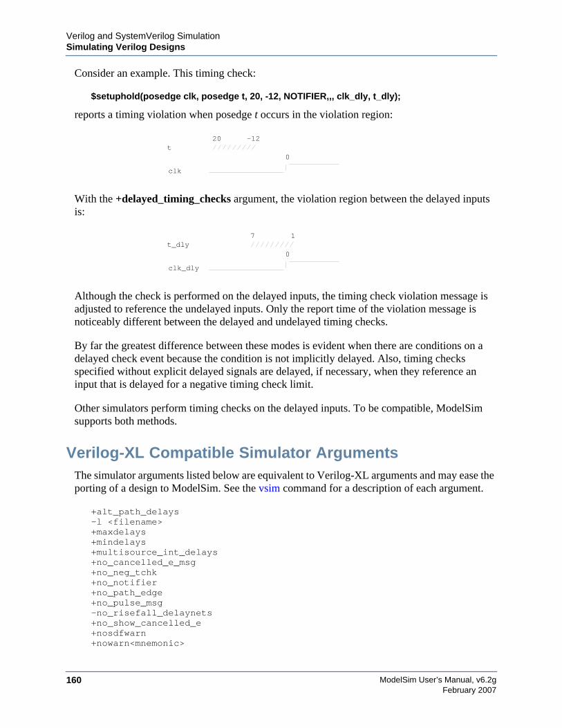
ModelSim User’s Manual, v6.2g160
Verilog and SystemVerilog SimulationSimulating Verilog Designs
February 2007
Consider an example. This timing check:
$setuphold(posedge clk, posedge t, 20, -12, NOTIFIER,,, clk_dly, t_dly);
reports a timing violation when posedge t occurs in the violation region:
With the +delayed_timing_checks argument, the violation region between the delayed inputsis:
Although the check is performed on the delayed inputs, the timing check violation message isadjusted to reference the undelayed inputs. Only the report time of the violation message isnoticeably different between the delayed and undelayed timing checks.
By far the greatest difference between these modes is evident when there are conditions on adelayed check event because the condition is not implicitly delayed. Also, timing checksspecified without explicit delayed signals are delayed, if necessary, when they reference aninput that is delayed for a negative timing check limit.
Other simulators perform timing checks on the delayed inputs. To be compatible, ModelSimsupports both methods.
Verilog-XL Compatible Simulator ArgumentsThe simulator arguments listed below are equivalent to Verilog-XL arguments and may ease theporting of a design to ModelSim. See the vsim command for a description of each argument.
+alt_path_delays-l <filename>+maxdelays+mindelays+multisource_int_delays+no_cancelled_e_msg+no_neg_tchk+no_notifier+no_path_edge+no_pulse_msg-no_risefall_delaynets+no_show_cancelled_e+nosdfwarn+nowarn<mnemonic>
-12
clk
20t
0
1
clk_dly
7t_dly
0
Verilog and SystemVerilog SimulationSimulating Verilog Designs
ModelSim User’s Manual, v6.2g 161February 2007
+ntc_warn+pulse_e/<percent>+pulse_e_style_ondetect+pulse_e_style_onevent+pulse_int_e/<percent>+pulse_int_r/<percent>+pulse_r/<percent>+sdf_nocheck_celltype+sdf_verbose+show_cancelled_e+transport_int_delays+transport_path_delays+typdelays
Using Escaped IdentifiersModelSim always converts Verilog escaped identifiers to VHDL syntax.
In Verilog, escaped identifiers start with the backslash character and end with a white space.Neither the backslash at the beginning or the white space at the end are considered to be a partof the identifier. When a ModelSim displays Verilog escaped identifiers, however, a backslashis added at the end in order to match the VHDL syntax for escaped identifiers. This is becauseall Verilog escaped identifiers can be easily converted to VHDL but the converse is not true.
So, for example, a Verilog escaped identifier like the following:
\/top/dut/03
will be displayed as follows:
\/top/dut/03\
When entering Verilog identifiers with the ModelSim command line interface, you should usethe VHDL syntax, with a backslash at the beginning and end of the identifier.
In Tcl, the backslash is one of a number of characters that have a special meaning. For example,
\n
creates a new line.
When a Tcl command is used in the command line interface, the TCL backslash should beescaped by adding another backslash. For example:
force -freeze /top/ix/iy/\\yw\[1\]\\ 10 0, 01 {50 ns} -r 100
The Verilog identifier, in this example, is \yw[1]. Here, double backslashes are used because itis necessary to escape the square brackets ([]), which have a special meaning in Tcl.
For a more detailed description of special characters in Tcl and how backslashes should be usedwith those characters, click Help > Tcl Syntax in the menu bar of the graphic interface, orsimply open the docs/tcl_help_html/TclCmd directory in your ModelSim installation.
ModelSim User’s Manual, v6.2g162
Verilog and SystemVerilog SimulationCell Libraries
February 2007
Cell LibrariesModel Technology passed the ASIC Council’s Verilog test suite and achieved the "LibraryTested and Approved" designation from Si2 Labs. This test suite is designed to ensure Verilogtiming accuracy and functionality and is the first significant hurdle to complete on the way toachieving full ASIC vendor support. As a consequence, many ASIC and FPGA vendors’Verilog cell libraries are compatible with ModelSim Verilog.
The cell models generally contain Verilog "specify blocks" that describe the path delays andtiming constraints for the cells. See section 13 in the IEEE Std 1364-1995 for details on specifyblocks, and section 14.5 for details on timing constraints. ModelSim Verilog fully implementsspecify blocks and timing constraints as defined in IEEE Std 1364 along with some Verilog-XLcompatible extensions.
SDF Timing AnnotationModelSim Verilog supports timing annotation from Standard Delay Format (SDF) files. SeeStandard Delay Format (SDF) Timing Annotation for details.
Delay ModesVerilog models may contain both distributed delays and path delays. The delays on primitives,UDPs, and continuous assignments are the distributed delays, whereas the port-to-port delaysspecified in specify blocks are the path delays. These delays interact to determine the actualdelay observed. Most Verilog cells use path delays exclusively, with the distributed delays setto zero. For example,
module and2(y, a, b);input a, b;output y;and(y, a, b);specify
(a => y) = 5;(b => y) = 5;
endspecifyendmodule
In the above two-input "and" gate cell, the distributed delay for the "and" primitive is zero, andthe actual delays observed on the module ports are taken from the path delays. This is typical formost cells, but a complex cell may require non-zero distributed delays to work properly. Evenso, these delays are usually small enough that the path delays take priority over the distributeddelays. The rule is that if a module contains both path delays and distributed delays, then thelarger of the two delays for each path shall be used (as defined by the IEEE Std 1364). This isthe default behavior, but you can specify alternate delay modes with compiler directives and
Verilog and SystemVerilog SimulationSystem Tasks and Functions
ModelSim User’s Manual, v6.2g 163February 2007
arguments. These arguments and directives are compatible with Verilog-XL. Compiler delaymode arguments take precedence over delay mode directives in the source code.
Distributed Delay ModeIn distributed delay mode the specify path delays are ignored in favor of the distributed delays.Select this delay mode with the +delay_mode_distributed compiler argument or the`delay_mode_distributed compiler directive.
Path Delay ModeIn path delay mode the distributed delays are set to zero in any module that contains a pathdelay. Select this delay mode with the +delay_mode_path compiler argument or the`delay_mode_path compiler directive.
Unit Delay ModeIn unit delay mode the non-zero distributed delays are set to one unit of simulation resolution(determined by the minimum time_precision argument in all ‘timescale directives in yourdesign or the value specified with the -t argument to vsim), and the specify path delays andtiming constraints are ignored. Select this delay mode with the +delay_mode_unit compilerargument or the `delay_mode_unit compiler directive.
Zero Delay ModeIn zero delay mode the distributed delays are set to zero, and the specify path delays and timingconstraints are ignored. Select this delay mode with the +delay_mode_zero compiler argumentor the `delay_mode_zero compiler directive.
System Tasks and FunctionsModelSim supports system tasks and functions as follows:
• All system tasks and functions defined in IEEE Std 1364
• Some system tasks and functions defined in SystemVerilog IEEE std p1800-2005 LRM
• Several system tasks and functions that are specific to ModelSim
• Several non-standard, Verilog-XL system tasks
The system tasks and functions listed in this section are built into the simulator, although somedesigns depend on user-defined system tasks implemented with the Programming LanguageInterface (PLI), Verilog Procedural Interface (VPI), or the SystemVerilog DPI (DirectProgramming Interface). If the simulator issues warnings regarding undefined system tasks orfunctions, then it is likely that these tasks or functions are defined by a PLI/VPI application thatmust be loaded by the simulator.
ModelSim User’s Manual, v6.2g164
Verilog and SystemVerilog SimulationSystem Tasks and Functions
February 2007
IEEE Std 1364 System Tasks and FunctionsThe following system tasks and functions are described in detail in the IEEE Std 1364.
Table 6-4. IEEE Std 1364 System Tasks and Functions - 1
Timescale tasks Simulator controltasks
Simulation timefunctions
Command line input
$printtimescale $finish $realtime $test$plusargs
$timeformat $stop $stime $value$plusargs
$time
Table 6-5. IEEE Std 1364 System Tasks and Functions - 2
Probabilisticdistributionfunctions
Conversionfunctions
Stochastic analysistasks
Timing check tasks
$dist_chi_square $bitstoreal $q_add $hold
$dist_erlang $itor $q_exam $nochange
$dist_exponential $realtobits $q_full $period
$dist_normal $rtoi $q_initialize $recovery
$dist_poisson $signed $q_remove $setup
$dist_t $unsigned $setuphold
$dist_uniform $skew
$random $width1
1. Verilog-XL ignores the threshold argument even though it is part of the Verilog spec. ModelSim does notignore this argument. Be careful that you don’t set the threshold argument greater-than-or-equal to the limitargument as that essentially disables the $width check. Note too that you cannot override the thresholdargument via SDF annotation.
$removal
$recrem
Table 6-6. IEEE Std 1364 System Tasks
Display tasks PLA modeling tasks Value change dump(VCD) file tasks
$display $async$and$array $dumpall
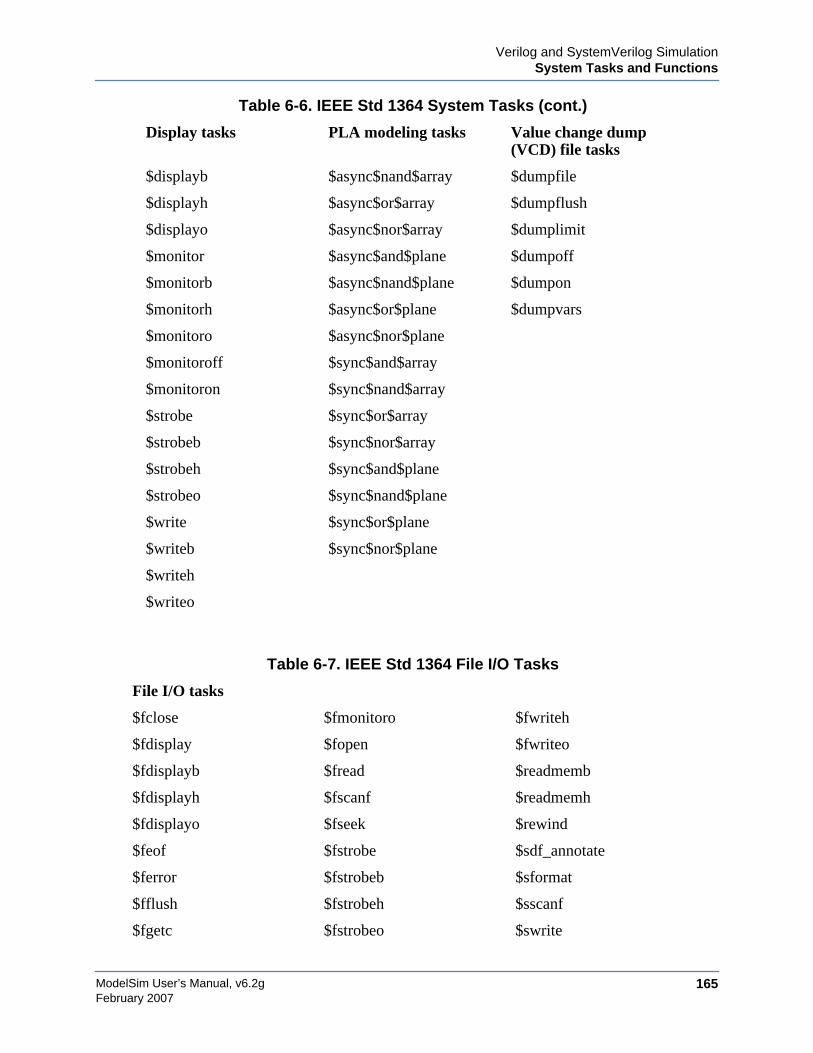
Verilog and SystemVerilog SimulationSystem Tasks and Functions
ModelSim User’s Manual, v6.2g 165February 2007
$displayb $async$nand$array $dumpfile
$displayh $async$or$array $dumpflush
$displayo $async$nor$array $dumplimit
$monitor $async$and$plane $dumpoff
$monitorb $async$nand$plane $dumpon
$monitorh $async$or$plane $dumpvars
$monitoro $async$nor$plane
$monitoroff $sync$and$array
$monitoron $sync$nand$array
$strobe $sync$or$array
$strobeb $sync$nor$array
$strobeh $sync$and$plane
$strobeo $sync$nand$plane
$write $sync$or$plane
$writeb $sync$nor$plane
$writeh
$writeo
Table 6-7. IEEE Std 1364 File I/O Tasks
File I/O tasks
$fclose $fmonitoro $fwriteh
$fdisplay $fopen $fwriteo
$fdisplayb $fread $readmemb
$fdisplayh $fscanf $readmemh
$fdisplayo $fseek $rewind
$feof $fstrobe $sdf_annotate
$ferror $fstrobeb $sformat
$fflush $fstrobeh $sscanf
$fgetc $fstrobeo $swrite
Table 6-6. IEEE Std 1364 System Tasks (cont.)
Display tasks PLA modeling tasks Value change dump(VCD) file tasks

ModelSim User’s Manual, v6.2g166
Verilog and SystemVerilog SimulationSystem Tasks and Functions
February 2007
SystemVerilog System Tasks and FunctionsThe following ModelSim-supported system tasks and functions are described in detail in theSystemVerilog IEEE Std p1800-2005 LRM.
$fgets $ftell $swriteb
$fmonitor $fwrite $swriteh
$fmonitorb $fwriteb $swriteo
$fmonitorh $ungetc
Table 6-8. SystemVerilog System Tasks and Functions - 1
Expression size function Range function
$bits $isunbounded
Table 6-9. SystemVerilog System Tasks and Functions - 2
Shortrealconversions
Array queryingfunctions
$shortrealbits $dimensions
$bitstoshortreal $left
$right
$low
$high
$increment
$size
Table 6-10. SystemVerilog System Tasks and Functions - 4
Reading packed datafunctions
Writing packed datafunctions
Other functions
$readmemb $writememb $root
$readmemh $writememh $unit
Table 6-7. IEEE Std 1364 File I/O Tasks (cont.)
File I/O tasks
Verilog and SystemVerilog SimulationSystem Tasks and Functions
ModelSim User’s Manual, v6.2g 167February 2007
System Tasks and Functions Specific to the ToolThe following system tasks and functions are specific to ModelSim. They are not included inthe IEEE Std 1364, nor are they likely supported in other simulators. Their use may limit theportability of your code.
$init_signal_driver
The $init_signal_driver() system task drives the value of a VHDL signal or Verilog netonto an existing VHDL signal or Verilog net. This allows you to drive signals or nets atany level of the design hierarchy from within a Verilog module (e.g., a testbench). See$init_signal_driver for complete details.
$init_signal_spy
The $init_signal_spy() system task mirrors the value of a VHDL signal or Verilogregister/net onto an existing Verilog register or VHDL signal. This system task allowsyou to reference signals, registers, or nets at any level of hierarchy from within a Verilogmodule (e.g., a testbench). See $init_signal_spy for complete details.
$psprintf()
The $psprintf() system function behaves like the $sformat() file I/O task except that thestring result is passed back to the user as the function return value for $psprintf(), notplaced in the first argument as for $sformat(). Thus $psprintf() can be used where astring is valid. Note that at this time, unlike other system tasks and functions, $psprintf()cannot be overridden by a user-defined system function in the PLI.
$signal_force
The $signal_force() system task forces the value specified onto an existing VHDL signalor Verilog register or net. This allows you to force signals, registers, or nets at any levelof the design hierarchy from within a Verilog module (e.g., a testbench). A$signal_force works the same as the force command with the exception that you cannotissue a repeating force. See $signal_force for complete details.
$signal_release
The $signal_release() system task releases a value that had previously been forced ontoan existing VHDL signal or Verilog register or net. A $signal_release works the same asthe noforce command. See $signal_release for complete details.
$sdf_done
This task is a "cleanup" function that removes internal buffers, called MIPDs, that havea delay value of zero. These MIPDs are inserted in response to the -v2k_int_delayargument to the vsim command. In general the simulator will automatically remove allzero delay MIPDs. However, if you have $sdf_annotate() calls in your design that arenot getting executed, the zero-delay MIPDs are not removed. Adding the $sdf_done taskafter your last $sdf_annotate() will remove any zero-delay MIPDs that have beencreated.
ModelSim User’s Manual, v6.2g168
Verilog and SystemVerilog SimulationSystem Tasks and Functions
February 2007
Verilog-XL Compatible System Tasks and FunctionsModelSim supports a number of Verilog-XL specific system tasks and functions.
Supported Tasks and Functions Mentioned in IEEE Std 1364The following supported system tasks and functions, though not part of the IEEE standard, aredescribed in an annex of the IEEE Std 1364.
$countdrivers$getpattern$sreadmemb$sreadmemh
Supported Tasks not Described in the IEEE Std 1364The following system tasks are also provided for compatibility with Verilog-XL, though theyare not described in the IEEE Std 1364.
$deposit(variable, value);
This system task sets a Verilog register or net to the specified value. variable is theregister or net to be changed; value is the new value for the register or net. The valueremains until there is a subsequent driver transaction or another $deposit task for thesame register or net. This system task operates identically to the ModelSimforce -deposit command.
$disable_warnings("<keyword>"[,<module_instance>...]);
This system task instructs ModelSim to disable warnings about timing check violationsor triregs that acquire a value of ‘X’ due to charge decay. <keyword> may be decay ortiming. You can specify one or more module instance names. If you don’t specify amodule instance, ModelSim disables warnings for the entire simulation.
$enable_warnings("<keyword>"[,<module_instance>...]);
This system task enables warnings about timing check violations or triregs that acquire avalue of ‘X’ due to charge decay. <keyword> may be decay or timing. You can specifyone or more module instance names. If you don’t specify a module_instance, ModelSimenables warnings for the entire simulation.
$system("command");
This system function takes a literal string argument, executes the specified operatingsystem command, and displays the status of the underlying OS process. Double quotesare required for the OS command. For example, to list the contents of the workingdirectory on Unix:
$system("ls -l");
Verilog and SystemVerilog SimulationSystem Tasks and Functions
ModelSim User’s Manual, v6.2g 169February 2007
Return value of the $system function is a 32-bit integer that is set to the exit status codeof the underlying OS process.
NoteThere is a known issue in the return value of this system function on the win32 platform.If the OS command is built with a cygwin compiler, the exit status code may not bereported correctly when an exception is thrown, and thus the return code may be wrong.The workaround is to avoid building the application using cygwin or to use the switch-mno-cygwin in cygwin the gcc command line.
$systemf(list_of_args)
This system function can take any number of arguments. The list_of_args is treatedexactly the same as with the $display() function. The OS command that will be run is thefinal output from $display() given the same list_of_args. Return value of the $systemffunction is a 32-bit integer that is set to the exit status code of the underlying OSprocess.
NoteThere is a known issue in the return value of this system function on the win32 platform.If the OS command is built with a cygwin compiler, the exit status code may not bereported correctly when an exception is thrown, and thus the return code may be wrong.The workaround is to avoid building the application using cygwin or to use the switch-mno-cygwin in cygwin the gcc command line.
Supported Tasks that Have Been ExtendedThe following system tasks are extended to provide additional functionality for negative timingconstraints and an alternate method of conditioning, as in Verilog-XL.
$recovery(reference event, data_event, removal_limit, recovery_limit, [notifier],[tstamp_cond], [tcheck_cond], [delayed_reference], [delayed_data])
The $recovery system task normally takes a recovery_limit as the third argument and anoptional notifier as the fourth argument. By specifying a limit for both the third andfourth arguments, the $recovery timing check is transformed into a combinationremoval and recovery timing check similar to the $recrem timing check. The onlydifference is that the removal_limit and recovery_limit are swapped.
$setuphold(clk_event, data_event, setup_limit, hold_limit, [notifier], [tstamp_cond],[tcheck_cond], [delayed_clk], [delayed_data])
The tstamp_cond argument conditions the data_event for the setup check and theclk_event for the hold check. This alternate method of conditioning precludes specifyingconditions in the clk_event and data_event arguments.
ModelSim User’s Manual, v6.2g170
Verilog and SystemVerilog SimulationSystem Tasks and Functions
February 2007
The tcheck_cond argument conditions the data_event for the hold check and theclk_event for the setup check. This alternate method of conditioning precludesspecifying conditions in the clk_event and data_event arguments.
The delayed_clk argument is a net that is continuously assigned the value of the netspecified in the clk_event. The delay is non-zero if the setup_limit is negative, zerootherwise.
The delayed_data argument is a net that is continuously assigned the value of the netspecified in the data_event. The delay is non-zero if the hold_limit is negative, zerootherwise.
The delayed_clk and delayed_data arguments are provided to ease the modeling ofdevices that may have negative timing constraints. The model's logic should referencethe delayed_clk and delayed_data nets in place of the normal clk and data nets. Thisensures that the correct data is latched in the presence of negative constraints. Thesimulator automatically calculates the delays for delayed_clk and delayed_data such thatthe correct data is latched as long as a timing constraint has not been violated. SeeNegative Timing Check Limits for more details.
Unsupported Verilog-XL System TasksThe following system tasks are Verilog-XL system tasks that are not implemented in ModelSimVerilog, but have equivalent simulator commands.
$input("filename")
This system task reads commands from the specified filename. The equivalent simulatorcommand is do <filename>.
$list[(hierarchical_name)]
This system task lists the source code for the specified scope. The equivalentfunctionality is provided by selecting a module in the structure pane of the Workspace.The corresponding source code is displayed in a Source window.
$reset
This system task resets the simulation back to its time 0 state. The equivalent simulatorcommand is restart.
$restart("filename")
This system task sets the simulation to the state specified by filename, saved in aprevious call to $save. The equivalent simulator command is restore <filename>.
$save("filename")
This system task saves the current simulation state to the file specified by filename. Theequivalent simulator command is checkpoint <filename>.
$scope(hierarchical_name)
Verilog and SystemVerilog SimulationCompiler Directives
ModelSim User’s Manual, v6.2g 171February 2007
This system task sets the interactive scope to the scope specified by hierarchical_name.The equivalent simulator command is environment <pathname>.
$showscopes
This system task displays a list of scopes defined in the current interactive scope. Theequivalent simulator command is show.
$showvars
This system task displays a list of registers and nets defined in the current interactivescope. The equivalent simulator command is show.
Compiler DirectivesModelSim Verilog supports all of the compiler directives defined in the IEEE Std 1364, someVerilog-XL compiler directives, and some that are proprietary. The SystemVerilog IEEE StdP1800-2005 version of the ‘define and ‘include compiler directives are not currently supported.
Many of the compiler directives (such as `timescale) take effect at the point they are defined inthe source code and stay in effect until the directive is redefined or until it is reset to its defaultby a `resetall directive. The effect of compiler directives spans source files, so the order ofsource files on the compilation command line could be significant. For example, if you have afile that defines some common macros for the entire design, then you might need to place it firstin the list of files to be compiled.
The `resetall directive affects only the following directives by resetting them back to theirdefault settings (this information is not provided in the IEEE Std 1364):
`celldefine‘default_decay_time`default_nettype`delay_mode_distributed`delay_mode_path`delay_mode_unit`delay_mode_zero`protected`timescale`unconnected_drive`uselib
ModelSim Verilog implicitly defines the following macro:
`define MODEL_TECH
IEEE Std 1364 Compiler DirectivesThe following compiler directives are described in detail in the IEEE Std 1364.
ModelSim User’s Manual, v6.2g172
Verilog and SystemVerilog SimulationCompiler Directives
February 2007
`celldefine`default_nettype`define`else`elsif`endcelldefine`endif`ifdef‘ifndef`include‘line`nounconnected_drive`resetall`timescale`unconnected_drive`undef
Verilog-XL Compatible Compiler DirectivesThe following compiler directives are provided for compatibility with Verilog-XL.
‘default_decay_time <time>
This directive specifies the default decay time to be used in trireg net declarations thatdo not explicitly declare a decay time. The decay time can be expressed as a real orinteger number, or as "infinite" to specify that the charge never decays.
`delay_mode_distributed
This directive disables path delays in favor of distributed delays. See Delay Modes fordetails.
`delay_mode_path
This directive sets distributed delays to zero in favor of path delays. See Delay Modesfor details.
`delay_mode_unit
This directive sets path delays to zero and non-zero distributed delays to one time unit.See Delay Modes for details.
`delay_mode_zero
This directive sets path delays and distributed delays to zero. See Delay Modes fordetails.
`uselib
This directive is an alternative to the -v, -y, and +libext source library compilerarguments. See Verilog-XL uselib Compiler Directive for details.
The following Verilog-XL compiler directives are silently ignored by ModelSim Verilog. Manyof these directives are irrelevant to ModelSim Verilog, but may appear in code being portedfrom Verilog-XL.

Verilog and SystemVerilog SimulationVerilog PLI/VPI and SystemVerilog DPI
ModelSim User’s Manual, v6.2g 173February 2007
`accelerate`autoexpand_vectornets`disable_portfaults`enable_portfaults`expand_vectornets`noaccelerate`noexpand_vectornets`noremove_gatenames`noremove_netnames`nosuppress_faults`remove_gatenames`remove_netnames`suppress_faults
The following Verilog-XL compiler directives produce warning messages in ModelSimVerilog. These are not implemented in ModelSim Verilog, and any code containing thesedirectives may behave differently in ModelSim Verilog than in Verilog-XL.
`default_trireg_strength`signed`unsigned
Verilog PLI/VPI and SystemVerilog DPIModelSim supports the use of the Verilog PLI (Programming Language Interface) and VPI(Verilog Procedural Interface) and the SystemVerilog DPI (Direct Programming Interface).These three interfaces provide a mechanism for defining tasks and functions that communicatewith the simulator through a C procedural interface. For more information on the ModelSimimplementation, see Verilog PLI/VPI/DPI.

ModelSim User’s Manual, v6.2g174
Verilog and SystemVerilog SimulationVerilog PLI/VPI and SystemVerilog DPI
February 2007
ModelSim User’s Manual, v6.2g 175February 2007
Chapter 7WLF Files (Datasets) and Virtuals
This chapter describes the Wave Log Format (WLF) file and how you should and can use it inyour simulation flow.
A ModelSim simulation can be saved to a wave log format (WLF) file for future viewing orcomparison to a current simulation. We use the term "dataset" to refer to a WLF file that hasbeen reopened for viewing.
You can open more than one WLF file for simultaneous viewing. You can also create virtualsignals that are simple logical combinations of, or logical functions of, signals from differentdatasets.
WLF files are recordings of simulation runs. The WLF file is written as an archive file in binaryformat and is used to drive the debug windows at a later time. The files contain data fromlogged objects (e.g., signals and variables) and the design hierarchy in which the logged objectsare found. You can record the entire design or choose specific objects.
The WLF file provides you with precise in-simulation and post-simulation debuggingcapability. Any number of WLF files can be reloaded for viewing or comparing to the activesimulation.
A dataset is a previously recorded simulation that has been loaded into ModelSim. Each datasethas a logical name to let you indicate the dataset to which any command applies. This logicalname is displayed as a prefix. The current, active simulation is prefixed by "sim:", while anyother datasets are prefixed by the name of the WLF file by default.
Two datasets are displayed in the Wave window in Figure 7-1. The current simulation is shownin the top pane and is indicated by the "sim" prefix. A dataset from a previous simulation isshown in the bottom pane and is indicated by the "gold" prefix.
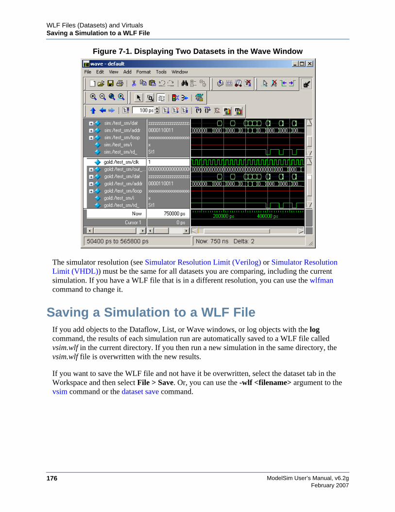
ModelSim User’s Manual, v6.2g176
WLF Files (Datasets) and VirtualsSaving a Simulation to a WLF File
February 2007
Figure 7-1. Displaying Two Datasets in the Wave Window
The simulator resolution (see Simulator Resolution Limit (Verilog) or Simulator ResolutionLimit (VHDL)) must be the same for all datasets you are comparing, including the currentsimulation. If you have a WLF file that is in a different resolution, you can use the wlfmancommand to change it.
Saving a Simulation to a WLF FileIf you add objects to the Dataflow, List, or Wave windows, or log objects with the logcommand, the results of each simulation run are automatically saved to a WLF file calledvsim.wlf in the current directory. If you then run a new simulation in the same directory, thevsim.wlf file is overwritten with the new results.
If you want to save the WLF file and not have it be overwritten, select the dataset tab in theWorkspace and then select File > Save. Or, you can use the -wlf <filename> argument to thevsim command or the dataset save command.
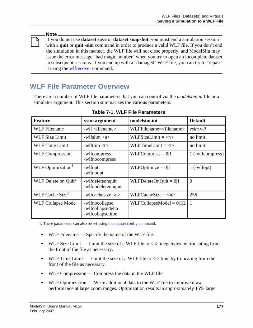
WLF Files (Datasets) and VirtualsSaving a Simulation to a WLF File
ModelSim User’s Manual, v6.2g 177February 2007
NoteIf you do not use dataset save or dataset snapshot, you must end a simulation sessionwith a quit or quit -sim command in order to produce a valid WLF file. If you don’t endthe simulation in this manner, the WLF file will not close properly, and ModelSim mayissue the error message "bad magic number" when you try to open an incomplete datasetin subsequent sessions. If you end up with a "damaged" WLF file, you can try to "repair"it using the wlfrecover command.
WLF File Parameter OverviewThere are a number of WLF file parameters that you can control via the modelsim.ini file or asimulator argument. This section summarizes the various parameters.
• WLF Filename — Specify the name of the WLF file.
• WLF Size Limit — Limit the size of a WLF file to <n> megabytes by truncating fromthe front of the file as necessary.
• WLF Time Limit — Limit the size of a WLF file to <t> time by truncating from thefront of the file as necessary.
• WLF Compression — Compress the data in the WLF file.
• WLF Optimization — Write additional data to the WLF file to improve drawperformance at large zoom ranges. Optimization results in approximately 15% larger
Table 7-1. WLF File Parameters
Feature vsim argument modelsim.ini Default
WLF Filename -wlf <filename> WLFFilename=<filename> vsim.wlf
WLF Size Limit -wlfslim <n> WLFSizeLimit = <n> no limit
WLF Time Limit -wlftlim <t> WLFTimeLimit = <t> no limit
WLF Compression -wlfcompress-wlfnocompress
WLFCompress = 0|1 1 (-wlfcompress)
WLF Optimization1
1. These parameters can also be set using the dataset config command.
-wlfopt-wlfnoopt
WLFOptimize = 0|1 1 (-wlfopt)
WLF Delete on Quita -wlfdeleteonquit-wlfnodeleteonquit
WLFDeleteOnQuit = 0|1 0
WLF Cache Sizea -wlfcachesize <n> WLFCacheSize = <n> 256
WLF Collapse Mode -wlfnocollapse-wlfcollapsedelta-wlfcollapsetime
WLFCollapseModel = 0|1|2 1
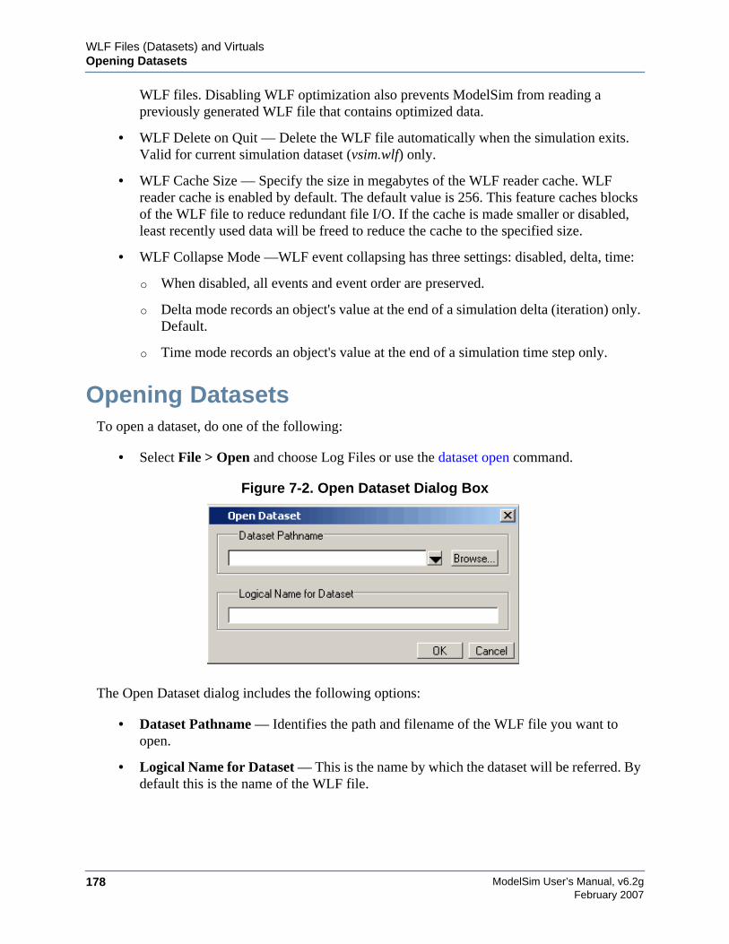
ModelSim User’s Manual, v6.2g178
WLF Files (Datasets) and VirtualsOpening Datasets
February 2007
WLF files. Disabling WLF optimization also prevents ModelSim from reading apreviously generated WLF file that contains optimized data.
• WLF Delete on Quit — Delete the WLF file automatically when the simulation exits.Valid for current simulation dataset (vsim.wlf) only.
• WLF Cache Size — Specify the size in megabytes of the WLF reader cache. WLFreader cache is enabled by default. The default value is 256. This feature caches blocksof the WLF file to reduce redundant file I/O. If the cache is made smaller or disabled,least recently used data will be freed to reduce the cache to the specified size.
• WLF Collapse Mode —WLF event collapsing has three settings: disabled, delta, time:
o When disabled, all events and event order are preserved.
o Delta mode records an object's value at the end of a simulation delta (iteration) only.Default.
o Time mode records an object's value at the end of a simulation time step only.
Opening DatasetsTo open a dataset, do one of the following:
• Select File > Open and choose Log Files or use the dataset open command.
Figure 7-2. Open Dataset Dialog Box
The Open Dataset dialog includes the following options:
• Dataset Pathname — Identifies the path and filename of the WLF file you want toopen.
• Logical Name for Dataset — This is the name by which the dataset will be referred. Bydefault this is the name of the WLF file.
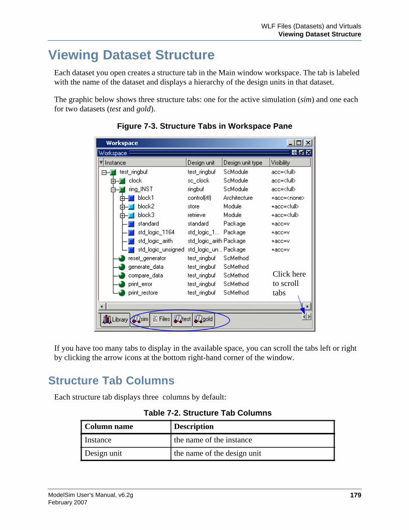
WLF Files (Datasets) and VirtualsViewing Dataset Structure
ModelSim User’s Manual, v6.2g 179February 2007
Viewing Dataset StructureEach dataset you open creates a structure tab in the Main window workspace. The tab is labeledwith the name of the dataset and displays a hierarchy of the design units in that dataset.
The graphic below shows three structure tabs: one for the active simulation (sim) and one eachfor two datasets (test and gold).
Figure 7-3. Structure Tabs in Workspace Pane
If you have too many tabs to display in the available space, you can scroll the tabs left or rightby clicking the arrow icons at the bottom right-hand corner of the window.
Structure Tab ColumnsEach structure tab displays three columns by default:
Table 7-2. Structure Tab Columns
Column name Description
Instance the name of the instance
Design unit the name of the design unit
Click hereto scrolltabs
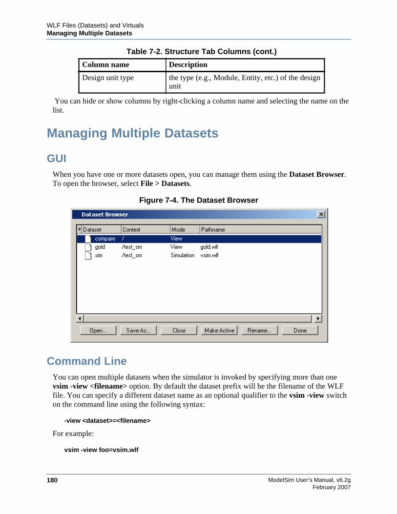
ModelSim User’s Manual, v6.2g180
WLF Files (Datasets) and VirtualsManaging Multiple Datasets
February 2007
You can hide or show columns by right-clicking a column name and selecting the name on thelist.
Managing Multiple Datasets
GUIWhen you have one or more datasets open, you can manage them using the Dataset Browser.To open the browser, select File > Datasets.
Figure 7-4. The Dataset Browser
Command LineYou can open multiple datasets when the simulator is invoked by specifying more than onevsim -view <filename> option. By default the dataset prefix will be the filename of the WLFfile. You can specify a different dataset name as an optional qualifier to the vsim -view switchon the command line using the following syntax:
-view <dataset>=<filename>
For example:
vsim -view foo=vsim.wlf
Design unit type the type (e.g., Module, Entity, etc.) of the designunit
Table 7-2. Structure Tab Columns (cont.)
Column name Description
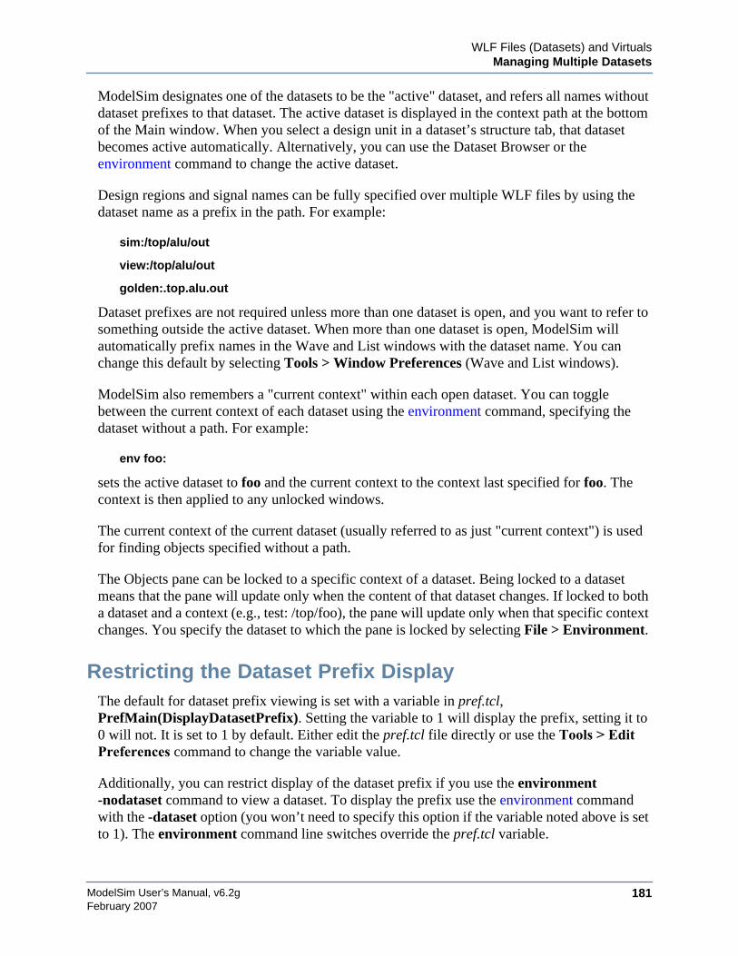
WLF Files (Datasets) and VirtualsManaging Multiple Datasets
ModelSim User’s Manual, v6.2g 181February 2007
ModelSim designates one of the datasets to be the "active" dataset, and refers all names withoutdataset prefixes to that dataset. The active dataset is displayed in the context path at the bottomof the Main window. When you select a design unit in a dataset’s structure tab, that datasetbecomes active automatically. Alternatively, you can use the Dataset Browser or theenvironment command to change the active dataset.
Design regions and signal names can be fully specified over multiple WLF files by using thedataset name as a prefix in the path. For example:
sim:/top/alu/out
view:/top/alu/out
golden:.top.alu.out
Dataset prefixes are not required unless more than one dataset is open, and you want to refer tosomething outside the active dataset. When more than one dataset is open, ModelSim willautomatically prefix names in the Wave and List windows with the dataset name. You canchange this default by selecting Tools > Window Preferences (Wave and List windows).
ModelSim also remembers a "current context" within each open dataset. You can togglebetween the current context of each dataset using the environment command, specifying thedataset without a path. For example:
env foo:
sets the active dataset to foo and the current context to the context last specified for foo. Thecontext is then applied to any unlocked windows.
The current context of the current dataset (usually referred to as just "current context") is usedfor finding objects specified without a path.
The Objects pane can be locked to a specific context of a dataset. Being locked to a datasetmeans that the pane will update only when the content of that dataset changes. If locked to botha dataset and a context (e.g., test: /top/foo), the pane will update only when that specific contextchanges. You specify the dataset to which the pane is locked by selecting File > Environment.
Restricting the Dataset Prefix DisplayThe default for dataset prefix viewing is set with a variable in pref.tcl,PrefMain(DisplayDatasetPrefix). Setting the variable to 1 will display the prefix, setting it to0 will not. It is set to 1 by default. Either edit the pref.tcl file directly or use the Tools > EditPreferences command to change the variable value.
Additionally, you can restrict display of the dataset prefix if you use the environment-nodataset command to view a dataset. To display the prefix use the environment commandwith the -dataset option (you won’t need to specify this option if the variable noted above is setto 1). The environment command line switches override the pref.tcl variable.
ModelSim User’s Manual, v6.2g182
WLF Files (Datasets) and VirtualsSaving at Intervals with Dataset Snapshot
February 2007
Saving at Intervals with Dataset SnapshotDataset Snapshot lets you periodically copy data from the current simulation WLF file toanother file. This is useful for taking periodic "snapshots" of your simulation or for clearing thecurrent simulation WLF file based on size or elapsed time.
Once you have logged the appropriate objects, select Tools > Dataset Snapshot (Wavewindow).
Figure 7-5. Dataset Snapshot Dialog
Collapsing Time and Delta StepsBy default ModelSim collapses delta steps. This means each logged signal that has eventsduring a simulation delta has its final value recorded to the WLF file when the delta has expired.The event order in the WLF file matches the order of the first events of each signal.
WLF Files (Datasets) and VirtualsVirtual Objects
ModelSim User’s Manual, v6.2g 183February 2007
You can configure how ModelSim collapses time and delta steps using arguments to the vsimcommand or by setting the WLFCollapseMode variable in the modelsim.ini file. The tablebelow summarizes the arguments and how they affect event recording.
When a run completes that includes single stepping or hitting a breakpoint, all events areflushed to the WLF file regardless of the time collapse mode. It’s possible that single steppingthrough part of a simulation may yield a slightly different WLF file than just running over thatpiece of code. If particular detail is required in debugging, you should disable time collapsing.
Virtual ObjectsVirtual objects are signal-like or region-like objects created in the GUI that do not exist in theModelSim simulation kernel. ModelSim supports the following kinds of virtual objects:
• Virtual Signals
• Virtual Functions
• Virtual Regions
• Virtual Types
Virtual objects are indicated by an orange diamond as illustrated by bus in Figure 7-6:
Table 7-3. vsim Arguments for Collapsing Time and Delta Steps
vsim argument effect modelsim.ini setting
-wlfnocollapse All events for each logged signal arerecorded to the WLF file in the exact orderthey occur in the simulation.
WLFCollapseMode = 0
-wlfdeltacollapse Each logged signal which has events during asimulation delta has its final value recordedto the WLF file when the delta has expired.Default.
WLFCollapseMode = 1
-wlftimecollapse Same as delta collapsing but at the timestepgranularity.
WLFCollapseMode = 2
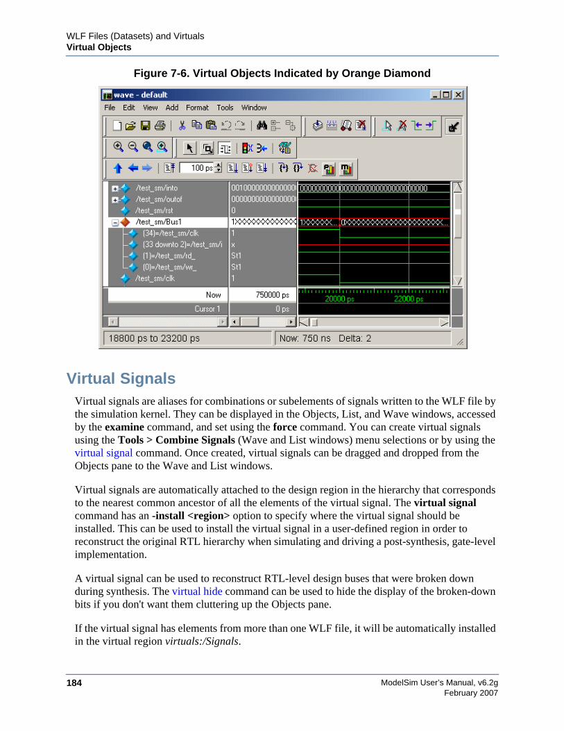
ModelSim User’s Manual, v6.2g184
WLF Files (Datasets) and VirtualsVirtual Objects
February 2007
Figure 7-6. Virtual Objects Indicated by Orange Diamond
Virtual SignalsVirtual signals are aliases for combinations or subelements of signals written to the WLF file bythe simulation kernel. They can be displayed in the Objects, List, and Wave windows, accessedby the examine command, and set using the force command. You can create virtual signalsusing the Tools > Combine Signals (Wave and List windows) menu selections or by using thevirtual signal command. Once created, virtual signals can be dragged and dropped from theObjects pane to the Wave and List windows.
Virtual signals are automatically attached to the design region in the hierarchy that correspondsto the nearest common ancestor of all the elements of the virtual signal. The virtual signalcommand has an -install <region> option to specify where the virtual signal should beinstalled. This can be used to install the virtual signal in a user-defined region in order toreconstruct the original RTL hierarchy when simulating and driving a post-synthesis, gate-levelimplementation.
A virtual signal can be used to reconstruct RTL-level design buses that were broken downduring synthesis. The virtual hide command can be used to hide the display of the broken-downbits if you don't want them cluttering up the Objects pane.
If the virtual signal has elements from more than one WLF file, it will be automatically installedin the virtual region virtuals:/Signals.
WLF Files (Datasets) and VirtualsVirtual Objects
ModelSim User’s Manual, v6.2g 185February 2007
Virtual signals are not hierarchical – if two virtual signals are concatenated to become a thirdvirtual signal, the resulting virtual signal will be a concatenation of all the scalar elements of thefirst two virtual signals.
The definitions of virtuals can be saved to a macro file using the virtual save command. Bydefault, when quitting, ModelSim will append any newly-created virtuals (that have not beensaved) to the virtuals.do file in the local directory.
If you have virtual signals displayed in the Wave or List window when you save the Wave orList format, you will need to execute the virtuals.do file (or some other equivalent) to restorethe virtual signal definitions before you re-load the Wave or List format during a later run.There is one exception: "implicit virtuals" are automatically saved with the Wave or Listformat.
Implicit and Explicit VirtualsAn implicit virtual is a virtual signal that was automatically created by ModelSim without yourknowledge and without you providing a name for it. An example would be if you expand a busin the Wave window, then drag one bit out of the bus to display it separately. That action createsa one-bit virtual signal whose definition is stored in a special location, and is not visible in theObjects pane or to the normal virtual commands.
All other virtual signals are considered "explicit virtuals".
Virtual FunctionsVirtual functions behave in the GUI like signals but are not aliases of combinations or elementsof signals logged by the kernel. They consist of logical operations on logged signals and can bedependent on simulation time. They can be displayed in the Objects, Wave, and List windowsand accessed by the examine command, but cannot be set by the force command.
Examples of virtual functions include the following:
• a function defined as the inverse of a given signal
• a function defined as the exclusive-OR of two signals
• a function defined as a repetitive clock
• a function defined as "the rising edge of CLK delayed by 1.34 ns"
Virtual functions can also be used to convert signal types and map signal values.
The result type of a virtual function can be any of the types supported in the GUI expressionsyntax: integer, real, boolean, std_logic, std_logic_vector, and arrays and records of these types.Verilog types are converted to VHDL 9-state std_logic equivalents and Verilog net strengthsare ignored.
ModelSim User’s Manual, v6.2g186
WLF Files (Datasets) and VirtualsVirtual Objects
February 2007
Virtual functions can be created using the virtual function command.
Virtual functions are also implicitly created by ModelSim when referencing bit-selects or part-selects of Verilog registers in the GUI, or when expanding Verilog registers in the Objects,Wave, or List window. This is necessary because referencing Verilog register elements requiresan intermediate step of shifting and masking of the Verilog "vreg" data structure.
Virtual RegionsUser-defined design hierarchy regions can be defined and attached to any existing design regionor to the virtuals context tree. They can be used to reconstruct the RTL hierarchy in a gate-leveldesign and to locate virtual signals. Thus, virtual signals and virtual regions can be used in agate-level design to allow you to use the RTL test bench.
Virtual regions are created and attached using the virtual region command.
Virtual TypesUser-defined enumerated types can be defined in order to display signal bit sequences asmeaningful alphanumeric names. The virtual type is then used in a type conversion expressionto convert a signal to values of the new type. When the converted signal is displayed in any ofthe windows, the value will be displayed as the enumeration string corresponding to the value ofthe original signal.
Virtual types are created using the virtual type command.
ModelSim User’s Manual, v6.2g 187February 2007
Chapter 8Waveform Analysis
When your simulation finishes, you will often want to analyze waveforms to assess and debugyour design. Designers typically use the Wave window for waveform analysis. However, youcan also look at waveform data in a textual format in the List window.
To analyze waveforms in ModelSim, follow these steps:
1. Compile your files.
2. Load your design.
3. Add objects to the Wave or List window.
add wave <object_name>add list <object_name>
4. Run the design.
Objects You Can ViewThe list below identifies the types of objects can be viewed in the Wave or List window.
• VHDL objects — (indicated by dark blue diamond in the Wave window)
signals, aliases, process variables, and shared variables
• Verilog objects — (indicated by light blue diamond in the Wave window)
nets, registers, variables, and named events
• Virtual objects — (indicated by an orange diamond in the Wave window)
virtual signals, buses, and functions, see; Virtual Objects for more information
Wave Window OverviewThe Wave window opens by default in the MDI frame of the Main window as shown below.The window can be undocked from the main window by pressing the Undock button in thewindow header or by using the view -undock wave command. The preference variablePrefMain(ViewUnDocked) wave can be used to control this default behavior. Setting thisvariable will open the Wave Window undocked each time you start ModelSim.
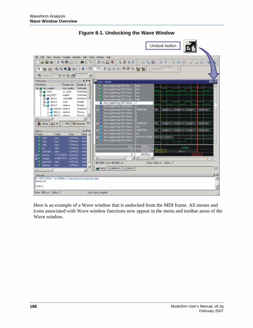
ModelSim User’s Manual, v6.2g188
Waveform AnalysisWave Window Overview
February 2007
Figure 8-1. Undocking the Wave Window
Here is an example of a Wave window that is undocked from the MDI frame. All menus andicons associated with Wave window functions now appear in the menu and toolbar areas of theWave window.
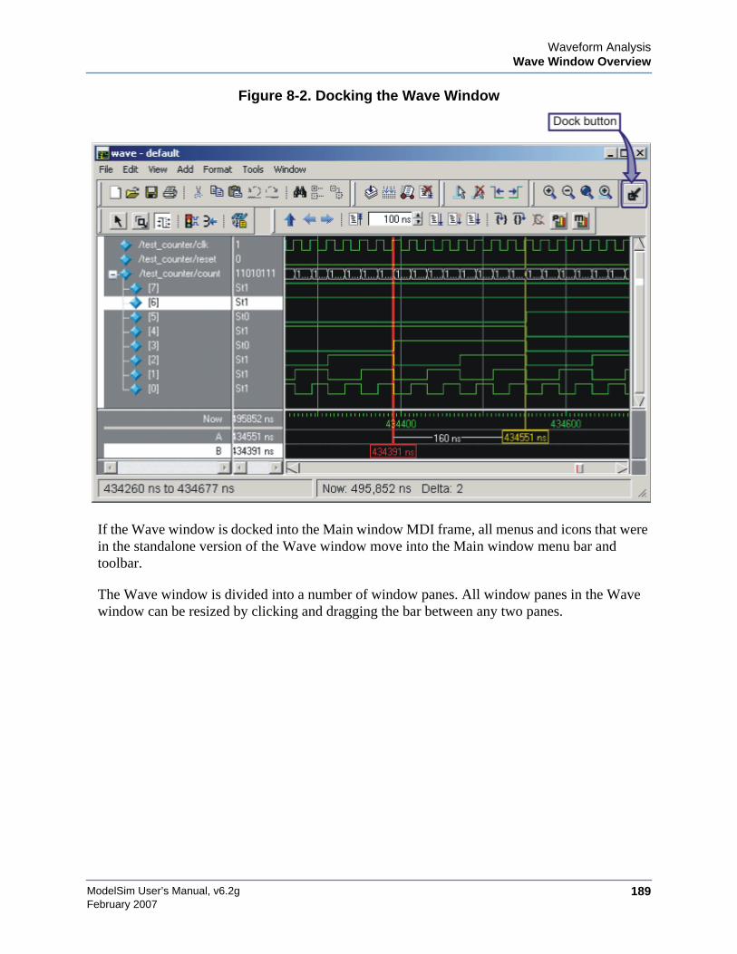
Waveform AnalysisWave Window Overview
ModelSim User’s Manual, v6.2g 189February 2007
Figure 8-2. Docking the Wave Window
If the Wave window is docked into the Main window MDI frame, all menus and icons that werein the standalone version of the Wave window move into the Main window menu bar andtoolbar.
The Wave window is divided into a number of window panes. All window panes in the Wavewindow can be resized by clicking and dragging the bar between any two panes.

ModelSim User’s Manual, v6.2g190
Waveform AnalysisList Window Overview
February 2007
Figure 8-3. Panes in the Wave Window
List Window OverviewThe List window displays simulation results in tabular format. Common tasks that people usethe window for include:
• Using gating expressions and trigger settings to focus in on particular signals or events.See Configuring New Line Triggering in the List Window.
• Debugging delta delay issues. See Delta Delays for more information.
The window is divided into two adjustable panes, which allows you to scroll horizontallythrough the listing on the right, while keeping time and delta visible on the left.
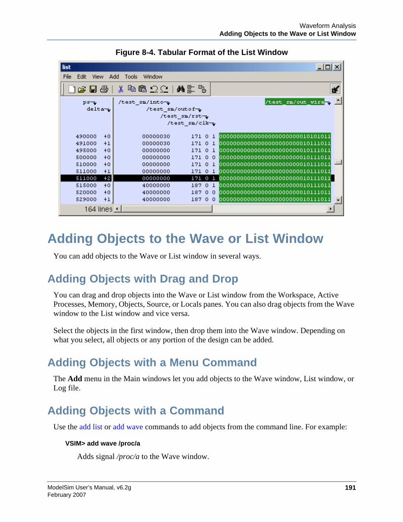
Waveform AnalysisAdding Objects to the Wave or List Window
ModelSim User’s Manual, v6.2g 191February 2007
Figure 8-4. Tabular Format of the List Window
Adding Objects to the Wave or List WindowYou can add objects to the Wave or List window in several ways.
Adding Objects with Drag and DropYou can drag and drop objects into the Wave or List window from the Workspace, ActiveProcesses, Memory, Objects, Source, or Locals panes. You can also drag objects from the Wavewindow to the List window and vice versa.
Select the objects in the first window, then drop them into the Wave window. Depending onwhat you select, all objects or any portion of the design can be added.
Adding Objects with a Menu CommandThe Add menu in the Main windows let you add objects to the Wave window, List window, orLog file.
Adding Objects with a CommandUse the add list or add wave commands to add objects from the command line. For example:
VSIM> add wave /proc/a
Adds signal /proc/a to the Wave window.
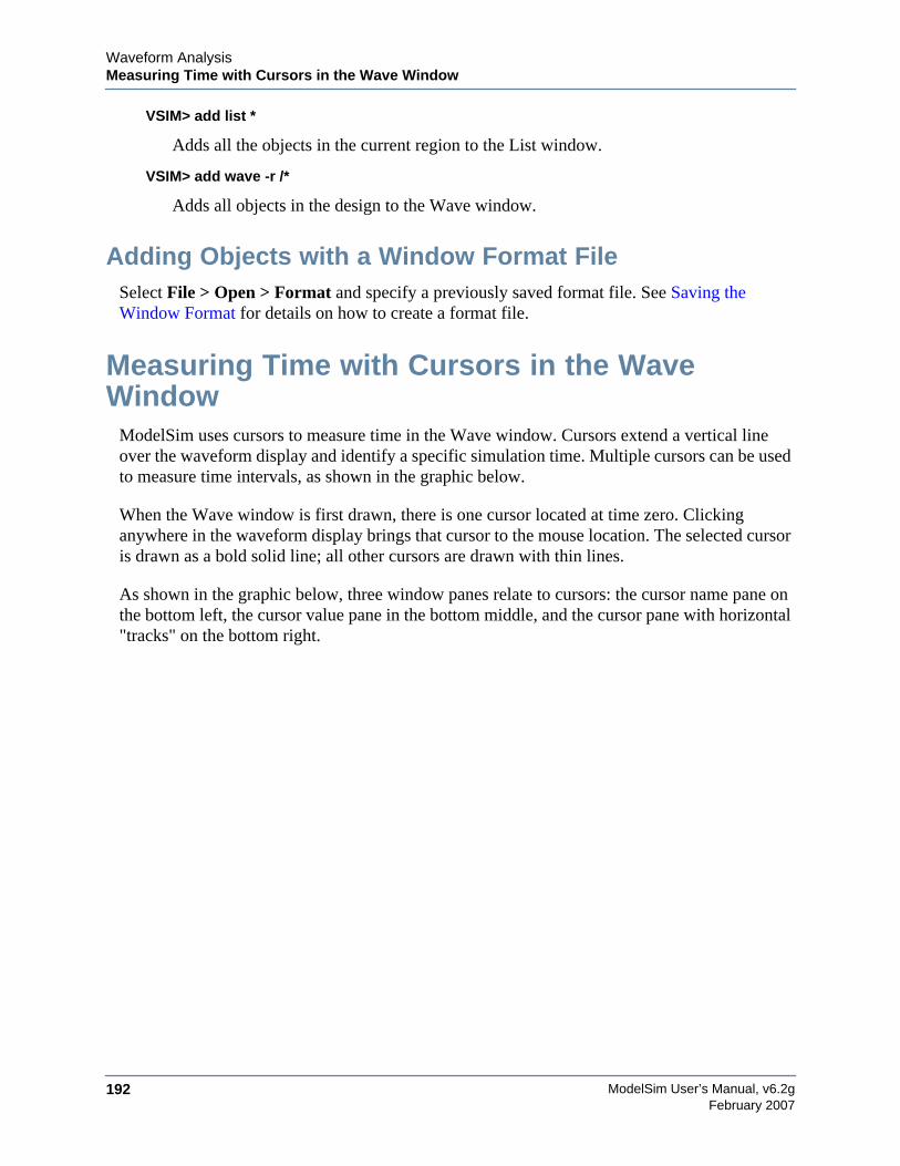
ModelSim User’s Manual, v6.2g192
Waveform AnalysisMeasuring Time with Cursors in the Wave Window
February 2007
VSIM> add list *
Adds all the objects in the current region to the List window.
VSIM> add wave -r /*
Adds all objects in the design to the Wave window.
Adding Objects with a Window Format FileSelect File > Open > Format and specify a previously saved format file. See Saving theWindow Format for details on how to create a format file.
Measuring Time with Cursors in the WaveWindow
ModelSim uses cursors to measure time in the Wave window. Cursors extend a vertical lineover the waveform display and identify a specific simulation time. Multiple cursors can be usedto measure time intervals, as shown in the graphic below.
When the Wave window is first drawn, there is one cursor located at time zero. Clickinganywhere in the waveform display brings that cursor to the mouse location. The selected cursoris drawn as a bold solid line; all other cursors are drawn with thin lines.
As shown in the graphic below, three window panes relate to cursors: the cursor name pane onthe bottom left, the cursor value pane in the bottom middle, and the cursor pane with horizontal"tracks" on the bottom right.
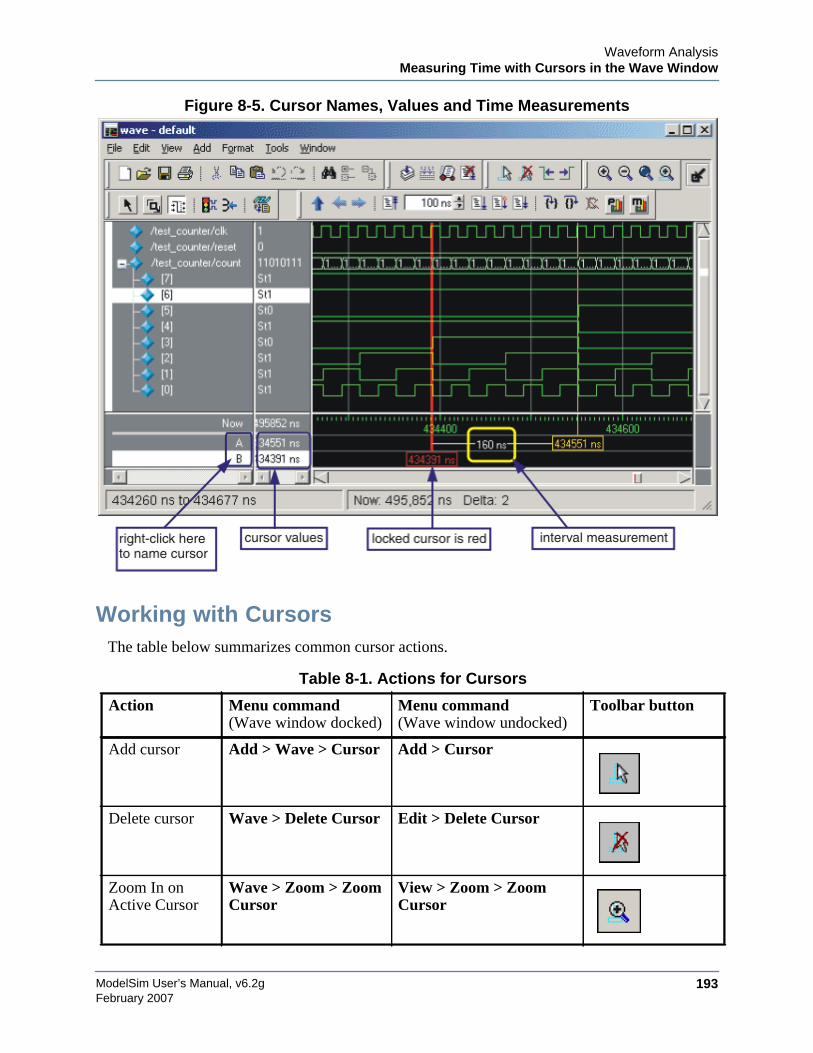
Waveform AnalysisMeasuring Time with Cursors in the Wave Window
ModelSim User’s Manual, v6.2g 193February 2007
Figure 8-5. Cursor Names, Values and Time Measurements
Working with CursorsThe table below summarizes common cursor actions.
Table 8-1. Actions for Cursors
Action Menu command(Wave window docked)
Menu command(Wave window undocked)
Toolbar button
Add cursor Add > Wave > Cursor Add > Cursor
Delete cursor Wave > Delete Cursor Edit > Delete Cursor
Zoom In onActive Cursor
Wave > Zoom > ZoomCursor
View > Zoom > ZoomCursor
ModelSim User’s Manual, v6.2g194
Waveform AnalysisMeasuring Time with Cursors in the Wave Window
February 2007
Shortcuts for Working with CursorsThere are a number of useful keyboard and mouse shortcuts related to the actions listed above:
• Select a cursor by clicking the cursor name.
• Jump to a "hidden" cursor (one that is out of view) by double-clicking the cursor name.
• Name a cursor by right-clicking the cursor name and entering a new value. Press<Enter> on your keyboard after you have typed the new name.
• Move a locked cursor by holding down the <shift> key and then clicking-and-draggingthe cursor.
• Move a cursor to a particular time by right-clicking the cursor value and typing the valueto which you want to scroll. Press <Enter> on your keyboard after you have typed thenew value.
Understanding Cursor BehaviorThe following list describes how cursors "behave" when you click in various panes of the Wavewindow:
• If you click in the waveform pane, the cursor closest to the mouse position is selectedand then moved to the mouse position.
• Clicking in a horizontal "track" in the cursor pane selects that cursor and moves it to themouse position.
• Cursors "snap" to a waveform edge if you click or drag a cursor along the selectedwaveform to within ten pixels of a waveform edge. You can set the snap distance in theWindow Preferences dialog. Select Tools > Options > Wave Preferences when theWave window is docked in the Main window MDI frame. Select Tools > WindowPreferences when the Wave window is a stand-alone, undocked window.
• You can position a cursor without snapping by dragging in the cursor pane below thewaveforms.
Lock cursor Wave > Edit Cursor Edit > Edit Cursor NA
Name cursor Wave > Edit Cursor Edit > Edit Cursor NA
Select cursor Wave > Cursors View > Cursors NA
Table 8-1. Actions for Cursors (cont.)
Action Menu command(Wave window docked)
Menu command(Wave window undocked)
Toolbar button

Waveform AnalysisSetting Time Markers in the List Window
ModelSim User’s Manual, v6.2g 195February 2007
Jumping to a Signal TransitionYou can move the active cursor to the next or previous transition on the selected signal usingthese two buttons on the toolbar:
Setting Time Markers in the List WindowTime markers in the List window are similar to cursors in the Wave window. Time markers taglines in the data table so you can quickly jump back to that time. Markers are indicated by a thinbox surrounding the marked line.
Figure 8-6. Time Markers in the List Window
Working with MarkersThe table below summarizes actions you can take with markers.
Find PreviousTransitionlocate the previoussignal value change
for the selected signal
Find Next Transitionlocate the next signalvalue change for theselected signal
Table 8-2. Actions for Time Markers
Action Method
Add marker Select a line and then select Edit > Add Marker
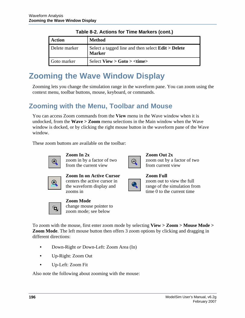
ModelSim User’s Manual, v6.2g196
Waveform AnalysisZooming the Wave Window Display
February 2007
Zooming the Wave Window DisplayZooming lets you change the simulation range in the waveform pane. You can zoom using thecontext menu, toolbar buttons, mouse, keyboard, or commands.
Zooming with the Menu, Toolbar and MouseYou can access Zoom commands from the View menu in the Wave window when it isundocked, from the Wave > Zoom menu selections in the Main window when the Wavewindow is docked, or by clicking the right mouse button in the waveform pane of the Wavewindow.
These zoom buttons are available on the toolbar:
To zoom with the mouse, first enter zoom mode by selecting View > Zoom > Mouse Mode >Zoom Mode. The left mouse button then offers 3 zoom options by clicking and dragging indifferent directions:
• Down-Right or Down-Left: Zoom Area (In)
• Up-Right: Zoom Out
• Up-Left: Zoom Fit
Also note the following about zooming with the mouse:
Delete marker Select a tagged line and then select Edit > DeleteMarker
Goto marker Select View > Goto > <time>
Zoom In 2xzoom in by a factor of twofrom the current view
Zoom Out 2xzoom out by a factor of twofrom current view
Zoom In on Active Cursorcenters the active cursor inthe waveform display andzooms in
Zoom Fullzoom out to view the fullrange of the simulation fromtime 0 to the current time
Zoom Modechange mouse pointer tozoom mode; see below
Table 8-2. Actions for Time Markers (cont.)
Action Method
Waveform AnalysisZooming the Wave Window Display
ModelSim User’s Manual, v6.2g 197February 2007
• The zoom amount is displayed at the mouse cursor. A zoom operation must be morethan 10 pixels to activate.
• You can enter zoom mode temporarily by holding the <Ctrl> key down while in selectmode.
• With the mouse in the Select Mode, the middle mouse button will perform the abovezoom operations.
Saving Zoom Range and Scroll Position with BookmarksBookmarks save a particular zoom range and scroll position. This lets you return easily to aspecific view later. You save the bookmark with a name and then access the named bookmarkfrom the Bookmark menu. Bookmarks are saved in the Wave format file (see Adding Objectswith a Window Format File) and are restored when the format file is read.
Managing BookmarksThe table below summarizes actions you can take with bookmarks.
Adding BookmarksTo add a bookmark, follow these steps:
1. Zoom the wave window as you see fit using one of the techniques discussed in Zoomingthe Wave Window Display.
2. If the Wave window is docked, select Add > Wave > Bookmark. If the Wave windowis undocked, select Add > Bookmark.
Table 8-3. Actions for Bookmarks
Action Menu commands(Wave windowdocked)
Menu commands(Wave windowundocked)
Command
Add bookmark Add > Wave >Bookmark
Add > Bookmark bookmark add wave
View bookmark Wave > Bookmarks ><bookmark_name>
View > Bookmarks ><bookmark_name>
bookmark goto wave
Delete bookmark Wave > Bookmarks >Bookmarks > <selectbookmark then Delete>
View > Bookmarks >Bookmarks > <selectbookmark then Delete>
bookmark delete wave
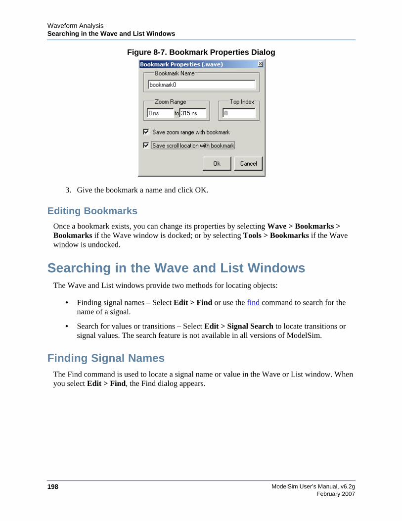
ModelSim User’s Manual, v6.2g198
Waveform AnalysisSearching in the Wave and List Windows
February 2007
Figure 8-7. Bookmark Properties Dialog
3. Give the bookmark a name and click OK.
Editing BookmarksOnce a bookmark exists, you can change its properties by selecting Wave > Bookmarks >Bookmarks if the Wave window is docked; or by selecting Tools > Bookmarks if the Wavewindow is undocked.
Searching in the Wave and List WindowsThe Wave and List windows provide two methods for locating objects:
• Finding signal names – Select Edit > Find or use the find command to search for thename of a signal.
• Search for values or transitions – Select Edit > Signal Search to locate transitions orsignal values. The search feature is not available in all versions of ModelSim.
Finding Signal NamesThe Find command is used to locate a signal name or value in the Wave or List window. Whenyou select Edit > Find, the Find dialog appears.
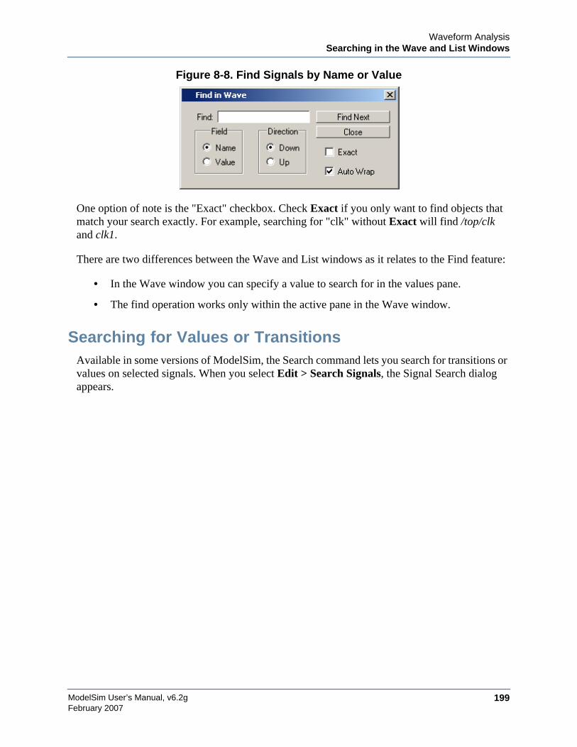
Waveform AnalysisSearching in the Wave and List Windows
ModelSim User’s Manual, v6.2g 199February 2007
Figure 8-8. Find Signals by Name or Value
One option of note is the "Exact" checkbox. Check Exact if you only want to find objects thatmatch your search exactly. For example, searching for "clk" without Exact will find /top/clkand clk1.
There are two differences between the Wave and List windows as it relates to the Find feature:
• In the Wave window you can specify a value to search for in the values pane.
• The find operation works only within the active pane in the Wave window.
Searching for Values or TransitionsAvailable in some versions of ModelSim, the Search command lets you search for transitions orvalues on selected signals. When you select Edit > Search Signals, the Signal Search dialogappears.
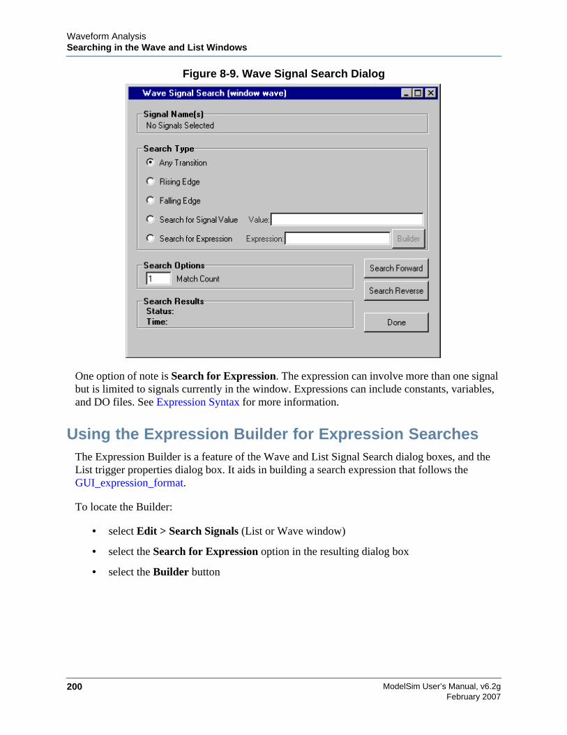
ModelSim User’s Manual, v6.2g200
Waveform AnalysisSearching in the Wave and List Windows
February 2007
Figure 8-9. Wave Signal Search Dialog
One option of note is Search for Expression. The expression can involve more than one signalbut is limited to signals currently in the window. Expressions can include constants, variables,and DO files. See Expression Syntax for more information.
Using the Expression Builder for Expression SearchesThe Expression Builder is a feature of the Wave and List Signal Search dialog boxes, and theList trigger properties dialog box. It aids in building a search expression that follows theGUI_expression_format.
To locate the Builder:
• select Edit > Search Signals (List or Wave window)
• select the Search for Expression option in the resulting dialog box
• select the Builder button
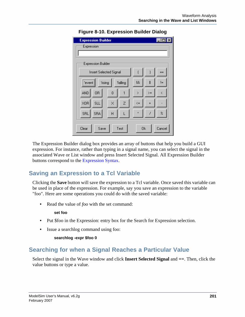
Waveform AnalysisSearching in the Wave and List Windows
ModelSim User’s Manual, v6.2g 201February 2007
Figure 8-10. Expression Builder Dialog
The Expression Builder dialog box provides an array of buttons that help you build a GUIexpression. For instance, rather than typing in a signal name, you can select the signal in theassociated Wave or List window and press Insert Selected Signal. All Expression Builderbuttons correspond to the Expression Syntax.
Saving an Expression to a Tcl VariableClicking the Save button will save the expression to a Tcl variable. Once saved this variable canbe used in place of the expression. For example, say you save an expression to the variable"foo". Here are some operations you could do with the saved variable:
• Read the value of foo with the set command:
set foo
• Put $foo in the Expression: entry box for the Search for Expression selection.
• Issue a searchlog command using foo:
searchlog -expr $foo 0
Searching for when a Signal Reaches a Particular ValueSelect the signal in the Wave window and click Insert Selected Signal and ==. Then, click thevalue buttons or type a value.
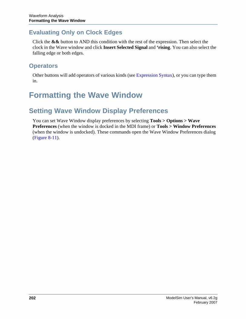
ModelSim User’s Manual, v6.2g202
Waveform AnalysisFormatting the Wave Window
February 2007
Evaluating Only on Clock EdgesClick the && button to AND this condition with the rest of the expression. Then select theclock in the Wave window and click Insert Selected Signal and ‘rising. You can also select thefalling edge or both edges.
OperatorsOther buttons will add operators of various kinds (see Expression Syntax), or you can type themin.
Formatting the Wave Window
Setting Wave Window Display PreferencesYou can set Wave Window display preferences by selecting Tools > Options > WavePreferences (when the window is docked in the MDI frame) or Tools > Window Preferences(when the window is undocked). These commands open the Wave Window Preferences dialog(Figure 8-11).
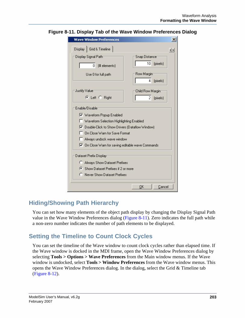
Waveform AnalysisFormatting the Wave Window
ModelSim User’s Manual, v6.2g 203February 2007
Figure 8-11. Display Tab of the Wave Window Preferences Dialog
Hiding/Showing Path HierarchyYou can set how many elements of the object path display by changing the Display Signal Pathvalue in the Wave Window Preferences dialog (Figure 8-11). Zero indicates the full path whilea non-zero number indicates the number of path elements to be displayed.
Setting the Timeline to Count Clock CyclesYou can set the timeline of the Wave window to count clock cycles rather than elapsed time. Ifthe Wave window is docked in the MDI frame, open the Wave Window Preferences dialog byselecting Tools > Options > Wave Preferences from the Main window menus. If the Wavewindow is undocked, select Tools > Window Preferences from the Wave window menus. Thisopens the Wave Window Preferences dialog. In the dialog, select the Grid & Timeline tab(Figure 8-12).
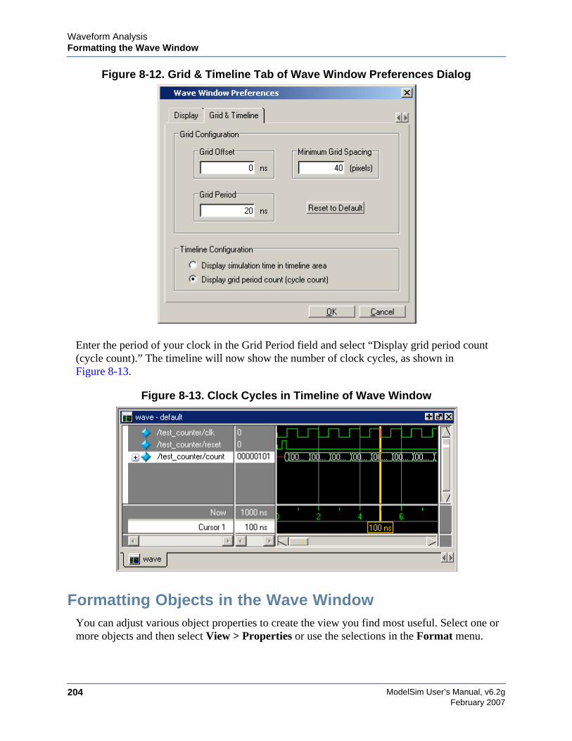
ModelSim User’s Manual, v6.2g204
Waveform AnalysisFormatting the Wave Window
February 2007
Figure 8-12. Grid & Timeline Tab of Wave Window Preferences Dialog
Enter the period of your clock in the Grid Period field and select “Display grid period count(cycle count).” The timeline will now show the number of clock cycles, as shown inFigure 8-13.
Figure 8-13. Clock Cycles in Timeline of Wave Window
Formatting Objects in the Wave WindowYou can adjust various object properties to create the view you find most useful. Select one ormore objects and then select View > Properties or use the selections in the Format menu.
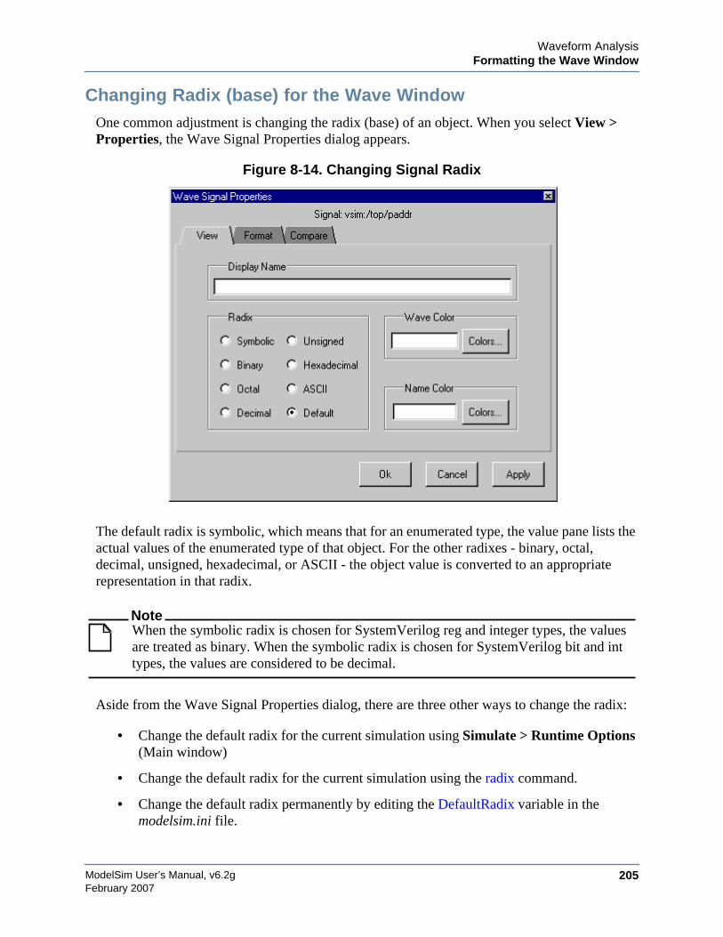
Waveform AnalysisFormatting the Wave Window
ModelSim User’s Manual, v6.2g 205February 2007
Changing Radix (base) for the Wave WindowOne common adjustment is changing the radix (base) of an object. When you select View >Properties, the Wave Signal Properties dialog appears.
Figure 8-14. Changing Signal Radix
The default radix is symbolic, which means that for an enumerated type, the value pane lists theactual values of the enumerated type of that object. For the other radixes - binary, octal,decimal, unsigned, hexadecimal, or ASCII - the object value is converted to an appropriaterepresentation in that radix.
NoteWhen the symbolic radix is chosen for SystemVerilog reg and integer types, the valuesare treated as binary. When the symbolic radix is chosen for SystemVerilog bit and inttypes, the values are considered to be decimal.
Aside from the Wave Signal Properties dialog, there are three other ways to change the radix:
• Change the default radix for the current simulation using Simulate > Runtime Options(Main window)
• Change the default radix for the current simulation using the radix command.
• Change the default radix permanently by editing the DefaultRadix variable in themodelsim.ini file.
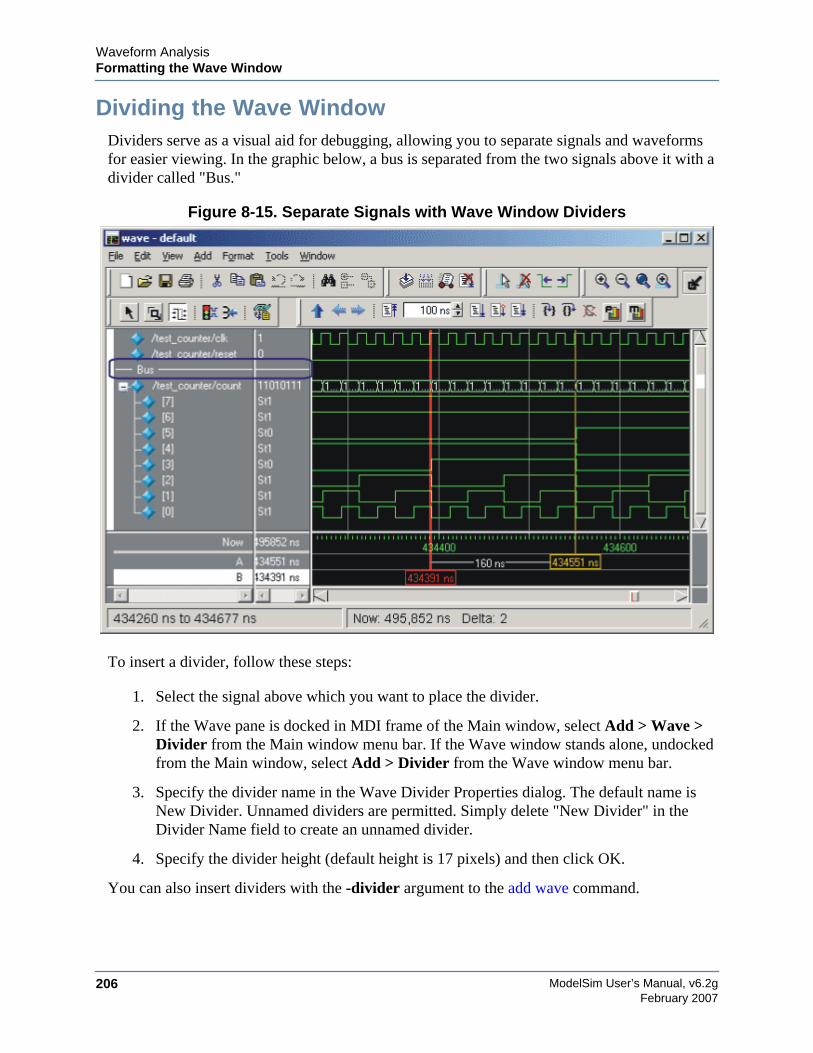
ModelSim User’s Manual, v6.2g206
Waveform AnalysisFormatting the Wave Window
February 2007
Dividing the Wave WindowDividers serve as a visual aid for debugging, allowing you to separate signals and waveformsfor easier viewing. In the graphic below, a bus is separated from the two signals above it with adivider called "Bus."
Figure 8-15. Separate Signals with Wave Window Dividers
To insert a divider, follow these steps:
1. Select the signal above which you want to place the divider.
2. If the Wave pane is docked in MDI frame of the Main window, select Add > Wave >Divider from the Main window menu bar. If the Wave window stands alone, undockedfrom the Main window, select Add > Divider from the Wave window menu bar.
3. Specify the divider name in the Wave Divider Properties dialog. The default name isNew Divider. Unnamed dividers are permitted. Simply delete "New Divider" in theDivider Name field to create an unnamed divider.
4. Specify the divider height (default height is 17 pixels) and then click OK.
You can also insert dividers with the -divider argument to the add wave command.
Waveform AnalysisFormatting the Wave Window
ModelSim User’s Manual, v6.2g 207February 2007
Working with DividersThe table below summarizes several actions you can take with dividers:
Splitting Wave Window PanesThe pathnames, values, and waveforms panes of the Wave window display can be split toaccommodate signals from one or more datasets. For more information on viewing multiplesimulations, see WLF Files (Datasets) and Virtuals.
To split the window, select Add > Window Pane.
In the illustration below, the top split shows the current active simulation with the prefix "sim,"and the bottom split shows a second dataset with the prefix "gold".
Table 8-4. Actions for Dividers
Action Method
Move a divider Click-and-drag the divider to the desired location
Change a divider’sname or size
Right-click the divider and select Divider Properties
Delete a divider Right-click the divider and select Delete
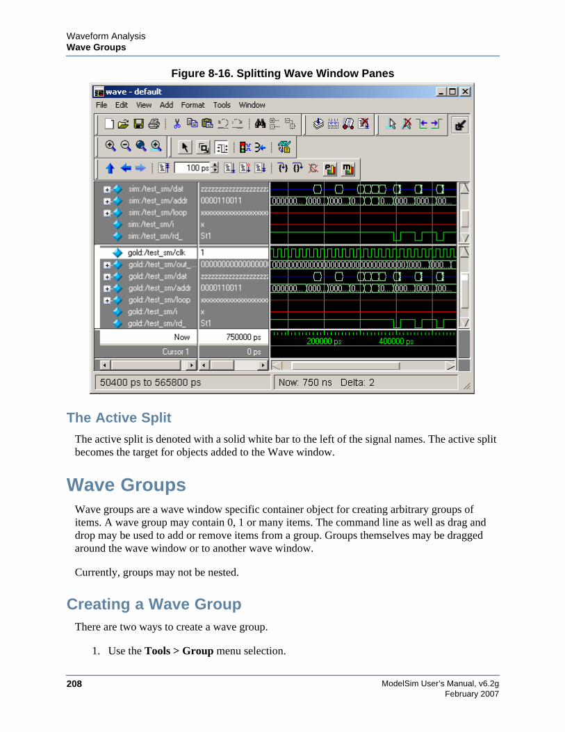
ModelSim User’s Manual, v6.2g208
Waveform AnalysisWave Groups
February 2007
Figure 8-16. Splitting Wave Window Panes
The Active SplitThe active split is denoted with a solid white bar to the left of the signal names. The active splitbecomes the target for objects added to the Wave window.
Wave GroupsWave groups are a wave window specific container object for creating arbitrary groups ofitems. A wave group may contain 0, 1 or many items. The command line as well as drag anddrop may be used to add or remove items from a group. Groups themselves may be draggedaround the wave window or to another wave window.
Currently, groups may not be nested.
Creating a Wave GroupThere are two ways to create a wave group.
1. Use the Tools > Group menu selection.
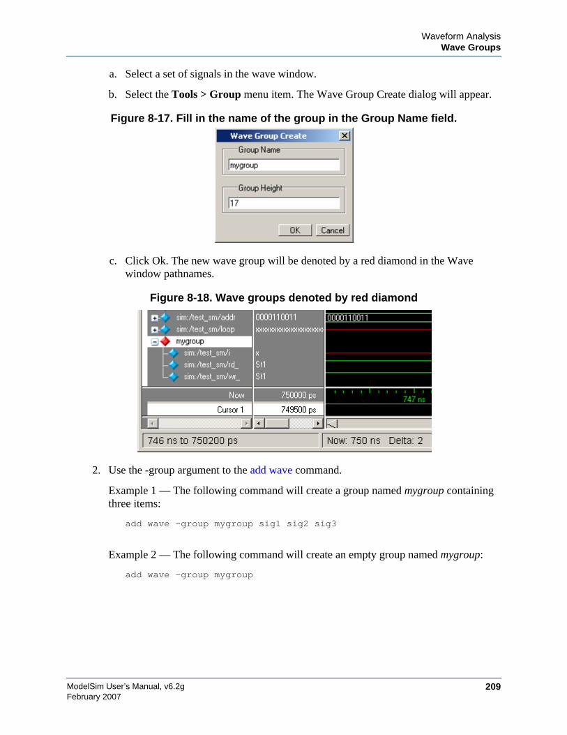
Waveform AnalysisWave Groups
ModelSim User’s Manual, v6.2g 209February 2007
a. Select a set of signals in the wave window.
b. Select the Tools > Group menu item. The Wave Group Create dialog will appear.
Figure 8-17. Fill in the name of the group in the Group Name field.
c. Click Ok. The new wave group will be denoted by a red diamond in the Wavewindow pathnames.
Figure 8-18. Wave groups denoted by red diamond
2. Use the -group argument to the add wave command.
Example 1 — The following command will create a group named mygroup containingthree items:
add wave -group mygroup sig1 sig2 sig3
Example 2 — The following command will create an empty group named mygroup:
add wave -group mygroup
ModelSim User’s Manual, v6.2g210
Waveform AnalysisWave Groups
February 2007
Deleting or Ungrouping a Wave GroupIf a wave group is selected and cut or deleted the entire group and all its contents will beremoved from the wave window. Likewise, the delete wave command will remove the entiregroup if the group name is specified.
If a wave group is selected and the Tools > Ungroup menu item is selected the group will beremoved and all of its contents will remain in the Wave window in existing order.
Adding Items to an Existing Wave GroupThere are three ways to add items to an existing wave group.
1. Using the drag and drop capability to move items outside of the group or from otherwindows within ModelSim into the group. The insertion indicator will show the positionthe item will be dropped into the group. If the cursor is moved over the lower portion ofthe group item name a box will be drawn around the group name indicating the item willbe dropped into the last position in the group.
2. The cut/copy/paste functions may be used to paste items into a group.
3. Use the add wave -group command.
The following example adds two more signals to an existing group called mygroup.
add wave -group mygroup sig4 sig5
Removing Items from an Existing Wave GroupYou can use any of the following methods to remove an item from a wave group.
1. Use the drag and drop capability to move an item outside of the group.
2. Use menu or icon selections to cut or delete an item or items from the group.
3. Use the delete wave command to specify a signal to be removed from the group.
NoteThe delete wave command removes all occurrences of a specified name from the wavewindow, not just an occurrence within a group.
Miscellaneous Wave Group FeaturesDragging a wave group from the Wave window to the List window will result in all of the itemswithin the group being added to the List window.
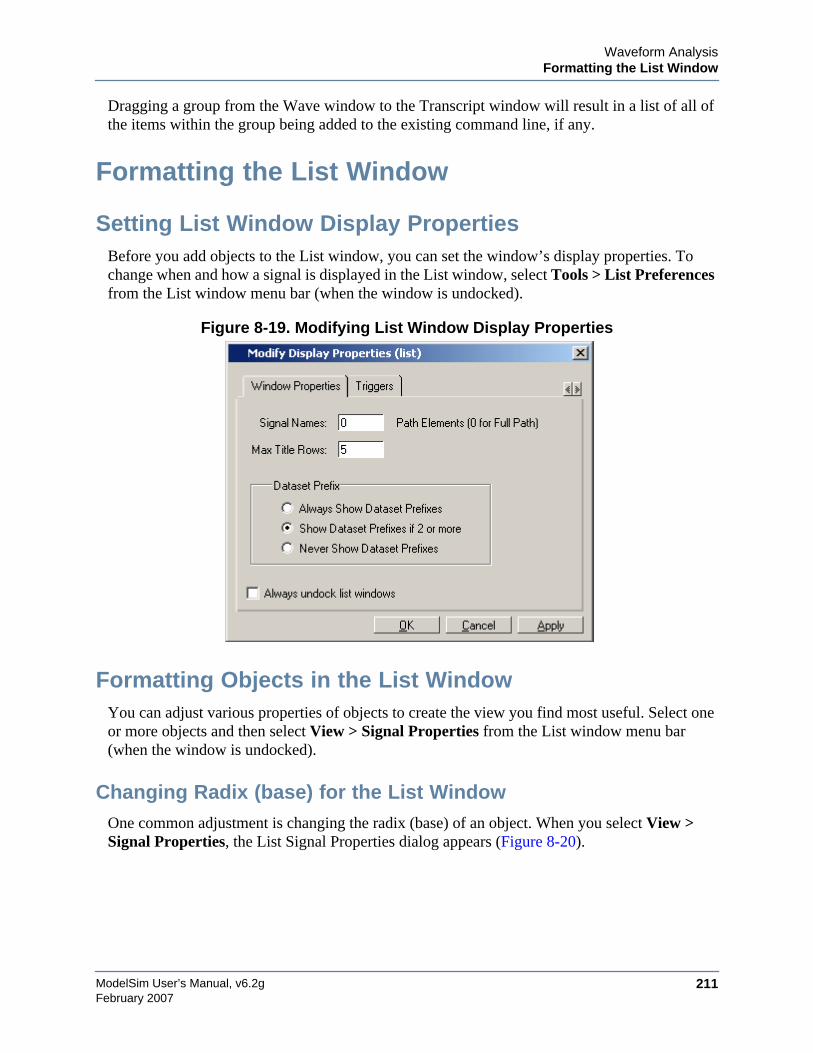
Waveform AnalysisFormatting the List Window
ModelSim User’s Manual, v6.2g 211February 2007
Dragging a group from the Wave window to the Transcript window will result in a list of all ofthe items within the group being added to the existing command line, if any.
Formatting the List Window
Setting List Window Display PropertiesBefore you add objects to the List window, you can set the window’s display properties. Tochange when and how a signal is displayed in the List window, select Tools > List Preferencesfrom the List window menu bar (when the window is undocked).
Figure 8-19. Modifying List Window Display Properties
Formatting Objects in the List WindowYou can adjust various properties of objects to create the view you find most useful. Select oneor more objects and then select View > Signal Properties from the List window menu bar(when the window is undocked).
Changing Radix (base) for the List WindowOne common adjustment is changing the radix (base) of an object. When you select View >Signal Properties, the List Signal Properties dialog appears (Figure 8-20).
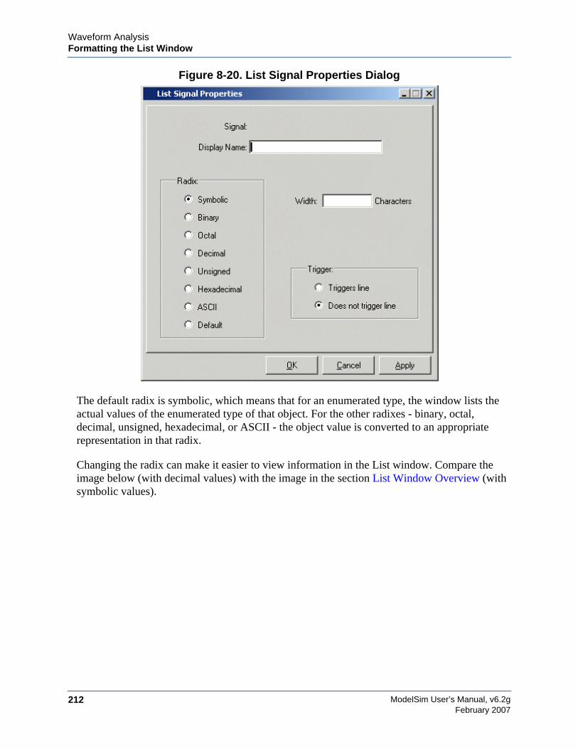
ModelSim User’s Manual, v6.2g212
Waveform AnalysisFormatting the List Window
February 2007
Figure 8-20. List Signal Properties Dialog
The default radix is symbolic, which means that for an enumerated type, the window lists theactual values of the enumerated type of that object. For the other radixes - binary, octal,decimal, unsigned, hexadecimal, or ASCII - the object value is converted to an appropriaterepresentation in that radix.
Changing the radix can make it easier to view information in the List window. Compare theimage below (with decimal values) with the image in the section List Window Overview (withsymbolic values).
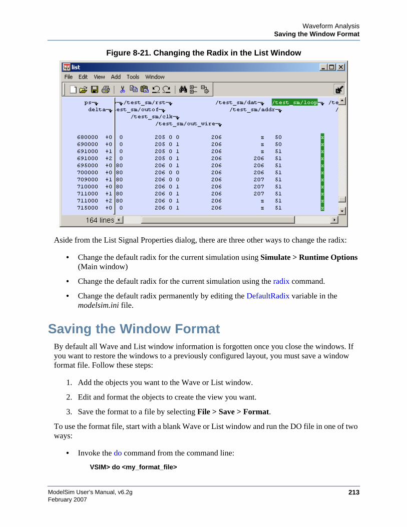
Waveform AnalysisSaving the Window Format
ModelSim User’s Manual, v6.2g 213February 2007
Figure 8-21. Changing the Radix in the List Window
Aside from the List Signal Properties dialog, there are three other ways to change the radix:
• Change the default radix for the current simulation using Simulate > Runtime Options(Main window)
• Change the default radix for the current simulation using the radix command.
• Change the default radix permanently by editing the DefaultRadix variable in themodelsim.ini file.
Saving the Window FormatBy default all Wave and List window information is forgotten once you close the windows. Ifyou want to restore the windows to a previously configured layout, you must save a windowformat file. Follow these steps:
1. Add the objects you want to the Wave or List window.
2. Edit and format the objects to create the view you want.
3. Save the format to a file by selecting File > Save > Format.
To use the format file, start with a blank Wave or List window and run the DO file in one of twoways:
• Invoke the do command from the command line:
VSIM> do <my_format_file>

ModelSim User’s Manual, v6.2g214
Waveform AnalysisPrinting and Saving Waveforms in the Wave window
February 2007
• Select File > Load.
NoteWindow format files are design-specific. Use them only with the design you weresimulating when they were created.
Printing and Saving Waveforms in the Wavewindow
You can print the waveform display or save it as an encapsulated postscript (EPS) file.
Saving a .eps Waveform File and Printing in UNIXSelect File > Print Postscript (Wave window) to print all or part of the waveform in the currentWave window in UNIX, or save the waveform as a .eps file on any platform (see also the writewave command).
Printing from the Wave Window on Windows PlatformsSelect File > Print (Wave window) to print all or part of the waveform in the current Wavewindow, or save the waveform as a printer file (a Postscript file for Postscript printers).
Printer Page SetupSelect File > Page setup or click the Setup button in the Write Postscript or Print dialog box todefine how the printed page will appear.
Saving List Window Data to a FileSelect File > Write List in the List window to save the data in one of these formats:
• Tabular — writes a text file that looks like the window listing
ns delta /a /b /cin /sum /cout0 +0 X X U X U0 +1 0 1 0 X U2 +0 0 1 0 X U
• Events — writes a text file containing transitions during simulation
Waveform AnalysisCombining Objects into Buses
ModelSim User’s Manual, v6.2g 215February 2007
@0 +0/a X/b X/cin U/sum X/cout U@0 +1/a 0/b 1/cin 0
• TSSI — writes a file in standard TSSI format; see also, the write tssi command.
0 00000000000000010?????????2 00000000000000010???????1?3 00000000000000010??????0104 00000000000000010000000010100 00000001000000010000000010
You can also save List window output using the write list command.
Combining Objects into BusesYou can combine signals in the Wave or List window into buses. A bus is a collection of signalsconcatenated in a specific order to create a new virtual signal with a specific value. A virtualcompare signal (the result of a comparison simulation) is not supported for combination withany other signal.
To combine signals into a bus, use one of the following methods:
• Select two or more signals in the Wave or List window and then choose Tools >Combine Signals from the menu bar. A virtual signal that is the result of a comparisonsimulation is not supported for combining with any other signal.
• Use the virtual signal command at the Main window command prompt.
In the illustration below, three signals have been combined to form a new bus called "Bus1".Note that the component signals are listed in the order in which they were selected in the Wavewindow. Also note that the value of the bus is made up of the values of its component signals,arranged in a specific order.
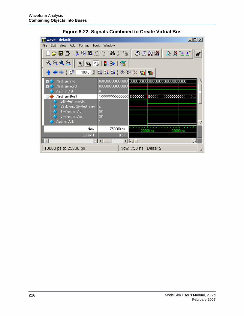
ModelSim User’s Manual, v6.2g216
Waveform AnalysisCombining Objects into Buses
February 2007
Figure 8-22. Signals Combined to Create Virtual Bus
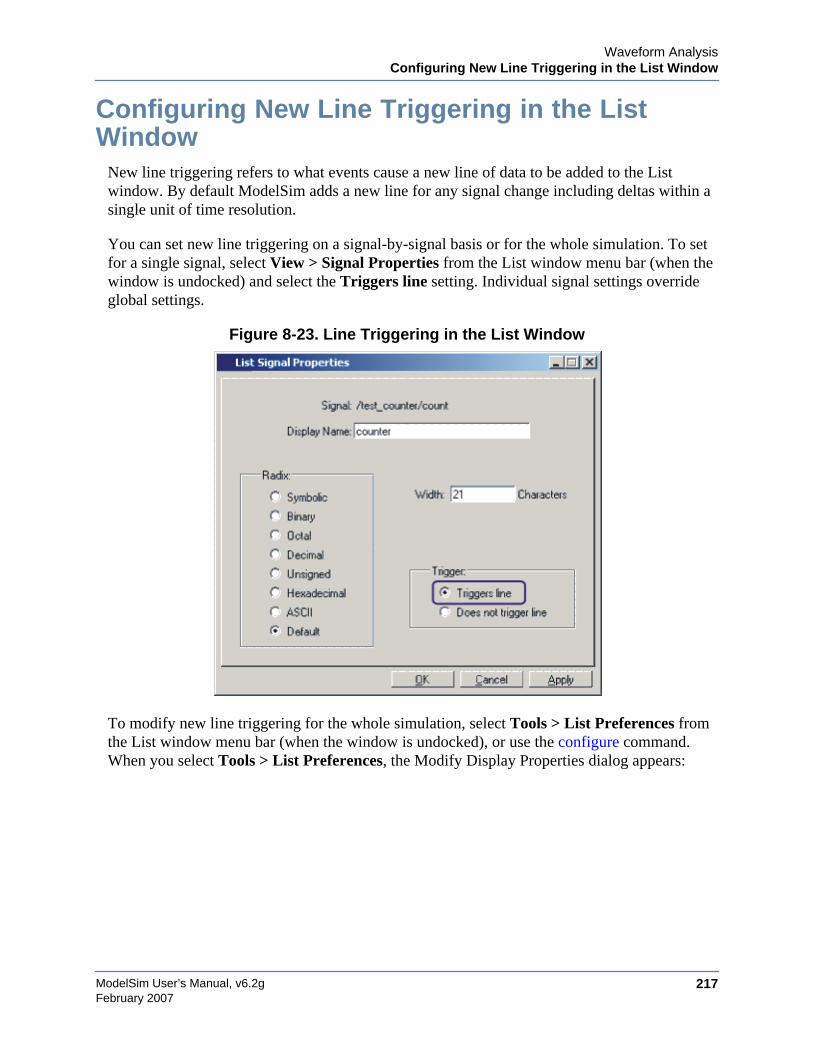
Waveform AnalysisConfiguring New Line Triggering in the List Window
ModelSim User’s Manual, v6.2g 217February 2007
Configuring New Line Triggering in the ListWindow
New line triggering refers to what events cause a new line of data to be added to the Listwindow. By default ModelSim adds a new line for any signal change including deltas within asingle unit of time resolution.
You can set new line triggering on a signal-by-signal basis or for the whole simulation. To setfor a single signal, select View > Signal Properties from the List window menu bar (when thewindow is undocked) and select the Triggers line setting. Individual signal settings overrideglobal settings.
Figure 8-23. Line Triggering in the List Window
To modify new line triggering for the whole simulation, select Tools > List Preferences fromthe List window menu bar (when the window is undocked), or use the configure command.When you select Tools > List Preferences, the Modify Display Properties dialog appears:
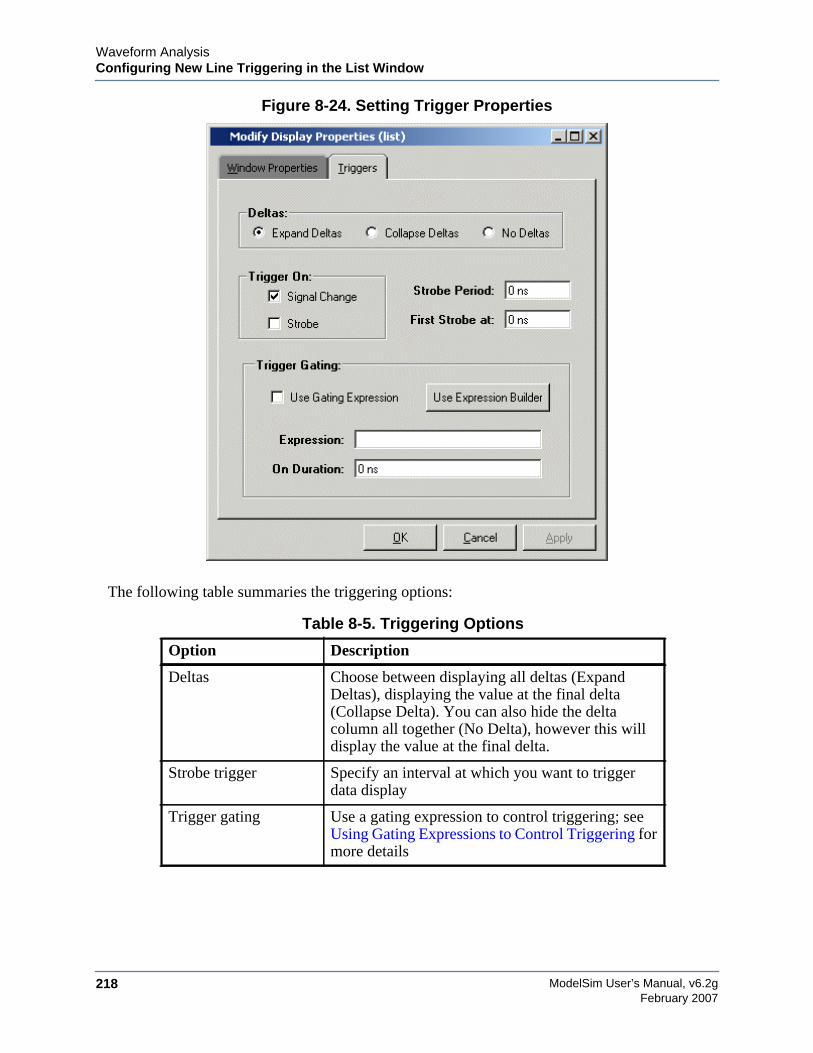
ModelSim User’s Manual, v6.2g218
Waveform AnalysisConfiguring New Line Triggering in the List Window
February 2007
Figure 8-24. Setting Trigger Properties
The following table summaries the triggering options:
Table 8-5. Triggering Options
Option Description
Deltas Choose between displaying all deltas (ExpandDeltas), displaying the value at the final delta(Collapse Delta). You can also hide the deltacolumn all together (No Delta), however this willdisplay the value at the final delta.
Strobe trigger Specify an interval at which you want to triggerdata display
Trigger gating Use a gating expression to control triggering; seeUsing Gating Expressions to Control Triggering formore details
Waveform AnalysisConfiguring New Line Triggering in the List Window
ModelSim User’s Manual, v6.2g 219February 2007
Using Gating Expressions to Control TriggeringTrigger gating controls the display of data based on an expression. Triggering is enabled oncethe gating expression evaluates to true. This setup behaves much like a hardware signal analyzerthat starts recording data on a specified setup of address bits and clock edges.
Here are some points about gating expressions:
• Gating expressions affect the display of data but not acquisition of the data.
• The expression is evaluated when the List window would normally have displayed arow of data (given the other trigger settings).
• The duration determines for how long triggering stays enabled after the gatingexpression returns to false (0). The default of 0 duration will enable triggering onlywhile the expression is true (1). The duration is expressed in x number of defaulttimescale units.
• Gating is level-sensitive rather than edge-triggered.
Trigger Gating Example Using the Expression BuilderThis example shows how to create a gating expression with the ModelSim Expression Builder.Here is the procedure:
1. Select Tools > Window Preferences from the List window menu bar (when thewindow is undocked) and select the Triggers tab.
2. Click the Use Expression Builder button.
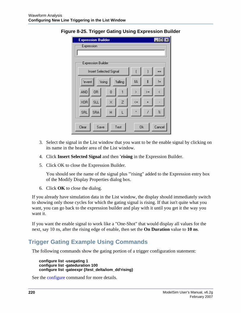
ModelSim User’s Manual, v6.2g220
Waveform AnalysisConfiguring New Line Triggering in the List Window
February 2007
Figure 8-25. Trigger Gating Using Expression Builder
3. Select the signal in the List window that you want to be the enable signal by clicking onits name in the header area of the List window.
4. Click Insert Selected Signal and then 'rising in the Expression Builder.
5. Click OK to close the Expression Builder.
You should see the name of the signal plus "'rising" added to the Expression entry boxof the Modify Display Properties dialog box.
6. Click OK to close the dialog.
If you already have simulation data in the List window, the display should immediately switchto showing only those cycles for which the gating signal is rising. If that isn't quite what youwant, you can go back to the expression builder and play with it until you get it the way youwant it.
If you want the enable signal to work like a "One-Shot" that would display all values for thenext, say 10 ns, after the rising edge of enable, then set the On Duration value to 10 ns.
Trigger Gating Example Using CommandsThe following commands show the gating portion of a trigger configuration statement:
configure list -usegating 1configure list -gateduration 100configure list -gateexpr {/test_delta/iom_dd'rising}
See the configure command for more details.

Waveform AnalysisMiscellaneous Tasks
ModelSim User’s Manual, v6.2g 221February 2007
Sampling Signals at a Clock ChangeYou easily can sample signals at a clock change using the add list command with the-notrigger argument. The -notrigger argument disables triggering the display on the specifiedsignals. For example:
add list clk -notrigger a b c
When you run the simulation, List window entries for clk, a, b, and c appear only when clkchanges.
If you want to display on rising edges only, you have two options:
1. Turn off the List window triggering on the clock signal, and then define a repeatingstrobe for the List window.
2. Define a "gating expression" for the List window that requires the clock to be in aspecified state. See above.
Miscellaneous Tasks
Examining Waveform ValuesYou can use your mouse to display a dialog that shows the value of a waveform at a particulartime. You can do this two ways:
• Rest your mouse pointer on a waveform. After a short delay, a dialog will pop-up thatdisplays the value for the time at which your mouse pointer is positioned. If you’d preferthat this popup not display, it can be toggled off in the display properties. See SettingWave Window Display Preferences.
• Right-click a waveform and select Examine. A dialog displays the value for the time atwhich you clicked your mouse. This method works in the List window as well.
Displaying Drivers of the Selected WaveformYou can automatically display in the Dataflow window the drivers of a signal selected in theWave window. You can do this three ways:
• Select a waveform and click the Show Drivers button on the toolbar.
• Select a waveform and select Show Drivers from the shortcut menu
• Double-click a waveform edge (you can enable/disable this option in the displayproperties dialog; see Setting Wave Window Display Preferences)
This operation opens the Dataflow window and displays the drivers of the signal selected in theWave window. The Wave pane in the Dataflow window also opens to show the selected signal
ModelSim User’s Manual, v6.2g222
Waveform AnalysisCreating and managing breakpoints
February 2007
with a cursor at the selected time. The Dataflow window shows the signal(s) values at thecurrent cursor position.
Sorting a Group of Objects in the Wave WindowSelect View > Sort to sort the objects in the pathname and values panes.
Creating and managing breakpointsModelSim supports both signal (i.e., when conditions) and file-line breakpoints. Breakpointscan be set from multiple locations in the GUI or from the command line.
Signal breakpointsSignal breakpoints (when conditions) instruct ModelSim to perform actions when the specifiedconditions are met. For example, you can break on a signal value or at a specific simulator time(see the when command for additional details). When a breakpoint is hit, a message in the Mainwindow transcript identifies the signal that caused the breakpoint.
Setting signal breakpoints from the command lineYou use the when command to set a signal breakpoint from the VSIM> prompt.
Setting signal breakpoints from the GUISignal breakpoints are most easily set in the Objects Pane and the Wave Window Overview.Right-click a signal and select Insert Breakpoint from the context menu. A breakpoint is set onthat signal and will be listed in the Breakpoints dialog.
File-line breakpointsFile-line breakpoints are set on executable lines in your source files. When the line is hit, thesimulator stops and the Source window opens to show the line with the breakpoint. You canchange this behavior by editing the PrefSource(OpenOnBreak) variable. See Simulator GUIPreferences for details on setting preference variables.
Setting file-line breakpoints from the command lineYou use the bp command to set a file-line breakpoint from the VSIM> prompt.
Setting file-line breakpoints from the GUIFile-line breakpoints are most easily set using your mouse in the Source Window. Click on ablue line number at the left side of the Source window, and a red diamond denoting a breakpoint

Waveform AnalysisCreating and managing breakpoints
ModelSim User’s Manual, v6.2g 223February 2007
will appear. The breakpoints are toggles – click once to create the colored diamond; click againto disable or enable the breakpoint. To delete the breakpoint completely, click the red diamondwith your right mouse button, and select Remove Breakpoint.

ModelSim User’s Manual, v6.2g224
Waveform AnalysisCreating and managing breakpoints
February 2007
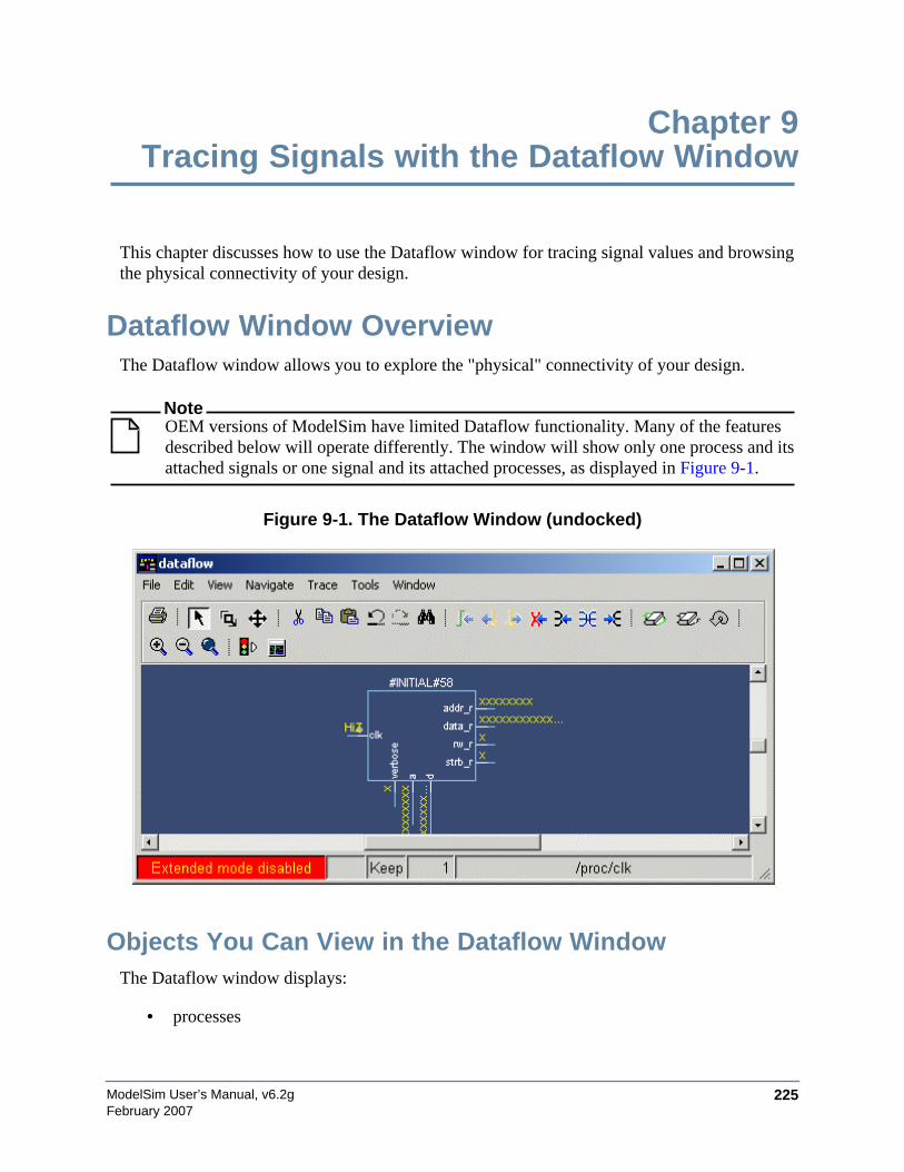
ModelSim User’s Manual, v6.2g 225February 2007
Chapter 9Tracing Signals with the Dataflow Window
This chapter discusses how to use the Dataflow window for tracing signal values and browsingthe physical connectivity of your design.
Dataflow Window OverviewThe Dataflow window allows you to explore the "physical" connectivity of your design.
NoteOEM versions of ModelSim have limited Dataflow functionality. Many of the featuresdescribed below will operate differently. The window will show only one process and itsattached signals or one signal and its attached processes, as displayed in Figure 9-1.
Figure 9-1. The Dataflow Window (undocked)
Objects You Can View in the Dataflow WindowThe Dataflow window displays:
• processes
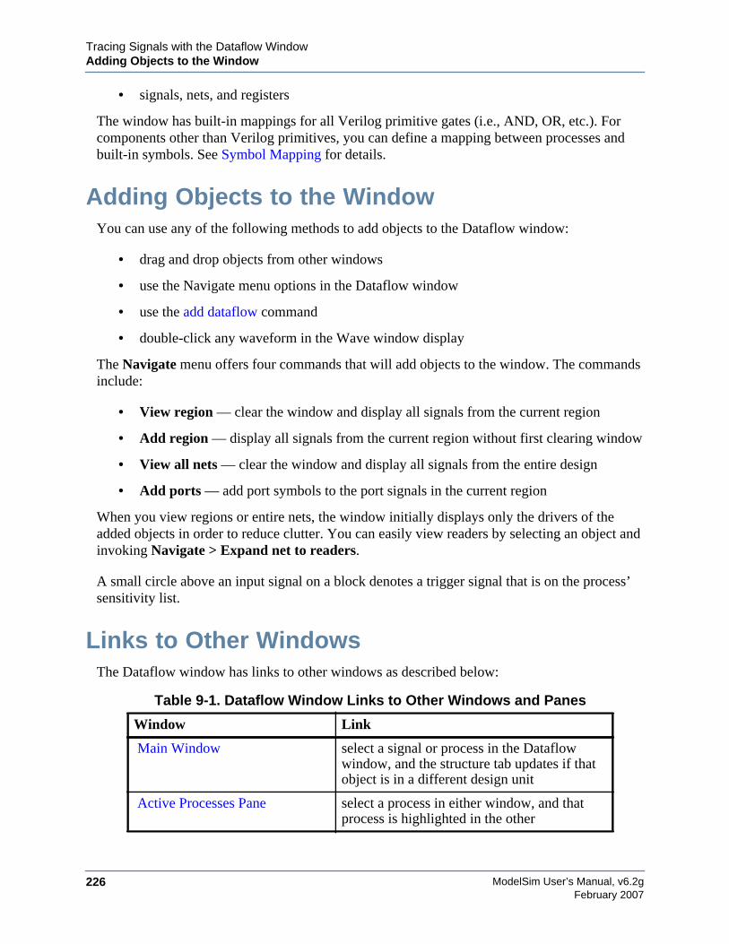
ModelSim User’s Manual, v6.2g226
Tracing Signals with the Dataflow WindowAdding Objects to the Window
February 2007
• signals, nets, and registers
The window has built-in mappings for all Verilog primitive gates (i.e., AND, OR, etc.). Forcomponents other than Verilog primitives, you can define a mapping between processes andbuilt-in symbols. See Symbol Mapping for details.
Adding Objects to the WindowYou can use any of the following methods to add objects to the Dataflow window:
• drag and drop objects from other windows
• use the Navigate menu options in the Dataflow window
• use the add dataflow command
• double-click any waveform in the Wave window display
The Navigate menu offers four commands that will add objects to the window. The commandsinclude:
• View region — clear the window and display all signals from the current region
• Add region — display all signals from the current region without first clearing window
• View all nets — clear the window and display all signals from the entire design
• Add ports — add port symbols to the port signals in the current region
When you view regions or entire nets, the window initially displays only the drivers of theadded objects in order to reduce clutter. You can easily view readers by selecting an object andinvoking Navigate > Expand net to readers.
A small circle above an input signal on a block denotes a trigger signal that is on the process’sensitivity list.
Links to Other WindowsThe Dataflow window has links to other windows as described below:
Table 9-1. Dataflow Window Links to Other Windows and Panes
Window Link
Main Window select a signal or process in the Dataflowwindow, and the structure tab updates if thatobject is in a different design unit
Active Processes Pane select a process in either window, and thatprocess is highlighted in the other
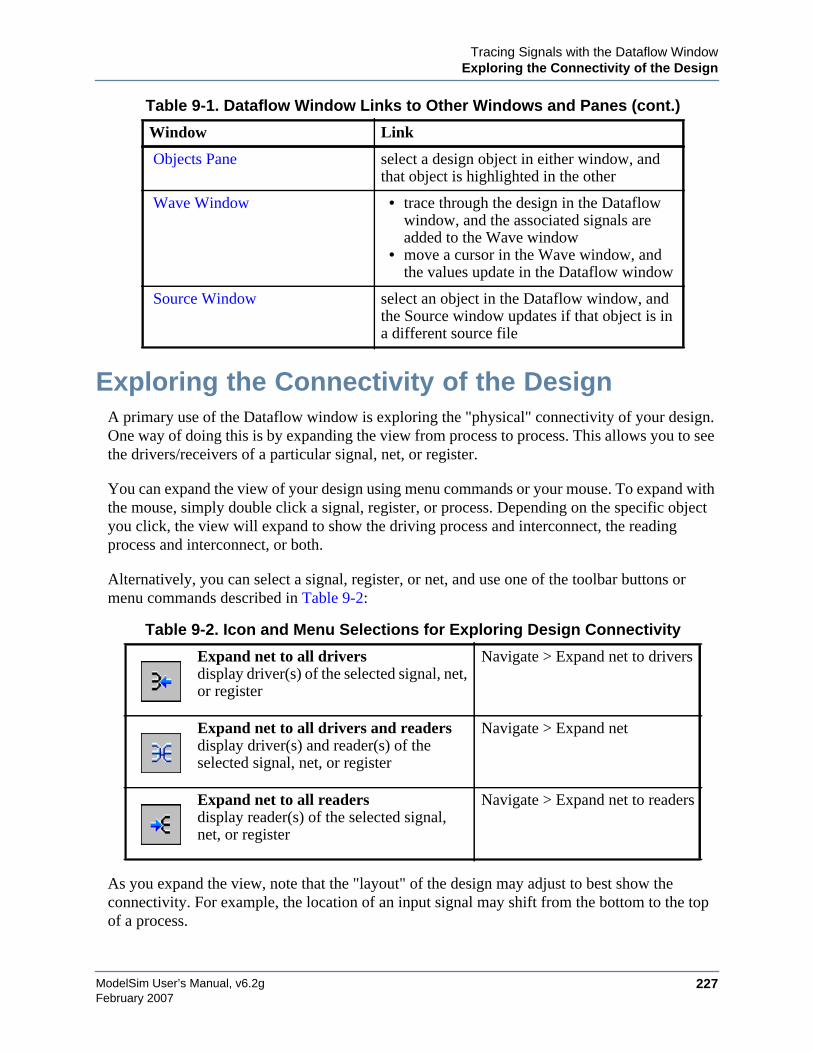
Tracing Signals with the Dataflow WindowExploring the Connectivity of the Design
ModelSim User’s Manual, v6.2g 227February 2007
Exploring the Connectivity of the DesignA primary use of the Dataflow window is exploring the "physical" connectivity of your design.One way of doing this is by expanding the view from process to process. This allows you to seethe drivers/receivers of a particular signal, net, or register.
You can expand the view of your design using menu commands or your mouse. To expand withthe mouse, simply double click a signal, register, or process. Depending on the specific objectyou click, the view will expand to show the driving process and interconnect, the readingprocess and interconnect, or both.
Alternatively, you can select a signal, register, or net, and use one of the toolbar buttons ormenu commands described in Table 9-2:
As you expand the view, note that the "layout" of the design may adjust to best show theconnectivity. For example, the location of an input signal may shift from the bottom to the topof a process.
Objects Pane select a design object in either window, andthat object is highlighted in the other
Wave Window • trace through the design in the Dataflowwindow, and the associated signals areadded to the Wave window
• move a cursor in the Wave window, andthe values update in the Dataflow window
Source Window select an object in the Dataflow window, andthe Source window updates if that object is ina different source file
Table 9-2. Icon and Menu Selections for Exploring Design Connectivity
Expand net to all driversdisplay driver(s) of the selected signal, net,or register
Navigate > Expand net to drivers
Expand net to all drivers and readersdisplay driver(s) and reader(s) of theselected signal, net, or register
Navigate > Expand net
Expand net to all readersdisplay reader(s) of the selected signal,net, or register
Navigate > Expand net to readers
Table 9-1. Dataflow Window Links to Other Windows and Panes (cont.)
Window Link
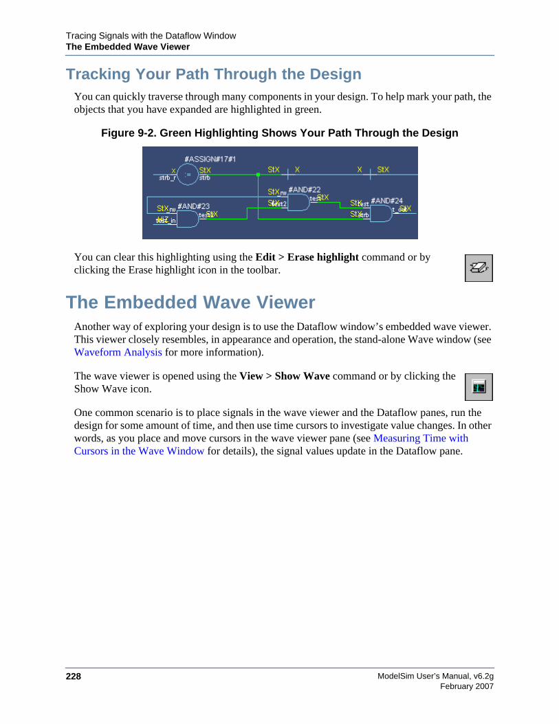
ModelSim User’s Manual, v6.2g228
Tracing Signals with the Dataflow WindowThe Embedded Wave Viewer
February 2007
Tracking Your Path Through the DesignYou can quickly traverse through many components in your design. To help mark your path, theobjects that you have expanded are highlighted in green.
Figure 9-2. Green Highlighting Shows Your Path Through the Design
You can clear this highlighting using the Edit > Erase highlight command or byclicking the Erase highlight icon in the toolbar.
The Embedded Wave ViewerAnother way of exploring your design is to use the Dataflow window’s embedded wave viewer.This viewer closely resembles, in appearance and operation, the stand-alone Wave window (seeWaveform Analysis for more information).
The wave viewer is opened using the View > Show Wave command or by clicking theShow Wave icon.
One common scenario is to place signals in the wave viewer and the Dataflow panes, run thedesign for some amount of time, and then use time cursors to investigate value changes. In otherwords, as you place and move cursors in the wave viewer pane (see Measuring Time withCursors in the Wave Window for details), the signal values update in the Dataflow pane.
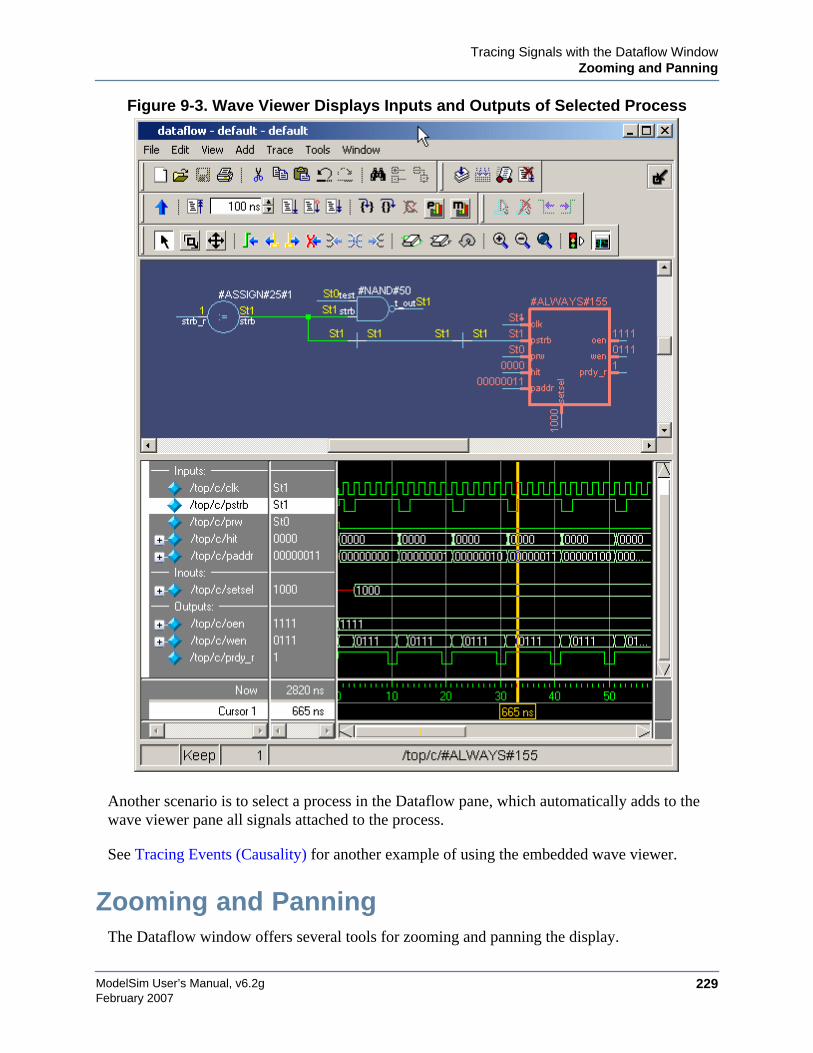
Tracing Signals with the Dataflow WindowZooming and Panning
ModelSim User’s Manual, v6.2g 229February 2007
Figure 9-3. Wave Viewer Displays Inputs and Outputs of Selected Process
Another scenario is to select a process in the Dataflow pane, which automatically adds to thewave viewer pane all signals attached to the process.
See Tracing Events (Causality) for another example of using the embedded wave viewer.
Zooming and PanningThe Dataflow window offers several tools for zooming and panning the display.

ModelSim User’s Manual, v6.2g230
Tracing Signals with the Dataflow WindowTracing Events (Causality)
February 2007
These zoom buttons are available on the toolbar:
To zoom with the mouse, you can either use the middle mouse button or enter Zoom Mode byselecting View > Zoom and then use the left mouse button.
Four zoom options are possible by clicking and dragging in different directions:
• Down-Right: Zoom Area (In)
• Up-Right: Zoom Out (zoom amount is displayed at the mouse cursor)
• Down-Left: Zoom Selected
• Up-Left: Zoom Full
The zoom amount is displayed at the mouse cursor. A zoom operation must be more than 10pixels to activate.
Panning with the MouseYou can pan with the mouse in two ways: 1) enter Pan Mode by selecting View > Pan and thendrag with the left mouse button to move the design; 2) hold down the <Ctrl> key and drag withthe middle mouse button to move the design.
Tracing Events (Causality)One of the most useful features of the Dataflow window is tracing an event to see the cause ofan unexpected output. This feature uses the Dataflow window’s embedded wave viewer (seeThe Embedded Wave Viewer for more details).
In short you identify an output of interest in the Dataflow pane and then use time cursors in thewave viewer pane to identify events that contribute to the output.
The process for tracing events is as follows:
1. Log all signals before starting the simulation (add log -r /*).
2. After running a simulation for some period of time, open the Dataflow window and thewave viewer pane.
3. Add a process or signal of interest into the Dataflow window (if adding a signal, find itsdriving process). Select the process and all signals attached to the selected process willappear in the wave viewer pane.
Zoom Inzoom in by a factorof two from thecurrent view
Zoom Outzoom out by afactor of two fromcurrent view
Zoom Fullzoom out to viewthe entire schematic
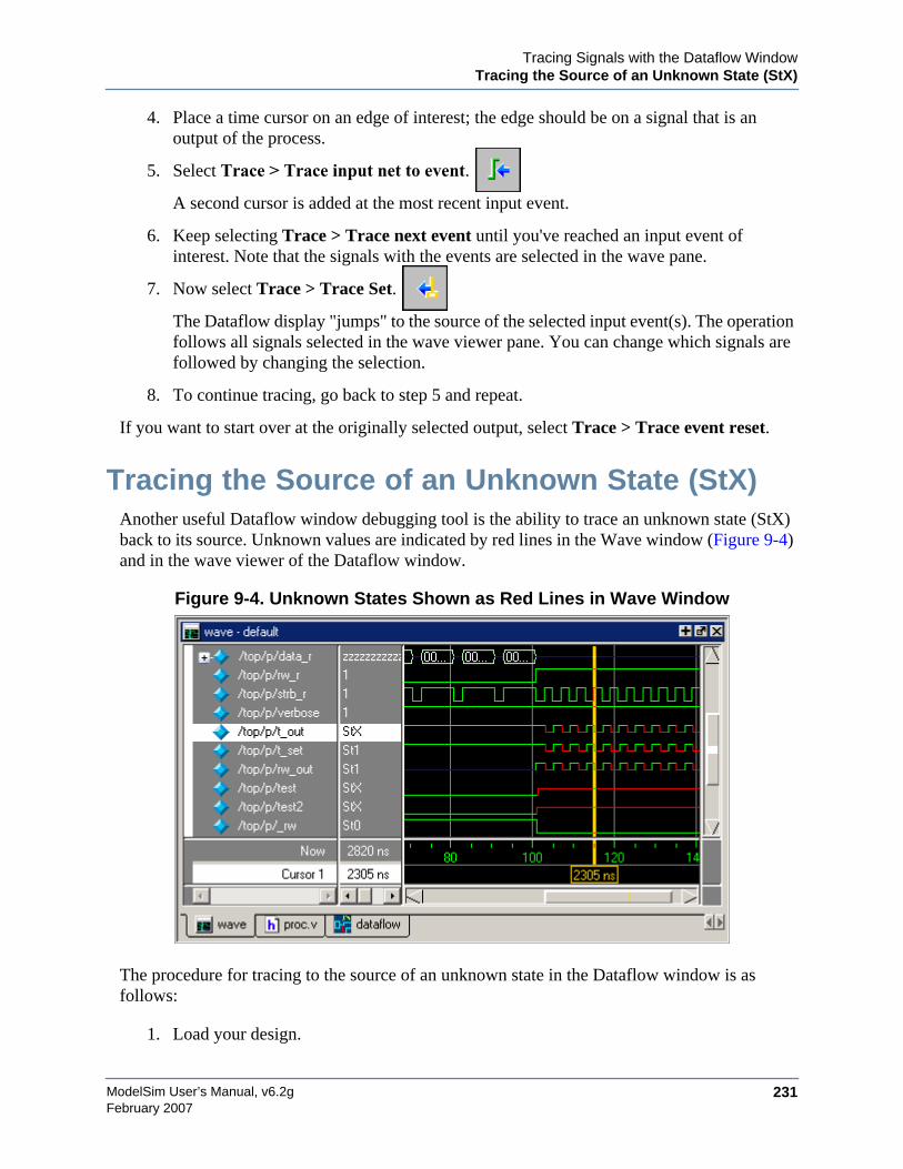
Tracing Signals with the Dataflow WindowTracing the Source of an Unknown State (StX)
ModelSim User’s Manual, v6.2g 231February 2007
4. Place a time cursor on an edge of interest; the edge should be on a signal that is anoutput of the process.
5. Select Trace > Trace input net to event.
A second cursor is added at the most recent input event.
6. Keep selecting Trace > Trace next event until you've reached an input event ofinterest. Note that the signals with the events are selected in the wave pane.
7. Now select Trace > Trace Set.
The Dataflow display "jumps" to the source of the selected input event(s). The operationfollows all signals selected in the wave viewer pane. You can change which signals arefollowed by changing the selection.
8. To continue tracing, go back to step 5 and repeat.
If you want to start over at the originally selected output, select Trace > Trace event reset.
Tracing the Source of an Unknown State (StX)Another useful Dataflow window debugging tool is the ability to trace an unknown state (StX)back to its source. Unknown values are indicated by red lines in the Wave window (Figure 9-4)and in the wave viewer of the Dataflow window.
Figure 9-4. Unknown States Shown as Red Lines in Wave Window
The procedure for tracing to the source of an unknown state in the Dataflow window is asfollows:
1. Load your design.
ModelSim User’s Manual, v6.2g232
Tracing Signals with the Dataflow WindowFinding Objects by Name in the Dataflow Window
February 2007
2. Log all signals in the design or any signals that may possibly contribute to the unknownvalue (log -r /* will log all signals in the design).
3. Add signals to the Wave window or wave viewer pane, and run your design the desiredlength of time.
4. Put a Wave window cursor on the time at which the signal value is unknown (StX). InFigure 9-4, Cursor 1 at time 2305 shows an unknown state on signal t_out.
5. Add the signal of interest to the Dataflow window by doing one of the following:
o double-clicking on the signal’s waveform in the Wave window,
o right-clicking the signal in the Objects window and selecting Add to Dataflow >Selected Signals from the popup menu,
o selecting the signal in the Objects window and selecting Add > Dataflow > SelectedSignals from the menu bar.
6. In the Dataflow window, make sure the signal of interest is selected.
7. Trace to the source of the unknown by doing one of the following:
o If the Dataflow window is docked, select Tools > Trace > TraceX, Tools > Trace >TraceX Delay, Tools > Trace > ChaseX, or Tools > Trace > ChaseX Delay.
o If the Dataflow window is undocked, select Trace > TraceX, Trace > TraceXDelay, Trace > ChaseX, or Trace > ChaseX Delay.
These commands behave as follows:
• TraceX / TraceX Delay— Steps back to the last driver of an X value. TraceXDelay works similarly but it steps back in time to the last driver of an X value.TraceX should be used for RTL designs; TraceX Delay should be used for gate-level netlists with back annotated delays.
• ChaseX / ChaseX Delay — "Jumps" through a design from output to input,following X values. ChaseX Delay acts the same as ChaseX but also movesbackwards in time to the point where the output value transitions to X. ChaseXshould be used for RTL designs; ChaseX Delay should be used for gate-levelnetlists with back annotated delays.
Finding Objects by Name in the DataflowWindow
Select Edit > Find from the menu bar, or click the Find icon in the toolbar, to searchfor signal, net, or register names or an instance of a component. This opens the Find inDataflow dialog (Figure 9-5).
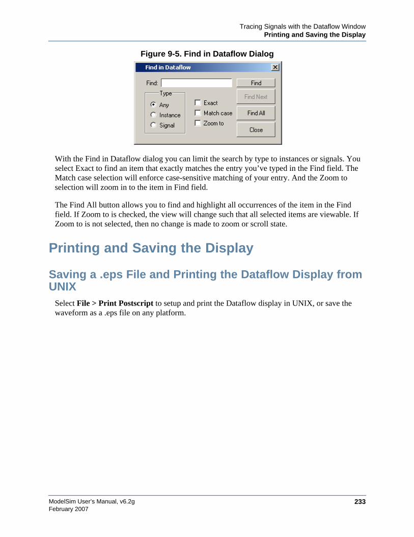
Tracing Signals with the Dataflow WindowPrinting and Saving the Display
ModelSim User’s Manual, v6.2g 233February 2007
Figure 9-5. Find in Dataflow Dialog
With the Find in Dataflow dialog you can limit the search by type to instances or signals. Youselect Exact to find an item that exactly matches the entry you’ve typed in the Find field. TheMatch case selection will enforce case-sensitive matching of your entry. And the Zoom toselection will zoom in to the item in Find field.
The Find All button allows you to find and highlight all occurrences of the item in the Findfield. If Zoom to is checked, the view will change such that all selected items are viewable. IfZoom to is not selected, then no change is made to zoom or scroll state.
Printing and Saving the Display
Saving a .eps File and Printing the Dataflow Display fromUNIX
Select File > Print Postscript to setup and print the Dataflow display in UNIX, or save thewaveform as a .eps file on any platform.

ModelSim User’s Manual, v6.2g234
Tracing Signals with the Dataflow WindowPrinting and Saving the Display
February 2007
Figure 9-6. The Print Postscript Dialog
Printing from the Dataflow Display on Windows PlatformsSelect File > Print to print the Dataflow display or to save the display to a file.
Figure 9-7. The Print Dialog
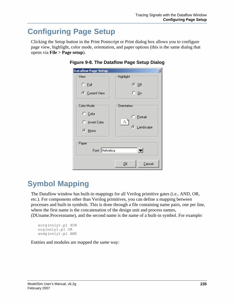
Tracing Signals with the Dataflow WindowConfiguring Page Setup
ModelSim User’s Manual, v6.2g 235February 2007
Configuring Page SetupClicking the Setup button in the Print Postscript or Print dialog box allows you to configurepage view, highlight, color mode, orientation, and paper options (this is the same dialog thatopens via File > Page setup).
Figure 9-8. The Dataflow Page Setup Dialog
Symbol MappingThe Dataflow window has built-in mappings for all Verilog primitive gates (i.e., AND, OR,etc.). For components other than Verilog primitives, you can define a mapping betweenprocesses and built-in symbols. This is done through a file containing name pairs, one per line,where the first name is the concatenation of the design unit and process names,(DUname.Processname), and the second name is the name of a built-in symbol. For example:
xorg(only).p1 XORorg(only).p1 ORandg(only).p1 AND
Entities and modules are mapped the same way:
ModelSim User’s Manual, v6.2g236
Tracing Signals with the Dataflow WindowSymbol Mapping
February 2007
AND1 ANDAND2 AND # A 2-input and gateAND3 ANDAND4 ANDAND5 ANDAND6 ANDxnor(test) XNOR
Note that for primitive gate symbols, pin mapping is automatic.
The Dataflow window looks in the current working directory and inside each library referencedby the design for the file dataflow.bsm (.bsm stands for "Built-in Symbol Map"). It will read allfiles found.
User-defined symbolsYou can also define your own symbols using an ASCII symbol library file format for definingsymbol shapes. This capability is delivered via Concept Engineering’s NlviewTM widgetSymlib format.
The Dataflow window will search the current working directory, and inside each libraryreferenced by the design, for the file dataflow.sym. Any and all files found will be given to theNlview widget to use for symbol lookups. Again, as with the built-in symbols, the DU name andoptional process name is used for the symbol lookup. Here's an example of a symbol for a fulladder:
symbol adder(structural) * DEF \port a in -loc -12 -15 0 -15 \pinattrdsp @name -cl 2 -15 8 \port b in -loc -12 15 0 15 \pinattrdsp @name -cl 2 15 8 \port cin in -loc 20 -40 20 -28 \pinattrdsp @name -uc 19 -26 8 \port cout out -loc 20 40 20 28 \
pinattrdsp @name -lc 19 26 8 \port sum out -loc 63 0 51 0 \pinattrdsp @name -cr 49 0 8 \path 10 0 0 7 \path 0 7 0 35 \path 0 35 51 17 \path 51 17 51 -17 \path 51 -17 0 -35 \path 0 -35 0 -7 \path 0 -7 10 0
Port mapping is done by name for these symbols, so the port names in the symbol definitionmust match the port names of the Entity|Module|Process (in the case of the process, it’s thesignal names that the process reads/writes).
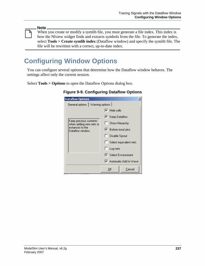
Tracing Signals with the Dataflow WindowConfiguring Window Options
ModelSim User’s Manual, v6.2g 237February 2007
NoteWhen you create or modify a symlib file, you must generate a file index. This index ishow the Nlview widget finds and extracts symbols from the file. To generate the index,select Tools > Create symlib index (Dataflow window) and specify the symlib file. Thefile will be rewritten with a correct, up-to-date index.
Configuring Window OptionsYou can configure several options that determine how the Dataflow window behaves. Thesettings affect only the current session.
Select Tools > Options to open the Dataflow Options dialog box.
Figure 9-9. Configuring Dataflow Options

ModelSim User’s Manual, v6.2g238
Tracing Signals with the Dataflow WindowConfiguring Window Options
February 2007
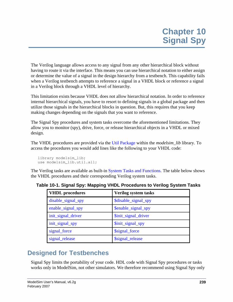
ModelSim User’s Manual, v6.2g 239February 2007
Chapter 10Signal Spy
The Verilog language allows access to any signal from any other hierarchical block withouthaving to route it via the interface. This means you can use hierarchical notation to either assignor determine the value of a signal in the design hierarchy from a testbench. This capability failswhen a Verilog testbench attempts to reference a signal in a VHDL block or reference a signalin a Verilog block through a VHDL level of hierarchy.
This limitation exists because VHDL does not allow hierarchical notation. In order to referenceinternal hierarchical signals, you have to resort to defining signals in a global package and thenutilize those signals in the hierarchical blocks in question. But, this requires that you keepmaking changes depending on the signals that you want to reference.
The Signal Spy procedures and system tasks overcome the aforementioned limitations. Theyallow you to monitor (spy), drive, force, or release hierarchical objects in a VHDL or mixeddesign.
The VHDL procedures are provided via the Util Package within the modelsim_lib library. Toaccess the procedures you would add lines like the following to your VHDL code:
library modelsim_lib;use modelsim_lib.util.all;
The Verilog tasks are available as built-in System Tasks and Functions. The table below showsthe VHDL procedures and their corresponding Verilog system tasks.
Designed for TestbenchesSignal Spy limits the portability of your code. HDL code with Signal Spy procedures or tasksworks only in ModelSim, not other simulators. We therefore recommend using Signal Spy only
Table 10-1. Signal Spy: Mapping VHDL Procedures to Verilog System Tasks
VHDL procedures Verilog system tasks
disable_signal_spy $disable_signal_spy
enable_signal_spy $enable_signal_spy
init_signal_driver $init_signal_driver
init_signal_spy $init_signal_spy
signal_force $signal_force
signal_release $signal_release

ModelSim User’s Manual, v6.2g240
Signal Spy
February 2007
in testbenches, where portability is less of a concern, and the need for such a tool is moreapplicable.
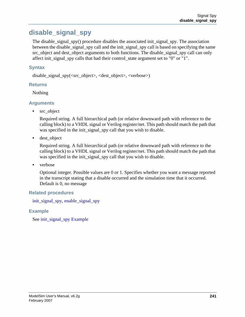
Signal Spydisable_signal_spy
ModelSim User’s Manual, v6.2g 241February 2007
disable_signal_spyThe disable_signal_spy() procedure disables the associated init_signal_spy. The associationbetween the disable_signal_spy call and the init_signal_spy call is based on specifying the samesrc_object and dest_object arguments to both functions. The disable_signal_spy call can onlyaffect init_signal_spy calls that had their control_state argument set to "0" or "1".
Syntax
disable_signal_spy(<src_object>, <dest_object>, <verbose>)
Returns
Nothing
Arguments
• src_object
Required string. A full hierarchical path (or relative downward path with reference to thecalling block) to a VHDL signal or Verilog register/net. This path should match the path thatwas specified in the init_signal_spy call that you wish to disable.
• dest_object
Required string. A full hierarchical path (or relative downward path with reference to thecalling block) to a VHDL signal or Verilog register/net. This path should match the path thatwas specified in the init_signal_spy call that you wish to disable.
• verbose
Optional integer. Possible values are 0 or 1. Specifies whether you want a message reportedin the transcript stating that a disable occurred and the simulation time that it occurred.Default is 0, no message
Related procedures
init_signal_spy, enable_signal_spy
Example
See init_signal_spy Example
ModelSim User’s Manual, v6.2g242
Signal Spyenable_signal_spy
February 2007
enable_signal_spyThe enable_signal_spy() procedure enables the associated init_signal_spy. The associationbetween the enable_signal_spy call and the init_signal_spy call is based on specifying the samesrc_object and dest_object arguments to both functions. The enable_signal_spy call can onlyaffect init_signal_spy calls that had their control_state argument set to "0" or "1".
Syntax
enable_signal_spy(<src_object>, <dest_object>, <verbose>)
Returns
Nothing
Arguments
• src_object
Required string. A full hierarchical path (or relative downward path with reference to thecalling block) to a VHDL signal or Verilog register/net. This path should match the path thatwas specified in the init_signal_spy call that you wish to enable.
• dest_object
Required string. A full hierarchical path (or relative downward path with reference to thecalling block) to a VHDL signal or Verilog register/net. This path should match the path thatwas specified in the init_signal_spy call that you wish to enable.
• verbose
Optional integer. Possible values are 0 or 1. Specifies whether you want a message reportedin the transcript stating that an enable occurred and the simulation time that it occurred.Default is 0, no message
Related procedures
init_signal_spy, disable_signal_spy
Example
See init_signal_spy Example
Signal Spyinit_signal_driver
ModelSim User’s Manual, v6.2g 243February 2007
init_signal_driverThe init_signal_driver() procedure drives the value of a VHDL signal or Verilog net (called thesrc_object) onto an existing VHDL signal or Verilog net (called the dest_object). This allowsyou to drive signals or nets at any level of the design hierarchy from within a VHDLarchitecture (e.g., a testbench).
The init_signal_driver procedure drives the value onto the destination signal just as if thesignals were directly connected in the HDL code. Any existing or subsequent drive or force ofthe destination signal, by some other means, will be considered with the init_signal_drivervalue in the resolution of the signal.
Call only once
The init_signal_driver procedure creates a persistent relationship between the source anddestination signals. Hence, you need to call init_signal_driver only once for a particular pair ofsignals. Once init_signal_driver is called, any change on the source signal will be driven on thedestination signal until the end of the simulation.
Thus, we recommend that you place all init_signal_driver calls in a VHDL process. You need tocode the VHDL process correctly so that it is executed only once. The VHDL process shouldnot be sensitive to any signals and should contain only init_signal_driver calls and a simple waitstatement. The process will execute once and then wait forever. See the example below.
Syntax
init_signal_driver(<src_object>, <dest_object>, <delay>, <delay_type>, <verbose>)
Returns
Nothing
Arguments
• src_object
Required string. A full hierarchical path (or relative downward path with reference to thecalling block) to a VHDL signal or Verilog net. Use the path separator to which yoursimulation is set (i.e., "/" or "."). A full hierarchical path must begin with a "/" or ".". Thepath must be contained within double quotes.
• dest_object
Required string. A full hierarchical path (or relative downward path with reference to thecalling block) to an existing VHDL signal or Verilog net. Use the path separator to whichyour simulation is set (i.e., "/" or "."). A full hierarchical path must begin with a "/" or ".".The path must be contained within double quotes.
• delay
Optional time value. Specifies a delay relative to the time at which the src_object changes.The delay can be an inertial or transport delay. If no delay is specified, then a delay of zerois assumed.
ModelSim User’s Manual, v6.2g244
Signal Spyinit_signal_driver
February 2007
• delay_type
Optional del_mode. Specifies the type of delay that will be applied. The value must beeither mti_inertial or mti_transport. The default is mti_inertial.
• verbose
Optional integer. Possible values are 0 or 1. Specifies whether you want a message reportedin the Transcript stating that the src_object is driving the dest_object. Default is 0, nomessage.
Related procedures
init_signal_spy, signal_force, signal_release
Limitations
• When driving a Verilog net, the only delay_type allowed is inertial. If you set the delaytype to mti_transport, the setting will be ignored and the delay type will be mti_inertial.
• Any delays that are set to a value less than the simulator resolution will be rounded tothe nearest resolution unit; no special warning will be issued.
init_signal_driver Example
This example creates a local clock (clk0) and connects it to two clocks within the designhierarchy. The .../blk1/clk will match local clk0 and a message will be displayed. The openentries allow the default delay and delay_type while setting the verbose parameter to a 1. The.../blk2/clk will match the local clk0 but be delayed by 100 ps.
library IEEE, modelsim_lib;use IEEE.std_logic_1164.all;use modelsim_lib.util.all;
entity testbench isend;
architecture only of testbench issignal clk0 : std_logic;
begingen_clk0 : processbeginclk0 <= '1' after 0 ps, '0' after 20 ps;wait for 40 ps;
end process gen_clk0;
drive_sig_process : processbegininit_signal_driver("clk0", "/testbench/uut/blk1/clk", open, open, 1);init_signal_driver("clk0", "/testbench/uut/blk2/clk", 100 ps,
mti_transport);wait;
end process drive_sig_process;...
end;
Signal Spyinit_signal_spy
ModelSim User’s Manual, v6.2g 245February 2007
init_signal_spyThe init_signal_spy() procedure mirrors the value of a VHDL signal or Verilog register/net(called the src_object) onto an existing VHDL signal or Verilog register (called thedest_object). This allows you to reference signals, registers, or nets at any level of hierarchyfrom within a VHDL architecture (e.g., a testbench).
The init_signal_spy procedure only sets the value onto the destination signal and does not driveor force the value. Any existing or subsequent drive or force of the destination signal, by someother means, will override the value that was set by init_signal_spy.
Call only once
The init_signal_spy procedure creates a persistent relationship between the source anddestination signals. Hence, you need to call init_signal_spy once for a particular pair of signals.Once init_signal_spy is called, any change on the source signal will mirror on the destinationsignal until the end of the simulation unless the control_state is set.
The control_state determines whether the mirroring of values can be enabled/disabled and whatthe initial state is. Subsequent control of whether the mirroring of values is enabled/disabled ishandled by the enable_signal_spy and disable_signal_spy calls.
We recommend that you place all init_signal_spy calls in a VHDL process. You need to codethe VHDL process correctly so that it is executed only once. The VHDL process should not besensitive to any signals and should contain only init_signal_spy calls and a simple waitstatement. The process will execute once and then wait forever, which is the desired behavior.See the example below.
Syntax
init_signal_spy(<src_object>, <dest_object>, <verbose>, <control_state>)
Returns
Nothing
Arguments
• src_object
Required string. A full hierarchical path (or relative downward path with reference to thecalling block) to a VHDL signal or Verilog register/net. Use the path separator to whichyour simulation is set (i.e., "/" or "."). A full hierarchical path must begin with a "/" or ".".The path must be contained within double quotes.
• dest_object
Required string. A full hierarchical path (or relative downward path with reference to thecalling block) to an existing VHDL signal or Verilog register. Use the path separator towhich your simulation is set (i.e., "/" or "."). A full hierarchical path must begin with a "/" or".". The path must be contained within double quotes.
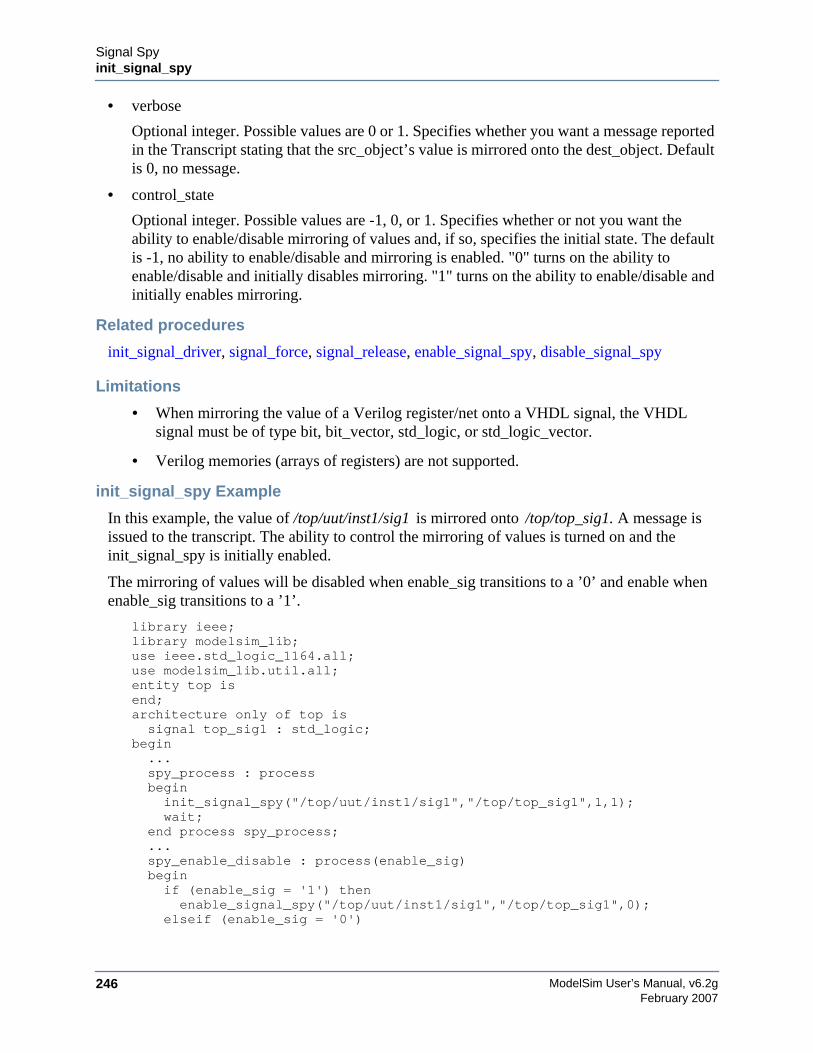
ModelSim User’s Manual, v6.2g246
Signal Spyinit_signal_spy
February 2007
• verbose
Optional integer. Possible values are 0 or 1. Specifies whether you want a message reportedin the Transcript stating that the src_object’s value is mirrored onto the dest_object. Defaultis 0, no message.
• control_state
Optional integer. Possible values are -1, 0, or 1. Specifies whether or not you want theability to enable/disable mirroring of values and, if so, specifies the initial state. The defaultis -1, no ability to enable/disable and mirroring is enabled. "0" turns on the ability toenable/disable and initially disables mirroring. "1" turns on the ability to enable/disable andinitially enables mirroring.
Related procedures
init_signal_driver, signal_force, signal_release, enable_signal_spy, disable_signal_spy
Limitations
• When mirroring the value of a Verilog register/net onto a VHDL signal, the VHDLsignal must be of type bit, bit_vector, std_logic, or std_logic_vector.
• Verilog memories (arrays of registers) are not supported.
init_signal_spy Example
In this example, the value of /top/uut/inst1/sig1 is mirrored onto /top/top_sig1. A message isissued to the transcript. The ability to control the mirroring of values is turned on and theinit_signal_spy is initially enabled.
The mirroring of values will be disabled when enable_sig transitions to a ’0’ and enable whenenable_sig transitions to a ’1’.
library ieee;library modelsim_lib;use ieee.std_logic_1164.all;use modelsim_lib.util.all;entity top isend;architecture only of top issignal top_sig1 : std_logic;
begin...spy_process : processbegininit_signal_spy("/top/uut/inst1/sig1","/top/top_sig1",1,1);wait;
end process spy_process;...spy_enable_disable : process(enable_sig)beginif (enable_sig = '1') thenenable_signal_spy("/top/uut/inst1/sig1","/top/top_sig1",0);
elseif (enable_sig = '0')

Signal Spyinit_signal_spy
ModelSim User’s Manual, v6.2g 247February 2007
disable_signal_spy("/top/uut/inst1/sig1","/top/top_sig1",0);end if;
end process spy_enable_disable;...
end;
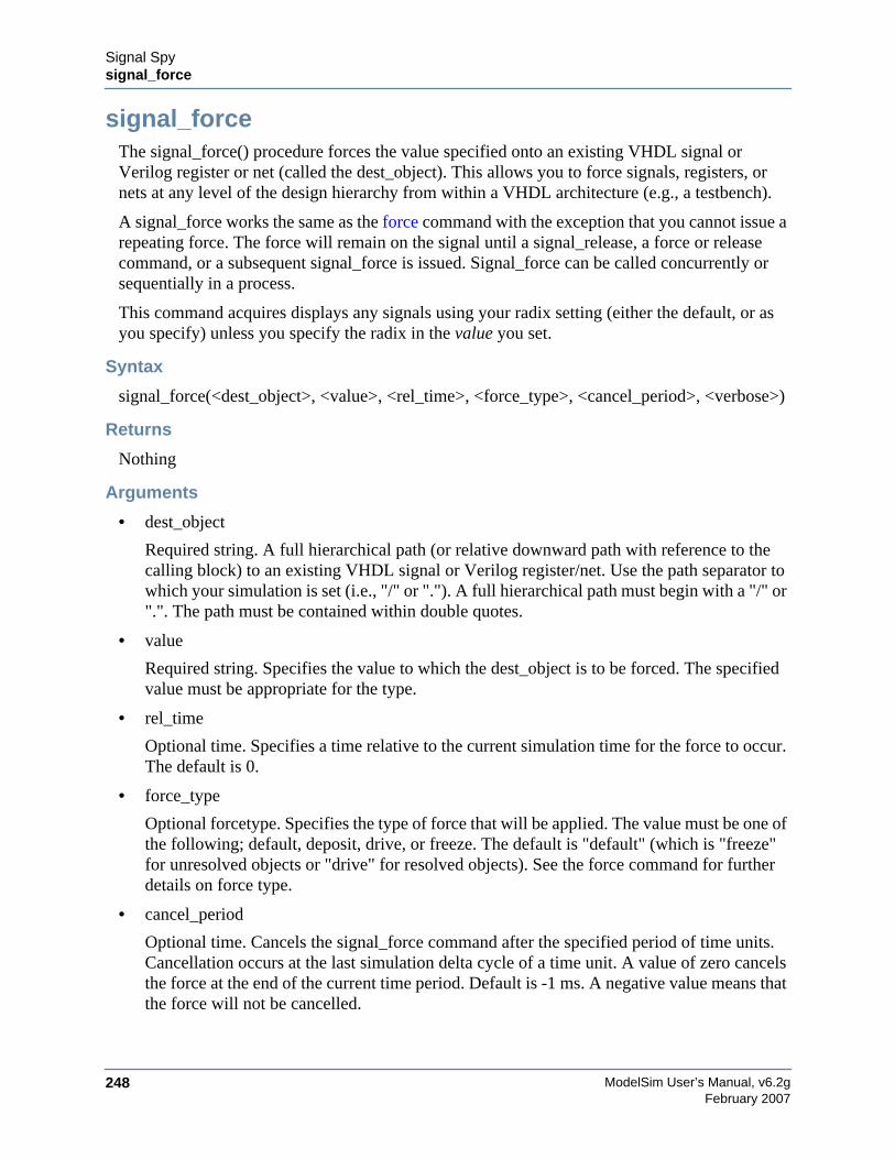
ModelSim User’s Manual, v6.2g248
Signal Spysignal_force
February 2007
signal_forceThe signal_force() procedure forces the value specified onto an existing VHDL signal orVerilog register or net (called the dest_object). This allows you to force signals, registers, ornets at any level of the design hierarchy from within a VHDL architecture (e.g., a testbench).
A signal_force works the same as the force command with the exception that you cannot issue arepeating force. The force will remain on the signal until a signal_release, a force or releasecommand, or a subsequent signal_force is issued. Signal_force can be called concurrently orsequentially in a process.
This command acquires displays any signals using your radix setting (either the default, or asyou specify) unless you specify the radix in the value you set.
Syntax
signal_force(<dest_object>, <value>, <rel_time>, <force_type>, <cancel_period>, <verbose>)
Returns
Nothing
Arguments
• dest_object
Required string. A full hierarchical path (or relative downward path with reference to thecalling block) to an existing VHDL signal or Verilog register/net. Use the path separator towhich your simulation is set (i.e., "/" or "."). A full hierarchical path must begin with a "/" or".". The path must be contained within double quotes.
• value
Required string. Specifies the value to which the dest_object is to be forced. The specifiedvalue must be appropriate for the type.
• rel_time
Optional time. Specifies a time relative to the current simulation time for the force to occur.The default is 0.
• force_type
Optional forcetype. Specifies the type of force that will be applied. The value must be one ofthe following; default, deposit, drive, or freeze. The default is "default" (which is "freeze"for unresolved objects or "drive" for resolved objects). See the force command for furtherdetails on force type.
• cancel_period
Optional time. Cancels the signal_force command after the specified period of time units.Cancellation occurs at the last simulation delta cycle of a time unit. A value of zero cancelsthe force at the end of the current time period. Default is -1 ms. A negative value means thatthe force will not be cancelled.
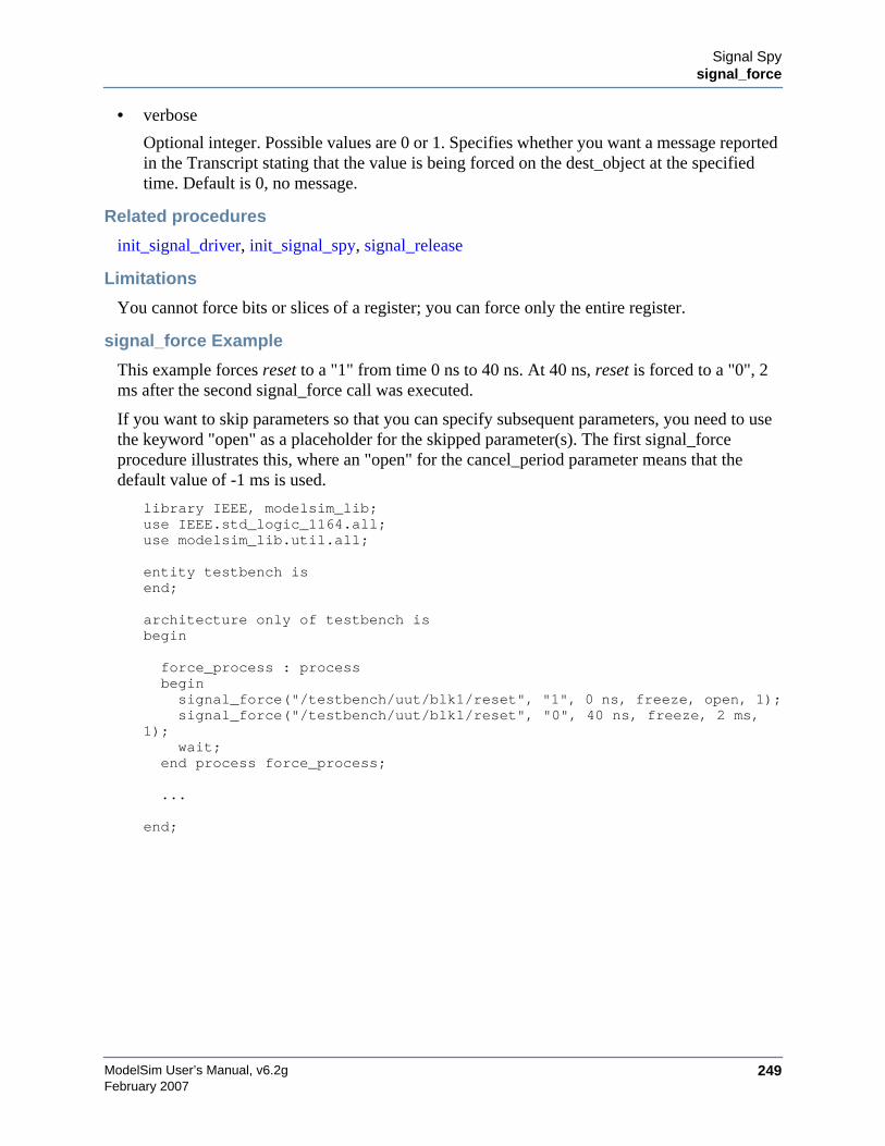
Signal Spysignal_force
ModelSim User’s Manual, v6.2g 249February 2007
• verbose
Optional integer. Possible values are 0 or 1. Specifies whether you want a message reportedin the Transcript stating that the value is being forced on the dest_object at the specifiedtime. Default is 0, no message.
Related procedures
init_signal_driver, init_signal_spy, signal_release
Limitations
You cannot force bits or slices of a register; you can force only the entire register.
signal_force Example
This example forces reset to a "1" from time 0 ns to 40 ns. At 40 ns, reset is forced to a "0", 2ms after the second signal_force call was executed.
If you want to skip parameters so that you can specify subsequent parameters, you need to usethe keyword "open" as a placeholder for the skipped parameter(s). The first signal_forceprocedure illustrates this, where an "open" for the cancel_period parameter means that thedefault value of -1 ms is used.
library IEEE, modelsim_lib;use IEEE.std_logic_1164.all;use modelsim_lib.util.all;
entity testbench isend;
architecture only of testbench isbegin
force_process : processbeginsignal_force("/testbench/uut/blk1/reset", "1", 0 ns, freeze, open, 1);signal_force("/testbench/uut/blk1/reset", "0", 40 ns, freeze, 2 ms,
1);wait;
end process force_process;
...
end;
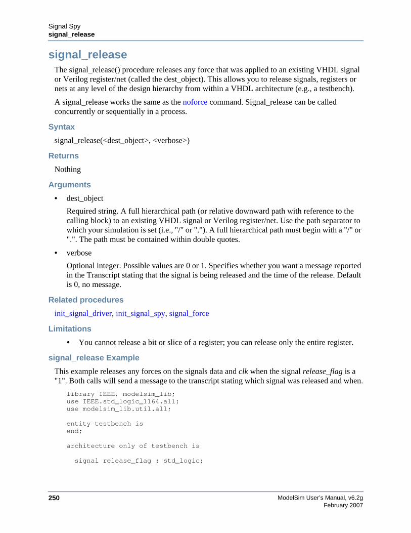
ModelSim User’s Manual, v6.2g250
Signal Spysignal_release
February 2007
signal_releaseThe signal_release() procedure releases any force that was applied to an existing VHDL signalor Verilog register/net (called the dest_object). This allows you to release signals, registers ornets at any level of the design hierarchy from within a VHDL architecture (e.g., a testbench).
A signal_release works the same as the noforce command. Signal_release can be calledconcurrently or sequentially in a process.
Syntax
signal_release(<dest_object>, <verbose>)
Returns
Nothing
Arguments
• dest_object
Required string. A full hierarchical path (or relative downward path with reference to thecalling block) to an existing VHDL signal or Verilog register/net. Use the path separator towhich your simulation is set (i.e., "/" or "."). A full hierarchical path must begin with a "/" or".". The path must be contained within double quotes.
• verbose
Optional integer. Possible values are 0 or 1. Specifies whether you want a message reportedin the Transcript stating that the signal is being released and the time of the release. Defaultis 0, no message.
Related procedures
init_signal_driver, init_signal_spy, signal_force
Limitations
• You cannot release a bit or slice of a register; you can release only the entire register.
signal_release Example
This example releases any forces on the signals data and clk when the signal release_flag is a"1". Both calls will send a message to the transcript stating which signal was released and when.
library IEEE, modelsim_lib;use IEEE.std_logic_1164.all;use modelsim_lib.util.all;
entity testbench isend;
architecture only of testbench is
signal release_flag : std_logic;
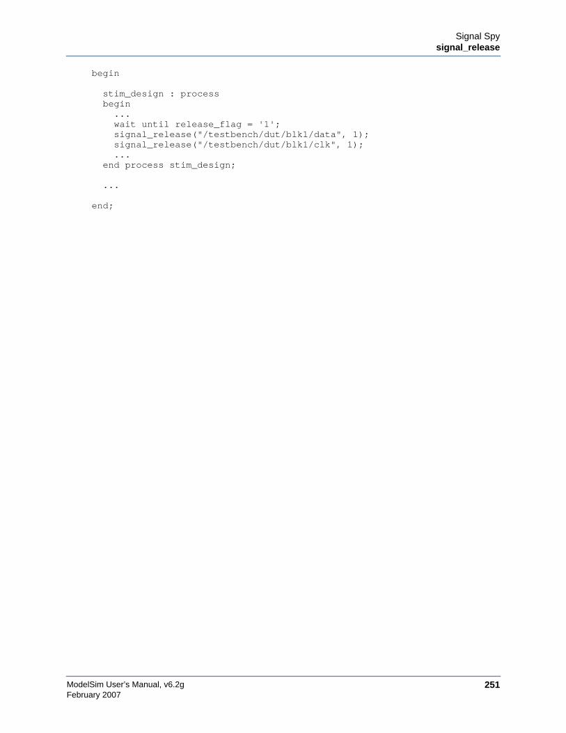
Signal Spysignal_release
ModelSim User’s Manual, v6.2g 251February 2007
begin
stim_design : processbegin...wait until release_flag = '1';signal_release("/testbench/dut/blk1/data", 1);signal_release("/testbench/dut/blk1/clk", 1);...
end process stim_design;
...
end;
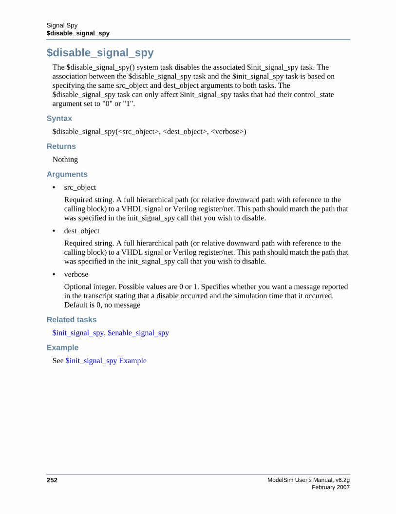
ModelSim User’s Manual, v6.2g252
Signal Spy$disable_signal_spy
February 2007
$disable_signal_spyThe $disable_signal_spy() system task disables the associated $init_signal_spy task. Theassociation between the $disable_signal_spy task and the $init_signal_spy task is based onspecifying the same src_object and dest_object arguments to both tasks. The$disable_signal_spy task can only affect $init_signal_spy tasks that had their control_stateargument set to "0" or "1".
Syntax
$disable_signal_spy(<src_object>, <dest_object>, <verbose>)
Returns
Nothing
Arguments
• src_object
Required string. A full hierarchical path (or relative downward path with reference to thecalling block) to a VHDL signal or Verilog register/net. This path should match the path thatwas specified in the init_signal_spy call that you wish to disable.
• dest_object
Required string. A full hierarchical path (or relative downward path with reference to thecalling block) to a VHDL signal or Verilog register/net. This path should match the path thatwas specified in the init_signal_spy call that you wish to disable.
• verbose
Optional integer. Possible values are 0 or 1. Specifies whether you want a message reportedin the transcript stating that a disable occurred and the simulation time that it occurred.Default is 0, no message
Related tasks
$init_signal_spy, $enable_signal_spy
Example
See $init_signal_spy Example
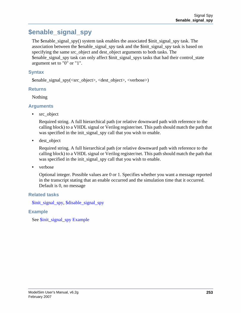
Signal Spy$enable_signal_spy
ModelSim User’s Manual, v6.2g 253February 2007
$enable_signal_spyThe $enable_signal_spy() system task enables the associated $init_signal_spy task. Theassociation between the $enable_signal_spy task and the $init_signal_spy task is based onspecifying the same src_object and dest_object arguments to both tasks. The$enable_signal_spy task can only affect $init_signal_spys tasks that had their control_stateargument set to "0" or "1".
Syntax
$enable_signal_spy(<src_object>, <dest_object>, <verbose>)
Returns
Nothing
Arguments
• src_object
Required string. A full hierarchical path (or relative downward path with reference to thecalling block) to a VHDL signal or Verilog register/net. This path should match the path thatwas specified in the init_signal_spy call that you wish to enable.
• dest_object
Required string. A full hierarchical path (or relative downward path with reference to thecalling block) to a VHDL signal or Verilog register/net. This path should match the path thatwas specified in the init_signal_spy call that you wish to enable.
• verbose
Optional integer. Possible values are 0 or 1. Specifies whether you want a message reportedin the transcript stating that an enable occurred and the simulation time that it occurred.Default is 0, no message
Related tasks
$init_signal_spy, $disable_signal_spy
Example
See $init_signal_spy Example
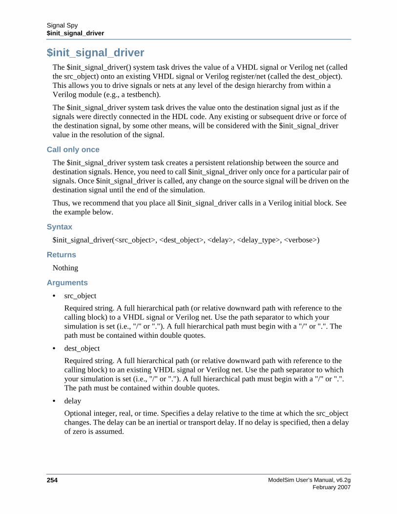
ModelSim User’s Manual, v6.2g254
Signal Spy$init_signal_driver
February 2007
$init_signal_driverThe $init_signal_driver() system task drives the value of a VHDL signal or Verilog net (calledthe src_object) onto an existing VHDL signal or Verilog register/net (called the dest_object).This allows you to drive signals or nets at any level of the design hierarchy from within aVerilog module (e.g., a testbench).
The $init_signal_driver system task drives the value onto the destination signal just as if thesignals were directly connected in the HDL code. Any existing or subsequent drive or force ofthe destination signal, by some other means, will be considered with the $init_signal_drivervalue in the resolution of the signal.
Call only once
The $init_signal_driver system task creates a persistent relationship between the source anddestination signals. Hence, you need to call $init_signal_driver only once for a particular pair ofsignals. Once $init_signal_driver is called, any change on the source signal will be driven on thedestination signal until the end of the simulation.
Thus, we recommend that you place all $init_signal_driver calls in a Verilog initial block. Seethe example below.
Syntax
$init_signal_driver(<src_object>, <dest_object>, <delay>, <delay_type>, <verbose>)
Returns
Nothing
Arguments
• src_object
Required string. A full hierarchical path (or relative downward path with reference to thecalling block) to a VHDL signal or Verilog net. Use the path separator to which yoursimulation is set (i.e., "/" or "."). A full hierarchical path must begin with a "/" or ".". Thepath must be contained within double quotes.
• dest_object
Required string. A full hierarchical path (or relative downward path with reference to thecalling block) to an existing VHDL signal or Verilog net. Use the path separator to whichyour simulation is set (i.e., "/" or "."). A full hierarchical path must begin with a "/" or ".".The path must be contained within double quotes.
• delay
Optional integer, real, or time. Specifies a delay relative to the time at which the src_objectchanges. The delay can be an inertial or transport delay. If no delay is specified, then a delayof zero is assumed.
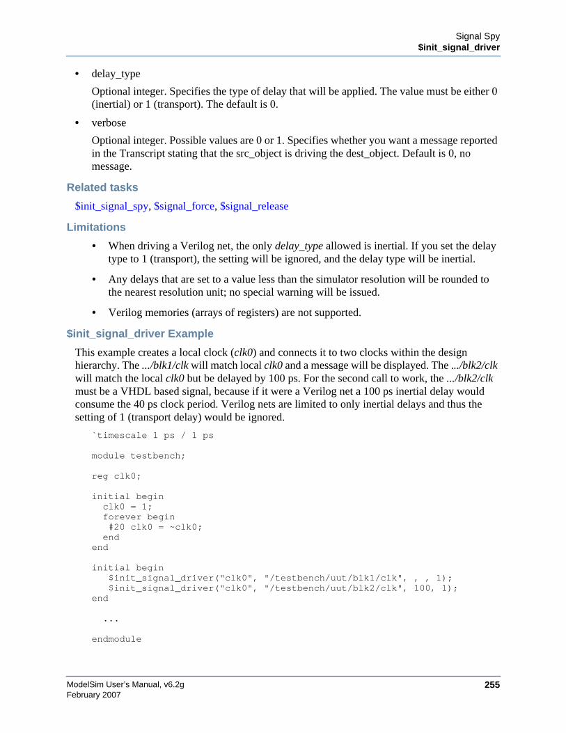
Signal Spy$init_signal_driver
ModelSim User’s Manual, v6.2g 255February 2007
• delay_type
Optional integer. Specifies the type of delay that will be applied. The value must be either 0(inertial) or 1 (transport). The default is 0.
• verbose
Optional integer. Possible values are 0 or 1. Specifies whether you want a message reportedin the Transcript stating that the src_object is driving the dest_object. Default is 0, nomessage.
Related tasks
$init_signal_spy, $signal_force, $signal_release
Limitations
• When driving a Verilog net, the only delay_type allowed is inertial. If you set the delaytype to 1 (transport), the setting will be ignored, and the delay type will be inertial.
• Any delays that are set to a value less than the simulator resolution will be rounded tothe nearest resolution unit; no special warning will be issued.
• Verilog memories (arrays of registers) are not supported.
$init_signal_driver Example
This example creates a local clock (clk0) and connects it to two clocks within the designhierarchy. The .../blk1/clk will match local clk0 and a message will be displayed. The .../blk2/clkwill match the local clk0 but be delayed by 100 ps. For the second call to work, the .../blk2/clkmust be a VHDL based signal, because if it were a Verilog net a 100 ps inertial delay wouldconsume the 40 ps clock period. Verilog nets are limited to only inertial delays and thus thesetting of 1 (transport delay) would be ignored.
`timescale 1 ps / 1 ps
module testbench;
reg clk0;
initial beginclk0 = 1;forever begin#20 clk0 = ~clk0;end
end
initial begin$init_signal_driver("clk0", "/testbench/uut/blk1/clk", , , 1);$init_signal_driver("clk0", "/testbench/uut/blk2/clk", 100, 1);
end
...
endmodule

ModelSim User’s Manual, v6.2g256
Signal Spy$init_signal_spy
February 2007
$init_signal_spyThe $init_signal_spy() system task mirrors the value of a VHDL signal or Verilog register/net(called the src_object) onto an existing VHDL signal or Verilog register (called thedest_object). This allows you to reference signals, registers, or nets at any level of hierarchyfrom within a Verilog module (e.g., a testbench).
The $init_signal_spy system task only sets the value onto the destination signal and does notdrive or force the value. Any existing or subsequent drive or force of the destination signal, bysome other means, will override the value set by $init_signal_spy.
Call only once
The $init_signal_spy system task creates a persistent relationship between the source and thedestination signal. Hence, you need to call $init_signal_spy only once for a particular pair ofsignals. Once $init_signal_spy is called, any change on the source signal will mirror on thedestination signal until the end of the simulation unless the control_state is set.
The control_state determines whether the mirroring of values can be enabled/disabled and whatthe initial state is. Subsequent control of whether the mirroring of values is enabled/disabled ishandled by the $enable_signal_spy and $disable_signal_spy tasks.
We recommend that you place all $init_signal_spy tasks in a Verilog initial block. See theexample below.
Syntax
$init_signal_spy(<src_object>, <dest_object>, <verbose>, <control_state>)
Returns
Nothing
Arguments
• src_object
Required string. A full hierarchical path (or relative downward path with reference to thecalling block) to a VHDL signal or Verilog register/net. Use the path separator to whichyour simulation is set (i.e., "/" or "."). A full hierarchical path must begin with a "/" or ".".The path must be contained within double quotes.
• dest_object
Required string. A full hierarchical path (or relative downward path with reference to thecalling block) to a Verilog register or VHDL signal. Use the path separator to which yoursimulation is set (i.e., "/" or "."). A full hierarchical path must begin with a "/" or ".". Thepath must be contained within double quotes.
• verbose
Optional integer. Possible values are 0 or 1. Specifies whether you want a message reportedin the Transcript stating that the src_object’s value is mirrored onto the dest_object. Defaultis 0, no message.

Signal Spy$init_signal_spy
ModelSim User’s Manual, v6.2g 257February 2007
• control_state
Optional integer. Possible values are -1, 0, or 1. Specifies whether or not you want theability to enable/disable mirroring of values and, if so, specifies the initial state. The defaultis -1, no ability to enable/disable and mirroring is enabled. "0" turns on the ability toenable/disable and initially disables mirroring. "1" turns on the ability to enable/disable andinitially enables mirroring.
Related tasks
$init_signal_driver, $signal_force, $signal_release, $disable_signal_spy
Limitations
• When mirroring the value of a VHDL signal onto a Verilog register, the VHDL signalmust be of type bit, bit_vector, std_logic, or std_logic_vector.
• Verilog memories (arrays of registers) are not supported.
$init_signal_spy Example
In this example, the value of .top.uut.inst1.sig1 is mirrored onto .top.top_sig1. A message isissued to the transcript. The ability to control the mirroring of values is turned on and theinit_signal_spy is initially enabled.
The mirroring of values will be disabled when enable_reg transitions to a ’0’ and enabled whenenable_reg transitions to a ’1’.
module top;...reg top_sig1;reg enable_reg;...initialbegin$init_signal_spy(".top.uut.inst1.sig1",".top.top_sig1",1,1);endalways @ (posedge enable_reg)begin$enable_signal_spy(".top.uut.inst1.sig1",".top.top_sig1",0);endalways @ (negedge enable_reg)begin$disable_signal_spy(".top.uut.inst1.sig1",".top.top_sig1",0);end
...endmodule

ModelSim User’s Manual, v6.2g258
Signal Spy$signal_force
February 2007
$signal_forceThe $signal_force() system task forces the value specified onto an existing VHDL signal orVerilog register/net (called the dest_object). This allows you to force signals, registers, or netsat any level of the design hierarchy from within a Verilog module (e.g., a testbench).
A $signal_force works the same as the force command with the exception that you cannot issuea repeating force. The force will remain on the signal until a $signal_release, a force or releasecommand, or a subsequent $signal_force is issued. $signal_force can be called concurrently orsequentially in a process.
Syntax
$signal_force(<dest_object>, <value>, <rel_time>, <force_type>, <cancel_period>,<verbose>)
Returns
Nothing
Arguments
• dest_object
Required string. A full hierarchical path (or relative downward path with reference to thecalling block) to an existing VHDL signal or Verilog register/net. Use the path separator towhich your simulation is set (i.e., "/" or "."). A full hierarchical path must begin with a "/" or".". The path must be contained within double quotes.
• value
Required string. Specifies the value to which the dest_object is to be forced. The specifiedvalue must be appropriate for the type.
• rel_time
Optional integer, real, or time. Specifies a time relative to the current simulation time for theforce to occur. The default is 0.
• force_type
Optional integer. Specifies the type of force that will be applied. The value must be one ofthe following; 0 (default), 1 (deposit), 2 (drive), or 3 (freeze). The default is "default"(which is "freeze" for unresolved objects or "drive" for resolved objects). See the forcecommand for further details on force type.
• cancel_period
Optional integer, real, time. Cancels the $signal_force command after the specified periodof time units. Cancellation occurs at the last simulation delta cycle of a time unit. A value ofzero cancels the force at the end of the current time period. Default is -1. A negative valuemeans that the force will not be cancelled.
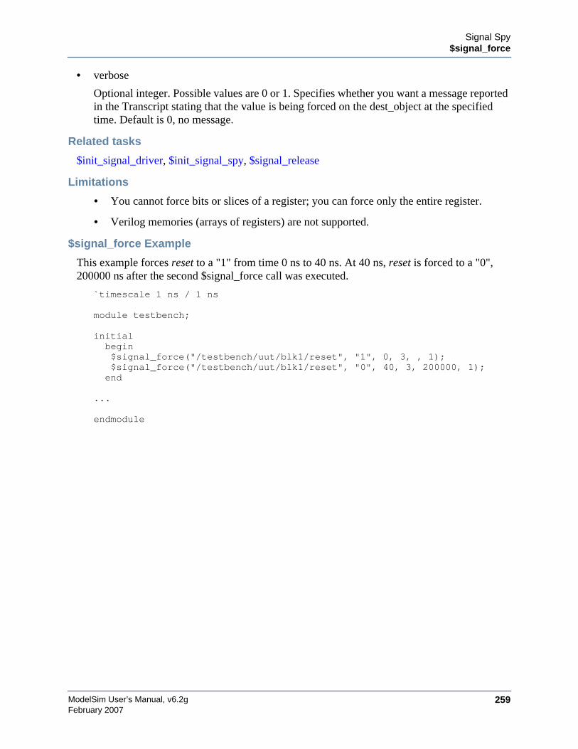
Signal Spy$signal_force
ModelSim User’s Manual, v6.2g 259February 2007
• verbose
Optional integer. Possible values are 0 or 1. Specifies whether you want a message reportedin the Transcript stating that the value is being forced on the dest_object at the specifiedtime. Default is 0, no message.
Related tasks
$init_signal_driver, $init_signal_spy, $signal_release
Limitations
• You cannot force bits or slices of a register; you can force only the entire register.
• Verilog memories (arrays of registers) are not supported.
$signal_force Example
This example forces reset to a "1" from time 0 ns to 40 ns. At 40 ns, reset is forced to a "0",200000 ns after the second $signal_force call was executed.
`timescale 1 ns / 1 ns
module testbench;
initialbegin$signal_force("/testbench/uut/blk1/reset", "1", 0, 3, , 1);$signal_force("/testbench/uut/blk1/reset", "0", 40, 3, 200000, 1);end
...
endmodule
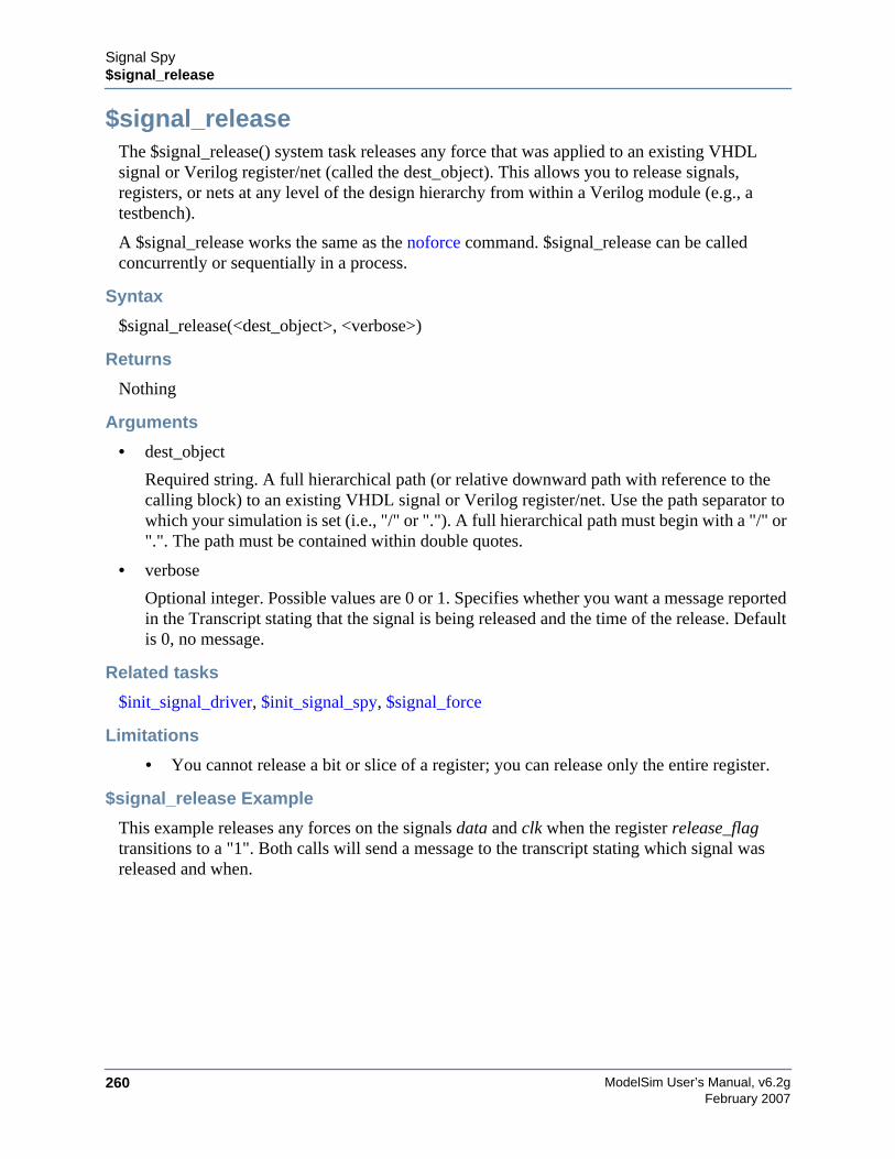
ModelSim User’s Manual, v6.2g260
Signal Spy$signal_release
February 2007
$signal_releaseThe $signal_release() system task releases any force that was applied to an existing VHDLsignal or Verilog register/net (called the dest_object). This allows you to release signals,registers, or nets at any level of the design hierarchy from within a Verilog module (e.g., atestbench).
A $signal_release works the same as the noforce command. $signal_release can be calledconcurrently or sequentially in a process.
Syntax
$signal_release(<dest_object>, <verbose>)
Returns
Nothing
Arguments
• dest_object
Required string. A full hierarchical path (or relative downward path with reference to thecalling block) to an existing VHDL signal or Verilog register/net. Use the path separator towhich your simulation is set (i.e., "/" or "."). A full hierarchical path must begin with a "/" or".". The path must be contained within double quotes.
• verbose
Optional integer. Possible values are 0 or 1. Specifies whether you want a message reportedin the Transcript stating that the signal is being released and the time of the release. Defaultis 0, no message.
Related tasks
$init_signal_driver, $init_signal_spy, $signal_force
Limitations
• You cannot release a bit or slice of a register; you can release only the entire register.
$signal_release Example
This example releases any forces on the signals data and clk when the register release_flagtransitions to a "1". Both calls will send a message to the transcript stating which signal wasreleased and when.
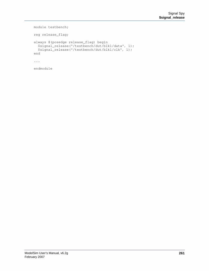
Signal Spy$signal_release
ModelSim User’s Manual, v6.2g 261February 2007
module testbench;
reg release_flag;
always @(posedge release_flag) begin$signal_release("/testbench/dut/blk1/data", 1);$signal_release("/testbench/dut/blk1/clk", 1);
end
...
endmodule

ModelSim User’s Manual, v6.2g262
Signal Spy$signal_release
February 2007
ModelSim User’s Manual, v6.2g 263February 2007
Chapter 11Standard Delay Format (SDF) Timing
Annotation
This chapter discusses ModelSim’s implementation of SDF (Standard Delay Format) timingannotation. Included are sections on VITAL SDF and Verilog SDF, plus troubleshooting.
Verilog and VHDL VITAL timing data can be annotated from SDF files by using thesimulator’s built-in SDF annotator.
NoteSDF timing annotations can be applied only to your FPGA vendor’s libraries; all otherlibraries will simulate without annotation.
Specifying SDF Files for SimulationModelSim supports SDF versions 1.0 through 4.0 (except the NETDELAY statement). Thesimulator’s built-in SDF annotator automatically adjusts to the version of the file. Use thefollowing vsim command-line options to specify the SDF files, the desired timing values, andtheir associated design instances:
-sdfmin [<instance>=]<filename>-sdftyp [<instance>=]<filename>-sdfmax [<instance>=]<filename>
Any number of SDF files can be applied to any instance in the design by specifying one of theabove options for each file. Use -sdfmin to select minimum, -sdftyp to select typical, and-sdfmax to select maximum timing values from the SDF file.
Instance SpecificationThe instance paths in the SDF file are relative to the instance to which the SDF is applied.Usually, this instance is an ASIC or FPGA model instantiated under a testbench. For example,to annotate maximum timing values from the SDF file myasic.sdf to an instance u1 under a top-level named testbench, invoke the simulator as follows:
vsim -sdfmax /testbench/u1=myasic.sdf testbench
If the instance name is omitted then the SDF file is applied to the top-level. This is usuallyincorrect because in most cases the model is instantiated under a testbench or within a largersystem level simulation. In fact, the design can have several models, each having its own SDFfile. In this case, specify an SDF file for each instance. For example,
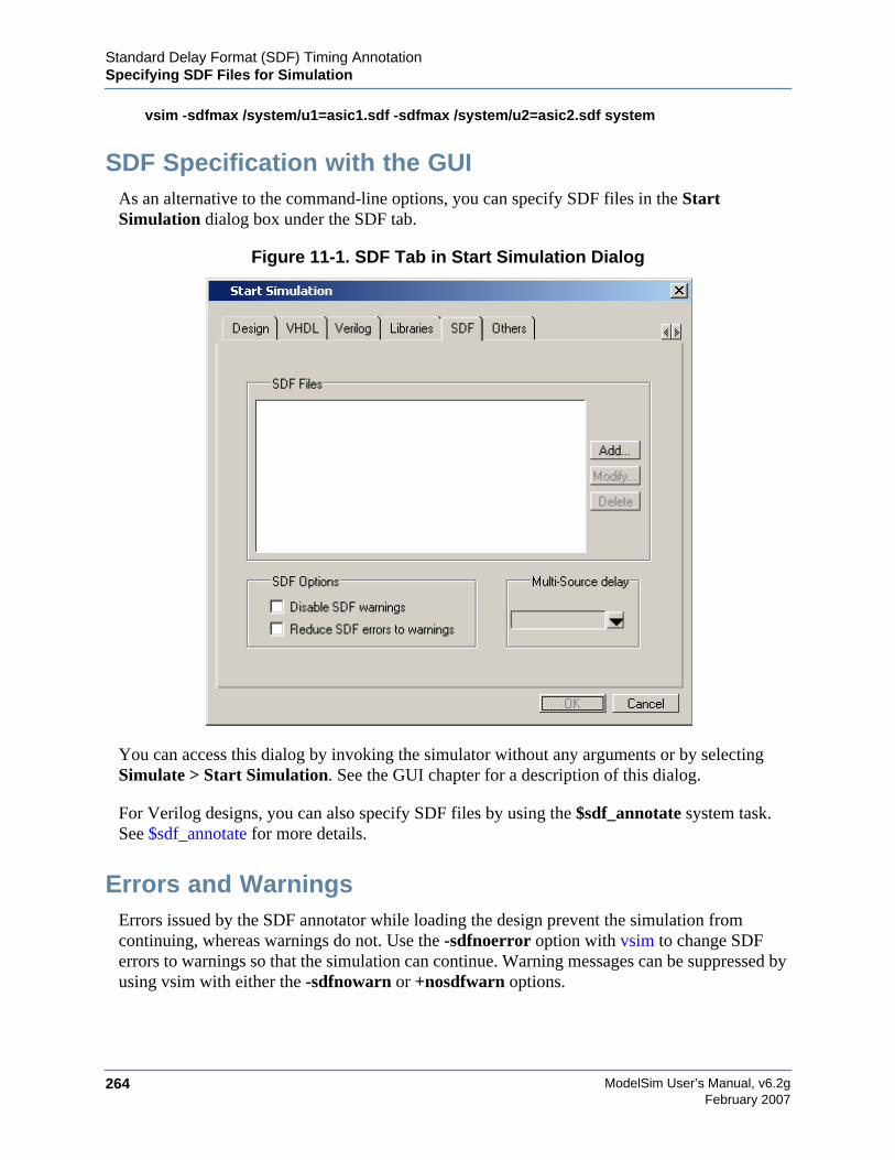
ModelSim User’s Manual, v6.2g264
Standard Delay Format (SDF) Timing AnnotationSpecifying SDF Files for Simulation
February 2007
vsim -sdfmax /system/u1=asic1.sdf -sdfmax /system/u2=asic2.sdf system
SDF Specification with the GUIAs an alternative to the command-line options, you can specify SDF files in the StartSimulation dialog box under the SDF tab.
Figure 11-1. SDF Tab in Start Simulation Dialog
You can access this dialog by invoking the simulator without any arguments or by selectingSimulate > Start Simulation. See the GUI chapter for a description of this dialog.
For Verilog designs, you can also specify SDF files by using the $sdf_annotate system task.See $sdf_annotate for more details.
Errors and WarningsErrors issued by the SDF annotator while loading the design prevent the simulation fromcontinuing, whereas warnings do not. Use the -sdfnoerror option with vsim to change SDFerrors to warnings so that the simulation can continue. Warning messages can be suppressed byusing vsim with either the -sdfnowarn or +nosdfwarn options.
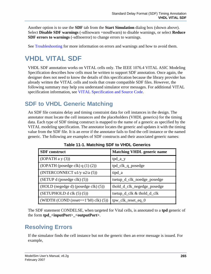
Standard Delay Format (SDF) Timing AnnotationVHDL VITAL SDF
ModelSim User’s Manual, v6.2g 265February 2007
Another option is to use the SDF tab from the Start Simulation dialog box (shown above).Select Disable SDF warnings (-sdfnowarn +nosdfwarn) to disable warnings, or select ReduceSDF errors to warnings (-sdfnoerror) to change errors to warnings.
See Troubleshooting for more information on errors and warnings and how to avoid them.
VHDL VITAL SDFVHDL SDF annotation works on VITAL cells only. The IEEE 1076.4 VITAL ASIC ModelingSpecification describes how cells must be written to support SDF annotation. Once again, thedesigner does not need to know the details of this specification because the library provider hasalready written the VITAL cells and tools that create compatible SDF files. However, thefollowing summary may help you understand simulator error messages. For additional VITALspecification information, see VITAL Specification and Source Code.
SDF to VHDL Generic MatchingAn SDF file contains delay and timing constraint data for cell instances in the design. Theannotator must locate the cell instances and the placeholders (VHDL generics) for the timingdata. Each type of SDF timing construct is mapped to the name of a generic as specified by theVITAL modeling specification. The annotator locates the generic and updates it with the timingvalue from the SDF file. It is an error if the annotator fails to find the cell instance or the namedgeneric. The following are examples of SDF constructs and their associated generic names:
The SDF statement CONDELSE, when targeted for Vital cells, is annotated to a tpd generic ofthe form tpd_<inputPort>_<outputPort>.
Resolving ErrorsIf the simulator finds the cell instance but not the generic then an error message is issued. Forexample,
Table 11-1. Matching SDF to VHDL Generics
SDF construct Matching VHDL generic name
(IOPATH a y (3)) tpd_a_y
(IOPATH (posedge clk) q (1) (2)) tpd_clk_q_posedge
(INTERCONNECT u1/y u2/a (5)) tipd_a
(SETUP d (posedge clk) (5)) tsetup_d_clk_noedge_posedge
(HOLD (negedge d) (posedge clk) (5)) thold_d_clk_negedge_posedge
(SETUPHOLD d clk (5) (5)) tsetup_d_clk & thold_d_clk
(WIDTH (COND (reset==1’b0) clk) (5)) tpw_clk_reset_eq_0
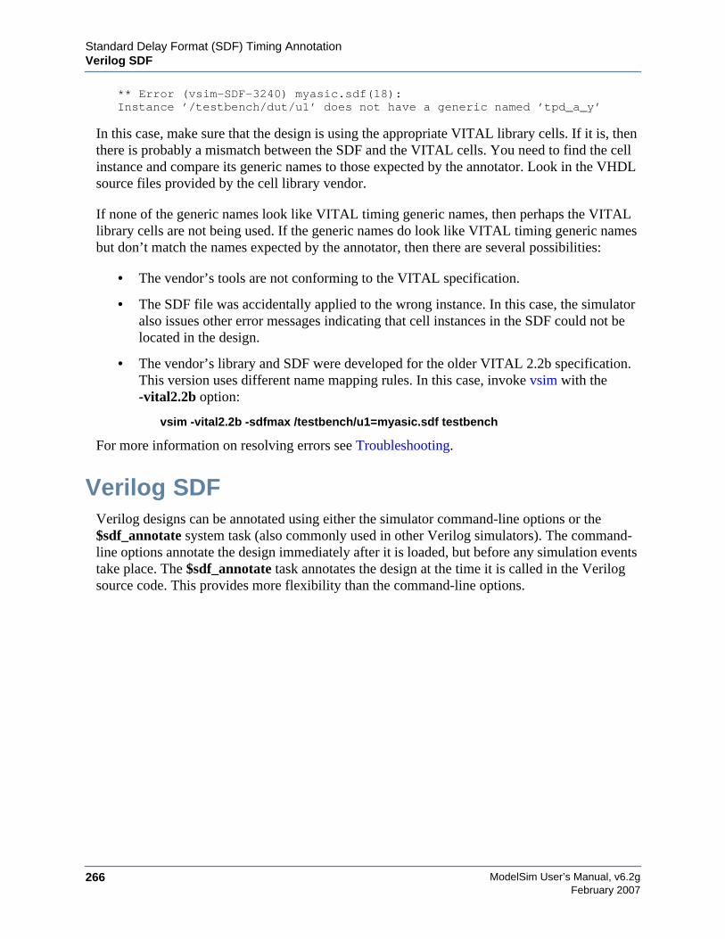
ModelSim User’s Manual, v6.2g266
Standard Delay Format (SDF) Timing AnnotationVerilog SDF
February 2007
** Error (vsim-SDF-3240) myasic.sdf(18):Instance ’/testbench/dut/u1’ does not have a generic named ’tpd_a_y’
In this case, make sure that the design is using the appropriate VITAL library cells. If it is, thenthere is probably a mismatch between the SDF and the VITAL cells. You need to find the cellinstance and compare its generic names to those expected by the annotator. Look in the VHDLsource files provided by the cell library vendor.
If none of the generic names look like VITAL timing generic names, then perhaps the VITALlibrary cells are not being used. If the generic names do look like VITAL timing generic namesbut don’t match the names expected by the annotator, then there are several possibilities:
• The vendor’s tools are not conforming to the VITAL specification.
• The SDF file was accidentally applied to the wrong instance. In this case, the simulatoralso issues other error messages indicating that cell instances in the SDF could not belocated in the design.
• The vendor’s library and SDF were developed for the older VITAL 2.2b specification.This version uses different name mapping rules. In this case, invoke vsim with the-vital2.2b option:
vsim -vital2.2b -sdfmax /testbench/u1=myasic.sdf testbench
For more information on resolving errors see Troubleshooting.
Verilog SDFVerilog designs can be annotated using either the simulator command-line options or the$sdf_annotate system task (also commonly used in other Verilog simulators). The command-line options annotate the design immediately after it is loaded, but before any simulation eventstake place. The $sdf_annotate task annotates the design at the time it is called in the Verilogsource code. This provides more flexibility than the command-line options.
Standard Delay Format (SDF) Timing Annotation$sdf_annotate
ModelSim User’s Manual, v6.2g 267February 2007
$sdf_annotateSyntax
$sdf_annotate(["<sdffile>"], [<instance>], ["<config_file>"], ["<log_file>"], ["<mtm_spec>"],["<scale_factor>"], ["<scale_type>"]);
Arguments
• "<sdffile>"
String that specifies the SDF file. Required.
• <instance>
Hierarchical name of the instance to be annotated. Optional. Defaults to the instance wherethe $sdf_annotate call is made.
• "<config_file>"
String that specifies the configuration file. Optional. Currently not supported, this argumentis ignored.
• "<log_file>"
String that specifies the logfile. Optional. Currently not supported, this argument is ignored.
• "<mtm_spec>"
String that specifies the delay selection. Optional. The allowed strings are "minimum","typical", "maximum", and "tool_control". Case is ignored and the default is "tool_control".The "tool_control" argument means to use the delay specified on the command line by+mindelays, +typdelays, or +maxdelays (defaults to +typdelays).
• "<scale_factor>"
String that specifies delay scaling factors. Optional. The format is"<min_mult>:<typ_mult>:<max_mult>". Each multiplier is a real number that is used toscale the corresponding delay in the SDF file.
• "<scale_type>"
String that overrides the <mtm_spec> delay selection. Optional. The <mtm_spec> delayselection is always used to select the delay scaling factor, but if a <scale_type> is specified,then it will determine the min/typ/max selection from the SDF file. The allowed strings are"from_min", "from_minimum", "from_typ", "from_typical", "from_max","from_maximum", and "from_mtm". Case is ignored, and the default is "from_mtm", whichmeans to use the <mtm_spec> value.
Examples
Optional arguments can be omitted by using commas or by leaving them out if they are at theend of the argument list. For example, to specify only the SDF file and the instance to which itapplies:
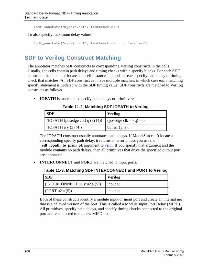
ModelSim User’s Manual, v6.2g268
Standard Delay Format (SDF) Timing Annotation$sdf_annotate
February 2007
$sdf_annotate("myasic.sdf", testbench.u1);
To also specify maximum delay values:
$sdf_annotate("myasic.sdf", testbench.u1, , , "maximum");
SDF to Verilog Construct MatchingThe annotator matches SDF constructs to corresponding Verilog constructs in the cells.Usually, the cells contain path delays and timing checks within specify blocks. For each SDFconstruct, the annotator locates the cell instance and updates each specify path delay or timingcheck that matches. An SDF construct can have multiple matches, in which case each matchingspecify statement is updated with the SDF timing value. SDF constructs are matched to Verilogconstructs as follows.
• IOPATH is matched to specify path delays or primitives:
The IOPATH construct usually annotates path delays. If ModelSim can’t locate acorresponding specify path delay, it returns an error unless you use the+sdf_iopath_to_prim_ok argument to vsim. If you specify that argument and themodule contains no path delays, then all primitives that drive the specified output portare annotated.
• INTERCONNECT and PORT are matched to input ports:
Both of these constructs identify a module input or inout port and create an internal netthat is a delayed version of the port. This is called a Module Input Port Delay (MIPD).All primitives, specify path delays, and specify timing checks connected to the originalport are reconnected to the new MIPD net.
Table 11-2. Matching SDF IOPATH to Verilog
SDF Verilog
(IOPATH (posedge clk) q (3) (4)) (posedge clk => q) = 0;
(IOPATH a y (3) (4)) buf u1 (y, a);
Table 11-3. Matching SDF INTERCONNECT and PORT to Verilog
SDF Verilog
(INTERCONNECT u1.y u2.a (5)) input a;
(PORT u2.a (5)) inout a;

Standard Delay Format (SDF) Timing Annotation$sdf_annotate
ModelSim User’s Manual, v6.2g 269February 2007
• PATHPULSE and GLOBALPATHPULSE are matched to specify path delays:
If the input and output ports are omitted in the SDF, then all path delays are matched inthe cell.
• DEVICE is matched to primitives or specify path delays:
If the SDF cell instance is a primitive instance, then that primitive’s delay is annotated.If it is a module instance, then all specify path delays are annotated that drive the outputport specified in the DEVICE construct (all path delays are annotated if the output portis omitted). If the module contains no path delays, then all primitives that drive thespecified output port are annotated (or all primitives that drive any output port if theoutput port is omitted).
SETUP is matched to $setup and $setuphold:
• HOLD is matched to $hold and $setuphold:
Table 11-4. Matching SDF PATHPULSE and GLOBALPATHPULSE to Verilog
SDF Verilog
(PATHPULSE a y (5) (10)) (a => y) = 0;
(GLOBALPATHPULSE a y (30) (60)) (a => y) = 0;
Table 11-5. Matching SDF DEVICE to Verilog
SDF Verilog
(DEVICE y (5)) and u1(y, a, b);
(DEVICE y (5)) (a => y) = 0; (b => y) = 0;
Table 11-6. Matching SDF SETUP to Verilog
SDF Verilog
(SETUP d (posedge clk) (5)) $setup(d, posedge clk, 0);
(SETUP d (posedge clk) (5)) $setuphold(posedge clk, d, 0, 0);
Table 11-7. Matching SDF HOLD to Verilog
SDF Verilog
(HOLD d (posedge clk) (5)) $hold(posedge clk, d, 0);
(HOLD d (posedge clk) (5)) $setuphold(posedge clk, d, 0, 0);
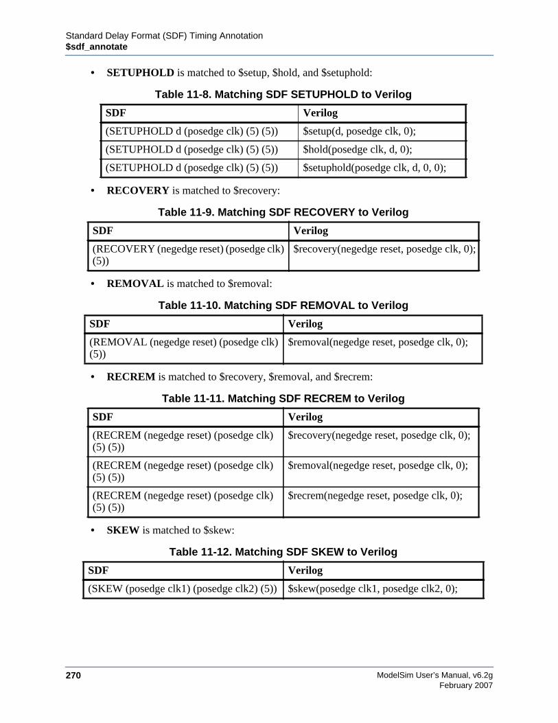
ModelSim User’s Manual, v6.2g270
Standard Delay Format (SDF) Timing Annotation$sdf_annotate
February 2007
• SETUPHOLD is matched to $setup, $hold, and $setuphold:
• RECOVERY is matched to $recovery:
• REMOVAL is matched to $removal:
• RECREM is matched to $recovery, $removal, and $recrem:
• SKEW is matched to $skew:
Table 11-8. Matching SDF SETUPHOLD to Verilog
SDF Verilog
(SETUPHOLD d (posedge clk) (5) (5)) $setup(d, posedge clk, 0);
(SETUPHOLD d (posedge clk) (5) (5)) $hold(posedge clk, d, 0);
(SETUPHOLD d (posedge clk) (5) (5)) $setuphold(posedge clk, d, 0, 0);
Table 11-9. Matching SDF RECOVERY to Verilog
SDF Verilog
(RECOVERY (negedge reset) (posedge clk)(5))
$recovery(negedge reset, posedge clk, 0);
Table 11-10. Matching SDF REMOVAL to Verilog
SDF Verilog
(REMOVAL (negedge reset) (posedge clk)(5))
$removal(negedge reset, posedge clk, 0);
Table 11-11. Matching SDF RECREM to Verilog
SDF Verilog
(RECREM (negedge reset) (posedge clk)(5) (5))
$recovery(negedge reset, posedge clk, 0);
(RECREM (negedge reset) (posedge clk)(5) (5))
$removal(negedge reset, posedge clk, 0);
(RECREM (negedge reset) (posedge clk)(5) (5))
$recrem(negedge reset, posedge clk, 0);
Table 11-12. Matching SDF SKEW to Verilog
SDF Verilog
(SKEW (posedge clk1) (posedge clk2) (5)) $skew(posedge clk1, posedge clk2, 0);
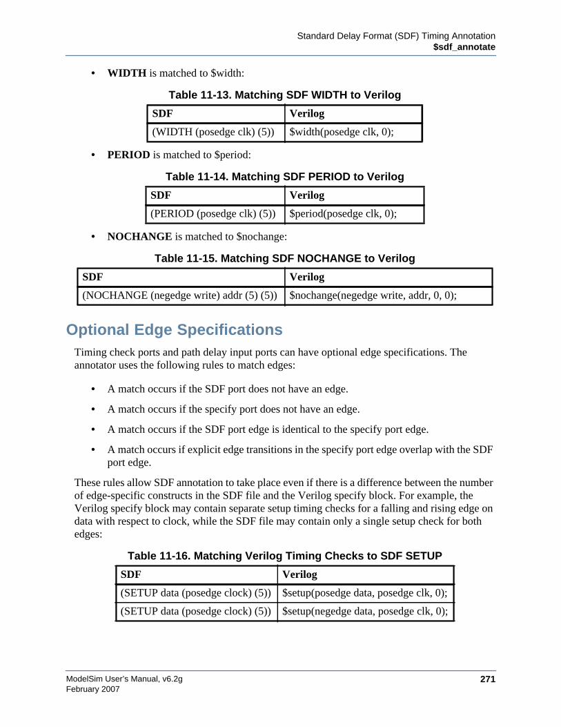
Standard Delay Format (SDF) Timing Annotation$sdf_annotate
ModelSim User’s Manual, v6.2g 271February 2007
• WIDTH is matched to $width:
• PERIOD is matched to $period:
• NOCHANGE is matched to $nochange:
Optional Edge SpecificationsTiming check ports and path delay input ports can have optional edge specifications. Theannotator uses the following rules to match edges:
• A match occurs if the SDF port does not have an edge.
• A match occurs if the specify port does not have an edge.
• A match occurs if the SDF port edge is identical to the specify port edge.
• A match occurs if explicit edge transitions in the specify port edge overlap with the SDFport edge.
These rules allow SDF annotation to take place even if there is a difference between the numberof edge-specific constructs in the SDF file and the Verilog specify block. For example, theVerilog specify block may contain separate setup timing checks for a falling and rising edge ondata with respect to clock, while the SDF file may contain only a single setup check for bothedges:
Table 11-13. Matching SDF WIDTH to Verilog
SDF Verilog
(WIDTH (posedge clk) (5)) $width(posedge clk, 0);
Table 11-14. Matching SDF PERIOD to Verilog
SDF Verilog
(PERIOD (posedge clk) (5)) $period(posedge clk, 0);
Table 11-15. Matching SDF NOCHANGE to Verilog
SDF Verilog
(NOCHANGE (negedge write) addr (5) (5)) $nochange(negedge write, addr, 0, 0);
Table 11-16. Matching Verilog Timing Checks to SDF SETUP
SDF Verilog
(SETUP data (posedge clock) (5)) $setup(posedge data, posedge clk, 0);
(SETUP data (posedge clock) (5)) $setup(negedge data, posedge clk, 0);
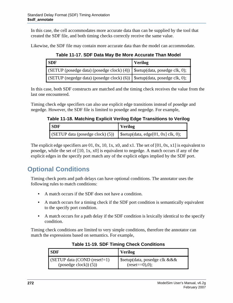
ModelSim User’s Manual, v6.2g272
Standard Delay Format (SDF) Timing Annotation$sdf_annotate
February 2007
In this case, the cell accommodates more accurate data than can be supplied by the tool thatcreated the SDF file, and both timing checks correctly receive the same value.
Likewise, the SDF file may contain more accurate data than the model can accommodate.
In this case, both SDF constructs are matched and the timing check receives the value from thelast one encountered.
Timing check edge specifiers can also use explicit edge transitions instead of posedge andnegedge. However, the SDF file is limited to posedge and negedge. For example,
The explicit edge specifiers are 01, 0x, 10, 1x, x0, and x1. The set of [01, 0x, x1] is equivalent toposedge, while the set of [10, 1x, x0] is equivalent to negedge. A match occurs if any of theexplicit edges in the specify port match any of the explicit edges implied by the SDF port.
Optional ConditionsTiming check ports and path delays can have optional conditions. The annotator uses thefollowing rules to match conditions:
• A match occurs if the SDF does not have a condition.
• A match occurs for a timing check if the SDF port condition is semantically equivalentto the specify port condition.
• A match occurs for a path delay if the SDF condition is lexically identical to the specifycondition.
Timing check conditions are limited to very simple conditions, therefore the annotator canmatch the expressions based on semantics. For example,
Table 11-17. SDF Data May Be More Accurate Than Model
SDF Verilog
(SETUP (posedge data) (posedge clock) (4)) $setup(data, posedge clk, 0);
(SETUP (negedge data) (posedge clock) (6)) $setup(data, posedge clk, 0);
Table 11-18. Matching Explicit Verilog Edge Transitions to Verilog
SDF Verilog
(SETUP data (posedge clock) (5)) $setup(data, edge[01, 0x] clk, 0);
Table 11-19. SDF Timing Check Conditions
SDF Verilog
(SETUP data (COND (reset!=1)(posedge clock)) (5))
$setup(data, posedge clk &&&(reset==0),0);
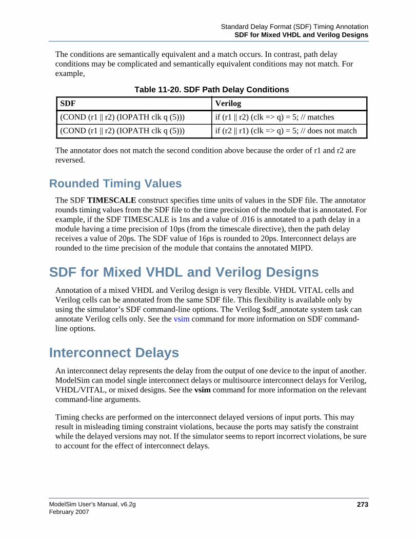
Standard Delay Format (SDF) Timing AnnotationSDF for Mixed VHDL and Verilog Designs
ModelSim User’s Manual, v6.2g 273February 2007
The conditions are semantically equivalent and a match occurs. In contrast, path delayconditions may be complicated and semantically equivalent conditions may not match. Forexample,
The annotator does not match the second condition above because the order of r1 and r2 arereversed.
Rounded Timing ValuesThe SDF TIMESCALE construct specifies time units of values in the SDF file. The annotatorrounds timing values from the SDF file to the time precision of the module that is annotated. Forexample, if the SDF TIMESCALE is 1ns and a value of .016 is annotated to a path delay in amodule having a time precision of 10ps (from the timescale directive), then the path delayreceives a value of 20ps. The SDF value of 16ps is rounded to 20ps. Interconnect delays arerounded to the time precision of the module that contains the annotated MIPD.
SDF for Mixed VHDL and Verilog DesignsAnnotation of a mixed VHDL and Verilog design is very flexible. VHDL VITAL cells andVerilog cells can be annotated from the same SDF file. This flexibility is available only byusing the simulator’s SDF command-line options. The Verilog $sdf_annotate system task canannotate Verilog cells only. See the vsim command for more information on SDF command-line options.
Interconnect DelaysAn interconnect delay represents the delay from the output of one device to the input of another.ModelSim can model single interconnect delays or multisource interconnect delays for Verilog,VHDL/VITAL, or mixed designs. See the vsim command for more information on the relevantcommand-line arguments.
Timing checks are performed on the interconnect delayed versions of input ports. This mayresult in misleading timing constraint violations, because the ports may satisfy the constraintwhile the delayed versions may not. If the simulator seems to report incorrect violations, be sureto account for the effect of interconnect delays.
Table 11-20. SDF Path Delay Conditions
SDF Verilog
(COND (r1 || r2) (IOPATH clk q (5))) if (r1 || r2) (clk => q) = 5; // matches
(COND (r1 || r2) (IOPATH clk q (5))) if (r2 || r1) (clk => q) = 5; // does not match
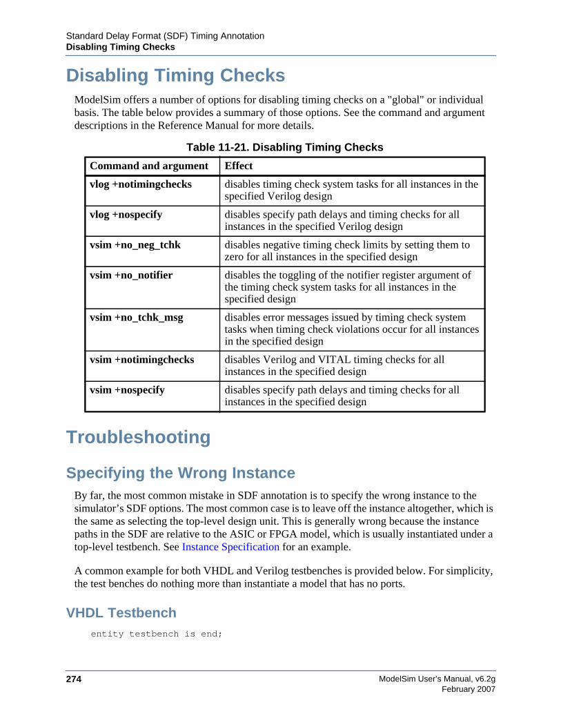
ModelSim User’s Manual, v6.2g274
Standard Delay Format (SDF) Timing AnnotationDisabling Timing Checks
February 2007
Disabling Timing ChecksModelSim offers a number of options for disabling timing checks on a "global" or individualbasis. The table below provides a summary of those options. See the command and argumentdescriptions in the Reference Manual for more details.
Troubleshooting
Specifying the Wrong InstanceBy far, the most common mistake in SDF annotation is to specify the wrong instance to thesimulator’s SDF options. The most common case is to leave off the instance altogether, which isthe same as selecting the top-level design unit. This is generally wrong because the instancepaths in the SDF are relative to the ASIC or FPGA model, which is usually instantiated under atop-level testbench. See Instance Specification for an example.
A common example for both VHDL and Verilog testbenches is provided below. For simplicity,the test benches do nothing more than instantiate a model that has no ports.
VHDL Testbenchentity testbench is end;
Table 11-21. Disabling Timing Checks
Command and argument Effect
vlog +notimingchecks disables timing check system tasks for all instances in thespecified Verilog design
vlog +nospecify disables specify path delays and timing checks for allinstances in the specified Verilog design
vsim +no_neg_tchk disables negative timing check limits by setting them tozero for all instances in the specified design
vsim +no_notifier disables the toggling of the notifier register argument ofthe timing check system tasks for all instances in thespecified design
vsim +no_tchk_msg disables error messages issued by timing check systemtasks when timing check violations occur for all instancesin the specified design
vsim +notimingchecks disables Verilog and VITAL timing checks for allinstances in the specified design
vsim +nospecify disables specify path delays and timing checks for allinstances in the specified design
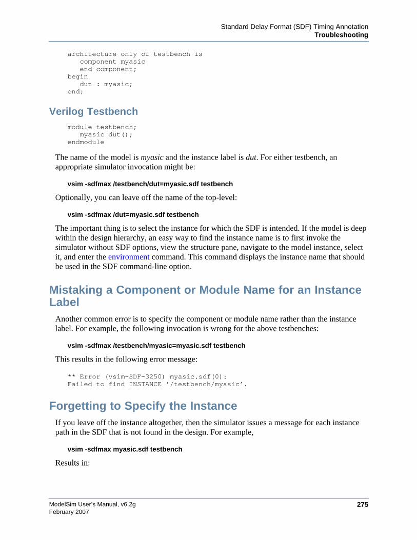
Standard Delay Format (SDF) Timing AnnotationTroubleshooting
ModelSim User’s Manual, v6.2g 275February 2007
architecture only of testbench iscomponent myasicend component;
begindut : myasic;
end;
Verilog Testbenchmodule testbench;
myasic dut();endmodule
The name of the model is myasic and the instance label is dut. For either testbench, anappropriate simulator invocation might be:
vsim -sdfmax /testbench/dut=myasic.sdf testbench
Optionally, you can leave off the name of the top-level:
vsim -sdfmax /dut=myasic.sdf testbench
The important thing is to select the instance for which the SDF is intended. If the model is deepwithin the design hierarchy, an easy way to find the instance name is to first invoke thesimulator without SDF options, view the structure pane, navigate to the model instance, selectit, and enter the environment command. This command displays the instance name that shouldbe used in the SDF command-line option.
Mistaking a Component or Module Name for an InstanceLabel
Another common error is to specify the component or module name rather than the instancelabel. For example, the following invocation is wrong for the above testbenches:
vsim -sdfmax /testbench/myasic=myasic.sdf testbench
This results in the following error message:
** Error (vsim-SDF-3250) myasic.sdf(0):Failed to find INSTANCE ’/testbench/myasic’.
Forgetting to Specify the InstanceIf you leave off the instance altogether, then the simulator issues a message for each instancepath in the SDF that is not found in the design. For example,
vsim -sdfmax myasic.sdf testbench
Results in:
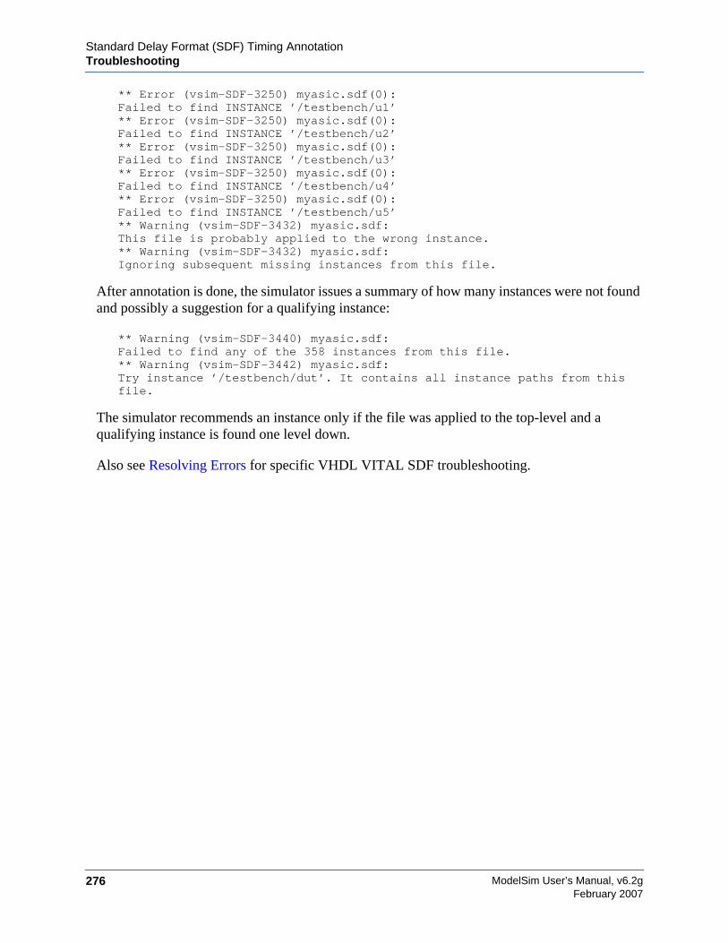
ModelSim User’s Manual, v6.2g276
Standard Delay Format (SDF) Timing AnnotationTroubleshooting
February 2007
** Error (vsim-SDF-3250) myasic.sdf(0):Failed to find INSTANCE ’/testbench/u1’** Error (vsim-SDF-3250) myasic.sdf(0):Failed to find INSTANCE ’/testbench/u2’** Error (vsim-SDF-3250) myasic.sdf(0):Failed to find INSTANCE ’/testbench/u3’** Error (vsim-SDF-3250) myasic.sdf(0):Failed to find INSTANCE ’/testbench/u4’** Error (vsim-SDF-3250) myasic.sdf(0):Failed to find INSTANCE ’/testbench/u5’** Warning (vsim-SDF-3432) myasic.sdf:This file is probably applied to the wrong instance.** Warning (vsim-SDF-3432) myasic.sdf:Ignoring subsequent missing instances from this file.
After annotation is done, the simulator issues a summary of how many instances were not foundand possibly a suggestion for a qualifying instance:
** Warning (vsim-SDF-3440) myasic.sdf:Failed to find any of the 358 instances from this file.** Warning (vsim-SDF-3442) myasic.sdf:Try instance ’/testbench/dut’. It contains all instance paths from thisfile.
The simulator recommends an instance only if the file was applied to the top-level and aqualifying instance is found one level down.
Also see Resolving Errors for specific VHDL VITAL SDF troubleshooting.
ModelSim User’s Manual, v6.2g 277February 2007
Chapter 12Value Change Dump (VCD) Files
This chapter describes how to use VCD files in ModelSim. The VCD file format is specified inthe IEEE 1364 standard. It is an ASCII file containing header information, variable definitions,and variable value changes.
VCD is in common use for Verilog designs, and is controlled by VCD system task calls in theVerilog source code. ModelSim provides command equivalents for these system tasks andextends VCD support to VHDL designs. The ModelSim commands can be used on VHDL,Verilog, or mixed designs.
If you need vendor-specific ASIC design-flow documentation that incorporates VCD, pleasecontact your ASIC vendor.
Creating a VCD FileThere are two flows in ModelSim for creating a VCD file. One flow produces a four-state VCDfile with variable changes in 0, 1, x, and z with no strength information; the other produces anextended VCD file with variable changes in all states and strength information and port driverdata.
Both flows will also capture port driver changes unless filtered out with optional command-linearguments.
Flow for Four-State VCD FileFirst, compile and load the design:
% cd ~/modeltech/examples/misc% vlib work% vlog counter.v tcounter.v% vsim test_counter
Next, with the design loaded, specify the VCD file name with the vcd file command and addobjects to the file with the vcd add command:
VSIM 1> vcd file myvcdfile.vcdVSIM 2> vcd add /test_counter/dut/*VSIM 3> runVSIM 4> quit -f
There will now be a VCD file in the working directory.
ModelSim User’s Manual, v6.2g278
Value Change Dump (VCD) FilesUsing Extended VCD as Stimulus
February 2007
Flow for Extended VCD FileFirst, compile and load the design:
% cd ~/modeltech/examples/misc% vlib work% vlog counter.v tcounter.v% vsim test_counter
Next, with the design loaded, specify the VCD file name and objects to add with thevcd dumpports command:
VSIM 1> vcd dumpports -file myvcdfile.vcd /test_counter/dut/*VSIM 3> runVSIM 4> quit -f
There will now be an extended VCD file called myvcdfile.vcd in the working directory.
NoteThere is an internal limit to the number of port driver changes that can be created with thevcd dumpports command. If that limit is reached, use the vcd add command with the-dumpports option to create additional port driver changes.
By default ModelSim uses strength ranges for resolving conflicts as specified by IEEE1364-2005. You can ignore strength ranges using the -no_strength_range argument to thevcd dumpports command. See Resolving Values for more details.
Case SensitivityVHDL is not case sensitive so ModelSim converts all signal names to lower case when itproduces a VCD file. Conversely, Verilog designs are case sensitive so ModelSim maintainscase when it produces a VCD file.
Using Extended VCD as StimulusYou can use an extended VCD file as stimulus to re-simulate your design. There are two waysto do this: 1) simulate the top level of a design unit with the input values from an extended VCDfile; and 2) specify one or more instances in a design to be replaced with the output values fromthe associated VCD file.
Simulating with Input Values from a VCD FileWhen simulating with inputs from an extended VCD file, you can simulate only one design unitat a time. In other words, you can apply the VCD file inputs only to the top level of the designunit for which you captured port data.
The general procedure includes two steps:
Value Change Dump (VCD) FilesUsing Extended VCD as Stimulus
ModelSim User’s Manual, v6.2g 279February 2007
1. Create a VCD file for a single design unit using the vcd dumpports command.
2. Resimulate the single design unit using the -vcdstim argument to vsim. Note that-vcdstim works only with VCD files that were created by a ModelSim simulation.
Example 12-1. Verilog Counter
First, create the VCD file for the single instance using vcd dumpports:
% cd ~/modeltech/examples/misc% vlib work% vlog counter.v tcounter.v% vsim test_counterVSIM 1> vcd dumpports -file counter.vcd /test_counter/dut/*VSIM 2> runVSIM 3> quit -f
Next, rerun the counter without the testbench, using the -vcdstim argument:
% vsim -vcdstim counter.vcd counterVSIM 1> add wave /*VSIM 2> run 200
Example 12-2. VHDL Adder
First, create the VCD file using vcd dumpports:
% cd ~/modeltech/examples/misc% vlib work% vcom gates.vhd adder.vhd stimulus.vhd% vsim testbench2VSIM 1> vcd dumpports -file addern.vcd /testbench2/uut/*VSIM 2> run 1000VSIM 3> quit -f
Next, rerun the adder without the testbench, using the -vcdstim argument:
% vsim -vcdstim addern.vcd addern -gn=8 -do "add wave /*; run 1000"
Example 12-3. Mixed-HDL Design
First, create three VCD files, one for each module:
% cd ~/modeltech/examples/tutorials/mixed/projects% vlib work% vlog cache.v memory.v proc.v% vcom util.vhd set.vhd top.vhd% vsim topVSIM 1> vcd dumpports -file proc.vcd /top/p/*VSIM 2> vcd dumpports -file cache.vcd /top/c/*VSIM 3> vcd dumpports -file memory.vcd /top/m/*VSIM 4> run 1000VSIM 5> quit -f
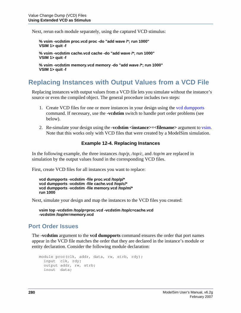
ModelSim User’s Manual, v6.2g280
Value Change Dump (VCD) FilesUsing Extended VCD as Stimulus
February 2007
Next, rerun each module separately, using the captured VCD stimulus:
% vsim -vcdstim proc.vcd proc -do "add wave /*; run 1000"VSIM 1> quit -f
% vsim -vcdstim cache.vcd cache -do "add wave /*; run 1000"VSIM 1> quit -f
% vsim -vcdstim memory.vcd memory -do "add wave /*; run 1000"VSIM 1> quit -f
Replacing Instances with Output Values from a VCD FileReplacing instances with output values from a VCD file lets you simulate without the instance’ssource or even the compiled object. The general procedure includes two steps:
1. Create VCD files for one or more instances in your design using the vcd dumpportscommand. If necessary, use the -vcdstim switch to handle port order problems (seebelow).
2. Re-simulate your design using the -vcdstim <instance>=<filename> argument to vsim.Note that this works only with VCD files that were created by a ModelSim simulation.
Example 12-4. Replacing Instances
In the following example, the three instances /top/p, /top/c, and /top/m are replaced insimulation by the output values found in the corresponding VCD files.
First, create VCD files for all instances you want to replace:
vcd dumpports -vcdstim -file proc.vcd /top/p/*vcd dumpports -vcdstim -file cache.vcd /top/c/*vcd dumpports -vcdstim -file memory.vcd /top/m/*run 1000
Next, simulate your design and map the instances to the VCD files you created:
vsim top -vcdstim /top/p=proc.vcd -vcdstim /top/c=cache.vcd-vcdstim /top/m=memory.vcd
Port Order IssuesThe -vcdstim argument to the vcd dumpports command ensures the order that port namesappear in the VCD file matches the order that they are declared in the instance’s module orentity declaration. Consider the following module declaration:
module proc(clk, addr, data, rw, strb, rdy);input clk, rdy;output addr, rw, strb;inout data;
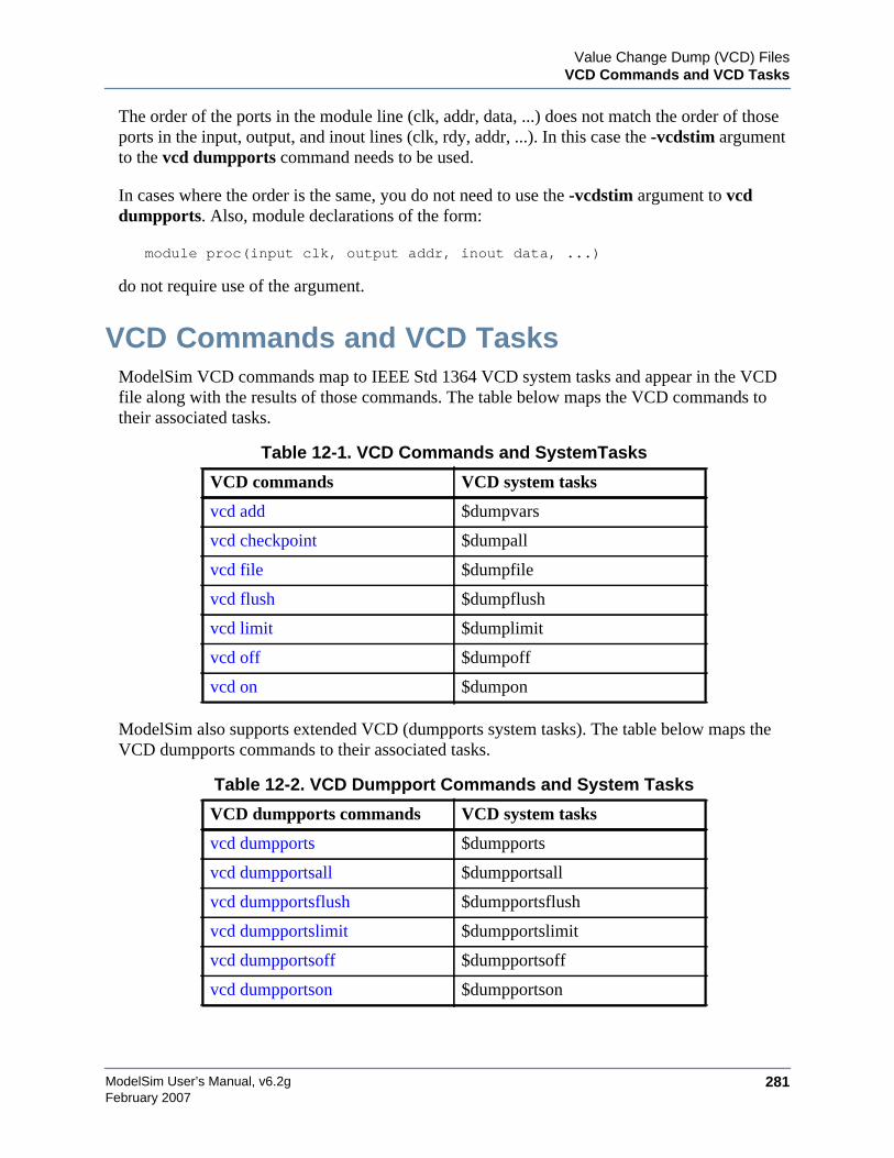
Value Change Dump (VCD) FilesVCD Commands and VCD Tasks
ModelSim User’s Manual, v6.2g 281February 2007
The order of the ports in the module line (clk, addr, data, ...) does not match the order of thoseports in the input, output, and inout lines (clk, rdy, addr, ...). In this case the -vcdstim argumentto the vcd dumpports command needs to be used.
In cases where the order is the same, you do not need to use the -vcdstim argument to vcddumpports. Also, module declarations of the form:
module proc(input clk, output addr, inout data, ...)
do not require use of the argument.
VCD Commands and VCD TasksModelSim VCD commands map to IEEE Std 1364 VCD system tasks and appear in the VCDfile along with the results of those commands. The table below maps the VCD commands totheir associated tasks.
ModelSim also supports extended VCD (dumpports system tasks). The table below maps theVCD dumpports commands to their associated tasks.
Table 12-1. VCD Commands and SystemTasks
VCD commands VCD system tasks
vcd add $dumpvars
vcd checkpoint $dumpall
vcd file $dumpfile
vcd flush $dumpflush
vcd limit $dumplimit
vcd off $dumpoff
vcd on $dumpon
Table 12-2. VCD Dumpport Commands and System Tasks
VCD dumpports commands VCD system tasks
vcd dumpports $dumpports
vcd dumpportsall $dumpportsall
vcd dumpportsflush $dumpportsflush
vcd dumpportslimit $dumpportslimit
vcd dumpportsoff $dumpportsoff
vcd dumpportson $dumpportson
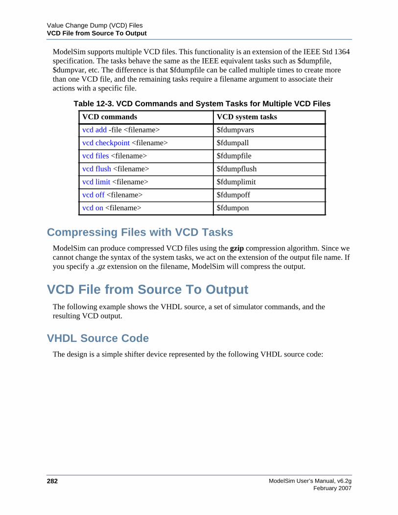
ModelSim User’s Manual, v6.2g282
Value Change Dump (VCD) FilesVCD File from Source To Output
February 2007
ModelSim supports multiple VCD files. This functionality is an extension of the IEEE Std 1364specification. The tasks behave the same as the IEEE equivalent tasks such as $dumpfile,$dumpvar, etc. The difference is that $fdumpfile can be called multiple times to create morethan one VCD file, and the remaining tasks require a filename argument to associate theiractions with a specific file.
Compressing Files with VCD TasksModelSim can produce compressed VCD files using the gzip compression algorithm. Since wecannot change the syntax of the system tasks, we act on the extension of the output file name. Ifyou specify a .gz extension on the filename, ModelSim will compress the output.
VCD File from Source To OutputThe following example shows the VHDL source, a set of simulator commands, and theresulting VCD output.
VHDL Source CodeThe design is a simple shifter device represented by the following VHDL source code:
Table 12-3. VCD Commands and System Tasks for Multiple VCD Files
VCD commands VCD system tasks
vcd add -file <filename> $fdumpvars
vcd checkpoint <filename> $fdumpall
vcd files <filename> $fdumpfile
vcd flush <filename> $fdumpflush
vcd limit <filename> $fdumplimit
vcd off <filename> $fdumpoff
vcd on <filename> $fdumpon
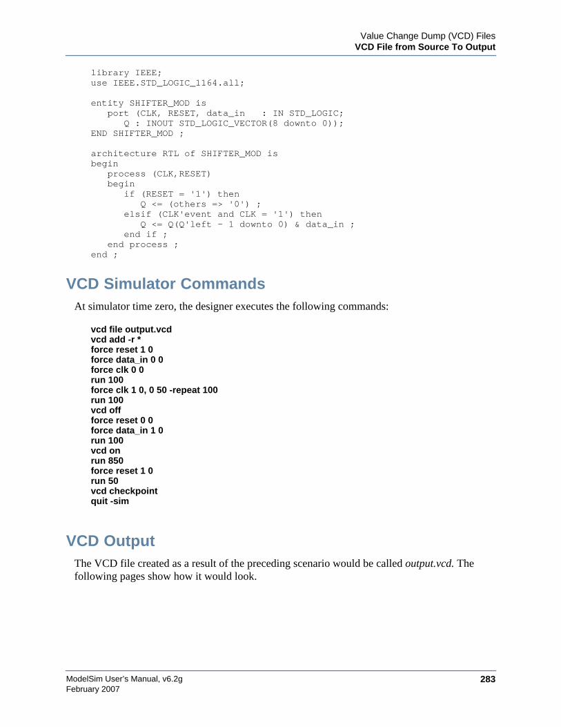
Value Change Dump (VCD) FilesVCD File from Source To Output
ModelSim User’s Manual, v6.2g 283February 2007
library IEEE;use IEEE.STD_LOGIC_1164.all;
entity SHIFTER_MOD isport (CLK, RESET, data_in : IN STD_LOGIC;
Q : INOUT STD_LOGIC_VECTOR(8 downto 0));END SHIFTER_MOD ;
architecture RTL of SHIFTER_MOD isbegin
process (CLK,RESET)begin
if (RESET = '1') thenQ <= (others => '0') ;
elsif (CLK'event and CLK = '1') thenQ <= Q(Q'left - 1 downto 0) & data_in ;
end if ;end process ;
end ;
VCD Simulator CommandsAt simulator time zero, the designer executes the following commands:
vcd file output.vcdvcd add -r *force reset 1 0force data_in 0 0force clk 0 0run 100force clk 1 0, 0 50 -repeat 100run 100vcd offforce reset 0 0force data_in 1 0run 100vcd onrun 850force reset 1 0run 50vcd checkpointquit -sim
VCD OutputThe VCD file created as a result of the preceding scenario would be called output.vcd. Thefollowing pages show how it would look.
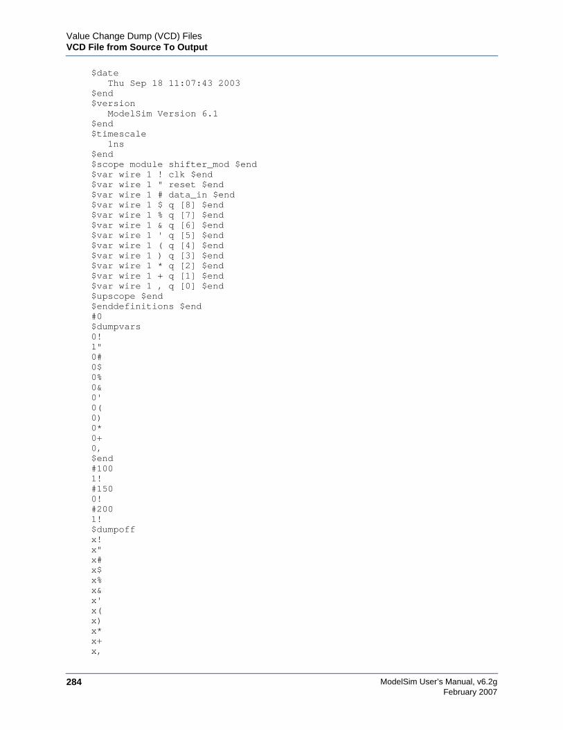
ModelSim User’s Manual, v6.2g284
Value Change Dump (VCD) FilesVCD File from Source To Output
February 2007
$dateThu Sep 18 11:07:43 2003
$end$version
ModelSim Version 6.1$end$timescale
1ns$end$scope module shifter_mod $end$var wire 1 ! clk $end$var wire 1 " reset $end$var wire 1 # data_in $end$var wire 1 $ q [8] $end$var wire 1 % q [7] $end$var wire 1 & q [6] $end$var wire 1 ' q [5] $end$var wire 1 ( q [4] $end$var wire 1 ) q [3] $end$var wire 1 * q [2] $end$var wire 1 + q [1] $end$var wire 1 , q [0] $end$upscope $end$enddefinitions $end#0$dumpvars0!1"0#0$0%0&0'0(0)0*0+0,$end#1001!#1500!#2001!$dumpoffx!x"x#x$x%x&x'x(x)x*x+x,
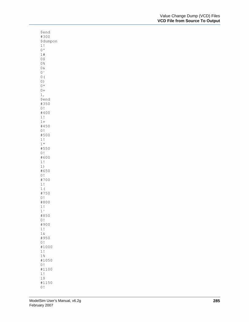
Value Change Dump (VCD) FilesVCD File from Source To Output
ModelSim User’s Manual, v6.2g 285February 2007
$end#300$dumpon1!0"1#0$0%0&0'0(0)0*0+1,$end#3500!#4001!1+#4500!#5001!1*#5500!#6001!1)#6500!#7001!1(#7500!#8001!1'#8500!#9001!1├!#10001!1%#10500!#11001!1$#11500!

ModelSim User’s Manual, v6.2g286
Value Change Dump (VCD) FilesCapturing Port Driver Data
February 2007
1"0,0+0*0)0(0'0&0%0$#12001!$dumpall1!1"1#0$0%0&0'0(0)0*0+0,$end
Capturing Port Driver DataSome ASIC vendors’ toolkits read a VCD file format that provides details on port drivers. Thisinformation can be used, for example, to drive a tester. See the ASIC vendor’s documentationfor toolkit specific information.
In ModelSim use the vcd dumpports command to create a VCD file that captures port driverdata. Each time an external or internal port driver changes values, a new value change isrecorded in the VCD file with the following format:
p<state> <0 strength> <1 strength> <identifier_code>
Driver StatesThe driver states are recorded as TSSI states if the direction is known, as detailed in this table:
Table 12-4. Driver States
Input (testfixture) Output (dut)
D low L low
U high H high
N unknown X unknown
Z tri-state T tri-state

Value Change Dump (VCD) FilesCapturing Port Driver Data
ModelSim User’s Manual, v6.2g 287February 2007
If the direction is unknown, the state will be recorded as one of the following:
Driver StrengthThe recorded 0 and 1 strength values are based on Verilog strengths:
d low (two or moredrivers active)
l low (two or moredrivers active)
u high (two or moredrivers active)
h high (two ormore drivers active)
Table 12-5. State When Direction is Unknown
Unknown direction
0 low (both input and output are driving low)
1 high (both input and output are driving high)
? unknown (both input and output are drivingunknown)
F three-state (input and output unconnected)
A unknown (input driving low and output drivinghigh)
a unknown (input driving low and output drivingunknown)
B unknown (input driving high and output drivinglow)
b unknown (input driving high and output drivingunknown)
C unknown (input driving unknown and outputdriving low)
c unknown (input driving unknown and outputdriving high)
f unknown (input and output three-stated)
Table 12-6. Driver Strength
Strength VHDL std_logic mappings
0 highz ’Z’
1 small
Table 12-4. Driver States (cont.)
Input (testfixture) Output (dut)
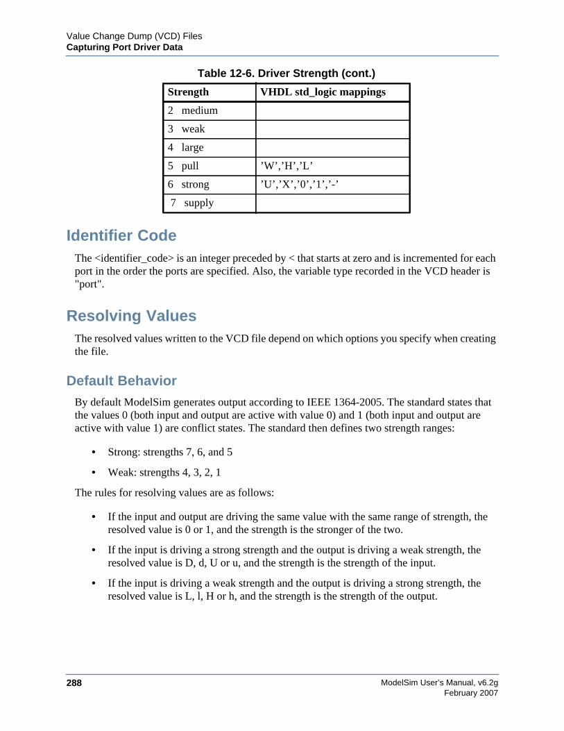
ModelSim User’s Manual, v6.2g288
Value Change Dump (VCD) FilesCapturing Port Driver Data
February 2007
Identifier CodeThe <identifier_code> is an integer preceded by < that starts at zero and is incremented for eachport in the order the ports are specified. Also, the variable type recorded in the VCD header is"port".
Resolving ValuesThe resolved values written to the VCD file depend on which options you specify when creatingthe file.
Default BehaviorBy default ModelSim generates output according to IEEE 1364-2005. The standard states thatthe values 0 (both input and output are active with value 0) and 1 (both input and output areactive with value 1) are conflict states. The standard then defines two strength ranges:
• Strong: strengths 7, 6, and 5
• Weak: strengths 4, 3, 2, 1
The rules for resolving values are as follows:
• If the input and output are driving the same value with the same range of strength, theresolved value is 0 or 1, and the strength is the stronger of the two.
• If the input is driving a strong strength and the output is driving a weak strength, theresolved value is D, d, U or u, and the strength is the strength of the input.
• If the input is driving a weak strength and the output is driving a strong strength, theresolved value is L, l, H or h, and the strength is the strength of the output.
2 medium
3 weak
4 large
5 pull ’W’,’H’,’L’
6 strong ’U’,’X’,’0’,’1’,’-’
7 supply
Table 12-6. Driver Strength (cont.)
Strength VHDL std_logic mappings
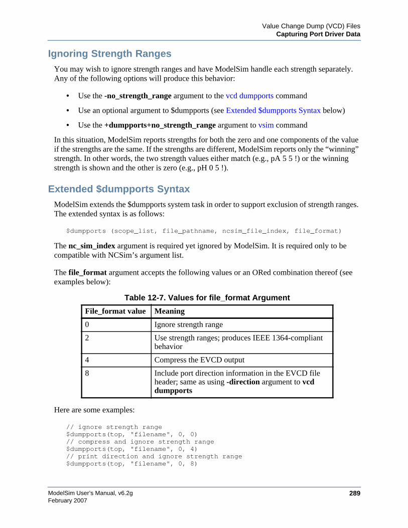
Value Change Dump (VCD) FilesCapturing Port Driver Data
ModelSim User’s Manual, v6.2g 289February 2007
Ignoring Strength RangesYou may wish to ignore strength ranges and have ModelSim handle each strength separately.Any of the following options will produce this behavior:
• Use the -no_strength_range argument to the vcd dumpports command
• Use an optional argument to $dumpports (see Extended $dumpports Syntax below)
• Use the +dumpports+no_strength_range argument to vsim command
In this situation, ModelSim reports strengths for both the zero and one components of the valueif the strengths are the same. If the strengths are different, ModelSim reports only the “winning”strength. In other words, the two strength values either match (e.g., pA 5 5 !) or the winningstrength is shown and the other is zero (e.g., pH 0 5 !).
Extended $dumpports SyntaxModelSim extends the $dumpports system task in order to support exclusion of strength ranges.The extended syntax is as follows:
$dumpports (scope_list, file_pathname, ncsim_file_index, file_format)
The nc_sim_index argument is required yet ignored by ModelSim. It is required only to becompatible with NCSim’s argument list.
The file_format argument accepts the following values or an ORed combination thereof (seeexamples below):
Here are some examples:
// ignore strength range$dumpports(top, "filename", 0, 0)// compress and ignore strength range$dumpports(top, "filename", 0, 4)// print direction and ignore strength range$dumpports(top, "filename", 0, 8)
Table 12-7. Values for file_format Argument
File_format value Meaning
0 Ignore strength range
2 Use strength ranges; produces IEEE 1364-compliantbehavior
4 Compress the EVCD output
8 Include port direction information in the EVCD fileheader; same as using -direction argument to vcddumpports
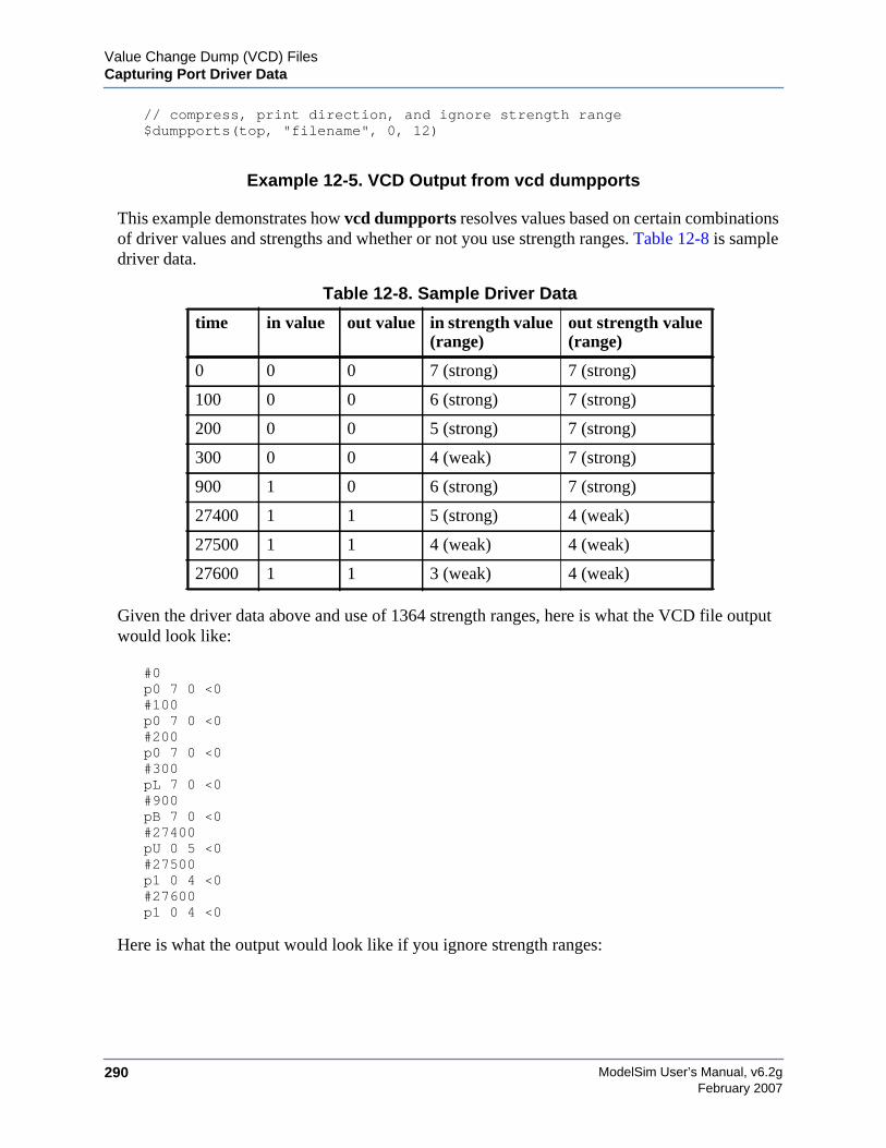
ModelSim User’s Manual, v6.2g290
Value Change Dump (VCD) FilesCapturing Port Driver Data
February 2007
// compress, print direction, and ignore strength range$dumpports(top, "filename", 0, 12)
Example 12-5. VCD Output from vcd dumpports
This example demonstrates how vcd dumpports resolves values based on certain combinationsof driver values and strengths and whether or not you use strength ranges. Table 12-8 is sampledriver data.
Given the driver data above and use of 1364 strength ranges, here is what the VCD file outputwould look like:
#0p0 7 0 <0#100p0 7 0 <0#200p0 7 0 <0#300pL 7 0 <0#900pB 7 0 <0#27400pU 0 5 <0#27500p1 0 4 <0#27600p1 0 4 <0
Here is what the output would look like if you ignore strength ranges:
Table 12-8. Sample Driver Data
time in value out value in strength value(range)
out strength value(range)
0 0 0 7 (strong) 7 (strong)
100 0 0 6 (strong) 7 (strong)
200 0 0 5 (strong) 7 (strong)
300 0 0 4 (weak) 7 (strong)
900 1 0 6 (strong) 7 (strong)
27400 1 1 5 (strong) 4 (weak)
27500 1 1 4 (weak) 4 (weak)
27600 1 1 3 (weak) 4 (weak)
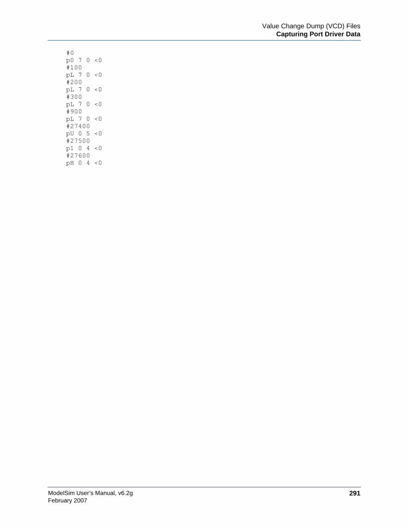
Value Change Dump (VCD) FilesCapturing Port Driver Data
ModelSim User’s Manual, v6.2g 291February 2007
#0p0 7 0 <0#100pL 7 0 <0#200pL 7 0 <0#300pL 7 0 <0#900pL 7 0 <0#27400pU 0 5 <0#27500p1 0 4 <0#27600pH 0 4 <0

ModelSim User’s Manual, v6.2g292
Value Change Dump (VCD) FilesCapturing Port Driver Data
February 2007
ModelSim User’s Manual, v6.2g 293February 2007
Chapter 13Tcl and Macros (DO Files)
Tcl is a scripting language for controlling and extending ModelSim. Within ModelSim you candevelop implementations from Tcl scripts without the use of C code. Because Tcl is interpreted,development is rapid; you can generate and execute Tcl scripts on the fly without stopping torecompile or restart ModelSim. In addition, if ModelSim does not provide the command youneed, you can use Tcl to create your own commands.
Tcl FeaturesUsing Tcl with ModelSim gives you these features:
• command history (like that in C shells)
• full expression evaluation and support for all C-language operators
• a full range of math and trig functions
• support of lists and arrays
• regular expression pattern matching
• procedures
• the ability to define your own commands
• command substitution (that is, commands may be nested)
• robust scripting language for macros
Tcl ReferencesTwo books about Tcl are Tcl and the Tk Toolkit by John K. Ousterhout, published by Addison-Wesley Publishing Company, Inc., and Practical Programming in Tcl and Tk by Brent Welchpublished by Prentice Hall. You can also consult the following online references:
• Select Help > Tcl Man Pages.
Tcl CommandsFor complete information on Tcl commands, select Help > Tcl Man Pages. Also see SimulatorGUI Preferences for information on Tcl preference variables.
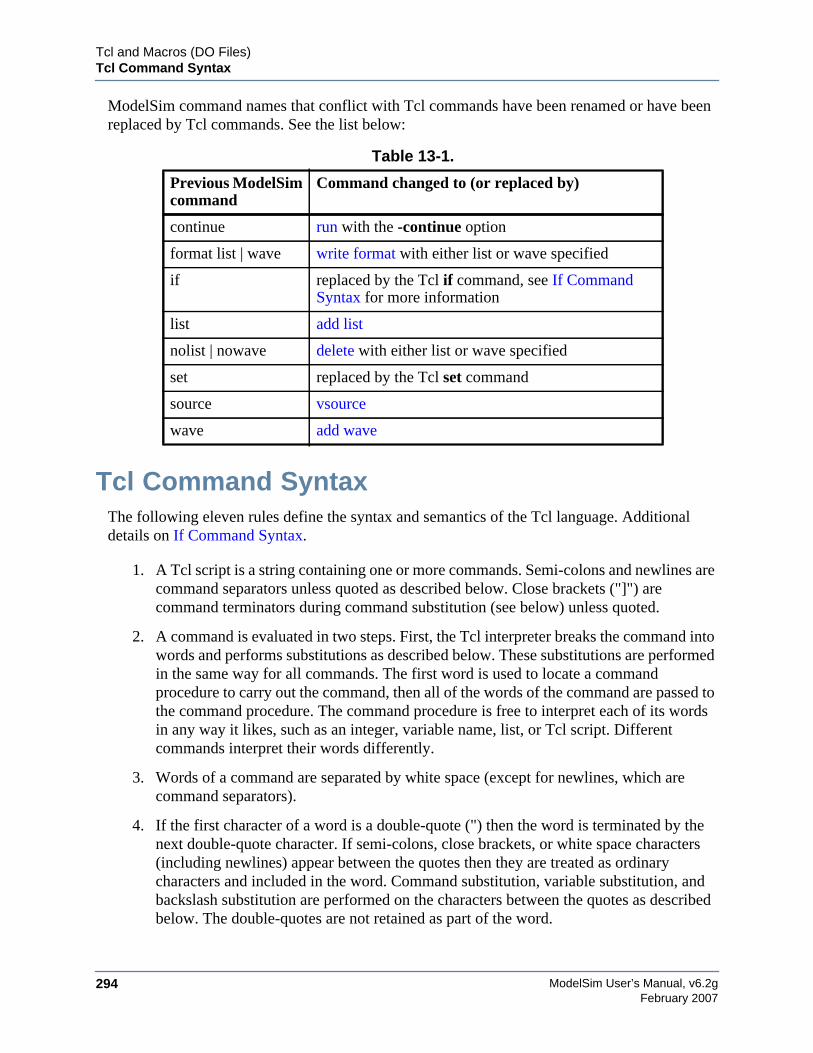
ModelSim User’s Manual, v6.2g294
Tcl and Macros (DO Files)Tcl Command Syntax
February 2007
ModelSim command names that conflict with Tcl commands have been renamed or have beenreplaced by Tcl commands. See the list below:
Tcl Command SyntaxThe following eleven rules define the syntax and semantics of the Tcl language. Additionaldetails on If Command Syntax.
1. A Tcl script is a string containing one or more commands. Semi-colons and newlines arecommand separators unless quoted as described below. Close brackets ("]") arecommand terminators during command substitution (see below) unless quoted.
2. A command is evaluated in two steps. First, the Tcl interpreter breaks the command intowords and performs substitutions as described below. These substitutions are performedin the same way for all commands. The first word is used to locate a commandprocedure to carry out the command, then all of the words of the command are passed tothe command procedure. The command procedure is free to interpret each of its wordsin any way it likes, such as an integer, variable name, list, or Tcl script. Differentcommands interpret their words differently.
3. Words of a command are separated by white space (except for newlines, which arecommand separators).
4. If the first character of a word is a double-quote (") then the word is terminated by thenext double-quote character. If semi-colons, close brackets, or white space characters(including newlines) appear between the quotes then they are treated as ordinarycharacters and included in the word. Command substitution, variable substitution, andbackslash substitution are performed on the characters between the quotes as describedbelow. The double-quotes are not retained as part of the word.
Table 13-1.
Previous ModelSimcommand
Command changed to (or replaced by)
continue run with the -continue option
format list | wave write format with either list or wave specified
if replaced by the Tcl if command, see If CommandSyntax for more information
list add list
nolist | nowave delete with either list or wave specified
set replaced by the Tcl set command
source vsource
wave add wave
Tcl and Macros (DO Files)Tcl Command Syntax
ModelSim User’s Manual, v6.2g 295February 2007
5. If the first character of a word is an open brace ({) then the word is terminated by thematching close brace (}). Braces nest within the word: for each additional open bracethere must be an additional close brace (however, if an open brace or close brace withinthe word is quoted with a backslash then it is not counted in locating the matching closebrace). No substitutions are performed on the characters between the braces except forbackslash-newline substitutions described below, nor do semi-colons, newlines, closebrackets, or white space receive any special interpretation. The word will consist ofexactly the characters between the outer braces, not including the braces themselves.
6. If a word contains an open bracket ([) then Tcl performs command substitution. To dothis it invokes the Tcl interpreter recursively to process the characters following theopen bracket as a Tcl script. The script may contain any number of commands and mustbe terminated by a close bracket (]). The result of the script (i.e. the result of its lastcommand) is substituted into the word in place of the brackets and all of the charactersbetween them. There may be any number of command substitutions in a single word.Command substitution is not performed on words enclosed in braces.
7. If a word contains a dollar-sign ($) then Tcl performs variable substitution: the dollar-sign and the following characters are replaced in the word by the value of a variable.Variable substitution may take any of the following forms:
o $name
Name is the name of a scalar variable; the name is terminated by any character thatisn't a letter, digit, or underscore.
o $name(index)
Name gives the name of an array variable and index gives the name of an elementwithin that array. Name must contain only letters, digits, and underscores. Commandsubstitutions, variable substitutions, and backslash substitutions are performed onthe characters of index.
o ${name}
Name is the name of a scalar variable. It may contain any characters whatsoeverexcept for close braces.
There may be any number of variable substitutions in a single word. Variablesubstitution is not performed on words enclosed in braces.
8. If a backslash (\) appears within a word then backslash substitution occurs. In all casesbut those described below the backslash is dropped and the following character istreated as an ordinary character and included in the word. This allows characters such asdouble quotes, close brackets, and dollar signs to be included in words without
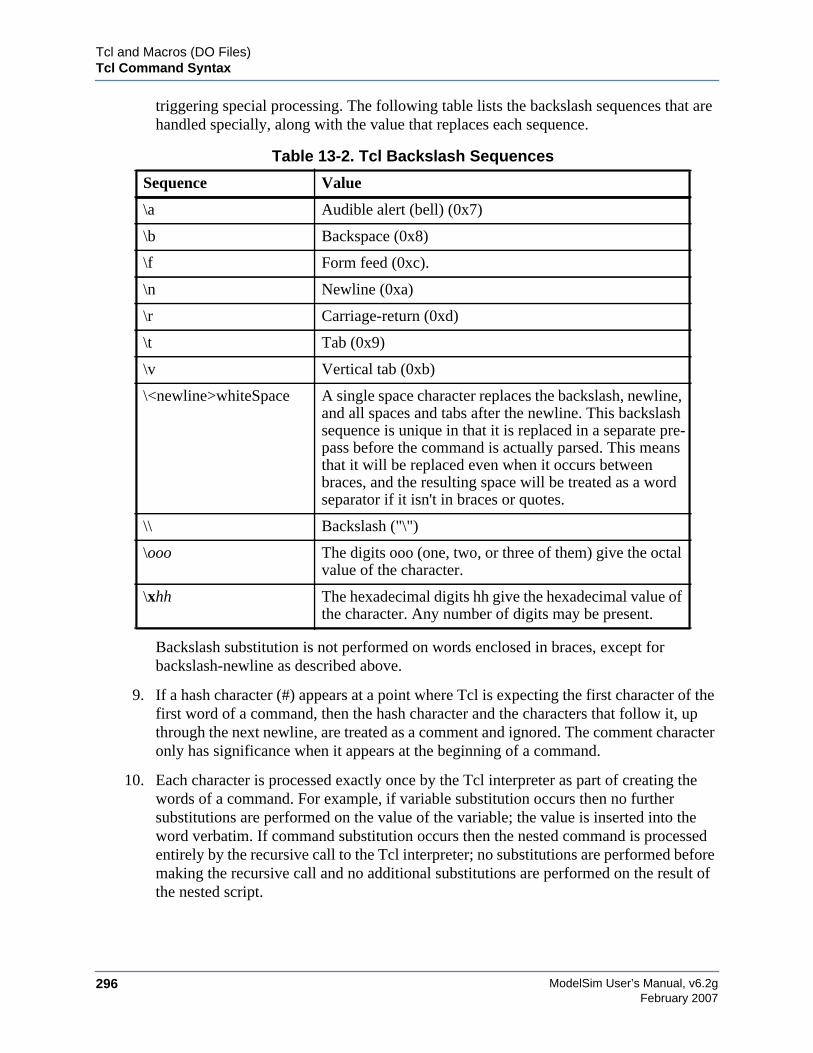
ModelSim User’s Manual, v6.2g296
Tcl and Macros (DO Files)Tcl Command Syntax
February 2007
triggering special processing. The following table lists the backslash sequences that arehandled specially, along with the value that replaces each sequence.
Backslash substitution is not performed on words enclosed in braces, except forbackslash-newline as described above.
9. If a hash character (#) appears at a point where Tcl is expecting the first character of thefirst word of a command, then the hash character and the characters that follow it, upthrough the next newline, are treated as a comment and ignored. The comment characteronly has significance when it appears at the beginning of a command.
10. Each character is processed exactly once by the Tcl interpreter as part of creating thewords of a command. For example, if variable substitution occurs then no furthersubstitutions are performed on the value of the variable; the value is inserted into theword verbatim. If command substitution occurs then the nested command is processedentirely by the recursive call to the Tcl interpreter; no substitutions are performed beforemaking the recursive call and no additional substitutions are performed on the result ofthe nested script.
Table 13-2. Tcl Backslash Sequences
Sequence Value
\a Audible alert (bell) (0x7)
\b Backspace (0x8)
\f Form feed (0xc).
\n Newline (0xa)
\r Carriage-return (0xd)
\t Tab (0x9)
\v Vertical tab (0xb)
\<newline>whiteSpace A single space character replaces the backslash, newline,and all spaces and tabs after the newline. This backslashsequence is unique in that it is replaced in a separate pre-pass before the command is actually parsed. This meansthat it will be replaced even when it occurs betweenbraces, and the resulting space will be treated as a wordseparator if it isn't in braces or quotes.
\\ Backslash ("\")
\ooo The digits ooo (one, two, or three of them) give the octalvalue of the character.
\xhh The hexadecimal digits hh give the hexadecimal value ofthe character. Any number of digits may be present.
Tcl and Macros (DO Files)Tcl Command Syntax
ModelSim User’s Manual, v6.2g 297February 2007
11. Substitutions do not affect the word boundaries of a command. For example, duringvariable substitution the entire value of the variable becomes part of a single word, evenif the variable's value contains spaces.
If Command SyntaxThe Tcl if command executes scripts conditionally. Note that in the syntax below the questionmark (?) indicates an optional argument.
Syntax
if expr1 ?then? body1 elseif expr2 ?then? body2 elseif ... ?else? ?bodyN?
Description
The if command evaluates expr1 as an expression. The value of the expression must be aboolean (a numeric value, where 0 is false and anything else is true, or a string value such astrue or yes for true and false or no for false); if it is true then body1 is executed by passing it tothe Tcl interpreter. Otherwise expr2 is evaluated as an expression and if it is true then body2 isexecuted, and so on. If none of the expressions evaluates to true then bodyN is executed. Thethen and else arguments are optional "noise words" to make the command easier to read. Theremay be any number of elseif clauses, including zero. BodyN may also be omitted as long as elseis omitted too. The return value from the command is the result of the body script that wasexecuted, or an empty string if none of the expressions was non-zero and there was no bodyN.
Command SubstitutionPlacing a command in square brackets ([ ]) will cause that command to be evaluated first and itsresults returned in place of the command. An example is:
set a 25set b 11set c 3echo "the result is [expr ($a + $b)/$c]"
will output:
"the result is 12"
This feature allows VHDL variables and signals, and Verilog nets and registers to be accessedusing:
[examine -<radix> name]
The %name substitution is no longer supported. Everywhere %name could be used, you nowcan use [examine -value -<radix> name] which allows the flexibility of specifying commandoptions. The radix specification is optional.
ModelSim User’s Manual, v6.2g298
Tcl and Macros (DO Files)Tcl Command Syntax
February 2007
Command SeparatorA semicolon character (;) works as a separator for multiple commands on the same line. It is notrequired at the end of a line in a command sequence.
Multiple-Line CommandsWith Tcl, multiple-line commands can be used within macros and on the command line. Thecommand line prompt will change (as in a C shell) until the multiple-line command is complete.
In the example below, note the way the opening brace ’{’ is at the end of the if and else lines.This is important because otherwise the Tcl scanner won't know that there is more coming in thecommand and will try to execute what it has up to that point, which won't be what you intend.
if { [exa sig_a] == "0011ZZ"} {echo "Signal value matches"do macro_1.do
} else {echo "Signal value fails"do macro_2.do
}
Evaluation OrderAn important thing to remember when using Tcl is that anything put in braces ({}) is notevaluated immediately. This is important for if-then-else statements, procedures, loops, and soforth.
Tcl Relational Expression EvaluationWhen you are comparing values, the following hints may be useful:
• Tcl stores all values as strings, and will convert certain strings to numeric values whenappropriate. If you want a literal to be treated as a numeric value, don't quote it.
if {[exa var_1] == 345}...
The following will also work:
if {[exa var_1] == "345"}...
• However, if a literal cannot be represented as a number, you must quote it, or Tcl willgive you an error. For instance:
if {[exa var_2] == 001Z}...
will give an error.
if {[exa var_2] == "001Z"}...

Tcl and Macros (DO Files)Tcl Command Syntax
ModelSim User’s Manual, v6.2g 299February 2007
will work okay.
• Don't quote single characters in single quotes:
if {[exa var_3] == 'X'}...
will give an error
if {[exa var_3] == "X"}...
will work okay.
• For the equal operator, you must use the C operator (==). For not-equal, you must usethe C operator (!=).
Variable SubstitutionWhen a $<var_name> is encountered, the Tcl parser will look for variables that have beendefined either by ModelSim or by you, and substitute the value of the variable.
NoteTcl is case sensitive for variable names.
To access environment variables, use the construct:
$env(<var_name>)echo My user name is $env(USER)
Environment variables can also be set using the env array:
set env(SHELL) /bin/csh
See Simulator State Variables for more information about ModelSim-defined variables.
System CommandsTo pass commands to the UNIX shell or DOS window, use the Tcl exec command:
echo The date is [exec date]
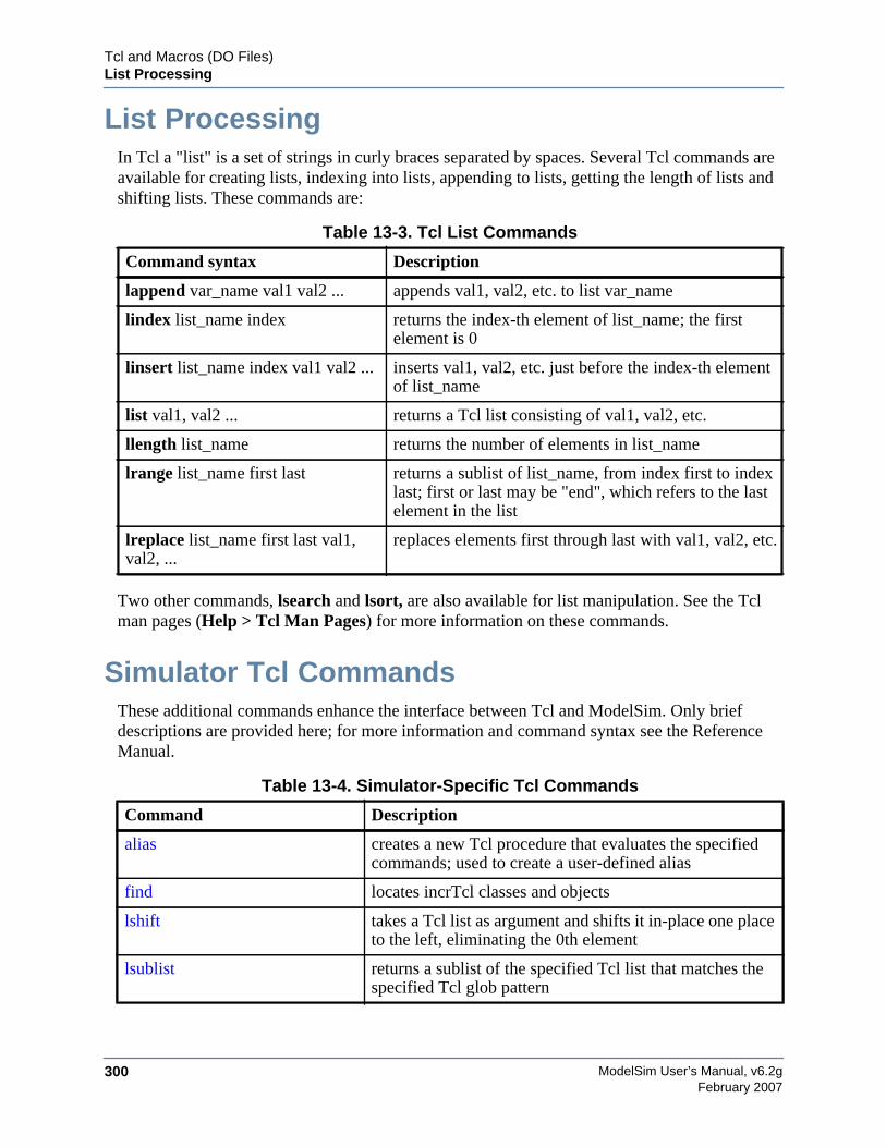
ModelSim User’s Manual, v6.2g300
Tcl and Macros (DO Files)List Processing
February 2007
List ProcessingIn Tcl a "list" is a set of strings in curly braces separated by spaces. Several Tcl commands areavailable for creating lists, indexing into lists, appending to lists, getting the length of lists andshifting lists. These commands are:
Two other commands, lsearch and lsort, are also available for list manipulation. See the Tclman pages (Help > Tcl Man Pages) for more information on these commands.
Simulator Tcl CommandsThese additional commands enhance the interface between Tcl and ModelSim. Only briefdescriptions are provided here; for more information and command syntax see the ReferenceManual.
Table 13-3. Tcl List Commands
Command syntax Description
lappend var_name val1 val2 ... appends val1, val2, etc. to list var_name
lindex list_name index returns the index-th element of list_name; the firstelement is 0
linsert list_name index val1 val2 ... inserts val1, val2, etc. just before the index-th elementof list_name
list val1, val2 ... returns a Tcl list consisting of val1, val2, etc.
llength list_name returns the number of elements in list_name
lrange list_name first last returns a sublist of list_name, from index first to indexlast; first or last may be "end", which refers to the lastelement in the list
lreplace list_name first last val1,val2, ...
replaces elements first through last with val1, val2, etc.
Table 13-4. Simulator-Specific Tcl Commands
Command Description
alias creates a new Tcl procedure that evaluates the specifiedcommands; used to create a user-defined alias
find locates incrTcl classes and objects
lshift takes a Tcl list as argument and shifts it in-place one placeto the left, eliminating the 0th element
lsublist returns a sublist of the specified Tcl list that matches thespecified Tcl glob pattern
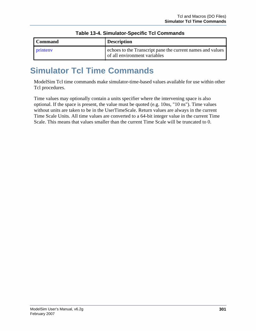
Tcl and Macros (DO Files)Simulator Tcl Time Commands
ModelSim User’s Manual, v6.2g 301February 2007
Simulator Tcl Time CommandsModelSim Tcl time commands make simulator-time-based values available for use within otherTcl procedures.
Time values may optionally contain a units specifier where the intervening space is alsooptional. If the space is present, the value must be quoted (e.g. 10ns, "10 ns"). Time valueswithout units are taken to be in the UserTimeScale. Return values are always in the currentTime Scale Units. All time values are converted to a 64-bit integer value in the current TimeScale. This means that values smaller than the current Time Scale will be truncated to 0.
printenv echoes to the Transcript pane the current names and valuesof all environment variables
Table 13-4. Simulator-Specific Tcl Commands
Command Description
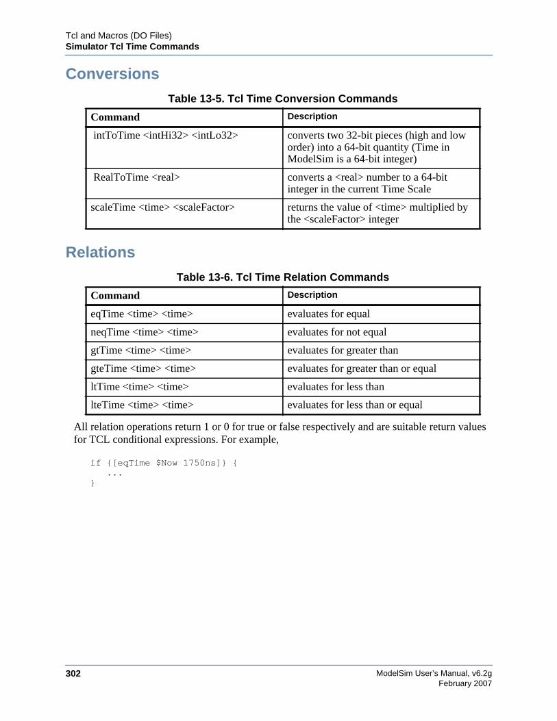
ModelSim User’s Manual, v6.2g302
Tcl and Macros (DO Files)Simulator Tcl Time Commands
February 2007
Conversions
Relations
All relation operations return 1 or 0 for true or false respectively and are suitable return valuesfor TCL conditional expressions. For example,
if {[eqTime $Now 1750ns]} {...
}
Table 13-5. Tcl Time Conversion Commands
Command Description
intToTime <intHi32> <intLo32> converts two 32-bit pieces (high and loworder) into a 64-bit quantity (Time inModelSim is a 64-bit integer)
RealToTime <real> converts a <real> number to a 64-bitinteger in the current Time Scale
scaleTime <time> <scaleFactor> returns the value of <time> multiplied bythe <scaleFactor> integer
Table 13-6. Tcl Time Relation Commands
Command Description
eqTime <time> <time> evaluates for equal
neqTime <time> <time> evaluates for not equal
gtTime <time> <time> evaluates for greater than
gteTime <time> <time> evaluates for greater than or equal
ltTime <time> <time> evaluates for less than
lteTime <time> <time> evaluates for less than or equal
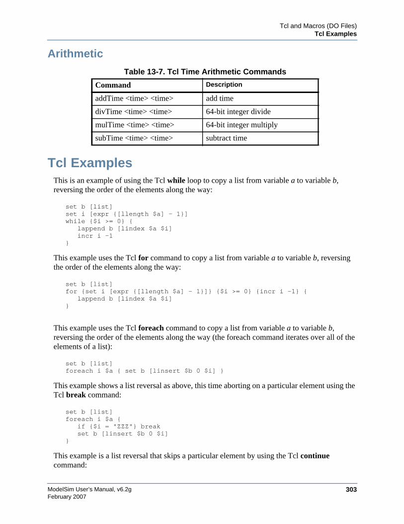
Tcl and Macros (DO Files)Tcl Examples
ModelSim User’s Manual, v6.2g 303February 2007
Arithmetic
Tcl ExamplesThis is an example of using the Tcl while loop to copy a list from variable a to variable b,reversing the order of the elements along the way:
set b [list]set i [expr {[llength $a] - 1}]while {$i >= 0} {
lappend b [lindex $a $i]incr i -1
}
This example uses the Tcl for command to copy a list from variable a to variable b, reversingthe order of the elements along the way:
set b [list]for {set i [expr {[llength $a] - 1}]} {$i >= 0} {incr i -1} {
lappend b [lindex $a $i]}
This example uses the Tcl foreach command to copy a list from variable a to variable b,reversing the order of the elements along the way (the foreach command iterates over all of theelements of a list):
set b [list]foreach i $a { set b [linsert $b 0 $i] }
This example shows a list reversal as above, this time aborting on a particular element using theTcl break command:
set b [list]foreach i $a {
if {$i = "ZZZ"} breakset b [linsert $b 0 $i]
}
This example is a list reversal that skips a particular element by using the Tcl continuecommand:
Table 13-7. Tcl Time Arithmetic Commands
Command Description
addTime <time> <time> add time
divTime <time> <time> 64-bit integer divide
mulTime <time> <time> 64-bit integer multiply
subTime <time> <time> subtract time
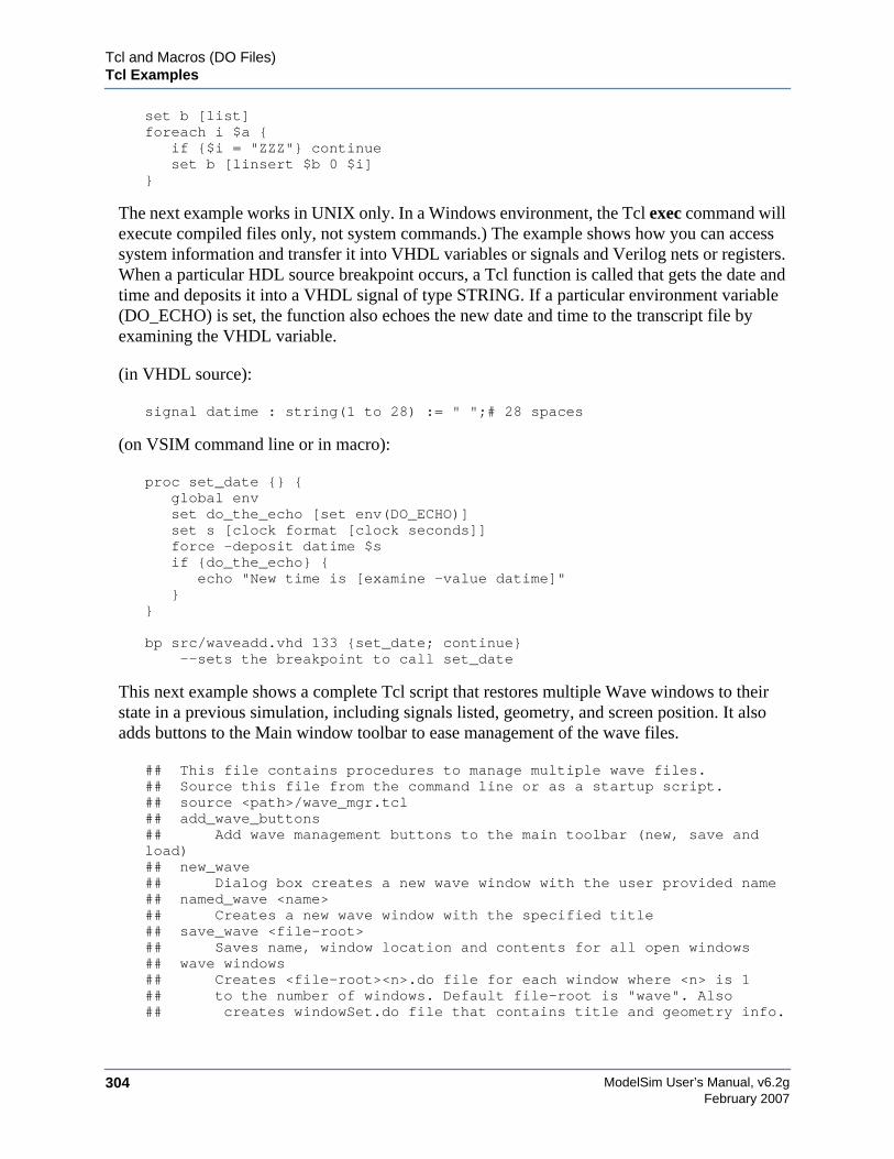
ModelSim User’s Manual, v6.2g304
Tcl and Macros (DO Files)Tcl Examples
February 2007
set b [list]foreach i $a {
if {$i = "ZZZ"} continueset b [linsert $b 0 $i]
}
The next example works in UNIX only. In a Windows environment, the Tcl exec command willexecute compiled files only, not system commands.) The example shows how you can accesssystem information and transfer it into VHDL variables or signals and Verilog nets or registers.When a particular HDL source breakpoint occurs, a Tcl function is called that gets the date andtime and deposits it into a VHDL signal of type STRING. If a particular environment variable(DO_ECHO) is set, the function also echoes the new date and time to the transcript file byexamining the VHDL variable.
(in VHDL source):
signal datime : string(1 to 28) := " ";# 28 spaces
(on VSIM command line or in macro):
proc set_date {} {global envset do_the_echo [set env(DO_ECHO)]set s [clock format [clock seconds]]force -deposit datime $sif {do_the_echo} {
echo "New time is [examine -value datime]"}
}
bp src/waveadd.vhd 133 {set_date; continue} --sets the breakpoint to call set_date
This next example shows a complete Tcl script that restores multiple Wave windows to theirstate in a previous simulation, including signals listed, geometry, and screen position. It alsoadds buttons to the Main window toolbar to ease management of the wave files.
## This file contains procedures to manage multiple wave files.## Source this file from the command line or as a startup script.## source <path>/wave_mgr.tcl## add_wave_buttons## Add wave management buttons to the main toolbar (new, save andload)## new_wave## Dialog box creates a new wave window with the user provided name## named_wave <name>## Creates a new wave window with the specified title## save_wave <file-root>## Saves name, window location and contents for all open windows## wave windows## Creates <file-root><n>.do file for each window where <n> is 1## to the number of windows. Default file-root is "wave". Also## creates windowSet.do file that contains title and geometry info.
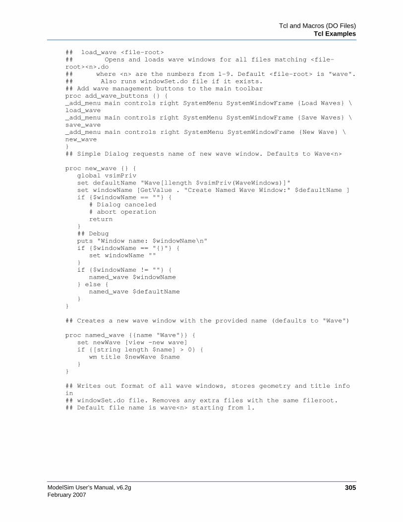
Tcl and Macros (DO Files)Tcl Examples
ModelSim User’s Manual, v6.2g 305February 2007
## load_wave <file-root>## Opens and loads wave windows for all files matching <file-root><n>.do## where <n> are the numbers from 1-9. Default <file-root> is "wave".## Also runs windowSet.do file if it exists.## Add wave management buttons to the main toolbarproc add_wave_buttons {} {_add_menu main controls right SystemMenu SystemWindowFrame {Load Waves} \load_wave_add_menu main controls right SystemMenu SystemWindowFrame {Save Waves} \save_wave_add_menu main controls right SystemMenu SystemWindowFrame {New Wave} \new_wave}## Simple Dialog requests name of new wave window. Defaults to Wave<n>
proc new_wave {} {global vsimPrivset defaultName "Wave[llength $vsimPriv(WaveWindows)]"set windowName [GetValue . "Create Named Wave Window:" $defaultName ]if {$windowName == ""} {
# Dialog canceled# abort operationreturn
}## Debugputs "Window name: $windowName\n"if {$windowName == "{}"} {
set windowName ""}if {$windowName != ""} {
named_wave $windowName} else {
named_wave $defaultName}
}
## Creates a new wave window with the provided name (defaults to "Wave")
proc named_wave {{name "Wave"}} {set newWave [view -new wave]if {[string length $name] > 0} {
wm title $newWave $name}
}
## Writes out format of all wave windows, stores geometry and title infoin## windowSet.do file. Removes any extra files with the same fileroot.## Default file name is wave<n> starting from 1.
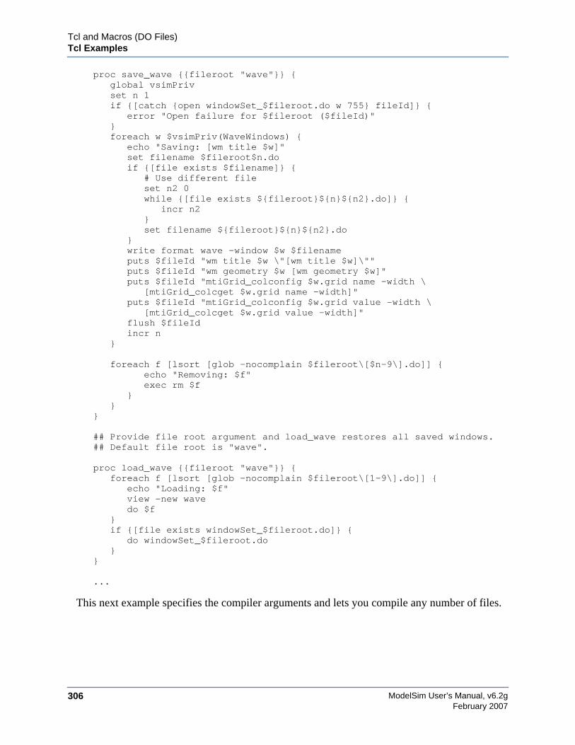
ModelSim User’s Manual, v6.2g306
Tcl and Macros (DO Files)Tcl Examples
February 2007
proc save_wave {{fileroot "wave"}} {global vsimPrivset n 1if {[catch {open windowSet_$fileroot.do w 755} fileId]} {
error "Open failure for $fileroot ($fileId)"}foreach w $vsimPriv(WaveWindows) {
echo "Saving: [wm title $w]"set filename $fileroot$n.doif {[file exists $filename]} {
# Use different fileset n2 0while {[file exists ${fileroot}${n}${n2}.do]} {
incr n2}set filename ${fileroot}${n}${n2}.do
}write format wave -window $w $filenameputs $fileId "wm title $w \"[wm title $w]\""puts $fileId "wm geometry $w [wm geometry $w]"puts $fileId "mtiGrid_colconfig $w.grid name -width \
[mtiGrid_colcget $w.grid name -width]"puts $fileId "mtiGrid_colconfig $w.grid value -width \
[mtiGrid_colcget $w.grid value -width]"flush $fileIdincr n
}
foreach f [lsort [glob -nocomplain $fileroot\[$n-9\].do]] {echo "Removing: $f"exec rm $f
}}
}
## Provide file root argument and load_wave restores all saved windows.## Default file root is "wave".
proc load_wave {{fileroot "wave"}} {foreach f [lsort [glob -nocomplain $fileroot\[1-9\].do]] {
echo "Loading: $f"view -new wavedo $f
}if {[file exists windowSet_$fileroot.do]} {
do windowSet_$fileroot.do}
}
...
This next example specifies the compiler arguments and lets you compile any number of files.
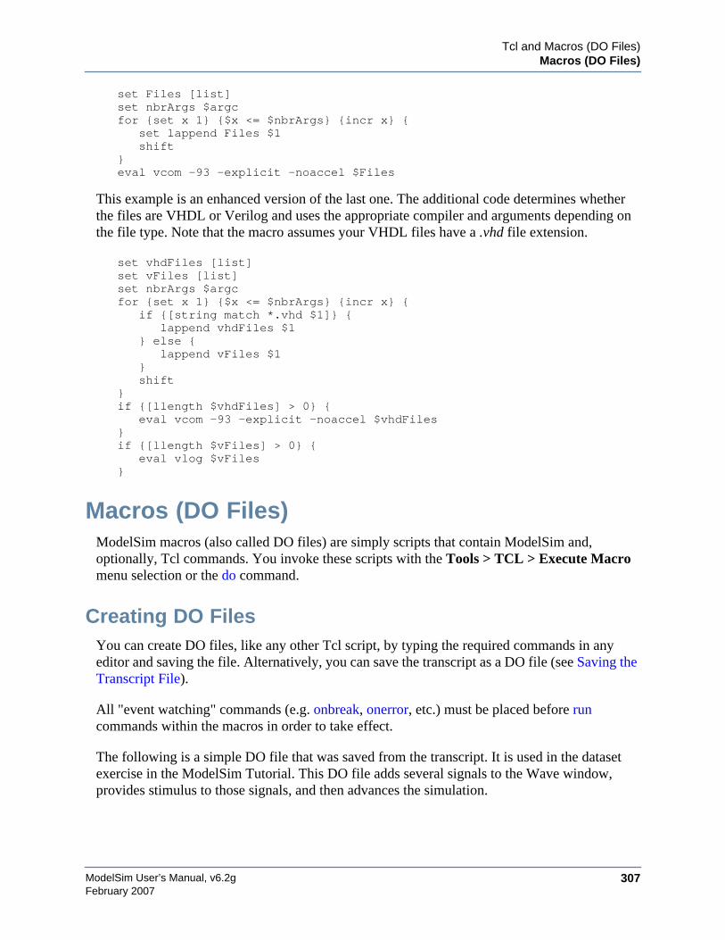
Tcl and Macros (DO Files)Macros (DO Files)
ModelSim User’s Manual, v6.2g 307February 2007
set Files [list]set nbrArgs $argcfor {set x 1} {$x <= $nbrArgs} {incr x} {
set lappend Files $1shift
}eval vcom -93 -explicit -noaccel $Files
This example is an enhanced version of the last one. The additional code determines whetherthe files are VHDL or Verilog and uses the appropriate compiler and arguments depending onthe file type. Note that the macro assumes your VHDL files have a .vhd file extension.
set vhdFiles [list]set vFiles [list]set nbrArgs $argcfor {set x 1} {$x <= $nbrArgs} {incr x} {
if {[string match *.vhd $1]} {lappend vhdFiles $1
} else {lappend vFiles $1
}shift
}if {[llength $vhdFiles] > 0} {
eval vcom -93 -explicit -noaccel $vhdFiles}if {[llength $vFiles] > 0} {
eval vlog $vFiles}
Macros (DO Files)ModelSim macros (also called DO files) are simply scripts that contain ModelSim and,optionally, Tcl commands. You invoke these scripts with the Tools > TCL > Execute Macromenu selection or the do command.
Creating DO FilesYou can create DO files, like any other Tcl script, by typing the required commands in anyeditor and saving the file. Alternatively, you can save the transcript as a DO file (see Saving theTranscript File).
All "event watching" commands (e.g. onbreak, onerror, etc.) must be placed before runcommands within the macros in order to take effect.
The following is a simple DO file that was saved from the transcript. It is used in the datasetexercise in the ModelSim Tutorial. This DO file adds several signals to the Wave window,provides stimulus to those signals, and then advances the simulation.
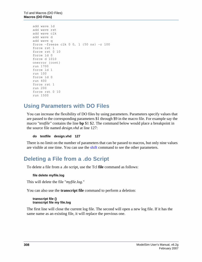
ModelSim User’s Manual, v6.2g308
Tcl and Macros (DO Files)Macros (DO Files)
February 2007
add wave ldadd wave rstadd wave clkadd wave dadd wave qforce -freeze clk 0 0, 1 {50 ns} -r 100force rst 1force rst 0 10force ld 0force d 1010onerror {cont}run 1700force ld 1run 100force ld 0run 400force rst 1run 200force rst 0 10run 1500
Using Parameters with DO FilesYou can increase the flexibility of DO files by using parameters. Parameters specify values thatare passed to the corresponding parameters $1 through $9 in the macro file. For example say themacro "testfile" contains the line bp $1 $2. The command below would place a breakpoint inthe source file named design.vhd at line 127:
do testfile design.vhd 127
There is no limit on the number of parameters that can be passed to macros, but only nine valuesare visible at one time. You can use the shift command to see the other parameters.
Deleting a File from a .do ScriptTo delete a file from a .do script, use the Tcl file command as follows:
file delete myfile.log
This will delete the file "myfile.log."
You can also use the transcript file command to perform a deletion:
transcript file ()transcript file my file.log
The first line will close the current log file. The second will open a new log file. If it has thesame name as an existing file, it will replace the previous one.
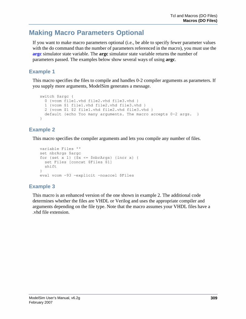
Tcl and Macros (DO Files)Macros (DO Files)
ModelSim User’s Manual, v6.2g 309February 2007
Making Macro Parameters OptionalIf you want to make macro parameters optional (i.e., be able to specify fewer parameter valueswith the do command than the number of parameters referenced in the macro), you must use theargc simulator state variable. The argc simulator state variable returns the number ofparameters passed. The examples below show several ways of using argc.
Example 1
This macro specifies the files to compile and handles 0-2 compiler arguments as parameters. Ifyou supply more arguments, ModelSim generates a message.
switch $argc {0 {vcom file1.vhd file2.vhd file3.vhd }1 {vcom $1 file1.vhd file2.vhd file3.vhd }2 {vcom $1 $2 file1.vhd file2.vhd file3.vhd }default {echo Too many arguments. The macro accepts 0-2 args. }
}
Example 2
This macro specifies the compiler arguments and lets you compile any number of files.
variable Files ""set nbrArgs $argcfor {set x 1} {$x <= $nbrArgs} {incr x} {set Files [concat $Files $1]shift
}eval vcom -93 -explicit -noaccel $Files
Example 3
This macro is an enhanced version of the one shown in example 2. The additional codedetermines whether the files are VHDL or Verilog and uses the appropriate compiler andarguments depending on the file type. Note that the macro assumes your VHDL files have a.vhd file extension.
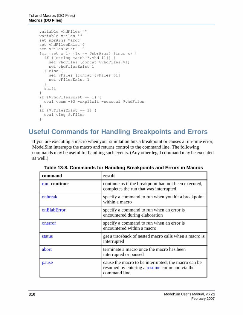
ModelSim User’s Manual, v6.2g310
Tcl and Macros (DO Files)Macros (DO Files)
February 2007
variable vhdFiles ""variable vFiles ""set nbrArgs $argcset vhdFilesExist 0set vFilesExist 0for {set x 1} {$x <= $nbrArgs} {incr x} {if {[string match *.vhd $1]} {set vhdFiles [concat $vhdFiles $1]set vhdFilesExist 1
} else {set vFiles [concat $vFiles $1]set vFilesExist 1
}shift
}if {$vhdFilesExist == 1} {eval vcom -93 -explicit -noaccel $vhdFiles
}if {$vFilesExist == 1} {eval vlog $vFiles
}
Useful Commands for Handling Breakpoints and ErrorsIf you are executing a macro when your simulation hits a breakpoint or causes a run-time error,ModelSim interrupts the macro and returns control to the command line. The followingcommands may be useful for handling such events. (Any other legal command may be executedas well.)
Table 13-8. Commands for Handling Breakpoints and Errors in Macros
command result
run -continue continue as if the breakpoint had not been executed,completes the run that was interrupted
onbreak specify a command to run when you hit a breakpointwithin a macro
onElabError specify a command to run when an error isencountered during elaboration
onerror specify a command to run when an error isencountered within a macro
status get a traceback of nested macro calls when a macro isinterrupted
abort terminate a macro once the macro has beeninterrupted or paused
pause cause the macro to be interrupted; the macro can beresumed by entering a resume command via thecommand line
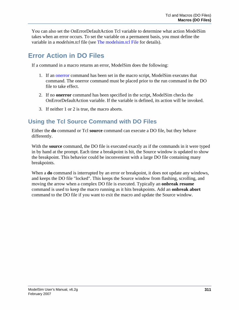
Tcl and Macros (DO Files)Macros (DO Files)
ModelSim User’s Manual, v6.2g 311February 2007
You can also set the OnErrorDefaultAction Tcl variable to determine what action ModelSimtakes when an error occurs. To set the variable on a permanent basis, you must define thevariable in a modelsim.tcl file (see The modelsim.tcl File for details).
Error Action in DO FilesIf a command in a macro returns an error, ModelSim does the following:
1. If an onerror command has been set in the macro script, ModelSim executes thatcommand. The onerror command must be placed prior to the run command in the DOfile to take effect.
2. If no onerror command has been specified in the script, ModelSim checks theOnErrorDefaultAction variable. If the variable is defined, its action will be invoked.
3. If neither 1 or 2 is true, the macro aborts.
Using the Tcl Source Command with DO FilesEither the do command or Tcl source command can execute a DO file, but they behavedifferently.
With the source command, the DO file is executed exactly as if the commands in it were typedin by hand at the prompt. Each time a breakpoint is hit, the Source window is updated to showthe breakpoint. This behavior could be inconvenient with a large DO file containing manybreakpoints.
When a do command is interrupted by an error or breakpoint, it does not update any windows,and keeps the DO file "locked". This keeps the Source window from flashing, scrolling, andmoving the arrow when a complex DO file is executed. Typically an onbreak resumecommand is used to keep the macro running as it hits breakpoints. Add an onbreak abortcommand to the DO file if you want to exit the macro and update the Source window.

ModelSim User’s Manual, v6.2g312
Tcl and Macros (DO Files)Macros (DO Files)
February 2007
ModelSim User’s Manual, v6.2g 313February 2007
Appendix ASimulator Variables
This appendix documents the following types of variables:
• Environment Variables — Variables referenced and set according to operating systemconventions. Environment variables prepare the ModelSim environment prior tosimulation.
• Simulator Control Variables — Variables used to control compiler, simulator, andvarious other functions.
• Simulator State Variables — Variables that provide feedback on the state of the currentsimulation.
Variable Settings ReportThe report command returns a list of current settings for either the simulator state or simulatorcontrol variables. Use the following commands at either the ModelSim or VSIM prompt:
report simulator statereport simulator control
Environment Variables
Environment Variable ExpansionThe shell commands vcom, vlog, vsim, and vmap, no longer expand environment variables infilename arguments and options. Instead, variables should be expanded by the shell beforehand,in the usual manner. The -f option that most of these commands support, now performsenvironment variable expansion throughout the file.
Environment variable expansion is still performed in the following places:
• Pathname and other values in the modelsim.ini file
• Strings used as file pathnames in VHDL and Verilog
• VHDL Foreign attributes
• The PLIOBJS environment variable may contain a path that has an environmentvariable.
• Verilog `uselib file and dir directives
ModelSim User’s Manual, v6.2g314
Simulator VariablesEnvironment Variables
February 2007
• Anywhere in the contents of a -f file
The recommended method for using flexible pathnames is to make use of the MGC LocationMap system (see Using Location Mapping). When this is used, then pathnames stored inlibraries and project files (.mpf) will be converted to logical pathnames.
If a file or path name contains the dollar sign character ($), and must be used in one of the placeslisted above that accepts environment variables, then the explicit dollar sign must be escaped byusing a double dollar sign ($$).
Setting Environment VariablesBefore compiling or simulating, several environment variables may be set to provide thefunctions described below. The variables are set through the System control panel on Windows2000 and XP machines. For UNIX, the variables are typically found in the .login script. TheLM_LICENSE_FILE variable is required; all others are optional.
DOPATH
The toolset uses the DOPATH environment variable to search for DO files (macros). DOPATHconsists of a colon-separated (semi-colon for Windows) list of paths to directories. You canoverride this environment variable with the DOPATH Tcl preference variable.
The DOPATH environment variable isn’t accessible when you invoke vsim from a UNIX shellor from a Windows command prompt. It is accessible once ModelSim or vsim is invoked. Ifyou need to invoke from a shell or command line and use the DOPATH environment variable,use the following syntax:
vsim -do "do <dofile_name>" <design_unit>
EDITOR
The EDITOR environment variable specifies the editor to invoke with the edit command
HOME
The toolset uses the HOME environment variable to look for an optional graphical preferencefile and optional location map file. Refer to Simulator Control Variables for additionalinformation.
HOME_0IN
The HOME_0IN environment variable identifies the location of the 0-In executables directory.Refer to the 0-In documentation for more information.
Simulator VariablesEnvironment Variables
ModelSim User’s Manual, v6.2g 315February 2007
LD_LIBRARY_PATH
A UNIX shell environment variable setting the search directories for shared libraries. Itinstructs the OS where to search for the shared libraries for FLI/PLI/VPI/DPI. This variable isused for both 32-bit and 64-bit shared libraries on Solaris/Linux systems.
LD_LIBRARY_PATH_32
A UNIX shell environment variable setting the search directories for shared libraries. Itinstructs the OS where to search for the shared libraries for FLI/PLI/VPI/DPI. This variable isused only for 32-bit shared libraries on Solaris/Linux systems.
LD_LIBRARY_PATH_64
A UNIX shell environment variable setting the search directories for shared libraries. Itinstructs the OS where to search for the shared libraries for FLI/PLI/VPI/DPI. This variable isused only for 64-bit shared libraries on Solaris/Linux systems.
LM_LICENSE_FILE
The toolset’s file manager uses the LM_LICENSE_FILE environment variable to find thelocation of the license file. The argument may be a colon-separated (semi-colon for Windows)set of paths, including paths to other vendor license files. The environment variable is required.
MODEL_TECH
The toolset automatically sets the MODEL_TECH environment variable to the directory inwhich the binary executable resides; DO NOT SET THIS VARIABLE!
MODEL_TECH_TCL
The toolset uses the MODEL_TECH_TCL environment variable to find Tcl libraries for Tcl/Tk8.3 and vsim, and may also be used to specify a startup DO file. This variable defaults to/modeltech/../tcl, however you may set it to an alternate path
MGC_LOCATION_MAP
The toolset uses the MGC_LOCATION_MAP environment variable to find source files basedon easily reallocated "soft" paths.
MODELSIM
The toolset uses the MODELSIM environment variable to find the modelsim.ini file. Theargument consists of a path including the file name.
An alternative use of this variable is to set it to the path of a project file(<Project_Root_Dir>/<Project_Name>.mpf). This allows you to use project settings with
ModelSim User’s Manual, v6.2g316
Simulator VariablesEnvironment Variables
February 2007
command line tools. However, if you do this, the .mpf file will replace modelsim.ini as theinitialization file for all tools.
MODELSIM_PREFERENCES
The MODELSIM_PREFERENCES environment variable specifies the location to store userinterface preferences. Setting this variable with the path of a file instructs the toolset to use thisfile instead of the default location (your HOME directory in UNIX or in the registry inWindows). The file does not need to exist beforehand, the toolset will initialize it. Also, if thisfile is read-only, the toolset will not update or otherwise modify the file. This variable maycontain a relative pathname – in which case the file will be relative to the working directory atthe time the tool is started.
MODELSIM_TCL
The toolset uses the MODELSIM_TCL environment variable to look for an optional graphicalpreference file. The argument can be a colon-separated (UNIX) or semi-colon separated(Windows) list of file paths.
MTI_COSIM_TRACE
The MTI_COSIM_TRACE environment variable creates an mti_trace_cosim file containingdebugging information about FLI/PLI/VPI function calls. You should set this variable to anyvalue before invoking the simulator.
MTI_TF_LIMIT
The MTI_TF_LIMIT environment variable limits the size of the VSOUT temp file (generatedby the toolset’s kernel). Set the argument of this variable to the size of k-bytes
The environment variable TMPDIR controls the location of this file, while STDOUT controlsthe name. The default setting is 10, and a value of 0 specifies that there is no limit. This variabledoes not control the size of the transcript file.
MTI_RELEASE_ON_SUSPEND
The MTI_RELEASE_ON_SUSPEND environment variable allows you to turn off or modifythe delay for the functionality of releasing all licenses when the tool is suspended. The defaultsetting is 10 (in seconds), which means that if you do not set this variable your licenses will bereleased 10 seconds after your run is suspended. If you set this environment variable with anargument of 0 (zero) the tool will not release the licenses after being suspended. You canchange the default length of time (number of seconds) by setting this environment variable to aninteger greater than 0 (zero).
Simulator VariablesEnvironment Variables
ModelSim User’s Manual, v6.2g 317February 2007
MTI_USELIB_DIR
The MTI_USELIB_DIR environment variable specifies the directory into which object librariesare compiled when using the -compile_uselibs argument to the vlog command
NOMMAP
When set to 1, the NOMMAP environment variable disables memory mapping in the toolset.You should only use this variable when running on Linux 7.1 because it will decrease the speedwith which the tool reads files.
PLIOBJS
The toolset uses the PLIOBJS environment variable to search for PLI object files for loading.The argument consists of a space-separated list of file or path names
STDOUT
The argument to the STDOUT environment variable specifies a filename to which the simulatorsaves the VSOUT temp file information. Typically this information is deleted when thesimulator exits. The location for this file is set with the TMPDIR variable, which allows you tofind and delete the file in the event of a crash, because an unnamed VSOUT file is not deletedafter a crash.
TMP
(Windows environments) The TMP environment variable specifies the path to a tempnam()generated file (VSOUT) containing all stdout from the simulation kernel.
TMPDIR
(UNIX environments) The TMPDIR environment variable specifies the path to a tempnam()generated file (VSOUT) containing all stdout from the simulation kernel.
Creating Environment Variables in WindowsIn addition to the predefined variables shown above, you can define your own environmentvariables. This example shows a user-defined library path variable that can be referenced by thevmap command to add library mapping to the modelsim.ini file.
1. From your desktop, right-click your My Computer icon and select Properties
2. In the System Properties dialog box, select the Advanced tab
3. Click Environment Variables
4. In the Environment Variables dialog box and User variables for <user> pane, selectNew:
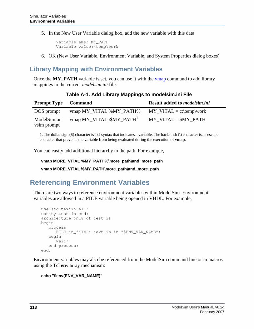
ModelSim User’s Manual, v6.2g318
Simulator VariablesEnvironment Variables
February 2007
5. In the New User Variable dialog box, add the new variable with this data
Variable ame: MY_PATHVariable value:\temp\work
6. OK (New User Variable, Environment Variable, and System Properties dialog boxes)
Library Mapping with Environment VariablesOnce the MY_PATH variable is set, you can use it with the vmap command to add librarymappings to the current modelsim.ini file.
You can easily add additional hierarchy to the path. For example,
vmap MORE_VITAL %MY_PATH%\more_path\and_more_path
vmap MORE_VITAL \$MY_PATH\more_path\and_more_path
Referencing Environment VariablesThere are two ways to reference environment variables within ModelSim. Environmentvariables are allowed in a FILE variable being opened in VHDL. For example,
use std.textio.all;entity test is end;architecture only of test isbegin
processFILE in_file : text is in "$ENV_VAR_NAME";
beginwait;
end process;end;
Environment variables may also be referenced from the ModelSim command line or in macrosusing the Tcl env array mechanism:
echo "$env(ENV_VAR_NAME)"
Table A-1. Add Library Mappings to modelsim.ini File
Prompt Type Command Result added to modelsim.ini
DOS prompt vmap MY_VITAL %MY_PATH% MY_VITAL = c:\temp\work
ModelSim orvsim prompt
vmap MY_VITAL \$MY_PATH1
1. The dollar sign ($) character is Tcl syntax that indicates a variable. The backslash (\) character is an escapecharacter that prevents the variable from being evaluated during the execution of vmap.
MY_VITAL = $MY_PATH
Simulator VariablesSimulator Control Variables
ModelSim User’s Manual, v6.2g 319February 2007
NoteEnvironment variable expansion does not occur in files that are referenced via the -fargument to vcom, vlog, or vsim.
Removing Temp Files (VSOUT)The VSOUT temp file is the communication mechanism between the simulator kernel and theGraphical User Interface. In normal circumstances the file is deleted when the simulator exits. Ifthe tool crashes, however, the temp file must be deleted manually. Specifying the location of thetemp file with TMPDIR (above) will help you locate and remove the file.
Simulator Control VariablesInitialization (INI) files contain control variables that specify reference library paths andcompiler and simulator settings. The default initialization file is modelsim.ini and is located inyour install directory.
To set these variables, edit the initialization file directly with any text editor. The syntax forvariables in the file is:
<variable> = <value>
Comments within the file are preceded with a semicolon ( ; ).
The following sections contain information about the variables:
• Library Path Variables
• Verilog Compiler Control Variables
• VHDL Compiler Control Variables
• Simulation Control Variables
Library Path VariablesYou can find these variables under the heading [Library] in the modelsim.ini file.
ieee
This variable sets the path to the library containing IEEE and Synopsys arithmetic packages.
• Value Range: any valid path; may include environment variables
• Default: $MODEL_TECH/../ieee
ModelSim User’s Manual, v6.2g320
Simulator VariablesSimulator Control Variables
February 2007
modelsim_lib
This variable sets the path to the library containing Model Technology VHDL utilities such asSignal Spy.
• Value Range: any valid path; may include environment variables
• Default: $MODEL_TECH/../modelsim_lib
std
This variable sets the path to the VHDL STD library.
• Value Range: any valid path; may include environment variables
• Default: $MODEL_TECH/../std
std_developerskit
This variable sets the path to the libraries for MGC standard developer’s kit.
• Value Range: any valid path; may include environment variables
• Default: $MODEL_TECH/../std_developerskit
synopsys
This variable sets the path to the accelerated arithmetic packages.
• Value Range: any valid path; may include environment variables
• Default: $MODEL_TECH/../synopsys
sv_std
This variable sets the path to the SystemVerilog STD library.
• Value Range: any valid path; may include environment variables
• Default: $MODEL_TECH/../sv_std
verilog
This variable sets the path to the library containing VHDL/Verilog type mappings.
• Value Range: any valid path; may include environment variables
• Default: $MODEL_TECH/../verilog
Simulator VariablesSimulator Control Variables
ModelSim User’s Manual, v6.2g 321February 2007
vital2000
This variable sets the path to the VITAL 2000 library
• Value Range: any valid path; may include environment variables
• Default: $MODEL_TECH/../vital2000
others
This variable points to another modelsim.ini file whose library path variables will also be read;the pathname must include "modelsim.ini"; only one others variable can be specified in anymodelsim.ini file.
• Value Range: any valid path; may include environment variables
• Default: none
Verilog Compiler Control VariablesYou can find these variables under the heading [vlog] in the modelsim.ini file.
DisableOpt
This variable, when on, disables all optimizations enacted by the compiler; same as the -O0argument to vlog.
• Value Range: 0, 1
• Default: off (0)
GenerateLoopIterationMax
This variable specifies the maximum number of iterations permitted for a generate loop;restricting this permits the implementation to recognize infinite generate loops.
• Value Range: natural integer (>=0)
• Default: 100000
GenerateRecursionDepthMax
This variable specifies the maximum depth permitted for a recursive generate instantiation;restricting this permits the implementation to recognize infinite recursions.
• Value Range: natural integer (>=0)
• Default: 200
ModelSim User’s Manual, v6.2g322
Simulator VariablesSimulator Control Variables
February 2007
Hazard
This variable turns on Verilog hazard checking (order-dependent accessing of global variables).
• Value Range: 0, 1
• Default: off (0)
Incremental
This variable activates the incremental compilation of modules.
• Value Range: 0, 1
• Default: off (0)
MultiFileCompilationUnit
Controls how Verilog files are compiled into compilation units. Valid arguments:
• 1 -- (0n) Compiles all files on command line into a single compilation unit. Thisbehavior is called Multi File Compilation Unit (MFCU) mode; same as -mfcu argumentto
• 0 -- (Off) Default value. Compiles each file in the compilation command line intoseparate compilation units. This behavior is called Single File Compilation Unit (SFCU)mode.
Refer to SystemVerilog Multi-File Compilation Issues for details on the implications of thesesettings.
NoteThe default behavior in versions prior to 6.1 was opposite of the current default behavior.
NoDebug
This variable, when on, disables the inclusion of debugging info within design units.
• Value Range: 0, 1
• Default: off (0)
Quiet
This variable turns off "loading…" messages.
• Value Range: 0, 1
• Default: off (0)
Simulator VariablesSimulator Control Variables
ModelSim User’s Manual, v6.2g 323February 2007
Show_BadOptionWarning
This variable instructs the tool to generate a warning whenever an unknown plus argument isencountered.
• Value Range: 0, 1
• Default: off (0)
Show_Lint
This variable instructs the tool to display lint warning messages.
• Value Range: 0, 1
• Default: off (0)
Show_WarnCantDoCoverage
This variable instructs the tool to display warning messages when the simulator encountersconstructs which code coverage cannot handle.
• Value Range: 0,1
• Default: on (1)
Show_WarnMatchCadence
This variable instructs the tool to display warning messages about non-LRM compliance inorder to match Cadence behavior.
• Value Range: 0, 1
• Default: on (1)
Show_source
This variable instructs the tool to show any source line containing an error.
• Value Range: 0, 1
• Default: off (0)
vlog95compat
This variable instructs the tool to disable SystemVerilog and Verilog 2001 support, making thecompiler compatible with IEEE Std 1364-1995.
• Value Range: 0, 1
ModelSim User’s Manual, v6.2g324
Simulator VariablesSimulator Control Variables
February 2007
• Default: off (0)
VHDL Compiler Control VariablesYou can find these variables under the heading [vcom].
BindAtCompile
This variable instructs the tool to perform VHDL default binding at compile time rather thanload time. Refer to Default Binding for more information.
• Value Range: 0, 1
• Default: off (0)
CheckSynthesis
This variable turns on limited synthesis rule compliance checking, which includes checkingonly signals used (read) by a process and understanding only combinational logic, not clockedlogic.
• Value Range: 0, 1
• Default: off (0)
DisableOpt
This variable disables all optimizations enacted by the compiler, similar to using the -O0argument to vcom.
• Value Range: 0, 1
• Default: off (0)
Explicit
This variable enables the resolving of ambiguous function overloading in favor of the "explicit"function declaration (not the one automatically created by the compiler for each typedeclaration).
• Value Range: 0, 1
• Default: on (1)
IgnoreVitalErrors
This variable instructs the tool to ignore VITAL compliance checking errors.
• Value Range: 0, 1
Simulator VariablesSimulator Control Variables
ModelSim User’s Manual, v6.2g 325February 2007
• Default: off (0)
NoCaseStaticError
This variable changes case statement static errors to warnings.
• Value Range: 0, 1
• Default: off (0)
NoDebug
This variable disables turns off inclusion of debugging info within design units.
• Value Range: 0, 1
• Default: off (0)
NoIndexCheck
This variable disables run time index checks.
• Value Range: 0, 1
• Default: off (0)
NoOthersStaticError
This variable disables errors caused by aggregates that are not locally static.
• Value Range: 0, 1
• Default: off (0)
NoRangeCheck
This variable disables run time range checking.
• Value Range: 0, 1
• Default: off (0)
NoVital
This variable disables acceleration of the VITAL packages.
• Value Range: 0, 1
• Default: off (0)
ModelSim User’s Manual, v6.2g326
Simulator VariablesSimulator Control Variables
February 2007
NoVitalCheck
This variable disables VITAL compliance checking.
• Value Range: 0, 1
• Default: off (0)
Optimize_1164
This variable disables optimization for the IEEE std_logic_1164 package.
• Value Range: 0, 1
• Default: on (1)
PedanticErrors
This variable overrides NoCaseStaticError and NoOthersStaticError
• Value Range: 0, 1
• Default: off(0)
Quiet
This variable disables the “loading…” messages.
• Value Range: 0, 1
• Default: off (0)
RequireConfigForAllDefaultBinding
This variable instructs the compiler not to generate a default binding during compilation.
• Value Range: 0, 1
• Default: off (0)
Show_Lint
This variable enables lint-style checking.
• Value Range: 0, 1
• Default: off (0)
Show_source
This variable shows source line containing error.
Simulator VariablesSimulator Control Variables
ModelSim User’s Manual, v6.2g 327February 2007
• Value Range: 0, 1
• Default: off (0)
Show_VitalChecksOpt
This variable enables VITAL optimization warnings.
• Value Range: 0, 1
• Default: on (1)
Show_VitalChecksWarnings
This variable enables VITAL compliance-check warnings.
• Value Range: 0, 1
• Default: on (1)
Show_WarnCantDoCoverage
This variable enables warnings when the simulator encounters constructs which code coveragecannot handle.
• Value Range: 0, 1
• Default: on (1)
Show_Warning1
This variable enables unbound-component warnings.
• Value Range: 0, 1
• Default: on (1)
Show_Warning2
This variable enables process-without-a-wait-statement warnings.
• Value Range: 0, 1
• Default: on (1)
Show_Warning3
This variable enables null-range warnings.
• Value Range: 0, 1
ModelSim User’s Manual, v6.2g328
Simulator VariablesSimulator Control Variables
February 2007
• Default: on (1)
Show_Warning4
This variable enables no-space-in-time-literal warnings.
• Value Range: 0, 1
• Default: on (1)
Show_Warning5
This variable enables multiple-drivers-on-unresolved-signal warnings.
• Value Range: 0, 1
• Default: on (1)
Show_Warning9
This variable enables warnings about signal value dependency at elaboration.
• Value Range: 0, 1
• Default: on (1)
Show_Warning10
This variable enables warnings about VHDL-1993 constructs in VHDL-1987 code.
• Value Range: 0, 1
• Default: on (1)
Show_WarnLocallyStaticError
This variable enables warnings about locally static errors deferred until run time.
• Value Range: 0, 1
• Default: on (1)
VHDL93
This variable enables support for VHDL-1987, where “1” enables support for VHDL-1993 and“2” enables support for VHDL-2002.
• Value Range: 0, 1, 2
• Default: 2
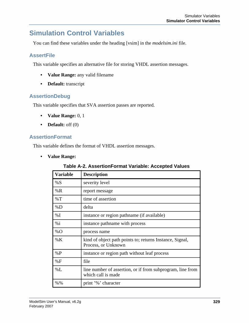
Simulator VariablesSimulator Control Variables
ModelSim User’s Manual, v6.2g 329February 2007
Simulation Control VariablesYou can find these variables under the heading [vsim] in the modelsim.ini file.
AssertFile
This variable specifies an alternative file for storing VHDL assertion messages.
• Value Range: any valid filename
• Default: transcript
AssertionDebug
This variable specifies that SVA assertion passes are reported.
• Value Range: 0, 1
• Default: off (0)
AssertionFormat
This variable defines the format of VHDL assertion messages.
• Value Range:
Table A-2. AssertionFormat Variable: Accepted Values
Variable Description
%S severity level
%R report message
%T time of assertion
%D delta
%I instance or region pathname (if available)
%i instance pathname with process
%O process name
%K kind of object path points to; returns Instance, Signal,Process, or Unknown
%P instance or region path without leaf process
%F file
%L line number of assertion, or if from subprogram, line fromwhich call is made
%% print ’%’ character
ModelSim User’s Manual, v6.2g330
Simulator VariablesSimulator Control Variables
February 2007
• Default: "** %S: %R\n Time: %T Iteration: %D%I\n"
AssertionFormatBreak
This variable defines the format of messages for VHDL assertions that trigger a breakpoint.
• Value Range: Refer to Table A-2
• Default: "** %S: %R\n Time: %T Iteration: %D %K: %i File: %F\n"
AssertionFormatError
This variable defines the format of messages for VHDL Error assertions.
If undefined, AssertionFormat is used unless assertion causes a breakpoint in which caseAssertionFormatBreak is used.
• Value Range: Refer to Table A-2
• Default: "** %S: %R\n Time: %T Iteration: %D %K: %i File: %F\n"
AssertionFormatFail
This variable defines the format of messages for VHDL Fail assertions.
If undefined, AssertionFormat is used unless assertion causes a breakpoint in which caseAssertionFormatBreak is used
• Value Range: Refer to Table A-2
• Default: "** %S: %R\n Time: %T Iteration: %D %K: %i File: %F\n"
AssertionFormatFatal
This variable defines the format of messages for VHDL Fatal assertions
If undefined, AssertionFormat is used unless assertion causes a breakpoint in which caseAssertionFormatBreak is used.
• Value Range: Refer to Table A-2
• Default: "** %S: %R\n Time: %T Iteration: %D %K: %i File: %F\n"
AssertionFormatNote
This variable defines the format of messages for VHDL Note assertions
If undefined, AssertionFormat is used unless assertion causes a breakpoint in which caseAssertionFormatBreak is used
Simulator VariablesSimulator Control Variables
ModelSim User’s Manual, v6.2g 331February 2007
• Value Range: Refer to Table A-2
• Default: "** %S: %R\n Time: %T Iteration: %D%I\n"
AssertionFormatWarning
This variable defines the format of messages for VHDL Warning assertions
If undefined, AssertionFormat is used unless assertion causes a breakpoint in which caseAssertionFormatBreak is used
• Value Range: Refer to Table A-2
• Default: "** %S: %R\n Time: %T Iteration: %D%I\n"
BreakOnAssertion
This variable defines the severity of VHDL assertions that cause a simulation break. It alsocontrols any messages in the source code that use assertion_failure_*. For example, since mostruntime messages use some form of assertion_failure_*, any runtime error will cause thesimulation to break if the user sets BreakOnAssertion to 2.
You can set this variable interactively in the GUI; refer to Setting Simulator Control VariablesWith The GUI.
• Value Range: 0 (note), 1 (warning), 2 (error), 3 (failure), 4 (fatal)
• Default: 3 (failure)
CheckPlusargs
This variable defines the simulator’s behavior when encountering unrecognized plusargs.
• Value Range: 0 (ignores), 1 (issues warning, simulates while ignoring), 2 (issues error,exits)
• Default: 0 (ignores)
CheckpointCompressMode
This variable specifies that checkpoint files are written in compressed format
• Value Range: 0, 1
• Default: on (1)
CommandHistory
This variable specifies the name of a file in which to store the Main window command history.
ModelSim User’s Manual, v6.2g332
Simulator VariablesSimulator Control Variables
February 2007
• Value Range: any valid filename
• Default: commented out (;)
ConcurrentFileLimit
This variable controls the number of VHDL files open concurrently. This number should be lessthan the current limit setting for max file descriptors.
• Value Range: any positive integer or 0 (unlimited)
• Default: 40
DatasetSeparator
This variable specifies the dataset separator for fully-rooted contexts, for example:
sim:/top
The argument to DatasetSeparator must not be the same character as PathSeparator
• Value Range: any character except those with special meaning, such as \, {, }, etc.
• Default: :
DefaultForceKind
This variable defines the kind of force used when not otherwise specified.
You can set this variable interactively in the GUI; refer to Setting Simulator Control VariablesWith The GUI.
• Value Range: freeze, drive, or deposit
• Default: drive, for resolved signals; freeze, for unresolved signals
DefaultRadix
This variable specifies a numeric radix may be specified as a name or number. For example,you can specify binary as “binary” or “2” or octal as “octal” or “8”.
You can set this variable interactively in the GUI; refer to Setting Simulator Control VariablesWith The GUI.
• Value Range: symbolic, binary, octal, decimal, unsigned, hexadecimal, ascii
• Default: symbolic
Simulator VariablesSimulator Control Variables
ModelSim User’s Manual, v6.2g 333February 2007
DefaultRestartOptions
This variable sets the default behavior for the restart command
• Value Range: one or more of: -force, -noassertions, -nobreakpoint, -nofcovers, -nolist,-nolog, -nowave
• Default: commented out (;)
DelayFileOpen
This variable instructs the tool to open VHDL87 files on first read or write, else open files whenelaborated.
• Value Range: 0, 1
• Default: off (0)
DumpportsCollapse
This variable collapses vectors (VCD id entries) in dumpports output.
• Value Range: 0, 1
• Default: off (0)
GenerateFormat
This variable controls the format of a generate statement label. Do not enclose the argument inquotation marks.
• Value Range: Any non-quoted string containing at a minimum a %s followed by a %d
• Default: %s__%d
GlobalSharedObjectsList
This variable instruct the tool to load the specified PLI/FLI shared objects with global symbolvisibility.
• Value Range: comma separated list of filenames
• Default: commented out (;)
IgnoreError
This variable instructs the tool to ignore VHDL assertion errors.
You can set this variable interactively in the GUI; refer to Setting Simulator Control VariablesWith The GUI.
ModelSim User’s Manual, v6.2g334
Simulator VariablesSimulator Control Variables
February 2007
• Value Range: 0,1
• Default: off (0)
IgnoreFailure
This variable instructs the tool to ignore VHDL assertion failures.
You can set this variable interactively in the GUI; refer to Setting Simulator Control VariablesWith The GUI.
• Value Range: 0,1
• Default: off (0)
IgnoreNote
This variable instructs the tool to ignore VHDL assertion notes.
You can set this variable interactively in the GUI; refer to Setting Simulator Control VariablesWith The GUI.
• Value Range: 0,1
• Default: off (0)
IgnoreWarning
This variable instructs the tool to ignore VHDL assertion warnings.
You can set this variable interactively in the GUI; refer to Setting Simulator Control VariablesWith The GUI.
• Value Range: 0,1
• Default: off (0)
IterationLimit
This variable specifies a limit on simulation kernel iterations allowed without advancing time.
You can set this variable interactively in the GUI; refer to Setting Simulator Control VariablesWith The GUI.
• Value Range: positive integer
• Default: 5000
Simulator VariablesSimulator Control Variables
ModelSim User’s Manual, v6.2g 335February 2007
License
This variable controls the license file search.
• Value Range: one ore more of the following <license_option>, separated by spaces ifusing multiple entries. Refer also to the vsim <license_option>.
• Default: search all licenses
LockedMemory
For HP-UX 10.2 use only. This variable enables memory locking to speed up large designs (>500mb memory footprint)
• Value Range: positive integer in units of MB.
• Default: disabled
MaxReportRhsCrossProducts
This variable specifies a limit on number of Cross (bin) products which are listed against aCross when a XML or UCDB report is generated. The warning reports when any instance ofunusually high number of Cross (bin) product and truncation of Cross (bin) product list for aCross.
• Value Range: positive integer
Table A-3. License Variable: License Options
license_option Description
lnlonly only use msimhdlsim and hdlsim
mixedonly exclude single language licenses
nomgc exclude MGC licenses
nolnl exclude language neutral licenses
nomix exclude msimhdlmix and hdlmix
nomti exclude MTI licenses
noqueue do not wait in license queue if no licenses are available
noslvhdl exclude qhsimvh and vsim
noslvlog exclude qhsimvl and vsimvlog
plus only use PLUS license
vlog only use VLOG license
vhdl only use VHDL license
ModelSim User’s Manual, v6.2g336
Simulator VariablesSimulator Control Variables
February 2007
• Default: 1000
NumericStdNoWarnings
This variable disables warnings generated within the accelerated numeric_std and numeric_bitpackages.
You can set this variable interactively in the GUI; refer to Setting Simulator Control VariablesWith The GUI.
• Value Range: 0, 1
• Default: off (0)
OnFinish
This variable controls the behavior of the tool when it encounters $finish in the design code.
• Value Range:
• ask —
o In batch mode, the simulation exits.
o In GUI mode, a dialog box pops up and asks for user confirmation on whether toquit the simulation.
• stop — Causes the simulation to stay loaded in memory. This can make some post-simulation tasks easier.
• exit — The simulation exits without asking for any confirmation.
• Default: ask — Exits in batch mode; prompts user in GUI mode.
PathSeparator
This variable specifies the character used for hierarchical boundaries of HDL modules. Thisvariable does not affect file system paths. The argument to PathSeparator must not be the samecharacter as DatasetSeparator.
• Value Range: any character except those with special meaning, such as \, {, }, etc.
• Default: /
PrintSimStats
This variable instructs the simulator to print the output of the simstats command upon exit. Youcan set this variable interactively with the -printsimstats argument to the vsim command.
• Value Range: 0, 1

Simulator VariablesSimulator Control Variables
ModelSim User’s Manual, v6.2g 337February 2007
• Default: 0
Resolution
This variable specifies the simulator resolution. The argument must be less than or equal to theUserTimeUnit and must not contain a space between value and units, for example:
Resoultion = 10fs
You can override this value with the -t argument to vsim. You should set a smaller resolution ifyour delays get truncated.
• Value Range: fs, ps, ns, us, ms, or sec with optional prefix of 1, 10, or 100
• Default: ps
RunLength
This variable specifies the default simulation length in units specified by the UserTimeUnitvariable
You can set this variable interactively in the GUI; refer to Setting Simulator Control VariablesWith The GUI.
• Value Range: positive integer
• Default: 100
ShowFunctions
This variable sets the format for Breakpoint and Fatal error messages. When set to 1 (the defaultvalue), messages will display the name of the function, task, subprogram, module, orarchitecture where the condition occurred, in addition to the file and line number. Set to 0 torevert messages to previous format.
• Value Range: 0, 1
• Default: 1
SignalSpyPathSeparator
This variable specifies a unique path separator for the Signal Spy functions. The argument toSignalSpyPathSeparator must not be the same character as DatasetSeparator.
• Value Range: any character except those with special meaning, such as \, {, }, etc.
• Default: /
ModelSim User’s Manual, v6.2g338
Simulator VariablesSimulator Control Variables
February 2007
Startup
This variable specifies a simulation startup macro. Refer to the do command
• Value Range: = do <DO filename>; any valid macro (do) file
• Default: commented out (;)
StdArithNoWarnings
This variable suppresses warnings generated within the accelerated Synopsys std_arithpackages.
You can set this variable interactively in the GUI; refer to Setting Simulator Control VariablesWith The GUI.
• Value Range: 0, 1
• Default: off (0)
ToggleMaxIntValues
This variable sets the maximum number of VHDL integer values to record with togglecoverage.
• Value Range: positive integer
• Default: 100
TranscriptFile
This variable specifies a file for saving command transcript. You can specify environmentvariables in the pathname.
• Value Range: any valid filename
• Default: transcript
UnbufferedOutput
This variable controls VHDL and Verilog files open for write.
• Value Range: 0 (buffered), 1 (unbuffered)
• Default: 0
UseCsupV2
Applies only to HP-UX 11.00 and when you compiled FLI/PLI/VPI C++ code with the -AAoption for aCC.
Simulator VariablesSimulator Control Variables
ModelSim User’s Manual, v6.2g 339February 2007
This variable instructs vsim to use /usr/lib/libCsup_v2.sl for shared object loading.
• Value Range: 0, 1
• Default: off (0)
UserTimeUnit
This variable specifies scaling for the Wave window and the default time units to use forcommands such as force and run. You should generally set this variable to default, in whichcase it takes the value of the Resolution variable.
• Value Range: fs, ps, ns, us, ms, sec, or default
• Default: default
Veriuser
This variable specifies a list of dynamically loadable objects for Verilog PLI/VPI applications.
• Value Range: one or more valid shared object names
• Default: commented out (;)
WarnConstantChange
This variable controls whether a warning is issued when the change command changes thevalue of a VHDL constant or generic.
• Value Range: 0, 1
• Default: on (1)
WaveSignalNameWidth
This variable controls the number of visible hierarchical regions of a signal name shown in theWave Window.
• Value Range: 0 (display full name), positive integer (display corresponding level ofhierarchy)
• Default: 0
WLFCacheSize
This variable sets the number of megabytes for the WLF reader cache; WLF reader cachingcaches blocks of the WLF file to reduce redundant file I/O
• Value Range: positive integer
ModelSim User’s Manual, v6.2g340
Simulator VariablesSimulator Control Variables
February 2007
• Default: 0
WLFCollapseMode
This variable controls when the WLF file records values.
• Value Range: 0 (every change of logged object), 1 (end of each delta step), 2 (end ofsimulator time step)
• Default: 1
WLFCompress
This variable enables WLF file compression.
• Value Range: 0, 1
• Default: 1 (on)
WLFDeleteOnQuit
This variable specifies whether a WLF file should be deleted when the simulation ends.
• Value Range: 0, 1
• Default: 0 (do not delete)
WLFFilename
This variable specifies the default WLF file name.
• Value Range: 0, 1
• Default: vsim.wlf
WLFOptimize
This variable specifies whether the viewing of waveforms is optimized.
• Value Range: 0, 1
• Default: 1 (on)
WLFSaveAllRegions
This variable specifies the regions to save in the WLF file.
• Value Range: 0 (only regions containing logged signals), 1 (all design hierarchy)
• Default: 0
Simulator VariablesSimulator Control Variables
ModelSim User’s Manual, v6.2g 341February 2007
WLFSizeLimit
This variable limits the WLF file by size (as closely as possible) to the specified number ofmegabytes; if both size and time limits are specified the most restrictive is used.
You can set this variable interactively in the GUI; refer to Setting Simulator Control VariablesWith The GUI.
• Value Range: any positive integer in units of MB or 0 (unlimited)
• Default: 0 (unlimited)
WLFTimeLimit
This variable limits the WLF file by time (as closely as possible) to the specified amount oftime. If both time and size limits are specified the most restrictive is used.
You can set this variable interactively in the GUI; refer to Setting Simulator Control VariablesWith The GUI.
• Value Range: any positive integer or 0 (unlimited)
• Default: 0 (unlimited)
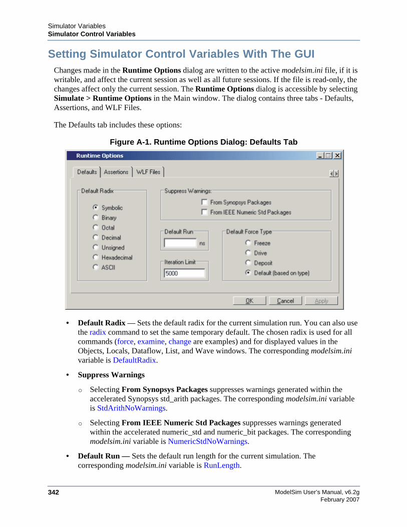
ModelSim User’s Manual, v6.2g342
Simulator VariablesSimulator Control Variables
February 2007
Setting Simulator Control Variables With The GUIChanges made in the Runtime Options dialog are written to the active modelsim.ini file, if it iswritable, and affect the current session as well as all future sessions. If the file is read-only, thechanges affect only the current session. The Runtime Options dialog is accessible by selectingSimulate > Runtime Options in the Main window. The dialog contains three tabs - Defaults,Assertions, and WLF Files.
The Defaults tab includes these options:
Figure A-1. Runtime Options Dialog: Defaults Tab
• Default Radix — Sets the default radix for the current simulation run. You can also usethe radix command to set the same temporary default. The chosen radix is used for allcommands (force, examine, change are examples) and for displayed values in theObjects, Locals, Dataflow, List, and Wave windows. The corresponding modelsim.inivariable is DefaultRadix.
• Suppress Warnings
o Selecting From Synopsys Packages suppresses warnings generated within theaccelerated Synopsys std_arith packages. The corresponding modelsim.ini variableis StdArithNoWarnings.
o Selecting From IEEE Numeric Std Packages suppresses warnings generatedwithin the accelerated numeric_std and numeric_bit packages. The correspondingmodelsim.ini variable is NumericStdNoWarnings.
• Default Run — Sets the default run length for the current simulation. Thecorresponding modelsim.ini variable is RunLength.
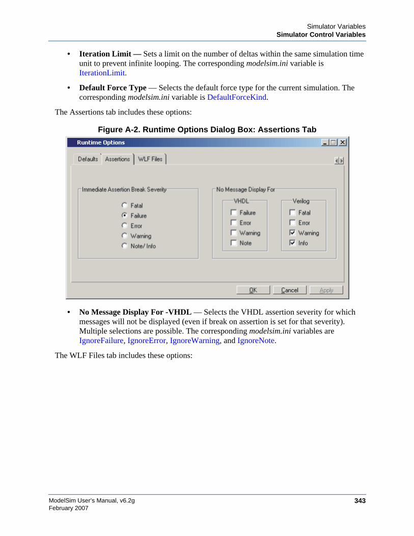
Simulator VariablesSimulator Control Variables
ModelSim User’s Manual, v6.2g 343February 2007
• Iteration Limit — Sets a limit on the number of deltas within the same simulation timeunit to prevent infinite looping. The corresponding modelsim.ini variable isIterationLimit.
• Default Force Type — Selects the default force type for the current simulation. Thecorresponding modelsim.ini variable is DefaultForceKind.
The Assertions tab includes these options:
Figure A-2. Runtime Options Dialog Box: Assertions Tab
• No Message Display For -VHDL — Selects the VHDL assertion severity for whichmessages will not be displayed (even if break on assertion is set for that severity).Multiple selections are possible. The corresponding modelsim.ini variables areIgnoreFailure, IgnoreError, IgnoreWarning, and IgnoreNote.
The WLF Files tab includes these options:
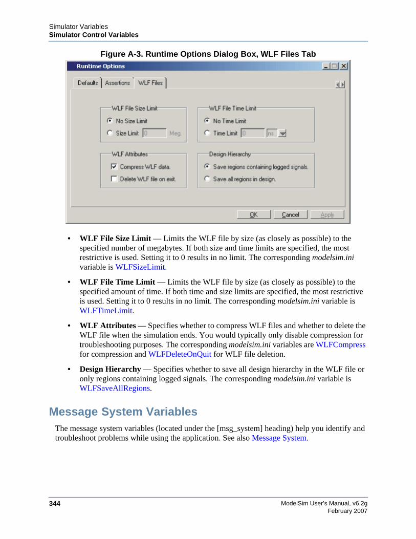
ModelSim User’s Manual, v6.2g344
Simulator VariablesSimulator Control Variables
February 2007
Figure A-3. Runtime Options Dialog Box, WLF Files Tab
• WLF File Size Limit — Limits the WLF file by size (as closely as possible) to thespecified number of megabytes. If both size and time limits are specified, the mostrestrictive is used. Setting it to 0 results in no limit. The corresponding modelsim.inivariable is WLFSizeLimit.
• WLF File Time Limit — Limits the WLF file by size (as closely as possible) to thespecified amount of time. If both time and size limits are specified, the most restrictiveis used. Setting it to 0 results in no limit. The corresponding modelsim.ini variable isWLFTimeLimit.
• WLF Attributes — Specifies whether to compress WLF files and whether to delete theWLF file when the simulation ends. You would typically only disable compression fortroubleshooting purposes. The corresponding modelsim.ini variables are WLFCompressfor compression and WLFDeleteOnQuit for WLF file deletion.
• Design Hierarchy — Specifies whether to save all design hierarchy in the WLF file oronly regions containing logged signals. The corresponding modelsim.ini variable isWLFSaveAllRegions.
Message System VariablesThe message system variables (located under the [msg_system] heading) help you identify andtroubleshoot problems while using the application. See also Message System.
Simulator VariablesSimulator Control Variables
ModelSim User’s Manual, v6.2g 345February 2007
error
This variable changes the severity of the listed message numbers to "error". Refer to ChangingMessage Severity Level for more information.
• Value Range: list of message numbers
• Default: none
fatal
This variable changes the severity of the listed message numbers to "fatal". Refer to ChangingMessage Severity Level for more information.
• Value Range: list of message numbers
• Default: none
note
This variable changes the severity of the listed message numbers to "note". Refer to ChangingMessage Severity Level for more information
• Value Range: list of message numbers
• Default: none
suppress
This variable suppresses the listed message numbers. Refer to Changing Message SeverityLevel for more information
• Value Range: list of message numbers
• Default: none
warning
This variable changes the severity of the listed message numbers to "warning". Refer toChanging Message Severity Level for more information
• Value Range: list of message numbers
• Default: none
msgmode
This variable controls where the simulator outputs elaboration and runtime messages. Refer tothe section “Message Viewer” for more information.
ModelSim User’s Manual, v6.2g346
Simulator VariablesSimulator Control Variables
February 2007
• Value Range: tran (transcript only), wlf (wlf file only), both
• Default: both
Commonly Used INI VariablesSeveral of the more commonly used modelsim.ini variables are further explained below.
Common Environment VariablesYou can use environment variables in your initialization files. Use a dollar sign ($) before theenvironment variable name. For example:
[Library]work = $HOME/work_libtest_lib = ./$TESTNUM/work...[vsim]IgnoreNote = $IGNORE_ASSERTSIgnoreWarning = $IGNORE_ASSERTSIgnoreError = 0IgnoreFailure = 0
There is one environment variable, MODEL_TECH, that you cannot — and should not — set.MODEL_TECH is a special variable set by Model Technology software. Its value is the nameof the directory from which the VCOM or VLOG compilers or VSIM simulator was invoked.MODEL_TECH is used by the other Model Technology tools to find the libraries.
Hierarchical Library MappingBy adding an "others" clause to your modelsim.ini file, you can have a hierarchy of librarymappings. If the ModelSim tools don’t find a mapping in the modelsim.ini file, then they willsearch only the library section of the initialization file specified by the "others" clause. Forexample:
[Library]asic_lib = /cae/asic_libwork = my_workothers = /install_dir/modeltech/modelsim.ini
Since the file referred to by the "others" clause may itself contain an "others" clause, you canuse this feature to chain a set of hierarchical INI files for library mappings.
Creating a Transcript FileA feature in the system initialization file allows you to keep a record of everything that occursin the transcript: error messages, assertions, commands, command outputs, etc. To do this, set
Simulator VariablesSimulator Control Variables
ModelSim User’s Manual, v6.2g 347February 2007
the value for the TranscriptFile line in the modelsim.ini file to the name of the file in which youwould like to record the ModelSim history.
; Save the command window contents to this fileTranscriptFile = trnscrpt
You can disable the creation of the transcript file by using the following ModelSim commandimmediately after ModelSim starts:
transcript file ""
Using a Startup FileThe system initialization file allows you to specify a command or a do file that is to be executedafter the design is loaded. For example:
; VSIM Startup commandStartup = do mystartup.do
The line shown above instructs ModelSim to execute the commands in the macro file namedmystartup.do.
; VSIM Startup commandStartup = run -all
The line shown above instructs VSIM to run until there are no events scheduled.
See the do command for additional information on creating do files.
Turning Off Assertion MessagesYou can turn off assertion messages from your VHDL code by setting a switch in themodelsim.ini file. This option was added because some utility packages print a huge number ofwarnings.
[vsim]IgnoreNote = 1IgnoreWarning = 1IgnoreError = 1IgnoreFailure = 1
Turning off Warnings from Arithmetic PackagesYou can disable warnings from the Synopsys and numeric standard packages by adding thefollowing lines to the [vsim] section of the modelsim.ini file.
[vsim]NumericStdNoWarnings = 1StdArithNoWarnings = 1
ModelSim User’s Manual, v6.2g348
Simulator VariablesSimulator Control Variables
February 2007
Force Command DefaultsThe force command has -freeze, -drive, and -deposit options. When none of these is specified,then -freeze is assumed for unresolved signals and -drive is assumed for resolved signals. But ifyou prefer -freeze as the default for both resolved and unresolved signals, you can change thedefaults in the modelsim.ini file.
[vsim]; Default Force Kind; The choices are freeze, drive, or depositDefaultForceKind = freeze
Restart Command DefaultsThe restart command has -force, -nobreakpoint, -nofcovers, -nolist, -nolog, and -nowaveoptions. You can set any of these as defaults by entering the following line in the modelsim.inifile:
DefaultRestartOptions = <options>
where <options> can be one or more of -force, -nobreakpoint, -nofcovers, -nolist, -nolog, and -nowave.
Example:
DefaultRestartOptions = -nolog -force
VHDL StandardYou can specify which version of the 1076 Std ModelSim follows by default using theVHDL93 variable:
[vcom]; VHDL93 variable selects language version as the default.; Default is VHDL-2002.; Value of 0 or 1987 for VHDL-1987.; Value of 1 or 1993 for VHDL-1993.; Default or value of 2 or 2002 for VHDL-2002.VHDL93 = 2002
Opening VHDL FilesYou can delay the opening of VHDL files with an entry in the INI file if you wish. NormallyVHDL files are opened when the file declaration is elaborated. If the DelayFileOpen option isenabled, then the file is not opened until the first read or write to that file.
[vsim]DelayFileOpen = 1
Simulator VariablesVariable Precedence
ModelSim User’s Manual, v6.2g 349February 2007
Variable PrecedenceNote that some variables can be set in a .modelsim file (Registry in Windows) or a .ini file. Avariable set in the .modelsim file takes precedence over the same variable set in a .ini file. Forexample, assume you have the following line in your modelsim.ini file:
TranscriptFile = transcript
And assume you have the following line in your .modelsim file:
set PrefMain(file) {}
In this case the setting in the .modelsim file overrides that in the modelsim.ini file, and atranscript file will not be produced.
Simulator State VariablesUnlike other variables that must be explicitly set, simulator state variables return a valuerelative to the current simulation. Simulator state variables can be useful in commands,especially when used within ModelSim DO files (macros). The variables are referenced incommands by prefixing the name with a dollar sign ($).
argc
This variable returns the total number of parameters passed to the current macro.
architecture
This variable returns the name of the top-level architecture currently being simulated; for aconfiguration or Verilog module, this variable returns an empty string.
configuration
This variable returns the name of the top-level configuration currently being simulated; returnsan empty string if no configuration.
delta
This variable returns the number of the current simulator iteration.
entity
This variable returns the name of the top-level VHDL entity or Verilog module currently beingsimulated.
library
This variable returns the library name for the current region.
ModelSim User’s Manual, v6.2g350
Simulator VariablesSimulator State Variables
February 2007
MacroNestingLevel
This variable returns the current depth of macro call nesting.
n
This variable represents a macro parameter, where n can be an integer in the range 1-9.
Now
This variable always returns the current simulation time with time units (e.g., 110,000 ns) Note:will return a comma between thousands.
now
This variable when time resolution is a unary unit (i.e., 1ns, 1ps, 1fs): returns the currentsimulation time without time units (e.g., 100000) when time resolution is a multiple of the unaryunit (i.e., 10ns, 100ps, 10fs): returns the current simulation time with time units (e.g. 110000 ns)Note: will not return comma between thousands.
resolution
This variable returns the current simulation time resolution.
Referencing Simulator State VariablesVariable values may be referenced in simulator commands by preceding the variable name witha dollar sign ($). For example, to use the now and resolution variables in an echo commandtype:
echo "The time is $now $resolution."
Depending on the current simulator state, this command could result in:
The time is 12390 ps 10ps.
If you do not want the dollar sign to denote a simulator variable, precede it with a "\". Forexample, \$now will not be interpreted as the current simulator time.
Special Considerations for the now VariableFor the when command, special processing is performed on comparisons involving the nowvariable. If you specify "when {$now=100}...", the simulator will stop at time 100 regardless ofthe multiplier applied to the time resolution.
You must use 64-bit time operators if the time value of now will exceed 2147483647 (the limitof 32-bit numbers). For example:

Simulator VariablesSimulator State Variables
ModelSim User’s Manual, v6.2g 351February 2007
if { [gtTime $now 2us] } {...
See Simulator Tcl Time Commands for details on 64-bit time operators.

ModelSim User’s Manual, v6.2g352
Simulator VariablesSimulator State Variables
February 2007

ModelSim User’s Manual, v6.2g 353February 2007
Appendix BLocation Mapping
Pathnames to source files are recorded in libraries by storing the working directory from whichthe compile is invoked and the pathname to the file as specified in the invocation of thecompiler. The pathname may be either a complete pathname or a relative pathname.
Referencing Source Files with Location MapsModelSim tools that reference source files from the library locate a source file as follows:
• If the pathname stored in the library is complete, then this is the path used to referencethe file.
• If the pathname is relative, then the tool looks for the file relative to the current workingdirectory. If this file does not exist, then the path relative to the working directory storedin the library is used.
This method of referencing source files generally works fine if the libraries are created and usedon a single system. However, when multiple systems access a library across a network, thephysical pathnames are not always the same and the source file reference rules do not alwayswork.
Using Location MappingLocation maps are used to replace prefixes of physical pathnames in the library withenvironment variables. The location map defines a mapping between physical pathnameprefixes and environment variables.
ModelSim tools open the location map file on invocation if the MGC_LOCATION_MAPenvironment variable is set. If MGC_LOCATION_MAP is not set, ModelSim will look for afile named "mgc_location_map" in the following locations, in order:
• the current directory
• your home directory
• the directory containing the ModelSim binaries
• the ModelSim installation directory
Use these two steps to map your files:
ModelSim User’s Manual, v6.2g354
Location MappingReferencing Source Files with Location Maps
February 2007
1. Set the environment variable MGC_LOCATION_MAP to the path to your location mapfile.
2. Specify the mappings from physical pathnames to logical pathnames:
$SRC/home/vhdl/src/usr/vhdl/src
$IEEE/usr/modeltech/ieee
Pathname SyntaxThe logical pathnames must begin with $ and the physical pathnames must begin with /. Thelogical pathname is followed by one or more equivalent physical pathnames. Physicalpathnames are equivalent if they refer to the same physical directory (they just have differentpathnames on different systems).
How Location Mapping WorksWhen a pathname is stored, an attempt is made to map the physical pathname to a path relativeto a logical pathname. This is done by searching the location map file for the first physicalpathname that is a prefix to the pathname in question. The logical pathname is then substitutedfor the prefix. For example, "/usr/vhdl/src/test.vhd" is mapped to "$SRC/test.vhd". If a mappingcan be made to a logical pathname, then this is the pathname that is saved. The path to a sourcefile entry for a design unit in a library is a good example of a typical mapping.
For mapping from a logical pathname back to the physical pathname, ModelSim expects anenvironment variable to be set for each logical pathname (with the same name). ModelSimreads the location map file when a tool is invoked. If the environment variables correspondingto logical pathnames have not been set in your shell, ModelSim sets the variables to the firstphysical pathname following the logical pathname in the location map. For example, if youdon't set the SRC environment variable, ModelSim will automatically set it to "/home/vhdl/src".
Mapping with TCL VariablesTwo Tcl variables may also be used to specify alternative source-file paths; SourceDir andSourceMap. You would define these variables in a modelsim.tcl file. See the The modelsim.tclFile for details.
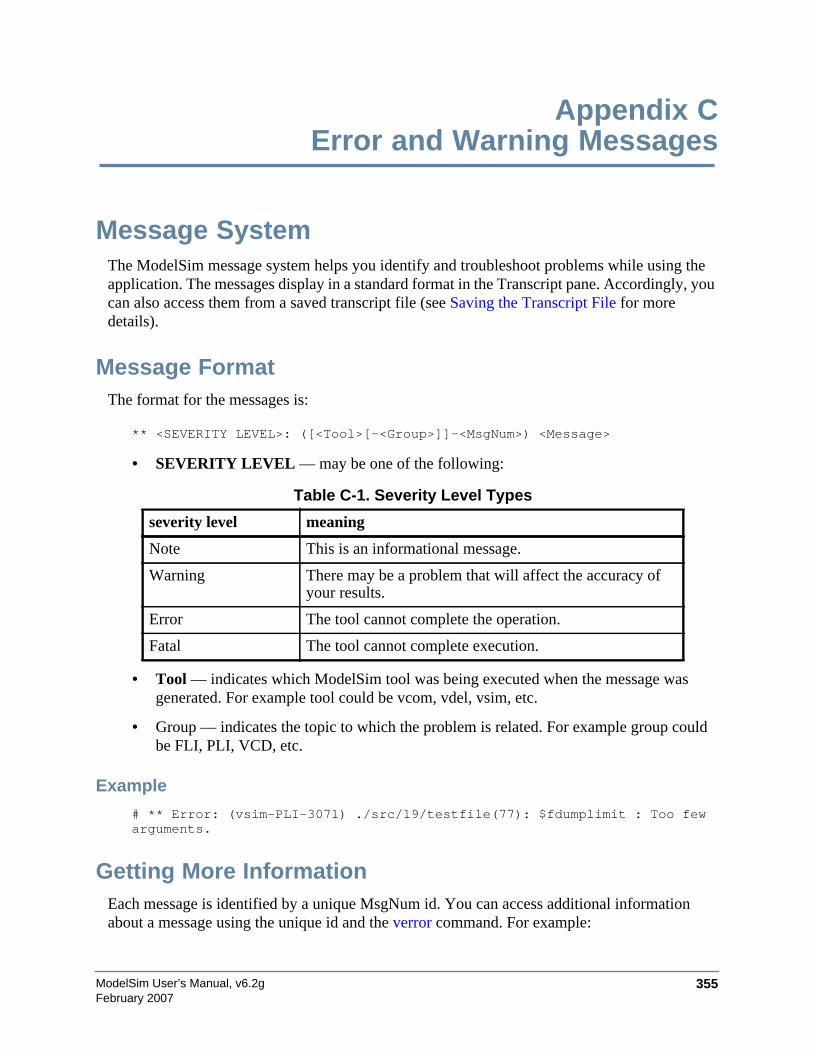
ModelSim User’s Manual, v6.2g 355February 2007
Appendix CError and Warning Messages
Message SystemThe ModelSim message system helps you identify and troubleshoot problems while using theapplication. The messages display in a standard format in the Transcript pane. Accordingly, youcan also access them from a saved transcript file (see Saving the Transcript File for moredetails).
Message FormatThe format for the messages is:
** <SEVERITY LEVEL>: ([<Tool>[-<Group>]]-<MsgNum>) <Message>
• SEVERITY LEVEL — may be one of the following:
• Tool — indicates which ModelSim tool was being executed when the message wasgenerated. For example tool could be vcom, vdel, vsim, etc.
• Group — indicates the topic to which the problem is related. For example group couldbe FLI, PLI, VCD, etc.
Example
# ** Error: (vsim-PLI-3071) ./src/19/testfile(77): $fdumplimit : Too fewarguments.
Getting More InformationEach message is identified by a unique MsgNum id. You can access additional informationabout a message using the unique id and the verror command. For example:
Table C-1. Severity Level Types
severity level meaning
Note This is an informational message.
Warning There may be a problem that will affect the accuracy ofyour results.
Error The tool cannot complete the operation.
Fatal The tool cannot complete execution.
ModelSim User’s Manual, v6.2g356
Error and Warning MessagesSuppressing Warning Messages
February 2007
% verror 3071Message # 3071:Not enough arguments are being passed to the specified system task orfunction.
Changing Message Severity LevelYou can suppress or change the severity of notes, warnings, and errors that come from vcom,vlog, and vsim. You cannot change the severity of or suppress Fatal or Internal messages.
There are two ways to modify the severity of or suppress notes, warnings, and errors:
• Use the -error, -fatal, -note, -suppress, and -warning arguments to vcom, vlog, or vsim.See the command descriptions in the Reference Manual for details on those arguments.
• Set a permanent default in the [msg_system] section of the modelsim.ini file. SeeSimulator Control Variables for more information.
Suppressing Warning MessagesYou can suppress some warning messages. For example, you may receive warning messagesabout unbound components about which you are not concerned.
Suppressing VCOM Warning MessagesUse the -nowarn <number> argument to vcom to suppress a specific warning message. Forexample:
vcom -nowarn 1
suppresses unbound component warning messages.
Alternatively, warnings may be disabled for all compiles via the modelsim.ini file (see VerilogCompiler Control Variables).
The warning message numbers are:
1 = unbound component2 = process without a wait statement3 = null range4 = no space in time literal5 = multiple drivers on unresolved signal6 = compliance checks7 = optimization messages8 = lint checks9 = signal value dependency at elaboration10 = VHDL93 constructs in VHDL87 code14 = locally static error deferred until simulation run
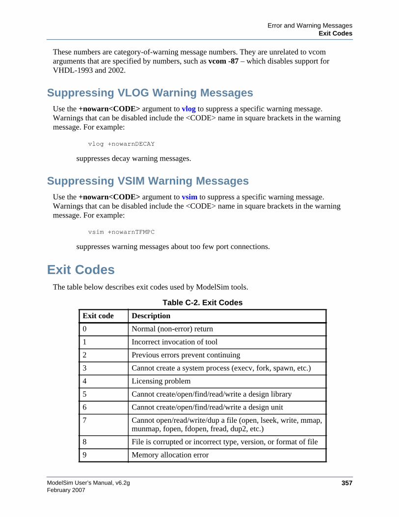
Error and Warning MessagesExit Codes
ModelSim User’s Manual, v6.2g 357February 2007
These numbers are category-of-warning message numbers. They are unrelated to vcomarguments that are specified by numbers, such as vcom -87 – which disables support forVHDL-1993 and 2002.
Suppressing VLOG Warning MessagesUse the +nowarn<CODE> argument to vlog to suppress a specific warning message.Warnings that can be disabled include the <CODE> name in square brackets in the warningmessage. For example:
vlog +nowarnDECAY
suppresses decay warning messages.
Suppressing VSIM Warning MessagesUse the +nowarn<CODE> argument to vsim to suppress a specific warning message.Warnings that can be disabled include the <CODE> name in square brackets in the warningmessage. For example:
vsim +nowarnTFMPC
suppresses warning messages about too few port connections.
Exit CodesThe table below describes exit codes used by ModelSim tools.
Table C-2. Exit Codes
Exit code Description
0 Normal (non-error) return
1 Incorrect invocation of tool
2 Previous errors prevent continuing
3 Cannot create a system process (execv, fork, spawn, etc.)
4 Licensing problem
5 Cannot create/open/find/read/write a design library
6 Cannot create/open/find/read/write a design unit
7 Cannot open/read/write/dup a file (open, lseek, write, mmap,munmap, fopen, fdopen, fread, dup2, etc.)
8 File is corrupted or incorrect type, version, or format of file
9 Memory allocation error
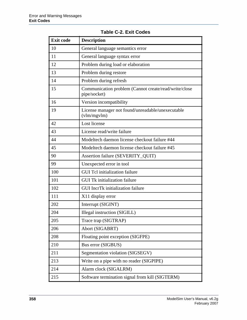
ModelSim User’s Manual, v6.2g358
Error and Warning MessagesExit Codes
February 2007
10 General language semantics error
11 General language syntax error
12 Problem during load or elaboration
13 Problem during restore
14 Problem during refresh
15 Communication problem (Cannot create/read/write/closepipe/socket)
16 Version incompatibility
19 License manager not found/unreadable/unexecutable(vlm/mgvlm)
42 Lost license
43 License read/write failure
44 Modeltech daemon license checkout failure #44
45 Modeltech daemon license checkout failure #45
90 Assertion failure (SEVERITY_QUIT)
99 Unexpected error in tool
100 GUI Tcl initialization failure
101 GUI Tk initialization failure
102 GUI IncrTk initialization failure
111 X11 display error
202 Interrupt (SIGINT)
204 Illegal instruction (SIGILL)
205 Trace trap (SIGTRAP)
206 Abort (SIGABRT)
208 Floating point exception (SIGFPE)
210 Bus error (SIGBUS)
211 Segmentation violation (SIGSEGV)
213 Write on a pipe with no reader (SIGPIPE)
214 Alarm clock (SIGALRM)
215 Software termination signal from kill (SIGTERM)
Table C-2. Exit Codes
Exit code Description

Error and Warning MessagesMiscellaneous Messages
ModelSim User’s Manual, v6.2g 359February 2007
Miscellaneous MessagesThis section describes miscellaneous messages which may be associated with ModelSim.
Compilation of DPI Export TFs Error
# ** Fatal: (vsim-3740) Can't locate a C compiler for compilation ofDPI export tasks/functions.
• Description — ModelSim was unable to locate a C compiler to compile the DPIexported tasks or functions in your design.
• Suggested Action —Make sure that a C compiler is visible from where you are runningthe simulation.
Empty port name warning
# ** WARNING: [8] <path/file_name>: empty port name in port list.
• Description — ModelSim reports these warnings if you use the -lint argument to vlog. Itreports the warning for any NULL module ports.
• Suggested action — If you wish to ignore this warning, do not use the -lint argument.
Lock message
waiting for lock by user@user. Lockfile is <library_path>/_lock
• Description — The _lock file is created in a library when you begin a compilation intothat library, and it is removed when the compilation completes. This preventssimultaneous updates to the library. If a previous compile did not terminate properly,ModelSim may fail to remove the _lock file.
• Suggested action — Manually remove the _lock file after making sure that no one else isactually using that library.
216 User-defined signal 1 (SIGUSR1)
217 User-defined signal 2 (SIGUSR2)
218 Child status change (SIGCHLD)
230 Exceeded CPU limit (SIGXCPU)
231 Exceeded file size limit (SIGXFSZ)
Table C-2. Exit Codes
Exit code Description
ModelSim User’s Manual, v6.2g360
Error and Warning MessagesMiscellaneous Messages
February 2007
Metavalue detected warning
Warning: NUMERIC_STD.">": metavalue detected, returning FALSE
• Description — This warning is an assertion being issued by the IEEE numeric_stdpackage. It indicates that there is an 'X' in the comparison.
• Suggested action — The message does not indicate which comparison is reporting theproblem since the assertion is coming from a standard package. To track the problem,note the time the warning occurs, restart the simulation, and run to one time unit beforethe noted time. At this point, start stepping the simulator until the warning appears. Thelocation of the blue arrow in a Source window will be pointing at the line following theline with the comparison.
These messages can be turned off by setting the NumericStdNoWarnings variable to 1from the command line or in the modelsim.ini file.
Sensitivity list warning
signal is read by the process but is not in the sensitivity list
• Description — ModelSim outputs this message when you use the -check_synthesisargument to vcom. It reports the warning for any signal that is read by the process but isnot in the sensitivity list.
• Suggested action — There are cases where you may purposely omit signals from thesensitivity list even though they are read by the process. For example, in a strictlysequential process, you may prefer to include only the clock and reset in the sensitivitylist because it would be a design error if any other signal triggered the process. In suchcases, your only option is to not use the -check_synthesis argument.
Tcl Initialization error 2
Tcl_Init Error 2 : Can't find a usable Init.tcl in the followingdirectories :
./../tcl/tcl8.3 .
• Description — This message typically occurs when the base file was not included in aUnix installation. When you install ModelSim, you need to download and install 3 filesfrom the ftp site. These files are:
modeltech-base.tar.gzmodeltech-docs.tar.gzmodeltech-<platform>.exe.gz
If you install only the <platform> file, you will not get the Tcl files that are located inthe base file.
This message could also occur if the file or directory was deleted or corrupted.
• Suggested action — Reinstall ModelSim with all three files.
Error and Warning MessagesMiscellaneous Messages
ModelSim User’s Manual, v6.2g 361February 2007
Too few port connections
# ** Warning (vsim-3017): foo.v(1422): [TFMPC] - Too few portconnections. Expected 2, found 1.
# Region: /foo/tb
• Description — This warning occurs when an instantiation has fewer port connectionsthan the corresponding module definition. The warning doesn’t necessarily meananything is wrong; it is legal in Verilog to have an instantiation that doesn’t connect allof the pins. However, someone that expects all pins to be connected would like to seesuch a warning.
Here are some examples of legal instantiations that will and will not cause the warningmessage.
Module definition:
module foo (a, b, c, d);
Instantiation that does not connect all pins but will not produce the warning:
foo inst1(e, f, g, ); // positional associationfoo inst1(.a(e), .b(f), .c(g), .d()); // named association
Instantiation that does not connect all pins but will produce the warning:
foo inst1(e, f, g); // positional associationfoo inst1(.a(e), .b(f), .c(g)); // named association
Any instantiation above will leave pin d unconnected but the first example has aplaceholder for the connection. Here’s another example:
foo inst1(e, , g, h);foo inst1(.a(e), .b(), .c(g), .d(h));
• Suggested actions —
o Check that there is not an extra comma at the end of the port list. (e.g., model(a,b,) ).The extra comma is legal Verilog and implies that there is a third port connectionthat is unnamed.
o If you are purposefully leaving pins unconnected, you can disable these messagesusing the +nowarnTFMPC argument to vsim.
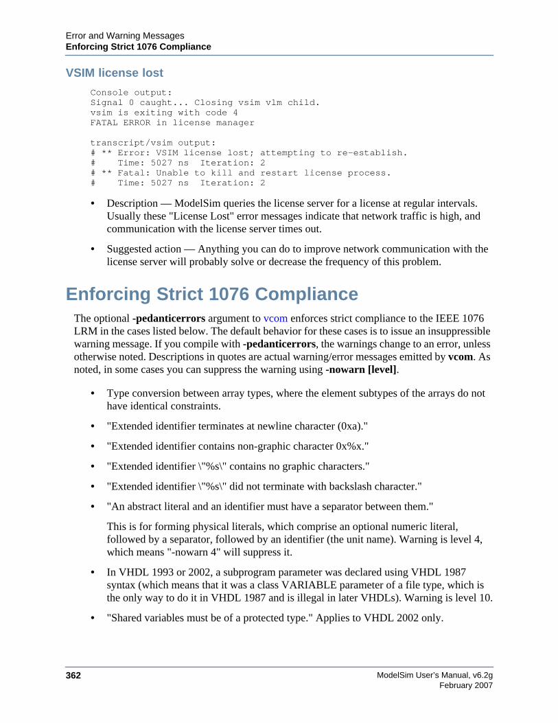
ModelSim User’s Manual, v6.2g362
Error and Warning MessagesEnforcing Strict 1076 Compliance
February 2007
VSIM license lost
Console output:Signal 0 caught... Closing vsim vlm child.vsim is exiting with code 4FATAL ERROR in license manager
transcript/vsim output:# ** Error: VSIM license lost; attempting to re-establish.# Time: 5027 ns Iteration: 2# ** Fatal: Unable to kill and restart license process.# Time: 5027 ns Iteration: 2
• Description — ModelSim queries the license server for a license at regular intervals.Usually these "License Lost" error messages indicate that network traffic is high, andcommunication with the license server times out.
• Suggested action — Anything you can do to improve network communication with thelicense server will probably solve or decrease the frequency of this problem.
Enforcing Strict 1076 ComplianceThe optional -pedanticerrors argument to vcom enforces strict compliance to the IEEE 1076LRM in the cases listed below. The default behavior for these cases is to issue an insuppressiblewarning message. If you compile with -pedanticerrors, the warnings change to an error, unlessotherwise noted. Descriptions in quotes are actual warning/error messages emitted by vcom. Asnoted, in some cases you can suppress the warning using -nowarn [level].
• Type conversion between array types, where the element subtypes of the arrays do nothave identical constraints.
• "Extended identifier terminates at newline character (0xa)."
• "Extended identifier contains non-graphic character 0x%x."
• "Extended identifier \"%s\" contains no graphic characters."
• "Extended identifier \"%s\" did not terminate with backslash character."
• "An abstract literal and an identifier must have a separator between them."
This is for forming physical literals, which comprise an optional numeric literal,followed by a separator, followed by an identifier (the unit name). Warning is level 4,which means "-nowarn 4" will suppress it.
• In VHDL 1993 or 2002, a subprogram parameter was declared using VHDL 1987syntax (which means that it was a class VARIABLE parameter of a file type, which isthe only way to do it in VHDL 1987 and is illegal in later VHDLs). Warning is level 10.
• "Shared variables must be of a protected type." Applies to VHDL 2002 only.
Error and Warning MessagesEnforcing Strict 1076 Compliance
ModelSim User’s Manual, v6.2g 363February 2007
• Expressions evaluated during elaboration cannot depend on signal values. Warning islevel 9.
• "Non-standard use of output port '%s' in PSL expression." Warning is level 11.
• "Non-standard use of linkage port '%s' in PSL expression." Warning is level 11.
• Type mark of type conversion expression must be a named type or subtype, it can't havea constraint on it.
• When the actual in a PORT MAP association is an expression, it must be a (globally)static expression. The port must also be of mode IN.
• The expression in the CASE and selected signal assignment statements must follow therules given in 8.8 of the LRM. In certain cases we can relax these rules, but-pedanticerrors forces strict compliance.
• A CASE choice expression must be a locally static expression. We allow it to be onlyglobally static, but -pedanticerrors will check that it is locally static. Same rule forselected signal assignment statement choices. Warning level is 8.
• When making a default binding for a component instantiation, ModelSim's non-standardsearch rules found a matching entity. VHDL 2002 LRM Section 5.2.2 spells out thestandard search rules. Warning level is 1.
• Both FOR GENERATE and IF GENERATE expressions must be globally static. Weallow non-static expressions unless -pedanticerrors is present.
• When the actual part of an association element is in the form of a conversion functioncall [or a type conversion], and the formal is of an unconstrained array type, the returntype of the conversion function [type mark of the type conversion] must be of aconstrained array subtype. We relax this (with a warning) unless -pedanticerrors ispresent when it becomes an error.
• OTHERS choice in a record aggregate must refer to at least one record element.
• In an array aggregate of an array type whose element subtype is itself an array, allexpressions in the array aggregate must have the same index constraint, which is theelement's index constraint. No warning is issued; the presence of -pedanticerrors willproduce an error.
• Non-static choice in an array aggregate must be the only choice in the only elementassociation of the aggregate.
• The range constraint of a scalar subtype indication must have bounds both of the sametype as the type mark of the subtype indication.
• The index constraint of an array subtype indication must have index ranges each ofwhose both bounds must be of the same type as the corresponding index subtype.
• When compiling VHDL 1987, various VHDL 1993 and 2002 syntax is allowed. Use-pedanticerrors to force strict compliance. Warnings are all level 10.

ModelSim User’s Manual, v6.2g364
Error and Warning MessagesEnforcing Strict 1076 Compliance
February 2007
ModelSim User’s Manual, v6.2g 365February 2007
Appendix DVerilog PLI/VPI/DPI
This appendix describes the ModelSim implementation of the Verilog PLI (ProgrammingLanguage Interface), VPI (Verilog Procedural Interface) and SystemVerilog DPI (DirectProgramming Interface). These three interfaces provide a mechanism for defining tasks andfunctions that communicate with the simulator through a C procedural interface. There aremany third party applications available that interface to Verilog simulators through the PLI (seeThird Party PLI Applications). In addition, you may write your own PLI/VPI/DPI applications.
Implementation InformationModelSim Verilog implements the PLI as defined in the IEEE Std 1364-2001, with theexception of the acc_handle_datapath() routine. We did not implement theacc_handle_datapath() routine because the information it returns is more appropriate for astatic timing analysis tool.
The VPI is partially implemented as defined in the IEEE Std 1364-2005. The list of currentlysupported functionality can be found in the following file:
<install_dir>/modeltech/docs/technotes/Verilog_VPI.note
ModelSim SystemVerilog implements DPI as defined in IEEE Std P1800-2005.
The IEEE Std 1364 is the reference that defines the usage of the PLI/VPI routines, and the IEEEStd P1800-2005 Language Reference Manual (LRM) defines the usage of DPI routines. Thismanual describes only the details of using the PLI/VPI/DPI with ModelSim Verilog andSystemVerilog.
g++ Compiler Support for use with PLI/VPI/DPIWe strongly encourage that unless you have a reason to do otherwise, you should use the built-in g++ compiler that is shipped with the ModelSim compiler to compile your C++ code. This isthe version that has been tested and is supported for any given release.
Specifying Your Own g++ CompilerIf you must use a different g++ compiler, other than that shipped with ModelSim, you need toset a variable in your modelsim.ini file, as follows:
CppPath = /usr/bin/g++
to point to the desired g++ version.
ModelSim User’s Manual, v6.2g366
Verilog PLI/VPI/DPIRegistering PLI Applications
February 2007
Registering PLI ApplicationsEach PLI application must register its system tasks and functions with the simulator, providingthe name of each system task and function and the associated callback routines. Since many PLIapplications already interface to Verilog-XL, ModelSim Verilog PLI applications make use ofthe same mechanism to register information about each system task and function in an array ofs_tfcell structures. This structure is declared in the veriuser.h include file as follows:
typedef int (*p_tffn)();typedef struct t_tfcell {
short type;/* USERTASK, USERFUNCTION, or USERREALFUNCTION */short data;/* passed as data argument of callback function */p_tffn checktf; /* argument checking callback function */p_tffn sizetf; /* function return size callback function */p_tffn calltf; /* task or function call callback function */p_tffn misctf; /* miscellaneous reason callback function */char *tfname;/* name of system task or function */
/* The following fields are ignored by ModelSim Verilog */int forwref;char *tfveritool;char *tferrmessage;int hash;struct t_tfcell *left_p;struct t_tfcell *right_p;char *namecell_p;int warning_printed;
} s_tfcell, *p_tfcell;
The various callback functions (checktf, sizetf, calltf, and misctf) are described in detail in theIEEE Std 1364. The simulator calls these functions for various reasons. All callback functionsare optional, but most applications contain at least the calltf function, which is called when thesystem task or function is executed in the Verilog code. The first argument to the callbackfunctions is the value supplied in the data field (many PLI applications don't use this field). Thetype field defines the entry as either a system task (USERTASK) or a system function thatreturns either a register (USERFUNCTION) or a real (USERREALFUNCTION). The tfnamefield is the system task or function name (it must begin with $). The remaining fields are notused by ModelSim Verilog.
On loading of a PLI application, the simulator first looks for an init_usertfs function, and then averiusertfs array. If init_usertfs is found, the simulator calls that function so that it can callmti_RegisterUserTF() for each system task or function defined. The mti_RegisterUserTF()function is declared in veriuser.h as follows:
void mti_RegisterUserTF(p_tfcell usertf);
The storage for each usertf entry passed to the simulator must persist throughout the simulationbecause the simulator de-references the usertf pointer to call the callback functions. Werecommend that you define your entries in an array, with the last entry set to 0. If the array isnamed veriusertfs (as is the case for linking to Verilog-XL), then you don't have to provide an
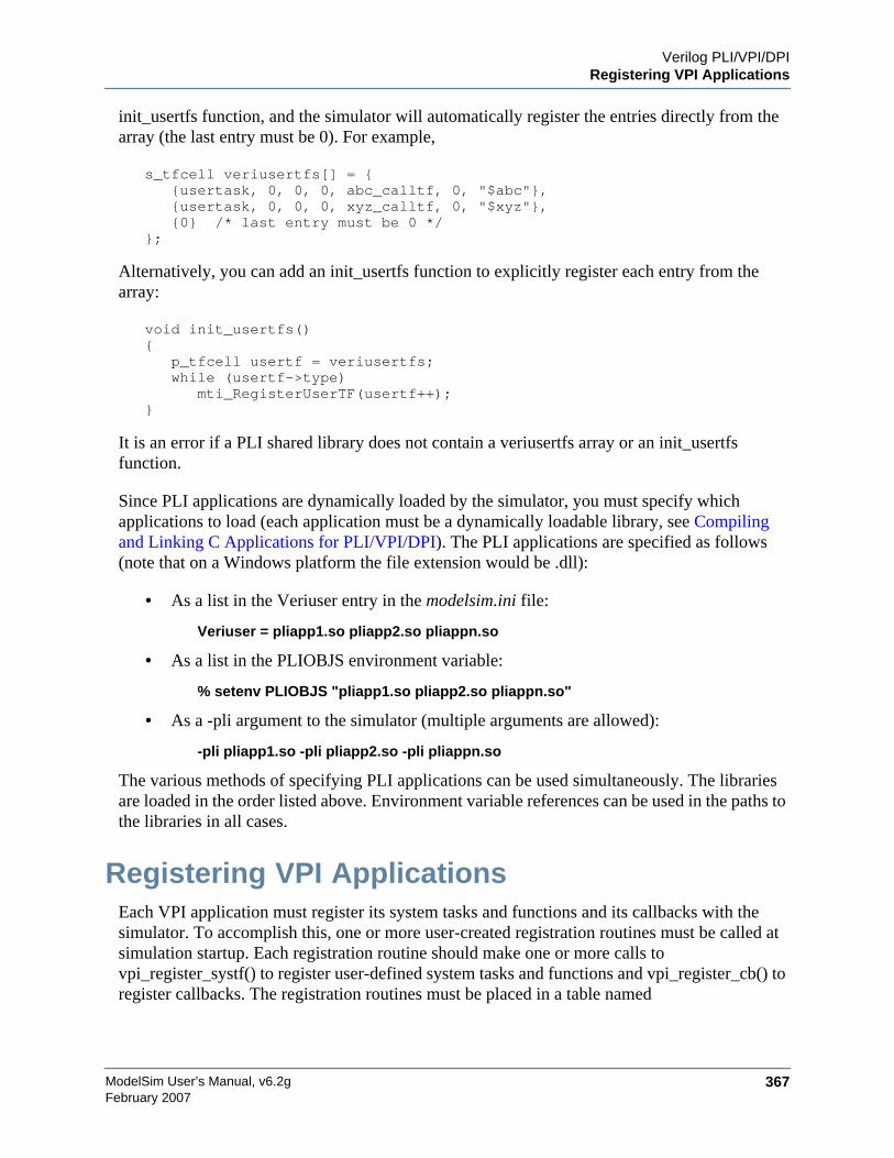
Verilog PLI/VPI/DPIRegistering VPI Applications
ModelSim User’s Manual, v6.2g 367February 2007
init_usertfs function, and the simulator will automatically register the entries directly from thearray (the last entry must be 0). For example,
s_tfcell veriusertfs[] = {{usertask, 0, 0, 0, abc_calltf, 0, "$abc"},{usertask, 0, 0, 0, xyz_calltf, 0, "$xyz"},{0} /* last entry must be 0 */
};
Alternatively, you can add an init_usertfs function to explicitly register each entry from thearray:
void init_usertfs(){
p_tfcell usertf = veriusertfs;while (usertf->type)
mti_RegisterUserTF(usertf++);}
It is an error if a PLI shared library does not contain a veriusertfs array or an init_usertfsfunction.
Since PLI applications are dynamically loaded by the simulator, you must specify whichapplications to load (each application must be a dynamically loadable library, see Compilingand Linking C Applications for PLI/VPI/DPI). The PLI applications are specified as follows(note that on a Windows platform the file extension would be .dll):
• As a list in the Veriuser entry in the modelsim.ini file:
Veriuser = pliapp1.so pliapp2.so pliappn.so
• As a list in the PLIOBJS environment variable:
% setenv PLIOBJS "pliapp1.so pliapp2.so pliappn.so"
• As a -pli argument to the simulator (multiple arguments are allowed):
-pli pliapp1.so -pli pliapp2.so -pli pliappn.so
The various methods of specifying PLI applications can be used simultaneously. The librariesare loaded in the order listed above. Environment variable references can be used in the paths tothe libraries in all cases.
Registering VPI ApplicationsEach VPI application must register its system tasks and functions and its callbacks with thesimulator. To accomplish this, one or more user-created registration routines must be called atsimulation startup. Each registration routine should make one or more calls tovpi_register_systf() to register user-defined system tasks and functions and vpi_register_cb() toregister callbacks. The registration routines must be placed in a table named
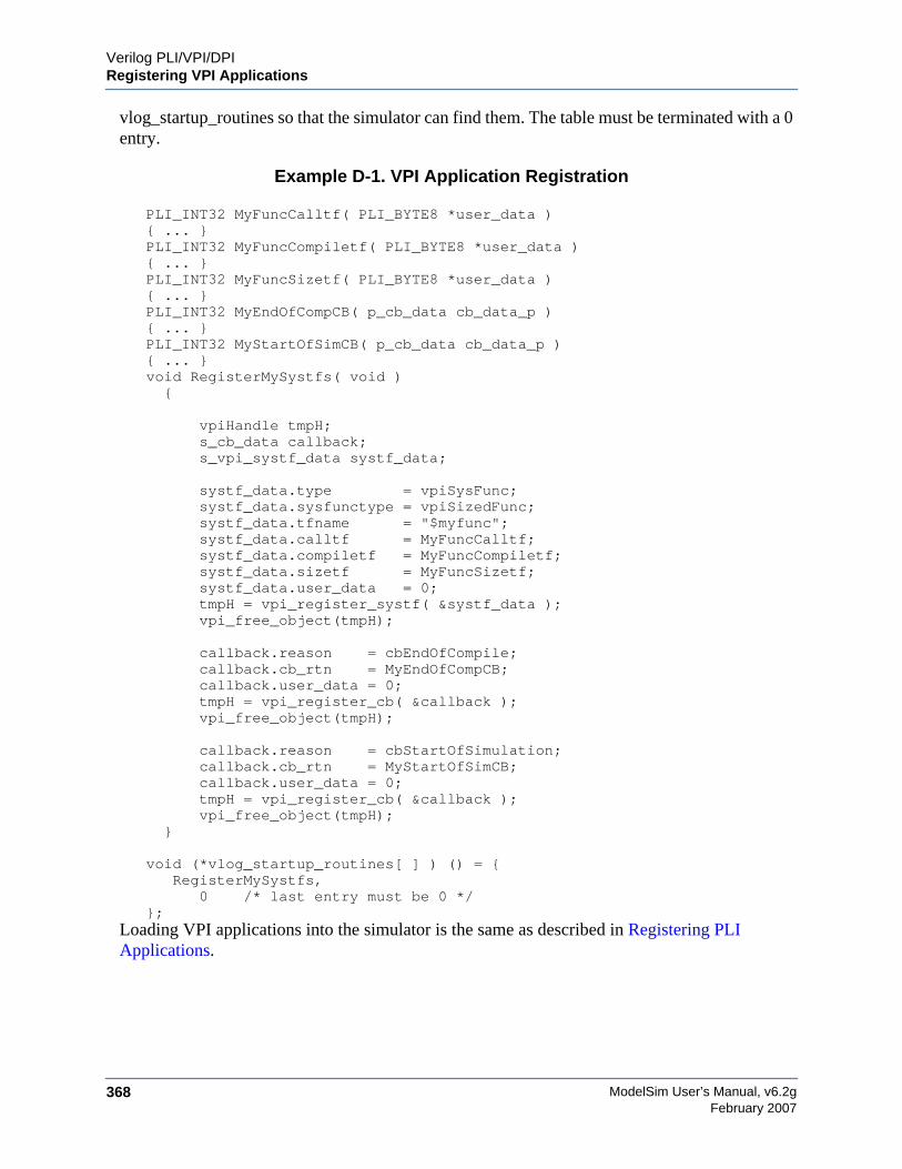
ModelSim User’s Manual, v6.2g368
Verilog PLI/VPI/DPIRegistering VPI Applications
February 2007
vlog_startup_routines so that the simulator can find them. The table must be terminated with a 0entry.
Example D-1. VPI Application Registration
PLI_INT32 MyFuncCalltf( PLI_BYTE8 *user_data ){ ... }PLI_INT32 MyFuncCompiletf( PLI_BYTE8 *user_data ){ ... }PLI_INT32 MyFuncSizetf( PLI_BYTE8 *user_data ){ ... }PLI_INT32 MyEndOfCompCB( p_cb_data cb_data_p ){ ... }PLI_INT32 MyStartOfSimCB( p_cb_data cb_data_p ){ ... }void RegisterMySystfs( void ){
vpiHandle tmpH;s_cb_data callback;
s_vpi_systf_data systf_data;
systf_data.type = vpiSysFunc; systf_data.sysfunctype = vpiSizedFunc; systf_data.tfname = "$myfunc"; systf_data.calltf = MyFuncCalltf; systf_data.compiletf = MyFuncCompiletf; systf_data.sizetf = MyFuncSizetf; systf_data.user_data = 0; tmpH = vpi_register_systf( &systf_data );
vpi_free_object(tmpH);
callback.reason = cbEndOfCompile; callback.cb_rtn = MyEndOfCompCB; callback.user_data = 0; tmpH = vpi_register_cb( &callback );
vpi_free_object(tmpH);
callback.reason = cbStartOfSimulation; callback.cb_rtn = MyStartOfSimCB; callback.user_data = 0;
tmpH = vpi_register_cb( &callback );vpi_free_object(tmpH);
}
void (*vlog_startup_routines[ ] ) () = {RegisterMySystfs,
0 /* last entry must be 0 */};
Loading VPI applications into the simulator is the same as described in Registering PLIApplications.
Verilog PLI/VPI/DPIRegistering DPI Applications
ModelSim User’s Manual, v6.2g 369February 2007
Using PLI and VPI TogetherPLI and VPI applications can co-exist in the same application object file. In such cases, theapplications are loaded at startup as follows:
• If an init_usertfs() function exists, then it is executed and only those system tasks andfunctions registered by calls to mti_RegisterUserTF() will be defined.
• If an init_usertfs() function does not exist but a veriusertfs table does exist, then onlythose system tasks and functions listed in the veriusertfs table will be defined.
• If an init_usertfs() function does not exist and a veriusertfs table does not exist, but avlog_startup_routines table does exist, then only those system tasks and functions andcallbacks registered by functions in the vlog_startup_routines table will be defined.
As a result, when PLI and VPI applications exist in the same application object file, they mustbe registered in the same manner. VPI registration functions that would normally be listed in avlog_startup_routines table can be called from an init_usertfs() function instead.
Registering DPI ApplicationsDPI applications do not need to be registered. However, each DPI imported or exported task orfunction must be identified using SystemVerilog ‘import “DPI-C”’ or ‘export “DPI-C”’syntax.Examples of the syntax follow:
export "DPI-C" task t1;task t1(input int i, output int o);...end taskimport "DPI-C" function void f1(input int i, output int o);
Your code must provide imported functions or tasks, compiled with an external compiler. Animported task must return an int value, "1" indicating that it is returning due to a disable, or "0"indicating otherwise.
These imported functions or objects may then be loaded as a shared library into the simulatorwith either the command line option -sv_lib <lib> or -sv_liblist <bootstrap_file>. Forexample,
vlog dut.vgcc -shared -Bsymbolic -o imports.so imports.cvsim -sv_lib imports top -do <do_file>
The -sv_lib option specifies the shared library name, without an extension. A file extension isadded by the tool, as appropriate to your platform. For a list of file extensions accepted byplatform, see DPI File Loading.

ModelSim User’s Manual, v6.2g370
Verilog PLI/VPI/DPIDPI Use Flow
February 2007
You can also use the command line options -sv_root and -sv_liblist to control the process forloading imported functions and tasks. These options are defined in the IEEE Std P1800-2005LRM.
DPI Use FlowCorrect use of ModelSim DPI depends on the flow presented in this section.
Figure D-1. DPI Use Flow Diagram
1. Run vlog to generate a dpiheader.h file.
This file defines the interface between C and ModelSim for exported and imported tasksand functions. Though the dpiheader.h is a user convenience file rather thanrequirement, including dpiheader.h in your C code can immediately solve problems
vlog
gccC compiler
.v
dpiheader.h
.c
vsim
#include "dpiheader.h"
vlog -dpiheader dpiheader.h
vsim
<exportobj>
vsim -dpiexportobj <exportobj>
.omtipli.lib
ld/linkloader/linker
<test>.soshared object
Step 1 Create header
Step 1.5 Required for
Step 2 Include header
Step 3
Compile
C code
vsim -sv_lib <test>
compileduser code
and load/link
Step 4 Simulate
Windows only
Verilog PLI/VPI/DPIDPI Use Flow
ModelSim User’s Manual, v6.2g 371February 2007
caused by an improperly defined interface. An example command for creating theheader file would be:
vlog -dpiheader <dpiheader>.h files.v
2. Required for Windows only; Run a preliminary invocation of vsim with the-dpiexportobj argument.
Because of limitations with the linker/loader provided on Windows, this additional stepis required. You must create the exported task/function compiled object file (exportobj)by running a preliminary vsim command, such as:
vsim -dpiexportobj exportobj top
3. Include the dpiheader.h file in your C code.
ModelSim recommends that any user DPI C code that accesses exported tasks/functions,or defines imported tasks/functions, will include the dpiheader.h file. This allows the Ccompiler to verify the interface between C and ModelSim.
4. Compile the C code into a shared object.
Compile your code, providing any .a or other .o files required.
For Windows users — In this step, the object file needs to be bound together with the.obj that you created using the -dpiexportobj argument, into a single .dll file.
5. Simulate the design.
When simulating, specify the name of the imported DPI C shared object (according tothe SystemVerilog LRM). For example:
vsim -sv_lib <test> top
When Your DPI Export Function is Not Getting CalledThis issue can arise in your C code due to the way the C linker resolves symbols. It happens if aname you choose for a SystemVerilog export function happens to match a function name in acustom, or even standard C library. In this case, your C compiler will bind calls to the functionin that C library, rather than to the export function in the SystemVerilog simulator.
The symptoms of such a misbinding can be difficult to detect. Generally, the misbound functionsilently returns an unexpected or incorrect value.
To determine if you have this type of name aliasing problem, consult the C librarydocumentation (either the online help or man pages).
Simplified Import of FLI / PLI / C Library FunctionsIn addition to the traditional method of importing FLI / PLI / C library functions, a simplifiedmethod can be used: you can declare VPI and FLI functions as DPI-C imports. When you
ModelSim User’s Manual, v6.2g372
Verilog PLI/VPI/DPIDPI Use Flow
February 2007
declare VPI and FLI functions as DPI-C imports, the DPI shared object is loaded at runtimeautomatically. Neither the C implementation of the import tf, nor the -sv_lib argument isrequired.
Also, on most platforms (see Platform Specific Information), you can declare most standard Clibrary functions as DPI-C imports.
The following example is processed directly, without DPI C code:
package cmath; import "DPI-C" function real sin(input real x); import "DPI-C" function real sqrt(input real x);endpackage
package fli; import "DPI-C" function mti_Cmd(input string cmd);endpackage
module top; import cmath::*; import fli::*; int status, A; initial begin $display("sin(0.98) = %f", sin(0.98)); $display("sqrt(0.98) = %f", sqrt(0.98)); status = mti_Cmd("change A 123"); $display("A = %1d, status = %1d", A, status); endendmodule
To simulate, you would simply enter a command such as: vsim top.
Platform Specific Information
This feature is not supported on AIX.
On Windows, only FLI and PLI commands may be imported in this fashion. C library functionsare not automatically importable. They must be wrapped in user DPI C functions, which arebrought into the simulator using the -sv_lib argument.
Use Model for Read-Only Work LibrariesYou may want to create the work library as a read-only entity, which enables multiple users tosimultaneously share the design library at runtime. The steps are as follows:
• Windows and RS6000/RS64
On these platforms, simply change the permissions on the design library to read only byissuing a command such as "chmod -R a-w <libname>". Do this after you have finishedcompiling with vlog/vcom and vopt.
Verilog PLI/VPI/DPICompiling and Linking C Applications for PLI/VPI/DPI
ModelSim User’s Manual, v6.2g 373February 2007
• All Other Platforms
If a design contains no DPI export tasks or functions, the work library can be changed bysimply changing the permissions, as shown for win32 and rs6000/rs64 above.
For designs that contain DPI export tasks and functions, and are not run on Windows orRS6000/RS64, by default vsim creates a shared object in directory <libname>/_dpi.This shared object is called exportwrapper.so (Linux and Solaris) or exportwrapper.sl(hp700, hppa64, and hpux_ia64). If you are using a read-only library, vsim must notcreate any objects in the library.
To prevent vsim from creating objects in the library at runtime, the vsim -dpiexportobj flow isavailable on all platforms. Use this flow after compilation, but before you start simulation usingthe design library.
An example command sequence on Linux would be:
vlib workvlog -dpiheader dpiheader.h test.svgcc -shared -Bsymbolic -o test.so test.cvsim -c -dpiexportobj work/_dpi/exportwrapper topchmod -R a-w work
The library is now ready for simulation by multiple simultaneous users, as follows:
vsim top -sv_lib test
The work/_dpi/exportwrapper argument provides a basename for the shared object.
At runtime, vsim automatically checks to see if the file work/_dpi/exportwrapper.so is up-to-date with respect to its C source code. If it is out of date, an error message is issued andelaboration stops.
Compiling and Linking C Applications forPLI/VPI/DPI
The following platform-specific instructions show you how to compile and link yourPLI/VPI/DPI C applications so that they can be loaded by ModelSim. Various native C/C++compilers are supported on different platforms. The gcc compiler is supported on all platforms.
The following PLI/VPI/DPI routines are declared in the include files located in the ModelSim<install_dir>/modeltech/include directory:
• acc_user.h — declares the ACC routines
• veriuser.h — declares the TF routines
• vpi_user.h — declares the VPI routines
• svdpi.h — declares DPI routines
ModelSim User’s Manual, v6.2g374
Verilog PLI/VPI/DPICompiling and Linking C Applications for PLI/VPI/DPI
February 2007
The following instructions assume that the PLI, VPI, or DPI application is in a single sourcefile. For multiple source files, compile each file as specified in the instructions and link all ofthe resulting object files together with the specified link instructions.
Although compilation and simulation switches are platform-specific, loading shared libraries isthe same for all platforms. For information on loading libraries for PLI/VPI see PLI/VPI fileloading. For DPI loading instructions, see DPI File Loading.
For all UNIX PlatformsThe information in this section applies to all UNIX platforms.
app.soIf app.so is not in your current directory, you must tell the OS where to search for the sharedobject. You can do this one of two ways:
• Add a path before app.so in the command line option or control variable (The path mayinclude environment variables.)
• Put the path in a UNIX shell environment variable:
LD_LIBRARY_PATH_32= <library path without filename> (for Solaris/Linux 32-bit)
or
LD_LIBRARY_PATH_64= <library path without filename> (for Solaris 64-bit)
or
SHLIB_PATH= <library path without filename> (for HP-UX)
Correct Linking of Shared Libraries with -Bsymbolic
In the examples shown throughout this appendix, the -Bsymbolic linker option is used with thecompilation (gcc or g++) or link (ld) commands to correctly resolve symbols. This optioninstructs the linker to search for the symbol within the local shared library and bind to thatsymbol if it exists. If the symbol is not found within the library, the linker searches for thesymbol within the vsimk executable and binds to that symbol, if it exists.
When using the -Bsymbolic option, the linker may warn about symbol references that are notresolved within the local shared library. It is safe to ignore these warnings, provided thesymbols are present in other shared libraries or the vsimk executable. (An example of such awarning would be a reference to a common API call such as vpi_printf()).
Windows Platforms• Microsoft Visual C 4.1 or Later
Verilog PLI/VPI/DPICompiling and Linking C Applications for PLI/VPI/DPI
ModelSim User’s Manual, v6.2g 375February 2007
cl -c -I<install_dir>\modeltech\include app.clink -dll -export:<init_function> app.obj <install_dir>\win32\mtipli.lib -out:app.dll
For the Verilog PLI, the <init_function> should be "init_usertfs". Alternatively, if thereis no init_usertfs function, the <init_function> specified on the command line should be"veriusertfs". For the Verilog VPI, the <init_function> should be"vlog_startup_routines". These requirements ensure that the appropriate symbol isexported, and thus ModelSim can find the symbol when it dynamically loads the DLL.
When executing cl commands in a DO file, use the /NOLOGO switch to prevent theMicrosoft C compiler from writing the logo banner to stderr. Writing the logo causes Tclto think an error occurred.
• MinGW gcc 3.2.3
gcc -c -I<install_dir>\include app.cgcc -shared -Bsymbolic -o app.dll app.o -L<install_dir>\win32 -lmtipli
The ModelSim tool requires the use of MinGW gcc compiler rather than the Cygwin gcccompiler. MinGW gcc is available on the ModelSim FTP site. Remember to add thepath to your gcc executable in the Windows environment variables.
DPI Imports on Windows PlatformsWhen linking the shared objects, be sure to specify one export option for each DPI importedtask or function in your linking command line. You can use the -isymfile argument from thevlog command to obtain a complete list of all imported tasks/functions expected by ModelSim.
As an alternative to specifying one -export option for each imported task or function, you canmake use of the __declspec (dllexport) macro supported by Visual C. You can place this macrobefore every DPI import task or function declaration in your C source. All the marked functionswill be available for use by vsim as DPI import tasks and functions.
DPI Flow for Exported Tasks and Functions on Windows Platforms
Since the Windows platform lacks the necessary runtime linking capabilities, you must performan additional manual step in order to prepare shared objects containing calls to exportedSystemVerilog tasks or functions. You need to invoke a special run of vsim. The command is asfollows:
vsim <top du list> -dpiexportobj <objname> <other args>
The -dpiexportobj generates an object file <objname>.obj that contains "glue" code forexported tasks and functions. You must add that object file to the link line for your .dll, listedafter the other object files. For example, a link line for MinGW would be:
gcc -shared -Bsymbolic -o app.dll app.obj <objname>.obj-L<install_dir>\modeltech\win32 -lmtipli
and a link line for Visual C would be:
ModelSim User’s Manual, v6.2g376
Verilog PLI/VPI/DPICompiling and Linking C Applications for PLI/VPI/DPI
February 2007
link -dll -export:<init_function> app.obj <objname>.obj\<install_dir>\modeltech\win32\mtipli.lib -out:app.dll
32-bit Linux PlatformIf your PLI/VPI/DPI application uses anything from a system library, you will need to specifythat library when you link your PLI/VPI/DPI application. For example, to use the standard Clibrary, specify ‘-lc’ to the ‘ld’ command.
• gcc compiler
gcc -c -I/<install_dir>/modeltech/include app.cld -shared -Bsymbolic -E -o app.so app.o -lc
If you are using ModelSim with RedHat version 7.1 or below, you also need to add the-noinhibit-exec switch when you specify -Bsymbolic.
The compiler switch -freg-struct-return must be used when compiling any FLIapplication code that contains foreign functions that return real or time values.
64-bit Linux for IA64 Platform64-bit Linux is supported on RedHat Linux Advanced Workstation 2.1 for Itanium 2.
• gcc compiler (gcc 3.2 or later)
gcc -c -fPIC -I/<install_dir>/modeltech/include app.cld -shared -Bsymbolic -E --allow-shlib-undefined -o app.so app.o
If your PLI/VPI/DPI application requires a user or vendor-supplied C library, or anadditional system library, you will need to specify that library when you link yourPLI/VPI/DPI application. For example, to use the system math library libm, specify -lmto the ld command:
gcc -c -fPIC -I/<install_dir>/modeltech/include math_app.cld -shared -Bsymbolic -E --allow-shlib-undefined -o math_app.so math_app.o -lm
64-bit Linux for Opteron/Athlon 64 and EM64T Platforms64-bit Linux is supported on RedHat Linux EWS 3.0 for Opteron/Athlon 64 and EM64T.
• gcc compiler (gcc 3.2 or later)
gcc -c -fPIC -I/<install_dir>/modeltech/include app.cld -shared -Bsymbolic -E --allow-shlib-undefined -o app.so app.o
To compile for 32-bit operation, specify the -m32 argument on the gcc command line.
If your PLI/VPI/DPI application requires a user or vendor-supplied C library, or anadditional system library, you will need to specify that library when you link your
Verilog PLI/VPI/DPICompiling and Linking C Applications for PLI/VPI/DPI
ModelSim User’s Manual, v6.2g 377February 2007
PLI/VPI/DPI application. For example, to use the system math library libm, specify -lmto the ld command:
gcc -c -fPIC -I/<install_dir>/modeltech/include math_app.cld -shared -Bsymbolic -E --allow-shlib-undefined -o math_app.so math_app.o -lm
32-bit Solaris PlatformIf your PLI/VPI/DPI application uses anything from a system library, you will need to specifythat library when you link your PLI/VPI/DPI application. For example, to use the standard Clibrary, specify ‘-lc’ to the ‘ld’ command.
• gcc compiler
gcc -c -I/<install_dir>/modeltech/include app.cld -G -Bsymbolic -o app.so app.o -lc
• cc compiler
cc -c -I/<install_dir>/modeltech/include app.cld -G -Bsymbolic -o app.so app.o -lc
64-bit Solaris Platform• gcc compiler
gcc -c -I<install_dir>/modeltech/include -m64 -fPIC app.cgcc -shared -Bsymbolic -o app.so -m64 app.o
This was tested with gcc 3.2.2. You may need to add the location of libgcc_s.so.1 to theLD_LIBRARY_PATH_64 environment variable.
• cc compiler
cc -v -xarch=v9 -O -I<install_dir>/modeltech/include -c app.cld -G -Bsymbolic app.o -o app.so
32-bit HP700 PlatformA shared library is created by creating object files that contain position-independent code (usethe +z or -fPIC compiler argument) and by linking as a shared library (use the -b linkerargument).
If your PLI/VPI/DPI application uses anything from a system library, you’ll need to specify thatlibrary when you link your PLI/VPI/DPI application. For example, to use the standard C library,specify ‘-lc’ to the ‘ld’ command.
• gcc compiler
gcc -c -fPIC -I/<install_dir>/modeltech/include app.cld -b -o app.sl app.o -lc

ModelSim User’s Manual, v6.2g378
Verilog PLI/VPI/DPICompiling and Linking C Applications for PLI/VPI/DPI
February 2007
Note that -fPIC may not work with all versions of gcc.
• cc compiler
cc -c +z +DD32 -I/<install_dir>/modeltech/include app.cld -b -o app.sl app.o -lc
64-bit HP Platform• cc compiler
cc -v +DD64 -O -I<install_dir>/modeltech/include -c app.cld -b -o app.sl app.o -lc
64-bit HP for IA64 Platform• cc compiler (/opt/ansic/bin/cc, /usr/ccs/bin/ld)
cc -c +DD64 -I/<install_dir>/modeltech/include app.cld -b -o app.sl app.o
If your PLI/VPI/DPI application requires a user or vendor-supplied C library, or anadditional system library, you will need to specify that library when you link yourPLI/VPI/DPI application. For example, to use the system math library, specify '-lm' tothe 'ld' command:
cc -c +DD64 -I/<install_dir>/modeltech/include math_app.cld -b -o math_app.sl math_app.o -lm
32-bit IBM RS/6000 PlatformModelSim loads shared libraries on the IBM RS/6000 workstation. The shared library mustimport ModelSim's PLI/VPI/DPI symbols, and it must export the PLI or VPI application’sinitialization function or table. The ModelSim tool’s export file is located in the ModelSiminstallation directory in rs6000/mti_exports.
If your PLI/VPI/DPI application uses anything from a system library, you’ll need to specify thatlibrary when you link your PLI/VPI/DPI application. For example, to use the standard C library,specify ‘-lc’ to the ‘ld’ command. The resulting object must be marked as shared reentrant usingthese gcc or cc compiler commands for AIX 4.x:
• gcc compiler
gcc -c -I/<install_dir>/modeltech/include app.cld -o app.sl app.o -bE:app.exp \
-bI:/<install_dir>/modeltech/rs6000/mti_exports -bM:SRE -bnoentry -lc
• cc compiler
cc -c -I/<install_dir>/modeltech/include app.cld -o app.sl app.o -bE:app.exp \
-bI:/<install_dir>/modeltech/rs6000/mti_exports -bM:SRE -bnoentry -lc
Verilog PLI/VPI/DPICompiling and Linking C Applications for PLI/VPI/DPI
ModelSim User’s Manual, v6.2g 379February 2007
The app.exp file must export the PLI/VPI initialization function or table. For the PLI, theexported symbol should be "init_usertfs". Alternatively, if there is no init_usertfs function, thenthe exported symbol should be "veriusertfs". For the VPI, the exported symbol should be"vlog_startup_routines". These requirements ensure that the appropriate symbol is exported,and thus ModelSim can find the symbol when it dynamically loads the shared object.
DPI Imports on 32-bit IBM RS/6000 PlatformWhen linking the shared objects, be sure to specify -bE:<isymfile> option on the link commandline. <isymfile> is the name of the file generated by the-isymfile argument to the vlogcommand. Once you have created the <isymfile>, it contains a complete list of all importedtasks and functions expected by ModelSim.
DPI Flow for Exported Tasks and Functions on 32-bit IBM RS/6000 Platform
Since the RS6000 platform lacks the necessary runtime linking capabilities, you must performan additional manual step in order to prepare shared objects containing calls to exportedSystemVerilog tasks or functions shared object file. You need to invoke a special run of vsim.The command is as follows:
vsim <top du list> -dpiexportobj <objname> <other args>
The -dpiexportobj generates the object file <objname>.o that contains "glue" code for exportedtasks and functions. You must add that object file to the link line, listed after the other objectfiles. For example, a link line would be:
ld -o app.so app.o <objname>.o-bE:<isymfile> -bI:/<install_dir>/modeltech/rs6000/mti_exports -bM:SRE -bnoentry -lc
64-bit IBM RS/6000 PlatformOnly versions 5.1 and later of AIX support the 64-bit platform. A gcc 64-bit compiler is notavailable at this time.
• VisualAge cc compiler
cc -c -q64 -I/<install_dir>/modeltech/include app.cld -o app.s1 app.o -b64 -bE:app.exports \
-bI:/<install_dir>/modeltech/rs64/mti_exports -bM:SRE -bnoentry -lc
DPI Imports on 64-bit IBM RS/6000 PlatformWhen linking the shared objects, be sure to specify -bE:<isymfile> option on the link commandline. <isymfile> is the name of the file generated by the-isymfile argument to the vlogcommand. Once you have created the <isymfile>, it contains a complete list of all importedtasks and functions expected by ModelSim.
ModelSim User’s Manual, v6.2g380
Verilog PLI/VPI/DPICompiling and Linking C++ Applications for PLI/VPI/DPI
February 2007
DPI Flow for Exported Tasks and Functions on 64-bit IBM RS/6000 Platform
Since the RS6000 platform lacks the necessary runtime linking capabilities, you must performan additional manual step in order to prepare shared objects containing calls to exportedSystemVerilog tasks or functions shared object file. You need to invoke a special run of vsim.The command is as follows:
vsim <top du list> -dpiexportobj <objname> <other args>
The -dpiexportobj generates the object file <objname>.o that contains "glue" code for exportedtasks and functions. You must add that object file to the link line, listed after the other objectfiles. For example, a link line would be:
ld -o app.dll app.o <objname>.o-bE:<isymfile> -bI:/<install_dir>/modeltech/rs6000/mti_exports -bM:SRE-bnoentry -lc
Compiling and Linking C++ Applications forPLI/VPI/DPI
ModelSim does not have direct support for any language other than standard C; however, C++code can be loaded and executed under certain conditions.
Since ModelSim's PLI/VPI/DPI functions have a standard C prototype, you must prevent theC++ compiler from mangling the PLI/VPI/DPI function names. This can be accomplished byusing the following type of extern:
extern "C"{<PLI/VPI/DPI application function prototypes>
}
The header files veriuser.h, acc_user.h, and vpi_user.h, svdpi.h, and dpiheader.h alreadyinclude this type of extern. You must also put the PLI/VPI/DPI shared library entry point(veriusertfs, init_usertfs, or vlog_startup_routines) inside of this type of extern.
The following platform-specific instructions show you how to compile and link yourPLI/VPI/DPI C++ applications so that they can be loaded by ModelSim.
Although compilation and simulation switches are platform-specific, loading shared libraries isthe same for all platforms. For information on loading libraries, see DPI File Loading.
For PLI/VPI onlyIf app.so is not in your current directory you must tell Solaris where to search for the sharedobject. You can do this one of two ways:
Verilog PLI/VPI/DPICompiling and Linking C++ Applications for PLI/VPI/DPI
ModelSim User’s Manual, v6.2g 381February 2007
• Add a path before app.so in the foreign attribute specification. (The path may includeenvironment variables.)
• Put the path in a UNIX shell environment variable:LD_LIBRARY_PATH_32= <library path without filename> (32-bit)orLD_LIBRARY_PATH_64= <library path without filename> (64-bit)
Windows Platforms• Microsoft Visual C++ 4.1 or Later
cl -c [-GX] -I<install_dir>\modeltech\include app.cxxlink -dll -export:<init_function> app.obj
<install_dir>\modeltech\win32\mtipli.lib /out:app.dll
The -GX argument enables exception handling.
For the Verilog PLI, the <init_function> should be "init_usertfs". Alternatively, if thereis no init_usertfs function, the <init_function> specified on the command line should be"veriusertfs". For the Verilog VPI, the <init_function> should be"vlog_startup_routines". These requirements ensure that the appropriate symbol isexported, and thus ModelSim can find the symbol when it dynamically loads the DLL.
When executing cl commands in a DO file, use the /NOLOGO switch to prevent theMicrosoft C compiler from writing the logo banner to stderr. Writing the logo causes Tclto think an error occurred.
• MinGW C++ Version 3.2.3
g++ -c -I<install_dir>\modeltech\include app.cppg++ -shared -Bsymbolic -o app.dll app.o -L<install_dir>\modeltech\win32 -lmtipli
ModelSim requires the use of MinGW gcc compiler rather than the Cygwin gcccompiler.
DPI Imports on Windows PlatformsWhen linking the shared objects, be sure to specify one -export option for each DPI importedtask or function in your linking command line. You can use Verilog’s -isymfile option to obtaina complete list of all imported tasks and functions expected by ModelSim.
DPI Special Flow for Exported Tasks and FunctionsSince the Windows platform lacks the necessary runtime linking complexity, you must performan additional manual step in order to compile the HDL source files into the shared object file.You need to invoke a special run of vsim. The command is as follows:
vsim <top du list> -dpiexportobj <objname> <other args>
ModelSim User’s Manual, v6.2g382
Verilog PLI/VPI/DPICompiling and Linking C++ Applications for PLI/VPI/DPI
February 2007
The -dpiexportobj generates the object file <objname>.obj that contains "glue" code forexported tasks and functions. You must add that object file to the link line, listed after the otherobject files. For example, if the object name was dpi1, the link line for MinGW would be:
g++ -shared -Bsymbolic -o app.dll app.obj <objname>.obj-L<install_dir>\modeltech\win32 -lmtipli
32-bit Linux Platform• GNU C++ Version 2.95.3 or Later
g++ -c -fPIC -I<install_dir>/modeltech/include app.cppg++ -shared -Bsymbolic -fPIC -o app.so app.o
64-bit Linux for IA64 Platform64-bit Linux is supported on RedHat Linux Advanced Workstation 2.1 for Itanium 2.
• GNU C++ compiler version gcc 3.2 or later
g++ -c -fPIC -I/<install_dir>/modeltech/include app.cppld -shared -Bsymbolic -E --allow-shlib-undefined -o app.so app.o
If your PLI/VPI application requires a user or vendor-supplied C library, or anadditional system library, you will need to specify that library when you link yourPLI/VPI application. For example, to use the system math library libm, specify '-lm' tothe 'ld' command:
g++ -c -fPIC -I/<install_dir>/modeltech/include math_app.cppld -shared -Bsymbolic -E --allow-shlib-undefined -o math_app.so math_app.o -lm
64-bit Linux for Opteron/Athlon 64 and EM64T Platforms64-bit Linux is supported on RedHat Linux EWS 3.0 for Opteron/Athlon 64 and EM64T.
• GNU C++ compiler version gcc 3.2 or later
g++ -c -fPIC -I/<install_dir>/modeltech/include app.cppld -shared -Bsymbolic -E --allow-shlib-undefined -o app.so app.o
To compile for 32-bit operation, specify the -m32 argument on the gcc command line.
If your PLI/VPI/DPI application requires a user or vendor-supplied C library, or anadditional system library, you will need to specify that library when you link yourPLI/VPI/DPI application. For example, to use the system math library libm, specify -lmto the ld command:
g++ -c -fPIC -I/<install_dir>/modeltech/include math_app.cppld -shared -Bsymbolic -E --allow-shlib-undefined -o math_app.so math_app.o -lm
Verilog PLI/VPI/DPICompiling and Linking C++ Applications for PLI/VPI/DPI
ModelSim User’s Manual, v6.2g 383February 2007
32-bit Solaris PlatformIf your PLI/VPI application uses anything from a system library, you will need to specify thatlibrary when you link your PLI/VPI application. For example, to use the standard C library,specify ‘-lc’ to the ‘ld’ command.
• GNU C++ compiler version gcc 3.2 or later
g++ -c -I/<install_dir>/modeltech/include app.cppld -G -Bsymbolic -o app.so app.o -lc
• Sun Forte C++ Compiler
cc -c -I/<install_dir>/modeltech/include app.cppld -G -Bsymbolic -o app.so app.o -lc
64-bit Solaris Platform• GNU C++ compiler version gcc 3.2 or later
g++ -c -I<install_dir>/modeltech/include -m64 -fPIC app.cppg++ -shared -Bsymbolic -o app.so -m64 app.o
This was tested with gcc 3.2.2. You may need to add the location of libgcc_s.so.1 to theLD_LIBRARY_PATH_64 environment variable.
• cc compiler
cc -v -xarch=v9 -O -I<install_dir>/modeltech/include -c app.cppld -G -Bsymbolic app.o -o app.so
32-bit HP700 PlatformA shared library is created by creating object files that contain position-independent code (usethe +z or -fPIC compiler argument) and by linking as a shared library (use the -b linkerargument).
If your PLI/VPI application uses anything from a system library, you’ll need to specify thatlibrary when you link your PLI/VPI application. For example, to use the standard C library,specify ‘-lc’ to the ‘ld’ command.
• GNU C++ compiler
g++ -c -fPIC -I/<install_dir>/modeltech/include app.cppld -b -o app.sl app.o -lc
• cc compiler
cc -c +z +DD32 -I/<install_dir>/modeltech/include app.cppld -b -o app.sl app.o -lc
Note that -fPIC may not work with all versions of gcc.
ModelSim User’s Manual, v6.2g384
Verilog PLI/VPI/DPICompiling and Linking C++ Applications for PLI/VPI/DPI
February 2007
64-bit HP Platform• cc Compiler
cc -v +DD64 -O -I<install_dir>/modeltech/include -c app.cppld -b -o app.sl app.o -lc
64-bit HP for IA64 Platform• HP ANSI C++ Compiler (/opt/ansic/bin/cc, /usr/ccs/bin/ld)
cc -c +DD64 -I/<install_dir>/modeltech/include app.cppld -b -o app.sl app.o
If your PLI/VPI application requires a user or vendor-supplied C library, or anadditional system library, you will need to specify that library when you link yourPLI/VPI application. For example, to use the system math library, specify '-lm' to the 'ld'command:
cc -c +DD64 -I/<install_dir>/modeltech/include math_app.cld -b -o math_app.sl math_app.o -lm
32-bit IBM RS/6000 PlatformModelSim loads shared libraries on the IBM RS/6000 workstation. The shared library mustimport ModelSim's PLI/VPI symbols, and it must export the PLI or VPI application’sinitialization function or table. The ModelSim tool's export file is located in the ModelSiminstallation directory in rs6000/mti_exports.
If your PLI/VPI application uses anything from a system library, you’ll need to specify thatlibrary when you link your PLI/VPI application. For example, to use the standard C library,specify ‘-lc’ to the ‘ld’ command. The resulting object must be marked as shared reentrant usingthese gcc or cc compiler commands for AIX 4.x:
• GNU C++ compiler version gcc 3.2 or later
g++ -c -I/<install_dir>/modeltech/include app.cppld -o app.sl app.o -bE:app.exp \
-bI:/<install_dir>/modeltech/rs6000/mti_exports -bM:SRE -bnoentry -lc
• VisualAge C++ Compiler
cc -c -I/<install_dir>/modeltech/include app.cppld -o app.sl app.o -bE:app.exp \
-bI:/<install_dir>/modeltech/rs6000/mti_exports -bM:SRE -bnoentry -lc
The app.exp file must export the PLI/VPI initialization function or table. For the PLI, theexported symbol should be "init_usertfs". Alternatively, if there is no init_usertfs function, thenthe exported symbol should be "veriusertfs". For the VPI, the exported symbol should be"vlog_startup_routines". These requirements ensure that the appropriate symbol is exported,and thus ModelSim can find the symbol when it dynamically loads the shared object.
Verilog PLI/VPI/DPICompiling and Linking C++ Applications for PLI/VPI/DPI
ModelSim User’s Manual, v6.2g 385February 2007
For DPI ImportsWhen linking the shared objects, be sure to specify -bE:<isymfile> option on the link commandline. <isymfile> is the name of the file generated by the-isymfile argument to the vlogcommand. Once you have created the <isymfile>, it contains a complete list of all importedtasks and functions expected by ModelSim.
DPI Special Flow for Exported Tasks and FunctionsSince the RS6000 platform lacks the necessary runtime linking capabilities, you must performan additional manual step in order to prepare shared objects containing calls to exportedSystemVerilog tasks or functions shared object file. You need to invoke a special run of vsim.The command is as follows:
vsim <top du list> -dpiexportobj <objname> <other args>
The -dpiexportobj generates the object file <objname>.o that contains "glue" code for exportedtasks and functions. You must add that object file to the link line, listed after the other objectfiles. For example, a link line would be:
ld -o app.dll app.o <objname>.o-bE:<isymfile> -bI:/<install_dir>/modeltech/rs6000/mti_exports -bM:SRE-bnoentry -lc
64-bit IBM RS/6000 PlatformOnly version 5.1 and later of AIX supports the 64-bit platform. A gcc 64-bit compiler is notavailable at this time.
• VisualAge C++ Compiler
cc -c -q64 -I/<install_dir>/modeltech/include app.cppld -o app.s1 app.o -b64 -bE:app.exports \
-bI:/<install_dir>/modeltech/rs64/mti_exports -bM:SRE -bnoentry -lc
For DPI ImportsWhen linking the shared objects, be sure to specify -bE:<isymfile> option on the link commandline. <isymfile> is the name of the file generated by the-isymfile argument to the vlogcommand. Once you have created the <isymfile>, it contains a complete list of all importedtasks and functions expected by ModelSim.
DPI Special Flow for Exported Tasks and FunctionsSince the RS6000 platform lacks the necessary runtime linking capabilities, you must performan additional manual step in order to prepare shared objects containing calls to exportedSystemVerilog tasks or functions shared object file. You need to invoke a special run of vsim.The command is as follows:
ModelSim User’s Manual, v6.2g386
Verilog PLI/VPI/DPISpecifying Application Files to Load
February 2007
vsim <top du list> -dpiexportobj <objname> <other args>
The -dpiexportobj generates the object file <objname>.o that contains "glue" code for exportedtasks and functions. You must add that object file to the link line, listed after the other objectfiles. For example, a link line would be:
ld -o app.so app.o <objname>.o-bE:<isymfile> -bI:/<install_dir>/modeltech/rs6000/mti_exports -bM:SRE-bnoentry -lc
Specifying Application Files to LoadPLI and VPI file loading is identical. DPI file loading uses switches to the vsim command.
PLI/VPI file loadingThe PLI/VPI applications are specified as follows:
• As a list in the Veriuser entry in the modelsim.ini file:
Veriuser = pliapp1.so pliapp2.so pliappn.so
• As a list in the PLIOBJS environment variable:
% setenv PLIOBJS "pliapp1.so pliapp2.so pliappn.so"
• As a -pli argument to the simulator (multiple arguments are allowed):
-pli pliapp1.so -pli pliapp2.so -pli pliappn.so
NoteOn Windows platforms, the file names shown above should end with .dll rather than .so.
The various methods of specifying PLI/VPI applications can be used simultaneously. Thelibraries are loaded in the order listed above. Environment variable references can be used in thepaths to the libraries in all cases.
See also Simulator Variables for more information on the modelsim.ini file.
Verilog PLI/VPI/DPIPLI Example
ModelSim User’s Manual, v6.2g 387February 2007
DPI File LoadingDPI applications are specified to vsim using the following SystemVerilog arguments:
When the simulator finds an imported task or function, it searches for the symbol in thecollection of shared objects specified using these arguments.
For example, you can specify the DPI application as follows:
vsim -sv_lib dpiapp1 -sv_lib dpiapp2 -sv_lib dpiappn top
It is a mistake to specify DPI import tasks and functions (tf) inside PLI/VPI shared objects.However, a DPI import tf can make calls to PLI/VPI C code, providing that vsim -gblso wasused to mark the PLI/VPI shared object with global symbol visibility. See Loading SharedObjects with Global Symbol Visibility.
Loading Shared Objects with Global Symbol VisibilityOn Unix platforms you can load shared objects such that all symbols in the object have globalvisibility. To do this, use the -gblso argument to vsim when you load your PLI/VPI application.For example:
vsim -pli obj1.so -pli obj2.so -gblso obj1.so top
The -gblso argument works in conjunction with the GlobalSharedObjectList variable in themodelsim.ini file. This variable allows user C code in other shared objects to refer to symbols ina shared object that has been marked as global. All shared objects marked as global are loadedby the simulator earlier than any non-global shared objects.
PLI ExampleThe following example is a trivial, but complete PLI application.
hello.c:
Table D-1. vsim Arguments for DPI Application
Argument Description
-sv_lib <name> specifies a library name to be searched and used. No filenameextensions must be specified. (The extensions ModelSim expectsare: .sl for HP, .dll for Win32, .so for all other platforms.)
-sv_root <name> specifies a new prefix for shared objects as specified by -sv_lib
-sv_liblist specifies a “bootstrap file” to use
ModelSim User’s Manual, v6.2g388
Verilog PLI/VPI/DPIVPI Example
February 2007
#include "veriuser.h"static PLI_INT32 hello(){
io_printf("Hi there\n");return 0;
}s_tfcell veriusertfs[] = {
{usertask, 0, 0, 0, hello, 0, "$hello"},{0} /* last entry must be 0 */
};hello.v:
module hello;initial $hello;
endmoduleCompile the PLI code for the Solaris operating system:
% cc -c -I<install_dir>/modeltech/include hello.c% ld -G -Bsymbolic -o hello.sl hello.o
Compile the Verilog code:% vlib work% vlog hello.v
Simulate the design:% vsim -c -pli hello.sl hello# Loading work.hello# Loading ./hello.slVSIM 1> run -all# Hi thereVSIM 2> quit
VPI ExampleThe following example is a trivial, but complete VPI application. A general VPI example can befound in <install_dir>/modeltech/examples/verilog/vpi.
hello.c:
#include "vpi_user.h"static PLI_INT32 hello(PLI_BYTE8 * param){
vpi_printf( "Hello world!\n" );return 0;
}void RegisterMyTfs( void ){
s_vpi_systf_data systf_data;vpiHandle systf_handle;systf_data.type = vpiSysTask;systf_data.sysfunctype = vpiSysTask;systf_data.tfname = "$hello";systf_data.calltf = hello;systf_data.compiletf = 0;systf_data.sizetf = 0;systf_data.user_data = 0;systf_handle = vpi_register_systf( &systf_data );vpi_free_object( systf_handle );
}
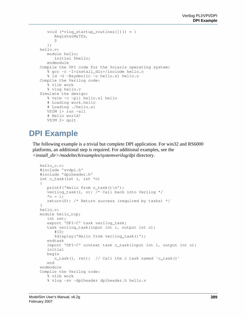
Verilog PLI/VPI/DPIDPI Example
ModelSim User’s Manual, v6.2g 389February 2007
void (*vlog_startup_routines[])() = {RegisterMyTfs,0
};hello.v:
module hello;initial $hello;
endmoduleCompile the VPI code for the Solaris operating system:
% gcc -c -I<install_dir>/include hello.c% ld -G -Bsymbolic -o hello.sl hello.o
Compile the Verilog code:% vlib work% vlog hello.v
Simulate the design:% vsim -c -pli hello.sl hello# Loading work.hello# Loading ./hello.slVSIM 1> run -all# Hello world!VSIM 2> quit
DPI ExampleThe following example is a trivial but complete DPI application. For win32 and RS6000platforms, an additional step is required. For additional examples, see the<install_dir>/modeltech/examples/systemverilog/dpi directory.
hello_c.c:#include "svdpi.h"#include "dpiheader.h"int c_task(int i, int *o){
printf("Hello from c_task()\n");verilog_task(i, o); /* Call back into Verilog */*o = i;return(0); /* Return success (required by tasks) */
}hello.v:module hello_top;
int ret;export "DPI-C" task verilog_task;task verilog_task(input int i, output int o);
#10;$display("Hello from verilog_task()");
endtaskimport "DPI-C" context task c_task(input int i, output int o);initialbegin
c_task(1, ret); // Call the c task named 'c_task()'end
endmoduleCompile the Verilog code:
% vlib work% vlog -sv -dpiheader dpiheader.h hello.v
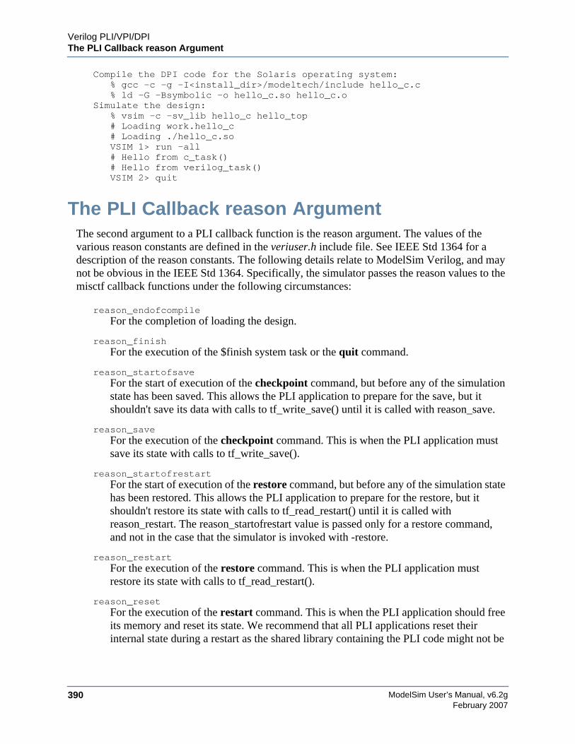
ModelSim User’s Manual, v6.2g390
Verilog PLI/VPI/DPIThe PLI Callback reason Argument
February 2007
Compile the DPI code for the Solaris operating system:% gcc -c -g -I<install_dir>/modeltech/include hello_c.c% ld -G -Bsymbolic -o hello_c.so hello_c.o
Simulate the design:% vsim -c -sv_lib hello_c hello_top# Loading work.hello_c# Loading ./hello_c.soVSIM 1> run -all# Hello from c_task()# Hello from verilog_task()VSIM 2> quit
The PLI Callback reason ArgumentThe second argument to a PLI callback function is the reason argument. The values of thevarious reason constants are defined in the veriuser.h include file. See IEEE Std 1364 for adescription of the reason constants. The following details relate to ModelSim Verilog, and maynot be obvious in the IEEE Std 1364. Specifically, the simulator passes the reason values to themisctf callback functions under the following circumstances:
reason_endofcompileFor the completion of loading the design.
reason_finishFor the execution of the $finish system task or the quit command.
reason_startofsaveFor the start of execution of the checkpoint command, but before any of the simulationstate has been saved. This allows the PLI application to prepare for the save, but itshouldn't save its data with calls to tf_write_save() until it is called with reason_save.
reason_saveFor the execution of the checkpoint command. This is when the PLI application mustsave its state with calls to tf_write_save().
reason_startofrestartFor the start of execution of the restore command, but before any of the simulation statehas been restored. This allows the PLI application to prepare for the restore, but itshouldn't restore its state with calls to tf_read_restart() until it is called withreason_restart. The reason_startofrestart value is passed only for a restore command,and not in the case that the simulator is invoked with -restore.
reason_restartFor the execution of the restore command. This is when the PLI application mustrestore its state with calls to tf_read_restart().
reason_resetFor the execution of the restart command. This is when the PLI application should freeits memory and reset its state. We recommend that all PLI applications reset theirinternal state during a restart as the shared library containing the PLI code might not be

Verilog PLI/VPI/DPIThe sizetf Callback Function
ModelSim User’s Manual, v6.2g 391February 2007
reloaded. (See the -keeploaded and -keeploadedrestart arguments to vsim for relatedinformation.)
reason_endofresetFor the completion of the restart command, after the simulation state has been reset butbefore the design has been reloaded.
reason_interactiveFor the execution of the $stop system task or any other time the simulation is interruptedand waiting for user input.
reason_scopeFor the execution of the environment command or selecting a scope in the structurewindow. Also for the call to acc_set_interactive_scope() if the callback_flag argument isnon-zero.
reason_paramvcFor the change of value on the system task or function argument.
reason_synchFor the end of time step event scheduled by tf_synchronize().
reason_rosynchFor the end of time step event scheduled by tf_rosynchronize().
reason_reactivateFor the simulation event scheduled by tf_setdelay().
reason_paramdrcNot supported in ModelSim Verilog.
reason_forceNot supported in ModelSim Verilog.
reason_releaseNot supported in ModelSim Verilog.
reason_disableNot supported in ModelSim Verilog.
The sizetf Callback FunctionA user-defined system function specifies the width of its return value with the sizetf callbackfunction, and the simulator calls this function while loading the design. The following details onthe sizetf callback function are not found in the IEEE Std 1364:
• If you omit the sizetf function, then a return width of 32 is assumed.
• The sizetf function should return 0 if the system function return value is of Verilog type"real".
• The sizetf function should return -32 if the system function return value is of Verilogtype "integer".
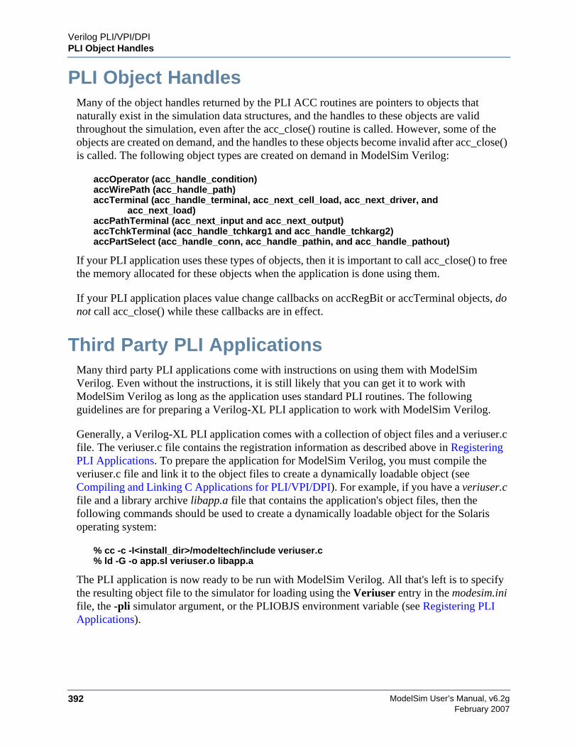
ModelSim User’s Manual, v6.2g392
Verilog PLI/VPI/DPIPLI Object Handles
February 2007
PLI Object HandlesMany of the object handles returned by the PLI ACC routines are pointers to objects thatnaturally exist in the simulation data structures, and the handles to these objects are validthroughout the simulation, even after the acc_close() routine is called. However, some of theobjects are created on demand, and the handles to these objects become invalid after acc_close()is called. The following object types are created on demand in ModelSim Verilog:
accOperator (acc_handle_condition)accWirePath (acc_handle_path)accTerminal (acc_handle_terminal, acc_next_cell_load, acc_next_driver, and
acc_next_load)accPathTerminal (acc_next_input and acc_next_output)accTchkTerminal (acc_handle_tchkarg1 and acc_handle_tchkarg2)accPartSelect (acc_handle_conn, acc_handle_pathin, and acc_handle_pathout)
If your PLI application uses these types of objects, then it is important to call acc_close() to freethe memory allocated for these objects when the application is done using them.
If your PLI application places value change callbacks on accRegBit or accTerminal objects, donot call acc_close() while these callbacks are in effect.
Third Party PLI ApplicationsMany third party PLI applications come with instructions on using them with ModelSimVerilog. Even without the instructions, it is still likely that you can get it to work withModelSim Verilog as long as the application uses standard PLI routines. The followingguidelines are for preparing a Verilog-XL PLI application to work with ModelSim Verilog.
Generally, a Verilog-XL PLI application comes with a collection of object files and a veriuser.cfile. The veriuser.c file contains the registration information as described above in RegisteringPLI Applications. To prepare the application for ModelSim Verilog, you must compile theveriuser.c file and link it to the object files to create a dynamically loadable object (seeCompiling and Linking C Applications for PLI/VPI/DPI). For example, if you have a veriuser.cfile and a library archive libapp.a file that contains the application's object files, then thefollowing commands should be used to create a dynamically loadable object for the Solarisoperating system:
% cc -c -I<install_dir>/modeltech/include veriuser.c% ld -G -o app.sl veriuser.o libapp.a
The PLI application is now ready to be run with ModelSim Verilog. All that's left is to specifythe resulting object file to the simulator for loading using the Veriuser entry in the modesim.inifile, the -pli simulator argument, or the PLIOBJS environment variable (see Registering PLIApplications).
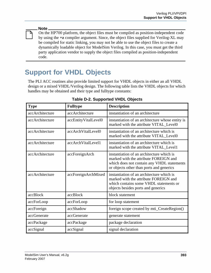
Verilog PLI/VPI/DPISupport for VHDL Objects
ModelSim User’s Manual, v6.2g 393February 2007
NoteOn the HP700 platform, the object files must be compiled as position-independent codeby using the +z compiler argument. Since, the object files supplied for Verilog-XL maybe compiled for static linking, you may not be able to use the object files to create adynamically loadable object for ModelSim Verilog. In this case, you must get the thirdparty application vendor to supply the object files compiled as position-independentcode.
Support for VHDL ObjectsThe PLI ACC routines also provide limited support for VHDL objects in either an all VHDLdesign or a mixed VHDL/Verilog design. The following table lists the VHDL objects for whichhandles may be obtained and their type and fulltype constants:
Table D-2. Supported VHDL Objects
Type Fulltype Description
accArchitecture accArchitecture instantiation of an architecture
accArchitecture accEntityVitalLevel0 instantiation of an architecture whose entity ismarked with the attribute VITAL_Level0
accArchitecture accArchVitalLevel0 instantiation of an architecture which ismarked with the attribute VITAL_Level0
accArchitecture accArchVitalLevel1 instantiation of an architecture which ismarked with the attribute VITAL_Level1
accArchitecture accForeignArch instantiation of an architecture which ismarked with the attribute FOREIGN andwhich does not contain any VHDL statementsor objects other than ports and generics
accArchitecture accForeignArchMixed instantiation of an architecture which ismarked with the attribute FOREIGN andwhich contains some VHDL statements orobjects besides ports and generics
accBlock accBlock block statement
accForLoop accForLoop for loop statement
accForeign accShadow foreign scope created by mti_CreateRegion()
accGenerate accGenerate generate statement
accPackage accPackage package declaration
accSignal accSignal signal declaration

ModelSim User’s Manual, v6.2g394
Verilog PLI/VPI/DPISupport for VHDL Objects
February 2007
The type and fulltype constants for VHDL objects are defined in the acc_vhdl.h include file. Allof these objects (except signals) are scope objects that define levels of hierarchy in the structurewindow. Currently, the PLI ACC interface has no provision for obtaining handles to generics,types, constants, variables, attributes, subprograms, and processes.
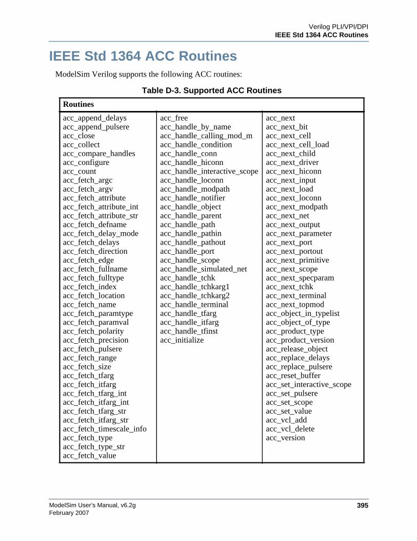
Verilog PLI/VPI/DPIIEEE Std 1364 ACC Routines
ModelSim User’s Manual, v6.2g 395February 2007
IEEE Std 1364 ACC RoutinesModelSim Verilog supports the following ACC routines:
Table D-3. Supported ACC Routines
Routines
acc_append_delaysacc_append_pulsereacc_closeacc_collectacc_compare_handlesacc_configureacc_countacc_fetch_argcacc_fetch_argvacc_fetch_attributeacc_fetch_attribute_intacc_fetch_attribute_stracc_fetch_defnameacc_fetch_delay_modeacc_fetch_delaysacc_fetch_directionacc_fetch_edgeacc_fetch_fullnameacc_fetch_fulltypeacc_fetch_indexacc_fetch_locationacc_fetch_nameacc_fetch_paramtypeacc_fetch_paramvalacc_fetch_polarityacc_fetch_precisionacc_fetch_pulsereacc_fetch_rangeacc_fetch_sizeacc_fetch_tfargacc_fetch_itfargacc_fetch_tfarg_intacc_fetch_itfarg_intacc_fetch_tfarg_stracc_fetch_itfarg_stracc_fetch_timescale_infoacc_fetch_typeacc_fetch_type_stracc_fetch_value
acc_freeacc_handle_by_nameacc_handle_calling_mod_macc_handle_conditionacc_handle_connacc_handle_hiconnacc_handle_interactive_scopeacc_handle_loconnacc_handle_modpathacc_handle_notifieracc_handle_objectacc_handle_parentacc_handle_pathacc_handle_pathinacc_handle_pathoutacc_handle_portacc_handle_scopeacc_handle_simulated_netacc_handle_tchkacc_handle_tchkarg1acc_handle_tchkarg2acc_handle_terminalacc_handle_tfargacc_handle_itfargacc_handle_tfinstacc_initialize
acc_nextacc_next_bitacc_next_cellacc_next_cell_loadacc_next_childacc_next_driveracc_next_hiconnacc_next_inputacc_next_loadacc_next_loconnacc_next_modpathacc_next_netacc_next_outputacc_next_parameteracc_next_portacc_next_portoutacc_next_primitiveacc_next_scopeacc_next_specparamacc_next_tchkacc_next_terminalacc_next_topmodacc_object_in_typelistacc_object_of_typeacc_product_typeacc_product_versionacc_release_objectacc_replace_delaysacc_replace_pulsereacc_reset_bufferacc_set_interactive_scopeacc_set_pulsereacc_set_scopeacc_set_valueacc_vcl_addacc_vcl_deleteacc_version

ModelSim User’s Manual, v6.2g396
Verilog PLI/VPI/DPIIEEE Std 1364 ACC Routines
February 2007
acc_fetch_paramval() cannot be used on 64-bit platforms to fetch a string value of a parameter.Because of this, the function acc_fetch_paramval_str() has been added to the PLI for this use.acc_fetch_paramval_str() is declared in acc_user.h. It functions in a manner similar toacc_fetch_paramval() except that it returns a char *. acc_fetch_paramval_str() can be used onall platforms.
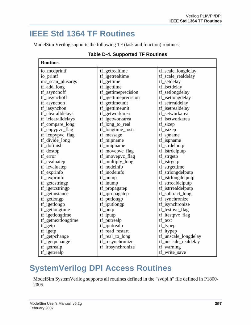
Verilog PLI/VPI/DPIIEEE Std 1364 TF Routines
ModelSim User’s Manual, v6.2g 397February 2007
IEEE Std 1364 TF RoutinesModelSim Verilog supports the following TF (task and function) routines;
SystemVerilog DPI Access RoutinesModelSim SystemVerilog supports all routines defined in the "svdpi.h" file defined in P1800-2005.
Table D-4. Supported TF Routines
Routines
io_mcdprintfio_printfmc_scan_plusargstf_add_longtf_asynchofftf_iasynchofftf_asynchontf_iasynchontf_clearalldelaystf_iclearalldelaystf_compare_longtf_copypvc_flagtf_icopypvc_flagtf_divide_longtf_dofinishtf_dostoptf_errortf_evaluateptf_ievaluateptf_exprinfotf_iexprinfotf_getcstringptf_igetcstringptf_getinstancetf_getlongptf_igetlongptf_getlongtimetf_igetlongtimetf_getnextlongtimetf_getptf_igetptf_getpchangetf_igetpchangetf_getrealptf_igetrealp
tf_getrealtimetf_igetrealtimetf_gettimetf_igettimetf_gettimeprecisiontf_igettimeprecisiontf_gettimeunittf_igettimeunittf_getworkareatf_igetworkareatf_long_to_realtf_longtime_tostrtf_messagetf_mipnametf_imipnametf_movepvc_flagtf_imovepvc_flagtf_multiply_longtf_nodeinfotf_inodeinfotf_numptf_inumptf_propagateptf_ipropagateptf_putlongptf_iputlongptf_putptf_iputptf_putrealptf_iputrealptf_read_restarttf_real_to_longtf_rosynchronizetf_irosynchronize
tf_scale_longdelaytf_scale_realdelaytf_setdelaytf_isetdelaytf_setlongdelaytf_isetlongdelaytf_setrealdelaytf_isetrealdelaytf_setworkareatf_isetworkareatf_sizeptf_isizeptf_spnametf_ispnametf_strdelputptf_istrdelputptf_strgetptf_istrgetptf_strgettimetf_strlongdelputptf_istrlongdelputptf_strrealdelputptf_istrrealdelputptf_subtract_longtf_synchronizetf_isynchronizetf_testpvc_flagtf_itestpvc_flagtf_texttf_typeptf_itypeptf_unscale_longdelaytf_unscale_realdelaytf_warningtf_write_save

ModelSim User’s Manual, v6.2g398
Verilog PLI/VPI/DPIVerilog-XL Compatible Routines
February 2007
Verilog-XL Compatible RoutinesThe following PLI routines are not defined in IEEE Std 1364, but ModelSim Verilog providesthem for compatibility with Verilog-XL.
char *acc_decompile_exp(handle condition)
This routine provides similar functionality to the Verilog-XL acc_decompile_expr routine. Thecondition argument must be a handle obtained from the acc_handle_condition routine. Thevalue returned by acc_decompile_exp is the string representation of the condition expression.
char *tf_dumpfilename(void)
This routine returns the name of the VCD file.
void tf_dumpflush(void)
A call to this routine flushes the VCD file buffer (same effect as calling $dumpflush in theVerilog code).
int tf_getlongsimtime(int *aof_hightime)
This routine gets the current simulation time as a 64-bit integer. The low-order bits are returnedby the routine, while the high-order bits are stored in the aof_hightime argument.
64-bit Support for PLIThe PLI function acc_fetch_paramval() cannot be used on 64-bit platforms to fetch a stringvalue of a parameter. Because of this, the function acc_fetch_paramval_str() has been added tothe PLI for this use. acc_fetch_paramval_str() is declared in acc_user.h. It functions in a mannersimilar to acc_fetch_paramval() except that it returns a char *. acc_fetch_paramval_str() can beused on all platforms.
Using 64-bit ModelSim with 32-bit ApplicationsIf you have 32-bit PLI/VPI/DPI applications and wish to use 64-bit ModelSim, you will need toport your code to 64 bits by moving from the ILP32 data model to the LP64 data model. Westrongly recommend that you consult the 64-bit porting guides for Sun and HP.
PLI/VPI TracingThe foreign interface tracing feature is available for tracing PLI and VPI function calls. Foreigninterface tracing creates two kinds of traces: a human-readable log of what functions werecalled, the value of the arguments, and the results returned; and a set of C-language files thatcan be used to replay what the foreign interface code did.
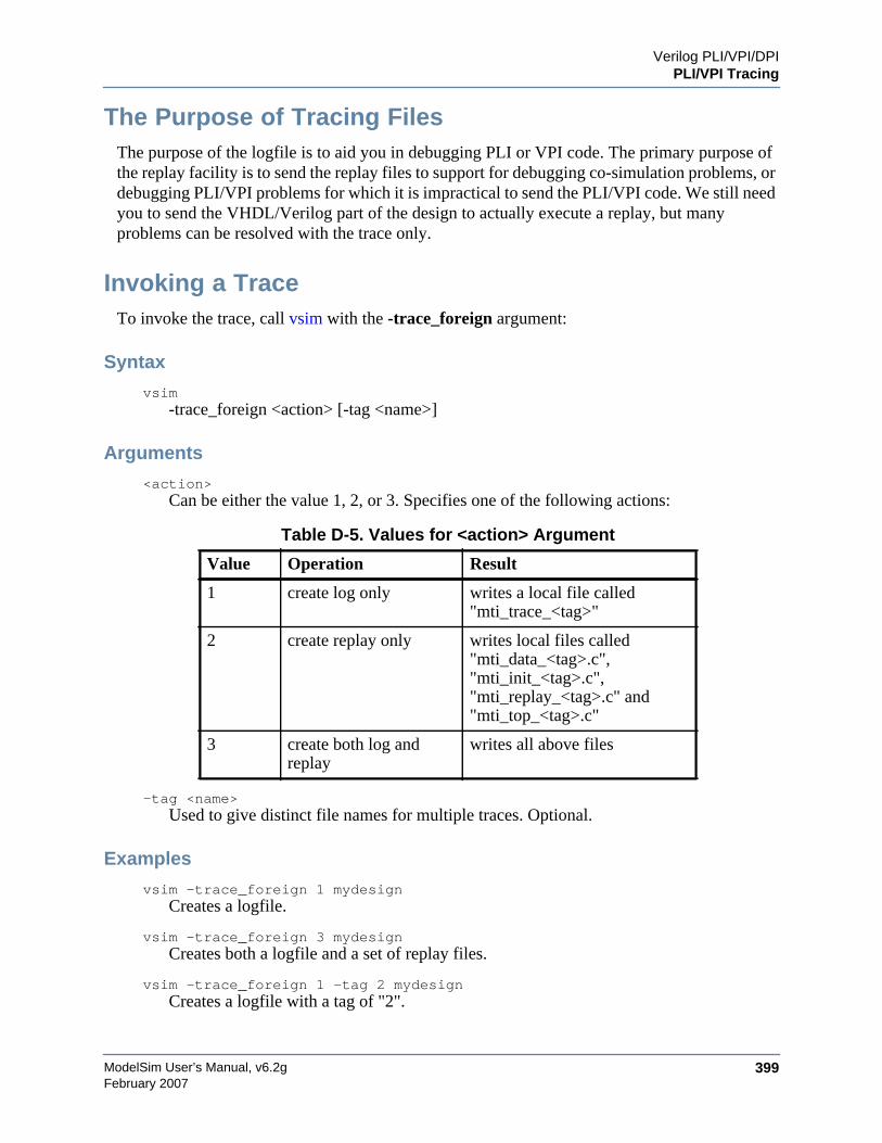
Verilog PLI/VPI/DPIPLI/VPI Tracing
ModelSim User’s Manual, v6.2g 399February 2007
The Purpose of Tracing FilesThe purpose of the logfile is to aid you in debugging PLI or VPI code. The primary purpose ofthe replay facility is to send the replay files to support for debugging co-simulation problems, ordebugging PLI/VPI problems for which it is impractical to send the PLI/VPI code. We still needyou to send the VHDL/Verilog part of the design to actually execute a replay, but manyproblems can be resolved with the trace only.
Invoking a TraceTo invoke the trace, call vsim with the -trace_foreign argument:
Syntax
vsim-trace_foreign <action> [-tag <name>]
Arguments
<action>Can be either the value 1, 2, or 3. Specifies one of the following actions:
-tag <name>Used to give distinct file names for multiple traces. Optional.
Examples
vsim -trace_foreign 1 mydesignCreates a logfile.
vsim -trace_foreign 3 mydesignCreates both a logfile and a set of replay files.
vsim -trace_foreign 1 -tag 2 mydesignCreates a logfile with a tag of "2".
Table D-5. Values for <action> Argument
Value Operation Result
1 create log only writes a local file called"mti_trace_<tag>"
2 create replay only writes local files called"mti_data_<tag>.c","mti_init_<tag>.c","mti_replay_<tag>.c" and"mti_top_<tag>.c"
3 create both log andreplay
writes all above files
ModelSim User’s Manual, v6.2g400
Verilog PLI/VPI/DPIDebugging PLI/VPI/DPI Application Code
February 2007
The tracing operations will provide tracing during all user foreign code-calls, including PLI/VPIuser tasks and functions (calltf, checktf, sizetf and misctf routines), and Verilog VCL callbacks.
Debugging PLI/VPI/DPI Application CodeIn order to debug your PLI/VPI/DPI application code in a debugger, you must first:
1. Compile the application code with debugging information (using the -g option) andwithout optimizations (for example, don’t use the -O option).
2. Load vsim into a debugger.
Even though vsim is stripped, most debuggers will still execute it. You can invoke thedebugger directly on vsimk, the simulation kernel where your application code is loaded(for example, "ddd `which vsimk`"), or you can attach the debugger to an alreadyrunning vsim process. In the second case, you must attach to the PID for vsimk, and youmust specify the full path to the vsimk executable (for example, "gdb$MTI_HOME/sunos5/vsimk 1234").
On Solaris, AIX, and Linux systems you can use either gdb or ddd. On HP-UX systemsyou can use the wdb debugger from HP. You will need version 1.2 or later.
3. Set an entry point using breakpoint.
Since initially the debugger recognizes only vsim's PLI/VPI/DPI function symbols,when invoking the debugger directly on vsim you need to place a breakpoint in the firstPLI/VPI/DPI function that is called by your application code. An easy way to set anentry point is to put a call to acc_product_version() as the first executable statement inyour application code. Then, after vsim has been loaded into the debugger, set abreakpoint in this function. Once you have set the breakpoint, run vsim with the usualarguments.
When the breakpoint is reached, the shared library containing your application code hasbeen loaded.
4. In some debuggers, you must use the share command to load the application's symbols.
At this point all of the application's symbols should be visible. You can now set breakpoints inand single step through your application code.
Troubleshooting a Missing DPI Import FunctionDPI uses C function linkage. If your DPI application is written in C++, it is important toremember to use extern "C" declaration syntax appropriately. Otherwise the C++ compiler willproduce a mangled C++ name for the function, and the simulator is not able to locate and bindthe DPI call to that function.

Verilog PLI/VPI/DPIDebugging PLI/VPI/DPI Application Code
ModelSim User’s Manual, v6.2g 401February 2007
Also, if you do not use the -Bsymbolic argument on the command line for specifying a link, thesystem may bind to an incorrect function, resulting in unexpected behavior. For moreinformation, see Correct Linking of Shared Libraries with -Bsymbolic.
HP-UX Specific WarningsOn HP-UX you might see some warning messages that vsim does not have debugginginformation available. This is normal. If you are using Exceed to access an HP machine fromWindows NT, it is recommended that you run vsim in command line or batch mode becauseyour NT machine may hang if you run vsim in GUI mode. Click on the "go" button, or use F5or the go command to execute vsim in wdb.
You might also see a warning about not finding "__dld_flags" in the object file. This warningcan be ignored. You should see a list of libraries loaded into the debugger. It should include thelibrary for your PLI/VPI/DPI application. Alternatively, you can use share to load only a singlelibrary.

ModelSim User’s Manual, v6.2g402
Verilog PLI/VPI/DPIDebugging PLI/VPI/DPI Application Code
February 2007
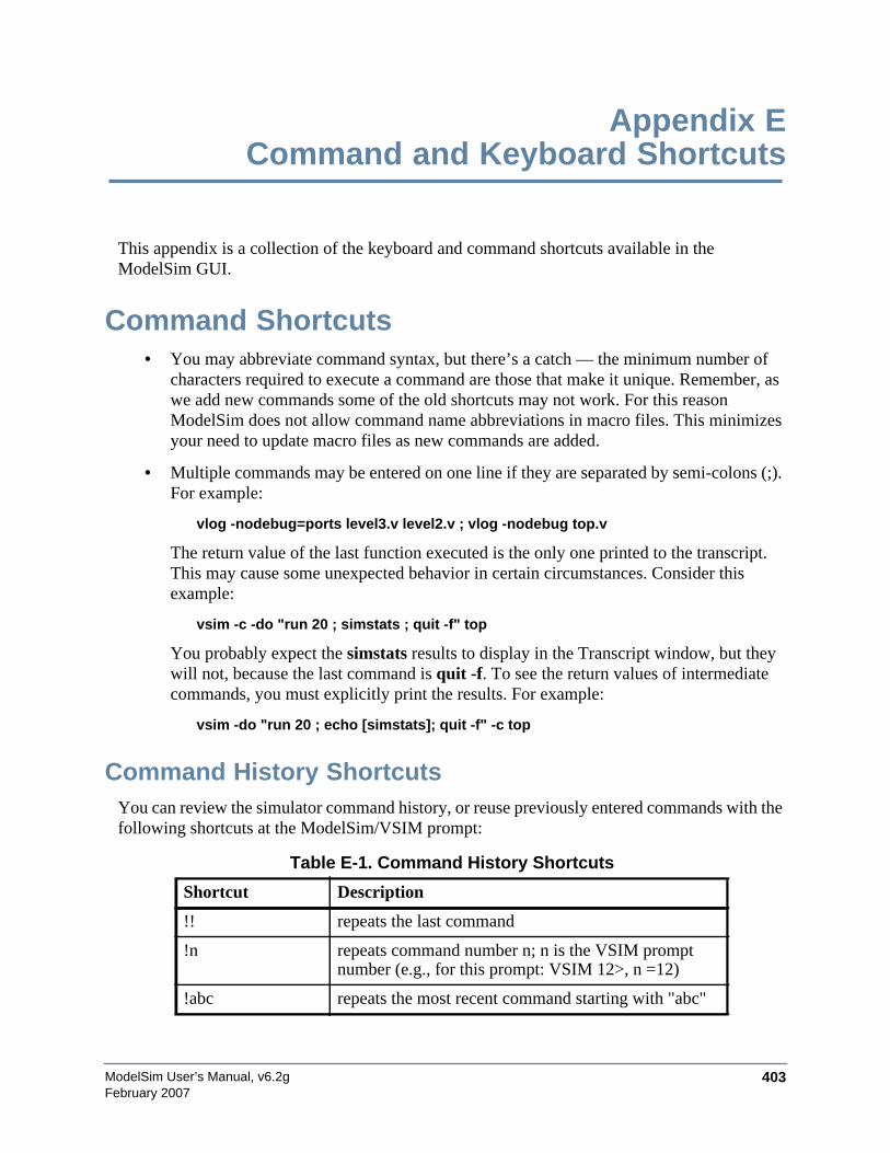
ModelSim User’s Manual, v6.2g 403February 2007
Appendix ECommand and Keyboard Shortcuts
This appendix is a collection of the keyboard and command shortcuts available in theModelSim GUI.
Command Shortcuts• You may abbreviate command syntax, but there’s a catch — the minimum number of
characters required to execute a command are those that make it unique. Remember, aswe add new commands some of the old shortcuts may not work. For this reasonModelSim does not allow command name abbreviations in macro files. This minimizesyour need to update macro files as new commands are added.
• Multiple commands may be entered on one line if they are separated by semi-colons (;).For example:
vlog -nodebug=ports level3.v level2.v ; vlog -nodebug top.v
The return value of the last function executed is the only one printed to the transcript.This may cause some unexpected behavior in certain circumstances. Consider thisexample:
vsim -c -do "run 20 ; simstats ; quit -f" top
You probably expect the simstats results to display in the Transcript window, but theywill not, because the last command is quit -f. To see the return values of intermediatecommands, you must explicitly print the results. For example:
vsim -do "run 20 ; echo [simstats]; quit -f" -c top
Command History ShortcutsYou can review the simulator command history, or reuse previously entered commands with thefollowing shortcuts at the ModelSim/VSIM prompt:
Table E-1. Command History Shortcuts
Shortcut Description
!! repeats the last command
!n repeats command number n; n is the VSIM promptnumber (e.g., for this prompt: VSIM 12>, n =12)
!abc repeats the most recent command starting with "abc"
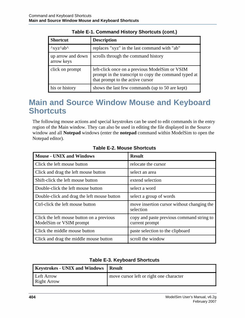
ModelSim User’s Manual, v6.2g404
Command and Keyboard ShortcutsMain and Source Window Mouse and Keyboard Shortcuts
February 2007
Main and Source Window Mouse and KeyboardShortcuts
The following mouse actions and special keystrokes can be used to edit commands in the entryregion of the Main window. They can also be used in editing the file displayed in the Sourcewindow and all Notepad windows (enter the notepad command within ModelSim to open theNotepad editor).
^xyz^ab^ replaces "xyz" in the last command with "ab"
up arrow and downarrow keys
scrolls through the command history
click on prompt left-click once on a previous ModelSim or VSIMprompt in the transcript to copy the command typed atthat prompt to the active cursor
his or history shows the last few commands (up to 50 are kept)
Table E-2. Mouse Shortcuts
Mouse - UNIX and Windows Result
Click the left mouse button relocate the cursor
Click and drag the left mouse button select an area
Shift-click the left mouse button extend selection
Double-click the left mouse button select a word
Double-click and drag the left mouse button select a group of words
Ctrl-click the left mouse button move insertion cursor without changing theselection
Click the left mouse button on a previousModelSim or VSIM prompt
copy and paste previous command string tocurrent prompt
Click the middle mouse button paste selection to the clipboard
Click and drag the middle mouse button scroll the window
Table E-3. Keyboard Shortcuts
Keystrokes - UNIX and Windows Result
Left ArrowRight Arrow
move cursor left or right one character
Table E-1. Command History Shortcuts (cont.)
Shortcut Description
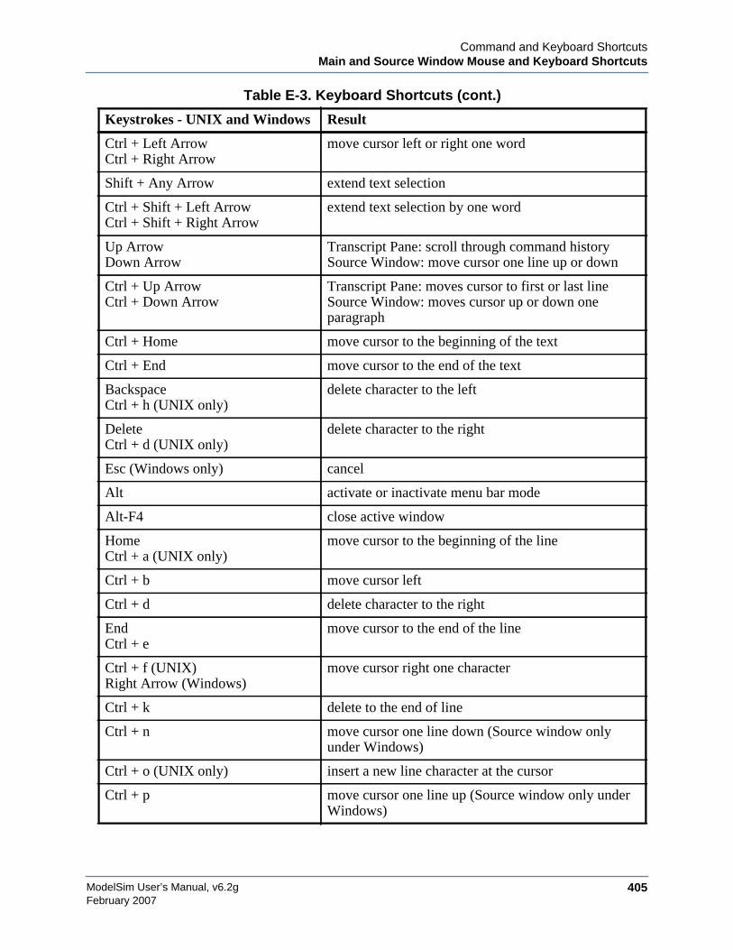
Command and Keyboard ShortcutsMain and Source Window Mouse and Keyboard Shortcuts
ModelSim User’s Manual, v6.2g 405February 2007
Ctrl + Left ArrowCtrl + Right Arrow
move cursor left or right one word
Shift + Any Arrow extend text selection
Ctrl + Shift + Left ArrowCtrl + Shift + Right Arrow
extend text selection by one word
Up ArrowDown Arrow
Transcript Pane: scroll through command historySource Window: move cursor one line up or down
Ctrl + Up ArrowCtrl + Down Arrow
Transcript Pane: moves cursor to first or last lineSource Window: moves cursor up or down oneparagraph
Ctrl + Home move cursor to the beginning of the text
Ctrl + End move cursor to the end of the text
BackspaceCtrl + h (UNIX only)
delete character to the left
DeleteCtrl + d (UNIX only)
delete character to the right
Esc (Windows only) cancel
Alt activate or inactivate menu bar mode
Alt-F4 close active window
HomeCtrl + a (UNIX only)
move cursor to the beginning of the line
Ctrl + b move cursor left
Ctrl + d delete character to the right
EndCtrl + e
move cursor to the end of the line
Ctrl + f (UNIX)Right Arrow (Windows)
move cursor right one character
Ctrl + k delete to the end of line
Ctrl + n move cursor one line down (Source window onlyunder Windows)
Ctrl + o (UNIX only) insert a new line character at the cursor
Ctrl + p move cursor one line up (Source window only underWindows)
Table E-3. Keyboard Shortcuts (cont.)
Keystrokes - UNIX and Windows Result

ModelSim User’s Manual, v6.2g406
Command and Keyboard ShortcutsMain and Source Window Mouse and Keyboard Shortcuts
February 2007
Ctrl + s (UNIX)Ctrl + f (Windows)
find
Ctrl + t reverse the order of the two characters on either side ofthe cursor
Ctrl + u delete line
Page DownCtrl + v (UNIX only)
move cursor down one screen
Ctrl + w (UNIX)Ctrl + x (Windows)
cut the selection
Ctrl + sCtrl + x (UNIX Only)
save
Ctrl + y (UNIX)Ctrl + v (Windows)
paste the selection
Ctrl + a (Windows Only) select the entire contents of the widget
Ctrl + \ clear any selection in the widget
Ctrl + - (UNIX)Ctrl + / (UNIX)Ctrl + z (Windows)
undoes previous edits in the Source window
Meta + < (UNIX only) move cursor to the beginning of the file
Meta + > (UNIX only) move cursor to the end of the file
Page UpMeta + v (UNIX only)
move cursor up one screen
Meta + w (UNIX)Ctrl + c (Windows)
copy selection
F3 Peforms a Find Next action in the Source Window.
F4Shift+F4
Change focus to next pane in main windowChange focus to previous pane in main window
F5
Shift+F5
Toggle between expanding and restoring size of paneto fit the entire main windowToggle on/off the pane headers.
F8 search for the most recent command that matches thecharacters typed (Main window only)
F9 run simulation
F10 continue simulation
F11 (Windows only) single-step
Table E-3. Keyboard Shortcuts (cont.)
Keystrokes - UNIX and Windows Result
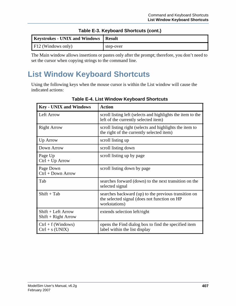
Command and Keyboard ShortcutsList Window Keyboard Shortcuts
ModelSim User’s Manual, v6.2g 407February 2007
The Main window allows insertions or pastes only after the prompt; therefore, you don’t need toset the cursor when copying strings to the command line.
List Window Keyboard ShortcutsUsing the following keys when the mouse cursor is within the List window will cause theindicated actions:
F12 (Windows only) step-over
Table E-4. List Window Keyboard Shortcuts
Key - UNIX and Windows Action
Left Arrow scroll listing left (selects and highlights the item to theleft of the currently selected item)
Right Arrow scroll listing right (selects and highlights the item tothe right of the currently selected item)
Up Arrow scroll listing up
Down Arrow scroll listing down
Page UpCtrl + Up Arrow
scroll listing up by page
Page DownCtrl + Down Arrow
scroll listing down by page
Tab searches forward (down) to the next transition on theselected signal
Shift + Tab searches backward (up) to the previous transition onthe selected signal (does not function on HPworkstations)
Shift + Left ArrowShift + Right Arrow
extends selection left/right
Ctrl + f (Windows)Ctrl + s (UNIX)
opens the Find dialog box to find the specified itemlabel within the list display
Table E-3. Keyboard Shortcuts (cont.)
Keystrokes - UNIX and Windows Result
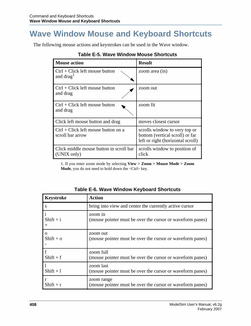
ModelSim User’s Manual, v6.2g408
Command and Keyboard ShortcutsWave Window Mouse and Keyboard Shortcuts
February 2007
Wave Window Mouse and Keyboard ShortcutsThe following mouse actions and keystrokes can be used in the Wave window.
Table E-5. Wave Window Mouse Shortcuts
Mouse action Result
Ctrl + Click left mouse buttonand drag1
1. If you enter zoom mode by selecting View > Zoom > Mouse Mode > ZoomMode, you do not need to hold down the <Ctrl> key.
zoom area (in)
Ctrl + Click left mouse buttonand drag
zoom out
Ctrl + Click left mouse buttonand drag
zoom fit
Click left mouse button and drag moves closest cursor
Ctrl + Click left mouse button on ascroll bar arrow
scrolls window to very top orbottom (vertical scroll) or farleft or right (horizontal scroll)
Click middle mouse button in scroll bar(UNIX only)
scrolls window to position ofclick
Table E-6. Wave Window Keyboard Shortcuts
Keystroke Action
s bring into view and center the currently active cursor
iShift + i+
zoom in(mouse pointer must be over the cursor or waveform panes)
oShift + o-
zoom out(mouse pointer must be over the cursor or waveform panes)
fShift + f
zoom full(mouse pointer must be over the cursor or waveform panes)
lShift + l
zoom last(mouse pointer must be over the cursor or waveform panes)
rShift + r
zoom range(mouse pointer must be over the cursor or waveform panes)
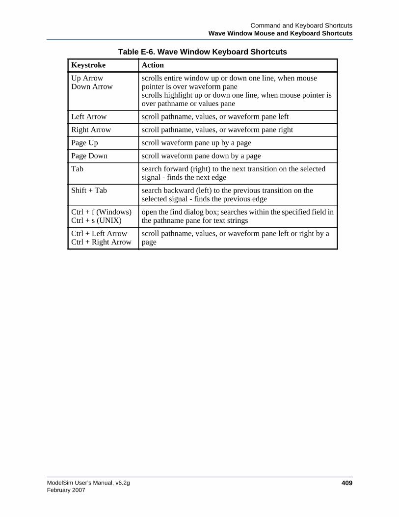
Command and Keyboard ShortcutsWave Window Mouse and Keyboard Shortcuts
ModelSim User’s Manual, v6.2g 409February 2007
Up ArrowDown Arrow
scrolls entire window up or down one line, when mousepointer is over waveform panescrolls highlight up or down one line, when mouse pointer isover pathname or values pane
Left Arrow scroll pathname, values, or waveform pane left
Right Arrow scroll pathname, values, or waveform pane right
Page Up scroll waveform pane up by a page
Page Down scroll waveform pane down by a page
Tab search forward (right) to the next transition on the selectedsignal - finds the next edge
Shift + Tab search backward (left) to the previous transition on theselected signal - finds the previous edge
Ctrl + f (Windows)Ctrl + s (UNIX)
open the find dialog box; searches within the specified field inthe pathname pane for text strings
Ctrl + Left ArrowCtrl + Right Arrow
scroll pathname, values, or waveform pane left or right by apage
Table E-6. Wave Window Keyboard Shortcuts
Keystroke Action

ModelSim User’s Manual, v6.2g410
Command and Keyboard ShortcutsWave Window Mouse and Keyboard Shortcuts
February 2007
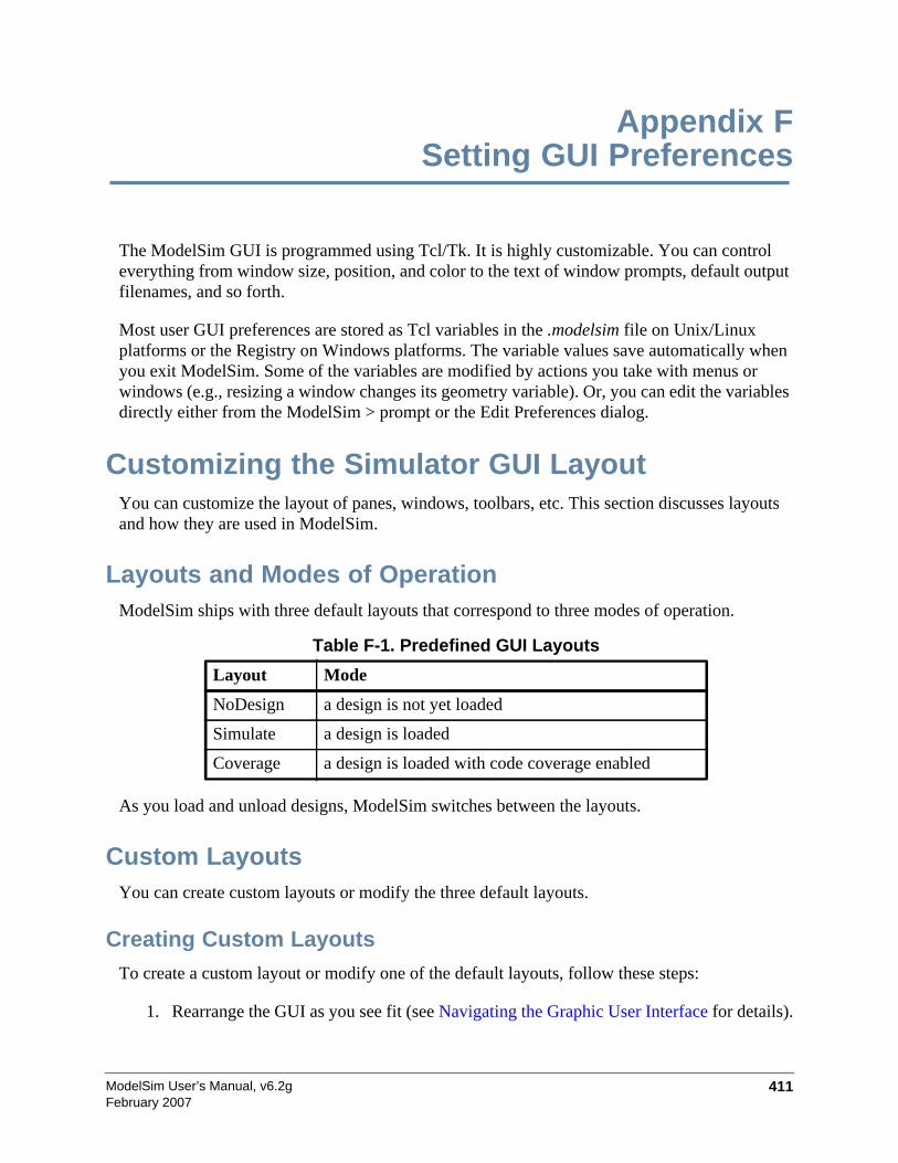
ModelSim User’s Manual, v6.2g 411February 2007
Appendix FSetting GUI Preferences
The ModelSim GUI is programmed using Tcl/Tk. It is highly customizable. You can controleverything from window size, position, and color to the text of window prompts, default outputfilenames, and so forth.
Most user GUI preferences are stored as Tcl variables in the .modelsim file on Unix/Linuxplatforms or the Registry on Windows platforms. The variable values save automatically whenyou exit ModelSim. Some of the variables are modified by actions you take with menus orwindows (e.g., resizing a window changes its geometry variable). Or, you can edit the variablesdirectly either from the ModelSim > prompt or the Edit Preferences dialog.
Customizing the Simulator GUI LayoutYou can customize the layout of panes, windows, toolbars, etc. This section discusses layoutsand how they are used in ModelSim.
Layouts and Modes of OperationModelSim ships with three default layouts that correspond to three modes of operation.
As you load and unload designs, ModelSim switches between the layouts.
Custom LayoutsYou can create custom layouts or modify the three default layouts.
Creating Custom LayoutsTo create a custom layout or modify one of the default layouts, follow these steps:
1. Rearrange the GUI as you see fit (see Navigating the Graphic User Interface for details).
Table F-1. Predefined GUI Layouts
Layout Mode
NoDesign a design is not yet loaded
Simulate a design is loaded
Coverage a design is loaded with code coverage enabled

ModelSim User’s Manual, v6.2g412
Setting GUI PreferencesCustomizing the Simulator GUI Layout
February 2007
2. Select Layout > Save.
Figure F-1. Save Current Window Layout Dialog Box
3. Specify a new name or use an existing name to overwrite that layout.
4. Click OK.
The layout is saved to the .modelsim file (or Registry on Windows).
Assigning Layouts to ModesYou can assign which layout appears in each mode (no design loaded, design loaded, designloaded with coverage). Follow these steps:
1. Create your custom layouts as described above.
2. Select Layout > Configure.
Example F-1. Configure Window Layouts Dialog Box
3. Select a layout for each mode.
4. Click OK.
The layout assignment is saved to the .modelsim file (Registry on Windows).
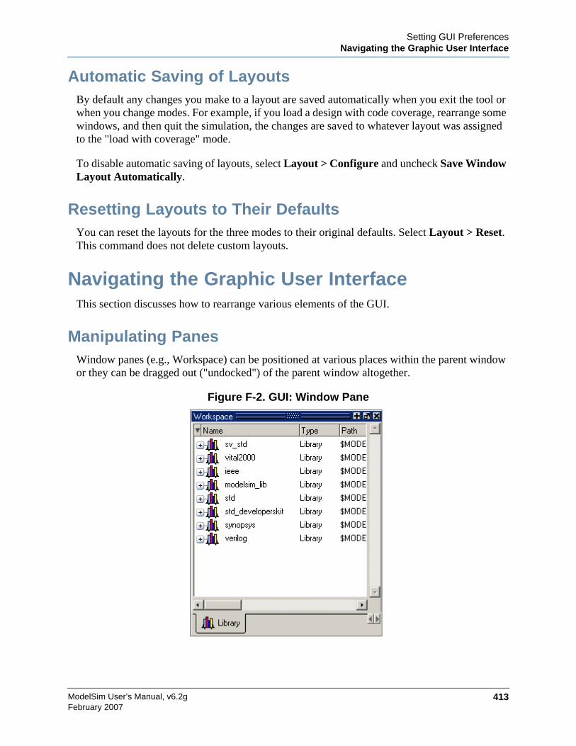
Setting GUI PreferencesNavigating the Graphic User Interface
ModelSim User’s Manual, v6.2g 413February 2007
Automatic Saving of LayoutsBy default any changes you make to a layout are saved automatically when you exit the tool orwhen you change modes. For example, if you load a design with code coverage, rearrange somewindows, and then quit the simulation, the changes are saved to whatever layout was assignedto the "load with coverage" mode.
To disable automatic saving of layouts, select Layout > Configure and uncheck Save WindowLayout Automatically.
Resetting Layouts to Their DefaultsYou can reset the layouts for the three modes to their original defaults. Select Layout > Reset.This command does not delete custom layouts.
Navigating the Graphic User InterfaceThis section discusses how to rearrange various elements of the GUI.
Manipulating PanesWindow panes (e.g., Workspace) can be positioned at various places within the parent windowor they can be dragged out ("undocked") of the parent window altogether.
Figure F-2. GUI: Window Pane

ModelSim User’s Manual, v6.2g414
Setting GUI PreferencesNavigating the Graphic User Interface
February 2007
Moving PanesWhen you see a double bar at the top edge of a pane, it means you can modify the pane position.
Figure F-3. GUI: Double Bar
Click-and drag the pane handle in the middle of a double bar (your mouse pointer will change toa four-headed arrow when it is in the correct location) to reposition the pane inside the parentwindow. As you move the mouse to various parts of the main window, a gray outline will showyou valid locations to drop the pane.
Or, drag the pane outside of the parent window, and when you let go of the mouse button, thepane becomes a free-floating window.
Docking and Undocking PanesYou can undock a pane by clicking the undock button in the heading of a pane.
Figure F-4. GUI: Undock Button
To redock a floating pane, click on the pane handle at the top of the window and drag it backinto the parent window, or click the dock icon.
Figure F-5. GUI: Dock Button
Zooming PanesYou can expand panes to fill the entire Main window by clicking the zoom icon in the headingof the pane.
Figure F-6. GUI: Zoom Button
To restore the pane to its original size and position click the unzoom button in the heading of thepane.
Setting GUI PreferencesSimulator GUI Preferences
ModelSim User’s Manual, v6.2g 415February 2007
Figure F-7. GUI: Zoom Button
Columnar Information DisplayMany panes (e.g., Objects, Workspace, etc.) display information in a columnar format. You canperform a number of operations on columnar formats:
• Click and drag on a column heading to rearrange columns
• Click and drag on a border between column names to increase/decrease column size
• Sort columns by clicking once on the column heading to sort in ascending order;clicking twice to sort in descending order; and clicking three times to sort in defaultorder.
• Hide or show columns by either right-clicking a column heading and selecting an objectfrom the context menu or by clicking the column-list drop down arrow and selecting anobject.
Quick Access ToolbarsToolbar buttons provide access to commonly used commands and functions. Toolbars can bedocked and undocked (moved to or from the main toolbar area) by clicking and dragging on thetoolbar handle at the left-edge of a toolbar.
Figure F-8. Toolbar Manipulation
You can also hide/show the various toolbars. To hide or show a toolbar, right-click on a blankspot of the main toolbar area and select a toolbar from the list.
To reset toolbars to their original state, right-click on a blank spot of the main toolbar area andselect Reset.
Simulator GUI PreferencesSimulator GUI preferences are stored by default either in the .modelsim file in your HOMEdirectory on UNIX/Linux platforms or the Registry on Windows platforms.
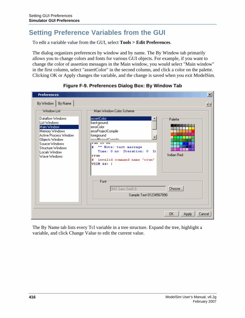
ModelSim User’s Manual, v6.2g416
Setting GUI PreferencesSimulator GUI Preferences
February 2007
Setting Preference Variables from the GUITo edit a variable value from the GUI, select Tools > Edit Preferences.
The dialog organizes preferences by window and by name. The By Window tab primarilyallows you to change colors and fonts for various GUI objects. For example, if you want tochange the color of assertion messages in the Main window, you would select "Main window"in the first column, select "assertColor" in the second column, and click a color on the palette.Clicking OK or Apply changes the variable, and the change is saved when you exit ModelSim.
Figure F-9. Preferences Dialog Box: By Window Tab
The By Name tab lists every Tcl variable in a tree structure. Expand the tree, highlight avariable, and click Change Value to edit the current value.
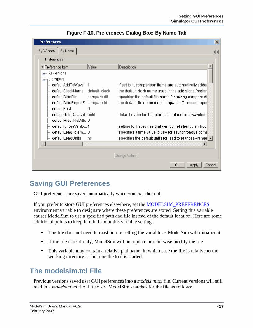
Setting GUI PreferencesSimulator GUI Preferences
ModelSim User’s Manual, v6.2g 417February 2007
Figure F-10. Preferences Dialog Box: By Name Tab
Saving GUI PreferencesGUI preferences are saved automatically when you exit the tool.
If you prefer to store GUI preferences elsewhere, set the MODELSIM_PREFERENCESenvironment variable to designate where these preferences are stored. Setting this variablecauses ModelSim to use a specified path and file instead of the default location. Here are someadditional points to keep in mind about this variable setting:
• The file does not need to exist before setting the variable as ModelSim will initialize it.
• If the file is read-only, ModelSim will not update or otherwise modify the file.
• This variable may contain a relative pathname, in which case the file is relative to theworking directory at the time the tool is started.
The modelsim.tcl FilePrevious versions saved user GUI preferences into a modelsim.tcl file. Current versions will stillread in a modelsim.tcl file if it exists. ModelSim searches for the file as follows:
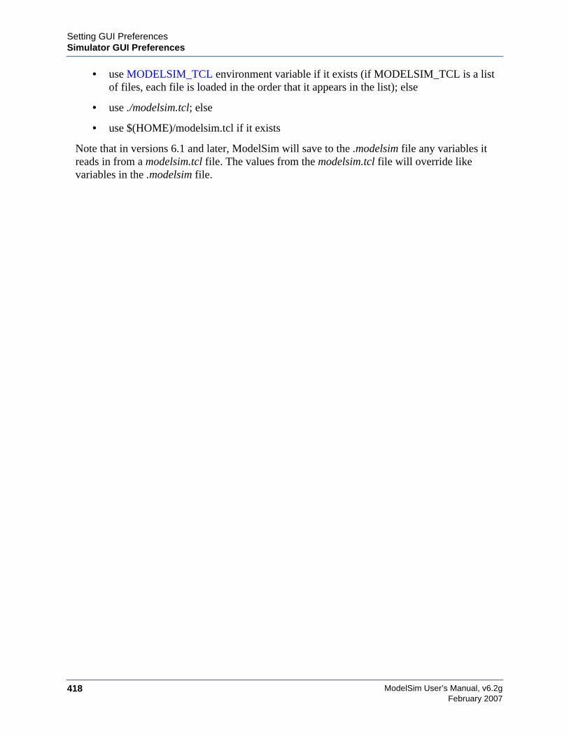
ModelSim User’s Manual, v6.2g418
Setting GUI PreferencesSimulator GUI Preferences
February 2007
• use MODELSIM_TCL environment variable if it exists (if MODELSIM_TCL is a listof files, each file is loaded in the order that it appears in the list); else
• use ./modelsim.tcl; else
• use $(HOME)/modelsim.tcl if it exists
Note that in versions 6.1 and later, ModelSim will save to the .modelsim file any variables itreads in from a modelsim.tcl file. The values from the modelsim.tcl file will override likevariables in the .modelsim file.
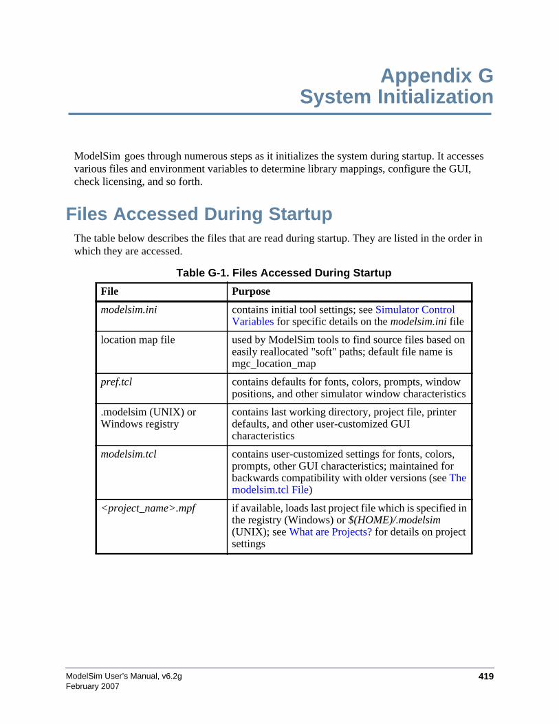
ModelSim User’s Manual, v6.2g 419February 2007
Appendix GSystem Initialization
ModelSim goes through numerous steps as it initializes the system during startup. It accessesvarious files and environment variables to determine library mappings, configure the GUI,check licensing, and so forth.
Files Accessed During StartupThe table below describes the files that are read during startup. They are listed in the order inwhich they are accessed.
Table G-1. Files Accessed During Startup
File Purpose
modelsim.ini contains initial tool settings; see Simulator ControlVariables for specific details on the modelsim.ini file
location map file used by ModelSim tools to find source files based oneasily reallocated "soft" paths; default file name ismgc_location_map
pref.tcl contains defaults for fonts, colors, prompts, windowpositions, and other simulator window characteristics
.modelsim (UNIX) orWindows registry
contains last working directory, project file, printerdefaults, and other user-customized GUIcharacteristics
modelsim.tcl contains user-customized settings for fonts, colors,prompts, other GUI characteristics; maintained forbackwards compatibility with older versions (see Themodelsim.tcl File)
<project_name>.mpf if available, loads last project file which is specified inthe registry (Windows) or $(HOME)/.modelsim(UNIX); see What are Projects? for details on projectsettings
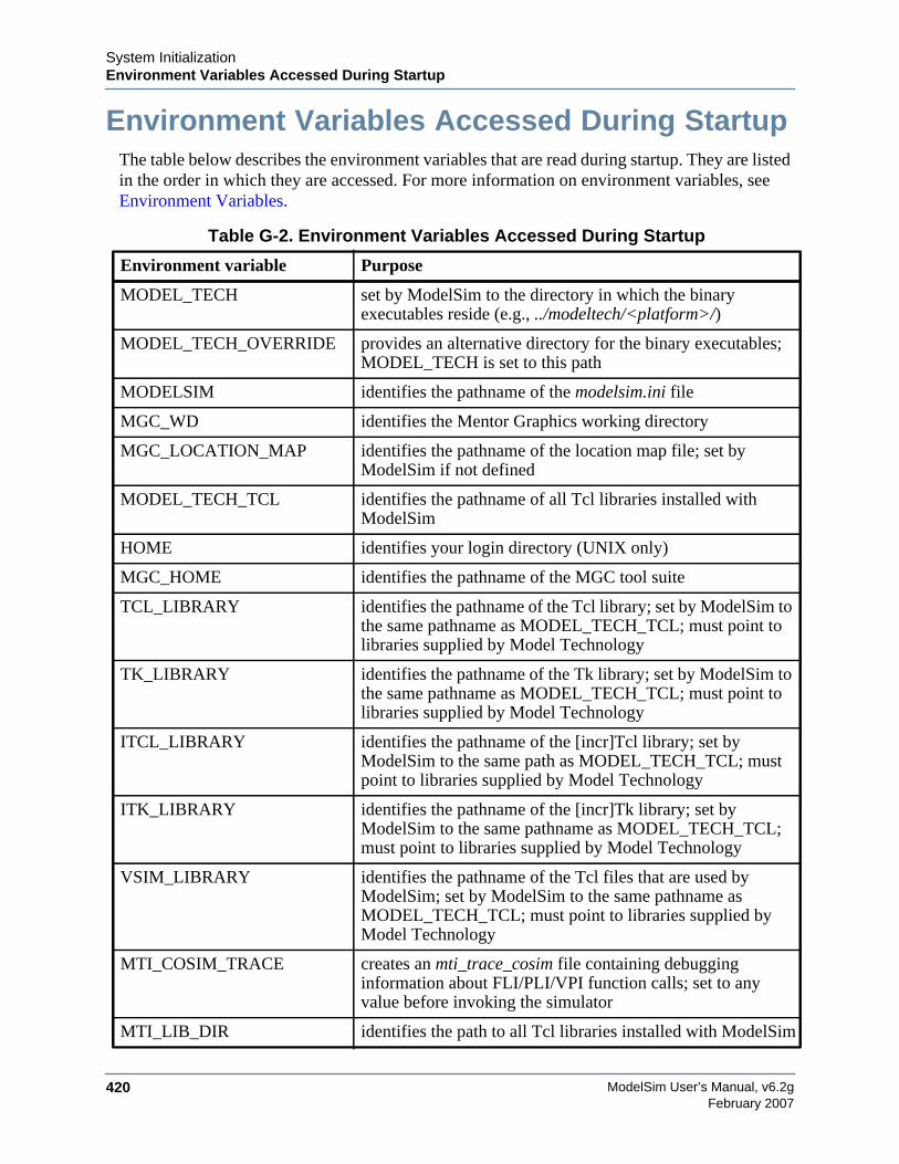
ModelSim User’s Manual, v6.2g420
System InitializationEnvironment Variables Accessed During Startup
February 2007
Environment Variables Accessed During StartupThe table below describes the environment variables that are read during startup. They are listedin the order in which they are accessed. For more information on environment variables, seeEnvironment Variables.
Table G-2. Environment Variables Accessed During Startup
Environment variable Purpose
MODEL_TECH set by ModelSim to the directory in which the binaryexecutables reside (e.g., ../modeltech/<platform>/)
MODEL_TECH_OVERRIDE provides an alternative directory for the binary executables;MODEL_TECH is set to this path
MODELSIM identifies the pathname of the modelsim.ini file
MGC_WD identifies the Mentor Graphics working directory
MGC_LOCATION_MAP identifies the pathname of the location map file; set byModelSim if not defined
MODEL_TECH_TCL identifies the pathname of all Tcl libraries installed withModelSim
HOME identifies your login directory (UNIX only)
MGC_HOME identifies the pathname of the MGC tool suite
TCL_LIBRARY identifies the pathname of the Tcl library; set by ModelSim tothe same pathname as MODEL_TECH_TCL; must point tolibraries supplied by Model Technology
TK_LIBRARY identifies the pathname of the Tk library; set by ModelSim tothe same pathname as MODEL_TECH_TCL; must point tolibraries supplied by Model Technology
ITCL_LIBRARY identifies the pathname of the [incr]Tcl library; set byModelSim to the same path as MODEL_TECH_TCL; mustpoint to libraries supplied by Model Technology
ITK_LIBRARY identifies the pathname of the [incr]Tk library; set byModelSim to the same pathname as MODEL_TECH_TCL;must point to libraries supplied by Model Technology
VSIM_LIBRARY identifies the pathname of the Tcl files that are used byModelSim; set by ModelSim to the same pathname asMODEL_TECH_TCL; must point to libraries supplied byModel Technology
MTI_COSIM_TRACE creates an mti_trace_cosim file containing debugginginformation about FLI/PLI/VPI function calls; set to anyvalue before invoking the simulator
MTI_LIB_DIR identifies the path to all Tcl libraries installed with ModelSim

System InitializationInitialization Sequence
ModelSim User’s Manual, v6.2g 421February 2007
Initialization SequenceThe following list describes in detail ModelSim’s initialization sequence. The sequenceincludes a number of conditional structures, the results of which are determined by the existenceof certain files and the current settings of environment variables.
In the steps below, names in uppercase denote environment variables (except MTI_LIB_DIRwhich is a Tcl variable). Instances of $(NAME) denote paths that are determined by anenvironment variable (except $(MTI_LIB_DIR) which is determined by a Tcl variable).
1. Determines the path to the executable directory (../modeltech/<platform>). SetsMODEL_TECH to this path, unless MODEL_TECH_OVERRIDE exists, in which caseMODEL_TECH is set to the same value as MODEL_TECH_OVERRIDE.
2. Finds the modelsim.ini file by evaluating the following conditions:
• use $(MODELSIM)/modelsim.ini if it exists; else
• use $(MGC_PWD)/modelsim.ini; else
• use ./modelsim.ini; else
• use $(MODEL_TECH)/modelsim.ini; else
• use $(MODEL_TECH)/../modelsim.ini; else
• use $(MGC_HOME)/lib/modelsim.ini; else
• set path to ./modelsim.ini even though the file doesn’t exist
3. Finds the location map file by evaluating the following conditions:
• use MGC_LOCATION_MAP if it exists (if this variable is set to "no_map",ModelSim skips initialization of the location map); else
MTI_VCO_MODE determines which version of ModelSim to use on platformsthat support both 32- and 64-bit versions when ModelSimexecutables are invoked from the modeltech/bin directory bya Unix shell command (using full path specification or PATHsearch)
MODELSIM_TCL identifies the pathname to a user preference file (e.g.,C:\modeltech\modelsim.tcl); can be a list of file pathnames,separated by semicolons (Windows) or colons (UNIX); notethat user preferences are now stored in the .modelsim file(Unix) or registry (Windows); ModelSim will still read thisenvironment variable but it will then save all the settings tothe .modelsim file when you exit the tool
Table G-2. Environment Variables Accessed During Startup
Environment variable Purpose
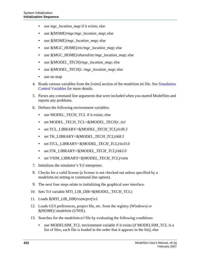
ModelSim User’s Manual, v6.2g422
System InitializationInitialization Sequence
February 2007
• use mgc_location_map if it exists; else
• use $(HOME)/mgc/mgc_location_map; else
• use $(HOME)/mgc_location_map; else
• use $(MGC_HOME)/etc/mgc_location_map; else
• use $(MGC_HOME)/shared/etc/mgc_location_map; else
• use $(MODEL_TECH)/mgc_location_map; else
• use $(MODEL_TECH)/../mgc_location_map; else
• use no map
4. Reads various variables from the [vsim] section of the modelsim.ini file. See SimulationControl Variables for more details.
5. Parses any command line arguments that were included when you started ModelSim andreports any problems.
6. Defines the following environment variables:
• use MODEL_TECH_TCL if it exists; else
• set MODEL_TECH_TCL=$(MODEL_TECH)/../tcl
• set TCL_LIBRARY=$(MODEL_TECH_TCL)/tcl8.3
• set TK_LIBRARY=$(MODEL_TECH_TCL)/tk8.3
• set ITCL_LIBRARY=$(MODEL_TECH_TCL)/itcl3.0
• set ITK_LIBRARY=$(MODEL_TECH_TCL)/itk3.0
• set VSIM_LIBRARY=$(MODEL_TECH_TCL)/vsim
7. Initializes the simulator’s Tcl interpreter.
8. Checks for a valid license (a license is not checked out unless specified by amodelsim.ini setting or command line option).
9. The next four steps relate to initializing the graphical user interface.
10. Sets Tcl variable MTI_LIB_DIR=$(MODEL_TECH_TCL)
11. Loads $(MTI_LIB_DIR)/vsim/pref.tcl.
12. Loads GUI preferences, project file, etc. from the registry (Windows) or$(HOME)/.modelsim (UNIX).
13. Searches for the modelsim.tcl file by evaluating the following conditions:
• use MODELSIM_TCL environment variable if it exists (if MODELSIM_TCL is alist of files, each file is loaded in the order that it appears in the list); else
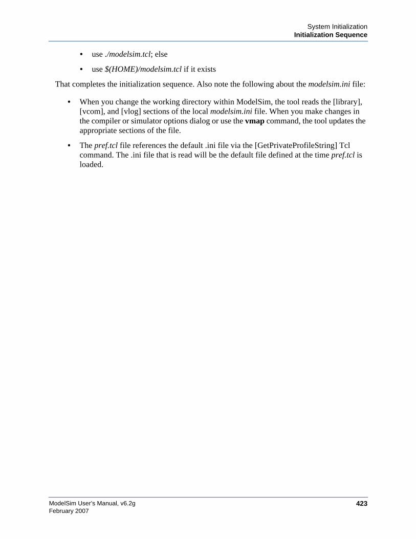
System InitializationInitialization Sequence
ModelSim User’s Manual, v6.2g 423February 2007
• use ./modelsim.tcl; else
• use $(HOME)/modelsim.tcl if it exists
That completes the initialization sequence. Also note the following about the modelsim.ini file:
• When you change the working directory within ModelSim, the tool reads the [library],[vcom], and [vlog] sections of the local modelsim.ini file. When you make changes inthe compiler or simulator options dialog or use the vmap command, the tool updates theappropriate sections of the file.
• The pref.tcl file references the default .ini file via the [GetPrivateProfileString] Tclcommand. The .ini file that is read will be the default file defined at the time pref.tcl isloaded.

ModelSim User’s Manual, v6.2g424
System InitializationInitialization Sequence
February 2007
425
A B F GDC E H I J K L M N O P Q R S T U V XW Y Z
ModelSim User’s Manual, v6.2gFebruary 2007
— Symbols —#, comment character, 296$disable_signal_spy, 252$enable_signal_spy, 253$finish
behavior, customizing, 336$unit scope, visibility in SV declarations, 145.ini control variables
AssertFile, 329AssertionDebug, 329AssertionFormat, 329AssertionFormatBreak, 330AssertionFormatError, 330AssertionFormatFail, 330AssertionFormatFatal, 330AssertionFormatNote, 330AssertionFormatWarning, 331BreakOnAssertion, 331CheckPlusargs, 331CheckpointCompressMode, 331CommandHistory, 331ConcurrentFileLimit, 332DatasetSeparator, 332DefaultForceKind, 332DefaultRadix, 332DefaultRestartOptions, 333DelayFileOpen, 333DumpportsCollapse, 333GenerateFormat, 333GlobalSharedObjectList, 333IgnoreError, 333IgnoreFailure, 334IgnoreNote, 334IgnoreWarning, 334IterationLimit, 334License, 335LockedMemory, 335NumericStdNoWarnings, 336PathSeparator, 336Resolution, 337
RunLength, 337Startup, 338StdArithNoWarnings, 338ToggleMaxIntValues, 338TranscriptFile, 338UnbufferedOutput, 338UseCsupV2, 338UserTimeUnit, 339Veriuser, 339WarnConstantChange, 339WaveSignalNameWidth, 339WLFCacheSize, 339WLFCollapseMode, 340WLFCompress, 340WLFDeleteOnQuit, 340WLFFilename, 340WLFOptimize, 340WLFSaveAllRegions, 340WLFSizeLimit, 341WLFTimeLimit, 341
.ini variablesset simulator control with GUI, 342
.modelsim filein initialization sequence, 422purpose, 419
.so, shared object fileloading PLI/VPI/DPI C applications, 373loading PLI/VPI/DPI C++ applications,
380
— Numerics —0-In tools
setting environment variable, 3141076, IEEE Std, 28
differences between versions, 1111364, IEEE Std, 28, 13964-bit libraries, 10764-bit time
now variable, 350Tcl time commands, 301
Index
426February 2007
ModelSim User’s Manual, v6.2g
A B F GDC E H I J K L M N O P Q R S T U V XW Y Z
64-bit vsim, using with 32-bit FLI apps, 398
— A —ACC routines, 395accelerated packages, 106access
hierarchical objects, 239Active Processes pane, 47
see also windows, Active Processes panearchitecture simulator state variable, 349archives
described, 100argc simulator state variable, 349arguments
passing to a DO file, 308arithmetic package warnings, disabling, 347AssertFile .ini file variable, 329AssertionDebug .ini variable, 329AssertionFormat .ini file variable, 329AssertionFormatBreak .ini file variable, 330AssertionFormatError .ini file variable, 330AssertionFormatFail .ini file variable, 330AssertionFormatFatal .ini file variable, 330AssertionFormatNote .ini file variable, 330AssertionFormatWarning .ini file variable, 331assertions
file and line number, 329message display, 343messages
turning off, 347setting format of messages, 329warnings, locating, 329
— B —bad magic number error message, 177base (radix)
List window, 211Wave window, 205
batch-mode simulations, 28BindAtCompile .ini file variable, 324binding, VHDL, default, 115blocking assignments, 156bookmarks
Source window, 68Wave window, 197
break
stop simulation run, 46BreakOnAssertion .ini file variable, 331breakpoints
deleting, 67, 223setting, 67Source window, viewing in, 62
.bsm file, 235buffered/unbuffered output, 338busses
RTL-level, reconstructing, 184user-defined, 215
— C —C applications
compiling and linking, 373C++ applications
compiling and linking, 380Call Stack pane, 48cancelling scheduled events, performance, 136causality, tracing in Dataflow window, 230cell libraries, 162chasing X, 231-check_synthesis argument
warning message, 360CheckPlusargs .ini file variable (VLOG), 331CheckpointCompressMode .ini file variable,
331CheckSynthesis .ini file variable, 324clock change, sampling signals at, 221clock cycles
display in timeline, 203collapsing time and delta steps, 182colorization, in Source window, 68columns
hide/showing in GUI, 415moving, 415sorting by, 415
combining signals, busses, 215CommandHistory .ini file variable, 331command-line mode, 27commands
event watching in DO file, 307system, 299VSIM Tcl commands, 300
comment characterTcl and DO files, 296
427ModelSim User’s Manual, v6.2gFebruary 2007
A B F GDC E H I J K L M N O P Q R S T U V XW Y Z
compare signal, virtualrestrictions, 215
compare simulations, 175compilation
multi-file issues (SystemVerilog), 145compilation unit scope, 145compile order
auto generate, 90changing, 89SystemVerilog packages, 142
compiler directives, 171IEEE Std 1364-2000, 171XL compatible compiler directives, 172
compilingoverview, 25changing order in the GUI, 89grouping files, 90order, changing in projects, 89properties, in projects, 94range checking in VHDL, 110Verilog, 140
incremental compilation, 141XL ’uselib compiler directive, 147XL compatible options, 146
VHDL, 109, 110VITAL packages, 124
compiling C code, gcc, 375component, default binding rules, 115Compressing files
VCD tasks, 282ConcurrentFileLimit .ini file variable, 332configuration simulator state variable, 349configurations
Verilog, 149connectivity, exploring, 227context menus
Library tab, 102convert real to time, 127convert time to real, 126cursors
adding, deleting, locking, naming, 193link to Dataflow window, 227measuring time with, 192trace events with, 230Wave window, 192
customizingvia preference variables, 415
— D —deltas
explained, 116Dataflow window, 49, 225
extended mode, 225pan, 229zoom, 229see also windows, Dataflow window
dataflow.bsm file, 235Dataset Browser, 180Dataset Snapshot, 182datasets, 175
managing, 180opening, 178restrict dataset prefix display, 181view structure, 179
DatasetSeparator .ini file variable, 332debugging the design, overview, 26default binding
BindAtCompile .ini file variable, 324disabling, 116
default binding rules, 115Default editor, changing, 314DefaultForceKind .ini file variable, 332DefaultRadix .ini file variable, 332DefaultRestartOptions .ini variable, 333DefaultRestartOptions variable, 348delay
delta delays, 116modes for Verilog models, 162
DelayFileOpen .ini file variable, 333deleting library contents, 101delta collapsing, 182delta simulator state variable, 349deltas
in List window, 218referencing simulator iteration
as a simulator state variable, 349dependent design units, 110descriptions of HDL items, 67design library
creating, 101logical name, assigning, 102
428February 2007
ModelSim User’s Manual, v6.2g
A B F GDC E H I J K L M N O P Q R S T U V XW Y Z
mapping search rules, 104resource type, 99VHDL design units, 109working type, 99
design object icons, described, 35design units, 99DEVICE
matching to specify path delays, 269dialogs
Runtime Options, 342Direct Programming Interface, 365directories
moving libraries, 104disable_signal_spy, 241DisableOpt .ini file variable, 321display preferences
Wave window, 202distributed delay mode, 163dividers
Wave window, 206DLL files, loading, 373, 380DO files (macros)
error handling, 311executing at startup, 315, 338parameters, passing to, 308Tcl source command, 311
dockingwindow panes, 413
DOPATH environment variable, 314DPI
export TFs, 359missing DPI import function, 400registering applications, 369use flow, 370
DPI access routines, 397DPI export TFs, 359DPI/VPI/PLI, 365drivers
Dataflow Window, 227show in Dataflow window, 221Wave window, 221
dumpports tasks, VCD files, 281DumpportsCollapse .ini file variable, 333
— E —Editing
in notepad windows, 404in the Main window, 404in the Source window, 404
EDITOR environment variable, 314editor, default, changing, 314embedded wave viewer, 228empty port name warning, 359enable_signal_spy, 242ENDFILE function, 122ENDLINE function, 121entities
default binding rules, 115entity simulator state variable, 349environment variables, 313
accessed during startup, 420expansion, 313referencing from command line, 318referencing with VHDL FILE variable, 318setting, 314setting in Windows, 317TranscriptFile, specifying location of, 338used in Solaris linking for FLI, 374, 381used in Solaris linking for
PLI/VPI/DPI/FLI, 315using with location mapping, 353variable substitution using Tcl, 299
errorcan’t locate C compiler, 359
Error .ini file variable, 345errors
bad magic number, 177DPI missing import function, 400getting more information, 355severity level, changing, 356SystemVerilog, missing declaration, 322Tcl_init error, 360VSIM license lost, 362
escaped identifiers, 161event order
in Verilog simulation, 154event queues, 154event watching commands, placement of, 307events, tracing, 230exit codes, 357expand
429ModelSim User’s Manual, v6.2gFebruary 2007
A B F GDC E H I J K L M N O P Q R S T U V XW Y Z
environment variables, 313expand net, 227Explicit .ini file variable, 324export TFs, in DPI, 359Expression Builder, 200
configuring a List trigger with, 219saving expressions to Tcl variable, 201
— F —F8 function key, 406Fatal .ini file variable, 345File compression
VCD tasks, 282file I/O
TextIO package, 118file-line breakpoints, 67files
.modelsim, 419files, grouping for compile, 90filter
processes, 47filtering
signals in Objects window, 60folders, in projects, 92fonts
controlling in X-sessions, 36scaling, 35
force commanddefaults, 348
format file, 213Wave window, 213
FPGA libraries, importing, 107Function call, debugging, 48functions
virtual, 185
— G —generate statements, Veilog, 150GenerateFormat .ini file variable, 333GenerateLoopIterationMax .ini file variable,
321GenerateRecursionDepthMax .ini variable,
321get_resolution() VHDL function, 125global visibility
PLI/FLI shared objects, 387
GLOBALPATHPULSEmatching to specify path delays, 269
GlobalSharedObjectsList .ini file variable, 333graphic interface, 187, 225grouping files for compile, 90grouping objects, Monitor window, 71groups
in wave window, 208GUI_expression_format
GUI expression builder, 200
— H —Hazard .ini file variable (VLOG), 322hazards
limitations on detection, 158hierarchy
driving signals in, 243, 254forcing signals in, 126, 248, 258referencing signals in, 125, 245, 256releasing signals in, 126, 250, 260
highlighting, in Source window, 68history
of commandsshortcuts for reuse, 403
HOLDmatching to Verilog, 269
HOME environment variable, 314HOME_0IN environment variable, 314
— I —I/O
TextIO package, 118icons
shapes and meanings, 35identifiers
escaped, 161ieee .ini file variable, 319IEEE libraries, 106IEEE Std 1076, 28
differences between versions, 111IEEE Std 1364, 28, 139IgnoreError .ini file variable, 333IgnoreFailure .ini file variable, 334IgnoreNote .ini file variable, 334IgnoreVitalErrors .ini file variable, 324IgnoreWarning .ini file variable, 334

430February 2007
ModelSim User’s Manual, v6.2g
A B F GDC E H I J K L M N O P Q R S T U V XW Y Z
importing FPGA libraries, 107Incremental .ini file variable, 322incremental compilation
automatic, 143manual, 143with Verilog, 141
index checking, 110$init_signal_driver, 254init_signal_driver, 243$init_signal_spy, 256init_signal_spy, 125, 245init_usertfs function, 366initialization sequence, 421inlining
VHDL subprograms, 110input ports
matching to INTERCONNECT, 268matching to PORT, 268
INTERCONNECTmatching to input ports, 268
interconnect delays, 273IOPATH
matching to specify path delays, 268iteration_limit, infinite zero-delay loops, 118IterationLimit .ini file variable, 334
— K —keyboard shortcuts
List window, 407Main window, 404Source window, 404Wave window, 408
keywordsSystemVerilog, 140
— L —-L work, 144language templates, 65language versions, VHDL, 111libraries
64-bit and 32-bit in same library, 107creating, 101design libraries, creating, 101design library types, 99design units, 99group use, setting up, 104
IEEE, 106importing FPGA libraries, 107mapping
from the command line, 103from the GUI, 103hierarchically, 346search rules, 104
modelsim_lib, 124moving, 104multiple libraries with common modules,
144naming, 102predefined, 105refreshing library images, 106resource libraries, 99std library, 105Synopsys, 106Verilog, 144VHDL library clause, 105working libraries, 99working vs resource, 24working with contents of, 101
library map file, Verilog configurations, 149library mapping, overview, 25library maps, Verilog 2001, 149library simulator state variable, 349library, definition, 24License .ini file variable, 335licensing
License variable in .ini file, 335List pane
see also pane, List paneList window, 53, 190
setting triggers, 219see also windows, List window
LM_LICENSE_FILE environment variable,315
loading the design, overview, 26Locals window, 55
see also windows, Locals windowlocation maps, referencing source files, 353locations maps
specifying source files with, 353lock message, 359LockedMemory .ini file variable, 335
431ModelSim User’s Manual, v6.2gFebruary 2007
A B F GDC E H I J K L M N O P Q R S T U V XW Y Z
locking cursors, 193log file
overview, 175see also WLF files
long simulationssaving at intervals, 182
— M —MacroNestingLevel simulator state variable,
350macros (DO files), 307
creating from a saved transcript, 39depth of nesting, simulator state variable,
350error handling, 311parameters
as a simulator state variable (n), 350passing, 308total number passed, 349
startup macros, 347Main window, 36
see also windows, Main windowmapping
librariesfrom the command line, 103hierarchically, 346
symbolsDataflow window, 235
mapping libraries, library mapping, 103math_complex package, 106math_real package, 106MDI frame, 41MDI pane
tab groups, 42memories
displaying the contents of, 56navigation, 58saving formats, 58selecting memory instances, 57viewing contents, 57viewing multiple instances, 57
memorymodeling in VHDL, 128
memory leak, cancelling scheduled events, 136Memory pane, 56pane
Memory panesee also Memory pane
memory tabmemories you can view, 56
Memory window, 56see also windows, Memory window
message system, 355Message Viewer tab, 40Messages, 40messages, 355
bad magic number, 177empty port name warning, 359exit codes, 357getting more information, 355lock message, 359long description, 355message system variables, 344metavalue detected, 360redirecting, 338sensitivity list warning, 360suppressing warnings from arithmetic
packages, 347Tcl_init error, 360too few port connections, 361turning off assertion messages, 347VSIM license lost, 362warning, suppressing, 356
metavalue detected warning, 360MGC_LOCATION_MAP env variable, 353MGC_LOCATION_MAP variable, 315MinGW gcc, 375, 381missing DPI import function, 400MODEL_TECH environment variable, 315MODEL_TECH_TCL environment variable,
315modeling memory in VHDL, 128MODELSIM environment variable, 315modelsim.ini
found by the tool, 421default to VHDL93, 348delay file opening with, 348environment variables in, 346force command default, setting, 348hierarchical library mapping, 346opening VHDL files, 348
432February 2007
ModelSim User’s Manual, v6.2g
A B F GDC E H I J K L M N O P Q R S T U V XW Y Z
restart command defaults, setting, 348startup file, specifying with, 347transcript file created from, 346turning off arithmetic package warnings,
347turning off assertion messages, 347
modelsim.tcl, 417modelsim_lib, 124
path to, 320MODELSIM_PREFERENCES variable, 316,
417MODELSIM_TCL environment variable, 316modes of operation, 27Modified field, Project tab, 89modules
handling multiple, common names, 144Monitor window
grouping/ungrouping objects, 71monitor window, 70mouse shortcuts
Main window, 404Source window, 404Wave window, 408
.mpf file, 81loading from the command line, 97order of access during startup, 419
msgmode .ini file variable, 345msgmode variable, 40mti_cosim_trace environment variable, 316mti_inhibit_inline attribute, 111MTI_TF_LIMIT environment variable, 316multi-file compilation issues, SystemVerilog,
145MultiFileCompilationUnit .ini file variable,
322multiple document interface, 41Multiple simulations, 175
— N —n simulator state variable, 350Name field
Project tab, 88name visibility in Verilog generates, 150names, modules with the same, 144negative timing
$setuphold/$recovery, 169
algorithm for calculating delays, 159check limits, 159
netsDataflow window, displaying in, 49, 225values of
displaying in Objects window, 60saving as binary log file, 175
waveforms, viewing, 72Nlview widget Symlib format, 236NoCaseStaticError .ini file variable, 325NOCHANGE
matching to Verilog, 271NoDebug .ini file variable (VCOM), 325NoDebug .ini file variable (VLOG), 322NoIndexCheck .ini file variable, 325NOMMAP environment variable, 317non-blocking assignments, 156NoOthersStaticError .ini file variable, 325NoRangeCheck .ini file variable, 325Note .ini file variable, 345Notepad windows, text editing, 404-notrigger argument, 221NoVital .ini file variable, 325NoVitalCheck .ini file variable, 326Now simulator state variable, 350now simulator state variable, 350numeric_bit package, 106numeric_std package, 106
disabling warning messages, 347NumericStdNoWarnings .ini file variable, 336
— O —object
defined, 30objects
virtual, 183Objects window, 60
see also windows, Objects windowoperating systems supported, See Installation
Guideoptimizations
VHDL subprogram inlining, 110Optimize_1164 .ini file variable, 326ordering files for compile, 89organizing projects with folders, 92organizing windows, MDI pane, 42
433ModelSim User’s Manual, v6.2gFebruary 2007
A B F GDC E H I J K L M N O P Q R S T U V XW Y Z
others .ini file variable, 321overview, simulation tasks, 22
— P —packages
standard, 105textio, 105util, 124VITAL 1995, 123VITAL 2000, 123
page setupDataflow window, 235Wave window, 214
pan, Dataflow window, 229panes
docking and undocking, 413Memory panes, 56
parametersmaking optional, 309using with macros, 308
path delay mode, 163path delays,matching to DEVICE statements,
269path delays,matching to
GLOBALPATHPULSE statements,269
path delays,matching to IOPATH statements,268
path delays,matching to PATHPULSEstatements, 269
pathnameshiding in Wave window, 203
PATHPULSEmatching to specify path delays, 269
PathSeparator .ini file variable, 336PedanticErrors .ini file variable, 326performance
cancelling scheduled events, 136PERIOD
matching to Verilog, 271platforms supported, See Installation GuidePLI
loading shared objects with global symbolvisibility, 387
specifying which apps to load, 367Veriuser entry, 367
PLI/VPI, 173tracing, 398
PLI/VPI/DPI, 365registering DPIapplications, 369specifying the DPI file to load, 387
PLIOBJS environment variable, 317, 367PORT
matching to input ports, 268Port driver data, capturing, 286Postscript
saving a waveform in, 214saving the Dataflow display in, 233
precedence of variables, 349precision, simulator resolution, 151preference variables
.ini files, located in, 319editing, 415saving, 415
preferencessaving, 415Wave window display, 202
PrefMain(EnableCommandHelp), 40PrefMain(ShowFilePane) preference variable,
38PrefMemory(ExpandPackedMem) variable, 57primitives, symbols in Dataflow window, 235printing
Dataflow window display, 233waveforms in the Wave window, 214
Programming Language Interface, 173, 365project tab
information in, 88sorting, 89
projects, 81accessing from the command line, 97adding files to, 84benefits, 81close, 88compile order, 89
changing, 89compiler properties in, 94compiling files, 85creating, 83creating simulation configurations, 91folders in, 92
434February 2007
ModelSim User’s Manual, v6.2g
A B F GDC E H I J K L M N O P Q R S T U V XW Y Z
grouping files in, 90loading a design, 86MODELSIM environment variable, 315open and existing, 88overview, 81
protected types, 128
— Q —quick reference
table of simulation tasks, 22Quiet .ini file variable
VCOM, 326Quiet .ini file variable (VLOG), 322
— R —race condition, problems with event order, 154radix
List window, 211SystemVerilog types, 75, 205Wave window, 205
range checking, 110readers and drivers, 227real type, converting to time, 127reconstruct RTL-level design busses, 184RECOVERY
matching to Verilog, 270$recovery, 169RECREM
matching to Verilog, 270redirecting messages, TranscriptFile, 338refreshing library images, 106regions
virtual, 186registers
values ofdisplaying in Objects window, 60saving as binary log file, 175
waveforms, viewing, 72REMOVAL
matching to Verilog, 270report
simulator control, 313simulator state, 313
RequireConfigForAllDefaultBinding variable,326
resolution
returning as a real, 125verilog simulation, 151VHDL simulation, 114
Resolution .ini file variable, 337resolution simulator state variable, 350resource libraries, 105restart command
defaults, 348toolbar button, 46, 78
results, saving simulations, 175RTL-level design busses
reconstructing, 184RunLength .ini file variable, 337Runtime Options dialog, 342
— S —saveLines preference variable, 39saving
simulation options in a project, 91waveforms, 175
scaling fonts, 35SDF
disabling timing checks, 274errors and warnings, 264instance specification, 263interconnect delays, 273mixed VHDL and Verilog designs, 273specification with the GUI, 264troubleshooting, 274Verilog
$sdf_annotate system task, 267optional conditions, 272optional edge specifications, 271rounded timing values, 273SDF to Verilog construct matching, 268
VHDLresolving errors, 265SDF to VHDL generic matching, 265
SDF DEVICEmatching to Verilog constructs, 269
SDF GLOBALPATHPULSEmatching to Verilog constructs, 269
SDF HOLDmatching to Verilog constructs, 269
SDF INTERCONNECTmatching to Verilog constructs, 268
435ModelSim User’s Manual, v6.2gFebruary 2007
A B F GDC E H I J K L M N O P Q R S T U V XW Y Z
SDF IOPATHmatching to Verilog constructs, 268
SDF NOCHANGEmatching to Verilog constructs, 271
SDF PATHPULSEmatching to Verilog constructs, 269
SDF PERIODmatching to Verilog constructs, 271
SDF PORTmatching to Verilog constructs, 268
SDF RECOVERYmatching to Verilog constructs, 270
SDF RECREMmatching to Verilog constructs, 270
SDF REMOVALmatching to Verilog constructs, 270
SDF SETUPHOLDmatching to Verilog constructs, 270
SDF SKEWmatching to Verilog constructs, 270
SDF WIDTHmatching to Verilog constructs, 271
$sdf_done, 167searching
Expression Builder, 200Verilog libraries, 144
sensitivity list warning, 360set simulator control with GUI, 342SETUP
matching to Verilog, 269SETUPHOLD
matching to Verilog, 270$setuphold, 169severity, changing level for errors, 356shared objects
loading FLI applicationssee FLI Reference manual
loading PLI/VPI/DPI C applications, 373loading PLI/VPI/DPI C++ applications,
380loading with global symbol visibility, 387
Shortcutstext editing, 404
shortcutscommand history, 403
command line caveat, 403List window, 407Main window, 404Source window, 404Wave window, 408
show driversDataflow window, 227Wave window, 221
Show_ WarnMatchCadence .ini file variable,323
Show_BadOptionWarning .ini file variable,323
Show_Lint .ini file variableVCOM, 326
Show_Lint .ini file variable (VLOG), 323Show_source .ini file variable
VCOM, 326Show_source .ini file variable (VLOG), 323Show_VitalChecksOpt .ini file variable, 327Show_VitalChecksWarning .ini file variable,
327Show_WarnCantDoCoverage .ini file variable,
323Show_WarnCantDoCoverage variable, 327Show_Warning1 .ini file variable, 327Show_Warning10 .ini file variable, 328Show_Warning2 .ini file variable, 327Show_Warning3 .ini file variable, 327Show_Warning4 .ini file variable, 328Show_Warning5 .ini file variable, 328Show_Warning9 .ini file variable, 328Show_WarnLocallyStaticError variable, 328signal groups
in wave window, 208Signal Spy, 125, 245
disable, 241, 252enable, 242, 253
$signal_force, 258signal_force, 126, 248$signal_release, 260signal_release, 126, 250signals
combining into a user-defined bus, 215Dataflow window, displaying in, 49, 225driving in the hierarchy, 243
436February 2007
ModelSim User’s Manual, v6.2g
A B F GDC E H I J K L M N O P Q R S T U V XW Y Z
filtering in the Objects window, 60hierarchy
driving in, 243, 254referencing in, 125, 245, 256releasing anywhere in, 250releasing in, 126, 260
sampling at a clock change, 221transitions, searching for, 196types, selecting which to view, 60values of
displaying in Objects window, 60forcing anywhere in the hierarchy, 126,
248, 258saving as binary log file, 175
virtual, 184waveforms, viewing, 72
simulatingbatch mode, 27command-line mode, 27comparing simulations, 175default run length, 342iteration limit, 343saving dataflow display as a Postscript file,
233saving options in a project, 91saving simulations, 175saving waveform as a Postscript file, 214Verilog, 151
delay modes, 162hazard detection, 158resolution limit, 151XL compatible simulator options, 160
VHDL, 114viewing results in List pane, 53viewing results in List window, 190VITAL packages, 124
simulating the design, overview, 26simulation
basic steps for, 23Simulation Configuration
creating, 91simulation task overview, 22simulations
event order in, 154saving results, 175
saving results at intervals, 182simulator control
with .ini variables, 342simulator resolution
returning as a real, 125Verilog, 151VHDL, 114
simulator state variables, 349sizetf callback function, 391SKEW
matching to Verilog, 270so, shared object file
loading PLI/VPI/DPI C applications, 373loading PLI/VPI/DPI C++ applications,
380source files, referencing with location maps,
353source files, specifying with location maps, 353source highlighting, customizing, 68source libraries
arguments supporting, 147Source window, 62
colorization, 68tab stops in, 68see also windows, Source window
specify path delaysmatching to DEVICE construct, 269matching to GLOBALPATHPULSE
construct, 269matching to IOPATH statements, 268matching to PATHPULSE construct, 269
standards supported, 28startup
environment variables access during, 420files accessed during, 419macro in the modelsim.ini file, 338macros, 347startup macro in command-line mode, 27using a startup file, 347
Startup .ini file variable, 338state variables, 349status bar
Main window, 44Status field
Project tab, 88
437ModelSim User’s Manual, v6.2gFebruary 2007
A B F GDC E H I J K L M N O P Q R S T U V XW Y Z
std .ini file variable, 320std_arith package
disabling warning messages, 347std_developerskit .ini file variable, 320std_logic_arith package, 106std_logic_signed package, 106std_logic_textio, 106std_logic_unsigned package, 106StdArithNoWarnings .ini file variable, 338STDOUT environment variable, 317steps for simulation, overview, 23subprogram inlining, 110subprogram write is ambiguous error, fixing,
120Suppress .ini file variable, 345sv_std .ini file variable, 320symbol mapping
Dataflow window, 235symbolic link to design libraries (UNIX), 104synopsys .ini file variable, 320Synopsys libraries, 106syntax highlighting, 68synthesis
rule compliance checking, 324system calls
VCD, 282Verilog, 163
system commands, 299system tasks
proprietary, 167VCD, 282Verilog, 163Verilog-XL compatible, 168
SystemVerilogkeyword considerations, 140multi-file compilation, 145suppported implementation details, 28
SystemVerilog DPIspecifying the DPI file to load, 387
SystemVerilog typesradix, 75, 205
— T —tab groups, 42tab stops
Source window, 68
Tcl, ?? to 303command separator, 298command substitution, 297command syntax, 294evaluation order, 298history shortcuts, 403preference variables, 415relational expression evaluation, 298time commands, 301variable
substitution, 299VSIM Tcl commands, 300
Tcl_init error message, 360temp files, VSOUT, 319testbench, accessing internal objectsfrom, 239text and command syntax, 31Text editing, 404TEXTIO
buffer, flushing, 122TextIO package
alternative I/O files, 122containing hexadecimal numbers, 121dangling pointers, 121ENDFILE function, 122ENDLINE function, 121file declaration, 119implementation issues, 120providing stimulus, 122standard input, 120standard output, 120WRITE procedure, 120WRITE_STRING procedure, 121
TF routines, 397TFMPC
explanation, 361time
measuring in Wave window, 192time resolution as a simulator state
variable, 350time collapsing, 182time resolution
in Verilog, 151in VHDL, 114
time typeconverting to real, 126
438February 2007
ModelSim User’s Manual, v6.2g
A B F GDC E H I J K L M N O P Q R S T U V XW Y Z
timelinedisplay clock cycles, 203
timescale directive warninginvestigating, 152
timing$setuphold/$recovery, 169disabling checks, 274negative check limits
described, 159TMPDIR environment variable, 317to_real VHDL function, 126to_time VHDL function, 127toggle coverage
max VHDL integer values, 338too few port connections, explanation, 361tool structure, 21toolbar
Dataflow window, 50Main window, 45
tracingevents, 230source of unknown, 231
transcriptdisable file creation, 39, 347file name, specifed in modelsim.ini, 346saving, 39using as a DO file, 39
Transcript windowchanging buffer size, 39changing line count, 39
TranscriptFile .ini file variable, 338triggers, in the List window, 219triggers, in the List window, setting, 217troubleshooting
DPI, missing import funtion, 400TSSI
in VCD files, 286type
converting real to time, 127converting time to real, 126
Type field, Project tab, 88types
virtual, 186
— U —UnbufferedOutput .ini file variable, 338
ungroupingin wave window, 210
ungrouping objects, Monitor window, 71unit delay mode, 163unknowns, tracing, 231use clause, specifying a library, 105use flow
DPI, 370UseCsupV2 .ini file variable, 338user-defined bus, 183, 215UserTimeUnit .ini file variable, 339util package, 124
— V —values
of HDL items, 67variables, 342
environment, 313expanding environment variables, 313LM_LICENSE_FILE, 315precedence between .ini and .tcl, 349setting environment variables, 314simulator state variables
current settings report, 313iteration number, 349name of entity or module as a variable,
349resolution, 349simulation time, 349
values ofdisplaying in Objects window, 60saving as binary log file, 175
VCD filescapturing port driver data, 286case sensitivity, 278creating, 277dumpports tasks, 281from VHDL source to VCD output, 282stimulus, using as, 278supported TSSI states, 286VCD system tasks, 282
VerilogACC routines, 395capturing port driver data with -dumpports,
286cell libraries, 162
439ModelSim User’s Manual, v6.2gFebruary 2007
A B F GDC E H I J K L M N O P Q R S T U V XW Y Z
compiler directives, 171compiling and linking PLI C applications,
373compiling and linking PLI C++
applications, 380compiling design units, 140compiling with XL ’uselib compiler
directive, 147configurations, 149DPI access routines, 397event order in simulation, 154generate statements, 150language templates, 65library usage, 144SDF annotation, 266sdf_annotate system task, 266simulating, 151
delay modes, 162XL compatible options, 160
simulation hazard detection, 158simulation resolution limit, 151source code viewing, 62standards, 28system tasks, 163TF routines, 397XL compatible compiler options, 146XL compatible routines, 398XL compatible system tasks, 168
verilog .ini file variable, 320Verilog 2001
disabling support, 323Verilog PLI/VP/DPII
registering VPI applications, 367Verilog PLI/VPI
64-bit support in the PLI, 398debugging PLI/VPI code, 399
Verilog PLI/VPI/DPIcompiling and linking PLI/VPI C++
applications, 380compiling and linking PLI/VPI/CPI C
applications, 373PLI callback reason argument, 390PLI support for VHDL objects, 393registering PLI applications, 366specifying the PLI/VPI file to load, 386
Verilog-XLcompatibility with, 139, 365
Veriuser .ini file variable, 339, 367Veriuser, specifying PLI applications, 367veriuser.c file, 392VHDL
compiling design units, 109creating a design library, 109delay file opening, 348dependency checking, 110file opening delay, 348language templates, 65language versions, 111library clause, 105object support in PLI, 393optimizations
inlining, 110simulating, 114source code viewing, 62standards, 28timing check disabling, 114VITAL package, 106
VHDL utilities, 124, 125, 245, 256get_resolution(), 125to_real(), 126to_time(), 127
VHDL-1987, compilation problems, 111VHDL-1993, enabling support for, 328VHDL-2002, enabling support for, 328VHDL93 .ini file variable, 328viewing, 40
library contents, 101waveforms, 175
virtual compare signal, restrictions, 215virtual hide command, 184virtual objects, 183
virtual functions, 185virtual regions, 186virtual signals, 184virtual types, 186
virtual region command, 186virtual regions
reconstruct RTL hierarchy, 186virtual save command, 185virtual signal command, 184
440February 2007
ModelSim User’s Manual, v6.2g
A B F GDC E H I J K L M N O P Q R S T U V XW Y Z
virtual signalsreconstruct RTL-level design busses, 184reconstruct the original RTL hierarchy, 184virtual hide command, 184
visibilityof declarations in $unit, 145
VITALcompiling and simulating with accelerated
VITAL packages, 124disabling optimizations for debugging, 124specification and source code, 123VITAL packages, 124
vital95 .ini file variable, 321vlog95compat .ini file variable, 323VPI, registering applications, 367VPI/PLI, 173VPI/PLI/DPI, 365
compiling and linking C applications, 373compiling and linking C++ applications,
380VSIM license lost, 362VSOUT temp file, 319
— W —WarnConstantChange .ini file variable, 339Warning .ini file variable, 345warnings
empty port name, 359exit codes, 357getting more information, 355messages, long description, 355metavalue detected, 360severity level, changing, 356suppressing VCOM warning messages,
356suppressing VLOG warning messages, 357suppressing VSIM warning messages, 357Tcl initialization error 2, 360too few port connections, 361turning off warnings from arithmetic
packages, 347waiting for lock, 359
watching a signal value, 70wave groups, 208
add items to existing, 210creating, 208
deleting, 210drag from Wave to List, 210drag from Wave to Transcript, 210removing items from existing, 210ungrouping, 210
Wave Log Format (WLF) file, 175wave log format (WLF) file
see also WLF fileswave viewer, Dataflow window, 228Wave window, 72, 187
docking and undocking, 72, 188in the Dataflow window, 228saving layout, 213timeline
display clock cycles, 203see also windows, Wave window
waveform logfileoverview, 175see also WLF files
waveforms, 175optimize viewing of, 340viewing, 72
WaveSignalNameWidth .ini file variable, 339WIDTH
matching to Verilog, 271windows
Active Processes pane, 47Dataflow window, 49, 225
toolbar, 50zooming, 229
List window, 53, 190display properties of, 211formatting HDL items, 211saving data to a file, 214setting triggers, 217, 219
Locals window, 55Main window, 36
status bar, 44text editing, 404time and delta display, 44toolbar, 45
Memory window, 56monitor, 70Objects window, 60Signals window
441ModelSim User’s Manual, v6.2gFebruary 2007
A B F GDC E H I J K L M N O P Q R S T U V XW Y Z
VHDL and Verilog items viewed in, 60Source window, 62
text editing, 404viewing HDL source code, 62
Variables windowVHDL and Verilog items viewed in, 55
Wave window, 72, 187adding HDL items to, 191cursor measurements, 192display preferences, 202display range (zoom), changing, 196format file, saving, 213path elements, changing, 339time cursors, 192zooming, 196
WLF file parameterscache size, 178collapse mode, 178compression, 177delete on quit, 178filename, 177optimization, 177overview, 177size limit, 177time limit, 177
WLF filescollapsing events, 182optimizing waveform viewing, 340saving, 176saving at intervals, 182
WLFCacheSize .ini file variable, 339WLFCollapseMode .ini file variable, 340WLFCompress .ini variable, 340WLFDeleteOnQuit .ini variable, 340WLFFilename .ini file variable, 340WLFSaveAllRegions .ini variable, 340WLFSizeLimit .ini variable, 341WLFTimeLimit .ini variable, 341work library, 100
creating, 101workspace, 37WRITE procedure, problems with, 120
— X —X
tracing unknowns, 231
.Xdefaults file, controlling fonts, 36X-session
controlling fonts, 36
— Z —zero delay elements, 116zero delay mode, 163zero-delay loop, infinite, 118zero-delay oscillation, 118zero-delay race condition, 154zoom
Dataflow window, 229saving range with bookmarks, 197
zooming window panes, 414

442February 2007
ModelSim User’s Manual, v6.2g
A B F GDC E H I J K L M N O P Q R S T U V XW Y Z
Third-Party Information
This section provides information on third-party software that may be included in the ModelSim product, including anyadditional license terms.
• This product may include Valgrind third-party software.
©Julian Seward. All rights reserved.
THIS SOFTWARE IS PROVIDED BY THE AUTHOR ``AS IS'' AND ANY EXPRESS OR IMPLIED WARRANTIES,INCLUDING, BUT NOT LIMITED TO, THE IMPLIED WARRANTIES OF MERCHANTABILITY AND FITNESSFOR A PARTICULAR PURPOSE ARE DISCLAIMED. IN NO EVENT SHALL THE AUTHOR BE LIABLE FORANY DIRECT, INDIRECT, INCIDENTAL, SPECIAL, EXEMPLARY, OR CONSEQUENTIAL DAMAGES(INCLUDING, BUT NOT LIMITED TO, PROCUREMENT OF SUBSTITUTE GOODS OR SERVICES; LOSS OFUSE, DATA, OR PROFITS; OR BUSINESS INTERRUPTION) HOWEVER CAUSED AND ON ANY THEORY OFLIABILITY, WHETHER IN CONTRACT, STRICT LIABILITY, OR TORT (INCLUDING NEGLIGENCE OROTHERWISE) ARISING IN ANY WAY OUT OF THE USE OF THIS SOFTWARE, EVEN IF ADVISED OF THEPOSSIBILITY OF SUCH DAMAGE.
• This product may use MinGW GCC third-party software.
©Red Hat, Inc. All rights reserved.
©Pipeline Associates, Inc. All rights reserved.
©Matthew Self. All rights reserved.
©National Research Council of Canada. All rights reserved.
©The Regents of the University of California.
THIS SOFTWARE IS PROVIDED BY THE REGENTS AND CONTRIBUTORS ``AS IS'' AND ANY EXPRESS ORIMPLIED WARRANTIES, INCLUDING, BUT NOT LIMITED TO, THE IMPLIED WARRANTIES OFMERCHANTABILITY AND FITNESS FOR A PARTICULAR PURPOSE ARE DISCLAIMED. IN NO EVENTSHALL THE REGENTS OR CONTRIBUTORS BE LIABLE FOR ANY DIRECT, INDIRECT, INCIDENTAL,SPECIAL, EXEMPLARY, OR CONSEQUENTIAL DAMAGES (INCLUDING, BUT NOT LIMITED TO,PROCUREMENT OF SUBSTITUTE GOODS OR SERVICES; LOSS OF USE, DATA, OR PROFITS; OR BUSINESSINTERRUPTION) HOWEVER CAUSED AND ON ANY THEORY OF LIABILITY, WHETHER IN CONTRACT,STRICT LIABILITY, OR TORT (INCLUDING NEGLIGENCE OR OTHERWISE) ARISING IN ANY WAY OUT OFTHE USE OF THIS SOFTWARE, EVEN IF ADVISED OF THE POSSIBILITY OF SUCH DAMAGE.
©Free Software Foundation, Inc. All rights reserved.
Refer to the license file in your install directory:
<install_directory>/docs/legal/mingw_gcc.pdf
• This software application may include GNU GCC third-party software.
© AT&T. All rights reserved.
Permission to use, copy, modify, and distribute this software for any purpose without fee is hereby granted, provided thatthis entire notice is included in all copies of any software which is or includes a copy or modification of this software andin all copies of the supporting documentation for such software.
THIS SOFTWARE IS BEING PROVIDED "AS IS", WITHOUT ANY EXPRESS OR IMPLIED WARRANTY. INPARTICULAR, NEITHER THE AUTHOR NOR AT&T MAKES ANY REPRESENTATION OR WARRANTY OFANY KIND CONCERNING THE MERCHANTABILITY OF THIS SOFTWARE OR ITS FITNESS FOR ANYPARTICULAR PURPOSE.
Refer to the license file in your install directory:
<install_directory>/docs/legal/gnu_gcc.pdf
• This software application may include GNU GCC third-party software.
© Doug Bell. All Rights Reserved.
THIS SOFTWARE IS PROVIDED BY THE AUTHOR AND CONTRIBUTORS ``AS IS'' AND ANY EXPRESS ORIMPLIED WARRANTIES, INCLUDING, BUT NOT LIMITED TO, THE IMPLIED WARRANTIES OFMERCHANTABILITY AND FITNESS FOR A PARTICULAR PURPOSE ARE DISCLAIMED. IN NO EVENTSHALL THE AUTHOR OR CONTRIBUTORS BE LIABLE FOR ANY DIRECT, INDIRECT, INCIDENTAL,SPECIAL, EXEMPLARY, OR CONSEQUENTIAL DAMAGES (INCLUDING, BUT NOT LIMITED TO,PROCUREMENT OF SUBSTITUTE GOODS OR SERVICES; LOSS OF USE, DATA, OR PROFITS; OR BUSINESSINTERRUPTION) HOWEVER CAUSED AND ON ANY THEORY OF LIABILITY, WHETHER IN CONTRACT,STRICT LIABILITY, OR TORT (INCLUDING NEGLIGENCE OR OTHERWISE) ARISING IN ANY WAY OUT OFTHE USE OF THIS SOFTWARE, EVEN IF ADVISED OF THE POSSIBILITY OF SUCH DAMAGE.
Refer to the license file in your install directory:
<install_directory>/docs/legal/gnu_gcc.pdf
• This software application may include GNU third-party software distributed by The Free Software Foundation.
© Free Software Foundation.
To view a copy of the GNU GPL, LGPL, Library, and Documentation licenses, refer to:
http://www.fsf.org/licensing/licenses.
Refer to the license file in your install directory:
<install_directory>/docs/legal/gnu_gcc.pdf
• This software application may include GNU GCC third-party software.
©The Regents of the University of California. All rights reserved.
THIS SOFTWARE IS PROVIDED BY THE REGENTS AND CONTRIBUTORS ``AS IS'' AND ANY EXPRESS ORIMPLIED WARRANTIES, INCLUDING, BUT NOT LIMITED TO, THE IMPLIED WARRANTIES OFMERCHANTABILITY AND FITNESS FOR A PARTICULAR PURPOSE ARE DISCLAIMED. IN NO EVENTSHALL THE REGENTS OR CONTRIBUTORS BE LIABLE FOR ANY DIRECT, INDIRECT, INCIDENTAL,SPECIAL, EXEMPLARY, OR CONSEQUENTIAL DAMAGES (INCLUDING, BUT NOT LIMITED TO,PROCUREMENT OF SUBSTITUTE GOODS OR SERVICES; LOSS OF USE, DATA, OR PROFITS; OR BUSINESSINTERRUPTION)HOWEVER CAUSED AND ON ANY THEORY OF LIABILITY, WHETHER IN CONTRACT,STRICT LIABILITY, OR TORT (INCLUDING NEGLIGENCE OR OTHERWISE) ARISING IN ANY WAY OUT OFTHE USE OF THIS SOFTWARE, EVEN IF ADVISED OF THE POSSIBILITY OF SUCH DAMAGE.
Refer to the license file in your install directory:
<install_directory>/docs/legal/gnu_gcc.pdf
• This product may include freeWrap open source software
© Dennis R. LaBelle All Rights Reserved.
Disclaimer of warranty: Licensor provides the software on an ``as is'' basis. Licensor does not warrant, guarantee, or makeany representations regarding the use or results of the software with respect to it correctness, accuracy, reliability orperformance. The entire risk of the use and performance of the software is assumed by licensee. ALL WARANTIESINCLUDING, WITHOUT LIMITATION, ANY WARRANTY OF FITNESS FOR A PARTICULAR PURPOSE ORMERCHANTABILITY ARE HEREBY EXCLUDED.
• This software application may include MinGW GNU diffutils version 2.7 third-party software.

© 1991, 1993 The Regents of the University of California. All rights reserved.
© UNIX System Laboratories, Inc.
All or some portions of this file are derived from material licensed to the University of California by American Telephoneand Telegraph Co. or Unix System Laboratories, Inc. and are reproduced herein with the permission of UNIX SystemLaboratories, Inc.
* This code is derived from software contributed to Berkeley by* Hugh Smith at The University of Guelph.** Redistribution and use in source and binary forms, with or without* modification, are permitted provided that the following conditions* are met:* 1. Redistributions of source code must retain the above copyright* notice, this list of conditions and the following disclaimer.* 2. Redistributions in binary form must reproduce the above copyright* notice, this list of conditions and the following disclaimer in the* documentation and/or other materials provided with the distribution.* 3. All advertising materials mentioning features or use of this software* must display the following acknowledgement:* This product includes software developed by the University of* California, Berkeley and its contributors.* 4. Neither the name of the University nor the names of its contributors* may be used to endorse or promote products derived from this software* without specific prior written permission.*
* THIS SOFTWARE IS PROVIDED BY THE REGENTS AND CONTRIBUTORS ``AS IS'' AND* ANY EXPRESS OR IMPLIED WARRANTIES, INCLUDING, BUT NOT LIMITED TO, THE* IMPLIED WARRANTIES OF MERCHANTABILITY AND FITNESS FOR A PARTICULAR PURPOSE* ARE DISCLAIMED. IN NO EVENT SHALL THE REGENTS OR CONTRIBUTORS BE LIABLE* FOR ANY DIRECT, INDIRECT, INCIDENTAL, SPECIAL, EXEMPLARY, OR CONSEQUENTIAL* DAMAGES (INCLUDING, BUT NOT LIMITED TO, PROCUREMENT OF SUBSTITUTE GOODS* OR SERVICES; LOSS OF USE, DATA, OR PROFITS; OR BUSINESS INTERRUPTION)* HOWEVER CAUSED AND ON ANY THEORY OF LIABILITY, WHETHER IN CONTRACT, STRICT* LIABILITY, OR TORT (INCLUDING NEGLIGENCE OR OTHERWISE) ARISING IN ANY WAY* OUT OF THE USE OF THIS SOFTWARE, EVEN IF ADVISED OF THE POSSIBILITY OF* SUCH DAMAGE.
• This software application may include MinGW GNU diffutils version 2.7 third-party software. You can view thecomplete license at:http://www.fsf.org/licensing/licenses/lgpl.html
Refer to the license file in your install directory:
<install_directory>/docs/legal/lgpl.pdf

End-User License AgreementThe latest version of the End-User License Agreement is available on-line at:
www.mentor.com/terms_conditions/enduser.cfm
END-USER LICENSE AGREEMENT (“Agreement”)
This is a legal agreement concerning the use of Software between you, the end user, as an authorizedrepresentative of the company acquiring the license, and Mentor Graphics Corporation and Mentor Graphics(Ireland) Limited acting directly or through their subsidiaries (collectively “Mentor Graphics”). Except for licenseagreements related to the subject matter of this license agreement which are physically signed by you and anauthorized representative of Mentor Graphics, this Agreement and the applicable quotation contain the parties'entire understanding relating to the subject matter and supersede all prior or contemporaneous agreements. If youdo not agree to these terms and conditions, promptly return or, if received electronically, certify destruction ofSoftware and all accompanying items within five days after receipt of Software and receive a full refund of anylicense fee paid.
1. GRANT OF LICENSE. The software programs, including any updates, modifications, revisions, copies, documentationand design data (“Software”), are copyrighted, trade secret and confidential information of Mentor Graphics or itslicensors who maintain exclusive title to all Software and retain all rights not expressly granted by this Agreement.Mentor Graphics grants to you, subject to payment of appropriate license fees, a nontransferable, nonexclusive license touse Software solely: (a) in machine-readable, object-code form; (b) for your internal business purposes; (c) for the licenseterm; and (d) on the computer hardware and at the site authorized by Mentor Graphics. A site is restricted to a one-halfmile (800 meter) radius. Mentor Graphics’ standard policies and programs, which vary depending on Software, licensefees paid or services purchased, apply to the following: (a) relocation of Software; (b) use of Software, which may belimited, for example, to execution of a single session by a single user on the authorized hardware or for a restricted periodof time (such limitations may be technically implemented through the use of authorization codes or similar devices); and(c) support services provided, including eligibility to receive telephone support, updates, modifications, and revisions.
2. EMBEDDED SOFTWARE. If you purchased a license to use embedded software development (“ESD”) Software, ifapplicable, Mentor Graphics grants to you a nontransferable, nonexclusive license to reproduce and distribute executablefiles created using ESD compilers, including the ESD run-time libraries distributed with ESD C and C++ compilerSoftware that are linked into a composite program as an integral part of your compiled computer program, provided thatyou distribute these files only in conjunction with your compiled computer program. Mentor Graphics does NOT grantyou any right to duplicate, incorporate or embed copies of Mentor Graphics' real-time operating systems or otherembedded software products into your products or applications without first signing or otherwise agreeing to a separateagreement with Mentor Graphics for such purpose.
3. BETA CODE. Software may contain code for experimental testing and evaluation (“Beta Code”), which may not be usedwithout Mentor Graphics’ explicit authorization. Upon Mentor Graphics’ authorization, Mentor Graphics grants to you atemporary, nontransferable, nonexclusive license for experimental use to test and evaluate the Beta Code without chargefor a limited period of time specified by Mentor Graphics. This grant and your use of the Beta Code shall not be construedas marketing or offering to sell a license to the Beta Code, which Mentor Graphics may choose not to releasecommercially in any form. If Mentor Graphics authorizes you to use the Beta Code, you agree to evaluate and test theBeta Code under normal conditions as directed by Mentor Graphics. You will contact Mentor Graphics periodicallyduring your use of the Beta Code to discuss any malfunctions or suggested improvements. Upon completion of yourevaluation and testing, you will send to Mentor Graphics a written evaluation of the Beta Code, including its strengths,weaknesses and recommended improvements. You agree that any written evaluations and all inventions, productimprovements, modifications or developments that Mentor Graphics conceived or made during or subsequent to thisAgreement, including those based partly or wholly on your feedback, will be the exclusive property of Mentor Graphics.Mentor Graphics will have exclusive rights, title and interest in all such property. The provisions of this section 3 shallsurvive the termination or expiration of this Agreement.
IMPORTANT INFORMATION
USE OF THIS SOFTWARE IS SUBJECT TO LICENSE RESTRICTIONS. CAREFULLY READ THISLICENSE AGREEMENT BEFORE USING THE SOFTWARE. USE OF SOFTWARE INDICATES YOURCOMPLETE AND UNCONDITIONAL ACCEPTANCE OF THE TERMS AND CONDITIONS SET FORTH
IN THIS AGREEMENT. ANY ADDITIONAL OR DIFFERENT PURCHASE ORDER TERMS ANDCONDITIONS SHALL NOT APPLY.
4. RESTRICTIONS ON USE. You may copy Software only as reasonably necessary to support the authorized use. Eachcopy must include all notices and legends embedded in Software and affixed to its medium and container as received fromMentor Graphics. All copies shall remain the property of Mentor Graphics or its licensors. You shall maintain a record ofthe number and primary location of all copies of Software, including copies merged with other software, and shall makethose records available to Mentor Graphics upon request. You shall not make Software available in any form to anyperson other than employees and on-site contractors, excluding Mentor Graphics' competitors, whose job performancerequires access and who are under obligations of confidentiality. You shall take appropriate action to protect theconfidentiality of Software and ensure that any person permitted access to Software does not disclose it or use it except aspermitted by this Agreement. Except as otherwise permitted for purposes of interoperability as specified by applicableand mandatory local law, you shall not reverse-assemble, reverse-compile, reverse-engineer or in any way derive fromSoftware any source code. You may not sublicense, assign or otherwise transfer Software, this Agreement or the rightsunder it, whether by operation of law or otherwise (“attempted transfer”), without Mentor Graphics’ prior written consentand payment of Mentor Graphics’ then-current applicable transfer charges. Any attempted transfer without MentorGraphics' prior written consent shall be a material breach of this Agreement and may, at Mentor Graphics' option, result inthe immediate termination of the Agreement and licenses granted under this Agreement. The terms of this Agreement,including without limitation, the licensing and assignment provisions shall be binding upon your successors in interestand assigns. The provisions of this section 4 shall survive the termination or expiration of this Agreement.
5. LIMITED WARRANTY.
5.1. Mentor Graphics warrants that during the warranty period Software, when properly installed, will substantiallyconform to the functional specifications set forth in the applicable user manual. Mentor Graphics does not warrantthat Software will meet your requirements or that operation of Software will be uninterrupted or error free. Thewarranty period is 90 days starting on the 15th day after delivery or upon installation, whichever first occurs. Youmust notify Mentor Graphics in writing of any nonconformity within the warranty period. This warranty shall not bevalid if Software has been subject to misuse, unauthorized modification or improper installation. MENTORGRAPHICS' ENTIRE LIABILITY AND YOUR EXCLUSIVE REMEDY SHALL BE, AT MENTOR GRAPHICS'OPTION, EITHER (A) REFUND OF THE PRICE PAID UPON RETURN OF SOFTWARE TO MENTORGRAPHICS OR (B) MODIFICATION OR REPLACEMENT OF SOFTWARE THAT DOES NOT MEET THISLIMITED WARRANTY, PROVIDED YOU HAVE OTHERWISE COMPLIED WITH THIS AGREEMENT.MENTOR GRAPHICS MAKES NO WARRANTIES WITH RESPECT TO: (A) SERVICES; (B) SOFTWAREWHICH IS LICENSED TO YOU FOR A LIMITED TERM OR LICENSED AT NO COST; OR(C) EXPERIMENTAL BETA CODE; ALL OF WHICH ARE PROVIDED “AS IS.”
5.2. THE WARRANTIES SET FORTH IN THIS SECTION 5 ARE EXCLUSIVE. NEITHER MENTOR GRAPHICSNOR ITS LICENSORS MAKE ANY OTHER WARRANTIES, EXPRESS, IMPLIED OR STATUTORY, WITHRESPECT TO SOFTWARE OR OTHER MATERIAL PROVIDED UNDER THIS AGREEMENT. MENTORGRAPHICS AND ITS LICENSORS SPECIFICALLY DISCLAIM ALL IMPLIED WARRANTIES OFMERCHANTABILITY AND FITNESS FOR A PARTICULAR PURPOSE AND NON-INFRINGEMENT OFINTELLECTUAL PROPERTY.
6. LIMITATION OF LIABILITY. EXCEPT WHERE THIS EXCLUSION OR RESTRICTION OF LIABILITYWOULD BE VOID OR INEFFECTIVE UNDER APPLICABLE LAW, IN NO EVENT SHALL MENTOR GRAPHICSOR ITS LICENSORS BE LIABLE FOR INDIRECT, SPECIAL, INCIDENTAL, OR CONSEQUENTIAL DAMAGES(INCLUDING LOST PROFITS OR SAVINGS) WHETHER BASED ON CONTRACT, TORT OR ANY OTHERLEGAL THEORY, EVEN IF MENTOR GRAPHICS OR ITS LICENSORS HAVE BEEN ADVISED OF THEPOSSIBILITY OF SUCH DAMAGES. IN NO EVENT SHALL MENTOR GRAPHICS' OR ITS LICENSORS'LIABILITY UNDER THIS AGREEMENT EXCEED THE AMOUNT PAID BY YOU FOR THE SOFTWARE ORSERVICE GIVING RISE TO THE CLAIM. IN THE CASE WHERE NO AMOUNT WAS PAID, MENTORGRAPHICS AND ITS LICENSORS SHALL HAVE NO LIABILITY FOR ANY DAMAGES WHATSOEVER. THEPROVISIONS OF THIS SECTION 6 SHALL SURVIVE THE EXPIRATION OR TERMINATION OF THISAGREEMENT.
7. LIFE ENDANGERING ACTIVITIES. NEITHER MENTOR GRAPHICS NOR ITS LICENSORS SHALL BELIABLE FOR ANY DAMAGES RESULTING FROM OR IN CONNECTION WITH THE USE OF SOFTWARE INANY APPLICATION WHERE THE FAILURE OR INACCURACY OF THE SOFTWARE MIGHT RESULT INDEATH OR PERSONAL INJURY. THE PROVISIONS OF THIS SECTION 7 SHALL SURVIVE THEEXPIRATION OR TERMINATION OF THIS AGREEMENT.
8. INDEMNIFICATION. YOU AGREE TO INDEMNIFY AND HOLD HARMLESS MENTOR GRAPHICS AND ITSLICENSORS FROM ANY CLAIMS, LOSS, COST, DAMAGE, EXPENSE, OR LIABILITY, INCLUDINGATTORNEYS' FEES, ARISING OUT OF OR IN CONNECTION WITH YOUR USE OF SOFTWARE AS

DESCRIBED IN SECTION 7. THE PROVISIONS OF THIS SECTION 8 SHALL SURVIVE THE EXPIRATION ORTERMINATION OF THIS AGREEMENT.
9. INFRINGEMENT.
9.1. Mentor Graphics will defend or settle, at its option and expense, any action brought against you alleging thatSoftware infringes a patent or copyright or misappropriates a trade secret in the United States, Canada, Japan, ormember state of the European Patent Office. Mentor Graphics will pay any costs and damages finally awardedagainst you that are attributable to the infringement action. You understand and agree that as conditions to MentorGraphics' obligations under this section you must: (a) notify Mentor Graphics promptly in writing of the action;(b) provide Mentor Graphics all reasonable information and assistance to defend or settle the action; and (c) grantMentor Graphics sole authority and control of the defense or settlement of the action.
9.2. If an infringement claim is made, Mentor Graphics may, at its option and expense: (a) replace or modify Software sothat it becomes noninfringing; (b) procure for you the right to continue using Software; or (c) require the return ofSoftware and refund to you any license fee paid, less a reasonable allowance for use.
9.3. Mentor Graphics has no liability to you if infringement is based upon: (a) the combination of Software with anyproduct not furnished by Mentor Graphics; (b) the modification of Software other than by Mentor Graphics; (c) theuse of other than a current unaltered release of Software; (d) the use of Software as part of an infringing process; (e) aproduct that you make, use or sell; (f) any Beta Code contained in Software; (g) any Software provided by MentorGraphics’ licensors who do not provide such indemnification to Mentor Graphics’ customers; or (h) infringement byyou that is deemed willful. In the case of (h) you shall reimburse Mentor Graphics for its attorney fees and other costsrelated to the action upon a final judgment.
9.4. THIS SECTION IS SUBJECT TO SECTION 6 ABOVE AND STATES THE ENTIRE LIABILITY OF MENTORGRAPHICS AND ITS LICENSORS AND YOUR SOLE AND EXCLUSIVE REMEDY WITH RESPECT TOANY ALLEGED PATENT OR COPYRIGHT INFRINGEMENT OR TRADE SECRET MISAPPROPRIATIONBY ANY SOFTWARE LICENSED UNDER THIS AGREEMENT.
10. TERM. This Agreement remains effective until expiration or termination. This Agreement will immediately terminateupon notice if you exceed the scope of license granted or otherwise fail to comply with the provisions of Sections 1, 2, or4. For any other material breach under this Agreement, Mentor Graphics may terminate this Agreement upon 30 dayswritten notice if you are in material breach and fail to cure such breach within the 30 day notice period. If Software wasprovided for limited term use, this Agreement will automatically expire at the end of the authorized term. Upon anytermination or expiration, you agree to cease all use of Software and return it to Mentor Graphics or certify deletion anddestruction of Software, including all copies, to Mentor Graphics’ reasonable satisfaction.
11. EXPORT. Software is subject to regulation by local laws and United States government agencies, which prohibit exportor diversion of certain products, information about the products, and direct products of the products to certain countriesand certain persons. You agree that you will not export any Software or direct product of Software in any manner withoutfirst obtaining all necessary approval from appropriate local and United States government agencies.
12. RESTRICTED RIGHTS NOTICE. Software was developed entirely at private expense and is commercial computersoftware provided with RESTRICTED RIGHTS. Use, duplication or disclosure by the U.S. Government or a U.S.Government subcontractor is subject to the restrictions set forth in the license agreement under which Software wasobtained pursuant to DFARS 227.7202-3(a) or as set forth in subparagraphs (c)(1) and (2) of the Commercial ComputerSoftware - Restricted Rights clause at FAR 52.227-19, as applicable. Contractor/manufacturer is Mentor GraphicsCorporation, 8005 SW Boeckman Road, Wilsonville, Oregon 97070-7777 USA.
13. THIRD PARTY BENEFICIARY. For any Software under this Agreement licensed by Mentor Graphics from Microsoftor other licensors, Microsoft or the applicable licensor is a third party beneficiary of this Agreement with the right toenforce the obligations set forth herein.
14. AUDIT RIGHTS. You will monitor access to, location and use of Software. With reasonable prior notice and duringyour normal business hours, Mentor Graphics shall have the right to review your software monitoring system andreasonably relevant records to confirm your compliance with the terms of this Agreement, an addendum to thisAgreement or U.S. or other local export laws. Such review may include FLEXlm or FLEXnet report log files that youshall capture and provide at Mentor Graphics’ request. Mentor Graphics shall treat as confidential information all of yourinformation gained as a result of any request or review and shall only use or disclose such information as required by lawor to enforce its rights under this Agreement or addendum to this Agreement. The provisions of this section 14 shallsurvive the expiration or termination of this Agreement.

15. CONTROLLING LAW, JURISDICTION AND DISPUTE RESOLUTION. THIS AGREEMENT SHALL BEGOVERNED BY AND CONSTRUED UNDER THE LAWS OF THE STATE OF OREGON, USA, IF YOU ARELOCATED IN NORTH OR SOUTH AMERICA, AND THE LAWS OF IRELAND IF YOU ARE LOCATEDOUTSIDE OF NORTH OR SOUTH AMERICA. All disputes arising out of or in relation to this Agreement shall besubmitted to the exclusive jurisdiction of Portland, Oregon when the laws of Oregon apply, or Dublin, Ireland when thelaws of Ireland apply. Notwithstanding the foregoing, all disputes in Asia (except for Japan) arising out of or in relation tothis Agreement shall be resolved by arbitration in Singapore before a single arbitrator to be appointed by the Chairman ofthe Singapore International Arbitration Centre (“SIAC”) to be conducted in the English language, in accordance with theArbitration Rules of the SIAC in effect at the time of the dispute, which rules are deemed to be incorporated by referencein this section 15. This section shall not restrict Mentor Graphics’ right to bring an action against you in the jurisdictionwhere your place of business is located. The United Nations Convention on Contracts for the International Sale of Goodsdoes not apply to this Agreement.
16. SEVERABILITY. If any provision of this Agreement is held by a court of competent jurisdiction to be void, invalid,unenforceable or illegal, such provision shall be severed from this Agreement and the remaining provisions will remain infull force and effect.
17. PAYMENT TERMS AND MISCELLANEOUS. You will pay amounts invoiced, in the currency specified on theapplicable invoice, within 30 days from the date of such invoice. Any past due invoices will be subject to the impositionof interest charges in the amount of one and one-half percent per month or the applicable legal rate currently in effect,whichever is lower. Some Software may contain code distributed under a third party license agreement that may provideadditional rights to you. Please see the applicable Software documentation for details. This Agreement may only bemodified in writing by authorized representatives of the parties. Waiver of terms or excuse of breach must be in writingand shall not constitute subsequent consent, waiver or excuse.
Rev. 060210, Part No. 227900