Ludic Odour : Designing a Digital Artefact with Smell at ...
Upload
independentCategory
view
0download
0
Noname manuscript No.(will be inserted by the editor)
Artefact-based Requirements Engineering:
The AMDiRE Approach
D. Mendez Fernandez · B. Penzenstadler
Received: date / Accepted: date
Abstract The various influences in the processes and application domainsmake Requirements Engineering (RE) inherently complex and di�cult to im-plement. In general, we have two options for establishing an RE approach:we can either establish an activity-based RE approach or we can establish anartefact-based one where project participants concentrate on the RE artefactsrather than on the way of creating them. While a number of activity-basedRE approaches have been proposed in recent years, we have gained much em-pirical evidence and experiences about the advantages of the artefact-basedparadigm for RE. However, artefact orientation is still a young paradigm withvarious interpretations and practical manifestations whereby we need a clearunderstanding of its basic concepts and a consolidated and evaluated view onthe paradigm.
In this article, we contribute an artefact-based approach to RE (AMDiRE)that emerges from six years of experiences in fundamental and evidence-basedresearch. To this end, we first discuss the basic notion of artefact orientationand its evolution in recent years. We briefly introduce a set of artefact-basedRE models we developed in industrial research cooperations for di↵erent ap-plication domains, show their empirical evaluations, and their disseminationinto academia and practice, eventually leading to the AMDiRE approach. Weconclude with a discussion of experiences we made during the developmentand di↵erent industrial evaluations, and lessons learnt.
Daniel Mendez FernandezTechnische Universitat Munchen, GarchingTel.: +49-89-28917056E-mail: [email protected]
Birgit PenzenstadlerUniversity of California, IrvineMob: +1-949-302-2665E-mail: [email protected]
© SPRINGER. PREPRINT. This is the author's version of the work. It is posted here by permission of SPRINGER for your personal use.The final publication is available at /link.springer.com.
DOI: http://dx.doi.org/10.1007/s00766-014-0206-y

2 D. Mendez Fernandez, B. Penzenstadler
Keywords Requirements Engineering · Artefact Orientation · EmpiricalEvaluation
1 Introduction
Requirements Engineering (RE) is an important success factor for softwareand systems development projects as precise requirements are critical deter-minants of quality [9]. Although the discipline is known to be crucial for thesuccess of every project, we still observe companies struggling with their REprocess. Many of these companies have unclear roles and responsibilities buta detailedly defined process that is obligatory for all projects. RE is too oftenperformed mindlessly or even faked [50], without awareness of the reasons whya process step should (or should not) be executed, and without awareness ofhow to structure and specify the results [45].
A major reason for this circumstance is that many things are not clear fromthe beginning of a project, which makes the discipline inherently complex andvolatile. The need for flexibility is additionally hardened by potentially largeamounts of requirements [57], which are too often insu�ciently structuredin spreadsheets. The e↵ects of this circumstance can be often observed inincomplete and inconsistent requirements, and, finally, in failed projects.
The chaos report from the Standish Group [66] states that 44 % of the rea-sons for failed projects have their origin in insu�cient RE. As the report takesonly a limited view into RE itself and is also known to have serious flaws in itsdesign negatively a↵ecting the validity of the results [18], we launched a seriesof empirical investigations on practical problems in RE and how those prob-lems manifest themselves in the whole software development process [40, 44].We discovered that the missing awareness of what should be done in RE man-ifests in irreproducible, incomplete, and inconsistent artefacts without clearterminology, all together seen to be the major reason for time overruns, costoverruns, and eventually for failed projects [40, 43]. A solution to these prob-lems is to establish a company-wide RE reference model that should support1. flexibility in the way of working to cope with the various influences in
individual project environments, and2. the reproducible creation of resilient and detailed specification documents.
In Zave’s classification of research e↵orts in RE, this addresses the twoproblems of integrating multiple views and representations, and obtaining com-plete, consistent, and unambiguous specifications [74, p.317].
There are two basic paradigms for the establishment of such an RE ref-erence model: activity orientation and artefact orientation. Activity orienta-tion means to define the reference model by means of detailed interconnectedprocedures that dictate which methods to combine and use in which projectsituation [67]. The underlying idea is to define a situation-specific process by aset of small steps, i.e. methods to be performed in a particular order to createcertain artefacts as outcome (see also [8, 68]). In contrast, artefact orientationestablishes a blueprint of the created RE results, their contents, and their de-
© SPRINGER. PREPRINT. This is the author's version of the work. It is posted here by permission of SPRINGER for your personal use.The final publication is available at /link.springer.com.
DOI: http://dx.doi.org/10.1007/s00766-014-0206-y

The AMDiRE Approach 3
pendencies [41]. That is, we abstract from the way of creating the results bythe use of particular methods and modelling notations and specify what hasto be done rather than dictating how to do something.
In our experience, the focus on RE artefacts strongly supports achievingthe goals of a flexible process that still leads to detailed and, to some extent,(semantically) accurate RE specifications [41, 42]. Our process-agnostic focuson what should be created in a project in contrast to how to do somethingallows us to abstract from the variability in the processes, because the actualcreation of artefacts by the use of particular methods in a particular sequenceis reduced to the created artefacts, their contents, and their dependencies, alldefined in the artefact-based reference model of a company [41, 42].
Problem Statement. Although we have made first steps into the direction ofgathering a common understanding about artefact orientation [41, 45, 42], theparadigm is still young and it comes too often with various interpretationsand manifestations in practice. In fact, little is yet known about how to es-tablish an artefact-based RE approach in practice, which basic concepts haveto be taken into account during this establishment, and what benefits as wellas shortcomings the paradigm brings. This is, however, crucial to steer fur-ther evidence-based research within the various research communities and toincrease the awareness of the basic principles for the practical application ofthe paradigm.
Objectives. In this article, we aim at providing a consolidated and empiricallyevaluated view on artefact-based requirements engineering.
Contribution. To provide a consolidated view on artefact-based requirementsengineering, we contribute a domain-independent, artefact-based RE approach(the AMDiRE approach), which emerged from six years of experiences in fun-damental and evidence-based research. Our contributions are intended to servemore than one purpose:
1. We introduce the basic concepts of artefact orientation in RE that wehave established in fundamental research devoted to this area to lay aterminological and conceptual foundation.
2. We introduce our 6 years of research projects and resulting artefact-basedRE approaches to support a common understanding of the various con-cepts and di↵erent interpretations of artefact orientation disseminated intoacademia and practice.
3. We contribute an artefact-based approach to RE, which uses a tailorableartefact model for domain-independent RE (AMDiRE) as its backbone,and which consolidates our previously developed and evaluated approaches.
4. We share our experiences in the development of artefact-based RE ap-proaches, lessons learnt, and conducted empirical evaluations in industrialcontexts. The evaluations also show the practical implications that thedi↵erent interpretations of artefact orientation have in practice.
© SPRINGER. PREPRINT. This is the author's version of the work. It is posted here by permission of SPRINGER for your personal use.The final publication is available at /link.springer.com.
DOI: http://dx.doi.org/10.1007/s00766-014-0206-y

4 D. Mendez Fernandez, B. Penzenstadler
With our contributions, we aim at supporting researchers as well as prac-titioners: Researchers can directly build their fundamental, educational, andevidence-based work upon our artefact model and our experiences to steertheir research in a problem-driven manner. Practitioners can directly applyour model in their own socio-economic contexts with the awareness of thebenefits and shortcomings of the incorporated concepts.
Delimitations. Instead of preaching the use of one paradigm while neglectingpotential benefits of the other, it is our intention to clarify the notion of artefactorientation in RE, draw an outline of its practical application, and discuss thelessons we learnt in recent years. We therefore also discuss the evolution ofthe paradigm from our experience, and contribute a consolidated approachas a result of various industrial research cooperations. We do not intent topropagate the dogmatic application of artefact orientation for all domains,nor do we claim its valid advantages to hold for all purposes. In fact, we agreewith Tell and Babar [67] that, on the long run, we can make use of the benefitsof both paradigms while limiting their shortcomings.
Research Method. Our contribution at hand, in particular the AMDiRE ap-proach, emerges from a series of di↵erent artefact-based RE reference mod-els developed in di↵erent research cooperations. For each development in aspecific socio-economic context, we followed the principles of empirical designscience [70, 72], i.e. we applied scientific methods in practical contexts to estab-lish an artefact-based RE approach in response to company-specific problemsand goals (see also Sect. 5.1 where we discuss our general experiences in theconstruction of those models as well as the procedure we followed). In eachproject, we started with a problem analysis (see, e.g., [43]) to infer a set ofimprovement goals, before developing particular artefact models via technicalaction research workshops [71] with our partners from industry. We finally con-ducted case study research to evaluate each of the developed artefact modelsw.r.t. the previously determined improvement goals and investigated to whatextent we solved the discovered problems. This allowed us to get a deeper un-derstanding on the various characteristics artefact-based approaches can havein dependency to various goals, and what implications those characteristicshave when applying the models in practical environments. In Fig. 1, we depictthe procedure on the left side.
In a second step, we consolidated the results of the various developmentand evaluation procedures and synthesised the key concepts of the createdartefact models into the AMDiRE approach, which forms the main contribu-tion of this article (see the middle side of Fig. 1). So far, we see the resultingAMDiRE approach to be successful, because up to now the concepts fromwhich we inferred AMDiRE have resulted in successful (evaluated) RE refer-ence models leading, e.g. to new company-specific RE standards (see, e.g. theBISA approach in Table 2, Sect. 3.2).
© SPRINGER. PREPRINT. This is the author's version of the work. It is posted here by permission of SPRINGER for your personal use.The final publication is available at /link.springer.com.
DOI: http://dx.doi.org/10.1007/s00766-014-0206-y

The AMDiRE Approach 5
Evaluation
External Evaluation
Dissemination
Context-specific Design Science Consolidation
Problem Analyses
Design
Evaluation Research
Synthesis
AMDiRE
Artefact Model 1
Case Study 1
Artefact Model n
Case Study n
Operationalisation
Models, Templates, Tools
Internal Evaluation
Case Study
Fig. 1: The applied research method.
Some of the former models and their empirical evaluations have been pub-lished earlier [41, 42]. This article presents the consolidation of our work andthe actual resulting AMDiRE model on the basis of its development over time.
In contrast to the empirical evaluations of our previous artefact modelswhere we conducted comparative case studies to evaluate to what extent thedevelopments lead to an improvement of previously used activity-based REapproaches, we do not provide such evaluation for AMDiRE in this paper.The reason is that we reached the point where it yet has to be shown whetherour approach can be used by others if we are not involved at all, thus, we needan external evaluation independently carried out by unbiased researchers andpractitioners not involved in the development of AMDiRE. For this reason, wemake our contribution and its operationalisation (e.g. relating models, tools,and evaluation templates) openly accessible [37] and disseminate our resultsfrom 6 years of research with the article at hand. This lays the foundation forthe final external evaluation, depicted on the right side of Fig. 1.
Outline. The remainder of the article is as follows. In Sect. 2, we discuss thework directly related to our contributions, and the gaps we intend to close. Weconclude with a discussion of the fundamentals in artefact orientation and theterminology we use in context of this article. In Sect. 3, we then introduce thebackground of artefact orientation resulting from our fundamental, conceptual,and empirical work in this area, i.e. introduce the previously developed artefactmodels and give a first introduction into the di↵erent case studies we conductedwith those models. After discussing the synthesis of the models in Sect. 3.3,we present the AMDiRE approach in detail in Sect. 4. In Sect. 5, we finallydiscuss our experiences, our evaluations, and the lessons learnt, and concludewith Sect. 6.
2 Fundamentals and Related Work
We first discuss the areas of activity orientation and then the fundamentals inartefact orientation as well as the terminology used in context of this article.
© SPRINGER. PREPRINT. This is the author's version of the work. It is posted here by permission of SPRINGER for your personal use.The final publication is available at /link.springer.com.
DOI: http://dx.doi.org/10.1007/s00766-014-0206-y

6 D. Mendez Fernandez, B. Penzenstadler
2.1 Form Activity Orientation to Artefact Orientation
Activity orientation is based on the idea of providing an RE reference modelas an ordered set of activities and methods, each defining procedures andtechniques for a particular purpose [48], from which project participants canselect the appropriate one to design their project-specific RE process. Eachactivity, e.g. how to apply use cases [17], is performed by a particular role thatcreates the corresponding artefact type, e.g. the requirements specification.Each of those techniques is then placed into a particular sequence of applicationand used to specify the RE results [6].
At the organisational level, these activity oriented RE reference models areintegrated into activity-based software process models that, for example, relyon the Software & Systems Process Engineering Meta-Model (SPEM) [49], suchas the Rational Unified Process (RUP) [33]. Approaches that provide meansto systematically select and combine methods at project level are addressed,in turn, by the research area of Situational Method Engineering [8, 68]. Thisarea can be complemented by (content-centric) Decision Support Systems [56],which contribute approaches to select, classify, and rate a set of alternativesin the choice of methods (and description techniques) according to projectparameters.
Although the importance of a well-defined artefact model is recognisedin the area of activity orientation [19], the definition of artefacts, their con-tents, and especially their dependencies is not in scope of available approaches.Braun et al. [6] discovered that only 50% of the analysed approaches includean artefact description at all, while the other 50% reduce the artefacts to anoutcome of self-contained and interconnected methods that produce the arte-facts. A first contribution that addresses the incorporation of artefacts intothose activity-centric software processes is made by Silva and Oliveira [64]who propose a concept of meta-modeling to define an artefact layer and aprocess layer for a better organisation of software artefact authoring. Theyillustrate their approach with a use case specification outline, but do not yetprovide a complete artefact model or reference implementation that wouldprovide insights into strengths and weaknesses [34].
Considering the absence of strong empirical work in the area of activityorientation [51] and, thus, following a purely argumentative line of reasoning,activity-oriented approaches still have di�culties to overcome the problem ofproviding a means to support a flexible RE process that guides the creation ofconsistent RE artefacts. In contrast, when following the principles of artefactorientation, we are supposed to define an RE reference model by defining theartefacts, their contents, and their dependencies rather than dictating the wayof creating the artefacts, thus, supporting flexibility in the process and thecreation of detailed, consistent RE artefacts. First evidence for the benefits ofartefact orientation is provided by industrial case studies that evaluate bothparadigms in a comparative manner, e.g. [42] (see also Sect. 3).
The basic idea of artefact orientation is, however, not new. First artefactmodels have been proposed as part of checklists and templates for RE, for
© SPRINGER. PREPRINT. This is the author's version of the work. It is posted here by permission of SPRINGER for your personal use.The final publication is available at /link.springer.com.
DOI: http://dx.doi.org/10.1007/s00766-014-0206-y

The AMDiRE Approach 7
example, with the VOLERE requirements specification templates [60] or theIEEE recommended practice for software requirements specifications (IEEEstd. 830-1998) [26]. Those templates provided a first, common understandingon the general contents to be considered in RE artefacts in the form of generictables of content, but they did not consider the dependencies within and be-tween the contents. The latter is, however, important to support syntacticallyconsistent result structures.
First content-related dependencies resulting from refinement and decom-position in the modelling concepts are provided by Berenbach et al. [2, chp. 2].These cover the basic concepts previously developed in a research co-operationbetween Siemens Corporate Research and Technische Universitat Munchen(TUM) [21] (see also Sect. 3). They provide an RE artefact model and namethe key components for measurable RE artefacts, include a first process guide-line, and suggest practices for their elaboration.
This and similar artefact models enable an understanding about how tostructure RE artefacts and how the contents relate to each other. However,those models are limited to general content descriptions rather than providingclear definitions of the modelling concepts used, for example, to create usecase models. Thus, they still do not support syntactically consistent resultstructures.
This non-exhaustive list of artefact-based approaches already shows thatwe, as a research community, have developed di↵erent views on artefact modelsdepending on their intended purpose. More structure-oriented artefact models,like the one provided by Berenbach et al. [2, chp. 2], allow for a clear processintegration, since a simplified view on the contents of the artefacts can be in-tegrated with process elements like milestones. More content-oriented artefactmodels, like the one provided by Schaetz et al. [63], focus on (tool-supported)seamless modelling, although a process integration becomes di�cult due tothe increased complexity in the models [62].
A meta model for our proposed paradigm is provided in [41]. Over the years,we have instantiated this meta model for di↵erent domains of applicationswhere the resulting artefact models have been evaluated and disseminatedto practice. A discussion of those models is provided in Sect. 3. The modelshad all di↵erent contents, but they all relied on the same notion of artefactorientation that we introduce in the following.
2.2 Fundamentals and Terminology used in Artefact Orientation
In the following, we introduce the basic concepts and the terminology usedfor artefact-based RE as it results from our previous work [41, 42] and as itshall be used in context of this article. The most important terms are listedin Table 1.
Each artefact captures two views: A structure view and a content view. Thestructure view captures for each artefact type (e.g., requirements specification)the content items to be considered (e.g., use case model). For each content item,
© SPRINGER. PREPRINT. This is the author's version of the work. It is posted here by permission of SPRINGER for your personal use.The final publication is available at /link.springer.com.
DOI: http://dx.doi.org/10.1007/s00766-014-0206-y

8 D. Mendez Fernandez, B. Penzenstadler
Table 1: Terminology used in this article.
Term DescriptionProject Software development e↵ort aimed at the construction of a (soft-
ware) system through the application (execution) of a develop-ment process model (see also [23]).
RequirementsEngineering refer-ence model
Standardised organisational blueprint that includes the descrip-tion of the generic process (definition) to follow, the artefacts tobe generated, as well as roles involved (see also [23, 30]).
Process A process is a series of actions that produce something or thatlead to a particular result [46].
Artefact Deliverable of major interest that abstracts from contents of aspecification document. It is used as input, output, or as anintermediate result of a process step (see also [41]).
Artefact model Model that defines a family of artefacts and their dependencies.Method An information systems development method is likely to include
a series of phases with subphases, each having expected outputs(or artefacts); a series of techniques; a series of tools; a trainingscheme and some underlying philosophy [1, p. 44].
we define the content view via the modelling concepts, e.g., the elements and(content) relations of a use case model and di↵erent description techniquesthat can be used to instantiate these concepts and form the representation ofan artefact. The structure model is used to couple the contents to the elementsnecessary to define a process, i.e., to roles, methods, and milestones. Regardingthe methods and description techniques for creating the contents (e.g. UMLor natural text), we leave open which one to choose, as long as the contentsand relationships proposed by the artefact model are specified.
Organisational Level (Artefact-based RE Reference Model)
Artefact Model
StructureContent Role Model
Process Model
Project Level
Create Requirements Specification
...
Business Information Systems‘ Analysis
Change Management
(Out of Scope)
System Vision
accepted
Requirements Specification
completed
Customise to Project Environment
Engineering Activity
Management Activity
Milestone
Legend
...
...
Create Business Specification
Business Vision
accepted
Business Specification
completed
...
BISA
approved
BISA
completed
Met
a M
odel
RE
Ref
eren
ce M
odel
Structure Content
Proj
ect-s
peci
fic
Exem
plar
s
inst
ance
of
inst
ance
of
!
PRODUKT.PROJEKTBEZEICHNUNG - PRODUKT.NAME
Zuletzt geändert: 27.10.2010 13:28 3/20
Content
1! Introduction .......................................................................................................................... 6!
1.1! Overview ....................................................................................................................... 6!
1.2! Purpose .......................................................................................................................... 6!
1.3! References ..................................................................................................................... 7!
1.4! Scope ............................................................................................................................. 8!
2! System Vision ...................................................................................................................... 8!
2.1! Summary of Business Specification.............................................................................. 8!
2.2! Scope of Information System under Consideration ...................................................... 8!
2.2.1! System Overview ................................................................................................... 8!
2.2.2! External Systems .................................................................................................. 10!
2.2.3! Use Case Overview .............................................................................................. 10!
2.2.4! Information System Service Overview ................................................................ 10!
3! Information System Requirements..................................................................................... 11!
3.1! Actors .......................................................................................................................... 11!
3.2! Generic Scenarios........................................................................................................ 11!
3.3! Domain-specific Application Capabilities .................................................................. 12!
3.3.1! <<Business Domain>> <Name>.......................................................................... 12!
3.4! Information System Objects........................................................................................ 14!
3.5! System Quality Requirements..................................................................................... 16!
3.6! Architectural Constraints............................................................................................. 16!
3.6.1! Logical Restrictions.............................................................................................. 17!
3.6.2! Technical Restrictions .......................................................................................... 17!
4! Integrational Requirements ................................................................................................ 18!
4.1! Deployment Requirements.......................................................................................... 18!
4.2! Migration Requirements.............................................................................................. 18!
5! Organisational Requirements ............................................................................................. 19!
5.1! Project Requirements .................................................................................................. 19!
5.2! Obligations .................................................................................................................. 19!
5.3! Glossary....................................................................................................................... 19!
6! Abbreviations ..................................................................................................................... 20!
7! References .......................................................................................................................... 20!
Travel Ordering System
Requirements Specification
Version: 0.1
Project Name <Name>
Project Lead <Name>
Responsible <Name>
Created on <Date>
Last changed
X In process
Submitted
State
Completed
Document File
V-Modell XT Version VMRELEASE 1.3with BISA Extension
illustrative
Representation(Language & Methods)
Packages,Document Hiararchy
Concept Models, Ontologies, Checklists, ...
Models, Diagrams, Natural Text, ...
Fig. 2: Principles of artefact orientation.
© SPRINGER. PREPRINT. This is the author's version of the work. It is posted here by permission of SPRINGER for your personal use.The final publication is available at /link.springer.com.
DOI: http://dx.doi.org/10.1007/s00766-014-0206-y

The AMDiRE Approach 9
Same as for activity-oriented approaches, we consider a guiding backbonenecessary for artefact-based approaches, which is constituted by the artefactmodels (see Fig. 2, left side). However, instead of defining the artefact-basedrequirements engineering approach on the basis of interconnected phases, ac-tivities and methods, we define the approach on the basis of the artefacts andtheir dependencies. We define roles and responsibilities for the artefacts to becreated as well as the milestones, which define until when to complete, qualityassure, and deliver an artefact. This reference model at the organisational levelthereby allows to flexibly guide RE at the project level as the way of creatingthe artefacts is left open to the project participants.
3 Our Artefact-based RE Approaches and their Synthesis
The backgrounds of AMDiRE are various fundamental and conceptual ap-proaches from our previous research. After evaluating and disseminating thoseapproaches into practice during the past 6 years, we synthesise those experi-ences in the AMDiRE approach. Figure 3 illustrates an overview of our previ-ously developed approaches.
Dissemination
Artefact-based Requirements Engineering
2004
REReference Model (REM)
2006
REMsES for embedded systems
BISA for business inf. systems
Generalisation& Synthesis
2009
Generic RE ContentModel for teaching
2011
Empirical Studies
Siemens case study
2010
Capgemini TSpilot studies
2012
Capgemini TScompanystandard
Meta model for artefact orientation
ARAMiSRE model
Cassidian & BMWcase study
AMDIRE
Harmonisation
Lufthansacase study
Wacker ChemieRE reference model
Daimler Powertrainreference model
2012 2013
RE field study
Consolidation
Wackercase study
AMDIREresourcespubliclyavailable online
Fig. 3: Background: Development of artefact-based RE approaches.
The figure is organised into 3 layers. The upper layer shows the developedapproaches to RE, followed by the second layer that illustrates major empiricalevaluations of those approaches. The positive and negative results gatheredfrom those evaluations served to steer the subsequent development. Finally, thethird layer illustrates the dissemination of results (and intermediate results)into academia and practice.
© SPRINGER. PREPRINT. This is the author's version of the work. It is posted here by permission of SPRINGER for your personal use.The final publication is available at /link.springer.com.
DOI: http://dx.doi.org/10.1007/s00766-014-0206-y

10 D. Mendez Fernandez, B. Penzenstadler
In the following, we briefly introduce the development, evaluation, anddissemination of our artefact-based RE approaches, before summarising thosethat serve as a basis for the AMDiRE approach.
3.1 Overview of Development of Artefact-based RE Approaches at TUM
Before devoting our research to RE, we, as a research group, investigated theparadigm of artefact orientation in the area of software process models startingfrom 2004, as depicted in Fig. 3. In 2006, we first transferred the basic conceptsof artefact orientation to RE. This e↵ort resulted in our first reference modelfor artefact-based requirements engineering: the requirements engineering ref-erence model (REM) [21, 63]. REM resulted from a research co-operationbetween the Technische Universitat Munchen (TUM) and Siemens CorporateResearch. The model defines the structure of goals, requirements and specifi-cations within a proposed taxonomy-based guideline and informally describesdependencies between the elements of the guideline based on proposed refine-ment principles. Although REM was not intended to capture details of partic-ular application domains, the approach provided a first consolidated view onthe previously existing guidelines and checklists available to RE, such as theVOLERE requirements specification templates [60], the IEEE recommendedpractice for software requirements specifications (IEEE std. 830-1998) [26], ormore practical guidelines such as the one of Wiegers [69].
A first domain-specific artefact-based approach was developed under theREMsES project [7]1, a research collaboration with partners from academiaand industry including BOSCH and Daimler. This project resulted in an arte-fact model for RE in the automotive domain with a strong focus on contentsnecessary to specify embedded reactive systems [53]. The reference model isbased on two key concepts: support for abstraction levels and coverage of threecontent categories. The structure supports requirements engineers in determin-ing which type of model they should use and what kind of abstractions theyshould consider in a particular project.
In parallel to this development, we worked on another artefact-based REapproach for business information systems analysis (BISA) [39, 38] as part of abilateral research co-operation between the TUM and Capgemini TechnologyServices, the German branch of the Capgemini group for custom softwaredevelopment. The resulting BISA approach is a model-based RE approachthat consists of (1) an artefact abstraction model with horizontal abstractionand modelling views, (2) a concept model that defines the possible notions forproducing the models, and finally (3) a method description that defines theactivities and tasks of the RE process. After two years of development andevaluation in 16 pilot projects the approach became the company standard forRE.
The evaluations of both approaches showed benefits as well as shortcom-ings. In contrast to the REMsES approach, the BISA approach proved to
1 REMsES guide available at http://www.remses.org
© SPRINGER. PREPRINT. This is the author's version of the work. It is posted here by permission of SPRINGER for your personal use.The final publication is available at /link.springer.com.
DOI: http://dx.doi.org/10.1007/s00766-014-0206-y

The AMDiRE Approach 11
better support the specification of detailed results due to the detailed conceptmodel, but needed training and coaching. Also, the method descriptions inBISA increased the complexity unnecessarily.
The subsequent consolidation thus included three steps. First, we inte-grated the artefact-based approaches into our previously developed softwareprocess models [39] to address a broader audience and to steer further eval-uations. Second, we generalised and synthesised our approaches to establisha meta model for artefact orientation. Third, we conducted additional casestudies where we applied the consolidated approach in di↵erent socio-economiccontexts to test the external validity.
The meta model for artefact orientation [41] unifies the di↵erent views wehad so far on artefact models, including a coarse-grained view on the structureof artefact models as given in development process models and a detailedcontent view as given in model-based development where we detailed the topicswith concrete concept models (successfully introduced by BISA). The coarseview aimed at supporting a flexible process definition, while the concept modelaimed at o↵ering guidance for the creation of detailed results. Both viewsresult in our understanding on the constructs necessary to define an artefact,as discussed in Sect. 2.2.
The first case study of the consolidated approach was performed with astreet tra�c management business unit from Siemens [42]. In this case study,we empirically analysed the di↵erent benefits and shortcomings of our artefact-based RE approach, but remained aware that the empirical evidence was lim-ited to the particular, sensitive context of our study. The case study, however,was the first one to evaluate the available paradigms to construct RE referencemodels in a comparative manner by directly comparing our approach with thepreviously used activity-based one, followed by another study at the DeutscheLufthansa (DLH).
The results in those studies showed us that the views captured in the metamodel artefact orientation were valuable to, on the one hand, define a flexibleprocess on the basis of a coarse structure model, and, on the other hand,to guide the creation of detailed results due to the detailed content model.However, the results also indicated that the complexity in the content modelimplies a higher learning curve2 in the application of the approach in contrastto applying activity-based approaches.
The subsequently conducted project Automotive, Railway and Avionics inMulti-core Systems (ARAMiS)3, a German publicly funded research projectwhere 40 partners from academia and industry worked on an integrated ap-proach for developing cyber physical systems scenarios, resulted in an artefact-based RE approach [52] with a less complex content model. Subsequent casestudies at BMW and Cassidian [54] followed the same study design as definedfor the study at Siemens and strengthened our confidence on the general ben-
2 We understand learning curve in the sense of being related to the power law of practice,such that continued application will lead to learning, as defined and described in [58, p. 3/4].
3http://www.projekt-aramis.de/
© SPRINGER. PREPRINT. This is the author's version of the work. It is posted here by permission of SPRINGER for your personal use.The final publication is available at /link.springer.com.
DOI: http://dx.doi.org/10.1007/s00766-014-0206-y

12 D. Mendez Fernandez, B. Penzenstadler
efits of artefact orientation, but also that the complexity in the given contentmodel, although necessary to support a high level of detail in the results, ham-pers its easy applicability. The investigation of these phenomena is in scope ofcurrent investigations as part of a family of studies [55].
Finally, after preliminary evaluation on an Automatic Cashier System [3],the first empirical study on AMDiRE has been completed at Wacker Chemie(reported in Sec. 5.2.4), see right side of Fig. 3. Another study investigatedthe applicability for constructing a RE model in the context of agile meth-ods [73]. Further studies to contribute to the family of studies [55] are cur-rently in progress. For dissemination, a set of resources — cheat sheet, MagicDraw plugin, example specifications, and evaluation template — is availableonline [37].
3.2 Summary of Approaches and Their Characteristics
Table 2 summarises those artefact-based RE approaches, which serve as a basisfor the AMDiRE approach. We take into account their structuring into basiccomponents as well as their contents.
Table 2: List of approaches with their evaluations and characteristics.
Approach Components Characteristic Evaluation ReferencesREM Artefact
modelStructure model N/A Model [21],
Tool [63]REMSeS Artefact
model andmodellingtechniques
Checklists and mod-elling techniques forembedded systems
Daimler,BOSCH
Model&Eval. [53],http://www.
remses.org
ARAMiS Generic con-tent model
Domain-independentstructure model forcyber-physical systemsand partial conceptmodel (for tooling)
BMW,Cassidian
Model&Eval. [52],http://www.
projekt-aramis.
de/
BISA Artefactmodel, pro-cess elements,customisa-tion ap-proach,
Structure model andconcept model for thepurpose of process in-tegration
CapGemini(N/A),Siemens
Model [39, 38],Evaluation(Siemens) [42]
While the first artefact-based approaches served as initial guidelines, theyprovided only limited guidance for the content creation as their focus was theestablishment of a basic structure model and the inclusion of checklists forthe content creation. The BISA approach furthermore incorporated a detailedconcept model. This allowed us to support the creation of detailed resultsas the artefact model made explicit the concepts of an application domain.
© SPRINGER. PREPRINT. This is the author's version of the work. It is posted here by permission of SPRINGER for your personal use.The final publication is available at /link.springer.com.
DOI: http://dx.doi.org/10.1007/s00766-014-0206-y

The AMDiRE Approach 13
The structure model additionally supported the process integration, i.e. thecoupling of the content items to milestones or roles. Other components whichturned out to be necessary for application in project environments were acustomisation approach as well as tool support relying on the concept modelfrom which we inferred UML profiles. Further information can be found in [41,38].
3.3 Synthesis of Established Concepts
As discussed in our research method in the introduction (page 4), we synthe-sised the established concepts to develop the AMDiRE approach. To this end,we considered the basic components provided by BISA and the content itemsprovided by ARAMiS, which serve as a lessons-learnt-based set of contentitems relevant for di↵erent application domains.
In order to ensure the applicability of AMDiRE, we made use of the processelements and the customisation approach of BISA that both rely on a structuremodel. This idea of a plain structure model, in turn, results from ARAMiS, andlogically groups modelling concepts constituted by the BISA concept model.
As AMDiRE is intended to be broadly applicable across application do-mains, we aggregated, where possible and reasonable, those elements that spec-ify same or similar concepts for di↵erent domains into one content item. Forinstance, AMDiRE includes an element Domain Model that includes businessprocess modelling as well as the operational context with hardware and soft-ware - the first is relevant to business information systems, the latter for thedomain of embedded reactive systems.
In summary, the resulting artefact-based approach shall allow for the spec-ification of detailed results (supported by the detailed concept model) and, atthe same time, be easy to use (supported by a simplified structure model).Both views and relating process elements are introduced in the following sec-tion.
4 The AMDiRE Approach
In the following, we describe the AMDiRE approach resulting from the con-solidation of the fundamental, conceptual, as well as empirical contributionsintroduced in the previous section. We first introduce the basic components ofthe approach and give an overview of the artefact types, the role model and theprocess model, as well as further constructs used to operationalise AMDiREin individual socio-economic contexts. We then introduce the artefact modelin detail.
© SPRINGER. PREPRINT. This is the author's version of the work. It is posted here by permission of SPRINGER for your personal use.The final publication is available at /link.springer.com.
DOI: http://dx.doi.org/10.1007/s00766-014-0206-y
14 D. Mendez Fernandez, B. Penzenstadler
4.1 Artefact Types, Roles, and Milestones of AMDiRE
Figure 4 shows the basic components that build up the AMDiRE artefact-based RE approach. Those components result from our understanding of theartefact-based paradigm as introduced in Sect. 2.2 and lessons learnt intro-duced in Sect. 3.
Artefact-based RE Reference Model (Basic Components)
StructureModel
Artefact Model
ContentModel
Role Model
Process Model
Tool SupportCustomisation Approach
Met
a M
odel
RE
Ref
eren
ce M
odel
Structure ContentPr
ojec
t-spe
cific
Ex
empl
ars
inst
ance
of
inst
ance
of
!
PRODUKT.PROJEKTBEZEICHNUNG - PRODUKT.NAME
Zuletzt geändert: 27.10.2010 13:28 3/20
Content
1! Introduction .......................................................................................................................... 6!
1.1! Overview ....................................................................................................................... 6!
1.2! Purpose .......................................................................................................................... 6!
1.3! References ..................................................................................................................... 7!
1.4! Scope ............................................................................................................................. 8!
2! System Vision ...................................................................................................................... 8!
2.1! Summary of Business Specification.............................................................................. 8!
2.2! Scope of Information System under Consideration ...................................................... 8!
2.2.1! System Overview ................................................................................................... 8!
2.2.2! External Systems .................................................................................................. 10!
2.2.3! Use Case Overview .............................................................................................. 10!
2.2.4! Information System Service Overview ................................................................ 10!
3! Information System Requirements..................................................................................... 11!
3.1! Actors .......................................................................................................................... 11!
3.2! Generic Scenarios........................................................................................................ 11!
3.3! Domain-specific Application Capabilities .................................................................. 12!
3.3.1! <<Business Domain>> <Name>.......................................................................... 12!
3.4! Information System Objects........................................................................................ 14!
3.5! System Quality Requirements..................................................................................... 16!
3.6! Architectural Constraints............................................................................................. 16!
3.6.1! Logical Restrictions.............................................................................................. 17!
3.6.2! Technical Restrictions .......................................................................................... 17!
4! Integrational Requirements ................................................................................................ 18!
4.1! Deployment Requirements.......................................................................................... 18!
4.2! Migration Requirements.............................................................................................. 18!
5! Organisational Requirements ............................................................................................. 19!
5.1! Project Requirements .................................................................................................. 19!
5.2! Obligations .................................................................................................................. 19!
5.3! Glossary....................................................................................................................... 19!
6! Abbreviations ..................................................................................................................... 20!
7! References .......................................................................................................................... 20!
Travel Ordering System
Requirements Specification
Version: 0.1
Project Name <Name>
Project Lead <Name>
Responsible <Name>
Created on <Date>
Last changed
X In process
Submitted
State
Completed
Document File
V-Modell XT Version VMRELEASE 1.3with BISA Extension
illustrative
Organisational LevelProcess Integration
Project LevelStatic Tailoring
Dynamic Tailoring
...
Project Scope defined
System Specificationaccepted
...
Business Analyst...
Requirements Engineer
Context Specification
Requirements Specification
System Specification
Fig. 4: Overview of the AMDiRE components.
The artefact model represents the backbone of the approach and encom-passes concepts used to specify the contents of the artefacts. This model con-sists of two basic sub-models: the content model and the structure model.The content model abstracts from the modelling concepts used for a partic-ular family of systems and only scopes the type of information needed. Thestructure model gives a logical structuring to those concepts and is used forthe integration with the role model and the process model.
We distinguish in total three artefact types (Figs. 4 and 5):
1. The context specification defines the context of the system under considera-tion including a specification of the overall project scope, the stakeholders,rules, goals, and constraints as well as a specification of the domain model.The latter comprises, for example, business processes to be supported with-out, however, defining how the system is intended to be used in context ofthose processes.
2. The requirements specification comprises the requirements on the systemunder consideration taking a black-box view on the system, i.e. we specify
© SPRINGER. PREPRINT. This is the author's version of the work. It is posted here by permission of SPRINGER for your personal use.The final publication is available at /link.springer.com.
DOI: http://dx.doi.org/10.1007/s00766-014-0206-y

The AMDiRE Approach 15
requirements from a user’s perspective without constraining the internalrealisation of the system.
3. The system specification finally comprises a glass-box view on the internalrealisation of a system including a logical component architecture and aspecification of the behaviour realisation with, e.g., functions and inter-faces. While we consider the context and the requirements specification toaddress the problem space, the system specification addresses the solutionspace and is the interface to tie in with the design phase.
Figure 5 shows the artefact types in relation to roles and responsibilities(left side) and in relation to milestones (right side) which we use to integratethe model into a process.
Role Model Process Model
Project Scope defined
System Specificationaccepted
Business Analyst
RequirementsEngineer
System Architect
ArchitectureOverviewdefined
RequirementsSpecificationaccepted
System Visiondefined
ContextSpecificationaccepted
Context Specification
System Specification
Requirements Specification
Fig. 5: Overview of artefacts types, roles, and milestones.
For each artefact type, we define one particular role, which has the respon-sibility for an artefact type, independent of other potentially supporting rolesprovided by the software process model (e.g., quality manager), and indepen-dent of whether same persons are assigned to di↵erent roles in a project.
1. The Business Analyst has the responsibility for the context specificationand is expected to have the necessary domain knowledge, e.g. regardingthe business processes, typical stakeholders, or constraints and rules.
2. The Requirements Engineer has the responsibility for the requirementsspecification and serves also as a mediator between the business analystand the system architect.
3. The System Architect has the responsibility for the system specificationand is expected to have technical knowledge. In dependency to the appli-cation domain, we can further distinguish between a role for the logical
© SPRINGER. PREPRINT. This is the author's version of the work. It is posted here by permission of SPRINGER for your personal use.The final publication is available at /link.springer.com.
DOI: http://dx.doi.org/10.1007/s00766-014-0206-y

16 D. Mendez Fernandez, B. Penzenstadler
architecture and a role for the technical architecture (e.g. in the area ofbusiness information systems).
For each artefact type, we furthermore define two milestones. The first mile-stone defines the point in time in which the first content item is defined, thus,reflecting a certain maturity of the content in the artefact as the first contentitems serve the purpose of a summary for subsequent contents. For instance,the system vision in the requirements specification comprises an overview ofthe major use cases; its definition and agreement indicate that the use cases aresu�ciently defined to be further refined and modelled and, thus, allowing, forexample, for first cost estimations based on function points. The second mile-stone of each artefact indicates the point in time when an artefact is finalised,respectively formally accepted.
Those milestones serve the purpose of a process integration and instan-tiation as they give us the opportunity to formally embed the artefacts intoproject-specific decisions. These decisions are to be taken at a specific pointin time, such as when to conduct first cost estimations, when changes in therequirements should be formally defined via change requests, or when to takethe contents in the specifications for a project classification and customisation(tailoring).
4.2 AMDiRE Artefact Model
In the following, we introduce the refinement principles over the three levels ofabstraction by giving an overview of the content-related dependencies betweenthe artefact types. Afterwards, we outline the content model.
The artefact model is specified using the following notational aspects ofUML class diagrams:
– We denote the hierarchical structuring of the structure model with pack-ages.
– For the definition of the content model, we use a class diagram.– For content items that are crucial for only a specific application domain,
but irrelevant for another, we use the stereotype <<Domain>>, such asbusiness process models being crucial for the domain of business informa-tion systems, but irrelevant for the domain of embedded reactive systems.
4.2.1 Refinement Principles and Artefact Dependencies
Figure 6 organises the three artefact types in a top-down hierarchy reflected inthe three previously introduced levels of abstraction (see also Fig. 5) and showsthe refinement principles we use when modelling requirements and systemproperties. For reasons of complexity, we intentionally refrain from a completeoverview of the artefact model and instead focus on selected concept types tointroduce the content-related dependencies.
© SPRINGER. PREPRINT. This is the author's version of the work. It is posted here by permission of SPRINGER for your personal use.The final publication is available at /link.springer.com.
DOI: http://dx.doi.org/10.1007/s00766-014-0206-y

The AMDiRE Approach 17
Fig. 6: Refinement and Realisation Principles in AMDiRE (completerelations are visible in the detailed subfigures in the appendix).
In the context specification, we capture behaviour in form of stakehold-ers performing selected processes. We specify, for example, a business processmodel that dictates functional behaviour by a set of process steps interrelatedin a causal manner.
© SPRINGER. PREPRINT. This is the author's version of the work. It is posted here by permission of SPRINGER for your personal use.The final publication is available at /link.springer.com.
DOI: http://dx.doi.org/10.1007/s00766-014-0206-y

18 D. Mendez Fernandez, B. Penzenstadler
In the requirements specification, we select those steps to be supportedby a system and specify how the system is intended to be used in interactionwith the user groups. The content-related dependencies between both artefacttypes is given as follows:
– Actors to which we refer in usage models (e.g. in use case models spec-ified via UML activity diagrams) realise either User Groups or ExternalSystems.
– Data Objects to which we refer to specify which information is used asinput or output to our system from a black-box perspective realise selectedBusiness Objects.
– Actions to which we refer when specifying external system behaviour (e.g.via usage models) realise selected Process Steps by either defining actionsan actor performs or actions a system shall automatise.
In the system specification, we then specify how the system will realise thefunctional external behaviour within a component architecture and its internalbehaviour. To this end, we define the following content-related dependencies:
– System Functions, which are provided by components, realise user-visiblefunctions, i.e. those System Actions in an Usage Model specified in therequirements specification. Same holds for the System Interfaces, whichrealise the identified (typed) Interfaces. The realisation dependencies arelimited to the external interfaces and functions as we enrich the systemspecification during design activities with additional internal functions andinterfaces between the components of a (logical and/or technical) compo-nent architecture.
– Data Elements, which are allocated to specific components and which areprocessed by system functions over their typed interfaces, realise the DataObjects specified in the requirements specification.
– States realise the Modes in a requirements specification and form systembehaviour by interrelating the di↵erent states of a system via state ma-chines. Similar as it is the case for the transition from the context to therequirements being of interest for business information systems, the tran-sition at hand is of interest when addressing the domain of embeddedreactive systems where we identify the relevant states during requirementsengineering (reflected in modes).
Refinement of Quality-related Properties Further elements relevant for thetransition between two levels of abstraction (not shown in Fig. 6) are those weuse to specify quality and quality requirements as part of more general non-functional requirements. In our understanding, non-functional requirementscover system-related quality aspects as well as requirements on properties ofthe development project specified, e.g., via Process Requirements [22]. Qualityis a multifaceted topic with di↵erent views of the term Quality [20, 32], and nocommonly accepted definition [22]. To avoid ambiguities and to be precise withwhat we consider as Quality, we explicitly refer to a quality definition model.
© SPRINGER. PREPRINT. This is the author's version of the work. It is posted here by permission of SPRINGER for your personal use.The final publication is available at /link.springer.com.
DOI: http://dx.doi.org/10.1007/s00766-014-0206-y

The AMDiRE Approach 19
Due to the focus we have in RE on specifying activities with business processesand use cases, we rely on the activity-based quality definition model [16, 15]by TUM, which is based on early e↵orts of Boehm et al. [5] and McCall etal. [11].
The basic idea in this model is to define quality via a set of system prop-erties and their associations to activities carried out during the use of thesystem [15]. For AMDiRE, this means that we define quality via (1) abstractgoals [14] over di↵erent levels of abstraction to motivate the refinement of be-haviour. This behaviour is specified via (2) generic scenarios that define whichnon-functional activities the system shall support (e.g., activities the adminis-trator carries out), and, finally, refine those scenarios to (3) assessable qualityrequirements, which then are used to motivate design decision in a componentarchitecture. Consequently, we do not follow a strict separation of concerns re-garding quality, but see the notion of quality to a↵ect and define behaviouralproperties of a system and structural properties as well.
4.2.2 AMDiRE Content Model
The AMDiRE content model is structured into three artefact types that en-compass over 70 elements and various relations. For the sake of clarity, weprovide a simplified view on the content model while detailed informationof all content items and the underlying concept model are provided in Ap-pendix A. Figure 7 illustrates the content model and shows a sketch for eachcontent item. For reasons of reducing complexity, we likewise depict only asubset of the dependencies between the content items (for the complete list,see Appendix A). As introduced in the previous sections, AMDiRE relies on arefinement notion for functional as well as non-functional modelling concepts.
Starting at the top, in the Context Specification, the Project Scope definesthe relevant problem to be addressed by a project and the primary scope. TheStakeholder Model is used to capture the most relevant stakeholders and therelationships and are used as a central definition of key reporting lines andone important rationale for requirements and goals. Goals are specified, e.g.,in a graph form, and serve as a means to steer the specification of a businessprocess model in the domain model. The Domain Model provides informationon the operational environment.
In the Requirements Specification, the System Vision defines the basic ideaof the system under consideration and the stakeholders of a project agree on asystem scope (major features and use cases) as well as its boundaries specifiedvia a context diagram or a rich picture. To capture functional behaviour inthe Usage Model, we define for each identified use case how future users intendto use the system in interaction.A Service Model is used as a complementarymeans to define which services the system shall o↵er – in contrast to a usecase model not necessarily defining the relation to actors but, instead, thecausal relations between the services. We further use the system-supportedactions in a use case model, e.g., specified via UML activity diagrams, toselect candidates for user-visible system functions, which we structure and
© SPRINGER. PREPRINT. This is the author's version of the work. It is posted here by permission of SPRINGER for your personal use.The final publication is available at /link.springer.com.
DOI: http://dx.doi.org/10.1007/s00766-014-0206-y

20 D. Mendez Fernandez, B. Penzenstadler
Context Layer
System Layer
Requirements Layer
Stakeholder Model Objectives & Goals
Constraints & Rules
!
!
!
!
!
Data Model
EA
A AE
System Vision
Functional Hierarchy
Architecture Overview
System
Function ModelFun 1
Fun 2
Component Model
C C
Data Model
EA
A AE
Behaviour Model
Business Cases
Deployment Requirements
System Constraints
Domain Model
Service ModelUsage Model
Quality Requirements
Risk List
Project Scope
Process Requirements
Glossary
Glossary
Glossary
Fig. 7: Overview of AMDiRE Content Model in a simplified manner.
refine in a Functional Hierarchy. This hierarchy builds the point of entry intothe system specification.
In the System Specification, we finally allocate the Functions of a func-tional hierarchy to Components, define their syntactic interfaces and theirinternal Behaviour with, for example, automata. This behaviour specificationalso serves the identification of the (typed) entities defined in relation to eachother in a Data Model.
© SPRINGER. PREPRINT. This is the author's version of the work. It is posted here by permission of SPRINGER for your personal use.The final publication is available at /link.springer.com.
DOI: http://dx.doi.org/10.1007/s00766-014-0206-y
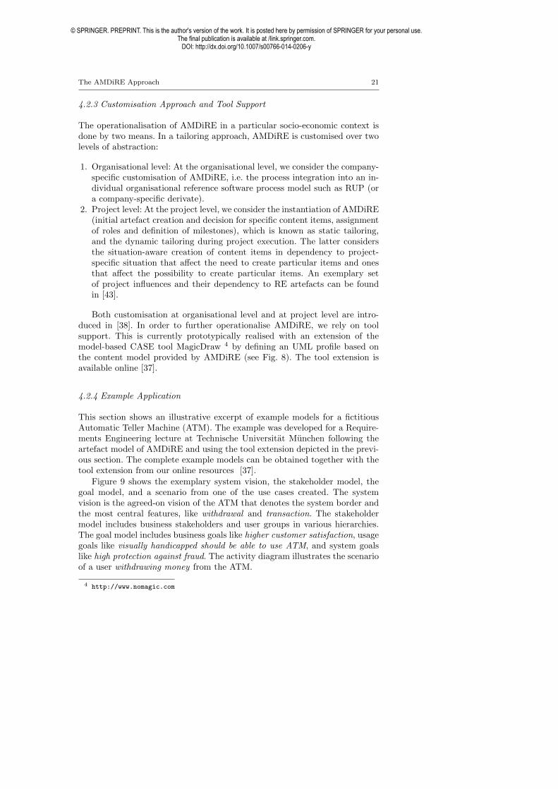
The AMDiRE Approach 21
4.2.3 Customisation Approach and Tool Support
The operationalisation of AMDiRE in a particular socio-economic context isdone by two means. In a tailoring approach, AMDiRE is customised over twolevels of abstraction:
1. Organisational level: At the organisational level, we consider the company-specific customisation of AMDiRE, i.e. the process integration into an in-dividual organisational reference software process model such as RUP (ora company-specific derivate).
2. Project level: At the project level, we consider the instantiation of AMDiRE(initial artefact creation and decision for specific content items, assignmentof roles and definition of milestones), which is known as static tailoring,and the dynamic tailoring during project execution. The latter considersthe situation-aware creation of content items in dependency to project-specific situation that a↵ect the need to create particular items and onesthat a↵ect the possibility to create particular items. An exemplary setof project influences and their dependency to RE artefacts can be foundin [43].
Both customisation at organisational level and at project level are intro-duced in [38]. In order to further operationalise AMDiRE, we rely on toolsupport. This is currently prototypically realised with an extension of themodel-based CASE tool MagicDraw 4 by defining an UML profile based onthe content model provided by AMDiRE (see Fig. 8). The tool extension isavailable online [37].
4.2.4 Example Application
This section shows an illustrative excerpt of example models for a fictitiousAutomatic Teller Machine (ATM). The example was developed for a Require-ments Engineering lecture at Technische Universitat Munchen following theartefact model of AMDiRE and using the tool extension depicted in the previ-ous section. The complete example models can be obtained together with thetool extension from our online resources [37].
Figure 9 shows the exemplary system vision, the stakeholder model, thegoal model, and a scenario from one of the use cases created. The systemvision is the agreed-on vision of the ATM that denotes the system border andthe most central features, like withdrawal and transaction. The stakeholdermodel includes business stakeholders and user groups in various hierarchies.The goal model includes business goals like higher customer satisfaction, usagegoals like visually handicapped should be able to use ATM, and system goalslike high protection against fraud. The activity diagram illustrates the scenarioof a user withdrawing money from the ATM.
4http://www.nomagic.com
© SPRINGER. PREPRINT. This is the author's version of the work. It is posted here by permission of SPRINGER for your personal use.The final publication is available at /link.springer.com.
DOI: http://dx.doi.org/10.1007/s00766-014-0206-y
22 D. Mendez Fernandez, B. Penzenstadler
Fig. 8: Screenshot of model-based tool support at the example of a contextdiagram.
5 Experiences, Evaluations, and Lessons Learnt
We have developed a number of artefact models, conducted case studies withdi↵erent companies, and gained di↵erent experiences. In the following, wefirst discuss the experiences we gained throughout the construction of artefactmodels. Furthermore, we discuss the industrial evaluations we performed. Thisshall give a picture of benefits and shortcoming in the construction and theapplication of the various notions in artefact-based RE. We finally concludewith a discussion of general lessons learnt in the construction and applicationof artefact orientation in industrially hosted environments.
5.1 Experiences in the Construction of Artefact-based RE Approaches
Over the last years, we have performed a series of di↵erent research coop-erations in the field of artefact-based RE improvement where we developedcompany-specific artefact-based RE approaches.
The research approach that has proven feasible for us throughout a numberof projects is to follow a problem-driven exploration where we apply conceptsof empirical design science [70, 24] to build a company-specific RE approachas part of an RE improvement endeavour. Figure 10 illustrates this research
© SPRINGER. PREPRINT. This is the author's version of the work. It is posted here by permission of SPRINGER for your personal use.The final publication is available at /link.springer.com.
DOI: http://dx.doi.org/10.1007/s00766-014-0206-y
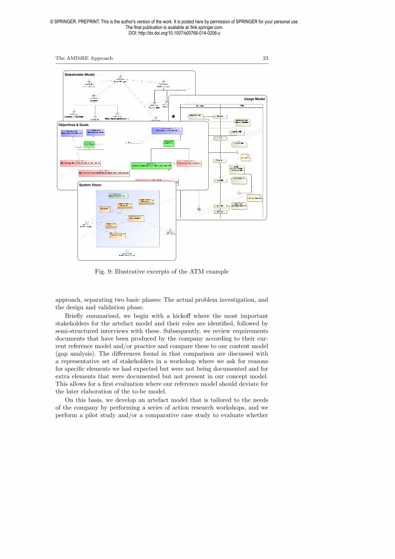
The AMDiRE Approach 23
Stakeholder Model
Usage Model
Objectives & Goals
System Vision
Fig. 9: Illustrative excerpts of the ATM example
approach, separating two basic phases: The actual problem investigation, andthe design and validation phase.
Briefly summarised, we begin with a kicko↵ where the most importantstakeholders for the artefact model and their roles are identified, followed bysemi-structured interviews with these. Subsequently, we review requirementsdocuments that have been produced by the company according to their cur-rent reference model and/or practice and compare these to our content model(gap analysis). The di↵erences found in that comparison are discussed witha representative set of stakeholders in a workshop where we ask for reasonsfor specific elements we had expected but were not being documented and forextra elements that were documented but not present in our concept model.This allows for a first evaluation where our reference model should deviate forthe later elaboration of the to-be model.
On this basis, we develop an artefact model that is tailored to the needsof the company by performing a series of action research workshops, and weperform a pilot study and/or a comparative case study to evaluate whether
© SPRINGER. PREPRINT. This is the author's version of the work. It is posted here by permission of SPRINGER for your personal use.The final publication is available at /link.springer.com.
DOI: http://dx.doi.org/10.1007/s00766-014-0206-y

24 D. Mendez Fernandez, B. Penzenstadler
RE Improvement Problem Investigation
Design and Validation of Improvement Transfer
Artefact-based RE Improvement Design and Validation
Investigation of REArtefacts
Investigation of Stakeholdersand Goals
Stakeholder & Goal Elaboration
Goals&
Metrics
Art.-based RE Analysis
Reporting & Decision Analysis
Report
Kick-OffConceptualisation
art.-based RE
Constructionart.-based RE
Re-designedRE ConceptModel
ImplementedRE Approach
Design of Process Integration
Evaluation in Pilot
EvaluationReport
Artefact-based RE Reference Model ("BISA")
Artefact Meta Model
Project Planning & Decision
Validation
Training Design
ReleaseRelease Planning
Treatment Design & Design Validation
Fig. 10: Procedure for constructing artefact-based RE approaches.
the artefact model brings the desired improvement for their requirements engi-neering practice. A detailed explanation of our approach to construct artefactmodels is provided in [45].
Apart from the methodological experiences we made when building upvarious artefact models (introduced in [45]), for example, regarding the useof action research workshops to support knowledge transfer [71], we gainedexperience in structuring artefact models at a more syntactic layer.
In [41], we already discussed first experiences regarding the notion of arte-fact orientation and inferred a meta model for the paradigm. We discussedthat we need to consider di↵erent views on artefact models depending oncompany-specific objectives. Those objectives a↵ect the way artefact modelsare structured (e.g. by defining a detailed concept model via a data model orby defining the content model via a checklist). The models can have di↵er-ent levels of detail according to how much detail the company wants in themodel, leading to more complexity, which a↵ects ease of use. Consequently,an increased level of detail requires a higher learning curve by the applyingcompany. This trade-o↵ between higher level of detail and ease of use has tobe addressed.
In Table 2 (Sect. 3.2), we selected previously developed artefact-based REapproaches and their characteristics. In Table 3, we structure di↵erent ap-proaches in a similar way and summarise the main objectives of the companyand their e↵ects on the establishment of the artefact models, as well as thee↵ort spent in their development (in person months).
Top to bottom in Table 3, we can see– An increase in the details the artefact model incorporates by its underlying
content models. Those range from detailed data models in case of the BISAapproach to support seamless modelling to artefact models that incorporatechecklists and selected concepts to clarify the notion of selected contents(e.g., use cases).
– A decrease of the e↵ort spent in the construction of those models. Takinginto account our own learning curve during the construction of those mod-els, we still have e↵orts that di↵er by a factor of 18. Apart from light-weight
© SPRINGER. PREPRINT. This is the author's version of the work. It is posted here by permission of SPRINGER for your personal use.The final publication is available at /link.springer.com.
DOI: http://dx.doi.org/10.1007/s00766-014-0206-y

The AMDiRE Approach 25
Table 3: Artefact models, their objective and resulting characteristics.
Approach Objectives Characteristics & E↵ort#A BISA / Quasar
Requirements(Capgemini TS)
Process integration andseamless modelling
Structure model and contentmodel defined via a data modeland conformance constraints, 112PM
#B Generic Con-tent Model(ARAMiS)
Common terminologyacross the 40 projectpartners and a conceptmodel for tool support andguidance
Structure model and implementedconcept model / UML profile, 20PM
#C Artefact Modelfor WackerChemie
Template-oriented checklistto integrate RE artefactsinto quality assurance
Structure model and templates, de-tailed concept model for use casesand the relation to test cases, andprocess elements, 8 PM
#D PowertrainArtefact Model(Daimler)
Clarifying the notion of re-quirements contents
Structure model and detailed con-cept model without roles, mile-stones or other process elements, 6PM
versus heavy-weight models, this is mainly due to the up-front budgetingand time framing for the projects.The simpler models developed in context of Daimler (# D) and Wacker
Chemie (#C) follow a similar objective where we established the artefact-basedRE approach to clarify the basic RE concepts and corresponding terminol-ogy. Those models serve the purpose of giving a quick overview of elementarymodelling concepts such as use case models, their allocation to requirements-specific artefacts and their dependencies to surrounding development phases.At Wacker, the process integration could explain the additional 2 PM. Dur-ing this integration, we defined roles and responsibilities, a quality assuranceprocess and the integration of a tailoring profile (see Sect. 4.2.3). The e↵ectsof following those objectives can be observed, however, especially in the waythe artefact models were created. In scope were the structure models to de-fine which content items were of general interest. For each content item, weprovided a brief guidance in form of a checklist and only specified the con-cept model in detail where necessary (e.g. for the use case model to define thedependency to testing).
In contrast, the objectives followed by the two more detailed models (#Aand #B) were mainly to support seamless modelling and tool support. Theimplication for the artefact model was that the content models were specifiedin full via a data model to define which concepts and relations have to be con-sidered during the artefact creation. Both concept models were also enrichedby a structure model to ease the process integration.
The e↵ort in the detailed models mostly arose from:1. Terminological and conceptual discussions at workshops, frequent action
research workshops to realise the concepts, and a longer review and re-
© SPRINGER. PREPRINT. This is the author's version of the work. It is posted here by permission of SPRINGER for your personal use.The final publication is available at /link.springer.com.
DOI: http://dx.doi.org/10.1007/s00766-014-0206-y

26 D. Mendez Fernandez, B. Penzenstadler
lease process at the partners’ sites as the approaches had not anymore thecharacter of being a checklist.
2. The development of training and coaching material as well as tool support.3. The supervision of pilot projects and coaching during those pilot studies.4. More general, a missing willingness to organisational change we could ob-
serve in the projects as project participants were confronted with complexmodels and needed a longer learning curve to understand the basic conceptsand tailoring mechanisms.
5.2 Evaluations: Results from Industrial Case Studies
We performed a series of evaluations with the previously developed artefactmodels on which AMDiRE relies. We complement this evaluation with a casestudy where we directly used AMDiRE as a reference model to establisha company-specific artefact-based RE approach following the principles de-scribed in the previous Sect. 5.1.
5.2.1 Summary of Previously Conducted Comparative Case Studies
We have performed three comparative, industrial case studies that we brieflydiscuss with regard to their results. These studies each evaluated an artefact-based approach in direct comparison to the formerly used activity-based ap-proach and were performed with partners at Siemens, BMW, and Cassidian.Table 4 provides the type of studies and their major results.
In the following, we summarise those previously published case study de-signs and results relevant to the context of the article while details on the studydesigns and the full results can be taken from references listed in Table 4.
Table 4: Comparative industrial case studies.
Study Approach Partner ResultsTra�c LightsManagment Sys-tem
#A Siemens(2011)
Improvement of, inter alia, syntactic con-sistency and completeness, ease of use, ef-fectivity, structuredness and ease percep-tion [42]
Intelligent Info-tainment Systems(IIS)
#B BMW(2012)
Improvement of e↵ectivity, productivity,and adequacy [54, 52]
Unmanned Air-craft System(UAS)
#B Cassidian(2012)
Improvement of ease of use, e↵ectivity,unambiguousness and adequacy [54, 52]
© SPRINGER. PREPRINT. This is the author's version of the work. It is posted here by permission of SPRINGER for your personal use.The final publication is available at /link.springer.com.
DOI: http://dx.doi.org/10.1007/s00766-014-0206-y

The AMDiRE Approach 27
5.2.2 Case Study Designs Overview
As shown in Table 3 and in Sect. 3 introducing the previously developedmodels, we initiated our case studies with smaller studies at Capgemini TSwhere we evaluated the approach in 12 internal pilot projects. As those studiesremain unpublished due to a non-disclosure agreement, and because we aimedat increasing the external validity, we applied our approach #A in nothersocio-economic contexts. After this evaluation, we continued the developmentof our artefact models leading to approach #B which, again, we evaluated totest its sensitivity in a socio-economic context.
Overall, we conducted three case studies where we evaluated two approaches(see Table 4). We evaluated approach #A at Siemens and approach #B atCassidian and at BMW. The objectives of the case studies were defined, atthe time of conducting the studies, according to the improvement goals of theprojects. That is, in dependency to the defined goals, we formulated the re-search questions and the evaluation criteria. However, the overall study designremained the same for all studies to allow for a comparability of the results.
In each study, we conducted a series of workshops with our industry part-ners and specified the requirements for a selected subsystem following theestablished artefact-based RE approach. We then conducted an assessmentworkshop with interviews where the subject evaluated the created RE arte-facts as well as the way of working in direct comparison to the artefacts and theprocess dictated by the (activity-based) RE reference model previously usedin the same context. For the assessment, we intentionally conducted one inter-view session with all involved participants to enable joint discussions amongthe participants and to get a final agreement on the ratings (without checkingthe inter-rater consistency). In all case studies, we involved a requirements en-gineer (in case of Siemens represented by the role of a product manager) andthe overall project lead responsible for broader project management activities.
The rating was conducted by answering a questionnaire with a series ofopen and closed questions. The closed questions aimed at rating single crite-rion, such as ease of use on a Likert Scale while the open questions servedto justify the ratings. The choice of the criteria was performed in discussionwith the project participants according to the (improvement) goals and canbe taken from the Kiviat diagrams in subsequent result sections.
5.2.3 Case Study Results Overview
In the following, we summarise the results from the previously conducted casestudies relevant to the context of this article.
Figure 11(a) shows the results from the internal rating at Siemens. Wecomplemented the internal rating with an external one where we called in aneutral person not involved in the RE workshops to support a more unbi-ased evaluation. The results of the external rating are shown in Fig. 11(b).Both evaluations consider the process when applying the artefact-based RE
© SPRINGER. PREPRINT. This is the author's version of the work. It is posted here by permission of SPRINGER for your personal use.The final publication is available at /link.springer.com.
DOI: http://dx.doi.org/10.1007/s00766-014-0206-y

28 D. Mendez Fernandez, B. Penzenstadler
approach as well as the quality in the created artefacts. Although some crite-ria had a low consistency between the internal and external rating (e.g., thetraceability), the application of the detailed artefact model resulted in generalin a better support of creating syntactically consistent and testable results indirect comparison to the previously used RE reference model. The ease of use,however, was rated worse. Details on the the full results can be taken from [42].
(a) Internal rating
(b) External rating
Fig. 11: Results from the case study with Siemens.
The replication studies at Cassidian and BMW revealed that the detailedconcept model used to establish the tool infrastructure (see Table 3) againsupported the syntactic consistency and completeness in the created artefacts.For both case study systems, we received positive feedback on the artefact-based approach and the evaluation results showed, in contrast to the study
© SPRINGER. PREPRINT. This is the author's version of the work. It is posted here by permission of SPRINGER for your personal use.The final publication is available at /link.springer.com.
DOI: http://dx.doi.org/10.1007/s00766-014-0206-y

The AMDiRE Approach 29
at Siemens, improvement in various aspects in the process for creating theartefacts, most importantly, the e↵ectivity and ease of use. Our explanationfor the di↵erent rating is that the model developed at Capgemini TS hasa far more comprehensive concept model capturing all particularities of theappellation domain, which, in turn, implies a stronger learning curve.
An overview of the rating of the closed questions from our automotivepartner BMW is depicted in Fig. 12(a) and 12(b) and from our avionics partnerCassidian in Fig. 12(c) and 12(d). For reasons of illustration, the centre of theKiviat diagram is labelled again with the value of zero instead of one, sinceotherwise the data points would overlap in the center.
(a) Applicability evaluation at BMW (b) Artefact evaluation at BMW
(c) Applicability evaluation at Cassidian (d) Artefact evaluation at Cassidian
Fig. 12: Results from the ARAMiS case studies with BMW and Cassidian.
Both partners seem to perceive the ARAMiS artefact model as improve-ment in comparison to their previous reference model. The business units atboth companies have also incorporated the artefact model into their stan-dard. On first glance, the rating was more critical for both their own and theARAMiS model by the automotive partner. When analysing the answers tothe open questions (the rationale for their ratings), we found that some of thereasons given for a specific rating were quite similar, but rated rather di↵er-ently. For example, for traceability, both stated that their own reference modelprovided the possibility to link requirements, but did not provide the possi-
© SPRINGER. PREPRINT. This is the author's version of the work. It is posted here by permission of SPRINGER for your personal use.The final publication is available at /link.springer.com.
DOI: http://dx.doi.org/10.1007/s00766-014-0206-y

30 D. Mendez Fernandez, B. Penzenstadler
bility to document a rationale. At the same time, their rating of 1 at BMWversus the higher rating of 5 at Cassidian for the criterion Traceability showsa considerable di↵erence in perceiving the importance of an artefact-basedreference model providing the possibility to document a rationale.
Details on the design and the results of the case studies conducted atCassidian and BMW can be taken from [54, 52].
5.2.4 AMDiRE Case Study
Apart from the previously conducted and published case studies where weevaluated the models on which AMDiRE relies, we conducted one industrialstudy where we directly made use of AMDiRE. In contrast to the previouslyconducted comparative case studies, however, we used AMDiRE as a referencemodel to build a company-specific artefact model following the procedure il-lustrated in Sect. 5.1 and published in detail in [45].
The case study took place at Wacker Chemie, a company working in thechemical business with quarters in Munich. The department with which weworked focuses on the engineering of development processes for standard aswell as custom software development in the company-specific operation pro-cesses and their production sites. The goal during the development of theartefact-based RE reference model was to support traceability and testabilityof the RE artefacts. After a series of analysis workshops and workshops to con-struct the artefact model (see [45]), we prepare the evaluation in three pilotprojects, which considered internal developments in the company. For reasonsof confidentiality, we omit details of the projects and the involved subjectsand remain on an abstract description. As a preparation of the evaluation inthe pilot projects, we created a short presentation as internal training mate-rial and document templates for the new artefacts to be applied in the pilotprojects.
The projects covered both standard software development for SAP andcustom software development. As project participants served in total 8 em-ployees of which for each project one project lead and one developer werecomplemented by two process engineers involved in the development of theartefact-based RE reference model. Those latter two process engineers servedas coaches to train in a one-day workshop the people for applying the newartefact-based RE reference model developed on basis of AMDiRE. The studydesign was the same as the one from previously conducted case studies. Thatis, we conducted workshops to create requirements specifications followingthe artefact-based RE approach and concluded with an assessment where theproject participants rated the new RE approach in direct comparison to theapproach previously used in same environment (for previous releases). For theassessment, the project participants were provided again a questionnaire. Thisquestionnaire was similar to the one we used in the previous studies, with mi-nor modifications in wording. For each criteria we used in the rating, we askeda closed question where the participants should rate their agreement to a state-ment on a Likert-scale from 0 to 6 followed by an open question where the
© SPRINGER. PREPRINT. This is the author's version of the work. It is posted here by permission of SPRINGER for your personal use.The final publication is available at /link.springer.com.
DOI: http://dx.doi.org/10.1007/s00766-014-0206-y

The AMDiRE Approach 31
Table 5: Questionnaire for the Assessment (condensed)
Criteria StatementFlexibility The RE reference model allows for flexibility.Ease of use The RE reference model is easy to understand.E↵ectivity The RE reference model leads to the desired results.E�ciency I perceived the e�ciency in the process as high.Customisation The RE reference model is tailorable according to
project-specific situations of the company.Process Integration The RE reference model is integrated into further de-
velopment activities (e.g., testing) and within the lineorganisation.
Structuredness Artefacts The specification documents are well-suited to be un-derstood respecting their structure by people not beinginvolved into the elaboration of the specifications
Syntactic Artefact Quality The RE reference model supports a high syntactic qual-ity in the created RE artefacts w.r.t. consistency andcompleteness.
Traceability in Artefact The RE reference model supports traceability withinRE (e.g., through rationales) and between RE and fur-ther disciplines.
Semantic Artefact Quality The RE reference model supports semantically consis-tent and complete results.
Testability of Artefacts The RE reference model supports testable RE artefacts.
participant could give a rationale for their rating. Table 5 gives a condensedview on the closed questions.
In the following, we summarise the case study results followed by informalfeedback given during the evaluation.
Case Study Results Figure 13 summarises the results from the case study andshows with a solid red line the rating given to the artefact-based RE referencemodel and with a dashed blue line the rating given for the previously usedreference model where the RE artefacts were underrepresented.
The goals of improving the support of traceability and testability werereached and the participants positively rated also other aspects in the arte-facts created according to the new reference model. For instance, they saw anincreased structuredness in the RE artefacts and rated the process integrationto be better than in the previous model as the artefact-based nature clearlydefined, for example, roles and responsibilities.
However, the ease of use was slightly worse than in the previous model,where the feedback indicated the higher level of detail in the reference modelto be the main reason. Further feedback that supported this was that partic-ipants needed more detailed training as well as comprehensive tool support(going beyond the document templates) to better support the learning curvein applying the new reference model.
Discussion Our case study at Wacker supports our claimed general benefits ofthe artefact-based approach. One remarkable feedback provided by the projectparticipants was, however, the strong need to support the application of the
© SPRINGER. PREPRINT. This is the author's version of the work. It is posted here by permission of SPRINGER for your personal use.The final publication is available at /link.springer.com.
DOI: http://dx.doi.org/10.1007/s00766-014-0206-y

32 D. Mendez Fernandez, B. Penzenstadler
0"
1"
2"
3"
4"
5"
6"Flexibility"
Ease"of"Use"
Effec9vity"
Efficiency"
Customisa9on"
Process"Integra9on"Stucturedness"Artefacts"
Syntac9c"Quality"
Traceability"Artefacts"
Seman9c"Quality"
Testability"
ArtIb"RE"Previous"Apr."
Fig. 13: Results from case study at Wacker.
model with tool environments, and detailed training material as, otherwise,the ease of use in the model is strongly hampered. This observation is in tunewith the previously conducted case studies where the ARAMiS model resultedto be better rated than the BISA model due to:
1. providing a less complex structure model that does not focus too much onparticularities of single application domains, while
2. hiding the remaining complexity of the underlying concept model with itsa directly applicable tool environment.
Although the AMDiRE approach covers both characteristics, we have nowreached the point where we need to conduct external evaluations by unbiasedresearchers and practitioners not involved in the development of AMDiRE (seealso the research method in the introduction on page 4). This will also show towhat extent AMDiRE can be used by others and what exact e↵ects this willhave on aspects negatively rated at Wacker (relating to the learning curve).
To this end, we make publicly accessible the tools, the models, and theexamples as well as the evaluation templates related to AMDiRE [37] andencourage researchers and practitioners to critically discuss and evaluate ourapproach in external contexts.
© SPRINGER. PREPRINT. This is the author's version of the work. It is posted here by permission of SPRINGER for your personal use.The final publication is available at /link.springer.com.
DOI: http://dx.doi.org/10.1007/s00766-014-0206-y

The AMDiRE Approach 33
The article at hand thus builds the first step in the dissemination of ourresearch results not only into practical environments with isolated problemsand goals, but also back into the research community.
5.3 Lessons Learnt
Throughout the past six years of collaborating with industrial partners on im-proving their requirements engineering practices, we have collected a numberof lessons learnt, which we summarise in the following.
Tradeo↵ between high level of detail and usability. Regarding more generallessons learnt in the field of artefact orientation, we have observed more de-tailed artefact models to increase the quality of the results as they can givedetailed guidance on the concepts to use when specifying the contents. Atthe same time, however, those more detailed models constrain the ease of useas they implicate a higher learning curve. Obviously, simpler artefact mod-els have the opposite e↵ect. Whereas they are easy to apply and understand,they cannot give detailed guidance on creating detailed, syntactically consis-tent contents. The only mitigation we see to this problem so far is to explicitlypoint out this tradeo↵ as early as possible and in case of focussing on detailedconcept models providing tool support right from the beginning.
Terminology. In every workshop we have held, the longest time was usuallyspent on terminology discussions. Either there were di↵erent terms availableand the discussion was which one of them should be given preference, for ex-ample context versus environment. Or there was one term but di↵erent stake-holders had di↵erent interpretations of the concept it represented, for examplefunction. These discussions are time-consuming but unavoidable and crucialto make sure the artefact model will be accepted by all stakeholders later on.The mitigation strategy we followed was to explicitly reserve a time slot earlyon to establish a list of most important terms and definitions that have to beagreed on.
Maintainability. Furthermore, we noticed the maintenance of established arte-fact models to be challenging. Once detailed models are established, it is di�-cult to integrate new concepts due to the complex content-related dependen-cies. We are not aware of any real mitigation to this point, but we suggest thatevery single modification of the model should be justified, carefully planned,well documented, and explicitly evaluated in an own pilot project to detectpotential inconsistencies arising from the modification in the model as earlyas possible.
© SPRINGER. PREPRINT. This is the author's version of the work. It is posted here by permission of SPRINGER for your personal use.The final publication is available at /link.springer.com.
DOI: http://dx.doi.org/10.1007/s00766-014-0206-y

34 D. Mendez Fernandez, B. Penzenstadler
Incorporate down-to-earth informality. The biggest lesson learnt, although notsurprising in itself but only in its extent, is the down-to-earth informalitythat is residing in the daily business of software systems development. Thisis in contrast to the high quality requirements and constraints that have tobe adhered to by the final products. There is a high demand for easy to useapproaches. The more details a concept model has, the more should be investedin pilot studies, coaching material, and guidelines (reflected, e.g., in the e↵ortspent for the development of the approach at Capgemini TS).
Support learning curves. One of the quality characteristics that has alwaysbeen rated worse for the new artefact-based approaches compared to the pre-viously residing approaches is e�ciency. Our assumption is that this is notonly due to the higher simplicity of the previous models but also that the pre-vious approaches are what the developers are accustomed to. Consequently,anything that is di↵erent from what they are used to will initially require aslightly higher e↵ort and might therefore easily leave the impression of de-creased e�ciency. As a matter of fact, this strongly relates to a learning curvethat is always implied by new approaches [65]. We encountered two meansto support learning curves: continuous pilot studies and training and coach-ing. The first includes a smooth integration of developed approaches via pilotphases, which we use to get additional feedback from the project environments,and extends to long-term studies to investigate the benefits of improvementendeavours w.r.t. to project quality. The latter includes the preparation ofguidance, which we believe to build an essential building block for not onlyintroducing a new approach but for establishing it in a long run taking intoaccount the di↵erent organisational cultures. Unfortunately, the writing of ahandbook or the development of course material and trainings is often ne-glected. In that case the developers are likely to be resistant against innova-tions.
Tackle distrust right from the beginning. In projects, we have often encoun-tered a certain distrust against new approaches. The willingness to change israther low and a commonly known problem [40], i.e., the willingness to changeresults from the initial e↵ort required to even try a di↵erent way of working,but also from general beliefs, experiences, expectations, emotions and desires.There is no universal silver-bullet to tackle this problem as, more generallyspeaking, the success of any improvement endeavour also depends on socialskills [61, chp. 10] and eventually on politics [47]. We experienced, however,the deep involvement of di↵erent stakeholders (especially from project settings)right from the beginning of an improvement project and an honest communi-cation are the most important aspects to tackle distrust (see also [45]).
6 Conclusion
This article described the fundamentals in artefact-based requirements engi-neering and presented the AMDiRE approach that emerged from six years
© SPRINGER. PREPRINT. This is the author's version of the work. It is posted here by permission of SPRINGER for your personal use.The final publication is available at /link.springer.com.
DOI: http://dx.doi.org/10.1007/s00766-014-0206-y

The AMDiRE Approach 35
of experience with developing artefact models and integrating them into thesurrounding requirements engineering processes of various socio-economic con-texts. Furthermore, we presented our evaluations in di↵erent industrial casestudies and their replications in di↵erent companies as well as lessons learntfrom these collaborations.
A subset of our case studies were performed as comparative studies thatevaluate the application of the artefact-based RE approaches in direct com-parison to the activity-based approaches previously used in the same environ-ment. We could show how artefact orientation supports for detailed, consistentresults while supporting the flexibility in the process which is especially impor-tant to RE. We also discussed, however, that we continuously need to make atrade-o↵ between a detailed content model to support high quality results, andthe resulting higher learning curve that a↵ects the ease of use of artefact-basedRE.
Our work has been incorporated into the daily requirements engineeringpractices of the companies with whom we collaborated. We strongly believethat this approach of carrying research into practice, adapting it to the busi-ness context, and establishing it in collaboration with the practitioners is asustainable way of promoting the use of current research results. We hope tocarry this work further into the requirements engineering community to en-courage the application of artefact-based approaches and to give an exampleof an artefact model that can be used in a variety of application domains.
Researchers can already build their fundamental, educational, and evidence-based work upon our contributions. Our empirical results already give the op-portunity to steer their requirements engineering research in a problem-drivenmanner. Practitioners can furthermore directly apply our model in their ownsocio-economic contexts with the awareness of the benefits and shortcomingsof the incorporated concepts. We thus laid the first fundamental, conceptual,and empirical basis for artefact-based RE research. However, we do not claimthat our approach suits every situation and that our empirical results allowfor perpetually valid generalisations as we always focused with our action re-search case studies on specific socio-economic contexts. In fact, the researcharea needs further investigation and the case studies need further independentreplications. The reason for independent replications is that if we go to an-other company and help them improve their requirements engineering usingour model (which is the only reason for a company to hire us), this probably bi-ases the results towards our model as companies get free consulting during theprocess. Therefore, we need an external third party to perform the validation.Consequently, we encourage researchers and practitioners to critically discussour approach and to join us in the empirical evaluations of artefact-based RE.
Future Work. We are encouraging further replications of our comparativestudies in di↵erent application domains and development contexts. Anotherobjective for future work is to further facilitate the dissemination and empir-ical evaluation of our approach. We have developed a first prototype for toolsupport as a profile with a respective template in MagicDraw that is freely
© SPRINGER. PREPRINT. This is the author's version of the work. It is posted here by permission of SPRINGER for your personal use.The final publication is available at /link.springer.com.
DOI: http://dx.doi.org/10.1007/s00766-014-0206-y

36 D. Mendez Fernandez, B. Penzenstadler
available [37]. We use our tools as an additional means for the disseminationand for continuous evaluations in pilot projects to gather more information anduser feedback while preparing the development of a more elaborated stand-alone tool.
© SPRINGER. PREPRINT. This is the author's version of the work. It is posted here by permission of SPRINGER for your personal use.The final publication is available at /link.springer.com.
DOI: http://dx.doi.org/10.1007/s00766-014-0206-y

The AMDiRE Approach 37
A AMDiRE Content Model
The following appendix defines the content model of AMDiRE in detail giving for eachcontent item a definition of the used concepts.
The artefact model is specified using the following notational aspects of UML classdiagrams:– We denote the hierarchical structuring of the structure model with packages.– For the definition of the content model, we use a class diagram.– For content items that are crucial for only a specific application domain, but irrelevant
for another, we use the stereotype <<Domain>>, such as business process models beingcrucial for the domain of business information systems, but irrelevant for the domain ofembedded reactive systems.
A.1 Context Specification
The context specification is depicted in Fig. 14. It contains the Project Scope, the Constraintsand Rules, the Stakeholder Model, the Business Case, the Objectives and Goals, the DomainModel, and the Glossary.
Fig. 14: The AMDiRE context specification.
© SPRINGER. PREPRINT. This is the author's version of the work. It is posted here by permission of SPRINGER for your personal use.The final publication is available at /link.springer.com.
DOI: http://dx.doi.org/10.1007/s00766-014-0206-y

38 D. Mendez Fernandez, B. Penzenstadler
A description of the content items is provided in Table 6.
Table 6: Content items in the Context Specification.
ContentItem
Exempl.Notation
Description
Project Scope Naturaltext
Content item of the Context Specification that consists of aProblem Description and a Statement of Intent, i.e. a con-clusion of the objectives of a potentially resulting project.
Constraintsand Rules
Natural text,graphs
Restrictions that can influence each other either in form ofsupport or a conflict. We distinguish Constraints as not ne-gotiable restrictions in the domain and Rule, often referredas conditional standard procedures [27]
StakeholderModel
UML actorhierarchy,tables
Stakeholders comprehend individuals, groups, or institu-tions having the responsibility for requirements and a majorinterest in the project [13], while User Groups are a spe-cialisation of stakeholders with a particular proficiency andinvolvement in interaction with the system [31].
BusinessCase
Naturaltext
Described and detailed using the additional elements ofCost, Value, and Risk. The Business Case satisfies the State-ment of Intent from the Project Scope and rationalises thegoals in the content item Objectives and Goals
Objectivesand Goals
Goal graphs(e.g.KAOS)
Each Goal, whether it is a Business Goal, a Usage Goal, ora System Goal, is issued by a Stakeholder. Goals satisfy theStatement of Intent [35], they build a hierarchy, and theycan influence each other in terms of conflicts, constraints, orsupport. Each usage goal is related to a business goal andeach system goal to a usage goal. Furthermore, system goalsdemand one or more Quality Attributes [4].
DomainModel
UML activitydiagrams orBMPN
The External Systems, that interact with the system un-der development, compose the Domain Model. For businessinformation systems, the domain model is extended with aBusiness Process Model represented in various types of Ac-tivities that need and produce Business Objects. A businessprocess model is a collection of all instances of the activitiesand their (causal) relations, performed by roles in order toproduce some outcome of value [36]. The activities can bedefined as an abstract Business Process, a Business Task(business use case), or an atomic Process Step – the latterrepresents single atomic steps performed by a User Group.
Glossary Structuredtext
This content item contains all important Terms for the sys-tem under consideration and the respective project manage-ment, including their abbreviation, synonyms, and descrip-tion. It shows up as well in Requirements Specification andthe System Specification as more Terms are added over thecourse of the project.
© SPRINGER. PREPRINT. This is the author's version of the work. It is posted here by permission of SPRINGER for your personal use.The final publication is available at /link.springer.com.
DOI: http://dx.doi.org/10.1007/s00766-014-0206-y

The AMDiRE Approach 39
A.2 Requirements Specification
Fig. 15: The AMDiRE requirements specification.
The requirements specification is depicted in Fig. 15. It contains the SystemVision, the Usage Model, the Data Model, the Service Model, the FunctionalHierarchy, the Quality Requirements, the Deployment Requirements, The Sys-tem Constraints, the Process Requirements, and the Risk List. A descriptionof the content items is provided in Table 7.
© SPRINGER. PREPRINT. This is the author's version of the work. It is posted here by permission of SPRINGER for your personal use.The final publication is available at /link.springer.com.
DOI: http://dx.doi.org/10.1007/s00766-014-0206-y
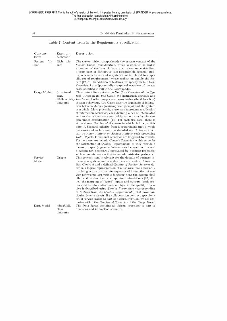
40 D. Mendez Fernandez, B. Penzenstadler
Table 7: Content items in the Requirements Specification.
ContentItem
Exempl.Notation
Description
System Vi-sion
Rich pic-ture
The system vision comprehends the system context of theSystem Under Consideration, which is intended to realisea number of Features. A feature is, in our understanding,a prominent or distinctive user-recognisable aspects, qual-ity, or characteristics of a system that is related to a spe-cific set of requirements, whose realisation enable the fea-ture [12, 31]. In addition to features, we specify an Use CaseOverview, i.e. a (potentially) graphical overview of the usecases specified in full in the usage model.
Usage Model Structuredtext,UML activitydiagrams
This content item details the Use Case Overview of the Sys-tem Vision in its Use Cases. We distinguish Services andUse Cases. Both concepts are means to describe (black box)system behaviour. Use Cases describe sequences of interac-tion between Actors (realising user groups) and the systemas a whole. More precisely, a use case represents a collectionof interaction scenarios, each defining a set of interrelatedactions that either are executed by an actor or by the sys-tem under consideration [14]. For each use case, there isat least one Functional Scenario in which Actors partici-pate. A Scenario inherits from a requirement (not a wholeuse case) and each Scenario is detailed into Actions, whichcan be Actor Actions or System Actions each processingData Objects. Functional scenarios are triggered by Events.Furthermore, we include Generic Scenarios, which serve forthe satisfaction of Quality Requirements as they provide ameans to specify generic interactions between actors anda system not necessarily motivated by business processes,such as maintenance activities an administrator performs.
ServiceModel
Graphs This content item is relevant for the domain of business in-formation systems and specifies Services with a Collabora-tion Contract and a defined Quality of Service. Services de-scribe a logical representation of a use case, not necessarilyinvolving actors or concrete sequences of interaction. A ser-vice represents user-visible functions that the system shallo↵er and is described via input/output-relations [25, 59],i.e., the mapping of (typed) inputs and outputs, both rep-resented as information system objects. The quality of ser-vice is described using Service Parameters (correspondingto Metrics from the Quality Requirements) that have par-ticular Service Levels. If a collaboration contract specifies aset of service (calls) as part of a causal relation, we use sce-narios within the Functional Scenarios of the Usage Model.
Data Model mboxUMLclassdiagrams
The Data Model contains all objects processed as part offunctions and interaction scenarios.
© SPRINGER. PREPRINT. This is the author's version of the work. It is posted here by permission of SPRINGER for your personal use.The final publication is available at /link.springer.com.
DOI: http://dx.doi.org/10.1007/s00766-014-0206-y

The AMDiRE Approach 41
FunctionalHierarchy
Graphs,I/O-tables
The User-visible Functions equal the Services from the BIS-specific Service Model and realise the System Actions fromthe Usage Model. Functions are organised in a hierarchyto build the transition to the system specification as theydescribe a logical representation of a system action and of-fered by typed interfaces. When a Function is triggered, wecan optionally define Modes, which we use in the SystemSpecification for the definition of detailed Behaviour Mod-els. Services, in turn, describe a complementary logical rep-resentation of a use case, not necessarily involving actorsor concrete sequences of interaction. They furthermore o↵erInterfaces, which are typed according to the Data Objectsof the Data Model.
QualityRequirements
Naturaltext
Quality requirements are assessed by Measurements thatcan be either a Normative Reference (e.g. a GUI style guide)or aMetric. Quality Requirements constrain System Actionsand can be satisfied by Generic Scenarios. We make use ofquality definition models as by Deissenbock et al. [16].
DeploymentRequirements
Naturaltext
Deployment Requirements describe demands towards thedeployment procedure, constraining the process design ofthe deployment, and the technical environment during ini-tial launch of the system or specific parts of it.
SystemConstraints
Naturaltext
The system’s constraints describe logical and technical re-strictions on a system’s architecture, its functionality bymeans of single atomic actions, and its quality by meansof assessable system quality requirements. We consider con-cepts that describe the transition to logical and technicalarchitecture layers acc. to [69]. Hence, we see a system as agrey box rather than as a glass box, since we restrict sys-tems’ internals, but do not consider their logical structure byinteracting components, interface specifications, and func-tions.
ProcessRequirements
Naturaltext
Process Requirements constrain the content and / or struc-ture of selected artefact types and the process model, i.e.,the definition of the milestones regarding time schedules,used infrastructure like mandatory tools, and compliance toselected standards and software process models.
Risk List Naturaltext
The Risk List includes a description of all risks that arerelated to project-specific requirements. The conceptualisa-tion of requirements risks is considered on the basis of anartefact model [28, 29]. The Requirements Risks are impliedby the various types of Requirements and we use the risklist as an interface to risk management. Each risk is causedby a Risk Factor. A Risk Trend is composed by all RiskFactors.
© SPRINGER. PREPRINT. This is the author's version of the work. It is posted here by permission of SPRINGER for your personal use.The final publication is available at /link.springer.com.
DOI: http://dx.doi.org/10.1007/s00766-014-0206-y

42 D. Mendez Fernandez, B. Penzenstadler
A.3 System Specification
The system specification is depicted in Fig. 16. It contains the Function Model,the Component Model, the Behaviour Model, the State Model, and the DataModel. A description of the content items is provided in Table 8.
Fig. 16: The AMDiRE system specification.
Table 8: Content items in the System Specification.
ContentItem
Exempl.Notation
Description
ArchitectureOverview
Componentdiagram
The Architecture Overview includes the ComponentOverview of the Components as well as the Major Func-tions that summarize the Functional Hierarchy.
FunctionModel
Graphs,tables
The System Functions o↵ered by the System Interface re-alise the User-visible Functions from the Functional Hier-archy. The system interface encompasses the Ports detailedin the Component Model.
© SPRINGER. PREPRINT. This is the author's version of the work. It is posted here by permission of SPRINGER for your personal use.The final publication is available at /link.springer.com.
DOI: http://dx.doi.org/10.1007/s00766-014-0206-y

The AMDiRE Approach 43
ComponentModel
Componentdiagram
The component model describes the logical component ar-chitecture in detail including Ports (building typed inter-faces) and Channels over which components communicate.Components can be decomposed into more further sub-components [10].
BehaviourModel
Automata The behaviour of components is specified with by Events,States and State Transitions. The resulting state machinesspecify the behaviour and the used data elements of the datamodel.
Data Model UML classdiagram,dictionary
We specify data elements of a certain type and their rela-tions as they result from the behaviour model. To this end,Data Elements refine Data Objects from the requirementsspecification and have a particular Data Type.
© SPRINGER. PREPRINT. This is the author's version of the work. It is posted here by permission of SPRINGER for your personal use.The final publication is available at /link.springer.com.
DOI: http://dx.doi.org/10.1007/s00766-014-0206-y

44 D. Mendez Fernandez, B. Penzenstadler
References
1. Avison D, Fitzgerald G (2006) Information Systems Development:Methodologies, Techniques, and Tools, 4th edn. McGraw-Hill Education,Berkshire, United Kingdom
2. Berenbach B, Paulish D, Kazmeier J, Rudorfer A (2009) Software & Sys-tems Requirements Engineering: In Practice. ISBN-13: 978-0071605472,McGraw-Hill Osborne Media
3. Besner V (2013) Bsc. thesis: Evaluation of an artefact-based requirementsengineering approach. Master’s thesis, Technische Universitat Munchen,Department of Informatics
4. Boegh J (2008) A New Standard for Quality Requirements. IEEE Software25(2):57–63
5. Boehm B, Brown J, Kaspar H, Lipow M, Macleod G, Merrit M (1978)Characteristics of Software Quality. ISBN-13: 978-0444851055, ElsevierScience Ltd North-Holland Pub. Co.
6. Braun C, Wortmann F, Hafner M, Winter R (2005) Method Construction- A Core Approach to Organizational Engineering. In: Proceedings of the20th ACM symposium on Applied computing (SAC ’05), ACM New York,NY, USA, pp 1295–1299
7. Braun P, Broy M, Houdek F, Kirchmayr M, Muller M, Penzenstadler B,Pohl K, Weyer T (2010) Guiding requirements engineering for software-intensive embedded systems in the automotive industry. Computer ScienceResearch and Development
8. Brinkkemper S (1996) Method Engineering: Engineering of InformationSystems Development Methods and Tools. Information and Software Tech-nology 38(4):275–280
9. Broy M (2006) Requirements Engineering as a Key to Holistic SoftwareQuality. In: Levi A, Savas E, Yenigun H, Balcisoy S, Saygin Y (eds) Pro-ceedings of the 21th International Symposium on Computer and Informa-tion Sciences (ISCIS 2006), Springer-Verlag Berlin, vol 4263, pp 24–34
10. Broy M, Feilkas M, Grunbauer J, Gruler A, Harhurin A, Hartmann J,Penzenstadler B, Schatz B, Wild D (2008) Umfassendes Architekturmodellfur das Engineering eingebetteter Software-intensiver Systeme. Tech. Rep.TUM-I0816, Technische Universitat Munchen
11. Cavano J, McCall J (1978) A Framework for the Measurement of SoftwareQuality. SIGSOFT Software Engineering Notes 3(5):133–139, DOI http://doi.acm.org/10.1145/800283.811113
12. Classen A, Heymans P, Schobbens PY (2008) What’s in a Feature : ARequirements Engineering Perspective. In: Fiadeiro J, Inverardi P (eds)Proceeding of the 11th International Conference on Fundamental Ap-proaches to Software Engineering (FASE 08) in Conjunction with ETAPS08, Springer-Verlag Berlin, no. 4961 in FASE/ETAPS, pp 16–30
13. Cleland D (ed) (2005) Project Management Field Guide. ISBN-13: 978-0471292067, John Wiley and Sons, Inc.
© SPRINGER. PREPRINT. This is the author's version of the work. It is posted here by permission of SPRINGER for your personal use.The final publication is available at /link.springer.com.
DOI: http://dx.doi.org/10.1007/s00766-014-0206-y

The AMDiRE Approach 45
14. Cockburn A (2000) Writing E↵ective Use Cases. ISBN-13: 978-0201702255, Addison-Wesley Longman Publishing Co., Inc.
15. Deissenboeck F (2009) Continuous Quality Control of Long-Lived Soft-ware Systems. PhD thesis, Technische Universitat Munchen, Departmentof Informatics
16. Deissenboeck F, Juergens E, Lochmann K, Wagner S (2009) SoftwareQuality Models: Purposes, Usage Scenarios and Requirements. In: Pro-ceedings of the 7th international workshop on Software Quality (WoSQ09), IEEE Computer Society Press, p N/A
17. Doerr J, Kerkow D, Von Knethen A, Paech B (2003) Eliciting E�ciencyRequirements with Use Cases. In: Proceedings of the 9th InternationalWorkshop on Requirements Engineering: Foundation for Software Quality(REFSQ 03), pp 23–32
18. Eveleens J, Verhoef T (2010) The Rise and Fall of the Chaos ReportFigures. IEEE Software 27(1):30–36
19. Foorthuis R, Brinkkemper S, Bos R (2009) An Artifact Model for ProjectsConforming to Enterprise Architecture. In: Stirna J, Persson A (eds) Pro-ceedings of the 1st Working Conference on the Practice of Enterprise Mod-eling (POEM), Springer-Verlag, vol 15, pp 30–46
20. Garvin D (1984) What does Product Quality really mean? MIT SloanManagement Review 26(1):25–43
21. Geisberger E, Broy M, Berenbach B, Kazmeier J, Paulish D, RudorferA (2006) Requirements Engineering Reference Model (REM). Tech. Rep.TUM-I0618, Technische Universitat Munchen
22. Glinz M (2007) On Non-Functional Requirements. In: Proceedings of the15th IEEE International Conference on Requirements Engineering (RE07), IEEE Computer Society, pp 21–26
23. Gonzalez-Perez C, Henderson-Sellers B (2006) A Powertype-based Meta-modelling Framework. Software and Systems Modeling 5(1):72–90
24. Hevner AR, March ST, Park J, Ram S (2004) Design science in infor-mation systems research. MIS Quarterly 28(1):pp. 75–105, URL http:
//www.jstor.org/stable/25148625
25. Hummel B, Thyssen J (2009) Behavioural Specification of Reactive Sys-tems Using Stream-Based I/O Tables. In: Proceedings of the 7th IEEEInternational Conference on Software Engineering and Formal Methods(SEFM 09), IEEE Computer Society, pp 137–146
26. IEEE (1998) IEEE Recommended Practice for Software RequirementsSpecifications – IEEE Std 830-1998. Technical Standard IEEE Std 830-1998, The Institute of Electrical and Electronics Engineers, Inc.
27. IIBA (2009) A Guide to the Business Analysis Body of Knowledge(BABOK Guide). ISBN-13: 978-0981129211, International Institute ofBusiness Analysis (IIBA)
28. Islam S (2009) Software Development Risk Management Model - A GoalDriven Approach. In: Proceedings of the 7th Joint Meeting of the Euro-pean Software Engineering Conference and the ACM SIGSOFT Sympo-sium on the Foundation of Software Engineering (ESEC / FSE), ACM
© SPRINGER. PREPRINT. This is the author's version of the work. It is posted here by permission of SPRINGER for your personal use.The final publication is available at /link.springer.com.
DOI: http://dx.doi.org/10.1007/s00766-014-0206-y

46 D. Mendez Fernandez, B. Penzenstadler
Press, New York, NY, USA, pp 5–829. Islam S, Houmb S, Mendez Fernandez D, Joarder M (2009) O↵shore-
Outsourced Software Development Risk Management Model. In: Proceed-ings of the 12th IEEE International Conference on Computer and Infor-mation Technology (ICCIT 09), pp 514–519
30. ISO/IEC (2007) ISO / IEC Std. 24744 Software Engineering - Metamodelfor Development Methodologies. Tech. Rep. 2007-02-15, International Or-ganization for Standardization
31. Kang K, Cohen S, Hess J, Nowak W, Peterson S (1990) Feature-OrientedDomain Analysis (FODA) Feasibility Study. Tech. Rep. CMU/SEI-90-TR-21, Software Engineering Institute, Carnegie Mellon University Pitts-burgh, PA.
32. Kitchenham B, Pfleeger S (1996) Software Quality: The Elusive Target.IEEE Software 13(1):12–21
33. Kroll P, Kruchten P (2003) The Rational Unified Process made Easy:a Practitioner’s Guide to the RUP. ISBN-13: 978-0321166098, Addison-Wesley Longman Publishing Co., Inc.
34. Kuhrmann M, Mendez Fernandez D, Steenweg R (2013) Systematic Soft-ware Process Development - Where do we stand today? In: Proceedings ofthe 9th International Conference on Software and System Process (ICSSP13, ACM Press
35. van Lamsweerde A (2009) Requirements Engineering: From System Goalsto UML Models to Software Specifications. ISBN-13: 978-0470012703, Wi-ley & Sons
36. List B, Korherr B (2006) An Evaluation of Conceptual Business ProcessModelling Languages. In: Proceedings of the 2006 ACM symposium onApplied computing (SAC 06), ACM New York, NY, USA, pp 1532–1539
37. Mendez D, Penzenstadler B, Eckhardt J (2013) Amdire online resources.http://www4.in.tum.de/~mendezfe/openspace.shtml
38. Mendez Fernandez D (2011) Requirements Engineering: Artefact-BasedCustomisation. PhD thesis, Technische Universitat Munchen, Departmentof Informatics
39. Mendez Fernandez D, Kuhrmann M (2009) Artefact-Based RequirementsEngineering and its Integration into a Process Framework: A CustomisableModel-based Approach for Business Information Systems’ Analysis. Tech.Rep. TUM-I0929, Technische Universitat Munchen, URL http://www.
in.tum.de/forschung/pub/reports/2006/TUM-I0618.pdf.gz
40. Mendez Fernandez D, Wagner S (2013) Naming the Pain in RequirementsEngineering: Design of a global Family of Surveys and first Results fromGermany. In: Proceedings of the 17th International Conference on Evalu-ation and Assessment in Software Engineering (EASE 2013, ACM Press,pp 183–194
41. Mendez Fernandez D, Penzenstadler B, Kuhrmann M, Broy M (2010) AMeta Model for Artefact-Orientation: Fundamentals and Lessons Learnedin Requirements Engineering. In: Petriu D, Rouquette N, Haugen O (eds)Proceedings of the 13th International Conference on Model Driven Engi-
© SPRINGER. PREPRINT. This is the author's version of the work. It is posted here by permission of SPRINGER for your personal use.The final publication is available at /link.springer.com.
DOI: http://dx.doi.org/10.1007/s00766-014-0206-y

The AMDiRE Approach 47
neering Languages and Systems (Models), Springer-Verlag Berlin Heidel-berg, vol 6395, pp 183–197
42. Mendez Fernandez D, Lochmann K, Penzenstadler B, Wagner S (2011) ACase Study on the Application of an Artefact-Based Requirements Engi-neering Approach. In: Proceedings of the 15th International Conferenceon Evaluation and Assessment in Software Engineering (EASE 2011), In-stitution of Engineering and Technology (IET), pp 104–113
43. Mendez Fernandez D, Wagner S, Lochmann K, Baumann A, de Carne H(2012) Field Study on Requirements Engineering: Investigation of Arte-facts, Project Parameters, and Execution Strategies. Information and Soft-ware Technology 54(2):162–178
44. Mendez Fernandez, D and Wagner, S (2013) Naming the Pain in Re-quirements Engineering. Information and Software Technology Currentlyin Review, Reviewer Version available under: http://www4.in.tum.de/
~mendezfe/openspace/NaPiRE/INFSOF-S-13-00428.pdf
45. Mendez Fernandez, D and Wieringa, R (2013) Improving requirementsengineering by artefact orientation. In: Proc. of the 14th InternationalConference on Product-Focused Software Development and Process Im-provement (PROFES ’13), Springer, vol 108–122
46. Merriam Webster Online Dictionary (2014) Definition: Process. http://www.merriam-webster.com/dictionary/process
47. Milne A, Maiden N (2011) Power and Politics in Requirements Engineer-ing: A Proposed Research Agenda. In: Proc. 19th International Conferenceon Requirements Engineering (RE 2011), IEEE Computer Society
48. Nuseibeh B, Easterbrook S (2000) Requirements Engineering: ARoadmap. In: Proceedings of the Conference on the Future of SoftwareEngineering, ACM, New York, NY, USA, pp 35–46
49. OMG (2008) Software and Systems Process Engineering Meta-Model(SPEM) Specification V. 2.0. Technical Standard formal/2008-04-01, Ob-ject Management Group
50. Parnas DL, Clements PC (1986) A Rational Design Process: How andWhyto fake it. IEEE Transactions on Software Engineering 12(2):251–257
51. Pedreira O, Piattini M, Luaces M, Brisaboa N (2007) A Systematic Re-view of Software Process Tailoring. SIGSOFT Software Engineering Notes32(3):1–6
52. Penzenstadler B, Eckhardt J (2012) A requirements engineering contentmodel for cyber-physical systems. In: 20th International Conference onRequirements Engineering
53. Penzenstadler B, Sikora E, Pohl K (2009) A Requirements ReferenceModel for Model-based Requirements Engineering in the Automotive Do-main. In: Glinz M, Heymans P (eds) Proceedings of the The 15th Inter-national Working Conference on Requirements Engineering: Foundationfor Software Quality (REFSQ 09), Springer-Verlag Berlin Heidelberg, vol5512, pp 212–217
54. Penzenstadler B, Eckhardt J, Mendez Fernandez D (2013) Two Replica-tion Studies for Evaluating Artefact Models in RE: Results and Lessons
© SPRINGER. PREPRINT. This is the author's version of the work. It is posted here by permission of SPRINGER for your personal use.The final publication is available at /link.springer.com.
DOI: http://dx.doi.org/10.1007/s00766-014-0206-y

48 D. Mendez Fernandez, B. Penzenstadler
Learnt. In: To appear in: Proc. of the 3rd International Workshop onReplication in Empirical Softwware Engineering Research (RESER 13)
55. Penzenstadler B, Mendez Fernandez D, Eckhardt J (2013) Unterstandingthe Impact of Artefact-based RE - Design of a Replication Study. In:To appear in: Proc. of the 7th International Symposium on EmpiricalSoftware Engineering and Measurement (ESEM 13)
56. Regnell B, Paech B, Aurum A, Wohlin C, Dutoit A, och Dag J (2001) Re-quirements Mean Decisions!–Research Issues for Understanding and Sup-porting Decision-Making in Requirements Engineering. In: Bengtsson P(ed) Proceedings of the 1st Swedish Conference on Software EngineeringResearch and Practise, Bleking Institute of Technology, no. 2001:10 (Re-search Report) in SERP, pp 49–52
57. Regnell B, Svensson RB, Wnuk K (2008) Can We Beat the Complexityof Very Large-Scale Requirements Engineering? In: Proceedings of the14th international conference on Requirements Engineering: Foundationfor Software Quality, Springer-Verlag, REFSQ ’08, pp 123–128
58. Ritter F, Schooler LJ (2001) The learning curve, Oxford, UK: Pergamon59. Rittmann S (2008) A Methodology for Modeling Usage Behavior of Multi-
functional Systems. PhD thesis, Technische Universitat Munchen, Depart-ment of Informatics
60. Robertson J, Robertson S (2007) Volere Requirements Specification Tem-plates - Edition 11. http://www.volere.co.uk
61. Rogers EM (1995) Di↵usion of Innovation, 4th edn. The Free Press62. Schatz B (2008) Model-Based Development of Software Systems: From
Models to Tools. Habilitationsschrift, Technische Universitat Munchen,Department of Informatics
63. Schatz B, Fleischmann A, Geisberger E, Pister M (2005) Model-BasedRequirements Engineering with AutoRAID. In: Cremers A, Manthey R,Martini P, Steinhage V (eds) Proceedings zum Workshop ModellbasierteQualitatssicherung (QUAM), Bonner Kollen Verlag, Lecture Notes in In-formatics (LNI), pp 511–516
64. Silva M, Oliveira T (2011) Towards Detailed Software Artifact Specifica-tion with SPEMArti. In: Proceedings of the 7th International Conferenceon Software and System Process (ICSSP 13
65. Spence AM (1981) The learning curve and competition. The Bell Journalof Economics 12(1):pp. 49–70
66. Standish Group International (1995) The Chaos Report.http://net.educause.edu/ir/library/pdf/NCP08083B.pdf, accessed on2009/03/15
67. Tell P, Babar M (2012) Activity Theory applied to Global Software Engi-neering: Theoretical Foundations and Implications for Tool Builders. In:Proceedings of the 7th International Conference on Global Software En-gineering, pp 21–30
68. Ter Hofstede A, Verhoef T (1997) On the Feasibility of Situational MethodEngineering* 1. Information Systems 22(6/7):401–422, URL http://
linkinghub.elsevier.com/retrieve/pii/S0306437997000240
© SPRINGER. PREPRINT. This is the author's version of the work. It is posted here by permission of SPRINGER for your personal use.The final publication is available at /link.springer.com.
DOI: http://dx.doi.org/10.1007/s00766-014-0206-y

The AMDiRE Approach 49
69. Wiegers K (2003) Software Requirements, 2nd edn. ISBN-13: 978-0735618794, Microsoft Press, Redmond, WA, USA
70. Wieringa R (2009) Design Science as Nested Problem Solving. In: Pro-ceedings of the 4th International Conference on Design Science Researchin Information Systems and Technology, ACM New York, NY, USA
71. Wieringa R, Aycse M (2012) Technical action research as a validationmethod in information systems design science. In: Proceedings of the 7thinternational conference on Design Science Research in Information Sys-tems: advances in theory and practice, pp 220–238
72. Wieringa RJ (2010) Relevance and problem choice in design science. In:Global Perspectives on Design Science Research., Springer, pp 61–76
73. Wiesi S (2013) Msc. thesis: Development and evaluation of an artefact-based requirements engineering approach for agile development. Master’sthesis, Technische Universitat Munchen, Department of Informatics
74. Zave P (1997) Classification of research e↵orts in requirements engineering.ACM Computing Surveys Vol. 29(4):315–321
© SPRINGER. PREPRINT. This is the author's version of the work. It is posted here by permission of SPRINGER for your personal use.The final publication is available at /link.springer.com.
DOI: http://dx.doi.org/10.1007/s00766-014-0206-y
Copyright © 2022 FDOKUMEN