Repair and Strengthening of Reinforced Concrete Beam-Column Joints State
Upload
khangminh22Category
view
1download
0
Journal of Engineering Volume 16 September 2010 Number 3
5753
STRENGTHENING OF CRACKED REINFORCED
CONCRETE T-BEAM BY JACKETING
Dr. ADNAN SADIQ AL-KUAITY
LecturerOf Civil Engineering,
Engineering Faculty, University of Kufa
ABSTRACT
This investigation presents an extensive experimental study on the behaviour and strength
of reinforced concrete T-beams before and after strengthening by using reinforced concrete
jacket. Four full scale beams were first loaded to certain levels of ultimate capacity (0, 60%,
77%, 100% of failure load). Then, after formation of cracks or failure, they were repaired by
reinforced concrete jacketing method and tested again up to failure.
The main objective of this study is to restore the full ultimate capacity beams failed by
flexure and to strengthen the cracked beam. Also, it is aimed to investigate the effect of
loadig condition on beam before repair on the ultimate capacity after repair. Extensive
measurements of deformations, cracking and strength were made before and after repair
throughout all stages of loading.
Test results showed that the repairing by reinforced jacketing can effectively restore more
than 150% of the full flexural capacity of the original beam. Also reinforced jacket can
effectively increase the ultimate capacity of cracked T-beam after repair up to 250%.
Furthermore, the use of reinforced jacket for the cracked or failed beams is greatly improved
serviceability, deformation behaviour, cracking behaviour as well as ductility of T- beams
compared to those of the original beams.The ultimate flexural strength of T-beams failed by
flexure and repaired by reinforced concrete jacket can accurately be predicted using
conventional ultimate strength method of reinforced concrete .
KEYWORD: cracks,flexure, jacketing, reinforced concrete, repair, strengthening,T-
beam.
:الخالصة
تاسرخذام قثل وتعذ ذقىيرها Tتوقطع ًىع الخشساًيح الوسلؽح لسلىك و هقاوهح الشوافذ يقذم هزا الثؽس دساسح عوليح شاهلح
:وهي هي الرؽويل فاوذحذن ذؽويل استعح ًوارض هي الشوافذ الخشساًيح الً هسرىياخ هر. الغالف الخشساًي الوسلػ
و تعذ ؼذوز الرشققاخ او ؼذوز الفشل في هزٍ الشوافذ ذن لهزٍ الشوافذ هي الرؽول االقصً 000%،77%،00%،0%
.هي شن أُعيذ فؽصها لغايح الفشلالخشساًي الوسلػ وإصالؼها تإؼاطرها تالغالف
هزٍ الذساسح و ذهذف. اى الغشض االساسي هي هزٍ الذساسح هي تؽس اهناًيح اسرشظاع هقاوهح الشوافذ الفاشلح او الورشققح
.ً تؽس ذاشيش الرؽويل الوسثق قثل االصالغ علً قاتيليح ذؽولها تعذ االصالغمزلل ال
.أظشيد قياساخ هنصفح للرشىهاخ و الرشققاخ اشٌاء مافح هشاؼل الرؽويل قثل و تعذ عوليح االصالغ
هي % 000هشخ ًرائط الثؽس اى الغالف الخشساًي الوسلػ ماى فعاالً في اسرشظاع الوقاوهح القصىي تٌسة ذصل الً اظ
.هقاوهح الصٌي لهزٍ الشوافذ
الورشققح تٌسة ذفي الشواف القصىيلػ قذ ادي الً صيادج الوقاوهح ف الخشساًي الوسهشخ الٌرائط مزلل تاى الغالاظلقذ
.رها االصليحهي اقاوه %000ذصل الً امصش هي

A. S. AL-KUAITY Strengthening of cracked reinforced
concrete t-beam by jacketing
5754
رشققح قذ ؼسٌد تصىسج مثيشج قاتليح الخذهح اضافح الً رلل فاى اسرخذام االغلفح الخشساًيح الوسلؽح في ذقىيح الشوافذ الو
.في هزٍ الشوافذ وادخ الً صيادج في اللذوًح هقاسًح الً ؼالرها االصليح
في عرواد علً الطشيقح الوالىفحًيح الوسلؽح تاالاهي الووني ايعاد قاتليح ذؽول هزٍ الشوافذ الري صلؽد تاالغلفح الخشس
.لشوافذ االعرياديحللقصىي الوقاوهح ا ؽسابت الخاص النىد االهشيني
CONTENTS
Abstract
List of contents
Introduction
Experimental investigation
Test beams
strengthening of beams by jacketing
Concrete
Steel reinforcement
Test procedure
Test results
Load deflection curves
Load-steel strain curves
Load-Concrete Strain Behaviour
Cracking behaviour
Beams before repair
Beams after repair
Failure load of test beams
Effect of loading on the strength of repaired beam
Theoretical failure load
Conclusions
References
-INTRODUCTION
In recent years, the repair of existing structures is rapidly emerging as new sector in
structural engineering. Sometimes, repair of deteriorated concrete structures (strengthening,
rehabilitation and retrofitting) becomes more economical than building new one, if by
repairing a safe and serviceable structure can be achieved. The success of a rpair or
rehabilitaion projet will depend upon the degree to which the work is excuted in conformance
with plans and specifications.
Due to the importance of the problem, many international conference are currently been
held (7th International Conference,2001) to investigate the problems and to suggest the
solutions involving the repair of damage structures or unserviceable structures.Guidance
manuals are also presnted for evaluation and repair of concrete structures (U.S.Army Corps
of Eng.,2002). In fact, the repair involves many uncertain factors, which has not yet been
fully investigated.
One of the main problem related to repair is the bond between the surface of the damaged
concrete and the material of repair. The short-term properties (shrinkage and creep) of both
the damage concrete and the material of repair would significantly affect the performance of
the structure after repair.It is important that the design engineer reponsible for the
investigation of the distress and selection of repair materials and construction techniques.

Journal of Engineering Volume 16 September 2010 Number 3
5755
In certain cases, reinforced concrete structures may require to increase its own ultimate
capacity by strengthening some main structural members like beams and
columns.Strengthening may also used to stop the deterioration of the structures by repairing
the harmful cracks and preventing the excessive deflection.
The reduction in the strength of reinforced concrete members can be resulted from different
reasons. These may be due to natural disasters (earthquake), wars, successive deflection,
cracking due to misuse of the structures and corrosion of steel reinforcement, especially, at
offshore structures.... etc.
Repair and strengthening of reinforced concrete beam is commonly carried out by
“Jacketing” . Jacketing is casting new reinforced concrete shell around the damage member.
There are several methods and materials for concrete repair [ Emmons,1993].
The concrete used in the jacket may be pre-replaced aggregate concrete with compressive
strength higher than that for the old concrete. The bond strength between the new concrete
and the old concrete can be assessed by slant shear tests [Ersoy,1993].
In other cases of repairing of damaged beam, additional steel is required. Full anchorage of
the additional steel is necessary and should be located at the region of minimum flexural
stresses. Anchorage of the additional links at the top of the beam is also necessary. However,,
jacketing may be one of[Johnson,1965] more reliable method of strengthening than
externally bonded plate, but, it would increase the size of the original beam. On the other
hand, externally bonded plate method, may be easier than jacketing method.
Very few research works have been done on experimental behaviour of jacketed reinforced
concrete beams. Cheong and MacAlevey, [2000] carried static and dynamic load tests to
failure on 61 slant shear prisms and 13 jacketed reinforced concrete T-beams. The concrete
used in the jacket was replaced aggregate concrete. The strength of the bond between
preplaced aggregate concrete and plain concrete was assessed by slant shear tests and a
Mohr-coulomb type failure envelope was derived. Static failure of the beam specimens was
related to this failure envelope. Test results showed the importance of adequate
reinforcement detailing on the beam strength (i.e. that full anchorage of the additional steel at
simple supports and points of counter flexure and anchorage of the additional links at the top
of the beam was necessary).However, they concluded that good reinforcement detailing in
beams was fully contributing to the strength of the jacketed beams. Furthermore, moderate
dynamic loading of jacketed beam does not seem to result in significant reduction in the load
capacity.
Cracks can form in reinforced concrete members due to several reasons .Errors in design
and detailing that may result in unacceptable cracking include use of poorly detailed corners
in walls, precast members and slabs. The use of an inadequate amount of reinforcing may
result in excessive cracking.
Generally, deterioration of concrete structures is mainly due to formation of cracks as
aresult of many reasons. Inadequate detailing of reinforcement, expansion, and construction
joints, creep and shrinkage and unexpected loads may cause cracks in concrete.
Crack width increases with increasing steel stress, cover thickness, and area of concrete
surrounding each reinforcing bar. The width of a bottom crack increases with an increasing
strain gradient between the steel and the tension face of the beam.However, jacketing method
of repair for T-beam is adopted in this study ,since, it can provide new reliable hollow sectins
around the existing damage member. The research work is aimed to investigate the following
objectives:
-To restore the capacity of partially and totally failed reinforced concrete T-beams by
flexural.

A. S. AL-KUAITY Strengthening of cracked reinforced
concrete t-beam by jacketing
5756
-To increase the flexural capacity of existing reinforced concrete T-beam
-To investigate the behaviour of T-beam repaired by jacketing using ordinary reinforced
concrete .
The main variables considered in this research are the effect of working loads before
strengthening on the behaviour and strength of reinforced concrete beams after repair.
EXPERIMENTAL INVESTIGATION
The test program reported in this study is intended to investigate the possibility of restoring
the capacity of reinforced concrete T-beam which was failed by flexure. Four reinforced
concrete T-beams were subjected to two point load which was increased up to certain level of
failure load. The behavior and strength of repaired T-beam under two point loads were
observed at all stages of loading. The method of repair used here was the reinforced concrete
jacketing. Jacketing is generally used where there is no limitation for the increase in the size
of the member.
The main variables considered in the test beams are the effect of cracking condition caused
by applied loads (preloading) on their strength after repairing or strengthening. The
preloading is defined here to be the ratio of applied load on the member before repair to its
own ultimate load. It is well known that the applied load is variable during the useful life of
the member. It could be less or more than the maximum service load.
Therefore, it may causes instantaneous deformation or long term deformation in addition to
invisible cracks. The intensity of the deformation and cracks depend mainly on the amount
and the period of application of the applied load. Test programme involves four beams given
in Table 1.
Table (1) Test Beams
Beam
Stage-One
Loading condition
Stage-Two
Test after jacketing
Applied load
as % of
ultimate load
(λ)
Cracking
condition
Repairing
details
Applied
load
B0 0 No cracks Fig.1
up to
failure
B60 60 Flexural
cracks Fig. 1 “
B77 77 Flexural
cracks Fig.1 “
B100 100 Flexural
failure Fig.1 “

Journal of Engineering Volume 16 September 2010 Number 3
5757
Test beams
Series BO beams is designed to investigate the effect of preloading (=0 %, 60%, 77% and
100%) on the strength and behaviour of beams B0, B60, B77, B100 ) after repair .Beam
B100 is loaded first to failure ,then repaired by jacketing method (see Figure (1)) and tested
again up to failure. This beam was designed to study the possibility of restoring the flexural
capacity by using jacketing method. Beam B0 was not loaded at first stage and therefore has
no cracks whereas the other (B60,B77) were loaded at first stage up to 60% and 77% of
failure load which produced flexural hair cracks at first stage.All beams have same flexural
capacity. Then, all these beams were strengthening by jacketing as shown Figure(1) and
Figure(2).
The main tensile reinforcement (bottom reinforcement) is kept constant (2¢12) .Minimum
stirrups of ¢6@100mm cc was used in the original beams and same amount was used again
at jacketing to prevent shear failure. The new stirrups added to the beams during repair are
welded from the top by overlapping the bar’s end at a distance 4 times diameter of bars [BS,
1990]. The original beams (B60,B77,B100) were loaded first up to the degree of loading λ
mentioned above (60%,77%,100%), then, they were repaired as shown in Figure(1) and
(2).Then, all beams retested again up to failure.
Strengthening of beams by jacketing
Remove all the concrete which has been cracked or crushed at compression zone and else
where due to failure of beams (B100)
Remove the concrete covers of the sides and bottom reinforcement for beams (B0, B60,
B77), which are prepared for strengthening.
Clean concrete surface by washing with water for all beams.
Fix the new main steel reinforcement for beam (B0, B60, B77, B100) as shwn in Figure
(1)
and (2).
Prepare concrete mix in same quantities of materials used for the original beams.
Before casting the new concrete, all concrete surface should be covered with 1:1 water :
cement liquid.
Concrete was compacted by using damping rod and vibrators.
Beams were cured again for 28 day before testing.
A. S. AL-KUAITY Strengthening of cracked reinforced
concrete t-beam by jacketing
5758
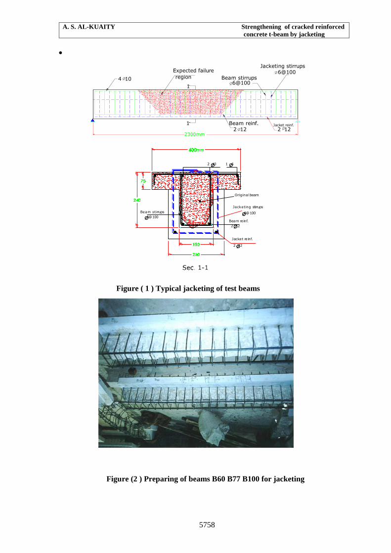
Figure ( 1 ) Typical jacketing of test beams
Figure (2 ) Preparing of beams B60 B77 B100 for jacketing
1
1
Jacketing stirrups 6@100
Beam stirrups 6@100
Beam reinf.2 12
Jacket reinf.
2 122300mm
Expected failure
region4 10
Jacket reinf.
2 12
Jacketing stirrups
6@100
Beam reinf.
2 12
Beam stirrups
6@100
2 10 1 6
Original beam

Journal of Engineering Volume 16 September 2010 Number 3
5759
Concrete
In this research the mix proportion of concrete used was 1 : 2 : 4 by weight ( cement : sand :
coarse aggregate) with 0.55 w/c ratio.This mix was aimed to obtain about 30N/mm2 cube
compressive strength at age 28-days.
The concrete mix used for repairing was same as that used for beams except the w/c ratio
was reduced to 0.5 to get the target compressive strength of about 35 N/mm2 at age 28-days.
The concrete mix was found to be workable with slump of about 70mm which suitable for
casting and repairing of test specimens.
Steel reinforcement
The steel reinforcement used are 6mm, 10mm, 12mm, and 16mm dia. deformed bars which
are free from harmful defects, seams, porosity, segregation, non-metallic inclusions.
In this research the samples of steel bars are tested in tension according to BS4449:1988 .The
test results are given in Table (2). All samples tested are satisfying the BS4449:1988
standards.
All stirrups used for beams before repair are 6mm diameter. Same diameter are used for
beams after repair which are welded by E43 electrode according to BS5950 part 1:1990. The
overlap is about 50mm. Tensile tests were carried on this type of welding. Results have
shown that the strength of weld is greater than the strength of the original reinforcement.
The yield stress and ultimate stress of bars tested are summarised in Table (2).
Table (2) tensile strength of bars reinforcement
Bar dia. (mm) 6 10 12
Yield stress
(N/mm2) 255 287 361
Ultimat stress
(N/mm2) 368 431 595
Test procedure
The test procedure was carried out as follows:-
The sample was put under the test instrument type FM 2750 machine Nr. 613 wolpert
ch-8232 Merishausen where the hydraulic jack is used to exert load on the specimen
(See Figure (3).
The load capacity of the testing machine used is 30 tons and its sensitivity is 0.1 KN
The specimen was put on supported roller to be simply supported.
A steel beam with a dimension of 1000 x 240 x 120 mm was used to transfer the single
load from the testing machine to two points loads on the tests specimen. The said steel beam
would change the concentrated loads in to two equal loads.
The initial readings were taken before loading, for all deflection points and concrete strain
gauges.

A. S. AL-KUAITY Strengthening of cracked reinforced
concrete t-beam by jacketing
5760
The loading was exerted on the specimen at increment which was 4 KN. until the appearance
of the first cracking load. All cracks were marked on the concrete surfaces of the specimen
during all loading stages. The deflection and concrete strain gauge readings were taken at
each stage of the loading until the concrete failure occurs.
Figure ( 3 ) Typical instrumentation of test beams
TEST RESULTS
The behaviour of reinforced concrete beams is well established by research workers but it its
behaviour after repair has not yet been fully investigated. However, one of the objective of
this study is to investigate the behaviour of repaired beam under flexure.
The beams must be safe and serviceable. A beam is safe if it is able to resist all forces which
will act on it during its life time. Serviceability implies that deflections and other distortions
under load shall be unobjectionable small.
Load- deflection behaviour
The deflections along the spans of the test beam before and after repair were measured at all
stages of loading. The maximum centre deflections for these beams were plotted in Figure
(4). as a function of the total applied load. All beams have shown similar behavior before and
after repair. These curves are composed of three distinguished regions namely, pre-cracking
stage, post cracking stage and post serviceability cracking stage.
At pre-cracking stage, the applied loads are directly proportional to the centre deflections for
beams before and after repair. This means that the entire concrete section is effective in
resisting deflection, which caused by applied load. The pre-cracking segment of load
deflection curve is, therefore, defining full elastic behaviour for all beams tested here. The
theoretical deflections shown on the figures, are based on moment of inertia of the un
cracked reinforced concrete section which agreed well with those obtained from test results.
The theoretical deflections are slightly lower than those observed from tests. This may be due
to approximate evaluation of modulus of elasticity by ACI expression:
cc fWEC 043.05.1
However, the elastic behaviour of beams after repair are similar to those before repair
irrespective to the loading condition before repair.
Demic disc
I-section (240x120)
Steel hinge
Dial gauge
Demic disc
Steel roller
Steel support
Test T-beam

Journal of Engineering Volume 16 September 2010 Number 3
5761
When the load on the test beams is gradually increased beyond the first crack to the service
load, the behaviour of beams changed slightly in to a post-cracking stage. Figure (4) showed
that the relationship between load and deflection at post-cracking stage are approximately
linear defining semi-elastic behaviour.
At post-cracking service load stage, the formation of flexural cracks in beams before repair
reduced the flexural stiffness of the beam section making the load-deflection curve less steep
in this region than in the pre-cracking stage segment. Similar behaviour was observed for the
beams after repairs.The theoretical deflections on these figuress are calculated based on the
procedure specified by ACI code,2005, art 9-5-2-2. ACI code methods is slightly
underestimated the deflection especially for beams before repairs.This may be due evaluation
of cracking moment capacity Mcr in ACI-method which related to approximate value of
modulus of rapture
)(t
gr
cry
IfM
However, Fig (4) shows that the beams repaired by jacketing gave higher flexural stiffness
than their original flexural stiffness, in spite, of the existing cracks in the original concrete.
This means the jacketing is significantly increased the flexural stiffness and hence would
improve the serviceability.
When the load is further increased beyond the service load, the beams showed substantial
loss in their stiffness because of the extensive cracking penetrating to the compression zone.
In the region (post serviceability cracking stage), the load deflection curve tend to be flatter.
The small increase in the applied load resulted in large amount of deflection.
However, the repaired beams have shown similar or even better load deflection behaviour
than the original beams. Jacketing method enhanced the serviceability compared to the
original beam. On the other hand, the loading condition and crack condition of the beams
before repairs have no significant effect on the load deflection behaviour of the beams after
repair. Repair by jacketing resulted in reduction in the deflection under service load to about
40% of the original deflection before repair. The jacketing method has given the best result
in improving the load deflection behaviour of beams.

A. S. AL-KUAITY Strengthening of cracked reinforced
concrete t-beam by jacketing
5762
Figure (4 ) Load-deflection curves of beams before and
after jacketing
Load-steel strain curves
The steel strains were measured at three sections along the span (under two points load and at
the middle sections). Mechanical strain gauge was used with 200mm gauge length, which
measured the concrete surface strain at steel level.
It is assumed that the concrete surface adjacent to the steel will have same strain as the steel.
However, this is the best available technique in the laboratory.
The load-tensile steel strain curves at mid-span were plotted for all beams before and after
repair as shown in Figure (5). Three different stages of behaviour can be clearly
distinguished.
At low load, it can be seen that the steel strain is directly proportional with the applied load
following the elastic behaviour (elastic stage). After formation the first crack, the steel strain
is changed to be flatter than that before crack. Then it increases steadily and linearly up to the
yielding strain.
In the cracking region, the stresses are still proportional to strains. Further increase in the
applied load beyond the service load resulted in a large and non-linear increase in the tensile
strain of beams before and after repair.
Test results show that the repair by jacketing causes a great decrease in the tensile strain of
the original beams. This means that the reinforcement of the jacketing is significantly
contributing in resisting the applied load besides the original reinforcement. The percentage
of decrease is ranging between about 90% in beam B77 to about 70% in beam B100 at
service load.
On the other hand, the top steel plate reduced the steel strain in beams before repairs as
shown in Fig. (5).
Journal of Engineering Volume 16 September 2010 Number 3
5763
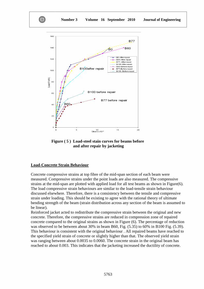
Figure ( 5 ) Load-steel stain curves for beams before
and after repair by jacketing
Load-Concrete Strain Behaviour
Concrete compressive strains at top fibre of the mid-span section of each beam were
measured. Compressive strains under the point loads are also measured. The compressive
strains at the mid-span are plotted with applied load for all test beams as shown in Figure(6).
The load compressive strain behaviours are similar to the load-tensile strain behaviour
discussed elsewhere. Therefore, there is a consistency between the tensile and compressive
strain under loading. This should be existing to agree with the rational theory of ultimate
bending strength of the beam (strain distribution across any section of the beam is assumed to
be linear).
Reinforced jacket acted to redistribute the compressive strain between the original and new
concrete. Therefore, the compressive strains are reduced in compression zone of repaired
concrete compared to the original strains as shown in Figure (6). The percentage of reduction
was observed to be between about 30% in beam B60, Fig. (5.35) to 60% in B100 Fig. (5.39).
This behaviour is consistent with the original behaviour . All repaired beams have reached to
the specified yield strain of concrete or slightly higher than that. The observed yield strain
was ranging between about 0.0035 to 0.0060. The concrete strain in the original beam has
reached to about 0.003. This indicates that the jacketing increased the ductility of concrete.

A. S. AL-KUAITY Strengthening of cracked reinforced
concrete t-beam by jacketing
5764
Figure ( 6 ) Load-compressive stain curves for beams
before and after repair by jacketing
CRACKING BEHAVIOUR
The formation of cracks at every stage of loading is marked on the test beams as shown in
Figures (7) and (8). Concrete cracks at an early stage of its loading history will crack first
because its weak in tension. Consequently, it is necessary to study its cracking behaviour and
control the width of the flexural cracks. Cracking contributes to the corrosion of the
reinforcement, surface deterioration and its long-term deterioration effects. The problem of
cracking becomes much more important in retrofitting the deteriorated beams, because, the
existing uncontrolled cracks may reduce the load carrying capacity of the beams and will
increase the deflections beyond the permitted limits.
Hence, the prediction and control of cracking and crack widths are essential for reliable
serviceability performance under long-term loading.
As a beam is subjected to bending moment resulting from applied loads, tension stresses will
occur in one side of neutral axis and compression stresses developed in the other side. When
the tension stress exceeds the modulus of rapture, cracks form. If the concrete compression
stress is less than approximately half compressive concrete strength and the steel stress has
not yet reached the yield point, both materials continue to behave elastically or very nearly so.
At this stage, it is assumed that tension cracks have progressed all the way to the neutral axis,
and that sections plane before bending are plane in the bent member.
Beams before repair
The initial flexural cracks have first developed in all beams tested except beams B0, which
was not loaded before repair. The typical cracking condition of B100 is shown in Figure (7).
All beams have shown that the first crackform at about same load, which was about 16 KN
because these beams were identical. The flexural cracks developed at bottom fibre in the
region of maximum bending moment (between points loads). These cracks penetrated
upward as the load increased and new cracks spread toward the points load. Then, the load
was removed when it reached to 60% of the ultimate load (B60) whereas the applied load
continued, untill 77% of the ultimate load in beam B77 . In this beam, the flexural cracks
penetrate deeper in the flange of the beam (compression zone) and some cracks separated

Journal of Engineering Volume 16 September 2010 Number 3
5765
into two branches. Beam B100 has nearly similar cracking behaviour at this stage (77% Pu).
Then, the loading continued for beam B100 up to failure.
As the loaded increases above 77% of the ultimate load in beam B100, the cracks, under the
left point load have deeply penetrated to the compression zone resulting in complete failure
by crushing the flange under the point load resulting a complete flexural failure.
Beams after repair
The objective of B0 was to investigate the possibility of increasing the ultimate capacity of
non-cracked section by jacketing method. Beams B60, B77 were tested to investigate the
strengthening of cracked sections using jacketing method. To retrofit the failed beam by
jacketing, B100 was investigated. The cracking behaviour of B0 after strengthening, is
similar to the cracking behaviour of beams B60, B77, B100 before repair. This means, the
strengthening by jacketing would result in similar cracking behaviour to that of the original
beams.
Therefore, same principle of the original beam may be used to predict crack width of the
beams strengthened by jacketing. The mode of failure of beam B0 is a pure flexural failure
which crushed the compression zone, (top flange) between points load. So, the ultimate
strength theory can also be used to predict the moment carrying capacity of strengthened
beam by jacketing.
After repairing beams B60, B77, B100 by jacketing, the cracking behaviour were
approximately similar to those observed before repair . A typical cracking condition of beam
after repair is shown in Figure(8). Then, the mode of failure of beam B100 after repair Figure
(10) was exactly in similar type and in same location as that of the original beam before
repair Figure (9). Beams B60, B77 showed similar mode of failure after repair as in beam
B100 but with improved ductility (large deflection before failure). This indicates that the
behaviour of strengthened beams (B77, B60) are more ductile than the retrofitted beam
(B100).
Figure ( 7 ) Cracking of Beam B100 (before repair)

A. S. AL-KUAITY Strengthening of cracked reinforced
concrete t-beam by jacketing
5766
Figure ( 8 ) Cracking of Beam B100 (after repair)
FAILURE LOAD OF TEST BEAMS
Experimental and theoretical failure loads are given in Table (3). Based on this table, the
strength and the efficiency of repair are presented here.
As mensioned elswhere,all beams have same steel reinforcement, size and concrete
properties. They were designed to have flexural failure before repair at ultimate load of about
38KN according to ACI method.
Beam B0 was strengthened by reinforced jacket without any flexural cracks in the original
concrete, (unloaded before repair). To show the efficiency of jacketing method in non-
cracked section.
Beams B60 , B77 were loaded to 60% and 77% of the failure load obtained from test. Such
loading produced flexural cracks with intensity related to the applied load .In fact, the higher
the load the more cracks will produce. Then, these beams were repaired by reinforced jacket
as mentioned elsewhere. After curing, the beams were tested again to gradually up to failure.
Observations were made for surface strain and deflection during the loading. Cracks were
also marked on concrete surfaces. Beam B100 was first loaded to flexural failure. then, the
crushed concrete was removed and replaced by new concrete in addition to the reinforced
jacket. The main aim of this beam was to investigate the possibility of restoring the flexural
strength of failed beam using reinforced jacket.
Referring to Table (3), the use reinforced jacket with (2 12) increased the failure load of
beam B0, B60, B77 from 64KN to about 165KN. This means the failure load after
strengthening increased to about 150% as much as the original failure load irrespective to the
condition of cracks before repair. Therefore, the existing flexural cracks have no significant
effect on the flexural strength after repair.
The high flexural strength of beams may be attributed to the confinment of cracked beam by
new jacket with very high bond strength between the original and jacket concrete,These will
make the beam to act as one unit. In fact, the removing of the concrete cover of these beams
before jacketing provided a very rough surface for good bond between cracked concrete and
new concrete. The ratio between theoretical failure load to the experimental value is about
0.82. The theoretical procedure followed here has taken in consideration the increase in

Journal of Engineering Volume 16 September 2010 Number 3
5767
effective deth after jacketing as weel as the exiting reinforcement in the original beam. On
the other hand, the theoretical failure load is very closed to the experimental failure load of
the original beam (before jacketing). The ratio between the theoretical to the experimental is
about 0.91.
For beam B100, the jacketing was restored about 167% of the original ultimate capacity of
the beam. The original reinforcement in this beam was useless since it was ruptured by the
first test before jacketing. The ratio between the theoretical and the experimental failure load
was about 0.73. this means, that the existing reptured steel contribute in resisting applied
load. However, the yield reinforcement may carried about 27% of the failure load in the
second test (after jacketing).
Figure ( 9 ) Flexural failure mode of Beam B100 (before repair)
Figure (10 ) Failure mode of Beam B100 (after repair)

A. S. AL-KUAITY Strengthening of cracked reinforced
concrete t-beam by jacketing
5768
Table (3) Ultimate experimental loads of beams repaired by jacketing
Beam
1st cracking load Failure load (Pu) Mode
of
failure
Original beam After repair Original beam After repair
Exp.
(KN)
Theo.
(KN)
Exp.
(KN)
Theo.
(KN)
Exp.
(KN)
Theo.
(KN)
Exp.
(KN)
Theo.
(KN)
B0 16 18.5 20 41.6 64 62 162 135 Flexure
B60 16 18.30 22 33.9 64 62 164 135 Flexure
B77 16 18.30 20 34.2 64 62 169 135 Flexure
B100 18 18.50 22 41.6 64 62 107 78 Flexure
EFFECT OF LOADING ON THE STRENGTH OF REPAIRED BEAM
The failure loads of beams B0, B60, B77, B100 were plotted against the first load test
)100( uP
P
, which corresponded to crack condition of the original beams before repair as
shown in Figure (11). All beams have same failure load because they are identical. The
conditions of cracks at the original beams were marked on the axis.
Figure (11) shows that, the existing flexural cracks in the original beam up to load level of
77% has no significant effect on the strength after jacketing. The strength of beams after
jacketing is mainly affected by the amount both the existing reinforcement and the
reinforcement of jacketing. The reduction in the strength of beam failed in flexural before
jacketing, (Beam B100) compared to other, (B0, B60 and B77), was mainly due to lost of
original reinforcement by rupture during the first test.
Fig. (11) Effect of loadig before repair on the strength
of beams repaired by jacketing

Journal of Engineering Volume 16 September 2010 Number 3
5769
THEORETICAL FAILURE LOAD
Based on ACI-318M-2005 the ultimate moment capacity of the beam (B0, B60, B77, B100),
were calculated using the actual dimensions in Figures (1),(3) and material strengths Table
(2).The notations used here are same as that given in ACI Code.
Beam before repair
Fcu = 35.6 N/mm2 , fc' = 30 N/mm2 , fsu = 595 N/mm2 ,
Main reinforcement 2 Ø 12
As = 113X2 =226 mm2
Effective depth = 240 - (25 + 12) = 203 mm
As min = 0.005 x b x d
As min = 0.005 x 150 x 203 =152.25 mm2
As x fy 226 x 595
a = ------------------ = ----------------- = 13.2 mm < t ( Sec. rectangular with b =400)
0.85 x , fc' x b o.85 x 30 x 400
)600
600(
85.0
yy
c
bff
fB
22
1 /30,/361,85.0 mmNfmmNfB cy
037487.0)361600
600(
361
3085.085.0
b
bdA bs 75.0max
2106.856203150037487.075.0 mm
As prov.< As max. O.K. beam under reinforced.
Mu = As fu ( d – a/2) Ø = 1 (actual moment capacity without factor of safety)
Mu = 226 x 595 ( 203 – 13.2/2 ) = 26409908 N.mm = 26.4 kN.m
Total failure load (Pu) = 2 x 26.4/.85 = 62 kN.m
Beam with jacket B 100
Fcu = 35.6 N/mm2 , fc' = 30 N/mm2 , fsu = 595 N/mm2 ,
Main reinforcement 2 Ø 12
As = 113X2 =226 mm2
A. S. AL-KUAITY Strengthening of cracked reinforced
concrete t-beam by jacketing
5770
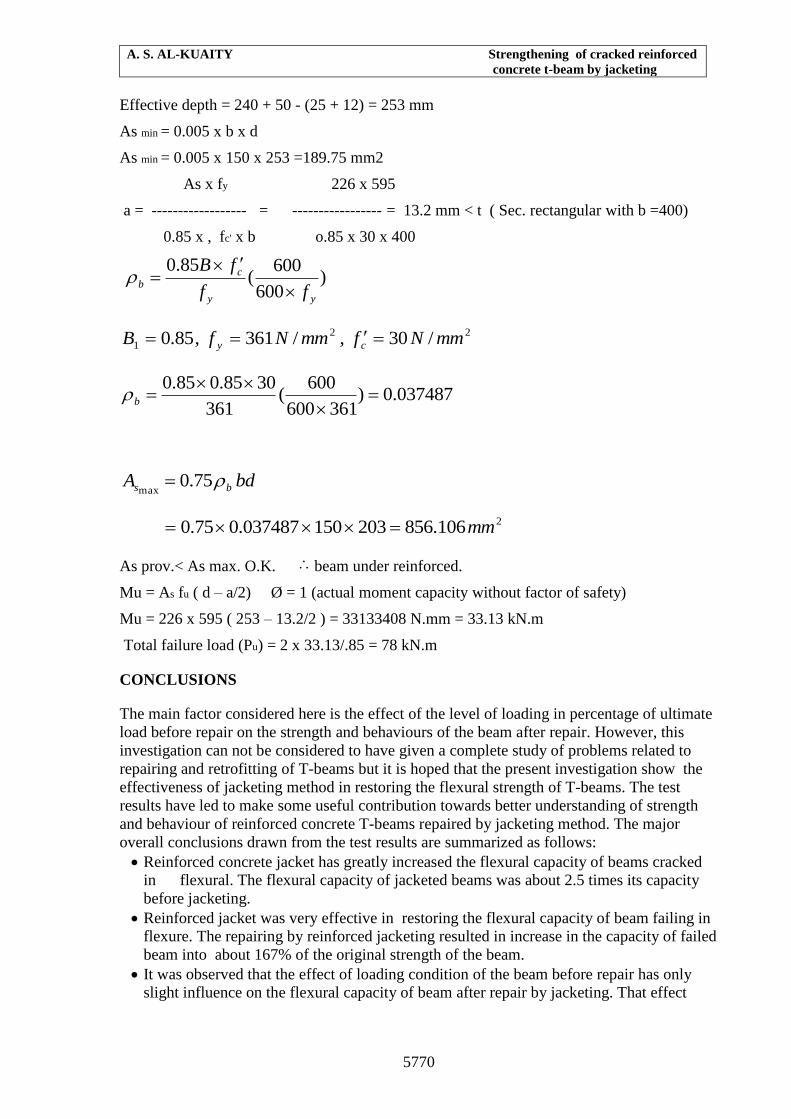
Effective depth = 240 + 50 - (25 + 12) = 253 mm
As min = 0.005 x b x d
As min = 0.005 x 150 x 253 =189.75 mm2
As x fy 226 x 595
a = ------------------ = ----------------- = 13.2 mm < t ( Sec. rectangular with b =400)
0.85 x , fc' x b o.85 x 30 x 400
)600
600(
85.0
yy
c
bff
fB
22
1 /30,/361,85.0 mmNfmmNfB cy
037487.0)361600
600(
361
3085.085.0
b
bdA bs 75.0max
2106.856203150037487.075.0 mm
As prov.< As max. O.K. beam under reinforced.
Mu = As fu ( d – a/2) Ø = 1 (actual moment capacity without factor of safety)
Mu = 226 x 595 ( 253 – 13.2/2 ) = 33133408 N.mm = 33.13 kN.m
Total failure load (Pu) = 2 x 33.13/.85 = 78 kN.m
CONCLUSIONS
The main factor considered here is the effect of the level of loading in percentage of ultimate
load before repair on the strength and behaviours of the beam after repair. However, this
investigation can not be considered to have given a complete study of problems related to
repairing and retrofitting of T-beams but it is hoped that the present investigation show the
effectiveness of jacketing method in restoring the flexural strength of T-beams. The test
results have led to make some useful contribution towards better understanding of strength
and behaviour of reinforced concrete T-beams repaired by jacketing method. The major
overall conclusions drawn from the test results are summarized as follows:
Reinforced concrete jacket has greatly increased the flexural capacity of beams cracked
in flexural. The flexural capacity of jacketed beams was about 2.5 times its capacity
before jacketing.
Reinforced jacket was very effective in restoring the flexural capacity of beam failing in
flexure. The repairing by reinforced jacketing resulted in increase in the capacity of failed
beam into about 167% of the original strength of the beam.
It was observed that the effect of loading condition of the beam before repair has only
slight influence on the flexural capacity of beam after repair by jacketing. That effect

Journal of Engineering Volume 16 September 2010 Number 3
5771
becomes very significant when there is a a complete flexural failure in the beam before
repair.
First flexural cracking load of beams strengthening by jacketing is increased by amount
of 25% resulting in an improvement in workability.
Test results showed that the yielded reinforcement before repair contribute in increasing
the flexural capacity of beam after jacketing by amount of 27% of the failure load.
Reinforced jacket increased, significantly, the flexural stiffness of the original beams
resulting in less deflection under service load. The percentage of reduction in deflection
was about 40%.
Tensile steel strain was, considerably, reduced by reinforced jacketing. The percentage of
decrease was ranging between 70% to 90% .
Reinforced jacketing has led to considerable increase in concrete compressive strain at
ultimate stage of loading in a very ductile mode of failure.
Reinforced concrete jacketing has greatly improved the cracking behaviour of beams
irrespetive to cracking condition before repair.
Test results showed that the addition of steel reinforcement at the compression zone
increased both the ultimate capacity (22%) and ductility.
A safe and reliable prediction of failure load of beams repaired by reinforced jacket can
be obtained using stress-strain relationship of steel reinforcement. Neglecting the existing
yield reinforcement, the average ratio of predicted failure load to that obtained from test
beam was about 0.75.
REFERENCECS
ACI-318M-2005 “Building Code Requirement Concrete: American Concrete Institute,
2005.
British Standard Specifications,Table 32, BS5950part1:1990.
British Standard Specifications for steel tension(BS4449:19888).
Department of th army U.S.Army Corps of Engineers "Evaluation and Repair of Concrete
Structures"Manual No.1110-2-2002.
Emmons,P. H.,Vaysburd,Alexander M,and McDonald,James E."Arational Approach to
Durable Concrete Repairs,"Concrete International,Vol. 15, No.9, pp40-45.
Ersoy, U, Tankut, T and Suleiman, R. “Behavior of Jacketed columns” ACI Jr. May-June
1993 pp. 288-293.
H.K. Cheong W. MacAlevey, "Experimental behavior of jackted reinforced
concrete beams" (2000).
Johnson,S. M. "Detterioration Maintenance, and Repair of Structures"McGraw-Hill,
New York.
7th International Conference on inspection ,Appraisal repair and maintenance of
buildings and Structures 11-13 September 2001, Nottingham Trent University
compus, Nottingham, UK.
Copyright © 2022 FDOKUMEN