Vibration Fatigue Analysis of a Simply Supported Cracked ...
10
Appl. Sci. 2022, 12, 7398. https://doi.org/10.3390/app12157398 www.mdpi.com/journal/applsci Article Vibration Fatigue Analysis of a Simply Supported Cracked Beam Subjected to a Typical Load Yijiang Ma 1 , Guoping Chen 2 , Jie Wu 1, *, Kangjia Ma 3 and Le Fan 1 1 School of Naval Architecture and Ocean Engineering, Jiangsu University of Science and Technology, Zhenjiang 212003, China; [email protected] (Y.M.); [email protected] (L.F.) 2 State Key Laboratory of Mechanics and Control for Mechanical Structures, Nanjing University of Aeronautics and Astronautics, Nanjing 210016, China; [email protected] 3 Zhongshan Institute, College of Mechanical and Electrical Engineering, University of Electronic Science and Technology of China, Zhongshan 528400, China; [email protected] * Correspondence: [email protected] Abstract: In order to realize the accurate prediction of the vibration fatigue life of the beam in ser‐ vice, a loose coupling analysis method is proposed to carry out vibration fatigue analysis of a beam with an initial crack. In modal analysis, the initial crack segment is replaced with a torsion spring, and the damping loss factor is introduced by the complex modulus of elasticity; for the simply sup‐ ported beam, the inherent vibration characteristic equation of the cracked beam is derived. In vibra‐ tion fatigue analysis, the interaction between the crack’s growth and vibration analysis is consid‐ ered, and a loose coupling analysis method is proposed to conduct modal dynamic response and vibration fatigue analysis simultaneously. Results indicate that the crack’s relative location and depth determine the modal of the cracked beam, and crack parameters, damping loss factor and external excitation frequency are important factors for the vibration fatigue life of the beam. Keywords: crack; simply supported beam; vibration; fatigue life 1. Introduction As modern industry develops rapidly, the development trend for large equipment are the extreme environments of high speed, high temperature and high pressure, and factors causing the failure of the engineering structure are increasing. In the service pro‐ cess of large mechanical equipment, vibration fatigue is one of the most important failure factors. In the vibrating environment, when the external excitation frequency is close to the natural frequency of the structure, resonance failure is caused in the engineering struc‐ ture, which will in turn cause major losses to personnel and affect property safety. For engineering structures, the fatigue crack is an important structural health problem, and safety accidents caused by cracks in engineering structures are very common. Therefore, dynamic characteristics analysis of structures with cracks is essential, and conducting modal analysis and vibration fatigue life analysis of cracked structures has great engineer‐ ing value. In the past 40 years, vibration fatigue analysis of the cracked structures has received extensive attention from scholars. Dentsoras and Dimarogonas [1,2] systematically stud‐ ied the fatigue crack growth mechanism under the resonance condition based on the Paris equation [3]. Dentsoras and Kouvaritakis [4] assumed a polymer material beam was un‐ der the resonance condition, and systematically investigated the influence mechanism of the excitation frequency on crack growth. Colakoglu [5] derived the relationship between the crack initiation life and the structural damping changes. Eldoǧan and Cigeroglu [6] developed an in‐house numerical code to conduct vibration fatigue analysis of a cracked cantilever beam, and investigated the influence of damping ratio on the vibration fatigue Citation: Ma, Y.; Chen, G.; Wu, J.; Ma, K.; Fan, L. Vibration Fatigue Analysis of a Simply Supported Cracked Beam Subjected to a Typical Load. Appl. Sci. 2022, 12, 7398. https://doi.org/10.3390/app12157398 Academic Editors: Chen Wang, Mukhtar A. Kassem, Lincoln C. Wood and Jeffrey Boon Hui Yap Received: 7 July 2022 Accepted: 22 July 2022 Published: 23 July 2022 Publisher’s Note: MDPI stays neu‐ tral with regard to jurisdictional claims in published maps and institu‐ tional affiliations. Copyright: © 2022 by the authors. Li‐ censee MDPI, Basel, Switzerland. This article is an open access article distributed under the terms and con‐ ditions of the Creative Commons At‐ tribution (CC BY) license (https://cre‐ ativecommons.org/licenses/by/4.0/).
-
Upload
khangminh22 -
Category
Documents
-
view
2 -
download
0
Transcript of Vibration Fatigue Analysis of a Simply Supported Cracked ...
Appl. Sci. 2022, 12, 7398. https://doi.org/10.3390/app12157398 www.mdpi.com/journal/applsci
Article
Vibration Fatigue Analysis of a Simply Supported Cracked
Beam Subjected to a Typical Load
Yijiang Ma 1, Guoping Chen 2, Jie Wu 1,*, Kangjia Ma 3 and Le Fan 1
1 School of Naval Architecture and Ocean Engineering, Jiangsu University of Science and Technology,
Zhenjiang 212003, China; [email protected] (Y.M.); [email protected] (L.F.) 2 State Key Laboratory of Mechanics and Control for Mechanical Structures, Nanjing University of
Aeronautics and Astronautics, Nanjing 210016, China; [email protected] 3 Zhongshan Institute, College of Mechanical and Electrical Engineering, University of Electronic Science and
Technology of China, Zhongshan 528400, China; [email protected]
* Correspondence: [email protected]
Abstract: In order to realize the accurate prediction of the vibration fatigue life of the beam in ser‐
vice, a loose coupling analysis method is proposed to carry out vibration fatigue analysis of a beam
with an initial crack. In modal analysis, the initial crack segment is replaced with a torsion spring,
and the damping loss factor is introduced by the complex modulus of elasticity; for the simply sup‐
ported beam, the inherent vibration characteristic equation of the cracked beam is derived. In vibra‐
tion fatigue analysis, the interaction between the crack’s growth and vibration analysis is consid‐
ered, and a loose coupling analysis method is proposed to conduct modal dynamic response and
vibration fatigue analysis simultaneously. Results indicate that the crack’s relative location and
depth determine the modal of the cracked beam, and crack parameters, damping loss factor and
external excitation frequency are important factors for the vibration fatigue life of the beam.
Keywords: crack; simply supported beam; vibration; fatigue life
1. Introduction
As modern industry develops rapidly, the development trend for large equipment
are the extreme environments of high speed, high temperature and high pressure, and
factors causing the failure of the engineering structure are increasing. In the service pro‐
cess of large mechanical equipment, vibration fatigue is one of the most important failure
factors. In the vibrating environment, when the external excitation frequency is close to
the natural frequency of the structure, resonance failure is caused in the engineering struc‐
ture, which will in turn cause major losses to personnel and affect property safety. For
engineering structures, the fatigue crack is an important structural health problem, and
safety accidents caused by cracks in engineering structures are very common. Therefore,
dynamic characteristics analysis of structures with cracks is essential, and conducting
modal analysis and vibration fatigue life analysis of cracked structures has great engineer‐
ing value.
In the past 40 years, vibration fatigue analysis of the cracked structures has received
extensive attention from scholars. Dentsoras and Dimarogonas [1,2] systematically stud‐
ied the fatigue crack growth mechanism under the resonance condition based on the Paris
equation [3]. Dentsoras and Kouvaritakis [4] assumed a polymer material beam was un‐
der the resonance condition, and systematically investigated the influence mechanism of
the excitation frequency on crack growth. Colakoglu [5] derived the relationship between
the crack initiation life and the structural damping changes. Eldoǧan and Cigeroglu [6]
developed an in‐house numerical code to conduct vibration fatigue analysis of a cracked
cantilever beam, and investigated the influence of damping ratio on the vibration fatigue
Citation: Ma, Y.; Chen, G.; Wu, J.;
Ma, K.; Fan, L. Vibration Fatigue
Analysis of a Simply Supported
Cracked Beam Subjected to a Typical
Load. Appl. Sci. 2022, 12, 7398.
https://doi.org/10.3390/app12157398
Academic Editors: Chen Wang,
Mukhtar A. Kassem, Lincoln C.
Wood and Jeffrey Boon Hui Yap
Received: 7 July 2022
Accepted: 22 July 2022
Published: 23 July 2022
Publisher’s Note: MDPI stays neu‐
tral with regard to jurisdictional
claims in published maps and institu‐
tional affiliations.
Copyright: © 2022 by the authors. Li‐
censee MDPI, Basel, Switzerland.
This article is an open access article
distributed under the terms and con‐
ditions of the Creative Commons At‐
tribution (CC BY) license (https://cre‐
ativecommons.org/licenses/by/4.0/).
Appl. Sci. 2022, 12, 7398 2 of 10
life of the cantilever. Jassim et al. [7] conducted the vibration fatigue analysis of the
cracked beam by the numerical method, and carried out the vibration fatigue experiment
of the cracked beam for verification. Demirel and Kayran [8] designed a rectangular cross‐
section cracked beam, and applied the Dirlik’s damage model to investigate a random
vibration fatigue mechanism in the frequency domain numerically and experimentally.
Liu and Barkey [9] used the energy principle to derive the friction damping loss factor
based on the Coulomb friction model, and investigated the coupling mechanism of vibra‐
tion analysis and crack’s growth. Wu et al. [10] established the high frequency vibration‐
induced fatigue failure experimental platform of the cracked beam, and analyzed the in‐
fluence of dynamic stress, acceleration and operational modal on the vibration fatigue life.
References above provided a variety of solutions for vibration fatigue analysis of the
cracked beam, but these methods had certain defects. In the theoretical method, the inter‐
action between crack growth and the stress field is not considered; in the numerical
method, the crack growth cannot be tracked; in the experimental method, the workload is
huge and the cost is high.
Structural vibration induces fatigue crack propagation, and fatigue crack propaga‐
tion also changes the vibration characteristics and stress field of a structure, and then the
crack growth behavior is affected. Scholars have carried out a lot of analysis and research
to consider the complexity of the interaction between vibration and fatigue crack propa‐
gation, Shih and Chen [11] considered the interaction between stress intensity factor and
crack axis, and established a model for fatigue life and crack axis analysis. Shih and Wu
[12] used the generalized Forman equation [13] to simulate the crack growth, and ana‐
lyzed the influence of the vibration on the crack growth of a rectangular plate with a uni‐
lateral crack. Wu and Shih [14] assumed the periodic load excitation was acting on the
rectangular plate with a unilateral crack, and studied the non‐linear vibration response
characteristics. Liu and He [15] considered the coupling effect of vibration analysis and
crack’s growth, and proposed a new method to conduct the vibration fatigue analysis of
cracked beams by introducing the complex elastic modulus. Assuming that the cyclic
loading was acting on a V‐notched cantilever beam, Liu and Barkey [16] investigated the
crack growth characteristics by experimental method, and proposed a new method to pre‐
dict remaining life. Appert and Gautrelet [17] designed the shaker vibration fatigue ex‐
perimental plan of the cracked beam, and investigated non‐linear behavior and remaining
life. Considering the coupling effect between vibration analysis and the crack’s growth,
the references above provide several solutions to predict the remaining life of a beam. In
the vibrating environment, there is interaction between the stress field and the crack field,
and the modal dynamic response and vibration fatigue analysis need to be carried out at
the same time.
In this paper, a loose coupling analysis method is proposed to carry out vibration
fatigue analysis for a simply supported beam under a typical harmonic excitation. Assum‐
ing that the crack does not grow in each vibration cycle, and the crack grows at the end of
each vibration cycle. For simplicity, only the first order natural frequency of the cracked
beam is considered. According to the loose coupling analysis method, modal, dynamic
response and vibration fatigue analysis can be carried out synchronously in each vibration
cycle, and the influence of crack’s parameters, damping loss factor and external excitation
frequency on the fatigue life is investigated.
2. Modal Analysis
2.1. Model of Cracked Beam
As shown in Figure 1, the research object is a rectangular cross‐section beam with an
initial transverse crack. The length, height and thickness of the beam are L , h and b , respectively, and the position and depth of the crack are cx and 0a , respectively.

Appl. Sci. 2022, 12, 7398 3 of 10
Figure 1. Model of the beam with a unilateral crack.
Based on the crack, the beam can be transformed into a two‐segment elastic beam
with no mass torsion spring. For simplicity, the torsion spring coefficient TK is consid‐
ered only. The torsion spring coefficient [18] of the crack can be equivalent, as follows:
* 3
272 1T
E hK
v F r
(1)
where v is the Poisson ratio; *E is the complex modulus of elasticity [19], and
* (1 i )E E ; is the material damping loss factor; r is the relative depth of the crack, 0r a h ; and ( )F r is the flexibility correction function [20] obtained through
the strain energy density function:
2 3 4 5 6
7 8 9 10
1.98 3.277 14.43 31.26 63.56
103.36 147.52 127.69 61.5
F r r r r r r
r r r r
(2)
2.2. Modal Analysis
As shown in Figure 1, the homogeneous slender straight beam can be regarded as
the Euler‐Bernoulli beam [21], and the vibration differential equation can be expressed as:
2 4*
2 4
( , ) ( , )0
y x t y x tA E I
t x
(3)
where is the material density; A is the cross‐section area of the beam; and I is the cross‐section moment of inertia.
Equation (3) is a fourth order homogeneous differential equation with constant coef‐
ficients, and can be solved by the separation variable method [22]:
( , t) ( )sin( )y x y x t (4)
Substitute Equation (4) into Equation (3), and motion equations of two stage beams
can be yielded:
1 1 2 3 4
2 5 6 7 8
( ) sin( ) cos( )+ sinh( ) cosh( )
( ) sin( ) cos( )+ sinh( ) cosh( )
y x c x c x c x c x
y x c x c x c x c x
(5)
where is the frequency constant, and 4 2 ( * )A E I ; 1 2 8, , ,c c c are the unde‐
termined coefficients, which can be determined by boundary conditions.
Due to the simply supported beam, boundary conditions can be written as follows:
Appl. Sci. 2022, 12, 7398 4 of 10
''1 1
''2 2
1 2
1 2
1 2
21 1 22
(0) 0; (0) 0
( ) 0; ( ) 0
( ) ( );
( ) ( )
( ) ( )
( ) ( ) ( )*
c c
c c
c c
c c cT
y y
y L y L
y x y x
M x M x
F x F x
y x y x y xE I K
x x x
(6)
Substitute Equation (5) into Equation (6), algebraic equations with undetermined co‐
efficients 1 2 8, , ,c c c can be obtained, which can be transformed into the matrix form:
'1 2 3 4 5 6 7 8[ ] 0H c c c c c c c c (7)
where H is the coefficient determinant matrix.
Through the condition that the algebraic equations have nonzero solutions, the value
of the coefficient determinant is zero, then natural frequencies of the simply supported
cracked beam can be obtained:
det( ) 0H (8)
3. Vibration Fatigue Analysis
3.1. Dynamic Response Analysis
Assume that the cracked beam is under the distribution harmonic excitation shown
in Figure 2, then vibration response equations can be expressed, respectively, as follows:
1 1 2 3
04 * 4
2 5 6 7
08 * 4
( ) sin cos + sinh
(cosh cos 2)cosh
2( ) sin cos + sinh
(cosh cos 2)cosh
2
d d d d
d
d d d d
d
y x c x c x c x
q x xc x
E Iy x c x c x c x
q x xc x
E I
(9)
Boundary conditions can be written, respectively, as:
''1 1
''2 2
1 2
1 2
1 2
21 1 22
(0) 0; (0) 0
( ) 0; ( ) 0
( ) ( )
( ) ( )
( ) ( )
( ) ( ) ( )*
d d
d d
d c d c
d c d c
d c d c
d c d c d cT
y y
y L y L
y x y x
M x M x
F x F x
y x y x y xE I K
x x x
(10)
Substitute Equation (9) into Equation (10), and undetermined coefficients
1 2 8, , ,d d dc c c can be obtained. Assume that the unilateral crack is the open crack, and
the normal stress at the cross section can be derived:
2
2( ) *
My yx E z
I x
(11)
where z is the distance to neutral axis of the beam.

Appl. Sci. 2022, 12, 7398 5 of 10
For the beam under the distribution harmonic excitation, assume [0, 2]cx L , and
the maximum stress expression at the crack tip ( 0( ) 2z h a ) can be written as:
21
2( ) *
c
dc x x
yx E z
x
(12)
Figure 2. Model of the beam under distribution harmonic excitation.
3.2. Stress Intensity Factor
Stress intensity factor at the crack tip can be derived as follows:
I ( ) dK Y r a (13)
where IK is the stress intensity factor; d is the maximum stress; and ( )Y r is the
crack correction factor: 2 3 4( ) 1.122 1.4 7.33 13.08 14Y r r r r r .
Under the distribution harmonic excitation, the stress intensity factor at the crack tip
can be derived as follows:
I Im 0( ) ( )ax cK K Y r x a (14)
3.3. Loose Coupling Analysis Method
In the vibration of the cracked beam, the interaction occurs between the cracked beam
vibration and crack’s growth. Crack growth will change the modal and dynamic response
of the beam, and affect the stress field distribution; variation of the stress field distribution
of the cracked beam will also change the crack growth rate. In this paper, a loose coupling
analysis method is proposed to conduct the vibration fatigue analysis of the cracked beam.
Assume that the crack length is constant in each cycle of vibration, and the crack will grow
at the end of each cycle. Crack growth and cracked beam vibration analysis are in seg‐
mented data transmission form, which means that data transmission occurs at the end of
each vibration cycle. The flow chart of loose coupling analysis method is shown in Figure 3.

Appl. Sci. 2022, 12, 7398 6 of 10
Figure 3. Flow chart of loose coupling analysis method.
Paris Law [23] can be applied to describe the crack growth rate in this paper:
I
d( )
dna
C KN
(15)
where C , n are the constants of beam material; andd da N is the crack growth rate.
Substitute Equation (14) into Equation (15), and the crack growth rate can be ob‐
tained:
0
d( ) ( )
d
n
c
aC Y r x a
N (16)
After jN periodic vibration, the crack growth increment can be calculated:
10( ) ( )
j
j
nN
j cNa C Y r x a dN
(17)
Assume 1 1j j jN N N , and d
dj
j
aa
N N
.
Equation (17) can be transformed as follows:
0( ) ( )n
j c ja C Y r x a N (18)
where ja is the crack growth increment after thj periodic cycle.
According to the fatigue damage accumulation theory, the depth of the crack can be
calculated:
0
k
j jj
a a a (19)
where k is the number of cycles; and ka is the depth after k periodic cycles.

Appl. Sci. 2022, 12, 7398 7 of 10
3.4. Fatigue Failure Criterion
The following three fatigue failure criteria are applied in this paper:
Criterion 1: if the depth of the crack reaches to the neutral layer of the beam, the beam
will be destroyed.
ca a (20)
where ca is the critical crack depth, 2ca h .
Criterion 2: if the stress intensity factor reaches to the material fracture toughness,
the beam will be destroyed.
max cK K (21)
where maxK is the maximum stress intensity factor; and cK is the material fracture
toughness.
Criterion 3: if the maximum stress at the crack surface reaches to the material ulti‐
mate strength, the beam will be destroyed.
max b (22)
where max is the maximum stress at the crack surface; and b is the material ultimate
strength.
4. Results and Discussions
Assume that geometric dimensions of the beam are as follows: 0.3mL ,
0.02mh and 0.002mb . The structural material is the low carbon alloy steel
AISI1050, and material parameters are as follows: 210GPaE , 0.05 , 37860kg.m , 723.45MPab , 0.33v , 1 21172.2MPa .mcK ,
1 20.93421MPa .mthK , 3.0093 32C e and 3.3m .
4.1. Natural Frequency
For the simply supported cracked beam, the geometric parameters of the crack are as
follows: [0, ]cx L and 0 / [0,0.5]a h . As the relative position and depth of the crack
change, the first order natural frequency variation is shown in Figure 4.
Figure 4. First order natural frequency variation.
As shown in Figure 4, the crack is the important factor affecting natural frequencies
of the beam, which cannot be ignored. As the crack’s relative depth increases, the first
order natural frequency of the beam gradually decreases, and the amplitude of the de‐
crease gradually increases. From the perspective of the crack’s relative position, the first

Appl. Sci. 2022, 12, 7398 8 of 10
order natural frequency variation is symmetrical in the middle section of the simply sup‐
ported beam. When the crack is in the middle part of the simply supported beam (
[0.3,0.7]cx L ), the first order natural frequency decreases faster as the crack’s relative
depth increases.
4.2. Relative Positions
Assume that the crack’s geometric parameters are as follows:
0.1,0.2, ,0.9cx L , 0.05,0.1,0.15r and 0 500N/ mq , 0.05 . At the res‐
onance condition, vibration fatigue lives are shown in Table 1.
Table 1. Vibration fatigue lives as the crack’s geometric parameters change.
cx L 0.1 0.2 0.3 0.4 0.5 0.6 0.7 0.8 0.9
0.05 385,337 37,099 14,859 13,403 12,706 13,403 14,859 37,099 385,337
0.1 234,626 20,118 9327 8535 7877 8535 9327 20,118 234,626
0.15 159,228 12,371 7030 6636 6080 6636 7030 12,371 159,228
As shown in Table 1, the crack’s geometric parameters are important factors affecting
the vibration fatigue life of the beam. From the perspective of the crack’s relative position,
the vibration fatigue lives of the beam are symmetrical in the simply supported beam, and
the vibration fatigue life of the beam with the same‐depth crack at the midpoint is the
least. As the crack is close to the middle section of the simply supported beam, the ampli‐
tude of the beam’s vibration fatigue life gradually decreases. As the relative depth of the
crack decreases, the vibration fatigue life of the cracked beam gradually decreases.
4.3. Damping Region
Assume that the crack’s geometric parameters are as follows: 0.3cx L , 0.1r
and 0 500N/ mq , 0.005,0.01,0.05,0.1 . Vibration fatigue life curves are shown
at the resonance condition, in Figure 5.
Figure 5. Vibration fatigue life curves as the damping loss factor changes.
As shown in Figure 5, the damping loss factor is another important factor affecting
the vibration fatigue life of the beam. When 0.005,0.01 , the simply supported beam
will be destroyed at around 0.3r , because the maximum stress at the crack’s surface
reaches to the material ultimate strength. As the damping loss factor gradually increases,
the vibration fatigue life of the beam increases. The influence of a small damping loss
factor on the vibration fatigue life is not obvious, but a big damping loss factor will greatly
influence the vibration fatigue life of the cracked beam.
Appl. Sci. 2022, 12, 7398 9 of 10
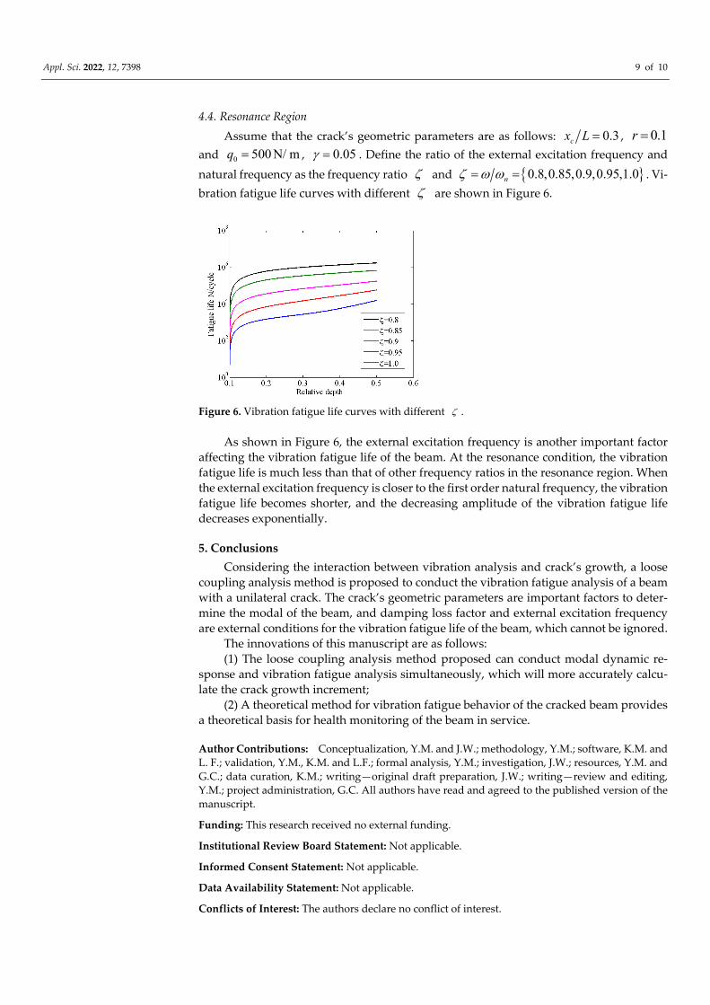
4.4. Resonance Region
Assume that the crack’s geometric parameters are as follows: 0.3cx L , 0.1r
and 0 500N/ mq , 0.05 . Define the ratio of the external excitation frequency and
natural frequency as the frequency ratio and 0.8,0.85,0.9,0.95,1.0n . Vi‐
bration fatigue life curves with different are shown in Figure 6.
Figure 6. Vibration fatigue life curves with different .
As shown in Figure 6, the external excitation frequency is another important factor
affecting the vibration fatigue life of the beam. At the resonance condition, the vibration
fatigue life is much less than that of other frequency ratios in the resonance region. When
the external excitation frequency is closer to the first order natural frequency, the vibration
fatigue life becomes shorter, and the decreasing amplitude of the vibration fatigue life
decreases exponentially.
5. Conclusions
Considering the interaction between vibration analysis and crack’s growth, a loose
coupling analysis method is proposed to conduct the vibration fatigue analysis of a beam
with a unilateral crack. The crack’s geometric parameters are important factors to deter‐
mine the modal of the beam, and damping loss factor and external excitation frequency
are external conditions for the vibration fatigue life of the beam, which cannot be ignored.
The innovations of this manuscript are as follows:
(1) The loose coupling analysis method proposed can conduct modal dynamic re‐
sponse and vibration fatigue analysis simultaneously, which will more accurately calcu‐
late the crack growth increment;
(2) A theoretical method for vibration fatigue behavior of the cracked beam provides
a theoretical basis for health monitoring of the beam in service.
Author Contributions: Conceptualization, Y.M. and J.W.; methodology, Y.M.; software, K.M. and
L. F.; validation, Y.M., K.M. and L.F.; formal analysis, Y.M.; investigation, J.W.; resources, Y.M. and
G.C.; data curation, K.M.; writing—original draft preparation, J.W.; writing—review and editing,
Y.M.; project administration, G.C. All authors have read and agreed to the published version of the
manuscript.
Funding: This research received no external funding.
Institutional Review Board Statement: Not applicable.
Informed Consent Statement: Not applicable.
Data Availability Statement: Not applicable.
Conflicts of Interest: The authors declare no conflict of interest.

Appl. Sci. 2022, 12, 7398 10 of 10
References
1. Dentsoras, A.; Dimarogonas, A.D. Resonance controlled fatigue crack propagation. Eng. Fract. Mech. 1983, 17, 381–386.
2. Dentsoras, A.J.; Dimarogonas, A.D. Fatigue crack propagation in resonating structures. Eng. Fract. Mech. 1989, 34, 721–728.
3. Paris, P.C.; Erdogan, F. A critical analysis of crack propagation laws. J. Fluids Eng. 1963, 85, 528–533.
4. Dentsoras, A.J.; Kouvaritakis, E.P.; Kouvaritakis, E.P. Effects of vibration frequency on fatigue crack propagation of a polymer
at resonance. Eng. Fract. Mech. 1995, 50, 467–473.
5. Colakoglu, M. Measurement and Analysis of Damping Factor in Engineering Materials to Assess Fatigue Damage; Washington Uni‐
versity: Washington, DC, USA, 2001; pp. 1–68.
6. Eldoǧan, Y.; Cigeroglu, E. Vibration fatigue analysis of a cantilever beam using different fatigue theories. In Topics in Modal
Analysis; Springer: New York, NY, USA, 2014; Volume 7, pp. 471–478.
7. Jassim, Z.A.; Ali, N.N.; Mustapha, F.; Jalil, N.A. A review on the vibration analysis for a damage occurrence of a cantilever
beam. Eng. Fail. Anal. 2013, 31, 442–461.
8. Demirel, G.İ.; Kayran, A. Implementation of Dirlik′s damage model for the vibration fatigue analysis. Procedia Struct. Integr.
2019, 21, 101–111.
9. Liu, W.; Barkey, M.E. The effects of breathing behaviour on crack growth of a vibrating beam. Shock. Vib. 2018, 2018, 2579419.
10. Wu, X.; Xie, C.; Liu, K.; Wu, S.; Wen, Z.; Mo, J. Study on high frequency vibration‐induced fatigue failure of antenna beam in a
metro bogie. Eng. Fail. Anal. 2022, 133, 105976.
11. Shih, Y.; Shih, Y. Analysis of fatigue crack growth on a cracked shaft. Int. J. Fatigue 1997, 19, 477–485.
12. Shih, Y.S.; Wu, G.Y. Effect of vibration on fatigue crack growth of an edge crack for a rectangular plate. Int. J. Fatigue 2002, 24,
557–566.
13. Forman, R.G.; Kearney, V.E.; Engle, R.M. Numerical analysis of crack propagation in cyclicloaded structures. ASME J. Basic Eng.
1967, 89, 459–463.
14. Wu, G.Y.; Shih, Y.S. Dynamic instability of rectangular plate with an edge crack. Comput. Struct. 2005, 84, 1–10.
15. Liu, W.G.; He, H.L. An Analytical Method for Vibration Fatigue of Cracked Beams. In Advanced Materials Research; Trans Tech
Publications Ltd.: Bäch, Switzerland, 2012; Volume 479, pp. 783–786.
16. Liu, W.; Barkey, M.E. Prediction on Remaining Life of a V‐Notched Beam by Measured Modal Frequency. Shock. Vib. 2019, 2019,
7351386.
17. Appert, A.; Gautrelet, C.; Khalij, L.; Troian, R. Development of a test bench for vibratory fatigue experiments of a cantilever
beam with an electrodynamic shaker. In Proceedings of the MATEC Web of Conferences, Poitiers, France, 27 May–1 June 2018;
EDP Sciences: Les Ulis, France, Volume 165, pp. 10007.
18. Douka, E.; Loutridis, S.; Trochidis, A. Crack identification in beams using wavelet analysis. Int. J. Solids Struct. 2003, 40, 3557–
3569.
19. Dentsoras, A.J.; Dimarogonas, A.D. Resonance controlled fatigue crack propagation in a beam under longitudinal vibrations.
Int. J. Fract. 1983, 23, 15–22.
20. Wu, Q.; Guo, S.; Li, X.; Gao, G. Crack diagnosis method for a cantilevered beam structure based on modal parameters. Meas.
Sci. Technol. 2019, 31, 035001.
21. Andreaus, U.; Spagnuolo, M.; Lekszycki, T.; Eugster, S.R. A Ritz approach for the static analysis of planar pantographic struc‐
tures modeled with nonlinear Euler–Bernoulli beams. Contin. Mech. Thermodyn. 2018, 30, 1103–1123.
22. Vidal, P.; Giunta, G.; Gallimard, L.; Polit, O. Modeling of composite and sandwich beams with a generic cross‐section using a
variable separation method. Compos. Part B Eng. 2019, 165, 648–661.
23. Pugno, N.; Ciavarella, M.; Cornetti, P.; Carpinteri, A. A generalized Paris’ law for fatigue crack growth. J. Mech. Phys. Solids
2006, 54, 1333–1349.