Fatigue of Magnesium Alloys
52
647 Fatigue of Magnesium Alloys F. A. Mirza and D. L. Chen 13.1 INTRODUCTION 13.1.1 WHY MAGNESIUM The increasing extreme precipitation events and destructive floods under global warming, which are known to be largely irreversible on timescales of many centuries [1], have recently been real- ized to stem from the human-caused greenhouse gas emissions [2–4]. As stated in the Kyoto global warming agreement [5], lightweighting in ground vehicles and aircraft is today deemed as one of the most effective strategies to improve fuel economy and reduce anthropogenic environment-dam- aging emissions [6–11]. Advanced high-strength steels, aluminum alloys, magnesium alloys, and polymers are being used to reduce vehicle weight and the subsequent CO 2 emissions, but substantial reductions could be further achieved by a greater application of magnesium alloys [5,6,9,12,13]. Magnesium has thus been considered as a strategic ultralightweight material in the automotive and 13 CONTENTS 13.1 Introduction .......................................................................................................................... 647 13.1.1 Why Magnesium....................................................................................................... 647 13.1.2 Magnesium in Aerospace Industry ........................................................................... 648 13.1.3 Significance of Fatigue of Mg Alloys ....................................................................... 648 13.2 Microstructures..................................................................................................................... 649 13.2.1 Cast Mg Alloys ......................................................................................................... 649 13.2.2 Extruded Mg Alloys ................................................................................................. 650 13.2.3 Welded Joints of Mg Alloys...................................................................................... 652 13.3 Deformation Mechanisms..................................................................................................... 654 13.4 Fatigue Properties of Mg Alloys........................................................................................... 657 13.4.1 Cyclic Deformation and Low Cycle Fatigue ............................................................ 658 13.4.1.1 Cast Mg Alloys .......................................................................................... 662 13.4.1.2 Extruded Mg Alloys................................................................................... 665 13.4.2 Fatigue Crack Initiation and Propagation ................................................................. 668 13.4.2.1 Cast Mg Alloys .......................................................................................... 668 13.4.2.2 Extruded Mg Alloys................................................................................... 672 13.4.3 Fatigue Life ............................................................................................................... 674 13.4.3.1 Cast Mg Alloys .......................................................................................... 674 13.4.3.2 Extruded Mg Alloys................................................................................... 678 13.4.4 Multiaxial Fatigue..................................................................................................... 679 13.4.5 Fatigue of Welded Joints of Mg Alloys .................................................................... 681 13.4.6 Environmental Effect................................................................................................ 685 13.4.6.1 Corrosion Fatigue....................................................................................... 686 13.4.6.2 Fatigue at Elevated Temperatures .............................................................. 688 13.5 Summary and Remarks ........................................................................................................ 689 Acknowledgments.......................................................................................................................... 691 References ...................................................................................................................................... 691
Transcript of Fatigue of Magnesium Alloys

647
Fatigue of Magnesium Alloys
F. A. Mirza and D. L. Chen
13.1 introduction
13.1.1 Why magneSium
The increasing extreme precipitation events and destructive floods under global warming, which are known to be largely irreversible on timescales of many centuries [1], have recently been real-ized to stem from the human-caused greenhouse gas emissions [2–4]. As stated in the Kyoto global warming agreement [5], lightweighting in ground vehicles and aircraft is today deemed as one of the most effective strategies to improve fuel economy and reduce anthropogenic environment-dam-aging emissions [6–11]. Advanced high-strength steels, aluminum alloys, magnesium alloys, and polymers are being used to reduce vehicle weight and the subsequent CO2 emissions, but substantial reductions could be further achieved by a greater application of magnesium alloys [5,6,9,12,13]. Magnesium has thus been considered as a strategic ultralightweight material in the automotive and
13contents
13.1 Introduction .......................................................................................................................... 64713.1.1 Why Magnesium ....................................................................................................... 64713.1.2 Magnesium in Aerospace Industry ...........................................................................64813.1.3 Significance of Fatigue of Mg Alloys .......................................................................648
13.2 Microstructures .....................................................................................................................64913.2.1 Cast Mg Alloys .........................................................................................................64913.2.2 Extruded Mg Alloys ................................................................................................. 65013.2.3 Welded Joints of Mg Alloys ...................................................................................... 652
13.3 Deformation Mechanisms.....................................................................................................65413.4 Fatigue Properties of Mg Alloys ........................................................................................... 657
13.4.1 Cyclic Deformation and Low Cycle Fatigue ............................................................ 65813.4.1.1 Cast Mg Alloys .......................................................................................... 66213.4.1.2 Extruded Mg Alloys...................................................................................665
13.4.2 Fatigue Crack Initiation and Propagation .................................................................66813.4.2.1 Cast Mg Alloys ..........................................................................................66813.4.2.2 Extruded Mg Alloys................................................................................... 672
13.4.3 Fatigue Life ............................................................................................................... 67413.4.3.1 Cast Mg Alloys .......................................................................................... 67413.4.3.2 Extruded Mg Alloys................................................................................... 678
13.4.4 Multiaxial Fatigue ..................................................................................................... 67913.4.5 Fatigue of Welded Joints of Mg Alloys .................................................................... 68113.4.6 Environmental Effect ................................................................................................ 685
13.4.6.1 Corrosion Fatigue .......................................................................................68613.4.6.2 Fatigue at Elevated Temperatures ..............................................................688
13.5 Summary and Remarks ........................................................................................................ 689Acknowledgments .......................................................................................................................... 691References ...................................................................................................................................... 691

648 Aerospace Materials Handbook
aerospace industry that is also the driving force behind the recent rapid increase in the application of magnesium alloys.
Magnesium (Mg), discovered in 1774 and named after the ancient city Magnesia, is found to be the sixth most abundant element, constituting 2% of the total mass of the Earth’s crust. It can be produced from seawater, brine, and magnesium-bearing minerals which give a virtually unlimited supply of ore reserves; for example, it was estimated that at current world use levels there would be enough magnesium in the Dead Sea for at least 22,000 years [11]. Magnesium is the lightest (density of 1.74 g/cm3, ~36% less than aluminum, ~4.5 times less than steel, and nearly the same as many polymers) structural metallic material available [5,6,9]. The melting point and specific heat of magnesium are almost the same as those of aluminum, while the Young’s modulus and shear modulus of magnesium are about two-thirds of those of aluminum. Pure magnesium shows even higher damping properties than cast iron, although these properties are highly dependent on prior heat treatment. Other attractive properties of magnesium alloys include electromagnetic shielding, dimensional stability, and good machinability and recyclability [14]. Magnesium and magnesium alloys have thus been increasingly employed in a wide variety of lightweighting applications in automotive, aerospace, 3C (computer, communication, and consumer) industries because of their high strength-to-weight ratio [10,14].
A report released by USAMP (United States Automotive Materials Partnership) expressed the vision of increasing considerably the use of magnesium alloys by 340 lbs per car by the year 2020 (only about 10–12 lbs of magnesium alloys were used in a typical car in 2006), which will lead to a significant reduction of the vehicle weight (about 15%) [15]. In a January 2007 article, IIHS (Insurance Institute of Highway Safety) reported that “a way to improve fuel economy and maintain vehicle crashworthiness is to use lighter materials that reduce vehicle weight but not size.” IIHS also noted that “some weight reduction, especially among very heavy vehicles, could improve total safety by lowering the risk to other people on the road.” Therefore, the application of magnesium alloys not only results in weight reduction, energy-saving, and environmental protection, but also improves the overall safety of our vehicles.
13.1.2 magneSium in aeroSpace induStry
The aerospace industry has long recognized the benefits of weight reduction by utilizing high-perfor-mance sand cast and forged Mg alloys for the production of critical components. Reduction of 20% weight in aircraft would save about 10% of fuel, and reduction of 30% weight in aircraft would save about 10% of operation cost. The applications of Mg castings and extrusions include canopy, gear-boxes, and housings in the helicopter industry [16], and back panel of aircraft door, momentum wheel bracket for satellite. However, it has not been applied as widely as might be expected, because in the past the alloys were deemed to be susceptible to a number of constraints which limited the use of Mg alloys in automotive structural applications and also made their introduction as candidate materials for aircraft structures difficult, including conception of flammability, medium values of both strength and ductility, inferior corrosion performance, inadequate creep resistance, low fatigue stability, limited cold workability and toughness, as well as expensive manufacturing processes, when compared to alu-minum alloys [10,13,17–22]. Fortunately, the recent intensive research efforts and the development of modern Mg alloy technology have gradually overcome corrosion and creep problems, and expanding knowledge among engineers has disproved the flammability myth. There is a great need for develop-ing advanced lightweight Mg alloys with improved mechanical properties including fatigue resistance suitable for widespread use in automotive and aerospace structural applications [17,23].
13.1.3 Significance of fatigue of mg alloyS
As mentioned above, the growing environmental impact of vehicle emissions, scarce resources, and the constraint to save energy have led to extensive research aiming at developing advanced Mg alloys

649Fatigue of Magnesium Alloys
for lightweight aircraft and automotive structural applications [17]. To ensure the safe and reliable applications of Mg alloys, fatigue deformation resistance of Mg alloys has to be studied, especially after welding and joining since such a manufacturing process normally causes weakening of the material. For instance, the wing of an Airbus A380 alone is composed of over 30,000 elements, with approximately 750,000 bolted joints. These joints are of key importance since they form a weak point that can contribute to the breakage of the element [24]. In this regard, the mechanical proper-ties such as strength (tensile and fatigue), ductility, strain-hardening behavior, strain-rate sensitivity, and so on, of the welded joints in conjunction with the microstructural changes, must be evaluated to ensure the integrity and durability of the joints and structures. It is also necessary to study the joining ability with respect to different welding techniques and special joining methods in order to create the basic requirements for specific applications.
Since typical applications of magnesium alloys in the transportation industry, including cam-shaft covers, clutch and transmission housings, intake manifolds and automobile wheels [25], are unavoidably subjected to cyclic stresses and strains for millions of cycles during operation, the evaluation of fatigue resistance of these Mg alloys is of vital importance in order to manufacture durable vehicle components and estimate the fatigue life. It is possible to harness the full potential and benefits of weight reduction by using magnesium alloys only when the fatigue behavior of mag-nesium alloys is properly understood [26]. A lot of investigations have been conducted on the fatigue behavior of Mg alloys in the last decade or so, including stress-controlled high cycle fatigue (HCF) and strain-controlled low cycle fatigue (LCF). The materials studied encompass wrought alloys AZ31 [27–32], AM30 [33,34], ZK60 [35,36], and cast alloys AZ91 [37–40], AM60 [41–44], AM50 [45–47], and so on. For example, in the case of AZ31 alloy [27–32], fatigue crack was observed to initiate at an early stage of fatigue process, mainly at the interfaces between the Mg matrix and the existing intermetallic phases. As a consequence of the early fatigue crack initiation, fatigue life consists mainly of fatigue crack growth phase. On the other hand, fatigue crack growth resistance of the AZ31 alloy was reported to be inferior when compared to other structural alloys [48]. Obviously, it is necessary to understand the fatigue fracture mechanisms of magnesium alloys and explore new ways to improve effectively the fatigue resistance of the lightweight magnesium alloys. The scope of this review is mainly to summarize some recent information on fatigue studies, mainly based on some results obtained in Dr. Chen’s research group, including extruded, cast, and welded magne-sium alloys, and the relevant results reported in the literature.
13.2 Microstructures
13.2.1 caSt mg alloyS
Currently, a majority of the Mg alloys are produced by high-pressure die casting (HPDC). In cast Mg alloys (e.g., AM50, AM60, and AZ91 alloys), Al enrichment took place to different extents in the α-Mg dendrite cells (Figure 13.1) and these enrichment gradients consisted of a bulky Al-poor dendrite core, followed by a eutectic Al-rich solid solution band at the dendrite cell boundary [43]. Within this Al-rich eutectic band, β-Mg17Al12 intermetallic phase precipitated. Such a morphol-ogy is commonly called a divorced eutectic structure [49–51]. The β-Mg17Al12 phase was shown to have a cubic crystal structure with a lattice parameter of a = 1.056 nm [52]. The presence of the β-phase increased as the Al content increased in the Mg alloys. For the AZ91 alloy, the Al-rich eutectic took a completely divorced form, with massive and continuous precipitation of the β-phase [53]. For the AM50, AM60, and AZ91 cast alloys, particles rich in Al and Mn were observed in the Al-rich eutectic structure. The Mn-rich inclusions were demonstrated to be present in the form of an Mn-poor round phase overlaid by smaller Al8Mn5 particles [46]. The Al8Mn5 particles were revealed to have a hexagonal crystal structure with a lattice parameter of a = 1.273 nm and c = 1.588 nm [52]. It should be mentioned that some rare earth elements have been added to cast Mg alloys [54–57], which have been found to improve effectively both the strength and elongation via a

650 Aerospace Materials Handbook
refinement of dendritic size, an increase of interdendritic phase amount, and an improvement in the thermal stability of interdendritic phases. Since no fatigue work on such alloys has been done, to the authors’ knowledge, further description on these alloys is out of scope.
It is known that in normal Mg die castings, imperfections such as gas porosity and inclusions are highly common due to turbulent mold filling, which limits their use as highly stressed body components. A lot of efforts have been made to develop casting processes for Mg alloys capable of producing castings which are heat treatable, weldable, and economical. The latest technology which utilizes the phenomenon of thixotropy is thixomolding. It is a semi-solid process combining die casting with plastic injection molding and has been increasingly used for making near-net-shape components of high integrity. The microstructure of semi-solid-processed/thixomolded Mg alloys typically consists of primary solid fraction of α-Mg globules (30–50 µm average size) with some equiaxed secondary α-Mg grains (8–10 µm average size) surrounded by eutectic structure consisting of α-Mg and β-Mg17Al12 intermetallic particles (average size of 1–2 µm). The typi-cal alloy composition and associated temperature range, shown in the Mg–Al phase diagram for the thixo-casting/molding process, are shown in Figure 13.2a [12]. Intense stirring prevents the usual formation of dendritic grains and instead forms globular grains during the process. The formation of dendritic grains in the die casting process is shown in Figure 13.2b [12]. The optical micrographs of the thixomolded AZ91D and AM60B Mg alloys from Patel et al. [58] are shown in Figure 13.3a and b, respectively. The microstructure in both alloys consisted basically of globular primary α-Mg surrounded by the divorced eutectic structure. Such a microstructure could be con-sidered as suspension of solid primary α-Mg particles dispersed in a liquid matrix in the absence of dendrites [59,60].
13.2.2 extruded mg alloyS
To meet the requirements of highly stressed body components, extruded Mg alloys have been developed. Figure 13.4 shows typical microstructures of the extruded AZ31 across the thickness of a 7-mm-thick plate [28]. It is seen that the microstructure is nonuniform along the thickness of the specimen. Larger grains were observed at both top and bottom surfaces of the extruded plate (Figure 13.4a and d), where the center of the plate contained very small grains with an average size
Figure 13.1 Backscattered electron images of a polished AM50 sample cut from the grip section of a fractured fatigue specimen showing (a) an overall view of the microstructure with shrinkage pore clusters and an Al-rich eutectic layer along the dendrite cell boundaries and large presolidified grains and (b) a higher-magnification image revealing the formation of the beta phase and Mn-rich intermetallic particle within the Al-rich eutectic layer. (Reprinted with kind permission from Springer Science + Business Media: Metall. Mater. Trans. A. Fatigue crack growth mechanisms in high-pressure die-cast magnesium alloys. 39 A, 2008. 192, El Kadiri, H. et al. Figure 1.)

651Fatigue of Magnesium Alloys
of about 6 µm, as shown in Figure 13.4c. Fine and equiaxed grains form the primary feature of the structure with an almost random distribution of second-phase particles. Such structures often pro-mote good properties, especially the combination of strength and ductility. The transition area from the large grains to small grains is shown in Figure 13.4b. Figure 13.4d shows an abrupt change of the grain sizes from small-to-large grains.
Begum et al. [33] also studied the cyclic deformation characteristics (cyclic hardening or soften-ing) of another extruded AM30 magnesium alloy where the typical microstructures of extruded AM30 alloy across the thickness (7 mm) from the top surface to the bottom surface are shown in Figure 13.5. Again, the microstructure was nonuniform along the thickness of the specimen and the grain size varied from top to bottom of the surface. Larger grains were present at both top and bot-tom surfaces of the plate. The top surface contained a layer of large grains about 0.9 mm below the surface with an average grain size of about 44 µm, as shown in Figure 13.5a. Figure 13.5b shows the transition of the grains and this layer was about 2.5 mm wide. Apparently, the grains became
10
200
300
400
500Te
mpe
ratu
re
650
700
(a)
(b)
Typical temperature range foran AZ91-melt when thixo-moulding
437°C
Composition for a AZ91 alloywith 9% Al
Melt
α + melt
α
α + β
°C
20AL
30 40Weight-%
After shear
Melt
Dendrites (α) Globulites (α)
Without shear
Figure 13.2 (a) Typical alloy composition and associated temperature range, shown by the magnesium/aluminum phase diagram for the thixo-casting/molding process. (b) Dendritic and globular formation in an Mg/Al alloy. (From Kainer, K. U. Magnesium—Alloys and Technology. 2003. 67. Copyright Wiley-VCH Verlag GmbH & Co. KGaA. Reproduced with permission.)

652 Aerospace Materials Handbook
smaller and the lower section of the plate contained an average grain size of about 15 µm, as shown in Figure 13.5c. This layer contained clusters of very fine grains <10 µm in size around compara-tively large grains. The bottom of the specimen contained a thin layer (~0.5 mm) of larger grains of about 25 µm in size (Figure 13.5d). The EDS analysis revealed that the black dots on the images were Mn- and Al-containing particles/inclusions.
13.2.3 Welded JointS of mg alloyS
The structural applications of Mg alloys inevitably involve welding and joining. Since welding usu-ally causes weakening of materials due to the microstructural changes across the weld and/or the potential generation of welding defects, the characterization, evaluation, and process optimization of welded joints are particularly important so as to avoid the occurrence of catastrophic failure of structural components. Numerous studies on the welding of Mg alloys have been reported [61–93]. Except AZ series and AM series with extremely high porosity, most Mg alloys could be easily welded without serious defects [77]. Zhao and Debroy [78] investigated the formation of porosity in AM60 Mg alloy during laser welding and concluded that hydrogen in the parent material was the main origin of porosity in the welds and thus suggested remelting as a remedy measure. Sun et al. [79] evaluated TIG, CO2, and pulsed Nd:YAG laser-welded joints of AZ31 sheet and reported that TIG welding could be used to achieve welds without defects but with coarser grain sizes that
Figure 13.3 Optical microscope images showing the microstructure of thixomolded magnesium alloy (a) AZ91D and (b) AM60B. (Reprinted from J. Alloys Comp. 496, Patel, H. A. et al. Microstructure and ten-sile properties of thixomolded magnesium alloys. 496, 141, Copyright 2010, with permission from Elsevier.)

653Fatigue of Magnesium Alloys
could reduce the mechanical properties. A lot of studies on the FSW of magnesium alloys have been reported, including microstructural evaluation [62,94–98] and tensile properties [63–65,96,98–100] in relation to the welding parameters. To improve the mechanical properties and ensure the integ-rity of the FSWed joints, it is essential to ascertain the flow behavior of materials during FSW. An important contribution to material flow visualization was done by Fratini et al. [101] and Chowdhury et al. [65] who incorporated the material flow and analysis with microstructural evaluation and pin tool thread orientation. More studies on the material flow during FSW of aluminum and other alloys have also been documented in Refs. [102–109]. Typical macroscopic and microscopic structure of FSWed AZ31B-H24 Mg alloys is shown in Figure 13.6 [110]. Figure 13.6a shows the top weld bead after FSW and Figure 13.6b presents a typical cross section of the FSWed sample, including HAZ, thermomechanically affected zone (TMAZ), and stir zone (SZ). As seen in Figure 13.6c, both equiaxed and elongated grains were present in the HAZ. The recrystallization temperature of the alloy was approximately 205°C. Thus, the temperature in part of the HAZ may have been above this value, depending on the distance from the center of the weld. This was confirmed by some large grains (observed in the HAZ) due to grain growth after recrystallization [111]. The grain structure in the TMAZ (Figure 13.6d) is basically equiaxed and recrystallized, which was similar to the recent results reported by Cao and Jahazi [111], Afrin et al. [64], and Park et al. [97]. The grains
Figure 13.4 Light microscope images of an extruded AZ31 magnesium alloy. (a) Microstructure near the top surface showing the large grains, (b) microstructure in the transition area from the larger grains to smaller grains below the top surface, (c) microstructure at the center of the specimen showing the small grains, (d) microstructure near the bottom surface of the showing the small and large grains. (Reprinted from Int. J. Fatigue 31, Begum, S. et al. Low cycle fatigue properties of an extruded AZ31 magnesium alloy. 728, Copyright 2009, with permission from Elsevier.)

654 Aerospace Materials Handbook
in the SZ were equiaxed (Figure 13.6e) and became noticeably larger in the center of the stir zone (~8 µm). These changes were caused by dynamic recrystallization during FSW [112].
13.3 deForMAtion MecHAnisMs
While magnesium has a high strength-to-weight ratio and other characteristics mentioned above, its room temperature formability is inadequate because of its hexagonal close-packed (HCP) crys-tal structure with the lattice parameter of a = 0.32094 nm and c = 0.52105 nm [52] and an atomic diameter of 0.32 nm. Figure 13.7 shows the HCP unit cell and slip and twin systems of magnesium. The plane and directions for easy crystallographic slip in HCP single crystals are close-packed basal plane and close-packed directions. At low temperatures, the three dominant sets of slip systems are (0002) < >1120 , called basal <a> slip systems (Figure 13.7a). At elevated tempera-tures, it is possible for the prismatic <a> slip { }1010 1210< > (Figure 13.7a), and pyramidal <c+a> slip { }1122 1123< > systems (Figure 13.7b), which would be activated in polycrystalline materials mainly due to large stresses generated in grain boundary regions arising from the misorienta-tion between neighboring grains. Thus, magnesium has good ductility at elevated temperatures because of the activation of an additional three sets of slip systems. As a result, the commercially
200 μm 200 μm
200 μm200 μm
(a) (b)
(c) (d)
Figure 13.5 Light microscope images showing microstructure of extruded AM30 magnesium alloy across the thickness of 7 mm (a) near the top surface showing large grains, (b) in the transition area from larger to smaller grains below the top surface, (c) near the middle of specimen thickness showing small grains, and (d) at the bottom surface showing mainly large grains with some small grains. (With kind permission from Springer Science + Business Media: Metall. Mat. Trans. A. Strain-controlled low-cycle fatigue proper-ties of a newly developed extruded magnesium alloy. 39A, 2008, 3016. Begum, S. et al. Figure 2.)

655Fatigue of Magnesium Alloys
(a) (c)
(b)c d
AS
e
RS
1 mm
5 mm
(d) (e)
50 μm
50 μm50 μm
Figure 13.6 Typical macroscopic and microscopic structures of a friction stir welded AZ31-H24 alloy. (a) Top weld bead surface, (b) cross section of the welded joint, (c) heat-affected zone (HAZ), (d) thermo-mechanically affected zone (TMAZ), and (e) stir zone (SZ). (Reprinted from Mater. Sci. Eng. A. 527, S. M. Chowdhury et al. Tensile properties and strain-hardening behavior of double-sided arc welded and friction stir welded AZ31B magnesium alloy. 2953, Figure 2, Copyright 2010, with permission from Elsevier.)
c c c
a3 a3 a3
a2 a2 a2
a1 a1 a1Pyramidal <c+a> slip{1122} <1123>
(a) (b) (c)
Prismatic <a> slip{1010} <1210>
Basal <a> slip(0002) <1120>
Extension twin{1012} <1011>
Contraction twin{1011} <1012>
Figure 13.7 Slip and twin systems in Mg alloys, (a) basal-<a>, prismatic-<a>, (b) pyramidal- <c+a> slip, and (c) twin systems.
656 Aerospace Materials Handbook
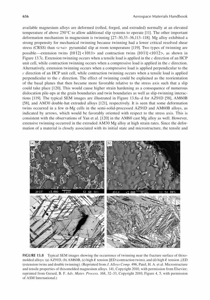
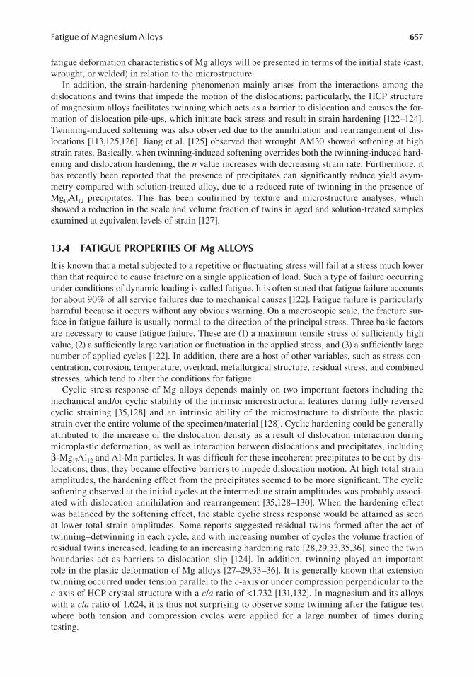
available magnesium alloys are deformed (rolled, forged, and extruded) normally at an elevated temperature of above 250°C to allow additional slip systems to operate [11]. The other important deformation mechanism in magnesium is twinning [27–30,33–36,113–118]. Mg alloy exhibited a strong propensity for mechanical twinning because twinning had a lower critical resolved shear stress (CRSS) than <c+a> pyramidal slip at room temperature [119]. Two types of twinning are possible—extension twins { }1012 1011< > and contraction twins { }1011 1012< >, as shown in Figure 13.7c. Extension twinning occurs when a tensile load is applied in the c direction of an HCP unit cell, while contraction twinning occurs when a compressive load is applied in the c direction. Alternatively, extension twinning occurs when a compressive load is applied perpendicular to the c direction of an HCP unit cell, while contraction twinning occurs when a tensile load is applied perpendicular to the c direction. The effect of twinning could be explained as the reorientation of the basal planes that then became more favorable relative to the stress axis such that a slip could take place [120]. This would cause higher strain hardening as a consequence of numerous dislocation pile-ups at the grain boundaries and twin boundaries as well as slip-twinning interac-tions [119]. The typical SEM images are illustrated in Figure 13.8a–d for AZ91D [58], AM60B [58], and AM30 double-hat extruded alloys [121], respectively. It is seen that some deformation twins occurred in a few α-Mg cells in the semi-solid-processed AZ91D and AM60B alloys, as indicated by arrows, which would be favorably oriented with respect to the stress axis. This is consistent with the observations of Yan et al. [120] in the AM60 cast Mg alloy as well. However, extensive twinning occurred in the extruded AM30 Mg alloy at high strain rates. Since the defor-mation of a material is closely associated with its initial state and microstructure, the tensile and
Figure 13.8 Typical SEM images showing the occurrence of twinning near the fracture surface of thixo-molded alloys: (a) AZ91D, (b) AM60B, (c) high �ε tension ‖ED (contraction twins), and (d) high �ε tension ⊥ED (extension twins and double twinning). (Reprinted from J. Alloys Comp. 496, Patel, H. A. et al. Microstructure and tensile properties of thixomolded magnesium alloys. 141, Copyright 2010, with permission from Elsevier; reprinted from Gerard, B. F. Adv. Mater. Process. 168, 32–33, Copyright 2010, Figure 4, 5, with permission of ASM International.)
657Fatigue of Magnesium Alloys
fatigue deformation characteristics of Mg alloys will be presented in terms of the initial state (cast, wrought, or welded) in relation to the microstructure.
In addition, the strain-hardening phenomenon mainly arises from the interactions among the dislocations and twins that impede the motion of the dislocations; particularly, the HCP structure of magnesium alloys facilitates twinning which acts as a barrier to dislocation and causes the for-mation of dislocation pile-ups, which initiate back stress and result in strain hardening [122–124]. Twinning-induced softening was also observed due to the annihilation and rearrangement of dis-locations [113,125,126]. Jiang et al. [125] observed that wrought AM30 showed softening at high strain rates. Basically, when twinning-induced softening overrides both the twinning-induced hard-ening and dislocation hardening, the n value increases with decreasing strain rate. Furthermore, it has recently been reported that the presence of precipitates can significantly reduce yield asym-metry compared with solution-treated alloy, due to a reduced rate of twinning in the presence of Mg17Al12 precipitates. This has been confirmed by texture and microstructure analyses, which showed a reduction in the scale and volume fraction of twins in aged and solution-treated samples examined at equivalent levels of strain [127].
13.4 FAtigue properties oF Mg Alloys
It is known that a metal subjected to a repetitive or fluctuating stress will fail at a stress much lower than that required to cause fracture on a single application of load. Such a type of failure occurring under conditions of dynamic loading is called fatigue. It is often stated that fatigue failure accounts for about 90% of all service failures due to mechanical causes [122]. Fatigue failure is particularly harmful because it occurs without any obvious warning. On a macroscopic scale, the fracture sur-face in fatigue failure is usually normal to the direction of the principal stress. Three basic factors are necessary to cause fatigue failure. These are (1) a maximum tensile stress of sufficiently high value, (2) a sufficiently large variation or fluctuation in the applied stress, and (3) a sufficiently large number of applied cycles [122]. In addition, there are a host of other variables, such as stress con-centration, corrosion, temperature, overload, metallurgical structure, residual stress, and combined stresses, which tend to alter the conditions for fatigue.
Cyclic stress response of Mg alloys depends mainly on two important factors including the mechanical and/or cyclic stability of the intrinsic microstructural features during fully reversed cyclic straining [35,128] and an intrinsic ability of the microstructure to distribute the plastic strain over the entire volume of the specimen/material [128]. Cyclic hardening could be generally attributed to the increase of the dislocation density as a result of dislocation interaction during microplastic deformation, as well as interaction between dislocations and precipitates, including β-Mg17Al12 and Al-Mn particles. It was difficult for these incoherent precipitates to be cut by dis-locations; thus, they became effective barriers to impede dislocation motion. At high total strain amplitudes, the hardening effect from the precipitates seemed to be more significant. The cyclic softening observed at the initial cycles at the intermediate strain amplitudes was probably associ-ated with dislocation annihilation and rearrangement [35,128–130]. When the hardening effect was balanced by the softening effect, the stable cyclic stress response would be attained as seen at lower total strain amplitudes. Some reports suggested residual twins formed after the act of twinning–detwinning in each cycle, and with increasing number of cycles the volume fraction of residual twins increased, leading to an increasing hardening rate [28,29,33,35,36], since the twin boundaries act as barriers to dislocation slip [124]. In addition, twinning played an important role in the plastic deformation of Mg alloys [27–29,33–36]. It is generally known that extension twinning occurred under tension parallel to the c-axis or under compression perpendicular to the c-axis of HCP crystal structure with a c/a ratio of <1.732 [131,132]. In magnesium and its alloys with a c/a ratio of 1.624, it is thus not surprising to observe some twinning after the fatigue test where both tension and compression cycles were applied for a large number of times during testing.

658 Aerospace Materials Handbook
13.4.1 cyclic deformation and loW cycle fatigue
In the low cycle fatigue tests, plastic strain amplitude is a physical quantity that initiates several damaging processes and influences the internal microstructure, which eventually affects the strain resistance and finally the fatigue life. The change of the plastic strain amplitude (Δ εp/2) during cyclic deformation is shown in Figure 13.9 at different applied strain amplitudes [28]. As the total strain amplitude increased, the value of plastic strain amplitude also increased and the fatigue life of the material decreased. At lower total strain amplitudes (0.1% and 0.2%), the plastic strain amplitude remained nearly constant over the entire fatigue life [27]. However, as the total strain amplitude increased, the slope of the curve on the semi-log scale became steeper, which is similar to results reported in [31,32]. At the lower strain amplitudes up to about 5–20 cycles, the plastic strain amplitude was almost horizontal [28], but after about 50 cycles the slope of the curve decreased with increasing number of cycles. The following relationship has been proposed to describe the slope change [28,33]:
∆εα βp
2= + log( )N
(13.1)
where N is the number of cycles, α is the initial plastic strain amplitude at the 50th cycle for extruded AM30 alloy, and β is the slope of the plastic strain amplitude versus the number of cycles in the semi-log plot. It has a negative value for AM30 [28] and also for the extruded AZ31 [31,32,133] and its absolute value can be considered as a strain-hardening coefficient. It should be noted that a posi-tive β value is possible in other materials, which would represent a strain softening coefficient. Both α and β are dependent on the applied strain amplitude.
Begum et al. [28] evaluated the cyclic deformation behavior of extruded AZ31 magnesium alloy. It was observed that the alloy was cyclically stable at lower strain amplitudes and exhibited cyclic hardening characteristics at higher strain amplitudes. Figure 13.10 shows the evolution of stress amplitude with respect to the number of cycles at different strain amplitudes [28]. At high strain amplitudes (0.5% and 0.6%) during the early cycles (up to 10 cycles), the alloy showed very little cyclic softening which was followed by cyclic hardening until failure. At intermediate strain ampli-tudes (0.3% and 0.4%), cyclic hardening started a little later and the cyclic hardening effect was
–0.011.E+0 1.E+2 1.E+3
Number of cycles, N1.E+4 1.E+51.E+1
0.04
0.14
Δεp/
2, %
0.19 Total strain amplitudes0.6%0.5%0.4%0.3%0.2%0.1%0.09
Figure 13.9 Plastic strain amplitude versus the number of cycles at different total strain amplitudes of extruded AZ31 magnesium alloy. (Reprinted from Int. J. Fatigue 31, Begum, S. et al. Low cycle fatigue proper-ties of an extruded AZ31 magnesium alloy. 729, Copyright 2009, with permission from Elsevier.)

659Fatigue of Magnesium Alloys
not as strong as that at higher strain amplitudes. The stress amplitudes remained almost constant at the lower strain amplitudes (0.1%, 0.2%) and at room temperature the material could undergo cyclic strain hardening at high strain amplitudes. While Noster and Scholtes [31] reported the tem-perature effect on the stress response and mentioned that the strain hardening effect was very little at room temperature. During cyclic deformation of the LCF process, the evolution of stress ampli-tude is an important characteristic. Cyclic response was dominated by the cyclic stability of the microstructural features, dislocation multiplication, and slip systems [134]. During stress evolu-tion, the strain-hardening phenomenon mainly arose from the interactions among the dislocations that impede the motion of the dislocations. As mentioned above, the HCP structure of magnesium alloys facilitated twinning, which acted as a barrier to the movement of dislocations and caused the formation of dislocation pile-ups, which initiated back stress and resulted in strain hardening [27–29,33,34,122,124,134].
Figure 13.11 shows the effect of strain amplitudes on the shape of hysteresis loops (a) at the first cycle and (b) at the half-life cycle for AM30 [33]. The first-cycle hysteresis loops at higher strain amplitudes in Figure 13.11a were more skewed than the mid-life hysteresis loops in Figure 13.11b. This unsymmetrical tensile and compressive yielding phenomenon was a Bauschinger-like effect [122] and was a consequence of the twinning–detwinning in the cyclic deformation process. The deformation asymmetry in AM30 alloy seen from hysteresis loops at different strain amplitudes also concurred with the results reported by other investigators [29,31,32]. It is seen from Figure 13.11a and b that the very first cycle showed higher Bauschinger-like effect than the mid-life cycle. The possible reason behind this could be that the formation of residual twins became saturated near the mid-life cycle. The presence of yield asymmetry is basically due to the activity of twinning in compression during unloading and subsequent detwinning in tension during loading [27–32,126,135]. In other words, twins can disappear or become narrower under reversed loading or unloading, and can reappear under reloading. Brown et al. [30,136], Gharghouri et al. [137], and Oliver et al. [138] found that twinning and detwinning appear alternately in cyclic loading using in situ neutron scattering. Lou et al. [135] revealed twinning during in-plane compression and detwinning upon the subsequent tension of an AZ31B Mg alloy sheet using metallography, acoustic emission, and x-ray texture measurements. Some other reports [30,135,137,139–146] show similar twinning–detwinning behavior which produces the above abnormal hysteresis loops during cyclic deformation. Another study [147] also observed
0
50
100
150
200
250Total strain amplitudes
0.6%0.5%0.4%0.3%0.2%0.1%
Stre
ss am
plitu
de, M
Pa
1.E+0 1.E+1 1.E+2Number of cycles, N
1.E+3 1.E+4 1.E+5
Figure 13.10 Stress amplitude versus the number of cycles at different total strain amplitudes of extruded AZ31 magnesium alloy. (Reprinted from Int. J. Fatigue 31, Begum, S. et al. Low cycle fatigue properties of an extruded AZ31 magnesium alloy. 729, Copyright 2009, with permission from Elsevier.)

660 Aerospace Materials Handbook
the hysteresis curves of extruded AM30 alloy at different total strain amplitudes, as shown in Figure 13.12. At εtotal/2 = 0.1%, the hardening characteristic of AM30 alloy appears under tensile loading, yet softening characteristic under compressive loading, but at other total strain amplitudes, the cyclic hardening characteristics are shown in Figure 13.12b–f. In addition, the maximum compressive stress almost reached to about 100 MPa and the maximum tensile stress became greater almost to 250 MPa, except for strain amplitude 0.1%, which indicates that the hardenability in the compressive direction almost reached to maximum; however, that in the tensile direction was not saturated but improved. Moreover, when εtotal/2 ≥ 0.5%, there is a stress asymmetry between the tensile and compressive deformation. The cyclic deformation behav-ior is different from monotonic deformation behavior, again mainly due to deformation twins formed during the compressive cycles [147].
Depending on the initial state and test condition, a metal may undergo cyclic hardening, cyclic softening, or remain cyclically stable. In the strain-controlled fatigue tests, cyclic hardening or softening was characterized and it was observed increasing or decreasing peak stress with increas-ing number of cycles [148]. Low cycle fatigue conditions are frequently created where the repeated stresses are of thermal origin or at a notch root. Thermal stresses arise from the thermal expansion of the material; it is easy to see that in this case fatigue results from cyclic strain rather than from cyclic stress. The low cycle fatigue occurs at high stress level and low number of cycles. Usually,
–0.8
–100
–50
100
150
200
180
120
60
0
–60
–120
–180–0.8 –0.6 –0.4 –0.2 0
Strain, %0.2 0.4 0.80.6
240
0.4%0.3%
First cycle
Half-life cycle
0.2% 0.1%
0.1%0.3%
0.4%0.5%0.6%
0.2%
0.5%0.6%
50
Stre
ss, M
Pa
(a)
(b)
Stre
ss, M
Pa0
–150–0.6 –0.4 –0.2
Strain, %0 0.2 0.4 0.6 0.8
Figure 13.11 (a) Hysteresis loops at the first cycle for different total strain amplitudes of extruded AM30 magnesium alloy. (b) Hysteresis loops at the mid-life cycle for different total strain amplitudes of extruded AM30 magnesium alloy. (With kind permission from Springer Science + Business Media: Metall. Mat. Trans. A. Strain-controlled low-cycle fatigue properties of a newly developed extruded magnesium alloy. 39A, 2008, 3019. Begum, S. et al., Figure 2.)

661Fatigue of Magnesium Alloys
nuclear pressure vessels, steam turbines, and most other types of pressure vessels must be consid-ered for low cycle fatigue [122].
In addition, in wrought AZ31 Mg alloys, asymmetric hysteresis loop and nonelastic unloading behavior have been reported due to the repeated activation of twinning and detwinning during cyclic straining. These natures induced the development of nonzero mean stress affecting the fatigue characteristics and the ambiguity in determining the plastic strain amplitude from a stress–strain hysteresis loop. This makes it difficult to express fatigue life with the Coffin–Manson-type model defined by plastic strain range at zero stress which is generally used to predict low cycle fatigue
–0.10 –0.3
–100–80–60–40–20
406080
200
–0.2 –0.1 0.0 0.1 0.2–60–40
–100
–150
–100
–50
0
100
150
200
250
50
–150–100
–500
100150200250300
50
–50
–200
0
2040
Stre
ss, M
PaSt
ress
, MPa
Stre
ss, M
Pa
Stre
ss, M
PaSt
ress
, MPa
60
100 1–1020–100200–10002000–10,000
1–1020–100200–1000
1–1020–100200–1000
1–1020–100200–1000
2000–8000
1–1020–100200–10002000–2833
1–1020–100200–10002000–10,000
(a) (b)
(c) (d)
(f )(e)
80
50
100
150
–150
–50
–100
0
Stre
ss, M
Pa 50
100
150
–0.05 0.00Strain, % Strain, %
–0.3 –0.2 –0.1 0.0 0.1 0.2 0.3Strain, %
–0.6 –0.4 –0.2 0.0 0.2 0.4 0.6Strain, %
–0.6 –0.4 –0.2 0.0 0.2 0.4 0.6Strain, %
–0.6 –0.4 –0.2 0.0 0.2 0.4Strain, %
0.05 0.10
Figure 13.12 Hysteresis curves of extruded AM30 alloy. (a) εtotal/2 = 0.1%; (b) εtotal/2 = 0.2%; (c) εtotal/2 = 0.3%; (d) εtotal/2 = 0.4%; (e) εtotal/2 = 0.5%; (f) εtotal/2 = 0.6%. (Reprinted from Mater. Design 31, Luo, T. J. et al. Fatigue deformation characteristic of as-extruded AM30 magnesium alloy. 1619, Figure 5, Copyright (2010), with permission from Elsevier.)

662 Aerospace Materials Handbook
life [8]. Cyclic plastic strain energy models based on the analysis of the hysteresis loop have been developed by several researchers [9–12] and successfully extended to the uniaxial and multiaxial low cycle fatigue characteristics of various materials [13–15]. Criteria based on total strain energy composed of elastic and plastic energy were found to be in good agreement with experimental results under complex loading state with mean stress [15]. However, it is still not sure whether the proposed criteria can be used to predict low cycle fatigue life of Mg alloys whose hysteresis loops are severely distorted due to the different deformation mechanisms during tension and compression.
13.4.1.1 cast Mg AlloysCast materials show generally a larger scatter in fatigue and monotonic properties. Consequently, castings have typically been designed by a worst-case-scenario paradigm, whereby the component is assumed to have the weakest material at the location of the highest stresses. The variability in the properties of as-cast materials is a direct consequence of the extremely strong dependence of the resulting microstructure on local solidification mechanisms. For example, the dimensions of the casting dictate the local cooling rate, which in turn produces geometry-dependent dendrite cells with varying porosity levels. A more robust design methodology for cast components would entail predicting the distribution of critical microstructural parameters as a function of the geometry of the casting, followed by the life estimation based on the predicted microstructural features. To facilitate the interactive microstructure-based design of cast components for durability, the mecha-nisms of fatigue and the sources of variability must be linked to critical microstructural features in the as-cast material [149].
Low cycle fatigue characteristics of AZ91 Mg alloy was reported by Eisenmeier et al. [37] who performed strain-controlled fatigue tests at room temperature and at 130°C to evaluate the tempera-ture effects. The test results were presented in terms of strain amplitudes versus number of rever-sals to failure as shown in Figure 13.13. It is seen that the Coffin–Manson and Basquin equations basically hold true. Chen et al. [38] performed fully reversed total strain-controlled fatigue tests
10–1
1
10–2
10–3
10–4
10–5
10–1
Basquin:
Basquin:
T = 20°C
T = 130°C
Manson–Coffin:
Manson–Coffin:
Δεel/2 = 0.014 (2Nf)–0.143
Δεel/2 = 0.013 (2Nf)–0.156
Δεpl/2 = 0.043 (2Nf)–0.465
Δεpl/2 = 0.061 (2Nf)–0.444
Δεpl/2
Δε/2
Δε/2
Δεel/2Δεt/2
10–2
10–3
10–4
10–5
10–6101 102 103 104 105 106 1071
2Nf
Figure 13.13 Total, elastic, and plastic strain amplitudes Δεt/2, Δεel/2, and Δεpl/2 versus number of reversals to failure 2Nf, R(εt) = −1, at room temperature and at 130°C of die casting AZ91 magnesium alloy. (Reprinted from Mater. Sci. Eng. A. 319–321, Eisenmeier, G. et al. Cyclic deformation and fatigue behaviour of the mag-nesium alloy AZ91. 579, Figure 2, Copyright 2001, with permission from Elsevier.)

663Fatigue of Magnesium Alloys
on conventional and die cast AZ91 alloys, while Li et al. [150] performed similar tests on die cast and solution-treated (T4) AZ91 as well as AE42 alloys. Patel et al. [139] conducted the LCF tests of the thixomolded AZ91D alloy along with the influence of strain ratio. Figure 13.14a and b show stress amplitude and plastic strain amplitude as a function of the number of cycles at different total strain amplitudes, respectively [139]. Both stress amplitude and plastic strain amplitude increased and fatigue life decreased as the total strain amplitude increased. At higher strain amplitudes (1.0% and 1.2%), the alloy showed cyclic hardening characteristics, which also corresponded to decreas-ing plastic strain amplitude until failure. At intermediate strain amplitudes (0.3–0.8%), the alloy showed initial cyclic softening, followed by cyclic hardening for the remaining life. At lower strain amplitudes (0.1% and 0.2%), the stress amplitude and plastic strain amplitude remained almost constant. Similar cyclic hardening effect was observed by Chen et al. [38] for a conventional die cast AZ91 alloy at total strain amplitudes ranging from 0.3% to 1.0%, while for cast AM50 alloy, cyclic hardening occurred at total strain amplitudes ranging from 0.8% to 1.5% and cyclic softening followed by hardening occurred at lower total strain amplitudes ranging from 0.4% to 0.65% [128]. Liu et al. [40] observed cyclic strain hardening in an HPDC (high-pressure die cast) AZ91 alloy with and without solution (T4) treatment at strain levels between 0.25% and 1.5%, while for a cast AM50 alloy [45] cyclic hardening occurred at higher strain levels and cyclic softening occurred at lower strain levels as well. Also, Xu et al. [126] observed cyclic hardening effect in the fine-grained HPDC AM50, AE44, AJ62A alloys and cyclic softening effect in the coarse-grained LPDC (low-pressure die cast) AM50 alloy.
250
0.6
0.5
0.4
0.3
0.2
0.1
0
0.1%0.2%0.3%
0.8%1.0%1.2%
0.6%0.4%
0.1%0.2%0.3%
0.8%1.0%1.2%
0.6%0.4%
(a)
(b)
200
Stre
ss am
plitu
de, M
paPl
astic
str
ain
ampl
itude
, %
250
100
50
01.E+0 1.E+1 1.E+31.E+2
Number of cycles, N
Number of cycles, N
1.E+4 1.E+5
1.E+0 1.E+1 1.E+31.E+2 1.E+4 1.E+5
Figure 13.14 Variation of (a) stress amplitude and (b) plastic strain amplitude with the number of cycles at different total strain amplitudes of AZ91D magnesium alloy. (Reprinted from Mater. Sci. Eng. A. 528, Patel, H. A. et al. Cyclic deformation and twinning in a semi-solid processed AZ91D magnesium alloy. 208–219, Copyright 2010, with permission from Elsevier.)

664 Aerospace Materials Handbook
Twinning played a significant role in the deformation of Mg alloys and it would help Mg to satisfy the von-Mises criterion at room temperature, where five independent deformation systems for an arbitrary homogeneous straining are required. Besides the slip of dislocations with <c + a> Burgers vectors, which was recognizably a very hard deformation mechanism, twinning was the only active deformation mode that could provide straining along the c-axis at room temperature [35,151]. To demonstrate the evidence that twinning occurred, typical micrographs are shown in Figure 13.15a–c for the thixomolded AZ91D alloy [35,139]. It is seen that twins formed in the vicinity of the fracture surface (Figure 13.15a). Twinning basically occurred in some favorably oriented large primary α-Mg grains with respect to the loading axis, which could be explained by the decreasing stacking fault energy [41] and lower CRSS [34,152]. Some wider lenticular twins in Figure 13.15b and some needle-like narrow twins indicated by small arrows in Figure 13.15c were observed. The wider twins (clean inside) were extension twins [152,153], while the narrow twins (thin, dark inside) were contraction twins [152,153]. In addition, the occurrence of twinning in relation to applied loading can be schematically illustrated in Figure 13.15d [35]. The extension twins could be generated either in tension along the c-axis of the HCP unit cell, or in compression with a loading direction perpendicular to the c-axis. The formation of contraction twins would also occur when the loading direction with respect to the c-axis of HCP unit cell was reversed [35,139,152,153].
(a) (b)
(d)
Wide extensiontwins
{0002}
Extension twinning
Contraction twinning
20 kV
20 kV
×3000
×3000
5 μm
5 μm
12 SEI50
12 SEI50
50 μm
(c)
Figure 13.15 (a) Low-magnification OM image showing twins near the fracture surface, (b) SEM image of the boxed region in (a) at a higher magnification showing wide lenticular extension twins, (c) another SEM image at a higher magnification showing narrow contraction twins marked by arrows, and (d) the applied loading directions with respect to the c-axis favorable for the formation of two types of twins where the filled arrows show the loading direction favorable for extension twinning and the empty arrows show the loading direction favorable for contraction twinning. (Reprinted from Mater. Sci. Eng. A. 528, Patel, H. A. et al. Cyclic deformation and twinning in a semi-solid processed AZ91D magnesium alloy. 208–219, Copyright 2010, with permission from Elsevier.)

665Fatigue of Magnesium Alloys
13.4.1.2 extruded Mg AlloysIn a recent study, Lv et al. [154] observed the low cycle fatigue properties along two directions of a rolled AZ31 alloy. Figure 13.16 shows the evolution of stress amplitude with respect to the number of cycles at different total strain amplitudes on a semi-log scale. At high strain amplitudes, such as 0.6%, 0.7%, and 0.8%, the corresponding stress amplitudes are high and cyclic hardening behavior can be observed in both TD and RD samples. At lower strain amplitudes, such as 0.2%, 0.3%, and 0.4%, the corresponding stress amplitudes are low and nearly remain constant during the whole cyclic defor-mation. Meanwhile, it is found that the stress amplitudes of TD samples are higher than those of RD samples at the total strain amplitude higher than 0.3%; however, the stress amplitudes of TD and RD samples are almost identical at the strain amplitude of 0.2%. The relatively higher stress amplitudes of TD samples could be attributed to the higher yield strength of TD samples than that of RD samples. As the stress amplitudes of TD samples are always higher than those of RD samples, the case in their plastic strain amplitudes is just the opposite. As shown in Figure 13.17, in the high strain amplitude range from 0.5% to 0.8%, the plastic strain amplitudes of RD samples are higher than those of TD samples. At lower strain amplitudes of 0.2%, 0.3%, and 0.4%, the plastic strain amplitudes of RD and TD samples are quite stable, indicating that neither cyclic softening nor cyclic hardening occurs.
50100 101
Number of cycles, N102 103 104 105
100 101
Number of cycles, N102 103 104 105
100
150
200
250
300(a)0.8%0.7%0.6%0.5%0.4%0.3%0.2%
0.8%0.7%0.6%0.5%0.4%0.3%0.2%
Stre
ss am
plitu
de (M
Pa)
50
100
150
200
250
300(b)
Stre
ss am
plitu
de (M
Pa)
Figure 13.16 Stress amplitude versus the number of cycles at different total strain amplitudes of (a) TD and (b) RD samples of rolled AZ31 magnesium alloy. (Reprinted from Int. J. Fatigue 33, Lv, F. et al. Fatigue properties of rolled magnesium alloy (AZ31) sheet: Influence of specimen orientation. 675, Figure 6, Copyright 2011, with permission from Elsevier.)

666 Aerospace Materials Handbook
Another study shows stress amplitude and plastic strain amplitude as a function of the number of cycles at different total strain amplitudes, respectively [33]. Three strain rates were applied to examine the effect of strain rate on the fatigue life of AM30. It is observed that fatigue life increased with increasing strain rate as shown in Figure 13.18. Stress amplitude evolved at high, moderate, and low strain rates was almost the same (about 105–109 MPa) within the experimen-tal error, so the strain rate had basically a marginal effect on the cyclic deformation behavior of AM30. It is to be noted that cyclic hardening occurred at all three strain rates. Similarly, there was no big difference in the plastic strain amplitude versus the number of cycles as shown in Figure 13.19 [33].
Twinning-induced softening was also observed due to the annihilation and rearrangement of dis-locations [30]. Plastic deformation of magnesium alloy was largely affected by twinning [9,27,29–39,140]. Two types of twinning frequently occur in wrought magnesium alloys, extension twins on the { }1012 planes along the < >1011 directions, and contraction twins on the { }1011 planes along the < >1012 directions [155,113], as also shown in Figure 13.7c. Investigation by Brown et al. [156] showed that twinning was associated with a low stress regime, and typically evolved within a stress
0.5(a)
(b)
0.8%0.7%0.6%0.5%0.4%0.3%0.2%
0.8%0.7%0.6%0.5%0.4%0.3%0.2%
0.4
0.3
0.2
0.1
Plas
tic st
rain
ampl
itude
, %Pl
astic
stra
in am
plitu
de, %
0.0
–0.1
0.5
0.4
0.3
0.2
0.1
0.0
–0.1
100 101
Number of cycles, N102 103 104 105
100 101
Number of cycles, N102 103 104 105
Figure 13.17 Plastic strain amplitude versus the number of cycles at different total strain amplitudes (a) TD and (b) RD samples of rolled AZ31 magnesium alloy. (Reprinted from Int. J. Fatigue 33, Lv, F. et al. Fatigue properties of rolled magnesium alloy (AZ31) sheet: Influence of specimen orientation. 676, Figure 6, Copyright 2011, with permission from Elsevier.)

667Fatigue of Magnesium Alloys
level of 70–200 MPa (0.1–0.8% strain) for AZ31 alloy. In this stress range, twinning occurred to accommodate the deformation due to tensile or compressive stress. The strain hardening of AM30 alloy could be related to the formation of residual twins during cyclic loading, as the texture of AM30 and the texture observed by Wu et al. [35] in ZK60A alloy were similar. Wu et al. [35] also observed that in ZK60A residual twins formed after the act of twinning and detwinning of each cycle, and with increasing number of cycles, the volume fraction of residual twins increased, leading to an increased hardening rate.
200Applied strain rate
acb
a = 8 × 10⁻²s–1
b = 1 × 10⁻²s–1
c = 1 × 10⁻³s–1170
140
110
80
50100 101 102
Number of cycles, N
Stre
ss am
plitu
de, M
Pa
103 104 105
Figure 13.18 Stress amplitude versus number of cycles at a strain amplitude of 0.4 pct and strain ratio of −1 at different strain rates of AZ31 magnesium alloy. (With kind permission from Springer Science + Business Media: Metall. Mat. Trans. A. Strain-controlled low-cycle fatigue properties of a newly developed extruded magnesium alloy. 39A, 2008, 3022. Begum, S. et al. Figure 2.)
0.2Applied strain rate
0.16
0.12
Plas
tic st
rain
ampl
itude
, %
0.08
0.04
0100 101
Number of cycles, N102 103 104 105
a = 8 × 10⁻²s–1
b = 1 × 10⁻²s–1
c = 1 × 10⁻³s–1
ab
c
Figure 13.19 Plastic strain amplitude versus number of cycles at a strain amplitude of 0.4 pct and strain ratio of −1 at different strain rates of AZ31 magnesium alloy. (With kind permission from Springer Science + Business Media: Metall. Mat. Trans. A. Strain-controlled low-cycle fatigue properties of a newly developed extruded magnesium alloy. 39A, 2008, 3022. Begum, S. et al. Figure 2.)
668 Aerospace Materials Handbook
13.4.2 fatigue crack initiation and propagation
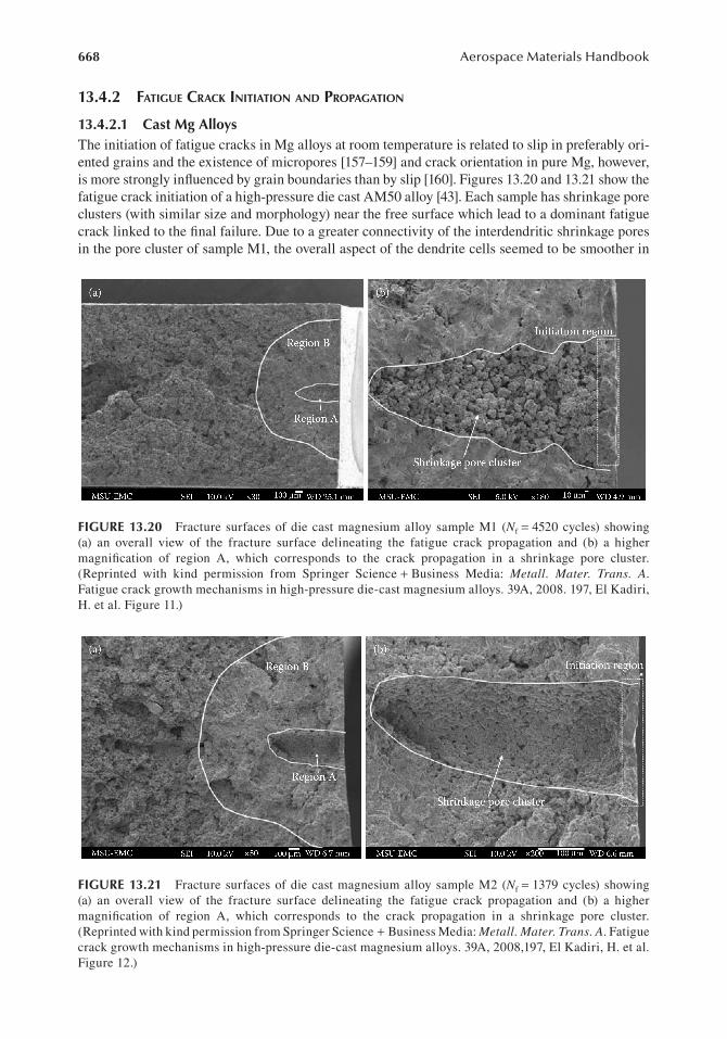
13.4.2.1 cast Mg AlloysThe initiation of fatigue cracks in Mg alloys at room temperature is related to slip in preferably ori-ented grains and the existence of micropores [157–159] and crack orientation in pure Mg, however, is more strongly influenced by grain boundaries than by slip [160]. Figures 13.20 and 13.21 show the fatigue crack initiation of a high-pressure die cast AM50 alloy [43]. Each sample has shrinkage pore clusters (with similar size and morphology) near the free surface which lead to a dominant fatigue crack linked to the final failure. Due to a greater connectivity of the interdendritic shrinkage pores in the pore cluster of sample M1, the overall aspect of the dendrite cells seemed to be smoother in
Figure 13.20 Fracture surfaces of die cast magnesium alloy sample M1 (Nf = 4520 cycles) showing (a) an overall view of the fracture surface delineating the fatigue crack propagation and (b) a higher magnification of region A, which corresponds to the crack propagation in a shrinkage pore cluster. (Reprinted with kind permission from Springer Science + Business Media: Metall. Mater. Trans. A. Fatigue crack growth mechanisms in high-pressure die-cast magnesium alloys. 39A, 2008. 197, El Kadiri, H. et al. Figure 11.)
Figure 13.21 Fracture surfaces of die cast magnesium alloy sample M2 (Nf = 1379 cycles) showing (a) an overall view of the fracture surface delineating the fatigue crack propagation and (b) a higher magnification of region A, which corresponds to the crack propagation in a shrinkage pore cluster. (Reprinted with kind permission from Springer Science + Business Media: Metall. Mater. Trans. A. Fatigue crack growth mechanisms in high-pressure die-cast magnesium alloys. 39A, 2008,197, El Kadiri, H. et al. Figure 12.)

669Fatigue of Magnesium Alloys
sample M1 than in sample M2. This accounts for the difference of fatigue life between samples M2 and M1.
The fracture surface of specimen Z1 (Nf = 5685 cycles) of AZ91 cast alloy shows that the main fatigue crack nucleated at an agglomeration of large casting pores (Figure 13.22) [43]. These large casting pores were partly contained within the original skin layer of the cast plate and extended into the main bulk microstructure. As seen in Figure 13.23, the AZ91 plates typically exhibited a higher content of large casting pores as compared to the other alloys. Recently, x-ray computed tomography (XRCT) demonstrated that AM50 and AM60 exhibited a lower volume of large cast-ing and shrinkage pores than did AZ91 and AE44 cast under the same conditions [161]. This would explain the low fatigue durability of the AZ91 alloy as compared to the AM50 and AM60
Figure 13.22 Fracture surfaces of die cast magnesium alloy sample Z1 (Nf = 5685 cycles) cut from an AZ91 alloy plate showing (a) an overall view of the fracture surface and (b) a higher magnification of the region, including the casting pore that nucleated the main fatigue crack. Note that the casting pore extends along the sample-free surface. (Reprinted with kind permission from Springer Science + Business Media: Metall. Mater. Trans. A. Fatigue crack growth mechanisms in high-pressure die-cast magnesium alloys. 39A, 2008. 197, El Kadiri, H. et al. Figure 14.)
Figure 13.23 SEM micrographs of a polished AZ91 sample cut from the grip section of a fractured fatigue specimen showing (a) the Al-rich eutectic layer taking a completely divorced form, with a large and continu-ous presence of the beta phase and (b) large casting pores reaching several millimeters in size. (Reprinted with kind permission from Springer Science + Business Media: Metall. Mater. Trans. A. Fatigue crack growth mechanisms in high-pressure die-cast magnesium alloys. 39A, 2008. 193, El Kadiri, H. et al. Figure 5.)

670 Aerospace Materials Handbook
cast alloys. The large number of casting pores in specimen Z1 induced a rough crack propagation path through the coalescence of fatigue cracks that nucleated at neighboring casting and shrinkage pores (Figure 13.23). This pore, however, was significantly more elongated in the crack propaga-tion direction.
Another observation about the fracture surfaces of fatigued specimens is shown in Figure 13.24a–d for a semi-solid-processed AZ91D magnesium alloy tested at a total strain amplitude of 0.3% [139]. At a low magnification, the fracture surface was in general flat without slant fracture in the final rapid fracture area (Figure 13.24a). Multiple crack initiation from the surface or near surface defects/pores was observed (Figure 13.24b) [139], which was possible since the locations of the pores were unknown in the semi-solid-processed or cast alloys. This pore size was relatively small compared to that reported in the die cast alloy [39,43,162]. The initiated cracks started propa-gating from different locations, but the final separation occurred when the multiple cracks merged along the weakest path (with more pores). These casting and shrinkage pores provided a driv-ing force for fatigue crack nucleation and propagation due to the presence of stress concentration. Thus, relatively large pores in the alloy served as crack formation sites, while distributed porosity caused a preferential path for fatigue crack propagation. Once the cracks propagated to such a depth that the remaining material was no longer sufficient to withstand the applied cyclic load, the
(a)
(c) (d)
(b)b
c
d
Pores
20 kV20 kV ×500×30 12 50 SEI25 50 SEI 50 μm
20 kV 20 kV×1000 ×300012 50 SEI 12
Crac
k pr
opag
atio
n di
rect
ion
50 SEI10 μm 5 μm
500 μm
Figure 13.24 Typical SEM images showing the fatigue fracture surface obtained at a total strain ampli-tude of 0.3%: (a) overall view at a low magnification, (b) magnified view near the initiation site as marked in (a), (c) magnified view in the crack propagation area as marked in (a), and (d) further magnified view in the crack propagation area as marked in (a) (thixomolded magnesium alloys). (Reprinted from Mater. Sci. Eng. A. 528, Patel, H. A. et al. Cyclic deformation and twinning in a semi-solid processed AZ91D magnesium alloy. 208–219, Copyright 2010, with permission from Elsevier.)

671Fatigue of Magnesium Alloys
remaining portion/ligament failed like tensile fracture of the alloy. The semi-solid thixomolded AZ91D alloy had a relatively low porosity (1.25–1.3%), leading to a longer fatigue life especially at low strain amplitudes. Significant experimental evidence also showed that fatigue life correlated inversely with the size of such pores or inclusions in both as-cast and wrought materials [39,162]. Figure 13.24c and d shows the higher magnification SEM images taken in the propagation area in Figure 13.24a. Crack propagation was basically characterized by fatigue striation-like features that were randomly oriented (due to random grain distribution) with each other in conjunction with tear ridges near the initiation site (Figure 13.24c). The fatigue striations were perpendicular to the crack propagation direction observed far from crack initiation site (Figure 13.24d). Since each fatigue striation could represent a single loading cycle [122], the spacing of fatigue striations could reflect the fatigue crack propagation rate, and the related fatigue life. Fatigue striations normally occurred by a repeated plastic blunting–sharpening process via the slip of dislocations in fcc materials at the fatigue crack tip [122,163]. It was expected that the generation of twins in the plastic zone ahead of the crack tip would participate in the formation of fatigue striations in Mg alloy, which has also been pointed out in [27–29,34]. It has been reported that the narrow-banded contraction twins would be more detrimental since voids were observed to form largely at this type of narrow contraction twins that were arrested by grain boundaries [153], which led to a reduction in cross-sectional area, stress concentrations, and premature transgranular failure in the extruded AM30 Mg alloy [153]. More studies in this aspect are needed to further identify the relationship between the formation of fatigue striations and twinning in Mg alloys.
Some more typical micrographs from the side views near the area of fatigue fracture of some samples are shown in Figure 13.25a–c [139] to better see the crack initiation characteristics. It seemed from Figure 13.25a that the crack initiated at a free surface through α-phase, but the Al–Mn particle was not cut through during the crack propagation. Instead, the crack changed its direction and moved further into the sample and this deflection suggested that Al–Mn particles could act as barriers to fatigue crack propagation. Figure 13.25b shows that after reaching a certain depth the crack ran either along the α–β interface or through the primary α-Mg grains. Figure 13.25c shows the side view in the rapid fracture area of a fatigued sample, where the eutectic structure basically dislodged from α-grains. It has been reported that relatively small cracks were unable to prema-turely fracture or debond the β-phase in front of the crack tip owing to relatively small stress inten-sity factor and tend to propagate primarily through the α-Mg grains [44]. On the other hand, when the crack tip stress intensity factor was high enough to fracture/debond the α-phase, the failed phase provided a weak material path for the propagating crack tip [45]. It is seen from Figure 13.25b and c that the fracture occurred predominantly through the eutectic structure or grain boundary [139]. Even the secondary crack near the fracture surface after a certain depth also followed a similar path as illustrated in Figure 13.25b. The β-Mg17Al12 intermetallic phase in the eutectic structure was known for its higher strength but lower ductility and toughness by lowering the cohesive strength in the grain boundary regions, resulting in a brittle interface between α- and β-phases. This brittle interface arose from the incompatibility between the bcc crystal structure of β-phase and the HCP crystal structure of α-phase [164,165], and increased stress concentrations at the grain boundaries [43].
Xu et al. [166] investigated the high cycle fatigue properties of the die cast magnesium alloy AZ91D containing 1% mischmetal (mass fraction) at a stress ratio of 0.1. The fracture surfaces of AZ91D-1%MM-fatigued specimens failed after 1.2 × 10⁵ cycles at a stress amplitude of 80 MPa are shown in Figure 13.26 [166]. Although the three stages of fatigue damage in the specimen with major defects were hardly distinguished because the crack developed from pores and grew quickly, the fractographic examination to specimen with minor defects indicated those stages of fatigue damage in the high cycle fatigue regime: crack incubation, microstructurally small crack growth, and long crack growth. The macroscopic appearance of the fracture surface in Figure 13.26a is straight and has no obvious plastic deformation. The micrographs at a high magnification shown in Figure 13.26b–d are taken within three areas in Figure 13.26a. The fatigue crack initiated at casting

672 Aerospace Materials Handbook
defects as shown in Figure 13.26b. There are the mixed-rupture characteristics of cleavage step, river shape, and minute tough dimple. In the HCP metals, such as magnesium, primary cleavage occurs on the (0001) basal plane. The micrograph of microstructurally small crack growth shown in Figure 13.26c is composed of a tearing ridge. The micrograph of long crack growth is shown in Figure 13.26d. It is straight and forms a semicircle dimple because of the shear stress. As a whole, the die cast magnesium alloy AZ91D-1%MM shows a mixed ductile and brittle fracture feature [166].
13.4.2.2 extruded Mg AlloysFigure 13.27 shows a few typical low-magnification SEM images on the fatigue crack initiation site and propagation zone of the specimens tested at different strain amplitudes of an extruded AZ31B Mg alloy [29]. Unlike the cast Mg alloys with shrinkage pores (Figures 13.20 through 13.23), in the extruded Mg alloys, fatigue crack initiation in all the tested specimens, regardless of the applied strain amplitudes, was observed to occur from the specimen surface, even though some fine Mn-containing inclusions were present in the extruded alloy. This indicates a higher fatigue resistance of the extruded Mg alloys than that of the cast Mg alloys. As seen from Figure 13.27, the
(a)
(c)(b)
20 kV ×500 22 5350μm
Secondary crack
Secondary crack
Al-Mn particle
Fracture surface
Fracture surface50 μm 50 μmσσ
σ
Figure 13.25 Typical micrographs showing the side view near the fatigue fracture surface: (a) SEM image showing a secondary crack and an Al–Mn particle acting as a barrier to the crack propagation, (b) OM image showing a secondary crack propagating mainly along α–β interfaces, and (c) OM image in the rapid fracture area where the eutectic structure was dislodged from the α grains (thixomolded magnesium alloys). (Reprinted from Mater. Sci. Eng. A. 528, Patel, H. A. et al. Cyclic deformation and twinning in a semi-solid processed AZ91D magnesium alloy. 208–219, Copyright 2010, with permission from Elsevier.)

673Fatigue of Magnesium Alloys
area of the fatigue crack propagation increased with decreasing total strain amplitudes, as indicated by the dashed line on the images. Figure 13.28 shows typical SEM micrographs taken in the fatigue crack propagation area at approximately the same distance from the crack initiation site at a higher magnification [29]. It is seen that the fatigue crack propagation of the extruded AZ31B magnesium alloy was characterized by typical fatigue striations, coupled with some secondary cracks along the striations at higher total strain amplitudes. As the total strain amplitude increased, the spacing of the striations increased. Each fatigue striation normally reflected a single stress cycle [122], thus the spacing of fatigue striations represented the fatigue crack propagation rate. As a result, the larger spacing of fatigue striations observed at the higher strain amplitudes corresponded to faster crack propagation, and thus a shorter fatigue lifetime [29].
Another observation about the fracture surfaces of rolled AZ31-fatigued specimens is shown in Figure 13.29a–d, where the second phase (β-Mg17Al12) on the surface suffered cyclic stress, form-ing some small surface cracks at a total strain amplitude of 0.3% [154]. Most fatigue cracks initi-ated from the surface of the samples, some cracks initiated from the second phase as shown in
Figure 13.26 SEM images of fatigue fracture surface of specimen: (a) overall fracture surface; (b) at crack incubation region; (c) at small crack growth region; (d) at long crack growth region (AZ91D magnesium alloys). (Reprinted from Trans. Nonferrous Met. Soc. China 18, Xu, Y. L. et al. High cycle fatigue proper-ties of die-cast magnesium alloy AZ91D-1%MM. s307, Figure 7, Copyright 2008, with permission from Elsevier.)

674 Aerospace Materials Handbook
Figure 13.29a and b, and some cracks initiated from slip bands were also observed as shown in Figure 13.29c and d. The typical SEM images of strain-controlled fatigue fracture morphologies are shown in Figure 13.30a–d [154]; the fracture surfaces can be clearly divided into three regions, that is, crack initiation area (region A), crack propagation area (region B), and final rapid fracture area (region C). The RD and TD samples, failing at a total strain amplitude of 0.5%, have smooth fracture surfaces and there are no shrinkage pore clusters in region A as reported by Kadiri et al. [43]. At a higher magnification of region A as shown in Figure 13.30b and d, it can be seen that the fatigue cracks mainly initiated from the surface, the same as the result in Refs. [27–29,43,46]. There are striation-like features in region B, but no secondary cracks can be seen on the fracture surface. The formation of fatigue striation in HCP magnesium alloy can be attributed to twining in the compressive phase and detwinning in the tensile phase [27–29,43]. Under this condition, as grain is finer after rolling of AZ31, however, there is no great difference in the initiation and propagation regions. In region B, there is a radial feature along the crack propagation direction, as indicated by the black arrow, indicating the crack propagation paths. In region C, the rapid final fracture region is obvious.
13.4.3 fatigue life
13.4.3.1 cast Mg AlloysFor the evaluation of fatigue lifetime for the semi-solid thixomolded AZ91D alloy, the total strain amplitude versus the number of cycles to failure is shown in Figure 13.31 [139]. Run-outs are
Figure 13.27 Typical low-magnification SEM images showing extruded magnesium alloys the over-all view of the fracture surfaces at the total strain amplitudes of (a) 0.6%, (b) 0.4%, (c) 0.3%, and (d) 0.2%. (Reprinted from Mater. Sci. Eng. A. 496, Lin, X. Z., and D. L. Chen. Strain controlled cyclic deformation behavior of an extruded magnesium alloy. 111, Copyright 2008, with permission from Elsevier.)

675Fatigue of Magnesium Alloys
Figure 13.28 Typical SEM micrographs of extruded magnesium alloys showing the fatigue crack propa-gation area at the total strain amplitudes of (a) 0.6%, (b) 0.4%, (c) 0.3%, and (d) 0.2%. (Reprinted from Mater. Sci. Eng. A. 496, Lin, X. Z., and D. L. Chen. Strain controlled cyclic deformation behavior of an extruded magnesium alloy. 112, Copyright 2008, with permission from Elsevier.)
Figure 13.29 SEM micrograph of RD and TD samples of rolled AZ31 magnesium alloys (a and b) at total strain amplitude of 0.3% RD (c and d) at total strain amplitude of 0.5%. (Reprinted from Int. J. Fatigue 33, Lv, F. et al. Fatigue properties of rolled magnesium alloy (AZ31) sheet: Influence of specimen orientation. 680, Figure 6, Copyright 2011, with permission from Elsevier.)
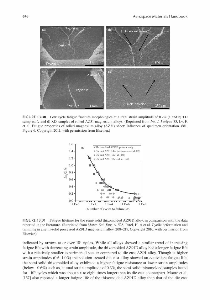
676 Aerospace Materials Handbook
indicated by arrows at or over 107 cycles. While all alloys showed a similar trend of increasing fatigue life with decreasing strain amplitude, the thixomolded AZ91D alloy had a longer fatigue life with a relatively smaller experimental scatter compared to die cast AZ91 alloy. Though at higher strain amplitudes (0.6–1.0%) the solution-treated die cast alloy showed an equivalent fatigue life, the semi-solid thixomolded alloy exhibited a higher fatigue resistance at lower strain amplitudes (below ~0.6%) such as, at total strain amplitude of 0.3%, the semi-solid thixomolded samples lasted for ~105 cycles which was about six to eight times longer than its die cast counterpart. Moore et al. [167] also reported a longer fatigue life of the thixomolded AZ91D alloy than that of the die cast
Die cast AZ91E-T4, horstemeyer et al. [39]Die cast AZ91, Li et al. [150]Die cast AZ91-T4, Li et al. [150]
Thixomolded AZ91D, present study1.6
Δεt/2
, %
1.4
1.0
0.8
0.6
0.4
0.2
0.01.E+0 1.E+2 1.E+4
Number of cycles to failure, Nf
1.E+6 1.E+8
1.2
Figure 13.31 Fatigue lifetime for the semi-solid thixomolded AZ91D alloy, in comparison with the data reported in the literature. (Reprinted from Mater. Sci. Eng. A. 528, Patel, H. A.et al. Cyclic deformation and twinning in a semi-solid processed AZ91D magnesium alloy. 208–219, Copyright 2010, with permission from Elsevier.)
Figure 13.30 Low cycle fatigue fracture morphologies at a total strain amplitude of 0.7% (a and b) TD samples, (c and d) RD samples of rolled AZ31 magnesium alloys. (Reprinted from Int. J. Fatigue 33, Lv, F. et al. Fatigue properties of rolled magnesium alloy (AZ31) sheet: Influence of specimen orientation. 681, Figure 6, Copyright 2011, with permission from Elsevier.)

677Fatigue of Magnesium Alloys
counterpart at a given stress level in their stress-controlled high cycle fatigue tests and that the fatigue behavior was primarily a factor of the size and distribution of the porosity within the speci-men, and less a factor of the microstructural constituents when comparing S–N curves between the thixomolded and Vacural (gravity) die cast AZ91 alloys, with the former showing a higher fatigue limit. For the strain-controlled fatigue tests, the total strain amplitude can be expressed as elastic strain amplitude and plastic strain amplitude [28,29,33,40,122], that is
∆ ∆ ∆ε ε ε σ εt e p f ff f2 2 2
22= + = ′ + ′
( )( )
NE
Nb
c
(13.2)
where E is the Young’s modulus (for the thixomolded AZ91D alloy, the average value during fatigue testing was ~41 GPa), Nf is the fatigue life or number of cycles to failure, σf is the fatigue strength coefficient, b is the fatigue strength exponent, εf is the fatigue ductility coefficient, and c is the fatigue ductility exponent. The elastic strain component is referred to as Basquin’s equation and the plastic strain component is known as the Coffin–Manson relation. In general, cyclic hardening/softening behavior is considered to depend only on the portion of the plastic strain amplitude and is independent of the elastic strain amplitude [40], which can be expressed by the following equation [28,29,33,122]:
∆ ∆σ ε2 2
= ′
′
Kn
p
(13.3)
where n′ is the cyclic strain-hardening exponent and K′ is the cyclic strength coefficient. Table 13.1 is the summarized fatigue life parameters data from Equations 13.1 and 13.2 [37,38,40,45,139,150]. It is seen that the cyclic strain-hardening exponent n′ of the thixomolded AZ91D alloy was higher than that of the conventional and die cast AZ91 alloy [38] and also higher than the monotonic strain-hardening exponent (n) obtained at the same strain rate of 1 × 10⁻² s−1 (Table 13.1). This means that the thixomolded AZ91D alloy could be hardened more significantly in the cyclic loading condition than in the monotonic condition. A similar cyclic hardening behavior has also been reported in the literature for AZ91 Mg alloy [37,38,40,45].
tABle 13.1strain-controlled Fatigue parameters obtained for the present semi-solid-processed AZ91d Alloy in comparison with the same Alloy Fabricated using other processes in the literature
processing conditions n′ K ′σf b ε′f c references
Vacuum die cast AZ91 – – 630.0a −0.143 4.3 −0.465 [37]
Conventional cast AZ91 0.185 402.8 399.9 −0.106 1.6 −0.289 [38]
Die cast AZ91 0.116 239.6 458.2 −0.135 3.6 −0.416 [38]
Die cast AZ91 – – 594.0a −0.155 2.0 −0.360 [40,45]
Thixomolded AZ91D 0.23 708 494 −0.122 3.4 −0.389 [139]
Die cast AZ91-T4 – – 491.9 −0.137 1.5 −0.209 [150]
Die cast AZ91 – – 480.7 −0.141 2.4 −0.365 [150]
Source: Data from Mater. Sci. Eng. A, 528, Patel, H. A. et al. Cyclic deformation and twinning in a semi-solid processed AZ91D magnesium alloy. 208–219, Copyright 2010, with permission from Elsevier.
a The Young’s modulus was assumed to be 45 GPa.

678 Aerospace Materials Handbook
13.4.3.2 extruded Mg AlloysTotal strain amplitudes (Δ εt/2) versus the number of cycles to failure (Nf) of an extruded AZ31 Mg- alloy on a semi-log scale are shown in Figure 13.32 [28]. As the applied total strain amplitude decreased, the number of cycles to failure increased. Note that for the specimens tested at a strain amplitude of 0.1%, no failure occurred at 107 cycles. The fatigue test parameters following Equations 13.1 and 13.2 for extruded AZ31 magnesium alloy are summarized in Table 13.2, together with other available data of the extruded Mg alloys. Figure 13.33 shows the strain-life plot of AZ31-rolled Mg alloy samples [154]. It can be seen that the fatigue lives of TD samples are longer than those of RD samples at most strain amplitudes albeit the data of fatigue lives are somewhat scat-tered. In combination with the stress amplitude and plastic stain amplitude aforementioned, it can be concluded that the strain-controlled fatigue properties of TD samples are better than those of RD samples. The stress-controlled fatigue tests were also carried out at stress amplitude ranging from 80 to 140 MPa, and the stress-life diagram is shown in Figure 13.33b [154]. It can be seen that
0.01.E+2 1.E+3 1.E+4
Number of cycles to failure, Nf
1.E+5 1.E+6 1.E+7 1.E+8
0.1
0.2
0.3
0.4
Δεt/2
, %
0.5
0.6
0.7
0.8
Figure 13.32 Total strain amplitude as a function of the number of cycles to failure for the extruded AZ31 magnesium alloy. (Reprinted from Int. J. Fatigue 31, Begum, S. et al. Low cycle fatigue properties of an extruded AZ31 magnesium alloy. 731, Copyright 2009, with permission from Elsevier.)
tABle 13.2low cycle Fatigue parameters for the extruded AZ31, AZ31B, and AM30 Magnesium Alloy
low cycle Fatigue pparameters extruded AZ31 extruded AZ31B extruded AM30
Cyclic strain-hardening exponent, n′ 0.34 0.33 0.33
Cyclic strength coefficient, K′ (MPa) 1976 1621 1610
Fatigue strength coefficient, ′σf (MPa) 616 467 678
Fatigue strength exponent, b − 0.15 − 0.13 − 0.16
Fatigue ductility coefficient, ′εf , (%) 1.78 1.89 2.97
Fatigue ductility exponent, c − 0.40 − 0.39 − 0.44
Source: Data from International Journal of Fatigue, 31, Begum, S. et al. 2009. Low cycle fatigue prop-erties of an extruded AZ31 magnesium alloy. 726–735, Copyright 2009, with permission from Elsevier; with kind permission from Springer Science + Business Media: Metall. Mat. Trans. A. Strain-controlled low-cycle fatigue properties of a newly developed extruded magnesium alloy. 39A, 2008, 3016. Begum, S. et al. Table V.
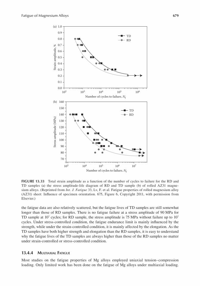
679Fatigue of Magnesium Alloys
the fatigue data are also relatively scattered, but the fatigue lives of TD samples are still somewhat longer than those of RD samples. There is no fatigue failure at a stress amplitude of 90 MPa for TD sample at 107 cycles; for RD sample, the stress amplitude is 75 MPa without failure up to 107 cycles. Under stress-controlled condition, the fatigue endurance limit is mainly influenced by the strength, while under the strain-controlled condition, it is mainly affected by the elongation. As the TD samples have both higher strength and elongation than the RD samples, it is easy to understand why the fatigue lives of the TD samples are always higher than those of the RD samples no matter under strain-controlled or stress-controlled condition.
13.4.4 multiaxial fatigue
Most studies on the fatigue properties of Mg alloys employed uniaxial tension–compression loading. Only limited work has been done on the fatigue of Mg alloys under multiaxial loading.
0.0102 103
Number of cycles to failure, Nf
104 105 106
105103
Number of cycles to failure, Nf
104 106 107
0.1
0.2
0.3
0.4
Stra
in am
plitu
de, %
Stre
ss am
plitu
de (M
Pa)
0.5
0.6
0.7
0.8
0.9
1.0
70
80
90
100
110
120
130
140
150
160
TDRD
TDRD
(a)
(b)
Figure 13.33 Total strain amplitude as a function of the number of cycles to failure for the RD and TD samples (a) the stress amplitude-life diagram of RD and TD sample (b) of rolled AZ31 magne-sium alloys. (Reprinted from Int. J. Fatigue 33, Lv, F. et al. Fatigue properties of rolled magnesium alloy (AZ31) sheet: Influence of specimen orientation. 675, Figure 6, Copyright 2011, with permission from Elsevier.)

680 Aerospace Materials Handbook
Recently, Yu et al. [168] carried out extensive fatigue experiments using thin-walled tubular speci-men of extruded AZ61A Mg alloy under fully reversed strain-controlled tension–compression, cyclic torsion, proportional axial-torsion, and nonproportional axial-torsion loading at room tem-perature. Figure 13.34 shows the stress–strain hysteresis loops at half fatigue life at different strain amplitudes under tension–compression (Path a) and pure torsion (Path b) [168]. When the strain amplitude was larger than 0.45% for Path a (tension–compression), the stress–strain hysteresis loops exhibited an asymmetric sigmoidal shape with a positive mean stress. This is associated with the initial strong basal texture of the extruded AZ61A, which results in mechanical twinning in the compression phase and detwinning in the subsequent tension phase. The mean stress was <10 MPa when the strain amplitude was <0.4%. The mean stress increased significantly when the strain amplitude increased from 0.4% to 0.6%. When the strain amplitude was in the range between 0.7% and 1.0%, the mean stress was almost a constant value of 34 MPa, regardless of the value of the strain amplitude. This indicates that cyclic deformation is dominated by mechanical twins when the strain amplitude is in the range between 0.5% and 1% but by dislocation slips when the strain amplitude is lower than 0.5%. Under cyclic torsion, the stress–strain hysteresis loops are almost symmetric (Figure 13.34b). Albinmousa et al. [121,169] presents a study about the cyclic behavior of AZ31B extrusion under pure cyclic axial and pure cyclic torsional loading. This figure illus-trates the asymmetric feature of the cyclic axial loading that is due to two different deformation mechanisms: slipping and twinning. On the other hand, pure torsional loading yields symmetric cyclic behavior.
1%
300 Extruded AZ61ATension-compression (path a)
Extruded AZ61ACyclic tension (path b)
200
100
0
–100
–200
–300
–150–0.03 –0.02 0.00
Shear strain
(b)
0.01 0.02 0.03–0.01
–100
–50
150
100
50
0
–0.010 0.000Axial strain
Axi
al st
ress
, MPa
Shea
r str
ess,
MPa
(a)
0.010
0.7%0.6%
0.5%0.45% 0.4% 0.35%
0.443%0.346%
0.312%2.425%1.732%
1.524%
1.212%
1.04%
0.887% 0.83%0.779%
0.693%
0.52% 0.606%
0.3%0.25%
0.2%0.15%
Δε/2 = 0.137%
Δγ/2 = 2.6%
Figure 13.34 Stabilized stress–strain hysteresis loops under fully reversed strain-controlled (a) tension–compression and (b) torsion. (Reprinted from Int. J. Fatigue 33(3), Yu, Q. et al. Multiaxial fatigue of extruded AZ61A magnesium alloy, 439, Copyright 2011, with permission from Elsevier.)

681Fatigue of Magnesium Alloys
The axial and the torsional stress responses versus the number of cycles are shown in Figure 13.35 [169]. It is seen that the axial and torsional hardening starts from the beginning and continues until the end of the tests. However, the axial hardening is not symmetric; this is not the case in the torsional mode. In the axial mode, the maximum stress increases to a value of about 250 MPa for the proportional test [169]. However, the minimum stress reached is about 120 MPa. The absolute ratio of the maximum to the minimum stress is about 2:1. This is again attributed to the different deformation mechanisms in tension (slip) and in compression (twinning). A similar comparison between the maximum and the minimum shear stresses results in a difference of only about 20%. Variation of axial and torsional plastic strain amplitudes with the number of cycles is illustrated in Figure 13.36. This figure shows that the hardening behavior is associated with a decrease in the plastic strain. Figure 13.36a indicates the change of the axial plastic strain amplitude in non-proportional loading that is different from that in proportional loading. Both modes experience plastic strain reduction in a nonlinear fashion. For the axial mode, the amount of plastic strain amplitude reduction in proportional and nonproportional loading is 60% and 34%, respectively. For the torsional mode, this amount is higher, reaching ~75% and 65% for the proportional and nonpro-portional tests, respectively. However, more studies on multiaxial fatigue of Mg alloys are needed to identify the deformation mechanisms and predict fatigue lives under multiaxial loading.
13.4.5 fatigue of Welded JointS of mg alloyS
A variety of welding and joining techniques have been used to join Mg alloys including tungsten-inert gas welding (TIG), metal-arc inert welding, laser welding (CO2, Nd:YAG, fiber laser), and resistance spot welding [61,66–86,89–92,110,170], and solid state type of welding, including friction
300(a)
(b)
Axi
al st
ress
resp
onse
, σ (M
Pa)
Shea
r str
ess r
espo
nse,
τ (M
Pa)
0
–3001 10 100 1000
Number of cycles10,000
Multiaxial (phase = 0)
Multiaxial (phase = 90)
Multiaxial (phase = 45)
Multiaxial (phase = 0)
Multiaxial (phase = 90)
Multiaxial (phase = 45)
1 10 100 1000Number of cycles
10,000
70
0
–70
Figure 13.35 Maximum and minimum stress responses for multiaxial tests: (a) axial mode and (b) tor-sional mode of magnesium alloys. (Reprinted from Int. J. Fatigue 33, Albinmousa, J., Jahed, H., and S. Lambert. Cyclic behaviour of wrought magnesium alloy under multiaxial load. 1132, Copyright 2011, with permission from Elsevier.)

682 Aerospace Materials Handbook
stir welding and ultrasonic spot welding [62–65,87,88,93,102,103,108,110,171]. Significant micro-structural changes occurred after welding, including local variations of grain size in the FZ and heat-affected zone (HAZ), precipitate size, shape of grains and their orientation, and formation of porosity. Such changes are expected to affect strongly the integrity and reliability of the welded joints and structures because they would have a significant influence on the mechanical properties such as tensile and fatigue strength, ductility, and strain-hardening behavior. However, the fatigue studies on the welded Mg alloys have been very limited so far. The available fatigue behavior of the welded joints of Mg alloys is summarized below.
Load-controlled fatigue tests on the fiber-laser welded (FLWed) and diode-laser-welded (DLWed) AZ31B-H24 magnesium alloys were conducted at a stress ratio of R = 0.1, 50 Hz, and room tem-perature. The obtained S–N curves of the AZ31B-H24 base metal, fiber laser welded (FLWed), and diode laser welded (DLWed) joints are shown in Figure 13.37 [66]. This allows a direct compari-son and gives an indication of the influence of welding on fatigue life and integrity, which has to be taken into account in designing welded structural components made from Mg alloys. It is seen from Figure 13.37 that fatigue life decreased after welding. However, the fatigue strength or life of the FLWed joints was closer to that of the BM, which was much higher than that of DLWed joints. As the stress amplitude decreased, the difference of fatigue life among the welded joints and the BM became smaller in the semi-log scale diagram. The fatigue limit of the FLWed and DLWed joints (Table 13.3) dropped by 40% and 60%, respectively, and the fatigue ratio for both types of laser-welded joints decreased by approximately 34% compared with that of the BM. This was attrib-uted mainly to the microstructural changes after welding, and also the geometry and shape of the
0.000
0.000
0.003
0.003
1 10 100Number of cycles
Axi
al p
last
ic st
rain
ampl
itude
, εp,
α (m
m/m
m)
Tors
iona
l pla
stic
stra
inam
plitu
de, γ
p, α
(rad
)
1000 10,000
1 10 100Number of cycles
1000 10,000
(a)
(b)
Multiaxial(phase = 0)
Multiaxial(phase = 90)
Multiaxial(phase = 45)
Multiaxial(phase = 0)
Multiaxial(phase = 90)
Multiaxial(phase = 45)
Figure 13.36 Plastic strain amplitude variation with number of cycles for different multiaxial tests: (a) axial mode and (b) torsional mode of magnesium alloys. (Reprinted from Int. J. Fatigue 33, Albinmousa, J., Jahed, H., and S. Lambert. Cyclic behaviour of wrought magnesium alloy under multiaxial load. 1132, Copyright 2011, with permission from Elsevier.)

683Fatigue of Magnesium Alloys
DLWed joints. The presence of the weld drop-through in the FZ of the DLWed joints has caused an extrabending moment. This would facilitate early fatigue crack initiation and subsequent propaga-tion at the center of the weld drop-through in the DLWed joints [66]. For the welded joints, the same Basquin-type equation [59] can be used to fit the obtained fatigue data:
σ σa f f= ′ ( )2N b (13.4)
where σa is the cyclic stress amplitude, ′σf is the fatigue strength coefficient defined by the stress intercept at 2Nf = 1, Nf is the number of cycles to failure, 2Nf is the number of reversals to failure, and b is the fatigue strength exponent. Table 13.4 shows the values of fatigue strength coefficient
′σf and fatigue strength exponent b of the AZ31B-H24 Mg base metal, FLWed and DLWed joints [66]. Normally, a smaller absolute value of b, a larger value of ′σf and a lower stress amplitude σa correspond to a longer fatigue life based on Equation 13.4. From Table 13.4, it is seen that the
tABle 13.3ultimate tensile strength, Fatigue limit, and Fatigue ratio of the AZ31B-H24 Mg BM, FlWed, and dlWed Joints
specimen Fatigue limit (Mpa) ultimate tensile strength (Mpa) Fatigue ratio
Base metal 50 285 0.175
FLW 30 260 0.115
DLW 20 169 0.118
Source: Data with kind permission from Springer Science + Business Media: Metall Mater. Trans. A. Microstructure and mechanical properties of fiber-laser-welded and diode-laser-welded AZ31 magnesium alloy. 42A, 2011, 1984, Chowdhury, S. M. et al. Table II.
01.E+01 1.E+03
Number of cycles to failure, N
Stre
ss am
plitu
de, M
Pa
1.E+05 1.E+07 1.E+09
20
40
60
80
100
120
140
160
180
200
Base metalFLWDLW
Figure 13.37 S–N curves of the AZ31B-H24 base metal, and FLWed and DLWed joints tested at R = 0.1, 50 Hz, and room temperature. (Reprinted with kind permission from Springer Science + Business Media: Metall Mater. Trans. A. Microstructure and mechanical properties of fiber-laser-welded and diode-laser-welded AZ31 magnesium alloy. 42A, 2011, 1984, Chowdhury, S. M. et al. Figure 13.)
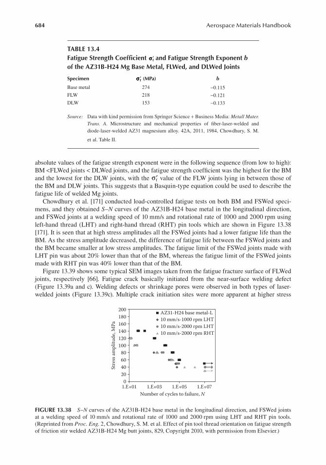
684 Aerospace Materials Handbook
absolute values of the fatigue strength exponent were in the following sequence (from low to high): BM <FLWed joints < DLWed joints, and the fatigue strength coefficient was the highest for the BM and the lowest for the DLW joints, with the ′σf value of the FLW joints lying in between those of the BM and DLW joints. This suggests that a Basquin-type equation could be used to describe the fatigue life of welded Mg joints.
Chowdhury et al. [171] conducted load-controlled fatigue tests on both BM and FSWed speci-mens, and they obtained S–N curves of the AZ31B-H24 base metal in the longitudinal direction, and FSWed joints at a welding speed of 10 mm/s and rotational rate of 1000 and 2000 rpm using left-hand thread (LHT) and right-hand thread (RHT) pin tools which are shown in Figure 13.38 [171]. It is seen that at high stress amplitudes all the FSWed joints had a lower fatigue life than the BM. As the stress amplitude decreased, the difference of fatigue life between the FSWed joints and the BM became smaller at low stress amplitudes. The fatigue limit of the FSWed joints made with LHT pin was about 20% lower than that of the BM, whereas the fatigue limit of the FSWed joints made with RHT pin was 40% lower than that of the BM.
Figure 13.39 shows some typical SEM images taken from the fatigue fracture surface of FLWed joints, respectively [66]. Fatigue crack basically initiated from the near-surface welding defect (Figure 13.39a and c). Welding defects or shrinkage pores were observed in both types of laser-welded joints (Figure 13.39c). Multiple crack initiation sites were more apparent at higher stress
tABle 13.4Fatigue strength coefficient ′σσ f and Fatigue strength exponent b of the AZ31B-H24 Mg Base Metal, FlWed, and dlWed Joints
specimen ′σσ f (Mpa) b
Base metal 274 −0.115
FLW 218 −0.121
DLW 153 −0.133
Source: Data with kind permission from Springer Science + Business Media: Metall Mater. Trans. A. Microstructure and mechanical properties of fiber-laser-welded and diode-laser-welded AZ31 magnesium alloy. 42A, 2011, 1984, Chowdhury, S. M.
et al. Table II.
200 AZ31-H24 base metal-L10 mm/s-1000 rpm LHT10 mm/s-2000 rpm LHT10 mm/s-2000 rpm RHT
180160140120100
80604020
01.E+01 1.E+03 1.E+05
Number of cycles to failure, N
Stre
ss am
plitu
de, M
Pa
1.E+07
Figure 13.38 S–N curves of the AZ31B-H24 base metal in the longitudinal direction, and FSWed joints at a welding speed of 10 mm/s and rotational rate of 1000 and 2000 rpm using LHT and RHT pin tools. (Reprinted from Proc. Eng. 2, Chowdhury, S. M. et al. Effect of pin tool thread orientation on fatigue strength of friction stir welded AZ31B-H24 Mg butt joints, 829, Copyright 2010, with permission from Elsevier.)

685Fatigue of Magnesium Alloys
amplitudes as observed from Figure 13.39b. In the absence of surface welding defects (e.g., Figure 13.39b), surface grains were usually less constrained than the interior grains, and the occurrence of slip in a few grains near the specimen surface could become relatively easier during fatigue [172]. Surface roughness and protrusions could also act as a site of stress concentration that caused crack initiation during fatigue. Fatigue crack propagation was characterized mainly by fatigue striations (Figure 13.39d) along with secondary cracks, which were usually perpendicular to the propagating direction. Similar patterns can also be observed from the DLWed joints [66]. The fatigue stria-tions normally occurred by a repeated plastic blunting–sharpening process in the face-centered cubic materials because of the slip of dislocations in the plastic zone ahead of the fatigue crack tip. The formation of the fatigue striations in the magnesium alloys with an HCP crystal structure was expected to be related to the twinning in the compressive phase and detwinning in the tensile phase [27–29,33,35,135].
13.4.6 environmental effect
Magnesium alloys have high strength-to-weight ratios but their poor corrosion resistance affects the viability of increased magnesium usage in aerospace, automotive, and other applications [19–21,173–185]. The other drawback of magnesium as a structural material is low creep resis-tance [22,186–190]. Until now, many authors have treated such problems independently, as cor-rosion behavior in the nonstressed state and creep under noncorrosive conditions. However, under actual service conditions, plastic deformation and corrosion processes often occur simul-taneously, accelerating each other. Since many mechanically loaded parts of automobiles and
Figure 13.39 Typical SEM images of fatigue fracture surface of FLWed joints. (a) Overall view of the entire fracture surface at a lower stress amplitude of 40 MPa, (b) multiple crack initiation at a higher stress amplitude of 80 MPa, (c) crack initiation from a welding defect, and (d) crack propagation zone. (Reprinted with kind permission from Springer Science + Business Media: Metall Mater. Trans. A. Microstructure and mechanical properties of fiber-laser-welded and diode-laser-welded AZ31 magnesium alloy. 42A, 2011, 1984, Chowdhury, S. M. et al. Figure 15.)

686 Aerospace Materials Handbook
aircraft are often subjected to prolonged static or cyclic stresses in an active medium, it is of scientific and practical interest to study corrosion fatigue and creep of die cast and extruded Mg alloys, such as AZ91D, ZK60, AM50, and AZ31 [191,192].
13.4.6.1 corrosion FatigueThe fatigue life of magnesium alloys in a corrosive environment, for example, in NaCl solu-tion, is always less than that in air [19,191–194]. The relative fatigue life of Mg alloys in cor-rosive solutions varied with the processing and test conditions such as the solution’s acidity. For example, due to the anodic dissolution of magnesium and instability of pH in basic electrolytes, the borate 0.1 N Na2B4O7 buffer solutions (pH 9.3) was used in high cycle fatigue tests [193] and it was found that the fatigue life of AM50 and AZ91D alloys was longer than that in air. Apparently, such a characteristic of magnesium alloys means that the inhibiting action of buffer solution during fatigue tests is dominant in comparison with the alloy degradation due to stress corrosion in this medium.
Eliezer et al. [195] investigated corrosion fatigue behavior of die cast and extruded Mg–Al–Mn, Mg–Al–Zn, and Mg–Zn–Zr alloys in NaCl-based solutions and in a 0.1 N Na2B4O7 buffer solution. Their results showed that fatigue life of all the alloys was significantly longer in air than in NaCl-containing solutions (Figure 13.40). In air, the longest fatigue life was observed for ZK60 alloy and the shortest for extruded AM50 and AZ31 alloys. Extruded AM50 has a some-what lower fatigue life than that of AZ31 under low stress levels (Figure 13.40a). An extruded ZK60 alloy showed very high fatigue resistance in comparison with other alloys, both in air and
100
200
190
170
160
150
140
130
1201.E+04
180
1.E+04 1.E+05 1.E+06
1.E+05 1.E+06
(a)
Cycles to failure, (N)
(b)
Cycles to failure, (N)
1.E+07 1.E+08 1.E+09
ZK 60AM 50AZ 31
ZK 60AM 50AZ 31
120
140
180
Appl
ied
stre
ss, M
PaAp
plie
d st
ress
, MPa
200
220
240
260
160
Figure 13.40 S–N curves of extruded ZK60, AM50, and AZ31 alloys in (a) air and (b) 3.5% NaCl solu-tion saturated with Mg(OH)2. (Reprinted from Eliezer, A. et al. 2005. Mater. Manuf. Process. 20(1), 79, with permission of the publisher Taylor & Francis Ltd, http://www.tandf.co.uk/journals.)

687Fatigue of Magnesium Alloys
in 3.5% NaCl + Mg(OH)2 saturated solution. Also, under the same applied stress level, extruded Mg alloys show a significantly longer fatigue life both in air and in NaCl-containing solutions as compared to the earlier data for die cast alloy [196] due to a significantly lower porosity and higher standard mechanical properties. However, in another case at a lower applied stress ampli-tude, 0.1 N Na2B4O7 buffer solution and solution saturated with magnesium hydroxide are more aggressive corrosion media in comparison with NaCl solution [195]. Saturation of buffer borate solution with magnesium hydroxide does not affect the corrosion fatigue behavior of extruded AZ31 alloy (Figure 13.41a). On the contrary, this addition decreases the fatigue life of AZ80 alloy (Figure 13.41b) due to a higher percentage of β-phase in the former and its higher sensitivity to stress corrosion. The decrease in corrosion fatigue life of AZ80 with the addition of magnesium hydroxide to the buffer solution might be explained by the instability of such a basic electrolyte as 0.1 N Na2B4O7 + Mg(OH)2-saturated solution (it is not a buffer solution), but more studies on this are required [195].
Unigovski et al. [48] conducted corrosion fatigue tests on extruded AZ31, AM50, and ZK60 Mg alloys in air, and NaCl-based and borate solutions. An increase in the fatigue life of AZ31 with the addition of magnesium hydroxide in 3.5% NaCl (Figure 13.42) is associated, probably, with the increase of pH values from ~5 to 10.5 and the strengthening of the passivation
120
200
180
12010 102 103
140
160
10E+01 10E+02
(a)
10E+03 10E+04Cycles to failure, N × 103
(b)
Cycles to failure, N × 103
10E+05
140
2
2
3
4
1
3, 4
160
Appl
ied
stre
ss, M
PaAp
plie
d st
ress
, MPa
180
200AZ31 NaClAZ31 airAZ31, TB
AZ80, NaCl
AZ80, TB
AZ80, TB + MH
AZ31, TB+MH
Figure 13.41 S–N curves for extruded AZ31 alloy in air (1), 3.5% NaCl (2), 0.1 N Na2B4O7 (3), 0.1 N Na2B4O7 solution saturated with magnesium hydroxide (4). TB = sodium tetraborate and MH = magnesium hydroxide. (Reprinted from Eliezer, A. et al. 2005. Mater. Manuf. Process. 20(1), 80, with permission of the publisher Taylor & Francis Ltd, http://www.tandf.co.uk/journals.)

688 Aerospace Materials Handbook
layer on the alloy surface. Saturation of the buffer solution with magnesium hydroxide practi-cally does not affect the corrosion fatigue behavior of extruded AZ31 alloy due to the same values of pH (pH 9.3) of these solutions (Figure 13.43). Thus, the improvement of corrosion fatigue resistance of AZ31 in 3.5% NaCl with such an addition of magnesium hydroxide is understandable. Under stresses above 160 MPa, the fatigue life of AZ31 in 3.5% NaCl was shorter than that in the buffer solution; however, at a lower applied stress, 0.1 N Na2B4O7 buffer solution and the same solution saturated with magnesium hydroxide represent more aggressive corrosion media in comparison with sodium chloride (Figure 13.43). Thus, under cyclic loading of extruded AZ31, the borate buffer solution represents, like NaCl, a strong corrosive environ-ment for this alloy.
13.4.6.2 Fatigue at elevated temperaturesSince cast magnesium alloys are used in several automotive applications such as covers, door structures, and heavier load-bearing components like engine cradle, wheels, housings, and
100
Appl
ied
stre
ss, M
Pa
1.E+03 1.E+04 1.E+06 1.E+07
AZ31
Cycles to failure, (N)1.E+05
120
140
160
180
200
Figure 13.42 S–N curves of an extruded AZ31 alloys in 3.5% NaCl solution (k) and in 3.5% NaCl solution saturated with Mg(OH)2 (m). (Reprinted from Mater. Eng. A. 360, Unigovski, Ya. et al. Corrosion fatigue of extruded magnesium alloys. 134, Copyright 2003, with permission from Elsevier.)
1201.E+04 1.E+05 1.E+06
2
1
3, 4
Cycles to failure, (N)1.E+07 1.E+08
140Appl
ied
stre
ss, M
Pa
160
180
200AZ31 NaClAZ31 airAZ31, TBAZ31, TB + MH
Figure 13.43 S–N curves for extruded AZ31 alloy in air (1), 3.5% NaCl (2), 0.1 N Na2B4O7 (3), and 0.1 N Na2B4O7 solution saturated with magnesium hydroxide (4) (“TB” and “MH” in the legend are abbreviations for sodium tetraborate and magnesium hydroxide). (Reprinted from Mater. Eng. A. 360, Unigovski, Ya. et al. Corrosion fatigue of extruded magnesium alloys. Mater. Eng. A. 360, 134, Copyright 2003, with permission from Elsevier.)

689Fatigue of Magnesium Alloys
frames and these components are subjected to variable and repeated mechanical straining, where the number of load cycles may be on the order of 109 cycles in car wheels, fatigue properties at elevated temperatures are required [197]. Recently, Xue et al. [197] conducted fatigue tests of high-pressure die cast AE44 magnesium alloys extracted from as-cast bars and from an engine cradle under strain control at room and elevated temperatures. The uniaxial strain-life results are shown in Figure 13.44. The fatigue lives at 121°C are in general longer than those at room temperature under constant strain amplitude experiments, which is likely due to increasing duc-tility at elevated temperatures, since strain-life of a material is associated with both strength and ductility. In addition, the specimens experienced large cyclic plastic strains when the strain amplitudes were >0.28%. However, Lamark et al. [198] investigated the influence of the surface condition and elevated temperature on the fatigue properties of high-pressure die cast magnesium alloy AS21X under stress control tests, and reported that with the as-cast surface layer intact, no significant temperature influence on fatigue life was observed for large stress amplitudes, whereas the fatigue strength at 107 cycles decreased from 50 MPa at 20°C to 40 MPa at 150°C. Another study [199] was conducted with the high cycle fatigue tests of the high-pressure die cast magnesium alloys AZ91 hp, AS21 hp and AE42 hp and of the aluminum alloy AlSi9Cu3 at ultrasonic cyclic frequency and load ratio R = −1. Compared with ambient air, crack growth data measured in warm air are shifted toward lower stress intensity amplitudes. Fatigue cracks initiated nearly exclusively at casting porosity and fracture surfaces appear similar at low and elevated temperatures. The fatigue behavior of the magnesium die cast alloys AZ91, AE42, and AM50 at constant amplitude was also studied in strain-controlled cyclic tests at ambient and elevated temperatures [191]. Based on these limited fatigue data, several variants of methods fol-lowing both the nominal-stress concept and the local-strain approach were applied to determine guidelines to improve the reliability of lifetime estimation of components made of magnesium. However, more studies are needed to clarify the fatigue deformation mechanisms of magnesium alloys at elevated temperatures.
13.5 suMMAry And reMArks
A fair amount of research work of both cast and wrought magnesium alloys dealing with the mechanical properties such as strength (tensile and fatigue), ductility, strain-hardening behavior,
0.01e+2
R = –1
Runout
As-cast bar.RT
As-cast bar.HTCradle.RT
Cradle.HT
1e+3 1e+4 1e+5Cycles to failure, Nf
Stra
in am
plitu
de (Δ
ε/2,
%)
1e+6 1e+7
0.2
0.4
0.6
Figure 13.44 Strain-life of AE44 Mg alloy specimens machined from as-cast bars and from an engine cradle tested at room temperature and 121°C under strain-controlled, constant amplitude with completely reversed strain amplitude experiments. (Reprinted from Int. J. Fatigue, 29(4), Xue, Y. et al. Microstructure-based multistage fatigue modeling of a cast AE44 magnesium alloy. 669, Copyright 2007, with permission from Elsevier.)

690 Aerospace Materials Handbook
and strain-rate sensitivity has been reported lately. Based on the above survey on the fatigue charac-teristics of magnesium alloys, a few main points can be summarized as follows.
1. Mg alloys can exhibit cyclic hardening, softening, or stabilization, depending mainly on the applied strain amplitude and material state. At higher strain amplitudes for both extruded and cast alloys, cyclic hardening occurred, while cyclic deformation remained nearly stable at lower strain amplitudes. For the semi-solid-processed alloy, slight cyclic softening was observed in the intermediate strain amplitudes.
2. Mg alloys, especially extruded alloys, exhibited characteristic anisotropic deformation behavior, and skewed and unsymmetrical hysteresis loops were observed when the cyclic load was applied in the extrusion direction. While such unsymmetrical deformation behav-ior was present in the cast alloys as well, the extent was much lower. This was attributed to the occurrence of twinning in the compressive phase and subsequent detwinning in the tensile phase during cyclic deformation, stemming from the presence of strong crystallo-graphic texture in the extruded alloys.
3. Mg alloys exhibited nonlinear or pseudoelastic cyclic deformation behavior. The elastic modulus during cyclic deformation, being constant at the low strain amplitude, decreased with increasing strain amplitude and increased with increasing number of cycles at high strain amplitudes.
4. The strain-life data (the relationship between the strain amplitude and the number of rever-sals to failure) of magnesium alloys could be described by the Coffin–Manson law. The fatigue life of the semisolid-processed (or thixomolded) magnesium alloys was longer than that of the corresponding die cast magnesium alloys especially at the lower strain amplitude. The load-controlled S–N curve for the welded joints of magnesium alloys was observed to follow the Basquin equation well.
5. Fatigue life reduced after welding, with the extent of reduction dependent on the welding processes and parameters. In laser welding, fiber laser welding led to a higher fatigue resis-tance than diode laser welding due to the narrower fusion zone and heat-affected zone. In friction stir welding, fatigue strength was higher in the FSWed joints made with a left-hand thread pin tool than that of the FSWed joints made with a right-hand thread pin tool in the clockwise rotation. This was due to the elimination of the welding porosity located near the bottom surface of the FSWed joints in the former case via a downward material flow close to the pin tool surface. Fatigue life increased either by decreasing the tool rotation rate while the welding speed was kept constant or by increasing the welding speed while the tool rotation rate remained constant.
6. In the extruded alloys, fatigue cracks initiated from the specimen surface, regardless of the total strain amplitude applied, and at higher strain amplitudes, multiple initiation sites were observed. In the cast alloys and welded joints, fatigue crack initiation predominantly occurred at casting or welding defects at or near the specimen surface.
7. Fatigue crack propagation in all types of Mg alloys was characterized by fatigue striation-like features, coupled with the presence of some secondary cracks. The spacing of fatigue striations increased with increasing distance from the initiation sites. While the fatigue striations normally occurred by a repeated plastic blunting–sharpening process in face-centered cubic materials due to the slip of dislocations in the plastic zone at the fatigue crack tip, the formation of the fatigue striations in the magnesium alloys was associated with the twinning–detwinning process.
Although a lot of fatigue data of magnesium alloys including the effects of temperature and corrosive environment have been obtained, it is still far from our understanding on the cyclic deformation mechanisms, and meeting the needs for the application, design, and life prediction of magnesium alloys. Significant research efforts and programs to understand strain-life and fatigue

691Fatigue of Magnesium Alloys
crack growth behavior and develop life prediction methodologies for magnesium alloys are needed. Further studies on the controlling mechanisms of the peculiar unsymmetrical cyclic deformation behavior, and fatigue crack propagation mechanisms in relation to twinning–detwinning, corrosion fatigue, and fatigue at elevated temperatures in both cast and wrought alloys are required. Welding and joining pose a specific safety and reliability issue in the application of magnesium alloys due to the weakening effect caused by the microstructural changes across the weld, and particular atten-tion must be paid to evaluate and optimize the fatigue resistance of welded magnesium joints. It is hoped that the information and references herein will be useful for further studies.
Finally, we have witnessed a growing use of ultralightweight magnesium alloy in aerospace, automotive, and other industries in recent years. Such a trend is a result of the improvement and development of new alloys with enhancing resistance to corrosion, fatigue, and creep at elevated temperatures. The driving force behind the development and application of magnesium alloys is the ever-increasing concern for environmental protection via vehicle weight reduction and more fuel efficiency. The ultralightweight nature and superior recycling capabilities will bring magnesium to the attention of researchers and engineers in the aerospace and automotive sectors and make it the metal of the twenty-first century.
AcknoWledgMents
The authors would like to thank the Natural Sciences and Engineering Research Council of Canada (NSERC) and AUTO21 Network of Centers of Excellence for providing financial support. This inves-tigation involves part of Canada–China–USA Collaborative Research Project on the Magnesium Front End Research and Development (MFERD). The authors also thank General Motors Research and Development Center, USA, and G-Mag International, Canada, for supplying various test mate-rials. One of the authors (D.L. Chen) is grateful for financial support by the Premier’s Research Excellence Award (PREA), NSERC-DAS Award, Canada Foundation for Innovation (CFI), and Ryerson Research Chair (RRC) program. This chapter includes part of research work done by Dr. Chen’s former graduate students, including N. Afrin, S. Begum, S.H. Chowdhury, S.M. Chowdhury, A.R. Emami, M. Fairman, C.L. Fan, X.Z. Lin, C. Liu, H.A. Patel, and V.K. Patel. The assistance of Q. Li, A. Machin, J. Amankrah, D. Ostrom, and R. Churaman in performing the experiments is gratefully acknowledged. The authors also thank Dr. S. Xu, Dr. K. Sadayappan, Dr. M.S. Kozdras, and Dr. J. Jackman (CANMET-MTL); Dr. X. Cao (NRC); and Professor N. Atalla, Professor H. Jahed, Professor S. Lambert, Professor D.C. Weckman, Professor Y. Zhou, Professor Y.S. Yang, Professor J. Allison, Professor M.F. Horstemeyer, Professor B. Jordon, Dr. A.A. Luo, Mr. R. Osborne, Mr J.F. Quinn, Dr. X.M. Su, and Mr L. Zhang for the helpful discussion.
reFerences
1. Gillett, N. P., Arora, V. K., Zickfeld, K., Marshall, S. J., and W. J. Merryfield. 2011. Ongoing climate change following a complete cessation of carbon dioxide emissions. Nat. Geosci. 4:83–87.
2. Min, S. K., Zhang, X. B., Zwiers, F. W., and G. C. Hegerl. 2011. Human contribution to more-intense precipitation extremes. Nature 470:378–81.
3. Schiermeier, Q. 2011. Increased flood risk linked to global warming. Nature 470:316. 4. Pall, P., Aina, T., Stone, D. A., Scott, P. A., Nozawa, T., Hilberts, A. G. J., Lohmann, D., and M. R. Allen.
2007. Anthropogenic greenhouse gas contribution to flood risk in England and Wales in autumn 2000. Nature 470(7334):382–85.
5. Hassan, S. F., and M. Gupta. 2004. Development of high performance magnesium nanocomposites using solidification processing route. Mat. Sci. Tech. 20:1383–88.
6. Pollock, T. M. 2010. Weight loss with magnesium alloys. Science 328:986–87. 7. Wise, M., Calvin, K., Thomson, A., Clarke, L., Lamberty, B. B., Sands, R., Smith, S. J., Janetos, A.,
and J. Edmonds. 2009. Implications of limiting CO2 concentrations for land use and energy. Science 324:1183–86.
8. Kump, L. R. 2002. Reducing uncertainty about carbon dioxide as a climate driver. Nature 419:188–90.

692 Aerospace Materials Handbook
9. Agnew, W. G. 1974. Reducing automotive emissions. Science 183(4122):254–56. 10. Mordike, B. L., and T. Ebert. 2001. Magnesium: Properties-applications-potential. Mater. Sci. Eng. A.
302(1):37–45. 11. Eliezer, D., Aghion, E., and F. H. Froes. 1998. Magnesium science, technology and applications. Adv.
Perfor. Mater. 5:201–12. 12. Kainer, K. U. 2003. Magnesium—Alloys and Technology. Wiley-VCH, Cambridge. 13. Luo, A. A. 2004. Recent magnesium alloy development for elevated temperature applications. Int. Mater.
Rev. 49(1):13–30. 14. Ke, W., Han, E. H., Han, Y. F., Kainer K., and A. A. Luo. 2005. Mechanical properties and creep behavior
of Mg-Al-Ca alloys. Proceedings of International Conference on Magnesium—Science, Technology and Applications. Beijing, China. Mater. Sci. Forum. 488–89.
15. United States Automotive Materials Partnership (USAMP). 2006. Magnesium vision 2020: A North American automotive strategic vision for magnesium.
16. Duffy, L. 1996. Magnesium alloys—An introduction. Mater. World 4(3):127–30. 17. Pantelakis, Sp. G., Alexopoulos, N. D., and A. N. Chamos. 2007. Mechanical performance evaluation of
cast magnesium alloys for automotive and aeronautical applications. J. Eng. Mater. Tech. 129:422–30. 18. Göken, J., Bohlen, J., Hort, N., Letzig, D., and Kainer, K.U. 2003. New development in magnesium
technology for lightweight structures in transportation industries. Mater. Sci. Forum 426–432(1):153–60. 19. Zeng, R. C., Han, E. H., and W. Ke. 2005. Fatigue and corrosion fatigue of magnesium alloys. Mater. Sci.
Forum 488–489:721–24. 20. Makar, G.L., and Kruger, J. 1993. Corrosion of magnesium. Int. Mater. Rev. 38(3):138–53. 21. Ghali, E., Dietzel, W., and K. U. Kainer. Testing of general and localized corrosion of magnesium alloys:
A critical review. J. Mater. Eng. Per. 13(5):517–29. 22. Pekguleryuz, M. O., and A. A. Kaya. 2004. Creep resistant magnesium alloys for powertrain applica-
tions. In Magnesium: Proceedings of the 6th International Conference Magnesium Alloys and Their Applications. Edited by K. U. Kainer. Wiley-Vch Verlag GmbH, Weinheim, Germany. pp. 74–93.
23. Nicholas, J. 2005. High performance magnesium. Adv. Mater. Process. 163(9):65–67. 24. ASM International. The Materials Information Society. 2011. Research improves the bolted joints in
airplanes. 25. Wang, Q., Zhang, Z. M., Zhang, X., and G. J., Li. 2010. New extrusion process of Mg alloy automobile
wheels. Trans. Nonfer. Metal. Soc. China 20(2):599–03. 26. Potzies, C., and K. U. Kainer. 2004. Fatigue of magnesium alloys. Adv. Eng. Mater. 6(5):281–89. 27. Begum, S., Chen, D. L., Xu, S., and A. A. Luo. 2009. Effect of strain ratio and strain rate on low cycle
fatigue behavior of AZ31 wrought magnesium alloy. Mater. Sci. Eng. A. 517:334–43. 28. Begum, S., Chen, D. L., Xu, S., and A. A. Luo. 2009. Low cycle fatigue properties of an extruded AZ31
magnesium alloy. Int. J. Fatigue 31:726–35. 29. Lin, X. Z., and D. L. Chen. 2008. Strain controlled cyclic deformation behavior of an extruded magne-
sium alloy. Mater. Sci. Eng. A. 496:106–13. 30. Brown, D. W., Jain, A., Agnew, S., and R. B. Clausen. 2007. Twinning and detwinning during cyclic
deformation of Mg alloy AZ31B. Mater. Sci. Forum 539–543:3407–13. 31. Noster, U., and B. Scholtes. 2003. Isothermal strain-controlled quasi-static and cyclic deformation behavior
of magnesium wrought alloy AZ31. Mater. Res. Adv. Tech. (Zeitschrift fuer Metallkunde). 94(5):559–63. 32. Hasegawa, S., Tsuchida, Y., Yano, H., and M. Matsui. 2007. Evaluation of low cycle fatigue life in AZ31
magnesium alloy. Int. J. Fatigue 29:1839–45. 33. Begum, S., Chen, D. L., Xu, S., and A. A. Luo. 2008. Strain-controlled low-cycle fatigue properties of a
newly developed extruded magnesium alloy. Metall. Mat. Trans. A. 39:3014–26. 34. Fan, C. L., Chen, D. L., and A. A. Luo. 2009. Dependence of the distribution of deformation twins on
strain amplitudes in an extruded magnesium alloy after cyclic deformation. Mater. Sci. Eng. A. 519:38–45. 35. Wu, L., Jain, A., Brown, D. W., Stoica, G. M, Agnew, S. R., Clausen, B., Fielden, D. E., and P. K. Liaw.
2008. Twinning-detwinning behavior during the strain-controlled low-cycle fatigue testing of a wrought magnesium alloy, ZK60A. Acta Mater. 56:688–95.
36. Wu, L., Agnew, S. R., Brown, D.W., Stoica, G. M, Clausen, B., Jain, B., Fielden, D. E., and P. K. Liaw. 2008. Internal stress relaxation and load redistribution during the twinning-detwinning-dominated cyclic deformation of a wrought magnesium alloy, ZK60A. Acta Mater. 56:3699–07.
37. Eisenmeier, G., Holzwarth, B., Hoppel, H. W., and H. Mughrabi. 2001. Cyclic deformation and fatigue behaviour of the magnesium alloy AZ91. Mater. Sci. Eng. A. 319–321:578–82.
38. Chen, L., Shen, J., Wu, W. Li, F., Wang, Y., and Z. Liu. 2005. Low-cycle fatigue behavior of magnesium alloy AZ91. Mater. Sci. Forum 488–489:725–28.

693Fatigue of Magnesium Alloys
39. Horstemeyer, M. F., Yang, N., Gall, K., McDowell, D. L., Fan, J., and P. M. Gullett. 2004. High cycle fatigue of a die cast AZ91E-T4 magnesium alloy. Acta Mater. 52:1327–36.
40. Liu, Z., Xu, Y. Y., Wang, Z.G., Wang, Y., and Z.Y. Liu. 2000. Low cycle fatigue behavior of AZ91HP alloy in as high pressure die-casting. Acta Metall. Sin. (English Letters) 13:961–66.
41. Islamgaliev, R. K., Kulyasova, O. B., Mingler, B., Zehetbauer, M., and A. Minkow. 2008. Structure and fatigue properties of the Mg alloy AM60 processed by ECAP. Mater. Sci. Forum 584–586:803–08.
42. Kulyasova, O., Islamgaliev, R., Mingler, B., and M. Zehetbauer. 2009. Microstructure and fatigue proper-ties of the ultrafine-grained AM60 magnesium alloy processed by equal-channel angular pressing. Mater. Sci. Eng. A. 503:176–80.
43. El Kadiri, H., Horstemeyer, M. F., Jordon, J. B., and Y. Xue. 2008. Fatigue crack growth mechanisms in high-pressure die-cast magnesium alloys. Metall. Mat. Trans. A. 39:190–05.
44. Horstemeyer, M. F., Yang, N. K. Gall, McDowell, D., Fan, J., and P. Gullett. 2002. High cycle fatigue mechanisms in a cast AM60B magnesium alloy. Fatigue Fract. Eng. Mater. Struct. 25:1045–56.
45. Liu, Z., Ji, H., Lin, L., Chen, L., Wu, W., and L. Yang. 2007. Cyclic deformation behavior and poten-tial automobile application of magnesium die casting alloys AZ91 and AM50, Mater. Sci. Forum 539–543:1626–31.
46. El Kadiri, H., Xue, Y., Horstemeyer, M. F., Jordon, J. B., and P.T. Wang. 2006. Identification and modeling of fatigue crack growth mechanisms in a die-cast AM50 magnesium alloy. Acta Mater. 54(19):5061–76.
47. Liu, Z., Wang, Z. G., Wang, Y., and Z. Y. Liu. 1999. Cyclic deformation behavior of high pressure die casting alloy AM50. J. Mater. Sci. Lett. 18:1567–69.
48. Unigovski, Y., Eliezer, A., Abramov, E., Snir, Y., and E. M. Gutman. 2003. Corrosion fatigue of extruded magnesium alloys. Mater. Sci. Eng. A. 360:132–39.
49. Barbagallo, S., Laukli, H. I., Lohne, O., and E. Cerri. 2004. Divorced eutectic in a HPDC magnesium-aluminum alloy. J. Alloys Comp. 378:226–32.
50. Moreno, I. P., Nandy, T. K., Jones, J. W., Allison, J. E., and T. M. Pollock. 2001. Microstructural charac-terization of a die-cast magnesium-rare earth alloy. Scripta Mater. 45(12):1423–29.
51. Cai, J., Ma, G. C., Liu, Z., Zhang, H. F., and Z. Q. Hu. 2006. Influence of rapid solidification on the microstructure of AZ91HP alloy. J. Alloys Comp. 422(1–2):92–96.
52. Wang, R. M., Eliezer, A., and E. M. Gutman. 2003. An investigation on the microstructure of an AM50 magnesium alloy. Mater. Sci. Eng. A. 355:201–07.
53. ASM Handbook. 2004. Metallography and Microstructures. ASM, Materials Park, OH. Vol. 9, p. 813, Figure 27.
54. He, S. M., Zeng, X. Q., Peng, L. M., Gao, X., Nie, J. F., and W. J., Ding. 2007. Microstructure and strengthening mechanism of high strength Mg-10Gd-2Y-0.5Zr alloy. J. Alloys Comp. 427(1–2):316–23.
55. Lü, Y. Z., Wang, Q. D., Zeng, X. Q., Ding, W. J., Zhai, C. Q., and Y. P., Zhu. 2000. Effects of rare earths on the microstructure, properties and fracture behavior of Mg-Al alloys. Mater. Sci. Eng. A. 278(1–2):66–76.
56. He, S. M., Peng, L. M., Zeng, X. Q., Ding, W. J., and Y. P., Zhu. 2006. Comparison of the microstructure and mechanical properties of a ZK60 alloy with and without 1.3 wt.% gadolinium addition. Mater. Sci. Eng. A. 433(1–2):175–81.
57. Li, Q., Wang, Q. D., Wang, Y. X., Zeng, X. Q., and W. J., Ding. 2007. Effect of Nd and Y addition on microstructure and mechanical properties of as-cast Mg-Zn-Zr alloy. J. Alloys Comp. 427(1–2):115–23.
58. Patel, H. A., Chen, D. L., Bhole, S. D., and K. Sadayappan. 2010. Microstructure and tensile properties of thixomolded magnesium alloys. J. Alloys Comp. 496(1-2):140–48.
59. Zhang, Y. F., Liu, Y. B., Zhang, Q. Q., Cao, Z. Y., Cui, X. P., and Y. Wang. 2007. Microstructural evolu-tion of thixomolded AZ91D magnesium alloy with process parameters variation. Mater. Sci. Eng. A. 444:251–56.
60. Fan, Z. 2002. Semisolid metal processing. Int. Mater. Rev. 47:49–86. 61. Cao, X., Jahazi, M., Immarigeon, J. P., and W. Wallace. 2006. A review of laser welding techniques for
magnesium alloys. J. Mater. Proc. Tech. 171(2):188–04. 62. Fairman, M., Afrin, N., Chen, D. L., Cao, X. J., and M. Jahazi. 2007. Microstructural evaluation of fric-
tion stir processed AZ31B-H24 magnesium alloy. Can. Metall. Quart. 46:425–32. 63. Afrin, N., Chen, D. L., Cao, X., and M. Jahazi. 2007. Strain hardening behaviour of a friction stir welded
magnesium alloy. Scripta Mater. 57:1004–07. 64. Afrin, N., Chen, D. L., Cao, X., and M. Jahazi. 2008. Microstructure and tensile properties of friction stir
welded AZ31B magnesium alloy. Mater. Sci. Eng. A. 472:179–86. 65. Chowdhury, S. M., Chen, D. L., Bhole, S. D., and X. Cao. 2010. Tensile properties of a friction stir
welded magnesium alloy: Effect of pin tool thread orientation and weld pitch. Mater. Sci. Eng. A. 527(21–22):6064–75.

694 Aerospace Materials Handbook
66. Chowdhury, S. M., Chen, D. L., Bhole, S.D., Powidajko, E., Weckman, D. C., and Y. Zhou. 2011. Microstructure and mechanical properties of fiber-laser-welded and diode-laser-welded AZ31 magne-sium alloy. Metall. Mater. Trans. A. 42A:1974–89.
67. Chowdhury, S. H., Chen, D. L., S. D. Bhole, S.D., Powidajko, E., Weckman, D. C., and Y. Zhou. 2012. Fiber laser welded AZ31 magnesium alloy: Effect of welding speed on microstructure and mechanical properties. Metall. Mater. Trans. A. 43(6):2133–47.
68. Mohanty, P. S., and J. Mazumder. 1998. Solidification behavior and microstructural evolution during laser beam-material interaction. Metall. Mater. Trans. B. 29B:1269–79.
69. Kou, S., and Y. Le. 1985. Alternating grain orientation and weld solidification cracking. Metall. Trans. A. 16(10):1887–96.
70. Rappaz, M., Vitek, J. M., David, S. A., and L.A. Boatner. 1993. Microstructural formation in longitudinal bicrystal welds. Metall. Trans. A. 24:1433–46.
71. Somboonsuk, K., Mason, J. T., and R. Trivedi. 1984. Interdendritic spacing: Part I. experimental studies. Metall. Trans. A. 15(6):967–75.
72. Wu, S. H., Huang, J. C., and Y. N. Wang. 2004. Evolution of microstructure and texture in Mg-Al-Zn alloys during electron-beam and gas tungsten arc welding. Metall. Trans. A. 35(8):2455–69.
73. Liu, Y., Koch, J., Mazumder, J., and K. Shibata. 1994. Processing, microstructure, and properties of laser-clad Ni alloy FP-5 on Al alloy AA333. Metalls Trans. B. 25(3):425–34.
74. Yajie, Q., Chen, Z., Yu, Z., Gong, X., and M. Li. 2008. Effects of heat input on microstructure and tensile properties of laser welded magnesium alloy AZ31. Mater. Char. 59(10):1799–04.
75. Yu, L., Nakata, K., Yamamoto, N., and J. Liao. 2009. Texture and its effect on mechanical properties in fiber laser weld of a fine-grained Mg alloy. Mater. Lett. 63(11):870–72.
76. Yu, Z. H., Yan, H. G., Gong, X. S., Quan, Y. J., Chen, J. H., and Q. Chen. 2009. Microstructure and mechan-ical properties of laser welded wrought ZK21 magnesium alloy. Mat. Sci. Eng. A. 523(1–2):220–25.
77. Weisheit, A., Galun, R., and B. L. Mordike. 1998. CO2 laser beam welding of magnesium-based alloys. Weld. J. 77(4):148–54.
78. Zhao, H., and T. Debroy. 2001. Pore formation during laser beam welding of die-cast magnesium alloy AM60B—Mechanism and remedy. Weld. J. 80(8):204–10.
79. Sun, Z., Pan, D., and J. Wei. 2002. Comparative evaluation of tungsten inert gas and laser welding of AZ31 magnesium alloy. Sci. Tech. Weld. J. 7(6):343–51.
80. Padmanaban, G., and V. Balasubramanian. 2010. Fatigue performance of pulsed current gas tungsten arc, friction stir and laser beam welded AZ31B magnesium alloy joints. Mater. Des. 31(8):3724–32.
81. Sun, H., Song, G., and L. F. Zhang. 2008. Effects of oxide activating flux on laser welding of magnesium alloy. Sci. Tech. Weld. J. 13(4):305–11.
82. Liu, L. M. 2010. Welding and Joining of Magnesium Alloys. Woodhead Publishing in Materials, Cambridge, England.
83. Ren, D. X., and L. M., Liu. 2010. Effect of adhesive induced gas on penetration and plasma behaviour in laser weld bonding of magnesium alloy. Mater. Res. Inno. 14(5):405–09.
84. Liu, L. M., and X. F., Hao. 2010. Low-power laser/TIG hybrid welding process of magnesium alloy with filler wire, Mater. Manuf. Process. 25(11):1213–18.
85. Song, G., Wang, P., and L. M. Liu. 2010. Study on ac-PMIG welding of AZ31B magnesium alloy. Sci. Technol. Welding Joining 15(3):219–25.
86. Liu, L. M., Song, G., and M. L. Zhu. 2008. Low-power laser/arc hybrid welding behavior in AZ-based Mg alloys. Metall. Mater. Trans. A. 39(7):1702–11.
87. Xie, G. M., Ma, Z. Y., and L. Geng. 2008. Effect of microstructural evolution on mechanical properties of friction stir welded ZK60 alloy. Mater. Sci. Eng. A. 486(1-2):49–55.
88. Xie, G. M., Ma, Z. Y., Geng, L., and R.S. Chen. 2007. Microstructural evolution and mechanical proper-ties of friction stir welded Mg-Zn-Y-Zr alloy. Mater. Sci. Eng. A. 471(1–2):63–68.
89. Xiao, L., Liu, L., Chen, D. L., Esmaeili, S., and Y. Zhou. 2011. Resistance spot weld fatigue behavior and dislocation substructures in two different heats of AZ31 magnesium alloy. Mater. Sci. Eng. A. 529:81–87.
90. Xiao, L., Liu, L., Zhou, Y., and S., Esmaeili. 2010. Resistance-spot-welded AZ31 magnesium alloys: Part I. Dependence of fusion zone microstructures on second-phase particles. Metall. Mater. Trans. A: Phy. Metall. Mater. Sci. 41(6):1511–22.
91. Liu, L., Xiao, L., Feng, J. C., Tian, Y. H., Zhou, S. Q., and Zhou, Y. 2010. Resistance spot welded AZ31 magnesium alloys, part II: Effects of welding current on microstructure and mechanical properties. Metall. Mater. Trans. A: Phy. Metall. Mater. Sci. 41(10):2642–50.
92. Liu, L., Zhou, S. Q., Tian, Y. H., Feng, J. C., Jung, J. P., and Y. N., Zhou. 2009. Effects of surface condi-tions on resistance spot welding of Mg alloy AZ31. Sci. Tech. Welding Joining 14(4):356–61.

695Fatigue of Magnesium Alloys
93. Patel, V. K., Bhole, S. D., and D. L. Chen. 2011. Influence of ultrasonic spot welding on microstructure in a magnesium alloy. Scripta Mater. 65(10):911–14.
94. Kim, S. H., You, B. S., You, B. S., and C. D. Yim. 2005. The effect of rolling conditions on the micro-structure and texture evolution of AZ31 Mg alloy sheets. Mater. Forum 29:530–35.
95. Johnson, R. 2003. Friction stir welding of magnesium alloys. Mater. Sci. Forum 419–422:365–70. 96. Wang, X. H., and K. Wang. 2006. Microstructure and properties of friction stir butt-welded AZ31 mag-
nesium alloy. Mater. Sci. Eng. A. 431:114–17. 97. Park, S. H. C., Sato, Y. S., and H. Kokawa. 2003. Effect of micro-texture on fracture location in friction
stir weld of Mg alloy AZ61 during tensile test. Scripta Mater. 49:161–66. 98. Woo, W., Choo, H., Prime, M. B., Feng, Z., and B. Clausen. 2008. Microstructure, texture and residual
stress in a friction-stir-processed AZ31B magnesium alloy. Acta Mater. 56:1701–11. 99. Commin, L., Dumont, M., Masse, J. E., and L. Barrallier. 2009. Friction stir welding of AZ31 magnesium
alloy rolled sheets: Influence of processing parameters. Acta Mater. 57:326–34. 100. Seidel, T.U., and A. P. Reynolds. 2001. Visualization of the material flow in AA2195 friction-stir welds
using a marker strain technique. Metall. Mater. Trans. A. 32:2879–84. 101. Fratini, L., Buffa, G., Palmeri, D., Hua, J., and R. Shivpur. 2006. Material flow in FSW of AA7075-T6
butt joints: Continuous dynamic recrystallization phenomena. J. Eng. Mater. Tech. 128:228–35. 102. Xu, W. F., Liu, J. H., and D.L. Chen. 2011. Material flow and core/multi-shell structures in a friction stir
welded aluminum alloy. J. Alloys Comp. 509(33):8449–54. 103. Cui, G. R., Ma, Z. Y., and S.X. Li. 2008. Periodical plastic flow pattern in friction stir processed Al-Mg
alloy. Scripta Mater. 58:1082–85. 104. Schmidt, H. N. B., Dickerson, T. L., and J. H. Hattel. 2006. Material flow in butt friction stir welds in
AA2024-T3. Acta Mater. 54:1199–09. 105. Mishra, R. S., and Z. Y. Ma. 2005. Friction stir welding and processing. Mater. Sci. Eng. R. 50(1-2):1–78. 106. Çam, G. 2011. Friction stir welded structural materials: Beyond Al-alloys. Int. Mater. Rev. 56(1):1–48. 107. Threadgilll, P. L., Leonard, A. J., Shercliff, H. R., and P.J. Withers. 2009. Friction stir welding of alu-
minium alloys. Int. Mater. Rev. 54(2):49–93. 108. Ma, Z. Y. 2008. Friction stir processing technology: A review. Metall. Mater. Trans. A. 39 A(3):642–58. 109. Nandan, R., DebRoy, T., and H. K. D. H. Bhadeshia, 2008. Recent advances in friction-stir welding-
Process, weldment structure and properties. Prog. Mater. Sci. 53(6):980–23. 110. Chowdhury, S. M., Chen, D. L., Bhole, S. D., Cao, X., Powidajko, E., Weckman, D. C., and Y. Zhou.
2010. Tensile properties and strain hardening behavior of double-sided arc welded and friction stir welded AZ31B magnesium alloy. Mater. Sci. Eng. A. 527(12):2951–61.
111. Cao, X., and M. Jahazi. 2009. Effect of welding speed on the quality of friction stir welded butt joints of a magnesium alloy. Mater. Des. 30:2033–42.
112. Esparza, J. A., Davis, W. C., Trillo, E. A., and L. E. Murr. 2002. Friction stir welding of magnesium alloy AZ 31B. J. Mater. Sci. Lett. 21:917–20.
113. Jiang, L., Jonas, J. J., Luo, A. A., Sachdev, A. K., and S. Godet. 2006. Twinning-induced softening in polycrystalline AM30 Mg alloy at moderate temperatures. Scripta Mater. 54:771–75.
114. Barnett, M. R. 2007. Twinning and the ductility of magnesium alloys. Part I: “Tension” twins. Mater. Sci. Eng. A. 464(1–2):1–7.
115. Barnett, M. R. 2007. Twinning and the ductility of magnesium alloys. Part II. “Contraction” twins. Mater. Sci. Eng. A. 464(1–2):8–16.
116. Jain, A., and S. R., Agnew. 2007. Modeling the temperature dependent effect of twinning on the behavior of magnesium alloy AZ31B sheet. Mater. Sci. Eng. A. 462(1–2):29–36.
117. Bohlen, J., Nürnberg, M. R., Senn, J. W., Letzig, D., and S. R. Agnew. 2007. The texture and anisotropy of magnesium-zinc-rare earth alloy sheets. Acta Mater. 55(6):2101–12.
118. Wang, Y. N., and J. C., Huang. 2007. The role of twinning and untwinning in yielding behavior in hot-extruded Mg-Al-Zn alloy. Acta Mater. 55(3):897–05.
119. Zeng, R., Han, E., Ke, W., Dietzel, W., Kainer, K. U., and A. Atrens. 2010. Influence of microstructure on tensile properties and fatigue crack growth in extruded magnesium alloy AM60. Int. J. Fatigue 32:411–19.
120. Yan, C., Ma, W., Burg, V., and M. W. Chen. 2007. Experimental and numerical investigation on ductile-brittle fracture transition in a magnesium alloy. J. Mater. Sci. 42:7702–07.
121. Albinmousa, J., Jahed, H., and S. Lambert. 2011. Cyclic axial and cyclic torsional behaviour of extruded AZ31B magnesium alloy. Int. J. Fatigue 33:1403–16.
122. Dieter, G. E. 1986. Mechanical Metallurgy. 3rd Ed., McGraw-Hill, Boston, Massachusetts. pp. 197–01. 123. Yoo, M. H., Morris, J. R., Ho, K. M., and S. R. Agnew. 2002. Nonbasal deformation modes of HCP met-
als and alloys: Role of dislocation source and mobility. Metall. Mat. Trans. A. 33A:813–22.

696 Aerospace Materials Handbook
124. Serra, A., Bacon, D. J., and R. C. Pond. 2002. Twins as barriers to basal slip in hexagonal close-packed metals. Metall. Mat. Trans. A. 33A:809–12.
125. Jiang, L., Jonas, J. J., Luo, A. A., Sachdev, A. K., and S. Godet. 2006. Microstructural and texture evolu-tion during the uniaxial tensile testing of AM30 magnesium alloy. Magnesium Tech. TMS, 135th Annual Meeting. 233–38.
126. Xu, S., Gertsman, V. Y., Li, J., Thompson, J. P., and M. Sahoo. 2005. Role of mechanical twinning in tensile compressive yield asymmetry of die cast Mg alloys. Canadian Metall. Quart. 44(2):155–66.
127. Jain, J., Poole, W. J., Sinclair, C. W., and M. A., Gharghouri. 2010. Reducing the tension-compression yield asymmetry in a Mg-8Al-0.5Zn alloy via precipitation. Scripta Mater. 62(5):301–04.
128. Chen, L. J., Wang, C. Y., Wu, W., Liu, Z., Stoica, G. M., Wu, L., and K. Liaw. 2007. Low-cycle fatigue behavior of an As-extruded AM50 magnesium alloy. Metall. Mater. Trans. A. 38:2235–41.
129. Chai, H. F., and C. Laird. 1987. Mechanisms of cyclic softening and cyclic creep in low carbon steel. Mater. Sci. Eng. 93:159–74.
130. Laird, C. 1981. Cyclic deformation, fatigue crack nucleation and propagation in metals and alloys. In Metallurgical Treatises. Edited by J. K. Tien, and J. F. Elliott. The Metallurgical Society of the AIME, Warrendale, PA, pp. 505–28.
131. Reed-Hill, R. E., and R. Abbaschinan. 1994. Physical Metallurgy Principles, 3rd ed. PWS Publishing Company, Boston, MA.
132. Park, S. H., Hong, S., and C.S. Lee. 2010. Activation mode dependent {10–12} twinning characteristics in a polycrystalline magnesium alloy. Scripta Mater. 62:202–05.
133. Kwon, S. H., Song, K. S., Shin, K. S., and S. I. Kwun. 2011. Low cycle fatigue properties and an energy-based approach for as-extruded AZ31 magnesium Alloy. Met. Mater. Int. 17(2):207–13.
134. Yoo, M. H., Morris, J. R., Ho, K. M., and S. R. Agnew. 2001. Non-basal slip systems in HCP metals and alloys: Source mechanisms. Mater. Sci. Eng. A. A319-A321:87–92.
135. Lou, X.Y., Li, M., Boger, R. K., Agnew, S. R., and R. H. Wagoner. 2007. Hardening evolution of AZ31B Mg sheet. Int. J. Plast. 23:44–86.
136. Brown, D. W., Agnew, S. R., Abeln, S. P., Blumenthal, W. R., Bourke, M. A. M., Mataya, M. C., Tomé, C. N., and S. C. Vogel. 2005. The role of texture, temperature, and strain rate in the activity of deformation twinning. Mat. Sci. Forum 495–497:1037–42.
137. Gharghouri, M. A., Weatherly, G. C., Embury, J. D., and J. Root. 1999. Study of the mechanical proper-ties of Mg-7.7at.% Al by in-situ neutron diffraction. Philos. Mag. A. 79:1671–95.
138. Oliver, E. C., Daymond, M. R., and P. J. Withers. 2005. Neutron diffraction study of extruded magnesium during cyclic and elevated temperature loading. Mater. Sci. Forum 490–491:257–62.
139. Patel, H. A., Chen, D. L., Bhole, S. D., and K. Sadayappan. 2010. Cyclic deformation and twinning in a semi-solid processed AZ91D magnesium alloy. Mater. Sci. Eng. A. 528(1):208–19.
140. Jordon, J. B., Gibson, J. B., Horstemeyer, M. F., Kadiri, H. El., Baird, J. C., and A. A. Luo. 2011. Effect of twinning, slip, and inclusions on the fatigue anisotropy of extrusion-textured AZ61 magnesium alloy. Mater. Sci. Eng. A. 528:6860–71.
141. Yin, S. M., Yang, H. J., Li, S. X., Wu, S. D., and F. Yang. 2008. Cyclic deformation behavior of as-extruded Mg-3%Al-1%Zn. Scripta Mater. 58(9):751–54.
142. Yin, S. M., Yang, F., Yang, X. M., Wu, S. D., Li, S. X., and G. Y., Li. 2008. The role of twinning-detwin-ning on fatigue fracture morphology of Mg-3%Al-1%Zn alloy. Mater. Sci. Eng. A. 494(1–2):397–00.
143. Yu, Q., Zhang, J. X., Jiang,Y. Y., and Q. Z. Li. 2012. An experimental study on cyclic deformation and fatigue of extruded ZK60 magnesium alloy. Int. J. Fatigue. 36:47–58.
144. Huppmann, M., Lentz, M., Chedid, S., and R. Walter. 2011. Analyses of deformation twinning in the extruded magnesium alloy AZ31 after compressive and cyclic loading. J. Mater. Sci. 46(4):938–50.
145. Park, S. H., Hong, S. G., Byoung, H. L., Wonkyu, B., and Chong, S. L. 2010. Low-cycle fatigue charac-teristics of rolled Mg-3Al-1Zn alloy. Int. J. Fatigue 32(11):1835–42.
146. Wu, L., Agnew, S. R., Ren,Y., Brown, D. W., Clausen, B., Stoica, G. M., Wenk, H. R., and P. K. Liaw. 2010. The effects of texture and extension twinning on the low-cycle fatigue behavior of a rolled magne-sium alloy AZ31B. Mater. Sci. Eng. A. 527(26):7057–67.
147. Luo, T. J., Yang, Y. S., Tong, W. H., Duan, Q. Q., and X. G. Dong. 2010. Fatigue deformation character-istic of as-extruded AM30 magnesium alloy. Mater. Design 31:1617–21.
148. Lin, X. Z., and D. L. Chen. 2008. Strain hardening and strain-rate sensitivity of an extruded magnesium alloy. J. Mater. Eng. Per. 17:894–01.
149. Decker, R. F. The renaissance in magnesium. 1998. Adv. Mater. Process. 154:31–33. 150. Li, F., Wang, Y., Chen, L., Liu, Z., and J. Zhou. 2005. Low-cycle fatigue behavior of two magnesium
alloys. J. Mater. Sci. 40:1529–31.

697Fatigue of Magnesium Alloys
151. Agnew, S. R., and O. Duygulu. 2005. Plastic anisotropy and the role of non-basal slip in magnesium alloy AZ31B. Int. J. Plas. 21:1161–93.
152. Koike. J. 2005. Enhanced deformation mechanisms by anisotropic plasticity in polycrystalline Mg alloys at room temperature. Metall. Mater. Trans. A. 36:1689–96.
153. Gerard, B. F. 2010. Anisotropy and voiding at high strain rates in a Mg alloy extrudate. Adv. Mater. Process. 168:32–33.
154. Lv, F., Yang, F., Duan, Q. Q., Yang, Y. S., Wu, S. D., Li, S. X., and Z. F. Zhang. 2011. Fatigue prop-erties of rolled magnesium alloy (AZ31) sheet: Influence of specimen orientation. Int. J. Fatigue 33:672–82.
155. Jiang, L., Jonas, J. J., Mishra, R. K., Luo, A. A., Sachdev, A. K., and S. Godet. 2007. Twinning and tex-ture development in two Mg alloys subjected to loading along three different strain paths. Acta Mater. 55:3899–10.
156. Brown, D. W., Agnew, S. R., Bourke, M. A. M., Holden, T. M., Vogel, S. C., and C. N. Tome. 2005. Internal strain and texture evolution during deformation twinning in magnesium. Mater. Sci. Eng. A. 399:1–12.
157. Grinberg, N. M., Serdyuk, V. A., Yakovenko, L. F., Malinkina, T. I., and A. S. Kamyshkov. 1977. Kinetics and mechanism of fatigue fracture of magnesium alloys MA2–1 and MA12. Probl. Prochn. 8:40–45.
158. Serdyuk, V. A., and N. M. Grinberg. 1980. Resoftening of IMV6 magnesium alloy in the fatigue process. Probl. Prochn. 1:35–39.
159. Bhambri, A. K., and T. Z. Kattamis. 1971. Cast microstructure and fatigue behaviour of a grain-refined Mg-Zn-Zr alloy. Met. Trans. 2:1869–74.
160. Gregory, J. K. 1987. Proceedings of the 3rd International Conference of Fatigue Fatigue Thresholds. Charlottesville, pp. 303–13.
161. Horstemeyer, M. F., Oglesby, D., and Fan, J. 2006. CAVS/MSU Report Prepared for USCAR/USAMP-AMD, Center for Advanced Vehicular Systems (CAVS), Starkville, MS.
162. Mayer, H., Papakyriacou, M., Zettl, B., and S. E. Stanzl-Tschegg. 2003. Influence of porosity on the fatigue limit of die cast magnesium and aluminium alloys. Int. J. Fatigue 25:245–56.
163. Laird. C. 1967. Fatigue Crack Propagation, ASTM, West Conshohocken, PA. ASTM STP 415. 164. Mansoor, B., Mukherjee, S., and A. Ghosh. 2009. Microstructure and porosity in thixomolded Mg alloys
and minimizing adverse effects on formability. Mater. Sci. Eng. A. 512:10–18. 165. D’Errico, F., Rivolta, B., Gerosa, R., and G. Perricone. 2008. Thixomolded magnesium alloys: Strategic
product innovation in automobiles. JOM 60:70–76. 166. Xu, Y. L., Zhang, K., Li, X. G., Lei, E. J., Yang Y. S., and T., and J. Luo. 2008. High cycle fatigue proper-
ties of die-cast magnesium alloy AZ91D-1%MM. Trans. Nonferrous Met. Soc. China 18:s306-s11. 167. Moore, A. R., Torbet, C. J., Shyam, A., Jones, J. W., Walukas, D. M., and R. F. Decker. 2004. Fatigue
Behavior of Thixomolded® Magnesium AZ91D Using Ultrasonic Techniques. Magnesium Technology 2004. The Minerals, Metals & Materials Society, United States, pp. 263–68.
168. Yu, Q., Zhang, J., Jiang, Y., and Q. Li. 2011. Multiaxial fatigue of extruded AZ61A magnesium alloy. Int. J. Fatigue 33(3):437–47.
169. Albinmousa, J., Jahed, H., and S. Lambert. 2011. Cyclic behaviour of wrought magnesium alloy under multiaxial load. Int. J. Fatigue 33:1127–39.
170. Liu, L., and C. Dong. 2006. Gas tungsten-arc filler welding of AZ31 magnesium alloy. Mater. Lett. 60:2194–97.
171. Chowdhury, S. M., Chen, D. L., Bhole, S. D., and X. Cao. 2010. Effect of pin tool thread orientation on fatigue strength of friction stir welded AZ31B-H24 Mg butt joints. Proc. Eng. 2(1):825–33.
172. Chan, K. S., Yi-Ming, P., Davidson, D., and R. C. McClung. 1997. Fatigue crack growth mechanisms in HSLA-80 steels. Mater. Sci. Eng. A. A222:1–8.
173. Chen, J., Wang, J. Q., Han, E. H., and W. Ke. 2008. Electrochemical corrosion and mechanical behaviors of the charged magnesium. Mater. Sci. Eng. A. 494(1–2):257–62.
174. Chen, J., Wang, J. Q., Han, E. H., Dong, J. H., and W. Ke. 2007. AC impedance spectroscopy study of the corrosion behavior of an AZ91 magnesium alloy in 0.1 M sodium sulfate solution. Electrochim. Acta 52(9):3299–09.
175. Zhou, W. Q., Shan, D. Y., Han, E. H., and W. Ke. 2008. Structure and formation mechanism of phosphate conversion coating on die-cast AZ91D magnesium alloy. Corrosion Sci. 50(2):329–37.
176. Winzer, N., Atrens, A., Song, G. L., Ghali, E., Dietzel, W., Kainer, K. U., Hort, N., and C., Blawert. 2005. A critical review of the Stress Corrosion Cracking (SCC) of magnesium alloys. Adv. Eng. Mater. 7(8):659–93.
177. Blawert, C., Dietzel, W., Ghali, E., and G. L., Song. 2006. Anodizing treatments for magnesium alloys and their effect on corrosion resistance in various environments, Adv. Eng. Mater. 8(6):511–33.

698 Aerospace Materials Handbook
178. Atrens, A., Winzer, N., and W., Dietzel. 2011. Stress corrosion cracking of magnesium alloys. Adv. Eng. Mater. 13(1–2):11–18.
179. Arrabal, R., Matykina, E., Viejo, F., Skeldon, P., and G. E. Thompson. 2008. Corrosion resistance of WE43 and AZ91D magnesium alloys with phosphate PEO coatings. Corrosion Sci. 50(6):1744–52.
180. Huo, H. W., Li, Y., and F. H., Wang. 2004. Corrosion of AZ91D magnesium alloy with a chemical conver-sion coating and electroless nickel layer. Corrosion Sci. 46(6):1467–77.
181. Zhang, T., Meng, G. Z., Shao, Y. W., Cui, Z. Y., and F. H., Wang. 2011. Corrosion of hot extrusion AZ91 magnesium alloy. Part II: Effect of rare earth element neodymium (Nd) on the corrosion behavior of extruded alloy. Corrosion Sci. 53(9):2934–42.
182. Zhang, T., Shao, Y. W., Meng, G. Z., Cui, Z. Y., and F. H., Wang. 2011. Corrosion of hot extrusion AZ91 magnesium alloy: I-relation between the microstructure and corrosion behavior. Corrosion Sci. 53(5):1960–68.
183. Jackman, J. A., Wood, J., Essadiqi, E., Lo, J., Sahoo, M., Xu, S., Thomson, J., and W. J., Liu. 2005. Overview of key R&D activities for the development of high-performance magnesium materials in Canada. Mater. Sci. Forum 488–489:21–24.
184. Villafuerte, J., and W. Y., Zheng. 2007. Corrosion protection of magnesium alloys by cold spray. Adv. Mater. Proc. 165(9):53–54.
185. Hussein, R. O., Zhang, P., Northwood, D. O., and X., Nie. 2011. Improving the corrosion resistance of magnesium alloy AJ62 by a plasma electrolytic oxidation PEO coating process. Corrosion Mater. 36(3):38–49.
186. Luo, A., and M. O. Pekguleryuz. 1994. Cast magnesium alloys for elevated temperature applications. J. Mater. Sci. 29(20):5259–71.
187. Pekguleryuz, M., and M., Celikin. 2010. Creep resistance in magnesium alloys. Int. Mater. Rev. 55(4):197–17.
188. Hu, H., Yu, A., Li, N. Y., and J. E., Allison. 2003. Potential magnesium alloys for high temperature die cast automotive applications: A review. Mater. Manuf. 18(5):687–17.
189. Vespa, G., Mackenzie, L. W. F., Verma, R., Zarandi, F., Essadiqi, E., and S., Yue. 2008. The influence of the as-hot rolled microstructure on the elevated temperature mechanical properties of magnesium AZ31 sheet. Mater. Sci. Eng. A. 487(1–2):243–50.
190. Shang, L., Yue, S., Verma, R., Krajewski, P., Galvani, C., and E., Essadiqi. 2011. Effect of microalloying (Ca, Sr, and Ce) on elevated temperature tensile behavior of AZ31 magnesium sheet alloy. Mater. Sci. Eng. A. 528(10–11):3761–70.
191. Werdin, S., Tromann, T., Gugau, M., and K. L. Kotte. 2005. Structural durability of magnesium alloys and components. Materialwissenschaft und Werkstofftechnik. 36(11):659–68.
192. Hilpert, M., and L. Wagner. 2000. Effect of mechanical surface treatment and environment on fatigue behavior of wrought magnesium alloys. In Magnesium Alloys and Their Applications, Edited by K. U. Kainer. Wiley-Vch: Weinheim, Germany, pp. 463–68.
193. Gutman, E.M., Unigovski, Ya., Eliezer, A., Abramov, E., and L. Riber. 2000. Effect of processing and environment on mechanical properties of die cast magnesium alloys. Light Metal Age 58:14–20.
194. Zhou, H. M., Wang, J. Q., Zang, Q. S., and E. H. Han. 2007. Study on the effect of Cl− concentration on the corrosion fatigue damage in a rolled AZ31B magnesium alloy by acoustic emission. Key Eng. Mater. 353–358 (PART 1):327–30.
195. Eliezer, A., Haddad, J., Unigovski, Y., and E. M. Gutman. 2005. Static and dynamic corrosion fatigue of Mg alloys used in automotive industry. Mater. Manuf. Process. 20(1):75–88.
196. Stephens, R. I., Schrader, C. D., and K. B. Lease. 1995. Corrosion fatigue of AZ91E-T6 cast magnesiun alloy in a 3.5 percent NaCl aqueous environment. J. Eng. Mater. Tech. 117:293–98.
197. Xue, Y., Horstemeyer, M. F., McDowell, D. L., El Kadiri, H., and J. Fan. 2007. Microstructure-based multistage fatigue modeling of a cast AE44 magnesium alloy. Int. J. Fatigue 29(4):666–76.
198. Lamark, T. T., Janecek, M., and Y. Estrin. 2005. Influence of surface skin on the fatigue properties of die-cast magnesium alloy AS21X. Mater. Sci. Forum 482:379–82.
199. Mayer, H., Papakyriacou, M., Zettl, B., and S. Vacic. 2005. Endurance limit and threshold stress intensity of die cast magnesium and aluminium alloys at elevated temperatures. Int. J. Fatigue 27(9):1076–88.